KR20190021795A - Substrate treating apparatus and substrate treating method - Google Patents
Substrate treating apparatus and substrate treating methodDownload PDFInfo
- Publication number
- KR20190021795A KR20190021795AKR1020170107029AKR20170107029AKR20190021795AKR 20190021795 AKR20190021795 AKR 20190021795AKR 1020170107029 AKR1020170107029 AKR 1020170107029AKR 20170107029 AKR20170107029 AKR 20170107029AKR 20190021795 AKR20190021795 AKR 20190021795A
- Authority
- KR
- South Korea
- Prior art keywords
- substrate
- water vapor
- chamber
- process gas
- supplied
- Prior art date
- Legal status (The legal status is an assumption and is not a legal conclusion. Google has not performed a legal analysis and makes no representation as to the accuracy of the status listed.)
- Granted
Links
Images


Classifications
- H—ELECTRICITY
- H01—ELECTRIC ELEMENTS
- H01L—SEMICONDUCTOR DEVICES NOT COVERED BY CLASS H10
- H01L21/00—Processes or apparatus adapted for the manufacture or treatment of semiconductor or solid state devices or of parts thereof
- H01L21/02—Manufacture or treatment of semiconductor devices or of parts thereof
- H01L21/04—Manufacture or treatment of semiconductor devices or of parts thereof the devices having potential barriers, e.g. a PN junction, depletion layer or carrier concentration layer
- H01L21/18—Manufacture or treatment of semiconductor devices or of parts thereof the devices having potential barriers, e.g. a PN junction, depletion layer or carrier concentration layer the devices having semiconductor bodies comprising elements of Group IV of the Periodic Table or AIIIBV compounds with or without impurities, e.g. doping materials
- H01L21/30—Treatment of semiconductor bodies using processes or apparatus not provided for in groups H01L21/20 - H01L21/26
- H01L21/302—Treatment of semiconductor bodies using processes or apparatus not provided for in groups H01L21/20 - H01L21/26 to change their surface-physical characteristics or shape, e.g. etching, polishing, cutting
- H01L21/306—Chemical or electrical treatment, e.g. electrolytic etching
- H01L21/3065—Plasma etching; Reactive-ion etching
- H—ELECTRICITY
- H01—ELECTRIC ELEMENTS
- H01L—SEMICONDUCTOR DEVICES NOT COVERED BY CLASS H10
- H01L21/00—Processes or apparatus adapted for the manufacture or treatment of semiconductor or solid state devices or of parts thereof
- H01L21/02—Manufacture or treatment of semiconductor devices or of parts thereof
- H01L21/04—Manufacture or treatment of semiconductor devices or of parts thereof the devices having potential barriers, e.g. a PN junction, depletion layer or carrier concentration layer
- H01L21/18—Manufacture or treatment of semiconductor devices or of parts thereof the devices having potential barriers, e.g. a PN junction, depletion layer or carrier concentration layer the devices having semiconductor bodies comprising elements of Group IV of the Periodic Table or AIIIBV compounds with or without impurities, e.g. doping materials
- H01L21/30—Treatment of semiconductor bodies using processes or apparatus not provided for in groups H01L21/20 - H01L21/26
- H01L21/31—Treatment of semiconductor bodies using processes or apparatus not provided for in groups H01L21/20 - H01L21/26 to form insulating layers thereon, e.g. for masking or by using photolithographic techniques; After treatment of these layers; Selection of materials for these layers
- H01L21/3105—After-treatment
- H01L21/311—Etching the insulating layers by chemical or physical means
- H01L21/31105—Etching inorganic layers
- H01L21/31111—Etching inorganic layers by chemical means
- H01L21/31116—Etching inorganic layers by chemical means by dry-etching
- H—ELECTRICITY
- H01—ELECTRIC ELEMENTS
- H01L—SEMICONDUCTOR DEVICES NOT COVERED BY CLASS H10
- H01L21/00—Processes or apparatus adapted for the manufacture or treatment of semiconductor or solid state devices or of parts thereof
- H01L21/02—Manufacture or treatment of semiconductor devices or of parts thereof
- H01L21/04—Manufacture or treatment of semiconductor devices or of parts thereof the devices having potential barriers, e.g. a PN junction, depletion layer or carrier concentration layer
- H01L21/18—Manufacture or treatment of semiconductor devices or of parts thereof the devices having potential barriers, e.g. a PN junction, depletion layer or carrier concentration layer the devices having semiconductor bodies comprising elements of Group IV of the Periodic Table or AIIIBV compounds with or without impurities, e.g. doping materials
- H01L21/30—Treatment of semiconductor bodies using processes or apparatus not provided for in groups H01L21/20 - H01L21/26
- H01L21/324—Thermal treatment for modifying the properties of semiconductor bodies, e.g. annealing, sintering
- H—ELECTRICITY
- H01—ELECTRIC ELEMENTS
- H01L—SEMICONDUCTOR DEVICES NOT COVERED BY CLASS H10
- H01L21/00—Processes or apparatus adapted for the manufacture or treatment of semiconductor or solid state devices or of parts thereof
- H01L21/67—Apparatus specially adapted for handling semiconductor or electric solid state devices during manufacture or treatment thereof; Apparatus specially adapted for handling wafers during manufacture or treatment of semiconductor or electric solid state devices or components ; Apparatus not specifically provided for elsewhere
- H01L21/67005—Apparatus not specifically provided for elsewhere
- H01L21/67011—Apparatus for manufacture or treatment
- H01L21/67017—Apparatus for fluid treatment
- H01L21/67063—Apparatus for fluid treatment for etching
- H01L21/67069—Apparatus for fluid treatment for etching for drying etching
- H—ELECTRICITY
- H01—ELECTRIC ELEMENTS
- H01L—SEMICONDUCTOR DEVICES NOT COVERED BY CLASS H10
- H01L21/00—Processes or apparatus adapted for the manufacture or treatment of semiconductor or solid state devices or of parts thereof
- H01L21/67—Apparatus specially adapted for handling semiconductor or electric solid state devices during manufacture or treatment thereof; Apparatus specially adapted for handling wafers during manufacture or treatment of semiconductor or electric solid state devices or components ; Apparatus not specifically provided for elsewhere
- H01L21/67005—Apparatus not specifically provided for elsewhere
- H01L21/67011—Apparatus for manufacture or treatment
- H01L21/67098—Apparatus for thermal treatment
Landscapes
- Engineering & Computer Science (AREA)
- Physics & Mathematics (AREA)
- Microelectronics & Electronic Packaging (AREA)
- General Physics & Mathematics (AREA)
- Manufacturing & Machinery (AREA)
- Computer Hardware Design (AREA)
- Condensed Matter Physics & Semiconductors (AREA)
- Power Engineering (AREA)
- Chemical & Material Sciences (AREA)
- Chemical Kinetics & Catalysis (AREA)
- General Chemical & Material Sciences (AREA)
- Inorganic Chemistry (AREA)
- Plasma & Fusion (AREA)
- Drying Of Semiconductors (AREA)
Abstract
Description
Translated fromKorean본 발명은 기판 처리 장치 및 기판 처리 방법에 관한 것이다.The present invention relates to a substrate processing apparatus and a substrate processing method.
전자 제품은 그 부피가 점점 작아지면서도 고용량의 데이터 처리를 요하고 있다. 이에 따라, 이러한 전자 제품에 사용되는 반도체 메모리 장치의 집적도를 향상시킬 필요가 있다. 반도체 메모리 장치의 집적도를 향상시키기 위해, 반도체 메모리의 패턴의 선폭이 점차 좁아지고 있다.Electronic products require a large amount of data processing while getting smaller in volume. Accordingly, it is necessary to improve the degree of integration of semiconductor memory devices used in such electronic products. In order to improve the degree of integration of the semiconductor memory device, the line width of the pattern of the semiconductor memory is gradually narrowed.
반도체 메모리 소자의 제조 과정에서, 웨이퍼에는 패턴 형성을 위해 서로 상이한 물성의 층들이 형성된다. 패턴의 선폭이 좁아 짐에 따라, 높은 선택비를 가지면서 상이한 물성의 층들 가운데 일부를 식각 시킬 필요성이 증가하고 있다.In the process of manufacturing a semiconductor memory device, layers of different physical properties are formed on the wafer for pattern formation. As the line width of the pattern narrows, there is an increasing need to etch some of the layers having different physical properties while having a high selectivity.
본 발명은 기판을 효율적으로 처리하는 기판 처리 장치 및 기판 처리 방법을 제공하기 위한 것이다.The present invention provides a substrate processing apparatus and a substrate processing method for efficiently processing a substrate.
또한, 본 발명은 선택적 식각을 효율적으로 수행할 수 있는 기판 처리 장치 및 기판 처리 방법을 제공하기 위한 것이다.The present invention also provides a substrate processing apparatus and a substrate processing method capable of efficiently performing selective etching.
본 발명의 일 측면에 따르면, 폴리실리콘에 대한 실리콘 산화막을 선택적으로 식각하되, 기판이 제공된 챔버 내부로 수증기를 공급하여 기판의 주위에 수증기 층을 형성하는 단계와; 상기 수증기 층 형성 단계 이후에 상기 챔버 내부로 불소를 포함하는 공정 가스를 공급하여 상기 실리콘 산화막을 선택적으로 식각하는 식각 단계를 포함하는 기판 처리 방법이 제공될 수 있다.According to an aspect of the present invention, there is provided a method of manufacturing a semiconductor device, comprising: selectively etching a silicon oxide film for polysilicon, wherein water vapor is supplied into a chamber provided with a substrate to form a water vapor layer around the substrate; And an etching step of selectively etching the silicon oxide film by supplying a process gas containing fluorine into the chamber after the step of forming the water vapor layer.
또한, 상기 식각 단계에서 상기 공정 가스가 공급될 때, 상기 수증기의 공급이 이루어 질 수 있다.Further, when the process gas is supplied in the etching step, the supply of the steam may be performed.
또한, 상기 수증기 층 형성단계에서 상기 수증기는 캐리어 가스와 혼합된 상태로 공급될 수 있다.Further, in the step of forming the water vapor layer, the water vapor may be supplied while being mixed with the carrier gas.
또한, 상기 수증기 층이 형성되는 단계에서 상기 기판은 설정 온도로 제어될 수 있다.Further, in the step of forming the water vapor layer, the substrate may be controlled to a set temperature.
또한, 상기 식각 단계 이 후, 상기 기판을 설정 온도로 가열하는 열처리 단계를 더 포함할 수 있다.The method may further include a heat treatment step of heating the substrate to a set temperature after the etching step.
또한, 상기 열처리는 상기 기판을 지지하는 서셉터를 가열하여 이루어 질 수 있다.Further, the heat treatment may be performed by heating the susceptor supporting the substrate.
또한, 상기 열처리는 샤워 헤드에 위치된 히터에 의해 이루어 질 수 있다.Further, the heat treatment may be performed by a heater positioned in the showerhead.
본 발명의 다른 측면에 따르면, 챔버; 상기 챔버의 내측에 위치되어, 기판을 지지하는 서셉터; 상기 챔버의 내부로 수증기를 공급하는 수분 공급관; 및 상기 수증기에 의해 수증기 층이 형성된 상태에서, 상기 챔버의 내부로 불소를 포함하는 공정 가스를 공급하여 폴리 실리콘에 대해 실리콘 산화막이 선택적으로 식각되게 하는 공정 가스 공급부를 포함하는 기판 처리 장치가 제공될 수 있다.According to another aspect of the present invention, A susceptor positioned inside the chamber and supporting the substrate; A water supply pipe for supplying water vapor into the chamber; And a process gas supply unit for supplying a process gas containing fluorine into the chamber to selectively etch the silicon oxide film to the polysilicon in a state where a water vapor layer is formed by the steam. .
또한, 상기 공정 가스가 공급될 때 상기 수증기가 함께 공급되도록 상기 수분 공급관 및 상기 공정 가스 공급부를 제어하는 제어기를 더 포함할 수 있다.The apparatus may further include a controller for controlling the moisture supply pipe and the process gas supply unit so that the water vapor is supplied together when the process gas is supplied.
또한, 상기 수분 공급관은 상기 수증기를 캐리어 가스와 혼합된 상태로 공급할 수 있다.Further, the water supply pipe may supply the water vapor in a mixed state with the carrier gas.
또한, 상기 서셉터는 상기 수증기 층이 형성될 때, 상기 기판을 가열하는 가열 부재를 포함할 수 있다.In addition, the susceptor may include a heating member for heating the substrate when the water vapor layer is formed.
본 발명의 일 실시 예에 의하면, 기판을 효율적으로 처리할 수 있는 기판 처리 장치 및 기판 처리 방법이 제공될 수 있다.According to one embodiment of the present invention, a substrate processing apparatus and a substrate processing method that can efficiently process a substrate can be provided.
또한, 본 발명의 일 실시 예에 의하면, 선택적 식각을 효율적으로 수행할 수 있는 기판 처리 장치 및 기판 처리 방법이 제공될 수 있다.In addition, according to an embodiment of the present invention, a substrate processing apparatus and a substrate processing method capable of efficiently performing selective etching can be provided.
도 1은 본 발명의 실시 예에 따른 기판 처리 장치를 나타내는 평면도이다.
도 2는 도 1의 공정 모듈에 제공될 수 있는 식각 모듈을 나타내는 도면이다.
도 3은 기판이 처리되는 상태를 나타내는 도면이다.
도 4는 기판의 주위에 수증기 층이 형성된 상태를 나타내는 도면이다.
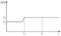
도 5는 챔버의 내부 압력 변화를 나타내는 도면이다.1 is a plan view showing a substrate processing apparatus according to an embodiment of the present invention.
Figure 2 is a view of an etch module that may be provided in the process module of Figure 1;
3 is a view showing a state in which the substrate is processed.
4 is a view showing a state in which a water vapor layer is formed around a substrate.
5 is a view showing the change in the internal pressure of the chamber.
이하, 본 발명의 실시 예를 첨부된 도면들을 참조하여 더욱 상세하게 설명한다. 본 발명의 실시 예는 여러 가지 형태로 변형할 수 있으며, 본 발명의 범위가 아래의 실시 예들로 한정되는 것으로 해석되어서는 안 된다. 본 실시 예는 당업계에서 평균적인 지식을 가진 자에게 본 발명을 더욱 완전하게 설명하기 위해 제공되는 것이다. 따라서 도면에서의 요소의 형상은 보다 명확한 설명을 강조하기 위해 과장되었다.Hereinafter, embodiments of the present invention will be described in detail with reference to the accompanying drawings. The embodiments of the present invention can be modified in various forms, and the scope of the present invention should not be construed as being limited to the following embodiments. This embodiment is provided to more fully describe the present invention to those skilled in the art. Thus, the shape of the elements in the figures has been exaggerated to emphasize a clearer description.
도 1은 본 발명의 실시 예에 따른 기판 처리 장치를 나타내는 평면도이다.1 is a plan view showing a substrate processing apparatus according to an embodiment of the present invention.
도 1을 참조하면, 기판 처리 장치(1)는 설비 전방 단부 모듈(equipment front end module, EFEM)(20) 및 공정 처리부(30)를 가진다. 설비 전방 단부 모듈(20)과 공정 처리부(30)는 일 방향으로 배치된다. 이하, 설비 전방 단부 모듈(20)과 공정 처리부(30)가 배열된 방향을 제 1 방향(11)이라하고, 상부에서 바라볼 때 제 1 방향(11)에 수직인 방향을 제 2 방향(12)이라 한다.Referring to FIG. 1, the
설비 전방 단부 모듈(20)은 로드 포트(load port, 10) 및 이송프레임(21)을 가진다. 로드 포트(10)는 제1방향(11)으로 설비 전방 단부 모듈(20)의 전방에 배치된다. 로드 포트(10)는 복수 개의 지지부(6)를 가진다. 각각의 지지부(6)는 제 2 방향(12)으로 일렬로 배치되며, 공정에 제공될 기판(W) 및 공정처리가 완료된 기판(W)이 수납된 캐리어(4)(예를 틀어, 카세트, FOUP등)가 위치된다. 캐리어(4)에는 공정에 제공될 기판(W) 및 공정처리가 완료된 기판(W)이 수납된다. 이송프레임(21)은 로드 포트(10)와 공정 처리실(30) 사이에 배치된다. 이송프레임(21)은 그 내부에 배치되고 로드 포트(10)와 공정 처리부(30)간에 기판(W)을 이송하는 제 1 이송로봇(25)을 포함한다. 제 1 이송로봇(25)은 제 2 방향(12)으로 구비된 이송 레일(27)을 따라 이동하여 캐리어(4)와 공정 처리실(30)간에 기판(W)을 이송한다.The apparatus
공정 처리실(30)은 로드락 챔버(40), 트랜스퍼 챔버(50), 그리고 공정 모듈(60)를 포함한다.The
로드락 챔버(40)는 이송프레임(21)에 인접하게 배치된다. 일 예로, 로드락 챔버(40)는 트랜스퍼 챔버(50)와 설비 전방 단부 모듈(20)사이에 배치될 수 있다. 로드락 챔버(40)는 공정에 제공될 기판(W)이 공정 모듈(60)로 이송되기 전, 또는 공정 처리가 완료된 기판(W)이 설비 전방 단부 모듈(20)로 이송되기 전 대기하는 공간을 제공한다.The
트랜스퍼 챔버(50)는 로드락 챔버(40)에 인접하게 배치된다. 트랜스퍼 챔버(50)는 상부에서 바라볼 때, 다각형의 몸체를 갖는다. 일 예로, 트랜스퍼 챔버(50)는 상부에서 바라볼 때, 오각형의 몸체를 가질 수 있다. 몸체의 외측에는 로드락 챔버(40)와 복수개의 공정 모듈(60)들이 몸체의 둘레를 따라 배치된다. 몸체의 각 측벽에는 기판(W)이 출입하는 통로(미도시)가 형성되며, 통로는 트랜스퍼 챔버(50)와 로드락 챔버(40) 또는 공정 모듈(60)들을 연결한다. 각 통로에는 통로를 개폐하여 내부를 밀폐시키는 도어(미도시)가 제공된다. 트랜스퍼 챔버(50)의 내부공간에는 로드락 챔버(40)와 공정 모듈(60)들간에 기판(W)을 이송하는 제 2 이송 로봇(53)이 배치된다. 제 2 이송 로봇(53)은 로드락 챔버(40)에서 대기하는 미처리된 기판(W)을 공정 모듈(60)로 이송하거나, 공정처리가 완료된 기판(W)을 로드락 챔버(40)로 이송한다. 그리고, 복수개의 공정 모듈(60)에 기판(W)을 순차적으로 제공하기 위하여 공정 모듈(60)간에 기판(W)을 이송할 수 있다. 도 1과 같이, 트랜스퍼 챔버(50)가 오각형의 몸체를 가질 때, 설비 전방 단부 모듈(20)과 인접한 측벽에는 로드락 챔버(40)가 각각 배치되며, 나머지 측벽에는 공정 모듈(60)들이 배치된다. 트랜스퍼 챔버(50)는 상기 형상뿐만 아니라, 요구되는 공정모듈에 따라 다양한 형태로 제공될 수 있다.The
공정 모듈(60)는 트랜스퍼 챔버(50)의 둘레를 따라 배치된다. 공정 모듈(60)는 복수 개 제공될 수 있다. 각각의 공정 모듈(60)내에서는 기판(W)에 대한 공정처리가 진행된다. 공정 모듈(60)는 제 2 이송 로봇(53)으로부터 기판(W)을 이송 받아 공정처리를 하고, 공정처리가 완료된 기판(W)을 제 2 이송 로봇(53)으로 제공한다. 각각의 공정 모듈(60)에서 진행되는 공정처리는 서로 동일하거나 상이할 수 있다. 공정 모듈(60)이 수행하는 공정은 기판(W)을 이용해 반도체 소자 또는 디스플레이 패널을 생산하는 과정 가운데 일 공정일 수 있다. 공정 모듈(60)가운데 하나 이상은 기판(W)을 식각 처리 하는 모듈(도 2의 200a)을 포함한다. 제어기(미도시)는 기판 처리 장치의 구성 요소를 제어할 수 있다.The
도 2는 도 1의 공정 모듈에 제공될 수 있는 식각 모듈을 나타내는 도면이다.Figure 2 is a view of an etch module that may be provided in the process module of Figure 1;
도 2를 참조하면, 식각 모듈(200a)은 챔버(2100), 서셉터(2200), 샤워 헤드(2300) 및 플라스마 여기부(2400)를 포함한다. 식각 모듈(200a)의 구성은 제어기에 이해 제어될 수 있다.Referring to FIG. 2, the
챔버(2100)는 공정 처리가 수행되는 공간을 제공한다. 챔버(2100)는 바디(2110)와 밀폐 커버(2120)를 가진다. 바디(2110)는 상면이 개방되며 내부에 공간이 형성된다. 바디(2110)의 측벽에는 기판이 출입하는 개구(미도시)가 형성되며, 개구는 슬릿 도어(slit door)(미도시)와 같은 개폐 부재에 의해 개폐될 수 있다. 개폐 부재는 챔버(2100) 내에서 기판(W) 처리가 수행되는 동안 개구를 폐쇄하고, 기판(W)이 챔버(2100) 내부로 반입될 때와 챔버(2100) 외부로 반출될 때 개구를 개방한다. 바디(2110)의 일측에는 배기홀(2111)이 형성된다. 일 예로, 배기홀(2111)은 바디(2110)의 하부벽 또는 측벽에 형성될 수 있다.The
배기홀(2111)은 배기 라인(2112)과 연결된다. 배기 라인(2112)을 통해 챔버(2100)의 내부 압력이 조절되고, 공정에서 발생된 반응 부산물이 챔버(2100) 외부로 배출된다.The
밀폐 커버(2120)는 바디(2110)의 상부벽과 결합하며, 바디(2110)의 개방된 상면을 덮어 바디(2110) 내부를 밀폐시킨다. 밀폐 커버(2120)의 상단은 플라스마 여기부(2400)와 연결된다. 밀폐 커버(2120)에는 확산공간(2121)이 형성된다. 확산공간(2121)은 샤워 헤드(2300)에 가까워질수록 너비가 점차 넓어진다. 예를 들어, 확산공간(2121)은 역 깔때기 형상을 가질 수 있다.The sealing
서셉터(2200)는 챔버(2100) 내부에 위치된다. 서셉터(2200)의 상면에는 기판이 놓여진다. 서셉터(2200)의 내부에는 냉각 유체가 순환하는 냉각 유로(미도시)가 형성될 수 있다. 냉각 유체는 냉각 유로를 따라 순환하며 서셉터(2200)를 냉각한다. 서셉터(2200)에는 플라즈마에 의한 기판(W) 처리 정도를 조절하기 위해 바이어스 전원(2210)으로부터 전력이 인가될 수 있다. 바이어스 전원(2210)이 인가하는 전력은 라디오 주파수(radio frequency, RF) 전원일 수 있다. 서셉터(2200)는 바이어스 전원(2210)이 공급하는 전력에 의해 쉬즈를 형성하고, 그 영역에서 고밀도의 플라즈마를 형성하여 공정 능력을 향상시킬 수 있다.The
서셉터(2200)의 내부에는 가열 부재(2220)가 제공될 수 있다. 일 예에 의하면, 가열 부재(222)는 열선으로 제공되거나, 가열된 유체가 유동하는 배관으로 형성될 수 있다. 가열 부재(222)는 기판(W)을 기 설정된 온도 또는 기 설정도니 온도 범위로 가열한다.A
서셉터(2200)의 내부에는 냉각 부재(2230)가 제공될 수 있다. 일 예에 의하면, 냉각 부재(2230)는 냉매가 유동하는 배관일 수 있다.A cooling
샤워 헤드(2300)는 바디(2110)의 상부벽에 결합된다. 샤워 헤드(2300)는 플레이트 형상으로, 서셉터(2200)의 상면과 나란하게 배치될 수 있다. 샤워 헤드(2300)는 표면이 산화 처리된 알루미늄 재질로 제공될 수 있다. 샤워 헤드(2300)에는 분배홀(2310)들이 형성된다. 분배홀(2310)들은 균일한 라디칼 공급을 위해 동심의 원주상에 일정 간격으로 형성될 수 있다. 확산공간(2121)에서 확산된 플라스마는 분배홀(2310)들에 유입된다. 이때 전자 또는 이온 등과 같은 하전 입자는 샤워 헤드(2300)에 갇히고, 산소 라디칼 등과 같이 전하를 띄지 않는 중성 입자들은 분배홀(2310)들을 통과하여 기판(W)으로 공급된다. 또한, 샤워 헤드는 접지되어 전자 또는 이온이 이동되는 통로를 형성할 수 있다. 또한, 샤워 헤드(2300)에는 가열을 위한 히터(미도시)가 위치될 수 있다.The
플라스마 여기부(2400)는 플라스마를 생성하여, 챔버(2100)로 공급한다. 플라스마 여기부(2400)는 챔버(2100)의 상부에 제공될 수 있다. 플라스마 여기부(2400)는 발진기(2410), 도파관(2420), 유전체 관(2430) 및 공정 가스 공급부(2440)를 포함한다.The
발진기(2410)는 전자기파를 발생시킨다. 도파관(2420)은 발진기(2410)와 유전체 관(2430)을 연결하며, 발진기(2410)에서 발생된 전자기파가 유전체 관(2430) 내부로 전달되는 통로를 제공한다. 공정 가스 공급부(2440)는 챔버(2100)의 상부로 공정 가스를 공급한다. 유전체 관(2430) 내부로 공급된 공정 가스는 전자기파에 의해 플라스마 상태로 여기 된다. 플라스마는 유전체 관(2430)을 거쳐 확산공간(2121)으로 유입된다.The
상술한 플라즈마 여기부(2400)는 전자기파를 이용하는 경우를 예로 들었으나, 또 다른 실시 예로, 플라즈마 여기부(2400)는 유도결합 플라즈마 여기부, 용량 결합 플라즈마 여기부 등으로 제공될 수 도 있다.The
챔버(2100)의 일측에는 수분 공급관(2130)이 연결된다. 일 예로, 수분 공급관(2130)은 샤워 헤드(2300)의 위쪽에서 밀폐 커버(2120)에 연결되는 형태로 제공될 수 있다. 따라서, 수분 공급관(2130)을 통해 공급된 수분을 샤워 헤드(2300)를 거쳐 기판으로 균일하게 공급될 수 있다. 또 다른 예로, 수분 공급관(2130)은 샤워 헤드(2300)의 아래쪽에 위치되도록 바디(2110)의 측벽에 연결될 수 도 있다. 수분 공급관(2130)은 챔버(2100)의 내측 공간으로 수분을 공급한다. 수분 공급관(2130)은 수분을 설정 온도로 가열되어 기화된 증기 형태로 공급할 수 있다. 또한, 수분 공급관(2130)은 수분의 공급 효율 또는 공급 상태의 조절을 용이하게 하기 위해, 수분을 불활성 가스와 혼합한 상태로 공급할 수 있다.A
도 3은 기판이 처리되는 상태를 나타내는 도면이고, 도 4는 기판의 주위에 수증기 층이 형성된 상태를 나타내는 도면이고, 도 5는 챔버의 내부 압력 변화를 나타내는 도면이다.FIG. 3 is a view showing a state in which a substrate is processed, FIG. 4 is a view showing a state in which a water vapor layer is formed around a substrate, and FIG.
공정 처리를 위해 기판이 챔버(2100)로 반입되어, 서셉터(2200)에 위치되면, 챔버(2100)의 내부공간으로 수증기가 공급된다.When the substrate is brought into the
기판(W)에는 폴리실리콘 층(3100)과 식각 대상막(3120)이 형성된 상태로 제공된다. 일 예로, 기판(W)은 폴리실리콘 층(3100)의 상부에 식각 대상막(3120)인 산화막 층(3120)이 패턴을 가지고 형성되어 있을 수 있다. 따라서, 산화막 층(3120)의 상면은 외부로 노출된다. 그리고 폴리실리콘 층(3100)의 일부는 산화막 층(3120)의 패턴을 통해 외부로 노출된다.The substrate W is provided with a
내부 공간으로 공급된 수증기는 기판의 외면에 맺혀 물 방울을 형성하지 않은 상태로 기판 주위에 수증기 층을 형성하여, 기판이 습식 처리 방식으로 처리되는 상태와 유사한 환경이 되도록 한다. 구체적으로, 수증기가 공급될 때, 챔버(2100)의 내부 공간은 대기압 보다 낮은 예비 압력(Fa)으로 조절된 상태일 수 있다. 예비 압력(Fa)은 진공에 근접하거나, 수 내지 수십 Torr 인 상태일 수 있다. 또한, 수증기가 공급될 때, 기판은 가열 부재(2220), 냉각 부재(2230), 또는 가열 부재(2220)와 냉각 부재(2230)에 의해 설정 온도 또는 설정 범위의 온도로 조절된 상태일 수 있다. 이와 같이 챔버(2100)의 내부 공간, 또는 챔버(2100)의 내부 공간과 챔버(2100)의 온도가 조절된 상태로 수증기가 공급되면, 수증기는 기판에 물방울 형태로 맺히지 않을 수 있다. 이때, 기판 주위의 수증기는 기판과 반응하여, 주로 실리콘 산화막층의 산소에 수소가 결합되는 형태의 반응이 발생한다.The water vapor supplied to the inner space is formed on the outer surface of the substrate so as to form a water vapor layer around the substrate without forming water droplets so that the environment becomes similar to the state in which the substrate is treated by the wet processing method. Specifically, when water vapor is supplied, the inner space of the
수증기의 공급이 개시되고 설정 시간이 경과되면, 챔버(2100)의 내부 공간으로 공정 가스가 공급되어, 실리콘 산화막을 식각하는 공정이 수행된다. 공정 가스 공급부가 공정 가스를 공급하면, 공정 가스는 주로 실리콘 산화막층과 반응하여, 실리콘 산화막층을 선택적으로 식각 한다. 기판의 주위에 위치된 수증기는 기판 주위를 습식 식각 공정과 유사한 환경으로 한다. 또한, 실리콘 산화막층의 산소에 결합된 수소는, 공정 가스와 실리콘 산화막층의 반응성을 증가 시킨다.When the supply of steam is started and the set time has elapsed, a process gas is supplied to the inner space of the
공정 가스는 불소 원자를 포함하는 화합물로 제공된다. 예를 들어, 공정 가스는 삼불화 질소, 사불화탄소, 2플루오르화 메테인(difluoro methane) 또는 3플루오르화 메테인(trifluoro methane) 등으로 제공될 수 있다. 또한, 공정 가스는 삼불화 질소, 사불화탄소, 2플루오르화 메테인(difluoro methane) 및 3플루오르화 메테인(trifluoro methane) 가운데 2개 이상의 혼합 가스로 제공될 수 도 있다. 공정 가스는 플라즈마 상태로 여기된 상태로 공급되어, 기판과의 반응성이 증가될 수 있다. 공정 가스는 플라즈마로 여기되는 과정에서 불소 라디칼을 제공한다.The process gas is provided as a compound containing a fluorine atom. For example, the process gas may be provided by nitrogen trifluoride, carbon tetrafluoride, difluoro methane, trifluoromethane, or the like. In addition, the process gas may be provided as two or more gaseous gases among nitrogen trifluoride, carbon tetrafluoride, difluoro methane and trifluoromethane. The process gas is supplied in a state of being excited to the plasma state, so that the reactivity with the substrate can be increased. The process gas provides a fluorine radical in the process of being excited by the plasma.
공정 가스가 공급되어 식각 공정이 수행될 때, 챔버(2100)의 내부는 공정 압력(Fb)으로 설정될 수 있다. 공정 가스가 공급될 때 기판의 온도는 0°~50°범위로 조절되고, 공정 압력(Fb)은 3 Torr 내지 30 Torr 범위로 조절된다. 공정 압력(Fb)은 예비 압력(Fa)과 설정 관계를 갖도록 설정될 수 있다. 공정 압력(Fb)은 예비 압력(Fa)보다 설정 압력만큼 크게 형성될 수 있다. 또한, 공정 압력(Fb)은 예비 압력(Fa)보다 설정 압력만큼 작게 설정되거나, 예비 압력(Fa)과 동일할 수 있다. 공정 가스는 챔버(2100)의 내부가 예비 압력(Fa)이 공정 압력(Fb)으로 조절된 진 후 공급이 개시되거나, 챔버(2100)의 내부가 공정 압력(Fb)으로 조절되고 설정 시간이 경과된 후 개시될 수 있다. 공정 가스가 공급될 때, 수증기는 계속 공급되는 상태일 수 있다. 이후, 설정 시간 동안 식각 공정이 수행되면, 공정 가스와 수증기의 공급은 종료될 수 있다. 이때, 공정 가스의 공급이 먼저 중단될 수 있다. 또한, 공정 가스와 수증기의 공급은 함께 중단될 수 있다.When the process gas is supplied and the etching process is performed, the inside of the
이 후, 기판은 설정 온도로 가열되어 열처리 된다. 기판이 식각 처리 된 후, 기판에는 반응 부산물이 잔류하는 상태일 수 있다. 이 와 같은 반응 부산물은 기판의 가열의 통해 기판에서 제거될 수 있다. 기판(W)은 가열은 플라즈마 모듈(200a)에서 가열 부재(2220)에 의해 수행될 수 있다. 기판(W)의 가열은 샤워 헤드(2300)에 위치된 히터에 의해 이루어 질 수도 있다.또한, 기판의 가열은 플라즈마 모듈(200a)에서 반출된 후 다른 공정 모듈에서 수행될 수 도 있다.Thereafter, the substrate is heated to a set temperature and heat-treated. After the substrate is etched, the reaction byproduct may remain in the substrate. Such reaction by-products can be removed from the substrate through heating of the substrate. Heating of the substrate W can be performed by the
이상의 상세한 설명은 본 발명을 예시하는 것이다. 또한 전술한 내용은 본 발명의 바람직한 실시 형태를 나타내어 설명하는 것이며, 본 발명은 다양한 다른 조합, 변경 및 환경에서 사용할 수 있다. 즉 본 명세서에 개시된 발명의 개념의 범위, 저술한 개시 내용과 균등한 범위 및/또는 당업계의 기술 또는 지식의 범위내에서 변경 또는 수정이 가능하다. 저술한 실시예는 본 발명의 기술적 사상을 구현하기 위한 최선의 상태를 설명하는 것이며, 본 발명의 구체적인 적용 분야 및 용도에서 요구되는 다양한 변경도 가능하다. 따라서 이상의 발명의 상세한 설명은 개시된 실시 상태로 본 발명을 제한하려는 의도가 아니다. 또한 첨부된 청구범위는 다른 실시 상태도 포함하는 것으로 해석되어야 한다.The foregoing detailed description is illustrative of the present invention. In addition, the foregoing is intended to illustrate and explain the preferred embodiments of the present invention, and the present invention may be used in various other combinations, modifications, and environments. That is, it is possible to make changes or modifications within the scope of the concept of the invention disclosed in this specification, within the scope of the disclosure, and / or within the skill and knowledge of the art. The embodiments described herein are intended to illustrate the best mode for implementing the technical idea of the present invention and various modifications required for specific applications and uses of the present invention are also possible. Accordingly, the detailed description of the invention is not intended to limit the invention to the disclosed embodiments. It is also to be understood that the appended claims are intended to cover such other embodiments.
10: 로드 포트 20: 설비 전방 단부 모듈
21: 이송프레임 25: 제 1 이송로봇
30: 공정 처리실 40: 로드락 챔버
50: 트랜스퍼 챔버 60: 공정 모듈
200a: 플라즈마 모듈 2100: 챔버
2110: 바디 2200: 서셉터10: load port 20: equipment front end module
21: transfer frame 25: first transfer robot
30: process chamber 40: load lock chamber
50: Transfer chamber 60: Process module
200a: plasma module 2100: chamber
2110: Body 2200: Susceptor
Claims (11)
Translated fromKorean기판이 제공된 챔버 내부로 수증기를 공급하여 기판의 주위에 수증기 층을 형성하는 단계와;
상기 수증기 층 형성 단계 이후에 상기 챔버 내부로 불소를 포함하는 공정 가스를 공급하여 상기 실리콘 산화막을 선택적으로 식각하는 식각 단계를 포함하는 기판 처리 방법.A silicon oxide film for polysilicon is selectively etched,
Supplying water vapor into the chamber provided with the substrate to form a water vapor layer around the substrate;
And an etching step of selectively etching the silicon oxide film by supplying a process gas containing fluorine into the chamber after the step of forming the water vapor layer.
상기 식각 단계에서 상기 공정 가스가 공급될 때, 상기 수증기의 공급이 이루어 지는 기판 처리 방법.The method according to claim 1,
Wherein the supply of the steam is performed when the process gas is supplied in the etching step.
상기 수증기 층 형성단계에서 상기 수증기는 캐리어 가스와 혼합된 상태로 공급되는 기판 처리 방법.3. The method according to claim 1 or 2,
Wherein the water vapor is supplied in a mixed state with the carrier gas in the step of forming the water vapor layer.
상기 수증기 층이 형성되는 단계에서 상기 기판은 설정 온도로 제어되는 기판 처리 방법.The method according to claim 1,
Wherein the substrate is controlled at a set temperature in the step of forming the water vapor layer.
상기 식각 단계 이 후, 상기 기판을 설정 온도로 가열하는 열처리 단계를 더 포함하는 기판 처리 방법.The method according to claim 1,
Further comprising a heat treatment step of heating the substrate to a set temperature after the etching step.
상기 열처리는 상기 기판을 지지하는 서셉터를 가열하여 이루어 지는 기판 처리 방법.6. The method of claim 5,
Wherein the heat treatment is performed by heating a susceptor supporting the substrate.
상기 열처리는 샤워 헤드에 위치된 히터에 의해 이루어 지는 기판 처리 방법.6. The method of claim 5,
Wherein the heat treatment is performed by a heater positioned in the showerhead.
상기 챔버의 내측에 위치되어, 기판을 지지하는 서셉터;
상기 챔버의 내부로 수증기를 공급하는 수분 공급관; 및
상기 수증기에 의해 수증기 층이 형성된 상태에서, 상기 챔버의 내부로 불소를 포함하는 공정 가스를 공급하여 폴리 실리콘에 대해 실리콘 산화막이 선택적으로 식각되게 하는 공정 가스 공급부를 포함하는 기판 처리 장치.chamber;
A susceptor positioned inside the chamber and supporting the substrate;
A water supply pipe for supplying water vapor into the chamber; And
And a process gas supply unit for supplying a process gas containing fluorine into the chamber to selectively etch the silicon oxide film to the polysilicon in a state where a water vapor layer is formed by the water vapor.
상기 공정 가스가 공급될 때 상기 수증기가 함께 공급되도록 상기 수분 공급관 및 상기 공정 가스 공급부를 제어하는 제어기를 더 포함하는 기판 처리 장치.9. The method of claim 8,
Further comprising a controller for controlling the water supply pipe and the process gas supply unit so that the water vapor is supplied together when the process gas is supplied.
상기 수분 공급관은 상기 수증기를 캐리어 가스와 혼합된 상태로 공급하는 기판 처리 장치.9. The method of claim 8,
Wherein the water supply pipe supplies the water vapor in a mixed state with the carrier gas.
상기 서셉터는 상기 수증기 층이 형성될 때, 상기 기판을 가열하는 가열 부재를 포함하는 기판 처리 장치.9. The method of claim 8,
Wherein the susceptor includes a heating member for heating the substrate when the water vapor layer is formed.
Priority Applications (1)
| Application Number | Priority Date | Filing Date | Title |
|---|---|---|---|
| KR1020170107029AKR102095982B1 (en) | 2017-08-24 | 2017-08-24 | Substrate treating apparatus and substrate treating method |
Applications Claiming Priority (1)
| Application Number | Priority Date | Filing Date | Title |
|---|---|---|---|
| KR1020170107029AKR102095982B1 (en) | 2017-08-24 | 2017-08-24 | Substrate treating apparatus and substrate treating method |
Publications (2)
| Publication Number | Publication Date |
|---|---|
| KR20190021795Atrue KR20190021795A (en) | 2019-03-06 |
| KR102095982B1 KR102095982B1 (en) | 2020-04-02 |
Family
ID=65761565
Family Applications (1)
| Application Number | Title | Priority Date | Filing Date |
|---|---|---|---|
| KR1020170107029AActiveKR102095982B1 (en) | 2017-08-24 | 2017-08-24 | Substrate treating apparatus and substrate treating method |
Country Status (1)
| Country | Link |
|---|---|
| KR (1) | KR102095982B1 (en) |
Citations (3)
| Publication number | Priority date | Publication date | Assignee | Title |
|---|---|---|---|---|
| KR910004039B1 (en)* | 1985-08-28 | 1991-06-22 | 에프_에스_아이 코포레이션 | Gas treatment method and apparatus for removing thin film from substrate |
| JP2005302897A (en)* | 2004-04-08 | 2005-10-27 | Sony Corp | Method for removing hard etching mask and manufacturing method for semiconductor device |
| JP2011091389A (en)* | 2009-09-25 | 2011-05-06 | Hitachi Kokusai Electric Inc | Substrate processing apparatus and method of manufacturing semiconductor device |
- 2017
- 2017-08-24KRKR1020170107029Apatent/KR102095982B1/enactiveActive
Patent Citations (3)
| Publication number | Priority date | Publication date | Assignee | Title |
|---|---|---|---|---|
| KR910004039B1 (en)* | 1985-08-28 | 1991-06-22 | 에프_에스_아이 코포레이션 | Gas treatment method and apparatus for removing thin film from substrate |
| JP2005302897A (en)* | 2004-04-08 | 2005-10-27 | Sony Corp | Method for removing hard etching mask and manufacturing method for semiconductor device |
| JP2011091389A (en)* | 2009-09-25 | 2011-05-06 | Hitachi Kokusai Electric Inc | Substrate processing apparatus and method of manufacturing semiconductor device |
Also Published As
| Publication number | Publication date |
|---|---|
| KR102095982B1 (en) | 2020-04-02 |
Similar Documents
| Publication | Publication Date | Title |
|---|---|---|
| US20230178419A1 (en) | Scaled liner layer for isolation structure | |
| TWI469238B (en) | Plasma etching treatment device and plasma etching treatment method | |
| US20020036066A1 (en) | Method and apparatus for processing substrates | |
| TWI870500B (en) | Method for etching film and plasma processing apparatus | |
| JP7349861B2 (en) | Etching methods, damaged layer removal methods, and storage media | |
| US10546753B2 (en) | Method of removing silicon oxide film | |
| US20100093185A1 (en) | Method for forming silicon oxide film, plasma processing apparatus and storage medium | |
| US7972973B2 (en) | Method for forming silicon oxide film, plasma processing apparatus and storage medium | |
| US20150064921A1 (en) | Low temperature plasma anneal process for sublimative etch processes | |
| KR20100019469A (en) | Micro wave plasma processing device, micro wave plasma processing method, and micro wave transmitting plate | |
| WO2020066172A1 (en) | Etching method, method for removing etching residue, and storage medium | |
| JP2023099471A (en) | Substrate processing method and substrate processing apparatus | |
| KR102052337B1 (en) | Substrate treating apparatus and substrate treating method | |
| KR20210015710A (en) | Substrate processing method, substrate processing apparatus and cleaning apparatus | |
| KR101603971B1 (en) | Substrate treating apparatus and Substrate treating method | |
| KR102095982B1 (en) | Substrate treating apparatus and substrate treating method | |
| KR102095983B1 (en) | Substrate treating apparatus and substrate treating method | |
| KR20230063745A (en) | Upper electrode unit and substrate processing apparatus including same | |
| KR102212998B1 (en) | Apparatus for treating substrate | |
| KR101909110B1 (en) | Substrate treating method | |
| KR20160113410A (en) | Substrate treating apparatus and Substrate treating method | |
| KR102688353B1 (en) | Apparatus and method for treating substrate | |
| KR102614922B1 (en) | Apparatus and method for treating substrate | |
| KR102870983B1 (en) | Showerhead and plasma processing apparatus comprising the same | |
| KR102674205B1 (en) | Apparatus and method for treating substrate |
Legal Events
| Date | Code | Title | Description |
|---|---|---|---|
| A201 | Request for examination | ||
| PA0109 | Patent application | Patent event code:PA01091R01D Comment text:Patent Application Patent event date:20170824 | |
| PA0201 | Request for examination | ||
| E902 | Notification of reason for refusal | ||
| PE0902 | Notice of grounds for rejection | Comment text:Notification of reason for refusal Patent event date:20190104 Patent event code:PE09021S01D | |
| PG1501 | Laying open of application | ||
| AMND | Amendment | ||
| E601 | Decision to refuse application | ||
| PE0601 | Decision on rejection of patent | Patent event date:20191023 Comment text:Decision to Refuse Application Patent event code:PE06012S01D Patent event date:20190104 Comment text:Notification of reason for refusal Patent event code:PE06011S01I | |
| X091 | Application refused [patent] | ||
| AMND | Amendment | ||
| PX0901 | Re-examination | Patent event code:PX09011S01I Patent event date:20191023 Comment text:Decision to Refuse Application Patent event code:PX09012R01I Patent event date:20190404 Comment text:Amendment to Specification, etc. | |
| PX0701 | Decision of registration after re-examination | Patent event date:20200109 Comment text:Decision to Grant Registration Patent event code:PX07013S01D Patent event date:20191223 Comment text:Amendment to Specification, etc. Patent event code:PX07012R01I Patent event date:20191023 Comment text:Decision to Refuse Application Patent event code:PX07011S01I Patent event date:20190404 Comment text:Amendment to Specification, etc. Patent event code:PX07012R01I | |
| X701 | Decision to grant (after re-examination) | ||
| PN2301 | Change of applicant | Patent event date:20200317 Comment text:Notification of Change of Applicant Patent event code:PN23011R01D | |
| PR0701 | Registration of establishment | Comment text:Registration of Establishment Patent event date:20200326 Patent event code:PR07011E01D | |
| PR1002 | Payment of registration fee | Payment date:20200327 End annual number:3 Start annual number:1 | |
| PG1601 | Publication of registration | ||
| PR1001 | Payment of annual fee | Payment date:20221207 Start annual number:4 End annual number:4 | |
| PR1001 | Payment of annual fee | Payment date:20231211 Start annual number:5 End annual number:5 |