KR20190011859A - Patient-Specific Artificial Shoulder Joint Surgical Instruments - Google Patents
Patient-Specific Artificial Shoulder Joint Surgical InstrumentsDownload PDFInfo
- Publication number
- KR20190011859A KR20190011859AKR1020170094212AKR20170094212AKR20190011859AKR 20190011859 AKR20190011859 AKR 20190011859AKR 1020170094212 AKR1020170094212 AKR 1020170094212AKR 20170094212 AKR20170094212 AKR 20170094212AKR 20190011859 AKR20190011859 AKR 20190011859A
- Authority
- KR
- South Korea
- Prior art keywords
- humerus
- patient
- guide
- contact surface
- surgical instrument
- Prior art date
- Legal status (The legal status is an assumption and is not a legal conclusion. Google has not performed a legal analysis and makes no representation as to the accuracy of the status listed.)
- Granted
Links
- 210000000323shoulder jointAnatomy0.000titleclaimsabstractdescription88
- 210000002758humerusAnatomy0.000claimsabstractdescription184
- 238000005520cutting processMethods0.000claimsabstractdescription66
- 210000004095humeral headAnatomy0.000claimsabstractdescription38
- 230000000295complement effectEffects0.000claimsabstractdescription32
- 210000000988bone and boneAnatomy0.000claimsdescription13
- 230000000149penetrating effectEffects0.000claimsdescription5
- 238000000926separation methodMethods0.000claimsdescription2
- 238000001356surgical procedureMethods0.000abstractdescription28
- 230000007246mechanismEffects0.000description15
- 238000000034methodMethods0.000description11
- 238000003780insertionMethods0.000description7
- 230000037431insertionEffects0.000description7
- 230000000694effectsEffects0.000description6
- 210000001124body fluidAnatomy0.000description5
- 239000010839body fluidSubstances0.000description5
- 239000007943implantSubstances0.000description5
- 230000006870functionEffects0.000description4
- 210000004369bloodAnatomy0.000description3
- 239000008280bloodSubstances0.000description3
- 230000008878couplingEffects0.000description3
- 238000010168coupling processMethods0.000description3
- 238000005859coupling reactionMethods0.000description3
- 238000010586diagramMethods0.000description3
- 238000004519manufacturing processMethods0.000description3
- 238000012986modificationMethods0.000description3
- 230000004048modificationEffects0.000description3
- 230000008569processEffects0.000description3
- 230000000284resting effectEffects0.000description3
- 210000001991scapulaAnatomy0.000description3
- 2380000101463D printingMethods0.000description2
- 241001653121GlenoidesSpecies0.000description2
- 238000007796conventional methodMethods0.000description2
- 230000009545invasionEffects0.000description2
- 210000003205muscleAnatomy0.000description2
- 239000004065semiconductorSubstances0.000description2
- 239000000126substanceSubstances0.000description2
- 206010003246arthritisDiseases0.000description1
- 239000003795chemical substances by applicationSubstances0.000description1
- 238000010276constructionMethods0.000description1
- 208000014674injuryDiseases0.000description1
- 230000002452interceptive effectEffects0.000description1
- 238000005304joiningMethods0.000description1
- 230000008407joint functionEffects0.000description1
- 210000003041ligamentAnatomy0.000description1
- 230000033001locomotionEffects0.000description1
- 238000002324minimally invasive surgeryMethods0.000description1
- 238000009751slip formingMethods0.000description1
- 239000007787solidSubstances0.000description1
- 210000002435tendonAnatomy0.000description1
- 210000001519tissueAnatomy0.000description1
- 230000008733traumaEffects0.000description1
Images


Classifications
- A—HUMAN NECESSITIES
- A61—MEDICAL OR VETERINARY SCIENCE; HYGIENE
- A61B—DIAGNOSIS; SURGERY; IDENTIFICATION
- A61B17/00—Surgical instruments, devices or methods
- A61B17/16—Instruments for performing osteoclasis; Drills or chisels for bones; Trepans
- A61B17/17—Guides or aligning means for drills, mills, pins or wires
- A61B17/1739—Guides or aligning means for drills, mills, pins or wires specially adapted for particular parts of the body
- A61B17/1778—Guides or aligning means for drills, mills, pins or wires specially adapted for particular parts of the body for the shoulder
- A—HUMAN NECESSITIES
- A61—MEDICAL OR VETERINARY SCIENCE; HYGIENE
- A61B—DIAGNOSIS; SURGERY; IDENTIFICATION
- A61B17/00—Surgical instruments, devices or methods
- A61B17/16—Instruments for performing osteoclasis; Drills or chisels for bones; Trepans
- A61B17/1662—Instruments for performing osteoclasis; Drills or chisels for bones; Trepans for particular parts of the body
- A61B17/1684—Instruments for performing osteoclasis; Drills or chisels for bones; Trepans for particular parts of the body for the shoulder
- A—HUMAN NECESSITIES
- A61—MEDICAL OR VETERINARY SCIENCE; HYGIENE
- A61F—FILTERS IMPLANTABLE INTO BLOOD VESSELS; PROSTHESES; DEVICES PROVIDING PATENCY TO, OR PREVENTING COLLAPSING OF, TUBULAR STRUCTURES OF THE BODY, e.g. STENTS; ORTHOPAEDIC, NURSING OR CONTRACEPTIVE DEVICES; FOMENTATION; TREATMENT OR PROTECTION OF EYES OR EARS; BANDAGES, DRESSINGS OR ABSORBENT PADS; FIRST-AID KITS
- A61F2/00—Filters implantable into blood vessels; Prostheses, i.e. artificial substitutes or replacements for parts of the body; Appliances for connecting them with the body; Devices providing patency to, or preventing collapsing of, tubular structures of the body, e.g. stents
- A61F2/02—Prostheses implantable into the body
- A61F2/30—Joints
- A61F2/40—Joints for shoulders
- A61F2/4059—Humeral shafts
- A61F2002/4062—Proximal or metaphyseal parts of shafts
Landscapes
- Health & Medical Sciences (AREA)
- Life Sciences & Earth Sciences (AREA)
- Surgery (AREA)
- Veterinary Medicine (AREA)
- Animal Behavior & Ethology (AREA)
- Orthopedic Medicine & Surgery (AREA)
- Oral & Maxillofacial Surgery (AREA)
- Engineering & Computer Science (AREA)
- Biomedical Technology (AREA)
- Heart & Thoracic Surgery (AREA)
- Public Health (AREA)
- General Health & Medical Sciences (AREA)
- Nuclear Medicine, Radiotherapy & Molecular Imaging (AREA)
- Molecular Biology (AREA)
- Medical Informatics (AREA)
- Dentistry (AREA)
- Cardiology (AREA)
- Transplantation (AREA)
- Vascular Medicine (AREA)
- Surgical Instruments (AREA)
- Prostheses (AREA)
Abstract
Translated fromKoreanDescription
Translated fromKorean본 발명은 환자 맞춤형 어깨관절 수술기구에 관한 것으로, 더욱 상세하게는, 상완골두의 해부학적 형상에 상응하는 접촉면을 가지면서 상완골두에 삽입될 핀을 가이드하는 가이드부와, 상기 가이드부로부터 연장형성되어 상완골의 이두근 홈 상에 안착되는 위치설정부를 포함하고, 상기 가이드부는, 상완골두 컷팅 가이드가 안착되는 베이스부와, 상기 베이스부의 하측면으로부터 수직으로 연장형성되어 단부에 상기 접촉면을 형성한 샤프트부를 포함하며, 상기 베이스부는, 베이스부의 상측면의 외곽을 따라 돌출형성되어 상완골두 컷팅가이드의 이탈을 방지하는 돌출부와, 상기 상완골두 컷팅 가이드가 끼워져 고정되는 슬롯을 포함하고, 상기 위치설정부는, 외측면에서부터 접촉면까지 관통형성되어 고정핀을 가이드 하는 관통홀을 포함함으로써, 환자의 상완골두의 외주면 형상과 상보적인 형상을 가지는 샤프트부의 접촉면이 사전에 계획된 해당 위치에 정확히 안착되도록 함으로써 가이드핀을 용이하고 정확하게 삽입할 수 있도록 하며, 베이스부 상에 상완골두 컷팅 가이드가 안착되도록 함으로써 인공 어깨관절 치환수술을 진행하는 과정에서 상완골두를 정확하고 용이하게 자를 수 있도록 하는, 환자 맞춤형 어깨관절 수술기구에 관한 것이다.The present invention relates to a patient-customized shoulder joint surgical instrument, and more particularly, to a shoulder joint surgical instrument having a guide portion that has a contact surface corresponding to an anatomical shape of the humerus and guides a pin to be inserted into the humerus, And the guide portion includes a base portion on which the two humeral head cutting guides are mounted and a shaft portion extending vertically from the lower side of the base portion and having the contact surface formed on the end portion thereof, Wherein the base portion includes a protrusion formed to protrude along an outer periphery of an upper surface of the base portion to prevent the detachment of the humerus two cutting guides and a slot into which the humerus two cutting guides are inserted and fixed, And a through hole formed to penetrate from the side surface to the contact surface to guide the fixing pin, So that the contact surface of the shaft portion having the shape complementary to the shape of the outer circumference of the patient's humeral head is accurately seated at the predetermined planned position so that the guide pin can be inserted easily and accurately and that the two cut guides of the humerus are seated on the base portion To a patient-customized shoulder joint surgical instrument which can accurately and easily cut the humeral head during the course of artificial shoulder joint replacement surgery.
어깨관절(Shoulder Joint)은 견갑골(Scapula)과 상완골(Humerus) 사이의 관절을 의미하는 것으로, 상기 견갑골에는 상기 상완골을 수용하는 부분인 글레노이드(Glenoid)가 구성되고, 상기 상완골의 가장 위에는 반구 모양의 상완골두(Humeral Head)가 형성된다. 구상관절(Ball and Socket Joint)을 이루기 위하여 상기 상완골두는 견갑골의 글레노이드와 접하게 되어 움직이면서 자연스러운 팔 운동을 가능하게 하는데, 관절염, 외상 등에 의해 상기 어깨관절이 제 기능을 상실하였을 때 파괴된 관절을 대치할 수 있는 임플란트를 이식하여 정상적인 어깨관절의 기능을 수행할 수 있도록 인공 어깨관절 치환수술을 시술하게 된다.The shoulder joint refers to the joint between the scapula and the humerus. The scapula consists of a Glenoid, which is a portion for accommodating the humerus, and a hemispherical shape The humeral head is formed. In order to achieve a ball and socket joint, the humerus head is brought into contact with the glenoid of the scapula to allow a natural arm movement, and when the shoulder joint is lost in function due to arthritis or trauma, The implant should be transplanted to perform artificial shoulder joint replacement surgery to perform normal shoulder joint function.
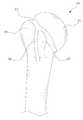
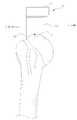
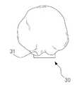
도 1은 일반적인 상완골의 해부학적 형상을 도시한 도면으로, 도 1을 참고하여 설명하면, 근위부 상완골(Proximal Humerus, 80)은 볼록한 형상의 상완골두(Humeral Head, 81)와, 상완골두 넥(Humeral Neck, 83)과, 상완골 상의 돌출된 돌기인 대결절(Greater Tubercle, 85)과 소결절(Lesser Tubercle, 87) 및 상기 대결절(85)과 소결절(87) 사이의 이두근 홈(Bicipital Groove, 89)으로 구분된다. 인공 어깨관절 치환수술은 상기 상완골두(81)를 절개하고 환자에게 맞는 임플란트를 근위부 상완골에 대체 삽입하는 방식으로 이루어진다.Referring to FIG. 1, a
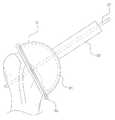
도 2는 종래기술인 환자 맞춤형 숄더 가이드에 관한 도면으로, 이는 미국공개특허공보 US 2011/0054478 A1(2011.03.03)에 개시되어 있다. 도 2에 도시된 내용을 참고하면, 전술한 바와 같이, 인공어깨관절 치환수술을 진행하는 과정에서 상완골(80) 상에 임플란트를 삽입하기에 위해서는 상완골두(81)를 자르는 작업이 필요하게 되는데, 이를 위해 상기 환자 맞춤형 숄더 가이드(90)는, 환자의 상완골두(81)의 형상과 상보적인 형상을 가지는 캡(91)과, 상기 캡(91)으로부터 연장형성된 가이드부(93)와, 상완골두(81)의 컷팅을 가이드 하는 절개부(95)를 포함한다.Figure 2 is a prior art patient-specific shoulder guide, which is disclosed in U.S. Patent Application Publication No. US 2011/0054478 Al (Mar. 3, 2011). Referring to FIG. 2, in order to insert the implant on the
도 2의 환자 맞춤형 숄더 가이드는 상기 캡(91)을 환자의 상완골두(81) 상에 안착시키고 상기 가이드부(93)를 통해 정렬핀(97)을 삽입하여 고정하면서, 상기 절개부(95)의 가이드를 받아 상완골두(81)를 자를 수 있도록 한다.The patient-customized shoulder guide of FIG. 2 places the
이러한 종래기술의 경우, 캡 내측의 결합면이 환자의 상완골두의 외주면과 상보적인 형상을 가지도록 구성되는바, 이론적으로는 환자의 상완골두 표면에 숄더 가이드의 캡(91)이 용이하게 빈틈없이 정확히 안착될 것처럼 보이지만, 실제 수술현장에서는 환자의 혈액과 체액이 낭자하게 되어 환자의 상완골두에 이물질이 묻거나, 반대로 캡(91) 내측의 결합면에 이물질이 묻게 되는 경우가 많아 상완골두의 전체 외주면과 다 맞닿도록 설계된 상기 종래기술과 같은 경우에는, 사전에 계획했던 정확한 위치상에 숄더 가이드를 위치시키기 어렵게 된다.In this conventional technique, the coupling surface on the inside of the cap is configured to have a shape complementary to the outer circumferential surface of the patient's humerus. Theoretically, the
뿐만 아니라 환자의 상완골두와 상보적인 형상의 결합면을 갖는 캡(91) 내측을 구성하기 위해 환자의 상완골을 3차원 스캐닝 등을 통해 그 형상데이터를 얻고 컴퓨터 작업 등을 거쳐 상기 결합면을 형성하더라도, 실제 수술현장에서는 수술의가 환자의 어깨 부분의 피부를 절개하고, 상완골을 감싸는 근육, 인대, 힘줄 등을 제거하면서 수술을 진행하기 때문에, 상완골두 표면에 예기치 않은 이물질, 조직 등이 제거되지 않은채 남아 있거나 묻어 있을 가능성이 있다.In addition, in order to construct the inside of the
그렇기 때문에 상완골두 전체를 덮는 캡(91)을 구성하고 상기 캡 내측에 정교한 결합면을 형성하더라도, 실제 수술을 진행하는 과정에서 상기 숄더 가이드를 사전에 계획했던 정확한 위치상에 안착시키는 것은 어려울수 밖에 없다.Therefore, even though the
따라서 관련 업계에서는 근위부 상완골을 수술하는 과정에서, 상완골에 삽입될 가이드핀을 사전에 계획된 정확한 위치상에 용이하게 삽입할 수 있도록 하는 환자 맞춤형 어깨관절 수술기구의 개발을 요구하고 있는 실정에 있다고 하겠다.Therefore, in the related industry, it is required to develop a patient - customized shoulder joint surgical instrument which can easily insert the guide pin to be inserted into the humerus in a predetermined and precisely planned position during the operation of the proximal humerus.
본 발명은 상기와 같은 문제점을 해결하고자 안출된 것으로,SUMMARY OF THE INVENTION The present invention has been made to solve the above problems,
본 발명의 목적은, 상완골두의 해부학적 형상에 상응하는 접촉면을 가지면서 상완골두에 삽입될 핀을 가이드하는 가이드부와, 상기 가이드부로부터 연장형성되어 상완골의 이두근 홈 상에 안착되는 위치설정부를 구성함으로써, 인공 어깨관절 수술을 진행하는 과정에서 환자의 상완골에 사전에 계획된 정확한 지점에, 정확한 방향으로 가이드핀을 용이하게 삽입할 수 있도록 하는, 환자 맞춤형 어깨관절 수술기구를 제공하는 것이다.An object of the present invention is to provide a positioning device which has a guide portion having a contact surface corresponding to an anatomical shape of the humerus and guiding a pin to be inserted into the humerus and a positioning portion extending from the guide portion and resting on the biceps groove of the humerus The present invention provides a patient-customized shoulder-joint surgical instrument that can easily insert the guide pin in a precise and precisely planned position on the patient's humerus in the course of artificial shoulder joint surgery.
본 발명의 다른 목적은, 상기 가이드부는, 상완골두 컷팅 가이드가 안착되는 베이스부와, 상기 베이스부의 하측면으로부터 수직으로 연장형성되어 단부에 상기 접촉면을 형성한 샤프트부를 포함하도록 구성하여, 환자의 상완골두의 외주면 형상과 상보적인 형상을 가지는 샤프트부의 접촉면이 사전에 계획된 해당 위치에 정확히 안착되도록 함으로써 가이드핀을 용이하고 정확하게 삽입할 수 있도록 하며, 베이스부 상에 상완골두 컷팅 가이드가 안착되도록 함으로써 인공 어깨관절 치환수술을 진행하는 과정에서 상완골두를 정확하고 용이하게 자를 수 있도록 하는, 환자 맞춤형 어깨관절 수술기구를 제공하는 것이다.It is a further object of the present invention to provide a medical device in which the guide portion includes a base portion on which a humerus two cutting guides are seated and a shaft portion extending vertically from a lower side surface of the base portion and having the contact surface formed at an end thereof, The contact surface of the shaft portion having a shape complementary to the shape of the outer circumference of the two is accurately seated at the corresponding planned position beforehand so that the guide pin can be inserted easily and accurately and the cutting guide of the humerus is seated on the base portion, And to provide a patient-customized shoulder joint surgical instrument which can accurately and easily cut the humeral head during the course of joint replacement surgery.
본 발명의 또 다른 목적은, 상기 접촉면은, 상완골두의 접촉하는 부위의 해부학적 형상에 상보적인 형상을 가지도록 구성하여, 인공 어깨관절 수술을 진행하는 과정에서 환자의 상완골에 사전에 계획된 정확한 지점에, 정확한 방향으로 가이드핀을 용이하게 삽입할 수 있도록 하는, 환자 맞춤형 어깨관절 수술기구를 제공하는 것이다.It is a further object of the present invention to provide a method and a device for constructing an abutment surface in which the contact surface has a shape complementary to an anatomical shape of a contact portion of the humeral head, In which the guide pin can be easily inserted in the correct direction.
본 발명의 또 다른 목적은, 상기 접촉면은, 상기 상완골두의 정점을 커버하도록 형성하여, 수술과정에서 수술의가 상완골두의 정위치에 안착시키면서 파지하고 있는 환자 맞춤형 어깨관절 수술기구가 상완골두를 따라 미끄러지는 등의 문제가 방지되는, 환자 맞춤형 어깨관절 수술기구를 제공하는 것이다.It is a further object of the present invention to provide a method and a device for a patient-customized shoulder-joint surgical instrument that is configured to cover the apex of the humerus, The present invention is to provide a patient-customized shoulder-joint surgical instrument in which problems such as slippage are prevented.
본 발명의 또 다른 목적은, 상기 가이드부의 접촉면은, 상완골의 외측에서 상완골의 내측 방향으로 상완골두를 덮는 형상을 가지도록 구성하여, 위치설정부를 이두근홈 상에 끼워 대략적인 위치를 잡고 상대적으로 외측에 위치한 이두근홈으로부터 내측방향으로 가이드부의 접촉면을 통해 상완골두를 덮는 방식으로 환자 맞춤형 어깨관절 수술기구를 환자의 골면 상에 안착시킴으로써, 최소 침습을 이유로 좁은 절개 부위를 통해 수술을 진행하는 과정에서 수술의의 시야를 방해하는 것 없이, 사전에 계획된 지점 상에 수술기구를 용이하게 위치 설정할 수 있도록 하는, 환자 맞춤형 어깨관절 수술기구를 제공하는 것이다.It is a further object of the present invention to provide a guiding portion of a guiding structure in which a contact surface of the guide portion is configured to have a shape covering the humeral head from the outside of the humerus in an inward direction of the humerus, The patient is placed on the bony surface of the patient's shoulder joint in a manner that covers the humeral head through the contact surface of the guide portion from the biceps groove in the biceps groove on the side of the biceps and the operation is performed through the narrow incision site due to minimal invasion. Which allows a surgical instrument to be easily positioned on a previously planned point without interfering with the field of view of the patient.
본 발명의 또 다른 목적은, 상기 가이드부의 접촉면은, ML길이가 AP길이보다 길게 형성되도록 구성하여, 만일 AP길이가 길어지게 되면, 상기 가이드부의 전체적인 부피가 커지게 되고, 과도하게 큰 가이드부로 인해 수술의의 파지가 어려움은 물론, 이러한 가이드부에 결합될 상완골두 컷팅 가이드가 환자의 뼈로부터 보다 더 멀어지게 되어 상완골두를 컷팅할 때 원거리에서 상완골두를 자르는 작업을 수행하게 됨으로써 정확한 컷팅은 더욱 어려울 수 있는 문제를, 상대적으로 상기 가이드부의 접촉면 가운데 AP길이를 줄임으로써 수술의의 시야 확보와 작업공간확보가 가능해져 수술의 편의성은 더욱 높아진, 환자 맞춤형 어깨관절 수술기구를 제공하는 것이다.It is a further object of the present invention to provide a contact surface of the guide portion having a longer ML length than the AP length. If the length of the AP becomes longer, the overall volume of the guide portion becomes larger, In addition to the difficulty of gripping the surgeon, the guide of the humerus two cutting guides to be connected to this guide part is farther away from the bone of the patient, so that the cutting of the humerus head is performed at a distance when cutting the humerus head, The present invention is to provide a patient-customized shoulder joint surgical instrument which has a relatively shortened AP length in the contact surface of the guide portion, thereby securing a field of view of a surgeon and securing a work space, thereby making the operation more convenient.
본 발명의 또 다른 목적은, 상기 위치설정부는, 상완골의 이두근홈 사이에 위치하도록 상기 가이드부로부터 원위방향으로 연장하여, 상기 샤프트부의 접촉면 이외의 부분에서 기구의 정확한 위치설정을 용이하게 도모할 수 있도록 하는, 환자 맞춤형 어깨관절 수술기구를 제공하는 것이다.Yet another object of the present invention is to provide a position setting device which can extend in the distal direction from the guide portion so as to be positioned between the biceps groove of the humerus and can easily set an accurate position of the mechanism in a portion other than the contact surface of the shaft portion And to provide a patient-customized shoulder-joint surgical instrument.
본 발명의 또 다른 목적은, 상기 위치설정부는, 이두근홈의 골면에 상보적인 형상을 가진 접촉면을 가지도록 구성하여, 사전에 계획된 위치상에 기구가 정확히 위치할 수 있도록 하는, 환자 맞춤형 어깨관절 수술기구를 제공하는 것이다.It is a further object of the present invention to provide a positioning apparatus for a patient with a bipedal muscle that is configured to have a contact surface having a complementary shape on the bony surface of the biceps groove, To provide a mechanism.
본 발명의 또 다른 목적은, 상기 위치설정부의 접촉면과 상기 가이드부의 접촉면은, 상완골두 넥의 골면과 상보적인 형상을 가진 연결면에 의해 연속적으로 연결되도록 구성하여, 환자 맞춤형 어깨관절 수술기구가 정해진 위치상에 견고하고 안정적으로 거치 되도록 하는, 환자 맞춤형 어깨관절 수술기구를 제공하는 것이다.It is a further object of the present invention to provide an apparatus and method for constructing a patient-customized shoulder joint surgical instrument, which is configured such that the contact surface of the positioning unit and the contact surface of the guide unit are continuously connected by a connecting surface having a complementary shape to the bony surface of the two- And to be stably and stably mounted on the position.
본 발명의 또 다른 목적은, 상기 베이스부는, 베이스부의 상측면의 외곽을 따라 돌출형성되는 돌출부를 포함하도록 구성하여, 베이스부 상에 안착되는 상완골두 컷팅 가이드가 정해진 위치에서 벗어나 베이스부로부터 이탈하는 문제를 사전에 방지하는, 환자 맞춤형 어깨관절 수술기구를 제공하는 것이다.It is a further object of the present invention to provide a surgical instrument in which the base portion includes a projection protruding along an outer periphery of an upper side of a base portion so that the two humerus cutting guides resting on the base portion are separated from the base portion And to provide a patient-customized shoulder surgery apparatus that prevents problems in advance.
본 발명의 또 다른 목적은, 상기 돌출부는, 상기 상완골두 컷팅 가이드가 끼워져 고정되는 슬롯을 구성하여, 상완골두 컷팅 가이드를 견고하게 고정하고, 고정된 컷팅 가이드가 베이스부 상에서 회전하지 않도록 하는, 환자 맞춤형 어깨관절 수술기구를 제공하는 것이다.It is a further object of the present invention to provide a surgical instrument which comprises a slot in which the two humerus cutting guides are fitted and fixed so as to firmly fix the two humerus cutting guides and prevent the fixed cutting guide from rotating on the base part. And to provide a customized shoulder joint surgical instrument.
본 발명의 또 다른 목적은, 상기 슬롯은, 환자 맞춤형으로 상기 돌출부 상에서 그 위치와 방향이 정해지도록 구성되어, 사람마다 상완골두의 크기가 다르고 그 방향도 조금씩 상이하여 환자마다 상완골두 컷팅면을 결정해야 하는 문제를, 가이드레일이 끼워지는 슬롯을 구성할 때부터 환자 맞춤식으로 슬롯의 위치와 방향을 정해, 수술의가 용의하게 상완골두 컷팅을 수행할 수 있도록 하는, 환자 맞춤형 어깨관절 수술기구를 제공하는 것이다.It is a further object of the present invention to provide a method of determining the position and orientation of a patient in a patient-customized manner on the protruding portion, the size of the humeral head being different for each person, A customized shoulder surgery instrument is provided that allows the user to tailor the position and orientation of the slot in a patient-customized manner from the time the slot is inserted into the guide rail and to perform two cuts of the humerus for surgery. .
본 발명의 또 다른 목적은, 상기 샤프트부는, 상기 베이스부의 하측면으로부터 단차를 형성하도록 축경되어 수직으로 연장형성됨으로써, 수술기구가 전체적으로 비대해지지 않아 수술의의 파지가 용이하도록 하고, 기구의 위치설정에 필요한 크기의 접촉면만이 형성되도록 하면서도 베이스부 상에 안착되는 상완골두 컷팅 가이드가 안정되게 안착되도록 하는, 환자 맞춤형 어깨관절 수술기구를 제공하는 것이다.It is still another object of the present invention to provide a surgical instrument which is vertically extended with a shaft diameter so as to form a step from a lower side of the base portion so that the surgical instrument is not enlarged as a whole, And to provide a patient-customized shoulder-joint surgical instrument that allows only two contact surfaces of a desired size to be formed while allowing the two humerus cutting guides that are seated on the base portion to be stably seated.
본 발명의 또 다른 목적은, 상기 가이드부는, 베이스부의 상측면으로부터 샤프트부의 접촉면까지 수직으로 관통 형성된 가이드홀을 포함하도록 구성하여, 상기 가이드홀을 따라, 수술 전 계획된 위치상에 계획된 방향으로 정확히 가이드핀을 삽입할 수 있도록 하는, 환자 맞춤형 어깨관절 수술기구를 제공하는 것이다.It is a further object of the present invention to provide a guiding structure in which the guide portion includes a guide hole vertically penetrating from an upper surface of a base portion to a contact surface of a shaft portion so as to guide accurately along the guide hole in a planned direction on a pre- Thereby allowing insertion of a pin into the patient's shoulder.
본 발명의 또 다른 목적은, 상기 가이드홀은, 베이스부의 상측면으로부터 일정한 높이까지 수직으로 함입형성된 제1가이드홀과, 상기 제1가이드홀의 단부에서 단차를 형성하도록 내측으로 축경되면서 상기 제1가이드홀과 연통되는 제2가이드홀을 포함하도록 구성하여, 가이드핀이 단차 진 턱에 걸리게 함으로써 계획된 바에 따라 가이드핀의 삽입깊이를 제한할 수 있는, 환자 맞춤형 어깨관절 수술기구를 제공하는 것이다.It is a further object of the present invention to provide a method of manufacturing a semiconductor device, wherein the guide hole includes: a first guide hole vertically penetrated from an upper surface of the base portion to a predetermined height; and a second guide hole formed at the end of the first guide hole, And a second guide hole communicating with the hole so that the guide pin is caught by the stepped jaw so that the depth of insertion of the guide pin can be limited as planned.
본 발명의 또 다른 목적은, 상기 위치설정부는, 외측면에서부터 접촉면까지 관통형성되어 고정핀을 가이드 하는 관통홀을 구성함으로써, 사전에 계획된 위치상에 기구가 위치하게 되면, 해당 정위치에서 기구가 가고정되도록 하는, 환자 맞춤형 어깨관절 수술기구를 제공하는 것이다.It is a further object of the present invention to provide a positioning apparatus for a positioning apparatus, wherein the position setting unit includes a through hole formed to penetrate from an outer surface to a contact surface to guide the fixing pin so that when the mechanism is positioned on a previously planned position, And to provide a patient-customized shoulder-joint surgical instrument.
본 발명의 또 다른 목적은, 상기 관통홀은, 관통홀의 중심축이 가이드홀의 중심축과 만나지 않도록 구성하여, 관통홀을 따라 삽입되는 고정핀이, 가이드홀을 따라 삽입되는 가이드핀과 간섭을 일으키지 않도록 하는, 환자 맞춤형 어깨관절 수술기구를 제공하는 것이다.It is a further object of the present invention to provide a through hole in which the center axis of the through hole is not aligned with the center axis of the guide hole so that the fixing pin inserted along the through hole does not interfere with the guide pin inserted along the guide hole And to provide a patient-customized shoulder-joint surgical instrument.
본 발명의 또 다른 목적은, 상기 관통홀은, 상기 위치설정부 상에 복수 개가 형성되도록 구성하여, 사전에 계획된 위치상에 기구가 위치하게 되면, 해당 정위치에서 기구를 가고정할 때 복수 개의 고정핀을 상완골에 삽입할 수 있도록 함에 따라 상완골에 대한 기구의 가고정력을 더욱 강화시키는, 환자 맞춤형 어깨관절 수술기구를 제공하는 것이다. It is a further object of the present invention to provide a method of manufacturing a semiconductor device in which a plurality of through holes are formed on the positioning portion so that when the mechanism is positioned on a previously planned position, To provide a patient-tailored shoulder-joint surgical instrument that further enhances the tactile force of the instrument relative to the humerus by allowing the pin to be inserted into the humerus.
본 발명은 앞서 본 목적을 달성하기 위해서 다음과 같은 구성을 가진 실시예에 의해서 구현된다.In order to achieve the above object, the present invention is implemented by the following embodiments.
본 발명의 일 실시예에 따르면, 본 발명은, 상완골두의 해부학적 형상에 상응하는 접촉면을 가지면서 상완골두에 삽입될 핀을 가이드하는 가이드부와, 상기 가이드부로부터 연장형성되어 상완골의 이두근 홈 상에 안착되는 위치설정부를 포함하는 것을 특징으로 한다.According to an embodiment of the present invention, the present invention provides a method of manufacturing a humerus comprising a guide portion having a contact surface corresponding to an anatomical shape of the humerus and guiding a pin to be inserted into the humerus, And a position setting unit that is mounted on the base.
본 발명의 다른 실시예에 따르면, 본 발명은, 상기 가이드부는, 상완골두 컷팅 가이드가 안착되는 베이스부와, 상기 베이스부의 하측면으로부터 수직으로 연장형성되어 단부에 상기 접촉면을 형성한 샤프트부를 포함하는 것을 특징으로 한다.According to another embodiment of the present invention, the guide portion includes a base portion on which the two humerus cutting guides are seated, and a shaft portion extending vertically from the lower side of the base portion and having the contact surface formed at the end portion thereof .
본 발명의 또 다른 실시예에 따르면, 본 발명은, 상기 접촉면은, 상완골두의 접촉하는 부위의 해부학적 형상에 상보적인 형상을 가지는 것을 특징으로 한다.According to another embodiment of the present invention, the present invention is characterized in that the contact surface has a shape complementary to an anatomical shape of a portion in contact with the humeral head.
본 발명의 또 다른 실시예에 따르면, 상기 접촉면은, 상기 상완골두의 정점을 커버하도록 형성되는 것을 특징으로 한다.According to another embodiment of the present invention, the contact surface is formed to cover the apex of the humerus.
본 발명의 또 다른 실시예에 따르면, 상기 가이드부의 접촉면은, 상완골의 외측에서 상완골의 내측 방향으로 상완골두를 덮는 형상을 가지는 것을 특징으로 한다.According to another embodiment of the present invention, the contact surface of the guide portion has a shape covering the humeral head from the outside of the humerus toward the medial side of the humerus.
본 발명의 또 다른 실시예에 따르면, 상기 가이드부의 접촉면은, ML길이가 AP길이보다 길게 형성되는 것을 특징으로 한다.According to another embodiment of the present invention, the contact surface of the guide portion is formed such that the ML length is longer than the AP length.
본 발명의 또 다른 실시예에 따르면, 상기 위치설정부는, 상완골의 이두근홈 사이에 위치하도록 상기 가이드부로부터 원위방향으로 연장되는 것을 특징으로 한다.According to another embodiment of the present invention, the positioning portion extends in the distal direction from the guide portion so as to be positioned between the biceps groove of the humerus.
본 발명의 또 다른 실시예에 따르면, 상기 위치설정부는, 이두근홈의 골면에 상보적인 형상을 가진 접촉면을 가지는 것을 특징으로 한다.According to another embodiment of the present invention, the position setting unit has a contact surface having a shape complementary to the bony surface of the biceps groove.
본 발명의 또 다른 실시예에 따르면, 상기 위치설정부의 접촉면과 상기 가이드부의 접촉면은, 상완골두 넥의 골면과 상보적인 형상을 가진 연결면에 의해 연속적으로 연결되는 것을 특징으로 한다.According to another embodiment of the present invention, the contact surface of the positioning portion and the contact surface of the guide portion are continuously connected by a connecting surface having a shape complementary to the bone surface of the humerus double neck.
본 발명의 또 다른 실시예에 따르면, 본 발명은, 상기 베이스부는, 베이스부의 상측면의 외곽을 따라 돌출형성되어 상완골두 컷팅가이드의 이탈을 방지하는 돌출부를 포함하는 것을 특징으로 한다.According to another embodiment of the present invention, the base portion includes protrusions protruding along the outer periphery of the upper surface of the base portion to prevent separation of the two humerus cutting guides.
본 발명의 또 다른 실시예에 따르면, 본 발명은, 상기 돌출부는, 상기 상완골두 컷팅 가이드가 끼워져 고정되는 슬롯을 포함하는 것을 특징으로 한다.According to another embodiment of the present invention, the present invention is characterized in that the protrusion includes a slot in which the two humerus cutting guides are fitted and fixed.
본 발명의 또 다른 실시예에 따르면, 본 발명은, 상기 슬롯은, 환자 맞춤형으로 상기 돌출부 상에서 그 위치와 방향이 정해지는 것을 특징으로 한다.According to another embodiment of the present invention, the present invention is characterized in that the slot is positionally and directionally determined on the protrusion in a patient-customized manner.
본 발명의 또 다른 실시예에 따르면, 본 발명은, 상기 샤프트부는, 상기 베이스부의 하측면으로부터 단차를 형성하도록 축경되어 수직으로 연장형성되는 것을 특징으로 한다.According to another embodiment of the present invention, in the present invention, the shaft portion is formed to be vertically extended with a reduced diameter so as to form a step from a lower side of the base portion.
본 발명의 또 다른 실시예에 따르면, 본 발명은, 상기 가이드부는, 베이스부의 상측면으로부터 샤프트부의 접촉면까지 수직으로 관통 형성된 가이드홀을 포함하는 것을 특징으로 한다.According to another embodiment of the present invention, the guide portion includes a guide hole vertically penetrating from an upper surface of the base portion to a contact surface of the shaft portion.
본 발명의 또 다른 실시예에 따르면, 본 발명은, 상기 가이드홀은, 베이스부의 상측면으로부터 일정한 높이까지 수직으로 함입형성된 제1가이드홀과, 상기 제1가이드홀의 단부에서 단차를 형성하도록 내측으로 축경되면서 상기 제1가이드홀과 연통되는 제2가이드홀을 포함하는 것을 특징으로 한다.According to another embodiment of the present invention, the guide hole includes a first guide hole formed vertically from the upper side of the base portion to a predetermined height, and a second guide hole formed inwardly to form a step at the end of the first guide hole And a second guide hole communicating with the first guide hole while being reduced in diameter.
본 발명의 또 다른 실시예에 따르면, 본 발명은, 상기 위치설정부는, 외측면에서부터 접촉면까지 관통형성되어 고정핀을 가이드 하는 관통홀을 포함하는 것을 특징으로 한다.According to another embodiment of the present invention, the position setting unit includes a through hole formed to penetrate from the outer surface to the contact surface to guide the fixing pin.
본 발명의 또 다른 실시예에 따르면, 본 발명은, 상기 관통홀은, 관통홀의 중심축이 가이드홀의 중심축과 만나지 않는 것을 특징으로 한다.According to another embodiment of the present invention, the through hole is characterized in that the central axis of the through hole does not meet the central axis of the guide hole.
본 발명의 또 다른 실시예에 따르면, 본 발명은, 상기 관통홀은, 상기 위치설정부 상에 복수 개가 형성되는 것을 특징으로 한다.According to another embodiment of the present invention, the present invention is characterized in that a plurality of through holes are formed on the positioning portion.
본 발명은 앞서 본 실시예와 하기에 설명할 구성과 결합, 사용관계에 의해 다음과 같은 효과를 얻을 수 있다.The present invention can obtain the following effects by the above-described embodiment, the constitution described below, the combination, and the use relationship.
본 발명은, 상완골두의 해부학적 형상에 상응하는 접촉면을 가지면서 상완골두에 삽입될 핀을 가이드하는 가이드부와, 상기 가이드부로부터 연장형성되어 상완골의 이두근 홈 상에 안착되는 위치설정부를 구성함으로써, 인공 어깨관절 수술을 진행하는 과정에서 환자의 상완골에 사전에 계획된 정확한 지점에, 정확한 방향으로 가이드핀을 용이하게 삽입할 수 있도록 하는, 환자 맞춤형 어깨관절 수술기구를 제공하는 효과를 가진다.The present invention provides a guiding unit having a contact surface corresponding to an anatomical shape of the humeral head and guiding a pin to be inserted into a humeral head and a positioning unit extending from the guiding unit and resting on a biceps groove of a humerus The present invention provides a patient-customized shoulder-joint surgical instrument that can easily insert a guide pin in a precise and precisely planned position on a patient's humerus in the course of performing artificial shoulder joint surgery.
본 발명은, 상기 가이드부는, 상완골두 컷팅 가이드가 안착되는 베이스부와, 상기 베이스부의 하측면으로부터 수직으로 연장형성되어 단부에 상기 접촉면을 형성한 샤프트부를 포함하도록 구성하여, 환자의 상완골두의 외주면 형상과 상보적인 형상을 가지는 샤프트부의 접촉면이 사전에 계획된 해당 위치에 정확히 안착되도록 함으로써 가이드핀을 용이하고 정확하게 삽입할 수 있도록 하며, 베이스부 상에 상완골두 컷팅 가이드가 안착되도록 함으로써 인공 어깨관절 치환수술을 진행하는 과정에서 상완골두를 정확하고 용이하게 자를 수 있도록 하는, 환자 맞춤형 어깨관절 수술기구를 제공하는 효과를 도출한다.The present invention is characterized in that the guide portion includes a base portion on which the humerus two cutting guides are seated and a shaft portion extending vertically from the lower side surface of the base portion and having the contact surface formed at the end portion, The contact surface of the shaft portion having the shape and complementary shape is accurately seated at the predetermined planned position so that the guide pin can be inserted easily and accurately and the cutting guide of the humerus is seated on the base portion, The user is able to accurately and easily cut the humeral head during the course of the operation of the shoulder joint.
본 발명은, 상기 접촉면은, 상완골두의 접촉하는 부위의 해부학적 형상에 상보적인 형상을 가지도록 구성하여, 인공 어깨관절 수술을 진행하는 과정에서 환자의 상완골에 사전에 계획된 정확한 지점에, 정확한 방향으로 가이드핀을 용이하게 삽입할 수 있도록 하는, 환자 맞춤형 어깨관절 수술기구를 제공하는 효과가 있다.The contact surface is configured to have a shape complementary to the anatomical shape of the contact portion of the humeral head so that the contact surface can be accurately positioned at a precise planned point on the patient's humerus in the process of artificial shoulder joint surgery So that the guide pin can be easily inserted into the shoulder.
본 발명은, 상기 접촉면은, 상기 상완골두의 정점을 커버하도록 형성하여, 수술과정에서 수술의가 상완골두의 정위치에 안착시키면서 파지하고 있는 환자 맞춤형 어깨관절 수술기구가 상완골두를 따라 미끄러지는 등의 문제가 방지되는, 환자 맞춤형 어깨관절 수술기구를 제공하는 효과를 가진다.The contact surface is formed so as to cover the apex of the humerus head so that the patient-customized shoulder joint surgical instrument which is held by the surgeon in a fixed position of the humerus head in the surgical procedure slides along the humerus head The present invention has an effect of providing a patient-customized shoulder-joint surgical instrument in which problems are prevented.
본 발명은, 상기 가이드부의 접촉면은, 상완골의 외측에서 상완골의 내측 방향으로 상완골두를 덮는 형상을 가지도록 구성하여, 위치설정부를 이두근홈 상에 끼워 대략적인 위치를 잡고 상대적으로 외측에 위치한 이두근홈으로부터 내측방향으로 가이드부의 접촉면을 통해 상완골두를 덮는 방식으로 환자 맞춤형 어깨관절 수술기구를 환자의 골면 상에 안착시킴으로써, 최소 침습을 이유로 좁은 절개 부위를 통해 수술을 진행하는 과정에서 수술의의 시야를 방해하는 것 없이, 사전에 계획된 지점 상에 수술기구를 용이하게 위치 설정할 수 있도록 하는, 환자 맞춤형 어깨관절 수술기구를 제공하는 효과를 도출한다.The present invention is characterized in that the contact surface of the guide portion is configured to have a shape covering the humerus in the medial direction of the humerus from the outside of the humerus and the approximate position of the biceps root groove, By placing the patient-customized shoulder-joint surgical instrument on the patient's bone surface in a manner that covers the humeral head through the contact surface of the guide in the inward direction, thereby obstructing the view of the surgeon during the operation through the narrow incision site due to minimal invasion The need to provide a patient-customized shoulder surgery instrument that allows for easy positioning of the surgical instrument on a pre-planned point,
본 발명은, 상기 가이드부의 접촉면은, ML길이가 AP길이보다 길게 형성되도록 구성하여, 만일 AP길이가 길어지게 되면, 상기 가이드부의 전체적인 부피가 커지게 되고, 과도하게 큰 가이드부로 인해 수술의의 파지가 어려움은 물론, 이러한 가이드부에 결합될 상완골두 컷팅 가이드가 환자의 뼈로부터 보다 더 멀어지게 되어 상완골두를 컷팅할 때 원거리에서 상완골두를 자르는 작업을 수행하게 됨으로써 정확한 컷팅은 더욱 어려울 수 있는 문제를, 상대적으로 상기 가이드부의 접촉면 가운데 AP길이를 줄임으로써 수술의의 시야 확보와 작업공간확보가 가능해져 수술의 편의성은 더욱 높아진, 환자 맞춤형 어깨관절 수술기구를 제공하는 효과가 있다.In the present invention, the contact surface of the guide portion is formed such that the ML length is longer than the AP length. If the AP length becomes longer, the overall volume of the guide portion becomes larger and the grip of the surgeon due to an excessively large guide portion In addition to difficulty, the guide of the humerus two cutting guides to be connected to this guide part is farther away from the patient's bones, and when performing the cutting of the humerus head, it performs the task of cutting the humerus head from a distance, , It is possible to secure the field of view of the surgeon and to secure a work space by reducing the AP length in the contact surface of the guide portion relatively, thereby providing a patient-customized shoulder joint surgical instrument with higher operability.
본 발명은, 상기 위치설정부는, 상완골의 이두근홈 사이에 위치하도록 상기 가이드부로부터 원위방향으로 연장하여, 상기 샤프트부의 접촉면 이외의 부분에서 기구의 정확한 위치설정을 용이하게 도모할 수 있도록 하는, 환자 맞춤형 어깨관절 수술기구를 제공하는 효과를 도출한다.The present invention is characterized in that the position setting section extends in the distal direction from the guide section so as to be positioned between the biceps groove of the humerus so as to facilitate the accurate positioning of the instrument at a portion other than the contact surface of the shaft section. Thereby providing an effect of providing a customized shoulder joint surgical instrument.
본 발명은, 상기 위치설정부는, 이두근홈의 골면에 상보적인 형상을 가진 접촉면을 가지도록 구성하여, 사전에 계획된 위치상에 기구가 정확히 위치할 수 있도록 하는, 환자 맞춤형 어깨관절 수술기구를 제공하는 효과가 있다.The present invention provides a patient-customized shoulder joint surgical instrument, wherein the position setting unit is configured to have a contact surface having a complementary shape on the bony surface of the biceps groove, so that the instrument can be accurately positioned on a previously planned position It is effective.
본 발명은, 상기 위치설정부의 접촉면과 상기 가이드부의 접촉면은, 상완골두 넥의 골면과 상보적인 형상을 가진 연결면에 의해 연속적으로 연결되도록 구성하여, 환자 맞춤형 어깨관절 수술기구가 정해진 위치상에 견고하고 안정적으로 거치 되도록 하는, 환자 맞춤형 어깨관절 수술기구를 제공하는 효과를 가진다.The contact surface of the positioning portion and the contact surface of the guide portion are continuously connected by a connecting surface having a complementary shape to the bony surface of the humerus double neck so that the patient- So that a patient-customized shoulder joint operating mechanism can be provided.
본 발명은, 상기 베이스부는, 베이스부의 상측면의 외곽을 따라 돌출형성되는 돌출부를 포함하도록 구성하여, 베이스부 상에 안착되는 상완골두 컷팅 가이드가 정해진 위치에서 벗어나 베이스부로부터 이탈하는 문제를 사전에 방지하는, 환자 맞춤형 어깨관절 수술기구를 제공하는 효과를 가진다.The present invention is characterized in that the base portion includes a protruding portion protruding along the outer periphery of the upper side of the base portion so that the problem that the two humerus cutting guides seated on the base portion depart from the predetermined position and are separated from the base portion, And to provide a patient-customized shoulder-joint surgical instrument.
본 발명은, 상기 돌출부는, 상기 상완골두 컷팅 가이드가 끼워져 고정되는 슬롯을 구성하여, 상완골두 컷팅 가이드를 견고하게 고정하고, 고정된 컷팅 가이드가 베이스부 상에서 회전하지 않도록 하는, 환자 맞춤형 어깨관절 수술기구를 제공하는 효과를 도출한다.The present invention is characterized in that the protruding portion comprises a slot in which the two humerus cutting guides are fitted and fixed so as to firmly fix the humerus two cutting guides and prevent the fixed cutting guide from rotating on the base portion, The effect of providing the mechanism is derived.
본 발명은, 상기 슬롯은, 환자 맞춤형으로 상기 돌출부 상에서 그 위치와 방향이 정해지도록 구성되어, 사람마다 상완골두의 크기가 다르고 그 방향도 조금씩 상이하여 환자마다 상완골두 컷팅면을 결정해야 하는 문제를, 가이드레일이 끼워지는 슬롯을 구성할 때부터 환자 맞춤식으로 슬롯의 위치와 방향을 정해, 수술의가 용의하게 상완골두 컷팅을 수행할 수 있도록 하는, 환자 맞춤형 어깨관절 수술기구를 제공하는 효과가 있다.The present invention is characterized in that the slot is configured such that its position and direction are determined on the protruding portion in a patient-customized manner, and the size of the humeral head is different for each person and the direction is also slightly different, , And the slot position and direction can be determined in a patient-customized manner from the time when the slot in which the guide rail is inserted is set, thereby enabling the operator to perform two cuts of the humerus for the purpose of surgery. .
본 발명은, 상기 샤프트부는, 상기 베이스부의 하측면으로부터 단차를 형성하도록 축경되어 수직으로 연장형성됨으로써, 수술기구가 전체적으로 비대해지지 않아 수술의의 파지가 용이하도록 하고, 기구의 위치설정에 필요한 크기의 접촉면만이 형성되도록 하면서도 베이스부 상에 안착되는 상완골두 컷팅 가이드가 안정되게 안착되도록 하는, 환자 맞춤형 어깨관절 수술기구를 제공하는 효과를 가진다.The present invention is characterized in that the shaft portion is vertically extended to form a step from the lower side of the base portion so that the surgical instrument is not enlarged as a whole so that it is easy to grasp the surgeon's body, The present invention has the effect of providing a patient-customized shoulder-joint surgical instrument that allows only two humerus cutting guides that are seated on the base portion to be stably seated.
본 발명은, 상기 가이드부는, 베이스부의 상측면으로부터 샤프트부의 접촉면까지 수직으로 관통 형성된 가이드홀을 포함하도록 구성하여, 상기 가이드홀을 따라, 수술 전 계획된 위치상에 계획된 방향으로 정확히 가이드핀을 삽입할 수 있도록 하는, 환자 맞춤형 어깨관절 수술기구를 제공하는 효과를 도출한다.The present invention is characterized in that the guide portion includes a guide hole vertically penetrating from the upper side of the base portion to the contact surface of the shaft portion so that the guide pin is inserted exactly along the guide hole in the planned direction on the pre- To provide a patient-tailored shoulder-joint operative device.
본 발명은, 상기 가이드홀은, 베이스부의 상측면으로부터 일정한 높이까지 수직으로 함입형성된 제1가이드홀과, 상기 제1가이드홀의 단부에서 단차를 형성하도록 내측으로 축경되면서 상기 제1가이드홀과 연통되는 제2가이드홀을 포함하도록 구성하여, 가이드핀이 단차 진 턱에 걸리게 함으로써 계획된 바에 따라 가이드핀의 삽입깊이를 제한할 수 있는, 환자 맞춤형 어깨관절 수술기구를 제공하는 효과가 있다.The present invention is characterized in that the guide hole has a first guide hole formed vertically to a predetermined height from an upper side of the base portion and a second guide hole communicated with the first guide hole while being shrunk inward to form a step at the end of the first guide hole And the second guide hole, so that the insertion depth of the guide pin can be limited according to the planned operation by engaging the guide pin with the stepped step, thereby providing a patient-customized shoulder joint surgical instrument.
본 발명은, 상기 위치설정부는, 외측면에서부터 접촉면까지 관통형성되어 고정핀을 가이드 하는 관통홀을 구성함으로써, 사전에 계획된 위치상에 기구가 위치하게 되면, 해당 정위치에서 기구가 가고정되도록 하는, 환자 맞춤형 어깨관절 수술기구를 제공하는 효과를 가진다.According to the present invention, the positioning portion is formed as a through hole that is formed so as to pass from the outer surface to the contact surface to guide the fixing pin, so that when the mechanism is positioned on the previously planned position, the mechanism is fixed , And a patient-customized shoulder joint operating mechanism.
본 발명은, 상기 관통홀은, 관통홀의 중심축이 가이드홀의 중심축과 만나지 않도록 구성하여, 관통홀을 따라 삽입되는 고정핀이, 가이드홀을 따라 삽입되는 가이드핀과 간섭을 일으키지 않도록 하는, 환자 맞춤형 어깨관절 수술기구를 제공하는 효과를 도출한다.The present invention is characterized in that the through hole is formed so that the center axis of the through hole does not meet the center axis of the guide hole so that the fixing pin inserted along the through hole does not interfere with the guide pin inserted along the guide hole Thereby providing an effect of providing a customized shoulder joint surgical instrument.
본 발명은, 상기 관통홀은, 상기 위치설정부 상에 복수 개가 형성되도록 구성하여, 사전에 계획된 위치상에 기구가 위치하게 되면, 해당 정위치에서 기구를 가고정할 때 복수 개의 고정핀을 상완골에 삽입할 수 있도록 함에 따라 상완골에 대한 기구의 가고정력을 더욱 강화시키는, 환자 맞춤형 어깨관절 수술기구를 제공하는 효과가 있다. The present invention is characterized in that a plurality of through holes are formed on the positioning portion so that when the mechanism is positioned on a previously planned position, a plurality of fixing pins are fixed to the humerus The present invention provides a patient-customized shoulder joint surgical instrument which further strengthens the tactile force of the instrument relative to the humerus as it can be inserted.
도 1은 일반적인 상완골의 해부학적 형상을 도시한 도면.
도 2는 종래기술인 환자 맞춤형 숄더 가이드에 관한 도면.
도 3은 본 발명인 환자 맞춤형 어깨관절 수술기구에 관한 사시도.
도 4는 도 3의 평면도.
도 5는 슬롯에 결합된 상완골두 컷팅 가이드에 관한 도면.
도 6은 슬롯에 따라, 상완골두 컷팅 가이드의 결합 방향이 달라지는 것을 도시한 도면.
도 7은 슬롯에 따라, 상완골두 컷팅 가이드의 결합 방향이 달라지는 것을 도시한 도면.
도 8은 도 3의 저면도.
도 9는 상완골두의 정점을 넘어서지 않는 접촉면에 관한 도면.
도 10은 상완골두의 정점을 넘어서는 접촉면에 관한 도면.
도 11은 도 3의 A-A'단면도.
도 12는 환자의 상완골 상에 환자 맞춤형 어깨관절 수술기구를 안착시킨 뒤 가이드 핀을 삽입한 도면.
도 13은 가이드부의 접촉면과, 위치설정부의 접촉면 및 연결면에 관한 도면.
도 14는 가이드부로부터 연장형성되는 위치설정부의 일 실시예에 관한 도면.
도 15는 가이드부로부터 연장형성되는 위치설정부의 다른 실시예에 관한 도면.
도 16은 결절을 덮으면서 이두근 홈에 안착되는 위치설정부에 관한 도면.
도 17은 결절을 덮지않고 이두근 홈에 안착되는 위치설정부에 관한 도면.
도 18은 위치설정부의 관통홀을 도시한 도면.
도 19는 가이드홀의 중심축과 관통홀의 중심축에 관한 도면.
도 20은 본 발명인 환자 맞춤형 어깨관절 수술기구에 관한 사용상태도.
도 21은 본 발명인 환자 맞춤형 어깨관절 수술기구에 관한 사용상태도.1 shows an anatomical shape of a normal humerus;
Figure 2 is a prior art patient-specific shoulder guide.
FIG. 3 is a perspective view of a patient-customized shoulder joint surgical instrument of the present invention. FIG.
Figure 4 is a plan view of Figure 3;
5 is a view of a two-piece humerus guide coupled to a slot;
FIG. 6 is a view showing that the direction in which the humerus two cutting guides are joined is changed according to the slot. FIG.
Fig. 7 is a view showing that the direction in which the humerus two cutting guides are joined is changed according to the slot. Fig.
Fig. 8 is a bottom view of Fig. 3; Fig.
9 is a view of a contact surface that does not exceed the apex of the humeral head;
10 is a view of a contact surface beyond the apex of the humeral head;
11 is a cross-sectional view taken along line A-A 'of FIG. 3;
FIG. 12 is a view showing a patient's customized shoulder joint surgical instrument placed on a humerus of a patient and then inserting a guide pin. FIG.
13 is a view of a contact surface of a guide portion and a contact surface and a connection surface of the positioning portion.
14 is a view of one embodiment of a positioning portion extending from a guide portion;
15 is a view of another embodiment of a positioning portion extending from a guide portion;
16 is a view showing a positioning unit which is placed in the biceps groove while covering the nodule.
Fig. 17 is a view showing a positioning part which is seated in the biceps groove without covering the nodule; Fig.
18 is a view showing a through hole of the position setting portion;
19 is a view showing the center axis of the guide hole and the center axis of the through hole.
FIG. 20 is a state of use of the patient-customized shoulder joint apparatus of the present invention. FIG.
FIG. 21 is a use state diagram of a patient-customized shoulder surgery apparatus according to the present invention. FIG.
이하에서는 본 발명에 따른 환자 맞춤형 어깨관절 수술기구의 바람직한 실시 예들을 첨부된 도면을 참조하여 상세히 설명한다. 하기에서 본 발명을 설명함에 있어 공지의 기능 또는 구성에 대한 구체적인 설명이 본 발명의 요지를 불필요하게 흐릴 수 있다고 판단되는 경우에는 그 상세한 설명을 생략하도록 한다. 특별한 정의가 없는 한 본 명세서의 모든 용어는 본 발명이 속하는 기술분야의 통상의 지식을 가진 기술자가 이해하는 당해 용어의 일반적 의미와 동일하고 만약 본 명세서에서 사용된 용어의 의미와 충돌하는 경우에는 본 명세서에서 사용된 정의에 따른다.DETAILED DESCRIPTION OF THE PREFERRED EMBODIMENTS Hereinafter, preferred embodiments of a patient-customized shoulder joint surgical instrument according to the present invention will be described in detail with reference to the accompanying drawings. In the following description, well-known functions or constructions are not described in detail to avoid unnecessarily obscuring the subject matter of the present invention. Unless defined otherwise, all terms used herein are the same as the general meaning of the term understood by those of ordinary skill in the art to which this invention belongs and, if conflict with the meaning of the terms used herein, And the definition used in the specification.
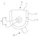
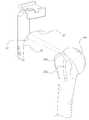
도 3은 본 발명인 환자 맞춤형 어깨관절 수술기구에 관한 사시도로, 도 3을 참고하여 설명하면, 본 발명인 환자 맞춤형 어깨관절 수술기구(1)는, 인공 어깨관절 치환수술을 진행하는 과정에서, 수술의가 사전에 계획된 대로 환자의 상완골두를 컷팅하고 컷팅된 상완골두에 임플란트를 이식하기에 앞서, 상완골두를 컷팅하는데 사용되는 상완골두 컷팅 가이드를 정위치에 안착시키고자, 그 이전 준비작업으로 컷팅 전의 상완골두 상에 가이드핀을 정확한 위치에 정확한 방향으로 삽입하는데에 사용되는 수술기구를 말한다. 이러한 상기 환자 맞춤형 어깨관절 수술기구(1)는 가이드부(10)와, 위치설정부(30)를 포함한다.FIG. 3 is a perspective view of a patient-customized shoulder joint surgical instrument according to the present invention. Referring to FIG. 3, the patient-customized shoulder joint
상기 가이드부(10)는, 상완골두의 해부학적 형상에 상보적인 접촉면(131)을 가지면서 상완골두에 삽입될 핀을 가이드하는 구성을 말한다. 도 3을 참고하여 설명하면, 상기 가이드부(10)는 전체적으로 수직하게 신장된 형태를 가진다. 이러한 가이드부(10)의 수직 높이가 길어질수록, 상기 환자 맞춤형 어깨관절 수술기구(1)에 의해 가이드 되어 환자의 상완골에 삽입되는 가이드핀을 가이드 하는 영역이 커짐에 따라 보다 안정적으로 가이드핀을 가이드할 수 있게 된다. 반면에 가이드부(10)의 수직 높이가 길어지게 되면 환자의 상완골두 상에 상기 가이드부(10)를 안착하였을 때, 안정성이 다소 떨어질 수 있다. 따라서 상기 가이드부(10)의 수직 높이는 가이드핀의 가이드 영역의 관점과 가이드부(10) 안착시 안정성의 측면을 고려하여 정해질 수 있다. 이러한 상기 가이드부(10)는, 베이스부(11), 샤프트부(13), 가이드홀(15)을 포함한다.The
상기 베이스부(11)는, 상완골두 컷팅 가이드가 안착되는 구성을 말한다. 본 발명인 환자 맞춤형 어깨관절 수술기구(1)는 상완골두에 위치설정되어 가이드핀을 수용하게 되고, 상완골에 가이드핀이 삽입되면, 상기 환자 맞춤형 어깨관절 수술기구(1) 상에 상완골두 컷팅 가이드가 상기 가이드핀의 안내를 받으면서 놓여 지게 된다. 여기서 상완골두 컷팅 가이드란, 상완골의 상완골두를 컷팅하는 수술기구를 총칭하는 것으로, 환자 맞춤형 수술기구(1)에 안착 되어 고정됨으로써 상완골두의 절개를 가이드 할 수 있는 공지된 또는 공지될 모든 구성을 의미한다고 할 것이다. 이러한 상기 베이스부(11)는, 돌출부(111)를 포함한다.The
상기 돌출부(111)는, 베이스부(11)의 상측면의 외곽을 따라 돌출형성되어 상완골두 컷팅가이드의 이탈을 방지하는 구성을 말한다. 즉, 상기 돌출부(111)는 도 3 및 도 4에 도시된 바와 같이, 상기 상완골두 컷팅 가이드가 안착될 베이스부(11)의 상측면의 외주 형상에 따라 소정의 높이만큼 돌출형성된 턱을 가리킨다. 도 3 및 도 4에 도시된 내용에 따르면, 상기 돌출부(111)가 일정한 높이의 턱으로 도시된 것을 알 수 있으나, 본 발명의 상기 돌출부(111)는 반드시 이러한 개념으로 한정되는 것은 아니며, 베이스부(11)의 상측면 외곽을 따라 턱을 형성하되, 그 돌출된 정도를 구역마다 다르게 지정할 수 있는 등 다양한 모든 개념을 포함할 수 있다. 이러한 상기 돌출부(111)는, 슬롯(111a)을 포함한다.The
상기 슬롯(111a)은, 상기 상완골두 컷팅 가이드가 끼워져 고정되는 부분을 말한다. 상기 돌출부(111)가 구성됨으로써 베이스부(11) 상측면에 안착된 상완골두 컷팅 가이드의 이탈은 어느 정도 방지될 수 있겠으나, 상기 돌출부(111)에 감싸진 내부 공간에서 상기 상완골두 컷팅 가이드가 회전하는 문제 등이 유발될 수 있다. 따라서 상기 돌출부(111) 상에는 비-턱영역인 상기 슬롯(111a)이 구성됨으로써, 상완골두의 컷팅 가이드의 일부가 상기 슬롯(111a)에 끼워져 고정될 수 있으며, 이로써 상기 슬롯(111a)에 의해 상완골두 컷팅 가이드의 회전 등은 방지될 수 있다.The
도 5는 슬롯에 결합된 상완골두 컷팅 가이드에 관한 도면이다. 도 5를 참고하여 설명하면, 일반적인 상완골두 컷팅 가이드(HC)에는, 도시된 바와 같이, 가이드레일(L)을 따라 이동하는 컷팅기구(C)가 포함될 수 있다. 바람직하게는 상기 슬롯(111a) 상에는 상기 상완골두 컷팅 가이드(HC)의 가이드레일(L)이 끼워져 결합되는데, 상기 슬롯(111a)에 상기 가이드레일(L)이 정확히 결합되기 위해서는 상기 가이드레일(L) 단면의 높이와 폭에 상보적인 크기를 가지는 슬롯(111a)이 형성되어야 함은 물론이거니와, 무엇보다도 상기 슬롯(111a)의 위치와 방향이 고려될 필요가 있다.Figure 5 is a diagram of a two-humped cut guide coupled to a slot. Referring to FIG. 5, a general humerus two cutting guide HC may include a cutting mechanism C that moves along a guide rail L, as shown in FIG. Preferably, the guide rails L of the two humerus cutting guides HC are fitted on the
도 6 및 도 7은 슬롯에 따라 상완골두 컷팅 가이드의 결합 방향이 달라지는 것을 도시한 도면이다. 이하에서는 도 6 및 도 7을 참고하여 설명하도록 하겠다.FIGS. 6 and 7 are views showing that the direction of joining of the humerus two cutting guides is changed according to the slot. Hereinafter, a description will be made with reference to FIG. 6 and FIG.
상기 슬롯(111a)은 상완골두 컷팅 가이드(HC)의 가이드레일(L)이 끼워져 고정되는 부분인바, 상기 슬롯(111a)이 상기 돌출부(111) 상의 어느 위치에 어느 방향을 따라 형성됐는지는, 상기 가이드레일(L)의 방향을 결정하는 요소가 될 수 있다. 이는 결국 상기 가이드레일(L)에 결합하게 되는 컷팅기구(C)의 위치에 영향을 줄 수 있다. 따라서 상기 슬롯(111a)의 위치와 방향은 상완골두 컷팅면을 결정하는 중요한 기준이 된다고 하겠다. 사람마다 상완골두의 크기가 다르고 그 방향도 조금씩 상이할 수 있기 때문에, 상완골두 컷팅면을 결정하는 것은 환자마다 달라질 수밖에 없고, 수술의는 환자에 따라 컷팅면을 조절할 필요가 있기에, 상기 가이드레일(L)이 끼워지는 상기 슬롯(111a)의 위치, 방향 등 역시 컷팅면을 고려하여 환자 맞춤형으로 구성될 필요가 있다.The
상기 샤프트부(13)는, 상기 베이스부(11)의 하측면으로부터 수직으로 연장형성되어 단부에 접촉면(131)을 형성한 구성을 말한다. 전술한 바와 같이, 상기 가이드부(10)의 상측은 상기 베이스부(11)가 형성되어 상완골두 컷팅 가이드를 지지하고, 상기 가이드부(10)의 하측은 상기 베이스부(11)로부터 연장형성된 샤프트부(13)가 구성됨으로써, 환자 맞춤형 수술기구(1)를 통해 삽입된 가이드핀이 보다 넓은 범위에서 상기 가이드부(10)의 가이드를 받을 수 있도록 한다. 이러한 샤프트부(13)의 형상과 관련하여, 이를 특정한 개념으로 한정하는 것은 아니지만, 바람직하게는 상기 샤프트부(13)는, 상기 베이스부(11)의 하측면으로부터 단차를 형성하도록 축경되어 수직으로 연장형성될 수 있다. 인공 어깨관절 수술은 환자의 피와 체액이 낭자하는 환경에서 이루어지는데, 이러한 환경 하에서 사용되는 환자 맞춤형 어깨관절 수술기구(1)의 부피가 지나치게 클 경우에는 수술의의 파지가 쉽지 않게 된다. 이러한 문제는 수술과정에서 수술기구(1)에 환자의 피나 체액이 묻는 경우 더욱 심각해 질 수밖에 없다. 따라서 상기 가이드부(10)를 구성할 때, 상기 베이스부(11)의 크기는 상기 베이스부(11)가 상완골두 컷팅 가이드를 지지 및 고정하는 구성이라는 점에서 그 크기를 줄이는 것이 제한적일 수밖에 없으나, 상기 샤프트부(13)는 접촉면(131)에 의해 사전에 계획된 지점에 환자 맞춤형 수술기구(1)가 위치하도록 하고, 내측에 마련된 가이드홀에 의해 가이드핀을 가이드하는 기능을 하는바, 상기 샤프트부(13)의 크기를 보다 작게 할 수 있다.The
또한 환자 맞춤형 수술기구(1)를 구성할 때, 환자의 뼈와 직접적으로 접촉하는 접촉면(131)의 크기를 늘릴 경우, 환자의 뼈와 접촉면(131)이 조금이라도 어긋나게 되면 제대로 된 결합 자체가 불가능하게 된다. 따라서 환자 맞춤형으로 구성된 접촉면(131)의 크기를 무조건 늘리기보다는, 정확한 위치 설정의 기능은 발현할 수 있으면서, 그 크기를 최소화하는 것이 중요할 수 있다. 그렇기 때문에 상기 샤프트부(13)를 베이스부(11)의 하측면의 크기 그대로 수직하게 연장형성 할 수도 있겠으나, 정확한 위치 설정이 가능한 범위라면, 그 크기를 단차를 형성하도록 축경시켜 연장형성함이 바람직하다.Further, when the size of the
상기 접촉면(131)은, 샤프트부(13)의 단부면으로 환자의 상완골두와 접하는 부분을 가리킨다. 도 8을 참고하여 설명하면, 상기 접촉면(131)은 환자의 상완골두의 외주면과 상보적인 형상을 갖도록 구성된다. 이를 위해 수술 전 환자의 상완골두를 3차원 스캐닝하여 뼈의 형상 데이터를 획득하게 되고, 모델링 작업과 3D 프린팅 기술 등을 사용함으로써, 환자의 상완골두와 상보적인 형상을 가지는 환자 맞춤형 어깨관절 수술기구(1)를 제작할 수 있다.The
상기 가이드부(10)의 접촉면(131)은, 바람직하게는 상완골의 외측에서 상완골의 내측 방향으로 상완골두를 덮는 형상을 가지도록 구성될 수 있다. 이를 위해, 상기 접촉면(131)은 도 8에 도시된 바와 같이, ML길이(Medial-Lateral)가 AP길이(Anterior-Posterior)보다 길게 형성됨이 보다 바람직하다.The
인공어깨관절 치환수술은 환자의 어깨 부위의 피부를 절개하고 절개된 틈으로 환자의 상완골을 노출시켜 수술을 진행하게 된다. 이때 수술의는 환자의 상완골 전측(Anterior)을 바라보면 시술하게 되며, 대부분의 수술기구들이 수술의의 시야가 확보되는 전측에 놓이게 되는바, 상완골 전측 공간의 확보는 무엇보다 중요하다고 할 것이다. 만일 상완골 전측 공간이 확보되지 못한 채 수술이 진행되면, 환자 맞춤형 어깨관절 수술기구(1)로 수술부위가 가려지거나 수술공간이 좁아져 수술과정에서 수술기구들 간의 간섭현상이 발생할 수 있다. 그러므로, 수술의의 시야 및 수술공간 확보 측면에서 상기 가이드부(10)의 접촉면(131) 중 AP길이를 줄이는 것이 바람직하다.Artificial shoulder joint replacement surgery is performed by exposing the patient 's humerus through the incision in the shoulder area of the patient' s shoulder. At this time, the surgeon will perform the operation according to the patient's anterior view of the humerus, and most of the surgical instruments will be placed in the front of the surgeon's field of view. If surgery is performed without securing anterior space of the humerus, patient-customized shoulder joint surgery (1) may obscure the operation site or narrow the operative space and cause interference between surgical instruments during the operation. Therefore, it is desirable to reduce the AP length among the contact surfaces 131 of the
또한 만일 AP길이가 길어지게 되면, 상기 가이드부(10)의 전체적인 부피가 커지게 되고, 과도하게 큰 가이드부(10)로 인해 수술의의 파지가 어려움은 물론, 이러한 가이드부(10)에 결합될 상완골두 컷팅 가이드가 환자의 뼈로부터 보다 더 멀어지게 되어 상완골두를 컷팅할 때 원거리에서 상완골두를 자르는 작업을 수행하게 됨으로써, 정확한 컷팅은 더욱 어려울 수 있다.In addition, if the length of the AP becomes long, the entire volume of the
따라서 상대적으로 상기 가이드부(10)의 접촉면(131) 가운데 AP길이를 줄임으로써 수술의의 시야확보와 작업공간확보가 가능해져 수술의 편의성은 더욱 높아지게 된다.Therefore, by relatively reducing the AP length in the
도 9는 상완골두의 정점을 넘어서지 않는 접촉면에 관한 도면이고, 도 10은 상완골두의 정점(P)을 넘어서는 접촉면에 관한 도면으로, 상기 접촉면(131)을 구성할 때, 가이드핀이 삽입될 위치를 고려해야함은 물론 이거니와, 상기 가이드부(10)의 안정성을 높이기 위해 상기 접촉면(131)의 구성을 다르게 할 수 있다. 상완골을 수직으로 세웠을 때, 상완골두의 맨 꼭대기인 정점(P)을 기준으로, 상기 접촉면(131)이 상기 정점(P)을 넘어서지 않도록 구성되는 도 8과 같은 실시예에서는 곡률을 가진 상완골두를 따라 환자 맞춤형 어깨관절 수술기구(1)가 미끄러질 가능성이 더 높다.FIG. 9 is a view of a contact surface that does not exceed the apex of the humerus, and FIG. 10 is a view of a contact surface that exceeds the apex P of the humerus. When constructing the
반면에, 상기 접촉면(131)이 상기 정점(P)을 넘어서도록 구성되는 도 9와 같은 실시예의 경우 상완골두의 정점(P)을 상기 접촉면(131)이 감싸게 되는바, 수술과정에서 수술의가 상완골두의 정위치에 안착시키면서 파지하고 있는 환자 맞춤형 어깨관절 수술기구(1)가 상완골두를 따라 미끄러지는 등의 문제를 미연에 방지할 수 있다. 따라서 상기 접촉면(131)은 상완골두의 안정적 파지의 측면에서 상완골두의 정점(P)을 넘어서면서 상기 정점을 덮도록 구성됨이 바람직하다.9 in which the
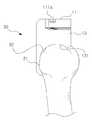
상기 가이드홀(15)은, 베이스부(11)의 상측면으로부터 샤프트부(13)의 접촉면(131)까지 수직으로 관통 형성된 구성을 말한다. 도 11은 도 3의 A-A'단면도로, 도 6을 참고하여 설명하면, 상기 가이드홀(15)은, 베이스부(11)와 샤프트부(13)로 이루어진 가이드부(10) 상에 수직으로 관통 형성된 구멍으로 볼 수 있다. 이러한 상기 가이드홀(15)을 통하여, 상기 가이드핀은 가이드홀(15)의 안내를 받으면서, 상완골 내측으로 삽입될 수 있게 된다. 이러한 가이드홀(15)은 제1가이드홀(151)과, 제2가이드홀(153)을 포함한다.The
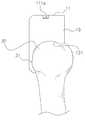
상기 제1가이드홀(151)은, 베이스부(11)의 상측면으로부터 일정한 높이까지 수직으로 함입형성된 구성을 말한다. 상기 가이드핀은 상완골에 삽입되는 부분의 직경이 삽입의 용이성과 상완골에 과도하게 큰 구멍을 만들지 않기 위한 목적으로 상대적으로 작게 구성될 수 있고, 그 이외 부분의 직경은 상기 상완골두 컷팅 가이드의 지지 등을 이유로 상대적으로 크게 구성될 수 있다. 따라서 상기 가이드홀(15)은, 상대적인 직경 차이가 발생하는 가이드핀의 외형과 상보적인 형태로 구성됨으로써, 상기 가이드핀의 삽입 깊이 등을 제한할 수 있어야 한다. 이를 위해 상기 제1가이드홀(151)은 베이스부(11)의 상측면으로부터 소정의 높이까지 그대로 함입되어, 구간별로 크기가 차이가 있는 가이드핀이 걸리지 않고 통과될 수 있는 크기를 가지도록 구성될 수 있다.The
상기 제2가이드홀(153)은, 상기 제1가이드홀(151)의 단부에서 단차를 형성하도록 내측으로 축경되면서 상기 제1가이드홀(151)과 연통되는 구성을 말한다. 전술한 바와 같이, 상기 가이드핀은 상완골에 삽입되는 부분의 직경이 상대적으로 작게 구성될 수 있는바, 해당 부분만이 상완골에 삽입될 수 있도록 가이드핀의 삽입을 제한하는 수단이 필요하게 된다. 이를 위해 상기 제1가이드홀(151)의 크기보다 작은 크기를 가지는 상기 제2가이드홀(153)을 구성함으로써, 상대적으로 직경이 작은 가이드핀의 부분은 상기 제2가이드홀(153)을 통과할 수 있도록 하되, 상대적으로 직경이 큰 가이드핀의 부분은 단차진 부분에 걸릴 수 있도록 함이 바람직하다. 이를 통해 사전에 계획된 깊이 만큼으로 상기 가이드핀이 상완골에 삽입되도록 할 수 있다.The
도 12는 환자의 상완골 상에 환자 맞춤형 어깨관절 수술기구를 안착시킨 뒤 가이드 핀을 삽입한 도면으로, 도 12에 도시된 바와 같이, 부분적으로 직경의 차이가 있는 가이드핀(GP)이 환자의 상완골(H)에 삽입될 때, 가이드핀(GP)이 삽입되는 깊이가 제한할 수 있도록 상기 환자 맞춤형 어깨관절 수술기구(1) 상에는 상기 제1가이드홀(151)과 상기 제2가이드홀(153)이 구성되고, 도 12의 B-B' 단면을 참고하면 상기 제1가이드홀(151)과 상기 제2가이드홀(153)의 경계에 상기 가이드핀(GP)이 걸리게 됨을 알 수 있다.FIG. 12 is a view showing a state in which a guide pin is inserted after placing a patient-customized shoulder joint surgical instrument on a patient's humerus, and as shown in FIG. 12, a guide pin GP having a partially- The
상기 위치설정부(30)는, 상기 가이드부(10)로부터 원위방향으로 연장형성되어 상완골의 이두근 홈 상에 안착되는 구성을 말한다. 전술한 바와 같이, 환자의 상완골은 상완골 넥을 기준으로 상측에 상완골두가 존재하게 되고, 그 하측에는 돌출된 돌기인 대결절과 소결절이 존재하며, 상기 대결절과 소결절 사이에는 이두근 홈이 위치한다. 상기 위치설정부(30)는 상기 이두근 홈에 안착되도록 설계된 구성인바, 상기 접촉면(131)과 상보적인 형상을 가지는 상완골두의 특정 부분을 찾는데 어려움이 있을 수 있는 문제를, 상기 위치설정부(30)를 상완골 상에서 확연히 도드라진 이두근 홈에 안착시키는 작업을 통해 자연스럽게 환자 맞춤형 어깨관절 수술기구(1)의 정위치를 용이하게 찾을 수 있게 한다. 이를 위해, 상기 위치설정부(30)는, 위치설정부(30)의 접촉면(31)이 이두근 홈의 외주면과 상보적인 형상을 가지도록 구성될 수 있다.The
상기 위치설정부(30)의 접촉면(31)과, 상기 가이드부(10)의 접촉면(131)은 상완골두 넥의 골면과 상보적인 형상을 가진 연결면(32)에 의해 연속적으로 연결될 수 있다.The
도 13은 가이드부의 접촉면과, 위치설정부의 접촉면 및 연결면에 관한 도면으로, 이하에서는 도 13을 참고하여 설명하도록 한다. 도 13에 도시된 바와 같이, 상기 가이드부(10)의 접촉면(131)은 상완골두(Humeral Head, HH) 상에 안착되는 부분을 말한다. 반면에 상기 위치설정부(30)의 접촉면(31)은, 상완골의 이두근홈(Bicipital Groove, BG) 상에 안착되는 부분이며, 상기 위치설정부(30)의 연결면(32)은 상완골의 넥상(Humeral Neck, HN)에 안착되는 부분을 말한다.Fig. 13 is a view of the contact surface of the guide portion and the contact surface and the connection surface of the positioning portion, and will be described with reference to Fig. 13 below. As shown in FIG. 13, the
상기 연결면(32)에 의해 상기 가이드부(10)의 접촉면(131)은 상기 위치설정부(30)의 접촉면(31)과 연속적으로 연결될 수 있다. 만일 상기 위치설정부(30)의 접촉면(31)이 상기 가이드부(10)의 접촉면(131)과 불연속적으로 연결될 경우, 불연속적 부분이 환자의 상완골과 접촉하지 않기 때문에, 환자 맞춤형 어깨관절 수술기구(1)를 환자의 상완골 상에 안착시킬 때, 해당 부분만큼 안정성이 떨어질 수 있다. 따라서 상기 가이드부(10)의 접촉면(131)과 상기 위치설정부(30)의 접촉면(31)을 연속적으로 구성하는 것을 통해 환자 맞춤형 어깨관절 수술기구(1)가 정해진 위치상에 견고하고 안정적으로 거치 되도록 할 수 있다.The
환자의 해부학적 특성에 따라 상기 위치설정부(30)의 접촉면(31)은 상대적으로 상완골의 외측에 위치하게 되는데, 상기 가이드부(10)의 접촉면(131)을 상대적으로 외측에 위치한 위치설정부(30)의 접촉면(31)으로부터 상완골의 내측방향으로 상완골두를 덮도록 구성함으로써, 최소 침습을 이유로 좁은 절개 부위를 통해 수술을 진행하는 과정에서 수술의가 용이하게 환자 맞춤형 어깨관절 수술기구를 상완골 상의 정확한 위치에 안착시킬 수 있다.The
도 14는 가이드부로부터 연장형성되는 위치설정부의 일 실시예에 관한 도면이고, 도 15는 가이드부로부터 연장형성되는 위치설정부의 다른 실시예에 관한 도면이다.FIG. 14 is a view of an embodiment of a positioning portion extending from a guide portion, and FIG. 15 is a view showing another embodiment of a positioning portion extending from the guide portion.
상기 가이드부(10)로부터 연장형성되는 상기 위치설정부(30)를 구성하는 방법과 관련하여, 도 14는 별도의 구분없이, 상기 가이드부(10)로부터 상완골두를 감싸 내려오듯 자연스럽게 위치설정부(30)를 구성한 특징이 있고, 도 15는 별도의 구분을 통해, 상기 가이드부(10)는 상완골두 상의 정위치에 안착이 되고, 상기 가이드부(10)의 측면상에 이두근 홈에 끼워지는 별도의 위치설정부(30)를 구분하여 구성한 특징이 있다.Referring to the method of constructing the
도 14의 경우, 상기 가이드부(10)로부터 자연스럽게 연장형성되는 위치설정부(30)를 구성하다 보니, 장치가 비대해지는 문제와 함께, 환자의 상완골의 외주와 접하게 되는 면적이 늘어나게 되면서, 해당 면적을 모두 환자 맞춤형으로 구성해야하는 문제가 생긴다.In the case of FIG. 14, when the
반면에 도 15의 경우, 상기 가이드부(10)의 접촉면(131)만을 환자 맞춤형으로 구성하고, 상기 가이드부(10)의 측면에 별도의 위치설정부(30)를 구성하되, 상기 위치설정부(30)의 접촉면만을 환자 맞춤형으로 별도 구성하면 되는바, 도 14의 실시예에 비해 장치가 슬림해지며, 환자의 상완골의 외주와 접하게 되는 면적도 다소 줄어들게 되는바, 환자 맞춤형으로 구성해야 하는 부분의 면적이 감소하는 효과를 거둘수 있다.On the other hand, in the case of FIG. 15, only the
이는 환자의 상완골 형상을 3D 스캐닝한 뒤, 모델링 작업을 거쳐, 3D 프린팅 기술 등으로 제품구현을 할 때, 도 14의 경우 제품 전체를 한번에 작업해야 하지만, 도 15의 경우 제품을 가이드부(10)와 위치설정부(30)의 구성으로 나누어 작업이 가능한 용이점도 있고, 또한 도 14의 실시예에 비해 도 15의 실시예의 환자 맞춤형 어깨관절 수술기구(1)가 보다 용이한 파지가 가능할 수 있다.In the case of FIG. 14, the entire product must be operated at a time. However, in the case of FIG. 15, when the product is guided by the
따라서 상기 위치설정부(30)는 도 15에 도시된 바와 같이 상기 가이드부(10)와 구분되어 연장형성됨이 보다 바람직할 수 있다.Therefore, it is preferable that the
도 16은 결절을 덮으면서 이두근 홈에 안착되는 위치설정부에 관한 도면이고, 도 17은 결절을 덮지않고 이두근 홈에 안착되는 위치설정부에 관한 도면이다.Fig. 16 is a view of a positioning part which is seated in a biceps groove while covering a nodule, and Fig. 17 is a view of a positioning part which is seated in a biceps groove without covering the nodule.
전술한 바와 같이 상기 위치설정부(30)는 환자의 이두근 홈 상에 안착되는 구성인데, 도 16 및 도 17 모두 상기 위치설정부(30)가 이두근 홈에 모두 안착된다는 점에서는 동일하다.As described above, the
하지만, 도 16의 경우, 위치설정부(30)의 접촉면이 대결절과 소결절을 덮으면서 이두근 홈에 안착이 되는바, 접촉면(31)이 넓어지게 되면서 환자 맞춤형으로 구성되는 면적의 넓이가 과도하게 넓어지게 된다.However, in the case of FIG. 16, since the contact surface of the
반면에, 도 17의 경우, 위치설정부(30)가 대결절과 소결절을 덮지 않으면서 이두근 홈에 끼워지는 크기를 가지기 때문에, 환자의 골 형상과 상보적인 형상을 가지는 접촉면(31)은 좁게 구성이 된다.On the other hand, in the case of FIG. 17, since the
환자의 골 외주면과 맞닿는 위치설정부(30)의 접촉면(31) 면적이 넓을수록 안정적 파지가 가능해질 수는 있겠으나, 이러한 접촉면(31)이나 상기 접촉면(31)과 접하게 될 환자의 골 상에는 환자의 혈액, 체액, 이물질 등이 묻게 될 확률이 높아지게 되어, 상기 위치설정부(30)를 통한 정확한 위치설정은 보다 어려워질 수 있다.Stable gripping may be possible as the area of the
따라서 바람직하게는 상기 위치설정부(30)는 도 17에 도시된 바와 같이, 대결절과 소결절을 덮지 않으면서 이두근 홈 상에 끼워지는 크기를 가지도록 구성할 수 있다.Therefore, as shown in FIG. 17, the
상기 위치설정부(30)의 접촉면(31) 형상은 수술 전 환자의 이두근 홈부를 3차원 스캐닝하여 뼈의 형상 데이터를 획득하게 되고, 모델링 작업과 3D 프린팅 기술 등을 사용함으로써, 환자의 이두근 홈부와 상보적인 형상을 가지는 위치설정부(30)를 구성할 수 있게 된다. 따라서 접촉면은 이두근 홈의 표면에 매장되어 위치설정부를 통한 견고한 지지를 가능하게 한다. 이러한 상기 위치설정부(30)는 관통홀(33)을 포함한다.The shape of the
도 18은 위치설정부의 관통홀을 도시한 도면으로, 상기 관통홀(33)은, 위치설정부(30)의 외측면에서부터 내측의 접촉면(31)까지 관통형성되어 고정핀을 가이드 하는 구성을 말한다. 이러한 상기 관통홀(33)은 상기 위치설정부(30) 상에 복수 개가 형성될 수 있다. 상기 위치설정부(30)를 이두근 홈에 안착시키는 과정과, 상기 가이드부(10)의 접촉면(131)에 대응되는 상완골두의 특정 지점을 찾는 과정을 통해 상기 환자 맞춤형 어깨관절 수술기구(1)는 정위치에 위치설정이 될 것인데, 정위치에 위치설정된 수술기구(1)가 외력에 의해 해당 위치를 이탈할 위험이 있으므로, 이를 움직이지 않도록 가고정하고자, 상기 위치설정부(30)의 외측면에서 접촉면을 관통하는 상기 관통홀(33)을 구성함으로써, 상기 관통홀(33)을 통해 고정핀을 삽입하게 된다. 상기 위치설정부(30) 상에 복수 개의 관통홀(33)을 구성한다면, 각각의 관통홀(33)에 고정핀을 삽입할 수 있게 되어, 더욱 강한 고정력의 확보가 가능해진다.18 is a view showing a through hole of the position setting portion and the through
도 19는 가이드홀의 중심축과 관통홀의 중심축에 관한 도면이다. 도 19를 참고하여 설명하면, 바람직하게는 상기 관통홀(33)은, 관통홀(33)의 중심축(AF1, AF2)이 가이드홀(15)의 중심축(AG)과 만나지 않도록 구성될 수 있다. 상기 가이드홀(15)을 통해 삽입되는 상기 가이드핀(GP)이 상완골의 종방향으로 삽입되는 구성이라면, 상기 관통홀(33)을 통해 삽입되는 고정핀(FP)은 횡방향으로 삽입되는 구성인바, 상기 가이드핀(GP)과 상기 고정핀(FP)이 간섭을 일으킬 우려가 생긴다. 이러한 문제를 방지하기 위해, 상기 관통홀(33)의 중심축(AF1, AF2)은 상기 가이드홀(15)의 중심축(AG1)과 만나지 않도록 구성됨이 바람직할 것이다.19 is a diagram showing the center axis of the guide hole and the center axis of the through hole. 19, it is preferable that the through-
또한 도 19에 도시된 바와 같이, 관통홀(33)을 복수 개로 구성할 경우, 복수의 관통홀(33) 중심축이 평행하는 경우보다, 도 19에 도시된 바와 같이 복수의 관통홀(33) 중심축(AF1, AF2)이 엇갈리도록 구성하는 것이, 고정력 확보 측면에서 용이할 수 있다. 본 발명은 이러한 모든 실시예를 포함한다.19, when a plurality of through
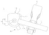
도 20 및 도 21은 본 발명인 환자 맞춤형 어깨관절 수술기구에 관한 사용상태도이다. 이하에서는 도 20 및 도 21을 참고하여 설명하도록 하겠다.FIGS. 20 and 21 are usage states of the patient-customized shoulder surgery apparatus of the present invention. Hereinafter, a description will be made with reference to FIG. 20 and FIG.
도 20에 도시된 바와 같이, 환자의 상완골에 가이드핀을 삽입하는 과정에서 본 발명인 환자 맞춤형 어깨관절 수술기구(1)가 사용될 수 있다. 전술한 바와 같이 환자 맞춤형 어깨관절 수술기구(1)에는 환자의 상완골두의 특정 지점과 상보적인 형상을 가지는 접촉면(131)이 형성되고, 환자의 이두근 홈과 상보적인 형상을 가지는 접촉면(31)을 포함한 위치설정부(30)가 형성이 되는바, 상기 접촉면(131)과 위치설정부(30)를 통해, 사전에 계획된 위치상에 상기 환자 맞춤형 어깨관절 수술기구(1)를 안착시키게 된다. 이때까지 수술의는 환자 맞춤형 어깨관절 수술기구(1)를 손으로 파지한 상태에 있고, 환자 맞춤형 어깨관절 수술기구(1)의 가이드부(10)가 단차를 형성하며 베이스부(11)와 샤프트부(13)로 구분되어 비대해 지지 않도록 형성됨으로써, 수술의는 보다 용이하게 환자 맞춤형 어깨관절 수술기구(1)를 파지할 수 있다.As shown in FIG. 20, the patient-customized shoulder joint
정위치에 환자 맞춤형 어깨관절 수술기구(1)가 안착이 되면, 수술의는 상기 가이드홀(15)을 통해 가이드핀(GP)을 삽입한다. 상기 가이드핀(GP)에 의해 환자 맞춤형 어깨관절 수술기구(1)의 고정 및 상완골두 컷팅 가이드(HC)의 위치설정이 가능해지는 것은 물론이거니와, 상기 가이드핀(GP)에 의해 환자의 상완골 상에는 홀이 생기게 되며, 이러한 홀은 상완골두를 컷팅한 후에도 상완골 상에 남아 있게 되어, 상완골 내측으로 임플란트 보철물의 스템(Stem)을 삽입하기 위한 리밍 작업을 수행할때, 리밍의 기준 홀 역할을 하게 된다.When the patient-customized shoulder joint
수술의는 상기 위치설정부(30)에 형성된 관통홀(33)을 통해 고정핀(FP)을 삽입함으로써, 환자 맞춤형 어깨관절 수술기구(1)를 고정하게 된다. 이때 상기 가이드홀(15)의 중심축과 상기 관통홀(33)의 중심축은 서로 만나지 않도록 구성되는바, 간섭현상이 발생하지 않는다.The surgeon fixes the patient-customized shoulder-joint
이후 수술의는 상기 가이드핀(GP)의 안내를 받으면서 상완골두 컷팅 가이드(HC)를 베이스부(11)의 상면에 안착시키게 되고, 상기 베이스부(11) 상에는 돌출부(111)와 비-턱영역인 슬롯(111a)이 마련되어 상완골두 컷팅 가이드(HC)의 이탈 및 회전을 방지해 고정하게 된다.The surgeon places the humerus two cutting guides HC on the upper surface of the
여기까지의 작업이 마무리되면, 수술의는 상완골두 컷팅 가이드(HC)를 조절하면서 상완골두의 절개 위치를 설정하게 되고, 위치 설정이 마무리되면, 도 21에 도시된 바와 같이, 고정핀(FP)에 의해 고정된 컷팅기구(C)만 남겨 놓은 채 컷팅기구(C)의 안내를 받으면서 상완골두를 절개하는 작업을 수행한다.When the operation up to this point is completed, the surgeon sets the cutting position of the humerus head while adjusting the humerus two cutting guides (HC). When the positioning is completed, as shown in Fig. 21, The operation of cutting the humeral head is performed while receiving the guidance of the cutting mechanism C while leaving only the cutting mechanism C fixed by the cutting mechanism C. [
이상의 상세한 설명은 본 발명을 예시하는 것이다. 또한, 전술한 내용은 본 발명의 바람직한 실시 형태를 나타내어 설명하는 것이며, 본 발명은 다양한 다른 조합, 변경 및 환경에서 사용할 수 있다. 즉 본 명세서에 개시된 발명의 개념의 범위, 저술한 개시 내용과 균등한 범위 및/또는 당업계의 기술 또는 지식의 범위내에서 변경 또는 수정이 가능하다. 저술한 실시예는 본 발명의 기술적 사상을 구현하기 위한 최선의 상태를 설명하는 것이며, 본 발명의 구체적인 적용 분야 및 용도에서 요구되는 다양한 변경도 가능하다. 따라서 이상의 발명의 상세한 설명은 개시된 실시 상태로 본 발명을 제한하려는 의도가 아니다. 또한 첨부된 청구범위는 다른 실시 상태도 포함하는 것으로 해석되어야 한다.The foregoing detailed description is illustrative of the present invention. In addition, the foregoing is intended to illustrate and explain the preferred embodiments of the present invention, and the present invention may be used in various other combinations, modifications and environments. That is, it is possible to make changes or modifications within the scope of the concept of the invention disclosed in this specification, within the scope of the disclosure, and / or within the skill and knowledge of the art. The embodiments described herein are intended to illustrate the best mode for implementing the technical idea of the present invention and various modifications required for specific applications and uses of the present invention are also possible. Accordingly, the detailed description of the invention is not intended to limit the invention to the disclosed embodiments. It is also to be understood that the appended claims are intended to cover such other embodiments.
1: 환자 맞춤형 어깨관절 수술기구
10: 가이드부11: 베이스부
111: 돌출부111a: 슬롯
13: 샤프트부131: 접촉면
15: 가이드홀151: 제1가이드홀
153: 제2가이드홀30: 위치설정부
31: 접촉면32: 연결면
33: 관통홀1: Patient-tailored shoulder surgery instrument
10: guide portion 11: base portion
111: projecting
13: shaft portion 131: contact surface
15: guide hole 151: first guide hole
153: second guide hole 30: position setting section
31: contact surface 32: connection surface
33: Through hole
Claims (16)
Translated fromKoreanPriority Applications (1)
| Application Number | Priority Date | Filing Date | Title |
|---|---|---|---|
| KR1020170094212AKR102053600B1 (en) | 2017-07-25 | 2017-07-25 | Patient-Specific Artificial Shoulder Joint Surgical Instruments |
Applications Claiming Priority (1)
| Application Number | Priority Date | Filing Date | Title |
|---|---|---|---|
| KR1020170094212AKR102053600B1 (en) | 2017-07-25 | 2017-07-25 | Patient-Specific Artificial Shoulder Joint Surgical Instruments |
Publications (2)
| Publication Number | Publication Date |
|---|---|
| KR20190011859Atrue KR20190011859A (en) | 2019-02-08 |
| KR102053600B1 KR102053600B1 (en) | 2019-12-11 |
Family
ID=65365195
Family Applications (1)
| Application Number | Title | Priority Date | Filing Date |
|---|---|---|---|
| KR1020170094212AActiveKR102053600B1 (en) | 2017-07-25 | 2017-07-25 | Patient-Specific Artificial Shoulder Joint Surgical Instruments |
Country Status (1)
| Country | Link |
|---|---|
| KR (1) | KR102053600B1 (en) |
Citations (7)
| Publication number | Priority date | Publication date | Assignee | Title |
|---|---|---|---|---|
| US5021055A (en)* | 1990-09-19 | 1991-06-04 | Intermedics Orthopedics, Inc. | Patellar clamp and surgical saw guide |
| US5129907A (en)* | 1990-12-10 | 1992-07-14 | Zimmer, Inc. | Patellar clamp and reamer with adjustable stop |
| JP2008541914A (en)* | 2005-06-03 | 2008-11-27 | デピュイ・アイルランド・リミテッド | Instrument for use in joint replacement |
| KR20120132468A (en)* | 2009-11-18 | 2012-12-05 | 바이오멧 유케이 리미티드 | A Drill Guide |
| KR20150058525A (en)* | 2006-02-08 | 2015-05-28 | 지. 린 라스무쎈 | Guide assembly for guiding cuts to a femur and tibia during a knee arthroplasty |
| WO2015099275A1 (en)* | 2013-12-24 | 2015-07-02 | 주식회사 코렌텍 | Patient-customized surgical instrument for tibia and surgical module using same |
| KR101779920B1 (en)* | 2016-03-29 | 2017-09-21 | 주식회사 코렌텍 | Tibial resection guide combination assembly |
- 2017
- 2017-07-25KRKR1020170094212Apatent/KR102053600B1/enactiveActive
Patent Citations (8)
| Publication number | Priority date | Publication date | Assignee | Title |
|---|---|---|---|---|
| US5021055A (en)* | 1990-09-19 | 1991-06-04 | Intermedics Orthopedics, Inc. | Patellar clamp and surgical saw guide |
| US5129907A (en)* | 1990-12-10 | 1992-07-14 | Zimmer, Inc. | Patellar clamp and reamer with adjustable stop |
| JP2008541914A (en)* | 2005-06-03 | 2008-11-27 | デピュイ・アイルランド・リミテッド | Instrument for use in joint replacement |
| KR20150058525A (en)* | 2006-02-08 | 2015-05-28 | 지. 린 라스무쎈 | Guide assembly for guiding cuts to a femur and tibia during a knee arthroplasty |
| KR20120132468A (en)* | 2009-11-18 | 2012-12-05 | 바이오멧 유케이 리미티드 | A Drill Guide |
| WO2015099275A1 (en)* | 2013-12-24 | 2015-07-02 | 주식회사 코렌텍 | Patient-customized surgical instrument for tibia and surgical module using same |
| KR101779920B1 (en)* | 2016-03-29 | 2017-09-21 | 주식회사 코렌텍 | Tibial resection guide combination assembly |
| WO2017171378A2 (en)* | 2016-03-29 | 2017-10-05 | 주식회사 코렌텍 | Tibia cutting guide coupling assembly |
Also Published As
| Publication number | Publication date |
|---|---|
| KR102053600B1 (en) | 2019-12-11 |
Similar Documents
| Publication | Publication Date | Title |
|---|---|---|
| US20210315593A1 (en) | Patient specific instruments and methods for joint prosthesis | |
| EP2613718B1 (en) | Positioning apparatus for a prosthetic implant | |
| US12193943B2 (en) | Guides and instruments for improving accuracy of glenoid implant placement | |
| US20200046381A1 (en) | Patient-specific glenoid guides | |
| US20080027451A1 (en) | Method and apparatus for preparing a glenoid surface | |
| US20130110116A1 (en) | Patient-specific glenoid guides | |
| KR20110134415A (en) | Systems, methods and apparatus for placing the femoral neck guide wire | |
| KR101863741B1 (en) | Patient-Specific Artificial Shoulder Joint Surgical Instruments | |
| KR20190011859A (en) | Patient-Specific Artificial Shoulder Joint Surgical Instruments | |
| US9462967B2 (en) | Condyle axis locator | |
| KR102713935B1 (en) | Humeral Stem with Enhanced Rotational Stability |
Legal Events
| Date | Code | Title | Description |
|---|---|---|---|
| A201 | Request for examination | ||
| PA0109 | Patent application | Patent event code:PA01091R01D Comment text:Patent Application Patent event date:20170725 | |
| PA0201 | Request for examination | ||
| E902 | Notification of reason for refusal | ||
| PE0902 | Notice of grounds for rejection | Comment text:Notification of reason for refusal Patent event date:20181123 Patent event code:PE09021S01D | |
| PG1501 | Laying open of application | ||
| E90F | Notification of reason for final refusal | ||
| PE0902 | Notice of grounds for rejection | Comment text:Final Notice of Reason for Refusal Patent event date:20190403 Patent event code:PE09021S02D | |
| E701 | Decision to grant or registration of patent right | ||
| PE0701 | Decision of registration | Patent event code:PE07011S01D Comment text:Decision to Grant Registration Patent event date:20191013 | |
| GRNT | Written decision to grant | ||
| PR0701 | Registration of establishment | Comment text:Registration of Establishment Patent event date:20191203 Patent event code:PR07011E01D | |
| PR1002 | Payment of registration fee | Payment date:20191204 End annual number:3 Start annual number:1 | |
| PG1601 | Publication of registration | ||
| PR1001 | Payment of annual fee | Payment date:20221011 Start annual number:4 End annual number:4 | |
| PR1001 | Payment of annual fee | Payment date:20241015 Start annual number:6 End annual number:6 |