KR20180138544A - Exposure apparatus, and method of manufacturing article - Google Patents
Exposure apparatus, and method of manufacturing articleDownload PDFInfo
- Publication number
- KR20180138544A KR20180138544AKR1020180070702AKR20180070702AKR20180138544AKR 20180138544 AKR20180138544 AKR 20180138544AKR 1020180070702 AKR1020180070702 AKR 1020180070702AKR 20180070702 AKR20180070702 AKR 20180070702AKR 20180138544 AKR20180138544 AKR 20180138544A
- Authority
- KR
- South Korea
- Prior art keywords
- substrate
- height direction
- stage
- measured value
- shot area
- Prior art date
- Legal status (The legal status is an assumption and is not a legal conclusion. Google has not performed a legal analysis and makes no representation as to the accuracy of the status listed.)
- Granted
Links
- 238000004519manufacturing processMethods0.000titleclaimsdescription10
- 239000000758substrateSubstances0.000claimsabstractdescription320
- 238000005259measurementMethods0.000claimsabstractdescription191
- 238000000034methodMethods0.000claimsdescription27
- 230000001133accelerationEffects0.000claimsdescription13
- 238000006073displacement reactionMethods0.000claims1
- 230000003287optical effectEffects0.000description44
- 230000008569processEffects0.000description14
- 238000010586diagramMethods0.000description8
- 238000006243chemical reactionMethods0.000description7
- 238000005286illuminationMethods0.000description7
- 238000012937correctionMethods0.000description5
- 230000000873masking effectEffects0.000description3
- 238000012545processingMethods0.000description3
- 230000008859changeEffects0.000description2
- 239000003795chemical substances by applicationSubstances0.000description2
- 230000002950deficientEffects0.000description2
- 230000008021depositionEffects0.000description2
- 238000009826distributionMethods0.000description2
- 230000006870functionEffects0.000description2
- 238000009434installationMethods0.000description2
- 230000004043responsivenessEffects0.000description2
- 239000004065semiconductorSubstances0.000description2
- 238000007493shaping processMethods0.000description2
- 238000012935AveragingMethods0.000description1
- 238000007796conventional methodMethods0.000description1
- 230000007423decreaseEffects0.000description1
- 238000005530etchingMethods0.000description1
- 238000005304joiningMethods0.000description1
- 239000004973liquid crystal related substanceSubstances0.000description1
- 238000012986modificationMethods0.000description1
- 230000004048modificationEffects0.000description1
- 230000003647oxidationEffects0.000description1
- 238000007254oxidation reactionMethods0.000description1
- 238000004806packaging method and processMethods0.000description1
- 238000000206photolithographyMethods0.000description1
- 239000002574poisonSubstances0.000description1
- 231100000614poisonToxicity0.000description1
- 230000009467reductionEffects0.000description1
- 230000035945sensitivityEffects0.000description1
- 238000003860storageMethods0.000description1
Images


Classifications
- G—PHYSICS
- G03—PHOTOGRAPHY; CINEMATOGRAPHY; ANALOGOUS TECHNIQUES USING WAVES OTHER THAN OPTICAL WAVES; ELECTROGRAPHY; HOLOGRAPHY
- G03F—PHOTOMECHANICAL PRODUCTION OF TEXTURED OR PATTERNED SURFACES, e.g. FOR PRINTING, FOR PROCESSING OF SEMICONDUCTOR DEVICES; MATERIALS THEREFOR; ORIGINALS THEREFOR; APPARATUS SPECIALLY ADAPTED THEREFOR
- G03F7/00—Photomechanical, e.g. photolithographic, production of textured or patterned surfaces, e.g. printing surfaces; Materials therefor, e.g. comprising photoresists; Apparatus specially adapted therefor
- G03F7/20—Exposure; Apparatus therefor
- G—PHYSICS
- G03—PHOTOGRAPHY; CINEMATOGRAPHY; ANALOGOUS TECHNIQUES USING WAVES OTHER THAN OPTICAL WAVES; ELECTROGRAPHY; HOLOGRAPHY
- G03F—PHOTOMECHANICAL PRODUCTION OF TEXTURED OR PATTERNED SURFACES, e.g. FOR PRINTING, FOR PROCESSING OF SEMICONDUCTOR DEVICES; MATERIALS THEREFOR; ORIGINALS THEREFOR; APPARATUS SPECIALLY ADAPTED THEREFOR
- G03F7/00—Photomechanical, e.g. photolithographic, production of textured or patterned surfaces, e.g. printing surfaces; Materials therefor, e.g. comprising photoresists; Apparatus specially adapted therefor
- G03F7/70—Microphotolithographic exposure; Apparatus therefor
- G03F7/70691—Handling of masks or workpieces
- G03F7/70716—Stages
- G03F7/70725—Stages control
- G—PHYSICS
- G03—PHOTOGRAPHY; CINEMATOGRAPHY; ANALOGOUS TECHNIQUES USING WAVES OTHER THAN OPTICAL WAVES; ELECTROGRAPHY; HOLOGRAPHY
- G03F—PHOTOMECHANICAL PRODUCTION OF TEXTURED OR PATTERNED SURFACES, e.g. FOR PRINTING, FOR PROCESSING OF SEMICONDUCTOR DEVICES; MATERIALS THEREFOR; ORIGINALS THEREFOR; APPARATUS SPECIALLY ADAPTED THEREFOR
- G03F7/00—Photomechanical, e.g. photolithographic, production of textured or patterned surfaces, e.g. printing surfaces; Materials therefor, e.g. comprising photoresists; Apparatus specially adapted therefor
- G03F7/70—Microphotolithographic exposure; Apparatus therefor
- G03F7/70483—Information management; Active and passive control; Testing; Wafer monitoring, e.g. pattern monitoring
- G03F7/70605—Workpiece metrology
- G03F7/706835—Metrology information management or control
- G03F7/706837—Data analysis, e.g. filtering, weighting, flyer removal, fingerprints or root cause analysis
- G—PHYSICS
- G03—PHOTOGRAPHY; CINEMATOGRAPHY; ANALOGOUS TECHNIQUES USING WAVES OTHER THAN OPTICAL WAVES; ELECTROGRAPHY; HOLOGRAPHY
- G03F—PHOTOMECHANICAL PRODUCTION OF TEXTURED OR PATTERNED SURFACES, e.g. FOR PRINTING, FOR PROCESSING OF SEMICONDUCTOR DEVICES; MATERIALS THEREFOR; ORIGINALS THEREFOR; APPARATUS SPECIALLY ADAPTED THEREFOR
- G03F7/00—Photomechanical, e.g. photolithographic, production of textured or patterned surfaces, e.g. printing surfaces; Materials therefor, e.g. comprising photoresists; Apparatus specially adapted therefor
- G03F7/70—Microphotolithographic exposure; Apparatus therefor
- G03F7/70483—Information management; Active and passive control; Testing; Wafer monitoring, e.g. pattern monitoring
- G03F7/70605—Workpiece metrology
- G03F7/706843—Metrology apparatus
- G03F7/706845—Calibration, e.g. tool-to-tool calibration, beam alignment, spot position or focus
- G—PHYSICS
- G03—PHOTOGRAPHY; CINEMATOGRAPHY; ANALOGOUS TECHNIQUES USING WAVES OTHER THAN OPTICAL WAVES; ELECTROGRAPHY; HOLOGRAPHY
- G03F—PHOTOMECHANICAL PRODUCTION OF TEXTURED OR PATTERNED SURFACES, e.g. FOR PRINTING, FOR PROCESSING OF SEMICONDUCTOR DEVICES; MATERIALS THEREFOR; ORIGINALS THEREFOR; APPARATUS SPECIALLY ADAPTED THEREFOR
- G03F7/00—Photomechanical, e.g. photolithographic, production of textured or patterned surfaces, e.g. printing surfaces; Materials therefor, e.g. comprising photoresists; Apparatus specially adapted therefor
- G03F7/70—Microphotolithographic exposure; Apparatus therefor
- G03F7/70691—Handling of masks or workpieces
- G03F7/70716—Stages
- G—PHYSICS
- G03—PHOTOGRAPHY; CINEMATOGRAPHY; ANALOGOUS TECHNIQUES USING WAVES OTHER THAN OPTICAL WAVES; ELECTROGRAPHY; HOLOGRAPHY
- G03F—PHOTOMECHANICAL PRODUCTION OF TEXTURED OR PATTERNED SURFACES, e.g. FOR PRINTING, FOR PROCESSING OF SEMICONDUCTOR DEVICES; MATERIALS THEREFOR; ORIGINALS THEREFOR; APPARATUS SPECIALLY ADAPTED THEREFOR
- G03F7/00—Photomechanical, e.g. photolithographic, production of textured or patterned surfaces, e.g. printing surfaces; Materials therefor, e.g. comprising photoresists; Apparatus specially adapted therefor
- G03F7/70—Microphotolithographic exposure; Apparatus therefor
- G03F7/70691—Handling of masks or workpieces
- G03F7/70758—Drive means, e.g. actuators, motors for long- or short-stroke modules or fine or coarse driving
- G—PHYSICS
- G03—PHOTOGRAPHY; CINEMATOGRAPHY; ANALOGOUS TECHNIQUES USING WAVES OTHER THAN OPTICAL WAVES; ELECTROGRAPHY; HOLOGRAPHY
- G03F—PHOTOMECHANICAL PRODUCTION OF TEXTURED OR PATTERNED SURFACES, e.g. FOR PRINTING, FOR PROCESSING OF SEMICONDUCTOR DEVICES; MATERIALS THEREFOR; ORIGINALS THEREFOR; APPARATUS SPECIALLY ADAPTED THEREFOR
- G03F7/00—Photomechanical, e.g. photolithographic, production of textured or patterned surfaces, e.g. printing surfaces; Materials therefor, e.g. comprising photoresists; Apparatus specially adapted therefor
- G03F7/70—Microphotolithographic exposure; Apparatus therefor
- G03F7/70691—Handling of masks or workpieces
- G03F7/70775—Position control, e.g. interferometers or encoders for determining the stage position
- G—PHYSICS
- G03—PHOTOGRAPHY; CINEMATOGRAPHY; ANALOGOUS TECHNIQUES USING WAVES OTHER THAN OPTICAL WAVES; ELECTROGRAPHY; HOLOGRAPHY
- G03F—PHOTOMECHANICAL PRODUCTION OF TEXTURED OR PATTERNED SURFACES, e.g. FOR PRINTING, FOR PROCESSING OF SEMICONDUCTOR DEVICES; MATERIALS THEREFOR; ORIGINALS THEREFOR; APPARATUS SPECIALLY ADAPTED THEREFOR
- G03F7/00—Photomechanical, e.g. photolithographic, production of textured or patterned surfaces, e.g. printing surfaces; Materials therefor, e.g. comprising photoresists; Apparatus specially adapted therefor
- G03F7/70—Microphotolithographic exposure; Apparatus therefor
- G03F7/708—Construction of apparatus, e.g. environment aspects, hygiene aspects or materials
- G03F7/70808—Construction details, e.g. housing, load-lock, seals or windows for passing light in or out of apparatus
- G03F7/70825—Mounting of individual elements, e.g. mounts, holders or supports
Landscapes
- Physics & Mathematics (AREA)
- General Physics & Mathematics (AREA)
- Engineering & Computer Science (AREA)
- Health & Medical Sciences (AREA)
- Environmental & Geological Engineering (AREA)
- Epidemiology (AREA)
- Public Health (AREA)
- Data Mining & Analysis (AREA)
- Exposure And Positioning Against Photoresist Photosensitive Materials (AREA)
- Container, Conveyance, Adherence, Positioning, Of Wafer (AREA)
Abstract
Description
Translated fromKorean본 발명은, 노광 장치 및 물품의 제조 방법에 관한 것이다.The present invention relates to an exposure apparatus and a method of manufacturing an article.
포토리소그래피 기술을 사용하여 반도체 디바이스 등을 제조할 때에, 마스크와 기판을 주사하면서 마스크의 패턴을 기판에 전사하는 스텝·앤드·스캔 방식의 노광 장치(스캐너)가 사용되고 있다. 이러한 노광 장치에 있어서, 기판 스테이지에 보유지지된 기판의 표면 위치(높이 방향의 위치)를 계측하는 계측부를 복수 설치하는 것이 일본 특허 공개 제2014-143429호 공보에 제안되어 있다. 일본 특허 공개 제2014-143429호 공보에는, 노광 슬릿의 투영 위치에서 주사 방향에 대하여 떨어진 위치를 계측하는 제1 계측부(선독 센서)와, 노광 슬릿의 투영 위치에서 제1 계측부보다도 더욱 떨어진 위치를 계측하는 제2 계측부(선선독 센서)를 갖는 노광 장치가 개시되어 있다.An exposure apparatus (scanner) of a step-and-scan type is used in which, when a semiconductor device or the like is manufactured by using a photolithography technique, the pattern of the mask is transferred onto the substrate while scanning the mask and the substrate. In such an exposure apparatus, Japanese Unexamined Patent Application Publication No. 2014-143429 proposes to provide a plurality of measuring units for measuring the surface position (position in the height direction) of the substrate held on the substrate stage. Japanese Patent Laid-Open Publication No. 2014-143429 discloses a projection exposure apparatus that includes a first measurement unit (a pre-reading sensor) for measuring a position away from the projection direction at the projection position of the exposure slit, a second measurement unit (Linear poison sensor) for detecting the position of the second measuring unit.
또한, 주사 노광에 있어서의 기판의 노광 대상 영역의 최적 노광 위치로의 매칭은, 제2 계측부의 계측 결과에 기초하여 기판 스테이지를 구동하는 제1 구동과, 제1 계측부의 계측 결과에 기초하여 기판 스테이지를 구동하는 제2 구동에 의해 행하여지고 있다. 여기서, 최적 노광 위치란, 적절한 높이 방향의 위치이고, 노광 슬릿(상면)의 베스트 포커스 위치 및 당해 베스트 포커스 위치에 대하여 허용 초점 심도의 범위 내의 위치이다.The matching of the exposure target area of the substrate with the optimum exposure position in the scanning exposure can be achieved by the first drive for driving the substrate stage on the basis of the measurement result of the second measurement part and the second drive for driving the substrate stage based on the measurement result of the first measurement part. And a second drive for driving the stage. Here, the optimum exposure position is a position in a suitable height direction, and is a position within a range of the best focus position of the exposure slit (upper surface) and the best focus position within the allowable depth of focus.
또한, 기판 스테이지에 보유지지된 기판의 표면 위치를 계측하는 계측부로서, 시간 평균형 센서를 사용하는 기술이 일본 특허 공개 제2003-254710호 공보에 제안되어 있다. 일본 특허 공개 제2003-254710호 공보에서는, 기판 스테이지에 보유지지된 기판의 표면 위치의 계측에 있어서, 주사 노광에 있어서의 주사 속도에 따라서 시간 평균형 센서에 의한 계측 개시 시각 및 계측 종료 시각을 조정함으로써, 계측 대상이 되는 기판의 표면 위치의 영역을 일정하게 유지하고 있다.Further, Japanese Patent Laid-Open No. 2003-254710 proposes a technique of using a time-averaged sensor as a measuring unit for measuring the surface position of a substrate held on a substrate stage. Japanese Patent Application Laid-Open No. 2003-254710 discloses a technique of adjusting the measurement start time and the measurement end time by the time-averaging sensor in accordance with the scanning speed in scanning exposure in the measurement of the surface position of the substrate held on the substrate stage Whereby the area of the surface position of the substrate to be measured is kept constant.
노광 장치의 생산성을 향상시키기 위해서, 주사 노광 시의 기판 스테이지의 주사 속도를 빠르게 하여 노광에 요하는 시간을 짧게 하는 것이 생각된다. 이 경우, 기판의 표면 위치의 계측으로부터 기판의 노광을 개시할 때까지의 시간이 짧아지기 때문에, 기판의 노광 대상 영역의 최적 노광 위치로의 매칭에 요하는 시간을 짧게 할 필요가 있다.In order to improve the productivity of the exposure apparatus, it is conceivable to increase the scanning speed of the substrate stage at the time of scanning exposure to shorten the time required for exposure. In this case, since the time from the measurement of the surface position of the substrate to the start of exposure of the substrate is shortened, it is necessary to shorten the time required for matching the exposure target area of the substrate to the optimum exposure position.
주사 노광에 있어서의 기판 스테이지의 주사 속도가 빨라진 경우에도, 계측 대상이 되는 기판의 표면 위치의 영역을 일정하게 유지하기 위해서는, 주사 속도와, 주사 거리와, 주사 시간과의 관계로부터, 기판의 표면 위치의 계측에 요하는 시간을 짧게 할 필요가 있다. 그러나, 기판의 표면 위치의 계측에 요하는 시간을 짧게 하면, S/N비가 저하되고, 기판의 노광 대상 영역의 최적 노광 위치로의 매칭에 오차를 일으키는 요인이 된다.In order to keep the area of the surface position of the substrate to be measured constant even when the scanning speed of the substrate stage in the scanning exposure is increased, It is necessary to shorten the time required for the measurement of the position. However, if the time required for measuring the surface position of the substrate is shortened, the S / N ratio is lowered, which causes an error in the matching of the exposure target area of the substrate to the optimum exposure position.
본 발명은, 기판 스테이지의 기판 높이 방향으로의 구동의 제어에 유리한 노광 장치를 제공한다.The present invention provides an exposure apparatus advantageous for controlling the driving of the substrate stage in the height direction of the substrate.
본 발명의 일측면으로서의 노광 장치는, 마스크와 기판을 이동시키면서 상기 기판을 노광함으로써 상기 기판 상에 패턴을 전사하는 노광 장치이며, 상기 기판을 보유지지하여 이동시키는 스테이지와, 상기 스테이지를 제어하는 제어부와, 상기 스테이지에 보유지지된 상기 기판의 샷 영역이 상기 샷 영역에 대한 노광이 행해지는 노광 영역에 도달하기 전에, 상기 샷 영역의 높이 방향의 위치를 계측하는 제1 계측부와, 상기 제1 계측부에 앞서 상기 샷 영역의 상기 높이 방향의 위치를 계측하는 제2 계측부를 갖고, 상기 제어부는, 상기 제2 계측부에서 상기 샷 영역의 상기 높이 방향의 위치를 계측하여 얻어지는 제1 계측값에 기초하여 상기 기판을 상기 높이 방향으로 이동시키기 위한 제1 구동과, 상기 제1 구동에 이어 상기 제1 계측부에서 상기 샷 영역의 상기 높이 방향의 위치를 계측하여 얻어지는 제2 계측값과 상기 제1 계측값에 기초하여 상기 기판을 상기 높이 방향으로 이동시키기 위한 제2 구동에 의해, 상기 샷 영역이 상기 노광 영역에 도달할 때까지 상기 스테이지에 보유지지된 상기 기판의 상기 높이 방향의 위치가 최종 목표 위치가 되도록 상기 스테이지를 제어하는 것을 특징으로 한다.An exposure apparatus as an aspect of the present invention is an exposure apparatus for transferring a pattern onto a substrate by exposing the substrate while moving a mask and a substrate. The exposure apparatus includes a stage for holding and moving the substrate, A first measurement unit for measuring a position in the height direction of the shot area before the shot area of the substrate held on the stage reaches an exposure area in which exposure for the shot area is performed; And a second measuring unit for measuring a position of the shot area in the height direction before the shot area is measured by the first measuring unit, A first drive for moving the substrate in the height direction, and a second drive for moving the substrate in the height direction, By the second drive for moving the substrate in the height direction based on the second measured value obtained by measuring the position in the height direction and the first measured value until the shot area reaches the exposure area And the stage is controlled so that the position of the substrate held in the stage in the height direction becomes the final target position.
본 발명의 추가적인 목적 또는 기타의 측면은, 이하, 첨부 도면을 참조하여 설명되는 바람직한 실시 형태에 의해 밝혀질 것이다.Further objects or other aspects of the present invention will be apparent from the following description of preferred embodiments with reference to the accompanying drawings.
본 발명에 따르면, 예를 들어 기판 스테이지의 기판 높이 방향으로의 구동의 제어에 유리한 노광 장치를 제공할 수 있다.According to the present invention, it is possible to provide an exposure apparatus which is advantageous for, for example, controlling the driving of the substrate stage in the height direction of the substrate.
도 1은, 본 발명의 일측면으로서의 노광 장치의 구성을 도시하는 개략도이다.
도 2는, 계측부가 기판의 샷 영역에 형성하는 계측점과, 노광 슬릿의 관계를 도시하는 도면이다.
도 3a 내지 도 3d는, 기판 스테이지의 구동에 관한 제어를 설명하기 위한 도면이다.
도 4a 및 도 4b는, 본 실시 형태에 있어서의 기판 스테이지의 구동에 관한 제어를 설명하기 위한 도면이다.
도 5a 및 도 5b는, 본 실시 형태에 있어서의 기판 스테이지의 구동에 관한 제어를 설명하기 위한 도면이다.
도 6은, 제2 구동에 있어서의 구동 목표값을 구하는 처리를 설명하기 위한 흐름도이다.
도 7은, 기판의 표면 요철과 계측광의 관계를 도시하는 도면이다.1 is a schematic view showing the configuration of an exposure apparatus as one aspect of the present invention.
2 is a diagram showing the relationship between the measurement point formed in the shot area of the substrate and the exposure slit.
3A to 3D are diagrams for explaining control relating to driving of a substrate stage.
Figs. 4A and 4B are diagrams for explaining control relating to driving of the substrate stage in the present embodiment. Fig.
5A and 5B are views for explaining control relating to driving of the substrate stage in the present embodiment.
Fig. 6 is a flowchart for explaining a process for obtaining a drive target value in the second drive.
7 is a diagram showing the relationship between the surface irregularities of the substrate and the measurement light.
이하, 첨부 도면을 참조하여, 본 발명의 적합한 실시 형태에 대하여 설명한다. 또한, 각 도면에 있어서, 동일한 부재에 대해서는 동일한 참조 번호를 붙이고, 중복되는 설명은 생략한다.Hereinafter, preferred embodiments of the present invention will be described with reference to the accompanying drawings. In the drawings, the same members are denoted by the same reference numerals, and redundant explanations are omitted.
도 1은, 본 발명의 일측면으로서의 노광 장치(100)의 구성을 도시하는 개략도이다. 노광 장치(100)는, 마스크(102)와 기판(104)을 이동시키면서 마스크(102)를 조명하고, 기판 상에 패턴을 전사한다. 본 실시 형태에서는, 노광 장치(100)는 노광 영역을 직사각형 또는 원호의 슬릿 형상으로 하고, 마스크(102)와 기판(104)을 상대적으로 고속으로 이동시켜서 대화각으로 고정밀도로 노광하는 스텝·앤드·스캔 방식의 노광 장치(스캐너)이다. 노광 장치(100)는, 도 1에 도시한 바와 같이, 투영 광학계(101)와, 마스크 스테이지(103)와, 기판 스테이지(105)와, 조명 광학계(106)와, 주제어부(127)와, 계측부 MU와, 표시부(131)와, 입력부(132)를 갖는다.1 is a schematic view showing the configuration of an
투영 광학계(101)의 광축 AX와 평행한 방향에 Z축을 정의하고, 투영 광학계(101)의 상면은 Z축 방향과 수직인 관계에 있다. 마스크(102)는, 마스크 스테이지(103)에 보유지지된다. 마스크(102)의 패턴은, 투영 광학계(101)의 배율(예를 들어, 1/4, 1/2, 1/5)로 투영되고, 투영 광학계(101)의 상면에 상을 형성한다.The Z axis is defined in a direction parallel to the optical axis AX of the projection
기판(104)은, 예를 들어 그 표면에 레지스트(감광제)가 도포된 웨이퍼이다. 기판(104)에는, 전번의 노광 처리에서 형성된 동일한 패턴 구조를 갖는 복수의 샷 영역이 배열되어 있다. 기판 스테이지(105)는, 기판(104)을 보유지지하여 이동하는 스테이지이며, 기판(104)을 흡착(고정)하는 척을 갖는다. 또한, 기판 스테이지(105)는 X축 방향 및 Y축 방향의 각각에 수평 이동 가능한 XY 스테이지나 투영 광학계(101)의 광축 AX와 평행한 Z축 방향(기판(104)의 높이 방향)으로 이동 가능한 Z 스테이지를 포함한다. 또한, 기판 스테이지(105)는, X축 및 Y축의 주위에 회전 가능한 레벨링 스테이지나 Z축의 주위에 회전 가능한 회전 스테이지도 포함한다. 이와 같이, 기판 스테이지(105)는 마스크(102)의 패턴 상을 기판(104)의 샷 영역에 일치시키기 위한 6축 구동계를 구성하고 있다. 기판 스테이지(105)의 X축 방향, Y축 방향 및 Z축 방향의 위치는, 기판 스테이지(105)에 배치된 바 미러(123)와, 간섭계(124)에 의해 항상 계측되고 있다.The
계측부 MU는, 기판(104)의 표면 위치(높이 방향의 위치) 및 기울기를 계측하는 기능을 갖고, 본 실시 형태에서는, 기판 스테이지(105)에 보유지지된 기판(104)의 샷 영역의 계측 대상 개소의 높이 방향의 위치를 계측한다. 계측부 MU는, 광원(110), 콜리메이터 렌즈(111), 슬릿 부재(112), 투광측 광학계(113), 투광측 미러(114), 수광측 미러(115), 수광측 광학계(116), 스토퍼 조리개(117), 보정 광학계(118), 광전 변환 소자(119)를 3개씩 포함한다. 계측부 MU는, 이들의 구성을 1개씩 구비한 제1 계측부, 제2 계측부 및 제3 계측부를 포함한다.The measurement unit MU has a function of measuring the surface position (position in the height direction) and the tilt of the
제1 계측부, 제2 계측부 및 제3 계측부는, 서로 계측 대상의 XY 평면 내의 위치가 상이하다. 제3 계측부는, 노광 슬릿의 투영 위치를 계측한다. 제1 계측부는, 노광 슬릿의 투영 위치에서 주사 방향에 대하여 떨어진 위치를 계측하고, 제2 계측부는, 제1 계측부보다도 노광 슬릿의 투영 위치에서 더욱 떨어진 위치를 계측한다. 이와 같이, 제2 계측부는, 제1 계측부에 앞서 노광 대상의 샷 영역의 Z축 방향의 높이를 계측한다. 계측부 MU의 계측 결과에 기초하여, 후술하는 기판 스테이지(105)의 Z축 방향의 제어가 행하여진다.The first measurement unit, the second measurement unit, and the third measurement unit are different in position in the XY plane from each other. The third metrology section measures the projection position of the exposure slit. The first measurement unit measures a position away from the projection direction at the projection position of the exposure slit and the second measurement unit measures a position farther away from the projection position of the exposure slit than the first measurement unit. Thus, the second metering section measures the height in the Z-axis direction of the shot area to be exposed prior to the first metering section. Based on the measurement result of the measurement unit MU, control in the Z-axis direction of the
광원(110)은, 램프 또는 발광 다이오드 등을 포함한다. 콜리메이터 렌즈(111)는, 광원(110)로부터의 광을, 단면의 강도 분포가 거의 균일한 평행 광으로 변환한다. 슬릿 부재(112)는, 한 쌍의 프리즘(프리즘 형상의 부재)을 서로의 경사면이 상대하도록 접합하여 구성되고, 이러한 접합면에는, 복수의 개구(본 실시 형태에서는, 15개의 핀 홀)가 크롬 등의 차광막을 사용하여 형성되어 있다. 투광측 광학계(113)는, 양측 텔레센트릭계이며, 슬릿 부재(112)의 15개의 핀 홀을 통과한 광 각각을, 투광측 미러(114)를 개재하여, 기판(104)의 샷 영역의 15개의 계측 대상 개소에 도광한다.The
투광측 광학계(113)에 대하여, 핀 홀이 형성된 평면(접합면)과 기판(104)의 표면을 포함하는 평면은, 샤인 프루프의 조건을 충족하도록 설정되어 있다. 본 실시 형태에 있어서, 투광측 광학계(113)로부터의 광의 기판(104)으로의 입사각(광축 AX와 이루는 각) Φ는, 70도 이상이다. 투광측 광학계(113)를 통과한 15개의 광은, 기판 상의 서로 독립된 각 계측 대상 개소에 입사하여 결상한다. 또한, 투광측 광학계(113)로부터의 광은, 기판 상의 15개의 계측 대상 개소가 서로 독립하여 관찰 가능하도록, X축 방향으로부터 XY 평면 내에서 θ도(예를 들어, 22.5도) 회전한 방향으로부터 입사한다.With respect to the light-projecting
수광측 광학계(116)는, 양측 텔레센트릭계이다. 기판(104)의 각 계측 대상 개소에서 반사된 15개의 광(반사광)은, 수광측 미러(115)를 개재하여, 수광측 광학계(116)에 입사한다. 스토퍼 조리개(117)는, 수광측 광학계(116)의 내부에 배치되고, 15개의 각 계측 대상 개소에 대하여 공통으로 설치되어 있다. 스토퍼 조리개(117)는, 기판(104)에 형성되어 있는 패턴에 의해 발생하는 높은 차원의 회절 광(노이즈 광)을 차단한다.The light-receiving-side
수광측 광학계(116)를 통과한 광은, 그 광축이 서로 평행으로 되어 있다. 보정 광학계(118)는 15개의 보정 렌즈를 포함하고, 수광측 광학계(116)를 통과한 15개의 광을, 광전 변환 소자(119)의 광전 변환면(수광면)에 대하여, 서로 동일한 크기를 갖는 스폿 광으로서 재결상한다. 또한, 수광측 광학계(116), 스토퍼 조리개(117) 및 보정 광학계(118)는, 본 실시 형태에서는, 기판 상의 각 계측 대상 개소와 광전 변환 소자(119)의 광전 변환면이 서로 공액이 되도록 쓰러짐 보정을 행하고 있다. 따라서, 기판 상의 각 계측 대상 개소의 국소적인 기울기에서 기인하는 광전 변환면에서의 핀 홀 상의 위치 변화는 없고, 각 계측 대상 위치의 광축 AX와 평행한 방향에서의 높이의 변화에 따라, 광전 변환면에서 핀 홀 상이 변화한다. 여기서, 광전 변환 소자(119)는, 예를 들어 15개의 1차원 CCD 라인 센서로 구성되지만, 2차원 센서를 복수개 배치하여 구성해도 된다.The light beams passing through the light-receiving-side
상술한 바와 같이, 마스크(102)는 마스크 스테이지(103)에 보유지지된다. 마스크 스테이지(103)는, 투영 광학계(101)의 광축 AX에 수직인 면 내에서, X축 방향(화살표(103a)의 방향)으로 일정 속도로 구동한다. 이때, 마스크 스테이지(103)는, 마스크 스테이지(103)의 Y축 방향의 위치가 항상 목표 위치를 유지하도록 보정 구동된다. 마스크 스테이지(103)의 X축 방향 및 Y축 방향의 위치는, 마스크 스테이지(103)에 배치된 바 미러(120)와, 간섭계(121)에 의해 항상 계측되고 있다.As described above, the
조명 광학계(106)는, 엑시머 레이저 등의 펄스 광을 발생하는 광원으로부터의 광을 사용하여, 마스크(102)를 조명한다. 조명 광학계(106)는 빔 정형 광학계, 옵티컬 인테그레이터, 콜리메이터 렌즈, 미러 및 마스킹 블레이드 등을 포함하고, 원자외 영역의 펄스 광을 효율적으로 투과 또는 반사한다. 빔 정형 광학계는, 입사광의 단면 형상(치수)을 미리 정해진 형상으로 정형한다. 옵티컬 인테그레이터는, 광의 배광 특성을 균일하게 하여 마스크(102)를 균일한 조도로 조명한다. 마스킹 블레이드는, 칩 사이즈에 대응하는 직사각형의 조명 영역을 규정한다. 이러한 조명 영역에서 부분 조명된 마스크(102)의 패턴은, 투영 광학계(101)를 개재하여, 기판(104)에 투영된다.The illumination
주제어부(127)는 CPU나 메모리 등을 포함하고, 노광 장치(100)의 각 부를 통괄적으로 제어한다. 주제어부(127)는, 마스크(102)의 패턴으로부터의 광을 기판(104)의 소정 영역에 결상시키기 위해서, 마스크(102)를 보유지지하는 마스크 스테이지(103)나 기판(104)을 보유지지하는 기판 스테이지(105)를 제어한다. 예를 들어, 주제어부(127)는, 마스크 스테이지(103)나 기판 스테이지(105)를 개재하여, 마스크(102)나 기판(104)의 XY면 내의 위치(X축 방향 및 Y축 방향의 위치 및 Z축에 대한 회전)나 Z축 방향의 위치(X축 및 Y축 각각에 대한 회전)를 조정한다. 또한, 주제어부(127)는, 마스크 스테이지(103)와 기판 스테이지(105)를 투영 광학계(101)에 대하여 동기시켜서 주사한다. 이와 같이, 주제어부(127)는, 기판 스테이지(105)에 의해 기판(104)을 주사하면서 기판(104)의 샷 영역 각각을 노광 영역에서 노광하는 노광 처리를 제어한다.The
마스크 스테이지(103)를 화살표(103a)의 방향으로 주사하는 경우, 기판 스테이지(105)는 화살표(105a)의 방향으로, 투영 광학계(101)의 배율(축소 배율)만 보정한 속도로 주사한다. 마스크 스테이지(103)의 주사 속도는, 조명 광학계(106)에 있어서의 마스킹 블레이드의 주사 방향의 폭 및 기판(104)의 표면에 도포된 레지스트의 감도에 기초하여, 생산성이 유리해지도록 결정된다.When the
마스크(102)의 패턴 XY면 내에서의 위치 정렬은, 마스크 스테이지(103)의 위치, 기판 스테이지(105)의 위치 및 기판 스테이지(105)에 대한 기판 상의 각 샷 영역의 위치에 기초하여 행하여진다. 마스크 스테이지(103)의 위치 및 기판 스테이지(105)의 위치 각각은, 상술한 바와 같이, 간섭계(121) 및 (124)에 의해 계측된다. 기판 스테이지(105)에 대한 기판 상의 각 샷 영역의 위치는, 얼라인먼트 현미경(도시하지 않음)으로 기판 스테이지(105)에 설치된 마크의 위치 및 기판(104)에 형성된 얼라인먼트 마크의 위치를 검출함으로써 얻어진다.The alignment of the
마스크(102)의 패턴 Z축 방향의 위치 정렬, 즉, 투영 광학계(101)의 상면으로의 위치 정렬은, 계측부 MU의 계측 결과에 기초하여, 기판 스테이지(105)(에 포함되는 레벨링 스테이지)를 제어함으로써 실현된다.Alignment of the
도 2는, 계측부 MU가 기판(104)의 샷 영역(201)에 형성하는 계측점(203 내지 217)과, 노광 슬릿(202)의 관계를 도시하는 도면이다. 노광 슬릿(202)은, 도 2에 파선으로 나타내는 직사각형의 노광 영역이다. 바꾸어 말하면, 노광 영역은, 노광 슬릿(202)이 투영되는 XY 평면 내의 영역이다. 노광 슬릿(202)의 XY면 내에서의 위치는, 투영 광학계(101)의 최종 렌즈와 대향하는 위치이다. 계측점(203, 204 및 205)은 노광 슬릿(202)에 형성된 계측점이다. 계측점(206, 207 및 208) 및 계측점(212, 213 및 214)은 노광 슬릿(202)으로부터 거리 Lp1만 이격된 위치에 형성된 계측점이다. 계측점(209, 210 및 211), 및 계측점(215, 216 및 217)은 노광 슬릿(202)으로부터 거리 Lp2만큼 이격된 위치에 형성된 계측점이다. 여기서, 거리 Lp1과 거리 Lp2의 관계는, Lp1<Lp2이다.2 is a diagram showing the relationship between the measuring
본 실시 형태에 있어서, 계측점(206, 207 및 208), 및 계측점(212, 213 및 214)은, 계측부 MU의 제1 계측부의 계측점이다. 계측점(209, 210 및 211), 및 계측점(215, 216 및 217)은 계측부 MU의 제2 계측부의 계측점이다. 계측점(203, 204 및 205)은 계측부 MU의 제3 계측부의 계측점이다. 제1 계측부는, 노광 처리에 있어서, 샷 영역(201)이 노광 슬릿(202)에 도달하기 전에, 기판 스테이지(105)에 보유지지된 기판(104)의 샷 영역(201)의 계측 대상 개소의 높이 방향의 위치를 계측한다. 제2 계측부는, 노광 처리에 있어서, 제1 계측부에 앞서 기판(104)의 샷 영역(201)의 계측 대상 개소의 높이 방향의 위치를 계측한다. 제3 계측부는, 노광 처리에 있어서, 샷 영역(201)이 노광 슬릿(202)에 도달했을 때에, 기판 스테이지(105)에 보유지지된 기판(104)의 샷 영역(201)의 계측 대상 개소의 높이 방향의 위치를 계측한다.In the present embodiment, the measurement points 206, 207, and 208 and the measurement points 212, 213, and 214 are the measurement points of the first measurement portion of the measurement unit MU. The measurement points 209, 210, and 211 and the measurement points 215, 216, and 217 are measurement points of the second measurement unit of the measurement unit MU. The measurement points 203, 204, and 205 are the measurement points of the third measurement unit of the measurement unit MU. The first metering section is a part of the
주제어부(127)는, 노광 슬릿(202)과 각 계측점(203 내지 217)의 거리 및 기판 스테이지(105)의 주사 방향 및 주사 속도에 기초하여, 계측부 MU에 의한 각 계측점(203 내지 217)의 계측 타이밍을 제어할 수 있다. 계측점(203, 206, 209, 212 및 315)은 동일한 X 좌표 위치에 형성되어 있다. 또한, 계측점(204, 207, 210, 213 및 216)은 동일한 X 좌표 위치에 형성되어 있다. 또한, 계측점(205, 208, 211, 214 및 217)은 동일한 X 좌표 위치에 형성되어 있다. 따라서, 예를 들어 기판 스테이지(105)를 Y축 방향으로 주사하는 경우에는, 각 계측점(203 내지 217)의 계측 타이밍을 조정(제어)함으로써, 샷 영역(201)이 동일한 좌표 위치(계측 대상 개소)를 다른 계측점에 있어서 계측할 수 있다.The
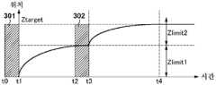
도 3a 내지 도 3d를 참조하여, 기판(104)의 높이 방향(Z축 방향)의 위치를 최적 노광 위치에 위치시키기 위한 기판 스테이지(105)의 구동에 관한 제어에 대하여 설명한다. 도 3a 내지 도 3d는, 기판 스테이지(105)의 높이 방향의 위치와 시간의 관계, 즉, 기판 스테이지(105)의 이동 궤적을 나타내고 있다. 도 3a 내지 도 3d에서는, 종축은 기판 스테이지(105)의 높이 방향의 위치를 나타내고, 횡축은 시간(시각)을 나타내고 있다. 주제어부(127)는 기판(104)의 샷 영역이 노광 슬릿(202)에 도달할 때까지, 기판(104)의 샷 영역이 최종 노광 위치(최종 목표 위치)에 위치하도록, 기판 스테이지(105)를 Z축 방향으로 이동시킨다. 여기서, 최적 노광 위치란, 마스크(102)의 패턴 결상면, 즉, 투영 광학계(101)의 상면의 위치(베스트 포커스 위치)이다. 단, 최적 노광 위치란, 투영 광학계(101)의 상면의 위치에 완전히 일치하는 위치를 의미하는 것은 아니고, 허용 초점 심도의 범위 내를 포함하는 것이다.3A to 3D, a description will be given of control relating to driving of the
도 3a는, 제1 계측부 및 제2 계측부 각각에 의한 기판(104)의 높이 방향의 위치 계측에 계측 오차가 포함되지 않고, 기판(104)의 높이 방향의 위치를 이상적으로 계측했을 경우에서의 기판 스테이지(105)의 이동 궤적을 나타내고 있다. 시각 t0으로부터 시각 t1까지의 기간(301)은 기판 스테이지(105)에 보유지지된 기판(104)의 높이 방향의 위치를 제2 계측부에서 계측하는 기간이다. 시각 t1로부터 시각 t3까지의 기간은, 제2 계측부에서 기판(104)의 높이 방향의 위치를 계측하여 얻어지는 제1 계측값(제2 계측부의 계측 결과)에 기초하여 기판 스테이지(105)에 의해 기판(104)을 높이 방향으로 구동하는 기간이다. 시각 t2로부터 시각 t3까지의 기간(302)은 기판 스테이지(105)에 보유지지된 기판(104)의 높이 방향의 위치를 제1 계측부에서 계측하는 기간이다. 여기서, 제1 계측부에서 기판(104)의 높이 방향의 위치를 계측할 때의 기판(104)의 XY 위치와, 제2 계측부에서 기판(104)의 높이 방향의 위치를 계측할 때의 기판(104)의 XY 위치는, 대략 동일 위치가 되도록 조정되어 있다. 바꾸어 말하면, 제1 계측부와 제2 계측부가 기판(104)의 동일 계측 대상 개소의 높이 방향의 위치를 계측하도록, 제1 계측부 및 제2 계측부 각각에서 기판(104)의 높이 방향의 위치를 계측하는 타이밍(계측 타이밍)이 제어되어 있다. 시각 t3으로부터 시각 t4까지의 기간은, 제1 계측부에서 기판(104)의 높이 방향의 위치를 계측하여 얻어지는 제2 계측값(제1 계측부의 계측 결과)에 기초하여 기판 스테이지(105)에 의해 기판(104)을 높이 방향으로 구동하는 기간이다. Ztarget는, 최적 노광 위치이다.3A is a graph showing the relationship between the position of the
또한, 시각 t1로부터 시각 t3까지의 기간에 있어서의 기판 스테이지(105)의 구동 및 시각 t3으로부터 시각 t4까지의 기간에 있어서의 기판 스테이지(105)의 구동에는, 각각, 구동 제한량 Zlimit1 및 Zlimit2가 설치되어 있다. 기판 스테이지(105)의 응답성을 초과하는 구동량으로 기판 스테이지(105)를 구동시키면, 기판 스테이지(105)의 제어 편차가 커진다. 기판(104)이 최적 노광 위치 Ztarget에 도달했을 때에, 기판 스테이지(105)의 제어 편차가 수렴되지 않고 잔존하고 있으면, 디포커스에 의한 해상 불량을 야기하는 원인이 된다. 따라서, 시각 t1로부터 시각 t3까지의 기간 및 시각 t3으로부터 시각 t4까지의 기간 각각에 있어서, 기판 스테이지(105)의 구동량을, 기판 스테이지(105)의 응답성 범위 내에서 제한하는 것이 필요해진다.The driving of the
예를 들어, 주제어부(127)는 기간(301)에서 얻어진 제1 계측값에 기초하여, 시각 t1로부터 시각 t3까지의 기간에서 기판(104)을 목표 위치에 위치시키기 위한 기판 스테이지(105)의 구동량(구동 목표값)을 구한다. 이러한 구동 목표값이 구동 제한량 Zlimit1을 초과하는 경우에는, 시각 t1로부터 시각 t3까지의 기간에 있어서의 기판 스테이지(105)의 구동량을 구동 제한량 Zlimit1로 제한한다. 마찬가지로, 주제어부(127)는 기간(302)에서 얻어진 제2 계측값에 기초하여, 시각 t3으로부터 시각 t4까지의 기간에서 기판(104)을 목표 위치에 위치시키기 위한 기판 스테이지(105)의 구동량(구동 목표값)을 구한다. 이러한 구동 목표값이 구동 제한량 Zlimit2에 수렴되는 경우에는, 시각 t3으로부터 시각 t4까지의 기간에 있어서의 기판 스테이지(105)의 구동량을 구동 제한량 Zlimit2로 제한하지 않는다. 이 경우, 구동 목표값은, 기판(104)을 최적 노광 위치 Ztarget에 위치시키기 위한 기판 스테이지(105)의 구동량이 된다.For example, the
도 3a에 도시하는 바와 같이, 제1 계측부 및 제2 계측부에 의한 계측에 계측 오차가 포함되어 있지 않은 경우, 시각 t1로부터 시각 t3까지의 기간에 있어서의 구동 목표값과 시각 t3으로부터 시각 t4까지의 기간에 있어서의 구동 목표값 사이에, 변동은 발생하지 않는다. 따라서, 시각 t1로부터 시각 t3까지의 기간에 기판 스테이지(105)를 구동한 후의 기판(104)의 높이 방향의 위치와, 시각 t3으로부터 시각 t4까지의 기간에서 기판 스테이지(105)를 구동한 후의 기판(104)의 높이 방향의 위치 사이에도, 변동은 발생하지 않는다.3A, when the measurement by the first measurement unit and the second measurement unit does not include a measurement error, the drive target value in the period from time t1 to time t3 and the drive target value in the period from time t3 to time t4 No fluctuation occurs between the drive target values in the period. The position of the
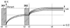
도 3b는, 종래 기술에 있어서의 기판 스테이지(105)의 이동 궤적을 나타내고 있다. 실제로는, 제1 계측부 및 제2 계측부 각각에 의한 기판(104)의 높이 방향의 위치 계측에는, 계측 오차가 포함되어 있다. 이러한 경우, 제2 계측값으로부터 구해지는 시각 t3으로부터 시각 t4까지의 기간에 있어서의 구동 목표값은, 제1 계측부에 의한 계측에 포함되는 계측 오차와, 제2 계측부에 의한 계측에 포함되는 계측 오차를 포함하게 된다. 따라서, 시각 t3으로부터 시각 t4까지의 기간에서는, 이러한 계측 오차를 포함하는 구동 목표값에 기초하여, 기판 스테이지(105)가 구동되게 된다. 이로 인해, 기판 스테이지(105)를 구동한 후의 기판(104)의 높이 방향의 위치는, 도 3b에 도시하는 바와 같이, 최종 노광 위치 Ztarget에 대하여, Δzb의 범위에서 변동되어 버린다.FIG. 3B shows the movement locus of the
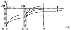
도 3c는, 도 3b에 나타내는 상태보다도 주사 속도가 빨라진 경우에 있어서의 기판 스테이지(105)의 이동 궤적을 나타내고 있다. 주사 속도가 빨라지면, 도 3c에 도시하는 바와 같이, 제2 계측부에 의한 기판(104)의 높이 방향의 위치 계측 시간, 즉, 시각 t0으로부터 시각 t1까지의 기간(301)이 도 3b에 나타내는 기간(301)보다도 짧아진다. 마찬가지로, 제1 계측부에 의한 기판(104)의 높이 방향의 위치 계측 시간, 즉, 시각 t2로부터 시각 t3까지의 기간(302)도 도 3b에 나타내는 기간(302)보다도 짧아진다.3C shows the movement locus of the
도 3c에 도시하는 바와 같이, 제1 계측부나 제2 계측부에 의한 계측 시간이 짧아지면, S/N비가 저하하기 때문에, 제1 계측값 및 제2 계측값에 포함되는 계측 오차가 커진다. 따라서, 기판 스테이지(105)를 구동한 후의 기판(104)의 높이 방향의 위치는, 최종 노광 위치 Ztarget에 대하여, Δzc의 범위에서 변동되어 버린다. Δzc는, Δzb보다도 크다. 이와 같이, 변동이 커지면, 디포커스에 의한 해상 불량을 야기하는 원인이 된다.As shown in FIG. 3C, when the measurement time by the first measurement unit or the second measurement unit becomes short, the S / N ratio decreases, and the measurement error included in the first measurement value and the second measurement value becomes large. Therefore, the position of the
그래서, 본 실시 형태에서는, 기판(104)의 높이 방향의 위치를 최적 노광 위치에 위치시키기 위한 기판 스테이지(105)의 구동 제어에 유리한 기술을 제공한다. 도 3d는, 본 실시 형태에 있어서의 기판 스테이지(105)의 이동 궤적을 나타내고 있다. 본 실시 형태에서는, 시각 t0으로부터 시각 t1까지의 기간(301)에 있어서, 기판 스테이지(105)에 보유지지된 기판(104)의 높이 방향의 위치를 제2 계측부에서 계측하여 제1 계측값을 취득한다. 이러한 제1 계측값에 기초하여, 시각 t1로부터 시각 t3까지의 기간에 있어서의 기판(104)의 높이 방향의 목표 위치를 구하고, 시각 t1로부터 시각 t3까지의 기간에서 기판(104)을 목표 위치에 위치시키기 위한 기판 스테이지(105)의 구동량(구동 목표값)을 구한다. 이러한 구동 목표값이 구동 제한량 Zlimit1을 초과하는 경우에는, 상술한 바와 같이, 시각 t1로부터 시각 t3까지의 기간에 있어서의 기판 스테이지(105)의 구동량을 구동 제한량 Zlimit1로 제한한다. 그리고, 구동 목표값, 또는, 구동 제한량 Zlimit1로 제한된 구동 목표값에 따라, 시각 t1로부터 시각 t3까지의 기간에 있어서, 기판 스테이지(105)에 의해 기판(104)을 높이 방향으로 이동시키기 위한 제1 구동을 행한다.Thus, the present embodiment provides a technique advantageous for driving control of the
이어서, 시각 t2로부터 시각 t3까지의 기간(302)에 있어서, 기판 스테이지(105)에 보유지지된 기판(104)의 높이 방향의 위치를 제1 계측부에서 계측하여 제2 계측값을 취득한다. 상술한 바와 같이, 제1 계측부와 제2 계측부가 기판(104)이 동일한 계측 대상 개소의 높이 방향의 위치를 계측하도록, 제1 계측부 및 제2 계측부 각각에서 기판(104)의 높이 방향의 위치를 계측하는 타이밍(계측 타이밍)이 제어되어 있다. 이러한 제2 계측값과 기간(301)에서 얻어진 제1 계측값에 기초하여, 시각 t3으로부터 시각 t4까지의 기간에 있어서의 기판(104)의 높이 방향의 목표 위치를 구한다. 예를 들어, 제1 계측값과 제2 계측값의 평균값으로부터 시각 t3으로부터 시각 t4까지의 기간에 있어서의 기판(104)의 높이 방향의 목표 위치를 구한다. 또한, 시각 t3으로부터 시각 t4까지의 기간에서 기판(104)을 목표 위치에 위치시키기 위한 기판 스테이지(105)의 구동량(구동 목표값)을 구한다. 이러한 구동 목표값이 구동 제한량 Zlimit2를 초과하는 경우에는, 상술한 바와 같이, 시각 t3으로부터 시각 t4까지의 기간에 있어서의 기판 스테이지(105)의 구동량을 구동 제한량 Zlimit2로 제한한다. 여기에서는, 구동 목표값이 구동 제한량 Zlimit2에 수렴되어 있는 것으로 한다. 따라서, 구동 목표값은, 최적 노광 위치 Ztarget에 기판(104)을 위치시키기 위한 기판 스테이지(105)의 구동량이 된다. 그리고, 구동 목표값에 따라, 시각 t3으로부터 시각 t4까지의 기간에 있어서, 기판 스테이지(105)에 의해 기판(104)을 높이 방향으로 이동시키기 위한 제2 구동을 행한다.Subsequently, in the
이와 같이, 본 실시 형태에서는, 제1 구동과 제2 구동에 의해, 기판(104)의 샷 영역이 노광 영역에 도달할 때까지 기판(104)의 높이 방향의 위치가 최적 노광 위치 Ztarget가 되도록 기판 스테이지(105)를 제어한다. 또한, 제1 구동이란, 기간(301)에 있어서 제2 계측부에서 얻어지는 제1 계측값에 기초하여 기판(104)을 높이 방향으로 구동하는 것이다. 또한, 제2 구동이란, 기간(302)에 있어서 제1 계측부에서 얻어지는 제2 계측값과, 기간(301)에 있어서 제2 계측부에서 얻어진 제1 계측값에 기초하여 기판(104)을 높이 방향으로 구동하는 것이다. 본 실시 형태에서는, 제2 구동에 있어서의 기판(104)의 높이 방향의 목표 위치를, 제1 계측값 및 제2 계측값의 양쪽을 사용하여 구함으로써, 평균화 효과에 의해 구동 목표값에 포함되는 계측 오차의 비율을 감소시키고 있다. 따라서, 도 3d에 도시하는 바와 같이, 기판 스테이지(105)를 구동한 후의 기판(104)의 높이 방향의 위치는, 최종 노광 위치 Ztarget에 대하여 Δzd의 범위에서 변동되기는 하지만, Δzd는 Δzc보다도 작아지기 때문에, 디포커스의 발생을 억제할 수 있다.As described above, in the present embodiment, the first drive and the second drive are performed so that the position of the
도 4a 및 도 4b를 참조하여, 본 실시 형태에 있어서의 기판 스테이지(105)의 구동에 관한 제어의 다른 예에 대하여 설명한다. 도 4a는 노광 슬릿(202), 계측점(203 내지 211), 샷 영역(401, 402 및 403) 및 기판 스테이지(105)의 이동 궤적을 도시하는 도면이다. 도 4a에 있어서, 샷 영역(401)은 노광 처리가 행하여진 샷 영역이다. 샷 영역(402)은 샷 영역(401)의 다음에 노광 처리를 행할 샷 영역이고, 샷 영역(403)은 샷 영역(402)의 다음에 노광 처리를 행할 샷 영역이다. 또한, 도 4a에 있어서, 파선으로 나타내는 화살표는, XY 평면에 있어서의 기판 스테이지(105)의 이동 궤적이다.Another example of control relating to driving of the
도 4a에 도시하는 바와 같이, 샷 영역(401)의 노광 처리가 종료되면, 기판 스테이지(105)는 Y축 방향으로 감속하면서 X축 방향으로 이동하고, 다음으로 노광 처리를 행하는 샷 영역(402)으로 이동한다. 기판 스테이지(105)가 Y축 방향으로의 가속 개시점에 도달하면(즉, X축 방향으로의 이동이 종료함), 샷 영역(401)을 주사한 방향과는 역의 방향으로 기판 스테이지(105)를 가속 이동시킨다. 기판 스테이지(105)의 속도(주사 속도)가 일정 속도가 되면, 노광 슬릿(202)이 샷 영역(402)을 통과할 때까지 등속 이동을 계속한다. 샷 영역(402)의 노광 처리가 종료되면, 기판 스테이지(105)는 Y축 방향으로 감속하면서 X축 방향으로 이동하고, 다음으로 노광 처리를 행할 샷 영역(403)으로 이동한다. 기판 스테이지(105)가 Y축 방향으로의 가속 개시점에 도달하면(즉, X축 방향으로의 이동이 종료함), 샷 영역(402)을 주사한 방향과는 역의 방향으로 기판 스테이지(105)를 가속 이동시킨다. 이와 같이, 기판 스테이지(105)가 가속, 등속, 감속을 반복하면서, 샷 영역(401 내지 403)을 순차 노광한다.4A, when the exposure process of the
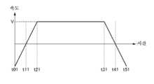
도 4b는, 샷 영역(402)을 노광할 때의 기판 스테이지(105)의 Y축 방향의 속도와 시간의 관계를 도시하는 도면이다. 도 4b에서는, 종축은 기판 스테이지(105)의 Y축 방향의 속도를 나타내고, 횡축은 시간(시각)을 나타내고 있다. 시각 t01로부터 시각 t11까지의 기간은, 샷 영역(401)의 노광이 완료되고, 기판 스테이지(105)를 감속하는 기간이다. 시각 t11로부터 시각 t21까지의 기간은, 샷 영역(402)을 노광하기 위해서, 기판 스테이지(105)를 가속하는 기간이다. 시각 t21로부터 시각 t31은, 기판 스테이지(105)를 일정한 속도 V(등속)로 유지하고, 샷 영역(402)을 노광하는 기간이다. 시각 t31로부터 시각 t41까지의 기간은, 다음 샷 영역(403)으로 이동하기 위해서, 기판 스테이지(105)를 감속하는 기간이다.4B is a diagram showing the relationship between the speed in the Y-axis direction and the time of the
생산성을 향상시키기 위해서, 시각 t11로부터 시각 t21까지의 기간에 있어서의 기판 스테이지(105)의 가속도를 크게 함으로써, 시각 t11로부터 시각 t21까지의 기간을 짧게 할 것이 요구되고 있다. 시각 t11로부터 시각 t21까지의 기간을 짧게 하면, 시각 t11로부터 시각 t21까지의 기간(가속 기간)에 있어서, 제2 계측부가 기판(104)의 높이 방향의 위치를 계측해야 하는 경우가 있다. 기판 스테이지(105)가 가속하고 있는 상태에서는, 노광 장치(100)의 본체 구조체나 기판 스테이지(105)의 변형이 발생한다. 그 때문에, 시각 t11로부터 시각 t21까지의 기간에 얻어지는 제2 계측부의 계측 결과는, 기판 스테이지(105)가 등속인 기간에서 얻어지는 제1 계측부의 계측 결과와 비교하여, 계측 오차가 커진다(계측 정밀도가 낮다).It is required to shorten the period from the time t11 to the time t21 by increasing the acceleration of the
상술한 바와 같이, 본 실시 형태에서는, 제2 구동에 있어서의 기판(104)의 높이 방향의 목표 위치를, 제1 계측값 및 제2 계측값의 양쪽을 사용하여 구하고 있다. 여기서, 시각 t11로부터 시각 t21까지의 기간에서 얻어지는 제1 계측값에는, 노광 장치(100)의 본체 구조체나 기판 스테이지(105)의 변형에서 기인하는 오차 성분이 포함되어 있다. 한편, 제1 계측부에 의한 기판(104)의 높이 방향의 위치 계측은, 시각 t21 내지 시각 t31의 기간(등속 기간)에서 행할 수 있는 경우가 많다. 이러한 경우에는, 가속 기간에서 얻어진 제1 계측값보다도 등속 기간에서 얻어진 제2 계측값에 가중치를 부여하고, 제2 구동에 있어서의 기판(104)의 높이 방향의 목표 위치를 구한다. 이에 의해, 제2 구동에 있어서의 구동 목표값에 포함되는 계측 오차의 비율을 감소시킬 수 있다.As described above, in the present embodiment, the target position in the height direction of the
또한, 시각 t11로부터 시각 t21까지의 기간을 짧게 하면, 시각 t11로부터 시각 t21까지의 기간(가속 기간)에 있어서, 제1 계측부가 기판(104)의 높이 방향의 위치를 계측해야 하는 경우도 있다. 이러한 경우, 제2 계측부가 기판(104)의 높이 방향의 위치를 계측할 때의 기판 스테이지(105)의 속도는, 제1 계측부가 기판(104)의 높이 방향의 위치를 계측할 때의 기판 스테이지(105)의 속도보다도 늦다. 따라서, 제2 계측부의 계측 결과는, 제1 계측부의 계측 결과와 비교하여, 계측 오차가 작아진다(계측 정밀도가 높다). 그래서, 제2 계측값보다도 제1 계측값에 가중치를 부여하여, 제2 구동에 있어서의 기판(104)의 높이 방향의 목표 위치를 구한다. 이에 의해, 제2 구동에 있어서의 구동 목표값에 포함되는 계측 오차의 비율을 감소시킬 수 있다.In addition, when the period from the time t11 to the time t21 is shortened, the position of the
또한, 가속 기간에 기판(104)의 높이 방향의 위치를 계측하면, 기판 스테이지(105)의 제어 편차가 커지는 경우가 있다. 이러한 경우에는, 제1 계측부에서 기판(104)의 높이 방향의 위치를 계측했을 때의 기판 스테이지(105)의 제어 편차와, 제2 계측부에서 기판(104)의 높이 방향의 위치를 계측했을 때의 기판 스테이지(105)의 제어 편차를 비교한다. 그리고, 제1 계측값 및 제2 계측값 중, 기판 스테이지(105)의 제어 편차가 작은 쪽의 계측값에 가중치를 부여하여, 제2 구동에 있어서의 기판(104)의 높이 방향의 목표 위치를 구한다. 이에 의해, 제2 구동에 있어서의 구동 목표값에 포함되는 계측 오차의 비율을 감소시킬 수 있다.Further, when the position of the
이와 같이, 기판 스테이지(105)가 가속되고 있는 상태에서 기판(104)의 높이 방향의 위치를 계측하는 경우에도, 제1 계측값 및 제2 계측값의 각각에 가중치를 부여하여 제2 구동에 있어서의 기판(104)의 높이 방향의 목표 위치를 구하면 된다. 또한, 제1 계측값 및 제2 계측값 각각에 부여할 가중치는 상술한 바와 같이, 제1 계측부의 계측 시의 기판 스테이지(105)의 가속도와, 제2 계측부의 계측 시의 기판 스테이지(105)의 가속도의 관계에 기초하여 결정하면 된다. 마찬가지로, 제1 계측부의 계측 시의 기판 스테이지(105)의 제어 편차와, 제2 계측부의 계측 시의 기판 스테이지(105)의 제어 편차의 관계에 기초하여, 제1 계측값 및 제2 계측값 각각에 부여할 가중치를 결정해도 된다. 또한, 유저의 입력에 따라, 제1 계측값 및 제2 계측값 각각에 부여할 가중치를 결정해도 된다. 이 경우, 유저는, 예를 들어 표시부(131)에 표시되는 설정 화면(유저 인터페이스)을 확인하면서, 마우스나 키보드 등을 포함하는 입력부(132)를 조작함으로써, 제1 계측값 및 제2 계측값 각각에 부여할 가중치를 지정할 수 있다.Thus, even when the position of the
도 5a 및 5b를 참조하여, 본 실시 형태에 있어서의 기판 스테이지(105)의 구동에 관한 제어의 다른 예에 대하여 설명한다. 도 5a 및 도 5b는, 노광 슬릿(202), 계측점(203 내지 211), 샷 영역(401, 402 및 403) 및 기판 스테이지(105)의 이동 궤적을 도시하는 도면이다. 또한, 도 5a 및 도 5b에 있어서, 파선으로 나타내는 화살표는, XY 평면에 있어서의 기판 스테이지(105)의 이동 궤적이다.Another example of control relating to driving of the
도 5a에 도시하는 바와 같이, 샷 영역(401)의 노광 처리가 종료되면, 다음 샷 영역(402)을 노광하기 위해서, 기판 스테이지(105)는 X축 방향으로 이동한다. 단, 기판 스테이지(105)의 이동 궤적에 따라서는, 기판 스테이지(105)의 X축 방향으로의 이동이 종료되기 전에, 제2 계측부가 기판(104)의 높이 방향의 위치를 계측해야 하는 경우가 있다. 이 경우, 제2 계측부는, 계측 대상 개소(501, 502 및 503)에 대하여 X축 방향으로 어긋난 계측점(209, 210 및 210)에서 기판(104)의 높이 방향의 위치를 계측하게 된다. 계측 대상 개소에 대하여 어긋난 위치에서 기판(104)의 높이 방향의 위치를 계측하면, 최적 노광 위치로의 기판(104)의 매칭에 오차를 발생하게 된다.5A, when the exposure process of the
한편, 제1 계측부는, 계측 대상 개소(501, 502 및 503)에 대하여 어긋나 있지 않은 계측점(206, 207 및 208)에서 기판(104)의 높이 방향의 위치를 계측할 수 있다. 그래서, 본 실시 형태에서는, 계측 대상 개소에 대하여 어긋난 위치에서 계측하여 얻어진 제1 계측값보다도 계측 대상 개소에 대하여 어긋남 없이 계측하여 얻어진 제2 계측값에 가중치를 부여하고, 제2 구동에 있어서의 기판(104)의 높이 방향의 목표 위치를 구한다. 이에 의해, 제2 구동에 있어서의 구동 목표값에 포함되는 계측 오차의 비율을 감소시킬 수 있다.On the other hand, the first measuring unit can measure the position in the height direction of the
이와 같이, 계측 대상 개소에 대하여 어긋난 위치에서 제2 계측부가 기판(104)의 높이 방향의 위치를 계측하는 경우에는, 제1 계측값 및 제2 계측값의 각각에 가중치를 부여하여 제2 구동에 있어서의 기판(104)의 높이 방향의 목표 위치를 구하면 된다. 또한, 제1 계측값 및 제2 계측값 각각에 부여할 가중치는 제1 계측부에서 계측하는 기판(104)의 XY 평면 내의 위치와, 제2 계측부에서 계측하는 기판(104)의 XY 평면 내의 위치의 어긋남량에 기초하여 결정하면 된다. 여기서, 기판(104)의 XY 평면 내의 위치란, 기판(104)의 높이 방향 및 주사 방향에 직교하는 방향에 있어서의 기판(104)의 위치이다.In this manner, when the position of the second measurement unit in the height direction of the
도 6은, 제2 계측부에서 얻어지는 제1 계측값 및 제1 계측부에서 얻어지는 제2 계측값의 각각에 가중치를 부여하는 경우에 있어서, 제2 구동에 있어서의 구동 목표값을 구하는 처리를 설명하기 위한 흐름도이다. 이러한 처리는, 주제어부(127)가 노광 장치(100)의 각 부를 통괄적으로 제어함으로써 행하여진다.Fig. 6 is a graph for explaining a process for obtaining a drive target value in the second drive in the case where a weight is assigned to each of the first measured value obtained by the second measuring section and the second measured value obtained by the first measuring section FIG. This processing is performed by the
S601에 있어서, 기판 스테이지(105)에 보유지지된 기판(104)의 높이 방향의 위치를 제2 계측부에서 계측하여 제1 계측값을 취득한다. S602에 있어서, S601에서 기판(104)의 높이 방향의 위치를 제2 계측부에서 계측했을 때의 기판 스테이지(105)의 제어 편차(제1 제어 편차)를 취득한다. 기판 스테이지(105)의 제어 편차는, 기판 스테이지(105)의 구동 프로파일 및 간섭계(124)에 의해 계측되는 기판 스테이지(105)의 위치로부터 구할 수 있다.In S601, the position of the
S603에 있어서, 기판 스테이지(105)에 보유지지된 기판(104)의 높이 방향의 위치를 제1 계측부에서 계측하여 제2 계측값을 취득한다. S604에 있어서, S603에서 기판(104)의 높이 방향의 위치를 제1 계측부에서 계측했을 때의 기판 스테이지(105)의 제어 편차(제2 제어 편차)를 취득한다.In S603, the position of the
S605에 있어서, S602에서 취득한 제1 제어 편차 및 S604에서 취득한 제2 제어 편차에 기초하여, S601에서 취득한 제1 계측값 및 S603에서 취득한 제2 계측값의 각각에 가중치를 부여한다. 예를 들어, 제1 제어 편차 및 제2 제어 편차에 따라, 그것에 반비례하도록, 제1 계측값 및 제2 계측값의 각각에 가중치를 부여한다. S606에 있어서, S605에서 가중치를 부여한 제1 계측값 및 제2 계측값에 기초하여, 제2 구동에 있어서의 구동 목표값을 구한다.In S605, on the basis of the first control deviation obtained in S602 and the second control deviation obtained in S604, a weight is assigned to each of the first measured value acquired in S601 and the second measured value acquired in S603. For example, each of the first measured value and the second measured value is weighted in accordance with the first control deviation and the second control deviation in inverse proportion thereto. In step S606, a drive target value in the second drive is obtained based on the first measured value and the second measured value that are weighted in step S605.
여기에서는, 제1 계측값 및 제2 계측값 각각에 부여할 가중치에 대해서, 기판 스테이지(105)의 제어 편차를 예로 들어 설명하였다. 단, 기판 스테이지(105)의 가속도(속도)나 제1 계측부와 제2 계측부의 계측 위치의 XY면에 있어서의 위치 어긋남에 대해서도 동일하게, 제1 계측값 및 제2 계측값 각각에 부여할 가중치를 결정하는 것이 가능하다.Here, the control deviations of the
도 7은, 기판(104)의 표면(701)의 요철과, 제1 계측부, 제2 계측부 및 제3 계측부 각각으로부터의 계측광(광원(110)으로부터의 광)(702, 703 및 704)의 관계를 도시하는 도면이다. 도 7에 도시하는 바와 같이, 제1 계측부, 제2 계측부 및 제3 계측부 각각으로부터의 계측광(702, 703 및 704)이 기판(104)의 표면(701)에 입사하는 위치(Y축 방향의 위치)는 각 계측부에서 상이하다. 이것은, 각 계측부의 설치 위치의 조정에, 제조상의 변동이 있기 때문이다. 일반적으로, 각 계측부의 설치 위치의 조정에서는, 노광 슬릿의 투영 위치를 계측하는 제3 계측부를 기준으로 하여, 제1 계측부 및 제2 계측부의 설치 위치를 조정한다. 따라서, 제3 계측부에 대하여, 제1 계측부 및 제2 계측부에 위치 어긋남이 발생한다.7 is a graph showing the relationship between the irregularities of the
예를 들어, 도 7에서는, 제3 계측부로부터의 계측광(704)과 제2 계측부로부터의 계측광(703) 사이에 어긋남 ΔL1이 발생하고, 제3 계측부로부터의 계측광(704)과 제1 계측부로부터의 계측광(702) 사이에 어긋남 ΔL2가 발생하고 있다. 기판(104)의 표면(701)의 요철이 크면, 도 7에 도시하는 바와 같이, 제2 계측부로부터의 계측광(703)이 요철에서 차광되어, 수광측 광학계(116)에 도달하지 않게 된다. 이러한 경우에는, 제2 계측부에서는, 기판(104)의 높이 방향의 위치를 정확하게 계측할 수 없다. 따라서, 제2 구동에 있어서의 기판(104)의 높이 방향의 목표 위치를, 제1 계측값 및 제2 계측값의 양쪽을 사용하는 것이 아니라, 제1 계측부에서 얻어지는 제2 계측값만을 사용하여 구하면 된다.For example, in Fig. 7, a deviation DELTA L1 occurs between the
도 7에서는, ΔL1>ΔL2가 되는 경우를 예로 들어 설명했지만, ΔL1<ΔL2가 되는 경우도 있다. ΔL1<ΔL2가 되는 경우에는, 제1 계측부에서 얻어지는 제2 계측값을 사용하지 않고, 제2 계측부에서 얻어지는 제1 계측값만을 사용하여 제2 구동에 있어서의 기판(104)의 높이 방향의 목표 위치를 구하면 된다.In Fig. 7, the case where? L1>? L2 has been described as an example, however, there is a case where? L1 <? L2. When? L1 <? L2, the second measured value obtained by the first measuring section is not used, and only the first measured value obtained by the second measuring section is used to determine the target position in the height direction of the
기판(104)의 표면 요철 상태는, 샷 영역별로 상이한 경우가 있다. 따라서, 제2 구동에 있어서의 기판(104)의 높이 방향의 목표 위치를 구할 때에, 제1 계측값 및 제2 계측값의 양쪽을 사용할 것인지, 또는, 제1 계측값 및 제2 계측값 중 어느 한쪽을 사용할 것인지는, 샷 영역별로 변경해도 된다.The surface unevenness state of the
구체적으로는, 노광 장치(100)에 대하여, 기판 스테이지(105)를 제어하는 모드로서, 제1 모드 및 제2 모드를 포함하는 2개의 모드를 선택 가능하게 설정한다. 예를 들어, 제1 모드는, 제1 구동과 제2 구동에 의해, 기판 스테이지(105)에 보유지지된 기판(104)의 높이 방향의 위치가 최종 목표 위치가 되도록 기판 스테이지(105)를 제어하는 모드로 한다. 한편, 제2 모드는, 제1 구동과 제3 구동에 의해, 기판 스테이지(105)에 보유지지된 기판(104)의 높이 방향의 위치가 최종 목표 위치가 되도록 기판 스테이지(105)를 제어하는 모드로 한다. 여기서, 제3 구동이란, 제1 계측값 및 제2 계측값의 양쪽이 아닌, 제1 계측값 및 제2 계측값 중 어느 한쪽에 기초하여 기판(104)을 높이 방향으로 구동하는 것이다.Concretely, two modes including a first mode and a second mode are selectively set for the
또한, 기판 스테이지(105)를 제1 모드에서 제어하느냐, 또는, 기판 스테이지(105)를 제2 모드에서 제어하느냐는, 주제어부(127)가 자동으로 결정해도 되고, 유저의 입력에 따라서 결정해도 된다. 유저는, 예를 들어 표시부(131)에 표시되는 설정 화면(유저 인터페이스)을 개재하여, 기판 스테이지(105)를 제어하는 모드를 선택(지정)할 수 있다.Whether the
이와 같이, 제1 계측부 또는 제2 계측부에서 기판(104)의 높이 방향의 위치를 정확하게 계측할 수 없는 경우에도, 제1 계측값 및 제2 계측값 중 어느 한쪽을 사용함으로써, 제2 구동에 있어서의 구동 목표값에 포함되는 계측 오차의 비율을 감소시킬 수 있다.Thus, even when the position in the height direction of the
본 발명의 실시 형태에 있어서의 물품의 제조 방법은, 예를 들어 디바이스(반도체 소자, 자기 기억 매체, 액정 표시 소자 등) 등의 물품을 제조하기에 적합하다. 이러한 제조 방법은, 노광 장치(100)를 사용하여, 감광제가 도포된 기판을 노광하는 공정과, 노광된 기판을 현상하는 공정을 포함한다. 또한, 이러한 제조 방법은, 다른 주지의 공정(산화, 성막, 증착, 도핑, 평탄화, 에칭, 레지스트 박리, 다이싱, 본딩, 패키징 등)을 포함할 수 있다. 본 실시 형태에 있어서의 물품의 제조 방법은, 종래에 비하여, 물품의 성능, 품질, 생산성 및 생산 비용의 적어도 하나에 있어서 유리하다.The method of manufacturing an article in the embodiment of the present invention is suitable for producing an article such as a device (semiconductor device, magnetic storage medium, liquid crystal display element, etc.). Such a manufacturing method includes a step of exposing a substrate coated with a photosensitive agent using the
이상, 본 발명의 바람직한 실시 형태에 대하여 설명했지만, 본 발명은 이들 실시 형태에 한정되지 않음은 물론, 그 요지의 범위 내에서 다양한 변형 및 변경이 가능하다.Although the preferred embodiments of the present invention have been described above, the present invention is not limited to these embodiments, and various modifications and changes are possible within the scope of the present invention.
Claims (10)
Translated fromKorean상기 기판을 보유지지하여 이동시키는 스테이지와,
상기 스테이지를 제어하는 제어부와,
상기 스테이지에 보유지지된 상기 기판의 샷 영역이 상기 샷 영역에 대한 노광이 행해지는 노광 영역에 도달하기 전에, 상기 샷 영역의 높이 방향의 위치를 계측하는 제1 계측부와,
상기 제1 계측부에 앞서 상기 샷 영역의 상기 높이 방향의 위치를 계측하는 제2 계측부를 갖고,
상기 제어부는, 상기 제2 계측부에서 상기 샷 영역의 상기 높이 방향의 위치를 계측하여 얻어지는 제1 계측값에 기초하여 상기 기판을 상기 높이 방향으로 이동시키기 위한 제1 구동과, 상기 제1 구동에 이어 상기 제1 계측부에서 상기 샷 영역의 상기 높이 방향의 위치를 계측하여 얻어지는 제2 계측값과 상기 제1 계측값에 기초하여 상기 기판을 상기 높이 방향으로 이동시키기 위한 제2 구동에 의해, 상기 샷 영역이 상기 노광 영역에 도달할 때까지 상기 스테이지에 보유지지된 상기 기판의 상기 높이 방향의 위치가 최종 목표 위치가 되도록 상기 스테이지를 제어하는 것을 특징으로 하는, 노광 장치.An exposure apparatus for transferring a pattern onto a substrate by exposing the substrate while moving a mask and a substrate,
A stage for holding and moving the substrate,
A control unit for controlling the stage,
A first measuring unit for measuring a position in the height direction of the shot area before a shot area of the substrate held on the stage reaches an exposure area in which exposure for the shot area is performed;
And a second metering section for measuring a position of the shot area in the height direction prior to the first metering section,
Wherein the control unit includes a first drive for moving the substrate in the height direction based on a first measured value obtained by measuring a position of the shot area in the height direction at the second measuring unit, By the second drive for moving the substrate in the height direction based on the second measured value obtained by measuring the position of the shot area in the height direction at the first measurement unit and the first measured value, Controls the stage so that the position in the height direction of the substrate held on the stage until the exposure region reaches the exposure region becomes the final target position.
상기 제어부는, 상기 제1 계측부와 상기 제2 계측부가 상기 샷 영역의 동일 계측 대상 개소의 상기 높이 방향의 위치를 계측하도록, 상기 제1 계측부 및 상기 제2 계측부 각각에서 상기 샷 영역의 상기 높이 방향의 위치를 계측하는 타이밍을 제어하는 것을 특징으로 하는, 노광 장치.The method according to claim 1,
Wherein the control unit controls the first metering unit and the second metering unit such that the first metering unit and the second metering unit measure the position of the shots in the height direction of the shots to be measured, And the timing of measuring the position of the exposure apparatus.
상기 제어부는, 상기 제1 계측값과 상기 제2 계측값의 평균값으로부터 상기 제2 구동에 있어서의 상기 기판의 상기 높이 방향의 목표 위치를 구하고, 상기 제2 구동에서는, 상기 스테이지에 보유지지된 상기 기판의 상기 높이 방향의 위치가 상기 목표 위치가 되도록 상기 스테이지를 제어하는 것을 특징으로 하는, 노광 장치.The method according to claim 1,
Wherein the control unit obtains a target position in the height direction of the substrate in the second drive from an average value of the first measured value and the second measured value and in the second drive, And controls the stage so that the position of the substrate in the height direction becomes the target position.
상기 제어부는, 상기 제1 계측값 및 상기 제2 계측값의 각각에 가중치를 부여하여 상기 제2 구동에 있어서의 상기 기판의 상기 높이 방향의 목표 위치를 구하고, 상기 제2 구동에서는, 상기 스테이지에 보유지지된 상기 기판의 상기 높이 방향의 위치가 상기 목표 위치가 되도록 상기 스테이지를 제어하는 것을 특징으로 하는, 노광 장치.The method according to claim 1,
Wherein the control unit assigns a weight to each of the first measured value and the second measured value to obtain a target position in the height direction of the substrate in the second drive and in the second drive, And controls the stage so that the position of the held and held substrate in the height direction becomes the target position.
상기 제어부는, 상기 제1 계측부에서 상기 샷 영역의 상기 높이 방향의 위치를 계측할 때의 상기 스테이지의 가속도와, 상기 제2 계측부에서 상기 샷 영역의 상기 높이 방향의 위치를 계측할 때의 상기 스테이지의 가속도의 관계에 기초하여, 상기 제1 계측값 및 상기 제2 계측값 각각에 부여할 가중치를 결정하는 것을 특징으로 하는, 노광 장치.The method of claim 3,
Wherein the control unit is configured to control the acceleration of the stage when the position of the shot area in the height direction is measured by the first measurement unit and the acceleration of the stage when the position of the shot area in the height direction is measured by the second measurement unit, And determines a weight to be given to each of the first measured value and the second measured value based on the relationship between the first measured value and the second measured value.
상기 제어부는, 상기 제1 계측부에서 상기 샷 영역의 상기 높이 방향의 위치를 계측할 때의 상기 스테이지의 제어 편차와, 상기 제2 계측부에서 상기 샷 영역의 상기 높이 방향의 위치를 계측할 때의 상기 스테이지의 제어 편차의 관계에 기초하여, 상기 제1 계측값 및 상기 제2 계측값 각각에 부여할 가중치를 결정하는 것을 특징으로 하는, 노광 장치.The method of claim 3,
Wherein the control unit includes a control unit for controlling the stage in a case where a control deviation of the stage at the time of measuring the position of the shot area in the height direction at the first measurement unit and a control deviation of the stage at the time of measuring the position of the shot area in the height direction at the second measurement unit And determines a weight to be given to each of the first measured value and the second measured value based on the relationship of the control deviation of the stage.
상기 제어부는, 상기 제1 계측부에서 계측하는, 상기 높이 방향 및 상기 기판의 주사 방향에 직교하는 방향에 있어서의 상기 샷 영역의 위치와, 상기 제2 계측부에서 계측하는, 상기 높이 방향 및 상기 기판의 주사 방향에 직교하는 방향에 있어서의 상기 샷 영역의 위치의 어긋남량에 기초하여, 상기 제1 계측값 및 상기 제2 계측값 각각에 부여할 가중치를 결정하는 것을 특징으로 하는, 노광 장치.The method of claim 3,
Wherein the control unit controls the position of the shot area in the height direction and the direction orthogonal to the scanning direction of the substrate measured by the first measuring unit and the position of the shot area measured by the second measuring unit, And determines a weight to be given to each of the first measured value and the second measured value based on a displacement amount of the position of the shot area in a direction orthogonal to the scanning direction.
상기 제어부는, 유저의 입력에 따라, 상기 제1 계측값 및 상기 제2 계측값 각각에 부여할 가중치를 결정하는 것을 특징으로 하는, 노광 장치.The method of claim 3,
Wherein the control unit determines a weight to be given to each of the first measured value and the second measured value in accordance with an input from the user.
상기 제어부는, 상기 제1 구동과 상기 제2 구동에 의해, 상기 샷 영역이 상기 노광 영역에 도달할 때까지 상기 스테이지에 보유지지된 상기 기판의 상기 높이 방향의 위치가 상기 최종 목표 위치가 되도록 상기 스테이지를 제어하는 제1 모드, 또는, 상기 제1 구동과 상기 제1 계측값 및 상기 제2 계측값 중 어느 한쪽에 기초하여 상기 기판을 상기 높이 방향으로 구동하는 제3 구동에 의해, 상기 샷 영역이 상기 노광 영역에 도달할 때까지 상기 스테이지에 보유지지된 상기 기판의 상기 높이 방향의 위치가 상기 최종 목표 위치가 되도록 상기 스테이지를 제어하는 제2 모드에서, 상기 스테이지를 제어하는 것을 특징으로 하는, 노광 장치.The method according to claim 1,
The control unit controls the first driving and the second driving so that the position in the height direction of the substrate held on the stage until the shot area reaches the exposure area becomes the final target position, A third mode for controlling the stage or a third drive for driving the substrate in the height direction based on the first drive and either the first measured value or the second measured value, Wherein the stage is controlled in a second mode in which the stage is controlled so that the position in the height direction of the substrate held on the stage reaches the final target position until reaching the exposure region. Exposure apparatus.
노광 장치를 사용하여 기판을 노광하는 공정과,
노광한 상기 기판을 현상하는 공정과,
현상된 상기 기판으로부터 물품을 제조하는 공정을 갖고,
상기 노광 장치는,
마스크와 상기 기판을 이동시키면서 상기 기판을 노광함으로써 상기 기판 상에 패턴을 전사하고,
상기 기판을 보유지지하여 이동시키는 스테이지와,
상기 스테이지를 제어하는 제어부와,
상기 스테이지에 보유지지된 상기 기판의 샷 영역이 상기 샷 영역에 대한 노광이 행해지는 노광 영역에 도달하기 전에, 상기 샷 영역의 높이 방향의 위치를 계측하는 제1 계측부와,
상기 제1 계측부에 앞서 상기 샷 영역의 상기 높이 방향의 위치를 계측하는 제2 계측부를 갖고,
상기 제어부는, 상기 제2 계측부에서 상기 샷 영역의 상기 높이 방향의 위치를 계측하여 얻어지는 제1 계측값에 기초하여 상기 기판을 상기 높이 방향으로 이동시키기 위한 제1 구동과, 상기 제1 구동에 이어 상기 제1 계측부에서 상기 샷 영역의 상기 높이 방향의 위치를 계측하여 얻어지는 제2 계측값과 상기 제1 계측값에 기초하여 상기 기판을 상기 높이 방향으로 이동시키기 위한 제2 구동에 의해, 상기 샷 영역이 상기 노광 영역에 도달할 때까지 상기 스테이지에 보유지지된 상기 기판의 상기 높이 방향의 위치가 최종 목표 위치가 되도록 상기 스테이지를 제어하는 것을 특징으로 하는, 물품의 제조 방법.A method of manufacturing an article,
A step of exposing the substrate using an exposure apparatus,
A step of developing the exposed substrate;
And a step of manufacturing an article from the developed substrate,
The exposure apparatus includes:
Transferring the pattern onto the substrate by exposing the substrate while moving the mask and the substrate,
A stage for holding and moving the substrate,
A control unit for controlling the stage,
A first measuring unit for measuring a position in the height direction of the shot area before a shot area of the substrate held on the stage reaches an exposure area in which exposure for the shot area is performed;
And a second metering section for measuring a position of the shot area in the height direction prior to the first metering section,
Wherein the control unit includes a first drive for moving the substrate in the height direction based on a first measured value obtained by measuring a position of the shot area in the height direction at the second measuring unit, By the second drive for moving the substrate in the height direction based on the second measured value obtained by measuring the position of the shot area in the height direction at the first measurement unit and the first measured value, Wherein the stage is controlled so that the position in the height direction of the substrate held on the stage until reaching the exposure region becomes the final target position.
Applications Claiming Priority (2)
| Application Number | Priority Date | Filing Date | Title |
|---|---|---|---|
| JP2017121561AJP6882091B2 (en) | 2017-06-21 | 2017-06-21 | Exposure equipment and manufacturing method of articles |
| JPJP-P-2017-121561 | 2017-06-21 |
Publications (2)
| Publication Number | Publication Date |
|---|---|
| KR20180138544Atrue KR20180138544A (en) | 2018-12-31 |
| KR102354948B1 KR102354948B1 (en) | 2022-01-25 |
Family
ID=64844993
Family Applications (1)
| Application Number | Title | Priority Date | Filing Date |
|---|---|---|---|
| KR1020180070702AActiveKR102354948B1 (en) | 2017-06-21 | 2018-06-20 | Exposure apparatus, and method of manufacturing article |
Country Status (3)
| Country | Link |
|---|---|
| JP (1) | JP6882091B2 (en) |
| KR (1) | KR102354948B1 (en) |
| CN (1) | CN109100920B (en) |
Cited By (1)
| Publication number | Priority date | Publication date | Assignee | Title |
|---|---|---|---|---|
| KR20210144594A (en)* | 2020-05-21 | 2021-11-30 | 캐논 가부시끼가이샤 | Processing apparatus, measurement method, and article manufacturing method |
Families Citing this family (6)
| Publication number | Priority date | Publication date | Assignee | Title |
|---|---|---|---|---|
| JP7312053B2 (en)* | 2019-08-05 | 2023-07-20 | キヤノン株式会社 | Exposure apparatus and article manufacturing method |
| US11908722B2 (en)* | 2019-09-09 | 2024-02-20 | Kla Corporation | Automatic teaching of substrate handling for production and process-control tools |
| JP7361599B2 (en)* | 2019-12-26 | 2023-10-16 | キヤノン株式会社 | Exposure equipment and article manufacturing method |
| TWI885087B (en)* | 2020-03-24 | 2025-06-01 | 日商東京威力科創股份有限公司 | Heat treatment device and heat treatment method |
| JP7494066B2 (en)* | 2020-09-14 | 2024-06-03 | キヤノン株式会社 | Exposure apparatus and method for manufacturing article |
| JP2023545963A (en)* | 2020-10-20 | 2023-11-01 | エーエスエムエル ネザーランズ ビー.ブイ. | Substrate level sensing in lithography equipment |
Citations (3)
| Publication number | Priority date | Publication date | Assignee | Title |
|---|---|---|---|---|
| JPH11102852A (en)* | 1997-09-29 | 1999-04-13 | Nec Corp | Exposure method |
| WO1999039374A1 (en)* | 1998-01-29 | 1999-08-05 | Nikon Corporation | Exposure method and device |
| WO2005124832A1 (en)* | 2004-06-17 | 2005-12-29 | Nikon Corporation | Exposure system |
Family Cites Families (11)
| Publication number | Priority date | Publication date | Assignee | Title |
|---|---|---|---|---|
| JPH11186129A (en)* | 1997-12-19 | 1999-07-09 | Nikon Corp | Scanning exposure method and apparatus |
| JP2003173960A (en)* | 2001-12-06 | 2003-06-20 | Nikon Corp | Exposure equipment |
| JP2003203855A (en)* | 2002-01-10 | 2003-07-18 | Nikon Corp | Exposure method, exposure apparatus, and device manufacturing method |
| JP3780221B2 (en)* | 2002-03-26 | 2006-05-31 | キヤノン株式会社 | Exposure method and apparatus |
| JP3428639B2 (en)* | 2002-08-28 | 2003-07-22 | 株式会社ニコン | Scanning exposure apparatus and device manufacturing method |
| JP5498243B2 (en)* | 2010-05-07 | 2014-05-21 | キヤノン株式会社 | Exposure apparatus, exposure method, and device manufacturing method |
| EP2871526B1 (en)* | 2012-07-09 | 2018-11-28 | Nikon Corporation | Drive system and drive method, and exposure device and exposure method |
| JP6071628B2 (en)* | 2013-02-22 | 2017-02-01 | キヤノン株式会社 | Exposure apparatus, exposure method, and device manufacturing method |
| JP6267530B2 (en)* | 2014-02-04 | 2018-01-24 | キヤノン株式会社 | Exposure apparatus and article manufacturing method |
| US20160266500A1 (en)* | 2015-03-13 | 2016-09-15 | Kabushiki Kaisha Toshiba | Exposure apparatus, exposure method, and manufacturing method of device |
| JP6806509B2 (en)* | 2016-09-15 | 2021-01-06 | キヤノン株式会社 | Method of manufacturing exposure equipment and articles |
- 2017
- 2017-06-21JPJP2017121561Apatent/JP6882091B2/ennot_activeExpired - Fee Related
- 2018
- 2018-06-20KRKR1020180070702Apatent/KR102354948B1/enactiveActive
- 2018-06-21CNCN201810642012.2Apatent/CN109100920B/ennot_activeExpired - Fee Related
Patent Citations (3)
| Publication number | Priority date | Publication date | Assignee | Title |
|---|---|---|---|---|
| JPH11102852A (en)* | 1997-09-29 | 1999-04-13 | Nec Corp | Exposure method |
| WO1999039374A1 (en)* | 1998-01-29 | 1999-08-05 | Nikon Corporation | Exposure method and device |
| WO2005124832A1 (en)* | 2004-06-17 | 2005-12-29 | Nikon Corporation | Exposure system |
Cited By (1)
| Publication number | Priority date | Publication date | Assignee | Title |
|---|---|---|---|---|
| KR20210144594A (en)* | 2020-05-21 | 2021-11-30 | 캐논 가부시끼가이샤 | Processing apparatus, measurement method, and article manufacturing method |
Also Published As
| Publication number | Publication date |
|---|---|
| CN109100920A (en) | 2018-12-28 |
| JP6882091B2 (en) | 2021-06-02 |
| JP2019008029A (en) | 2019-01-17 |
| CN109100920B (en) | 2021-07-09 |
| KR102354948B1 (en) | 2022-01-25 |
Similar Documents
| Publication | Publication Date | Title |
|---|---|---|
| KR20180138544A (en) | Exposure apparatus, and method of manufacturing article | |
| KR101444981B1 (en) | Exposure apparatus, exposure method, and method of manufacturing device | |
| KR100365602B1 (en) | Exposure Method and Apparatus and Semiconductor Device Manufacturing Method | |
| KR102294481B1 (en) | Method for controlling moving body, exposure method, method for manufacturing device, moving body apparatus, and exposure apparatus | |
| TW200807164A (en) | Exposure apparatus and device manufacturing method | |
| US10481508B2 (en) | Exposure apparatus and method of manufacturing article | |
| JP2004014876A (en) | Adjustment method, method for measuring spatial image, method for measuring image surface, and exposure device | |
| JP6267530B2 (en) | Exposure apparatus and article manufacturing method | |
| US10488764B2 (en) | Lithography apparatus, lithography method, and method of manufacturing article | |
| US20170307985A1 (en) | Detecting apparatus, detecting method, program, lithography apparatus, and article manufacturing method | |
| US20090310108A1 (en) | Exposure apparatus and method of manufacturing device | |
| KR20200002621A (en) | Exposure apparatus and method of manufacturing article | |
| JP2014143429A (en) | Exposure device, exposure method, and device manufacturing method | |
| JP3465710B2 (en) | Projection exposure apparatus, projection exposure method, and integrated circuit manufacturing method | |
| JP2021026113A (en) | Exposure apparatus and article manufacturing method | |
| JP2016218407A (en) | Exposure apparatus, exposure method and producing method of product | |
| KR20240175295A (en) | Exposure apparatus, exposure method, and article manufacturing method | |
| KR20220138803A (en) | Exposure apparatus, exposure method, and article manufacturing method | |
| JP6053316B2 (en) | Lithographic apparatus and article manufacturing method | |
| JP2023077924A (en) | Exposure apparatus, exposure method, and article manufacturing method | |
| JP2018077288A (en) | Exposure apparatus and article manufacturing method | |
| JPH10223731A (en) | Exposure equipment |
Legal Events
| Date | Code | Title | Description |
|---|---|---|---|
| PA0109 | Patent application | Patent event code:PA01091R01D Comment text:Patent Application Patent event date:20180620 | |
| PG1501 | Laying open of application | ||
| PA0201 | Request for examination | Patent event code:PA02012R01D Patent event date:20191220 Comment text:Request for Examination of Application Patent event code:PA02011R01I Patent event date:20180620 Comment text:Patent Application | |
| E902 | Notification of reason for refusal | ||
| PE0902 | Notice of grounds for rejection | Comment text:Notification of reason for refusal Patent event date:20210406 Patent event code:PE09021S01D | |
| E701 | Decision to grant or registration of patent right | ||
| PE0701 | Decision of registration | Patent event code:PE07011S01D Comment text:Decision to Grant Registration Patent event date:20211122 | |
| PR0701 | Registration of establishment | Comment text:Registration of Establishment Patent event date:20220119 Patent event code:PR07011E01D | |
| PR1002 | Payment of registration fee | Payment date:20220120 End annual number:3 Start annual number:1 | |
| PG1601 | Publication of registration |