KR20180138067A - Real-time location method and system with improved accuracy - Google Patents
Real-time location method and system with improved accuracyDownload PDFInfo
- Publication number
- KR20180138067A KR20180138067AKR1020170078162AKR20170078162AKR20180138067AKR 20180138067 AKR20180138067 AKR 20180138067AKR 1020170078162 AKR1020170078162 AKR 1020170078162AKR 20170078162 AKR20170078162 AKR 20170078162AKR 20180138067 AKR20180138067 AKR 20180138067A
- Authority
- KR
- South Korea
- Prior art keywords
- signal
- blink
- physical information
- blink signal
- tag
- Prior art date
- Legal status (The legal status is an assumption and is not a legal conclusion. Google has not performed a legal analysis and makes no representation as to the accuracy of the status listed.)
- Granted
Links
Images


Classifications
- G—PHYSICS
- G01—MEASURING; TESTING
- G01S—RADIO DIRECTION-FINDING; RADIO NAVIGATION; DETERMINING DISTANCE OR VELOCITY BY USE OF RADIO WAVES; LOCATING OR PRESENCE-DETECTING BY USE OF THE REFLECTION OR RERADIATION OF RADIO WAVES; ANALOGOUS ARRANGEMENTS USING OTHER WAVES
- G01S5/00—Position-fixing by co-ordinating two or more direction or position line determinations; Position-fixing by co-ordinating two or more distance determinations
- G01S5/02—Position-fixing by co-ordinating two or more direction or position line determinations; Position-fixing by co-ordinating two or more distance determinations using radio waves
- G01S5/0257—Hybrid positioning
- G01S5/0258—Hybrid positioning by combining or switching between measurements derived from different systems
- G01S5/02585—Hybrid positioning by combining or switching between measurements derived from different systems at least one of the measurements being a non-radio measurement
- G—PHYSICS
- G01—MEASURING; TESTING
- G01S—RADIO DIRECTION-FINDING; RADIO NAVIGATION; DETERMINING DISTANCE OR VELOCITY BY USE OF RADIO WAVES; LOCATING OR PRESENCE-DETECTING BY USE OF THE REFLECTION OR RERADIATION OF RADIO WAVES; ANALOGOUS ARRANGEMENTS USING OTHER WAVES
- G01S5/00—Position-fixing by co-ordinating two or more direction or position line determinations; Position-fixing by co-ordinating two or more distance determinations
- G01S5/02—Position-fixing by co-ordinating two or more direction or position line determinations; Position-fixing by co-ordinating two or more distance determinations using radio waves
- G01S5/0205—Details
- G—PHYSICS
- G01—MEASURING; TESTING
- G01S—RADIO DIRECTION-FINDING; RADIO NAVIGATION; DETERMINING DISTANCE OR VELOCITY BY USE OF RADIO WAVES; LOCATING OR PRESENCE-DETECTING BY USE OF THE REFLECTION OR RERADIATION OF RADIO WAVES; ANALOGOUS ARRANGEMENTS USING OTHER WAVES
- G01S5/00—Position-fixing by co-ordinating two or more direction or position line determinations; Position-fixing by co-ordinating two or more distance determinations
- G01S5/0009—Transmission of position information to remote stations
- G01S5/0018—Transmission from mobile station to base station
- G—PHYSICS
- G01—MEASURING; TESTING
- G01S—RADIO DIRECTION-FINDING; RADIO NAVIGATION; DETERMINING DISTANCE OR VELOCITY BY USE OF RADIO WAVES; LOCATING OR PRESENCE-DETECTING BY USE OF THE REFLECTION OR RERADIATION OF RADIO WAVES; ANALOGOUS ARRANGEMENTS USING OTHER WAVES
- G01S5/00—Position-fixing by co-ordinating two or more direction or position line determinations; Position-fixing by co-ordinating two or more distance determinations
- G01S5/02—Position-fixing by co-ordinating two or more direction or position line determinations; Position-fixing by co-ordinating two or more distance determinations using radio waves
- G01S5/0205—Details
- G01S5/021—Calibration, monitoring or correction
- H—ELECTRICITY
- H04—ELECTRIC COMMUNICATION TECHNIQUE
- H04W—WIRELESS COMMUNICATION NETWORKS
- H04W4/00—Services specially adapted for wireless communication networks; Facilities therefor
- H04W4/02—Services making use of location information
- H—ELECTRICITY
- H04—ELECTRIC COMMUNICATION TECHNIQUE
- H04W—WIRELESS COMMUNICATION NETWORKS
- H04W64/00—Locating users or terminals or network equipment for network management purposes, e.g. mobility management
Landscapes
- Engineering & Computer Science (AREA)
- Physics & Mathematics (AREA)
- General Physics & Mathematics (AREA)
- Radar, Positioning & Navigation (AREA)
- Remote Sensing (AREA)
- Computer Networks & Wireless Communication (AREA)
- Signal Processing (AREA)
- Position Fixing By Use Of Radio Waves (AREA)
Abstract
Translated fromKoreanDescription
Translated fromKorean본 발명의 개념에 따른 실시예는 실시간 측위 방법 및 시스템으로서, 보다 상세하게는 정밀도를 향상시킨 실시간 측위 방법 및 시스템에 관한 것이다.An embodiment according to the concept of the present invention relates to a real-time positioning method and system, and more particularly to a real-time positioning method and system with improved accuracy.
실시간 측위 시스템(Real Time Location System; RTLS)은 측정하고자 하는 대상체의 위치정보를 통해 다양한 서비스를 제공하는 것을 목적으로 한다.Real Time Location System (RTLS) aims to provide various services through location information of object to be measured.
관련 기술은 국방 분야, 제조 산업 분야, 의료 분야, 및 물류 운송 분야 등에 활용되고 있으며, 시장 규모 또한 연평균 20% 이상의 고속 성장을 거듭하고 있다.Related technologies are used in defense, manufacturing, medical, logistics and transportation sectors, and the market size is growing at an annual average rate of 20% or more.
다만, 실시간 측위 시스템은 환경 및 시스템에 따라 성능의 차이가 발생하며, 특히 상기 시스템을 구성하는 태그와 AP(Access Point) 사이에 장애물 등이 존재하는 비시선(Non-Line of Sight; NLOS) 상태에서, 계산된 위치정보의 발생 오차가 증가하는 문제가 있다.However, there is a difference in performance between the real-time positioning system and the environment and the system. In particular, a Non-Line of Sight (NLOS) state in which an obstacle exists between an access point There is a problem that the error of the calculated position information increases.
본 발명이 이루고자 하는 기술적인 과제는 시선 상태에서는 물론, 비시선 상태에서도 정밀도를 향상시킬 수 있는 실시간 측위 방법 및 시스템을 제공하는 것이다.SUMMARY OF THE INVENTION The present invention has been made in view of the above problems, and it is an object of the present invention to provide a real-time positioning method and system capable of improving accuracy even in a non-line-of-sight state as well as a line-of-sight state.
본 발명의 일 실시예에 따른 실시간 측위 시스템은, 블링크 신호 및 물리 정보를 송신하는 태그, 상기 블링크 신호 및 상기 물리 정보를 수신하고, 상기 물리 정보와 함께상기 블링크 신호의 도달시간을 송신하는 복수의 AP, 및 상기 블링크 신호의 도달시간 및 상기 물리 정보를 이용하여, 상기 태그의 위치정보를 계산하는 측위계산기를 포함한다.A real-time positioning system according to an embodiment of the present invention includes a plurality of antennas for receiving a tag for transmitting a blink signal and physical information, the blink signal and the physical information, and transmitting the arrival time of the blink signal together with the physical information An AP, and a positioning calculator for calculating position information of the tag using the arrival time of the blink signal and the physical information.
실시예에 따라, 상기 태그는 상기 측위계산기에 의해 생성된 제어신호에 응답하여, 상기 블링크 신호 및 상기 물리 정보를 생성하고, 상기 제어신호는 상기 블링크 신호 및 상기 물리 정보 각각의 생성 주기 및 생성의 멈춤여부에 관한 정보를 포함한다.According to the embodiment, the tag generates the blink signal and the physical information in response to the control signal generated by the positioning calculator, and the control signal includes a generation period of each of the blink signal and the physical information, And information on whether or not the vehicle stops.
실시예에 따라, 상기 태그는 물리 센서를 포함하고, 상기 물리 센서는 상기 물리 정보를 생성하며, 상기 물리 센서는 자이로 센서, 가속도 센서, 및 지자기 센서 중 적어도 하나를 포함한다.According to an embodiment, the tag includes a physical sensor, and the physical sensor generates the physical information, wherein the physical sensor includes at least one of a gyro sensor, an acceleration sensor, and a geomagnetic sensor.
실시예에 따라, 상기 태그는 상기 블링크 신호를 제1 주기마다 송신하고, 상기 물리 정보를 제2 주기마다 송신하며, 상기 제1 주기는 상기 제2 주기보다 길다.According to an embodiment, the tag transmits the blink signal every first period and transmits the physical information every second period, and the first period is longer than the second period.
실시예에 따라, 상기 블링크 신호는 UWB(Ultra Wide Band) 신호, Wi-Fi(Wireless-Fidelity) 신호, BLE(Bluetooth Low Energy) 신호, 및 지그비(Zigbee) 신호 중 적어도 하나를 포함한다.According to an exemplary embodiment, the blink signal includes at least one of an Ultra Wide Band (UWB) signal, a Wireless-Fidelity (Wi-Fi) signal, a Bluetooth Low Energy (BLE) signal, and a Zigbee signal.
실시예에 따라, 상기 측위계산기는, 상기 블링크 신호의 도달시간을 이용한 TDoA(Time Difference of Arrival) 방식을 기반으로, 상기 태그의 위치정보를 계산한다.According to an embodiment, the positioning calculator calculates location information of the tag based on a Time Difference of Arrival (TDoA) scheme using the arrival time of the blink signal.
실시예에 따라, 상기 복수의 AP는, 마스터 AP 및 슬레이브 AP를 포함하고, 상기 마스터 AP 및 상기 슬레이브 AP 각각은 상기 마스터 AP로부터 송신되는 동기 신호에 의해 동기화된다.According to an embodiment, the plurality of APs includes a master AP and a slave AP, and each of the master AP and the slave AP is synchronized by a synchronization signal transmitted from the master AP.
본 발명의 다른 실시예에 따른 실시간 측위 시스템용 태그는, 물리 정보를 생성하는 물리센서, 블링크 신호를 생성하는 블링크 신호 송신부, 제어부, 및 측위계산기 통신부를 포함하고, 상기 측위계산기 통신부는 외부로부터 제어신호를 수신하고, 상기 제어부는 상기 제어신호에 응답하여 상기 물리센서 및 상기 블링크 신호 송신부를 제어하며, 상기 블링크 신호 송신부는 상기 물리 정보 및 상기 블링크 신호를 송신한다.A tag for a real-time positioning system according to another embodiment of the present invention includes a physical sensor for generating physical information, a blink signal transmitting unit for generating a blink signal, a control unit, and a positioning calculator communication unit, And the control unit controls the physical sensor and the blink signal transmitting unit in response to the control signal, and the blink signal transmitting unit transmits the physical information and the blink signal.
실시예에 따라, 상기 블링크 신호 송신부는 상기 블링크 신호를 제1 주기마다 송신하고, 상기 물리 정보를 제2 주기마다 송신하며, 상기 제1 주기는 상기 제2 주기보다 길다.According to an embodiment, the blink signal transmitting unit transmits the blink signal every first period, and transmits the physical information every second period, and the first period is longer than the second period.
실시예에 따라, 상기 블링크 신호는 UWB(Ultra Wide Band) 신호, Wi-Fi(Wireless-Fidelity) 신호, BLE(Bluetooth Low Energy) 신호, 및 지그비(Zigbee) 신호 중 적어도 하나를 포함하고, 상기 제어신호는 상기 블링크 신호 및 상기 물리 정보 각각의 생성 주기 및 생성의 멈춤여부에 관한 정보를 포함한다.According to an embodiment, the blink signal may include at least one of a UWB (Ultra Wide Band) signal, a Wi-Fi signal, a BLE signal, and a Zigbee signal, The signal includes information on the generation period of each of the blink signal and the physical information and whether or not the generation of the blink signal and the physical information is stopped.
본 발명의 일 실시예에 따른 실시간 측위 방법 및 시스템은, 블링크 신호에 더하여 물리 정보를 이용하여 태그의 위치정보를 계산함으로써, 실시간 측위 시스템의 정밀도를 향상시키는 효과를 발휘한다.The real-time positioning method and system according to an embodiment of the present invention exerts the effect of improving the accuracy of the real-time positioning system by calculating the positional information of the tag using physical information in addition to the blink signal.
본 발명의 일 실시예에 따른 실시간 측위 방법 및 시스템은, 블링크 신호와 물리 정보의 생성 주기 및 생성의 멈춤여부에 관한 정보를 포함하는 제어신호를 이용하여, 다양한 환경에서 실시간 측위 시스템의 정밀도를 향상시키는 효과를 발휘한다.The real-time positioning method and system according to an embodiment of the present invention improve the accuracy of a real-time positioning system in various environments by using a control signal including information on generation period and generation stop of blink signal and physical information Effect.
본 발명의 상세한 설명에서 인용되는 도면을 보다 충분히 이해하기 위하여 각 도면의 간단한 설명이 제공된다.
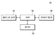
도 1은 본 발명의 일 실시예에 따른 정밀도를 향상시킨 실시간 측위 시스템의 구성블록도이다.
도 2는 도 1에 도시된 태그의 구성블록도이다.
도 3은 본 발명의 일 실시예에 따른 정밀도를 향상시킨 실시간 측위 방법을 나타내는 흐름도이다.
도 4는 제어신호를 생성하는 과정을 나타내는 흐름도이다.
도 5는 제어신호를 생성하기 위해 블링크 신호 및 물리 정보를 분석하는 과정을 나타내는 흐름도이다.
도 6은 태그의 이동경로에 따른 블링크 신호 및 물리 정보의 송신여부를 설명하기 위한 도면이다.
도 7의 (a) 내지 도 7의 (d)는 태그에서 생성되는 블링크 신호 및 물리 정보의 구체적인 태양을 나타내는 도면이다.BRIEF DESCRIPTION OF THE DRAWINGS A brief description of each drawing is provided to more fully understand the drawings recited in the description of the invention.
1 is a block diagram of a real-time positioning system with improved accuracy according to an embodiment of the present invention.
2 is a block diagram of the configuration of the tag shown in Fig.
3 is a flowchart illustrating a real-time positioning method with improved accuracy according to an embodiment of the present invention.
4 is a flowchart showing a process of generating a control signal.
5 is a flowchart illustrating a process of analyzing a blink signal and physical information to generate a control signal.
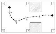
6 is a diagram for explaining whether a blink signal and physical information are transmitted according to a movement path of a tag.
Figs. 7A to 7D are views showing concrete aspects of the blink signal and the physical information generated in the tag. Fig.
본 발명은 다양한 변경을 가할 수 있고 여러 가지 실시예를 가질 수 있는 바, 특정 실시예들을 도면에 예시하고 이를 상세한 설명을 통해 상세히 설명하고자 한다. 그러나, 이는 본 발명을 특정한 실시 형태에 대해 한정하려는 것이 아니며, 본 발명의 사상 및 기술 범위에 포함되는 모든 변경, 균등물 내지 대체물을 포함하는 것으로 이해되어야 한다.While the present invention has been described in connection with certain exemplary embodiments, it is to be understood that the invention is not limited to the disclosed embodiments, but, on the contrary, is intended to cover various modifications and similarities. It should be understood, however, that the invention is not intended to be limited to the particular embodiments, but includes all modifications, equivalents, and alternatives falling within the spirit and scope of the invention.
본 발명을 설명함에 있어서, 관련된 공지 기술에 대한 구체적인 설명이 본 발명의 요지를 불필요하게 흐릴 수 있다고 판단되는 경우, 그 상세한 설명을 생략한다. 또한, 본 명세서의 설명 과정에서 이용되는 숫자(예를 들어, 제1, 제2 등)는 하나의 구성요소를 다른 구성요소와 구분하기 위한 식별기호에 불과하다.DETAILED DESCRIPTION OF THE PREFERRED EMBODIMENTS Hereinafter, exemplary embodiments of the present invention will be described in detail with reference to the accompanying drawings. In addition, numerals (e.g., first, second, etc.) used in the description of the present invention are merely an identifier for distinguishing one component from another.
또한, 본 명세서에서, 일 구성요소가 다른 구성요소와 "연결된다" 거나 "접속된다" 등으로 언급된 때에는, 상기 일 구성요소가 상기 다른 구성요소와 직접 연결되거나 또는 직접 접속될 수도 있지만, 특별히 반대되는 기재가 존재하지 않는 이상, 중간에 또 다른 구성요소를 매개하여 연결되거나 또는 접속될 수도 있다고 이해되어야 할 것이다.Also, in this specification, when an element is referred to as being "connected" or "connected" with another element, the element may be directly connected or directly connected to the other element, It should be understood that, unless an opposite description is present, it may be connected or connected via another element in the middle.
이하의 설명에서 사용되는 구성요소에 대한 접미사 "모듈" 및 "부"는 명세서 작성의 용이함만이 고려되어 부여되거나 혼용되는 것으로서, 그 자체로 서로 구별되는 의미 또는 역할을 갖는 것은 아니다. 또한, 본 발명을 명확하게 설명하기 위하여 설명과 관계없는 부분은 도면에서 생략하였으며, 도면들에 있어서 구성요소의 폭, 길이, 두께 등은 편의를 위하여 과장되어 표현될 수 있다. 명세서 전체에 걸쳐서 동일한 참조부호들은 동일한 구성요소들을 나타낸다.The suffix "module" and " part "for the components used in the following description are given or mixed in consideration of ease of specification, and do not have their own meaning or role. Further, in order to clearly explain the present invention, parts not related to the description are omitted in the drawings, and the width, length, thickness, etc. of the components may be exaggerated for convenience. Like reference numerals refer to like elements throughout the specification.
이하, 첨부된 도면들을 참조하여 본 발명의 실시를 위한 구체적인 내용을 설명하도록 한다.Hereinafter, embodiments of the present invention will be described in detail with reference to the accompanying drawings.
도 1은 본 발명의 일 실시예에 따른 정밀도를 향상시킨 실시간 측위 시스템의 구성블록도이다. 도 2는 도 1에 도시된 태그의 구성블록도이다.1 is a block diagram of a real-time positioning system with improved accuracy according to an embodiment of the present invention. 2 is a block diagram of the configuration of the tag shown in Fig.
도 1 및 도 2를 참조하면, 본 발명의 일 실시예에 따른 정밀도를 향상시킨 실시간 측위 시스템(10)은, 실내외 기타 다양한 환경에서, 태그(100)가 부착되거나 태그(100)를 소지하고 있는 사람 또는 사물의 위치정보를 계산할 수 있다.Referring to FIGS. 1 and 2, a real-
한편, 상기 사람 또는 사물의 수는 제한되지 않으나, 본 명세서에서는 설명의 편의를 위해, 상기 사람 또는 사물의 수는 단수인 것으로 가정한다.On the other hand, although the number of persons or objects is not limited, in the present specification, for convenience of explanation, it is assumed that the number of persons or objects is a singular number.
본 발명의 일 실시예에 따른 정밀도를 향상시킨 실시간 측위 시스템(10)은 태그(100), 복수의 AP(200-1~200-n; 단, n은 2 이상의 정수), 및 측위계산기(300)를 포함할 수 있다. 그리고, 태그(100)는 물리센서(120), 블링크 신호 송신부(140), 제어부(160), 및 측위계산기 통신부(180)를 포함할 수 있다.The real-
태그(100)는 위치정보가 계산되어야 하는 사람이 소지하거나 또는 사물에 부착될 수 있고, 주기적으로 블링크 신호(blink signal)을 생성하여 주변에 위치한 복수의 AP(200-1~200-n; 단, n은 2 이상의 정수)로 송신할 수 있다. 상기 블링크 신호는 블링크 신호 송신부(140)를 이용하여 송신될 수 있다.The
여기서, 상기 블링크 신호는 UWB(Ultra Wide Band) 신호로서, 나노초 이하의 짧은 펄스신호일 수 있으나, 본 발명의 범위가 이에 한정되는 것은 아니다. 실시예에 따라, 상기 블링크 신호는 Wi-Fi(Wireless-Fidelity) 신호, BLE(Bluetooth Low Energy) 신호, 또는 지그비(Zigbee) 신호 중 어느 하나일 수도 있다.Here, the blink signal may be a UWB (Ultra Wide Band) signal, which may be a short pulse signal of nanoseconds or less, but the scope of the present invention is not limited thereto. According to an embodiment, the blink signal may be a Wi-Fi (Wireless-Fidelity) signal, a BLE (Bluetooth Low Energy) signal, or a Zigbee signal.
태그(100)는 상기 블링크 신호에 더하여, 주기적으로 물리 정보를 생성할 수 있다. 그리고, 생성된 물리 정보를 주변에 위치한 복수의 AP(200-1~200-n; 단, n은 2 이상의 정수)로 송신할 수 있다.In addition to the blink signal, the
상기 물리 정보는 태그(100) 내에 포함된 물리센서(120)에 의해 생성되는 정보이고, 물리센서(120)는 자이로(gyro) 센서, 가속도(acceleration) 센서, 및 지자기(geomagnetism) 센서 중 적어도 하나를 포함할 수 있다. 그리고, 상기 물리 정보는 자이로 센서, 가속도 센서, 및 지자기 센서 각각에 의해 생성된 자이로 정보, 가속도 정보, 및 지자기 정보를 포함할 수 있다.The physical information is information generated by the
상기 물리 정보는 상기 블링크 신호와 함께, 블링크 신호 송신부(140)를 이용하여 송신될 수 있다.The physical information may be transmitted together with the blink signal using the
태그(100)는 상기 블링크 신호를 제1 주기마다 송신하고, 상기 물리 정보를 제2 주기마다 송신할 수 있다. 상기 제1 주기와 상기 제2 주기는 서로 다르며, 실시예에 따라, 상기 제1 주기는 상기 제2 주기보다 길 수 있다.The
한편, 태그(100)는 측위계산기 통신부(180)를 통해, 외부로부터 제어신호를 수신하고, 수신된 제어신호에 따라, 각 구성요소들(120, 140, 160, 및 180)을 동작시킬 수 있다. 실시예에 따라, 태그(100)는 상기 제어신호에 응답하여, 상기 블링크 신호 및 상기 물리 정보의 생성주기를 조절할 수 있고, 상기 블링크 신호 및 상기 물리 정보 중 어느 하나의 생성을 멈출 수도 있다. 이에 관한 보다 구체적인 설명은, 도 3 내지 도 7을 참조하여, 후술하기로 한다.On the other hand, the
복수의 AP(200-1~200-n; 단, n은 2 이상의 정수) 각각은 태그(100)로부터 상기 블링크 신호 및 상기 물리 정보를 수신할 수 있다. 그리고, 수신된 물리 정보와 함께 수신된 블링크 신호의 도달시간을 측위계산기(300)로 송신할 수 있다.Each of the plurality of APs 200-1 to 200-n (n is an integer of 2 or more) can receive the blink signal and the physical information from the
실시예에 따라, 복수의 AP(200-1~200-n) 각각은 상기 물리 정보, 상기 블링크 신호의 도달시간 외에 상기 블링크 신호의 도달각도를 측위계산기(300)로 송신할 수 있다.According to the embodiment, each of the plurality of APs 200-1 to 200-n may transmit the arrival angle of the blink signal to the
실시예에 따라, 복수의 AP(200-1~200-n)는 어느 하나의 AP(200-k; 단, k는 1 이상 n 이하의 정수)가 마스터 AP로 동작하고, 이를 제외한 나머지 AP(200-1~200-(k-1), 200-(k+1)~200-n; 단, k는 1 이상 n 이하의 정수)가 슬레이브 AP로 동작할 수 있다. 이 경우, 상기 마스터 AP는, 상기 슬레이브 AP로, 상기 마스터 AP와 상기 슬레이브 AP가 동기된 채로 동작하기 위한 동기신호를 송신할 수 있다. 그러나, 본 발명의 범위가 이에 한정되는 것은 아니다.According to the embodiment, a plurality of APs 200-1 to 200-n operate as a master AP and any one of APs 200-k (where k is an integer of 1 or more and n or less) 200-1 to 200- (k-1), 200- (k + 1) to 200-n, where k is an integer equal to or greater than 1 and equal to or less than n) can operate as a slave AP. In this case, the master AP can transmit, to the slave AP, a synchronization signal for operating the master AP and the slave AP synchronously. However, the scope of the present invention is not limited thereto.
측위계산기(300)는 복수의 AP(200-1~200-n; 단, n은 2 이상의 정수) 각각으로부터 상기 블링크 신호의 도달시간 및 상기 물리 정보를 수신할 수 있다.The
실시예에 따라, 측위계산기(300)는 상기 물리 정보, 및 상기 블링크 신호의 도달시간 외에 상기 블링크 신호의 도달각도를 더 수신할 수도 있다.According to the embodiment, the
측위계산기(300)는 상기 블링크 신호의 도달시간 또는 도달각도 중 적어도 하나, 및 상기 물리 정보를 이용하여, 태그(100)의 위치정보를 계산할 수 있다.The
한편, 측위계산기(300)가 태그(100)의 위치정보를 계산함에 있어서, 다양한 방식의 알고리즘이 적용될 수 있다.Meanwhile, various algorithms can be applied to the
실시예에 따라, 측위계산기(300)는 상기 블링크 신호의 도달시간을 기초로, ToA(Time of Arrival) 및 TDoA(Time Difference of Arrival) 방식의 알고리즘을 적용하여, 태그(100)의 위치정보를 계산할 수 있다.According to the embodiment, the
다른 실시예에 따라, 측위계산기(300)는 상기 블링크 신호의 도달각도를 기초로, AoA(Angle of Arrival) 방식의 알고리즘을 적용하여, 태그(100)의 위치정보를 계산할 수 있다.According to another embodiment, the
또 다른 실시예에 따라, 측위계산기(300)는 상기 블링크 신호의 도달시간 및 도달각도를 기초로, ToA, TDoA, 및 AoA 방식의 알고리즘을 적용하여, 태그(100)의 위치정보를 계산할 수 있다.According to another embodiment, the
이하에서는, 도 1 내지 3을 참조하여, 실시간 측위 시스템(10)의 작동방법에 관하여 보다 구체적으로 설명하기로 한다.Hereinafter, a method of operating the real-
도 3은 본 발명의 일 실시예에 따른 정밀도를 향상시킨 실시간 측위 방법을 나타내는 흐름도이다. 본 발명의 일 실시예에 따른 정밀도를 향상시킨 실시간 측위 방법은, 먼저 제어 신호를 수신하는 단계(S10)를 포함할 수 있다. 그리고, S10 단계 후에, 물리 정보를 생성하는 단계(S20)를 포함할 수 있고, S20 단계 후에, 블링크 신호 및 물리 정보를 송신하는 단계(S30)를 포함할 수 있다.3 is a flowchart illustrating a real-time positioning method with improved accuracy according to an embodiment of the present invention. The real-time positioning method with improved accuracy according to an embodiment of the present invention may include a step (S10) of receiving a control signal first. Then, after step S10, it may include generating physical information (S20), and after step S20, transmitting blink signal and physical information (S30).
여기서, S10 단계, S20 단계, 및 S30 단계는 태그(100)에 의해 수행될 수 있다. 이 경우, 상기 제어 신호는 측위계산기(300)에 의해 생성되어, 측위계산기 통신부(180)를 통해 수신된 신호일 수 있고, 상기 제어 신호는 태그(100)가 생성하는 블링크 신호 및 물리 정보의 생성 주기 및 생성의 멈춤여부에 관한 정보를 포함할 수 있다.Here, steps
여기서, 상기 제어신호의 생성 및 상기 제어신호의 생성을 위해 블링크 신호 및 물리 정보를 분석하는 과정에 대해, 도 4 내지 도 5를 참조하여, 보다 구체적으로 설명하기로 한다.Hereinafter, the process of generating the control signal and analyzing the blink signal and the physical information for generating the control signal will be described in more detail with reference to FIG. 4 through FIG.
도 4는 제어신호를 생성하는 과정을 나타내는 흐름도이다. 도 5는 제어신호를 생성하기 위해 블링크 신호 및 물리 정보를 분석하는 과정을 나타내는 흐름도이다.4 is a flowchart showing a process of generating a control signal. 5 is a flowchart illustrating a process of analyzing a blink signal and physical information to generate a control signal.
먼저, 도 4 및 도 5를 참조하면, 제어신호를 생성하는 과정은, 블링크 신호 및 물리 정보를 분석하는 단계(S100)를 포함할 수 있다. 그리고, S100 단계는, 블링크 신호 및 물리 정보 중 적어도 어느 하나의 단위시간당 도달 개수를 카운트하는 단계(S120) 및 상기 도달 개수의 감소 여부를 판단하는 단계(S140)를 포함할 수 있다. 나아가, 제어신호를 생성하는 과정은, S100 단계 후에, 제어신호를 생성하는 단계(S500)를 포함할 수 있다.4 and 5, the process of generating a control signal may include analyzing a blink signal and physical information (S100). The step S100 may include a step S120 of counting the number of arrivals per unit time of at least one of the blink signal and the physical information and a step S140 of judging whether the number of arrivals is reduced. Further, the process of generating a control signal may include a step S500 of generating a control signal after step S100.
여기서, S100 단계, S120 단계, 및 S140 단계는 측위계산기(300)에 의해 수행될 수 있다.Here, steps S100, S120, and S140 may be performed by the
보다 구체적으로, 측위계산기(300)는, 복수의 AP(200-1~200-n; 단, n은 2 이상의 정수) 각각으로부터 상기 블링크 신호의 도달시간 및 상기 물리 정보를 수신할 수 있고, 실시예에 따라, 상기 물리 정보, 상기 블링크 신호의 도달시간 외에 상기 블링크 신호의 도달각도를 더 수신할 수도 있다.More specifically, the
한편, 상기 블링크 신호의 도달시간 및/또는 도달각도, 및 상기 물리 정보 각각의 도달개수는 실시간 측위 시스템(10)이 적용되는 환경의 변화에 따라 변화할 수 있다. 예컨대, 태그(100)가 복수의 AP(200-1~200-n; 단, n은 2 이상의 정수)와의 관계에서 비시선(NLOS) 상태에 놓이게 되는 경우, 상기 도달개수는 감소하게 된다. 여기서, 상기 도달개수의 변화에 대한 구체적인 설명을 위해, 도 6을 참조하기로 한다.Meanwhile, the arrival time and / or the arrival angle of the blink signal and the arrival number of each physical information may change according to the change of the environment to which the real-
도 6은 태그의 이동경로에 따른 블링크 신호 및 물리 정보의 송신여부를 설명하기 위한 도면이다.6 is a diagram for explaining whether a blink signal and physical information are transmitted according to a movement path of a tag.
각 위치(A, B, C, D, E, 및 F)는 복수의 AP(200-1~200-n; 단, n은 2 이상의 정수)가 설치되어 있는 장소이다. 태그(100)는 시간이 경과(즉, T1 시점으로부터 T4 시점까지)함에 따라 도시된 바와 같은 이동경로를 가지는 것으로 가정한다. 그리고, 일부 영역(특히, 빗금 친 영역)은 상기 블링크 신호가 전달될 수 없는 영역을 의미한다.Each of the positions A, B, C, D, E, and F is a place where a plurality of APs 200-1 to 200-n (n is an integer of 2 or more) are installed. It is assumed that the
여기서, 시간의 경과에 따른 태그(100)의 상태에 관하여 살펴보면, 태그는(100)는 T1 내지 T3 시점까지, A, B, C, 및 D 위치에 설치된 복수의 AP(200-1~200-n)와의 관계에서 시선(LOS) 상태에 놓이게 되고, E 및 F 위치에 설치된 복수의 AP(200-1~200-n)와의 관계에서 비시선(NLOS) 상태에 놓이게 된다.Herein, as to the state of the
한편, 태그(100)는 T4 시점에서, A, B, C, 및 D 위치에 설치된 복수의 AP(200-1~200-n)와의 관계에서 비시선(NLOS) 상태에 놓이게 되고, E 및 F 위치에 설치된 복수의 AP(200-1~200-n)와의 관계에서 시선(LOS) 상태에 놓이게 된다.On the other hand, the
즉, 시간의 경과에 따른 태그(100)의 이동경로에 따라, 복수의 AP(200-1~200-n) 각각에 수신되는 상기 블링크 신호 및 상기 물리 정보의 도달개수는 변화하고, 상기 변화에 따라, 측위계산기(300)가 수신하는 상기 블링크 신호의 도달시간 및/또는 도달각도와 상기 물리 정보 각각의 도달개수도 변화하게 된다.That is, the arrival number of the blink signal and the physical information received in each of the plurality of APs 200-1 to 200-n varies according to the movement path of the
따라서, 측위계산기(300)는 상기 수신된 블링크 신호의 도달시간 및/또는 도달각도를 기초로 상기 블링크 신호의 도달개수의 감소여부를 판단할 수 있고, 상기 수신된 물리 정보를 기초로 상기 물리 정보의 도달개수의 감소여부를 판단할 수 있다. 그리고, 측위계산기(300)는 최종적으로 상기 제어신호의 생성을 위한 상기 블링크 신호 및 상기 물리 정보의 분석을 마칠 수 있다.Accordingly, the
측위계산기(300)는 상기 블링크 신호 및 상기 물리 정보의 분석 결과를 기초로, 상기 제어신호를 생성할 수 있다. 여기서, 상기 생성된 제어신호에 따른 블링크 신호 및 물리 정보의 태양에 관한 구체적인 설명을 위해 도 7의 (a) 내지 도 7의 (d)을 참조하기로 한다.The
도 7의 (a) 내지 도 7의 (d)는 태그에서 생성되는 블링크 신호 및 물리 정보의 구체적인 태양을 나타내는 도면이다.Figs. 7A to 7D are views showing concrete aspects of the blink signal and the physical information generated in the tag. Fig.
도 7의 (a) 내지 도 7의 (c)는 태그(100)가 복수의 AP(200-1~200-n)와의 관계에서 시선(LOS) 상태에 놓여있는 경우를 나타내고, 도 7의 (d)는 태그(100)가 복수의 AP(200-1~200-n)와의 관계에서 시선(LOS) 상태에 놓여있다가 비시선(NLOS) 상태로 놓이게 된 경우를 나타낸다.Figs. 7A to 7C show a case where the
각 도면(도 7의 (a) 내지 도 7의 (d))에서, 태그(100)는 블링크 신호(1400a) 및 물리 정보(1400b)를 주기적으로 생성한다.In each of the drawings (Figs. 7A to 7D), the
도 7의 (a)의 경우, 태그(100)는 각 시점(즉, ⓐ, ⓑ, 및 ⓒ)에서 블링크 신호(1400a)를 생성하고, 블링크 신호(1400a)의 생성 시점 사이에 물리 정보(1400b)를 생성할 수 있다.7A, the
도 7의 (b)의 경우, 태그(100)는 각 시점(즉, ⓐ, ⓑ, 및 ⓒ)에서 블링크 신호(1400a)를 생성하고, 블링크 신호(1400a)의 생성 시점을 포함하여 물리 정보(1400b)를 더 생성할 수 있다.7B, the
도 7의 (c)의 경우, 태그(100)는 각 시점(즉, ⓐ, ⓑ, 및 ⓒ)에서 블링크 신호(1400a)를 생성하고, 블링크 신호(1400a)의 생성 시점 사이에, 생성 주기를 변화시켜가면서 물리 정보(1400b)를 생성할 수 있다.7C, the
도 7의 (d)의 경우, 태그(100)는 각 시점(즉, ⓐ 및 ⓑ)에서 블링크 신호(1400a)를 생성하고, 블링크 신호(1400a)의 생성 시점 사이에 물리 정보(1400b)를 생성하며, 특정 시점(즉, ⓒ)에 이르러, 블링크 신호(1400a)의 생성을 멈출 수 있다.7 (d), the
본 발명의 일 실시예에 따른 정밀도를 향상시킨 실시간 측위 방법은, S30 단계 후에, 블링크 신호의 도달시간을 계산하는 단계(S40)를 포함할 수 있고, S40 단계 후에, 블링크 신호의 도달시간 및 물리 정보를 송신하는 단계(S50)를 포함할 수 있다.The real-time positioning method with improved accuracy according to an embodiment of the present invention may include calculating (S40) the arrival time of the blink signal after step S30, and after step S40, And transmitting information (S50).
여기서, S40 단계는 복수의 AP(200-1~200-n; 단, n은 1 이상의 정수) 각각에 의해 수행될 수 있다.Here, the step S40 may be performed by each of a plurality of APs 200-1 to 200-n (n is an integer of 1 or more).
본 발명의 일 실시예에 따른 정밀도를 향상시킨 실시간 측위 방법은, S50 단계 후에, 태그의 위치정보를 계산하는 단계(S60)를 포함할 수 있다.The real-time positioning method with improved accuracy according to an embodiment of the present invention may include a step S60 of calculating the position information of the tag after step S50.
여기서, S60 단계는 측위계산기(300)에 의해 수행될 수 있다.Here, the step S60 may be performed by the
상술한 바와 같이, 본 발명의 일 실시예에 따른 정밀도를 향상시킨 실시간 측위 방법 및 시스템은 블링크 신호에 더하여 물리 정보를 이용하여 태그의 위치정보를 계산함으로써, 보다 정밀도를 향상시킬 수 있다.As described above, the real-time positioning method and system with improved accuracy according to an embodiment of the present invention can improve the accuracy by calculating the position information of the tag using physical information in addition to the blink signal.
본 발명의 일 실시예에 따른 정밀도를 향상시킨 실시간 측위 방법 및 시스템은 상기 블링크 신호와 물리 정보의 생성 주기 및 생성의 멈춤여부에 관한 정보를 포함하는 제어신호를 이용하여, 다양한 환경에서 보다 정밀도를 향상시킬 수 있다.A real-time positioning method and system with improved accuracy according to an embodiment of the present invention uses a control signal including information on generation period and generation stop of the blink signal and physical information, Can be improved.
이상의 설명은 본 발명의 기술 사상을 예시적으로 설명한 것에 불과한 것으로서, 본 발명이 속하는 기술 분야에서 통상의 지식을 가진 자라면 본 발명의 본질적인 특성에서 벗어나지 않는 범위에서 다양한 수정 및 변형이 가능할 것이다.The foregoing description is merely illustrative of the technical idea of the present invention, and various changes and modifications may be made by those skilled in the art without departing from the essential characteristics of the present invention.
따라서, 본 발명에 개시된 실시 예들은 본 발명의 기술 사상을 한정하기 위한 것이 아니라 설명하기 위한 것이고, 이러한 실시 예에 의하여 본 발명의 기술 사상의 범위가 한정되는 것은 아니다.Therefore, the embodiments disclosed in the present invention are intended to illustrate rather than limit the scope of the present invention, and the scope of the technical idea of the present invention is not limited by these embodiments.
본 발명의 보호 범위는 아래의 청구범위에 의하여 해석되어야 하며, 그와 동등한 범위 내에 있는 모든 기술 사상은 본 발명의 권리범위에 포함되는 것으로 해석되어야 할 것이다.The scope of protection of the present invention should be construed according to the following claims, and all technical ideas within the scope of equivalents should be construed as falling within the scope of the present invention.
10: 실시간 측위 시스템
100: 태그
120: 물리센서
140: 블링크 신호 송신부
160: 제어부
180: 측위계산기 통신부
200-1~200-n: 복수의 AP
300: 측위계산기10: Real-time positioning system
100: Tag
120: Physical sensor
140: Blink signal transmitter
160:
180: Positioning calculator communication unit
200-1 to 200-n: a plurality of APs
300: positioning calculator
Claims (10)
Translated fromKorean상기 블링크 신호 및 상기 물리 정보를 수신하고, 상기 물리 정보와 함께상기 블링크 신호의 도달시간을 송신하는 복수의 AP; 및
상기 블링크 신호의 도달시간 및 상기 물리 정보를 이용하여, 상기 태그의 위치정보를 계산하는 측위계산기를 포함하는, 실시간 측위 시스템.A tag for transmitting a blink signal and physical information;
A plurality of APs receiving the blink signal and the physical information, and transmitting the arrival time of the blink signal together with the physical information; And
And a positioning calculator that calculates positional information of the tag using the arrival time of the blink signal and the physical information.
상기 태그는 상기 측위계산기에 의해 생성된 제어신호에 응답하여, 상기 블링크 신호 및 상기 물리 정보를 생성하고,
상기 제어신호는 상기 블링크 신호 및 상기 물리 정보 각각의 생성 주기 및 생성의 멈춤여부에 관한 정보를 포함하는, 실시간 측위 시스템.The method according to claim 1,
Wherein the tag generates the blink signal and the physical information in response to a control signal generated by the positioning calculator,
Wherein the control signal includes information about a generation period of each of the blink signal and the physical information and whether to stop generation of the blink signal and the physical information.
상기 태그는 물리 센서를 포함하고,
상기 물리 센서는 상기 물리 정보를 생성하며,
상기 물리 센서는 자이로 센서, 가속도 센서, 및 지자기 센서 중 적어도 하나를 포함하는, 실시간 측위 시스템.The method according to claim 1,
The tag includes a physical sensor,
Wherein the physical sensor generates the physical information,
Wherein the physical sensor comprises at least one of a gyro sensor, an acceleration sensor, and a geomagnetic sensor.
상기 블링크 신호를 제1 주기마다 송신하고, 상기 물리 정보를 제2 주기마다 송신하며,
상기 제1 주기는 상기 제2 주기보다 긴, 실시간 측위 시스템.The method of claim 1, wherein the tag
Transmits the blink signal every first period, transmits the physical information every second period,
Wherein the first period is longer than the second period.
상기 블링크 신호는 UWB(Ultra Wide Band) 신호, Wi-Fi(Wireless-Fidelity) 신호, BLE(Bluetooth Low Energy) 신호, 및 지그비(Zigbee) 신호 중 적어도 하나를 포함하는, 실시간 측위 시스템.The method according to claim 1,
Wherein the blink signal comprises at least one of a UWB (Ultra Wide Band) signal, a Wi-Fi (Wireless-Fidelity) signal, a BLE (Bluetooth Low Energy) signal, and a Zigbee signal.
상기 블링크 신호의 도달시간을 이용한 TDoA(Time Difference of Arrival) 방식을 기반으로, 상기 태그의 위치정보를 계산하는, 실시간 측위 시스템.The positioning system according to claim 1,
Wherein the location information of the tag is calculated based on a Time Difference of Arrival (TDoA) method using the arrival time of the blink signal.
상기 마스터 AP 및 상기 슬레이브 AP 각각은 상기 마스터 AP로부터 송신되는 동기 신호에 의해 동기화되는, 실시간 측위 시스템.Wherein the plurality of APs include a master AP and a slave AP,
Wherein each of the master AP and the slave AP is synchronized by a synchronization signal transmitted from the master AP.
상기 측위계산기 통신부는 외부로부터 제어신호를 수신하고,
상기 제어부는 상기 제어신호에 응답하여 상기 물리센서 및 상기 블링크 신호 송신부를 제어하며,
상기 블링크 신호 송신부는 상기 물리 정보 및 상기 블링크 신호를 송신하는, 실시간 측위 시스템용 태그.A physical sensor for generating physical information; A blink signal transmitter for generating a blink signal; A control unit; And a positioning calculator communication unit,
The positioning computer communication unit receives a control signal from the outside,
Wherein the controller controls the physical sensor and the blink signal transmitter in response to the control signal,
And the blink signal transmitter transmits the physical information and the blink signal.
상기 블링크 신호를 제1 주기마다 송신하고, 상기 물리 정보를 제2 주기마다 송신하며,
상기 제1 주기는 상기 제2 주기보다 긴, 실시간 측위 시스템용 태그.9. The apparatus of claim 8, wherein the blink signal transmitter
Transmits the blink signal every first period, transmits the physical information every second period,
Wherein the first period is longer than the second period.
상기 블링크 신호는 UWB(Ultra Wide Band) 신호, Wi-Fi(Wireless-Fidelity) 신호, BLE(Bluetooth Low Energy) 신호, 및 지그비(Zigbee) 신호 중 적어도 하나를 포함하고,
상기 제어신호는 상기 블링크 신호 및 상기 물리 정보 각각의 생성 주기 및 생성의 멈춤여부에 관한 정보를 포함하는, 실시간 측위 시스템용 태그.9. The method of claim 8,
The blink signal includes at least one of an Ultra Wide Band (UWB) signal, a Wireless-Fidelity (Wi-Fi) signal, a Bluetooth low energy (BLE) signal, and a Zigbee signal,
Wherein the control signal includes information about a generation period of each of the blink signal and the physical information and whether to stop generation of the blink signal and the physical information.
Priority Applications (1)
| Application Number | Priority Date | Filing Date | Title |
|---|---|---|---|
| KR1020170078162AKR102112906B1 (en) | 2017-06-20 | 2017-06-20 | Real-time location method and system with improved accuracy |
Applications Claiming Priority (1)
| Application Number | Priority Date | Filing Date | Title |
|---|---|---|---|
| KR1020170078162AKR102112906B1 (en) | 2017-06-20 | 2017-06-20 | Real-time location method and system with improved accuracy |
Publications (2)
| Publication Number | Publication Date |
|---|---|
| KR20180138067Atrue KR20180138067A (en) | 2018-12-28 |
| KR102112906B1 KR102112906B1 (en) | 2020-05-19 |
Family
ID=65008540
Family Applications (1)
| Application Number | Title | Priority Date | Filing Date |
|---|---|---|---|
| KR1020170078162AActiveKR102112906B1 (en) | 2017-06-20 | 2017-06-20 | Real-time location method and system with improved accuracy |
Country Status (1)
| Country | Link |
|---|---|
| KR (1) | KR102112906B1 (en) |
Cited By (4)
| Publication number | Priority date | Publication date | Assignee | Title |
|---|---|---|---|---|
| CN111479228A (en)* | 2020-01-13 | 2020-07-31 | 张苏 | UWB positioning system, tag position determination method and device |
| KR20230149501A (en)* | 2022-04-20 | 2023-10-27 | (주)쉬운기술 | Real-time positioning method |
| KR20240080000A (en)* | 2022-11-29 | 2024-06-05 | 재단법인차세대융합기술연구원 | Method for positioning and azimuth estimation |
| WO2024258251A1 (en)* | 2023-06-16 | 2024-12-19 | 현대자동차주식회사 | Localization method and device for charging electric vehicle |
Citations (5)
| Publication number | Priority date | Publication date | Assignee | Title |
|---|---|---|---|---|
| KR101025832B1 (en)* | 2009-01-30 | 2011-03-30 | 부산대학교 산학협력단 | Real-time position tracking system and its tag positioning correction method |
| KR20110098487A (en)* | 2010-02-26 | 2011-09-01 | 부산대학교 산학협력단 | Operation method of real-time multi-level location recognition system based on port environment |
| KR20120026889A (en)* | 2010-09-10 | 2012-03-20 | 엘지이노텍 주식회사 | Rtls tag for real-time management of livestock and livestock managing system using the same |
| KR20170044532A (en)* | 2015-10-15 | 2017-04-25 | 에스케이텔레콤 주식회사 | Method and Apparatus for Preventing Tag Collision in Real Time Location System |
| KR20170058783A (en)* | 2015-11-19 | 2017-05-29 | 한국마사회 | Race horse tracking system |
- 2017
- 2017-06-20KRKR1020170078162Apatent/KR102112906B1/enactiveActive
Patent Citations (5)
| Publication number | Priority date | Publication date | Assignee | Title |
|---|---|---|---|---|
| KR101025832B1 (en)* | 2009-01-30 | 2011-03-30 | 부산대학교 산학협력단 | Real-time position tracking system and its tag positioning correction method |
| KR20110098487A (en)* | 2010-02-26 | 2011-09-01 | 부산대학교 산학협력단 | Operation method of real-time multi-level location recognition system based on port environment |
| KR20120026889A (en)* | 2010-09-10 | 2012-03-20 | 엘지이노텍 주식회사 | Rtls tag for real-time management of livestock and livestock managing system using the same |
| KR20170044532A (en)* | 2015-10-15 | 2017-04-25 | 에스케이텔레콤 주식회사 | Method and Apparatus for Preventing Tag Collision in Real Time Location System |
| KR20170058783A (en)* | 2015-11-19 | 2017-05-29 | 한국마사회 | Race horse tracking system |
Cited By (6)
| Publication number | Priority date | Publication date | Assignee | Title |
|---|---|---|---|---|
| CN111479228A (en)* | 2020-01-13 | 2020-07-31 | 张苏 | UWB positioning system, tag position determination method and device |
| CN111479228B (en)* | 2020-01-13 | 2021-12-21 | 张苏 | UWB positioning system, tag position determination method and device |
| KR20230149501A (en)* | 2022-04-20 | 2023-10-27 | (주)쉬운기술 | Real-time positioning method |
| KR20240080000A (en)* | 2022-11-29 | 2024-06-05 | 재단법인차세대융합기술연구원 | Method for positioning and azimuth estimation |
| WO2024117373A1 (en)* | 2022-11-29 | 2024-06-06 | 재단법인 차세대융합기술연구원 | Positioning and azimuth estimation method |
| WO2024258251A1 (en)* | 2023-06-16 | 2024-12-19 | 현대자동차주식회사 | Localization method and device for charging electric vehicle |
Also Published As
| Publication number | Publication date |
|---|---|
| KR102112906B1 (en) | 2020-05-19 |
Similar Documents
| Publication | Publication Date | Title |
|---|---|---|
| KR102009791B1 (en) | 3D position tracking system using UWB | |
| RU2697838C1 (en) | Positioning system | |
| US12418321B2 (en) | Location system with ultra-wideband (UWB) infrastructure and discovery infrastructure | |
| JP2016156809A (en) | Calculation method and device of relative azimuth angle, and relative position specifying method | |
| US12253596B2 (en) | Ad hoc positioning of mobile devices using near ultrasound signals | |
| US20240107260A1 (en) | Low level smartphone audio and sensor clock synchronization | |
| CN109696167A (en) | A kind of UWB indoor three-dimensional positioning system and method | |
| KR20180138067A (en) | Real-time location method and system with improved accuracy | |
| KR101608976B1 (en) | System and Method of Collaborative Localization Using Short Range Wireless Communication Network Without Location Infrastructure | |
| CN107479513A (en) | A kind of localization method and system, electronic equipment | |
| KR101814698B1 (en) | Method for simultaneously setting coordinates of anchor and tag using wireless transmission / reception and communication system thereof | |
| KR20130136708A (en) | Apparatus and method for estimating location | |
| Syberfeldt et al. | Localizing operators in the smart factory: A review of existing techniques and systems | |
| Wang et al. | Prototyping and experimental comparison of IR-UWB based high precision localization technologies | |
| Zhang et al. | Ultrawideband-based real-time positioning with cascaded wireless clock synchronization method | |
| Yudanto et al. | Ultra-wideband localization: Advancements in device and system calibration for enhanced accuracy and flexibility | |
| Michel et al. | A novell wireless forklift positioning system for indoor and outdoor use | |
| CN104777454A (en) | Method for adjusting positioning system, method for positioning objects, and positioning system | |
| SambathKumar et al. | Arithmetical analysis of WSN based indoor positioning localization systems with Kalman filtering | |
| KR102185062B1 (en) | Real time locating system and transmitter for the same | |
| Wiebking et al. | Remote local positioning radar | |
| KR102604367B1 (en) | a high definition positioning and movement capturing device for virtual reality space sevice supply containing eXtended Reality | |
| Cho et al. | Performance tests for wireless real-time localization systems to improve mobile robot navigation in various indoor environments | |
| CN107920327B (en) | Positioning method, device and system, positioning signal determination method and terminal | |
| Cho et al. | Localization Systems to Improve Mobile Robot Navigation in Various Indoor Environments |
Legal Events
| Date | Code | Title | Description |
|---|---|---|---|
| A201 | Request for examination | ||
| PA0109 | Patent application | Patent event code:PA01091R01D Comment text:Patent Application Patent event date:20170620 | |
| PA0201 | Request for examination | ||
| PG1501 | Laying open of application | ||
| E902 | Notification of reason for refusal | ||
| PE0902 | Notice of grounds for rejection | Comment text:Notification of reason for refusal Patent event date:20190313 Patent event code:PE09021S01D | |
| E90F | Notification of reason for final refusal | ||
| PE0902 | Notice of grounds for rejection | Comment text:Final Notice of Reason for Refusal Patent event date:20191031 Patent event code:PE09021S02D | |
| E701 | Decision to grant or registration of patent right | ||
| PE0701 | Decision of registration | Patent event code:PE07011S01D Comment text:Decision to Grant Registration Patent event date:20200401 | |
| GRNT | Written decision to grant | ||
| PR0701 | Registration of establishment | Comment text:Registration of Establishment Patent event date:20200513 Patent event code:PR07011E01D | |
| PR1002 | Payment of registration fee | Payment date:20200513 End annual number:3 Start annual number:1 | |
| PG1601 | Publication of registration | ||
| PR1001 | Payment of annual fee | Payment date:20230510 Start annual number:4 End annual number:4 | |
| PR1001 | Payment of annual fee | Payment date:20240513 Start annual number:5 End annual number:5 | |
| PR1001 | Payment of annual fee | Payment date:20250610 Start annual number:6 End annual number:6 |