KR20180128259A - Bicycle anti-theft device using bicycle saddie - Google Patents
Bicycle anti-theft device using bicycle saddieDownload PDFInfo
- Publication number
- KR20180128259A KR20180128259AKR1020170063602AKR20170063602AKR20180128259AKR 20180128259 AKR20180128259 AKR 20180128259AKR 1020170063602 AKR1020170063602 AKR 1020170063602AKR 20170063602 AKR20170063602 AKR 20170063602AKR 20180128259 AKR20180128259 AKR 20180128259A
- Authority
- KR
- South Korea
- Prior art keywords
- bicycle
- saddle
- fixed
- fixing
- wire
- Prior art date
- Legal status (The legal status is an assumption and is not a legal conclusion. Google has not performed a legal analysis and makes no representation as to the accuracy of the status listed.)
- Granted
Links
Images

Classifications
- B—PERFORMING OPERATIONS; TRANSPORTING
- B62—LAND VEHICLES FOR TRAVELLING OTHERWISE THAN ON RAILS
- B62H—CYCLE STANDS; SUPPORTS OR HOLDERS FOR PARKING OR STORING CYCLES; APPLIANCES PREVENTING OR INDICATING UNAUTHORIZED USE OR THEFT OF CYCLES; LOCKS INTEGRAL WITH CYCLES; DEVICES FOR LEARNING TO RIDE CYCLES
- B62H5/00—Appliances preventing or indicating unauthorised use or theft of cycles; Locks integral with cycles
- B62H5/14—Appliances preventing or indicating unauthorised use or theft of cycles; Locks integral with cycles preventing wheel rotation
- B—PERFORMING OPERATIONS; TRANSPORTING
- B62—LAND VEHICLES FOR TRAVELLING OTHERWISE THAN ON RAILS
- B62J—CYCLE SADDLES OR SEATS; AUXILIARY DEVICES OR ACCESSORIES SPECIALLY ADAPTED TO CYCLES AND NOT OTHERWISE PROVIDED FOR, e.g. ARTICLE CARRIERS OR CYCLE PROTECTORS
- B62J1/00—Saddles or other seats for cycles; Arrangement thereof; Component parts
- B62J1/28—Other additional equipment, e.g. back-rests for children
Landscapes
- Engineering & Computer Science (AREA)
- Mechanical Engineering (AREA)
- Lock And Its Accessories (AREA)
- Axle Suspensions And Sidecars For Cycles (AREA)
Abstract
Description
Translated fromKorean본 발명은 자전거 안장을 이용한 자전거 도난방지 장치에 관한 것으로서, 더욱 상세하게는 자전거의 안장을 포함한 자전거의 도난을 방지하기 위해 잠금장치를 사용할 편리하게 사용할 수 있으며, 자전거의 거치상태에 따라 안장, 앞바퀴 및 뒷바퀴를 선택적으로 고정할 수 있는 자전거 안장을 이용한 자전거 도난방지 장치에 관한 것이다.The present invention relates to a bicycle security device using a bicycle saddle, and more particularly, to a bicycle security device using a bicycle saddle, and more particularly, And a bicycle saddle which can selectively fix the rear wheel.
일반적으로 자전거는 운동기구, 교통수단으로서, 다양한 연령층의 남녀노소 누구나 편리하게 사용하는 기구이다.Generally, bicycles are exercise equipment and transportation means, and it is a convenient tool for all ages of all ages.
이러한 자전거는 타인이 쉽게 사용할 수 있고 무게가 가벼워 분실 또는 도난이 빈번하게 발생하고 있어 별도의 잠금장치를 이용하여 예방하고 있다.These bicycles are easy to use by others, are light in weight, are frequently lost or stolen, and are prevented by using a separate locking device.
하지만, 자전거는 조립구조가 간편하여 앞바퀴, 뒷바퀴 프레임 및 안장을 별도의 공구 없이 분리할 수 있어 각각의 앞바퀴, 뒷바퀴 프레임 및 안장을 분리하여 도난당하는 문제점이 발생하고 있다.However, since the assembly structure of the bicycle is simple, it is possible to separate the front wheel, the rear wheel frame and the saddle without a separate tool, so that the front wheel, the rear wheel frame and the saddle are separated and stolen.
이러한 문제점을 해결하기 위해 종래기술로 한국공개특허 제10-2010-0001691호 "자전거에 구비된 안장 잠금장치"가 제시된 바 있다.In order to solve such a problem, Korean Patent Laid-Open No. 10-2010-0001691 entitled " Saddle lock device equipped on a bicycle "
종래기술은 몸체프레임과 연결된 안장부가 흰지 장치에 의해 회동 가능하게 형성되며, 안장의 뒷부분에 잠금장치를 형성된다.In the prior art, a saddle portion connected to the body frame is rotatably formed by a white device, and a locking device is formed at a rear portion of the saddle.
이를 통해 흰지 장치를 통해 안장을 뒷바퀴 측으로 회동시킨 후 잠금장치를 통해 고정할 수 있다.Through this, the saddle can be pivoted to the rear wheel side through the white device and fixed through the locking device.
하지만, 안장을 회동하게 이루어져 있어 과도한 하중에 의해 임의로 회동 되거나, 절곡되는 문제점이 있다.However, there is a problem in that the saddle is rotated so that it is arbitrarily rotated or bent due to an excessive load.
또한, 안장은 신체의 높이에 맞춰 조절하여 탑승하게 되나, 바퀴와 체결시 안장의 높이를 조절하게 됨에 따라 매번 번거롭게 안장 높이를 조절해야 하는 불편한 점이 있다.In addition, although the saddle is adjusted to the height of the body, it is inconvenient to adjust the height of the saddle every time the saddle is adjusted when the wheel is fastened with the saddle.
본 발명은 상기와 같은 문제점을 해결하기 위해 안출된 것으로서, 본 발명의 목적은 자전거의 도난을 방지하며, 일체로 형성되어 휴대 및 관리가 편리한 자전거 안장을 이용한 자전거 도난방지 장치을 제공하는 데 있다.SUMMARY OF THE INVENTION The present invention has been made to solve the above-mentioned problems, and it is an object of the present invention to provide a bicycle theft prevention device using a bicycle saddle, which prevents the bicycle from being stolen and is integrally formed,
본 발명의 또 다른 목적은, 자전거의 부품 가운데 분리가 편리한 안장과 앞바퀴, 뒷바퀴 및 프레임을 연결하여 개별적인 부품의 도난을 방지할 수 있는 자전거 안장을 이용한 자전거 도난방지 장치을 제공하는 데 있다.It is another object of the present invention to provide a bicycle theft prevention device using a bicycle saddle which can prevent theft of individual parts by connecting a saddle which is easy to separate among parts of the bicycle and a front wheel, a rear wheel and a frame.
상기와 같은 목적을 달성하기 위해 본 발명은 자전거 안장에 구비된 자전거 안장을 이용한 자전거 도난방지 장치에 있어서, 안장의 하부에 설치되는 몸체; 상기 몸체의 내부에 권취부에 권취되며 끝단에 고리부가 형성되어 상기 몸체의 일측으로 노출되는 와이어; 상기 몸체의 타측에 구비되며, 키를 통해 개폐조작되는 잠금수단을 통해 상기 고리부를 결합고정시키는 고정부;로 이루어지는 것을 특징으로 한다.In order to achieve the above object, the present invention provides a bicycle theft prevention apparatus using a bicycle saddle provided on a bicycle saddle, comprising: a body installed at a lower portion of a saddle; A wire wound around the winding part inside the body and having a hook at an end thereof and exposed to one side of the body; And a fixing part which is provided on the other side of the body and fixes the loop part through a locking means which is opened and closed by a key.
상기 권취부는, 상기 몸체의 내부에 형성된 고정축과, 상기 고정축에 회전가능하게 결합되며 와이어가 권취되는 회전축 및 상기 고정축과 상기 회전축에 양 끝단이 각각 고정되어 탄성에 의해 상기 회전축을 일방향으로 회전시키는 스프링으로 이루어지는 것이 바람직하다.The winding unit includes a fixed shaft formed inside the body, a rotating shaft rotatably coupled to the fixed shaft and wound around the wire, and both ends fixed to the fixed shaft and the rotating shaft so that the rotating shaft is rotated in one direction And a spring that rotates.
상기 고정부는, 상기 몸체에 회동 가능하게 결합되며, 상기 고리부를 고정하는 고정프레임과, 상기 고정프레임을 탄성에 의해 폐쇄시키는 탄성체와, 상기 잠금수단의 조작에 의해 상기 고정프레임을 고정 및 이동 조절하는 이동체로 이루어지는 것이 바람직하다.The fixing unit includes a fixed frame rotatably coupled to the body and fixed to the body, an elastic body that elastically closes the fixed frame, and a fixing frame fixed and moved by the operation of the locking unit It is preferable that it is composed of a moving body.
본 발명의 자전거 안장을 이용한 자전거 도난방지 장치에 따르면, 안장의 하부면에 설치되어 자전거를 고정할 수 있는 잠금장치가 설치되어 휴대 및 관리가 편리하고 잠금장치의 분실을 방지하며, 자전거의 도난당하는 상황을 예방할 수 있는 효과가 있다.According to the bicycle theft prevention device using the bicycle saddle of the present invention, a locking device that is installed on the lower surface of the saddle and can fix the bicycle is installed, which is convenient to carry and manage, prevents the locking device from being lost, There is an effect that the situation can be prevented.
본 발명에 따르면, 자전거의 부품 가운데 분리가 편리한 안장과 앞바퀴, 뒷바퀴 및 프레임을 연결하여 개별적인 부품의 도난을 방지할 수 있는 장점이 있다.According to the present invention, it is possible to prevent theft of individual parts by connecting the saddle, which is easy to separate among the parts of the bicycle, to the front wheel, the rear wheel and the frame.
본 발명에 따르면, 와이어의 인출이 편리하고 사용시 권취되어 거치적거리거나, 외부에 간섭이 발생하지 않아 사용이 편리한 이점이 있다.According to the present invention, there is an advantage that the wire is convenient to be drawn out, wound at the time of use, is stationary, and does not cause interference to the outside.
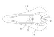
도 1은 본 발명에 따른 자전거 안장을 이용한 자전거 도난방지 장치를 도시한 개념도,
도 2는 본 발명에 따른 작동상태를 도시한 개념도,
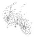
도 3은 본 발명에 따른 사용상태를 도시한 측면도이다.1 is a conceptual view showing a bicycle theft prevention device using a bicycle saddle according to the present invention;
2 is a conceptual diagram showing an operating state according to the present invention;
3 is a side view showing the use state according to the present invention.
이하에서는 본 발명에 따른 자전거 안장을 이용한 자전거 도난방지 장치에 관하여 첨부된 도면과 함께 더불어 상세히 설명하기로 한다.DETAILED DESCRIPTION OF THE PREFERRED EMBODIMENTS Hereinafter, a bicycle theft prevention apparatus using a bicycle saddle according to the present invention will be described in detail with reference to the accompanying drawings.
도 1은 본 발명에 따른 자전거 안장을 이용한 자전거 도난방지 장치를 도시한 개념도이며, 도 2는 본 발명에 따른 작동상태를 도시한 개념도이고, 도 3은 본 발명에 따른 사용상태를 도시한 측면도이다.FIG. 1 is a conceptual view showing a bicycle theft prevention device using a bicycle saddle according to the present invention, FIG. 2 is a conceptual view showing an operating state according to the present invention, and FIG. 3 is a side view showing a use state according to the present invention .
도 1 내지 도 3에 도시된 바와 같이 본 발명은 자전거 안장을 이용한 자전거 도난방지 장치에 관한 것으로서, 더욱 상세하게는 자전거의 안장을 포함한 자전거의 도난을 방지하기 위해 잠금장치를 사용할 편리하게 사용할 수 있으며, 자전거의 거치상태에 따라 안장, 앞바퀴 및 뒷바퀴를 선택적으로 고정할 수 있는 자전거 안장을 이용한 자전거 도난방지 장치에 관한 것이다.As shown in FIGS. 1 to 3, the present invention relates to a bicycle security device using a bicycle saddle, and more particularly, a locking device can be conveniently used to prevent the bicycle from being stolen, including a saddle And a bicycle saddle which can selectively fix a saddle, a front wheel and a rear wheel according to a state of mounting the bicycle.
이러한 본 발명은 자전거의 프레임, 안장, 앞바퀴 및 뒷바퀴를 선택하여 고정할 수 있도록 안장의 하부면에 위치하여 몸체(10), 와이어(20) 및 고정부(30)로 이루어진다.The present invention comprises a
상기 몸체(10)는 상기 안장(110)의 하부에 설치된다.The
따라서 탑승자가 상기 안장(110)에 탑승시 접촉이 발생하지 않는 하부에 위치하되, 상기 프레임(120)과 상기 안장(110)의 높낮이를 조절하는 시트포스트와 간섭이 발생하지 않도록 형성된다.Accordingly, it is formed so as not to interfere with the seat post that controls the height of the
상기 와이어(20)는 상기 몸체(10)의 내부의 권취부(40)에 권취되며, 끝단에 고리부(21)가 형성되어 상기 몸체(10)의 일측으로 노출된다.The
여기서 상기 권취부(40)는 상기 몸체(10)의 내부에 형성된 고정축(41)과, 상기 고정축(41)에 회전가능하게 결합되며 상기 와이어(20)가 권취되는 회전축(42) 및 상기 고정축(41)과 상기 회전축(42)에 양 끝단이 각각 고정되어 탄성에 의해 상기 회전축(42)을 일방향으로 회전시키는 스프링(43)으로 이루어진다.The
즉, 와이어(20)가 권취된 상기 회전축(42)은 상기 고정축(41)에 회전 가능하게 결합되며, 상기 스프링(43)의 탄성에 의해 일방향으로 회전하여 상기 와이어(20)를 권취시킬 수 있다.That is, the
따라서 상기 와이어(20)를 인출하면 상기 회전축(42)의 회전에 의해 상기 스프링(43)에 탄성이 가해지고, 상기 와이어(20)에 가해진 당기는 힘이 제거되면 상기 스프링(43)에 의해 상기 회전축(42)이 회전하여 상기 와이어(20)를 권취할 수 있다.When the
이에 따라 상기 와이어(20)는 상기 고리부(21)를 파지하여 인출할 수 있으며, 당기는 힘이 제거되면 상기 스프링(43)에 의해 자동으로 권취된다.Accordingly, the
상기 고정부(30)는 상기 몸체(10)의 타측에 구비되며, 키를 통해 개폐조작되는 잠금수단(33)을 통해 상기 고리부(21)를 결합고정시킨다.The
여기서 상기 고정부(30)는 상기 몸체에 이동 가능하게 결합되며, 상기 고리부(21)를 고정하는 고정프레임(31)과, 상기 고정프레임(31)을 탄성에 의해 폐쇄시키는 탄성체(32)와 상기 잠금수단(33)의 조작에 의해 상기 고정프레임(31)을 고정 및 이동시키는 이동체(34)로 이루어진다.The
따라서 상기 고정프레임(31)은 상기 몸체(10)의 타측에 이동 및 회동하여 개폐 가능하게 결합되며, 상기 고리부(21)를 탈착할 수 있다.Therefore, the
그리고 상기 탄성체(32)는 상기 몸체(10)와 상기 고정프레임(31)에 양끝단이 접촉되어 탄성에 의해 상기 고정프레임(31)을 한쪽으로 이동시켜 폐쇄 가능하게 설치된다.The
즉, 상기 잠금수단(33)을 조작하여 상기 고정프레임(31)을 개폐 조작이 가능하며, 개방상태에서 상기 고리부(21)를 끼움 결합하고 상기 탄성체(32)에 의해 상기 고정프레임(31)이 폐쇄된다.That is, it is possible to open and close the fixed
또한, 상기 고리부(21)가 결합된 상태에서 상기 잠금수단(33)을 조작하여 상기 고정프레임(31)을 개방한 상태에서 상기 고리부(21)를 이탈할 수 있다.In addition, in a state in which the
아울러 상기 잠금수단(33)은 일반적인 자물쇠의 키와 동일한 구조로 이루어지되, 숫자, 패턴 등으로 변경할 수 있다.In addition, the lock means 33 has the same structure as a key of a general lock, but can be changed to a number, a pattern, or the like.
따라서 상기 잠금수단(33)을 통해 상기 고정프레임(31)을 회동시켜 개방하되, 상기 탄성체(32)에 의해 폐쇄될 수 있도록 이루어져 개방상태에서 상기 고리부(21)를 고정하며 상기 탄성체(32)에 의해 폐쇄되어 상기 고리부(21)를 고정할 수 있다.Therefore, the
이에 따라 도 3에 도시된 바와 같이 상기 와이어(20)를 인출하여 앞바퀴(130), 뒷바퀴(140), 프레임(120) 및 자전거 거치대 등에 고정하여 도난을 방지할 수 있도록 사용한다.As shown in FIG. 3, the
상기 몸체(10)의 일측에 노출된 고리부(21)를 파지하여 상기 와이어(20)를 인출시킨 후 앞바퀴(130), 뒷바퀴(140), 프레임(120) 및 자전거 거치대 등을 선택하여 연결한다.The
그리고 상기 잠금수단(33)을 조작해 상기 고정프레임(31)을 개방시킨 후 상기 고리부(21)를 고정하고 상기 고정프레임(31)을 상기 몸체(10)에 고정시킨다.Then, after the
여기서 상기 고정프레임(31)은 상기 탄성체(32)의 탄성에 의해 이동하여 상기 몸체(10)에 밀착되며, 외부에서 강한 힘을 가해 고정할 수 있도록 이루어지는 것이 바람직하다.Here, the
이때, 상기 고리부(21)가 상기 고정프레임(31)에 고정된 상태에서 상기 와이어(20)는 상기 권취부(40)에 의해 권취되어 팽팽 잡아당겨 거치적거리지 않으며, 외부와 간섭이 발생하지 않는다.At this time, in a state where the
이에 따라 상기 자전거(100)를 고정할 수 있으며, 분리가 편한 뒷바퀴(140), 앞바퀴(130), 프레임(120) 및 상기 안장(110)을 연결하여 개별적인 도난을 방지할 수 있다.Accordingly, the
또한, 거치 된 상기 자전거(100)를 사용할 때에는 상기 잠금수단(33)에 맞는 키를 이용하여 조작해 상기 몸체(10)에 고정된 상기 고정프레임(31)을 이탈시킨다.When the
그리고 상기 몸체(10)에서 이탈된 상기 고정프레임(31)을 조작하여 상기 고리부(21)를 분리하되, 상기 고정프레임(31) 또는 상기 와이어(20)를 파지하고 잡아당겨 편리하게 분리할 수 있다.The
이후 자전거 거치대, 앞바퀴(130), 뒷바퀴(140) 및 프레임(120)에 감긴 상기 와이어(20)를 잠금 시킨 역방향으로 이동시켜 해제한 후 상기 와이어(20)는 상기 권취부(40)에 권취시킨다.The
이를 통해 상기 안장(110)의 하부에 편리하게 보관할 수 있어 별도로 잠금장치를 구비하지 않고 사용이 가능하며, 상기 자전거(100)를 사용시 편리하게 관리할 수 있다.Accordingly, it can be conveniently stored in the lower portion of the
이상에서와 같이 본 발명의 권리는 위에서 설명된 실시예에 한정되지 않고 청구범위에 기재된 바에 의해 정의되며, 본 발명의 분야에서 통상의 지식을 가진 자가 청구범위에 기재된 권리범위 내에서 다양한 변형과 개작을 할 수 있다는 것은 자명하다.It will be apparent to those skilled in the art that various modifications and variations can be made in the present invention without departing from the spirit or scope of the invention as defined by the appended claims. It is obvious that you can do it.
10: 몸체20: 와이어
21: 고리부30: 고정부
31: 고정프레임32: 탄성체
33: 잠금수단34: 이동체
40: 권취부41: 고정축
42; 회전축43: 스프링
100: 자전거110: 안장
120: 프레임130: 앞바퀴
140: 뒷바퀴10: body 20: wire
21: collar 30:
31: fixed frame 32: elastic body
33: Locking means 34: Moving body
40: winding section 41: fixed shaft
42; Rotation shaft 43: Spring
100: Bicycle 110: Saddle
120: Frame 130: Front wheel
140: Rear wheel
Claims (3)
Translated fromKorean안장(110)의 하부에 설치되는 몸체(10);
상기 몸체(10)의 내부에 권취부(40)에 권취되며 끝단에 고리부(21)가 형성되어 상기 몸체(10)의 일측으로 노출되는 와이어(20);
상기 몸체(10)의 타측에 구비되며, 키를 통해 개폐조작되는 잠금수단(33)을 통해 상기 고리부(21)를 결합고정시키는 고정부(30);로 이루어지는 것을 특징으로 하는 자전거 안장을 이용한 자전거 도난방지 장치.A bicycle security device using a bicycle saddle equipped with a bicycle saddle,
A body 10 installed at a lower portion of the saddle 110;
A wire 20 wound around the winding unit 40 inside the body 10 and formed with a ring 21 at an end thereof and exposed to one side of the body 10;
And a fixing part (30) provided on the other side of the body (10) for fixing the claw part (21) through a locking means (33) opened and closed by a key. Bicycle anti-theft device.
상기 권취부(40)는,
상기 몸체(10)의 내부에 형성된 고정축(41)과,
상기 고정축(41)에 회전가능하게 결합되며 상기 와이어(20)가 권취되는 회전축(42) 및
상기 고정축(41)과 상기 회전축(42)에 양 끝단이 각각 고정되어 탄성에 의해 상기 회전축(42)을 일방향으로 회전시키는 스프링(43);으로 이루어지는 것을 특징으로 하는 자전거 안장을 이용한 자전거 도난방지 장치.The method according to claim 1,
The winding portion (40)
A fixing shaft 41 formed inside the body 10,
A rotating shaft 42 rotatably coupled to the fixed shaft 41 and wound around the wire 20,
And a spring (43) fixed at both ends to the fixed shaft (41) and the rotary shaft (42) to rotate the rotary shaft (42) in one direction by elasticity. Device.
상기 고정부(30)는,
상기 몸체(10)에 회동 가능하게 결합되며, 상기 고리부(21)를 고정하는 고정프레임(31)과,
상기 고정프레임(31)을 탄성에 의해 폐쇄시키는 탄성체(32)와,
상기 잠금수단(33)의 조작에 의해 상기 고정프레임(31)을 고정 및 이동 조절하는 이동체(34)로 이루어지는 것을 특징으로 하는 자전거 안장을 이용한 자전거 도난방지 장치.The method according to claim 1,
The fixing portion (30)
A fixed frame 31 rotatably coupled to the body 10 and fixing the ring 21,
An elastic body 32 for closing the fixed frame 31 by elasticity,
And a moving body (34) for fixing and moving the fixed frame (31) by the operation of the locking means (33).
Priority Applications (1)
| Application Number | Priority Date | Filing Date | Title |
|---|---|---|---|
| KR1020170063602AKR102311883B1 (en) | 2017-05-23 | 2017-05-23 | Bicycle anti-theft device using bicycle saddie |
Applications Claiming Priority (1)
| Application Number | Priority Date | Filing Date | Title |
|---|---|---|---|
| KR1020170063602AKR102311883B1 (en) | 2017-05-23 | 2017-05-23 | Bicycle anti-theft device using bicycle saddie |
Publications (2)
| Publication Number | Publication Date |
|---|---|
| KR20180128259Atrue KR20180128259A (en) | 2018-12-03 |
| KR102311883B1 KR102311883B1 (en) | 2021-10-12 |
Family
ID=64743163
Family Applications (1)
| Application Number | Title | Priority Date | Filing Date |
|---|---|---|---|
| KR1020170063602AActiveKR102311883B1 (en) | 2017-05-23 | 2017-05-23 | Bicycle anti-theft device using bicycle saddie |
Country Status (1)
| Country | Link |
|---|---|
| KR (1) | KR102311883B1 (en) |
Cited By (1)
| Publication number | Priority date | Publication date | Assignee | Title |
|---|---|---|---|---|
| US11939019B2 (en) | 2020-12-11 | 2024-03-26 | Hyundai Motor Company | Electric kickboard and method for controlling the same |
Citations (5)
| Publication number | Priority date | Publication date | Assignee | Title |
|---|---|---|---|---|
| US4044577A (en)* | 1976-09-09 | 1977-08-30 | Lock-A-Bike, Inc. | Anti-theft device for portable apparatus |
| JPH0374724U (en)* | 1989-11-14 | 1991-07-26 | ||
| JP2003011866A (en)* | 2001-07-03 | 2003-01-15 | Marui:Kk | Bicycle |
| KR20090123225A (en)* | 2008-05-27 | 2009-12-02 | 김동호 | Bicycle lock |
| JP3169798U (en)* | 2011-06-06 | 2011-08-18 | 福恵 金城 | Anti-theft |
- 2017
- 2017-05-23KRKR1020170063602Apatent/KR102311883B1/enactiveActive
Patent Citations (5)
| Publication number | Priority date | Publication date | Assignee | Title |
|---|---|---|---|---|
| US4044577A (en)* | 1976-09-09 | 1977-08-30 | Lock-A-Bike, Inc. | Anti-theft device for portable apparatus |
| JPH0374724U (en)* | 1989-11-14 | 1991-07-26 | ||
| JP2003011866A (en)* | 2001-07-03 | 2003-01-15 | Marui:Kk | Bicycle |
| KR20090123225A (en)* | 2008-05-27 | 2009-12-02 | 김동호 | Bicycle lock |
| JP3169798U (en)* | 2011-06-06 | 2011-08-18 | 福恵 金城 | Anti-theft |
Cited By (1)
| Publication number | Priority date | Publication date | Assignee | Title |
|---|---|---|---|---|
| US11939019B2 (en) | 2020-12-11 | 2024-03-26 | Hyundai Motor Company | Electric kickboard and method for controlling the same |
Also Published As
| Publication number | Publication date |
|---|---|
| KR102311883B1 (en) | 2021-10-12 |
Similar Documents
| Publication | Publication Date | Title |
|---|---|---|
| CN1131684C (en) | Collapsible add-on luggage securing and security securing device and method | |
| US4023387A (en) | Cable dispensing and retrieving device | |
| US20150089779A1 (en) | Closure devices for coupling components to racks and methods therefor | |
| JP2016515669A (en) | Helmet lock device | |
| US5582043A (en) | Golf bag and club securing device | |
| US2451100A (en) | Chain lock | |
| US3990279A (en) | Bi-circle lock | |
| EP0471748B1 (en) | Bicycle accessory for carrying a shackle | |
| JP2007314243A5 (en) | ||
| US3971589A (en) | Rectractable automobile trunk lid tie down | |
| US8196945B2 (en) | Bicycle pedal with integrated cable lock | |
| CN106799986A (en) | A kind of automatic band-retracting mechanism of wheel fixator | |
| KR20180128259A (en) | Bicycle anti-theft device using bicycle saddie | |
| KR101098773B1 (en) | Vehicle cover | |
| JP2016171796A (en) | Fishing reel with concealed line stopper | |
| KR101175184B1 (en) | A portable motor car cover | |
| KR101002261B1 (en) | Bicycle lock | |
| JP2002068358A (en) | Bicycle housing case | |
| KR200420804Y1 (en) | Length adjustment device of earphone cord | |
| KR200420542Y1 (en) | Length adjustment device of earphone cord | |
| CN207595116U (en) | A kind of lock that may act as kettle-frame | |
| KR20100006173A (en) | Fastening apparatus for carrying coffin | |
| KR101170100B1 (en) | Protective equipment and bike storage compatibility stands | |
| CA1042952A (en) | Retractable automobile trunk lid tie down | |
| JP2001200670A (en) | Storable article for preventing bag snatching/lifting for bicycle |
Legal Events
| Date | Code | Title | Description |
|---|---|---|---|
| PA0109 | Patent application | St.27 status event code:A-0-1-A10-A12-nap-PA0109 | |
| PG1501 | Laying open of application | St.27 status event code:A-1-1-Q10-Q12-nap-PG1501 | |
| R18-X000 | Changes to party contact information recorded | St.27 status event code:A-3-3-R10-R18-oth-X000 | |
| R17-X000 | Change to representative recorded | St.27 status event code:A-3-3-R10-R17-oth-X000 | |
| PA0201 | Request for examination | St.27 status event code:A-1-2-D10-D11-exm-PA0201 | |
| D13-X000 | Search requested | St.27 status event code:A-1-2-D10-D13-srh-X000 | |
| D14-X000 | Search report completed | St.27 status event code:A-1-2-D10-D14-srh-X000 | |
| E902 | Notification of reason for refusal | ||
| PE0902 | Notice of grounds for rejection | St.27 status event code:A-1-2-D10-D21-exm-PE0902 | |
| E13-X000 | Pre-grant limitation requested | St.27 status event code:A-2-3-E10-E13-lim-X000 | |
| P11-X000 | Amendment of application requested | St.27 status event code:A-2-2-P10-P11-nap-X000 | |
| P13-X000 | Application amended | St.27 status event code:A-2-2-P10-P13-nap-X000 | |
| E701 | Decision to grant or registration of patent right | ||
| PE0701 | Decision of registration | St.27 status event code:A-1-2-D10-D22-exm-PE0701 | |
| GRNT | Written decision to grant | ||
| PR0701 | Registration of establishment | St.27 status event code:A-2-4-F10-F11-exm-PR0701 | |
| PR1002 | Payment of registration fee | St.27 status event code:A-2-2-U10-U11-oth-PR1002 Fee payment year number:1 | |
| PG1601 | Publication of registration | St.27 status event code:A-4-4-Q10-Q13-nap-PG1601 | |
| R18-X000 | Changes to party contact information recorded | St.27 status event code:A-5-5-R10-R18-oth-X000 | |
| PN2301 | Change of applicant | St.27 status event code:A-5-5-R10-R13-asn-PN2301 St.27 status event code:A-5-5-R10-R11-asn-PN2301 | |
| PN2301 | Change of applicant | St.27 status event code:A-5-5-R10-R11-asn-PN2301 | |
| PN2301 | Change of applicant | St.27 status event code:A-5-5-R10-R14-asn-PN2301 | |
| P14-X000 | Amendment of ip right document requested | St.27 status event code:A-5-5-P10-P14-nap-X000 | |
| R18-X000 | Changes to party contact information recorded | St.27 status event code:A-5-5-R10-R18-oth-X000 | |
| K11-X000 | Ip right revival requested | St.27 status event code:A-6-4-K10-K11-oth-X000 | |
| K12-X000 | Request for ip right revival rejected | St.27 status event code:A-6-4-K10-K12-oth-X000 | |
| P14-X000 | Amendment of ip right document requested | St.27 status event code:A-5-5-P10-P14-nap-X000 | |
| P14-X000 | Amendment of ip right document requested | St.27 status event code:A-5-5-P10-P14-nap-X000 | |
| P14-X000 | Amendment of ip right document requested | St.27 status event code:A-5-5-P10-P14-nap-X000 |