KR20180125948A - Surgical robot system - Google Patents
Surgical robot systemDownload PDFInfo
- Publication number
- KR20180125948A KR20180125948AKR1020187023002AKR20187023002AKR20180125948AKR 20180125948 AKR20180125948 AKR 20180125948AKR 1020187023002 AKR1020187023002 AKR 1020187023002AKR 20187023002 AKR20187023002 AKR 20187023002AKR 20180125948 AKR20180125948 AKR 20180125948A
- Authority
- KR
- South Korea
- Prior art keywords
- section
- subject
- robot
- robotic
- stiffness
- Prior art date
- Legal status (The legal status is an assumption and is not a legal conclusion. Google has not performed a legal analysis and makes no representation as to the accuracy of the status listed.)
- Granted
Links
- 238000002432robotic surgeryMethods0.000claimsabstractdescription6
- 238000000034methodMethods0.000claimsdescription54
- 238000001356surgical procedureMethods0.000claimsdescription20
- 230000008878couplingEffects0.000claimsdescription9
- 238000010168coupling processMethods0.000claimsdescription9
- 238000005859coupling reactionMethods0.000claimsdescription9
- 210000003484anatomyAnatomy0.000claimsdescription8
- 238000002224dissectionMethods0.000claimsdescription7
- 238000003780insertionMethods0.000claimsdescription6
- 230000037431insertionEffects0.000claimsdescription6
- 230000003287optical effectEffects0.000claimsdescription6
- 230000004927fusionEffects0.000claimsdescription5
- 210000001562sternumAnatomy0.000claimsdescription5
- 230000003068static effectEffects0.000claimsdescription4
- 210000000988bone and boneAnatomy0.000abstractdescription49
- 230000029058respiratory gaseous exchangeEffects0.000abstractdescription6
- 206010011224CoughDiseases0.000abstractdescription3
- 238000013459approachMethods0.000description7
- 239000012636effectorSubstances0.000description4
- 230000000399orthopedic effectEffects0.000description3
- 206010023230Joint stiffnessDiseases0.000description2
- 238000005452bendingMethods0.000description2
- 238000012544monitoring processMethods0.000description2
- 210000000115thoracic cavityAnatomy0.000description2
- 230000003187abdominal effectEffects0.000description1
- 230000009471actionEffects0.000description1
- 230000003466anti-cipated effectEffects0.000description1
- 210000000746body regionAnatomy0.000description1
- 230000008859changeEffects0.000description1
- 210000000038chestAnatomy0.000description1
- 238000010276constructionMethods0.000description1
- 230000008602contractionEffects0.000description1
- 238000010586diagramMethods0.000description1
- 230000000694effectsEffects0.000description1
- 238000005516engineering processMethods0.000description1
- 239000007943implantSubstances0.000description1
- 210000003127kneeAnatomy0.000description1
- 230000007246mechanismEffects0.000description1
- 238000012986modificationMethods0.000description1
- 230000004048modificationEffects0.000description1
- 210000000056organAnatomy0.000description1
- 230000008569processEffects0.000description1
- 230000000717retained effectEffects0.000description1
- 239000011435rockSubstances0.000description1
- 230000006641stabilisationEffects0.000description1
- 238000011105stabilizationMethods0.000description1
Images


Classifications
- A—HUMAN NECESSITIES
- A61—MEDICAL OR VETERINARY SCIENCE; HYGIENE
- A61B—DIAGNOSIS; SURGERY; IDENTIFICATION
- A61B34/00—Computer-aided surgery; Manipulators or robots specially adapted for use in surgery
- A61B34/30—Surgical robots
- A—HUMAN NECESSITIES
- A61—MEDICAL OR VETERINARY SCIENCE; HYGIENE
- A61B—DIAGNOSIS; SURGERY; IDENTIFICATION
- A61B17/00—Surgical instruments, devices or methods
- A61B17/00234—Surgical instruments, devices or methods for minimally invasive surgery
- A—HUMAN NECESSITIES
- A61—MEDICAL OR VETERINARY SCIENCE; HYGIENE
- A61B—DIAGNOSIS; SURGERY; IDENTIFICATION
- A61B34/00—Computer-aided surgery; Manipulators or robots specially adapted for use in surgery
- A61B34/10—Computer-aided planning, simulation or modelling of surgical operations
- A—HUMAN NECESSITIES
- A61—MEDICAL OR VETERINARY SCIENCE; HYGIENE
- A61B—DIAGNOSIS; SURGERY; IDENTIFICATION
- A61B34/00—Computer-aided surgery; Manipulators or robots specially adapted for use in surgery
- A61B34/20—Surgical navigation systems; Devices for tracking or guiding surgical instruments, e.g. for frameless stereotaxis
- A—HUMAN NECESSITIES
- A61—MEDICAL OR VETERINARY SCIENCE; HYGIENE
- A61B—DIAGNOSIS; SURGERY; IDENTIFICATION
- A61B34/00—Computer-aided surgery; Manipulators or robots specially adapted for use in surgery
- A61B34/70—Manipulators specially adapted for use in surgery
- A—HUMAN NECESSITIES
- A61—MEDICAL OR VETERINARY SCIENCE; HYGIENE
- A61B—DIAGNOSIS; SURGERY; IDENTIFICATION
- A61B90/00—Instruments, implements or accessories specially adapted for surgery or diagnosis and not covered by any of the groups A61B1/00 - A61B50/00, e.g. for luxation treatment or for protecting wound edges
- A61B90/03—Automatic limiting or abutting means, e.g. for safety
- A—HUMAN NECESSITIES
- A61—MEDICAL OR VETERINARY SCIENCE; HYGIENE
- A61B—DIAGNOSIS; SURGERY; IDENTIFICATION
- A61B90/00—Instruments, implements or accessories specially adapted for surgery or diagnosis and not covered by any of the groups A61B1/00 - A61B50/00, e.g. for luxation treatment or for protecting wound edges
- A61B90/39—Markers, e.g. radio-opaque or breast lesions markers
- A—HUMAN NECESSITIES
- A61—MEDICAL OR VETERINARY SCIENCE; HYGIENE
- A61B—DIAGNOSIS; SURGERY; IDENTIFICATION
- A61B90/00—Instruments, implements or accessories specially adapted for surgery or diagnosis and not covered by any of the groups A61B1/00 - A61B50/00, e.g. for luxation treatment or for protecting wound edges
- A61B90/50—Supports for surgical instruments, e.g. articulated arms
- A—HUMAN NECESSITIES
- A61—MEDICAL OR VETERINARY SCIENCE; HYGIENE
- A61F—FILTERS IMPLANTABLE INTO BLOOD VESSELS; PROSTHESES; DEVICES PROVIDING PATENCY TO, OR PREVENTING COLLAPSING OF, TUBULAR STRUCTURES OF THE BODY, e.g. STENTS; ORTHOPAEDIC, NURSING OR CONTRACEPTIVE DEVICES; FOMENTATION; TREATMENT OR PROTECTION OF EYES OR EARS; BANDAGES, DRESSINGS OR ABSORBENT PADS; FIRST-AID KITS
- A61F2/00—Filters implantable into blood vessels; Prostheses, i.e. artificial substitutes or replacements for parts of the body; Appliances for connecting them with the body; Devices providing patency to, or preventing collapsing of, tubular structures of the body, e.g. stents
- A61F2/02—Prostheses implantable into the body
- A61F2/30—Joints
- A61F2/44—Joints for the spine, e.g. vertebrae, spinal discs
- A61F2/4455—Joints for the spine, e.g. vertebrae, spinal discs for the fusion of spinal bodies, e.g. intervertebral fusion of adjacent spinal bodies, e.g. fusion cages
- A—HUMAN NECESSITIES
- A61—MEDICAL OR VETERINARY SCIENCE; HYGIENE
- A61F—FILTERS IMPLANTABLE INTO BLOOD VESSELS; PROSTHESES; DEVICES PROVIDING PATENCY TO, OR PREVENTING COLLAPSING OF, TUBULAR STRUCTURES OF THE BODY, e.g. STENTS; ORTHOPAEDIC, NURSING OR CONTRACEPTIVE DEVICES; FOMENTATION; TREATMENT OR PROTECTION OF EYES OR EARS; BANDAGES, DRESSINGS OR ABSORBENT PADS; FIRST-AID KITS
- A61F2/00—Filters implantable into blood vessels; Prostheses, i.e. artificial substitutes or replacements for parts of the body; Appliances for connecting them with the body; Devices providing patency to, or preventing collapsing of, tubular structures of the body, e.g. stents
- A61F2/02—Prostheses implantable into the body
- A61F2/30—Joints
- A61F2/46—Special tools for implanting artificial joints
- A61F2/4603—Special tools for implanting artificial joints for insertion or extraction of endoprosthetic joints or of accessories thereof
- A61F2/4611—Special tools for implanting artificial joints for insertion or extraction of endoprosthetic joints or of accessories thereof of spinal prostheses
- A—HUMAN NECESSITIES
- A61—MEDICAL OR VETERINARY SCIENCE; HYGIENE
- A61B—DIAGNOSIS; SURGERY; IDENTIFICATION
- A61B17/00—Surgical instruments, devices or methods
- A61B2017/00017—Electrical control of surgical instruments
- A61B2017/00115—Electrical control of surgical instruments with audible or visual output
- A61B2017/00128—Electrical control of surgical instruments with audible or visual output related to intensity or progress of surgical action
- A—HUMAN NECESSITIES
- A61—MEDICAL OR VETERINARY SCIENCE; HYGIENE
- A61B—DIAGNOSIS; SURGERY; IDENTIFICATION
- A61B17/00—Surgical instruments, devices or methods
- A61B2017/00681—Aspects not otherwise provided for
- A61B2017/00694—Aspects not otherwise provided for with means correcting for movement of or for synchronisation with the body
- A61B2017/00699—Aspects not otherwise provided for with means correcting for movement of or for synchronisation with the body correcting for movement caused by respiration, e.g. by triggering
- A—HUMAN NECESSITIES
- A61—MEDICAL OR VETERINARY SCIENCE; HYGIENE
- A61B—DIAGNOSIS; SURGERY; IDENTIFICATION
- A61B34/00—Computer-aided surgery; Manipulators or robots specially adapted for use in surgery
- A61B34/10—Computer-aided planning, simulation or modelling of surgical operations
- A61B2034/101—Computer-aided simulation of surgical operations
- A61B2034/105—Modelling of the patient, e.g. for ligaments or bones
- A—HUMAN NECESSITIES
- A61—MEDICAL OR VETERINARY SCIENCE; HYGIENE
- A61B—DIAGNOSIS; SURGERY; IDENTIFICATION
- A61B34/00—Computer-aided surgery; Manipulators or robots specially adapted for use in surgery
- A61B34/10—Computer-aided planning, simulation or modelling of surgical operations
- A61B2034/107—Visualisation of planned trajectories or target regions
- A—HUMAN NECESSITIES
- A61—MEDICAL OR VETERINARY SCIENCE; HYGIENE
- A61B—DIAGNOSIS; SURGERY; IDENTIFICATION
- A61B34/00—Computer-aided surgery; Manipulators or robots specially adapted for use in surgery
- A61B34/20—Surgical navigation systems; Devices for tracking or guiding surgical instruments, e.g. for frameless stereotaxis
- A61B2034/2046—Tracking techniques
- A61B2034/2055—Optical tracking systems
- A—HUMAN NECESSITIES
- A61—MEDICAL OR VETERINARY SCIENCE; HYGIENE
- A61B—DIAGNOSIS; SURGERY; IDENTIFICATION
- A61B90/00—Instruments, implements or accessories specially adapted for surgery or diagnosis and not covered by any of the groups A61B1/00 - A61B50/00, e.g. for luxation treatment or for protecting wound edges
- A61B90/06—Measuring instruments not otherwise provided for
- A61B2090/064—Measuring instruments not otherwise provided for for measuring force, pressure or mechanical tension
- A—HUMAN NECESSITIES
- A61—MEDICAL OR VETERINARY SCIENCE; HYGIENE
- A61B—DIAGNOSIS; SURGERY; IDENTIFICATION
- A61B90/00—Instruments, implements or accessories specially adapted for surgery or diagnosis and not covered by any of the groups A61B1/00 - A61B50/00, e.g. for luxation treatment or for protecting wound edges
- A61B90/50—Supports for surgical instruments, e.g. articulated arms
- A61B90/57—Accessory clamps
- A61B2090/571—Accessory clamps for clamping a support arm to a bed or other supports
- A—HUMAN NECESSITIES
- A61—MEDICAL OR VETERINARY SCIENCE; HYGIENE
- A61F—FILTERS IMPLANTABLE INTO BLOOD VESSELS; PROSTHESES; DEVICES PROVIDING PATENCY TO, OR PREVENTING COLLAPSING OF, TUBULAR STRUCTURES OF THE BODY, e.g. STENTS; ORTHOPAEDIC, NURSING OR CONTRACEPTIVE DEVICES; FOMENTATION; TREATMENT OR PROTECTION OF EYES OR EARS; BANDAGES, DRESSINGS OR ABSORBENT PADS; FIRST-AID KITS
- A61F2/00—Filters implantable into blood vessels; Prostheses, i.e. artificial substitutes or replacements for parts of the body; Appliances for connecting them with the body; Devices providing patency to, or preventing collapsing of, tubular structures of the body, e.g. stents
- A61F2/02—Prostheses implantable into the body
- A61F2/30—Joints
- A61F2002/30001—Additional features of subject-matter classified in A61F2/28, A61F2/30 and subgroups thereof
- A61F2002/30621—Features concerning the anatomical functioning or articulation of the prosthetic joint
- A61F2002/30622—Implant for fusing a joint or bone material
- A—HUMAN NECESSITIES
- A61—MEDICAL OR VETERINARY SCIENCE; HYGIENE
- A61F—FILTERS IMPLANTABLE INTO BLOOD VESSELS; PROSTHESES; DEVICES PROVIDING PATENCY TO, OR PREVENTING COLLAPSING OF, TUBULAR STRUCTURES OF THE BODY, e.g. STENTS; ORTHOPAEDIC, NURSING OR CONTRACEPTIVE DEVICES; FOMENTATION; TREATMENT OR PROTECTION OF EYES OR EARS; BANDAGES, DRESSINGS OR ABSORBENT PADS; FIRST-AID KITS
- A61F2/00—Filters implantable into blood vessels; Prostheses, i.e. artificial substitutes or replacements for parts of the body; Appliances for connecting them with the body; Devices providing patency to, or preventing collapsing of, tubular structures of the body, e.g. stents
- A61F2/02—Prostheses implantable into the body
- A61F2/30—Joints
- A61F2/46—Special tools for implanting artificial joints
- A61F2002/4632—Special tools for implanting artificial joints using computer-controlled surgery, e.g. robotic surgery
Landscapes
- Health & Medical Sciences (AREA)
- Life Sciences & Earth Sciences (AREA)
- Engineering & Computer Science (AREA)
- Surgery (AREA)
- Biomedical Technology (AREA)
- Animal Behavior & Ethology (AREA)
- Veterinary Medicine (AREA)
- Heart & Thoracic Surgery (AREA)
- General Health & Medical Sciences (AREA)
- Public Health (AREA)
- Medical Informatics (AREA)
- Molecular Biology (AREA)
- Nuclear Medicine, Radiotherapy & Molecular Imaging (AREA)
- Oral & Maxillofacial Surgery (AREA)
- Robotics (AREA)
- Orthopedic Medicine & Surgery (AREA)
- Pathology (AREA)
- Neurology (AREA)
- Transplantation (AREA)
- Cardiology (AREA)
- Vascular Medicine (AREA)
- Physical Education & Sports Medicine (AREA)
- Manipulator (AREA)
Abstract
Translated fromKoreanDescription
Translated fromKorean본 발명은, 환자의 작은 동작이 수술 도구의 위치 정확성을 감소시킴 없이, 환자의 신체상의 상당한 범위의 위치에 걸쳐 환자에게 수술 절차를 실행하기 위한, 특히 정형외과 수술에 사용하기 위한 로봇 시스템 분야에 관한 것이다.The present invention relates to the field of robotic systems for use in orthopedic surgery, particularly for orthopedic surgery, to perform surgical procedures on a patient over a significant range of locations on the body of a patient, without the small motion of the patient reducing the positional accuracy of the surgical instrument. .
본 출원의 공동 발명자인 M. Shoham의 "Miniature Bone-Attached Surgical Robot"에 대한 미국 특허 제 8,571,638 호에는 소형 뼈 장착 수술용 로봇이 개시되어 있는데, 이 로봇은 소형 사이즈의 로봇과 함께 피술자의 뼈에 장착됨으로 인해, 로봇 아암이 의도된 자세로 가동될 때 로봇이 장착된 피술자의 뼈에 대해 정확한 위치를 유지하도록 보장한다. 이런 상황은 피술자의 뼈에 로봇 베이스가 단단히 부착되기 때문에 달성된다.U.S. Patent No. 8,571,638 to M. Shoham, co-inventor of the present application, entitled "Miniature Bone-Attached Surgical Robot", discloses a small bone-mounted surgical robot, which, together with a small size robot, Thereby ensuring that the robot will maintain an accurate position with respect to the bone of the mounted subject when the robot arm is operated in its intended posture. This situation is achieved because the robot base is firmly attached to the bones of the subject.
소형 뼈 장착 수술용 로봇은, 미국 특허 제 8,838,205 호 "Robot for use with Orthopedic Inserts, 및 미국 특허 제 8,518,051 호 "Robotic Total/Partial Knee Arthroplastics" 과 같이 뼈 장착 로봇의 다양한 응용 분야에 대해 다수의 특허 출원 및 등록된 특허에 의해 증명된 바와 같이, 피술자의 신체의 합리적인 제한 영역에 걸쳐 수술을 수행할 때 많은 잇점이 있는데, 양 특허는 본 출원, 및 다른 출원과 공동 발명자를 가진다. 그러나 이 시스템은, 뼈에 장착될 수 있는 소형 로봇이 필연적으로 제한된 작동 범위(operating envelope)를 갖게 장착되기에, 환자의 신체의 더 넓은 영역에 걸쳐 수술을 수행해야 하는 경우 단점을 가질 수 있다. 뼈 부착의 실질적인 잇점을 잃지 않고, 넓은 범위의 접근을 가능하게 하고 여러 위치에서 해제 및 재부착(release and reattachment) 할 필요가 없는 로봇 시스템이 바람직할 것이다.A small bone-mounted surgical robot has been patented for various applications of bone-mounted robots such as US Pat. No. 8,838,205 "Robot for use with Orthopedic Inserts" and US Pat. No. 8,518,051 "Robotic Total / Partial Knee Arthroplastics" And as demonstrated by the registered patent, there are many advantages in performing surgery over a reasonable range of restraint of the subject's body, both of which have this application, and other applications and co-inventors, Small robots, which can be mounted on bones, are inevitably equipped with a limited operating envelope, which can have the disadvantage of requiring surgery over a wider area of the patient's body. Robots that do not need to release and reattach at multiple locations to enable a wide range of access, This system would be desirable.
B. Mittelstadt에 의한 "Positioning Surgical Robot을 위한 방법 및 시스템"의 미국 특허 제 5,806,518 호에서와 같은 종래 기술에서, 피술자의 뼈가 수술 로봇에 장착된 베드의 베이스 또는 바닥에 대해 견고하게 고정되는 로봇 수술 시스템이 기술되어 있다. 피술자의 뼈가 위치 모니터링 고정구(position monitoring fixture)에 부착되어 임의의 뼈 동작(bone motion)의 발생에 대해 보상이 이루어질 수 있도록 뼈의 동작이 시스템 제어기에 1 대 1의 관계로 전달되는 다른 시스템이 존재한다. 그러나 이러한 시스템은 크고 다루기 힘든 것으로 간주 될 수 있으며, 뼈의 위치를 모니터링하기 위한 추가적인 능동 제어 기능(active control functions)이 필요하다.In the prior art, such as in US Pat. No. 5,806,518, entitled " METHOD AND SYSTEM FOR POSITIONING SURGICAL ROBOTS " by B. Mittelstadt, a robot surgical procedure in which the bones of a subject are firmly secured against the base or floor of a bed mounted on a surgical robot System is described. Another system in which the bones of a subject are attached to a position monitoring fixture so that the motion of the bones is delivered in a one-to-one relationship to the system controller so that compensation for the occurrence of any bone motion exist. However, such systems can be considered large and cumbersome, and require additional active control functions to monitor the location of the bones.
따라서, 종래의 시스템 및 방법의 단점 중 적어도 일부를 극복하는 로봇 수술 시스템에 대한 필요성이 존재한다.Thus, there is a need for a robotic surgical system that overcomes at least some of the disadvantages of conventional systems and methods.
명세서의 이 섹션 및 및 다른 섹션에서 언급된 각 간행물의 공개는 참조로 서, 전체로서 각각 여기에 통합된다.The disclosure of each publication referred to in this and other sections of the specification is incorporated herein by reference in its entirety.
본 발명은, 로봇의 단부 액추에이터의 위치와, 단부 액츄에이터에 의해 유지되는 도구가 작동하고자 하는 피술자의 해부 부분 사이에서 한정적이고 정확한 관계(defined and precise relationship)를 제공하는, 큰 작업 범위(working envelope)를 갖는 새로운 외과 로봇 시스템을 기술한다. 동시에, 시스템은 피술자에 과도한 제약을 가하지 않고 호흡 또는 외과의사의 압력으로 인한 동작과 관련된, 제한된 움직임을 겪도록 피술자에 허용하고, 단부 액츄에이터가 그것이 작동하는 신체 부분에 대해 정확하게 한정된 공간적 위치(defined spatial location) 및 방향(orientation )을 위반하지 않도록 한다. 현재 기술된 시스템에서, 로봇 아암은, 일반적으로 단단하지만, 선택적으로 제어 가능하고 확장 및 수축 특징을 모니터링할 수 있는 연결 요소(connection element)에 의해 신체 부분에 고정(anchored)된다. 피술자의 상체 부위(upper body section) 영역에서 작동하는 시스템의 실례를 사용하면, 피술자의 호흡이나 기침으로 인해 피술자의 흉추(thoracic spine) 또는 흉골(sternum)의 동작 범위는, 더 큰 움직임이 가능하지만 일반적으로 10-12mm 정도일 뿐이다. 모든 로봇 아암은 특정한 본질적인 유연성 수준(intrinsic level of flexibility)을 가진다. 그러나, 종래의 시스템에서, 로봇 동작의 정확성을 유지하기 위해, 로봇의 치수 및 무게에 상응하는(commensurate) 최대 수준의 강성을 지닌 링크 및 조인트 구성을 사용함으로써, 그러한 유연성은 가능한 한 제한되는 것을 일반적으로 목표로 한다.The present invention provides a large working envelope that provides a defined and precise relationship between the position of the end actuator of the robot and the anatomy portion of the subject in which the tool held by the end actuator is intended to operate. Lt; RTI ID = 0.0 > a < / RTI > At the same time, the system permits the subject to undergo limited movement in relation to motion due to breathing or surgeon's pressure without undue constraints on the subject, and allows the end actuator to accurately define defined spatial location and orientation. In the presently described system, the robot arm is anchored to the body part by a connection element that is generally rigid, but optionally controllable, and capable of monitoring expansion and contraction characteristics. Using an example of a system operating in the upper body section region of the subject, the range of motion of the subject's thoracic spine or sternum due to breathing or coughing of the subject may be greater, Typically only 10-12mm. Every robot arm has a certain intrinsic level of flexibility. However, in conventional systems, by using link and joint configurations with maximum level of rigidity commensurate to the dimensions and weight of the robots, to maintain the accuracy of robot operation, such flexibility is generally limited as much as possible .
본 시스템은 로봇 아암의 일부가 미리 결정된 증가된 유연성 수준을 갖도록 구성될 수 있다는 것이 종래 기술의 시스템과 상이하며, 아암이 피술자의 신체 부분에 연결되더라도, 로봇 아암의 섹션은 로봇의 베이스로부터 신체 부분에 대한 아암의 연결에 이르기까지, 피술자의 신체가 과도한 압력을 받지않고, 피술자의 제한된 동작을 흡수할 수 있으며, 로봇 아암으로부터 신체 부분 연결이 분리되지 않는다. 이러한 미리 결정된 증가된 유연성 수준은, 아암 링크 자체의 기계적 강성, 또는 조인트 제어법(joint control law) 활용으로 인한 아암의 조인트 강성의 수준에 관계없이, 피술자의 신체 부분에 대한 연결(부) 및 로봇 베이스 사이에서 로봇 링크 및 조인트의 구조의 적절한 선택에 의해 가능해 진다. 로봇 베이스 아암의 유연성은 환자의 동작을 보상하기 위한 것이어야 하며, 일련의 "스프링"으로 모델링 할 수 있는데, 일부는 로봇 베이스 아암 링크를 나타내며, 일부는 로봇 베이스 아암 조인트를 나타낸다.The system differs from prior art systems in that a portion of the robotic arm can be configured to have a predetermined increased level of flexibility and even if the arm is connected to the body portion of the subject, The body of the subject can absorb the limited movement of the subject without being subjected to excessive pressure, and the body part connection from the robot arm can not be separated. This predetermined increased level of flexibility is achieved by the connection (part) to the body part of the subject and the connection to the body of the robot, regardless of the mechanical stiffness of the arm link itself, or the level of joint stiffness of the arm due to the use of joint control law Lt; RTI ID = 0.0 > and / or < / RTI > The flexibility of the robot base arm should be to compensate for patient motion and can be modeled as a series of "springs", some representing robot-based arm links and some representing robot-based arm joints.
다른 한편으로, 로봇 가동 아암(robotic actuation arm)은, 신체 연결 유닛에 대한 부착 지점으로부터 로봇 단부 엑츄에이터까지, 가능한 약간의 자유로운 작동을 지니며, 최대한 단단한 것을 특징으로 하지므로, 로봇 단부 액츄에이터는 신체 연결 유닛에 대해 정확하게 알려져 있다. 이 단단(견고)한 로봇 가동 아암은 암 또는 링크 또는 스트럿 요소, 및 신체 연결 지점과 단부 액츄에이터 사이의 회전 또는 프리즘 조인트(prismatic joint)를 포함한다. 용어 체계를 단순화하기 위해, 피술자의 신체 부분에 대한 연결 및 로봇의 베이스 사이의 로봇 연결 링크 및 조인트는, 이하에서는 "로봇 베이스 아암"으로 알려져 있으며, 한편으로 뼈 연결기(bone connector)에 대한 연결의 지점으로부터 로봇 단부 액츄에이터까지 전체 로못 가동 아암 또는 아암들은. 이하에서는 "로봇 액츄에이터 아암"으로 알려져 있다. 로봇 액츄에이터 아암의 링크 및 그들과 연결된 조인트는, 달성가능한 높은 정확성 및 견고성을 갖도록 구성되며, 수술 로봇 시스템이 작동되는 환경에 의해 로봇 액츄에이터 아암에 부과된 임의의 사이즈 또는 무게 제한에 상응(부합)하며, 그리고 구조 구성의 비용 효과와 편의성을 가진다.On the other hand, since the robotic actuation arm has as little free operation as possible from the attachment point to the body connecting unit to the robot end actuator, and is as rigid as possible, The unit is known exactly. This robust robotic motion arm includes a rock or link or strut element, and a rotation or prismatic joint between the body connection point and the end actuator. To simplify the terminology, the robot connection link and the joint between the base of the robot and the connection to the body part of the subject are known as the " robot base arm ", while the connection to the bone connector The entire lobe moving arm or arms from the point to the robot end actuator. Hereinafter, it is known as a " robot actuator arm ". The links of the robotic actuator arms and the joints associated therewith are configured to have high accuracy and robustness achievable and correspond to any size or weight limitation imposed on the robot actuator arm by the environment in which the surgical robot system is operated , And cost-effectiveness and convenience of structure construction.
로봇 아암 구성에서, 링크는 기계 구조에 의존하는 가변형성 수준(level of deformability)을 가지며, 한편 조인트 제어기는 일반적으로 정확도를 유지하기 위해 가능한 작은 추적 오차(tracking error)를 갖도록 설계된다. 그러나, 현재 기술된 시스템의 또 다른 예시적인 구현에 따르면, 로봇 베이스 아암의 링크가 미리 결정된 수준의 유연성을 갖도록 구성되는 동안, 조인트 강성은 조인트 위치를 제어하는데 사용되는 전자 피드백 루프(electronic feedback loop)의 기밀성(tightness)을 선택함으로써 제어가능하게 만들 수 있다. 후자의 효과는 가변 강성 로봇 베이스 아암을 제공하여 로봇 베이스 아암의 유연성을 전자식으로 조정할 수 있게 한다. 이 특징은 이러한 구현에 다수의 잇점을 제공한다. 첫째, 로봇 베이스 아암의 강성은 연결 요소의 부착 지점(attachment point)에서 환자의 예상되는 동작에 따라 전자적으로 조정할 수 있다. 따라서, 비만한 환자 또는 호흡이 심한 환자에 대해, 큰 동작이 예상되는 경우 로봇 베이스 아암의 유연성이 증가될 수 있다. 가볍게 호흡하는 피술자와 같은 작은 동작이 예상되거나, 피술자의 가슴에서 멀리 떨어진 해부학적 부분에 연결부가 부착되는 경우 유연성이 감소될 수 있다.In a robotic arm configuration, the link has a level of deformability that depends on the machine structure, while the joint controller is generally designed to have as little tracking error as possible to maintain accuracy. However, according to another exemplary implementation of the presently described system, the joint stiffness is determined by an electronic feedback loop used to control the joint position, while the link of the robot base arm is configured to have a predetermined level of flexibility. Lt; RTI ID = 0.0 > tightness. ≪ / RTI > The latter effect provides a variable stiffness robot base arm that allows the flexibility of the robot base arm to be electronically adjusted. This feature provides a number of advantages to this implementation. First, the stiffness of the robot base arm can be electronically adjusted according to the expected behavior of the patient at the attachment point of the coupling element. Thus, for an obese patient or a patient with severe respiration, the flexibility of the robot base arm can be increased if a large motion is expected. Flexibility may be reduced if small movements, such as a lightly breathing subject, are anticipated, or if the attachment is attached to an anatomical portion remote from the subject's chest.
둘째, 로봇 베이스 아암의 강성(stiffness)은 로봇 베이스 아암의 자세 또는 구성에 따라 조정될 수 있다. 이 특징은, 연결 지점이 베이스에 가깝게 배치된 위치에 있는 환자에 비해, 베이스로부터 멀리 떨어진 대상 연결 지점에 도달하게끔 로봇 베이스 아암이 연장될 때 요구될 수 있는 다양한 수준의 유연성으로 인해 중요할 수 있으며, 따라서 로봇 베이스 아암이 상당히 접힌 형태(folded configuration)를 취할 필요가 있다.Second, the stiffness of the robot base arm can be adjusted according to the posture or configuration of the robot base arm. This feature may be important because of the varying degrees of flexibility that may be required when the robot base arm is extended to reach a target connection point remote from the base, as compared to a patient at a location where the connection point is located close to the base , So that the robot base arm needs to take a considerably folded configuration.
시스템의 로봇 단부 이펙터의 위치 및 방향(position and orientation)은, 당업계에 공지된 등록 방법에 의해 피술자의 해부학, 및 그에 따른 이미지 비교에 의해 피술자의 해부학의 임의의 수술 전 이미지와 관련될 수 있다. 특히 편리한 방법은, 공지된 3차원 패턴으로 배열된 방사선 비투과 마커(radio-opaque markers)를 갖는 타겟을 단부 이펙터에 부착하고, 타겟을 포함하는 피술자의 해부학 이미지의 하나 이상의 이미지를 생성하는 한편, 로봇 자세의 설정, 즉 단부 액추에이터의 위치와 방향이 알려져 있다. 이러한 이미지 또는 이미지들은 피술자의 해부학에 대한 로봇 단부 액츄에이터의 수술 중의 좌표계를 고유하게 정의하는 데 사용할 수 있으며, 그리고 수술 중의 이미지(들)의 해부학적 특징과 수술 전의 이미지의 해부학적 특징을 비교하여 로봇 좌표계가 피술자의 수술 전의 해부학적 이미지가 등록되도록 할 수 있어서, 로봇 단부 이펙터가 수술 전 수술 계획을 수행하도록 지향될 수 있다. 분명하게, 이 등록 절차 및 후속 로봇 유도 수술 절차는, 현 시스템의 로봇 액츄에이터 아암의 높은 수준의 단단함(견고성) 때문에, 로봇의 제어 시스템에 의해 피술자의 해부학에 대한 단부 이펙터의 수술 중 위치가 잘 한정되기 때문에 효과적이다.The position and orientation of the robotic end effector of the system may be related to any pre-operative images of the subject's anatomy by the anatomy of the subject, and the resulting image comparison, by a registration method known in the art . A particularly convenient method is to attach a target having radio-opaque markers arranged in a known three-dimensional pattern to the end effector and to produce one or more images of the anatomical image of the subject comprising the target, The setting of the posture, that is, the position and direction of the end actuator, is known. Such images or images can be used to uniquely define the coordinate system during surgery of the end-of-robot actuator with respect to the anatomy of the subject, and by comparing the anatomical features of the image (s) during surgery with the anatomical features of the pre- The coordinate system allows the pre-operative anatomical image of the subject to be registered so that the robot end effector can be directed to perform the preoperative surgical plan. Obviously, this enrollment procedure and subsequent robot guided surgical procedures are well tolerated because of the high level of robustness of the robotic actuator arm of the current system, that the positional position of the end effector for the anatomy of the subject, by the control system of the robot, So it is effective.
본 시스템에서 유리하게 사용될 피술자의 가장 통상적으로 사용되는 해부학 적 부분은 뼈이며, 그리고 텍스트를 단순화하기 위해, 본 개시는 뼈 연결의 실례를 시스템 사용의 주요 방법으로 언급할 것이며, 이는 연결 요소를 피술자의 해부학적 부분에 확실한 방식으로 부착할 수 있는 시스템을 어떤 식으로든 제한하려는 의도가 아니라는 것을 이해해야 한다.The most commonly used anatomical portion of the subject to be used advantageously in the present system is the bone, and for simplicity of the text, the present disclosure will refer to an example of a bone connection as the primary method of use of the system, It should be understood that the present invention is not intended to be limited in any way to a system that can be attached in a reliable manner to the anatomical portion of the implant.
피술자의 상체 부위에서 뼈 연결의 실례를 사용하여, 피술자의 흉골이나 흉추의 자유 동작(free motion)은 이들 시스템의 사용에 의해 일정 수준으로 제지(restrained)될 수 있으며. 이러한 제지는 피술자에 과도한 불편함이 가해지지 않아야 된다. 그러나, 로봇 베이스 아암의 유연성에 의해 가능해지는 것보다 큰 동작을 피술자의 신체에 착수할 수 있게 하기 위해, 본 발명에 개시된 수술 로봇 시스템은 WO 2015/087335 호로 공개된 "Semi-Rigid Bone Attachment Robotic Surgery System" 이라는 제목의 PCT 특허 출원에 기술된 장치를 선택적으로 갖출 수 있다. 여기에는, 베드 또는 바닥과 같은, 피술자의 근처에 장착된 베이스를 갖는 수술 로봇에 피술자의 뼈를 부착하기 위한 뼈 연결 시스템이 기재되어 있다. 이 시스템은 피술자의 뼈와 선택된 지지 지점(support point)사이 부착된, 예를 들어 로봇 베이스 아암과 로봇 액츄에이터 아암 사이의 연결 링크에 부착된 전환 가능한 뼈 연결 유닛(switchable bone connection unit)을 포함한다. 이 유닛은 뼈가 본질적으로 지지 지점에 단단히 부착되는 잠금 상태(locked state)와 뼈가 지지 지점에 대해 움직일 수 있는 해제 상태(released state)를 가진다. 상기 유닛은 뼈와 로봇의 지지 지점 사이에 가해지는 힘을 결정하기 위한 힘 센서(force sensor)와, 유닛이 그 해제 상태에 있는 동안 로봇의 지지 지점에 대한 뼈의 위치를 측정하기 위한 위치 센서(position sensor)를 포함한다. 상기 유닛은 뼈가 그 뼈 연결 요소로부터 분리되지 않고 움직일 수 있도록 선택되며, 그리고 정적 연결(static connection)의 견고성이 환자에게 과도한 불편함을 가하지 않도록 상기 힘이 미리 결정된 수준을 초과할 때 잠금 상태로부터 해제 상태로 전환된다. 로봇 제어 시스템이 뼈 부착 유닛의 작동을 모니터링할 수 있게끔 측정 장치가 포함되어야 하므로, 로봇 가동 아암의 적절한 조정에 의해 뼈에 대한 로봇 가동 아암의 알려진 위치가 유지될 수 있다. 이러한 뼈 연결 유닛이 현재 기술된 시스템들에 포함될 때, 본 시스템의 작동을 손상시키지 않으면서 현재 기술된 시스템의 증가된 유연성의 작동에 순차적으로, 그리고 그에 추가하여 작동하게 된다. 따라서 로봇 자세 기준(robotic pose reference)을 잃지 않고 피술자의 부착 뼈의 전체적인 움직임을 가능하게 하여, 이로인해 전체 움직임이 현재 기술된 시스템이 허용하고자 하는 제한된 동작보다 실질적으로 클 수 있다.Using the example of bone connection in the upper body region of the subject, the free motion of the subject's sternum or thoracic spine can be restrained to a certain degree by the use of these systems. Such restraint should not cause excessive inconvenience to the subject. However, in order to enable the subject's body to perform a larger operation than is possible due to the flexibility of the robot base arm, the surgical robot system disclosed in the present invention is described in " Semi-Rigid Bone Attachment Robotic Surgery System ". < / RTI > There is described a bone connecting system for attaching the bones of a subject to a surgical robot having a base mounted near the subject, such as a bed or floor. The system includes a switchable bone connection unit attached between the bones of the subject and a selected support point, for example, attached to a connecting link between the robot base arm and the robot actuator arm. The unit has a locked state in which the bone is essentially attached to the support point and a released state in which the bone can move relative to the support point. The unit comprises a force sensor for determining the force applied between the bone and the support point of the robot and a position sensor for measuring the position of the bone relative to the support point of the robot while the unit is in its released state position sensor. The unit is selected to allow the bone to move without being detached from its bone connecting element and the force from the locked state when the force exceeds a predetermined level so that the robustness of the static connection does not cause undue discomfort to the patient. It is switched to the released state. Since the robot control system must include a measuring device so that it can monitor the operation of the bone attaching unit, the known position of the robotic moveable arm relative to the bone can be maintained by proper adjustment of the robot moveable arm. When such bone connecting units are included in the presently described systems, they operate sequentially and in addition to the operation of the increased flexibility of the presently described system without compromising the operation of the present system. Thus allowing overall movement of the attachment bone of the subject without losing the robotic pose reference, thereby allowing the overall motion to be substantially larger than the limited motion that the presently described system would allow.
이 개시에서 설명된 시스템은 또한 신규하고 유용한 잇점을 제공하는 다수의 추가 특징을 가질 수 있다. 뼈-장착 로봇 시스템과 비교해 볼 때, 증가된 체적의 작동 범위로 인해, 이 시스템은 충돌 회피 시설을 통합해야 하기에, 부정확하게 지향된 로봇 아암의 어떤 부분과 충돌하여 피술자에게 피해를 초래할 위험이 없다. 이는 수술대에서 환자의 외피(outer envelope)를 한정하는 광학 스캐너를 사용하여 편리하게 달성될 수 있으며, 로봇 제어기에 입력 신호를 인가하여 로봇 액츄에이터 아암의 동작을 제어함으로 발생할 수 있는 그러한 충돌을 방지한다.The system described in this disclosure may also have a number of additional features that provide new and useful advantages. Compared to a bone-mounted robotic system, due to the increased volumetric operating range, the system has to incorporate a collision avoidance facility, so there is a risk of colliding with any part of the robot arm that is incorrectly oriented and causing damage to the subject none. This can be conveniently accomplished using an optical scanner that defines the outer envelope of the patient at the operating table and prevents such collisions by applying an input signal to the robot controller to control the operation of the robot actuator arm.
추가적인 안전 특징으로서, 로봇 액츄에이터 아암의 회전 또는 프리즘 조인트는 전원 장애 또는 제어기 오류의 경우에 백 드라이브(back drivable)가능하도록 구성될 수 있어서, 의료 요원이 손으로 안전한 위치로 로봇 액츄에이터 아암을 신속하게 옮길수 있다. 이러한 백 드라이빙(back driving)은 조속식 구동기어(harmonic drive gear)와 같은 당업계에 공지된 다수의 구동 구성 요소로부터 얻어질 수 있다.As an additional safety feature, the rotation or prismatic joint of the robot actuator arm may be configured to be back drivable in the event of a power failure or controller failure, so that the medical personnel can quickly move the robot actuator arm to a safe position by hand have. Such back driving may be obtained from a number of drive components known in the art such as a harmonic drive gear.
큰 작동 범위로 인해 현재의 로봇 시스템에서 가능하게 된 또 다른 특징은 로봇 액츄에이터 아암이 90°이상의 각도로 환자에게 접근할 수 있다는 것이다. 이러한 상황에서, 후방 방향(posterior orientation) 및 측면 방향(lateral orientation) 모두로부터의 접근으로, 측면 위치로 누워 있는 환자에게 척추 수술을 수행하는 것이 가능해 진다. XLIF(eXtreme Lateral Interbody Fusion) 기술과 같은 측면 접근법(lateral approach)에서 가장 잘 수행되는 척추 수술 절차가 있기 때문에 이러한 적용은 중요한 잇점을 가진다. 이러한 절차는 측면 접근법에서 가장 안전하고 효율적으로 수행되므로, 이전에 일반적으로 사용된 전방 접근법(anterior approach)에서 중대한 문제로 제기된 주요 혈관 및 복부 기관을 피할 수 있다 (체간 절차(interbody procedures)에 대한 후방 접근법을 사용하는 것도 가능하지만 흔하지 않음). 다른 한편, 다른 척추 수술 절차는 척추뼈 사이에 융합 로드(fusion rods)를 적용하기 위한 척추경 나사의 경피 삽입(percutaneous insertion of pedicle screws)과 같은 후방 접근법으로부터 가장 잘 수행되거나 심지어 수행 가능하다. 종래 기술에서, 이러한 절차가 모두 수행되어야 할 때, 각 단계 사이의 환자의 위치 변경(재배치)을 갖는 2단계로 이를 수행하는 통상적인 관행이었다. 추간 케이지(intervertebral cage)의 삽입을 포함하는 더 복잡한 XLIF 절차는 전통적으로 환자가 측면 위치에 누워있는 상태에서 먼저 수행된다. 일단 완료되면, 경피 절차(수술)로 삽입된 척추경 나사 사이에 고정된 융합 로드를 사용하여 추가적인 안정화를 수행할 필요가 있는 경우, 환자는 수술대에서 엎드린 위치(prone position)로 틀어져야 하므로, 절차에 대한 후방 접근이 더 쉽게 달성될 수 있다. 이 요구는 외과 의사가 측면 위치의 환자에게 후방 경피 절차(수술)를 수행하는 것이 어렵기 때문에 발생하는데, 대부분 수평 방향에서 올바른 각도 접근법을 시각화하고 액세스하기가 어렵기 때문이다. 수술 중 환자를 돌리고 재배열하는 과정은 시간이 오래 걸리는 과정이어서 수술 시간이 현저히 길어져 환자에게 불리하며 수술실 시간이 더 요구된다.Another feature enabled by the current robotic system due to its large operating range is that the robot actuator arm is accessible to the patient at an angle of 90 ° or more. In this situation, with access from both the posterior orientation and the lateral orientation, it becomes possible to perform spinal surgery on a patient lying in a lateral position. This application has significant advantages because of the best performing spinal procedures in the lateral approach, such as XLIF (eXtreme Lateral Interbody Fusion) technology. This procedure is most safely and efficiently performed in the lateral approach, thus avoiding major vessels and abdominal organs that have been raised as a major problem in previously used anterior approaches It is also possible, but not common, to use a posterior approach). On the other hand, other spinal procedures are best performed or even performed from a posterior approach such as percutaneous insertion of pedicle screws to apply fusion rods between vertebrae. In the prior art, when all of these procedures had to be performed, it was a common practice to do this in two steps with the patient's position change (relocation) between each step. A more complex XLIF procedure involving the insertion of an intervertebral cage is traditionally performed first with the patient lying in a lateral position. Once completed, if additional stabilization needs to be performed using a fusion rod fixed between the pedicle screws inserted in the percutaneous procedure (surgery), the patient must be switched to the prone position in the operating table, Backward access to the vehicle can be achieved more easily. This requirement arises because it is difficult for a surgeon to perform a posterior transcutaneous procedure (surgery) on a patient in a lateral position, since it is often difficult to visualize and access the correct angular approach in the horizontal direction. The procedure of turning and rearranging the patient during the operation is a time-consuming process, which makes the operation time considerably longer, which is disadvantageous to the patient and requires more time in the operating room.
본 발명의 방법에 따르면, 하나의 측면 위치에서 이들 절차 모두를 수행하는 것이 가능하다. 케이지 및 나사 삽입 모두를 포함하는 전체 절차는 환자의 측면 위치에서 수행된다. 일단 LIF 절차가 완료되면, 로봇 액츄에이터 아암은 후방 접근법에서 경피 척추경 나사 삽입 절차를 수행하기 위해 위치 변경될 수 있지만, 환자의 위치가 변경되지 않고, 환자는 동일한 초기 등록 절차를 사용하여 측면 위치에서 움직이지 않고 누워 있는다. 이러한 절차는, 본 시스템의 뼈 연결 유닛 및 2개 부분 유연성 로봇 관절식 아암을 구비하거나 구비하지 않고도, 충분히 큰 작동 범위를 갖는 임의의 수술 로봇 시스템에 의해 수행될 수 있으며, 본 발명의 상술된 시스템에 한정되는 것은 아니라는 것을 이해해야한다.According to the method of the present invention, it is possible to perform all of these procedures at one side position. The entire procedure, including both cage and screw insertion, is performed at the patient's lateral position. Once the LIF procedure has been completed, the robot actuator arm can be repositioned to perform the percutaneous pedicle screw insertion procedure in the posterior approach, but the position of the patient is not changed, and the patient uses the same initial registration procedure I lay down without moving. This procedure can be performed by any surgical robot system having a sufficiently large operating range, with or without a bone connecting unit and two partially flexible robot articulated arms of the present system, It is to be understood that the invention is not limited to these embodiments.
따라서, 본 개시에 기재된 시스템의 예시적인 구현에 따라, 로봇 수술 시스템이 제공되며, 상기 로봇 수술 시스템은,Thus, in accordance with an exemplary implementation of the system described in this disclosure, a robotic surgical system is provided,
(i)수술대에 대해 시스템을 고정시키기 위한 베이스,(i) a base for securing the system to the operating table,
(ii)수술대 상의 피술자에 대한 절차(수술)을 수행하기 위한 수술 도구의 정렬을 가능하게하기 위한 단부 액츄에이터,(ii) an end actuator for enabling alignment of the surgical tool to perform the procedure (surgery) on the subject on the operating table,
(iii)상기 베이스와 상기 단부 액츄에이터 사이에 연결된 로봇 가동 아암 셋트(a set of robotically actuated arms)를 포함하고, 상기 로봇 가동 아암 셋트는,(iii) a set of robotically actuated arms connected between the base and the end actuator, the robot arm assembly comprising:
베이스에 일 단부가 연결된 제1 섹션, 및A first section having one end connected to the base, and
상기 단부로부터 떨어져서 상기 제1 섹션에 연결되고, 그 연결부로부터 상기 제1 섹션까지 멀리 떨어진 단부 영역에 있는 단부 액츄에이터를 갖는 제2 섹션,을 포함하며,A second section connected to said first section away from said end and having an end actuator in an end region remote from said connection section to said first section, / RTI >
(iv)제1 섹션과 제2 섹션 사이의 지점을 피술자의 해부(체)의 일부분에 연결하는 연결 요소를 포함하며,(iv) a connecting element connecting a point between the first section and the second section to a portion of the dissection (sieve) of the subject,
상기 제1 섹션의 기계적 강성은 상기 제2 섹션의 기계적 강성보다 작도록 구성되는 것을 특징으로 한다.And the mechanical stiffness of the first section is smaller than the mechanical stiffness of the second section.
임의의 이러한 시스템에서, 제1 섹션의 기계적 강성은 적어도 부분적으로 제1 섹션의 적어도 하나의 링크의 소정의 강성으로부터 또는 제1 섹션의 적어도 하나의 조인트의 강성으로부터 발생할 수 있다. 후자의 경우, 조인트의 강성은 조인트를 제어하는 전자 피드백의 게인(gain)을 제어함으로써 조정할 수 있다. 제1 섹션의 기계적 강성은 피술자의 해부(체)의 부분의 예상된 동작에 따라 전자적으로 조정될 수 있다. 대안적으로, 제1 섹션의 기계적 강성은 제1 섹션의 자세(pose)에 따라 전자적으로 조정될 수 있다.In any such system, the mechanical stiffness of the first section may at least partially arise from the predetermined stiffness of at least one link of the first section or from the stiffness of at least one joint of the first section. In the latter case, the rigidity of the joint can be adjusted by controlling the gain of the electronic feedback controlling the joint. The mechanical stiffness of the first section can be electronically adjusted according to the expected behavior of the portion of the subject's anatomy (sieve). Alternatively, the mechanical stiffness of the first section may be electronically adjusted according to the pose of the first section.
또한, 상술한 시스템들 중 어느 하나에서, 연결 요소는 로봇 가동 아암 셋트의 제1 섹션과 제2 섹션 사이의 접합 영역(junction region) 또는 접합부에 연결될 수 있거나, 또는 로봇 가동 아암 셋트의 제1 섹션과 제2 섹션 사이에 위치한 구성요소에 연결될 수 있다.Also, in any of the above-described systems, the connecting element may be connected to a junction region or junction between the first and second sections of the robotic moving arm set, or may be connected to the first section of the robotic mobile arm set And the second section.
전술한 로봇 수술 시스템 중 임의의 추가 구현에서, 로봇 가동 아암 셋트의 제1 섹션은 이러한 유형의 조인트에서 달성할 수 있는 최대 강성과 비교하여 감소 된 강성 수준을 갖도록 구성된 적어도 하나의 조인트를 가질 수 있어서, 제1 섹션의 기계적 강성은 제2 섹션의 기계적 강성보다 작다. 이러한 감소된 강성 수준은 조인트와 연관된 제어 회로의 게인(gain)을 감소시킴으로써 생성될 수 있다.In any of the foregoing embodiments of the robotic surgical system, the first section of the robotic arm set may have at least one joint configured to have a reduced level of stiffness compared to the maximum stiffness achievable in this type of joint , The mechanical stiffness of the first section is less than the mechanical stiffness of the second section. This reduced level of stiffness can be created by reducing the gain of the control circuit associated with the joint.
또 다른 예시적인 구현은 이러한 로봇 수술 시스템을 포함할 수 있지만, 로봇 가동 아암 셋트의 제1 섹션은 이러한 유형의 아암 부재에서 달성할 수 있는 최대 강성과 비교하여 감소된 강성 수준을 갖도록 구성된 적어도 하나의 아암 부재를 가질 수 있어서, 로봇 가동 아암 셋트의 제1 섹션의 기계적 강성이 제2 섹션의 기계적 강성보다 작다.Yet another exemplary implementation may include such a robotic surgical system, but the first section of the robotic arm assembly is configured to have at least one < RTI ID = 0.0 > Arm member so that the mechanical stiffness of the first section of the robotic arm set is less than the mechanical stiffness of the second section.
또한, 상술한 로봇 수술 시스템에서, 로봇 가동 아암 셋트의 제2 섹션은 연결 요소에 연결된 지점의 위치에 대한 단부 액츄에이터의 위치가 외과 수술 절차에서 요구되는 정확성을 달성하도록 결정되는 수준 내에 유지되게끔 충분한 강성을 가져야 한다.Also, in the robotic surgical system described above, the second section of the robotic arm set is sufficient to keep the position of the end actuator relative to the position of the point connected to the connecting element within a level determined to achieve the accuracy required in the surgical procedure It should have rigidity.
상술한 로봇 수술 시스템 중 임의의 것은 피술자의 신체를 검출하기 위한 광학 스캐닝 시스템, 및 신체 또는 이식 부속품과 로봇 가동 아암 셋트의 충돌을 방지하기 위해 로봇 가동 아암 셋트의 위치 및 신체 위치의 위치를 입력하는 제어 시스템을 더 포함할 수 있다. 이러한 시스템에서, 광학 스캐닝 시스템은 로봇 가동 아암 셋트 상에 또는 근처의 정적 지점(static point)에 위치될 수 있다.Any of the robotic surgical systems described above may include an optical scanning system for detecting the subject's body and a positional and body positional input of the robotic arm arm set to prevent collision between the body or graft accessory and the robotic motion arm set And a control system. In such a system, the optical scanning system may be located at a static point on or near the robot arm set.
상술한 로봇 수술 시스템의 또 다른 구현에 따르면, 제1 섹션의 기계적 강성은 제2 섹션의 기계적 강성보다 충분히 작을 수 있으며, 연결 요소에 연결된 피술자의 해부(체) 부분은 연결 요소로부터 분리되지 않고 피술자의 예상되는 동작의 추정 범위까지 움직일 수 있다. 부가적으로, 연결 요소는 강성 상태와 연결 요소의 종 방향 연장을 허용하는 해제 상태 사이에서 전환 가능할 수 있고, 시스템은 연결 요소를 따른 힘이 미리 결정된 수준을 초과할 때 연결 요소가 강성 상태에서 해제 상태로 전환되도록 힘 센서를 추가로 포함해야 한다. 이 경우, 제2 섹션의 기계적 강성과 비교하여 제1 섹션의 기계적 강성은 연결 요소에 연결된 피술자의 해부 부분이 연결 요소가 강성 상태와 해제 상태 사이에서 전환하기 전에 피술자의 예상되는 동작의 추정 범위까지 움직이게 할 수 있어야 한다. 피술자의 흉골에 대한 연결과 같은 특정 예로서, 미리 결정된 힘의 수준은, 미리 결정된 힘의 수준에 도달하기 전에 연결 요소에 연결된 피술자의 해부 부분이 최대 12mm 까지 움직이게 할 수 있다. 또한, 연결 요소에 연결된 피술자의 해부 부분의 동작은 자유로운 상태의 세 방향으로 허용되어야 한다. 마지막으로, 전환 가능한 연결 요소를 포함하는 구현들 중 임의의 것에서, 연결 요소는, 공지된 위치에서, 해제 후에 재접속(reconnect)하도록 적응된다.According to another embodiment of the robotic surgical system described above, the mechanical stiffness of the first section may be sufficiently smaller than the mechanical stiffness of the second section, and the dissection (sieve) portion of the subject connected to the coupling element is not detached from the coupling element, Lt; RTI ID = 0.0 > of the expected behavior of the < / RTI > In addition, the connecting element may be switchable between a stiff state and a releasing state allowing longitudinal extension of the connecting element, and the system is configured such that when the force along the connecting element exceeds a predetermined level, Quot; state " state. In this case, the mechanical stiffness of the first section as compared to the mechanical stiffness of the second section is such that the anatomical portion of the subject connected to the connecting element is brought to the presumed range of the subject's expected action It must be able to move. As a specific example, such as a connection to a sternum of a subject, a predetermined level of force may cause the dissection portion of the subject connected to the connecting element to move up to 12 mm before reaching a predetermined level of force. In addition, the operation of the anatomical portion of the subject connected to the connecting element should be allowed in three directions free. Finally, in any of the implementations including switchable connection elements, the connection elements are adapted to reconnect after release at a known location.
본 발명에 개시된 또 다른 구현에 따르면, 피술자에 척추 수술을 수행하는 방법이 제공되며, 상기 방법은,According to another embodiment disclosed in the present invention, there is provided a method of performing a spinal operation on a subject,
(i) 피술자를 수술대 상에 측면 위치로 눕힘(laying);(i) laying the subject to a side position on the operating table;
(ii)수술 도구가 피술자의 측면 쪽(lateral side) 및 후방 척추 위치에 도달 할수 있게 하는 작동 범위(operating envelope)를 갖는 로봇 수술 시스템을 제공(providing),(ii) providing a robotic surgical system having a working envelope that allows the surgical tool to reach the lateral side and posterior spinal position of the subject,
(iii)측면 위치로 누운 피술자에 로봇 측면 체간 융합 절차(robotic Lateral Interbody Fusion procedure)를 수행(performing), 및(iii) performing a robotic lateral interbody fusion procedure on the subject lying to the side position, and
(iv) 로봇 수술 시스템에 경피 후방 척추 절차(percutaneous posterior spinal procedure)를 수행하도록 지시(directing), 를 포함하며,(iv) directing the robot surgical system to perform a percutaneous posterior spinal procedure,
상기 두 절차 모두 피술자를 움직일 필요가 없이 수행된다.Both of these procedures are performed without the need to move the subject.
이러한 방법에서, 추간 요소(intervertebral element)의 측면(방) 삽입 및 경피 후방 척추 절차는 단일 등록 절차를 사용하여 로봇으로(robotically) 수행될 수 있다. 또한, 로봇 수술 시스템은 절차들 사이의 분리(detachment)없이 피술자의 해부 부분에 부착될 수 있다. 마지막으로, 상기 작동 범위는 전술한 로봇 수술 시스템 중 임의의 것을 사용하여 얻어질 수 있다.In this way, lateral insertion of the intervertebral element and transcutaneous posterior spinal procedures can be performed robotically using a single registration procedure. In addition, the robotic surgical system can be attached to the anatomy of the subject without detachment between procedures. Finally, the operating range may be obtained using any of the robot surgical systems described above.
본 발명은 환자의 작은 동작으로도 수술 도구의 위치 정확성을 감소시킴 없이, 환자의 신체상의 상당한 범위의 위치에 걸쳐 환자에게 수술 절차를 실행할 수 있다. The present invention allows a patient to perform a surgical procedure on a patient over a significant range of locations on the patient's body, without reducing the positional accuracy of the surgical tool even with small movements of the patient.
본 발명은 도면과 관련하여 취해진 다음의 상세한 설명으로부터보다 잘 이해되고 인식될 것이다:
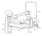
도 1은 본 발명의 바닥 장착 수술 로봇 시스템(floor mounted surgical robot system)의 개략적인 도면이다.
도 2 내지 도 4는 로봇 베이스가 지지 포스트에 의해 수술대에 연결된 대안적인 로봇 수술 시스템의 개략적인 등측도이다.The invention will be better understood and appreciated from the following detailed description taken in conjunction with the drawings, in which:
Figure 1 is a schematic illustration of a floor mounted surgical robot system of the present invention.
Figures 2 to 4 are schematic isometric views of an alternative robot surgical system in which the robot base is connected to the operating table by a support post.
먼저, 본 발명의 바닥 장착 수술 로봇 시스템의 개략적인 도면인, 도 1을 참조하면, 환자(19)는 수술대 상에 누워있는 상태로 도시되어 있고, 뼈 연결 링크 (13,bone connection link)에 의해 로봇 아암의 부착 위치(18,attachment location)에 부착된다. 시스템의 로봇 아암은 회전(식) 또는 프리즘 조인트(16,prismatic joints)에 의해 연결된 아암 부분(17,arm parts)으로 구성되며, 아암 부분은 2개 부분으로 나누어진다. 뼈 연결 링크(13)와 로봇 베이스(12,robotic base) 사이에 위치되는, 로봇 베이스 아암으로 알려진 아암 섹션(11,arm section)은, 그 섹션이 소정의 수준의 유연성(flexibility)을 갖도록 하는 구조를 가지며, 뼈 연결 링크(13)가 제한된 범위에 대해 움직일 수 있게 한다. 결과적으로, 환자의 신체는, 환자에게 과도한 압력을 가하지 않고, 또는 환자가 뼈 연결 링크(13)로부터 분리내지 않고 그 범위에 대해 움직일수 있다. 이 섹션과는 대조적으로, 뼈 연결 링크(13)와 로봇 액츄에이터 아암으로 알려진 로봇의 단부 액츄에이터(14,end actuator) 사이에 위치된 아암 섹션(15)은 높은 수준의 단단함을 가지므로 환자의 해부(체)에 대한 단부 액츄에이터(14)의 자세(pose)의 정확성이 가능한 최고 수준으로 유지된다. 결과적으로, 환자의 몸이 호흡 또는 기침에 의해 발생되는 것과 같은 작은 움직임을 겪을 때, 뼈 연결 링크(13) 및 부착 위치(18)는 환자의 뼈의 동작과 함께 움직이고, 이로인해 로봇의 단부 액츄에이터(14)의 자세가 부착 위치(18)에 대해 정확하게 유지되어 환자의 신체 위치로 움직인다. 도 1에서, 로봇의 단부 액츄에이터(14)는 수술 도구를 수용(holding)하는 유도 튜브(guide tube)로써 도시되어 있지만, 이것은 드릴, 메스 및 임의의 다른 수술 도구를 수용할 수 있는 단부 액츄에이터의 사용의 하나의 실례일 뿐이라고 이해된다.Referring first to Figure 1, which is a schematic illustration of a floor mounted surgical robotic system of the present invention, a
도 1에서, 로봇 베이스(12)는 바닥에 장착된 베이스로써 도시되어 있지만, 도 2 내지 도 4에 도시된 바와 같이, 로봇 베이스는 수술대에 부착된 지지 포스트(support post)에 부착될 수 있으며, 또는 수술대 위의 천장과 같은 근처의 임의의 다른 피쳐(feature)를 포함할 수 있다고 이해된다. 베이스는 카트 상에 지지될 수도 있다. 이러한 카트는 안전한 작동을 보장하기 위해 제자리에 고정되어야 하지만, 로봇이 장착된 베드 또는 바닥과 비교할 때 로봇이 장착된 카트의 자연스러운 유연성은 의도적으로 통합된 베이스 시스템의 유연성에 일부 기여할 수 있다. 이러한 구성에서, 진정한 베이스는 수술실 바닥에 고정된 카트(cart)의 바퀴로 간주 될 수 있지만, 카트 자체는 로봇 베이스 아암의 일부로 간주 될 수 있다.In Fig. 1, the robot base 12 is shown as a base mounted on the floor, but as shown in Figs. 2 to 4, the robot base may be attached to a support post attached to the operating table, Or any other feature in the vicinity, such as a ceiling on a surgical table. The base may be supported on the cart. These carts must be held in place to ensure safe operation, but the natural flexibility of a robot-equipped cart compared to a robot-equipped bed or floor can contribute partly to the flexibility of the intentionally integrated base system. In this configuration, the true base may be regarded as a wheel of a cart fixed to the floor of the operating room, but the cart itself may be regarded as a part of the robot base arm.
또한, 지지 포스트 또는 유사한 것은 본질적인 유연성을 가질 수 있으므로, 베이스와 뼈 연결 링크(13) 사이의 유연한 기계적 경로의 부분으로 간주 될 수 있다.In addition, support posts or the like can have inherent flexibility and can therefore be regarded as part of the flexible mechanical path between the base and the
도 1에 도시된 구현 예에서, 상기 뼈 연결 링크는 정적 로드(static rod)이거나, 또는 위에서 언급된 국제 공개 특허 출원 WO2015/087335호에 기술된 바와 같이 자동화된 뼈 연결 유닛(10)을 포함할 수 있다.In the embodiment shown in Figure 1, the bone connecting link may be a static rod, or it may comprise an automated
3차원 X-선 타겟(도시되지 않음)은 로봇 액츄에이터 아암에 의해 보유될 수있어서, 타겟을 포함하는 관심 영역(region of interest)의 형광투시 X-선 이미지가 수술 계획에 사용된 임의의 수술 전 이미지에 대한 로봇 기준 프레임의 등록을 위해 사용될 수 있다.A 3D x-ray target (not shown) may be retained by the robot actuator arm such that the fluoroscopic x-ray image of the region of interest, including the target, Can be used for registration of a robot reference frame for an image.
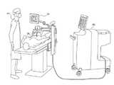
도 2를 참조하면, 로봇 베이스가 지지 포스트(20)에 의해 수술대(21,operating table)에 연결되는 대안적인 로봇 수술 시스템의 개략적 등측도(isometric view)가 도시되어 있다. 로봇 아암은 2개 섹션을 가진다:Referring to Figure 2, there is shown a schematic isometric view of an alternative robotic surgical system in which the robot base is connected to an operating table 21 by a
(i) 스트럿(23,struts) 및 회전 및 프리즘 조인트(24)를 포함하는 로봇 베이스 아암 섹션(22)은 또한 로봇 베이스 아암의 일부로 간주되어야 하며, 그 유연성은 로봇 지지 포스트(20)의 벤딩(bending)과 함께 베이스 아암 섹션에 원하는 유연성의 범위를 제공한다.(i) the robot
(ii) 이 예시적인 시스템에서 형성된 로봇 액츄에이터 아암 섹션(25)은, 매우 단단(견고)하게 구성된 섹션이며, 여러개의 회전 조인트(26)와 단부 액츄에이터(27) 자체이다. 만약, 더 큰 로봇 작업 범위(robotic work envelope)가 요구되면, 추가 링크가 회전 조인트(26) 사이에 포함될 수 있다.(ii) The robotic
뼈 연결 링크(28)는 베이스 아암 섹션(22,base arm section)과 로봇 액츄에이터 아암 섹션(25,robotic actuator arm section) 사이의 고정 위치에 부착된 것으로 도시되어 있다. 말단부에, 클램프 또는 k-와이어와 같이 뾰족하거나 나사끝(threaded end)과 같은 뼈 연결 구성요소가 있을 수 있다. 또한, 뼈 연결 링크(28)는 도 1에 도시된 것과 같은 자동화된 뼈 연결 유닛을 포함할 수 있다. 작은 센서 장치 일 수 있는 광학 스캐닝 헤드(29,optical scanning head)는, 액츄에이터 아암의 단부(27)와 같은, 로봇 아암이 움직일 때 표면을 스캔할 수 있는 위치에 장착된다. 선택적인 네비게이션 카메라는, 수술 도구를 타겟으로 조종하는 것에 관여하지 않더라도, 수술 도구와 같은 아이템을 추적하기 위해 지지 포스트(20) 상에 장착된 것으로 도시되어 있다. 로봇 베이스는, 로봇 베이스와 아암을 "떠 움직이게하는(floats)" 메카니즘을 통해 베드(bed)에 연결될 수 있어서 간호사가 쉽게 베드에 부착할 수 있다.The
도 2에 도시된 시스템의 추가적인 도면인 도 3을 참조하면, 대안적인 유리한 위치에서 도 2에 설명된 부분이 도시되어 있다. 수술을 수행하는 외과 의사에게 정보를 제공하기위한 디스플레이 스크린(30)이 또한 도시되어 있다.Referring to Fig. 3, which is a further illustration of the system shown in Fig. 2, there is shown in Fig. 2 an alternative advantageous position. There is also shown a
도 4를 참조하면, 시스템 제어 카트(40,system control cart)로 진행 중인 수술, 및 수술대 스크린(30) 상의 데이터를 점검하는 외과 의사(41)를 나타내는 개략도가 도시되어 있다. 뼈 연결 링크(28)는 환자의 하부 척추의 한 지점을 향하게끔 베이스 아암 섹션과 로봇 액츄에이터 아암 섹션의 접합부(junction)에 부착한 것이 도시되어 있다.Referring to FIG. 4, there is shown a schematic diagram illustrating a
당업자는 본 발명이 상기에 구체적으로 도시되고 기술된 것에 의해 제한되지 않음을 이해할 것이다. 오히려, 본 발명의 범위는 전술한 다양한 특징의 조합 및 부조합 뿐만 아니라 상기 설명을 읽었을 때 당업자에게 발생할 수 있고 종래 기술에 존재하지 않는 변형 및 수정을 포함한다.Those skilled in the art will appreciate that the invention is not limited by what has been particularly shown and described hereinabove. Rather, the scope of the invention includes combinations and subcombinations of the various features described above as well as variations and modifications which may occur to those skilled in the art upon reading the above description and which do not exist in the prior art.
Claims (25)
Translated fromKorean상기 로봇 수술 시스템은,
상기 시스템을 수술대에 대해 고정하기 위한 베이스;
상기 수술대 상에 피술자(subject)에 대한 절차(수술)를 수행하기 위한 수술 도구의 정렬을 가능하게하는 단부 액츄에이터;
상기 베이스와 상기 단부 액츄에이터 사이에 연결된 로봇 가동 아암 셋트를 포함하며; 상기 로봇 가동 아암 셋트는,
상기 베이스에 일단 단부가 연결된 제1 섹션;
상기 단부로부터 멀리 떨어져 상기 제1 섹션에 연결되고, 그 연결부로부터 상기 제1 섹션까지 멀리 떨어진 단부 영역에 있는 단부 엑츄에이터를 갖는 제2 섹션; 을 포함하며,
상기 제1 섹션 및 상기 제2 섹션 사이의 지점을 피술자의 해부(체)의 일부분에 연결하는 연결 요소; 를 포함하며,
상기 제1 섹션의 기계적 강성은 상기 제2 섹션보다 작도록 구성되는 것을 특징으로 하는 로봇 수술 시스템.In a robotic surgery system,
In the robot surgery system,
A base for securing the system to the operating table;
An end actuator for enabling alignment of a surgical tool for performing a procedure (surgery) on a subject on the operating table;
A robot arm assembly connected between the base and the end actuator; The robot moving arm set includes:
A first section having one end connected to the base;
A second section connected to the first section away from the end and having an end actuator in an end region remote from the connection section to the first section; / RTI >
A connecting element connecting a point between the first section and the second section to a portion of a dissection (sieve) of the subject; / RTI >
Wherein the mechanical stiffness of the first section is smaller than that of the second section.
제1 섹션의 기계적 강성은 적어도 부분적으로 제1 섹션의 적어도 하나의 링크의 소정의 강성으로부터 발생하는 것을 특징으로 하는 로봇 수술 시스템.The method according to claim 1,
Wherein the mechanical stiffness of the first section arises at least in part from a predetermined stiffness of the at least one link of the first section.
제1 섹션의 기계적 강성은 적어도 부분적으로 제1 섹션의 적어도 하나의 조인트의 강성으로부터 발생하는 것을 특징으로 하는 로봇 수술 시스템.The method according to claim 1,
Wherein the mechanical stiffness of the first section arises at least in part from the rigidity of the at least one joint of the first section.
제1 섹션의 적어도 하나의 조인트의 강성은 상기 조인트를 제어하는 전자 피드백의 게인을 제어함으로써 조정될 수 있는 것을 특징으로 하는 로봇 수술 시스템.The method of claim 3,
Wherein the rigidity of the at least one joint of the first section can be adjusted by controlling the gain of the electronic feedback controlling the joint.
상기 제1 섹션의 기계적 강성은 상기 피술자의 해부(체) 부분의 예상된 동작에 따라 전자적으로 조정되는 것을 특징으로하는 로봇 수술 시스템.5. The method of claim 4,
Wherein the mechanical stiffness of the first section is electronically adjusted according to an expected motion of a dissection (sieve) portion of the subject.
상기 제1 섹션의 기계적 강성은 제1 섹션의 자세에 따라 전자적으로 조정되는 것을 특징으로 하는 로봇 수술 시스템.5. The method of claim 4,
Wherein the mechanical stiffness of the first section is electronically adjusted according to the posture of the first section.
상기 연결 요소는 상기 로봇 가동 아암 셋트의 제1 섹션과 제2 섹션 사이의 접합 영역에 연결되는 것을 특징으로 하는 로봇 수술 시스템.In any of the preceding claims,
Wherein the connecting element is connected to a junction region between the first section and the second section of the robot arm assembly.
상기 연결 요소는 로봇 가동 아암 셋트의 제1 섹션과 제2 섹션 사이에 위치되는 구성요소에 연결되는 것을 특징으로 하는 로봇 수술 시스템.7. The method according to any one of claims 1 to 6,
Wherein the connecting element is connected to a component located between a first section and a second section of the robotic arm assembly.
상기 연결 요소는 로봇 가동 아암 셋트의 제1 섹션과 제2 섹션 사이의 접합부에 연결되는 것을 특징으로 하는 로봇 수술 시스템.In any of the preceding claims,
Wherein the connecting element is connected to a junction between a first section and a second section of the robot arm assembly.
상기 로봇 가동 아암 셋트의 제1 섹션은 이러한 유형의 조인트에서 달성 가능한 최대 강성과 비교하여 감소된 강성 수준을 갖도록 구성된 적어도 하나의 조인트를 가짐으로써, 제1 섹션의 기계적 강성은 제2 섹션의 기계적 강성보다 작은 것을 특징으로 하는 로봇 수술 시스템.In any of the preceding claims,
The first section of the robotic moving arm set has at least one joint configured to have a reduced stiffness level compared to the maximum stiffness achievable with this type of joint such that the mechanical stiffness of the first section is greater than the mechanical stiffness of the second section Wherein the robot is operated by a user.
상기 조인트의 감소된 강성 수준은 조인트와 연관된 전자회로의 게인을 감소시킴으로써 생성되는 것을 특징으로 하는 로봇 수술 시스템.11. The method of claim 10,
Wherein the reduced stiffness level of the joint is created by reducing the gain of the electronics associated with the joint.
상기 로봇 가동 아암 셋트의 제1 섹션은 이러한 유형의 아암 부재에서 달성할 수 있는 최대 강성과 비교하여 감소된 강성 수준을 갖도록 구성된 적어도 하나의 아암 부재를 가짐으로써, 로봇 가동 아암 셋트의 제1 섹션의 기계적 강성이 제2 섹션의 기계적 강성보다 작은 것을 특징으로 하는 로봇 수술 시스템.In any of the preceding claims,
The first section of the robotic arm assembly has at least one arm member configured to have a reduced stiffness level compared to the maximum stiffness achievable in this type of arm member, Wherein the mechanical stiffness is less than the mechanical stiffness of the second section.
상기 로봇 가동 아암 셋트의 제2 섹션은 연결 요소에 연결된 지점의 위치에 대한 단부 액츄에이터의 위치가 외과 수술 절차에서 요구되는 정확성을 달성하도록 결정된 수준 내에 유지되는 충분한 강성을 갖는 것을 특징으로 하는 로봇 수술 시스템.10. The method according to any one of claims 1 to 9,
Wherein the second section of the robotic arm assembly is of sufficient stiffness that the position of the end actuator relative to the position of the point connected to the connecting element is maintained within a level determined to achieve the accuracy required in the surgical procedure. .
피술자의 신체를 검출하기 위한 광학 스캐닝 시스템, 및 신체 또는 이식 부속품과 로봇 가동 아암 셋트의 충돌을 방지하기 위해 로봇 가동 아암 셋트의 위치 및 신체 위치를 입력하는 제어 시스템을 더 포함하는 것을 특징으로 하는 로봇 수술 시스템.In any of the preceding claims,
An optical scanning system for detecting the body of the subject, and a control system for inputting a position and a body position of the robot moving arm set to prevent collision of the robot moving arm set with the body or the graft fitting, Surgical system.
상기 광학 스캐닝 시스템은 로봇 가동 아암 셋트 상에, 또는 근처의 정적 지점에 위치되는 것을 특징으로 하는 로봇 수술 시스템.15. The method of claim 14,
Wherein the optical scanning system is located at a static point on, or near, the robot moving arm set.
상기 제1 섹션의 기계적 강성은 제2 섹션의 기계적 강성보다 충분히 작아서, 연결 요소에 연결된 상기 피험자의 해부(체)의 부분은 상기 연결 요소로부터 분리되지 않고 피술자의 동작의 추정 범위까지 움직일 수 있는 것을 특징으로 하는 로봇 수술 시스템.In any of the preceding claims,
The mechanical stiffness of the first section is sufficiently smaller than the mechanical stiffness of the second section such that a portion of the subject's anatomy connected to the connecting element can move to an estimated range of motion of the subject without being detached from the connecting element A robotic surgery system characterized by.
연결 요소는 강성 상태와 연결 요소의 종 방향 연장을 허용하는 해제 상태 사이에서 전환 가능하고, 시스템은 연결 요소를 따른 힘이 미리 결정된 수준을 초과할 때 연결 요소가 강성 상태에서 해제 상태로 전환되도록 힘 센서를 더 포함하는 것을 특징으로 하는 로봇 수술 시스템.In any of the preceding claims,
The coupling element is switchable between a rigid state and an unlocked state which allows longitudinal extension of the coupling element and the system is arranged such that when the force along the coupling element exceeds a predetermined level, Wherein the robot further comprises a sensor.
제2 섹션의 기계적 강성과 비교하여 제1 섹션의 기계적 강성은 연결 요소에 연결된 피술자의 해부 부분이 연결 요소가 강성 상태와 해제 상태 사이에서 전환하기 전에 피술자의 동작의 추정 범위까지 움직이게 할 수 있는 것을 특징으로 하는 로봇 수술 시스템.18. The method of claim 17,
The mechanical stiffness of the first section relative to the mechanical stiffness of the second section is such that the anatomical portion of the subject connected to the coupling element can move the coupling element to the estimated range of movement of the subject before switching between the stiffness state and the released state A robotic surgery system characterized by.
상기 미리 결정된 힘의 수준은 피술자의 흉골에 연결하기 위한 것이며, 미리 결정된 힘의 수준에 도달하기 전에 흉골이 최대 12mm 까지 움직이게 할 수 있는 것을 특징으로 하는 로봇 수술 시스템.18. The method of claim 17,
Wherein the predetermined level of force is for connecting to the subject's sternum and is capable of moving the sternum to a maximum of 12 mm before reaching a predetermined level of strength.
상기 연결 요소에 연결된 피술자의 해부의 부분은 자유로운 세방향으로 움직일 수 있는 것을 특징으로 하는 로봇 수술 시스템.The method according to any one of claims 16, 18 and 19,
Wherein the portion of the dissection of the subject connected to the connection element is movable in three free directions.
상기 연결 요소는, 공지된 위치에서, 해제 후에 재접속(reconnect)하도록 적응되는 것을 특징으로 하는 로봇 수술 시스템.18. The method of claim 17,
Characterized in that the coupling element is adapted to reconnect at a known position after release.
피술자를 수술대 상에 측면 위치로 눕힘;
수술 도구가 피술자의 측면 쪽(lateral side) 및 후방 척추 위치에 도달 할수 있게 하는 작동 범위(operating envelope)를 갖는 로봇 수술 시스템을 제공;
측면 위치로 누운 피술자에 로봇 측면 체간 융합 절차(robotic Lateral Interbody Fusion procedure)를 수행; 및
로봇 수술 시스템에 경피 후방 척추 절차를 수행하도록 지시, 를 포함하며,
상기 두 절차는 모두 피술자를 움직일 필요 없이 수행되는 것을 특징으로 하는 방법.In a method for performing spinal surgery on a subject,
Placing the subject in a side position on the operating table;
Providing a robotic surgical system having a working envelope that allows the surgical tool to reach the lateral side and posterior spinal position of the subject;
Performing a robotic lateral interbody fusion procedure on the subject lying to the side position; And
Instructing the robotic surgery system to perform a transcutaneous posterior spinal procedure,
≪ / RTI > wherein both procedures are performed without the need to move the subject.
추간 요소(intervertebral element)의 측면(방) 삽입 및 경피 후방 척추 절차는 단일 등록 절차를 사용하여 로봇으로 수행되는 것을 특징으로 하는 방법.23. The method of claim 22,
Wherein the lateral insertion of the intervertebral element and the percutaneous posterior spinal procedure are performed by a robot using a single registration procedure.
로봇 수술 시스템은 상기 절차들 사이의 분리(detachment)없이 피술자의 해부 부분에 부착되는 것을 특징으로 하는 방법.23. The method of claim 22,
Wherein the robotic surgical system is attached to a dissection portion of the subject without detachment between the procedures.
작동 범위는 청구항 1항 내지 21항 중 한 항에 따른 로봇 수술 시스템의 사용으로 얻어지는 것을 특징으로 하는 방법.23. The method of claim 22,
Characterized in that the working range is obtained by use of a robotic surgical system according to one of claims 1 to 21.
Applications Claiming Priority (3)
| Application Number | Priority Date | Filing Date | Title |
|---|---|---|---|
| US201662277114P | 2016-01-11 | 2016-01-11 | |
| US62/277,114 | 2016-01-11 | ||
| PCT/IL2017/050036WO2017122202A1 (en) | 2016-01-11 | 2017-01-11 | Surgical robotic system |
Publications (2)
| Publication Number | Publication Date |
|---|---|
| KR20180125948Atrue KR20180125948A (en) | 2018-11-26 |
| KR102650270B1 KR102650270B1 (en) | 2024-03-21 |
Family
ID=59310895
Family Applications (1)
| Application Number | Title | Priority Date | Filing Date |
|---|---|---|---|
| KR1020187023002AActiveKR102650270B1 (en) | 2016-01-11 | 2017-01-11 | surgical robot system |
Country Status (6)
| Country | Link |
|---|---|
| US (2) | US11141227B2 (en) |
| EP (1) | EP3402414A4 (en) |
| KR (1) | KR102650270B1 (en) |
| CN (2) | CN114098979B (en) |
| CA (1) | CA3011008A1 (en) |
| WO (1) | WO2017122202A1 (en) |
Families Citing this family (38)
| Publication number | Priority date | Publication date | Assignee | Title |
|---|---|---|---|---|
| WO2014198796A1 (en) | 2013-06-11 | 2014-12-18 | Minmaxmedical | System for positioning a surgical device |
| US10959783B2 (en) | 2015-04-15 | 2021-03-30 | Mobius Imaging, Llc | Integrated medical imaging and surgical robotic system |
| CN114469211A (en) | 2016-07-12 | 2022-05-13 | 莫比乌斯成像公司 | Multistage dilator and cannula system and method |
| EP3512450A4 (en) | 2016-09-16 | 2020-11-04 | Mobius Imaging LLC | System and method for mounting a robotic arm in a surgical robotic system |
| CN111417352B (en) | 2016-10-21 | 2024-05-24 | 莫比乌斯成像公司 | Method and system for setting trajectory and target location for image guided surgery |
| US11751948B2 (en) | 2016-10-25 | 2023-09-12 | Mobius Imaging, Llc | Methods and systems for robot-assisted surgery |
| US10682129B2 (en) | 2017-03-23 | 2020-06-16 | Mobius Imaging, Llc | Robotic end effector with adjustable inner diameter |
| US11033341B2 (en) | 2017-05-10 | 2021-06-15 | Mako Surgical Corp. | Robotic spine surgery system and methods |
| WO2018209042A2 (en) | 2017-05-10 | 2018-11-15 | Mako Surgical Corp. | Robotic spine surgery system and methods |
| US11660145B2 (en) | 2017-08-11 | 2023-05-30 | Mobius Imaging Llc | Method and apparatus for attaching a reference marker to a patient |
| EP3691545A4 (en) | 2017-10-04 | 2022-02-16 | Mobius Imaging, LLC | SYSTEMS AND METHODS FOR PERFORMING SPINAL SURGERY WITH LATERAL APPROACH |
| AU2018346790B2 (en) | 2017-10-05 | 2024-09-26 | Mobius Imaging, Llc | Methods and systems for performing computer assisted surgery |
| WO2019121378A1 (en)* | 2017-12-21 | 2019-06-27 | Koninklijke Philips N.V. | Compliant end-effector for image guided surgical procedures |
| US20210121264A1 (en)* | 2018-05-02 | 2021-04-29 | Riverfield Inc. | Intraocular surgery instrument holder |
| EP4595919A3 (en) | 2018-05-15 | 2025-08-13 | The Regents of the University of California | System for automated image-guided robotic intraocular surgery |
| CN110179541A (en)* | 2019-05-30 | 2019-08-30 | 温州大学 | Robot perceptual system and control method |
| CA3142222A1 (en)* | 2019-05-31 | 2020-12-03 | Ganymed Robotics | Lockable surgical system |
| CN114126529A (en) | 2019-06-25 | 2022-03-01 | 奥瑞斯健康公司 | Medical instrument including a wrist with hybrid redirecting surfaces |
| WO2020263629A1 (en) | 2019-06-27 | 2020-12-30 | Auris Health, Inc. | Systems and methods for a medical clip applier |
| WO2020263949A1 (en) | 2019-06-28 | 2020-12-30 | Auris Health, Inc. | Medical instruments including wrists with hybrid redirect surfaces |
| US11896330B2 (en) | 2019-08-15 | 2024-02-13 | Auris Health, Inc. | Robotic medical system having multiple medical instruments |
| US10959792B1 (en) | 2019-09-26 | 2021-03-30 | Auris Health, Inc. | Systems and methods for collision detection and avoidance |
| WO2021059100A1 (en) | 2019-09-26 | 2021-04-01 | Auris Health, Inc. | Systems and methods for collision avoidance using object models |
| US11737845B2 (en) | 2019-09-30 | 2023-08-29 | Auris Inc. | Medical instrument with a capstan |
| CN110731817B (en)* | 2019-10-11 | 2021-04-13 | 浙江大学 | Radiationless percutaneous spine positioning method based on optical scanning automatic contour segmentation matching |
| US11737835B2 (en) | 2019-10-29 | 2023-08-29 | Auris Health, Inc. | Braid-reinforced insulation sheath |
| CN114727850A (en) | 2019-11-21 | 2022-07-08 | 奥瑞斯健康公司 | Systems and methods for draping surgical systems |
| CN114901188A (en) | 2019-12-31 | 2022-08-12 | 奥瑞斯健康公司 | Dynamic pulley system |
| JP6892707B1 (en)* | 2020-02-20 | 2021-06-23 | リバーフィールド株式会社 | Surgical support device |
| US12370002B2 (en) | 2020-03-30 | 2025-07-29 | Auris Health, Inc. | Workspace optimization for robotic surgery |
| CN111437011B (en)* | 2020-03-30 | 2021-04-13 | 中国科学院深圳先进技术研究院 | A puncture surgery robot system |
| EP3906882A1 (en)* | 2020-05-05 | 2021-11-10 | Ecential Robotics | Surgical robotic system |
| CN115802975A (en) | 2020-06-29 | 2023-03-14 | 奥瑞斯健康公司 | System and method for detecting contact between a connecting rod and an external object |
| CN115734765A (en) | 2020-06-30 | 2023-03-03 | 奥瑞斯健康公司 | Robotic medical system with crash proximity indicator |
| US11357586B2 (en) | 2020-06-30 | 2022-06-14 | Auris Health, Inc. | Systems and methods for saturated robotic movement |
| US12185972B2 (en) | 2021-11-05 | 2025-01-07 | Nuvasive, Inc. | Cutting apparatus |
| US12419692B2 (en) | 2022-05-03 | 2025-09-23 | Mazor Robotics Ltd. | Robotic arm navigation using virtual bone mount |
| US12383346B2 (en) | 2023-01-12 | 2025-08-12 | Depuy Ireland Unlimited Company | Automatic detection of tracking array motion during navigated surgery |
Citations (5)
| Publication number | Priority date | Publication date | Assignee | Title |
|---|---|---|---|---|
| US4756662A (en)* | 1986-03-31 | 1988-07-12 | Agency Of Industrial Science & Technology | Varible compliance manipulator |
| KR20120099423A (en)* | 2009-10-01 | 2012-09-10 | 마코 서지컬 코포레이션 | Surgical system for positioning prosthetic component and/or for constraining movement of surgical tool |
| US20140316436A1 (en)* | 2011-12-05 | 2014-10-23 | Mazor Robotics Ltd. | Active bed mount for surgical robot |
| WO2015023853A1 (en)* | 2013-08-15 | 2015-02-19 | Intuitive Surgical Operations, Inc. | Robotic instrument driven element |
| WO2015087335A1 (en)* | 2013-12-15 | 2015-06-18 | Mazor Robotics Ltd. | Semi-rigid bone attachment robotic surgery system |
Family Cites Families (35)
| Publication number | Priority date | Publication date | Assignee | Title |
|---|---|---|---|---|
| DE3805946A1 (en) | 1988-02-25 | 1989-09-07 | Fraunhofer Ges Forschung | DEVICE FOR DETERMINING CHARACTERISTIC PARAMETERS FROM THE INPUT AND OUTPUT SIGNALS OF A SYSTEM FOR AUDIO SIGNAL PROCESSING |
| US4921393A (en)* | 1988-03-09 | 1990-05-01 | Sri International | Articulatable structure with adjustable end-point compliance |
| US5806518A (en) | 1995-09-11 | 1998-09-15 | Integrated Surgical Systems | Method and system for positioning surgical robot |
| US6322567B1 (en)* | 1998-12-14 | 2001-11-27 | Integrated Surgical Systems, Inc. | Bone motion tracking system |
| US8004229B2 (en) | 2005-05-19 | 2011-08-23 | Intuitive Surgical Operations, Inc. | Software center and highly configurable robotic systems for surgery and other uses |
| US6837892B2 (en) | 2000-07-24 | 2005-01-04 | Mazor Surgical Technologies Ltd. | Miniature bone-mounted surgical robot |
| US7822466B2 (en)* | 2002-04-25 | 2010-10-26 | The Johns Hopkins University | Robot for computed tomography interventions |
| JP4439393B2 (en) | 2002-06-17 | 2010-03-24 | メイザー サージカル テクノロジーズ リミテッド | Robots for use with orthopedic inserts |
| JP3753378B2 (en)* | 2002-11-01 | 2006-03-08 | 三鷹光器株式会社 | Endoscope stand device |
| WO2004100758A2 (en) | 2003-05-16 | 2004-11-25 | Mazor Surgical Technologies Ltd | Robotic total/partial knee arthoplastics |
| CN201029876Y (en)* | 2007-01-15 | 2008-03-05 | 杭州市萧山区中医院 | Navigation system for bone surgery |
| CN100560304C (en)* | 2008-02-21 | 2009-11-18 | 北京航空航天大学 | A nine-degree-of-freedom hybrid robot combining active and passive |
| US8663130B2 (en)* | 2008-05-28 | 2014-03-04 | Technion Researh & Development Foundation Ltd. | Ultrasound guided robot for flexible needle steering |
| US9610131B2 (en)* | 2008-11-05 | 2017-04-04 | The Johns Hopkins University | Rotating needle driver and apparatuses and methods related thereto |
| EP2189254B1 (en)* | 2008-11-25 | 2013-07-03 | BrainLAB AG | Method of determining the anchor point of a medical robot arm |
| US8632064B2 (en)* | 2009-07-15 | 2014-01-21 | The Board Of Trustees Of The Leland Stanford Junior University | Positioning apparatus with lockable joints and method of use |
| US10045882B2 (en)* | 2009-10-30 | 2018-08-14 | The Johns Hopkins University | Surgical instrument and systems with integrated optical sensor |
| US8795335B1 (en)* | 2009-11-06 | 2014-08-05 | Samy Abdou | Spinal fixation devices and methods of use |
| CN101919739B (en)* | 2010-09-07 | 2011-10-26 | 天津大学 | Minimally invasive robot mechanical arm having large movement space and high structural rigidity |
| US9308050B2 (en)* | 2011-04-01 | 2016-04-12 | Ecole Polytechnique Federale De Lausanne (Epfl) | Robotic system and method for spinal and other surgeries |
| US20130096573A1 (en)* | 2011-10-18 | 2013-04-18 | Hyosig Kang | System and method for surgical tool tracking |
| FR2983059B1 (en)* | 2011-11-30 | 2014-11-28 | Medtech | ROBOTIC-ASSISTED METHOD OF POSITIONING A SURGICAL INSTRUMENT IN RELATION TO THE BODY OF A PATIENT AND DEVICE FOR CARRYING OUT SAID METHOD |
| US20170258535A1 (en)* | 2012-06-21 | 2017-09-14 | Globus Medical, Inc. | Surgical robotic automation with tracking markers |
| US9125662B2 (en)* | 2012-06-28 | 2015-09-08 | Ethicon Endo-Surgery, Inc. | Multi-axis articulating and rotating surgical tools |
| KR102184960B1 (en)* | 2012-08-15 | 2020-12-01 | 인튜어티브 서지컬 오퍼레이션즈 인코포레이티드 | Movable surgical mounting platform controlled by manual motion of robotic arms |
| WO2014072976A1 (en)* | 2012-11-08 | 2014-05-15 | Emodi Omri | Intracavity illumination device |
| CN103085083B (en)* | 2013-01-07 | 2015-06-24 | 汪雯 | Flexible continuous body mechanical structure capable of bending and stretching |
| FR3000696B1 (en)* | 2013-01-08 | 2015-03-06 | Commissariat Energie Atomique | PURE TRANSLATIONAL MANIPULATOR ROBOT WITH THREE DEGREES OF FREEDOM SERIES WITH REDUCED SIZE |
| US10433763B2 (en)* | 2013-03-15 | 2019-10-08 | Synaptive Medical (Barbados) Inc. | Systems and methods for navigation and simulation of minimally invasive therapy |
| US20150051608A1 (en)* | 2013-08-19 | 2015-02-19 | Coloplast A/S | Surgical system including a support for an instrument |
| JP6192550B2 (en)* | 2014-01-29 | 2017-09-06 | オリンパス株式会社 | Medical device and medical system |
| US11389268B2 (en)* | 2015-02-05 | 2022-07-19 | Intuitive Surgical Operations, Inc. | System and method for anatomical markers |
| US10959783B2 (en)* | 2015-04-15 | 2021-03-30 | Mobius Imaging, Llc | Integrated medical imaging and surgical robotic system |
| US9888975B2 (en)* | 2015-12-04 | 2018-02-13 | Ethicon Endo-Surgery, Llc | Methods, systems, and devices for control of surgical tools in a robotic surgical system |
| US10136952B2 (en)* | 2016-06-16 | 2018-11-27 | Zimmer, Inc. | Soft tissue balancing in articular surgery |
- 2017
- 2017-01-11EPEP17738286.8Apatent/EP3402414A4/enactivePending
- 2017-01-11WOPCT/IL2017/050036patent/WO2017122202A1/ennot_activeCeased
- 2017-01-11CACA3011008Apatent/CA3011008A1/enactivePending
- 2017-01-11USUS16/068,947patent/US11141227B2/enactiveActive
- 2017-01-11CNCN202111345241.6Apatent/CN114098979B/enactiveActive
- 2017-01-11KRKR1020187023002Apatent/KR102650270B1/enactiveActive
- 2017-01-11CNCN201780010636.6Apatent/CN108697415B/enactiveActive
- 2021
- 2021-10-11USUS17/498,609patent/US20220022981A1/enactivePending
Patent Citations (5)
| Publication number | Priority date | Publication date | Assignee | Title |
|---|---|---|---|---|
| US4756662A (en)* | 1986-03-31 | 1988-07-12 | Agency Of Industrial Science & Technology | Varible compliance manipulator |
| KR20120099423A (en)* | 2009-10-01 | 2012-09-10 | 마코 서지컬 코포레이션 | Surgical system for positioning prosthetic component and/or for constraining movement of surgical tool |
| US20140316436A1 (en)* | 2011-12-05 | 2014-10-23 | Mazor Robotics Ltd. | Active bed mount for surgical robot |
| WO2015023853A1 (en)* | 2013-08-15 | 2015-02-19 | Intuitive Surgical Operations, Inc. | Robotic instrument driven element |
| WO2015087335A1 (en)* | 2013-12-15 | 2015-06-18 | Mazor Robotics Ltd. | Semi-rigid bone attachment robotic surgery system |
Also Published As
| Publication number | Publication date |
|---|---|
| CA3011008A1 (en) | 2017-07-20 |
| US20190117320A1 (en) | 2019-04-25 |
| US20220022981A1 (en) | 2022-01-27 |
| CN114098979A (en) | 2022-03-01 |
| CN108697415A (en) | 2018-10-23 |
| EP3402414A4 (en) | 2019-08-14 |
| KR102650270B1 (en) | 2024-03-21 |
| CN108697415B (en) | 2021-11-09 |
| CN114098979B (en) | 2024-05-14 |
| EP3402414A1 (en) | 2018-11-21 |
| US11141227B2 (en) | 2021-10-12 |
| WO2017122202A1 (en) | 2017-07-20 |
Similar Documents
| Publication | Publication Date | Title |
|---|---|---|
| US20220022981A1 (en) | Surgical robotic system | |
| US12016645B2 (en) | Surgical robotic automation with tracking markers | |
| CN111265301B (en) | Drilling tool guide fixture, skull bone insertion fixture, and related methods and robotic systems | |
| US11864839B2 (en) | Methods of adjusting a virtual implant and related surgical navigation systems | |
| US11857149B2 (en) | Surgical robotic systems with target trajectory deviation monitoring and related methods | |
| US11998283B2 (en) | System for guiding a surgical tool relative to a target axis in spine surgery | |
| US11793570B2 (en) | Surgical robotic automation with tracking markers | |
| US20240020831A1 (en) | REGISTRATION OF 3D and 2D IMAGES FOR SURGICAL NAVIGATION AND ROBOTIC GUIDANCE WITHOUT USING RADIOPAQUE FIDUCIALS IN THE IMAGES | |
| EP3409231A1 (en) | Surgical robot system with interchangeable end effector | |
| EP4306071A1 (en) | System for registration of 3d and 2d images for surgical navigation and robotic guidance without using radiopaque fiducials in the images | |
| EP3666212A1 (en) | Surgical robotic automation with tracking markers | |
| EP3510927A1 (en) | Surgical robotic systems with target trajectory deviation monitoring | |
| US20240180655A1 (en) | Active end effectors for surgical robots | |
| US20230218359A1 (en) | Drill guide fixtures, cranial insertion fixtures, and related methods and robotic systems | |
| EP3586784B1 (en) | Methods of adjusting a virtual implant and related surgical navigation systems | |
| EP3865069B1 (en) | System and method of determining optimal 3-dimensional position and orientation of imaging device for imaging patient bones | |
| US20240197407A1 (en) | Methods of adjusting a virtual implant and related surgical navigation systems | |
| US12262954B2 (en) | Surgical robotic automation with tracking markers | |
| HK40049295A (en) | System and method of determining optimal 3-dimensional position and orientation of imaging device for imaging patient bones | |
| HK40049295B (en) | System and method of determining optimal 3-dimensional position and orientation of imaging device for imaging patient bones | |
| HK40019645A (en) | Methods of adjusting a virtual implant and related surgical navigation systems | |
| HK40019645B (en) | Methods of adjusting a virtual implant and related surgical navigation systems | |
| HK40010349A (en) | Surgical robotic systems with target trajectory deviation monitoring | |
| HK40001260A (en) | Surgical robot system with interchangeable end effector |
Legal Events
| Date | Code | Title | Description |
|---|---|---|---|
| PA0105 | International application | Patent event date:20180809 Patent event code:PA01051R01D Comment text:International Patent Application | |
| PG1501 | Laying open of application | ||
| A201 | Request for examination | ||
| PA0201 | Request for examination | Patent event code:PA02012R01D Patent event date:20211122 Comment text:Request for Examination of Application | |
| E902 | Notification of reason for refusal | ||
| PE0902 | Notice of grounds for rejection | Comment text:Notification of reason for refusal Patent event date:20230726 Patent event code:PE09021S01D | |
| E701 | Decision to grant or registration of patent right | ||
| PE0701 | Decision of registration | Patent event code:PE07011S01D Comment text:Decision to Grant Registration Patent event date:20240214 | |
| GRNT | Written decision to grant | ||
| PR0701 | Registration of establishment | Comment text:Registration of Establishment Patent event date:20240319 Patent event code:PR07011E01D | |
| PR1002 | Payment of registration fee | Payment date:20240319 End annual number:3 Start annual number:1 | |
| PG1601 | Publication of registration |