KR20180123704A - Swing analysis device, swing analysis method and swing analysis system - Google Patents
Swing analysis device, swing analysis method and swing analysis systemDownload PDFInfo
- Publication number
- KR20180123704A KR20180123704AKR1020187030153AKR20187030153AKR20180123704AKR 20180123704 AKR20180123704 AKR 20180123704AKR 1020187030153 AKR1020187030153 AKR 1020187030153AKR 20187030153 AKR20187030153 AKR 20187030153AKR 20180123704 AKR20180123704 AKR 20180123704A
- Authority
- KR
- South Korea
- Prior art keywords
- angle
- information
- golf club
- shaft
- swing
- Prior art date
- Legal status (The legal status is an assumption and is not a legal conclusion. Google has not performed a legal analysis and makes no representation as to the accuracy of the status listed.)
- Granted
Links
- 238000004458analytical methodMethods0.000titleclaimsabstractdescription119
- 230000001133accelerationEffects0.000claimsabstractdescription60
- XEEYBQQBJWHFJM-UHFFFAOYSA-NIronChemical compound[Fe]XEEYBQQBJWHFJM-UHFFFAOYSA-N0.000claimsdescription108
- 229910052742ironInorganic materials0.000claimsdescription54
- 238000000034methodMethods0.000claimsdescription30
- 238000012937correctionMethods0.000claimsdescription17
- 238000004364calculation methodMethods0.000claimsdescription15
- 238000000611regression analysisMethods0.000claimsdescription11
- 238000010586diagramMethods0.000description31
- 238000004891communicationMethods0.000description22
- 230000007704transitionEffects0.000description21
- 238000005259measurementMethods0.000description20
- 239000011159matrix materialSubstances0.000description17
- 238000012790confirmationMethods0.000description13
- 230000000875corresponding effectEffects0.000description11
- 230000006870functionEffects0.000description11
- 238000012545processingMethods0.000description10
- 238000005452bendingMethods0.000description7
- 235000000396ironNutrition0.000description7
- 230000008569processEffects0.000description6
- 238000004088simulationMethods0.000description6
- 238000001514detection methodMethods0.000description5
- 230000014509gene expressionEffects0.000description5
- 238000013459approachMethods0.000description4
- 230000008859changeEffects0.000description4
- 229910000831SteelInorganic materials0.000description3
- 210000003205muscleAnatomy0.000description3
- 239000010959steelSubstances0.000description3
- OKTJSMMVPCPJKN-UHFFFAOYSA-NCarbonChemical compound[C]OKTJSMMVPCPJKN-UHFFFAOYSA-N0.000description2
- 239000002131composite materialSubstances0.000description2
- 230000002596correlated effectEffects0.000description2
- 229910002804graphiteInorganic materials0.000description2
- 239000010439graphiteSubstances0.000description2
- 238000011835investigationMethods0.000description2
- 238000010295mobile communicationMethods0.000description2
- 230000009466transformationEffects0.000description2
- 239000002023woodSubstances0.000description2
- 241000272814Anser sp.Species0.000description1
- 238000012935AveragingMethods0.000description1
- 238000007664blowingMethods0.000description1
- 235000009508confectioneryNutrition0.000description1
- 230000001276controlling effectEffects0.000description1
- 230000000694effectsEffects0.000description1
- 238000005516engineering processMethods0.000description1
- 238000011156evaluationMethods0.000description1
- 230000006872improvementEffects0.000description1
- 230000010354integrationEffects0.000description1
- 230000007774longtermEffects0.000description1
- 238000012986modificationMethods0.000description1
- 230000004048modificationEffects0.000description1
- 230000003287optical effectEffects0.000description1
- 230000009467reductionEffects0.000description1
- 230000033764rhythmic processEffects0.000description1
- 238000005070samplingMethods0.000description1
- 239000000758substrateSubstances0.000description1
- 239000000725suspensionSubstances0.000description1
Images


Classifications
- A—HUMAN NECESSITIES
- A63—SPORTS; GAMES; AMUSEMENTS
- A63B—APPARATUS FOR PHYSICAL TRAINING, GYMNASTICS, SWIMMING, CLIMBING, OR FENCING; BALL GAMES; TRAINING EQUIPMENT
- A63B24/00—Electric or electronic controls for exercising apparatus of preceding groups; Controlling or monitoring of exercises, sportive games, training or athletic performances
- A63B24/0003—Analysing the course of a movement or motion sequences during an exercise or trainings sequence, e.g. swing for golf or tennis
- G—PHYSICS
- G09—EDUCATION; CRYPTOGRAPHY; DISPLAY; ADVERTISING; SEALS
- G09B—EDUCATIONAL OR DEMONSTRATION APPLIANCES; APPLIANCES FOR TEACHING, OR COMMUNICATING WITH, THE BLIND, DEAF OR MUTE; MODELS; PLANETARIA; GLOBES; MAPS; DIAGRAMS
- G09B19/00—Teaching not covered by other main groups of this subclass
- G09B19/003—Repetitive work cycles; Sequence of movements
- G09B19/0038—Sports
- A—HUMAN NECESSITIES
- A61—MEDICAL OR VETERINARY SCIENCE; HYGIENE
- A61B—DIAGNOSIS; SURGERY; IDENTIFICATION
- A61B5/00—Measuring for diagnostic purposes; Identification of persons
- A61B5/103—Measuring devices for testing the shape, pattern, colour, size or movement of the body or parts thereof, for diagnostic purposes
- A61B5/11—Measuring movement of the entire body or parts thereof, e.g. head or hand tremor or mobility of a limb
- A—HUMAN NECESSITIES
- A61—MEDICAL OR VETERINARY SCIENCE; HYGIENE
- A61B—DIAGNOSIS; SURGERY; IDENTIFICATION
- A61B5/00—Measuring for diagnostic purposes; Identification of persons
- A61B5/68—Arrangements of detecting, measuring or recording means, e.g. sensors, in relation to patient
- A61B5/6887—Arrangements of detecting, measuring or recording means, e.g. sensors, in relation to patient mounted on external non-worn devices, e.g. non-medical devices
- A61B5/6895—Sport equipment
- A—HUMAN NECESSITIES
- A63—SPORTS; GAMES; AMUSEMENTS
- A63B—APPARATUS FOR PHYSICAL TRAINING, GYMNASTICS, SWIMMING, CLIMBING, OR FENCING; BALL GAMES; TRAINING EQUIPMENT
- A63B60/00—Details or accessories of golf clubs, bats, rackets or the like
- A63B60/46—Measurement devices associated with golf clubs, bats, rackets or the like for measuring physical parameters relating to sporting activity, e.g. baseball bats with impact indicators or bracelets for measuring the golf swing
- A—HUMAN NECESSITIES
- A63—SPORTS; GAMES; AMUSEMENTS
- A63B—APPARATUS FOR PHYSICAL TRAINING, GYMNASTICS, SWIMMING, CLIMBING, OR FENCING; BALL GAMES; TRAINING EQUIPMENT
- A63B69/00—Training appliances or apparatus for special sports
- A63B69/36—Training appliances or apparatus for special sports for golf
- A63B69/3605—Golf club selection aids informing player of his average or expected shot distance for each club
- A—HUMAN NECESSITIES
- A63—SPORTS; GAMES; AMUSEMENTS
- A63B—APPARATUS FOR PHYSICAL TRAINING, GYMNASTICS, SWIMMING, CLIMBING, OR FENCING; BALL GAMES; TRAINING EQUIPMENT
- A63B71/00—Games or sports accessories not covered in groups A63B1/00 - A63B69/00
- A63B71/06—Indicating or scoring devices for games or players, or for other sports activities
- A63B71/0619—Displays, user interfaces and indicating devices, specially adapted for sport equipment, e.g. display mounted on treadmills
- A63B71/0622—Visual, audio or audio-visual systems for entertaining, instructing or motivating the user
- A—HUMAN NECESSITIES
- A63—SPORTS; GAMES; AMUSEMENTS
- A63B—APPARATUS FOR PHYSICAL TRAINING, GYMNASTICS, SWIMMING, CLIMBING, OR FENCING; BALL GAMES; TRAINING EQUIPMENT
- A63B2102/00—Application of clubs, bats, rackets or the like to the sporting activity ; particular sports involving the use of balls and clubs, bats, rackets, or the like
- A63B2102/32—Golf
- A—HUMAN NECESSITIES
- A63—SPORTS; GAMES; AMUSEMENTS
- A63B—APPARATUS FOR PHYSICAL TRAINING, GYMNASTICS, SWIMMING, CLIMBING, OR FENCING; BALL GAMES; TRAINING EQUIPMENT
- A63B2220/00—Measuring of physical parameters relating to sporting activity
- A63B2220/10—Positions
- A63B2220/16—Angular positions
- A—HUMAN NECESSITIES
- A63—SPORTS; GAMES; AMUSEMENTS
- A63B—APPARATUS FOR PHYSICAL TRAINING, GYMNASTICS, SWIMMING, CLIMBING, OR FENCING; BALL GAMES; TRAINING EQUIPMENT
- A63B2220/00—Measuring of physical parameters relating to sporting activity
- A63B2220/20—Distances or displacements
- A63B2220/24—Angular displacement
- A—HUMAN NECESSITIES
- A63—SPORTS; GAMES; AMUSEMENTS
- A63B—APPARATUS FOR PHYSICAL TRAINING, GYMNASTICS, SWIMMING, CLIMBING, OR FENCING; BALL GAMES; TRAINING EQUIPMENT
- A63B2220/00—Measuring of physical parameters relating to sporting activity
- A63B2220/30—Speed
- A63B2220/34—Angular speed
- A—HUMAN NECESSITIES
- A63—SPORTS; GAMES; AMUSEMENTS
- A63B—APPARATUS FOR PHYSICAL TRAINING, GYMNASTICS, SWIMMING, CLIMBING, OR FENCING; BALL GAMES; TRAINING EQUIPMENT
- A63B2220/00—Measuring of physical parameters relating to sporting activity
- A63B2220/40—Acceleration
- A—HUMAN NECESSITIES
- A63—SPORTS; GAMES; AMUSEMENTS
- A63B—APPARATUS FOR PHYSICAL TRAINING, GYMNASTICS, SWIMMING, CLIMBING, OR FENCING; BALL GAMES; TRAINING EQUIPMENT
- A63B2220/00—Measuring of physical parameters relating to sporting activity
- A63B2220/40—Acceleration
- A63B2220/44—Angular acceleration
- A—HUMAN NECESSITIES
- A63—SPORTS; GAMES; AMUSEMENTS
- A63B—APPARATUS FOR PHYSICAL TRAINING, GYMNASTICS, SWIMMING, CLIMBING, OR FENCING; BALL GAMES; TRAINING EQUIPMENT
- A63B2220/00—Measuring of physical parameters relating to sporting activity
- A63B2220/80—Special sensors, transducers or devices therefor
- A63B2220/83—Special sensors, transducers or devices therefor characterised by the position of the sensor
- A63B2220/833—Sensors arranged on the exercise apparatus or sports implement
- A—HUMAN NECESSITIES
- A63—SPORTS; GAMES; AMUSEMENTS
- A63B—APPARATUS FOR PHYSICAL TRAINING, GYMNASTICS, SWIMMING, CLIMBING, OR FENCING; BALL GAMES; TRAINING EQUIPMENT
- A63B2225/00—Miscellaneous features of sport apparatus, devices or equipment
- A63B2225/02—Testing, calibrating or measuring of equipment
Landscapes
- Health & Medical Sciences (AREA)
- General Health & Medical Sciences (AREA)
- Physical Education & Sports Medicine (AREA)
- Engineering & Computer Science (AREA)
- Life Sciences & Earth Sciences (AREA)
- Physics & Mathematics (AREA)
- Multimedia (AREA)
- Human Computer Interaction (AREA)
- Surgery (AREA)
- Veterinary Medicine (AREA)
- Biomedical Technology (AREA)
- Heart & Thoracic Surgery (AREA)
- Medical Informatics (AREA)
- Molecular Biology (AREA)
- Biophysics (AREA)
- Animal Behavior & Ethology (AREA)
- Public Health (AREA)
- Pathology (AREA)
- Business, Economics & Management (AREA)
- Dentistry (AREA)
- Oral & Maxillofacial Surgery (AREA)
- Physiology (AREA)
- Entrepreneurship & Innovation (AREA)
- Educational Administration (AREA)
- Educational Technology (AREA)
- General Physics & Mathematics (AREA)
- Theoretical Computer Science (AREA)
- Golf Clubs (AREA)
Abstract
Translated fromKoreanDescription
Translated fromKorean본 개시는, 골프 클럽의 스윙을 해석하기 위한 기술에 관한 것이다.This disclosure relates to techniques for interpreting the swing of a golf club.
골프에서는, 스윙 운동의 리듬이나 폼을 개선함에 의해, 경기력을 향상할 수 있다고 생각된다. 근래, 골프 클럽에 부착한 센서의 출력 데이터를 이용하여, 피험자의 스윙을 해석하고, 해석 결과를 제시하는 기술이 알려져 있다.In golf, it is believed that improving the rhythm and form of the swing motion can improve the performance. BACKGROUND ART [0002] In recent years, there has been known a technique of analyzing a swing of a subject by using output data of a sensor attached to a golf club and presenting an analysis result.
예를 들면, 일본 특개2014-240025호 공보(특허 문헌 1)는, 스윙 해석 장치를 개시하고 있다. 스윙 해석 시스템은, 운동 기구의 스윙에 대응한 모션 센서의 출력 데이터에 의거하여 스윙 특징 정보를 연산하고, 스윙 특징 정보를 선별한다. 스윙 해석 시스템은, 선별된 스윙 특징 정보에 의거하여, 기준으로서 사용하는 기준 스윙 특징 정보를 연산하여 기억부에 유지한다.For example, Japanese Patent Laying-Open No. 2014-240025 (Patent Document 1) discloses a swing analysis apparatus. The swing analysis system calculates swing feature information based on output data of a motion sensor corresponding to a swing of a fitness instrument, and selects swing feature information. The swing analysis system calculates the reference swing feature information to be used as a reference based on the selected swing feature information and holds it in the storage unit.
특허 문헌 1은, 가속도 센서 및 각속도 센서로부터의 데이터를 이용하여 스윙 궤적, 헤드 스피드 등의 스윙 특징 정보를 산출하는 구성을 개시하고 있다. 골프에서는, 임팩트시에 있어서의, 골프 클럽의 헤드의 경사, 또는 타격면의 각도 등의 차이가 플레이의 결과를 크게 좌우한다. 특허 문헌 1에 관한 기술에서는, 임팩트시에 있어서의 상세한 스윙 분석에 관해서는 행하여지고 있지 않기 때문에, 스윙의 해석 정밀도를 향상시킨다는 관점에서 개선의 여지가 있다고 생각된다.
본 개시의 어느 국면에서의 목적은, 골프 클럽의 스윙을 정밀도 좋게 해석하는 것이 가능한 스윙 해석 장치, 스윙 해석 방법 및 스윙 해석 시스템을 제공하는 것이다.SUMMARY OF THE INVENTION An object of the present invention is to provide a swing analysis apparatus, a swing analysis method, and a swing analysis system capable of accurately analyzing a swing of a golf club.
어느 실시의 형태에 따르면, 골프 클럽 사용자의 스윙을 해석하기 위한 스윙 해석 장치가 제공된다. 스윙 해석 장치는, 골프 클럽의 샤프트에 부착된 센서에 의해 검출된 가속도 정보, 각속도 정보 및 샤프트의 왜곡 정보의 입력을 접수하는 정보 입력부와, 가속도 정보 및 각속도 정보에 의거하여, 스윙 기간의 골프 클럽의 자세 정보를 산출하는 자세 산출부와, 샤프트의 왜곡 정보에 의거하여, 임팩트시에 있어서의 골프 클럽의 자세 정보를 보정하는 보정부와, 보정부에 의해 보정된 골프 클럽의 자세 정보를 디스플레이에 표시시키는 표시 제어부를 구비한다.According to an embodiment, there is provided a swing analyzing apparatus for analyzing a swing of a golf club user. The swing analysis apparatus includes an information input section for receiving input of acceleration information, angular velocity information, and distortion information of a shaft detected by a sensor attached to a shaft of a golf club, and a swing angle determination section for determining, based on the acceleration information and the angular velocity information, A correction unit that corrects the attitude information of the golf club at the time of impact on the basis of the distortion information of the shaft, and a correction unit that corrects the attitude information of the golf club corrected by the correction unit on the display And a display control unit for displaying the image.
바람직하게는, 자세 정보는 지면에 대한 골프 클럽의 샤프트의 각도를 나타내는 라이각을 포함한다. 왜곡 정보는, 샤프트의 토우다운 방향의 왜곡량을 포함한다. 보정부는, 임팩트시에 있어서의 토우다운 방향의 왜곡량에 의거하여, 자세 산출부에 의해 산출된 임팩트시의 라이각을 보정한다.Preferably, the posture information includes a lie angle indicating the angle of the shaft of the golf club relative to the ground. The distortion information includes a distortion amount in the toe down direction of the shaft. The correcting unit corrects the lie angle at the time of impact calculated by the attitude calculating unit on the basis of the amount of distortion in the down-down direction at the time of impact.
바람직하게는, 보정부는, 임팩트시에 있어서의 토우다운 방향의 왜곡량과, 산출된 임팩트시의 라이각을 설명변수로 하고, 임팩트시의 라이각의 실측치를 목적변수로 하여 회귀 분석을 행함에 의해 얻어지는 제1 회귀식을 이용하여, 산출된 임팩트시의 라이각을 보정한다.Preferably, the correcting unit obtains the amount of distortion in the toe down direction at the time of impact and the lie angle at the calculated impact as the explanatory variables, and performing regression analysis with the measured value of the lie angle at the time of impact as the target variable Using the first regression equation, the lie angle at the calculated impact is corrected.
바람직하게는, 자세 정보는, 지면에 대해 수직한 가상면에 대한 샤프트의 각도를 나타내는 샤프트 린각을 또한 포함한다. 왜곡 정보는, 샤프트의 타구 방향의 왜곡량을 또한 포함한다. 보정부는, 임팩트시에 있어서의 타구 방향의 왜곡량에 의거하여, 자세 산출부에 의해 산출된 임팩트시의 샤프트 린각을 보정한다.Preferably, the attitude information also includes a shaft angle of attack indicative of an angle of the shaft with respect to a virtual plane perpendicular to the ground. The distortion information also includes a distortion amount of the shaft in the hit direction. The correcting unit corrects the shaft angle of impact at the time of impact calculated by the attitude calculating unit based on the amount of distortion in the hit direction at the time of impact.
바람직하게는, 보정부는, 임팩트시에 있어서의 타구 방향의 왜곡량과, 산출된 임팩트시의 샤프트 린각을 설명변수로 하고, 임팩트시의 샤프트 린각의 실측치를 목적변수로 하여 회귀 분석을 행함에 의해 얻어지는 제2 회귀식을 이용하여, 산출된 임팩트시의 샤프트 린각을 보정한다.Preferably, the correcting unit performs regression analysis with the amount of distortion in the hit direction at the time of impact and the shaft angle of attack at the calculated impact as explanatory variables, with the measured value of the shaft angle at impact as the target variable Using the obtained second regression equation, the calculated shaft angle at the time of impact is corrected.
바람직하게는, 스윙 해석 장치는, 각속도 정보에 의거한 합성 각속도가 기준 임계치에 도달하는 제1 시각을 산출하고, 제1 시각보다도 제1의 시간만큼 과거의 제2 시각부터, 제1 시각보다도 제2의 시간만큼 과거의 제3 시각까지의 기간을, 사용자가 정지하고 있는 정지 기간으로서 산출하는 정지 기간 산출부를 또한 구비한다. 자세 산출부는, 정지 기간에서의 가속도 정보에 의거하여, 스윙 기간의 시작 직전의 사용자의 어드레스시의 자세 정보를 산출한다.Preferably, the swing analysis apparatus calculates a first time at which the synthetic angular velocity based on the angular velocity information reaches a reference threshold value, and calculates a first time from a second time in the past by a first time, 2 as the stop period during which the user stops. The attitude calculation unit calculates attitude information at the user's address immediately before the beginning of the swing period based on the acceleration information in the suspension period.
바람직하게는, 스윙 해석 장치는, 골프 클럽의 샤프트가 지면과 평행한 면에 설치된 치구로 고정된 상태에서, 골프 클럽의 라이각이 소정 각도로 설정되어 있는 경우에 자세 산출부에 의해 산출된 라이각과, 소정 각도와의 차분을, 라이각의 캘리브레이션 값으로서 격납하고, 라이각이 소정 각도로 설정되어 있는 경우에 자세 산출부에 의해 산출된 샤프트 린각을, 샤프트 린각의 캘리브레이션 값으로서 격납하는 정보 격납부를 또한 구비한다.Preferably, the swing analysis apparatus further includes a lie angle calculator for calculating a lie angle calculated by the attitude calculating unit when the lie angle of the golf club is set to a predetermined angle in a state where the shaft of the golf club is fixed by a jig provided on a surface parallel to the ground, , An information storage part for storing the difference between the predetermined angle and the calibration value of the lie angle and storing the shaft angle calculated by the attitude calculation part as the calibration value of the shaft angle when the lie angle is set to a predetermined angle Respectively.
바람직하게는, 스윙 해석 장치는, 미리 준비된 복수의 골프 클럽 중에서 사용자에게 적합한 골프 클럽을 제시하는 제시 화면을 디스플레이에 표시시키는 표시 제어부를 또한 구비한다. 표시 제어부는, 미리 준비된 복수의 골프 클럽의 각각에 관해, 당해 골프 클럽에서의 타구의 좌우방향으로의 비상(飛翔) 특성의 지표가 되는 제1 지표치와, 당해 골프 클럽에서의 타구의 상하방향으로의 비상 특성의 지표가 되는 제2 지표치에 의거한 제1 정보를 제시 화면에 표시시킨다. 자세 정보는, 임팩트시에 있어서의 지면에 대한 스윙 궤도의 방향의 각도를 나타내는 어택각과, 타겟 라인 방향에 직교하는 가상면에 대한 골프 클럽의 페이스면의 각도를 나타내는 페이스각으로부터, 스윙 궤도의 방향에 대한 타겟 라인 방향이 이루는 각도를 나타내는 입사각을 감산한 상대 페이스각을 또한 포함한다. 스윙 해석 장치는, 상대 페이스각을 포함하는 제1 파라미터에 의거하여 사용자에게 추천하는 제1 지표치를 산출하고, 어택각을 포함하는 제2 파라미터에 의거하여 사용자에게 추천하는 제2 지표치를 산출하는 추천치 산출부를 또한 구비한다. 표시 제어부는, 추천치 산출부에 의해 산출된, 사용자에게 추천하는 제1 지표치 및 사용자에게 추천하는 제2 지표치에 의거한 제2 정보를 제시 화면에 또한 표시시킨다.Preferably, the swing analysis apparatus further comprises a display control unit for displaying on a display a presentation screen for presenting a golf club suitable for a user out of a plurality of golf clubs prepared in advance. The display control unit is configured to display the first index value which is an index of the flying characteristics in the left and right direction of the ball in the golf club with respect to each of a plurality of golf clubs prepared in advance, On the presentation screen, the first information based on the second indicator value, which is an index of the emergency characteristic to the user. The attitude information includes an attack angle indicating an angle of the swing trajectory with respect to the ground at the time of impact and a face angle indicating an angle of the face of the golf club with respect to a virtual plane perpendicular to the target line direction, And a relative phase angle obtained by subtracting the incident angle representing the angle formed by the target line direction with respect to the target line direction. The swing analysis device calculates a first index value recommended to the user on the basis of a first parameter including a relative face angle and calculates a second index value recommended to the user based on a second parameter including an attack angle And a value calculating section. The display control section further displays on the presentation screen second information based on a first index value recommended by the user and a second index value recommended by the user calculated by the recommendation value calculation section.
바람직하게는, 표시 제어부는, 자세 산출부에 의해 산출된, 어택각 및 상대 페이스각을 나타내는 제3 정보를 제시 화면에 또한 표시시킨다.Preferably, the display control section further displays third information indicating the attack angle and the relative face angle calculated by the attitude calculating section on the presentation screen.
바람직하게는, 스윙 해석 장치는, 가속도 정보 및 각속도 정보에 의거하여, 스윙 기간의 골프 클럽의 헤드 스피드를 산출하는 헤드 스피드 산출부를 또한 구비한다. 제1 파라미터 및 제2 파라미터는, 임팩트시의 헤드 스피드를 또한 포함한다.Preferably, the swing analysis apparatus further comprises a head speed calculating section for calculating a head speed of the golf club during the swing period based on the acceleration information and the angular velocity information. The first parameter and the second parameter also include the head speed at the time of impact.
바람직하게는, 사용자가 골프 클럽을 복수회 스윙한 경우에, 헤드 스피드 산출부는, 복수회에 있어서의 임팩트시의 헤드 스피드의 표준편차를 또한 산출한다. 제1 파라미터 및 제2 파라미터는, 표준편차를 또한 포함한다.Preferably, when the user swings the golf club a plurality of times, the head speed calculating section also calculates the standard deviation of the head speed at the time of impact at a plurality of times. The first parameter and the second parameter also include a standard deviation.
바람직하게는, 표시 제어부는, 골프 클럽의 예측 비거리와, 골프 클럽의 번수와는 다른 번수(番手)의 골프 클럽의 예측 비거리를 포함하는 화면을 디스플레이에 표시시킨다.Preferably, the display control unit causes the display to display a screen including a predicted distance of the golf club and a predicted distance of the golf club of the number different from the number of the golf club.
바람직하게는, 표시 제어부는, 골프 클럽의 타입과는 다른 타입의 다른 골프 클럽의 예측 비거리를 상기 화면에 또한 표시시킨다. 당해 타입은, 아이언 타입, 웨지 타입 및 유틸리티 타입 중 적어도 2개를 포함한다.Preferably, the display control unit also displays on the screen a predicted distance of another golf club of a type different from the type of the golf club. The type includes at least two of iron type, wedge type and utility type.
또 다른 실시의 형태에 따르면, 골프 클럽 사용자의 스윙을 해석하기 위한 스윙 해석 방법이 제공된다. 스윙 해석 방법은, 골프 클럽의 샤프트에 부착된 센서에 의해 검출된 가속도 정보, 각속도 정보 및 샤프트의 왜곡 정보의 입력을 접수하는 스텝과, 가속도 정보 및 각속도 정보에 의거하여, 스윙 기간의 골프 클럽의 자세 정보를 산출하는 스텝과, 샤프트의 왜곡 정보에 의거하여, 임팩트시에 있어서의 골프 클럽의 자세 정보를 보정하는 스텝과, 보정된 골프 클럽의 자세 정보를 표시하는 스텝을 포함한다.According to another embodiment, there is provided a swing analysis method for analyzing a swing of a golf club user. The swing analysis method includes the steps of receiving input of acceleration information, angular velocity information, and distortion information of a shaft detected by a sensor attached to a shaft of a golf club, and determining, based on the acceleration information and the angular velocity information, A step of calculating attitude information, a step of correcting attitude information of the golf club at the time of impact based on the distortion information of the shaft, and a step of displaying attitude information of the corrected golf club.
또 다른 실시의 형태에 따르면, 골프 클럽 사용자의 스윙을 해석하기 위한 스윙 해석 시스템이 제공된다. 스윙 해석 시스템은, 골프 클럽의 샤프트에 부착된 센서 장치와, 센서 장치에 의해 검출된 정보에 의거하여 사용자의 스윙을 해석하기 위한 스윙 해석 장치를 구비한다. 스윙 해석 장치는, 센서 장치에 의해 검출된 가속도 정보, 각속도 정보 및 샤프트의 왜곡 정보의 입력을 접수하는 정보 입력부와, 가속도 정보 및 각속도 정보에 의거하여, 스윙 기간의 골프 클럽의 자세 정보를 산출하는 자세 산출부와, 샤프트의 왜곡 정보에 의거하여, 임팩트시에 있어서의 골프 클럽의 자세 정보를 보정하는 보정부와, 보정부에 의해 보정된 골프 클럽의 자세 정보를 디스플레이에 표시시키는 표시 제어부를 포함한다.According to yet another embodiment, there is provided a swing analysis system for analyzing a swing of a golf club user. The swing analysis system includes a sensor device attached to a shaft of a golf club and a swing analysis device for analyzing a user's swing based on information detected by the sensor device. The swing analysis apparatus includes an information input unit for receiving input of acceleration information, angular velocity information, and distortion information of a shaft detected by the sensor device, and information on the attitude of the golf club during the swing period based on the acceleration information and the angular velocity information And a display control unit for displaying the attitude information of the golf club corrected by the correcting unit on the display based on the distortion information of the shaft do.
본 개시에 의하면, 골프 클럽의 스윙을 정밀도 좋게 해석하는 것이 가능해진다.According to the present disclosure, it is possible to accurately interpret the swing of a golf club.
도 1은 스윙 해석 시스템의 전체 구성을 설명하기 위한 도면.
도 2는 스윙 해석 장치의 하드웨어 구성을 도시하는 블록도.
도 3은 센서 장치의 하드웨어 구성을 도시하는 블록도.
도 4는 로컬 좌표계 및 글로벌 좌표계를 설명하기 위한 도면.
도 5는 왜곡 게이지의 배치 상태를 모식적으로 도시하는 평면도.
도 6은 골퍼가 타구하기 직전의 양상을 타구 방향에서 본 모식도.
도 7은 골퍼가 타구하기 직전의 양상을 측방에서 본 모식도.
도 8은 스윙 해석 시스템의 동작 개요를 설명하기 위한 플로우 차트.
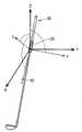
도 9는 라이각, 어택각, 샤프트 린각, 페이스각 및 스윙 패스(입사각)를 설명하기 위한 도면.
도 10은 캘리브레이션 설정 화면의 한 예를 도시하는 도면.
도 11은 캘리브레이션의 확인 화면의 한 예를 도시하는 도면.
도 12는 정지 검출 방식을 설명하기 위한 도면.
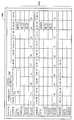
도 13은 회귀 분석에 의해 구한 중회귀식의 타당성을 설명하기 위한 도면.
도 14는 톱 화면의 한 예를 도시하는 도면.
도 15는 각종 정보의 입력 화면의 한 예를 도시하는 도면.
도 16은 측정 화면의 한 예를 도시하는 도면.
도 17은 아이언 샤프트 추천 화면의 한 예를 도시하는 도면.
도 18은 아이언 헤드 추천 화면의 한 예를 도시하는 도면.
도 19는 아이언 헤드 추천 화면의 한 예를 도시하는 도면.
도 20은 아이언 헤드 추천 화면의 한 예를 도시하는 도면.
도 21은 아이언 헤드 선택 화면의 한 예를 도시하는 도면.
도 22는 선택한 아이언의 확인 화면의 한 예를 도시하는 도면
도 23는 웨지 헤드 선택 화면의 한 예를 도시하는 도면.
도 24는 웨지 헤드 선택 화면의 다른 예를 도시하는 도면.
도 25는 유틸리티 헤드 선택 화면의 한 예를 도시하는 도면.
도 26은 스윙 해석 장치의 기능 블록도.
도 27은 센서 장치의 외관을 도시하는 도면.BRIEF DESCRIPTION OF THE DRAWINGS Fig. 1 is a diagram for explaining the overall configuration of a swing analysis system. Fig.
2 is a block diagram showing a hardware configuration of a swing analysis device;
3 is a block diagram showing a hardware configuration of a sensor device;
4 is a diagram for explaining a local coordinate system and a global coordinate system;
5 is a plan view schematically showing an arrangement state of a distortion gauge;
Fig. 6 is a schematic view of a side viewed immediately before a golf ball is hit, viewed from the batted direction; Fig.
7 is a schematic view of a side view of a golf player immediately before the golf ball is viewed from the side.
8 is a flowchart for explaining an operation outline of the swing analysis system.
9 is a view for explaining a lie angle, an attack angle, a shaft angle, a face angle, and a swing path (incident angle).
10 is a view showing an example of a calibration setting screen;
11 is a view showing an example of a calibration confirmation screen;
12 is a diagram for explaining a stop detection method;
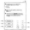
13 is a diagram for explaining the validity of a multiple regression equation obtained by regression analysis;
14 is a view showing an example of a top screen;
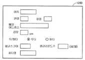
15 is a diagram showing an example of an input screen of various information;
16 is a view showing an example of a measurement screen;
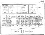
17 is a view showing an example of an iron shaft recommendation screen;
18 is a view showing an example of a ironhead recommendation screen;
19 is a view showing an example of a ironhead recommendation screen;
20 is a view showing an example of a ironhead recommendation screen;
21 is a view showing an example of a ironhead selection screen;
22 is a view showing an example of a confirmation screen of a selected iron
23 is a view showing an example of a wedge head selection screen;
24 is a view showing another example of a wedge head selection screen;
25 is a view showing an example of a utility head selection screen;
26 is a functional block diagram of the swing analysis apparatus.
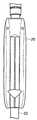
27 is a view showing an appearance of a sensor device;
이하에, 본 발명의 실시의 형태에 관해 설명한다. 또한, 동일 또는 상당하는 부분에 동일한 참조 부호를 붙이고, 그 설명을 반복하지 않는 경우가 있다.Hereinafter, embodiments of the present invention will be described. In addition, the same or equivalent portions are denoted by the same reference numerals, and the description thereof may not be repeated.
또한, 이하에 설명하는 실시의 형태에서, 개수, 양 등에 언급하는 경우, 특히 기재가 있는 경우를 제외하고, 본 발명의 범위는 반드시 그 개수, 양 등으로 한정되지 않는다. 또한, 이하의 실시의 형태에서, 각각의 구성 요소는, 특히 기재가 있는 경우를 제외하고, 본 발명에서 반드시 필수의 것은 아니다.In addition, in the embodiments described below, the scope of the present invention is not necessarily limited to the number, quantity, and the like, except for the case where there is a substrate in particular. In the following embodiments, each component is not necessarily essential to the present invention except for the case where there is a description in particular.
<시스템의 구성><System Configuration>
(전체 구성)(Total configuration)
도 1은, 스윙 해석 시스템의 전체 구성을 설명하기 위한 도면이다. 도 1을 참조하면, 스윙 해석 시스템(1000)은, 골프 클럽 사용자의 스윙을 해석하여 해석 결과를 사용자에게 제시한다. 스윙 해석 시스템(1000)은, 해석 결과에 의거하여, 사용자에게 적합한 골프 클럽을 나타내는 정보를 제시한다. 구체적으로는, 스윙 해석 시스템(1000)은, 스윙 해석 장치(10)와, 센서 장치(20)를 포함한다.1 is a view for explaining the overall configuration of a swing analysis system. Referring to FIG. 1, a
골프 클럽(50)은, 샤프트(52)와, 샤프트(52)의 일단에 마련된 헤드와, 샤프트(52)의 타단에 마련된 그립을 포함한다. 골프 클럽(50)은, 사용자 자신이 준비한 것, 다른 자가 준비한 것 등, 어느 골프 클럽이라도 좋다.The
스윙 해석 장치(10)는, 스마트 폰으로 구성된다. 단, 스윙 해석 장치(10)는, 종류를 불문하고 임의의 장치로서 실현할 수 있다. 예를 들면, 스윙 해석 장치(10)는, 노트 PC(personal Computer), 태블릿 단말, PDA(Personal Digital Assistance), 데스크톱 PC 등의 기기라도 좋다.The
스윙 해석 장치(10)는, Bluetooth(등록상표), 무선 LAN(Local Area Network), 적외선 통신 등의 무선 통신을 이용하여 센서 장치(20)와 통신하다. 또한, 스윙 해석 장치(10)는, USB(Universal Serial Bus) 등의 유선 통신을 이용하여 센서 장치(20)와 통신 가능하게 구성되어 있어도 좋다.The
센서 장치(20)는, 그립의 상단부로부터, 예를 들면, 약 12인치∼15인치에 위치하는 부분에 센서 장치(20)의 중심이 위치하도록 샤프트(52)에 장착된다. 골프 클럽(50)은, 그립의 단부로부터, 예를 들면, 14인치의 점에서 중량 밸런스가 잡혀 있고, 이 부분에 추 등을 장착하여도 골프 클럽(50) 전체의 중량 밸런스에 큰 영향이 없다. 이 때문에, 상기한 위치에 센서 장치(20)를 장착함으로써, 센서 장치(20)가 장착된 전후에 있어서, 골프 클럽(50)의 특성이 크게 변화하는 것이 억제된다.The
센서 장치(20)는, 가속도 센서와, 각속도 센서와, 왜곡 센서를 포함한다. 센서 장치(20)는, 각 센서에 의해 검출된 센서 데이터 및 센서 데이터에 의거한 연산 결과 등을 스윙 해석 장치(10)에 송신한다. 스윙 해석 장치(10)는, 센서 장치(20)로부터 각종 정보를 수신하여, 피험자의 스윙 해석 등의 각종 처리를 실행한다.The
(하드웨어 구성)(Hardware configuration)
도 2는, 스윙 해석 장치의 하드웨어 구성을 도시하는 블록도이다. 도 2를 참조하면, 스윙 해석 장치(10)는, 주된 구성 요소로서, 프로세서(102)와, 메모리(104)와, 터치 패널(106)과, 버튼(108)과, 디스플레이(110)와, 무선 통신부(112)와, 통신 안테나(113)와, 메모리 인터페이스(I/F)(114)와, 스피커(116)과, 마이크로폰(118)과, 통신 인터페이스(I/F)(120)를 포함한다. 또한, 기록 매체(115)는, 외부의 기억 매체이다.2 is a block diagram showing the hardware configuration of the swing analysis apparatus. 2, the
프로세서(102)는, 전형적으로는, CPU(Central Processing Unit)나 MPU(Multi Processing Unit)라는 연산 처리부이다. 프로세서(102)는, 메모리(104)에 기억된 프로그램을 판독하여 실행함으로써, 스윙 해석 장치(10)의 각 부분의 동작을 제어한다. 보다 상세하게는 프로세서(102)는, 당해 프로그램을 실행함에 의해, 후술하는 스윙 해석 장치(10)의 처리(스텝)의 각각을 실현한다.The
메모리(104)는, RAM(Random Access Memory), ROM(Read-Only Memory), 플래시 메모리 등에 의해 실현된다. 메모리(104)는, 프로세서(102)에 의해 실행되는 프로그램, 또는 프로세서(102)에 의해 사용되는 데이터 등을 기억한다.The
터치 패널(106)은, 표시부로서의 기능을 갖는 디스플레이(110)상에 마련되어 있고, 저항막 방식, 정전용량 방식 등의 어느 타입이라도 좋다. 버튼(108)은, 스윙 해석 장치(10)의 표면에 배치되어 있고, 유저로부터의 지시를 접수하여, 프로세서(102)에 당해 지시를 입력한다.The
무선 통신부(112)는, 통신 안테나(113)를 통하여 이동체 통신망에 접속하고 무선 통신을 위한 신호를 송수신한다. 이에 의해, 스윙 해석 장치(10)는, 예를 들면, LTE(Long Term Evolution) 등의 이동체 통신망을 통하여 소정의 외부 장치와의 통신이 가능해진다.The
메모리 인터페이스(I/F)(114)는, 외부의 기록 매체(115)로부터 데이터를 판독한다. 즉, 프로세서(102)는, 메모리 인터페이스(114)를 통하여 외부의 기록 매체(115)에 격납되어 있는 데이터를 판독하고, 당해 데이터를 메모리(104)에 격납한다. 프로세서(102)는, 메모리(104)로부터 데이터를 판독하고, 메모리 인터페이스(114)를 통하여 당해 데이터를 외부의 기록 매체(115)에 격납한다.The memory interface (I / F) 114 reads data from the
기록 매체(115)로서는, CD(Compact Disc), DVD(Digital Versatile Disk), BD(Blu-ray(등록상표) Disc), USB(Universal Serial Bus) 메모리, 메모리 카드, FD(Flexible Disk), 하드 디스크 등의 불휘발적으로 프로그램을 격납하는 매체를 들 수 있다.Examples of the
스피커(116)는, 프로세서(102)로부터의 명령에 의거하여 음성을 출력한다. 마이크로폰(118)은, 스윙 해석 장치(10)에 대한 음성을 접수한다.The
통신 인터페이스(I/F)(120)는, 예를 들면, 스윙 해석 장치(10)와 센서 장치(20)와의 사이에서 데이터를 송수신하기 위한 통신 인터페이스이고, 어댑터나 커넥터 등에 의해 실현된다. 통신 방식으로서는, 예를 들면, Bluetooth(등록상표), 무선 LAN 등에 의한 무선 통신 또는 USB를 이용한 유선 통신이다.The communication interface (I / F) 120 is, for example, a communication interface for transmitting and receiving data between the
도 3은, 센서 장치(20)의 하드웨어 구성을 도시하는 블록도이다. 도 3을 참조하면, 센서 장치(20)는, 주된 구성 요소로서, 각종 처리를 실행하기 위한 프로세서(202)와, 프로세서(202)에 의해 실행되는 프로그램, 데이터 등을 격납하기 위한 메모리(204)와, 가속도 센서(206)와, 각속도 센서(208)와, 왜곡 센서(210)와, 스윙 해석 장치(10)와 통신하기 위한 통신 인터페이스(I/F212)와, 센서 장치(20)의 각종 구성 요소에 전력을 공급하는 축전지(214)와, LED(light emitting diode)(216)를 포함한다.3 is a block diagram showing a hardware configuration of the
가속도 센서(206)는, 서로 직교하는 3축방향의 가속도(이하 「가속도 정보」라고도 칭한다.)를 검출한다. 각속도 센서(208)는, 서로 직교하는 3축 둘레의 각속도(이하 「각속도 정보」라고도 칭한다.)를 검출한다.The
도 4는, 로컬 좌표계 및 글로벌 좌표계를 설명하기 위한 도면이다. 도 4를 참조하면, 센서 좌표계(로컬 좌표계)에서의 x축은 샤프트(52)의 긴변 방향으로 설정되고, y축 및 z축은 각각 임의로 설정된다. 절대 좌표계(글로벌 좌표계)에서의 Z축은 연직 방향으로 설정되고, Y축은 사용자의 스윙 방향으로 설정되고, X축은 Y축 및 Z축의 수직 방향으로 설정된다.4 is a diagram for explaining a local coordinate system and a global coordinate system. Referring to Fig. 4, the x-axis in the sensor coordinate system (local coordinate system) is set to the long-side direction of the
왜곡 센서(210)는, 샤프트(52)의 타구 방향 및 토우다운 방향의 각 왜곡량(이하, 「왜곡 정보」라고도 칭한다.)을 검출한다. 구체적으로는, 왜곡 센서(210)는, 샤프트(52)에 장착된 2개의 왜곡 게이지(타구 방향용 왜곡 게이지) 및 왜곡 게이지(토우다운용 왜곡 게이지)를 포함한다.The
도 5는, 왜곡 게이지의 배치 상태를 모식적으로 도시하는 평면도이다. 구체적으로는, 도 5에는, 샤프트(202)의 축방향으로부터 평면으로 본 평면도가 도시되어 있고, 왜곡 게이지(220)와, 왜곡 게이지(221)와의 배치 상태를 모식적으로 나타내고 있다. 도 5를 참조하면, 왜곡 게이지(220)는, 샤프트(52)의 둘레면 중, 타구 방향(Ex 방향)에 대해 수직하게 되는 부분에 배치되고, 왜곡 게이지(221)는, 이 타구 방향과 직교하는 방향(Ey 방향)에 대해 수직하게 되는 부분에 부착되어 있다.5 is a plan view schematically showing the arrangement state of the distortion gages. More specifically, FIG. 5 is a plan view of the
왜곡 게이지(220) 및 왜곡 게이지(221)는, 예를 들면, 그립측 단부로부터 약 12인치∼15인치의 위치, 특히, 그립측 단부로부터 약 14인치의 위치에 마련된다. 또한, 왜곡 게이지(220)와, 왜곡 게이지(221)는, 샤프트(52)의 둘레방향으로 90도 떨어지도록 마련되어 있다.The
도 6은, 골퍼가 타구하기 직전의 양상을 타구 방향에서 본 모식도이다. 도 7은, 골퍼가 타구하기 직전의 양상을 측방에서 본 모식도이다. 도 6을 참조하면, 골프 클럽(50)의 스윙 중, 골프 클럽(50)이 내리쳐진 때에, 샤프트(52)의 중심축선(P)으로부터 샤프트(52)의 선단 및 헤드가 원심력에 의해, 지면 방향으로 아래로 드리워진다. 이 아래로 드리워지는 방향(Ey 방향)을 「토우다운 방향」이라고 한다. 왜곡 게이지(221)는, 샤프트(52) 중 왜곡 게이지(221)가 장착된 위치의 Ey 방향의 (토우다운 방향)의 왜곡을 측정한다. 도 5 및 도 7을 참조하면, 왜곡 게이지(220)는, 샤프트(52) 중, 왜곡 게이지(220)가 장착된 위치의 Ex 방향(타구 방향)의 왜곡을 측정한다.Fig. 6 is a schematic view showing the aspect immediately before the golfer hit the golf ball, viewed from the batted direction. Fig. 7 is a schematic view of a side view of the golf player immediately before kicking. Fig. 6, when the
<시스템의 동작 개요><System operation overview>
도 8은, 스윙 해석 시스템(1000)의 동작 개요를 설명하기 위한 플로우 차트이다. 여기서는, 도 1에 도시하는 바와 같이, 사용자가 지면에 놓여진 볼을 골프 클럽(50)으로 타격하는 장면을 상정한다. 사용자가 스윙 한 골프 클럽(50)은, 예를 들면, 7번 아이언이다. 또한, 골프 클럽(50)은, 6번 아이언 등의 다른 번수라도 좋고, 우드라도 좋다. 스윙 해석 장치(10) 및 센서 장치(20)는, 서로 통신 가능한 상태라고 한다.8 is a flowchart for explaining an outline of the operation of the
도 8을 참조하면, 골프 클럽(50)의 샤프트(52)에 부착된 센서 장치(20)는, 가속도 정보, 각속도 정보 및 왜곡 정보를 시계열로 검출한다(스텝 S100). 구체적으로는, 센서 장치(20)는, 샘플링 주기(예를 들면, 1ms)마다 센서 좌표계(로컬 좌표계)에서의 가속도 정보 및 각속도 정보와, 왜곡 정보를 검출한다. 센서 장치(20)는, 검출한 가속도 정보, 각속도 정보 및 왜곡 정보를 스윙 해석 장치(10)에 송신한다(스텝 S110).Referring to FIG. 8, the
스윙 해석 장치(10)는, 센서 장치(20)로부터 취득한 가속도 정보 및 각속도 정보에 의거하여, 스윙 기간에서의 골프 클럽(50)의 헤드 스피드 및 자세 정보를 산출한다(스텝 S120). 구체적으로는, 스윙 해석 장치(10)는, 임팩트시(즉, 타구시)에서의 골프 클럽(50)의 헤드의 자세각을 산출한다. 자세각은, 임팩트시에 있어서의 라이각, 어택각, 샤프트 린각 및 페이스각(보다 상세하게는, 후술하는 상대 페이스각)을 포함한다. 또한, 본원 명세서에서, 「임팩트시」란, 임팩트와 동시 또는 임팩트 시각부터 소정의 시간(예를 들면, 1/1000초 정도)만큼 전의 시점을 의미한다.The
도 9는, 라이각, 어택각, 샤프트 린각, 페이스각 및 스윙 패스(입사각)를 설명하기 위한 도면이다. 도 9에서는, 지면(예를 들면, 수평면)상의 일방의 축을 Bx축, Bx축에 수직한 지면상의 타방의 축을 By축, Bx축 및 By축에 수직한 방향을 Bz축으로 한 좌표계를 정의한다. 지면에 대해 수직 방향에서 본 때의 방향(-Bz방향)을 평면시라고 칭한다. 또한, Bx축을 타겟 라인 방향이라고 정의한다. 타겟 라인 방향은, 예를 들면, 평면시에 있어서의 타구의 목표 방향이다. 구체적으로는, 도 9(a)는, 임팩트시의 라이각을 도시하는 도면이다. 도 9(b)는, 임팩트시의 어택각 및 샤프트 린각을 도시하는 도면이다. 도 9(c)는, 임팩트시의 페이스각 및 스윙 패스를 도시하는 도면이다.Fig. 9 is a view for explaining a lie angle, an attack angle, a shaft angle, a face angle, and a swing path (incident angle). 9, a coordinate system in which one axis on a paper surface (e.g., a horizontal plane) is defined as a Bx axis, another axis on a paper plane perpendicular to the Bx axis is defined as a By axis, and a direction perpendicular to the Bx axis and By axis is defined as a Bz axis . The direction (-Bz direction) when viewed in the direction perpendicular to the paper is referred to as planar. The Bx axis is defined as the target line direction. The target line direction is, for example, the target direction of the ball in the plan view. Specifically, Fig. 9 (a) is a view showing a lie angle at the time of impact. FIG. 9 (b) is a diagram showing the attack angle and the shaft angle of attack at the time of impact. Fig. 9 (c) is a diagram showing a face angle and a swing path at the time of impact.
도 9(a)를 참조하면, 임팩트시의 라이각은, 지면(도면 중의 BxBy평면)에 대한, 골프 클럽(50)의 샤프트(52)(구체적으로는, 샤프트 센터 라인)의 각도(θ1)로서 정의된다.9A, the impact angle of the lie angle is set to an angle? 1 of the shaft 52 (specifically, the shaft center line) of the
도 9(b)를 참조하면, 임팩트시의 어택각은, 지면에 대해 수직한 가상 수직면(도면 중의 BxBz평면)에 투영된, 골프 클럽(50)의 헤드의 스윙 궤적에 접하는 임팩트시의 접선 방향(스윙 라인 방향)과, 당해 가상 수직면에 투영된 타겟 라인 방향이 이루는 각도(θ2)로서 정의된다. 환언하면, 임팩트시의 어택각(θ2)은, 임팩트시에 있어서의 지면에 대한 스윙 궤도의 방향의 각도이다. 본 실시의 형태에서는, 스윙 라인의 경사가 부의 값인 경우(도 9(b)에 도시하는 경우)에는 어택각(θ2)이 부의 값, 스윙 라인의 경사가 정의 값인 경우에는 어택각(θ2)이 정의 값이라고 한다. 구체적으로는, 헤드가 볼에 대해 경사 하방향으로 입사하는 다운 블로우인 경우에는 어택각(θ2)<0°이고, 헤드가 볼에 대해 수평으로 입사하는 레벨 블로우인 경우에는 어택각(θ2)=0°이고, 헤드가 볼에 대해 경사 상방향으로 입사하는 어퍼 블로우인 경우에는 어택각(θ2)>0 이다.Referring to Fig. 9 (b), the attack angle at the time of impact is defined as a tangential line direction at the time of impact tangent to the swing trajectory of the head of the
도 9(b)를 참조하면, 임팩트시의 샤프트 린각은, 타겟 라인 방향에 수직한 가상면(J1)에 대한 샤프트(52)의 각도(θ3)로서 정의된다. 환언하면, 임팩트시의 샤프트 린각(θ3)은, 임팩트시에 있어서의 지면에 대해 수직한 가상면(J1)에 대한 샤프트(52)의 각도이다. 본 실시의 형태에서는, 샤프트 센터 라인의 경사가 정의 값인 경우(도면 9(b)에 도시하는 경우)에는 샤프트 린각(θ3)이 부의 값, 샤프트 센터 라인의 경사가 부의 값인 경우에는 샤프트 린각(θ3)이 정의 값이라고 한다.Referring to Fig. 9 (b), the angle of the shaft at the time of impact is defined as the angle [theta] 3 of the
도 9(c)를 참조하면, 임팩트시의 페이스각은, 타겟 라인 방향에 직교하는 가상면(J2)에 대한 골프 클럽(50)의 페이스면의 각도(θ4)로서 정의된다. 본 실시의 형태에서는, 페이스면의 경사가 정의 값인 경우(도면 9(c)에 도시하는 경우)에는 페이스각(θ4)이 정의 값, 페이스면의 경사가 부의 값인 경우에는 페이스각(θ4)이 부의 값이라고 한다.Referring to Fig. 9 (c), the face angle at the time of impact is defined as the angle [theta] 4 of the face surface of the
임팩트시의 스윙 패스(입사각)는, 스윙 라인 방향에 대한 타겟 라인 방향과 이루는 각도(θ5)로서 정의된다. 본 실시의 형태에서는, 스윙 라인 방향의 경사가 정의 값인 경우(도면 9(c)에 도시하는 경우)에는 스윙 패스(θ5)가 부의 값, 스윙 라인 방향의 경사가 부의 값인 경우에는 스윙 패스(θ5)가 정의 값이라고 한다.The swing path (incident angle) at the time of impact is defined as an angle (? 5) with the direction of the target line with respect to the swing line direction. In the present embodiment, when the slope in the swing line direction is a positive value (in the case shown in Fig. 9 (c)), when the swing path? 5 is negative and the slope in the swing line direction is negative, ) Is a positive value.
페이스각(θ4)은, 헤드의 타격점에의 입사 방향(스윙 라인 방향)과 관계없이 방향이 고정되어 있는 타겟 라인 방향을 기준으로 하는 페이스면의 경사를 나타내고 있다. 한편, 스윙 라인 방향을 기준으로 하는 페이스면의 경사를 나타내는 상대적인 페이스각(이하, 「상대 페이스각」이라고도 칭한다.)은, 페이스각(θ4)으로부터 스윙 패스(θ5)를 감산한 각도이다. 또한, 상대 페이스각은, 페이스 투 패스각이라고도 불린다.The face angle [theta] 4 indicates the inclination of the face surface with reference to the target line direction in which the direction is fixed irrespective of the incidence direction (swing line direction) of the head to the impact point. On the other hand, a relative face angle (hereinafter also referred to as a "relative face angle") indicating the inclination of the face surface with respect to the swing line direction is an angle obtained by subtracting the swing path θ5 from the face angle θ4. The relative face angle is also referred to as a face-to-pass angle.
재차, 도 8을 참조하면, 스윙 해석 장치(10)는, 왜곡 정보에 의거하여, 골프 클럽(50)의 자세 정보(자세각)를 보정한다(스텝 S130). 구체적으로는, 스윙 해석 장치(10)는, 미리 정하여진 식 및 왜곡 정보를 이용하여, 스텝 S120에서 산출한 자세각 중의 라이각 및 어택각을 보정한다. 상세는 후술하지만, 스텝 S130의 처리는, 임팩트시에 있어서의 샤프트(52)의 왜곡을 고려함에 의해, 임팩트시에 있어서의 라이각 및 어택각을 정밀도 좋게 산출하기 위한 처리이다.8, the
스윙 해석 장치(10)는, 보정한 라이각 및 어택각을 포함하는 자세각 및 그 밖의 해석 정보(예를 들면, 스윙 템포 등)를 포함하는 스윙 해석 정보를 디스플레이(110)에 표시한다(스텝 S140). 스윙 해석 장치(10)는, 터치 패널(106)을 통하여 유저로부터의 지시를 접수하고, 골퍼에 적합한 골프 클럽을 피팅하기 위한 화면을 순차적으로 표시한다(스텝 S150).The
<각 처리의 상세><Details of each processing>
이하, 스윙 해석 시스템(1000)에서 실행되는 각 처리의 상세에 관해 설명한다.Hereinafter, details of each process executed in the
(캘리브레이션)(calibration)
상술한 바와 같이, 센서 장치(20)는, 골프 클럽(50)의 샤프트(52)에 부착된다. 센서 장치(20)를 부착한 골프 클럽(50)은, 골프 상점 등에 제공되고, 골프 상점에 내점한 고객의 스윙 해석 등에 사용된다.As described above, the
도 4에서 설명한 바와 같이, 센서 장치(20)는, 센서 좌표의 x축이 샤프트(52)의 긴변 방향으로 설정되도록 샤프트(52)에 부착된다. 그러나, 센서 장치(20)의 부착 방법 등에 따라서는, 센서 좌표의 x축방향과, 샤프트(52)의 긴변 방향과의 사이에 차분이 생기고 있을 가능성도 있다. 이 경우, 스윙 해석 장치(10)에 의해 산출된 각종의 자세각은, 당해 차분에 상당하는 각도만큼 오차가 생긴다.4, the
그래서, 본 실시의 형태에 관한 스윙 해석 시스템(1000)에서는, 개체차에 의한 스윙 해석 성능의 편차를 억제하기 위한 캘리브레이션을 실행 가능하게 구성되어 있다. 센서 장치(20)를 부착한 골프 클럽(50)을 고정한 상태에서, 상기 차분에 상당하는 캘리브레이션 값이 산출된다. 여기서는, 캘리브레이션 설정의 실행자는, 골프 클럽의 구입을 고객(여기서는, 골프 클럽(50)을 사용하는 골퍼)에게 촉구하는 자(이하, 단지 「피터」라고 칭한다.)라고 가정한다. 또한, 캘리브레이션 설정은, 센서 장치(20) 부착의 골프 클럽(50)이 골프 상점 등에 제공되기 전에 실행되어도 좋다.Thus, in the
도 10은, 캘리브레이션 설정 화면의 한 예를 도시하는 도면이다. 도 11은, 캘리브레이션의 확인 화면의 한 예를 도시하는 도면이다. 스윙 해석 장치(10)는, 그 밖의 메뉴 화면(도시 생략)에 포함되는 캘리브레이션 설정 버튼의 선택을 접수하면, 도 10에 도시하는 바와 같은 캘리브레이션 설정 화면(1100)을 표시한다.10 is a diagram showing an example of a calibration setting screen. 11 is a diagram showing an example of a calibration confirmation screen. Upon receiving the selection of the calibration setting button included in another menu screen (not shown), the
도 10을 참조하면, 캘리브레이션 설정 화면(1100)에 표시된 지시에 따라, 피터는, 센서 장치(20)를 부착한 골프 클럽(50)을 지면과 평행한 면에 설치된 치구인 클럽 계측기에 고정한다. 예를 들면, 골프 클럽(50)으로서 6번 아이언을 선택한 경우에는, 골프 클럽(50)의 라이각을 61도에 맞춘 상태에서 클럽 계측기에 고정한다. 골프 클럽(50)으로서 7번 아이언을 선택한 경우에는, 골프 클럽(50)의 라이각을 61.5도에 맞춘 상태에서 클럽 계측기에 고정한다. 클럽 계측기로서는, 골프 클럽 헤드의 치수 측정에 사용되는 공지의 측정기(예를 들면, 골프 클럽 게이지, 골프 클럽 앵글 측정기) 등이 사용된다.Referring to FIG. 10, in accordance with an instruction displayed on the
피터는, 영역(1108)에 표시되어 있는 「x」, 「y」 및 「z」가 0인 것을 확인한다. 「x」, 「y」 및 「z」는, 각각, 센서 좌표계의 x축방향의 가속도, y축방향의 가속도 및 z축방향의 가속도를 나타내고 있다. 이들이 0이 아닌 경우에는 클리어 버튼(1104)을 선택하고, 3축방향의 가속도를 0으로 한다.Peter confirms that "x", "y", and "z" displayed in the
영역(1110)에 표시되어 있는 「H_LIE」는, 라이각에 관한 캘리브레이션 값이고, 「H_SL」은 샤프트 린각에 관한 캘리브레이션 값이다. 이들의 캘리브레이션 값(H_SL, H_LIE)은, 센서 장치(20)의 메모리(204)에 보존되도록 구성되어 있다. 스윙 해석 장치(10)는, 센서 장치(20)와의 통신 확립시에, 캘리브레이션 값을 판독함(수신함)에 의해, 판독한 캘리브레이션 값을 영역(1110)에 표시한다. 예를 들면, 캘리브레이션 값(H_SL)의 초기치는 0이고, 캘리브레이션 값(H_LIE)의 초기치는 -1.0이다."H_LIE" displayed in the
다음에, 피터는, 골프 클럽(50)을 정지시킨 상태에서, 캘리브레이션 버튼(1102)을 선택한다. 스윙 해석 장치(10)는, 캘리브레이션 버튼(1102)의 선택을 접수하면, 센서 장치(20)로부터 취득한 3축방향의 가속도를 영역(1108)에 표시한다. 스윙 해석 장치(10)는, 캘리브레이션 버튼(1102)의 선택을 재차 접수하면, 영역(1108)의 표시치를 센서 장치(20)로부터 재취득한 3축방향의 가속도로 갱신한다.Next, the Peter selects the
스윙 해석 장치(10)는, 평균화 버튼(1106)의 선택을 접수하면, 복수회의 가속도 데이터를 평균화하고, 당해 평균치에 의거하여, 라이각 및 샤프트 린각을 산출한다. 라이각 및 샤프트 린각의 산출 방식에 관해서는 후술한다. 스윙 해석 장치(10)는, 산출한 라이각(C_LIE0 및 샤프트 린각(C_SL)을 이용하여 캘리브레이션 값을 산출한다.Upon receiving the selection of the
예를 들면, 골프 클럽(50)이 7번 아이언인 경우에는, 골프 클럽(50)의 라이각을 61.5도에 맞춘 상태에서 클럽 계측기에 고정되어 있다. 그 때문에, H_LIE=61.5-C_LIE가 성립한다. 또한, H_SL=0-C_SL이다.For example, if the
스윙 해석 장치(10)는, 캘리브레이션 값을 산출하면, 캘리브레이션 설정 화면(1100)의 중앙 부근에, 도 11에 도시하는 확인 화면(1150)을 팝 업 표시한다. 확인 화면(1150)에는, 캘리브레이션 값(H_SL, H_LIE)이 표시됨과 함께, 피터에 당해 캘리브레이션 값의 재기록의 확인을 촉구하는 정보가 표시된다.The
스윙 해석 장치(10)는, YES 버튼(1152)의 선택을 접수하면, 캘리브레이션 값(H_SL, H_LIE)을 내부 메모리에 기억하도록 센서 장치(20)에 지시한다. 센서 장치(20)는, 당해 캘리브레이션 값을 메모리(204)에 재기록 보존한다.Upon receiving the selection of the
스윙 해석 장치(10)는, NO 버튼(1154)의 선택을 접수하면, 산출한 복수회의 가속도 데이터의 평균치를 캔슬한다. 이 경우, 캘리브레이션 값(H_SL, H_LIE)은, 센서 장치(20)에 보존되지 않는다.When receiving the selection of the
스윙 해석 장치(10)는, 리셋 버튼(1156)의 선택을 접수하면, 캘리브레이션 값(H_SL, H_LIE)을 초기치로 설정하도록 센서 장치(20)에 지시한다. 센서 장치(20)는, 캘리브레이션 값의 초기치를 메모리(204)에 재기록 보존한다.Upon receiving the selection of the
또한, 스윙 해석 장치(10)는, 캘리브레이션 값(H_SL, H_LIE)의 적어도 일방이 소정 범위(예를 들면, -5도 이상∼+5도 이하의 범위)에 수습되지 않은 경우에는, 캘리브레이션 값이 이상한 것을 나타내는 경고 화면을 표시하여도 좋다. 이 경우, 캘리브레이션 값(H_SL, H_LIE)은, 센서 장치(20)에 재기록 보존되지 않는다.When at least one of the calibration values H_SL and H_LIE is not within a predetermined range (for example, a range from -5 degrees to +5 degrees), the
스윙 해석 장치(10)는, 센서 장치(20)와의 통신 확립시에, 상기한 바와 같이 설정된 캘리브레이션 값을 판독하고, 당해 캘리브레이션 값에 의거하여 자세각 정보를 보정한다. 그 때문에, 개체차에 의한 스윙 해석 성능의 편차를 억제할 수 있다.The
(정지 검출)(Stop detection)
여기서는, 스윙 직전의 정지 상태의 검출 방식에 관해 설명한다. 사용자가 골프 클럽을 스윙할 때에는, 대강 이하와 같은 순서로 행하여진다. 구체적으로는, 사용자는, 골프 클럽을 쥐고, 어드레스의 자세를 취한 후, 스윙 동작을 행하여, 골프공을 타구한다.Here, the detection method of the stop state immediately before the swing will be described. When the user swings the golf club, the following steps are performed roughly. Specifically, the user grasps a golf club, takes an address posture, performs a swing operation, and strikes a golf ball.
스윙 해석 장치(10)는, 센서 장치(20)로부터 취득한 센서 데이터(예를 들면, 가속도 정보 및 각속도 정보)에 의거하여, 시계열로 스윙 해석 정보를 산출한다. 예를 들면, 스윙의 준비중(예를 들면, 왜글 동작 중;waggling)을 스윙 시작 시점으로 설정하면, 적분 오차 등이 축적되고 적절한 스윙 해석 정보를 얻을 수 없을 가능성이 있기 때문에, 스윙 직전의 정지 상태(즉, 스윙 시작 시점)를 정밀도 좋게 검출할 필요가 있다.The
도 12는, 정지 검출 방식을 설명하기 위한 도면이다. 도 12에서의 횡축은 시각(Ts)을 나타내고 있고, 종축은, 서로 직교하는 3축 둘레(센서 좌표계)의 각속도(deg/s) 및 합성 각속도를 나타내고 있다.12 is a diagram for explaining the stop detection method. In Fig. 12, the abscissa represents time (Ts), and the ordinate represents angular velocity (deg / s) and synthetic angular velocity of three axes (sensor coordinate system) perpendicular to each other.
도 12에 도시하는 그래프에는, 사용자가 골프 클럽(50)을 스윙하여 볼을 타격한 때의 각속도 정보가 나타나 있다. 스윙 해석 장치(10)는, 임팩트 시각부터 소정 시간(예를 들면, 0.5초)만큼 전의 시각부터 시간을 거슬러 올라가, 합성 각속도(W)가 기준 임계치(Th)(예를 들면, 20deg/s) 미만이 되는 시각(t1)을 산출한다.The graph shown in Fig. 12 shows angular velocity information when the user swings the
x축 둘레의 각속도(ωx), y축 둘레의 각속도(ωy), 축 둘레의 각속도(ωz)라고 하면, 합성 각속도(W)는 이하의 식(1)으로 표시된다.and the angular velocity omega z around the axis, the angular velocity omega x around the x axis, the angular velocity omega y around the y axis, and the angular velocity omega z about the axis, the synthetic angular velocity W is expressed by the following equation (1).
[수식 1][Equation 1]

다음에, 임팩트 시각에 관해 설명한다. 임팩트시에서는 센서 장치(20)의 가속도 센서(206)의 신호가 볼을 친 충격에 의해 과도(過度) 응답하기 때문에, 가속도가 급격하게 변화한다. 그래서, 스윙 해석 장치(10)는, 합성 가속도(AC)의 단위시간당의 변화량이 임계치(예를 들면, 500) 이상이 된 시각을 임팩트 시각으로서 산출한다.Next, the impact time will be described. At the time of impact, since the signal of the
x축방향의 가속도(ax), y축방향의 가속도(ay), z축방향의 가속도(az)라고 하면, 합성 가속도(AC)는 이하의 식(2)으로 표시된다.Assuming that the acceleration ax in the x-axis direction, the acceleration in the y-axis direction (ay), and the acceleration in the z-axis direction (az), the composite acceleration AC is expressed by the following expression (2).
[수식 2][Equation 2]

스윙 해석 장치(10)는, 산출한 시각(t1)보다도 시간(Ta)(예를 들면, 0.2초)만큼 과거의 시각(t2)부터, 시각(t1)보다도 시간(Tb)(예를 들면, -0.1초)만큼 과거의 시각(t3)까지의 기간(Tc)을, 사용자가 정지하고 있는 기간(정지 기간)으로서 산출한다.The
(자세각의 산출)(Calculation of attitude angle)
스윙 해석 장치(10)는, 가속도 정보 및 각속도 정보에 의거하여, 센서 장치(20)의 자세 정보를 산출한다. 여기서, 센서 장치(20)의 자세 정보인 방향 여현행렬(direction cosine matrix)(Rq)은 이하의 식(3)과 같이 표시된다.The
[수식 3][Equation 3]

도 4에 도시하는 바와 같이, 센서 좌표계(로컬 좌표계의 x축은 샤프트(52)의 긴변 방향으로 설정되어 있다. 그 때문에, 센서 장치(20)의 자세 정보(즉, 방향 여현행렬(Rq))을 이용하여 골프 클럽(50)의 자세각을 산출할 수 있다. 구체적으로는, 방향 여현행렬(Rq)의 각 성분을 이용하여, 골프 클럽(50)의 라이각(A_LIE), 샤프트 린각(A_SL) 및 페이스각(A_FA)은, 각각 이하의 식(4), 식(5) 및 식(6)과 같이 표시된다.4, the sensor coordinate system (the x-axis of the local coordinate system is set to the long-side direction of the
[수식 4][Equation 4]

스윙 해석 장치(10)(의 프로세서(102))는, 정지 기간(Tc)에서의 시계열의 가속도 정보(3축방향의 가속도)를 평균화하고, 당해 평균화된 가속도 정보에 의거하여, 센서 장치(20)의 초기 자세인 방향 여현행렬(Rq0)을 산출한다. 프로세서(102)는, 방향 여현행렬(Rq0) 및 상술한 식(4)∼(6)을 이용하여, 라이각(A_LIE), 샤프트 린각(A_SL) 및 페이스각(A_FA)의 초기치(즉, 초기 자세각)를 산출한다. 프로세서(102)는, 도 12 중의 시각(t3)을 스윙 시작 시각으로 설정한다.(The
프로세서(102)는, 스윙 시작 시각부터 임팩트시까지의 스윙 기간에서의 방향 여현행렬(Rq)을 시계열로 산출한다. 대강 이하와 같은 흐름으로 방향 여현행렬(Rq)이 시계열로 산출된다.The
센서 좌표계의 가속도 정보가, 방향 여현행렬(Rq)을 이용하여 글로벌 좌표계의 가속도 정보(가속도 벡터)로 변환된다. 계속해서, 센서 장치(20)로부터 골프 클럽(50)의 헤드 중심에의 벡터(r)(센서 좌표계)가, 방향 여현행렬(Rq)을 이용하여 글로벌 좌표계로 변환된다.The acceleration information of the sensor coordinate system is converted into acceleration information (acceleration vector) of the global coordinate system by using the direction cosine matrix Rq. Subsequently, the vector r (sensor coordinate system) from the
다음에, 3축 둘레의 각속도에 의거하여, 센서 좌표계의 회전 단위 벡터(u) 및 단위당의 회전각(α)이 산출된다. 방향 여현행렬(Rq)을 이용하여 센서 좌표계의 회전 단위 벡터(u)가 글로벌 좌표계로 변환되고, 글로벌 좌표계로 변환된 회전 단위 벡터(ug) 및 회전각(α)을 이용하여, 글로벌 좌표계의 각속도 벡터(ωg)가 산출된다.Next, the rotation unit vector u of the sensor coordinate system and the rotation angle? Per unit are calculated based on the angular speed around the three axes. The rotation unit vector u of the sensor coordinate system is converted into the global coordinate system by using the direction cosine matrix Rq and the rotation unit vector ug and the rotation angle α converted into the global coordinate system are used to calculate the angular velocity The vector? G is calculated.
다음에, 회전 단위 벡터(ug)에 로드리게스의 회전 공식을 이용하여, 변환행렬(R)이 구하여진다. 그리고, 변환행렬(R)을 이용하여 방향 여현행렬(Rq)을 회전시킨 방향 여현행렬(Rq1)이 산출된다. 방향 여현행렬(Rq1)을 이용하여, 상술한 처리가 반복된다. 이에 의해, 방향 여현행렬(Rq)이 시계열로 산출된다.Next, the transformation matrix R is obtained by using the rotation formula of Rodriguez in the rotation unit vector (ug). Then, a direction cosine matrix Rq1 obtained by rotating the directionality matrix Rq using the transformation matrix R is calculated. Using the direction cosine matrix Rq1, the above-described processing is repeated. Thus, the directionality matrix Rq is calculated in a time series.
한편, 프로세서(102)는, 글로벌 좌표계의 가속도 정보(가속도 벡터)를 시간 적분하여, 글로벌 좌표계의 센서 장치(20)의 속도 정보(속도 벡터(V))를 산출한다. 프로세서(102)는, 글로벌 좌표계의 속도 벡터(V), 각속도 벡터(ωg) 및 센서 장치(20)로부터 헤드 중심에의 벡터(r)에 의거하여, 헤드 속도 벡터(Vh)를 산출한다. 헤드 속도 벡터(Vh)의 X성분, Y성분 및 Z성분을 Vhx, Vhy, Vhz라고 하면, 헤드 스피드(Vhs)는, 이하의 식(7)으로 표시된다.On the other hand, the
[수식 5][Equation 5]

속도 벡터(V)의 각 성분을 이용하여, 골프 클럽(50)의 어택각(A_AT), 스윙 패스(SWP)는, 각각 이하의 식(8), 식(9)과 같이 표시된다.The attack angle A_AT of the
[수식 6][Equation 6]

그리고, 임팩트시의 방향 여현행렬(Rqi)과, 식(4) 및 (5)에 의거하여, 임팩트시의 라이각(Lc), 샤프트 린각(SLc), 페이스각(FAc)이 산출된다. 임팩트시의 속도 벡터(V)와, 식(8) 및 (9)에 의거하여, 임팩트시의 어택각(ATc), 스윙 패스(SWc)가 산출된다. 임팩트시의 상대 페이스각(Frc)은, 페이스각(FAc)으로부터 스윙 패스(SWc)를 감산한 값에 상당한다.The lie angle Lc, the shaft angle? SLc, and the face angle FAc at the time of impact are calculated based on the directionality matrix Rqi at the time of impact and the equations (4) and (5). The attack angle ATc and the swing path SWc at the time of impact are calculated based on the velocity vector V at the time of impact and the equations (8) and (9). The relative face angle Frc at the time of impact corresponds to a value obtained by subtracting the swing path SWc from the face angle FAc.
(자세각의 보정)(Correction of attitude angle)
상술한 바와 같이 산출된 자세각을 왜곡 정보를 이용하여 보정하는 방식에 관해 설명한다. 도 6 및 도 7에 도시하는 바와 같이, 골프 클럽이 내리쳐진 임팩트시에서는, 샤프트(52)의 토우다운 방향(Ey) 및 타구 방향(Ex)에 왜곡이 생긴다.A method of correcting the calculated attitude angle using the distortion information as described above will be described. As shown in Figs. 6 and 7, at the time of impact at which the golf club is lowered, distortion occurs in the toe down direction Ey and the hit direction Ex of the
상술한 방식에 의해 산출된 자세각은, 골프 클럽(50)의 헤드가 샤프트(52)의 중심축선(P)에 응한 위치에 있다고 가정하여 구하여져 있다. 그 때문에, 당해 산출된 자세각은, 임팩트시에 있어서의 실제의 자세각과는 다소의 오차가 존재한다고 생각된다. 그래서, 본 실시의 형태에 관한 스윙 해석 장치(10)는, 왜곡 정보를 이용하여 당해 산출된 자세각을 보정한다.The attitude angle calculated by the above-described method is obtained on the assumption that the head of the
본원 발명자가 예의 검토한 결과, 자세각 중의 라이각(도면 9 중의 θ1에 대응하는 각도) 및 샤프트 린각(도면 9 중의 θ3에 대응하는 각도)이 샤프트(52)의 왜곡의 영향을 크게 받는 것이 판명되었다. 구체적으로는, 18명의 골퍼에게 합계 42구 시타를 받아, 라이각 및 샤프트 린각의 실측치와 왜곡량과의 관계성이 평가되었다.As a result of intensive investigations by the present inventors, it has been found that the lie angle (angle corresponding to? 1 in Fig. 9) and the shaft angle (angle corresponding to? 3 in Fig. 9) in the attitude angle are greatly affected by the distortion of the
본원 발명자는, 이 평가로부터 예의 검토한 바, 샤프트(52)의 토우다운 방향(Ey)의 왜곡량이, 라이각의 실측치에 대해 특히 상관이 높은 것을 발견하였다. 또한, 본원 발명자는, 샤프트(52)의 타구 방향(Ex)의 왜곡량, 페이스각 및 스윙 패스가, 샤프트 린각의 실측치에 대해 특히 상관이 높은 것을 발견하였다.As a result of intensive investigation from this evaluation, the inventor of the present invention found that the amount of distortion of the
그래서, 본원 발명자는, 상 지견에 의거하여, 상술한 방식에 의해 산출된 임팩트시의 라이각(Lc)과, 임팩트시의 토우다운 방향(Ey)의 왜곡량(Dy)을 설명변수로 하고, 임팩트시의 라이각의 실측치를 목적변수로 하여 중회귀(重回歸) 분석을 행하였다. 이 결과 산출된 회귀식은 식(10)과 같이 표시된다. a0, a1, a2는 중회귀 계수이다. 라이각(La)은, 목적변수의 계산치이다.Therefore, the inventor of the present invention has found that, taking the lie angle Lc at impact and the amount of distortion Dy in the down-direction (Ey) at impact as calculated by the above-described method as explanatory variables, A multiple regression analysis was conducted using the measured values of the lie angle of the city as the target variables. The resulting regression equation is shown in Equation (10). a0, a1 and a2 are the multiple regression coefficients. The lie angle La is a calculated value of the objective variable.
[수식 7][Equation 7]

식(10)을 이용함에 의해, 임팩트시의 라이각(Lc)과, 임팩트시의 토우다운 방향(Ey)의 왜곡량(Dy)에 의거하여, 목적변수(즉, 실측된 라이각)의 계산치인 라이각(La)을 구할 수 있다. 따라서 라이각(Lc)을 실측치에 보다 근접시키는 보정을 행할 수 있다. 이하, 라이각(Lc)을 식(10)을 이용하여 보정한 값인 라이각(La)을, 라이각의 보정치라고 칭하는 경우가 있다. 식(10)에 표시하는 중회귀식의 타당성은, 도 13에 도시되는 바와 같다.Using the equation (10), the lie angle (Ly), which is a calculated value of the target variable (i.e., the actually measured lie angle) based on the lie angle Lc at the time of impact and the amount of distortion Dy at the time of impact in the down- (La) can be obtained. Therefore, correction can be performed to bring the lie angle Lc closer to the measured value. Hereinafter, the lie angle La, which is the value obtained by correcting the lie angle Lc using equation (10), may be referred to as a correction value of the lie angle. The validity of the multiple regression equation shown in equation (10) is as shown in Fig.
도 13은, 회귀 분석에 의해 구한 중회귀식의 타당성을 설명하기 위한 도면이다. 구체적으로는, 횡축에는 식(10)을 이용하여 산출된 라이각의 보정치(La)가 나타나고 있고, 종축에는 본래의 라이각의 실측치가 나타나 있다. 도 13을 참조하면, 식(10)에 표시하는 중회귀식의 결정계수(R2)는 0.6628이기 때문에, 높은 결정계수를 얻을 수 있고, 본원 발명자가 예의 검토한 결과 얻어진 상술한 지견의 타당성이 나타나 있다.13 is a diagram for explaining the validity of the multiple regression equation obtained by regression analysis. Specifically, the correction value La of the lie angle calculated using the equation (10) is shown on the horizontal axis, and the measured value of the original lie angle is shown on the vertical axis. Referring to FIG. 13, since the coefficient of determination R2 of the multiple regression equation shown in equation (10) is 0.6628, a high coefficient of determination can be obtained and the validity of the above-described findings obtained as a result of intensive studies have.
마찬가지로, 본원발명자는, 상기 지견에 의거하여, 상술한 방식에 의해 산출된 임팩트시의 샤프트린각(SLc), 페이스각(FAc), 스윙패스(SWc)와, 임팩트시의 타구방향(Ex)의 왜곡량(Dx)을 설명변수로 하고, 임팩트시의 샤프트린각의 실측치를 목적변수로 하여 중회귀분석을 행하였다. 이 결과 산출된 회귀식을 다음 식(11)에 표시한다. b0, b1, b2, b3은 중회귀 계수이다. 샤프트린각(SLa)은, 목적변수의 계산치이다.Likewise, the inventors of the present invention have found that, based on the above knowledge, the inventors of the present invention have found that the shaft angle of attack (SLc), the face angle (FAc), the swing path (SWc) The multiple regression analysis was performed with the distortion amount Dx as the explanatory variable and the measured value of the shaft angle at the time of impact as the target variable. The resulting regression equation is shown in the following equation (11). b0, b1, b2, b3 are the multiple regression coefficients. The shaft angle of attack SLa is a calculated value of the objective variable.
[수식 8][Equation 8]

식(11)을 이용함에 의해, 임팩트시의 샤프트 린각(SLc), 페이스각(FAc), 스윙 패스(SWc)와, 임팩트시의 타구 방향(Ex)의 왜곡량(Dx)에 의거하여, 목적변수(즉, 실측된 샤프트 린각)의 계산치인 샤프트 린각(SLa)을 구할 수 있다. 따라서 샤프트 린각(SLc)을 실측치에 보다 근접하는 보정을 행할 수 있다. 이하, 샤프트 린각(SLc)을 식(11)을 이용하여 보정한 값인 샤프트 린각(SLa)을, 샤프트 린각의 보정치라고 칭하는 경우가 있다. 식(11)에 표시하는 중회귀식의 결정계수(R2)는0.8102이기 때문에, 높은 결정계수를 얻을 수 있고, 본원 발명자가 예의 검토한 결과 얻어진 상술한 지견의 타당성이 나타나 있다.Based on the equation (11), on the basis of the shaft angle of attack SLc, the face angle FAc, the swing path SWc at impact, and the amount of distortion Dx in the hit direction Ex at impact, The shaft angle of rotation SLa, which is a calculated value of the variable (i.e., the measured shaft angle of the shaft), can be obtained. Therefore, the correction can be performed so that the shaft angle of inclination SLc is closer to the measured value. Hereinafter, the shaft angle of leaning SLa, which is a value obtained by correcting the shaft angle of leaning SLc using the equation (11), may be referred to as a correction value of the shaft angle of rotation. Since the coefficient of determination R2 of the multiple regression equation shown in Expression (11) is 0.8102, a high determination coefficient can be obtained, and the above-described findings obtained as a result of intensive studies by the present inventors are shown.
또한, 캘리브레이션 값을 고려한 최종적인 임팩트시의 라이각(Lf), 샤프트린각(SLf), 어택각(ATf) 및 상대 페이스각(Frf)은, 각각 식(12), 식(13), 식(14) 및 식(15)과 같이 표현된다.The lie angle (Lf), the shaft angle of attack (SLf), the attack angle (ATf) and the relative face angle (Frf) at the time of the final impact taking into consideration the calibration value are expressed by Expressions (12), ) And Eq. (15).
[수식 9][Equation 9]

이와 같이, 최종적인 라이각(Lf)은, 가속도 정보 및 각속도 정보에 의거하여 산출된 라이각(Lc)을, 왜곡량(Dy) 및 캘리브레이션 값(H_LIE)에 의거하여 보정한 값이다. 또한, 최종적인 샤프트 린각(SLf)은, 가속도 정보 및 각속도 정보에 의거하여 산출된 샤프트 린각(SLc)을, 왜곡량(Dx) 및 캘리브레이션 값(H_SL)에 의거하여 보정한 값이다.Thus, the final lie angle Lf is a value obtained by correcting the lie angle Lc calculated based on the acceleration information and the angular velocity information based on the distortion amount Dy and the calibration value H_LIE. The final shaft angle of inclination SLf is a value obtained by correcting the shaft angle of inclination SLc calculated based on the acceleration information and the angular velocity information on the basis of the amount of distortion Dx and the calibration value H_SL.
(피팅)(fitting)
여기서는, 사용자에게 적합한 골프 클럽이 피팅될 때까지의 흐름에 관해 설명한다. 이하의 설명에서는, 스윙 해석 장치(10)의 유저는, 피터라고 가정한다. 또한, 골프 클럽(50)은 7번 아이언으로 한다.Here, a description will be given of the flow until a golf club suitable for the user is fitted. In the following description, it is assumed that the user of the
피터는, 디스플레이(110)에 표시된 아이콘을 선택하고, 스윙 해석용의 어플리케이션의 기동 지시를 행한다. 스윙 해석 장치(10)는, 기동 지시를 접수하면 로그인 화면을 표시하고, 소정의 유저 ID 및 패스워드의 입력을 접수한다. 스윙 해석 장치(10)는, 로그인 인증이 성공한 경우 톱 화면(1200)을 표시한다.The Peter selects an icon displayed on the
도 14는, 톱 화면의 한 예를 도시하는 도면이다. 도 14를 참조하면, 톱 화면(1200)은, 우드의 계측치 입력을 접수하는 버튼(1202)과, 아이언의 계측치 입력을 접수하는 버튼(1204)과, 과거의 측정 이력을 표시하기 위한 버튼(1206)을 포함한다. 본 실시의 형태에서는, 버튼(1204)이 선택된 경우에 관해 설명한다.14 is a diagram showing an example of a top screen. 14, the
스윙 해석 장치(10)는, 버튼(1204)의 선택을 접수하면, 센서 장치(20)와의 통신을 확립한다. 전형적으로는, 스윙 해석 장치(10) 및 센서 장치(20)는, 페어링 접속된다. 스윙 해석 장치(10)는, 페어링 접속이 완료되면, 사용자에 관한 각종 정보의 입력 화면을 표시한다. 이때, 스윙 해석 장치(10)는, 상술한 캘리브레이션 값을 판독한다.Upon receiving the selection of the
도 15는, 각종 정보의 입력 화면(1250)의 한 예를 도시하는 도면이다. 도 15를 참조하면, 스윙 해석 장치(10)는, 터치 패널(106)을 통하여, 사용자의 이름, 연령, 성별, 메일 어드레스, 신장, 잘 쓰는 손, 평균 스코어, 평균 라운드수 및 피터명 등의 정보를 접수한다.Fig. 15 is a diagram showing an example of an
도 16은, 측정 화면의 한 예를 도시하는 도면이다. 도 16을 참조하면, 측정 화면(1300)은, 측정 결과가 표시되는 결과 영역(1302)과, 측정을 시작하기 위한 시작 버튼(1304)과, 측정을 캔슬하기 위한 버튼(1306)과, 우드 샤프트의 추천 화면으로 천이하기 위한 천이 버튼(1308)과, 아이언 샤프트의 추천 화면으로 천이하기 위한 천이 버튼(1310)을 포함한다.16 is a diagram showing an example of a measurement screen. 16, the
스윙 해석 장치(10)는, 시작 버튼(1304)을 접수하면, 「정지하여 주시오」, 「샷하여 주시오」 등의 메시지를 사용자에게 통보한다. 사용자는, 당해 메시지에 따라, 센서 장치(20)가 장착된 골프 클럽(50)을 이용하여, 어드레스의 자세를 취한 후, 스윙 동작을 행하여 골프공을 샷한다.When the
스윙 해석 장치(10)는, 센서 장치(20)로부터 수신한 각종 정보에 의거하여, 스윙 해석 처리를 실행하고, 당해 해석 결과를 측정 결과로서 표시한다. 구체적으로는, 결과 영역(1302)에는, 임팩트시의 「헤드 스피드」와, 스윙 중의 최대 벤딩량을 나타내는 「스윙 템포」와, 임팩트시의 「킥앵글」과, 임팩트시의 「토우다운량」과, 임팩트시의 「벤딩계수」와, 임팩트시의 「라이각」과, 임팩트시의 「샤프트 린각」과, 임팩트시의 「어택각」과, 임팩트시의 「상대 페이스각」이 표시된다. 헤드 스피드, 라이각, 샤프트 린각, 어택각 및 상대 페이스각에 관해서는, 상술한 방식을 이용하여 산출된다. 또한, 고객에게의 설명을 용이화하기 위해, 상대 페이스각에 관해서는, 단지 「페이스각」이라고 표시되어 있다. 이것은, 이하에 설명한 화면에 대해서도 마찬가지이다.The
스윙 템포, 킥앵글, 토우다운량 및 벤딩계수의 각 측정치는, 왜곡 센서(210)를 이용하여 센서 장치(20)에 의해 산출된다. 스윙 템포, 킥앵글, 토우다운량의 산출 방법에 관해서는, 예를 들면, 일본 특개2010-187749호 공보에 개시되어 있다. 또한, 벤딩계수의 산출 방법에 관해서는, 일본 특개2010-187749호 공보에서, 벤딩 포인트 상정치의 산출 방법으로서 개시되어 있다.Each measurement value of the swing tempo, the kick angle, the amount of down-down, and the bending coefficient is calculated by the
도 16에는, 사용자에 의해 1회째의 스윙 동작의 해석이 실행되고, 각 측정 결과가 표시되어 있는 장면을 나타내고 있다. 사용자에 의해 스윙이 행하여질 때마다, 측정 결과가 추가된다. 또한, 각 측정 결과의 평균치도 표시된다. 사용자의 스윙이 종료되면, 피터는, 천이 버튼(1310)을 선택한다.Fig. 16 shows a scene in which the analysis of the first swing motion is performed by the user and the measurement results are displayed. Every time the swing is performed by the user, the measurement result is added. The average value of each measurement result is also displayed. When the swing of the user ends, the Peter selects the
도 17은, 아이언 샤프트 추천 화면의 한 예를 도시하는 도면이다. 도 17을 참조하면, 아이언 샤프트 추천 화면(1350)은, 아이언 샤프트를 선택하기 위한 요소가 되는 각 측정치를 표시하는 영역(1352)과, 피터의 추천 샤프트를 표시하는 영역(1354)과, 사용자에게 적합한 스틸 샤프트를 표시하는 영역(1356)과, 사용자에게 적합한 그래파이트 샤프트를 표시하는 영역(1358)과, 톱 화면으로 천이하는 천이 버튼(1360)과, 전의 화면으로 되돌아가는 버튼(1362)과, 아이언 헤드의 추천 화면으로 천이하는 천이 버튼(1364)을 포함한다.17 is a diagram showing an example of the iron shaft recommendation screen. Referring to Fig. 17, the iron
영역(1352)에는, 사용자 자신의 각 측정치가 표시(도면 중의 흑점 부분)됨과 함께, 일반적인 골퍼의 평균치가 표시(도면 중의 해칭 부분)되어 있다. 사용자는, 평균에 대한 자신의 위치를 곧바로 파악할 수 있다.In the
영역(1356)에는, 헤드 스피드, 스윙 템포, 토우다운량, 킥앵글 및 벤딩계수에 의거하여, 스윙 해석 장치(10)가 선택한 스틸 샤프트가 표시되어 있다. 영역(1356)에는, 가장 적합한 스틸 샤프트가 「샤프트(ST1)」인 것이 표시되어 있다. 마찬가지로, 영역(1358)에는, 가장 적합한 그래파이트 샤프트가 「샤프트(G1)」인 것이 표시되어 있다. 아이언 샤프트의 선택이 종료되면, 피터는, 천이 버튼(1364)을 선택한다.In the
도 18, 도 19 및 도 20은, 아이언 헤드 추천 화면의 한 예를 도시하는 도면이다. 구체적으로는, 도 18은, 임팩트시의 자세각을 표시하는 화면 영역(1400)을 도시하는 도면이다. 도 19는, 헤드 선택 맵을 나타내는 화면 영역(1430)을 도시하는 도면이다. 도 20은, 사용자에게 적합한 헤드를 표시하는 화면 영역(1450)을 도시하는 도면이다. 아이언 헤드 추천 화면은, 화면 영역(1400, 1430, 1450)을 포함하고, 이들의 화면 영역은, 아이언 헤드 추천 화면을 상하로 화면 스크롤 함에 의해 표시된다.18, 19 and 20 are views showing an example of the ironhead recommendation screen. Specifically, Fig. 18 is a diagram showing a
도 18을 참조하면, 화면 영역(1400)은, 임팩트시의 라이각을 표시하는 영역(1402)과, 임팩트시의 샤프트 린각 및 어택각을 표시하는 영역(1404)과, 임팩트시의 페이스각(및 스윙 패스)를 표시하는 영역(1406)을 포함한다. 골퍼는, 화면 영역(1400)을 확인함에 의해, 임팩트시의 라이각, 샤프트 린각, 어택각, 페이스각 및 스윙 패스의 상태를 이미지 할 수 있다.18, the
각 영역(1402∼1406)에는, 사용자 자신의 각 측정치가 표시(도면 중의 흑점 부분)됨과 함께, 일반적인 평균치가 표시(도면 중의 해칭 부분)되어 있다. 그 때문에, 사용자는, 평균에 대한 자신의 위치를 곧바로 파악할 수 있다.In each of the
도 19를 참조하면, 화면 영역(1430)은, 사용자에게 추천되는 아이언 헤드의 스펙 정보를 표시하는 영역(1432)과, 사용자에 대해 추천된 아이언 모델을 표시하는 영역(1434)과, 헤드 타입과 어택각과의 관계성을 표시하는 영역(1436)과, 넥 타입과 상대 페이스각과의 관계성을 표시하는 영역(1438)을 포함한다.19, the
구체적으로는, 영역(1432)에는, 사용자에게 추천되는 헤드 사이즈, 넥 타입, 헤드 타입, 라이각의 정보가 표시된다. 도 19의 예에서는, 「작음」보다도 「큼」의 헤드 사이즈가 추천되고, 「스트레이트」보다도 「구즈;goose」의 넥 타입이 추천되고, 「머슬;muscle」보다도 「딥 캐비티;deep cavity」의 헤드 타입이 추천되고, 「업」보다도 「플랫」의 라이각이 추천되어 있다.More specifically, in the
영역(1434)에는, 어택각, 상대 페이스각, 샤프트 린각, 헤드 스피드 및 헤드 스피드의 편차(표준편차)에 의거하여, 사용자에게 추천하는 아이언 모델을 선택하기 위한 맵(30)이 나타나고 있다.In the
맵(30)의 횡축에는, 임팩트시에 있어서의 타구의 좌우방향으로의 비상 특성의 지표의 대표례로서, 임팩트시의 상대 페이스각이 나타나 있다. 임팩트시의 상대 페이스각이 정방향으로 큰 경우(즉, 페이스 방향이 스윙 궤도에 대해 오픈인 경우)에는, 슬라이스 스핀으로 오른쪽으로 구부러지는 탄도가 된다. 한편, 임팩트시의 페이스각이 부방향으로 큰 경우(즉, 페이스 방향이 스윙 궤도에 대해 클로즈인 경우)에는, 훅 스핀으로 왼쪽으로 구부러지는 탄탄도가 된다.On the abscissa of the
일반적으로, 「구즈」 타입은 훅 스핀이 걸리기 쉬운 넥 타입이다. 그 때문에, 영역(1438)에서, 페이스 방향이 스윙 궤도에 대해 오픈(즉, 슬라이스 스핀이 걸리기 쉬운 스윙)인 것을 나타내는 화상의 부근에, 추천 넥 타입인 「구즈」라는 문자가 표시된다.In general, the "Guze" type is a neck type that is susceptible to hook spin. Therefore, in the
「스트레이트」 타입은 슬라이스 스핀이 걸리기 쉬운 넥 타입이다. 그 때문에, 영역(1438)에서는, 페이스 방향이 스윙 궤도에 대해 클로즈(즉, 훅 스핀이 걸리기 쉬운 스윙)인 것을 나타내는 화상의 부근에, 추천 넥 타입인 「스트레이트」라는 문자가 표시된다.The "straight" type is a neck type that is susceptible to slice spin. Therefore, in the
맵(30)의 종축에는, 임팩트시에 있어서의 타구의 상하방향으로의 비상 특성의 지표의 대표례로서, 임팩트시의 어택각이 나타나고 있다. 임팩트시의 어택각이 정방향으로 큰 경우(즉, 레벨 블로우의 스윙 궤도인 경우)에는, 고탄도(높게 올라가기 쉬운 탄도)가 된다. 한편, 임팩트시의 어택각이 부방향으로 큰 경우(즉, 다운 블로우의 스윙 궤도인 경우)에는, 저탄도(높게 올라가기 어려운 탄도)가 된다.At the vertical axis of the
일반적으로, 「딥 캐비티」 타입은 비거리 중시의 헤드 타입이다. 그 때문에, 영역(1436)에서, 레벨 블로우의 스윙 궤도(즉, 너무 높게 올라가서 비거리가 늘어나기 어려운 고탄도의 스윙 궤도)인 것을 나타내는 화상의 부근에, 추천 헤드 타입인 「딥 캐비티」라는 문자가 표시된다.In general, the " deep cavity " type is a head type focusing on a distance. Therefore, in the
「머슬」 타입은 컨트롤 중시의 헤드 타입이다. 그 때문에, 영역(1436)에서, 다운 블로우의 스윙 궤도(즉, 저탄도의 스윙 궤도)인 것 나타내는 화상의 부근에, 추천 헤드 타입인 「머슬」이라는 문자가 표시된다.The "Muscle" type is the head type that focuses on the control. Therefore, in the
맵(30) 중의 각 점(A1∼A8)은, 서로 스펙이 다른 복수의 아이언 클럽의 모델명을 나타내고 있다. 맵(30) 중의 점(A1∼A8)은, 각각 아이언 클럽(A1∼A8)에 대응한다. 각 점(A1∼A8)은, 각 아이언 클럽의 스펙 정보에 의거하여 매핑된다. 구체적으로는, 각 아이언 클럽에 관해, 타구의 좌우방향으로의 비상 특성의 좌우 지표치와, 타구의 상하방향으로의 비상 특성의 상하 지표치가 산출된다. 좌우 지표치에 의거하여 맵(30) 중의 좌우 위치가 결정되고, 상하 지표치에 의거하여 맵(30) 중의 상하 위치가 결정된다.Each of the points A1 to A8 in the
예를 들면, 좌우 지표치(Irf)는, 중심 심도(Ge), 페이스 프로그레이션(FP), 중심 거리(Gi) 및 좌우 관성 모멘트(Mrf)를 이용하여 이하의 식(16)과 같이 표시된다. c0, c1, c2, c3, c4는 계수이다.For example, the left and right indicator values Irf are expressed by the following Expression (16) using the center depth Ge, the face progression FP, the center distance Gi and the left and right moment of inertia Mrf . c0, c1, c2, c3, and c4 are coefficients.
[수식 10][Equation 10]

상하 지표치(Iud)는, 중심 심도(Ge), 로프트각(L) 」, 스위트 스폿 높이(SS) 및 상하 관성 모멘트(Mud)를 이용하여 이하의 식(17)과 같이 표시된다. d0, d1, d2, d3, d4는 계수이다.The upper and lower ground surface values Iud are expressed by the following formula (17) using the center depth Ge, the loft angle L, the sweet spot height SS and the vertical inertia moment Mud. d0, d1, d2, d3 and d4 are coefficients.
[수식 11][Equation 11]

전형적인 예로서, 아이언 클럽(A1)과 아이언 클럽(A7)을 비교한다. 아이언 클럽(A1)은, 맵(30) 중의 좌하 부근에 위치하고 있다. 그 때문에, 아이언 클럽(A1)은, 훅 스핀으로 왼쪽으로 구부러지기 쉽고, 저탄도가 되기 쉬운 스윙 특성을 갖는 골퍼에 적합한 클럽인 것을 나타내고 있다. 환언하면, 아이언 클럽(A1)은, 슬라이스 스핀으로 위로 구부러지기 쉽고, 고탄도가 되기 쉬운 클럽이다.As a typical example, compare Iron Club A1 with Iron Club A7. The iron club A1 is located in the lower left of the
한편, 아이언 클럽(A7)은, 맵(30) 중의 우상 부근에 위치하고 있다. 그 때문에, 아이언 클럽(A7)은, 슬라이스 스핀으로 위로 구부러지기 쉽고, 고탄도가 되기 쉬운 스윙 특성을 갖는 사용자에게 적합한 클럽인 것을 나타내고 있다. 환언하면, 아이언 클럽(A7)은, 훅 스핀으로 왼쪽으로 구부러지기 쉽고, 저탄도가 되기 쉬운 클럽이다.On the other hand, the iron club A7 is located near the upper right of the
맵(30) 중의 점(H)은, 임팩트시의 상대 페이스각 및 어택각의 측정치(구체적으로는, 상대 페이스각(Frf) 및 어택각(ATf))을 나타내고 있다. 원 영역(1441)(맵(30) 중의 해칭 부분)은, 상대 페이스각, 어택각, 샤프트 린각, 헤드 스피드 및 헤드 스피드의 편차(표준편차)의 전부를 고려하여 묘화된다. 따라서 원 영역(1441)이, 사용자에게 적합한 골프 클럽을 시사하는 정보가 된다.The point H in the
예를 들면, 도 19의 예에서는, 원 영역(1441)에 포함되는 아이언 클럽(A4, A6, A7)이 사용자에게 적합한 모델인 것을 시사하고 있다. 보다 상세하게는, 맵(30)에서, 아이언 클럽의 모델을 나타내는 각 점(예를 들면, 점(A1∼A8)) 중, 원 영역(1441)의 중심점(Q)에 가장 가까운 점(이 경우, 점(A4))에 대응하는 클럽이, 사용자에게 가장 적합한 클럽이 된다.For example, in the example of Fig. 19, it is indicated that the iron clubs A4, A6, A7 included in the
맵(30)으로부터, 사용자에게 추천되는 로프트각도 확인할 수 있다. 예를 들면, 원 영역(1441)의 중심점은, 로프트각 28도의 점선 및 로프트각 29도의 점선의 사이에 존재하고 있기 때문에, 28도 또는 29도의 로프트각이 추천된다.From the
영역(1432)에는, 사용자에게 추천되는 헤드 사이즈, 넥 타입, 헤드 타입 및 라이각의 정보가 표시된다. 원 영역(1441)은, 맵(30) 중의 비교적 우상에 위치하고 있다. 그 때문에, 넥 타입은, 「스트레이트」보다도 「구즈」가 추천되어 있고, 헤드 타입은, 「머슬」보다도 「딥 캐비티」가 추천되어 있다.In the
헤드 사이즈는, 추천 로프트각에 의해 결정된다. 추천 로프트각이 27도에 근접할수록 「큼」의 헤드 사이즈가 추천되고, 추천 로프트각이 36도에 근접할수록 「작음」의 헤드 사이즈가 추천된다. 도 19의 예에서는, 추천 로프트각은, 28도 또는 29도이기 때문에, 비교적 「큼」의 헤드 사이즈가 추천되어 있다.The head size is determined by the recommended loft angle. As the recommended loft angle approaches 27 degrees, a "large" head size is recommended, and a "small" head size is recommended as the recommended loft angle approaches 36 degrees. In the example of Fig. 19, since the recommended loft angle is 28 degrees or 29 degrees, a relatively " large " head size is recommended.
라이각에 관해서는, 기준 각도(예를 들면, 61.5도)보다도 임팩트시의 라이각의 측정치가 작은 경우에는, 「플랫」의 라이각이 추천된다. 한편, 기준 각도보다도 임팩트시의 라이각의 측정치가 큰 경우에는, 「업」의 라이각이 추천된다.Regarding the lie angle, when the measured value of the lie angle at impact is smaller than the reference angle (for example, 61.5 degrees), a "flat" lie angle is recommended. On the other hand, when the measured value of the lie angle at impact is larger than the reference angle, the " up " lie angle is recommended.
여기서, 원 영역(1441)의 묘화 방식에 관해 설명한다. 상술한 바와 같이, 원 영역(1441)은, 상대 페이스각, 어택각, 샤프트 린각, 헤드 스피드 및 헤드 스피드의 편차(표준편차)에 의거하여 묘화된다. 구체적으로는, 원 영역(1441)은, 중심점(Q)부터 소정 반경의 원의 내부 영역이다. 반경은, 피터 등에 의해 임의로 설정된다. 중심점(Q)의 좌우방향의 좌표인 좌우 추천치(Krl)(즉, 사용자에게 추천되는 좌우 지표치)는, 타구의 좌우방향의 비상 특성에 영향을 주는 임팩트시의 상대 페이스각(Frf), 임팩트시의 헤드 스피드(Vhs) 및 헤드 스피드(Vhs)의 표준편차(Vsd)를 이용하여, 이하의 식(18)과 같이 표시된다.Here, the drawing method of the
[수식 12][Equation 12]

여기서, e0∼e3은 계수이다. 상대 페이스각(Frc)가 정방향으로 클수록 중심점(Q)이 맵(30) 중의 우방향으로 시프트하고, 헤드 스피드(Vhs)가 클수록 중심점(Q)이 맵(30) 중의 좌방향으로 시프트하고, 표준편차(Vsd)가 클수록 중심점(Q)이 맵(30) 중의 우방향으로 시프트하도록, 계수(e0∼e3)가 설정되어 있다.Here, e0 to e3 are coefficients. The center point Q shifts to the right in the
중심점(Q)의 상하방향의 좌표인 상하 추천치(Kud)(즉, 사용자에게 추천되는 상하 지표치)는, 타구의 상하방향의 비상 특성에 영향을 주는 임팩트시의 어택각(ATf), 샤프트 린각(SLf), 임팩트시의 헤드 스피드(Vhs) 및 표준편차(Vsd)를 이용하여, 이하의 식(19)과 같이 나타난다.The upper and lower recommended values Kud (that is, upper and lower recommended values recommended by the user), which are the coordinates in the vertical direction of the center point Q, are determined by the attack angle ATf at the time of impact, Is expressed by the following equation (19) using the angle of attack (SLf), the head speed (Vhs) and the standard deviation (Vsd) at the time of impact.
[수식 13][Equation 13]

여기서, f0∼f4는 계수이다. 어택각(ATf) 및 샤프트 린각(SLf)이 정방향으로 클수록 중심점(Q)이 맵(30) 중의 상방향으로 시프트하고, 헤드 스피드(Vhs)가 클수록 중심점(Q)이 맵(30) 중의 하방향으로 시프트하고, 표준편차(Vsd)가 클수록 중심점(Q)이 맵(30) 중의 상방향으로 시프트하도록, 계수(f0∼f4)가 설정되어 있다.Here, f0 to f4 are coefficients. The center point Q shifts upward in the
정리하면, 중심점(Q)은, 상대 페이스각(Frf)이 정방향으로 클수록 맵(30) 중의 우방향으로 시프트한다. 중심점(Q)은, 어택각(ATf) 및 샤프트 린각(SLf)이 정방향으로 클수록 맵(30) 중의 상방향으로 시프트한다. 중심점(Q)은, 헤드 스피드(Vhs)가 클수록 맵(30) 중의 좌하방향으로 시프트한다. 중심점(Q)은, 표준편차(Vsd)가 클수록 맵(30) 중의 우상방향으로 시프트한다.In summary, the center point Q shifts to the right in the
헤드 스피드(Vhs)가 클수록 맵 중의 좌하방향으로 중심점(Q)을 시프트하는 이유는 이하와 같은 지견에 의거하고 있다. 구체적으로는, 헤드 스피드가 빠른 골퍼는, 숙련자이고, 어택각이 부방향으로 크고(다운 블로우의 경향이 강하고), 또한 페이스각이 부방향으로 크다(페이스 방향이 스윙 궤도에 대해 클로즈인 경향이 강하다)는 지견이다.The reason why the center point Q is shifted in the lower left direction in the map as the head speed Vhs is larger is based on the following knowledge. Specifically, a golfer with a high head speed is an expert, and the attack angle is large in the negative direction (strong tendency of down blow) and the face angle is large in the negative direction (the face direction tends to be closed with respect to the swing trajectory Strong) is knowledge.
또한, 헤드 스피드의 표준편차(Vsd)가 클수록 맵 중의 우상방향으로 중심점(Q)을 시프트하는 이유는, 이하와 같은 지견에 의거하고 있다. 구체적으로는, 헤드 스피드의 표준편차가 큰 골퍼는, 초중급자이고, 어택각이 정방향으로 크고(레벨 블로우의 경향이 강하고), 또한 페이스각이 정방향에 크다(페이스 방향이 스윙 궤도에 대해 오픈인 경향이 강하다)는 지견이다.The reason why the center point Q is shifted in the upper right direction of the map as the standard deviation Vsd of the head speed is larger is based on the following knowledge. Specifically, a golfer having a large standard speed deviation of head speed is a super middleweight player, and has an attack angle larger in the normal direction (strong tendency of the level blow) and a larger face angle in the normal direction (the face direction is open to the swing trajectory Is strong).
도 20을 참조하면, 화면 영역(1450)은, 피터의 추천 골프 클럽을 표시하는 영역(1452)과, 사용자에게 적합한 프로 모델의 아이언 클럽을 표시하는 영역(1454)과, 사용자에게 적합한 일반 모델의 아이언 클럽을 표시하는 영역(1456)과, 톱 화면으로 천이하는 천이 버튼(1458)과, 전의 화면으로 되돌아가는 버튼(1460)과, 유틸리티의 선택 화면으로 천이하는 천이 버튼(1462)과, 웨지의 선택 화면으로 천이하는 천이 버튼(1464)과, 아이언 헤드의 선택 화면으로 천이하기 위한 천이 버튼(1466)을 포함한다.20, the
영역(1454)에는, 가장 적합한 프로 모델의 아이언이 「아이언 클럽(A2)」인 것이 표시되어 있다. 마찬가지로, 영역(1456)에는, 가장 적합한 일반 모델의 아이언이 「아이언 클럽(A4)」인 것이 표시되어 있다. 다음에, 천이 버튼(1466)이 선택되면, 도 21에 도시되는 아이언 헤드 선택 화면으로 천이한다.In the
도 21은, 아이언 헤드 선택 화면의 한 예를 도시하는 도면이다. 구체적으로는, 도 18∼도 20에 도시한 아이언 헤드 추천 화면을 확인하고, 아이언 헤드의 모델(예를 들면, 아이언(A7) 등)이 선택되면, 도 21의 화면이 표시된다. 도 21을 참조하면, 헤드 선택 화면(1500)은, 영역(1502)과, 영역(1504)과, 전의 화면으로 되돌아가는 버튼(1506)과, 샤프트 선택 화면으로 천이하는 천이 버튼(1508)을 포함한다.21 is a diagram showing an example of the ironhead selection screen. More specifically, when the iron head recommendation screen shown in Figs. 18 to 20 is checked and a model (for example, iron A7) of the iron head is selected, the screen of Fig. 21 is displayed. 21, the
영역(1502)은, 도 19 중의 영역(1432)과 동일하다. 영역(1504)에는, 각 번수의 아이언과, 피칭 웨지의 각 파라미터(예를 들면, 샤프트의 길이, 로프트각, 라이각)가 표시됨과 함께, 대응하는 예측 비거리가 표시되어 있다. 사용자는, 구입하고 싶은 번수를 선택하거나, 각 파라미터를 변경하거나 할 수 있다. 도 21의 예에서는, 4번 아이언은 구입 대상으로부터 제외되어 있다. 또한, 번수마다의 예측 비거리는, 시뮬레이션에 의해 산출되어 있다.The
비거리는, 타구 초기 조건에 의해 결정된다. 주된 타구 초기 조건은, 볼 초속(初速), 타출각, 백스핀이다. 볼 초속, 타출각 및 백스핀이 3차원 탄도 시뮬레이션 함수(탄도 방정식)에 입력됨에 의해, 예측 비거리가 산출된다. 3차원 탄도 방정식은, 실측 및 시뮬레이션의 조합에 의해 작성된다.The distance is determined by the initial conditions of the batting. The initial conditions of the main batting are the ball speed (initial velocity), the throw angle, and the back spin. The predicted flying distance is calculated by inputting the ball velocity, the launch angle, and the back spin into the three-dimensional ballistic simulation function (ballistic equation). The three-dimensional ballistic equation is created by a combination of actual measurement and simulation.
볼 초속은, 각종 정보가, 미리 정하여진 볼 초속 예측 함수에 입력됨에 의해 산출된다. 각종 정보는, 골프 클럽의 질량, 중심 심도, 좌우방향 관성 모멘트, 상하방향 관성 모멘트, 반발 계수, 미끄럼 계수, 임팩트시의 헤드 스피드, 임팩트시의 로프트각 및 임팩트시의 어택각을 포함한다. 또한, 임팩트시의 로프트각은, 골프 클럽의 로프트각(오리지널 로프트각)과, 임팩트시의 샤프트 린각에 의거하여 산출된다. 볼 초속 예측 함수는, 실측 및 시뮬레이션의 조합에 의해 작성된다.The ball speed is calculated by inputting various kinds of information to a predetermined ball speed prediction function. The various kinds of information include the mass of the golf club, the center depth, the lateral inertia moment, the vertical inertia moment, the restitution coefficient, the slip coefficient, the head speed at impact, the loft angle at impact, and the attack angle at impact. The loft angle at the time of impact is calculated based on the loft angle (original loft angle) of the golf club and the shaft angle of the shaft at the time of impact. The ball first speed prediction function is created by a combination of actual measurement and simulation.
타출각은, 상기 각종 정보가, 미리 정하여진 타출각 예측 함수에 입력됨에 의해 산출된다. 타출각 예측 함수는, 실측 및 시뮬레이션의 조합에 의해 작성된다.The launch angle is calculated by inputting the above various information to the launch angle prediction function defined in advance. The launch angle prediction function is created by a combination of actual measurement and simulation.
백스핀은, 상기 각종 정보가, 미리 정하여진 백스핀 예측 함수에 입력됨에 의해 산출된다. 백스핀 예측 함수는, 실측 및 시뮬레이션의 조합에 의해 작성된다.The backspin is calculated by inputting the above-described various information to a predetermined backspin prediction function. The back-spin prediction function is created by a combination of actual measurement and simulation.
다음에, 천이 버튼(1508)이 선택되면, 샤프트 선택 화면(도시 생략)으로 천이한다. 샤프트 선택 화면에서는, 도 17에 도시하는 아이언 샤프트 추천 화면(1350)에서 추천된 아이언 샤프트가 선택된다. 아이언 샤프트가 선택되면, 피터에 지시에 따라 그립 선택 화면(도시 생략)이 표시된다. 그립이 선택 화면에서, 그립이 선택되면, 피터에 지시에 따라, 도 22에 도시하는 아이언의 확인 화면이 표시된다.Next, when the
도 22는, 선택한 아이언의 확인 화면의 한 예를 도시하는 도면이다. 도 22를 참조하면, 확인 화면(1550)은, 측정된 각 파라미터를 표시하는 영역(1552)과, 선택된 아이언의 모델, 번수, 샤프트 및 그립을 표시하는 영역(1554)과, 전의 화면으로 되돌아가는 버튼(1556)과, 유틸리티의 선택 화면으로 천이하는 천이 버튼(1558)과, 아이언의 선택 화면으로 되돌아가기 위한 천이 버튼(1560)과, 웨지의 선택 화면으로 천이하는 천이 버튼(1562)과, 완료 버튼(1564)을 포함한다. 선택한 아이언의 확인이 종료되면, 피터는, 천이 버튼(1562)을 선택한다.22 is a diagram showing an example of a confirmation screen of a selected iron. Referring to Fig. 22, the
도 23은, 웨지 헤드 선택 화면의 한 예를 도시하는 도면이다. 도 23을 참조하면, 웨지 헤드 선택 화면(1600)은, 사용자에게 추천되는 웨지의 스펙 정보를 표시하는 영역(1602)과, 도 21의 영역(1504)과 같은 영역(1604)과, 추천된 웨지에 관한 정보를 표시하는 영역(1606)을 포함한다.23 is a diagram showing an example of a wedge head selection screen. 23, the wedge
영역(1602)에는, 사용자에게 추천되는 라이, 바운스가 표시된다. 도 23의 예에서는, 「업」보다도 「플랫」의 라이각이 추천되고, 「로우 바운스」보다도 「하이 바운스」의 바운스가 추천되어 있다. 바운스는, 추천 로프트각에 의해 결정된다. 추천 로프트각이 27도에 근접할수록 「로우 바운스」가 추천되고, 추천 로프트각이 36도에 근접할수록 「하이 바운스」가 추천된다.In the
영역(1606)에는, 추천하는 웨지 3개의 각 스펙(예를 들면, 샤프트의 길이, 로프트각, 라이각)이 표시됨과 함께, 대응하는 예측 비거리가 표시되어 있다. 또한, 영역(1604)에는, 각 번수의 아이언의 예측 비거리가 표시되어 있다. 그 때문에, 사용자는, 각 번수의 아이언의 예측 비거리 및 웨지의 예측 비거리를 동시에 확인할 수 있다. 즉, 선택이 끝난 각 번수의 아이언의 예측 비거리를 참고로 하면서, 웨지 헤드를 선택할 수 있다. 또한, 사용자는, 오브젝트(1608)를 선택함에 의해, 추천 웨지 갯수를 2개로 변경할 수도 있다.In the
도 24는, 웨지 헤드 선택 화면의 다른 예를 도시하는 도면이다. 도 24를 참조하면, 오브젝트(1608)에서, 웨지 갯수 「2개」를 선택함에 의해, 영역(1606)에는, 2개의 추천 웨지 헤드가 표시된다.24 is a diagram showing another example of the wedge head selection screen. Referring to FIG. 24, two recommended wedge heads are displayed in the
다음에, 사용자가 웨지 헤드를 선택하면, 피터의 지시에 따라, 웨지 샤프트 및 웨지 그립의 선택 화면(도시 생략)으로 천이한다. 웨지 샤프트 및 웨지 그립이 선택되면, 웨지의 확인 화면이 표시된다. 웨지의 선택이 완료되면, 피터의 지시에 따라 유틸리티 선택 화면으로 천이한다.Next, when the user selects the wedge head, it transits to the selection screen (not shown) of the wedge shaft and the wedge grip in accordance with the instruction of the Peter. When the wedge shaft and wedge grip are selected, a wedge confirmation screen is displayed. When the wedge selection is completed, the utility selection screen is displayed according to Peter's instructions.
도 25는, 유틸리티 헤드 선택 화면의 한 예를 도시하는 도면이다. 도 25를 참조하면, 유틸리티 헤드 선택 화면(1650)은, 사용자에게 추천되는 유틸리티 헤드의 스펙 정보를 표시하는 영역(1652)과, 도 21의 영역(1504)과 동일한 영역(1654)과, 추천된 유틸리티 헤드에 관한 정보를 표시하는 영역(1656)과, 전의 화면으로 되돌아가는 버튼(1658)과, 유틸리티 샤프트 선택 화면으로 천이한 버튼(1660)을 포함한다.25 is a diagram showing an example of a utility head selection screen. 25, the utility
영역(1656)에는, 각 번수의 유틸리티의 스펙(예를 들면, 샤프트의 길이, 로프트각, 라이각)이 표시됨과 함께, 대응하는 예측 비거리가 표시되어 있다. 또한, 영역(1654)에는, 각 번수의 아이언의 예측 비거리가 표시되어 있다. 그 때문에, 사용자는, 각 번수의 아이언의 예측 비거리 및 유틸리티의 예측 비거리를 동시에 확인할 수 있다.In the
사용자가 유틸리티 헤드를 선택하면, 피터의 지시에 따라, 유틸리티 샤프트 및 유틸리티 그립의 선택 화면(도시 생략)으로 천이한다. 유틸리티 샤프트 및 유틸리티 그립이 선택되면, 유틸리티의 확인 화면이 표시된다. 유틸리티의 선택이 완료되면, 피터의 지시에 따라, 확정 화면이 표시된다. 상기한 바와 같이, 아이언, 웨지, 유틸리티의 피팅이 행하여진다.When the user selects the utility head, it transits to the selection screen (not shown) of the utility shaft and the utility grip in accordance with Peter's instruction. When the Utility Shaft and Utility Grips are selected, the Utility confirmation screen is displayed. When the utility selection is completed, the confirmation screen is displayed according to Peter's instructions. As described above, fitting of irons, wedges, and utilities is performed.
<기능 구성><Function Configuration>
도 26은, 스윙 해석 장치(10)의 기능 블록도이다. 도 26을 참조하면, 스윙 해석 장치(10)는, 주된 기능 구성으로서고, 정보 입력부(150)와, 정지 기간 산출부(152)와, 스윙 정보 산출부(154)와, 보정부(156)와, 추천치 산출부(158)와, 표시 제어부(160)를 포함한다. 이들은, 기본적으로는, 스윙 해석 장치(10)의 프로세서(102)가 메모리(104)에 격납된 프로그램을 실행하고, 스윙 해석 장치(10)의 구성 요소에 지령을 주는 등에 의해 실현된다. 즉, 프로세서(102)는 스윙 해석 장치(10)의 동작 전체를 제어하는 제어부로서 기능한다. 또한, 이들의 기능 구성의 일부 또는 전부는, 하드웨어로 실현되어 있어도 좋다.Fig. 26 is a functional block diagram of the
정보 입력부(150)는, 골프 클럽(50)에 부착된 센서 장치(20)에 의해 검출된 가속도 정보, 각속도 정보 및 왜곡 정보의 입력을 접수한다. 또한, 정보 입력부(150)는, 센서 장치(20)에 의해 산출된 「스윙 템포」, 「킥앵글」, 「토우다운량」 및 「벤딩계수」의 입력을 접수한다. 전형적으로는, 정보 입력부(150)는, 통신 인터페이스(120)를 통하여, 센서 장치(20)로부터 송신되는 이들의 정보를 수신한다. 단, 정보 입력부(150)는, 터치 패널(106)(이나 버튼(108))을 통하여, 이들의 정보의 입력을 접수하여도 좋다.The
정지 기간 산출부(152)는, 상술한 (정지 검출 방식)에 따라, 정지 기간을 산출한다. 정지 기간 산출부(152)는, 각속도 정보에 의거한 합성 각속도(W)가 기준 임계치(Th)에 도달하는 시각(t1)을 산출한다. 보다 상세하게는, 정지 기간 산출부(152)는, 합성 가속도(AC)를 산출하고, 합성 가속도(AC)의 단위시간당의 변화량이 임계치 이상에 도달한 시각을 임팩트 시각으로서 산출한다. 정지 기간 산출부(152)는, 임팩트 시각부터 소정 시간만큼 전의 시각으로부터 시간을 거슬러 올라가, 합성 각속도(W)가 기준 임계치(Th) 미만이 되는 시각(t1)을 산출한다.The stop
정지 기간 산출부(152)는, 시각(t1)보다도 시간(Ta)(예를 들면, 0.5초)만큼 과거의 시각(t2)부터, 시각(t1)보다도 시간(Tb)만큼 과거의 시각(t3)까지의 기간(Tc)을, 골퍼가 정지하고 있는 정지 기간으로서 산출한다.The
스윙 정보 산출부(154)는, 상술한 (자세 산출 방식)에 따라, 골프 클럽(50)의 자세 정보를 산출한다. 구체적으로는, 스윙 정보 산출부(154)는, 정지 기간(Tc)에서의 가속도 정보에 의거하여, 스윙 기간의 시작 직전의 사용자의 어드레스시의 자세각을 산출한다.The swing
스윙 정보 산출부(154)는, 스윙 기간의 시작시부터 종료시(임팩트시)까지의 자세각을 산출한다. 특히, 스윙 정보 산출부(154)는, 임팩트시의 골프 클럽의 자세각으로서, 라이각(Lc)과, 샤프트 린각(SLc)과, 어택각(ATc)과, 페이스각(FAc), 스윙 패스(SWc)를 산출한다.The
다른 국면에서는, 스윙 정보 산출부(154)는, 가속도 정보 및 각속도 정보에 의거하여 임팩트시의 헤드 스피드(Vhs)를 또한 산출한다. 사용자가 골프 클럽을 복수회 스윙한 경우에는, 스윙 정보 산출부(154)는, 임팩트시의 헤드 스피드(Vhs)의 표준편차(Vsd)를 또한 산출한다.In another aspect, the swing
보정부(156)는, 골프 클럽(50)의 샤프트의 왜곡 정보에 의거하여, 스윙 정보 산출부(154)에 의해 산출된, 임팩트시에 있어서의 골프 클럽(50)의 자세 정보를 보정한다. 구체적으로는, 보정부(156)는, 임팩트시에 있어서의 토우다운 방향(Ey)의 왜곡량(Dy)에 의거하여, 스윙 정보 산출부(154)에 의해 산출된 임팩트시의 라이각(Lc)을 보정한다. 즉, 보정부(156)는, 식(10)을 이용하여, 임팩트시의 라이각(La)을 산출한다. 식(10)은, 왜곡량(Dy)과, 임팩트시의 라이각(Lc)을 설명변수로 하고, 임팩트시의 라이각의 실측치를 목적변수로 하여 회귀 분석을 행함에 의해 얻어지는 회귀식이다.The correcting
보정부(156)는, 임팩트시에 있어서의 타구 방향(Ex)의 왜곡량(Dx)에 의거하여, 스윙 정보 산출부(154)에 의해 산출된 임팩트시의 샤프트 린각(SLc)을 보정한다. 즉, 보정부(156)는, 식(11)을 이용하여, 임팩트시의 샤프트 린각(SLa)을 산출한다. 식(11)은, 왜곡량(Dx)과, 임팩트시의 샤프트 린각(SLc), 페이스각(FAc), 스윙 패스(SWc)를 설명변수로 하고, 임팩트시의 샤프트 린각의 실측치를 목적변수로 하여 회귀 분석을 행함에 의해 얻어지는 회귀식이다.The correcting
다른 국면에서는, 보정부(156)는, 메모리(104)에 격납된 캘리브레이션 값에 의거하여, 당해 산출된 임팩트시의 라이각(La) 및 샤프트 린각(SLa)을 더욱 보정한다. 구체적으로는, 보정부(156)는, 캘리브레이션 값(H_LIE)을 이용하여, 임팩트시의 라이각(La)을 라이각(Lf)에 보정한다. 보정부(156)는, 캘리브레이션 값(H_SL)을 이용하여, 임팩트시의 샤프트 린각(SLa)을 샤프트 린각(SLf)에 보정한다.In another aspect, the correcting
또한, 캘리브레이션 값(H_LIE)은, 골프 클럽(50)의 샤프트(52)가 지면과 평행한 면에 설치된 치구로 고정된 상태에서, 골프 클럽(50)의 라이각이 소정 각도로 설정되어 있는 경우에 스윙 정보 산출부(154)에 의해 산출된 라이각과, 당해 소정 각도와의 차분이다. 캘리브레이션 값(H_SL)은, 골프 클럽(50)의 라이각이 소정 각도로 설정되어 있는 경우에 스윙 정보 산출부(154)에 의해 산출된 샤프트 린각이다.The calibration value H_LIE is obtained when the lie angle of the
추천치 산출부(158)는, 임팩트시의 상대 페이스각(Frf), 임팩트시의 헤드 스피드(Vhs) 및 헤드 스피드(Vhs)의 표준편차(Vsd)를 이용하여, 사용자에게 추천하는 좌우 지표치(좌우 추천치(Krl)에 대응)를 산출한다. 추천치 산출부(158)는, 임팩트시의 어택각(ATf), 임팩트시의 샤프트 린각(SLf), 임팩트시의 헤드 스피드(Vhs) 및 표준편차(Vsd)를 이용하여, 사용자에게 추천하는 상하 지표치(상하 추천치(Kud)에 대응)를 산출한다.The recommended
표시 제어부(160)는, 미리 준비된 복수의 골프 클럽 중에서 사용자에게 적합한 골프 클럽을 제시하는 제시 화면(예를 들면, 도 19에 도시하는 맵(30)을 포함하는 화면)를 디스플레이(110)에 표시시킨다.The
구체적으로는, 표시 제어부(160)는, 미리 준비된 복수의 골프 클럽의 각각에 관해, 당해 골프 클럽의 좌우 지표치 및 상하 지표치에 의거한 정보(예를 들면, 각 점(A1∼A8))를 제시 화면에 표시시킨다. 또한, 표시 제어부(160)는, 미리 준비된 복수의 골프 클럽의 각각에 관해, 당해 골프 클럽의 좌우 지표치 및 상하 지표치에 의거한 정보(예를 들면, 각 점(A1∼A8))을 제시 화면에 표시시킨다. 표시 제어부(160)는, 추천치 산출부(158)에 의해 산출된 좌우 추천치(Krl) 및 상하 추천치(Kud)에 의거한 정보(예를 들면, 원 영역(1441))을 제시 화면에 또한 표시시킨다.Specifically, the
표시 제어부(160)는, 어택각(ATf) 및 상대 페이스각(Frf)에 의거한 정보(예를 들면, 점(H))을 제시 화면에 또한 표시시킨다. 표시 제어부(160)는, 골프 클럽(50)의 예측 비거리와, 골프 클럽(50)의 타입(예를 들면, 아이언 타입)과는 다른 타입(예를 들면, 유틸리티 타입)의 골프 클럽의 예측 비거리를 포함하는 화면(예를 들면, 도 25 중의 유틸리티 헤드 선택 화면(1650))을 디스플레이(110)에 표시시킨다. 또한, 당해 화면에는, 골프 클럽(50)의 번수(예를 들면, 7번)와는 다른 번수(예를 들면, 5번 등)의 예측 비거리도 포함된다. 또한, 표시 제어부(160)는, 상술한 각종 화면을 디스플레이(110)에 또한 표시시킨다.The
<센서 장치(20)의 외관><Appearance of the
도 27은, 센서 장치(20)의 외관을 도시하는 도면이다. 구체적으로는, 도 27은, 도 1 중의 센서 장치(20)의 확대도이다.Fig. 27 is a diagram showing an outer appearance of the
<기타의 실시의 형태>≪ Other Embodiments >
(1) 상술한 실시의 형태에서는, 좌우 추천치를 산출하기 위한 파라미터가, 임팩트시의 상대 페이스각, 임팩트시의 헤드 스피드 및 헤드 스피드의 표준편차인 구성에 관해 설명하였지만, 당해 구성으로 한정되지 않는다. 당해 파라미터는, 상대 페이스각뿐이라도 좋다. 또한, 당해 파라미터는, 상대 페이스각과, 헤드 스피드 및 표준편차의 어느 일방을 포함하는 구성이라도 좋다.(1) In the above-described embodiment, the parameters for calculating the left and right recommended values are the standard deviation of the relative face angle at the time of impact, the head speed at the time of impact, and the head speed, but the present invention is not limited to this configuration . The parameter may be only the relative face angle. Further, the parameter may include a relative face angle and either one of head speed and standard deviation.
(2) 상술한 실시의 형태에서는, 상하 추천치를 산출하기 위한 파라미터가, 임팩트시의 어택각, 샤프트 린각, 임팩트시의 헤드 스피드 및 표준편차인 구성에 관해 설명하였지만, 당해 구성으로 한정되지 않는다. 당해 파라미터는, 어택각 및 샤프트 린각뿐이라도 좋다. 또한, 당해 파라미터는, 어택각 및 샤프트 린각과, 헤드 스피드 및 표준편차의 어느 일방을 포함하는 구성이라도 좋다.(2) In the above-described embodiment, the parameters for calculating the upper and lower recommended values are the attack angle at the time of impact, the shaft angle of attack, the head speed and the standard deviation at impact, but the present invention is not limited to this configuration. This parameter may be only an attack angle and a shaft ridge angle. Further, the parameter may include an attack angle, a shaft lean angle, and either a head speed or a standard deviation.
(3) 상술한 실시의 형태에서는, 보정부(156)에 의해 보정된 라이각 및 샤프트 린각 등에 의거하여, 좌우 추천치 및 상하 추천치가 산출되는 구성에 관해 설명하였지만, 당해 구성으로 한정되지 않는다. 예를 들면, 처리 부하의 경감 등, 보다 간이적으로 스윙 해석을 행하여 피팅을 행하고 싶은 경우에는, 보정부(156)에 의한 보정 처리를 실행하지 않는 구성이라도 좋다.(3) In the above-described embodiment, the description has been given of the configuration in which the left and right recommended values and the vertical recommended values are calculated based on the lie angle and shaft angle corrected by the correcting
(4) 상술한 실시의 형태에서는, 회귀식(11)을 이용하여, 샤프트 린각의 보정치(SLa)를 산출하는 구성에 관해 설명하였지만, 당해 구성으로 한정되지 않는다. 구체적으로는, 임팩트시의 샤프트 린각(SLc), 임팩트시의 타구 방향(Ex)의 왜곡량(Dx)을 설명변수로 하고, 임팩트시의 샤프트 린각의 실측치를 목적변수로 하여 중회귀 분석을 행한 결과 얻어진 이하의 회귀식(20)을 이용하여, 샤프트 린각의 보정치(SLa)를 산출하는 구성이라도 좋다. g0, g1, g2는 중회귀 계수이다.(4) In the above-described embodiment, the configuration for calculating the correction value SLa of the shaft rinse angle using the regression equation (11) has been described. However, the present invention is not limited to this configuration. Concretely, a multiple regression analysis was carried out using the shaft angle of attack at impact as SLc and the amount of distortion Dx in the hit direction Ex at impact as explanatory variables and using the measured value of the shaft angle at impact as an objective variable And the correction value SLa of the shaft angle of rotation may be calculated using the following regression equation (20) obtained as a result. g0, g1, g2 are the multiple regression coefficients.
[수식 14][Equation 14]

식(20)으로 표시하는 중회귀식의 결정계수(R2)는 0.3964이기 때문에, 높은 결정계수가 얻어져 있고, 정밀도 좋게 샤프트린각을 산출할 수 있다.Since the coefficient of determination R2 of the multiple regression equation expressed by the equation (20) is 0.3964, a high determination coefficient is obtained, and the shaft angle of the shaft can be calculated with high precision.
(5) 컴퓨터를 기능시켜서, 상술한 바와 같은 제어를 실행시키는 프로그램을 제공할 수도 있다. 이와 같은 프로그램은, 컴퓨터에 부속하는 플렉시블 디스크, CD-ROM(Compact Disk Read Only Memory), ROM, RAM 및 메모리 카드 등의 일시적이 아닌 컴퓨터 판독 가능한 기록 매체에 기록시켜서, 프로그램 제품으로서 제공할 수도 있다. 또는, 컴퓨터에 내장하는 하드 디스크 등의 기록 매체에 기록시켜서, 프로그램을 제공할 수도 있다. 또한, 네트워크를 통한 다운로드에 의해, 프로그램을 제공할 수도 있다.(5) It is also possible to provide a program for causing the computer to function to execute the control as described above. Such a program may be provided as a program product by being recorded in a non-temporary computer-readable recording medium such as a flexible disk, a CD-ROM (Compact Disk Read Only Memory), a ROM, a RAM and a memory card attached to a computer . Alternatively, the program may be recorded on a recording medium such as a hard disk built in the computer. It is also possible to provide a program by downloading via a network.
프로그램은, 컴퓨터의 오퍼레이팅 시스템(OS)의 일부로서 제공되는 프로그램 모듈 중, 필요한 모듈을 소정의 타이밍에서 호출하여 처리를 실행시키는 것이라도 좋다. 그 경우, 프로그램 자체에는 상기 모듈이 포함되지 않고 OS와 협동하여 처리가 실행된다. 이와 같은 모듈을 포함하지 않는 프로그램도, 본 실시의 형태에 관한 프로그램에 포함될 수 있다.The program may be one in which a necessary module among program modules provided as part of an operating system (OS) of a computer is called at a predetermined timing to execute the process. In this case, the program itself does not include the module but is executed in cooperation with the OS. A program not including such a module may also be included in the program according to the present embodiment.
또한, 본 실시의 형태에 관한 프로그램은 다른 프로그램의 일부에 조립되어 제공되는 것이라도 좋다. 그 경우에도, 프로그램 자체에는 상기 다른 프로그램에 포함되는 모듈이 포함되지 않고, 다른 프로그램과 협동하여 처리가 실행된다. 이와 같은 다른 프로그램에 조립된 프로그램도, 본 실시의 형태에 관한 프로그램에 포함될 수 있다.The program according to the present embodiment may be provided in a part of another program. In this case, the program itself does not include a module included in the other program, but executes processing in cooperation with another program. Such a program assembled into another program may also be included in the program according to the present embodiment.
상술한 실시의 형태로서 예시하는 구성은, 본 발명의 구성의 한 예이고, 다른 공지의 기술과 조합시키는 것도 가능하고, 본 발명의 요지를 일탈하지 않는 범위에서, 일부를 생략하는 등, 변경하여 구성하는 것도 가능하다.The configuration exemplified as the above-described embodiment is an example of the configuration of the present invention, and can be combined with other known technology. In the range of not deviating from the gist of the present invention, .
<실시의 형태의 효과>≪ Effect of Embodiment >
본 실시의 형태에 의하면, 임팩트시에 있어서의 샤프트의 왜곡을 고려함에 의해, 임팩트시의 자세각을 정밀도 좋게 산출할 수 있기 때문에, 스윙 해석 정밀도를 향상할 수 있다. 또한, 스윙 해석 정밀도의 향상에 의해, 사용자에게 적절한 골프 클럽을 추천할 수 있다.According to the present embodiment, since the attitude angle at the time of impact can be calculated with high accuracy by considering the distortion of the shaft at the time of impact, the swing analysis accuracy can be improved. Further, by improving the accuracy of swing analysis, it is possible to recommend an appropriate golf club to the user.
본 실시의 형태에 의하면, 사용자에게 적합한 골프 클럽을 선택하기 위한 맵이 디스플레이에 표시되기 때문에, 사용자는, 어느 골프 클럽이 자신에 적합하여 있는지를 즉시에 파악할 수 있다.According to the present embodiment, since a map for selecting a golf club suitable for the user is displayed on the display, the user can immediately grasp which golf club is suitable for him / her.
금회 개시된 실시의 형태는 모든 점에서 예시이고 제한적인 것이 아니라고 생각되어야 할 것이다. 본 발명의 범위는, 상기한 설명이 아니라, 청구의 범위에 의해 나타나고, 청구의 범위와 균등한 의미 및 범위 내에서의 모든 변경이 포함되는 것이 의도된다.It should be understood that the embodiments disclosed herein are illustrative and non-restrictive in all respects. It is intended that the scope of the invention be indicated by the appended claims rather than the foregoing description, and that all changes and modifications within the meaning and range of equivalency of the claims are intended to be embraced therein.
10 : 스윙 해석 장치 20 : 센서 장치
30 : 맵 50 : 골프 클럽
52 : 샤프트 102, 202 : 프로세서
104, 204 : 메모리 106 : 터치 패널
108 : 버튼 110 : 디스플레이
112 : 무선 통신부 113 : 통신 안테나
114 : 메모리 인터페이스 115 : 기록 매체
116 : 스피커 118 : 마이크로폰
120 : 통신 인터페이스 150 : 정보 입력부
152 : 정지 기간 산출부 154 : 스윙 정보 산출부
156 : 보정부 158 : 추천치 산출부
160 : 표시 제어부 206 : 가속도 센서
208 : 각속도 센서 210 : 왜곡 센서
214 : 축전지 220, 221 : 왜곡 게이지
1000 : 스윙 해석 시스템10: swing analysis device 20: sensor device
30: map 50: golf club
52:
104, 204: memory 106: touch panel
108: Button 110: Display
112: wireless communication unit 113: communication antenna
114: memory interface 115: recording medium
116: speaker 118: microphone
120: Communication interface 150: Information input unit
152: stop period calculating unit 154: swing information calculating unit
156: correction unit 158: recommended value calculation unit
160: display control unit 206: acceleration sensor
208: angular velocity sensor 210: distortion sensor
214:
1000: Swing analysis system
Claims (15)
Translated fromKorean상기 골프 클럽의 샤프트에 부착된 센서에 의해 검출된 가속도 정보, 각속도 정보 및 상기 샤프트의 왜곡 정보의 입력을 접수하는 정보 입력부와,
상기 가속도 정보 및 상기 각속도 정보에 의거하여, 스윙 기간의 상기 골프 클럽의 자세 정보를 산출하는 자세 산출부와,
상기 샤프트의 왜곡 정보에 의거하여, 임팩트시에 있어서의 상기 골프 클럽의 자세 정보를 보정하는 보정부와,
상기 보정부에 의해 보정된 상기 골프 클럽의 자세 정보를 디스플레이에 표시시키는 표시 제어부를 구비하는 것을 특징으로 하는 스윙 해석 장치.A swing analysis device for analyzing a swing of a golf club user,
An information input unit for receiving acceleration information, angular velocity information, and distortion information of the shaft detected by a sensor attached to a shaft of the golf club;
An attitude calculating unit for calculating attitude information of the golf club in the swing period based on the acceleration information and the angular velocity information;
A correction unit that corrects the attitude information of the golf club at the time of impact based on the distortion information of the shaft,
And a display control unit for displaying on the display the attitude information of the golf club corrected by the correcting unit.
상기 자세 정보는, 지면에 대한 상기 골프 클럽의 샤프트의 각도를 나타내는 라이각을 포함하고,
상기 왜곡 정보는, 상기 샤프트의 토우다운 방향의 왜곡량을 포함하고,
상기 보정부는, 상기 임팩트시에 있어서의 상기 토우다운 방향의 왜곡량에 의거하여, 상기 자세 산출부에 의해 산출된 상기 임팩트시의 라이각을 보정하는 것을 특징으로 하는 스윙 해석 장치.The method according to claim 1,
Wherein the attitude information includes a lie angle indicating an angle of the shaft of the golf club relative to the ground,
Wherein the distortion information includes a distortion amount in a toe down direction of the shaft,
Wherein the correcting unit corrects the lie angle at the time of impact calculated by the attitude calculating unit based on the amount of distortion in the toe down direction at the time of impact.
상기 보정부는, 상기 임팩트시에 있어서의 상기 토우다운 방향의 왜곡량과, 상기 산출된 상기 임팩트시의 라이각을 설명변수로 하고, 상기 임팩트시의 라이각의 실측치를 목적변수로 하여 회귀 분석을 행함에 의해 얻어지는 제1 회귀식을 이용하여, 상기 산출된 상기 임팩트시의 라이각을 보정하는 것을 특징으로 하는 스윙 해석 장치.3. The method of claim 2,
The correction section performs regression analysis with the amount of distortion in the toe down direction at the time of the impact and the calculated lie angle at the time of the impact as explanatory variables and using the measured value of the lie angle at the time of impact as the target variable And the lie angle at the time of impact is calculated using the first regression equation obtained by the first regression equation.
상기 자세 정보는, 지면에 대해 수직한 가상면에 대한 상기 샤프트의 각도를 나타내는 샤프트 린각을 또한 포함하고,
상기 왜곡 정보는, 상기 샤프트의 타구 방향의 왜곡량을 또한 포함하고,
상기 보정부는, 상기 임팩트시에 있어서의 상기 타구 방향의 왜곡량에 의거하여, 상기 자세 산출부에 의해 산출된 상기 임팩트시의 샤프트 린각을 보정하는 것을 특징으로 하는 스윙 해석 장치.4. The method according to any one of claims 1 to 3,
Wherein the attitude information also includes a shaft angle of attack indicative of an angle of the shaft relative to a virtual plane perpendicular to the ground,
Wherein the distortion information further includes a distortion amount of the shaft in a hit direction,
Wherein the correcting unit corrects the shaft angle of the shaft at the time of impact calculated by the attitude calculating unit based on the amount of distortion in the hit direction at the time of impact.
상기 보정부는, 상기 임팩트시에 있어서의 상기 타구 방향의 왜곡량과, 상기 산출된 상기 임팩트시의 샤프트 린각을 설명변수로 하고, 상기 임팩트시의 샤프트 린각의 실측치를 목적변수로 하여 회귀 분석을 행함에 의해 얻어지는 제2 회귀식을 이용하여, 상기 산출된 상기 임팩트시의 샤프트 린각을 보정하는 것을 특징으로 하는 스윙 해석 장치.5. The method of claim 4,
The correction section performs regression analysis with the amount of distortion in the hit direction at the time of impact and the calculated shaft angle of impact at the impact calculated as the explanatory variables and using the measured value of the shaft angle of attack at the time of impact as the target variable And a second regression equation obtained by the second regression equation is used to correct the calculated shaft angle at the time of impact.
상기 각속도 정보에 의거한 합성 각속도가 기준 임계치에 도달하는 제1 시각을 산출하고, 상기 제1 시각보다도 제1의 시간만큼 과거의 제2 시각부터, 상기 제1 시각보다도 제2의 시간만큼 과거의 제3 시각까지의 기간을, 상기 사용자가 정지하고 있는 정지 기간으로서 산출하는 정지 기간 산출부를 또한 구비하고,
상기 자세 산출부는, 상기 정지 기간에서의 상기 가속도 정보에 의거하여, 상기 스윙 기간의 시작 직전의 상기 사용자의 어드레스시의 자세 정보를 산출하는 것을 특징으로 하는 스윙 해석 장치.6. The method according to any one of claims 1 to 5,
A first time at which the synthesized angular velocity based on the angular velocity information reaches a reference threshold value is calculated, and a second time from a past second time by a first time than the first time, And a stop period calculating unit for calculating a period up to the third time as a stop period in which the user stops,
Wherein the attitude calculation unit calculates attitude information at the address of the user immediately before the start of the swing period based on the acceleration information in the stop period.
상기 골프 클럽의 샤프트가 지면과 평행한 면에 설치된 치구로 고정된 상태에서, 상기 골프 클럽의 라이각이 소정 각도로 설정되어 있는 경우에 상기 자세 산출부에 의해 산출된 라이각과, 상기 소정 각도와의 차분을, 상기 라이각의 캘리브레이션 값으로서 격납하고, 상기 라이각이 상기 소정 각도로 설정되어 있는 경우에 상기 자세 산출부에 의해 산출된 샤프트 린각을, 상기 샤프트 린각의 캘리브레이션 값으로서 격납하는 정보 격납부를 또한 구비하는 것을 특징으로 하는 스윙 해석 장치.7. The method according to any one of claims 1 to 6,
Wherein when a lie angle of the golf club is set to a predetermined angle in a state in which the shaft of the golf club is fixed by a jig provided on a plane parallel to the ground surface and a lie angle calculated by the attitude calculating unit, An information storage section for storing the difference as the calibration value of the lie angle and storing the shaft rinse angle calculated by the attitude calculating section as the calibration value of the shaft rinse angle when the lie angle is set to the predetermined angle And the swing angle of the swing arm.
미리 준비된 복수의 골프 클럽 중에서 사용자에게 적합한 골프 클럽을 제시하는 제시 화면을 디스플레이에 표시시키는 표시 제어부를 또한 구비하고,
상기 표시 제어부는, 상기 미리 준비된 복수의 골프 클럽의 각각에 관해, 당해 골프 클럽에서의 타구의 좌우방향으로의 비상 특성의 지표가 되는 제1 지표치와, 당해 골프 클럽에서의 타구의 상하방향으로의 비상 특성의 지표가 되는 제2 지표치에 의거한 제1 정보를 상기 제시 화면에 표시시키고,
상기 자세 정보는, 임팩트시에 있어서의 지면에 대한 스윙 궤도의 방향의 각도를 나타내는 어택각과, 타겟 라인 방향에 직교하는 가상면에 대한 상기 골프 클럽의 페이스면의 각도를 나타내는 페이스각으로부터, 스윙 궤도의 방향에 대한 상기 타겟 라인 방향이 이루는 각도를 나타내는 입사각을 감산한 상대 페이스각을 또한 포함하고,
상기 상대 페이스각을 포함하는 제1 파라미터에 의거하여 상기 사용자에게 추천하는 제1 지표치를 산출하고, 상기 어택각을 포함하는 제2 파라미터에 의거하여 상기 사용자에게 추천하는 제2 지표치를 산출하는 추천치 산출부를 더 구비하고,
상기 표시 제어부는, 상기 추천치 산출부에 의해 산출된, 상기 사용자에게 추천하는 제1 지표치 및 상기 사용자에게 추천하는 제2 지표치에 의거한 제2 정보를 상기 제시 화면에 또한 표시시키는 것을 특징으로 하는 스윙 해석 장치.8. The method according to any one of claims 1 to 7,
Further comprising a display control unit for displaying on a display a presentation screen for presenting a golf club suitable for a user out of a plurality of golf clubs prepared in advance,
Wherein the display control unit is operable to set the first indicator value to be an index of the emergency characteristic in the left and right direction of the hit in the golf club with respect to each of the plurality of golf clubs prepared in advance, On the presentation screen, first information based on a second indicator value which is an index of the emergency characteristic of the first terminal,
The attitude information includes at least one of an attack angle indicating an angle of the swing trajectory with respect to the ground at the time of impact and a face angle indicating an angle of the face of the golf club with respect to a virtual plane perpendicular to the target line direction, And a relative phase angle obtained by subtracting an incident angle representing an angle formed by the direction of the target line with respect to a direction of the target line,
Calculating a first index value recommended to the user based on a first parameter including the relative face angle and calculating a second index value recommended to the user based on a second parameter including the attack angle Further comprising a calculating unit,
The display control section further displays on the presentation screen second information based on a first index value recommended by the user and a second index value recommended by the user calculated by the recommendation value calculation section, .
상기 표시 제어부는, 상기 자세 산출부에 의해 산출된, 상기 어택각 및 상기 상대 페이스각을 나타내는 제3 정보를 상기 제시 화면에 또한 표시시키는 것을 특징으로 하는 스윙 해석 장치.9. The method of claim 8,
Wherein the display control unit further displays third information indicating the attack angle and the relative face angle calculated by the attitude calculation unit on the presentation screen.
상기 가속도 정보 및 상기 각속도 정보에 의거하여, 스윙 기간의 상기 골프 클럽의 헤드 스피드를 산출하는 헤드 스피드 산출부를 더 구비하고,
상기 제1 파라미터 및 상기 제2 파라미터는, 상기 임팩트시의 헤드 스피드를 또한 포함하는 것을 특징으로 하는 스윙 해석 장치.10. The method according to claim 8 or 9,
Further comprising a head speed calculating section for calculating a head speed of the golf club in a swing period based on the acceleration information and the angular velocity information,
Wherein the first parameter and the second parameter further include a head speed at the impact time.
상기 사용자가 상기 골프 클럽을 복수회 스윙한 경우에, 상기 헤드 스피드 산출부는, 복수회에서의 상기 임팩트시의 헤드 스피드의 표준편차를 또한 산출하고,
상기 제1 파라미터 및 상기 제2 파라미터는, 상기 표준편차를 더 포함하는 것을 특징으로 하는 스윙 해석 장치.11. The method of claim 10,
When the user swings the golf club a plurality of times, the head speed calculating section also calculates the standard deviation of the head speed at the time of the impact at a plurality of times,
Wherein the first parameter and the second parameter further include the standard deviation.
상기 표시 제어부는, 상기 골프 클럽의 예측 비거리와, 상기 골프 클럽의 번수와는 다른 번수의 골프 클럽의 예측 비거리를 포함하는 화면을 상기 디스플레이에 표시시키는 것을 특징으로 하는 스윙 해석 장치.The method according to any one of claims 8 to 11,
Wherein the display control unit causes the display to display a screen including a predicted distance of the golf club and a predicted distance of the golf club of a different number from the number of the golf club.
상기 표시 제어부는, 상기 골프 클럽의 타입과는 다른 타입의 다른 골프 클럽의 예측 비거리를 상기 화면에 또한 표시시키고,
상기 타입은, 아이언 타입, 웨지 타입 및 유틸리티 타입 중 적어도 2개를 포함하는 것을 특징으로 하는 스윙 해석 장치.13. The method of claim 12,
Wherein the display control unit further displays a predicted distance of another golf club of a type different from the type of the golf club on the screen,
Wherein the type includes at least two of an iron type, a wedge type, and a utility type.
상기 골프 클럽의 샤프트에 부착된 센서에 의해 검출된 가속도 정보, 각속도 정보 및 상기 샤프트의 왜곡 정보의 입력을 접수하는 스텝과,
상기 가속도 정보 및 상기 각속도 정보에 의거하여, 스윙 기간의 상기 골프 클럽의 자세 정보를 산출하는 스텝과,
상기 샤프트의 왜곡 정보에 의거하여, 임팩트시에 있어서의 상기 골프 클럽의 자세 정보를 보정하는 스텝과,
상기 보정된 상기 골프 클럽의 자세 정보를 표시하는 스텝을 포함하는 것을 특징으로 하는 스윙 해석 방법.A swing analysis method for analyzing a swing of a golf club user,
A step of receiving input of acceleration information, angular velocity information and distortion information of the shaft detected by a sensor attached to a shaft of the golf club;
Calculating the attitude information of the golf club during the swing period based on the acceleration information and the angular velocity information;
Correcting the attitude information of the golf club at the time of impact based on the distortion information of the shaft;
And displaying the corrected attitude information of the golf club.
상기 골프 클럽의 샤프트에 부착된 센서 장치와,
상기 센서 장치에 의해 검출된 정보에 의거하여 상기 사용자의 스윙을 해석하기 위한 스윙 해석 장치를 구비하고,
상기 스윙 해석 장치는,
상기 센서 장치에 의해 검출된 가속도 정보, 각속도 정보 및 상기 샤프트의 왜곡 정보의 입력을 접수하는 정보 입력부와,
상기 가속도 정보 및 상기 각속도 정보에 의거하여, 스윙 기간의 상기 골프 클럽의 자세 정보를 산출하는 자세 산출부와,
상기 샤프트의 왜곡 정보에 의거하여, 임팩트시에 있어서의 상기 골프 클럽의 자세 정보를 보정하는 보정부와,
상기 보정부에 의해 보정된 상기 골프 클럽의 자세 정보를 디스플레이에 표시시키는 표시 제어부를 포함하는 것을 특징으로 하는 스윙 해석 시스템.A swing analysis system for analyzing a swing of a golf club user,
A sensor device attached to the shaft of the golf club,
And a swing analysis device for analyzing the swing of the user based on the information detected by the sensor device,
The swing analysis device includes:
An information input unit for receiving acceleration information, angular velocity information, and distortion information of the shaft detected by the sensor device;
An attitude calculating unit for calculating attitude information of the golf club in the swing period based on the acceleration information and the angular velocity information;
A correction unit that corrects the attitude information of the golf club at the time of impact based on the distortion information of the shaft,
And a display control unit for displaying the attitude information of the golf club corrected by the correcting unit on a display.
Applications Claiming Priority (3)
| Application Number | Priority Date | Filing Date | Title |
|---|---|---|---|
| JPJP-P-2017-080592 | 2017-04-14 | ||
| JP2017080592AJP6342034B1 (en) | 2017-04-14 | 2017-04-14 | Swing analysis device, swing analysis method, and swing analysis system |
| PCT/JP2018/009041WO2018190044A1 (en) | 2017-04-14 | 2018-03-08 | Swing analysis device, swing analysis method, and swing analysis system |
Publications (2)
| Publication Number | Publication Date |
|---|---|
| KR20180123704Atrue KR20180123704A (en) | 2018-11-19 |
| KR102053564B1 KR102053564B1 (en) | 2019-12-06 |
Family
ID=62555862
Family Applications (1)
| Application Number | Title | Priority Date | Filing Date |
|---|---|---|---|
| KR1020187030153AActiveKR102053564B1 (en) | 2017-04-14 | 2018-03-08 | Swing analysis device, swing analysis method and swing analysis system |
Country Status (5)
| Country | Link |
|---|---|
| US (1) | US11291885B2 (en) |
| EP (1) | EP3610931A4 (en) |
| JP (1) | JP6342034B1 (en) |
| KR (1) | KR102053564B1 (en) |
| WO (1) | WO2018190044A1 (en) |
Families Citing this family (6)
| Publication number | Priority date | Publication date | Assignee | Title |
|---|---|---|---|---|
| JP7349134B2 (en)* | 2019-10-03 | 2023-09-22 | 株式会社三浦技研 | Golf club fitting equipment, fitting system, computer program and fitting method |
| WO2022254996A1 (en)* | 2021-05-31 | 2022-12-08 | 株式会社村田製作所 | Processing device |
| JP7722201B2 (en)* | 2022-01-13 | 2025-08-13 | 住友ゴム工業株式会社 | Golf club shaft fitting device |
| WO2023181828A1 (en)* | 2022-03-23 | 2023-09-28 | 株式会社村田製作所 | Computation circuit and computation program |
| KR102809470B1 (en)* | 2022-06-02 | 2025-05-21 | 주식회사 크리에이츠 | Method, system and non-transitory computer-readable recording medium for providing feedback information on golf swing |
| JP2025080626A (en)* | 2023-11-14 | 2025-05-26 | 住友ゴム工業株式会社 | Golf club head fitting device, fitting method, and fitting program |
Citations (6)
| Publication number | Priority date | Publication date | Assignee | Title |
|---|---|---|---|---|
| JP2010187749A (en)* | 2009-02-16 | 2010-09-02 | Mizuno Corp | Swing analyzer and golf club shaft selecting system |
| US8210960B1 (en)* | 2010-05-11 | 2012-07-03 | Golf Impact Llc | Golf free swing measurement and analysis system |
| JP2012196241A (en)* | 2011-03-18 | 2012-10-18 | Seiko Epson Corp | Swing analysis system |
| US20140179454A1 (en)* | 2012-12-21 | 2014-06-26 | Taylor Made Golf Company, Inc. | Method for matching golfers with golf club shafts |
| JP2014519396A (en)* | 2011-06-16 | 2014-08-14 | カーステン マニュファクチュアリング コーポレーション | Systems, methods, and products for measuring, analyzing and sharing golf swing characteristics |
| JP2014240025A (en) | 2014-09-29 | 2014-12-25 | セイコーエプソン株式会社 | Swing analysis device, swing analysis system, program, and swing analysis method |
Family Cites Families (2)
| Publication number | Priority date | Publication date | Assignee | Title |
|---|---|---|---|---|
| JP2009240677A (en)* | 2008-03-31 | 2009-10-22 | Mizuno Corp | Swing analyzer |
| JP2015173862A (en)* | 2014-03-17 | 2015-10-05 | セイコーエプソン株式会社 | Motion analysis method, motion analysis device, motion analysis system and program |
- 2017
- 2017-04-14JPJP2017080592Apatent/JP6342034B1/enactiveActive
- 2018
- 2018-03-08WOPCT/JP2018/009041patent/WO2018190044A1/ennot_activeCeased
- 2018-03-08KRKR1020187030153Apatent/KR102053564B1/enactiveActive
- 2018-03-08USUS16/092,523patent/US11291885B2/enactiveActive
- 2018-03-08EPEP18778788.2Apatent/EP3610931A4/enactivePending
Patent Citations (6)
| Publication number | Priority date | Publication date | Assignee | Title |
|---|---|---|---|---|
| JP2010187749A (en)* | 2009-02-16 | 2010-09-02 | Mizuno Corp | Swing analyzer and golf club shaft selecting system |
| US8210960B1 (en)* | 2010-05-11 | 2012-07-03 | Golf Impact Llc | Golf free swing measurement and analysis system |
| JP2012196241A (en)* | 2011-03-18 | 2012-10-18 | Seiko Epson Corp | Swing analysis system |
| JP2014519396A (en)* | 2011-06-16 | 2014-08-14 | カーステン マニュファクチュアリング コーポレーション | Systems, methods, and products for measuring, analyzing and sharing golf swing characteristics |
| US20140179454A1 (en)* | 2012-12-21 | 2014-06-26 | Taylor Made Golf Company, Inc. | Method for matching golfers with golf club shafts |
| JP2014240025A (en) | 2014-09-29 | 2014-12-25 | セイコーエプソン株式会社 | Swing analysis device, swing analysis system, program, and swing analysis method |
Also Published As
| Publication number | Publication date |
|---|---|
| JP6342034B1 (en) | 2018-06-13 |
| EP3610931A4 (en) | 2021-01-13 |
| US20210213327A1 (en) | 2021-07-15 |
| KR102053564B1 (en) | 2019-12-06 |
| US11291885B2 (en) | 2022-04-05 |
| WO2018190044A1 (en) | 2018-10-18 |
| JP2018175496A (en) | 2018-11-15 |
| EP3610931A1 (en) | 2020-02-19 |
Similar Documents
| Publication | Publication Date | Title |
|---|---|---|
| KR102053564B1 (en) | Swing analysis device, swing analysis method and swing analysis system | |
| CN103357161B (en) | The matching method of the shaft of golf clubs | |
| US9962591B2 (en) | Motion analysis method, program, and motion analysis device | |
| JP6554981B2 (en) | Diagnostic server, diagnostic system, diagnostic method, diagnostic program, recording medium | |
| JP5352805B2 (en) | Butt selection system and sensor bat | |
| JP6753144B2 (en) | RBI estimation device | |
| KR102218993B1 (en) | Park golf club that detects swing motion and motion correcting system using the same | |
| JP2011142927A6 (en) | Butt selection system and sensor bat | |
| JP6650019B1 (en) | Golf ball recommendation device, golf ball recommendation method, and golf ball recommendation system | |
| JP7020195B2 (en) | Virtual golf simulation device | |
| JP6368280B2 (en) | Swing analysis device, program for causing computer to analyze swing, and swing analysis system | |
| JP6074373B2 (en) | Bat selection device, bat selection method, and program for causing a computer to select a bat | |
| JP6488126B2 (en) | Golf club fitting apparatus, method and program | |
| JP4118118B2 (en) | Plot method of test hit mark, flight distance chart, and golf club selection support device using flight distance chart | |
| CN108392805A (en) | A kind of golf swing action-analysing method and intelligent terminal | |
| JP2018089111A (en) | Simulation apparatus, simulation method, and simulation system | |
| JP6984682B2 (en) | RBI estimation device | |
| JP6828952B2 (en) | Selection support device and selection support method | |
| JP2021058305A (en) | Fitting device of golf club | |
| JP2021058301A (en) | Fitting device of golf club | |
| JP5953115B2 (en) | Golf club shaft fitting method | |
| JP7749939B2 (en) | Golf club fitting device | |
| JP7415409B2 (en) | golf club fitting device | |
| WO2017192379A1 (en) | Golf clubs and golf club heads having a sensor | |
| WO2025104948A1 (en) | Golf club head fitting device, fitting method, and fitting program |
Legal Events
| Date | Code | Title | Description |
|---|---|---|---|
| A201 | Request for examination | ||
| PA0105 | International application | Patent event date:20181018 Patent event code:PA01051R01D Comment text:International Patent Application | |
| PA0201 | Request for examination | ||
| PG1501 | Laying open of application | ||
| E701 | Decision to grant or registration of patent right | ||
| PE0701 | Decision of registration | Patent event code:PE07011S01D Comment text:Decision to Grant Registration Patent event date:20191011 | |
| GRNT | Written decision to grant | ||
| PR0701 | Registration of establishment | Comment text:Registration of Establishment Patent event date:20191202 Patent event code:PR07011E01D | |
| PR1002 | Payment of registration fee | Payment date:20191202 End annual number:3 Start annual number:1 | |
| PG1601 | Publication of registration | ||
| PR1001 | Payment of annual fee | Payment date:20221125 Start annual number:4 End annual number:4 |