KR20180122726A - Virtual and augmented reality systems and methods - Google Patents
Virtual and augmented reality systems and methodsDownload PDFInfo
- Publication number
- KR20180122726A KR20180122726AKR1020187030833AKR20187030833AKR20180122726AKR 20180122726 AKR20180122726 AKR 20180122726AKR 1020187030833 AKR1020187030833 AKR 1020187030833AKR 20187030833 AKR20187030833 AKR 20187030833AKR 20180122726 AKR20180122726 AKR 20180122726A
- Authority
- KR
- South Korea
- Prior art keywords
- depth
- depth plane
- user
- plane
- display system
- Prior art date
- Legal status (The legal status is an assumption and is not a legal conclusion. Google has not performed a legal analysis and makes no representation as to the accuracy of the status listed.)
- Ceased
Links
Images


Classifications
- G—PHYSICS
- G02—OPTICS
- G02B—OPTICAL ELEMENTS, SYSTEMS OR APPARATUS
- G02B27/00—Optical systems or apparatus not provided for by any of the groups G02B1/00 - G02B26/00, G02B30/00
- G02B27/01—Head-up displays
- G02B27/017—Head mounted
- G02B27/0172—Head mounted characterised by optical features
- G—PHYSICS
- G02—OPTICS
- G02B—OPTICAL ELEMENTS, SYSTEMS OR APPARATUS
- G02B27/00—Optical systems or apparatus not provided for by any of the groups G02B1/00 - G02B26/00, G02B30/00
- G02B27/01—Head-up displays
- G02B27/0179—Display position adjusting means not related to the information to be displayed
- G—PHYSICS
- G02—OPTICS
- G02B—OPTICAL ELEMENTS, SYSTEMS OR APPARATUS
- G02B6/00—Light guides; Structural details of arrangements comprising light guides and other optical elements, e.g. couplings
- G02B6/0001—Light guides; Structural details of arrangements comprising light guides and other optical elements, e.g. couplings specially adapted for lighting devices or systems
- G02B6/0011—Light guides; Structural details of arrangements comprising light guides and other optical elements, e.g. couplings specially adapted for lighting devices or systems the light guides being planar or of plate-like form
- G02B6/0075—Arrangements of multiple light guides
- G02B6/0076—Stacked arrangements of multiple light guides of the same or different cross-sectional area
- G—PHYSICS
- G06—COMPUTING OR CALCULATING; COUNTING
- G06T—IMAGE DATA PROCESSING OR GENERATION, IN GENERAL
- G06T19/00—Manipulating 3D models or images for computer graphics
- G06T19/006—Mixed reality
- H—ELECTRICITY
- H04—ELECTRIC COMMUNICATION TECHNIQUE
- H04N—PICTORIAL COMMUNICATION, e.g. TELEVISION
- H04N9/00—Details of colour television systems
- H04N9/12—Picture reproducers
- H04N9/31—Projection devices for colour picture display, e.g. using electronic spatial light modulators [ESLM]
- G—PHYSICS
- G02—OPTICS
- G02B—OPTICAL ELEMENTS, SYSTEMS OR APPARATUS
- G02B27/00—Optical systems or apparatus not provided for by any of the groups G02B1/00 - G02B26/00, G02B30/00
- G02B27/01—Head-up displays
- G02B27/0101—Head-up displays characterised by optical features
- G02B2027/0127—Head-up displays characterised by optical features comprising devices increasing the depth of field
- G—PHYSICS
- G02—OPTICS
- G02B—OPTICAL ELEMENTS, SYSTEMS OR APPARATUS
- G02B27/00—Optical systems or apparatus not provided for by any of the groups G02B1/00 - G02B26/00, G02B30/00
- G02B27/01—Head-up displays
- G02B27/0179—Display position adjusting means not related to the information to be displayed
- G02B2027/0185—Displaying image at variable distance
Landscapes
- Physics & Mathematics (AREA)
- General Physics & Mathematics (AREA)
- Optics & Photonics (AREA)
- Engineering & Computer Science (AREA)
- Computer Graphics (AREA)
- Computer Hardware Design (AREA)
- General Engineering & Computer Science (AREA)
- Software Systems (AREA)
- Theoretical Computer Science (AREA)
- Multimedia (AREA)
- Signal Processing (AREA)
- Mechanical Optical Scanning Systems (AREA)
- User Interface Of Digital Computer (AREA)
- Devices For Indicating Variable Information By Combining Individual Elements (AREA)
- Processing Or Creating Images (AREA)
- Eye Examination Apparatus (AREA)
Abstract
Translated fromKoreanDescription
Translated fromKorean[0001]본 출원은 2016년 3월 25일에 출원된 미국 가출원 번호 제62/313,698호; 및 2016년 8월 22일에 출원된 미국 특허 출원 번호 제62/378,109호를 35 U.S.C.§119(e) 하에서 우선권으로 주장한다. 이들 우선권 서류들 각각의 전체 개시내용은 인용에 의해 본원에 포함된다.[0001]This application claims the benefit of U.S. Provisional Application No. 62 / 313,698, filed March 25, 2016; And U.S. Patent Application No. 62 / 378,109, filed Aug. 22, 2016, which claims priority under 35 USC § 119 (e). The entire disclosure of each of these priority documents is incorporated herein by reference.
[0002]본 출원은 다음 특허 출원들 각각의 전체를 인용에 의해 포함한다: 2014년 11월 27일에 출원된 미국 출원 번호 제14/555,585호; 2015년 4월 18일에 출원된 미국 출원 번호 제14/690,401호; 2014년 3월 14일에 출원된 미국 출원 번호 제14/212,961호; 및 2014년 7월 14일에 출원된 미국 출원 번호 제14/331,218호.[0002]This application is incorporated by reference in its entirety, each of the following patent applications: U.S. Serial No. 14 / 555,585, filed November 27, 2014; U.S. Serial No. 14 / 690,401, filed April 18, 2015; U.S. Serial No. 14 / 212,961, filed March 14, 2014; And U.S. Serial No. 14 / 331,218, filed July 14, 2014.
[0003]본 개시내용은 증강 현실 이미징 및 시각화 시스템들을 포함하는, 디스플레이 시스템들에 관한 것이다.[0003]The present disclosure relates to display systems, including augmented reality imaging and visualization systems.
[배경기술]BACKGROUND ART [0002]
[0004]현대 컴퓨팅 및 디스플레이 기술들은 소위 "가상 현실" 또는 "증강 현실" 경험들을 위한 시스템들의 개발을 가능하게 하였고, 여기서 디지털적으로 재생된 이미지들 또는 이미지들의 부분들은, 그들이 실제인 것으로 보이거나, 실제로서 지각될 수 있는 방식으로 사용자에게 제시된다. 가상 현실, 또는 "VR" 시나리오는 통상적으로 다른 실제 실세계 시각적 입력에 대한 투명성(transparency) 없는 디지털 또는 가상 이미지 정보의 제시(presentation)를 수반하고; 증강 현실, 또는 "AR" 시나리오는 통상적으로 사용자 주위 실제 세계의 시각화에 대한 증강으로서 디지털 또는 가상 이미지 정보의 제시를 수반한다. 혼합 현실, 또는 "MR" 시나리오는 AR 시나리오의 타입이고 통상적으로 자연 세계에 통합되고 이에 응답하는 가상 객체들을 수반한다. 예컨대, MR 시나리오는 실세계의 객체들에 의해 차단되는 것으로 보이거나 그렇지 않으면 이 객체들과 상호작용하는 것으로 지각되는 AR 이미지 콘텐츠를 포함할 수 있다.[0004]Modern computing and display technologies have enabled the development of systems for so-called " virtual reality " or " augmented reality " experiences, where digitally reproduced images or portions of images are displayed as if they were real, Presented to the user in a perceptible manner. A virtual reality, or " VR " scenario, typically involves presentation of digital or virtual image information without transparency to other real world visual inputs; The augmented reality, or " AR " scenario, typically involves presentation of digital or virtual image information as an enhancement to the visualization of the real world around the user. A mixed reality, or " MR " scenario, is a type of AR scenario and typically involves virtual objects that are integrated into and respond to the natural world. For example, an MR scenario may include AR image content that appears to be blocked by objects in real world or otherwise perceived as interacting with these objects.
[0005]도 1을 참조하면, 증강 현실 장면(10)이 묘사된다. AR 기술의 사용자는 배경 내의 사람들, 나무들, 빌딩들, 및 콘크리트 플랫폼(30)을 특징으로 하는 실세계 공원형 세팅(20)을 본다. 사용자는 또한, 자신이 "가상 콘텐츠", 이를테면 실세계 플랫폼(30)에 서 있는 로봇 동상(40), 및 호박벌의 의인화인 것으로 보이는 날고 있는 만화형 아바타 캐릭터(50)를 "보는" 것을 지각한다. 이들 엘리먼트들(50, 40)은, 이들이 실세계에 존재하지 않는다는 점에서 "가상"이다. 인간 시각 지각 시스템이 복잡하기 때문에, 다른 가상 또는 실세계 이미저리(imagery) 엘리먼트들 사이에서 가상 이미지 엘리먼트들의 편안하고, 자연스럽고, 풍부한 제시를 가능하게 하는 AR 기술을 만들어내는 것은 난제이다.[0005]Referring to FIG. 1, an augmented
[0006]본원에 개시된 시스템들 및 방법들은 VR 및 AR 기술에 관련된 다양한 난제들을 처리한다.[0006]The systems and methods disclosed herein handle various difficulties associated with VR and AR technology.
[발명의 내용]DISCLOSURE OF THE INVENTION
[0007] 일부 실시예들에서, 디스플레이 시스템은 과초점 거리를 가진 머리-장착가능 디스플레이를 포함한다. 머리-장착가능 디스플레이는 광 파워 및 연관된 깊이 평면을 각각 가진 하나 또는 그 초과의 도파관들을 포함한다. 하나 또는 그 초과의 도파관들은 연관된 깊이 평면들상의 이미지 콘텐츠를 디스플레이하기 위해 광을 뷰어(viewer)에게 투사하도록 구성된다. 깊이 평면들의 각각은 광학 무한대 미만이다.[0007] In some embodiments, the display system includes a head-mountable display having a focal length. The head-mountable display includes one or more waveguides each having optical power and an associated depth plane. One or more waveguides are configured to project light to a viewer to display image content on associated depth planes. Each of the depth planes is less than optical infinity.
[0008]일부 다른 실시예들에서, 디스플레이 시스템은 머리-장착가능 디스플레이를 포함한다. 머리-장착가능 디스플레이는 광 파워 및 연관된 깊이 평면을 각각 가진 하나 또는 그 초과의 도파관들을 포함한다. 하나 또는 그 초과의 도파관들은 연관된 깊이 평면들상의 이미지 콘텐츠를 디스플레이하기 위해 광을 뷰어에게 투사하도록 구성된다. 깊이 평면들 중 가장 먼 깊이 평면은 광학 무한대의 약 0.33dpt 내에 있다.[0008]In some other embodiments, the display system includes a head-mountable display. The head-mountable display includes one or more waveguides each having optical power and an associated depth plane. One or more waveguides are configured to project light to a viewer to display image content on associated depth planes. The farthest depth plane of the depth planes is within about 0.33 dpt of optical infinity.
[0009]또 다른 실시예들에서, 디스플레이 시스템은 머리-장착가능 디스플레이를 포함한다. 머리-장착가능 디스플레이는 도파관들의 스택(stack)을 형성하는 복수의 도파관들을 포함한다. 각각의 도파관은 광 파워 및 연관된 깊이 평면을 가지며, 도파관들은 연관된 깊이 평면들상의 이미지 콘텐츠를 디스플레이하기 위해 광을 뷰어에게 투사하도록 구성된다. 깊이 평면들 중 가장 먼 깊이 평면은 광학 무한대의 미스매치 허용오차(mismatch tolerance) 내에 있다. 미스매치 허용오차는 약 0.5 dpt이다.[0009]In still other embodiments, the display system includes a head-mountable display. The head-mountable display includes a plurality of waveguides forming a stack of waveguides. Each waveguide has optical power and an associated depth plane, and the waveguides are configured to project light to a viewer to display image content on associated depth planes. The farthest depth plane of the depth planes is within the mismatch tolerance of optical infinity. The mismatch tolerance is about 0.5 dpt.
[0010]일부 다른 실시예들에서, 머리-장착 디스플레이상에 이미지 콘텐츠를 디스플레이하기 위한 방법이 제공된다. 방법은, 이미지 콘텐츠에 대한 원근조절-이접운동 미스매치가 임계치를 초과하는지 여부를 결정하는 단계; 및 원근조절-이접운동 미스매치가 임계치를 초과하는 경우 이미지 콘텐츠를 수정하는 단계를 포함한다.[0010]In some other embodiments, a method for displaying image content on a head-mounted display is provided. The method includes the steps of determining whether a perspective adjustment-discrete motion mismatch for image content exceeds a threshold; And modifying the image content if the perspective adjustment-discrete motion mismatch exceeds a threshold value.
[0011]또 다른 실시예들에서, 사용자에 의해 착용된 머리-장착 디스플레이 상에 이미지 콘텐츠를 디스플레이하기 위한 방법이 제공된다. 방법은 사용자의 눈 피로감의 존재를 결정하는 단계; 및 눈 피로감이 존재하는 것으로 결정되는 경우 이미지 콘텐츠를 수정하는 단계를 포함한다.[0011]In yet another embodiment, a method is provided for displaying image content on a head-mounted display worn by a user. The method includes determining the presence of eye fatigue of the user; And modifying the image content if it is determined that eye fatigue is present.
[0012]일부 실시예들에서, 웨어러블 머리-장착 디스플레이 시스템은 사용자가 착용하도록 구성된 프레임을 포함한다. 디스플레이는 프레임에 부착된다. 디스플레이 시스템은 또한, 사용자의 머리의 일측으로부터 머리의 다른 측으로 확장되도록 구성된 지지 구조를 포함한다. 지지 구조는 기계적으로 프레임에 커플링된다.[0012]In some embodiments, the wearable head-mounted display system comprises a frame adapted to be worn by a user. The display is attached to the frame. The display system also includes a support structure configured to extend from one side of the user's head to the other side of the head. The support structure is mechanically coupled to the frame.
[0013]일부 실시예들에서, 디스플레이 시스템은 디스플레이 디바이스, 하나 또는 그 초과의 프로세서들 및 컴퓨터 저장 매체를 포함한다. 디스플레이 시스템은 응시 깊이를 결정하는 것을 포함하는 동작들을 수행하고, 응시 깊이는, 사용자의 눈들이 응시하고 있는 깊이이다. 동작들은 또한, (1) 오로지 선택된 깊이 평면만이 포함하거나; 또는 (2) 선택된 깊이 평면 및 인접 깊이 평면 둘 모두가 포함하는 깊이 평면 범위 내에 응시 깊이가 있는지 여부에 기반하여, 가상 객체가 사용자의 눈들에 제시되고 있는 선택된 깊이 평면의 선택을 조절하는 것을 결정할지 여부를 결정하는 것을 포함한다. 가상 객체의 제시는 선택된 깊이 평면의 선택을 조절할지 여부를 결정할 때 이루어진 결정들에 기반하여 선택된 특정 깊이 평면에서 야기된다.[0013]In some embodiments, the display system includes a display device, one or more processors, and a computer storage medium. The display system performs operations, including determining the depth of gaze, and the gaze depth is the depth at which the user's eyes are gazing. The operations may also include (1) only include the selected depth plane; Or (2) whether the virtual object will decide to adjust the selection of the selected depth plane being presented to the user's eyes, based on whether there is a depth of entry within the depth plane range that both the selected depth plane and the adjacent depth plane include And the like. The presentation of the virtual object is caused in a specific depth plane selected based on the decisions made when deciding whether to adjust the selection of the selected depth plane.
[0014]일부 실시예들에서, 디스플레이 시스템은 디스플레이 디바이스, 하나 또는 그 초과의 프로세서들 및 컴퓨터 저장 매체를 포함한다. 디스플레이 시스템은 응시 깊이를 결정하는 것을 포함하는 동작들을 수행하고, 응시 깊이는, 사용자의 눈들이 응시하고 있는 깊이이다. 가상 객체가 사용자에게 제시될 복수의 깊이 평면들 중 특정 깊이 평면이 결정되고, 결정은 깊이 평면들의 각각이 포함하는 깊이 평면 범위들 및 응시 깊이에 기반하고, 인접 깊이 평면들 둘 모두는 깊이 오버랩 구역을 포함한다. 가상 객체의 제시는 특정 깊이 평면에 야기된다.[0014]In some embodiments, the display system includes a display device, one or more processors, and a computer storage medium. The display system performs operations, including determining the depth of gaze, and the gaze depth is the depth at which the user's eyes are gazing. A specific depth plane among a plurality of depth planes to be presented to the user is determined and the determination is based on the depth plane ranges and the gaze depths each of which includes the depth planes, . The presentation of a virtual object is caused to a certain depth plane.
[0015]일부 실시예들에서, 방법은 응시 깊이를 결정하는 단계를 포함하고, 응시 깊이는, 사용자의 눈들이 응시하고 있는 깊이이다. 가상 객체가 사용자의 눈들에 제시되고 있는 선택된 깊이 평면의 선택을 조절할지 여부는 (1) 오로지 선택된 깊이 평면만이 포함하거나; 또는 (2) 선택된 깊이 평면 및 인접 깊이 평면 둘 모두가 포함하는 깊이 평면 범위 내에 응시 깊이가 있는지 여부에 기반하여 결정된다. 가상 객체의 제시는 선택된 깊이 평면의 선택을 조절할지 여부의 결정에 기반하여 선택된 특정 깊이 평면에서 야기된다.[0015]In some embodiments, the method includes determining a gaze depth, wherein the gaze depth is the depth at which the user's eyes are gazing. Whether or not the virtual object controls the selection of the selected depth plane presented to the user's eyes includes (1) only the selected depth plane is included; Or (2) whether there is a depth of entry within the depth plane range that both the selected depth plane and the adjacent depth plane include. The presentation of the virtual object is caused in a specific depth plane selected based on the determination of whether to adjust the selection of the selected depth plane.
[0016]일부 실시예들에서, 디스플레이 시스템은 디스플레이 디바이스, 하나 또는 그 초과의 프로세서들 및 컴퓨터 저장 매체를 포함한다. 디스플레이 시스템은, 사용자가 응시하고 있는 3차원 위치를 표시하는 사용자의 응시 포인트를 결정하는 것을 포함하는 동작들을 수행한다. 동작들은 또한, 가상 객체가 제시될 깊이 평면을 스위칭할지 여부를 결정하는 것을 포함하고, 결정은 결정된 응시 포인트의 깊이에 적어도 부분적으로 기반한다. 가상 객체가 제시될 깊이 평면은 스위칭되고, 깊이 평면을 스위칭하는 것은 사용자 지각 제한 이벤트에 의해 트리거된다.[0016]In some embodiments, the display system includes a display device, one or more processors, and a computer storage medium. The display system performs operations including determining a user's gazing point indicating a three-dimensional position the user is staring at. The operations also include determining whether to switch the depth plane in which the virtual object is to be presented, and the determination is based at least in part on the depth of the determined point of interest. The depth plane to which the virtual object will be presented is switched, and switching the depth plane is triggered by the user perception limit event.
[0017]실시예들의 부가적인 예들이 아래에 제공된다.[0017]Additional examples of embodiments are provided below.
[0018]예 1: 디스플레이 시스템으로서,[0018]Example 1: As a display system,
머리-장착가능 디스플레이를 포함하며,A head-mountable display,
머리-장착가능 디스플레이는 하나 또는 그 초과의 도파관들을 포함하며, 하나 또는 그 초과의 도파관들은 각각 광 파워를 가지며 연관된 깊이 평면상의 콘텐츠를 제공하도록 구성되고, 하나 또는 그 초과의 도파관들은 하나 또는 그 초과의 도파관들의 연관된 깊이 평면상의 이미지 콘텐츠를 디스플레이하기 위하여 뷰어에게 광을 투사하도록 구성되며;Wherein the one or more waveguides are each configured to have optical power and to provide content on an associated depth plane, wherein the one or more waveguides are configured to provide one or more waveguides with one or more Is configured to project light to a viewer to display image content on an associated depth plane of waveguides of the waveguide;
깊이 평면들 각각은 광학 무한대 미만에 있다.Each of the depth planes is below optical infinity.
[0019]예 2: 제1 항에 있어서, 깊이 평면들 중 가장 먼 깊이 평면은 광학 무한대의 약 0.50 dpt내에 있다.[0019]Example 2: The method of
[0020]예 3: 제2 항에 있어서, 깊이 평면들 중 가장 먼 깊이 평면은 광학 무한대의 약 0.33 dpt내에 있다.[0020]Example 3: In
[0021]예 4: 제3 항에 있어서, 깊이 평면들 중 가장 먼 깊이 평면은 광학 무한대의 약 0.25 dpt내에 있다.[0021]Example 4: In
[0022]예 5: 제1 항 내지 제4 항 중 어느 한 항에 있어서, 깊이 평면들은 약 0.7 dpt 이하 만큼 분리된다.[0022]Example 5: In accordance with one of the preceding claims, the depth planes are separated by about 0.7 dpt or less.
[0023]예 6: 제1 항 내지 제6 항 중 어느 한 항에 있어서, 깊이 평면들은 약 0.5 dpt 이하 만큼 분리된다.[0023]Example 6: The method of any one of
[0024]예 7: 제1 항 내지 제 7 항 중 어느 한 항에 있어서, 디스플레이는 단지 2개의 깊이 평면들상의 이미지 정보를 디스플레이하도록 구성되며, 2개의 깊이 평면들은 각각 광학 무한대 미만에 있다.[0024]Example 7: The display according to any one of
[0025]예 8: 제1 항에 있어서, 디스플레이는 단지 하나의 깊이 평면상의 이미지 정보를 디스플레이하도록 구성되며, 하나의 깊이 평면은 광학 무한대 미만에 있다.[0025]Example 8: The display of
[0026]예 9: 디스플레이 시스템으로서,[0026]Example 9: As a display system,
머리-장착가능 디스플레이를 포함하며,A head-mountable display,
머리-장착가능 디스플레이는 하나 또는 그 초과의 도파관들을 포함하며, 하나 또는 그 초과의 도파관들은 각각 광 파워 및 연관된 깊이 평면을 가지며, 하나 또는 그 초과의 도파관들은 연관된 깊이 평면상의 이미지 콘텐츠를 디스플레이하기 위하여 뷰어에게 광을 투사하도록 구성되며;The head-mountable display includes one or more waveguides, wherein one or more of the waveguides each have optical power and an associated depth plane, and one or more waveguides are arranged to display image content on an associated depth plane Configured to project light to a viewer;
깊이 평면들 중 가장 먼 깊이 평면은 광학 무한대의 약 0.33 dpt내에 있다.The farthest depth plane of the depth planes is within about 0.33 dpt of optical infinity.
[0027]예 10: 제10 항에 있어서, 깊이 평면들 중 다음으로 가장 먼 깊이 평면은 깊이 평면들 중 가장 먼 깊이 평면의 약 0.66 dpt 내에 있다.[0027]Example 10: The method of
[0028]예 11: 제10 항 또는 제11 항에 있어서, 깊이 평면들의 총 수는 2개이다.[0028]Example 11: The method according to claim 10 or 11, wherein the total number of depth planes is two.
[0029]예 12: 제10 항 내지 제12 항 중 어느 한 항에 있어서, 깊이 평면들의 총 수는 2개 초과이며, 바로 이웃하는 깊이 평면들 간의 분배는 약 0.66 dpt 미만이다.[0029]Example 12: The method of any one of
[0030]예 13: 제10 항 내지 제13 항 중 어느 한 항에 있어서, 깊이 평면들의 총 수는 4개 미만이다.[0030]Example 13: The method of any one of
[0031]예 14: 제10 항 내지 제13 항 중 어느 한 항에 있어서, 하나 또는 그 초과의 도파관들은 도파관들의 스택을 형성하며, 각각의 도파관은 도파관 내부에서 내부 전반사(total internal reflection)에 의해 전파하도록 입사 광을 재지향시키도록 구성된 인커플링 광학 엘리먼트들을 포함한다.[0031]The method of any one of
[0032]예 15: 제15 항에 있어서, 각각의 도파관의 인커플링 광학 엘리먼트들은 단일 컴포넌트 컬러에 대응하는 파장들을 가진 광을 선택적으로 재지향시키도록 구성된다.[0032]Example 15: The method of
[0033]예 16: 제15 항에 있어서,[0033]Example 16: The method according to
하향식 평면도(top-down plan view)에서 볼때, 각각의 도파관의 인커플링 광학 엘리먼트들은 다른 도파관들의 인커플링 광학 엘리먼트들로부터 측면으로 이격된다.In view of the top-down plan view, the incoupling optical elements of each waveguide are laterally spaced from the incoupling optical elements of the other waveguides.
[0034]예 17: 제15 항 내지 제17 항 중 어느 한 항에 있어서, 각각의 도파관은 각각의 도파관내에서 전파하는 광을 도파관 밖으로 재지향시키도록 구성된 아웃커플링 광학 엘리먼트들을 더 포함한다.[0034]Example 17: The method of any one of
[0035]예 18: 제15 항 내지 제18 항 중 어느 한 항에 있어서, 도파관들의 인커플링 광학 엘리먼트들에 이미지 콘텐츠를 지향시키도록 구성된 광 투사기 시스템을 더 포함하며, 광 투사기 시스템은,[0035]18. The system of any one of claims 15-18, further comprising a light projector system configured to direct image content to incoupling optical elements of the waveguides,
광 이미터; 및Light emitters; And
공간 광 변조기를 포함한다.Spatial light modulator.
[0036]예 19: 제10 항 내지 제19 항 중 어느 한 항에 있어서, 각각의 도파관은 단지 단일 깊이 평면만을 생성하기 위한 광 파워를 가진다.[0036]Example 19: A method according to any one of
[0037]예 20: 디스플레이 시스템으로서,[0037]Example 20: As a display system,
머리-장착가능 디스플레이를 포함하며,A head-mountable display,
머리-장착가능 디스플레이는 도파관들의 스택을 형성하는 복수의 도파관들을 포함하며, 각각의 도파관은 광 파워를 가지며 연관된 깊이 평면상의 콘텐츠를 제공하도록 구성되며, 도파관들은 연관된 깊이 평면들상의 이미지 콘텐츠를 디스플레이하기 위하여 뷰어에게 광을 투사하도록 구성되며,The head-mountable display includes a plurality of waveguides that form a stack of waveguides, each waveguide having optical power and configured to provide content on an associated depth plane, wherein the waveguides display image content on associated depth planes To project light to the viewer,
깊이 평면들 중 가장 먼 깊이 평면은 광학 무한대의 미스매치 허용오차내에 있으며, 미스매치 허용오차는 약 0.5 dpt이다.The farthest depth plane of the depth planes is within the optical infinity mismatch tolerance and the mismatch tolerance is about 0.5 dpt.
[0038]예 21: 제21 항에 있어서, 미스매치 허용오차는 약 0.33 dpt이다.[0038]Example 21: The method of claim 21, wherein the mismatch tolerance is about 0.33 dpt.
[0039]예 22: 제21 항 또는 제22 항에 있어서, 스택의 가장 가까운 연관된 깊이 평면과 연관된 깊이 평면 간의 분리는 미스매치 허용오차의 약 2배 또는 그 미만이다.[0039]Example 22: The method of claim 21 or 22 wherein the separation between the depth planes associated with the nearest associated depth plane of the stack is about twice or less than the mismatch tolerance.
[0040]예 23: 제21 항 내지 제23 항 중 어느 한 항에 있어서, 깊이 평면들의 총 수는 4개 또는 그 미만이다.[0040]Example 23: The method of any one of claims 21-23, wherein the total number of depth planes is four or less.
[0041]예 24: 제24 항에 있어서, 깊이 평면들의 총 수는 2개이다.[0041]Example 24: The method of claim 24, wherein the total number of depth planes is two.
[0042]예 25: 머리-장착 디스플레이상에 이미지 콘텐츠를 디스플레이하기 위한 방법으로서,[0042]Example 25: A method for displaying image content on a head-mounted display,
이미지 콘텐츠에 대한 원근조절-이접운동 미스매치가 임계치를 초과하는지 여부를 결정하는 단계; 및Determining whether a perspective adjustment-discrete motion mismatch for image content exceeds a threshold; And
만일 원근조절-이접운동 미스매치가 임계치를 초과하면 이미지 콘텐츠를 수정하는 단계를 포함한다.And modifying the image content if the perspective adjustment-discrete motion mismatch exceeds a threshold value.
[0043]예 26: 제26 항에 있어서, 원근조절-이접운동 미스매치 임계치는 0.5 dpt 또는 그 미만이다.[0043]Example 26: The method of claim 26, wherein the perspective control-dislocation motion mismatch threshold is 0.5 dpt or less.
[0044]예 27: 제27 항에 있어서, 원근조절-이접운동 미스매치 임계치는 0.33 dpt 또는 그 미만이다.[0044]Example 27: The method of claim 27, wherein the perspective control-reciprocal mismatch threshold is 0.33 dpt or less.
[0045]예 28: 제26 항 내지 제28 항 중 어느 한 항에 있어서, 이미지 콘텐츠를 수정하는 단계는 이미지 콘텐츠를 페이딩(fading)하는 단계를 포함한다.[0045]Example 28: The method of any one of claims 26-28, wherein modifying the image content comprises fading the image content.
[0046]예 29: 제29 항에 있어서, 이미지 콘텐츠를 페이딩하는 단계는 이미지 콘텐츠의 해상도를 감소시키는 단계를 포함한다.[0046]Example 29. The method of claim 29, wherein fading the image content comprises reducing the resolution of the image content.
[0047]예 30: 제30 항에 있어서, 이미지 콘텐츠의 해상도의 감소는 원근조절-이접운동 미스매치가 증가함에 따라 증가한다.[0047]Example 30: The method of
[0048]예 31: 제26 항 내지 제31 항 중 어느 한 항에 있어서, 이미지 콘텐츠를 수정하는 단계는 이미지 콘텐츠를 디스플레이하지 않는 단계를 포함한다.[0048]Example 31: The method of any one of claims 26 to 31, wherein modifying the image content comprises not displaying the image content.
[0049]예 32: 디스플레이 시스템으로서,[0049]Example 32: As a display system,
프로세서; 및A processor; And
디스플레이 시스템에 의해 실행될 때, 디스플레이 시스템으로 하여금, 제26항 내지 제32항 중 어느 한 항의 방법을 포함하는 동작들을 수행하게 하는 명령들을 저장하는 컴퓨터 저장 매체를 포함한다.32. A computer storage medium storing instructions that, when executed by a display system, causes a display system to perform operations comprising the method of any of claims 26-32.
[0050]예 33: 제33 항에 있어서, 디스플레이 시스템은 단지 하나의 깊이 평면상의 이미지 정보를 디스플레이하도록 구성되며, 하나의 깊이 평면은 광학 무한대 미만에 있다.[0050]Example 33: The display system of claim 33, wherein the display system is configured to display image information on only one depth plane, wherein one depth plane is below optical infinity.
[0051]예 34: 제33 항에 있어서, 디스플레이 시스템은 단지 2개의 깊이 평면들상의 이미지 정보를 디스플레이하도록 구성되며, 2개의 깊이 평면들은 각각 광학 무한대 미만에 있다.[0051]Example 34: The display system of claim 33, wherein the display system is configured to display image information on only two depth planes, each of the two depth planes being below an optical infinity.
[0052]예 35: 사용자에 의해 착용된 머리-장착 디스플레이상에 이미지 콘텐츠를 디스플레이하기 위한 방법으로서,[0052]Example 35: A method for displaying image content on a head-mounted display worn by a user,
사용자의 눈 피로감의 존재를 결정하는 단계; 및Determining the presence of eye fatigue of the user; And
만일 눈 피로감이 존재하는 것으로 결정되면 이미지 콘텐츠를 수정하는 단계를 포함한다.And modifying the image content if it is determined that eye fatigue is present.
[0053]예 36: 제36 항에 있어서, 눈 피로감의 존재를 결정하는 단계는 사용자의 한쪽 눈 또는 양쪽 눈을 이미징하는 단계를 포함한다.[0053]Example 36: The method of claim 36, wherein determining the presence of eye fatigue comprises imaging one or both eyes of the user.
[0054]예 37: 제36 항 또는 제37 항에 있어서, 눈 피로감의 존재를 결정하는 단계는 동공 팽창, 수렴 진동 및 동공 진동 중 하나 또는 그 초과를 검출하는 단계를 포함한다.[0054]Example 37: The method of claim 36 or 37, wherein determining the presence of eye fatigue comprises detecting one or more of pupil dilation, converging vibration, and pupil vibration.
[0055]예 38: 제36 항 내지 제38 항 중 어느 한 항에 있어서, 눈 피로감의 존재를 결정하는 단계는 전기 피부 반응을 측정하는 단계를 포함한다.[0055]38. The method of any one of claims 36 to 38, wherein determining the presence of eye fatigue comprises measuring an electrical skin response.
[0056]예 39: 제36 항 내지 제39 항 중 어느 한 항에 있어서, 눈 피로감의 존재를 결정하는 단계는 0.25 dpt를 초과하는 원근조절-이접운동 미스매치를 가진 이미지 콘텐츠에의 노출의 지속기간을 검출하는 단계를 포함한다.[0056]39. The method of any one of claims 36 to 39, wherein determining the presence of eye fatigue comprises detecting a duration of exposure to image content with a perspective adjustment-retract motion mismatch greater than 0.25 dpt .
[0057]예 40: 제40 항에 있어서, 원근조절-이접운동 미스매치는 0.33 dpt을 초과한다.[0057]Example 40: The method of
[0058]예 41: 제41 항에 있어서, 원근조절-이접운동 미스매치는 0.50 dpt를 초과한다.[0058]Example 41: The method of claim 41, wherein the perspective control-reciprocating mismatch exceeds 0.50 dpt.
[0059]예 42: 제36 항 내지 제42 항 중 어느 한 항에 있어서, 이미지 콘텐츠를 수정하는 단계는,[0059]42. The method of any one of claims 36 to 42, wherein modifying the image content comprises:
이미지 콘텐츠의 피처들의 크기를 증가시키는 단계;Increasing the size of features of the image content;
이미지 콘텐츠의 해상도를 감소시키는 단계; 및Reducing the resolution of the image content; And
이미지 콘텐츠에 대해 원래 특정된 것보다 뷰어로부터 더 먼 깊이 평면상의 이미지 콘텐츠를 디스플레이하는 단계 중 하나 또는 그 초과를 포함한다.Displaying image content on a depth plane further from the viewer than originally specified for the image content.
[0060]예 43: 제36 항 내지 제43 항 중 어느 한 항에 있어서, 이미지 콘텐츠를 수정하는 단계는 눈 피로감의 존재가 더 이상 사용자에게서 검출되지 않을 때까지 수행된다.[0060]Example 43: The method of any one of claims 36 to 43, wherein modifying the image content is performed until the presence of eye fatigue is no longer detected in the user.
[0061]예 44: 제36 항 내지 제44 항 중 어느 한 항에 있어서, 이미지 콘텐츠를 수정하는 단계는 세팅된 지속기간 동안 수행된다.[0061]Example 44: The method of any one of claims 36 to 44, wherein modifying the image content is performed during a set duration.
[0062]예 45: 디스플레이 시스템은 프로세서, 및 디스플레이 시스템에 의해 실행될 때, 디스플레이 시스템으로 하여금, 제36항 내지 제45항 중 어느 한 항의 방법을 수행하게 하는 명령들을 저장하는 컴퓨터 저장 매체를 포함한다.[0062]Example 45: The display system includes a processor and a computer storage medium, when executed by the display system, for storing instructions that cause the display system to perform the method of any of claims 36 to 45.
[0063]예 46: 제45 항에 있어서, 디스플레이 시스템은 단지 하나의 깊이 평면상의 이미지 정보를 디스플레이하도록 구성되며, 하나의 깊이 평면은 광학 무한대 미만에 있다.[0063]Example 46: The display system of claim 45, wherein the display system is configured to display image information on only one depth plane, wherein one depth plane is below optical infinity.
[0064]예 47: 제45 항에 있어서, 디스플레이 시스템은 단지 2개의 깊이 평면들상의 이미지 정보를 디스플레이하도록 구성되며, 2개의 깊이 평면들은 각각 광학 무한대 미만에 있다.[0064]47. The method of claim 45, wherein the display system is configured to display image information on only two depth planes, wherein each of the two depth planes is less than an optical infinity.
[0065]예 48: 웨어러블 머리-장착 디스플레이 시스템으로서,[0065]Example 48: A wearable head-mounted display system,
사용자가 착용하도록 구성된 프레임;A frame configured to be worn by a user;
프레임에 부착된 디스플레이; 및A display attached to the frame; And
사용자의 머리의 한 측으로부터 머리의 다른 측으로 확장하도록 구성된 지지 구조를 포함하며;A support structure configured to extend from one side of the user's head to the other side of the head;
지지 구조는 프레임에 기계적으로 커플링된다.The support structure is mechanically coupled to the frame.
[0066]예 49: 제48 항에 있어서, 지지 구조에 부착되고 사용자의 귀로 사운드를 지향시키도록 구성된 사운드 트랜스듀서를 더 포함한다.[0066]Example 49: The apparatus of claim 48, further comprising a sound transducer attached to the support structure and configured to direct sound to the user's ear.
[0067]예 50: 제49 항에 있어서, 사운드 트랜스듀서는 스피커이다.[0067]Example 50: The sound transducer of claim 49, wherein the sound transducer is a speaker.
[0068]예 51: 제48 항 내지 제 50 항 중 어느 한 항에 있어서, 지지 구조는 머리의 한 측으로부터 머리의 다른 측으로 확장하도록 구성된 밴드이다.[0068]50. The method of any one of claims 48 to 50 wherein the support structure is a band configured to extend from one side of the head to the other side of the head.
[0069]예 52: 제51 항에 있어서, 밴드는 사용자의 눈들과 귀들을 교차하는 평면에 대해 35° 내지 55° 각도로 사용자의 머리를 크로스(cross)한다.[0069]Example 52: The band according to claim 51, wherein the band crosses the user's head at an angle of between 35 and 55 relative to a plane intersecting the user's eyes and ears.
[0070]예 53: 제51 항에 있어서, 밴드는 사용자의 눈들과 귀들과 교차하는 평면에 대해 80°내지 100°각도로 사용자의 머리를 크로스한다.[0070]Example 53: The band according to claim 51, wherein the band crosses the user ' s head at an angle of from 80 DEG to 100 DEG with respect to a plane intersecting the user's eyes and ears.
[0071]예 54: 제52 항 또는 제53 항에 있어서, 사용자의 눈과 제1 및 제2 귀를 교차하는 평면에 대한 밴드의 각도는 조절가능하다.[0071]Example 54: The method of claim 52 or 53, wherein the angle of the band with respect to the plane intersecting the user's eye and the first and second ears is adjustable.
[0072]예 55: 제48 항 내지 제 54 항 중 어느 한 항에 있어서,[0072]Example 55: A method according to any one of claims 48 to 54,
입사 광의 특성에 기반하여 입사 광을 도파관에 선택적으로 인커플링하도록 구성된 인커플링 광학 엘리먼트; 및An in-coupling optical element configured to selectively couple the incident light to the waveguide based on characteristics of the incident light; And
도파관에 인커플링된 광을 아웃커플링함으로써 뷰어의 눈에 광을 투사하도록 구성된 아웃커플링 광학 엘리먼트를 포함하는 도파관을 더 포함한다.And a waveguide including an outcoupling optical element configured to project light into the viewer's eye by outcoupling the light coupled to the waveguide.
[0073]예 56: 제55 항에 있어서, 아웃커플링 광학 엘리먼트는 광 파워를 가지며, 연관된 깊이 평면상의 이미지 콘텐츠를 디스플레이하기 위하여 광을 눈에 투사하도록 구성되고, 연관된 깊이 평면은 광학 무한대 미만이다.[0073]Example 56: The optical element of claim 55, wherein the outcoupling optical element has optical power and is configured to project light into the eye to display image content on an associated depth plane, wherein the associated depth plane is less than optical infinity.
[0074]예 57: 제56 항에 있어서, 도파관은 도파관들의 스택의 일부분이며, 도파관들의 스택의 적어도 일부 도파관들은 상이한 연관된 깊이 평면들, 및 적어도 일부 도파관들 각각에 대한 출사 광의 상이한 발산을 제공하기 위하여 상이한 광 파워를 가진 아웃커플링 광학 엘리먼트들을 포함한다.[0074]57. The method of claim 56, wherein the waveguide is a portion of a stack of waveguides, wherein at least some of the waveguides of the stack of waveguides have different associated depth planes, and different optical paths to provide different divergence of outgoing light for each of the at least some waveguides. And outcoupling optical elements with power.
[0075]예 58: 디스플레이 시스템으로서,[0075]Example 58: As a display system,
복수의 깊이 평면들에서 가상 객체들을 사용자에게 제시하도록 구성된 디스플레이 디바이스;A display device configured to present virtual objects to a user in a plurality of depth planes;
하나 또는 그 초과의 프로세서들; 및One or more processors; And
디스플레이 시스템에 의해 실행될 때, 디스플레이 시스템으로 하여금 동작들을 수행하게 하는 명령들을 저장하는 컴퓨터 저장 매체를 포함하며,A computer storage medium storing instructions that, when executed by a display system, cause a display system to perform operations,
동작들은,The operations include,
응시 깊이를 결정하는 동작 ― 응시 깊이는 사용자의 눈들이 응시하고 있는 깊이임―;The action to determine the depth of gaze - The depth of gaze is the depth at which the user's eyes are gazing;
(1) 오로지 선택된 깊이 평면만이 포함하거나 또는 (2) 선택된 깊이 평면 및 인접 깊이 평면 둘다가 포함하는 깊이 평면 범위내에 응시 깊이가 있는지 여부에 기반하여 가상 객체가 사용자의 눈들에 제시되고 있는 선택된 깊이 평면의 선택을 조절할지 여부를 결정하는 동작; 및(1) only the selected depth plane is included, or (2) the depth of the depth plane including both the selected depth plane and the adjacent depth plane, Determining whether to adjust the selection of the plane; And
선택된 깊이 평면의 선택을 조절할지 여부를 결정하는 것에 기반하여 선택된 특정 깊이 평면에서의 가상 객체의 제시를 야기하는 동작을 포함한다.And causing presentation of the virtual object at the selected depth plane based on determining whether to adjust the selection of the selected depth plane.
[0076]예 59: 제58 항에 있어서, 응시 깊이는 오로지 선택된 깊이 평면만이 포함하는 깊이 평면 범위내에 있으며, 깊이 평면의 선택을 조절할지 여부에 대한 결정은 네거티브(negative)이다.[0076]Example 59. The method of claim 58, wherein the viewing depth is within a depth plane range that includes only the selected depth plane, and the determination of whether to control the selection of the depth plane is negative.
[0077]예 60: 제58 항에 있어서, 응시 깊이는 선택된 깊이 평면 및 인접 깊이 평면 둘다가 포함하는 깊이 평면 범위내에 있으며, 깊이 평면의 선택을 조절할지 여부에 대한 결정은 네거티브이다.[0077]Example 60: The method of claim 58, wherein the gaze depth is within a depth plane range including both selected depth planes and adjacent depth planes, and the determination of whether to control the selection of the depth planes is negative.
[0078]예 61: 제58 항에 있어서, 응시 깊이는 (1) 오로지 선택된 깊이 평면만이 포함하고 (2) 선택된 깊이 평면 및 인접 깊이 평면 둘다가 포함하는 깊이 평면 범위 외부의 특정 깊이 평면 범위내에 있으며, 깊이 평면의 선택을 조절할지 여부에 대한 결정은 포지티브(positive)이다.[0078]Example 61: The method of claim 58, wherein the depth of entry is selected such that (1) only the selected depth plane is included, (2) the depth plane is within a specific depth plane range outside the depth plane range including both selected depth planes and adjacent depth planes, The decision as to whether to adjust the selection of the plane is positive.
[0079]예 62: 제61 항에 있어서, 가상 객체는 특정 깊이 평면 범위를 포함하는 깊이 평면에서 제시된다.[0079]Example 62: The method of claim 61, wherein the virtual object is presented in a depth plane that includes a specific depth plane range.
[0080]예 63: 제58 항에 있어서, 응시 깊이는 오로지 인접 깊이 평면만이 포함하는 깊이 평면 범위내에 있으며, 깊이 평면의 선택을 조절할지 여부에 대한 결정은 포지티브이다.[0080]Example 63: The method of claim 58, wherein the gaze depth is within a depth plane range that includes only the adjacent depth plane, and the determination of whether to control the selection of the depth plane is positive.
[0081]예 64: 제63 항에 있어서, 가상 객체는 인접 깊이 평면에서 제시된다.[0081]Example 64: The method of
[0082]예 65: 제58 항에 있어서, 깊이 평면의 선택을 조절하는 포지티브 결정에 응답하여, 사용자에 의한 깜박거림 또는 단속적 운동의 수행을 검출하는 것에 대한 응답으로 조절된 깊이 평면에서의 제시를 트리거링하는 것을 포함한다.[0082]Example 65: The method of claim 58, further comprising triggering a presentation at the adjusted depth plane in response to detecting a flicker or intermittent motion performed by the user in response to a positive determination to adjust the selection of the depth plane .
[0083]예 66: 제58 항에 있어서, 동작들은,[0083]Example 66: The method of claim 58,
사용자가 응시하고 있는 3차원 위치를 표시하는 사용자의 응시 포인트를 결정하는 동작을 더 포함하며, 3차원 위치는 응시 깊이를 표시한다.Further comprising an operation of determining a user's gazing point indicating a three-dimensional position the user is looking at, wherein the three-dimensional position indicates the gaze depth.
[0084]예 67: 디스플레이 시스템으로서,[0084]Example 67: As a display system,
복수의 깊이 평면들에서 가상 객체들을 사용자에게 제시하도록 구성된 디스플레이 디바이스;A display device configured to present virtual objects to a user in a plurality of depth planes;
하나 또는 그 초과의 프로세서들; 및One or more processors; And
디스플레이 시스템에 의해 실행될 때, 디스플레이 시스템으로 하여금 동작들을 수행하게 하는 명령들을 저장하는 컴퓨터 저장 매체를 포함하며,A computer storage medium storing instructions that, when executed by a display system, cause a display system to perform operations,
동작들은,The operations include,
응시 깊이를 결정하는 동작 ― 응시 깊이는 사용자의 눈들이 응시하고 있는 깊이임―;The action to determine the depth of gaze - The depth of gaze is the depth at which the user's eyes are gazing;
가상 객체가 사용자에게 제시될, 복수의 깊이 평면들 중 특정 깊이 평면을 결정하는 동작 ― 결정은 깊이 평면들 각각이 포함하는 깊이 평면 범위들 및 응시 깊이에 기반하며, 인접 깊이 평면들 둘다는 깊이 오버랩 구역을 포함함 ―; 및The action-determination for determining a particular depth plane among a plurality of depth planes to be presented to the user by the virtual object is based on the depth plane ranges and the gaze depths included in each of the depth planes, Includes zones; And
특정 깊이 평면에서의 가상 객체의 제시를 야기하는 동작을 포함한다.And causing the presentation of a virtual object at a specific depth plane.
[0085]예 68: 제66 항에 있어서, 깊이 평면이 포함하는 깊이 평면 범위는, 깊이 평면에 응시할 때, 깊이 평면에서의 가상 객체의 제시를 야기하는, 사용자로부터의 깊이들의 범위를 표시한다.[0085]Example 68: The method of
[0086]예 69: 제66 항에 있어서, 특정 깊이 평면에서의 제시는 가상 객체와 연관된 위치 정보에 기반하여 특정 깊이 평면의 공칭 초점 깊이와 연관된 원근조절 큐들 및 이접운동 큐들로 가상 객체를 제시하는 것을 포함한다.[0086]69. The method of
[0087]예 70: 제69 항에 있어서,[0087]Example 70: The method according to item 69,
특정 깊이 평면이 포함하는 깊이 평면 범위의 크기는 원근조절-이접운동 미스매치 허용오차에 기반하며, 원근조절-이접운동 미스매치 허용오차는 제시된 가상 객체의 이접운동 큐들과 연관된 지각된(perceived) 깊이와 가상 객체의 원근조절 큐들과 연관된 지각된 깊이 간의 최대 차이를 표시한다.The size of the depth plane range that a particular depth plane includes is based on the distance-mismatch mismatch tolerance, and the perspective-mismatch mismatch tolerance is based on the perceived depth associated with the transposed motion cues of the presented virtual object And the perceived depth associated with the perspective control cues of the virtual object.
[0088]예 71: 제66 항에 있어서, 깊이 오버랩 구역의 크기는 응시 깊이들을 결정하는 것과 연관된 에러에 기반한다.[0088]Example 71: The method of
[0089]예 72: 제66 항에 있어서, 응시 깊이는, 깊이가 깊이 평면 범위내에 있도록 오로지 특정 깊이 평면에만 포함된다.[0089]Example 72: The method of
[0090]예 73: 제66 항에 있어서, 응시 깊이는 특정 깊이 평면 및 인접 깊이 평면이 포함하는 깊이 오버랩 구역내에 있으며, 특정 깊이 평면을 결정하는 것은 사용자의 이전 응시 깊이들에 기반한다.[0090]Example 73: The method of
[0091]예 74: 제73 항에 있어서, 동작들은 이전 응시 깊이들에 기반하여, 사용자가 깊이 오버랩 구역내의 하나 또는 그 초과의 응시 깊이들에 응시하기 전에 오로지 특정 깊이 평면만이 포함하는 응시 깊이를 응시하였음을 식별하는 동작을 더 포함한다.[0091]Example 74: The method of claim 73, wherein the actions are based on previous look-up depths, and the user has gazed at the look-up depth that only a particular depth plane includes before the user strikes one or more of the look-up depths in the depth overlap region Lt; / RTI >
[0092]예 75: 제73 항에 있어서, 동작들은,[0092]Example 75: The method of claim 73,
깊이 오버랩 구역내에 있는 사용자의 후속 응시 깊이를 결정하는 동작; 및Determining a subsequent depth of entry of the user in the depth overlap zone; And
특정 깊이 평면에서의 가상 객체의 제시를 야기하는 동작을 더 포함한다.And causing the presentation of the virtual object at a specific depth plane.
[0093]예 76: 제73 항에 있어서, 동작들은,[0093]76. The method of claim 73,
인접 깊이 평면이 포함하며 깊이 오버랩 구역 외부에 있는, 사용자의 후속 응시 깊이를 결정하는 동작; 및Determining a subsequent depth of entry of a user that includes an adjacent depth plane and is outside the depth overlap zone; And
인접 깊이 평면에서의 가상 객체의 제시를 야기하는 동작을 더 포함한다.Thereby causing presentation of the virtual object in the adjacent depth plane.
[0094]예 77: 제76 항에 있어서, 디스플레이 시스템은 사용자가 (1) 깜박거림 또는 (2) 단속적 운동을 수행하였음을 결정하고, 이에 응답하여 인접 깊이 평면에서의 제시를 야기하도록 구성된다.[0094]Example 77: The display system of claim 76, wherein the display system is configured to determine that the user has performed (1) flicker or (2) intermittent motion and, in response, to cause presentation in the adjacent depth plane.
[0095]예 78: 복수의 깊이 평면들에서 가상 객체들을 사용자에게 제시하도록 구성된 디스플레이 디바이스에 의해 적어도 부분적으로 구현되는 방법으로서,[0095]Example 78: A method implemented at least in part by a display device configured to present virtual objects to a user in a plurality of depth planes,
응시 깊이를 결정하는 단계 ― 응시 깊이는, 사용자의 눈들이 응시하고 있는 깊이임―;Determining the depth of gaze - The gaze depth is the depth at which the user's eyes are gazing;
(1) 오로지 선택된 깊이 평면만이 포함하거나 또는 (2) 선택된 깊이 평면 및 인접 깊이 평면 둘다가 포함하는 깊이 평면 범위내에 응시 깊이가 있는지 여부에 기반하여 가상 객체가 사용자의 눈들에 제시되고 있는 선택된 깊이 평면의 선택을 조절할지 여부를 결정하는 단계; 및(1) only the selected depth plane is included, or (2) the depth of the depth plane including both the selected depth plane and the adjacent depth plane, Determining whether to adjust the selection of the plane; And
선택된 깊이 평면의 선택을 조절할지 여부에 대한 결정에 기반하여 선택된 특정 깊이 평면에서의 가상 객체의 제시를 야기하는 단계를 포함한다.And causing presentation of the virtual object at the selected specific depth plane based on the determination of whether to adjust the selection of the selected depth plane.
[0096]예 79: 제78 항에 있어서, 응시 깊이는 (1) 오로지 선택된 깊이 평면만이 포함하고 (2) 선택된 깊이 평면 및 인접 깊이 평면 둘다가 포함하는 깊이 평면 범위 외부의 특정 깊이 평면 범위내에 있으며, 그리고[0096]Example 79: The method of claim 78, wherein the viewing depth is selected from the group consisting of (1) only the selected depth plane is included, (2) a specific depth plane outside the depth plane range that includes both the selected depth plane and the adjacent depth plane,
깊이 평면의 선택을 조절할지 여부에 대한 결정은 포지티브이다.The decision as to whether to control the selection of the depth plane is positive.
[0097]예 80: 제78 항에 있어서, 깊이 평면의 선택을 조절하는 포지티브 결정에 응답하여, 사용자에 의한 깜박거림 또는 단속적 운동의 수행을 검출하는 것에 대한 응답으로 조절된 깊이 평면에서의 제시를 트리거링하는 단계를 포함한다.[0097]80. The method of claim 78, wherein in response to the positive determination to adjust the selection of the depth plane, triggering the presentation in the depth plane adjusted in response to detecting a blinking or intermittent motion by the user .
[0098]예 81: 디스플레이 시스템으로서,[0098]Example 81: As a display system,
복수의 깊이 평면들에서 가상 객체들을 사용자에게 제시하도록 구성된 디스플레이 디바이스;A display device configured to present virtual objects to a user in a plurality of depth planes;
프로세서들; 및Processors; And
디스플레이 시스템에 의해 실행될 때, 디스플레이 시스템으로 하여금 동작들을 수행하게 하는 명령들을 저장하는 컴퓨터 저장 매체를 포함하며,A computer storage medium storing instructions that, when executed by a display system, cause a display system to perform operations,
동작들은,The operations include,
사용자가 응시하고 있는 3차원 위치를 표시하는 사용자의 응시 포인트를 결정하는 동작;Determining an eye point of a user indicating a three-dimensional position that the user is staring;
가상 객체가 제시될 깊이 평면을 스위칭할지 여부를 결정하는 동작 ― 결정은 결정된 응시 포인트의 깊이에 적어도 부분적으로 기반함 ―; 및Wherein the act of determining whether to switch the depth plane to which the virtual object is to be presented is based at least in part on the depth of the determined point of interest; And
가상 객체가 제시될 깊이 평면을 스위칭하는 동작을 포함하며,And switching the depth plane to which the virtual object is to be presented,
깊이 평면을 스위칭하는 동작은 사용자 지각 제한 이벤트에 의해 트리거링된다.The action of switching the depth plane is triggered by the user perception limit event.
[0099]예 82: 제81 항에 있어서, 동작들은 수행되고 있는 깜박거림 또는 단속적 운동 중 하나 또는 그 초과를 포함하는 사용자 지각 제한 이벤트를 검출하기 위하여 사용자의 눈들을 모니터링하는 동작을 더 포함한다.[0099]82. The method of claim 81, wherein the actions further comprise monitoring the user's eyes to detect a user perception restricted event that includes one or more of a flicker or intermittent motion being performed.
[0100]예 83: 제82 항에 있어서, 사용자의 눈들을 모니터링하는 동작은 사용자의 동공들을 모니터링하는 동작을 포함하며, 단속적 운동을 검출하는 것은 동공들의 회전 속도가 임계 속도를 초과하는 것에 기반한다.[0100]83. The method of claim 82, wherein the act of monitoring the user's eyes comprises monitoring the pupils of the user, wherein detecting intermittent motion is based on the rotational speed of the pupils exceeding the threshold velocity.
[0101]예 84: 제83 항에 있어서, 단속적 운동을 검출하는 것은 사용자의 머리와 연관된 움직임 정보에 추가로 기반한다.[0101]Example 84: The method of claim 83, wherein detecting intermittent motion is further based on motion information associated with the user ' s head.
[0102]예 85: 제81 항에 있어서, 깊이 평면을 스위칭하는 동작은,[0102]85. The method of claim 81, wherein the act of switching the depth plane comprises:
사용자에 의해 수행되고 있는 깜박거림을 검출하는 동작; 및Detecting a flicker being performed by a user; And
이에 응답하여, 깊이 평면을 스위칭하는 동작을 포함한다.In response thereto, it includes an operation of switching the depth plane.
[0103]예 86: 제81 항에 있어서, 깊이 평면을 스위칭하는 동작은,[0103]Example 86: The method of claim 81, wherein the act of switching the depth plane comprises:
사용자에 의해 수행되고 있는 단속적 운동을 검출하는 동작; 및Detecting an intermittent motion being performed by the user; And
이에 응답하여, 깊이 평면을 스위칭하는 동작을 포함한다.In response thereto, it includes an operation of switching the depth plane.
[0104]예 87: 제81 항에 있어서, 깊이 평면을 스위칭하는 동작은 임계 시간량 이후에 깜박거림 또는 단속적 운동의 수행을 검출하지 않는 것에 대한 응답으로 깊이 평면을 스위칭하는 동작을 포함한다.[0104]Example 87: The method of claim 81, wherein the act of switching the depth plane comprises switching the depth plane in response to not detecting a flicker or intermittent motion performance after a threshold amount of time.
[0105]예 88: 제81 항에 있어서, 깊이 평면을 스위칭할지 여부를 결정하는 동작은 결정된 응시 포인트의 깊이가 스위칭된 깊이 평면에 의해 포함됨을 결정하는 동작을 포함한다.[0105]Example 88: The method of claim 81, wherein the act of determining whether to switch the depth plane comprises determining that the depth of the determined point of interest is included by the switched depth plane.
[0106]예 89: 제81 항에 있어서, 동작들은,[0106]Example 89: The method of claim 81,
깊이 평면이 스위칭되어야 함을 표시하는 정보를 저장하는 동작, 및Storing information indicating that the depth plane should be switched, and
사용자 지각 제한 이벤트를 결정하기 위하여 사용자의 눈들을 모니터링하는 동작을 더 포함한다.And monitoring the user's eyes to determine a user perception limiting event.
[0107]예 90: 제81 항에 있어서,[0107]Example 90: The method according to claim 81,
디스플레이 디바이스는 디스플레이 영역을 형성하고 디스플레이 영역을 통해 주변 환경의 뷰를 제공하는 복수의 스택된 도파관들을 포함하며, 복수의 도파관들 중 적어도 일부 도파관들은 다른 도파관들과 상이한 파면 발산을 갖는 광을 출력하도록 구성되며, 각각의 도파관은 깊이 평면과 연관되며; 그리고The display device includes a plurality of stacked waveguides that form a display area and provide a view of the environment through the display area, wherein at least some of the plurality of waveguides are configured to output light having a wavefront divergence different from the other waveguides Wherein each waveguide is associated with a depth plane; And
스위칭된 깊이 평면에서의 가상 객체를 제시하는 것은 스위칭된 깊이 평면과 연관된 도파관이 가상 객체를 형성하기 위한 광을 출력하는 것을 포함한다.Presenting a virtual object in a switched depth plane includes outputting light for a waveguide associated with the switched depth plane to form a virtual object.
[0108]예 91: 복수의 깊이 평면들에서 가상 객체들을 사용자에게 제시하도록 구성된 디스플레이 디바이스에 의해 적어도 부분적으로 구현되는 방법으로서,[0108]Example 91: A method implemented at least in part by a display device configured to present virtual objects to a user in a plurality of depth planes,
사용자가 응시하고 있는 3차원 위치를 표시하는 사용자의 응시 포인트를 결정하는 단계;Determining a user's gazing point indicating a three-dimensional position that the user is staring;
가상 객체가 제시될 깊이 평면을 스위칭할지 여부를 결정하는 단계 ― 결정은 결정된 응시 포인트의 깊이에 적어도 부분적으로 기반함 ―; 및Determining whether to switch the depth plane in which the virtual object is to be presented, the decision being based at least in part on the depth of the determined point of interest; And
가상 객체가 제시될 깊이 평면을 스위칭하는 단계를 포함하며, 깊이 평면을 스위칭하는 단계는 사용자 지각 제한 이벤트에 의해 트리거링된다.And switching the depth plane to which the virtual object is to be presented, wherein switching the depth plane is triggered by a user perception limit event.
[0109]예 92: 제 91항에 있어서, 수행되고 있는 깜박거림 또는 단속적 운동 중 하나 또는 그 초과를 포함하는 사용자 지각 제한 이벤트를 검출하기 위하여 사용자의 눈들을 모니터링하는 단계를 더 포함한다.[0109]Example 92: The method of claim 91, further comprising monitoring a user's eyes to detect a user perception limiting event that includes one or more of a flicker or intermittent motion being performed.
[0110]예 93: 제92 항에 있어서, 사용자의 눈들을 모니터링하는 단계는 사용자의 동공들을 모니터링하는 단계를 포함하며, 단속적 운동을 검출하는 것은 동공들의 회전 속도가 임계 속도를 초과하는 것에 기반한다.[0110]93. The method of claim 92, wherein monitoring the user's eyes comprises monitoring pupils of the user, wherein detecting intermittent motion is based on the rotational speed of the pupils exceeding the threshold velocity.
[0111]예 94: 제93 항에 있어서, 단속적 운동을 검출하는 것은 사용자의 머리와 연관된 움직임 정보에 추가로 기반한다.[0111]Example 94: The method of claim 93, wherein detecting intermittent motion is further based on motion information associated with the user ' s head.
[0112]예 95: 제91 항에 있어서, 깊이 평면을 스위칭하는 단계는,[0112]95. The method of claim 91, wherein switching the depth plane comprises:
사용자에 의해 수행되고 있는 깜박거림을 검출하는 단계; 및Detecting a flicker being performed by a user; And
이에 응답하여, 깊이 평면을 스위칭하는 단계를 포함한다.And in response thereto, switching the depth plane.
[0113]예 96: 제91 항에 있어서, 깊이 평면을 스위칭하는 단계는,[0113]Example 96: The method of claim 91, wherein switching the depth plane comprises:
사용자에 의해 수행되고 있는 단속적 운동을 검출하는 단계; 및Detecting an intermittent motion being performed by a user; And
이에 응답하여, 깊이 평면을 스위칭하는 단계를 포함한다.And in response thereto, switching the depth plane.
[0114]예 97: 디스플레이 시스템으로서,[0114]Example 97: As a display system,
디스플레이 디바이스, 프로세서들, 및 프로세서들에 의해 실행될 때, 디스플레이 시스템으로 하여금 동작들을 수행하게 하는 명령들을 저장하는 컴퓨터 저장 매체를 포함하며;A computer storage medium storing instructions that, when executed by a display device, processors, and processors, causes the display system to perform operations;
동작들은,The operations include,
복수의 깊이 평면들에서 사용자에게 가상 콘텐츠를 포함하는 프레임들을, 디스플레이 디바이스에 의해, 제시하는 동작 ― 사용자에게 제시되는 각각의 프레임에 대하여, 가상 콘텐츠는 사용자 응시 정보에 기반하여 선택된 동일한 깊이 평면에서 제시됨 ―; 및For each frame presented to the user-the user presenting the frames containing the virtual content to the user in a plurality of depth planes, by the display device, the virtual content is presented in the same depth plane selected based on the user's gaze information -; And
선택된 깊이 평면의 선택이 조절되어야 함을 식별하는 것에 대한 응답으로, 사용자에 의해 수행되고 있는 깜박거림 또는 단속적 운동의 검출시에, 가상 콘텐츠의 하나 또는 그 초과의 프레임들이 디스플레이 디바이스에 의해 조절된 깊이 평면에서 제시되어야 함을 표시하는 정보를 저장하는 동작을 포함한다.In response to identifying that the selection of the selected depth plane should be adjusted, upon detection of a flicker or intermittent motion being performed by the user, one or more frames of the virtual content are detected by the depth controlled by the display device ≪ / RTI > and storing information indicating that it should be presented in a plane.
[0115]예 98: 제97 항에 있어서, 동작들은,[0115]Example 98: The method of claim 97,
깜박거림 또는 단속적 운동의 수행을 검출하는 동작; 및Detecting an occurrence of flicker or intermittent motion; And
검출에 대한 응답으로, 가상 콘텐츠를 조절된 깊이 평면에서 제시하는 동작을 더 포함한다.In response to detection, presenting the virtual content in a controlled depth plane.
[0116]예 99: 제97 항에 있어서, 동작들은,[0116]Example 99: The method of claim 97,
사용자가 임계 시간을 초과한 시간 동안 깜박거림 또는 단속적 운동을 수행하지 않았음을 결정하는 동작; 및Determining that the user has not performed a flicker or intermittent motion for a time exceeding the threshold time; And
결정에 대한 응답으로, 가상 콘텐츠를 조절된 깊이 평면에서 제시하는 동작을 더 포함한다.And in response to the determination, presenting the virtual content in a controlled depth plane.
[0117]예 100: 제97 항에 있어서, 동작들은,[0117]Example 100: The method of claim 97,
깜박거림 또는 단속적 운동을 검출하기 위하여 사용자의 눈들을 모니터링하는 동작; 및Monitoring a user's eyes to detect a flicker or intermittent motion; And
모니터링 동안, 선택된 깊이 평면에서 가상 콘텐츠의 하나 또는 그 초과의 프레임들을 제시하는 동작을 더 포함한다.During the monitoring, it further comprises presenting one or more frames of the virtual content at the selected depth plane.
[0118]예 101: 제97 항에 있어서, 깜박거림 또는 단속적 운동의 검출을 대기하는 동안, 사용자가 조절된 깊이 평면과 상이한 특정 깊이 평면과 연관된 깊이를 응시하고 있음을 결정하는 동작, 및 깜박거림 또는 단속적 운동의 검출시에 가상 콘텐츠가 특정 깊이 평면에서 제시되어야 함을 표시하는 정보를 저장하는 동작을 포함한다.[0118]101. The method of claim 97, further comprising: determining that the user is staring at a depth associated with a particular depth plane different from the adjusted depth plane while waiting for detection of a flicker or intermittent motion, And storing information indicating that the virtual content should be presented in a specific depth plane.
[0119]도 1은 증강 현실(AR: augmented reality) 디바이스를 통한 AR의 사용자의 뷰를 예시한다.
[0120]도 2는 사용자에 대한 3차원 이미저리를 시뮬레이트하기 위한 종래의 디스플레이 시스템을 예시한다.
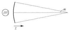
[0121]도 3a-3c는 곡률의 반경과 초점 반경 간의 관계들을 예시한다.
[0122]도 4a는 인간 시각 시스템의 원근조절-이접운동 응답의 표현을 예시한다.
[0123]도 4b는 사용자의 한 쌍의 눈들의 상이한 원근조절 상태들 및 이접운동 상태들의 예들을 예시한다.
[0124]도 5는 파면 발산을 수정함으로써 3차원 이미저리를 시뮬레이트하기 위한 접근법의 양상들을 예시한다.
[0125]도 6은 이미지 정보를 사용자에게 출력하기 위한 도파관 스택의 예를 예시한다.
[0126]도 7은 도파관에 의해 출력되는 출사 빔들의 예를 예시한다.
[0127]도 8은, 각각의 깊이 평면이 다수의 상이한 컴포넌트 컬러들을 사용하여 형성되는 이미지들을 포함하는 스택된 도파관 어셈블리의 예를 예시한다.
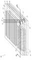
[0128]도 9a는, 인커플링 광학 엘리먼트를 각각 포함하는 스택된 도파관들의 세트의 예의 측 단면도를 예시한다.
[0129]도 9b는 도 9a의 복수의 스택된 도파관들의 예의 사시도를 예시한다.
[0130]도 9c는 도 9a 및 9b의 복수의 스택된 도파관들의 예의 하향식 평면도를 예시한다.
[0131]도 9d는 웨어러블 디스플레이 시스템의 예를 예시한다.
[0132]도 10a 및 10b는 매칭된 원근조절-이접운동 거리들 및 미스매칭된 원근조절-이접운동 거리들의 예들을 각각 예시한다.
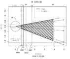
[0133]도 11은 원근조절-이접운동 미스매치 임계치들을 고려하는 깊이 평면 배치의 예를 예시한다.
[0134]도 12는 원근조절-이접운동 미스매치 임계치들을 고려하는 깊이 평면 배치의 또 다른 예를 예시한다.
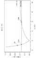
[0135]도 13은 단일 깊이 평면 디스플레이 시스템에 대한 원근조절-이접운동 미스매치의 플롯의 예를 예시한다.
[0136]도 14는 2개의 깊이 평면 디스플레이 시스템 및 하나의 깊이 평면 디스플레이 시스템에 대한 원근조절-이접운동 미스매치의 플롯의 예를 예시한다.
[0137]도 15는 2개의 깊이 평면 디스플레이 시스템 및 하나의 깊이 평면 디스플레이 시스템에 대한 원근조절-이접운동 미스매치의 플롯의 또 다른 예를 예시한다.
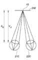
[0138]도 16은 사용자가 응시 포인트에서 응시하는 예를 예시한다.
[0139]도 17은 인접 깊이 평면들 간의 깊이 오버랩을 예시한다.
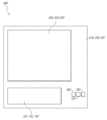
[0140]도 18a-18b는 디스플레이 시스템의 사용자의 시야(field of view)의 표현을 예시한다.
[0141]도 19는 가상 콘텐츠를 제시하기 위한 예시적인 프로세스의 흐름도이다.
[0142]도 20은, 사용자의 지각이 제한된 동안에, 사용자로의 콘텐츠의 제시를 조절하기 위한 예시적인 프로세스의 흐름도이다.
[0143]도 21a는, 이미지 콘텐츠가 임계치를 초과하는 원근조절-이접운동 미스매치를 제공할 때, 뷰어 편안함을 유지하기 위한 방법의 예를 예시한다.
[0144]도 21b는 사용자 눈 피로감을 감소시키기 위한 방법의 예를 예시한다.
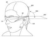
[0145]도 22a는 지지 구조를 갖는 머리-장착 디스플레이의 예를 예시한다.
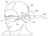
[0146]도 22b는 지지 구조 및 통합된 스피커들을 갖는 머리-장착 디스플레이의 예를 예시한다.
[0147]도면들은 예시적인 실시예들을 예시하도록 제공되고, 본 개시내용의 범위를 제한하도록 의도되지 않는다.[0119] Figure 1 illustrates a view of a user of an AR via an augmented reality (AR) device.
[0120] FIG. 2 illustrates a conventional display system for simulating three-dimensional imagers for a user.
[0121] Figures 3A-3C illustrate the relationship between the radius of curvature and the focus radius.
[0122] FIG. 4A illustrates a representation of a perspective-response motion response in a human vision system.
[0123] FIG. 4B illustrates examples of different perspective control states and discrete motion states of a pair of eyes of a user.
[0124] FIG. 5 illustrates aspects of an approach for simulating a three-dimensional imager by modifying wavefront divergence.
[0125] FIG. 6 illustrates an example of a waveguide stack for outputting image information to a user.
[0126] FIG. 7 illustrates an example of output beams output by a waveguide.
[0127] FIG. 8 illustrates an example of a stacked waveguide assembly in which each depth plane comprises images formed using a number of different component colors.
[0128] FIG. 9a illustrates a cross-sectional side view of an example of a set of stacked waveguides each including an incoupling optical element.
[0129] FIG. 9b illustrates a perspective view of an example of a plurality of stacked waveguides of FIG. 9a.
[0130] FIG. 9C illustrates a top-down plan view of an example of a plurality of stacked waveguides of FIGS. 9A and 9B.
[0131] FIG. 9D illustrates an example of a wearable display system.
[0132] FIGS. 10A and 10B illustrate examples of matched perspective control-to-reciprocation distances and mismatched perspective control-reciprocation distances, respectively.
[0133] FIG. 11 illustrates an example of a depth planar layout that takes perspective control-discrete motion mismatch thresholds.
[0134] FIG. 12 illustrates another example of a depth plane placement that takes perspective adjustment-discrete motion mismatch thresholds into consideration.
[0135] FIG. 13 illustrates an example of a plot of a perspective adjustment-discrete motion mismatch for a single-depth planar display system.
[0136] FIG. 14 illustrates an example of a plot of perspective-displacement motion mismatch for two depth-plane display systems and one depth-plane display system.
[0137] FIG. 15 illustrates another example of a plot of perspective control-displacement motion mismatch for two depth-plane display systems and one depth-plane display system.
[0138] FIG. 16 illustrates an example in which the user gazes at a gazing point.
[0139] FIG. 17 illustrates depth overlap between adjacent depth planes.
[0140] Figures 18a-18b illustrate a representation of a user's field of view in a display system.
[0141] FIG. 19 is a flowchart of an exemplary process for presenting virtual content.
[0142] FIG. 20 is a flowchart of an exemplary process for adjusting the presentation of content to a user while the perception of the user is limited.
[0143] FIG. 21A illustrates an example of a method for maintaining viewer comfort when the image content provides a perspective adjustable-displacement motion mismatch that exceeds a threshold.
[0144] FIG. 21B illustrates an example of a method for reducing user's eye fatigue.
[0145] FIG. 22A illustrates an example of a head-mounted display having a support structure.
[0146] FIG. 22b illustrates an example of a head-mounted display having a support structure and integrated speakers.
[0147] The figures are provided to illustrate exemplary embodiments, and are not intended to limit the scope of the present disclosure.
[0148]가상 및 증강 디스플레이 시스템들은 다양한 이미지 콘텐츠를 제공할 수 있고, 이미지 콘텐츠의 풍부함은 확장된 지속기간 동안에 시스템들을 착용하기 위한 사용자 능력에 따라 증가할 수 있다. 예컨대, 증강 디스플레이 시스템들은 종래의 디스플레이들(예컨대, 컴퓨터 모니터들, 스마트 폰 디스플레이들 등)을 단일 디바이스로 대체할 가능성을 제공하고, 단일 디바이스는 또한, 증강 디스플레이 시스템들이 없다면 이용가능하지 않은 콘텐츠를 제공함으로써, 세계의 사용자의 지각들을 증강시킬 수 있다. 그러나, 이들 디스플레이 시스템들은 부피가 크고 그리고/또는 무거울 수 있고, 시스템들 상에 디스플레이되는 특정 이미지 콘텐츠는 장기 사용자의 편안함을 해칠 수 있다. 예컨대, 본원에서 논의되는 일부 디스플레이 시스템들은, 많은 수의 깊이 평면들에 걸친 이미지 정보를 사용자에게 투사하고, 이로써 3-차원 뷰잉 경험을 제공하기 위해, 도파관들의 스택을 활용할 수 있다. 그러한 도파관들의 스택은 무거울 수 있고, 이는 그러한 스택을 통합하는 디스플레이 시스템들의 장기 사용에 대해 바람직하지 않다.[0148]Virtual and augmented display systems can provide a variety of image content, and the abundance of image content can increase with user capabilities to wear systems for extended durations. For example, augmented display systems offer the possibility of replacing conventional displays (e.g., computer monitors, smartphone displays, etc.) with a single device, and a single device can also provide content that is not available without augmented display systems Thereby enhancing the user's perception of the world. However, these display systems can be bulky and / or heavy, and certain image content displayed on systems can harm long-term user comfort. For example, some display systems discussed herein may utilize a stack of waveguides to project image information over a large number of depth planes to a user, thereby providing a three-dimensional viewing experience. The stack of such waveguides may be heavy, which is undesirable for long term use of display systems incorporating such a stack.
[0149]유리하게, 일부 실시예들에서, 장기 착용자의 편암함을 가능하게 할 수 있는 시스템들 및 방법들이 제공된다. 일부 실시예들에서, 신뢰성있고 편안한 3-차원 뷰잉 경험은, 단지 하나 또는 단지 2개의 깊이 평면들에서의 이미지 정보를 사용자에게 투사하도록 구성된 감소된 도파관 스택을 사용하여 제공된다. 일부 실시예들에서, 3개 또는 4개의 깊이 평면들을 포함하여, 깊이 평면들의 수가 더 많을 수 있다.[0149]Advantageously, in some embodiments, systems and methods are provided that are capable of enabling the wearer of the organ to be comfortable. In some embodiments, a reliable and comfortable three-dimensional viewing experience is provided using a reduced waveguide stack configured to project image information to the user in only one or only two depth planes. In some embodiments, the number of depth planes may be greater, including three or four depth planes.
[0150]본원에서 설명된 바와 같이, 디스플레이 시스템이 디스플레이되는 콘텐츠에 깊이 감각을 제시하기 위해 이접운동 큐들 및 원근조절 큐들 둘 모두를 활용할 수 있다는 것이 인지될 것이다. 이접운동 큐들은 가상 객체의 약간 상이한 뷰들을 사용자의 각각의 눈에 제시함으로써 생성될 수 있다. 원근조절 큐들은, 그러한 약간 상이한 뷰들을 형성하는 광의 파면 발산으로부터 유도될 수 있다. 이접운동 큐들은 눈들로 하여금, 예컨대, 눈들이 가상 객체 상에 수렴하는 특정 이접운동 상태를 가정하도록 회전하게 한다. 원근조절 큐들은, 눈들의 렌즈들로 하여금, 가상 객체의 포커싱된 이미지를 눈들의 망막들 상에 제공하는 특정 형상을 가정하게 할 수 있다. 따라서, 특정 이접운동 큐들은, 눈들로 하여금 특정 이접운동 상태들을 가정하게 할 수 있고, 특정 원근조절 큐들은 눈들로 하여금 특정 원근조절 상태들을 가정하게 할 수 있다. 공간 내의 실제 객체들이 뷰어로부터 광학 또는 z-축을 따른 자신들의 거리에 기반하여 변하는 이접운동 및 원근조절 큐들을 제공하여, 특정 이접운동 큐들이 특정 이접운동 거리들과 상관될 수 있고, 특정 원근조절 큐들이 마찬가지로 뷰어로부터 멀어지는 특정 원근조절 거리들과 상관될 수 있다는 것이 인지될 것이다. 통상적으로, 이접운동 및 원근조절 큐들이 뷰어 불편함을 방지하기 위해 서로 밀접하게 매칭해야 한다고 생각되었고, 즉, 가상 객체에 대한 이접운동 및 원근조절 거리들이 원근조절-이접운동 미스매치를 피하기 위해 동일해야 한다고 생각되었다. 가상 객체를 디스플레이할 때 원근조절-이접운동 미스매치는 가상 객체에 대한 이접운동 및 원근조절 거리들 간의 디옵터에서의 차이로서 정의될 수 있다.[0150]It will be appreciated that, as described herein, the display system may utilize both discrete motion cues and perspective adjustment cues to present a sense of depth to the displayed content. The discrete motion cues may be generated by presenting slightly different views of the virtual object to each eye of the user. Perspective control cues can be derived from the wavefront divergence of light forming such slightly different views. The discrete motion cues cause the eyes to rotate, for example, to assume a particular state of the discrete motion in which the eyes converge on the virtual object. The perspective adjustment cues may allow the lenses of the eyes to assume a particular shape that provides a focused image of the virtual object on the retinas of the eyes. Thus, certain discrete motion cues may cause the eyes to assume certain discrete motion states, and certain perspective control cues may allow the eyes to assume certain perspective control states. It is possible to provide discrete and perspective control cues in which real objects in space vary from their viewers based on their distance along the optical or z-axis, so that certain discrete motion cues can be correlated with specific discrete motion distances, May be correlated with certain perspective adjustment distances that are similarly away from the viewer. Typically, it has been thought that the discrete motion and perspective control cues should closely match one another to prevent viewer discomfort, that is, the discrete motion and perspective control distances for the virtual object are the same to avoid perspective-displacement motion mismatch I thought it was necessary. When displaying a virtual object, a perspective adjustment-disjoint motion mismatch can be defined as the difference in diopter between discrete motion and perspective control distances for a virtual object.
[0151]그러나, 인간 시각 시스템이 일정 레벨들의 원근조절-이접운동 미스매치들을 용인한다는 것이 알려져 있다. 결과적으로, 미스매치 허용오차 내에서, 원근조절 큐들은 동일하게 계속 유지될 수 있는 반면에, 이접운동 큐들은 변할 수 있고, 이로써 가상 객체의 인지된 깊이를 변경한다. 따라서, 일부 실시예들에서, 이접운동 큐들은 계속해서 변할 수 있는 반면에, 원근조절 큐들은 이산 단계들로 변하고, 원근조절 및 이접운동 간의 미스매치는 미스매치 허용오차 레벨 미만으로 유지된다. 원근조절-이접운동 미스매치 허용오차들의 예들은 0.5 dpt 또는 그 미만, 0.33 dpt 또는 그 미만, 또는 0.25 dpt 또는 그 미만을 포함한다. 일부 실시예들에서, 가장 먼 깊이 평면은 광학 무한대의 원근조절-이접운동 미스매치 허용오차 내에 있을 수 있고, 다음 가장 먼 깊이 평면은 가장 먼 깊이 평면의 원근조절-이접운동 미스매치 허용오차들에 의해 형성된 볼륨의 원근조절-이접운동 미스매치 허용오차 내에 있을 수 있고, 이러한 식일 수 있다.[0151]It is known, however, that the human visual system tolerates certain levels of perspective adjustment-reciprocal motion mismatches. As a result, within the mismatch tolerance, the perspective adjustment cues can remain the same, while the discrete motion cues can change, thereby changing the perceived depth of the virtual object. Thus, in some embodiments, the discrete motion cues may continue to change, while the perspective adjustment cues become discrete steps, and the mismatch between perspective adjustment and discrete motion remains below the mismatch tolerance level. Examples of perspective control-discrete motion mismatch tolerances include 0.5 dpt or less, 0.33 dpt or less, or 0.25 dpt or less. In some embodiments, the farthest depth plane may be within an optical infinity perspective adjustment-to-reciprocation mismatch tolerance, and the next farthest depth plane may be a distance-controlled mismatch tolerance of the farthest depth plane And may be within this distance-mismatch-tolerance mismatch tolerance of the volume created by, for example,
[0152]특정 양의 파면 발산이 특정 깊이 평면들과 연관되고, 즉, 디스플레이 시스템에 의해 출력된 광의 파면 발산이 z-축을 따른 특정 깊이에서 실제 객체로부터 나오는 광의 파면 발산에 대응한다는 것이 인지될 것이다. 결과적으로, 파면 발산 및 원근조절 큐들을 변경하는 것은, 디스플레이 시스템이 가상 객체를 제시하는 깊이 평면을 스위칭하는 것을 수반하는 것으로 이해될 수 있다. 일부 실시예들에서, 깊이 평면은, 원근조절-이접운동 미스매치를 수용가능한 허용오차 레벨 미만으로 유지하기 위해 스위칭될 수 있다. 각각의 깊이 평면은, 깊이 평면에서 나오는 것처럼 보이는 광에 대한 대응하는 파면 발산을 갖는 공칭 초점 깊이를 가질 수 있다. 그러나, 원근조절-이접운동 미스매치 허용오차로 인해, 콘텐츠는, 가상 객체가 깊이 평면보다 뷰어로부터 더 가깝거나 뷰어로부터 더 멀리 있다는 지각을 제공하기 위해 이접운동 큐들이 활용될 수 있는 바로 그 순간에, 그 깊이 평면 "상에" (즉, 그 깊이 평면에 대응하는 파면 발산으로) 디스플레이될 수 있다. 특정 깊이 평면이 활용될 수 있는 거리들의 외부 경계들은, 본원에서 개시된 바와 같이, 디옵터 단위로 측정될 수 있는 원근조절-이접운동 미스매치에 의해 결정된다.[0152]It will be appreciated that a certain amount of wavefront divergence is associated with certain depth planes, i.e., the wavefront divergence of the light output by the display system corresponds to the wavefront divergence of light coming from the real object at a certain depth along the z-axis. As a result, changing the wavefront divergence and perspective control cues can be understood to involve switching the depth plane in which the display system presents the virtual object. In some embodiments, the depth plane may be switched to maintain the perspective adjustment-discrete motion mismatch below an acceptable tolerance level. Each depth plane may have a nominal depth of focus with a corresponding wavefront divergence for the light that appears to come from the depth plane. However, due to the perspective adjustment-reciprocal motion mismatch tolerance, the content may be displayed at the very moment when the displacement exercise cues can be utilized to provide a perception that the virtual object is closer to the viewer than the depth plane, , &Quot; on its depth plane " (i.e., with a wavefront divergence corresponding to its depth plane). The outer boundaries of the distances at which a particular depth plane can be utilized are determined by a perspective adjustment-discrete motion mismatch that can be measured in diopter units, as described herein.
[0153]다초점 디스플레이 시스템들로 본원에서 지칭되는 일부 디스플레이 시스템들은 이산 깊이 평면들상의 가상 콘텐츠를 제시할 수 있는데, 모든 가상 콘텐츠는 주어진 시간에 동일한 깊이 평면에서 제시된다(예컨대, 한 번에, 단지 하나의 깊이 평면만이 액티브이거나, 또는 이미지 정보가 출력됨). 한 번에 하나의 깊이 평면 상에 콘텐츠를 디스플레이하는 것은, 디스플레이 시스템에서 컴퓨테이셔널 리소스들을 절약하는 장점을 가질 수 있다. 가상 콘텐츠를 어느 깊이 평면에서 제시할지를 결정하기 위해, 다초점 디스플레이 시스템은, 예컨대 사용자의 눈들이 응시하고 있는 타겟까지의 거리를 결정함으로써, 사용자의 눈들이 응시되는 깊이(본원에서 응시 깊이로 또한 지칭됨)를 결정할 수 있다. 일단 응시 깊이가 결정되면, 디스플레이 시스템은, 응시 깊이에 대응하거나 또는 매칭되는 깊이 평면 상의 콘텐츠를 제시할 수 있다. 매치로서의 자격을 얻는 것은, 깊이 평면에 매칭되고 그리고/또는 그 깊이 평면의 원근조절-이접운동 미스매치 허용오차 내에 있는 응시 깊이일 수 있다. 본원에서 사용된 바와 같이, 객체의 깊이는, 광 또는 z-축을 따라 측정되는, 사용자로부터의 그 객체의 거리이다.[0153]Some display systems, referred to herein as multifocus display systems, can present virtual content on discrete depth planes, where all virtual content is presented in the same depth plane at a given time (e.g., Only the depth plane is active, or image information is output). Displaying content on one depth plane at a time can have the advantage of saving computational resources in the display system. To determine which depth plane to present the virtual content, the multifocus display system determines the depth at which the user ' s eyes will be gazed (also referred to herein as the gaze depth) by determining the distance to the target, Can be determined. Once the gaze depth is determined, the display system can present the content on the depth plane that corresponds to or matches the gaze depth. Qualifying as a match may be the depth of the eye that is matched to the depth plane and / or is within the perspective adjustment-discrete motion mismatch tolerance of the depth plane. As used herein, the depth of an object is the distance of that object from the user as measured along the light or z-axis.
[0154]응시 깊이를 결정하는 예로서, 디스플레이 시스템은, 사용자의 눈들의 응시 포인트를 결정할 수 있다. 예컨대, 디스플레이 시스템은, 사용자의 눈들의 배향들을 모니터링하며, 그리고 눈들의 개개의 결정된 시선들이 교차하는 3차원 위치를 결정하기 위해, 사용자의 눈들과 연관된 시선 벡터들을 추정할 수 있다. 디스플레이 시스템은 사용자의 눈들이 특정 3차원 위치에 응시된다는 것을 결정할 수 있으며, 디스플레이 시스템은 이 3차원 위치에 대응하는 깊이 평면상의 가상 콘텐츠를 제시할 수 있다. 이러한 방식으로, 디스플레이 시스템은, 뷰어에게 디스플레이된 콘텐츠가 그 깊이 평면에 적합하다는 것을 보장할 수 있다.[0154]As an example of determining the depth of gaze, the display system may determine the gazing point of the user's eyes. For example, the display system may monitor the orientations of the user's eyes, and may estimate gaze vectors associated with the user's eyes to determine the three-dimensional position at which the respective determined gaze of the eyes intersect. The display system may determine that the user's eyes are being gazed at a particular three dimensional location and the display system may present the virtual content on the depth plane corresponding to the three dimensional location. In this manner, the display system can ensure that the content displayed to the viewer fits in its depth plane.
[0155]결과적으로, 일부 실시예들에서, 디스플레이 시스템은, 사용자의 눈들을 추적하도록 그리고 사용자의 눈들이 응시하고 있는 깊이에 대응하는 깊이 평면 상에 콘텐츠를 제공하도록 구성될 수 있다. 사용자의 눈들의 응시 포인트가 변화함에 따라, 디스플레이 시스템은 상이한 깊이 평면으로 스위칭하도록 구성될 수 있으며, 이는 가상 객체의 이미지에 의해 야기되는 망막 블러(retinal blur)에서의 순간적 점프를 야기할 수 있다. 통상적인 사용자에게, 이는, 눈들이 새로운 깊이 평면에 의해 제공되는 파면 발산에 대해 원근조절하는 동안 짧은(예컨대, 100-300ms) 기간의 흐릿함이 뒤따르는, 디스플레이에서의 플리커 처럼 보일 것이다.[0155]Consequently, in some embodiments, the display system can be configured to track the user's eyes and provide content on a depth plane corresponding to the depth the user's eyes are staring at. As the viewing point of the user's eyes changes, the display system can be configured to switch to a different depth plane, which can cause an instantaneous jump in the retinal blur caused by the image of the virtual object. To a typical user, this would look like a flicker in the display, followed by a blur of a short (e.g., 100-300ms) period while the eyes adjust the perspective for the wavefront divergence provided by the new depth plane.
[0156]이미지 콘텐츠를 제공할 깊이 평면이 사용자의 눈들의 응시 깊이에 관련 있는 경우, 응시 깊이를 결정할 때의 에러들은 깊이 평면들 간의 스위칭 시 에러들을 야기할 수 있다. 가능한 에러 소스들은, 예컨대, 사용자의 눈들(예컨대, 배향)을 모니터링하는 것; 시선 추적; 모니터링 하드웨어의 전기, 컴퓨테이셔널 및/또는 광학 제한들 등과 연관된 에러를 포함한다. 이들 에러 소스들에 기인하여, 응시 포인트의 위치의 연속적인 결정들은 그 위치에 대한 상이한 값들을 제공할 수 있다. 응시 깊이가 2개의 깊이 평면들 간의 경계 근처일 경우, 응시 포인트의 결정된 위치에서의 임의의 동요는 깊이 평면들 간의 스위칭 시 동요들을 야기할 수 있다. 이어서, 바람직하지 않게, 디스플레이 시스템은, 제1 깊이 평면 상의 가상 콘텐츠를 제시하는 것과 제2 깊이 평면 상의 가상 콘텐츠를 제시하는 것 간에 교번할 수 있는데, 각각의 교번은 플리커링으로서 사용자에 의해 인지된다. 이론에 의해 제약되지 않으면서, 이 플리커링은, 사용자에게 불편함을 야기할 뿐만 아니라 뷰잉 경험에서 사용자의 몰입감을 감소시킬 것으로 예상될 수 있다.[0156]If the depth plane to provide the image content is related to the depth of gaze of the user's eyes, errors in determining the depth of gaze may cause errors in switching between depth planes. Possible error sources include, for example, monitoring the user's eyes (e.g., orientation); Eye tracking; Errors associated with electrical, computational and / or optical limitations of the monitoring hardware, and the like. Due to these error sources, successive determinations of the location of the point of interest can provide different values for that location. If the gaze depth is near the boundary between the two depth planes, any fluctuation at the determined position of the gaze point may cause fluctuations in switching between the depth planes. Then, undesirably, the display system may alternate between presenting the virtual content on the first depth plane and presenting the virtual content on the second depth plane, with each alternate being recognized by the user as flickering . Without being bound by theory, this flickering can be expected to not only cause inconvenience to the user but also reduce the user's immersion in the viewing experience.
[0157]일부 실시예들에서, 깊이 평면들 간의 원치 않는 스위칭이 발생하는 정도를 제한하기 위한 기법들이 제공된다. 아래에서 설명될 바와 같이, 제1 깊이 평면이 커버하거나 또는 포함하는 깊이 평면 범위의 일부분이 제2 깊이 평면이 커버하거나 또는 포함하는 깊이 평면 범위의 일부분과 오버랩될 수 있도록, 깊이 오버랩이 활용될 수 있다. 예컨대, 도 16-도 18에 관하여 아래에서 설명되는 바와 같이, 깊이 평면이 포함하는 깊이 범위는, 응시될 때 디스플레이 시스템으로 하여금 가상 콘텐츠를 제시하기 위해 그 깊이 평면을 선택하게 하는, 사용자로부터의 거리들을 나타낸다. 이러한 방식으로, 만약 사용자의 응시 포인트들이 깊이가 변하지만, 깊이 오버랩 내에 위치되면, 디스플레이 시스템은 가상 콘텐츠가 제시되는 깊이 평면을 변경하지 않을 수 있다. 따라서, 디스플레이 시스템이 상이한 깊이 평면들 간에 불필요하게 스위칭하는 것이 방지될 수 있다.[0157]In some embodiments, techniques are provided to limit the degree to which unwanted switching between depth planes occurs. As described below, a depth overlap may be utilized such that a portion of the depth plane range covered by or including the first depth plane may overlap or overlap with a portion of the depth plane range that the second depth plane covers or includes have. For example, as described below with respect to Figures 16-18, the depth range that the depth plane includes includes the distance from the user, which when selected causes the display system to select the depth plane to present the virtual content . In this way, if the user's gazing points change in depth but are located within the depth overlap, the display system may not change the depth plane in which the virtual content is presented. Thus, it is possible to prevent the display system from unnecessarily switching between different depth planes.
[0158]일부 실시예들에서, 깊이 평면은, z-축 상에서 깊이 평면으로부터 특정 값만큼 앞뒤로 확장되는 깊이들을 포함하는 연관된 깊이 평면 범위를 가질 수 있다. 예컨대, 각각의 깊이 평면 범위는, 깊이 평면과 연관된 공칭 초점 깊이로부터 더 깊은 특정 거리를, 공칭 초점 깊이로부터 더 가까운 특정 거리로 확장할 수 있다. 예로서, 특정 거리는 0.2, 0.33, 또는 0.5 디옵터일 수 있다. 0.33 디옵터의 예에 대해, 1 디옵터의 공칭 초점 깊이와 연관된 예시적 깊이 평면의 경우, 만약 사용자가 0.66 내지 1.33 디옵터의, 사용자의 눈들(예컨대, 사용자의 눈들의 출사동(exit pupil))로부터의 깊이를 갖는 3차원 위치를 응시하고 있다면, 디스플레이 시스템은, 이 예시적 깊이 평면에서의 가상 콘텐츠를 제시할 수 있다. 일부 실시예들에서, 공칭 초점 깊이로부터 더 깊은 특정 거리는 원근조절-이접운동 미스매치 허용오차 레벨(예컨대, 최대 미스매치)을 나타낼 수 있다.[0158]In some embodiments, the depth plane may have an associated depth plane range that includes depths extending back and forth by a certain value from the depth plane on the z-axis. For example, each depth plane range may extend a certain distance deeper from the nominal depth of focus associated with the depth plane, to a certain distance closer than the nominal depth of focus. By way of example, the specific distance may be 0.2, 0.33, or 0.5 diopters. For the example of 0.33 diopters, for an exemplary depth plane associated with a nominal focus depth of 1 diopter, if the user has a diopter from the user's eyes (e.g., the exit pupil of the user's eyes) of 0.66 to 1.33 diopters If you are staring at a three-dimensional position with depth, the display system can present the virtual content in this exemplary depth plane. In some embodiments, a deeper specific distance from the nominal focus depth may indicate a perspective adjustable-displacement motion mismatch tolerance level (e.g., maximum mismatch).
[0159]위에서 설명된 바와 같이, 인접 깊이 평면 범위들의 일부분들은 z-축을 따라 깊이들의 세트를 포함하도록 오버랩될 수 있다. 일부 실시예들에서, 깊이 오버랩의 정도는 응시 포인트들을 결정하는 것과 연관된 에러에 기반할 수 있다. 각각의 깊이 평면이 (예컨대, 원근조절-이접운동 미스매치 허용오차에 기반하여) 고정 깊이 평면 범위를 포함하는 실시예들의 경우, 깊이 오버랩은, 오버랩 구역을 갖지 않는 깊이 평면 레이아웃과 비교할 때, 하나 또는 그 초과의 깊이 평면들과 연관된 공칭 초점 깊이들의 시프팅을 야기할 수 있다. 예컨대, 특정 깊이 평면의 말단 경계는 더 깊은 인접 깊이 평면의 근위 경계를 넘어 확장되도록 조절될 수 있다. 특정 깊이 평면의 말단 경계가 사용자로부터 깊이가 더 깊도록 조절되기 때문에, 고정 깊이 평면 범위를 유지하기 위해, 특정 깊이 평면의 근위 경계는 유사하게, 깊이가 더 깊도록 조절될 수 있다. 그러므로, 특정 깊이 평면의 깊이 평면 범위가 포함하는 모든 깊이들이, 특정 깊이 평면의 공칭 초점 깊이로부터 원근조절-이접운동 미스매치 허용오차 미만으로 확장된다는 것을 보장하기 위해, 공칭 초점 깊이는 유사하게 조절된다. 깊이 평면들의 공칭 초점 깊이들을 조절하는 것은 도 18a-도 18b에 대해 아래에서 더욱 상세히 설명된다.[0159]As described above, portions of adjacent depth plane ranges may overlap to include a set of depths along the z-axis. In some embodiments, the degree of depth overlap may be based on errors associated with determining the points of interest. For embodiments in which each of the depth planes includes a fixed depth plane range (e.g., based on perspective adjustment-displacement motion mismatch tolerance), the depth overlap is reduced by one, as compared to a depth plane layout without an overlap zone Or to cause shifting of the nominal depth of focus associated with depth planes beyond that. For example, the end boundary of a particular depth plane may be adjusted to extend beyond the proximal boundary of a deeper adjacent depth plane. Since the end boundary of a particular depth plane is adjusted to be deeper from the user, the proximal boundary of a particular depth plane may be similarly adjusted to a deeper depth to maintain a fixed depth plane range. Therefore, in order to ensure that all depths included in the depth plane range of a particular depth plane extend beyond the perspective adjustment-displacement motion mismatch tolerance from the nominal depth of focus of a particular depth plane, the nominal focus depth is similarly adjusted . Adjusting the nominal depth of focus of the depth planes is described in more detail below with respect to Figures 18A-18B.
[0160]깊이 평면과 연관된 공칭 초점 깊이의 위에서 설명된 조절은, 일부 예시적 디스플레이 시스템들에서, 가상 콘텐츠가 디스플레이 시스템에 의해 사용자에게 제시될 수 있는 전체 깊이 평면 범위를 감소시킬 수 있다. 예컨대, 인접 깊이 평면들이 오버랩되거나 또는 그들의 깊이 평면 범위들의 일부분들을 공유하기 때문에, 깊이 평면들 전부가 포함하는 깊이들의 총 범위는, 깊이 평면들 간의 오버랩이 없었던 경우 미만일 수 있다. 그러나, 깊이 오버랩들이, 눈들의 응시 포인트의 결정 시 에러들에 기인하여 신속한 스위칭에 의해 야기되는 플리커링의 발생들을 감소시킬 수 있기 때문에, 디스플레이 시스템으로부터 입수가능한 깊이들의 유용한 범위가 적더라도, 사용자의 뷰잉 경험은 그럼에도 불구하고 개선될 수 있다.[0160]The adjustments described above of the nominal focus depth associated with the depth plane can, in some exemplary display systems, reduce the overall depth plane range over which the virtual content can be presented to the user by the display system. For example, because adjacent depth planes overlap or share portions of their depth plane ranges, the total range of depths that all of the depth planes include may be less than if there was no overlap between the depth planes. However, even if the useful range of depths available from the display system is small, since the depth overlaps can reduce the occurrence of flickering caused by fast switching due to errors in the determination of the eye's point of gaze, The viewing experience can nevertheless be improved.
[0161]부가적으로, 만약 임의의 깊이 평면이 포함하는 깊이들의 범위 외부의 특정 깊이를 사용자가 응시하고 있다면, 디스플레이 시스템은 선택적으로, 특정 깊이에 대응하는 이접운동 큐들로 가상 객체를 제시할 수 있다. 제시와 연관된 원근조절 큐들(예컨대, 공칭 초점 깊이)이 특정 깊이에 가장 가까운 깊이 평면에 기반할 것이기 때문에, 원근조절-이접운동 미스매치는 위에서 설명된 미스매치 허용오차 레벨들을 초과할 것이다. 위에서 설명된 바와 같이, 원근조절-이접운동 미스매치 허용오차를 초과하는 것이, 사용자의 불편함을 야기할 수 있기 때문에, 디스플레이 시스템은, 미스매치가 임계치를 초과하는 동안 가상 콘텐츠가 제시될 수 있는 시간량(예컨대, 10초, 30초, 3분, 및/또는 사용자-선택가능 시간량)을 제한할 수 있다.[0161]Additionally, if the user is staring at a particular depth outside the range of depths that an arbitrary depth plane includes, the display system can optionally present the virtual object to discrete motion cues corresponding to a particular depth. Since the perspective adjustment cues associated with the presentation (e.g., the nominal focus depth) will be based on the nearest depth plane to a certain depth, the perspective adjustment-discrete motion mismatch will exceed the mismatch tolerance levels described above. As described above, since exceeding the perspective adjustment-discrete motion mismatch tolerance can cause user discomfort, the display system can determine that the virtual content can be presented while the mismatch exceeds the threshold (E.g., 10 seconds, 30 seconds, 3 minutes, and / or a user-selectable amount of time).
[0162]일부 실시예들에서, 깊이 평면 스위칭의 지각을 마스킹하거나 또는 다른 방식으로 감소시키는 이벤트 동안 이 스위칭을 수행함으로써, 사용자의 뷰잉 편안함은 개선될 수 있다. 예컨대, 디스플레이 시스템은, (예컨대, 사용자가 새로운 응시 포인트를 응시하는 것에 기인하여) 현재 선택된 깊이 평면과는 상이한 특정 깊이 평면에서의 가상 콘텐츠가 제시되어야 한다는 것을 결정할 수 있다. 예컨대, 다초점 디스플레이 시스템들에 대한 깊이 평면 스위칭은, 위에서 주목된 바와 같이, 지각 가능한 플리커를 야기할 수 있다. 그 결과, 일부 실시예들에서, 디스플레이 시스템은, 시각적 시스템이 예컨대 일시적으로 비활성이 되는 이벤트가 발생할 때까지 깊이 평면 스위칭을 지연시키고, 그러한 이벤트 동안 스위칭을 수행함으로써 스위칭을 마스킹할 수 있다. 그러한 이벤트는 (1) 깜박거림 또는 (2) 단속적 운동을 수행하는 것을 포함할 수 있다. 그러한 이벤트의 검출 시, 깊이 평면 스위칭이 수행될 수 있다. 예로서, 디스플레이 시스템은, 사용자의 3차원 응시 포인트들을 모니터링하는 것에 기반하여, 가상 콘텐츠를 제시하기 위해 상이한 깊이 평면이 선택되어야 한다는 것을 결정할 수 있다. 이어서, 디스플레이 시스템은, (1) 사용자가 깜박거릴 때까지 또는 (2) 가상 콘텐츠의 제시를 상이한 깊이 평면으로 스위칭하기 전에 사용자가 단속적 운동을 수행할 때까지, 대기할 수 있다. 바람직하게, 스위칭은 깜박거림 또는 단속적 운동 동안 발생하며, 그 결과, 사용자는 스위칭을 알아챌 수 없는데, 그 이유는 스위칭의 인스턴트 시 눈들이 감기거나 또는 움직이고 있을 수 있기 때문이다.[0162]In some embodiments, by performing this switching during the event of masking or otherwise reducing the perception of depth plane switching, the viewing comfort of the user can be improved. For example, the display system may determine that the virtual content at a particular depth plane that is different from the currently selected depth plane (e.g., due to the user staring at the new entry point) should be presented. For example, depth plane switching for multifocus display systems can cause perceptible flicker, as noted above. As a result, in some embodiments, the display system may mask the switching by delaying the depth plane switching until the visual system is, for example, temporarily incapacitated, and performing switching during such events. Such an event may include (1) blinking or (2) performing intermittent motion. Upon detection of such an event, depth plane switching can be performed. By way of example, the display system may determine that a different depth plane should be selected to present the virtual content, based on monitoring the user's three-dimensional viewing points. The display system can then wait until (1) the user is blinking or (2) the user performs intermittent motion before switching the presentation of the virtual content to a different depth plane. Preferably, the switching occurs during a flicker or intermittent motion, so that the user is not aware of the switching because the eyes may be winding or moving at the instant of switching.
[0163]본원에서 설명된 기법들을 활용하여, 가상 콘텐츠의 인지된 제시 품질은 개선될 수 있다. 예컨대, 지각 가능한 시각적 아티팩트들, 이를테면 상이한 깊이 평면들 간에 콘텐츠를 스위칭함으로써 야기되는 플리커는, 특히 디스플레이 시스템이 다초점 모드로 동작하고 있을 때, 감소될 수 있다.[0163]Utilizing the techniques described herein, the perceived presentation quality of virtual content can be improved. For example, flicker caused by perceptible visual artifacts, such as switching content between different depth planes, can be reduced, especially when the display system is operating in a multi-focus mode.
[0164]본원에서 개시된 다양한 실시예들은 또한, 사용자에게 편안한 뷰잉 경험을 제공하기 위한 부가적인 시스템들 및 방법들을 제공한다. 예컨대, 본원에서 논의된 바와 같이, 원근조절-이접운동 미스매치는 사용자가 허용가능하도록 발견할 수 있는 범위를 초과할 수 있다. 일부 실시예들에서, 원근조절-이접운동의 큰 미스매치에 의해 야기되는 사용자 불편함을 감소시키기 위해, 디스플레이 시스템은 콘텐츠가 큰 원근조절-이접운동 미스매치를 야기할지 여부를 결정하도록 이미지 콘텐츠를 액티브하게 모니터링하도록 구성될 수 있다. 그러한 큰 미스매치를 검출할 시, 이미지 콘텐츠는 디스플레이되기 전에 미스매치를 감소시키거나 또는 제거하는 방식으로 수정될 수 있다. 예컨대, 디스플레이 시스템은 큰 미스매치를 초래하는 이미지 콘텐츠를 페이딩하거나 또는 디스플레이하지 않도록 구성될 수 있다.[0164]The various embodiments disclosed herein also provide additional systems and methods for providing a comfortable viewing experience for the user. For example, as discussed herein, the perspective adjustment-reciprocal motion mismatch may exceed the range that the user may find to be acceptable. In some embodiments, in order to reduce user discomfort caused by a large mismatch in perspective adjustment-reciprocation motion, the display system may determine that the content is to be used to determine whether to cause a large perspective adjustment- Can be configured to be actively monitored. When detecting such a large mismatch, the image content may be modified in such a way as to reduce or eliminate mismatches before being displayed. For example, the display system may be configured to fade or not display image content that results in a large mismatch.
[0165]일부 다른 실시예들에서, 시스템은 사용자의 눈 피로감을 액티브하게 모니터링하도록 구성될 수 있다. 눈 피로감을 검출할 시, 시스템은 눈 피로감을 감소시키기 위해 이미지 콘텐츠를 수정하도록 구성될 수 있다.[0165]In some other embodiments, the system may be configured to actively monitor the user's eye fatigue. Upon detecting eye fatigue, the system may be configured to modify the image content to reduce eye fatigue.
[0166]일부 실시예들에서, 디스플레이 시스템의 무게 및/또는 밸런스에 대한 물리적인 불편함은 사용자의 머리 위로 그리고/또는 사용자의 머리의 뒤쪽을 향해 확장할 수 있는 지지 구조를 사용하여 처리될 수 있다. 지지 구조는, 예컨대, (예컨대, 디바이스의 노우즈패드에 대한 압력을 감소시키기 위해) 디스플레이를 끌어 올리고 그리고/또는 디스플레이의 무게를 사용자의 머리의 전면 및 후면 둘 모두에 대해 밸런스를 맞추는 힘을 제공하는 밴드일 수 있다.[0166]In some embodiments, the physical discomfort to the weight and / or balance of the display system may be handled using a support structure that can extend over the user ' s head and / or toward the back of the user ' s head. The support structure may include, for example, pulling up the display (e.g., to reduce pressure on the nose pad of the device) and / or providing a force to balance the weight of the display with both the front and back sides of the user's head Band.
[0167]디스플레이 시스템은 증강 현실 디스플레이 시스템 또는 가상 현실 디스플레이 시스템의 일부일 수 있다는 것이 인지될 것이다. 일 예로서, 디스플레이 시스템은 투과적일 수 있으며, 이미지들, 비디오, 상호 작용 등의 형태로 가상 콘텐츠를 사용자에게 제공하는 동안 사용자에게 실세계의 뷰를 허용할 수 있다. 다른 예로서, 디스플레이 시스템은 실세계에 대한 사용자의 뷰를 차단할 수 있으며, 가상 현실 이미지들, 비디오, 상호 작용 등이 사용자에게 제시될 수 있다.[0167]It will be appreciated that the display system may be part of an augmented reality display system or a virtual reality display system. As an example, the display system may be transparent and allow the user to view the real world while presenting the virtual content to the user in the form of images, video, interaction, and so on. As another example, the display system may block the user's view of the real world and virtual reality images, video, interaction, etc. may be presented to the user.
[0168]이제, 동일한 참조 번호들은 전반에 걸쳐 동일한 부분들을 지칭하는 도면들에 대해 참조가 이루어질 것이다.[0168]BRIEF DESCRIPTION OF THE DRAWINGS Reference will now be made to the drawings, wherein like reference numerals refer to like parts throughout.
예시적인 디스플레이 시스템들Exemplary display systems
[0169]도 2는 사용자에 대한 3차원 이미저리를 시뮬레이트하기 위한 종래의 디스플레이 시스템을 예시한다. 사용자의 눈들은 이격되어 있고, 공간에서 실제 객체를 볼 때 각각의 눈은 객체의 약간 상이한 뷰를 가질 것이며, 각각의 눈의 망막 상의 상이한 위치들에서 객체의 이미지를 형성할 수 있다는 것이 인지될 것이다. 이것은 양안 시차(binocular disparity)로 지칭될 수 있으며, 깊이의 지각을 제공하기 위해 인간의 시각적 시스템에 의해 활용될 수 있다. 종래의 디스플레이 시스템들은, 가상 객체가 원하는 깊이의 실제 객체이면, 각각의 눈이 볼 가상 객체의 뷰들에 대응하는 동일한 가상 객체의 약간 상이한 뷰들 - 각각의 눈(210, 220)에 하나씩 - 을 가지는 2개의 별개의 이미지들(190, 200)을 제시함으로써 양안 시차를 시뮬레이트한다. 이러한 이미지들은 사용자의 시각적 시스템이 깊이의 지각을 유도하기 위해 해석할 수 있는 양안 큐들을 제공한다.[0169]Figure 2 illustrates a conventional display system for simulating three-dimensional imagers for a user. It will be appreciated that the user's eyes are spaced apart and that when viewing the real object in space each eye will have a slightly different view of the object and can form an image of the object at different positions on the retina of each eye . This can be referred to as binocular disparity and can be exploited by the human visual system to provide a perception of depth. Conventional display systems have two different views of the same virtual object corresponding to the views of the virtual object to be viewed, one for each
[0170]도 2를 계속 참조하면, 이미지들(190, 200)은 z-축 상의 거리(230)만큼 눈들(210, 220)로부터 이격되어 있다. z-축은 뷰어의 광학 축에 평행하며, 뷰어들의 눈들은 뷰어 바로 앞에서 광학 무한대로 객체를 응시한다. 이미지들(190, 200)은 편평하며, 눈들(210, 220)로부터 고정 거리에 있다. 눈들(210, 220)에 각각 제시되는 이미지들에서의 가상 객체의 약간 상이한 뷰들에 기반하여, 눈들은, 객체의 이미지가 단일 쌍안시를 유지하기 위해 눈들 각각의 망막들 상의 대응하는 포인트들에 떨어지도록 자연적으로 회전한다. 이러한 회전은, 눈들(210, 220) 각각의 시선(line of sight)들이, 가상 객체가 존재하는 것으로 인지되는 공간 상의 포인트 상으로 수렴하게 할 수 있다. 결과적으로, 3차원 이미저리를 제공하는 것은 통상적으로, 사용자의 눈들(210, 220)의 이접운동을 조작할 수 있고 인간의 시각적 시스템이 깊이의 지각을 제공하도록 해석하는 양안 큐들을 제공하는 것을 수반한다.[0170]With continued reference to FIG. 2,
[0171]그러나, 현실적이고 편안한 깊이의 지각을 생성하는 것이 난제이다. 눈들로부터 상이한 거리들에 있는 객체들로부터의 광은 상이한 양들의 발산을 갖는 파면들을 갖는다는 것이 인지될 것이다. 도 3a-3c는 거리와 광선들의 발산 간의 관계들을 예시한다. 객체와 눈(210) 간의 거리는 거리가 감소하는 순서로 R1, R2 및 R3로 표현된다. 도 3a-3c에 도시된 바와 같이, 광선들은 객체까지의 거리가 감소함에 따라 더 발산된다. 반대로, 거리가 증가함에 따라, 광선들이 더 시준된다. 환언하면, 포인트(객체 또는 객체의 부분)에 의해 생성된 광 필드가 구면 파면 곡률을 가지며, 이는 포인트가 사용자의 눈으로부터 얼마나 멀리 떨어져 있는지의 함수라고 말할 수 있다. 곡률은 객체와 눈(210) 간의 거리가 감소함에 따라 증가한다. 도 3a-3c 및 본원의 다른 도면들에서 예시의 명확성을 위해 단일 눈(210)만이 예시되지만, 눈(210)에 관한 논의들은 뷰어의 양쪽 눈들(210 및 220)에 적용될 수 있다.[0171]However, creating a realistic and comfortable depth of perception is a challenge. It will be appreciated that light from objects at different distances from the eyes has wavefronts with different amounts of divergence. Figures 3A-3C illustrate the relationship between distance and divergence of rays. The distance between the object and the
[0172]도 3a-3c를 계속 참조하면, 뷰어의 눈들이 응시하는 객체로부터의 광은 상이한 정도들의 파면 발산을 가질 수 있다. 상이한 양들의 파면 발산으로 인해, 광은 눈의 렌즈에 의해 상이하게 포커싱될 수 있고, 이에 따라 렌즈가 눈의 망막 상에 포커싱되는 이미지를 형성하기 위해 상이한 형상들을 취할 것을 요구할 수 있다. 포커싱되는 이미지가 망막 상에 형성되지 않는 경우, 결과적인 망막 블러는 포커싱되는 이미지가 망막 상에 형성될 때까지 눈의 렌즈의 형상의 변경을 야기하는 원근조절에 대한 큐로서 역할을 한다. 예컨대, 원근조절에 대한 큐는, 수축 또는 이완되도록 눈의 렌즈를 둘러싸는 섬모 근육들을 트리거하여, 그에 의해 렌즈를 홀딩하는 현수 인대(suspensory ligament)들에 적용된 힘을 변조하며, 따라서, 망막 블러가 제거되거나 또는 최소화될 때까지 눈의 렌즈의 형상이 변경되게 하여, 그에 의해 눈의 망막/중심와(fovea) 상에 응시하는 객체의 포커싱되는 이미지를 형성한다. 눈의 렌즈가 형상을 변경하게 하는 프로세스는 원근조절로 지칭될 수 있고, 눈의 망막/중심와 상에 응시하는 객체의 포커싱되는 이미지를 형성하는데 필요한 눈의 렌즈의 형상은 원근조절 상태로 지칭될 수 있다.[0172]With continued reference to Figures 3A-3C, the light from the object that the eyes of the viewer are striking may have different degrees of wavefront divergence. Due to the different amounts of wavefront divergence, the light can be focused differently by the lens of the eye, thereby requiring the lens to take different shapes to form an image that is focused on the retina of the eye. If the focused image is not formed on the retina, the resulting retinal blur acts as a queue for perspective adjustment that causes a change in the shape of the lens of the eye until the focused image is formed on the retina. For example, the cue for perspective adjustment triggers the ciliary muscles surrounding the lens of the eye to contract or relax thereby modulating the force applied to the suspensory ligaments thereby holding the lens, and thus the retinal blur The shape of the lens of the eye is changed until it is removed or minimized, thereby forming a focused image of the object that strikes on the retina / central fovea of the eye. The process by which the lens of the eye changes shape may be referred to as perspective adjustment and the shape of the eye lens required to form a focused image of an object that strikes the retina / have.
[0173]이제, 도 4a를 참조하면, 인간의 시각적 시스템의 원근조절-이접운동 응답의 표현이 예시된다. 객체를 응시하기 위한 눈들의 움직임은 눈들로 하여금 객체로부터 광을 받게 하고, 광은 눈들의 망막들 각각 상에 이미지를 형성한다. 망막 상에 형성된 이미지에서 망막 블러의 존재는 원근조절에 대한 큐를 제공할 수 있고, 망막들 상의 이미지의 관련 위치들은 이접운동에 대한 큐를 제공할 수 있다. 원근조절에 대한 큐는 원근조절이 발생하게 하여, 눈들의 렌즈들이 각각 눈의 망막/중심와 상에 객체의 포커싱되는 이미지를 형성하는 특정 원근조절 상태를 취하게 한다. 한편, 이접운동에 대한 큐는, 각각의 눈의 각각의 망막 상에 형성된 이미지들이 단일 쌍안시를 유지하는 대응하는 망막 포인트들에 있도록 이접운동 움직임들(눈들의 회전)이 발생하게 한다. 이러한 포지션들에서, 눈들은 특정 이접운동 상태를 취했다고 말할 수 있다. 도 4a를 계속 참조하면, 원근조절은 눈이 특정 원근조절 상태를 실현하게 하는 프로세스인 것으로 이해될 수 있고, 이접운동은 눈이 특정 이접운동 상태를 실현하게 하는 프로세스인 것으로 이해될 수 있다. 도 4a에 표시된 바와 같이, 만약 사용자가 다른 객체를 응시하면, 눈들의 원근조절 및 이접운동 상태들이 변경될 수 있다. 예컨대, 만약 사용자가 z-축 상의 상이한 깊이에 있는 새로운 객체를 응시하면, 원근조절 상태가 변경될 수 있다.[0173]Referring now to FIG. 4A, an expression of a perspective-displacement motion response of a human visual system is illustrated. The movement of the eyes to stare the object causes the eyes to receive light from the object, and the light forms an image on each of the retinas of the eyes. The presence of retinal blur in the image formed on the retina may provide a queue for perspective control and the relevant positions of the image on the retinas may provide a cue for the retraction movement. The cue for perspective adjustment causes perspective adjustments to occur, allowing the lenses of the eyes to take a particular perspective adjustment state, each of which forms a focused image of the object on the retina / center of the eye. On the other hand, the cue for discrete movements causes the motion of the reciprocating movements (rotation of the eyes) to occur so that the images formed on each retina of each eye are at corresponding retinal points that maintain a single binocular time. In these positions, it can be said that the eyes have taken a specific state of the articulated movement. With continued reference to FIG. 4A, perspective adjustment can be understood to be a process that allows the eye to realize a particular perspective adjustment state, and the reciprocating motion can be understood to be a process that allows the eye to realize a particular, tethered motion state. As shown in FIG. 4A, if the user stare at another object, the perspective adjustment and discrete motion states of the eyes can be changed. For example, if the user strikes a new object at a different depth on the z-axis, the perspective adjustment state may change.
[0174]이론에 의해 제한되지 않고, 객체의 뷰어들은 이접운동과 원근조절의 조합으로 인해 "3차원"인 것으로서 객체를 인지할 수 있다고 여겨진다. 위에서 주목된 바와 같이, 서로 관련된 두 눈들의 이접운동 움직임들(예컨대, 동공들이 객체를 응시하기 위해 눈들의 시선들을 수렴하도록 서로를 향해 또는 서로로부터 멀리 이동하도록 하는 눈들의 회전)은 눈들의 렌즈들의 원근조절과 밀접하게 연관된다. 노멀 조건들 하에서, 하나의 객체로부터 상이한 거리에 있는 다른 객체로의 포커스를 변경하기 위해 눈들의 렌즈들의 형상들을 변경하는 것은, "원근조절-이접운동 반사"로 알려져 있는 관계 하에서, 동일한 거리로의 이접운동의 매칭 변경을 자동적으로 야기할 것이다. 마찬가지로, 이접운동의 변경은, 노멀 조건들 하에서, 렌즈 형상의 매칭 변경을 트리거할 것이다.[0174]Without being limited by theory, it is believed that the viewers of an object can perceive the object as being "three dimensional" because of the combination of discrete motion and perspective control. As noted above, the reciprocating movements of two eyes associated with each other (e.g., rotation of the eyes to cause the pupils to move away from each other or toward each other to converge the eyes of the eyes to gaze at the object) It is closely related to perspective control. Under the normal conditions, changing the shapes of the lenses of the eyes to change the focus from one object to another at a different distance can be accomplished by changing the shape of the lenses of the eye to the same distance It will automatically cause a change in the matching of the movements. Likewise, a change in discrete motion will trigger a matching change of the lens shape under normal conditions.
[0175]이제, 도 4b를 참조하면, 눈들의 상이한 원근조절 및 이접운동 상태들의 예들이 예시된다. 한 쌍의 눈들(222a)은 광학 무한대로 객체를 응시하는 반면, 한 쌍의 눈들(222b)은 광학 무한대 미만으로 객체(221)를 응시한다. 특히, 각각의 쌍의 눈들의 이접운동 상태들은 상이하며, 한 쌍의 눈들(222a)은 똑바로 지향되는 반면, 한 쌍의 눈들(222b)은 객체(221) 상에 수렴한다. 각각의 쌍의 눈들(222a 및 222b)을 형성하는 눈들의 원근조절 상태들은 또한, 상이한 형상들의 렌즈들(210a, 220a)로 표현되는 바와 같이, 상이하다.[0175]Referring now to FIG. 4B, examples of different perspective control and discrete motion conditions of eyes are illustrated. The pair of
[0176]바람직하지 못하게, 종래의 "3-D" 디스플레이 시스템들의 많은 사용자들은, 그러한 종래의 시스템들이 불편한 것을 발견하거나, 또는 이 디스플레이들에서 원근조절 및 이접운동 상태들 간의 미스매치로 인해 깊이감을 전혀 인지하지 못할 수 있다. 위에서 주목된 바와 같이, 많은 입체적인 또는 "3-D" 디스플레이 시스템들은 약간 상이한 이미지들을 각각의 눈에 제공함으로써 장면을 디스플레이한다. 그러한 시스템들은 많은 뷰어들에게 불편한데, 그 이유는, 다른 것들 중에서도, 시스템들이 단순히 장면의 상이한 제시들을 제공하고, 눈들의 이접운동 상태들의 변화들을 야기하지만, 그러한 눈들의 원근조절 상태들의 대응하는 변경이 없기 때문이다. 오히려, 이미지들은 눈들로부터의 고정 거리에 있는 디스플레이에 의해 보여져서, 눈들은 단일 원근조절 상태에서 모든 이미지 정보를 보게 된다. 그러한 어레인지먼트(arrangement)는 원근조절 상태에서 매칭 변경 없이 이접운동 상태의 변경들을 야기함으로써 "원근조절-이접운동 반사"에 대해 작용한다. 이러한 미스매치는 뷰어의 불편함을 야기하는 것으로 여겨진다. 원근조절과 이접운동 간의 보다 양호한 매치를 제공하는 디스플레이 시스템들은 3차원 이미저리의 더 현실적이고 편안한 시뮬레이션들을 형성할 수 있다.[0176]Undesirably, many users of conventional " 3-D " display systems find that such conventional systems are inconvenient, or that they do not perceive depth due to mismatches between perspective adjustments and discrete motion conditions on these displays I can not. As noted above, many stereoscopic or " 3-D " display systems display a scene by providing slightly different images to each eye. Such systems are inconvenient for many viewers because, among other things, the systems simply provide different presentations of the scene and cause changes in the discrete motion states of the eyes, but the corresponding changes in the perspective adjustment states of such eyes It is because there is not. Rather, the images are viewed by a display at a fixed distance from the eyes, so that the eyes see all image information in a single perspective adjustment. Such an arrangement acts on " perspective adjustment-discrete motion reflections " by causing changes in the discrete motion state without a matching change in the perspective adjustment state. Such a mismatch is considered to cause viewer inconvenience. Display systems that provide a better match between perspective adjustments and discrete movements can form more realistic and comfortable simulations of 3D imaging.
[0177]이론에 의해 제한되지 않고, 인간의 눈은 통상적으로 깊이 지각을 제공하기 위해 유한적인 수의 깊이 평면들을 해석할 수 있다고 여겨진다. 결과적으로, 인지된 깊이의 매우 믿을 수 있는 시뮬레이션은 이러한 제한된 수들의 깊이 평면들 각각에 대응하는 이미지의 상이한 제시들을 눈에 제공함으로써 실현될 수 있다. 일부 실시예들에서, 상이한 제시들은 이접운동에 대한 큐들 및 원근조절에 대한 매칭 큐들 둘 모두를 제공할 수 있어서, 그에 의해 생리학적으로 정확한 원근조절-이접운동 매칭을 제공한다.[0177]Without being limited by theory, it is believed that the human eye is capable of interpreting a finite number of depth planes to provide depth perception. As a result, a very reliable simulation of perceived depth can be realized by providing different views of the image corresponding to each of these limited number of depth planes in sight. In some embodiments, different presentations can provide both cues for discrete movements and matching cues for perspective adjustments, thereby providing physiologically accurate perspective adjustable-displacement exercise matching.
[0178]도 4b를 계속 참조하면, 눈들(210, 220)로부터 공간에서 상이한 거리들에 대응하는 2개의 깊이 평면들(240)이 예시된다. 주어진 깊이 평면(240)에 대해, 이접운동 큐들은 각각의 눈(210, 220) 마다 적절하게 상이한 관점들의 이미지들을 디스플레이함으로써 제공될 수 있다. 게다가, 주어진 깊이 평면(240)에 대해, 각각의 눈(210, 220)에 제공되는 이미지들을 형성하는 광은 그 깊이 평면(240)의 거리에 있는 포인트에 의해 생성된 광 필드에 대응하는 파면 발산을 가질 수 있다.[0178]4B, two
[0179]예시된 실시예에서, 포인트(221)를 포함하는 깊이 평면(240)의 z-축을 따른 거리는 1 m이다. 본 명세서에서 사용되는 바와 같이, z-축을 따른 거리들 또는 깊이들은 사용자의 눈들의 출사동들에 위치하는 제로 포인트로 측정될 수 있다. 따라서, 1 m의 깊이에 위치하는 깊이 평면(240)은 사용자의 눈들의 광학 축 상에서 사용자의 눈들의 출사동들로부터 1 m 떨어진 거리에 대응한다. 근사치로서, z-축을 따른 깊이 또는 거리는, 디바이스와 사용자의 눈들의 출사동들 간의 거리에 대한 값 플러스 (예컨대, 도파관의 표면으로부터) 사용자의 눈들의 정면의 디스플레이로부터 측정될 수 있다. 그 값은 아이 릴리프(eye relief)로 불릴 수 있고, 사용자의 눈의 출사동과 눈의 정면에 사용자에 의해 착용된 디스플레이 간의 거리에 대응한다. 실제로, 아이 릴리프에 대한 값은 모든 뷰어들에 대해 일반적으로 사용되는 정규화된 값일 수 있다. 예컨대, 아이 릴리프는 20 mm로 가정될 수 있고, 1 m의 깊이에 있는 깊이 평면은 디스플레이의 정면에서 980 mm의 거리에 있을 수 있다.[0179]In the illustrated embodiment, the distance along the z-axis of
[0180]도 5는 파면 발산을 수정함으로써 3차원 이미저리를 시뮬레이트하기 위한 접근법의 양상들을 예시한다. 디스플레이 시스템은 이미지 정보로 인코딩된 광(770)을 수신하고 그 광을 사용자의 눈(210)에 출력하도록 구성되는 도파관(270)을 포함한다. 도파관(270)은 원하는 깊이 평면(240) 상의 포인트에 의해 생성되는 라이트 필드의 파면 발산에 대응하는 파면 발산의 정의된 양을 갖는 광(650)을 출력할 수 있다. 일부 실시예들에서, 그 깊이 평면 상에서 제시되는 모든 객체들에 대해 동일한 양의 파면 발산이 제공된다. 게다가, 사용자의 다른 눈에는 유사한 도파관으로부터의 이미지 정보가 제공될 수 있는 것이 예시될 것이다.[0180]Figure 5 illustrates aspects of an approach for simulating three-dimensional imagers by modifying wavefront divergence. The display system includes a
[0181]일부 실시예들에서, 단일 도파관은 단일 또는 제한된 수의 깊이 평면들에 대응하는 세팅된 양의 파면 발산을 갖는 광을 출력하도록 구성될 수 있고 그리고/또는 도파관은 제한된 범위의 파장들의 광을 출력하도록 구성될 수 있다. 결과적으로, 일부 실시예들에서, 상이한 깊이 평면들에 대해 상이한 양들의 파면 발산을 제공하기 위해 그리고/또는 상이한 범위들의 파장들의 광을 출력하기 위해 복수의 도파관들 또는 도파관들의 스택이 활용될 수 있다.[0181]In some embodiments, a single waveguide may be configured to output light having a set amount of wavefront divergence corresponding to a single or a limited number of depth planes, and / or the waveguide may be configured to output light of a limited range of wavelengths Lt; / RTI > Consequently, in some embodiments, a plurality of waveguides or stacks of waveguides may be utilized to provide different amounts of wavefront divergence for different depth planes and / or to output light of different ranges of wavelengths .
[0182]도 6은 사용자에게 이미지 정보를 출력하기 위한 도파관 스택의 예를 예시한다. 디스플레이 시스템(250)은 복수의 도파관들(270, 280, 290, 300, 310)을 사용하여 눈/뇌에 3차원 지각을 제공하기 위해 활용될 수 있는 도파관들의 스택 또는 스택된 도파관 어셈블리(260)를 포함한다. 디스플레이 시스템(250)은 일부 실시예들에서 라이트 필드 디스플레이로 고려될 수 있는 것이 인식될 것이다. 게다가, 도파관 어셈블리(260)는 또한 아이피스로 지칭될 수 있다.[0182]6 illustrates an example of a waveguide stack for outputting image information to a user.
[0183]일부 실시예들에서, 디스플레이 시스템(250)은 이접운동에 대한 실질적으로 연속하는 큐들 및 원근조절에 대한 다수의 이산 큐들을 제공하도록 구성될 수 있다. 이접운동에 대한 큐들은 사용자의 눈들 각각에 상이한 이미지들을 디스플레이함으로써 제공될 수 있고, 원근조절에 대한 큐들은 파면 발산의 이산 양들을 갖는 이미지들을 형성하는 광을 출력함으로써 제공될 수 있다. 일부 실시예들에서, 파면 발산의 각각의 이산 레벨은 특정 깊이 평면에 대응하고, 도파관들(270, 280, 290, 300, 310) 중 특정 도파관에 의해 제공될 수 있다.[0183]In some embodiments, the
[0184]도 6을 계속 참조하면, 도파관 어셈블리(260)는 또한 도파관들 간에 복수의 피처들(320, 330, 340, 350)을 포함할 수 있다. 일부 실시예들에서, 피처들(320, 330, 340, 350)은 하나 또는 그 초과의 렌즈들일 수 있다. 도파관들(270, 280, 290, 300, 310) 및/또는 복수의 렌즈들(320, 330, 340, 350)은 다양한 레벨들의 파면 곡률 또는 광선 발산으로 눈에 이미지 정보를 전송하도록 구성될 수 있다. 각각의 도파관 레벨은 특정 깊이 평면과 연관될 수 있고, 그 깊이 평면에 대응하는 이미지 정보를 출력하도록 구성될 수 있다. 이미지 주입 디바이스들(360, 370, 380, 390, 400)은 도파관들에 대한 광의 소스로서 기능할 수 있고, 이미지 정보를 도파관들(270, 280, 290, 300, 310)에 주입하기 위해 활용될 수 있고, 도파관들 각각은 본원에서 설명된 바와 같이, 눈(210) 쪽으로의 출력을 위해 각각의 개개의 도파관에 걸쳐 인입 광을 분산시키도록 구성될 수 있다. 광은 이미지 주입 디바이스들(360, 370, 380, 390, 400)의 출력 표면(410, 420, 430, 440, 450)을 빠져나가고, 도파관들(270, 280, 290, 300, 310)의 대응하는 입력 표면(460, 470, 480, 490, 500)으로 주입된다. 일부 실시예들에서, 입력 표면들(460, 470, 480, 490, 500) 각각은 대응하는 도파관의 에지일 수 있거나 또는 대응하는 도파관(즉, 세계(510) 또는 뷰어의 눈(210)을 직접 향하는 도파관 표면들 중 하나)의 주 표면의 일부일 수 있다. 일부 실시예들에서, 광의 단일 빔(예컨대, 시준된 빔)은 특정 도파관과 연관된 깊이 평면에 대응하는 특정 각도들(및 발산의 양들)에서 눈(210) 쪽으로 지향되는 복제된 시준된 빔들의 전체 필드를 출력하기 위해 각각의 도파관으로 주입될 수 있다. 일부 실시예들에서, 이미지 주입 디바이스들(360, 370, 380, 390, 400) 중 단일 디바이스가 복수의(예컨대, 3개의) 도파관들(270, 280, 290, 300, 310)과 연관되고 그에 광을 주입할 수 있다.[0184]6, the
[0185]일부 실시예들에서, 이미지 주입 디바이스들(360, 370, 380, 390, 400)은 각각 대응하는 도파관(270, 280, 290, 300, 310)으로의 주입을 위해 이미지 정보를 각각 생성하는 이산 디스플레이들이다. 일부 다른 실시예들에서, 이미지 주입 디바이스들(360, 370, 380, 390, 400)은, 예컨대, 이미지 정보를 하나 또는 그 초과의 광학 도관들(이를테면 광섬유 케이블들)을 통해 이미지 주입 디바이스들(360, 370, 380, 390, 400) 각각에 파이핑할 수 있는 단일 멀티플렉싱된 디스플레이의 출력 단부들이다. 이미지 주입 디바이스들(360, 370, 380, 390, 400)에 의해 제공되는 이미지 정보는 상이한 파장들 또는 컬러들(예컨대, 본원에서 논의된 바와 같이 상이한 컴포넌트 컬러들)의 광을 포함할 수 있음이 인지될 것이다.[0185]In some embodiments, the image-
[0186]일부 실시예들에서, 도파관들(270, 280, 290, 300, 310)에 주입되는 광은, 광 이미터, 이를테면 LED(light emitting diode)를 포함할 수 있는 광 모듈(530)을 포함하는 광 투사기 시스템(520)에 의해 제공된다. 광 모듈(530)로부터의 광은 빔 스플리터(550)를 통해 광 변조기(540), 예컨대, 공간 광 변조기로 지향되고 그에 의해 수정될 수 있다. 광 변조기(540)는 광을 이미지 정보와 인코딩하기 위해 도파관들(270, 280, 290, 300, 310)에 주입되는 광의 인지된 강도를 변경하도록 구성될 수 있다. 공간 광 변조기들의 예들은 LCOS(liquid crystal on silicon) 디스플레이들을 포함하는 LCD(liquid crystal displays)를 포함한다. 이미지 주입 디바이스들(360, 370, 380, 390, 400)이 개략적으로 예시되고, 일부 실시예들에서, 이러한 이미지 주입 디바이스들은 도파관들(270, 280, 290, 300, 310) 중 연관된 것들로 광을 출력하도록 구성되는 공통 투사 시스템에서 상이한 광 경로들 및 위치들을 표현할 수 있음이 인지될 것이다. 일부 실시예들에서, 도파관 어셈블리(260)의 도파관들은 도파관들 내로 주입된 광을 사용자의 눈들에 중계하는 한편 이상적인 렌즈로서 기능할 수 있다. 이러한 개념에서, 객체는 공간 광 변조기(540)일 수 있고, 이미지는 깊이 평면 상의 이미지일 수 있다.[0186]In some embodiments, the light injected into the
[0187]일부 실시예들에서, 디스플레이 시스템(250)은 다양한 패턴들(예컨대, 래스터 스캔, 나선형 스캔, 리사주(Lissajous) 패턴들 등)로 광을 하나 또는 그 초과의 도파관들(270, 280, 290, 300, 310)에 그리고 궁극적으로 뷰어의 눈(210)에 투사하도록 구성되는 하나 또는 그 초과의 스캐닝 섬유들을 포함하는 스캐닝 섬유 디스플레이일 수 있다. 일부 실시예들에서, 예시된 이미지 주입 디바이스들(360, 370, 380, 390, 400)은 광을 하나의 또는 복수의 도파관들(270, 280, 290, 300, 310)에 주입하도록 구성되는 단일 스캐닝 섬유 또는 스캐닝 섬유들의 번들을 개략적으로 표현할 수 있다. 일부 다른 실시예들에서, 예시된 이미지 주입 디바이스들(360, 370, 380, 390, 400)은 복수의 스캐닝 섬유들 또는 스캐닝 섬유들의 복수의 번들들을 개략적으로 표현할 수 있고, 이들 각각은 도파관들(270, 280, 290, 300, 310) 중 연관된 도파관에 광을 주입하도록 구성된다. 하나 또는 그 초과의 광학 섬유들이 광 모듈(530)로부터 하나 또는 그 초과의 도파관들(270, 280, 290, 300, 310)에 광을 송신하도록 구성될 수 있음이 인지될 것이다. 예컨대, 스캐닝 섬유를 빠져나가는 광을 하나 또는 그 초과의 도파관들(270, 280, 290, 300, 310)에 재지향시키기 위해, 하나 또는 그 초과의 개입하는 광학 구조들이 스캐닝 섬유 또는 섬유들과 하나 또는 그 초과의 도파관들(270, 280, 290, 300, 310) 간에 제공될 수 있음이 인지될 것이다.[0187]In some embodiments, the
[0188]제어기(560)는 이미지 주입 디바이스들(360, 370, 380, 390, 400), 광 소스(530) 및 광 변조기(540)의 동작을 포함하는 스택된 도파관 어셈블리(260) 중 하나 또는 그 초과의 동작을 제어한다. 일부 실시예들에서, 제어기(560)는 로컬 데이터 프로세싱 모듈(140)의 일부이다. 제어기(560)는 예컨대 본원에 개시된 다양한 방식들 중 임의의 것에 따라 도파관들(270, 280, 290, 300, 310)에 이미지 정보의 타이밍 및 프로비전을 조절하는 프로그래밍(예컨대, 비-일시적 매체의 명령들)을 포함한다. 일부 실시예들에서, 제어기는 단일 통합 디바이스, 또는 유선 또는 무선 통신 채널들에 의해 연결되는 분산된 시스템일 수 있다. 제어기(560)는 일부 실시예들에서 프로세싱 모듈들(140 또는 150)(도 9d)의 일부일 수 있다.[0188]The
[0189]도 6을 계속 참조하면, 도파관들(270, 280, 290, 300, 310)은 TIR(total internal reflection)에 의해 각각의 개개의 도파관 내에서 광을 전파하도록 구성될 수 있다. 도파관들(270, 280, 290, 300, 310) 각각은 평면형일 수 있거나, 주 최상부 및 바닥 표면들 및 그러한 주 최상부와 바닥 표면들 사이에서 확장되는 에지들을 갖는 다른 형상(예컨대, 곡선형)을 가질 수 있다. 예시된 구성에서, 도파관들(270, 280, 290, 300, 310) 각각은, 눈(210)에 이미지 정보를 출력하기 위해 도파관 밖으로, 각각의 개개의 도파관 내에서 전파하는 광을 재지향시킴으로써 도파관으로부터 광을 추출하도록 구성되는 아웃-커플링 광학 엘리먼트들(570, 580, 590, 600, 610)을 포함할 수 있다. 추출된 광은 또한 아웃-커플링된 광으로 지칭될 수 있고, 아웃-커플링된 광학 엘리먼트 광은 또한 광학 엘리먼트들을 추출한 광으로 지칭될 수 있다. 광의 추출된 빔은, 도파관에서 전파하는 광이 광학 엘리먼트를 추출하는 광에 부딪치는 위치들에서 도파관에 의해 출력될 수 있다. 아웃-커플링된 광학 엘리먼트들(570, 580, 590, 600, 610)은 예컨대, 본원에서 추가로 논의되는 바와 같이, 회절성 광학 피처들을 포함하는 격자들일 수 있다. 설명 및 도면 명확성을 용이하게 하기 위해 도파관들(270, 280, 290, 300, 310)의 바닥 주 표면들에 배치되는 것으로 예시되지만, 일부 실시예들에서, 아웃-커플링 광학 엘리먼트들(570, 580, 590, 600, 610)은 최상부 및/또는 바닥 주 표면들에 배치될 수 있고 그리고/또는 본원에서 추가로 논의되는 바와 같이 도파관들(270, 280, 290, 300, 310)의 볼륨에 직접 배치될 수 있다. 일부 실시예들에서, 아웃-커플링 광학 엘리먼트들(570, 580, 590, 600, 610)은, 도파관들(270, 280, 290, 300, 310)을 형성하기 위해 투명한 기판에 부착되는 물질의 층에서 형성될 수 있다. 일부 다른 실시예들에서, 도파관들(270, 280, 290, 300, 310)은 물질의 모놀리식 피스일 수 있고, 아웃-커플링 광학 엘리먼트들(570, 580, 590, 600, 610)은 물질의 그 피스의 표면 상에 및/또는 그 내부에 형성될 수 있다.[0189]With continued reference to FIG. 6,
[0190]도 6을 계속 참조하면, 본원에서 논의된 바와 같이, 각각의 도파관(270, 280, 290, 300, 310)은 광을 출력하여 특정 깊이 평면에 대응하는 이미지를 형성하도록 구성된다. 예컨대, 눈에 가장 가까운 도파관(270)은 (이 도파관(270)에 주입된) 시준된 광을 눈(210)에 전달하도록 구성될 수 있다. 시준된 광은 광학 무한대 초점 평면을 나타낼 수 있다. 위쪽의 다음 도파관(280)은 시준된 광이 눈(210)에 도달하기 전에 제1 렌즈(350)(예컨대, 네거티브 렌즈)를 관통하는 시준된 광을 전송하도록 구성될 수 있다; 이러한 제1 렌즈(350)는 약간의 볼록한 파면 곡률을 생성하도록 구성되어, 눈/뇌가 위쪽의 다음 도파관(280)으로부터 오는 광을 광학 무한대로부터 눈(210) 안쪽으로 더 가까운 제1 초점 평면으로부터 나오는 것으로 해석하게 한다. 유사하게, 위쪽의 제3 도파관(290)은 그 출력 광이 눈(210)에 도달하기 전에 그 출력 광이 제1 렌즈(350) 및 제2 렌즈(340) 모두를 통과하게 하고; 제1 렌즈(350) 및 제2 렌즈(340)의 결합된 광 파워는, 눈/뇌가 제3 도파관(290)으로부터 나오는 광을 상기 위쪽의 다음 도파관(280)으로부터의 광보다 광학 무한대로부터 사람 안쪽으로 훨씬 더 가까운 제2 초점 평면으로부터 나오는 것으로 해석하도록 다른 증분 량의 파면 곡률을 생성하기 위해 구성될 수 있다.[0190]With continued reference to FIG. 6, each
[0191]다른 도파관 층들(300, 310) 및 렌즈들(330, 320)은 유사하게 구성되며, 스택 내의 가장 높은 도파관(310)은, 사람과 가장 가까운 초점면을 나타내는 총 초점 파워에 대해 눈과 가장 높은 도파관(310) 사이의 모든 렌즈를 통해 자신의 출력을 전송한다. 스택된 도파관 어셈블리(260)의 다른 측의 세계(510)로부터 나오는 광을 뷰잉/해석할 때, 렌즈들(320, 330, 340, 350)의 스택을 보상하기 위해, 보상 렌즈 층(620)이 아래의 렌즈 스택(320, 330, 340, 350)의 총 파워를 보상하기 위해 스택의 최상부에 배치될 수 있다. 이러한 구성은, 이용 가능한 도파관/렌즈 쌍들이 존재하는 것만큼 많은 인지된 초점 평면들을 제공한다. 도파관들의 아웃-커플링 광학 엘리먼트들 및 렌즈들의 포커싱 양상들 둘 모두는 정적(즉, 동적이거나 전기-액티브가 아님)일 수 있다. 일부 대안적인 실시예들에서, 어느 하나 또는 둘 모두는 전기-액티브 피처들을 사용하여 동적일 수 있다.[0191]The
[0192]일부 실시예들에서, 도파관(270, 280, 290, 300, 310)들 중 2개 또는 그 초과는 동일한 연관된 깊이 평면을 가질 수 있다. 예컨대, 다수의 도파관들(270, 280, 290, 300, 310)은 동일한 깊이 평면들에 설정된 이미지들을 출력하도록 구성될 수 있거나, 도파관들(270, 280, 290, 300, 310)의 다수의 서브 세트들은, 각각의 깊이 평면에 대해 하나의 세트씩, 동일한 복수의 깊이 평면에 설정된 이미지들을 출력하도록 구성될 수 있다. 이는 이러한 깊이 평면들에서 확대된 시야를 제공하기 위해 타일링된 이미지를 형성하는 장점들을 제공할 수 있다.[0192]In some embodiments, two or more of the
[0193]도 6을 계속 참조하면, 아웃-커플링 광학 엘리먼트들(570, 580, 590, 600, 610)은 이들 각각의 도파관 밖으로 광을 재지향시키고, 도파관과 관련된 특정 깊이 평면에 대해 발산 또는 시준의 적절한 양으로 이 광을 출력하도록 구성될 수 있다. 결과적으로, 상이한 연관된 깊이 평면들을 갖는 도파관들은, 연관된 깊이 평면에 따라 상이한 발산 양으로 광을 출력하는 아웃-커플링 광학 엘리먼트들(570, 580, 590, 600, 610)의 상이한 구성을 가질 수 있다. 일부 실시예들에서, 광 추출 광학 엘리먼트들(570, 580, 590, 600, 610)은 특정 각도들로 광을 출력하도록 구성될 수 있는 볼륨 또는 표면 피처들일 수 있다. 예컨대, 광 추출 광학 엘리먼트들(570, 580, 590, 600, 610)은 볼륨 홀로그램들, 표면 홀로그램들 및/또는 회절 격자들일 수 있다. 일부 실시예들에서, 피처들(320, 330, 340, 350)은 렌즈들이 아닐 수 있다; 오히려, 이들은 단순히 스페이서들(예컨대, 클래딩 층들 및/또는 공기 갭들을 형성하기 위한 구조)일 수 있다.[0193]6, the outcoupling
[0194]일부 실시예들에서, 아웃-커플링 광학 엘리먼트들(570, 580, 590, 600, 610)은 "회절성 광학 엘리먼트"(본 명세서에서 "DOE"라고도 지칭됨) 또는 회절 패턴을 형성하는 회절성 피처들이다. 바람직하게, DOE들은 충분히 낮은 회절 효율을 가지므로, DOE의 각각의 교차의 경우 빔의 광의 일부만이 눈(210) 쪽으로 편향되고 나머지는 계속 TIR에 의해 도파관을 통해 이동한다. 따라서, 이미지 정보를 운반하는 광은 다수의 위치들에서 도파관을 빠져나가는 다수의 관련된 출사 빔들로 분할되고, 그 결과는 도파관 내에서 이리저리 산란하는 이 특정 시준된 빔에 대해 눈(210) 쪽으로 상당히 균일한 출사 방출 패턴이다.[0194]In some embodiments, the out-coupling
[0195]일부 실시예들에서, 하나 또는 그 초과의 DOE들은, 이들이 액티브하게 회절하는 "온" 상태들과, 이들이 현저하게 회절하지는 않는 "오프" 상태들 사이에서 스위칭 가능할 수 있다. 예컨대, 스위칭 가능한 DOE는 폴리머 분산된 액정의 층을 포함할 수 있으며, 여기서 마이크로액적들은 호스트 매체에 회절 패턴을 포함하고, 마이크로액적들의 굴절률은 호스트 재료의 굴절률과 실질적으로 매칭하도록 스위칭될 수 있거나(이 경우 패턴은 입사광을 상당히 회절시키지는 않음), 또는 마이크로액적은 호스트 매체와 일치하지 않는 인덱스로 스위칭될 수 있다(이 경우 패턴은 입사광을 액티브하게 회절시킴).[0195]In some embodiments, one or more DOEs may be switchable between " on " states in which they actively diffract and " off " states in which they are not significantly diffracted. For example, the switchable DOE can comprise a layer of polymer dispersed liquid crystals, wherein the microdroplets include a diffraction pattern in the host medium, and the refractive index of the microdroplets can be switched to substantially match the refractive index of the host material In which case the pattern does not significantly diffract the incident light), or the microdroplet can be switched to an index that does not match the host medium (in which case the pattern will actively diffract the incident light).
[0196]일부 실시예들에서, 카메라 어셈블리(630)(예컨대, 가시광 및 적외선 카메라들을 포함하는 디지털 카메라)는, 예컨대, 사용자 입력들을 검출하고 그리고/또는 사용자의 생리적 상태를 모니터링하기 위해, 눈(210) 및/또는 눈(210) 주위의 조직의 이미지를 캡처하기 위해 제공될 수 있다. 본 명세서에 사용된 바와 같이, 카메라는 임의의 이미지 캡처 디바이스일 수 있다. 일부 실시예들에서, 카메라 어셈블리(630)는 눈에 광(예컨대, 적외선)을 투사하기 위한 광 소스 및 이미지 캡처 디바이스를 포함할 수 있고, 이어 투사된 광은 눈에 의해 반사되어 이미지 캡처 디바이스에 의해 검출될 수 있다. 일부 실시예들에서, 카메라 어셈블리(630)는 프레임(80)(도 9D)에 부착될 수 있고, 카메라 어셈블리(630)로부터 이미지 정보를 프로세싱할 수 있는 프로세싱 모듈들(140 및/또는 150)과 전기적으로 통신할 수 있다. 일부 실시예들에서, 각각의 눈을 개별적으로 모니터링하기 위해, 각각의 눈 마다 하나의 카메라 어셈블리(630)가 이용될 수 있다.[0196]In some embodiments, the camera assembly 630 (e.g., a digital camera that includes visible light and infrared cameras) can be used to detect and / or monitor the user ' s
[0197]이제 도 7을 참조하면, 도파관에 의해 출력된 출사 빔들의 예가 도시된다. 하나의 도파관이 예시되어 있지만, 도파관 어셈블리(260)(도 6) 내의 다른 도파관들이 유사하게 기능할 수 있을 것임을 이해할 것이며, 여기서 도파관 어셈블리(260)는 다수의 도파관들을 포함한다. 광(640)은 도파관(270)의 입력 표면(460)에서 도파관(270)으로 주입되고, TIR에 의해 도파관(270) 내에서 전파된다. 광(640)이 DOE(570)에 충돌하는 포인트들에서, 광의 일부는 출사 빔들(650)로서 도파관을 빠져나간다. 출사 빔들(650)은 실질적으로 평행한 것으로 예시되어 있지만, 본원에서 논의된 바와 같이, 이들은 또한 도파관(270)과 연관된 깊이 평면에 따라 임의의 각도로 눈(210)에 전파되도록 재지향될 수 있다(예컨대, 발산 출사 빔들을 형성함). 실질적으로 평행한 출사 빔들은, 눈(210)으로부터 먼 거리(예컨대, 광학 무한대)에서 깊이 평면 상에 설정되는 것처럼 보이는 이미지들을 형성하기 위해 광을 아웃-커플링하는 아웃-커플링 광학 엘리먼트들을 갖는 도파관을 나타낼 수 있다는 것이 인지될 것이다. 다른 도파관들 또는 다른 세트의 아웃-커플링 광학 엘리먼트들은, 더 발산하는 출사 빔 패턴을 출력할 수 있으며, 이는 눈(210)이 망막에 초점을 맞추기 위해 더 가까운 거리로 원근조절할 것을 필요로 하고, 광학 무한대보다 눈(210)에 가까운 거리로부터의 광으로서 뇌에 의해 해석될 것이다.[0197]Referring now to FIG. 7, an example of outgoing beams output by a waveguide is shown. Although one waveguide is illustrated, it will be appreciated that other waveguides within the waveguide assembly 260 (FIG. 6) may function similarly, wherein the
[0198]일부 실시예들에서, 풀 컬러 이미지는 각각의 컴포넌트 컬러들, 예컨대, 3개 또는 그 초과의 컴포넌트 컬러들로 이미지들을 오버레이함으로써 각각의 깊이 평면에 형성될 수 있다. 도 8은 각각의 깊이 평면이 다수의 상이한 컴포넌트 컬러들을 사용하여 형성된 이미지들을 포함하는 적층된 도파관 어셈블리의 예를 예시한다. 예시된 실시예는 깊이 평면들(240a-240f)을 도시하지만, 더 많거나 더 적은 깊이들이 또한 고려된다. 각각의 깊이 평면은 자신과 연관된 3개 또는 그 초과의 컴포넌트 컬러 이미지들(제1 컬러(G)의 제1 이미지; 제2 컬러(R)의 제2 이미지; 및 제3 컬러(B)의 제3 이미지를 포함함)을 가질 수 있다. 상이한 깊이 평면들이 문자 G, R 및 B 다음에 디옵터(dpt)에 대한 다른 숫자로 도면에 표시된다. 단지 예들로서, 이들 문자들 각각 뒤에 오는 숫자들은 디옵터(1/m)을 표시하거나, 또는 뷰어로부터 깊이 평면까지의 거리의 역수를 표시하며, 도면들의 각각의 박스는 개별적인 컴포넌트 컬러 이미지를 표현한다. 일부 실시예들에서, 상이한 파장들을 갖는 광의 눈 포커싱에서의 차이를 해결하기 위해, 상이한 컴포넌트 컬러들에 대한 깊이 평면들의 정확한 배치가 변할 수 있다. 예컨대, 주어진 깊이 평면에 대한 상이한 컴포넌트 컬러 이미지들은 사용자로부터의 상이한 거리들에 대응하는 깊이 평면들 상에 배치될 수 있다. 이러한 어레인지먼트는 시력과 사용자의 편안함을 증가시킬 수 있고 그리고/또는 색수차를 감소시킬 수 있다.[0198]In some embodiments, a full color image may be formed in each depth plane by overlaying the images with respective component colors, e.g., three or more component colors. Figure 8 illustrates an example of a laminated waveguide assembly in which each depth plane comprises images formed using a number of different component colors. Although the illustrated embodiment shows
[0199]일부 실시예들에서, 각각의 컴포넌트 컬러의 광은, 단일의 전용된 도파관에 의해 출력될 수 있고, 결과적으로 각각의 깊이 평면은 자신과 관련된 다수의 도파관들을 가질 수 있다. 이러한 실시예들에서, 문자(G, R 또는 B)를 포함하는 도면들의 각각의 박스는, 개별적인 도파관을 나타내는 것으로 이해될 수 있고, 3개의 도파관들이 깊이 평면마다 제공될 수 있으며, 여기서 3개의 컴포넌트 컬러 이미지들은 깊이 평면마다 제공된다. 설명을 용이하게 하기 위해, 각각의 깊이 평면과 연관된 도파관들이, 이 도면에서 서로 인접하여 도시되어 있지만, 물리적 디바이스에서, 도파관들은 모두, 레벨 당 하나의 도파관씩, 스택으로 배열될 수 있다는 것이 인지될 것이다. 일부 다른 실시예들에서, 다수의 컴포넌트 컬러들이 동일한 도파관에 의해 출력될 수 있어서, 예컨대, 단지 단일의 도파관이 깊이 평면마다 제공될 수 있다.[0199]In some embodiments, the light of each component color may be output by a single dedicated waveguide, and consequently each depth plane may have a plurality of waveguides associated with it. In these embodiments, each box in the figures comprising letters (G, R or B) can be seen as representing a separate waveguide, and three waveguides can be provided per depth plane, Color images are provided per depth plane. It is to be appreciated that, for ease of discussion, waveguides associated with each depth plane are shown adjacent to each other in this figure, in a physical device, all of the waveguides may be arranged in a stack, one waveguide per level will be. In some other embodiments, multiple component colors can be output by the same waveguide, e.g., only a single waveguide can be provided per depth plane.
[0200]도 8을 계속 참조하면, 일부 실시예들에서, G는 녹색, R은 적색, B는 청색이다. 일부 다른 실시예들에서, 마젠타 및 시안을 포함하는 다른 파장들의 광과 관련된 다른 컬러들이 적색, 녹색 또는 청색 중 하나 이상에 추가하여 사용되거나, 이들을 대체할 수 있다.[0200]With continued reference to Figure 8, in some embodiments, G is green, R is red, and B is blue. In some other embodiments, other colors associated with light of different wavelengths, including magenta and cyan, may be used in addition to, or substitutes for, one or more of red, green, or blue.
[0201]본 개시내용 전반에 걸쳐 주어진 광의 컬러에 대한 언급은, 그 주어진 컬러인 것으로서 뷰어가 인지하는 광의 파장들의 범위 내의 하나 또는 그 초과의 파장들의 광을 포함하도록 이해될 것임이 인지될 것이다. 예컨대, 적색광은 약 620-780nm 범위의 하나 또는 그 초과의 파장들의 광을 포함할 수 있고, 녹색 광은 약 492-577nm 범위의 하나 또는 그 초과의 파장들의 광을 포함할 수 있으며, 청색 광은 약 435-493nm의 범위의 하나 또는 그 초과의 파장들의 광을 포함할 수 있다.[0201]It will be appreciated that reference to a given color of light throughout this disclosure will be understood to include light of one or more wavelengths within the range of wavelengths of light that the viewer perceives as being the given color. For example, the red light may include light of one or more wavelengths in the range of about 620-780 nm, and the green light may include light of one or more wavelengths in the range of about 492-577 nm, And may include light of one or more wavelengths in the range of about 435-493 nm.
[0202]일부 실시예들에서, 광원(530)(도 6)은 뷰어의 시지각 범위 밖의 하나 또는 그 초과의 파장들, 예컨대, 적외선 및/또는 자외선 파장들의 광을 방출하도록 구성될 수 있다. 게다가, 디스플레이(250)의 도파관들의 인-커플링, 아웃-커플링 및 다른 광 재지향 구조들은, 예컨대, 이미징 및/또는 사용자 자극 애플리케이션들을 위해, 사용자의 눈(210) 쪽으로 디스플레이로부터 이 광을 지향 및 방출하도록 구성될 수 있다.[0202]In some embodiments, the light source 530 (FIG. 6) may be configured to emit light at one or more wavelengths, such as infrared and / or ultraviolet wavelengths, outside the viewing angle range of the viewer. In addition, the in-coupling, out-coupling, and other light redirecting structures of the waveguides of the
[0203]이제 도 9a를 참조하면, 일부 실시예들에서, 도파관에 충돌하는 광은 도파관 내로 그 광을 인-커플링하기 위해 재지향될 필요가 있을 수 있다. 인-커플링 광학 엘리먼트는 광을 그 대응 도파관으로 재지향시키고 인-커플링하는 데 사용될 수 있다. 도 9a는 각각 인-커플링 광학 엘리먼트를 포함하는 복수의 스택된 도파관들 또는 스택된 도파관들의 세트(660)의 예의 측 단면도를 예시한다. 도파관들은 각각 하나 또는 그 초과의 상이한 파장들, 또는 하나 또는 그 초과의 상이한 파장들의 범위의 광을 출력하도록 구성될 수 있다. 이미지 주입 디바이스들(360, 370, 380, 390, 400) 중 하나 또는 그 초과로부터의 광이, 인-커플링하기 위해 광이 재지향될 필요가 있는 포지션으로부터 도파관들에 주입되는 것을 제외하고, 스택(660)이 스택(260)(도 6)에 대응할 수 있고, 스택(660)의 예시된 도파관들은 복수의 도파관들(270, 280, 290, 300, 310)의 일부에 대응할 수 있다는 것이 인지될 것이다.[0203]Referring now to FIG. 9A, in some embodiments, light impinging on the waveguide may need to be redirected to in-coupling the light into the waveguide. The in-coupling optical element can be used to redirect and in-couple light to its corresponding waveguide. 9A illustrates a cross-sectional side view of an example of a plurality of stacked waveguides or a set of stacked
[0204]스택된 도파관들의 예시된 세트(660)는 도파관들(670, 680, 및 690)을 포함한다. 각각의 도파관은 연관된 인-커플링 광학 엘리먼트(도파관 상의 광 입력 영역으로 또한 지칭될 수 있음)를 포함하며, 예컨대, 인-커플링 광학 엘리먼트(700)는 도파관(670)의 주 표면(예컨대, 상위 주 표면) 상에 배치되고, 인-커플링 광학 엘리먼트(710)는 도파관(680)의 주 표면(예컨대, 상위 주 표면) 상에 배치되고, 인-커플링 광학 엘리먼트(720)는 도파관(690)의 주 표면(예컨대, 상위 주 표면) 상에 배치된다. 일부 실시예들에서, 인-커플링 광학 엘리먼트들(700, 710, 720) 중 하나 또는 그 초과는 개개의 도파관(670, 680, 690)의 최하부 주 표면 상에 배치될 수 있다(특히, 여기서, 하나 또는 그 초과의 인-커플링 광학 엘리먼트들은 반사성 편향 광학 엘리먼트들임). 예시된 바와 같이, 인-커플링 광학 엘리먼트들(700, 710, 720)은 이들의 개개의 도파관(670, 680, 690)의 상위 주 표면(또는 다음 하위 도파관의 최상부) 상에 배치될 수 있으며, 특히, 여기서, 이들 인-커플링 광학 엘리먼트들은 투과성 편향 광학 엘리먼트들이다. 일부 실시예들에서, 인-커플링 광학 엘리먼트들(700, 710, 720)은 개개의 도파관(670, 680, 690)의 바디에 배치될 수 있다. 일부 실시예들에서, 본원에서 논의된 바와 같이, 인-커플링 광학 엘리먼트들(700, 710, 720)은 파장 선택적이고, 그에 따라, 이들은 광의 다른 파장들을 송신하면서 광의 하나 또는 그 초과의 파장들을 선택적으로 재지향시킨다. 이들의 개개의 도파관(670, 680, 690)의 하나의 측 또는 코너에 예시되어 있지만, 일부 실시예들에서, 인-커플링 광학 엘리먼트들(700, 710, 720)은 이들의 개개의 도파관(670, 680, 690)의 다른 영역들에 배치될 수 있다는 것이 인지될 것이다.[0204]An
[0205]예시된 바와 같이, 인-커플링 광학 엘리먼트들(700, 710, 720)은 서로 측면으로 오프셋될 수 있다. 일부 실시예들에서, 각각의 인-커플링 광학 엘리먼트는 오프셋될 수 있고, 그에 따라, 각각의 인-커플링 광학 엘리먼트는 광이 다른 인-커플링 광학 엘리먼트로 통과되지 않으면서 그 광을 수신한다. 예컨대, 각각의 인-커플링 광학 엘리먼트(700, 710, 720)는 도 6에 도시된 바와 같은 상이한 이미지 주입 디바이스(360, 370, 380, 390, 및 400)로부터 광을 수신하도록 구성될 수 있고, 다른 인-커플링 광학 엘리먼트들(700, 710, 720)로부터 분리(예컨대, 측면으로 이격)될 수 있고, 그에 따라, 각각의 인-커플링 광학 엘리먼트(700, 710, 720)는 인-커플링 광학 엘리먼트들(700, 710, 720) 중 다른 인-커플링 광학 엘리먼트들로부터 광을 실질적으로 수신하지 않는다.[0205]As illustrated, the in-coupling
[0206]각각의 도파관은 또한, 연관된 광 분산 엘리먼트들을 포함하며, 예컨대, 광 분산 엘리먼트(730)는 도파관(670)의 주 표면(예컨대, 최상부 주 표면) 상에 배치되고, 광 분산 엘리먼트들(740)은 도파관(680)의 주 표면(예컨대, 최상부 주 표면) 상에 배치되고, 광 분산 엘리먼트들(750)은 도파관(690)의 주 표면(예컨대, 최상부 주 표면) 상에 배치된다. 일부 다른 실시예들에서, 광 분산 엘리먼트들(730, 740, 750)은 각각, 연관된 도파관들(670, 680, 690)의 최하부 주 표면 상에 배치될 수 있다. 일부 다른 실시예에서, 광 분산 엘리먼트들(730, 740, 750)은 각각, 연관된 도파관들(670, 680, 690)의 최상부 및 최하부 주 표면 둘 모두 상에 배치될 수 있거나; 또는 광 분산 엘리먼트들(730, 740, 750)은 각각, 상이한 연관된 도파관들(670, 680, 690)에서의 최상부 및 최하부 주 표면들 중 상이한 주 표면들 상에 배치될 수 있다.[0206]Each of the waveguides also includes associated optical dispersion elements such that the
[0207]도파관들(670, 680, 690)은, 예컨대 재료의 가스, 액체, 및/또는 고체 층들에 의해, 이격 및 분리될 수 있다. 예컨대, 예시된 바와 같이, 층(760a)은 도파관들(670 및 680)을 분리할 수 있고; 층(760b)은 도파관들(680 및 690)을 분리할 수 있다. 일부 실시예들에서, 층들(760a 및 760b)은 낮은 굴절률 재료들(즉, 도파관들(670, 680, 690) 중 바로 이웃하는 도파관을 형성하는 재료보다 더 낮은 굴절률을 갖는 재료들)로 형성된다. 바람직하게, 층들(760a, 760b)을 형성하는 재료의 굴절률은 도파관들(670, 680, 690)을 형성하는 재료의 굴절률보다 0.05 또는 그 초과 또는 0.10 또는 그 미만 더 낮다. 유리하게, 더 낮은 굴절률 층들(760a, 760b)은 도파관들(670, 680, 690)을 통하는 광의 TIR(total internal reflection)(예컨대, 각각의 도파관의 최상부 및 최하부 주 표면들 간의 TIR)을 가능하게 하는 클래딩 층들로서 기능할 수 있다. 일부 실시예들에서, 층들(760a, 760b)은 공기로 형성된다. 예시되어 있지 않지만, 도파관들의 예시된 세트(660)의 최상부 및 최하부가 바로 이웃하는 클래딩 층들을 포함할 수 있다는 것이 인지될 것이다.[0207]The
[0208]바람직하게, 제조의 용이함 및 다른 고려사항들을 위해서, 도파관들(670, 680, 690)을 형성하는 재료는 유사하거나 또는 동일하고, 층들(760a, 760b)을 형성하는 재료는 유사하거나 또는 동일하다. 일부 실시예들에서, 위에서 주목된 다양한 굴절률 관계들이 여전히 유지되면서, 도파관들(670, 680, 690)을 형성하는 재료는 하나 또는 그 초과의 도파관들 간에 상이할 수 있고, 그리고/또는 층들(760a, 760b)을 형성하는 재료는 상이할 수 있다.[0208]Preferably, for ease of fabrication and other considerations, the materials forming the
[0209]도 9a를 계속 참조하면, 광선들(770, 780, 790)이 도파관들의 세트(660) 상에 입사한다. 광선들(770, 780, 790)이 하나 또는 그 초과의 이미지 주입 디바이스들(360, 370, 380, 390, 400)(도 6)에 의해 도파관들(670, 680, 690) 내에 주입될 수 있다는 것이 인지될 것이다.[0209]9A, rays 770, 780, 790 are incident on a set of
[0210]일부 실시예들에서, 광선들(770, 780, 790)은 상이한 특성들, 예컨대, 상이한 컬러들에 대응할 수 있는, 상이한 파장들 또는 파장들의 상이한 범위들을 갖는다. 인-커플링 광학 엘리먼트들(700, 710, 720)은 각각, 광이 TIR에 의해 도파관들(670, 680, 690) 중 개개의 도파관을 통해 전파하도록, 입사 광을 편향시킨다. 일부 실시예들에서, 인커플링 광학 엘리먼트들(700, 710, 720)은 각각, 광의 하나 또는 그 초과의 특정 파장들을 선택적으로 편향시키는 한편, 아래에 놓인 도파관 및 연관된 인커플링 광학 엘리먼트에 다른 파장들을 송신한다.[0210]In some embodiments, the rays 770,780, 790 have different ranges of wavelengths or wavelengths, which may correspond to different properties, e.g., different colors. The in-coupling
[0211]예컨대, 인-커플링 광학 엘리먼트(700)는 제1 파장 또는 파장들의 범위를 갖는 광선(770)을 편향시키는 한편, 상이한 제2 및 제3 파장들 또는 파장들의 범위들을 각각 갖는 광선들(780 및 790)을 송신하도록 구성될 수 있다. 송신된 광선(780)은 인-커플링 광학 엘리먼트(710) 상에 충돌하고, 인-커플링 광학 엘리먼트(710)에 의해 편향되며, 인-커플링 광학 엘리먼트(710)는 제2 파장 또는 파장들의 범위의 광을 편향시키도록 구성된다. 광선(790)은 인-커플링 광학 엘리먼트(720)에 의해 편향되며, 인-커플링 광학 엘리먼트(720)는 제3 파장 또는 파장들의 범위의 광을 선택적으로 편향시키도록 구성된다.[0211]For example, the phosphorus-coupling
[0212]도 9a를 계속 참조하면, 편향된 광선들(770, 780, 790)은 이들이 대응 도파관(670, 680, 690)을 통해 전파하도록 편향되는데, 즉, 각각의 도파관의 인-커플링 광학 엘리먼트들(700, 710, 720)은 광을 그 대응 도파관(670, 680, 690) 내로 편향시켜서, 광을 그 대응 도파관에 인-커플링한다. 광선들(770, 780, 790)은 광이 TIR에 의해 개개의 도파관(670, 680, 690)을 통해 전파하게 하는 각도들로 편향된다. 광선들(770, 780, 790)은, 도파관의 대응 광 분산 엘리먼트들(730, 740, 750) 상에 충돌할 때까지, TIR에 의해 개개의 도파관(670, 680, 690)을 통해 전파한다.[0212]9A, the deflected beams 770,780, 790 are biased such that they propagate through
[0213]이제 도 9b를 참조하면, 도 9a의 복수의 스택된 도파관들의 예의 사시도가 예시된다. 위에서 주목된 바와 같이, 인-커플링된 광선들(770, 780, 790)은 각각, 인-커플링 광학 엘리먼트들(700, 710, 720)에 의해 편향되고, 이어서, 각각 도파관들(670, 680, 690) 내에서 TIR에 의해 전파한다. 이어서, 광선들(770, 780, 790)은 각각, 광 분산 엘리먼트들(730, 740, 750) 상에 충돌한다. 광 분산 엘리먼트들(730, 740, 750)은 광선들(770, 780, 790)을 편향시키고, 그에 따라, 광선들(770, 780, 790)은 각각, 아웃-커플링 광학 엘리먼트들(800, 810, 820) 쪽으로 전파한다.[0213]Referring now to FIG. 9B, a perspective view of an example of the plurality of stacked waveguides of FIG. 9A is illustrated. As noted above, the in-coupled
[0214]일부 실시예들에서, 광 분산 엘리먼트들(730, 740, 750)은 OPE(orthogonal pupil expander)들이다. 일부 실시예들에서, OPE들은 아웃-커플링 광학 엘리먼트들(800, 810, 820)로 광을 편향 또는 분산시키고, 일부 실시예들에서, 그 광이 아웃-커플링 광학 엘리먼트들로 전파할 때, 그 광의 빔 또는 스폿 크기를 또한 증가시킬 수 있다. 일부 실시예들에서, 광 분산 엘리먼트들(730, 740, 750)이 생략될 수 있고, 인-커플링 광학 엘리먼트들(700, 710, 720)이 아웃-커플링 광학 엘리먼트들(800, 810, 820)로 직접적으로 광을 편향시키도록 구성될 수 있다. 예컨대, 도 9a를 참조하면, 광 분산 엘리먼트들(730, 740, 750)은 각각, 아웃-커플링 광학 엘리먼트들(800, 810, 820)로 대체될 수 있다. 일부 실시예들에서, 아웃-커플링 광학 엘리먼트들(800, 810, 820)은 뷰어의 눈(210)(도 7)에 광을 지향시키는 출사동(EP:exit pupil)들 또는 EPE(exit pupil expander)들 이다. OPE들은 적어도 하나의 축에서 눈 박스의 치수들을 증가시키도록 구성될 수 있고, EPE들은 OPE들의 축을 크로스하는, 예컨대 OPE들의 축에 직교하는 축에서 눈 박스를 증가시키기 위한 것일 수 있다는 것이 인지될 것이다. 예컨대, 각각의 OPE는 OPE를 스트라이킹하는 광의 일부분을 동일한 도파관의 EPE로 재지향시키는 한편, 광의 나머지 부분이 도파관 아래로 계속 전파할 수 있게 하도록 구성될 수 있다. 다시 OPE 상에 충돌할 시에, 나머지 광의 다른 부분이 EPE로 재지향되고, 그 부분의 나머지 부분은 도파관 더 아래로 계속 전파하는 등이 이루어진다. 유사하게, EPE를 스트라이킹할 시에, 충돌 광의 일부분은 사용자 쪽으로 도파관 밖으로 지향되고, 그 광의 나머지 부분은 다시 EP를 스트라이킹할 때까지 도파관을 통해 계속 전파하고, 그 광의 나머지 부분이 다시 EP를 스트라이킹할 때, 충돌 광의 다른 부분이 도파관 밖으로 지향되는 등이 이루어진다. 결과적으로, 인커플링된 광의 단일 빔은 그 광의 일부분이 OPE 또는 EPE에 의해 재지향될 때마다 “복사”될 수 있고, 그에 의해, 도 6에 도시된 바와 같이, 광의 복제된 빔들의 필드를 형성할 수 있다. 일부 실시예들에서, OPE 및/또는 EPE는 광의 빔들의 크기를 수정하도록 구성될 수 있다.[0214]In some embodiments, the optical dispersion elements 730,740, 750 are orthogonal pupil expanders (OPEs). In some embodiments, the OPEs deflect or scatter light to the out-coupling optical elements 800,810, 820 and, in some embodiments, when the light propagates to the out-coupling optical elements , The beam or spot size of the light can also be increased. In some embodiments,
[0215]그에 따라서, 도 9a 및 도 9b를 참조하면, 일부 실시예들에서, 도파관들의 세트(660)는, 각각의 컴포넌트 컬러에 대해, 도파관들(670, 680, 690); 인-커플링 광학 엘리먼트들(700, 710, 720); 광 분산 엘리먼트들(예컨대, OPE들)(730, 740, 750); 및 아웃-커플링 광학 엘리먼트들(예컨대, EP들)(800, 810, 820)을 포함한다. 도파관들(670, 680, 690)은 서로 간에 공기 갭/클래딩 층을 두고 스택될 수 있다. 인-커플링 광학 엘리먼트들(700, 710, 720)은 자신의 도파관 내로 입사 광을 (상이한 파장들의 광을 수신하는 상이한 인-커플링 광학 엘리먼트들을 이용하여) 재지향 또는 편향시킨다. 이어서, 광은 개개의 도파관(670, 680, 690) 내에서 TIR을 초래할 각도로 전파한다. 도시된 예에서, 이전에 설명된 방식으로, 광선(770)(예컨대, 청색 광)은 제1 인-커플링 광학 엘리먼트(700)에 의해 편향되고, 이어서, 도파관 아래로 계속 산란하여, 광 분산 엘리먼트(예컨대, OPE들)(730)와 상호작용하고, 이어서, 아웃-커플링 광학 엘리먼트(예컨대, EP들)(800)과 상호작용한다. 광선들(780 및 790)(예컨대, 각각 녹색 및 적색 광)은 도파관(670)을 통과할 것이고, 광선(780)은 인-커플링 광학 엘리먼트(710) 상에 충돌하고, 인-커플링 광학 엘리먼트(710)에 의해 편향된다. 이어서, 광선(780)은 TIR을 통해 도파관(680) 아래로 산란하여, 그것의 광 분산 엘리먼트(예컨대, OPE들)(740) 상으로 그리고 이어서 아웃-커플링 광학 엘리먼트(예컨대, EP들)(810) 상으로 진행한다. 마지막으로, 광선(790)(예컨대, 적색 광)이 도파관(690)을 통과하여, 도파관(690)의 광 인-커플링 광학 엘리먼트들(720) 상에 충돌한다. 광 인-커플링 광학 엘리먼트들(720)은 광선(790)을 편향시키고, 그에 따라, 광선은 TIR에 의해 광 분산 엘리먼트(예컨대, OPE들)(750)로 전파하고, 이어서, TIR에 의해 아웃-커플링 광학 엘리먼트(예컨대, EP들)(820)로 전파한다. 이어서 마지막으로, 아웃-커플링 광학 엘리먼트(820)는, 다른 도파관들(670, 680)로부터의 아웃-커플링된 광을 또한 수신하는 뷰어에게 광선(790)을 아웃-커플링한다.[0215]Accordingly, referring to FIGS. 9A and 9B, in some embodiments, the set of
[0216]도 9c는 도 9a 및 9b의 복수의 스택된 도파관들의 예의 하향식 평면도를 예시한다. 예시된 바와 같이, 각각의 도파관의 연관된 광 분산 엘리먼트(730, 740, 750) 및 연관된 아웃-커플링 광학 엘리먼트(800, 810, 820)과 함께 도파관들(670, 680, 690)은 수직으로 정렬될 수 있다. 그러나, 본원에서 논의된 바와 같이, 인-커플링 광학 엘리먼트들(700, 710, 720)은 수직으로 정렬되지 않으며; 오히려, 인-커플링 광학 엘리먼트들은 바람직하게 비-오버랩한다(예컨대, 하향식 뷰에서 보여지는 바와 같이 측면으로 이격된다). 본원에서 추가로 논의된 바와 같이, 이러한 비오버랩 공간 어레인지먼트는 일대일 기반으로 상이한 자원들로부터 상이한 도파관들로의 광의 주입을 가능하게 하며, 그에 의해, 특정 광원이 특정 도파관에 고유하게 커플링되게 할 수 있다. 일부 실시예들에서, 비오버랩 공간적으로-분리된 인-커플링 광학 엘리먼트들을 포함하는 어레인지먼트들은 시프트된 동공 시스템으로 지칭될 수 있으며, 이들 어레인지먼트들 내의 인-커플링 광학 엘리먼트들은 하위 동공들에 대응할 수 있다.[0216]FIG. 9C illustrates a top-down plan view of an example of a plurality of stacked waveguides of FIGS. 9A and 9B. As illustrated,
[0217]도 9d는, 본원에서 개시된 다양한 도파관들 및 관련된 시스템들이 통합될 수 있는 웨어러블 디스플레이 시스템(60)의 예를 예시한다. 일부 실시예들에서, 디스플레이 시스템(60)은 도 6의 시스템(250)이며, 도 6은 그 시스템(60)의 일부 부분들을 더 상세하게 개략적으로 도시한다. 예컨대, 도 6의 도파관 어셈블리(260)는 디스플레이(70)의 부분일 수 있다.[0217]9D illustrates an example of a
[0218]도 9d를 계속 참조하면, 디스플레이 시스템(60)은 디스플레이(70), 및 그 디스플레이(70)의 기능을 지원하기 위한 다양한 기계 및 전자 모듈들 및 시스템들을 포함한다. 디스플레이(70)는, 디스플레이 시스템 사용자 또는 뷰어(90)에 의해 착용가능하고, 사용자(90)의 눈들의 정면에 디스플레이(70)를 포지셔닝하도록 구성되는 프레임(80)에 커플링될 수 있다. 일부 실시예들에서, 디스플레이(70)는 아이웨어(eyewear)로 고려될 수 있다. 일부 실시예들에서, 스피커(100)는 프레임(80)에 커플링되며, 사용자(90)의 외이도에 인접하게 포지셔닝되도록 구성된다(일부 실시예들에서, 도시되지 않은 다른 스피커는 선택적으로, 스테레오/형상가능 사운드 제어를 제공하기 위해 사용자의 다른 외이도에 인접하게 포지셔닝될 수 있다). 디스플레이 시스템은 또한, 사운드를 검출하기 위한 하나 또는 그 초과의 마이크로폰들(110) 또는 다른 디바이스들을 포함할 수 있다. 일부 실시예들에서, 마이크로폰은, 사용자가 입력들 또는 커맨드들(예컨대, 음성 메뉴 커맨드들, 자연어 질문들 등의 선택)을 시스템(60)에 제공하게 할 수 있도록 구성되고, 그리고/또는 다른 사람들(예컨대, 유사한 디스플레이 시스템들의 다른 사용자들)과의 오디오 통신을 허용할 수 있다. 마이크로폰은 오디오 데이터(예컨대, 사용자 및/또는 환경으로부터의 사운드들)를 수집하도록 주변 센서로서 추가로 구성될 수 있다. 일부 실시예들에서, 디스플레이 시스템은 또한, 프레임(80)으로부터 분리되어 사용자(90)의 신체에 (예컨대, 사용자(90)의 머리, 몸통, 팔다리 등 상에) 부착될 수 있는 주변 센서(120a)를 포함할 수 있다. 일부 실시예들에서, 주변 센서(120a)는 사용자(90)의 생리학적 상태를 특성화한 데이터를 획득하도록 구성될 수 있다. 예컨대, 센서(120a)는 전극일 수 있다.[0218]9d, the
[0219]도 9d를 계속 참조하면, 디스플레이(70)는, 다양한 구성들로, 이를테면 프레임(80)에 고정적으로 부착되거나, 사용자에 의해 착용된 헬멧 또는 모자에 고정적으로 부착되거나, 헤드폰들에 임베딩되거나, 또는 그렇지 않으면 사용자(90)에 착탈가능하게 (예컨대, 백팩-스타일 구성으로, 벨트-커플링 스타일 구성으로) 부착되는 것으로 장착될 수 있는 로컬 데이터 프로세싱 모듈(140)에 통신 링크(130)에 의해, 이를테면 유선 리드 또는 무선 연결에 의해 동작가능하게 커플링된다. 유사하게, 센서(120a)는 로컬 프로세서 및 데이터 모듈(140)에 통신 링크(120b), 예컨대 유선 리드 또는 무선 연결에 의해 동작가능하게 커플링될 수 있다. 로컬 프로세싱 및 데이터 모듈(140)은 하드웨어 프로세서 뿐만 아니라 디지털 메모리, 이를테면 비-휘발성 메모리(예컨대, 플래시 메모리 또는 하드 디스크 드라이브들)를 포함할 수 있으며, 이들 둘 모두는 데이터의 프로세싱, 캐싱, 및 저장을 보조하기 위해 활용될 수 있다. 선택적으로, 로컬 프로세서 및 데이터 모듈(140)은 하나 또는 그 초과의 CPU(central processing unit)들, GPU(graphics processing unit)들, 전용 프로세싱 하드웨어 등을 포함할 수 있다. 데이터는, a) (예컨대, 프레임(80)에 동작가능하게 커플링되거나 또는 그렇지 않으면 사용자(90)에 부착될 수 있는) 센서들, 이를테면 이미지 캡처 디바이스들(이를테면, 카메라들), 마이크로폰들, 관성 측정 유닛들, 가속도계들, 컴파스들, GPS 유닛들, 라디오 디바이스들, 자이로들, 및/또는 본원에서 개시된 다른 센서들로부터 캡처되고; 그리고/또는 b) 원격 프로세싱 모듈(150) 및/또는 원격 데이터 저장소(160)(가상 콘텐츠에 관련된 데이터를 포함함)를 사용하여 획득 및/또는 프로세싱되어, 가능하게는, 그러한 프로세싱 또는 리트리벌 이후 디스플레이(70)에 전달되는 데이터를 포함할 수 있다. 원격 프로세싱 모듈(150) 및 원격 데이터 저장소(160)가 서로 동작가능하게 커플링되고, 로컬 프로세싱 및 데이터 모듈(140)에 대한 자원들로서 이용가능하도록, 로컬 프로세싱 및 데이터 모듈(140)은 이들 원격 모듈들(150, 160)에 통신 링크들(170, 180)에 의해, 이를테면 유선 또는 무선 통신 링크들을 통해 동작가능하게 커플링될 수 있다. 일부 실시예들에서, 로컬 프로세싱 및 데이터 모듈(140)은 이미지 캡처 디바이스들, 마이크로폰들, 관성 측정 유닛들, 가속도계들, 컴파스들, GPS 유닛들, 라디오 디바이스들, 및/또는 자이로들 중 하나 또는 그 초과를 포함할 수 있다. 일부 다른 실시예들에서, 이들 센서들 중 하나 또는 그 초과는 프레임(80)에 부착될 수 있거나, 또는 유선 또는 무선 통신 경로들에 의해 로컬 프로세싱 및 데이터 모듈(140)과 통신하는 독립형 구조들일 수 있다.[0219]9d, the
[0220]도 9d를 계속 참조하면, 일부 실시예들에서, 원격 프로세싱 모듈(150)은, 예컨대, 하나 또는 그 초과의 CPU(central processing unit)들, GPU(graphics processing unit)들, 전용 프로세싱 하드웨어 등을 포함하는, 데이터 및/또는 이미지 정보를 분석 및 프로세싱하도록 구성된 하나 또는 그 초과의 프로세서들을 포함할 수 있다. 일부 실시예들에서, 원격 데이터 저장소(160)는, 인터넷, 또는 "클라우드" 자원 구성의 다른 네트워킹 구성을 통해 이용가능할 수 있는 디지털 데이터 스토리지 설비를 포함할 수 있다. 일부 실시예들에서, 원격 데이터 저장소(160)는, 정보, 예컨대 증강 현실 콘텐츠를 생성하기 위한 정보를 로컬 프로세싱 및 데이터 모듈(140) 및/또는 원격 프로세싱 모듈(150)에 제공하는 하나 또는 그 초과의 원격 서버들을 포함할 수 있다. 일부 실시예들에서, 로컬 프로세싱 및 데이터 모듈에서 모든 데이터가 저장되고, 모든 컴퓨테이션들이 수행되어, 원격 모듈로부터의 완전히 자율적인 사용을 허용한다. 선택적으로, CPU들, GPU들 등을 포함하는 외부 시스템(예컨대, 하나 또는 그 초과의 프로세서들, 하나 또는 그 초과의 컴퓨터들의 시스템)은 프로세싱(예컨대, 이미지 정보를 생성하는 것, 데이터를 프로세싱하는 것)의 적어도 일부분을 수행하며, 예컨대, 무선 또는 유선 연결들을 통해 모듈들(140, 150, 160)에 정보를 제공하고 모듈들(140, 150, 160)로부터 정보를 수신할 수 있다.[0220]9D,
깊이 평면 구성들Depth plane configurations
[0221]이제 도 10a 및 10b를 참조하면, 매칭된 원근조절-이접운동 거리들 및 미스매칭된 원근조절-이접운동 거리들의 예들이 각각 예시된다. 도 10a에 예시된 바와 같이, 디스플레이 시스템은 가상 객체의 이미지들을 각각의 눈(210, 220)에 제공할 수 있다. 이미지들은 눈들(210, 220)로 하여금, 눈들이 깊이 평면(240) 상의 포인트(15) 상에 수렴하는 이접운동 상태를 가정하게 할 수 있다. 게다가, 이미지들은 그 깊이 평면(240)의 실제 객체들에 대응하는 파면 곡률을 갖는 광에 의해 형성될 수 있다. 결과적으로, 눈들(210, 220)은, 이미지들이 그 눈들의 망막들 상에 포커싱되는 원근조절 상태를 가정한다. 따라서, 사용자는 가상 객체를 깊이 평면(240) 상의 포인트(15)에 있는 것으로 인지할 수 있다.[0221]Referring now to FIGS. 10a and 10b, examples of matched perspective adjustable-discrete motion distances and mismatched perspective adjustment-discrete motion distances, respectively, are illustrated. As illustrated in FIG. 10A, the display system may provide images of a virtual object to each eye 210,220. The images may cause the eyes 210,220 to assume a torsional motion condition in which the eyes converge on the
[0222]눈들(210, 220)의 원근조절 및 이접운동 상태들 각각이 z-축 상의 특정 거리와 연관된다는 것이 인지될 것이다. 예컨대, 눈들(210, 220)로부터의 특정 거리에 있는 객체는 그 눈들로 하여금 객체의 거리들에 기반하여 특정 원근조절 상태들을 가정하게 한다. 특정 원근조절 상태와 연관된 거리는 원근조절 거리(Ad)로 지칭될 수 있다. 유사하게, 특정 이접운동 상태들의 눈들과 연관된 특정 이접운동 거리들(Vd), 또는 서로에 대한 포지션들이 존재한다. 원근조절 거리와 이접운동 거리가 매칭하는 경우, 원근조절과 이접운동 간의 관계는 생리학적으로 정확하다고 지칭될 수 있다. 이것은 뷰어에 대한 가장 편안한 시나리오인 것으로 고려된다.It will be appreciated that each of the perspective adjustment and disengagement motion states of the
[0223]그러나, 입체적인 디스플레이들에서, 원근조절 거리와 이접운동 거리는 항상 매칭하지는 않을 수 있다. 예컨대, 도 10b에 예시된 바와 같이, 눈들(210, 220)에 디스플레이된 이미지들은 깊이 평면(240)에 대응하는 파면 발산으로 디스플레이될 수 있으며, 눈들(210, 220)은 그 깊이 평면 상의 포인트들(15a, 15b)이 포커싱되는 특정 원근조절 상태를 가정할 수 있다. 그러나, 눈들(210, 220)에 디스플레이되는 이미지들은, 눈들(210, 220)로 하여금 깊이 평면(240) 상에 로케이팅되지 않는 포인트(15) 상으로 수렴하게 하는 이접운동에 대한 큐들을 제공할 수 있다. 결과적으로, 일부 실시예들에서, 원근조절 거리는 눈들(210, 220)의 출사동들로부터 깊이 평면(240)까지의 거리에 대응하는 반면, 이접운동 거리는 눈들(210, 220)의 출사동들로부터 포인트(15)까지의 더 큰 거리에 대응한다. 원근조절 거리는 이접운동 거리와는 상이하다. 따라서, 원근조절-이접운동 미스매치가 존재한다. 그러한 미스매치는 바람직하지 않은 것으로 고려되며, 사용자에게 불편함을 야기할 수 있다. 미스매치가 거리(예컨대, Vd―Ad)에 대응하며, 디옵터를 사용하여 특징화될 수 있다는 것이 인지될 것이다.[0223] However, in stereoscopic displays, the perspective adjustment distance and the displacement distance may not always match. For example, as illustrated in FIG. 10B, the images displayed in the
[0224]일부 실시예들에서, 눈들(210, 220)의 출사동들 이외의 참조 포인트는, 동일한 참조 포인트가 원근조절 거리 및 이접운동 거리에 대해 활용되는 한, 거리를 결정하기 위해 활용될 수 있다는 것이 인지될 것이다. 예컨대, 거리들은 각막으로부터 깊이 평면까지, 망막으로부터 깊이 평면까지, 아이피스(예컨대, 디스플레이 디바이스의 도파관)로부터 깊이 평면까지 등에서 측정될 수 있다.[0224]In some embodiments, a reference point other than the exit pupils of the
[0225]원근조절-이접운동 미스매치들에 대한 잠재성, 그러한 미스매치들이 일반적으로 바람직하지 않다는 지각, 및 거의 무한 수의 가능한 이접운동 큐들을 제공하기 위한 디스플레이 시스템들의 능력으로 인해, 많은 수의 가능한 이접운동 큐들과 가능한 가깝게 매칭하도록 많은 수의 가능한 원근조절 큐들을 제공하기 위해 많은 수의 깊이 평면들 상에서 가상 콘텐츠를 제공할 수 있는 디스플레이 시스템을 제공하는 것이 바람직한 것으로 고려되었다. 그러나, 본원에서 주목되는 바와 같이, 많은 수의 깊이 평면들은 많은 수의 연관된 도파관들을 필요로 할 수 있다. 이것은, 광이 뷰어에 도달하기 위해 전파되어야 하는 스택 내의 많은 수의 광학적으로 액티브한 피처들로 인해 (디스플레이에 의해 투사된 이미지 콘텐츠 및 외부 세계로부터 수신된 광 둘 모두에 대해) 가능하게는 광학 수차들 외에도, 편안하지 않을 수 있고, 또한 제조하는 데 난제일 수 있는 크고 무거운 디바이스들을 바람직하지 않게 초래할 수 있다.[0225]Due to the potential for perspective adjustment-disengagement motion mismatches, the perception that such mismatches are generally undesirable, and the ability of display systems to provide an almost infinite number of possible discrete motion cues, It has been considered desirable to provide a display system capable of providing virtual content on a large number of depth planes to provide a large number of possible perspective adjustment cues to match as closely as possible the cues. However, as will be noted herein, a large number of depth planes may require a large number of associated waveguides. This is because of the large number of optically active features in the stack (both for the image content projected by the display and for the light received from the outside world) that the light has to propagate to reach the viewer, In addition to these, it can be uncomfortable, and can undesirably result in large and heavy devices that can be difficult to manufacture.
[0226]유리하게, 신뢰성있는 3차원 경험이, 상대적으로 작은 수의 깊이 평면들 상에서 가상 콘텐츠를 제공하는 디스플레이 시스템을 사용하여 달성될 수 있다는 것이 발견되었다. 예컨대, 일부 실시예들에서, 디스플레이 시스템에 의해 제공된 깊이 평면들의 총 수는 2일 수 있다. 다른 실시예들에서, 디스플레이 시스템에 의해 제공된 깊이 평면들의 총 수는 1일 수 있다. 게다가, 2개 초과의 깊이 평면들을 갖는 디스플레이 시스템들이 고려된다. 예컨대, 일부 실시예들에서, 깊이 평면들의 총 수는 4 또는 그 미만, 또는 3 또는 그 미만일 수 있다. 본원에서 논의된 바와 같이, 깊이 평면들의 총 수는, 디스플레이 시스템이 사용자에게 얼마나 가깝게 가상 객체들을 디스플레이하도록 예상되는지에 기반하여 특정 애플리케이션에 맞춰질 수 있다. 예컨대, 깊이 평면들의 수는 사용자에 대한 가상 객체들의 거리를 감소시킴에 따라 증가할 수 있다.[0226]Advantageously, it has been found that a reliable three-dimensional experience can be achieved using a display system that provides virtual content on a relatively small number of depth planes. For example, in some embodiments, the total number of depth planes provided by the display system may be two. In other embodiments, the total number of depth planes provided by the display system may be one. In addition, display systems with more than two depth planes are contemplated. For example, in some embodiments, the total number of depth planes may be 4 or less, or 3 or less. As discussed herein, the total number of depth planes can be tailored to a particular application based on how closely the display system is expected to display virtual objects to the user. For example, the number of depth planes may increase as the distance of the virtual objects to the user decreases.
[0227]이론에 의해 제한되지 않으면서, 사용자들이 0.25 디옵터, 0.33 디옵터, 및 최대 대략 0.5 디옵터의 원근조절-이접운동 미스매치들을 생리학적으로 정확한 것으로 여전히 인지할 수 있다고 여겨진다(그 미스매치 자체는 상당한 불편함을 야기하지 않음). 그 결과, 특정 범위 내의 미스매치들에 대한 뷰어의 허용오차를 고려하면, 제한된 수의 깊이 평면들로 생리학적으로 정확한 원근조절-이접운동 미스매치들을 제공하는 것이 가능하다. 디스플레이되는 콘텐츠에 따라, 깊이 평면들의 수는 하나 또는 2개일 수 있다. 일부 다른 실시예들에서는, 본원에서 논의된 바와 같이, 2개보다 더 많은 깊이 평면들이 또한 구현될 수 있다.[0227]Without being limited by theory, it is believed that users can still perceive 0.25 diopters, 0.33 diopters, and up to approximately 0.5 diopters of perspective control-movements mismatches as physiologically correct (the mismatch itself is a significant inconvenience Lt; / RTI > As a result, taking into account the viewer's tolerance for mismatches within a certain range, it is possible to provide physiologically accurate perspective adjustment-displacement motion mismatches with a limited number of depth planes. Depending on the content being displayed, the number of depth planes may be one or two. In some other embodiments, more than two depth planes may also be implemented, as discussed herein.
[0228]일부 실시예들에서, z-축 상의 깊이 평면들의 배치는 광학 무한대를 참조하여 선택된다. 도 11은 수용가능한 원근조절-이접운동 미스매치들을 고려한 깊이 평면 배치의 예를 예시한다. z-축 상의 가장 먼 깊이 평면은 광학 무한대의 생리학적으로 수용가능한 원근조절-이접운동 미스매치 내에 있는 거리에 있도록 선택될 수 있다. 미스매치는 바람직하게 대략 0.5 디옵터 또는 그 미만, 더 바람직하게 대략 0.33 디옵터 또는 그 미만, 또는 대략 0.25 디옵터 또는 그 미만이다. 일부 실시예들에서, 대략 0.55 디옵터의 미스매치가 고려된다. 이런 깊이 평면이 디스플레이에 의해서 제공되는 가장 먼 깊이 평면인 것으로 고려될 수 있고 그리고 광학 무한대 미만에 있다는 것이 인지될 것이다.[0228]In some embodiments, the arrangement of depth planes on the z-axis is selected with reference to optical infinity. Figure 11 illustrates an example of a depth planar layout that takes into account acceptable perspective control-dislocation motion mismatches. The farthest depth plane on the z-axis can be selected to be at a distance within the optically infinite physiologically acceptable perspective control-reciprocal motion mismatch. The mismatch is preferably about 0.5 diopters or less, more preferably about 0.33 diopters or less, or about 0.25 diopters or less. In some embodiments, a mismatch of approximately 0.55 diopters is considered. It will be appreciated that such a depth plane can be considered to be the farthest depth plane provided by the display and is below optical infinity.
[0229]부가적인 깊이 평면이 또한 뷰어(60)에게 더 가까이 제공될 수 있다. 바람직하게, 이런 부가적인 깊이 평면은 수용가능한 원근조절-이접운동 미스매치의 2X 또는 그 미만만큼 다른 깊이 평면으로부터 이격된다. 예컨대, 2개의 깊이 평면들 간의 간격은 바람직하게 대략 1.0 디옵터 또는 그 미만, 더 바람직하게 대략 0.66 디옵터 또는 그 미만(예컨대, 0.667 디옵터 또는 그 미만), 또는 대략 0.5 디옵터 또는 그 미만이다.[0229]Additional depth planes may also be provided closer to the
[0230]도 11을 계속 참조하면, 예시된 예에서, 2 깊이 평면 구성이 도시되어 있다. 비교적 가까운 깊이 평면(3000)(뷰어(60)에 대해 결정된 근접성)은 1.0 dpt에 제공되고, 가장 먼 깊이 평면(3002)은 0.3 dpt(대략 0.33 dpt를 포함함)에 제공된다. 깊이 평면들(3000 및 3002)은 1.0 dpt 미만만큼 분리된다. 예시된 바와 같이, ±0.3 dpt의 수용가능한 미스매치 범위를 가정하면, 깊이 평면(3000)은 3000a 및 3000b에 의해서 정의된 수용가능한 원근조절-이접운동 미스매치들의 구역을 갖는다. 유리하게, 이론에 의해 제한되지 않으면서, 수용가능한 미스매치 범위 내에서 사용자로부터 떨어진 거리들에 있는 가상 객체들을 묘사하는 이미지 콘텐츠는, 사용자에게 불편할 수 있고 사용자에 의해 검출가능한 원근조절-이접운동 미스매치를 야기하지 않으면서 깊이 평면(3000) 상에 디스플레이될 수 있는 것으로 여겨진다.[0230]With continued reference to Figure 11, in the illustrated example, a two-depth plan configuration is shown. A relatively close depth plane 3000 (proximity determined for viewer 60) is provided at 1.0 dpt and a
[0231]하위 경계(3000a)는 자신과 뷰어(60) 간에 갭을 계속 남겨 둔다는 것이 인지될 것이다. 미스매치가 0.3 dpt이도록 선택되었기 때문에, 0.5 dpt 내에 있는 공간(3008)이 계속 존재한다. 그 결과, 일부 콘텐츠가 이 거리에서 계속 디스플레이될 수 있다. 바람직하게, 이것은 수용가능한 미스매치들의 외부 범위에 있기 때문에, 본원에서 논의된 바와 같이, 콘텐츠의 지속기간 및/또는 공간 주파수는 제한될 수 있다.[0231]It will be appreciated that the
[0232]도 12는 수용가능한 원근조절-이접운동 미스매치를 고려한 깊이 평면 배치의 다른 예를 예시한다. 이 예에서는, 광학 무한대의 수용가능한 미스매치 내에 가장 먼 깊이 평면(3002)을 배치하기보다는, 가장 먼 깊이 평면(3002)이 광학 무한대를 갖는 수용가능한 원근조절-이접운동 미스매치보다 더 큰 미스매치에서 z-축을 따른 깊이에 배치될 수 있다. 그런 구성에서, 이접운동 큐들에 기반하여 콘텐츠 광학 무한대를 배치하는 것은 0.6 dpt의 깊이 평면(3002)에 대응하는 파면 발산을 갖는 도파관 출력 광에 의해서 제공되는 원근조절 큐들과의 불편할 수 있는 미스매치를 제공할 수 있다. 그럼에도 불구하고, 그런 구성은 도 11의 구성보다 사용자(60)에게 더 가까이 콘텐츠가 디스플레이되게 할 수 있다. 예컨대, 도 12의 어레인지먼트가 적절한 원근조절-이접운동 매칭을 유지하면서 콘텐츠를 제공할 수 있는 가장 가까운 깊이는 63 cm이다. 반면에, 도 11의 어레인지먼트에 대한 가장 가까운 깊이는 76 cm이다.[0232]Figure 12 illustrates another example of a depth planar layout that takes into account an acceptable perspective adjustment-dislocation motion mismatch. In this example, rather than placing the
[0233]도 13은 단일 깊이 평면 디스플레이 시스템에 대한 원근조절-이접운동 미스매치의 플롯의 예를 예시한다. 점선은 뷰어로부터 상이한 (가상) 거리들에서의 원근조절-이접운동 미스매치를 도시한다. 수평 축은 뷰어로부터의 거리에 대응하고, 수직 축은 AVM으로도 또한 지칭되는 원근조절-이접운동 미스매치에 대응한다. 단일 깊이 평면은 2 m에 포지셔닝되고, 이는 제로의 미스매치와 대응한다. 유리하게, 2 m보다 더 큰 거리들(예컨대, z=2m부터 z=광학 무한대까지)에서는, 원근조절-이접운동 미스매치가 항상 0.5 dpt 아래로 유지된다. 더 가까운 거리들에서는, 미스매치가 증가하고, 뷰어로부터 1 m 미만의 거리에서는, 생리학적으로 정확한 것으로 여겨지는 것을 미스매치가 초과할 수 있다. 뷰어로부터 1 m 미만의 거리들에서는, 그 거리의 이미지 콘텐츠를 단순히 뷰잉하는 것이 불편한 것으로 예상될 수 있다.[0233]Figure 13 illustrates an example of a plot of a perspective adjustment-discrete motion mismatch for a single depth planar display system. The dashed line shows a perspective adjustment-discrete motion mismatch at different (virtual) distances from the viewer. The horizontal axis corresponds to the distance from the viewer and the vertical axis corresponds to the perspective adjustable-displacement motion mismatch, also referred to as AVM. The single depth plane is positioned at 2 m, which corresponds to a zero mismatch. Advantageously, at distances greater than 2 m (e.g., from z = 2 m to z = optical infinity), the perspective adjustment-displacement motion mismatch is always kept below 0.5 dpt. At closer distances, a mismatch may increase, and at distances of less than 1 meter from the viewer, mismatch may exceed what is considered physiologically correct. At distances less than 1 m from the viewer, it can be expected that simply viewing the image content of that distance is inconvenient.
[0234]도 14는 2 깊이 평면 디스플레이 시스템 및 1 깊이 평면 디스플레이 시스템에 대한 원근조절-이접운동 미스매치의 플롯의 예를 예시한다. 실선은 2 깊이 평면들 시스템을 도시하고, 점선은 단일 깊이 평면 시스템을 도시한다. 뷰어로부터 더 먼 거리들에서의 원근조절-이접운동 미스매치는 2 깊이 평면 시스템에 대해서 더 작다는 것 및 2 깊이 평면 시스템은 수용가능한 미스매치 값을 계속 유지하면서 콘텐츠가 뷰어에게 더 가까운 거리들에서 디스플레이되게 할 수 있다는 것이 인지될 것이다. 일부 실시예들에서, 가장 먼 깊이 평면은 광학 무한대의 수용가능한 미스매치 값 내에 있을 수 있다. 본원에서 논의된 바와 같이, 수용가능한 미스매치는 대략 0.5 dpt 또는 그 미만, 대략 0.33 dpt 또는 그 미만, 또는 대략 0.25 dpt 또는 그 미만일 수 있다. 예시된 바와 같이, 수용가능한 미스매치는 0.33 dpt일 수 있다. 일부 실시예들에서, 가장 먼 깊이 평면은 0.33 dpt(사용자로부터 3 m에 대응함)로 세팅될 수 있고, 더 가까운 제2 깊이 평면은 수용가능한 미스매치의 2배와 동일한 값, 예컨대 0.33 dpt × 2, 또는 0.66 dpt 만큼 가장 먼 깊이 평면으로부터 안쪽으로 세팅될 수 있다. 그 결과, 일부 실시예들에서, 더 가까운 제2 깊이 평면은 1 dpt로 세팅될 수 있다.[0234]Figure 14 illustrates an example of a plot of perspective control-discrete motion mismatch for a 2-deep flat display system and a 1-deep flat display system. The solid line shows the two depth plane system, and the dotted line shows the single depth plane system. Perspective control at farther distances from the viewer -The movement mismatch is smaller for a 2-deep plane system and 2-deep plane system keeps an acceptable mismatch value while content is moving closer to the viewer It will be appreciated that it can be displayed. In some embodiments, the farthest depth plane may be within acceptable infinity mismatch values. As discussed herein, the acceptable mismatch may be about 0.5 dpt or less, about 0.33 dpt or less, or about 0.25 dpt or less. As illustrated, the acceptable mismatch may be 0.33 dpt. In some embodiments, the farthest depth plane may be set to 0.33 dpt (corresponding to 3 m from the user), and the closer second depth plane may have a value equal to twice the acceptable mismatch, e.g., 0.33 dpt x 2 , Or 0.66 dpt from the depth plane most distant. Consequently, in some embodiments, the closer second depth plane can be set to 1 dpt.
[0235]도 14를 계속 참조하면, 우측으로부터 좌측으로 실선의 플롯을 따라 진행하면서(사용자의 눈들로부터의 거리를 감소시킴에 따라), 원근조절-이접운동 미스매치는 0.33 dpt의 미스매치 값이 관측될 때까지 증가한다. 그 결과, 0.33 dpt로 가장 먼 깊이 평면의 예시적인 배치가 주어지는 경우, 1.2 m 내지 무한대의 거리들에 있는 가상 객체들에 대한 이미지 콘텐츠는 주목할 만한 불편함이 없이 동일한 깊이 평면(사용자의 눈들로부터 3 m 또는 0.33 dpt로 세팅됨) 상에 디스플레이될 수 있는데, 그 이유는 이런 범위 내의 모든 이미지 콘텐츠가 수용가능한 미스매치 내에 있기 때문이다. 1.2 m 보다 가까운 거리들에 있는 가상 객체들의 경우, 예시된 바와 같이, 제2 깊이 평면이 제공될 수 있다. 위에서 주목된 바와 같이, 제2 깊이 평면은 1 dpt에 있을 수 있다.[0235]Continuing with FIG. 14, as the distance-adjustments-discrete motion mismatch progresses along the solid line plot from the right to the left (as the distance from the user's eyes decreases), when a mismatch value of 0.33 dpt is observed . As a result, given the exemplary placement of the deepest plane furthest to 0.33 dpt, the image content for virtual objects at distances of 1.2 m to infinity is the same depth plane (3 from the user's eyes) without noticeable inconvenience. m or 0.33 dpt) because all image content within this range is within an acceptable mismatch. For virtual objects at distances closer than 1.2 m, a second depth plane may be provided, as illustrated. As noted above, the second depth plane may be at 1 dpt.
[0236]0.33 dpt의 수용가능한 미스매치에 의해서 표현되는 거리가 더 작아지게 될수록, 깊이 평면은 사용자에게 더 가까이 배치된다는 것이 인지될 것이다. 일부 다른 실시예들에서는, 1 dpt 깊이 평면으로부터 0.33 dpt 만큼 분리되어 제공되는 최소 거리보다 더 가까운 거리에서 가상 객체들을 디스플레이하는 것이 바람직할 수 있다. 예시된 바와 같이, 0.75 m 또는 그 미만의 거리들에서, 수용가능한 미스매치 값은 0.33 dpt 위로 증가한다. 그 결과, 하나 또는 그 초과의 부가적인 깊이 평면들이 더 가까운 거리들에서 이미지 콘텐츠를 디스플레이하기 위해 제공될 수 있다. 예컨대, 0.75 m 보다 가까운 거리들에서 이미지 콘텐츠를 디스플레이하기 위해 제3 깊이 평면이 형성될 수 있다. 깊이 평면들 각각이 가장 가까운 이웃 깊이 평면으로부터 수용가능한 미스매치의 2배 또는 그 미만만큼 분리된다는 것이 인지될 것이다.[0236]It will be appreciated that the smaller the distance represented by the acceptable mismatch of 0.33 dpt, the closer the depth plane is to the user. In some other embodiments, it may be desirable to display virtual objects at a distance less than the minimum distance provided by being separated by 0.33 dpt from the 1 dpt depth plane. As illustrated, at distances of 0.75 m or less, acceptable mismatch values increase above 0.33 dpt. As a result, one or more additional depth planes may be provided to display the image content at closer distances. For example, a third depth plane may be formed to display image content at distances less than 0.75 m. It will be appreciated that each of the depth planes is separated by a factor of two or less than the acceptable mismatch from the nearest neighbor depth plane.
[0237]도 15는 2 깊이 평면 디스플레이 시스템 및 1 깊이 평면 디스플레이 시스템에 대한 원근조절-이접운동 미스매치의 플롯의 다른 예를 예시한다. 이런 예에서, 2 평면 시스템의 가장 먼 깊이 평면은 단일 깊이 평면 시스템과 동일한 거리(2 m 또는 0.5 dpt)에 포지셔닝된다. 특히, 단일 깊이 평면보다 먼 거리들에서의 미스매치들은 등가이다. 이런 예에서, 2 평면 시스템의 주요한 장점은 수용가능한 미스매치 값을 유지하면서 단일 평면 시스템보다 뷰어에게 더 가까운 거리들에 콘텐츠를 제공하는 능력이다.[0237]Figure 15 illustrates another example of a plot of perspective control-discrete motion mismatch for a 2-deep flat display system and a 1-deep flat display system. In this example, the farthest depth plane of the two plane system is positioned at the same distance (2 m or 0.5 dpt) as the single depth plane system. In particular, mismatches at distances farther than the single depth plane are equivalent. In this example, a major advantage of a two-plane system is its ability to provide content at closer distances to the viewer than a single plane system while maintaining acceptable mismatch values.
[0238]도 11-15에서 확인되는 바와 같이, 일부 타입들의 이미지 콘텐츠의 경우에, 단일 깊이 평면을 갖는 디스플레이 시스템은 비교적 큰 범위의 거리들에 걸쳐 신뢰성있는 3-D 경험을 허용하면서 생리학적으로 정확한 원근조절-이접운동 매치를 획득하기에 충분할 수 있다. 바람직하게, 가장 먼 깊이 평면은, 하나 또는 다중 깊이 평면 디스플레이 시스템에 있는지 여부와 관계없이, 광학 무한대 미만에 있고, 그리고 광학 무한대의 수용가능한 미스매치 범위 내에 있다. 일부 다른 실시예들에서, 가장 먼 깊이 평면은 광학 무한대의 수용가능한 미스매치 내에서 세팅될 수 있다. 일부 실시예들에서, 단일 깊이 평면 시스템은 그 시스템에 의해서 디스플레이될 이미지 콘텐츠의 타입에 따라 세팅되는 깊이 평면의 포지션을 가질 수 있다는 것이 인지될 것이다. 예컨대, 깊이 평면은, 특히 이미지 콘텐츠가 뷰어에게 비교적 가까운 것으로 예상되는 애플리케이션들에서는, 예시된 것보다 뷰어에게 더 가까이 세팅될 수 있다. 따라서, 도 11-15를 참조하면, 디스플레이 시스템은 이산 단계들에서 원근조절 큐들을 제공하도록 구성될 수 있는데 반해, 거의 무한 수의 상이한 이접운동 큐들이 제공될 수 있다.[0238]As can be seen in Figures 11-15, in the case of some types of image content, a display system with a single depth plane allows a physiologically accurate perspective adjustment while allowing a reliable 3-D experience over a relatively large range of distances - It may be enough to acquire a second-movement match. Preferably, the farthest depth plane is less than optical infinity, and is within an acceptable infinite mismatch range, whether or not it is in a single or multi-depth plane display system. In some other embodiments, the farthest depth plane may be set within an acceptable infinity of acceptable mismatches. It will be appreciated that, in some embodiments, a single depth plane system may have a depth plane position that is set according to the type of image content to be displayed by the system. For example, the depth plane may be set closer to the viewer than is illustrated, especially in applications where image content is expected to be relatively close to the viewer. Thus, with reference to Figs. 11-15, a display system can be configured to provide perspective adjustment cues in discrete steps, while an almost infinite number of different discrete motion cues can be provided.
깊이 평면 스위칭Depth plane switching
[0239]본원에서 설명된 바와 같이, 다양한 실시예들에 따른 디스플레이 시스템들(예컨대, 증강 현실 디스플레이 시스템들, 이를테면 도 9d의 디스플레이 시스템(60))은 오버랩 깊이 평면들을 활용할 수 있다. 다초점 모드에서, 디스플레이 시스템은 사용자가 응시하고 있는 깊이를 결정할 수 있고, 그리고 응시 깊이에 기반하여 가상 콘텐츠를 제시하기 위한 깊이 평면을 선택할 수 있다. 예컨대, 디스플레이 시스템은 사용자가 응시하고 있는 3차원 응시 포인트를 결정하고, 그리고 깊이 평면을 선택하기 위해 그 응시 포인트의 결정된 깊이를 활용할 수 있다. 응시 깊이를 결정하는 것과 연관된 에러들은 응시 깊이의 위치에 대해 불확실성을 유발할 수 있다. 이들 에러들이 주어지는 경우에, 응시 포인트의 연속적인 측정들은 상이한 결과들을 제공할 수 있다. 이들 상이한 결과들이 2개의 깊이 평면들 간의 경계에서 발생하는 경우에는, 응시 포인트의 연속적인 측정들이 2개의 깊이 평면들 사이에서 왔다갔다 이동하는 응시 포인트를 갖는 결과들을 제공하기 때문에, 변화하는 결과들이 디스플레이 시스템으로 하여금 그 2개의 깊이 평면들 사이에서 신속히 왔다갔다 스위칭하게 할 수 있다. 그 결과, 가상 콘텐츠를 사용자에게 제시하는 동안에는, 디스플레이 시스템이 그 가상 콘텐츠를 제시하기 위해 깊이 평면 사이에서 왔다갔다 스위칭하기 때문에, 플리커링 또는 다른 가상 아티팩트들이 유발될 수 있다.[0239]As described herein, display systems (e.g., augmented reality display systems, such as
[0240]위에서 설명된 시각적 아티팩트들을 완화시키기 위해서 깊이 오버랩들이 활용될 수 있다. 본원에서 설명된 바와 같이, 인접 깊이 평면들은 z-축을 따라 부분적으로 오버랩하는 연관된 깊이 평면 범위들을 가질 수 있다(예컨대, 인접 깊이 평면들은 z-축을 따라 특정 범위의 깊이들에서 오버랩할 수 있다). 그러한 오버랩의 예시적인 표현은 도 17에 예시되어 있고, 그리고 아래에서 추가로 설명된다. 일부 실시예들에서, 깊이 오버랩의 크기는 응시 포인트들을 결정하는 것(예컨대, 사용자가 응시하고 있는 깊이들을 결정하는 것)과 연관되는 추정된 불확실성에 기반할 수 있다. 깊이 오버랩을 활용하여, 디스플레이 시스템은, 사용자가 (1) 특정 깊이 평면과 연관된 깊이 평면 범위 내에 오로지 응시하고 있다는 것 및/또는 (2) 특정 깊이 평면과 연관된 깊이 오버랩 내에 응시하고 있다는 것을 식별하는 것에 기반하여 가상 콘텐츠를 제시할 특정 깊이 평면을 선택할 수 있다. 만약 사용자의 응시 포인트가 상이한 깊이 평면과 오로지 연관된 깊이 평면 범위 내에 있도록 사용자가 그 응시 포인트를 변화시킨다면, 디스플레이 시스템은 상이한 깊이 평면으로 스위칭할 수 있다. 예컨대, 사용자의 결정된 응시 포인트가 특정 깊이 평면이 포함하는 깊이들(예컨대, 특정 깊이 평면이 오로지 포함하는 깊이들, 또는 특정 깊이 평면 및 인접 깊이 평면이 포함하는 깊이 오버랩에 포함된 깊이들) 중 임의의 깊이에 있는 동안에, 디스플레이 시스템은 특정 깊이 평면 상의 가상 콘텐츠를 계속 제시할 수 있다. 만약 이어서 사용자가 특정 깊이 평면이 포함하지 않는 깊이들을 응시하고 있다면, 디스플레이 시스템은 상이한 깊이 평면으로 스위칭할 수 있다.[0240]Depth overlaps can be exploited to mitigate the visual artifacts described above. As described herein, adjacent depth planes may have associated depth plane ranges that partially overlap along the z-axis (e.g., adjacent depth planes may overlap at a certain range of depths along the z-axis). An exemplary representation of such an overlap is illustrated in Fig. 17 and is further described below. In some embodiments, the magnitude of the depth overlap may be based on the estimated uncertainty associated with determining the gazing points (e.g., determining the depths the user is staring at). Utilizing depth overlap, the display system may be configured to determine whether the user is (1) only gazing within a depth plane range associated with a particular depth plane and / or (2) is staring into a depth overlap associated with a particular depth plane Based on which a specific depth plane to present the virtual content can be selected. If the user changes its gazing point so that the user's gazing point is within the depth plane range associated only with the different depth planes, the display system can switch to a different depth plane. For example, if the user's determined gaze point is one of the depths included in the specific depth plane (e.g., the depths that the specific depth plane only contains, or the depths included in the depth overlap included in the specific depth plane and adjacent depth planes) The display system can continue to present the virtual content on a specific depth plane. If, then, the user is gazing at depths that do not include a particular depth plane, then the display system can switch to a different depth plane.
[0241]일부 실시예들에서, 응시 포인트는, (1) x-축(예컨대, 가로 축), (2) y-축(예컨대, 수직 축), 및 (3) z-축(예컨대, 포인트의 깊이, 예컨대, 사용자의 눈들의 출사동들로부터 응시 포인트까지의 깊이)을 따라 공간에 위치될 수 있다. 일부 실시예들에서, 디스플레이 시스템은, 각각의 눈의 시선 방향을 결정하기 위해, 사용자의 눈들(예컨대, 각각의 눈의 동공 및/또는 각막 등)을 모니터링하기 위한 카메라들과 같은 센서들(예컨대, 도 6의 센서(630))을 활용할 수 있다. 각각의 눈의 시선 방향은, 눈의 렌즈의 중심을 통해 중심와로부터 연장되는 벡터와 평행한 것으로 이해될 수 있다. 디스플레이 시스템은 눈들과 연관된 벡터들이 교차하는 곳을 외삽(extrapolate)하도록 구성될 수 있으며, 이러한 교차지점 포인트는 눈들의 응시 포인트인 것으로 이해될 수 있다. 다른 방식으로 언급하자면, 응시 포인트는, 사용자의 눈들이 이접운동하는 3-차원 공간 내의 위치일 수 있다. 일부 실시예들에서, 디스플레이 시스템은, 예컨대 급속한 움직임들(예컨대, 단속적 운동들, 미세 단속적 운동들) 동안의 사용자의 눈들의 작은 움직임들을 필터링할 수 있고, 눈들이 3-차원 공간 내의 위치를 응시한다고 결정할 시 응시 포인트를 업데이트할 수 있다. 예컨대, 디스플레이 시스템은, 임계 지속기간 미만 동안 포인트를 응시하는 눈의 움직임들을 무시하고 그리고/또는 불수의적(involuntary) 눈 움직임들(예컨대, 깜박거림들)을 무시하도록 구성될 수 있다.[0241]In some embodiments, the point of interest may be selected from the group consisting of (1) an x-axis (e.g., a transverse axis), (2) a y-axis For example, the depth from the exit pupils of the user's eyes to the gazing point). In some embodiments, the display system may include sensors (e. G., Sensors such as cameras for monitoring a user ' s eyes (e.g., pupil and / or cornea of each eye) , The
[0242]도 16은, 사용자가 응시 포인트(1604)를 응시하는 예를 예시한다. 예컨대, 사용자는, 2개의 깊이 평면들(240b, 240a)을 포함할 수 있는 디스플레이 시스템(예컨대, 위에서 설명된 바와 같은 다초점 디스플레이 시스템)을 활용할 수 있다. 각각의 깊이 평면(240b, 240a)은, 특정 깊이 범위(예컨대, 각각, 깊이 평면 구역(1809), 깊이 평면 구역(1808))를 포함할 수 있다. 예시된 바와 같이, 깊이 평면 구역(1809)은, 깊이 평면(1808)과 별개이고 그에 바로 인접한다. 이러한 방식으로, 만약 응시 포인트(1604)가 예컨대 깊이 평면 구역(1809) 내에 있다면, 디스플레이 시스템은, 가상 콘텐츠를 제시할 깊이 평면(240b)을 선택할 수 있다. 이어서, 가상 콘텐츠는, 깊이 평면(240b)과 연관된 원근조절에 대한 큐들과 함께 가상 콘텐츠가 출력되도록, 깊이 평면(240b)에서 제시될 수 있다. 예로서, 디스플레이 시스템은, 원근조절(예컨대, 파면 발산들)에 대한 개개의 큐들과 함께 광을 출력하도록 구성되는 2개의 도파관들을 포함할 수 있으며, 각각의 도파관은 깊이 평면에 대응한다.[0242]Figure 16 illustrates an example in which the user stares at an
[0243]도 16의 예는 2개의 깊이 평면들이 포함되는 것을 표시하지만, 본원에서 설명된 기법들을 활용하는 디스플레이 시스템에는 임의의 수의 깊이 평면들(및 그들의 연관된 깊이 평면 범위들)이 포함될 수 있다는 것이 이해되어야 한다. 예시된 바와 같이, 디스플레이 시스템은, 사용자의 눈들(210, 220)이 특정 응시 포인트(1604)를 응시(예컨대, 이접운동)한다는 것을 결정한다. 일부 시나리오들에서, 결정된 응시 포인트(1604)는, 깊이 평면 구역(1809)과 깊이 평면 구역(1808) 사이의 경계 근위에 있는 깊이에 위치된다.[0243]Although the example of FIG. 16 indicates that two depth planes are included, it should be understood that any number of depth planes (and their associated depth planar ranges) may be included in the display system utilizing the techniques described herein do. As illustrated, the display system determines that the user ' s eyes 210,220 stare (e.g., move away) a
[0244]응시 포인트(1604)와 연관된 추정된 결정 에러(1605)가 예시된다. 위에서 설명된 바와 같이, 에러들은, 디스플레이 시스템이 응시 포인트들을 결정할 때 유발될 수 있다. 예컨대, 디스플레이 시스템은, 사용자의 눈들(210, 220) 각각의 시선을 정확하게 결정하지 못할 수 있다. 예컨대, 눈의 기하학적 구조에 기반하여 결정된 눈의 광학 축은, 눈의 중심와로 이어지는 눈의 시각적 축과 상이할 수 있다. 디스플레이 시스템이 사용자의 눈들(210, 220) 및 그에 따른 광학 축을 모니터링하므로, 디스플레이 시스템의 응시 포인트 결정은, 시각적 축의 분석에 의해 주어질 정확한 위치로부터 벗어날 수 있다. 디스플레이 시스템은, 예컨대 디스플레이 시스템의 초기 사용 동안 사용자에 대한 트레이닝 정보에 액세스할 수 있고, 사용자는 시각적 축이 더 잘 결정될 수 있도록 시스템을 교정할 수 있지만, 에러들이 여전히 존재할 수 있다. 다른 예로서, 사용자의 눈들은 고유한 의학적 문제들을 가질 수 있거나 고유하게 포커싱할 수 있어서, 응시 포인트들의 추정들은 실제 응시 포인트로부터 벗어날 수 있다. 게다가, 눈을 추적하거나 이미징하는 데 활용되는 센서들이 또한, 결정된 응시 포인트에서의 에러들을 초래하는, 해상도에서의 에러들 또는 제한들을 가질 수 있다. 결과적으로, 디스플레이 시스템에 의해 결정된 응시 포인트는 일정 범위의 불확실성을 가질 수 있다. 따라서, 결정 에러(1605)는, 정확한 3-차원 응시 포인트에 대한 불확실성을 표현한다. 예컨대, 결정 에러(1605)는, 응시 포인트(1604)의 깊이에 대한 불확실성, 이를테면, 0.1 디옵터, 0.2 디옵터, 0.3 디옵터, 0.58 디옵터 등을 표시할 수 있다. 사용자가 응시하는 실제 깊이가 결정된 응시 포인트(1604)의 앞 또는 뒤일 수 있으므로, 사용자가 응시할 수 있는 실제3 차원 위치는, 결정 에러(1605)의 두 배인 깊이들의 범위에 포함된다.[0244]An estimated
[0245]결정 에러(1605)가 깊이 평면 구역(1809) 및 깊이 평면 구역(1808)으로 확장되므로, 디스플레이 시스템은, 응시 포인트(1604)가 깊이 평면들(240B, 240A) 중 어느 하나가 포함하는 깊이에 있는 것으로 결정할 수 있다. 예컨대, 디스플레이 시스템은, 하나 또는 그 초과의 연속적인 프레임들에 대해 깊이 평면(240A)에서의 가상 콘텐츠를 제시하고, 깊이 평면(240B)에 있도록 제시를 스위칭할 수 있는 그러한 식이다. 상이한 깊이 평면들에서의 이미지들의 제시 간의 이러한 스위칭은 신속하게 발생할 수 있으며, 사용자에 대한 바람직하지 않은 시각적 아티팩트들을 도입할 수 있다. 예로서, 플리커가 사용자에게 명백할 수 있다. 다른 예로서, 상이한 깊이 평면으로 스위칭할 때, 원근조절 큐들이 조절될 것이어서(예컨대, 출력되는 광의 파면 발산이 깊이 평면들 각각에 대해 상이할 것임), 사용자가 자신의 포커스를 조절하는 것이 요구될 것이다.[0245]Because the
[0246]응시 포인트를 결정함에 있어서의 에러들로 인한 깊이 평면들 간의 원치 않는 스위칭의 발생을 최소화하기 위해, 깊이 평면 구역(1808)의 일부분 및 깊이 평면 구역(1809)의 일부분을 포함하는 깊이 오버랩이 활용될 수 있다. 설명될 바와 같이, 디스플레이 시스템은, 만약 결정된 응시 포인트가, (1) 오로지 특정 깊이 평면의 깊이 평면 범위 내에 있거나 또는 (2) 깊이 평면 구역(1808)과 깊이 평면 구역(1809) 간의 깊이 오버랩 내에 있다면, 특정 깊이 평면에서 계속 콘텐츠를 제시할 수 있다. 반면, 만약 사용자의 응시 포인트가 오로지 상이한 깊이 평면이 포함하는 깊이에 위치된다면, 디스플레이 시스템은, 그 깊이 평면으로 스위칭하여 상이한 깊이 평면에서 가상 콘텐츠를 제시할 수 있다.[0246]To minimize the occurrence of unwanted switching between depth planes due to errors in determining the point of view, a depth overlap including a portion of the
[0247]도 17은, 깊이 평면들(240A, 240B)의 인접 깊이 평면 구역들(1808, 1809) 간의 깊이 오버랩(1812)을 예시한다. 위에서 설명된 바와 같이, 3-차원 응시 포인트들을 결정하는 것은 에러 소스들을 포함할 수 있어서, 사용자가 응시하는 정확한 3-차원 위치에 대한 불확실성이 존재한다. 예컨대, 도 16에 예시된 결정 에러(1605)는, 사용자가 응시하는 깊이에 대한 불확실성을 야기할 수 있다. 따라서, 일부 실시예들에서, 깊이 오버랩(1812)은, 디스플레이 시스템에 의해 이러한 결정 에러(1605)를 표현하는 데 활용될 수 있다. 일부 다른 실시예들에서, 깊이 오버랩(1812)은 임의적으로 세팅된 크기를 가질 수 있다.[0247]Figure 17 illustrates
[0248]예시된 바와 같이, 깊이 오버랩(1812)은, 깊이 평면 구역(1808) 및 깊이 평면 구역(1809) 둘 모두 내에 있다. 구체적으로, 도 17의 예에서, 깊이 평면 구역(1808)은, 말단 단부가 사용자의 눈들(210, 220)로부터 더 멀리 시프팅되도록 조정되었다. 이러한 방식으로, 사전에 오로지 깊이 평면 구역(1809) 내에만 있던 깊이 평면 범위가 이제 또한 조절된 깊이 평면(240B1)에 포함된다. 도 17의 예에서, 깊이 오버랩(1812)은, 도 16에 예시된 결정 에러(1605)의 크기의 두 배일 수 있는 깊이 범위를 포함한다. 일부 실시예들에서, 만약 디스플레이 시스템이 사용자의 응시 포인트를 특정 범위의 깊이들(예컨대, 0.1 디옵터, 0.2 디옵터 등) 내에 있는 것으로 신뢰가능하게 결정할 수 있다면, 깊이 오버랩은, 특정 범위의 깊이들만큼 인접 깊이 평면들로 확장될 수 있다.[0248]As illustrated, the
[0249]가상 콘텐츠를 제시할 때, 디스플레이 시스템은, 조절된 깊이 평면(240B1) 또는 깊이 평면(240A)에서 제시할 수 있다. 가상 콘텐츠를 제시할 특정 깊이 평면을 선택하기 위해, 깊이 오버랩은 어느 하나의 깊이 평면의 확장으로서 고려될 수 있다. 예컨대, 디스플레이 시스템은, 만약 사용자가 깊이 오버랩(1812)에 포함된 응시 포인트들을 포함하는 깊이 평면 구역(1808) 내의 응시 포인트들을 응시한다면, 깊이 평면(240A)에서 가상 콘텐츠의 제시를 유지할 수 있다. 그러나, 만약 사용자가 오로지 깊이 평면 구역(1809) 내의 응시 포인트를 응시한다면, 즉, 응시 포인트가 깊이 오버랩(1812)에 포함되지 않는다면, 시스템은, 조절된 깊이 평면(240B1)을 선택하여 가상 콘텐츠를 제시한다. 유사하게, 조절된 깊이 평면(240B1)에서의 가상 콘텐츠의 제시는, 만약 사용자가, 깊이 오버랩(1812) 내의 응시 포인트들을 포함하는 깊이 평면 구역(1809) 내의 응시 포인트들을 응시한다면 유지될 수 있다. 그러나, 응시 포인트가 깊이 평면 범위(1809) 또는 깊이 오버랩(1812) 외부로 이동하자마자, 깊이 평면(240A)이 가상 콘텐츠를 제시하도록 선택된다.[0249]When presenting the virtual content, the display system can be presented in the adjusted depth plane 240B1 or the depth plane 240A. To select a specific depth plane to present the virtual content, the depth overlap can be considered as an extension of either depth plane. For example, the display system may maintain presentation of the virtual content in the depth plane 240A if the user stares at the point of view in the
[0250]도 18a-18b는, 하나 또는 그 초과의 깊이 평면 범위 오버랩들의 활용을 추가적으로 예시하기 위한, 디스플레이 시스템의 사용자의 시야(1800)의 표현을 예시한다. 시야(1800)는, 제1 깊이 평면(240A) 및 제2 깊이 평면(240B)의 표현들을 포함한다. 예시된 바와 같이, 깊이 평면 범위는, 각각의 깊이 평면과 연관된 실세계 공간의 볼륨(예컨대, 볼륨들(1808, 1809))을 정의할 수 있다. 예컨대, 깊이 평면 2(240B)의 깊이 평면 범위는, 깊이(240B-근위)로부터 깊이(240B-말단)까지 확장된다. 범위(240B-근위 내지 240B-말단) 내의 깊이에서 제시될 가상 객체에는, 깊이 평면 2(참조 번호 240B로 또한 식별됨)에 대응하는 파면 발산이 제시될 수 있다. 예로서, 가상 객체에 대한 광 포함 이미지 정보가 깊이 평면 2와 연관된 도파관을 통해 출력될 수 있다. 부가적으로, 범위(240B-근위 내지 240B-말단) 내의 깊이에서 제시될 임의의 가상 객체의 파면 발산은 동일할 수 있으며, 따라서, 깊이 평면 2와 연관될 수 있다. 깊이 평면들의 크기들 및 형상들은 도 18a에 예시된 것과 상이할 수 있다는 것이 인지될 것이다. 예컨대, 깊이 평면들을 정의하는 볼륨들은, 일부 실시예들에서, 곡선형 또는 다른 임의적 형상들을 가질 수 있다.[0250]18A-18B illustrate a representation of a user's field of
[0251]위에서 설명된 바와 같이, 디스플레이 시스템은, 사용자의 눈들이 응시될 응시 포인트를 결정할 수 있다. 만약 응시 포인트가 범위(240B-근위 내지 240B-말단) 내에 속한다면, 디스플레이 시스템은, 깊이 평면 2(240B)와 연관된 파면 발산과 함께 가상 콘텐츠를 제시할 수 있다. 이어서, 만약 사용자가 깊이 평면 1(240A)이 포함하는 깊이 평면 범위 내에 속하는 위치를 응시한다면, 디스플레이 시스템은, 깊이 평면 1(240A)과 연관된 파면 발산과 함께 콘텐츠를 제시할 수 있다. 위에서 설명된 바와 같이, 디스플레이 시스템은 다초점 디스플레이 시스템일 수 있어서, 사용자에게 제시되는 임의의 프레임에 대해 단일 깊이 평면이 활용된다. 예컨대, 각각의 프레임에 대한 모든 가상 콘텐츠를 출력하기 위해 하나의 도파관이 활용될 수 있다.[0251]As described above, the display system can determine the gazing point at which the user's eyes will be gazed. If the point of interest is within range (240B-proximal to 240B-end), the display system may present the virtual content with the wavefront divergence associated with depth plane 2 (240B). Subsequently, if the user strikes a position that falls within the depth plane range that
[0252]예시된 바와 같이, 깊이 평면 1(240A) 및 깊이 평면 2(240B)는, 사용자의 눈들로부터의 특정 공칭 초점 깊이에 위치하는 것으로 각각 표시된다. 예컨대, 깊이 평면 2(240B)는 사용자로부터의 인지된 공칭 깊이로 세팅되는 것으로 표시되어서, 만약 깊이 평면 2(240B)가 가상 콘텐츠를 제시하도록 선택된다면, 가상 콘텐츠는 공칭 깊이와 연관된 원근조절에 큐를 제공할 것이다. 이러한 방식으로, 원근조절만을 고려한, 가상 콘텐츠의 인지된 깊이는 공칭 깊이가 될 것이다. 일부 실시예들에서, 각각의 깊이 평면 범위는 (예컨대, 디옵터 단위로) 동일한 크기일 수 있고, 예컨대 깊이들의 동일한 범위를 포함할 수 있다. 예로서, 깊이 평면 2(240B)는 1 디옵터의 공칭 깊이로 세팅될 수 있고, 0.66 디옵터 내지 1.33 디옵터의 깊이 평면 범위를 포함할 수 있다. 유사하게 그리고 예로서, 깊이 평면 1(240A)은 0.33 디옵터의 공칭 깊이로 세팅될 수 있고, 0 디옵터 내지 0.66 디옵터의 깊이 평면 범위를 포함할 수 있다. 이러한 방식으로, 디스플레이 시스템은 0 디옵터 내지 1.33 디옵터의 전체 깊이 평면 범위를 포함할 수 있다. 도 18a의 예가 2개의 깊이 평면들을 예시하지만, 전체 깊이 평면 범위를 추가로 분해(break up)하고, 그리고/또는 허용가능한 원근조절-이접운동 미스매치를 초과하지 않으면서, 사용자가 가상 콘텐츠를 얼마나 가까이(예컨대, 사용자 근위에) 응시할 수 있는지를 증가시키는 부가적인 깊이 평면들이 활용될 수 있다(예컨대, 전체 깊이 평면 범위의 근위 깊이는 1.66 디옵터, 2 디옵터 등으로 세팅될 수 있음).[0252]As illustrated,
[0253]각각의 깊이 평면이 포함하는 깊이 평면 범위는 선택적으로, 원근조절-이접운동 미스매치 허용오차에 기반할 수 있어서, 깊이 평면에서의 가상 콘텐츠의 제시와 연관된 원근조절 큐들은, 뷰어 불편함을 야기할 정도로 이접운동 큐들과 지나치게 미스매칭되지는 않을 것이다. 0 디옵터 내지 0.66 디옵터인 깊이 평면 1(240A)이 포함하는 깊이 평면 범위의 예에 대해, 깊이 평면 1(240A)에서 제시되는 가상 콘텐츠의 원근조절 큐들은 0.33 디옵터에 대응할 수 있다. 이러한 예에서, 임계 이접운동-원근조절 미스매치는 0.33 디옵터일 수 있고, 다른 예들에서, 미스매치는 0.2 디옵터, 0.5 디옵터, 또는 뷰어 불편함을 회피하기 위한 임의의 다른 적절한 값일 수 있다. 위에서 설명된 바와 같이, 원근조절-이접운동 미스매치 허용오차는, 이접운동 큐들 및 원근조절 큐들과 연관된 가상 콘텐츠의 인지된 깊이의 최대 차이를 표시한다. 이접운동 큐들과 원근조절 큐들 사이의 차이가 증가됨에 따라, 예컨대, 각각의 깊이 평면의 깊이 평면 범위가 너무 멀리 확장되면, 사용자는 네거티브 생리학적 반응들을 경험할 수 있다. 따라서, 원근조절-이접운동 미스매치 허용오차는, 각각의 깊이 평면이 포함하는 깊이 평면 범위들을 정의하기 위해 활용될 수 있다.[0253]The depth plane range included by each depth plane may optionally be based on a perspective adjustment-discrete motion mismatch tolerance such that perspective adjustment cues associated with presentation of virtual content in the depth plane may cause viewer discomfort It will not be overly mismatched with the movement cues. For an example of a depth planar range that includes
[0254]도 18a의 예에서, 깊이 평면 1(240A)의 근위 범위는 깊이 평면 2(240B)의 말단 범위에 대응한다. 위에서 설명된 바와 같이, 도 16에 대해, 이 경계 근처에 위치하는 응시 포인트는 정확한 위치의 불확실성으로 인해 깊이 평면 1(240A) 또는 깊이 평면 2(240B)가 포함하도록 결정될 수 있다.[0254]In the example of FIG. 18A, the proximal extent of
[0255]도 18b는 깊이 오버랩(1812)이 포함된 시야(1800)의 표현을 예시한다. 예시된 바와 같이, 깊이 평면 2(240B)의 말단 경계는 깊이가 추가로 확장되어, 조절된 깊이 평면 2(240B1)는 오로지 깊이 평면 1(240A)에 의해서만 사전에 커버되었던 깊이들의 범위를 포함한다. 조절된 깊이 평면 2(240B1)가 도 18a에서와 동일한 깊이들의 범위를 커버하는 것을 보장하기 위해, 깊이 평면 2(240B1)의 근위 경계는 유사하게 깊이가 추가로 확장된다. 예컨대, 위에서 설명된 바와 같이, 깊이 평면이 포함하는 깊이들의 범위는 원근조절-이접운동 미스매치 허용오차에 기반할 수 있다. 일부 실시예들에서, 원근조절-이접운동 미스매치 허용오차는 포함되는 깊이들에 따를 수 있다. 예컨대, 원근조절-이접운동 미스매치 허용오차는, 깊이에 있어서 더 가까운 깊이 평면 범위보다 사용자로부터 깊이에 있어서 더 깊은 깊이 평면 범위에 대해 더 클 수 있다. 예컨대, 깊이 평면 1(240A)은 깊이 평면 2(240B1)보다 크기가 더 큰 깊이 평면 범위를 포함하도록 구성될 수 있다. 유사하게, 깊이 평면의 공칭 초점 깊이는 말단 경계의 중간이 아닌 위치, 및 깊이 평면이 포함하는 깊이들의 근위 경계에 세팅될 수 있다. 예컨대, 말단 경계로부터 깊이 평면의 공칭 초점 깊이까지 포함되는 깊이들의 범위는, 공칭 초점 깊이로부터 깊이 평면의 근위 경계까지 포함되는 깊이들의 범위보다 더 클 수 있거나, 또는 그 반대의 경우도 가능하다.[0255]FIG. 18B illustrates a representation of a
[0256]깊이 평면 2의 근위 경계 - 240B1 및 말단 경계 - 240B1이 더 깊이 시프트되었기 때문에, 깊이 평면 2(240B1)의 공칭 초점 깊이는 유사하게 조절되었다. 예컨대, 깊이 평면 2(240B1)의 공칭 초점 깊이는 근위 경계 - 240B1과 말단 경계 - 240B1 간의 중간에 배치될 수 있다. 이러한 방식으로, 깊이 평면 2(240B1)가 가상 콘텐츠를 제시하도록 선택될 때, 깊이 평면 2(240B1)와 연관된 도파관으로부터 출력되는 광은, 조절된 공칭 초점 깊이에 대응하는 파면 발산을 갖는 광을 제시할 것이다. 게다가, 깊이 평면 2(240B1)의 깊이의 시프팅으로 인해, 렌더링가능한 볼륨(1814)의 감소가 야기될 수 있다. 예컨대, 깊이 평면 2(240B1)에 의해 사전에 포함된 깊이들의 범위는 이제 포함되지 않을 수 있다.[0256]Because the proximal boundary 240B1 and the distal boundary 240B1 of
[0257]깊이 오버랩(1812)을 결정하는 예는 다음과 같다. 다음의 예에서, 예시적인 원근조절-이접운동 미스매치 허용오차는 0.33 디옵터이고, 예시적인 디스플레이 시스템은 0.33 디옵터의 공칭 초점 깊이로 세팅된 제1 깊이 평면 및 1 디옵터의 공칭 초점 깊이로 세팅된 제2 깊이 평면을 갖는 2개의 깊이 평면들을 포함한다.[0257]An example of determining the
[0258]제2 깊이 평면의 공칭 초점 깊이를 결정하기 위해, 응시 포인트 결정 에러의 표시가 획득될 수 있다. 이어서, 공칭 초점 깊이는 응시 포인트 결정 에러에 기반하여 결정될 수 있다.[0258]In order to determine the nominal depth of focus of the second depth plane, an indication of the point of view determination error may be obtained. The nominal depth of focus can then be determined based on the point of view determination error.
[0259]예컨대, 일부 실시예들에서, 공칭 초점 깊이는 다음과 등가일 수 있다:[0259]For example, in some embodiments, the nominal depth of focus may be equivalent to:
[0260]
[0261]0.1 디옵터의 예시적인 응시 포인트 결정 에러에 대해, 위의 예에서의 깊이 평면 2의 공칭 초점 깊이는 0.79 디옵터일 것이다. 원근조절 이접운동 미스매치가 0.33 디옵터이기 때문에, 깊이 평면 2의 깊이 평면 범위는 0.46 내지 1.12 디옵터일 것이다.[0261]For an exemplary reference point determination error of 0.1 diopter, the nominal focus depth of
[0262]따라서, 깊이 오버랩은 0.46 디옵터 내지 0.66 디옵터일 것이다. 예컨대, 깊이 평면 2의 말단 단부는 0.46 디옵터인 것으로 결정되고, 깊이 평면 1의 근위 단부는 0.66 디옵터일 것이다.[0262]Thus, the depth overlap will be 0.46 diopter to 0.66 diopter. For example, the distal end of the
[0263]다른 예로서, 0.25 디옵터의 응시 포인트 결정 에러의 경우, 깊이 평면 2의 공칭 초점 깊이는 0.49일 것이고, 깊이 평면 2의 깊이 평면 범위는 0.11 내지 0.82 디옵터일 것이다.[0263]As another example, for a point-of-sight determination error of 0.25 diopters, the nominal focus depth of
[0264]예컨대, 1 디옵터로부터 0.49 디옵터로의, 공칭 초점 깊이에 대한 조절은 디스플레이 시스템에 포함된 하드웨어의 수정일 수 있다. 예컨대, 깊이 평면 2를 제시하는 도파관의 조절이 수행되어서, 도파관을 통해 출력되는 광의 파면 발산은 0.49 디옵터의 인지된 깊이에 대응할 수 있다. 선택적으로, 도파관은 디스플레이 시스템에 의해 실행되는 명령들을 통해 조절가능할 수 있다. 예로서, 일부 실시예들에서, 도 6에 대해 위에서 설명된 아웃-커플링 광학 엘리먼트들(570, 580, 590, 600, 610)은 인가된 전기장들을 통해 조절가능한 회절 격자들일 수 있다. 이러한 방식으로, 응시 포인트 결정 에러에 대해 개선들이 이루짐에 따라, 결과적인 깊이 오버랩이 대응하여 감소될 수 있다. 도 19에 대해 아래에서 설명되는 바와 같이, 깊이 오버랩을 포함하여, 각각의 깊이 평면이 포함하는 깊이 평면 범위는 디스플레이 시스템에 의해 액세스가능한 정보로서 유지될 수 있다. 사용자에게의 제시를 위해 콘텐츠를 렌더링할 때, 디스플레이 시스템은 이러한 유지된 정보를 활용하여, 가상 콘텐츠를 제시할 깊이 평면을 선택할 수 있다.[0264]For example, adjustment to the nominal focus depth, from 1 diopter to 0.49 diopter, may be a modification of the hardware included in the display system. For example, adjustment of the waveguide to present a
[0265]도 19는 가상 콘텐츠를 제시하기 위한 예시적인 프로세스(1900)의 흐름도이다. 편의상, 프로세스(1900)는 디스플레이 시스템(예컨대, 프로세싱 하드웨어 및 소프트웨어를 포함할 수 있고, 선택적으로는 하나 또는 그 초과의 컴퓨터들의 외부 시스템으로 정보를 또는 예컨대, 외부 시스템으로 프로세싱을 오프로드할 다른 프로세싱을 제공하고, 외부 시스템으로부터 정보를 수신할 수 있는 웨어러블 디스플레이 시스템(60)(도 9d))에 의해 수행되는 것으로 설명될 수 있다.[0265]19 is a flow diagram of an
[0266]블록(1902)에서, 디스플레이 시스템은 사용자의 눈들이 응시하고 있는 응시 깊이들을 결정한다. 예컨대, 디스플레이 시스템은, 렌더링되어 사용자에게 제시되고 있는 각각의 프레임에 대한 사용자의 눈들의 3차원 응시 포인트를 결정할 수 있거나, 또는 디스플레이 시스템은 렌더링되고 있는 각각의 프레임에 대한 응시 포인트들의 임계 개수를 결정할 수 있다. 예로서, 사용자에게 제시되고 있는 프레임들의 디스플레이 레이트는 특정 레이트(예컨대, 30 Hz, 60 Hz, 120 Hz 등)일 수 있고, 디스플레이 시스템은 더 높은 레이트(예컨대, 60 Hz, 120 Hz, 240 Hz 등)로 3차원 응시 포인트들을 결정할 수 있다. 이러한 방식으로, 디스플레이 시스템은, 사용자가 응시하고 있는 정확한 위치를 결정하기 위해, 결정된 3차원 응시 포인트들을 활용할 수 있다. 예컨대, 단속적 운동들, 일시적인 눈 움직임들, 이를테면, 사용자가 일시적으로 다른 것을 보는 것 등은 제거될 수 있다. 위에서 설명된 바와 같이, 디스플레이 시스템은 사용자의 눈들과 연관된 정보(예컨대, 눈들의 배향)를 모니터링하기 위한 센서들을 포함할 수 있다. 센서들의 비-한정적인 리스트는 적외선 센서들, 자외선 센서들, 및 가시 파장 광 센서들을 포함한다. 센서들은 선택적으로, 적외선, 자외선, 가시광, 및/또는 편광된 광을 사용자의 눈들 상으로 출력하고, 그리고 사용자의 눈들로부터 출력된 광의 반사들을 결정할 수 있다. 예로서, 적외선 광은 적외선 광 이미터에 의해 출력될 수 있고, 적외선 광 센서는 눈을 이미징하기 위해 사용될 수 있다. 광 이미터를 포함할 수 있는 센서는 도 6의 이미징 디바이스(630)에 대응할 수 있다는 것이 인지될 것이다.[0266]At
[0267]디스플레이 시스템은, 각각의 눈과 연관된 시선(예컨대, 사용자의 눈으로부터 확장되는, 이를테면, 눈의 렌즈를 통해 중심와로부터 확장되는 벡터), 및 각각의 눈으로부터의 시선의 교차지점을 결정함으로써 사용자의 응시를 추적하기 위해 센서들을 활용할 수 있다. 예컨대, 디스플레이 시스템은 사용자의 눈들 상에 적외선 광을 출력할 수 있고, 눈으로부터의 반사들(예컨대, 각막 반사들)이 모니터링될 수 있다. 눈의 동공 중심(예컨대, 디스플레이 시스템은, 예컨대 적외선 이미징을 통해 동공의 센트로이드(centroid)를 결정할 수 있음)과 눈으로부터의 반사들 간의 벡터는 눈의 시선을 결정하기 위해 사용될 수 있다. 따라서, 시선들의 교차지점은 3차원 응시 포인트로서 할당될 수 있다. 선택적으로, 디스플레이 시스템은, 응시 포인트를 결정할 때, 디스플레이 시스템과 연관된 배향 정보(예컨대, 3차원 공간에서의 디스플레이 시스템의 배향을 설명하는 정보)를 활용할 수 있다.[0267]The display system is configured to determine a point of intersection of a line of sight from each eye and a line of sight associated with each eye (e.g., a vector that extends from a user's eye, such as a vector extending from a central line through a lens of the eye) Can be used to track the sensors. For example, the display system may output infrared light on the user's eyes, and reflections from the eye (e.g., corneal reflections) may be monitored. The vector between the pupil center of the eye (e.g., the display system can determine the centroid of the pupil through, for example, infrared imaging) and the reflections from the eye can be used to determine the eye's gaze. Thus, the intersection points of the eyes can be assigned as the three-dimensional point of gaze. Optionally, the display system may utilize orientation information associated with the display system (e.g., information describing the orientation of the display system in three-dimensional space) when determining the point of gazing.
[0268]다른 예로서, 디스플레이 시스템은, 눈마다, 임계 개수의 광들, 예컨대 LED들(예컨대, 4개의 LED들)과 함께, 하나 또는 그 초과의 이미징 디바이스들(예컨대, 카메라들)을 활용할 수 있다. 임계 개수의 LED들은 각각의 눈을 비추는 광을 방출할 수 있고, 하나 또는 그 초과의 이미징 디바이스들은 각각의 눈의 하나 또는 그 초과의 이미지들을 캡처할 수 있다. 각각의 눈의 동공의 중심(예컨대, 센트로이드)은, 눈의 이미지들로부터 식별되는, 각각의 LED로부터의 광의 위치에 기반하여 결정될 수 있다(예컨대, LED들로부터의 4개의 글린트(glint)들이 각각의 이미지에서의 각각의 눈의 동공 상에서 보여질 수 있다). 이어서, 각각의 눈의 광학 축이 동공의 중심에 기반하여 결정될 수 있다. 위에서 설명된 바와 같이, 디스플레이 시스템의 사용 이전에, 디스플레이 시스템은 개별적인 사용자에 대해 교정될 수 있고, 선택적으로, 디스플레이 시스템은 하나 또는 그 초과의 사용자들에 대한 교정(예컨대, 트레이닝) 정보를 유지할 수 있다. 예컨대, 사용자들은 디스플레이 시스템들과 연관된 사용자 계정(user account)들을 가질 수 있고, 선택적으로, 디스플레이 시스템은 네트워크(예컨대, 인터넷)를 통해 디스플레이 시스템과 통신하는 외부 시스템에 의해 저장되는 교정 정보에 액세스할 수 있다. 교정의 예로서, 사용자는 공간에서의 객체의 실제-위치와 눈 시선을 상관시키도록 요구될 수 있으며, 그에 따라, 이들의 눈들의 광학 축과 이들의 눈들의 시각적 축 간의 차이의 결정이 이루어질 수 있게 된다. 예컨대, 타겟 객체는 임계 개수의 실세계 포지션들(예컨대, 5 포지션들, 9 포지션들, 12 포지션들)로 이동될 수 있으며, 그리고 시선 벡터들을 결정할 때 활용될 계수들을 특정하는 다항식 맵이 결정될 수 있다. 다항식 맵을 활용하여, 사용자의 시각적 축이 더 정확하게 결정될 수 있다. 선택적으로, 시선 벡터들을 결정하는 대신에, 사용자의 눈들의 동공들 간의 사용자의 동공 거리(interpupillary distance)(예컨대, 2개의 눈들의 동공들의 중심 간의 거리)가 활용될 수 있다. 예로서, 사용자에 더 가까운(예컨대, 근위) 객체들은 더 작은 동공 거리를 가질 수 있으며, 그리고 이러한 동공 거리들은 z-축을 따라 상이한 깊이들로 상관될 수 있다.[0268]As another example, the display system may utilize one or more imaging devices (e.g., cameras) with a threshold number of lights, e.g., LEDs (e.g., four LEDs), per eye. A critical number of LEDs may emit light to illuminate each eye, and one or more imaging devices may capture one or more images of each eye. The center of the pupil of each eye (e.g., centroid) can be determined based on the position of the light from each LED, which is identified from the images of the eye (e.g., four glints from the LEDs) Can be seen in the pupil of each eye in each image). The optical axis of each eye can then be determined based on the center of the pupil. As described above, prior to use of the display system, the display system may be calibrated for an individual user and, optionally, the display system may maintain calibration (e.g., training) information for one or more users have. For example, users may have user accounts associated with display systems and, optionally, display systems may access calibration information stored by an external system that communicates with the display system over a network (e.g., the Internet) . As an example of calibration, the user may be required to correlate the eye-gaze with the actual-position of the object in space, so that a determination of the difference between the optical axis of these eyes and the visual axis of their eye can be made . For example, the target object may be moved to a threshold number of real-world positions (e.g., 5 positions, 9 positions, 12 positions), and a polynomial map may be determined that specifies the coefficients to be utilized when determining the eye vectors . Utilizing a polynomial map, the user's visual axis can be determined more accurately. Alternatively, instead of determining the gaze vectors, the interpupillary distance of the user (e.g., the distance between the centers of the pupils of the two eyes) between the pupils of the user's eyes may be exploited. By way of example, objects closer to the user (e.g., proximal) may have a smaller pupil distance, and such pupil distances may be correlated to different depths along the z-axis.
[0269]일부 실시예들에서, 디스플레이 시스템은, 사용자가 뷰잉하고 있는 객체들을 추적하기 위해, 결정된 응시 포인트들을 모니터링하도록 구성될 수 있다. 예컨대, 디스플레이 시스템은, 제1 가상 객체가 제시되는 3차원 위치에 대응하는 결정된 3차원 응시 포인트에 기반하여, 사용자가 제1 가상 객체를 뷰잉하고 있다고 결정할 수 있다. 부가적으로, 디스플레이 시스템은 사용자가, 가상 객체에 대응하지 않는 위치에 응시하고 있다고 결정할 수 있으며, 그리고 실세계 객체가 응시 포인트에 위치될 가능성이 있다고 결정할 수 있다.[0269]In some embodiments, the display system may be configured to monitor the determined entry points to track objects the user is viewing. For example, the display system may determine that the user is viewing the first virtual object based on the determined three-dimensional gaze point corresponding to the three-dimensional location where the first virtual object is presented. Additionally, the display system may determine that the user is staring at a location that does not correspond to the virtual object, and may determine that the real-world object is likely to be located at the staring point.
[0270]도 19를 계속 참조하면, 블록(1904)에서, 디스플레이 시스템은 사용자에게 제시하기 위한 가상 객체들과 연관된 위치 정보를 획득한다. 디스플레이 시스템은, 가상 객체들을 (예컨대, 위에서 설명된 바와 같이, 도파관들의 출력들을 통해) 사용자에게 제시하기 위해 렌더링하기 이전에, 그 가상 객체들과 연관된 3차원 위치 정보를 획득할 수 있다. 예컨대, 위에서 설명된 바와 같이, 가상 객체들은 콘텐츠가 실세계에 위치하는 것 처럼 보이도록 사용자에게 제시될 수 있다(예컨대, 콘텐츠는 사용자의 시야 내의 상이한 인지된 깊이들에 위치될 수 있다). 디스플레이 시스템은 주변 환경의 3차원 맵(이는 이러한 주변 환경 내의 임의의 가상 콘텐츠의 의도된 위치들을 포함함)을 포함할 수 있거나 또는 이러한 3차원 맵에 액세스할 수 있다는 것이 인지될 것이다. 이러한 맵을 참조하여, 디스플레이 시스템은 사용자의 시야 내의 가상 콘텐츠의 3차원 위치들(예컨대, 도 18a-18b에 예시된 바와 같은, 디스플레이 절두체(frustum) 내의 위치들)을 특정하는 정보에 액세스하고 이러한 정보를 제공할 수 있다.[0270]Continuing with FIG. 19, at
[0271]위에서 설명된 바와 같이, 가상 객체에 대한 위치 정보는 3차원 위치를 포함할 수 있다. 3차원 위치에 기반하여, 가상 객체는 특정의 인지된 깊이와 연관될 수 있고, 그에 따라, 만약 사용자가 가상 객체를 응시한다면, 모든 가상 콘텐츠를 제시하기 위해 특정 깊이 평면이 선택될 수 있다. 예컨대, 가상 객체를 응시하는 것과 연관된 원근조절 큐들은, 이접운동 큐들로부터 결정되는 바와 같은 특정의 인지된 깊이에 대응할 것이다.[0271]As described above, the location information for the virtual object may include a three-dimensional location. Based on the three-dimensional position, the virtual object can be associated with a specific perceived depth, and if a user stare the virtual object, a particular depth plane can be selected to present all the virtual content. For example, the perspective adjustment cues associated with gazing at the virtual object will correspond to a particular perceived depth as determined from the discrete motion cues.
[0272]블록(1906)에서, 가상 객체들을 제시하기 위한 깊이 평면이 선택된다. 도 17-18에 대해 위에서 설명된 바와 같이, 디스플레이 절두체는, 인접 깊이 평면 범위들 둘 모두가 포함할 수 있는 하나 또는 그 초과의 깊이 오버랩들을 포함할 수 있다. 깊이 평면을 선택하기 위해, 디스플레이 시스템은, 결정된 응시 깊이(예컨대, 블록(1902)에 대해 위에서 설명됨)가, 오로지 깊이 평면 만이 포함하는 깊이 평면 범위 내에 있는지, 또는 깊이 오버랩이 포함하는 깊이 평면 범위 내에 있는지 여부를 식별할 수 있다. 다른 방식으로 설명하면, 디스플레이 시스템이 특정 깊이 평면에서 가상 객체들을 제시하고 있다면, (예컨대, 오로지 특정 깊이 평면 만이 포함하는 깊이 평면 범위 내에서, 또는 특정 깊이 평면 및 인접 깊이 평면이 포함하는 깊이 오버랩에 포함되는 깊이 평면 범위 내에서) 응시 깊이가 특정 깊이 평면에 의해 포함되는 경우, 디스플레이 시스템은 그러한 특정 깊이 평면에서의 가상 객체의 제시를 유지할 수 있다.[0272]At
[0273]오로지 깊이 평면 만이 포함하는 깊이 평면 범위 내에 있는 응시 깊이에 대해, 디스플레이 시스템은 가상 객체들을 제시하기 위한 깊이 평면을 선택할 수 있다. 예컨대, 제1 깊이 평면 및 제2 깊이 평면이 포함하는 깊이들의 범위를 포함하는, 깊이 오버랩이 포함하는 깊이 평면 범위 내에 있는 응시 깊이에 대해, 일부 실시예들에서, 디스플레이 시스템은 가장 최근의 깊이 평면(결정된 응시 깊이는 오로지 이 깊이 평면 내에 있었음)을 식별할 수 있다. 예컨대, 현재의 응시 깊이 이전에, 하나 또는 그 초과의 응시 깊이들이 깊이 오버랩 내에 있는 것으로 결정되었다면, 디스플레이 시스템은 오로지 제1 깊이 평면 내에 있었거나 또는 제2 깊이 평면 내에 있었던 가장 최근의 응시 깊이를 식별할 수 있다. 이어서, 가상 객체들을 제시하기 위해, 깊이 평면(식별된 응시 깊이는 오로지 이 깊이 평면 내에 있었음)이 선택될 수 있다. 위에서 설명된 바와 같이, 깊이 오버랩은, 제1 깊이 평면 및 제2 깊이 평면이 포함하는 깊이 평면 범위의 확장을 나타낼 수 있다. 따라서, 그리고 예로서, 응시 깊이가 제2 깊이 평면 내에 있다면, 그리고 이어서, 응시 깊이가 깊이 오버랩 내에 있다면, 디스플레이 시스템은 사용자에게 가상 콘텐츠를 제시하기 위해 제2 깊이 평면의 선택을 유지할 수 있다.[0273]For a viewing depth that is only within the depth plane range that only the depth plane includes, the display system can select a depth plane for presenting virtual objects. For example, for a depth of view within the depth plane range that the depth overlap includes, including the range of depths that the first depth plane and the second depth plane include, in some embodiments, (The determined depth of entry was only within this depth plane). For example, prior to the current viewing depth, if one or more of the viewing depths were determined to be within the depth overlap, the display system would identify the most recent viewing depth that was either within the first depth plane or within the second depth plane can do. Then, in order to present the virtual objects, the depth plane (the identified gaze depth was only in this depth plane) may be selected. As described above, the depth overlap may represent an extension of the depth plane range that the first depth plane and the second depth plane include. Thus, and by way of example, if the viewing depth is within the second depth plane, and then the viewing depth is within the depth overlap, then the display system can maintain the selection of the second depth plane to present the user with the virtual content.
[0274]선택적으로, 응시 깊이가 특정 깊이 오버랩 내에 있고, 그리고 가장 최근의 이전 응시 깊이가, 그러한 특정 깊이 오버랩을 포함하지 않는 깊이 평면 범위 내에 있었다면, 디스플레이 시스템은 응시 깊이에 가장 가까운 공칭 초점 깊이를 갖는 깊이 평면을 선택할 수 있다. 예컨대, 사용자는 사용자로부터 말단에 포지셔닝된 가상 객체를 응시할 수 있고, 이어서, 사용자에 대해 근위에 포지셔닝된 가상 객체를 응시할 수 있다. 이러한 예에서, 제1 깊이 평면은, 사용자가 말단 객체를 응시하고 있는 동안 선택될 수 있으며, 그리고 사용자가 근위 객체를 응시할 때, 사용자의 응시는 제2 깊이 평면과 제3 깊이 평면 간의 특정 깊이 오버랩 내에 있을 수 있다. 응시 깊이가 특정 깊이 오버랩 내에 있기 때문에, 디스플레이 시스템은 제2 깊이 평면 또는 제3 깊이 평면을 선택할 수 있는데, 이는 이들 중 어느 것의 깊이 평면의 공칭 초점 깊이가, 결정된 응시 깊이에 더 가까운지 여부에 기반하여 이루어진다. 선택적으로, 디스플레이 시스템은 깊이 평면들 중에서 임의로 선택할 수 있다.[0274]Optionally, if the viewing depth is within a certain depth overlap and the most recent previous viewing depth is within a depth plane range that does not include such a particular depth overlap, then the display system will display a depth plane with a nominal focal depth closest to the viewing depth Can be selected. For example, a user may stare at a virtual object positioned at the end from the user, and then stare at a proximal positioned virtual object with respect to the user. In this example, the first depth plane may be selected while the user is staring at the end object, and when the user stare at the proximal object, the user's gaze may be selected as a specific depth overlap between the second depth plane and the third depth plane Lt; / RTI > Because the viewing depth is within a certain depth overlap, the display system can select either a second depth plane or a third depth plane based on whether the nominal focus depth of the depth plane of either of these is closer to the determined viewing depth . Optionally, the display system can be selected arbitrarily from among the depth planes.
[0275]일부 실시예들에서, 신뢰성 레벨이 응시 깊이에 대해 선택적으로 결정될 수 있다. 예컨대, 디스플레이 시스템은 결정된 응시 깊이가 사용자의 실제 응시를 정확하게 나타내는 신뢰성을 결정할 수 있다. 예컨대, 불량한 조명 조건들은 사용자의 응시 깊이를 결정하는 것과 연관된 난관을 증가시킬 수 있고, 신뢰성이 감소될 수 있다. 또한, 빠른 눈 움직임들은 응시 깊이를 결정함에 있어서의 난관을 증가시킬 수 있고, 신뢰성이 감소될 수 있다. 선택적으로, 디스플레이 시스템은 결정된 신뢰성을 활용하여, 가상 객체들을 제시할 깊이 평면의 선택을 알릴 수 있다. 예컨대, 응시 깊이가 깊이 오버랩 내에 있다면, 디스플레이 시스템은 응시 깊이에 더 가까운 공칭 초점 깊이를 갖는 깊이 오버랩을 포함하는 깊이 평면을 선택할 수 있다. 디스플레이 시스템은, 깊이 오버랩의 에지에 대한 응시 깊이의 근접성과 함께, 결정된 신뢰성을 활용할 수 있다. 예컨대, 응시 깊이가 깊이 오버랩 내에 있지만, 깊이 오버랩의 에지에 대한 임계 깊이 내에 있다면, 디스플레이 시스템은 에지에 가장 가까운 공칭 초점 깊이를 갖는 깊이 평면을 선택할 수 있다. 이러한 임계 깊이는 신뢰성에 기반할 수 있으며, 그에 따라, 디스플레이 시스템의 결정된 신뢰성이 증가함에 따라, 임계 깊이는 감소될 수 있다. 또한, 깊이 오버랩의 크기는 신뢰성에 기반하여 조절될 수 있다. 예컨대, 신뢰성이 증가함에 따라, 응시 깊이에 대한 불확실성이 줄어들고, 깊이 오버랩이 감소될 수 있어서, 인접 깊이 평면들 간의 오버랩이 줄어든다.[0275]In some embodiments, the confidence level can be selectively determined for the depth of the gaze. For example, the display system can determine the reliability that the determined gaze depth accurately represents the actual gaze of the user. For example, poor lighting conditions can increase the difficulty associated with determining the user's gaze depth and reliability can be reduced. In addition, fast eye movements can increase the difficulty in determining the gaze depth, and reliability can be reduced. Optionally, the display system can utilize the determined reliability to inform selection of the depth plane to present the virtual objects. For example, if the viewing depth is within the depth overlap, the display system may select a depth plane that includes a depth overlap with a nominal focal depth that is closer to the viewing depth. The display system can take advantage of the determined reliability, with the proximity of the depth of the eye to the edge of depth overlap. For example, if the viewing depth is within the depth overlap but within a critical depth for the edge of depth overlap, the display system may select a depth plane with a nominal focal depth closest to the edge. This critical depth may be based on reliability, and accordingly, as the determined reliability of the display system increases, the critical depth may be reduced. In addition, the magnitude of the depth overlap can be adjusted based on reliability. For example, as the reliability increases, the uncertainty about the depth of gaze is reduced and the depth overlap can be reduced, so that the overlap between adjacent depth planes is reduced.
[0276]블록(1908)에서, 디스플레이 시스템은 사용자에게 가상 객체들을 제시한다. 예컨대, 디스플레이 시스템은 선택된 깊이 평면에서의 제시를 야기할 수 있는데, 이는 제시된 가상 객체들의 원근조절 큐들이 그러한 선택된 깊이 평면에 대응하도록 이루어진다. 위에서 설명된 바와 같이, 제1 깊이 평면으로부터 제2 깊이 평면으로 스위칭할 때, 지각 가능한 플리커가 사용자에게 명백할 수 있다. 유사하게, 사용자는 디스플레이 시스템을 통해 제공되는 광 출력에 대해 원근조절(예컨대, 원근조절 큐들에 기반하여 눈의 렌즈의 형상을 변경)을 행하도록 요구될 것이다.[0276]At
[0277]일부 실시예들에서, 도 20에 대해 아래에서 설명되는 바와 같이, 디스플레이 시스템은, 사용자의 스위칭 지각을 감소시키는 이벤트(예컨대, 지각 제한 이벤트)가 발생할 때까지, 사용자의 눈들을 모니터링하고 깊이 평면들을 스위칭하는 것을 지연시킬 수 있다. 일부 실시예들에서, 이러한 이벤트는 (1) 깜박거림 또는 (2) 단속적 운동의 발생일 수 있다. 예컨대, 깊이 평면들의 스위칭이 발생할 것임을 식별하면, 디스플레이 시스템은, 사용자에 의한 깜박거림 또는 단속적 운동의 검출시, 디스플레이 시스템이 (예컨대, 블록(1906)에서 설명된 바와 같이) 선택된 깊이 평면으로의 스위칭을 수행할 것임을 표시하는 정보(예컨대, 플래그)를 저장할 수 있다. 스위칭을 수행하기 이전에, 디스플레이 시스템은 이전 깊이 평면에서의 가상 객체들을 렌더링하여 제시할 수 있으며, 그리고 깜박거림 또는 단속적 운동 이후, 선택된 깊이 평면에서의 가상 객체들을 렌더링하여 제시할 수 있다. 이러한 방식으로, 디스플레이 시스템은 깊이 평면의 스위칭을 마스킹하기 위해 깜박거림 및/또는 단속적 운동을 사용할 수 있다.[0277]In some embodiments, as described below with respect to FIG. 20, the display system monitors the user's eyes until an event (e.g., a perceptual limit event) that reduces the user's switching perception is generated, It is possible to delay switching. In some embodiments, such an event may be (1) a flicker or (2) an occurrence of intermittent motion. For example, if it is determined that switching of the depth planes will occur, the display system will switch to a selected depth plane (e.g., as described in block 1906), when the display system detects flickering or intermittent motion by the user (E.g., a flag) indicating that it is to be performed. Prior to performing the switching, the display system can render and present virtual objects in the previous depth plane, and then render and present virtual objects in the selected depth plane after a flicker or intermittent motion. In this way, the display system can use flicker and / or intermittent motion to mask the switching of the depth plane.
[0278]부가적으로, 일부 실시예들에서, 디스플레이 시스템은, 사용자에 의해 깜박거림 또는 단속적 운동이 이루어졌다고 결정하지 않으면서, 상이한(예컨대, 스위칭된) 깊이 평면에서의 제시를 업데이트할 수 있다. 예컨대, 사용자가 임계 시간량(예컨대, 10 초, 30 초, 60 초) 내에 깜박거림 또는 단속적 운동을 수행하지 않는다면, 디스플레이 시스템은, 상이한 깊이 평면에서 가상 콘텐츠를 제시하는 것으로 스위칭할 수 있다. 또한, 상이한 깊이 평면이, 현재의 깊이 평면의 공칭 초점 깊이로부터의 임계 깊이보다 큰 공칭 초점 깊이에 있다면, 디스플레이 시스템은 깜박거림 또는 단속적 운동을 대기하지 않으면서 제시를 업데이트할 수 있다. 예로서, 현재 선택된 깊이 평면이 0.2 디옵터의 공칭 초점 깊이에 있고, 스위칭될 깊이 평면이 1 디옵터의 공칭 초점 깊이에 있다면, 디스플레이 시스템은, 예컨대, 스위칭이 발생하지 않은 경우 큰 원근조절-이접운동 미스매치들에 대한 가능성으로 인해, 깜박거림 또는 단속적 운동을 대기하지 않으면서 제시를 업데이트할 수 있다. 부가적으로, 사용자가 깜박거림 또는 단속적 운동을 수행하기를 대기하는 임계 시간량은, 제시되는 가상 객체들에 대해 이루어질 원근조절 큐들의 차이에 기반할 수 있다. 예컨대, 2개의 깊이 평면들 간의 공칭 초점 깊이의 차이가 증가함에 따라, 임계 시간량은 감소할 수 있다.[0278]Additionally, in some embodiments, the display system may update the presentation in a different (e.g., switched) depth plane, without determining that a flicker or intermittent motion has been made by the user. For example, if the user does not perform flicker or intermittent motion within a threshold amount of time (e.g., 10 seconds, 30 seconds, 60 seconds), the display system may switch to presenting virtual content in different depth planes. Further, if the different depth planes are at a nominal depth of focus greater than the critical depth from the nominal depth of focus of the current depth plane, the display system can update the presentation without waiting for a flicker or intermittent motion. For example, if the currently selected depth plane is at a nominal focal depth of 0.2 diopters and the depth plane to be switched is at a nominal focal depth of 1 diopter, then the display system may, for example, Due to the possibility of matches, the presentation can be updated without waiting for a flicker or intermittent motion. Additionally, the amount of critical time that the user waits for the user to perform a flicker or intermittent motion may be based on the difference in perspective adjustment cues to be made for the presented virtual objects. For example, as the difference in the nominal focus depth between the two depth planes increases, the amount of critical time can be reduced.
[0279]도 20은 사용자의 지각이 제한되는 동안 사용자에 대한 콘텐츠의 제시를 조절하기 위해 깊이 평면들을 스위칭하기 위한 예시적인 프로세스(2000)의 흐름도이다. 편의상, 프로세스(2000)는 디스플레이 시스템(예컨대, 프로세싱 하드웨어 및 소프트웨어를 포함할 수 있고, 선택적으로 하나 또는 그 초과의 컴퓨터들의 외부 시스템으로 정보를 또는 예컨대, 외부 시스템으로 프로세싱을 오프로드할 다른 프로세싱을 제공하고, 외부 시스템으로부터 정보를 수신할 수 있는 웨어러블 디스플레이 시스템(60))에 의해 수행되는 것으로 설명될 수 있다.[0279]20 is a flow diagram of an
[0280]블록(2002)에서, 디스플레이 시스템은 가상 객체들을 제시하기 위해 발생할, 깊이 평면의 스위칭을 표시하는 정보를 획득한다. 도 19에 대해 위에서 설명된 바와 같이, 디스플레이 시스템은 사용자가 응시하고 있는 응시 깊이들을 결정(예컨대, 3차원 응시 포인트들을 모니터링)할 수 있고, 결정된 응시 깊이들에 기반하여, 콘텐츠가 제공되는 깊이 평면이 스위칭되어야 함을 추가로 결정할 수 있다. 예컨대, 사용자는 제1 깊이 평면이 포함하는 깊이에서 응시하고 있을 수 있고, 이어서 제2 깊이 평면이 포함하는 깊이에서 응시할 수 있다. 가상 객체들이 제2 깊이 평면 상에서 제시되어야 한다는 결정시, 디스플레이 시스템은 스위칭이 수행되어야 함을 표시하는 정보를 저장할 수 있다.[0280]At
[0281]다음에, 디스플레이 시스템은 스위칭의 사용자의 지각을 감소시키는 이벤트가 발생하고 있는지 여부를 결정할 수 있다. 이러한 이벤트는 사용자의 눈꺼풀들의 깜박거림 및/또는 단속적 운동일 수 있다. 예컨대, 블록(2004)에서, 디스플레이 시스템은 사용자가 깜박거림을 수행했는지 여부를 결정한다. 예로서, 디스플레이 시스템은 사용자의 눈들을 모니터링할 수 있는데, 이를테면 카메라(630)(도 6)를 사용하여 사용자의 눈들의 이미지들을 획득할 수 있고, 만약 (예컨대, 도 19에 대해 위에서 설명된 바와 같이) 획득된 이미지들에서 더 이상 동공들이 검출되지 않는다면, 디스플레이 시스템은 사용자가 깜박거리고 있다고 결정할 수 있다. 다른 예로서, 예시적인 눈 추적 알고리즘(예컨대, 스타버스트 알고리즘)이 활용될 수 있으며, 만약 눈 추적 알고리즘이 사용자의 동공 또는 눈들로부터의 광의 반사들을 검출하는 데 실패한다면, 디스플레이 시스템은 사용자가 깜박거리고 있다고 결정할 수 있다.[0281]Next, the display system can determine whether an event is occurring that reduces the user's perception of switching. Such an event may be flickering and / or intermittent movement of the user's eyelids. For example, at
[0282]블록(2004)을 수행하는 것과 동시적으로 또는 대안적으로, 디스플레이 시스템은 블록(2006)을 수행할 수 있다. 블록(2006)에서, 디스플레이 시스템은 사용자가 단속적 운동을 수행했는지 여부를 결정한다. 단속적 운동은 사용자의 지각이 제한되는, 눈들의 빠른 움직임을 나타낸다. 디스플레이 시스템은 예컨대, 임계 주파수(예컨대, 500 Hz, 750 Hz, 1200 Hz 등)보다 더 큰 주파수에서 획득된 사용자의 눈들의 이미지들을 사용하여 단속적 운동을 모니터링할 수 있다. 단속적 운동의 지속기간이 깜박거림의 지속기간보다 실질적으로 더 짧을 수 있기 때문에, 더 높은 주파수의 이미징 디바이스가 단속적 운동을 검출하기 위해 활용될 수 있거나, 더 높은 주파수로 작동되는 동일한 센서가 사용될 수 있다.[0282]Concurrently or alternatively, the display system may perform
[0283]단속적 운동을 결정하는 예로서, 디스플레이 시스템은 눈들의 동공들의 회전 속도를 결정할 수 있고, 적어도 부분적으로는 회전 속도를 활용하여, 단속적 운동과 눈들에 의해 수행되고 있는 원활 추종 운동을 구별할 수 있다. 디스플레이 시스템은 예컨대, 자이로를 활용하여 사용자의 머리 포즈를 표시하는 정보를 획득할 수 있으며, 만약 동공들의 측정된 회전 속도가 원활 추종 운동들과 연관된 임계 속도를 초과하고 사용자의 머리가 임계 속도보다 더 큰 속도로 움직이고 있지 않다면, 디스플레이 시스템은 단속적 운동이 수행되고 있다고 결정할 수 있다.[0283]As an example of determining the intermittent motion, the display system can determine the rotational velocity of the pupils of the eyes, and at least partially utilize the rotational velocity to distinguish between intermittent motion and smooth follow-up motion being performed by the eyes. The display system may, for example, utilize a gyro to obtain information indicative of the user's head pose, and if the measured rotational velocity of the pupils exceeds a threshold velocity associated with smooth follow-up motions and the user & If not moving at a high speed, the display system can determine that intermittent motion is being performed.
[0284]블록(2010)에서, 디스플레이 시스템은 깊이 평면의 선택을 업데이트하고 가상 객체들을 사용자에게 제시한다. 깜박거림 또는 단속적 운동의 검출시, 디스플레이 시스템은 깊이 평면의 조절을 수행할 수 있다. 대안적으로, 블록(2008)에서, 만약 임계 시간량보다 더 오랫동안 깜박거림 또는 단속적 운동이 결정되지 않는다면, 디스플레이 시스템은 깊이 평면의 조절을 수행할 수 있다. 예시적인 임계 시간량들은 20초, 30초, 120초, 사용자-선택가능한 시간량 등일 수 있다.[0284]At
[0285]부가적으로, 디스플레이 시스템이 사용자가 깜박거림 또는 단속적 운동을 수행하길 대기할 때, 사용자는 조절된 깊이 평면과는 상이한 깊이 평면이 포함하는 깊이에서 응시할 수 있다. 예컨대, 블록(2002)에 대해, 사용자는 깊이 평면의 조절이 발생해야 하는 깊이에서 응시할 수 있다. 깊이 평면의 선택을 조절된 깊이 평면으로 업데이트하기 위해 사용자가 깜박거림 또는 단속적 운동을 수행하기를 대기하는 동안, 사용자는 새로운 응시 깊이에서 응시할 수 있다. 이어서, 디스플레이 시스템은 선택적으로, 깊이 평면의 선택을 새로운 응시 깊이를 포함하는 깊이 평면으로 업데이트할 수 있다. 따라서, 만약 이어서, 사용자가 단속적 운동 또는 깜박거림을 수행한다면, 디스플레이 시스템은 새로운 응시 깊이를 포함하는 깊이 평면을 선택할 수 있다.[0285]Additionally, when the display system waits for the user to perform a flicker or intermittent motion, the user can stare at a depth that includes a depth plane that is different from the adjusted depth plane. For example, for
뷰어 눈 피로감에 대한 조절들Controls for viewer eye fatigue
[0286]도 11 - 도 15로부터 명백하듯이, 일반적으로 뷰어와 매우 가까운 거리들의 범위가 있으며, 여기서 원근조절-이접운동 미스매치는 크지만, 그럼에도 불구하고 콘텐츠는 디스플레이될 수 있다. 본원에서 논의된 바와 같이, 이러한 콘텐츠는 뷰어 불편함을 야기할 수 있고, 결과적으로 바람직하지 않을 수 있다. 일부 실시예들에서, 수용불가능한 원근조절-이접운동 미스매치를 야기하는 것으로 결정되는 디스플레이 콘텐츠는 뷰어 불편함을 방지하도록 수정된다.[0286]As is apparent from Figs. 11-15, there is generally a range of distances very close to the viewer, where the content of the content can be displayed although the distance-control movement mismatch is large. As discussed herein, such content may cause viewer discomfort and, as a result, may not be desirable. In some embodiments, the display content determined to cause an unacceptable perspective adjustment-discrete motion mismatch is modified to prevent viewer discomfort.
[0287]도 21a는 이미지 콘텐츠가 임계치를 초과하는 원근조절-이접운동 미스매치를 제공할 때, 뷰어 편안함을 유지하기 위한 방법(4000)의 예를 예시한다. 블록(4002)에서, 이미지 콘텐츠가 분석되어 이미지 콘텐츠가 임계치를 초과하는 원근조절-이접운동 미스매치를 초래하는지 여부가 결정된다. 블록(4004)에서, 만약 미스매치가 임계치를 초과하는 것으로 결정된다면, 이미지 콘텐츠가 수정된다. 일부 실시예들에서, 원근조절-이접운동 미스매치 임계치는 0.5 dpt 또는 그 미만, 또는 0.33 dpt 또는 그 미만이다.[0287]FIG. 21A illustrates an example of a
[0288]이미지 콘텐츠의 수정은: 콘텐츠가 디스플레이되는 지속기간을 감소시키는 것, (예컨대, 이미지 콘텐츠의 해상도 또는 공간 주파수를 감소시킴으로써) 이미지 콘텐츠를 페이딩하는 것, 또는 단순히, 임계치가 초과되지 않게 하고 있는 콘텐츠를 디스플레이하지 않는 것 중 하나 또는 그 초과를 포함할 수 있다. 이미지 콘텐츠의 해상도가 감소되는 일부 실시예들에서, 이미지 콘텐츠의 해상도의 감소 정도는 원근조절-이접운동 미스매치가 증가함에 따라(예컨대, 콘텐츠가 뷰어에 더 가까워지게 됨에 따라) 증가한다.[0288]Modification of the image content may include: reducing the duration for which the content is displayed; fading the image content (e.g., by reducing the resolution or spatial frequency of the image content); or simply reducing the content And may include one or more of those that do not display. In some embodiments in which the resolution of the image content is reduced, the degree of reduction in the resolution of the image content increases as the distance-adjustment motion mismatch increases (e.g., as the content becomes closer to the viewer).
[0289]원근조절-이접운동 미스매치가 수용가능한 경우에도, 머리-장착 디스플레이 디바이스의 장기 사용은 그럼에도 불구하고 잠재적으로 어떤 눈 피로감을 야기할 수 있다는 것이 인지될 것이다. 이제 도 21b를 참조하면, 뷰어 눈 피로감을 감소시키기 위한 방법(5000)의 예가 예시된다. 블록(5002)에서, 사용자의 눈 피로감의 존재가 결정된다. 블록(5004)에서, 만약 눈 피로감이 존재하는 것으로 결정된다면, 이미지 콘텐츠가 수정된다.[0289]It will be appreciated that even if a perspective adjustable-displacement motion mismatch is acceptable, the long term use of the head-mounted display device nevertheless can potentially cause some eye fatigue. Referring now to FIG. 21B, an example of a
[0290]눈 피로감의 존재를 결정하는 것은 예컨대, 카메라 어셈블리(500)(도 6)를 활용하여 사용자의 한쪽 눈 또는 양쪽 눈을 이미징하는 것을 포함할 수 있다는 것이 인지될 것이다. 눈 피로감의 존재를 결정하는 것은 동공 팽창, 수렴 진동 및 동공 진동 중 하나 또는 그 초과를 검출하는 것을 포함할 수 있다. 일부 실시예들에서, 눈 피로감의 존재를 결정하는 것은 전기 피부 반응을 측정하는 것을 포함한다. 일부 다른 실시예들에서, 눈 피로감의 존재를 결정하는 것은 0.25 dpt보다 더 크거나, 0.33 dpt보다 더 크거나, 또는 0.5 dpt보다 더 큰 원근조절-이접운동 미스매치를 갖는 이미지 콘텐츠에의 노출 지속기간을 검출하는 것을 포함한다. 위의-검출된 스트레스원들이 다른 문제들에 의해 야기될 수 있지만, 눈 피로감의 결정의 정확도를 증가시키기 위해 다수의 변수들이 평가되도록, 눈 피로감의 존재를 결정하기 위한 이러한 방법들 중 하나 또는 그 초과가 함께 구현될 수 있다. 예컨대, 스트레스원들이 머리-장착 디스플레이 디바이스의 사용과 적어도 부분적으로 연관되는지 여부를 결정하기 위해, 위에 언급한 방법들 중 하나 또는 그 초과가 구현되고 평가될 수 있다. 게다가, 스트레스원들의 발생이 시간에 대해 측정될 수 있고, 디스플레이 시스템에 의해 디스플레이되는 콘텐츠 및/또는 디스플레이 시스템의 사용 지속기간과 상관되어, 스트레스원이 디스플레이의 결과라는 신뢰성을 더욱 증가시킬 수 있다. 게다가, 눈 피로감의 결정은 이러한 변수들 중 하나 또는 그 초과에서의 변화들을 평가하는 것을 수반할 수 있거나, 변수가 미리 결정된 임계값을 초과하는지 여부를 결정할 수 있다.[0290]It will be appreciated that determining the presence of eye fatigue can include, for example, imaging the user's eyes or both eyes utilizing the camera assembly 500 (Fig. 6). Determining the presence of eye fatigue may include detecting one or more of pupil dilation, converging oscillation, and pupil oscillation. In some embodiments, determining the presence of eye fatigue includes measuring an electrical skin response. In some other embodiments, the determination of the presence of eye fatigue may include continuing exposure to image content with a perspective adjustment-retirement mismatch that is greater than 0.25 dpt, greater than 0.33 dpt, or greater than 0.5 dpt And detecting the period. Although the above-identified stressors may be caused by other problems, one or more of these methods for determining the presence of eye fatigue, such that multiple variables are evaluated to increase the accuracy of the determination of eye fatigue, Excess can be implemented together. For example, one or more of the above-mentioned methods may be implemented and evaluated to determine whether stressors are at least partially associated with use of the head-mounted display device. In addition, the occurrence of stressors can be measured over time and correlated with the duration of use of the content and / or display system displayed by the display system, thereby further increasing the reliability that the stress source is the result of the display. In addition, the determination of eye fatigue may involve evaluating changes in one or more of these variables, or may determine whether a variable exceeds a predetermined threshold.
[0291]만약 눈 피로감이 존재하는 것으로 결정된다면, 눈 피로감을 줄이도록 이미지 콘텐츠가 수정된다. 일부 실시예들에서, 이미지 콘텐츠를 수정하는 것은: 이미지 콘텐츠의 피처들의 크기를 증가시키는 것; 이미지 콘텐츠의 해상도를 감소시키는 것; 그리고 이미지 콘텐츠에 대해 원래 특정된 것보다 뷰어로부터 더 멀리 떨어진 깊이 평면 상에 이미지 콘텐츠를 디스플레이하는 것 중 하나 또는 그 초과를 포함할 수 있다. 예컨대, 콘텐츠, 예컨대 비디오 게임을 위한 콘텐츠를 디스플레이할 때, 뷰어가 집중하도록 권장되는 콘텐츠는 더 먼 깊이 평면 상에 있도록 선택될 수 있다. 일 예에서, 뷰어의 바로 근처에서 가상 객체들과 상호 작용하기보다는, 게임은 객체들이 뷰어로부터 일정 거리를 두고 있는 상호작용들을 제공하도록 지향될 수 있다.[0291]If it is determined that eye fatigue is present, the image content is modified to reduce eye fatigue. In some embodiments, modifying the image content may include: increasing the size of the features of the image content; Reducing the resolution of the image content; And displaying the image content on a depth plane further away from the viewer than originally specified for the image content. For example, when displaying content for content, e.g., a video game, the content that the viewer is encouraged to focus on may be selected to be on a farther depth plane. In one example, rather than interacting with virtual objects in the immediate vicinity of the viewer, the game may be oriented to provide interactions where objects are at a certain distance from the viewer.
[0292]일부 실시예들에서, 눈 피로감의 결정 및 이미지 콘텐츠의 수정은 연속적으로 수행될 수 있다. 눈 피로감이 더 이상 존재하지 않는다는 결정시, 이미지 수정이 중단될 수 있다. 일부 다른 실시예들에서, 이미지 수정은 설정된 지속기간 동안 또는 특정 이벤트가 발생할 때까지(예컨대, 비디오 게임을 하는 뷰어가 새로운 레벨에 도달할 때) 발생하도록 설정될 수 있다.[0292]In some embodiments, determination of eye fatigue and modification of image content may be performed continuously. When it is determined that eye fatigue is no longer present, image modification may be discontinued. In some other embodiments, the image modification may be set to occur for a set duration or until a particular event occurs (e.g., when the viewer playing a video game reaches a new level).
머리-장착 디스플레이를 지지 및/또는Supporting the head-mounted display and / or밸런싱하기Balancing 위한 구조들 Structures for
[0293]이제 도 22a - 도 22b를 참조하면, 본원에서 논의된 바와 같이, 머리-장착 디스플레이 시스템은 부피가 크거나 무거울 수 있으며, 이는 특히 장기 사용시 시스템들의 편안함에 해로울 수 있다. 게다가, 사용자의 머리에 대한 시스템의 무게 분포가 고르지 않을 수 있으며, 이는 또한 장기 사용 중 불편함의 원인이 될 수 있다. 유리하게, 머리-장착 디스플레이 시스템들은 사용자 편안함을 증가시키기 위해 하나 또는 그 초과의 지지 구조들이 갖춰질 수 있다.[0293]Referring now to Figures 22A-22B, as discussed herein, a head-mounted display system can be bulky or heavy, which can be detrimental to the comfort of systems, especially for long term use. In addition, the weight distribution of the system to the user's head may be uneven, which may also cause discomfort during long-term use. Advantageously, the head-mounted display systems may be equipped with one or more support structures to increase user comfort.
[0294]도 22a는 지지 구조를 갖는 머리-장착 디스플레이의 예시적인 실시예를 예시한다. 도 22a에 도시된 바와 같이, 사용자(90)의 눈들의 정면에 포지셔닝된 디스플레이(70)에 커플링된 프레임 구조를 포함하는 머리-장착 디스플레이 시스템을 착용한 사용자(90)가 도시된다.[0294]22A illustrates an exemplary embodiment of a head-mounted display having a support structure. A
[0295]지지 구조(900)는 예컨대, 무게 밸런스를 위해 사용자(90)의 머리의 상이한 부분들에 디스플레이의 무게를 분산시키기 위해 그리고 (이를테면, 디스플레이 시스템의 노즈 패드들 상에 분산된 무게로 인해 사용자(90)의 노즈 상에서) 압력 포인트들을 감소시키기 위해 머리-장착 디스플레이 시스템의 부분으로서 포함될 수 있다. 일부 실시예들에서, 지지 구조(900)는 사용자의 머리의 한 측으로부터 머리의 다른 측으로 확장되도록 구성된다. 일부 실시예들에서, 지지 구조(900)는 선택적으로 사운드 트랜스듀서(예컨대, 스피커)(100)를 포함할 수 있다. 지지 구조(900)는 머리의 한 측으로부터 머리의 다른 측으로 확장되도록 구성된 밴드(예컨대, 금속 밴드 및/또는 플라스틱 밴드)일 수 있다. 일부 실시예들에서, 지지 구조(900)는 귀로부터 귀로 측면으로 머리를 크로스한다. 일부 실시예들에서, 지지 구조(900)는 눈들로부터 후두부로 종방향으로 머리를 크로스할 수 있다. 일부 실시예들에서, 지지 구조는 위도 방향으로 또는 종방향으로 각도들의 인터벌들로 머리를 크로스하는 다수의 이러한 지지 구조(900)를 포함할 수 있다.[0295]The
[0296]지지 구조(900)는 상이한 각도들로 사용자의 머리를 크로스할 수 있다. 도 22a는 지지 구조(900)가 위도 방향으로, 즉 거의 귀로부터 귀로 사용자의 머리를 크로스하는 예를 예시한다. 각도(904)는 사용자의 눈들 및 귀들과 교차하는 평면(902)과, 사용자(90)의 머리의 한 측으로부터 머리의 다른 측으로 연장되는 지지 구조의 중심선 간에 정의될 수 있다. 특정 실시예들에서, 각도(904)는 약 35-55도이다. 일부 다른 실시예들에서, 각도(904)는 대략 80-100도이다. 또 다른 실시예들에서, 예컨대, 지지 구조(900)가 거의 사용자의 눈들 및 귀들의 평면(902)에 있을 때, 각도(904)는 거의 0도일 수 있다. 본원에서 논의된 바와 같이, 머리-장착 디스플레이 시스템은 다양한 각도들(904)로 사용자의 머리를 크로스하는 다수의 이러한 지지 구조들(900)을 포함할 수 있다. 게다가, 일부 실시예들에서, 사용자의 머리에 대한 지지 구조(900)의 포지션은 평면(902)에 대한 각도(904)가 조절가능하도록 이동될 수 있다.[0296]The
[0297]프레임(80)은 다양한 포지션들에서 지지 구조(900)와 교차할 수 있다. 일부 실시예들에서, 예컨대, 도 22a에 도시된 바와 같이, 프레임(80)은 사용자의 귀 위에서 지지 구조(900)와 교차할 수 있다. 일부 다른 실시예들에서, 프레임(80)은 사운드 트랜스듀서(100)에서 교차할 수 있다. 또 다른 실시예들에서, 프레임(80) 및 지지 구조(900)는 본원에서 설명된 바와 같이 사용자의 머리를 크로스하는 단일 구조로 통합될 수 있다. 일부 실시예들에서, 사운드 트랜스듀서(100)는 프레임(80)에 부착된다. 일부 실시예들에서, 사운드 트랜스듀서는 지지 구조(900)에 부착될 수 있다. 다른 실시예들(도시안됨)에서, 사운드 트랜스듀서는 다른 수단에 의해 또는 별개의 구조에 의해 함께 부착될 수 있다. 본원에서 설명된 바와 같이, 특정 실시예들에서, 머리-장착 디스플레이는 프레임(80) 및 지지 구조(900)를 포함하지만 사운드 트랜스듀서(100)는 포함하지 않을 수 있다.[0297]The
[0298]도 22b는 사운드 트랜스듀서가 사용자의 귀를 커버하는 스피커인 예시적인 실시예를 예시한다. 스피커는 도시된 구성에서 프레임(80)에 선택적으로 커플링될 수 있고 사용자의 귀 위에 그리고/또는 사용자의 외이도에 인접하게 포지셔닝될 수 있다(일 실시예에서, 도시되지 않은 다른 스피커가 사용자의 귀 위에 그리고/또는 다른 외이도에 인접하게 포지셔닝되어 스테레오/형상가능 사운드 제어를 제공함).[0298]22B illustrates an exemplary embodiment in which the sound transducer is a speaker that covers the user's ear. The loudspeaker can be selectively coupled to the
[0299]본원에서 설명되고 그리고/또는 도면들에 도시되는 프로세스들, 방법들 및 알고리즘들 각각은 하나 또는 그 초과의 물리적 컴퓨팅 시스템들, 하드웨어 컴퓨터 프로세서들, 애플리케이션-특정 회로 및/또는 특별 및 특정 컴퓨터 명령들을 실행하도록 구성된 전자 하드웨어에 의해 실행되는 코드 모듈들에서 구현되고, 이 코드 모듈들에 의해 완전히 또는 부분적으로 자동화될 수 있다는 것이 인지될 것이다. 예컨대, 컴퓨팅 시스템들은 특수 컴퓨터 명령들로 프로그래밍된 범용 컴퓨터들(예컨대, 서버들) 또는 특수 목적 컴퓨터들, 특수 목적 회로 등을 포함할 수 있다. 코드 모듈은 컴파일되어 실행가능한 프로그램으로 링크되거나, 동적 링크 라이브러리에 설치될 수 있거나, 또는 해석된 프로그래밍 언어로 작성될 수 있다. 일부 실시예들에서, 특정한 동작들 및 방법들은, 주어진 기능에 특정적인 회로에 의해 수행될 수 있다.[0299]Each of the processes, methods, and algorithms described herein and / or illustrated in the figures may be implemented within one or more physical computing systems, hardware computer processors, application-specific circuitry, and / It will be appreciated that the present invention may be implemented in, and be fully or partially automated by, code modules executed by electronic hardware configured to execute. For example, computing systems may include general purpose computers (e.g., servers) or special purpose computers, special purpose circuits, etc. programmed with special computer instructions. A code module can be compiled and linked to an executable program, installed in a dynamic link library, or written in an interpreted programming language. In some embodiments, certain operations and methods may be performed by circuitry specific to a given function.
[0300]또한, 본 개시내용의 기능성의 특정 실시예들은, 애플리케이션-특정 하드웨어 또는 하나 또는 그 초과의 물리적 컴퓨팅 디바이스들(적합한 특수화된 실행가능 명령들을 활용함)이, 예컨대 실질적으로 실시간으로 결과들을 제공하기 위해 또는 수반되는 계산들의 양 또는 복잡성으로 인해 기능성을 수행하는 데 필수적이란 점에서 충분히 수학적으로, 계산상으로 또는 기술적으로 복잡하다. 예컨대, 비디오는 다수의 프레임들(각각의 프레임은 수백만 개의 픽셀들을 가짐)을 포함할 수 있고, 상업적으로 적당한 시간량에서 원하는 이미지 프로세싱 태스크 또는 애플리케이션을 제공하도록 비디오 데이터를 프로세싱하기 위해 특별히 프로그래밍된 컴퓨터 하드웨어가 필수적이다.[0300]In addition, certain embodiments of the functionality of the present disclosure may be implemented as a combination of application-specific hardware or one or more physical computing devices (utilizing suitable specialized executable instructions) to provide results, e.g., Mathematically, computationally, or technically complex in that it is essential to perform the functionality due to the amount or complexity of the computations, or associated computations. For example, video may comprise a plurality of frames (each frame having millions of pixels), and a computer programmed specifically for processing video data to provide the desired image processing task or application at a commercially reasonable amount of time Hardware is essential.
[0301]코드 모듈들 또는 임의의 타입의 데이터는, 임의의 타입의 비-일시적 컴퓨터-판독가능 매체, 이를테면, 하드 드라이브, 솔리드 스테이트 메모리, RAM(random access memory), ROM(read only memory), 광학 디스크, 휘발성 또는 비-휘발성 스토리지, 이들의 조합들 등을 포함하는 물리 컴퓨터 스토리지 상에 저장될 수 있다. 일부 실시예들에서, 비-일시적 컴퓨터-판독가능 매체는 로컬 프로세싱 및 데이터 모듈(140), 원격 프로세싱 모듈(150) 및 원격 데이터 저장소(160) 중 하나 또는 그 초과의 것의 부분일 수 있다. 방법들 및 모듈들(또는 데이터)은 또한, 생성된 데이터 신호들로서(예컨대, 반송파 또는 다른 아날로그 또는 디지털 전파된 신호의 부분으로서) 무선-기반 및 유선/케이블-기반 매체들을 포함하는 다양한 컴퓨터-판독가능 송신 매체들 상에서 송신될 수 있고, (예컨대, 단일 또는 멀티플렉싱된 아날로그 신호의 부분으로서, 또는 다수의 이산 디지털 패킷들 또는 프레임들로서) 다양한 형태들을 취할 수 있다. 개시된 프로세스들 또는 프로세스 단계들의 결과들은 임의의 타입의 비-일시적 유형적인 컴퓨터 스토리지에 지속적으로 또는 다른 방식으로 저장될 수 있거나, 또는 컴퓨터-판독가능 송신 매체를 통해 통신될 수 있다.[0301]Code modules or any type of data may be stored on any type of non-transitory computer-readable medium, such as a hard drive, solid state memory, random access memory (RAM), read only memory (ROM) Volatile or non-volatile storage, combinations thereof, and the like. In some embodiments, the non-transitory computer-readable medium may be part of one or more of local processing and
[0302]본원에서 설명되고 그리고/또는 첨부된 도면들에 도시되는 흐름도들에서의 임의의 프로세스들, 블록들, 상태들, 단계들 또는 기능성들은 특정 기능들(예컨대, 로지컬 또는 산술적) 또는 프로세스의 단계들을 구현하기 위한 하나 또는 그 초과의 실행가능 명령들을 포함하는 코드 모듈들, 세그먼트들 또는 코드의 부분들을 잠재적으로 제시하는 것으로 이해되어야 한다. 다양한 프로세스들, 블록들, 상태들, 단계들 또는 기능성들은 결합되거나, 재배열되거나, 본원에서 제공된 예시적인 예들에 부가되거나, 이 예들로부터 제거되거나, 수정되거나, 또는 이 예들로부터 다른 방식으로 변할 수 있다. 일부 실시예들에서, 부가적인 또는 상이한 컴퓨팅 시스템들 또는 코드 모듈들은 본원에서 설명된 기능성들 중 일부 또는 전부를 수행할 수 있다. 본원에 설명된 방법들 및 프로세스들은 또한 임의의 특정 시퀀스로 제한되지 않고, 그에 관련된 블록들, 단계들 또는 상태들은 적합한 다른 시퀀스들로, 예컨대, 직렬로, 병렬로 또는 일부 다른 방식으로 수행될 수 있다. 태스크들 또는 이벤트들은 개시된 예시적인 실시예들에 부가되거나 그로부터 제거될 수 있다. 게다가, 본원에서 설명된 실시예들에서의 다양한 시스템 컴포넌트들의 분리는 예시 목적들을 위한 것이며, 모든 실시예들에서 이러한 분리를 요구하는 것으로 이해되어서는 안 된다. 설명된 프로그램 컴포넌트들, 방법들 및 시스템들은 일반적으로 단일 컴퓨터 제품에 함께 통합되거나 다수의 컴퓨터 제품들로 패키징될 수 있다는 것이 이해되어야 한다.[0302]Any of the processes, blocks, states, steps or functionality in the flowcharts set forth herein and / or illustrated in the accompanying drawings may be implemented with specific functions (e.g., logical or arithmetic) Or portions of code that include one or more executable instructions for performing the functions described herein. It is to be appreciated that the various processes, blocks, states, steps or functionality may be combined, rearranged, added to, removed from, modified from, or otherwise altered from the illustrative examples provided herein have. In some embodiments, additional or different computing systems or code modules may perform some or all of the functionality described herein. The methods and processes described herein are also not limited to any particular sequence, and the associated blocks, steps or states may be performed in other suitable sequences, for example, in series, in parallel, or in some other manner have. Tasks or events may be added to or removed from the disclosed exemplary embodiments. In addition, the separation of the various system components in the embodiments described herein is for illustrative purposes and should not be understood as requiring such separation in all embodiments. It should be understood that the described program components, methods and systems may generally be integrated into a single computer product or packaged into multiple computer products.
[0303]전술한 명세서에서, 본 발명은 본 발명의 특정 실시예들을 참조하여 설명되었다. 그러나, 본 발명의 더 넓은 사상 및 범위를 벗어나지 않으면서 다양한 수정들 및 변경들이 본 발명에 행해질 수 있다는 것은 명백할 것이다. 따라서, 명세서 및 도면들은 제한적인 의미보다는 예시적인 의미로 간주될 것이다.[0303]In the foregoing specification, the invention has been described with reference to specific embodiments thereof. It will, however, be evident that various modifications and changes may be made thereto without departing from the broader spirit and scope of the invention. Accordingly, the specification and figures are to be regarded in an illustrative rather than a restrictive sense.
[0304]실제로, 본 개시내용의 시스템들 및 방법들 각각은 여러 개의 혁신적인 양상들을 가지며, 그 양상들 중 어떠한 단일 양상도 본원에서 개시된 바람직한 속성들을 오로지 담당하지 않거나, 이 속성들을 위해 요구되진 않는다는 것이 인지될 것이다. 위에서 설명된 다양한 피처들 및 프로세스들은 서로 독립적으로 사용될 수 있거나, 또는 다양한 방식들로 결합될 수 있다. 모든 가능한 조합들 및 서브조합들은 본 개시내용의 범위 내에 속하는 것으로 의도된다.[0304]Indeed, it will be appreciated that each of the systems and methods of the present disclosure has several innovative aspects, and that any single aspect of the aspects may not be solely responsible for, or required by, the preferred attributes disclosed herein . The various features and processes described above may be used independently of each other, or may be combined in various ways. All possible combinations and subcombinations are intended to be within the scope of this disclosure.
[0305]별개의 실시예들의 콘텍스트에서 본 명세서에 설명된 특정 피처들은 또한, 단일 실시예의 조합으로 구현될 수 있다. 대조적으로, 단일 실시예의 콘텍스트에서 설명된 다양한 피처들은 또한, 다수의 실시예들에서 별개로 또는 임의의 적절한 서브조합으로 구현될 수 있다. 게다가, 비록 피처들이 특정 조합들에서 동작하는 것으로 위에서 설명되고 심지어 초기에는 그와 같이 청구될 수도 있을지라도, 청구된 조합으로부터의 하나 또는 그 초과의 피처들은 일부 경우들에서, 그 조합으로부터 삭제될 수 있으며, 청구된 조합은 서브조합 또는 서브조합의 변동에 관련될 수 있다. 어떠한 단일 피처 또는 피처들의 그룹도 각각의 그리고 모든 실시예에 필요하거나 필수적이지 않다.[0305]Certain features described herein in the context of separate embodiments may also be implemented in a single combination of embodiments. In contrast, the various features described in the context of a single embodiment may also be implemented separately or in any suitable subcombination in multiple embodiments. In addition, one or more features from the claimed combination may, in some cases, be deleted from the combination, even though the features may be claimed above and even initially claimed to operate in certain combinations , The claimed combination may relate to a variation of the subcombination or subcombination. No single feature or group of features is necessary or necessary for each and every embodiment.
[0306]구체적으로 달리 언급되지 않거나 또는 사용된 콘텍스트 내에서 달리 이해되지 않으면, 본원에서 사용된 조건부 언어, 이를테면, 다른 것들 중에서도, "할 수 있다(can, could, might, may)", "예컨대" 등은 일반적으로, 특정 실시예들은 특정 피처들, 엘리먼트들, 및/또는 단계들을 포함하지만 다른 실시예들은 이들을 포함하지 않는다는 것을 전달하도록 의도된다는 것이 인지될 것이다. 따라서, 그러한 조건부 언어는 일반적으로, 피처들, 엘리먼트들, 및/또는 단계들이 임의의 방식으로 하나 또는 그 초과의 실시예들에 대해 요구된다는 것, 또는 하나 또는 그 초과의 실시예들이, 저자 입력 또는 프롬프팅(prompting)을 이용하거나 또는 그러한 것을 이용함이 없이, 이들 피처들, 엘리먼트들, 및/또는 단계들이 임의의 특정 실시예에 포함되는지 또는 임의의 특정 실시예들에서 수행되어야 하는지 여부를 결정하기 위한 로직을 반드시 포함한다는 것을 의미하도록 의도되진 않는다. "포함하는(comprising), 구비하는(including), "갖는(having)" 등의 용어들은 동의어이며, 제한을 두지 않는 방식으로 포괄적으로 사용되며, 부가적인 엘리먼트들, 피처들, 행동들, 동작들 등을 배제하지 않는다. 또한, "또는"이라는 용어는 (그의 배타적인 의미가 아니라) 그의 포괄적인 의미로 사용되어서, 예컨대, 엘리먼트들의 리스트를 연결하기 위해 사용될 때, "또는"이라는 용어는 리스트 내의 엘리먼트들 중 하나, 일부, 또는 전부를 의미한다. 게다가, 본 명세서 및 첨부된 청구항들에서 사용되는 단수 표현은 달리 특정되지 않는 한 "하나 또는 그 초과" 또는 "적어도 하나"를 의미하는 것으로 해석될 것이다. 유사하게, 동작들이 특정한 순서로 도면들에 도시될 수 있지만, 바람직한 결과들을 달성하기 위해, 그러한 동작들이 도시된 특정한 순서 또는 순차적인 순서로 수행될 필요가 없거나, 모든 예시된 동작들이 수행될 필요가 없다는 것이 인지될 것이다. 추가로, 도면들은 흐름도의 형태로 하나 또는 그 초과의 예시적인 프로세스들을 개략적으로 도시할 수 있다. 그러나, 도시되지 않은 다른 동작들이, 개략적으로 예시된 예시적인 방법들 및 프로세스들에 통합될 수 있다. 예컨대, 하나 또는 그 초과의 부가적인 동작들은, 예시된 동작들 중 임의의 동작 이전에, 이후에, 동시적으로, 또는 그 사이에서 수행될 수 있다. 부가적으로, 동작들은 다른 실시예들에서 재배열되거나 재순서화될 수 있다. 특정 환경들에서, 멀티태스킹 및 병렬 프로세싱이 유리할 수 있다. 게다가, 위에서 설명된 실시예들에서의 다양한 시스템 컴포넌트들의 분리는 모든 실시예들에서 그러한 분리를 요구하는 것으로서 이해되지는 않아야 하며, 설명된 프로그램 컴포넌트들 및 시스템들이 일반적으로, 단일 소프트웨어 제품에 함께 통합되거나 다수의 소프트웨어 제품들에 패키징될 수 있음이 이해되어야 한다. 부가적으로, 다른 실시예들은 다음의 청구항들의 범위 내에 있다. 일부 경우들에서, 청구항들에서 인용된 액션들은, 상이한 순서로 수행될 수 있으며, 여전히 바람직한 결과들을 달성할 수 있다.[0306]Unless specifically stated otherwise or otherwise understood within the context in which it is used, the conditional language used herein, such as, among others, "can, could, might, may" In general, it will be appreciated that the specific embodiments include certain features, elements, and / or steps, but that other embodiments do not include them. Thus, such conditional language generally means that features, elements, and / or steps are required in any manner for one or more embodiments, or that one or more embodiments are implemented by way of an author input Whether or not these features, elements, and / or steps should be included in any particular embodiment or in any particular embodiment, whether or not such features, elements, and / And does not necessarily mean that it includes the logic to do so. The terms "comprising," "including," "having," and the like are synonymous and are used in a generic and non-limiting manner, with additional elements, features, The term " or " is used in its inclusive sense (rather than in its exclusive sense), for example, when used to link a list of elements, the term " The singular forms " as used in this specification and the appended claims are to be interpreted to mean " one or more " or " at least one " Similarly, although operations may be shown in the figures in a particular order, to achieve desired results, such operations may be performed in a specific order or sequence shown It will be appreciated that not all illustrated acts need be performed, or that all illustrated acts need not be performed. In addition, the Figures may schematically illustrate one or more exemplary processes in the form of flowcharts. Other operations not shown may be incorporated into the exemplary methods and processes illustrated schematically. For example, one or more additional operations may be performed prior to, during, or after any of the illustrated operations Operations may be reordered or reordered in other embodiments. In certain circumstances, multitasking and parallel processing may be advantageous. In addition, , The separation of the various system components in the embodiments described above is understood as requiring such separation in all embodiments It should be understood that the described program components and systems may generally be integrated into a single software product or packaged into multiple software products. In some cases, the actions recited in the claims may be performed in a different order and still achieve the desired results.
[0307]그에 따라서, 청구항들은 본원에서 도시된 실시예들로 제한되도록 의도되는 것이 아니라, 본원에서 개시된 본 개시내용, 원리들 및 신규한 특징들과 일치하는 가장 넓은 범위로 허여될 것이다.[0307]Accordingly, the claims are not intended to be limited to the embodiments shown herein but are to be accorded the widest scope consistent with the present disclosure, principles and novel features disclosed herein.
Claims (101)
Translated fromKorean머리-장착가능 디스플레이를 포함하며,
상기 머리-장착가능 디스플레이는 하나 또는 그 초과의 도파관들을 포함하며, 상기 하나 또는 그 초과의 도파관들은 각각 광 파워를 가지며 연관된 깊이 평면상의 콘텐츠를 제공하도록 구성되며, 상기 하나 또는 그 초과의 도파관들은 상기 하나 또는 그 초과의 도파관들의 연관된 깊이 평면들상의 이미지 콘텐츠를 디스플레이하기 위하여 뷰어에게 광을 투사하도록 구성되며;
상기 깊이 평면들 각각은 광학 무한대 미만에 있는, 디스플레이 시스템.As a display system,
A head-mountable display,
Wherein the one or more waveguides are each configured to have optical power and to provide content on an associated depth plane, wherein the one or more waveguides are configured to receive And configured to project light to a viewer to display image content on associated depth planes of one or more of the waveguides;
Each of the depth planes being below an optical infinity.
상기 깊이 평면들 중 가장 먼 깊이 평면은 광학 무한대의 약 0.50 dpt내에 있는, 디스플레이 시스템.The method according to claim 1,
And wherein the farthest depth plane of the depth planes is within about 0.50 dpt of optical infinity.
상기 깊이 평면들 중 가장 먼 깊이 평면은 광학 무한대의 약 0.33 dpt내에 있는, 디스플레이 시스템.3. The method of claim 2,
And the farthest depth plane of the depth planes is within about 0.33 dpt of optical infinity.
상기 깊이 평면들 중 가장 먼 깊이 평면은 광학 무한대의 약 0.25 dpt내에 있는, 디스플레이 시스템.The method of claim 3,
And the farthest depth plane of the depth planes is within about 0.25 dpt of optical infinity.
상기 깊이 평면들 중 가장 먼 깊이 평면은 광학 무한대에 있는, 디스플레이 시스템.The method according to claim 1,
Wherein the farthest depth plane of the depth planes is in optical infinity.
상기 깊이 평면들은 약 0.7 dpt 이하 만큼 분리되는, 디스플레이 시스템.The method according to claim 1,
Wherein the depth planes are separated by less than about 0.7 dpt.
상기 깊이 평면들은 약 0.5 dpt 이하 만큼 분리되는, 디스플레이 시스템.The method according to claim 6,
Wherein the depth planes are separated by about 0.5 dpt or less.
상기 디스플레이는 단지 2개의 깊이 평면들상의 이미지 정보를 디스플레이하도록 구성되며, 상기 2개의 깊이 평면들은 각각 광학 무한대 미만에 있는, 디스플레이 시스템.The method according to claim 1,
Wherein the display is configured to display image information on only two depth planes, the two depth planes being each less than optical infinity.
상기 디스플레이는 단지 하나의 깊이 평면상의 이미지 정보를 디스플레이하도록 구성되며, 상기 하나의 깊이 평면은 광학 무한대 미만에 있는, 디스플레이 시스템.The method according to claim 1,
Wherein the display is configured to display image information on only one depth plane, wherein the one depth plane is below optical infinity.
머리-장착가능 디스플레이를 포함하며,
상기 머리-장착가능 디스플레이는 하나 또는 그 초과의 도파관들을 포함하며, 상기 하나 또는 그 초과의 도파관들 각각은 광 파워 및 연관된 깊이 평면을 가지며, 상기 하나 또는 그 초과의 도파관들은 연관된 깊이 평면들상의 이미지 콘텐츠를 디스플레이하기 위하여 뷰어에게 광을 투사하도록 구성되며;
상기 깊이 평면들 중 가장 먼 깊이 평면은 광학 무한대의 약 0.33 dpt내에 있는, 디스플레이 시스템.As a display system,
A head-mountable display,
Wherein the one or more waveguides have optical power and associated depth planes, and wherein the one or more waveguides have an image on the associated depth planes Configured to project light to a viewer to display content;
And the farthest depth plane of the depth planes is within about 0.33 dpt of optical infinity.
상기 깊이 평면들 중 다음으로 가장 먼 깊이 평면은 상기 깊이 평면들 중 가장 먼 깊이 평면의 약 0.66 dpt내에 있는, 디스플레이 시스템.11. The method of claim 10,
And the next farthest depth plane among the depth planes is within about 0.66 dpt of the farthest depth plane among the depth planes.
깊이 평면들의 총 수는 2개인, 디스플레이 시스템.11. The method of claim 10,
The total number of depth planes is two, the display system.
깊이 평면들의 총 수는 2개 초과이며, 바로 이웃하는 깊이 평면들 간의 간격은 약 0.66 dpt 미만인, 디스플레이 시스템.11. The method of claim 10,
Wherein the total number of depth planes is greater than two and the spacing between immediately adjacent depth planes is less than about 0.66 dpt.
깊이 평면들의 총 수는 4개 미만인, 디스플레이 시스템.11. The method of claim 10,
Wherein the total number of depth planes is less than four.
상기 하나 또는 그 초과의 도파관들은 상기 도파관들의 스택을 형성하며, 각각의 도파관은 상기 도파관 내부에서 내부 전반사(total internal reflection)에 의해 전파하도록 입사 광을 재지향시키도록 구성된 인커플링 광학 엘리먼트들을 포함하는, 디스플레이 시스템.11. The method of claim 10,
The one or more waveguides forming a stack of waveguides, each waveguide including in-coupling optical elements configured to redirect incident light to propagate by total internal reflection within the waveguide , Display system.
각각의 도파관의 상기 인커플링 광학 엘리먼트들은 단일 컴포넌트 컬러에 대응하는 파장들을 가진 광을 선택적으로 재지향시키도록 구성되는, 디스플레이 시스템.16. The method of claim 15,
Wherein the incoupling optical elements of each waveguide are configured to selectively redirect light having wavelengths corresponding to a single component color.
하향식 평면도(top-down plan view)에서 볼때, 각각의 도파관의 상기 인커플링 광학 엘리먼트들은 다른 도파관들의 상기 인커플링 광학 엘리먼트들로부터 측면으로 이격되는, 디스플레이 시스템.16. The method of claim 15,
Viewed from a top-down plan view, the incoupling optical elements of each waveguide are laterally spaced from the incoupling optical elements of the other waveguides.
각각의 도파관은 각각의 도파관내에서 전파하는 광을 상기 도파관 밖으로 재지향시키도록 구성된 아웃커플링 광학 엘리먼트들을 더 포함하는, 디스플레이 시스템.16. The method of claim 15,
Each waveguide further comprising outcoupling optical elements configured to redirect light propagating within each waveguide out of the waveguide.
상기 도파관들의 인커플링 광학 엘리먼트들에 이미지 콘텐츠를 지향시키도록 구성된 광 투사기 시스템을 더 포함하며,
상기 광 투사기 시스템은,
광 이미터; 및
공간 광 변조기를 포함하는, 디스플레이 시스템.16. The method of claim 15,
Further comprising a light projector system configured to direct image content to incoupling optical elements of the waveguides,
The light projector system comprises:
Light emitters; And
And a spatial light modulator.
각각의 도파관은 단지 단일 깊이 평면만을 생성하기 위한 광 파워를 가지는, 디스플레이 시스템.11. The method of claim 10,
Each waveguide having an optical power to produce only a single depth plane.
머리-장착가능 디스플레이를 포함하며,
상기 머리-장착가능 디스플레이는 도파관들의 스택을 형성하는 복수의 도파관들을 포함하며, 각각의 도파관은 광 파워를 가지며 연관된 깊이 평면상의 콘텐츠를 제공하도록 구성되며, 상기 도파관들은 연관된 깊이 평면들상의 이미지 콘텐츠를 디스플레이하기 위하여 뷰어에게 광을 투사하도록 구성되며;
상기 깊이 평면들 중 가장 먼 깊이 평면은 광학 무한대의 미스매치 허용오차(mismatch tolerance)내에 있으며, 상기 미스매치 허용오차는 약 0.5 dpt인, 디스플레이 시스템.As a display system,
A head-mountable display,
Wherein the head-mountable display comprises a plurality of waveguides that form a stack of waveguides, each waveguide having optical power and configured to provide content on an associated depth plane, the waveguides having image content on associated depth planes Configured to project light to a viewer for display;
Wherein the deepest depth plane among the depth planes is within a mismatch tolerance of optical infinity and the mismatch tolerance is about 0.5 dpt.
상기 미스매치 허용오차는 약 0.33 dpt인, 디스플레이 시스템.22. The method of claim 21,
Wherein the mismatch tolerance is about 0.33 dpt.
상기 스택의 가장 가까운 연관된 깊이 평면과 연관된 깊이 평면 간의 간격은 상기 미스매치 허용오차의 약 2배 또는 그 미만인, 디스플레이 시스템.22. The method of claim 21,
Wherein an interval between depth planes associated with a nearest associated depth plane of the stack is about twice or less than the mismatch tolerance.
깊이 평면들의 총 수는 4개 또는 그 미만인, 디스플레이 시스템.22. The method of claim 21,
Wherein the total number of depth planes is four or less.
깊이 평면들의 총 수는 2개인, 디스플레이 시스템.25. The method of claim 24,
The total number of depth planes is two, the display system.
상기 이미지 콘텐츠에 대한 원근조절-이접운동 미스매치가 임계치를 초과하는지 여부를 결정하는 단계; 및
만일 상기 원근조절-이접운동 미스매치가 상기 임계치를 초과하면 상기 이미지 콘텐츠를 수정하는 단계를 포함하는, 머리-장착 디스플레이상에 이미지 콘텐츠를 디스플레이하기 위한 방법.A method for displaying image content on a head-mounted display,
Determining whether a perspective adjustment-discrete motion mismatch for the image content exceeds a threshold; And
And modifying the image content if the perspective adjustment-discrete motion mismatch exceeds the threshold. ≪ Desc / Clms Page number 22 >
상기 원근조절-이접운동 미스매치 임계치는 0.5 dpt 또는 그 미만인, 머리-장착 디스플레이상에 이미지 콘텐츠를 디스플레이하기 위한 방법.27. The method of claim 26,
Wherein the perspective adjustment-discrete motion mismatch threshold is 0.5 dpt or less.
상기 원근조절-이접운동 미스매치 임계치는 0.33 dpt 또는 그 미만인, 머리-장착 디스플레이상에 이미지 콘텐츠를 디스플레이하기 위한 방법.28. The method of claim 27,
Wherein the perspective adjustment-discrete motion mismatch threshold is 0.33 dpt or less.
상기 이미지 콘텐츠를 수정하는 단계는 상기 이미지 콘텐츠를 페이딩(fading)하는 단계를 포함하는, 머리-장착 디스플레이상에 이미지 콘텐츠를 디스플레이하기 위한 방법.27. The method of claim 26,
Wherein modifying the image content comprises fading the image content. ≪ Desc / Clms Page number 21 >
상기 이미지 콘텐츠를 페이딩하는 단계는 상기 이미지 콘텐츠의 해상도를 감소시키는 단계를 포함하는, 머리-장착 디스플레이상에 이미지 콘텐츠를 디스플레이하기 위한 방법.30. The method of claim 29,
Wherein fading the image content comprises reducing the resolution of the image content. ≪ Desc / Clms Page number 22 >
상기 이미지 콘텐츠의 해상도의 감소는 원근조절-이접운동 미스매치가 증가함에 따라 증가하는, 머리-장착 디스플레이상에 이미지 콘텐츠를 디스플레이하기 위한 방법.31. The method of claim 30,
Wherein the reduction of the resolution of the image content increases as the perspective adjustment-discrete motion mismatch increases.
상기 이미지 콘텐츠를 수정하는 단계는 상기 이미지 콘텐츠를 디스플레이하지 않는 단계를 포함하는, 머리-장착 디스플레이상에 이미지 콘텐츠를 디스플레이하기 위한 방법.27. The method of claim 26,
Wherein modifying the image content comprises not displaying the image content. ≪ Desc / Clms Page number 22 >
프로세서; 및
상기 디스플레이 시스템에 의해 실행될 때, 상기 디스플레이 시스템으로 하여금, 제26항 내지 제32항 중 어느 한 항의 방법을 포함하는 동작들을 수행하게 하는 명령들을 저장하는 컴퓨터 저장 매체를 포함하는, 디스플레이 시스템.As a display system,
A processor; And
32. A display system, comprising: a computer storage medium storing instructions that, when executed by the display system, cause the display system to perform operations comprising the method of any of claims 26-32.
상기 디스플레이 시스템은 단지 하나의 깊이 평면상의 이미지 정보를 디스플레이하도록 구성되며, 상기 하나의 깊이 평면은 광학 무한대 미만에 있는, 디스플레이 시스템.34. The method of claim 33,
Wherein the display system is configured to display image information on only one depth plane, wherein the one depth plane is below optical infinity.
상기 디스플레이 시스템은 단지 2개의 깊이 평면들상의 이미지 정보를 디스플레이하도록 구성되며, 상기 2개의 깊이 평면들은 각각 광학 무한대 미만에 있는, 디스플레이 시스템.34. The method of claim 33,
Wherein the display system is configured to display image information on only two depth planes, wherein the two depth planes are each below an optical infinity.
사용자의 눈 피로감의 존재를 결정하는 단계; 및
만일 눈 피로감이 존재하는 것으로 결정되면 상기 이미지 콘텐츠를 수정하는 단계를 포함하는, 사용자에 의해 착용된 머리-장착 디스플레이상에 이미지 콘텐츠를 디스플레이하기 위한 방법.A method for displaying image content on a head-mounted display worn by a user,
Determining the presence of eye fatigue of the user; And
And modifying the image content if it is determined that eye fatigue is present. ≪ Desc / Clms Page number 19 >
상기 눈 피로감의 존재를 결정하는 단계는 상기 사용자의 한쪽 눈 또는 양쪽 눈을 이미징하는 단계를 포함하는, 사용자에 의해 착용된 머리-장착 디스플레이상에 이미지 콘텐츠를 디스플레이하기 위한 방법.37. The method of claim 36,
Wherein determining the presence of eye fatigue comprises imaging one or both eyes of the user. ≪ RTI ID = 0.0 >< / RTI >
상기 눈 피로감의 존재를 결정하는 단계는 동공 팽창, 수렴 진동 및 동공 진동 중 하나 또는 그 초과를 검출하는 단계를 포함하는, 사용자에 의해 착용된 머리-장착 디스플레이상에 이미지 콘텐츠를 디스플레이하기 위한 방법.37. The method of claim 36,
Wherein determining the presence of eye fatigue comprises detecting one or more of pupil dilation, convergent vibration, and pupil vibration. ≪ Desc / Clms Page number 22 >
상기 눈 피로감의 존재를 결정하는 단계는 전기 피부 반응을 측정하는 단계를 포함하는, 사용자에 의해 착용된 머리-장착 디스플레이상에 이미지 콘텐츠를 디스플레이하기 위한 방법.37. The method of claim 36,
Wherein the step of determining the presence of eye fatigue includes measuring an electrical skin response. ≪ Desc / Clms Page number 21 >
상기 눈 피로감의 존재를 결정하는 단계는 0.25 dpt를 초과하는 원근조절-이접운동 미스매치를 가진 이미지 콘텐츠에의 노출의 지속기간을 검출하는 단계를 포함하는, 사용자에 의해 착용된 머리-장착 디스플레이상에 이미지 콘텐츠를 디스플레이하기 위한 방법.37. The method of claim 36,
Wherein the step of determining the presence of eye fatigue comprises detecting the duration of exposure to image content having a perspective adjustment-retract motion mismatch in excess of 0.25 dpt. / RTI >
상기 원근조절-이접운동 미스매치는 0.33 dpt을 초과하는, 사용자에 의해 착용된 머리-장착 디스플레이상에 이미지 콘텐츠를 디스플레이하기 위한 방법.41. The method of claim 40,
Wherein the perspective adjustment-discrete motion mismatch exceeds 0.33 dpt. ≪ RTI ID = 0.0 > 11. < / RTI >
상기 원근조절-이접운동 미스매치는 0.50 dpt를 초과하는, 사용자에 의해 착용된 머리-장착 디스플레이상에 이미지 콘텐츠를 디스플레이하기 위한 방법.42. The method of claim 41,
Wherein the perspective adjustment-discrete motion mismatch exceeds 0.50 dpt. ≪ RTI ID = 0.0 > 11. < / RTI >
상기 이미지 콘텐츠를 수정하는 단계는,
상기 이미지 콘텐츠의 피처들의 크기를 증가시키는 단계;
상기 이미지 콘텐츠의 해상도를 감소시키는 단계; 및
상기 이미지 콘텐츠에 대해 원래 특정된 것 보다 상기 뷰어로부터 더 먼 깊이 평면상의 상기 이미지 콘텐츠를 디스플레이하는 단계 중 하나 또는 그 초과를 포함하는, 사용자에 의해 착용된 머리-장착 디스플레이상에 이미지 콘텐츠를 디스플레이하기 위한 방법.37. The method of claim 36,
Wherein modifying the image content comprises:
Increasing the size of features of the image content;
Reducing the resolution of the image content; And
Displaying the image content on a depth-wise surface further away from the viewer than that originally specified for the image content; displaying the image content on a head-mounted display worn by a user, Way.
상기 이미지 콘텐츠를 수정하는 단계는 상기 눈 피로감의 존재가 더 이상 상기 사용자에게서 검출되지 않을 때까지 수행되는, 사용자에 의해 착용된 머리-장착 디스플레이상에 이미지 콘텐츠를 디스플레이하기 위한 방법.44. The method of claim 43,
Wherein modifying the image content is performed until the presence of the eye fatigue is no longer detected in the user. ≪ Desc / Clms Page number 21 >
프로세서, 및 상기 디스플레이 시스템에 의해 실행될 때, 상기 디스플레이 시스템으로 하여금, 제36항 내지 제45항 중 어느 한 항의 방법을 수행하게 하는 명령들을 저장하는 컴퓨터 저장 매체를 포함하는, 디스플레이 시스템.As a display system,
45. A display system, comprising: a processor; and a computer storage medium, when executed by the display system, for storing instructions that cause the display system to perform the method of any of claims 36 to 45.
상기 디스플레이 시스템은 단지 하나의 깊이 평면상의 이미지 정보를 디스플레이하도록 구성되며, 상기 하나의 깊이 평면은 광학 무한대 미만에 있는, 디스플레이 시스템.46. The method of claim 45,
Wherein the display system is configured to display image information on only one depth plane, wherein the one depth plane is below optical infinity.
상기 디스플레이 시스템은 단지 2개의 깊이 평면들상의 이미지 정보를 디스플레이하도록 구성되며, 상기 2개의 깊이 평면들은 각각 광학 무한대 미만에 있는, 디스플레이 시스템.46. The method of claim 45,
Wherein the display system is configured to display image information on only two depth planes, wherein the two depth planes are each below an optical infinity.
사용자가 착용하도록 구성된 프레임;
상기 프레임에 부착된 디스플레이; 및
상기 사용자의 머리의 한 측으로부터 상기 머리의 다른 측으로 확장하도록 구성된 지지 구조를 포함하며;
상기 지지 구조는 상기 프레임에 기계적으로 커플링되는, 웨어러블 머리-장착 디스플레이 시스템.A wearable head-mounted display system,
A frame configured to be worn by a user;
A display attached to the frame; And
A support structure configured to extend from one side of the user's head to the other side of the head;
Wherein the support structure is mechanically coupled to the frame.
상기 지지 구조에 부착되고 상기 사용자의 귀로 사운드를 지향시키도록 구성된 사운드 트랜스듀서를 더 포함하는, 웨어러블 머리-장착 디스플레이 시스템.49. The method of claim 48,
Further comprising a sound transducer attached to the support structure and configured to direct sound to the user ' s ear.
상기 사운드 트랜스듀서는 스피커인, 웨어러블 머리-장착 디스플레이 시스템.50. The method of claim 49,
Wherein the sound transducer is a speaker.
상기 지지 구조는 상기 머리의 한 측으로부터 상기 머리의 다른 측으로 확장하도록 구성된 밴드인, 웨어러블 머리-장착 디스플레이 시스템.49. The method of claim 48,
Wherein the support structure is a band configured to extend from one side of the head to the other side of the head.
상기 밴드는 상기 사용자의 눈들과 귀들과 교차하는 평면에 대해 35° 내지 55° 각도로 상기 사용자의 머리를 크로스(cross)하는, 웨어러블 머리-장착 디스플레이 시스템.52. The method of claim 51,
Wherein the band crosses the user ' s head at an angle of between < RTI ID = 0.0 > 35-55 < / RTI > relative to a plane intersecting the user's eyes and ears.
상기 밴드는 상기 사용자의 눈들과 귀들과 교차하는 평면에 대해 80°내지 100°각도로 상기 사용자의 머리를 크로스하는, 웨어러블 머리-장착 디스플레이 시스템.52. The method of claim 51,
Wherein the band crosses the user ' s head at an angle of 80 DEG to 100 DEG with respect to a plane intersecting the user's eyes and ears.
상기 사용자의 눈과 제1 및 제2 귀를 교차하는 평면에 대한 상기 밴드의 각도는 조절가능한, 웨어러블 머리-장착 디스플레이 시스템.52. The method of claim 51,
Wherein the angle of the band with respect to a plane intersecting the user's eye and the first and second ears is adjustable.
입사 광의 특성에 기반하여 상기 입사 광을 도파관에 선택적으로 인커플링하도록 구성된 인커플링 광학 엘리먼트; 및
상기 도파관에 인커플링된 상기 광을 아웃커플링함으로써 뷰어의 눈에 광을 투사하도록 구성된 아웃커플링 광학 엘리먼트를 포함하는 상기 도파관을 더 포함하는, 웨어러블 머리-장착 디스플레이 시스템.49. The method of claim 48,
An in-coupling optical element configured to selectively couple the incident light to the waveguide based on characteristics of the incident light; And
Further comprising an outcoupling optical element configured to outcouple said light that is in-coupled to said waveguide to project light into the eye of the viewer.
상기 아웃커플링 광학 엘리먼트는 광 파워를 가지며, 연관된 깊이 평면상의 이미지 콘텐츠를 디스플레이하기 위하여 광을 상기 눈에 투사하도록 구성되며, 상기 연관된 깊이 평면은 광학 무한대 미만에 있는, 웨어러블 머리-장착 디스플레이 시스템.56. The method of claim 55,
Wherein the outcoupling optical element has optical power and is configured to project light to the eye to display image content on an associated depth plane, wherein the associated depth plane is less than optical infinity.
상기 도파관은 도파관들의 스택의 일부분이며, 상기 도파관들의 스택의 적어도 일부 도파관들은 상이한 연관된 깊이 평면들, 및 상기 적어도 일부 도파관들 각각에 대한 출사 광의 상이한 발산을 제공하기 위하여 상이한 광 파워를 가진 아웃커플링 광학 엘리먼트들을 포함하는, 웨어러블 머리-장착 디스플레이 시스템.57. The method of claim 56,
Wherein the waveguide is a portion of a stack of waveguides and at least some of the waveguides of the stack of waveguides have different associated depth planes and outcoupling with different optical power to provide different divergence of outgoing light for each of the at least some waveguides. A wearable head-mounted display system, comprising optical elements.
복수의 깊이 평면들에서 가상 객체들을 사용자에게 제시하도록 구성된 디스플레이 디바이스;
하나 또는 그 초과의 프로세서들; 및
상기 디스플레이 시스템에 의해 실행될 때, 상기 디스플레이 시스템으로 하여금 동작들을 수행하게 하는 명령들을 저장하는 컴퓨터 저장 매체를 포함하며,
상기 동작들은,
응시 깊이를 결정하는 동작 ― 응시 깊이는 사용자의 눈들이 응시하고 있는 깊이임―;
(1) 오로지 선택된 깊이 평면만이 포함하거나 또는 (2) 상기 선택된 깊이 평면 및 인접 깊이 평면 둘다가 포함하는 깊이 평면 범위내에 상기 응시 깊이가 있는지 여부에 기반하여 가상 객체가 상기 사용자의 눈들에 제시되고 있는 상기 선택된 깊이 평면의 선택을 조절할지 여부를 결정하는 동작; 및
선택된 깊이 평면의 선택을 조절할지 여부를 결정하는 것에 기반하여 선택된 특정 깊이 평면에서의 상기 가상 객체의 제시(presentation)를 야기하는 동작을 포함하는, 디스플레이 시스템.As a display system,
A display device configured to present virtual objects to a user in a plurality of depth planes;
One or more processors; And
A computer storage medium storing instructions that when executed by the display system causes the display system to perform operations,
The operations include,
The action to determine the depth of gaze - The depth of gaze is the depth at which the user's eyes are gazing;
(1) only a selected depth plane is included, or (2) a virtual object is presented to the user's eyes based on whether the depth of view is within the depth plane range including both the selected depth plane and the adjacent depth plane Determining whether to adjust the selection of the selected depth plane; And
And causing presentation of the virtual object at a selected depth plane based on determining whether to adjust the selection of the selected depth plane.
상기 응시 깊이는 오로지 상기 선택된 깊이 평면만이 포함하는 깊이 평면 범위내에 있으며, 상기 깊이 평면의 선택을 조절할지 여부에 대한 결정은 네거티브(negative)인, 디스플레이 시스템.59. The method of claim 58,
Wherein the viewing depth is only within a depth plane range that includes only the selected depth plane and the determination as to whether to select the depth plane is negative.
상기 응시 깊이는 상기 선택된 깊이 평면 및 인접 깊이 평면 둘다가 포함하는 깊이 평면 범위내에 있으며, 상기 깊이 평면의 선택을 조절할지 여부에 대한 결정은 네거티브인, 디스플레이 시스템.59. The method of claim 58,
Wherein the gaze depth is within a depth plane range that includes both the selected depth plane and the adjacent depth planes, and the determination as to whether to adjust the selection of the depth planes is negative.
상기 응시 깊이는 (1) 오로지 상기 선택된 깊이 평면만이 포함하고 (2) 상기 선택된 깊이 평면 및 인접 깊이 평면 둘다가 포함하는 깊이 평면 범위 외부의 특정 깊이 평면 범위내에 있으며, 상기 깊이 평면의 선택을 조절할지 여부에 대한 결정은 포지티브(positive)인, 디스플레이 시스템.59. The method of claim 58,
(2) the depth plane is within a specific depth plane range outside the depth plane range including both the selected depth plane and the adjacent depth plane, and The determination as to whether or not the display is positive is based on the display system.
상기 가상 객체는 상기 특정 깊이 평면 범위를 포함하는 깊이 평면에서 제시되는, 디스플레이 시스템.62. The method of claim 61,
Wherein the virtual object is presented in a depth plane that includes the specific depth plane range.
상기 응시 깊이는 오로지 상기 인접 깊이 평면만이 포함하는 깊이 평면 범위내에 있으며, 상기 깊이 평면의 선택을 조절할지 여부에 대한 결정은 포지티브인, 디스플레이 시스템.59. The method of claim 58,
Wherein the viewing depth is within a depth plane range that includes only the adjacent depth plane and the determination as to whether to control the selection of the depth plane is positive.
상기 가상 객체는 상기 인접 깊이 평면에서 제시되는, 디스플레이 시스템.64. The method of claim 63,
Wherein the virtual object is presented in the adjacent depth plane.
깊이 평면의 선택을 조절하는 포지티브 결정에 응답하여, 상기 사용자에 의한 깜박거림 또는 단속적 운동의 수행을 검출하는 것에 대한 응답으로 조절된 깊이 평면에서의 제시를 트리거링하는 동작을 포함하는, 디스플레이 시스템.59. The method of claim 58,
Responsive to a positive determination to adjust the selection of the depth plane, triggering a presentation in the depth plane adjusted in response to detecting a flicker or intermittent motion performed by the user.
상기 동작들은,
상기 사용자가 응시하고 있는 3차원 위치를 표시하는 사용자의 응시 포인트를 결정하는 동작을 더 포함하며, 상기 3차원 위치는 상기 응시 깊이를 표시하는, 디스플레이 시스템.59. The method of claim 58,
The operations include,
Further comprising: determining a user's gazing point indicating a three-dimensional position that the user is staring, wherein the three-dimensional position indicates the gaze depth.
복수의 깊이 평면들에서 가상 객체들을 사용자에게 제시하도록 구성된 디스플레이 디바이스;
하나 또는 그 초과의 프로세서들; 및
상기 디스플레이 시스템에 의해 실행될 때, 상기 디스플레이 시스템으로 하여금 동작들을 수행하게 하는 명령들을 저장하는 컴퓨터 저장 매체를 포함하며,
상기 동작들은,
응시 깊이를 결정하는 동작 ― 상기 응시 깊이는 사용자의 눈들이 응시하고 있는 깊이임―;
가상 객체가 상기 사용자에게 제시될, 상기 복수의 깊이 평면들 중 특정 깊이 평면을 결정하는 동작 ― 상기 결정은 깊이 평면들 각각이 포함하는 깊이 평면 범위들 및 상기 응시 깊이에 기반하며, 인접 깊이 평면들 둘다는 깊이 오버랩 구역을 포함함 ―; 및
상기 특정 깊이 평면에서의 상기 가상 객체의 제시를 야기하는 동작을 포함하는, 디스플레이 시스템.As a display system,
A display device configured to present virtual objects to a user in a plurality of depth planes;
One or more processors; And
A computer storage medium storing instructions that when executed by the display system causes the display system to perform operations,
The operations include,
An act of determining a gaze depth, the gaze depth is the depth at which the user's eyes are gazing;
Determining a specific depth plane of the plurality of depth planes to which a virtual object is to be presented to the user, the determination being based on the depth plane ranges and the gaze depths each of the depth planes includes, Both including deep overlap zones; And
And causing presentation of the virtual object at the particular depth plane.
깊이 평면이 포함하는 깊이 평면 범위는, 상기 깊이 평면에 응시할 때, 상기 깊이 평면에서의 상기 가상 객체의 제시를 야기하는, 상기 사용자로부터의 깊이들의 범위를 표시하는, 디스플레이 시스템.67. The method of claim 66,
Wherein the depth plane range that the depth plane includes includes a range of depths from the user that causes presentation of the virtual object in the depth plane when striking the depth plane.
상기 특정 깊이 평면에서의 제시는 상기 가상 객체와 연관된 위치 정보에 기반하여 상기 특정 깊이 평면의 공칭 초점 깊이와 연관된 원근조절 큐들 및 이접운동 큐들로 상기 가상 객체를 제시하는 것을 포함하는, 디스플레이 시스템.67. The method of claim 66,
Wherein presentation at the specific depth plane includes presenting the virtual object to perspective adjustment cues and discrete motion cues associated with a nominal focus depth of the particular depth plane based on position information associated with the virtual object.
상기 특정 깊이 평면이 포함하는 상기 깊이 평면 범위의 크기는 원근조절-이접운동 미스매치 허용오차에 기반하며, 상기 원근조절-이접운동 미스매치 허용오차는 제시된 가상 객체의 이접운동 큐들과 연관된 지각된(perceived) 깊이와 상기 가상 객체의 원근조절 큐들과 연관된 지각된 깊이 간의 최대 차이를 표시하는, 디스플레이 시스템.70. The method of claim 69,
Wherein the magnitude of the depth plane range included in the specific depth plane is based on a perspective adjustment-discrete motion mismatch tolerance, the perspective control-disjoint motion mismatch tolerance being based on a perceptual perceived depth and the perceived depth associated with the perspective control cues of the virtual object.
상기 깊이 오버랩 구역의 크기는 응시 깊이들을 결정하는 것과 연관된 에러에 기반하는, 디스플레이 시스템.67. The method of claim 66,
Wherein the size of the depth overlap zone is based on an error associated with determining the depth of coverage.
상기 응시 깊이는 상기 깊이가 상기 깊이 평면 범위내에 있도록 오로지 상기 특정 깊이 평면에만 포함되는, 디스플레이 시스템.67. The method of claim 66,
Wherein the viewing depth is included only in the specific depth plane such that the depth is within the depth plane range.
상기 응시 깊이는 상기 특정 깊이 평면 및 인접 깊이 평면이 포함하는 깊이 오버랩 구역내에 있으며, 상기 특정 깊이 평면을 결정하는 것은 상기 사용자의 이전 응시 깊이들에 기반하는, 디스플레이 시스템.67. The method of claim 66,
Wherein the gaze depth is within a depth overlap zone that includes the specific depth plane and the adjacent depth plane, and wherein determining the specific depth plane is based on the user's previous gaze depths.
상기 동작들은 상기 이전 응시 깊이들에 기반하여, 상기 사용자가 상기 깊이 오버랩 구역내의 하나 또는 그 초과의 응시 깊이들에 응시하기 전에 오로지 상기 특정 깊이 평면만이 포함하는 응시 깊이를 응시하였음을 식별하는 동작을 더 포함하는, 디스플레이 시스템.77. The method of claim 73,
The operations are based on the previous gaze depths, and the user identifies that the gaze depth has only stared at the gaze depth that only the particular depth plane includes before gazing at one or more gaze depths in the depth overlap zone ≪ / RTI >
상기 동작들은,
상기 깊이 오버랩 구역내에 있는 상기 사용자의 후속 응시 깊이를 결정하는 동작; 및
상기 특정 깊이 평면에서의 상기 가상 객체의 제시를 야기하는 동작을 더 포함하는, 디스플레이 시스템.77. The method of claim 73,
The operations include,
Determining a subsequent depth of the user in the depth overlap zone; And
Further comprising: causing the presentation of the virtual object at the particular depth plane.
상기 동작들은,
상기 인접 깊이 평면이 포함하며 상기 깊이 오버랩 구역 외부에 있는, 상기 사용자의 후속 응시 깊이를 결정하는 동작; 및
상기 인접 깊이 평면에서의 상기 가상 객체의 제시를 야기하는 동작을 더 포함하는, 디스플레이 시스템.77. The method of claim 73,
The operations include,
Determining a subsequent depth of the user that includes the adjacent depth plane and is outside the depth overlap zone; And
Further comprising: causing the presentation of the virtual object in the adjacent depth plane.
상기 디스플레이 시스템은 상기 사용자가 (1) 깜박거림 또는 (2) 단속적 운동을 수행하였음을 결정하고, 이에 응답하여 상기 인접 깊이 평면에서의 제시를 야기하도록 구성되는, 디스플레이 시스템.80. The method of claim 76,
Wherein the display system is configured to determine that the user has performed (1) a flicker or (2) intermittent motion, and in response thereto cause a presentation in the adjacent depth plane.
응시 깊이를 결정하는 단계 ― 상기 응시 깊이는 사용자의 눈들이 응시하고 있는 깊이임―;
(1) 오로지 선택된 깊이 평면만이 포함하거나 또는 (2) 상기 선택된 깊이 평면 및 인접 깊이 평면이 포함하는 깊이 평면 범위내에 상기 응시 깊이가 있는지 여부에 기반하여 가상 객체가 상기 사용자의 눈들에 제시되고 있는 상기 선택된 깊이 평면의 선택을 조절할지 여부를 결정하는 단계; 및
상기 선택된 깊이 평면의 선택을 조절할지 여부에 대한 결정에 기반하여 선택된 특정 깊이 평면에서의 상기 가상 객체의 제시를 야기하는 단계를 포함하는, 복수의 깊이 평면들에서 가상 객체들을 사용자에게 제시하도록 구성된 디스플레이 디바이스에 의해 적어도 부분적으로 구현되는 방법.1. A method implemented at least in part by a display device configured to present virtual objects to a user in a plurality of depth planes,
Determining a gaze depth, the gaze depth being the depth at which the user's eyes are gazing;
(1) only a selected depth plane is included, or (2) a virtual object is presented to the user's eyes based on whether the selected depth plane and adjacent depth planes include the depth of view within the depth plane range Determining whether to adjust the selection of the selected depth plane; And
Determining whether to adjust the selection of the selected depth plane based on a determination of whether to adjust the selection of the selected depth plane; Wherein the device is at least partially implemented by the device.
상기 응시 깊이는 (1) 오로지 상기 선택된 깊이 평면만이 포함하고 (2) 상기 선택된 깊이 평면 및 인접 깊이 평면 둘다가 포함하는 깊이 평면 범위 외부의 특정 깊이 평면 범위내에 있으며, 그리고
상기 깊이 평면의 선택을 조절할지 여부에 대한 결정은 포지티브인, 복수의 깊이 평면들에서 가상 객체들을 사용자에게 제시하도록 구성된 디스플레이 디바이스에 의해 적어도 부분적으로 구현되는 방법.79. The method of claim 78,
(2) the depth planes are within a specific depth plane range outside the depth plane range including both the selected depth plane and the adjacent depth planes, and
Wherein the determination as to whether to adjust the selection of the depth plane is at least partially implemented by a display device configured to present virtual objects to a user in a plurality of depth planes that are positive.
깊이 평면의 선택을 조절하는 포지티브 결정에 응답하여, 상기 사용자에 의한 깜박거림 또는 단속적 운동의 수행을 검출하는 것에 대한 응답으로 상기 조절된 깊이 평면에서의 제시를 트리거링하는 단계를 포함하는, 복수의 깊이 평면들에서 가상 객체들을 사용자에게 제시하도록 구성된 디스플레이 디바이스에 의해 적어도 부분적으로 구현되는 방법.79. The method of claim 78,
And triggering presentation in the adjusted depth plane in response to detecting a blinking or intermittent motion performed by the user in response to a positive determination to adjust the selection of the depth plane. Wherein the virtual objects are at least partially implemented by a display device configured to present virtual objects to the user in the planes.
복수의 깊이 평면들에서 가상 객체들을 사용자에게 제시하도록 구성된 디스플레이 디바이스;
프로세서들; 및
상기 디스플레이 시스템에 의해 실행될 때, 상기 디스플레이 시스템으로 하여금 동작들을 수행하게 하는 명령들을 저장하는 컴퓨터 저장 매체를 포함하며,
상기 동작들은,
상기 사용자가 응시하고 있는 3차원 위치를 표시하는 사용자의 응시 포인트를 결정하는 동작;
가상 객체가 제시될 깊이 평면을 스위칭할지 여부를 결정하는 동작 ― 상기 결정은 결정된 응시 포인트의 깊이에 적어도 부분적으로 기반함 ―;
상기 가상 객체가 제시될 상기 깊이 평면을 스위칭하는 동작을 포함하며,
상기 깊이 평면을 스위칭하는 동작은 사용자 지각 제한 이벤트에 의해 트리거링되는, 디스플레이 시스템.As a display system,
A display device configured to present virtual objects to a user in a plurality of depth planes;
Processors; And
A computer storage medium storing instructions that when executed by the display system causes the display system to perform operations,
The operations include,
Determining a user's gazing point indicating a three-dimensional position that the user is staring;
Determining whether to switch the depth plane in which the virtual object is to be presented, the determination being based at least in part on the depth of the determined point of interest;
And switching the depth plane to which the virtual object is to be presented,
Wherein the act of switching the depth plane is triggered by a user perception limit event.
상기 동작들은 수행되고 있는 깜박거림 또는 단속적 운동 중 하나 또는 그 초과를 포함하는 상기 사용자 지각 제한 이벤트를 검출하기 위하여 상기 사용자의 눈들을 모니터링하는 동작을 더 포함하는, 디스플레이 시스템.83. The method of claim 81,
Wherein the operations further comprise monitoring the user's eyes to detect the user perceptual limited event including one or more of a flicker or intermittent motion being performed.
상기 사용자의 눈들을 모니터링하는 동작은 상기 사용자의 동공들을 모니터링하는 동작을 포함하며, 단속적 운동을 검출하는 것은 상기 동공들의 회전 속도가 임계 속도를 초과하는 것에 기반하는, 디스플레이 시스템.83. The method of claim 82,
Wherein monitoring the user's eyes comprises monitoring pupils of the user, wherein detecting intermittent motion is based on the rotational speed of the pupils exceeding a threshold velocity.
상기 단속적 운동을 검출하는 것은 상기 사용자의 머리와 연관된 움직임 정보에 추가로 기반하는, 디스플레이 시스템.85. The method of claim 83,
Wherein detecting the intermittent motion is further based on motion information associated with the head of the user.
상기 깊이 평면을 스위칭하는 동작은,
상기 사용자에 의해 수행되고 있는 깜박거림을 검출하는 동작; 및
이에 응답하여, 상기 깊이 평면을 스위칭하는 동작을 포함하는, 디스플레이 시스템.83. The method of claim 81,
The operation of switching the depth plane includes:
Detecting a flicker being performed by the user; And
And in response thereto, switching the depth plane.
상기 깊이 평면을 스위칭하는 동작은,
상기 사용자에 의해 수행되고 있는 단속적 운동을 검출하는 동작; 및
이에 응답하여, 상기 깊이 평면을 스위칭하는 동작을 포함하는,디스플레이 시스템.83. The method of claim 81,
The operation of switching the depth plane includes:
Detecting an intermittent motion being performed by the user; And
And in response thereto, switching the depth plane.
상기 깊이 평면을 스위칭하는 동작은 임계 시간량 이후에 깜박거림 또는 단속적 운동의 수행을 검출하지 않는 것에 대한 응답으로 상기 깊이 평면을 스위칭하는 동작을 포함하는, 디스플레이 시스템.83. The method of claim 81,
Wherein the act of switching the depth plane comprises switching the depth plane in response to not detecting a flicker or intermittent motion performance after a threshold amount of time.
상기 깊이 평면을 스위칭할지 여부를 결정하는 동작은 상기 결정된 응시 포인트의 깊이가 스위칭된 깊이 평면에 의해 포함됨을 결정하는 동작을 포함하는, 디스플레이 시스템.83. The method of claim 81,
Wherein the act of determining whether to switch the depth plane comprises determining that the depth of the determined point of interest is included by the switched depth plane.
상기 동작들은,
상기 깊이 평면이 스위칭되어야 함을 표시하는 정보를 저장하는 동작, 및
상기 사용자 지각 제한 이벤트를 결정하기 위하여 상기 사용자의 눈들을 모니터링하는 동작을 더 포함하는, 디스플레이 시스템.83. The method of claim 81,
The operations include,
Storing information indicating that the depth plane should be switched, and
And monitoring the user's eyes to determine the user perceptual limitation event.
상기 디스플레이 디바이스는 디스플레이 영역을 형성하고 상기 디스플레이 영역을 통해 주변 환경의 뷰를 제공하는 복수의 스택된 도파관들을 포함하며, 상기 복수의 도파관들 중 적어도 일부 도파관들은 다른 도파관들과 상이한 파면 발산을 갖는 광을 출력하도록 구성되며, 각각의 도파관은 깊이 평면과 연관되며; 그리고
스위칭된 깊이 평면에서 상기 가상 객체를 제시하는 것은 상기 스위칭된 깊이 평면과 연관된 도파관이 상기 가상 객체를 형성하기 위한 광을 출력하는 것을 포함하는, 디스플레이 시스템.83. The method of claim 81,
Wherein the display device comprises a plurality of stacked waveguides forming a display area and providing a view of the environment through the display area, wherein at least some waveguides of the plurality of waveguides have different waveguide divergence than the other waveguides Each waveguide being associated with a depth plane; And
Wherein presenting the virtual object in the switched depth plane comprises outputting light for forming the virtual object by a waveguide associated with the switched depth plane.
상기 사용자가 응시하고 있는 3차원 위치를 표시하는 사용자의 응시 포인트를 결정하는 단계;
가상 객체가 제시될 깊이 평면을 스위칭할지 여부를 결정하는 단계 ― 상기 결정은 결정된 응시 포인트의 깊이에 적어도 부분적으로 기반함 ―; 및
상기 가상 객체가 제시될 상기 깊이 평면을 스위칭하는 단계를 포함하며, 상기 깊이 평면을 스위칭하는 단계는 사용자 지각 제한 이벤트에 의해 트리거링되는, 복수의 깊이 평면들에서 가상 객체들을 사용자에게 제시하도록 구성된 디스플레이 디바이스에 의해 적어도 부분적으로 구현되는 방법.1. A method implemented at least in part by a display device configured to present virtual objects to a user in a plurality of depth planes,
Determining a user's gazing point indicating a three-dimensional position the user is staring;
Determining whether to switch the depth plane in which the virtual object is to be presented, the determination being based at least in part on the depth of the determined point of interest; And
Wherein the step of switching the depth plane is triggered by a user perceptual limitation event, wherein the step of switching the depth plane comprises: displaying the virtual object on a display device RTI ID = 0.0 > at least < / RTI >
수행되고 있는 깜박거림 또는 단속적 운동 중 하나 또는 그 초과를 포함하는 상기 사용자 지각 제한 이벤트를 검출하기 위하여 상기 사용자의 눈들을 모니터링하는 단계를 더 포함하는, 복수의 깊이 평면들에서 가상 객체들을 사용자에게 제시하도록 구성된 디스플레이 디바이스에 의해 적어도 부분적으로 구현되는 방법.92. The method of claim 91,
Further comprising monitoring the user's eyes to detect the user perceptual limited event including one or more of a flicker or intermittent motion being performed, wherein the virtual objects are presented to a user in a plurality of depth planes RTI ID = 0.0 > 1, < / RTI >
상기 사용자의 눈들을 모니터링하는 단계는 상기 사용자의 동공들을 모니터링하는 단계를 포함하며, 상기 단속적 운동을 검출하는 것은 상기 동공들의 회전 속도가 임계 속도를 초과하는 것에 기반하는, 복수의 깊이 평면들에서 가상 객체들을 사용자에게 제시하도록 구성된 디스플레이 디바이스에 의해 적어도 부분적으로 구현되는 방법.93. The method of claim 92,
Wherein monitoring the user's eyes comprises monitoring pupils of the user, wherein detecting the intermittent motion includes detecting a pupil of the pupil of the pupil of the pupil based on the rotational speed of the pupils exceeding the threshold velocity, And at least partially implemented by a display device configured to present objects to a user.
상기 단속적 운동을 검출하는 것은 상기 사용자의 머리와 연관된 움직임 정보에 추가로 기반하는, 복수의 깊이 평면들에서 가상 객체들을 사용자에게 제시하도록 구성된 디스플레이 디바이스에 의해 적어도 부분적으로 구현되는 방법.93. The method of claim 93,
Wherein detecting the intermittent motion is at least partially implemented by a display device configured to present virtual objects to a user in a plurality of depth planes based additionally to motion information associated with the head of the user.
상기 깊이 평면을 스위칭하는 단계는,
상기 사용자에 의해 수행되고 있는 깜박거림을 검출하는 단계; 및
이에 응답하여, 상기 깊이 평면을 스위칭하는 단계를 포함하는, 복수의 깊이 평면들에서 가상 객체들을 사용자에게 제시하도록 구성된 디스플레이 디바이스에 의해 적어도 부분적으로 구현되는 방법.92. The method of claim 91,
Wherein the step of switching the depth plane comprises:
Detecting a flicker being performed by the user; And
And in response thereto, switching the depth plane. ≪ RTI ID = 0.0 > [0002] < / RTI >
상기 깊이 평면을 스위칭하는 단계는,
상기 사용자에 의해 수행되고 있는 단속적 운동을 검출하는 단계; 및
이에 응답하여, 상기 깊이 평면을 스위칭하는 단계를 포함하는, 복수의 깊이 평면들에서 가상 객체들을 사용자에게 제시하도록 구성된 디스플레이 디바이스에 의해 적어도 부분적으로 구현되는 방법.92. The method of claim 91,
Wherein the step of switching the depth plane comprises:
Detecting an intermittent motion being performed by the user; And
And in response thereto, switching the depth plane. ≪ RTI ID = 0.0 > [0002] < / RTI >
상기 디스플레이 시스템은 디스플레이 디바이스, 프로세서들, 및 상기 프로세서들에 의해 실행될 때, 상기 디스플레이 시스템으로 하여금 동작들을 수행하게 하는 명령들을 저장하는 컴퓨터 저장 매체를 포함하며;
상기 동작들은,
복수의 깊이 평면들에서 사용자에게 가상 콘텐츠를 포함하는 프레임들을, 상기 디스플레이 디바이스에 의해, 제시하는 동작 ― 상기 사용자에게 제시되는 각각의 프레임에 대하여, 상기 가상 콘텐츠는 사용자 응시 정보에 기반하여 선택된 동일한 깊이 평면에서 제시됨 ―; 및
선택된 깊이 평면의 선택이 조절되어야 함을 식별하는 것에 대한 응답으로, 상기 사용자에 의해 수행되고 있는 깜박거림 또는 단속적 운동의 검출시에, 상기 가상 콘텐츠의 하나 또는 그 초과의 프레임들이 상기 디스플레이 디바이스에 의해 조절된 깊이 평면에서 제시되어야 함을 표시하는 정보를 저장하는 동작을 포함하는, 디스플레이 시스템.As a display system,
Wherein the display system comprises a display device, processors, and a computer storage medium, when executed by the processors, for storing instructions that cause the display system to perform operations;
The operations include,
Presenting, by the display device, frames comprising a virtual content to a user in a plurality of depth planes, for each frame presented to the user, the virtual content is selected to have the same depth Presented in a plane; And
In response to identifying that the selection of the selected depth plane should be adjusted, upon detection of a flicker or intermittent motion being performed by the user, one or more frames of the virtual content are detected by the display device And storing information indicative of that it should be presented in the adjusted depth plane.
상기 동작들은,
깜박거림 또는 단속적 운동의 수행을 검출하는 동작; 및
상기 검출에 대한 응답으로, 상기 가상 콘텐츠를 상기 조절된 깊이 평면에서 제시하는 동작을 더 포함하는, 디스플레이 시스템.98. The method of claim 97,
The operations include,
Detecting an occurrence of flicker or intermittent motion; And
And presenting the virtual content in the adjusted depth plane in response to the detection.
상기 동작들은,
상기 사용자가 임계 시간을 초과한 시간 동안 깜박거림 또는 단속적 운동을 수행하지 않았음을 결정하는 동작; 및
상기 결정에 대한 응답으로, 상기 가상 콘텐츠를 상기 조절된 깊이 평면에서 제시하는 동작을 더 포함하는, 디스플레이 시스템.98. The method of claim 97,
The operations include,
Determining that the user has not performed a flicker or intermittent motion for a time exceeding the threshold time; And
And in response to the determination, presenting the virtual content in the adjusted depth plane.
상기 동작들은,
깜박거림 또는 단속적 운동을 검출하기 위하여 상기 사용자의 눈들을 모니터링하는 동작; 및
모니터링 동안, 선택된 깊이 평면에서 가상 콘텐츠의 하나 또는 그 초과의 프레임들을 제시하는 동작을 더 포함하는, 디스플레이 시스템.98. The method of claim 97,
The operations include,
Monitoring the user's eyes to detect a flicker or intermittent motion; And
During the monitoring, presenting one or more frames of the virtual content at the selected depth plane.
깜박거림 또는 단속적 운동의 검출을 대기하는 동안, 상기 사용자가 상기 조절된 깊이 평면과 상이한 특정 깊이 평면과 연관된 깊이를 응시하고 있음을 결정하는 동작, 및 깜박거림 또는 단속적 운동의 검출시에 상기 가상 콘텐츠가 상기 특정 깊이 평면에서 제시되어야 함을 표시하는 정보를 저장하는 동작을 포함하는, 디스플레이 시스템.98. The method of claim 97,
Determining that the user is staring at a depth associated with a particular depth plane that is different from the adjusted depth plane while waiting for detection of a flicker or intermittent motion, and determining, when detecting a flicker or intermittent motion, And storing information indicating that a particular depth plane should be presented in the particular depth plane.
Priority Applications (1)
| Application Number | Priority Date | Filing Date | Title |
|---|---|---|---|
| KR1020227027052AKR102550587B1 (en) | 2016-03-25 | 2017-03-24 | Virtual and augmented reality systems and methods |
Applications Claiming Priority (5)
| Application Number | Priority Date | Filing Date | Title |
|---|---|---|---|
| US201662313698P | 2016-03-25 | 2016-03-25 | |
| US62/313,698 | 2016-03-25 | ||
| US201662378109P | 2016-08-22 | 2016-08-22 | |
| US62/378,109 | 2016-08-22 | ||
| PCT/US2017/024145WO2017165848A1 (en) | 2016-03-25 | 2017-03-24 | Virtual and augmented reality systems and methods |
Related Child Applications (1)
| Application Number | Title | Priority Date | Filing Date |
|---|---|---|---|
| KR1020227027052ADivisionKR102550587B1 (en) | 2016-03-25 | 2017-03-24 | Virtual and augmented reality systems and methods |
Publications (1)
| Publication Number | Publication Date |
|---|---|
| KR20180122726Atrue KR20180122726A (en) | 2018-11-13 |
Family
ID=59898557
Family Applications (3)
| Application Number | Title | Priority Date | Filing Date |
|---|---|---|---|
| KR1020227027052AActiveKR102550587B1 (en) | 2016-03-25 | 2017-03-24 | Virtual and augmented reality systems and methods |
| KR1020187030833ACeasedKR20180122726A (en) | 2016-03-25 | 2017-03-24 | Virtual and augmented reality systems and methods |
| KR1020237021717AActiveKR102667713B1 (en) | 2016-03-25 | 2017-03-24 | Virtual and augmented reality systems and methods |
Family Applications Before (1)
| Application Number | Title | Priority Date | Filing Date |
|---|---|---|---|
| KR1020227027052AActiveKR102550587B1 (en) | 2016-03-25 | 2017-03-24 | Virtual and augmented reality systems and methods |
Family Applications After (1)
| Application Number | Title | Priority Date | Filing Date |
|---|---|---|---|
| KR1020237021717AActiveKR102667713B1 (en) | 2016-03-25 | 2017-03-24 | Virtual and augmented reality systems and methods |
Country Status (10)
| Country | Link |
|---|---|
| US (4) | US10698215B2 (en) |
| EP (1) | EP3433661A4 (en) |
| JP (4) | JP7152312B2 (en) |
| KR (3) | KR102550587B1 (en) |
| CN (2) | CN109154723B (en) |
| AU (3) | AU2017238847A1 (en) |
| CA (1) | CA3017930A1 (en) |
| IL (2) | IL311155A (en) |
| NZ (1) | NZ746514A (en) |
| WO (1) | WO2017165848A1 (en) |
Cited By (3)
| Publication number | Priority date | Publication date | Assignee | Title |
|---|---|---|---|---|
| WO2020149692A1 (en)* | 2019-01-18 | 2020-07-23 | 삼성전자 주식회사 | Method and device for processing image |
| WO2022149748A1 (en)* | 2021-01-05 | 2022-07-14 | 삼성전자 주식회사 | Electronic device for displaying contents and operation method therefor |
| US12063346B2 (en) | 2021-01-05 | 2024-08-13 | Samsung Electronics Co., Ltd. | Electronic device for displaying content and method of operation thereof |
Families Citing this family (55)
| Publication number | Priority date | Publication date | Assignee | Title |
|---|---|---|---|---|
| US11138793B2 (en) | 2014-03-14 | 2021-10-05 | Magic Leap, Inc. | Multi-depth plane display system with reduced switching between depth planes |
| KR102726904B1 (en) | 2016-02-11 | 2024-11-05 | 매직 립, 인코포레이티드 | Multi-depth plane display system with reduced switching between depth planes |
| AU2017225977C1 (en) | 2016-03-04 | 2023-08-03 | Magic Leap, Inc. | Current drain reduction in AR/VR display systems |
| US10698215B2 (en) | 2016-03-25 | 2020-06-30 | Magic Leap, Inc. | Virtual and augmented reality systems and methods |
| KR102450362B1 (en) | 2016-05-09 | 2022-10-04 | 매직 립, 인코포레이티드 | Augmented Reality Systems and Methods for User Health Analysis |
| US10460520B2 (en)* | 2017-01-13 | 2019-10-29 | Simpsx Technologies Llc | Computer ball device for mixed reality, virtual reality, or augmented reality |
| US10859834B2 (en) | 2017-07-03 | 2020-12-08 | Holovisions | Space-efficient optical structures for wide field-of-view augmented reality (AR) eyewear |
| US10338400B2 (en) | 2017-07-03 | 2019-07-02 | Holovisions LLC | Augmented reality eyewear with VAPE or wear technology |
| US11668935B2 (en) | 2017-08-18 | 2023-06-06 | A9.Com, Inc. | Waveguide image combiners for augmented reality displays |
| US11789265B2 (en) | 2017-08-18 | 2023-10-17 | A9.Com, Inc. | Waveguide image combiners for augmented reality displays |
| US10859833B2 (en) | 2017-08-18 | 2020-12-08 | Tipd, Llc | Waveguide image combiner for augmented reality displays |
| US11698492B2 (en) | 2017-08-18 | 2023-07-11 | A9.Com, Inc. | Waveguide image combiners for augmented reality displays |
| EP3682274B1 (en)* | 2017-10-06 | 2024-07-17 | Vuzix Corporation | Multi-channel waveguide with reduced crosstalk |
| CN111587392B (en)* | 2017-12-11 | 2025-05-23 | 奇跃公司 | Waveguide illuminator |
| US12372793B2 (en) | 2017-12-11 | 2025-07-29 | Magic Leap, Inc. | Illumination layout for compact projection system |
| US10852547B2 (en)* | 2017-12-15 | 2020-12-01 | Magic Leap, Inc. | Eyepieces for augmented reality display system |
| FI128665B (en) | 2017-12-22 | 2020-09-30 | Dispelix Oy | Improved brightness waveguide display |
| IL275824B2 (en) | 2018-01-17 | 2024-08-01 | Magic Leap Inc | Display systems and methods for determining registration between a display and a user's eyes |
| AU2019209930B2 (en) | 2018-01-17 | 2023-08-03 | Magic Leap, Inc. | Eye center of rotation determination, depth plane selection, and render camera positioning in display systems |
| US10942355B2 (en) | 2018-01-22 | 2021-03-09 | Facebook Technologies, Llc | Systems, devices, and methods for tiled multi-monochromatic displays |
| EP4510558A3 (en) | 2018-03-14 | 2025-05-07 | Magic Leap, Inc. | Display systems and methods for clipping content to increase viewing comfort |
| US11886000B2 (en) | 2018-04-02 | 2024-01-30 | Magic Leap, Inc. | Waveguides having integrated spacers, waveguides having edge absorbers, and methods for making the same |
| CN117369133A (en) | 2018-07-13 | 2024-01-09 | 奇跃公司 | System and method for displaying binocular deformation compensation |
| US11966055B2 (en) | 2018-07-19 | 2024-04-23 | Magic Leap, Inc. | Content interaction driven by eye metrics |
| CN109948410B (en)* | 2018-07-20 | 2020-09-11 | 华为技术有限公司 | Electronic equipment with texture detection function |
| US11567336B2 (en) | 2018-07-24 | 2023-01-31 | Magic Leap, Inc. | Display systems and methods for determining registration between display and eyes of user |
| CN112805659A (en) | 2018-08-03 | 2021-05-14 | 奇跃公司 | Selecting depth planes for a multi-depth plane display system by user classification |
| US10979681B2 (en)* | 2018-09-13 | 2021-04-13 | Varjo Technologies Oy | Display apparatus and method of displaying using light source and beam scanning arrangement |
| US11125993B2 (en)* | 2018-12-10 | 2021-09-21 | Facebook Technologies, Llc | Optical hyperfocal reflective systems and methods, and augmented reality and/or virtual reality displays incorporating same |
| CN119902373A (en) | 2019-01-11 | 2025-04-29 | 奇跃公司 | Time-multiplexed display of virtual content at various depths |
| CN109803133B (en)* | 2019-03-15 | 2023-04-11 | 京东方科技集团股份有限公司 | Image processing method and device and display device |
| WO2020191170A1 (en)* | 2019-03-20 | 2020-09-24 | Magic Leap, Inc. | System for providing illumination of the eye |
| US20220091420A1 (en)* | 2019-04-23 | 2022-03-24 | Directional Systems Tracking Limited | Augmented reality system |
| WO2020235816A1 (en) | 2019-05-21 | 2020-11-26 | Samsung Electronics Co., Ltd. | Glasses-type display apparatus |
| EP3973510A4 (en)* | 2019-05-23 | 2022-07-13 | Magic Leap, Inc. | MIXED MODE THREE-DIMENSIONAL DISPLAY SYSTEMS AND METHODS |
| US11467370B2 (en) | 2019-05-27 | 2022-10-11 | Samsung Electronics Co., Ltd. | Augmented reality device for adjusting focus region according to direction of user's view and operating method of the same |
| US11726317B2 (en) | 2019-06-24 | 2023-08-15 | Magic Leap, Inc. | Waveguides having integral spacers and related systems and methods |
| CN110413124A (en)* | 2019-08-01 | 2019-11-05 | 贵州电网有限责任公司 | A kind of man-machine interactive system and its application method based on VR video |
| EP4414772A3 (en)* | 2019-08-15 | 2024-10-02 | Magic Leap, Inc. | Ghost image mitigation in see-through displays with pixel arrays |
| JP7467623B2 (en) | 2019-11-26 | 2024-04-15 | マジック リープ, インコーポレイテッド | Improved eye tracking for augmented or virtual reality display systems |
| JP7676400B2 (en) | 2019-12-09 | 2025-05-14 | マジック リープ, インコーポレイテッド | SYSTEM AND METHOD FOR OPERATING A HEAD MOUNTED DISPLAY SYSTEM BASED ON USER IDENTIFICATION - Patent application |
| JP7679379B2 (en) | 2019-12-10 | 2025-05-19 | マジック リープ, インコーポレイテッド | Increased Depth of Field for Mixed Reality Displays |
| CN110928516B (en)* | 2019-12-12 | 2023-08-01 | Oppo广东移动通信有限公司 | Augmented reality display method, device, terminal and computer readable storage medium |
| CN115190837A (en) | 2020-02-28 | 2022-10-14 | 奇跃公司 | Method of making molds for forming eyepieces with integral spacers |
| CN113325947A (en)* | 2020-02-28 | 2021-08-31 | 北京七鑫易维信息技术有限公司 | Display method, display device, terminal equipment and storage medium |
| WO2021237115A1 (en)* | 2020-05-22 | 2021-11-25 | Magic Leap, Inc. | Augmented and virtual reality display systems with correlated in-coupling and out-coupling optical regions |
| US11947314B2 (en) | 2020-12-15 | 2024-04-02 | A9.Com, Inc. | Volume holographic optical elements with expanded angular acceptance |
| US12259686B2 (en) | 2021-05-21 | 2025-03-25 | Amazon Technologies, Inc. | Waveguide geometry for improved display performance |
| WO2022261316A1 (en)* | 2021-06-10 | 2022-12-15 | Blinktbi, Inc. | A blink reflex monitoring device |
| CN114252997A (en)* | 2021-11-03 | 2022-03-29 | 上海大学 | Color near-to-eye display device and method based on cylindrical waveguide |
| WO2023183980A1 (en)* | 2022-03-30 | 2023-10-05 | ResMed Pty Ltd | Display system and user interface |
| CN114911063B (en)* | 2022-04-07 | 2023-11-10 | 南昌虚拟现实研究院股份有限公司 | Focal plane imaging system applied to virtual reality display |
| KR20240068928A (en) | 2022-11-10 | 2024-05-20 | 현대자동차주식회사 | Side view display device of vehicle and method using the same |
| WO2025009226A1 (en)* | 2023-07-03 | 2025-01-09 | 株式会社ソニー・インタラクティブエンタテインメント | Information processing device and information processing method |
| US12326971B1 (en) | 2024-10-03 | 2025-06-10 | Bansen Labs, Llc | System and method for facilitating adaptive recentering in virtual reality environments |
Family Cites Families (108)
| Publication number | Priority date | Publication date | Assignee | Title |
|---|---|---|---|---|
| US6222525B1 (en) | 1992-03-05 | 2001-04-24 | Brad A. Armstrong | Image controllers with sheet connected sensors |
| JP3563459B2 (en) | 1994-10-31 | 2004-09-08 | 大正製薬株式会社 | Blink detection system |
| JPH08271953A (en) | 1995-03-30 | 1996-10-18 | Olympus Optical Co Ltd | Finder device |
| JPH08322004A (en)* | 1995-05-24 | 1996-12-03 | Olympus Optical Co Ltd | Stereoscopic display device |
| US5670988A (en) | 1995-09-05 | 1997-09-23 | Interlink Electronics, Inc. | Trigger operated electronic device |
| JPH09105853A (en) | 1995-10-06 | 1997-04-22 | Canon Inc | Optical device and photographing device |
| JP3651204B2 (en) | 1996-12-18 | 2005-05-25 | トヨタ自動車株式会社 | Stereoscopic image display device, stereoscopic image display method, and recording medium |
| JPH11249064A (en) | 1998-03-04 | 1999-09-17 | Omron Corp | Head mounted display device |
| US6525699B1 (en)* | 1998-05-21 | 2003-02-25 | Nippon Telegraph And Telephone Corporation | Three-dimensional representation method and an apparatus thereof |
| JP4129972B2 (en)* | 2002-02-18 | 2008-08-06 | オリンパス株式会社 | Decentered optical system |
| DE60332328D1 (en) | 2002-03-13 | 2010-06-10 | Imax Corp | SYSTEMS AND METHODS FOR DIGITAL REMASTERING OR OTHERWISE MODIFYING MOBILE IMAGES OR OTHER IMAGE RECORDING DATA |
| WO2003079272A1 (en)* | 2002-03-15 | 2003-09-25 | University Of Washington | Materials and methods for simulating focal shifts in viewers using large depth of focus displays |
| USD514570S1 (en) | 2004-06-24 | 2006-02-07 | Microsoft Corporation | Region of a fingerprint scanning device with an illuminated ring |
| JP4088282B2 (en) | 2004-08-20 | 2008-05-21 | 清実 中村 | Computer input method and apparatus |
| US7206107B2 (en)* | 2004-12-13 | 2007-04-17 | Nokia Corporation | Method and system for beam expansion in a display device |
| US7656853B2 (en) | 2004-12-27 | 2010-02-02 | Microsoft Corporation | Reducing power consumption of a wireless device |
| US20070081123A1 (en) | 2005-10-07 | 2007-04-12 | Lewis Scott W | Digital eyewear |
| US8696113B2 (en) | 2005-10-07 | 2014-04-15 | Percept Technologies Inc. | Enhanced optical and perceptual digital eyewear |
| US11428937B2 (en) | 2005-10-07 | 2022-08-30 | Percept Technologies | Enhanced optical and perceptual digital eyewear |
| JP2009267733A (en) | 2008-04-24 | 2009-11-12 | Sharp Corp | Imaging apparatus and imaging control method |
| US8514215B2 (en) | 2008-11-12 | 2013-08-20 | International Business Machines Corporation | Dynamically managing power consumption of a computer with graphics adapter configurations |
| EP2373924B2 (en) | 2008-12-12 | 2022-01-05 | BAE Systems PLC | Improvements in or relating to waveguides |
| JP5212155B2 (en) | 2009-02-10 | 2013-06-19 | ブラザー工業株式会社 | Head mounted display |
| WO2011008793A1 (en) | 2009-07-13 | 2011-01-20 | Emsense Corporation | Systems and methods for generating bio-sensory metrics |
| US20110075257A1 (en)* | 2009-09-14 | 2011-03-31 | The Arizona Board Of Regents On Behalf Of The University Of Arizona | 3-Dimensional electro-optical see-through displays |
| JP5308305B2 (en) | 2009-10-20 | 2013-10-09 | 株式会社トーメーコーポレーション | Retinal potential measuring device |
| US20110106025A1 (en) | 2009-10-29 | 2011-05-05 | Hall Gary S | Ophthalmic fluid pump |
| US8345984B2 (en) | 2010-01-28 | 2013-01-01 | Nec Laboratories America, Inc. | 3D convolutional neural networks for automatic human action recognition |
| US9766381B2 (en)* | 2010-03-12 | 2017-09-19 | Nokia Technologies Oy | Light-guiding structures |
| JP2012022150A (en)* | 2010-07-14 | 2012-02-02 | Nikon Corp | Display device and display method |
| US9292973B2 (en)* | 2010-11-08 | 2016-03-22 | Microsoft Technology Licensing, Llc | Automatic variable virtual focus for augmented reality displays |
| US9304319B2 (en) | 2010-11-18 | 2016-04-05 | Microsoft Technology Licensing, Llc | Automatic focus improvement for augmented reality displays |
| WO2012088478A1 (en) | 2010-12-24 | 2012-06-28 | Chunyu Gao | An ergonomic head mounted display device and optical system |
| US10156722B2 (en) | 2010-12-24 | 2018-12-18 | Magic Leap, Inc. | Methods and systems for displaying stereoscopy with a freeform optical system with addressable focus for virtual and augmented reality |
| JP2012203127A (en) | 2011-03-24 | 2012-10-22 | Seiko Epson Corp | Head mounted display, method for controlling head mounted display and computer program for controlling head mounted display |
| US9081416B2 (en) | 2011-03-24 | 2015-07-14 | Seiko Epson Corporation | Device, head mounted display, control method of device and control method of head mounted display |
| AU2012253797B2 (en) | 2011-05-06 | 2017-06-22 | Magic Leap, Inc. | Massive simultaneous remote digital presence world |
| US10795448B2 (en) | 2011-09-29 | 2020-10-06 | Magic Leap, Inc. | Tactile glove for human-computer interaction |
| US8976110B2 (en) | 2011-10-27 | 2015-03-10 | Tobii Technology Ab | Power management in an eye-tracking system |
| CN106484115B (en) | 2011-10-28 | 2019-04-19 | 奇跃公司 | Systems and methods for augmented and virtual reality |
| BR112014012615A2 (en) | 2011-11-23 | 2017-06-13 | Magic Leap Inc | three-dimensional augmented reality and virtual reality display system |
| KR101891786B1 (en) | 2011-11-29 | 2018-08-27 | 삼성전자주식회사 | Operation Method For User Function based on a Eye-Tracking and Portable Device supporting the same |
| US8235529B1 (en) | 2011-11-30 | 2012-08-07 | Google Inc. | Unlocking a screen using eye tracking information |
| JP5936379B2 (en) | 2012-02-07 | 2016-06-22 | シャープ株式会社 | Image display device |
| US9128522B2 (en) | 2012-04-02 | 2015-09-08 | Google Inc. | Wink gesture input for a head-mountable device |
| WO2013152205A1 (en) | 2012-04-05 | 2013-10-10 | Augmented Vision Inc. | Wide-field of view (fov) imaging devices with active foveation capability |
| US20130300634A1 (en) | 2012-05-09 | 2013-11-14 | Nokia Corporation | Method and apparatus for determining representations of displayed information based on focus distance |
| US10502876B2 (en)* | 2012-05-22 | 2019-12-10 | Microsoft Technology Licensing, Llc | Waveguide optics focus elements |
| CN115494654B (en) | 2012-06-11 | 2025-08-01 | 奇跃公司 | Multi-depth planar three-dimensional display using waveguide reflector array projector |
| US9671566B2 (en) | 2012-06-11 | 2017-06-06 | Magic Leap, Inc. | Planar waveguide apparatus with diffraction element(s) and system employing same |
| US8437513B1 (en) | 2012-08-10 | 2013-05-07 | EyeVerify LLC | Spoof detection for biometric authentication |
| KR20150054967A (en) | 2012-09-11 | 2015-05-20 | 매직 립, 인코포레이티드 | Ergonomic head mounted display device and optical system |
| US9207760B1 (en) | 2012-09-28 | 2015-12-08 | Google Inc. | Input detection |
| JP5873982B2 (en) | 2012-10-09 | 2016-03-01 | パナソニックIpマネジメント株式会社 | 3D display device, 3D image processing device, and 3D display method |
| CN110022472B (en)* | 2012-10-18 | 2022-07-26 | 亚利桑那大学评议会 | Stereoscopic display with addressable focus cues |
| US9851787B2 (en) | 2012-11-29 | 2017-12-26 | Microsoft Technology Licensing, Llc | Display resource management |
| EP3865921A1 (en) | 2013-01-15 | 2021-08-18 | Magic Leap, Inc. | Ultra-high resolution scanning fiber display |
| CN105339866B (en) | 2013-03-01 | 2018-09-07 | 托比股份公司 | Interaction is stared in delay distortion |
| JP6499154B2 (en) | 2013-03-11 | 2019-04-10 | マジック リープ, インコーポレイテッドMagic Leap,Inc. | Systems and methods for augmented and virtual reality |
| CN107632709B (en) | 2013-03-15 | 2021-06-08 | 奇跃公司 | Display system and method |
| US9874749B2 (en) | 2013-11-27 | 2018-01-23 | Magic Leap, Inc. | Virtual and augmented reality systems and methods |
| US10262462B2 (en) | 2014-04-18 | 2019-04-16 | Magic Leap, Inc. | Systems and methods for augmented and virtual reality |
| US20140380249A1 (en) | 2013-06-25 | 2014-12-25 | Apple Inc. | Visual recognition of gestures |
| US10228242B2 (en) | 2013-07-12 | 2019-03-12 | Magic Leap, Inc. | Method and system for determining user input based on gesture |
| US9389683B2 (en) | 2013-08-28 | 2016-07-12 | Lg Electronics Inc. | Wearable display and method of controlling therefor |
| AU2014337171B2 (en) | 2013-10-16 | 2018-11-15 | Magic Leap, Inc. | Virtual or augmented reality headsets having adjustable interpupillary distance |
| JP5620562B1 (en) | 2013-10-23 | 2014-11-05 | 株式会社光波 | Single crystal phosphor and light emitting device |
| JP6287095B2 (en)* | 2013-11-19 | 2018-03-07 | セイコーエプソン株式会社 | Optical device and electronic apparatus |
| US9857591B2 (en)* | 2014-05-30 | 2018-01-02 | Magic Leap, Inc. | Methods and system for creating focal planes in virtual and augmented reality |
| IL313875A (en)* | 2013-11-27 | 2024-08-01 | Magic Leap Inc | Virtual and augmented reality systems and methods |
| US10689172B2 (en) | 2013-12-06 | 2020-06-23 | Sonoco Development, Inc. | Peel-away shaker can and can membrane |
| US9651784B2 (en) | 2014-01-21 | 2017-05-16 | Osterhout Group, Inc. | See-through computer display systems |
| CN110376743B (en) | 2014-01-31 | 2022-03-04 | 奇跃公司 | Multi-focus display system and method |
| EP4099274B1 (en) | 2014-01-31 | 2024-03-06 | Magic Leap, Inc. | Multi-focal display system and method |
| KR20150098162A (en) | 2014-02-19 | 2015-08-27 | 삼성전자주식회사 | Method and apparatus for controlling operation associated with multimedia data |
| WO2015126095A1 (en) | 2014-02-21 | 2015-08-27 | 삼성전자 주식회사 | Electronic device |
| KR101950562B1 (en) | 2014-02-25 | 2019-02-20 | 아이베리파이 인크. | Eye gaze tracking |
| JP6451059B2 (en)* | 2014-02-28 | 2019-01-16 | セイコーエプソン株式会社 | Photoelectric conversion device, method for manufacturing photoelectric conversion device, and electronic apparatus |
| CA2941655C (en) | 2014-03-05 | 2021-03-09 | Arizona Board Of Regents On Behalf Of The University Of Arizona | Wearable 3d augmented reality display with variable focus and/or object recognition |
| US10203762B2 (en)* | 2014-03-11 | 2019-02-12 | Magic Leap, Inc. | Methods and systems for creating virtual and augmented reality |
| US11138793B2 (en) | 2014-03-14 | 2021-10-05 | Magic Leap, Inc. | Multi-depth plane display system with reduced switching between depth planes |
| JP2015205114A (en) | 2014-04-23 | 2015-11-19 | アルプス電気株式会社 | Eyeglass-type electronic equipment |
| WO2016018487A2 (en) | 2014-05-09 | 2016-02-04 | Eyefluene, Inc. | Systems and methods for biomechanically-based eye signals for interacting with real and virtual objects |
| USD759657S1 (en) | 2014-05-19 | 2016-06-21 | Microsoft Corporation | Connector with illumination region |
| EP3149528B1 (en) | 2014-05-30 | 2023-06-07 | Magic Leap, Inc. | Methods and system for creating focal planes in virtual and augmented reality |
| CA2950432C (en) | 2014-05-30 | 2022-01-04 | Magic Leap, Inc. | Methods and systems for generating virtual content display with a virtual or augmented reality apparatus |
| USD752529S1 (en) | 2014-06-09 | 2016-03-29 | Comcast Cable Communications, Llc | Electronic housing with illuminated region |
| US9606622B1 (en) | 2014-06-26 | 2017-03-28 | Audible, Inc. | Gaze-based modification to content presentation |
| JP6573755B2 (en) | 2014-07-10 | 2019-09-11 | 富士通株式会社 | Display control method, information processing program, and information processing apparatus |
| US20160025971A1 (en) | 2014-07-25 | 2016-01-28 | William M. Crow | Eyelid movement as user input |
| US9946361B2 (en) | 2014-08-14 | 2018-04-17 | Qualcomm Incorporated | Management for wearable display |
| US9494799B2 (en)* | 2014-09-24 | 2016-11-15 | Microsoft Technology Licensing, Llc | Waveguide eye tracking employing switchable diffraction gratings |
| US20160131904A1 (en) | 2014-11-07 | 2016-05-12 | Osterhout Group, Inc. | Power management for head worn computing |
| US20160131905A1 (en) | 2014-11-07 | 2016-05-12 | Kabushiki Kaisha Toshiba | Electronic apparatus, method and storage medium |
| US9489044B2 (en) | 2014-11-07 | 2016-11-08 | Eye Labs, LLC | Visual stabilization system for head-mounted displays |
| NZ773836A (en)* | 2015-03-16 | 2022-07-01 | Magic Leap Inc | Methods and systems for diagnosing and treating health ailments |
| USD758367S1 (en) | 2015-05-14 | 2016-06-07 | Magic Leap, Inc. | Virtual reality headset |
| EP3109689A1 (en) | 2015-06-22 | 2016-12-28 | Nokia Technologies Oy | Transition from a display power mode to a different display power mode |
| JP2017058853A (en) | 2015-09-15 | 2017-03-23 | 株式会社コーエーテクモゲームス | Information processing apparatus, operation control method, and operation control program |
| KR102726904B1 (en) | 2016-02-11 | 2024-11-05 | 매직 립, 인코포레이티드 | Multi-depth plane display system with reduced switching between depth planes |
| USD805734S1 (en) | 2016-03-04 | 2017-12-26 | Nike, Inc. | Shirt |
| AU2017225977C1 (en) | 2016-03-04 | 2023-08-03 | Magic Leap, Inc. | Current drain reduction in AR/VR display systems |
| USD794288S1 (en) | 2016-03-11 | 2017-08-15 | Nike, Inc. | Shoe with illuminable sole light sequence |
| US10698215B2 (en) | 2016-03-25 | 2020-06-30 | Magic Leap, Inc. | Virtual and augmented reality systems and methods |
| AU2017248363A1 (en) | 2016-04-08 | 2018-11-22 | Vizzario, Inc. | Methods and systems for obtaining, aggregating, and analyzing vision data to assess a person's vision performance |
| KR102626821B1 (en) | 2016-08-02 | 2024-01-18 | 매직 립, 인코포레이티드 | Fixed-distance virtual and augmented reality systems and methods |
| US11966055B2 (en) | 2018-07-19 | 2024-04-23 | Magic Leap, Inc. | Content interaction driven by eye metrics |
| CN109147715A (en) | 2018-08-28 | 2019-01-04 | 武汉华星光电技术有限公司 | For reducing the method for display panel power consumption and the display device of low-power consumption |
- 2017
- 2017-03-24USUS15/469,369patent/US10698215B2/enactiveActive
- 2017-03-24KRKR1020227027052Apatent/KR102550587B1/enactiveActive
- 2017-03-24KRKR1020187030833Apatent/KR20180122726A/ennot_activeCeased
- 2017-03-24NZNZ746514Apatent/NZ746514A/enunknown
- 2017-03-24CNCN201780032331.5Apatent/CN109154723B/enactiveActive
- 2017-03-24CACA3017930Apatent/CA3017930A1/enactivePending
- 2017-03-24JPJP2018549246Apatent/JP7152312B2/enactiveActive
- 2017-03-24WOPCT/US2017/024145patent/WO2017165848A1/ennot_activeCeased
- 2017-03-24AUAU2017238847Apatent/AU2017238847A1/ennot_activeAbandoned
- 2017-03-24ILIL311155Apatent/IL311155A/enunknown
- 2017-03-24CNCN202110864567.3Apatent/CN113589529A/enactivePending
- 2017-03-24KRKR1020237021717Apatent/KR102667713B1/enactiveActive
- 2017-03-24EPEP17771290.8Apatent/EP3433661A4/enactivePending
- 2017-03-24ILIL261769Apatent/IL261769B2/enunknown
- 2020
- 2020-06-17USUS16/904,423patent/US11467408B2/enactiveActive
- 2021
- 2021-11-24AUAU2021273574Apatent/AU2021273574B2/enactiveActive
- 2022
- 2022-04-28JPJP2022074389Apatent/JP7398507B2/enactiveActive
- 2022-10-07USUS17/962,355patent/US11966059B2/enactiveActive
- 2023
- 2023-07-26JPJP2023121586Apatent/JP2023129621A/enactivePending
- 2024
- 2024-03-20USUS18/611,050patent/US20240264446A1/enactivePending
- 2024-05-09AUAU2024203082Apatent/AU2024203082B2/enactiveActive
- 2025
- 2025-03-27JPJP2025053493Apatent/JP2025092587A/enactivePending
Cited By (4)
| Publication number | Priority date | Publication date | Assignee | Title |
|---|---|---|---|---|
| WO2020149692A1 (en)* | 2019-01-18 | 2020-07-23 | 삼성전자 주식회사 | Method and device for processing image |
| US12266171B2 (en) | 2019-01-18 | 2025-04-01 | Samsung Electronics Co., Ltd. | Method and device for processing image |
| WO2022149748A1 (en)* | 2021-01-05 | 2022-07-14 | 삼성전자 주식회사 | Electronic device for displaying contents and operation method therefor |
| US12063346B2 (en) | 2021-01-05 | 2024-08-13 | Samsung Electronics Co., Ltd. | Electronic device for displaying content and method of operation thereof |
Also Published As
| Publication number | Publication date |
|---|---|
| JP2025092587A (en) | 2025-06-19 |
| EP3433661A4 (en) | 2019-11-20 |
| US20230032100A1 (en) | 2023-02-02 |
| IL311155A (en) | 2024-04-01 |
| AU2017238847A1 (en) | 2018-10-04 |
| US11467408B2 (en) | 2022-10-11 |
| AU2021273574B2 (en) | 2024-02-15 |
| KR102550587B1 (en) | 2023-06-30 |
| IL261769B1 (en) | 2024-04-01 |
| EP3433661A1 (en) | 2019-01-30 |
| JP2023129621A (en) | 2023-09-14 |
| JP2022097588A (en) | 2022-06-30 |
| WO2017165848A1 (en) | 2017-09-28 |
| WO2017165848A8 (en) | 2018-10-04 |
| US10698215B2 (en) | 2020-06-30 |
| US20240264446A1 (en) | 2024-08-08 |
| AU2024203082A1 (en) | 2024-05-30 |
| KR20220115816A (en) | 2022-08-18 |
| CN109154723B (en) | 2021-08-17 |
| US11966059B2 (en) | 2024-04-23 |
| AU2024203082B2 (en) | 2025-01-23 |
| US20170276948A1 (en) | 2017-09-28 |
| IL261769A (en) | 2018-10-31 |
| KR102667713B1 (en) | 2024-05-20 |
| CN113589529A (en) | 2021-11-02 |
| KR20230098725A (en) | 2023-07-04 |
| IL261769B2 (en) | 2024-08-01 |
| CA3017930A1 (en) | 2017-09-28 |
| AU2021273574A1 (en) | 2021-12-16 |
| NZ746514A (en) | 2020-03-27 |
| CN109154723A (en) | 2019-01-04 |
| JP2019512741A (en) | 2019-05-16 |
| US20200319466A1 (en) | 2020-10-08 |
| JP7398507B2 (en) | 2023-12-14 |
| JP7152312B2 (en) | 2022-10-12 |
Similar Documents
| Publication | Publication Date | Title |
|---|---|---|
| US11966059B2 (en) | Virtual and augmented reality systems and methods | |
| JP7596436B2 (en) | MULTIPLE DEPTH PLANE DISPLAY SYSTEM WITH REDUCED SWITCHING BETWEEN DEPTH | |
| JP7636478B2 (en) | Display system and method for clipping content and increasing viewing comfort - Patents.com | |
| NZ786499A (en) | Virtual and augmented reality systems and methods | |
| NZ786497A (en) | Virtual and augmented reality systems and methods |
Legal Events
| Date | Code | Title | Description |
|---|---|---|---|
| PA0105 | International application | Patent event date:20181024 Patent event code:PA01051R01D Comment text:International Patent Application | |
| PG1501 | Laying open of application | ||
| A201 | Request for examination | ||
| AMND | Amendment | ||
| PA0201 | Request for examination | Patent event code:PA02012R01D Patent event date:20200324 Comment text:Request for Examination of Application | |
| E902 | Notification of reason for refusal | ||
| PE0902 | Notice of grounds for rejection | Comment text:Notification of reason for refusal Patent event date:20211019 Patent event code:PE09021S01D | |
| AMND | Amendment | ||
| E601 | Decision to refuse application | ||
| PE0601 | Decision on rejection of patent | Patent event date:20220223 Comment text:Decision to Refuse Application Patent event code:PE06012S01D Patent event date:20211019 Comment text:Notification of reason for refusal Patent event code:PE06011S01I | |
| AMND | Amendment | ||
| PX0901 | Re-examination | Patent event code:PX09011S01I Patent event date:20220223 Comment text:Decision to Refuse Application Patent event code:PX09012R01I Patent event date:20211220 Comment text:Amendment to Specification, etc. Patent event code:PX09012R01I Patent event date:20200324 Comment text:Amendment to Specification, etc. | |
| PX0601 | Decision of rejection after re-examination | Comment text:Decision to Refuse Application Patent event code:PX06014S01D Patent event date:20220503 Comment text:Amendment to Specification, etc. Patent event code:PX06012R01I Patent event date:20220325 Comment text:Decision to Refuse Application Patent event code:PX06011S01I Patent event date:20220223 Comment text:Amendment to Specification, etc. Patent event code:PX06012R01I Patent event date:20211220 Comment text:Notification of reason for refusal Patent event code:PX06013S01I Patent event date:20211019 Comment text:Amendment to Specification, etc. Patent event code:PX06012R01I Patent event date:20200324 | |
| X601 | Decision of rejection after re-examination | ||
| PA0104 | Divisional application for international application | Comment text:Divisional Application for International Patent Patent event code:PA01041R01D Patent event date:20220804 |