KR20180122691A - Mainly a detection method and mainly a detection device - Google Patents
Mainly a detection method and mainly a detection deviceDownload PDFInfo
- Publication number
- KR20180122691A KR20180122691AKR1020187029663AKR20187029663AKR20180122691AKR 20180122691 AKR20180122691 AKR 20180122691AKR 1020187029663 AKR1020187029663 AKR 1020187029663AKR 20187029663 AKR20187029663 AKR 20187029663AKR 20180122691 AKR20180122691 AKR 20180122691A
- Authority
- KR
- South Korea
- Prior art keywords
- mainly
- boundary
- main
- shape
- points
- Prior art date
- Legal status (The legal status is an assumption and is not a legal conclusion. Google has not performed a legal analysis and makes no representation as to the accuracy of the status listed.)
- Ceased
Links
Images


Classifications
- G—PHYSICS
- G08—SIGNALLING
- G08G—TRAFFIC CONTROL SYSTEMS
- G08G1/00—Traffic control systems for road vehicles
- G08G1/16—Anti-collision systems
- G08G1/167—Driving aids for lane monitoring, lane changing, e.g. blind spot detection
- G—PHYSICS
- G06—COMPUTING OR CALCULATING; COUNTING
- G06V—IMAGE OR VIDEO RECOGNITION OR UNDERSTANDING
- G06V20/00—Scenes; Scene-specific elements
- G06V20/50—Context or environment of the image
- G06V20/56—Context or environment of the image exterior to a vehicle by using sensors mounted on the vehicle
- G06V20/588—Recognition of the road, e.g. of lane markings; Recognition of the vehicle driving pattern in relation to the road
- B—PERFORMING OPERATIONS; TRANSPORTING
- B60—VEHICLES IN GENERAL
- B60W—CONJOINT CONTROL OF VEHICLE SUB-UNITS OF DIFFERENT TYPE OR DIFFERENT FUNCTION; CONTROL SYSTEMS SPECIALLY ADAPTED FOR HYBRID VEHICLES; ROAD VEHICLE DRIVE CONTROL SYSTEMS FOR PURPOSES NOT RELATED TO THE CONTROL OF A PARTICULAR SUB-UNIT
- B60W30/00—Purposes of road vehicle drive control systems not related to the control of a particular sub-unit, e.g. of systems using conjoint control of vehicle sub-units
- B60W30/10—Path keeping
- B60W30/12—Lane keeping
- G—PHYSICS
- G06—COMPUTING OR CALCULATING; COUNTING
- G06F—ELECTRIC DIGITAL DATA PROCESSING
- G06F18/00—Pattern recognition
- G06F18/20—Analysing
- G06F18/23—Clustering techniques
- G06F18/232—Non-hierarchical techniques
- G06F18/2321—Non-hierarchical techniques using statistics or function optimisation, e.g. modelling of probability density functions
- G—PHYSICS
- G06—COMPUTING OR CALCULATING; COUNTING
- G06T—IMAGE DATA PROCESSING OR GENERATION, IN GENERAL
- G06T7/00—Image analysis
- G06T7/10—Segmentation; Edge detection
- G06T7/13—Edge detection
- G—PHYSICS
- G06—COMPUTING OR CALCULATING; COUNTING
- G06T—IMAGE DATA PROCESSING OR GENERATION, IN GENERAL
- G06T7/00—Image analysis
- G06T7/60—Analysis of geometric attributes
- G—PHYSICS
- G06—COMPUTING OR CALCULATING; COUNTING
- G06T—IMAGE DATA PROCESSING OR GENERATION, IN GENERAL
- G06T7/00—Image analysis
- G06T7/70—Determining position or orientation of objects or cameras
- G—PHYSICS
- G06—COMPUTING OR CALCULATING; COUNTING
- G06V—IMAGE OR VIDEO RECOGNITION OR UNDERSTANDING
- G06V10/00—Arrangements for image or video recognition or understanding
- G06V10/40—Extraction of image or video features
- G—PHYSICS
- G06—COMPUTING OR CALCULATING; COUNTING
- G06V—IMAGE OR VIDEO RECOGNITION OR UNDERSTANDING
- G06V10/00—Arrangements for image or video recognition or understanding
- G06V10/70—Arrangements for image or video recognition or understanding using pattern recognition or machine learning
- G06V10/762—Arrangements for image or video recognition or understanding using pattern recognition or machine learning using clustering, e.g. of similar faces in social networks
- G06V10/763—Non-hierarchical techniques, e.g. based on statistics of modelling distributions
- G—PHYSICS
- G08—SIGNALLING
- G08G—TRAFFIC CONTROL SYSTEMS
- G08G1/00—Traffic control systems for road vehicles
- G08G1/16—Anti-collision systems
- G—PHYSICS
- G06—COMPUTING OR CALCULATING; COUNTING
- G06F—ELECTRIC DIGITAL DATA PROCESSING
- G06F2218/00—Aspects of pattern recognition specially adapted for signal processing
- G06F2218/08—Feature extraction
- G06F2218/10—Feature extraction by analysing the shape of a waveform, e.g. extracting parameters relating to peaks
- G—PHYSICS
- G06—COMPUTING OR CALCULATING; COUNTING
- G06T—IMAGE DATA PROCESSING OR GENERATION, IN GENERAL
- G06T2207/00—Indexing scheme for image analysis or image enhancement
- G06T2207/30—Subject of image; Context of image processing
- G06T2207/30248—Vehicle exterior or interior
- G06T2207/30252—Vehicle exterior; Vicinity of vehicle
- G06T2207/30256—Lane; Road marking
Landscapes
- Engineering & Computer Science (AREA)
- Physics & Mathematics (AREA)
- Theoretical Computer Science (AREA)
- General Physics & Mathematics (AREA)
- Computer Vision & Pattern Recognition (AREA)
- Data Mining & Analysis (AREA)
- Multimedia (AREA)
- Probability & Statistics with Applications (AREA)
- Artificial Intelligence (AREA)
- Evolutionary Computation (AREA)
- Software Systems (AREA)
- Geometry (AREA)
- Mechanical Engineering (AREA)
- Transportation (AREA)
- Automation & Control Theory (AREA)
- Medical Informatics (AREA)
- Databases & Information Systems (AREA)
- Life Sciences & Earth Sciences (AREA)
- Bioinformatics & Cheminformatics (AREA)
- Bioinformatics & Computational Biology (AREA)
- Evolutionary Biology (AREA)
- General Engineering & Computer Science (AREA)
- General Health & Medical Sciences (AREA)
- Computing Systems (AREA)
- Health & Medical Sciences (AREA)
- Traffic Control Systems (AREA)
- Image Analysis (AREA)
- Image Processing (AREA)
- Control Of Position, Course, Altitude, Or Attitude Of Moving Bodies (AREA)
Abstract
Translated fromKorean
Description
Translated fromKorean본 발명은 주로 검출 방법 및 주로 검출 장치에 관한 것이다.BACKGROUND OF THE
종래부터, 노면의 화상으로부터 주행 레인을 검출하는 장치가 알려져 있다(특허문헌 1). 특허문헌 1에서는, 우선, 노면 좌표에 역투영된 복수의 에지점에 대하여, 수평 방향의 에지 히스토그램을 작성한다. 그리고, 에지 히스토그램의 피크 위치를 구하고, 피크 위치에 기여하는 에지군을 하나의 그룹으로 함으로써, 레인 마커를 검출한다.BACKGROUND ART Conventionally, an apparatus for detecting a traveling lane from an image of a road surface is known (Patent Document 1). In
그러나, 갓길일수록 오염이 많아지기 때문에 검출되는 에지점의 수가 적어지거나, 차량의 먼 곳일수록 검출되는 에지점의 수가 적어지거나 한다. 이 때문에, 특허문헌 1의 장치에서는, 주로 상에 평행하게 그려져 있는 레인 마커가, 평행하지 않은 상태로 추정되어 버리는 경우가 있었다.However, the number of edge points to be detected is reduced because the contamination becomes greater as the level of the road surface becomes smaller, or the number of edge points detected as the distance from the vehicle becomes smaller. For this reason, in the apparatus of
본 발명은 상기 과제를 감안하여 이루어진 것이며, 그 목적은, 주로 경계의 형상을 안정적으로 검출할 수 있는 주로 검출 방법 및 주로 검출 장치를 제공하는 것이다.SUMMARY OF THE INVENTION The present invention has been made in view of the above problems, and an object thereof is to provide a mainly detecting method and a mainly detecting apparatus capable of stably detecting the shape of a boundary.
본 발명의 일 양태에 관한 주로 검출 방법은, 차량에 탑재된 물표 검출 센서가 검출한 복수의 주로 특징점의 연속성에 기초하여 추출된 평행인 복수의 주로 경계점군을 중첩하고, 중첩한 복수의 주로 경계점군에 포함되는 주로 특징점에 기초하여 주로 형상을 추정하고, 평행인 복수의 주로 경계점군의 가로 위치와 주로 형상에 기초하여 주로 경계를 결정한다.According to one aspect of the present invention, there is provided a main detection method including: a step of superimposing a plurality of principal boundary points extracted in parallel based on a continuity of a plurality of main feature points detected by a main body point detecting sensor mounted on a vehicle, The shape is mainly estimated based on the feature points mainly included in the group, and the boundaries are mainly determined based on the horizontal position of the group of boundary points and mainly the shape of the parallel plural groups.
본 발명에 따르면, 다른 주로에 대하여 평행하지 않은 분기로 등에 속하는 주로 특징점을 배제하여 주로 형상을 추정할 수 있다. 따라서, 주로 경계의 형상을 안정적으로 검출할 수 있다.According to the present invention, it is possible to predetermine the shape mainly by excluding mainly the feature points mainly belonging to the branch roads and the like which are not parallel to other main roads. Therefore, the shape of the boundary can be stably detected.
도 1은 제1 실시 형태에 관한 주로 검출 장치(1)의 구성을 도시하는 블록도이다.
도 2는 도 1에 도시한 주로 검출 장치(1)를 사용한 주로 검출 방법의 일례를 나타내는 흐름도이다.
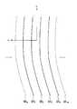
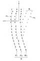
도 3a는 차량(51)이 완만한 우커브의 2차선 도로 중 좌측의 차선을 주행하고 있는 모습을 도시하는 부감도이다.
도 3b의 (a)는 도 3a의 제1 주변 지도로부터 생성되는 제2 주변 지도의 일례를 도시하는 부감도이며, 도 3b의 (b)는 도 3b의 (a)의 제2 주변 지도로부터 생성되는 히스토그램의 일례를 나타내는 그래프이다.
도 4a는 평행인 복수의 주로 경계점군의 각각에 맞는 5개의 도로 모델 함수(KK0, KK1, KK2, KK3, KK4)와 각 주로 경계점군에 포함되는 주로 특징점 FP를 도시하는 부감도이다.
도 4b는 평행인 복수의 주로 경계점군에 포함되는 주로 특징점 FP를 중첩한 상태를 도시하는 부감도이다.
도 5a는 중첩한 복수의 주로 경계점군에 포함되는 주로 특징점 FP에 기초하여 추정된 주로 형상 BC를 도시하는 부감도이다.
도 5b는 도로 모델 함수(KK0 내지 KK4)의 y축 방향의 오프셋양(가로 위치 : d0 내지 d4)만큼 각각 이동시킨 주로 형상(BC0 내지 BC4)을 도시하는 부감도이다.
도 6은 제1 실시 형태의 변형예에 관한 주로 검출 방법의 일례를 나타내는 흐름도이다.
도 7은 전회의 처리 사이클에서 구해진 주로 경계(SK1, SK2, SK3, SK4, SK4)를 도시하는 부감도이다.
도 8은 제2 실시 형태에 관한 주로 검출 장치(2)의 구성을 도시하는 블록도이다.
도 9a는 도 8의 카메라(34')가 촬상한 화상(52)의 일례를 도시한다.
도 9b는 부감 좌표 상의 위치로 변환된 주로 특징점 FP를 도시하는 부감도이다.
도 10은 제3 실시 형태에 관한 주로 검출 방법의 일례를 나타내는 흐름도이다.
도 11a는 주된 주로(54)의 주로 형상(BC1 내지 BC3)을 지지하는 복수의 주로 특징점 FP1과, 분기로(55)에 속하는 복수의 주로 특징점 FP2를 도시하는 부감도이다.
도 11b는 도 11a로부터, 주로 특징점 FP1을 삭제하고, 분기로(55)의 주로 형상(BC4, BC5)을 지지하는 복수의 주로 특징점 FP2를 남긴 상태를 도시하는 부감도이다.Fig. 1 is a block diagram mainly showing the configuration of the
Fig. 2 is a flow chart showing an example of the main detection method mainly using the
3A is a sub-view showing a state in which the
FIG. 3B is a sub-image showing an example of a second surrounding map generated from the first surrounding map in FIG. 3A, and FIG. 3B is a diagram showing a sub- FIG. 7 is a graph showing an example of a histogram. FIG.
FIG. 4A is a graph showing the relationship between five road model functions (KK0 , KK1 , KK2 , KK3 , and KK4 ) corresponding to each of a plurality of principal boundary point groups in parallel, to be.
FIG. 4B is a sub-image showing a state in which the feature points FP are mainly superimposed on a plurality of parallel main boundary point groups.
5A is a sub-sensitivity mainly showing a shape BC mainly estimated based on a feature point FP included in a plurality of overlapping groups of boundary points.
Fig. 5B is a sub-sensitivity showing the principal shapes (BC0 to BC4 ) shifted by the offset amounts (lateral positions: d0 to d4 ) of the road model functions (KK0 to KK4 ) in the y-
6 is a flowchart showing an example of a main detection method according to a modification of the first embodiment.
7 is a diagram showing a mainly bugamdo boundary(SK 1, SK 2, SK 3, SK 4, SK 4) obtained in the previous processing cycle.
Fig. 8 is a block diagram showing the configuration of the
FIG. 9A shows an example of an
9B is a sub-sensitivity mainly showing the minutiae point FP converted into a position on the sub-image coordinate.
10 is a flowchart showing an example of the main detection method according to the third embodiment.
11A shows a plurality of mainly feature points FP1 mainly supporting shapes (BC1 to BC3 ) of the main
Fig. 11B is a sub-view showing a state in which a plurality of main feature points FP2 are mainly left for supporting the main shape (BC4 , BC5 ) of the
(제1 실시 형태)(First Embodiment)
다음에, 도면을 참조하여, 실시 형태를 상세하게 설명한다.Next, an embodiment will be described in detail with reference to the drawings.
도 1을 참조하여, 제1 실시 형태에 관한 주로 검출 장치(1)의 구성을 설명한다. 주로 검출 장치(1)는 차량에 탑재된 센서가 검출한 노면 상의 주로 특징점으로부터, 차량이 주행하는 주로의 경계를 검출한다. 주로 검출 장치(1)는 차량에 탑재된 물표 검출 센서(11)와, 차량의 이동 속도 및 차량의 요 레이트에 기초하여 차량의 이동량을 검출하는 이동량 검출 센서(10)와, 물표 검출 센서(11)가 검출한 복수의 주로 특징점 및 이동량 검출 센서(10)가 검출한 차량의 이동량에 기초하여, 주로 경계를 검출하는 주로 검출 회로(12)를 구비한다.Referring to Fig. 1, the configuration of the
물표 검출 센서(11)는 차량 주위의 노면에 표시된 백선(레인 마커를 포함함)을 검출한다. 물표 검출 센서(11)는 차량에 설치된 카메라(34)와, 카메라(34)가 촬상한 디지털 화상으로부터 백선을 포함하는 노면 표시를 검출하는 화상 처리 회로(35)를 구비한다. 검출된 노면 표시는, 그 위치를 나타내는 복수의 주로 특징점으로 이루어지는 특징점군으로서 표현된다. 화상 처리 회로(35)는 주로 특징점으로서, 예를 들어 화상의 밝기가 예민하게 혹은 불연속으로 변화되고 있는 개소(휘도 에지)를 검출하면 된다.The
이동량 검출 센서(10)는 차륜속 센서(31)와, 요 레이트 센서(32)와, 이동량 검출 회로(33)를 구비한다. 차륜속 센서(31)는 차량이 구비하는 차륜의 회전 속도를 검출한다. 요 레이트 센서(32)는, 차량의 요 레이트를 검출한다. 이동량 검출 회로(33)는 차륜의 회전 속도 및 차량의 요 레이트로부터, 소정 시간에 있어서의 차량의 이동량을 검출한다. 차량의 이동량은, 예를 들어 차량의 이동 방향 및 이동 거리를 포함한다.The movement
주로 검출 회로(12)는 CPU(중앙 처리 장치), 메모리 및 입출력부를 구비하는 마이크로컴퓨터를 사용하여 실현 가능하다. 마이크로컴퓨터를 주로 검출 회로(12)로서 기능시키기 위한 컴퓨터 프로그램(주로 검출 프로그램)을, 마이크로컴퓨터에 인스톨하여 실행한다. 이에 의해, 마이크로컴퓨터는, 주로 검출 회로(12)로서 기능한다. 또한, 여기에서는, 소프트웨어에 의해 주로 검출 회로(12)를 실현하는 예를 나타내지만, 물론, 이하에 나타내는 각 정보 처리를 실행하기 위한 전용 하드웨어를 준비하여, 주로 검출 회로(12)를 구성하는 것도 가능하다. 또한, 주로 검출 회로(12)에 포함되는 복수의 회로(21, 22, 23)를 개별의 하드웨어에 의해 구성해도 된다. 또한, 주로 검출 회로(12)뿐만 아니라, 화상 처리 회로(35) 및 이동량 검출 회로(33)의 각각도, 마찬가지로 하여, 소프트웨어 혹은 전용의 하드웨어로서 실현가능하다. 또한, 주로 검출 회로(12)는 차량에 관계되는 다른 제어에 사용하는 전자 제어 유닛(ECU)과 겸용해도 된다.Mainly, the
주로 검출 회로(12)는 주변 지도 생성 회로(21)와, 주로 형상 추정 회로(22)와, 주로 경계 평가 회로(23)를 포함한다. 주변 지도 생성 회로(21)는 물표 검출 센서(11)에 의해 검출된 특징점군의 이력을, 특징점군을 검출한 시각간의 차량의 이동량에 기초하여 서로 연결한, 특징점군을 포함하는 차량 주위의 지도(제1 주변 지도)를 생성한다. 바꾸어 말하면, 주변 지도 생성 회로(21)는, 상이한 시각에 관측된 주로 특징점을, 차량의 이동량을 고려하여 서로 연결한다. 이에 의해, 주로 특징점의 검출 이력을 축적하여, 제1 주변 지도를 생성한다.Mainly the
구체적으로, 카메라(34)는 소정 시간마다 차량 주위의 노면을 촬상한다. 이동량 검출 센서(10)는 이 소정 시간에 있어서의 차량의 이동 방향 및 이동 거리를 검출한다. 주변 지도 생성 회로(21)는 주로 특징점의 위치를 차량의 이동 방향의 역방향으로 차량의 이동 거리만큼 이동시킨다. 주변 지도 생성 회로(21)는 이것을 반복하면서, 상이한 시각에 관측된 복수의 주로 특징점을 차량의 이동량을 고려하여, 서로 연결함으로써, 복수의 주로 특징점의 검출 이력을 축적하여 제1 주변 지도를 생성한다.Specifically, the
도 3a에 도시한 바와 같이, 차량(51)이 완만한 우커브의 2차선 도로 중 좌측의 차선을 주행하고 있다. 도 3a에는 이 2차선 도로를 정의하는 3개의 주로 경계(SKa, SKb, SKc)를 도시하고 있다. 주변 지도 생성 회로(21)가 생성하는 제1 주변 지도는, 3개의 주로 경계(SKa, SKb, SKc)를 따라서 검출된 특징점군(도시하지 않음)을 포함한다. 또한, 실시 형태에 있어서, 차량(51)의 위치를 원점으로 하고, 차량(51)의 진행 방향을 x축, 차량(51)의 차폭 방향을 y축으로 하는 평면 좌표를 사용한다.As shown in Fig. 3A, the
주로 형상 추정 회로(22)는 제1 주변 지도에 포함되는 복수의 주로 특징점의 연속성에 기초하여 주로 경계점군을 추출한다. 그리고, 주로 형상 추정 회로(22)는, 평행인 복수의 주로 경계점군이 추출된 경우에는, 평행인 복수의 주로 경계점군을 중첩하고, 중첩한 복수의 주로 경계점군에 포함되는 주로 특징점에 기초하여 주로 형상을 추정한다. 이하, 주로 형상 추정 회로(22)의 처리 동작을 상세하게 설명한다.Mainly the
주로 형상 추정 회로(22)는 복수의 주로 특징점의 연속성을, 차폭 방향(y축 방향)의 좌표의 도수에 의해 판정한다. 예를 들어, 주로 형상 추정 회로(22)는 차량(51)의 위치를 원점으로 하고, 차량(51)의 차폭 방향을 y축으로 하고, y축에 직교하는 축을 시간축(t축)으로 하고, 차량(51)의 이동량을 고려하지 않고, 제2 주변 지도를 작성한다. 주로 형상 추정 회로(22)는, 도 3b의 (a)에 도시한 바와 같이, 도 3a에 도시한 제1 주변 지도에 포함되는 복수의 주로 특징점 FP를, 그 검출 시각 (t) 및 차폭 방향의 위치(y좌표)에 기초하여 제2 주변 지도 상에 플롯한다.The
도 3a에 도시한 바와 같이 주로를 따라서 차량(51)이 주행하고 있으면, 도 3b의 (a)의 제2 주변 지도에 나타내는 바와 같이, 시간축(t축)에 대하여, 차량(51)의 이동량을 고려하고 있지 않으므로, 주로 특징점 FP의 차폭 방향의 위치(y좌표)는 거의 일정하다. 이 때문에, 도로 형상(완만한 우커브)에 상관없이, 주로 특징점 FP는 t축에 평행한 직선을 따른 플롯이 된다.3A, if the
주로 형상 추정 회로(22)는, 제2 주변 지도 상의 주로 특징점 FP를, 도 3b의 (b)에 도시한 바와 같이, y축을 따른 일차원의 히스토그램에 투표한다. 주로 형상 추정 회로(22)는 히스토그램으로부터 복수의 주로 특징점의 연속성을 판정할 수 있다.Mainly the
주로 형상 추정 회로(22)는, 히스토그램의 피크(y좌표)를 검출하고, 피크별로 제2 주변 지도 상의 주로 특징점 FP를 그루핑함으로써 주로 경계점군을 추출한다. 또한, 제2 주변 지도 상에서 주로 특징점 FP를 그루핑함으로써, 제1 주변 지도 상의 주로 특징점 FP를 그루핑하는 것보다도, 용이하게 주로 특징점 FP를 그루핑할 수 있다. 그루핑된 복수의 주로 특징점 FP는 하나의 주로 경계점군을 구성한다. 또한, 히스토그램을 사용한 그루핑을 행함으로써, 주로 형상 추정 회로(22)는 평행인 복수의 주로 경계점군을 동시에 추출할 수 있다. 혹은, 주로 형상 추정 회로(22)는 히스토그램을 사용하는 대신에, 주로 특징점 FP를 기지의 방법을 사용하여 곡선으로 근사함으로써, 경계점군에 대하여 복수의 곡선을 적용시킬 수 있다. 그리고, 주로 형상 추정 회로(22)는, 적용시킨 복수의 곡선이 평행선인지 여부를 판단할 수 있다.The
다음에, 주로 형상 추정 회로(22)는 제1 주변 지도에서, 각 주로 경계점군에 대하여, 도로 모델 함수로 표현되는 곡선을 적용시킨다. 도로 모델 함수는, 예를 들어 3차 함수(y=ax3+bx2+cx+d)이다. 이 경우, 주로 형상 추정 회로(22)는 계수 a, b, c 및 d를 산출한다. 여기서, 최소 제곱법에 의한 함수 적용을 사용해도 되지만, 보다 안정성을 추구하는 경우에는 RANSAC(Random sample consensus) 등의 로버스트 추정을 사용해도 된다.Next, mainly, the
주로 형상 추정 회로(22)는 평행인 복수의 주로 경계점군이 추출되었는지 여부를 판단한다. 구체적으로, 주로 형상 추정 회로(22)는, 계수 a, b 및 c가 거의 일치하고, 또한 계수 d가 상이한 도로 모델 함수가 적용된 복수의 주로 경계점군은 서로 평행하다고 판단한다. 혹은, 히스토그램 상에 2 이상의 피크를 검출할 수 있었는지 여부를 판단해도 된다.The
도 4a에 도시한 부감도는, 평행인 복수의 주로 경계점군의 각각에 적용시킨 5개의 도로 모델 함수(KK0, KK1, KK2, KK3, KK4)와 주로 경계점군에 포함되는 주로 특징점 FP를 나타낸다. 5개의 도로 모델 함수(KK0 내지 KK4)는 다음과 같다.The sub-sensitivity shown in FIG. 4A is obtained by dividing five road model functions (KK0 , KK1 , KK2 , KK3 , and KK4 ) applied to each of a plurality of main boundary point groups in parallel, FP. The five road model functions (KK0 to KK4 ) are as follows.
KK0 : y=ax3+bx2+cx+d0KK0 : y = ax3 + bx2 + cx + d0
KK1 : y=ax3+bx2+cx+d1KK1 : y = ax3 + bx2 + cx + d1
KK2 : y=ax3+bx2+cx+d2KK2 : y = ax3 + bx2 + cx + d2
KK3 : y=ax3+bx2+cx+d3KK3 : y = ax3 + bx2 + cx + d3
KK4 : y=ax3+bx2+cx+d4KK4 : y = ax3 + bx2 + cx + d4
5개의 도로 모델 함수(KK0 내지 KK4)에 있어서, 계수 a, b 및 c는 일치하고, 또한 계수 d는 상이하다. 자차를 원점으로 하는 xy좌표계에 있어서, 각 도로 모델 함수의 상수항 d0, d1, d2, d3, d4는, 도로 모델 함수의 y축 방향의 오프셋양(가로 위치)에 상당한다. 바꾸어 말하면, 평행인 복수의 주로 경계점군간의 가로 위치 관계를 나타내고 있고, 또한, 평행인 복수의 주로 경계점군간의 상대 위치 관계를 나타내고 있다. 또한, 도로 모델 함수(KK0 내지 KK4)로부터, y축 방향의 오프셋양(가로 위치)을 구하는 예를 나타냈지만, 도 3b의 (b)의 y축을 따른 일차원의 히스토그램의 y축의 SKa, SKb, SKc점의 좌표를 주로 경계점군의 오프셋양(가로 위치)으로 할 수도 있다. 이에 의해, 각 주로 경계점군의 도로 모델 함수의 연산을 생략할 수 있다.In the five road model functions (KK0 to KK4 ), the coefficients a, b and c coincide, and the coefficient d is different. In the xy coordinate system to the deviation to zero, constant term of each road model functiond 0, d 1, d 2 , d 3, d 4 correspond to the offset amount (horizontal position) of the y-axis direction of the road model function. In other words, the horizontal positional relationship between a plurality of parallel border points is mainly shown, and the relative positional relationship between a plurality of parallel border point groups is mainly shown. Although an example of obtaining the offset amount (horizontal position) in the y-axis direction from the road model functions (KK0 to KK4 ) is shown, the SKa and SKb of the y-axis of the one-dimensional histogram along the y- , And the coordinates of the SKc point may be mainly set as the offset amount (horizontal position) of the boundary point group. Thereby, it is possible to omit calculation of the road model functions of each main boundary point group.
다음에, 평행인 복수의 주로 경계점군이 추출된 경우, 주로 형상 추정 회로(22)는, 도 4b에 도시한 바와 같이, 평행인 복수의 주로 경계점군에 포함되는 주로 특징점 FP를, 적용시킨 도로 모델 함수(KK0 내지 KK4)의 y축 방향의 오프셋양(d0, d1, d2, d3, d4)과는 역방향으로 동일한 양만큼 이동시킨다. 이에 의해, 주로 형상 추정 회로(22)는 평행인 복수의 주로 경계점군에 포함되는 주로 특징점 FP를 중첩할 수 있다. 또한, 주로 특징점 FP를 중첩하는 위치는, y축의 제로점이어도 되고, 평행인 복수의 주로 경계점군 중 어느 것의 주로 경계점군에, 다른 주로 경계점군을 이동시켜, 중첩해도 된다.Next, when a plurality of principal boundary point groups are extracted in parallel, the
주로 형상 추정 회로(22)는 제1 주변 지도에서, 도 5a에 도시한 바와 같이, 중첩한 복수의 주로 경계점군에 포함되는 주로 특징점 FP에 기초하여 주로 형상 BC를 추정한다. 구체적으로는, 중첩한 복수의 주로 경계점군에 대하여 도로 모델 함수를 적용시킨다. 도로 모델 함수가 3차 함수(y=ax3+bx2+cx+d)인 경우, 주로 형상 추정 회로(22)는 계수 a, b, c 및 d를 산출한다. 주로 형상 BC는 도로 모델 함수에 의해 표현된다.Mainly the
주로 경계 평가 회로(23)는, 평행인 복수의 주로 경계점군의 가로 위치(오프셋양)와 주로 형상 BC에 기초하여 주로 경계를 결정한다. 구체적으로, 주로 경계 평가 회로(23)는, 도 5b에 도시한 바와 같이, 주로 형상 BC를, 도로 모델 함수(KK0 내지 KK4)의 y축 방향의 오프셋양(가로 위치 : d0 내지 d4)만큼, 각각 이동시킨다. 바꾸어 말하면, 주로 형상 BC와, 각 주로 경계점군의 차폭 방향의 위치(y좌표)에 기초하여, 각 주로 경계의 위치를 주로 형상 BC의 형상으로 복원한다.The
주로 경계 평가 회로(23)는, 각 주로 경계점군에 포함되는 주로 특징점의 주로 형상(BC0, BC1, BC2, BC3, BC4)에 대한 합치도에 기초하여 주로 경계를 결정한다. 주로 경계 평가 회로(23)는, 주로 형상(BC0, BC1, BC2, BC3, BC4)으로부터의 거리가 기준값보다 짧은 주로 특징점의 수를, 상기한 합치도로서 계수한다. 주로 경계 평가 회로(23)는, 계수한 주로 특징점의 수가 소정값보다도 적으면 합치도가 낮고, 주로 특징점의 수가 소정값 이상이면 합치도가 높다고 판단한다. 그리고, 합치도가 낮다고 판단한 주로 형상(BC0)을, 오검출한 주로 특징점(FPf1, FPf2)으로부터 추출된 주로 형상으로서 기각한다. 한편, 주로 경계 평가 회로(23)는, 합치도가 높다고 판단한 주로 형상(BC1, BC2, BC3, BC4)을 주로 경계로서 결정하고, 주로 검출 결과로서, 결정한 주로 경계로 구성되는 주로 위치 정보를 출력한다.The
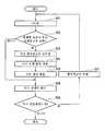
다음에, 도 2의 흐름도를 참조하여, 도 1에 도시한 주로 검출 장치(1)를 사용한 주로 검출 방법의 일례를 설명한다. 여기에서는, 도 1에 도시한 주로 검출 장치(1) 중 주로 검출 회로(12)의 동작 수순을 설명한다. 도 2에 도시한 처리는 소정 주기로 반복하여 실행된다.Next, referring to the flowchart of Fig. 2, an example of the principal detection method using mainly the
우선 스텝 S01에 있어서, 주로 검출 회로(12)는 도 3a, 도 3b의 (a) 및 도 3b의 (b)를 참조하여 설명한 바와 같이, 복수의 주로 특징점 FP의 연속성에 기초하여 주로 경계점군을 추출한다.First, in step S01, mainly, as described with reference to Figs. 3A, 3B and 3B (b), the
상세하게는, 우선, 주변 지도 생성 회로(21)는 상이한 시각에 관측된 주로 특징점 FP를, 차량의 이동량을 고려하여 서로 연결한다. 이에 의해, 주로 특징점 FP의 검출 이력을 축적하여, 제1 주변 지도를 생성한다. 그리고, 주로 형상 추정 회로(22)는 제1 주변 지도에 포함되는 복수의 주로 특징점의 연속성에 기초하여 주로 경계점군을 추출한다. 주로 형상 추정 회로(22)는 도 3b의 (b)의 히스토그램의 피크(y좌표)를 검출하고, 피크별로 도 3b의 (a)의 제2 주변 지도 상의 주로 특징점 FP를 그루핑함으로써 주로 경계점군을 추출한다. 또한, 주로 형상 추정 회로(22)는, 추출된 각 주로 경계점군에 대하여, 도로 모델 함수로 표현되는 곡선을 적용시킨다. 예를 들어, 3차 함수(y=ax3+bx2+cx+d)의 계수 a, b, c 및 d를 산출한다.In detail, first, the peripheral
스텝 S02로 진행하여, 주로 형상 추정 회로(22)는 스텝 S01에 있어서 평행인 복수의 주로 경계점군이 추출되었는지 여부를 판단한다. 예를 들어, y축을 따른 1차원의 히스토그램에 2 이상의 피크가 동시에 발견되면, 평행인 복수의 주로 경계점군이 추출되었다고 판단할 수 있다. 혹은, 주로 형상 추정 회로(22)는, 계수 a, b 및 c가 거의 일치하고, 또한 계수 d가 상이한 도로 모델 함수가 있으면, 평행인 복수의 주로 경계점군이 추출되었다고 판단해도 된다.The flow advances to step S02, and the
스텝 S02에서 "예"의 경우, 평행인 복수의 주로 경계점군의 중첩 처리가 가능해지기 때문에, 스텝 S03으로 진행하고, 스텝 S02에서 "아니오"의 경우, 중첩 처리가 불가능하기 때문에, 스텝 S06으로 진행한다.In the case of "YES" in step S02, since a plurality of parallel border point groups can be overlapped, the process proceeds to step S03. In the case of NO in step S02, the overlap process is not possible and the process proceeds to step S06 do.
스텝 S03에 있어서, 주로 형상 추정 회로(22)는, 도 4b에 도시한 바와 같이, 평행인 복수의 주로 경계점군에 포함되는 주로 특징점 FP를, 적용시킨 도로 모델 함수(KK0 내지 KK4)의 y축 방향의 오프셋양(d0 내지 d4)과는 역방향으로 동일한 양만큼 이동시킨다. 이에 의해, 주로 형상 추정 회로(22)는 평행인 복수의 주로 경계점군을 중첩할 수 있다.In step S03, as shown in Fig. 4B, the
스텝 S04에 있어서, 주로 형상 추정 회로(22)는, 중첩한 복수의 주로 경계점군에 대하여 도로 모델 함수를 적용시킨다. 이에 의해, 주로 형상 추정 회로(22)는, 도 5a에 도시한 바와 같이, 중첩한 복수의 주로 경계점군에 포함되는 주로 특징점 FP에 기초하여 주로 형상 BC를 추정할 수 있다.In step S04, the
스텝 S05에 있어서, 주로 경계 평가 회로(23)는, 도 5b에 도시한 바와 같이, 주로 형상 BC를, 도로 모델 함수(KK0 내지 KK4)의 y축 방향의 오프셋양(가로 위치 : d0 내지 d4)만큼, 각각 이동시킨다. 이에 의해, 주로 경계 평가 회로(23)는 각 주로 경계점군의 차폭 방향 위치(y좌표)에 기초하여, 각 주로 경계의 위치를 복원할 수 있다.In step S05, the
스텝 S06에 있어서, 주로 경계 평가 회로(23)는 각 주로 경계점군에 포함되는 주로 특징점 FP의 주로 형상(BC0 내지 BC4)에 대한 합치도에 기초하여 주로 경계를 결정한다. 구체적으로는, 우선, 주로 경계 평가 회로(23)는 주로 특징점 FP의 주로 형상(BC0 내지 BC4)에 대한 합치도를 산출한다. 그리고, 주로 경계 평가 회로(23)는, 합치도가 소정값보다도 낮다고 판단한 주로 형상(BC0)을, 오검출한 주로 특징점(FPf1, FPf2)으로부터 추출된 주로 형상으로서 기각한다. 한편, 주로 경계 평가 회로(23)는, 합치도가 소정값 이상이라고 판단한 주로 형상(BC1 내지 BC4)을 주로 경계로서 결정하고, 주로 검출 결과로서, 결정한 주로 경계로 구성되는 주로 위치 정보를 출력한다.In step S06, mainly the
또한, 평행인 복수의 주로 경계점군이 추출되지 않은 경우(S02에서 "아니오"), S05에서 복원된 주로 형상(BC0 내지 BC4) 대신에, S01에서 적용된 도로 모델 함수에 대한 주로 특징점 FP의 합치도를 산출하면 된다.Further, instead of a plurality of mainly parallel when boundary point group has not been extracted (S02 from the "No"), the mainly shape (BC0 to BC4) restored in S05, the mainly feature point FP on the road model function applied at S01 You can calculate the concordance.
(제1 실시 형태의 변형예)(Modification of First Embodiment)
도 1에 도시한 주로 검출 장치(1)는 스텝 S01에서 나타낸 주로 경계점군의 추출 처리에 있어서, 전회의 처리 사이클에서 구해진 주로 경계로부터 사전 차선군을 구성하여, 주로 경계점군을 추출해도 된다.The
도 6의 흐름도를 참조하여, 제1 실시 형태의 변형예에 관한 주로 검출 방법의 일례를 설명한다. 여기에서는, 주로 검출 장치(1) 중 주로 검출 회로(12)의 동작 수순을 설명한다. 도 2에 도시한 처리는 소정 주기로 반복하여 실행된다. 도 2의 스텝 S01 대신에, 스텝 S10 및 스텝 S20을 실행한다. 그 밖의 스텝 S03 내지 06은 도 2와 동일하며, 설명을 생략한다.An example of a mainly detecting method according to a modification of the first embodiment will be described with reference to the flowchart of Fig. Here, mainly the operation procedure of the
스텝 S10에서, 주로 형상 추정 회로(22)는 전회의 처리 사이클에서 구해진 주로 경계를 사용하여 사전 차선군을 구성한다. 구체적으로, 도 7에 도시한 바와 같이, 전회의 처리 사이클에 있어서, 4개의 주로 경계(SK1, SK2, SK3, SK4)를 구한 경우에 대하여 설명한다.In step S10, predominantly the
SK1 : y=a'x3+b'x2+c'x+d'1SK1 : y = a'x3 + b'x2 + c'x + d '1
SK2 : y=a'x3+b'x2+c'x+d'2SK2 : y = a'x3 + b'x2 + c'x + d '2
SK3 : y=a'x3+b'x2+c'x+d'3SK3 : y = a'x3 + b'x2 + c'x + d '3
SK4 : y=a'x3+b'x2+c'x+d'4SK4 : y = a'x3 + b'x2 + c'x + d '4
4개의 주로 경계(SK1 내지 SK4)에 있어서, 계수 a', b' 및 c'가 일치하고, 또한 오프셋양(y절편 : d'0 내지 d'4)이 상이하다. 주로 형상 추정 회로(22)는 4개의 주로 경계(SK1 내지 SK4)로부터 평균의 주로폭(w)을 구한다. 즉, 인접하는 주로 경계간의 거리(주로폭)를 각각 구하고, 그것들의 평균값(w)을 구한다. 그리고, 주로 형상 추정 회로(22)는 4개의 주로 경계(SK1 내지 SK4)의 양측에 주로폭(w)을 갖는 새로운 주로 경계(SKW, SK-w)를 각각 추가한다. 주로 형상 추정 회로(22)는 합계하여, 6개의 주로 경계(SK1 내지 SK4, SKW, SK-w)를 사전 차선군으로서 구성한다.The coefficients a ', b' and c 'coincide with each other and the offset amounts (y intercepts: d'0 to d '4 ) are different in the four primary boundaries SK1 to SK4 . Mainly shape estimating
또한, 변형예에서는, 전회의 처리 사이클에서 구해진 주로 경계를 사용하여 사전 차선군을 구성하는 예를 설명하지만, 이에 한하지 않고, 예를 들어 지도 정보의 차선군 정보에 의해, 사전 차선군을 구성해도 된다.In the modified example, an example in which the preliminary lane group is constructed using the main boundaries obtained in the previous processing cycle is described. However, the present invention is not limited to this example. For example, You can.
스텝 S20으로 진행하여, 주로 형상 추정 회로(22)는 사전 차선군과의 합치도에 기초하여 주로 특징점 FP를 그루핑함으로써 주로 경계점군을 추출한다. 주로 형상 추정 회로(22)는 주로 특징점 FP와 사전 차선군을 구성하는 각 주로 경계(SK1 내지 SK4, SKW, SK-w)의 거리를 구하고, 그 거리가 최소로 되는 주로 경계(SK1 내지 SK4, SKW, SK-w)에 주로 특징점 FP를 할당한다. 그리고, 동일한 주로 경계에 할당된 주로 특징점을 그루핑하여, 하나의 주로 경계점군으로서 추출한다.Proceeding to step S20, mainly the
여기서, 주로 특징점 FP의 좌표를 (xi, yi)라 하고, 주로 경계를 y=a'x3+b'x2+c'x+d'라 하면, 주로 특징점 FP와 주로 경계의 거리는, yi-(a'x3+b'x2+c'x+d')의 절댓값으로서 얻어진다. 어느 주로 특징점 FP로부터도 지지되지 않는 주로 경계는, 이 시점에서 기각된다.Here, usually the coordinates of the feature point FP (xi, yi) referred to, and when referred to mainly boundaryy = a'x 3 + b'x 2 + c'x + d ', mainly feature point FP and the distance of the main boundary , yi - (a'x3 + b'x2 + c'x + d '). The predominant boundary, which is not mainly supported from the feature point FP, is rejected at this point.
그리고, 제1 실시 형태의 스텝 S01과 마찬가지로 하여, 주로 형상 추정 회로(22)는, 동일한 주로 경계(SK1 내지 SK4, SKW, SK-w)에 할당된 주로 특징점군에 대하여, 3차 함수를 적용시키고, 얻어진 상수항 (d)로부터 주로 경계의 좌표계 원점에 대한 오프셋양을 구한다.And, in the same manner as the step S01 of the first embodiment, mainly with respect to the
이상 설명한 바와 같이, 제1 실시 형태 및 그 변형예에 따르면, 이하의 작용 효과가 얻어진다.As described above, according to the first embodiment and its modifications, the following operational effects are obtained.
주로 형상 추정 회로(22)는, 중첩한 복수의 주로 경계점군에 포함되는 주로 특징점 FP에 기초하여 주로 형상(BC0 내지 BC4)을 추정하고, 주로 경계 평가 회로(23)는 평행인 복수의 주로 경계점군의 가로 위치(d0 내지 d4)와 주로 형상(BC0 내지 BC4)에 기초하여 주로 경계를 결정한다. 이에 의해, 다른 주로에 대하여 평행하지 않은 분기로 등에 속하는 주로 특징점을 배제하여 주로 형상을 추정할 수 있다. 따라서, 현재 관측되고 있는 것 중에서 주된 주로의 형상을 안정적으로 추정할 수 있고, 주로 전체의 차선수나 차선폭 등의 정보를 얻을 수 있다.The
제1 주변 지도에 포함되는 복수의 주로 특징점은, 상이한 시각에 검출되며, 또한 차량의 이동량을 고려하여 서로 연결한 주로 특징점이다. 이에 의해, 1시각에 검출된 주로 특징점만으로 주로 형상을 판단하는 경우에 비해, 주로 형상을 보다 높은 확실도로 추정할 수 있다.The plurality of mainly feature points included in the first peripheral map are detected at different times and are mainly feature points connected to each other in consideration of the amount of movement of the vehicle. As a result, the shape can be mainly estimated with higher certainty, compared with the case where the shape is mainly determined mainly by the feature points detected at one time.
주로 경계 평가 회로(23)는, 각 주로 경계점군에 포함되는 주로 특징점의 주로 형상(BC0 내지 BC4)에 대한 합치도(확실성)에 기초하여 주로 경계를 결정한다. 이에 의해, 오검출된 주로 특징점(FPf1, FPf2)이나 잘못 추정된 주로 형상을, 합치도에 기초하여 기각할 수 있다.Mainly, the
(제2 실시 형태)(Second Embodiment)
제2 실시 형태에서는, 상이한 시각에 검출되며, 또한 차량의 이동량을 고려하여 서로 연결한 주로 특징점 대신에, 1시각에 검출된 주로 특징점만으로부터 주로 형상 및 주로 경계를 구하는 예에 대하여 설명한다.In the second embodiment, an example in which mainly the shape and mainly the boundary are mainly determined from only the feature points detected at one time instead of the main feature points detected at different times and connected to each other considering the amount of movement of the vehicle will be described.
도 8을 참조하여, 제2 실시 형태에 관한 주로 검출 장치(2)의 구성을 설명한다. 주로 검출 장치(2)는 주로 특징점을 차량의 이동량을 고려하여 서로 연결하여, 제1 주변 지도를 생성할 필요는 없기 때문에, 도 1의 이동량 검출 센서(10)가 구비되어 있지 않다. 또한, 주로 검출 회로(12)는 도 1의 주변 지도 생성 회로(21)를 구비하고 있지 않다. 또한, 제2 실시 형태에 있어서, 카메라(34')는, 그 촬상 방향을 차량의 진행 방향의 노면으로 향하게 한 상태에서, 차량에 설치되어 있다. 그 밖의 구성은, 주로 검출 장치(1)와 동일하다.Referring to Fig. 8, the configuration of the
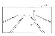
카메라(34')는, 차량의 차 실내 전방에 설치되어, 차량 전방의 노면 표시를 촬상한다. 도 9a는 카메라(34')가 촬상한 화상(52)의 일례를 도시한다. 화상(52)에는, 주로 경계를 나타내는 노면 표시(레인 마커(56))가 포함되어 있다. 화상 처리 회로(35)는 화상(52)의 밝기가 예민하게 혹은 불연속으로 변화되고 있는 레인 마커(56)의 에지 부분을 주로 특징점 FP로서 검출한다.The camera 34 'is provided in front of the vehicle cabin of the vehicle, and captures a road surface display on the front of the vehicle. 9A shows an example of an
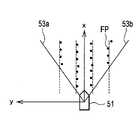
주로 형상 추정 회로(22)는, 도 9b에 도시한 바와 같이, 검출된 주로 특징점 FP의 화상(52) 상의 위치를, 차량(51) 상방으로부터 본 부감 좌표 상의 위치로 변환한다. 주로 형상 추정 회로(22)는, 이 시점 변환 처리를, 노면에 대한 카메라(34')의 설치 각도, 즉 노면에 대하여 촬상 방향이 이루는 각도, 및 노면으로부터의 카메라(34')까지의 거리에 기초하여, 실행한다. 그리고, 주로 형상 추정 회로(22)는, 도 9b의 부감 좌표 상에 있어서, 주로 경계(56)별로 주로 특징점 FP를 그루핑하여, 주로 특징점군을 추출한다. 즉, 주로 형상 추정 회로(22)는, 도 3a 및 도 3b의 (a)에 도시한 제1 및 제2 주변 지도 대신에, 도 9b의 부감 좌표에 나타낸 주로 특징점 FP에 대하여 처리를 행한다. 또한, 도 9b에 있어서, 주로 특징점 FP는, 카메라(34')의 화각(53a, 53b) 내에서 검출된다. 주로 특징점 FP의 차폭 방향의 좌표(y좌표)의 도수를 취하면, 1프레임의 화상 중의 특징점에 대하여, 도 3b의 (b)와 마찬가지로 하여, 히스토그램을 작성할 수 있다. 따라서, 주로 형상 추정 회로(22)는 이 히스토그램으로부터 복수의 주로 특징점 FP의 연속성을 판정하면 된다.Mainly the
그 밖의 주로 형상 추정 회로(22)의 동작 및 주로 경계 평가 회로(23)의 동작은, 제1 실시 형태 혹은 그 변형예와 동일하며 설명을 생략한다. 또한, 주로 검출 장치(2)를 사용한 주로 검출 방법을 나타내는 흐름도는, 도 2 혹은 도 6과 공통된다.The other operations of the
이와 같이, 제2 실시 형태에 따르면, 상이한 시각에 검출되며, 또한 차량의 이동량을 고려하여 서로 연결한 주로 특징점에 비해, 보다 단시간에 주로 형상 및 주로 경계를 검출할 수 있다. 특히, 카메라(34')가 차량(51)의 전방의 노면에 표시된 노면 표시를 촬상함으로써, 과거의 주로 특징점의 검출 이력으로부터는 얻을 수 없는, 차량(51) 전방의 주로 경계를 검출할 수 있다.As described above, according to the second embodiment, mainly the shape and mainly the boundary can be detected in a shorter time than the main feature points detected at different times and connected to each other in consideration of the amount of movement of the vehicle. Particularly, by capturing the road surface mark displayed on the road surface in front of the
(제3 실시 형태)(Third Embodiment)
제3 실시 형태에서는, 주된 주로(본선)를 검출한 후의 재검색에 의해, 주된 주로와는 상이한 주로, 예를 들어 분기로를 검출하는 예를 설명한다. 여기에서는, 제1 실시 형태(도 2)에서 설명한 주된 주로의 검출 처리 후에, 분기로의 재검색의 처리를 추가한 예에 대하여 설명하지만, 제1 실시 형태의 변형예(도 6) 혹은 제2 실시 형태 후에 실시해도 상관없다.In the third embodiment, an example in which, for example, a branch path different from the main main path is detected by re-searching after the main main path (main line) is detected will be described. Here, an example in which the process of rediscovering the branch road is added after the detection processing of the main principal explained in the first embodiment (Fig. 2) will be described, but a modification of the first embodiment (Fig. 6) It may be done after the form.
도 10의 흐름도를 참조하여, 제3 실시 형태에 관한 주로 검출 방법의 일례를 설명한다. 여기에서는, 주로 검출 장치(1) 중 주로 검출 회로(12)의 동작 수순을 설명한다. 도 10에 도시한 처리는 소정 주기로 반복하여 실행된다.An example of the main detection method according to the third embodiment will be described with reference to the flowchart of Fig. Here, mainly the operation procedure of the
스텝 S01 내지 스텝 S06은 제1 실시예와 동일하며, 설명을 생략한다.Steps S01 to S06 are the same as those in the first embodiment, and a description thereof will be omitted.
스텝 S06 후에 스텝 S30으로 진행하여, 주로 검출 회로(12)는 스텝 S06에 있어서 기준값 이상의 합치도를 갖는 주로 형상이 있었는지 여부를 판단한다. 즉, 합치도가 기준값 이상이기 때문에 주로 경계로서 판정된 주로 형상이 있었는지 여부를 판단한다. 주로 경계가 검출된 경우(S30에서 "예"), 검출된 주된 주로(본선)뿐만 아니라, 다른 주로(분기로)의 주로 경계도 검출하기 위해, 스텝 S31을 거쳐, 스텝 S01로 되돌아간다. 한편, 주로 경계가 검출되지 않은 경우(S30에서 "아니오"), 지금까지 결정한 주로 경계로 구성되는 주로 위치 정보를 출력하고 종료한다.After step S06, the process proceeds to step S30. In step S06, the
스텝 S31에 있어서, 주로 검출 회로(12)는 주로 특징점 FP의 주로 형상에 대한 합치도가 소정값보다 낮은 주로 경계점군을 추출한다. 예를 들어, 도 11a에 도시한 바와 같이, 주된 주로(54)의 주로 형상(BC1 내지 BC3)을 지지하는 복수의 주로 특징점 FP1(합치점군)을 삭제하고, 주된 주로(54)의 주로 경계를 지지하지 않는 주로 특징점 FP2만을 남긴다.In step S31, the
스텝 S01로 되돌아가, 남겨진 주로 특징점 FP2를 그루핑하여 주로 경계점군을 추출한다. 그 후, 스텝 S02 내지 S06을 다시 실행함으로써, 주로 검출 회로(12)는 도 11b에 도시한 주로 형상(BC4, BC5)을 분기로(55)의 주로 경계로서 검출할 수 있다. 그 후, 스텝 S31로 진행하지만, 도 11a 및 도 11b의 예에서는 본선(54)과 분기로(55)의 2 노선만이므로, 분기로를 검출한 후에는, 본선 및 분기로를 구성하는 주로 경계점군 이외의 특징점군밖에 추출되지 않는다. 즉, 주로 형상(BC1 내지 BC5)을 지지하지 않는 주로 특징점은 남아 있지 않기 때문에, 스텝 S06에서 주로 경계는 검출되지 않아, 스텝 S31에서 "아니오"라고 판단된다. 지금까지 결정한 본선(54) 및 분기로(55)의 주로 경계로 구성되는 주로 위치 정보를 출력하고 처리 사이클을 종료한다.Returns to the step S01, left mainly grouping the feature point FP2 mainly extracting the boundary point group. Then, it is possible to detect a boundary of a mainly to the step S02 to S06, by again running, mainly the
이상 설명한 바와 같이, 제3 실시 형태에 따르면, 주로 형상(BC1 내지 BC3)에 대한 합치도가 소정값보다 낮은 주로 경계점군을 추출하고, 합치도가 소정값보다 낮은 주로 경계점군에 기초하여 다른 주로 형상(BC4, BC5)을 추정한다. 이에 의해, 주로 형상(주된 주로)뿐만 아니라, 다른 주로 형상(분기로 등)을 추정할 수 있다.As described above, according to the third embodiment, it is possible to extract a group of main boundary points mainly having a conformance to shapes BC1 to BC3 lower than a predetermined value, And shapes (BC4 , BC5 ) are estimated. Thereby, it is possible to estimate not only the shape (main principal), but also other principal shapes (branch paths, etc.).
또한, 제1 실시 형태에서 히스토그램을 사용한 주로 특징점의 그루핑 처리를 설명하였다. 물론, 제2 실시 형태에 있어서도, 차폭 방향의 좌표(y좌표)의 도수를 취하면, 1프레임의 화상(52) 중의 주로 특징점 FP에 대하여, 히스토그램을 취할 수 있다. 마찬가지로, 제3 실시 형태에 있어서도, 히스토그램을 사용한 주로 특징점의 그루핑 처리가 가능하다. 예를 들어, 도 11b에 도시한 분기로(55)에 속하는 주로 특징점 FP에 대하여 곡선을 근사하고, 근사 곡선의 경사 방향에 x축을 맞추어 재설정한다. 이에 의해, 히스토그램을 사용한 주로 특징점 FP2의 그루핑 처리를, 재차 실행할 수 있다.In addition, the grouping process of the feature points mainly using the histogram has been described in the first embodiment. Of course, also in the second embodiment, it is possible to take a histogram mainly for the minutiae point FP in the
상술한 각 실시 형태에서 설명한 각 기능은, 하나 또는 복수의 처리 회로에 의해 실장될 수 있다. 처리 회로는, 전기 회로를 포함하는 처리 장치 등의 프로그램된 처리 장치를 포함한다. 처리 장치는, 또한, 실시 형태에 기재된 기능을 실행하도록 어레인지된 특정 용도용 집적 회로(ASIC)나 종래형 회로 부품과 같은 장치를 포함한다.Each function described in each of the above embodiments can be implemented by one or a plurality of processing circuits. The processing circuit includes a programmed processing device such as a processing device including an electrical circuit. The processing apparatus also includes an apparatus such as an application specific integrated circuit (ASIC) or a conventional circuit component arranged to perform the functions described in the embodiments.
실시 형태에서는, 이동량 검출 센서(10) 및 물표 검출 센서(11)를 구비하는 스탠드 얼론형 주로 검출 장치(1, 2)를 예시하였지만, 주로 검출 장치는, 무선 통신망을 통한 컴퓨터 네트워크를 사용한 클라이언트 서버 모델로서도 실현 가능하다. 이 경우, 예를 들어 이동량 검출 센서(10) 및 물표 검출 센서(11)를 구비하는 차량(51)(클라이언트)은 컴퓨터 네트워크를 통해 주로 검출 장치(서버)에 접속한다. 이에 의해, 도 1 또는 도 8에 도시한 주로 검출 회로(12)를 구비하는 서버를, 컴퓨터 네트워크를 통해, 이동량 검출 센서(10) 및 물표 검출 센서(11)에 접속할 수 있다. 이 경우, 주로 검출 장치는, 주로 주로 검출 회로(12)(서버)에 의해 구성되며, 이동량 검출 센서(10) 및 물표 검출 센서(11)는 주로 검출 장치에 포함되지 않는다.In the embodiment, the stand-alone type
이상, 실시예에 따라서 본 발명의 내용을 설명하였지만, 본 발명은 이들 기재에 한정되는 것은 아니고, 다양한 변형 및 개량이 가능한 것은 당업자에게는 자명하다.While the present invention has been described with reference to the preferred embodiments, it is to be understood that the invention is not limited to those precise embodiments and various modifications and improvements will be apparent to those skilled in the art.
1, 2 : 주로 검출 장치
10 : 이동량 검출 센서
11 : 물표 검출 센서
12 : 주로 검출 회로
22 : 주로 형상 추정 회로
23 : 주로 경계 평가 회로
51 : 차량
BC0 내지 BC5 : 주로 형상
FP : 주로 특징점1, 2: mainly detecting device
10: Movement detection sensor
11:
12: mainly detection circuit
22: mainly shape estimation circuit
23: mainly the boundary evaluation circuit
51: vehicle
BC0 to BC5 : mainly shape
FP: mainly feature points
Claims (5)
Translated fromKorean상기 주로 검출 회로는,
상기 복수의 주로 특징점의 연속성에 기초하여 주로 경계점군을 추출하고,
평행한 복수의 주로 경계점군이 추출된 경우에는, 상기 평행한 복수의 주로 경계점군을 중첩하고,
중첩한 복수의 주로 경계점군에 포함되는 주로 특징점에 기초하여 주로 형상을 추정하고,
상기 평행한 복수의 주로 경계점군의 가로 위치와 상기 주로 형상에 기초하여 주로 경계를 결정하는 것을 특징으로 하는, 주로 검출 방법.A main detection method mainly using a detection circuit that mainly detects a boundary based on a plurality of main road feature points detected by a road surface detection sensor mounted on a vehicle,
Preferably,
Extracting a group of boundary points mainly based on continuity of the plurality of feature points,
When a plurality of parallel boundary points are mainly extracted, the plurality of parallel boundary points are mainly overlapped,
A shape is mainly estimated on the basis of mainly feature points included in a plurality of superposed groups of boundary points,
Characterized in that a boundary is mainly determined based on the horizontal positions of the plurality of parallelly predominantly border point groups and the main shape.
상기 복수의 주로 특징점은, 상이한 시각에 검출되며, 또한 차량의 이동량을 고려하여 서로 연결한 주로 특징점인 것을 특징으로 하는, 주로 검출 방법.The method according to claim 1,
Characterized in that the plurality of mainly feature points are detected at different times and are mainly feature points connected to each other in consideration of the amount of movement of the vehicle.
상기 주로 검출 회로는, 각 주로 경계점군에 포함되는 주로 특징점의 상기 주로 형상에 대한 합치도에 기초하여 주로 경계를 결정하는 것을 특징으로 하는, 주로 검출 방법.3. The method according to claim 1 or 2,
Characterized in that said detection circuit mainly determines a boundary mainly based on the consistency of mainly the feature points mainly included in the group of boundary points with respect to said main shape.
상기 주로 검출 회로는, 주로 경계점군에 포함되는 주로 특징점의 상기 주로 형상에 대한 합치도가 소정값보다 낮은 주로 경계점군을 추출하고, 상기 합치도가 소정값보다 낮은 주로 경계점군에 기초하여 다른 주로 형상을 추정하는 것을 특징으로 하는, 주로 검출 방법.4. The method according to any one of claims 1 to 3,
The main detection circuit mainly extracts a group of main boundary points mainly consisting of a plurality of boundary point groups and having a total degree of conformity of the feature points to the main shape is lower than a predetermined value, Wherein the first detection means estimates the second detection signal.
상기 평행한 복수의 주로 경계점군의 가로 위치와 상기 주로 형상에 기초하여 주로 경계를 결정하는 주로 경계 평가 회로를 구비하는 것을 특징으로 하는, 주로 검출 장치.In the case where a plurality of boundary point groups are mainly extracted based on a plurality of mainly feature points detected by a vehicle-mounted object detection sensor mounted on a vehicle, and a plurality of parallel boundary points are mainly extracted, the plurality of parallel boundary points are superimposed, A shape predicting circuit mainly predominantly estimating a shape based mainly on feature points included in a plurality of mainly sets of boundary points,
And a main boundary evaluation circuit which mainly determines a boundary on the basis of the horizontal position of the plurality of parallel main border point groups and the main shape.
Applications Claiming Priority (1)
| Application Number | Priority Date | Filing Date | Title |
|---|---|---|---|
| PCT/JP2016/059397WO2017163367A1 (en) | 2016-03-24 | 2016-03-24 | Travel path detection method and travel path detection device |
Publications (1)
| Publication Number | Publication Date |
|---|---|
| KR20180122691Atrue KR20180122691A (en) | 2018-11-13 |
Family
ID=59900032
Family Applications (1)
| Application Number | Title | Priority Date | Filing Date |
|---|---|---|---|
| KR1020187029663ACeasedKR20180122691A (en) | 2016-03-24 | 2016-03-24 | Mainly a detection method and mainly a detection device |
Country Status (10)
| Country | Link |
|---|---|
| US (1) | US10614321B2 (en) |
| EP (1) | EP3435352B1 (en) |
| JP (1) | JP6617828B2 (en) |
| KR (1) | KR20180122691A (en) |
| CN (1) | CN108885831B (en) |
| BR (1) | BR112018069472B1 (en) |
| CA (1) | CA3018661C (en) |
| MX (1) | MX373490B (en) |
| RU (1) | RU2725561C2 (en) |
| WO (1) | WO2017163367A1 (en) |
Families Citing this family (6)
| Publication number | Priority date | Publication date | Assignee | Title |
|---|---|---|---|---|
| WO2018212287A1 (en) | 2017-05-19 | 2018-11-22 | パイオニア株式会社 | Measurement device, measurement method, and program |
| CN109086650B (en)* | 2017-06-14 | 2022-04-12 | 现代摩比斯株式会社 | Calibration method and calibration apparatus |
| US11023746B2 (en)* | 2019-01-02 | 2021-06-01 | Here Global B.V. | Lane count estimation |
| JP7609444B2 (en)* | 2019-05-28 | 2025-01-07 | モービルアイ ビジョン テクノロジーズ リミテッド | System for vehicle navigation |
| US11932245B2 (en)* | 2020-09-01 | 2024-03-19 | Toyota Motor Engineering & Manufacturing North America, Inc. | Systems and methods for improving path selection for automated driving |
| WO2022118422A1 (en)* | 2020-12-03 | 2022-06-09 | 日本電気株式会社 | Line position estimation device, method, and program |
Family Cites Families (31)
| Publication number | Priority date | Publication date | Assignee | Title |
|---|---|---|---|---|
| US5638116A (en)* | 1993-09-08 | 1997-06-10 | Sumitomo Electric Industries, Ltd. | Object recognition apparatus and method |
| US5991427A (en)* | 1996-07-31 | 1999-11-23 | Aisin Seiki Kabushiki Kaisha | Method and apparatus for detecting a lane on a road |
| JP3584194B2 (en)* | 2000-02-22 | 2004-11-04 | 株式会社ホンダエレシス | White line detection method and white line detection device |
| US6819779B1 (en)* | 2000-11-22 | 2004-11-16 | Cognex Corporation | Lane detection system and apparatus |
| JP4551018B2 (en)* | 2001-04-05 | 2010-09-22 | 富士通株式会社 | Image combiner |
| JP3603836B2 (en)* | 2001-11-20 | 2004-12-22 | 日産自動車株式会社 | Road white line recognition device |
| JP2004200351A (en)* | 2002-12-18 | 2004-07-15 | Hitachi Ltd | Exposure apparatus and exposure method |
| JP3864945B2 (en) | 2003-09-24 | 2007-01-10 | アイシン精機株式会社 | Road lane detection device |
| JP3956926B2 (en)* | 2003-09-24 | 2007-08-08 | アイシン精機株式会社 | Road lane detection device |
| JP4092308B2 (en) | 2004-06-02 | 2008-05-28 | トヨタ自動車株式会社 | Boundary line detection device |
| JP4616046B2 (en)* | 2005-03-22 | 2011-01-19 | 本田技研工業株式会社 | VEHICLE IMAGE PROCESSING SYSTEM, VEHICLE IMAGE PROCESSING METHOD, VEHICLE IMAGE PROCESSING PROGRAM, AND VEHICLE |
| JP4659631B2 (en)* | 2005-04-26 | 2011-03-30 | 富士重工業株式会社 | Lane recognition device |
| JP4614826B2 (en) | 2005-06-14 | 2011-01-19 | トヨタ自動車株式会社 | Road marking line detection device |
| JP4965991B2 (en)* | 2006-01-10 | 2012-07-04 | 株式会社リコー | Color image forming apparatus |
| JP2007241468A (en) | 2006-03-06 | 2007-09-20 | Toyota Motor Corp | Lane change detection device |
| US7916935B2 (en)* | 2006-09-19 | 2011-03-29 | Wisconsin Alumni Research Foundation | Systems and methods for automatically determining 3-dimensional object information and for controlling a process based on automatically-determined 3-dimensional object information |
| JP2009041972A (en)* | 2007-08-07 | 2009-02-26 | Toshiba Corp | Image processing apparatus and method |
| JP5363921B2 (en)* | 2009-08-31 | 2013-12-11 | 富士重工業株式会社 | Vehicle white line recognition device |
| JP5035371B2 (en)* | 2010-03-15 | 2012-09-26 | アイシン精機株式会社 | Crosswalk detection device, crosswalk detection system, crosswalk detection method and program |
| JP5603687B2 (en)* | 2010-07-15 | 2014-10-08 | 富士重工業株式会社 | Vehicle white line recognition device |
| US20120022739A1 (en)* | 2010-07-20 | 2012-01-26 | Gm Global Technology Operations, Inc. | Robust vehicular lateral control with front and rear cameras |
| JP5258859B2 (en)* | 2010-09-24 | 2013-08-07 | 株式会社豊田中央研究所 | Runway estimation apparatus and program |
| JP5568029B2 (en)* | 2011-02-09 | 2014-08-06 | 富士重工業株式会社 | Vehicle white line recognition device |
| CN102184535B (en)* | 2011-04-14 | 2013-08-14 | 西北工业大学 | Method for detecting boundary of lane where vehicle is |
| US9098751B2 (en)* | 2011-07-27 | 2015-08-04 | Gentex Corporation | System and method for periodic lane marker identification and tracking |
| MX2014000652A (en)* | 2011-08-02 | 2014-04-30 | Nissan Motor | Object detector and object detection method. |
| RU2576362C2 (en)* | 2011-08-02 | 2016-02-27 | Ниссан Мотор Ко., Лтд. | Driving aid device and process |
| US9349057B2 (en)* | 2011-09-12 | 2016-05-24 | Nissan Motor Co., Ltd. | Three-dimensional object detection device |
| RU2571871C2 (en)* | 2012-12-06 | 2015-12-27 | Александр ГУРЕВИЧ | Method of determining road boundaries, shape and position of objects on road, and device therefor |
| JP6259239B2 (en) | 2013-09-27 | 2018-01-10 | 株式会社Subaru | Vehicle white line recognition device |
| KR101906951B1 (en)* | 2013-12-11 | 2018-10-11 | 한화지상방산 주식회사 | System and method for lane detection |
- 2016
- 2016-03-24CACA3018661Apatent/CA3018661C/enactiveActive
- 2016-03-24JPJP2018506707Apatent/JP6617828B2/enactiveActive
- 2016-03-24USUS16/087,477patent/US10614321B2/enactiveActive
- 2016-03-24RURU2018137203Apatent/RU2725561C2/enactive
- 2016-03-24BRBR112018069472-0Apatent/BR112018069472B1/enactiveIP Right Grant
- 2016-03-24MXMX2018011509Apatent/MX373490B/enactiveIP Right Grant
- 2016-03-24WOPCT/JP2016/059397patent/WO2017163367A1/ennot_activeCeased
- 2016-03-24CNCN201680083901.9Apatent/CN108885831B/enactiveActive
- 2016-03-24EPEP16895403.0Apatent/EP3435352B1/enactiveActive
- 2016-03-24KRKR1020187029663Apatent/KR20180122691A/ennot_activeCeased
Also Published As
| Publication number | Publication date |
|---|---|
| RU2725561C2 (en) | 2020-07-02 |
| BR112018069472B1 (en) | 2023-12-19 |
| WO2017163367A1 (en) | 2017-09-28 |
| CN108885831B (en) | 2020-04-14 |
| RU2018137203A3 (en) | 2020-04-24 |
| RU2018137203A (en) | 2020-04-24 |
| BR112018069472A2 (en) | 2019-02-12 |
| US10614321B2 (en) | 2020-04-07 |
| US20190095723A1 (en) | 2019-03-28 |
| JP6617828B2 (en) | 2019-12-18 |
| MX2018011509A (en) | 2019-01-10 |
| JPWO2017163367A1 (en) | 2019-02-14 |
| EP3435352A1 (en) | 2019-01-30 |
| CN108885831A (en) | 2018-11-23 |
| CA3018661A1 (en) | 2017-09-28 |
| CA3018661C (en) | 2020-06-09 |
| MX373490B (en) | 2020-05-05 |
| EP3435352B1 (en) | 2021-11-17 |
| EP3435352A4 (en) | 2019-03-27 |
Similar Documents
| Publication | Publication Date | Title |
|---|---|---|
| KR20180122691A (en) | Mainly a detection method and mainly a detection device | |
| JP5804185B2 (en) | Moving object position / orientation estimation apparatus and moving object position / orientation estimation method | |
| CN106056570B (en) | Road Slope Detection Device | |
| CN107850446B (en) | Self-position estimating device and self-position estimate method | |
| US10650535B2 (en) | Measurement device and measurement method | |
| CN109074741B (en) | Travel path detection method and travel path detection device | |
| KR101977652B1 (en) | A method for automatic generation of road surface type using a mobile mapping system | |
| JP5310027B2 (en) | Lane recognition device and lane recognition method | |
| JP6844235B2 (en) | Distance measuring device and distance measuring method | |
| JP7024176B2 (en) | Track detection method and track detection device | |
| JP7058128B2 (en) | Information processing equipment and programs | |
| CN109344677B (en) | Method, device, vehicle and storage medium for recognizing three-dimensional object | |
| JP6416654B2 (en) | White line detector | |
| JP2013148354A (en) | Vehicle position calculation device | |
| JP2018096935A (en) | Own vehicle position estimation device, program, recording medium, and own vehicle position estimation method | |
| JP6451544B2 (en) | Road boundary detection device, self-position estimation device, and road boundary detection method | |
| JP2004030440A (en) | Image processing method, image processing program, and computer readable recording medium with the program recorded thereon |
Legal Events
| Date | Code | Title | Description |
|---|---|---|---|
| A201 | Request for examination | ||
| AMND | Amendment | ||
| PA0105 | International application | Patent event date:20181015 Patent event code:PA01051R01D Comment text:International Patent Application | |
| PA0201 | Request for examination | ||
| PG1501 | Laying open of application | ||
| PA0302 | Request for accelerated examination | Patent event date:20181127 Patent event code:PA03022R01D Comment text:Request for Accelerated Examination | |
| E902 | Notification of reason for refusal | ||
| PE0902 | Notice of grounds for rejection | Comment text:Notification of reason for refusal Patent event date:20190315 Patent event code:PE09021S01D | |
| E601 | Decision to refuse application | ||
| PE0601 | Decision on rejection of patent | Patent event date:20190929 Comment text:Decision to Refuse Application Patent event code:PE06012S01D Patent event date:20190315 Comment text:Notification of reason for refusal Patent event code:PE06011S01I | |
| X091 | Application refused [patent] | ||
| AMND | Amendment | ||
| PX0901 | Re-examination | Patent event code:PX09011S01I Patent event date:20190929 Comment text:Decision to Refuse Application Patent event code:PX09012R01I Patent event date:20181015 Comment text:Amendment to Specification, etc. | |
| PX0601 | Decision of rejection after re-examination | Comment text:Decision to Refuse Application Patent event code:PX06014S01D Patent event date:20200122 Comment text:Amendment to Specification, etc. Patent event code:PX06012R01I Patent event date:20191218 Comment text:Decision to Refuse Application Patent event code:PX06011S01I Patent event date:20190929 Comment text:Notification of reason for refusal Patent event code:PX06013S01I Patent event date:20190315 Comment text:Amendment to Specification, etc. Patent event code:PX06012R01I Patent event date:20181015 |