KR20180121052A - Hierarchical type power control system - Google Patents
Hierarchical type power control systemDownload PDFInfo
- Publication number
- KR20180121052A KR20180121052AKR1020170055229AKR20170055229AKR20180121052AKR 20180121052 AKR20180121052 AKR 20180121052AKR 1020170055229 AKR1020170055229 AKR 1020170055229AKR 20170055229 AKR20170055229 AKR 20170055229AKR 20180121052 AKR20180121052 AKR 20180121052A
- Authority
- KR
- South Korea
- Prior art keywords
- power
- ess
- load
- micro
- control system
- Prior art date
- Legal status (The legal status is an assumption and is not a legal conclusion. Google has not performed a legal analysis and makes no representation as to the accuracy of the status listed.)
- Ceased
Links
Images


Classifications
- H—ELECTRICITY
- H02—GENERATION; CONVERSION OR DISTRIBUTION OF ELECTRIC POWER
- H02J—CIRCUIT ARRANGEMENTS OR SYSTEMS FOR SUPPLYING OR DISTRIBUTING ELECTRIC POWER; SYSTEMS FOR STORING ELECTRIC ENERGY
- H02J3/00—Circuit arrangements for AC mains or AC distribution networks
- H02J3/28—Arrangements for balancing of the load in a network by storage of energy
- H02J3/32—Arrangements for balancing of the load in a network by storage of energy using batteries with converting means
- G—PHYSICS
- G06—COMPUTING OR CALCULATING; COUNTING
- G06Q—INFORMATION AND COMMUNICATION TECHNOLOGY [ICT] SPECIALLY ADAPTED FOR ADMINISTRATIVE, COMMERCIAL, FINANCIAL, MANAGERIAL OR SUPERVISORY PURPOSES; SYSTEMS OR METHODS SPECIALLY ADAPTED FOR ADMINISTRATIVE, COMMERCIAL, FINANCIAL, MANAGERIAL OR SUPERVISORY PURPOSES, NOT OTHERWISE PROVIDED FOR
- G06Q50/00—Information and communication technology [ICT] specially adapted for implementation of business processes of specific business sectors, e.g. utilities or tourism
- G06Q50/06—Energy or water supply
- H—ELECTRICITY
- H02—GENERATION; CONVERSION OR DISTRIBUTION OF ELECTRIC POWER
- H02J—CIRCUIT ARRANGEMENTS OR SYSTEMS FOR SUPPLYING OR DISTRIBUTING ELECTRIC POWER; SYSTEMS FOR STORING ELECTRIC ENERGY
- H02J3/00—Circuit arrangements for AC mains or AC distribution networks
- H02J3/38—Arrangements for parallely feeding a single network by two or more generators, converters or transformers
- H02J3/381—Dispersed generators
- H—ELECTRICITY
- H02—GENERATION; CONVERSION OR DISTRIBUTION OF ELECTRIC POWER
- H02J—CIRCUIT ARRANGEMENTS OR SYSTEMS FOR SUPPLYING OR DISTRIBUTING ELECTRIC POWER; SYSTEMS FOR STORING ELECTRIC ENERGY
- H02J9/00—Circuit arrangements for emergency or stand-by power supply, e.g. for emergency lighting
- H02J9/04—Circuit arrangements for emergency or stand-by power supply, e.g. for emergency lighting in which the distribution system is disconnected from the normal source and connected to a standby source
- H02J9/06—Circuit arrangements for emergency or stand-by power supply, e.g. for emergency lighting in which the distribution system is disconnected from the normal source and connected to a standby source with automatic change-over, e.g. UPS systems
- H02J9/08—Circuit arrangements for emergency or stand-by power supply, e.g. for emergency lighting in which the distribution system is disconnected from the normal source and connected to a standby source with automatic change-over, e.g. UPS systems requiring starting of a prime-mover
- Y—GENERAL TAGGING OF NEW TECHNOLOGICAL DEVELOPMENTS; GENERAL TAGGING OF CROSS-SECTIONAL TECHNOLOGIES SPANNING OVER SEVERAL SECTIONS OF THE IPC; TECHNICAL SUBJECTS COVERED BY FORMER USPC CROSS-REFERENCE ART COLLECTIONS [XRACs] AND DIGESTS
- Y02—TECHNOLOGIES OR APPLICATIONS FOR MITIGATION OR ADAPTATION AGAINST CLIMATE CHANGE
- Y02A—TECHNOLOGIES FOR ADAPTATION TO CLIMATE CHANGE
- Y02A30/00—Adapting or protecting infrastructure or their operation
- Y02A30/60—Planning or developing urban green infrastructure
- Y—GENERAL TAGGING OF NEW TECHNOLOGICAL DEVELOPMENTS; GENERAL TAGGING OF CROSS-SECTIONAL TECHNOLOGIES SPANNING OVER SEVERAL SECTIONS OF THE IPC; TECHNICAL SUBJECTS COVERED BY FORMER USPC CROSS-REFERENCE ART COLLECTIONS [XRACs] AND DIGESTS
- Y02—TECHNOLOGIES OR APPLICATIONS FOR MITIGATION OR ADAPTATION AGAINST CLIMATE CHANGE
- Y02B—CLIMATE CHANGE MITIGATION TECHNOLOGIES RELATED TO BUILDINGS, e.g. HOUSING, HOUSE APPLIANCES OR RELATED END-USER APPLICATIONS
- Y02B70/00—Technologies for an efficient end-user side electric power management and consumption
- Y02B70/30—Systems integrating technologies related to power network operation and communication or information technologies for improving the carbon footprint of the management of residential or tertiary loads, i.e. smart grids as climate change mitigation technology in the buildings sector, including also the last stages of power distribution and the control, monitoring or operating management systems at local level
- Y02B70/3225—Demand response systems, e.g. load shedding, peak shaving
- Y—GENERAL TAGGING OF NEW TECHNOLOGICAL DEVELOPMENTS; GENERAL TAGGING OF CROSS-SECTIONAL TECHNOLOGIES SPANNING OVER SEVERAL SECTIONS OF THE IPC; TECHNICAL SUBJECTS COVERED BY FORMER USPC CROSS-REFERENCE ART COLLECTIONS [XRACs] AND DIGESTS
- Y04—INFORMATION OR COMMUNICATION TECHNOLOGIES HAVING AN IMPACT ON OTHER TECHNOLOGY AREAS
- Y04S—SYSTEMS INTEGRATING TECHNOLOGIES RELATED TO POWER NETWORK OPERATION, COMMUNICATION OR INFORMATION TECHNOLOGIES FOR IMPROVING THE ELECTRICAL POWER GENERATION, TRANSMISSION, DISTRIBUTION, MANAGEMENT OR USAGE, i.e. SMART GRIDS
- Y04S10/00—Systems supporting electrical power generation, transmission or distribution
- Y04S10/14—Energy storage units
- Y—GENERAL TAGGING OF NEW TECHNOLOGICAL DEVELOPMENTS; GENERAL TAGGING OF CROSS-SECTIONAL TECHNOLOGIES SPANNING OVER SEVERAL SECTIONS OF THE IPC; TECHNICAL SUBJECTS COVERED BY FORMER USPC CROSS-REFERENCE ART COLLECTIONS [XRACs] AND DIGESTS
- Y04—INFORMATION OR COMMUNICATION TECHNOLOGIES HAVING AN IMPACT ON OTHER TECHNOLOGY AREAS
- Y04S—SYSTEMS INTEGRATING TECHNOLOGIES RELATED TO POWER NETWORK OPERATION, COMMUNICATION OR INFORMATION TECHNOLOGIES FOR IMPROVING THE ELECTRICAL POWER GENERATION, TRANSMISSION, DISTRIBUTION, MANAGEMENT OR USAGE, i.e. SMART GRIDS
- Y04S20/00—Management or operation of end-user stationary applications or the last stages of power distribution; Controlling, monitoring or operating thereof
- Y04S20/12—Energy storage units, uninterruptible power supply [UPS] systems or standby or emergency generators, e.g. in the last power distribution stages
- Y—GENERAL TAGGING OF NEW TECHNOLOGICAL DEVELOPMENTS; GENERAL TAGGING OF CROSS-SECTIONAL TECHNOLOGIES SPANNING OVER SEVERAL SECTIONS OF THE IPC; TECHNICAL SUBJECTS COVERED BY FORMER USPC CROSS-REFERENCE ART COLLECTIONS [XRACs] AND DIGESTS
- Y04—INFORMATION OR COMMUNICATION TECHNOLOGIES HAVING AN IMPACT ON OTHER TECHNOLOGY AREAS
- Y04S—SYSTEMS INTEGRATING TECHNOLOGIES RELATED TO POWER NETWORK OPERATION, COMMUNICATION OR INFORMATION TECHNOLOGIES FOR IMPROVING THE ELECTRICAL POWER GENERATION, TRANSMISSION, DISTRIBUTION, MANAGEMENT OR USAGE, i.e. SMART GRIDS
- Y04S20/00—Management or operation of end-user stationary applications or the last stages of power distribution; Controlling, monitoring or operating thereof
- Y04S20/20—End-user application control systems
- Y04S20/222—Demand response systems, e.g. load shedding, peak shaving
Landscapes
- Engineering & Computer Science (AREA)
- Business, Economics & Management (AREA)
- Power Engineering (AREA)
- Economics (AREA)
- Health & Medical Sciences (AREA)
- General Health & Medical Sciences (AREA)
- Strategic Management (AREA)
- Water Supply & Treatment (AREA)
- Emergency Management (AREA)
- Human Resources & Organizations (AREA)
- Marketing (AREA)
- Primary Health Care (AREA)
- Public Health (AREA)
- Tourism & Hospitality (AREA)
- Physics & Mathematics (AREA)
- General Business, Economics & Management (AREA)
- General Physics & Mathematics (AREA)
- Theoretical Computer Science (AREA)
- Supply And Distribution Of Alternating Current (AREA)
Abstract
Description
Translated fromKorean본 발명은 계층형 전력 제어 시스템에 관한 것이다.The present invention relates to a hierarchical power control system.
에너지 저장 시스템(Energy Storage System)은 생산된 전력을 발전소, 변전소 및 송전선 등을 포함한 각각의 연계 시스템에 저장한 후, 전력이 필요한 시기에 선택적, 효율적으로 사용하여 에너지 효율을 높이는 시스템이다.Energy Storage System is a system that stores generated power in each link system including power plant, substation and transmission line, and then uses energy selectively and efficiently at necessary time to enhance energy efficiency.
에너지 저장 시스템은 시간대 및 계절별 변동이 큰 전기부하를 평준화시켜 전반적인 부하율을 향상시킬 경우, 발전 단가를 낮출 수 있으며 전력설비 증설에 필요한 투자비와 운전비 등을 절감할 수 있어서 전기요금을 인하하고 에너지를 절약할 수 있다.The energy storage system can reduce the power generation cost when the overall load ratio is improved by leveling the electric load with large time and seasonal variation, and it is possible to reduce the investment cost and the operation cost required for the electric power facility expansion, can do.
이러한 에너지 저장 시스템은 전력계통에서 발전, 송배전, 수용가에 설치되어 이용되고 있으며, 주파수 조정(Frequency Regulation), 신재생에너지를 이용한 발전기 출력 안정화, 첨두부하 저감(Peak Shaving), 부하 평준화(Load Leveling), 비상 전원 등의 기능으로 사용되고 있다.These energy storage systems are installed in power generation, transmission, distribution, and customer in power system. Frequency regulation, generator output stabilization using peak energy, peak shaving, load leveling, , And emergency power supply.
에너지 저장 시스템은 저장방식에 따라 크게 물리적 에너지 저장과 화학적 에너지 저장으로 구분된다. 물리적 에너지 저장으로는 양수발전, 압축 공기 저장, 플라이휠 등을 이용한 방법이 있고, 화학적 에너지 저장으로는 리튬이온 배터리, 납축전지, Nas 전지 등을 이용한 방법이 있다.Energy storage systems are divided into physical energy storage and chemical energy storage depending on the storage method. Physical energy storage includes pumped storage, compressed air storage, and flywheel. Chemical storage includes lithium ion batteries, lead acid batteries, and Nas batteries.
다만, 이러한 에너지 저장 시스템은 직접 관리하고 있는 지역(예를 들어, 마이크로그리드(microgrid) 단위) 또는 건물의 전력 상태만을 관리할 수 있을 뿐 인접한 지역 또는 건물에서 전력 부족으로 어려움을 겪을 때 현재의 전력 수급 상태를 고려하여 인접한 지역 또는 건물의 전력 부족 문제를 도울 수는 없었다.However, this energy storage system can manage only the power state of a building (for example, a microgrid unit) or a building in which it is directly managed, Considering the supply and demand situation, we could not help the power shortage problem in the adjacent area or building.
특히, 피크 제어 또는 계통 사고시, 특정 지역 또는 건물은 여유 전력이 남는데 반해, 다른 지역 또는 건물은 전력 부족으로 인해 어려움을 겪는 문제가 발생하곤 하였다.Particularly, in peak control or systematic accidents, a certain area or building is left with a surplus power, while other areas or buildings often suffer difficulties due to power shortages.
이러한 문제들을 해결하기 위해, 인접한 마이크로그리드 단위 지역들의 전력을 통합하여 효율적으로 관리할 수 있는 시스템에 대한 필요성이 대두되고 있다.In order to solve these problems, there is a need for a system that can efficiently manage the power of adjacent microgrid unit areas.
본 발명은 서로 인접한 마이크로그리드 셀(Microgrid Cell)들의 전력 수급 상태를 통합하여 효율적으로 제어할 수 있는 계층형 전력 제어 시스템을 제공하는 것을 목적으로 한다.An object of the present invention is to provide a hierarchical power control system capable of efficiently controlling the power supply / demand state of adjacent microgrid cells.
본 발명의 목적들은 이상에서 언급한 목적으로 제한되지 않으며, 언급되지 않은 본 발명의 다른 목적 및 장점들은 하기의 설명에 의해서 이해될 수 있고, 본 발명의 실시예에 의해 보다 분명하게 이해될 것이다. 또한, 본 발명의 목적 및 장점들은 특허 청구 범위에 나타낸 수단 및 그 조합에 의해 실현될 수 있음을 쉽게 알 수 있을 것이다.The objects of the present invention are not limited to the above-mentioned objects, and other objects and advantages of the present invention which are not mentioned can be understood by the following description and more clearly understood by the embodiments of the present invention. It will also be readily apparent that the objects and advantages of the invention may be realized and attained by means of the instrumentalities and combinations particularly pointed out in the appended claims.
상기의 목적을 달성하기 위한 본 발명의 일 실시예에 따른 계층형 전력 제어 시스템은, 클라우드 서버와 연계된 계층형 전력 제어 시스템에 있어서, UPS(Uninterruptible Power Supply) 구조를 갖춘 제1 ESS(Energy Storage System)와 제1 ESS에 의해 전력 상태가 관리되는 제1 부하를 포함하는 제1 마이크로그리드 셀, 제2 부하와 제2 부하의 전력 상태를 관리하는 제2 ESS를 포함하는 제2 마이크로그리드 셀, 제3 부하를 포함하는 제3 마이크로그리드 셀, 제1 내지 제3 마이크로그리드 셀과 통신하는 미들웨어 서버(middleware server) 및 미들웨어 서버와 통신하고, 제1 내지 제3 마이크로그리드 셀의 전력 수급 상태를 통합하여 제어하는 통합 제어 시스템을 포함하되, 상기 제1 마이크로그리드 셀과 상기 제2 마이크로그리드 셀은 컨버터를 통해 연결되어 상호간 전력이 융통된다.According to an aspect of the present invention, there is provided a hierarchical power control system connected to a cloud server, the system including a first ESS (Energy Storage System) having an uninterruptible power supply (UPS) A second micro grid cell including a first micro grid cell including a first load that is managed by a first ESS and a first load that is managed by a first ESS, a second ESS that manages power states of a second load and a second load, A third middle grid server communicating with the first through third micro grid cells, and a middleware server communicating with the first through third micro grid cells, The first micro grid cell and the second micro grid cell are connected to each other through a converter, and power is mutually exchanged.
제1 마이크로그리드 셀은 제1 부하의 전력 상태를 감지하는 제1 센서를 더 포함하고, 제2 마이크로그리드 셀은 제2 부하의 전력 상태를 감지하는 제2 센서를 더 포함하고, 제3 마이크로그리드 셀은 제3 부하의 전력 상태를 감지하는 제3 센서를 더 포함하되, 제1 내지 제3 센서는 각각 제1 내지 제3 부하의 전력 상태를 감지하여 클라우드 서버로 송신한다.The first microgrid cell further comprises a first sensor for sensing a power state of the first load and the second microgrid cell further comprises a second sensor for sensing a power state of the second load, The cell further includes a third sensor for sensing a power state of the third load, wherein each of the first to third sensors senses a power state of each of the first to third loads and transmits the power state to the cloud server.
클라우드 서버는, 외부로부터 기후 데이터 및 전력 관련 데이터를 제공받고, 제1 내지 제3 센서로부터 제공받은 제1 내지 제3 부하의 전력 상태 및 외부로부터 제공받은 기후 데이터 및 전력 관련 데이터를 종합하여 분석하고, 분석 결과를 미들웨어 서버로 제공한다.The cloud server receives the weather data and the power-related data from the outside, collects and analyzes the power states of the first to third loads provided from the first to third sensors, and the climate data and the power-related data provided from the outside , And provides the analysis result to the middleware server.
미들웨어 서버는 제공받은 분석 결과 및 제1 내지 제3 마이크로그리드 셀로부터 각각 제공받은 실시간 전력 상태 정보를 통합 제어 시스템에 제공하고, 통합 제어 시스템은 미들웨어 서버로부터 제공받은 분석 결과 및 제1 내지 제3 마이크로그리드 셀의 실시간 전력 상태 정보를 토대로 제1 내지 제3 마이크로그리드 셀의 전력 수급 상태를 통합하여 제어한다.The middleware server provides the analysis result and the real-time power status information provided from the first to third micro grid cells to the integrated control system. The integrated control system analyzes the analysis result provided from the middleware server and the first to third micro- The power supply state of the first to third micro-grid cells is integrated based on the real-time power state information of the grid cell.
제1 ESS는 계통의 정전 또는 복전시 제1 부하에 무정전 전력 공급이 가능하다.The first ESS is capable of supplying uninterruptible power to the first load of the system power failure or recuperation.
제1 마이크로그리드 셀은, 비상 발전기와, 계통과 제1 ESS 간 연결 및 계통과 제1 부하 간 연결을 개폐하는 STS와, 비상 발전기 및 제1 ESS를 제어하는 제1 EMS(Energy Management System)를 더 포함한다.The first micro grid cell comprises an emergency generator, an STS for opening and closing the system-to-ESS connection and a connection between the system and the first load, a first EMS (Energy Management System) for controlling the emergency generator and the first ESS .
계통 정전시, STS는 계통 정전을 감지하여 계통과의 연결을 차단하고, 제1 ESS는 구동 모드를 정전력 모드에서 CVCF(Constant Voltage Constant Frequency) 모드로 변경하여 제1 부하에 독립적으로 전력을 공급하고, 제1 EMS는 제1 ESS가 CVCF 모드로 변경되어 제1 부하에 독립적으로 전력을 공급하면 비상 발전기를 구동시키고, 제1 EMS에 의해 구동된 비상 발전기는 제1 부하 측으로 전력을 공급하고, STS는 비상 발전기에 의해 공급되는 전력이 감지되면 제1 ESS에 제1 알림을 제공하며, 제1 ESS는 STS로부터 제1 알림을 제공받으면, 제1 동기화 알고리즘을 수행하되, 제1 동기화 알고리즘은 제1 ESS의 주파수, 전압 및 위상각을 비상 발전기의 주파수, 전압 및 위상각과 동기화시키기 위한 알고리즘이다.In case of system power failure, STS detects grid failure and disconnects the system. The first ESS changes the drive mode from constant power mode to CVCF (Constant Voltage Constant Frequency) mode to supply power independently to the first load The first EMS drives the emergency generator when the first ESS is switched to the CVCF mode and supplies power independently to the first load, the emergency generator driven by the first EMS supplies power to the first load side, The STS provides a first notification to the first ESS when power supplied by the emergency generator is detected, and when the first ESS receives the first notification from the STS, it performs a first synchronization algorithm, 1 is an algorithm for synchronizing the frequency, voltage and phase angles of the ESS with the frequency, voltage and phase angle of the emergency generator.
제1 ESS의 제1 동기화 알고리즘이 수행되면, STS는 계통과의 연결 차단을 해제하고, 비상 발전기는 주파수 추종 모드로 구동되고, 제1 ESS는 정전력 모드로 다시 변경되어 구동된다.When the first synchronization algorithm of the first ESS is performed, the STS releases the connection with the system, the emergency generator is driven in the frequency tracking mode, and the first ESS is changed back to the constant power mode and driven.
계통 복전시, 제1 EMS는 비상 발전기의 구동을 정지시키고, STS는 비상 발전기의 구동 정지를 감지하여 제1 ESS에 제2 알림을 제공하고, 계통과의 연결을 다시 차단하며, 제1 ESS는 STS로부터 제2 알림을 제공받으면, 정전력 모드에서 CVCF 모드로 변경하여 제1 부하에 독립적으로 전력을 공급하고, 계통으로부터 제1 부하 측으로 전력이 공급되면, STS는 계통에 의해 공급되는 전력을 감지하여 제1 ESS에 제3 알림을 제공하고, 제1 ESS는 STS로부터 제3 알림을 제공받으면, 제2 동기화 알고리즘을 수행하고, 제1 ESS가 제2 동기화 알고리즘을 수행하면, STS는 계통과의 연결 차단을 다시 해제하되, 제2 동기화 알고리즘은 제1 ESS의 주파수, 전압 및 위상각을 계통의 주파수, 전압 및 위상각과 동기화시키기 위한 알고리즘이다.The first EMS stops the operation of the emergency generator, the STS senses the operation stop of the emergency generator and provides the second notification to the first ESS, disconnects the connection with the system again, and the first ESS Upon receiving the second notification from the STS, the STS changes the mode from the constant power mode to the CVCF mode to supply power independently to the first load. When power is supplied from the system to the first load side, the STS senses the power supplied by the system The first ESS provides a third notification to the first ESS, and when the first ESS receives the third notification from the STS, it performs a second synchronization algorithm, and when the first ESS performs the second synchronization algorithm, The second synchronization algorithm is an algorithm for synchronizing the frequency, voltage and phase angle of the first ESS with the frequency, voltage and phase angle of the system.
통합 제어 시스템은 제1 및 제2 마이크로그리드 셀 각각의 여유 전력 및 부족 전력을 계산하여 전력 융통량값을 결정하고, 결정된 전력 융통량값을 미들웨어 서버를 통해 제1 마이크로그리드 셀 및 제2 마이크로그리드 셀 중 여유 전력이 있는 마이크로그리드 셀에 제공한다.The integrated control system determines the power budget value by calculating the available power and the undervoted power of each of the first and second micro grid cells, and transmits the determined power budget value to the first micro grid cell and the second micro grid cell through the middleware server And provides it to the microgrid cell having the spare power.
제1 마이크로그리드 셀에 여유 전력이 있는 경우, 제1 EMS는 미들웨어 서버로부터 결정된 전력 융통량값을 제공받고, 제공받은 결정된 전력 융통량값을 제1 ESS로 전달하고, 제1 ESS는 전달받은 결정된 전력 융통량값을 토대로 배터리의 충방전량을 제어한 후, 컨버터를 통해 제2 마이크로그리드 셀에 전력을 공급한다.If there is sufficient power in the first micro-grid cell, the first EMS receives the determined power value from the middleware server and delivers the determined power value to the first ESS, and the first ESS sends the determined power- And controls the charging / discharging amount of the battery based on the charge amount, and supplies power to the second micro grid cell through the converter.
제2 부하는 서로 다른 우선 순위를 가지는 적어도 하나 이상의 부하를 포함하고, 통합 제어 시스템은 제1 마이크로그리드 셀의 여유 전력량 및 제2 부하 중 우선 순위가 높은 부하에서 필요로 하는 부족 전력량을 토대로 전력 융통량값을 결정하고, 제1 ESS는 결정된 전력 융통량값을 토대로 배터리의 충방전량을 제어한 후, 컨버터를 통해 제2 부하 중 우선 순위가 높은 부하에 전력을 공급한다.The second load includes at least one load having a different priority, and the integrated control system is configured to control the power consumption of the first micro grid cell based on the remaining power amount of the first micro grid cell, The first ESS controls the charge amount of the battery based on the determined power availability value, and then supplies power to the load having the higher priority among the second loads through the converter.
통합 제어 시스템은 제1 및 제2 마이크로그리드 셀 각각의 여유 전력 및 부족 전력을 계산하여 전력 융통량값을 결정하고, 결정된 전력 융통량값을 미들웨어 서버를 통해 제1 마이크로그리드 셀 및 제2 마이크로그리드 셀 중 여유 전력이 있는 마이크로그리드 셀에 제공한다.The integrated control system determines the power budget value by calculating the available power and the undervoted power of each of the first and second micro grid cells, and transmits the determined power budget value to the first micro grid cell and the second micro grid cell through the middleware server And provides it to the microgrid cell having the spare power.
상기 제1 마이크로그리드 셀은 제1 ESS 및 제1 부하를 통합하여 제어하는 제1 EMS를 포함하되, 제1 마이크로그리드 셀에 여유 전력이 있는 경우, 제1 EMS는 미들웨어 서버로부터 결정된 전력 융통량값을 제공받고, 제공받은 결정된 전력 융통량값을 제1 ESS로 전달하고, 제1 ESS는 전달받은 결정된 전력 융통량값을 토대로 배터리의 충방전량을 제어한 후, 컨버터를 통해 제2 마이크로그리드 셀에 전력을 공급한다.Wherein the first micro grid cell includes a first EMS for aggregating and controlling the first ESS and the first load, wherein if there is a reserve power in the first micro grid cell, the first EMS will determine a power budget value determined from the middleware server The first ESS transmits the determined power level value to the first ESS. The first ESS controls the charge amount of the battery based on the determined power level value, and then supplies power to the second micro grid cell via the converter do.
상기 제2 부하는 서로 다른 우선 순위를 가지는 적어도 하나 이상의 부하를 포함하고, 통합 제어 시스템은 제1 마이크로그리드 셀의 여유 전력량 및 제2 부하 중 우선 순위가 높은 부하에서 필요로 하는 부족 전력량을 토대로 전력 융통량값을 결정하고, 제1 ESS는 결정된 전력 융통량값을 토대로 배터리의 충방전량을 제어한 후, 컨버터를 통해 제2 부하 중 우선 순위가 높은 부하에 전력을 공급한다.Wherein the second load includes at least one load having a different priority and the integrated control system is configured to control the power consumption of the first micro grid cell based on the amount of power remaining in the first micro grid cell, The first ESS controls the charge amount of the battery based on the determined power availability value and then supplies power to the load having the higher priority among the second loads through the converter.
상기 컨버터는 서로 직렬 연결된 AC-DC 컨버터 및 DC-AC 컨버터를 포함한다.The converter includes an AC-DC converter and a DC-AC converter connected in series with each other.
상기 제2 마이크로그리드 셀의 전력이 부족한 경우, 제1 마이크로그리드 셀은 AC-DC 컨버터로 AC 전압을 제공하고, AC-DC 컨버터는 제1 마이크로그리드 셀로부터 제공받은 AC 전압을 DC 전압으로 변환하여 DC-AC 컨버터로 제공하고, DC-AC 컨버터는 AC-DC 컨버터로부터 제공받은 DC 전압을 다시 AC 전압으로 변환하여 제2 마이크로그리드 셀에 제공한다.When the power of the second micro grid cell is insufficient, the first micro grid cell provides the AC voltage to the AC-DC converter, and the AC-DC converter converts the AC voltage supplied from the first micro grid cell to the DC voltage DC converter, and the DC-AC converter converts the DC voltage supplied from the AC-DC converter to an AC voltage and supplies the AC voltage to the second micro-grid cell.
상기 AC-DC 컨버터의 일단은 제1 ESS와 제1 부하 사이에 연결되고, AC-DC 컨버터의 타단은 DC-AC 컨버터의 일단에 연결된다.One end of the AC-DC converter is connected between the first ESS and the first load, and the other end of the AC-DC converter is connected to one end of the DC-AC converter.
상기 DC-AC 컨버터의 일단은 AC-DC 컨버터의 타단에 연결되고, DC-AC 컨버터의 타단은 제2 ESS와 제2 부하 사이에 연결된다.One end of the DC-AC converter is connected to the other end of the AC-DC converter, and the other end of the DC-AC converter is connected between the second ESS and the second load.
제1 부하의 전력 융통 우선순위는 제2 부하 및 제3 부하 각각의 전력 융통 우선순위보다 높다.The power priority of the first load is higher than the power priority of each of the second load and the third load.
제1 마이크로그리드 셀은, BEMS(Building Energy Management System)와, BEMS와 통신하는 분전반과, BEMS와 통신하는 BAS(Building Automation System)와, BAS와 연결된 냉난방 시스템과, BAS와 연결된 제1 분산 전원 시스템과, BAS와 연결된 제3 ESS를 더 포함하되, BEMS는 BAS를 통해 냉난방 시스템, 제1 분산 전원 시스템 및 제3 ESS 중 적어도 하나를 제어하여 피크 부하를 저감한다.The first microgrid cell comprises a building energy management system (BEMS), a distribution board for communicating with the BEMS, a building automation system (BAS) for communicating with the BEMS, a heating and cooling system connected to the BAS, And a third ESS coupled to the BAS, wherein the BEMS controls at least one of the air conditioning system, the first distributed power system, and the third ESS via the BAS to reduce the peak load.
제2 마이크로그리드 셀은 제2 ESS와 연계되어 구동되는 제2 분산 전원 시스템과, 제2 ESS 및 제2 분산 전원 시스템을 제어하는 제2 EMS(Energy Management System)를 더 포함한다.The second micro grid cell further includes a second distributed power supply system driven in conjunction with the second ESS, and a second EMS (Energy Management System) controlling the second ESS and the second distributed power supply system.
상기의 목적을 달성하기 위한 본 발명의 다른 실시예에 따른 계층형 전력 제어 시스템은, 클라우드 서버와 연계된 계층형 전력 제어 시스템에 있어서, CTTS(Closed Transition Transfer Switch)를 통해 계통과의 연결이 개폐되는 비상 발전기와, 비상 발전기와 연계되어 구동되는 제1 ESS(Energy Storage System)와, 제1 ESS에 의해 전력 상태가 관리되는 제1 부하를 포함하는 제1 마이크로그리드 셀, 제2 부하와 제2 부하의 전력 상태를 관리하는 제2 ESS를 포함하는 제2 마이크로그리드 셀, 제3 부하를 포함하는 제3 마이크로그리드 셀, 제1 내지 제3 마이크로그리드 셀과 통신하는 미들웨어 서버(middleware server) 및 미들웨어 서버와 통신하고, 제1 내지 제3 마이크로그리드 셀을 통합하여 제어하는 통합 제어 시스템을 포함하되, 제1 마이크로그리드 셀과 제2 마이크로그리드 셀은 컨버터를 통해 연결되어 상호간 전력이 융통된다.According to another aspect of the present invention, there is provided a hierarchical power control system connected to a cloud server. The hierarchical power control system includes a controller for controlling a connection to a system through a CTTS (Closed Transition Transfer Switch) A first micro grid cell including a first emergency power generator, a first ESS (Energy Storage System) driven in association with the emergency generator, and a first load whose power state is managed by the first ESS, A second micro grid cell including a second ESS for managing the power state of the load, a third micro grid cell including a third load, a middleware server communicating with the first through third micro grid cells, And an integrated control system for communicating with the server and controlling the first to third micro-grid cells, wherein the first micro-grid cell and the second micro- Is connected through the emitter is each other and power is flexible.
제1 마이크로그리드 셀은, 계통과 제1 ESS 간 연결 및 계통과 제1 부하 간 연결을 개폐하는 STS와, 비상 발전기 및 제1 ESS를 제어하는 제1 EMS(Energy Management System)를 더 포함한다.The first microgrid cell further includes an STS that opens and closes the link between the system and the first ESS and the link between the system and the first load, and a first EMS (Energy Management System) that controls the emergency generator and the first ESS.
계통 정전시, STS는 계통 정전을 감지하여 계통과의 연결을 차단하고, 제1 ESS는 구동 모드를 정전력 모드에서 CVCF(Constant Voltage Constant Frequency) 모드로 변경하여 제1 부하에 독립적으로 전력을 공급하고, 제1 EMS는 제1 ESS가 CVCF 모드로 변경되어 제1 부하에 독립적으로 전력을 공급하면 비상 발전기를 구동시키고, 비상 발전기가 구동되면, CTTS는 비상 발전기와 계통 간 연결을 차단하면서 비상 발전기를 STS와 연결시키고, 비상 발전기는 제1 부하 측으로 전력을 공급하고, STS는 비상 발전기에 의해 공급되는 전력이 감지되면 제1 ESS에 제1 알림을 제공하며, 제1 ESS는 STS로부터 제1 알림을 제공받으면, 제1 동기화 알고리즘을 수행한다.In case of system power failure, STS detects grid failure and disconnects the system. The first ESS changes the drive mode from constant power mode to CVCF (Constant Voltage Constant Frequency) mode to supply power independently to the first load And the first EMS activates the emergency generator when the first ESS is switched to the CVCF mode and supplies power independently to the first load. When the emergency generator is activated, the CTTS disconnects the emergency generator and the system, The STS provides a first notification to the first ESS when power supplied by the emergency generator is detected and the first ESS sends a first notification from the STS to the STS, A first synchronization algorithm is performed.
제1 ESS의 제1 동기화 알고리즘이 수행되면, STS는 계통과의 연결 차단을 해제하고, 비상 발전기는 주파수 추종 모드로 구동되고, 제1 ESS는 정전력 모드로 다시 변경되어 구동된다.When the first synchronization algorithm of the first ESS is performed, the STS releases the connection with the system, the emergency generator is driven in the frequency tracking mode, and the first ESS is changed back to the constant power mode and driven.
계통 복전시, 제1 EMS는 비상 발전기의 구동을 정지시키고, CTTS는 비상 발전기의 구동 정지를 감지하여 비상 발전기와 STS 간 연결을 차단하면서 STS를 계통과 연결시키고, STS가 계통과 연결되면, CTTS는 CTTS용 동기화 알고리즘을 수행하되, CTTS용 동기화 알고리즘은 제1 ESS의 주파수, 전압 및 위상각을 계통의 주파수, 전압 및 위상각과 동기화시키기 위한 알고리즘이다.When the STS is connected to the system, the CTTS stops the operation of the emergency generator. The CTTS stops the connection between the emergency generator and the STS, detects the stop of the emergency generator, Performs a synchronization algorithm for the CTTS, wherein the synchronization algorithm for the CTTS is an algorithm for synchronizing the frequency, voltage and phase angle of the first ESS with the frequency, voltage and phase angle of the system.
계통 복전시, 제1 EMS는 비상 발전기의 구동을 정지시키고, STS는 비상 발전기의 구동 정지를 감지하여 제1 ESS에 제2 알림을 제공하고, 계통과의 연결을 다시 차단하며, 제1 ESS는 STS로부터 제2 알림을 제공받으면, 정전력 모드에서 CVCF 모드로 변경하여 제1 부하에 독립적으로 전력을 공급하고, 제1 ESS가 CVCF 모드로 변경되면, CTTS는 비상 발전기와 STS 간 연결을 차단하면서 STS를 계통과 연결시키고, 계통으로부터 제1 부하 측으로 전력이 공급되면, STS는 계통에 의해 공급되는 전력을 감지하여 제1 ESS에 제3 알림을 제공하고, 제1 ESS는 STS로부터 제3 알림을 제공받으면, 제2 동기화 알고리즘을 수행하고, 제1 ESS가 제2 동기화 알고리즘을 수행하면, STS는 계통과의 연결 차단을 다시 해제하고, 계통과의 연결 차단이 다시 해제되면, 제1 ESS는 CVCF 모드에서 정전력 모드로 다시 변경되되, 제2 동기화 알고리즘은 제1 ESS의 주파수, 전압 및 위상각을 계통의 주파수, 전압 및 위상각과 동기화시키기 위한 알고리즘이다.The first EMS stops the operation of the emergency generator, the STS senses the operation stop of the emergency generator and provides the second notification to the first ESS, disconnects the connection with the system again, and the first ESS When the second notification is received from the STS, the mode is switched from the constant power mode to the CVCF mode to supply power independently to the first load. When the first ESS changes to the CVCF mode, the CTTS interrupts the connection between the emergency generator and the STS When the STS is connected to the grid and power is supplied from the grid to the first load side, the STS senses the power supplied by the grid to provide a third notification to the first ESS, and the first ESS receives a third notification from the STS When the first ESS performs the second synchronization algorithm, the STS resumes the connection disconnection with the system, and when the connection disconnection with the system is released again, the first ESS resets the CVCF Constant power mode Doedoe changed again, the second synchronization algorithm is an algorithm for synchronizing the frequency, voltage and phase angle of the grid frequency, voltage and phase angle of the 1 ESS.
상기의 목적을 달성하기 위한 본 발명의 또 다른 실시예에 따른 계층형 전력 제어 시스템은, 클라우드 서버와 연계된 계층형 전력 제어 시스템에 있어서, UPS(Uninterruptible Power Supply) 구조를 갖춘 제1 ESS(Energy Storage System)와 제1 ESS에 의해 전력 상태가 관리되는 제1 부하를 포함하는 제1 마이크로그리드 셀, 제2 부하와 제2 부하의 전력 상태를 관리하는 제2 ESS를 포함하는 제2 마이크로그리드 셀, 제3 부하를 포함하는 제3 마이크로그리드 셀, 제1 내지 제3 마이크로그리드 셀과 통신하고, 제1 내지 제3 마이크로그리드 셀의 전력 수급 상태를 통합하여 제어하는 통합 제어 시스템을 포함하되, 제1 마이크로그리드 셀과 제2 마이크로그리드 셀은 컨버터를 통해 연결되어 상호간 전력이 융통된다.According to another aspect of the present invention, there is provided a hierarchical power control system connected to a cloud server, the hierarchical power control system comprising: a first ESS (Energy Saving Controller) having an uninterruptible power supply (UPS) A second micro grid cell including a first micro grid cell including a first load that is managed by a first ESS and a first load that is managed by a first ESS and a second ESS that manages power states of a second load and a second load, , A third micro-grid cell including a third load, and an integrated control system communicating with the first through third micro-grid cells and integrally controlling the power supply and demand states of the first through third micro-grid cells, One microgrid cell and the second microgrid cell are connected to each other through a converter to mutually exchange power.
제1 마이크로그리드 셀은, 비상 발전기와, 계통과 제1 ESS 간 연결 및 계통과 제1 부하 간 연결을 개폐하는 STS(Static Transfer Switch)와, 비상 발전기 및 제1 ESS를 제어하는 제1 EMS(Energy Management System)를 더 포함한다.The first micro-grid cell comprises an emergency generator, a STS (Static Transfer Switch) for opening and closing the system-to-ESS connection and the connection between the system and the first load, a first EMS Energy Management System).
상기의 목적을 달성하기 위한 본 발명의 또 다른 실시예에 따른 계층형 전력 제어 시스템은, 클라우드 서버와 연계된 계층형 전력 제어 시스템에 있어서, CTTS(Closed Transition Transfer Switch)를 통해 계통과의 연결이 개폐되는 비상 발전기와, 비상 발전기와 연계되어 구동되는 제1 ESS(Energy Storage System)와, 제1 ESS에 의해 전력 상태가 관리되는 제1 부하를 포함하는 제1 마이크로그리드 셀, 제2 부하와 제2 부하의 전력 상태를 관리하는 제2 ESS를 포함하는 제2 마이크로그리드 셀, 제3 부하를 포함하는 제3 마이크로그리드 셀, 제1 내지 제3 마이크로그리드 셀과 통신하고, 제1 내지 제3 마이크로그리드 셀을 통합하여 제어하는 통합 제어 시스템을 포함하되, 제1 마이크로그리드 셀과 제2 마이크로그리드 셀은 컨버터를 통해 연결되어 상호간 전력이 융통된다.According to another aspect of the present invention, there is provided a hierarchical power control system in a hierarchical power control system connected to a cloud server, the system comprising: A first micro grid cell including a first emergency load, an emergency generator, a first ESS (Energy Storage System) driven in association with the emergency generator, and a first load whose power status is managed by the first ESS, A second micro-grid cell including a second ESS for managing the power state of the second load, a third micro-grid cell including a third load, and first to third micro-grid cells, And an integrated control system for integrally controlling the grid cells, wherein the first micro-grid cell and the second micro-grid cell are connected to each other through a converter to mutually exchange power.
전술한 바와 같이 본 발명에 의하면, 제1 내지 제3 마이크로그리드 셀의 전력 수급 상태를 통합하여 제어하는 통합 제어 시스템을 통해 피크 제어 또는 계통 정전시 마이크로그리드 셀 간 전력 융통을 효율적으로 수행함으로써 전력 수급 문제를 해결할 수 있다.As described above, according to the present invention, it is possible to efficiently perform power control between micro grid cells during peak control or system power failure through an integrated control system that integrally controls the power supply state of first through third micro grid cells, I can solve the problem.
도 1은 본 발명의 일 실시예에 따른 계층형 전력 제어 시스템을 설명하는 개략도이다.
도 2는 도 1의 제1 내지 제3 마이크로그리드 셀을 설명하는 개략도이다.
도 3은 도 2의 제1 마이크로그리드 셀을 설명하는 개략도이다.
도 4 내지 도 11은 계통 정전시 도 3의 제1 마이크로그리드 셀의 독립 운전 방법의 일 예를 설명하는 개략도들이다.
도 12 내지 도 21은 계통 정전시 도 3의 제1 마이크로그리드 셀의 독립 운전 방법의 다른 예를 설명하는 개략도들이다.
도 22는 도 1의 계층형 전력 제어 시스템의 전력 융통 방법을 설명하는 순서도이다.1 is a schematic diagram illustrating a hierarchical power control system according to an embodiment of the present invention.
2 is a schematic view for explaining the first to third micro-grid cells of FIG.
3 is a schematic diagram illustrating the first micro-grid cell of Fig.
FIGS. 4 to 11 are schematic diagrams illustrating an example of the independent operation method of the first micro grid cell of FIG. 3 during system power failure.
FIGS. 12 to 21 are schematic views for explaining another example of the independent operation method of the first micro grid cell of FIG. 3 during system power failure.
FIG. 22 is a flowchart for explaining a power-up method of the hierarchical power control system of FIG. 1;
전술한 목적, 특징 및 장점은 첨부된 도면을 참조하여 상세하게 후술되며, 이에 따라 본 발명이 속하는 기술분야에서 통상의 지식을 가진 자가 본 발명의 기술적 사상을 용이하게 실시할 수 있을 것이다. 본 발명을 설명함에 있어서 본 발명과 관련된 공지 기술에 대한 구체적인 설명이 본 발명의 요지를 불필요하게 흐릴 수 있다고 판단되는 경우에는 상세한 설명을 생략한다. 이하, 첨부된 도면을 참조하여 본 발명에 따른 바람직한 실시예를 상세히 설명하기로 한다. 도면에서 동일한 참조부호는 동일 또는 유사한 구성요소를 가리키는 것으로 사용된다.The above and other objects, features, and advantages of the present invention will become more apparent by describing in detail exemplary embodiments thereof with reference to the attached drawings, which are not intended to limit the scope of the present invention. In the following description, well-known functions or constructions are not described in detail since they would obscure the invention in unnecessary detail. Hereinafter, preferred embodiments of the present invention will be described in detail with reference to the accompanying drawings. In the drawings, the same reference numerals are used to denote the same or similar elements.
이하에서는, 도 1 내지 도 3을 참조하여 본 발명의 일 실시예에 따른 계층형 전력 제어 시스템을 설명하도록 한다.Hereinafter, a hierarchical power control system according to an embodiment of the present invention will be described with reference to FIG. 1 to FIG.
도 1은 본 발명의 일 실시예에 따른 계층형 전력 제어 시스템을 설명하는 개략도이다. 도 2는 도 1의 제1 내지 제3 마이크로그리드 셀을 설명하는 개략도이다. 도 3은 도 2의 제1 마이크로그리드 셀을 설명하는 개략도이다.1 is a schematic diagram illustrating a hierarchical power control system according to an embodiment of the present invention. 2 is a schematic view for explaining the first to third micro-grid cells of FIG. 3 is a schematic diagram illustrating the first micro-grid cell of Fig.
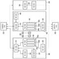
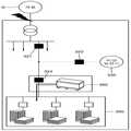
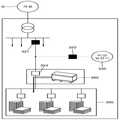
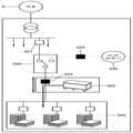
도 1 및 도 2를 참조하면, 본 발명의 일 실시예에 따른 계층형 전력 제어 시스템(1)은 통합 제어 시스템(100), 미들웨어 서버(200), 제1 마이크로그리드 셀(300), 제2 마이크로그리드 셀(400), 제3 마이크로그리드 셀(500)을 포함할 수 있다.1 and 2, a hierarchical power control system 1 according to an embodiment of the present invention includes an
참고로, 도 1의 계층형 전력 제어 시스템(1)은 클라우드 서버(600)를 더 포함할 수도 있으나, 본 발명에서는 설명의 편의를 위해, 계층형 전력 제어 시스템(1)이 클라우드 서버(600)를 포함하지 않는 것을 예로 들어 설명하기로 한다.The hierarchical power control system 1 of FIG. 1 may further include a
또한 도면에 도시되어 있지는 않지만, 도 1의 계층형 전력 제어 시스템(1)은 계통을 더 포함할 수 있다. 여기에서, 계통은 제1 내지 제3 마이크로그리드 셀(300, 400, 500) 각각에 존재할 수도 있지만, 제1 내지 제3 마이크로그리드 셀(300, 400, 500)에 공통된 하나의 계통만이 존재할 수도 있다.Also, although not shown in the figure, the hierarchical power control system 1 of Fig. 1 may further include a system. Here, although the system may exist in each of the first through third
또한 계통은 예를 들어, 발전소, 변전소, 송전선 등을 포함할 수 있다.The system may also include, for example, a power station, a substation, a transmission line, and the like.
통합 제어 시스템(100)은 미들웨어 서버(200)와 통신하고, 제1 내지 제3 마이크로그리드 셀(300, 400, 500)의 전력 수급 상태를 통합하여 제어할 수 있다The
구체적으로, 통합 제어 시스템(100)은 크게 통합감시 및 제어 기능과 최적발전 및 제어 기능을 가지도록 설계될 수 있다.Specifically, the
통합감시 및 제어 기능은 예를 들어, 감시 기능(monitoring), 제어 기능(control), 레포팅 기능(reporting), 경보 기능(alarming), 연산 기능(calculation), DB 관리 기능(Database Management), 트렌드 기능(Trend), 화면표시 기능을 포함할 수 있다.The integrated monitoring and control functions include, for example, monitoring, control, reporting, alarming, calculation, database management, trending, (Trend), and a display function.
여기에서, 감시 기능은 제1 내지 제3 마이크로그리드 셀(300, 400, 500)의 상태/고장 감시 및 계측 기능을 포함하고, 제어 기능은 제1 내지 제3 마이크로그리드 셀(300, 400, 500)에 구비된 설비의 운전/정지/스케줄링 및 최적운전 제어 기능을 포함할 수 있다.Here, the monitoring function includes a state / fault monitoring and measurement function of the first to third
레포팅 기능은 제1 내지 제3 마이크로그리드 셀(300, 400, 500)에 대한 기간 별 계측 정보 및 조작/보수 기록을 제공하는 기능을 포함하고, 경보 기능은 알람 인지 처리 및 저장 기능을 포함할 수 있다.The reporting function includes the function of providing period-specific measurement information and operation / maintenance records for the first to third
연산 기능은 역률 등 계산이 필요한 데이터에 연산/함수 기능을 제공하는 기능을 포함하고, DB 관리 기능은 실시간 데이터베이스 API(Application Program Interface)를 통한 데이터 인터페이스 기능을 포함할 수 있다.The arithmetic function includes a function of providing arithmetic / function functions for data requiring power factor calculation and the DB management function may include a data interface function through a real-time database API (application program interface).
트렌드 기능은 데이터 변화 추이를 감시하는 기능을 포함하고, 화면표시 기능은 감시, 이벤트, 알람, 권한 등을 화면(예를 들어, 통합 제어 시스템(100)의 화면 또는 클라우드 서버(600)를 통해 연동된 모바일 단말(800)의 화면)에 표시하는 기능을 포함할 수 있다.The trend function includes a function of monitoring a trend of data change. The screen display function is a function of monitoring, event, alarm, authority, and the like on the screen (for example, the screen of the
한편, 최적발전 및 제어 기능은 예를 들어, 부하 예측 기능, 태양광 발전 예측 기능, 최적발전계획 수립 기능, 경제급전 기능, 자동발전제어 기능, 가정산 기능, 부하 차단 기능, 아일랜딩(islanding) 알고리즘 수행 기능을 포함할 수 있다.On the other hand, the optimal power generation and control functions include, for example, a load prediction function, a solar power generation prediction function, an optimum power generation planning function, an economical power supply function, an automatic power generation control function, Algorithm execution function.
여기에서, 부하 예측 기능은 다양한 예측 알고리즘을 사용하여 결과를 도출하는 앙상블(Ensemble) 다중모델조합 알고리즘을 적용하여 설계하는 기능 및 계통 내 부하의 이력데이터를 취득하여 오라클 DB에 저장하는 기능을 포함할 수 있다.Here, the load prediction function includes a function of designing by applying an ensemble multiple model combination algorithm that derives a result using various prediction algorithms, and a function of acquiring historical data of the load in the system and storing it in the Oracle DB .
태양광 발전 예측 기능은 클라우드 서버(600)를 통해 외부(700; 예를 들어, 기상청)로부터 제공받은 강수량 정보를 토대로 강수량 확률을 패턴화하여, K-mean Cluster 기법을 이용하여 발전량을 예측하는 기능 및 기상청 연계 예측과 미연계 예측을 구분하여 알고리즘을 설계하는 기능을 포함할 수 있다.The photovoltaic power generation prediction function is a function of predicting the amount of generated power using the K-mean cluster technique by patterning the probability of precipitation based on the precipitation amount information provided from the outside 700 (for example, the meteorological agency) through the
최적발전계획 수립 기능은 제1 내지 제3 마이크로그리드 셀(300, 400, 500)의 전력수급상태를 고려하여 각각의 최적발전계획을 수립하는 기능을 포함할 수 있다.The optimum power generation plan setting function may include a function of establishing each optimal power generation plan considering the power supply / demand state of the first to third
경제급전 기능은 최적발전계획의 결과로 구동되는 에너지원에 대한 열/전기 에너지원의 출력을 결정하여 마이크로그리드 셀 단위로 구분된 결과를 도출하는 기능을 포함할 수 있다.The economic dispatch function may include the ability to determine the output of a thermal / electrical energy source for an energy source driven as a result of an optimal power generation plan and to derive the results divided into microgrid cell units.
자동발전제어 기능은 계통 연계 모드(연계 조류 유지)와 독립 운전 모드(주파수 유지)의 목표를 추종하도록 설계하는 기능을 포함할 수 있다.The automatic power generation control function may include a function of designing to follow the targets of the grid connection mode (maintaining the connected tide) and the independent operation mode (maintaining the frequency).
가정산 기능은 전기 사용량 이력 데이터를 토대로 전기 요금을 계산하는 기능을 포함할 수 있다.Assumption function may include the ability to calculate electricity rates based on electricity usage history data.
부하 차단 기능은 기준값 초과시 우선순위에 의해 부하를 차단하는 기능을 포함할 수 있다.The load cutoff function can include a function to cut off the load by priority in case of exceeding the reference value.
아일랜딩 알고리즘 수행 기능은 독립 운전시 전력 융통 및 부하 차단 방안을 탐색하는 기능을 포함할 수 있다.The function of performing the islanding algorithm may include the function of searching for power flexibility and load cutoff in independent operation.
이러한 통합 제어 시스템(100)은 미들웨어 서버(200)로부터 다양한 정보를 제공받아 이를 토대로 제1 내지 제3 마이크로그리드 셀의 전력 수급 상태를 통합하여 제어할 수 있다.The
이에 대한 구체적인 내용은 후술하도록 한다.Details of this will be described later.
미들웨어 서버(200)는 제1 내지 제3 마이크로그리드 셀(300, 400, 500)과 통신할 수 있다.The
참고로, 미들웨어 서버(200)는 별도로 존재하지 않고, 통합 제어 시스템(100) 안에 포함될 수도 있다. 이 경우, 통합 제어 시스템(100)이 직접 제1 내지 제3 마이크로그리드 셀(300, 400, 500) 또는 클라우드 서버(600)와 통신할 수 있다.For reference, the
다만, 설명의 편의를 위해, 본 발명에서는, 미들웨어 서버(200)가 통합 제어 시스템(100)과 별도로 존재하는 것을 예로 들어 설명하기로 한다.However, for convenience of explanation, it is assumed that the
구체적으로, 미들웨어 서버(200)는 제1 내지 제3 마이크로그리드 셀(300, 400, 500)로부터 각각 제공받은 실시간 전력 상태 정보를 통합 제어 시스템(100)에 제공할 수 있고, 통합 제어 시스템(100)으로부터 제공받은 제어 명령 또는 신호를 제1 내지 제3 마이크로그리드 셀(300, 400, 500)에 제공할 수 있다.In detail, the
또한 미들웨어 서버(200)는 클라우드 서버(600)로부터 분석 결과를 제공받을 수 있다.Also, the
참고로, 클라우드 서버(600)는 외부(700; 예를 들어, 기상청 또는 한국전력)로부터 기후 데이터 및 전력 관련 데이터 중 적어도 하나를 제공받고, 제1 내지 제3 센서(320, 420, 520)로부터 각각 제1 내지 제3 부하(350, 450, 550)의 전력 상태를 제공받을 수 있다.The
또한 클라우드 서버(600)는 제1 내지 제3 센서(320, 420, 520)로부터 제공받은 제1 내지 제3 부하(350, 450, 550)의 전력 상태 및 외부로부터 제공받은 기후 데이터 및 전력 관련 데이터 중 적어도 하나를 종합하여 분석하고, 분석 결과를 미들웨어 서버(200)로 제공할 수 있다.In addition, the
즉, 미들웨어 서버(200)는 클라우드 서버(600)로부터 제공받은 분석 결과 및 제1 내지 제3 마이크로그리드 셀(300, 400, 500)로부터 각각 제공받은 실시간 전력 상태 정보를 통합 제어 시스템에 제공할 수 있다.That is, the
이를 통해, 통합 제어 시스템(100)은 미들웨어 서버(200)로부터 제공받은 분석 결과 및 제1 내지 제3 마이크로그리드 셀(300, 400, 500)의 실시간 전력 상태 정보를 토대로 제1 내지 제3 마이크로그리드 셀(300, 400, 500)의 전력 수급 상태를 통합하여 제어할 수 있다.In this way, the
또한 클라우드 서버(600)는 모바일 단말(800)과 연동되어, 모바일 단말(800)로 전력 관련 정보를 송신함으로써, 사용자로 하여금 실시간으로 모바일 단말(800)을 통해 제1 내지 제3 마이크로그리드 셀(300, 400, 500) 각각의 전력 상태를 파악할 수 있도록 한다.In addition, the
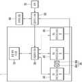
제1 마이크로그리드 셀(300)은 UPS 구조를 갖춘 제1 ESS(360)와 제1 ESS(360)에 의해 전력 상태가 관리되는 제1 부하(350)를 포함할 수 있다.The first
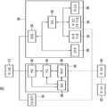
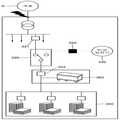
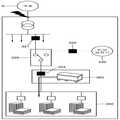
구체적으로, 도 2 및 도 3을 참조하면, 제1 마이크로그리드 셀(300)은 제1 EMS(310), 제1 센서(320), 비상 발전기(330), 제1 ESS(360), 건물 관련 전력 시스템(390), 제1 부하(350)를 포함할 수 있다.2 and 3, the first
참고로, 제1 마이크로그리드 셀(300)은 비상 발전기(330)를 포함하지 않을 수도 있다. 이 경우, 계통의 정전 또는 복전시, UPS 구조를 갖춘 제1 ESS(360)가 무정전으로 제1 부하(350)에 전력을 공급할 수 있다.For reference, the first
다만, 설명의 편의를 위해, 본 발명에서는, 제1 마이크로그리드 셀(300)이 비상 발전기(330)를 포함하는 것을 예로 들어 설명하기로 한다.However, for convenience of explanation, it is assumed that the first
제1 EMS(310)는 비상 발전기(330) 및 제1 ESS(360)를 제어할 수 있다.The
구체적으로, 제1 EMS(310)는 제1 마이크로그리드 셀(300) 내에 포함된 구성 요소(즉, 제1 센서(320), 비상 발전기(330), 제1 ESS(360), 건물 관련 전력 시스템(390), 제1 부하(350))를 모두 관리하는 역할을 수행할 수 있다.Specifically, the
또한 제1 EMS(310)는 미들웨어 서버(200)와 통신할 수 있는바, 제1 마이크로그리드 셀(300)의 전력 관련 데이터를 미들웨어 서버(200)로 송신하거나 미들웨어 서버(200)로부터 통합 제어 시스템(100)의 제어 신호 또는 명령을 제공받을 수도 있다.The
참고로, 제1 EMS(310)는 PMS(362; Power Management System)로부터 제공받은 배터리(366)에 관한 데이터에 기초하여 배터리(366)의 유지 및 보수에 관한 정보를 생성하고, 생성된 배터리(366)의 유지 및 보수에 관한 정보를 PMS(362)를 통해 배터리(366)를 관리하는 BMS(368; Battery Management System)로 제공할 수도 있다.For reference, the
제1 센서(320)는 제1 부하(350)의 전력 상태를 감지할 수 있다.The
구체적으로, 제1 센서(320)는 예를 들어, 통신 기능이 구비된 IoT 센서일 수 있고, 제1 부하(350)의 전력 상태(예를 들어, 전력 부족 여부, 전력 과잉 여부 등)를 감지하여 클라우드 서버(600)로 감지된 정보를 제공할 수 있다.Specifically, the
비상 발전기(330)는 계통 정전시 제1 EMS(310)에 의해 구동될 수 있다.
구체적으로, 비상 발전기(330)는 예를 들어, 디젤 발전기일 수 있고, 제1 ESS(360)와 연동되어 구동됨으로써 계통 정전시 제1 마이크로그리드 셀(300)의 무정전 독립 운전이 특정 시간(예를 들어, 4시간)동안 유지되도록 할 수 있다.In particular, the
참고로, 비상 발전기(330)로 기존의 디젤 발전기를 활용하고, 제1 ESS(360)로 소용량 ESS를 사용함으로써, 초기 투자비용을 절감할 수 있다. 또한 비상 발전기(330)를 통해 장시간 또는 무제한 독립 운전이 가능한바, 전력 수급의 신뢰성을 확보할 수 있고, 계획적인 독립 운전을 가능하게 함으로써 피크 부하 절감을 통해 경제성도 확보할 수 있다.For reference, the initial investment cost can be reduced by utilizing the existing diesel generator as the
제1 ESS(360)는 UPS 구조를 갖출 수 있고, 계통 정전 등의 사고시를 대비하여 무순단 독립 운전이 가능하도록 설계됨으로써 신뢰성 있는 전력 공급을 가능하게 한다.The
구체적으로, 제1 ESS(360)는 UPS 구조를 토대로 계통 정전 또는 복전시 무정전으로 제1 부하(350)에 전력을 공급할 수 있고, 제1 부하(350)의 전력 상태를 관리할 수 있다.Specifically, the
여기에서, 제1 ESS(360)는 PMS(362), PCS(364), 배터리(366), BMS(368)를 포함할 수 있다.Here, the
PCS(364)는 분산 전원 시스템(미도시; 예를 들어, 태양광 또는 풍력과 같은 신재생 에너지 시스템)에서 발전된 전력을 배터리(366)에 저장하거나 계통, 제1 부하(350)로 전달할 수 있다. 또한 PCS(364)는 배터리(366)에 저장된 전력을 계통 또는 제1 부하(350)로 전달할 수 있다. PCS(364)는 계통에서 공급된 전력을 배터리(366)에 저장할 수도 있다.The
또한 PCS(364)는 배터리(366)의 충전 상태(State of Charge, 이하 "SOC 레벨"이라 한다)를 기초로 배터리(366)의 충전 및 방전을 제어할 수 있다.The
참고로, PCS(364)는 전력 시장의 전력 가격, 분산 전원 시스템의 발전 계획, 발전량 및 계통의 전력 수요 등을 기초로 제1 ESS(360)의 동작에 대한 스케줄을 생성할 수 있다.For reference, the
배터리(366)는 PCS(364)에 의해 충전 또는 방전될 수 있다.The battery 366 may be charged or discharged by the
구체적으로, 배터리(366)는 분산 전원 시스템 및 계통의 전력 중 하나 이상을 공급받아 저장할 수 있고, 저장된 전력을 계통, 제1 부하(350) 중 하나 이상에 공급할 수 있다. 이러한 배터리(366)는 적어도 하나 이상의 배터리 셀로 이루어질 수 있으며, 각 배터리 셀은 복수의 베어셀을 포함할 수 있다.Specifically, the battery 366 may receive and store one or more of the distributed power system and the power of the system, and may supply the stored power to one or more of the
BMS(368)는 배터리(366)의 상태를 모니터링하고, 배터리(366)의 충전 및 방전 동작을 제어할 수 있다. 또한 BMS(368)는 배터리(366)의 충전 상태인 SOC 레벨을 포함한 배터리(366)의 상태를 모니터링 할 수 있고, 모니터링된 배터리(366)의 상태(예를 들어, 전압, 전류, 온도, 잔여 전력량, 수명, 충전 상태 등) 정보를 PCS(364)에 제공할 수 있다.The
또한 BMS(368)는 배터리(366)를 보호하기 위한 보호 동작을 수행할 수 있다. 예를 들어, BMS(368)는 배터리(366)에 대한 과충전 보호 기능, 과방전 보호 기능, 과전류 보호 기능, 과전압 보호 기능, 과열 보호 기능, 셀 밸런싱 기능 중 하나 이상을 수행할 수 있다.The
또한 BMS(368)는 배터리(366)의 SOC 레벨을 조절할 수 있다.The
구체적으로, BMS(368)는 PCS(364)로부터 제어 신호를 수신하고, 수신된 신호를 토대로 배터리(366)의 SOC 레벨을 조절할 수 있다.Specifically, the
PMS(362)는 BMS(368)로부터 제공받은 배터리(366)와 관련된 데이터에 기초하여 PCS(364)를 제어할 수 있다.The
구체적으로, PMS(362)는 배터리(366)의 상태를 모니터링하고, PCS(364)의 상태를 모니터링할 수 있다. 즉, PMS(362)는 BMS(368)로부터 수신한 배터리(366)와 관련된 데이터에 기초하여 PCS(364)를 그 효율에 따라 제어할 수 있다.In particular, the
또한 PMS(362)는 BMS(368)를 통해 배터리(366)의 상태를 모니터링하여 수집한 배터리(366) 관련 데이터를 제1 EMS(310)에 제공할 수 있다.The
건물 관련 전력 시스템(390)은 BEMS(392), 분전반(398), BAS(393), 냉난방 시스템(394), 제1 분산 전원 시스템(395), 제3 ESS(396)를 포함할 수 있다.The building related
구체적으로, BEMS(392)는 BAS(393)를 통해 냉난방 시스템(394), 제1 분산 전원 시스템(395) 및, 제3 ESS(396) 중 적어도 하나를 제어하여 피크 부하를 절감할 수 있고, 분전반(398)도 제어 가능하다.Specifically, the
또한 분전반(398)과 BAS(393)는 BEMS(392)와의 통신을 통해 제어될 수 있고, 냉난방 시스템(394), 제1 분산 전원 시스템(395), 제3 ESS(396)는 BAS(393)와 연결됨으로써 BEMS(392)에 의해 제어될 수 있다.The
이러한 건물 관련 전력 시스템(390)은 에너지 절감을 위해 최적 제어됨으로써, 에너지 비용 및 피크 부하를 절감할 수 있다.This building-related
제1 부하(350)는 제1 ESS(360)에 의해 전력 상태가 관리될 수 있고, 예를 들어, 가정, 대형 건물, 공장 등을 포함할 수 있다.The
구체적으로, 제1 부하(350)는 제1 ESS(360), 비상 발전기(330) 및, 건물 관련 전력 시스템(390) 중 적어도 하나에 의해 전력 수급이 관리될 수 있고, 제1 센서(320)와 연결될 수 있다.Specifically, the
참고로, 제1 부하(350)는 무정전의 고품질 전력 공급이 필요한 중요 부하(예를 들어, 연구실 건물, 병원 등)일 수 있다.For reference, the
이에 따라, 통합 제어 시스템(100)의 전력 융통 작업 수행시, 제1 부하(350)의 전력 융통 우선순위는 제2 부하(450) 및 제3 부하(550) 각각의 전력 융통 우선순위보다 높을 수 있다.Accordingly, in performing the power-up operation of the
제2 마이크로그리드 셀(400)은 제2 부하(450)와 제2 부하(450)의 전력 상태를 관리하는 제2 ESS(460)를 포함할 수 있다.The second
구체적으로, 제2 마이크로그리드 셀(400)은 제2 EMS(410), 제2 센서(420), 제2 부하(450), 제2 ESS(460)를 포함할 수 있다.Specifically, the second
참고로, 도면에 도시되어 있지는 않지만, 제2 마이크로그리드 셀(400)은 제2 ESS(460)와 연계되어 구동되는 제2 분산 전원 시스템(미도시; 예를 들어, 풍력 또는 태양광과 같은 신재생 에너지 시스템)을 더 포함할 수 있다.For reference, although not shown, the second
제2 EMS(410)는 제2 ESS(460) 및 제2 분산 전원 시스템을 제어할 수 있다.The
구체적으로, 제2 EMS(410)는 제2 마이크로그리드 셀(400) 내에 포함된 구성 요소(즉, 제2 센서(420), 제2 부하(450), 제2 ESS(460), 제2 분산 전원 시스템)를 모두 관리하는 역할을 수행할 수 있다.Specifically, the
또한 제2 EMS(410)는 미들웨어 서버(200)와 통신할 수 있는바, 제2 마이크로그리드 셀(400)의 전력 관련 데이터를 미들웨어 서버(200)로 송신하거나 미들웨어 서버(200)로부터 통합 제어 시스템(100)의 제어 신호 또는 명령을 제공받을 수도 있다.The
제2 센서(420)는 제2 부하(450)의 전력 상태를 감지할 수 있다.The second sensor 420 may sense the power state of the
구체적으로, 제2 센서(420)는 예를 들어, 통신 기능이 구비된 IoT 센서일 수 있고, 제2 부하(450)의 전력 상태(예를 들어, 전력 부족 여부, 전력 과잉 여부 등)를 감지하여 클라우드 서버(600)로 감지된 정보를 제공할 수 있다.Specifically, the second sensor 420 may be, for example, an IoT sensor equipped with a communication function and may sense the power state of the second load 450 (e.g., whether power is low, whether power is excessive, etc.) And provide the sensed information to the
제2 부하(450)는 제2 ESS(460)에 의해 전력 상태가 관리될 수 있고, 예를 들어, 가정, 대형 건물, 공장 등을 포함할 수 있다.The
구체적으로, 제2 부하(450)는 제2 ESS(460)에 의해 전력 수급이 관리될 수 있고, 제2 센서(420)와 연결될 수 있다.Specifically, the
참고로, 제2 부하(450)는 제2 분산 전원 시스템과 연계를 통해 에너지 효율화가 필요한 일반 부하(예를 들어, 강의실 건물, 기숙사 등)일 수 있다.For reference, the
또한 제2 부하(450)는 서로 다른 우선 순위를 가지는 적어도 하나 이상의 부하(450a~450c)를 포함할 수 있다.Also, the
따라서, 피크 제어 또는 계통 정전 등으로 인해 제2 마이크로그리드 셀(400) 내 전력이 부족해지게 되어, 제1 마이크로그리드 셀(300)로부터 전력을 제공받게 되면, 제2 부하(450) 중 우선 순위가 높은 부하부터 선별되어 전력을 공급받을 수 있다.Accordingly, when power is supplied from the first
즉, 제2 부하(450) 중 우선 순위가 높은 부하(예를 들어, 450a)는 피크 제어 또는 계통 정전 발생시 제1 마이크로그리드 셀(300)로부터 전력을 융통받아 구동될 수 있지만, 우선 순위가 낮은 부하(예를 들어, 450b, 또는 450c)는 피크 제어 또는 계통 정전 발생시, 전력을 융통받지 못할 수도 있다.In other words, a load with a high priority (for example, 450a) of the
정리하자면, 제2 마이크로그리드 셀(400)에는 피크 제어 또는 계통 정전 등의 이벤트 발생시 특성 또는 우선 순위를 토대로 선별적으로 구동될 필요가 있는 부하들이 포함될 수 있다.To summarize, the second
제2 ESS(460)는 제2 부하(450)의 전력 상태를 관리하고, 피크 제어 기능을 수행할 수 있다.The
또한, 제2 ESS(460)는 전술한 제1 ESS(360)와 같이, PMS, 배터리, BMS, PCS를 포함할 수 있지만, 이에 대한 구체적인 설명은 생략하도록 한다.Also, the
참고로, 제2 마이크로그리드 셀(400)과 제1 마이크로그리드 셀(300)은 컨버터(380)를 통해 연결되어 상호간 전력이 융통될 수 있다.For reference, the second
구체적으로, 컨버터(380)는 서로 직렬 연결된 AC-DC 컨버터(380a) 및 DC-AC 컨버터(380b)를 포함할 수 있다.Specifically, the
여기에서, AC-DC 컨버터(380a) 및 DC-AC 컨버터(380b)는 제1 마이크로그리드 셀(300)에서 제2 마이크로그리드 셀(400) 측으로 전력이 제공되는 것을 기준으로 각 컨버터의 명칭을 정의하였다. 즉, 제2 마이크로그리드 셀(400)에서 제1 마이크로그리드 셀(300) 측으로 전력이 제공되는 것을 기준으로 보면, DC-AC 컨버터(380b)는 AC-DC 컨버터가 되고, AC-DC 컨버터(380a)는 DC-AC 컨버터가 될 수 있다.Here, the AC-
다만, 설명의 편의를 위해, 제1 마이크로그리드 셀(300)에서 제2 마이크로그리드 셀(400) 측으로 전력이 제공되는 것을 기준으로 각 컨버터의 명칭을 정의하기로 한다.For convenience of explanation, the name of each converter will be defined on the basis that power is supplied from the first
구체적으로, 예를 들어, 피크 제어 또는 계통 정전으로 인해 제2 마이크로그리드 셀(400)의 전력이 부족한 경우, 제1 마이크로그리드 셀(300)은 AC-DC 컨버터(380a)로 AC 전압을 제공하고, AC-DC 컨버터(380a)는 제1 마이크로그리드 셀(300)로부터 제공받은 AC 전압을 DC 전압으로 변환하여 DC-AC 컨버터(380b)로 제공할 수 있다. 또한 DC-AC 컨버터(380b)는 AC-DC 컨버터(380a)로부터 제공받은 DC 전압을 다시 AC 전압으로 변환하여 제2 마이크로그리드 셀(400)에 제공할 수 있다.Specifically, if the power of the second
물론, 피크 제어 또는 계통 정전으로 인해 제1 마이크로그리드 셀(300)의 전력이 부족한 경우에는, 제2 마이크로그리드 셀(400)은 DC-AC 컨버터(380b)로 AC 전압을 제공하고, DC-AC 컨버터(380b)는 제2 마이크로그리드 셀(400)로부터 제공받은 AC 전압을 DC 전압으로 변환하여 AC-DC 컨버터(380a)로 제공할 수 있다. 또한 AC-DC 컨버터(380a)는 DC-AC 컨버터(380b)로부터 제공받은 DC 전압을 다시 AC 전압으로 변환하여 제1 마이크로그리드 셀(300)에 제공할 수 있다.Of course, if the power of the first
여기에서, 컨버터(380)는 제1 마이크로그리드 셀(300)로부터 여유 전력을 제공받아 제2 마이크로그리드 셀(400)로 전달하는 경우, 제1 마이크로그리드 셀(300)의 여유 전력(즉, 주파수, 전압, 위상각 등)을 제2 마이크로그리드 셀(400)에서 사용되는 전력에 맞게 동기화시킬 수 있다.In this case, when the spare power is received from the first
또한 컨버터(380)는 제2 마이크로그리드 셀(400)로부터 여유 전력을 제공받아 제1 마이크로그리드 셀(300)로 전달하는 경우, 제2 마이크로그리드 셀(400)의 여유 전력(즉, 주파수, 전압, 위상각 등)을 제1 마이크로그리드 셀(300)에서 사용되는 전력에 맞게 동기화시킬 수 있다.In addition, when the spare power is received from the second
이러한 컨버터(380)는 제1 마이크로그리드 셀(300)과 제2 마이크로그리드 셀(400)이 항상 연계되어 전력을 상호간에 융통할 수 있도록 해주며, 특히, 피크 제어시 또는 계통 정전시 상호간에 전력 융통이 가능하게 하는 역할을 한다.The
또한 컨버터(380)는 예를 들어, IGBT(Insulated Gate Bipolar Transistor) 컨버터일 수 있다.The
참고로, AC-DC 컨버터(380a)의 경우, 일단은 제1 ESS(360)와 제1 부하(350) 사이에 연결되고, 타단은 DC-AC 컨버터(380b)의 일단에 연결될 수 있다. 또한 DC-AC 컨버터(380b)의 경우, 일단은 AC-DC 컨버터(380a)의 타단에 연결되고, 타단은 제2 ESS(460)와 제2 부하(450) 사이에 연결될 수 있다.For reference, in the case of the AC-
다만, AC-DC 컨버터(380a) 및 DC-AC 컨버터(380b)의 각 단이 연결되는 위치가 이에 한정되는 것은 아니다.However, the positions where the respective ends of the AC-
또한 상황에 따라, AC-DC 컨버터(380a)와 제1 마이크로그리드 셀(300) 사이 또는 DC-AC 컨버터(380b)와 제2 마이크로그리드 셀(400) 사이에 추가 컨버터가 설치될 수 있다.Further, depending on the circumstances, additional converters may be installed between the AC-
즉, 예를 들어, AC-DC 컨버터(380a)의 일단이 제1 ESS(360)의 배터리(366)에 연결되는 경우, 배터리(366)와 AC-DC 컨버터(380a) 사이에는 DC-DC 컨버터(미도시) 및 DC-AC 컨버터(미도시)가 추가로 장착되거나 DC-AC 컨버터(미도시)만 추가로 설치될 수 있다.That is, for example, when one end of the AC-
이 경우, 배터리(366)의 DC 전압이 DC-DC 컨버터를 통해 DC-AC 컨버터로 전달되고, DC-AC 컨버터는 DC-DC 컨버터를 통해 전달받은 DC 전압을 AC 전압으로 변환하여 AC-DC 컨버터(380a)로 제공할 수 있다.In this case, the DC voltage of the battery 366 is transferred to the DC-AC converter through the DC-DC converter, and the DC-AC converter converts the DC voltage received through the DC-DC converter to the AC voltage, (380a).
또는 배터리(366)의 DC 전압이 DC-AC 컨버터로 전달되고, DC-AC 컨버터는 전달받은 DC 전압을 AC 전압으로 변환하여 AC-DC 컨버터(380a)로 제공할 수 있다.Or the DC voltage of the battery 366 is transferred to the DC-AC converter, and the DC-AC converter can convert the received DC voltage into an AC voltage and provide it to the AC-
또한 예를 들어, DC-AC 컨버터(380b)의 타단이 제2 ESS(460)의 배터리(미도시)에 연결되는 경우, DC-AC 컨버터(380b)와 배터리 사이에는 AC-DC 컨버터(미도시) 및 DC-DC 컨버터(미도시)가 추가로 장착되거나 AC-DC 컨버터(미도시)만 추가로 설치될 수 있다.Also, for example, when the other end of the DC-
이 경우, DC-AC 컨버터(380b)의 AC 전압이 AC-DC 컨버터로 전달되고, AC-DC 컨버터는 전달받은 AC 전압을 DC 전압으로 변환하여 DC-DC 컨버터를 통해 제2 ESS(460)의 배터리로 제공할 수 있다.In this case, the AC voltage of the DC-
또는 DC-AC 컨버터(380b)의 AC 전압이 AC-DC 컨버터로 전달되고, AC-DC 컨버터는 전달받은 AC 전압을 DC 전압으로 변환하여 제2 ESS(460)의 배터리로 제공할 수 있다.Alternatively, the AC voltage of the DC-
제3 마이크로그리드 셀(500)은 제3 부하(550)를 포함할 수 있다.The third
구체적으로, 제3 마이크로그리드 셀(500)은 제3 센서(520)와 제3 부하(550)를 포함할 수 있다.In particular, the third
참고로, 제3 마이크로그리드 셀(500)에는 제2 마이크로그리드 셀(400)과 달리, EMS, ESS 또는 분산 전원 시스템이 없을 수 있다. 이에 따라, 제3 마이크로그리드 셀(500)의 전력 수급 상태는 클라우드 서버(600)를 통해 미들웨어 서버(200)로 전달될 수 있다.For reference, unlike the second
물론, 제3 마이크로그리드 셀(500)의 제3 센서(520)가 미들웨어 서버(200)와 통신함으로써 직접 제3 부하(550)의 전력 상태를 미들웨어 서버(200)로 송신할 수도 있다.Of course, the
제3 센서(520)는 제3 부하(550)의 전력 상태를 감지할 수 있다.The
구체적으로, 제3 센서(520)는 예를 들어, 통신 기능이 구비된 IoT 센서일 수 있고, 제3 부하(550)의 전력 상태(예를 들어, 전력 부족 여부, 전력 과잉 여부 등)를 감지하여 클라우드 서버(600)로 감지된 정보를 제공할 수 있다.Specifically, the
제3 부하(550)는 예를 들어, 가정, 대형 건물, 공장 등을 포함할 수 있다.The
구체적으로, 제3 부하(550)는 제3 센서(520)와 연결될 수 있다.Specifically, the
참고로, 제3 부하(550)는 분산 전원 시스템과의 연계가 없는 일반 부하일 수 있고, 제3 센서(520)를 통한 분석 기반의 에너지 저감 서비스(예를 들어, 클라우드 서버(600)로 제3 부하(550)의 전력 상태 정보를 송신함으로써 사용자가 클라우드 서버(600)와 통신할 수 있는 모바일 단말(800)을 통해 제3 부하(550)의 전력 상태를 실시간으로 확인 가능)를 제공하는 것을 목적으로 할 수 있다.The
이하에서는, 도 4 내지 도 11을 참조하여, 계통 정전시 도 3의 제1 마이크로그리드 셀의 독립 운전 방법의 일 예를 설명하도록 한다.Hereinafter, an example of the independent operation method of the first micro grid cell of Fig. 3 during system power failure will be described with reference to Figs. 4 to 11. Fig.
도 4 내지 도 11은 계통 정전시 도 3의 제1 마이크로그리드 셀의 독립 운전 방법의 일 예를 설명하는 개략도들이다.FIGS. 4 to 11 are schematic diagrams illustrating an example of the independent operation method of the first micro grid cell of FIG. 3 during system power failure.
참고로, 설명의 편의를 위해, 도 3에 도시되지 않은 일부 구성 요소를 도 4 내지 도 11의 제1 마이크로그리드 셀(300)에 추가하거나 도 3에 도시된 일부 구성 요소를 도 4 내지 도 11의 제1 마이크로그리드 셀(300)에서 생략하고 설명하도록 한다.For reference, some components not shown in FIG. 3 are added to the first
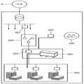
먼저, 도 3 내지 도 6을 참조하면, 계통(G) 정전시, STS(324; Static Transfer Switch)는 계통(G) 정전을 감지하여 계통(G)과의 연결을 차단하고, 제1 ESS(360)는 구동 모드를 정전력 모드에서 CVCF(Constant Voltage Constant Frequency) 모드로 변경하여 제1 부하(350)에 독립적으로 전력을 공급할 수 있다.3 to 6, the STS 324 (Static Transfer Switch) detects a power failure of the system G and interrupts the connection with the system G when a power failure occurs in the system G, 360 can supply power to the
구체적으로, STS(324)는 계통(G)과 제1 ESS(360)간 연결 및 계통(G)과 제1 부하(350) 간 연결을 개폐할 수 있다.Specifically, the
또한 STS(324)는 예를 들어, 계통(G) 정전시 4ms의 시간 내에 계통(G) 정전을 감지하여 계통(G)과의 연결을 차단할 수 있다.In addition, the
또한 제1 ESS(360)는 계통(G) 정전시, 10ms 이내에 CVCF 모드로 구동 모드를 변경 후 제1 부하(350)에 안정적으로 전력을 공급(즉, 제1 ESS(360)의 무순단 독립 운전)할 수 있다.The
이 때 계통(G) 측에 설치된 차단기(321) 역시 계통(G)과의 연결을 차단할 수 있다.At this time, the
이어서, 도 3, 도 7 및 도 8을 참조하면, 제1 EMS(310)는 제1 ESS(360)가 CVCF 모드로 변경되어 제1 부하(350)에 독립적으로 전력을 공급하면 비상 발전기(330)를 구동시키고, 제1 EMS(310)에 의해 구동된 비상 발전기(330)는 제1 부하(350) 측으로 전력을 공급할 수 있다.3, 7, and 8, when the
이 때, 비상 발전기(330) 측에 설치된 차단기(322)는 비상 발전기(330)의 연결을 활성화시키지만, STS(324)로 인해 비상 발전기(330)와 제1 부하(350) 간 연결은 차단될 수 있다. 이에 따라, 비상 발전기(330)는 무부하 운전을 하게 된다.At this time, the
STS(324)는 비상 발전기(330)에 의해 공급되는 전력이 감지되면 제1 ESS(360)에 제1 알림을 제공하고, 제1 ESS(360)는 STS(324)로부터 제1 알림을 제공받으면, 제1 동기화 알고리즘을 수행할 수 있다.The
참고로, 제1 동기화 알고리즘은 제1 ESS(360)의 주파수, 전압 및 위상각을 비상 발전기(330)의 주파수, 전압 및 위상각과 동기화시키기 위한 알고리즘일 수 있다.The first synchronization algorithm may be an algorithm for synchronizing the frequency, voltage, and phase angle of the
제1 ESS(360)의 제1 동기화 알고리즘이 수행되면, STS(324)는 계통(G)과의 연결 차단을 해제하고, 비상 발전기(330)는 주파수 추종 모드로 구동되고, 제1 ESS(360)는 정전력 모드로 다시 변경되어 구동될 수 있다.When the first synchronization algorithm of the
이에 따라, 제1 부하(350)는 계통(G)이 복전되기 전까지 비상 발전기(330) 및 제1 ESS(360)로부터 안정적으로 전력을 공급받을 수 있다.Accordingly, the
이어서, 도 3, 도 9 내지 도 11을 참조하면, 계통(G) 복전시, 제1 EMS(310)는 비상 발전기(330)의 구동을 정지시킬 수 있다.3, 9 to 11, the
이 때, 비상 발전기(330) 측에 설치된 차단기(322)는 비상 발전기(330)의 연결을 차단하게 된다.At this time, the
STS(324)는 비상 발전기(330)의 구동 정지를 감지하여 제1 ESS(360)에 제2 알림을 제공하고, 계통(G)과의 연결을 다시 차단할 수 있다.The
제1 ESS(360)는 STS(324)로부터 제2 알림을 제공받으면, 정전력 모드에서 CVCF 모드로 변경하여 제1 부하(350)에 독립적으로 전력을 공급할 수 있다.When the
계통(G) 측에 설치된 차단기(321)가 다시 활성화되어 계통(G)으로부터 제1 부하(350) 측으로 전력이 공급되면, STS(324)는 계통(G)에 의해 공급되는 전력을 감지하여 제1 ESS(360)에 제3 알림을 제공할 수 있다.The
제1 ESS(360)는 STS(324)로부터 제3 알림을 제공받으면, 제2 동기화 알고리즘을 수행하게 되고, 제1 ESS(360)가 제2 동기화 알고리즘을 수행하면, STS(324)는 계통(G)과의 연결 차단을 다시 해제할 수 있다.When the
여기에서, 제2 동기화 알고리즘은 제1 ESS(360)의 주파수, 전압 및 위상각을 계통(G)의 주파수, 전압 및 위상각과 동기화시키기 위한 알고리즘일 수 있다.Here, the second synchronization algorithm may be an algorithm for synchronizing the frequency, voltage, and phase angle of the
또한 STS(324)가 계통(G)과의 연결 차단을 다시 해제함으로써, 계통(G) 정전 전의 상태로 다시 정상 복구될 수 있다.In addition, the
전술한 과정을 통해 계통(G) 정전시, 본 발명의 제1 마이크로그리드 셀(300)은 독립 운전을 할 수 있다.During the power failure of the system G, the first
또한 전술한 제1 마이크로그리드 셀(300)의 독립 운전은 소용량 배터리(제1 ESS(360) 내 배터리(366))로 무순단 독립운전을 구현함으로써 비용을 절감할 수 있을 뿐만 아니라 비상 발전기(330)와 제1 ESS(360)의 병렬 운전을 통해 장시간(예를 들어, 4시간 이상) 독립운전이 가능하다.In addition, the independent operation of the first
이하에서는, 도 12 내지 도 21을 참조하여, 계통 정전시 도 3의 제1 마이크로그리드 셀의 독립 운전 방법의 다른 예를 설명하도록 한다.Hereinafter, another example of the independent operation method of the first micro grid cell of Fig. 3 during system power failure will be described with reference to Figs. 12 to 21. Fig.
도 12 내지 도 21은 계통 정전시 도 3의 제1 마이크로그리드 셀의 독립 운전 방법의 다른 예를 설명하는 개략도들이다.FIGS. 12 to 21 are schematic views for explaining another example of the independent operation method of the first micro grid cell of FIG. 3 during system power failure.
참고로, 설명의 편의를 위해, 도 3에 도시되지 않은 일부 구성 요소를 도 12 내지 도 21의 제1 마이크로그리드 셀(300)에 추가하거나 도 3에 도시된 일부 구성 요소를 도 12 내지 도 21의 제1 마이크로그리드 셀(300)에서 생략하고 설명하도록 한다.For reference, some components not shown in Fig. 3 are added to the first
먼저, 도 3, 도 12 내지 도 14를 참조하면, 계통(G) 정전시, STS(324; Static Transfer Switch)는 계통(G) 정전을 감지하여 계통(G)과의 연결을 차단하고, 제1 ESS(360)는 구동 모드를 정전력 모드에서 CVCF(Constant Voltage Constant Frequency) 모드로 변경하여 제1 부하(350)에 독립적으로 전력을 공급할 수 있다.Referring to FIGS. 3 and 12 to 14, at the time of power failure of the system G, the STS 324 (Static Transfer Switch) senses the power failure of the system G to block the connection with the system G, 1
구체적으로, STS(324)는 계통(G)과 제1 ESS(360)간 연결 및 계통(G)과 제1 부하(350) 간 연결을 개폐할 수 있다.Specifically, the
또한 STS(324)는 예를 들어, 계통(G) 정전시 4ms의 시간 내에 계통(G) 정전을 감지하여 계통(G)과의 연결을 차단할 수 있다.In addition, the
또한 제1 ESS(360)는 계통(G) 정전시, 10ms 이내에 CVCF 모드로 구동 모드를 변경 후 제1 부하(350)에 안정적으로 전력을 공급(즉, 제1 ESS(360)의 무순단 독립 운전)할 수 있다.The
이 때 계통(G) 측에 설치된 차단기(321) 역시 계통(G)과의 연결을 차단할 수 있다.At this time, the
이어서, 도 3, 도 15 내지 도 17을 참조하면, 제1 EMS(310)는 제1 ESS(360)가 CVCF 모드로 변경되어 제1 부하(350)에 독립적으로 전력을 공급하면 비상 발전기(330)를 구동시킬 수 있다.3, 15 to 17, when the
또한 비상 발전기(330)가 구동되면, CTTS(326; Closed Transition Transfer Switch)는 비상 발전기(330)와 계통(G) 간 연결을 차단하면서 비상 발전기(330)를 STS(324)와 연결시킬 수 있고, 비상 발전기(330)는 제1 부하(350) 측으로 전력을 공급할 수 있다.In addition, when the
구체적으로, CTTS(326)는 계통(G)과 STS(324) 간 연결 및 계통(G)과 비상 발전기(330) 간 연결을 개폐할 수 있다. 즉, CTTS(326)는 무정전으로 계통(G)에서 비상 발전기(330)로의 절체 작업 또는 비상 발전기(330)에서 계통(G)으로의 절체 작업을 가능하게 한다.The
이 때, 비상 발전기(330) 측에 설치된 차단기(322)는 비상 발전기(330)의 연결을 활성화시키지만, STS(324)로 인해 비상 발전기(330)와 제1 부하(350) 간 연결은 차단될 수 있다. 이에 따라, 비상 발전기(330)는 무부하 운전을 하게 된다.At this time, the
STS(324)는 비상 발전기(330)에 의해 공급되는 전력이 감지되면 제1 ESS(360)에 제1 알림을 제공하고, 제1 ESS(360)는 STS(324)로부터 제1 알림을 제공받으면, 제1 동기화 알고리즘을 수행할 수 있다.The
참고로, 제1 동기화 알고리즘은 제1 ESS(360)의 주파수, 전압 및 위상각을 비상 발전기(330)의 주파수, 전압 및 위상각과 동기화시키기 위한 알고리즘일 수 있다.The first synchronization algorithm may be an algorithm for synchronizing the frequency, voltage, and phase angle of the
제1 ESS(360)의 제1 동기화 알고리즘이 수행되면, STS(324)는 계통(G)과의 연결 차단을 해제하고, 비상 발전기(330)는 주파수 추종 모드로 구동되고, 제1 ESS(360)는 정전력 모드로 다시 변경되어 구동될 수 있다.When the first synchronization algorithm of the
이에 따라, 제1 부하(350)는 계통(G)이 복전되기 전까지 비상 발전기(330) 및 제1 ESS(360)로부터 안정적으로 전력을 공급받을 수 있다.Accordingly, the
이어서, 도 3, 도 18 및 도 19를 참조하면, 계통(G) 복전시, 계통(G) 측에 설치된 차단기(321)는 활성화될 수 있다.3, 18, and 19, the
또한 제1 EMS(310)는 계통(G) 복전시, 비상 발전기(330)의 구동을 정지시킬 수 있고, CTTS(326)는 비상 발전기(330)의 구동 정지를 감지하여 비상 발전기(330)와 STS(324) 간 연결을 차단하면서 STS(324)를 계통(G)과 연결시킬 수 있다.The
이 때, 비상 발전기(330) 측에 설치된 차단기(322)는 비상 발전기(330)의 연결을 차단하게 된다.At this time, the
STS(324)가 계통(G)과 연결되면, CTTS(326)는 CTTS용 동기화 알고리즘을 수행함으로써 계통(G)으로부터 제공받는 전력을 제1 ESS(360)의 전력과 동기화시킬 수 있다.When the
여기에서, CTTS용 동기화 알고리즘은 제1 ESS의 주파수, 전압 및 위상각을 계통의 주파수, 전압 및 위상각과 동기화시키기 위한 알고리즘일 수 있다.Here, the synchronization algorithm for the CTTS may be an algorithm for synchronizing the frequency, voltage and phase angles of the first ESS with the frequency, voltage and phase angles of the system.
또한 STS(324)가 계통(G)과 연결되고, 계통(G)으로부터 제공받는 전력과 제1 ESS(360)의 전력이 동기화됨으로써, 계통(G) 정전 전의 상태로 다시 정상 복구될 수 있다.The
반면에, 도 3, 도 18, 도 20 및 도 21을 참조하면, 도 18 및 도 19와 다른 과정을 통해서 계통(G)과 재연계될 수 있다.3, 18, 20 and 21, it can be re-connected to the system G through a process different from that of FIGS. 18 and 19.
구체적으로, 계통(G) 복전시, 계통(G) 측에 설치된 차단기(321)는 활성화될 수 있다.Specifically, the
또한 제1 EMS(310)는 비상 발전기(330)의 구동을 정지시키고, STS(324)는 비상 발전기(330)의 구동 정지를 감지하여 제1 ESS(360)에 제2 알림을 제공하고, 계통(G)과의 연결을 다시 차단할 수 있다.The
여기에서, 비상 발전기(330)의 구동이 정지되면, 비상 발전기(330) 측에 설치된 차단기(322)는 비상 발전기(330)의 연결을 차단하게 된다.Here, when the driving of the
제1 ESS(360)는 STS(324)로부터 제2 알림을 제공받으면, 정전력 모드에서 CVCF 모드로 변경하여 제1 부하(350)에 독립적으로 전력을 공급할 수 있다.When the
여기에서, 제1 ESS(360)가 CVCF 모드로 변경되면, CTTS(326)는 비상 발전기(330)와 STS(324) 간 연결을 차단하면서 STS(324)를 계통(G)과 연결시킬 수 있다.Here, when the
계통(G)으로부터 제1 부하(350) 측으로 전력이 공급되면, STS(324)는 계통(G)에 의해 공급되는 전력을 감지하여 제1 ESS(360)에 제3 알림을 제공하고, 제1 ESS(360)는 STS(324)로부터 제3 알림을 제공받으면, 제2 동기화 알고리즘을 수행할 수 있다.When power is supplied from the system G to the
제1 ESS(360)가 제2 동기화 알고리즘을 수행하면, STS(324)는 계통(G)과의 연결 차단을 다시 해제하고, 계통(G)과의 연결 차단이 다시 해제되면, 제1 ESS(360)는 CVCF 모드에서 정전력 모드로 다시 변경될 수 있다.When the
참고로, 제2 동기화 알고리즘은 제1 ESS(360)의 주파수, 전압 및 위상각을 계통(G)의 주파수, 전압 및 위상각과 동기화시키기 위한 알고리즘일 수 있다.For reference, the second synchronization algorithm may be an algorithm for synchronizing the frequency, voltage, and phase angle of the
또한 STS(324)가 계통(G)과의 연결 차단을 다시 해제함으로써, 계통(G) 정전 전의 상태로 다시 정상 복구될 수 있다.In addition, the
이하에서는, 도 22를 참조하여, 도 1의 계층형 전력 제어 시스템의 전력 융통 방법을 설명하도록 한다.Hereinafter, with reference to FIG. 22, a power-up method of the hierarchical power control system of FIG. 1 will be described.
도 22는 도 1의 계층형 전력 제어 시스템의 전력 융통 방법을 설명하는 순서도이다.FIG. 22 is a flowchart for explaining a power-up method of the hierarchical power control system of FIG. 1;
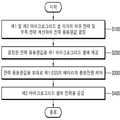
도 1 내지 도 3 및 도 22를 참조하면, 먼저, 제1 마이크로그리드 셀 및 제2 마이크로그리드 셀 각각의 여유 전력 및 부족 전력을 계산하여 전력 융통량값을 결정한다(S100).Referring to FIGS. 1 to 3 and FIG. 22, first, power margin values of the first micro grid cell and the second micro grid cell are calculated to determine a power fitness value (S100).
구체적으로, 계통 정전시에는, 제1 마이크로그리드 셀(300) 및 제2 마이크로그리드 셀(400) 각각의 여유 전력 및 부족 전력을 계산하기에 앞서, 다음과 같은 과정을 우선적으로 수행할 수 있다.Specifically, in the systematic power failure, the following steps may be performed prior to calculating the redundant power and the insufficient power of the first
먼저, 계통 정전 여부를 감지할 수 있다. 이 때, 계통(미도시) 정전 여부는 통합 제어 시스템(100)에서 감지되어 미들웨어 서버(200)를 통해 제1 내지 제3 마이크로그리드 셀(300, 400, 500)로 계통 정전 사실이 통지될 수도 있고, 제1 내지 제3 마이크로그리드 셀(300, 400, 500) 각각에서 직접 감지할 수도 있다.First, it can detect the power failure of the system. At this time, the power failure of the grid (not shown) may be detected by the
계통 정전 사실이 감지되면, 제1 마이크로그리드 셀(300)의 독립 운전을 개시할 수 있다.When the system power failure is detected, independent operation of the first
구체적으로, 제1 마이크로그리드 셀(300)은 전술한 방법을 통해서 무정전 독립 운전이 가능하다. 즉, 제1 마이크로그리드 셀(300) 내 제1 ESS(360)와 비상 발전기(330)의 연계 구동을 통해 제1 부하(350)에 무정전으로 전력을 공급할 수 있다.Specifically, the first
물론, 제1 마이크로그리드 셀(300) 내에 비상 발전기(330)가 구비되지 않은 경우에는, UPS 구조를 갖춘 제1 ESS(360)가 독립 운전 모드로 구동되어 제1 부하(350)에 무정전으로 전력을 공급할 수 있다.Of course, in the case where the
이와 같이, 제1 마이크로그리드 셀(300)의 독립 운전이 개시되면, 제1 마이크로그리드 셀(300) 및 제2 마이크로그리드 셀(400) 각각의 여유 전력 및 부족 전력을 계산하여 전력 융통량값을 결정할 수 있다.When the independent operation of the first
계통 정전시가 아닌 평상시의 경우, 대표적으로 피크 제어시, 전술한 계통 정전 여부 감지 및 제1 마이크로그리드 셀의 독립 운전 과정 없이 제1 마이크로그리드 셀(300) 및 제2 마이크로그리드 셀(400) 각각의 여유 전력 및 부족 전력을 계산하여 전력 융통량값을 결정할 수 있다.When the system is not in a power failure state but typically during peak control, the first
구체적으로, 제1 마이크로그리드 셀(300) 및 제2 마이크로그리드 셀(400)은 각각 자신의 여유 전력 및 부족 전력 정보를 미들웨어 서버(200)를 통해 통합 제어 시스템(100)에 제공할 수 있다.Specifically, the first
통합 제어 시스템(100)은 미들웨어 서버(200)를 통해 제1 마이크로그리드 셀(300) 및 제2 마이크로그리드 셀(400) 각각의 여유 전력 및 부족 전력 정보를 제공받으면, 제공받은 여유 전력 및 부족 전력을 계산하여 전력 융통량값을 결정할 수 있다.When the
여기에서, 전력 융통량값은 여유 전력이 있는 마이크로그리드 셀에서 전력이 부족한 마이크로그리드 셀로 융통(제공)해줄 수 있는 전력량 값을 의미할 수 있다.Here, the power budget value may mean a power amount value that can be provided (provided) to a micro grid cell having insufficient power in a micro grid cell having a spare power.
참고로, 설명의 편의를 위해, 이하에서는, 제2 마이크로그리드 셀(400)의 전력이 부족하고, 제1 마이크로그리드 셀(300)의 전력이 여유가 있는 상태를 가정하여 설명하도록 한다.For the sake of convenience of description, the following description will be made on the assumption that the power of the second
물론, 이하에서 설명하는 전력 융통 방법의 각 단계는 제1 마이크로그리드 셀(300)의 전력이 부족하고, 제2 마이크로그리드 셀(400)의 전력이 여유가 있는 상태에도 동일하게 적용될 수 있는바, 이에 대한 설명은 생략하도록 한다.Of course, each step of the power-up method described below can be applied equally to a state in which the power of the first
다만, 피크 제어시가 아닌 계통 정전시에는 제1 마이크로그리드 셀(300)이 일정 시간 동안 무정전 독립 운전이 가능한바, 제2 마이크로그리드 셀(400)보다 여유 전력이 있을 가능성이 높다.However, during system power failure, not during peak control, the first
전력 융통량값이 결정되면(S100), 결정된 전력 융통량값을 제1 마이크로그리드 셀(300)에 제공한다(S200).If the power budget value is determined (S100), the determined power budget value is provided to the first micro grid cell 300 (S200).
구체적으로, 통합 제어 시스템(100)은 전력 융통량값을 미들웨어 서버(200)를 통해 제1 마이크로그리드 셀(300) 및 제2 마이크로그리드 셀(400) 중 여유 전력이 있는 마이크로그리드 셀로 제공할 수 있다.Specifically, the
전술한 바와 같이, 제1 마이크로그리드 셀(300)에 여유 전력이 있고, 제2 마이크로그리드 셀(400)은 전력이 부족한 상태라고 가정하면, 통합 제어 시스템(100)은 전력 융통량값을 미들웨어 서버(200)를 통해 여유 전력이 있는 제1 마이크로그리드 셀(300)로 제공할 수 있다.Assuming that there is sufficient power in the first
제1 마이크로그리드 셀에 전력 융통량값이 제공되면(S200), 전력 융통량값을 토대로 제1 ESS(360)의 배터리(366)의 충방전량을 제어한다(S300).If the first micro grid cell is provided with a power availability value (S200), the charge amount of the battery 366 of the
구체적으로, 제1 EMS(310)는 미들웨어 서버(200)로부터 결정된 전력 융통량값을 제공받고, 제공받은 결정된 전력 융통량값을 제1 ESS(360)로 전달할 수 있다.Specifically, the
제1 ESS(360)는 전달받은 전력 융통량값을 토대로 배터리(366)의 충방전량(즉, 충전량 및 방전량 중 적어도 하나 이상)을 제어할 수 있다.The
제1 마이크로그리드 셀(300) 내 배터리(366)의 충방전량이 제어되면(S300), 제2 마이크로그리드 셀(400)에 전력을 공급한다(S400).When the charge / discharge amount of the battery 366 in the first
구체적으로, 제1 ESS(360)는 전달받은 전력 융통량값을 토대로 배터리(366)의 충방전량을 제어한 후 컨버터(380)를 통해 제2 마이크로그리드 셀(400)에 전력을 공급할 수 있다.Specifically, the
또한 통합 제어 시스템(100)은 예를 들어, 전력 융통량값을 결정시, 제1 마이크로그리드 셀(300)의 여유 전력량 및 제2 마이크로그리드 셀(400) 내 제2 부하(450) 중 우선 순위가 높은 부하에서 필요로 하는 부족 전력량을 토대로 전력 융통량값을 결정할 수 있다.In addition, the
따라서, 제1 ESS(360)는 전달받은 전력 융통량값을 토대로 배터리(366)의 충방전량을 제어한 후 컨버터(380)를 통해 제2 부하(450) 중 우선 순위가 높은 부하에 전력을 공급할 수 있다.Accordingly, the
구체적으로, 제1 ESS(360)가 제2 마이크로그리드 셀(400)로 전력을 공급하면, 제2 마이크로그리드 셀(400)의 제2 ESS(460)는 제1 ESS(360)로부터 제공받은 전력을 토대로 제2 부하(450) 중 우선 순위가 높은 부하에 전력을 공급할 수 있다.In detail, when the
물론, 제1 ESS(360)가 제2 마이크로그리드 셀(400)로 공급한 전력이 제2 ESS(460)를 거치지 않고 바로 제2 부하(450) 중 우선 순위가 높은 부하로 공급될 수도 있다.Of course, the power supplied by the
전술한 바와 같이 본 발명에 의하면, 제1 내지 제3 마이크로그리드 셀(300, 400, 500)의 전력 수급 상태를 통합하여 제어하는 통합 제어 시스템(100)을 통해 계통 정전시 마이크로그리드 셀 간 전력 융통을 효율적으로 수행함으로써 전력 수급 문제를 해결할 수 있다.As described above, according to the present invention, through the
전술한 본 발명은, 본 발명이 속하는 기술 분야에서 통상의 지식을 가진 자에게 있어 본 발명의 기술적 사상을 벗어나지 않는 범위 내에서 여러 가지 치환, 변형 및 변경이 가능하므로 전술한 실시예 및 첨부된 도면에 의해 한정되는 것이 아니다.While the present invention has been described in connection with what is presently considered to be practical exemplary embodiments, it is to be understood that the invention is not limited to the disclosed embodiments, but, on the contrary, But the present invention is not limited thereto.
100: 통합 제어 시스템200: 미들웨어 서버
300: 제1 마이크로그리드 셀380: 컨버터
400: 제2 마이크로그리드 셀500: 제3 마이크로그리드 셀
600: 클라우드 서버700: 외부
800: 모바일 단말
100: Integrated control system 200: Middleware server
300: first microgrid cell 380: converter
400: second microgrid cell 500: third microgrid cell
600: Cloud server 700: External
800: mobile terminal
Claims (31)
Translated fromKoreanUPS(Uninterruptible Power Supply) 구조를 갖춘 제1 ESS(Energy Storage System)와 상기 제1 ESS에 의해 전력 상태가 관리되는 제1 부하를 포함하는 제1 마이크로그리드 셀;
제2 부하와 상기 제2 부하의 전력 상태를 관리하는 제2 ESS를 포함하는 제2 마이크로그리드 셀;
제3 부하를 포함하는 제3 마이크로그리드 셀;
상기 제1 내지 제3 마이크로그리드 셀과 통신하는 미들웨어 서버(middleware server); 및
상기 미들웨어 서버와 통신하고, 상기 제1 내지 제3 마이크로그리드 셀의 전력 수급 상태를 통합하여 제어하는 통합 제어 시스템을 포함하되,
상기 제1 마이크로그리드 셀과 상기 제2 마이크로그리드 셀은 컨버터를 통해 연결되어 상호간 전력이 융통되는
계층형 전력 제어 시스템.
A hierarchical power control system associated with a cloud server,
A first micro grid cell including a first ESS (Energy Storage System) having an uninterruptible power supply (UPS) structure and a first load managed by the first ESS;
A second micro grid cell including a second ESS for managing a power state of the second load and the second load;
A third microgrid cell including a third load;
A middleware server communicating with the first through third micro grid cells; And
And an integrated control system that communicates with the middleware server and integrally controls power supply and demand states of the first through third micro grid cells,
The first micro-grid cell and the second micro-grid cell are connected through a converter,
Hierarchical power control system.
상기 제1 마이크로그리드 셀은 상기 제1 부하의 전력 상태를 감지하는 제1 센서를 더 포함하고,
상기 제2 마이크로그리드 셀은 상기 제2 부하의 전력 상태를 감지하는 제2 센서를 더 포함하고,
상기 제3 마이크로그리드 셀은 상기 제3 부하의 전력 상태를 감지하는 제3 센서를 더 포함하되,
상기 제1 내지 제3 센서는 각각 상기 제1 내지 제3 부하의 전력 상태를 감지하여 상기 클라우드 서버로 송신하는
계층형 전력 제어 시스템.
The method according to claim 1,
Wherein the first microgrid cell further comprises a first sensor for sensing a power state of the first load,
Wherein the second microgrid cell further comprises a second sensor for sensing a power state of the second load,
The third micro-grid cell further includes a third sensor for sensing a power state of the third load,
The first to third sensors sense power states of the first to third loads, respectively, and transmit them to the cloud server
Hierarchical power control system.
상기 클라우드 서버는,
외부로부터 기후 데이터 및 전력 관련 데이터 중 적어도 하나를 제공받고,
상기 제1 내지 제3 센서로부터 제공받은 상기 제1 내지 제3 부하의 전력 상태 및 상기 외부로부터 제공받은 상기 기후 데이터 및 전력 관련 데이터 중 적어도 하나를 종합하여 분석하고,
상기 분석 결과를 상기 미들웨어 서버로 제공하는
계층형 전력 제어 시스템.
3. The method of claim 2,
The cloud server includes:
Receiving at least one of weather data and power-related data from outside,
At least one of the power state of the first to third loads provided from the first to third sensors, and at least one of the climate data and the power related data provided from the outside,
And providing the analysis result to the middleware server
Hierarchical power control system.
상기 미들웨어 서버는 상기 제공받은 분석 결과 및 상기 제1 내지 제3 마이크로그리드 셀로부터 각각 제공받은 실시간 전력 상태 정보를 상기 통합 제어 시스템에 제공하고,
상기 통합 제어 시스템은 상기 미들웨어 서버로부터 제공받은 상기 분석 결과 및 상기 제1 내지 제3 마이크로그리드 셀의 실시간 전력 상태 정보를 토대로 상기 제1 내지 제3 마이크로그리드 셀의 전력 수급 상태를 통합하여 제어하는
계층형 전력 제어 시스템.
The method of claim 3,
The middleware server provides the integrated control system with the analysis results and the real-time power status information provided from the first through third micro grid cells, respectively,
Wherein the integrated control system integrates and controls the power supply state of the first to third micro grid cells based on the analysis result provided from the middleware server and the real time power state information of the first to third micro grid cells
Hierarchical power control system.
상기 제1 ESS는 계통의 정전 또는 복전시 상기 제1 부하에 무정전 전력 공급이 가능한
계층형 전력 제어 시스템.
The method according to claim 1,
The first ESS is capable of supplying uninterruptible power to the first load
Hierarchical power control system.
상기 제1 마이크로그리드 셀은,
비상 발전기와,
계통과 상기 제1 ESS 간 연결 및 상기 계통과 상기 제1 부하 간 연결을 개폐하는 STS(Static Transfer Switch)와,
상기 비상 발전기 및 상기 제1 ESS를 제어하는 제1 EMS(Energy Management System)를 더 포함하는
계층형 전력 제어 시스템.
The method according to claim 1,
Wherein the first micro-grid cell comprises:
An emergency generator,
An STS (Static Transfer Switch) for opening and closing the connection between the system and the first ESS and the connection between the system and the first load,
Further comprising a first EMS (Energy Management System) for controlling the emergency generator and the first ESS
Hierarchical power control system.
상기 계통 정전시,
상기 STS는 상기 계통 정전을 감지하여 상기 계통과의 연결을 차단하고,
상기 제1 ESS는 구동 모드를 정전력 모드에서 CVCF(Constant Voltage Constant Frequency) 모드로 변경하여 상기 제1 부하에 독립적으로 전력을 공급하고,
상기 제1 EMS는 상기 제1 ESS가 상기 CVCF 모드로 변경되어 상기 제1 부하에 독립적으로 전력을 공급하면 상기 비상 발전기를 구동시키고,
상기 제1 EMS에 의해 구동된 상기 비상 발전기는 상기 제1 부하 측으로 전력을 공급하고,
상기 STS는 상기 비상 발전기에 의해 공급되는 전력이 감지되면 상기 제1 ESS에 제1 알림을 제공하며,
상기 제1 ESS는 상기 STS로부터 상기 제1 알림을 제공받으면, 제1 동기화 알고리즘을 수행하되,
상기 제1 동기화 알고리즘은 상기 제1 ESS의 주파수, 전압 및 위상각을 상기 비상 발전기의 주파수, 전압 및 위상각과 동기화시키기 위한 알고리즘인
계층형 전력 제어 시스템.
The method according to claim 6,
During the system power failure,
The STS senses the system power failure, disconnects the system from the system,
The first ESS changes the drive mode from the constant power mode to the CVCF (constant voltage constant frequency) mode to supply power independently to the first load,
Wherein the first EMS drives the emergency generator when the first ESS is switched to the CVCF mode and supplies power independently to the first load,
The emergency generator being driven by the first EMS supplies power to the first load side,
The STS provides a first notification to the first ESS when power supplied by the emergency generator is sensed,
Wherein the first ESS, when receiving the first notification from the STS, performs a first synchronization algorithm,
The first synchronization algorithm is an algorithm for synchronizing the frequency, voltage and phase angle of the first ESS with the frequency, voltage and phase angle of the emergency generator
Hierarchical power control system.
상기 제1 ESS의 상기 제1 동기화 알고리즘이 수행되면,
상기 STS는 상기 계통과의 연결 차단을 해제하고,
상기 비상 발전기는 주파수 추종 모드로 구동되고,
상기 제1 ESS는 상기 정전력 모드로 다시 변경되어 구동되는
계층형 전력 제어 시스템.
8. The method of claim 7,
When the first synchronization algorithm of the first ESS is performed,
The STS releases the connection to the system,
The emergency generator is driven in a frequency tracking mode,
The first ESS is changed back to the constant power mode and driven
Hierarchical power control system.
상기 계통 복전시,
상기 제1 EMS는 상기 비상 발전기의 구동을 정지시키고,
상기 STS는 상기 비상 발전기의 구동 정지를 감지하여 상기 제1 ESS에 제2 알림을 제공하고, 상기 계통과의 연결을 다시 차단하며,
상기 제1 ESS는 상기 STS로부터 상기 제2 알림을 제공받으면, 상기 정전력 모드에서 상기 CVCF 모드로 변경하여 상기 제1 부하에 독립적으로 전력을 공급하고,
상기 계통으로부터 상기 제1 부하 측으로 전력이 공급되면, 상기 STS는 상기 계통에 의해 공급되는 전력을 감지하여 상기 제1 ESS에 제3 알림을 제공하고,
상기 제1 ESS는 상기 STS로부터 상기 제3 알림을 제공받으면, 제2 동기화 알고리즘을 수행하고,
상기 제1 ESS가 상기 제2 동기화 알고리즘을 수행하면, 상기 STS는 상기 계통과의 연결 차단을 다시 해제하되,
상기 제2 동기화 알고리즘은 상기 제1 ESS의 주파수, 전압 및 위상각을 상기 계통의 주파수, 전압 및 위상각과 동기화시키기 위한 알고리즘인
계층형 전력 제어 시스템.
9. The method of claim 8,
The systematic display,
The first EMS stops driving the emergency generator,
The STS senses a drive stop of the emergency generator and provides a second notification to the first ESS, disconnects the connection with the system again,
Wherein the first ESS changes the CVCF mode in the constant power mode and supplies power independently to the first load when receiving the second notification from the STS,
When power is supplied from the system to the first load side, the STS senses the power supplied by the system and provides a third notification to the first ESS,
The first ESS, upon receiving the third notification from the STS, performs a second synchronization algorithm,
If the first ESS performs the second synchronization algorithm, the STS deactivates the connection with the system again,
The second synchronization algorithm is an algorithm for synchronizing the frequency, voltage and phase angle of the first ESS with the frequency, voltage and phase angle of the system
Hierarchical power control system.
상기 통합 제어 시스템은 상기 제1 및 제2 마이크로그리드 셀 각각의 여유 전력 및 부족 전력을 계산하여 전력 융통량값을 결정하고, 상기 결정된 전력 융통량값을 상기 미들웨어 서버를 통해 상기 제1 마이크로그리드 셀 및 상기 제2 마이크로그리드 셀 중 여유 전력이 있는 마이크로그리드 셀에 제공하는
계층형 전력 제어 시스템.
The method according to claim 6,
Wherein the integrated control system determines a power budget value by calculating an allowance power and a power insufficiency of each of the first and second micro grid cells and transmits the determined power budget value to the first micro grid cell and the second micro grid cell via the middleware server, To the microgrid cell having the spare power among the second microgrid cells
Hierarchical power control system.
상기 제1 마이크로그리드 셀에 여유 전력이 있는 경우,
상기 제1 EMS는 상기 미들웨어 서버로부터 상기 결정된 전력 융통량값을 제공받고, 제공받은 상기 결정된 전력 융통량값을 상기 제1 ESS로 전달하고,
상기 제1 ESS는 전달받은 상기 결정된 전력 융통량값을 토대로 배터리의 충방전량을 제어한 후, 상기 컨버터를 통해 상기 제2 마이크로그리드 셀에 전력을 공급하는
계층형 전력 제어 시스템.
11. The method of claim 10,
When there is an available power in the first micro-grid cell,
Wherein the first EMS receives the determined power value from the middleware server and delivers the determined power value to the first ESS,
The first ESS controls the charge amount of the battery based on the determined power availability value, and then supplies power to the second micro grid cell through the converter
Hierarchical power control system.
상기 제2 부하는 서로 다른 우선 순위를 가지는 적어도 하나 이상의 부하를 포함하고,
상기 통합 제어 시스템은 상기 제1 마이크로그리드 셀의 여유 전력량 및 상기 제2 부하 중 우선 순위가 높은 부하에서 필요로 하는 부족 전력량을 토대로 상기 전력 융통량값을 결정하고,
상기 제1 ESS는 상기 결정된 전력 융통량값을 토대로 배터리의 충방전량을 제어한 후, 상기 컨버터를 통해 상기 제2 부하 중 우선 순위가 높은 부하에 전력을 공급하는
계층형 전력 제어 시스템.
12. The method of claim 11,
Wherein the second load includes at least one load having a different priority,
Wherein the integrated control system determines the power budget value based on an amount of power remaining in the first micro grid cell and an amount of power shortage required in a load having a higher priority of the second load,
The first ESS controls the charge amount of the battery based on the determined power availability value and then supplies power to the load having a higher priority among the second loads through the converter
Hierarchical power control system.
상기 통합 제어 시스템은 상기 제1 및 제2 마이크로그리드 셀 각각의 여유 전력 및 부족 전력을 계산하여 전력 융통량값을 결정하고, 상기 결정된 전력 융통량값을 상기 미들웨어 서버를 통해 상기 제1 마이크로그리드 셀 및 상기 제2 마이크로그리드 셀 중 여유 전력이 있는 마이크로그리드 셀에 제공하는
계층형 전력 제어 시스템.
The method according to claim 1,
Wherein the integrated control system determines a power budget value by calculating an allowance power and a power insufficiency of each of the first and second micro grid cells and transmits the determined power budget value to the first micro grid cell and the second micro grid cell via the middleware server, To the microgrid cell having the spare power among the second microgrid cells
Hierarchical power control system.
상기 제1 마이크로그리드 셀은 상기 제1 ESS 및 상기 제1 부하를 통합하여 제어하는 제1 EMS를 포함하되,
상기 제1 마이크로그리드 셀에 여유 전력이 있는 경우,
상기 제1 EMS는 상기 미들웨어 서버로부터 상기 결정된 전력 융통량값을 제공받고, 제공받은 상기 결정된 전력 융통량값을 상기 제1 ESS로 전달하고,
상기 제1 ESS는 전달받은 상기 결정된 전력 융통량값을 토대로 배터리의 충방전량을 제어한 후, 상기 컨버터를 통해 상기 제2 마이크로그리드 셀에 전력을 공급하는
계층형 전력 제어 시스템.
14. The method of claim 13,
Wherein the first micro grid cell includes a first EMS for unifying and controlling the first ESS and the first load,
When there is an available power in the first micro-grid cell,
Wherein the first EMS receives the determined power value from the middleware server and delivers the determined power value to the first ESS,
The first ESS controls the charge amount of the battery based on the determined power availability value, and then supplies power to the second micro grid cell through the converter
Hierarchical power control system.
상기 제2 부하는 서로 다른 우선 순위를 가지는 적어도 하나 이상의 부하를 포함하고,
상기 통합 제어 시스템은 상기 제1 마이크로그리드 셀의 여유 전력량 및 상기 제2 부하 중 우선 순위가 높은 부하에서 필요로 하는 부족 전력량을 토대로 상기 전력 융통량값을 결정하고,
상기 제1 ESS는 상기 결정된 전력 융통량값을 토대로 배터리의 충방전량을 제어한 후, 상기 컨버터를 통해 상기 제2 부하 중 우선 순위가 높은 부하에 전력을 공급하는
계층형 전력 제어 시스템.
15. The method of claim 14,
Wherein the second load includes at least one load having a different priority,
Wherein the integrated control system determines the power budget value based on an amount of power remaining in the first micro grid cell and an amount of power shortage required in a load having a higher priority of the second load,
The first ESS controls the charge amount of the battery based on the determined power availability value and then supplies power to the load having a higher priority among the second loads through the converter
Hierarchical power control system.
상기 컨버터는 서로 직렬 연결된 AC-DC 컨버터 및 DC-AC 컨버터를 포함하는
계층형 전력 제어 시스템.
The method according to claim 1,
The converter includes an AC-DC converter and a DC-AC converter connected in series to each other
Hierarchical power control system.
상기 제2 마이크로그리드 셀의 전력이 부족한 경우,
상기 제1 마이크로그리드 셀은 상기 AC-DC 컨버터로 AC 전압을 제공하고,
상기 AC-DC 컨버터는 상기 제1 마이크로그리드 셀로부터 제공받은 상기 AC 전압을 DC 전압으로 변환하여 상기 DC-AC 컨버터로 제공하고,
상기 DC-AC 컨버터는 상기 AC-DC 컨버터로부터 제공받은 상기 DC 전압을 다시 AC 전압으로 변환하여 상기 제2 마이크로그리드 셀에 제공하는
계층형 전력 제어 시스템.
17. The method of claim 16,
If the power of the second micro-grid cell is insufficient,
The first micro-grid cell provides an AC voltage to the AC-DC converter,
Wherein the AC-DC converter converts the AC voltage provided from the first micro-grid cell into a DC voltage and provides the DC voltage to the DC-AC converter,
The DC-AC converter converts the DC voltage supplied from the AC-DC converter to an AC voltage and provides the DC voltage to the second micro-grid cell
Hierarchical power control system.
상기 AC-DC 컨버터의 일단은 상기 제1 ESS와 상기 제1 부하 사이에 연결되고,
상기 AC-DC 컨버터의 타단은 상기 DC-AC 컨버터의 일단에 연결되는
계층형 전력 제어 시스템.
17. The method of claim 16,
One end of the AC-DC converter is connected between the first ESS and the first load,
The other end of the AC-DC converter is connected to one end of the DC-AC converter
Hierarchical power control system.
상기 DC-AC 컨버터의 일단은 상기 AC-DC 컨버터의 타단에 연결되고,
상기 DC-AC 컨버터의 타단은 상기 제2 ESS와 상기 제2 부하 사이에 연결되는
계층형 전력 제어 시스템.
19. The method of claim 18,
One end of the DC-AC converter is connected to the other end of the AC-DC converter,
And the other end of the DC-AC converter is connected between the second ESS and the second load
Hierarchical power control system.
상기 제1 부하의 전력 융통 우선순위는 상기 제2 부하 및 상기 제3 부하 각각의 전력 융통 우선순위보다 높은
계층형 전력 제어 시스템.
The method according to claim 1,
Wherein the power priority of the first load is higher than the power priority of each of the second load and the third load
Hierarchical power control system.
상기 제1 마이크로그리드 셀은,
BEMS(Building Energy Management System)와,
상기 BEMS와 통신하는 분전반과,
상기 BEMS와 통신하는 BAS(Building Automation System)와,
상기 BAS와 연결된 냉난방 시스템과,
상기 BAS와 연결된 제1 분산 전원 시스템과,
상기 BAS와 연결된 제3 ESS를 더 포함하되,
상기 BEMS는 상기 BAS를 통해 상기 냉난방 시스템, 상기 제1 분산 전원 시스템 및 상기 제3 ESS 중 적어도 하나를 제어하여 피크 부하를 저감하는
계층형 전력 제어 시스템.
The method according to claim 1,
Wherein the first micro-grid cell comprises:
BEMS (Building Energy Management System)
A distribution board in communication with the BEMS,
A Building Automation System (BAS) for communicating with the BEMS,
An air conditioning system connected to the BAS,
A first distributed power system coupled to the BAS,
And a third ESS connected to the BAS,
The BEMS controls at least one of the cooling / heating system, the first distributed power system, and the third ESS through the BAS to reduce the peak load
Hierarchical power control system.
상기 제2 마이크로그리드 셀은 상기 제2 ESS와 연계되어 구동되는 제2 분산 전원 시스템과,
상기 제2 ESS 및 상기 제2 분산 전원 시스템을 제어하는 제2 EMS(Energy Management System)를 더 포함하는
계층형 전력 제어 시스템.
The method according to claim 1,
The second micro grid cell includes a second distributed power system operatively associated with the second ESS,
And a second EMS (Energy Management System) for controlling the second ESS and the second distributed power system
Hierarchical power control system.
CTTS(Closed Transition Transfer Switch)를 통해 계통과의 연결이 개폐되는 비상 발전기와, 상기 비상 발전기와 연계되어 구동되는 제1 ESS(Energy Storage System)와, 상기 제1 ESS에 의해 전력 상태가 관리되는 제1 부하를 포함하는 제1 마이크로그리드 셀;
제2 부하와 상기 제2 부하의 전력 상태를 관리하는 제2 ESS를 포함하는 제2 마이크로그리드 셀;
제3 부하를 포함하는 제3 마이크로그리드 셀;
상기 제1 내지 제3 마이크로그리드 셀과 통신하는 미들웨어 서버(middleware server); 및
상기 미들웨어 서버와 통신하고, 상기 제1 내지 제3 마이크로그리드 셀을 통합하여 제어하는 통합 제어 시스템을 포함하되,
상기 제1 마이크로그리드 셀과 상기 제2 마이크로그리드 셀은 컨버터를 통해 연결되어 상호간 전력이 융통되는
계층형 전력 제어 시스템.
A hierarchical power control system associated with a cloud server,
A first ESS (Energy Storage System) that is connected to the emergency generator and connected to the system through a CTTS (Closed Transition Transfer Switch); a first ESS (Energy Storage System) 1 < / RTI >load;
A second micro grid cell including a second ESS for managing a power state of the second load and the second load;
A third microgrid cell including a third load;
A middleware server communicating with the first through third micro grid cells; And
And an integrated control system that communicates with the middleware server and integrally controls the first through third micro grid cells,
The first micro-grid cell and the second micro-grid cell are connected through a converter,
Hierarchical power control system.
상기 제1 마이크로그리드 셀은,
상기 계통과 상기 제1 ESS 간 연결 및 상기 계통과 상기 제1 부하 간 연결을 개폐하는 STS와,
상기 비상 발전기 및 상기 제1 ESS를 제어하는 제1 EMS(Energy Management System)를 더 포함하는
계층형 전력 제어 시스템.
24. The method of claim 23,
Wherein the first micro-grid cell comprises:
An STS for opening and closing a connection between the system and the first ESS and a connection between the system and the first load,
Further comprising a first EMS (Energy Management System) for controlling the emergency generator and the first ESS
Hierarchical power control system.
상기 계통 정전시,
상기 STS는 상기 계통 정전을 감지하여 상기 계통과의 연결을 차단하고,
상기 제1 ESS는 구동 모드를 정전력 모드에서 CVCF(Constant Voltage Constant Frequency) 모드로 변경하여 상기 제1 부하에 독립적으로 전력을 공급하고,
상기 제1 EMS는 상기 제1 ESS가 상기 CVCF 모드로 변경되어 상기 제1 부하에 독립적으로 전력을 공급하면 상기 비상 발전기를 구동시키고,
상기 비상 발전기가 구동되면, 상기 CTTS는 상기 비상 발전기와 상기 계통 간 연결을 차단하면서 상기 비상 발전기를 상기 STS와 연결시키고,
상기 비상 발전기는 상기 제1 부하 측으로 전력을 공급하고,
상기 STS는 상기 비상 발전기에 의해 공급되는 전력이 감지되면 상기 제1 ESS에 제1 알림을 제공하며,
상기 제1 ESS는 상기 STS로부터 상기 제1 알림을 제공받으면, 제1 동기화 알고리즘을 수행하는
계층형 전력 제어 시스템.
25. The method of claim 24,
During the system power failure,
The STS senses the system power failure, disconnects the system from the system,
The first ESS changes the drive mode from the constant power mode to the CVCF (constant voltage constant frequency) mode to supply power independently to the first load,
Wherein the first EMS drives the emergency generator when the first ESS is switched to the CVCF mode and supplies power independently to the first load,
When the emergency generator is activated, the CTTS connects the emergency generator to the STS while blocking the connection between the emergency generator and the grid,
Wherein the emergency generator is configured to supply power to the first load side,
The STS provides a first notification to the first ESS when power supplied by the emergency generator is sensed,
When the first ESS receives the first notification from the STS, it performs a first synchronization algorithm
Hierarchical power control system.
상기 제1 ESS의 상기 제1 동기화 알고리즘이 수행되면,
상기 STS는 상기 계통과의 연결 차단을 해제하고,
상기 비상 발전기는 주파수 추종 모드로 구동되고,
상기 제1 ESS는 상기 정전력 모드로 다시 변경되어 구동되는
계층형 전력 제어 시스템.
26. The method of claim 25,
When the first synchronization algorithm of the first ESS is performed,
The STS releases the connection to the system,
The emergency generator is driven in a frequency tracking mode,
The first ESS is changed back to the constant power mode and driven
Hierarchical power control system.
상기 계통 복전시,
상기 제1 EMS는 상기 비상 발전기의 구동을 정지시키고,
상기 CTTS는 상기 비상 발전기의 구동 정지를 감지하여 상기 비상 발전기와 상기 STS 간 연결을 차단하면서 상기 STS를 상기 계통과 연결시키고,
상기 STS가 상기 계통과 연결되면, 상기 CTTS는 CTTS용 동기화 알고리즘을 수행하되,
상기 CTTS용 동기화 알고리즘은 상기 제1 ESS의 주파수, 전압 및 위상각을 상기 계통의 주파수, 전압 및 위상각과 동기화시키기 위한 알고리즘인
계층형 전력 제어 시스템.
27. The method of claim 26,
The systematic display,
The first EMS stops driving the emergency generator,
The CTTS detects the stop of the operation of the emergency generator and connects the STS to the system while interrupting the connection between the emergency generator and the STS,
When the STS is connected to the system, the CTTS performs a synchronization algorithm for CTTS,
The synchronization algorithm for CTTS is an algorithm for synchronizing the frequency, voltage and phase angle of the first ESS with the frequency, voltage and phase angle of the system
Hierarchical power control system.
상기 계통 복전시,
상기 제1 EMS는 상기 비상 발전기의 구동을 정지시키고,
상기 STS는 상기 비상 발전기의 구동 정지를 감지하여 상기 제1 ESS에 제2 알림을 제공하고, 상기 계통과의 연결을 다시 차단하며,
상기 제1 ESS는 상기 STS로부터 상기 제2 알림을 제공받으면, 상기 정전력 모드에서 상기 CVCF 모드로 변경하여 상기 제1 부하에 독립적으로 전력을 공급하고,
상기 제1 ESS가 상기 CVCF 모드로 변경되면, 상기 CTTS는 상기 비상 발전기와 상기 STS 간 연결을 차단하면서 상기 STS를 상기 계통과 연결시키고,
상기 계통으로부터 상기 제1 부하 측으로 전력이 공급되면, 상기 STS는 상기 계통에 의해 공급되는 전력을 감지하여 상기 제1 ESS에 제3 알림을 제공하고,
상기 제1 ESS는 상기 STS로부터 상기 제3 알림을 제공받으면, 제2 동기화 알고리즘을 수행하고,
상기 제1 ESS가 상기 제2 동기화 알고리즘을 수행하면, 상기 STS는 상기 계통과의 연결 차단을 다시 해제하고,
상기 계통과의 연결 차단이 다시 해제되면, 상기 제1 ESS는 상기 CVCF 모드에서 상기 정전력 모드로 다시 변경되되,
상기 제2 동기화 알고리즘은 상기 제1 ESS의 주파수, 전압 및 위상각을 상기 계통의 주파수, 전압 및 위상각과 동기화시키기 위한 알고리즘인
계층형 전력 제어 시스템.
27. The method of claim 26,
The systematic display,
The first EMS stops driving the emergency generator,
The STS senses a drive stop of the emergency generator and provides a second notification to the first ESS, disconnects the connection with the system again,
Wherein the first ESS changes the CVCF mode in the constant power mode and supplies power independently to the first load when receiving the second notification from the STS,
When the first ESS is changed to the CVCF mode, the CTTS disconnects the connection between the emergency generator and the STS, connects the STS to the system,
When power is supplied from the system to the first load side, the STS senses the power supplied by the system and provides a third notification to the first ESS,
The first ESS, upon receiving the third notification from the STS, performs a second synchronization algorithm,
When the first ESS performs the second synchronization algorithm, the STS resumes the connection disconnection with the system,
When the connection to the system is interrupted again, the first ESS is changed from the CVCF mode to the constant power mode again,
The second synchronization algorithm is an algorithm for synchronizing the frequency, voltage and phase angle of the first ESS with the frequency, voltage and phase angle of the system
Hierarchical power control system.
UPS(Uninterruptible Power Supply) 구조를 갖춘 제1 ESS(Energy Storage System)와 상기 제1 ESS에 의해 전력 상태가 관리되는 제1 부하를 포함하는 제1 마이크로그리드 셀;
제2 부하와 상기 제2 부하의 전력 상태를 관리하는 제2 ESS를 포함하는 제2 마이크로그리드 셀;
제3 부하를 포함하는 제3 마이크로그리드 셀; 및
상기 제1 내지 제3 마이크로그리드 셀과 통신하고, 상기 제1 내지 제3 마이크로그리드 셀의 전력 수급 상태를 통합하여 제어하는 통합 제어 시스템을 포함하되,
상기 제1 마이크로그리드 셀과 상기 제2 마이크로그리드 셀은 컨버터를 통해 연결되어 상호간 전력이 융통되는
계층형 전력 제어 시스템.
A hierarchical power control system associated with a cloud server,
A first micro grid cell including a first ESS (Energy Storage System) having an uninterruptible power supply (UPS) structure and a first load managed by the first ESS;
A second micro grid cell including a second ESS for managing a power state of the second load and the second load;
A third microgrid cell including a third load; And
And an integrated control system that communicates with the first to third micro grid cells and integrally controls power supply states of the first to third micro grid cells,
The first micro-grid cell and the second micro-grid cell are connected through a converter,
Hierarchical power control system.
상기 제1 마이크로그리드 셀은,
비상 발전기와,
계통과 상기 제1 ESS 간 연결 및 상기 계통과 상기 제1 부하 간 연결을 개폐하는 STS(Static Transfer Switch)와,
상기 비상 발전기 및 상기 제1 ESS를 제어하는 제1 EMS(Energy Management System)를 더 포함하는
계층형 전력 제어 시스템.
30. The method of claim 29,
Wherein the first micro-grid cell comprises:
An emergency generator,
An STS (Static Transfer Switch) for opening and closing the connection between the system and the first ESS and the connection between the system and the first load,
Further comprising a first EMS (Energy Management System) for controlling the emergency generator and the first ESS
Hierarchical power control system.
CTTS(Closed Transition Transfer Switch)를 통해 계통과의 연결이 개폐되는 비상 발전기와, 상기 비상 발전기와 연계되어 구동되는 제1 ESS(Energy Storage System)와, 상기 제1 ESS에 의해 전력 상태가 관리되는 제1 부하를 포함하는 제1 마이크로그리드 셀;
제2 부하와 상기 제2 부하의 전력 상태를 관리하는 제2 ESS를 포함하는 제2 마이크로그리드 셀;
제3 부하를 포함하는 제3 마이크로그리드 셀; 및
상기 제1 내지 제3 마이크로그리드 셀과 통신하고, 상기 제1 내지 제3 마이크로그리드 셀을 통합하여 제어하는 통합 제어 시스템을 포함하되,
상기 제1 마이크로그리드 셀과 상기 제2 마이크로그리드 셀은 컨버터를 통해 연결되어 상호간 전력이 융통되는
계층형 전력 제어 시스템.A hierarchical power control system associated with a cloud server,
A first ESS (Energy Storage System) that is connected to the emergency generator and connected to the system through a CTTS (Closed Transition Transfer Switch); a first ESS (Energy Storage System) 1 < / RTI >load;
A second micro grid cell including a second ESS for managing a power state of the second load and the second load;
A third microgrid cell including a third load; And
And an integrated control system that communicates with the first through third micro grid cells and integrally controls the first through third micro grid cells,
The first micro-grid cell and the second micro-grid cell are connected through a converter,
Hierarchical power control system.
Priority Applications (2)
| Application Number | Priority Date | Filing Date | Title |
|---|---|---|---|
| KR1020170055229AKR20180121052A (en) | 2017-04-28 | 2017-04-28 | Hierarchical type power control system |
| US15/964,988US10700521B2 (en) | 2017-04-28 | 2018-04-27 | Hierarchical type power control system |
Applications Claiming Priority (1)
| Application Number | Priority Date | Filing Date | Title |
|---|---|---|---|
| KR1020170055229AKR20180121052A (en) | 2017-04-28 | 2017-04-28 | Hierarchical type power control system |
Related Child Applications (1)
| Application Number | Title | Priority Date | Filing Date |
|---|---|---|---|
| KR1020180159947ADivisionKR101977117B1 (en) | 2018-12-12 | 2018-12-12 | Hierarchical type power control system |
Publications (1)
| Publication Number | Publication Date |
|---|---|
| KR20180121052Atrue KR20180121052A (en) | 2018-11-07 |
Family
ID=64363247
Family Applications (1)
| Application Number | Title | Priority Date | Filing Date |
|---|---|---|---|
| KR1020170055229ACeasedKR20180121052A (en) | 2017-04-28 | 2017-04-28 | Hierarchical type power control system |
Country Status (1)
| Country | Link |
|---|---|
| KR (1) | KR20180121052A (en) |
Cited By (2)
| Publication number | Priority date | Publication date | Assignee | Title |
|---|---|---|---|---|
| CN111416360A (en)* | 2020-04-24 | 2020-07-14 | 深圳市科陆电子科技股份有限公司 | Combined microgrid access system |
| CN116345575A (en)* | 2023-03-30 | 2023-06-27 | 湖北清江水电开发有限责任公司 | Hydropower plant automatic power generation control method based on multiple external voltage levels |
- 2017
- 2017-04-28KRKR1020170055229Apatent/KR20180121052A/ennot_activeCeased
Cited By (3)
| Publication number | Priority date | Publication date | Assignee | Title |
|---|---|---|---|---|
| CN111416360A (en)* | 2020-04-24 | 2020-07-14 | 深圳市科陆电子科技股份有限公司 | Combined microgrid access system |
| CN116345575A (en)* | 2023-03-30 | 2023-06-27 | 湖北清江水电开发有限责任公司 | Hydropower plant automatic power generation control method based on multiple external voltage levels |
| CN116345575B (en)* | 2023-03-30 | 2024-05-03 | 湖北清江水电开发有限责任公司 | Hydropower plant automatic power generation control method based on multiple external voltage levels |
Similar Documents
| Publication | Publication Date | Title |
|---|---|---|
| KR101977117B1 (en) | Hierarchical type power control system | |
| US10700521B2 (en) | Hierarchical type power control system | |
| KR20180121079A (en) | Hierarchical type power control system | |
| KR101918238B1 (en) | Hierarchical type power control system | |
| JP7009612B2 (en) | Energy storage system | |
| CN106505551A (en) | An optical-storage DC power supply system based on a coordinated control device | |
| US11404877B2 (en) | Hierarchical power control system | |
| KR101793579B1 (en) | Dc-ac common bus type hybrid power system | |
| KR102324325B1 (en) | Energy storage system hierarchical management system | |
| KR20140137545A (en) | Smart switchgear having energy storage module | |
| KR102421893B1 (en) | Energy storage system | |
| CN111682569A (en) | Intelligent control's energy storage system | |
| KR20170074631A (en) | Energy distribuition system in smart grid envirmnent | |
| CN117526515A (en) | Energy storage device | |
| CN118367588B (en) | An energy storage management system for smart grid stations | |
| KR20180121052A (en) | Hierarchical type power control system | |
| KR101977115B1 (en) | Hierarchical type power control system | |
| KR102222843B1 (en) | Hierarchical type power control system | |
| KR102222847B1 (en) | Hierarchical type power control system | |
| WO2023095911A1 (en) | Power system and control method | |
| KR20190017247A (en) | An energy storage system | |
| CN221767648U (en) | A power distribution system and power supply system with self-power supply capability in off-grid state | |
| JP7716967B2 (en) | Cubicle Monitoring System | |
| CN110829492A (en) | Combined energy supply method based on grid-connected energy storage and island triple co-generation | |
| KR20230171367A (en) | ESS/UPS Combined System that supports wide C-rate coverage |
Legal Events
| Date | Code | Title | Description |
|---|---|---|---|
| A201 | Request for examination | ||
| PA0109 | Patent application | Patent event code:PA01091R01D Comment text:Patent Application Patent event date:20170428 | |
| PA0201 | Request for examination | ||
| E902 | Notification of reason for refusal | ||
| PE0902 | Notice of grounds for rejection | Comment text:Notification of reason for refusal Patent event date:20180419 Patent event code:PE09021S01D | |
| AMND | Amendment | ||
| E601 | Decision to refuse application | ||
| PE0601 | Decision on rejection of patent | Patent event date:20181029 Comment text:Decision to Refuse Application Patent event code:PE06012S01D Patent event date:20180419 Comment text:Notification of reason for refusal Patent event code:PE06011S01I | |
| AMND | Amendment | ||
| PX0901 | Re-examination | Patent event code:PX09011S01I Patent event date:20181029 Comment text:Decision to Refuse Application Patent event code:PX09012R01I Patent event date:20180524 Comment text:Amendment to Specification, etc. | |
| PG1501 | Laying open of application | ||
| PX0601 | Decision of rejection after re-examination | Comment text:Decision to Refuse Application Patent event code:PX06014S01D Patent event date:20181204 Comment text:Amendment to Specification, etc. Patent event code:PX06012R01I Patent event date:20181102 Comment text:Decision to Refuse Application Patent event code:PX06011S01I Patent event date:20181029 Comment text:Amendment to Specification, etc. Patent event code:PX06012R01I Patent event date:20180524 Comment text:Notification of reason for refusal Patent event code:PX06013S01I Patent event date:20180419 | |
| A107 | Divisional application of patent | ||
| PA0107 | Divisional application | Comment text:Divisional Application of Patent Patent event date:20181212 Patent event code:PA01071R01D |