KR20180120802A - Method for measuring behavior of moving body and behavior measuring device - Google Patents
Method for measuring behavior of moving body and behavior measuring deviceDownload PDFInfo
- Publication number
- KR20180120802A KR20180120802AKR1020187031256AKR20187031256AKR20180120802AKR 20180120802 AKR20180120802 AKR 20180120802AKR 1020187031256 AKR1020187031256 AKR 1020187031256AKR 20187031256 AKR20187031256 AKR 20187031256AKR 20180120802 AKR20180120802 AKR 20180120802A
- Authority
- KR
- South Korea
- Prior art keywords
- moving
- moving object
- image
- movement
- detecting
- Prior art date
- Legal status (The legal status is an assumption and is not a legal conclusion. Google has not performed a legal analysis and makes no representation as to the accuracy of the status listed.)
- Granted
Links
Images


Classifications
- A—HUMAN NECESSITIES
- A63—SPORTS; GAMES; AMUSEMENTS
- A63B—APPARATUS FOR PHYSICAL TRAINING, GYMNASTICS, SWIMMING, CLIMBING, OR FENCING; BALL GAMES; TRAINING EQUIPMENT
- A63B69/00—Training appliances or apparatus for special sports
- A63B69/36—Training appliances or apparatus for special sports for golf
- A63B69/3658—Means associated with the ball for indicating or measuring, e.g. speed, direction
- A—HUMAN NECESSITIES
- A63—SPORTS; GAMES; AMUSEMENTS
- A63B—APPARATUS FOR PHYSICAL TRAINING, GYMNASTICS, SWIMMING, CLIMBING, OR FENCING; BALL GAMES; TRAINING EQUIPMENT
- A63B71/00—Games or sports accessories not covered in groups A63B1/00 - A63B69/00
- A63B71/06—Indicating or scoring devices for games or players, or for other sports activities
- A63B71/0619—Displays, user interfaces and indicating devices, specially adapted for sport equipment, e.g. display mounted on treadmills
- A63B71/0622—Visual, audio or audio-visual systems for entertaining, instructing or motivating the user
- A—HUMAN NECESSITIES
- A63—SPORTS; GAMES; AMUSEMENTS
- A63B—APPARATUS FOR PHYSICAL TRAINING, GYMNASTICS, SWIMMING, CLIMBING, OR FENCING; BALL GAMES; TRAINING EQUIPMENT
- A63B71/00—Games or sports accessories not covered in groups A63B1/00 - A63B69/00
- A63B71/06—Indicating or scoring devices for games or players, or for other sports activities
- A63B2071/0694—Visual indication, e.g. Indicia
- A—HUMAN NECESSITIES
- A63—SPORTS; GAMES; AMUSEMENTS
- A63B—APPARATUS FOR PHYSICAL TRAINING, GYMNASTICS, SWIMMING, CLIMBING, OR FENCING; BALL GAMES; TRAINING EQUIPMENT
- A63B2220/00—Measuring of physical parameters relating to sporting activity
- A63B2220/80—Special sensors, transducers or devices therefor
- A63B2220/806—Video cameras
- A—HUMAN NECESSITIES
- A63—SPORTS; GAMES; AMUSEMENTS
- A63B—APPARATUS FOR PHYSICAL TRAINING, GYMNASTICS, SWIMMING, CLIMBING, OR FENCING; BALL GAMES; TRAINING EQUIPMENT
- A63B2220/00—Measuring of physical parameters relating to sporting activity
- A63B2220/80—Special sensors, transducers or devices therefor
- A63B2220/83—Special sensors, transducers or devices therefor characterised by the position of the sensor
- A63B2220/833—Sensors arranged on the exercise apparatus or sports implement
Landscapes
- Health & Medical Sciences (AREA)
- General Health & Medical Sciences (AREA)
- Physical Education & Sports Medicine (AREA)
- Engineering & Computer Science (AREA)
- Life Sciences & Earth Sciences (AREA)
- Biophysics (AREA)
- Multimedia (AREA)
- Human Computer Interaction (AREA)
- Length Measuring Devices By Optical Means (AREA)
Abstract
Translated fromKoreanDescription
Translated fromKorean본 발명은, 이동체의 거동(擧動)을 계측하는 거동 계측 방법 및 거동 계측 장치에 관한 것이다.BACKGROUND OF THE
종래, 골프 볼 등의 이동체의 거동을 계측하는 데에 있어서, 이동체를 촬영한 복수의 화상(畵像)을 화상 처리하는 것에 의하여 각종의 거동을 도시하는 파라미터를 산출하는 방법이 이용되고 있다.Conventionally, in measuring the behavior of a moving object such as a golf ball, a method of calculating parameters showing various behaviors by image processing of a plurality of images taken of the moving object is used.
여기에서, 계측 대상이 되는 이동체는 고속으로 이동하기 (때문에, 통상(通常)의 카메라로는 촬영이 곤란하다. 고속으로 이동하는 이동체의 화상을 촬영하는 방법으로서는, 프레임 레이트(frame rate)가 높은 고속 비디오를 이용하는 방법 외, 예를 들어 1매의 화상을 촬영하는 동안에 복수 회(回) 셔터를 개폐하는 방법이나(하기 특허 문헌 1 참조), 1회 셔터를 개폐하는 동안에 복수 회의 스트로보(strobo) 노광(露光)을 하는 다중 노광에 의한 방법(하기 특허 문헌 2 참조)이 알려져 있다.Here, the moving object to be measured is moved at a high speed (therefore, it is difficult to capture with a normal (normal) camera). As a method of photographing an image of a moving object moving at a high speed, A method of opening and closing a shutter a plurality of times (for example) while shooting one image, or a method of opening and closing a shutter in a plurality of strokes while opening and closing the shutter once, There is known a method by multiple exposure in which exposure is performed (refer to Patent Document 2 below).
그렇지만, 상술한 종래 기술에 관련되는 방법에서는, 고속 비디오나 다중 노광을 할 수 있는 특수한 카메라, 스트로보와 동기(同期)하는 회로 등 복잡한 시스템이 필요하게 되어, 계측 기기가 고액으로 된다고 하는 과제가 있다.However, in the method related to the above-described prior art, there is a problem that a complicated system such as a special camera capable of high-speed video or multiple exposure and a circuit synchronizing with the strobe is required and the measurement apparatus becomes expensive .
본 발명은, 이와 같은 사정에 감안하여 이루어진 것이며, 그 목적은, 특수한 기기를 이용하지 않고 이동체의 거동을 계측할 수 있는 이동체의 거동 계측 방법 및 거동 계측 장치를 제공하는 것에 있다.SUMMARY OF THE INVENTION The present invention has been made in view of such circumstances, and an object thereof is to provide a behavior measuring method and a behavior measuring apparatus of a moving object which can measure the behavior of the moving object without using a special device.
상술의 목적을 달성하기 위하여, 청구항 1의 발명에 관련되는 이동체의 거동 계측 방법은, 이동체의 거동을 계측하는 이동체의 거동 계측 방법이고, 상기 이동체가 이동 개시 지점에 배치된 것을 검지하는 배치 검지 공정과, 상기 이동 개시 지점에 배치된 상태의 상기 이동체의 화상을 촬영하는 제1 촬영 공정과, 상기 이동체가 이동을 개시한 것을 검지하는 이동 개시 검지 공정과, 이동 개시 후의 상기 이동체의 화상을 촬영하는 제2 촬영 공정과, 상기 제1 촬영 공정에서 촬영된 제1 화상 및 상기 제2 촬영 공정에서 촬영된 제2 화상에 기초하여, 상기 이동체의 이동 방향 또는 회전축 방향 중 적어도 어느 하나를 산출하는 거동 산출 공정,을 포함한 것을 특징으로 한다.In order to achieve the above object, a method for measuring the behavior of a moving object according to the invention of
청구항 2의 발명에 관련되는 이동체의 거동 계측 방법은, 상기 거동 산출 공정에서는, 상기 이동체가 이동 개시하고 나서 상기 제2 화상이 촬영될 때까지의 경과 시간에 기초하여 상기 이동체의 이동 속도를 더 산출하는, 것을 특징으로 한다.In the moving behavior measuring method according to the invention of claim 2, in the behavior calculating step, the moving speed of the moving body is further calculated based on the elapsed time from when the moving body starts moving to when the second image is picked up .
청구항 3의 발명에 관련되는 이동체의 거동 계측 방법은, 상기 제1 촬영 공정 및 상기 제2 촬영 공정에서는, 동일한 촬영 영역 내의 화상을 촬영하고, 상기 거동 산출 공정에서는, 상기 제1 화상에 있어서의 상기 이동체의 위치와 상기 제2 화상에 있어서의 상기 이동체의 위치와의 변위(變位) 방향을 상기 이동 방향으로서 산출하는, 것을 특징으로 한다.The moving object movement measuring method according to the invention of claim 3 is characterized in that in the first photographing step and the second photographing step, an image in the same photographing area is photographed, and in the behavior calculating step, And calculates a displacement direction of the position of the moving object and the position of the moving object in the second image as the moving direction.
청구항 4의 발명에 관련되는 이동체의 거동 계측 방법은, 상기 이동체는, 직경이 기지(旣知)의 볼이고, 상기 거동 산출 공정에서는, 상기 제1 화상 및 상기 제2 화상에 있어서의 상기 볼의 직경의 비율에 기초하여, 상기 제1 촬영 공정 및 상기 제2 촬영 공정에 있어서의 촬영 방향과 직교하는 방향의 상기 이동 방향을 산출하는, 것을 특징으로 한다.The moving object movement measuring method according to the invention of claim 4 is characterized in that the moving object is a ball having a known diameter and in the behavior calculating step the movement of the ball in the first image and the second image And calculates the moving direction in a direction orthogonal to the photographing direction in the first photographing process and the second photographing process based on the ratio of the diameter.
청구항 5의 발명에 관련되는 이동체의 거동 계측 방법은, 상기 제1 촬영 공정 및 상기 제2 촬영 공정에서는, 복수 대(臺)의 카메라를 이용하여 상기 이동체의 화상을 촬영하고, 상기 거동 산출 공정에서는, 상기 복수 대의 카메라로 각각 촬영된 복수의 상기 제1 화상에 기초하여 이동 개시 전의 상기 이동체의 3차원 공간 상의 위치를 특정하고, 상기 복수 대의 카메라로 각각 촬영된 복수의 상기 제2 화상에 기초하여 이동 개시 후의 상기 이동체의 3차원 공간 상의 위치를 특정하고, 이동 개시 전후에 있어서의 상기 이동체의 3차원 공간 상의 위치의 차분(差分)에 기초하여 상기 이동 방향을 산출하는, 것을 특징으로 한다.In the moving object measuring method according to the invention of claim 5, in the first photographing step and the second photographing step, an image of the moving object is photographed using a plurality of cameras, and in the behavior calculating step A position of the moving object in the three-dimensional space before the start of movement is specified based on the plurality of first images photographed by the plurality of cameras, respectively, and based on the plurality of second images photographed by the plurality of cameras The position of the moving object on the three-dimensional space after starting the movement is specified, and the moving direction is calculated on the basis of the difference (positional difference) between positions on the three-dimensional space of the moving object before and after the start of the movement.
청구항 6의 발명에 관련되는 이동체의 거동 계측 방법은, 상기 이동체는, 전방위로부터 시인(視認) 가능한 도안을 가지고, 상기 거동 산출 공정에서는, 상기 제1 화상에 있어서의 상기 도안의 위치 및 향하는 쪽과 상기 제2 화상에 있어서의 상기 도안의 위치 및 향하는 쪽과의 차분으로부터 상기 회전축 방향을 산출하는, 것을 특징으로 한다.A moving object movement measuring method according to a sixth aspect of the present invention is characterized in that the moving object has a pattern that can be viewed from all directions, and in the behavior calculating step, the position and direction of the drawing in the first image, And the direction of the rotation axis is calculated from the difference between the position of the drawing and the facing side of the second image.
청구항 7의 발명에 관련되는 이동체의 거동 계측 방법은, 상기 이동체는, 타격구에 의하여 타격되는 것에 의하여 이동을 개시하고, 상기 배치 검지 공정에서는, 상기 타격구에 의한 타격 거동의 개시를 검지하는 것에 의하여, 상기 이동체가 상기 이동 개시 지점에 배치된 것을 검지하는, 것을 특징으로 한다.In the movement measuring method for a moving body according to the invention of claim 7, the moving body is started to be moved by being struck by the striking mouth, and in the above-mentioned positioning detection step, detection of the start of striking behavior by the striking mouth Thereby detecting that the moving body is disposed at the movement start point.
청구항 8의 발명에 관련되는 이동체의 거동 계측 방법은, 상기 배치 검지 공정에서는, 외부로부터 입력되는 배치 완료 신호를 검지하는 것에 의하여, 상기 이동체가 상기 이동 개시 지점에 배치된 것을 검지하는, 것을 특징으로 한다.The movement measuring method of a moving object according to an eighth aspect of the present invention is characterized in that the placement detection step detects that the moving object is disposed at the movement start point by detecting an arrangement completion signal input from the outside do.
청구항 9의 발명에 관련되는 이동체의 거동 계측 방법은, 상기 이동체는, 타격구에 의하여 타격되는 것에 의하여 이동을 개시하고, 상기 이동 개시 검지 공정에서는, 상기 타격구에 의한 상기 이동체의 타격음을 검지하여 상기 이동체가 이동을 개시한 것을 검지하는, 것을 특징으로 한다.According to a ninth aspect of the present invention, there is provided a method for measuring a movement of a moving body, wherein the moving body starts moving by being struck by a striking mouth, and in the moving start detecting step, And detects that the moving body has started to move.
청구항 10의 발명에 관련되는 이동체의 거동 계측 방법은, 상기 이동 개시 지점 주변의 온도를 검지하는 온도 검지 공정을 더 포함하고, 상기 이동 개시 검지 공정에서는, 상기 이동 개시 지점 주변의 온도에 기초하여 상기 이동체가 이동 개시한 타이밍을 보정하는, 것을 특징으로 한다.According to a tenth aspect of the present invention, there is provided a method of measuring a movement of a moving object, the method further comprising a temperature detecting step of detecting a temperature around the moving start point, And the timing at which the moving object starts to move is corrected.
청구항 11의 발명에 관련되는 이동체의 거동 계측 방법은, 상기 이동 개시 검지 공정에서는, 상기 이동체의 이동 경로 상을 검지 영역으로 하는 통과 검지 센서를 이용하여 상기 이동체가 이동을 개시한 것을 검지하는, 것을 특징으로 한다.The moving behavior measuring method according to the invention of claim 11 is characterized in that, in the moving start detecting step, the moving object starts to be detected using a passage detecting sensor having the traveling path of the moving object as a detection area .
청구항 12의 발명에 관련되는 이동체의 거동 계측 방법은, 상기 배치 검지 공정에서는, 상기 이동 개시 지점에 광(光)을 투광(投光)하는 투광부와, 상기 이동 개시 지점에 상기 이동체가 위치하는 경우에 상기 이동체에 의하여 반사한 반사광을 수광(受光)하는 수광부와, 상기 수광부에서 수광되는 광량(光量)의 변화에 기초하여 상기 이동 개시 지점에 있어서의 상기 이동체의 유무를 검지하는 검지부,를 구비하는 반사형 광학식 센서를 이용하여, 상기 이동체가 상기 이동 개시 지점에 배치된 것을 검지하는, 것을 특징으로 한다.The movement measuring method of a moving object according to the invention of
청구항 13의 발명에 관련되는 이동체의 거동 계측 방법은, 상기 배치 검지 공정에서는, 상기 반사광이 소정 시간 이상 계속하여 수광된 경우에 상기 이동체가 상기 이동 개시 지점에 배치되었다고 검지하는, 것을 특징으로 한다.The moving object movement measuring method according to
청구항 14의 발명에 관련되는 이동체의 거동 계측 방법은, 상기 반사형 광학식 센서의 검출 범위 내에 물체가 소정 시간 이상 계속하여 검지된 것을 보지(報知)하는 보지부를 더 구비하는, 것을 특징으로 한다.The moving object movement measuring method according to the invention of
청구항 15의 발명에 관련되는 이동체의 거동 계측 방법은, 상기 이동 개시 검지 공정에서는, 상기 반사형 광학식 센서를 이용하여 상기 이동체가 상기 이동 개시 지점으로부터 퇴거한 것을 검지하는 것에 의하여 상기 이동체가 이동을 개시한 것을 검지하는, 것을 특징으로 한다.According to a fifteenth aspect of the present invention, in the movement start detecting step, the moving object starts moving by detecting that the moving object has retreated from the movement starting point using the reflection type optical sensor And detecting the one that has occurred.
청구항 16의 발명에 관련되는 이동체의 거동 계측 방법은, 상기 반사형 광학식 센서는, 물체의 색을 식별하는 기능을 가지고, 상기 물체가 소정의 색이었을 경우에만 상기 반사형 광학식 센서의 검출 범위 내에 상기 물체가 있다고 검지하는, 것을 특징으로 한다.In the moving object movement measuring method according to the invention of
청구항 17의 발명에 관련되는 이동체의 거동 계측 장치는, 이동체의 거동을 계측하는 이동체의 거동 계측 장치이고, 상기 이동체가 이동 개시 지점에 배치된 것을 검지하는 배치 검지 수단과, 상기 이동체가 이동을 개시한 것을 검지하는 이동 개시 검지 수단과, 상기 이동 개시 지점을 촬영 영역에 포함하도록 배치된 촬영 수단과, 상기 배치 검지 수단 및 상기 이동 개시 검지 수단에 의한 검지 결과에 기초하여, 상기 촬영 수단에 의한 촬영 동작을 제어하는 촬영 제어 수단과, 상기 이동 개시 지점에 배치된 상태의 상기 이동체의 화상인 제1 화상과, 이동 개시 후의 상기 이동체의 화상인 제2 화상에 기초하여, 상기 이동체의 이동 방향 또는 회전축 방향 중 적어도 어느 하나를 산출하는 거동 산출 수단을 구비하는 것을 특징으로 한다.According to a seventeenth aspect of the present invention, there is provided a movement measuring device for a moving object, which measures the behavior of the moving object, comprising: a placement detection means for detecting that the moving object is disposed at a movement start point; An image pickup means arranged so as to include the movement start point in an image pickup area and an image pickup means for picking up an image taken by the image pickup means on the basis of a detection result by the placement detection means and the movement start detection means, Based on a first image which is an image of the moving object placed at the movement start point and a second image which is an image of the moving object after start of movement, the moving direction of the moving object or the rotation axis And a direction calculating means for calculating at least one of the direction and the direction.
청구항 18의 발명에 관련되는 이동체의 거동 계측 장치는, 상기 거동 산출 수단은, 상기 이동체가 이동 개시하고 나서 상기 제2 화상이 촬영될 때까지의 경과 시간에 기초하여 상기 이동체의 이동 속도를 더 산출하는, 것을 특징으로 한다.The movement measuring device according to
청구항 19의 발명에 관련되는 이동체의 거동 계측 장치는, 상기 촬영 수단은, 동일한 촬영 영역에서 상기 제1 화상 및 상기 제2 화상을 촬영하고, 상기 거동 산출 수단은, 상기 제1 화상에 있어서의 상기 이동체의 위치와 상기 제2 화상에 있어서의 상기 이동체의 위치와의 변위 방향을 상기 이동 방향으로서 산출하는, 것을 특징으로 한다.In the movement measuring device for a moving object according to the invention of
청구항 20의 발명에 관련되는 이동체의 거동 계측 장치는, 상기 촬영 수단은, 복수 대의 카메라이고, 상기 거동 산출 수단은, 상기 복수 대의 카메라로 각각 촬영된 복수의 상기 제1 화상에 기초하여 이동 개시 전의 상기 이동체의 3차원 공간 상의 위치를 특정하고, 상기 복수 대의 카메라로 각각 촬영된 복수의 상기 제2 화상에 기초하여 이동 개시 후의 상기 이동체의 3차원 공간 상의 위치를 특정하고, 이동 개시 전후에 있어서의 상기 이동체의 3차원 공간 상의 위치의 차분에 기초하여 상기 이동 방향을 산출하는, 것을 특징으로 한다.The movement measuring device according to
청구항 1 및 청구항 17의 발명에 의하면, 이동체가 이동 개시 지점에 배치된 상태를 촬영한 제1 화상과, 이동 개시 후의 이동체를 촬영한 제2 화상에 기초하여 이동체의 이동 방향이나 회전축 방향을 산출하기 때문에, 특수한 기기를 이용하는 일 없이 이동체의 거동을 계측할 수 있고, 이동체의 거동 계측에 관련되는 코스트를 저감할 수 있다.According to the invention of
청구항 2 및 청구항 18의 발명에 의하면, 이동체의 이동 방향이나 회전축 방향에 더하여 이동 속도를 계측하기 때문에, 보다 상세한 이동체의 거동 정보를 얻을 수 있다.According to the invention of Claim 2 and
청구항 3 및 청구항 19의 발명에 의하면, 2매의 화상에 있어서의 이동체의 위치의 변위 방향을 이동 방향으로서 산출하기 때문에, 화상 평면 내에 있어서의 이동 방향을 간이(簡易)하게 계측할 수 있다.According to the invention of claim 3 and
청구항 4의 발명에 의하면, 2매의 화상에 있어서의 이동체(볼)의 직경의 비율에 기초하여 촬영 방향(화상 평면)과 직교하는 방향의 이동 방향을 산출하기 때문에, 3차원 공간 내에 있어서의 이동체의 이동 방향을 계측할 수 있고, 보다 상세한 이동체의 거동 정보를 얻을 수 있다.According to the invention of claim 4, since the moving direction in the direction orthogonal to the photographing direction (image plane) is calculated on the basis of the ratio of the diameter of the movable body (ball) in two images, The moving direction of the moving object can be measured, and more detailed behavior information of the moving object can be obtained.
청구항 5 및 청구항 20의 발명에 의하면, 복수 대의 카메라를 이용한 스테레오 촬영에 의하여 이동체의 이동 방향을 산출하기 때문에, 특히 촬영 방향(화상 평면)과 직교하는 방향의 이동 방향을 보다 정확하게 산출할 수 있다.According to the invention of claim 5 and
청구항 6의 발명에 의하면, 2매의 화상에 있어서의 도안의 위치 및 향하는 쪽의 차분으로부터 회전축 방향을 산출하기 때문에, 도플러 센서 등으로도 측정이 곤란한 회전축 방향을 용이하게 계측할 수 있다.According to the invention of claim 6, since the direction of the rotation axis is calculated from the position of the pattern and the difference of the direction on the two images, it is possible to easily measure the direction of the rotation axis which is difficult to measure even with a Doppler sensor or the like.
청구항 7의 발명에 의하면, 타격구에 의한 타격 거동의 개시를 검지하는 것에 의하여 이동체가 이동 개시 지점에 배치된 것을 검지하기 때문에, 계측자가 조작 등을 행하는 일 없이 제1 화상을 촬영할 수 있고, 계측 조작을 간소화할 수 있다.According to the invention of claim 7, since it is detected that the moving body is disposed at the movement start point by detecting the start of the striking action by the striking mouth, the first image can be taken without performing the operation or the like by the measuring person, The operation can be simplified.
청구항 8의 발명에 의하면, 외부로부터 입력되는 배치 완료 신호를 검지하는 것에 의하여 이동체가 이동 개시 지점에 배치된 것을 검지하기 때문에, 타격구에 의한 타격 거동의 개시를 검지하는 것과 비교하여, 보다 확실히 이동체가 이동 개시 지점에 배치된 것을 검지할 수 있다.According to the eighth aspect of the present invention, since it is detected that the moving object is disposed at the movement start point by detecting the placement completion signal inputted from the outside, as compared with the detection of the start of the hitting behavior by the hit ball, Can be detected at the movement start point.
청구항 9의 발명에 의하면, 타격구에 의한 이동체의 타격음을 검지하여 이동체가 이동을 개시한 것을 검지하기 때문에, 마이크를 이용하여 용이 또한 단시간 내에 이동체의 이동 개시를 검지할 수 있다.According to the invention of claim 9, since it is detected that the moving object starts to move by detecting the sound of the moving object by the striking mouth, it is possible to easily detect the start of moving of the moving object within a short time by using a microphone.
청구항 10의 발명에 의하면, 이동 개시 지점 주변의 온도에 기초하여 이동체의 이동 개시한 타이밍을 보정하기 때문에, 이동체가 이동 개시한 타이밍을 보다 정확하게 특정할 수 있다.According to the invention of
청구항 11의 발명에 의하면, 이동체의 이동 경로 상을 검지 영역으로 하는 통과 검지 센서를 이용하여 이동체가 이동을 개시한 것을 검지하기 때문에, 타격음을 검지하는 것과 비교하여 보다 확실히 이동체가 이동을 개시한 것을 검지할 수 있다.According to the invention of claim 11, since it is detected that the moving body has started to move using the passage detecting sensor having the traveling path on the moving path of the moving body, it is possible to reliably detect that the moving body has started to move Can be detected.
청구항 12의 발명에 의하면, 이동체가 이동 개시 지점에 배치된 것을 검지하는 기구와, 이동체가 이동을 개시한 것을 검지하는 기구가 동일한 센서이기 때문에, 시스템 구성을 간소화할 수 있다. 또한, 반사형 광학식 센서의 검출 범위는 이동 개시 지점이라고 하는 극히 좁은 범위여도 무방하기 때문에, 계측에 사용 스페이스가 한정되어 있는 경우여도 무리없이 계측을 행할 수 있다.According to the invention of
청구항 13의 발명에 의하면, 이동 개시 지점으로부터의 반사광이 소정 시간 이상 계속하여 수광된 경우에 이동체가 이동 개시 지점에 배치되었다고 검지하기 때문에, 계측자의 손발이나 타격구 등을 이동체와 오검지(誤檢知)하는 것을 방지하여, 검지 정도(精度)를 향상시킬 수 있다.According to the thirteenth aspect of the present invention, when the reflected light from the movement start point is continuously received for a predetermined time or more, it is detected that the moving object is disposed at the movement start point, Thereby making it possible to improve the degree of detection (accuracy).
청구항 14의 발명에 의하면, 검출 범위 내에 물체가 소정 시간 이상 계속하여 검지된 것을 보지하는 보지부를 더 구비하기 때문에, 물체의 이동을 조작자가 개시시키는 경우에, 물체의 이동 개시 타이밍을 적확(的確)하게 설정할 수 있고, 효율적으로 물체의 화상을 촬영하는데 있어서 유리하게 된다.According to the invention of
청구항 15의 발명에 의하면, 이동체가 이동 개시 지점으로부터 퇴거한 경우에 이동체가 이동을 개시하였다고 검지하기 때문에, 타격음을 이용하는 경우 등보다도 안정된 계측을 행할 수 있다.According to the invention of
청구항 16의 발명에 의하면, 반사형 광학식 센서가 물체의 색을 식별하는 기능을 가지기 때문에, 특정의 물체를 인식하기 쉽게 되어, 반사형 광학식 센서의 인식 정도를 향상시키는데 있어서 유리하게 된다.According to the invention of
도 1은 실시예 1에 관련되는 이동체의 거동 계측 장치(10)의 개략 구성을 도시하는 설명도이다.
도 2는 컴퓨터(18)의 구성을 도시하는 블록도이다.
도 3은 거동 계측 장치(10)의 기능적 구성을 도시하는 블록도이다.
도 4는 거동 계측 장치(10)에 의한 처리의 수순을 도시하는 플로 차트(flow chart)이다.
도 5는 촬영 수단(106)에 의한 촬영 화상의 일례를 모식적으로 도시하는 설명도이다.
도 6은 촬영 수단(106)에 의한 촬영 화상의 일례를 모식적으로 도시하는 설명도이다.
도 7은 거동 계측 장치(10)의 다른 구성을 도시하는 설명도이다.
도 8은 온도 보정의 유무에 의한 오차를 도시하는 설명도이다.
도 9는 거동 계측 장치(10)의 다른 구성예를 도시하는 설명도이다.
도 10은 실시예 2에 관련되는 이동체의 거동 계측 장치(30)의 개략 구성을 도시하는 설명도이다.BRIEF DESCRIPTION OF DRAWINGS FIG. 1 is an explanatory view showing a schematic configuration of a moving
Fig. 2 is a block diagram showing the configuration of the
3 is a block diagram showing the functional configuration of the
Fig. 4 is a flow chart showing a procedure of processing by the
5 is an explanatory diagram schematically showing an example of a photographed image by the photographing means 106. Fig.
6 is an explanatory diagram schematically showing an example of a photographed image by the photographing means 106. Fig.
Fig. 7 is an explanatory view showing another configuration of the
Fig. 8 is an explanatory view showing the error due to the presence or absence of the temperature correction.
Fig. 9 is an explanatory view showing another configuration example of the
10 is an explanatory diagram showing a schematic configuration of a
이하에 첨부 도면을 참조하여, 본 발명에 관련되는 이동체의 거동 계측 방법 및 거동 계측 장치의 호적(好適)한 실시예를 상세하게 설명한다.DETAILED DESCRIPTION OF THE PREFERRED EMBODIMENTS Hereinafter, with reference to the accompanying drawings, a description will be given in detail of a preferred embodiment of a behavior measuring method and a behavior measuring apparatus according to the present invention.
본 실시예에서는, 이동체의 일례로서, 골프 클럽(22)에 의하여 타격되어, 이동하는 골프 볼(20)을 들어 설명한다.In this embodiment, as an example of the moving body, the
(실시예 1)(Example 1)
도 1은, 실시예 1에 관련되는 이동체의 거동 계측 장치(10)의 개략 구성을 도시하는 설명도이다.BRIEF DESCRIPTION OF DRAWINGS FIG. 1 is an explanatory view showing a schematic configuration of a
도 1A는 거동 계측 장치(10)의 구성을 측면(후방(後方))으로부터 본 도면이며, 도 1B는 도 1A에 있어서의 골프 볼(20)의 주변을 상면(上面)으로부터 본 도면이다.1A is a side view (rear view) of the configuration of the
도 1A에는, 골프 클럽(22)에 의하여 골프 볼(20)을 타격하려고 하는 계측자(플레이어)(I)가 도시되어 있다. 골프 볼(20)은, 지면(수평면)(G)에 삽입된 티(tee)(24) 상에 재치(載置)되어 있고, 이 상태에서 골프 클럽(22)에 의하여 타격되어, 이동을 개시한다. 즉, 도 1A의 예에서는, 티(24) 상의 골프 볼(20)의 위치가 이동 개시 지점 P0이 된다.1A shows a meter (player) I to strike a
덧붙여, 골프 볼(20)을 티(24)에 재치한 상태에서 계측을 행할지, 지면(G)에 재치한 상태에서 계측을 행할지, 즉, 티(24) 상의 골프 볼(20)의 위치를 이동 개시 지점으로 할지, 지면(G) 상의 골프 볼(20)의 위치를 이동 개시 지점으로 할지는 계측자(I)의 임의이다.It is also possible to carry out the measurement in the state in which the
또한, 도 1B에 도시하는 부호 X는, 골프 클럽(22)에 의하여 골프 볼(20)을 타격하였을 때의 목표 이동 방향이다. 이하, 거동 계측 장치(10)가 설치된 공간의 좌표의 원점을 이동 개시 지점 P0으로 하고, 목표 이동 방향 X를 향하고 지면(G)과 평행한 방향을 x축, 중력 방향과 반대 방향을 z축, x축 및 z축과 직교하는 방향을 y축으로 한다. 덧붙여, 도 1에서는 도시의 형편 상, 각 좌표축을 원점인 이동 개시 지점 P0으로부터 떨어진 위치에 도시하고 있다.1B indicates the target moving direction when the
또한, 부호 M은, 골프 볼(20)의 표면에 부여된 마크이다.Reference symbol M is a mark given to the surface of the
거동 계측 장치(10)는, 카메라(12), 조명(13), 마이크(14), 통과 검지 센서(15), 온도 센서(16)(도 3 참조), 컴퓨터(18)를 포함하여 구성된다.The
카메라(12)는, 정지 영상을 촬영하는 카메라이며, 골프 볼(20)의 이동 개시 지점 P0을 포함하는 영역을 촬영 영역으로 하도록 설치된다. 본 실시예에서는, 카메라(12)는 지면(G) 부근에 고정하여 설치되어 있고, 도 1B에 도시하는 바와 같이 이동 개시 지점 P0을 포함하는 촬영 영역(H) 내를 촬영한다.The
카메라(12)에 의하여 촬영된 화상은, 후술하는 컴퓨터(18)로 출력된다.The image photographed by the
또한, 카메라(12)의 촬영 타이밍은, 후술하는 컴퓨터(18)의 촬영 제어 수단(108)으로 제어된다.The photographing timing of the
조명(13)은, 카메라(12)의 촬영 타이밍에 연동하여 점등하고, 촬영 영역(H) 부근을 밝게 한다. 이것에 의하여, 촬영 화상에 골프 볼(20)을 선명하게 비출 수 있다.The
덧붙여, 도 1B에서는 카메라(12)와 후술하는 통과 검지 센서(15)와의 위치 관계를 명확하게 하기 위하여, 조명(13)의 도시를 생략하고 있다.1B, the illustration of the
마이크(14)는, 주위의 음성을 집음(集音)하여 음성 신호로서 컴퓨터(18)로 출력한다.The
본 실시예에서는, 마이크(14)는 골프 볼(20)의 타격음을 집음하고, 골프 볼(20)의 이동 개시를 검지하기 위하여 설치되어 있다.In this embodiment, the
덧붙여, 도 1B에서는 카메라(12)와 후술하는 통과 검지 센서(15)와의 위치 관계를 명확하게 하기 위하여, 마이크(14)의 도시를 생략하고 있다.1B, the
통과 검지 센서(15)는, 예를 들어 적외선 등을 이용하여 검지 에어리어(area) 내에 물체가 통과한 것을 검지하는 센서이다.The passing
통과 검지 센서(15)의 검지 결과는, 후술하는 컴퓨터(18)로 출력된다.The detection result of the passing
본 실시예에서는, 통과 검지 센서(15)는, 도 1B에 도시하는 바와 같이 골프 볼(20)의 설치 위치의 후방(목표 이동 방향 X와 반대 방향)으로 검지 에어리어 N1이 설정되고, 검지 에어리어 N1 내를 골프 클럽(22)이 통과한 것을 검지한다.1B, the detection area N1 is set behind the installation position of the golf ball 20 (in the direction opposite to the target movement direction X), and the detection area N1 It is detected that the
덧붙여, 본 실시예에서는, 통과 검지 센서(15)가 카메라(12)와 x축 방향으로 나란히 설치되어 있는 형편 상, 도 1A에서는 통과 검지 센서(15)의 도시를 생략하고 있다.Incidentally, in this embodiment, the
온도 센서(16)(도 3 참조)는, 계측이 행하여지는 지점, 즉 골프 볼(20)의 이동 개시 지점 P0 주변의 온도를 검지한다.The temperature sensor 16 (see Fig. 3) detects the temperature around the point at which the measurement is performed, that is, around the movement start point P0 of the
온도 센서(16)에 의하여 검지된 온도는, 후술하는 컴퓨터(18)로 출력된다.The temperature detected by the
본 실시예에서는, 온도 센서(16)는 마이크(14)에서 집음한 타격음의 발생 시각을 보다 정확하게 추정하기 위하여 설치되어 있다.In the present embodiment, the
컴퓨터(18)는, 다른 카메라(12)나 마이크(14) 등의 다른 구성부로부터 출력되는 정보를 이용하여 골프 볼(20)의 거동 데이터를 산출한다.The
도 2는, 컴퓨터(18)의 구성을 도시하는 블록도이다.2 is a block diagram showing the configuration of the
컴퓨터(18)는, CPU(1802), ROM(1804), RAM(1806), 하드 디스크 장치(HDD)(1808), 디스크 장치(1810), 키보드(1812), 마우스(1814), 디스플레이(1816), 프린터(1818), 입출력 인터페이스(I/F)(1820) 등을 가지고 있다.The
ROM(1804)은 제어 프로그램 등을 격납하고, RAM(1806)은 워킹 에어리어를 제공하는 것이다.The
하드 디스크 장치(1808)는 골프 볼(20)의 거동의 계측을 행하기 위한 전용의 프로그램(거동 계측 프로그램)을 격납하고 있다.The
디스크 장치(1810)는 CD나 DVD 등의 기록 매체에 대하여 데이터의 기록 및/또는 재생을 행하는 것이다.The
키보드(1812) 및 마우스(1814)는, 계측자에 의한 조작 입력을 받아들이는 것이다.The
디스플레이(1816)는 데이터를 표시 출력하는 것이고, 프린터(1818)는 데이터를 인쇄 출력하는 것이고, 디스플레이(1816) 및 프린터(1818)에 의하여 데이터를 출력한다.The
입출력 인터페이스(1820)는, 카메라(12), 마이크(14), 통과 검지 센서(15), 온도 센서(16) 등과의 사이에서 데이터의 수수(授受)를 행하는 것이다.The input /
덧붙여, 컴퓨터(18)로서 스마트폰이나 태블릿 등의 소형 정보 기기를 이용하여도 무방하다.In addition, a small information device such as a smart phone or a tablet may be used as the
또한, 도 1에서는 컴퓨터(18)와 카메라(12) 등의 기기를 배선으로 접속하여 도시하고 있지만, 이들의 기기 간의 통신을 무선 통신으로 행하여도 무방하다.Although the
또한, 컴퓨터(18)(스마트폰이나 태블릿 등을 포함한다)가 카메라(12)나 마이크(14)를 구비하고 있는 경우에는, 컴퓨터(18)가 구비하는 카메라(12)나 마이크(14)를 이용하여 화상의 촬영이나 음성의 집음을 행하여도 무방하다. 이 경우, 거동 계측 장치(10)를 구성하는 기기의 수를 적게 하여, 기기의 설치의 수고나 스페이스를 생략할 수 있다.When the computer 18 (including a smartphone or a tablet) has the
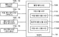
도 3은, 거동 계측 장치(10)의 기능적 구성을 도시하는 블록도이다.Fig. 3 is a block diagram showing the functional configuration of the
거동 계측 장치(10)는, 기능적으로는, 배치 검지 수단(102), 이동 개시 검지 수단(104), 촬영 수단(106), 촬영 제어 수단(108), 거동 산출 수단(110), 온도 검지 수단(112)에 의하여 구성된다.The
이들의 구성 가운데, 촬영 제어 수단(108) 및 거동 산출 수단(110)은, 상술한 컴퓨터(18)의 CPU(1802)가 거동 계측 프로그램을 실행하는 것에 의하여 실현된다.Among these configurations, the imaging control means 108 and the behavior calculation means 110 are realized by the
배치 검지 수단(102)은, 이동체인 골프 볼(20)이 이동 개시 지점에 배치된 것을 검지한다.The placement detection means 102 detects that the
본 실시예와 같이 골프 볼(20)의 이동 개시 지점이 티(24) 상인 경우, 배치 검지 수단(102)은, 골프 볼(20)이 티(24) 상에 배치된 것을 검지한다.When the movement start point of the
본 실시예에서는, 예를 들어 통과 검지 센서(15)에 의하여 배치 검지 수단(102)을 실현한다.In the present embodiment, for example, the batch detection means 102 is implemented by the
상술한 바와 같이, 통과 검지 센서(15)는 도 1B에 도시하는 바와 같이 골프 볼(20)의 설치 위치의 후방을 검지 에어리어 N1이라고 하고, 검지 에어리어 N1 내를 골프 클럽(22)이 통과하는 것을 검지한다.1B, the
이 에어리어 내를 골프 클럽(22)이 통과하는 것은, 계측자(I)가 어드레스 자세를 취하여, 백 스윙 및 다운 스윙을 행하는 때이다. 따라서, 통과 검지 센서(15)에서 골프 클럽(22)의 통과를 검지하는 것에 의하여, 골프 볼(20)이 티(24) 상에 배치되어 있다, 즉 이동 개시 지점에 배치된 것을 검지할 수 있다.The reason why the
즉, 이동체인 골프 볼(20)은, 타격구인 골프 클럽(22)에 의하여 타격되는 것에 의하여 이동을 개시하고, 배치 검지 수단(102)은, 타격구인 골프 클럽(22)에 의한 타격 거동(스윙)의 개시를 검지하는 것에 의하여, 이동체가 이동 개시 지점에 배치된 것을 검지한다.That is, the
덧붙여, 통과 검지 센서(15)의 검지 에어리어 N1은, 골프 볼(20)의 설치 위치의 후방으로 한정되지 않고, 골프 클럽(22)의 스윙이 개시된 것을 검지할 수 있는 범위이면 된다.In addition, the detection area N1 of the
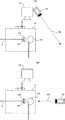
또한, 배치 검지 수단(102)은, 통과 검지 센서(15)로 한정되지 않고 도플러 센서여도 무방하다. 예를 들어 도 7A에 도시하는 바와 같이, 카메라(12)의 근방에 도플러 센서(19)를 설치하여, 골프 볼(20)의 설치 위치의 후방으로 안테나의 지향(指向) 방향 N2가 향하게 한다. 그리고, 도플러 신호의 검출을 행하여 지향 방향 N2에 대한 골프 클럽(22)의 접근(스윙의 개시)을 검지한다.The batch detection means 102 is not limited to the
또한, 예를 들어 도 7B에 도시하는 바와 같이 골프 볼(20)의 설치 위치의 후방에 도플러 센서(19)를 설치하여, 안테나의 지향 방향 N3이 목표 이동 방향 X(x축)와 일치하게 하여, 지향 방향 N3에 대한 골프 클럽(22)의 접근(스윙의 개시)을 검지하여도 무방하다.7B, a
또한, 배치 검지 수단(102)은, 외부로부터 입력되는 배치 완료 신호를 검지하는 것에 의하여, 이동체가 이동 개시 지점에 배치된 것을 검지하는 것이어도 무방하다.Further, the batch detection means 102 may detect that the moving object is disposed at the movement start point by detecting an arrangement completion signal inputted from the outside.
즉, 골프 볼(20)을 티(24) 상에 배치한 것을 계측자(I)가 컴퓨터(18)의 키보드(1812)를 이용하여 입력하거나, 전용의 리모콘이나 스위치 등을 이용하여 입력하거나 하여도 무방하다.That is, even if the meter I is placed on the
이동 개시 검지 수단(104)은, 이동체인 골프 볼(20)이 이동을 개시한 것을 검지한다.The movement start detecting means 104 detects that the
본 실시예에서는, 마이크(14)에 의하여 골프 볼(20)의 타격음을 집음하고, 골프 볼(20)의 이동 개시를 검지한다. 즉, 이동 개시 검지 수단(104)은, 타격구에 의한 이동체의 타격음을 검지하여 이동체가 이동을 개시한 것을 검지한다.In the present embodiment, the
덧붙여, 마이크(14)에는 계측자(I)의 이야기 소리 등, 다양한 음성이 집음되기 때문에, 미리 골프 볼(20)의 타격음을 도시하는 주파수대를 특정하여 두고, 음성 인식을 이용하여 이 주파수대의 음성이 집음된 것을 식별하는 것에 의하여, 골프 볼(20)이 이동을 개시한 것을 검지하여도 무방하다.Since the
또한, 이동 개시 검지 수단(104)은, 마이크(14)로 한정되지 않고, 통과 검지 센서(15)여도 무방하다.The movement start detecting means 104 is not limited to the
구체적으로는, 골프 볼(20)의 설치 위치의 전방(前方)이 검지 에어리어가 되도록 통과 검지 센서(15)를 설치하고, 검지 에어리어 내를 골프 볼(20) 또는 골프 클럽(22)이 통과한 것을 검지하는 것에 의하여, 골프 볼(20)이 이동을 개시한 것을 검지하여도 무방하다.Specifically, the
즉, 이동체의 이동 경로 상을 검지 영역으로 하는 통과 검지 센서(15)를 이용하여 이동체가 이동을 개시한 것을 검지하도록 하여도 무방하다.In other words, it is also possible to detect that the moving object has started to move using the
이 경우, 통과 검지 센서(15)의 검지 에어리어는, 후술하는 촬영 수단(106)의 촬영 영역 내에 골프 볼(20)이 위치하는 내에 촬영이 행하여지도록, 티(24)의 극히 근방으로 설정하는 것이 바람직하다.In this case, the detection area of the passing
촬영 수단(106)은, 이동체의 이동 개시 지점 P0을 촬영 영역에 포함하도록 배치되고, 촬영 영역 내의 화상을 촬영한다.The photographing means 106 is arranged to include the moving start point P0 of the moving object in the photographing area, and photographs the image within the photographing area.
상술한 바와 같이, 본 실시예에서는 카메라(12)가 촬영 수단(106)을 구성하고, 이동 개시 지점 P0인 티(24) 상을 포함하도록 촬영 영역(H)이 설정되어 있다.As described above, in the present embodiment, the photographing area H is set so that the
촬영 수단(106)은, 고속 비디오 등의 특수한 카메라일 필요는 없고, 후술하는 촬영 제어 수단(108)에 의한 촬영 타이밍 제어에 의하여 화상(정지 영상)이 촬영되면 된다.The photographing means 106 need not be a special camera such as a high-speed video, but an image (still image) may be photographed by photographing timing control by the photographing control means 108, which will be described later.
촬영 제어 수단(108)은, 배치 검지 수단(102) 및 이동 개시 검지 수단(104)에 의한 검지 결과에 기초하여, 촬영 수단(106)에 의한 촬영 동작을 제어한다.The photographing control means 108 controls the photographing operation by the photographing means 106 on the basis of the detection result by the placement detection means 102 and the movement start detection means 104. [
보다 상세하게는, 촬영 제어 수단(108)은, 배치 검지 수단(102)에서 골프 볼(20)이 이동 개시 지점에 배치되었다고 검지된 경우, 이동 개시 지점에 배치된 상태의 골프 볼(20)의 화상(제1 화상)을 촬영하도록 촬영 수단(106)을 제어한다. 또한, 촬영 제어 수단(108)은, 이동 개시 검지 수단(104)에 의하여 골프 볼(20)이 이동을 개시한 것을 검지된 경우, 이동 개시 후의 골프 볼(20)의 화상(제2 화상)을 촬영하도록 촬영 수단(106)을 제어한다.More specifically, when the placement detection means 102 detects that the
이것에 의하여, 골프 볼(20)의 이동 개시 전후(타출 전후)의 2매의 화상이 얻어진다.Thus, two images before and after the start of movement of the golf ball 20 (before and after the shooting) are obtained.
거동 산출 수단(110)은, 이동 개시 지점에 배치된 상태의 이동체의 화상인 제1 화상과 이동 개시 후의 이동체의 화상인 제2 화상에 기초하여, 이동체의 이동 방향 또는 회전축 방향 중 적어도 어느 하나를 산출한다.The behavior calculating means 110 calculates at least one of the moving direction of the moving object and the rotating axis direction based on the first image which is the image of the moving object placed at the movement start point and the second image which is the image of the moving object after the start of movement .
또한, 거동 산출 수단(110)은, 이동체가 이동 개시하고 나서 제2 화상이 촬영될 때까지의 경과 시간에 기초하여 이동체의 이동 속도를 더 산출한다.Further, the
거동 산출 수단(110)은, 이동 방향 산출 수단(1102), 회전축 방향 산출 수단(1104), 이동 속도 산출 수단(1106) 중 적어도 어느 하나를 구비한다. 이들은, 이동체의 거동 정보인, 이동 방향, 회전축 방향 및 이동 속도를 각각 산출한다.The behavior calculating means 110 includes at least one of a moving
여기에서, 거동 산출 수단(110)에 의한 거동 정보의 산출 방법에 관하여 설명한다.Here, a calculation method of the behavior information by the behavior calculation means 110 will be described.
도 5는, 촬영 수단(106)에 의한 촬영 화상의 일례를 모식적으로 도시하는 설명도이다.Fig. 5 is an explanatory view schematically showing an example of a photographed image by the photographing means 106. Fig.
도 5A는 제1 화상을 도시하고, 이동 개시 지점에 배치된 상태의 골프 볼(20)을 촬영한 것이며, 도 5B는 제2 화상을 도시하고, 이동 개시 후의 골프 볼(20)을 촬영한 것이다. 또한, 도 5C는 도 5B로부터 골프 볼(20) 이외의 요소를 소거(消去)한 다음, 도 5A 및 도 5B를 중첩(重疊)하고 있다.5A shows a first image, shows a
또한, 도 6도, 촬영 수단(106)에 의한 촬영 화상의 일례를 모식적으로 도시하는 설명도이며, 도 6A는 도 5A와 동일한 도면, 도 6B는 골프 볼(20)이 카메라(12)에 대하여 가까워지는 방향(y좌표 플러스 방향)으로 이동한 경우의 화상이며, 도 6C는 골프 볼(20)이 카메라(12)에 대하여 멀어지는 방향(y좌표 마이너스 방향)으로 이동한 경우의 화상이다.6A is a view similar to Fig. 5A. Fig. 6B is a view showing a state in which the
우선, 상하 방향(x-z 평면 상)에 있어서의 이동 방향 θh의 산출 방법에 관하여 설명한다.First, a calculation method of the moving direction? H in the up-and-down direction (on the x-z plane) will be described.
도 5C에 도시하는 바와 같이, 제1 화상에 있어서의 골프 볼(20)의 중심점 P1과 제2 화상에 있어서의 골프 볼(20)의 중심점 P2를 잇는 선분 L1과, 제1 화상에 있어서의 골프 볼(20)의 중심점 P1을 지나고 지면(G)과 평행한 선분 L2가 이루는 각(角) θh에 의하여, 상하 방향(x-z 평면 상)의 이동 방향을 특정할 수 있다.5C, a line segment L1 connecting the center point P1 of the
즉, 거동 산출 수단(110)은, 제1 화상에 있어서의 이동체의 위치와 제2 화상에 있어서의 이동체의 위치와의 변위 방향을 이동 방향으로서 산출한다.In other words, the
덧붙여, 카메라(12)의 광축(光軸)이 지면(G)과 평행이 아니라, 상하 방향으로 기울어 있는 경우는, 당해 기울기를 보정한 다음 상하 방향의 이동 방향 θh를 산출한다.Incidentally, when the optical axis of the
다음으로, 좌우 방향(x-y 평면 상)에 있어서의 이동 방향 θw의 산출 방법에 관하여 설명한다.Next, a calculation method of the moving direction? W in the left-right direction (on the x-y plane) will be described.
골프 볼(20)이 목표 이동 방향 X에 대하여 좌우 방향으로 기울어 이동하고 있는 경우에는, 도 6에 도시하는 바와 같이 이동 개시 전후로 화상 상의 골프 볼(20)의 직경이 다르다.In the case where the
도 6의 예에서는, 도 6A의 이동 개시 전의 골프 볼(20)의 직경 R0에 대하여, 도 6B와 같이 골프 볼(20)이 카메라(12)에 대하여 가까워지는 방향으로 이동한 경우에는 직경 R1이 커지고(R1>R0), 도 6C와 같이 골프 볼(20)이 카메라(12)에 대하여 멀어지는 방향으로 이동한 경우에는 직경 R2가 작아진다(R2<R0).6A, when the
카메라(12)의 촬영 배율 및 화각(畵角)은 기지이기 때문에, 이동 개시 전후의 골프 볼(20)의 직경의 차분에 기초하여, 좌우 방향(x-y 평면 상)의 이동 방향 θw를 특정할 수 있다.It is possible to specify the moving direction? W in the left-right direction (on the xy plane) based on the difference in diameter of the
예를 들어, 도 6B와 같이 골프 볼(20)이 카메라(12)에 대하여 가까워지는 방향(y좌표 플러스 방향)으로 이동한 경우에는, 화상 상의 골프 볼(20)의 직경이 클수록 카메라(12) 방향으로 크게 돌아가 있게 된다. 또한, 도 6C와 같이 골프 볼(20)이 카메라(12)에 대하여 멀어지는 방향(y좌표 마이너스 방향)으로 이동한 경우에는, 화상 상의 골프 볼(20)의 직경이 작을수록 카메라(12)와 반대 방향으로 크게 돌아가 있게 된다.For example, when the
즉, 거동 산출 수단(110)은, 제1 화상 및 제2 화상에 있어서의 골프 볼의 직경의 비율에 기초하여, 카메라(12)의 촬영 방향과 직교하는 방향의 이동 방향을 산출한다.That is, the
또한, 이동 방향 θw를 산출하는 다른 방법으로서 복수 대의 카메라(12)를 이용한 스테레오 계측을 행하여도 무방하다.As another method of calculating the moving direction? W, stereo measurement using a plurality of
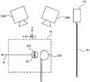
도 9는, 거동 계측 장치(10)의 다른 구성예를 도시하는 설명도이다.Fig. 9 is an explanatory view showing another example of the configuration of the
도 9에서는, 골프 볼(20)의 이동 개시 지점 P0을 포함하는 영역을 촬영 영역으로 하도록 2대의 카메라(12A, 12B)가 설치되어 있다. 카메라(12A, 12B)의 위치나 촬영 방향(향하는 쪽)이나 촬영 배율 등의 카메라 파라미터는, 미리 특정되어 있다.In Fig. 9, two
이 카메라(12A, 12B)로, 각각 동시에 골프 볼(20)의 이동 개시 전후(타출 전후)의 화상을 촬영한다.The
그리고, 각각의 카메라(12A, 12B)로 촬영한 화상 상에 있어서의 골프 볼(20)의 위치를 특정하고, 상기의 카메라 파라미터를 이용하여 이동 개시 전후에 있어서의 골프 볼(20)의 3차원 공간 상의 위치를 특정한다. 이 이동 개시 전후에 있어서의 골프 볼(20)의 3차원 공간 상의 위치의 차분으로부터 골프 볼(20)의 이동 방향 θw를 산출할 수 있다.The position of the
즉, 복수 대의 카메라(12A, 12B)로 각각 촬영된 복수의 제1 화상에 기초하여 이동 개시 전의 이동체의 3차원 공간 상의 위치를 특정하고, 복수 대의 카메라(12A, 12B)로 각각 촬영된 복수의 제2 화상에 기초하여 이동 개시 후의 이동체의 3차원 공간 상의 위치를 특정하고, 이동 개시 전후에 있어서의 이동체의 3차원 공간 상의 위치의 차분에 기초하여 이동 방향을 산출하도록 하여도 무방하다.That is, the position on the three-dimensional space of the moving object before the start of movement is specified based on the plurality of first images photographed by the plurality of
이와 같이, 복수 대의 카메라를 이용하여 촬영하는 것에 의하여, 골프 볼(20)의 이동 방향 θw를 보다 정도 높게 산출할 수 있다.As described above, by photographing using a plurality of cameras, the moving direction? W of the
다음으로, 회전축 방향의 산출 방법에 관하여 설명한다.Next, a calculation method of the direction of the rotation axis will be described.
도 5에 도시하는 바와 같이, 골프 볼(20)에는 마크 M이 부가되어 있다. 이동 개시 전후의 골프 볼(20)의 마크 M의 위치 및 방향에 기초하여, 골프 볼(20)의 회전축 방향을 특정할 수 있다.As shown in Fig. 5, a mark M is added to the
덧붙여, 골프 볼(20)에 부가하는 마크 M은, 골프 볼(20)이 어느 방향으로 회전하여도 화상 상에 비치는 것과 같은 도안으로 하는 것이 바람직하다. 이와 같은 도안으로서는, 예를 들어 도 5 등과 같이 골프 볼(20)의 전체 둘레에 걸쳐 그려진 선분 등 종래 공지의 다양한 도안을 이용할 수 있다.In addition, it is preferable that the mark M added to the
즉, 이동체는 전방위로부터 시인 가능한 도안을 가지고, 거동 산출 수단(110)은, 제1 화상에 있어서의 도안의 위치 및 향하는 쪽과 제2 화상에 있어서의 도안의 위치 및 향하는 쪽과의 차분으로부터 회전축 방향을 산출한다.That is, the moving object has a pattern visible from all directions, and the
계속하여, 이동 속도의 산출 방법에 관하여 설명한다.Next, a calculation method of the moving speed will be described.
상술한 이동 방향 및 회전축 방향의 산출은, 이동 개시 전후의 2매의 화상만으로 행할 수 있지만, 이동 속도의 산출에는, 이동체가 이동을 개시하고 나서 제2 화상을 촬영할 때까지의 경과 시간을 특정할 필요가 있다.The calculation of the movement direction and the rotation axis direction described above can be performed by only two images before and after the movement start. However, the calculation of the movement speed may specify the elapsed time from the start of movement of the moving object to the shooting of the second image There is a need.
이동 속도의 산출에는, 우선 골프 볼(20)의 이동 거리를 산출한다. 상술한 바와 같이 카메라(12)의 촬영 배율은 기지이기 때문에, 화상 상의 거리와 실 공간 상의 거리와의 비율은 기지이며, 제1 화상에 있어서의 골프 볼(20)의 위치(이동 개시 지점)와 제2 화상에 있어서의 골프 볼(20)의 위치와의 관계로부터 골프 볼(20)의 x-z 평면 상의 2차원적인 이동 거리를 산출할 수 있다.To calculate the moving speed, the moving distance of the
다음으로, 이동체가 이동을 개시한 시각을 특정한다. 이동 개시 검지 수단(104)이 마이크(14)인 경우, 마이크(14)에 의하여 타격음을 검지한 시각을 이동체가 이동을 개시한 시각으로 할 수 있다.Next, the time at which the mobile unit starts moving is specified. When the movement start detecting means 104 is the
이 때, 이동 개시 지점과 마이크(14)와의 사이의 거리를 음속으로 나눈 값을 타격음이 마이크(14)에 도달할 때까지의 지연(遲延) 시간으로서 산출하고, 이 지연 시간을 마이크(14)에 의하여 타격음을 검지한 시각으로부터 빼도 무방하다.At this time, a value obtained by dividing the distance between the movement start point and the
나아가, 이동 개시 지점 주변의 온도를 검지하는 온도 검지 수단(112)인 온도 센서(16)의 측정 온도를 이용하여 음속값을 보정하여도 무방하다. 즉, 일반적으로 이용되는 음속 C=331.5+0.61t(t는 섭씨 온도) 등의 식을 이용하여 실제의 음속에 의하여 가까운 값을 산출하고, 타격음이 마이크(14)에 도달할 때까지의 시간을 산출하여도 무방하다. 이것에 의하여, 한층 더 높게 이동체가 이동 개시한 시각을 특정할 수 있다.Further, the sound velocity value may be corrected using the measured temperature of the
도 8은, 온도 보정의 유무에 의한 오차를 도시하는 설명도이다.Fig. 8 is an explanatory view showing an error due to the presence or absence of the temperature correction.
도 8A에는, 마이크(14)와 이동 개시 지점 P0과의 사이의 거리가 0.5m인 경우에, 이동 개시 지점 P0에서 발생한 타격음이 마이크(14)에 도달할 때까지의 소요 시간을 도시하고 있다. 덧붙여, 도 8에서는 음속값의 소수점 이하의 값을 생략하고 있다.8A shows the time required until the hit sound generated at the movement start point P0 reaches the
음속값은, 기온 0℃의 경우 331m/s이며, 기온 35℃의 경우 352m/s이다.The sound velocity value is 331 m / s at the temperature of 0 ° C and 352 m / s at the temperature of 35 ° C.
따라서, 타격음이 마이크(14)에 도달할 때까지의 소요 시간은, 기온 0℃에서 1.51ms, 기온 35℃에서 1.42ms가 된다.Therefore, the time required until the hit sound reaches the
도 8B는, 골프 볼(20)의 이동 속도별로 추정되는 오차를 도시하고 있다.FIG. 8B shows an error estimated for each moving speed of the
예를 들어, 골프 볼(20)의 이동 속도가 40m/s의 경우, 타격음이 마이크(14)에 도달할 때까지의 소요 시간(도 8A 참조) 내에 골프 볼(20)이 이동하는 거리는, 기온 0℃에서 60.4mm(1.51ms로 이동하는 거리), 기온 35℃에서 56.8mm(1.42ms로 이동하는 거리)가 된다.For example, when the moving speed of the
여기에서, 상기와 같은 음속값의 온도 보정을 행하지 않았던 경우, 상기의 이동 거리는 기온 0℃과 마찬가지로 1.51ms로 이동하는 거리로서 계산된다. 즉, 기온 35℃에서는, 1.42ms로 이동한 거리가 1.51ms로 이동하는 거리로서 계산되어, 실제보다도 속도가 늦게 계산된다.Here, in the case where the temperature correction of the sound velocity value is not performed, the above moving distance is calculated as a distance moving to 1.51 ms as in the case of the air temperature 0 캜. That is, at a temperature of 35 ° C, the distance traveled to 1.42 ms is calculated as the distance to travel to 1.51 ms, and the speed is calculated to be slower than the actual speed.
구체적으로는, 기온 0℃에서는 40.0m/s와 올바른 이동 속도가 산출되는 한편으로, 기온 35℃에서는 37.6m/s로 산출되고, 실제보다도 2.4m/s 늦은 값으로 (-2.4m/s) 이동 속도가 산출된다.Specifically, the correct moving speed is calculated at 40.0 m / s at a temperature of 0 ° C, while it is calculated as 37.6 m / s at a temperature of 35 ° C, which is 2.4 m / s (-2.4 m / s) The moving speed is calculated.
이와 같은 오차는 골프 볼(20)의 이동 속도가 빠를수록 크게 되어, 속도 80m/s에서는 -4.8m/s로도 된다.Such an error increases as the moving speed of the
본원과 같은 온도 보정을 행하는 것에 의하여, 상기와 같은 오차를 방지하고, 보다 정도 좋게 이동 속도를 산출할 수 있다.By performing the temperature correction as in the present application, it is possible to prevent the above-described error and to calculate the moving speed more accurately.
그리고, 카메라(12)로 제2 화상을 촬영한 시각을 특정하면, 이동체가 이동 개시하고 나서 제2 화상이 촬영될 때까지의 경과 시간을 특정할 수 있다. 제2 화상을 촬영한 시각은, 촬영 제어 수단(108)이 카메라(12)에 촬영을 지시한 시각 또는 카메라(12)로 기록한 제2 화상의 촬영 시각이며, 이들은 대략 동일하다.When the time at which the second image is photographed by the
이와 같이 산출한 골프 볼(20)의 이동 거리를, 골프 볼(20)이 이동을 개시하고 나서 제2 화상을 촬영할 때까지의 경과 시간으로 나눈 것에 의하여, 골프 볼(20)의 이동 속도를 산출할 수 있다.The moving distance of the
덧붙여, 이동 개시 검지 수단(104)이 통과 검지 센서(15)인 경우, 이동 개시 지점으로부터 통과 검지 센서(15)의 검지 영역까지의 거리, 및 골프 볼(20)이 이동을 개시하고 나서 통과 검지 센서(15)에서 골프 볼(20)을 검지할 때까지의 경과 시각을 특정할 수 있으면, 거리를 경과 시각으로 나눈 것에 의하여 이동 속도를 산출할 수 있다.When the movement start detection means 104 is the
도 4는, 거동 계측 장치(10)에 의한 처리의 수순(手順)을 도시하는 플로 차트이다.Fig. 4 is a flowchart showing the procedure of the process by the
거동 계측 장치(10)는, 우선 배치 검지 수단(102)에 의하여 이동체가 이동 개시 지점에 배치된 것을 검지한다(스텝 S402: 배치 검지 공정).The
이동체가 이동 개시 지점에 배치되면(스텝 S402: Yes), 촬영 제어 수단(108)이 촬영 수단(106)에 화상 촬영을 지시하고, 이동체가 이동 개시 지점에 있는 상태를 제1 화상으로서 촬영한다(스텝 S404: 제1 촬영 공정).If the moving object is located at the movement start point (step S402: Yes), the image capturing control means 108 instructs the image capturing means 106 to take an image, and the moving object is photographed as the first image Step S404: First shooting step).
다음으로, 거동 계측 장치(10)는, 이동 개시 검지 수단(104)에 의하여 이동체가 이동을 개시한 것을 검지한다(스텝 S406: 이동 개시 검지 공정).Next, the
이동체가 이동을 개시하면(스텝 S406: Yes), 촬영 제어 수단(108)이 촬영 수단(106)에 화상 촬영을 지시하고, 이동체가 이동하고 있는 상태를 제2 화상으로서 촬영한다(스텝 S408: 제2 촬영 공정).When the moving object starts to move (Step S406: Yes), the image capturing control means 108 instructs the image capturing means 106 to take an image and captures the moving object as a second image (Step S408: 2 shooting process).
계속하여, 거동 산출 수단(110)에 의하여, 이동 방향, 회전축 방향, 이동 속도 등, 이동체의 거동을 산출한다(스텝 S410: 거동 산출 공정).Subsequently, the
그리고, 산출한 거동 정보를 디스플레이(1816)나 인쇄지 등에 표시하여(스텝 S412), 본 플로 차트에 의한 처리를 종료한다.Then, the calculated behavior information is displayed on the
이상 설명한 바와 같이, 실시예 1에 관련되는 이동체의 거동 계측 장치(10)는, 골프 볼(20)이 이동 개시 지점 P0에 배치된 상태를 촬영한 제1 화상과 이동 개시 후의 골프 볼(20)을 촬영한 제2 화상에 기초하여 골프 볼(20)의 이동 방향이나 회전축 방향, 이동 속도를 산출하기 때문에, 특수한 기기를 이용하는 일 없이 골프 볼(20)의 거동을 계측할 수 있고, 골프 볼(20)의 거동 계측에 드는 코스트를 저감할 수 있다.As described above, the moving object
또한, 거동 계측 장치(10)는, 2매의 화상에 있어서의 골프 볼(20)의 위치의 변위 방향을 이동 방향으로서 산출하기 때문에, 화상 평면 내에 있어서의 이동 방향을 간이하게 계측할 수 있다.Further, since the
또한, 거동 계측 장치(10)는, 2매의 화상에 있어서의 골프 볼(20)의 직경의 비율에 기초하여 촬영 방향(화상 평면)과 직교하는 방향의 이동 방향을 산출하기 때문에, 3차원 공간 내에 있어서의 이동체의 이동 방향을 계측할 수 있고, 보다 상세한 이동체의 거동 정보를 얻을 수 있다.Further, since the
또한, 거동 계측 장치(10)는, 2매의 화상에 있어서의 골프 볼(20)의 도안의 위치 및 향하는 쪽의 차분으로부터 회전축 방향을 산출하기 때문에, 도플러 센서 등으로도 측정이 곤란한 회전축 방향을 용이하게 계측할 수 있다.Further, since the
또한, 거동 계측 장치(10)는, 골프 클럽(22)에 의한 타격 거동의 개시를 검지하는 것에 의하여 골프 볼(20)이 이동 개시 지점 P0에 배치된 것을 검지하기 때문에, 계측자가 조작 등을 행하는 일 없이 제1 화상을 촬영할 수 있고, 계측 조작을 간소화할 수 있다.Since the
또한, 거동 계측 장치(10)에 있어서, 외부로부터 입력되는 배치 완료 신호를 검지하는 것에 의하여 골프 볼(20)이 이동 개시 지점 P0에 배치된 것을 검지하도록 하면, 골프 클럽(22)에 의한 타격 거동의 개시를 검지하는 것과 비교하여, 보다 확실히 골프 볼(20)이 이동 개시 지점 P0에 배치된 것을 검지할 수 있다.When the
또한, 거동 계측 장치(10)는, 골프 클럽(22)에 의한 골프 볼(20)의 타격음을 검지하여 골프 볼(20)이 이동을 개시한 것을 검지하기 때문에, 마이크(14)를 이용하여 용이 또한 단시간 내에 골프 볼(20)의 이동 개시를 검지할 수 있다.The
또한, 거동 계측 장치(10)에 있어서, 이동 개시 지점 P0 주변의 온도에 기초하여 골프 볼(20)의 이동 개시한 타이밍을 보정하도록 하면, 골프 볼(20)의 이동 개시한 타이밍을 보다 정확하게 특정할 수 있다.Further, by correcting the timing at which the
또한, 거동 계측 장치(10)에 있어서, 골프 볼(20)의 이동 경로 상을 검지 영역으로 하는 통과 검지 센서를 이용하여 골프 볼(20)이 이동을 개시한 것을 검지하도록 하면, 타격음을 검지하는 것과 비교하여 보다 확실히 골프 볼(20)이 이동을 개시한 것을 검지할 수 있다.In addition, in the
(실시예 2)(Example 2)
실시예 1에서는, 이동체가 이동 개시 지점에 배치된 것을 검지하는 배치 검지 수단과, 이동체가 이동을 개시한 것을 검지하는 이동 개시 검지 수단이 개별의 장치이었다. 실시예 2에서는, 배치 검지 수단과 이동 개시 검지 수단이 동일한 장치(반사형 광학식 센서)인 경우에 관하여 설명한다.In
이하, 실시예 2에 있어서, 실시예 1과 마찬가지의 개소는 도면 상에서 같은 부호를 붙이고, 상세한 설명을 생략한다.Hereinafter, in the second embodiment, the same parts as those in the first embodiment are denoted by the same reference numerals, and detailed description thereof is omitted.
도 10은, 실시예 2에 관련되는 이동체의 거동 계측 장치(30)의 개략 구성을 도시하는 설명도이다.10 is an explanatory diagram showing a schematic configuration of a
도 10A는 거동 계측 장치(30)의 구성을 측면으로부터 본 도면이며, 도 10B는 도 10A에 있어서의 골프 볼(20)의 주변을 상면으로부터 본 도면이다.FIG. 10A is a side view of the configuration of the
실시예 2에서는, 카메라(12) 상에 반사형 광학식 센서(32)가 설치되어 있다.In the second embodiment, the reflection type
덧붙여, 도시를 생략하고 있지만, 반사형 광학식 센서(32)는 컴퓨터(18)와 접속되어 있고, 그 검출 결과를 컴퓨터(18)에 출력한다.Incidentally, although the illustration is omitted, the reflective
반사형 광학식 센서(32)는, 임의의 검출 범위에 광을 투광하는 투광부와, 검출 범위에 물체가 위치하는 경우에 그 물체에 의하여 반사한 반사광을 수광하는 수광부와, 수광부에서 수광되는 광량의 변화에 기초하여 검출 범위에 있어서의 물체의 유무를 검지하는 검지부,를 구비한다.The reflection type
본 실시예에서는, 반사형 광학식 센서(32)의 검출 범위를 이동 개시 지점 P0(티(24) 상)에 맞추고 있다. 즉, 투광부로부터의 투영광 LI가 이동 개시 지점 P0을 통과하도록 설치한다. 티(24) 상에 골프 볼(20)이 없는 경우에는, 투영광 LI는 이동 개시 지점 P0을 통과하여 나가기 때문에, 수광부에서는 반사광 LR을 수광하지 않는다. 한편, 티(24) 상에 골프 볼(20)이 있는 경우에는, 골프 볼(20)의 표면에서 반사한 반사광 LR이 수광부를 향하고, 수광부에서의 수광량이 증가한다. 이것에 의하여, 티(24) 상의 골프 볼(20)의 유무를 검지할 수 있다.In this embodiment, the detection range of the reflection type
즉, 반사형 광학식 센서(32)는 배치 검지 수단(102)으로서 기능한다.In other words, the reflection type
여기에서, 반사형 광학식 센서(32)는, 수광부에 반사광이 소정 시간 이상 계속하여 수광된 경우에 골프 볼(20)이 이동 개시 지점에 배치되었다고 검지하여도 무방하다.Here, the reflection type
이것은, 반사형 광학식 센서(32)의 검출 범위인 티(24) 상 또는 티(24)의 근방에 물체가 검지된 경우여도, 그 물체가 골프 볼(20)이 아니라, 예를 들어 계측자(I)의 손발이나 골프 클럽(22)의 헤드 등일 가능성이 있고, 이 경우에 촬영을 행하면 오촬영(誤撮影)으로 되어 버리기 때문이다.This is because even if an object is detected on the
반사형 광학식 센서(32)의 검출 범위(티(24) 상)의 물체가 골프 볼(20)인 경우에는, 계측자(I)가 티 상에 골프 볼(20)을 세트한 후, 어드레스 자세를 취하여 스윙을 행하는 동안에 일정한 시간이 필요할 것이다. 한편으로, 반사형 광학식 센서(32)의 검출 범위의 물체가 골프 볼(20) 이외인 경우에는, 곧바로 이동하여 검출 범위로부터 벗어날 가능성이 높다.When the object in the detection range (on the Tier 24) of the reflection type
따라서, 반사형 광학식 센서(32)에 의한 물체의 검지가 소정 시간 이상 계속된 경우에만 촬영을 행하도록 하면, 물체의 오검지를 방지하여 확실히 골프 볼(20)을 촬영할 수 있다.Therefore, if the photographing is performed only when the detection of the object by the reflection type
덧붙여, 이 경우, 수광부에 반사광이 소정 시간 이상 계속하여 수광되고, 골프 볼(20)이 이동 개시 지점에 배치되었다고 인식된 것을 보지하는 보지부를 설치하여도 무방하다. 보지부로서는, 예를 들어 램프나 스피커 등을 이용할 수 있다. 계측자(I)는 골프 볼(20)을 티(24)에 세트한 후, 보지부에 의한 보지를 기다리고 스윙을 개시하면 된다.In this case, it is also possible to provide a holding section for holding the reflected light to the light receiving section continuously for a predetermined time or more and recognizing that the
또한, 골프 볼(20)이 이동 개시 지점 P0에 배치되었다고 검지된 후, 골프 볼(20)으로부터의 반사광이 수광되지 않게 된 경우에는, 골프 볼(20)이 골프 클럽(22)으로 타격되어, 골프 볼(20)이 이동을 개시하였다고 검지할 수 있다.When the reflected light from the
즉, 반사형 광학식 센서(32)는 이동 개시 검지 수단(104)으로서도 기능한다.In other words, the reflection type
이와 같이, 반사형 광학식 센서(32)는 배치 검지 수단(102) 및 이동 개시 검지 수단(104)의 양방으로서 이용할 수 있다.Thus, the reflection type
덧붙여, 반사형 광학식 센서(32)는, CMOS 센서 등의 화상 센서를 이용하여 물체의 색을 식별하는 기능을 가지는 것이어도 무방하다. 이 경우, 물체가 특정의 색이었을 경우에만 검출 범위 내에 물체가 있다고 검지한다.In addition, the reflection type
보다 상세하게는, 예를 들어 일반적인 골프 볼(20)의 색인 백색의 물체가 검출 범위 내에 있었을 경우에만 물체를 검출하는 센서를 이용한다. 이것에 의하여, 골프 클럽(22)이나 계측자(I)의 손발 등이 티(24) 주변에 있는 것을 골프 볼(20)로서 오검지하는 것을 방지하여, 반사형 광학식 센서(32)의 검출 정도를 향상시킬 수 있다.More specifically, for example, a sensor that detects an object is used only when an index white object of a
또한, 반사형 광학식 센서(32)의 반응 속도는, 1ms 이하인 것이 바람직하다.The reaction speed of the reflective
이것은, 골프 볼(20)의 이동 속도에 따라서는, 카메라(12)의 촬영 타이밍을 골프 볼(20)의 이동 개시 후, 극히 단시간으로 하는 것이 요구되기 때문이다. 반응 속도가 빠른 반사형 광학식 센서(32)를 사용하는 것에 의하여, 촬영 타이밍을 보다 빠른 타이밍으로 설정하는 것이 가능해지고, 카메라(12)에 의한 촬영 정도를 향상시킬 수 있다.This is because, depending on the moving speed of the
이상 설명한 바와 같이, 실시예 2에 관련되는 이동체의 거동 계측 장치(30)에 의하면, 골프 볼(20)이 이동 개시 지점 P0에 배치된 것을 검지하는 기구와, 골프 볼(20)이 이동을 개시한 것을 검지하는 기구가 동일한 반사형 광학식 센서(32)이기 때문에, 거동 계측 장치(30)의 시스템 구성을 간소화할 수 있다.As described above, according to the
또한, 반사형 광학식 센서(32)의 검출 범위는 이동 개시 지점 P0이라고 하는 극히 좁은 범위여도 무방하기 때문에, 계측에 사용 스페이스가 한정되어 있는 경우여도 무리없이 계측을 행할 수 있다.Further, the detection range of the reflection type
또한, 거동 계측 장치(30)에 있어서, 이동 개시 지점 P0으로부터의 반사광이 소정 시간 이상 계속하여 수광된 경우에 골프 볼(20)이 이동 개시 지점 P0에 배치되었다고 검지하도록 하면, 계측자(I)의 손발이나 골프 클럽(22) 등을 골프 볼(20)로 오검지하는 것을 방지하여, 검지 정도를 향상시킬 수 있다.Further, in the
또한, 거동 계측 장치(30)는, 골프 볼(20)이 이동 개시 지점 P0에 위치하면 검지된 후, 이동 개시 지점 P0으로부터 퇴거한 경우에 골프 볼(20)이 이동을 개시하였다고 검지하기 때문에, 타격음을 이용하는 경우 등보다도 안정된 계측을 행할 수 있다.Further, since the
10, 30……거동 계측 장치, 12……카메라, 13……조명, 14……마이크, 15……통과 검지 센서, 16……온도 센서, 18……컴퓨터, 19……도플러 센서, 20……골프 볼, 22……골프 클럽, 24……티, 32……반사형 광학식 센서, 102……배치 검지 수단, 104……이동 개시 검지 수단, 106……촬영 수단, 108……촬영 제어 수단, 110……거동 산출 수단, 1102……이동 방향 산출 수단, 1104……회전축 방향 산출 수단, 1106……이동 속도 산출 수단, 112……온도 검지 수단, G……지면, H……촬영 영역, I……계측자, M……마크, N1……검지 에어리어, N2……지향 방향, N3……지향 방향, P0……이동 개시 지점, P1……중심점, P2……중심점, R0……직경, R1……직경, R2……직경, X……목표 이동 방향10, 30 ... ... Behavior measurement device, 12 ... ... Camera, 13 ... ... Lighting, 14 ... ... Mike, 15 ... ... Pass detection sensor, 16 ... ... Temperature sensor, 18 ... ... Computer, 19 ... ... Doppler sensor, 20 ... ... Golf ball, 22 ... ... Golf club, 24 ... ... Tea, 32 ... ... Reflective type optical sensor, 102 ... ... Batch detection means, 104 ... ... Movement start detecting means, 106 ... ... Means for shooting, 108 ... ... Photographing control means, 110 ... ... A behavior calculating means, 1102 ... ... Moving direction calculating means, 1104 ... ... Rotation axis direction calculating means, 1106 ... ... Moving speed calculating means 112, ... Temperature detecting means, G ... ... Floor, H ... ... Shooting area, I ... ... Measurer, M ... ... Mark, N1 ... ... Detection Area, N2 ... ... Orientation direction, N3 ... ... Orientation direction, P0 ... ... Move start point, P1 ... ... Center point, P2 ... ... Center point, R0 ... ... Diameter, R1 ... ... Diameter, R2 ... ... Diameter, X ... ... Goal direction
Claims (20)
Translated fromKorean상기 이동체가 이동 개시 지점에 배치된 것을 검지(檢知)하는 배치 검지 공정과,
상기 이동 개시 지점에 배치된 상태의 상기 이동체의 화상(畵像)을 촬영하는 제1 촬영 공정과,
상기 이동체가 이동을 개시한 것을 검지하는 이동 개시 검지 공정과,
이동 개시 후의 상기 이동체의 화상을 촬영하는 제2 촬영 공정과,
상기 제1 촬영 공정에서 촬영된 제1 화상 및 상기 제2 촬영 공정에서 촬영된 제2 화상에 기초하여, 상기 이동체의 이동 방향 또는 회전축 방향 중 적어도 어느 하나를 산출하는 거동 산출 공정
을 포함한 것을 특징으로 하는 거동 계측 방법.A method of measuring a behavior of a moving object, the method comprising:
A batch detecting step of detecting that the moving body is disposed at the movement starting point;
A first photographing step of photographing an image of the moving object placed at the movement start point,
A movement start detecting step of detecting that the moving body has started to move,
A second photographing step of photographing an image of the moving body after start of movement;
A behavior calculating step of calculating at least one of a moving direction of the moving body and a rotational axis direction based on the first image photographed in the first photographing step and the second image photographed in the second photographing step
And a second step of measuring the movement of the object.
상기 거동 산출 공정에서는, 상기 이동체가 이동 개시하고 나서 상기 제2 화상이 촬영될 때까지의 경과 시간에 기초하여 상기 이동체의 이동 속도를 더 산출하는,
것을 특징으로 하는 거동 계측 방법.The method according to claim 1,
Wherein the movement calculating step further calculates the moving speed of the moving object based on the elapsed time from when the moving object starts moving to when the second image is captured,
Wherein the method comprises the steps of:
상기 제1 촬영 공정 및 상기 제2 촬영 공정에서는, 동일한 촬영 영역 내의 화상을 촬영하고,
상기 거동 산출 공정에서는, 상기 제1 화상에 있어서의 상기 이동체의 위치와 상기 제2 화상에 있어서의 상기 이동체의 위치와의 변위(變位) 방향을 상기 이동 방향으로서 산출하는,
것을 특징으로 하는 거동 계측 방법.3. The method according to claim 1 or 2,
In the first shooting step and the second shooting step, an image in the same shooting area is shot,
In the behavior calculation step, a displacement direction between the position of the moving object in the first image and the position of the moving object in the second image is calculated as the moving direction,
Wherein the method comprises the steps of:
상기 이동체는, 직경이 기지(旣知)의 볼이고,
상기 거동 산출 공정에서는, 상기 제1 화상 및 상기 제2 화상에 있어서의 상기 볼의 직경의 비율에 기초하여, 상기 제1 촬영 공정 및 상기 제2 촬영 공정에 있어서의 촬영 방향과 직교하는 방향의 상기 이동 방향을 산출하는,
것을 특징으로 하는 거동 계측 방법.The method of claim 3,
The moving body is a ball having a known diameter,
Wherein in the behavior calculation step, based on a ratio of the diameter of the ball in the first image and the second image, the shape of the ball in the direction orthogonal to the shooting direction in the first shooting step and the second shooting step Calculating a moving direction,
Wherein the method comprises the steps of:
상기 제1 촬영 공정 및 상기 제2 촬영 공정에서는, 복수 대(臺)의 카메라를 이용하여 상기 이동체의 화상을 촬영하고,
상기 거동 산출 공정에서는, 상기 복수 대의 카메라로 각각 촬영된 복수의 상기 제1 화상에 기초하여 이동 개시 전의 상기 이동체의 3차원 공간 상(上)의 위치를 특정하고, 상기 복수 대의 카메라로 각각 촬영된 복수의 상기 제2 화상에 기초하여 이동 개시 후의 상기 이동체의 3차원 공간 상의 위치를 특정하고, 이동 개시 전후에 있어서의 상기 이동체의 3차원 공간 상의 위치의 차분(差分)에 기초하여 상기 이동 방향을 산출하는,
것을 특징으로 하는 거동 계측 방법.3. The method according to claim 1 or 2,
In the first shooting step and the second shooting step, an image of the moving object is captured using a plurality of cameras,
In the behavior calculating step, a position in the three-dimensional space (upper) of the moving object before the start of movement is specified based on the plurality of first images photographed by the plurality of cameras, Dimensional space of the moving object after the start of movement based on the plurality of second images and determines the moving direction based on a difference (positional difference) between positions on the three-dimensional space of the moving object before and after the start of movement Calculating,
Wherein the method comprises the steps of:
상기 이동체는, 전방위로부터 시인(視認) 가능한 도안을 가지고,
상기 거동 산출 공정에서는, 상기 제1 화상에 있어서의 상기 도안의 위치 및 향하는 쪽과 상기 제2 화상에 있어서의 상기 도안의 위치 및 향하는 쪽과의 차분으로부터 상기 회전축 방향을 산출하는,
것을 특징으로 하는 거동 계측 방법.3. The method according to claim 1 or 2,
The moving body has a pattern that can be viewed from all directions,
Calculating the direction of the rotation axis from a difference between a position of the drawing and a direction of the drawing in the first image and a position and a direction of the drawing in the second image,
Wherein the method comprises the steps of:
상기 이동체는, 타격구에 의하여 타격되는 것에 의하여 이동을 개시하고,
상기 배치 검지 공정에서는, 상기 타격구에 의한 타격 거동의 개시를 검지하는 것에 의하여, 상기 이동체가 상기 이동 개시 지점에 배치된 것을 검지하는,
것을 특징으로 하는 거동 계측 방법.3. The method according to claim 1 or 2,
Wherein the moving body starts moving by being struck by a hitting hole,
Wherein the placement detection step detects that the moving object is disposed at the movement start point by detecting the start of the striking action by the striking mouth,
Wherein the method comprises the steps of:
상기 배치 검지 공정에서는, 외부로부터 입력되는 배치 완료 신호를 검지하는 것에 의하여, 상기 이동체가 상기 이동 개시 지점에 배치된 것을 검지하는,
것을 특징으로 하는 거동 계측 방법.3. The method according to claim 1 or 2,
Wherein the placement detection step detects a placement completion signal input from the outside to detect that the moving object is disposed at the movement start point,
Wherein the method comprises the steps of:
상기 이동체는, 타격구에 의하여 타격되는 것에 의하여 이동을 개시하고,
상기 이동 개시 검지 공정에서는, 상기 타격구에 의한 상기 이동체의 타격음을 검지하여 상기 이동체가 이동을 개시한 것을 검지하는,
것을 특징으로 하는 거동 계측 방법.3. The method according to claim 1 or 2,
Wherein the moving body starts moving by being struck by a hitting hole,
Wherein the moving start detection step detects a hit sound of the moving object by the hitting hole and detects that the moving object has started to move,
Wherein the method comprises the steps of:
상기 이동 개시 지점 주변의 온도를 검지하는 온도 검지 공정을 더 포함하고,
상기 이동 개시 검지 공정에서는, 상기 이동 개시 지점 주변의 온도에 기초하여 상기 이동체가 이동 개시한 타이밍을 보정하는,
것을 특징으로 하는 거동 계측 방법.10. The method of claim 9,
Further comprising a temperature detecting step of detecting a temperature around the movement start point,
Wherein the moving start detecting step corrects the timing at which the moving body starts moving based on the temperature around the moving starting point,
Wherein the method comprises the steps of:
상기 이동 개시 검지 공정에서는, 상기 이동체의 이동 경로 상을 검지 영역으로 하는 통과 검지 센서를 이용하여 상기 이동체가 이동을 개시한 것을 검지하는,
것을 특징으로 하는 거동 계측 방법.3. The method according to claim 1 or 2,
Wherein the moving start detecting step detects that the moving object has started to move using a passage detecting sensor having a moving path of the moving object as a detection area,
Wherein the method comprises the steps of:
상기 배치 검지 공정에서는, 상기 이동 개시 지점에 광(光)을 투광(投光)하는 투광부와, 상기 이동 개시 지점에 상기 이동체가 위치하는 경우에 상기 이동체에 의하여 반사한 반사광을 수광(受光)하는 수광부와, 상기 수광부에서 수광되는 광량(光量)의 변화에 기초하여 상기 이동 개시 지점에 있어서의 상기 이동체의 유무를 검지하는 검지부,를 구비하는 반사형 광학식 센서를 이용하여, 상기 이동체가 상기 이동 개시 지점에 배치된 것을 검지하는,
것을 특징으로 하는 거동 계측 방법.3. The method according to claim 1 or 2,
Wherein the placement detecting step includes a light projecting unit for projecting light to the movement start point and a light receiving unit for receiving reflected light reflected by the moving object when the moving object is located at the movement start point, And a detection unit for detecting the presence or absence of the moving object at the movement start point based on a change in the amount of light (light amount) received by the light receiving unit, wherein the moving object is moved Detecting that it is disposed at the start point,
Wherein the method comprises the steps of:
상기 배치 검지 공정에서는, 상기 반사광이 소정 시간 이상 계속하여 수광된 경우에 상기 이동체가 상기 이동 개시 지점에 배치되었다고 검지하는,
것을 특징으로 하는 거동 계측 방법.13. The method of claim 12,
Wherein the placement detection step detects that the moving object is located at the movement start point when the reflected light is continuously received for a predetermined time or more,
Wherein the method comprises the steps of:
상기 반사형 광학식 센서의 검출 범위 내에 물체가 소정 시간 이상 계속하여 검지된 것을 보지(報知)하는 보지부를 더 구비하는,
것을 특징으로 하는 거동 계측 방법.14. The method of claim 13,
Further comprising a holding unit for noticing that an object is continuously detected for a predetermined time or longer within the detection range of the reflection type optical sensor,
Wherein the method comprises the steps of:
상기 이동 개시 검지 공정에서는, 상기 반사형 광학식 센서를 이용하여 상기 이동체가 상기 이동 개시 지점으로부터 퇴거한 것을 검지하는 것에 의하여 상기 이동체가 이동을 개시한 것을 검지하는,
것을 특징으로 하는 거동 계측 방법.13. The method of claim 12,
Wherein the moving start detecting step detects that the moving object has started moving by detecting that the moving object has moved away from the moving starting point by using the reflective optical sensor,
Wherein the method comprises the steps of:
상기 반사형 광학식 센서는, 물체의 색을 식별하는 기능을 가지고, 상기 물체가 소정의 색이었을 경우에만 상기 반사형 광학식 센서의 검출 범위 내에 상기 물체가 있다고 검지하는,
것을 특징으로 하는 거동 계측 방법.13. The method of claim 12,
The reflection type optical sensor has a function of identifying the color of an object and detects that the object exists within the detection range of the reflection type optical sensor only when the object has a predetermined color,
Wherein the method comprises the steps of:
상기 이동체가 이동 개시 지점에 배치된 것을 검지하는 배치 검지 수단과,
상기 이동체가 이동을 개시한 것을 검지하는 이동 개시 검지 수단과,
상기 이동 개시 지점을 촬영 영역에 포함하도록 배치된 촬영 수단과,
상기 배치 검지 수단 및 상기 이동 개시 검지 수단에 의한 검지 결과에 기초하여, 상기 촬영 수단에 의한 촬영 동작을 제어하는 촬영 제어 수단과,
상기 이동 개시 지점에 배치된 상태의 상기 이동체의 화상인 제1 화상과, 이동 개시 후의 상기 이동체의 화상인 제2 화상에 기초하여, 상기 이동체의 이동 방향 또는 회전축 방향 중 적어도 어느 하나를 산출하는 거동 산출 수단
을 구비하는 것을 특징으로 하는 거동 계측 장치.A device for measuring the behavior of a moving object, comprising:
A placement detection means for detecting that the moving body is disposed at a movement start point,
Movement start detecting means for detecting that the moving body has started to move,
Photographing means arranged to include the movement start point in the photographing region,
An imaging control means for controlling an imaging operation by the imaging means on the basis of detection results by the placement detection means and the movement start detection means;
Calculating a movement direction or a rotation axis direction of the moving object on the basis of a first image that is an image of the moving object placed at the movement start point and a second image that is an image of the moving object after movement start, Calculating means
And a control unit for controlling the operation of the device.
상기 거동 산출 수단은, 상기 이동체가 이동 개시하고 나서 상기 제2 화상이 촬영될 때까지의 경과 시간에 기초하여 상기 이동체의 이동 속도를 더 산출하는,
것을 특징으로 하는 거동 계측 장치.18. The method of claim 17,
Wherein the behavior calculation means further calculates the movement speed of the moving object based on the elapsed time from when the moving object starts moving to when the second image is captured,
Wherein the first and second sensors are arranged in a matrix.
상기 촬영 수단은, 동일한 촬영 영역에서 상기 제1 화상 및 상기 제2 화상을 촬영하고,
상기 거동 산출 수단은, 상기 제1 화상에 있어서의 상기 이동체의 위치와 상기 제2 화상에 있어서의 상기 이동체의 위치와의 변위 방향을 상기 이동 방향으로서 산출하는,
것을 특징으로 하는 거동 계측 장치.The method according to claim 17 or 18,
The photographing means photographs the first image and the second image in the same photographing region,
Wherein the behavior calculation means calculates a displacement direction between a position of the moving object in the first image and a position of the moving object in the second image as the moving direction,
Wherein the first and second sensors are arranged in a matrix.
상기 촬영 수단은, 복수 대의 카메라이고,
상기 거동 산출 수단은, 상기 복수 대의 카메라로 각각 촬영된 복수의 상기 제1 화상에 기초하여 이동 개시 전의 상기 이동체의 3차원 공간 상의 위치를 특정하고, 상기 복수 대의 카메라로 각각 촬영된 복수의 상기 제2 화상에 기초하여 이동 개시 후의 상기 이동체의 3차원 공간 상의 위치를 특정하고, 이동 개시 전후에 있어서의 상기 이동체의 3차원 공간 상의 위치의 차분에 기초하여 상기 이동 방향을 산출하는,
것을 특징으로 하는 거동 계측 장치.The method according to claim 17 or 18,
Wherein the photographing means is a plurality of cameras,
Wherein the behavior calculating means specifies a position on the three-dimensional space of the moving object before the start of movement based on the plurality of first images photographed by the plurality of cameras, Dimensional space of the moving object after the start of movement based on the two images and calculates the moving direction based on the difference in position on the three-dimensional space of the moving object before and after the start of the movement,
Wherein the first and second sensors are arranged in a matrix.
Applications Claiming Priority (5)
| Application Number | Priority Date | Filing Date | Title |
|---|---|---|---|
| JPJP-P-2014-222331 | 2014-10-31 | ||
| JP2014222331 | 2014-10-31 | ||
| JP2015136319AJP6554950B2 (en) | 2014-10-31 | 2015-07-07 | Method and apparatus for measuring behavior of moving object |
| JPJP-P-2015-136319 | 2015-07-07 | ||
| PCT/JP2015/080523WO2016068227A1 (en) | 2014-10-31 | 2015-10-29 | Method for measuring behavior of moving body and behavior measuring device |
Related Parent Applications (1)
| Application Number | Title | Priority Date | Filing Date |
|---|---|---|---|
| KR1020177008561ADivisionKR20170048491A (en) | 2014-10-31 | 2015-10-29 | Method for measuring behavior of moving body and behavior measuring device |
Publications (2)
| Publication Number | Publication Date |
|---|---|
| KR20180120802Atrue KR20180120802A (en) | 2018-11-06 |
| KR102106274B1 KR102106274B1 (en) | 2020-05-04 |
Family
ID=56016635
Family Applications (2)
| Application Number | Title | Priority Date | Filing Date |
|---|---|---|---|
| KR1020177008561ACeasedKR20170048491A (en) | 2014-10-31 | 2015-10-29 | Method for measuring behavior of moving body and behavior measuring device |
| KR1020187031256AExpired - Fee RelatedKR102106274B1 (en) | 2014-10-31 | 2015-10-29 | Method for measuring behavior of moving body and behavior measuring device |
Family Applications Before (1)
| Application Number | Title | Priority Date | Filing Date |
|---|---|---|---|
| KR1020177008561ACeasedKR20170048491A (en) | 2014-10-31 | 2015-10-29 | Method for measuring behavior of moving body and behavior measuring device |
Country Status (2)
| Country | Link |
|---|---|
| JP (1) | JP6554950B2 (en) |
| KR (2) | KR20170048491A (en) |
Families Citing this family (3)
| Publication number | Priority date | Publication date | Assignee | Title |
|---|---|---|---|---|
| JP7208484B2 (en)* | 2018-11-26 | 2023-01-19 | 株式会社プロギア | GOLF BALL, GOLF BALL BEHAVIOR MEASURING DEVICE, AND METHOD OF APPLYING DESIGN TO GOLF BALL |
| KR102304799B1 (en)* | 2019-12-03 | 2021-09-28 | 주식회사 에스지엠 | Hitting plate for bunkershot and virtual golf device using the same |
| JP7711631B2 (en)* | 2022-06-03 | 2025-07-23 | 豊田合成株式会社 | VIDEO ANALYSIS DEVICE, VIDEO ANALYSIS METHOD, AND PROGRAM |
Citations (9)
| Publication number | Priority date | Publication date | Assignee | Title |
|---|---|---|---|---|
| JPS62286389A (en)* | 1986-06-04 | 1987-12-12 | Nanao:Kk | Video signal recording and reproducing device |
| JPS63186672A (en) | 1987-01-29 | 1988-08-02 | ブリヂストンスポーツ株式会社 | golf practice equipment |
| JPH0420359A (en)* | 1990-05-15 | 1992-01-23 | Riibuson:Kk | Image processor for golf |
| JP2001264016A (en) | 2000-03-15 | 2001-09-26 | Sumitomo Rubber Ind Ltd | Motion-measuring instrument for ball |
| KR20020005580A (en)* | 1999-01-29 | 2002-01-17 | 오서피딕 시스템즈 아이엔씨. | Golf ball flight monitoring system |
| JP2004248725A (en)* | 2003-02-18 | 2004-09-09 | National Institute Of Advanced Industrial & Technology | Hitting ball analysis apparatus and method |
| JP2006130289A (en)* | 2004-10-08 | 2006-05-25 | Kasco Corp | Impact monitoring system |
| JP2007101304A (en)* | 2005-10-03 | 2007-04-19 | Sri Sports Ltd | Ball measuring system |
| JP2013236659A (en)* | 2012-05-11 | 2013-11-28 | Flovel Co Ltd | Analysis system and analysis method of the same |
Family Cites Families (7)
| Publication number | Priority date | Publication date | Assignee | Title |
|---|---|---|---|---|
| JP2001307778A (en)* | 2000-04-21 | 2001-11-02 | Sony Corp | Device and method for carrying battery material |
| WO2003104838A1 (en)* | 2002-06-06 | 2003-12-18 | Wintriss Engineering Corporation | Flight parameter measurement system |
| EP2185255A4 (en)* | 2007-09-21 | 2013-08-14 | Playdata Llc | Object location and movement detection system and method |
| CN103079652B (en)* | 2010-06-29 | 2015-01-07 | 高夫准株式会社 | Sensing device and sensing processing method for moving object and virtual golf simulation device using the same |
| JP5606222B2 (en)* | 2010-08-31 | 2014-10-15 | 株式会社フローベル | Measuring apparatus and measuring method |
| JP5942343B2 (en)* | 2011-05-25 | 2016-06-29 | 株式会社リコー | Imaging device |
| JP2014035084A (en)* | 2012-08-07 | 2014-02-24 | Panasonic Corp | Refrigerator |
- 2015
- 2015-07-07JPJP2015136319Apatent/JP6554950B2/ennot_activeExpired - Fee Related
- 2015-10-29KRKR1020177008561Apatent/KR20170048491A/ennot_activeCeased
- 2015-10-29KRKR1020187031256Apatent/KR102106274B1/ennot_activeExpired - Fee Related
Patent Citations (9)
| Publication number | Priority date | Publication date | Assignee | Title |
|---|---|---|---|---|
| JPS62286389A (en)* | 1986-06-04 | 1987-12-12 | Nanao:Kk | Video signal recording and reproducing device |
| JPS63186672A (en) | 1987-01-29 | 1988-08-02 | ブリヂストンスポーツ株式会社 | golf practice equipment |
| JPH0420359A (en)* | 1990-05-15 | 1992-01-23 | Riibuson:Kk | Image processor for golf |
| KR20020005580A (en)* | 1999-01-29 | 2002-01-17 | 오서피딕 시스템즈 아이엔씨. | Golf ball flight monitoring system |
| JP2001264016A (en) | 2000-03-15 | 2001-09-26 | Sumitomo Rubber Ind Ltd | Motion-measuring instrument for ball |
| JP2004248725A (en)* | 2003-02-18 | 2004-09-09 | National Institute Of Advanced Industrial & Technology | Hitting ball analysis apparatus and method |
| JP2006130289A (en)* | 2004-10-08 | 2006-05-25 | Kasco Corp | Impact monitoring system |
| JP2007101304A (en)* | 2005-10-03 | 2007-04-19 | Sri Sports Ltd | Ball measuring system |
| JP2013236659A (en)* | 2012-05-11 | 2013-11-28 | Flovel Co Ltd | Analysis system and analysis method of the same |
Also Published As
| Publication number | Publication date |
|---|---|
| KR102106274B1 (en) | 2020-05-04 |
| JP6554950B2 (en) | 2019-08-07 |
| KR20170048491A (en) | 2017-05-08 |
| JP2016087427A (en) | 2016-05-23 |
Similar Documents
| Publication | Publication Date | Title |
|---|---|---|
| JP7208484B2 (en) | GOLF BALL, GOLF BALL BEHAVIOR MEASURING DEVICE, AND METHOD OF APPLYING DESIGN TO GOLF BALL | |
| JP2013061552A (en) | Projector device and operation detection method | |
| JP5877978B2 (en) | Measuring device and measuring method | |
| CN103223226B (en) | For the measurement device of golf clubs | |
| US20170354844A1 (en) | Detection apparatus, detection system, motion analysis system, recording medium, and analysis method | |
| KR20180120802A (en) | Method for measuring behavior of moving body and behavior measuring device | |
| WO2023218692A1 (en) | Display control device, method, and program | |
| JP2004248725A (en) | Hitting ball analysis apparatus and method | |
| JP2004226134A (en) | Ball trajectory measuring instrument | |
| WO2013161250A1 (en) | Strobe device and photography device provided with same | |
| JP2016086952A (en) | Behavior measuring method and behavior measuring device for mobile object | |
| US20240115904A1 (en) | Method, apparatus, and program for controlling display | |
| KR102527207B1 (en) | Shooting device and object behavior calculation device | |
| JP2005266520A (en) | Imaging apparatus and imaging method | |
| WO2016068227A1 (en) | Method for measuring behavior of moving body and behavior measuring device | |
| JP6829372B2 (en) | Shooting device and shooting control method | |
| JP6340651B2 (en) | Golf practice support device | |
| KR102010782B1 (en) | Method for correcting position of controller into recognizable range of multimedia device and the multimedia device therefor and target tracking device | |
| JP2019054951A (en) | Golf shot imaging apparatus, golf shot analysis system, and ball spin measuring device | |
| US7394917B2 (en) | Apparatus for measuring a trajectory | |
| WO2021005655A1 (en) | Head-mounted display | |
| CN110443848B (en) | System and method for image viewing angle augmentation and image stabilization | |
| JP2005233800A (en) | Apparatus for measuring falling point of ball | |
| KR101944705B1 (en) | Device and Method for measuring flight data of flying objects using high speed video camera and computer readable recording medium having program the same | |
| KR101845270B1 (en) | Baseball game system |
Legal Events
| Date | Code | Title | Description |
|---|---|---|---|
| A107 | Divisional application of patent | ||
| PA0104 | Divisional application for international application | St.27 status event code:A-0-1-A10-A16-div-PA0104 St.27 status event code:A-0-1-A10-A18-div-PA0104 | |
| PG1501 | Laying open of application | St.27 status event code:A-1-1-Q10-Q12-nap-PG1501 | |
| E13-X000 | Pre-grant limitation requested | St.27 status event code:A-2-3-E10-E13-lim-X000 | |
| P11-X000 | Amendment of application requested | St.27 status event code:A-2-2-P10-P11-nap-X000 | |
| P13-X000 | Application amended | St.27 status event code:A-2-2-P10-P13-nap-X000 | |
| PA0201 | Request for examination | St.27 status event code:A-1-2-D10-D11-exm-PA0201 | |
| E701 | Decision to grant or registration of patent right | ||
| PE0701 | Decision of registration | St.27 status event code:A-1-2-D10-D22-exm-PE0701 | |
| PR0701 | Registration of establishment | St.27 status event code:A-2-4-F10-F11-exm-PR0701 | |
| PR1002 | Payment of registration fee | Fee payment year number:1 St.27 status event code:A-2-2-U10-U12-oth-PR1002 | |
| PG1601 | Publication of registration | St.27 status event code:A-4-4-Q10-Q13-nap-PG1601 | |
| PC1903 | Unpaid annual fee | Not in force date:20230425 Payment event data comment text:Termination Category : DEFAULT_OF_REGISTRATION_FEE St.27 status event code:A-4-4-U10-U13-oth-PC1903 | |
| PC1903 | Unpaid annual fee | Ip right cessation event data comment text:Termination Category : DEFAULT_OF_REGISTRATION_FEE Not in force date:20230425 St.27 status event code:N-4-6-H10-H13-oth-PC1903 | |
| R18-X000 | Changes to party contact information recorded | St.27 status event code:A-5-5-R10-R18-oth-X000 |