KR20180116482A - Instrument manipulating system - Google Patents
Instrument manipulating systemDownload PDFInfo
- Publication number
- KR20180116482A KR20180116482AKR1020187030154AKR20187030154AKR20180116482AKR 20180116482 AKR20180116482 AKR 20180116482AKR 1020187030154 AKR1020187030154 AKR 1020187030154AKR 20187030154 AKR20187030154 AKR 20187030154AKR 20180116482 AKR20180116482 AKR 20180116482A
- Authority
- KR
- South Korea
- Prior art keywords
- instrument
- actuator
- manipulator
- output
- link
- Prior art date
- Legal status (The legal status is an assumption and is not a legal conclusion. Google has not performed a legal analysis and makes no representation as to the accuracy of the status listed.)
- Granted
Links
- 230000007246mechanismEffects0.000claimsabstractdescription279
- 230000033001locomotionEffects0.000claimsdescription97
- 238000000034methodMethods0.000claimsdescription41
- 238000002432robotic surgeryMethods0.000abstractdescription3
- 238000003780insertionMethods0.000description58
- 230000037431insertionEffects0.000description58
- 230000001954sterilising effectEffects0.000description31
- 239000011295pitchSubstances0.000description27
- 238000003384imaging methodMethods0.000description26
- 238000001356surgical procedureMethods0.000description23
- 238000012546transferMethods0.000description22
- 239000012636effectorSubstances0.000description18
- 230000006835compressionEffects0.000description14
- 238000007906compressionMethods0.000description14
- 238000004659sterilization and disinfectionMethods0.000description13
- 239000012528membraneSubstances0.000description12
- 238000005457optimizationMethods0.000description11
- 230000008878couplingEffects0.000description8
- 238000010168coupling processMethods0.000description8
- 238000005859coupling reactionMethods0.000description8
- 230000009471actionEffects0.000description7
- 230000008859changeEffects0.000description7
- 238000010586diagramMethods0.000description7
- 210000001015abdomenAnatomy0.000description6
- 230000000712assemblyEffects0.000description6
- 238000000429assemblyMethods0.000description6
- 238000005452bendingMethods0.000description6
- 230000008901benefitEffects0.000description6
- 230000005540biological transmissionEffects0.000description6
- 230000006870functionEffects0.000description6
- 210000002414legAnatomy0.000description6
- 230000013011matingEffects0.000description6
- 230000008569processEffects0.000description6
- 238000013459approachMethods0.000description5
- 238000013461designMethods0.000description5
- 238000005286illuminationMethods0.000description5
- 230000036544postureEffects0.000description5
- 238000013519translationMethods0.000description5
- 230000014616translationEffects0.000description5
- 241001631457CannulaSpecies0.000description4
- 206010028980NeoplasmDiseases0.000description4
- 230000009286beneficial effectEffects0.000description4
- 210000000988bone and boneAnatomy0.000description4
- 201000011510cancerDiseases0.000description4
- 239000000463materialSubstances0.000description4
- 230000003287optical effectEffects0.000description4
- 210000001519tissueAnatomy0.000description4
- 238000012084abdominal surgeryMethods0.000description3
- 238000006243chemical reactionMethods0.000description3
- 230000000694effectsEffects0.000description3
- 239000013307optical fiberSubstances0.000description3
- 210000004197pelvisAnatomy0.000description3
- 238000005096rolling processMethods0.000description3
- 229910000831SteelInorganic materials0.000description2
- 230000003187abdominal effectEffects0.000description2
- 210000003484anatomyAnatomy0.000description2
- 239000003831antifriction materialSubstances0.000description2
- 230000004888barrier functionEffects0.000description2
- 230000002708enhancing effectEffects0.000description2
- 239000000835fiberSubstances0.000description2
- 125000001475halogen functional groupChemical group0.000description2
- 208000014674injuryDiseases0.000description2
- 230000002452interceptive effectEffects0.000description2
- 239000000314lubricantSubstances0.000description2
- 210000001165lymph nodeAnatomy0.000description2
- 230000014759maintenance of locationEffects0.000description2
- 229910052751metalInorganic materials0.000description2
- 239000002184metalSubstances0.000description2
- 238000002324minimally invasive surgeryMethods0.000description2
- 230000036316preloadEffects0.000description2
- 238000012545processingMethods0.000description2
- 230000002829reductive effectEffects0.000description2
- 239000013643reference controlSubstances0.000description2
- 239000000523sampleSubstances0.000description2
- 239000010935stainless steelSubstances0.000description2
- 229910001220stainless steelInorganic materials0.000description2
- 239000010959steelSubstances0.000description2
- 230000000451tissue damageEffects0.000description2
- 231100000827tissue damageToxicity0.000description2
- 230000008733traumaEffects0.000description2
- 238000002604ultrasonographyMethods0.000description2
- 241001589086Bellapiscis mediusSpecies0.000description1
- 229910000599Cr alloyInorganic materials0.000description1
- 230000005355Hall effectEffects0.000description1
- 206010023230Joint stiffnessDiseases0.000description1
- 230000001154acute effectEffects0.000description1
- 210000004204blood vesselAnatomy0.000description1
- 210000001124body fluidAnatomy0.000description1
- 239000010839body fluidSubstances0.000description1
- 239000000788chromium alloySubstances0.000description1
- DYRBFMPPJATHRF-UHFFFAOYSA-Nchromium siliconChemical compound[Si].[Cr]DYRBFMPPJATHRF-UHFFFAOYSA-N0.000description1
- 239000012141concentrateSubstances0.000description1
- 238000010276constructionMethods0.000description1
- 238000007796conventional methodMethods0.000description1
- 238000005520cutting processMethods0.000description1
- 238000003795desorptionMethods0.000description1
- 238000001514detection methodMethods0.000description1
- 238000006073displacement reactionMethods0.000description1
- 229920001746electroactive polymerPolymers0.000description1
- 238000001839endoscopyMethods0.000description1
- 239000003000extruded plasticSubstances0.000description1
- 239000004744fabricSubstances0.000description1
- 230000008713feedback mechanismEffects0.000description1
- 238000002594fluoroscopyMethods0.000description1
- 230000006872improvementEffects0.000description1
- 230000001939inductive effectEffects0.000description1
- 210000003127kneeAnatomy0.000description1
- 238000002357laparoscopic surgeryMethods0.000description1
- 230000000670limiting effectEffects0.000description1
- 238000002595magnetic resonance imagingMethods0.000description1
- 238000012423maintenanceMethods0.000description1
- 238000004519manufacturing processMethods0.000description1
- 238000012986modificationMethods0.000description1
- 230000004048modificationEffects0.000description1
- 210000003205muscleAnatomy0.000description1
- 230000008520organizationEffects0.000description1
- 239000004033plasticSubstances0.000description1
- 229920003023plasticPolymers0.000description1
- 230000002265preventionEffects0.000description1
- 238000011084recoveryMethods0.000description1
- 230000000717retained effectEffects0.000description1
- 230000002441reversible effectEffects0.000description1
- 239000004065semiconductorSubstances0.000description1
- 229910001285shape-memory alloyInorganic materials0.000description1
- 238000010008shearingMethods0.000description1
- 239000000126substanceSubstances0.000description1
- 210000000115thoracic cavityAnatomy0.000description1
- 238000002627tracheal intubationMethods0.000description1
- 238000012549trainingMethods0.000description1
- 210000000707wristAnatomy0.000description1
- 201000009482yawsDiseases0.000description1
Images


Classifications
- A—HUMAN NECESSITIES
- A61—MEDICAL OR VETERINARY SCIENCE; HYGIENE
- A61B—DIAGNOSIS; SURGERY; IDENTIFICATION
- A61B17/00—Surgical instruments, devices or methods
- A61B17/34—Trocars; Puncturing needles
- A61B17/3417—Details of tips or shafts, e.g. grooves, expandable, bendable; Multiple coaxial sliding cannulas, e.g. for dilating
- A61B17/3421—Cannulas
- A61B17/3423—Access ports, e.g. toroid shape introducers for instruments or hands
- A—HUMAN NECESSITIES
- A61—MEDICAL OR VETERINARY SCIENCE; HYGIENE
- A61B—DIAGNOSIS; SURGERY; IDENTIFICATION
- A61B17/00—Surgical instruments, devices or methods
- A61B17/34—Trocars; Puncturing needles
- A61B17/3417—Details of tips or shafts, e.g. grooves, expandable, bendable; Multiple coaxial sliding cannulas, e.g. for dilating
- A61B17/3421—Cannulas
- A—HUMAN NECESSITIES
- A61—MEDICAL OR VETERINARY SCIENCE; HYGIENE
- A61B—DIAGNOSIS; SURGERY; IDENTIFICATION
- A61B34/00—Computer-aided surgery; Manipulators or robots specially adapted for use in surgery
- A61B34/70—Manipulators specially adapted for use in surgery
- A—HUMAN NECESSITIES
- A61—MEDICAL OR VETERINARY SCIENCE; HYGIENE
- A61B—DIAGNOSIS; SURGERY; IDENTIFICATION
- A61B1/00—Instruments for performing medical examinations of the interior of cavities or tubes of the body by visual or photographical inspection, e.g. endoscopes; Illuminating arrangements therefor
- A61B1/00131—Accessories for endoscopes
- A61B1/00135—Oversleeves mounted on the endoscope prior to insertion
- A—HUMAN NECESSITIES
- A61—MEDICAL OR VETERINARY SCIENCE; HYGIENE
- A61B—DIAGNOSIS; SURGERY; IDENTIFICATION
- A61B1/00—Instruments for performing medical examinations of the interior of cavities or tubes of the body by visual or photographical inspection, e.g. endoscopes; Illuminating arrangements therefor
- A61B1/00142—Instruments for performing medical examinations of the interior of cavities or tubes of the body by visual or photographical inspection, e.g. endoscopes; Illuminating arrangements therefor with means for preventing contamination, e.g. by using a sanitary sheath
- A—HUMAN NECESSITIES
- A61—MEDICAL OR VETERINARY SCIENCE; HYGIENE
- A61B—DIAGNOSIS; SURGERY; IDENTIFICATION
- A61B17/00—Surgical instruments, devices or methods
- A61B17/00234—Surgical instruments, devices or methods for minimally invasive surgery
- A—HUMAN NECESSITIES
- A61—MEDICAL OR VETERINARY SCIENCE; HYGIENE
- A61B—DIAGNOSIS; SURGERY; IDENTIFICATION
- A61B17/00—Surgical instruments, devices or methods
- A61B17/02—Surgical instruments, devices or methods for holding wounds open, e.g. retractors; Tractors
- A61B17/0218—Surgical instruments, devices or methods for holding wounds open, e.g. retractors; Tractors for minimally invasive surgery
- A—HUMAN NECESSITIES
- A61—MEDICAL OR VETERINARY SCIENCE; HYGIENE
- A61B—DIAGNOSIS; SURGERY; IDENTIFICATION
- A61B17/00—Surgical instruments, devices or methods
- A61B17/34—Trocars; Puncturing needles
- A61B17/3474—Insufflating needles, e.g. Veress needles
- A—HUMAN NECESSITIES
- A61—MEDICAL OR VETERINARY SCIENCE; HYGIENE
- A61B—DIAGNOSIS; SURGERY; IDENTIFICATION
- A61B34/00—Computer-aided surgery; Manipulators or robots specially adapted for use in surgery
- A—HUMAN NECESSITIES
- A61—MEDICAL OR VETERINARY SCIENCE; HYGIENE
- A61B—DIAGNOSIS; SURGERY; IDENTIFICATION
- A61B34/00—Computer-aided surgery; Manipulators or robots specially adapted for use in surgery
- A61B34/30—Surgical robots
- A—HUMAN NECESSITIES
- A61—MEDICAL OR VETERINARY SCIENCE; HYGIENE
- A61B—DIAGNOSIS; SURGERY; IDENTIFICATION
- A61B34/00—Computer-aided surgery; Manipulators or robots specially adapted for use in surgery
- A61B34/30—Surgical robots
- A61B34/35—Surgical robots for telesurgery
- A—HUMAN NECESSITIES
- A61—MEDICAL OR VETERINARY SCIENCE; HYGIENE
- A61B—DIAGNOSIS; SURGERY; IDENTIFICATION
- A61B34/00—Computer-aided surgery; Manipulators or robots specially adapted for use in surgery
- A61B34/30—Surgical robots
- A61B34/37—Leader-follower robots
- A—HUMAN NECESSITIES
- A61—MEDICAL OR VETERINARY SCIENCE; HYGIENE
- A61B—DIAGNOSIS; SURGERY; IDENTIFICATION
- A61B46/00—Surgical drapes
- A61B46/10—Surgical drapes specially adapted for instruments, e.g. microscopes
- A—HUMAN NECESSITIES
- A61—MEDICAL OR VETERINARY SCIENCE; HYGIENE
- A61B—DIAGNOSIS; SURGERY; IDENTIFICATION
- A61B46/00—Surgical drapes
- A61B46/20—Surgical drapes specially adapted for patients
- A61B46/23—Surgical drapes specially adapted for patients with means to retain or hold surgical implements
- A—HUMAN NECESSITIES
- A61—MEDICAL OR VETERINARY SCIENCE; HYGIENE
- A61B—DIAGNOSIS; SURGERY; IDENTIFICATION
- A61B50/00—Containers, covers, furniture or holders specially adapted for surgical or diagnostic appliances or instruments, e.g. sterile covers
- A—HUMAN NECESSITIES
- A61—MEDICAL OR VETERINARY SCIENCE; HYGIENE
- A61B—DIAGNOSIS; SURGERY; IDENTIFICATION
- A61B50/00—Containers, covers, furniture or holders specially adapted for surgical or diagnostic appliances or instruments, e.g. sterile covers
- A61B50/20—Holders specially adapted for surgical or diagnostic appliances or instruments
- A—HUMAN NECESSITIES
- A61—MEDICAL OR VETERINARY SCIENCE; HYGIENE
- A61B—DIAGNOSIS; SURGERY; IDENTIFICATION
- A61B50/00—Containers, covers, furniture or holders specially adapted for surgical or diagnostic appliances or instruments, e.g. sterile covers
- A61B50/30—Containers specially adapted for packaging, protecting, dispensing, collecting or disposing of surgical or diagnostic appliances or instruments
- A—HUMAN NECESSITIES
- A61—MEDICAL OR VETERINARY SCIENCE; HYGIENE
- A61B—DIAGNOSIS; SURGERY; IDENTIFICATION
- A61B90/00—Instruments, implements or accessories specially adapted for surgery or diagnosis and not covered by any of the groups A61B1/00 - A61B50/00, e.g. for luxation treatment or for protecting wound edges
- A61B90/50—Supports for surgical instruments, e.g. articulated arms
- A—HUMAN NECESSITIES
- A61—MEDICAL OR VETERINARY SCIENCE; HYGIENE
- A61B—DIAGNOSIS; SURGERY; IDENTIFICATION
- A61B90/00—Instruments, implements or accessories specially adapted for surgery or diagnosis and not covered by any of the groups A61B1/00 - A61B50/00, e.g. for luxation treatment or for protecting wound edges
- A61B90/90—Identification means for patients or instruments, e.g. tags
- A61B90/98—Identification means for patients or instruments, e.g. tags using electromagnetic means, e.g. transponders
- A—HUMAN NECESSITIES
- A61—MEDICAL OR VETERINARY SCIENCE; HYGIENE
- A61M—DEVICES FOR INTRODUCING MEDIA INTO, OR ONTO, THE BODY; DEVICES FOR TRANSDUCING BODY MEDIA OR FOR TAKING MEDIA FROM THE BODY; DEVICES FOR PRODUCING OR ENDING SLEEP OR STUPOR
- A61M13/00—Insufflators for therapeutic or disinfectant purposes, i.e. devices for blowing a gas, powder or vapour into the body
- A61M13/003—Blowing gases other than for carrying powders, e.g. for inflating, dilating or rinsing
- B—PERFORMING OPERATIONS; TRANSPORTING
- B25—HAND TOOLS; PORTABLE POWER-DRIVEN TOOLS; MANIPULATORS
- B25J—MANIPULATORS; CHAMBERS PROVIDED WITH MANIPULATION DEVICES
- B25J15/00—Gripping heads and other end effectors
- B25J15/0052—Gripping heads and other end effectors multiple gripper units or multiple end effectors
- B25J15/0066—Gripping heads and other end effectors multiple gripper units or multiple end effectors with different types of end effectors, e.g. gripper and welding gun
- B—PERFORMING OPERATIONS; TRANSPORTING
- B25—HAND TOOLS; PORTABLE POWER-DRIVEN TOOLS; MANIPULATORS
- B25J—MANIPULATORS; CHAMBERS PROVIDED WITH MANIPULATION DEVICES
- B25J15/00—Gripping heads and other end effectors
- B25J15/04—Gripping heads and other end effectors with provision for the remote detachment or exchange of the head or parts thereof
- B—PERFORMING OPERATIONS; TRANSPORTING
- B32—LAYERED PRODUCTS
- B32B—LAYERED PRODUCTS, i.e. PRODUCTS BUILT-UP OF STRATA OF FLAT OR NON-FLAT, e.g. CELLULAR OR HONEYCOMB, FORM
- B32B3/00—Layered products comprising a layer with external or internal discontinuities or unevennesses, or a layer of non-planar shape; Layered products comprising a layer having particular features of form
- B32B3/10—Layered products comprising a layer with external or internal discontinuities or unevennesses, or a layer of non-planar shape; Layered products comprising a layer having particular features of form characterised by a discontinuous layer, i.e. formed of separate pieces of material
- B32B3/12—Layered products comprising a layer with external or internal discontinuities or unevennesses, or a layer of non-planar shape; Layered products comprising a layer having particular features of form characterised by a discontinuous layer, i.e. formed of separate pieces of material characterised by a layer of regularly- arranged cells, e.g. a honeycomb structure
- F—MECHANICAL ENGINEERING; LIGHTING; HEATING; WEAPONS; BLASTING
- F16—ENGINEERING ELEMENTS AND UNITS; GENERAL MEASURES FOR PRODUCING AND MAINTAINING EFFECTIVE FUNCTIONING OF MACHINES OR INSTALLATIONS; THERMAL INSULATION IN GENERAL
- F16F—SPRINGS; SHOCK-ABSORBERS; MEANS FOR DAMPING VIBRATION
- F16F1/00—Springs
- F16F1/02—Springs made of steel or other material having low internal friction; Wound, torsion, leaf, cup, ring or the like springs, the material of the spring not being relevant
- F16F1/04—Wound springs
- F16F1/12—Attachments or mountings
- F16F1/121—Attachments or mountings adjustable, e.g. to modify spring characteristics
- G—PHYSICS
- G03—PHOTOGRAPHY; CINEMATOGRAPHY; ANALOGOUS TECHNIQUES USING WAVES OTHER THAN OPTICAL WAVES; ELECTROGRAPHY; HOLOGRAPHY
- G03B—APPARATUS OR ARRANGEMENTS FOR TAKING PHOTOGRAPHS OR FOR PROJECTING OR VIEWING THEM; APPARATUS OR ARRANGEMENTS EMPLOYING ANALOGOUS TECHNIQUES USING WAVES OTHER THAN OPTICAL WAVES; ACCESSORIES THEREFOR
- G03B3/00—Focusing arrangements of general interest for cameras, projectors or printers
- G—PHYSICS
- G03—PHOTOGRAPHY; CINEMATOGRAPHY; ANALOGOUS TECHNIQUES USING WAVES OTHER THAN OPTICAL WAVES; ELECTROGRAPHY; HOLOGRAPHY
- G03B—APPARATUS OR ARRANGEMENTS FOR TAKING PHOTOGRAPHS OR FOR PROJECTING OR VIEWING THEM; APPARATUS OR ARRANGEMENTS EMPLOYING ANALOGOUS TECHNIQUES USING WAVES OTHER THAN OPTICAL WAVES; ACCESSORIES THEREFOR
- G03B35/00—Stereoscopic photography
- H—ELECTRICITY
- H01—ELECTRIC ELEMENTS
- H01F—MAGNETS; INDUCTANCES; TRANSFORMERS; SELECTION OF MATERIALS FOR THEIR MAGNETIC PROPERTIES
- H01F27/00—Details of transformers or inductances, in general
- H01F27/28—Coils; Windings; Conductive connections
- H01F27/2823—Wires
- H—ELECTRICITY
- H01—ELECTRIC ELEMENTS
- H01F—MAGNETS; INDUCTANCES; TRANSFORMERS; SELECTION OF MATERIALS FOR THEIR MAGNETIC PROPERTIES
- H01F5/00—Coils
- H01F5/02—Coils wound on non-magnetic supports, e.g. formers
- H—ELECTRICITY
- H01—ELECTRIC ELEMENTS
- H01F—MAGNETS; INDUCTANCES; TRANSFORMERS; SELECTION OF MATERIALS FOR THEIR MAGNETIC PROPERTIES
- H01F5/00—Coils
- H01F5/04—Arrangements of electric connections to coils, e.g. leads
- H—ELECTRICITY
- H04—ELECTRIC COMMUNICATION TECHNIQUE
- H04N—PICTORIAL COMMUNICATION, e.g. TELEVISION
- H04N23/00—Cameras or camera modules comprising electronic image sensors; Control thereof
- H04N23/50—Constructional details
- H04N23/51—Housings
- H—ELECTRICITY
- H04—ELECTRIC COMMUNICATION TECHNIQUE
- H04N—PICTORIAL COMMUNICATION, e.g. TELEVISION
- H04N23/00—Cameras or camera modules comprising electronic image sensors; Control thereof
- H04N23/50—Constructional details
- H04N23/54—Mounting of pick-up tubes, electronic image sensors, deviation or focusing coils
- H—ELECTRICITY
- H04—ELECTRIC COMMUNICATION TECHNIQUE
- H04N—PICTORIAL COMMUNICATION, e.g. TELEVISION
- H04N23/00—Cameras or camera modules comprising electronic image sensors; Control thereof
- H04N23/50—Constructional details
- H04N23/55—Optical parts specially adapted for electronic image sensors; Mounting thereof
- H—ELECTRICITY
- H04—ELECTRIC COMMUNICATION TECHNIQUE
- H04N—PICTORIAL COMMUNICATION, e.g. TELEVISION
- H04N23/00—Cameras or camera modules comprising electronic image sensors; Control thereof
- H04N23/50—Constructional details
- H04N23/555—Constructional details for picking-up images in sites, inaccessible due to their dimensions or hazardous conditions, e.g. endoscopes or borescopes
- H—ELECTRICITY
- H04—ELECTRIC COMMUNICATION TECHNIQUE
- H04N—PICTORIAL COMMUNICATION, e.g. TELEVISION
- H04N23/00—Cameras or camera modules comprising electronic image sensors; Control thereof
- H04N23/57—Mechanical or electrical details of cameras or camera modules specially adapted for being embedded in other devices
- H—ELECTRICITY
- H04—ELECTRIC COMMUNICATION TECHNIQUE
- H04N—PICTORIAL COMMUNICATION, e.g. TELEVISION
- H04N23/00—Cameras or camera modules comprising electronic image sensors; Control thereof
- H04N23/60—Control of cameras or camera modules
- H—ELECTRICITY
- H04—ELECTRIC COMMUNICATION TECHNIQUE
- H04N—PICTORIAL COMMUNICATION, e.g. TELEVISION
- H04N23/00—Cameras or camera modules comprising electronic image sensors; Control thereof
- H04N23/60—Control of cameras or camera modules
- H04N23/68—Control of cameras or camera modules for stable pick-up of the scene, e.g. compensating for camera body vibrations
- H04N23/682—Vibration or motion blur correction
- H04N23/685—Vibration or motion blur correction performed by mechanical compensation
- H04N23/687—Vibration or motion blur correction performed by mechanical compensation by shifting the lens or sensor position
- H—ELECTRICITY
- H05—ELECTRIC TECHNIQUES NOT OTHERWISE PROVIDED FOR
- H05K—PRINTED CIRCUITS; CASINGS OR CONSTRUCTIONAL DETAILS OF ELECTRIC APPARATUS; MANUFACTURE OF ASSEMBLAGES OF ELECTRICAL COMPONENTS
- H05K1/00—Printed circuits
- H05K1/18—Printed circuits structurally associated with non-printed electric components
- A—HUMAN NECESSITIES
- A61—MEDICAL OR VETERINARY SCIENCE; HYGIENE
- A61B—DIAGNOSIS; SURGERY; IDENTIFICATION
- A61B17/00—Surgical instruments, devices or methods
- A61B17/28—Surgical forceps
- A61B17/29—Forceps for use in minimally invasive surgery
- A—HUMAN NECESSITIES
- A61—MEDICAL OR VETERINARY SCIENCE; HYGIENE
- A61B—DIAGNOSIS; SURGERY; IDENTIFICATION
- A61B17/00—Surgical instruments, devices or methods
- A61B2017/00477—Coupling
- A—HUMAN NECESSITIES
- A61—MEDICAL OR VETERINARY SCIENCE; HYGIENE
- A61B—DIAGNOSIS; SURGERY; IDENTIFICATION
- A61B17/00—Surgical instruments, devices or methods
- A61B17/34—Trocars; Puncturing needles
- A61B17/3417—Details of tips or shafts, e.g. grooves, expandable, bendable; Multiple coaxial sliding cannulas, e.g. for dilating
- A61B17/3421—Cannulas
- A61B2017/3445—Cannulas used as instrument channel for multiple instruments
- A61B2017/3447—Linked multiple cannulas
- A—HUMAN NECESSITIES
- A61—MEDICAL OR VETERINARY SCIENCE; HYGIENE
- A61B—DIAGNOSIS; SURGERY; IDENTIFICATION
- A61B34/00—Computer-aided surgery; Manipulators or robots specially adapted for use in surgery
- A61B34/30—Surgical robots
- A61B2034/302—Surgical robots specifically adapted for manipulations within body cavities, e.g. within abdominal or thoracic cavities
- A—HUMAN NECESSITIES
- A61—MEDICAL OR VETERINARY SCIENCE; HYGIENE
- A61B—DIAGNOSIS; SURGERY; IDENTIFICATION
- A61B34/00—Computer-aided surgery; Manipulators or robots specially adapted for use in surgery
- A61B34/30—Surgical robots
- A61B2034/305—Details of wrist mechanisms at distal ends of robotic arms
- A61B2034/306—Wrists with multiple vertebrae
- A—HUMAN NECESSITIES
- A61—MEDICAL OR VETERINARY SCIENCE; HYGIENE
- A61B—DIAGNOSIS; SURGERY; IDENTIFICATION
- A61B50/00—Containers, covers, furniture or holders specially adapted for surgical or diagnostic appliances or instruments, e.g. sterile covers
- A61B50/30—Containers specially adapted for packaging, protecting, dispensing, collecting or disposing of surgical or diagnostic appliances or instruments
- A61B2050/3008—Containers specially adapted for packaging, protecting, dispensing, collecting or disposing of surgical or diagnostic appliances or instruments having multiple compartments
- A—HUMAN NECESSITIES
- A61—MEDICAL OR VETERINARY SCIENCE; HYGIENE
- A61B—DIAGNOSIS; SURGERY; IDENTIFICATION
- A61B90/00—Instruments, implements or accessories specially adapted for surgery or diagnosis and not covered by any of the groups A61B1/00 - A61B50/00, e.g. for luxation treatment or for protecting wound edges
- A61B90/50—Supports for surgical instruments, e.g. articulated arms
- A61B2090/5025—Supports for surgical instruments, e.g. articulated arms with a counter-balancing mechanism
- B—PERFORMING OPERATIONS; TRANSPORTING
- B25—HAND TOOLS; PORTABLE POWER-DRIVEN TOOLS; MANIPULATORS
- B25J—MANIPULATORS; CHAMBERS PROVIDED WITH MANIPULATION DEVICES
- B25J15/00—Gripping heads and other end effectors
- B25J15/02—Gripping heads and other end effectors servo-actuated
- G—PHYSICS
- G03—PHOTOGRAPHY; CINEMATOGRAPHY; ANALOGOUS TECHNIQUES USING WAVES OTHER THAN OPTICAL WAVES; ELECTROGRAPHY; HOLOGRAPHY
- G03B—APPARATUS OR ARRANGEMENTS FOR TAKING PHOTOGRAPHS OR FOR PROJECTING OR VIEWING THEM; APPARATUS OR ARRANGEMENTS EMPLOYING ANALOGOUS TECHNIQUES USING WAVES OTHER THAN OPTICAL WAVES; ACCESSORIES THEREFOR
- G03B2205/00—Adjustment of optical system relative to image or object surface other than for focusing
- G03B2205/0007—Movement of one or more optical elements for control of motion blur
- G03B2205/0015—Movement of one or more optical elements for control of motion blur by displacing one or more optical elements normal to the optical axis
- G—PHYSICS
- G03—PHOTOGRAPHY; CINEMATOGRAPHY; ANALOGOUS TECHNIQUES USING WAVES OTHER THAN OPTICAL WAVES; ELECTROGRAPHY; HOLOGRAPHY
- G03B—APPARATUS OR ARRANGEMENTS FOR TAKING PHOTOGRAPHS OR FOR PROJECTING OR VIEWING THEM; APPARATUS OR ARRANGEMENTS EMPLOYING ANALOGOUS TECHNIQUES USING WAVES OTHER THAN OPTICAL WAVES; ACCESSORIES THEREFOR
- G03B2205/00—Adjustment of optical system relative to image or object surface other than for focusing
- G03B2205/0053—Driving means for the movement of one or more optical element
- G03B2205/0069—Driving means for the movement of one or more optical element using electromagnetic actuators, e.g. voice coils
- G—PHYSICS
- G03—PHOTOGRAPHY; CINEMATOGRAPHY; ANALOGOUS TECHNIQUES USING WAVES OTHER THAN OPTICAL WAVES; ELECTROGRAPHY; HOLOGRAPHY
- G03B—APPARATUS OR ARRANGEMENTS FOR TAKING PHOTOGRAPHS OR FOR PROJECTING OR VIEWING THEM; APPARATUS OR ARRANGEMENTS EMPLOYING ANALOGOUS TECHNIQUES USING WAVES OTHER THAN OPTICAL WAVES; ACCESSORIES THEREFOR
- G03B5/00—Adjustment of optical system relative to image or object surface other than for focusing
- G03B5/02—Lateral adjustment of lens
- H—ELECTRICITY
- H01—ELECTRIC ELEMENTS
- H01F—MAGNETS; INDUCTANCES; TRANSFORMERS; SELECTION OF MATERIALS FOR THEIR MAGNETIC PROPERTIES
- H01F5/00—Coils
- H01F5/02—Coils wound on non-magnetic supports, e.g. formers
- H01F2005/027—Coils wound on non-magnetic supports, e.g. formers wound on formers for receiving several coils with perpendicular winding axes, e.g. for antennae or inductive power transfer
- Y—GENERAL TAGGING OF NEW TECHNOLOGICAL DEVELOPMENTS; GENERAL TAGGING OF CROSS-SECTIONAL TECHNOLOGIES SPANNING OVER SEVERAL SECTIONS OF THE IPC; TECHNICAL SUBJECTS COVERED BY FORMER USPC CROSS-REFERENCE ART COLLECTIONS [XRACs] AND DIGESTS
- Y10—TECHNICAL SUBJECTS COVERED BY FORMER USPC
- Y10T—TECHNICAL SUBJECTS COVERED BY FORMER US CLASSIFICATION
- Y10T74/00—Machine element or mechanism
- Y10T74/20—Control lever and linkage systems
- Y10T74/20207—Multiple controlling elements for single controlled element
- Y10T74/20305—Robotic arm
Landscapes
- Health & Medical Sciences (AREA)
- Life Sciences & Earth Sciences (AREA)
- Engineering & Computer Science (AREA)
- Surgery (AREA)
- Animal Behavior & Ethology (AREA)
- General Health & Medical Sciences (AREA)
- Biomedical Technology (AREA)
- Heart & Thoracic Surgery (AREA)
- Veterinary Medicine (AREA)
- Public Health (AREA)
- Medical Informatics (AREA)
- Molecular Biology (AREA)
- Nuclear Medicine, Radiotherapy & Molecular Imaging (AREA)
- Robotics (AREA)
- Pathology (AREA)
- Physics & Mathematics (AREA)
- Multimedia (AREA)
- Signal Processing (AREA)
- Mechanical Engineering (AREA)
- Oral & Maxillofacial Surgery (AREA)
- Power Engineering (AREA)
- Electromagnetism (AREA)
- General Engineering & Computer Science (AREA)
- Anesthesiology (AREA)
- Hematology (AREA)
- Biophysics (AREA)
- Optics & Photonics (AREA)
- Radiology & Medical Imaging (AREA)
- General Physics & Mathematics (AREA)
- Microelectronics & Electronic Packaging (AREA)
- Manipulator (AREA)
Abstract
Translated fromKorean
Description
Translated fromKorean관련 출원의 참조Reference to Related Application
본 출원은 전체 내용이 모든 취지에 있어서 본원에 참고로 포함되는 2010년 5월 14일 제출된 미국 가 출원 제61/334,978호, 발명의 명칭 "Surgical System"의 이익을 주장한다.This application claims the benefit of U.S. Provisional Application No. 61 / 334,978, entitled "Surgical System, " filed May 14, 2010, the entire contents of which are incorporated herein by reference in its entirety.
본 출원은 모든 취지에 있어서 본원에 참고로 포함되는 미국 특허출원 제11/762,165호와 관련된다. 미국 특허출원 제11/762,165호는 이후의 미국 가 특허출원의 우선권을 주장했고, 이들은 모두 본원에 참고로 포함된다: 60/813,028, 발명의 명칭 "단일 입구 시스템 2" 2006년6월13일 제출, Cooper et al.; 60/813,029, 발명의 명칭 "단일 입구 수술 시스템 1" 2006년6월13일 제출, Cooper; 60/813,030, 발명의 명칭 "독립적으로 가동되는 광학 트레인" 2006년6월13일 제출, Larkin et al.; 60/813,075, 발명의 명칭 "모듈형 캐뉼라 구조" 2006년6월13일 제출, Larkin et al.; 60/813,125, 발명의 명칭 "최소한의 혼란으로 중간 구조를 거쳐 기구를 수술 부위로 송달하는 방법" 2006년6월13일 제출, Larkin et al.; 60/813,126, 발명의 명칭 "강성 단일 입구 수술 시스템" 2006년6월13일 제출, Cooper; 60/813,129, 발명의 명칭 "최소 순 힘 가동" 2006년6월13일 제출, Cooper et al.; 60/813,131, 발명의 명칭 "측면 작업하는 도구 및 카메라" 2006년6월13일 제출, Duval et al.; 60/813,172, 발명의 명칭 "조인트를 통과하는 케이블" 2006년6월13일 제출 Cooper; 60/813,173, 발명의 명칭 "매끄럽게 휘는 중공 기구 조인트" 2006년6월13일 제출, Larkin et al.; 60/813,198, 발명의 명칭 "리트랙션 장치 및 방법" 2006년6월13일 제출, Mohr et al.; 60/813,207, 발명의 명칭 "엔도루미날 로봇용의 감지 구조", 2006년6월13일 제출, Diolaiti et al.; 및 60/813,328, 발명의 명칭 "단일 입구 복강경 수술의 개념", 2006년6월13일 제출, Mohr et al.This application is related to U.S. Patent Application No. 11 / 762,165, which is incorporated herein by reference in its entirety. U.S. Patent Application No. 11 / 762,165 claims priority to the following U.S. patent applications, all of which are incorporated herein by reference: 60 / 813,028 entitled "
또한, 본 출원은 하기 계류중인 미국 특허출원과 관련되며, 이들은 모두 본원에 참고로 포함된다: 11/762,217, 발명의 명칭 "단일 입구 진입, 로봇 보조 의료 과정을 위한 조직 리트랙션", Mohr; 11/762,222, 발명의 명칭 "단일 입구 진입, 로봇 보조 의료 과정을 위한 번들형 의료 장치의 지지", Mohr et al.; 11/762,231, 발명의 명칭 "로봇 보조 의료 과정 동안 의료 장치를 지지하기 위한 연장 가능한 흡인면", Schena; 11/762,236, 발명의 명칭 "의료 로봇 시스템에서 비-이상적 가동장치-대-조인트 연결 특징을 보상하도록 구성된 제어 시스템", Diolaiti et al.; 11/762,185, 발명의 명칭 "수술 기구 가동 시스템", Cooper et al.; 11/762,172, 발명의 명칭 "수술 기구 가동장치", Cooper et al.; 11/762,161, 발명의 명칭 "최소 침습 수술 기구 개선", Larkin et al.; 11/762,158, 발명의 명칭 "수술 기구 제어 및 가동", Cooper et al.; 11/762,154, 발명의 명칭 "평행 동작 메커니즘을 지닌 수술 기구", Cooper; 11/762,149, 발명의 명칭 "측면 출구 기구를 지닌 최소 침습 수술 장치", Larkin; 11/762,170, 발명의 명칭 "측면 출구 기구를 지닌 최소 침습 수술 장치", Larkin; 11/762,143, 발명의 명칭 "최소 침습 수술 기구 시스템", Larkin; 11/762,135, 발명의 명칭 "측면 조망 최소 침습 수술 기구 조립체" Cooper et al.; 11/762,132, 발명의 명칭 "측면 조망 최소 침습 수술 기구 조립체" Cooper et al.; 11/762,127, 발명의 명칭 "최소 침습 수술 기구를 위한 가이드 튜브 제어" Larkin et al.; 11/762,123, 발명의 명칭 "최소 침습 수술 가이드 튜브", Larkin et al.; 11/762,120, 발명의 명칭 "최소 침습 수술 가이드 튜브", Larkin et al.; 11/762,118, 발명의 명칭 "최소 침습 수술 리트랙터 시스템", Larkin; 11/762,114, 발명의 명칭 "최소 침습 수술 조명", Schena et al.; 11/762,110, 발명의 명칭 "역행 기구", Duval et al.; 11/762,204, 발명의 명칭 "역행 기구", Duval et al.; 11/762,202, 발명의 명칭 "기구/조직 충돌 방지", Larkin; 11/762,189, 발명의 명칭 "단면이 감소된 최소 침습 수술 기구 조립체", Larkin et al.; 11/762,191, 발명의 명칭 "최소 침습 수술 시스템", Larkin et al.; 11/762,196, 발명의 명칭 "최소 침습 수술 시스템", Duval et al.; 및 11/762,200, 발명의 명칭 "최소 침습 수술 시스템", Diolaiti.This application is also related to the following pending U.S. patent applications, all of which are incorporated herein by reference: 11 / 762,217 entitled " Single Entrance, Organic Retraction for Robotic Aid Procedures ",Mohr; 11 / 762,222, entitled " Single Entrance, Supporting Bundled Medical Devices for Robotic Assisted Medical Procedures ", Mohr et al .; 11 / 762,231 entitled " Extendable suction surface for supporting a medical device during a robotic medical procedure, "Schena; 11 / 762,236, entitled " Control System Configured to Compensate for Non-Ideal Mobile-to-Joint Connection Characteristics in Medical Robotic Systems ", Diolaiti et al .; 11 / 762,185, entitled " Surgical Instrument Operation System ", Cooper et al .; 11 / 762,172, entitled " Surgical Instrument Moving Device ", Cooper et al .; 11 / 762,161, entitled " Minimally Invasive Surgical Instrument Improvement ", Larkin et al .; 11 / 762,158, entitled " Surgical Instrument Control and Operation ", Cooper et al .; 11 / 762,154, entitled "Surgical Instrument with Parallel Operating Mechanism ",Cooper; 11 / 762,149, entitled "Minimally Invasive Surgical Device with Side Exit Device", Larkin; No. 11 / 762,170 entitled "Minimally Invasive Surgical Device with Side Exit Device", Larkin; 11 / 762,143, entitled " Minimally Invasive Surgical Instrument System ",Larkin; 11 / 762,135, entitled " Side view minimally invasive surgical instrument assembly "Cooper et al .; 11 / 762,132, entitled " Side view minimally invasive surgical instrument assembly "Cooper et al .; 11 / 762,127, entitled " Guide tube control for minimally invasive surgical instruments "Larkin et al .; 11 / 762,123, entitled " Minimally invasive surgical guide tube ", Larkin et al .; 11 / 762,120 entitled " Minimally Invasive Surgical Guide Tube ", Larkin et al .; 11 / 762,118, entitled " Minimally Invasive Surgical Retractor System ",Larkin; 11 / 762,114, entitled " Minimally Invasive Surgical Illumination ", Schena et al .; 11 / 762,110 entitled "retrograde mechanism ", Duval et al .; 11 / 762,204, entitled "retrograde mechanism ", Duval et al .; 11 / 762,202, entitled "Prevention of Organization / Organizational Collision ",Larkin; 11 / 762,189 entitled " Minimally Invasive Surgical Instrument Assembly with Reduced Sections ", Larkin et al .; 11 / 762,191 entitled "Minimally Invasive Surgical System ", Larkin et al .; 11 / 762,196, entitled " Minimally Invasive Surgical System ", Duval et al .; And 11 / 762,200 entitled "Minimally Invasive Surgical System ", Diolaiti.
또한, 본 출원은 하기 미국 특허출원과 관련되며, 이들은 모두 본원에 참고로 포함된다: 12/163,051(2008년6월27일 제출, 발명의 명칭 "분배 배향 및 병진 모드를 이용한 영상 기준 카메라 제어를 가진 의료 로봇 시스템"); 12/163,069(2008년6월27일 제출, 발명의 명칭 "기구 팁 속도가 제한된 진입 가이드 컨트롤러를 가진 의료 로봇 시스템"); 12/494,695(2009년6월30일 제출, 발명의 명칭 "운동학적 단일성에 대한 의료 로봇 시스템 조작기의 제어"); 12/541,913(2009년8월15일, 발명의 명칭 "상이한 작업공간 조건을 지닌 관절화된 기구 횡단 면적의 매끄러운 제어"); 12/571,675(2009년10월1일 제출, 발명의 명칭 "외측 창문이 있는 캐뉼라"); 12/613,328(2009년11월5일 제출, 발명의 명칭 "진입 가이드 안팎으로의 움직임 동안 관절화된 기구의 컨트롤러 보조 재구성"); 12/645,391(2009년12월22일 제출, 발명의 명칭 "사이클로이드 표면을 지닌 기구 리스트"); 12/702,200(2010년2월8일 제출, 발명의 명칭 "다이렉트 풀 수술 그립퍼"); 12/704,669(2010년2월12일 제출, 발명의 명칭 "관절화된 기구의 명령된 상태와 바람직한 자세의 차이를 나타내는 감지 피드백을 제공하는 의료 로봇 시스템"); 12/163,087(2008년6월27일 제출, 발명의 명칭 "진입 가이드의 원단부로부터 연장된 관절화 가능한 기구의 보조 화면을 제공하는 의료 로봇 시스템"); 12/780,071(2010년5월14일 제출, 발명의 명칭 "제어 모드들이 연결된 의료 로봇 시스템"); 12/780,747(2010년5월14일 제출, 발명의 명칭 "케이블 재-순서화 장치"); 12/780,758(2010년5월14일 제출, 발명의 명칭 "로봇 수술 기구를 위한 힘 전달"); 12/780,773(2010년5월14일 제출, 발명의 명칭 "과잉 힘 보호 메커니즘"); 12/832,580(2010년7월8일 제출, 발명의 명칭 "조인트 적용 기구를 위한 외장"); 미국 특허출원 No. 12/855,499(2010년8월12일 제출, 발명의 명칭 "수술 시스템 멸균 드레이프"(대리인 사건번호 No. ISRG02430/US)); 미국 특허출원 No. 12/855,488(2010년8월12일 제출, 발명의 명칭 "수술 시스템 진입 가이드"(대리인 사건번호 No. ISRG02450/US)); 미국 특허출원 No. 12/855,413(2010년8월12일 제출, 발명의 명칭 "수술 시스템 기구 조작기"(대리인 사건번호 No. ISRG02460/US)); 미국 특허출원 No. 12/855,434(2010년8월12일 제출, 발명의 명칭 "수술 시스템 구조"(대리인 사건번호 No. ISRG02550/US)); 미국 특허출원 No. 12/855,475(2010년8월12일 제출, 발명의 명칭 "수술 시스템 평형추"(대리인 사건번호 No. ISRG02560/ US)); 및 미국 특허출원 No. 12/855,461(2010년8월12일, 발명의 명칭 "수술 시스템 기구 멸균 어댑터"(대리인 사건번호 No. ISRG02820/US)).This application is also related to the following US patent application, which is incorporated herein by reference in its entirety: 12 / 163,051 (filed June 27, 2008, entitled "Image Based Camera Control Using Distributed Orientation & Medical robotic system with "); 12 / 163,069 filed Jun. 27, 2008, entitled "Medical Robot System with Entry Guides Controller with Instrument Tip Speed Limited"); 12 / 494,695 filed on June 30, 2009, entitled "Control of a Medical Robotic System Actuator on Kinematic Unity"); 12 / 541,913 (entitled "Smooth Control of Articulated Instrument Cross-sectional Area with Different Workspace Conditions " 12 / 571,675 (filed October 1, 2009, entitled "Cannula with Outer Window"); 12 / 613,328, filed November 5, 2009, entitled " Controller Auxiliary Reconstruction of Articulated Instrument During Movement In and Out of the Entry Guide "); 12 / 645,391 filed on December 22, 2009, entitled " List of apparatus having a cycloid surface "); 12 / 702,200 (filed February 8, 2010, entitled "Direct Pool Surgical Gripper"); 12 / 704,669 (filed February 12, 2010, entitled " Medical Robotic System Providing Sensitive Feedback Indicating Differences Between Commanded States and Desired Positions of Articulated Instruments "); 12 / 163,087 filed Jun. 27, 2008, entitled " Medical Robot System Providing Subscreens of Articulatable Instruments Extending from the End of an Entry Guide "); 12 / 780,071 (filed on May 14, 2010, entitled " Medical Robot System Connected with Control Modes "); 12 / 780,747 (filed on May 14, 2010, entitled "Cable re-ordering device"); 12 / 780,758 (filed on May 14, 2010, entitled "Force Transfer for Robotic Surgical Instruments"); 12 / 780,773 (filed May 14, 2010, entitled "Excessive Force Protection Mechanism"); 12 / 832,580 (filed on July 8, 2010, entitled "Exterior for Joint Appliance"); U.S. patent application no. 12 / 855,499 filed on August 12, 2010, entitled " Surgical System Sterile Drape "(Attorney Docket No. No. ISRG02430 / US); U.S. patent application no. 12 / 855,488 (filed on August 12, 2010, entitled " Operating System Entry Guide "(Attorney Docket No. No. ISRG02450 / US)); U.S. patent application no. 12 / 855,413 filed on August 12, 2010, entitled " Surgical System Instrument Actuator "(Attorney Docket No. ISRG02460 / US); U.S. patent application no. 12 / 855,434 filed August 12, 2010, entitled "Surgical System Structure" (Attorney Docket No. No. ISRG02550 / US); U.S. patent application no. 12 / 855,475 filed on August 12, 2010, entitled "Surgical System Balance" (Attorney Docket No. No. ISRG02560 / US); And U.S. Pat. 12 / 855,461, entitled "Surgical System Instrument Sterilization Adapter" (Attorney Docket No. No. ISRG02820 / US), August 12, 2010.
로봇 보조 또는 원격로봇 수술에서 의사는 전형적으로 마스터 컨트롤러를 조종해서 환자로부터 먼 곳일 수 있는 장소로부터 수술 부위에서 수술 기구의 동작을 원격 제어한다(예를 들어, 수술실을 가로질러, 다른 수술실에서 또는 환자가 있는 곳과 완전히 다른 건물에서). 마스터 컨트롤러는 일반적으로 하나 이상의 손 입력 장치, 예를 들어 조이스틱, 외골격 글러브 등을 포함하며, 이들은 서보 모터를 가진 수술 기구에 연결되어 수술 부위에서 기구를 관절화한다. 서보 모터는 전형적으로 열린 수술 부위 안으로 직접 도입되거나 환자의 복부와 같은 체강으로 트로카 슬리브를 통해서 도입되는 수술 기구를 지지하고 제어하는 전기기계 장치나 수술 조작기("종속")의 일부이다. 작동시키는 동안 수술 조작기는 기계 관절화 및 조직 파지기, 니들 드라이버, 전기수술 소작 프로브 등과 같은 여러 수술 기구의 제어를 제공하며, 이들은 각각 바늘을 잡거나 구동시키는 것, 혈관을 붙잡는 것, 또는 조직을 절개하거나 소작하거나 응고시키는 것 등 의사를 위해 다양한 기능을 수행한다.In robot assisted or remote robot surgery, a physician typically manipulates the master controller to remotely control the operation of the surgical instrument at a surgical site from a location remote from the patient (e.g., across an operating room, In a completely different building). Master controllers generally include one or more hand input devices, such as joysticks, exoskeleton gloves, etc., which are connected to a surgical instrument having a servo motor to articulate the instrument at the surgical site. A servomotor is typically part of an electromechanical device or surgical manipulator ("subordinate") that supports and controls a surgical instrument introduced directly into an open surgical site or introduced through a trocar sleeve into a body cavity such as the abdomen of a patient. During operation, the surgical manipulator provides control of various surgical instruments, such as mechanical articulation and tissue grasping machines, needle drivers, electrosurgical endoscopic probes, etc., which are used to grasp or drive the needles, capture blood vessels, Or cauterize or coagulate the body.
자유도(DOF)의 수는 원격로봇 시스템의 자세/구성을 특유하게 식별하는 독립 변수들의 수이다. 로봇 조작기는 (입력) 조인트 공간과 (출력) 데카르트 공간을 맵핑하는 운동학적 사슬이므로 DOF의 인식은 이들 두 공간 중 어느 것으로 표현될 수 있다. 특히, 조인트 DOF의 세트는 모든 독립적으로 제어되는 조인트에 대한 조인트 변수들의 세트이다. 일반성의 손실 없이 조인트는, 예를 들어 단일 병진(프리즘 조인트) 또는 회전(레볼루트 조인트) DOF를 제공하는 메커니즘이다. 2개 이상의 분리된 조인트로서 운동학 모델링 관점으로부터 1 보다 큰 DOF 동작을 제공하는 어떤 메커니즘이 고려된다. 데카르트 DOF의 세트는 일반적으로 3개의 병진(위치) 변수(예를 들어, 서지, 히브, 스웨이)와 3개의 회전(방향) 변수(예를 들어, 율러 각도 또는 롤/피치/요우 각도)에 의해서 표시되며, 이들은 주어진 기준 데카르트 프레임과 관련하여 단부 작동기(또는 팁) 프레임의 위치와 방향을 설명한다.The number of degrees of freedom (DOF) is the number of independent variables that uniquely identify the posture / configuration of the remote robot system. Since the robot manipulator is a kinematic chain that maps (input) joint space and (output) Cartesian space, DOF recognition can be expressed in either of these two spaces. In particular, the set of joint DOFs is a set of joint variables for all independently controlled joints. A joint without loss of generality is, for example, a mechanism that provides a single translator (prism joint) or revolute (revolute joint) DOF. Any mechanism that provides DOF operation greater than one from the kinematic modeling standpoint as two or more separate joints is contemplated. The set of Cartesian DOFs is generally defined by three translational (position) variables (e.g., surge, hive, sway) and three rotational (directional) variables (e.g., Euler angles or roll / pitch / yaw angles) , Which describe the position and orientation of the end actuator (or tip) frame in relation to a given reference Cartesian frame.
예를 들어, 2개의 독립적인 수직 레일에 장착된 단부 작동기를 지닌 평면 메커니즘은 이 2개 레일에 걸쳐진 영역 안에서 x/y 위치를 제어하는 능력을 가진다(프리즘 DOF). 단부 작동기가 레일의 평면에 수직인 축 주위에서 회전될 수 있다면 3개의 출력 DOF(단부 작동기의 x/y 위치 및 방향 각도)에 상응하는 3개의 입력 DOF가 있게 된다(2개의 레일 위치 및 요우 각도).For example, a planar mechanism with an end actuator mounted on two independent vertical rails has the ability to control the x / y position within the area spanned by these two rails (prism DOF). If the end actuator can be rotated about an axis perpendicular to the plane of the rail there will be three input DOFs corresponding to the three output DOFs (x / y position and orientation angle of the end actuator) (two rail positions and yaw angle ).
모든 병진 및 방향 변수가 독립적으로 제어되는 데카르트 기준 프레임 안에서의 바디를 설명하는 비-여분 데카르트 DOF의 수는 6일 수 있지만, 조인트 DOF의 수는 일반적으로 메커니즘과 일의 내역의 복잡성을 고려한 설계 선택의 결과이다. 따라서, 조인트 DOF의 수는 6보다 많거나, 6과 동일하거나, 또는 6보다 적을 수 있다. 비-여분 운동학 사슬의 경우, 독립적으로 제어되는 조인트의 수는 단부 작동기 프레임의 이동성 정도와 같다. 특정한 수의 프리즘 및 레볼루트 조인트 DOF에서, 단부 작동기 프레임은 병진(x/y/z 위치)과 회전(롤/피치/요우 방향 각도) 동작의 조합에 상응하는 데카르트 공간 안에서 동일한 수의 DOF(단일 구성일 때를 제외하고)를 가질 것이다.The number of non-redundant Cartesian DOFs describing the bodies in the Cartesian frame of reference, where all translational and directional variables are independently controlled, may be six, but the number of joint DOFs is generally a design choice that takes into account the complexity of the mechanism and work . Thus, the number of joint DOFs can be greater than 6, equal to 6, or less than 6. For non-redundant kinematic chains, the number of independently controlled joints is equal to the degree of mobility of the end actuator frame. In a certain number of prism and revolute joint DOFs, the end actuator frame has the same number of DOFs in the Cartesian space corresponding to the combination of translation (x / y / z position) and rotation (roll / pitch / Except when it is configured.
입력 DOF와 출력 DOF의 구분은 운동학 사슬(예를 들어, 기계적 조작기)이 여분성 또는 "불완전성"인 상황에서 극히 중요하다. 특히, "불완전성" 조작기는 독립적으로 제어되는 조인트가 6개 미만이어서 단부 작동기 위치와 방향을 충분히 제어할 수 있는 능력을 갖지 못한다. 대신에, 불완전성 조작기는 위치와 방향 변수의 하위군만을 제어하도록 제한된다. 한편, 여분성 조작기는 6을 넘는 조인트 DOF를 가진다. 따라서, 여분성 조작기는 1을 넘는 조인트 구성을 사용하여 원하는 6-DOF 단부 작동기 자세를 확립할 수 있다. 다시 말해서, 추가의 자유도를 사용해서 단부 작동기의 위치와 방향은 물론 조작기 자체의 "모양"을 제어할 수 있다. 운동학적 자유도에 더하여, 메커니즘은 파지 턱 또는 가위 날의 선회하는 레버 움직임과 같은 다른 DOF를 가질 수 있다.The distinction between the input DOF and the output DOF is extremely important in situations where the kinematic chain (for example, a mechanical actuator) is redundant or "incomplete ". In particular, an "incomplete" manipulator has less than six independently controlled joints and thus does not have the ability to fully control the position and orientation of the end actuator. Instead, imperfect manipulators are constrained to only control subset of position and orientation variables. On the other hand, the redundancy actuator has a joint DOF of more than 6. Thus, the redundancy actuator can establish the desired 6-DOF end actuator posture using more than one joint configuration. In other words, additional degrees of freedom can be used to control the position and orientation of the end actuator as well as the "shape" of the actuator itself. In addition to kinematic degrees of freedom, the mechanism may have other DOFs, such as pawl jaws or pivoting lever movements of scissor blades.
원격 조작을 통한 원격로봇 수술은 수술에 필요한 절개부의 크기와 수를 줄일 수 있어서 환자 회복을 증진시키며, 또한 환자 외상과 불편함을 줄이는데도 도움이 된다. 그러나, 원격로봇 수술은 또한 많은 새로운 도전을 만들었다. 환자에 인접한 로봇 조작기는 때로 환자측 스텝이 환자에 접근하는 것을 어렵게 만들고, 특히 단일 입구 수술을 위해 설계된 로봇의 경우 단일 입구 접근이 극히 중요하다. 예를 들어, 의사는 수술 과정 동안 전형적으로 많은 수의 상이한 수술 기구/도구를 사용하며, 용이한 조작기 및 단일 입구 접근성과 용이한 기구 교환이 매우 바람직하다.Remotely operated remote robot surgery can reduce the size and number of incisions required for surgery, thus enhancing patient recovery and also helping to reduce trauma and inconvenience to patients. However, remote robot surgery has also created many new challenges. Robotic manipulators adjacent to the patient often make it difficult for the patient's steps to approach the patient, and a single entrance approach is particularly important for robots designed for single-entry surgery. For example, a physician typically uses a large number of different surgical instruments / instruments during the surgical procedure, and an easy manipulator and single access access and easy instrument exchange are highly desirable.
또 다른 도전은 전기기계적 수술 조작기의 일부가 수술 부위에 인접해서 위치된다는 사실로 인해서 생긴다. 따라서, 수술 조작기는 수술 동안 오염될 수 있으며, 전형적으로는 폐기되거나 작업 사이에 멸균된다. 비용의 관점에서는 장치를 멸균하는 것이 바람직할 것이다. 그러나, 모터를 로봇 제어하는데 필요한 서보 모터, 센서, 인코더 및 전기 접속은 멸균 과정 동안 이 시스템 부품들이 손상되거나 파손될 수 있기 때문에 전형적으로 종래의 방법, 예를 들어 스팀, 열 및 압력, 또는 화학물질을 사용해서 멸균될 수 없다.Another challenge is due to the fact that a portion of the electromechanical manipulator is located adjacent to the surgical site. Thus, the surgical manipulator can become contaminated during surgery, typically being discarded or sterilized between operations. From a cost standpoint, it would be desirable to sterilize the device. However, servomotors, sensors, encoders and electrical connections required to control the motors of a robot typically require the use of conventional methods, such as steam, heat and pressure, or chemicals, since these system components can be damaged or destroyed during the sterilization process It can not be sterilized by using.
수술 조작기를 덮기 위한 멸균 드레이프가 이미 사용되고 있으며, 이것은 어댑터(예를 들어, 리스트 유닛 어댑터 또는 캐뉼라 어댑터)가 멸균 현장으로 들어가는 통로인 구멍을 이미 포함했었다. 그러나, 이것은 불리하게도 각 과정 후 어댑터의 탈착과 멸균이 필요하며, 또한 드레이프에 있는 구멍을 통해 오염될 가능성이 크다.Sterile drapes have already been used to cover the surgical manipulator, which had already contained holes that are the passages through which the adapter (e.g., list unit adapter or cannula adapter) enters the sterilization site. However, this disadvantageously requires the desorption and sterilization of the adapter after each step, and is also likely to be contaminated through the holes in the drape.
또한, 다중 암 수술 로봇 시스템을 위한 현재의 멸균 드레이프 디자인에서는 시스템의 각각의 개별 암이 드레이프로 덮이지만, 이러한 디자인은 단일 입구 시스템의 경우, 특히 모든 기구 가동장치가 단일 종속 조작기에 의해서 함께 움직일 때는 적용될 수 없다.In addition, in the current sterile drape design for multiple cancer surgical robot systems, each individual arm of the system is covered with a drape, but this design is not suitable for single entry systems, especially when all instrument actuators are moved together by a single slave actuator It can not be applied.
따라서, 환자의 수술 부위에서 수술 기구를 원격 제어하기 위한 개선된 원격로봇 시스템, 장치 및 방법이 필요하다. 특히, 이들 시스템, 장치, 및 방법은 시스템과 수술 환자를 보호하면서 비용 효능을 개선하기 위해서 멸균 필요성을 최소화하도록 구성되어야 한다. 이에 더하여, 이들 시스템, 장치, 및 방법은 기구와 조작기 사이에 정확한 인터페이스를 제공하면서 수술 과정 동안 기구 교환 시간 및 어려움을 최소화하도록 설계되어야 한다. 또한, 이들 시스템 및 장치는 형태 요소를 최소화함으로써 수술 스텝을 위해 진입구 주위의 공간을 많이 이용할 수 있도록 하면서 개선된 동작 범위를 제공해야 한다. 또한, 이들 시스템, 장치, 및 방법은 기구와 다른 장치의 충돌을 줄이면서 단일 입구를 통해 다수의 기구를 조직하고 지지하며 효과적으로 작동시킬 수 있어야 한다.Accordingly, there is a need for an improved remote robot system, apparatus, and method for remotely controlling a surgical instrument at a surgical site of a patient. In particular, these systems, devices, and methods should be configured to minimize the need for sterilization to improve the cost effectiveness while protecting the system and surgical patient. In addition, these systems, devices, and methods should be designed to minimize the time and difficulty of instrument exchange during the surgical procedure, while providing an accurate interface between the instrument and the manipulator. In addition, these systems and devices should provide an improved range of motion while minimizing form factor so that much of the space around the entrance is available for surgical steps. In addition, these systems, devices, and methods should be able to organize, support, and effectively operate multiple instruments through a single inlet while reducing the impact of the instrument and other devices.
본 개시는 원격로봇 수술을 위한 개선된 수술 시스템, 장치 및 방법을 제공한다.The present disclosure provides an improved surgical system, apparatus, and method for remote robot surgery.
한 양태에 따라서, 시스템, 장치 및 방법은 정확하며 확실한 인터페이스로서 드레이프로 덮인 기구 조작기와 조작기 암의 원단부에 적어도 하나의 원격조작 수술 기구를 제공하며, 또한 용이한 기구 교환 및 증진된 기구 조작을 제공하고, 각 수술 기구는 서로 독립적으로 작동하며, 각각 데카르트 공간 안에서 적어도 6의 능동적으로 제어되는 자유도를 지닌 단부 작동기를 가진다(즉, 서지, 히브, 스웨이, 롤, 피치, 요우).According to one aspect, a system, apparatus and method provides at least one remote operated surgical instrument at the distal end of a manipulator arm and instrument manipulator covered with a drape as an accurate and reliable interface, and also facilitates easy instrument exchange and enhanced instrument manipulation And each surgical instrument operates independently of each other and has an end actuator with at least six actively controlled degrees of freedom within the Cartesian space (i.e., surge, hive, sway, roll, pitch, yaw).
한 구체예에서, 기구 조작기는 복수의 독립적인 가동장치 구동 모듈을 포함하며, 복수의 가동장치 구동 모듈은 각각 가동장치 출력을 포함하고, 가동장치 출력은 각각 또 다른 가동장치 출력으로부터의 힘 입력 없이 수술 기구의 상응하는 가동장치 입력을 독립적으로 가동시키도록 구성된다. 기구 조작기는 또한 복수의 독립적인 가동장치 구동 모듈을 수용하는 프레임을 포함하며, 프레임은 원단부를 포함하고, 이 원단부로부터 가동장치 출력이 각각 원위 쪽으로 돌출하여 수술 기구의 상응하는 가동장치 입력과 맞물린다.In one embodiment, the instrument actuator includes a plurality of independent movable drive modules, each of the plurality of movable drive modules including a movable output, each movable output having a respective power input from another movable output And is configured to independently actuate the corresponding movable device input of the surgical instrument. The mechanism manipulator also includes a frame for receiving a plurality of independent moveable drive modules, wherein the frame includes a distal portion from which the movable device output is respectively projected distally to engage the corresponding movable device input of the surgical instrument All.
다른 구체예에서, 로봇 수술 시스템은 로봇 수술 시스템의 원격 동작 중심을 위치시키기 위한 셋업 링크, 셋업 링크에 작동 가능하게 연결된 근위 링크, 근위 링크에 작동 가능하게 연결된 원위 링크, 및 원위 링크의 원단부에서 회전 가능한 요소에 작동 가능하게 연결된 상기 설명된 복수의 기구 조작기를 포함한다. 시스템은 또한 복수의 수술 기구를 포함하며, 각각의 기구는 상응하는 기구 조작기에 작동 가능하게 연결된다.In another embodiment, the robotic surgery system includes a setup link for locating the remote operating center of the robotic surgery system, a proximal link operably connected to the setup link, a distal link operatively connected to the proximal link, And a plurality of instrument actuators as described above operatively connected to the rotatable element. The system also includes a plurality of surgical instruments, each instrument operatively connected to a corresponding instrument manipulator.
당업자는 하나 이상의 구체예들에 대한 이후의 상세한 설명을 참조하여 본 개시의 구체예들을 더 완전히 이해하고, 추가의 이점들을 실현할 수 있을 것이다. 첨부된 도면을 참조하며, 먼저 이들을 간단히 설명한다.Those skilled in the art will be able to more fully understand the embodiments of the present disclosure and to realize additional advantages with reference to the following detailed description of one or more embodiments. Brief Description of the Drawings Fig.
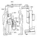
도 1a 및 1b는 본 개시의 한 구체예에 따른 멸균 드레이프가 있을 때와 없을 때의 원격수술 시스템에서 환자측 지지 조립체의 도식도를 각각 예시한다.
도 2a는 멸균 드레이프가 있고 기구가 장착된 원격수술 시스템의 한 구체예를 예시하는 도식적 투시도이다.
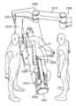
도 2b 및 2c는 멸균 드레이프가 도시되지 않은 상태의 도 2a의 원격수술 시스템의 측면도와 상면도를 각각 예시한다.
도 3은 조작기 베이스 플랫폼, 기구 조작기 클러스터, 및 장착된 기구의 한 구체예를 예시하는 투시도이다.
도 4a 및 4b는 삽입 축을 따라 각각 연장된 상태와 접힌 상태의 기구 조작의 투시도이다.
도 5a-1 및 5b-1은 기구 조작기의 원위면에 기구 전달 메커니즘의 근위면을 연결하기 위한 지지 후크의 작동을 예시하고, 도 5a-2 및 5b-2는 도 5a-1 및 5b-1의 단면도를 각각 예시한다.
도 5c-1 내지 5c-4는 외부 하우징이 없는 기구 조작기의 상이한 도면들을 예시한다.
도 6a-6b는 본 개시의 한 구체예에 따른 기구 조작기의 그립 모듈의 상이한 도면들을 예시한다.
도 7a는 본 개시의 한 구체예에 따른 기구 조작기의 짐볼 가동장치 모듈의 도면을 예시한다.
도 7b는 본 개시의 한 구체예에 따른 기구 조작기의 롤 모듈의 도면을 예시한다.
도 8은 본 개시의 한 구체예에 따른 기구 조작기의 텔레스코프 삽입 축의 도면을 예시한다.
도 9a 및 9b는 기구 조작기에 장착하도록 구성된 기구의 근위 부분 및 원위 부분의 투시도를 각각 예시한다.
도 10은 본 개시의 한 구체예에 따른 기구에 작동 가능하게 연결된 기구 조작기의 단면도를 예시한다.
도 11a-11b는 본 개시의 한 구체예에 따른 접힌 상태와 연장된 상태의 멸균 드레이프의 일부분의 투시도를 각각 예시한다.
도 11c는 본 개시의 한 구체예에 따른 베이스 플랫폼을 포함하는 조작기 암의 원단부에 장착된 회전하는 멸균 드레이프 부분의 단면도를 예시한다.
도 11d는 본 개시의 한 구체예에 따른 연장된 멸균 드레이프를 예시한다.
도 12는 본 개시의 한 구체예에 따른 멸균 어댑터를 포함하는 연장된 멸균 드레이프의 일부분의 투시도를 예시한다.
도 13a 및 13b는 본 개시의 한 구체예에 따른 조립된 멸균 어댑터의 투시도와 멸균 어댑터의 분해도를 각각 예시한다.
도 13c는 본 개시의 한 구체예에 따른 롤 가동장치 인터페이스의 확대도를 예시한다.
도 14a 및 14b는 본 개시의 한 구체예에 따른 기구 조작기의 하부 투시도와 하면도를 예시한다.
도 15는 본 개시의 한 구체예에 따른 멸균 어댑터에 작동 가능하게 연결된 기구 조작기의 하부 투시도를 예시한다.
도 16a-16e는 본 개시의 한 구체예에 따른 기구 조작기와 멸균 어댑터를 연결하기 위한 순서를 예시한다.
도 17a-17c는 본 개시의 한 구체예에 따른 멸균 어댑터에 수술 기구를 연결하기 위한 순서를 예시한다.
도 18a 및 18b는 맞물림 전의 기구와 멸균 어댑터의 확대된 투시도와 측면도를 각각 예시한다.
도 19a 및 19b는 접힌 위치와 전개된 위치에 있는 움직일 수 있는 캐뉼라 장착부의 투시도를 각각 예시한다.
도 20a 및 20b는 한 구체예에 따른 캐뉼라 클램프 상에 장착된 캐뉼라의 전면 및 후면 투시도를 예시한다.
도 21은 캐뉼라만의 투시도를 예시한다.
도 22는 본 개시의 한 구체예에 따른 조작기 플랫폼 위에서 기구 조작기에 장착된 기구와 조합된 도 21의 캐뉼라와 도 23a와 23b의 장착된 진입 가이드의 단면도를 예시한다.
도 23a 및 23b는 도 22의 진입 가이드의 투시도와 상면도를 예시한다.
도 24는 본 개시의 한 구체예에 따른 조작기 플랫폼 위에서 기구 조작기에 장착된 기구와 조합된 또 다른 캐뉼라와 또 다른 장착된 진입 가이드의 단면도를 예시한다.
도 24a-24b는 접힌 위치와 전개된 위치에 있는 또 다른 움직일 수 있는 캐뉼라 장착 암의 투시도를 각각 예시한다.
도 24c는 또 다른 구체예에 따른 캐뉼라의 근위 상부 구획을 예시한다.
도 24d는 또 다른 구체예에 따른 캐뉼라 장착 암의 원단부에 있는 캐뉼라 클램프를 예시한다.
도 25a-25c, 26a-26c 및 27a-27c는 기구 조작기 조립체 롤 축 또는 기구 삽입 축이 상이한 방향을 향하는 수술 시스템의 상이한 도면들을 예시한다.
도 28은 한 구체예에 따른 최소 침습 원격수술 시스템을 위한 집중 동작 제어 시스템의 도식도이다.
도 29는 한 구체예에 따른 최소 침습 원격수술 시스템을 위한 분산 동작 제어 시스템의 도식도이다.
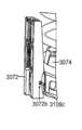
도 30a-30b는 한 구체예에 따른 로봇 수술 시스템의 평형추 링크의 상이한 도면들을 예시한다.
도 31은 한 구체예에 따른 외부 하우징이 없는 평형추 링크의 도면을 예시한다.
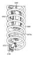
도 32a 및 32b는 한 구체예에 따른 평형추 링크의 원위 부분의 하부 투시도와 단면도를 각각 예시한다.
도 33은 단부 플러그가 없는 평형추 링크의 원위 부분의 측면도를 예시하고, 도 34는 단부 플러그 직선 가이드의 확대된 투시도를 예시하고, 도 35는 본 개시의 다양한 양태에 따른 조정 핀의 투시도를 예시한다.
도 36a-36c는 본 개시의 다양한 양태에 따른 직선 가이드에 대해 단부 플러그를 움직이는 조정 핀의 동작 범위를 도시하는 단면 측면도를 예시한다.
도 37a-37c는 본 개시의 다양한 양태에 따른 평형추 근위 링크의 원단부로부터의 상세도를 예시한다.
본 개시의 구체예들과 이들의 이점들은 이후의 상세한 설명과 관련하여 가장 잘 이해된다. 유사한 참조 번호들은 도면들 중 하나 이상에 예시된 유사한 요소들을 식별하기 위해 사용된다는 것이 인정되어야 한다. 또한, 도면들은 반드시 축적으로 그릴 필요는 없을 수 있다는 것이 인정되어야 한다.BRIEF DESCRIPTION OF THE DRAWINGS Figures 1A and 1B illustrate schematics of a patient side support assembly, respectively, in a remote surgical system with and without a sterile drape according to one embodiment of the present disclosure.
Figure 2a is a schematic perspective view illustrating one embodiment of a remote surgical system with sterile drape and instrumentation.
Figures 2b and 2c illustrate side and top views, respectively, of the remote surgical system of Figure 2a with sterile drapes not shown.
Figure 3 is a perspective view illustrating one embodiment of an actuator base platform, instrument actuator cluster, and mounted instrument.
Figs. 4A and 4B are perspective views of the operation of the mechanism in the extended state and in the folded state, respectively, along the insertion axis. Fig.
Figures 5A-1 and 5B-1 illustrate the operation of the support hooks for connecting the proximal surfaces of the mechanism transfer mechanism to the distal surface of the instrument manipulator, Figures 5A-2 and 5B-2 illustrate the operation of Figures 5A-1 and 5B-1 Respectively.
Figures 5c-1 through 5c-4 illustrate different views of a mechanism manipulator without an outer housing.
6A-6B illustrate different views of a grip module of a mechanism manipulator according to one embodiment of the present disclosure.
7A illustrates a diagram of a variable displacement actuator module of a mechanism manipulator according to one embodiment of the present disclosure;
Figure 7b illustrates a view of a roll module of a mechanism actuator according to one embodiment of the present disclosure;
8 illustrates a view of a telescope insertion axis of a mechanism manipulator according to one embodiment of the present disclosure;
Figures 9a and 9b illustrate, respectively, a perspective view of a proximal portion and a distal portion of a device configured to be mounted to a device manipulator.
10 illustrates a cross-sectional view of a mechanism manipulator operatively connected to a mechanism in accordance with one embodiment of the present disclosure;
Figures 11A-11B illustrate, respectively, a perspective view of a portion of a sterile drape in an extended state and a folded state in accordance with one embodiment of the present disclosure;
Figure 11C illustrates a cross-sectional view of a rotating sterile drape portion mounted to the distal end of an actuator arm including a base platform in accordance with one embodiment of the present disclosure.
11D illustrates an extended sterile drape according to one embodiment of the present disclosure.
12 illustrates a perspective view of a portion of an extended sterile drape comprising a sterile adapter according to one embodiment of the present disclosure;
Figures 13a and 13b illustrate a perspective view of an assembled sterile adapter and an exploded view of a sterile adapter, respectively, according to one embodiment of the present disclosure;
13C illustrates an enlarged view of a roll-moving device interface in accordance with one embodiment of the present disclosure.
Figures 14A and 14B illustrate bottom and bottom views of instrument actuators in accordance with one embodiment of the present disclosure;
15 illustrates a bottom perspective view of a device manipulator operatively connected to a sterilizing adapter in accordance with one embodiment of the present disclosure;
Figures 16A-16E illustrate a procedure for connecting a sterilizing adapter with a device manipulator according to one embodiment of the present disclosure.
17A-17C illustrate a procedure for connecting a surgical instrument to a sterile adapter according to one embodiment of the present disclosure.
18A and 18B illustrate an enlarged perspective view and a side view, respectively, of the mechanism before engagement and the sterilizing adapter.
Figures 19a and 19b illustrate a perspective view of the collapsible and movable cannula mounts in the deployed position, respectively.
20A and 20B illustrate front and rear perspective views of a cannula mounted on a cannula clamp according to one embodiment.
Figure 21 illustrates a perspective view of a cannula only.
Figure 22 illustrates a cross-sectional view of the cannula of Figure 21 and the mounted entry guide of Figures 23a and 23b in combination with a mechanism mounted on the instrument actuator on an actuator platform according to one embodiment of the present disclosure.
Figures 23A and 23B illustrate a perspective view and a top view of the entry guide of Figure 22;
24 illustrates a cross-sectional view of another cannula and another mounted entry guide in combination with a mechanism mounted on the instrument actuator on an actuator platform according to one embodiment of the present disclosure;
24A-24B illustrate perspective views of another collapsible cannula mounting arm in a collapsed and deployed position, respectively.
24C illustrates a proximal upper section of a cannula according to another embodiment.
Figure 24d illustrates a cannula clamp at the distal end of a cannula mounting arm according to another embodiment.
Figures 25a-25c, 26a-26c and 27a-27c illustrate different views of a surgical system in which the instrument actuator assembly roll axis or instrument insertion axis is oriented in different directions.
28 is a schematic diagram of a centralized motion control system for a minimally invasive telesurgical system in accordance with one embodiment.
29 is a schematic diagram of a distributed motion control system for a minimally invasive remote surgical system in accordance with one embodiment.
30A-30B illustrate different views of an equilibrium link of a robotic surgical system in accordance with one embodiment.
31 illustrates a view of an unbalanced link without an outer housing according to one embodiment.
32A and 32B illustrate a bottom perspective view and a cross-sectional view, respectively, of a distal portion of a counterweight link according to one embodiment.
Fig. 33 illustrates a side view of the distal portion of the counterweight link without the end plug, Fig. 34 illustrates an enlarged perspective view of the end plug straight guide, and Fig. 35 illustrates a perspective view of the adjustment pin according to various aspects of the present disclosure. do.
Figures 36A-36C illustrate cross-sectional side views showing the operating range of the adjustment pin for moving the end plug against a straight guide according to various aspects of the present disclosure.
Figures 37A-37C illustrate detail from the distal end of the balance weight proximal link according to various aspects of the present disclosure.
The embodiments of the present disclosure and their advantages are best understood with regard to the following detailed description. It should be appreciated that like reference numerals are used to identify like elements illustrated in one or more of the figures. It should also be appreciated that the drawings may not necessarily be drawn to scale.
본 개시의 양태들과 구체예들을 예시하는 본 설명 및 첨부한 도면들은 제한으로서 해석되어서는 안 된다. 다양한 기계적, 조성적, 구조적, 전기적 그리고 작동상의 변화들이 본 설명의 정신 및 범위로부터 벗어나지 않고 이루어질 수 있다. 일부 예에서, 잘 공지된 회로, 구조 및 기술은 본 개시를 애매하게 하지 않도록 상세히 나타내지 않았다. 둘 이상의 도면에서 같은 숫자들은 동일하거나 유사한 요소를 나타낸다.The present description and the accompanying drawings illustrating aspects and embodiments of the disclosure should not be construed as limiting. Various mechanical, structural, structural, electrical, and operational changes may be made without departing from the spirit and scope of the present disclosure. In some instances, well-known circuits, structures and techniques have not been shown in detail in order not to obscure the present disclosure. In the drawings, the same numerals denote the same or similar elements.
또한, 본 설명에서 용어들은 본 개시를 제한하지 않는다. 예를 들어, "밑", "아래", "하부", "위", "상부", "근위", "원위" 등과 같은 공간적으로 상대적인 용어들은 도면에 예시된 한 가지 요소 또는 특징과 다른 요소 또는 특징의 관계를 설명하기 위해서 사용될 수 있다. 이런 공간적으로 상대적인 용어들은 도면에 도시된 위치 및 방향에 더하여 사용중이거나 작동중인 장치의 다른 위치와 방향도 포함하도록 의도된다. 예를 들어, 도면의 장치가 뒤집힌 경우, 다른 요소 또는 특징의 "아래" 또는 "밑"으로서 설명된 요소들은 이 다른 요소 또는 특징의 "위" 또는 "상위"가 될 것이다. 따라서, 예시적인 용어 "아래"는 위와 아래의 위치와 방향을 모두 포함할 수 있다. 장치는 다른 식으로 배향될 수도 있으며(90도 회전 또는 다른 방향으로), 본원에 사용된 공간적으로 상대적인 기술자들은 그에 따라서 해석된다. 마찬가지로, 다양한 축을 따른 움직임과 축 주위의 움직임에 대한 설명도 여러 공간적인 장치 위치 및 방향을 포함한다. 이에 더하여, 단수형 "한" 및 "그"는 문맥상 다른 의미가 아니라면 복수형 역시 포함하도록 의도된다. 용어 "포함하다", "포함하는", "포함하다" 등은 언급된 특징, 단계, 작동, 요소 및/또는 구성요소의 존재를 명시하지만, 하나 이상의 다른 특징, 단계, 작동, 요소, 구성요소 및/또는 그룹의 존재 또는 부가를 배제하지 않는다. 결합된 것으로 설명된 구성요소들은 전기적으로 또는 기계적으로 직접 결합될 수 있거나, 또는 하나 이상의 중간 구성요소를 통해서 간접적으로 결합될 수 있다.In addition, the terms in this description do not limit this disclosure. For example, spatially relative terms such as "under", "under", "under", "above", "upper", "proximal" Or < / RTI > These spatially relative terms are intended to encompass other positions and orientations of the device in use or in operation in addition to the position and orientation shown in the figures. For example, if the device in the drawing is inverted, the elements described as "below" or "under" another element or feature will be "above" or "above" this other element or feature. Thus, the exemplary term "below" can include both the top and bottom positions and orientations. The device may be oriented differently (rotated 90 degrees or in the other direction) and the spatially-related descriptors used herein are interpreted accordingly. Likewise, the description of the movement along the various axes and the movement around the axis also includes various spatial device positions and orientations. In addition, the singular forms "a" and "it" are intended to include plural forms, unless the context otherwise requires. Steps, operations, elements, and / or components, but are not intended to preclude the presence or addition of one or more other features, steps, operations, elements, And / or the presence or addition of a group. The components described as being coupled may be electrically or mechanically coupled directly or indirectly through one or more intermediate components.
한 예에서, 용어 "근위" 또는 "근위 쪽에"는 시스템 움직임의 운동학적 사슬을 따라 조작기 암 베이스에 더 가까이 있는, 또는 시스템 움직임의 운동학적 사슬을 따라 원격 동작 중심(또는 수술 부위)로부터 더 멀리 있는 물체나 요소를 설명하기 위한 일반적인 방식으로 사용된다. 유사하게, 용어 "원위" 또는 "원위 쪽에"는 시스템 움직임의 운동학적 사슬을 따라 조작기 암 베이스로부터 더 멀리 있는, 또는 시스템 움직임의 운동학적 사슬을 따라 원격 동작 중심(또는 수술 부위)에 더 가까이 있는 물체나 요소를 설명하기 위한 일반적인 방식으로 사용된다.In one example, the term " proximal "or" proximal "refers to a position that is closer to the actuator arm base along the kinematic chain of system motion, or further away from the remote motion center (or surgical site) along the kinematic chain of system motion It is used as a general way to describe an object or element. Similarly, the terms "distal" or "distal" are intended to mean that they are further away from the actuator arm base along the kinematic chain of system motion, or closer to the remote motion center (or surgical site) along the kinematic chain of system motion It is used as a general way to describe an object or element.
로봇 종속 장치를 제어하여 작업 부위에서 작업을 수행하기 위해 마스터 장치에서 오퍼레이터의 입력을 사용하는 것은 잘 알려져 있다. 이러한 시스템은 여러 명칭으로 불리는데, 예를 들어 원격작동, 원격조작 또는 원격로봇 시스템이라고 한다. 원격조작 시스템의 한 가지 타입은 오퍼레이터가 작업 부위에 존재하는 것처럼 인식하는 것이며, 이러한 시스템은 예를 들어 텔레프레젠스 시스템이라고 불린다. 캘리포니아 서니베일의 Intuitive Surgical, Inc.에서 상용화된 da Vinci® 수술 시스템이 텔레프리젠스 원격조작 시스템의 한 예이다. 이러한 수술 시스템에 대한 텔레프리젠스 원리는 본원에 참고로 포함되는 미국특허 제6,574,355호(2001년 3월 21일 제출됨)에 개시된다. 원격작동 수술 시스템(텔레프리젠스 특징을 갖거나 갖지 않거나)은 원격수술 시스템이라고도 할 수 있다.It is well known to use the operator's input at the master unit to control the robot slave unit to perform tasks at the work site. These systems are referred to by various names, such as remote operation, remote operation or remote robot systems. One type of remote control system is one that recognizes an operator as if it is at a work site, and this system is called a telepresence system, for example. The da Vinci® surgical system, commercially available from Intuitive Surgical, Inc., Sunnyvale, CA, is an example of a telepresence telemetry system. The principle of telepresence for such a surgical system is disclosed in U.S. Patent No. 6,574,355, filed March 21, 2001, which is incorporated herein by reference. A remote operative system (with or without a telepresence feature) may be referred to as a remote surgical system.
하기 도면 및 설명에서 다양한 양태들과 예시적인 구체예들에 관해서 반복을 피하기 위해서 많은 특징들이 많은 양태들과 구체예들에 공통된다는 것이 이해되어야 한다. 설명이나 도면으로부터 어떤 양태의 생략은 그 양태가 해당 양태가 통합된 구체예에서 빠져 있다는 의미는 아니다. 대신에, 해당 양태는 명료성을 위해서 그리고 장황한 설명을 피하기 위해서 생략된 것일 수 있다. 따라서, 한 묘사된 및/또는 설명된 구체예와 관련해서 설명된 양태들은 실행 불가능하지 않다면 다른 묘사된 및/또는 설명된 구체예들과 함께 존재하거나 거기에 적용될 수 있다.It should be understood that many features are common to many aspects and embodiments in order to avoid repetition of various aspects and illustrative embodiments in the following drawings and description. Omissions of certain embodiments from the description or drawings are not meant to imply that the embodiment is absent from the integrated embodiment. Instead, the aspect may be omitted for clarity and to avoid redundant explanations. Accordingly, aspects described in connection with a depicted and / or described embodiment may reside in or be embodied with other described and / or illustrated embodiments, if not infeasible.
따라서, 몇 가지 일반적인 양태들은 하기 다양한 설명에 적용된다. 다양한 수술 기구, 가이드 튜브 및 기구 조립체들이 본 개시에 적용 가능하며, 본원에 참고로 포함되는 미국 특허출원 제11/762,165호(2007년 6월 13일 제출됨; 미국 특허출원 공개 US 2008/0065105 A1)에 더 설명된다. 수술 기구는 단독으로, 또는 가이드 튜브, 다수의 기구 및/또는 다수의 가이드 튜브를 포함하는 조립체로서 본 개시에 적용 가능하다. 따라서, 다양한 수술 기구가 이용될 수 있으며, 각 수술 기구는 서로 독립적으로 작동하고, 각각 단부 작동기를 가진다. 일부 예에서, 단부 작동기는 환자에 있는 단일 진입구를 통해서 데카르트 공간 내에서 적어도 6의 능동적으로 제어되는 DOF(즉, 서지, 히브, 스웨이, 롤, 피치, 요우)에 의해 작동한다. 1 이상의 추가 단부 작동기 DOF가, 예를 들어 파지 또는 전단 기구에서 단부 작동기의 턱 움직임에 적용될 수 있다.Accordingly, some general aspects apply to the following various descriptions. A variety of surgical instruments, guide tubes, and instrument assemblies are described in U.S. Patent Application No. 11 / 762,165, filed Jun. 13, 2007, which is incorporated herein by reference and is applicable to the present disclosure and is described in U.S. Patent Application Publication No. 2008/0065105 A1 ). The surgical instrument is applicable to the present disclosure alone, or as an assembly comprising a guide tube, a plurality of instruments and / or a plurality of guide tubes. Accordingly, various surgical instruments can be used, and each surgical instrument operates independently of each other, each having an end effector. In some examples, the end effector is actuated by at least six actively controlled DOFs (i.e., surges, heaves, sway, rolls, pitches, yaws) within the Cartesian space through a single entry in the patient. One or more additional end actuators DOF may be applied to the jaw movement of the end actuators, for example in gripping or shearing mechanisms.
예를 들어, 적어도 하나의 수술 단부 작동기가 여러 도면에 도시되거나 설명된다. 단부 작동기는 특정한 수술 기능(예를 들어, 겸자/집게, 니들 드라이버, 가위, 전기소작 후크, 스테이플러, 클립 적용기/제거기 등)을 수행하는 최소 침습 수술 기구 또는 조립체의 일부분이다. 많은 단부 작동기는 그 자체가 단일 DOF를 가지진다(예를 들어, 열리고 닫히는 집게). 단부 작동기는 "리스트" 타입 메커니즘 같은 1 이상의 추가 DOF를 제공하는 메커니즘을 가진 수술 기구 본체에 연결될 수 있다. 이러한 메커니즘의 예들은 본원에 참고로 포함되는 미국특허 제6,371,952호(1999년 6월 28일 제출됨; Madhani et al.)와 미국특허 제6,817,974호(2002년 6월 28일 제출됨; Cooper et al.)에 도시되고, da Vinci® 수술 시스템에서 8mm 및 5mm 기구에 사용되는 것과 같은 다양한 Intuitive Surgical, Inc. Endowrist® 메커니즘으로서 알려져 있다. 본원에 설명된 수술 기구는 일반적으로 단부 작동기를 포함하지만, 일부 양태에서는 단부 작동기가 생략될 수 있음이 이해되어야 한다. 예를 들어, 기구 본체 샤프트의 블런트 원위 팁은 조직의 리트랙션에 사용될 수 있다. 다른 예로서, 흡인 또는 관주 개구가 본체 샤프트 또는 리스트 메커니즘의 원위 팁에 존재할 수 있다. 이들 양태에서, 단부 작동기의 배치 및 배향에 관한 설명은 단부 작동기를 지니지 않은 수술 기구의 팁의 배치 및 배향을 포함한다는 것이 이해되어야 한다. 예를 들어, 단부 작동기의 팁에 대한 기준 프레임을 다루는 설명은 단부 작동기를 지니지 않은 수술 기구의 팁의 기준 프레임을 포함하는 것으로 읽혀야 한다.For example, at least one surgical end actuator is shown or described in the various figures. The end effector is a part of a minimally invasive surgical instrument or assembly that performs certain surgical functions (e.g., forceps / forceps, needle drivers, scissors, electrocautery hooks, staplers, clip applicators / Many end actuators themselves have a single DOF (for example, open and closed tongs). The end effector may be connected to a surgical instrument body having a mechanism for providing at least one additional DOF, such as a "list " type mechanism. Examples of such mechanisms are disclosed in U.S. Patent No. 6,371,952 (filed June 28, 1999; Madhani et al.) And U.S. Patent No. 6,817,974 (filed June 28, 2002; Cooper et al .), And are available in a variety of Intuitive Surgical, Inc. < (R) > It is known as the Endowrist® mechanism. It should be understood that the surgical instrument described herein generally includes an end effector, but in some aspects an end effector may be omitted. For example, the blunt distal tip of the instrument body shaft may be used for retraction of tissue. As another example, an aspiration or conduit opening may be present in the distal tip of the body shaft or list mechanism. In these aspects, it should be understood that the description of the positioning and orientation of the end effector includes the placement and orientation of the tip of the surgical instrument without the end effector. For example, the description of handling the reference frame for the tip of the end effector should be read as including the reference frame of the tip of the surgical instrument without the end effector.
본 설명 전체적으로 단안 또는 입체 영상 시스템/영상 캡처 구성요소/카메라 장치가 단부 작동기가 도시되거나 설명된 어디서든 기구의 원단부에 위치될 수 있거나(이 장치는 "카메라 기구"로 간주될 수 있다), 또는 어떤 가이드 튜브나 다른 기구 조립체 요소의 원단부에 또는 근처에 위치될 수 있다. 따라서, 본원에서 사용된 용어 "영상 시스템" 등은 설명된 양태들과 구체예들의 맥락 내에서 영상 캡처 구성요소 및 영상 캡처 구성요소와 관련 회로구조 및 하드웨어의 조합을 모두 포함하도록 광범하게 해석되어야 한다. 이러한 내시경 영상 시스템(예를 들어, 광학, 적외선, 초음파 등)은 원위 쪽에 위치된 영상 감지 칩과 관련 회로를 가진 시스템을 포함하며, 이들은 무선 또는 유선 접속을 통해서 신체 외부로 캡처된 영상 데이터를 중계한다. 이러한 내시경 영상 시스템은 또한 신체 외부에서 캡처하기 위해 영상을 중계하는 시스템을 포함한다(예를 들어, 로드 렌즈 또는 광섬유를 사용함으로써). 어떤 기구 또는 기구 조립체에서, 다이렉트 뷰 광학 시스템(내시경 영상을 대안렌즈로 직접 본다)이 사용될 수 있다. 원위 쪽에 위치된 반도체 입체 영상 시스템의 예가 본원에 참고로 포함되는 미국 특허출원 제11/614,661호(2006년 12월 2일 제출됨; "입체 내시경"을 개시함; Shafer et al.)에 개시된다. 전기 및 광섬유 조명 접속과 같은 잘 알려진 내시경 영상 시스템 구성요소는 명료성을 위해 생략되거나 기호로 표시된다. 내시경 영상을 위한 조명은 전형적으로 단일 조명 포트에 의해서 도면에 표시된다. 이들 설명은 예시라는 것이 이해되어야 한다. 조명 포트의 크기, 위치 및 수는 변할 수 있다. 조명 포트는 전형적으로 렌즈 구경의 여러 측면에 배열되거나, 또는 렌즈 구경을 완전히 둘러싸면서 배열되며, 이로써 깊은 음영이 최소화될 수 있다.As a whole, the monocular or stereoscopic imaging / image capture component / camera device may be located at the distal end of the device where the end effector is shown or described (this device may be considered a "camera device"), Or at or near the distal end of any guide tube or other instrument assembly element. Accordingly, the term "imaging system" or the like as used herein should be broadly interpreted to include both a combination of image capturing components and image capturing components and associated circuit structures and hardware within the context of the described aspects and embodiments . Such endoscopic imaging systems (e. G., Optical, infrared, ultrasound, etc.) include a system having an image sensing chip and associated circuitry located in the distal side, which relay image data captured outside the body via a wireless or wired connection do. Such an endoscopic imaging system also includes a system for relaying images for capturing outside the body (e.g., by using a rod lens or an optical fiber). In some apparatus or instrument assemblies, a direct view optical system (endoscopic image viewed directly as an alternative lens) may be used. An example of a distal-lying semiconductor stereoscopic imaging system is disclosed in U.S. Patent Application No. 11 / 614,661, filed December 2, 2006, entitled "Stereoscopic Endoscopy", Shafer et al., Which is incorporated herein by reference . Well-known endoscopic imaging system components, such as electrical and fiber optic illumination connections, are omitted or marked for clarity. Illumination for an endoscopic image is typically shown in the drawing by a single illumination port. It should be understood that these descriptions are illustrative. The size, position, and number of light ports may vary. The illumination ports are typically arranged on several sides of the lens aperture, or are arranged completely surrounding the aperture of the lens, so that deep shading can be minimized.
본 설명에서, 캐뉼라는 전형적으로 수술 기구나 가이드 튜브가 환자 조직에 문지르듯 닿는 것을 방지하기 위해 사용된다. 캐뉼라는 절개부와 자연 개구에 모두 사용될 수 있다. 기구나 가이드 튜브가 그것의 삽입 축(종축)에 대해 자주 병진하거나 회전하지 않는 상황에서는 캐뉼라가 사용되지 않을 수 있다. 취입이 필요한 상황에서는 캐뉼라는 기구나 가이드 튜브를 지나 과잉의 취입 가스가 누출되는 것을 방지할 수 있는 시일을 포함할 수 있다. 수술 부위에서의 취입과 취입 가스가 필요한 과정을 뒷받침하는 캐뉼라 조립체의 예들은 전체 개시가 모든 취지에 있어서 본원에 참고로 포함되는 미국 특허출원 제12/705,439호(2010년 2월 12일 제출됨; "단일 입구 시스템에서 다수 기구를 위한 진입 가이드"를 개시함)에서 찾을 수 있다. 취입이 필요하지 않은 흉부 수술의 경우 캐뉼라 시일은 생략될 수 있으며, 만일 기구 또는 가이드 튜브 삽입 축 움직임이 최소라면 캐뉼라 자체가 생략될 수도 있다. 강직성 가이드 튜브는 일부 구성에서 가이드 튜브에 대해 삽입되는 기구를 위한 캐뉼라로서 기능할 수 있다. 캐뉼라 및 가이드 튜브는, 예를 들어 스틸 또는 압출 플라스틱일 수 있다. 플라스틱은 스틸보다 저렴하며, 일회용으로 적합할 수 있다.In the present description, a cannula is typically used to prevent the surgical instrument or guide tube from rubbing against the patient tissue. The cannula can be used for both the incision and the natural opening. In situations where the instrument or guide tube does not translate or rotate frequently with respect to its insertion axis (longitudinal axis), a cannula may not be used. In situations where a blow is required, the cannula may include a seal that can prevent excess blown gas from leaking past the instrument or guide tube. Examples of cannula assemblies that support both surgical and blown gas processes are described in U. S. Patent Application Serial No. 12 / 705,439, filed Feb. 12, 2010, the entire disclosure of which is incorporated herein by reference in its entirety. Entitled " Entry Guidance for Multiple Mechanisms in a Single Entrance System "). The cannula seal may be omitted in thoracic surgery where no intubation is required, and the cannula itself may be omitted if the instrument or guide tube insertion axis movement is minimal. The rigid guide tube may serve as a cannula for a device that is inserted into the guide tube in some configurations. The cannula and guide tube may be, for example, steel or extruded plastic. Plastics are cheaper than steel, and can be used as a disposable.
가요성 수술 기구 및 가이드 튜브의 다양한 예들과 조립체들이 상기 인용된 미국 특허출원 제11/762,165호에 도시되고 설명된다. 이러한 가요성은 본 설명에서 다양한 방식으로 달성된다. 예를 들어, 기구 또는 가이드 튜브의 어떤 구간이 연속해서 곡선을 이룬 가요성 구조일 수 있으며, 예를 들어 나선형 권선 코일에 기초한 것 또는 여러 구간이 제거된 튜브(예를 들어, 커프 타입 컷들)에 기초한 것일 수 있다. 또는, 가요성 부분은 일련의 짧은 피벗 연결된 구간들로 이루어질 수 있으며, 이들은 연속 곡선 구조로 된 대략적인 뱀 모양을 제공한다. 기구 및 가이드 튜브 구조는 본원에 참고로 포함되는 미국 특허출원 공개 US 2004/0138700(2003년 12월 2일 제출됨; Cooper et al.)에 설명된 것들을 포함할 수 있다. 명료성을 위해서 도면 및 관련 설명은 일반적으로 기구 및 가이드 튜브의 단지 두 구간만을 도시하며, 이들은 근위(전달 메커니즘에 더 가깝고 수술 부위에서는 더 먼 쪽)와 원위(전달 메커니즘에서 더 멀고 수술 부위에 더 가까운 쪽)로 명명된다. 기구와 가이드 튜브는 3개 이상의 구간으로 나눠질 수 있으며, 각 구간은 강직성이거나, 수동적 가요성이거나, 또는 능동적 가요성이라는 것이 이해되어야 한다. 원위 구간, 근위 구간, 또는 전체 메커니즘에 관해 설명된 신축 및 휨은 또한 명료성을 위해 생략된 중간 구간에도 적용된다. 예를 들어, 근위 구간과 원위 구간 사이의 중간 구간은 간단한 또는 복합적인 곡선으로 휠 수 있다. 가요성 구간은 다양한 길이일 수 있다. 외경이 작은 구간은 더 작은 최소 곡률 반경을 가질 수 있고, 외경이 큰 구간보다 휘게 된다. 케이블-제어 시스템의 경우, 허용되지 않는 높은 케이블 마찰이나 바인딩이 휘는 동안의 최소 곡률 반경과 전체 휨 각도를 제한한다. 가이드 튜브의(또는 어떤 조인트의) 최소 휨 반경은 내부 수술 기구 메커니즘의 매끄러운 움직임을 곤란하게 하거나 저지하지 않도록 해야 한다. 가요성 구성요소는, 예를 들어 최대 약 4 피트 길이, 약 0.6 인치 직경일 수 있다. 특정 메커니즘에 대해서는 다른 길이 및 직경(예를 들어, 더 짧은, 더 작은)과 가요성 정도가 메커니즘이 맞춰서 설계된 표적 해부구조에 의해서 결정될 수 있다.Various examples and assemblies of flexible surgical instruments and guide tubes are shown and described in the above-referenced U.S. Patent Application No. 11 / 762,165. This flexibility is achieved in various ways in this description. For example, some section of the instrument or guide tube may be a continuously curved flexible structure, for example, based on a helical coil, or in tubes (e.g., cuff-type cuts) from which sections have been removed It can be based. Alternatively, the flexible portion may consist of a series of short pivotally connected sections, which provide an approximate serpentine shape of a continuous curve structure. The instrument and guide tube structures may include those described in U.S. Patent Application Publication No. US 2004/0138700 (filed December 2, 2003; Cooper et al.), Which is incorporated herein by reference. For the sake of clarity, the drawings and associated descriptions generally show only two sections of the instrument and guide tube, which are proximal (closer to the delivery mechanism and farther away from the surgical site) and distal (farther from the delivery mechanism and closer to the surgical site Side). It is to be understood that the instrument and guide tube can be divided into more than three sections, each section being rigid, passive, or active. The stretching and bending described with respect to the distal, proximal, or overall mechanism also applies to intermediate sections omitted for clarity. For example, the middle section between the proximal and distal sections may be a simple or complex curve. The flexible section may be of various lengths. A section with a small outer diameter can have a smaller minimum radius of curvature, and a section with a larger outer diameter will be bent. In the case of cable-control systems, unacceptable high cable friction or binding limits the minimum radius of curvature and total deflection during bending. The minimum bending radius of the guide tube (or of any joint) should be such that it does not hamper or impede the smooth movement of the internal surgical instrument mechanism. The flexible component may be, for example, up to about 4 feet long, about 0.6 inches in diameter. For certain mechanisms, different lengths and diameters (e.g., shorter, smaller) and degree of flexibility can be determined by the target anatomy designed with the mechanisms aligned.
일부 예에서는 기구 또는 가이드 튜브의 원위 구간만이 가요성이고, 근위 구간은 강직성이다. 다른 예에서는 환자 몸안에 존재하는 기구 또는 가이드 튜브의 전체 구간이 가요성이다. 또 다른 예에서, 가장 원위 구간이 강직성일 수 있고, 하나 이상의 다른 근위 구간은 가요성이다. 가요성 구간들은 수동적일 수 있거나, 또는 능동적으로 제어될 수 있다("조종가능"). 이러한 능동적 제어는, 예를 들어 대향하는 케이블 세트를 이용해서 행해질 수 있다(예를 들어, 한 세트는 "피치"를 제어하고 직교하는 세트는 "요우"를 제어한다; 3개의 케이블을 사용하여 유사한 작용을 수행할 수 있다). 작은 전기 또는 자기 가동장치, 형상기억 합금, 전자활성 폴리머("인공 근육"), 기압 또는 유압 풀무 또는 피스톤 등과 같은 다른 제어 요소들이 사용될 수 있다. 기구 또는 가이드 튜브의 구간이 완전히 또는 부분적으로 또 다른 가이드 튜브 안에 위치된 예에서는 능동적 가요성과 수동적 가요성의 다양한 조합들이 존재할 수 있다. 예를 들어, 수동적 가요성 가이드 튜브 안에서 능동적 가요성 기구가 둘러싼 가이드 튜브를 신축할 만큼 충분한 외측 힘을 발휘할 수 있다. 유사하게, 능동적 가요성 가이드 튜브는 그것 안의 수동적 가요성 기구를 신축할 수 있다. 가이드 튜브와 기구의 능동적 가요성 구간은 협력하여 작업할 수 있다. 기구와 가이드 튜브가 가요성이고 강직성인 두 경우 모두, 다양한 디자인에 있어서의 순응성을 고려하여, 중심 종축으로부터 더 멀리 위치된 제어 케이블이 중심 종축에 더 가까이 위치된 케이블보다 기계적 이점을 제공할 수 있다.In some instances, only the distal section of the instrument or guide tube is flexible, and the proximal section is rigid. In another example, the entire section of the instrument or guide tube present in the patient ' s body is flexible. In another example, the most distal section may be rigid, and one or more other proximal sections may be flexible. The flexible segments may be passive, or may be actively controlled ("steerable"). This active control can be done, for example, using a set of opposing cables (e.g., one set controls the "pitch" and the orthogonal set controls "yaw" Lt; / RTI > Other control elements such as small electric or magnetic actuators, shape memory alloys, electroactive polymers ("artificial muscles"), pneumatic or hydraulic bellows or pistons, There may be various combinations of active flexibility and passive flexibility in the example where the section of the instrument or guide tube is located entirely or partially within another guide tube. For example, an active flexure mechanism within the passive flexible guide tube may exert sufficient lateral force to stretch the surrounding guide tube. Similarly, the active flexible guide tube may expand the passive flexible mechanism therein. The active flexible sections of the guide tube and instrument can be worked together. In both cases where the instrument and guide tube are flexible and rigid, the control cable located farther from the central longitudinal axis can provide a mechanical advantage over the cable located closer to the central longitudinal axis, taking into account the adaptability in various designs .
가요성 구간의 순응성(강성)은 거의 완전히 이완된 상태(적은 내부 마찰이 존재한다)에서부터 실질적으로 강직성인 상태까지 변할 수 있다. 일부 양태에서, 순응성은 제어 가능하다. 예를 들어, 기구 또는 가이드 튜브의 가요성 구간의 어떤 구간이나 전부가 실질적으로(즉, 유효하지만 무한하지는 않은) 강직성일 수 있다(이 구간은 "강직성" 또는 "고정성"이다). 고정성 구간은 직선, 간단한 곡선 또는 복합적 곡선 모양으로 고정될 수 있다. 고정은 마찰을 일으켜 인접한 척추구조가 움직이는 것을 방지할 만큼 충분한 기구나 가이드 튜브를 따라 길이방향으로 이어진 하나 이상의 케이블에 장력을 적용함으로써 달성될 수 있다. 케이블 또는 케이블들은 각 척추구조의 큰 중심 구멍을 통해서 이어질 수 있거나, 또는 척추구조의 바깥 원주 근처에 있는 작은 구멍을 통해서 이어질 수 있다. 또는 달리, 하나 이상의 제어 케이블을 움직이는 하나 이상의 모터의 구동 요소가 제자리에 부드럽게 고정되어(예를 들어, 서보제어에 의해서) 케이블을 제자리에 홀딩함으로써 기구 또는 가이드 튜브 움직임을 방지하고, 이로써 척추구조를 제자리에 고정할 수 있다. 모터 구동 요소를 제자리에 유지함으로써 다른 움직일 수 있는 기구 및 가이드 튜브 구성요소를 역시 제자리에 효과적으로 유지할 수 있다. 서보제어 하의 강성은 유효하기는 하지만 일반적으로 조인트에 직접 위치된 브레이크, 예를 들어 수동적 셋업 조인트를 제자리에 유지하기 위해 사용된 브레이크를 사용하여 얻어질 수 있는 강성보다는 적다는 것이 이해되어야 한다. 일반적으로 케이블 강성은 그것이 일반적으로 서보시스템이나 브레이크 적용된 조인트 강성보다 적기 때문에 중요하다.The compliance (rigidity) of the flex section can vary from a nearly fully relaxed state (where there is little internal friction) to a substantially rigid state. In some aspects, compliance is controllable. For example, any section or all of the flexible section of the instrument or guide tube may be substantially (i. E., Valid but not infinite) rigid (this section is "rigid" or "fixed"). The stationary section can be fixed in a straight line, a simple curve or a complex curve shape. The fixation can be accomplished by applying tension to one or more cables that extend longitudinally along a guide tube or a device sufficient to cause friction and prevent adjacent vertebral structures from moving. The cables or cables may lead through a large central hole in each vertebral structure or through a small hole near the outer periphery of the vertebral structure. Alternatively, one or more motor drive elements that move one or more control cables may be gently secured in place to hold the cable in place (e.g., by servo control) to prevent movement of the instrument or guide tube, It can be fixed in place. By keeping the motor drive element in place, other moveable mechanisms and guide tube components can also be held in place effectively. It should be appreciated that the stiffness under servo control is effective, but less than the stiffness that can be achieved using brakes normally used to hold brakes directly in place, e.g., passive set-up joints in place. In general, cable stiffness is important because it is generally less than the servo system or brake applied joint stiffness.
어떤 상황에서, 가요성 구간의 순응성은 이완된 상태와 강직성 상태에서 계속 변할 수 있다. 예를 들어, 고정한 케이블 장력이 증가하면 강직성 상태에서 가요성 구간의 고정 없이도 강성이 증가할 수 있다. 이러한 중간 순응성은 수술 부위로부터의 반응성 힘에 의해 야기되는 움직임으로 인해 일어날 수 있는 조직 외상을 감소시키면서 원격수술 작동을 허용할 수 있다. 가요성 구간에 통합되는 적합한 휨 센서는 원격수술 시스템이 기구 및/또는 가이드 튜브 위치를 그것이 휘는 상태에 따라 결정할 수 있도록 한다. 본원에 참고로 포함되는 미국 특허출원 공개 US 2006/0013523(2005년 7월 13일 제출됨; Childers et al.)은 광섬유 위치 형상감지 장치와 방법을 개시한다. 본원에 참고로 포함되는 미국 특허출원 제11/491,384호(2006년 7월 20일 제출됨; Larkin et al.)는 이러한 구간 및 가요성 장치의 제어에 사용되는 광섬유 휨 센서(예를 들어, 광 브래그 격자)를 개시한다.In some situations, the compliance of the flexural section may continue to change in the relaxed state and the rigid state. For example, an increase in the fixed cable tension can increase the stiffness without fixing the flexible section in the rigid state. This intermediate compliance may allow for remote operative operation while reducing tissue trauma that may occur due to movement caused by reactive forces from the surgical site. Suitable bending sensors incorporated in the flexible section allow the remote surgical system to determine the position of the instrument and / or guide tube as it is bent. U.S. Patent Application Publication No. US 2006/0013523 (filed July 13, 2005, Childers et al.), Which is incorporated herein by reference, discloses an apparatus and method for detecting optical fiber position profiles. U.S. Patent Application No. 11 / 491,384, filed July 20, 2006, Larkin et al., Which is incorporated herein by reference, discloses an optical fiber flexure sensor (e.g., Bragg grating).
본원에 설명된 것 같은 최소 침습 수술 기구 조립체, 기구, 단부 작동기, 및 조작기 암 구성의 양태들을 제어하기 위한 의사의 입력은 일반적으로 직관적인 카메라 기준 제어 인터페이스를 사용하여 행해진다. 예를 들어, da Vinci® 수술 시스템은 이러한 제어 인터페이스를 가진 의사 콘솔을 포함하며, 이것은 본원에 설명된 양태들을 제어하도록 변형될 수 있다. 의사는 예를 들어 6의 DOF를 가진 하나 이상의 수동 입력 마스터 메커니즘을 조작하여 종속 기구 조립체 및 기구를 제어할 수 있다. 입력 메커니즘은 1 이상의 단부 작동기 DOF를 제어하기 위한 손가락으로 작동되는 집게를 포함한다(예를 들어, 집게의 턱을 닫는 것). 직관적 제어는 의사의 입력 메커니즘과 영상 출력 표시장치의 위치에 따라 단부 작동기와 내시경 영상 시스템의 상대적 위치를 배향함으로써 제공된다. 이런 배향은 의사가 마치 수술 작업 부위를 실질적으로 실제 현장에서 보고 있는 것처럼 입력 메커니즘과 단부 작동기 컨트롤을 조작할 수 있도록 한다. 이 원격작동 실제 현시는 의사가 오퍼레이터가 수술 부위에서 직접 보면서 작업하는 것처럼 나타난 투시로부터 영상을 본다는 것을 의미한다. 본원에 참고로 포함되는 미국특허 제6,671,581호(2002년 6월 5일 제출됨; Niemeyer et al.)는 최소 침습 수술 장치에서 카메라 기준 제어에 대한 더 이상의 정보를 함유한다.Physician inputs to control aspects of the minimally invasive surgical instrument assembly, instrument, end effector, and manipulator arm configuration as described herein are generally done using an intuitive camera reference control interface. For example, the da Vinci® surgical system includes a pseudo console with this control interface, which can be modified to control the aspects described herein. The physician may manipulate one or more passive input master mechanisms with a DOF of, for example, six, to control the slave mechanism assembly and mechanism. The input mechanism includes a finger-operated gripper for controlling at least one end effector DOF (e.g., closing the gripper's jaw). Intuitive control is provided by orienting the relative positions of the end effector and the endoscopic imaging system according to the position of the physician's input mechanism and the image output indicator. This orientation allows the physician to manipulate the input mechanism and end actuator controls as if they were actually seeing the surgical site in real life. This remote operation actually means that the physician sees the image from the perspective that appears as though the operator is looking directly at the surgical site. U.S. Patent No. 6,671,581 (filed June 5, 2002, Niemeyer et al.), Which is incorporated herein by reference, contains further information on camera reference control in a minimally invasive surgical device.
단일 입구 수술 시스템Single entrance surgery system
이제 도 1a 및 1b와 관련하여, 본원에 설명된 최소 침습 수술 기구, 기구 조립체 및 조작과 제어 시스템의 양태들을 이용하는 로봇-보조(원격조작) 최소 침습 수술 시스템의 양태를 예시하는 도식적 측면도와 정면도가 도시된다. 세 가지 주요 구성요소는 내시경 영상 시스템(102), 의사 콘솔(104)(마스터) 및 환자측 지지 시스템(100)(종속)이며, 도시된 대로 유선(전기 또는 광학) 또는 무선 접속(106)에 의해서 모두 상호 연결된다. 하나 이상의 전자 데이터 처리장치가 이들 주 구성요소에 다양하게 위치될 수 있으며, 이로써 시스템 기능성을 제공할 수 있다. 예들은 상기 인용된 미국특허 출원 제11/762,165호에 개시된다. 점선으로 도시된 멸균 드레이프(1000)가 유익하게 환자측 지지 시스템(100)의 적어도 일부를 덮어서 수술 과정 동안 멸균 현장을 유지하면서 기구와 그것의 관련 조작기 사이의 정확한 인터페이스와 함께 효과적이고 간단한 기구 교환을 제공한다.Referring now to Figures 1a and 1b, a schematic side elevation and front view illustrating aspects of a minimally invasive surgical instrument, apparatus assembly and a robotic-assisted minimally invasive surgical system utilizing aspects of the manipulation and control system described herein Respectively. The three main components are an
영상 시스템(102)은, 예를 들어 수술 부위의 캡처된 내시경 영상 데이터 및/또는 환자 외부에 있는 다른 영상 시스템으로부터의 사전작업 또는 실시간 영상 데이터에 대해 영상 처리 기능을 수행한다. 영상 시스템(102)은 처리된 영상 데이터(예를 들어, 수술 부위의 영상뿐만 아니라 관련된 제어 및 환자 정보)를 의사 콘솔(104)의 의사에게 출력한다. 일부 양태에서, 처리된 영상 데이터는 다른 수술실 요원이 볼 수 있는, 또는 수술실에서 먼 곳의 하나 이상의 장소에서 볼 수 있는 선택적 외부 모니터에 출력된다(예를 들어, 다른 장소에 있는 의사가 비디오를 모니터할 수 있다; 바로바로 제공되는 비디오가 훈련에 사용될 수 있다; 등등).The
의사 콘솔(104)은, 예를 들어 의사가 본원에 설명된 수술 기구, 가이드 튜브, 및 영상 시스템("종속") 장치를 조작할 수 있도록 하는 다중 DOF의 기계적 입력("마스터") 장치를 포함한다. 일부 양태에서, 이러한 입력 장치는 기구 및 기구 조립체 구성요소로부터 의사에게 촉각적 피드백을 제공한다. 또한, 콘솔(104)은 표시장치의 영상이 일반적으로 표시장치 스크린 뒤/아래에서 의사의 손작업에 상응하는 거리에서 초점이 맞도록 위치된 입체 비디오 출력 표시장치를 포함한다. 이들 양태는 본원에 참고로 포함되는 미국특허 제6,671,581호에 더 충분히 논의된다.The
삽입 동안의 제어는, 예를 들어 의사가 주 장치의 하나 또는 둘 다를 사용하여 실제로 영상을 움직임으로써 달성될 수 있다. 의사는 주 장치를 사용해서 영상을 옆으로 나란히 움직이고 영상을 자신 쪽으로 당겨서 영상 시스템과 그것의 관련 기구 조립체(예를 들어, 가요성 가이드 튜브)에 출력 표시장치 상의 고정된 중심점을 향해 조종하여 환자 몸안에서 나아가도록 명령을 내린다. 한 양태에서, 카메라 제어는 주 장치가 영상에 고정됨으로써 영상이 주 장치 핸들이 움직이는 것과 동일한 방향으로 움직인다는 인상을 제공하도록 설계된다. 이런 설계는 주 장치가 정확한 위치에 있도록 함으로써 의사가 카메라 제어를 하지 않을 때도 기구를 제어할 수 있도록 하며, 결과적으로 기구 제어를 시작하거나 재개하기 전에 주 장치를 클러치(맞물림 해제), 이동 및 제자리로 클러치 해제(맞물림)할 필요성이 없어진다. 일부 양태에서, 주 장치 위치는 넓은 주 장치 작업공간의 사용을 피하기 위해서 삽입 속도에 비례하여 정해질 수 있다. 또는 달리, 의사는 주 장치를 클러치 및 클러치 해제함으로써 래칫 동작을 이용해서 삽입을 행할 수 있다. 일부 양태에서, 삽입은 수동으로 제어될 수 있으며(예를 들어, 손으로 작동되는 휠에 의해서), 자동화된 삽입(예를 들어, 서보모터 구동 롤러)은 수술 기구 조립체의 원단부가 수술 부위 근처에 있을 때 행해진다. 환자의 해부학적 구조와 삽입 궤적에 이용될 수 있는 공간의 사전 작업 또는 실시간 영상 데이터(예를 들어, MRI, 엑스선)를 사용해서 삽입을 보조할 수 있다.Control during insertion may be accomplished, for example, by the physician actually moving the image using one or both of the main devices. The physician uses the main device to move the image sideways and pulls the image toward itself to steer the imaging system and its associated instrument assembly (e.g., a flexible guide tube) toward a fixed center point on the output display, Command to move in. In one aspect, the camera control is designed to provide an impression that the main device is fixed to the image so that the image moves in the same direction as the main device handle moves. This design allows the main device to be in the correct position, thereby allowing the physician to control the device even when the physician is not in control of the camera, and consequently to clutch, disengage, move and position the main device There is no need to release the clutch (engage). In some embodiments, the main device position may be proportional to the insertion rate to avoid the use of a large main device work space. Alternatively, the physician can perform the insertion using the ratchet operation by disengaging and disengaging the main device. In some aspects, the insertion can be manually controlled (e.g., by a hand-operated wheel) and automated insertion (e.g., servo motor drive rollers) It is done when there is. It can assist with the insertion of the patient's anatomy and the space available for the insertion trajectory or by using real-time image data (eg, MRI, x-rays).
환자측 지지 시스템(100)은 바닥-장착된 베이스(108), 또는 달리 교호선으로 도시된 것과 같은 천장-장착된 베이스(110)을 포함한다. 베이스는 움직일 수 있거나, 또는 고정될 수 있다(예를 들어, 바닥, 천장, 벽 또는 수술대와 같은 다른 장비에).The patient
베이스(108)는 수동적인 비제어형 "셋업" 부분과 능동적으로 제어되는 "조작기" 부분을 포함하는 암 조립체(101)를 지지한다. 한 예에서, 셋업 부분은 2개의 수동적 회전 "셋업" 조인트(116 및 120)를 포함하며, 이들은 조인트 브레이크가 해제되었을 때 연결된 셋업 링크(118 및 122)의 수동 배치를 허용한다. 암 조립체와 링크(114)에 연결된 베이스 사이에 수동적 프리즘형 셋업 조인트(미도시)를 사용하여 더 큰 수직 조정부(112)를 허용할 수 있다. 또는 달리, 이들 셋업 조인트의 일부는 능동적으로 제어될 수 있으며, 다양한 구성에서 셋업 조인트가 더 많이 또는 더 적게 사용될 수 있다. 셋업 조인트와 링크는 데카르트 x, y, z 공간 안에서 다양한 위치와 배향에 암의 로봇 조작기 부분을 배치할 수 있도록 한다. 원격 동작 중심은 요우, 피치 및 롤 축이 교차하는 장소이다(즉, 조인트는 이들의 동작 범위에서 움직이면서 운동학적 사슬은 유효하게 정지된 채로 유지되는 장소). 아래 더 상세히 설명된 대로, 이들 능동적으로 제어되는 조인트의 일부는 개별 수술 기구의 DOF를 제어하는 것과 관련되고, 이들 능동적으로 제어되는 조인트의 나머지는 이들 로봇 조작기의 단일 조립체의 DOF를 제어하는 것과 관련된다. 능동적 조인트와 링크는 모터 또는 다른 가동장치에 의해서 움직일 수 있으며, 의사 콘솔(104)에서 주 장치 암의 움직임과 관련된 움직임 제어 신호를 수신한다.The
도 1a 및 1b에 도시된 것처럼, 조작기 조립체 요우 조인트(124)는 셋업 링크(122)의 원단부와 제1 조작기 링크(126)의 근단부 사이에 연결된다. 요우 조인트(124)는 링크(126)가 조작기 조립체 요우 축(123) 주위에서 "요우"로서 임의로 한정될 수 있는 동작으로 링크(122)를 기준으로 움직일 수 있도록 한다. 도시된 대로, 요우 조인트(124)의 회전 축은 원격 동작 중심(146)과 정렬되며, 이것은 일반적으로 기구(미도시)가 환자로 들어가는 위치이다(예를 들어, 복부 수술에서는 배꼽). 한 구체예에서, 셋업 링크(122)는 수평 또는 x, y 평면을 따라 회전 가능하며, 요우 조인트(124)는 제1 조작기 링크(126)가 요우 축(123)을 중심으로 회전할 수 있도록 구성되고, 이로써 셋업 링크(122), 요우 조인트(124) 및 제1 조작기 링크(126)가 요우 조인트(124)에서부터 원격 동작 중심(146)까지 수직 점선으로 예시된 대로 로봇 암 조립체에 대해 일정한 수직 요우 축(123)을 제공한다.Actuator assembly yaw joint 124 is coupled between the proximal end of set-up
제1 조작기 링크(126)의 원단부는 제2 조작기 링크의 근단부에 연결되고, 제2 조작기 링크(130)의 원단부는 제3 조작기 링크(134)의 근단부에 연결되며, 제3 조작기 링크(134)의 원단부는 제4 조작기 링크(138)의 근단부에 연결되고, 이러한 연결은 각각 능동적으로 제어되는 회전 조인트(128, 132 및 136)에 의해 이루어진다. 한 구체예에서, 링크(130, 134 및 138)들이 함께 연결되어 연결된 동작 메커니즘으로서 작용한다. 연결된 동작 메커니즘은 잘 공지되어 있다(예를 들어, 이러한 메커니즘은 입력과 출력 링크 동작이 서로 평행하게 유지될 때 평행 동작 연결로 알려져 있다). 예를 들어, 회전 조인트(128)가 능동적으로 회전되면 조인트(132 및 136)들도 또한 회전하여 링크(138)가 링크(130)와 일정한 관계로 움직인다. 따라서, 조인트(128, 132 및 136)의 회전 축이 평행한 것을 알 수 있다. 이들 축이 조인트(124)의 회전 축과 수직일 때는 링크(130, 134 및 138)가 조작기 조립체 피치 축(139) 주위에서 "피치"로서 임의로 한정될 수 있는 동작으로 링크(126)를 기준으로 움직인다. 한 구체예에서, 링크(130, 134 및 138)는 단일 조립체로서 움직이므로, 제1 조작기 링크(126)는 능동적 근위 조작기 링크라고 간주될 수 있고, 제2 내지 제4 조작기 링크(130, 134 및 138)는 종합해서 능동적 원위 조작기 링크라고 간주될 수 있다.The distal end of the
조작기 조립체 플랫폼(140)은 제4 조작기 링크(138)의 원단부에 연결된다. 조작기 플랫폼(140)은 하기 더 상세히 설명되는 2개 이상의 수술 기구 조작기를 포함하는 조작기 조립체(142)를 지지하는 회전 가능한 베이스 플레이트를 포함한다. 회전하는 베이스 플레이트는 조작기 조립체(142)가 조작기 조립체 롤 축(141) 주위에서 "롤"로서 임의로 한정될 수 있는 동작으로 플랫폼(140)을 기준으로 단일 유닛으로서 회전할 수 있도록 한다.
최소 침습 수술의 경우, 불필요한 조직 손상을 피하기 위해서 기구들은 절개부든 자연 개구든 이들이 환자의 몸으로 진입하는 위치와 관련해서 실질적으로 정지된 채로 유지되어야 한다. 따라서, 기구 샤프트의 요우 및 피치 동작은 공간 내에서 비교적 정치한 상태로 머무르는 조작기 조립체 롤 축 또는 기구 삽입 축 상의 단일 위치에 중심이 있어야 한다. 이 위치를 원격 동작 중심이라고 한다. 기구들이 전부(카메라 기구를 포함해서) 하나의 작은 절개부(예를 들어, 배꼽에 있는)나자연 개구를 통해 진입되어야 하는 단일 입구 최소 침습 수술의 경우, 모든 기구는 이러한 일반적으로 정지된 원격 동작 중심을 기준으로 움직여야 한다. 따라서, 조작기 조립체(142)에 대한 원격 동작 중심은 조작기 조립체 요우 축(123)과 조작기 조립체 피치 축(139)의 교차에 의해서 한정된다. 링크(130, 134 및 138) 및 조인트(128, 132 및 136)의 구성은 원격 동작 중심(146)이 조작기 조립체가 환자와 관련하여 자유롭게 움직일 수 있는 충분한 거리를 두고 조작기 조립체(142)의 원위 쪽에 위치된다. 조작기 조립체 롤 축(141)이 또한 원격 동작 중심(146)과 교차한다는 것을 알 수 있다.In the case of minimally invasive surgery, to avoid unnecessary tissue damage, the instruments should remain substantially stationary with respect to the position of entry into the patient's body, whether the incision or natural opening. Thus, the yaw and pitch motion of the instrument shaft must be centered at a single location on the actuator assembly roll shaft or instrument insertion axis that remains relatively stationary in space. This location is called the remote action center. In the case of single-entry minimally invasive surgery where all of the instruments (including the camera instrument) must enter through one small incision (for example, in the navel) or a natural opening, You have to move around the center. Thus, the remote operating center for
아래 더 상세히 설명된 대로, 수술 기구는 조작기 조립체(142)의 각 수술 기구 조작기 상에 장착되어 그것에 의해서 가동된다. 기구들은 탈착 가능하게 장착되며, 이로써 다양한 기구들이 특정 기구 조작기 상에 상호 교환 가능하게 장착될 수 있다. 한 양태에서, 하나 이상의 기구 조작기는 카메라 기구와 같은 특정 타입의 기구를 지지하고 가동하도록 구성될 수 있다. 기구의 샤프트는 기구 조작기로부터 원위 쪽으로 연장된다. 샤프트들은 진입구에 위치된 공통된 캐뉼라를 통해서 환자 몸안으로 연장된다(예를 들어, 체벽을 통해서 또는 자연 개구에서). 한 양태에서, 진입 가이드는 캐뉼라 안에 위치되며, 각 기구 샤프트가 진입 가이드의 채널을 통해서 연장됨으로써 기구 샤프트를 위한 추가의 지지를 제공한다. 캐뉼라는 캐뉼라 장착부(150)에 탈착 가능하게 연결되며, 이것은 한 구체예에서 제4 조작기 링크(138)의 근단부에 연결된다. 한 실시형태에서, 캐뉼라 장착부(150)는 회전 조인트에 의해서 링크(138)에 연결되고, 이것은 장착부가 링크(138)에 인접한 삽입된 위치와 정확한 위치에 캐뉼라를 홀딩하는 작동 위치 사이에서 움직일 수 있도록 하며, 이로써 원격 동작 중심(146)이 캐뉼라를 따라 위치된다. 한 양태에 따라서, 작동 동안 캐뉼라 장착부는 링크(138)에 대해 제자리에 고정된다. 기구(들)는 캐뉼라 장착부(150)의 원단부에 장착된 진입 가이드와 캐뉼라 조립체를 통해 슬라이딩할 수 있으며, 이것의 예들이 하기 더 상세히 설명된다. 다양한 수동적 셋업 조인트/링크와 능동적 조인트/링크가 환자가 움직이는 수술대 위에서 다양한 자세로 있을 때 기구 조작기를 배치함으로써 기구와 영상 시스템을 큰 동작 범위에서 움직일 수 있도록 한다. 일부 구체예에서, 캐뉼라 장착부는 근위 링크 또는 제1 조작기 링크(126)에 연결될 수 있다.As described in more detail below, the surgical instrument is mounted on and operated by each surgical instrument actuator of the
조작기 암에서 특정한 셋업 및 능동적 조인트 및 링크는 로봇의 크기와 모양을 줄이기 위해서 생략될 수 있거나, 또는 조인트와 링크가 추가되어 자유도를 증가시킬 수 있다. 조작기 암은 수술을 위한 필요한 자세 범위를 달성하기 위하여 링크, 수동적 조인트 및 능동적 조인트의 다양한 조합을 포함할 수 있음이 이해되어야 한다(여분의 DOF가 제공될 수 있다). 또한, 다양한 수술 기구가 단독으로 또는 가이드 튜브, 다수의 기구 및/또는 다수의 가이드 튜브를 포함하는 기구 조립체, 및 다양한 구성(예를 들어, 기구 전달 수단 또는 기구 조작기의 근위면 또는 원위면 위에)을 통해 기구 조작기(예를 들어, 가동장치 조립체)에 연결된 기구가 본 개시의 양태들에 적용될 수 있다.Specific set-up and active joints and links in the actuator arm can be omitted to reduce the size and shape of the robot, or joints and links can be added to increase the degree of freedom. It should be understood that the manipulator arm may include various combinations of links, passive joints, and active joints (extra DOF may be provided) to achieve the required posture range for surgery. It will also be appreciated that the various surgical instruments may be used alone or in combination with a guide tube, a plurality of instruments and / or instrument assemblies including a plurality of guide tubes, and various configurations (e.g., on the proximal or distal surface of instrument delivery means or instrument manipulators) A mechanism connected to a mechanism manipulator (e.g., a moveable device assembly) may be applied to aspects of the present disclosure.
도 2a-2c는 각각 원격작동 수술(원격수술) 시스템의 환자측 지지 카트(200)의 도식적 투시도, 측면도 및 상면도이다. 묘사된 카트(200)는 도 1a 및 1b와 관련하여 상기 설명된 일반적 구성의 예시적인 구체예이다. 의사 콘솔과 비디오 시스템은 도시되지 않지만, 도 1a 및 1b와 공지된 원격로봇 수술 시스템 구조(예를 들어, da Vinci® 수술 시스템 구조)와 관련하여 상기 설명된 대로 적용할 수 있다. 이 구체예에서, 카트(200)는 바닥-장착된 베이스(208)를 포함한다. 베이스는 움직일 수 있거나, 또는 고정될 수 있다(예를 들어, 바닥, 천장, 벽 또는 다른 충분히 단단한 구조에). 베이스(208)는 지지 기둥(210)을 지지하며, 암 조립체(201)가 지지 기둥(210)에 연결된다. 암 조립체는 2개의 수동적 회전 셋업 조인트(216 및 220)을 포함하며, 이들은 브레이크가 해제되었을 때 연결된 셋업 링크(218 및 222)의 수동 배치를 허용한다. 묘사된 구체예에서, 셋업 링크(218 및 222)는 수평면에서 움직인다(바닥에 평행하게). 암 조립체는 기둥(210)과 수직 셋업 링크(214) 사이의 수동적 슬라이딩 셋업 조인트(215)에서 지지 기둥(210)에 연결된다. 조인트(215)는 조작기 암이 수직으로 조정되는 것을 허용한다(바닥에 수직으로). 따라서, 수동적 셋업 조인트와 링크를 사용하여 환자를 기준으로 원격 동작 중심(246)을 적절히 배치할 수 있다. 일단 원격 동작 중심(246)이 적절히 위치되면, 각 조인트(215, 216 및 220)에서 브레이크가 설정되어 암의 셋업 부분이 움직이는 것을 방지한다.Figures 2a-2c are schematic perspective, side and top views, respectively, of a patient
이에 더하여, 암 조립체는 조작기 암 구성과 움직임, 기구 조작, 및 기구 삽입을 위한 능동적 조인트 및 링크를 포함한다. 제1 조작기 링크(226)의 근단부는 능동적으로 제어되는 회전 조작기 조립체 요우 조인트(224)를 통해 셋업 링크(222)의 원단부에 연결된다. 도시된 것처럼, 요우 조인트(224)의 회전 조작기 조립체 요우 축(223)은 요우 조인트(224)에서부터 원격 동작 중심(246)까지 수직 점선으로 예시된 대로 원격 동작 중심(246)과 정렬된다.In addition, the arm assembly includes active arm joints and links for actuator arm configuration and movement, instrument manipulation, and instrument insertion. The proximal end of the
제1 조작기 링크(226)의 원단부는 제2 조작기 링크(230)의 근단부와 연결되고, 제2 조작기 링크(230)의 원단부는 제3 조작기 링크(234)의 근단부와 연결되며, 제3 조작기 링크(234)의 원단부는 제4 조작기 링크(238)의 근단부와 연결되고, 이러한 연결은 각각 능동적으로 제어되는 회전 조인트(228, 232 및 236)에 의해 이루어진다. 상기 설명된 대로, 링크(230, 234 및 238)는 연결된 동작 메커니즘으로서 기능하며, 이로써 링크(230)가 가동될 때 제2 조작기 링크(230)와 협력하여 제4 조작기 링크(238)가 자동으로 움직인다. 묘사된 구체예에서, 미국특허 제7,594,912호(2004년 9월 30일 제출됨)에 개시된 것과 유사한 메커니즘이 용도에 맞게 변형된다(또한, 예를 들어 미국 특허출원 제11/611,849호(2006년 12월 15일 제출됨; 미국 특허출원 공개 US 2007/0089557 A1)를 참조한다). 따라서, 제1 조작기 링크(226)는 능동적 근위 링크라고 생각될 수 있고, 제2 내지 제4 링크(230, 234 및 238)는 종합해서 능동적 원위 링크라고 생각될 수 있다. 한 구체예에서, 제1 링크(226)는 압축 스프링 평형추 메커니즘을 포함할 수 있으며, 이것은 하기 더 설명된 대로 조인트(228)를 중심으로 한 원위 링크의 움직임으로 인한 힘의 균형을 맞추는 역할을 한다.The distal end of the
조작기 조립체 플랫폼(240)은 제4 링크(238)의 원단부에 연결된다. 플랫폼(240)은 베이스 플레이트(240a)를 포함하며, 그 위에 기구 조작기 조립체(242)가 장착된다. 도 2a에 도시된 대로, 플랫폼(240)은 "할로" 링을 포함하며, 그 안에서 디스크 모양 베이스 플레이스(240a)가 회전한다. 다른 구체예에서는 할로와 디스크 이외의 다른 구성들이 사용될 수 있다. 베이스 플레이트(240)의 회전 중심은 조작기 플랫폼(240)의 중심과 원격 동작 중심(246)을 통해서 연장된 점선으로 나타낸 대로 조작기 조립체 롤 축(241)과 일치한다. 한 구체예에서, 기구(260)는 기구 조작기의 원위면 위에서 조작기 조립체(242)의 기구 조작기에 장착된다.
도 2a 및 2b에 도시된 것처럼, 기구 조작기 조립체(242)는 4개의 기구 조작기(242a)를 포함한다. 각 기구 조작기는 그것의 관련된 기구를 지지하고 가동시킨다. 묘사된 구체예에서, 1개의 기구 조작기(242a)는 카메라 기구를 가동하도록 구성되고, 3개의 기구 조작기(242a)는 수술 부위에서 수술 작업 및/또는 진단 작업을 수행하는 여러 다른 상호 교환가능한 수술 기구를 가동하도록 구성된다. 기구 조작기는 더 많이 또는 더 적게 사용될 수 있다. 일부 작동 구성에서, 하나 이상의 조작기는 수술 과정의 도중에 잠깐 또는 내내 관련된 수술 기구를 갖지 않을 수 있다. 기구 조작기가 아래 더 상세히 개시된다.As shown in Figs. 2A and 2B, the
상기 언급된 대로, 수술 기구(260)는 각 기구 조작기(242a)에 장착되어 조작기에 의해서 가동된다. 본 개시의 한 양태에 따라서, 각 기구는 단지 기구의 근단부에서만 그것의 관련된 조작기에 장착된다. 도 2a에서 이 근단부 장착 특징부가 기구 조작기 조립체(242)를 유지하고 환자로부터 가능한 멀리 떨어져 플랫폼(240)을 지지한다는 것을 볼 수 있으며, 이것은 주어진 기구 기하구조에서 조작기 암의 능동적으로 제어되는 부분이 환자와 부딪치지 않으면서 환자에 대해 최대 동작 범위 안에서 자유롭게 움직일 수 있도록 한다. 기구(260)는 이들의 샤프트가 조작기 조립체 롤 축(241) 주위에 클러스터를 이루도록 장착된다. 각 샤프트는 기구의 힘 전달 메커니즘으로부터 원위 쪽으로 연장되고, 모든 샤프트는 입구에 위치된 단일 캐뉼라를 통해 환자 몸안으로 연장된다. 캐뉼라는 제4 조작기 링크(238)에 연결된 캐뉼라 장착부(250)에 의해 베이스 플레이트(240a)에 대해 고정된 위치에 탈착 가능하게 홀딩된다. 단일 가이드 튜브가 캐뉼라에 삽입되어 그 안에서 자유롭게 회전하며, 각 기구 샤프트가 가이드 튜브에서 관련된 채널을 통해 연장된다. 캐뉼라와 가이드 튜브의 종축은 일반적으로 롤 축(241)과 일치한다. 따라서, 가이드 튜브는 베이스 플레이트(240a)가 회전함에 따라 캐뉼라 안에서 회전한다. 일부 구체예에서, 캐뉼라 장착부는 제1 조작기 링크(226)에 움직일 수 있게 연결될 수 있다.As mentioned above, the
각 기구 조작기(242a)는 베이스 플레이트(240a)에 작동 가능하게 연결된 능동적 텔레스코핑 삽입 메커니즘(224)(도 2b)에 가동 가능하게 연결되며, 이것을 사용하여 수술 기구(들)을 삽입하거나 빼낼 수 있다. 도 2a는 텔레스코핑 삽입 메커니즘(224)의 원단부를 향해 일정 거리 연장된 기구 조작기(242a)를 예시하고(또한, 도 3 및 4a를 참조한다), 도 2b는 텔레스코핑 삽입 메커니즘(244)의 근단부 쪽으로 리트랙트된 기구 조작기(242)를 예시한다(또한, 도 4b를 참조한다). 능동적 조인트(224, 228, 232, 236)와 조작기 플랫폼(240)이 함께 및/또는 독립적으로 움직이며, 이로써 수동적 셋업 암과 조인트에 의해서 원격 동작 중심이 확립된 후에 수술 기구(또는 조립체)가 진입구에서, 예를 들어 환자의 배꼽에서 원격 동작 중심(246) 주위에서 움직인다.Each
도 2a에 도시된 대로, 캐뉼라 장착부(250)가 제4 조작기 링크의 근단부 근처에서 제4 링크와 연결된다. 다른 양태에서, 캐뉼라 장착부(250)는 근위 링크의 다른 구간과 연결될 수 있다. 상기 설명된 대로, 캐뉼라 장착부(250)는 힌지를 이루며, 이로써 그것은 제4 링크(238)에 인접한 삽입된 위치와 캐뉼라를 지지할 수 있는 연장된 위치(도시된 것처럼)를 왔다갔다 할 수 있다. 한 양태에 따라서, 작동하는 동안 캐뉼라 장착부(250)는 제4 링크(238)에 대해 고정된 위치에 홀딩된다.As shown in FIG. 2A, the
제1 조작기 링크(226)는 묘사된 구체예에서는 일반적으로 한 예로서 뒤집힌 "L" 모양임을 알 수 있다. "L" 모양 링크의 근위쪽 다리는 요우 조인트(224)에서 링크(226)에 연결되고, 링크의 원위쪽 다리는 회전 조인트(228)에서 제2 조작기 링크(238)에 연결된다. 이 예시적인 구체예에서, 2개 다리는 일반적으로 수직이고, 제1 조작기 링크의 근위쪽 다리가 조작기 조립체 요우 축(223)에 일반적으로 수직인 평면 주위에서 회전한다(예를 들어, 요우 축이 수직(z)일 경우 수평(x, y)면). 따라서, 원위쪽 다리는 조작기 조립체 요우 축(223)에 일반적으로 평행하게 연장된다(예를 들어, 요우 축이 수평일 경우 수직(z)으로). 이 모양은 조작기 링크(230, 234 및 238)가 요우 축(224) 아래에서 움직이는 것을 허용하며, 이로써 링크(230, 234 및 238)는 원격 동작 중심(246)과 교차하는 조작기 조립체 피치 축(239)을 제공한다. 제1 링크(226)의 다른 구성들도 가능하다. 예를 들어, 제1 링크(226)의 근위쪽 다리와 원위쪽 다리는 서로 수직이 아닐 수 있으며, 근위쪽 다리가 수평면과 상이한 평면에서 회전할 수 있거나, 또는 링크(226)가 원호 모양과 같은 일반적인 "L" 모양이 아닌 다른 모양을 가질 수 있다.It will be appreciated that
점선(249)(도 2c)으로 도시된 대로 수직 요우 축(223)이 링크(226)가 실질적으로 360도 회전하도록 허용한다는 것을 알 수 있다. 한 예에서, 조작기 조립체의 요우 회전은 연속적일 수 있으며, 다른 예에서 조작기 조립체의 요우 회전은 대략 +180도이다. 또 다른 예에서, 조작기 조립체 요우 회전은 대략 660도일 수 있다. 피치 축(239)은 이러한 요우 축 회전 동안 일정하게 유지될 수도 있고 그렇지 않을 수도 있다. 기구들이 일반적으로 조작기 조립체의 롤 축(241)과 정렬된 방향으로 환자에 삽입되므로, 암을 능동적으로 제어하여 조작기 조립체 요우 축 주위에서 어떤 원하는 방향으로 기구 삽입 방향을 배치 및 재배치할 수 있다(예를 들어, 환자의 머리 쪽을 향한 기구 삽입 방향을 도시한 도 25a-25c와 환자의 발 쪽을 향한 기구 삽입 방향을 도시한 도 26a-26c를 참조한다). 이런 능력은 일부 수술에서는 상당히 유익할 수 있다. 기구가 배꼽에 위치된 단일 입구를 통해서 삽입되는 특정한 복부 수술에서, 예를 들어 기구들은 환자의 체벽에 새로운 입구를 열 필요없이 복부의 4개 사분면 모두에 접근할 수 있도록 위치될 수 있다. 다중 사분면 접근은, 예를 들어 복부를 통해 림프절에 접근하는 경우 필요할 수 있다. 반면에, 다중 입구 원격로봇 수술 시스템의 사용은 다른 복부 사분면에 더 충분히 접근하기 위해서 환자의 체벽에 추가의 입구를 만드는 것이 필요할 수 있다.It can be seen that the
추가로, 조작기는 약간 위로 피치된 구성으로 수직으로 아래를 향하도록 기구에 명령할 수 있다(예를 들어, 위로 피치된 기구 삽입 방향을 도시한 도 27a-27c를 참조한다). 이와 같이, 단일 진입구를 통한 기구의 진입 각도(원격 중심을 중심으로 요우와 피치 모두)가 쉽게 조작될 수 있고, 또한 환자 안전성 및 환자측 요원이 잘 조종할 수 있도록 하기 위해 진입구 주변의 공간을 넓히면서 변경될 수 있다.In addition, the manipulator may command the instrument to be vertically downward in a slightly upward pitch configuration (e.g., see Figs. 27A-27C illustrating the instrument insertion direction pitched up). In this way, it is possible to easily manipulate the angle of entry of the instrument through a single entrance (both yaw and pitch around the remote center), and also to increase the space around the entrance to allow for patient safety and patient maneuverability .
또한, 링크(230, 234 및 238)는 조인트(228, 232 및 236)와 함께 사용되며, 이로써 단일 진입구 주변에 공간을 만들면서 단일 진입구를 통과하는 기구의 진입 피치 각도를 쉽게 조작할 수 있다. 예를 들어, 링크(230, 234 및 238)는 환자로부터 "멀리 원호를 그리는" 형태 요소를 갖도록 위치될 수 있다. 이러한 떨어진 원호는 요우 축(223)을 중심으로 조작기 암의 회전을 허용하며, 조작기 암과 환자의 충돌을 일으키기 않는다. 또한, 이러한 떨어진 원호는 환자측 요원이 기구 교환시 조작기에 쉽게 접근할 수 있도록 하며, 수동 기구(예를 들어, 수동 복강경 기구 또는 리트랙션 장치)의 삽입 및 작동을 위한 진입구 접근도 용이하게 한다. 또 다른 예에서, 제4 링크(238)는 원격 동작 중심과 그에 따라 환자로부터 멀리 원호를 그리는 형태 요소를 가지며, 이로써 환자 안전성이 높아진다. 다른 용어로서, 기구 조작기(242a)의 클러스터의 작동 엔벨로프는 대략 원뿔형이며, 기구 조작기(242a)의 원격 동작 중심(246)에 원뿔의 팁이 위치되고, 근단부에 원뿔의 원형 단부가 위치된다. 이러한 작동 엔벨로프는 환자와 수술 로봇 시스템 사이의 방해를 줄이고, 시스템의 동작 범위를 크게 하여 수술 부위로의 접근성을 개선하며, 수술 스텝들의 환자 접근성을 개선한다.
따라서, 조작기 암 조립체(201)의 구성 및 기하구조는 그것의 큰 동작 범위와 함께 단일 입구를 통한 다중 사분면 수술을 허용한다. 단일 절개부를 통해서 조작기는 기구를 한 방향으로 보내고 쉽게 방향을 변경할 수 있으며, 예를 들어 환자의 머리나 골반 쪽에서 작업한 다음(예를 들어, 도 25a-25c를 참조한다), 조작기 암을 일정한 수직 요우 축을 중심으로 움직여서 방향을 환자의 골반이나 머리 쪽으로 변경할 수 있다(예를 들어, 도 26a-26c를 참조한다).Thus, the configuration and geometry of the
이 예시적인 조작기 암 조립체는, 예를 들어 원격 동작 중심을 참조하여 움직이도록 작동되는 기구 조립체에 사용된다. 조작기 암에서 특정한 셋업 및 능동적 조인트 및 링크는 생략될 수 있거나, 또는 자유도를 증가시키기 위해 조인트와 링크가 추가될 수 있다. 조작기 암은 수술에 필요한 자세 범위를 달성하기 위해서 링크, 수동적 조인트 및 능동적 조인트(여분의 DOF가 제공될 수 있다)의 다양한 조합을 포함할 수 있다는 것이 이해되어야 한다. 또한, 다양한 수술 기구는 단독으로 또는 가이드 튜브, 다수의 기구, 및/또는 다수의 가이드 튜브를 포함하는 기구 조립체로, 및 다양한 구성(예를 들어, 가동장치 조립체 또는 전달 메커니즘의 근위면 또는 원위면에)을 통해 기구 조작기에 연결된 기구들로서 본 개시에 적용될 수 있다.This exemplary manipulator arm assembly is used in an instrument assembly that is operated to move, for example, with reference to a remote motion center. Specific set-up and active joints and links in the actuator arm may be omitted, or joints and links may be added to increase the degree of freedom. It should be understood that the manipulator arm may include various combinations of links, passive joints, and active joints (extra DOF may be provided) to achieve the posture range required for surgery. The various surgical instruments may also be used alone or in combination with a guide tube, a plurality of instruments, and / or an instrument assembly including a plurality of guide tubes, and various configurations (e.g., proximal or distal surfaces of the movable device assembly or delivery mechanism Lt; RTI ID = 0.0 > to < / RTI >
이제 도 3, 4a-4b, 5a-1 내지 5b-2, 5c-1 내지 5c-4 및 8에 관해서, 기구 조작기의 양태들과 구체예들이 더 상세히 설명되지만, 이들 양태와 구체예들에 본 개시가 제한되는 것은 아니다. 도 3은 조작기 조립체 플랫폼의 회전 가능한 베이스 플레이트(340a), 베이스 플레이트(340a)에 장착되어 기구 조작기 조립체를 형성하는 4개의 기구 조작기(342)의 클러스터, 및 관련 기구 조작기(342)의 원위면에 각각 장착된 4개의 기구(360)(근위 부분이 예시된다)의 구체예의 투시도이다. 베이스 플레이트(340a)는 상기 설명된 대로 조작기 조립체 롤 축(341)을 중심으로 회전할 수 있다. 한 구체예에서, 롤 축(341)은 캐뉼라와 진입 가이드 조립체의 길이방향 중심을 통해서 이어지며, 진입 가이드를 통해서 기구(360)가 환자의 몸으로 들어간다. 롤 축(341)은 또한 각 기구 조작기(342)의 원위면의 실질적으로 단일 평면에 실질적으로 수직이며, 그 결과 기구 조작기의 원위면에 장착된 기구의 근위면의 실질적으로 단일 평면에도 실질적으로 수직이다.As regards Figures 3, 4a-4b, 5a-1 through 5b-2, 5c-1 through 5c-4 and 8, aspects and embodiments of the instrument actuator are described in greater detail, The disclosure is not limited. Fig. 3 shows a perspective view of an assembly of a four-
각 기구 조작기(342)는 베이스 플레이트(340a)에 연결된 삽입 메커니즘을 포함한다. 도 8은 기구 삽입 메커니즘의 구체예를 더 상세히 예시하는 컷어웨이 투시도이다. 도 8에 도시된 대로, 기구 삽입 메커니즘(844)은 텔레스코핑 방식으로 서로에 관하여 직선 슬라이딩하는 3개의 링크를 포함한다. 삽입 메커니즘(844)은 캐리지(802), 캐리지 링크(804) 및 베이스 링크(808)를 포함한다. 본원에 참고로 포함되는 미국 특허출원 제11/613,800호(2006년 12월 20일 제출됨; 미국 특허출원 공개 US 2007/0137371 A1)에 설명된 대로, 캐리지 링크(804)는 베이스 링크(808)를 따라 슬라이드하고, 캐리지(802)는 캐리지 링크(804)를 따라 슬라이드한다. 캐리지(802)와 링크(804, 808)는 커플링 루프(806)에 의해서 상호연결된다(이것은 한 예에서 하나 이상의 가요성 금속 벨트를 포함한다; 또는 달리 하나 이상의 케이블이 사용될 수 있다). 베이스 링크(808)의 리드 스크류(808a)가 커플링 루프(806) 상의 고정된 위치에 연결된 슬라이더(808b)를 구동시킨다. 캐리지(802)도 역시 고정된 위치에서 커플링 루프(806)에 연결되고, 이로써 슬라이더(808b)가 베이스 링크(808)를 기준으로 특정한 거리 x를 슬라이드함에 따라 캐리지(802)는 베이스 링크(808)를 기준으로 2x 만큼 슬라이드한다. 다양한 다른 직선 동작 메커니즘(예를 들어, 리드 스크류 및 캐리지)들도 삽입 메커니즘의 다른 실시형태에서 사용될 수 있다.Each
도 3 및 8에 도시된 것처럼, 베이스 링크(808)의 근단부는 회전 가능한 베이스 플레이트(340a)에 연결되고, 캐리지(802)는 기구 조작기(342)의 외부 쉘 또는 내부 프레임에 연결된다(예를 들어, 도 5c-1 내지 5c-3의 내부 프레임 구경(542i') 안에). 서보모터(미도시)가 리드 스크류(808a)를 구동시키고, 그 결과 기구 조작기(342)가 일반적으로 롤 축(341)과 평행한 방향으로 베이스 플레이트(340a)를 기준으로 근위와 원위 쪽으로 움직인다. 수술 기구(360)가 조작기(342)에 연결되므로, 삽입 메커니즘(344)은 캐뉼라를 통해 기구를 수술 부위를 향해서 삽입하고 수술 부위로부터 멀리 빼내는 기능을 한다(기구 삽입 DOF). 커플링 루프에 인접하여 이어진 평평한 전기전도성 신축성 케이블(미도시)이 기구 조작기에 파워, 신호 및 접지를 제공할 수 있다.3 and 8, the proximal end of the
삽입 메커니즘(344)의 텔레스코핑 특징부의 이점은 그것이 기구 조작기가 그것의 완전히 근위 위치에서 그것의 완전히 원위 위치로 움직일 때 더 큰 동작 범위를 제공한다는 점임을 알 수 있으며, 조작기가 그것의 완전히 근위 위치에 있을 때는 단지 하나의 정지된 삽입 단계 피스만이 사용된 경우보다 삽입 메커니즘이 더 적게 돌출된다(예를 들어, 도 4a(완전히 원위 위치)와 4b(완전히 근위 위치)를 참조한다). 단축된 돌출부는 기구 조작기가 그것의 근위 위치에 있을 때 삽입 메커니즘이 수술 동안 환자를 방해하는 것과 예를 들어 기구 교환 동안 수술실 요원을 방해하는 것을 방지한다.It can be seen that the advantage of the telescoping feature of the
도 3에 더 예시된 것처럼, 텔레스코핑 삽입 메커니즘(344)은 한 구체예에서 회전 가능한 베이스 플레이트(340a)에 대칭 장착되고, 따라서 기구 조작기(342)와 장착된 기구(360)가 롤 축(341)을 중심으로 대칭 클러스터를 이루게 된다. 한 구체예에서, 기구 조작기(342)와 그것의 관련 기구(360)는 일반적으로 파이-웨지 레이아웃으로 롤 축 주위에 배치되며, 기구 샤프트는 조작기 조립체 롤 축(341) 근처에 위치된다. 따라서, 베이스 플레이트가 롤 축(341)을 중심으로 회전함에 따라 기구 조작기(342)와 장착된 기구(360)의 클러스터도 역시 롤 축을 중심으로 회전한다.3, the
도 4a 및 4b는 각각 회전 가능한 베이스 플레이트(440a)에 장착된 삽입 메커니즘(444)을 따라 연장된 위치와 리트랙트된 위치에 있는 기구 조작기(442)를 예시하는 투시도이다. 상기 주지된 대로, 기구 조작기(442)는 삽입 메커니즘(444)에 인접한 이중 화살표로 도시된 대로 삽입 메커니즘의 베이스 플레이트(440a)와 자유 원단부(444a) 사이의 삽입 메커니즘(444)의 종축을 따라 연장되고 리트랙트될 수 있다. 이 예시적인 구체예에서, 기구는 기구 조작기(442)의 원위면(442a)에 대해 장착된다.Figures 4A and 4B are perspective views illustrating a
원위면(442a)은 가동력을 장착된 기구로 전달하는 다양한 가동 출력을 포함한다. 도 4a 및 4b에 도시된 대로, 이러한 가동 출력은 그립 출력 레버(442b)(기구 단부 작동기의 그립 동작 제어), 조글 출력 짐볼(442c)(원단부 평행 연결("조글" 또는 "엘보" 메커니즘)의 사이드 투 사이드 동작 및 업 앤 다운 동작 제어), 리스트 출력 짐볼(442d)(기구 단부 작동기의 요우 동작 및 피치 동작 제어), 및 롤 출력 디스크(442e)(기구의 롤 동작 제어)를 포함할 수 있다. 이러한 출력들과 이러한 출력을 수용하는 기구 힘 전달 메커니즘의 관련 부품들에 대한 상세한 내용은 본원에 참고로 포함되는 미국 특허출원 제12/060,104호(2008년 3월 31일 제출됨; 미국 특허출원 공개 US 2009/0248040 A1)에서 찾을 수 있다. 이러한 입력을 수용할 수 있는 예시적인 수술 기구의 근단부의 예들은 상기 참조된 미국 특허출원 제11/762,165호에서 찾을 수 있다. 간단히 말해서, 사이드 투 사이드 및 업 앤 다운 DOF는 원단부 평행 연결에 의해서 제공되고, 단부 작동기 요우 및 단부 작동기 피치 DOF는 원위 가요성 리스트 메커니즘에 의해서 제공되고, 기구 롤 DOF는 단부 작동기를 본질적으로 일정한 위치 및 피치/요우 방향에 유지하면서 기구 샤프트를 롤링함으로써 제공되고, 기구 그립 DOF는 2개의 움직이는 대향 단부 작동기 턱에 의해서 제공된다. 이러한 DOF는 더 많은 또는 더 적은 DOF의 예시이다(예를 들어, 일부 실시형태에서 카메라 기구는 기구 롤과 그립 DOF가 생략된다).The
기구 조작기의 원위면에 대한 기구의 장착을 용이하게 하기 위해서 지지 후크(442f)와 같은 지지물이 기구 조작기 상에 위치된다. 묘사된 구체예에서, 지지 후크는 기구 조작기의 메인 하우징에 관련하여 정지되어 있으며, 기구 조작기의 원위 표면이 근위와 원위 쪽으로 움직여서 기구 조작기와 기구 사이에 확고한 상호연결을 제공한다. 래치 메커니즘(442a)을 사용하여 기구 조작기의 원위면을 기구의 근위면 쪽으로 움직인다. 다른 구체예에서, 래치 메커니즘은 기구의 근위면을 조작기의 원위면 쪽으로 움직이기 위해 사용될 수 있으며, 이로써 조작기 출력과 기구 입력이 맞물리거나 맞물림이 해제될 수 있다.A support, such as a
도 5a-1 및 5b-1은 기구 조작기(542)의 예시적인 구조를 예시하는 투시도이다. 도 5a-2 및 5b-2는 각각 절단선 I-I 및 II-II를 따른 도 5a-1 및 5b-1의 단면도이다. 도시된 대로, 조작기는 외부 셀(542h)에, 예를 들어 슬라이딩 조인트, 레일 등에 의해서 움직일 수 있게 연결된 내부 프레임(542i)을 포함한다. 내부 프레임(542i)은 래치 메커니즘(542g)의 작용 결과로서 외부 셀(542h)을 기준으로 원위 및 근위 쪽으로 움직인다.5A-1 and 5B-1 are perspective views illustrating an exemplary structure of
이제 도 5a-1 내지 5b-2에 관해서, 기구 조작기(542)에 기구(미도시)를 장착하기 위한 지지 후크(542f)와 래치 메커니즘(542g)의 작동이 예시된다. 도시된 대로, 기구 조작기(542)의 원위면(542a)은 실질적으로 단일 평면이며, 그것은 기구 힘 전달 메커니즘의 근위면에 작동 가능하게 연결된다(예를 들어, 도 9a-9b에서 기구(960)의 근위면(960')). 래치 메커니즘(542g)은 도르래 및 와이어와 같은 가동 메커니즘을 포함할 수 있으며, 이로써 기구 조직기의 내부 프레임과 외부 셀을 서로에 대해서 움직일 수 있고, 작동 동안 원위면(542a)을 기구에 대해 홀딩할 수 있다.5A-1 to 5B-2, the operation of the
묘사된 구체예에서, 기구 지지 후크(542f)는 기구 조작기 외부 셀(542h)에 단단히 장착되며, 래치 메커니즘(542g)이 가동되었을 때 기구 조작기의 내부 프레임(542i)의 원위면(542a)이 기구 조작기의 외부 셀의 근위면(542j)으로부터 멀어지면서 지지 후크(542f)의 원단부를 향해 원위 쪽으로 움직인다. 따라서, 기구 힘 전달 메커니즘이 지지 후크(542f)에 장착된 경우, 기구 조작기의 원위면(542a)은 지지 후크(542f)에 의해 구속되는 기구 전달 메커니즘의 근위면을 향해 움직이며, 이로써 도 5a-1 및 5a-2에서 화살표 A1으로 예시된 대로 기구 조작기 출력과 기구 힘 전달 입력이 맞물리거나 작동 가능하게 인터페이스된다. 이 구체예에 의해 예시된 대로, 조작기의 가동장치 출력은 근위 기구 면에 대해 압착되어 인터페이스를 형성함으로써 기구 가동장치 신호를 기구로 전달한다. 래치(542g)가 역 방향으로 가동되었을 때는 기구 조작기의 원워면(542a)이 기구 조작기의 근위면(542j)을 향해 움직이며(즉, 정지된 지지 후크(542f)의 원단부로부터 멀리), 이로써 도 5b-1 및 5b-2에서 화살표 A2로 예시된 대로 기구 조작기 출력과 기구 입력의 맞물림이 해제된다. 묘사된 구체예의 장점은 래치 메커니즘이 활성화되었을 때 기구 조작기의 가동장치 부분이 지지 후크 상의 공간에 고정된 정지된 기구에 대해 움직인다는 점이다. 기구를 향한 또는 기로부터 멀어지는 기구 조작기 가동장치의 움직임은 래치 또는 래치 해제 과정 동안 불필요한 또는 의도치 않은 기구 동작을 최소화한다. 따라서, 기구가 기구 장착 과정 동안 환자에 대해 움직이지 않으므로 기구의 원단부가 계속 환자의 몸안에 있을 수 있기 때문에 가능한 조직 손상이 방지된다.In the depicted embodiment, the
다른 구체예에서, 지지 후크(542f)는 근위면(542j)을 향해 리트랙트되어 기구의 근위면을 정지된 기구 조작기의 원위면(542a) 쪽으로 이동시켜 도 5a-1 및 5a-2에서 화살표 B1으로 도시된 대로 기구 조작기 출력과 기구 입력을 맞물리게 한다. 래치가 열리거나 역 가동될 때는 이 과정이 역전되어 지지 후크(542f)가 정지된 기구 조작기의 원위면(542a)으로부터 멀어져서 도 5b-1 및 5b-2에서 화살표 B2로 예시된 대로 기구 조작기 출력과 기구 입력의 맞물림이 해제된다.In another embodiment, the
도 5c-1 내지 5c-4는 외부 셀(542h)이 없는 기구 조작기(542)의 상이한 도면들을 예시하며, 이로써 기구 조작기 출력을 가동시키기 위한 독립적인 구동 모듈들이 드러난다. 구동 모듈은 기구 조작기의 내부 프레임(542i)에 모듈 형태로 장착되며, 이것은 구동 모듈을 따라 기구 조작기의 외부 셀(542h)과 지지 후크(542f)에 대해 움직인다. 래치가 닫혔을 때 기구 조작기의 내부 프레임은 설정된 거리를 기구를 향해 움직이고, 스프링 로딩된 모듈 출력이 멸균 드레이프를 통해 기구 입력과 맞물리는데, 이것은 아래 더 설명된다. 래치가 열렸을 때는 이 과정이 역전된다. 스프링 로딩된 가동장치 구동 모듈 출력은 하기 더 상세히 설명된 대로 드레이프를 통한 기구 힘 전달 메커니즘 입력과의 강고한 인터페이스를 제공한다.Figures 5c-1 through 5c-4 illustrate different views of the
묘사된 구체예에 예시된 대로, 기구 조작기(542)는 그립 출력 레버(542b)를 가동하기 위한 그립 가동장치 구동 모듈(542b'), 조글 출력 짐볼(542c)을 가동하기 위한 조글 가동장치 구동 모듈(542c'), 리스트 출력 짐볼(542d)을 가동하기 위한 리스트 가동장치 구동 모듈(542d') 및 롤 출력 디스크(542e)를 가동하기 위한 롤 가동장치 구동 모듈(542e')을 포함한다. 출력(542b, 542c, 542d 및 542e)은 예를 들어 도 5c-4에 도시된 대로 기구 조작기의 원위면(542a)로부터 원위 쪽으로 돌출되며, 이들은 기구 힘 전달 메커니즘 출력과 맞물려 장착된 기구의 X-Y 병진과 그립, 피치, 요우 및 롤 단부 작동기 움직임을 가동시키도록 개조된다.As illustrated in the depicted embodiment, the
도 6a-6b는 기구 조작기의 그립 가동장치 구동 모듈(642b')의 상부 및 하부 투시도이다. 그립 가동장치 구동 모듈(642b')은 직선 슬라이드(602), 스프링(606)을 포함하는 구동 스프링 메커니즘(604) 및 그립 구동 출력 레버(642b)를 포함한다. 구동 스프링 메커니즘(604)은 기구 조작기의 내부 프레임(542i)에 연결된다. 래치(542g)가 가동되어 기구와 맞물림에 따라 내부 프레임이 움직이고, 그립 구동 모듈(642b')이 출력 레버(642b)가 그것의 기구 상의 메이팅 입력과 접촉할 때까지 직선 슬라이드(602)를 따라 움직인다. 이런 접촉은 스프링(606)에 미리 하중을 부과하며, 이로써 기구가 제자리에 래칫됨에 따라 기구 입력에 대해 그립 출력(642b)에 스프링이 로딩된다. 사전 로딩된 스프링(606)이 다음에 적절한 가동장치 구동 출력/입력 접촉이 작동 동안 유지되도록 보장하며, 이로써 출력/입력 접촉에 클리어런스가 발생하지 않고, 정밀한 운동학적 제어가 어렵게 된다.6A-6B are top and bottom perspective views of the gripper
도 7a는 기구의 조글 메커니즘의 X-Y 병진을 제어하는 조글 출력 짐볼 또는 기구 단부 작동기의 피치 및 요우를 제어하기 위한 리스트 출력 짐볼을 제공하는데 사용될 수 있는 기구 조작기의 짐볼 구동 모듈(742c/d')의 하부 투시도이다. 이 구체예에서, 짐볼 구동 모듈(742c/d')은 직선 슬라이드(702), 스프링(706)을 포함하는 구동 스프링 메커니즘(704) 및 짐볼 핀(710)상의 가동장치 출력 짐볼(742c/d)을 포함한다. 구동 스프링 메커니즘(704)은 기구 조작기의 내부 프레임(542i)에 연결된다. 래치(542f)가 가동되어 기구와 맞물림에 따라 내부 프레임은 원위 쪽으로 움직이고, 가동장치 구동 모듈(742c/d')은 출력 짐볼(742c/d)이 기구 상의 메이팅 입력과 접촉할 때까지 직선 슬라이드(702)를 따라 움직인다. 이런 접촉은 스프링(706)을 미리 로딩함으로써 기구가 제자리에 래칫될 때 기구 입력에 대해 출력 짐볼(742c/d)를 스프링 로딩한다. 그립 가동장치 구동 모듈과 마찬가지로, 미리 로딩된 스프링은 작동 동안 적절한 가동장치 구동 출력/입력 접촉이 유지되도록 보장하며, 이로써 출력/입력 접촉시 클리어런스가 발생하지 않아서 정밀한 운동학적 제어가 어렵게 된다. 짐볼 구동 모듈(742c/d')은 2개의 "도그 본" 링크(712), 2개의 볼 스크류(714), 2개의 모터(716), 2개의 홀 이펙트 센서(718) 및 2개의 회전 또는 직선 동작 인코더(720)를 더 포함한다. 모터(716)는 관련된 볼 스크류(714)를 구동시키고, 이것은 도그 본 링크(712)를 가동시킨다. 도그 본 링크(712)의 근단부는 직선 슬라이드(721)에 연결되고, 이것은 볼 스크류(714)와 평행한 축을 따라 움직인다. 도그 본 라인(712)의 원단부는 출력 짐볼(742c/d)과 연결되며, 이것은 각각 짐볼 핀(710)을 통해 종축에 수직인 2개의 직교 축을 중심으로 회전한다. 한 양태에서, 구동 모듈의 짐볼은 2의 자유도를 갖지만, 직교 축은 갖지 않는다.FIG. 7A is a cross-sectional view of a
도 7b는 장착된 기구의 롤 움직임을 제어하는 롤 출력 디스크를 제공하는데 사용될 수 있는 기구 조작기의 롤 가동장치 구동 모듈(742e')의 하부 투시도이다. 이 구체예에서, 롤 가동장치 구동 모듈(742e')은 하모닉 드라이브(736)를 구동시키는 모터(734)를 포함하며, 이것은 이어서 수퍼 기어(740)를 구동시킨다. 수퍼 기어(740)는 롤 출력 디스크(742e)를 회전시키고, 따라서 기구 상의 롤 입력 디스크를 구동시킨다. 인코더(732)를 사용하여 위치를 감지해서 모터(734)를 정류한다. 절대 인코더(738)는 롤 출력 디스크(742e)에 연결되고, 기구 롤의 절대 위치를 감지한다.7B is a bottom perspective view of a roll
한 양태에서, 시스템 구동 모듈은 작동 가능하게 독립적이며 서로 충분히 분리됨으로써 하나의 인터페이스 출력을 통해 적용되는 큰 힘이 나머지 인터페이스 출력에 전달되지 않는다. 다시 말해서, 하나의 인터페이스 출력을 통한 큰 힘은 다른 인터페이스 출력에 전달되지 않고, 이로써 나머지 인터페이스 출력에 의해 가동되는 기구 구성요소에 영향을 미치지 않는다. 한 양태에서, 구동 모듈과 그것의 상응하는 가동장치 출력은 다른 구동 모듈 및/또는 그것의 상응하는 가동장치 출력으로부터의 의도치 않은 힘 입력이 실질적으로 없게 된다. 이런 특징은 기구 작동을 개선하고, 결과적으로 환자 안전성을 개선한다.In one aspect, the system drive module is operatively independent and sufficiently separated from one another so that a large force applied through one interface output is not delivered to the remaining interface outputs. In other words, a large force through one interface output is not passed on to the other interface outputs, thereby not affecting the mechanism components driven by the remaining interface outputs. In one aspect, the drive module and its corresponding drive output are substantially free of unintended force input from other drive modules and / or their corresponding drive outputs. This feature improves instrument performance and consequently patient safety.
도 9a 및 9b는 각각 도 4a-4b와 5a-1 내지 5c-4의 기구 조작기에 장착하도록 구성된 기구(960)의 근위 부분(960a)과 원위 부분(960b)의 투시도이다. 기구(960)의 전달 메커니즘의 근위면(960')은 그립 출력 레버(542b)와 인터페이스되는 기구 그립 입력 레버(962b), 조글 출력 짐볼(542c)과 인터페이스되는 기구 조글 입력 짐볼(962c), 리스트 출력 짐볼(542d)과 인터페이스되는 기구 리스트 입력 짐볼(962d) 및 롤 출력 디스크(542e)와 인터페이스되는 기구 롤 입력 디스크(962e)를 포함한다. 도 9b는 리스트(964), 조글 메커니즘(966) 및 단부 작동기(968)를 포함하는 가요성 수술 기구(960)의 원단부(960b)의 일례를 예시한다. 한 구체예에서, 기구(960)의 전달 메커니즘의 근위면(960')은 조작기 출력과 기구 입력이 작동 가능하게 맞물렸을 때 기구 조작기의 원위면과 작동 가능하게 인터페이스되는 실질적으로 단일 평면이다. 본원에 참고로 포함되는 미국 특허출원 제11/762,165호, 발명의 명칭 "최소 침습 수술 시스템"(Larkin et al.) 및 본원에 참고로 포함되는 미국 특허출원 제11/762,154호, 발명의 명칭 "평행 동작 메커니즘 수술 기구"(Cooper et al.)가 기구(960)와 같은 수술 기구의 적용 가능한 원위 부분 및 근위 부분에 대해 더 상세히 개시한다.Figures 9a and 9b are perspective views of a
도 9a 및 9b에 도시된 예시적인 양태에서, 기구(960)는 그것의 근단부에 전달 부분, 기다란 기구 본체, 다양한 수술 단부 작동기(968) 중 하나, 및 단부 작동기(968)와 조글 메커니즘(966)과 기구 본체를 연결하는 뱀 모양의 2 자유도 리스트 메커니즘(964)을 포함한다. da Vinci® 수술 시스템과 마찬가지로, 일부 양태에서 전달 부분은 지지 암에 영구 장착된 전기 가동장치(예를 들어, 서보모터)와 인터페이스되는 디스크를 포함하며, 이로써 기구는 쉽게 교환될 수 있다. 짝을 이루는 짐볼 플레이트와 레버와 같은 다른 연결들도 기계적 인터페이스에서 가동력을 전달하는데 사용될 수 있다. 전달 부분의 기계 메커니즘(예를 들어, 기어, 레버, 짐볼)은 디스크로부터의 가동력을 기구 본체(이것은 하나 이상의 관절화된 부분을 포함할 수 있다)에 있는 하나 이상의 채널을 통해 이어진 케이블, 와이어 및/또는 케이블, 와이어 및 하이포튜브 조합으로 전달하여 리스트(964)와 단부 작동기(970) 움직임을 제어한다. 일부 양태에서, 하나 이상의 디스크 및 관련 메커니즘이 그것의 종축 주위에서 기구 본체를 롤링하는 가동력을 전달한다. 기구 본체의 주 부분은 실질적으로 강직성인 단일 튜브이며, 일부 양태에서는 약간 탄성이 있는 가요성일 수 있다. 이런 작은 가용성은 가이드 튜브의 근위 본체편 근위부(즉, 환자 바깥쪽의)가 약간 신축될 수 있도록 하며, 이로써 동일한 길이의 몇 개의 잘린 꽃들이 목이 좁은 화병에 위치된 것처럼 몇 개의 기구 본체가 이들의 각각의 전달 부분 하우징이 허용할 수 있는 것보다 가이드 튜브 안에서 더 밀착하여 있을 수 있다. 이런 신축은 최소한이며(예를 들어, 한 구체예에서 약 5도의 휨 각도 이하), 기구 본체 내에서 제어 케이블과 하이포튜브의 휨 각도가 작기 때문에 유의한 마찰을 일으키지도 않는다. 다시 말해서, 한 구체예에서 기구 샤프트는 힘 전달 메커니즘의 원위면 또는 근위면에 직교하는 대신 약간의 각도로 힘 전달 메커니즘의 원위 쪽에서 빠져나올 수 있다. 다음에, 기구 샤프트는 약간 휘어 계속 직선을 유지하면서 힘 전달 메커니즘의 원위 쪽에서 빠져나오는 기구 샤프트의 원위 구간에서 약간 원호를 형성할 수 있다. 이와 같이, 기구는 가이드 튜브 가까이 있는 근위 곡선 구간과 원위 직선 구간을 가진 기구 샤프트를 가질 수 있다. 한 예에서, 기구 샤프트는 힘 전달 메커니즘을 원위 쪽에서 빠져나올 때 약 0도 내지 약 5도로 피치될 수 있다.9A and 9B,
도 9a 및 9b에 도시된 대로, 기구(960)는 근위 본체편(968)(한 예에서 가이드 튜브를 통해 연장된다)과 적어도 하나의 원위 본체편 또는 조글 메커니즘(966)(한 예에서 가이드 튜브의 원단부를 지나 위치된다). 예를 들어, 기구(960)는 근위 본체편(968), 조인트(967)에서 근위 본체편(968)에 연결된 조글 메커니즘(966), 또 다른 조인트(965)에서 조글 메커니즘(966)과 연결된 리스트 메커니즘(964)(이 연결은 또 다른 짧은 원위 본체편을 포함할 수 있다), 및 단부 작동기(970)를 포함한다. 일부 양태에서, 조글 메커니즘(966)과 조인트(965 및 967)는 평행 동작 메커니즘으로 기능하며, 이 메커니즘의 원단부에 있는 기준 프레임의 위치는 원위 기준 프레임의 방향을 변경하지 않고 메커니즘의 근단부에 있는 기준 프레임에 대해 변경될 수 있다. 적용 가능한 기구의 관련된 조인트를 포함하는 적용 가능한 평행 동작 또는 조글 메커니즘의 상세한 내용은 본원에 참고로 포함되는 미국 특허출원 제11/762,165호에 더 개시된다.9A and 9B, the
도 10은 본 개시의 양태에 따른 기구(960)에 작동 가능하게 연결된 기구 조작기(542)의 단면도이다. 도 10에 도시된 대로, 기구 조작기(542)의 원위면 상의 가동장치 출력(542b-542e)은 수술 기구(960)의 근위면 상의 가동장치 입력(962b-962e)과 인터페이스된다.10 is a cross-sectional view of a
수술을 용이하게 하기 위해서 기구 단부 작동기에 7의 자유도(기구 삽입, 그립, 2-DOF 리스트 관절화, 2-DOF 조글(리스트 병진) 및 기구 롤)가 제공되므로, 기구 가동 정밀도의 요건은 높으며, 기구와 기구 조작기 사이에는 높은 충실도, 낮은 백러시 인터페이스가 바람직하다. 기구 조작기의 독립적으로 작동되는 구동 시스템 모듈(예를 들어, 모듈 542b', 542c', 542d' 및 542e')이 다양한 구동 트레인이 실질적으로 성능은 포함하지 않는 부정확하게 제조된 드레이프를 통해서 수술 기구에 연결되는 것을 허용된다. 구동 시스템 모듈들은 서로 연결되지 않고 서로 충분히 분리되어 있으므로, 하나의 인터페이스 출력을 통해 적용되는 큰 힘은 나머지 인터페이스 출력으로 전달되지 않는다. 다시 말해서, 하나의 인터페이스 출력을 통한 큰 힘은 다른 인터페이스 출력으로 전달되지 않으며, 이로써 나머지 인터페이스 출력에 의해서 가동되는 기구 구성요소에 영향을 미치지 않는다. 한 양태에서, 구동 모듈과 그것의 상응하는 가동장치 출력은 다른 구동 모듈 및/또는 그것의 상응하는 가동장치 출력으로부터 유래하는 의도치 않은 힘을 실질적으로 갖지 않는다. 이런 특징은 기구 작동을 개선하고, 결과적으로 환자 안전성을 개선한다.Since the instrument end actuator is provided with 7 degrees of freedom (instrument insertion, grip, 2-DOF list articulation, 2-DOF joggle (list translation) and instrument roll) to facilitate the operation, , A high fidelity, low backlash interface is desirable between the instrument and the instrument actuator. It should be noted that independently actuated drive system modules (e.g.,
한 양태에서, da Vinci® 수술 시스템 기구 인터페이스에서처럼 힘 전달 특징부와 가동 특징부에 메이팅 디스크가 사용될 수 있다. 다른 양태에서, 메이팅 짐볼 플레이트와 레버가 사용된다. 전달 메커니즘의 다양한 기계 구성요소(예를 들어, 기어, 레버, 케이블, 도르래, 케이블 가이드, 짐볼 등)를 사용하여 기계적인 힘을 인터페이스로부터 제어되는 요소로 전달한다. 각 가동장치 메커니즘은 관련 기구의 원단부에서 움직임을 제어하는 적어도 하나의 가동장치(예를 들어, 서보모터(브러시 또는 무브러시)를 포함한다. 예를 들어, 가동장치는 수술 기구의 단부 작동기 그립 DOF를 제어하는 전기 서보모터일 수 있다. 기구(본원에 설명된 가이드 프로브를 포함한다) 또는 가이드 튜브(또는 종합해서 기구 조립체)는 관련된 가동장치 메커니즘으로부터 해제되어 슬라이드될 수 있다. 다음에, 다른 기구나 가이드 튜브로 대체될 수 있다. 기계적 인터페이스에 더하여, 각 전달 메커니즘과 가동장치 메커니즘 사이에 전자적 인터페이스가 있다. 이런 전자적 인터페이스는 데이터의 전달을 허용한다(예를 들어, 기구/가이드 튜브 타입). 다양한 기구, 가이드 튜브 및 영상 시스템, 그리고 또한 멸균 현장을 보존하기 위한 멸균 드레이프에 대한 예들은 본원에 모두 참고로 포함되는 미국특허 제6,866,671호(2001년 8월 13일 제출됨; Tierney et al.)와 제6,132,368호(1997년 11월 21일 제출됨; Cooper)에 개시된다.In one aspect, a mating disk may be used in the force transfer feature and the motion feature as in the da Vinci® surgical system instrument interface. In another aspect, a mating jimbol plate and lever are used. (E.g., gears, levers, cables, pulleys, cable guides, ball bearings, etc.) of the transfer mechanism to transfer mechanical forces from the interface to the controlled element. Each mobile device mechanism includes at least one mobile device (e.g., a servomotor (brush or brush) that controls movement at the distal end of the associated device. For example, the mobile device includes an end- (Including the guide probe described herein) or the guide tube (or, in combination, the mechanism assembly) can be disengaged from the associated moving mechanism mechanism and then slid. In addition to the mechanical interface, there is an electronic interface between each delivery mechanism and the mobile mechanism. This electronic interface allows for the transfer of data (e.g., a device / guide tube type) Various instruments, guide tubes and imaging systems, and also sterilization to preserve sterile sites Examples of drape are disclosed in U. S. Patent No. 6,866,671 (filed August 13, 2001; Tierney et al.) And 6,132,368 (filed November 21, 1997, Cooper), all of which are incorporated herein by reference. do.
수술 기구는 단독으로 또는 가이드 튜브, 다수의 기구 및/또는 다수의 가이드 튜브를 포함하는 조립체로, 및 다양한 구성(예를 들어, 기구/가동장치 조립체의 근위면 또는 원위면 상에)을 통해 가동장치 조립체에 연결된 기구로서 본 개시에 적용될 수 있다. 따라서, 다양한 수술 기구가 이용될 수 있으며, 각 수술 기구는 서로 독립적으로 작동하고, 각각은 환자의 단일 진입구를 통해서 데카르트 공간(즉, 서지, 히브, 스웨이, 롤, 피치, 요우) 안에서 적어도 6의 능동적으로 제어되는 DOF를 가진 단부 작동기를 가진다.The surgical instrument may be operated alone or in combination with a guide tube, an assembly comprising a plurality of instruments and / or a plurality of guide tubes, and various configurations (e. G., On the proximal or distal surface of the instrument / Can be applied to this disclosure as a mechanism connected to a device assembly. Thus, a variety of surgical instruments can be used, each operating independently of one another, each having at least six of them in a Cartesian space (i.e., surge, hive, sway, roll, pitch, And an end actuator with an actively controlled DOF.
상기 설명된 이들 운동학적 사슬의 단부를 형성하는 기구 샤프트는 환자로의 삽입을 위한 캐뉼라 및/또는 진입 가이드를 통해 가이드될 수 있으며, 이것은 하기 더 설명된다. 캐뉼라와 같은 적용 가능한 부속 클램프와 부속품들은 전체 내용이 모든 취지를 위해서 본원에 참고로 포함되는 계류중인 미국 특허출원 제11/240,087호(2005년 9월 30일)에 개시된다.The instrument shaft forming the ends of these kinematic chains described above can be guided through a cannula and / or an entry guide for insertion into a patient, as will be described further below. Applicable accessory clamps and accessories such as cannulae are disclosed in pending U.S. Patent Application Serial No. 11 / 240,087, filed September 30, 2005, the entire contents of which are incorporated herein by reference in their entirety.
멸균 드레이프Sterile drape
멸균 드레이프의 구체예들이 이제 더 상세히 설명될 것이다. 다시 도 1a-1b 및 2a-2c와 관련하여, 멸균 드레이프(1000 및 2000)가 각각 암 조립체(101 및 201)의 일부를 덮어서 조작기 암의 비-멸균 부품을 멸균 현장으로부터 차폐하고, 또한 암과 그것의 여러 부품을 수술 과정의 물질(예를 들어, 체액 등)로부터 차폐하는 것이 도시된다. 한 구체예에서, 멸균 드레이프는 기구 조작기 조립체의 기구 조작기를 수용하도록 구성된 드레이프 포켓을 포함한다. 드레이프 포켓은 멸균 현장에 인접한 외부 표면과 비-멸균 기구 조작기에 인접한 내부 표면을 포함한다. 드레이프는 기구 조작기의 출력(예를 들어, 관련 기구에 가동력을 전달하는 인터페이스)과 수술 기구의 입력(예를 들어, 관련 기구 조작기로부터의 가동력을 수용하는 인터페이스) 사이의 인터페이스를 위한 드레이프 포켓의 원단부의 가요성 멤브레인, 및 드레이프 포켓의 근위 개구에 작동 가능하게 연결된 회전 가능한 시일을 포함한다.Embodiments of the sterile drape will now be described in more detail. Again with respect to Figures la-1b and 2a-2c,
다른 구체예에서, 멸균 드레이프는 복수의 드레이프 포켓을 포함하며, 각 드레이프 포켓은 각 기구 조작기의 출력과 수술 기구의 리스트, 롤, 그립 및 병진 동작을 제어하는 각 수술 기구의 입력 사이에 인터페이스를 위해 원단부에 복수의 가요성 멤브레인을 포함한다. 라비린스 시일과 같은 회전 가능한 시일이 드레이프 포켓의 근위 개구에 작동 가능하게 연결되어 모든 드레이프 포켓이 드레이프의 더 근위 부분을 기준으로 그룹으로서 함께 회전할 수 있도록 한다. 한 예에서, 다수의 드레이프 포켓을 포함하는 회전 가능한 시일의 제1 부분은 조작기 조립체 플랫폼의 회전 가능한 베이스 플레이트에 연결되고, 회전 가능한 시일의 제2 부분은 조작기 조립체 플랫폼의 프레임에 연결된다.In another embodiment, the sterile drape comprises a plurality of drape pockets, each drape pocket having an interface between the output of each instrument actuator and a list of surgical instruments, the roll, the grip and the input of each surgical instrument controlling the translational motion And a plurality of flexible membranes in the distal portion. A rotatable seal, such as a labyrinth seal, is operably connected to the proximal opening of the drape pocket to allow all drape pockets to rotate together as a group relative to the more proximal portion of the drape. In one example, a first portion of the rotatable seal comprising a plurality of drape pockets is connected to a rotatable base plate of the actuator assembly platform, and a second portion of the rotatable seal is connected to a frame of the actuator assembly platform.
또 다른 구체예에서, 로봇 수술 시스템의 조작기 암에 드레이프를 걸치는 방법은 먼저 기구 조작기의 원단부에 멸균 드레이프의 원단부를 위치시키고, 이어서 기구 조작기의 원단부로부터 기구 조작기의 근단부를 향해서 드레이프 포켓으로 각 기구 조작기를 덮는 것을 포함한다. 다음에, 멸균 드레이프의 회전 가능한 시일이 조작기 조립체 플랫폼의 회전 가능한 베이스 플레이트와 프레임에 연결된다. 다음에, 원한다면 조작기 암의 원단부로부터 조작기 암의 근단부를 향해서 조작기 암의 나머지 부분들에 드레이프가 덮일 수 있다. 이 예에서, 조작기 암은 기구 조작기로부터 요우 조인트 쪽으로 드레이프가 덮인다.In another embodiment, a method of draping a manipulator arm of a robotic surgical system comprises first positioning a distal end of the sterile drape in the distal end of the instrument manipulator, then moving the distal end of the instrument manipulator from the distal end to the proximal end of the instrument manipulator, And covering the mechanism manipulator. Next, a rotatable seal of the sterile drape is connected to the rotatable base plate and frame of the actuator assembly platform. Then, if desired, the drape may cover the remaining portions of the actuator arm from the distal end of the actuator arm toward the proximal end of the actuator arm. In this example, the manipulator arm is draped over from the mechanism manipulator to the yaw joint.
유익하게는, 멸균 드레이프를 구비한 조작기 암과 기구 조작기의 구성 및 기하구조는 큰 동작 범위를 제공하여, 단일 입구를 통한 다중 사분면 수술(즉, 단일 진입구에서 모든 환자 사분면으로의 수술적 접근), 환자 및 진입구 주위의 증가된 공간 및 증가된 환자 안전성을 허용하며, 동시에 또한 상기 설명된 대로 강고한 기구/조작기 인터페이스, 용이한 기구 교환 및 멸균 환경 유지를 제공한다.Advantageously, the construction and geometry of the manipulator arms and instrument manipulators with sterile drapes provide a large operating range, allowing multiple quadrant surgeries through a single inlet (i.e., a surgical approach from a single entry to all patient quadrants) Permits increased space around the patient and entry and increased patient safety, while at the same time providing a robust instrument / actuator interface, easy instrument exchange and sterile environment maintenance as described above.
다시 도 10과 관련하여, 기구 조작기(542)의 가동장치 출력은 멸균 드레이프(1000 또는 2000)를 통해서 기구(960)의 가동장치 입력과 맞물린다. 상기 주지된 대로, 한 구체예에서 래치(542g)가 가동되었을 때 기구 조작기(542)의 내부 프레임이 기구(960)를 향해 설정된 거리를 움직이고, 스프링 로딩된 모듈 출력(542b-542e)이 드레이프(1000 또는 2000)를 통해 기구 입력(962b-962e)과 맞물린다. 기구 조작기(542)의 독립적인 가동장치 구동 모듈(542b', 542c', 542d' 및 542e')은 각각 가동장치 출력(542b, 542c, 542d 및 542e)을 제공하고, 이들은 상기 설명된 대로 래치 메커니즘(542g)를 가동했을 때 멸균 드레이프를 통해 기구 입력(962b, 962c, 962d 및 962e)과 각각 맞물린다.Referring again to Fig. 10, the movable device output of the
이제 도 10과 함께 도 11a-11d를 보면, 도 11a-11b는 각각 리트랙트된 상태와 연장된 상태의 멸균 드레이프(1100)(도 11d)의 제1 드레이프 부분(1100a)의 투시도를 예시하고, 도 11c는 본 개시의 구체예에 따른 조작기 플랫폼의 회전 가능한 베이스 플레이트(1140a)의 원단부에 장착된 드레이프 부분(1100a)의 단면도를 예시한다. 상기 멸균 드레이프(1000 및 2000)에 관한 설명이 멸균 드레이프(1100)와 관련해서도 적용될 수 있다. 예를 들어, 멸균 드레이프(1100)는 조작기 암 조립체의 일부, 특히 기구 조작기를 덮어서 조작기 암의 비-멸균 부품을 멸균 현장으로부터 차폐한다. 또한, 드레이프 부분(1100a)은 복수의 포켓(1105)(예를 들어, 4개의 웨지 모양 드레이프 포켓(1105a-1105d가 도시된다)을 포함하며, 각 포켓은 멸균 현장에 인접하도록 구성된 외부 표면과 비-멸균 기구 조작기에 인접하도록 구성된 내부 표면을 포함한다. 드레이프 포켓(1105)은 각각 기구 조작기의 출력과 수술 기구의 입력 사이의 인터페이스를 위해 드레이프 포켓(1105)의 원단부(1101)에 복수의 가요성 멤브레인(1102)을 포함한다. 한 예에서, 가요성 멤브레인(1102b, 1102c, 1102d 및 1102e)이 기구 조작기 출력(542b, 542c, 542d, 542e)과 기구 입력(962b, 962c, 962d, 962e) 사이에 인터페이스되어 각각 수술 기구의 기구 그립, 병진, 리스트 및 롤 동작을 제어한다. 가요성 멤브레인은 각 기구 조작기(예를 들어, 삽입 메커니즘(444))의 텔레스코핑 삽입 메커니즘에 포켓 연장부(1106)를 제공하며, 이것을 따라 기구 조작기가 병진할 수 있다.Referring now to Figures 11a-11d with Figure 10, Figures 11a-11b illustrate perspective views of the
한 양태에서, 포켓 연장부(1106)의 원단부는 드레이프 포켓 연장부(1106)가 삽입 메커니즘과 함께 움직이고, 환자로부터 멀어져서는 컴팩트 형태로 유지됨으로써 수술 입구에 공간과 접근성을 제공할 수 있도록 삽입 메커니즘에 부착된다. 한 예에서, 포켓 연장부(1106)의 원단부는 클립, 탭, 벨크로 스트립 등과 같은 어떤 적절한 부착 수단에 의해서 삽입 메커니즘(844)(도 8)의 캐리지 링크(804)에 부착될 수 있다.In one aspect, the proximal portion of the
회전 가능한 시일(1108)은 드레이프 포켓(1105)의 근위 개구(1103)와 조작기 암 조립체의 조작기 플랫폼을 작동 가능하게 연결한다. 한 예에서, 회전 가능한 시일(1108)은 롤 커버 부분(1108a)과 롤 커버 부분(1108a) 안에서 그것에 대해 회전할 수 있는 베이스 콤 부분(1108b)을 가진 회전 가능한 라비린스 시일을 포함한다. 한 구체예에서, 베이스 콤 부분(1108b)은 구멍을 가진 복수의 웨지 모양 "프레임"을 형성하는 립(1104)을 가진 디스크를 포함하며, 각 프레임은 기구 조작기를 둘러쌀 수 있는 크기이다. 한 구체예에서, 베이스 콤 부분(1108b)은 디스크 안에서 90도 떨어져 형성된 립(1104)을 포함한다. 드레이프 포켓(1105)의 근단부는 베이스 콤 부분(1108b)의 각 프레임에 연결된다. 따라서, 립을 가진 베이스 콤 부분(1108b)은 기구 조작기의 회전 가능한 베이스 플레이트 위에서 밀착 클러스터를 이루고 있는 개별 기구 조작기들에 드레이프를 덮는 것을 보조하며, 더 나아가 수술 과정 동안 드레이프가 덮인 기구 조작기가 움직임일 때 드레이프 포켓(1105)의 방향 및 배치를 유지하는데도 도움이 된다.The
롤 커버 부분(1108a)은 조작기 플랫폼의 프레임에 고정 장착되고, 베이스 콤 부분(1108b)은 회전 가능한 베이스 플레이트(1140a)에 고정 장착되며, 이로써 베이스 플레이트(1140a)가 회전할 때 베이스 콤 부분(1108b)도 드레이프 덮인 기구 조작기와 함께 회전하며, 이때 롤 커버 부분(1108a)은 조작기 플랫폼 프레임에 고정 장착된 상태로 정지되어 있다.The
도 11a 및 11b는 기구 조작기가 그것의 각 삽입 축을 따라 리트랙트되고 연장될 때 리트랙트된 상태와 연장된 상태의 드레이프 포켓(1105)을 각각 예시한다. 4개의 드레이프 포켓(1105)이 동일하게 리트랙트되고 연장되는 것으로 도시되지만, 드레이프 포켓은 기구 조작기가 서로에 대해 독립적으로 및/또는 의존적으로 제어되기 때문에 독립적으로 리트랙트되고 연장될 수 있다.Figures 11A and 11B illustrate a retracted state and an
또한, 베이스 콤 부분(1108b)은 베이스 콤 부분의 각 프레임을 통해 기구 조작기를 장착할 수 있는 공간이 제공되기만 한다면 90도가 아닌 다른 각도로 배향된 다수의 립을 포함할 수 있다는 것이 주지되어야 한다. 한 예에서, 베이스 콤 부분(1108b)은 원형 면적을 각각 기구 조작기를 봉입할 수 있는 크기를 가진 다수의 구간으로 나누는 립들로 이루어질 수 있다.It should also be noted that the
또한, 멸균 드레이프(1100)는 도 11d에 도시된 대로 개별 기구 조작기에 덮인 드레이프를 조작기 암 조립체의 나머지 부분으로 이전하는 것을 허용한다. 드레이프(1100)는 회전 가능한 시일(1108)(예를 들어, 롤 커버 부분(1108a))로부터 계속되어 원한다면 조작기 암의 나머지 부분(예를 들어, 조인트 및 링크)을 덮도록 설계된 더 큰 제2의 드레이프 부분(1100b)에 합쳐질 수 있으며, 한 예에서는 조작기 조립체 요우 조인트(예를 들어, 요우 조인트(124, 224))까지 조작기 암을 연속하여 덮는다. 따라서, 회전 가능한 시일(1108)은 실질적으로 전체 암 조립체에 드레이프가 덮인 상태를 유지하면서 기구 조작기 클러스터가 조작기 암 조립체의 나머지 부분에 대해 자유롭게 회전하는 것을 허용하며, 이로써 수술 부위의 멸균 환경이 보존된다.
다른 구체예에 따라서, 멸균 드레이프 부분(1100b)은 리트랙션 가능한 캐뉼라 장착 암에 드레이프를 덮도록 설계되며, 이것은 아래 더 상세히 설명된다. 한 구체예에서, 움직이는 캐뉼라 장착부는 조작기 암에 연결된 베이스 부분과 베이스 부분에 움직일 수 있게 연결된 리트랙션 가능한 부분을 포함한다. 리트랙션 가능한 부분은 회전 조인트를 통해서 리트랙트된 위치와 전개된 위치에서 움직일 수 있으며, 이로써 리트랙션 가능한 부분이 위를 향해 회전되거나, 또는 베이스 부분을 향해 접혀서 환자 주위에 더 많은 공간을 만들 수 있고 및/또는 조작기 암에 드레이프를 덮을 때 캐뉼라 장착부 위에 더 쉽게 드레이프를 입힐 수 있다. 다른 조인트들도 리트랙션 가능한 부분과 베이스 부분을 연결하는데 사용될 수 있으며, 제한은 아니지만 이들은 볼 소켓 조인트 또는 만능 조인트, 텔레스코핑 효과를 만드는 슬라이딩 조인트 등을 포함하고, 이로써 리트랙션 가능한 부분이 베이스 부분에 더 가깝게 움직여서 캐뉼라 장착부의 전체적인 형태 요인을 감소시킬 수 있다. 또 다른 구체예에서, 전체 캐뉼라 장착부는 조작기 암에 대해 안쪽으로 텔레스코핑될 수 있다. 따라서, 움직이는 캐뉼라 장착 암은 드레이프에 비교적 작은 개구를 가진 더 큰 로봇 암의 드레이프를 허용한다. 드레이프는 리트랙트된 캐뉼라 장착 암 위에 위치될 수 있으며, 다음에 포켓(1110) 안에서 드레이프가 덮인 후 캐뉼라 장착 암이 작동 위치로 연장될 수 있다. 한 양태에 따라서, 캐뉼라 장착 암은 기구의 작동 동안 작업 위치에 고정된다.According to another embodiment, the
한 예에서, 드레이프 포켓(1110)은 캐뉼라 장착 암의 원단부에 있는 클램프(예를 들어, 도 19a-19b 및 20a-20b의 클램프(1754) 및 도 24a-24d의 클램프(2454)와 수용부(2456)를 참조한다) 위에 장착하는 강화된 드레이프 부분(1111)을 포함할 수 있다.19A-19B and 20A-20B and the
드레이프(1100a)는 개별 드레이프 포켓(1105)의 측면에 래치 커버(1107)를 더 포함할 수 있으며, 이로써 사용 도중에 기구 조작기의 원주 밖으로 연장될 수 있는 개별 래치(1342g)(도 14a, 15, 16a 및 17a-17c)를 덮을 수 있다.The
유익하게는, 기구와 인터페이스되는 기구 조작기의 원위면, 기구 조작기의 스프링 로딩된 독립적인 출력, 및 유익한 멸균 드레이프 때문에, 기구들은 수술 과정 동안 확실한 멸균 환경을 유지하면서 기구 조작기 위에서 쉽게 그리고 확실하게 교환될 수 있다. 또한, 멸균 드레이프는 빠르고 쉽게 제조될 수 있는 수술 로봇 시스템을 허용하며, 동시에 또한 작은 형태 요인을 가진 개선된 동작 범위(예를 들어, 회전 동작)를 제공하고, 이로써 수술실 제조 시간과 비용이 줄어든다.Advantageously, due to the distal surface of the instrument manipulator interfaced with the instrument, the spring loaded independent output of the instrument manipulator, and the beneficial sterile drape, the instruments are easily and reliably exchanged on the instrument manipulator while maintaining a sterile environment during the surgical procedure . In addition, sterile drapes allow for a surgical robot system that can be manufactured quickly and easily, while at the same time providing an improved operating range (e. G., Rotary motion) with small form factors, thereby reducing operating room manufacturing time and costs.
멸균 어댑터Sterilization adapter
멸균 어댑터를 포함하는 드레이프의 또 다른 구체예가 이제 더 상세히 설명된다. 도 12는 본 개시의 또 다른 구체예에 따른 멸균 어댑터(1250)를 포함하는 연장된 멸균 드레이프의 드레이프 부분(1200a)의 투시도를 예시한다. 드레이프 부분(1200a)은 도 11d의 드레이프 부분(1100a)을 대체할 수 있으며, 회전 가능한 시일(1108)과 실질적으로 유사한 회전 가능한 시일(1208)의 방식으로 드레이프 부분(1100b)과 작동 가능하게 연결된다. 드레이프 부분(1200a)은 회전 가능한 시일(1208)과 멸균 어댑터(1250) 사이에 연결된 복수의 드레이프 슬리브(1205)를 포함한다. 드레이프 부분(1200a)은 기구 조작기의 삽입 메커니즘 위에 드레이프를 덮기 위해 멸균 어댑터(1250)에 연결된 포켓 연장부(1206)를 더 포함한다.Another embodiment of a drape comprising a sterile adapter is now described in more detail. 12 illustrates a perspective view of a
회전 가능한 시일(1208)은 드레이프 슬리브(1205)의 근위 개구(1203)와 조작기 암 조립체의 조작기 플랫폼을 작동 가능하게 연결한다. 한 예에서, 회전 가능한 시일(1208)은 롤 커버 부분(1208a)과 롤 커버 부분(1208a)에 대해 회전 가능한 베이스 콤 부분(1208b)을 가진 회전 가능한 라비린스 시일을 포함한다. 한 구체예에서, 베이스 콤 부분(1208b)은 구멍을 가진 복수의 웨지 모양 "프레임"을 형성하는 립(1204)을 가진 디스크를 포함하며, 각 프레임은 기구 조작기를 둘러쌀 수 있는 크기이다. 한 구체예에서, 베이스 콤 부분(1208b)은 디스크 안에서 90도 떨어져 형성된 립(1204)을 포함한다. 드레이프 슬리브(1205)의 근단부는 베이스 콤 부분(1208b)의 각 프레임에 연결된다. 따라서, 립을 가진 베이스 콤 부분(1208b)은 기구 조작기의 회전 가능한 베이스 플레이트 위에서 밀착 클러스터를 이루고 있는 개별 기구 조작기들에 드레이프를 덮는 것을 보조하며, 더 나아가 수술 과정 동안 드레이프가 덮인 기구 조작기가 움직임일 때 드레이프 포켓(1205)의 방향 및 배치를 유지하는데도 도움이 된다.The
도 12는 드레이프 슬리브(1205)가 모두 연장된 상태인 것, 예를 들어 기구 조작기가 이들의 각 삽입 메커니즘을 따라 연장된 것을 예시하지만, 기구 조작기가 독립적으로 및/또는 의존적으로 서로에 대해 제어되기 때문에 드레이프 슬리브가 독립적으로 리트랙트되고 연장될 수 있다는 것이 주지된다.Figure 12 illustrates that the
또한, 베이스 콤 부분(1208b)은 베이스 콤 부분의 각 프레임을 통해 기구 조작기를 장착할 수 있는 공간이 제공되기만 한다면 90도가 아닌 다른 각도로 배향된 다수의 립을 포함할 수 있다는 것이 주지되어야 한다. 한 예에서, 베이스 콤 부분(1208b)은 원형 면적을 각각 기구 조작기를 봉입할 수 있는 크기를 가진 다수의 구간으로 나누는 립들로 이루어질 수 있다.It should also be noted that the
롤 커버 부분(1208a)은 조작기 플랫폼의 프레임(예를 들어, 조작기 할로)에 고정 장착되고, 베이스 콤 부분(1208b)은 회전가능한 베이스 플레이트(1140a)에 고정 장착되며, 이로써 베이스 플레이트(1140a)가 회전할 때 베이스 콤 부분(1208b)도 역시 드레이프가 덮인 기구 조작기와 함께 회전한다. 한 예에서, 드레이프 슬리브(1205)의 근단부가 베이스 콤 부분(1208b)에 연결되므로, 모든 드레이프 슬리브(1205)가 더 근위 쪽의 드레이프 부분(1100b)을 기준으로 그룹으로서 함께 회전한다.The
도 13a 및 13b는 본 개시의 구체예에 따른 조립된 멸균 어댑터(1250)의 투시도 및 멸균 어댑터(1250)의 분해도를 각각 예시한다. 멸균 어댑터(1250)는 부트 벽(1252a)과 기구 조작기 상의 포스트를 위한 통로로 사용되는 원통형 구멍(1252b)을 가진 부트(1252)를 포함하며, 이것은 아래 더 설명된다. 드레이프 슬리브(1205)의 원단부가 부트 벽(1252a)의 외부 표면에 연결될 수 있다. 어댑터(1250)는 또한 멸균 어댑터의 상부면 위의 기구 조작기와 맞물리도록 멸균 어댑터 밑에 수술 기구를 적절히 정렬하고 배치하고 보유하는데 사용되는 한 쌍의 지지물(1258)을 포함한다. 어댑터(1250)는 또한 수술 기구의 리스트, 롤, 그립 및 병진 동작을 제어하기 위한 각 기구 조작기의 출력과 각 수술 기구의 입력 사이에서 인터페이스되는 가요성 멤브레인 인터페이스(1254)를 포함한다. 한 구체예에서, 멤브레인 인터페이스(1254)는 관련된 기구 조작기 출력과 인터페이스되는 그립 가동장치 인터페이스(1254b), 조글 가동장치 인터페이스(1254c), 리스트 가동장치 인터페이스(1254d) 및 롤 가동장치 인터페이스(1254e)를 포함한다.13A and 13B illustrate a perspective view of the assembled
한 구체예에서, 롤 가동장치 인터페이스(1254e)는 멸균 어댑터(1250) 안에서 멸균 장벽을 회전시키고 유지할 수 있도록 설계된다. 도 13c에 예시된 대로, 한 양태에서, 롤 가동장치 인터페이스(1254e)는 평평한 보유 플레이트(1254f)를 수용하는 디스크의 원주 주위에 슬롯 또는 홈(1257b)이 있는 롤 디스크(1257a)를 포함한다(도 13b). 보유 플레이트(1254f)는 가요성 멤브레인 인터페이스(1254)에 부착되어 멸균 어댑터와 드레이프의 멸균 장벽을 유지하면서 롤 디스크가 회전할 수 있도록 한다.In one embodiment, the
멤브레인 인터페이스(1254)는 부트(1252)와 지지물(1258) 사이에 위치되고, 튜브(1256)가 부트(1252)와 멤브레인 인터페이스(1254)와 지지물(1258)을 함께 연결한다. 튜브(1256)는 부트 구멍(1252b) 및 멤브레인 구멍(1254b)과 정렬되고, 튜브(1256)의 샤프트 부분이 구멍들 사이에 위치된다. 튜브 립(1256a)이 부트 구멍 (1252b) 안에 보유되고, 튜브 단부(1256)는 튜브(1256)와 그에 따른 지지물(1258)이 도 13a에서 이중 화살표로 도시된 대로 튜브 샤프트의 특정한 길이방향 거리를 이동할 수 있도록 지지물(1258)에 고정 연결된다.The
선택적으로, 그립 가동장치 인터페이스 플레이트(1254b'), 조글 가동장치 인터페이스 플레이트(1254c') 및 리스트 가동장치 인터페이스 플레이트(1254d')가 그립 가동장치 인터페이스(1254b), 조글 가동장치 인터페이스(1254c) 및 리스트 가동장치 인터페이스(1254d)의 밑부분에 각각 연결될 수 있으며, 관련 기구 입력과의 맞물림과 연결이 증가된다.Optionally, the gripper moveable
도 14a 및 14b는 본 개시의 구체예에 따른 기구 조작기(1300)의 하부 투시도 및 하부도를 예시한다. 이 예시적인 구체예에서, 기구는 기구 조작기(1300)의 원위면(1342a)에 대해 장착된다. 원위면(1342a)은 도 3-8과 관련하여 상기 설명된 기구 조작기와 유사하게 가동력을 장착된 기구로 전달하는 다양한 가동 출력을 포함한다. 도 14a와 14b에 도시된 대로, 이러한 가동 출력은 그립 출력 레버(1342b)(기구 단부 작동기의 그립 동작 제어), 조글 출력 짐볼(1342c)(원단부 평행 연결("조글" 또는 "엘보" 메커니즘)의 사이드 투 사이드 동작 및 업 앤 다운 동작 제어), 리스트 출력 짐볼(1342d)(기구 단부 작동기의 요우 동작 및 피치 동작 제어), 및 롤 출력 디스크(1342e)(기구의 롤 동작 제어)를 포함할 수 있다. 기구 조작기(1300)의 독립적 가동장치 구동 모듈(모듈(542b', 542c', 542d' 및 542e')과 관련하여 상기 설명된 것들과 유사하다)이 가동장치 출력(1342b, 1342c, 1342d 및 1342e)을 제공한다. 유사한 방식으로, 가동장치 출력(1342b-1342e)은 스프링-로딩될 수 있다. 이러한 출력들과 이러한 출력을 수용하는 기구 힘 전달 메커니즘의 관련 부품들에 대한 상세한 내용은 본원에 참고로 포함되는 미국 특허출원 제12/060,104호(2008년 3월 31일 제출됨; 미국 특허출원 공개 US 2009/0248040 A1)에서 찾을 수 있다. 이러한 입력을 수용할 수 있는 예시적인 수술 기구의 근단부의 예들은 상기 참조된 미국 특허출원 제11/762,165호에서 찾을 수 있다. 이러한 입력을 수용할 수 있는 예시적인 수술 기구의 근단부의 예들은 상기 참조된 미국 특허출원 제11/762,165호에서 찾을 수 있다. 간단히 말해서, 사이드 투 사이드 및 업 앤 다운 DOF는 원단부 평행 연결에 의해서 제공되고, 단부 작동기 요우 및 단부 작동기 피치 DOF는 원위 가요성 리스트 메커니즘에 의해서 제공되고, 기구 롤 DOF는 단부 작동기를 본질적으로 일정한 위치 및 피치/요우 방향에 유지하면서 기구 샤프트를 롤링함으로써 제공되고, 기구 그립 DOF는 2개의 움직이는 대향 단부 작동기 턱에 의해서 제공된다. 이러한 DOF는 더 많은 또는 더 적은 DOF의 예시이다(예를 들어, 일부 실시형태에서 카메라 기구는 기구 롤과 그립 DOF가 생략된다).14A and 14B illustrate bottom and bottom views of
기구 조작기(1300)는 멸균 어댑터(1250)를 통해 기구 조작기(1300)의 가동장치 출력과 장착된 기구의 가동장치 입력을 맞물리기 위한 래치 메커니즘(1342g)을 더 포함한다. 한 구체예에서, 상기 설명된 래치 메커니즘과 유사하게, 래치(1342g)가 가동되었을 때 기구 조작기(1300)의 내부 프레임(1342i)은 외부 셀(1342h)에 대해 장착된 기구 쪽으로 설정된 거리를 움직인다. 스프링-로딩 모듈 출력(1342b-1342e)은 멸균 어댑터(1250)를 통해서, 한 구체예에서 멤브레인 인터페이스(1254)를 통해서 적절한 기구 입력을 맞물린다. 따라서, 장착된 기구가 멸균 어댑터의 멤브레인 인터페이스를 통해서 지지물(1258)의 상부 표면과 스프링 로딩된 출력 사이에 클램프된다.The
상기 주지된 대로, 드레이프(1100a)는 개별 드레이프 포켓(1105) 위의 래치 커버(1107)를 포함할 수 있으며, 이로써 사용 도중에 기구 조작기의 원주 바깥으로 연장될 수 있는 개별 래치(1342g)를 덮을 수 있다. 래치 핸들은 각각 상응하는 기구 조작기의 원주 안에서 접힐 수 있으며, 이로써 드레이프의 회전 가능한 시일이 기구 조작기를 확실히 지나갈 수 있다.As noted above, the
기구 조작기(1300)는 기구 조작기(1300)와 멸균 어댑터(1250)의 작동 가능한 연결을 위한 포스트(1350)를 더 포함하며, 이것은 하기 더 설명된다.The
이제 도 15 및 16a-16c에 관해서, 기구 조작기(1300)와 멸균 어댑터(1250)의 연결이 예시되고 설명된다. 도 15는 본 개시의 구체예에 따른 멸균 어댑터(1250)에 작동 가능하게 연결된 기구 조작기(1300)의 하부 투시도이다. 도 16a-16e는 본 개시의 구체예에 따른 멸균 어댑터(1250)와 기구 조작기(1300)를 연결하는 순서를 예시한다. 도 16a에 도시된 것처럼, 포스트(1350)가 부트 구멍(1252b) 내에서 튜브(1256)와 정렬된다. 다음에, 도 16b에 도시된 대로, 포스트(1350)의 자유 단부가 포스트(1350)의 단부에 있는 탭이 도 16e에 도시된 대로 관련 지지물 구멍과 맞물릴 때까지 튜브(1256)를 통과해 위치된다. 따라서, 포스트(1350)의 한쪽 단부가 지지물(1258)에 고정 장착된다. 한 구체예에서, 지지물(1258)은 도 16c-1 및 16c-2에 예시된 대로 키홀 구멍(1258b)을 가진 슬라이드(1258a)를 포함한다. 멸균 어댑터가 화살표 II로 도시된 대로 최종 위치로 리프트됨에 따라 지지물(1258)은 화살표 I의 방향으로 슬라이드되어 포스트(1350)가 키홀 구멍(1258b)의 단부로 넘어가게 된다. 다음에, 지지물(1258)은 바이어싱 수단에 의해 화살표 III의 방향으로 리턴되며, 이로써 키홀 구멍(1258b)의 좁은 구간이 포스트(1350)에 있는 홈(1350a)에 고정된다(도 16e).Referring now to Figures 15 and 16a-16c, the connection of
멸균 어댑터의 지지물(1258)이 기구 조작기 하우징의 포스트에 부착된 후 멸균 어댑터(1250)의 부트(1252)가 기구 조작기(1300)의 원위면(1342a)에 부착된다. 한 구체예에서, 이 부착은 기구 조작기의 내부 프레임(1342i)의 측면들에 있는 오목부에 정합하는 부트의 내벽 상의 돌출부에 의해서 달성된다. 이러한 부착은 내부 프레임이 래치(1342g)에 의해 상승하거나 하강할 때 부트가 내부 프레임에 부착된 채로 머무르는 것을 허용한다.The
이제 도 17a-17c와 18a-18b에 관해서, 수술 기구(1460)와 멸균 어댑터(1250)의 연결이 예시되며 설명된다. 도 17a-17c는 본 개시의 구체예에 따른 멸균 어댑터(1250)와 수술 기구(1460)를 연결하는 순서를 예시한다. 도 17a에 도시된 것처럼, 기구(1460)는 힘 전달 메커니즘(1460a)과 샤프트(1460b)를 포함한다. 샤프트(1460b)의 팁은 캐뉼라(1600) 안에서 자유롭게 회전 가능한 진입 가이드(1500) 안에 위치된다. 도 17b는 한 쌍의 지지물(1258)에 의해 정렬되어 그와 맞물린 기구(1460)의 힘 전달 메커니즘(1460a) 상의 탭(예를 들어, 도 18a의 탭(1462))을 도시하고, 도 17c는 힘 전달 메커니즘(1460a)을 도시하는데, 이것은 지지물(1258)의 상부면을 따라 또한 병진된다.17A-17C and 18A-18B, the connection of the
도 18a 및 18b는 지지물(1258)을 따라 힘 전달 메커니즘(1460a)이 완전히 이전되기 전의 기구(1460)와 멸균 어댑터(1250)의 확대된 투시도와 측면도를 각각 예시한다. 기구(1460)는 보유 메커니즘이 지지물을 따라 도달하게 될 때까지 지지물(1258)을 따라 이전되며, 이것은 한 예에서 지지물(1258)의 윗면에 있는 구멍과 정렬되어 결합되는 탭(1462)의 밑면에 있는 돌출부일 수 있다. 래치(1342g)가 다음에 가동되어 기구 조작기 출력과 기구 입력이 멸균 어댑터(1250)를 통해서 맞물릴 수 있다. 한 구체예에서, 지지물(1258)은 기구가 장착된 후 포스트(1350)로부터 제거되는 것이 방지된다. 한 양태에서, 지지물 상의 돌출부가 기구 힘 전달 메커니즘 하우징의 측면에 있는 오목부와 맞물려 기구가 장착되는 동안 지지물이 움직이는 것을 방지한다.Figures 18A and 18B illustrate enlarged perspective and side views of a
진입 가이드Entry guide
진입 가이드, 캐뉼라 및 캐뉼라 장착 암의 구체예들이 이제 더 상세히 설명된다. 앞서 설명된 대로, 수술 기구는 각각의 수술 기구 조작기에 장착되어 가동된다. 기구들은 착탈 가능하게 장착되며, 이로써 다양한 기구들이 특정한 조작기에 상호 교환 가능하게 장착될 수 있다. 한 양태에서, 하나 이상의 조작기는 카메라 기구와 같은 특정한 타입의 기구를 지지하고 가동하도록 구성될 수 있다. 기구의 샤프트는 기구 조작기로부터 원위 쪽으로 연장된다. 샤프트는 환자 몸안으로의 진입구에 위치된 공통 캐뉼라를 통해서 연장된다(예를 들어, 체벽을 통해서, 자연 개구에서). 캐뉼라는 조작기 암에 움직일 수 있게 연결된 캐뉼라 장착 암에 연결된다. 한 양태에서, 진입 가이드는 적어도 부분적으로 캐뉼라 안에 위치되며, 각 기구 샤프트는 진입 가이드의 채널을 통해서 연장되고, 이로써 기구 샤프트에 대해 추가의 지지가 제공될 수 있다.Embodiments of the entry guide, cannula and cannula mounting arm are now described in more detail. As described above, the surgical instrument is mounted on and operated by each surgical instrument manipulator. The mechanisms are removably mounted so that various mechanisms can be interchangeably mounted on a particular actuator. In one aspect, the one or more manipulators may be configured to support and operate a particular type of instrument, such as a camera mechanism. The shaft of the instrument extends distally from the instrument manipulator. The shaft extends through a common cannula located at the entry into the patient's body (e.g., through the body wall, at the natural opening). The cannula is connected to a cannula mounting arm movably connected to the manipulator arm. In one aspect, the entry guide is at least partially positioned within the cannula, and each instrument shaft extends through a channel of the entry guide, thereby providing additional support for the instrument shaft.
도 19a 및 19b는 접힌 위치와 전개된 위치에 있는 움직일 수 있고/있거나 탈착할 수 있는 캐뉼라 장착부(1750)의 구체예의 투시도를 각각 예시한다. 캐뉼라 장착부(1750)는 제4 조작기 링크(138)(도 1a 및 1b)의 근단부에 인접한 것과 같이, 조작기 암의 링크(1738)에 움직일 수 있게 연결된 연장부(1752)를 포함한다. 캐뉼라 장착부(1750)는 연장부(1752)의 원단부에 클램프(1754)를 더 포함한다. 한 실시형태에서, 연장부(1752)는 링크(1738)에 인접한 집어 넣어진 위치와 정확한 위치에 캐뉼라를 유지한 작동 위치 사이에서 연장부(1752)가 움직이도록 허용하는 회전 조인트(1753)에 의해서 링크(1738)에 연결되며, 이로써 원격 동작 중심이 캐뉼라를 따라 위치되게 된다. 한 실시형태에서, 연장부(1752)는 화살표 C로 도시된 대로 위를 향해 회전되거나 링크(1738)를 향해 접힐 수 있으며, 이로써 환자 주위에 더 많은 공간이 생기고/생기거나 조작기 암에 드레이프를 덮을 때 드레이프를 캐뉼라 장착부 위에 더 쉽게 입힐 수 있게 된다. 연장부(1752)를 연결하는데 다른 조인트들도 사용될 수 있으며, 제한은 아니지만 이들은 볼 소켓 조인트 또는 만능 조인트, 텔레스코핑 효과를 내는 슬라이딩 조인트 등을 포함하고, 이로써 연장부는 링크에 더 가까이 이동됨으로써 캐뉼라 장착부와 조작기 암의 전체적인 형태 요소를 감소시킬 수 있다. 다른 구체예에서, 연장부(1752)는 조작기 암에 대해 안쪽으로 텔레스코핑될 수 있거나, 또는 연장부(1752)는 링크로부터 탈착될 수 있고, 링크에 작동 가능하게 연결될 수 있다. 수술 시스템의 작동 동안 연장부(1752)는 작업 위치에 유지된다.FIGS. 19A and 19B illustrate perspective views of embodiments of a movable and / or
도 20a 및 20b는 도 19a-19b에 예시된 캐뉼라 장착부(1750)의 클램프(1754)에 장착된 캐뉼라(1800)의 투시도를 예시하고, 도 21은 자유-기립형 캐뉼라(1800)의 투시도를 예시한다. 한 구체예에서, 캐뉼라(1800)는 클램프(1754)에 탈착 가능하게 연결된 근위 부분(1804)과 기구 샤프트가 통과하는 튜브(1802)(도 22에 도시된 대로)를 포함한다. 일단 캐뉼라(1800)가 클램프(1754)에 장착되면 클램프는 캐뉼라(1800)가 회전하지 않도록 할 수 있다. 한 예에서, 튜브(1802)는 스테인리스 스틸로 이루어지고, 튜브(1802)의 내면은 윤활재나 마찰방지재로 코팅되거나 라이닝될 수 있지만, 캐뉼라는 다른 재료나 라이너로 이루어질 수도 있고, 라이너가 없을 수도 있다. 근위 부분(1804)은 도 22, 23a-23b에 도시된 대로 외부 릿지(1806, 1808)와 채널을 지닌 진입 가이드를 수용하기 위한 내부 공간을 포함할 수 있으며, 이것은 아래 더 상세히 설명된다. 캐뉼라와 같은 적용 가능한 부속 클램프 및 부속품들의 예들은 전체 내용이 모든 취지에 있어서 본원에 참고로 포함되는 2005년 9월 30일 제출된 계류중인 미국 특허출원 제11/240,087에 개시된다.Figures 20A and 20B illustrate a perspective view of a
본 개시의 구체예에 따른 이제 도 22 및 23a-23b에 관해서, 도 22는 도 21의 캐뉼라(1800)의 단면도, 및 장착된 진입 가이드 튜브(2200)의 단면도를 예시한다. 기구 조작기(1942)는 조작기 플랫폼의 회전 가능한 베이스 플레이트(1940)에, 한 예에서 텔레스코핑 삽입 메커니즘(1942a)에 의해 연결되며, 기구(2160)는 기구 조작기(1942)에 장착된다(예를 들어, 기구 조작기의 원위면 또는 근위면에). 한 구체예에서, 텔레스코핑 삽입 메커니즘(1942a)은 회전 가능한 베이스 플레이트(1940)에 대칭 장착되며, 한 예에서 서로 90도 떨어지게 설정되어 4개의 기구 조작기를 제공한다. 삽입 메커니즘(및 그에 따른 기구 조작기와 기구)의 다른 구성 및 수도 가능하다.Referring now to Figures 22 and 23a-23b according to embodiments of the present disclosure, Figure 22 illustrates a cross-sectional view of the
따라서, 기구(2160)는 기구 샤프트(2160b)들이 조작기 조립체 롤 축(1941) 주위에 클러스터를 이루도록 기구 조작기(1942)에 장착된다. 각 샤프트(2160b)는 기구의 힘 전달 메커니즘(2160a)으로부터 원위 쪽으로 연장되고, 모든 샤프트가 환자 몸안으로의 입구에 위치된 캐뉼라(1800)를 통해서 연장된다. 캐뉼라(1800)는 캐뉼라 장착부(1750)에 의해서 베이스 플레이트(1940)를 기준으로 고정된 위치에 탈착 가능하게 유지되며, 캐뉼라 장착부는 한 구체예에서 제4 조작기 링크(138)에 연결된다. 진입 가이드 튜브(2200)는 캐뉼라(1800)에 삽입되어 그 안에서 자유롭게 회전하고, 각 기구 샤프트(2160b)가 가이드 튜브(2200)의 관련 채널(2204)을 통해 연장된다. 캐뉼라와 가이드 튜브의 중심 종축은 일반적으로 롤 축(1941)과 일치한다. 따라서, 베이스 플레이트(1940)가 회전하여 기구 조작기와 각 가구 샤프트를 회전시킴에 따라 가이드 튜브(2200)도 베이스 플레이트(1940)가 회전함에 따라 캐뉼라 안에서 회전한다. 한 예에서, 진입 가이드 튜브(2200)는 캐뉼라의 중심 종축과 정렬된 가이드 튜브의 중심 종축을 중심으로 캐뉼라 안에서 자유롭게 회전할 수 있으며, 계속해서 캐뉼라의 중심 종축은 조작기 플랫폼의 롤 축(1941)과 정렬되거나 평행하게 이어진다. 다른 구체예에서, 진입 가이드 튜브(2200)는 기구 샤프트를 위해 고정된 지지물이 바람직할 경우 캐뉼라에 고정 장착될 수 있다.Thus, the
진입 가이드 튜브(2200)의 단면도는 커플링 립(2202), 튜브(2206) 및 채널 (2204a, 2204b)을 가진 진입 가이드 튜브(2200)의 측면도 및 상면도를 각각 예시하는 도 23a 및 23b의 선 III-III를 따라 취한 것이다. 진입 가이드 튜브(2200)는 튜브(2206)의 근단부 상에 진입 가이드와 캐뉼라의 근위 부분(1804)를 회전 가능하게 연결하기 위한 립(2202)을 포함한다. 한 예에서, 립(2202)은 캐뉼라의 릿지(예를 들어, 도 22의 릿지(1806 및 1808))들을 연결한다. 다른 구체예에서, 진입 가이드는 커플링 립을 필요로 하지 않으며, 이것은 하기 더 설명된다.The cross-sectional view of the
진입 가이드 튜브(2200)는 기구 샤프트(예로서 도 22의 기구 샤프트(2160b))의 통로로서 진입 가이드를 통하는 캐뉼라(2204a, 2204b)를 더 포함한다. 한 양태에서, 1개의 채널 또는 통로가 기구 샤프트마다 제공되며, 채널은 상이한 기하 모양과 크기를 가질 수 있다. 도 23a 및 23b에 예시된 것처럼, 채널(2204a)은 채널(2204b)과는 다른 모양과 크기를 가지며, 한 예에서 채널(2204a)은 더 크고 더 강직성인 샤프트를 가진 카메라 기구를 안내하는데 사용되고, 채널(2204b)은 전형적인 기구의 기구 샤프트를 안내하는데 사용된다. 다른 모양과 크기의 채널들도 적용될 수 있으며, 제한은 아니지만 원형, 계란형, 타원형, 삼각형, 정사각형, 직사각형 및 다각형의 모양을 가진 개구를 포함한다.The
베이스 플레이트가 롤 축(1941)을 중심으로 회전할 때 기구 조작기(1942)와 기구(2160)의 클러스터도 롤 축을 중심으로 회전한다. 기구 샤프트(2160b)가 진입 가이드의 채널(2204) 안에 있는 채로 롤 축(1941)을 중심으로 회전할 때 기구 샤프트는 진입 가이드 채널의 내면에 부딪히게 되고, 적어도 하나의 회전하는 기구 샤프트가 진입 가이드 튜브(2200)를 구동시켜 캐뉼라(1800) 안에서 그것에 대해 회전시킬 수 있으며, 캐뉼라(1800)는 캐뉼라 장착부의 클램프, 예를 들어 캐뉼라 장착부(1750)의 클램프(1754)에 의해서 클램핑되어 정지된 상태로 유지된다.As the base plate rotates about the
기구 샤프트는 각 삽입 메커니즘(1942a)의 움직임에 의해서 독립적으로 또는 서로 협력하여 진입 가이드 채널을 통해 삽입되고 철수될 수 있다. 기구(2160)는 롤 축(1941)을 중심으로 시계 방향 또는 반시계 방향으로 회전할 수 있으며, 그에 따라 진입 가이드 튜브(2200)도 상응하여 롤 축을 중심으로 시계 방향 또는 반시계 방향으로 회전할 수 있다. 또한, 4개의 채널이 진입 가이드에 예시되고, 복수의 기구 샤프트가 진입 가이드와 캐뉼라를 통과하는 것으로 예시되지만, 진입 가이드와 캐뉼라 조립체는 진입 가이드와 캐뉼라를 통해 이어진 다른 수의 채널 및 기구/기구 조립체 샤프트를 가진 수술 시스템 안에서 기능할 수 있다. 예를 들어, 진입 가이드와 캐뉼라를 통해 하나 이상의 기구/기구 조립체 샤프트가 이어지는 하나 이상의 채널을 가진 진입 가이드 튜브도 본 개시의 범위 내에 들어간다. 또한, 기구 샤프트에 의해 제공되어 진입 가이드를 회전시킬 수 있는 토크는 복수의 기구 샤프트에 의해 대칭 제공될 필요는 없으며, 단일 기구 샤프트에 의해서 제공되는 토크의 대부분을 포함해서 비대칭으로 그리고 독립적으로 제공될 수 있다.The mechanism shafts can be inserted and withdrawn through the entry guide channel either independently or in cooperation with each other by movement of the
한 구체예에서, 진입 가이드 튜브(2200)와 캐뉼라(1800)는 각각 라디오 주파수 식별(RFID) 칩 또는 택과 같은 전자 인터페이스 또는 무선 인터페이스를 포함하며, 이것은 캐뉼라 및/또는 진입 가이드 튜브에 대한 정보를 확인하는 것을 포함하고, 수술 시스템이 특정한 진입 가이드 및/또는 캐뉼라의 식별을 인식할 수 있도록 한다(예를 들어, 조작기 암에 의해 판독된다). 또한, 금속 링, 기계적 핀 및 유도 감지 메커니즘을 사용하여 식별 데이터를 판독할 수 있다. 이런 전자 또는 무선 인터페이스는 데이터(예를 들어, 진입 가이드 튜브/캐뉼라 타입)가 수술 시스템으로 전달되는 것을 허용한다. 다양한 기구, 가이드 튜브 및 영상 시스템을 위한 기계적 및 전기적 인터페이스와 멸균 필드를 보존하기 위한 멸균 드레이프 적용에 대한 상세한 내용은 모두 본원에 참고로 포함되는 미국특허 제6,866,671호(Tierney et al.) 및 제6,132,368호(Cooper)에서 논의되며, 이들은 진입 가이드 및 캐뉼라와 함께 유사하게 사용될 수 있다.In one embodiment, the
다른 구체예에서, 진입 가이드 튜브는 커플링 립을 포함하지 않을 수 있다는 것이 더 주지된다. 도 24는 캐뉼라(2400)에 장착된 진입 가이드 튜브(2300)의 단면도를 예시한다. 진입 가이드 튜브(2300)는 채널(2304)을 포함하며, 상기 설명된 진입 가이드 튜브(2200)와 유사하지만 커플링 립을 포함하지 않는다. 대신, 진입 가이드 튜브(2300)는 진입 가이드 튜브 채널(2304)의 내벽에 기구 샤프트(2160b)가 부딪히는 힘에 의해서 캐뉼라의 근위 부분에 회전 가능하게 연결된다. 또한, 캐뉼라가 근위 부분에 외부 릿지를 포함할 필요가 없다는 것이 주지된다. 또한, 한 양태에서, 진입 가이드 튜브는 진입 가이드 튜브를 통해 이어진 기구 샤프트에 의해서 구동되는, 캐뉼라의 종축 또는 롤 축을 따라 길이 방향으로 회전하면서 움직일 수 있다.It is further noted that in other embodiments, the entry guide tube may not include a coupling lip. 24 illustrates a cross-sectional view of an
이제 도 24a-24d에 관해서, 상기 설명된 진입 가이드와 함께 사용될 수 있는 캐뉼라 장착 암, 클램프 및 캐뉼라의 상이한 구체예가 예시된다. 도 24a 및 24b는 접힌 위치와 전개된 작동 위치에 있는 움직일 수 있고/있거나 탈착할 수 있는 캐뉼라 장착부(2450)의 구체예의 투시도를 각각 예시한다. 캐뉼라 장착부(2450)는 제4 조작기 링크(138)(도 1a, 1b)의 근단부에 인접한 것과 같이 기구 조작기 조립체 플랫폼(2440)을 가진 조작기 암의 링크(2438)에 움직일 수 있게 연결된 연장부(2452)를 포함한다. 한 실시형태에서, 연장부(2452)는 링크(2438)에 인접한 집어 넣어진 위치와 정확한 위치에 캐뉼라를 유지한 작동 위치 사이에서 연장부(2452)가 움직이도록 허용하는 회전 조인트(2453)에 의해서 링크(2438)에 연결되며, 이로써 원격 동작 중심이 캐뉼라를 따라 위치되게 된다. 한 실시형태에서, 연장부(2452)는 화살표 D로 도시된 대로 위를 향해 회전되거나 링크(2438)를 향해 접힐 수 있으며, 이로써 환자 주위에 더 많은 공간이 생기고/생기거나 조작기 암에 드레이프를 덮을 때 드레이프를 캐뉼라 장착부 위에 더 쉽게 입힐 수 있게 된다. 연장부(2452)를 연결하는데 다른 조인트들도 사용될 수 있으며, 제한은 아니지만 이들은 볼 소켓 조인트 또는 만능 조인트, 텔레스코핑 효과를 내는 슬라이딩 조인트 등을 포함하고, 이로써 연장부는 링크에 더 가까이 이동됨으로써 캐뉼라 장착부와 조작기 암의 전체적인 형태 요소를 감소시킬 수 있다. 다른 구체예에서, 연장부(2452)는 조작기 암에 대해 안쪽으로 텔레스코핑될 수 있거나, 또는 연장부(2452)는 링크로부터 탈착될 수 있고, 링크에 작동 가능하게 연결될 수 있다.24A-24D, different embodiments of a cannula mounting arm, clamp, and cannula that can be used with the entry guide described above are illustrated. 24A and 24B illustrate a perspective view of an embodiment of a movable and / or
캐뉼라 장착부(2450)는 연장부(2452)의 원단부 상에서 수용부(2456) 위에 클램프(2454)를 더 포함한다. 도 24c는 도 24d에 예시된 캐뉼라 장착부(2450)의 클램프(2454)와 수용부(2456)에 장착 가능한 캐뉼라(2470)의 투시도를 예시한다. 한 구체예에서, 캐뉼라(2470)는 보스(2476)를 가진 근위 부분(2474)을 포함한다. 보스(2476)는 짝을 이루는 수용부(2456) 안에 위치된 하부 반구면(2478)을 포함한다(반구면(2478)에서부터 수용부(2456)까지 화살표로 도시된 대로). 보스(2476)는 클램프(2454)와 맞물리는 상부면(2479)을 더 포함하며, 이로써 보스가 제자리에 고정되고, 그에 따라 캐뉼라(2470)도 캐뉼라 장착부 연장부(2452)에 대해 고정된 위치에 고정된다. 클램프(2454)는 레버(2480)에 의해서 가동된다. 캐뉼라(2470)는 기구 샤프트의 통로로서 튜브(2472)를 더 포함한다(도 22 및 24에 도시된 대로). 일단 캐뉼라(2470)가 클램프(2454)와 수용부(2456)에 의해 장착되면 클램프는 캐뉼라(2470)가 회전하지 않도록 할 수 있다. 한 예에서, 튜브(2472)는 스테인리스 스틸로 이루어지고, 튜브(2472)의 내면은 윤활재나 마찰방지재로 코팅되거나 라이닝될 수 있지만, 캐뉼라는 다른 재료나 라이너로 이루어질 수도 있고, 라이너가 없을 수도 있다. 근위 부분(2474)은 도 22 및 23a-23b 및 24에 도시된 대로 채널을 지닌 진입 가이드를 수용하기 위한 내부 공간을 포함한다. 캐뉼라와 같은 적용 가능한 부속 클램프 및 부속품들의 예들은 전체 내용이 모든 취지에 있어서 본원에 참고로 포함되는 2005년 9월 30일 제출된 계류중인 미국 특허출원 제11/240,087에 개시된다.The
한 양태에서, 상기 설명된 진입 가이드와 캐뉼라 조립체는 취입 및 수술 부위에 취입 가스가 필요한 과정을 지원한다. 진입 가이드와 캐뉼라 조립체를 통한 취입에 관한 추가의 개시는 전체 내용이 모든 취지에 있어서 본원에 참고로 포함되는 2010년 2월 12일 제출된 미국 특허출원 제12/705,439호, 발명의 명칭 "단일 입구 시스템에서 다수의 기구를 위한 진입 가이드"에서 찾을 수 있다.In one embodiment, the entry guide and cannula assembly described above supports a process that requires an inlet gas at the inlet and the surgical site. A further disclosure of the inlet guide and the introduction through the cannula assembly is disclosed in U.S. Patent Application No. 12 / 705,439, filed February 12, 2010, the entire content of which is incorporated herein by reference in its entirety, Introduction Guide for Multiple Instruments in the System ".
유익하게는, 진입 가이드가 기구 샤프트(들)에 의해 종속되어 구동되기 때문에, 진입 가이드를 회전시키기 위한 모터나 다른 가동 메커니즘에 대한 필요가 사라진다. 또한, 진입 가이드는 환자 또는 수술 부위 근처에서 부피가 큰 가동장치 메커니즘을 없애는 것을 허용한다. 따라서, 진입 가이드와 캐뉼라 조립체는 단일 입구를 통해서 다수의 기구를 유익하게 조직화하여 지지하고, 수술 과정 동안 기구와 다른 장치의 충돌을 줄일 수 있는 효과적이며 확실한 수단을 제공한다.Advantageously, the need for a motor or other actuation mechanism to rotate the entry guide disappears, since the entry guide is driven and driven by the mechanism shaft (s). In addition, the entry guide allows eliminating bulky mobile device mechanisms near the patient or surgical site. Thus, the entry guide and cannula assembly advantageously organizes and supports multiple instruments through a single inlet and provides an effective and reliable means to reduce the impact of instruments and other devices during the surgical procedure.
단일 입구 수술 시스템 구조Single entrance surgical system structure
도 25a-25c, 26a-26c 및 27a-27c는 환자(P)에 대해 상이한 방향을 향하는 기구 조작기 조립체 롤 축 또는 기구 삽입 축을 가진 수술 시스템(2500)의 상이한 도면들을 예시한다. 도 25a-25c는 환자(P)의 머리(H) 쪽으로 아래 방향으로 지정된 조작기 조립체 롤 축(2541)을 예시한다. 도 26a-26c는 환자(P)의 발(F) 쪽으로 아래 방향으로 지정된 조작기 조립체 롤 축(2541)을 예시한다. 도 27a-27c는 환자(P)의 머리(H) 쪽으로 위를 향해 지정된 조작기 조립체 롤 축(2541)을 예시한다.Figs. 25A-25C, 26A-26C and 27A-27C illustrate different views of a
수술 시스템(2500)은 로봇 수술 시스템의 원격 동작 중심을 위치시키기 위한 셋업 링크(2518) 및 능동적 근위 링크(2526)와 능동적 원위 링크(2528)를 포함하는 조작기 암 조립체(2501)를 포함하며, 근위 링크(2526)가 능동적 요우 조인트(2524)에 의해서 셋업 링크(2528)에 작동 가능하게 연결된다. 복수의 기구 조작기(2542)가 원위 링크(2528)의 원단부에 회전 가능하게 연결된 기구 조작기 조립체를 형성한다. 한 구체예에서, 복수의 기구 조작기들은 텔레스코핑 삽입 메커니즘(2544)에 의해서 조작기 조립체 플랫폼(2540)에 연결된다. 복수의 기구 조작기(2542)는 롤 축(2541)을 중심으로 회전할 수 있다. 한 구체예에서, 복수의 기구 조작기는 각각 원위면을 포함하며, 이 원위면으로부터 복수의 가동장치 출력이 원위 쪽으로 돌출되고, 복수의 수술 기구(2560)가 상응하는 기구 조작기의 원위면에 연결된다. 캐뉼라 장착부(2550)가 원위 링크(2528)에 움직일 수 있게 연결되고, 캐뉼라와 진입 가이드 튜브 조립체(2552)가 캐뉼라 장착부(2550)에 연결된다. 한 구체예에서, 캐뉼라는 롤 축(2541)과 실질적으로 일치하는 중심 종축을 가진다. 각 수술 기구는 진입 가이드 튜브와 캐뉼라를 통과하는 샤프트를 가지며, 이로써 적어도 하나의 기구 샤프트의 회전이 캐뉼라의 종축을 중심으로 진입 가이드 튜브를 회전시킨다.The
요우 조인트(2524)에서 수직 조작기 조립체 요우 축(2523)은 수술 시스템의 원격 동작 중심을 중심으로 근위 링크(2526)가 실질적으로 360도 이상 회전할 수 있도록 한다(예를 들어, 도 2c를 참조한다). 한 예에서, 조작기 조립체 요우 회전은 연속적일 수 있으며, 다른 예에서 조작기 조립체 요우 회전은 대략 +180도이다. 또 다른 예에서, 조작기 조립체 요우 회전은 대략 660도일 수 있다. 기구가 조작기 조립체 롤 축(2541)과 일반적으로 정렬된 방향으로 환자 몸안으로 삽입되므로, 조작기 암 조립체(2501)를 능동적으로 제어하여 조작기 조립체 요우 축 주위에서 임의의 원하는 방향으로 기구 삽입 방향을 배치 및 재배치할 수 있다(예를 들어, 환자의 머리 쪽을 향한 기구 삽입 방향을 도시하는 도 25a-25c와 환자의 발 쪽을 향한 기구 삽입 방향을 도시하는 도 26a-26c를 참조한다). 이런 능력은 일부 수술 과정에서 매우 유익할 수 있다. 기구가 배꼽에 위치된 단일 입구를 통해 삽입되는 특정한 복부 수술에서(예를 들어, 도 25a-25c를 참조한다), 예를 들어 기구는 환자의 체벽에 새로운 입구를 열 필요 없이 복부의 4개의 사분면 모두에 접근할 수 있도록 위치될 수 있다. 다중 사분면 접근은, 예를 들어 복부 전체에서의 림프절 접근에 필요할 수 있다. 반면에, 다중 입구 원격로봇 수술 시스템의 사용은 다른 복부 사분면에도 더 충분히 접근하기 위해서 환자의 체벽에 추가의 입구를 만들 필요가 있을 수 있다.At the yaw joint 2524, the vertical actuator
추가로, 조작기는 기구를 약간 위를 향해 피치된 구성으로 수직으로 아래를 향해 보낼 수 있다(예를 들어, 신체의 구멍(O) 근처에서 위를 향해 피치된 기구 삽입 방향을 도시한 도 27a-27c를 참조한다). 따라서, 단일 진입구를 통해 기구를 진입하는 각도(원격 중심을 중심으로 요우와 피치 모두)는 쉽게 조작되어 변경될 수 있으며, 동시에 또한 환자 안전성과 환자측 요원의 조종능을 위해 진입구 주위에 증가된 공간이 제공될 수 있다.In addition, the manipulator can be directed vertically downward in a slightly pitch-up configuration (see, for example, Figs. 27A-27E, which illustrate instrument insertion directions pivoted upwards near the bore O of the body) 27c). Thus, the angle at which the instrument enters through a single entry port (both yaw and pitch around the remote center) can be easily manipulated and altered, and at the same time, increased space around the entry port for patient safety and patient maneuverability Can be provided.
또한, 조작기 암 조립체(2501)의 링크와 능동적 조인트를 사용해서 단일 진입구 주위에 공간을 만들면서 단일 진입구를 통한 기구의 진입 각도의 피치를 쉽게 조작할 수 있다. 예를 들어, 암 조립체(2501)의 링크는 환자로부터 "멀리 원호를 그리는" 형태 요소를 갖도록 위치될 수 있다. 이러한 멀리 떨어져 원호를 이루는 것은 요우 축(2523)을 중심으로 한 조작기 암의 회전시 조작기 암과 환자의 충돌이 일으나지 않도록 한다. 또한, 이러한 원호는 환자측 요원이 조작기에 쉽게 접근하여 기구를 교환할 수 있도록 하고, 진입구에 쉽게 접근하여 수동 기구(예를 들어, 수동 복강경 기구 또는 리트랙션 장치)를 삽입하고 작동시킬 수 있도록 한다. 다시 말해서, 기구 조작기(2542)의 클러스터의 작업 엔벨로프는 대략 원뿔형일 수 있으며, 원격 동작 중심에 원뿔의 팁이 위치하고, 기구 조작기(2542)의 근단부에 원뿔의 원형 단부가 위치한다. 이러한 작업 엔벨로프는 환자와 수술 로봇 시스템 사이의 방해를 줄이고, 시스템의 동작 범위를 크게 하여 수술 부위 접근성을 개선하며, 수술 스태프들의 환자 접근성을 개선한다.It is also possible to easily manipulate the pitch of the entry angle of the instrument through a single entry port while creating space around a single entry port using the link and active joint of the
따라서, 조작기 암 조립체(2501)의 구성 및 기하구조는 그것의 큰 동작 범위와 함께 단일 입구를 통한 다중 사분면 수술을 허용한다. 단일 절개부를 통해서 조작기가 기구를 한 방향으로 보낼 수 있고 쉽게 방향을 바꿀 수도 있다. 예를 들어, 환자의 머리 쪽에서 작업한 다음(예를 들어, 도 25a-25c를 참조한다), 일정한 수직 요우 축(2523)을 중심으로 조작기 암을 움직임으로써 환자의 골반 쪽으로 방향을 바꿀 수 있다(예를 들어, 도 26a-26c를 참조한다).Thus, the configuration and geometry of the
이제 도 28에 관해서, 도식도는 본원에 설명된 수술 기구 조립체와 구성요소들을 통합한 최소 침습 원격수술 시스템의 집중 동작 제어 및 코디네이션 시스템 구조의 양태를 예시한다. 동작 코디네이터 시스템(2802)은 마스터 입력(2804), 센서 입력(2806) 및 최적화 입력(2808)을 수신한다.Referring now to FIG. 28, a schematic diagram illustrates aspects of a centralized motion control and coordination system architecture of a minimally invasive remote surgical system incorporating components and components of the surgical instrument assembly described herein. The
마스터 입력(2804)은 마스터 제어 메커니즘 상에서 의사의 팔, 손목, 손 및 손가락의 움직임을 포함할 수 있다. 입력은 또한 다른 움직임(예를 들어, 버튼, 레버, 스위치 등을 누르거나 움직이는 손가락, 발, 무릎 등) 및 특정 구성요소의 위치 및 방향을 제어하는 명령(예를 들어, 음성)이나 일-특이적 작업을 제어하는 명령(예를 들어, 전기소작 단부 작동기 또는 레이저에 에너지 적용, 영상 시스템 작동 등)으로부터 있을 수 있다.
센서 입력(2806)은, 예를 들어 측정된 서보모터 위치 또는 감지된 휨 정보로부터의 위치 정보를 포함할 수 있다. 본원에 참고로 포함되는 미국 특허출원 제11/491,384호(Larkin, et al.), 발명의 명칭 "섬유 브래그 격자를 이용한 위치 센서를 포함하는 로봇 수술 시스템"은 위치 감지를 위한 섬유 브래그 격자의 사용을 설명한다. 이러한 휨 센서는 본원에 설명된 다양한 기구 및 영상 시스템에 통합될 수 있으며, 구성요소(예를 들어, 단부 작동기 팁)의 위치 및 방향 정보를 결정할 때 사용될 수 있다. 또한, 위치 및 방향 정보는 환자의 외부에 위치된 하나 이상의 센서(예를 들어, 형광투시기, MRI, 초음파 등)에 의해 생성될 수 있으며, 환자 내부에서 구성요소의 위치 및 배향의 변화를 실시간으로 감지한다.The
아래 설명된 대로, 사용자 인터페이스는 3개의 연결된 제어 모드를 가지며, 이들은 기구(들)에 대한 모드, 영상 시스템에 대한 모드 및 조작기 암 구성 및/또는 롤 축 제어에 대한 모드이다. 가이드 튜브(들)에 대한 모드가 또한 이용될 수 있다. 이들 연결된 모드는 한 부분씩 직접 제어하는 것이 아니라 사용자가 시스템을 전체로서 다룰 수 있도록 한다. 따라서, 동작 코디네이터가 특정한 목표를 달성하기 위해 전체적인 시스템 운동학(즉, 시스템의 전체 DOF)을 어떻게 이용할 수 있을지 결정해야 한다. 예를 들어, 한 가지 목표는 환자 주위의 공간을 최적화하는 것, 또는 조작기 암의 형태 요소를 최소화하는 것일 수 있다. 또 다른 목표는 특정한 구성에 맞춰 기구 작업공간을 최적화하는 것일 수 있다. 다른 목표는 영상 시스템의 시야를 두 기구 사이에 중심을 둔 채로 유지하는 것을 수 있다. 따라서, 최적화 입력(2808)은 하이-레벨 커맨드일 수 있거나, 또는 이 입력은 더 상세한 명령 또는 지각 정보를 포함할 수 있다. 하이-레벨 커맨드의 예는 지능형 컨트롤러에 작업공간을 최적화하라고 하는 명령일 수 있다. 더 상세한 명령의 예는 영상 시스템에 그것의 카메라를 시작하거나 중지하라고 하는 명령일 수 있다. 센서 입력의 예는 작업공간 한계에 도달했다는 신호일 수 있다.As described below, the user interface has three connected control modes, which are the mode for the instrument (s), the mode for the imaging system and the actuator arm configuration and / or the roll axis control. The mode for the guide tube (s) can also be used. These connected modes allow the user to handle the system as a whole, rather than having direct control over them one by one. Thus, the motion coordinator must determine how to use the overall system kinematics (i.e., the overall DOF of the system) to achieve a particular goal. For example, one goal may be to optimize the space around the patient, or to minimize the form factor of the manipulator arm. Another goal might be to optimize the instrument workspace for a particular configuration. Another goal is to keep the vision of the imaging system centered between the two instruments. Thus, the
동작 코디네이터(2802)는 다양한 원격수술 시스템 암의 조작기와 관련된 다양한 가동장치 컨트롤러 및 가동장치(예를 들어, 서보모터)에 명령 신호를 출력한다. 도 28은 4개의 기구 컨트롤러(2810), 영상 시스템 컨트롤러(2812), 롤 축 컨트롤러(2814) 및 조작기 암 컨트롤러(2816)에 출력 신호를 전송하는 일례를 묘사하며, 이들은 이어서 기구 가동장치, 능동적 암 조인트, 조작기 플랫폼의 회전 메커니즘, 및 능동적 텔레스코핑 삽입 메커니즘에 제어 신호를 전송할 수 있다. 다른 수의 컨트롤러 및 조합이 사용될 수 있다. 제어 및 피드백 메커니즘과 신호, 예를 들어 위치 정보(예를 들어, 하나 이상의 무선 송신기, RFID 칩 등의) 및 감지 시스템으로부터의 다른 데이터는 본원에 참고로 포함되는 미국 특허출원 제11/762,196호에 개시되며, 이들은 본 개시에 적용될 수 있다.The
따라서, 일부 양태에서, 원격수술 시스템을 운용하는 의사는 상기 확인된 적어도 3개의 제어 모드에 동시에 자동으로 접근하게 될 것이며, 이들은 기구를 움직이기 위한 기구 제어 모드, 영상 시스템을 움직이기 위한 영상 시스템 제어 모드, 및 특정한 형태 요소로 또는 서로에 대해 조작기 암의 링크를 구성하거나 조작기 플랫폼의 회전을 구성하고, 또한 다중 사분면 수술을 보장하기 위한 외부 요우 축을 중심으로 한 능동적 움직임을 위한 조작기 암 롤 축 제어 모드이다. 유사한 집중 구조가 본원에 설명된 다양한 다른 메커니즘 양태들에 따라서 작업할 수 있도록 개조될 수 있다.Thus, in some aspects, a physician operating a remote surgical system will automatically access at least three of the identified control modes simultaneously, which may include a device control mode for moving the device, a video system control for moving the imaging system Mode and an actuator arm roll axis control mode for active movement around an external yaw axis to constitute a link of the actuator arm with respect to each other or with respect to each other or to constitute the rotation of the actuator platform and also to ensure multi- to be. Similar concentrates can be adapted to work in accordance with various other aspects of the mechanisms described herein.
도 29는 본원에 설명된 수술 기구 조립체와 구성요소들을 통합한 최소 침습 원격수술 시스템에 대한 분산된 동작 제어 및 코디네이션 시스템 구조의 양태를 예시하는 도식도이다. 도 29에 도시된 예시적인 양태에서, 제어 및 변환 프로세서 (2902)는 2개의 마스터 암 최적화기/컨트롤러(2904a, 2904b)와, 3개의 수술 기구 최적화기/컨트롤러(2906a, 2906b, 2906c)와, 영상 시스템 최적화기/컨트롤러(2908)와, 그리고 롤 축 최적화기/컨트롤러(2910)와 정보를 교환한다. 각 최적화기/컨트롤러는 원격수술 시스템의 마스터 암 또는 종속 암(이것은 예를 들어 카메라(영상 시스템) 암, 기구 암 및 조작기 암을 포함한다)과 관련된다. 최적화기/컨트롤러는 각각 암-특이적 최적화 목표(2912a-2912g)를 수신한다.29 is a schematic diagram illustrating aspects of a distributed motion control and coordination system architecture for a minimally invasive remote surgical system incorporating the surgical instrument assembly and components described herein. 29, the control and
제어 및 변환 프로세서(2902)와 다양한 최적화기/컨트롤러 사이의 이중 화살표는 최적화기/컨트롤러의 암과 관련된 추적 데이터의 교환을 표시한다. 추적 데이터는 베이스 프레임과 원위 팁 프레임을 포함하는 전체 암의 완전한 데카르트 구성을 포함한다. 제어 및 변환 프로세서(2902)는 각 최적화기/컨트롤러로부터 수신된 추적 데이터를 모든 최적화기/컨트롤러로 보내고, 이로써 각 최적화기/컨트롤러는 시스템에 있는 모든 암의 현재 데카르트 구성에 대한 데이터를 가지게 된다. 이에 더하여, 각 암의 최적화기/컨트롤러는 암에 특유한 최적화 목표를 수신한다. 다음에, 각 암의 최적화기/컨트롤러는 최적화 목표를 추구할 때 나머지 암 위치를 입력 및 구속으로서 이용한다. 한 양태에서, 각 최적화 컨트롤러는 내장된 로컬 최적화기를 사용해서 그것의 최적화 목표를 추구한다. 각 암의 최적화기/컨트롤러의 최적화 모듈은 독립적으로 켜지거나 꺼질 수 있다. 예를 들어, 단지 영상 시스템과 기구 암의 최적화 모듈만 켜질 수 있다.The double arrows between the control and
분산된 제어 구조는 집중 구조보다 더 많은 유연성을 제공하지만, 성능이 감소될 가능성이 있다. 그러나, 이런 분산된 구조에서는 최적화가 단일 모듈이 전체 시스템의 상태를 인식하는 집중 구조에서 수행될 수 있는 전체적인 최적화에 비해 국소적이다.A distributed control architecture provides more flexibility than a centralized architecture, but there is a potential for reduced performance. However, in this distributed architecture, optimization is local compared to overall optimization, where a single module can be performed in a centralized structure that recognizes the state of the overall system.
링크 평형추Link counterweight
이제 근위 링크에서 평형추 메커니즘의 구체예가 도 30a-37c를 참조하여 더 상세히 설명된다. 도 30a는 상기 설명된 암 조립체와 실질적으로 유사한 조작기 암 조립체(3001)를 예시하는데, 상기 설명된 암 조립체의 특징들이 조립체(3001)와 관련해서도 적용될 수 있으며, 도 30b는 암 조립체(3001)의 평형추 근위 링크의 근접도를 예시한다. 도 31-37c는 근위 링크 하우징의 벽이 없는 평형추 시스템의 상이한 양태들 및 도면을 예시한다. 특히, 도 31은 평형추 시스템의 투시도를 예시하고, 도 32a-36c는 조정 핀, 직선 가이드, 및 직선 가이드에 대해 단부 플러그를 움직이기 위한 조정 동작 범위의 도면들을 예시하고, 도 37a-37c는 본 개시의 다양한 양태에 따른 락커 암과 세트 스크류를 도시하는 평형추 근위 링크의 원단부로부터의 상세도를 예시한다.A specific example of the counterweight mechanism in the proximal link will now be described in more detail with reference to Figures 30a-37c. 30A illustrates an
이제 도 30a-30b에 관해서, 조작기 암 조립체(3001)는 요우 조인트에 의해서 셋업 링크에 작동 가능하게 연결되어 조작기 조립체 요우 축(3023)을 형성할 수 있는 근위 링크(3026)를 포함한다. 근위 링크(3026)는 선회 축(3070)을 중심으로 원위 링크(3028)에 회전 가능하게 연결된다. 한 예에서, 모터(3073)를 제어하여 선회 축(3070)을 중심으로 원위 링크(3028)를 선회시킬 수 있다. 한 구체예에서, 원위 링크(3028)는 원위 링크의 원단부에 기구 조작기 조립체 플랫폼(3040)을 포함한다. 캐뉼라 장착부(3050)는 원위 링크(3028)에 움직일 수 있게 연결된다. 한 구체예에서, 플랫폼(3040)은 회전 가능한 베이스 플레이트를 제공하며, 이 위에 기구 조작기가 장착되어 기구 조작기 조립체 롤 축(3041)을 중심으로 회전될 수 있다. 요우 축(3023), 롤 축(3041) 및 기구 조작기 조립체 피치 축(3039)의 교차가 상기 이미 설명된 대로 원격 동작 중심(3046)을 형성한다.30A-30B, the
이제 특히 도 30b 및 31에 관하여, 평형추 링크(3026)는 하우징 근단부 또는 제1 단부(3084a)와 하우징 원단부 또는 제2 단부(3084b) 사이에 이어진 중심 종축(3084c)을 가진 하우징(3084)을 포함한다. 압축 스프링(3080)이 종축(3084c)을 따라 배치되며, 이것은 스프링 근단부 또는 제1 단부(3080a)와 스프링 원단부 또는 제2 단부(3080b)를 가진다. 한 구체예에서, 압축 스프링은 실리콘 크롬 합금으로 이루어지지만, 다른 재료들로 이루어질 수도 있다. 베이스(3092)가 하우징의 제1 단부에 배치되고, 그 사이의 정렬 링(3090)에 의해서 압축 스프링(3080)의 제1 단부(3080a)와 연결된다. 플러그(3074)가 하우징의 제2 단부에 배치되고, 압축 스프링(3080)의 제2 단부(3080b)에 연결된다. 한 구체예에서, 정렬 링(3090)은 압축 스프링(3080)의 제1 단부(3080a)에 고정 연결되며, 플러그(3074)는 스프링 제2 단부(3080b)가 집어 넣어지는 외부 스크류 스레드(예를 들어, 스크류 스레드(3074a))를 포함한다.30b and 31, the
케이블의 제1 단부에 커플러(3071)를 가진 케이블(3088)이 원위 링크(3028)로부터의 로드에 연결되고, 케이블(3088)의 제2 단부는 플러그(3074)에 작동 가능하게 연결된다. 커플러(3071)에 있는 케이블(3088)의 로드 베어링 단부로부터 케이블(3088)이 하우징(3084) 바깥쪽의 복수의 도르래(3076 및 3078)를 통과하고, 이어서 베이스(3092)에 있는 도르래(3094)를 통과한 후에 플러그(3074)에 연결된다. 원위 링크(3028)로부터의 로드가 케이블(3088)을 도르래(3094)(도 31)를 중심으로 방향 E1 및 E2로 당겨서 플러그(3074)가 스프링(3080)을 E2 방향으로 압축하며, E2 방향은 선회 축(3070)을 중심으로 원위 링크로부터 로드의 적어도 일부를 평형을 맞출 수 있도록 설정된다.A
안전성을 증가시키기 위해 케이블(3088)은 여분의 케이블을 포함할 수 있으며, 이들은 여분의 케이블을 가로지른 장력을 대등하게 하는 케이블 장력 이퀄라이저(3082)에 연결된다. 케이블 트위스터(3095)를 선택적으로 사용해서 도르래(3094)와 커플러(3071) 사이에서 여분의 케이블들을 서로 작동 가능하게 연결한다. 복수의 캡 스크류(3075)가 케이블 장력 이퀄라이저(3082)와 플러그(3074) 사이에 배치될 수 있고, 이것을 사용해서 평형추 링크의 힘 분기를 조정할 수 있다. 한 구체예에서, 3개의 캡 스크류(3075)가 케이블 장력 이퀄라이저(3082)와 플러그(3074)를 연결하며, 1개의 캡 스크류는 실질적으로 모든 장력을 지탱하고, 나머지 2개의 캡 스크류는 여분성과 안전성을 위해 제공된다.To increase safety, the
한 양태에서, 도르래(3094)와 플러그(3074) 사이의 케이블(3088) 부분은 실질적으로 근위 링크 하우징의 중심 종축(3084c)을 따라 이어진다. 다른 양태에서, 스프링(3080)은 실질적으로 근위 링크 하우징의 중심 종축(3084c)을 따라 압축된다. 그러나, 스프링 압축은 하우징의 종축을 따라 스프링의 "보잉" 또는 비-직선 압축을 일으킬 수 있고, 이것은 연삭 및 근위 링크 하우징의 내면과 스프링의 접촉을 일으킬 수 있다. 보잉을 줄이거나 실질적으로 제거하기 위해서 제1 및 제2 단부(3080a 및 3080b) 모두에서 스프링(3080)의 방향은 본 개시의 다양한 양태에 따라서 조정될 수 있다. 또한, 한 구체예에서, 하우징은 하우징(3084c)의 종축과 평행하게 배치된 직선 가이드 트랙(3096)을 포함한다. 직선 가이드 트랙(3096)에 움직일 수 있고 슬라이드 가능하게 이어진 직선 가이드(3086)가 압축 스프링(3080)의 코일에 고정 연결된다. 직선 가이드 트랙(3096)에 또한 움직일 수 있게 또는 슬라이드 가능하게 이어진 직선 가이드(3072)가 플러그(3074)에 작동 가능하게 연결된다. 직선 가이드 트랙(3096)과 직선 가이드(3086 및 3072)는 더 나아가 압축 스프링(3080)의 보잉을 줄이거나 실질적으로 제거한다. 일부 구체예에서, 평형추 시스템은 직선 가이드와 직선 가이드 트랙 없이 작동될 수 있다는 것이 주지되어야 한다.In one aspect, the portion of the
이제 압축 스프링의 제1 단부 또는 근단부의 조정 가능한 정렬과 관련하여, 한 양태에서 정렬 링(3090)이 복수의 조정 스크류(3091)에 의해서 베이스(3092)에 움직일 수 있게 연결되며, 이로써 조정 스크류(3091)의 움직임이 정렬 링(3090)의 방향을 조정하고, 그에 따라 스프링(3080a)의 제1 단부의 방향이 정렬 링(3090)에 고정 연결된다. 한 예에서, 베이스(3092)는 정사각형 또는 직사각형 구성으로 서로 떨어져 있도록 설정된 4개의 조정 스크류(3091)에 의해서 정렬 링(3090)에 연결된다. 스크류의 다른 기하 구성들도 가능하다. 조정 스크류(3091)는 각각 정렬 링(3090)의 평면 상부면에 실질적으로 수직인 방향으로 움직이며(예를 들어, 내부 스크류 스레드를 가진 베이스 구멍을 통한 스크류 작용에 의해), 이로써 정렬 링의 방향은 조정 스크류와의 각 접촉 지점에서 조정될 수 있다. 따라서, 정렬 링(3090)의 방향과 스프링(3080)의 고정 연결된 제1 단부(3080a)는 정렬 링(3090)을 따라 여러 지점에서 조정될 수 있다. 더 많은 또는 더 적은 조정 스크류(3091)도 본 개시의 범위 내에 들어간다.Regarding the adjustable alignment of the first end or proximal end of the compression spring now, in one aspect, the
이제 도 32a-37c에 관해서, 링크 하우징의 벽이 없는 평형추 근위 링크의 원단부로부터의 상세도가 예시된다. 특히, 이 도면들은 본 개시의 다양한 양태에 따른 조정 핀(3106), 락커 암(3108), 및 단부 플러그(3074)와 스프링(3080)의 고정 연결된 제2 단부(3080b)의 방향을 조정하기 위한 조정 핀과 락커 암의 동작 범위의 도면들을 예시한다.Now with respect to Figures 32A-37C, a detail view from the distal end of the counterweight proximal link without a wall of the link housing is illustrated. In particular, these figures are intended to be used to adjust the orientation of the
도 32a는 평형추 시스템의 하부 투시도를 예시하고, 도 32b는 도 31, 32a 및 37a의 선 IV-IV를 따른 단면의 투시도를 예시한다. 상기 주지된 대로, 복수의 캡 스크류(3075a 및 3075b)가 케이블 장력 이퀄라이저(3082)와 플러그(3074) 사이에 배치되어 이들을 연결한다. 이 구체예에서, 캡 스크류(3075a)는 모든 장력을 지탱하고, 나머지 2개의 캡 스크류(3075b)는 여분성과 안전성을 위해서 제공된다. 상기 더 주지된 대로, 스프링(3080)의 원단부는 플러그(3074)의 외부 스크류 스레드(3074a) 상에서 스크류를 작용시킴으로써 플러그(3074)에 연결된다. 선택적으로 플러그(3074)는 플러그의 중량을 가볍게 하기 위해 형성된 복수의 홈(3200)을 포함한다. 또한, 직선 가이드(3072)는 직선 가이드 플랜지(3072a)에 의해 직선 가이드 트랙(3096)에 슬라이드 가능하게 연결될 수 있다.32A illustrates a bottom perspective view of the counterweight system, and FIG. 32B illustrates a perspective view of a cross-section along line IV-IV of FIGS. 31, 32A, and 37A. As is well known, a plurality of
도 32a-32b에서 볼 수 있는 것처럼, 플러그(3074)는 조정 핀(3106), 조정 핀(3106)의 내부 채널을 통해 이어진 소켓 스크류(3104) 및 소켓 스크류(3104)의 자유 단부(3104a) 위에서 스크류되어 조정 핀(3106)과 직선 가이드(3072)의 위치를 서로에 대해 제자리에 고정시키는 너트(3102)에 의해 직선 가이드(3072)에 연결된다. 한 구체예에서, 소켓 스크류(3104)는 6-소켓 스크류이다. 소켓 스크류(3104)의 헤드(3104b)는 자유 단부(3104a)와 대향하여 있으며, 조정 핀(3106)의 맞물리는 트렌치(3105) 내부에 위치되어 너트(3102)가 소켓 스크류의 자유 단부(3104a)에서 완전히 맞물렸을 때 소켓 스크류의 헤드 부분을 조정 핀 안에 고정할 수 있고, 이로써 조정 핀(3106)과 직선 가이드(3072)의 위치가 서로에 대해 고정된다.As can be seen in Figures 32A-32B, the
이제 도 33-36c에 관해서, 직선 가이드(3072)에 대한 조정 핀(3106)의 움직임을 조정하는 것이 더 상세히 설명된다. 도 33은 직선 가이드(3072)에 연결된 조정 핀(3106), 원(3114), 및 조정 핀이 직선 가이드(3072)에 대해 제자리에 완전히 고정되지 않았을 때 조정 핀(3106)이 선회할 수 있는 원 중심(3114a)의 측면도를 예시한다. 도 34는 조정 핀(3106)의 중심 종축(3107)이 직선 가이드(3072) 또는 가이드 트랙(3096)의 중심 종축(3097)과 수직일 때의 직선 가이드 마킹(3072b)과 조정 핀 마킹(3106c)을 예시한다. 평형추 시스템(및 특히 플러그 방향)의 조정장치에 의해서 직선 가이드 마킹(3072b)과 조정 핀 마킹(3106c)이 사용되어 조정핀과 직선 가이드의 상대적 위치가 결정될 수 있다. 도 35는 핀 샤프트(3106a)와 핀 헤드(3106b)를 포함하는 조정 핀(3106)의 투시도를 예시한다. 도 33-35에서 볼 수 있는 것처럼, 핀 헤드(3106b)는 직선 가이드(3072)의 곡선면과 작동 가능하게 짝을 이루는 곡선 상부면을 가진다.33-36c, adjusting the movement of the
도 36a-36c는 조정 핀(3106)과 직선 가이드(3072)와 이들의 각각의 중심 종축(3107 및 3097)의 측면도를 각각 예시한다. 도 36a는 직선 가이드(3072)의 중심 종축(3097)에 대한 조정 핀(3106)의 중심 종축(3107)의 수직 위치를 예시하고, 도 36b는 조정 핀(3106)의 중심 종축(3107)이 직선 가이드(3072)의 중심 종축(3097)과 둔각을 형성하는 위치를 예시하고, 도 36c는 조정 핀(3106)의 중심 종축(3107)이 직선 가이드(3072)의 중심 종축(3097)과 예각을 형성하는 위치를 예시한다. 따라서, 도 36a-36c는 직선 가이드(3072)에 대한 조정 핀(3106)의 선회 움직임과 그에 따라 플러그(3074)와 스프링(3080)의 고정 연결된 제2 단부(3080b)에 대해 이루어질 수 있는 방향 조정을 예시한다.36A-36C illustrate side views of the adjustment pins 3106, the
도 37a는 락커 암(3108)과 세트 스크류(3110)를 도시하는 평형추 시스템의 또 다른 하부 투시도를 예시하고, 도 37b는 플러그(3074)가 제거된 도 37a를 예시하고, 도 37c는 락커 암(3108)이 제거된 도 37b를 예시한다. 락커 암(3108)은 핀 샤프트(3106a)의 자유 단부에 있는 조정 핀(3106)에 연결되고, 세트 스크류(3110)는 락커 암(3108)과 플러그(3074)를 연결한다. 크로스 디스크 핀(3112)은 락커 암(3108)을 조정 핀(3106)에 클램프한다. 락커 암(3108)과 연결된 플러그(3074)는 조정 핀(3106)의 중심 종축(3107)을 중심으로 선회할 수 있고, 종축(3107)에 실질적으로 수직인 방향으로 세트 스크류(3110)의 움직임에 의해서, 예를 들어 내부 스크류 스레드를 가진 락커 암 구멍을 통한 스크류 작용에 의해서 조정될 수 있다. 따라서, 플러그(3074)와 스프링(3080)의 고정 연결된 제2 단부(3080b)의 방향은 세트 스크류(3110)과 접촉하는 각 지점에서 조정될 수 있다. 더 많은 또는 더 적은 조정 스크류(3110)도 본 개시의 범위 내에 들어간다. 따라서, 플러그와 그에 따른 스프링(3080)의 제2 또는 원단부의 방향은 조정 핀(3106)과 락커 암(3108)을 선회시킴으로써 다양한 지점에서 조정될 수 있다. 한 양태에서, 조정 핀(3106)과 락커 암(3108)은 서로 수직인 축들을 중심으로 선회한다.Figure 37a illustrates yet another bottom perspective view of the counterweight system showing the
또한, 본 개시의 평형추 링크는 플러그와 압축 스프링의 제2 단부 사이를 조정함으로써 압축 스프링에서 압축될 수 있는 능동적 코일의 수를 변화시킬 수 있다. 한 양태에서, 압축 스프링의 제2 단부는 플러그의 외부 스크류 스레드 위에서 더 멀리 또는 더 조금 스크류되어 압축될 수 있는 능동적 코일의 수를 변화시킬 수 있다.The counterweight link of the present disclosure can also change the number of active coils that can be compressed in the compression spring by adjusting between the plug and the second end of the compression spring. In one aspect, the second end of the compression spring can change the number of active coils that can be further screwed or slightly screwed on the external screw thread of the plug.
유익하게는, 증가된 유익한 로봇 암 구성 및 기구 조작을 위해 모터가 선회 축(3070)을 중심으로 원위 링크(3028)를 선회시킴에 따라, 평형추 근위 링크(3026)는 원위 링크의 더 용이한 움직임을 허용하고, 모터가 원위 링크를 선회시키는데 필요한 토크를 줄이면서 동시에 또한 어떤 모터 장애로부터도 증가된 안정성을 제공한다. 일부 구체예에서, 근위 링크의 평형추 메커니즘이 전체적으로 실패했더라도 원위 링크를 선회시키는 모터에 브레이크가 적용되어 원위 링크를 제자리에 고정할 수 있다.Advantageously, as the motor pivots the
상기 설명된 구체예들은 본 개시를 예시하며 제한하지 않는다. 또한, 다수의 변형와 변화가 본 개시의 원리를 따라서 가능하다는 것이 이해되어야 한다. 예를 들어, 많은 양태에서 본원에 설명된 장치는 단일 입구 장치로서 사용되는데, 즉 수술 과정을 완료하는데 필요한 모든 구성요소가 단일 진입구를 통해 몸안으로 들어간다. 그러나, 일부 양태에서 다수의 장치와 입구가 사용될 수 있다.The above-described embodiments illustrate and do not limit the present disclosure. Also, it should be understood that many modifications and variations are possible in accordance with the principles of the present disclosure. For example, in many aspects, the device described herein is used as a single entry device, i.e., all the components necessary to complete the surgical procedure enter the body through a single portal. However, in some embodiments, multiple devices and entrances may be used.
Claims (20)
Translated fromKorean제1 가동장치 구동 모듈 및 제2 가동장치 구동 모듈을 포함하는 조작기를 포함하고;
상기 제1 가동장치 구동 모듈은 직선 동작 출력을 포함하고, 그리고
상기 제2 가동장치 구동 모듈은 회전 동작 출력을 포함하는 기구 조작 시스템.
In the instrument operating system,
A manipulator including a first movable device drive module and a second movable device drive module;
The first movable unit drive module comprising a linear motion output, and
Wherein the second movable device drive module includes a rotary motion output.
상기 제1 가동장치 구동 모듈은,
모터; 및
상기 모터에 연결되고 상기 직선 동작 출력에 연결된 회전-직선 운동 변환기;를 더 포함하는 것을 특징으로 하는 기구 조작 시스템.
The method according to claim 1,
The first movable unit drive module includes:
motor; And
And a rotation-linear motion converter connected to the motor and connected to the linear motion output.
상기 회전-직선 운동 변환기는 볼 스크류 조립체를 포함하는 것을 특징으로 하는 기구 조작 시스템.
3. The method of claim 2,
Wherein the rotary-linear motion transducer comprises a ball screw assembly.
상기 제1 가동장치 구동 모듈은 상기 모터에 연결된 인코더를 더 포함하는 것을 특징으로 하는 기구 조작 시스템.
3. The method of claim 2,
Wherein the first moveable device drive module further comprises an encoder coupled to the motor.
상기 직선 동작 출력은 링크의 단부를 포함하는 것을 특징으로 하는 기구 조작 시스템.
The method according to claim 1,
Wherein the linear motion output comprises an end of the link.
상기 직선 동작 출력은 레버 동작 출력을 포함하는 것을 특징으로 하는 기구 조작 시스템.
The method according to claim 1,
Wherein the linear motion output comprises a lever motion output.
상기 직선 동작 출력에 연결된 출력 짐볼을 더 포함하고, 상기 직선 동작 출력은 상기 출력 짐볼에 직선 운동을 전달하기 위해 상기 출력 짐볼에 연결된 것을 특징으로 하는 기구 조작 시스템.
The method according to claim 1,
Further comprising an output load bar coupled to the linear motion output, wherein the linear motion output is connected to the output load bar for transmitting linear motion to the output load bar.
상기 제2 가동장치 구동 모듈은,
모터; 및
상기 모터에 연결된 롤 출력 디스크;를 더 포함하고, 상기 회전 동작 출력은 상기 롤 출력 디스크를 포함하는 것을 특징으로 하는 기구 조작 시스템.
The method according to claim 1,
Wherein the second movable device drive module comprises:
motor; And
Further comprising: a roll output disk coupled to the motor, wherein the rotary motion output includes the roll output disk.
상기 제2 가동장치 구동 모듈은,
상기 모터의 회전 동작을 상기 롤 출력 디스크에 전달하기 위해 상기 모터 및 상기 롤 출력 디스크에 연결된 수퍼 기어를 더 포함하는 것을 특징으로 하는 기구 조작 시스템.
9. The method of claim 8,
Wherein the second movable device drive module comprises:
Further comprising: a super gear coupled to the motor and the roll output disc for transferring rotational motion of the motor to the roll output disc.
상기 제2 가동장치 구동 모듈은 상기 모터에 연결된 인코더를 더 포함하는 것을 특징으로 하는 기구 조작 시스템.
9. The method of claim 8,
Wherein the second moveable device drive module further comprises an encoder coupled to the motor.
상기 직선 동작 출력은 상응하는 상기 조작기에 연결된 기구의 직선 동작 입력을 구동하도록 마련되고, 그리고
상기 회전 동작 출력은 상응하는 상기 조작기에 연결된 상기 기구의 회전 동작 입력을 구동하도록 마련되는 것을 특징으로 하는 기구 조작 시스템.
The method according to claim 1,
The linear motion output being adapted to drive a linear motion input of a mechanism connected to the corresponding manipulator, and
Wherein the rotary motion output is arranged to drive a rotary motion input of the mechanism connected to the corresponding manipulator.
어댑터를 더 포함하고,
상기 직선 동작 출력은 상응하는 상기 어댑터를 통하는 상기 기구의 직선 동작 입력을 구동하도록 마련되고, 그리고
상기 회전 동작 출력은 상응하는 상기 어댑터를 통하는 상기 기구의 회전 동작 입력을 구동하도록 마련되는 것을 특징으로 하는 기구 조작 시스템.
12. The method of claim 11,
Further comprising an adapter,
The linear motion output being adapted to drive a linear motion input of the mechanism through a corresponding adapter, and
Wherein the rotary motion output is arranged to drive a rotary motion input of the mechanism through a corresponding adapter.
상기 기구의 상기 직선 동작 입력은 짐볼을 포함하는 것을 특징으로 하는 기구 조작 시스템.
12. The method of claim 11,
Wherein the linear motion input of the mechanism comprises a zoom ball.
상기 제1 가동장치 구동 모듈에 연결된 상기 기구를 더 포함하는 것을 특징으로 하는 기구 조작 시스템.
14. The method of claim 13,
Further comprising the mechanism connected to the first movable device drive module.
상기 기구의 상기 직선 동작 입력은 레버를 포함하는 것을 특징으로 하는 기구 조작 시스템.
12. The method of claim 11,
Wherein the linear motion input of the mechanism comprises a lever.
상기 제1 가동장치 구동 모듈에 연결된 상기 기구를 더 포함하는 것을 특징으로 하는 기구 조작 시스템.
16. The method of claim 15,
Further comprising the mechanism connected to the first movable device drive module.
상기 기구의 상기 회전 동작 입력은 디스크를 포함하는 것을 특징으로 하는 기구 조작 시스템.
12. The method of claim 11,
Wherein the rotary motion input of the mechanism comprises a disk.
상기 제2 가동장치 구동 모듈에 연결된 상기 기구를 더 포함하는 것을 특징으로 하는 기구 조작 시스템.
18. The method of claim 17,
Further comprising the mechanism connected to the second moveable device drive module.
상기 제1 가동장치 구동 모듈 및 상기 제2 가동장치 구동 모듈에 연결된 상기 기구를 더 포함하는 것을 특징으로 하는 기구 조작 시스템.
12. The method of claim 11,
Further comprising the mechanism connected to the first moveable device drive module and the second moveable device drive module.
어댑터를 더 포함하고;
상기 기구는 상기 어댑터를 통하는 상기 제1 가동장치 구동 모듈에 연결되고, 그리고
상기 기구는 상기 어댑터를 통과하는 상기 제2 가동장치 구동 모듈에 연결되는 것을 특징으로 하는 기구 조작 시스템.20. The method of claim 19,
Further comprising an adapter;
The mechanism being connected to the first movable unit drive module through the adapter, and
Said mechanism being connected to said second moveable drive module through said adapter.
Applications Claiming Priority (5)
| Application Number | Priority Date | Filing Date | Title |
|---|---|---|---|
| US33497810P | 2010-05-14 | 2010-05-14 | |
| US61/334,978 | 2010-05-14 | ||
| US12/855,413 | 2010-08-12 | ||
| US12/855,413US8945148B2 (en) | 2007-06-13 | 2010-08-12 | Surgical system instrument manipulator |
| PCT/US2011/035117WO2011143022A1 (en) | 2010-05-14 | 2011-05-04 | Surgical system instrument manipulator |
Related Parent Applications (1)
| Application Number | Title | Priority Date | Filing Date |
|---|---|---|---|
| KR1020177036485ADivisionKR101911525B1 (en) | 2010-05-14 | 2011-05-04 | Surgical system instrument manipulator |
Publications (2)
| Publication Number | Publication Date |
|---|---|
| KR20180116482Atrue KR20180116482A (en) | 2018-10-24 |
| KR101990357B1 KR101990357B1 (en) | 2019-06-18 |
Family
ID=44121151
Family Applications (14)
| Application Number | Title | Priority Date | Filing Date |
|---|---|---|---|
| KR1020207031744AActiveKR102304696B1 (en) | 2010-05-14 | 2011-05-04 | Surgical system instrument mounting |
| KR1020217029784AActiveKR102455184B1 (en) | 2010-05-14 | 2011-05-04 | Surgical system instrument mounting |
| KR1020187030154AActiveKR101990357B1 (en) | 2010-05-14 | 2011-05-04 | Instrument manipulating system |
| KR1020127032245AActiveKR101812990B1 (en) | 2010-05-14 | 2011-05-04 | Surgical system instrument mounting |
| KR1020187013393AActiveKR101894849B1 (en) | 2010-05-14 | 2011-05-04 | Surgical system sterile drape |
| KR1020187012564AActiveKR101960345B1 (en) | 2010-05-14 | 2011-05-04 | Surgical system instrument mounting |
| KR1020127032773AActiveKR101812485B1 (en) | 2010-05-14 | 2011-05-04 | Surgical system instrument manipulator |
| KR1020197007458AActiveKR102076823B1 (en) | 2010-05-14 | 2011-05-04 | Surgical system instrument mounting |
| KR1020127032775AActiveKR101780238B1 (en) | 2010-05-14 | 2011-05-04 | Surgical system sterile drape |
| KR1020177036821AActiveKR101856099B1 (en) | 2010-05-14 | 2011-05-04 | Surgical system instrument mounting |
| KR1020207003642AActiveKR102176624B1 (en) | 2010-05-14 | 2011-05-04 | Surgical system instrument mounting |
| KR1020177025856AActiveKR101859012B1 (en) | 2010-05-14 | 2011-05-04 | Surgical system sterile drape |
| KR1020177036485AActiveKR101911525B1 (en) | 2010-05-14 | 2011-05-04 | Surgical system instrument manipulator |
| KR1020127032774AWithdrawnKR20130076825A (en) | 2010-05-14 | 2011-05-04 | Surgical system architecture |
Family Applications Before (2)
| Application Number | Title | Priority Date | Filing Date |
|---|---|---|---|
| KR1020207031744AActiveKR102304696B1 (en) | 2010-05-14 | 2011-05-04 | Surgical system instrument mounting |
| KR1020217029784AActiveKR102455184B1 (en) | 2010-05-14 | 2011-05-04 | Surgical system instrument mounting |
Family Applications After (11)
| Application Number | Title | Priority Date | Filing Date |
|---|---|---|---|
| KR1020127032245AActiveKR101812990B1 (en) | 2010-05-14 | 2011-05-04 | Surgical system instrument mounting |
| KR1020187013393AActiveKR101894849B1 (en) | 2010-05-14 | 2011-05-04 | Surgical system sterile drape |
| KR1020187012564AActiveKR101960345B1 (en) | 2010-05-14 | 2011-05-04 | Surgical system instrument mounting |
| KR1020127032773AActiveKR101812485B1 (en) | 2010-05-14 | 2011-05-04 | Surgical system instrument manipulator |
| KR1020197007458AActiveKR102076823B1 (en) | 2010-05-14 | 2011-05-04 | Surgical system instrument mounting |
| KR1020127032775AActiveKR101780238B1 (en) | 2010-05-14 | 2011-05-04 | Surgical system sterile drape |
| KR1020177036821AActiveKR101856099B1 (en) | 2010-05-14 | 2011-05-04 | Surgical system instrument mounting |
| KR1020207003642AActiveKR102176624B1 (en) | 2010-05-14 | 2011-05-04 | Surgical system instrument mounting |
| KR1020177025856AActiveKR101859012B1 (en) | 2010-05-14 | 2011-05-04 | Surgical system sterile drape |
| KR1020177036485AActiveKR101911525B1 (en) | 2010-05-14 | 2011-05-04 | Surgical system instrument manipulator |
| KR1020127032774AWithdrawnKR20130076825A (en) | 2010-05-14 | 2011-05-04 | Surgical system architecture |
Country Status (7)
| Country | Link |
|---|---|
| US (25) | US9096033B2 (en) |
| EP (8) | EP2568894A1 (en) |
| JP (8) | JP5849090B2 (en) |
| KR (14) | KR102304696B1 (en) |
| CN (9) | CN102892363A (en) |
| BR (4) | BR112012028465B1 (en) |
| WO (6) | WO2011143020A1 (en) |
Families Citing this family (1202)
| Publication number | Priority date | Publication date | Assignee | Title |
|---|---|---|---|---|
| JP3311145B2 (en) | 1994-06-14 | 2002-08-05 | カルビー株式会社 | Manufacturing method of molded potato chips |
| US8414505B1 (en) | 2001-02-15 | 2013-04-09 | Hansen Medical, Inc. | Catheter driver system |
| US9155544B2 (en)* | 2002-03-20 | 2015-10-13 | P Tech, Llc | Robotic systems and methods |
| US20070084897A1 (en) | 2003-05-20 | 2007-04-19 | Shelton Frederick E Iv | Articulating surgical stapling instrument incorporating a two-piece e-beam firing mechanism |
| US9060770B2 (en) | 2003-05-20 | 2015-06-23 | Ethicon Endo-Surgery, Inc. | Robotically-driven surgical instrument with E-beam driver |
| US11890012B2 (en) | 2004-07-28 | 2024-02-06 | Cilag Gmbh International | Staple cartridge comprising cartridge body and attached support |
| US11998198B2 (en) | 2004-07-28 | 2024-06-04 | Cilag Gmbh International | Surgical stapling instrument incorporating a two-piece E-beam firing mechanism |
| US8215531B2 (en) | 2004-07-28 | 2012-07-10 | Ethicon Endo-Surgery, Inc. | Surgical stapling instrument having a medical substance dispenser |
| US9072535B2 (en) | 2011-05-27 | 2015-07-07 | Ethicon Endo-Surgery, Inc. | Surgical stapling instruments with rotatable staple deployment arrangements |
| US7837674B2 (en)* | 2005-01-24 | 2010-11-23 | Intuitive Surgical Operations, Inc. | Compact counter balance for robotic surgical systems |
| US7763015B2 (en) | 2005-01-24 | 2010-07-27 | Intuitive Surgical Operations, Inc. | Modular manipulator support for robotic surgery |
| US8465474B2 (en) | 2009-05-19 | 2013-06-18 | Intuitive Surgical Operations, Inc. | Cleaning of a surgical instrument force sensor |
| US8496647B2 (en) | 2007-12-18 | 2013-07-30 | Intuitive Surgical Operations, Inc. | Ribbed force sensor |
| US11246590B2 (en) | 2005-08-31 | 2022-02-15 | Cilag Gmbh International | Staple cartridge including staple drivers having different unfired heights |
| US7673781B2 (en) | 2005-08-31 | 2010-03-09 | Ethicon Endo-Surgery, Inc. | Surgical stapling device with staple driver that supports multiple wire diameter staples |
| US7669746B2 (en) | 2005-08-31 | 2010-03-02 | Ethicon Endo-Surgery, Inc. | Staple cartridges for forming staples having differing formed staple heights |
| US7934630B2 (en) | 2005-08-31 | 2011-05-03 | Ethicon Endo-Surgery, Inc. | Staple cartridges for forming staples having differing formed staple heights |
| US11484312B2 (en) | 2005-08-31 | 2022-11-01 | Cilag Gmbh International | Staple cartridge comprising a staple driver arrangement |
| US9237891B2 (en) | 2005-08-31 | 2016-01-19 | Ethicon Endo-Surgery, Inc. | Robotically-controlled surgical stapling devices that produce formed staples having different lengths |
| US10159482B2 (en) | 2005-08-31 | 2018-12-25 | Ethicon Llc | Fastener cartridge assembly comprising a fixed anvil and different staple heights |
| US20070106317A1 (en) | 2005-11-09 | 2007-05-10 | Shelton Frederick E Iv | Hydraulically and electrically actuated articulation joints for surgical instruments |
| US7930065B2 (en) | 2005-12-30 | 2011-04-19 | Intuitive Surgical Operations, Inc. | Robotic surgery system including position sensors using fiber bragg gratings |
| US9962066B2 (en) | 2005-12-30 | 2018-05-08 | Intuitive Surgical Operations, Inc. | Methods and apparatus to shape flexible entry guides for minimally invasive surgery |
| US8628518B2 (en) | 2005-12-30 | 2014-01-14 | Intuitive Surgical Operations, Inc. | Wireless force sensor on a distal portion of a surgical instrument and method |
| US7753904B2 (en) | 2006-01-31 | 2010-07-13 | Ethicon Endo-Surgery, Inc. | Endoscopic surgical instrument with a handle that can articulate with respect to the shaft |
| US8820603B2 (en) | 2006-01-31 | 2014-09-02 | Ethicon Endo-Surgery, Inc. | Accessing data stored in a memory of a surgical instrument |
| US11793518B2 (en) | 2006-01-31 | 2023-10-24 | Cilag Gmbh International | Powered surgical instruments with firing system lockout arrangements |
| US8186555B2 (en) | 2006-01-31 | 2012-05-29 | Ethicon Endo-Surgery, Inc. | Motor-driven surgical cutting and fastening instrument with mechanical closure system |
| US8708213B2 (en) | 2006-01-31 | 2014-04-29 | Ethicon Endo-Surgery, Inc. | Surgical instrument having a feedback system |
| US9861359B2 (en) | 2006-01-31 | 2018-01-09 | Ethicon Llc | Powered surgical instruments with firing system lockout arrangements |
| US11278279B2 (en) | 2006-01-31 | 2022-03-22 | Cilag Gmbh International | Surgical instrument assembly |
| US20110024477A1 (en) | 2009-02-06 | 2011-02-03 | Hall Steven G | Driven Surgical Stapler Improvements |
| US20110295295A1 (en) | 2006-01-31 | 2011-12-01 | Ethicon Endo-Surgery, Inc. | Robotically-controlled surgical instrument having recording capabilities |
| US20120292367A1 (en) | 2006-01-31 | 2012-11-22 | Ethicon Endo-Surgery, Inc. | Robotically-controlled end effector |
| US11224427B2 (en) | 2006-01-31 | 2022-01-18 | Cilag Gmbh International | Surgical stapling system including a console and retraction assembly |
| US7845537B2 (en) | 2006-01-31 | 2010-12-07 | Ethicon Endo-Surgery, Inc. | Surgical instrument having recording capabilities |
| US8219178B2 (en) | 2007-02-16 | 2012-07-10 | Catholic Healthcare West | Method and system for performing invasive medical procedures using a surgical robot |
| US10357184B2 (en) | 2012-06-21 | 2019-07-23 | Globus Medical, Inc. | Surgical tool systems and method |
| US10653497B2 (en) | 2006-02-16 | 2020-05-19 | Globus Medical, Inc. | Surgical tool systems and methods |
| US10893912B2 (en) | 2006-02-16 | 2021-01-19 | Globus Medical Inc. | Surgical tool systems and methods |
| US8236010B2 (en) | 2006-03-23 | 2012-08-07 | Ethicon Endo-Surgery, Inc. | Surgical fastener and cutter with mimicking end effector |
| US8992422B2 (en) | 2006-03-23 | 2015-03-31 | Ethicon Endo-Surgery, Inc. | Robotically-controlled endoscopic accessory channel |
| KR101477133B1 (en) | 2006-06-13 | 2014-12-29 | 인튜어티브 서지컬 인코포레이티드 | Minimally invasive surgical system |
| US8322455B2 (en) | 2006-06-27 | 2012-12-04 | Ethicon Endo-Surgery, Inc. | Manually driven surgical cutting and fastening instrument |
| US7506791B2 (en) | 2006-09-29 | 2009-03-24 | Ethicon Endo-Surgery, Inc. | Surgical stapling instrument with mechanical mechanism for limiting maximum tissue compression |
| US10130359B2 (en) | 2006-09-29 | 2018-11-20 | Ethicon Llc | Method for forming a staple |
| US10568652B2 (en) | 2006-09-29 | 2020-02-25 | Ethicon Llc | Surgical staples having attached drivers of different heights and stapling instruments for deploying the same |
| US11980366B2 (en) | 2006-10-03 | 2024-05-14 | Cilag Gmbh International | Surgical instrument |
| US8632535B2 (en) | 2007-01-10 | 2014-01-21 | Ethicon Endo-Surgery, Inc. | Interlock and surgical instrument including same |
| US11291441B2 (en) | 2007-01-10 | 2022-04-05 | Cilag Gmbh International | Surgical instrument with wireless communication between control unit and remote sensor |
| US8684253B2 (en) | 2007-01-10 | 2014-04-01 | Ethicon Endo-Surgery, Inc. | Surgical instrument with wireless communication between a control unit of a robotic system and remote sensor |
| US8652120B2 (en) | 2007-01-10 | 2014-02-18 | Ethicon Endo-Surgery, Inc. | Surgical instrument with wireless communication between control unit and sensor transponders |
| US20080169333A1 (en) | 2007-01-11 | 2008-07-17 | Shelton Frederick E | Surgical stapler end effector with tapered distal end |
| US11039836B2 (en) | 2007-01-11 | 2021-06-22 | Cilag Gmbh International | Staple cartridge for use with a surgical stapling instrument |
| US7673782B2 (en) | 2007-03-15 | 2010-03-09 | Ethicon Endo-Surgery, Inc. | Surgical stapling instrument having a releasable buttress material |
| US8893946B2 (en) | 2007-03-28 | 2014-11-25 | Ethicon Endo-Surgery, Inc. | Laparoscopic tissue thickness and clamp load measuring devices |
| US8931682B2 (en) | 2007-06-04 | 2015-01-13 | Ethicon Endo-Surgery, Inc. | Robotically-controlled shaft based rotary drive systems for surgical instruments |
| US11564682B2 (en) | 2007-06-04 | 2023-01-31 | Cilag Gmbh International | Surgical stapler device |
| US9096033B2 (en) | 2007-06-13 | 2015-08-04 | Intuitive Surgical Operations, Inc. | Surgical system instrument sterile adapter |
| US7753245B2 (en) | 2007-06-22 | 2010-07-13 | Ethicon Endo-Surgery, Inc. | Surgical stapling instruments |
| US8408439B2 (en) | 2007-06-22 | 2013-04-02 | Ethicon Endo-Surgery, Inc. | Surgical stapling instrument with an articulatable end effector |
| US11849941B2 (en) | 2007-06-29 | 2023-12-26 | Cilag Gmbh International | Staple cartridge having staple cavities extending at a transverse angle relative to a longitudinal cartridge axis |
| US20130165945A9 (en)* | 2007-08-14 | 2013-06-27 | Hansen Medical, Inc. | Methods and devices for controlling a shapeable instrument |
| US8561473B2 (en) | 2007-12-18 | 2013-10-22 | Intuitive Surgical Operations, Inc. | Force sensor temperature compensation |
| US8400094B2 (en) | 2007-12-21 | 2013-03-19 | Intuitive Surgical Operations, Inc. | Robotic surgical system with patient support |
| US8561870B2 (en) | 2008-02-13 | 2013-10-22 | Ethicon Endo-Surgery, Inc. | Surgical stapling instrument |
| US8657174B2 (en) | 2008-02-14 | 2014-02-25 | Ethicon Endo-Surgery, Inc. | Motorized surgical cutting and fastening instrument having handle based power source |
| US11986183B2 (en) | 2008-02-14 | 2024-05-21 | Cilag Gmbh International | Surgical cutting and fastening instrument comprising a plurality of sensors to measure an electrical parameter |
| US8636736B2 (en) | 2008-02-14 | 2014-01-28 | Ethicon Endo-Surgery, Inc. | Motorized surgical cutting and fastening instrument |
| US8573465B2 (en) | 2008-02-14 | 2013-11-05 | Ethicon Endo-Surgery, Inc. | Robotically-controlled surgical end effector system with rotary actuated closure systems |
| US7866527B2 (en) | 2008-02-14 | 2011-01-11 | Ethicon Endo-Surgery, Inc. | Surgical stapling apparatus with interlockable firing system |
| JP5410110B2 (en) | 2008-02-14 | 2014-02-05 | エシコン・エンド−サージェリィ・インコーポレイテッド | Surgical cutting / fixing instrument with RF electrode |
| US9179912B2 (en) | 2008-02-14 | 2015-11-10 | Ethicon Endo-Surgery, Inc. | Robotically-controlled motorized surgical cutting and fastening instrument |
| US7819298B2 (en) | 2008-02-14 | 2010-10-26 | Ethicon Endo-Surgery, Inc. | Surgical stapling apparatus with control features operable with one hand |
| US8758391B2 (en) | 2008-02-14 | 2014-06-24 | Ethicon Endo-Surgery, Inc. | Interchangeable tools for surgical instruments |
| US11272927B2 (en) | 2008-02-15 | 2022-03-15 | Cilag Gmbh International | Layer arrangements for surgical staple cartridges |
| US9585657B2 (en) | 2008-02-15 | 2017-03-07 | Ethicon Endo-Surgery, Llc | Actuator for releasing a layer of material from a surgical end effector |
| PL3476312T3 (en) | 2008-09-19 | 2024-03-11 | Ethicon Llc | Surgical stapler with apparatus for adjusting staple height |
| US7954686B2 (en) | 2008-09-19 | 2011-06-07 | Ethicon Endo-Surgery, Inc. | Surgical stapler with apparatus for adjusting staple height |
| US9386983B2 (en) | 2008-09-23 | 2016-07-12 | Ethicon Endo-Surgery, Llc | Robotically-controlled motorized surgical instrument |
| US9005230B2 (en) | 2008-09-23 | 2015-04-14 | Ethicon Endo-Surgery, Inc. | Motorized surgical instrument |
| US8210411B2 (en) | 2008-09-23 | 2012-07-03 | Ethicon Endo-Surgery, Inc. | Motor-driven surgical cutting instrument |
| US11648005B2 (en) | 2008-09-23 | 2023-05-16 | Cilag Gmbh International | Robotically-controlled motorized surgical instrument with an end effector |
| US9339342B2 (en)* | 2008-09-30 | 2016-05-17 | Intuitive Surgical Operations, Inc. | Instrument interface |
| US9259274B2 (en) | 2008-09-30 | 2016-02-16 | Intuitive Surgical Operations, Inc. | Passive preload and capstan drive for surgical instruments |
| US8608045B2 (en) | 2008-10-10 | 2013-12-17 | Ethicon Endo-Sugery, Inc. | Powered surgical cutting and stapling apparatus with manually retractable firing system |
| WO2010090059A1 (en)* | 2009-02-03 | 2010-08-12 | オリンパスメディカルシステムズ株式会社 | Manipulator |
| US8517239B2 (en) | 2009-02-05 | 2013-08-27 | Ethicon Endo-Surgery, Inc. | Surgical stapling instrument comprising a magnetic element driver |
| US8453907B2 (en) | 2009-02-06 | 2013-06-04 | Ethicon Endo-Surgery, Inc. | Motor driven surgical fastener device with cutting member reversing mechanism |
| US8444036B2 (en) | 2009-02-06 | 2013-05-21 | Ethicon Endo-Surgery, Inc. | Motor driven surgical fastener device with mechanisms for adjusting a tissue gap within the end effector |
| RU2525225C2 (en) | 2009-02-06 | 2014-08-10 | Этикон Эндо-Серджери, Инк. | Improvement of drive surgical suturing instrument |
| US9138207B2 (en) | 2009-05-19 | 2015-09-22 | Teleflex Medical Incorporated | Methods and devices for laparoscopic surgery |
| US8851354B2 (en) | 2009-12-24 | 2014-10-07 | Ethicon Endo-Surgery, Inc. | Surgical cutting instrument that analyzes tissue thickness |
| US8220688B2 (en) | 2009-12-24 | 2012-07-17 | Ethicon Endo-Surgery, Inc. | Motor-driven surgical cutting instrument with electric actuator directional control assembly |
| US20110161172A1 (en)* | 2009-12-30 | 2011-06-30 | Wei-Yeh Lee | System and method for providing user control of the user's network usage data and personal profile information |
| EP3251604B1 (en) | 2010-01-20 | 2020-04-22 | EON Surgical Ltd. | System of deploying an elongate unit in a body cavity |
| US8721539B2 (en) | 2010-01-20 | 2014-05-13 | EON Surgical Ltd. | Rapid laparoscopy exchange system and method of use thereof |
| US8783543B2 (en) | 2010-07-30 | 2014-07-22 | Ethicon Endo-Surgery, Inc. | Tissue acquisition arrangements and methods for surgical stapling devices |
| FR2963693B1 (en) | 2010-08-04 | 2013-05-03 | Medtech | PROCESS FOR AUTOMATED ACQUISITION AND ASSISTED ANATOMICAL SURFACES |
| JP5612971B2 (en)* | 2010-09-07 | 2014-10-22 | オリンパス株式会社 | Master-slave manipulator |
| EP2615980B1 (en) | 2010-09-19 | 2017-08-16 | EON Surgical Ltd. | Micro laparoscopy devices and deployments thereof |
| US9232941B2 (en) | 2010-09-30 | 2016-01-12 | Ethicon Endo-Surgery, Inc. | Tissue thickness compensator comprising a reservoir |
| US9314246B2 (en) | 2010-09-30 | 2016-04-19 | Ethicon Endo-Surgery, Llc | Tissue stapler having a thickness compensator incorporating an anti-inflammatory agent |
| US9016542B2 (en) | 2010-09-30 | 2015-04-28 | Ethicon Endo-Surgery, Inc. | Staple cartridge comprising compressible distortion resistant components |
| US9364233B2 (en) | 2010-09-30 | 2016-06-14 | Ethicon Endo-Surgery, Llc | Tissue thickness compensators for circular surgical staplers |
| US10945731B2 (en) | 2010-09-30 | 2021-03-16 | Ethicon Llc | Tissue thickness compensator comprising controlled release and expansion |
| US9629814B2 (en) | 2010-09-30 | 2017-04-25 | Ethicon Endo-Surgery, Llc | Tissue thickness compensator configured to redistribute compressive forces |
| US9301753B2 (en) | 2010-09-30 | 2016-04-05 | Ethicon Endo-Surgery, Llc | Expandable tissue thickness compensator |
| US9351730B2 (en) | 2011-04-29 | 2016-05-31 | Ethicon Endo-Surgery, Llc | Tissue thickness compensator comprising channels |
| US11812965B2 (en) | 2010-09-30 | 2023-11-14 | Cilag Gmbh International | Layer of material for a surgical end effector |
| US9307989B2 (en) | 2012-03-28 | 2016-04-12 | Ethicon Endo-Surgery, Llc | Tissue stapler having a thickness compensator incorportating a hydrophobic agent |
| RU2013119928A (en) | 2010-09-30 | 2014-11-10 | Этикон Эндо-Серджери, Инк. | A STAPLING SYSTEM CONTAINING A RETAINING MATRIX AND A LEVELING MATRIX |
| US9788834B2 (en) | 2010-09-30 | 2017-10-17 | Ethicon Llc | Layer comprising deployable attachment members |
| US9055941B2 (en) | 2011-09-23 | 2015-06-16 | Ethicon Endo-Surgery, Inc. | Staple cartridge including collapsible deck |
| US11925354B2 (en) | 2010-09-30 | 2024-03-12 | Cilag Gmbh International | Staple cartridge comprising staples positioned within a compressible portion thereof |
| US9277919B2 (en) | 2010-09-30 | 2016-03-08 | Ethicon Endo-Surgery, Llc | Tissue thickness compensator comprising fibers to produce a resilient load |
| US9220501B2 (en) | 2010-09-30 | 2015-12-29 | Ethicon Endo-Surgery, Inc. | Tissue thickness compensators |
| US12213666B2 (en) | 2010-09-30 | 2025-02-04 | Cilag Gmbh International | Tissue thickness compensator comprising layers |
| US9332974B2 (en) | 2010-09-30 | 2016-05-10 | Ethicon Endo-Surgery, Llc | Layered tissue thickness compensator |
| US11298125B2 (en) | 2010-09-30 | 2022-04-12 | Cilag Gmbh International | Tissue stapler having a thickness compensator |
| US9386988B2 (en) | 2010-09-30 | 2016-07-12 | Ethicon End-Surgery, LLC | Retainer assembly including a tissue thickness compensator |
| US8695866B2 (en) | 2010-10-01 | 2014-04-15 | Ethicon Endo-Surgery, Inc. | Surgical instrument having a power control circuit |
| US9289115B2 (en) | 2010-10-01 | 2016-03-22 | Applied Medical Resources Corporation | Natural orifice surgery system |
| US12402960B2 (en) | 2010-10-11 | 2025-09-02 | Ecole Polytechnique Federale De Lausanne (Epfl) | Mechanical manipulator for surgical instruments |
| US9101379B2 (en) | 2010-11-12 | 2015-08-11 | Intuitive Surgical Operations, Inc. | Tension control in actuation of multi-joint medical instruments |
| US8979826B2 (en) | 2010-12-29 | 2015-03-17 | Boston Scientific Scimed, Inc. | Instrument holder |
| US9308050B2 (en) | 2011-04-01 | 2016-04-12 | Ecole Polytechnique Federale De Lausanne (Epfl) | Robotic system and method for spinal and other surgeries |
| AU2012250197B2 (en) | 2011-04-29 | 2017-08-10 | Ethicon Endo-Surgery, Inc. | Staple cartridge comprising staples positioned within a compressible portion thereof |
| US9259277B2 (en)* | 2011-05-13 | 2016-02-16 | Intuitive Surgical Operations, Inc. | Instrument actuation interface |
| US11207064B2 (en) | 2011-05-27 | 2021-12-28 | Cilag Gmbh International | Automated end effector component reloading system for use with a robotic system |
| EP2717798B1 (en) | 2011-06-07 | 2018-04-04 | Koninklijke Philips N.V. | Rotational position determination apparatus |
| JP2014529423A (en) | 2011-08-11 | 2014-11-13 | ザ ボード オブ トラスティーズ オブ ザ レランド スタンフォード ジュニア ユニバーシティー | Remote heart mechanism and method of using the same |
| US8961537B2 (en)* | 2011-08-24 | 2015-02-24 | The Chinese University Of Hong Kong | Surgical robot with hybrid passive/active control |
| US9050084B2 (en) | 2011-09-23 | 2015-06-09 | Ethicon Endo-Surgery, Inc. | Staple cartridge including collapsible deck arrangement |
| US20130303944A1 (en) | 2012-05-14 | 2013-11-14 | Intuitive Surgical Operations, Inc. | Off-axis electromagnetic sensor |
| US9452276B2 (en) | 2011-10-14 | 2016-09-27 | Intuitive Surgical Operations, Inc. | Catheter with removable vision probe |
| US10238837B2 (en) | 2011-10-14 | 2019-03-26 | Intuitive Surgical Operations, Inc. | Catheters with control modes for interchangeable probes |
| US9387048B2 (en) | 2011-10-14 | 2016-07-12 | Intuitive Surgical Operations, Inc. | Catheter sensor systems |
| US9713500B2 (en)* | 2011-10-25 | 2017-07-25 | Snu R&Db Foundation | Surgical robot control apparatus |
| US8912746B2 (en) | 2011-10-26 | 2014-12-16 | Intuitive Surgical Operations, Inc. | Surgical instrument motor pack latch |
| WO2013063675A1 (en) | 2011-11-04 | 2013-05-10 | Titan Medical Inc. | Apparatus and method for controlling an end-effector assembly |
| WO2013063674A1 (en) | 2011-11-04 | 2013-05-10 | Titan Medical Inc. | Apparatus and method for controlling an end-effector assembly |
| WO2013075205A1 (en)* | 2011-11-25 | 2013-05-30 | Titan Medical Inc. | Apparatus and method for mounting a trocar |
| FR2983059B1 (en)* | 2011-11-30 | 2014-11-28 | Medtech | ROBOTIC-ASSISTED METHOD OF POSITIONING A SURGICAL INSTRUMENT IN RELATION TO THE BODY OF A PATIENT AND DEVICE FOR CARRYING OUT SAID METHOD |
| US9636091B2 (en) | 2012-01-13 | 2017-05-02 | Covidien Lp | Hand-held electromechanical surgical system |
| US9241757B2 (en) | 2012-01-13 | 2016-01-26 | Covidien Lp | System and method for performing surgical procedures with a reusable instrument module |
| WO2013116869A1 (en) | 2012-02-02 | 2013-08-08 | Transenterix, Inc. | Mechanized multi-instrument surgical system |
| US9044230B2 (en) | 2012-02-13 | 2015-06-02 | Ethicon Endo-Surgery, Inc. | Surgical cutting and fastening instrument with apparatus for determining cartridge and firing motion status |
| KR101917076B1 (en)* | 2012-02-21 | 2018-11-09 | 삼성전자주식회사 | Link unit, and arm module having the same |
| JP6224070B2 (en) | 2012-03-28 | 2017-11-01 | エシコン・エンド−サージェリィ・インコーポレイテッドEthicon Endo−Surgery,Inc. | Retainer assembly including tissue thickness compensator |
| MX358135B (en) | 2012-03-28 | 2018-08-06 | Ethicon Endo Surgery Inc | Tissue thickness compensator comprising a plurality of layers. |
| BR112014024098B1 (en) | 2012-03-28 | 2021-05-25 | Ethicon Endo-Surgery, Inc. | staple cartridge |
| US9254234B2 (en)* | 2012-04-11 | 2016-02-09 | University of Pittsburgh—of the Commonwealth System of Higher Education | Robotic strong arm |
| CN104586510B (en)* | 2012-04-27 | 2018-10-02 | 库卡实验仪器有限公司 | Robotic surgical system |
| DE102012207060A1 (en)* | 2012-04-27 | 2013-10-31 | Deutsches Zentrum für Luft- und Raumfahrt e.V. | Robot assembly for use in medical fields |
| DE102012008535A1 (en)* | 2012-04-27 | 2013-10-31 | Kuka Laboratories Gmbh | Surgical robot system has instrument arrangement with instrument that is guided by robot, where degree of freedom of instrument shaft is actuated by drive train of drive train arrangement that is actuated by drive unit |
| DE102012015541A1 (en)* | 2012-08-06 | 2014-02-06 | Kuka Laboratories Gmbh | Robotic surgery system for use with instrument assembly having sterilizable drive unit for surgical instrument and manual operation unit, has robot assembly with robot and instrument assembly with instrument that is guided by robot assembly |
| US20130317519A1 (en) | 2012-05-25 | 2013-11-28 | Hansen Medical, Inc. | Low friction instrument driver interface for robotic systems |
| EP3915504A1 (en)* | 2012-06-01 | 2021-12-01 | Intuitive Surgical Operations, Inc. | Surgical instrument manipulator aspects |
| KR102386692B1 (en)* | 2012-06-01 | 2022-04-14 | 인튜어티브 서지컬 오퍼레이션즈 인코포레이티드 | Redundant axis and degree of freedom for hardware-constrained remote center robotic manipulator |
| EP3623120A1 (en)* | 2012-06-01 | 2020-03-18 | Intuitive Surgical Operations Inc. | Instrument carriage assembly for surgical system |
| CN107595392B (en)* | 2012-06-01 | 2020-11-27 | 直观外科手术操作公司 | Avoidance of manipulator arm collisions with patient using null space |
| EP4070755A1 (en)* | 2012-06-01 | 2022-10-12 | Intuitive Surgical Operations, Inc. | Multi-port surgical robotic system architecture |
| US9101358B2 (en) | 2012-06-15 | 2015-08-11 | Ethicon Endo-Surgery, Inc. | Articulatable surgical instrument comprising a firing drive |
| US11857266B2 (en) | 2012-06-21 | 2024-01-02 | Globus Medical, Inc. | System for a surveillance marker in robotic-assisted surgery |
| US20150032164A1 (en) | 2012-06-21 | 2015-01-29 | Globus Medical, Inc. | Methods for Performing Invasive Medical Procedures Using a Surgical Robot |
| US12220120B2 (en) | 2012-06-21 | 2025-02-11 | Globus Medical, Inc. | Surgical robotic system with retractor |
| US10350013B2 (en) | 2012-06-21 | 2019-07-16 | Globus Medical, Inc. | Surgical tool systems and methods |
| US11045267B2 (en) | 2012-06-21 | 2021-06-29 | Globus Medical, Inc. | Surgical robotic automation with tracking markers |
| US12262954B2 (en) | 2012-06-21 | 2025-04-01 | Globus Medical, Inc. | Surgical robotic automation with tracking markers |
| US11864839B2 (en) | 2012-06-21 | 2024-01-09 | Globus Medical Inc. | Methods of adjusting a virtual implant and related surgical navigation systems |
| US11399900B2 (en) | 2012-06-21 | 2022-08-02 | Globus Medical, Inc. | Robotic systems providing co-registration using natural fiducials and related methods |
| US11317971B2 (en) | 2012-06-21 | 2022-05-03 | Globus Medical, Inc. | Systems and methods related to robotic guidance in surgery |
| US11607149B2 (en) | 2012-06-21 | 2023-03-21 | Globus Medical Inc. | Surgical tool systems and method |
| US11974822B2 (en) | 2012-06-21 | 2024-05-07 | Globus Medical Inc. | Method for a surveillance marker in robotic-assisted surgery |
| US10624710B2 (en) | 2012-06-21 | 2020-04-21 | Globus Medical, Inc. | System and method for measuring depth of instrumentation |
| US11395706B2 (en) | 2012-06-21 | 2022-07-26 | Globus Medical Inc. | Surgical robot platform |
| US11253327B2 (en) | 2012-06-21 | 2022-02-22 | Globus Medical, Inc. | Systems and methods for automatically changing an end-effector on a surgical robot |
| US12004905B2 (en) | 2012-06-21 | 2024-06-11 | Globus Medical, Inc. | Medical imaging systems using robotic actuators and related methods |
| EP2863827B1 (en) | 2012-06-21 | 2022-11-16 | Globus Medical, Inc. | Surgical robot platform |
| US12310683B2 (en) | 2012-06-21 | 2025-05-27 | Globus Medical, Inc. | Surgical tool systems and method |
| US11857149B2 (en) | 2012-06-21 | 2024-01-02 | Globus Medical, Inc. | Surgical robotic systems with target trajectory deviation monitoring and related methods |
| US10136954B2 (en) | 2012-06-21 | 2018-11-27 | Globus Medical, Inc. | Surgical tool systems and method |
| US11793570B2 (en) | 2012-06-21 | 2023-10-24 | Globus Medical Inc. | Surgical robotic automation with tracking markers |
| US11864745B2 (en) | 2012-06-21 | 2024-01-09 | Globus Medical, Inc. | Surgical robotic system with retractor |
| US11116576B2 (en) | 2012-06-21 | 2021-09-14 | Globus Medical Inc. | Dynamic reference arrays and methods of use |
| US11298196B2 (en) | 2012-06-21 | 2022-04-12 | Globus Medical Inc. | Surgical robotic automation with tracking markers and controlled tool advancement |
| US12329593B2 (en) | 2012-06-21 | 2025-06-17 | Globus Medical, Inc. | Surgical robotic automation with tracking markers |
| US10758315B2 (en) | 2012-06-21 | 2020-09-01 | Globus Medical Inc. | Method and system for improving 2D-3D registration convergence |
| US10231791B2 (en) | 2012-06-21 | 2019-03-19 | Globus Medical, Inc. | Infrared signal based position recognition system for use with a robot-assisted surgery |
| US9408606B2 (en) | 2012-06-28 | 2016-08-09 | Ethicon Endo-Surgery, Llc | Robotically powered surgical device with manually-actuatable reversing system |
| US20140005718A1 (en) | 2012-06-28 | 2014-01-02 | Ethicon Endo-Surgery, Inc. | Multi-functional powered surgical device with external dissection features |
| US20140001231A1 (en) | 2012-06-28 | 2014-01-02 | Ethicon Endo-Surgery, Inc. | Firing system lockout arrangements for surgical instruments |
| US9282974B2 (en) | 2012-06-28 | 2016-03-15 | Ethicon Endo-Surgery, Llc | Empty clip cartridge lockout |
| JP6290201B2 (en) | 2012-06-28 | 2018-03-07 | エシコン・エンド−サージェリィ・インコーポレイテッドEthicon Endo−Surgery,Inc. | Lockout for empty clip cartridge |
| BR112014032776B1 (en) | 2012-06-28 | 2021-09-08 | Ethicon Endo-Surgery, Inc | SURGICAL INSTRUMENT SYSTEM AND SURGICAL KIT FOR USE WITH A SURGICAL INSTRUMENT SYSTEM |
| US12383267B2 (en) | 2012-06-28 | 2025-08-12 | Cilag Gmbh International | Robotically powered surgical device with manually-actuatable reversing system |
| US11278284B2 (en) | 2012-06-28 | 2022-03-22 | Cilag Gmbh International | Rotary drive arrangements for surgical instruments |
| US9289256B2 (en) | 2012-06-28 | 2016-03-22 | Ethicon Endo-Surgery, Llc | Surgical end effectors having angled tissue-contacting surfaces |
| EP2883511B1 (en) | 2012-07-03 | 2018-08-22 | KUKA Deutschland GmbH | Surgical instrument arrangement |
| DE102013007761A1 (en) | 2013-05-06 | 2014-11-06 | Kuka Laboratories Gmbh | Surgical instrument |
| DE102013005493A1 (en) | 2013-03-28 | 2014-10-02 | Kuka Laboratories Gmbh | Surgical instrument |
| WO2014018983A1 (en)* | 2012-07-27 | 2014-01-30 | The Board Of Trustees Of The Leland Stanford Junior University | Manipulation of imaging probe during medical procedure |
| JP6195333B2 (en)* | 2012-08-08 | 2017-09-13 | キヤノン株式会社 | Robot equipment |
| EP2884936A4 (en) | 2012-08-15 | 2016-04-27 | Intuitive Surgical Operations | Phantom degrees of freedom for manipulating the movement of surgical systems |
| EP2885114B1 (en) | 2012-08-15 | 2021-06-30 | Intuitive Surgical Operations, Inc. | Phantom degrees of freedom for manipulating the movement of mechanical bodies |
| WO2014028563A1 (en)* | 2012-08-15 | 2014-02-20 | Intuitive Surgical Operations, Inc. | Phantom degrees of freedom in joint estimation and control |
| US20140051934A1 (en)* | 2012-08-16 | 2014-02-20 | Covidien Lp | Stabilizing Port for Surgery for Facilitating Concurrent Introduction of Multiple Instruments |
| US9050527B2 (en) | 2012-08-23 | 2015-06-09 | Wms Gaming Inc. | Interactive tether using tension and feedback |
| CN104640514B (en) | 2012-09-17 | 2019-05-07 | 直观外科手术操作公司 | Method and system for assigning input devices to teleoperated surgical instrument functionality |
| SG11201502034WA (en)* | 2012-09-19 | 2015-05-28 | Univ Nanyang Tech | Flexible master - slave robotic endoscopy system |
| KR102359702B1 (en) | 2012-11-02 | 2022-02-09 | 인튜어티브 서지컬 오퍼레이션즈 인코포레이티드 | Flux transmission connectors and systems, flux disambiguation, and systems and methods for mapping flux supply paths |
| US10864048B2 (en) | 2012-11-02 | 2020-12-15 | Intuitive Surgical Operations, Inc. | Flux disambiguation for teleoperated surgical systems |
| WO2014078425A1 (en)* | 2012-11-14 | 2014-05-22 | Intuitive Surgical Operations, Inc. | Smart drapes for collision avoidance |
| EP2919674B1 (en) | 2012-11-14 | 2023-06-14 | Intuitive Surgical Operations, Inc. | Systems for a dual-control surgical instrument |
| WO2014078538A1 (en) | 2012-11-15 | 2014-05-22 | Intuitive Surgical Operations, Inc. | Endoscopic systems with low capacitance and/or electromagnetic shielding, and related methods |
| US11284803B2 (en) | 2012-11-15 | 2022-03-29 | Intuitive Surgical Operations, Inc. | Low capacitance endoscopic system |
| US9993135B2 (en) | 2012-11-15 | 2018-06-12 | Intuitive Surgical Operations, Inc. | Endoscopic system with electrogmagnetic interference shielding |
| US20150005784A2 (en)* | 2012-12-20 | 2015-01-01 | avateramedical GmBH | Device for Supporting and Positioning of a Surgical Instrument and/or an Endoscope for Use in Minimal-Invasive Surgery and a Surgical Robotic System |
| US9386984B2 (en) | 2013-02-08 | 2016-07-12 | Ethicon Endo-Surgery, Llc | Staple cartridge comprising a releasable cover |
| US9468438B2 (en) | 2013-03-01 | 2016-10-18 | Eticon Endo-Surgery, LLC | Sensor straightened end effector during removal through trocar |
| BR112015021082B1 (en) | 2013-03-01 | 2022-05-10 | Ethicon Endo-Surgery, Inc | surgical instrument |
| RU2672520C2 (en) | 2013-03-01 | 2018-11-15 | Этикон Эндо-Серджери, Инк. | Hingedly turnable surgical instruments with conducting ways for signal transfer |
| US9668814B2 (en) | 2013-03-07 | 2017-06-06 | Hansen Medical, Inc. | Infinitely rotatable tool with finite rotating drive shafts |
| US9345481B2 (en) | 2013-03-13 | 2016-05-24 | Ethicon Endo-Surgery, Llc | Staple cartridge tissue thickness sensor system |
| US9808244B2 (en) | 2013-03-14 | 2017-11-07 | Ethicon Llc | Sensor arrangements for absolute positioning system for surgical instruments |
| US11213363B2 (en) | 2013-03-14 | 2022-01-04 | Auris Health, Inc. | Catheter tension sensing |
| US9326822B2 (en) | 2013-03-14 | 2016-05-03 | Hansen Medical, Inc. | Active drives for robotic catheter manipulators |
| US9498601B2 (en) | 2013-03-14 | 2016-11-22 | Hansen Medical, Inc. | Catheter tension sensing |
| US9173713B2 (en) | 2013-03-14 | 2015-11-03 | Hansen Medical, Inc. | Torque-based catheter articulation |
| US20140277334A1 (en) | 2013-03-14 | 2014-09-18 | Hansen Medical, Inc. | Active drives for robotic catheter manipulators |
| US9629629B2 (en) | 2013-03-14 | 2017-04-25 | Ethicon Endo-Surgey, LLC | Control systems for surgical instruments |
| CN105209106B (en) | 2013-03-15 | 2020-03-20 | 直观外科手术操作公司 | Sealing multiple surgical instruments |
| KR102188100B1 (en)* | 2013-03-15 | 2020-12-07 | 삼성전자주식회사 | Robot and control method thereof |
| US10292730B2 (en) | 2013-03-15 | 2019-05-21 | Intuitive Surgical Operations, Inc. | Sealing multiple surgical instruments |
| WO2014144233A1 (en)* | 2013-03-15 | 2014-09-18 | Intuitive Surgical Operations, Inc. | Rotating assistant port |
| US20140276936A1 (en) | 2013-03-15 | 2014-09-18 | Hansen Medical, Inc. | Active drive mechanism for simultaneous rotation and translation |
| US9408669B2 (en) | 2013-03-15 | 2016-08-09 | Hansen Medical, Inc. | Active drive mechanism with finite range of motion |
| US9452018B2 (en) | 2013-03-15 | 2016-09-27 | Hansen Medical, Inc. | Rotational support for an elongate member |
| JP2016512725A (en) | 2013-03-15 | 2016-05-09 | アプライド メディカル リソーシーズ コーポレイション | Mechanical gel surgical access instrument |
| US20140276647A1 (en) | 2013-03-15 | 2014-09-18 | Hansen Medical, Inc. | Vascular remote catheter manipulator |
| US9888941B2 (en) | 2013-03-15 | 2018-02-13 | Intuitive Surgical Operations, Inc. | Sealing multiple surgical instruments |
| US9549783B2 (en)* | 2013-03-15 | 2017-01-24 | Corindus, Inc. | Catheter system with magnetic coupling |
| EP2969409B1 (en) | 2013-03-15 | 2024-05-01 | Intuitive Surgical Operations, Inc. | Inter-operative switching of tools in a robotic surgical system |
| JP6396987B2 (en) | 2013-03-15 | 2018-09-26 | エスアールアイ インターナショナルSRI International | Super elaborate surgical system |
| US10492825B2 (en) | 2013-03-15 | 2019-12-03 | Intuitive Surgical Operations, Inc. | Sealing multiple surgical instruments |
| WO2014151744A1 (en)* | 2013-03-15 | 2014-09-25 | Intuitive Surgical Operations, Inc. | Surgical patient side cart with drive system and method of moving a patient side cart |
| US9629681B2 (en) | 2013-03-15 | 2017-04-25 | Intuitive Surgical Operations, Inc. | Sealing multiple surgical instruments |
| US10070887B2 (en) | 2013-03-15 | 2018-09-11 | Intuitive Surgical Operations, Inc. | Sealing multiple surgical instruments |
| EP2977150B1 (en) | 2013-03-18 | 2017-06-28 | Olympus Corporation | Manipulator |
| US9332984B2 (en) | 2013-03-27 | 2016-05-10 | Ethicon Endo-Surgery, Llc | Fastener cartridge assemblies |
| US9795384B2 (en) | 2013-03-27 | 2017-10-24 | Ethicon Llc | Fastener cartridge comprising a tissue thickness compensator and a gap setting element |
| US9572577B2 (en) | 2013-03-27 | 2017-02-21 | Ethicon Endo-Surgery, Llc | Fastener cartridge comprising a tissue thickness compensator including openings therein |
| KR101994426B1 (en)* | 2013-04-04 | 2019-07-02 | 큐렉소 주식회사 | Medical Intervention Apparatus |
| ITMI20130516A1 (en)* | 2013-04-05 | 2014-10-06 | Sofar Spa | SURGICAL SYSTEM WITH STERILE TOWELS |
| DE102013005982A1 (en)* | 2013-04-08 | 2014-10-09 | Kuka Laboratories Gmbh | medical robots |
| BR112015026109B1 (en) | 2013-04-16 | 2022-02-22 | Ethicon Endo-Surgery, Inc | surgical instrument |
| US9826976B2 (en) | 2013-04-16 | 2017-11-28 | Ethicon Llc | Motor driven surgical instruments with lockable dual drive shafts |
| DE102013007597A1 (en)* | 2013-05-02 | 2014-11-06 | Kuka Laboratories Gmbh | Robot with tool |
| DE102013209122A1 (en)* | 2013-05-16 | 2014-11-20 | Deutsches Zentrum für Luft- und Raumfahrt e.V. | Holding device for a surgical instrument |
| US9574644B2 (en) | 2013-05-30 | 2017-02-21 | Ethicon Endo-Surgery, Llc | Power module for use with a surgical instrument |
| US9179051B1 (en)* | 2013-06-13 | 2015-11-03 | Clara Stoudt | Voice-activated hands-free camera holder systems |
| KR102158499B1 (en)* | 2013-06-24 | 2020-09-23 | 큐렉소 주식회사 | End effector for intervention of inserting needle |
| CN108784838B (en)* | 2013-08-15 | 2021-06-08 | 直观外科手术操作公司 | Instrument sterile adapter drive interface |
| EP3597135B1 (en) | 2013-08-15 | 2021-12-15 | Intuitive Surgical Operations, Inc. | Variable instrument preload mechanism controller |
| EP3708105B1 (en)* | 2013-08-15 | 2022-02-09 | Intuitive Surgical Operations, Inc. | Preloaded surgical instrument interface |
| US10016244B2 (en) | 2013-08-15 | 2018-07-10 | Intuitive Surgical Operations, Inc. | Robotic instrument driven element |
| US10550918B2 (en) | 2013-08-15 | 2020-02-04 | Intuitive Surgical Operations, Inc. | Lever actuated gimbal plate |
| CN109602495B (en)* | 2013-08-15 | 2021-05-11 | 直观外科手术操作公司 | Instrument sterile adapter drive features |
| US10076348B2 (en) | 2013-08-15 | 2018-09-18 | Intuitive Surgical Operations, Inc. | Rotary input for lever actuation |
| KR102313228B1 (en) | 2013-08-15 | 2021-10-18 | 인튜어티브 서지컬 오퍼레이션즈 인코포레이티드 | Actuator interface to instrument sterile adapter |
| MX369362B (en) | 2013-08-23 | 2019-11-06 | Ethicon Endo Surgery Llc | Firing member retraction devices for powered surgical instruments. |
| US9775609B2 (en) | 2013-08-23 | 2017-10-03 | Ethicon Llc | Tamper proof circuit for surgical instrument battery pack |
| WO2015030671A1 (en)* | 2013-08-28 | 2015-03-05 | Institute Of Technical Education | System and apparatus for guiding an instrument |
| EP3037222B1 (en) | 2013-09-24 | 2025-08-27 | Sony Olympus Medical Solutions Inc. | Medical robot arm system and program |
| US9283048B2 (en) | 2013-10-04 | 2016-03-15 | KB Medical SA | Apparatus and systems for precise guidance of surgical tools |
| CN106170266B (en)* | 2013-10-07 | 2020-05-22 | 杭州术创机器人有限公司 | Modular interface for robotic system |
| EP3060157B1 (en) | 2013-10-24 | 2019-12-11 | Auris Health, Inc. | System for robotic-assisted endolumenal surgery |
| US9737373B2 (en)* | 2013-10-24 | 2017-08-22 | Auris Surgical Robotics, Inc. | Instrument device manipulator and surgical drape |
| WO2015075689A1 (en)* | 2013-11-22 | 2015-05-28 | Sudhir Srivastava | Motorized surgical instrument |
| CN105813582B (en) | 2013-12-11 | 2019-05-28 | 柯惠Lp公司 | Wrist and jaw assemblies for robotic surgical systems |
| US9839428B2 (en) | 2013-12-23 | 2017-12-12 | Ethicon Llc | Surgical cutting and stapling instruments with independent jaw control features |
| US20150173756A1 (en) | 2013-12-23 | 2015-06-25 | Ethicon Endo-Surgery, Inc. | Surgical cutting and stapling methods |
| US20150173749A1 (en) | 2013-12-23 | 2015-06-25 | Ethicon Endo-Surgery, Inc. | Surgical staples and staple cartridges |
| US9724092B2 (en) | 2013-12-23 | 2017-08-08 | Ethicon Llc | Modular surgical instruments |
| TWI548388B (en) | 2013-12-30 | 2016-09-11 | 國立臺灣大學 | A handheld robot for orthopedic surgery and a control method thereof |
| US9241771B2 (en) | 2014-01-15 | 2016-01-26 | KB Medical SA | Notched apparatus for guidance of an insertable instrument along an axis during spinal surgery |
| CN106659540B (en) | 2014-02-03 | 2019-03-05 | 迪斯塔莫申股份公司 | Mechanical teleoperated devices including interchangeable distal instruments |
| US9314922B2 (en) | 2014-02-07 | 2016-04-19 | Control Interfaces LLC | Remotely operated manipulator and ROV control systems and methods |
| US20150224639A1 (en)* | 2014-02-07 | 2015-08-13 | Control Interfaces LLC | Remotely operated manipulator and rov control systems and methods |
| WO2015121311A1 (en) | 2014-02-11 | 2015-08-20 | KB Medical SA | Sterile handle for controlling a robotic surgical system from a sterile field |
| US9962161B2 (en) | 2014-02-12 | 2018-05-08 | Ethicon Llc | Deliverable surgical instrument |
| JP6165080B2 (en)* | 2014-02-21 | 2017-07-19 | オリンパス株式会社 | Initialization method of manipulator system |
| JP6462004B2 (en) | 2014-02-24 | 2019-01-30 | エシコン エルエルシー | Fastening system with launcher lockout |
| US20140166724A1 (en) | 2014-02-24 | 2014-06-19 | Ethicon Endo-Surgery, Inc. | Staple cartridge including a barbed staple |
| GB2523831B (en) | 2014-03-07 | 2020-09-30 | Cmr Surgical Ltd | Surgical arm |
| KR102300251B1 (en)* | 2014-03-17 | 2021-09-09 | 인튜어티브 서지컬 오퍼레이션즈 인코포레이티드 | Automatic push-out to avoid range of motion limits |
| CN111616804B (en) | 2014-03-17 | 2024-04-09 | 直观外科手术操作公司 | Surgical drape and system including a surgical drape and an attached sensor |
| KR102553082B1 (en)* | 2014-03-17 | 2023-07-10 | 인튜어티브 서지컬 오퍼레이션즈 인코포레이티드 | Surgical cannula mounts and related systems and methods |
| KR102470468B1 (en) | 2014-03-17 | 2022-11-25 | 인튜어티브 서지컬 오퍼레이션즈 인코포레이티드 | System and method for aligning with a reference target |
| US10595836B2 (en) | 2014-03-17 | 2020-03-24 | Intuitive Surgical Operations, Inc. | Systems and methods for confirming disc engagement |
| KR102536576B1 (en) | 2014-03-17 | 2023-05-26 | 인튜어티브 서지컬 오퍼레이션즈 인코포레이티드 | Surgical cannulas and related systems and methods of identifying surgical cannulas |
| KR102395425B1 (en)* | 2014-03-17 | 2022-05-09 | 인튜어티브 서지컬 오퍼레이션즈 인코포레이티드 | Alignment and engagement for teleoperated actuated surgical instruments |
| EP3119325B2 (en)* | 2014-03-17 | 2022-04-13 | Intuitive Surgical Operations, Inc. | Systems and methods for control of imaging instrument orientation |
| BR112016021943B1 (en) | 2014-03-26 | 2022-06-14 | Ethicon Endo-Surgery, Llc | SURGICAL INSTRUMENT FOR USE BY AN OPERATOR IN A SURGICAL PROCEDURE |
| US10013049B2 (en) | 2014-03-26 | 2018-07-03 | Ethicon Llc | Power management through sleep options of segmented circuit and wake up control |
| US12232723B2 (en) | 2014-03-26 | 2025-02-25 | Cilag Gmbh International | Systems and methods for controlling a segmented circuit |
| US10004497B2 (en) | 2014-03-26 | 2018-06-26 | Ethicon Llc | Interface systems for use with surgical instruments |
| US20150272580A1 (en) | 2014-03-26 | 2015-10-01 | Ethicon Endo-Surgery, Inc. | Verification of number of battery exchanges/procedure count |
| US9913642B2 (en) | 2014-03-26 | 2018-03-13 | Ethicon Llc | Surgical instrument comprising a sensor system |
| CN106163444B (en) | 2014-04-01 | 2019-06-28 | 直观外科手术操作公司 | Control Input Accuracy of Teleoperated Surgical Instruments |
| JP6629230B2 (en)* | 2014-04-02 | 2020-01-15 | インテュイティブ サージカル オペレーションズ, インコーポレイテッド | Minimal invasive system |
| CN103892922B (en)* | 2014-04-08 | 2016-08-17 | 合肥德铭电子有限公司 | Thing end quick pressure releasing adjusting means held by pneumatic arm for Minimally Invasive Surgery |
| CN106456176B (en) | 2014-04-16 | 2019-06-28 | 伊西康内外科有限责任公司 | Fastener Cartridge Including Extensions With Different Configurations |
| US10470768B2 (en) | 2014-04-16 | 2019-11-12 | Ethicon Llc | Fastener cartridge including a layer attached thereto |
| CN106456159B (en) | 2014-04-16 | 2019-03-08 | 伊西康内外科有限责任公司 | Fastener Cartridge Assembly and Nail Retainer Cover Arrangement |
| US10327764B2 (en) | 2014-09-26 | 2019-06-25 | Ethicon Llc | Method for creating a flexible staple line |
| US20150297225A1 (en) | 2014-04-16 | 2015-10-22 | Ethicon Endo-Surgery, Inc. | Fastener cartridges including extensions having different configurations |
| BR112016023825B1 (en) | 2014-04-16 | 2022-08-02 | Ethicon Endo-Surgery, Llc | STAPLE CARTRIDGE FOR USE WITH A SURGICAL STAPLER AND STAPLE CARTRIDGE FOR USE WITH A SURGICAL INSTRUMENT |
| US10046140B2 (en) | 2014-04-21 | 2018-08-14 | Hansen Medical, Inc. | Devices, systems, and methods for controlling active drive systems |
| US10080552B2 (en)* | 2014-04-21 | 2018-09-25 | Covidien Lp | Adapter assembly with gimbal for interconnecting electromechanical surgical devices and surgical loading units, and surgical systems thereof |
| EP3134022B1 (en) | 2014-04-24 | 2018-01-10 | KB Medical SA | Surgical instrument holder for use with a robotic surgical system |
| WO2015167740A1 (en)* | 2014-04-28 | 2015-11-05 | Covidien Lp | Surgical assemblies for housing force transmitting members |
| JP2017514608A (en) | 2014-05-05 | 2017-06-08 | バイカリアス サージカル インク. | Virtual reality surgical device |
| US10639113B2 (en)* | 2014-05-13 | 2020-05-05 | Covidien Lp | Robotic surgical systems and instrument drive units |
| US10569052B2 (en) | 2014-05-15 | 2020-02-25 | Auris Health, Inc. | Anti-buckling mechanisms for catheters |
| US10046421B2 (en)* | 2014-06-11 | 2018-08-14 | Andersen Industries, Inc. | Welding apparatus |
| US10045781B2 (en) | 2014-06-13 | 2018-08-14 | Ethicon Llc | Closure lockout systems for surgical instruments |
| US10792464B2 (en) | 2014-07-01 | 2020-10-06 | Auris Health, Inc. | Tool and method for using surgical endoscope with spiral lumens |
| US9561083B2 (en) | 2014-07-01 | 2017-02-07 | Auris Surgical Robotics, Inc. | Articulating flexible endoscopic tool with roll capabilities |
| KR101630794B1 (en)* | 2014-07-02 | 2016-06-15 | (주)미래컴퍼니 | Surgical robot system and active guide unit therewith |
| US10357257B2 (en) | 2014-07-14 | 2019-07-23 | KB Medical SA | Anti-skid surgical instrument for use in preparing holes in bone tissue |
| CN107072721B (en) | 2014-07-28 | 2020-03-20 | 直观外科手术操作公司 | Guide apparatus for delivery of flexible instruments and methods of use |
| CN106659538B (en) | 2014-08-13 | 2019-05-10 | 柯惠Lp公司 | Robot-controlled gripping with mechanical advantages |
| CN106573373B (en)* | 2014-08-14 | 2019-10-18 | 库卡罗伯特有限公司 | Positioning to robot |
| WO2016025544A1 (en)* | 2014-08-15 | 2016-02-18 | Intuitive Surgical Operations, Inc. | A surgical system with variable entry guide configurations |
| ES2848100T3 (en) | 2014-09-04 | 2021-08-05 | Memic Innovative Surgery Ltd | Device control including mechanical arms |
| BR112017004361B1 (en) | 2014-09-05 | 2023-04-11 | Ethicon Llc | ELECTRONIC SYSTEM FOR A SURGICAL INSTRUMENT |
| US11311294B2 (en) | 2014-09-05 | 2022-04-26 | Cilag Gmbh International | Powered medical device including measurement of closure state of jaws |
| US10135242B2 (en) | 2014-09-05 | 2018-11-20 | Ethicon Llc | Smart cartridge wake up operation and data retention |
| EP3193767B1 (en) | 2014-09-15 | 2022-04-20 | Covidien LP | Robotically controlling surgical assemblies |
| US10105142B2 (en) | 2014-09-18 | 2018-10-23 | Ethicon Llc | Surgical stapler with plurality of cutting elements |
| US11523821B2 (en) | 2014-09-26 | 2022-12-13 | Cilag Gmbh International | Method for creating a flexible staple line |
| CN107427300B (en) | 2014-09-26 | 2020-12-04 | 伊西康有限责任公司 | Surgical suture buttresses and auxiliary materials |
| US10076325B2 (en) | 2014-10-13 | 2018-09-18 | Ethicon Llc | Surgical stapling apparatus comprising a tissue stop |
| US9924944B2 (en) | 2014-10-16 | 2018-03-27 | Ethicon Llc | Staple cartridge comprising an adjunct material |
| EP3209238A4 (en) | 2014-10-23 | 2018-06-20 | Covidien LP | Drive unit and rack drape for robotic surgical instruments |
| EP4082466B1 (en)* | 2014-10-27 | 2025-07-30 | Intuitive Surgical Operations, Inc. | System for instrument disturbance compensation |
| KR102545930B1 (en) | 2014-10-27 | 2023-06-22 | 인튜어티브 서지컬 오퍼레이션즈 인코포레이티드 | System and method for integrated surgical table |
| EP3212107B1 (en) | 2014-10-27 | 2025-04-09 | Intuitive Surgical Operations, Inc. | Medical device with active brake release control |
| US10624807B2 (en) | 2014-10-27 | 2020-04-21 | Intuitive Surgical Operations, Inc. | System and method for integrated surgical table icons |
| WO2016069663A1 (en) | 2014-10-27 | 2016-05-06 | Intuitive Surgical Operations, Inc. | System and method for integrated surgical table motion |
| KR102479287B1 (en) | 2014-10-27 | 2022-12-20 | 인튜어티브 서지컬 오퍼레이션즈 인코포레이티드 | System and method for monitoring control points during reactive motion |
| CN110236853B (en) | 2014-10-27 | 2021-06-04 | 直观外科手术操作公司 | System and method for registration to an operating table |
| US11141153B2 (en) | 2014-10-29 | 2021-10-12 | Cilag Gmbh International | Staple cartridges comprising driver arrangements |
| US10517594B2 (en) | 2014-10-29 | 2019-12-31 | Ethicon Llc | Cartridge assemblies for surgical staplers |
| US9844376B2 (en) | 2014-11-06 | 2017-12-19 | Ethicon Llc | Staple cartridge comprising a releasable adjunct material |
| DE102014117407A1 (en)* | 2014-11-27 | 2016-06-02 | avateramedical GmBH | Device for robotic surgery |
| DE102014117408A1 (en)* | 2014-11-27 | 2016-06-02 | avateramedical GmBH | Device for robotic surgery |
| EP3226781B1 (en) | 2014-12-02 | 2018-08-01 | KB Medical SA | Robot assisted volume removal during surgery |
| US10736636B2 (en) | 2014-12-10 | 2020-08-11 | Ethicon Llc | Articulatable surgical instrument system |
| US10117649B2 (en) | 2014-12-18 | 2018-11-06 | Ethicon Llc | Surgical instrument assembly comprising a lockable articulation system |
| US9987000B2 (en) | 2014-12-18 | 2018-06-05 | Ethicon Llc | Surgical instrument assembly comprising a flexible articulation system |
| MX389118B (en) | 2014-12-18 | 2025-03-20 | Ethicon Llc | SURGICAL INSTRUMENT WITH AN ANVIL THAT CAN BE SELECTIVELY MOVED ON A DISCRETE, NON-MOBILE AXIS RELATIVE TO A STAPLE CARTRIDGE. |
| US9844374B2 (en) | 2014-12-18 | 2017-12-19 | Ethicon Llc | Surgical instrument systems comprising an articulatable end effector and means for adjusting the firing stroke of a firing member |
| US9943309B2 (en) | 2014-12-18 | 2018-04-17 | Ethicon Llc | Surgical instruments with articulatable end effectors and movable firing beam support arrangements |
| US10188385B2 (en) | 2014-12-18 | 2019-01-29 | Ethicon Llc | Surgical instrument system comprising lockable systems |
| US9844375B2 (en) | 2014-12-18 | 2017-12-19 | Ethicon Llc | Drive arrangements for articulatable surgical instruments |
| US10085748B2 (en) | 2014-12-18 | 2018-10-02 | Ethicon Llc | Locking arrangements for detachable shaft assemblies with articulatable surgical end effectors |
| US10013808B2 (en) | 2015-02-03 | 2018-07-03 | Globus Medical, Inc. | Surgeon head-mounted display apparatuses |
| WO2016131903A1 (en) | 2015-02-18 | 2016-08-25 | KB Medical SA | Systems and methods for performing minimally invasive spinal surgery with a robotic surgical system using a percutaneous technique |
| WO2016133633A1 (en) | 2015-02-19 | 2016-08-25 | Covidien Lp | Repositioning method of input device for robotic surgical system |
| KR20230162122A (en)* | 2015-02-20 | 2023-11-28 | 스트리커 코포레이션 | Sterile barrier assembly, mounting system, and method for coupling surgical components |
| CN107257669B (en)* | 2015-02-26 | 2021-10-26 | 柯惠Lp公司 | Instrument drive unit comprising a lead screw track |
| EP3261574B1 (en)* | 2015-02-26 | 2024-12-18 | Covidien LP | Robotically controlling remote center of motion with software and guide tube |
| US9993258B2 (en) | 2015-02-27 | 2018-06-12 | Ethicon Llc | Adaptable surgical instrument handle |
| US10159483B2 (en) | 2015-02-27 | 2018-12-25 | Ethicon Llc | Surgical apparatus configured to track an end-of-life parameter |
| US10180463B2 (en) | 2015-02-27 | 2019-01-15 | Ethicon Llc | Surgical apparatus configured to assess whether a performance parameter of the surgical apparatus is within an acceptable performance band |
| US11154301B2 (en) | 2015-02-27 | 2021-10-26 | Cilag Gmbh International | Modular stapling assembly |
| US9993248B2 (en) | 2015-03-06 | 2018-06-12 | Ethicon Endo-Surgery, Llc | Smart sensors with local signal processing |
| JP2020121162A (en) | 2015-03-06 | 2020-08-13 | エシコン エルエルシーEthicon LLC | Time dependent evaluation of sensor data to determine stability element, creep element and viscoelastic element of measurement |
| US10687806B2 (en) | 2015-03-06 | 2020-06-23 | Ethicon Llc | Adaptive tissue compression techniques to adjust closure rates for multiple tissue types |
| US9924961B2 (en) | 2015-03-06 | 2018-03-27 | Ethicon Endo-Surgery, Llc | Interactive feedback system for powered surgical instruments |
| US10441279B2 (en) | 2015-03-06 | 2019-10-15 | Ethicon Llc | Multiple level thresholds to modify operation of powered surgical instruments |
| US10245033B2 (en) | 2015-03-06 | 2019-04-02 | Ethicon Llc | Surgical instrument comprising a lockable battery housing |
| US10045776B2 (en) | 2015-03-06 | 2018-08-14 | Ethicon Llc | Control techniques and sub-processor contained within modular shaft with select control processing from handle |
| US9808246B2 (en) | 2015-03-06 | 2017-11-07 | Ethicon Endo-Surgery, Llc | Method of operating a powered surgical instrument |
| US9901342B2 (en) | 2015-03-06 | 2018-02-27 | Ethicon Endo-Surgery, Llc | Signal and power communication system positioned on a rotatable shaft |
| US10548504B2 (en) | 2015-03-06 | 2020-02-04 | Ethicon Llc | Overlaid multi sensor radio frequency (RF) electrode system to measure tissue compression |
| US10617412B2 (en) | 2015-03-06 | 2020-04-14 | Ethicon Llc | System for detecting the mis-insertion of a staple cartridge into a surgical stapler |
| US9895148B2 (en) | 2015-03-06 | 2018-02-20 | Ethicon Endo-Surgery, Llc | Monitoring speed control and precision incrementing of motor for powered surgical instruments |
| WO2016144937A1 (en) | 2015-03-10 | 2016-09-15 | Covidien Lp | Measuring health of a connector member of a robotic surgical system |
| GB201504486D0 (en)* | 2015-03-17 | 2015-04-29 | Cambridge Medical Robotics Ltd | Power supply for a robotic arm instrument |
| US9866035B2 (en)* | 2015-03-27 | 2018-01-09 | Irobot Corporation | Rotatable coupling |
| US10433844B2 (en) | 2015-03-31 | 2019-10-08 | Ethicon Llc | Surgical instrument with selectively disengageable threaded drive systems |
| WO2016164824A1 (en)* | 2015-04-09 | 2016-10-13 | Auris Surgical Robotics, Inc. | Surgical system with configurable rail-mounted mechanical arms |
| US10226239B2 (en)* | 2015-04-10 | 2019-03-12 | Covidien Lp | Adapter assembly with gimbal for interconnecting electromechanical surgical devices and surgical loading units, and surgical systems thereof |
| AU2016247965A1 (en)* | 2015-04-15 | 2017-09-14 | Covidien Lp | Methods for exchanging instruments using a surgical port assembly |
| WO2016172299A1 (en)* | 2015-04-22 | 2016-10-27 | Intuitive Surgical Operations, Inc. | Tension regulator for actuation elements, and related remotely actuated instruments, systems, and methods |
| GB2538326B (en)* | 2015-05-07 | 2019-06-05 | Cmr Surgical Ltd | A surgical drape for transferring drive |
| CN107735044B (en) | 2015-05-11 | 2021-02-05 | 柯惠Lp公司 | Coupling instrument drive unit and robotic surgical instrument |
| GB2538497B (en) | 2015-05-14 | 2020-10-28 | Cmr Surgical Ltd | Torque sensing in a surgical robotic wrist |
| KR20250079045A (en) | 2015-05-19 | 2025-06-04 | 마코 서지컬 코포레이션 | System and method for manipulating an anatomy |
| CN107771062B (en)* | 2015-06-01 | 2021-04-13 | 柯惠Lp公司 | Surgical drape incorporating a deployment mechanism |
| US10959788B2 (en) | 2015-06-03 | 2021-03-30 | Covidien Lp | Offset instrument drive unit |
| US10912544B2 (en)* | 2015-06-11 | 2021-02-09 | Intuitive Surgical Operations, Inc | Systems and methods for instrument engagement |
| FR3037269B1 (en)* | 2015-06-12 | 2017-07-14 | Robocath | MOVEMENT TRANSMISSION CHAIN BETWEEN ACTUATORS AND A DRIVE MEMBER BASE OF A MOBILE ELEMENT |
| JP6819966B2 (en)* | 2015-06-15 | 2021-01-27 | ヒューマン エクステンションズ リミテッド | Adapters or adapter systems for functionally sterilizing medical devices |
| CA2987637C (en) | 2015-06-16 | 2023-10-03 | Covidien Lp | Robotic surgical system torque transduction sensing |
| US10154841B2 (en) | 2015-06-18 | 2018-12-18 | Ethicon Llc | Surgical stapling instruments with lockout arrangements for preventing firing system actuation when a cartridge is spent or missing |
| JP6771494B2 (en)* | 2015-06-19 | 2020-10-21 | コヴィディエン リミテッド パートナーシップ | Control method for robotic surgical instruments with bidirectional connections |
| EP3310289A4 (en)* | 2015-06-19 | 2019-02-27 | Covidien LP | ROBOTIC SURGICAL SETS |
| JP6697487B2 (en)* | 2015-06-19 | 2020-05-20 | コヴィディエン リミテッド パートナーシップ | Robotic surgery assembly |
| EP3313315B1 (en) | 2015-06-23 | 2024-04-10 | Covidien LP | Robotic surgical assemblies |
| US10376325B2 (en) | 2015-07-07 | 2019-08-13 | Intuitive Surgical Operations, Inc. | Control of multiple devices |
| KR101703114B1 (en)* | 2015-07-08 | 2017-02-06 | 한국기계연구원 | Master device and conroling method of the master device for interventional procedure, and remote control interventional procedure device using the master device |
| US10058394B2 (en) | 2015-07-31 | 2018-08-28 | Globus Medical, Inc. | Robot arm and methods of use |
| US10646298B2 (en) | 2015-07-31 | 2020-05-12 | Globus Medical, Inc. | Robot arm and methods of use |
| US10321963B2 (en)* | 2015-08-04 | 2019-06-18 | Vanderbilt University | Apparatus and method for moving an elongate rod |
| US10080615B2 (en) | 2015-08-12 | 2018-09-25 | Globus Medical, Inc. | Devices and methods for temporary mounting of parts to bone |
| US10835249B2 (en) | 2015-08-17 | 2020-11-17 | Ethicon Llc | Implantable layers for a surgical instrument |
| MX2022009705A (en) | 2015-08-26 | 2022-11-07 | Ethicon Llc | Surgical staples comprising hardness variations for improved fastening of tissue. |
| RU2725081C2 (en) | 2015-08-26 | 2020-06-29 | ЭТИКОН ЭлЭлСи | Strips with surgical staples allowing the presence of staples with variable properties and providing simple loading of the cartridge |
| MX2018002392A (en) | 2015-08-26 | 2018-08-01 | Ethicon Llc | Staple cartridge assembly comprising various tissue compression gaps and staple forming gaps. |
| US10980538B2 (en) | 2015-08-26 | 2021-04-20 | Ethicon Llc | Surgical stapling configurations for curved and circular stapling instruments |
| JP6894431B2 (en) | 2015-08-31 | 2021-06-30 | ケービー メディカル エスアー | Robotic surgical system and method |
| MX2022006189A (en) | 2015-09-02 | 2022-06-16 | Ethicon Llc | Surgical staple configurations with camming surfaces located between portions supporting surgical staples. |
| US10238390B2 (en) | 2015-09-02 | 2019-03-26 | Ethicon Llc | Surgical staple cartridges with driver arrangements for establishing herringbone staple patterns |
| SI3190942T1 (en) | 2015-09-04 | 2020-10-30 | Memic Innovative Surgery Ltd. | Actuation of a device comprising mechanical arms |
| CN105058373B (en)* | 2015-09-07 | 2016-10-19 | 哈尔滨工业大学 | A Compliant Docking Device for Robotic Arm Based on Double Hooke Hinge Mechanism |
| CN108348133B (en)* | 2015-09-09 | 2020-11-13 | 奥瑞斯健康公司 | Instrument Manipulators for Surgical Robotic Systems |
| US10034716B2 (en)* | 2015-09-14 | 2018-07-31 | Globus Medical, Inc. | Surgical robotic systems and methods thereof |
| US10368908B2 (en) | 2015-09-15 | 2019-08-06 | Applied Medical Resources Corporation | Surgical robotic access system |
| DE102015115559A1 (en) | 2015-09-15 | 2017-03-16 | Karl Storz Gmbh & Co. Kg | Manipulation system and handling device for surgical instruments |
| US10327769B2 (en) | 2015-09-23 | 2019-06-25 | Ethicon Llc | Surgical stapler having motor control based on a drive system component |
| US10363036B2 (en) | 2015-09-23 | 2019-07-30 | Ethicon Llc | Surgical stapler having force-based motor control |
| US10085751B2 (en) | 2015-09-23 | 2018-10-02 | Ethicon Llc | Surgical stapler having temperature-based motor control |
| US10105139B2 (en) | 2015-09-23 | 2018-10-23 | Ethicon Llc | Surgical stapler having downstream current-based motor control |
| US10238386B2 (en) | 2015-09-23 | 2019-03-26 | Ethicon Llc | Surgical stapler having motor control based on an electrical parameter related to a motor current |
| US10076326B2 (en) | 2015-09-23 | 2018-09-18 | Ethicon Llc | Surgical stapler having current mirror-based motor control |
| AU2016326371B2 (en) | 2015-09-25 | 2020-07-23 | Covidien Lp | Robotic surgical assemblies and instrument drive connectors thereof |
| US10299878B2 (en) | 2015-09-25 | 2019-05-28 | Ethicon Llc | Implantable adjunct systems for determining adjunct skew |
| CN108024834A (en) | 2015-09-25 | 2018-05-11 | 柯惠Lp公司 | Elastic Surgical Interfaces for Robotic Surgical Systems |
| US11890015B2 (en) | 2015-09-30 | 2024-02-06 | Cilag Gmbh International | Compressible adjunct with crossing spacer fibers |
| US10980539B2 (en) | 2015-09-30 | 2021-04-20 | Ethicon Llc | Implantable adjunct comprising bonded layers |
| US10478188B2 (en) | 2015-09-30 | 2019-11-19 | Ethicon Llc | Implantable layer comprising a constricted configuration |
| US10433846B2 (en) | 2015-09-30 | 2019-10-08 | Ethicon Llc | Compressible adjunct with crossing spacer fibers |
| US9771092B2 (en) | 2015-10-13 | 2017-09-26 | Globus Medical, Inc. | Stabilizer wheel assembly and methods of use |
| EP3362232A4 (en)* | 2015-10-13 | 2019-08-21 | Reliance Industries Limited | An electromechanical device for removing material from an enclosed space |
| EP3878396A1 (en) | 2015-10-23 | 2021-09-15 | Covidien LP | Surgical system for detecting gradual changes in perfusion |
| US9949749B2 (en) | 2015-10-30 | 2018-04-24 | Auris Surgical Robotics, Inc. | Object capture with a basket |
| US10231793B2 (en) | 2015-10-30 | 2019-03-19 | Auris Health, Inc. | Object removal through a percutaneous suction tube |
| US9955986B2 (en) | 2015-10-30 | 2018-05-01 | Auris Surgical Robotics, Inc. | Basket apparatus |
| KR102202403B1 (en)* | 2015-11-12 | 2021-01-14 | 한국전자통신연구원 | stand assembly for supporting hair implanter |
| AU2016351730B2 (en)* | 2015-11-13 | 2019-07-11 | Novadaq Technologies Inc. | Systems and methods for illumination and imaging of a target |
| EP3376988B1 (en) | 2015-11-19 | 2023-08-23 | Covidien LP | Optical force sensor for robotic surgical system |
| US10292779B2 (en)* | 2015-11-23 | 2019-05-21 | Sina Robotics And Medical Innovators Co. | Adapting manual laparoscopic surgical instruments for robotic telesurgery applications |
| US10219871B2 (en)* | 2015-11-23 | 2019-03-05 | Alireza Mirbagheri | Robotic system for tele-surgery |
| GB201521808D0 (en)* | 2015-12-10 | 2016-01-27 | Cambridge Medical Robotics Ltd | Interfacing a surgical robot and instrument |
| JP6654884B2 (en)* | 2015-12-11 | 2020-02-26 | 川崎重工業株式会社 | Surgery system |
| JP6654883B2 (en)* | 2015-12-11 | 2020-02-26 | 川崎重工業株式会社 | Surgical system, manipulator arm, and manipulator arm support |
| US10779900B2 (en)* | 2015-12-29 | 2020-09-22 | Covidien Lp | Robotic surgical systems and instrument drive assemblies |
| US10292704B2 (en) | 2015-12-30 | 2019-05-21 | Ethicon Llc | Mechanisms for compensating for battery pack failure in powered surgical instruments |
| US10368865B2 (en) | 2015-12-30 | 2019-08-06 | Ethicon Llc | Mechanisms for compensating for drivetrain failure in powered surgical instruments |
| US10265068B2 (en) | 2015-12-30 | 2019-04-23 | Ethicon Llc | Surgical instruments with separable motors and motor control circuits |
| EP4248906B1 (en) | 2016-01-07 | 2025-08-06 | Intuitive Surgical Operations, Inc. | Telescoping cannula arm |
| KR20250135333A (en) | 2016-01-08 | 2025-09-12 | 인튜어티브 서지컬 오퍼레이션즈 인코포레이티드 | Sheathes for surgical instruments, and related devices and methods |
| JP6110527B1 (en)* | 2016-01-28 | 2017-04-05 | 上銀科技股▲分▼有限公司 | Control mechanism for elastic medical devices |
| US11058378B2 (en) | 2016-02-03 | 2021-07-13 | Globus Medical, Inc. | Portable medical imaging system |
| US11883217B2 (en) | 2016-02-03 | 2024-01-30 | Globus Medical, Inc. | Portable medical imaging system and method |
| US10448910B2 (en) | 2016-02-03 | 2019-10-22 | Globus Medical, Inc. | Portable medical imaging system |
| US10117632B2 (en) | 2016-02-03 | 2018-11-06 | Globus Medical, Inc. | Portable medical imaging system with beam scanning collimator |
| US10842453B2 (en) | 2016-02-03 | 2020-11-24 | Globus Medical, Inc. | Portable medical imaging system |
| US10413291B2 (en) | 2016-02-09 | 2019-09-17 | Ethicon Llc | Surgical instrument articulation mechanism with slotted secondary constraint |
| US11213293B2 (en) | 2016-02-09 | 2022-01-04 | Cilag Gmbh International | Articulatable surgical instruments with single articulation link arrangements |
| BR112018016098B1 (en) | 2016-02-09 | 2023-02-23 | Ethicon Llc | SURGICAL INSTRUMENT |
| US11224426B2 (en) | 2016-02-12 | 2022-01-18 | Cilag Gmbh International | Mechanisms for compensating for drivetrain failure in powered surgical instruments |
| US10258331B2 (en) | 2016-02-12 | 2019-04-16 | Ethicon Llc | Mechanisms for compensating for drivetrain failure in powered surgical instruments |
| US10448948B2 (en) | 2016-02-12 | 2019-10-22 | Ethicon Llc | Mechanisms for compensating for drivetrain failure in powered surgical instruments |
| EP3422990A4 (en) | 2016-03-04 | 2019-11-13 | Covidien LP | REVERSE KINEMATIC CONTROL SYSTEMS FOR SURGICAL ROBOTIC SYSTEM |
| US10463438B2 (en) | 2016-03-09 | 2019-11-05 | Memic Innovative Surgery Ltd. | Modular device comprising mechanical arms |
| US10866119B2 (en) | 2016-03-14 | 2020-12-15 | Globus Medical, Inc. | Metal detector for detecting insertion of a surgical device into a hollow tube |
| CN105686883B (en)* | 2016-03-14 | 2018-11-30 | 昆山一邦泰汽车零部件制造有限公司 | A kind of redundant degree of freedom holds mirror mechanical arm |
| CN113440259B (en)* | 2016-03-25 | 2024-11-01 | 直观外科手术操作公司 | Surgical platform supported by multiple arms |
| US20190105112A1 (en)* | 2016-03-31 | 2019-04-11 | Koninklijke Philips N.V. | Image guided robot for catheter placement |
| US10617413B2 (en) | 2016-04-01 | 2020-04-14 | Ethicon Llc | Closure system arrangements for surgical cutting and stapling devices with separate and distinct firing shafts |
| US10413297B2 (en) | 2016-04-01 | 2019-09-17 | Ethicon Llc | Surgical stapling system configured to apply annular rows of staples having different heights |
| US11576562B2 (en) | 2016-04-07 | 2023-02-14 | Titan Medical Inc. | Camera positioning method and apparatus for capturing images during a medical procedure |
| EP3241518B1 (en) | 2016-04-11 | 2024-10-23 | Globus Medical, Inc | Surgical tool systems |
| WO2017181153A1 (en) | 2016-04-14 | 2017-10-19 | Transenterix Surgical, Inc. | Electromechanical surgical system inlcuding linearly driven instrument roll |
| US11607239B2 (en) | 2016-04-15 | 2023-03-21 | Cilag Gmbh International | Systems and methods for controlling a surgical stapling and cutting instrument |
| US11179150B2 (en) | 2016-04-15 | 2021-11-23 | Cilag Gmbh International | Systems and methods for controlling a surgical stapling and cutting instrument |
| US10828028B2 (en) | 2016-04-15 | 2020-11-10 | Ethicon Llc | Surgical instrument with multiple program responses during a firing motion |
| US10335145B2 (en) | 2016-04-15 | 2019-07-02 | Ethicon Llc | Modular surgical instrument with configurable operating mode |
| US10492783B2 (en) | 2016-04-15 | 2019-12-03 | Ethicon, Llc | Surgical instrument with improved stop/start control during a firing motion |
| US10357247B2 (en) | 2016-04-15 | 2019-07-23 | Ethicon Llc | Surgical instrument with multiple program responses during a firing motion |
| US10456137B2 (en) | 2016-04-15 | 2019-10-29 | Ethicon Llc | Staple formation detection mechanisms |
| US10405859B2 (en) | 2016-04-15 | 2019-09-10 | Ethicon Llc | Surgical instrument with adjustable stop/start control during a firing motion |
| US10426467B2 (en) | 2016-04-15 | 2019-10-01 | Ethicon Llc | Surgical instrument with detection sensors |
| US11317917B2 (en) | 2016-04-18 | 2022-05-03 | Cilag Gmbh International | Surgical stapling system comprising a lockable firing assembly |
| US20170296173A1 (en) | 2016-04-18 | 2017-10-19 | Ethicon Endo-Surgery, Llc | Method for operating a surgical instrument |
| US10363037B2 (en) | 2016-04-18 | 2019-07-30 | Ethicon Llc | Surgical instrument system comprising a magnetic lockout |
| US10454347B2 (en) | 2016-04-29 | 2019-10-22 | Auris Health, Inc. | Compact height torque sensing articulation axis assembly |
| US11369450B2 (en)* | 2016-05-20 | 2022-06-28 | Intuitive Surgical Operations, Inc. | Instrument drape |
| EP3463143A4 (en) | 2016-05-26 | 2020-01-22 | Covidien LP | ROBOTIC SURGICAL ARRANGEMENTS |
| EP3463158B1 (en)* | 2016-05-26 | 2023-08-30 | Covidien LP | Cannula assemblies for use with robotic surgical systems |
| EP3463159B1 (en) | 2016-05-26 | 2024-01-03 | Covidien LP | Instrument drive units |
| WO2017210497A1 (en) | 2016-06-03 | 2017-12-07 | Covidien Lp | Systems, methods, and computer-readable program products for controlling a robotically delivered manipulator |
| CN109195543A (en) | 2016-06-03 | 2019-01-11 | 柯惠Lp公司 | Passive Shaft Systems for Robotic Surgical Systems |
| WO2017210500A1 (en) | 2016-06-03 | 2017-12-07 | Covidien Lp | Robotic surgical system with an embedded imager |
| CN107735040B (en) | 2016-06-03 | 2021-06-18 | 柯惠Lp公司 | Control Arms for Robotic Surgical Systems |
| US10893863B2 (en) | 2016-06-24 | 2021-01-19 | Ethicon Llc | Staple cartridge comprising offset longitudinal staple rows |
| USD826405S1 (en) | 2016-06-24 | 2018-08-21 | Ethicon Llc | Surgical fastener |
| USD847989S1 (en) | 2016-06-24 | 2019-05-07 | Ethicon Llc | Surgical fastener cartridge |
| JP6980705B2 (en) | 2016-06-24 | 2021-12-15 | エシコン エルエルシーEthicon LLC | Stapling system for use with wire staples and punched staples |
| USD850617S1 (en) | 2016-06-24 | 2019-06-04 | Ethicon Llc | Surgical fastener cartridge |
| JP6957532B2 (en) | 2016-06-24 | 2021-11-02 | エシコン エルエルシーEthicon LLC | Staple cartridges including wire staples and punched staples |
| CN106137396B (en)* | 2016-06-27 | 2018-11-27 | 哈尔滨思哲睿智能医疗设备有限公司 | A kind of bindiny mechanism for laparoscopic surgery robotic tool |
| WO2018005680A1 (en) | 2016-06-30 | 2018-01-04 | Intuitive Surgical Operations, Inc. | Systems and methods of steerable elongate device |
| CN114052854B (en) | 2016-07-01 | 2024-11-12 | 直观外科手术操作公司 | Computer-assisted medical system and method |
| WO2018005354A1 (en) | 2016-07-01 | 2018-01-04 | Intuitive Surgical Operations, Inc. | Method for positioning an endoscope with flexible shaft |
| EP3484397B1 (en) | 2016-07-14 | 2024-07-24 | Intuitive Surgical Operations, Inc. | Multi-cable medical instrument |
| WO2018013298A1 (en) | 2016-07-14 | 2018-01-18 | Intuitive Surgical Operations, Inc. | Geared grip actuation for medical instruments |
| WO2018013217A1 (en) | 2016-07-14 | 2018-01-18 | Intuitive Surgical Operations, Inc. | Instruments with electrically isolated components, related systems and methods |
| WO2018013305A1 (en)* | 2016-07-14 | 2018-01-18 | Intuitive Surgical Operations, Inc. | A surgical apparatus including a sterile adapter having mechanical lockouts |
| US11464595B2 (en) | 2016-07-14 | 2022-10-11 | Intuitive Surgical Operations, Inc. | Telescoping medical device assembly and sterile drape |
| WO2018013316A1 (en) | 2016-07-14 | 2018-01-18 | Intuitive Surgical Operations, Inc. | Geared roll drive for medical instrument |
| KR102398879B1 (en) | 2016-07-14 | 2022-05-17 | 인튜어티브 서지컬 오퍼레이션즈 인코포레이티드 | Automatic manipulator assembly deployment for draping |
| WO2018013354A1 (en) | 2016-07-14 | 2018-01-18 | Intuitive Surgical Operations, Inc. | Surgical instruments with electrically isolated actuation members, related devices, and related methods |
| WO2018013300A1 (en) | 2016-07-14 | 2018-01-18 | Intuitive Surgical Operations, Inc. | Mechanism for managing and retaining a surgical drape |
| CN115252149A (en)* | 2016-07-14 | 2022-11-01 | 直观外科手术操作公司 | Surgical drape installation aids |
| KR102764208B1 (en)* | 2016-07-14 | 2025-02-07 | 인튜어티브 서지컬 오퍼레이션즈 인코포레이티드 | Secondary instrument control in a computer-assisted teleoperated system |
| WO2018013303A1 (en)* | 2016-07-14 | 2018-01-18 | Intuitive Surgical Operations, Inc. | Automated instrument preload engage/disengage mechanism |
| CN109414300B (en) | 2016-07-14 | 2021-11-09 | 直观外科手术操作公司 | Instrument flushing system |
| US11890070B2 (en) | 2016-07-14 | 2024-02-06 | Intuitive Surgical Operations, Inc. | Instrument release |
| US11026757B2 (en) | 2016-07-20 | 2021-06-08 | Intuitive Surgical Operations, Inc. | Surgical cannulas, and related systems and methods |
| US11925431B2 (en) | 2016-07-29 | 2024-03-12 | Cmr Surgical Limited | Motion feedthrough |
| GB2552540B (en) | 2016-07-29 | 2021-11-24 | Cmr Surgical Ltd | Interface structure |
| GB201615616D0 (en)* | 2016-09-14 | 2016-10-26 | Cambridge Medical Robotics Ltd | Interfacing a surgical robotic arm and instrument |
| GB2552553B (en) | 2016-07-29 | 2022-03-16 | Cmr Surgical Ltd | Motion feedthrough |
| US10500000B2 (en) | 2016-08-16 | 2019-12-10 | Ethicon Llc | Surgical tool with manual control of end effector jaws |
| US11241559B2 (en) | 2016-08-29 | 2022-02-08 | Auris Health, Inc. | Active drive for guidewire manipulation |
| KR20230096148A (en) | 2016-08-31 | 2023-06-29 | 아우리스 헬스, 인코포레이티드 | Length conservative surgical instrument |
| AU2017324450B2 (en)* | 2016-09-12 | 2022-09-29 | Applied Medical Resources Corporation | Surgical robotic access system for irregularly shaped robotic actuators and associated robotic surgical instruments |
| WO2018053305A1 (en) | 2016-09-15 | 2018-03-22 | Intuitive Surgical Operations, Inc. | Computer-assisted tele-operated surgery systems and methods |
| US11266344B2 (en) | 2016-09-21 | 2022-03-08 | Samsung Electronics Co., Ltd. | Method for measuring skin condition and electronic device therefor |
| WO2018057690A1 (en) | 2016-09-22 | 2018-03-29 | Intuitive Surgical Operations, Inc. | Tension regulation of remotely actuated instruments, and related devices, systems, and methods |
| CN106236276B (en)* | 2016-09-28 | 2019-09-17 | 微创(上海)医疗机器人有限公司 | Surgical robot system |
| KR101853867B1 (en) | 2016-10-18 | 2018-05-02 | 한국기계연구원 | Handle unit for interventional procedure, and master device for interventional procedure using the handle unit, and remote control interventional procedure system using the master device |
| GB2555654B (en)* | 2016-11-08 | 2021-10-06 | Cmr Surgical Ltd | Attachment structure for securing a robot arm to a support structure |
| US11399886B2 (en)* | 2016-11-11 | 2022-08-02 | Intuitive Surgical Operations, Inc. | Surgical instruments, related systems, and related methods |
| US11166744B2 (en) | 2016-11-14 | 2021-11-09 | Intuitive Surgical Operations, Inc. | Electrically conductive reducer device, related systems, and related methods |
| WO2018094191A1 (en) | 2016-11-21 | 2018-05-24 | Intuitive Surgical Operations, Inc. | Cable length conserving medical instrument |
| BR112019010623B1 (en) | 2016-12-20 | 2023-01-24 | Verb Surgical Inc | SYSTEM FOR USE IN A ROBOTIC SURGICAL SYSTEM AND METHOD OF OPERATING A ROBOTIC SURGICAL SYSTEM |
| US10426471B2 (en) | 2016-12-21 | 2019-10-01 | Ethicon Llc | Surgical instrument with multiple failure response modes |
| US10568625B2 (en) | 2016-12-21 | 2020-02-25 | Ethicon Llc | Staple cartridges and arrangements of staples and staple cavities therein |
| US10687810B2 (en) | 2016-12-21 | 2020-06-23 | Ethicon Llc | Stepped staple cartridge with tissue retention and gap setting features |
| US11684367B2 (en) | 2016-12-21 | 2023-06-27 | Cilag Gmbh International | Stepped assembly having and end-of-life indicator |
| US20180168615A1 (en) | 2016-12-21 | 2018-06-21 | Ethicon Endo-Surgery, Llc | Method of deforming staples from two different types of staple cartridges with the same surgical stapling instrument |
| CN110087565A (en) | 2016-12-21 | 2019-08-02 | 爱惜康有限责任公司 | Surgical stapling system |
| US10758229B2 (en) | 2016-12-21 | 2020-09-01 | Ethicon Llc | Surgical instrument comprising improved jaw control |
| JP7010956B2 (en) | 2016-12-21 | 2022-01-26 | エシコン エルエルシー | How to staple tissue |
| US10542982B2 (en) | 2016-12-21 | 2020-01-28 | Ethicon Llc | Shaft assembly comprising first and second articulation lockouts |
| US11090048B2 (en) | 2016-12-21 | 2021-08-17 | Cilag Gmbh International | Method for resetting a fuse of a surgical instrument shaft |
| US10980536B2 (en) | 2016-12-21 | 2021-04-20 | Ethicon Llc | No-cartridge and spent cartridge lockout arrangements for surgical staplers |
| US10898186B2 (en) | 2016-12-21 | 2021-01-26 | Ethicon Llc | Staple forming pocket arrangements comprising primary sidewalls and pocket sidewalls |
| US10945727B2 (en) | 2016-12-21 | 2021-03-16 | Ethicon Llc | Staple cartridge with deformable driver retention features |
| US10582928B2 (en) | 2016-12-21 | 2020-03-10 | Ethicon Llc | Articulation lock arrangements for locking an end effector in an articulated position in response to actuation of a jaw closure system |
| JP2020501815A (en) | 2016-12-21 | 2020-01-23 | エシコン エルエルシーEthicon LLC | Surgical stapling system |
| MX2019007295A (en) | 2016-12-21 | 2019-10-15 | Ethicon Llc | Surgical instrument system comprising an end effector lockout and a firing assembly lockout. |
| US11134942B2 (en) | 2016-12-21 | 2021-10-05 | Cilag Gmbh International | Surgical stapling instruments and staple-forming anvils |
| US11419606B2 (en) | 2016-12-21 | 2022-08-23 | Cilag Gmbh International | Shaft assembly comprising a clutch configured to adapt the output of a rotary firing member to two different systems |
| JP7010957B2 (en) | 2016-12-21 | 2022-01-26 | エシコン エルエルシー | Shaft assembly with lockout |
| JP6983893B2 (en) | 2016-12-21 | 2021-12-17 | エシコン エルエルシーEthicon LLC | Lockout configuration for surgical end effectors and replaceable tool assemblies |
| US20180168625A1 (en) | 2016-12-21 | 2018-06-21 | Ethicon Endo-Surgery, Llc | Surgical stapling instruments with smart staple cartridges |
| US20180168648A1 (en) | 2016-12-21 | 2018-06-21 | Ethicon Endo-Surgery, Llc | Durability features for end effectors and firing assemblies of surgical stapling instruments |
| US10695055B2 (en) | 2016-12-21 | 2020-06-30 | Ethicon Llc | Firing assembly comprising a lockout |
| US10993715B2 (en) | 2016-12-21 | 2021-05-04 | Ethicon Llc | Staple cartridge comprising staples with different clamping breadths |
| US10973516B2 (en) | 2016-12-21 | 2021-04-13 | Ethicon Llc | Surgical end effectors and adaptable firing members therefor |
| US10624671B2 (en)* | 2016-12-21 | 2020-04-21 | Ethicon Llc | Trocar attachment devices and methods |
| US10813638B2 (en) | 2016-12-21 | 2020-10-27 | Ethicon Llc | Surgical end effectors with expandable tissue stop arrangements |
| US10485543B2 (en) | 2016-12-21 | 2019-11-26 | Ethicon Llc | Anvil having a knife slot width |
| US10244926B2 (en) | 2016-12-28 | 2019-04-02 | Auris Health, Inc. | Detecting endolumenal buckling of flexible instruments |
| US10543048B2 (en) | 2016-12-28 | 2020-01-28 | Auris Health, Inc. | Flexible instrument insertion using an adaptive insertion force threshold |
| CN106667579B (en)* | 2016-12-30 | 2020-02-21 | 哈尔滨思哲睿智能医疗设备有限公司 | Connecting mechanism for laparoscopic surgery robot instrument |
| US11173003B2 (en)* | 2017-01-10 | 2021-11-16 | Intuitive Surgical Operations, Inc. | Systems and methods for using a robotic medical system |
| JP7233841B2 (en) | 2017-01-18 | 2023-03-07 | ケービー メディカル エスアー | Robotic Navigation for Robotic Surgical Systems |
| US10617858B2 (en) | 2017-01-24 | 2020-04-14 | Intuitive Surgical Operations, Inc. | Surgical port features with electrically conductive portions, related devices, and related methods |
| US11235133B2 (en) | 2017-01-24 | 2022-02-01 | Intuitive Surgical Operations, Inc. | Surgical instrument ports configured for use with wound retractors, and related devices and methods |
| US11199545B2 (en) | 2017-01-31 | 2021-12-14 | Asensus Surgical Us, Inc. | Hydraulic instrument drive system for minimally invasive surgery |
| KR102528164B1 (en) | 2017-02-06 | 2023-05-04 | 인튜어티브 서지컬 오퍼레이션즈 인코포레이티드 | Systems and methods for coupling components of medical systems |
| GB2599325B (en)* | 2017-02-07 | 2022-08-03 | Cmr Surgical Ltd | Mounting an endoscope to a surgical robot |
| EP4400069A3 (en)* | 2017-02-08 | 2024-10-16 | Intuitive Surgical Operations, Inc. | Repositioning system for a remotely controllable manipulator |
| US10799308B2 (en) | 2017-02-09 | 2020-10-13 | Vicarious Surgical Inc. | Virtual reality surgical tools system |
| CN110139619A (en) | 2017-02-15 | 2019-08-16 | 柯惠Lp公司 | Anti-Crush Systems and Devices for Medical Robotics Applications |
| EP3363401A1 (en)* | 2017-02-16 | 2018-08-22 | Microsure B.V. | Robotic manipulator interface for hinged surgical tools |
| US10624738B2 (en)* | 2017-02-23 | 2020-04-21 | Edwards Lifesciences Corporation | Heart valve manufacturing devices and methods |
| US10357321B2 (en) | 2017-02-24 | 2019-07-23 | Intuitive Surgical Operations, Inc. | Splayed cable guide for a medical instrument |
| US10973592B2 (en) | 2017-03-09 | 2021-04-13 | Memie Innovative Surgery Ltd. | Control console for surgical device with mechanical arms |
| US11779410B2 (en) | 2017-03-09 | 2023-10-10 | Momentis Surgical Ltd | Control console including an input arm for control of a surgical mechanical arm |
| GB2560384B (en)* | 2017-03-10 | 2022-07-20 | Cmr Surgical Ltd | Controlling a surgical instrument |
| US11071594B2 (en) | 2017-03-16 | 2021-07-27 | KB Medical SA | Robotic navigation of robotic surgical systems |
| CN108618845B (en)* | 2017-03-20 | 2022-07-29 | 新加坡国立大学 | Parallel brain surgery minimally invasive surgery robot capable of being fixed on skull |
| US11076926B2 (en) | 2017-03-21 | 2021-08-03 | Intuitive Surgical Operations, Inc. | Manual release for medical device drive system |
| IT201700042116A1 (en)* | 2017-04-14 | 2018-10-14 | Medical Microinstruments Spa | ROBOTIC ASSEMBLY FOR SURGERY |
| JP6813675B2 (en)* | 2017-05-01 | 2021-01-13 | 株式会社メディカロイド | Treatment tool unit, medical treatment tool and surgical system |
| CN106983513B (en)* | 2017-05-02 | 2023-03-21 | 内蒙古智牧溯源技术开发有限公司 | Livestock sign detection device based on RFID and Internet of things |
| US11058503B2 (en) | 2017-05-11 | 2021-07-13 | Distalmotion Sa | Translational instrument interface for surgical robot and surgical robot systems comprising the same |
| WO2018209518A1 (en)* | 2017-05-15 | 2018-11-22 | Bio-Medical Engineering (HK) Limited | Systems, devices, and methods for performing surgical actions via externally driven driving assemblies |
| EP3629979A4 (en) | 2017-05-24 | 2021-02-17 | Covidien LP | PRESENCE DETECTION FOR ELECTROSURGICAL TOOLS IN A ROBOTIC SYSTEM |
| JP7130003B2 (en) | 2017-05-25 | 2022-09-02 | コヴィディエン リミテッド パートナーシップ | Systems and methods for detection of objects within the field of view of an image capture device |
| WO2018217431A1 (en) | 2017-05-25 | 2018-11-29 | Covidien Lp | Robotic surgical system with automated guidance |
| US11510747B2 (en) | 2017-05-25 | 2022-11-29 | Covidien Lp | Robotic surgical systems and drapes for covering components of robotic surgical systems |
| US10307170B2 (en) | 2017-06-20 | 2019-06-04 | Ethicon Llc | Method for closed loop control of motor velocity of a surgical stapling and cutting instrument |
| US10368864B2 (en) | 2017-06-20 | 2019-08-06 | Ethicon Llc | Systems and methods for controlling displaying motor velocity for a surgical instrument |
| USD879809S1 (en) | 2017-06-20 | 2020-03-31 | Ethicon Llc | Display panel with changeable graphical user interface |
| US10779820B2 (en) | 2017-06-20 | 2020-09-22 | Ethicon Llc | Systems and methods for controlling motor speed according to user input for a surgical instrument |
| US10881396B2 (en) | 2017-06-20 | 2021-01-05 | Ethicon Llc | Surgical instrument with variable duration trigger arrangement |
| US10390841B2 (en) | 2017-06-20 | 2019-08-27 | Ethicon Llc | Control of motor velocity of a surgical stapling and cutting instrument based on angle of articulation |
| US10888321B2 (en) | 2017-06-20 | 2021-01-12 | Ethicon Llc | Systems and methods for controlling velocity of a displacement member of a surgical stapling and cutting instrument |
| USD890784S1 (en) | 2017-06-20 | 2020-07-21 | Ethicon Llc | Display panel with changeable graphical user interface |
| US11382638B2 (en) | 2017-06-20 | 2022-07-12 | Cilag Gmbh International | Closed loop feedback control of motor velocity of a surgical stapling and cutting instrument based on measured time over a specified displacement distance |
| US10646220B2 (en) | 2017-06-20 | 2020-05-12 | Ethicon Llc | Systems and methods for controlling displacement member velocity for a surgical instrument |
| US10624633B2 (en) | 2017-06-20 | 2020-04-21 | Ethicon Llc | Systems and methods for controlling motor velocity of a surgical stapling and cutting instrument |
| US10881399B2 (en) | 2017-06-20 | 2021-01-05 | Ethicon Llc | Techniques for adaptive control of motor velocity of a surgical stapling and cutting instrument |
| US10327767B2 (en) | 2017-06-20 | 2019-06-25 | Ethicon Llc | Control of motor velocity of a surgical stapling and cutting instrument based on angle of articulation |
| US10813639B2 (en) | 2017-06-20 | 2020-10-27 | Ethicon Llc | Closed loop feedback control of motor velocity of a surgical stapling and cutting instrument based on system conditions |
| US11517325B2 (en) | 2017-06-20 | 2022-12-06 | Cilag Gmbh International | Closed loop feedback control of motor velocity of a surgical stapling and cutting instrument based on measured displacement distance traveled over a specified time interval |
| US11071554B2 (en) | 2017-06-20 | 2021-07-27 | Cilag Gmbh International | Closed loop feedback control of motor velocity of a surgical stapling and cutting instrument based on magnitude of velocity error measurements |
| US11653914B2 (en) | 2017-06-20 | 2023-05-23 | Cilag Gmbh International | Systems and methods for controlling motor velocity of a surgical stapling and cutting instrument according to articulation angle of end effector |
| US11090046B2 (en) | 2017-06-20 | 2021-08-17 | Cilag Gmbh International | Systems and methods for controlling displacement member motion of a surgical stapling and cutting instrument |
| US10980537B2 (en) | 2017-06-20 | 2021-04-20 | Ethicon Llc | Closed loop feedback control of motor velocity of a surgical stapling and cutting instrument based on measured time over a specified number of shaft rotations |
| USD879808S1 (en) | 2017-06-20 | 2020-03-31 | Ethicon Llc | Display panel with graphical user interface |
| US11090049B2 (en) | 2017-06-27 | 2021-08-17 | Cilag Gmbh International | Staple forming pocket arrangements |
| US11266405B2 (en) | 2017-06-27 | 2022-03-08 | Cilag Gmbh International | Surgical anvil manufacturing methods |
| US10772629B2 (en) | 2017-06-27 | 2020-09-15 | Ethicon Llc | Surgical anvil arrangements |
| US11324503B2 (en) | 2017-06-27 | 2022-05-10 | Cilag Gmbh International | Surgical firing member arrangements |
| US10993716B2 (en) | 2017-06-27 | 2021-05-04 | Ethicon Llc | Surgical anvil arrangements |
| US10856869B2 (en) | 2017-06-27 | 2020-12-08 | Ethicon Llc | Surgical anvil arrangements |
| US10903685B2 (en) | 2017-06-28 | 2021-01-26 | Ethicon Llc | Surgical shaft assemblies with slip ring assemblies forming capacitive channels |
| US10716614B2 (en) | 2017-06-28 | 2020-07-21 | Ethicon Llc | Surgical shaft assemblies with slip ring assemblies with increased contact pressure |
| US10765427B2 (en) | 2017-06-28 | 2020-09-08 | Ethicon Llc | Method for articulating a surgical instrument |
| USD906355S1 (en) | 2017-06-28 | 2020-12-29 | Ethicon Llc | Display screen or portion thereof with a graphical user interface for a surgical instrument |
| EP3420947B1 (en) | 2017-06-28 | 2022-05-25 | Cilag GmbH International | Surgical instrument comprising selectively actuatable rotatable couplers |
| US11564686B2 (en) | 2017-06-28 | 2023-01-31 | Cilag Gmbh International | Surgical shaft assemblies with flexible interfaces |
| US10758232B2 (en) | 2017-06-28 | 2020-09-01 | Ethicon Llc | Surgical instrument with positive jaw opening features |
| US11026758B2 (en) | 2017-06-28 | 2021-06-08 | Auris Health, Inc. | Medical robotics systems implementing axis constraints during actuation of one or more motorized joints |
| US11484310B2 (en) | 2017-06-28 | 2022-11-01 | Cilag Gmbh International | Surgical instrument comprising a shaft including a closure tube profile |
| USD869655S1 (en) | 2017-06-28 | 2019-12-10 | Ethicon Llc | Surgical fastener cartridge |
| USD851762S1 (en) | 2017-06-28 | 2019-06-18 | Ethicon Llc | Anvil |
| US10211586B2 (en) | 2017-06-28 | 2019-02-19 | Ethicon Llc | Surgical shaft assemblies with watertight housings |
| US11246592B2 (en) | 2017-06-28 | 2022-02-15 | Cilag Gmbh International | Surgical instrument comprising an articulation system lockable to a frame |
| USD854151S1 (en) | 2017-06-28 | 2019-07-16 | Ethicon Llc | Surgical instrument shaft |
| US11259805B2 (en) | 2017-06-28 | 2022-03-01 | Cilag Gmbh International | Surgical instrument comprising firing member supports |
| US10898183B2 (en) | 2017-06-29 | 2021-01-26 | Ethicon Llc | Robotic surgical instrument with closed loop feedback techniques for advancement of closure member during firing |
| US10932772B2 (en) | 2017-06-29 | 2021-03-02 | Ethicon Llc | Methods for closed loop velocity control for robotic surgical instrument |
| US10398434B2 (en) | 2017-06-29 | 2019-09-03 | Ethicon Llc | Closed loop velocity control of closure member for robotic surgical instrument |
| US11058508B2 (en)* | 2017-06-29 | 2021-07-13 | Verb Surgical Inc. | Sterile adapter for a linearly-actuating instrument driver |
| US11007022B2 (en) | 2017-06-29 | 2021-05-18 | Ethicon Llc | Closed loop velocity control techniques based on sensed tissue parameters for robotic surgical instrument |
| US10258418B2 (en) | 2017-06-29 | 2019-04-16 | Ethicon Llc | System for controlling articulation forces |
| US10426559B2 (en)* | 2017-06-30 | 2019-10-01 | Auris Health, Inc. | Systems and methods for medical instrument compression compensation |
| US11135015B2 (en) | 2017-07-21 | 2021-10-05 | Globus Medical, Inc. | Robot surgical platform |
| CN107361849B (en) | 2017-07-31 | 2023-11-21 | 成都博恩思医学机器人有限公司 | Console for actuating an actuator |
| CN107334536B (en)* | 2017-07-31 | 2023-05-30 | 成都博恩思医学机器人有限公司 | Internal supporting mechanism and control console |
| US11304695B2 (en) | 2017-08-03 | 2022-04-19 | Cilag Gmbh International | Surgical system shaft interconnection |
| US11944300B2 (en) | 2017-08-03 | 2024-04-02 | Cilag Gmbh International | Method for operating a surgical system bailout |
| US11974742B2 (en) | 2017-08-03 | 2024-05-07 | Cilag Gmbh International | Surgical system comprising an articulation bailout |
| US11471155B2 (en) | 2017-08-03 | 2022-10-18 | Cilag Gmbh International | Surgical system bailout |
| WO2019032984A2 (en) | 2017-08-11 | 2019-02-14 | Intuitive Surgical Operations, Inc. | Medical apparatus with optical sensing, and related devices and methods |
| WO2019036004A1 (en)* | 2017-08-16 | 2019-02-21 | Covidien Lp | Robotic surgical systems and drapes for covering components of robotic surgical systems |
| WO2019036418A1 (en) | 2017-08-16 | 2019-02-21 | Covidien Lp | End effector including wrist assembly and monopolar tool for robotic surgical systems |
| US11076883B2 (en) | 2017-08-21 | 2021-08-03 | Verb Surgical Inc. | Cannula attachment devices and methods for a surgical robotic system |
| CA3015089A1 (en) | 2017-08-23 | 2019-02-23 | Memic Innovative Surgery Ltd. | Tools and methods for vaginal access |
| CN109757098B (en)* | 2017-09-01 | 2021-07-13 | 株式会社高迎科技 | Medical Arm Components |
| WO2019050829A1 (en) | 2017-09-05 | 2019-03-14 | Covidien Lp | Collision handling algorithms for robotic surgical systems |
| US11583358B2 (en) | 2017-09-06 | 2023-02-21 | Covidien Lp | Boundary scaling of surgical robots |
| EP3678579A4 (en) | 2017-09-08 | 2021-06-16 | Covidien LP | Energy disconnect for robotic surgical assemblies |
| US11628029B2 (en)* | 2017-09-13 | 2023-04-18 | Intuitive Surgical Operations, Inc. | Surgical drape cooling |
| WO2019055681A1 (en) | 2017-09-14 | 2019-03-21 | Vicarious Surgical Inc. | Virtual reality surgical camera system |
| CA3017680A1 (en) | 2017-09-19 | 2019-03-19 | Memic Innovative Surgery Ltd. | Surgical drape |
| US10857347B2 (en) | 2017-09-19 | 2020-12-08 | Pulse Biosciences, Inc. | Treatment instrument and high-voltage connectors for robotic surgical system |
| US10729501B2 (en) | 2017-09-29 | 2020-08-04 | Ethicon Llc | Systems and methods for language selection of a surgical instrument |
| US10743872B2 (en) | 2017-09-29 | 2020-08-18 | Ethicon Llc | System and methods for controlling a display of a surgical instrument |
| USD907647S1 (en) | 2017-09-29 | 2021-01-12 | Ethicon Llc | Display screen or portion thereof with animated graphical user interface |
| US11399829B2 (en) | 2017-09-29 | 2022-08-02 | Cilag Gmbh International | Systems and methods of initiating a power shutdown mode for a surgical instrument |
| US10765429B2 (en) | 2017-09-29 | 2020-09-08 | Ethicon Llc | Systems and methods for providing alerts according to the operational state of a surgical instrument |
| USD917500S1 (en) | 2017-09-29 | 2021-04-27 | Ethicon Llc | Display screen or portion thereof with graphical user interface |
| US10796471B2 (en) | 2017-09-29 | 2020-10-06 | Ethicon Llc | Systems and methods of displaying a knife position for a surgical instrument |
| USD907648S1 (en) | 2017-09-29 | 2021-01-12 | Ethicon Llc | Display screen or portion thereof with animated graphical user interface |
| US11096754B2 (en) | 2017-10-04 | 2021-08-24 | Mako Surgical Corp. | Sterile drape assembly for surgical robot |
| US11134944B2 (en) | 2017-10-30 | 2021-10-05 | Cilag Gmbh International | Surgical stapler knife motion controls |
| US11090075B2 (en) | 2017-10-30 | 2021-08-17 | Cilag Gmbh International | Articulation features for surgical end effector |
| US10779903B2 (en) | 2017-10-31 | 2020-09-22 | Ethicon Llc | Positive shaft rotation lock activated by jaw closure |
| US10842490B2 (en) | 2017-10-31 | 2020-11-24 | Ethicon Llc | Cartridge body design with force reduction based on firing completion |
| US11794338B2 (en) | 2017-11-09 | 2023-10-24 | Globus Medical Inc. | Robotic rod benders and related mechanical and motor housings |
| US11357548B2 (en) | 2017-11-09 | 2022-06-14 | Globus Medical, Inc. | Robotic rod benders and related mechanical and motor housings |
| EP3492032B1 (en) | 2017-11-09 | 2023-01-04 | Globus Medical, Inc. | Surgical robotic systems for bending surgical rods |
| US12279847B2 (en) | 2017-11-10 | 2025-04-22 | Intuitive Surgical Operations, Inc. | Sterile channel pre-drape assembly |
| US11134862B2 (en) | 2017-11-10 | 2021-10-05 | Globus Medical, Inc. | Methods of selecting surgical implants and related devices |
| US11460360B2 (en) | 2017-11-14 | 2022-10-04 | Intuitive Surgical Operations, Inc. | Split bridge circuit force sensor |
| US10675107B2 (en) | 2017-11-15 | 2020-06-09 | Intuitive Surgical Operations, Inc. | Surgical instrument end effector with integral FBG |
| JP2021511087A (en) | 2017-11-15 | 2021-05-06 | スティーラブル インストゥルメンツ エヌヴイSteerable Instruments Nv | Controllable maneuverable equipment |
| US11160621B2 (en) | 2017-11-17 | 2021-11-02 | Intuitive Surgical Operations, Inc. | Surgical instrument sterile adapter with optical coupler |
| WO2019108437A2 (en) | 2017-11-29 | 2019-06-06 | Covidien Lp | Robotic surgical systems, instrument drive assemblies, and drive assemblies |
| US12029523B2 (en) | 2017-12-01 | 2024-07-09 | Covidien Lp | Drape management assembly for robotic surgical systems |
| CN111770736A (en) | 2017-12-11 | 2020-10-13 | 奥瑞斯健康公司 | Systems and methods for instrument-based insertion architectures |
| US11510736B2 (en) | 2017-12-14 | 2022-11-29 | Auris Health, Inc. | System and method for estimating instrument location |
| US10687813B2 (en) | 2017-12-15 | 2020-06-23 | Ethicon Llc | Adapters with firing stroke sensing arrangements for use in connection with electromechanical surgical instruments |
| US11033267B2 (en) | 2017-12-15 | 2021-06-15 | Ethicon Llc | Systems and methods of controlling a clamping member firing rate of a surgical instrument |
| US11071543B2 (en) | 2017-12-15 | 2021-07-27 | Cilag Gmbh International | Surgical end effectors with clamping assemblies configured to increase jaw aperture ranges |
| US11006955B2 (en) | 2017-12-15 | 2021-05-18 | Ethicon Llc | End effectors with positive jaw opening features for use with adapters for electromechanical surgical instruments |
| US10743875B2 (en) | 2017-12-15 | 2020-08-18 | Ethicon Llc | Surgical end effectors with jaw stiffener arrangements configured to permit monitoring of firing member |
| US10828033B2 (en) | 2017-12-15 | 2020-11-10 | Ethicon Llc | Handheld electromechanical surgical instruments with improved motor control arrangements for positioning components of an adapter coupled thereto |
| US10869666B2 (en) | 2017-12-15 | 2020-12-22 | Ethicon Llc | Adapters with control systems for controlling multiple motors of an electromechanical surgical instrument |
| US10966718B2 (en) | 2017-12-15 | 2021-04-06 | Ethicon Llc | Dynamic clamping assemblies with improved wear characteristics for use in connection with electromechanical surgical instruments |
| US11197670B2 (en) | 2017-12-15 | 2021-12-14 | Cilag Gmbh International | Surgical end effectors with pivotal jaws configured to touch at their respective distal ends when fully closed |
| US10743874B2 (en) | 2017-12-15 | 2020-08-18 | Ethicon Llc | Sealed adapters for use with electromechanical surgical instruments |
| US10779825B2 (en) | 2017-12-15 | 2020-09-22 | Ethicon Llc | Adapters with end effector position sensing and control arrangements for use in connection with electromechanical surgical instruments |
| US10779826B2 (en) | 2017-12-15 | 2020-09-22 | Ethicon Llc | Methods of operating surgical end effectors |
| US10835330B2 (en) | 2017-12-19 | 2020-11-17 | Ethicon Llc | Method for determining the position of a rotatable jaw of a surgical instrument attachment assembly |
| US11045270B2 (en) | 2017-12-19 | 2021-06-29 | Cilag Gmbh International | Robotic attachment comprising exterior drive actuator |
| US10716565B2 (en) | 2017-12-19 | 2020-07-21 | Ethicon Llc | Surgical instruments with dual articulation drivers |
| USD910847S1 (en) | 2017-12-19 | 2021-02-16 | Ethicon Llc | Surgical instrument assembly |
| US11020112B2 (en) | 2017-12-19 | 2021-06-01 | Ethicon Llc | Surgical tools configured for interchangeable use with different controller interfaces |
| US10729509B2 (en) | 2017-12-19 | 2020-08-04 | Ethicon Llc | Surgical instrument comprising closure and firing locking mechanism |
| US11076853B2 (en) | 2017-12-21 | 2021-08-03 | Cilag Gmbh International | Systems and methods of displaying a knife position during transection for a surgical instrument |
| US11179151B2 (en) | 2017-12-21 | 2021-11-23 | Cilag Gmbh International | Surgical instrument comprising a display |
| US11129680B2 (en) | 2017-12-21 | 2021-09-28 | Cilag Gmbh International | Surgical instrument comprising a projector |
| US11311290B2 (en) | 2017-12-21 | 2022-04-26 | Cilag Gmbh International | Surgical instrument comprising an end effector dampener |
| US12336705B2 (en) | 2017-12-21 | 2025-06-24 | Cilag Gmbh International | Continuous use self-propelled stapling instrument |
| CN108175506A (en)* | 2017-12-25 | 2018-06-19 | 宁波杨古诚文化传播有限公司 | A kind of medical mechanism arm for assisting operation |
| CN111556735A (en) | 2018-01-04 | 2020-08-18 | 柯惠Lp公司 | Systems and assemblies for mounting surgical accessories to robotic surgical systems and providing access therethrough |
| CN111587095A (en) | 2018-01-10 | 2020-08-25 | 柯惠Lp公司 | Robotic surgical system and method of controlling a robotic surgical system |
| EP3740150A4 (en) | 2018-01-17 | 2021-11-03 | Auris Health, Inc. | SURGICAL ROBOTIC SYSTEMS WITH IMPROVED ROBOTIC ARMS |
| KR102264368B1 (en) | 2018-01-17 | 2021-06-17 | 아우리스 헬스, 인코포레이티드 | Surgical platform with adjustable arm support |
| GB2570520B8 (en)* | 2018-01-30 | 2023-05-24 | Cmr Surgical Ltd | Interfacing a surgical robotic arm and instrument |
| GB2570518B8 (en)* | 2018-01-30 | 2023-05-24 | Cmr Surgical Ltd | Interfacing a surgical robotic arm and instrument |
| GB2570514B8 (en)* | 2018-01-30 | 2023-06-07 | Cmr Surgical Ltd | Surgical drape |
| US12102403B2 (en) | 2018-02-02 | 2024-10-01 | Coviden Lp | Robotic surgical systems with user engagement monitoring |
| AU2019218707B2 (en) | 2018-02-07 | 2024-10-24 | Distalmotion Sa | Surgical robot systems comprising robotic telemanipulators and integrated laparoscopy |
| US12376927B2 (en) | 2018-02-07 | 2025-08-05 | Distalmotion Sa | Surgical robot systems comprising robotic telemanipulators and integrated laparoscopy |
| US11497567B2 (en) | 2018-02-08 | 2022-11-15 | Intuitive Surgical Operations, Inc. | Jointed control platform |
| US11118661B2 (en) | 2018-02-12 | 2021-09-14 | Intuitive Surgical Operations, Inc. | Instrument transmission converting roll to linear actuation |
| WO2019157763A1 (en) | 2018-02-15 | 2019-08-22 | Covidien Lp | Sheath assembly for a rigid endoscope |
| US20190254753A1 (en) | 2018-02-19 | 2019-08-22 | Globus Medical, Inc. | Augmented reality navigation systems for use with robotic surgical systems and methods of their use |
| US11189379B2 (en) | 2018-03-06 | 2021-11-30 | Digital Surgery Limited | Methods and systems for using multiple data structures to process surgical data |
| CN111787880A (en)* | 2018-03-08 | 2020-10-16 | 柯惠Lp公司 | Surgical robot system |
| CN108852515B (en)* | 2018-03-23 | 2022-06-24 | 深圳市精锋医疗科技股份有限公司 | Slave operation device for single incision surgery and surgical robot |
| CN108567489B (en)* | 2018-03-23 | 2022-05-13 | 深圳市精锋医疗科技股份有限公司 | Operation arm, slave operation device and surgical robot |
| US10573023B2 (en) | 2018-04-09 | 2020-02-25 | Globus Medical, Inc. | Predictive visualization of medical imaging scanner component movement |
| AU2018419295B2 (en)* | 2018-04-17 | 2023-04-13 | Chengdu Borns Medical Robotics Inc. | Laparoscope-holding robot system for laparoscopic surgery |
| US11647888B2 (en) | 2018-04-20 | 2023-05-16 | Covidien Lp | Compensation for observer movement in robotic surgical systems having stereoscopic displays |
| CN110384557B (en)* | 2018-04-20 | 2021-03-30 | 赛诺微医疗科技(浙江)有限公司 | Combined positioning mechanism, instrument clamping hand adopting same and surgical operation robot |
| CN110384556B (en)* | 2018-04-20 | 2021-04-02 | 赛诺微医疗科技(浙江)有限公司 | Quick change mechanism, instrument clamping hand adopting same and surgical operation robot |
| EP3781367B1 (en) | 2018-04-20 | 2025-03-05 | Covidien LP | Methods for surgical robotic cart placement |
| KR102452566B1 (en) | 2018-04-27 | 2022-10-06 | 주식회사 엘지화학 | Super absorbent polymer composition |
| CN108324385A (en)* | 2018-05-04 | 2018-07-27 | 吕丹丹 | A kind of medical operating equipment |
| CN108338845A (en)* | 2018-05-04 | 2018-07-31 | 吕丹丹 | A kind of advanced medical operating equipment |
| CN108324384A (en)* | 2018-05-04 | 2018-07-27 | 傅丽秋 | A kind of modified form medical operating equipment |
| WO2019227032A1 (en) | 2018-05-25 | 2019-11-28 | Intuitive Surgical Operations, Inc. | Fiber bragg grating end effector force sensor |
| CN110623746B (en)* | 2018-06-22 | 2021-05-11 | 深圳市精锋医疗科技有限公司 | Surgical robot |
| CN109009449B (en)* | 2018-06-22 | 2020-08-11 | 深圳市精锋医疗科技有限公司 | Operation arm and slave operation device |
| CN109124773A (en)* | 2018-06-25 | 2019-01-04 | 深圳市精锋医疗科技有限公司 | mechanical arm |
| WO2020005370A1 (en) | 2018-06-27 | 2020-01-02 | Auris Health, Inc. | Systems and techniques for providing multiple perspectives during medical procedures |
| KR102712920B1 (en)* | 2018-06-27 | 2024-10-07 | 아우리스 헬스, 인코포레이티드 | Alignment and attachment systems for medical devices |
| WO2020009830A1 (en) | 2018-07-03 | 2020-01-09 | Covidien Lp | Systems, methods, and computer-readable media for detecting image degradation during surgical procedures |
| KR20210032998A (en) | 2018-07-17 | 2021-03-25 | 인튜어티브 서지컬 오퍼레이션즈 인코포레이티드 | Surgical Instruments, Related Devices, and Related Methods with Reduced Capacitance |
| US11083458B2 (en) | 2018-08-20 | 2021-08-10 | Cilag Gmbh International | Powered surgical instruments with clutching arrangements to convert linear drive motions to rotary drive motions |
| US11324501B2 (en) | 2018-08-20 | 2022-05-10 | Cilag Gmbh International | Surgical stapling devices with improved closure members |
| US11039834B2 (en) | 2018-08-20 | 2021-06-22 | Cilag Gmbh International | Surgical stapler anvils with staple directing protrusions and tissue stability features |
| US10912559B2 (en) | 2018-08-20 | 2021-02-09 | Ethicon Llc | Reinforced deformable anvil tip for surgical stapler anvil |
| US10779821B2 (en) | 2018-08-20 | 2020-09-22 | Ethicon Llc | Surgical stapler anvils with tissue stop features configured to avoid tissue pinch |
| US10842492B2 (en) | 2018-08-20 | 2020-11-24 | Ethicon Llc | Powered articulatable surgical instruments with clutching and locking arrangements for linking an articulation drive system to a firing drive system |
| US11045192B2 (en) | 2018-08-20 | 2021-06-29 | Cilag Gmbh International | Fabricating techniques for surgical stapler anvils |
| US20200054321A1 (en) | 2018-08-20 | 2020-02-20 | Ethicon Llc | Surgical instruments with progressive jaw closure arrangements |
| US11207065B2 (en) | 2018-08-20 | 2021-12-28 | Cilag Gmbh International | Method for fabricating surgical stapler anvils |
| US11291440B2 (en) | 2018-08-20 | 2022-04-05 | Cilag Gmbh International | Method for operating a powered articulatable surgical instrument |
| US10856870B2 (en) | 2018-08-20 | 2020-12-08 | Ethicon Llc | Switching arrangements for motor powered articulatable surgical instruments |
| US11253256B2 (en) | 2018-08-20 | 2022-02-22 | Cilag Gmbh International | Articulatable motor powered surgical instruments with dedicated articulation motor arrangements |
| USD914878S1 (en) | 2018-08-20 | 2021-03-30 | Ethicon Llc | Surgical instrument anvil |
| CN109009264A (en)* | 2018-08-24 | 2018-12-18 | 微创(上海)医疗机器人有限公司 | Snake Surgical Instruments |
| JP6777694B2 (en)* | 2018-08-28 | 2020-10-28 | 株式会社メディカロイド | Endoscope adapter |
| US12178528B2 (en) | 2018-09-14 | 2024-12-31 | Covidien Lp | Surgical robotic systems and methods of tracking usage of surgical instruments thereof |
| JP7427654B2 (en) | 2018-09-17 | 2024-02-05 | オーリス ヘルス インコーポレイテッド | Systems and methods for performing associated medical procedures |
| US12186040B2 (en) | 2018-09-17 | 2025-01-07 | Covidien Lp | Surgical robotic systems |
| WO2020060790A1 (en) | 2018-09-17 | 2020-03-26 | Covidien Lp | Surgical robotic systems |
| CN109091234A (en)* | 2018-09-19 | 2018-12-28 | 中国科学院苏州生物医学工程技术研究所 | Minimally Invasive Surgery puncture needle robot system |
| CN109223181A (en)* | 2018-09-19 | 2019-01-18 | 中国科学院苏州生物医学工程技术研究所 | The puncture needle robot for the treatment of is felt for pain |
| US11369449B2 (en) | 2018-09-20 | 2022-06-28 | Board Of Regents Of The University Of Nebraska | Modular cable-driven surgical robots |
| CN112804959B (en) | 2018-09-28 | 2025-01-28 | 奥瑞斯健康公司 | Robotic systems and methods for accompanying endoscopic and percutaneous medical procedures |
| WO2020069080A1 (en) | 2018-09-28 | 2020-04-02 | Auris Health, Inc. | Devices, systems, and methods for manually and robotically driving medical instruments |
| KR102813673B1 (en) | 2018-10-05 | 2025-05-30 | 인튜어티브 서지컬 오퍼레이션즈 인코포레이티드 | Systems and methods for deploying medical devices |
| US11109746B2 (en) | 2018-10-10 | 2021-09-07 | Titan Medical Inc. | Instrument insertion system, method, and apparatus for performing medical procedures |
| EP3639983A1 (en)* | 2018-10-18 | 2020-04-22 | Technische Universität München | Anti-collision safety measures for a reconfigurable modular robot |
| EP4461206A3 (en) | 2018-10-19 | 2025-01-15 | Intuitive Surgical Operations, Inc. | Cleaning devices for imaging instruments |
| JP6469304B1 (en) | 2018-10-23 | 2019-02-13 | 株式会社A−Traction | Surgery support apparatus, control method thereof, and program |
| US11337742B2 (en) | 2018-11-05 | 2022-05-24 | Globus Medical Inc | Compliant orthopedic driver |
| WO2020102778A1 (en) | 2018-11-15 | 2020-05-22 | Intuitive Surgical Operations, Inc. | Strain sensor with contoured deflection surface |
| US12048504B2 (en) | 2018-11-15 | 2024-07-30 | Intuitive Surgical Operations, Inc. | Cable drive limited slip capstan and shaft |
| CN109452973A (en)* | 2018-11-15 | 2019-03-12 | 山东大学齐鲁医院 | A kind of frame-type assisting minimally invasive single hole operating robot |
| WO2020102776A1 (en) | 2018-11-15 | 2020-05-22 | Intuitive Surgical Operations, Inc. | Surgical instrument with sensor aligned cable guide |
| CN109452974A (en)* | 2018-11-15 | 2019-03-12 | 山东大学齐鲁医院 | A kind of collapsible assisting minimally invasive single hole operating robot |
| US12419713B2 (en) | 2018-11-15 | 2025-09-23 | Intuitive Surgical Operations, Inc. | Surgical instrument with sensor aligned cable guide |
| US11278360B2 (en) | 2018-11-16 | 2022-03-22 | Globus Medical, Inc. | End-effectors for surgical robotic systems having sealed optical components |
| CN111249007B (en)* | 2018-11-30 | 2021-09-07 | 上海微创医疗机器人(集团)股份有限公司 | Medical robot and mechanical arm for clamping medical instrument |
| DE102018220758B4 (en)* | 2018-11-30 | 2023-02-16 | Siemens Healthcare Gmbh | Device and method for controlling an X-ray machine |
| US11602402B2 (en) | 2018-12-04 | 2023-03-14 | Globus Medical, Inc. | Drill guide fixtures, cranial insertion fixtures, and related methods and robotic systems |
| US11744655B2 (en) | 2018-12-04 | 2023-09-05 | Globus Medical, Inc. | Drill guide fixtures, cranial insertion fixtures, and related methods and robotic systems |
| AU2019391083B2 (en) | 2018-12-04 | 2025-07-24 | Mako Surgical Corp. | Mounting system with sterile barrier assembly for use in coupling surgical components |
| WO2020117908A1 (en) | 2018-12-05 | 2020-06-11 | Intuitive Surgical Operations, Inc. | Cannulas with non-circular cross-sections, systems, and methods |
| US11254009B2 (en) | 2018-12-20 | 2022-02-22 | Auris Health, Inc. | Systems and methods for robotic arm alignment and docking |
| JP6827518B2 (en)* | 2018-12-26 | 2021-02-10 | 川崎重工業株式会社 | Manipulator arm and patient side system used in surgical system |
| US11586106B2 (en) | 2018-12-28 | 2023-02-21 | Titan Medical Inc. | Imaging apparatus having configurable stereoscopic perspective |
| CN113453643B (en)* | 2018-12-30 | 2025-05-27 | 莫门提斯外科有限公司 | Surgical drapes for robotic devices |
| US11730556B2 (en) | 2018-12-31 | 2023-08-22 | Asensus Surgical Us, Inc. | Compact actuation configuration and expandable instrument receiver for robotically controlled surgical instruments |
| WO2020142340A1 (en)* | 2018-12-31 | 2020-07-09 | Xact Medical, Inc. | Subcutaneous delivery system |
| US11690688B2 (en) | 2018-12-31 | 2023-07-04 | Asensus Surgical Us, Inc. | Compact actuation configuration and expandable instrument receiver for robotically controlled surgical instruments |
| JP6870010B2 (en)* | 2019-01-21 | 2021-05-12 | 株式会社メディカロイド | Surgical system and support device |
| US11717355B2 (en) | 2019-01-29 | 2023-08-08 | Covidien Lp | Drive mechanisms for surgical instruments such as for use in robotic surgical systems |
| JP7153335B2 (en) | 2019-01-29 | 2022-10-14 | リバーフィールド株式会社 | Surgery support device |
| CN109620368A (en)* | 2019-01-30 | 2019-04-16 | 珠海市人民医院 | It is a kind of based on CT guidance under intervening of intelligence sting device |
| US11691299B2 (en) | 2019-02-01 | 2023-07-04 | Intuitive Surgical Operations, Inc. | Constraint mechanisms, systems, and methods |
| US11576733B2 (en) | 2019-02-06 | 2023-02-14 | Covidien Lp | Robotic surgical assemblies including electrosurgical instruments having articulatable wrist assemblies |
| US11857277B2 (en) | 2019-02-08 | 2024-01-02 | Auris Health, Inc. | Robotically controlled clot manipulation and removal |
| US11484372B2 (en) | 2019-02-15 | 2022-11-01 | Covidien Lp | Articulation mechanisms for surgical instruments such as for use in robotic surgical systems |
| US11571569B2 (en) | 2019-02-15 | 2023-02-07 | Pulse Biosciences, Inc. | High-voltage catheters for sub-microsecond pulsing |
| CN113453642B (en) | 2019-02-22 | 2025-06-03 | 奥瑞斯健康公司 | Surgical platform with motorized arm for adjustable arm support |
| EP3934558A4 (en) | 2019-03-07 | 2022-12-14 | PROCEPT BioRobotics Corporation | Robotic arms and methods for tissue resection and imaging |
| KR102269772B1 (en)* | 2019-03-13 | 2021-06-28 | 큐렉소 주식회사 | End effector for surgical robot |
| US11918313B2 (en) | 2019-03-15 | 2024-03-05 | Globus Medical Inc. | Active end effectors for surgical robots |
| WO2020197671A1 (en) | 2019-03-22 | 2020-10-01 | Auris Health, Inc. | Systems and methods for aligning inputs on medical instruments |
| US11419616B2 (en) | 2019-03-22 | 2022-08-23 | Globus Medical, Inc. | System for neuronavigation registration and robotic trajectory guidance, robotic surgery, and related methods and devices |
| US11317978B2 (en) | 2019-03-22 | 2022-05-03 | Globus Medical, Inc. | System for neuronavigation registration and robotic trajectory guidance, robotic surgery, and related methods and devices |
| US20200297357A1 (en) | 2019-03-22 | 2020-09-24 | Globus Medical, Inc. | System for neuronavigation registration and robotic trajectory guidance, robotic surgery, and related methods and devices |
| US11571265B2 (en) | 2019-03-22 | 2023-02-07 | Globus Medical Inc. | System for neuronavigation registration and robotic trajectory guidance, robotic surgery, and related methods and devices |
| US11382549B2 (en) | 2019-03-22 | 2022-07-12 | Globus Medical, Inc. | System for neuronavigation registration and robotic trajectory guidance, and related methods and devices |
| US11806084B2 (en) | 2019-03-22 | 2023-11-07 | Globus Medical, Inc. | System for neuronavigation registration and robotic trajectory guidance, and related methods and devices |
| US20220160448A1 (en)* | 2019-03-22 | 2022-05-26 | Intuitive Surgical Operations, Inc. | Systems and methods for maintaining sterility of a component using a movable, sterile volume |
| US20220117461A1 (en)* | 2019-03-25 | 2022-04-21 | W Endoluminal Robotics Ltd. | Manipulator with serial actuation |
| US11147551B2 (en) | 2019-03-25 | 2021-10-19 | Cilag Gmbh International | Firing drive arrangements for surgical systems |
| US11696761B2 (en) | 2019-03-25 | 2023-07-11 | Cilag Gmbh International | Firing drive arrangements for surgical systems |
| US11147553B2 (en) | 2019-03-25 | 2021-10-19 | Cilag Gmbh International | Firing drive arrangements for surgical systems |
| US11172929B2 (en) | 2019-03-25 | 2021-11-16 | Cilag Gmbh International | Articulation drive arrangements for surgical systems |
| CN109998685A (en)* | 2019-03-28 | 2019-07-12 | 山东大学齐鲁医院 | A kind of single, double arm assisted minimally invasive surgical operation robot and cooperative inclusion robot system |
| JP6866417B2 (en)* | 2019-03-28 | 2021-04-28 | 株式会社メディカロイド | Adapter and how to install the adapter |
| AT16885U1 (en) | 2019-03-28 | 2020-11-15 | Palfinger Ag | Crane with crane control |
| EP3952779A4 (en) | 2019-04-08 | 2023-01-18 | Auris Health, Inc. | SYSTEMS, PROCESSES AND WORKFLOW FOR CONCURRENT PROCEEDINGS |
| CN110251234B (en)* | 2019-07-10 | 2024-10-29 | 苏州点合医疗科技有限公司 | Gantry type retractable mechanical arm spine surgical robot |
| US12090629B2 (en)* | 2019-04-16 | 2024-09-17 | University Of Louisville Research Foundation, Inc. | Adaptive robotic nursing assistant |
| US11253254B2 (en) | 2019-04-30 | 2022-02-22 | Cilag Gmbh International | Shaft rotation actuator on a surgical instrument |
| US11452528B2 (en) | 2019-04-30 | 2022-09-27 | Cilag Gmbh International | Articulation actuators for a surgical instrument |
| US11648009B2 (en) | 2019-04-30 | 2023-05-16 | Cilag Gmbh International | Rotatable jaw tip for a surgical instrument |
| US11426251B2 (en) | 2019-04-30 | 2022-08-30 | Cilag Gmbh International | Articulation directional lights on a surgical instrument |
| US11471157B2 (en) | 2019-04-30 | 2022-10-18 | Cilag Gmbh International | Articulation control mapping for a surgical instrument |
| US11432816B2 (en) | 2019-04-30 | 2022-09-06 | Cilag Gmbh International | Articulation pin for a surgical instrument |
| US11903581B2 (en) | 2019-04-30 | 2024-02-20 | Cilag Gmbh International | Methods for stapling tissue using a surgical instrument |
| JP6562174B1 (en)* | 2019-05-10 | 2019-08-21 | 株式会社A−Traction | Surgery support device |
| US11045179B2 (en) | 2019-05-20 | 2021-06-29 | Global Medical Inc | Robot-mounted retractor system |
| US12376934B2 (en) | 2019-05-22 | 2025-08-05 | Covidien Lp | Surgical robotic arm storage assemblies and methods of replacing surgical robotic arms using the storage assemblies |
| US11123146B2 (en) | 2019-05-30 | 2021-09-21 | Titan Medical Inc. | Surgical instrument apparatus, actuator, and drive |
| CN113811257B (en) | 2019-06-13 | 2025-09-30 | 直观外科手术操作公司 | Medical tool with length conservation mechanism for actuating a tension band |
| CA3144616A1 (en)* | 2019-06-24 | 2020-12-30 | Vicarious Surgical Inc. | Methods of inserting a surgical robot through a trocar |
| US12023119B2 (en) | 2019-06-26 | 2024-07-02 | Auris Health, Inc. | Systems and methods for robotic arm alignment and docking |
| US10881477B1 (en)* | 2019-06-26 | 2021-01-05 | Titan Medical Inc. | Sterile barrier systems for robotic surgery systems |
| US10881478B1 (en) | 2019-06-26 | 2021-01-05 | Titan Medical Inc. | Methods for protecting robotic surgery systems with sterile barriers |
| US11625107B2 (en)* | 2019-06-27 | 2023-04-11 | Intuitive Surgical Operations, Inc. | System and method for motion mode management |
| US11246678B2 (en) | 2019-06-28 | 2022-02-15 | Cilag Gmbh International | Surgical stapling system having a frangible RFID tag |
| US11638587B2 (en) | 2019-06-28 | 2023-05-02 | Cilag Gmbh International | RFID identification systems for surgical instruments |
| US11660163B2 (en) | 2019-06-28 | 2023-05-30 | Cilag Gmbh International | Surgical system with RFID tags for updating motor assembly parameters |
| US11241235B2 (en) | 2019-06-28 | 2022-02-08 | Cilag Gmbh International | Method of using multiple RFID chips with a surgical assembly |
| US11376098B2 (en) | 2019-06-28 | 2022-07-05 | Cilag Gmbh International | Surgical instrument system comprising an RFID system |
| US11051807B2 (en) | 2019-06-28 | 2021-07-06 | Cilag Gmbh International | Packaging assembly including a particulate trap |
| US11298127B2 (en) | 2019-06-28 | 2022-04-12 | Cilag GmbH Interational | Surgical stapling system having a lockout mechanism for an incompatible cartridge |
| US11399837B2 (en) | 2019-06-28 | 2022-08-02 | Cilag Gmbh International | Mechanisms for motor control adjustments of a motorized surgical instrument |
| US11627959B2 (en) | 2019-06-28 | 2023-04-18 | Cilag Gmbh International | Surgical instruments including manual and powered system lockouts |
| US11259803B2 (en) | 2019-06-28 | 2022-03-01 | Cilag Gmbh International | Surgical stapling system having an information encryption protocol |
| US11426167B2 (en) | 2019-06-28 | 2022-08-30 | Cilag Gmbh International | Mechanisms for proper anvil attachment surgical stapling head assembly |
| US11497492B2 (en) | 2019-06-28 | 2022-11-15 | Cilag Gmbh International | Surgical instrument including an articulation lock |
| US11298132B2 (en) | 2019-06-28 | 2022-04-12 | Cilag GmbH Inlernational | Staple cartridge including a honeycomb extension |
| US11464601B2 (en) | 2019-06-28 | 2022-10-11 | Cilag Gmbh International | Surgical instrument comprising an RFID system for tracking a movable component |
| US11523822B2 (en) | 2019-06-28 | 2022-12-13 | Cilag Gmbh International | Battery pack including a circuit interrupter |
| US11684434B2 (en) | 2019-06-28 | 2023-06-27 | Cilag Gmbh International | Surgical RFID assemblies for instrument operational setting control |
| US11553971B2 (en) | 2019-06-28 | 2023-01-17 | Cilag Gmbh International | Surgical RFID assemblies for display and communication |
| US11771419B2 (en) | 2019-06-28 | 2023-10-03 | Cilag Gmbh International | Packaging for a replaceable component of a surgical stapling system |
| US11219455B2 (en) | 2019-06-28 | 2022-01-11 | Cilag Gmbh International | Surgical instrument including a lockout key |
| US11478241B2 (en) | 2019-06-28 | 2022-10-25 | Cilag Gmbh International | Staple cartridge including projections |
| US11224497B2 (en) | 2019-06-28 | 2022-01-18 | Cilag Gmbh International | Surgical systems with multiple RFID tags |
| US12004740B2 (en) | 2019-06-28 | 2024-06-11 | Cilag Gmbh International | Surgical stapling system having an information decryption protocol |
| US11291451B2 (en) | 2019-06-28 | 2022-04-05 | Cilag Gmbh International | Surgical instrument with battery compatibility verification functionality |
| US11628023B2 (en) | 2019-07-10 | 2023-04-18 | Globus Medical, Inc. | Robotic navigational system for interbody implants |
| WO2021011924A1 (en)* | 2019-07-17 | 2021-01-21 | Transenterix Surgical, Inc. | Compact actuation configuration and expandable instrument receiver for robotically controlled surgical instruments |
| US11896330B2 (en) | 2019-08-15 | 2024-02-13 | Auris Health, Inc. | Robotic medical system having multiple medical instruments |
| WO2021028883A1 (en)* | 2019-08-15 | 2021-02-18 | Auris Health, Inc. | Medical device having multiple bending sections |
| CN114375182A (en) | 2019-09-10 | 2022-04-19 | 奥瑞斯健康公司 | System and method for kinematic optimization using shared robot degrees of freedom |
| US12223629B2 (en) | 2019-09-11 | 2025-02-11 | Covidien Lp | Systems and methods for smoke-reduction in images |
| WO2021046752A1 (en) | 2019-09-11 | 2021-03-18 | Covidien Lp | Systems and methods for neural-network based color restoration |
| CN114423373B (en) | 2019-09-17 | 2025-03-14 | 直观外科手术操作公司 | Compact Differential Coaxial Inductive Force Sensor |
| CN114930139B (en) | 2019-09-17 | 2024-06-04 | 直观外科手术操作公司 | Symmetrical trimming of strain gauges |
| US11571171B2 (en) | 2019-09-24 | 2023-02-07 | Globus Medical, Inc. | Compound curve cable chain |
| US12396692B2 (en) | 2019-09-24 | 2025-08-26 | Globus Medical, Inc. | Compound curve cable chain |
| US10959792B1 (en) | 2019-09-26 | 2021-03-30 | Auris Health, Inc. | Systems and methods for collision detection and avoidance |
| WO2021059100A1 (en) | 2019-09-26 | 2021-04-01 | Auris Health, Inc. | Systems and methods for collision avoidance using object models |
| US12408929B2 (en) | 2019-09-27 | 2025-09-09 | Globus Medical, Inc. | Systems and methods for navigating a pin guide driver |
| US11864857B2 (en) | 2019-09-27 | 2024-01-09 | Globus Medical, Inc. | Surgical robot with passive end effector |
| US11426178B2 (en) | 2019-09-27 | 2022-08-30 | Globus Medical Inc. | Systems and methods for navigating a pin guide driver |
| US11890066B2 (en) | 2019-09-30 | 2024-02-06 | Globus Medical, Inc | Surgical robot with passive end effector |
| US12329391B2 (en) | 2019-09-27 | 2025-06-17 | Globus Medical, Inc. | Systems and methods for robot-assisted knee arthroplasty surgery |
| US20220401125A1 (en) | 2019-09-30 | 2022-12-22 | Intuitive Surgical Operations, Inc. | Single port instrument access device |
| US20220338901A1 (en) | 2019-09-30 | 2022-10-27 | Intuitive Surgical Operations, Inc. | Instrument entry guide |
| WO2021067467A1 (en) | 2019-09-30 | 2021-04-08 | Intuitive Surgical Operations, Inc. | Single port instrument access device |
| US11737845B2 (en) | 2019-09-30 | 2023-08-29 | Auris Inc. | Medical instrument with a capstan |
| US11359919B2 (en)* | 2019-10-04 | 2022-06-14 | Aptiv Technologies Limited | Calculating vehicle states of a vehicle system for lane centering |
| KR102343395B1 (en)* | 2019-10-04 | 2021-12-27 | 한국기계연구원 | Positioning apparatus for stimulation and treatment and method for positioning using the same |
| EP4025152A4 (en)* | 2019-10-11 | 2023-09-20 | Endoquest Robotics, Inc. | POSITIONING DEVICE WITH SEVEN DEGREES OF FREEDOM FOR ROBOTIC SURGERY |
| US11510684B2 (en) | 2019-10-14 | 2022-11-29 | Globus Medical, Inc. | Rotary motion passive end effector for surgical robots in orthopedic surgeries |
| WO2021076765A1 (en) | 2019-10-17 | 2021-04-22 | Intuitive Surgical Operations, Inc. | Surgical tool with nested shaft tubes |
| US11529734B2 (en)* | 2019-10-31 | 2022-12-20 | Verb Surgical Inc. | Systems and methods for visual sensing of and docking with a trocar |
| CN110811838B (en)* | 2019-11-01 | 2020-10-20 | 山东大学 | Double-operation mode surgical robot capable of realizing multi-hole single-hole interchange |
| US11375965B2 (en) | 2019-11-01 | 2022-07-05 | Turner Imaging Systems, Inc. | Sterile barriers for medical devices |
| US11071601B2 (en) | 2019-11-11 | 2021-07-27 | Procept Biorobotics Corporation | Surgical probes for tissue resection with robotic arms |
| FR3102946B1 (en)* | 2019-11-13 | 2022-04-01 | Percipio Robotics | Device for microactuator and microactuator equipped with such a device |
| US11724401B2 (en)* | 2019-11-13 | 2023-08-15 | Nvidia Corporation | Grasp determination for an object in clutter |
| CN114981626B (en) | 2019-11-15 | 2025-03-25 | 直观外科手术操作公司 | Expansion Bridge XY Force Sensor |
| US20210153966A1 (en)* | 2019-11-21 | 2021-05-27 | Auris Health, Inc. | Drape for arms of a robotic surgical system |
| CN114727850A (en) | 2019-11-21 | 2022-07-08 | 奥瑞斯健康公司 | Systems and methods for draping surgical systems |
| GB2589380B (en)* | 2019-11-29 | 2024-02-21 | Cmr Surgical Ltd | Controlling a surgical instrument |
| US11992373B2 (en) | 2019-12-10 | 2024-05-28 | Globus Medical, Inc | Augmented reality headset with varied opacity for navigated robotic surgery |
| US12220176B2 (en) | 2019-12-10 | 2025-02-11 | Globus Medical, Inc. | Extended reality instrument interaction zone for navigated robotic |
| US12133772B2 (en) | 2019-12-10 | 2024-11-05 | Globus Medical, Inc. | Augmented reality headset for navigated robotic surgery |
| CN110897659B (en)* | 2019-12-11 | 2021-03-16 | 山东大学 | Modular surgical robot capable of realizing conversion between single hole and multiple holes |
| US11653912B2 (en) | 2019-12-12 | 2023-05-23 | Intuitive Surgical Operations, Inc. | Needle driver devices and related systems and methods |
| US12064189B2 (en) | 2019-12-13 | 2024-08-20 | Globus Medical, Inc. | Navigated instrument for use in robotic guided surgery |
| US12350828B2 (en) | 2019-12-16 | 2025-07-08 | Covidien Lp | Surgical robotic systems including surgical instruments with articulation |
| WO2021121331A1 (en) | 2019-12-17 | 2021-06-24 | 成都博恩思医学机器人有限公司 | Surgical operating instrument and surgical robot |
| US11504122B2 (en) | 2019-12-19 | 2022-11-22 | Cilag Gmbh International | Surgical instrument comprising a nested firing member |
| US12035913B2 (en) | 2019-12-19 | 2024-07-16 | Cilag Gmbh International | Staple cartridge comprising a deployable knife |
| US11931033B2 (en) | 2019-12-19 | 2024-03-19 | Cilag Gmbh International | Staple cartridge comprising a latch lockout |
| US11291447B2 (en) | 2019-12-19 | 2022-04-05 | Cilag Gmbh International | Stapling instrument comprising independent jaw closing and staple firing systems |
| US11529139B2 (en) | 2019-12-19 | 2022-12-20 | Cilag Gmbh International | Motor driven surgical instrument |
| US11911032B2 (en) | 2019-12-19 | 2024-02-27 | Cilag Gmbh International | Staple cartridge comprising a seating cam |
| US11607219B2 (en) | 2019-12-19 | 2023-03-21 | Cilag Gmbh International | Staple cartridge comprising a detachable tissue cutting knife |
| US11844520B2 (en) | 2019-12-19 | 2023-12-19 | Cilag Gmbh International | Staple cartridge comprising driver retention members |
| US11559304B2 (en) | 2019-12-19 | 2023-01-24 | Cilag Gmbh International | Surgical instrument comprising a rapid closure mechanism |
| US11446029B2 (en) | 2019-12-19 | 2022-09-20 | Cilag Gmbh International | Staple cartridge comprising projections extending from a curved deck surface |
| US11576672B2 (en) | 2019-12-19 | 2023-02-14 | Cilag Gmbh International | Surgical instrument comprising a closure system including a closure member and an opening member driven by a drive screw |
| US11464512B2 (en) | 2019-12-19 | 2022-10-11 | Cilag Gmbh International | Staple cartridge comprising a curved deck surface |
| US11701111B2 (en) | 2019-12-19 | 2023-07-18 | Cilag Gmbh International | Method for operating a surgical stapling instrument |
| US11234698B2 (en) | 2019-12-19 | 2022-02-01 | Cilag Gmbh International | Stapling system comprising a clamp lockout and a firing lockout |
| US11529137B2 (en) | 2019-12-19 | 2022-12-20 | Cilag Gmbh International | Staple cartridge comprising driver retention members |
| US11304696B2 (en) | 2019-12-19 | 2022-04-19 | Cilag Gmbh International | Surgical instrument comprising a powered articulation system |
| EP4081152A1 (en) | 2019-12-23 | 2022-11-02 | Covidien LP | System for guiding surgical procedures |
| WO2021137108A1 (en) | 2019-12-31 | 2021-07-08 | Auris Health, Inc. | Alignment interfaces for percutaneous access |
| WO2021137109A1 (en) | 2019-12-31 | 2021-07-08 | Auris Health, Inc. | Alignment techniques for percutaneous access |
| EP4084724A4 (en) | 2019-12-31 | 2023-12-27 | Auris Health, Inc. | ADVANCED BASKET DRIVE MODE |
| EP4084721B1 (en) | 2019-12-31 | 2025-10-01 | Auris Health, Inc. | Anatomical feature identification and targeting |
| CN114901188A (en) | 2019-12-31 | 2022-08-12 | 奥瑞斯健康公司 | Dynamic pulley system |
| CN111134740B (en)* | 2020-01-07 | 2022-02-22 | 深圳市精锋医疗科技股份有限公司 | Method for connecting surgical instrument and driving device, slave operation device, and surgical robot |
| CN111166471B (en)* | 2020-01-09 | 2020-12-22 | 浙江理工大学 | A three-axis intersection type active-passive hybrid surgery mirror-holding arm |
| US12137880B2 (en) | 2020-01-16 | 2024-11-12 | Intuitive Surgical Operations, Inc. | Cleaning devices for instruments, and related methods |
| WO2021147270A1 (en)* | 2020-01-23 | 2021-07-29 | 诺创智能医疗科技(杭州)有限公司 | Surgical robot arm and surgical robot |
| EP4094708A4 (en)* | 2020-01-23 | 2024-01-17 | Noahtron Intelligence Medtech (Hangzhou) Co., Ltd. | Surgical robotic arm and surgical robot |
| CN111249008B (en)* | 2020-01-23 | 2021-07-27 | 诺创智能医疗科技(杭州)有限公司 | Surgical Manipulator and Surgical Robot |
| CN113561220B (en)* | 2020-01-23 | 2022-07-01 | 诺创智能医疗科技(杭州)有限公司 | Surgical robotic arm, computer equipment, and computer-readable storage medium |
| CN111227944B (en)* | 2020-01-23 | 2021-11-30 | 诺创智能医疗科技(杭州)有限公司 | Operation arm and operation robot |
| CN111214291A (en)* | 2020-01-23 | 2020-06-02 | 诺创智能医疗科技(杭州)有限公司 | Operation arm and operation robot |
| CN111227940B (en)* | 2020-01-23 | 2021-11-30 | 诺创智能医疗科技(杭州)有限公司 | Surgical Manipulator and Surgical Robot |
| CN111134847B (en)* | 2020-01-23 | 2021-10-22 | 诺创智能医疗科技(杭州)有限公司 | Operating components and surgical robots |
| WO2021150334A1 (en)* | 2020-01-24 | 2021-07-29 | Covidien Lp | Surgical robotic systems |
| IT202000002548A1 (en)* | 2020-02-10 | 2021-08-10 | Medical Microinstruments Spa | ASSEMBLY OF ROBOTIC SURGERY, OPERATIVE ARENA AND METHOD |
| IT202000002536A1 (en) | 2020-02-10 | 2021-08-10 | Medical Microinstruments Spa | STERILE ADAPTER FOR A ROBOTIC SURGERY SYSTEM, ASSEMBLY, SYSTEM AND METHOD |
| IT202000002545A1 (en) | 2020-02-10 | 2021-08-10 | Medical Microinstruments Spa | ASSEMBLY OF STERILE BARRIER AND ROBOTIC SURGERY SYSTEM |
| US11382699B2 (en) | 2020-02-10 | 2022-07-12 | Globus Medical Inc. | Extended reality visualization of optical tool tracking volume for computer assisted navigation in surgery |
| KR20220139972A (en)* | 2020-02-10 | 2022-10-17 | 메디컬 마이크로인스트러먼츠, 아이엔씨. | Sterile Barrier Assemblies and Robotic Surgical Systems |
| IT202000002539A1 (en)* | 2020-02-10 | 2021-08-10 | Medical Microinstruments Spa | ASSEMBLY OF CONTROL HANDPIECE AND ROBOTIC SURGERY SYSTEM |
| US12414752B2 (en) | 2020-02-17 | 2025-09-16 | Globus Medical, Inc. | System and method of determining optimal 3-dimensional position and orientation of imaging device for imaging patient bones |
| US11207150B2 (en) | 2020-02-19 | 2021-12-28 | Globus Medical, Inc. | Displaying a virtual model of a planned instrument attachment to ensure correct selection of physical instrument attachment |
| JP6892707B1 (en) | 2020-02-20 | 2021-06-23 | リバーフィールド株式会社 | Surgical support device |
| US12178541B2 (en) | 2020-02-20 | 2024-12-31 | Intuitive Surgical Operations, Inc. | Protective cover installation and removal tool, systems, and methods |
| EP4110221A1 (en) | 2020-02-26 | 2023-01-04 | Covidien LP | Robotic surgical instrument including linear encoders for measuring cable displacement |
| US12370002B2 (en) | 2020-03-30 | 2025-07-29 | Auris Health, Inc. | Workspace optimization for robotic surgery |
| US11737663B2 (en) | 2020-03-30 | 2023-08-29 | Auris Health, Inc. | Target anatomical feature localization |
| US11998197B2 (en) | 2020-04-02 | 2024-06-04 | Intuitive Surgical Operations, Inc. | Devices for instrument use recording, devices for recording instrument reprocessing events, and related systems and methods |
| US12023205B2 (en) | 2020-04-20 | 2024-07-02 | Intuitive Surgical Operations, Inc. | Breakage detection of tension element for counterbalance mechanism |
| US11253216B2 (en) | 2020-04-28 | 2022-02-22 | Globus Medical Inc. | Fixtures for fluoroscopic imaging systems and related navigation systems and methods |
| US11153555B1 (en) | 2020-05-08 | 2021-10-19 | Globus Medical Inc. | Extended reality headset camera system for computer assisted navigation in surgery |
| US11510750B2 (en) | 2020-05-08 | 2022-11-29 | Globus Medical, Inc. | Leveraging two-dimensional digital imaging and communication in medicine imagery in three-dimensional extended reality applications |
| US11382700B2 (en) | 2020-05-08 | 2022-07-12 | Globus Medical Inc. | Extended reality headset tool tracking and control |
| WO2021231508A1 (en) | 2020-05-12 | 2021-11-18 | Covidien Lp | Systems and methods for image mapping and fusion during surgical procedures |
| US12239393B2 (en) | 2020-05-18 | 2025-03-04 | Intuitive Surgical Operations, Inc. | Hard stop that produces a reactive moment upon engagement for cantilever-based force sensing |
| US12030195B2 (en) | 2020-05-27 | 2024-07-09 | Covidien Lp | Tensioning mechanisms and methods for articulating surgical instruments such as for use in robotic surgical systems |
| USD967421S1 (en) | 2020-06-02 | 2022-10-18 | Cilag Gmbh International | Staple cartridge |
| USD976401S1 (en) | 2020-06-02 | 2023-01-24 | Cilag Gmbh International | Staple cartridge |
| USD975850S1 (en) | 2020-06-02 | 2023-01-17 | Cilag Gmbh International | Staple cartridge |
| USD966512S1 (en) | 2020-06-02 | 2022-10-11 | Cilag Gmbh International | Staple cartridge |
| USD975851S1 (en) | 2020-06-02 | 2023-01-17 | Cilag Gmbh International | Staple cartridge |
| USD974560S1 (en) | 2020-06-02 | 2023-01-03 | Cilag Gmbh International | Staple cartridge |
| USD975278S1 (en) | 2020-06-02 | 2023-01-10 | Cilag Gmbh International | Staple cartridge |
| US11317973B2 (en) | 2020-06-09 | 2022-05-03 | Globus Medical, Inc. | Camera tracking bar for computer assisted navigation during surgery |
| US12070276B2 (en) | 2020-06-09 | 2024-08-27 | Globus Medical Inc. | Surgical object tracking in visible light via fiducial seeding and synthetic image registration |
| US11382713B2 (en) | 2020-06-16 | 2022-07-12 | Globus Medical, Inc. | Navigated surgical system with eye to XR headset display calibration |
| EP4167892A4 (en) | 2020-06-19 | 2024-10-30 | Remedy Robotics, Inc. | SYSTEMS AND METHODS FOR GUIDING INTRALUMINAL DEVICES WITHIN THE VASCULAR SYSTEM |
| US11096753B1 (en) | 2020-06-26 | 2021-08-24 | Procept Biorobotics Corporation | Systems and methods for defining and modifying range of motion of probe used in patient treatment |
| CN115802975A (en) | 2020-06-29 | 2023-03-14 | 奥瑞斯健康公司 | System and method for detecting contact between a connecting rod and an external object |
| CN115734765A (en) | 2020-06-30 | 2023-03-03 | 奥瑞斯健康公司 | Robotic medical system with crash proximity indicator |
| US11357586B2 (en) | 2020-06-30 | 2022-06-14 | Auris Health, Inc. | Systems and methods for saturated robotic movement |
| US11877807B2 (en) | 2020-07-10 | 2024-01-23 | Globus Medical, Inc | Instruments for navigated orthopedic surgeries |
| USD963851S1 (en) | 2020-07-10 | 2022-09-13 | Covidien Lp | Port apparatus |
| US11793588B2 (en) | 2020-07-23 | 2023-10-24 | Globus Medical, Inc. | Sterile draping of robotic arms |
| US11871925B2 (en) | 2020-07-28 | 2024-01-16 | Cilag Gmbh International | Surgical instruments with dual spherical articulation joint arrangements |
| EP4190267A4 (en)* | 2020-07-30 | 2024-05-01 | F. MED Co., Ltd. | MANIPULATOR FOR MICROSCOPIC WORK |
| JP7481941B2 (en)* | 2020-08-06 | 2024-05-13 | 株式会社安川電機 | Robots and Robot Systems |
| US12239402B2 (en)* | 2020-08-07 | 2025-03-04 | Intuitive Surgical Operations, Inc. | Rotatable carriage for an instrument holder |
| CN114098845B (en)* | 2020-08-28 | 2023-07-25 | 中国科学院沈阳自动化研究所 | A modular surgical robot driving device |
| AU2021338193A1 (en)* | 2020-09-02 | 2023-03-02 | Nuvasive, Inc. | Surgical systems |
| US11737831B2 (en) | 2020-09-02 | 2023-08-29 | Globus Medical Inc. | Surgical object tracking template generation for computer assisted navigation during surgical procedure |
| US11523785B2 (en) | 2020-09-24 | 2022-12-13 | Globus Medical, Inc. | Increased cone beam computed tomography volume length without requiring stitching or longitudinal C-arm movement |
| US11793597B2 (en) | 2020-09-30 | 2023-10-24 | Verb Surgical Inc. | Attachment mechanism for docking cannulas to surgical robotic arms |
| US11793500B2 (en) | 2020-09-30 | 2023-10-24 | Verb Surgical Inc. | Adjustable force and ball bearing attachment mechanism for docking cannulas to surgical robotic arms |
| US20230346538A1 (en) | 2020-10-07 | 2023-11-02 | Canary Medical Switzerland Ag | Providing medical devices with sensing functionality |
| JP7520678B2 (en)* | 2020-10-07 | 2024-07-23 | 株式会社メディカロイド | Surgical instruments |
| DE102020126581A1 (en)* | 2020-10-09 | 2022-04-14 | Aesculap Ag | Application system for medical clips |
| US11919153B2 (en) | 2020-10-15 | 2024-03-05 | Intuitive Surgical Operations, Inc. | Counterbalance mechanism including drive ratio |
| CN113967071B (en) | 2020-10-23 | 2023-09-29 | 成都博恩思医学机器人有限公司 | Control method and device for movement of mechanical arm of surgical robot along with operation bed |
| KR102495396B1 (en)* | 2020-10-26 | 2023-02-06 | 주식회사 피치랩 | Medical multi-dof robot |
| US11911112B2 (en) | 2020-10-27 | 2024-02-27 | Globus Medical, Inc. | Robotic navigational system |
| US12076091B2 (en) | 2020-10-27 | 2024-09-03 | Globus Medical, Inc. | Robotic navigational system |
| US11452526B2 (en) | 2020-10-29 | 2022-09-27 | Cilag Gmbh International | Surgical instrument comprising a staged voltage regulation start-up system |
| USD980425S1 (en) | 2020-10-29 | 2023-03-07 | Cilag Gmbh International | Surgical instrument assembly |
| US11896217B2 (en) | 2020-10-29 | 2024-02-13 | Cilag Gmbh International | Surgical instrument comprising an articulation lock |
| US11844518B2 (en) | 2020-10-29 | 2023-12-19 | Cilag Gmbh International | Method for operating a surgical instrument |
| US11517390B2 (en) | 2020-10-29 | 2022-12-06 | Cilag Gmbh International | Surgical instrument comprising a limited travel switch |
| US11717289B2 (en) | 2020-10-29 | 2023-08-08 | Cilag Gmbh International | Surgical instrument comprising an indicator which indicates that an articulation drive is actuatable |
| US11779330B2 (en) | 2020-10-29 | 2023-10-10 | Cilag Gmbh International | Surgical instrument comprising a jaw alignment system |
| US11617577B2 (en) | 2020-10-29 | 2023-04-04 | Cilag Gmbh International | Surgical instrument comprising a sensor configured to sense whether an articulation drive of the surgical instrument is actuatable |
| US12053175B2 (en) | 2020-10-29 | 2024-08-06 | Cilag Gmbh International | Surgical instrument comprising a stowed closure actuator stop |
| US11534259B2 (en) | 2020-10-29 | 2022-12-27 | Cilag Gmbh International | Surgical instrument comprising an articulation indicator |
| USD1013170S1 (en) | 2020-10-29 | 2024-01-30 | Cilag Gmbh International | Surgical instrument assembly |
| US11931025B2 (en) | 2020-10-29 | 2024-03-19 | Cilag Gmbh International | Surgical instrument comprising a releasable closure drive lock |
| EP4236851A1 (en) | 2020-10-30 | 2023-09-06 | MAKO Surgical Corp. | Robotic surgical system with slingshot prevention |
| US11941814B2 (en) | 2020-11-04 | 2024-03-26 | Globus Medical Inc. | Auto segmentation using 2-D images taken during 3-D imaging spin |
| US11717350B2 (en) | 2020-11-24 | 2023-08-08 | Globus Medical Inc. | Methods for robotic assistance and navigation in spinal surgery and related systems |
| CN112353496B (en)* | 2020-11-30 | 2025-04-11 | 沈阳术驰医疗科技有限公司 | A flexible endoscope control robot |
| WO2022115686A2 (en) | 2020-11-30 | 2022-06-02 | Intuitive Surgical Operations, Inc. | Medical gas ducts for medical gas evacuation devices and related systems and methods |
| US11744581B2 (en) | 2020-12-02 | 2023-09-05 | Cilag Gmbh International | Powered surgical instruments with multi-phase tissue treatment |
| US11849943B2 (en) | 2020-12-02 | 2023-12-26 | Cilag Gmbh International | Surgical instrument with cartridge release mechanisms |
| US11627960B2 (en) | 2020-12-02 | 2023-04-18 | Cilag Gmbh International | Powered surgical instruments with smart reload with separately attachable exteriorly mounted wiring connections |
| US11653915B2 (en) | 2020-12-02 | 2023-05-23 | Cilag Gmbh International | Surgical instruments with sled location detection and adjustment features |
| US11890010B2 (en) | 2020-12-02 | 2024-02-06 | Cllag GmbH International | Dual-sided reinforced reload for surgical instruments |
| US11653920B2 (en) | 2020-12-02 | 2023-05-23 | Cilag Gmbh International | Powered surgical instruments with communication interfaces through sterile barrier |
| US11678882B2 (en) | 2020-12-02 | 2023-06-20 | Cilag Gmbh International | Surgical instruments with interactive features to remedy incidental sled movements |
| US11944296B2 (en) | 2020-12-02 | 2024-04-02 | Cilag Gmbh International | Powered surgical instruments with external connectors |
| US11737751B2 (en) | 2020-12-02 | 2023-08-29 | Cilag Gmbh International | Devices and methods of managing energy dissipated within sterile barriers of surgical instrument housings |
| US20230414309A1 (en)* | 2020-12-07 | 2023-12-28 | The Uab Research Foundation | Surgical tool support system |
| US11744567B2 (en)* | 2020-12-28 | 2023-09-05 | Boston Scientific Scimed, Inc. | Control mechanism for end effectors and method of use |
| CN112618023B (en)* | 2020-12-30 | 2022-05-10 | 上海微创医疗机器人(集团)股份有限公司 | Sterile isolation device and surgical robot system |
| CN114931402B (en)* | 2020-12-30 | 2025-05-27 | 炳硕生医(新加坡)私人有限公司 | Medical Devices |
| US12161433B2 (en) | 2021-01-08 | 2024-12-10 | Globus Medical, Inc. | System and method for ligament balancing with robotic assistance |
| US12324580B2 (en) | 2021-02-26 | 2025-06-10 | Cilag Gmbh International | Method of powering and communicating with a staple cartridge |
| US11701113B2 (en) | 2021-02-26 | 2023-07-18 | Cilag Gmbh International | Stapling instrument comprising a separate power antenna and a data transfer antenna |
| US11730473B2 (en) | 2021-02-26 | 2023-08-22 | Cilag Gmbh International | Monitoring of manufacturing life-cycle |
| US11696757B2 (en) | 2021-02-26 | 2023-07-11 | Cilag Gmbh International | Monitoring of internal systems to detect and track cartridge motion status |
| US11751869B2 (en) | 2021-02-26 | 2023-09-12 | Cilag Gmbh International | Monitoring of multiple sensors over time to detect moving characteristics of tissue |
| US11950779B2 (en) | 2021-02-26 | 2024-04-09 | Cilag Gmbh International | Method of powering and communicating with a staple cartridge |
| US11793514B2 (en) | 2021-02-26 | 2023-10-24 | Cilag Gmbh International | Staple cartridge comprising sensor array which may be embedded in cartridge body |
| US11723657B2 (en) | 2021-02-26 | 2023-08-15 | Cilag Gmbh International | Adjustable communication based on available bandwidth and power capacity |
| US11980362B2 (en) | 2021-02-26 | 2024-05-14 | Cilag Gmbh International | Surgical instrument system comprising a power transfer coil |
| US11950777B2 (en) | 2021-02-26 | 2024-04-09 | Cilag Gmbh International | Staple cartridge comprising an information access control system |
| US11812964B2 (en) | 2021-02-26 | 2023-11-14 | Cilag Gmbh International | Staple cartridge comprising a power management circuit |
| US11925349B2 (en) | 2021-02-26 | 2024-03-12 | Cilag Gmbh International | Adjustment to transfer parameters to improve available power |
| US11749877B2 (en) | 2021-02-26 | 2023-09-05 | Cilag Gmbh International | Stapling instrument comprising a signal antenna |
| US12108951B2 (en) | 2021-02-26 | 2024-10-08 | Cilag Gmbh International | Staple cartridge comprising a sensing array and a temperature control system |
| US11744583B2 (en) | 2021-02-26 | 2023-09-05 | Cilag Gmbh International | Distal communication array to tune frequency of RF systems |
| EP4301270B1 (en)* | 2021-03-01 | 2025-10-15 | Mazor Robotics Ltd. | Shrink sterile drape and related systems |
| US20220296225A1 (en)* | 2021-03-18 | 2022-09-22 | Virtuoso Surgical, Inc. | System for performing minimally invasive surgery |
| US11826042B2 (en) | 2021-03-22 | 2023-11-28 | Cilag Gmbh International | Surgical instrument comprising a firing drive including a selectable leverage mechanism |
| US11717291B2 (en) | 2021-03-22 | 2023-08-08 | Cilag Gmbh International | Staple cartridge comprising staples configured to apply different tissue compression |
| US11737749B2 (en) | 2021-03-22 | 2023-08-29 | Cilag Gmbh International | Surgical stapling instrument comprising a retraction system |
| US11759202B2 (en) | 2021-03-22 | 2023-09-19 | Cilag Gmbh International | Staple cartridge comprising an implantable layer |
| US11723658B2 (en) | 2021-03-22 | 2023-08-15 | Cilag Gmbh International | Staple cartridge comprising a firing lockout |
| US11806011B2 (en) | 2021-03-22 | 2023-11-07 | Cilag Gmbh International | Stapling instrument comprising tissue compression systems |
| US11826012B2 (en) | 2021-03-22 | 2023-11-28 | Cilag Gmbh International | Stapling instrument comprising a pulsed motor-driven firing rack |
| US11832816B2 (en) | 2021-03-24 | 2023-12-05 | Cilag Gmbh International | Surgical stapling assembly comprising nonplanar staples and planar staples |
| US11944336B2 (en) | 2021-03-24 | 2024-04-02 | Cilag Gmbh International | Joint arrangements for multi-planar alignment and support of operational drive shafts in articulatable surgical instruments |
| US12102323B2 (en) | 2021-03-24 | 2024-10-01 | Cilag Gmbh International | Rotary-driven surgical stapling assembly comprising a floatable component |
| US11849945B2 (en) | 2021-03-24 | 2023-12-26 | Cilag Gmbh International | Rotary-driven surgical stapling assembly comprising eccentrically driven firing member |
| US11903582B2 (en) | 2021-03-24 | 2024-02-20 | Cilag Gmbh International | Leveraging surfaces for cartridge installation |
| US11793516B2 (en) | 2021-03-24 | 2023-10-24 | Cilag Gmbh International | Surgical staple cartridge comprising longitudinal support beam |
| US11857183B2 (en) | 2021-03-24 | 2024-01-02 | Cilag Gmbh International | Stapling assembly components having metal substrates and plastic bodies |
| US11786243B2 (en) | 2021-03-24 | 2023-10-17 | Cilag Gmbh International | Firing members having flexible portions for adapting to a load during a surgical firing stroke |
| US11896219B2 (en) | 2021-03-24 | 2024-02-13 | Cilag Gmbh International | Mating features between drivers and underside of a cartridge deck |
| US11744603B2 (en) | 2021-03-24 | 2023-09-05 | Cilag Gmbh International | Multi-axis pivot joints for surgical instruments and methods for manufacturing same |
| CN115120347B (en)* | 2021-03-24 | 2025-06-17 | 炳硕生医(新加坡)私人有限公司 | Surgical devices |
| US11896218B2 (en) | 2021-03-24 | 2024-02-13 | Cilag Gmbh International | Method of using a powered stapling device |
| US11849944B2 (en) | 2021-03-24 | 2023-12-26 | Cilag Gmbh International | Drivers for fastener cartridge assemblies having rotary drive screws |
| US11786239B2 (en) | 2021-03-24 | 2023-10-17 | Cilag Gmbh International | Surgical instrument articulation joint arrangements comprising multiple moving linkage features |
| WO2022212261A1 (en) | 2021-03-29 | 2022-10-06 | Intuitive Surgical Operations, Inc. | Devices, systems, and methods for performing suturing procedures |
| US12150728B2 (en) | 2021-04-14 | 2024-11-26 | Globus Medical, Inc. | End effector for a surgical robot |
| EP4322882A1 (en)* | 2021-04-14 | 2024-02-21 | Covidien LP | Robotic remote center of motion with active portal/trocar manipulation |
| US12178523B2 (en) | 2021-04-19 | 2024-12-31 | Globus Medical, Inc. | Computer assisted surgical navigation system for spine procedures |
| US12409003B2 (en) | 2021-05-14 | 2025-09-09 | Covidien Lp | Instrument cassette assemblies for robotic surgical instruments |
| CN115383787A (en)* | 2021-05-25 | 2022-11-25 | 敏捷医疗科技(苏州)有限公司 | Robotic arm and its control method |
| US11426886B1 (en)* | 2021-05-25 | 2022-08-30 | Rj Hanlon Company, Inc. | Protective robot wrap |
| US11948226B2 (en) | 2021-05-28 | 2024-04-02 | Covidien Lp | Systems and methods for clinical workspace simulation |
| US11826047B2 (en) | 2021-05-28 | 2023-11-28 | Cilag Gmbh International | Stapling instrument comprising jaw mounts |
| US12369998B2 (en) | 2021-05-28 | 2025-07-29 | Covidien Lp | Real time monitoring of a robotic drive module |
| US12279920B2 (en) | 2021-06-01 | 2025-04-22 | Intuitive Surgical Operations, Inc. | Configurable counterbalance mechanism |
| CN117500452A (en)* | 2021-06-21 | 2024-02-02 | 柯惠Lp公司 | Robotic surgical instruments with divergent form factors |
| US20220401161A1 (en)* | 2021-06-21 | 2022-12-22 | Globus Medical, Inc. | Gravity compensation of end effector arm for robotic surgical system |
| US12257014B2 (en) | 2021-06-22 | 2025-03-25 | Intuitive Surgical Operations, Inc. | Devices and methods for crimp interface for cable tension sensor |
| CN113331952B (en)* | 2021-06-28 | 2023-02-17 | 上海交通大学 | Surgical robot based on fiber choledochoscope |
| US11707332B2 (en) | 2021-07-01 | 2023-07-25 | Remedy Robotics, Inc. | Image space control for endovascular tools |
| US12121307B2 (en) | 2021-07-01 | 2024-10-22 | Remedy Robotics, Inc. | Vision-based position and orientation determination for endovascular tools |
| EP4364163A1 (en) | 2021-07-01 | 2024-05-08 | Remedy Robotics, Inc. | Vision-based position and orientation determination for endovascular tools |
| US11857273B2 (en) | 2021-07-06 | 2024-01-02 | Globus Medical, Inc. | Ultrasonic robotic surgical navigation |
| US12406597B2 (en) | 2021-07-15 | 2025-09-02 | Intuitive Surgical Operations, Inc. | Real-tissue head and neck surgical training system and associated methods |
| US11439444B1 (en) | 2021-07-22 | 2022-09-13 | Globus Medical, Inc. | Screw tower and rod reduction tool |
| CN113440291B (en)* | 2021-07-26 | 2023-05-16 | 河南医学高等专科学校 | Multifunctional medicine feeding, cleaning and integrating device in oral surgery |
| USD1044829S1 (en) | 2021-07-29 | 2024-10-01 | Mako Surgical Corp. | Display screen or portion thereof with graphical user interface |
| CN113616335B (en)* | 2021-08-09 | 2025-07-08 | 苏州点合医疗科技有限公司 | A minimally invasive spine surgery robot for tunnel-type plate installation based on clamp-type positioning |
| CN118076282A (en) | 2021-08-11 | 2024-05-24 | W腔内机器人有限公司 | A two-pronged approach to bronchoscopy |
| US20230052862A1 (en) | 2021-08-12 | 2023-02-16 | Imperative Care, Inc. | Sterile packaging assembly for robotic interventional device |
| US12419703B2 (en) | 2022-08-01 | 2025-09-23 | Imperative Care, Inc. | Robotic drive system for achieving supra-aortic access |
| US20230055386A1 (en)* | 2021-08-20 | 2023-02-23 | Titan Medical Inc. | Robotic surgery system |
| US12213745B2 (en) | 2021-09-16 | 2025-02-04 | Globus Medical, Inc. | Extended reality systems for visualizing and controlling operating room equipment |
| US12184636B2 (en) | 2021-10-04 | 2024-12-31 | Globus Medical, Inc. | Validating credential keys based on combinations of credential value strings and input order strings |
| US12238087B2 (en) | 2021-10-04 | 2025-02-25 | Globus Medical, Inc. | Validating credential keys based on combinations of credential value strings and input order strings |
| US11957337B2 (en) | 2021-10-18 | 2024-04-16 | Cilag Gmbh International | Surgical stapling assembly with offset ramped drive surfaces |
| US12239317B2 (en) | 2021-10-18 | 2025-03-04 | Cilag Gmbh International | Anvil comprising an arrangement of forming pockets proximal to tissue stop |
| US11980363B2 (en) | 2021-10-18 | 2024-05-14 | Cilag Gmbh International | Row-to-row staple array variations |
| US11877745B2 (en) | 2021-10-18 | 2024-01-23 | Cilag Gmbh International | Surgical stapling assembly having longitudinally-repeating staple leg clusters |
| WO2023069404A1 (en) | 2021-10-19 | 2023-04-27 | Intuitive Surgical Operations, Inc. | Force transmission systems using planetary gear assembly, and related devices and methods |
| US20230368330A1 (en) | 2021-10-20 | 2023-11-16 | Globus Medical, Inc. | Interpolation of medical images |
| US11937816B2 (en) | 2021-10-28 | 2024-03-26 | Cilag Gmbh International | Electrical lead arrangements for surgical instruments |
| US12432790B2 (en) | 2021-10-28 | 2025-09-30 | Cilag Gmbh International | Method and device for transmitting UART communications over a security short range wireless communication |
| US12089841B2 (en) | 2021-10-28 | 2024-09-17 | Cilag CmbH International | Staple cartridge identification systems |
| CN114098951A (en)* | 2021-11-11 | 2022-03-01 | 深圳市精锋医疗科技股份有限公司 | Mechanical arm, slave operation device and surgical robot |
| CN114098952A (en)* | 2021-11-11 | 2022-03-01 | 深圳市精锋医疗科技股份有限公司 | Mechanical arm, slave operation device and surgical robot |
| CN114098957A (en)* | 2021-11-11 | 2022-03-01 | 深圳市精锋医疗科技股份有限公司 | Mechanical arm, slave operation device and surgical robot |
| CN114098992A (en)* | 2021-11-11 | 2022-03-01 | 深圳市精锋医疗科技股份有限公司 | Mechanical arm, slave operation device and surgical robot |
| CN114098978B (en)* | 2021-11-12 | 2024-06-25 | 艺柏湾医疗科技(上海)有限公司 | A robotic arm for minimally invasive surgery |
| CN114098977B (en) | 2021-11-12 | 2024-06-25 | 艺柏湾医疗科技(上海)有限公司 | End mechanism of surgical robot, control method thereof and related equipment |
| US20230157777A1 (en)* | 2021-11-22 | 2023-05-25 | Roen Surgical, Inc. | System and device for endoscope surgery robot |
| TWI835436B (en) | 2021-11-30 | 2024-03-11 | 美商安督奎斯特機器人公司 | Steerable overtube assemblies for robotic surgical systems, control assemblies and method thereof |
| EP4440481A1 (en)* | 2021-11-30 | 2024-10-09 | Endoquest Robotics, Inc. | Barrier drape adapters for robotic surgical systems |
| WO2023101974A1 (en) | 2021-11-30 | 2023-06-08 | Endoquest Robotics, Inc. | Force transmission systems for robotically controlled medical devices |
| TWI850880B (en) | 2021-11-30 | 2024-08-01 | 美商安督奎斯特機器人公司 | Disposable end effectors, medical device, and operating method thereof |
| TWI838986B (en) | 2021-11-30 | 2024-04-11 | 美商安督奎斯特機器人公司 | Patient console, robotic surgical system having the same, and method for performing the same |
| WO2023101948A1 (en) | 2021-11-30 | 2023-06-08 | Endoquest, Inc. | Master control systems for robotic surgical systems |
| US20230165639A1 (en) | 2021-12-01 | 2023-06-01 | Globus Medical, Inc. | Extended reality systems with three-dimensional visualizations of medical image scan slices |
| US11963733B2 (en) | 2021-12-01 | 2024-04-23 | Nuvasive Inc. | Connector assemblies for connecting a robotic arm with a medical end effector |
| CN114209369A (en)* | 2021-12-10 | 2022-03-22 | 江苏集萃微纳自动化系统与装备技术研究所有限公司 | An axial dynamic system suitable for flexible bending |
| US12390294B2 (en) | 2021-12-14 | 2025-08-19 | Covidien Lp | Robotic surgical assemblies including surgical instruments having articulatable wrist assemblies |
| US11911115B2 (en) | 2021-12-20 | 2024-02-27 | Globus Medical Inc. | Flat panel registration fixture and method of using same |
| US12433699B2 (en) | 2022-02-10 | 2025-10-07 | Covidien Lp | Surgical robotic systems and robotic arm carts thereof |
| CN114521967B (en)* | 2022-02-22 | 2024-01-23 | 上海微创医疗机器人(集团)股份有限公司 | Mechanical arm and medical trolley |
| CN114533275B (en)* | 2022-02-22 | 2024-02-23 | 上海微创医疗机器人(集团)股份有限公司 | Terminal articulated arm, mechanical arm and medical trolley |
| CN114587603B (en)* | 2022-02-25 | 2023-04-25 | 上海奥朋医疗科技有限公司 | Sterile isolation device for laparoscopic surgical robot and laparoscopic surgical robot thereof |
| CN118829403A (en)* | 2022-03-07 | 2024-10-22 | 西拉格国际有限公司 | Reusable storage cover for robotic surgical systems |
| US12103480B2 (en) | 2022-03-18 | 2024-10-01 | Globus Medical Inc. | Omni-wheel cable pusher |
| CN114642486B (en)* | 2022-03-23 | 2023-04-07 | 哈尔滨工业大学 | Puncture needle clamping driving device and tail end operating device of prostate puncture robot |
| US12048493B2 (en) | 2022-03-31 | 2024-07-30 | Globus Medical, Inc. | Camera tracking system identifying phantom markers during computer assisted surgery navigation |
| US20230335013A1 (en)* | 2022-04-13 | 2023-10-19 | Intuitive Surgical Operations, Inc. | Surgical training device for use with thoracic tissue model and associated methods |
| KR20250003628A (en) | 2022-04-29 | 2025-01-07 | 인튜어티브 서지컬 오퍼레이션즈 인코포레이티드 | Embedded proximal link and associated devices, systems and methods for table-mounted manipulator systems |
| DE112023002075T5 (en) | 2022-04-29 | 2025-03-06 | Intuitive Surgical Operations, Inc. | TABLE MOUNTED MANIPULATOR SYSTEM AND RELATED DEVICES, SYSTEMS AND METHODS |
| CN119095550A (en) | 2022-04-29 | 2024-12-06 | 直观外科手术操作公司 | Guideway assembly for table mounted manipulator system and related apparatus, system and method |
| US12394086B2 (en) | 2022-05-10 | 2025-08-19 | Globus Medical, Inc. | Accuracy check and automatic calibration of tracked instruments |
| WO2023221075A1 (en)* | 2022-05-20 | 2023-11-23 | 北京歌锐科技有限公司 | Surgical device, surgical method, and surgical apparatus |
| EP4534031A4 (en) | 2022-05-27 | 2025-09-24 | Livsmed Inc | ROBOT ARM FOR SURGERY |
| US12161427B2 (en) | 2022-06-08 | 2024-12-10 | Globus Medical, Inc. | Surgical navigation system with flat panel registration fixture |
| EP4543355A1 (en) | 2022-06-21 | 2025-04-30 | Intuitive Surgical Operations, Inc. | Force transmission systems for instruments, and related devices |
| CN115153848A (en)* | 2022-06-24 | 2022-10-11 | 清华大学 | Diagnosis and treatment interchange front-end and medical robot |
| US20240021105A1 (en) | 2022-07-13 | 2024-01-18 | Intuitive Surgical Operations, Inc. | Surgical training model including a simulated human prostate and associated methods |
| US12226169B2 (en) | 2022-07-15 | 2025-02-18 | Globus Medical, Inc. | Registration of 3D and 2D images for surgical navigation and robotic guidance without using radiopaque fiducials in the images |
| US20240020840A1 (en) | 2022-07-15 | 2024-01-18 | Globus Medical, Inc. | REGISTRATION OF 3D and 2D IMAGES FOR SURGICAL NAVIGATION AND ROBOTIC GUIDANCE WITHOUT USING RADIOPAQUE FIDUCIALS IN THE IMAGES |
| US20240041480A1 (en) | 2022-08-02 | 2024-02-08 | Imperative Care, Inc. | Multi catheter system with integrated fluidics management |
| US12318150B2 (en) | 2022-10-11 | 2025-06-03 | Globus Medical Inc. | Camera tracking system for computer assisted surgery navigation |
| CN115674157B (en)* | 2022-10-27 | 2024-06-04 | 贵州电网有限责任公司 | Manipulator base of many scene applications |
| KR102807341B1 (en)* | 2022-11-04 | 2025-05-13 | 동국대학교 산학협력단 | Surgery assistance robot with automatic surgical tool changing function and drape jam prevention function |
| CN116999170A (en)* | 2022-11-25 | 2023-11-07 | 深圳康诺思腾科技有限公司 | Sterile adapter |
| US20240181213A1 (en) | 2022-12-01 | 2024-06-06 | Imperative Care, Inc. | Drive table with shuttle |
| FR3143965A1 (en)* | 2022-12-23 | 2024-06-28 | Robocath | Cassette for a motorized module of a robotic system for handling a medical device such as a catheter |
| WO2024145000A1 (en) | 2022-12-30 | 2024-07-04 | Intuitive Surgical Operations, Inc. | Clutching of manipulators and related devices and systems |
| USD1066405S1 (en)* | 2023-01-13 | 2025-03-11 | Covidien Lp | Display screen with graphical user interface |
| USD1066380S1 (en)* | 2023-01-13 | 2025-03-11 | Covidien Lp | Display screen with graphical user interface |
| USD1066404S1 (en)* | 2023-01-13 | 2025-03-11 | Covidien Lp | Display screen with graphical user interface |
| USD1066382S1 (en)* | 2023-01-13 | 2025-03-11 | Covidien Lp | Display screen with graphical user interface |
| USD1066383S1 (en) | 2023-01-13 | 2025-03-11 | Covidien Lp | Display screen with graphical user interface |
| USD1066381S1 (en)* | 2023-01-13 | 2025-03-11 | Covidien Lp | Display screen with graphical user interface |
| USD1066378S1 (en)* | 2023-01-13 | 2025-03-11 | Covidien Lp | Display screen with graphical user interface |
| USD1066379S1 (en)* | 2023-01-13 | 2025-03-11 | Covidien Lp | Display screen with graphical user interface |
| US11844585B1 (en) | 2023-02-10 | 2023-12-19 | Distalmotion Sa | Surgical robotics systems and devices having a sterile restart, and methods thereof |
| WO2024176225A1 (en)* | 2023-02-21 | 2024-08-29 | Momentis Surgical Ltd. | Robotic surgical system, methods of using the same, and robotic control unit |
| WO2024227073A2 (en)* | 2023-04-28 | 2024-10-31 | Promaxo, Inc. | Robot in mri-guided interventions |
| CN118924430B (en)* | 2023-05-12 | 2025-09-16 | 北京术锐机器人股份有限公司 | Distributed surgical robot system |
| US12377206B2 (en) | 2023-05-17 | 2025-08-05 | Imperative Care, Inc. | Fluidics control system for multi catheter stack |
| USD1087995S1 (en) | 2023-08-02 | 2025-08-12 | Covidien Lp | Surgeon display screen with a transitional graphical user interface having staple firing icon |
| USD1087135S1 (en) | 2023-08-02 | 2025-08-05 | Covidien Lp | Surgeon display screen with a graphical user interface having spent staple icon |
| WO2025054107A1 (en) | 2023-09-07 | 2025-03-13 | Intuitive Surgical Operations, Inc. | Surgical training model including a hydrogel base layer carrying harvested porcine tissue and associated methods |
| WO2025207873A1 (en) | 2024-03-28 | 2025-10-02 | Intuitive Surgical Operations, Inc. | Systems and methods for providing a sterility indiciator |
| CN118526290B (en)* | 2024-07-24 | 2024-11-29 | 苏州视通医疗科技有限公司 | Driving device of surgical robot, surgical robot and system thereof |
| CN119344871B (en)* | 2024-10-23 | 2025-05-27 | 武汉长江激光科技有限公司 | Multi-degree-of-freedom bone cutting mechanism and bone cutting robot |
| CN119655889A (en)* | 2024-12-12 | 2025-03-21 | 上海嘉奥信息科技发展有限公司 | Mechanical arm |
Citations (4)
| Publication number | Priority date | Publication date | Assignee | Title |
|---|---|---|---|---|
| US20070119274A1 (en)* | 1996-12-12 | 2007-05-31 | Devengenzo Roman L | Instrument interface of a robotic surgical system |
| US20080065105A1 (en)* | 2006-06-13 | 2008-03-13 | Intuitive Surgical, Inc. | Minimally invasive surgical system |
| KR20080100211A (en)* | 2006-02-03 | 2008-11-14 | 더 유럽피안 애토믹 에너지 커뮤니티(이유알에이티오엠), 리프레젠티드 바이 더 유럽피안 커미션 | Medical Robot System with Cylindrical Coordinate Operating Arm |
| JP5288609B2 (en)* | 2005-09-30 | 2013-09-11 | インテュイティブ サージカル, インコーポレイテッド | Surgical accessory clamp and system |
Family Cites Families (354)
| Publication number | Priority date | Publication date | Assignee | Title |
|---|---|---|---|---|
| US2941776A (en)* | 1957-05-13 | 1960-06-21 | Ritter Co Inc | Counterbalancing mechanism |
| NL106631C (en) | 1960-02-04 | 1963-11-15 | Pieter Johannes Meijs | SUPPORT AND LOCKING DEVICE, IN PARTICULAR FOR A TIMER |
| DE1212789B (en)* | 1963-05-30 | 1966-03-17 | Zikesch Carl Herbert | Clamping device for a helical compression spring |
| US3546961A (en) | 1967-12-22 | 1970-12-15 | Gen Electric | Variable flexibility tether |
| US3640140A (en)* | 1969-06-02 | 1972-02-08 | Res Engineering Co | Actuator |
| US3796477A (en)* | 1972-09-25 | 1974-03-12 | Xomox Corp | Lens housing and lens cover for objective lens ring of an operating microscope |
| US4160536A (en)* | 1976-10-27 | 1979-07-10 | Jac. Jacobsen A/S | Counterbalanced arm |
| US4107769A (en)* | 1977-03-21 | 1978-08-15 | American Sterilizer Company | Balanced single horizontal suspension arm |
| JPS57190549A (en) | 1981-05-19 | 1982-11-24 | Olympus Optical Co | Ultrasonic diagnostic apparatus |
| US4601283A (en) | 1981-12-07 | 1986-07-22 | Machida Endoscope Co., Ltd. | Endoscope with a memory shape alloy to control tube bending |
| US4437114A (en) | 1982-06-07 | 1984-03-13 | Farrand Optical Co., Inc. | Robotic vision system |
| US4518307A (en)* | 1982-09-29 | 1985-05-21 | The Boeing Company | Compliant robot arm adapter assembly |
| US4673988A (en) | 1985-04-22 | 1987-06-16 | E.I. Du Pont De Nemours And Company | Electronic mosaic imaging process |
| US4742817A (en) | 1985-05-15 | 1988-05-10 | Olympus Optical Co., Ltd. | Endoscopic apparatus having a bendable insertion section |
| US4799474A (en) | 1986-03-13 | 1989-01-24 | Olympus Optical Co., Ltd. | Medical tube to be inserted in body cavity |
| US4721097A (en) | 1986-10-31 | 1988-01-26 | Circon Corporation | Endoscope sheaths and method and apparatus for installation and removal |
| US4809191A (en) | 1987-04-28 | 1989-02-28 | Barry Wright Corporation | Robotic position sensor |
| US4792715A (en) | 1987-11-16 | 1988-12-20 | Barsky Michael F | Robot gripper control system using PVDF piezoelectric sensors |
| GB2226245A (en) | 1988-11-18 | 1990-06-27 | Alan Crockard | Endoscope, remote actuator and aneurysm clip applicator. |
| US5114403A (en)* | 1989-09-15 | 1992-05-19 | Eclipse Surgical Technologies, Inc. | Catheter torque mechanism |
| US4949927A (en) | 1989-10-17 | 1990-08-21 | John Madocks | Articulable column |
| US5231989A (en) | 1991-02-15 | 1993-08-03 | Raychem Corporation | Steerable cannula |
| FR2674639A1 (en) | 1991-03-29 | 1992-10-02 | Gaz De France | BRAGG NETWORK OPTIC FIBER AND ITS APPLICATIONS. |
| US5251611A (en) | 1991-05-07 | 1993-10-12 | Zehel Wendell E | Method and apparatus for conducting exploratory procedures |
| FI93607C (en)* | 1991-05-24 | 1995-05-10 | John Koivukangas | Cutting Remedy |
| US5417210A (en)* | 1992-05-27 | 1995-05-23 | International Business Machines Corporation | System and method for augmentation of endoscopic surgery |
| US5279309A (en)* | 1991-06-13 | 1994-01-18 | International Business Machines Corporation | Signaling device and method for monitoring positions in a surgical operation |
| US5631973A (en) | 1994-05-05 | 1997-05-20 | Sri International | Method for telemanipulation with telepresence |
| US6963792B1 (en) | 1992-01-21 | 2005-11-08 | Sri International | Surgical method |
| CA2128606C (en) | 1992-01-21 | 2008-07-22 | Philip S. Green | Teleoperator system and method with telepresence |
| US5624380A (en) | 1992-03-12 | 1997-04-29 | Olympus Optical Co., Ltd. | Multi-degree of freedom manipulator |
| JPH06511181A (en)* | 1992-03-18 | 1994-12-15 | ザ・スペクトラネティックス・コーポレーション | Fiber optic catheter with flexible tip |
| US5395367A (en)* | 1992-07-29 | 1995-03-07 | Wilk; Peter J. | Laparoscopic instrument with bendable shaft and removable actuator |
| US5762458A (en) | 1996-02-20 | 1998-06-09 | Computer Motion, Inc. | Method and apparatus for performing minimally invasive cardiac procedures |
| US5524180A (en) | 1992-08-10 | 1996-06-04 | Computer Motion, Inc. | Automated endoscope system for optimal positioning |
| US5297536A (en) | 1992-08-25 | 1994-03-29 | Wilk Peter J | Method for use in intra-abdominal surgery |
| US5397323A (en) | 1992-10-30 | 1995-03-14 | International Business Machines Corporation | Remote center-of-motion robot for surgery |
| US6450950B2 (en) | 1992-11-12 | 2002-09-17 | Karl Storz Gmbh & Co. Kg | Endoscope having stereo-lateral-view optics |
| US5554098A (en) | 1993-02-26 | 1996-09-10 | Olympus Optical Co., Ltd. | Endoscope system including endoscope and disposable protection cover |
| JP3250759B2 (en) | 1993-04-02 | 2002-01-28 | オリンパス光学工業株式会社 | Flexible tubular insert bending device |
| US6406472B1 (en) | 1993-05-14 | 2002-06-18 | Sri International, Inc. | Remote center positioner |
| EP0699053B1 (en) | 1993-05-14 | 1999-03-17 | Sri International | Surgical apparatus |
| US5487757A (en) | 1993-07-20 | 1996-01-30 | Medtronic Cardiorhythm | Multicurve deflectable catheter |
| US5577992A (en) | 1993-10-05 | 1996-11-26 | Asahi Kogaku Kogyo Kabushiki Kaisha | Bendable portion of endoscope |
| US5876325A (en) | 1993-11-02 | 1999-03-02 | Olympus Optical Co., Ltd. | Surgical manipulation system |
| US5467223A (en)* | 1993-12-16 | 1995-11-14 | Xomed-Treace Inc. | Drape adapter |
| US6010408A (en) | 1994-05-02 | 2000-01-04 | Eaton Corporation | Torsion isolator with active counterweight |
| US5617515A (en) | 1994-07-11 | 1997-04-01 | Dynetics, Inc. | Method and apparatus for controlling and programming a robot or other moveable object |
| US6120433A (en) | 1994-09-01 | 2000-09-19 | Olympus Optical Co., Ltd. | Surgical manipulator system |
| US6597941B2 (en) | 1994-09-15 | 2003-07-22 | Stryker Corporation | Transillumination of body members for protection during body invasive procedures |
| US5792045A (en)* | 1994-10-03 | 1998-08-11 | Adair; Edwin L. | Sterile surgical coupler and drape |
| US5649032A (en) | 1994-11-14 | 1997-07-15 | David Sarnoff Research Center, Inc. | System for automatically aligning images to form a mosaic image |
| US5868760A (en) | 1994-12-07 | 1999-02-09 | Mcguckin, Jr.; James F. | Method and apparatus for endolumenally resectioning tissue |
| US5662581A (en)* | 1995-01-05 | 1997-09-02 | Delaware Capital Formation, Inc. | Easily sterilizable glove system |
| US5649956A (en) | 1995-06-07 | 1997-07-22 | Sri International | System and method for releasably holding a surgical instrument |
| US5759151A (en) | 1995-06-07 | 1998-06-02 | Carnegie Mellon University | Flexible steerable device for conducting exploratory procedures |
| CN1155833A (en) | 1995-06-20 | 1997-07-30 | 伍云升 | Articulated arm for medical procedures |
| US5784542A (en)* | 1995-09-07 | 1998-07-21 | California Institute Of Technology | Decoupled six degree-of-freedom teleoperated robot system |
| US5710870A (en)* | 1995-09-07 | 1998-01-20 | California Institute Of Technology | Decoupled six degree-of-freedom robot manipulator |
| US5828813A (en)* | 1995-09-07 | 1998-10-27 | California Institute Of Technology | Six axis force feedback input device |
| IL115477A0 (en)* | 1995-10-01 | 1996-01-19 | Kaplan Harel Holdings Ltd | Scanner |
| AU709081B2 (en) | 1996-02-15 | 1999-08-19 | Biosense, Inc. | Medical procedures and apparatus using intrabody probes |
| US5855583A (en) | 1996-02-20 | 1999-01-05 | Computer Motion, Inc. | Method and apparatus for performing minimally invasive cardiac procedures |
| US6436107B1 (en) | 1996-02-20 | 2002-08-20 | Computer Motion, Inc. | Method and apparatus for performing minimally invasive surgical procedures |
| US6063095A (en) | 1996-02-20 | 2000-05-16 | Computer Motion, Inc. | Method and apparatus for performing minimally invasive surgical procedures |
| JP3225835B2 (en) | 1996-03-14 | 2001-11-05 | 富士写真光機株式会社 | Endoscope treatment instrument fixing mechanism |
| US5792044A (en)* | 1996-03-22 | 1998-08-11 | Danek Medical, Inc. | Devices and methods for percutaneous surgery |
| US5792135A (en) | 1996-05-20 | 1998-08-11 | Intuitive Surgical, Inc. | Articulated surgical instrument for performing minimally invasive surgery with enhanced dexterity and sensitivity |
| US5797900A (en) | 1996-05-20 | 1998-08-25 | Intuitive Surgical, Inc. | Wrist mechanism for surgical instrument for performing minimally invasive surgery with enhanced dexterity and sensitivity |
| US5755713A (en)* | 1996-06-03 | 1998-05-26 | Bilof; Michael L. | Laparoscopic instrument assembly including a plurality of instruments |
| US5785689A (en) | 1996-07-18 | 1998-07-28 | Act Medical, Inc. | Endoscopic catheter sheath position control |
| US6364888B1 (en) | 1996-09-09 | 2002-04-02 | Intuitive Surgical, Inc. | Alignment of master and slave in a minimally invasive surgical apparatus |
| US5752112A (en) | 1996-11-06 | 1998-05-12 | George Paddock, Inc. | Mounting system for body mounted camera equipment |
| US7666191B2 (en) | 1996-12-12 | 2010-02-23 | Intuitive Surgical, Inc. | Robotic surgical system with sterile surgical adaptor |
| US7699855B2 (en) | 1996-12-12 | 2010-04-20 | Intuitive Surgical Operations, Inc. | Sterile surgical adaptor |
| US6331181B1 (en) | 1998-12-08 | 2001-12-18 | Intuitive Surgical, Inc. | Surgical robotic tools, data architecture, and use |
| US6132368A (en)* | 1996-12-12 | 2000-10-17 | Intuitive Surgical, Inc. | Multi-component telepresence system and method |
| US8206406B2 (en)* | 1996-12-12 | 2012-06-26 | Intuitive Surgical Operations, Inc. | Disposable sterile surgical adaptor |
| US9050119B2 (en) | 2005-12-20 | 2015-06-09 | Intuitive Surgical Operations, Inc. | Cable tensioning in a robotic surgical system |
| US7727244B2 (en)* | 1997-11-21 | 2010-06-01 | Intuitive Surgical Operation, Inc. | Sterile surgical drape |
| US5892860A (en) | 1997-01-21 | 1999-04-06 | Cidra Corporation | Multi-parameter fiber optic sensor for use in harsh environments |
| AUPO478397A0 (en)* | 1997-01-31 | 1997-02-20 | Fairmont Medical Products Pty Ltd | Endoscopic drape |
| US5876328A (en)* | 1997-04-23 | 1999-03-02 | Endolap, Inc. | Surgical camera drape assembly and method |
| US5899425A (en) | 1997-05-02 | 1999-05-04 | Medtronic, Inc. | Adjustable supporting bracket having plural ball and socket joints |
| US6066090A (en) | 1997-06-19 | 2000-05-23 | Yoon; Inbae | Branched endoscope system |
| GB9713018D0 (en) | 1997-06-20 | 1997-08-27 | Secr Defence | Optical fibre bend sensor |
| US6030130A (en) | 1997-07-07 | 2000-02-29 | George Paddock Ii, Inc. | Body mounted camera support system |
| EP2362286B1 (en) | 1997-09-19 | 2015-09-02 | Massachusetts Institute Of Technology | Robotic apparatus |
| JPH11123675A (en)* | 1997-10-22 | 1999-05-11 | Sankyo Seiki Mfg Co Ltd | Vertical shaft up and down mechanism or robot |
| US6171277B1 (en) | 1997-12-01 | 2001-01-09 | Cordis Webster, Inc. | Bi-directional control handle for steerable catheter |
| US5982791A (en) | 1998-01-14 | 1999-11-09 | Hewlett-Packard Company | Wavelength tracking in adjustable optical systems |
| US7297142B2 (en)* | 1998-02-24 | 2007-11-20 | Hansen Medical, Inc. | Interchangeable surgical instrument |
| US6949106B2 (en) | 1998-02-24 | 2005-09-27 | Endovia Medical, Inc. | Surgical instrument |
| US6860878B2 (en) | 1998-02-24 | 2005-03-01 | Endovia Medical Inc. | Interchangeable instrument |
| US20020128661A1 (en)* | 1998-02-24 | 2002-09-12 | Brock David L. | Surgical instrument |
| US7789875B2 (en) | 1998-02-24 | 2010-09-07 | Hansen Medical, Inc. | Surgical instruments |
| US20020095175A1 (en) | 1998-02-24 | 2002-07-18 | Brock David L. | Flexible instrument |
| US7090683B2 (en) | 1998-02-24 | 2006-08-15 | Hansen Medical, Inc. | Flexible instrument |
| US7758569B2 (en)* | 1998-02-24 | 2010-07-20 | Hansen Medical, Inc. | Interchangeable surgical instrument |
| DE19815598B4 (en) | 1998-04-07 | 2007-01-18 | Stm Medizintechnik Starnberg Gmbh | Flexible access tube with everting tube system |
| US6191414B1 (en) | 1998-06-05 | 2001-02-20 | Cidra Corporation | Composite form as a component for a pressure transducer |
| US6629630B2 (en) | 1998-06-19 | 2003-10-07 | Scimed Life Systems, Inc. | Non-circular resection device and endoscope |
| US6352503B1 (en) | 1998-07-17 | 2002-03-05 | Olympus Optical Co., Ltd. | Endoscopic surgery apparatus |
| WO2000007503A1 (en) | 1998-08-04 | 2000-02-17 | Intuitive Surgical, Inc. | Manipulator positioning linkage for robotic surgery |
| US6490490B1 (en)* | 1998-11-09 | 2002-12-03 | Olympus Optical Co., Ltd. | Remote operation support system and method |
| US6309397B1 (en)* | 1999-12-02 | 2001-10-30 | Sri International | Accessories for minimally invasive robotic surgery and methods |
| US6620173B2 (en)* | 1998-12-08 | 2003-09-16 | Intuitive Surgical, Inc. | Method for introducing an end effector to a surgical site in minimally invasive surgery |
| JP4242491B2 (en) | 1998-12-09 | 2009-03-25 | オリンパス株式会社 | Endoscopic treatment device |
| US6275628B1 (en) | 1998-12-10 | 2001-08-14 | Luna Innovations, Inc. | Single-ended long period grating optical device |
| US6451027B1 (en)* | 1998-12-16 | 2002-09-17 | Intuitive Surgical, Inc. | Devices and methods for moving an image capture device in telesurgical systems |
| CA2261488A1 (en) | 1999-01-21 | 2000-07-21 | Anthony Paolitto | Transabdominal device for performing closed-chest cardiac surgery |
| US6394998B1 (en) | 1999-01-22 | 2002-05-28 | Intuitive Surgical, Inc. | Surgical tools for use in minimally invasive telesurgical applications |
| US6571639B1 (en) | 1999-03-01 | 2003-06-03 | Luna Innovations, Inc. | Fiber optic system |
| US6366722B1 (en) | 1999-03-04 | 2002-04-02 | Luna Innovations, Inc. | Optical waveguide sensors having high refractive index sensitivity |
| US6179776B1 (en) | 1999-03-12 | 2001-01-30 | Scimed Life Systems, Inc. | Controllable endoscopic sheath apparatus and related method of use |
| US6396574B1 (en) | 1999-03-15 | 2002-05-28 | Korea Advanced Institute Science And Technology | Apparatus for measuring the wavelength, optical power and optical signal-to-noise ratio of each optical signal in wavelength-division multiplexing optical communication |
| US6569084B1 (en) | 1999-03-31 | 2003-05-27 | Olympus Optical Co., Ltd. | Endoscope holder and endoscope device |
| US6424885B1 (en) | 1999-04-07 | 2002-07-23 | Intuitive Surgical, Inc. | Camera referenced control in a minimally invasive surgical apparatus |
| US7637905B2 (en) | 2003-01-15 | 2009-12-29 | Usgi Medical, Inc. | Endoluminal tool deployment system |
| US6788018B1 (en)* | 1999-08-03 | 2004-09-07 | Intuitive Surgical, Inc. | Ceiling and floor mounted surgical robot set-up arms |
| US6471710B1 (en) | 1999-08-13 | 2002-10-29 | Advanced Sensor Technology, Llc | Probe position sensing system and method of employment of same |
| DE19938549A1 (en)* | 1999-08-18 | 2001-02-22 | Uwe Thomas | Microprobe system used in neurophysiology and neurosurgery comprises a self-bearing device, a microfiber electrode and a macro-therapy electrode |
| US8004229B2 (en)* | 2005-05-19 | 2011-08-23 | Intuitive Surgical Operations, Inc. | Software center and highly configurable robotic systems for surgery and other uses |
| US8768516B2 (en) | 2009-06-30 | 2014-07-01 | Intuitive Surgical Operations, Inc. | Control of medical robotic system manipulator about kinematic singularities |
| US7594912B2 (en) | 2004-09-30 | 2009-09-29 | Intuitive Surgical, Inc. | Offset remote center manipulator for robotic surgery |
| SE514693C2 (en)* | 1999-09-23 | 2001-04-02 | Elekta Ab | Stereotactic apparatus |
| US6537205B1 (en) | 1999-10-14 | 2003-03-25 | Scimed Life Systems, Inc. | Endoscopic instrument system having reduced backlash control wire action |
| US6454702B1 (en) | 1999-10-14 | 2002-09-24 | Scimed Life Systems, Inc. | Endoscope and endoscopic instrument system having reduced backlash when moving the endoscopic instrument within a working channel of the endoscope |
| DE10004264C2 (en) | 2000-02-01 | 2002-06-13 | Storz Karl Gmbh & Co Kg | Device for the intracorporeal, minimally invasive treatment of a patient |
| JP2004500767A (en) | 2000-02-18 | 2004-01-08 | コーニング・インコーポレーテッド | Electronic detector for adaptive control of chromatic dispersion in optical systems |
| US6527753B2 (en) | 2000-02-29 | 2003-03-04 | Olympus Optical Co., Ltd. | Endoscopic treatment system |
| DE10011790B4 (en) | 2000-03-13 | 2005-07-14 | Siemens Ag | Medical instrument for insertion into an examination subject, and medical examination or treatment device |
| US6974411B2 (en) | 2000-04-03 | 2005-12-13 | Neoguide Systems, Inc. | Endoscope with single step guiding apparatus |
| US6800056B2 (en) | 2000-04-03 | 2004-10-05 | Neoguide Systems, Inc. | Endoscope with guiding apparatus |
| US6984203B2 (en) | 2000-04-03 | 2006-01-10 | Neoguide Systems, Inc. | Endoscope with adjacently positioned guiding apparatus |
| US6671055B1 (en) | 2000-04-13 | 2003-12-30 | Luna Innovations, Inc. | Interferometric sensors utilizing bulk sensing mediums extrinsic to the input/output optical fiber |
| JP2001327460A (en) | 2000-05-18 | 2001-11-27 | Olympus Optical Co Ltd | Endoscope device |
| US6743239B1 (en)* | 2000-05-25 | 2004-06-01 | St. Jude Medical, Inc. | Devices with a bendable tip for medical procedures |
| US6645196B1 (en) | 2000-06-16 | 2003-11-11 | Intuitive Surgical, Inc. | Guided tool change |
| US6975898B2 (en) | 2000-06-19 | 2005-12-13 | University Of Washington | Medical imaging, diagnosis, and therapy using a scanning single optical fiber system |
| DE10032203A1 (en) | 2000-07-01 | 2002-01-17 | Deutsches Krebsforsch | stereotactic |
| EP1303222A1 (en) | 2000-07-21 | 2003-04-23 | Atropos Limited | A cannula |
| US6902560B1 (en) | 2000-07-27 | 2005-06-07 | Intuitive Surgical, Inc. | Roll-pitch-roll surgical tool |
| US6746443B1 (en)* | 2000-07-27 | 2004-06-08 | Intuitive Surgical Inc. | Roll-pitch-roll surgical tool |
| US6572629B2 (en) | 2000-08-17 | 2003-06-03 | Johns Hopkins University | Gastric reduction endoscopy |
| WO2002017810A2 (en) | 2000-08-30 | 2002-03-07 | Johns Hopkins University | Controllable motorized device for percutaneous needle placement in soft tissue target and methods and systems related thereto |
| US7194118B1 (en) | 2000-11-10 | 2007-03-20 | Lucid, Inc. | System for optically sectioning and mapping surgically excised tissue |
| US6468226B1 (en)* | 2000-11-22 | 2002-10-22 | Mcintyre, Iv John J. | Remote tissue biopsy apparatus and associated methods |
| US6856400B1 (en) | 2000-12-14 | 2005-02-15 | Luna Technologies | Apparatus and method for the complete characterization of optical devices including loss, birefringence and dispersion effects |
| US20030135204A1 (en)* | 2001-02-15 | 2003-07-17 | Endo Via Medical, Inc. | Robotically controlled medical instrument with a flexible section |
| US7699835B2 (en) | 2001-02-15 | 2010-04-20 | Hansen Medical, Inc. | Robotically controlled surgical instruments |
| US6578967B1 (en) | 2001-03-15 | 2003-06-17 | George Paddock Ii, Inc. | Mounting system for body mounted camera equipment and connector assemblies therefor |
| US20020165524A1 (en)* | 2001-05-01 | 2002-11-07 | Dan Sanchez | Pivot point arm for a robotic system used to perform a surgical procedure |
| DK1389958T3 (en) | 2001-05-06 | 2009-01-12 | Stereotaxis Inc | Catheter delivery system |
| US6808491B2 (en) | 2001-05-21 | 2004-10-26 | Syntheon, Llc | Methods and apparatus for on-endoscope instruments having end effectors and combinations of on-endoscope and through-endoscope instruments |
| US20040054355A1 (en) | 2001-05-31 | 2004-03-18 | Intuitive Surgical, Inc. | Tool guide and method for introducing an end effector to a surgical site in minimally invasive surgery |
| US6817974B2 (en) | 2001-06-29 | 2004-11-16 | Intuitive Surgical, Inc. | Surgical tool having positively positionable tendon-actuated multi-disk wrist joint |
| AU2002322374B2 (en)* | 2001-06-29 | 2006-10-26 | Intuitive Surgical, Inc. | Platform link wrist mechanism |
| JP2003024336A (en)* | 2001-07-16 | 2003-01-28 | Hitachi Ltd | Operation instrument |
| US6676684B1 (en)* | 2001-09-04 | 2004-01-13 | Intuitive Surgical, Inc. | Roll-pitch-roll-yaw surgical tool |
| US6728599B2 (en) | 2001-09-07 | 2004-04-27 | Computer Motion, Inc. | Modularity system for computer assisted surgery |
| DE10147145C2 (en)* | 2001-09-25 | 2003-12-18 | Kunz Reiner | Multi-function instrument for micro-invasive surgery |
| US6839612B2 (en) | 2001-12-07 | 2005-01-04 | Institute Surgical, Inc. | Microwrist system for surgical procedures |
| US20030114732A1 (en) | 2001-12-18 | 2003-06-19 | Advanced Cardiovascular Systems, Inc. | Sheath for guiding imaging instruments |
| JP2003204920A (en) | 2002-01-11 | 2003-07-22 | Olympus Optical Co Ltd | Insertion assisting tool |
| JP2003230565A (en) | 2002-02-12 | 2003-08-19 | Univ Tokyo | Active trocar |
| JP4073249B2 (en)* | 2002-05-17 | 2008-04-09 | オリンパス株式会社 | Surgery system |
| US7041052B2 (en) | 2002-06-13 | 2006-05-09 | Usgi Medical Inc. | Shape lockable apparatus and method for advancing an instrument through unsupported anatomy |
| US6790173B2 (en) | 2002-06-13 | 2004-09-14 | Usgi Medical, Inc. | Shape lockable apparatus and method for advancing an instrument through unsupported anatomy |
| US20050137454A1 (en) | 2002-06-13 | 2005-06-23 | Usgi Medical Corp. | Shape lockable apparatus and method for advancing an instrument through unsupported anatomy |
| US6679836B2 (en) | 2002-06-21 | 2004-01-20 | Scimed Life Systems, Inc. | Universal programmable guide catheter |
| AU2003257309A1 (en)* | 2002-08-13 | 2004-02-25 | Microbotics Corporation | Microsurgical robot system |
| US7331967B2 (en)* | 2002-09-09 | 2008-02-19 | Hansen Medical, Inc. | Surgical instrument coupling mechanism |
| US7947000B2 (en) | 2003-09-12 | 2011-05-24 | Intuitive Surgical Operations, Inc. | Cannula system for free-space navigation and method of use |
| JP3680050B2 (en)* | 2002-09-18 | 2005-08-10 | 株式会社東芝 | Medical manipulator and control method thereof |
| US6854327B2 (en) | 2002-11-06 | 2005-02-15 | Shell Oil Company | Apparatus and method for monitoring compaction |
| US6899672B2 (en) | 2002-11-08 | 2005-05-31 | Scimed Life Systems, Inc. | Endoscopic imaging system including removable deflection device |
| CN1486667A (en) | 2002-11-22 | 2004-04-07 | Endoscope system with disposable sheath | |
| KR101087996B1 (en)* | 2002-12-06 | 2011-12-01 | 인튜어티브 서지컬 인코포레이티드 | Minimally invasive surgical instruments |
| US7386365B2 (en) | 2004-05-04 | 2008-06-10 | Intuitive Surgical, Inc. | Tool grip calibration for robotic surgery |
| US20040186350A1 (en) | 2003-01-13 | 2004-09-23 | Usgi Medical Corp. | Apparatus and methods for guiding an endoscope via a rigidizable wire guide |
| US20040249367A1 (en) | 2003-01-15 | 2004-12-09 | Usgi Medical Corp. | Endoluminal tool deployment system |
| US6925339B2 (en) | 2003-02-04 | 2005-08-02 | Zimmer Technology, Inc. | Implant registration device for surgical navigation system |
| US7158860B2 (en) | 2003-02-24 | 2007-01-02 | Intouch Technologies, Inc. | Healthcare tele-robotic system which allows parallel remote station observation |
| US6836578B2 (en) | 2003-04-14 | 2004-12-28 | Lake Shore Cryotronics, Inc. | System and method for measuring physical stimuli using vertical cavity surface emitting lasers with integrated tuning means |
| JP2003275223A (en) | 2003-04-21 | 2003-09-30 | Olympus Optical Co Ltd | Surgical instrument unit |
| US7371028B2 (en) | 2003-05-01 | 2008-05-13 | George Paddock Ii, Inc. | Post mounting system |
| EP2591820B1 (en) | 2003-05-21 | 2015-02-18 | The Johns Hopkins University | Devices and systems for minimally invasive surgery of the throat and other portions of mammalian body |
| US7090637B2 (en) | 2003-05-23 | 2006-08-15 | Novare Surgical Systems, Inc. | Articulating mechanism for remote manipulation of a surgical or diagnostic tool |
| JP4460857B2 (en) | 2003-06-23 | 2010-05-12 | オリンパス株式会社 | Surgical system |
| JP4559093B2 (en) | 2003-10-03 | 2010-10-06 | オリンパス株式会社 | Medical device support device |
| US20050096502A1 (en) | 2003-10-29 | 2005-05-05 | Khalili Theodore M. | Robotic surgical device |
| US7147650B2 (en) | 2003-10-30 | 2006-12-12 | Woojin Lee | Surgical instrument |
| US7052489B2 (en) | 2003-12-05 | 2006-05-30 | Scimed Life Systems, Inc. | Medical device with deflecting shaft and related methods of manufacture and use |
| US7481793B2 (en) | 2003-12-10 | 2009-01-27 | Boston Scientic Scimed, Inc. | Modular steerable sheath catheters |
| US20060100610A1 (en) | 2004-03-05 | 2006-05-11 | Wallace Daniel T | Methods using a robotic catheter system |
| US8052636B2 (en) | 2004-03-05 | 2011-11-08 | Hansen Medical, Inc. | Robotic catheter system and methods |
| WO2005087128A1 (en) | 2004-03-05 | 2005-09-22 | Hansen Medical, Inc. | Robotic catheter system |
| JP3922284B2 (en) | 2004-03-31 | 2007-05-30 | 有限会社エスアールジェイ | Holding device |
| US20050272977A1 (en) | 2004-04-14 | 2005-12-08 | Usgi Medical Inc. | Methods and apparatus for performing endoluminal procedures |
| US8992420B2 (en) | 2004-04-14 | 2015-03-31 | Usgi Medical, Inc. | Methods and apparatus for off-axis visualization |
| US7379790B2 (en)* | 2004-05-04 | 2008-05-27 | Intuitive Surgical, Inc. | Tool memory-based software upgrades for robotic surgery |
| US20050251176A1 (en) | 2004-05-07 | 2005-11-10 | Usgi Medical Inc. | System for treating gastroesophageal reflux disease |
| US8444657B2 (en) | 2004-05-07 | 2013-05-21 | Usgi Medical, Inc. | Apparatus and methods for rapid deployment of tissue anchors |
| US7837615B2 (en) | 2004-05-10 | 2010-11-23 | Usgi Medical, Inc. | Shape lockable apparatus and method for advancing an instrument through unsupported anatomy |
| JP2008516638A (en)* | 2004-05-14 | 2008-05-22 | カーディマ・インコーポレイテッド | Removal probe with reinforcing member |
| US8945116B2 (en) | 2004-05-17 | 2015-02-03 | Boston Scientific Scimed, Inc. | Mapping and ablation method for the treatment of ventricular tachycardia |
| US7828808B2 (en) | 2004-06-07 | 2010-11-09 | Novare Surgical Systems, Inc. | Link systems and articulation mechanisms for remote manipulation of surgical or diagnostic tools |
| CA2472421C (en) | 2004-06-25 | 2012-04-24 | 059312 N.B. Inc. | Shape-acceleration measurement device and method |
| US20060013523A1 (en) | 2004-07-16 | 2006-01-19 | Luna Innovations Incorporated | Fiber optic position and shape sensing device and method relating thereto |
| US7781724B2 (en) | 2004-07-16 | 2010-08-24 | Luna Innovations Incorporated | Fiber optic position and shape sensing device and method relating thereto |
| US7772541B2 (en) | 2004-07-16 | 2010-08-10 | Luna Innnovations Incorporated | Fiber optic position and/or shape sensing based on rayleigh scatter |
| CN2710567Y (en)* | 2004-07-22 | 2005-07-20 | 上海英迈吉东影图像设备有限公司 | Guiding system mechanical arm for operation |
| CA2513202C (en) | 2004-07-23 | 2015-03-31 | Mehran Anvari | Multi-purpose robotic operating system and method |
| US8075476B2 (en) | 2004-07-27 | 2011-12-13 | Intuitive Surgical Operations, Inc. | Cannula system and method of use |
| US8016835B2 (en)* | 2004-08-06 | 2011-09-13 | Depuy Spine, Inc. | Rigidly guided implant placement with control assist |
| CN101010027B (en) | 2004-09-07 | 2010-07-21 | 奥林巴斯株式会社 | Endoscope |
| US9261172B2 (en) | 2004-09-30 | 2016-02-16 | Intuitive Surgical Operations, Inc. | Multi-ply strap drive trains for surgical robotic arms |
| DE102004052036A1 (en) | 2004-10-26 | 2006-04-27 | Stm Medizintechnik Starnberg Gmbh | Endoscope for examining channel-like cavity e.g. duodenum, has alternating propulsion system to propel endoscope shaft into cavity using auxiliary unit e.g. flexible tube with fluid pad, or guided wire |
| WO2006054693A1 (en)* | 2004-11-22 | 2006-05-26 | Matsushita Electric Industrial Co., Ltd. | Joint structure body and robot arm |
| JP4588432B2 (en) | 2004-12-15 | 2010-12-01 | 富士重工業株式会社 | Method for manufacturing modular sensor for damage detection |
| US7222000B2 (en) | 2005-01-18 | 2007-05-22 | Intouch Technologies, Inc. | Mobile videoconferencing platform with automatic shut-off features |
| US7837674B2 (en) | 2005-01-24 | 2010-11-23 | Intuitive Surgical Operations, Inc. | Compact counter balance for robotic surgical systems |
| US7763015B2 (en)* | 2005-01-24 | 2010-07-27 | Intuitive Surgical Operations, Inc. | Modular manipulator support for robotic surgery |
| CN100336640C (en)* | 2005-02-01 | 2007-09-12 | 天津大学 | Secondary manipulator of surgery operation robot |
| US20060178562A1 (en) | 2005-02-10 | 2006-08-10 | Usgi Medical Inc. | Apparatus and methods for obtaining endoluminal access with a steerable guide having a variable pivot |
| US20060184161A1 (en)* | 2005-02-16 | 2006-08-17 | Usgi Medical Inc. | Flexible shaft system having interchangeable end effectors |
| US7175456B2 (en)* | 2005-02-28 | 2007-02-13 | Robert Bosch Gmbh | Anti-disengagement connect system for a power tool |
| US8075498B2 (en) | 2005-03-04 | 2011-12-13 | Endosense Sa | Medical apparatus system having optical fiber load sensing capability |
| US8182433B2 (en) | 2005-03-04 | 2012-05-22 | Endosense Sa | Medical apparatus system having optical fiber load sensing capability |
| US8463439B2 (en)* | 2009-03-31 | 2013-06-11 | Intuitive Surgical Operations, Inc. | Optic fiber connection for a force sensing instrument |
| US7752920B2 (en) | 2005-12-30 | 2010-07-13 | Intuitive Surgical Operations, Inc. | Modular force sensor |
| CN2824867Y (en)* | 2005-04-22 | 2006-10-11 | 董永华 | Operation isolation sheet |
| US7789874B2 (en) | 2005-05-03 | 2010-09-07 | Hansen Medical, Inc. | Support assembly for robotic catheter system |
| US9789608B2 (en) | 2006-06-29 | 2017-10-17 | Intuitive Surgical Operations, Inc. | Synthetic representation of a surgical robot |
| WO2006123397A1 (en) | 2005-05-16 | 2006-11-23 | Olympus Medical Systems Corp. | Endoscope system, control program for endoscope system, and control method for endoscope system |
| US10555775B2 (en) | 2005-05-16 | 2020-02-11 | Intuitive Surgical Operations, Inc. | Methods and system for performing 3-D tool tracking by fusion of sensor and/or camera derived data during minimally invasive robotic surgery |
| CA2609970C (en) | 2005-06-03 | 2014-08-12 | Tyco Healthcare Group Lp | Battery powered surgical instrument |
| JP4999012B2 (en) | 2005-06-06 | 2012-08-15 | インチュイティブ サージカル,インコーポレイテッド | Laparoscopic ultrasonic robotic surgical system |
| US20060287666A1 (en) | 2005-06-15 | 2006-12-21 | Usgi Medical Inc. | Apparatus and methods for endoluminal advancement |
| EP1901884B1 (en) | 2005-06-30 | 2019-02-13 | Intuitive Surgical Operations Inc. | Indicator for tool state communication in multi-arm telesurgery |
| US20070005002A1 (en) | 2005-06-30 | 2007-01-04 | Intuitive Surgical Inc. | Robotic surgical instruments for irrigation, aspiration, and blowing |
| JP2007029274A (en)* | 2005-07-25 | 2007-02-08 | Hitachi Ltd | Surgical device |
| JP2009507617A (en) | 2005-09-14 | 2009-02-26 | ネオガイド システムズ, インコーポレイテッド | Method and apparatus for performing transluminal and other operations |
| GB0521281D0 (en)* | 2005-10-19 | 2005-11-30 | Acrobat Company The Ltd | hybrid constrant mechanism |
| WO2007052354A1 (en) | 2005-11-04 | 2007-05-10 | Olympus Medical Systems Corp. | Endoscope system, endoscope, supporting member and method of using endoscope system |
| US20070135683A1 (en) | 2005-12-09 | 2007-06-14 | Konstantin Bob | Alternating propulsion type endoscope and continuous drive type endoscope |
| US8190238B2 (en) | 2005-12-09 | 2012-05-29 | Hansen Medical, Inc. | Robotic catheter system and methods |
| US8182470B2 (en) | 2005-12-20 | 2012-05-22 | Intuitive Surgical Operations, Inc. | Telescoping insertion axis of a robotic surgical system |
| JP5043414B2 (en)* | 2005-12-20 | 2012-10-10 | インテュイティブ サージカル インコーポレイテッド | Aseptic surgical adapter |
| US8672922B2 (en)* | 2005-12-20 | 2014-03-18 | Intuitive Surgical Operations, Inc. | Wireless communication in a robotic surgical system |
| US7930065B2 (en) | 2005-12-30 | 2011-04-19 | Intuitive Surgical Operations, Inc. | Robotic surgery system including position sensors using fiber bragg gratings |
| US9962066B2 (en) | 2005-12-30 | 2018-05-08 | Intuitive Surgical Operations, Inc. | Methods and apparatus to shape flexible entry guides for minimally invasive surgery |
| EP2289455B1 (en) | 2005-12-30 | 2019-11-13 | Intuitive Surgical Operations, Inc. | Modular force sensor |
| US8142420B2 (en) | 2006-01-25 | 2012-03-27 | Intuitive Surgical Operations Inc. | Robotic arm with five-bar spherical linkage |
| US8469945B2 (en)* | 2006-01-25 | 2013-06-25 | Intuitive Surgical Operations, Inc. | Center robotic arm with five-bar spherical linkage for endoscopic camera |
| US7845537B2 (en) | 2006-01-31 | 2010-12-07 | Ethicon Endo-Surgery, Inc. | Surgical instrument having recording capabilities |
| EP1815950A1 (en)* | 2006-02-03 | 2007-08-08 | The European Atomic Energy Community (EURATOM), represented by the European Commission | Robotic surgical system for performing minimally invasive medical procedures |
| US7918783B2 (en)* | 2006-03-22 | 2011-04-05 | Boston Scientific Scimed, Inc. | Endoscope working channel with multiple functionality |
| JP5631585B2 (en) | 2006-03-22 | 2014-11-26 | コーニンクレッカ フィリップス エレクトロニクス エヌ.ヴィ. | Optical fiber equipment sensing system |
| WO2007136769A2 (en) | 2006-05-19 | 2007-11-29 | Mako Surgical Corp. | Method and apparatus for controlling a haptic device |
| US8029516B2 (en) | 2006-06-13 | 2011-10-04 | Intuitive Surgical Operations, Inc. | Bracing of bundled medical devices for single port entry, robotically assisted medical procedures |
| US8597280B2 (en) | 2006-06-13 | 2013-12-03 | Intuitive Surgical Operations, Inc. | Surgical instrument actuator |
| US8517933B2 (en) | 2006-06-13 | 2013-08-27 | Intuitive Surgical Operations, Inc. | Retraction of tissue for single port entry, robotically assisted medical procedures |
| US8377045B2 (en) | 2006-06-13 | 2013-02-19 | Intuitive Surgical Operations, Inc. | Extendable suction surface for bracing medial devices during robotically assisted medical procedures |
| WO2007146984A2 (en) | 2006-06-13 | 2007-12-21 | Intuitive Surgical, Inc. | Control system configured to compensate for non-ideal actuator-to-joint linkage characteristics in a medical robotic system |
| WO2007149559A2 (en) | 2006-06-22 | 2007-12-27 | Board Of Regents Of The University Of Nebraska | Magnetically coupleable robotic devices and related methods |
| US10258425B2 (en)* | 2008-06-27 | 2019-04-16 | Intuitive Surgical Operations, Inc. | Medical robotic system providing an auxiliary view of articulatable instruments extending out of a distal end of an entry guide |
| ATE405764T1 (en)* | 2006-07-05 | 2008-09-15 | Haldex Brake Prod Ab | DISC BRAKE AND SPACER |
| US7690222B2 (en)* | 2006-08-02 | 2010-04-06 | Owens-Brockway Glass Container Inc. | Glass gob distribution |
| BRPI0714489B8 (en) | 2006-08-14 | 2021-06-22 | Cardiorobotics Inc | airship multi-articulated device |
| TWM306883U (en) | 2006-08-28 | 2007-03-01 | Taiwan Sakurai Mfg Co Ltd | Glove for baseball or softball |
| WO2008028149A2 (en) | 2006-09-01 | 2008-03-06 | Voyage Medical, Inc. | Electrophysiology mapping and visualization system |
| ES2420962T3 (en) | 2006-10-24 | 2013-08-28 | Carnegie Mellon University | Adjustable multi-articulated device that has a modular joint assembly |
| US8157793B2 (en)* | 2006-10-25 | 2012-04-17 | Terumo Kabushiki Kaisha | Manipulator for medical use |
| US9456877B2 (en) | 2006-12-01 | 2016-10-04 | Boston Scientific Scimed, Inc. | Direct drive instruments and methods of use |
| US8814779B2 (en) | 2006-12-21 | 2014-08-26 | Intuitive Surgical Operations, Inc. | Stereoscopic endoscope |
| US7918785B2 (en) | 2007-01-17 | 2011-04-05 | Olympus Medical Systems Corp. | Medical apparatus, treatment instrument for endoscope and endoscope apparatus |
| CN100479776C (en)* | 2007-02-02 | 2009-04-22 | 天津大学 | Multi-freedom micro-mechanical arm for minimally invasive operation |
| US20080249536A1 (en) | 2007-02-15 | 2008-10-09 | Hansen Medical, Inc. | Interface assembly for controlling orientation of robotically controlled medical instrument |
| DE102007049796A1 (en)* | 2007-05-18 | 2009-04-23 | Wisap Gesellschaft für wissenschaftlichen Apparatebau mbH | Apparatus for cutting and removing tissue cylinders from a tissue and their use |
| US20080221590A1 (en)* | 2007-03-05 | 2008-09-11 | Intuitive Surgical, Inc. | Apparatus for positioning and holding in place a manually manipulated medical device during the performance of a robotically assisted medical procedure |
| US20080235436A1 (en)* | 2007-03-23 | 2008-09-25 | Zimmer Vincent J | Storage access control |
| US8377044B2 (en)* | 2007-03-30 | 2013-02-19 | Ethicon Endo-Surgery, Inc. | Detachable end effectors |
| US9254077B2 (en) | 2007-04-02 | 2016-02-09 | Cook Medical Technologies Llc | Endoscopic apparatus having an outer rail |
| US20080262300A1 (en) | 2007-04-20 | 2008-10-23 | Usgi Medical, Inc. | Endoscopic system with disposable sheath |
| WO2008141202A2 (en) | 2007-05-11 | 2008-11-20 | Board Of Regents, The University Of Texas System | Medical scope carrier and scope as system and method |
| US8409234B2 (en)* | 2007-05-25 | 2013-04-02 | Hansen Medical, Inc. | Rotational apparatus system and method for a robotic instrument system |
| US9096033B2 (en) | 2007-06-13 | 2015-08-04 | Intuitive Surgical Operations, Inc. | Surgical system instrument sterile adapter |
| US8903546B2 (en) | 2009-08-15 | 2014-12-02 | Intuitive Surgical Operations, Inc. | Smooth control of an articulated instrument across areas with different work space conditions |
| US9084623B2 (en) | 2009-08-15 | 2015-07-21 | Intuitive Surgical Operations, Inc. | Controller assisted reconfiguration of an articulated instrument during movement into and out of an entry guide |
| US8620473B2 (en) | 2007-06-13 | 2013-12-31 | Intuitive Surgical Operations, Inc. | Medical robotic system with coupled control modes |
| US8444631B2 (en)* | 2007-06-14 | 2013-05-21 | Macdonald Dettwiler & Associates Inc | Surgical manipulator |
| US20080314181A1 (en)* | 2007-06-19 | 2008-12-25 | Bruce Schena | Robotic Manipulator with Remote Center of Motion and Compact Drive |
| US8264777B2 (en) | 2007-06-26 | 2012-09-11 | Qd Vision, Inc. | Portable electronic device having an electro wetting display illuminated by quantum dots |
| WO2009004616A2 (en)* | 2007-07-02 | 2009-01-08 | M.S.T. Medical Surgery Technologies Ltd | System for positioning endoscope and surgical instruments |
| US20090054728A1 (en) | 2007-08-21 | 2009-02-26 | Trusty Robert M | Manipulatable guide system and methods for natural orifice translumenal endoscopic surgery |
| US8663096B2 (en) | 2007-11-13 | 2014-03-04 | Covidien Lp | System and method for rigidizing flexible medical implements |
| US9066655B2 (en) | 2007-12-07 | 2015-06-30 | Ethicon Endo-Surgery, Inc. | Selective stiffening devices and methods |
| US20090163943A1 (en)* | 2007-12-20 | 2009-06-25 | Cavanaugh Brian J | Multi-purpose tool for minor surgery |
| JP5017076B2 (en) | 2007-12-21 | 2012-09-05 | テルモ株式会社 | Manipulator system and manipulator control method |
| DE102008005901B4 (en)* | 2008-01-24 | 2018-08-09 | Deutsches Zentrum für Luft- und Raumfahrt e.V. | Sterile barrier for a surgical robot with torque sensors |
| KR100975047B1 (en)* | 2008-02-15 | 2010-08-11 | (주)미래컴퍼니 | Coupling Structure of Surgical Instruments |
| US9895813B2 (en)* | 2008-03-31 | 2018-02-20 | Intuitive Surgical Operations, Inc. | Force and torque sensing in a surgical robot setup arm |
| US7886743B2 (en)* | 2008-03-31 | 2011-02-15 | Intuitive Surgical Operations, Inc. | Sterile drape interface for robotic surgical instrument |
| US8333755B2 (en) | 2008-03-31 | 2012-12-18 | Intuitive Surgical Operations, Inc. | Coupler to transfer controller motion from a robotic manipulator to an attached instrument |
| US9055864B2 (en) | 2008-04-02 | 2015-06-16 | Usgi Medical, Inc. | Endoscopic system with torque transmitting sheath |
| US9005114B2 (en) | 2008-04-14 | 2015-04-14 | Carnegie Mellon University | Articulated device with visualization system |
| ES2658968T3 (en) | 2008-06-05 | 2018-03-13 | Carnegie Mellon University | Extendable articulated probe device |
| WO2009151205A1 (en)* | 2008-06-11 | 2009-12-17 | (주)미래컴퍼니 | Instrument of surgical robot arm |
| US8220765B2 (en) | 2008-06-23 | 2012-07-17 | Intuitive Surgical Operations, Inc. | Spring counterbalance for rotating load |
| US8414469B2 (en) | 2008-06-27 | 2013-04-09 | Intuitive Surgical Operations, Inc. | Medical robotic system having entry guide controller with instrument tip velocity limiting |
| US9179832B2 (en) | 2008-06-27 | 2015-11-10 | Intuitive Surgical Operations, Inc. | Medical robotic system with image referenced camera control using partitionable orientational and translational modes |
| US8490953B2 (en) | 2008-06-30 | 2013-07-23 | Intuitive Surgical Operations, Inc. | Spring counterbalance with failure detection |
| US20100111645A1 (en) | 2008-11-04 | 2010-05-06 | Mayez Al-Mouhamed | Anthropomorphic force-reflective master arm |
| US8720448B2 (en)* | 2008-11-07 | 2014-05-13 | Hansen Medical, Inc. | Sterile interface apparatus |
| US8602031B2 (en) | 2009-01-12 | 2013-12-10 | Hansen Medical, Inc. | Modular interfaces and drive actuation through barrier |
| CN101474090B (en)* | 2009-02-17 | 2010-12-08 | 哈尔滨工业大学 | Six degrees of freedom wearable auxiliary bone setting parallel robot |
| US8337397B2 (en) | 2009-03-26 | 2012-12-25 | Intuitive Surgical Operations, Inc. | Method and system for providing visual guidance to an operator for steering a tip of an endoscopic device toward one or more landmarks in a patient |
| CN101548904B (en)* | 2009-05-22 | 2010-11-17 | 四川大学 | A surgical robot arm |
| US8918212B2 (en) | 2009-06-24 | 2014-12-23 | Intuitive Surgical Operations, Inc. | Arm with a combined shape and force sensor |
| US8918211B2 (en) | 2010-02-12 | 2014-12-23 | Intuitive Surgical Operations, Inc. | Medical robotic system providing sensory feedback indicating a difference between a commanded state and a preferred pose of an articulated instrument |
| US8504134B2 (en) | 2009-10-01 | 2013-08-06 | Intuitive Surgical Operations, Inc. | Laterally fenestrated cannula |
| US8887595B2 (en) | 2009-12-22 | 2014-11-18 | Intuitive Surgical Operations, Inc. | Instrument wrist with cycloidal surfaces |
| US9339341B2 (en) | 2010-02-08 | 2016-05-17 | Intuitive Surgical Operations, Inc. | Direct pull surgical gripper |
| US9877744B2 (en) | 2010-02-12 | 2018-01-30 | Intuitive Surgical Operations, Inc. | Entry guide for multiple instruments in a single port surgical system |
| US10376331B2 (en) | 2010-02-12 | 2019-08-13 | Intuitive Surgical Operations, Inc. | Sheaths for jointed instruments |
| US8603077B2 (en) | 2010-05-14 | 2013-12-10 | Intuitive Surgical Operations, Inc. | Force transmission for robotic surgical instrument |
| US8661927B2 (en) | 2010-05-14 | 2014-03-04 | Intuitive Surgical Operations, Inc. | Cable re-ordering device |
| US8991278B2 (en) | 2010-05-14 | 2015-03-31 | Intuitive Surgical Operations, Inc. | Overforce protection mechanism |
| CN104736085B (en) | 2012-10-12 | 2018-01-30 | 直观外科手术操作公司 | Determining the location of medical devices in branching anatomy |
| US9407838B2 (en) | 2013-04-23 | 2016-08-02 | Cedars-Sinai Medical Center | Systems and methods for recording simultaneously visible light image and infrared light image from fluorophores |
| KR102195714B1 (en) | 2013-05-02 | 2020-12-28 | 삼성전자주식회사 | Trocar for surgery and method for obtaining image using the same |
| CN105451802B (en) | 2013-08-15 | 2019-04-19 | 直观外科手术操作公司 | Graphical user interface for catheter positioning and insertion |
| KR102354675B1 (en) | 2013-08-15 | 2022-01-24 | 인튜어티브 서지컬 오퍼레이션즈 인코포레이티드 | Systems and methods for medical procedure confirmation |
| US9955966B2 (en) | 2013-09-17 | 2018-05-01 | Covidien Lp | Adapter direct drive with manual retraction, lockout, and connection mechanisms for improper use prevention |
| US20150223765A1 (en) | 2014-02-07 | 2015-08-13 | Intuitive Surgical Operations, Inc. | Systems and methods for using x-ray field emission to determine instrument position and orientation |
| CN111616804B (en) | 2014-03-17 | 2024-04-09 | 直观外科手术操作公司 | Surgical drape and system including a surgical drape and an attached sensor |
| US10912523B2 (en) | 2014-03-24 | 2021-02-09 | Intuitive Surgical Operations, Inc. | Systems and methods for anatomic motion compensation |
| US11351000B2 (en) | 2014-07-28 | 2022-06-07 | Intuitive Surgical Operations, Inc. | Systems and methods for planning multiple interventional procedures |
| US10791908B2 (en) | 2014-08-25 | 2020-10-06 | Intuitive Surgical Operations, Inc. | Systems and methods for medical instrument force sensing |
| WO2016100214A1 (en) | 2014-12-16 | 2016-06-23 | Intuitive Surgical Operations, Inc. | Ureter detection using waveband-selective imaging |
| CN108024699B (en) | 2015-08-14 | 2020-11-03 | 直观外科手术操作公司 | Registration system and method for image-guided surgery |
| CN108024693B (en) | 2015-09-10 | 2021-07-09 | 直观外科手术操作公司 | Systems and methods for utilizing tracking in image-guided medical procedures |
| EP3429501B1 (en) | 2016-03-17 | 2024-05-15 | Intuitive Surgical Operations, Inc. | Systems for instrument insertion control |
| US11266387B2 (en) | 2016-06-15 | 2022-03-08 | Intuitive Surgical Operations, Inc. | Systems and methods of integrated real-time visualization |
| US11219490B2 (en) | 2016-09-30 | 2022-01-11 | Intuitive Surgical Operations, Inc. | Systems and methods for entry point localization |
| US10799308B2 (en) | 2017-02-09 | 2020-10-13 | Vicarious Surgical Inc. | Virtual reality surgical tools system |
| WO2018169868A1 (en) | 2017-03-13 | 2018-09-20 | Intuitive Surgical Operations, Inc. | Systems and methods for medical procedures using optical coherence tomography sensing |
| AU2018346790B2 (en) | 2017-10-05 | 2024-09-26 | Mobius Imaging, Llc | Methods and systems for performing computer assisted surgery |
| WO2019125581A1 (en) | 2017-12-19 | 2019-06-27 | Intuitive Surgical Operations, Inc. | Imaging systems and methods of use |
| US11069012B2 (en) | 2017-12-28 | 2021-07-20 | Cilag Gmbh International | Interactive surgical systems with condition handling of devices and data capabilities |
| US11298505B2 (en) | 2018-03-05 | 2022-04-12 | Intuitive Surgical Operations, Inc. | Deployable bellows for delivery of a flexible, elongate device and methods of use |
| US11592657B2 (en) | 2018-12-18 | 2023-02-28 | Hemotech Cognition, LLC | Method and system for identifying objects in a blood sample |
- 2010
- 2010-08-12USUS12/855,461patent/US9096033B2/enactiveActive
- 2010-08-12USUS12/855,499patent/US8746252B2/enactiveActive
- 2010-08-12USUS12/855,434patent/US20110282357A1/ennot_activeAbandoned
- 2010-08-12USUS12/855,413patent/US8945148B2/enactiveActive
- 2010-08-12USUS12/855,452patent/US8852208B2/enactiveActive
- 2010-08-12USUS12/855,488patent/US8784435B2/enactiveActive
- 2010-08-12USUS12/855,475patent/US9301807B2/enactiveActive
- 2011
- 2011-05-04CNCN201180024096XApatent/CN102892363A/enactivePending
- 2011-05-04WOPCT/US2011/035109patent/WO2011143020A1/enactiveApplication Filing
- 2011-05-04CNCN201510271529.1Apatent/CN104958085B/enactiveActive
- 2011-05-04CNCN201510430673.5Apatent/CN105125263B/enactiveActive
- 2011-05-04WOPCT/US2011/035128patent/WO2011143024A1/enactiveApplication Filing
- 2011-05-04EPEP11720924Apatent/EP2568894A1/ennot_activeWithdrawn
- 2011-05-04EPEP20153951.7Apatent/EP3673857A1/enactivePending
- 2011-05-04CNCN201180024036.8Apatent/CN102892375B/enactiveActive
- 2011-05-04BRBR112012028465Apatent/BR112012028465B1/enactiveIP Right Grant
- 2011-05-04EPEP20155212.2Apatent/EP3677209B1/enactiveActive
- 2011-05-04KRKR1020207031744Apatent/KR102304696B1/enactiveActive
- 2011-05-04EPEP11719951.3Apatent/EP2568913B1/enactiveActive
- 2011-05-04KRKR1020217029784Apatent/KR102455184B1/enactiveActive
- 2011-05-04EPEP11720922.1Apatent/EP2568909B1/enactiveActive
- 2011-05-04KRKR1020187030154Apatent/KR101990357B1/enactiveActive
- 2011-05-04EPEP24185835.6Apatent/EP4418669A3/enactivePending
- 2011-05-04BRBR112012028375-8Apatent/BR112012028375B1/enactiveIP Right Grant
- 2011-05-04CNCN201610181366.2Apatent/CN105852976B/enactiveActive
- 2011-05-04KRKR1020127032245Apatent/KR101812990B1/enactiveActive
- 2011-05-04KRKR1020187013393Apatent/KR101894849B1/enactiveActive
- 2011-05-04KRKR1020187012564Apatent/KR101960345B1/enactiveActive
- 2011-05-04CNCN201510224829.4Apatent/CN104958111B/enactiveActive
- 2011-05-04BRBR112012028374Apatent/BR112012028374A2/ennot_activeIP Right Cessation
- 2011-05-04CNCN201180024117.8Apatent/CN102892376B/enactiveActive
- 2011-05-04KRKR1020127032773Apatent/KR101812485B1/enactiveActive
- 2011-05-04BRBR112012029169Apatent/BR112012029169B1/enactiveIP Right Grant
- 2011-05-04WOPCT/US2011/035123patent/WO2011143023A1/enactiveApplication Filing
- 2011-05-04EPEP11719953.9Apatent/EP2568908B1/enactiveActive
- 2011-05-04JPJP2013510168Apatent/JP5849090B2/enactiveActive
- 2011-05-04JPJP2013511203Apatent/JP5782114B2/enactiveActive
- 2011-05-04JPJP2013510169Apatent/JP5775154B2/enactiveActive
- 2011-05-04WOPCT/US2011/035117patent/WO2011143022A1/enactiveApplication Filing
- 2011-05-04KRKR1020197007458Apatent/KR102076823B1/enactiveActive
- 2011-05-04CNCN201910947224.6Apatent/CN110604619B/enactiveActive
- 2011-05-04KRKR1020127032775Apatent/KR101780238B1/enactiveActive
- 2011-05-04WOPCT/US2011/035097patent/WO2011143016A1/enactiveApplication Filing
- 2011-05-04JPJP2013510170Apatent/JP2013528065A/ennot_activeWithdrawn
- 2011-05-04WOPCT/US2011/035113patent/WO2011143021A1/enactiveApplication Filing
- 2011-05-04KRKR1020177036821Apatent/KR101856099B1/enactiveActive
- 2011-05-04EPEP17188902.5Apatent/EP3281752B1/enactiveActive
- 2011-05-04CNCN201180024022.6Apatent/CN102892374B/enactiveActive
- 2011-05-04KRKR1020207003642Apatent/KR102176624B1/enactiveActive
- 2011-05-04KRKR1020177025856Apatent/KR101859012B1/enactiveActive
- 2011-05-04KRKR1020177036485Apatent/KR101911525B1/enactiveActive
- 2011-05-04KRKR1020127032774Apatent/KR20130076825A/ennot_activeWithdrawn
- 2014
- 2014-04-11USUS14/250,705patent/US10537358B2/enactiveActive
- 2014-06-16USUS14/305,338patent/US9757149B2/enactiveActive
- 2014-09-05USUS14/478,311patent/US9801654B2/enactiveActive
- 2014-11-26USUS14/555,417patent/US9955996B2/enactiveActive
- 2015
- 2015-04-15JPJP2015083153Apatent/JP6130428B2/enactiveActive
- 2015-07-01USUS14/788,919patent/US10869730B2/enactiveActive
- 2015-07-02JPJP2015133881Apatent/JP6113787B2/enactiveActive
- 2015-11-30JPJP2015233121Apatent/JP6104353B2/enactiveActive
- 2016
- 2016-11-23USUS15/360,311patent/US10456166B2/enactiveActive
- 2017
- 2017-04-13JPJP2017079726Apatent/JP6285064B2/enactiveActive
- 2017-09-28USUS15/718,963patent/US10624672B2/enactiveActive
- 2018
- 2018-03-29USUS15/939,705patent/US10918449B2/enactiveActive
- 2018-07-31USUS16/050,033patent/US10856946B2/enactiveActive
- 2019
- 2019-09-09USUS16/565,113patent/US11376086B2/enactiveActive
- 2019-09-11USUS16/568,118patent/US11278364B2/enactiveActive
- 2020
- 2020-04-17USUS16/851,794patent/US11596488B2/enactiveActive
- 2020-05-14USUS16/874,163patent/US11684439B2/enactiveActive
- 2020-12-04USUS17/112,154patent/US20210085411A1/enactivePending
- 2021
- 2021-01-27USUS17/159,764patent/US20210220066A1/enactivePending
- 2022
- 2022-03-01USUS17/683,949patent/US12207895B2/enactiveActive
- 2022-06-10USUS17/837,422patent/US12127807B2/enactiveActive
- 2023
- 2023-06-01USUS18/327,238patent/US12274523B2/enactiveActive
Patent Citations (4)
| Publication number | Priority date | Publication date | Assignee | Title |
|---|---|---|---|---|
| US20070119274A1 (en)* | 1996-12-12 | 2007-05-31 | Devengenzo Roman L | Instrument interface of a robotic surgical system |
| JP5288609B2 (en)* | 2005-09-30 | 2013-09-11 | インテュイティブ サージカル, インコーポレイテッド | Surgical accessory clamp and system |
| KR20080100211A (en)* | 2006-02-03 | 2008-11-14 | 더 유럽피안 애토믹 에너지 커뮤니티(이유알에이티오엠), 리프레젠티드 바이 더 유럽피안 커미션 | Medical Robot System with Cylindrical Coordinate Operating Arm |
| US20080065105A1 (en)* | 2006-06-13 | 2008-03-13 | Intuitive Surgical, Inc. | Minimally invasive surgical system |
Also Published As
Similar Documents
| Publication | Publication Date | Title |
|---|---|---|
| KR101990357B1 (en) | Instrument manipulating system |
Legal Events
| Date | Code | Title | Description |
|---|---|---|---|
| A107 | Divisional application of patent | ||
| PA0104 | Divisional application for international application | Comment text:Divisional Application for International Patent Patent event code:PA01041R01D Patent event date:20181018 Application number text:1020177036485 Filing date:20171219 | |
| PG1501 | Laying open of application | ||
| PA0201 | Request for examination | Patent event code:PA02012R01D Patent event date:20181025 Comment text:Request for Examination of Application | |
| E902 | Notification of reason for refusal | ||
| PE0902 | Notice of grounds for rejection | Comment text:Notification of reason for refusal Patent event date:20181218 Patent event code:PE09021S01D | |
| E701 | Decision to grant or registration of patent right | ||
| PE0701 | Decision of registration | Patent event code:PE07011S01D Comment text:Decision to Grant Registration Patent event date:20190320 | |
| GRNT | Written decision to grant | ||
| PR0701 | Registration of establishment | Comment text:Registration of Establishment Patent event date:20190612 Patent event code:PR07011E01D | |
| PR1002 | Payment of registration fee | Payment date:20190613 End annual number:3 Start annual number:1 | |
| PG1601 | Publication of registration | ||
| PR1001 | Payment of annual fee | Payment date:20220602 Start annual number:4 End annual number:4 |