KR20180111798A - Adaptive stitching of frames in the panorama frame creation process - Google Patents
Adaptive stitching of frames in the panorama frame creation processDownload PDFInfo
- Publication number
- KR20180111798A KR20180111798AKR1020187020220AKR20187020220AKR20180111798AKR 20180111798 AKR20180111798 AKR 20180111798AKR 1020187020220 AKR1020187020220 AKR 1020187020220AKR 20187020220 AKR20187020220 AKR 20187020220AKR 20180111798 AKR20180111798 AKR 20180111798A
- Authority
- KR
- South Korea
- Prior art keywords
- frame
- imagers
- frames
- panorama
- objects
- Prior art date
- Legal status (The legal status is an assumption and is not a legal conclusion. Google has not performed a legal analysis and makes no representation as to the accuracy of the status listed.)
- Withdrawn
Links
Images


Classifications
- G—PHYSICS
- G06—COMPUTING OR CALCULATING; COUNTING
- G06T—IMAGE DATA PROCESSING OR GENERATION, IN GENERAL
- G06T7/00—Image analysis
- G06T7/30—Determination of transform parameters for the alignment of images, i.e. image registration
- G06T7/33—Determination of transform parameters for the alignment of images, i.e. image registration using feature-based methods
- G06T7/344—Determination of transform parameters for the alignment of images, i.e. image registration using feature-based methods involving models
- G—PHYSICS
- G03—PHOTOGRAPHY; CINEMATOGRAPHY; ANALOGOUS TECHNIQUES USING WAVES OTHER THAN OPTICAL WAVES; ELECTROGRAPHY; HOLOGRAPHY
- G03B—APPARATUS OR ARRANGEMENTS FOR TAKING PHOTOGRAPHS OR FOR PROJECTING OR VIEWING THEM; APPARATUS OR ARRANGEMENTS EMPLOYING ANALOGOUS TECHNIQUES USING WAVES OTHER THAN OPTICAL WAVES; ACCESSORIES THEREFOR
- G03B35/00—Stereoscopic photography
- G03B35/08—Stereoscopic photography by simultaneous recording
- G03B35/10—Stereoscopic photography by simultaneous recording having single camera with stereoscopic-base-defining system
- G—PHYSICS
- G03—PHOTOGRAPHY; CINEMATOGRAPHY; ANALOGOUS TECHNIQUES USING WAVES OTHER THAN OPTICAL WAVES; ELECTROGRAPHY; HOLOGRAPHY
- G03B—APPARATUS OR ARRANGEMENTS FOR TAKING PHOTOGRAPHS OR FOR PROJECTING OR VIEWING THEM; APPARATUS OR ARRANGEMENTS EMPLOYING ANALOGOUS TECHNIQUES USING WAVES OTHER THAN OPTICAL WAVES; ACCESSORIES THEREFOR
- G03B37/00—Panoramic or wide-screen photography; Photographing extended surfaces, e.g. for surveying; Photographing internal surfaces, e.g. of pipe
- G03B37/04—Panoramic or wide-screen photography; Photographing extended surfaces, e.g. for surveying; Photographing internal surfaces, e.g. of pipe with cameras or projectors providing touching or overlapping fields of view
- G—PHYSICS
- G06—COMPUTING OR CALCULATING; COUNTING
- G06T—IMAGE DATA PROCESSING OR GENERATION, IN GENERAL
- G06T19/00—Manipulating 3D models or images for computer graphics
- G06T19/006—Mixed reality
- G06T3/0018—
- G—PHYSICS
- G06—COMPUTING OR CALCULATING; COUNTING
- G06T—IMAGE DATA PROCESSING OR GENERATION, IN GENERAL
- G06T3/00—Geometric image transformations in the plane of the image
- G06T3/04—Context-preserving transformations, e.g. by using an importance map
- G06T3/047—Fisheye or wide-angle transformations
- G—PHYSICS
- G06—COMPUTING OR CALCULATING; COUNTING
- G06T—IMAGE DATA PROCESSING OR GENERATION, IN GENERAL
- G06T3/00—Geometric image transformations in the plane of the image
- G06T3/40—Scaling of whole images or parts thereof, e.g. expanding or contracting
- G06T3/4038—Image mosaicing, e.g. composing plane images from plane sub-images
- G—PHYSICS
- G06—COMPUTING OR CALCULATING; COUNTING
- G06T—IMAGE DATA PROCESSING OR GENERATION, IN GENERAL
- G06T7/00—Image analysis
- G06T7/10—Segmentation; Edge detection
- G—PHYSICS
- G06—COMPUTING OR CALCULATING; COUNTING
- G06T—IMAGE DATA PROCESSING OR GENERATION, IN GENERAL
- G06T7/00—Image analysis
- G06T7/20—Analysis of motion
- G06T7/269—Analysis of motion using gradient-based methods
- H—ELECTRICITY
- H04—ELECTRIC COMMUNICATION TECHNIQUE
- H04N—PICTORIAL COMMUNICATION, e.g. TELEVISION
- H04N13/00—Stereoscopic video systems; Multi-view video systems; Details thereof
- H04N13/10—Processing, recording or transmission of stereoscopic or multi-view image signals
- H04N13/106—Processing image signals
- H04N13/111—Transformation of image signals corresponding to virtual viewpoints, e.g. spatial image interpolation
- H—ELECTRICITY
- H04—ELECTRIC COMMUNICATION TECHNIQUE
- H04N—PICTORIAL COMMUNICATION, e.g. TELEVISION
- H04N13/00—Stereoscopic video systems; Multi-view video systems; Details thereof
- H04N13/10—Processing, recording or transmission of stereoscopic or multi-view image signals
- H04N13/106—Processing image signals
- H04N13/122—Improving the 3D impression of stereoscopic images by modifying image signal contents, e.g. by filtering or adding monoscopic depth cues
- H—ELECTRICITY
- H04—ELECTRIC COMMUNICATION TECHNIQUE
- H04N—PICTORIAL COMMUNICATION, e.g. TELEVISION
- H04N13/00—Stereoscopic video systems; Multi-view video systems; Details thereof
- H04N13/20—Image signal generators
- H04N13/282—Image signal generators for generating image signals corresponding to three or more geometrical viewpoints, e.g. multi-view systems
- H—ELECTRICITY
- H04—ELECTRIC COMMUNICATION TECHNIQUE
- H04N—PICTORIAL COMMUNICATION, e.g. TELEVISION
- H04N13/00—Stereoscopic video systems; Multi-view video systems; Details thereof
- H04N13/30—Image reproducers
- H04N13/332—Displays for viewing with the aid of special glasses or head-mounted displays [HMD]
- H04N13/344—Displays for viewing with the aid of special glasses or head-mounted displays [HMD] with head-mounted left-right displays
- G—PHYSICS
- G06—COMPUTING OR CALCULATING; COUNTING
- G06T—IMAGE DATA PROCESSING OR GENERATION, IN GENERAL
- G06T2207/00—Indexing scheme for image analysis or image enhancement
- G06T2207/10—Image acquisition modality
- G06T2207/10004—Still image; Photographic image
- G06T2207/10012—Stereo images
- G—PHYSICS
- G06—COMPUTING OR CALCULATING; COUNTING
- G06T—IMAGE DATA PROCESSING OR GENERATION, IN GENERAL
- G06T2207/00—Indexing scheme for image analysis or image enhancement
- G06T2207/20—Special algorithmic details
- G06T2207/20212—Image combination
- G06T2207/20221—Image fusion; Image merging
- G—PHYSICS
- G06—COMPUTING OR CALCULATING; COUNTING
- G06T—IMAGE DATA PROCESSING OR GENERATION, IN GENERAL
- G06T7/00—Image analysis
- G06T7/30—Determination of transform parameters for the alignment of images, i.e. image registration
- G06T7/38—Registration of image sequences
- H—ELECTRICITY
- H04—ELECTRIC COMMUNICATION TECHNIQUE
- H04N—PICTORIAL COMMUNICATION, e.g. TELEVISION
- H04N13/00—Stereoscopic video systems; Multi-view video systems; Details thereof
- H04N13/20—Image signal generators
- H04N13/204—Image signal generators using stereoscopic image cameras
- H04N13/239—Image signal generators using stereoscopic image cameras using two 2D image sensors having a relative position equal to or related to the interocular distance
Landscapes
- Engineering & Computer Science (AREA)
- Physics & Mathematics (AREA)
- General Physics & Mathematics (AREA)
- Multimedia (AREA)
- Theoretical Computer Science (AREA)
- Signal Processing (AREA)
- Computer Vision & Pattern Recognition (AREA)
- Computer Hardware Design (AREA)
- Computer Graphics (AREA)
- General Engineering & Computer Science (AREA)
- Software Systems (AREA)
- Studio Devices (AREA)
- Stereoscopic And Panoramic Photography (AREA)
- Image Processing (AREA)
- Testing, Inspecting, Measuring Of Stereoscopic Televisions And Televisions (AREA)
- Processing Or Creating Images (AREA)
- Closed-Circuit Television Systems (AREA)
Abstract
Translated fromKoreanDescription
Translated fromKorean본 발명은 그 일부 구체예에서 이미지 프로세싱과 관련되며, 특히 비한정적으로, 프레임 스티칭(frame stitching)에 관한 것이다.The present invention relates to image processing in some embodiments thereof, and more particularly, but not exclusively, to frame stitching.
가상 현실(VR)은 특별한 종류의 이미지 또는 영상 콘텐츠(content)이다. VR은, 그 이름이 시사하듯, 시청자에게 이미지 및 영상을 포함하는 기록된 콘텐츠의 몰입감(immersive sensation)을 제공하기 위해 현실(reality)을 대체하도록 설계된다. 시청자는 일반적으로 VR 헤드셋, VR 고글, 또는 VR 안경으로 지칭되는 특수한 디스플레이 안경을 사용한다. 상기 VR 헤드셋은 시청자의 자연 시각(natural vision)을 효과적으로 차단하고, 기록되거나 실시간으로 방송되는 콘텐츠로 대체한다.Virtual reality (VR) is a special kind of image or image content. The VR is designed to replace reality to provide the viewer immersive sensation of the recorded content, including images and images, as the name suggests. Viewers use special display glasses, commonly referred to as VR headsets, VR goggles, or VR glasses. The VR headset effectively blocks the viewer's natural vision and replaces it with content that is recorded or broadcast in real time.
VR 콘텐츠는 평면 스크린에 표시되도록 설계된 표준 디지털 콘텐츠와 다른데, VR은 자연 시각을 대체하도록 설계되기 때문이다. VR은 입체 시각을 제공하면서 넓은 시야(FOV)에 표시되도록 설계된다.VR content differs from standard digital content designed to be displayed on a flat screen because the VR is designed to replace the natural view. The VR is designed to be displayed in a wide field of view (FOV) while providing stereoscopic vision.
본 발명의 일부 구체예에 따르면, 프레임들에 나타난 오버랩핑(overlapping)에서 식별된 불규칙한 선을 따라 프레임들을 결합하는 것에 의하여 파노라마 프레임을 생성하는 방법에 있어서, 상기 방법은:According to some embodiments of the present invention, there is provided a method of generating a panorama frame by combining frames along an irregular line identified in overlapping appearing in the frames, the method comprising:
제1프레임의 제1프레임부에 기록된 콘텐츠와 제2프레임의 제2프레임부에 기록된 콘텐츠의 오버랩을 식별하는 단계;Identifying an overlap between the content recorded in the first frame portion of the first frame and the content recorded in the second frame portion of the second frame;
상기 제1프레임부의 복수의 객체들(objects)을 세그먼트화하는 단계;Segmenting a plurality of objects of the first frame part;
상기 복수의 객체들의 경계들을 식별하는 단계;Identifying boundaries of the plurality of objects;
상기 복수의 객체들 중 적어도 일부의 경계들의 적어도 일부를 따라 상기 제1프레임부의 대면하는 두개의 면들 사이를 연결하는 불규칙한 선로(line path)를 식별하는 단계;Identifying an irregular line path connecting between two facing sides of the first frame portion along at least a portion of the boundaries of at least some of the plurality of objects;
상기 불규칙한 선로를 따라 상기 제1프레임과 제2프레임을 스티칭하여 파노라마 프레임을 생성하는 단계를 포함한다.And stitching the first frame and the second frame along the irregular line to generate a panorama frame.
선택적으로, 상기 방법은, 각각 적어도 하나의 기정의된 특징점 속성을 갖는 복수의 특징점들(feature points)을 상기 제1프레임에서 감지하는 단계를 더 포함하며; 상기 복수의 객체들은 상기 복수의 특징점들에 따라 세그먼트화 된다.Optionally, the method further comprises sensing in the first frame a plurality of feature points each having at least one predefined feature point attribute; The plurality of objects are segmented according to the plurality of feature points.
또 선택적으로, 상기 복수의 객체들은 상기 복수의 특징점들을 기반으로 상기 제1프레임부로부터 생성된 워터쉐드 이미지(watershed image)에서 식별된다.Optionally, the plurality of objects are identified in a watershed image generated from the first frame portion based on the plurality of feature points.
또 선택적으로, 상기 복수의 특징점들은 FAST(accelerated segment test) 프로세스를 사용하여 식별된다.Optionally, the plurality of feature points are identified using an accelerated segment test (FAST) process.
선택적으로, 상기 오버랩은 피쳐 디스크립터 매칭 프로세스(feature descriptor matching process)를 수행함으로써 식별된다.Optionally, the overlap is identified by performing a feature descriptor matching process.
선택적으로, 상기 제1프레임과 제2프레임은 하나의 영상 장치의 복수의 영상기들(imagers)에 의해 촬영된다.Optionally, the first frame and the second frame are captured by a plurality of imagers of one imaging device.
또한 선택적으로, 상기 제1프레임과 상기 제2프레임은 복수의 영상기들 중 인접한 두 개의 영상기들에 의해 촬영되고, 상기 인접한 두 개의 영상기들 중 하나의 제1시야는 상기 두 개의 인접한 영상기들 중 다른 하나의 제2시야와 중첩되고; 상기 인접한 두 개의 영상기들은 다른 영상기들과 함께 공통 중심(common center) 주위에 장착된다.Optionally, the first frame and the second frame are captured by two adjacent imagers among a plurality of imagers, and a first view of one of the two adjacent imagers is captured by the two adjacent imagers Overlapping with a second view of the other of the first view; The two adjacent imagers are mounted around a common center with the other imagers.
또한 선택적으로, 상기 인접한 두 개의 영상기들 중 제1영상기의 광학 축(optical axis)은 상기 공통 중심과 상기 복수의 영상기들의 시야들의 모든 원점(origin point)을 지나는 가상의 원 위의 제1 인접 영상기 시야의 원점의 각 접선물림점(tangential point)을 통과하는 축에 대하여 기울어져 있다.Optionally, the optical axis of the first imager of the two adjacent imagers is located at an intersection of the common center and an imaginary circle of origin passing through all origin points of view of the imagers. 1 is tilted with respect to the axis passing through the tangential point of the origin of the near field image field.
선택적으로, 상기 방법은, 상기 제1프레임과 제2프레임 이후에 촬영된 신규한 프레임 쌍에서 상기 불규칙한 선로와 유사하게 계산된 신규한 불규칙한 선로를 따라 상기 불규칙한 선로를 조정하는 단계, 및 상기 조정된 불규칙한 선로를 이용하여 상기 신규한 이미지들을 스티칭하는 단계를 더 포함한다.Optionally, the method further comprises the steps of adjusting the irregular line along a new irregular line calculated similar to the irregular line in a new frame pair taken after the first frame and the second frame, And stitching the novel images using irregular lines.
선택적으로, 상기 방법은 상기 불규칙한 선로와 상기 신규한 불규칙한 선로의 차이가 문턱값보다 클 때 상기 조정 및 이용을 수행하는 단계를 포함한다.Optionally, the method includes performing the adjustment and use when the difference between the irregular line and the new irregular line is greater than a threshold.
선택적으로, 상기 파노라마 프레임은 가상 현실(VR) 파일의 복수의 프레임들 중 하나이다.Optionally, the panorama frame is one of a plurality of frames of a virtual reality (VR) file.
또한 선택적으로, 상기 파노라마 프레임은 좌안 파노라마 프레임이고, 상기 복수의 영상기들은 우안 파노라마 프레임에 결합되는 복수의 추가 프레임들을 촬영하기 위한 복수의 추가 영상기들과 서로 결합(intertwined)되어 있다.Optionally, the panorama frame is a left eye panorama frame, and the plurality of imagers is intertwined with a plurality of additional imagers for imaging a plurality of additional frames coupled to the right eye panorama frame.
선택적으로, 상기 방법은 상기 우안 파노라마 프레임을 상기 좌안 파노라마 프레임과 결합하여 입체(stereoscopic) 프레임을 생성하는 단계를 더 포함한다.[0302] Optionally the method further comprises combining the right panoramic frame with the left panoramic frame to create a stereoscopic frame.
또한 선택적으로, 상기 복수의 영상기들 및 상기 복수의 추가 프레임들의 구성 요소들은 공통 중심을 에워싸는(encircling) 가상의 원을 따라 교대로 배치된다.Optionally, the plurality of imagers and the components of the plurality of additional frames are alternately arranged along a virtual circle encircling a common center.
또한 선택적으로, 상기 파노라마 프레임은 우안 파노라마 프레임이고, 상기 복수의 영상기들은 좌안 파노라마 프레임에 결합되는 복수의 추가 프레임들을 촬영하기 위한 복수의 추가 영상기들과 서로 결합되어 있으며; 상기 좌안 파노라마 프레임을 상기 우안 파노라마 프레임과 결합하여 입체 프레임을 생성하는 단계를 더 포함한다.Also optionally, the panorama frame is a right eye panorama frame, the plurality of imagers are coupled to a plurality of additional imagers for imaging a plurality of additional frames coupled to a left eye panorama frame; And combining the left panoramic frame with the right panoramic frame to generate a stereoscopic frame.
또한 선택적으로, 상기 복수의 영상기들은 공통 중심을 에워싸는 가상의 원을 따라 배치되고; 상기 복수의 영상기들 각각은 그 광학 중심이 상기 공통 중심과 각각의 영상기의 시야의 원점의 접선물림점을 통과하는 축에 대하여 기울어지도록 장착된다.Optionally, the plurality of imagers are arranged along a virtual circle encircling a common center; Each of the plurality of imagers is mounted such that its optical center is tilted with respect to an axis passing through the common center and the tangent point of the origin of the field of view of each imager.
본 발명의 일부 구체예는, 프레임들에 나타난 오버랩핑에서 식별되는 불규칙한 선을 따라 프레임들을 결합하는 것에 의하여 파노라마 프레임을 생성하는 시스템에 관한 것이다. 상기 시스템은 영상 장치의 복수의 영상기들에 의해 촬영된 복수의 프레임들 중 두 프레임으로부터 제1프레임 및 제2프레임을 수신하도록 구성된 인터페이스, 코드를 저장하도록 구성된 코드 저장소, 상기 코드를 실행하도록 구성된 프로세서를 포함하고, 상기 코드는 제1프레임의 제1프레임부에 기록된 콘텐츠와 제2프레임의 제2프레임부에 기록된 콘텐츠 사이의 오버랩을 식별하기 위한 코드 명령어들, 상기 제1프레임부의 복수의 객체들을 세그먼트화하기 위한 코드 명령어들, 상기 복수의 객체들의 경계들을 식별하기 위한 코드 명령어들, 상기 복수의 객체들 중 적어도 일부의 경계의 적어도 일부를 따라 상기 제1프레임부의 대면하는 두개의 면들 사이를 연결하는 불규칙한 선로를 식별하기 위한 코드 명령어들, 상기 불규칙한 선로를 따라 상기 제1프레임과 제2프레임을 스티칭하여 파노라마 프레임을 생성하기 위한 코드 명령어들을 포함한다.Some embodiments of the present invention relate to a system for creating panoramic frames by combining frames along irregular lines identified in overlapping appearing in frames. The system includes an interface configured to receive a first frame and a second frame from two of the plurality of frames photographed by the plurality of imagers of the imaging device, a code store configured to store the code, a processor configured to execute the code, Wherein the code comprises code instructions for identifying an overlap between content recorded in a first frame portion of a first frame and content recorded in a second frame portion of a second frame, Code instructions for segmenting objects, code instructions for identifying boundaries of the plurality of objects, at least some of the boundaries of at least some of the plurality of objects between two facing faces of the first frame portion Code instructions for identifying an irregular line connecting the first line and the second line along the irregular line, And code commands for stitching the frame and the second frame to create a panorama frame.
달리 정의되지 않는 한, 본 명세서에서 사용된 모든 기술적 및/또는 과학 용어들은 본 발명이 속하는 분야의 당업자에 의해 흔히 사용되는 것과 동일한 의미를 가진다. 본 명세서에서 설명된 것과 유사하거나 동등한 방법 및 물질들이 본 발명의 구체예들의 시험 또는 실시에서 사용될 수 있지만, 이하에서는 예시적인 방법들 및/또는 물질들이 설명된다. 의미가 서로 충돌하는 경우, 정의들을 포함하는 본 특허 명세서가 기준이 될 것이다. 또한, 물질들, 방법들, 및 예들은 오직 예시적인 것이고, 반드시 제한적인 것으로 의도되지는 않는다.Unless otherwise defined, all technical and / or scientific terms used herein have the same meaning as commonly used by one of ordinary skill in the art to which this invention belongs. Although methods and materials similar or equivalent to those described herein can be used in the testing or implementation of embodiments of the present invention, exemplary methods and / or materials are described below. Where the meanings conflict, the present patent specification, including definitions, will serve as a basis. In addition, the materials, methods, and examples are illustrative only and not intended to be limiting.
본 발명의 일부 구체예들은 본 명세서에 첨부된 도면들을 참조하여 예시적으로 기술된다. 상세한 도면들에 대한 구체적인 참조를 통해, 보여진 세부 사항들은 예로서 제시된 것으로, 본 발명의 구체예들에 대한 예시적 논의를 목적으로 한 것임이 강조된다. 이와 관련하여, 도면과 함께 취해진 설명은 당업자가 본 발명의 구체예들이 어떻게 실시될 수 있는지를 명확히 알 수 있게 한다.
도면들에서:
도 1은 본 발명의 일부 구체예에 따라 공통 중심 영역 주위로 복수의 시야각을 갖는 복수의 영상기들에 의해 촬영된 인접한 프레임들의 오버랩핑 부분에서 식별된 불규칙한 스티치 라인을 이용하여 파노라마 프레임을 생성하는 흐름도이다.
도 2는 본 발명의 일부 구체예에 따라, 예를 들어 도 1에 나타난 방법을 실행함으로써 파노라마 프레임을 생성하는 시스템의 구성 요소들의 블록 다이어그램이다.
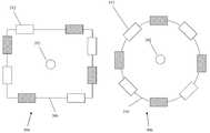
도 3a는 본 발명의 일부 구체예에 따라 본 명세서에 기술되는 시스템들 및/또는 방법들을 사용하여 파노라마 프레임으로 스티칭되는 복수의 시야각에서의 프레임들을 촬영하는 영상기들의 예시적 배열을 개략적으로 나타낸 개략도이다.
도 3b는 본 발명의 일부 구체예에 따라 본 명세서에 기술되는 시스템들 및/또는 방법들을 사용하여 파노라마 프레임으로 스티칭되는 복수의 시야각에서의 프레임들을 촬영하는 영상기들의 배열을 갖는 가상 현실(VR) 영상 장치의 개략적인 측면도이다.
도 3c 및 도 3d는 본 발명의 일부 구체예에 따른 영상기들의 장착 위치들을 통과하는 가상의 원의 반지름에 대하여 각각 경사진 광학 축 및 경사지지 않은 광학 축들을 가지는 영상기들의 시야들 사이의 오버랩을 예시적으로 나타낸 개략도이다.
도 4는 본 발명의 일부 구체예에 따른 특징점들(도트들), 객체들의 경계들(녹색 선들), 및 상기 경계들 중 일부를 따라 예시적 오버랩핑 영역을 가로지르는 최단 불규칙 경로를 표시한 예시적 오버랩핑 영역이다.
도 5는 본 발명의 일부 구체예에 따른 예시적 오버랩핑 영역에 나타난 객체들의 경계들을 표시한 예시적 오버랩핑 영역이다.
도 6a 내지 도 6c는 본 발명의 일부 구체예에 따른 복수의 시야각에서 촬영된 프레임들을 획득하여 상기 프레임들과 생성된 파노라마 프레임을 조정하는 과정을 나타낸 예시적 이미지들이다.Some embodiments of the present invention are described herein with reference to the drawings attached hereto. Through a specific reference to the detailed drawings, it is emphasized that the details shown are provided by way of example and are for the purpose of illustrating exemplary embodiments of the invention. In this regard, the description taken with the drawings allows one of ordinary skill in the art to clearly understand how embodiments of the invention may be practiced.
In the drawings:
1 is a flow chart for creating a panoramic frame using irregular stitch lines identified in overlapping portions of adjacent frames photographed by a plurality of imagers having a plurality of viewing angles about a common central region, according to some embodiments of the present invention to be.
2 is a block diagram of components of a system for generating a panoramic frame, for example, by executing the method shown in FIG. 1, in accordance with some embodiments of the present invention.
3A is a schematic diagram that schematically illustrates an exemplary arrangement of imagers capturing frames at a plurality of viewing angles stitched into a panoramic frame using the systems and / or methods described herein in accordance with some embodiments of the present invention. to be.
FIG. 3B illustrates a virtual reality (VR) having an array of imagers that frames frames at a plurality of viewing angles stitched into a panoramic frame using the systems and / or methods described herein in accordance with some embodiments of the present invention. Figure 3 is a schematic side view of the imaging device.
FIGS. 3C and 3D illustrate an overlap between views of imagers having optical axes inclined and non-inclined optical axes, respectively, relative to the radius of a virtual circle passing through the mounting locations of imagers according to some embodiments of the present invention. Fig.
FIG. 4 illustrates an example illustrating the minutiae (dots) according to some embodiments of the present invention, the boundaries of objects (green lines), and the shortest irregular path traversing an exemplary overlapping region along some of the boundaries Lt; / RTI >
FIG. 5 is an exemplary overlapping area showing the boundaries of objects shown in an exemplary overlapping area according to some embodiments of the present invention.
6A-6C are exemplary images illustrating the process of acquiring frames photographed at a plurality of viewing angles and adjusting the generated panorama frames with the frames according to some embodiments of the present invention.
본 발명의 일부 구체예는 이미지 프로세싱과 관련되며, 특히 비한정적으로, 프레임의 스티칭에 관한 것이다.Some embodiments of the present invention relate to image processing, and in particular, but not exclusively, to stitching of frames.
본 발명의 일부 구체예들의 한 측면은, 배치된 복수의 영상기들(예를 들어, 카메라, 이미지 센서)에 의해 복수의 시야각에서, 선택적으로 하나의 공통 중심 영역 주변에서 촬영한 프레임들 또는 이미지들(간결하게 하기 위해 본 명세서에서는 두 용어가 혼용됨)을 하나의 파노라마 프레임 또는 상기 공통 중심 영역(간결하게 지칭하면, 공통 중심) 주위의 환경을 나타내는 파노라마 프레임으로 스티칭하기 위한 시스템들 및/또는 방법들(예를 들어, 컴퓨터 장치의 프로세서에 의해 실행된 코드)에 관한 것이다. 상기 스티칭은 상기 스티칭 이음부를 덜 보이게 하고, 촬영된 주위 환경과 더욱 비슷하게 하여 사용자에게 개선된 파노라마 프레임 감상 경험을 제공하기 위하여 수행된다.One aspect of some embodiments of the present invention is the use of a plurality of imagers (e.g., a camera, an image sensor) arranged at a plurality of viewing angles, optionally frames or images Systems for stitching a panorama frame (in which the two terms are used in the present context for the sake of brevity) into one panorama frame or a panorama frame representing an environment around the common central region (briefly referred to as a common center) and / Methods (e. G., Code executed by a processor of a computer device). The stitching is performed to make the stitching joint less visible and more similar to the photographed surroundings to provide the user with an improved panorama frame viewing experience.
프레임의 스티칭은 상기 프레임들의 시야 사이의 오버랩핑 영역에서 식별된 불규칙한 선을 따라 수행된다. 상기 불규칙한 선은 선택적으로 오버랩핑 영역에 위치한 객체들 또는 세그먼트화된 영역들의 경계들을 따라 식별된다.Stitching of the frame is performed along an irregular line identified in the overlapping area between the fields of view of the frames. The irregular lines are optionally identified along the boundaries of the objects or segmented areas located in the overlapping area.
본 발명의 구체예에 따라 스티칭될 프레임들은 정렬 및 레지스트레이션을 위해 전처리(즉, 스티칭 전에)될 수 있다. 주위 환경의 공통 부분을 이미지화하는 시야들을 갖는 영상기들(본 명세서에서 인접 영상기들로도 지칭됨)에 의해 촬영된 두 개의 연속 프레임들 사이의 오버랩핑 영역들이 식별된다. 상기 오버랩핑 영역들은 반드시 상기 시야의 오버랩핑 영역을 분석함으로써 식별될 수 있는 것은 아니고, 오히려 외부적 방법들을 사용하여 예측될 수도 있다.According to embodiments of the present invention, the frames to be stitched may be preprocessed (i.e., before stitching) for alignment and registration. Overlapping regions between two consecutive frames photographed by imagers (also referred to herein as contiguous imagers) having views that image a common portion of the environment are identified. The overlapping regions are not necessarily identifiable by analyzing the overlapping regions of the field of view, but rather may be predicted using external methods.
선택적으로, 상기 오버랩핑 영역은 가상 구 골격 모델(virtual sphere skeleton model)에 상기 프레임들의 시각적 재현(representation)을 투사함에 의해 예측된다. 대안적으로 또는 추가적으로, 상기 오버랩핑 영역은 오버랩핑 프레임들을 촬영하는 하나 또는 두 개의 영상기에 대하여 규정된 캘리브레이션 모델(예를 들어, 수학적 모델)을 기반으로 예측된다. 상기 캘리브레이션 모델은 주점(principal point) 파라미터(들), 초점 거리 파라미터(들), 및/또는 어안(fisheye) 왜곡 파라미터(들)을 기반으로 규정될 수 있다.Optionally, the overlapping region is predicted by projecting a visual representation of the frames to a virtual sphere skeleton model. Alternatively or additionally, the overlapping region is predicted based on a calibration model (e.g., a mathematical model) defined for one or two imagers capturing overlapping frames. The calibration model may be defined based on principal point parameter (s), focal length parameter (s), and / or fisheye distortion parameter (s).
본 명세서에서 설명하는 상기 시스템들 및/또는 방법들은 복수의 시야각에서 촬영된 프레임들을 결합하여 파노라마 프레임을 생성할 때, 공통 중심 주위 환경을 나타내는 파노라마 프레임에서 어떻게 이음부를 덜 보이게 할 것인가 하는 기술적 문제에 대한 기술적 솔루션을 제공한다. 스티칭된 프레임들은 VR 파일의 프레임들일 수 있다. 이러한 VR 파일들은, 예를 들어 VR 영상 시청을 위한 VR 헤드셋에서 사용자에게 표시되는 가상 현실 시스템에 사용될 수 있다. 함께 스티칭되기 위해 획득된 프레임들은 서로 다른 관점 및/또는 초점, 노출, 화이트밸런스와 같은 서로 다른 속성들을 갖는 서로 다른 카메라들에 의해 촬영된다. 상기 영상기들에 사용되는 렌즈들(예를 들어, 광각 및/또는 어안 렌즈들)은 술통형(barrel) 왜곡, 바늘꽂이형(pincushion) 왜곡, 비네트형(vignette) 왜곡과 같은 시각적 왜곡들을 발생시켜 프레임의 스티칭에 추가적 문제를 유발할 수 있다. 하위 문제 중 하나는 서로 다른 속성들을 갖고 방향이 변하는(예를 들어, 고정되거나 조정가능한 카메라들의 작은 움직임) 서로 다른 카메라들에 의해 촬영된 프레임들을 이음부가 덜 보이거나 보이지 않도록 하는 방식으로 스티칭하는 것일 수 있다. 이음부가 보이면 VR 영상이 제공할 수 있는 자연스러운 외관 또는 실제감을 감소시킨다. (예를 들어, 각각 좌안 및 우안에 의해 보여지도록 설계된 좌안 및 우안 파노라마 프레임들에서) 스티칭 왜곡 및/또는 여러 아티팩트들을 완화 또는 제거하는 것은 시청자에게 불편감 및/또는 메스꺼움을 유발할 수 있는 일치하지 않는 비-수평적 시차(parallax)를 제거 또는 완화하여 상기 VR 영상을 개선한다.The systems and / or methods described herein combine frames photographed at a plurality of viewing angles to create a panoramic frame, a technical problem of how to make a seam less visible in a panoramic frame representing a common central ambience Provide a technical solution for The stitched frames may be frames of a VR file. These VR files can be used in a virtual reality system that is displayed to the user, for example, in a VR headset for viewing VR images. The frames acquired to be stitched together are taken by different cameras with different viewpoints and / or different attributes such as focus, exposure, white balance. The lenses (e.g., wide angle and / or fisheye lenses) used in the imagers cause visual distortions such as barrel distortion, pincushion distortion, and vignette distortion Thereby causing additional problems in the stitching of the frame. One of the sub-problems is to stitch frames taken by different cameras with different properties (e.g., small movements of fixed or adjustable cameras) in different ways so that joints are less visible or invisible . If the joint is visible, it reduces the natural appearance or realism that the VR image can provide. (E.g., in the left and right panoramic frames, respectively, designed to be viewed by the left and right eyes), mitigating or eliminating stitching distortions and / or various artifacts may cause inconsistencies and / or nausea And eliminates or alleviates non-horizontal parallax to improve the VR image.
본 명세서에서 설명하는 상기 시스템들 및/또는 방법들은 프로세서의 기능에 수학적 동작들(예를 들어, 프레임들의 오버랩핑 영역 예측, 운동 변화도(들)의 산출, 및 프레임 스티칭)을 적용하여, 예를 들어 하나의 공통 중심 주위의 복수의 시야각에서 획득한 프레임들을 상기 프레임들의 오버랩핑 영역을 지나는 불규칙한 선을 기반으로 하여 파노라마 프레임으로 스티칭함으로써 디지털 이미지들을 처리할 수 있도록 한다. 서로 다른 카메라 모듈들에 의해 생성된 콘텐츠가 스티칭될 필요가 있는 정확한 영역을 규정하는 몇몇 이미지 레지스트레이션 및 정렬 방법이 있음을 인지하여야 한다. 상기 레지스트레이션이 산출되면, 연결 프레임들의 오버랩핑 영역이 얼마나 정확하게 절단 및 병합될 것인지를 규정하는 것이 두 번째로 필수적이다.The systems and / or methods described herein may apply mathematical operations (e.g., overlapping region prediction of frames, calculation of motion variance (s), and frame stitching) So as to process digital images by stitching the frames acquired at a plurality of viewing angles around one common center into a panoramic frame based on an irregular line passing through the overlapping regions of the frames. It should be appreciated that there are some image registration and alignment methods that define the exact area in which content generated by different camera modules need to be stitched. Once the registration is computed, it is second essential to define how accurately the overlapping regions of the connection frames are to be truncated and merged.
상기 절단선을 정의하는 몇 가지 방법이 있다. 가장 단순한 방법은 선택된 좌표에서 두 개의 오버랩핑 프레임들을 절단하는 수직선이다. 하나의 오버랩핑 프레임으로부터 다른 하나의 오버랩핑 프레임으로의 점진적 전환을 추가하는 것 역시 직선을 채택하기 위해 사용된다. 예를 들어, 왼쪽과 오른쪽 두 개의 프레임들을 연결할 때, 상기 왼쪽 프레임의 오버랩핑 영역의 투명도가 상기 왼쪽 프레임의 왼쪽에서 오른쪽으로 갈수록, 그리고 상기 오른쪽 프레임에서는 정반대로 점차 증가할 수 있다. 모든 직선 절단 방법은 중대한 단점이 있는데, 인간의 시각은 직선과 같은 명확한 기하학적 도형들에 특히 민감하여, 명확한 스티칭 라인들은 사용자의 눈에 잘 띈다는 점이다.There are several ways to define the cut line. The simplest method is a vertical line that cuts two overlapping frames at the selected coordinates. Adding a gradual transition from one overlapping frame to another overlapping frame is also used to adopt a straight line. For example, when two left and right frames are connected, the transparency of the overlapping area of the left frame may be gradually increased from the left to the right of the left frame and contrary to the right frame. All straight-line cutting methods have serious drawbacks, such that the human vision is particularly sensitive to certain geometric shapes such as straight lines, so that the distinct stitching lines are well visible to the user's eyes.
본 명세서에서 기술되는 상기 시스템들 및/또는 방법들은 하나의 공통 중심 주위에 장착된 영상기들에 의해 복수의 시야각에서 획득된 프레임들을 처리하는 것에 관한 것이다. 획득된 프레임들을 함께 스티칭하여 새로운 데이터가 파노라마 프레임의 형태로 생성된다. 상기 파노라마 프레임은 메모리 장치에 저장될 수 있고, 선택적으로 사용자에 의해, 예를 들어 VR 헤드기어에서 디스플레이될 수 있다. 상기 파노라마 프레임은 복수의 최종 파노라마 프레임들을 포함하는 영상에 포함될 수 있다.The systems and / or methods described herein are directed to processing frames obtained at a plurality of viewing angles by imagers mounted around a common center. The acquired frames are stitched together to create new data in the form of a panorama frame. The panorama frame may be stored in a memory device and optionally displayed by a user, e.g., in a VR headgear. The panorama frame may be included in an image including a plurality of final panorama frames.
본 명세서에서 기술되는 상기 시스템들 및/또는 방법들은, 예를 들면 개선된 디지털이미지를 생성하는 데 더 적은 메모리 및/또는 개선된 연산 시간을 사용함으로써 컴퓨터의 성능을 개선한다.The systems and / or methods described herein improve the performance of a computer, for example, by using less memory and / or improved computation time to produce an improved digital image.
본 명세서에서 기술되는 상기 시스템들 및/또는 방법들은 필수적으로 디지털 이미지 처리에서 발생하는 실제 기술적 문제를 극복하기 위한 컴퓨터 기술에 기반하고 있다.The systems and / or methods described herein are essentially based on computer technology to overcome the actual technical problems that arise in digital image processing.
본 발명의 적어도 일 구체예를 상세히 설명하기 전에, 본 발명은 그것의 적용에 있어서, 후속하는 설명에서 전개되고/전개되거나, 도면 및/또는 예들에서 예시된 방법들 및/또는 성분들의 구성 및 배치의 세부 사항으로 필수적으로 제한되는 것은 아님을 이해하여야 한다. 본 발명에는 다른 구체예가 있을 수 있거나 다양한 방식으로 실시 또는 행해질 수 있다.Before describing in detail at least one embodiment of the present invention, the present invention may, in its application, be developed and / or evolved in the following description, and / or configured and arranged in such a way that the methods and / It is to be understood that the invention is not necessarily limited to the details of the foregoing description. There may be other embodiments of the invention or may be practiced or carried out in various ways.
본 발명은 시스템, 방법, 및/또는 컴퓨터 프로그램 제품일 수 있다. 컴퓨터 프로그램 제품은 컴퓨터 판독 가능 저장 매체(들)를 포함할 수 있으며, 이 매체 상의 프로세서가 본 발명의 특징들을 수행하기 위한 컴퓨터 판독 가능 프로그램 명령어들을 갖는다.The present invention may be a system, method, and / or computer program product. A computer program product may include a computer-readable storage medium (s) to which a processor on the medium has computer-readable program instructions for performing the features of the present invention.
상기 컴퓨터 판독 가능 저장 매체는 명령어 실행 디바이스에 의해 사용될 명령어들을 유지 및 저장할 수 있는 유형의(tangible) 디바이스일 수 있다. 상기 컴퓨터 판독 가능 저장 매체는, 예를 들면, 전자 저장 디바이스, 자기 저장 디바이스, 광학 저장 디바이스, 전자기 저장 디바이스, 반도체 저장 디바이스, 또는 전술한 것들의 모든 적절한 조합일 수 있으며, 그러나 이에 한정되지는 않는다. 컴퓨터 판독 가능 저장 매체의 더 구체적인 예들의 비포괄적인 목록에는 다음이 포함될 수 있다: 휴대용 컴퓨터 디스켓, 하드 디스크, 랜덤 액세스 메모리(RAM), 읽기전용 메모리(ROM), 소거 및 프로그램가능 읽기전용 메모리(EPROM 또는 플래시 메모리), 정적 랜덤 액세스 메모리(SRAM), 휴대용 컴팩트 디스크 판독-전용 메모리(CD-ROM), 디지털 다용도 디스크(DVD), 메모리 스틱, 플로피 디스크, 천공-카드들 또는 명령어들이 기록된 홈에 있는 융기된 구조들과 같이 기계적으로 인코딩된 디바이스, 및 전술한 것들의 모든 적절한 조합. 본 명세서에서 사용된 컴퓨터 판독 가능 저장 매체는 무선 전파들이나 다른 자유롭게 전파되는 전자기파들, 도파관이나 기타 전송 매체(예를 들어, 광섬유 케이블을 통해 전달되는 광 펄스들)를 통해 전파되는 전자기파들, 또는 선(wire)을 통해 전송되는 전기 신호들과 같은 일시적인(transitory) 신호들 자체인 것으로 해석되지는 않는다.The computer-readable storage medium may be a tangible device capable of holding and storing instructions to be used by the instruction executing device. The computer-readable storage medium may be, for example, but is not limited to, an electronic storage device, a magnetic storage device, an optical storage device, an electromagnetic storage device, a semiconductor storage device, or any suitable combination of the foregoing . A non-exhaustive list of more specific examples of computer readable storage media may include: a portable computer diskette, a hard disk, a random access memory (RAM), a read only memory (ROM), an erase and programmable read only memory EPROM or flash memory), static random access memory (SRAM), portable compact disk read-only memory (CD-ROM), digital versatile disk (DVD), memory stick, floppy disk, A mechanically encoded device such as elevated structures in the device, and any suitable combination of the foregoing. As used herein, the computer-readable storage medium refers to a computer-readable medium having stored thereon an electromagnetic wave propagated through radio waves or other freely propagating electromagnetic waves, waveguides or other transmission media (e.g., optical pulses transmitted through a fiber optic cable) but are not to be construed as transitory signals themselves, such as electrical signals transmitted through a wire.
본 명세서에 기술되는 컴퓨터 판독 가능 명령어들은, 예를 들어 인터넷, 근거리 통신망, 광역 통신망 및/또는 무선 네트워크 등의 통신망(네트워크)을 통해 각각 컴퓨터 판독 가능 저장 매체로부터 컴퓨팅/처리 디바이스들로 또는 외부 저장 디바이스로부터 외부 컴퓨터로 다운로드될 수 있다. 상기 통신망은 구리 전송 케이블, 광학 전송 섬유, 무선 전송, 라우터, 방화벽, 스위치, 게이트웨이 컴퓨터 및/또는 엣지 서버를 포함할 수 있다. 각 컴퓨팅/처리 디바이스 내의 네트워크 어댑터 카드 또는 네트워크 인터페이스는 상기 통신망으로부터 컴퓨터 판독 가능 프로그램 명령어들을 수신하고, 그 컴퓨터 판독 가능 프로그램 명령어들을 각각의 컴퓨팅/처리 디바이스 내의 컴퓨터 판독 가능 저장 매체에 저장하기 위해 전송한다.The computer-readable instructions described herein may be stored on a computer-readable storage medium, such as, for example, from a computer-readable storage medium to computing / processing devices via a communication network such as the Internet, a local area network, a wide area network and / And downloaded to the external computer from the device. The communication network may include copper transmission cables, optical transmission fibers, wireless transmissions, routers, firewalls, switches, gateway computers and / or edge servers. A network adapter card or network interface in each computing / processing device receives computer-readable program instructions from the communication network and transmits the computer-readable program instructions for storage in a computer-readable storage medium in a respective computing / processing device .
본 발명에 따른 연산들을 실행하기 위한 컴퓨터 판독 가능 프로그램 명령어들은 Smalltalk, C++ 또는 그와 유사 언어와 같은 객체 지향 프로그래밍 언어 및 "C" 프로그래밍 언어 또는 그와 유사한 언어와 같은 통상의 절차적 프로그래밍 언어들을 포함하여, 하나 또는 그 이상의 프로그래밍 언어들을 조합하여 작성된(written) 어셈블러 명령어들, 명령-세트-아키텍처(ISA) 명령어들, 기계어 명령어들, 기계 종속 명령어들, 마이크로코드, 펌웨어 명령어들, 상태-셋팅 데이터, 또는 소스 코드나 목적 코드일 수 있다. 상기 컴퓨터 판독 가능 프로그램 명령어들은 전적으로 사용자의 컴퓨터상에서, 부분적으로 사용자의 컴퓨터상에서, 독립형(stand-alone) 소프트웨어 패키지로서, 부분적으로 사용자의 컴퓨터상 및 부분적으로 원격 컴퓨터상에서, 또는 전적으로 원격 컴퓨터나 서버상에서 실행될 수 있다. 상기한 마지막의 경우에, 원격 컴퓨터는 근거리 통신망(LAN) 또는 광역 통신망(WAN)을 포함한 모든 종류의 네트워크를 통해서 사용자의 컴퓨터에 접속될 수 있고, 또는 이 접속은 (예를 들어, 인터넷 서비스 제공자를 이용한 인터넷을 통해서) 외부 컴퓨터에 대해 이루어질 수도 있다. 일부 바람직한 구체예들에서, 예를 들어 프로그램 가능 논리 회로, 필드-프로그램 가능 게이트 어레이들(FPGA), 또는 프로그램 가능 논리 어레이들(PLA)을 포함한 전자 회로가, 본 발명의 특징들을 수행하기 위해 전자 회로를 맞춤화하도록 상기 컴퓨터 판독 가능 프로그램 명령어들의 상태 정보를 활용하여 상기 컴퓨터 판독 가능 프로그램 명령어들을 실행할 수 있다.Computer-readable program instructions for executing operations in accordance with the present invention include conventional procedural programming languages such as object-oriented programming languages such as Smalltalk, C ++, or the like, and "C" (ISA) instructions, machine language instructions, machine dependent instructions, microcode, firmware instructions, state-setting data (e.g., instructions) written in combination with one or more programming languages , Or may be source code or object code. The computer-readable program instructions may be stored on a user's computer, partly on a user's computer, as a stand-alone software package, on a part of a user's computer and partly on a remote computer, Lt; / RTI > In the latter case, the remote computer may be connected to the user's computer through any kind of network, including a local area network (LAN) or a wide area network (WAN) (Via the Internet using the Internet). In some preferred embodiments, electronic circuits including, for example, programmable logic circuits, field-programmable gate arrays (FPGAs), or programmable logic arrays (PLAs) Readable program instructions to implement the computer readable program instructions utilizing state information of the computer readable program instructions to customize the circuit.
본 명세서에서는 본 발명의 바람직한 구체예들에 따른 방법들, 장치들(시스템들), 및 컴퓨터 프로그램 제품들의 순서 예시도들 및/또는 블록도들을 참조하여 본 발명의 특징들을 기술한다. 순서 예시도들 및/또는 블록도들의 각 블록과 순서 예시도들 및/또는 블록도들 내 블록들의 조합들은 컴퓨터 판독 가능 프로그램 명령어들에 의해 구현될 수 있다는 것을 이해할 수 있을 것이다.BRIEF DESCRIPTION OF THE DRAWINGS The features of the present invention will now be described with reference to exemplary illustrations and / or block diagrams of methods, apparatus (systems), and computer program products in accordance with preferred embodiments of the present invention. It will be appreciated that each block and sequence of flowchart illustrations and / or block diagrams and / or combinations of blocks within the block diagrams may be implemented by computer readable program instructions.
이 컴퓨터 판독 가능 프로그램 명령어들은 범용 컴퓨터, 특수목적용 컴퓨터, 또는 기타 프로그램가능 데이터 처리 장치의 프로세서에 제공되어 머신(machine)을 생성하고, 그렇게 하여 그 명령어들이 상기 컴퓨터 또는 기타 프로그램가능 데이터 처리 장치의 프로세서를 통해서 실행되어, 상기 순서도 및/또는 블록도의 블록 또는 블록들에 명시된 기능들/동작들을 구현하기 위한 수단을 생성할 수 있다. 이 컴퓨터 판독 가능 프로그램 명령어들은 또한 컴퓨터 판독 가능 저장 매체에 저장될 수 있으며, 컴퓨터, 프로그램가능 데이터 처리 장치 및/또는 기타 디바이스들에 지시하여, 명령어들이 저장된 상기 컴퓨터 판독 가능 저장 매체가 상기 순서도 및/또는 블록도의 블록 또는 블록들에 명시된 기능/동작의 특징들을 구현하는 명령어들을 포함하는 제조품(an article of manufacture)을 포함하도록 특정한 방식으로 기능하게 할 수 있다.These computer-readable program instructions may be provided to a processor of a general purpose computer, special purpose computer, or other programmable data processing apparatus to create a machine, such that the instructions may be provided to the processor of the computer or other programmable data processing apparatus To generate the means for implementing the functions / operations specified in the blocks or blocks of the flowchart and / or block diagrams. These computer-readable program instructions may also be stored in a computer-readable storage medium and direct the computer, the programmable data processing apparatus, and / or other devices to cause the computer-readable storage medium having stored thereon instructions to execute the flowchart and / Or an article of manufacture including instructions that implement the features / acts specified in the blocks or blocks of the block diagrams.
상기 컴퓨터 판독 가능 프로그램 명령어들은 또한 컴퓨터, 기타 프로그램가능 데이터 처리 장치, 또는 다른 디바이스에 로드되어, 상기 컴퓨터, 기타 프로그램가능 장치 또는 다른 디바이스에서 일련의 동작 단계들이 수행되게 하여 컴퓨터 구현 프로세스를 생성하며, 그렇게 하여 상기 컴퓨터, 기타 프로그램가능 장치, 또는 다른 장치 상에서 실행되는 명령어들이 순서도 및/또는 블록도의 블록 또는 블록들에 명시된 기능들/동작들을 구현할 수 있다.The computer-readable program instructions may also be loaded into a computer, other programmable data processing apparatus, or other device to cause the computer, other programmable apparatus, or other device to perform a series of operating steps to create a computer- Thus, the instructions that execute on the computer, other programmable device, or other device may implement the functions / acts specified in the blocks and / or blocks of the flowchart illustrations and / or block diagrams.
도면들 내 순서도 및 블록도들은 본 발명의 여러 바람직한 구체예들에 따른 시스템들, 방법들 및 컴퓨터 프로그램 제품들의 가능한 구현들의 아키텍처, 기능(functionality), 및 동작(operation)을 예시한다. 이와 관련하여, 상기 순서도 또는 블록도들 내 각 블록은 상기 명시된 논리적 기능(들)을 구현하기 위한 하나 또는 그 이상의 실행 가능한 명령어들을 포함한 모듈, 세그먼트 또는 명령어들의 일부분을 나타낼 수 있다. 일부 다른 구현들에서, 상기 블록에 언급되는 기능들은 도면들에 언급된 순서와 다르게 일어날 수도 있다. 예를 들면, 연속으로 도시된 두 개의 블록들은 실제로는 사실상 동시에 실행될 수도 있고, 또는 이 두 블록들은 때때로 관련된 기능에 따라서는 역순으로 실행될 수도 있다. 블록도들 및/또는 순서 예시도의 각 블록, 및 블록도들 및/또는 순서 예시도 내 블록들의 조합들은 특수목적용 하드웨어 및 컴퓨터 명령어들의 명시된 기능들 또는 동작들, 또는 이들의 조합들을 수행하는 특수목적용 하드웨어-기반 시스템들에 의해 구현될 수 있다는 것에 또한 유의하여야 할 것이다.The flowcharts and block diagrams in the figures illustrate the architecture, functionality, and operation of possible implementations of systems, methods, and computer program products in accordance with various preferred embodiments of the present invention. In this regard, each block in the flowchart or block diagrams may represent a portion of a module, segment, or instruction that includes one or more executable instructions for implementing the specified logical function (s). In some other implementations, the functions referred to in the block may occur differently from the order noted in the figures. For example, two blocks shown in succession may actually be executed substantially concurrently, or the two blocks may sometimes be executed in reverse order, depending on the associated function. Each block of the block diagrams and / or example illustrations, and combinations of blocks in the block diagrams and / or the example illustrations, are intended to be illustrative of the special features or operations of the special purpose hardware and computer instructions, It should also be noted that it may be implemented by any applicable hardware-based systems.
이제, 본 발명의 일부 구체예에 따른, 복수의 시야각에서의 인접 영상기들에 의해 촬영된 프레임들을 하나의 파노라마 프레임으로 스티칭하는 방법의 순서도인 도 1을 참조한다. 상기 방법은 오버랩핑 영역의 객체들 또는 다른 세그먼트화된 영역들의 경계들을 식별하고, 상기 오버랩핑 영역을 (예컨대, 둘로 나누면서) 지나는 가장 짧은 불규칙 선을 식별함으로써 프레임들의 오버랩핑 영역들에서 불규칙한 선을 식별한다. 상기 방법은 파노라마 영상 장치의 영상기들이 실질적으로 동시에 촬영한 모든 프레임 쌍에 대해 반복된다. 또한, 사용자가 각각 공통 중심 영역 주위로 서로 다른 각도를 향해 있는 복수의 시각 영상기들을 사용하여 (적어도 부분적으로) 공통 중심 영역을 둘러싼 주위 환경의 개별 파노라마 프레임들 또는 연속적인 파노라마 프레임들의 영상을 촬영할 수 있도록 하는 시스템(200)의 구성 요소들의 블록도인 도 2를 참조한다. 상기 사용자는 VR 헤드셋을 사용하는 것과 같은 가상 현실 환경에서 재생하기 위하여 상기 영상을 기록할 수 있다. 청구항 1의 방법은 도 2의 시스템(200)에 의해 구현될 수 있다.Reference is now made to Fig. 1, which is a flow chart of a method of stitching frames photographed by adjacent imagers at a plurality of viewing angles into one panoramic frame, in accordance with some embodiments of the present invention. The method identifies the boundaries of objects or other segmented regions of the overlapping region and identifies the shortest irregular line passing through (e.g., dividing into) the overlapping region, thereby generating an irregular line in the overlapping regions of the frames . The method is repeated for every pair of frames taken by the imagers of the panoramic imaging device at substantially the same time. It is also possible for a user to take images of individual panorama frames or consecutive panorama frames of the surrounding environment surrounding the common central area (at least partially) using a plurality of visual imagers, each facing a different angle around the common central area 2, which is a block diagram of the components of the
시스템(200)은, 예를 들어 본 명세서에서 VR 영상 장치(예를 들어, VR 영상 장치의 예시적 하우징인 도 3b 참조)로 지칭되는 임의 형태(custom designed)의 유닛인 영상기들(212)을 수용하고 있거나, 예를 들어 상기 영상기들(212)을 포함하는 개인용 컴퓨터, 서버, 모바일 장치, 웨어러블 컴퓨터, 또는 다른 형태의 하우징과 분리되어 있는 컴퓨팅 유닛(202)을 포함한다. 컴퓨팅 유닛(202)은 하나 이상의 프로세서(들)(204), 및 프로세서(들)(204)에 의해 실행되는 코드 명령어들을 저장하는 프로그램 저장소(206)를 포함한다.The
프로세서(들)(204)은, 예를 들어, 프로세싱 유닛(들)(CPU), 하나 이상의 그래픽 프로세싱 유닛(들)(GPUs), 필드 프로그램가능 로직 어레이(들)(FPGA), 디지털 신호 프로세서(들)(DSP), 및 주문형 집적회로(들)(ASIC)일 수 있다. 프로세서(들)은 클러스터 및/또는 하나 이상의 멀티 코어 프로세싱 유닛들로서 병렬 프로세싱을 위해 배열된 복수의 (동종 또는 이종) 프로세서들을 포함하는 프로세싱 유닛의 일부일 수 있다.The processor (s) 204 may include, for example, processing units (CPU), one or more graphics processing unit (s) (GPUs), a field programmable logic array (s) (DSP), and an application specific integrated circuit (s) (ASIC). The processor (s) may be part of a processing unit comprising a plurality (homogeneous or heterogeneous) processors arranged for parallel processing as a cluster and / or one or more multicore processing units.
프로그램 저장소(206)는, 프로세서(들)(204), 예를 들어 랜덤 액세스 메모리(RAM), 읽기 전용 메모리(ROM), 및/또는 예를 들어 비휘발성 메모리, 자기 매체, 반도체 메모리 장치, 하드 드라이브, 휴대용 저장소, 및 광학 매체(예컨대, DVD, CD-ROM)와 같은 저장 장치에 의해 구현될 수 있는 코드 명령어들을 저장한다. 상기 명령어들은 선택적으로 도 1에 기술된 방법을 구현하도록 구성된다.The program storage 206 may include one or more components or components of the processor (s) 204, such as random access memory (RAM), read only memory (ROM), and / Drive, portable storage, and code instructions that may be implemented by a storage device such as an optical medium (e.g., DVD, CD-ROM). The instructions are optionally configured to implement the method described in FIG.
컴퓨팅 유닛(202)은, 예를 들어 메모리, 저장 유닛, 하드 드라이브, 광학 디스크, 원격 저장 서버, 및/또는 클라우드 서버(예컨대, 네트워크 연결에 의해 접근 가능한)와 같은 데이터 저장소(208)를 포함하거나 데이터 저장소와 통신이 가능하다. 데이터 저장소(208)는 획득된 원본 프레임들을 (예컨대, 원본 프레임 저장소(208A)에) 저장하고, 본 명세서에 기술된 시스템들 및/또는 방법들에 의해 조절된 프레임들을 (예컨대, 파노라마 프레임 저장소(208C)에) 저장한다.The computing unit 202 may include a data store 208, such as a memory, a storage unit, a hard drive, an optical disk, a remote storage server, and / or a cloud server (e.g., accessible by a network connection) Communication with the data store is possible. The data store 208 may store the acquired original frames (e.g., in the
컴퓨팅 유닛(202)은 복수의 영상기들(212; 예컨대, 디지털 카메라들)의 각각으로부터 획득된 프레임들을 수신하기 위한 데이터 인터페이스(210; 예컨대, 물리적, 가상 및/또는 소프트웨어 인터페이스)를 포함한다. 영상기들(212; 예컨대, 적녹청(RGB) 영상기들)은, 예를 들어 이하에 자세히 기술될 도 3a의 공통 중심 영역을 중심으로 (수평적 및/또는 수직적으로) 선택적으로 적어도 180도, 선택적으로 360도의 주위 환경을 나타내는 일련의 프레임들을 획득하도록 배열된다.The computing unit 202 includes a data interface 210 (e.g., a physical, virtual and / or software interface) for receiving frames obtained from each of a plurality of imagers 212 (e.g., digital cameras). The imagers 212 (e.g., red, green, and blue (RGB) imagers) may be selectively imaged (e.g., horizontally and / or vertically) about the common central region of Figure 3A, , Optionally a series of frames representing an ambient environment of 360 degrees.
선택적으로, 영상기들(212)은 예를 들어 VT 헤드셋을 사용하여 서로 다른 눈에 보여질 수 있는 좌안 또는 우안용 프레임을 촬영하도록 둘씩 짝지어진다. 이러한 구체예에서, 영상기들은 좌안 그룹과 우안 그룹의 두 그룹으로 나뉠 수 있다. (위치들이 상기 공통 중심 영역을 둘러싸고 원형으로 순차적으로 분포되어 있다고 가정했을 때) 상기 좌안 그룹 영상기들은 짝수 위치들에, 우안 그룹 영상기들은 홀수 위치들에 또는 그 반대로 위치할 수 있다. 이러한 구체예들에서, 상기 좌안 그룹 영상기들에서 촬영된 프레임들은 좌안 파노라마 프레임으로 스티칭되고, 우안 그룹 영상기들에서 촬영된 프레임들은 우안 파노라마 프레임으로 스티칭된다. 예를 들어 이하에 기술된 것과 같이(오버랩핑 영역이 그룹 영상기들에 의해 촬영된 프레임들 사이에 존재), 상기 좌안 파노라마 이미지 및 상기 우안 파노라마 프레임의 스티칭은 각각 별개로 이루어진다. 상기 좌안 파노라마 프레임 및 상기 우안 파노라마 프레임을 병합하여 입체 파노라마 프레임을 생성한다. 예를 들어, 도 3a의 배열(304, 306)에서 빗금친 직사각형들은 좌안 그룹 영상기들, 빗금이 없는 직사각형들은 우안 그룹의 영상기들일 수 있다.Optionally,
대안적으로 또는 추가적으로, 영상기들(212)은, 예를 들어 180도 극장에서 양쪽 눈에 동시에 투사되도록 표시되는 프레임들을 촬영한다.Alternatively or additionally,
상기 영상기들(212) 각각은, 예를 들어 어안렌즈처럼 넓은 시야를 촬영하도록 설계된 광각 렌즈를 가질 수 있다. 예시적 영상기들(212)은 약 수평 120도 및 약 수직 175도 또는 다른 값을 갖는 범위를 촬영할 수 있는 초광각 및/또는 정각(vertical angle) 렌즈들을 갖는 카메라들이다.Each of the
상기 영상기들(212)의 수는 선택된 환경을 커버할 수 있도록(입체 파노라마 프레임이 생성되는 구체예들의 두 배) 선택되고, 카메라들의 렌즈들이 촬영할 수 있는 시야를 기반으로 예를 들어 4개, 8개, 10개, 16개 및/또는 이들 개수 사이의 개수 또는 더 많은 수의 영상기가 선택될 수 있다.The number of
이제 본 발명의 일부 구체예에 따른 영상기들(312; 도 2의 영상기들(212)에 해당)의 배열의 예시적 구현을 나타내는 도 3a를 참조한다. 영상기들(312)은 공통 중심(302) 주위에 장착된다. 영상기들(312)은 복수의 시야각에서 프레임들을 획득하도록 배열된다. 상기 프레임들은 (본 명세서에 기술된 시스템들 및/또는 방법들을 사용하여) 공통 중심(302) 주위의 환경을 나타내는 파노라마 프레임으로 스티칭된다.Reference is now made to Fig. 3a, which illustrates an exemplary implementation of an arrangement of imagers 312 (corresponding to
각 배열들(304, 306)은 공통 중심(302) 주위의 360도를 커버하기 위하여 배열된 8개의 영상기들(312)을 포함한다. 구현(304)은 정사각형(308)의 한 변마다 두 개의 영상기들(312)을 포함하는 정사각형(308) (또는 직사각형) 형태로 배열된 영상기들(312)을 나타내는데, 상기 두 개의 영상기들이 쌍을 이루어 좌안과 우안 프레임들을 촬영한다. 도 3b는 4쌍의 측면 영상기들(1312)을 포함하는 임의 형상 유닛의 절삭된(truncated) 코너를 갖는 예시적 사각 하우징의 측면도이며, 각 쌍은 상기 예시적 사각 하우징의 다른 절삭된 코너에 위치한다. 배열(306)은 원(310)의 원주를 따라 이격되게 배치된 원형(310) (또는 타원형) 배열의 영상기들(312)을 포함한다. 영상기들(312)은 좌안과 우안 프레임들을 촬영할 수 있다. 다른 구현 형태가 사용될 수 있음에 유의해야 한다.Each of the
본 발명의 일부 구체예에 따르면, 영상기들은 각 쌍이 하나의 입체 프레임을 촬영하도록 설계된 쌍들로 나누어질 수 있다. 이러한 구체예들에서, 입체 프레임들의 쌍들에서 오버랩핑 영역이 식별되어 입체 프레임을 생성하는 데 사용되는 방법이 후술된다. 간결함을 위해, 본 명세서에서 입체 프레임은 프레임으로, 입체 프레임을 촬영하도록 설계된 한 쌍의 영상기들은 영상기로 지칭된다. 예를 들어, 입체 프레임을 촬영하기 위한 영상기 쌍들의 배열을 갖는 VR 영상 장치는 그 시야가 도 3c에 나타난 것과 같은 시야일 때 사용된다. 선택적으로, 영상기 쌍의 각 영상기의 광학 축은 해당 영상기 쌍의 다른 영상기쪽으로, 예를 들어 그의 광학 축 쪽으로 기울어져 있다. 선택적으로, 상기 광학축은 상기 공통 중심, 및 예를 들어 도 3c와 도 3d에 나타난 원과 같이 모든 영상기들의 시야의 원점을 지나는 가상의 원 상의 각각의 영상기의 시야의 원점의 각 접선물림점을 통과하는 축에 대하여 기울어진다. 선택적으로, 상기 기울어짐은 20 내지 30도, 예를 들어 도 3c에 나타난 것처럼 22도이다. 영상기들의 기울어짐은 그 시야들 사이의 오버랩핑 영역들을 감소시킨다. 이는, 각 영상기가 쌍을 이루는 영상기쪽으로 기울어진 배열을 나타낸 도 3c의 영상기들과, 각 영상기의 광학 축이 모든 영상기들의 장착 포인트들, 예를 들어 상기 영상기들의 광학 축의 원점들을 지나는 가상의 원의 반지름을 연장하도록 배열된 도 3d와 비교하면 알 수 있을 것이다. 도 3c와 도 3d를 비교하면, 영상기들의 시야가 교차하는 부분을 나타내는 어두운 영역이 상기한 바와 같이 영상기들의 광학 축들이 기울어져 있을 때 더 넓은 것을 알 수 있다.According to some embodiments of the present invention, imagers can be divided into pairs, each pair designed to capture one stereoscopic frame. In these embodiments, a method in which overlapping regions are identified in pairs of stereoscopic frames to create a stereoscopic frame is described below. For the sake of brevity, stereoscopic frames are referred to herein as frames, and a pair of imagers designed to capture stereoscopic frames are referred to as imagers. For example, a VR imaging device having an array of imager pairs for imaging a stereoscopic frame is used when the field of view is as shown in FIG. 3C. Optionally, the optical axis of each imager of the imager pair is tilted towards the other imager of the imager pair, e. G., Toward its optical axis. Alternatively, the optical axis may be a tangent point at the origin of the field of view of each imager on the imaginary circle passing through the common center and, for example, the circles shown in Figures 3c and 3d, As shown in Fig. Optionally, said tilting is 20 to 30 degrees, for example 22 degrees as shown in Figure 3c. The tilting of the imagers reduces the overlapping areas between the views. This is because the imagers of FIG. 3C, in which each imager is tilted toward the imager pair, and the optical axis of each imager passing through the mounting points of all imagers, for example the origin of the optical axes of the imagers Compared with Figure 3d arranged to extend the radius of the imaginary circle. Comparing FIG. 3C with FIG. 3B, it can be seen that the dark region representing the intersection of the field of view of the imagers is wider when the optical axes of the imagers are inclined as described above.
구현예들(304, 306)은 실질적으로 디스크 형태를 가질 수 있는데, 이때 영상기들(312)은 하나의 평면에 배열된다. 다른 구현 프로파일, 예를 들어 구형 또는 반구형이 사용될 수 있다.
추가의 영상기들(312)이 위쪽 또는 아래쪽에 위치할 수 있다(미도시).
컴퓨팅 유닛(202) 및 영상기들(312)은, 예를 들어 소비자들이 가정에서 사용할 수 있는 자립형 포터블 유닛과 같이 구현예(304 및/또는 306)을 기반으로 하는 케이싱 내에 수용될 수 있다.The computing unit 202 and the
도 2를 다시 참조하면, 컴퓨팅 유닛(202)은 상기 생성된 파노라마 프레임들(예컨대, 영상)을 저장 및/또는 표시할 수 있는 하나 이상의 외부 장치들과 통신할 수 있는 통신 인터페이스(214)(예컨대, 물리적, 소프트웨어 및/또는 가상), 예를 들어 Wi-Fi™ 모듈 또는 Bluetooth™ 모듈을 포함한다. 예시적 외부 장치들은 개인용 디스플레이 장치(216(예컨대, VR 헤드셋), 영상을 나중에 재생할 수 있도록 저장하는 저장 장치(218), 및 네트워크(222)를 통해 통신이 가능한 서버(220; 예컨대, 웹 서버, 저장 서버, 비디오 서버)를 포함한다. 기록된 영상들은, 예를 들어 프로젝터(미도시)에 의해 공공장소, 예를 들어 극장에서, 방 또는 가정에서 입체 스크린에 투사되어 재생될 수 있음을 인지할 필요가 있다.2, the computing unit 202 may include a communication interface 214 (e. G., A < RTI ID = 0.0 > , Physical, software and / or virtual), for example a Wi-Fi ™ module or a Bluetooth ™ module. Exemplary external devices include a personal display device 216 (e.g., a VR headset), a
컴퓨팅 유닛(202)은, 예를 들어 터치 스크린, 키보드, 마우스 및 스피커와 마이크로폰을 사용하는 음성 인식 소프트웨어와 같은 사용자 인터페이스(224)(상기 컴퓨팅 유닛(202)을 수용하는 하우징에 통합되어 클라이언트 단말의 소프트웨어로서 그리고/또는 상기 파노라마 프레임들을 표시하는 디스플레이 장치의 일부로서 구현될 수 있음)를 포함하거나 그와 통신할 수 있다. 사용자 인터페이스(224)는 사용자 입력들을 기반으로 파노라마 프레임들의 생성을 커스터마이징할 수 있는 코드(예를 들어, 클라이언트 단말 및/또는 컴퓨팅 유닛(202)에 저장됨)에 액세스할 수 있다.The computing unit 202 may include a
본 발명의 일부 구체예에 따르면, 상기 영상기들은 시차 왜곡의 감소 뿐 아니라 이미지 정렬을 위한 카메라 캘리브레이션 모델을 계산하도록 캘리브레이션 된다. 선택적으로, 상기 카메라 캘리브레이션 모델은 각 영상기의 내부 파라미터들, 예를 들어 주점(principal point) 파라미터(들), 초점 거리 파라미터(들), 및/또는 어안 왜곡 파라미터(들) 및 선택적으로 외부 파라미터(들)을 기반으로 산출된다.According to some embodiments of the present invention, the imagers are calibrated to compute a camera calibration model for image alignment as well as reduction of parallax distortion. Alternatively, the camera calibration model may be configured to determine the internal parameters of each imager, e.g., principal point parameter (s), focal length parameter (s), and / or fisheye distortion parameter (S).
사용상에 있어서, 상기 파라미터들은 상기 VR 영상 장치가 회전하면서 프레임들의 시퀀스(들)를 촬영하는 동안 상기 VR 영상 장치의 영상기들을 체스판 패턴 앞에 위치시켜 계산할 수 있다.In use, the parameters may be calculated by positioning the imagers of the VR imaging device in front of the chessboard pattern while the VR imaging device is rotating while shooting the sequence (s) of frames.
선택적으로 프로세서(들)(204)을 사용하여 실행되는 카메라 캘리브레이션 모델의 산출시, 예를 들어 상기 패턴의 선형 최소 자승 호모그래피를 찾아내는 것에 의해, n × m 체스판 타일 패턴의 코너들이 감지된다. 상기한 영상기 파라미터들의 탐색 및 체스판의 몇몇 시각에서 감지된 호모그래피들을 수득하는 영상기들의 회전 및 번역의 탐색을 위해 가우스-뉴턴 방법이 적용될 수 있다. 평균 제곱오차법을 기반으로 하여 야코비안 행렬이 산출되고, 품질 기준이 산출된다. 이는 원격 객체들이 촬영되는 프레임들상의 광속조정(bundle adjustment)법에 의한 카메라 캘리브레이션 모델의 계산과 상호 회전들을 위한 각각의 리그(rig)의 외부 파라미터들을 캘리브레이션 가능하게 한다. 예를 들어, 상기 외부 파라미터들은 3D 공간에서(예컨대, 틸트(tilt), 팬(pan) 및 롤(roll)) 각 영상기의 회전 각도들(예컨대, 광학 축 각도)이다. 원격 콘텐츠는 같은 방향을 향해 수평적으로 이격된 각각의 두 개의 영상기들(입체 쌍) 사이의 광류(optical flow)를 계산함으로써 검출될 수 있다. 원격 콘텐츠를 포함하는 프레임 쌍들의 시차(parallax)는 현저히 낮은 시차를 가져야 한다. 호모그래피는, 예를 들어 SIFT(Scale-Invariant Feature Transform) 프로세스 또는 SURF(Speeded Up Robust Features) 프로세스를 사용하여 특징점들을 매칭함으로써 감지될 수 있다. 회전들은 Levenerg-Macart법에 의해 찾아낼 수 있다. 야코비안 행렬이 산술적으로 근사적으로 산출될 수 있다. 내부 파라미터들은 이 단계에서 변경 불가능할 수 있다. 상기 캘리브레이션은 초기에 영상기당 20 프레임의 체스판 패턴을 이용하여 실행될 수 있다. 선택적으로, 낮은 픽셀 재투사 에러(pixel reprojection error)를 유지하기 위하여 문턱값 이상의 품질을 갖는 프레임만 캘리브레이션에 사용되도록 캘리브레이션 코너들의 픽셀 재투사 에러가 높은 불분명한 프레임들은 제거된다. 상기한 바와 같이, 상기 캘리브레이션은 체스판 패턴 항목의 코너들에 대해 수행된다. 선택적으로, 상기 체스판은 움직이지 않으며, 따라서 (0.0.0)에서 시작하는 정사각형들로 이루어진 세계 좌표계(X-Y 평면)에서 고정된 좌표를 갖는 것으로 가정할 수 있다.When calculating a camera calibration model that is optionally executed using the processor (s) 204, the corners of the n x m chess plate tile pattern are detected, for example, by finding the linear least squares homography of the pattern. The Gauss-Newton method can be applied for the search of the above imager parameters and for the search of the rotation and translation of the imagers obtaining the sensed homographs at several views of the chessboard. The Jacobian matrix is calculated based on the mean square error method, and the quality criterion is calculated. This enables the calibration of the camera calibration model by bundle adjustment on the frames on which the remote objects are captured and the calibration of the external parameters of each rig for mutual rotations. For example, the external parameters are rotational angles (e.g., optical axis angles) of each imager in the 3D space (e.g., tilt, pan and roll). The remote content can be detected by calculating the optical flow between each of the two imagers (stereoscopic pairs) horizontally spaced towards the same direction. The parallax of the frame pairs containing the remote content should have a significantly lower parallax. Homography can be detected, for example, by matching feature points using a Scale-Invariant Feature Transform (SIFT) process or a SURF (Speeded Up Robust Features) process. The rotations can be detected by the Levenerg-Macart method. The Jacobian matrix can be calculated approximately arithmetically. The internal parameters may be unchangeable at this stage. The calibration may be performed initially using a chessboard pattern of 20 frames per frame. Alternatively, unclear frames with high pixel re-projection errors of the calibration corners are removed so that only those frames with quality above the threshold are used for calibration to maintain a low pixel reprojection error. As described above, the calibration is performed on the corners of the chessboard pattern item. Alternatively, it can be assumed that the chess board is stationary and therefore has a fixed coordinate in the world coordinate system (X-Y plane) consisting of squares starting at (0.0.0).
선택적으로, 후술하는 모의 코드는 내부 파라미터들을 산출하기 위한 프레임들을 반복적으로 수집한다:Optionally, the following simulated code repeatedly collects frames for computing internal parameters:
각 프레임에서: 상기 프레임에서 체스판이 감지될 때:In each frame: when a chessboard is detected in the frame:
[RMS, K, DistortionCoeffs, rotation_vectors_of_cameras, translation_vectors_of_cameras][RMS, K, DistortionCoeffs, rotation_vectors_of_cameras, translation_vectors_of_cameras]
= 캘리브레이션 수행 (체스판 정사각형들의 세계 좌표들, 이제까지 수집된모든 이미지에서 체스판 정사각형들의 이미지 좌표들, skew를 0으로 고정)= Perform calibration (world coordinates of chessboard squares, image coordinates of chessboard squares inall images ever collected, skew fixed to 0)
if ( 캘리브레이션 성공 ) AND ( RMS < 3pix또는 체스판을 이미지화하는 첫 프레임이다)if (calibration successful) AND (RMS <3pixor the first frame to image the chessboard)
than 현재 이미지로 이미지 컬렉션을 업데이트.Update the image collection to the current image.
마지막으로, 지금까지 촬영된 모든 프레임들로부터 산출된 솔루션으로 복귀.Finally, we return to the solution produced from all frames so far taken.
선택적으로, 후술하는 모의 코드를 사용하여 외부 파라미터를 산출한다:Optionally, an external parameter is calculated using the simulated code described below:
시작start
각각의 원래의 왜곡된 이미지에 대하여For each original distorted image
1.왜곡된 특징들을 탐색하라.One.Search for distorted features.
2.각 특징(예컨대, 체스판의 코너들)에 대하여 (상기 내부 파라미터들로부터) 왜곡 계수를 이용하여 왜곡되지 않은 위치가 계산된다.2.Distortionless positions are calculated using distortion coefficients (from the internal parameters) for each feature (e.g., the corners of the chessboard).
3.모든 특징들을 (왜곡되지 않은 특징점 위치들과) 매칭하라.3.Match all features (with undistorted feature points).
4.3단계에서 수신된 상기 매칭에 대해 광속 조정을 사용하여 외부 방향을 계산하라.4.Calculate the outward direction using the beam speed adjustment for the matching received in step 3.
5.4단계에서 수신된 결과값의 평균 제곱근(RMS)을 계산하라. (선택적으로, RMS가 문턱값을 초과할 때만 하나의 프레임이 추가된다)5.Calculate the mean square root of the result (RMS) received in step 4. (Optionally, one frame is added only when the RMS exceeds the threshold)
6.바람직한 '전방 카메라' 회전 행렬이 I3x3이 되도록 영상기들을 회전하라.6. Rotate imagers so that the preferred 'front camera' rotation matrix is I3x3 .
끝End
선택적으로, 2~5단계는 상기 캘리브레이션 프로세스에서 산출된 각각의 영상기의 내부 파라미터들을 사용하여 표준 컴퓨터 영상 루틴들을 이용하여 실행된다.Alternatively, steps 2 through 5 are performed using standard computer image routines using the internal parameters of each imager produced in the calibration process.
선택적으로, 영상기들이 쌍으로 배열될 때, 각 영상기는 독립적으로 캘리브레이션 된다. 예를 들어, 8개의 영상기들이 사용될 때, 상기 캘리브레이션 프로세스는 4개의 짝수(좌안) 영상기들에서 실행되고, 4개의 홀수(우안) 영상기들에서 실행된다. 상기 홀수 영상기들의 캘리브레이션을 위해 0번째 영상기가 인위적으로 임시적으로 추가될 수 있다. 이러한 방법으로, 짝수 및 홀수 영상기들은 공통 시야를 갖게 된다.Optionally, when imagers are arranged in pairs, each imager is calibrated independently. For example, when eight imagers are used, the calibration process is performed on four even (left eye) imagers and four odd (right eye) imagers. For the calibration of the odd-numbered imagers, a zero-th imager may be artificially added temporarily. In this way, even and odd imagers have a common field of view.
다시 도 1을 참조한다. 상기 도면은 주위 환경의 공통 부분을 나타내는 오버랩핑 영역을 갖는 프레임 한 쌍을 스티칭하는 프로세스를 나타낸다. 상기 프로세스는 한 세트의 프레임들을 촬영하는 데 사용되는 인접 영상기들에 의해 촬영된 프레임 쌍에 대하여 선택적으로 되풀이 되거나 동시에 반복된다. 상기 프레임 세트는 예를 들어 상기한 배열들을 사용하여, 예를 들어 도 2에 나타난 시스템 및 선택적으로 도 3A에 나타난 배열들 중 어느 것을 사용하여 공통 중심 주위에 마운트된 복수의 영상기들에 의해 동시에 또는 실질적으로 동시에(예컨대, 작은 기술적 시간 지연이 발생) 촬영된 프레임들을 선택적으로 포함한다. 선택적으로, 상기 방법은 도 3B에 나타난 영상 장치와 같은 영상 장치를 이용하여 순차적으로 촬영된 복수의 프레임 세트들을 복수의 파노라마 프레임들, 선택적으로 입체 프레임들로 스티칭하는 데 사용된다. 이는 사진으로 촬영된 파노라마들의 생성 및 시청, 그리고 복수의 시야각에서 촬영된 프레임들에 걸친 객체들의 탐색을 위한 복수의 연속적인 파노라마 프레임들을 갖는 VR 파일을 생성할 수 있도록 한다. 상기 파노라마 프레임 또는 이미지(서로 혼용되어 지칭됨)는 선택적으로 사용자 주위의 주변 환경을 모방하여(내부에서, 밖으로 보는) 중심 영역 주위의 주변 환경을 기록하는 VR 파노라마 프레임으로, 한 장소 및 선택적으로 해당 장소의 시간에 따른 변화를 느낄 수 있도록 한다.Referring again to FIG. The figure shows a process for stitching a pair of frames with an overlapping area representing a common part of the surrounding environment. The process is alternately repeated or simultaneously repeated for frame pairs taken by adjacent imagers used to capture a set of frames. The set of frames can be used, for example, using the arrangements described above, for example, by the system shown in FIG. 2 and optionally by a plurality of imagers mounted around a common center using either of the arrangements shown in FIG. 3A And selectively include frames photographed substantially simultaneously (e.g., a small technical time delay has occurred). Alternatively, the method may be used to stitch a plurality of frame sets sequentially photographed using an imaging device, such as the imaging device shown in FIG. 3B, into a plurality of panorama frames, optionally stereoscopic frames. This makes it possible to create a VR file with a plurality of consecutive panorama frames for the creation and viewing of photographed panoramas and for the search for objects over frames photographed at a plurality of viewing angles. The panorama frame or image (collectively referred to interchangeably) is a VR panorama frame that records the surrounding environment around the center area, optionally mimicking the surrounding environment around the user (inside out, looking out) Make the change of place according to time.
각 반복에서, 102에서 보여지듯, 동시에(본 명세서에서 사용되는 용어는 예를 들어 1초 미만의 작은 시간차를 갖는 실질적 동시의 의미도 갖는다) 촬영된 프레임 세트로부터 상기 주변 환경의 공통 부분을 나타내는 중첩된 영역을 갖는 프레임 쌍이 프로세싱에 선택된다. 프레임 세트는 예를 들어 상기한 대로, 예를 들어 도 2 에 나타나는 시스템 및/또는 도 3A에 나타난 배열을 사용하여 복수의 시야각에서 영상기들에 의해 촬영된 프레임들을 포함한다. 선택적으로 상기 프레임들은 구(sphere)에 투사된다.In each iteration, as shown at 102, a superimposition representing the common part of the environment from the set of photographed frames at the same time (the terms used herein have a substantially simultaneous meaning with, for example, a small time difference of less than one second) A frame pair having the region to be selected is selected for processing. The frame set includes frames taken by imagers at a plurality of viewing angles, for example using the system shown in Fig. 2 and / or the arrangement shown in Fig. 3A, as described above. Optionally, the frames are projected onto a sphere.
이제, 104에 보여지듯, 프레임 쌍의 프레임들 사이의 오버랩핑 영역은 본 명세서에 참고로 포함되어 있는(변리 참조 번호 64940) 동일 발명자들의 함께 출원된 발명 “STITCHING FRAMES INTO A PANORAMIC FRAME"에 기술된 방법으로 식별된다. 추가의 처리를 위해, 상기 프레임들을 나타내는 상기 프레임들 중 하나의 일부가 선택적으로 무작위적으로 선택된다.Now, as shown at 104, the overlapping regions between the frames of the frame pair are described in the co-inventors ' invented " STITCHING FRAMES INTO A PANORAMIC FRAME ", which is incorporated herein by reference For further processing, a portion of one of the frames representing the frames is optionally and randomly selected.
이제, 105에 보여지듯, 각 프레임 쌍에서 상기 오버랩핑 영역에 나타나는 상기 객체들의 경계들을 따라 상기 오버랩핑 영역을 지나는 불규칙한 선 경로가 식별된다. 선택적으로, 이 단계에서, 각각의 오버랩핑 영역에서, 예를 들어 FAST(accelerated segment test)와 같은 모서리 감지법 또는 다른 어떤 적절한 특징 감지 프로세스를 실행하여 상기 각 오버랩핑 영역에서 특징점들이 감지된다. 예를 들어, 도 4의 표시된 점들은 FAST 프로세스를 이용하여 식별된 특징점들이다. 상기 특징점들은 하나 이상의 기정의 특징점 속성(값 또는 값 범위), 예를 들어 기하학적 형태 및/또는 크기, 색상, 색조 및/또는 다른 속성 강도을 갖는 어떤 점일 수 있다.Now, as shown at 105, an irregular line path through the overlapping region along the boundaries of the objects appearing in the overlapping region in each frame pair is identified. Optionally, at this stage, in each overlapping region, feature points are detected in each overlapping region by, for example, performing an edge detection method such as an accelerated segment test (FAST) or any other suitable feature detection process. For example, the indicated points in FIG. 4 are feature points identified using the FAST process. The feature points may be any point having one or more default feature point attributes (value or range of values), e.g., geometric shape and / or size, hue, hue and / or other attribute strength.
선택적으로, 106에 보여지듯, 상기 오버랩핑 영역에 나타난 객체들, 예를 들어 상기 오버랩핑 영역의 영역들 또는 세그먼트들은 선택적으로 상기 오버랩핑 영역의 상기 특징점들의 위치를 기반으로 감지된다. 상기 객체들은 상기 특징점들 주위의 성장 영역을 위한 Watershed 프로세스와 같은 성장-영역 알고리즘을 사용하여 감지될 수 있다.Alternatively, as shown at 106, the objects shown in the overlapping region, e.g., the regions or segments of the overlapping region, are optionally sensed based on the location of the feature points in the overlapping region. The objects may be detected using a growth-area algorithm, such as a Watershed process for growth regions around the feature points.
이제, 108에 보여지듯, 상기 오버랩핑 영역에 나타난 상기 객체들의 경계들은 예를 들어 경계 표시 또는 식별 프로세스들을 사용하여 식별될 수 있다.Now, as shown at 108, the boundaries of the objects appearing in the overlapping region may be identified using, for example, boundary display or identification processes.
이는 110에 나타나듯, 상기 경계들 중 선택된 경계들을 따라 상기 오버랩핑 영역을 지나는 불규칙한 선 경로, 예를 들어 상기 오버랩핑 영역을 지나는 가장 짧은 불규칙한 선 경로를 식별할 수 있게 한다.This allows an irregular line path through the overlapping region along selected boundaries of the boundaries, e.g., 110, to identify the shortest irregular line path through the overlapping region.
선택적으로, 상기 불규칙한 선 경로는 상기 경계들로부터 그려진 그래프상에 표시된 꼭짓점들의 경로이고, 이때 G는 상기 그래프를 나타내고, V가 상기 경계들의 교차점, 예를 들어 모서리들을 나타내는 특징점들을 나타내고, E는 교차점들 사이의 연속선을, e는 E의 모서리를, w(e)는 Avg_D(점, 연속선)이 연속선의 점들의 점간 평균 거리를 나타낼 때 가장 가까운 10개의 특징점들의 Avg_D(특징점, 연속선)의 합을 나타낼 때 G=(V, E, w)이다.Alternatively, the irregular line path is a path of vertex points displayed on the graph drawn from the boundaries, where G represents the graph, V represents feature points representing the intersection of the boundaries, e.g., edges, (Feature point, continuous line) of 10 nearest feature points when e (e) is the average distance between points of consecutive lines of Avg_D (point, continuous line), e is the edge of E, (V, E, w), respectively.
선택적으로, 최상 및 최하 꼭직점들은 반드시 상기 불규칙한 선 경로를 통과하는 꼭지점들이 된다. 상기 그래프는 이후 상기 세그먼트들 또는 영역들의 경계들을 따라 상기 오버랩핑 영역을 지나는 가장 짧은 불규칙한 선 경로를 식별하기 위하여 분석된다. 예를 들어 도 4는 본 발명의 일부 구체예에 따라 특징점들(점들), 객체들의 경계들(녹색 선들) 및 상기 예시적 오버랩핑 영역을 상기 경계들의 일부를 따라 가로지르는 가장 짧은 불규칙한 경로가 표시된 예시적 오버랩핑 영역이다. 도 5는 본 발명의 일부 구체예에 따라 상기 예시적 오버랩핑 영역에 나타난 객체들의 경계들을 표시한 예시적 오버랩핑 영역을 나타낸다.Optionally, the topmost and bottommost points are necessarily vertices passing through the irregular line path. The graph is then analyzed to identify the shortest irregular line path through the overlapping region along the boundaries of the segments or regions. For example, FIG. 4 illustrates an exemplary embodiment of the present invention wherein feature points (dots), boundaries of objects (green lines), and the shortest irregular path traversing the exemplary overlapping region along a portion of the boundaries are shown Is an exemplary overlapping area. Figure 5 illustrates an exemplary overlapping area that represents the boundaries of the objects shown in the exemplary overlapping area in accordance with some embodiments of the present invention.
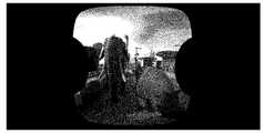
도 6A에는 스티칭된 프레임의 예시가 제공되는데, 복수의 시야각에서 영상기들에 의해 촬영된 4개의 프레임의 예시적 세트이다. 도 6B-6C는 도 1에 나타난 프로세스에 따라 스티칭된 파노라마 프레임의 부분들이다. 상기 프레임들은 도 2에 기술된 시스템(200)을 사용하여 획득되었다.Figure 6A provides an example of a stitched frame, which is an exemplary set of four frames photographed by imagers at a plurality of viewing angles. 6B-6C are portions of the panoramic frame stitched according to the process shown in Fig. The frames were obtained using the
선택적으로, 115에 보여지듯, 하나의 파노라마 프레임 이후 다른 하나를 표시할 때 콘텐츠의 빠른 전환이 깜빡임(flickering)을 유발하는 것을 방지하기 위해 선택된 불규칙한 경로의 좌표들이 같은 영상기들의 프레임들에 대하여 이전에 산출된 불규칙한 경로와 매칭된다. 기 정의된 문턱값 이상의 변화(shift)가 감지되면 이전에 산출된 불규칙한 경로의 좌표들에서 현재 불규칙한 경로의 좌표들로 전환하여 다른 불규칙한 경로를 산출한다.Alternatively, as shown at 115, in order to prevent a quick transition of the content from causing flickering when displaying the other one after the panorama frame, the coordinates of the selected irregular path are shifted relative to the frames of the same imagers And the irregular path calculated in the step S11. If a shift greater than the predefined threshold value is detected, the irregular path is shifted from the coordinates of the previously calculated irregular path to the coordinates of the current irregular path to calculate another irregular path.
선택적으로, 116에 보여지듯, 각각의 프레임들은 (이음부로 사용되는) 상기 불규칙한 경로를 따라 스티칭된다. 118에 보여지듯, 상기 프로세스는 파노라마 프레임을 생성하기 위한 인접 영상기들을 사용하여 촬영된 모든 프레임 쌍에 대하여 반복된다. 120에 보여지듯, 생성된 파노라마 프레임은 이전에 생성된 파노라마 프레임(해당되는 경우)에 추가되어 파노라마 VR 파일을 생성한다. 예를 들어 본 명세서에 참고로 포함되어 있는(변리 참조 번호 64940) 동일 발명자들의 함께 출원된 발명 “STITCHING FRAMES INTO A PANORAMIC FRAME"를 참고하라.Alternatively, as shown at 116, each of the frames is stitched along the irregular path (used as a joint). As shown at 118, the process is repeated for every frame pair photographed using adjacent imagers to create a panorama frame. As shown at 120, the generated panorama frame is added to the previously generated panorama frame (if applicable) to generate the panorama VR file. See, e.g., STITCHING FRAMES INTO A PANORAMIC FRAME, filed by the same inventors, which is incorporated herein by reference (Attorney Docket No. 64940).
본 발명의 다양한 구체예들의 설명은 예시 목적으로 제시된 것으로, 하나도 빼놓지 않은 완전한 것으로 의도되거나 개시된 구체예들에 제한되도록 의도된 것이 아니다. 기술된 구체예들의 범주와 사상을 벗어나지 않는 많은 수정과 변형들이 당업자에게 자명할 것이다. 본 명세서에 사용된 기술은 상기 구체예들의 원리들, 시장에서 발견되는 기술들에 대한 실용적 적용 또는 기술적 개선을 가장 잘 설명하도록, 또는 본 명세서에 개시된 상기 구체예들을 당업자들이 잘 이해할 수 있도록 하기 위해 선택되었다.The description of various embodiments of the present invention are presented for purposes of illustration and are not intended to be exhaustive or to limit the embodiments disclosed to those of ordinary skill in the art. Many modifications and variations will be apparent to those skilled in the art without departing from the scope and spirit of the described embodiments. The techniques used herein are intended to be best understood to illustrate the principles of the embodiments, the practical application or technical improvement to the technologies found in the market, or to enable those skilled in the art to understand the embodiments described herein Was selected.
본 출원으로부터 발명의 존속 기간동안 많은 관련된 영상기들이 개발될 것이 예상되며, 상기 용어 프레임의 범주는 이러한 모든 새로운 기술들을 포함하도록 의도된다.It is anticipated that many relevant imagers will be developed from the present application over the lifetime of the invention, and the scope of the term frame is intended to include all such new techniques.
본 명세서에 사용된 "약(about)"이라는 용어는 ±10%를 지칭한다.As used herein, the term " about " refers to +/- 10%.
"구비한다", "구비하는", "포함한다", "포함하는", "가진다"라는 용어들 및 그 활용어들은 "포함하지만 거기에 국한되지 않는다"는 것을 의미한다. 그 용어는 "~으로 이루어진다" 및 "실질적으로 ~으로 이루어진다"는 용어를 포괄한다.The terms " comprise ", " comprise ", " comprises ", " comprises ", and " comprises " The term encompasses the terms "consisting of" and "consisting essentially of".
"실질적으로 ~으로 이루어진다"는 용어는 조성이나 방법이 추가 성분들 및/또는 단계들을 포함할 수 있다는 것이나, 그 추가되는 성분들 및/또는 단계들이 실질적으로 청구된 조성이나 방법의 기본적인 신규한 특징을 바꾸지 않을 때에만 그러하다.The term " consisting essentially of "means that the composition or method may include additional components and / or steps, or that the additional components and / or steps are substantially equivalent to the basic novel features of the claimed composition or method This is true only if you do not change.
본 명세서에서 사용된 단수형 표현은 관련 문맥이 명백히 다른 것을 지시하지 않는 한 복수형 표현들을 포함한다. 예를 들어 "화합물"이나 "적어도 하나의 화합물"이라는 표현은 그들의 혼합물을 포함하는 복수의 화합물을 포함할 수 있다.The singular forms " a " as used herein include plural forms, unless the context clearly indicates otherwise. For example, the expression "compound" or "at least one compound" may include a plurality of compounds, including mixtures thereof.
"예시적인"이라는 용어는 본 명세서에서 "예, 경우, 또는 예시로서 기능한다"는 것을 의미하기 위해 사용된다. "예시적"이라고 기술된 어떤 구체예가 반드시, 다른 구체예들에 비해 선호되거나 바람직한 것으로 해석되거나 다른 구체예들로부터 나온 특징의 병합을 배제하는 것은 아니다.The word "exemplary" is used herein to mean "serving as an example, instance, or illustration. &Quot; Any embodiment described as "exemplary " is not necessarily to be construed as preferred or advantageous over other embodiments, nor does it exclude the merge of features from other embodiments.
"선택적으로"라는 용어는 본 명세서서 "어떤 구체예들에서는 제공되지만 다른 구체예들에서는 제공되지 않는다"는 것을 의미하기 위해 사용된다. 본 발명의 어떤 특정 구체예는 복수의 "선택적인" 특징들이 저촉되지 않는 이상 그러한 특징들을 포함할 수 있다.The term "optionally" is used herein to mean "provided in some embodiments but not in other embodiments ". Certain specific embodiments of the present invention may include such features as long as a plurality of "optional" features are not in conflict.
이 명세서 전체를 통해 본 발명의 다양한 구체예들은 범위의 형식으로 표현될 수 있다. 범위의 형식으로 된 서술은 단지 편의 및 간결함을 위한 것일 뿐 본 발명의 범위에 대한 융통성 없는 한계사항으로서 해석되어서는 안 될 것임을 알아야 한다. 따라서, 범위에 대한 서술은 모든 가능한 종속 범위들뿐 아니라 그 범위 안의 개별적 수치들까지 구체적으로 개시한 것으로 간주되어야 한다. 예를 들어, 1내지 6과 같은 범위에 대한 서술은 1 내지 3, 1 내지 4, 1 내지 5, 2 내지 4, 2 내지 6, 3 내지 6 등과 같은 종속 범위들뿐 아니라 그 범위 안의 개별 숫자들, 예컨대 1, 2, 3, 4, 5, 및 6을 특정하게 개시한 것으로 간주되어야 한다. 이것은 범위의 폭과 관계없이 적용된다.Throughout this specification various embodiments of the invention can be expressed in the form of a range. It should be understood that the description in the form of a range is merely for convenience and brevity, and should not be construed as an inflexible limitation on the scope of the invention. Accordingly, the description of ranges should be regarded as disclosing all possible subordinate ranges as well as individual values within that range. For example, the description for a range such as 1 to 6 includes not only dependent ranges such as 1 to 3, 1 to 4, 1 to 5, 2 to 4, 2 to 6, 3 to 6, , Such as 1, 2, 3, 4, 5, and 6, respectively. This applies irrespective of the width of the range.
본 명세서에서 수적인 범위가 지시될 때마다, 그것은 지시된 범위 안의 어떤 인용된 수(분수나 정수)를 포함하는 것으로 되어 있다. 제1지시 수 및 제2지시 수 "사이의 영역/범위" 및 "제1지시 수로부터 제2지시 수까지의 영역/범위"라는 용어는 본 명세서에서 서로 바꿔 사용될 수 있으며, 제1 및 제2지시 수들을 포함하고 그 사이의 모든 분수 및 정수들을 포함하는 것으로 되어 있다.Each time a numerical range is indicated in the specification, it is intended to include any quoted number (fraction or integer) within the indicated range. The term " area / range between first indication number and second indication number "and" area / range from first indication number to second indication number "can be used interchangeably herein, And includes all the fractions and integers between them.
명료성을 위해 별개의 구체예들과 관련해 기술된 본 발명의 소정 특징들은 하나의 구체예에서 조합되어 제공될 수도 있다는 것을 예상할 수 있다. 반대로, 간결성을 위해 하나의 구체예와 관련하여 기술된 본 발명의 여러 특징들은 별개로 또는 어떤 적절한 하위 조합을 통해서, 또는 본 발명의 어떤 다른 기술된 구체예를 통해 적절하게 제공될 수도 있다. 여러 구체예들과 관련하여 기술된 소정 특징들은 그 구체예가 그 요소들 없이는 작동이 불가한 경우가 아니라면 그 구체예들의 필수적인 특징들로 간주되어서는 안 된다.It is contemplated that certain features of the invention described in connection with the separate embodiments for clarity may be provided in combination in one embodiment. Conversely, various features of the invention described in connection with one embodiment for the sake of brevity may be provided separately or in any suitable subcombination, or through any other described embodiment of the invention. Certain features described in connection with the various embodiments should not be construed as essential features of the embodiments unless the embodiments are not operational without the elements.
본 발명은 그에 대한 특정 구체예들과 함께 기술되었으나, 많은 치환, 수정 및 변경이 당업자에게 자명할 것이라는 것은 명백하다. 따라서, 첨부된 청구범위의 개념과 범위에 속하는 그러한 모든 변형, 수정 및 변경들을 포괄하도록 의도된다.While the invention has been described in conjunction with specific embodiments thereof, it is evident that many alternatives, modifications and variations will be apparent to those skilled in the art. Accordingly, it is intended to embrace all such alterations, modifications and variations that fall within the spirit and scope of the appended claims.
각각의 개별 간행물, 특허 또는 특허출원이 본 명세서에 참조로서 포함되는 것으로 명시적이며 개별적으로 표시된 경우와 마찬가지로, 본 명세서에 언급된 모든 간행물, 특허 및 특허출원은 그 전체가 참조로서 이 명세서에 포함된다. 또한, 본 출원의 어떤 참조에 대한 인용이나 식별은 그러한 참조가 본 발명의 선행 기술로서 이용가능한 것임을 인정하는 것으로 해석되지 않아야 한다. 단락 제목들이 기재된 경우, 그 단락 제목들에 반드시 한정하는 것으로 해석되어서는 안된다.All publications, patents, and patent applications mentioned in this specification are herein incorporated in their entirety by reference into the specification as if each individual publication, patent or patent application were individually and individually indicated to be incorporated by reference herein. do. In addition, citation or identification of any reference in this application should not be construed as an admission that such reference is available as prior art to the present invention. If paragraph titles are listed, they should not necessarily be construed as limiting the paragraph titles.
Claims (17)
Translated fromKorean상기 방법은:
제1프레임의 제1프레임부에 기록된 콘텐츠와 제2프레임의 제2프레임부에 기록된 콘텐츠의 오버랩을 식별하는 단계;
상기 제1프레임부의 복수의 객체들을 세그먼트화하는 단계;
상기 복수의 객체들의 경계들을 식별하는 단계;
상기 복수의 객체들 중 적어도 일부의 경계들의 적어도 일부를 따라 상기 제1프레임부의 대면하는 두개의 면들 사이를 연결하는 불규칙한 선로(line path)를 식별하는 단계;
상기 불규칙한 선로를 따라 상기 제1프레임과 제2프레임을 스티칭하여 파노라마 프레임을 생성하는 단계를 포함하는 방법.CLAIMS 1. A method of generating a panorama frame by combining frames along irregular lines identified in overlapping appearing in frames,
The method comprising:
Identifying an overlap between the content recorded in the first frame portion of the first frame and the content recorded in the second frame portion of the second frame;
Segmenting a plurality of objects of the first frame part;
Identifying boundaries of the plurality of objects;
Identifying an irregular line path connecting between two facing sides of the first frame portion along at least a portion of the boundaries of at least some of the plurality of objects;
Stitching the first frame and the second frame along the irregular line to create a panorama frame.
상기 방법은, 각각 적어도 하나의 기정의된 특징점 속성을 갖는 복수의 특징점들을 상기 제1프레임에서 감지하는 단계를 더 포함하며, 상기 복수의 객체들은 상기 복수의 특징점들에 따라 세그먼트화되는 방법.The method according to claim 1,
The method further comprises sensing in the first frame a plurality of feature points each having at least one predetermined feature attribute, wherein the plurality of objects are segmented according to the plurality of feature points.
상기 복수의 객체들은 상기 복수의 특징점들을 기반으로 상기 제1프레임부로부터 생성된 워터쉐드 이미지에서 식별되는 방법.3. The method of claim 2,
Wherein the plurality of objects are identified in a watermarked image generated from the first frame unit based on the plurality of feature points.
상기 복수의 특징점들은 FAST(accelerated segment test) 프로세스를 사용하여 식별되는 방법.3. The method of claim 2,
Wherein the plurality of feature points are identified using an accelerated segment test (FAST) process.
상기 오버랩은 피쳐 디스크립터 매칭 프로세스(feature descriptor matching process)를 수행함으로써 식별되는 방법.The method according to claim 1,
Wherein the overlap is identified by performing a feature descriptor matching process.
상기 제1프레임과 제2프레임은 하나의 영상 장치의 복수의 영상기들에 의해 촬영되는 방법.The method according to claim 1,
Wherein the first frame and the second frame are captured by a plurality of imagers of one imaging device.
상기 제1프레임과 상기 제2프레임은 복수의 영상기들 중 인접한 두 개의 영상기들에서 촬영되고, 상기 인접한 두 개의 영상기들 중 하나의 제1시야는 상기 두 개의 영상기들 중 다른 하나의 제2시야와 중첩되고; 상기 인접한 두 개의 영상기들은 다른 영상기들과 함께 공통 중심 주위에 장착되는 방법.The method according to claim 6,
Wherein the first frame and the second frame are photographed at two adjacent imagers among a plurality of imagers and a first view of one of the two adjacent imagers is imaged on the other of the two imagers 2 overlaps with the field of view; Wherein the two adjacent imagers are mounted around a common center with the other imagers.
상기 인접한 두 개의 영상기들 중 제1영상기의 광학 축은 상기 공통 중심과 상기 복수의 영상기들의 시야들의 모든 원점을 지나는 가상의 원 위의 상기 제1 인접 영상기 시야의 원점의 각 접선물림점을 통과하는 축에 대하여 기울어져 있는 방법.8. The method of claim 7,
Wherein the optical axis of the first imager of the two imagers is a tangent point of the origin of the first imager field of view on a virtual circle that passes through all the origin of the field of view of the common center and the plurality of imagers Is tilted with respect to an axis passing through the first axis.
상기 방법은:
상기 제1프레임과 제2프레임 이후에 촬영된 신규한 프레임 쌍에서 상기 불규칙한 선로와 유사하게 계산된 신규한 불규칙한 선로를 따라 상기 불규칙한 선로를 조정하는 단계, 및
상기 조정된 불규칙한 선로를 이용하여 상기 신규한 이미지를 스티칭하는 단계를 더 포함하는 방법.9. The method of claim 8,
The method comprising:
Adjusting the irregular line along a new irregular line calculated similar to the irregular line in a new frame pair photographed after the first frame and the second frame; and
And stitching the novel image using the adjusted irregular line.
상기 방법은 상기 불규칙한 선로와 상기 신규한 불규칙한 선로의 차이가 문턱값보다 클 때 상기 조정 및 이용을 수행하는 방법.10. The method of claim 9,
The method further comprising the step of adjusting and utilizing the difference when the difference between the irregular line and the new irregular line is greater than a threshold value.
상기 파노라마 프레임은 가상 현실(VR) 파일의 복수의 프레임들 중 하나인 방법.The method according to claim 1,
Wherein the panorama frame is one of a plurality of frames of a virtual reality (VR) file.
상기 파노라마 프레임은 좌안 파노라마 프레임이고, 상기 복수의 영상기들은 우안 파노라마 프레임에 결합되는 복수의 추가 프레임들을 촬영하기 위한 복수의 추가 영상기들과 서로 결합되어 있으며; 상기 방법은 상기 우안 파노라마 프레임을 상기 좌안 파노라마 프레임과 결합하여 입체 프레임을 생성하는 단계를 더 포함하는 방법.The method according to claim 6,
Wherein the panorama frame is a left eye panorama frame and the plurality of imagers is coupled to a plurality of additional imagers for imaging a plurality of additional frames coupled to a right eye panorama frame; The method further comprising combining the right panoramic frame with the left panoramic frame to generate a stereoscopic frame.
상기 복수의 영상기들 및 상기 복수의 추가 프레임들의 구성 요소들은 공통 중심을 에워싸는 가상의 원을 따라 교대로 배치되는 방법.13. The method of claim 12,
Wherein the plurality of imagers and the components of the plurality of additional frames are alternately arranged along an imaginary circle enclosing a common center.
상기 파노라마 프레임은 우안 파노라마 프레임이고, 상기 복수의 영상기들은 좌안 파노라마 프레임에 결합되는 복수의 추가 프레임들을 촬영하기 위한 복수의 추가 영상기들과 서로 결합되어 있으며; 상기 방법은 좌안 파노라마 프레임을 상기 우안 파노라마 프레임과 결합하여 입체 프레임을 생성하는 단계를 더 포함하는 방법The method according to claim 6,
Wherein the panorama frame is a right eye panorama frame and the plurality of imagers is coupled to a plurality of additional imagers for capturing a plurality of additional frames coupled to a left eye panorama frame; The method further comprises combining the left panoramic frame with the right panoramic frame to generate a stereoscopic frame
상기 복수의 영상기들은 공통 중심을 에워싸는 가상의 원을 따라 배치되고, 상기 복수의 영상기들 각각은 그 광학 중심이 상기 공통 중심과 각각의 상기 영상기의 시야의 원점의 접선물림점을 통과하는 축에 대하여 기울어지도록 장착되는 방법.The method according to claim 6,
Wherein the plurality of imagers are arranged along a virtual circle encircling a common center and wherein each of the plurality of imagers passes through a tangent point of the common center and the origin of each imager's field of view And is mounted to be tilted with respect to the axis.
상기 시스템은:
영상 장치의 복수의 영상기들에 의해 촬영된 복수의 프레임들 중 두 프레임으로부터 제1 프레임 및 제2 프레임을 수신하도록 구성되는 인터페이스;
코드를 저장하도록 구성되는 코드 저장소;
상기 코드를 실행하도록 구성되는 프로세서를 포함하고,
상기 코드는,
제1프레임의 제1프레임부에 기록된 콘텐츠와 제2프레임의 제2프레임부에 기록된 콘텐츠 사이의 오버랩을 식별하기 위한 코드 명령어들;
상기 제1프레임부의 복수의 객체들을 세그먼트화하기 위한 코드 명령어들;
상기 복수의 객체들의 경계들을 식별하기 위한 코드 명령어들;
상기 복수의 객체들 중 적어도 일부의 경계의 적어도 일부를 따라 상기 제1프레임부의 대면하는 두개의 면들 사이를 연결하는 불규칙한 선로를 식별하기 위한 코드 명령어들; 및
상기 불규칙한 선로를 따라 상기 제1프레임과 제2프레임을 스티칭하여 파노라마 프레임을 생성하기 위한 코드 명령어들을 포함하는 시스템.A system for generating a panorama frame by combining frames along an irregular line identified in overlapping displayed in frames,
The system comprises:
An interface configured to receive a first frame and a second frame from two of a plurality of frames photographed by a plurality of imagers of the imaging device;
A code store configured to store code;
And a processor configured to execute the code,
The code includes:
Code instructions for identifying an overlap between content recorded in a first frame portion of a first frame and content recorded in a second frame portion of a second frame;
Code commands for segmenting a plurality of objects of the first frame portion;
Code instructions for identifying boundaries of the plurality of objects;
Code instructions for identifying an irregular line connecting between two facing sides of the first frame portion along at least a portion of a boundary of at least some of the plurality of objects; And
And stitching the first and second frames along the irregular line to generate a panoramic frame.
상기 프로그램 제품은:
비휘발성 컴퓨터 판독 가능 저장 매체;
제1프레임의 제1프레임부에 기록된 콘텐츠와 제2프레임의 제2프레임부에 기록된 콘텐츠 사이의 오버랩을 식별하기 위한 제1 프로그램 명령어들;
상기 제1프레임부의 복수의 객체들을 세그먼트화하기 위한 제2 프로그램 명령어들;
상기 복수의 객체들의 경계들을 식별하기 위한 제3 프로그램 명령어들;
상기 복수의 객체들 중 적어도 일부의 경계들의 적어도 일부를 따라 상기 제1프레임부의 대면하는 두 개의 면들 사이를 연결하는 불규칙한 선로를 식별하기 위한 제4 프로그램 명령어들; 및
상기 불규칙한 선로를 따라 상기 제1프레임과 제2프레임을 스티칭하여 파노라마 프레임을 생성하기 위한 제5프로그램 명령어들을 포함하고;
상기 제1, 제2, 제3, 제4 및 제5 프로그램 명령어들은 적어도 하나의 전산화된 프로세서에 의해 상기 비휘발성 컴퓨터 판독 가능 저장 매체로부터 실행되는 소프트웨어 프로그램 제품.16. A software program product for creating a panorama frame by combining frames along irregular lines identified in overlapping appearing in frames,
The program product comprising:
A non-volatile computer readable storage medium;
First program instructions for identifying an overlap between content recorded in a first frame portion of a first frame and content recorded in a second frame portion of a second frame;
Second program instructions for segmenting a plurality of objects of the first frame portion;
Third program instructions for identifying boundaries of the plurality of objects;
Fourth program instructions for identifying an irregular line connecting between two facing sides of the first frame portion along at least a portion of the boundaries of at least some of the plurality of objects; And
Fifth program instructions for stitching the first frame and the second frame along the irregular line to create a panoramic frame;
Wherein the first, second, third, fourth and fifth program instructions are executed from the non-volatile computer readable storage medium by at least one computerized processor.
Applications Claiming Priority (5)
| Application Number | Priority Date | Filing Date | Title |
|---|---|---|---|
| US201662274317P | 2016-01-03 | 2016-01-03 | |
| US201662274321P | 2016-01-03 | 2016-01-03 | |
| US62/274,317 | 2016-01-03 | ||
| US62/274,321 | 2016-01-03 | ||
| PCT/IL2016/051328WO2017115348A1 (en) | 2016-01-03 | 2016-12-12 | Adaptive stitching of frames in the process of creating a panoramic frame |
Publications (1)
| Publication Number | Publication Date |
|---|---|
| KR20180111798Atrue KR20180111798A (en) | 2018-10-11 |
Family
ID=59224696
Family Applications (2)
| Application Number | Title | Priority Date | Filing Date |
|---|---|---|---|
| KR1020187020220AWithdrawnKR20180111798A (en) | 2016-01-03 | 2016-12-12 | Adaptive stitching of frames in the panorama frame creation process |
| KR1020177032907AWithdrawnKR20180101165A (en) | 2016-01-03 | 2016-12-12 | Frame stitching with panoramic frame |
Family Applications After (1)
| Application Number | Title | Priority Date | Filing Date |
|---|---|---|---|
| KR1020177032907AWithdrawnKR20180101165A (en) | 2016-01-03 | 2016-12-12 | Frame stitching with panoramic frame |
Country Status (6)
| Country | Link |
|---|---|
| US (2) | US20190019299A1 (en) |
| EP (2) | EP3398163A4 (en) |
| JP (2) | JP2019511016A (en) |
| KR (2) | KR20180111798A (en) |
| CN (2) | CN107960121A (en) |
| WO (2) | WO2017115348A1 (en) |
Cited By (1)
| Publication number | Priority date | Publication date | Assignee | Title |
|---|---|---|---|---|
| KR102431955B1 (en)* | 2021-02-09 | 2022-08-18 | 브라이튼코퍼레이션 주식회사 | Method and device for providing function to review visual contents for visual contents production management |
Families Citing this family (34)
| Publication number | Priority date | Publication date | Assignee | Title |
|---|---|---|---|---|
| WO2017115348A1 (en) | 2016-01-03 | 2017-07-06 | Humaneyes Technologies Ltd. | Adaptive stitching of frames in the process of creating a panoramic frame |
| WO2017120776A1 (en)* | 2016-01-12 | 2017-07-20 | Shanghaitech University | Calibration method and apparatus for panoramic stereo video system |
| US10574995B2 (en) | 2017-04-10 | 2020-02-25 | Intel Corporation | Technology to accelerate scene change detection and achieve adaptive content display |
| JP6545229B2 (en)* | 2017-08-23 | 2019-07-17 | キヤノン株式会社 | IMAGE PROCESSING APPARATUS, IMAGING APPARATUS, CONTROL METHOD OF IMAGE PROCESSING APPARATUS, AND PROGRAM |
| WO2019061066A1 (en)* | 2017-09-27 | 2019-04-04 | Intel Corporation | Apparatus and method for optimized image stitching based on optical flow |
| JP2019080174A (en)* | 2017-10-25 | 2019-05-23 | 株式会社リコー | Image processing apparatus, imaging system, communication system, image processing method, and program |
| KR102025735B1 (en)* | 2017-11-23 | 2019-09-26 | 전자부품연구원 | 360 VR image conversion system and method using multiple images |
| GB2572956B (en)* | 2018-04-16 | 2021-09-08 | Sony Interactive Entertainment Inc | Calibration system and method |
| TWI678920B (en)* | 2018-05-23 | 2019-12-01 | 宏碁股份有限公司 | Video processing apparatus, video processing method thereof and computer program product |
| CN108900817A (en)* | 2018-08-23 | 2018-11-27 | 重庆加河科技有限公司 | A kind of education real-time monitoring system based on VR |
| EP3667414B1 (en)* | 2018-12-14 | 2020-11-25 | Axis AB | A system for panoramic imaging |
| KR20200081527A (en)* | 2018-12-19 | 2020-07-08 | 삼성전자주식회사 | Electronic apparatus and control method thereof |
| US10832377B2 (en)* | 2019-01-04 | 2020-11-10 | Aspeed Technology Inc. | Spherical coordinates calibration method for linking spherical coordinates to texture coordinates |
| CN211019015U (en)* | 2019-03-25 | 2020-07-14 | 人眼科技有限公司 | Imaging device with non-coplanar sensor |
| US12136192B2 (en)* | 2019-05-15 | 2024-11-05 | Ntt Docomo, Inc. | Image processing apparatus |
| CN112099616A (en)* | 2019-06-17 | 2020-12-18 | 深圳市黑电科技有限公司 | Method and system for realizing 360-degree full-view angle of body-control AR glasses and AR glasses |
| WO2020256517A2 (en)* | 2019-06-21 | 2020-12-24 | 주식회사 쓰리아이 | Automatic phase mapping processing method and system based on omnidirectional image information |
| KR102384177B1 (en)* | 2019-06-21 | 2022-04-29 | 주식회사 쓰리아이 | Auto topology mapping method based on omni-directional image and system thereof |
| CN114287126B (en)* | 2019-08-22 | 2025-06-10 | 深圳市铂岩科技有限公司 | Real-time video stitching method based on optical flow calculation |
| CN112927238B (en)* | 2019-12-06 | 2022-07-01 | 四川大学 | Core sequence image annotation method combining optical flow and watershed segmentation |
| KR102617222B1 (en)* | 2019-12-24 | 2023-12-26 | 주식회사 쓰리아이 | Auto topology mapping method based on omni-directional image and system thereof |
| GB2591278A (en)* | 2020-01-24 | 2021-07-28 | Bombardier Transp Gmbh | A monitoring system of a rail vehicle, a method for monitoring and a rail vehicle |
| CN111476716B (en)* | 2020-04-03 | 2023-09-26 | 深圳力维智联技术有限公司 | Real-time video stitching method and device |
| CN111738923B (en)* | 2020-06-19 | 2024-05-10 | 京东方科技集团股份有限公司 | Image processing method, device and storage medium |
| KR20220025600A (en) | 2020-08-24 | 2022-03-03 | 삼성전자주식회사 | Method and apparatus for generating image |
| CN112085814B (en)* | 2020-09-07 | 2024-05-14 | 北京百度网讯科技有限公司 | Electronic map display method, device, equipment and readable storage medium |
| CN112102307B (en)* | 2020-09-25 | 2023-10-20 | 杭州海康威视数字技术股份有限公司 | Method and device for determining heat data of global area and storage medium |
| WO2022076934A1 (en)* | 2020-10-09 | 2022-04-14 | Arizona Board Of Regents On Behalf Of Arizona State University | Anti-tamper protection using dendrites |
| US12322075B2 (en)* | 2021-02-05 | 2025-06-03 | Motorola Solutions, Inc. | Device, method and system for identifying objects in warped images from a fisheye camera |
| CN113888642B (en)* | 2021-09-23 | 2025-01-24 | 同济大学 | A method, system, device and medium for online correction of external parameters of surround view system |
| CN116416546A (en)* | 2021-12-31 | 2023-07-11 | 上海海思技术有限公司 | Image processing method, apparatus, storage medium, and program product |
| CN115293969A (en)* | 2022-07-25 | 2022-11-04 | 上海旷通科技有限公司 | Method, device and equipment for video image splicing |
| EP4594993A1 (en)* | 2022-10-29 | 2025-08-06 | Samsung Electronics Co., Ltd. | Method and apparatus for stitching frames of image comprising moving objects |
| CN116563186B (en)* | 2023-05-12 | 2024-07-12 | 中山大学 | Real-time panoramic sensing system and method based on special AI sensing chip |
Family Cites Families (22)
| Publication number | Priority date | Publication date | Assignee | Title |
|---|---|---|---|---|
| US7259784B2 (en)* | 2002-06-21 | 2007-08-21 | Microsoft Corporation | System and method for camera color calibration and image stitching |
| CN1830004A (en)* | 2003-06-16 | 2006-09-06 | 戴纳皮克斯智能成像股份有限公司 | Segmentation and data mining for gel electrophoresis images |
| US7730406B2 (en)* | 2004-10-20 | 2010-06-01 | Hewlett-Packard Development Company, L.P. | Image processing system and method |
| US9035968B2 (en) | 2007-07-23 | 2015-05-19 | Humaneyes Technologies Ltd. | Multi view displays and methods for producing the same |
| US10080006B2 (en)* | 2009-12-11 | 2018-09-18 | Fotonation Limited | Stereoscopic (3D) panorama creation on handheld device |
| US9361717B2 (en)* | 2010-10-19 | 2016-06-07 | Humaneyes Technologies Ltd. | Methods and systems of generating an interlaced composite image |
| JP5894602B2 (en)* | 2010-10-19 | 2016-03-30 | ヒューマンアイズ テクノロジーズ リミテッド | Method and system for forming interlaced composite images |
| US8818132B2 (en)* | 2010-11-29 | 2014-08-26 | Microsoft Corporation | Camera calibration with lens distortion from low-rank textures |
| US8581961B2 (en)* | 2011-03-31 | 2013-11-12 | Vangogh Imaging, Inc. | Stereoscopic panoramic video capture system using surface identification and distance registration technique |
| WO2012136388A1 (en)* | 2011-04-08 | 2012-10-11 | Fraunhofer-Gesellschaft zur Förderung der angewandten Forschung e.V. | Capturing panoramic or semi-panoramic 3d scenes |
| WO2013069049A1 (en)* | 2011-11-07 | 2013-05-16 | 株式会社ソニー・コンピュータエンタテインメント | Image generation device, and image generation method |
| JP2015156523A (en)* | 2012-06-06 | 2015-08-27 | ソニー株式会社 | Image processing device, image processing method, and program |
| JP5828039B2 (en)* | 2012-06-11 | 2015-12-02 | 株式会社ソニー・コンピュータエンタテインメント | Image generating apparatus and image generating method |
| EP2860957B1 (en)* | 2012-06-11 | 2020-11-18 | Sony Interactive Entertainment Inc. | Image capturing device, image capturing method and computer-readable recording medium |
| WO2014152855A2 (en)* | 2013-03-14 | 2014-09-25 | Geerds Joergen | Camera system |
| US9451162B2 (en)* | 2013-08-21 | 2016-09-20 | Jaunt Inc. | Camera array including camera modules |
| CN203632790U (en)* | 2013-10-18 | 2014-06-04 | 中国民用航空总局第二研究所 | Distributed linkage system capable of carrying out panoramic display and local check simultaneously |
| WO2015085406A1 (en)* | 2013-12-13 | 2015-06-18 | 8702209 Canada Inc. | Systems and methods for producing panoramic and stereoscopic videos |
| KR101811157B1 (en)* | 2013-12-19 | 2018-01-25 | 인텔 코포레이션 | Bowl-shaped imaging system |
| US10666862B2 (en)* | 2014-02-26 | 2020-05-26 | Searidge Technologies Inc. | Image stitching and automatic-color correction |
| US9262801B2 (en) | 2014-04-01 | 2016-02-16 | Gopro, Inc. | Image taping in a multi-camera array |
| WO2017115348A1 (en) | 2016-01-03 | 2017-07-06 | Humaneyes Technologies Ltd. | Adaptive stitching of frames in the process of creating a panoramic frame |
- 2016
- 2016-12-12WOPCT/IL2016/051328patent/WO2017115348A1/ennot_activeCeased
- 2016-12-12CNCN201680023730.0Apatent/CN107960121A/enactivePending
- 2016-12-12WOPCT/IL2016/051329patent/WO2017115349A1/ennot_activeCeased
- 2016-12-12USUS16/067,832patent/US20190019299A1/ennot_activeAbandoned
- 2016-12-12JPJP2017549069Apatent/JP2019511016A/enactivePending
- 2016-12-12KRKR1020187020220Apatent/KR20180111798A/ennot_activeWithdrawn
- 2016-12-12EPEP16881396.2Apatent/EP3398163A4/ennot_activeWithdrawn
- 2016-12-12KRKR1020177032907Apatent/KR20180101165A/ennot_activeWithdrawn
- 2016-12-12JPJP2018534905Apatent/JP2019511024A/enactivePending
- 2016-12-12CNCN201680081415.3Apatent/CN108700798A/enactivePending
- 2016-12-12EPEP16881395.4Apatent/EP3398016A4/ennot_activeWithdrawn
- 2016-12-12USUS15/560,495patent/US10460459B2/ennot_activeExpired - Fee Related
Cited By (1)
| Publication number | Priority date | Publication date | Assignee | Title |
|---|---|---|---|---|
| KR102431955B1 (en)* | 2021-02-09 | 2022-08-18 | 브라이튼코퍼레이션 주식회사 | Method and device for providing function to review visual contents for visual contents production management |
Also Published As
| Publication number | Publication date |
|---|---|
| EP3398016A4 (en) | 2019-08-28 |
| CN107960121A (en) | 2018-04-24 |
| JP2019511016A (en) | 2019-04-18 |
| CN108700798A (en) | 2018-10-23 |
| WO2017115348A1 (en) | 2017-07-06 |
| WO2017115349A1 (en) | 2017-07-06 |
| EP3398163A1 (en) | 2018-11-07 |
| EP3398163A4 (en) | 2019-10-16 |
| EP3398016A1 (en) | 2018-11-07 |
| KR20180101165A (en) | 2018-09-12 |
| JP2019511024A (en) | 2019-04-18 |
| US20190019299A1 (en) | 2019-01-17 |
| US20180063513A1 (en) | 2018-03-01 |
| US10460459B2 (en) | 2019-10-29 |
Similar Documents
| Publication | Publication Date | Title |
|---|---|---|
| KR20180111798A (en) | Adaptive stitching of frames in the panorama frame creation process | |
| KR101944050B1 (en) | Capture and render panoramic virtual reality content | |
| KR102023587B1 (en) | Camera Rig and Stereoscopic Image Capture | |
| EP3262614B1 (en) | Calibration for immersive content systems | |
| CN106797460B (en) | The reconstruction of 3 D video | |
| US10373362B2 (en) | Systems and methods for adaptive stitching of digital images | |
| US8581961B2 (en) | Stereoscopic panoramic video capture system using surface identification and distance registration technique | |
| Matsuyama et al. | 3D video and its applications | |
| JP6683307B2 (en) | Optimal spherical image acquisition method using multiple cameras | |
| CN109361912A (en) | Multilayer camera apparatus for 3 D visual image capture | |
| WO2011099896A1 (en) | Method for representing an initial three-dimensional scene on the basis of results of an image recording in a two-dimensional projection (variants) | |
| CN111866523B (en) | Panoramic video synthesis method and device, electronic equipment and computer storage medium | |
| GB2554925A (en) | Display of visual data with a virtual reality headset | |
| Schenkel et al. | Natural scenes datasets for exploration in 6DOF navigation | |
| JP6799468B2 (en) | Image processing equipment, image processing methods and computer programs | |
| KR101947799B1 (en) | 360 degrees Fisheye Rendering Method for Virtual Reality Contents Service | |
| GB2548080A (en) | A method for image transformation | |
| Tzavidas et al. | Multicamera setup for generating stereo panoramic video | |
| KR20170059879A (en) | three-dimensional image photographing apparatus | |
| CN114881898A (en) | Multi-angle free visual angle image data generation method and device, medium and equipment | |
| Loscos et al. | 3D Video: from Capture to Interactive Display. |
Legal Events
| Date | Code | Title | Description |
|---|---|---|---|
| PA0105 | International application | Patent event date:20180713 Patent event code:PA01051R01D Comment text:International Patent Application | |
| PG1501 | Laying open of application | ||
| PC1203 | Withdrawal of no request for examination |