KR20180109957A - Set of panels for assembled products - Google Patents
Set of panels for assembled productsDownload PDFInfo
- Publication number
- KR20180109957A KR20180109957AKR1020187024362AKR20187024362AKR20180109957AKR 20180109957 AKR20180109957 AKR 20180109957AKR 1020187024362 AKR1020187024362 AKR 1020187024362AKR 20187024362 AKR20187024362 AKR 20187024362AKR 20180109957 AKR20180109957 AKR 20180109957A
- Authority
- KR
- South Korea
- Prior art keywords
- edge
- panel
- major plane
- tongue
- groove
- Prior art date
- Legal status (The legal status is an assumption and is not a legal conclusion. Google has not performed a legal analysis and makes no representation as to the accuracy of the status listed.)
- Pending
Links
- 210000002105tongueAnatomy0.000claimsdescription83
- 238000003780insertionMethods0.000claimsdescription17
- 230000037431insertionEffects0.000claimsdescription17
- 239000011162core materialSubstances0.000claimsdescription7
- 229920002522Wood fibrePolymers0.000claimsdescription6
- 239000002025wood fiberSubstances0.000claimsdescription6
- 239000002131composite materialSubstances0.000claimsdescription3
- 239000011120plywoodSubstances0.000claimsdescription3
- 239000002990reinforced plasticSubstances0.000claimsdescription3
- 239000007787solidSubstances0.000claimsdescription3
- 239000002023woodSubstances0.000claimsdescription3
- 238000000034methodMethods0.000claims16
- 238000003801millingMethods0.000description8
- 238000006073displacement reactionMethods0.000description4
- 238000007688edgingMethods0.000description4
- 238000005336crackingMethods0.000description3
- 238000004519manufacturing processMethods0.000description2
- 238000005520cutting processMethods0.000description1
- 238000000354decomposition reactionMethods0.000description1
- 230000007547defectEffects0.000description1
- 239000000835fiberSubstances0.000description1
- 230000000977initiatory effectEffects0.000description1
Images


Classifications
- F—MECHANICAL ENGINEERING; LIGHTING; HEATING; WEAPONS; BLASTING
- F16—ENGINEERING ELEMENTS AND UNITS; GENERAL MEASURES FOR PRODUCING AND MAINTAINING EFFECTIVE FUNCTIONING OF MACHINES OR INSTALLATIONS; THERMAL INSULATION IN GENERAL
- F16B—DEVICES FOR FASTENING OR SECURING CONSTRUCTIONAL ELEMENTS OR MACHINE PARTS TOGETHER, e.g. NAILS, BOLTS, CIRCLIPS, CLAMPS, CLIPS OR WEDGES; JOINTS OR JOINTING
- F16B12/00—Jointing of furniture or the like, e.g. hidden from exterior
- F16B12/10—Jointing of furniture or the like, e.g. hidden from exterior using pegs, bolts, tenons, clamps, clips, or the like
- F16B12/12—Jointing of furniture or the like, e.g. hidden from exterior using pegs, bolts, tenons, clamps, clips, or the like for non-metal furniture parts, e.g. made of wood, of plastics
- F16B12/26—Jointing of furniture or the like, e.g. hidden from exterior using pegs, bolts, tenons, clamps, clips, or the like for non-metal furniture parts, e.g. made of wood, of plastics using snap-action elements
- A—HUMAN NECESSITIES
- A47—FURNITURE; DOMESTIC ARTICLES OR APPLIANCES; COFFEE MILLS; SPICE MILLS; SUCTION CLEANERS IN GENERAL
- A47B—TABLES; DESKS; OFFICE FURNITURE; CABINETS; DRAWERS; GENERAL DETAILS OF FURNITURE
- A47B47/00—Cabinets, racks or shelf units, characterised by features related to dismountability or building-up from elements
- A47B47/0075—Flat or flat-like panels connected without frames
- A—HUMAN NECESSITIES
- A47—FURNITURE; DOMESTIC ARTICLES OR APPLIANCES; COFFEE MILLS; SPICE MILLS; SUCTION CLEANERS IN GENERAL
- A47B—TABLES; DESKS; OFFICE FURNITURE; CABINETS; DRAWERS; GENERAL DETAILS OF FURNITURE
- A47B47/00—Cabinets, racks or shelf units, characterised by features related to dismountability or building-up from elements
- A47B47/04—Cabinets, racks or shelf units, characterised by features related to dismountability or building-up from elements made mainly of wood or plastics
- A47B47/042—Panels connected without frames
- A—HUMAN NECESSITIES
- A47—FURNITURE; DOMESTIC ARTICLES OR APPLIANCES; COFFEE MILLS; SPICE MILLS; SUCTION CLEANERS IN GENERAL
- A47B—TABLES; DESKS; OFFICE FURNITURE; CABINETS; DRAWERS; GENERAL DETAILS OF FURNITURE
- A47B61/00—Wardrobes
- A47B61/003—Details of garment-holders
- A—HUMAN NECESSITIES
- A47—FURNITURE; DOMESTIC ARTICLES OR APPLIANCES; COFFEE MILLS; SPICE MILLS; SUCTION CLEANERS IN GENERAL
- A47B—TABLES; DESKS; OFFICE FURNITURE; CABINETS; DRAWERS; GENERAL DETAILS OF FURNITURE
- A47B63/00—Cabinets, racks or shelf units, specially adapted for storing books, documents, forms, or the like
- A—HUMAN NECESSITIES
- A47—FURNITURE; DOMESTIC ARTICLES OR APPLIANCES; COFFEE MILLS; SPICE MILLS; SUCTION CLEANERS IN GENERAL
- A47B—TABLES; DESKS; OFFICE FURNITURE; CABINETS; DRAWERS; GENERAL DETAILS OF FURNITURE
- A47B77/00—Kitchen cabinets
- A—HUMAN NECESSITIES
- A47—FURNITURE; DOMESTIC ARTICLES OR APPLIANCES; COFFEE MILLS; SPICE MILLS; SUCTION CLEANERS IN GENERAL
- A47B—TABLES; DESKS; OFFICE FURNITURE; CABINETS; DRAWERS; GENERAL DETAILS OF FURNITURE
- A47B88/00—Drawers for tables, cabinets or like furniture; Guides for drawers
- A47B88/90—Constructional details of drawers
- A47B88/941—Drawers being constructed from two or more parts
- A—HUMAN NECESSITIES
- A47—FURNITURE; DOMESTIC ARTICLES OR APPLIANCES; COFFEE MILLS; SPICE MILLS; SUCTION CLEANERS IN GENERAL
- A47B—TABLES; DESKS; OFFICE FURNITURE; CABINETS; DRAWERS; GENERAL DETAILS OF FURNITURE
- A47B96/00—Details of cabinets, racks or shelf units not covered by a single one of groups A47B43/00 - A47B95/00; General details of furniture
- A47B96/20—Furniture panels or like furniture elements
- A47B96/201—Edge features
- B—PERFORMING OPERATIONS; TRANSPORTING
- B65—CONVEYING; PACKING; STORING; HANDLING THIN OR FILAMENTARY MATERIAL
- B65D—CONTAINERS FOR STORAGE OR TRANSPORT OF ARTICLES OR MATERIALS, e.g. BAGS, BARRELS, BOTTLES, BOXES, CANS, CARTONS, CRATES, DRUMS, JARS, TANKS, HOPPERS, FORWARDING CONTAINERS; ACCESSORIES, CLOSURES, OR FITTINGS THEREFOR; PACKAGING ELEMENTS; PACKAGES
- B65D9/00—Containers having bodies formed by interconnecting or uniting two or more rigid, or substantially rigid, components made wholly or mainly of wood or substitutes therefor
- B65D9/12—Containers having bodies formed by interconnecting or uniting two or more rigid, or substantially rigid, components made wholly or mainly of wood or substitutes therefor collapsible, e.g. with all parts detachable
- B65D9/22—Fastening devices for holding collapsible containers in erected state, e.g. integral with container walls
- B—PERFORMING OPERATIONS; TRANSPORTING
- B65—CONVEYING; PACKING; STORING; HANDLING THIN OR FILAMENTARY MATERIAL
- B65D—CONTAINERS FOR STORAGE OR TRANSPORT OF ARTICLES OR MATERIALS, e.g. BAGS, BARRELS, BOTTLES, BOXES, CANS, CARTONS, CRATES, DRUMS, JARS, TANKS, HOPPERS, FORWARDING CONTAINERS; ACCESSORIES, CLOSURES, OR FITTINGS THEREFOR; PACKAGING ELEMENTS; PACKAGES
- B65D9/00—Containers having bodies formed by interconnecting or uniting two or more rigid, or substantially rigid, components made wholly or mainly of wood or substitutes therefor
- B65D9/30—Applications of laminates as wall material, e.g. plywood
- B—PERFORMING OPERATIONS; TRANSPORTING
- B65—CONVEYING; PACKING; STORING; HANDLING THIN OR FILAMENTARY MATERIAL
- B65D—CONTAINERS FOR STORAGE OR TRANSPORT OF ARTICLES OR MATERIALS, e.g. BAGS, BARRELS, BOTTLES, BOXES, CANS, CARTONS, CRATES, DRUMS, JARS, TANKS, HOPPERS, FORWARDING CONTAINERS; ACCESSORIES, CLOSURES, OR FITTINGS THEREFOR; PACKAGING ELEMENTS; PACKAGES
- B65D9/00—Containers having bodies formed by interconnecting or uniting two or more rigid, or substantially rigid, components made wholly or mainly of wood or substitutes therefor
- B65D9/32—Details of wooden walls; Connections between walls
- B65D9/34—Joints; Local reinforcements
- F—MECHANICAL ENGINEERING; LIGHTING; HEATING; WEAPONS; BLASTING
- F16—ENGINEERING ELEMENTS AND UNITS; GENERAL MEASURES FOR PRODUCING AND MAINTAINING EFFECTIVE FUNCTIONING OF MACHINES OR INSTALLATIONS; THERMAL INSULATION IN GENERAL
- F16B—DEVICES FOR FASTENING OR SECURING CONSTRUCTIONAL ELEMENTS OR MACHINE PARTS TOGETHER, e.g. NAILS, BOLTS, CIRCLIPS, CLAMPS, CLIPS OR WEDGES; JOINTS OR JOINTING
- F16B12/00—Jointing of furniture or the like, e.g. hidden from exterior
- F16B12/10—Jointing of furniture or the like, e.g. hidden from exterior using pegs, bolts, tenons, clamps, clips, or the like
- F16B12/12—Jointing of furniture or the like, e.g. hidden from exterior using pegs, bolts, tenons, clamps, clips, or the like for non-metal furniture parts, e.g. made of wood, of plastics
- F16B12/125—Jointing of furniture or the like, e.g. hidden from exterior using pegs, bolts, tenons, clamps, clips, or the like for non-metal furniture parts, e.g. made of wood, of plastics using mortise and tenon joints
- F—MECHANICAL ENGINEERING; LIGHTING; HEATING; WEAPONS; BLASTING
- F16—ENGINEERING ELEMENTS AND UNITS; GENERAL MEASURES FOR PRODUCING AND MAINTAINING EFFECTIVE FUNCTIONING OF MACHINES OR INSTALLATIONS; THERMAL INSULATION IN GENERAL
- F16B—DEVICES FOR FASTENING OR SECURING CONSTRUCTIONAL ELEMENTS OR MACHINE PARTS TOGETHER, e.g. NAILS, BOLTS, CIRCLIPS, CLAMPS, CLIPS OR WEDGES; JOINTS OR JOINTING
- F16B12/00—Jointing of furniture or the like, e.g. hidden from exterior
- F16B12/44—Leg joints; Corner joints
- F16B12/46—Non-metal corner connections
- F16B2012/463—Non-metal corner connections for wooden members without additional elements
- F—MECHANICAL ENGINEERING; LIGHTING; HEATING; WEAPONS; BLASTING
- F16—ENGINEERING ELEMENTS AND UNITS; GENERAL MEASURES FOR PRODUCING AND MAINTAINING EFFECTIVE FUNCTIONING OF MACHINES OR INSTALLATIONS; THERMAL INSULATION IN GENERAL
- F16B—DEVICES FOR FASTENING OR SECURING CONSTRUCTIONAL ELEMENTS OR MACHINE PARTS TOGETHER, e.g. NAILS, BOLTS, CIRCLIPS, CLAMPS, CLIPS OR WEDGES; JOINTS OR JOINTING
- F16B12/00—Jointing of furniture or the like, e.g. hidden from exterior
- F16B12/44—Leg joints; Corner joints
- F16B12/46—Non-metal corner connections
- F16B2012/466—Non-metal corner connections using mortise and tenon joints
Landscapes
- Engineering & Computer Science (AREA)
- General Engineering & Computer Science (AREA)
- Mechanical Engineering (AREA)
- Life Sciences & Earth Sciences (AREA)
- Wood Science & Technology (AREA)
- Furniture Connections (AREA)
- Assembled Shelves (AREA)
- Connection Of Plates (AREA)
- Securing Of Glass Panes Or The Like (AREA)
- Rigid Containers With Two Or More Constituent Elements (AREA)
- Finishing Walls (AREA)
Abstract
Translated fromKoreanDescription
Translated fromKorean본 발명의 실시예들은, 패널들이 서로에 수직하게 배열되고 함께 잠금될 수 있도록 구성되는 패널들에 관한 것이다. 패널들은 가구 제품, 예컨대 책장, 컵보드(cupboard), 옷장(wardrobe), 상자, 서랍(drawer) 또는 가구 컴포넌트를 획득하기 위해 조립되고 함께 잠금될 수 있다. 이 잠금은 가요성 설형부(flexible tongue)를 포함할 수 있다.Embodiments of the present invention are directed to panels that are configured such that the panels are arranged perpendicular to each other and can be locked together. The panels can be assembled and locked together to obtain furniture articles, such as bookcases, cupboards, wardrobes, boxes, drawers or furniture components. The lock may comprise a flexible tongue.
종래의 가구 제품은 복수의 요소들 또는 패널들에 의해 조립될 수 있다. 패널들은, 예를 들어, WO 2012/154113 A1에서 개시되는 바와 같은 기계적인 잠금 시스템으로 조립될 수 있다. 제품은, 제1 패널에서의 에지 설형부, 제2 패널에서의 에지 홈(edge groove) 및 삽입 홈에서의 가요성 설형부를 포함하는 기계적인 잠금 시스템에 의해 제2 패널에 수직으로 연결되는 제1 패널을 포함한다.Conventional furniture articles can be assembled by a plurality of elements or panels. The panels can be assembled, for example, with a mechanical locking system as disclosed in WO 2012/154113 A1. The article comprises a first panel vertically connected to the second panel by a mechanical locking system comprising an edge tongue in the first panel, an edge groove in the second panel and a flexible tongue in the insertion groove, Panel.
일부 상황들에서, 제품이 조립된 후에, 제품을 조립해제하거나 분해하는 것이 요망될 수 있다. WO 2015/038059는 삽입 홈에서의 가요성 설형부를 포함하는 기계적 잠금 시스템에 의해 잠금되는 복수의 패널들에 의해 조립되는 제품을 개시한다. 기계적인 잠금 시스템은 분해 공구(dismantling tool)에 의해 잠금해제될 수 있으며, 이 분해 공구는 삽입 홈 내로 가요성 설형부를 푸시하며, 이는 패널들의 분해를 용이하게 한다.In some situations, after the product is assembled, it may be desirable to unassemble or disassemble the product. WO 2015/038059 discloses an article which is assembled by means of a plurality of panels locked by a mechanical locking system comprising a flexible tongue in the insertion groove. The mechanical locking system can be unlocked by a dismantling tool which pushes the flexible tongue into the insertion slot, which facilitates disassembly of the panels.
패널들은 다수의 밀링 공구들을 포함하는, 연속적인 제조 프로세스에서 일반적으로 제조된다. 에지 홈은 바람직하게는, 제조 이유들로 제2 패널의 전방 에지로부터 후방(back) 에지로 연속적으로 연장한다. 전방 에지에서의 에지 홈의 개구는, 예컨대, 스트립(strip)에 의해 덮일 수 있다. 에지 홈은 후방 에지에서 개구를 가질 수 있으며, 그리고 분해 공구는 개구를 통해 삽입될 수 있다. 후방 에지에서의 개구는 또한, 제1 및 제2 패널들이 에지 홈에 대해 에지 설형부를 변위시킴으로써 조립되거나 조립해제될 수 있는 이점을 가질 수 있다.The panels are generally manufactured in a continuous manufacturing process, including a plurality of milling tools. The edge grooves preferably extend continuously from the front edge to the back edge of the second panel for manufacturing reasons. The opening of the edge groove at the front edge can be covered, for example, by a strip. The edge grooves can have an opening at the rear edge, and the decomposition tool can be inserted through the opening. The openings at the rear edge may also have the advantage that the first and second panels can be assembled or disassembled by displacing the edge tongues with respect to the edge grooves.
본 발명의 실시예들은, 특히, 에지 홈의 개구를 포함하는 후방 에지에서 증가된 강도를 갖는 잠금을 제공할 필요를 해결한다.Embodiments of the present invention, among other things, address the need to provide a lock with increased strength at the back edge, including the opening of the edge groove.
이에 따라, 본 발명의 실시예들은 바람직하게는, 함께 잠금되도록 성형되고 그리고 구성되는 패널들의 세트─더 큰 힘이, 하중이 제1 및/또는 제2 패널에 적용될 때, 에지 부분보다 중심 부분에 의해 흡수됨─를 제공함으로써, 예컨대 위에서 식별된, 단독의 또는 임의의 조합으로 당 분야에서 하나 또는 그 초과의 결함들, 단점들 또는 이슈들(issues)을 완화하고, 경감시키거나 제거하는 것을 추구한다.Accordingly, embodiments of the present invention preferably include a set of panels that are molded and configured to be locked together-a greater force is applied to the center portion than the edge portion when the load is applied to the first and / Absorbed by, for example, one or more defects, disadvantages or issues identified in the art, alone or in any combination, as identified above .
본 발명의 실시예들의 추가의 목적은 증가된 강도 및 안정성을 갖는 가구 제품을 제공하는 것이다.It is a further object of embodiments of the present invention to provide a furniture product having increased strength and stability.
설명으로부터 명백해질 이러한 그리고 다른 목적들 및 이점들 중 적어도 일부는 제1 주 평면을 갖는 제1 패널 및 제2 주 평면을 갖는 제2 패널을 포함하는 패널들의 세트에 의해 달성되고 있다. 제1 패널의 제1 에지는 제2 패널의 제2 에지에 잠금되도록 구성되며, 여기서 제1 주 평면은 본질적으로, 제2 주 평면에 수직하며, 그리고 여기서 제1 및 제2 에지들은 제1 주 평면에 수직한 제1 방향으로 그리고 제2 주 평면에 수직한 제2 방향으로 잠금된다. 제1 에지는, 저부 에지, 제1 표면 및 반대편의 제2 표면을 포함하는, 제1 에지를 따라 길이 방향을 갖는 에지 설형부를 포함한다. 제2 에지는, 저부, 제1 표면 및 반대편의 제2 표면을 포함하는, 제2 에지를 따라 길이 방향을 갖는 에지 홈을 포함한다. 에지 설형부는 제1 방향으로 제1 및 제2 에지들을 함께 잠금하기 위해 에지 홈과 협동하도록 구성된다. 에지 설형부의 제1 표면은, 제1 에지 및 제2 에지의 길이 방향의 중심 부분에서 제1 방향으로의 상기 잠금을 위한 에지 홈의 제1 표면과 협동하도록 구성된다. 제1 패널은 제1 에지에 인접한 제3 에지를 포함하며, 그리고 제2 패널은 제2 에지에 인접한 제4 에지를 포함한다. 에지 홈은 제4 에지까지 연장하고 있다. 제4 에지에서의 에지 홈의 개구는, 하중이 적용될 때, 에지 홈의 외부 하부 부분에서의 제4 에지에서 균열이 발생하는 단점을 가질 수 있다. 에지 홈 및/또는 에지 설형부는, 하중이 제1 패널 및/또는 제2 패널에 적용될 때, 제3 및 제4 에지들에서 제1 에지 및 제2 에지의 에지 부분에 의해서보다 더 큰 힘이 상기 길이 방향의 중심 부분에 의해 흡수되도록 구성되어, 균열의 발생이 방지될 수 있고 그리고 잠금의 강도를 개선한다.At least some of these and other objects and advantages which will be apparent from the description are achieved by a set of panels comprising a first panel having a first major plane and a second panel having a second major plane. Wherein the first edge of the first panel is configured to be locked to the second edge of the second panel wherein the first major plane is essentially perpendicular to the second major plane and wherein the first and second edges are aligned with the first edge In a first direction perpendicular to the plane and in a second direction perpendicular to the second main plane. The first edge includes an edge tongue having a bottom edge, a first surface and a second surface opposite the first edge and having a longitudinal direction along the first edge. The second edge includes an edge groove having a longitudinal direction along a second edge, the edge including a bottom, a first surface and an opposite second surface. The edge edging portion is configured to cooperate with the edge groove to lock the first and second edges together in a first direction. The first surface of the edged portion is configured to cooperate with a first surface of the edge groove for locking in a first direction at a longitudinal center portion of the first edge and the second edge. The first panel includes a third edge adjacent the first edge, and the second panel includes a fourth edge adjacent the second edge. The edge groove extends to the fourth edge. The opening of the edge groove at the fourth edge may have the disadvantage that when the load is applied, a crack occurs at the fourth edge in the outer lower portion of the edge groove. The edge grooves and / or edge tongues are arranged such that when a load is applied to the first panel and / or the second panel, a greater force is exerted by the edge portions of the first and second edges at the third and fourth edges And is configured to be absorbed by the central portion in the longitudinal direction, so that the occurrence of cracks can be prevented and the strength of the lock is improved.
에지 홈은 에지 부분에서의 제1 홈 형상 및 길이 방향의 중심에서 제2 홈 형상을 가질 수 있다.The edge grooves may have a first groove shape at the edge portion and a second groove shape at the center in the longitudinal direction.
에지 설형부는 에지 부분에서의 제1 설형부 형상 및 길이 방향의 중심에서 제2 설형부 형상을 가질 수 있다.The edge edging may have a first tongue shape at the edge and a second tongue at the center of the length.
에지 부분은 에지 홈의 길이 방향으로 약 5mm 대략 내지 약 50mm의 범위의, 바람직하게는 약 20mm의 길이 방향 길이를 가질 수 있다.The edge portion may have a length in the longitudinal direction of the edge groove in the range of about 5 mm to about 50 mm, preferably about 20 mm.
에지 설형부의 제3 표면은 제1 및 제2 에지들의 잠금 포지션에서, 상기 에지 부분에서, 에지 홈의 제3 표면으로부터 소정 거리만큼 있도록 구성될 수 있다. 이 거리는 바람직하게는, 약 0.2mm 내지 약 2mm, 바람직하게는, 약 0.2mm 내지 약 0.5mm의 범위에 있다. 에지 설형부의 제3 표면은 제2 방향으로, 에지 설형부의 제1 표면과 동일한 포지션에, 그리고 에지 설형부의 동일한 측면 상에 있을 수 있다. 에지 홈의 제3 표면은 제2 방향으로, 에지 홈의 제1 표면과 동일한 포지션에, 그리고 에지 홈의 동일한 측면 상에 있을 수 있다.The third surface of the edge-like portion may be configured to be at a predetermined distance from the third surface of the edge groove, at the edge portion, at the locking position of the first and second edges. This distance is preferably in the range of about 0.2 mm to about 2 mm, preferably about 0.2 mm to about 0.5 mm. The third surface of the edge-shaped portion may be in a second direction, at the same position as the first surface of the edge-shaped portion, and on the same side of the edge-shaped portion. The third surface of the edge groove may be in a second direction, at the same position as the first surface of the edge groove, and on the same side of the edge groove.
길이 방향의 중심 부분에서 그리고 에지 설형부의 제1 표면에서의 에지 설형부의 제1 두께는 에지 설형부의 제2 두께보다 더 클 수 있다. 제2 두께는 에지 부분에 그리고 제2 방향으로 제1 두께와 동일한 포지션에 있을 수 있다. 제1 두께와 제2 두께 사이의 차이는 바람직하게는 약 0.2mm 내지 약 2mm, 바람직하게는 약 0.2mm 내지 약 0.5mm의 범위에 있다.The first thickness of the edge tongues at the longitudinal center portion and at the first surface of the edge tongues may be greater than the second thickness of the edge tongues. The second thickness may be at the same position as the first thickness in the edge portion and in the second direction. The difference between the first thickness and the second thickness is preferably in the range of from about 0.2 mm to about 2 mm, preferably from about 0.2 mm to about 0.5 mm.
에지 부분에서의 에지 홈의 제1 폭은 길이 방향의 중심 부분에서의 에지 홈의 제2 폭보다 더 클 수 있다. 제2 폭은 에지 홈의 제1 표면에 있을 수 있으며, 그리고 제1 폭은 제2 방향으로 제2 폭과 동일한 포지션에 있을 수 있다. 제1 폭과 제2 폭 사이의 차이는 바람직하게는 약 0.2mm 내지 약 2mm, 바람직하게는 약 0.2mm 내지 약 0.5mm의 범위에 있다.The first width of the edge groove in the edge portion may be greater than the second width of the edge groove in the longitudinal center portion. The second width may be at the first surface of the edge groove, and the first width may be at the same position as the second width in the second direction. The difference between the first width and the second width is preferably in the range of from about 0.2 mm to about 2 mm, preferably from about 0.2 mm to about 0.5 mm.
저부 에지와 저부 사이에 있고 그리고 에지 부분에 있는 제2 거리는, 제1 및 제2 에지들의 잠금 포지션에서, 저부 에지와 저부 사이에 있을 수 있으며 그리고 길이 방향의 중심 부분에 있을 수 있는 제1 거리보다 더 클 수 있다.The second distance between the bottom edge and the bottom edge and at the edge portion may be between the bottom edge and the bottom in the locking position of the first and second edges and may be less than a first distance It can be bigger.
에지 설형부는 길이 방향의 중심 부분에 걸쳐 연장할 수 있고 에지 부분 전에 종료될 수 있다.The edge-like portion can extend over the central portion in the longitudinal direction and can be finished before the edge portion.
에지 설형부의 제1 표면 및 에지 홈의 제1 표면은, 바람직하게는, 에지 설형부의 제2 표면 및 에지 홈의 제2 표면보다, 제1 및 제2 에지들의 잠금 포지션에서, 제1 및 제2 에지들의 외부 코너에 더 가깝다.The first surface of the edged portion and the first surface of the edge groove preferably have a first surface and a second surface at a locking position of the first and second edges than the second surface of the edge- It is closer to the outer corner of the edges.
에지 설형부는 설형부 홈을 포함할 수 있으며, 그리고 에지 홈은 설형부를 포함할 수 있다. 상기 설형부는 제2 방향으로 제1 및 제2 에지들을 함께 잠금하기 위해 상기 설형부 홈과 협동하도록 구성될 수 있다.The edge-like portion may include a tongue-like groove, and the edge groove may include a tongue-like portion. The tongue may be configured to cooperate with the tongue groove to lock together the first and second edges in a second direction.
설형부는 삽입 홈에 배열되는 가요성 설형부일 수 있다.The tongue-like portion may be a flexible tongue-like portion arranged in the insertion groove.
가요성 설형부는 바람직하게는, 삽입 홈에서 변위가능하다.The flexible tongue is preferably displaceable in the insertion groove.
삽입 홈은 에지 홈의 본질적으로 전체 길이를 따라 연장할 수 있다.The insertion groove can extend along essentially the entire length of the edge groove.
에지 홈은 제2 에지의 본질적으로 전체 길이를 따라 연장할 수 있다.The edge grooves may extend along essentially the entire length of the second edge.
제1 및 제2 패널의 코어 재료는 바람직하게는, 목재 섬유 기반의 보드, 예컨대 HDF, MDF, 합판(plywood), 원목(solid wood) 또는 파티클보드(particleboard), 또는 보강 플라스틱(plastic) 보드, 또는 목재 섬유 복합 보드를 포함할 수 있다.The core material of the first and second panels is preferably a wood fiber based board such as HDF, MDF, plywood, solid wood or particleboard, or reinforced plastic board, Or a wood fiber composite board.
코어에는 장식용 층이 제공될 수 있다.The core may be provided with a decorative layer.
제3 및 제4 에지들은 후방 에지들, 예컨대 가구 제품의 후방 에지들일 수 있다.The third and fourth edges may be rear edges, e.g., the rear edges of the furniture article.
제1 에지 및 제2 에지는 에지 부분 반대편에 있는 제2 에지 부분을 가질 수 있다. 제2 에지 부분은 길이 방향의 중심 부분과 동일한 홈 형상 및/또는 동일한 설형부 형상을 가질 수 있다.The first edge and the second edge may have a second edge portion opposite the edge portion. The second edge portion may have the same groove shape and / or the same tongue shape as the longitudinal center portion.
본 발명의 제2 양태는 제1 양태에 따라, 패널들의 세트를 포함하는 가구 제품이다. 패널들의 세트는 가구 제품의 프레임의 일부분일 수 있다.A second aspect of the present invention is a furniture article comprising a set of panels, according to the first aspect. The set of panels may be part of the frame of the furniture product.
본 발명의 실시예들이 가능할 수 있는 이들 및 다른 양태들, 특징들 및 이점들은 본 발명의 실시예들의 다음의 설명으로부터 명백해지고 설명될 것이며, 첨부 도면들에 대한 참조가 이루어진다.
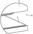
도 1a는 본 발명의 일 실시예의 3D 도면을 도시한다.
도 1b는 도 1a의 에워싸인 영역의 확대를 도시한다.
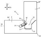
도 2a는 본 발명의 일 실시예의 3D 도면을 도시한다.
도 2b는 도 2a의 에워싸인 영역의 확대를 도시한다.
도 3a는 본 발명의 일 실시예의 3D 도면을 도시한다.
도 3b는 도 3a의 에워싸인 영역의 확대를 도시한다.
도 4a는 본 발명의 일 실시예의 길이 방향 중심 부분의 일 실시예의 횡단절단부(crosscut)를 도시한다.
도 4b는 도 4a의 에워싸인 영역의 확대를 도시한다.
도 5a는 에지 설형부 없는 도 4a의 확대를 도시한다.
도 5b는 에지 홈 없는 도 4a의 확대를 도시한다.
도 6a 및 도 6b는 본 발명의 일 실시예의 측면도로 에지 부분의 실시예들을 도시한다.
도 7a 및 도 7b는 본 발명의 일 실시예의 측면도로 에지 부분의 실시예들을 도시한다.
도 8a 내지 도 8f는 가요성 설형부의 일 실시예를 포함하는 본 발명의 일부분을 도시한다.These and other aspects, features and advantages with which the embodiments of the present invention may be made will be apparent from and will be elucidated with reference to the following description of embodiments of the present invention, in which reference is made to the accompanying drawings.
Figure 1A shows a 3D view of an embodiment of the present invention.
Figure 1B shows an enlargement of the enclosed area of Figure 1A.
Figure 2a shows a 3D view of one embodiment of the present invention.
Figure 2b shows an enlargement of the enclosed area of Figure 2a.
Figure 3A shows a 3D view of one embodiment of the present invention.
Figure 3b shows an enlargement of the enclosed area of Figure 3a.
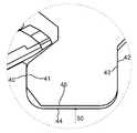
Figure 4a shows a crosscut of one embodiment of the longitudinal center portion of one embodiment of the present invention.
Figure 4b shows an enlargement of the enveloped area of Figure 4a.
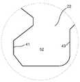
Figure 5a shows an enlargement of Figure 4a without edge tongue.
Figure 5b shows an enlargement of Figure 4a without edge grooves.
6A and 6B show embodiments of edge portions in side views of an embodiment of the present invention.
Figures 7A and 7B show embodiments of edge portions in side views of an embodiment of the present invention.
8A-8F illustrate a portion of the present invention including one embodiment of a flexible tongue.
본 발명의 특정 실시예들은 첨부 도면들을 참조로 하여 이제 설명될 것이다. 그러나, 본 발명은, 많은 상이한 형태들로 구체화될 수 있으며, 본원에서 설명되는 실시예들로 제한되는 것으로 해석되지 않아야 하며; 오히려, 이들 실시예들은 본 개시물이 철저하고 완벽할 것이고, 그리고 당업자에게 본 발명의 범주를 완전히 전달하도록 제공된다. 첨부 도면들에서 예시되는 실시예들의 상세한 설명에서 사용되는 전문용어는 본 발명을 제한하는 것으로 의도되지 않는다. 도면들에서, 동일한 수들이 동일한 요소들을 지칭한다.Certain embodiments of the present invention will now be described with reference to the accompanying drawings. However, the present invention may be embodied in many different forms and should not be construed as limited to the embodiments set forth herein; Rather, these embodiments are provided so that this disclosure will be thorough and complete, and will fully convey the scope of the invention to those skilled in the art. The terminology used in the detailed description of the embodiments illustrated in the accompanying drawings is not intended to be limiting of the invention. In the drawings, the same numbers denote the same elements.
제1 및 제2 패널의 결합된 부분들에서 균열이 발생하는 위험을 줄일 수 있는 실시예들이 도시된다.Embodiments are shown that can reduce the risk of cracking occurring in the joined portions of the first and second panels.
도 1a 내지 도 7b에서 도시되는 본 발명의 실시예들은 제1 주 평면을 갖는 제1 패널(4) 및 제2 주 평면을 갖는 제2 패널(2)을 포함하는 패널들의 세트를 포함한다. 제1 패널의 제1 에지는 제2 패널의 제2 에지에 잠금되도록 구성되며, 여기서 제1 주 평면은 본질적으로, 제2 주 평면에 수직하며, 그리고 여기서 제1 및 제2 에지들은 제1 주 평면에 수직한 제1 방향(D1)으로 그리고 제2 주 평면에 수직한 제2 방향(D2)으로 잠금된다. 제1 에지는, 저부 에지(45), 제1 표면(43) 및 반대편의 제2 표면(41)을 포함하는, 제1 에지를 따라 길이 방향을 갖는 에지 설형부(22)를 포함한다. 제2 에지는, 저부(44), 제1 표면(42) 및 반대편의 제2 표면(40)을 포함하는, 제2 에지를 따라 길이 방향을 갖는 에지 홈(21)을 포함한다. 에지 설형부(22)는 제1 방향(D1)으로 제1 및 제2 에지들을 함께 잠금하기 위해 에지 홈(21)과 협동하도록 구성된다. 에지 설형부(22)의 제1 표면(43)은, 길이 방향의 중심 부분에서 제1 방향(D1)으로 상기 잠금을 위해 에지 홈(21)의 제1 표면(42)과 함께 협동하도록 구성된다. 제1 패널(4)은 제1 에지에 인접한 제3 에지(65)를 포함하며, 그리고 제2 패널(2)은 제2 에지에 인접한 제4 에지(64)를 포함한다. 에지 홈(21)은 제4 에지(64)까지 연장한다. 에지 홈(21) 및/또는 에지 설형부(22)는, 하중(58)이 제1 패널(4) 및/또는 제2 패널(2)에 적용될 때, 제3 및 제4 에지들(63, 64)에서 에지 부분(62)에 의해서보다 더 큰 힘이 길이 방향의 중심 부분(61)에 의해 흡수되도록 구성된다. 제3 및 제4 에지들(63, 64)은 백(back) 에지들, 예컨대 가구 제품의 후방 에지들일 수 있다.Embodiments of the present invention shown in Figures 1A-B include a set of panels comprising a
도 1a는 에지 홈의 일 실시예를 도시하며, 이 에지 홈은 에지 부분(62)에서 제1 홈 형상을 가지며, 그리고 길이 방향의 중심 부분(61)에서 제2 홈 형상을 가진다. 제1 홈 형상은 대응하는 포지션에, 제2 홈 형상의 폭보다 더 넓은 폭을 포함한다.FIG. 1A shows an embodiment of an edge groove having a first groove shape at the
제1 에지 및 제2 에지는 에지 부분(62) 반대편에 있는 제2 에지 부분(66)을 가질 수 있다. 제2 에지 부분(66)은 길이 방향의 중심 부분(61)과 동일한 홈 형상 및/또는 동일한 설형부 형상을 가질 수 있다.The first and second edges may have a
도 1b는 도 1a의 에워싸인 영역의 확대를 도시한다. 에지 홈은, 제2 에지를 따라 밀링 공구(milling tool)를 변위시키고 그리고 더 넓은 에지 부분에서 제1 방향으로 밀링 공구를 변위시킴으로써 형성될 수 있다. 에지 설형부는 에지 설형부의 길이 방향으로 균일한 형상을 가질 수 있다. 에지 부분은 에지 홈의 길이 방향으로 약 5mm 내지 약 50mm의 범위의, 바람직하게는 약 20mm의 길이 방향 길이를 가질 수 있다.Figure 1B shows an enlargement of the enclosed area of Figure 1A. The edge grooves can be formed by displacing the milling tool along the second edge and displacing the milling tool in the first direction at the wider edge portion. The edge-shaped portion may have a uniform shape in the longitudinal direction of the edge-shaped portion. The edge portion may have a longitudinal length in the range of about 5 mm to about 50 mm, preferably about 20 mm, in the longitudinal direction of the edge grooves.
도 2a는 길이 방향의 중심 부분(61)에 걸쳐 연장하고 그리고 에지 부분(62) 전에 종료되는 에지 설형부의 일 실시예를 도시한다. 도 2b는 도 2a의 에워싸인 영역의 확대를 도시한다.FIG. 2A illustrates one embodiment of an edge tongue extending over a
에지 부분(62) 반대편에 있는 제2 에지 부분(66)은 길이 방향의 중심 부분(61) 및 에지 부분(62)과 상이한 형상을 가질 수 있다. 예를 들어, 제2 에지 부분(66)에서의 설형부 형상은 본질적으로, 에지 부분(62)에서의 설형부 형상과 동일할 것이다. 그러나, 제2 에지 부분(66)에서의 홈 형상은 길이 방향의 중심 부분(61) 및 에지 부분(62)의 홈 형상과 상이할 수 있다. 예를 들어, 제2 에지 부분(66)에서의 홈은 에지의 단부까지 연장할 수 없다. 예를 들어, 홈의 단부는 제2 에지의 단부로부터 약 5mm 내지 약 50mm, 바람직하게는 약 20mm일 수 있다.The
에지 설형부는, 제1 에지를 따라 밀링 공구를 변위시키고 그리고 에지 부분에서 제1 방향으로 밀링 공구를 변위시킴으로써 형성될 수 있다. 에지 부분은 에지 설형부의 길이 방향으로 약 5mm 내지 약 50mm의 범위의, 바람직하게는 약 20mm의 길이 방향 길이를 가질 수 있다.The edge edging portion can be formed by displacing the milling tool along the first edge and displacing the milling tool in the first direction at the edge portion. The edge portion may have a longitudinal length in the range of about 5 mm to about 50 mm, preferably about 20 mm, in the longitudinal direction of the edge spine.
도 3a는 에지 설형부의 일 실시예를 도시하며, 이 에지 설형부는 에지 부분(62)에서 제1 설형부 형상을 가지며, 그리고 길이 방향의 중심 부분(61)에서 제2 설형부 형상을 가진다. 제1 설형부 형상은 대응하는 포지션에서 제2 설형부 형상의 두께보다 더 얇은 두께를 가진다.Figure 3a shows one embodiment of an edged tongue having a first tongue shape at the
에지 부분(62) 반대편에 있는 제2 에지 부분(66)은 길이 방향의 중심 부분(61)과 동일한 홈 형상 및/또는 동일한 설형부 형상을 가질 수 있다.The
도 3b는 도 3a의 에워싸인 영역의 확대를 도시한다. 에지 설형부는, 제1 에지를 따라 밀링 공구를 변위시키고 그리고 더 얇은 에지 부분에서 제1 방향으로 밀링 공구를 변위시킴으로써 형성될 수 있다. 에지 홈은 에지 설형부의 길이 방향으로의 균일한 홈 형상을 가질 수 있다. 에지 부분은 에지 설형부의 길이 방향으로 약 5mm 내지 약 50mm의 범위의, 바람직하게는 약 20mm의 길이 방향 길이를 가질 수 있다.Figure 3b shows an enlargement of the enclosed area of Figure 3a. The edge edging portion can be formed by displacing the milling tool along the first edge and displacing the milling tool in the first direction at the thinner edge portion. The edge grooves may have a uniform groove shape in the longitudinal direction of the edge-shaped portion. The edge portion may have a longitudinal length in the range of about 5 mm to about 50 mm, preferably about 20 mm, in the longitudinal direction of the edge spine.
본 발명의 실시예들은 특히, 제2 주 평면에 본질적으로 평행하게 배열되는 섬유들을 포함하는 코어(core)를 포함하는 제2 패널의 실시예들에 이점들을 제공할 수 있다. 이러한 제2 패널은 균열이 발생하는 증가된 위험을 수반한다.Embodiments of the present invention may provide advantages, in particular, to embodiments of a second panel comprising a core comprising fibers arranged essentially parallel to a second major plane. This second panel is accompanied by an increased risk of cracking occurring.
도 4a는 잠금 포지션에서 제1 패널(4) 및 제2 패널(2)을 포함하는 길이 방향의 중심 부분(61)의 일 실시예의 횡단절취도를 도시한다. 도 4b는 도 4a의 에워싸인 영역의 확대를 도시한다. 에지 설형부(22)의 제1 표면(43) 및 에지 홈의 제1 표면(42)은, 에지 설형부(22)의 제2 표면(41) 및 에지 홈(21)의 제2 표면(40)보다 제1 및 제2 에지들의 외부 코너(63)에 더 가깝다. 저부 에지(45) 및 저부(44)는 서로 제1 거리(50)만큼 위치결정된다. 도 4b는, 에지 설형부(22)의 제1 표면(43)이 길이 방향(D1)으로의 상기 잠금을 위해 에지 홈(21)의 제1 표면(42)과 협동하는 것을 도시한다. 에지 설형부(22)의 제2 표면(41)은 바람직하게는, 제1 방향(D1)으로의 잠금을 위해 에지 홈(21)의 제2 표면(40)과 협동한다. 균열에 대한 가장 큰 위험은, 하중(58, 58', 58'')이 제1 및/또는 제2 패널에 적용될 때, 에지 홈의 하부 부분(lower part)(67)에 있을 수 있다. 균열은 제4 에지(64)에서 발생할 가능성이 더 크다. 이후, 균열은 제2 에지를 따라 퍼질(propagate) 수 있다. 에지 홈 및 에지 부분의 에지 설형부 상에 하중을 낮춤으로써, 균열의 개시가 방지될 수 있다.4A shows a transverse cut-away view of one embodiment of a
에지 설형부(22)는 설형부 홈(10)을 포함할 수 있으며, 그리고, 에지 홈(21)은 설형부(30)를 포함하며, 상기 설형부는 제2 방향(D2)으로 제1 및 제2 에지들을 함께 잠금하기 위해 상기 설형부 홈(10)과 협동하도록 구성된다.The
설형부는 바람직하게는, 삽입 홈(20)에 배열될 수 있는 가요성 설형부(30)를 포함한다.The tongue-like portion preferably includes a flexible tongue-like portion (30) that can be arranged in the insertion groove (20).
삽입 홈(20)은 에지 홈(21)의 본질적으로 전체 길이를 따라 연장할 수 있다.The
가요성 설형부(30)는 바람직하게는, 삽입 홈(20)에서 변위가능하다.The flexible tongue-
에지 홈(21)은 제2 에지의 본질적으로 전체 길이를 따라 연장할 수 있다.The
도 5a는 에지 설형부 없는 도 4a에서의 에워싸인 영역의 확대를 도시한다. 실시예는, 길이 방향의 중심 부분(61)에서, 에지 홈(21)의 제1 표면(42)에서 에지 홈(21)의 제2 폭(51)을 포함한다.Figure 5a shows enlargement of the enveloped area in Figure 4a without edge tongue. The embodiment includes a
도 5b는 에지 홈 없는 도 4a에서의 에워싸인 영역의 확대를 도시한다. 실시예는 길이 방향의 중심 부분에서 그리고 에지 홈(22)의 제1 표면(43)에서 에지 설형부(22)의 제1 두께(52)을 포함한다.Figure 5b shows enlargement of the enclosed area in Figure 4a without edge grooves. The embodiment includes a
에지 부분(62)의 일 실시예는 도 6a에서 횡단절취도로 도시된다. 실시예는 에지 부분에 그리고 제2 방향(D2)으로 제1 두께(52)와 동일한 포지션에 있는 에지 설형부(22)의 제2 두께(54)를 포함한다(도 5b 참조). 제1 두께는 제2 두께보다 더 크다. 제1 두께(52)와 제2 두께(54) 사이의 차이는 바람직하게는 약 0.2mm 내지 약 2mm, 바람직하게는 약 0.2mm 내지 약 0.5mm의 범위에 있다.One embodiment of the
에지 부분(62)의 일 실시예는 도 6b에서 횡단절취도로 도시된다. 실시예는 에지 부분(62)에서 에지 홈(21)의 제1 폭(53)을 포함한다. 제1 폭(53)은 길이 방향의 중심 부분(61)에서 에지 홈(21)의 제2 폭(51)보다 더 크다(도 5a 참조). 제1 폭(53)은 제2 방향(D2)으로 제2 폭(51)과 동일한 포지션에 있다. 제1 폭(53)과 제2 폭(51) 사이의 차이는 약 0.2mm 내지 약 2mm, 바람직하게는 약 0.2mm 내지 약 0.5mm의 범위에 있을 수 있다.One embodiment of the
도 6a 및 도 6b에서 도시되는 실시예들은 제1 및 제2 에지들의 잠금 포지션에서, 에지 홈의 제3 표면(72)으로부터 상기 에지 부분에서 거리(55)만큼 있도록 구성되는 에지 설형부의 제3 표면(71)을 포함한다. 거리는 바람직하게는, 약 0.2mm 내지 약 2mm, 바람직하게는, 약 0.2mm 내지 약 0.5mm의 범위에 있다. 에지 설형부의 제3 표면(71)은 제2 방향(D2)으로, 에지 설형부(22)의 제1 표면(43)과 동일한 포지션에, 그리고 에지 설형부(22)의 동일한 측면 상에 있다. 에지 홈(21)의 제3 표면(72)은 제2 방향(D2)으로, 에지 홈(21)의 제1 표면(42)과 동일한 포지션에, 그리고 에지 홈(21)의 동일한 측면 상에 있다.The embodiments shown in Figures 6A and 6B are characterized in that at the locking position of the first and second edges a
에지 부분(62)의 일 실시예는 도 7a에서 횡단절취도로 도시된다. 저부 에지(45) 및 저부(44)는 서로 제2 거리(56)만큼 위치결정된다. 제2 거리(56)는 제1 거리(50)보다 더 크며, 이 제1 거리는 제1 및 제2 에지들의 잠금 포지션에서, 저부 에지와 저부 사이에 그리고 길이 방향의 중심 부분(61)(도 4b 참조)에 있다.One embodiment of the
에지 부분(62)의 일 실시예는 도 7b에서 횡단절취도로 도시된다. 이러한 실시예에서, 에지 설형부는, 바람직하게는 기계적인 절단, 예컨대 밀링에 의해 제거된다.One embodiment of the
전술된 제1 및 제2 패널의 실시예들의 코어 재료는 목재 섬유 기반의 보드, 예컨대 HDF, MDF, 합판(plywood), 원목(solid wood) 또는 파티클보드(particleboard), 또는 보강 플라스틱(plastic) 보드, 또는 목재 섬유 복합 보드를 포함할 수 있다. 코어에는 장식용 층이 제공될 수 있다.The core material of embodiments of the first and second panels described above may be a wood fiber based board such as HDF, MDF, plywood, solid wood or particleboard, or reinforced plastic board , Or a wood fiber composite board. The core may be provided with a decorative layer.
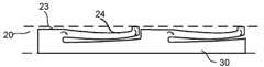
삽입 홈(20)에서 변위가능한 가요성 설형부(30)의 일 실시예는 도 8a 내지 도 8d에서 도시된다. 도 8a 및 도 8b는 잠금 부분에서의 가요성 설형부(30)를 도시하며, 그리고 도 8c 및 도 8d는 제1 패널(4) 및 제2 패널(2)의 조립 동안의 가요성 설형부(30)를 도시한다. 도 8b는 도 8a의 가요성 설형부(30)의 횡단면을 도시한다. 도 8d는 도 8c의 가요성 설형부(30)의 횡단면을 도시한다. 가요성 설형부(30)는 구부림가능한 돌출 부분들(24)을 포함한다. 공간(23)은 삽입 홈(20)의 저부 벽과 가요성 설형부(30) 사이에 제공된다. 도 8c는, 제4 패널(2)과 제1 패널(2)의 조립 동안, 가요성 설형부(30)가 삽입 홈(20) 내로 그리고 삽입 홈(20)의 저부 벽 내로 밀어넣어지는 것을 도시한다. 가요성 설형부(30)는, 제1 패널(4) 및 제2 패널(8)이 잠금 포지션에 도달할 때 그 초기 포지션을 향하여 튀어오른다(spring back). 오목부(25)는 바람직하게는, 각각의 구부림가능한 돌출 부분에 배열된다.One embodiment of the
가요성 설형부(30)는 삽입 홈(20)의 제3 변위 표면(28) 및 제4 변위 잠금 표면(29) 각각을 따라 변위되도록 구성되는 제1 변위 표면(26) 및 반대편의 제2 변위 표면(27)을 가질 수 있다.The
구부림가능한 돌출 부분들(24)이 없는 가요성 설형부(30)의 대안적인 실시예는 도 8e 및 도 8f에서 도시된다. 도 8f는 도 8e에서 도시되는 가요성 설형부(30)의 횡단면을 도시한다. 대안적인 실시예는 도 8a 내지 도 8d에서 도시되는 실시예와 유사한 기능을 성취하기 위해 그 길이 방향으로 구부림가능하다.An alternative embodiment of the
전술된 패널들의 세트는 프레임과 같은 가구 제품의 부분일 수 있다.The set of panels described above can be part of a furniture product such as a frame.
Claims (17)
Translated fromKorean상기 제1 패널의 제1 에지는 제2 패널의 제2 에지에 잠금되도록 구성되며, 상기 제1 주 평면은 본질적으로 상기 제2 주 평면에 수직하고, 그리고 상기 제1 및 제2 에지들은 상기 제1 주 평면에 수직한 제1 방향(D1)으로, 그리고 제2 주 평면에 수직한 제2 방향(D2)으로 잠금되며, 상기 제1 에지는, 저부 에지(45), 제1 표면(43) 및 반대편의 제2 표면(41)을 포함하는, 상기 제1 에지를 따라 길이 방향을 갖는 에지 설형부(edge tongue)(22)를 포함하며, 상기 제2 에지는, 저부(44), 제1 표면(42) 및 반대편의 제2 표면(40)을 포함하는, 상기 제2 에지를 따라 길이 방향을 갖는 에지 홈(groove)(21)을 포함하고, 상기 에지 설형부(22)는 상기 제1 방향(D1)으로 상기 제1 및 제2 에지들을 함께 잠금하기 위해 상기 에지 홈(21)과 협동하도록 구성되며,
상기 에지 설형부(22)의 제1 표면(43)은, 상기 제1 에지 및 상기 제2 에지의 길이 방향의 중심 부분에서 상기 제1 방향(D1)으로의 잠금을 위해 상기 에지 홈(21)의 제1 표면(42)과 협동하도록 구성되고,
상기 제1 패널(4)은 상기 제1 에지에 인접한 제3 에지(65)를 포함하며, 그리고 상기 제2 패널(2)은 상기 제2 에지에 인접한 제4 에지(64)를 포함하며,
상기 에지 홈(21)은 상기 제4 에지(64)로 연장하고,
상기 에지 홈(21) 및/또는 상기 에지 설형부(22)는, 하중(58)이 상기 제1 패널(4) 및/또는 상기 제2 패널(2)에 적용될 때, 상기 제3 및 제4 에지들에서 상기 제1 에지 및 상기 제2 에지의 에지 부분(62)에 의해서보다 더 큰 힘이 상기 길이 방향의 중심 부분(61)에 의해 흡수되도록 구성되는,
제1 주 평면을 갖는 제1 패널 및 제2 주 평면을 갖는 제2 패널을 포함하는 패널들의 세트.A set of panels comprising a first panel (4) having a first major plane and a second panel (2) having a second major plane,
Wherein the first edge of the first panel is configured to be locked to a second edge of the second panel, the first major plane being essentially perpendicular to the second major plane, and the first and second edges And is locked in a first direction D1 perpendicular to the one major plane and in a second direction D2 perpendicular to the second major plane, the first edge having a bottom edge 45, a first surface 43, And an edge tongue (22) having a longitudinal length along the first edge, the second edge comprising a bottom (44), a first edge And an edge groove (21) having a length along the second edge, the edge including a surface (42) and an opposite second surface (40), the edge tongue (22) Is configured to cooperate with said edge groove (21) to lock said first and second edges together in a direction (D1)
The first surface 43 of the edge tongue 22 has an edge groove 21 for locking in the first direction D1 at a longitudinal center portion of the first edge and the second edge, Is configured to cooperate with a first surface (42)
The first panel 4 includes a third edge 65 adjacent the first edge and the second panel 2 includes a fourth edge 64 adjacent the second edge,
The edge groove (21) extends to the fourth edge (64)
The edge grooves 21 and / or the edge tongues 22 are arranged such that when a load 58 is applied to the first panel 4 and / or the second panel 2, Wherein a greater force is absorbed by the longitudinal center portion (61) by the first edge and the edge portion (62) of the second edge at the edges,
A set of panels comprising a first panel having a first major plane and a second panel having a second major plane.
상기 에지 홈(21)은 상기 에지 부분(62)에서의 제1 홈 형상 및 상기 길이 방향의 중심 부분(61)에서의 제2 홈 형상을 가지며, 상기 제1 홈 형상은 상기 제2 홈 형상과 상이한,
제1 주 평면을 갖는 제1 패널 및 제2 주 평면을 갖는 제2 패널을 포함하는 패널들의 세트.The method according to claim 1,
Wherein the edge groove (21) has a first groove shape in the edge portion (62) and a second groove shape in a central portion (61) in the longitudinal direction, the first groove shape has a second groove shape Different,
A set of panels comprising a first panel having a first major plane and a second panel having a second major plane.
상기 에지 설형부(22)는 상기 에지 부분(62)에서의 제1 설형부 형상 및 상기 길이 방향의 중심 부분(61)에서의 제2 설형부 형상을 가지며, 상기 제1 설형부 형상은 상기 제2 설형부 형상과 상이한,
제1 주 평면을 갖는 제1 패널 및 제2 주 평면을 갖는 제2 패널을 포함하는 패널들의 세트.3. The method according to claim 1 or 2,
The edge tongue (22) has a first tongue shape at the edge portion (62) and a second tongue shape at the longitudinal center portion (61), wherein the first tongue- 2 different from the tongue shape,
A set of panels comprising a first panel having a first major plane and a second panel having a second major plane.
상기 에지 부분(62)은 상기 에지 홈의 길이 방향으로 약 5mm 내지 약 50mm, 바람직하게는 약 20mm의 범위의 길이 방향 길이를 가지는,
제1 주 평면을 갖는 제1 패널 및 제2 주 평면을 갖는 제2 패널을 포함하는 패널들의 세트.4. The method according to any one of claims 1 to 3,
The edge portion 62 has a longitudinal length in the range of about 5 mm to about 50 mm, preferably about 20 mm in the longitudinal direction of the edge groove,
A set of panels comprising a first panel having a first major plane and a second panel having a second major plane.
상기 에지 설형부의 제3 표면(71)은 상기 제1 및 제2 에지들의 잠금 포지션에서, 상기 에지 홈의 제3 표면(72)으로부터, 상기 에지 부분에서 소정의 거리(55)만큼 있도록 구성되며, 상기 거리는 바람직하게는, 약 0.2mm 내지 약 2mm, 바람직하게는, 약 0.2mm 내지 약 0.5mm의 범위에 있고,
상기 에지 설형부의 제3 표면(71)은, 상기 에지 설형부(22)의 제1 표면(43)과, 상기 제2 방향(D2)으로 동일한 포지션에 그리고 상기 에지 설형부(22)의 동일한 측면 상에 있으며, 그리고
상기 에지 홈(21)의 제3 표면(72)은, 상기 에지 홈(21)의 제1 표면(42)과 상기 제2 방향(D2)으로 동일한 포지션에 그리고 상기 에지 홈(21)의 동일한 측면 상에 있는,
제1 주 평면을 갖는 제1 패널 및 제2 주 평면을 갖는 제2 패널을 포함하는 패널들의 세트.5. The method according to any one of claims 1 to 4,
The third surface 71 of the edge tear-off portion is configured to be at a predetermined distance 55 from the third surface 72 of the edge groove at the edge portion in the locking position of the first and second edges, The distance is preferably in the range of from about 0.2 mm to about 2 mm, preferably from about 0.2 mm to about 0.5 mm,
The third surface 71 of the edge tongue-like portion is positioned at the same position in the second direction D2 and in the same direction as the first surface 43 of the edge tongue 22 and on the same side of the edge tongue- ≪ / RTI >
The third surface 72 of the edge groove 21 is located at the same position in the second direction D2 with the first surface 42 of the edge groove 21 and at the same side Lt; / RTI >
A set of panels comprising a first panel having a first major plane and a second panel having a second major plane.
상기 에지 설형부(22)의 상기 길이 방향의 중심 부분에 그리고 제1 표면(43)에 있는 상기 에지 설형부(22)의 제1 두께(52)는, 상기 에지 부분에 있는 그리고 상기 제1 두께(52)와, 상기 제2 방향(D2)으로 동일한 포지션에 있는 상기 에지 설형부(22)의 제2 두께(54)보다 더 크며, 상기 제1 두께와 상기 제2 두께 사이의 차이는 바람직하게는, 약 0.2mm 내지 약 2mm, 바람직하게는 약 0.2mm 내지 약 0.5mm의 범위에 있는,
제1 주 평면을 갖는 제1 패널 및 제2 주 평면을 갖는 제2 패널을 포함하는 패널들의 세트.6. The method according to any one of claims 1 to 5,
The first thickness 52 of the edge tongue 22 at the longitudinal center portion of the edge tongue 22 and at the first surface 43 is greater than the first thickness 52 at the edge portion, Is greater than the second thickness (54) of the edge tongue (22) at the same position in the second direction (D2), and the difference between the first thickness and the second thickness Is in the range of from about 0.2 mm to about 2 mm, preferably from about 0.2 mm to about 0.5 mm,
A set of panels comprising a first panel having a first major plane and a second panel having a second major plane.
상기 에지 부분(62)에서의 상기 에지 홈(21)의 제1 폭(53)은 상기 길이 방향의 중심 부분(61)에서의 상기 에지 홈(21)의 제2 폭(51)보다 더 크며, 상기 제2 폭(51)은 상기 에지 홈(21)의 제1 표면(42)에 있으며, 그리고 상기 제1 폭(53)은 상기 제2 폭(51)과, 상기 제2 방향(D2)으로 동일한 포지션에 있으며, 상기 제1 폭(53)과 상기 제2 폭(51) 사이의 차이는 바람직하게는, 약 0.2mm 내지 약 2mm, 바람직하게는, 약 0.2mm 내지 약 0.5mm의 범위에 있는,
제1 주 평면을 갖는 제1 패널 및 제2 주 평면을 갖는 제2 패널을 포함하는 패널들의 세트.7. The method according to any one of claims 1 to 6,
The first width 53 of the edge groove 21 in the edge portion 62 is greater than the second width 51 of the edge groove 21 in the longitudinal center portion 61, The second width 51 is at a first surface 42 of the edge groove 21 and the first width 53 is at least equal to the second width 51 and in the second direction D2 And the difference between the first width 53 and the second width 51 is preferably in the range of about 0.2 mm to about 2 mm, preferably about 0.2 mm to about 0.5 mm ,
A set of panels comprising a first panel having a first major plane and a second panel having a second major plane.
상기 저부 에지(45)와 상기 저부(44) 사이에 있고 그리고 상기 에지 부분(62)에 있는 제2 거리(56)는, 상기 제1 및 제2 에지들의 잠금 포지션에서, 상기 저부 에지와 상기 저부 사이에 있고 그리고 상기 길이 방향의 중심 부분(61)에 있는 상기 제1 거리(50)보다 더 큰,
제1 주 평면을 갖는 제1 패널 및 제2 주 평면을 갖는 제2 패널을 포함하는 패널들의 세트.8. The method according to any one of claims 1 to 7,
A second distance (56) between the bottom edge (45) and the bottom portion (44) and at the edge portion (62) is such that, at the locking position of the first and second edges, And greater than the first distance (50) in the longitudinal center portion (61)
A set of panels comprising a first panel having a first major plane and a second panel having a second major plane.
상기 에지 설형부(22)는 상기 길이 방향의 중심 부분(61)에 걸쳐 연장하고 그리고 상기 에지 부분(62) 전에 종료되는,
제1 주 평면을 갖는 제1 패널 및 제2 주 평면을 갖는 제2 패널을 포함하는 패널들의 세트.5. The method according to any one of claims 1 to 4,
The edge tongue 22 extends over the longitudinal center portion 61 and terminates before the edge portion 62. [
A set of panels comprising a first panel having a first major plane and a second panel having a second major plane.
상기 에지 설형부(22)의 제1 표면((43) 및 상기 에지 홈의 제1 표면(42)은, 상기 에지 설형부(22)의 제2 표면(41) 및 상기 에지 홈(21)의 제2 표면(40)보다, 상기 제1 및 제2 에지들의 잠금 포지션에서, 상기 제1 및 제2 에지들의 외부 코너(63)에 더 가까운,
제1 주 평면을 갖는 제1 패널 및 제2 주 평면을 갖는 제2 패널을 포함하는 패널들의 세트.10. The method according to any one of claims 1 to 9,
The first surface 43 of the edge tongue 22 and the first surface 42 of the edge tongue 22 are located on the second surface 41 of the edge tongue 22, Closer to the outer corner (63) of the first and second edges, at the locking position of the first and second edges than the second surface (40)
A set of panels comprising a first panel having a first major plane and a second panel having a second major plane.
상기 에지 설형부(22)는 설형부 홈(10)을 포함하며, 그리고, 상기 에지 홈(21)은 설형부(30)를 포함하며, 상기 설형부는 상기 제2 방향(D2)으로 상기 제1 및 제2 에지들을 함께 잠금하기 위해 상기 설형부 홈(10)과 협동하도록 구성되는,
제1 주 평면을 갖는 제1 패널 및 제2 주 평면을 갖는 제2 패널을 포함하는 패널들의 세트.11. The method according to any one of claims 1 to 10,
Wherein the edge tongue section (22) comprises a tongue groove groove (10) and the edge groove (21) comprises a tongue section (30) And cooperating with the tongue groove (10) to lock together the second edges,
A set of panels comprising a first panel having a first major plane and a second panel having a second major plane.
상기 설형부는 상기 삽입 홈(20)에 배열되는 가요성 설형부(30)인,
제1 주 평면을 갖는 제1 패널 및 제2 주 평면을 갖는 제2 패널을 포함하는 패널들의 세트.12. The method of claim 11,
Wherein the tongue-like portion is a flexible tongue-like portion (30) arranged in the insertion groove (20)
A set of panels comprising a first panel having a first major plane and a second panel having a second major plane.
상기 삽입 홈(20)은 본질적으로 상기 에지 홈(21)의 전체 길이를 따라 연장하는,
제1 주 평면을 갖는 제1 패널 및 제2 주 평면을 갖는 제2 패널을 포함하는 패널들의 세트.13. The method of claim 12,
The insertion groove 20 essentially extends along the entire length of the edge groove 21,
A set of panels comprising a first panel having a first major plane and a second panel having a second major plane.
상기 가요성 설형부(30)는 상기 삽입 홈(20)에서 변위가능한,
제1 주 평면을 갖는 제1 패널 및 제2 주 평면을 갖는 제2 패널을 포함하는 패널들의 세트.The method according to claim 12 or 13,
The flexible tongue-like portion (30) is movable in the insertion groove (20)
A set of panels comprising a first panel having a first major plane and a second panel having a second major plane.
상기 에지 홈(21)은 본질적으로 상기 제2 에지의 전체 길이를 따라 연장하는,
제1 주 평면을 갖는 제1 패널 및 제2 주 평면을 갖는 제2 패널을 포함하는 패널들의 세트.15. The method according to any one of claims 1 to 14,
The edge groove (21) essentially extends along the entire length of the second edge,
A set of panels comprising a first panel having a first major plane and a second panel having a second major plane.
상기 제1 및 제2 패널의 코어(core) 재료는 목재 섬유 기반의 보드, 예컨대 HDF, MDF, 합판(plywood), 원목(solid wood) 또는 파티클보드(particleboard), 또는 보강 플라스틱(plastic) 보드, 또는 목재 섬유 복합 보드를 포함하는,
제1 주 평면을 갖는 제1 패널 및 제2 주 평면을 갖는 제2 패널을 포함하는 패널들의 세트.16. The method according to any one of claims 1 to 15,
The core material of the first and second panels may be a wood fiber based board such as HDF, MDF, plywood, solid wood or particleboard, or a reinforced plastic board, Or wood fiber composite board.
A set of panels comprising a first panel having a first major plane and a second panel having a second major plane.
상기 코어에는 장식용 층이 제공되는,
제1 주 평면을 갖는 제1 패널 및 제2 주 평면을 갖는 제2 패널을 포함하는 패널들의 세트.17. The method of claim 16,
Wherein the core is provided with a decorative layer,
A set of panels comprising a first panel having a first major plane and a second panel having a second major plane.
Applications Claiming Priority (3)
| Application Number | Priority Date | Filing Date | Title |
|---|---|---|---|
| SE1650135-5 | 2016-02-04 | ||
| SE1650135 | 2016-02-04 | ||
| PCT/SE2017/050086WO2017135874A1 (en) | 2016-02-04 | 2017-02-02 | A set of panels for an assembled product |
Publications (1)
| Publication Number | Publication Date |
|---|---|
| KR20180109957Atrue KR20180109957A (en) | 2018-10-08 |
Family
ID=59498216
Family Applications (1)
| Application Number | Title | Priority Date | Filing Date |
|---|---|---|---|
| KR1020187024362APendingKR20180109957A (en) | 2016-02-04 | 2017-02-02 | Set of panels for assembled products |
Country Status (12)
| Country | Link |
|---|---|
| US (2) | US10544818B2 (en) |
| EP (1) | EP3411599B1 (en) |
| JP (1) | JP6891182B2 (en) |
| KR (1) | KR20180109957A (en) |
| CN (1) | CN108496013B (en) |
| BR (1) | BR112018014377A2 (en) |
| CA (1) | CA3011591A1 (en) |
| MY (1) | MY189374A (en) |
| PL (1) | PL3411599T3 (en) |
| RU (1) | RU2724688C2 (en) |
| UA (1) | UA124624C2 (en) |
| WO (1) | WO2017135874A1 (en) |
Families Citing this family (59)
| Publication number | Priority date | Publication date | Assignee | Title |
|---|---|---|---|---|
| UA109938C2 (en) | 2011-05-06 | 2015-10-26 | MECHANICAL LOCKING SYSTEM FOR CONSTRUCTION PANELS | |
| US9726210B2 (en) | 2013-09-16 | 2017-08-08 | Valinge Innovation Ab | Assembled product and a method of assembling the product |
| CN109854597B (en) | 2013-09-16 | 2021-03-19 | 瓦林格创新股份有限公司 | Combination product and method for assembling the same |
| US9714672B2 (en) | 2014-01-10 | 2017-07-25 | Valinge Innovation Ab | Panels comprising a mechanical locking device and an assembled product comprising the panels |
| MX376334B (en) | 2014-01-10 | 2025-03-07 | Vaelinge Innovation Ab | FURNITURE BOARD. |
| EP3851684A1 (en) | 2014-05-09 | 2021-07-21 | Välinge Innovation AB | Mechanical locking system for building panels |
| ES2758673T3 (en) | 2014-12-19 | 2020-05-06 | Vaelinge Innovation Ab | Panels comprising a mechanical locking device |
| EP3285620A4 (en) | 2015-04-21 | 2018-11-14 | Välinge Innovation AB | Panel with a slider |
| KR20170141223A (en) | 2015-04-30 | 2017-12-22 | 뵈린게 이노베이션 에이비이 | A panel having a fastening device |
| US9930959B2 (en)* | 2015-08-07 | 2018-04-03 | Comsero, Inc. | Modular furniture and structures |
| UA125554C2 (en) | 2015-09-22 | 2022-04-20 | Велінге Інновейшн Аб | Panels comprising a mechanical locking device and an assembled product comprising the panels |
| MX2018006522A (en) | 2015-12-03 | 2018-11-29 | Vaelinge Innovation Ab | Panels comprising a mechanical locking device and an assembled product comprising the panels. |
| EP3407765B1 (en) | 2016-01-26 | 2021-03-03 | Välinge Innovation AB | Panels comprising a mechanical locking device to obtain a furniture product |
| KR20180109957A (en) | 2016-02-04 | 2018-10-08 | 뵈린게 이노베이션 에이비이 | Set of panels for assembled products |
| CA3011703A1 (en) | 2016-02-09 | 2017-08-17 | Valinge Innovation Ab | Element and method for providing dismantling groove |
| US10415613B2 (en) | 2016-02-09 | 2019-09-17 | Valinge Innovation Ab | Set of panel-shaped elements for a composed element |
| JP6921834B2 (en) | 2016-02-15 | 2021-08-18 | ベーリンゲ、イノベイション、アクチボラグVaelinge Innovation Ab | How to form panels for furniture products |
| WO2018004440A1 (en) | 2016-06-29 | 2018-01-04 | Välinge Innovation AB | A method and device for managing and separating a tongue from a tongue blank |
| MY193272A (en) | 2016-06-29 | 2022-09-29 | Valinge Innovation Ab | Method and device for inserting a tongue |
| BR112018076069B1 (en) | 2016-06-29 | 2023-01-17 | Vãlinge Innovation Ab | METHOD AND DEVICE FOR INSERTING A TAG |
| CN109311179B (en) | 2016-06-30 | 2021-09-17 | 瓦林格创新股份有限公司 | Device for inserting a tongue |
| CN117703894A (en) | 2016-10-27 | 2024-03-15 | 瓦林格创新股份有限公司 | Panel assembly with mechanical locking means |
| DK3558609T3 (en) | 2016-12-22 | 2022-01-03 | Vaelinge Innovation Ab | DEVICE FOR INSERTING A FER IN AN INSERTING NOTICE IN A PANEL |
| HRP20230089T1 (en) | 2017-05-15 | 2023-03-17 | Välinge Innovation AB | Elements and a locking device for an assembled product |
| RU2740868C1 (en) | 2017-12-22 | 2021-01-21 | Велинге Инновейшн Аб | Set of panels, method of their assembling and locking device for furniture product |
| CN111465773B (en) | 2017-12-22 | 2021-11-02 | 瓦林格创新股份有限公司 | Panel set, method for assembling the panel set and locking device for furniture products |
| MY204146A (en) | 2018-03-23 | 2024-08-09 | Vlinge Innovation Ab | Panels comprising a mechanical locking device and an assembled product comprising the panels |
| PL3781822T3 (en)* | 2018-04-18 | 2024-11-18 | Välinge Innovation AB | Set of panels with a mechanical locking device |
| US11448252B2 (en) | 2018-04-18 | 2022-09-20 | Valinge Innovation Ab | Set of panels with a mechanical locking device |
| PL3781824T3 (en) | 2018-04-18 | 2024-06-24 | Välinge Innovation AB | Set of panels with a mechanical locking device |
| EA202092409A1 (en) | 2018-04-18 | 2021-02-26 | Велинге Инновейшн Аб | SYMMETRIC TONGUE AND T-SHAPED KNOT |
| US11614114B2 (en) | 2018-04-19 | 2023-03-28 | Valinge Innovation Ab | Panels for an assembled product |
| PT3844407T (en) | 2018-08-30 | 2024-06-18 | Vaelinge Innovation Ab | Set of panels with a mechanical locking device |
| CN109281910A (en)* | 2018-11-26 | 2019-01-29 | 韩硕明(北京)科技有限公司 | A kind of easily dress affixed crossbeam of fast disassembly type |
| EP4137705B1 (en)* | 2019-01-30 | 2024-09-25 | I4F Licensing Nv | Floor panel and floor covering |
| EP3718437A1 (en)* | 2019-04-05 | 2020-10-07 | Välinge Innovation AB | Method for assembling a piece of furniture |
| EP3730807A1 (en) | 2019-04-26 | 2020-10-28 | Välinge Innovation AB | Set of panels with a mechanical locking device |
| US11425996B2 (en)* | 2019-09-17 | 2022-08-30 | 902A Llc | Customizable modular shelving system |
| AT522435B1 (en)* | 2019-10-22 | 2020-11-15 | Sam John Regner | Furniture made of several panel-shaped elements that can be joined together |
| EP3834661A1 (en) | 2019-12-11 | 2021-06-16 | Välinge Innovation AB | Mechanical locking system for panels |
| SE544408C2 (en)* | 2019-12-18 | 2022-05-10 | Vilox Ab | Joining system for furniture, furniture portion comprising the joining system and method for manufacturing the joining element of the joining system |
| KR20220113725A (en) | 2019-12-19 | 2022-08-16 | 뵈린게 이노베이션 에이비이 | set of panels with mechanical locking device |
| WO2021150162A1 (en) | 2020-01-22 | 2021-07-29 | Välinge Innovation AB | Set of panels with a mechanical locking device |
| EP3871560A1 (en) | 2020-02-26 | 2021-09-01 | Välinge Innovation AB | Set of panels with a mechanical locking device |
| EP3871559A1 (en) | 2020-02-26 | 2021-09-01 | Välinge Innovation AB | Set of panels with a mechanical locking device |
| US11702844B2 (en) | 2020-06-05 | 2023-07-18 | Valinge Innovation Ab | Building panels comprising a locking device |
| CN115867171A (en) | 2020-07-17 | 2023-03-28 | 瓦林格创新股份有限公司 | Mechanical locking system for panels |
| CN112568619B (en)* | 2020-12-03 | 2023-06-06 | 浙江致派工贸有限公司 | Supporting frame of combined cabinet |
| EP4258943A4 (en) | 2020-12-11 | 2024-10-23 | Välinge Innovation AB | RAIL FOR CABINETS |
| MX2023007995A (en) | 2021-01-07 | 2023-09-18 | Vaelinge Innovation Ab | Wedge-shaped tongue insertion groove. |
| EP4274970A4 (en)* | 2021-01-11 | 2024-11-20 | Välinge Innovation AB | SET OF PANELS WITH A MECHANICAL LOCKING DEVICE FOR LOCKING A FIRST PANEL TO A SECOND PANEL AT A CORNER |
| WO2022159013A1 (en) | 2021-01-19 | 2022-07-28 | Välinge Innovation AB | A set of panels, a method for assembly of the same and a locking device for a furniture product |
| US12071769B2 (en) | 2021-02-03 | 2024-08-27 | Valinge Innovation Ab | Building panels comprising a locking device |
| US12247598B2 (en) | 2021-02-08 | 2025-03-11 | Välinge Innovation AB | Mounting bracket |
| WO2022184446A1 (en) | 2021-03-01 | 2022-09-09 | Välinge Innovation AB | Mechanical connection arrangement for panels |
| EP4352370A4 (en) | 2021-06-11 | 2025-04-09 | Välinge Innovation AB | LOCKING DEVICE WITH A SPRING AND A LOCKING PIN AND SET WITH FURNITURE COMPONENTS AND THE LOCKING DEVICE |
| CN117545928A (en)* | 2021-06-29 | 2024-02-09 | 瓦林格创新股份有限公司 | Panels and related assembled products containing mechanical locking devices |
| EP4413272A4 (en)* | 2021-10-04 | 2025-05-14 | Välinge Innovation AB | MECHANICAL CONNECTION ARRANGEMENT FOR PANELS |
| US20230313823A1 (en)* | 2022-03-30 | 2023-10-05 | Välinge Innovation AB | Set of panels and an associated assembled article |
Family Cites Families (309)
| Publication number | Priority date | Publication date | Assignee | Title |
|---|---|---|---|---|
| DE228872C (en) | ||||
| US291032A (en) | 1884-01-01 | Isaac g- | ||
| US634581A (en) | 1898-11-21 | 1899-10-10 | Robert H Miller | Carpenter's square. |
| US701000A (en) | 1901-07-31 | 1902-05-27 | Carl F W Ahrens | File-cabinet. |
| US861911A (en) | 1905-11-04 | 1907-07-30 | William Stewart | Joint for articles of furniture or woodwork. |
| US881673A (en) | 1907-03-11 | 1908-03-10 | Arthur L Ellison | Wardrobe or safe. |
| US1534468A (en) | 1922-10-30 | 1925-04-21 | Jr John J Shea | Joint structure |
| US1533099A (en) | 1924-07-14 | 1925-04-14 | Robert E Carroll | Square-corner glue joint |
| GB245332A (en) | 1925-05-04 | 1926-01-07 | George Hugh Foster | An improved dowelled joint for woodwork and the like |
| US1800386A (en) | 1926-08-28 | 1931-04-14 | Andrew Hoffman Mfg Company | Display rail |
| US1800387A (en) | 1926-12-30 | 1931-04-14 | Andrew Hoffman Mfg Company | Article-supporting device |
| US1802245A (en) | 1930-08-26 | 1931-04-21 | Clarence L Foretich | Display stand and shelving |
| US1954242A (en) | 1932-07-28 | 1934-04-10 | Thomas E Heppenstall | Dovetail spring joint |
| US2360451A (en) | 1942-06-02 | 1944-10-17 | Stone Abraham | Collapsible clothing container |
| US2362904A (en) | 1943-01-20 | 1944-11-14 | Allied Purchasing Corp | Joint for demountable furniture |
| US2496184A (en) | 1946-06-11 | 1950-01-31 | Canon Paul L Von | Furniture drawer construction and method |
| US2681483A (en) | 1948-10-14 | 1954-06-22 | Morawetz Hugo | Dowel connection |
| DE1062499B (en) | 1955-08-09 | 1959-07-30 | Waldes Kohinoor Inc | Oval spring ring |
| DE1107910B (en) | 1957-03-26 | 1961-05-31 | Curt Weinert | Flexible duebel |
| CH365507A (en) | 1958-11-17 | 1962-11-15 | Antonius Bus Johannes | Device for connecting perpendicular walls with automatic locking, in particular furniture walls |
| US3002630A (en) | 1960-05-24 | 1961-10-03 | Robert E Heisser | Toothbrush rack |
| US3195968A (en) | 1962-12-06 | 1965-07-20 | Lok Trim Corp | Knock-down furniture |
| DE1240638B (en) | 1963-03-07 | 1967-05-18 | Kueche | Dismountable furniture |
| AT260460B (en) | 1963-08-19 | 1968-03-11 | Trepatent As | Guide for drawers, shelves or the like. |
| US3313054A (en) | 1965-06-09 | 1967-04-11 | Poster Products Inc | Display devices |
| IS831B6 (en) | 1965-10-28 | 1973-04-12 | Nordischer Maschinenbau Rud. BaaderNordischer Maschinenbau, Rud. Baader | Method of removing the liver from the fishToys to decapitate the highly cut fish so that the wet bone remains on the fish |
| US3410441A (en) | 1966-06-29 | 1968-11-12 | Jeff S. Rhyne | Container |
| US3347610A (en) | 1966-07-28 | 1967-10-17 | Pilliod Cabinet Company | Cabinet construction |
| DE1955922C3 (en) | 1969-11-06 | 1974-01-10 | Hefendehl, Hansfriedrich, 5893 Kierspe | Box furniture made of plastic |
| US3722704A (en) | 1970-07-23 | 1973-03-27 | Castelli Sas Anonima | Structural components for the composition of disassemblable pieces offurniture |
| US3765465A (en) | 1972-01-05 | 1973-10-16 | Deutsch Fastener Corp | Retractable captive fastener |
| US3742807A (en) | 1972-02-03 | 1973-07-03 | D Manning | Leveling and locking pin |
| GB1398187A (en) | 1972-06-22 | 1975-06-18 | Schreiber Furniture | Kitchen cabinets |
| US3884002A (en) | 1973-03-15 | 1975-05-20 | American Store Equip | Partition system |
| DE2414104A1 (en) | 1974-03-23 | 1975-10-09 | Alfer Alu Fertigbau | Fastener for wooden shelving - comprises straight locking pins engaged by pressure of support plate |
| DE2514357C3 (en) | 1974-04-02 | 1979-03-22 | Takeshi Tokio Shimizu | Fitting for the pivotable connection of a furniture panel with a fixed furniture part |
| US3885845A (en) | 1974-06-27 | 1975-05-27 | Hans Krieks | Knock-down furniture system |
| US3981118A (en)* | 1974-10-17 | 1976-09-21 | The Goodyear Tire & Rubber Company | Clamping insert |
| ATA882576A (en) | 1975-12-02 | 1983-01-15 | Heinze Fa R | FURNITURE HINGE WITH A HINGED POT ANCHORABLE IN A HOLE OF A FURNITURE PART |
| CA1062321A (en) | 1976-05-12 | 1979-09-11 | I. T. W. Ltd. | Grommets for furniture connectors |
| DE2635237A1 (en) | 1976-08-05 | 1978-02-09 | Heinze Fa R | FURNITURE HINGE |
| JPS53113160U (en) | 1977-02-16 | 1978-09-08 | ||
| US4116510A (en) | 1977-03-03 | 1978-09-26 | Gte Automatic Electric Laboratories Incorporated | Chassis formed of sheet stock |
| US4099887A (en) | 1977-07-18 | 1978-07-11 | Einhard Mackenroth | Structural joints |
| US4222544A (en) | 1977-08-10 | 1980-09-16 | Kenneth Crowder | Picture rail apparatus |
| SE409603B (en) | 1977-12-20 | 1979-08-27 | Stockum Design Ab | CONNECTION |
| SE7809081L (en) | 1978-08-29 | 1980-03-01 | Hafa Fabriks Ab | DEVICE FOR COLLECTION OF CABINETS, MIRRORS, SHELVES AND OTHER DETAILS |
| US4211379A (en) | 1978-11-20 | 1980-07-08 | Morgan Myron B | Panelboard and mounting fixture combination |
| US4299067A (en) | 1979-10-30 | 1981-11-10 | J. C. Penney Company, Inc. | Partition connector system |
| US4308961A (en) | 1980-05-05 | 1982-01-05 | Kunce Thomas M | Article supporting structure |
| US4324517A (en) | 1980-06-16 | 1982-04-13 | Sps Technologies, Inc. | Panel fastener assembly with retainer ring |
| DE3047642A1 (en) | 1980-12-17 | 1982-10-28 | Arturo Salice S.p.A., 22060 Novedrate, Como | CONNECTING FITTING |
| DE3103281C2 (en) | 1981-01-31 | 1984-05-10 | C + A Dick GmbH, 5275 Bergneustadt | Material cupboard |
| FR2501805A1 (en) | 1981-03-10 | 1982-09-17 | Haeusler Roland | NEW TYPE TENON AND MORTISE GENDER ASSEMBLY SYSTEM AND FURNITURE ARTICLES INCORPORATING THE SAME SYSTEM |
| FR2517187A1 (en) | 1981-12-01 | 1983-06-03 | Beaux Dominique | DETACHABLE BOX FOR FURNITURE USE |
| US4509648A (en) | 1982-07-26 | 1985-04-09 | The Stanley Works | Merchandising display system and components therefor |
| US4593734A (en) | 1983-09-26 | 1986-06-10 | M. Bosley Wright | Frame routing apparatus |
| US4629076A (en) | 1984-05-10 | 1986-12-16 | Amstore Corporation | Slatboard |
| GB2163825B (en) | 1984-08-30 | 1988-03-02 | Hettich Paul Gmbh & Co | Furniture connector |
| US4595105A (en) | 1984-09-12 | 1986-06-17 | Gold Kenneth S | Interlocking bookrack |
| US4750794A (en) | 1984-11-21 | 1988-06-14 | Bass Cabinet Manufacturing, Inc. | Slide-fitted article of furniture |
| US4597122A (en) | 1985-06-10 | 1986-07-01 | Hirsh Company | Free-standing drawer |
| US4615448A (en) | 1985-09-27 | 1986-10-07 | Masonite Corporation | Display panel |
| US4891897A (en) | 1985-12-12 | 1990-01-09 | Gieske Detlef J | Display panel |
| FR2597173B1 (en) | 1986-04-10 | 1988-10-07 | Forschle Andre | DEVICE FOR EASILY ASSEMBLING AND MODIFYING THE COMPOSITION OF A KITCHEN FURNITURE |
| GB8612597D0 (en) | 1986-05-23 | 1986-07-02 | George W R | Joint between members |
| FR2602013B1 (en) | 1986-07-25 | 1988-12-30 | Kapikian Jean Claude | ASSEMBLY SYSTEM OF TENON AND MORTISE TYPE EASILY MOUNTABLE AND REMOVABLE |
| US4815908A (en) | 1986-10-14 | 1989-03-28 | Avibank Mfg., Inc. | Captive panel fastener assembly |
| US4844266A (en) | 1987-07-16 | 1989-07-04 | Intercraft Industries Corporation | Display system |
| CA1297934C (en) | 1987-07-24 | 1992-03-24 | Craig Mengel | Method of and structure for the joining of substantially rigidparts together |
| US4886326A (en) | 1988-01-29 | 1989-12-12 | Tetrad Marketing/Sales Ltd. | Interlock system for ready to assemble furniture, and furniture incorporating such system |
| US4961295A (en) | 1988-03-14 | 1990-10-09 | Kosch Sr Paul | Metal slat and wall system utilizing same |
| US4817900A (en) | 1988-05-09 | 1989-04-04 | Gorrie Advertising Management Limited | Support device for use on a display wall |
| JPH0266308A (en) | 1988-08-30 | 1990-03-06 | Kazuhiro Matsui | Assembly tool |
| IT215989Z2 (en) | 1988-09-02 | 1991-03-26 | Cattarozzi Andrea | MODULAR CONTAINER MODULAR AND MANUALLY TRANSPORTABLE, FOR THE STORAGE OF SUBSTANCES, IN SPECIAL WAY FOR FOOD USE |
| NL8802459A (en) | 1988-10-07 | 1990-05-01 | Homburg Interieuren B V | SHOW WALL. |
| US5471804A (en) | 1988-11-21 | 1995-12-05 | Winter, Iv; Amos G. | Building system using prefabricated building panels and fastening components used therewith |
| US4944416A (en) | 1988-11-21 | 1990-07-31 | Petersen Robert J | Light-weight slot-wall display panel |
| US4909581A (en) | 1988-12-12 | 1990-03-20 | American Moulding & Millwork Company | Drawer construction |
| EP0400124A1 (en) | 1988-12-13 | 1990-12-05 | TANNER, Rudolf | Connecting element for form-fitting connection |
| US5018323A (en) | 1989-05-12 | 1991-05-28 | Knud Clausen | Wall panel system |
| US5109993A (en) | 1989-10-31 | 1992-05-05 | Hutchison V James | Merchandise display system and merchandise holder therefor |
| US5138803A (en) | 1991-01-11 | 1992-08-18 | Commercial And Architectural Products, Inc. | Display panel assembly |
| US5121578A (en) | 1991-01-28 | 1992-06-16 | Holz Plastics, Inc. | Slat wall decorating system |
| JP3373511B2 (en) | 1991-04-01 | 2003-02-04 | ウォルター リンダル | Wooden frame building structure |
| US5209556A (en) | 1991-04-01 | 1993-05-11 | Anderson Robert F | Drawer assembly |
| US5114265A (en) | 1991-04-15 | 1992-05-19 | Grisley Kenneth M | Interlocking routed joint |
| US5299509A (en) | 1991-07-29 | 1994-04-05 | Ballard Donald M | Connectors for shelves and bins |
| US5125518A (en) | 1991-08-12 | 1992-06-30 | Innovative Accessories | Interlocking hanging system |
| CH684284A5 (en) | 1991-09-03 | 1994-08-15 | Edgar Probst | Rear wall fitting. |
| US5212925A (en) | 1991-11-21 | 1993-05-25 | Mcclinton John | Wall corner composite, mold and method for producing glazed unit for such |
| US5360121A (en) | 1992-08-07 | 1994-11-01 | Commerical And Architectural Products, Inc. | Slotted display wall panel |
| JP2530326Y2 (en) | 1992-08-24 | 1997-03-26 | 株式会社イトーキクレビオ | Device for connecting members in furniture etc. |
| CH685276A5 (en) | 1992-11-25 | 1995-05-31 | Werner Schmidt | Building elements for assembling shelves, cupboards and walling |
| ZA94676B (en) | 1993-02-03 | 1994-08-03 | Rohm & Haas | Reduction of microfoam in spray-applied waterborne composition. |
| US5423155A (en) | 1993-06-02 | 1995-06-13 | Darko Company, Inc. | Panel for resurfacing slat walls |
| US5499667A (en) | 1994-06-21 | 1996-03-19 | Nakanishi Construction Company | Drill/cutting bit, and method of making structural joint |
| AT400611B (en) | 1993-09-30 | 1996-02-26 | Kreutzinger Johann | Connecting and attachment element |
| US5527103A (en) | 1993-10-01 | 1996-06-18 | Pittman; Charles | Cabinet of improved design and construction |
| US5375802A (en) | 1993-11-17 | 1994-12-27 | Bill Branham Designs, Ltd. | Structure for fastening facing structural units |
| US5451102A (en) | 1994-01-13 | 1995-09-19 | Chuan; Yuan-Jung | Cabinet with connecting mechanism for two adjacent wall plate |
| US5499886A (en) | 1994-03-02 | 1996-03-19 | Sauder Woodworking Co. | Coupling assembly for furniture components |
| DE4410901A1 (en) | 1994-03-29 | 1995-10-05 | Licentia Gmbh | Fridge with refrigerated goods shelves |
| US5507331A (en) | 1994-06-21 | 1996-04-16 | Nakanishi Construction Company | Drilling/cutting bit, and method of making joint |
| DE9417168U1 (en) | 1994-10-26 | 1995-02-09 | Seeland, Peter, 37130 Gleichen | Kit for a piece of furniture |
| US5536108A (en) | 1995-02-27 | 1996-07-16 | Kval, Inc. | Low cohesion material joint |
| SE9500810D0 (en) | 1995-03-07 | 1995-03-07 | Perstorp Flooring Ab | Floor tile |
| DK9500332U3 (en) | 1995-08-29 | 1996-12-27 | Ikea Of Sweden Ab | Corner assembly between the end portions of two board-like items |
| US5658086A (en) | 1995-11-24 | 1997-08-19 | Brokaw; Paul E. | Furniture connector |
| US5775521A (en) | 1996-03-22 | 1998-07-07 | Custom Plastics, Inc. | Office organizer |
| CA2207533A1 (en) | 1996-06-12 | 1997-12-12 | David P. Thurston | Adjustable hanger system |
| US5950389A (en) | 1996-07-02 | 1999-09-14 | Porter; William H. | Splines for joining panels |
| US5810505A (en) | 1996-07-26 | 1998-09-22 | Kimball International, Inc. | Double threaded fastener system |
| GB2315988A (en) | 1996-08-07 | 1998-02-18 | Ultimate Systems Limited | Furniture with adjustable size panels |
| US5711115A (en) | 1996-10-30 | 1998-01-27 | Design Components, Inc. | Fireplace shelf and mantel support system |
| CA2200422C (en) | 1997-03-19 | 2002-05-07 | Jan B. Leurdijk | Storage track system |
| US5857304A (en) | 1997-04-07 | 1999-01-12 | Abex Display Systems | Slidable locking system for disengageable panels |
| CA2204301C (en) | 1997-05-02 | 2000-04-18 | Shang-Ming Lee | A connecting assembly for horizontal boards and wall boards of a cabinet |
| DE29714096U1 (en) | 1997-08-07 | 1998-12-03 | Dorth, Ursel, 51766 Engelskirchen | Connector system |
| NO974666L (en) | 1997-10-09 | 1999-04-12 | New Ideas | Joining device for plate-shaped structural parts, as well as measuring structure |
| US5941026A (en) | 1998-01-20 | 1999-08-24 | Storewall Llc | Slatwall display system |
| DE19805538A1 (en) | 1998-02-03 | 1999-08-12 | Montana Innovations Corp | Securing vehicle load using cams mounted on U-shaped frame |
| AT406181B (en) | 1998-02-09 | 2000-03-27 | Blum Gmbh Julius | FASTENING DEVICE FOR FASTENING SEVERAL FURNITURE FITTINGS ON ONE FURNITURE PART |
| WO1999041508A2 (en) | 1998-02-11 | 1999-08-19 | Ipeg Unabhängige Immobilienberatungs- Und Patentverwertungs-Gmbh | Device for joining flat elements or other components |
| DE29924630U1 (en) | 1998-02-11 | 2004-05-13 | Ipeg Gmbh - Ingenieurdienstleistungen | Securing vehicle load using cams mounted on U-shaped frame |
| US6363645B1 (en) | 1998-02-25 | 2002-04-02 | Bruce A Hunter | Insert for display panels |
| US5944294A (en) | 1998-07-06 | 1999-08-31 | Baer; Thomas C. | Mounting device in form of C-clamp mounted space from a wall |
| DE29820031U1 (en)* | 1998-11-10 | 1999-02-25 | Grant, Alasdair E., 33659 Bielefeld | Form-fitting connecting device for furniture or panel elements |
| US6349507B1 (en) | 1999-03-15 | 2002-02-26 | Spectra Products Corporation | Slat wall structure with profile for different shelf support brackets and the like |
| US6547086B1 (en) | 1999-03-25 | 2003-04-15 | Russell-William, Ltd. | Display wall panel |
| SE517478C2 (en) | 1999-04-30 | 2002-06-11 | Valinge Aluminium Ab | Locking system for mechanical hoisting of floorboards, floorboard provided with the locking system and method for producing mechanically foldable floorboards |
| IT1307424B1 (en) | 1999-04-29 | 2001-11-06 | Costa S P A A | METHOD FOR PROFILING STRIPS FOR PARQUET AND SQUARING MACHINE SUITABLE TO CREATE SUCH METHOD. |
| DE29911462U1 (en) | 1999-07-02 | 1999-11-18 | Akzenta Paneele & Profile Gmbh | Fastening system for panels |
| EP1243721A3 (en) | 1999-06-30 | 2003-07-09 | Akzenta Paneele + Profile GmbH | Floor covering, panel and panel fastening system |
| DE10001076C1 (en) | 2000-01-13 | 2001-10-04 | Huelsta Werke Huels Kg | Panel element to construct floor covering; has groove and spring on opposite longitudinal sides and has groove and tongue on opposite end faces, to connect and secure adjacent panel elements |
| SE517183C2 (en) | 2000-01-24 | 2002-04-23 | Valinge Aluminium Ab | Locking system for mechanical joining of floorboards, floorboard provided with the locking system and method for making such floorboards |
| MXPA02009326A (en) | 2000-03-24 | 2003-10-14 | Commercial And Architectural P | Merchandising panel display system. |
| US6413007B1 (en) | 2000-05-01 | 2002-07-02 | Sauder Woodworking Co. | Joint assembly |
| US6578498B1 (en) | 2000-06-06 | 2003-06-17 | Steelcase Development Corporation | Furniture accessory kit for portable computers and the like |
| NZ527354A (en) | 2001-01-12 | 2004-09-24 | Valinge Aluminium Ab | Floorboards and methods for production and installation thereof |
| US6675979B2 (en) | 2001-05-21 | 2004-01-13 | Gregory Albert Taylor | Furniture assembly system |
| DE20122778U1 (en) | 2001-08-10 | 2007-10-25 | Akzenta Paneele + Profile Gmbh | Panel and fastening system for panels |
| DE10142508A1 (en) | 2001-08-30 | 2003-03-27 | Bsh Bosch Siemens Hausgeraete | Locking device and food processor equipped with this |
| SE525558C2 (en) | 2001-09-20 | 2005-03-08 | Vaelinge Innovation Ab | System for forming a floor covering, set of floorboards and method for manufacturing two different types of floorboards |
| EP1430225B1 (en) | 2001-09-26 | 2005-12-21 | Agostino Ferrari S.p.A. | Device and method for detachably connecting abutting structural parts and tie member for use to form said device |
| JP2003239921A (en) | 2002-02-20 | 2003-08-27 | Takagaki Mokuzai Kogei Kk | Joining structure by tenon and mortise |
| USD482552S1 (en) | 2002-04-03 | 2003-11-25 | Commercial And Architectural Products, Inc. | Insert for a display panel |
| ATE467015T1 (en) | 2002-04-03 | 2010-05-15 | Vaelinge Innovation Ab | FLOOR PANEL WITH INTEGRATED CONNECTING MEANS AND METHOD FOR THE PRODUCTION THEREOF |
| US6772890B2 (en) | 2002-04-03 | 2004-08-10 | Commercial And Architectural Products, Inc. | Narrow groove display panel |
| AUPS265502A0 (en) | 2002-05-30 | 2002-06-20 | Ibj Resources Pty Ltd | Mounting system |
| AU2003251423A1 (en) | 2002-07-17 | 2004-02-09 | Device Works Company | Cable organization and hardware shelving system |
| US6827028B1 (en) | 2002-12-11 | 2004-12-07 | E. Pryor Callaway | Collapsible support |
| US7228977B2 (en) | 2003-06-16 | 2007-06-12 | Whirlpool Corporation | Workroom storage system |
| ATE471415T1 (en) | 2003-03-06 | 2010-07-15 | Vaelinge Innovation Ab | FLOORING SYSTEMS AND INSTALLATION METHODS |
| US7306299B2 (en) | 2003-03-07 | 2007-12-11 | Masterbrand Cabinets, Inc. | Semi-frameless cabinet and method for making the same |
| DE20304761U1 (en) | 2003-03-24 | 2004-04-08 | Kronotec Ag | Device for connecting building boards, in particular floor panels |
| US6971614B2 (en) | 2003-07-11 | 2005-12-06 | Jifram Extrusions, Inc. | Slatwall hanger stabilizing chip |
| KR100975937B1 (en) | 2003-09-30 | 2010-08-16 | 엘지전자 주식회사 | Door basket mounting device for refrigerator |
| US20050166516A1 (en) | 2004-01-13 | 2005-08-04 | Valinge Aluminium Ab | Floor covering and locking systems |
| SE526596C2 (en) | 2004-01-13 | 2005-10-11 | Vaelinge Innovation Ab | Floating floor with mechanical locking system that allows movement between the floorboards |
| CH696889A5 (en) | 2004-03-23 | 2008-01-15 | Vifian Moebelwerkstaette Ag | Locking element for locking of two plates, has slide surface that is provided at end of springy middle area that overlaps middle area and wedge shaped head area, and fixing area that is provided at other end of middle area |
| US20050247653A1 (en) | 2004-05-06 | 2005-11-10 | Dr. Brooks Innovations, L.L.C. | System for holding implements |
| US7641414B1 (en) | 2004-09-04 | 2010-01-05 | Joyce Jared L | Furniture and joint systems |
| ES2378330T3 (en) | 2004-10-22 | 2012-04-11 | Välinge Innovation AB | A method of providing floor panels with a mechanical locking system |
| US7841144B2 (en) | 2005-03-30 | 2010-11-30 | Valinge Innovation Ab | Mechanical locking system for panels and method of installing same |
| US7454875B2 (en) | 2004-10-22 | 2008-11-25 | Valinge Aluminium Ab | Mechanical locking system for floor panels |
| DE202004017486U1 (en) | 2004-11-11 | 2006-04-13 | Vietmeyer, Adolf | Framework for cabinet or shelf has two side panels, underbody and top end such that the upper body and the top end are connected to the side panels in the longitudinal direction by connecting elements by means of dowel pins or springs |
| GB0426634D0 (en) | 2004-12-03 | 2005-01-05 | Abbott Ooo | Display panel and display system |
| DE202004019882U1 (en) | 2004-12-20 | 2006-04-27 | Fritz Egger Gmbh & Co. | Furniture parts with connecting means |
| US7686172B2 (en) | 2005-02-14 | 2010-03-30 | Whirlpool Corporation | Storage bin |
| GB2423332B (en) | 2005-02-17 | 2009-05-27 | Arctium As | Connecting device |
| AU2006228367A1 (en) | 2005-03-29 | 2006-10-05 | Pieter Martin Henderson | Fastener for connecting components and assemblies embodying same |
| US20060273085A1 (en) | 2005-05-18 | 2006-12-07 | Casto Daniel A | Joint for connecting workpieces |
| US20090014401A1 (en) | 2005-05-24 | 2009-01-15 | Windquest Companies, Inc. | Slotwall mounting assembly |
| SE529076C2 (en) | 2005-07-11 | 2007-04-24 | Pergo Europ Ab | A joint for panels |
| CA2616611A1 (en) | 2005-07-28 | 2007-02-01 | Grandbay Holdings Pty Ltd | Interlocking members |
| CH698988B1 (en) | 2005-08-27 | 2009-12-31 | Lindauer Gmbh | Plate-shaped solid wood elements for cover, have profile section with groove running parallel to upper side and connected groove-shaped profile element aligned approximately perpendicular against lower side |
| DE202005019986U1 (en) | 2005-12-20 | 2006-02-23 | fif Möbel Vertriebs GmbH | Construction set for box shaped furniture comprises box elements with side walls, top-floor, lower-floor and back wall whereby walls and floors are made of identical, square plates and identical square rods, which act as connectors |
| SE530653C2 (en) | 2006-01-12 | 2008-07-29 | Vaelinge Innovation Ab | Moisture-proof floor board and floor with an elastic surface layer including a decorative groove |
| DE102006011887A1 (en) | 2006-01-13 | 2007-07-19 | Akzenta Paneele + Profile Gmbh | Blocking element, panel with separate blocking element, method of installing a panel covering of panels with blocking elements, and method and device for pre-assembling a blocking element on a panel |
| DE102006006124A1 (en) | 2006-02-10 | 2007-08-23 | Flooring Technologies Ltd. | Device for locking two building panels |
| SE533410C2 (en) | 2006-07-11 | 2010-09-14 | Vaelinge Innovation Ab | Floor panels with mechanical locking systems with a flexible and slidable tongue as well as heavy therefore |
| US7861482B2 (en) | 2006-07-14 | 2011-01-04 | Valinge Innovation Ab | Locking system comprising a combination lock for panels |
| DE102006037614B3 (en) | 2006-08-10 | 2007-12-20 | Guido Schulte | Floor covering, has head spring pre-assembled in slot and protruding over end of slot, and wedge surface formed at slot or head spring such that head spring runs into wedge surface by shifting projecting end of head spring into slot |
| US20080042532A1 (en) | 2006-08-16 | 2008-02-21 | Crabtree Phillip C | Cabinet system and method of assembling the same |
| US7614350B2 (en) | 2006-10-05 | 2009-11-10 | Haworth, Inc. | Wall-mounted shelf unit |
| EP1922954B1 (en) | 2006-11-14 | 2009-07-15 | Spichtig AG | Depositing and sorting device |
| SE531111C2 (en) | 2006-12-08 | 2008-12-23 | Vaelinge Innovation Ab | Mechanical locking of floor panels |
| GB2445954A (en) | 2007-01-23 | 2008-07-30 | Touac Internat Ltd | A panel joining fastener |
| PL1989956T3 (en) | 2007-05-08 | 2016-01-29 | Franz Baur | Connecting device and method for creating a connection between a first component and a second component |
| SE533028C2 (en) | 2007-06-05 | 2010-06-15 | Rickard Olsson | Box construction and mounting method |
| US7818939B2 (en) | 2007-06-05 | 2010-10-26 | Irvin Bearinger | Snap lock joint |
| US8220217B2 (en) | 2007-07-20 | 2012-07-17 | Innovaris Ag | Flooring system |
| US7726088B2 (en) | 2007-07-20 | 2010-06-01 | Moritz Andre Muehlebach | Flooring system |
| CN101099618A (en) | 2007-07-26 | 2008-01-09 | 刘瑞东 | Mortise and tenon type furniture |
| DE102007043308B4 (en) | 2007-09-11 | 2009-12-03 | Flooring Technologies Ltd. | Device for connecting and locking two building panels, in particular floor panels |
| US8146754B2 (en) | 2007-12-07 | 2012-04-03 | Red Star Traders, Llc | Storage and organization system |
| US8505257B2 (en) | 2008-01-31 | 2013-08-13 | Valinge Innovation Ab | Mechanical locking of floor panels |
| CA2623707A1 (en) | 2008-03-07 | 2009-09-07 | Pierre Trudel | Tongue and groove profile to ease desassembly of floorboards |
| GB0808252D0 (en) | 2008-05-07 | 2008-06-11 | Self Energising Coupling Compa | Latch mechanism |
| US7717278B2 (en) | 2008-07-07 | 2010-05-18 | Jui-Chien Kao | Tool suspension device |
| DE102008035293A1 (en) | 2008-07-29 | 2010-02-04 | Gronbach Forschungs- Und Entwicklungs Gmbh & Co. Kg | Mounting article for use in e.g. home, has two aluminum profiles provided with side surfaces, at which connection bolts are inserted, where bolts exhibit recess, in which o-rings are inserted |
| US8220648B2 (en) | 2008-08-01 | 2012-07-17 | Southern Imperial, Inc. | Folded slatwall inserts |
| DE202008011589U1 (en) | 2008-09-01 | 2008-11-27 | Akzenta Paneele + Profile Gmbh | Plastic floor panel with mechanical locking edges |
| WO2010042182A1 (en) | 2008-10-08 | 2010-04-15 | Armstrong World Industries, Inc. | Flooring panel with first and second decorative surfaces |
| US20100104354A1 (en) | 2008-10-29 | 2010-04-29 | Lamar Spalding | Pinned Lock Joint |
| BE1018389A3 (en) | 2008-12-17 | 2010-10-05 | Unilin Bvba | COMPOSITE ELEMENT, MULTI-LAYER PLATE AND PANEL-SHAPED ELEMENT FOR FORMING SUCH COMPOSITE ELEMENT. |
| US7998549B2 (en) | 2009-01-08 | 2011-08-16 | Thermwood Corporation | Structure and method of assembly thereof |
| BE1018627A5 (en) | 2009-01-16 | 2011-05-03 | Flooring Ind Ltd Sarl | FLOOR PANEL. |
| WO2010087752A1 (en) | 2009-01-30 | 2010-08-05 | Välinge Innovation Belgium BVBA | Mechanical lockings of floor panels and a tongue blank |
| US8464408B2 (en) | 2009-06-03 | 2013-06-18 | Tracy Leigh Hazzard | Hardware for furniture assembly |
| NL2003019C2 (en) | 2009-06-12 | 2010-12-15 | 4Sight Innovation Bv | FLOOR PANEL AND FLOOR COVERAGE CONSISING OF MULTIPLE OF SUCH FLOOR PANELS. |
| DE102009034902B4 (en) | 2009-07-27 | 2015-10-01 | Guido Schulte | Surface made of mechanically interconnectable panels |
| US8931174B2 (en) | 2009-07-31 | 2015-01-13 | Valinge Innovation Ab | Methods and arrangements relating to edge machining of building panels |
| US8365499B2 (en) | 2009-09-04 | 2013-02-05 | Valinge Innovation Ab | Resilient floor |
| DE102009041142B4 (en) | 2009-09-14 | 2015-11-05 | System 180 Gmbh | Arrangement with wall elements, kit for an arrangement as well as wall element for a furniture |
| DE202009012917U1 (en) | 2009-09-26 | 2011-02-10 | Fehre, Jürgen | drawer |
| EP2333353A3 (en) | 2009-12-02 | 2012-07-25 | Lolli, Paride | Longitudinal sliding joint |
| PL4092213T3 (en) | 2010-01-11 | 2024-03-25 | Välinge Innovation AB | Floor covering with interlocking design |
| BR112012016569A2 (en) | 2010-01-12 | 2016-04-05 | Vaelinge Innovation Ab | mechanical locking system for floor panels |
| CN102811645A (en) | 2010-01-13 | 2012-12-05 | 费尔设计有限公司 | Drawer Which Can Be Dismantled And Stacked |
| DE102010004717A1 (en) | 2010-01-15 | 2011-07-21 | Pergo (Europe) Ab | Set of panels comprising retaining profiles with a separate clip and method for introducing the clip |
| US8234830B2 (en) | 2010-02-04 | 2012-08-07 | Välinge Innovations AB | Mechanical locking system for floor panels |
| CA2786680C (en) | 2010-02-04 | 2018-06-12 | Vaelinge Innovation Ab | Mechanical locking system for floor panels and a tongue therefore |
| GB201002535D0 (en) | 2010-02-15 | 2010-03-31 | Fgb Ltd | Improvements relating to cabinets |
| EP2575542B1 (en) | 2010-06-03 | 2021-03-10 | Unilin, BV | Composed element and corner connection applied herewith |
| BE1019361A5 (en) | 2010-06-03 | 2012-06-05 | Unilin Bvba | COMPOSED ELEMENT. |
| EP2585723B1 (en)* | 2010-06-22 | 2018-01-24 | Joinlock PTY Ltd | Key and keyway connectors |
| US20120009383A1 (en)* | 2010-07-09 | 2012-01-12 | Michael Hardesty | Method for Joining Workpieces Together and Product Made Thereby |
| US8911037B2 (en) | 2010-12-14 | 2014-12-16 | Tenn-Tex Plastics, Inc. | Brackets and associated components for drawer and tray slides in cabinetry |
| GB201100622D0 (en) | 2011-01-14 | 2011-03-02 | Phillips Sean | Article of furniture |
| IT1403925B1 (en) | 2011-02-09 | 2013-11-08 | O M M S A S Dell Ing Roberto Mariani & C | JUNCTION DEVICE FOR PANELS OF A FURNITURE. |
| US8864407B1 (en) | 2011-03-17 | 2014-10-21 | Petter Sorum | Locking joint for joining structural members |
| UA109938C2 (en) | 2011-05-06 | 2015-10-26 | MECHANICAL LOCKING SYSTEM FOR CONSTRUCTION PANELS | |
| EP2526819A1 (en) | 2011-05-25 | 2012-11-28 | Steen Sauer | Assembling of drawer |
| US8602227B1 (en) | 2011-06-08 | 2013-12-10 | Megawall, Inc. | Slatwall panel |
| CH705082A2 (en) | 2011-06-14 | 2012-12-14 | Denz Ag | Locking element for locking arrangement for cabinets and shelf board, has arc-shaped projecting lug formed at cylindrical base body for axial holding of locking element in pan bore at base, shelf board or cover |
| BE1020044A5 (en) | 2011-06-29 | 2013-04-02 | Unilin Bvba | TRAY, TRAY CONSTRUCTION AND METHOD FOR MANUFACTURING A TRAY. |
| RU2603987C2 (en) | 2011-07-11 | 2016-12-10 | Сералок Инновейшн Аб | Mechanical locking system for floor panels |
| US9725912B2 (en) | 2011-07-11 | 2017-08-08 | Ceraloc Innovation Ab | Mechanical locking system for floor panels |
| CN103748298B (en) | 2011-08-15 | 2016-08-17 | 塞拉洛克创新股份有限公司 | Mechanical locking system for floor panels |
| US20130048632A1 (en) | 2011-08-29 | 2013-02-28 | Yi Hsiang Chen | Quick-disconnect storage box modular structure |
| KR101147274B1 (en) | 2011-11-09 | 2012-05-18 | 주식회사 한샘 | Method for manufacturing furniture panel |
| BE1020453A3 (en) | 2011-12-01 | 2013-10-01 | Unilin Bvba | FURNITURE AND METHOD FOR MANUFACTURING FURNITURE. |
| DE102012105219A1 (en) | 2011-12-23 | 2013-06-27 | Guido Schulte | Glueless body |
| DE102011057018B4 (en)* | 2011-12-23 | 2017-11-02 | Guido Schulte | Glueless body |
| JPWO2013111814A1 (en) | 2012-01-27 | 2015-05-11 | Dic株式会社 | COATING COMPOSITION, CAN COATING CONTAINING THE SAME, AND COATING METAL MATERIAL FOR INTERIORING OF CAN CAN COATED WITH THE CAN COATING |
| BE1020495A4 (en) | 2012-02-08 | 2013-11-05 | Unilin Bvba | COMPOSED ELEMENT AND CORNER CONNECTION APPLIED HEREIN. |
| US9216541B2 (en) | 2012-04-04 | 2015-12-22 | Valinge Innovation Ab | Method for producing a mechanical locking system for building panels |
| US8596013B2 (en) | 2012-04-04 | 2013-12-03 | Valinge Innovation Ab | Building panel with a mechanical locking system |
| ITBO20120281A1 (en) | 2012-05-23 | 2013-11-24 | Biesse Spa | MACHINE FOR EDGING WOODEN PANELS OR THE LIKE |
| BE1020722A3 (en) | 2012-06-01 | 2014-04-01 | Unilin Bvba | PANEL FOR FORMING A FLOOR COVERING AND METHOD FOR MANUFACTURING SUCH PANELS. |
| US9510518B2 (en) | 2012-07-11 | 2016-12-06 | Dimitri Shein | Sheet metal structure |
| DE102012013807A1 (en) | 2012-07-12 | 2014-05-15 | Kolbus Gmbh & Co. Kg | Device for grooving cardboard blank |
| DE112012006949T5 (en) | 2012-09-27 | 2015-06-11 | Whirlpool Corporation | Rail for a slot wall system |
| KR101423546B1 (en) | 2012-09-28 | 2014-07-25 | 주식회사 한샘 | panel for furniture and manufacturing method of the same |
| EP2916685B1 (en) | 2012-11-06 | 2016-11-30 | Inter IKEA Systems B.V. | Fastening device, fastening system and furniture assembly |
| DE102013100352A1 (en) | 2013-01-14 | 2014-07-17 | Guido Schulte | Glueless panel composite and method for glueless joining of two panel elements |
| WO2014121410A1 (en) | 2013-02-05 | 2014-08-14 | Luis Antonio Lira Campino | Prefabricated modular construction cell |
| US20140294498A1 (en)* | 2013-04-02 | 2014-10-02 | William Robert Logan | Furniture component joining system |
| WO2015015603A1 (en) | 2013-07-31 | 2015-02-05 | 株式会社白井産業 | Member-coupling structure, and assembly structure provided with same |
| CN203424576U (en) | 2013-08-21 | 2014-02-12 | 陈世威 | Plate combined automatic locks and combined cabinet |
| WO2015028084A1 (en) | 2013-08-30 | 2015-03-05 | Ikea Supply Ag | Furniture module |
| US9726210B2 (en) | 2013-09-16 | 2017-08-08 | Valinge Innovation Ab | Assembled product and a method of assembling the product |
| CN109854597B (en) | 2013-09-16 | 2021-03-19 | 瓦林格创新股份有限公司 | Combination product and method for assembling the same |
| GB2520927A (en) | 2013-11-13 | 2015-06-10 | Hassan Fouladi | Panel for building a structure |
| US9700157B2 (en) | 2013-12-20 | 2017-07-11 | Andreas Gesswein | Suspension device |
| US9714672B2 (en) | 2014-01-10 | 2017-07-25 | Valinge Innovation Ab | Panels comprising a mechanical locking device and an assembled product comprising the panels |
| MY175150A (en) | 2014-01-10 | 2020-06-11 | Valinge Innovation Ab | Panels comprising a mechanical locking device and an assembled product comprising the panels |
| MX376334B (en) | 2014-01-10 | 2025-03-07 | Vaelinge Innovation Ab | FURNITURE BOARD. |
| UA119763C2 (en) | 2014-01-10 | 2019-08-12 | Велінге Інновейшн Аб | ASSEMBLED PRODUCT AND METHOD OF ASSEMBLING THE PRODUCT |
| FR3019862B1 (en) | 2014-04-11 | 2017-07-21 | Elsa Profil | SYSTEM FOR ASSEMBLING PANELS FOLLOWING A DIEDRE FOR MAKING A FURNITURE AND FURNITURE SO PRODUCED |
| EP3851684A1 (en) | 2014-05-09 | 2021-07-21 | Välinge Innovation AB | Mechanical locking system for building panels |
| CN106460394B (en) | 2014-05-14 | 2019-09-17 | 瓦林格创新股份有限公司 | Building panel with mechanical locking system |
| BR112016029151A2 (en) | 2014-07-11 | 2017-08-22 | Vaelinge Innovation Ab | panel with a slider |
| DE102014110124A1 (en) | 2014-07-18 | 2016-01-21 | Guido Schulte | Tongue and Federeckverbindung of two components under inclusion of an additional tongue and groove connector |
| US9938066B2 (en) | 2014-09-12 | 2018-04-10 | Sonoco Development, Inc. | Temperature controlled pallet shipper |
| NO3031998T3 (en) | 2014-12-08 | 2018-02-24 | ||
| ES2758673T3 (en) | 2014-12-19 | 2020-05-06 | Vaelinge Innovation Ab | Panels comprising a mechanical locking device |
| CA2876325A1 (en) | 2014-12-31 | 2016-06-30 | Fitneff Inc. | Clip and rail attachment system |
| US10378570B2 (en) | 2015-01-07 | 2019-08-13 | Fyrn | Securing pin for securing structural members |
| EP3285620A4 (en) | 2015-04-21 | 2018-11-14 | Välinge Innovation AB | Panel with a slider |
| KR20170141223A (en) | 2015-04-30 | 2017-12-22 | 뵈린게 이노베이션 에이비이 | A panel having a fastening device |
| US10136726B2 (en) | 2015-05-20 | 2018-11-27 | Richard Stack | Modular cabinet with hidden clamping system |
| UA125554C2 (en) | 2015-09-22 | 2022-04-20 | Велінге Інновейшн Аб | Panels comprising a mechanical locking device and an assembled product comprising the panels |
| MX2018006522A (en) | 2015-12-03 | 2018-11-29 | Vaelinge Innovation Ab | Panels comprising a mechanical locking device and an assembled product comprising the panels. |
| EP3407765B1 (en) | 2016-01-26 | 2021-03-03 | Välinge Innovation AB | Panels comprising a mechanical locking device to obtain a furniture product |
| KR20180109957A (en) | 2016-02-04 | 2018-10-08 | 뵈린게 이노베이션 에이비이 | Set of panels for assembled products |
| US10415613B2 (en) | 2016-02-09 | 2019-09-17 | Valinge Innovation Ab | Set of panel-shaped elements for a composed element |
| CA3011703A1 (en) | 2016-02-09 | 2017-08-17 | Valinge Innovation Ab | Element and method for providing dismantling groove |
| JP6921834B2 (en) | 2016-02-15 | 2021-08-18 | ベーリンゲ、イノベイション、アクチボラグVaelinge Innovation Ab | How to form panels for furniture products |
| CN109311179B (en) | 2016-06-30 | 2021-09-17 | 瓦林格创新股份有限公司 | Device for inserting a tongue |
| CN117703894A (en) | 2016-10-27 | 2024-03-15 | 瓦林格创新股份有限公司 | Panel assembly with mechanical locking means |
| DE202017101856U1 (en) | 2017-03-30 | 2017-04-27 | Häfele Berlin Gmbh & Co Kg | Backplane Einsteckkeil |
| HRP20230089T1 (en) | 2017-05-15 | 2023-03-17 | Välinge Innovation AB | Elements and a locking device for an assembled product |
| RU2740868C1 (en) | 2017-12-22 | 2021-01-21 | Велинге Инновейшн Аб | Set of panels, method of their assembling and locking device for furniture product |
| CN111465773B (en) | 2017-12-22 | 2021-11-02 | 瓦林格创新股份有限公司 | Panel set, method for assembling the panel set and locking device for furniture products |
| MY204146A (en) | 2018-03-23 | 2024-08-09 | Vlinge Innovation Ab | Panels comprising a mechanical locking device and an assembled product comprising the panels |
| US11448252B2 (en) | 2018-04-18 | 2022-09-20 | Valinge Innovation Ab | Set of panels with a mechanical locking device |
| PL3781824T3 (en) | 2018-04-18 | 2024-06-24 | Välinge Innovation AB | Set of panels with a mechanical locking device |
| PL3781822T3 (en) | 2018-04-18 | 2024-11-18 | Välinge Innovation AB | Set of panels with a mechanical locking device |
| EA202092409A1 (en) | 2018-04-18 | 2021-02-26 | Велинге Инновейшн Аб | SYMMETRIC TONGUE AND T-SHAPED KNOT |
| US11614114B2 (en) | 2018-04-19 | 2023-03-28 | Valinge Innovation Ab | Panels for an assembled product |
| PT3844407T (en) | 2018-08-30 | 2024-06-18 | Vaelinge Innovation Ab | Set of panels with a mechanical locking device |
| EP3844406A4 (en) | 2018-08-30 | 2022-05-11 | Välinge Innovation AB | SET OF PLATES WITH MECHANICAL LOCKING DEVICE |
| EP3730807A1 (en) | 2019-04-26 | 2020-10-28 | Välinge Innovation AB | Set of panels with a mechanical locking device |
| EP3834661A1 (en) | 2019-12-11 | 2021-06-16 | Välinge Innovation AB | Mechanical locking system for panels |
| KR20220113725A (en) | 2019-12-19 | 2022-08-16 | 뵈린게 이노베이션 에이비이 | set of panels with mechanical locking device |
| WO2021150162A1 (en) | 2020-01-22 | 2021-07-29 | Välinge Innovation AB | Set of panels with a mechanical locking device |
- 2017
- 2017-02-02KRKR1020187024362Apatent/KR20180109957A/enactivePending
- 2017-02-02WOPCT/SE2017/050086patent/WO2017135874A1/ennot_activeCeased
- 2017-02-02RURU2018130663Apatent/RU2724688C2/enactive
- 2017-02-02CACA3011591Apatent/CA3011591A1/enactivePending
- 2017-02-02MYMYPI2018001245Apatent/MY189374A/enunknown
- 2017-02-02EPEP17747873.2Apatent/EP3411599B1/enactiveActive
- 2017-02-02USUS15/422,798patent/US10544818B2/enactiveActive
- 2017-02-02BRBR112018014377-4Apatent/BR112018014377A2/ennot_activeApplication Discontinuation
- 2017-02-02CNCN201780008372.0Apatent/CN108496013B/enactiveActive
- 2017-02-02JPJP2018539068Apatent/JP6891182B2/enactiveActive
- 2017-02-02PLPL17747873Tpatent/PL3411599T3/enunknown
- 2017-02-02UAUAA201808906Apatent/UA124624C2/enunknown
- 2019
- 2019-12-04USUS16/703,077patent/US11137007B2/enactiveActive
Also Published As
| Publication number | Publication date |
|---|---|
| BR112018014377A2 (en) | 2018-12-18 |
| EP3411599A1 (en) | 2018-12-12 |
| UA124624C2 (en) | 2021-10-20 |
| CN108496013A (en) | 2018-09-04 |
| WO2017135874A1 (en) | 2017-08-10 |
| EP3411599A4 (en) | 2019-07-24 |
| CA3011591A1 (en) | 2017-08-10 |
| JP2019510170A (en) | 2019-04-11 |
| MY189374A (en) | 2022-02-08 |
| CN108496013B (en) | 2020-06-02 |
| US10544818B2 (en) | 2020-01-28 |
| US11137007B2 (en) | 2021-10-05 |
| RU2018130663A3 (en) | 2020-03-05 |
| JP6891182B2 (en) | 2021-06-18 |
| US20170227035A1 (en) | 2017-08-10 |
| RU2018130663A (en) | 2020-03-04 |
| RU2724688C2 (en) | 2020-06-25 |
| US20200102978A1 (en) | 2020-04-02 |
| EP3411599B1 (en) | 2021-03-31 |
| PL3411599T3 (en) | 2021-08-09 |
Similar Documents
| Publication | Publication Date | Title |
|---|---|---|
| KR20180109957A (en) | Set of panels for assembled products | |
| US11098484B2 (en) | Panels comprising a mechanical locking device and an assembled product comprising the panels | |
| JP7221295B2 (en) | Panels with mechanical locking devices and assembled products with panels | |
| US11445820B2 (en) | Panels comprising a mechanical locking device and an assembled product comprising the panels | |
| KR102632500B1 (en) | Panels comprising a mechanical locking device and an assembled product comprising the panels | |
| KR102250749B1 (en) | Panels comprising a mechanical locking device and an assembled product comprising the panels | |
| KR20180110027A (en) | Elements and Methods for Providing Disassembly Grooves | |
| KR20180054714A (en) | An assembled product comprising panels and panels comprising a mechanical locking device |
Legal Events
| Date | Code | Title | Description |
|---|---|---|---|
| PA0105 | International application | Patent event date:20180823 Patent event code:PA01051R01D Comment text:International Patent Application | |
| PG1501 | Laying open of application | ||
| A201 | Request for examination | ||
| PA0201 | Request for examination | Patent event code:PA02012R01D Patent event date:20220124 Comment text:Request for Examination of Application | |
| E902 | Notification of reason for refusal | ||
| PE0902 | Notice of grounds for rejection | Comment text:Notification of reason for refusal Patent event date:20240423 Patent event code:PE09021S01D | |
| E701 | Decision to grant or registration of patent right | ||
| PE0701 | Decision of registration | Patent event code:PE07011S01D Comment text:Decision to Grant Registration Patent event date:20241119 |