KR20180108657A - Club head set and associated method having variable characteristic values - Google Patents
Club head set and associated method having variable characteristic valuesDownload PDFInfo
- Publication number
- KR20180108657A KR20180108657AKR1020187023172AKR20187023172AKR20180108657AKR 20180108657 AKR20180108657 AKR 20180108657AKR 1020187023172 AKR1020187023172 AKR 1020187023172AKR 20187023172 AKR20187023172 AKR 20187023172AKR 20180108657 AKR20180108657 AKR 20180108657A
- Authority
- KR
- South Korea
- Prior art keywords
- club head
- cavity
- insert
- toe
- region
- Prior art date
- Legal status (The legal status is an assumption and is not a legal conclusion. Google has not performed a legal analysis and makes no representation as to the accuracy of the status listed.)
- Granted
Links
Images


Classifications
- A—HUMAN NECESSITIES
- A63—SPORTS; GAMES; AMUSEMENTS
- A63B—APPARATUS FOR PHYSICAL TRAINING, GYMNASTICS, SWIMMING, CLIMBING, OR FENCING; BALL GAMES; TRAINING EQUIPMENT
- A63B53/00—Golf clubs
- A63B53/04—Heads
- A63B53/0445—Details of grooves or the like on the impact surface
- A—HUMAN NECESSITIES
- A63—SPORTS; GAMES; AMUSEMENTS
- A63B—APPARATUS FOR PHYSICAL TRAINING, GYMNASTICS, SWIMMING, CLIMBING, OR FENCING; BALL GAMES; TRAINING EQUIPMENT
- A63B53/00—Golf clubs
- A63B53/04—Heads
- A—HUMAN NECESSITIES
- A63—SPORTS; GAMES; AMUSEMENTS
- A63B—APPARATUS FOR PHYSICAL TRAINING, GYMNASTICS, SWIMMING, CLIMBING, OR FENCING; BALL GAMES; TRAINING EQUIPMENT
- A63B53/00—Golf clubs
- A63B53/04—Heads
- A63B53/0408—Heads characterised by specific dimensions, e.g. thickness
- A—HUMAN NECESSITIES
- A63—SPORTS; GAMES; AMUSEMENTS
- A63B—APPARATUS FOR PHYSICAL TRAINING, GYMNASTICS, SWIMMING, CLIMBING, OR FENCING; BALL GAMES; TRAINING EQUIPMENT
- A63B53/00—Golf clubs
- A63B53/04—Heads
- A63B53/0458—Heads with non-uniform thickness of the impact face plate
- A—HUMAN NECESSITIES
- A63—SPORTS; GAMES; AMUSEMENTS
- A63B—APPARATUS FOR PHYSICAL TRAINING, GYMNASTICS, SWIMMING, CLIMBING, OR FENCING; BALL GAMES; TRAINING EQUIPMENT
- A63B53/00—Golf clubs
- A63B53/04—Heads
- A63B53/047—Heads iron-type
- A—HUMAN NECESSITIES
- A63—SPORTS; GAMES; AMUSEMENTS
- A63B—APPARATUS FOR PHYSICAL TRAINING, GYMNASTICS, SWIMMING, CLIMBING, OR FENCING; BALL GAMES; TRAINING EQUIPMENT
- A63B60/00—Details or accessories of golf clubs, bats, rackets or the like
- A63B60/54—Details or accessories of golf clubs, bats, rackets or the like with means for damping vibrations
- A63B2053/0408—
- A63B2053/0458—
- A—HUMAN NECESSITIES
- A63—SPORTS; GAMES; AMUSEMENTS
- A63B—APPARATUS FOR PHYSICAL TRAINING, GYMNASTICS, SWIMMING, CLIMBING, OR FENCING; BALL GAMES; TRAINING EQUIPMENT
- A63B53/00—Golf clubs
- A63B53/04—Heads
- A63B2053/0491—Heads with added weights, e.g. changeable, replaceable
Landscapes
- Health & Medical Sciences (AREA)
- General Health & Medical Sciences (AREA)
- Physical Education & Sports Medicine (AREA)
- Golf Clubs (AREA)
Abstract
Translated fromKoreanDescription
Translated fromKorean관련 출원에 대한 상호 참조Cross-reference to related application
본 출원은 2011년 4월 28일자로 제출된 미국 특허 출원 제13/096,944호의 계속출원인, 2014년 6월 16일자로 제출된 미국 특허 출원 제14/306,033호의 일부계속출원이다. 한편, 미국 특허 출원 제13/096,944호는, 2010년 4월 12일자로 제출된 미국 가출원 제61/323,349호의 이익을 각각 주장하고 각각 2007년 6월 25일자로 제출된 미국 특허 출원 제11/828,260호(현재 포기됨)의 일부계속출원인, (i) 2010년 6월 1일자로 제출된 미국 특허 출원 제12/791,734호(현재 미국 특허 제8,690,710호), (ⅱ) 2010년 6월 1일자로 제출된 미국 특허 출원 제12/791,738호(현재 미국 특허 제8,574,094호) 및 (ⅲ) 2010년 6월 1일자로 제출된 미국 특허 출원 제12/791,740호(현재 미국 특허 제8,657,700호)의 일부계속출원이다. 미국 특허 출원 제13/096,944호도 또한 2011년 3월 17일자로 출원된 미국 가출원 제61/453,904호의 이익을 주장한다. 전술한 모든 출원의 내용은 그 전체가 본원에 참조로 인용된다.This application is a continuation-in-part of U.S. Patent Application No. 14 / 306,033, filed June 16, 2014, which is a continuation-in-part of U.S. Patent Application No. 13 / 096,944, filed April 28, U.S. Patent Application No. 13 / 096,944, entitled U.S. Provisional Application No. 61 / 323,349, filed Apr. 12, 2010, respectively, and claims U.S. Patent Application No. 11 / 828,260, filed June 25, 2007, (I) U.S. Patent Application No. 12 / 791,734, now U.S. Patent No. 8,690,710, filed June 1, 2010 (now U.S. Patent No. 8,690,710), (ii) U.S. Patent Application No. 12 / (Iii) a portion of U.S. Patent Application No. 12 / 791,740, now U.S. Patent No. 8,657,700, filed June 1, 2010, which is a continuation of U.S. Patent Application No. 12 / 791,738, now U.S. Patent No. 8,574,094; Application. U.S. Patent Application No. 13 / 096,944 also claims the benefit of U.S. Provisional Application No. 61 / 453,904, filed March 17, The entire contents of all of the foregoing applications are incorporated herein by reference in their entirety.
또한, 본 출원은 2016년 1월 11일자로 제출된 미국 가출원 제62/277,342호 및 2016년 4월 5일자로 제출된 미국 가출원 제62/318,665호의 이익을 주장하는데, 이들 미국 가출원 각각은 본원에 참조로 인용되어 있다.This application also claims benefit of U.S. Provisional Application No. 62 / 277,342, filed January 11, 2016, and U.S. Provisional Application No. 62 / 318,665, filed April 5, 2016, each of which is incorporated herein by reference Quot;
기술분야Technical field
본 개시내용은 일반적으로 스포츠 용품에 관한 것이고, 보다 구체적으로 클럽 헤드 및 관련 방법에 관한 것이다.The present disclosure relates generally to sporting goods, and more particularly to a club head and related methods.
통상적으로, 개인의 골프 스윙 및 이에 따른 골프 샷을 향상시키기 위해 다양한 디자인의 골프 클럽 및 구체적으로는 골프 클럽 헤드가 개발되어 왔다. 특히, 많은 사람들은 볼을 "하향" 타격하는 경우, 즉 볼을 정면을 향해 규칙적으로 타격하는 경우, 타격할 수 없거나 일관성이 부족하다. 골프 클럽 디자인과, 특히 골프 클럽 헤드 디자인은, 골프 클럽 헤드의 무게 중심의 위치 및 관성 모멘트 등과 같은, 골프 클럽 헤드의 가중 방안을 최적화할 수 있다. 이러한 디자인은, 개인의 일관성 결여 문제를 경감할 수 있다. 후방 가중 및/또는 추가적인 하측 토우의 가중은, 전략적으로 무게 중심의 위치를 설정할 수 있고, 개인이 스윙 중에 볼을 "하향" 타격하여 볼을 정면을 향해 타격하는 것을 유도할 수 있다.Traditionally, various designs of golf clubs have been developed, specifically golf club heads, to improve individual golf swing and accordingly golf shot. In particular, many people are unable to strike or be inconsistent when hitting the ball "downward", ie, hitting the ball regularly toward the front. The golf club design, and in particular the golf club head design, can optimize the weighting scheme of the golf club head, such as the position of the center of gravity of the golf club head and the moment of inertia. This design can alleviate the inconsistency problem of the individual. The rear weighting and / or the weighting of the additional lower side tow can strategically set the position of the center of gravity and can induce the individual to "hit" the ball "during the swing" to strike the ball toward the front.
본원에 기술된 골프 클럽 및 제조 방법의 일 실시형태에서, 골프 클럽 헤드는 토우 영역, 토우 영역 반대쪽의 힐 영역, 솔 영역, 그리고 솔 영역 반대쪽의 탑 영역을 구비한 바디를 포함한다. 골프 클럽 헤드는 전방면, 전방면 반대쪽의 제1 후방면, 전방면의 반대쪽에 마련되며 전방면으로부터 제1 후방면보다 더 멀리 연장되는 제2 후방면을 더 포함한다. 제2 후방면은 힐 영역으로부터 토우 영역까지 연장되며, 솔 영역으로부터 상기 솔 영역과 탑 영역 사이의 대략 중간 지점까지 연장된다. 골프 클럽 헤드는 제1 후방면과 제2 후방면 사이의 제1 캐비티와, 토우 영역에서 제2 후방면과 일체를 이루는 제2 캐비티를 더 포함한다. 본 실시형태는 제1 캐비티에 삽입되는 제1 무게추 및 제2 캐비티에 삽입되는 제2 무게추를 더 포함할 수 있다.In one embodiment of the golf club and method of manufacture described herein, the golf club head includes a body having a toe area, a heel area opposite the toe area, a sole area, and a top area opposite the sole area. The golf club head further includes a second rear surface that is provided on the front side, the first rear side opposite the front side, and the opposite side of the front side and extends further from the front side than the first rear side. The second rear surface extends from the heel region to the toe region and extends from the sole region to approximately the midpoint between the sole region and the top region. The golf club head further includes a first cavity between the first rear surface and the second rear surface, and a second cavity integral with the second rear surface in the tow region. The present embodiment may further include a first weight inserted into the first cavity and a second weight inserted into the second cavity.
골프 클럽 및 제조 방법의 다른 실시형태에서, 골프 클럽 헤드는 전방면, 힐 영역, 힐 영역 반대쪽의 토우 영역, 및 솔을 구비한 바디를 포함한다. 솔은 힐 영역으로부터 토우 영역까지 연장되며, 솔은 전방면으로부터 후방 솔 에지까지 연장된다. 골프 클럽 헤드는, 솔 반대쪽의 탑, 그리고 전방면의 반대쪽에 있고 전방면과 실질적으로 평행한 제1 후방면을 더 포함한다. 제1 후방면은 힐 영역으로부터 토우 영역까지 연장되며, 탑과 솔 사이의 중간 지점으로부터 탑까지 연장된다. 골프 클럽 헤드는, 제1 전방면의 반대쪽에 있고 후방 솔 에지로부터 대략 상기 중간 지점까지 연장되는 제2 후방면을 더 포함한다. 골프 클럽 헤드는 제2 후방면과 전방면 사이의 직사각형 제1 캐비티와, 토우 영역에서 제2 후방면과 일체를 이루고 있는 제2 캐비티를 더 포함한다. 본 실시형태는 제1 캐비티에 삽입되는 제1 무게추 및 제2 캐비티에 삽입되는 제2 무게추를 더 포함할 수 있다.In another embodiment of the golf club and the manufacturing method, the golf club head includes a front surface, a heel area, a toe area opposite the heel area, and a body with a brush. The sole extends from the heel region to the toe region, and the sole extends from the front side to the rear sole edge. The golf club head further includes a tower opposite the sole, and a first rear surface opposite the front surface and substantially parallel to the front surface. The first rear surface extends from the heel region to the toe region and extends from the midpoint between the tower and the sole to the tower. The golf club head further includes a second rear surface opposite the first front surface and extending from the rear sol edge to approximately the midpoint. The golf club head further includes a first rectangular cavity between the second rear surface and the front surface and a second cavity integral with the second rear surface in the tow region. The present embodiment may further include a first weight inserted into the first cavity and a second weight inserted into the second cavity.
골프 클럽 및 제조 방법의 다른 실시형태에서, 골프 클럽은 본원에 기술된 샤프트에 결합되는 골프 클럽 헤드를 포함한다. 골프 클럽은 0.75의 호젤 비율을 더 포함하는데, 상기 호젤 비율은 호젤 거리 대 전방면 거리로 이루어진다. 호젤 거리는 힐 영역의 일 지점으로부터 제1 단부 반대쪽의 제2 단부까지 연장되며, 전방면 거리는 상기 일 지점으로부터 토우 에지까지 전방면을 따라 솔에 대해 실질적으로 평행하게 측정된 거리로 이루어진다. 골프 클럽은, 제1 캐비티를 차지하는 제1 무게추와 제2 캐비티를 차지하는 제2 무게추를 더 포함할 수 있다.In another embodiment of a golf club and method of manufacture, the golf club comprises a golf club head coupled to the shaft described herein. The golf club further includes a hosel ratio of 0.75, wherein the hosel ratio is the hosel distance versus the frontal distance. The hosel distance extends from a point on the heel region to a second end opposite the first end and the frontal distance is a distance measured substantially parallel to the sole along the front surface from the one point to the toe edge. The golf club may further include a first weight accumulating the first cavity and a second weight accumulating the second cavity.
골프 클럽 및 제조 방법의 일 실시형태에서, 골프 클럽 헤드를 제조하는 방법은 토우 영역, 토우 영역 반대쪽의 힐 영역, 솔 영역, 그리고 솔 영역 반대쪽의 탑 영역을 구비한 바디를 제공하는 단계를 포함한다. 본 실시형태는, 전방면, 전방면 반대쪽의 제1 후방면, 전방면의 반대쪽에 마련되며 전방면으로부터 제1 후방면보다 더 멀리 연장되는 제2 후방면을 더 포함한다. 제2 후방면은 힐 영역으로부터 토우 영역까지 연장되며, 솔 영역으로부터 상기 솔 영역과 탑 영역 사이의 대략 중간 지점까지 연장된다. 바디는 또한, 제1 후방면과 제2 후방면 사이의 제1 캐비티와, 토우 영역에서 제2 후방면과 일체를 이루는 제2 캐비티를 포함하도록 제공된다. 본 실시형태는 제1 캐비티에 삽입되는 제1 무게추를 제공하는 단계와, 제2 캐비티에 삽입되는 제2 무게추를 제공하는 단계를 더 포함할 수 있다.In one embodiment of a golf club and method of manufacture, a method of manufacturing a golf club head includes providing a body having a toe area, a heel area opposite the toe area, a sole area, and a top area opposite the sole area . The present embodiment further includes a front surface, a first rear surface opposite to the front surface, and a second rear surface provided opposite to the front surface and extending further from the front surface than the first rear surface. The second rear surface extends from the heel region to the toe region and extends from the sole region to approximately the midpoint between the sole region and the top region. The body is also provided to include a first cavity between the first rear surface and the second rear surface, and a second cavity integral with the second back surface in the tow region. The present embodiment may further include providing a first weight to be inserted into the first cavity, and providing a second weight to be inserted into the second cavity.
클럽 헤드 세트는 2개 이상의 클럽 헤드를 포함하고, 각각의 클럽 헤드는 로프트 각도와, 전방면과, 상기 전방면 반대쪽의 후방면, 그리고 상기 후방면으로부터 돌출되는 하나 이상의 지지 바아를 포함하는 것인, 본 개시내용에 따른 예가 존재할 수 있다. 상기 로프트 각도는 상기 2개 이상의 클럽 헤드에 걸쳐 점증적으로 변화될 수 있고, 상기 로프트 각도가 상기 2개 이상의 클럽 헤드에 걸쳐 점증적으로 변화됨에 따라, 상기 하나 이상의 지지 바아의 특성값이 상기 2개 이상의 클럽 헤드에 걸쳐 점진적으로 변화된다.Wherein the club head set includes two or more club heads, each club head including a loft angle, at least one support bar projecting from the front face, the rear face opposite the front face, and the rear face , There may be instances according to this disclosure. Wherein the loft angle can be incrementally varied over the two or more clubheads and as the loft angle is incrementally varied over the two or more clubheads, It gradually changes over more than one club head.
또한, 클럽 헤드 세트가 제1 및 제2 클럽 헤드를 포함할 수 있는 본 개시내용에 따른 예가 존재할 수 있다. 제1 클럽 헤드는 제1 로프트 각도와, 제1 전방면, 그리고 제1 힐 영역, 제1 토우 영역, 제1 전방면 반대쪽에 마련되며 제1 힐 영역과 제1 토우 영역의 사이에서 연장되는 제1 후방면, 및 제1 후방면에 결합되는 하나 이상의 제1 지지 바아를 포함하는 제1 후방부를 포함할 수 있다. 제2 클럽 헤드는 제2 로프트 각도와, 제2 전방면, 그리고 제2 힐 영역, 제2 토우 영역, 제2 전방면 반대쪽에 마련되며 제2 힐 영역과 제2 토우 영역의 사이에서 연장되는 제2 후방면, 및 제2 후방면에 결합되는 하나 이상의 제2 지지 바아를 포함하는 제2 후방부를 포함할 수 있다. 이러한 예에서, 제1 로프트 각도는 제2 로프트 각도보다 크며, 하나 이상의 제1 지지 바아의 속성값이 하나 이상의 제2 지지 바아의 속성값보다 크다.There may also be instances in accordance with the present disclosure in which the club head set may include first and second club heads. The first club head is provided with a first loft angle, a first front surface, and a first heel zone, a first tow zone, and a second heel zone that is provided opposite the first front surface and extends between the first heel zone and the first tow zone. And a first rear portion including one rear surface and one or more first support bars coupled to the first rear surface. The second club head has a second heel area, a second heel area, a second tow area, a second heel area, and a second heel area, which are provided opposite the second front area and extend between the second heel area and the second tow area. And a second rear portion including one or more second support bars coupled to the first rear surface, the second rear surface, and the second rear surface. In this example, the first loft angle is greater than the second loft angle, and the property value of the at least one first support bar is greater than the property value of the at least one second support bar.
또한, 방법이 클럽 헤드 세트를 제공하는 단계를 포함할 수 있는 본 개시내용에 따른 예가 존재할 수 있다. 클럽 헤드 세트를 제공하는 단계는, 제1 클럽 헤드를 제공하는 단계로서, 제1 클럽 헤드는 제1 로프트 각도와, 제1 전방면, 그리고 제1 힐 영역, 제1 토우 영역, 제1 전방면 반대쪽에 마련되며 제1 힐 영역과 제1 토우 영역의 사이에서 연장되는 제1 후방면, 및 제1 후방면에 결합되는 하나 이상의 제1 지지 바아를 포함하는 제1 후방부를 포함하는 것이고, 상기 하나 이상의 제1 지지 바아는 제1 지지 바아 특성값을 포함하는 것인 제1 클럽 헤드 제공 단계를 포함할 수 있다. 클럽 헤드 세트를 제공하는 단계는 또한, 제2 클럽 헤드를 제공하는 단계로서, 제2 클럽 헤드는 제2 로프트 각도와, 제2 전방면, 그리고 제2 힐 영역, 제2 토우 영역, 제2 전방면 반대쪽에 마련되며 제2 힐 영역과 제2 토우 영역의 사이에서 연장되는 제2 후방면, 및 제2 후방면에 결합되는 하나 이상의 제2 지지 바아를 포함하는 제2 후방부를 포함하는 것이고, 상기 하나 이상의 제2 지지 바아는 제2 지지 바아 특성값을 포함하는 것인 제2 클럽 헤드 제공 단계를 포함할 수 있다. 이러한 예에서, 상기 제1 클럽 헤드 제공 단계는, 제2 로프트 각도보다 큰 제1 로프트 각도를 제공하는 단계와, 제2 지지 바아 특성값보다 큰 제1 지지 바아 특성값을 제공하는 단계를 포함한다.There may also be instances in accordance with the present disclosure, which may include providing a method for providing a club head set. The step of providing a club head set includes providing a first club head, the first club head having a first loft angle, a first front surface, and a first heel area, a first tow area, And a first rear portion provided on the opposite side and including a first rear surface extending between the first heel region and the first tow region and one or more first support bars coupled to the first rear surface, Wherein the first support bar comprises a first support bar characteristic value. The step of providing a club head set may also include providing a second club head, wherein the second club head has a second loft angle, a second front surface, and a second heel area, a second tow area, And a second rear portion provided opposite to the first heel region and extending between the second heel region and the second tow region, and a second rear portion including at least one second support bar coupled to the second rear surface, And the at least one second support bar includes a second support bar property value. In this example, the first club head providing step includes providing a first loft angle greater than a second loft angle, and providing a first support bar characteristic value greater than a second support bar characteristic value .
클럽 헤드 세트는 2개 이상의 클럽 헤드를 포함할 수 있고, 각각의 클럽 헤드는 로프트 각도와, 전방면, 그리고 상기 전방면 반대쪽의 후방면을 포함하는 후측부를 포함하며, 상기 후측부의 하측 토우 섹션에만 무게추가 배치되어 있는 본 개시내용에 따른 예가 존재할 수 있다. 이러한 예에서, 로프트 각도는 2개 이상의 클럽 헤드에 걸쳐 변화될 수 있고, 무게추의 제1 특성값이 2개 이상의 클럽 헤드에 걸쳐 변화될 수 있으며, 무게추의 제2 특성값이 2개 이상의 클럽 헤드에 걸쳐 변화될 수 있고, 제1 특성값과 제2 특성값은 서로에 대해 정반대로 변화될 수 있다.The club head set may include two or more club heads, each club head including a rear side including a loft angle, a front side, and a rear side opposite the front side, There may be instances in accordance with the present disclosure in which only weight is added to the section. In this example, the loft angle can be varied over two or more club heads, the first characteristic value of the weight can be varied over two or more club heads, and the second characteristic value of the weight can be varied over two or more Can be varied over the club head, and the first characteristic value and the second characteristic value can be changed opposite to each other.
또한, 클럽 헤드 세트가 제1 및 제2 클럽 헤드를 포함할 수 있는 본 개시내용에 따른 예가 존재할 수 있다. 제1 클럽 헤드는 제1 로프트 각도와, 제1 전방면, 그리고 제1 후방부를 포함할 수 있는데, 상기 제1 후방부는 제1 힐 영역, 제1 하측 토우 섹션을 포함하는 제1 토우 영역, 그리고 제1 힐 영역과 제1 토우 영역 사이에서 연장되며 제1 전방면의 반대쪽에 있는 제1 후방면을 포함하는 것이다. 제2 클럽 헤드는 제2 로프트 각도와, 제2 전방면, 그리고 제2 후방부를 포함할 수 있는데, 상기 제2 후방부는 제2 힐 영역, 제2 하측 토우 섹션을 포함하는 제2 토우 영역, 그리고 제2 힐 영역과 제2 토우 영역 사이에서 연장되며 제2 전방면의 반대쪽에 있는 제2 후방면을 포함하는 것이다. 제1 클럽 헤드는 또한, 제1 토우 영역의 제1 하측 토우 섹션에 제1 무게추를 포함할 수 있고, 제2 클럽 헤드는 또한, 제2 토우 영역의 제2 하측 토우 섹션에 제2 무게추를 포함할 수 있다. 이러한 예에서, 제1 로프트 각도는 제2 로프트 각도보다 클 수 있고, 제1 및 제2 무게추는 실질적으로 유사한 질량을 포함할 수 있으며, 제1 및 제2 무게추는 각각 서로에 대해 대응하는 제1 치수를 포함하고, 제1 및 제2 무게추는 각각 서로에 대해 대응하는 제2 치수를 포함한다. 제1 무게추의 제1 치수가 제2 무게추의 제1 치수보다 큰 경우, 제2 무게추의 제2 치수가 제1 무게추의 제2 치수보다 클 수 있다. 제1 무게추의 제2 치수가 제2 무게추의 제2 치수보다 큰 경우, 제2 무게추의 제1 치수가 제1 무게추의 제1 치수보다 클 수 있다.There may also be instances in accordance with the present disclosure in which the club head set may include first and second club heads. The first club head may include a first loft angle, a first front surface, and a first rear portion, the first rear portion including a first heel region, a first tow region comprising a first lower toe section, and And a first rear surface extending between the first heel region and the first tow region and opposite the first front surface. The second club head may include a second loft angle, a second front surface, and a second rear portion, the second rear portion including a second heel region, a second tow region comprising a second lower side toe section, and And a second rear surface extending between the second heel area and the second tow area and opposite the second front surface. The first club head may also include a first weight on the first lower toe section of the first toe area and the second club head may also include a second weight on the second lower toe section of the second toe area, . ≪ / RTI > In this example, the first loft angle may be greater than the second loft angle, and the first and second weights may comprise substantially similar masses, wherein the first and second weights each correspond to a first Wherein the first and second weights each include a second dimension corresponding to each other. If the first dimension of the first weight is greater than the first dimension of the second weight, the second dimension of the second weight may be greater than the second dimension of the first weight. If the second dimension of the first weight is greater than the second dimension of the second weight, the first dimension of the second weight may be greater than the first dimension of the first weight.
또한, 방법이 클럽 헤드 세트를 제공하는 단계를 포함할 수 있는 본 개시내용에 따른 예가 존재할 수 있다. 상기 클럽 헤드 세트를 제공하는 단계는, 클럽 헤드 세트의 제1 클럽 헤드를 제공하는 단계와 클럽 헤드 세트의 제2 클럽 헤드를 제공하는 단계를 포함할 수 있다. 제1 클럽 헤드는 제1 로프트 각도와, 제1 전방면, 그리고 제1 후방부를 포함할 수 있는데, 제1 후방부는 제1 전방면의 반대쪽에 마련되며 제1 후방부의 힐 영역과 토우 영역 사이에서 연장되는 제1 후방면, 및 제1 캐비티를 갖는 제1 하측 토우 섹션을 포함하는 것이다. 제2 클럽 헤드는 제2 로프트 각도와, 제2 전방면, 그리고 제2 후방부를 포함할 수 있는데, 제2 후방부는 제2 전방면의 반대쪽에 마련되며 제2 후방부의 힐 영역과 토우 영역 사이에서 연장되는 제2 후방면, 및 제2 캐비티를 갖는 제2 하측 토우 섹션을 포함하는 것이다. 상기 제1 클럽 헤드를 제공하는 단계는, 제1 캐비티에 제1 무게추를 제공하는 단계와, 제2 로프트 각도보다 큰 제1 로프트 각도를 제공하는 단계를 포함할 수 있다. 상기 제2 클럽 헤드를 제공하는 단계는, 제2 캐비티에 제2 무게추를 제공하는 단계를 포함할 수 있다. 제1 무게추를 제공하는 단계는, 제1 무게추의 제1 길이, 제1 폭, 및 제1 깊이를 제공하는 단계를 포함할 수 있다. 제2 무게추를 제공하는 단계는, 제2 무게추의 제2 길이가 제1 무게추의 제1 길이보다 크거나, 제2 무게추의 제2 폭이 제1 무게추의 제1 폭보다 큰 조건 중 적어도 하나를 충족하도록, 제2 무게추의 제2 길이 및 제2 폭을 제공하는 단계를 포함할 수 있다. 제2 무게추를 제공하는 단계는 또한, 제1 무게추의 제1 깊이가 제2 무게추의 제2 깊이보다 크도록, 제2 무게추의 제2 길이를 제공하는 단계를 포함할 수 있다.There may also be instances in accordance with the present disclosure, which may include providing a method for providing a club head set. The step of providing the club head set may include providing a first club head of the club head set and providing a second club head of the club head set. The first club head may include a first loft angle, a first front surface, and a first rear portion, the first rear portion being provided on the opposite side of the first front surface, the first rear surface being provided between the heel region and the tow region of the first rear portion A first rear side extending therefrom, and a first lower side toe section having a first cavity. The second club head may include a second loft angle, a second front surface, and a second rear portion, the second rear portion being provided on the opposite side of the second front surface, and between the heel region and the tow region of the second rear portion A second rear side extending therefrom, and a second lower side toe section having a second cavity. The step of providing the first club head may include providing a first weight to the first cavity and providing a first loft angle greater than the second loft angle. The step of providing the second club head may include providing a second weight to the second cavity. Providing the first weight may include providing a first length, a first width, and a first depth of the first weight. Providing a second weight is characterized in that the second length of the second weight is greater than the first length of the first weight or the second width of the second weight is greater than the first width of the first weight, And providing a second length and a second width of the second weight to meet at least one of the conditions. The step of providing the second weight may also include providing a second length of the second weight so that the first depth of the first weight is greater than the second depth of the second weight.
또한, 골프 클럽 헤드가 전방면과 후방부를 포함할 수 있는 본 개시내용에 따른 예가 존재할 수 있다. 후방부는 힐 영역, 토우 영역, 힐 영역과 토우 영역 사이의 중앙 영역, 힐 영역과 토우 영역의 사이에서 연장되는 후방 단부, 및 캐비티를 포함할 수 있다. 캐비티는 캐비티의 힐 구역, 캐비티의 토우 구역, 캐비티의 힐 구역과 토우 구역 사이의 캐비티 중앙 구역, 전방면쪽에 배치된 캐비티 내부 섹션, 및 후방 단부쪽에 배치된 캐비티 외부 섹션을 포함할 수 있다. 캐비티의 폭은, 캐비티의 힐 구역 및 토우 구역에서보다 캐비티 중앙 구역에서 더 넓을 수 있다.There may also be instances in accordance with the present disclosure in which the golf club head may include a front face and a rear face. The rear portion may include a heel region, a tow region, a central region between the heel region and the tow region, a rearward end extending between the heel region and the tow region, and a cavity. The cavity may include a heel section of the cavity, a toe section of the cavity, a cavity central section between the heel section and the toe section of the cavity, a cavity inner section disposed on the front side, and a cavity outer section disposed on the rear end side. The width of the cavity may be wider in the cavity central zone than in the heel and toe zones of the cavity.
또한, 방법이 골프 클럽 헤드용 인서트를 제공하는 단계 및/또는 클럽 헤드의 바디를 제공하는 단계를 포함할 수 있는 본 개시내용에 따른 예가 존재할 수 있다. 인서트를 제공하는 단계는, 인서트의 힐 및 토우 구역을 제공하는 단계와, 인서트의 힐 구역과 토우 구역보다 두꺼운 인서트의 중앙 구역을 인서트 힐 구역과 토우 구역 사이에 제공하는 단계를 포함할 수 있다. 바디를 제공하는 단계는, 바디의 후방부에 후방면 및 후방 단부를 제공하는 단계와, 상기 후방면과 상기 후방 단부의 사이에 캐비티를 제공하는 단계를 포함할 수 있다. 캐비티는, 후방면에 인접한 캐비티 내부 섹션, 후방 단부의 반대쪽에 있는 캐비티 외부 섹션, 캐비티의 힐 및 토우 구역, 및 캐비티의 힐 구역과 토우 구역 사이에 마련되며 캐비티의 힐 구역 및 토우 구역보다 두꺼운 캐비티 중앙 구역을 포함할 수 있다. 인서트는 캐비티에 적어도 부분적으로 수용되도록 제공될 수 있다.There may also be instances in accordance with the present disclosure, wherein the method may include providing an insert for a golf club head and / or providing the body of the club head. The step of providing the insert may include providing a heel and toe zone of the insert and providing a central zone of the insert that is thicker than the heel zone and the toe zone of the insert between the insert heel zone and the toe zone. The step of providing the body may include providing a rear face and a rear end to the rear portion of the body, and providing a cavity between the rear face and the rear end. The cavity includes a cavity inner section adjacent the rear surface, a cavity outer section opposite the rear end, a heel and toe section of the cavity, and a heel section and a toe section of the cavity, And may include a central zone. The insert may be provided to be at least partially received in the cavity.
또한, 골프 클럽 헤드가 클럽 헤드의 바디의 후방부와 인서트를 포함할 수 있는 본 개시내용에 따른 예가 존재할 수 있다. 후방부는 힐 영역, 토우 영역, 힐 영역과 토우 영역 사이에 있는 중앙 영역, 전방면의 반대쪽에 마련되며 힐 영역과 토우 영역 사이에서 연장되는 후방면, 힐 영역과 토우 영역 사이에서 연장되는 후방벽, 및 후방면과 후방벽의 사이에 배치되는 캐비티를 포함할 수 있다. 캐비티는 캐비티의 힐 구역, 캐비티의 토우 영역, 캐비티의 힐 구역과 토우 구역 사이에 있는 캐비티 중앙 구역, 후방면의 일부분을 포함하는 캐비티 내벽, 그리고 후방벽의 반대쪽에 배치되는 캐비티 외벽을 포함할 수 있다. 인서트는 인서트의 힐 구역, 인서트의 토우 구역, 인서트의 힐 구역과 토우 구역 사이에 있는 인서트의 중앙 구역, 캐비티 내벽에 대해 상보적인 인서트 내벽, 및 캐비티 외벽에 대해 상보적인 인서트 외벽을 포함할 수 있다. 골프 클럽 헤드는 중앙 영역에 대한 관성 모멘트를 포함할 수 있다. 인서트는 캐비티에 적어도 부분적으로 수용되도록 구성될 수 있다. 캐비티 내벽으로부터 캐비티 외벽까지에서, 캐비티의 폭은, 캐비티의 힐 구역 및 토우 구역에서보다 캐비티의 중앙 구역에서 더 넓을 수 있다. 인서트 내벽으로부터 인서트 외벽까지에서, 인서트의 폭은, 인서트의 힐 구역 및 토우 구역에서보다 인서트의 중앙 구역에서 더 넓을 수 있다. 캐비티 내벽의 질량 분포가 캐비티의 중앙 구역에 집중될 수 있다. 인서트의 질량 분포가 인서트의 힐 구역 및 토우 구역으로부터 멀어지게 그리고 인서트의 중앙 구역을 향해 이동될 수 있다. 골프 클럽 헤드의 바디의 밀도가 인서트의 밀도보다 클 수 있다. 캐비티의 힐 구역 및 토우 구역에서 클럽 헤드의 바디에 의해 야기되는 관성 모멘트의 제1 부분이, 인서트의 힐 구역 및 토우 구역에서 인서트에 의해 야기되는 관성 모멘트의 제2 부분보다 클 수 있다. 인서트의 힐 구역 및 토우 구역은, 인서트의 중앙 구역에 대하여 그리고 인서트 내벽을 따라 서로 둔각을 이루고 있을 수 있다. 캐비티 내벽은 인서트 내벽에 대해 상보적으로 둔각을 이루고 있을 수 있다. 인서트는, 캐비티로부터 인서트를 제거하는 동안 이를 돕기 위해 파지부를 포함할 수 있는데, 상기 파지부는, 인서트가 캐비티에 수용되어 있는 경우 캐비티의 외부에 남아 있도록 구성될 수 있다.There may also be instances in accordance with this disclosure in which the golf club head may include the rear portion of the body of the club head and the insert. The rear portion includes a heel region, a tow region, a central region located between the heel region and the tow region, a rear face provided opposite the front surface and extending between the heel region and the tow region, a rear wall extending between the heel region and the tow region, And a cavity disposed between the rear surface and the back wall. The cavity may include a heel zone of the cavity, a toe zone of the cavity, a cavity central zone between the heel zone and the toe zone of the cavity, a cavity inner wall comprising a portion of the rear face, and a cavity outer wall disposed opposite the rear wall have. The insert may include a heel zone of the insert, a toe zone of the insert, a central zone of the insert between the heel zone and the toe zone of the insert, an insert inner wall complementary to the inner cavity wall of the insert, and an insert outer wall complementary to the cavity outer wall . The golf club head may include an inertia moment about a central region. The insert may be configured to be at least partially received in the cavity. From the cavity inner wall to the cavity outer wall, the width of the cavity can be wider in the central region of the cavity than in the heel and toe regions of the cavity. From the inner wall of the insert to the outer wall of the insert, the width of the insert may be wider in the central region of the insert than in the heel and toe areas of the insert. The mass distribution of the cavity inner wall can be concentrated in the central region of the cavity. The mass distribution of the insert can be moved away from the heel and toe zones of the insert and towards the center region of the insert. The density of the body of the golf club head may be greater than the density of the insert. The first portion of the moment of inertia caused by the body of the club head in the heel and toe zones of the cavity may be larger than the second portion of the moment of inertia caused by the insert in the heel and toe zones of the insert. The heel and toe zones of the insert may be obtuse angles with respect to the central region of the insert and along the insert inner wall. The cavity inner wall may have a complementary obtuse angle with respect to the insert inner wall. The insert may include a gripper to assist in removing the insert from the cavity, wherein the gripper may be configured to remain on the exterior of the cavity when the insert is received in the cavity.
또한, 골프 클럽 헤드 세트가 제1 타격면, 제1 타격면의 반대쪽에 있는 제1 후방면, 제1 상단부, 제1 상단부의 반대쪽에 있는 제1 하단부, 제1 토우 단부, 제1 토우 단부를 포함하는 제1 토우 영역, 제1 토우 단부의 반대쪽에 있는 제1 힐 단부, 제1 힐 단부를 포함하는 제1 힐 영역, 및 제1 상단부와 제1 하단부를 통하여 실질적으로 수직 방향으로 연장되며 제1 힐 영역과 제1 토우 영역 사이에서 연장되는 제1 수직축을 포함하는 제1 클럽 헤드를 포함할 수 있는 본 개시내용에 따른 예가 존재할 수 있다. 제1 후방면은, 토우 영역에 배치되는 제1 캐비티로서 제1 캐비티 베이스와 제1 캐비티 베이스의 적어도 일부분의 경계를 획정하는 제1 캐비티 벽을 포함하는 것인 제1 캐비티를 포함할 수 있다. 제1 후방면은 또한, 제1 바아로서 제1 바아의 길이를 따라 연장되는 제1 바아 축을 포함하는 것인 제1 바아를 포함할 수 있다. 제1 바아는, 제1 캐비티 베이스로부터 돌출되며 제1 캐비티의 적어도 제1 부분을 가로질러 제1 수직축에 대해 대각선 방향으로 연장될 수 있다. 제1 바아 축은 제1 수직축과 교차할 수 있고, 제1 수직축으로부터 제1 토우 단부 및 제1 상단부를 향해 연장된다.The golf club head set may also include a first striking surface, a first striking surface opposite the first striking surface, a first top end, a first bottom end opposite the first top end, a first toe end, A first heel region comprising a first heel end opposite the first toe end, a first heel region comprising a first heel end, and a second heel region extending substantially vertically through the first top end and the first bottom end, There may be an example in accordance with this disclosure which may include a first club head comprising a first heel region and a first vertical axis extending between the first tow regions. The first backside may include a first cavity, which is a first cavity disposed in the tow region, the first cavity including a first cavity wall defining a boundary between the first cavity base and at least a portion of the first cavity base. The first rear surface may also include a first bar that includes a first bar axis extending along the length of the first bar as the first bar. The first bar may protrude from the first cavity base and extend diagonally relative to the first vertical axis across at least a first portion of the first cavity. The first bar axis may intersect the first vertical axis and extend from the first vertical axis toward the first toe end and the first upper end.
또한, 골프 클럽 헤드 세트가 제1 타격면, 제1 타격면의 반대쪽에 있는 제1 후방면, 제1 상단부, 제1 상단부의 반대쪽에 있는 제1 하단부, 제1 토우 단부, 제1 토우 단부를 포함하는 제1 토우 영역, 제1 토우 단부의 반대쪽에 있는 제1 힐 단부, 제1 힐 단부를 포함하는 제1 힐 영역, 및 제1 상단부와 제1 하단부를 통하여 실질적으로 수직 방향으로 연장되며 제1 힐 영역과 제1 토우 영역 사이에서 연장되는 제1 수직축을 포함하는 제1 클럽 헤드를 포함할 수 있는 본 개시내용에 따른 예가 존재할 수 있다. 제1 후방면은, 토우 영역에 배치되는 제1 캐비티로서 제1 캐비티 베이스와 제1 캐비티 베이스의 경계를 획정하는 제1 캐비티 벽을 포함하는 것인 제1 캐비티를 포함할 수 있다. 제1 후방면은 또한, 제1 캐비티 베이스로부터 돌출되고 제1 수직축에 대해 제1 바아 각도를 이루며 제1 캐비티를 가로질러 연장되는 제1 바아를 포함할 수 있다. 제1 후방면은 또한, 제1 후방면으로부터 돌출되며 상측부와, 하측부, 그리고 상측부와 하측부보다 폭이 좁은 중간부를 갖는 제1 모래시계형 지지부, 및 제1 모래시계형 지지부의 상측부와, 중간부, 그리고 하측부를 사이에 형성하는 힐 측벽과 토우 측벽을 포함할 수 있다. 제1 모래시계형 지지부의 토우 측벽은 제1 캐비티 베이스 위로 돌출될 수 있다. 제1 캐비티 벽은 제1 모래시계형 지지부의 토우 측벽을 포함할 수 있다.The golf club head set may also include a first striking surface, a first striking surface opposite the first striking surface, a first top end, a first bottom end opposite the first top end, a first toe end, A first heel region comprising a first heel end opposite the first toe end, a first heel region comprising a first heel end, and a second heel region extending substantially vertically through the first top end and the first bottom end, There may be an example in accordance with this disclosure which may include a first club head comprising a first heel region and a first vertical axis extending between the first tow regions. The first back surface may include a first cavity, which is a first cavity disposed in the tow region, the first cavity including a first cavity wall defining a boundary between the first cavity base and the first cavity base. The first back surface may also include a first bar projecting from the first cavity base and extending across the first cavity at a first bar angle relative to the first vertical axis. The first rear surface further includes a first hourglass-shaped support portion projecting from the first rear surface and having an upper portion, a lower portion, and a middle portion narrower than the upper portion and the lower portion, And a heel sidewall and a toe sidewall that define a side, middle, and lower portion. The toe side wall of the first hourglass shaped support can protrude above the first cavity base. The first cavity wall may include a toe side wall of the first hourglass shaped support.
또한, 골프 클럽 헤드 세트를 제공하기 위한 방법이, 대각선 안정화 바아를 포함하는 하나 이상의 클럽 헤드 중 제1 클럽 헤드를 제공하는 단계를 포함할 수 있는 본 개시내용에 따른 예가 존재할 수 있다. 제1 수직축은 제1 클럽 헤드의 제1 상단부와 제1 하단부를 통하여 그리고 제1 클럽 헤드의 제1 힐 영역과 제1 토우 영역의 사이에서 연장될 수 있다. 상기 제1 클럽 헤드를 제공하는 단계는, 제1 클럽 헤드의 제1 타격면의 반대쪽에 제1 후방면을 제공하는 단계, 제1 후방면과 제1 토우 영역에 제1 캐비티를 제공하는 단계, 및 제1 캐비티의 내부에 있고 제1 캐비티로부터 돌출되어 있는 제1 바아를 제공하는 단계를 포함할 수 있다. 제1 바아는, 제1 바아의 길이를 따라 연장되는 제1 바아 축을 포함할 수 있다. 하나 이상의 클럽 헤드 중 대각선 안정화 바아는 제1 바아를 포함할 수 있다. 제1 캐비티를 제공하는 단계는, 제1 캐비티 베이스를 제공하는 단계, 및 제1 캐비티 베이스의 경계를 획정하는 제1 캐비티 벽을 제공하는 단계를 포함할 수 있다. 상기 제1 바아를 제공하는 단계는, 제1 바아 축이 제1 수직축과 교차하며 제1 수직축으로부터 제1 클럽 헤드의 제1 토우 단부 및 제1 상단부를 향해 연장되도록, 제1 수직축에 대해 제1 바아 각도로 제1 바아를 비스듬하게 정렬하는 단계를 포함할 수 있다.In addition, there may be instances in accordance with the present disclosure that a method for providing a set of golf club heads may include providing a first one of the one or more club heads comprising a diagonal stabilizing bar. The first vertical axis may extend through the first upper end and the first lower end of the first club head and between the first heel region and the first tow region of the first club head. The step of providing the first club head may include providing a first rear surface opposite the first striking surface of the first club head, providing a first cavity in the first rear surface and the first tow area, And providing a first bar within the first cavity and projecting from the first cavity. The first bar may include a first bar axis extending along the length of the first bar. A diagonal stabilization bar of one or more club heads may include a first bar. Providing the first cavity may include providing a first cavity base, and providing a first cavity wall defining a boundary of the first cavity base. The step of providing the first bar may include positioning the first bar shaft such that the first bar axis intersects the first vertical axis and extends from the first vertical axis toward the first toe end of the first club head and the first top end, And aligning the first bar obliquely at a bar angle.
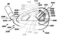
몇몇 실시형태는 골프 클럽 헤드를 포함한다. 골프 클럽 헤드는 타격면, 타격면의 반대쪽에 있는 후방면, 상단부, 상단부의 반대쪽에 있는 하단부, 토우 단부, 토우 단부를 포함하는 토우 영역, 토우 단부의 반대쪽에 있는 힐 단부, 및 힐 단부를 포함하는 힐 영역을 포함한다. 또한, 골프 클럽 헤드는 수직축을 포함한다. 수직축은 후방면의 수평 중심선에 실질적으로 수직하게 연장되고, 토우 단부와 힐 단부 사이의 대략 중간에 배치되며, 상단부와 하단부를 통하여 연장되고, 힐 영역의 경계를 토우 영역으로부터 획정한다. 더 나아가, 골프 클럽 헤드는, 타격면으로부터 멀어지게 그리고 적어도 클럽 헤드의 상단부 및 하단부를 따라 연장되는 둘레 무게추를 후방면에 포함한다. 또한, 골프 클럽 헤드는, 수직축을 가로지르고 상단부의 둘레 무게추와 하단부의 둘레 무게추 사이에서 연장되는 모래시계형 지지부를 후방면에 포함한다. 모래시계형 지지부는, 상측 모래시계 부분, 하측 모래시계 부분, 상측 모래시계 부분과 하측 모래시계 부분보다 좁은 중간 모래시계 부분, 및 모래시계형 지지부의 상측 모래시계 부분, 중간 모래시계 부분 및 하측 모래시계 부분을 사이에 획정하는 힐 및 토우 모래시계 측벽을 포함한다. 전술한 실시형태에서, 중간 모래시계 부분은 골프 클럽 헤드의 무게 중심을 높이기 위해 수평 중심선 위에 배치될 수 있고, 및/또는 상측 모래시계 부분은 골프 클럽 헤드의 무게 중심을 높이기 위해 하측 모래시계 부분보다 넓거나 및/또는 두꺼울 수 있다. 또한 전술한 또는 그 밖의 실시형태에서, 골프 클럽 헤드는 골프 클럽 헤드의 세트의 일부분일 수 있다.Some embodiments include a golf club head. The golf club head includes a striking surface, a rear surface opposite the striking surface, an upper end, a lower end opposite the upper end, a toe end, a toe area including the toe end, a heel end opposite the toe end, and a heel end The heel region. In addition, the golf club head includes a vertical axis. The vertical axis extends substantially perpendicular to the horizontal centerline of the rear surface, is disposed approximately midway between the toe end and the heel end, extends through the top and bottom ends, and defines the boundary of the heel area from the tow area. Further, the golf club head includes a rear waist on the rear face, which extends away from the striking face and at least along the upper and lower ends of the club head. The golf club head also includes an hourglass-shaped support on its rear face, which extends across the vertical axis and extends between the peripheral weight weight of the upper end and the peripheral weight weight of the lower end. The hourglass-shaped support portion includes an upper hourglass portion, a lower hourglass portion, an upper hourglass portion and a middle hourglass portion narrower than the lower hourglass portion, and an upper hourglass portion, a middle hourglass portion, And a heel and toe sandglass sidewall that delimits the clock portion. In the above-described embodiment, the intermediate hourglass portion may be disposed above the horizontal centerline to increase the center of gravity of the golf club head, and / or the upper hourglass portion may be positioned above the lower hourglass portion May be wide and / or thick. Also in the foregoing or other embodiments, the golf club head may be part of a set of golf club heads.
골프 클럽 및 제조 방법의 다른 실시형태에서, 골프 클럽 헤드는 탑 영역, 탑 영역의 반대쪽에 있는 솔 영역, 토우 영역, 토우 영역의 반대쪽에 있는 힐 영역, 중앙 지지 바아와 하측 지지 바아를 구비하는 지지 구조체, 전방면과 전방면의 반대쪽에 있는 후방면을 구비하는 타격면으로서, 타격면의 가장 얇은 부분이 타격면의 전방면으로부터 후방면까지의 최소 수직 거리로서 측정된 약 0.080 인치 이하의 두께를 갖는 것인 타격면, 및 인서트를 수용하도록 구성된 캐비티를 포함하고, 후방면과 인서트의 접촉 면적은 전방면의 표면적의 20%~40%를 이루는 것이다.In another embodiment of the golf club and method of manufacture, the golf club head includes a top region, a sole region opposite the top region, a toe region, a heel region opposite the toe region, a support having a central support bar and a bottom support bar A striking surface having a front face and a rear face opposite the front face wherein the thinnest portion of the striking face has a thickness of less than about 0.080 inches measured as the minimum vertical distance from the front face to the back face of the striking face And a cavity configured to receive the insert, wherein the contact area of the back surface and the insert is 20% to 40% of the surface area of the front surface.
일부 실시형태에서, 중앙 지지 바아는, 탑 영역의 부근에서부터 솔 영역의 부근까지 증가하는 폭을 갖고, 하측 지지 바아는, 중앙 부근에서부터 클럽 헤드의 힐 영역 및 토우 영역 부근까지 감소되는 높이를 갖는다.In some embodiments, the center support bar has a width that increases from near the top region to near the sol region, and the bottom support bar has a height that decreases from near the center to around the heel region and the toe region of the club head.
일부 실시형태에서, 클럽 헤드의 타격면은, 중앙 지지 바아에 의해 보강된 타격면의 일부분을 포함하는 중앙 구역과, 클럽 헤드의 힐 영역 부근의 지지 구조체로부터 보강받지 않는 타격면의 일부분을 포함하는 힐 구역과, 클럽 헤드의 토우 영역 부근의 지지 구조체로부터 보강받지 않는 타격면의 일부분을 포함하는 토우 구역과, 상기 중앙 구역, 상기 힐 구역, 상기 토우 구역 및 상기 하측 지지 바아를 둘러싸는 타격면의 일부분을 포함하는 둘레 구역을 포함하고, 상기 힐 구역에서의 타격면의 두께는 상기 토우 구역에서의 타격면의 두께와 대략 동일하며, 상기 힐 구역 및 토우 구역에서의 타격면의 두께는 상기 중앙 구역에서의 타격면의 두께보다 작고, 상기 중앙 구역에서의 타격면의 두께는 상기 둘레 구역에서의 타격면의 두께보다 작다.In some embodiments, the striking surface of the club head includes a central zone that includes a portion of the striking surface reinforced by the central support bar, and a portion of the striking surface that is not reinforced from the support structure in the vicinity of the heel area of the club head A toe zone comprising a heel zone and a toe zone comprising a portion of the striking surface that is not reinforced from the support structure in the vicinity of the toe zone of the club head and a striking surface surrounding the central zone, the heel zone, the toe zone and the lower support bar Wherein the thickness of the striking surface in the heel zone is approximately equal to the thickness of the striking surface in the tow zone and the thickness of the striking surface in the heel zone and the tow zone is greater than the thickness of the striking surface in the central zone And the thickness of the striking surface in the central zone is less than the thickness of the striking surface in the peripheral zone.
일부 실시형태에서, 클럽 헤드의 캐비티는 약 4.5 cc 내지 약 5.0cc 범위의 체적을 포함할 수 있다. 일부 실시형태에서, 클럽 헤드의 캐비티는 약 4.0 cc 이상의 체적을 포함할 수 있다.In some embodiments, the cavity of the club head may include a volume in the range of about 4.5 cc to about 5.0 cc. In some embodiments, the cavity of the club head may include a volume of about 4.0 cc or greater.
일부 실시형태에서, 인서트는 후방면에 인접한 캐비티의 개구를 지나서 약 0.15 인치 내지 약 2.0 인치의 거리만큼 연장될 수 있다. 일부 실시형태에서, 인서트는 후방면에 인접한 캐비티의 개구를 지나서 약 0.25 인치 이하의 거리만큼 연장될 수 있다.In some embodiments, the insert may extend a distance of about 0.15 inches to about 2.0 inches past the opening of the cavity adjacent the back surface. In some embodiments, the insert may extend a distance of about 0.25 inches or less beyond the opening of the cavity adjacent the rear surface.
일부 실시형태에서, 클럽 헤드의 무게 중심을 통과하여 힐 영역으로부터 토우 영역으로 연장되는 x-축에 대한 클럽 헤드의 관성 모멘트는 약 80 g·in² 이상이다. 일부 실시형태에서, 클럽 헤드의 무게 중심을 통과하여 탑 영역으로부터 솔 영역으로 연장되는 y-축에 대한 클럽 헤드의 관성 모멘트는 약 350 g·in² 이상이다.In some embodiments, the club head's moment of inertia about the x-axis extending from the heel region to the toe region through the center of gravity of the club head is greater than about 80 g · in². In some embodiments, the club head's moment of inertia about the y-axis extending from the top region to the sole region through the center of gravity of the club head is greater than about 350 g · in².
다른 예들과 실시형태들이 본원에 더 개시되어 있다. 이러한 예들과 실시형태들은 도면에서, 청구범위에서, 및/또는 본 출원의 명세서에서 확인될 수 있다.Other examples and embodiments are further disclosed herein. These examples and embodiments may be found in the drawings, in the claims, and / or in the specification of the present application.
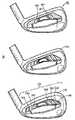
도 1은 본원에 기술된 골프 클럽 및 제조 방법의 일 실시형태에 따른 예시적인 골프 클럽 헤드의 분해도를 보여주고;
도 2는 도 1의 예시적인 골프 클럽 헤드의 정면도를 보여주며;
도 3은 도 1의 단면선 3-3을 따라 취한 예시적인 골프 클럽 헤드의 분해 단면도를 보여주고;
도 4는 도 1의 단면선 4-4를 따라 취한 예시적인 골프 클럽 헤드의 분해 단면도를 보여주며;
도 5는 도 1의 예시적인 골프 클럽 헤드의 사시도를 보여주고;
도 6은 골프 클럽 헤드가 제조될 수 있는 어느 한 방식의 흐름도를 도시하며;
도 7은 골프 클럽이 제조될 수 있는 어느 한 방식의 흐름도를 도시하고;
도 8은 본원에 기술된 골프 클럽 및 제조 방법의 일 실시형태에 따른 가변 특성값을 갖는 클럽 헤드 세트의 클럽 헤드의 배면도를 제시하며;
도 9는 도 8의 클럽 헤드의 토우측 도면을 제시하고;
도 10은 클럽 헤드가 분해되어 있는 상태인 도 8의 클럽 헤드의 바디의 배면도를 보여주며;
도 11은 클럽 헤드가 분해되어 있는 상태인 도 8의 클럽 헤드의 클럽 헤드 세트 중에서 다른 클럽 헤드의 바디의 배면도를 보여주고;
도 12는 클럽 헤드가 분해되어 있는 상태인 도 8의 클럽 헤드의 클럽 헤드 세트 중에서 또 다른 클럽 헤드의 바디의 배면도를 보여주며;
도 13은 도 10의 선 13-13을 따라 취한 도 8 및 도 10의 클럽 헤드의 단면도를 보여주고;
도 14는 도 11의 선 14-14를 따라 취한 도 11의 클럽 헤드의 단면도를 보여주며;
도 15는 도 12의 선 15-15를 따라 취한 도 12의 클럽 헤드의 단면도를 보여주고;
도 16은 도 8~도 15의 예시적인 클럽 헤드 세트에 대한 로프트 각도와 지지 바아의 폭 사이의 예시적인 관계의 도표를 보여주며;
도 17은 본원에 기술된 골프 클럽 및 제조 방법의 일 실시형태에 따른 가변 특성값을 갖는 클럽 헤드 세트의 여러 클럽 헤드를 보여주고;
도 18은 도 8에서의 선 18-18을 따라 취한 도 8의 클럽 헤드의 단면도를 보여주며;
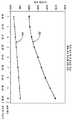
도 19는 본원에 기술된 골프 클럽 및 제조 방법의 일 실시형태에 따른, 도 8~도 18의 예시적인 클럽 헤드의 경우, 하측 토우 인서트로부터 전방면까지의 거리와 로프트 각도 사이의 예시적인 관계의 도표를 보여주고;
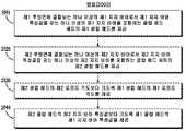
도 20은 도 8~도 19에 대해 기술된 클럽 헤드 세트와 유사한 클럽 헤드 세트를 제공하기 위한 방법의 흐름도를 보여주며;
도 21은 본원에 기술된 골프 클럽 및 제조 방법의 일 실시형태에 따른, 도 8~도 19에 대해 기술된 클럽 헤드 세트와 유사한 클럽 헤드 세트를 제공하기 위한 다른 방법의 흐름도를 보여주고;
도 22는 로프트 각도/클럽 헤드 번호와 지지 바아의 폭 사이의 관계에 대하여 표본 범위를 이용한 도표를 보여주며;
도 23은 하측 토우 인서트로부터 클럽 헤드의 전방면까지의 거리와 로프트 각도/클럽 헤드 번호 사이의 관계에 대하여 표본 범위를 이용한 도표를 보여주고;
도 24는 도 8~도 10, 도 13 및 도 18에 도시된 클럽 헤드와 유사한 클럽 헤드를 제공하기 위한 방법의 흐름도를 보여준다.
도 25는 본원에 기술된 골프 클럽 및 제조 방법의 일 실시형태에 따른 가변 특성값을 갖는 클럽 헤드 세트의 클럽 헤드의 배면도를 보여준다.
도 26은 도 25의 클럽 헤드 세트의 다른 클럽 헤드의 배면도를 보여준다.
도 27은 도 25의 클럽 헤드 세트의 또 다른 클럽 헤드의 배면도를 보여준다.
도 28은 골프 볼을 칠 태세가 되어 있는 도 25의 클럽 헤드의 "x-레이" 상면도를 보여준다.
도 29는 도 25의 클럽 헤드와 유사하며 가변 안정화 바아를 구비한 클럽 헤드의 배면도를 보여준다.
도 30은 도 25의 클럽 헤드와 유사하며 복수 개의 안정화 바아를 구비한 클럽 헤드의 배면도를 보여준다.
도 31은 도 25~도 30에 따른 클럽 헤드 세트를 제공하는 방법의 흐름도를 보여준다.
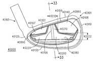
도 32는 본원에 기술된 골프 클럽 및 제조 방법의 일 실시형태에 따른 예시적인 골프 클럽 헤드의 배면도를 보여준다.
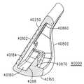
도 33은 도 32의 골프 클럽 헤드의 단면서 33-33을 따라 취한 단면도를 보여준다.
도 34는 도 32의 예시적인 골프 클럽 헤드의 다른 배면도를 보여준다.1 shows an exploded view of an exemplary golf club head according to one embodiment of the golf club and method of manufacture described herein;
Figure 2 shows a front view of the exemplary golf club head of Figure 1;
Figure 3 shows an exploded cross-sectional view of an exemplary golf club head taken along section line 3-3 of Figure 1;
Figure 4 shows an exploded cross-sectional view of an exemplary golf club head taken along section line 4-4 of Figure 1;
Figure 5 shows a perspective view of the exemplary golf club head of Figure 1;
Figure 6 shows a flow diagram of any manner in which a golf club head can be manufactured;
Figure 7 shows a flow diagram of one manner in which a golf club can be manufactured;
8 presents a rear view of the club head of a club head set having variable characteristic values according to one embodiment of the golf club and manufacturing method described herein;
Figure 9 shows a top view of the club head of Figure 8;
Figure 10 shows a rear view of the body of the club head of Figure 8 with the club head disassembled;
Figure 11 shows a rear view of the body of another club head among the club head sets of the club head of Figure 8 with the club head disassembled;
Figure 12 shows a rear view of the body of another club head among the club head sets of the club head of Figure 8 with the club head disassembled;
Figure 13 shows a cross-sectional view of the club head of Figures 8 and 10 taken along line 13-13 of Figure 10;
Figure 14 shows a cross-sectional view of the club head of Figure 11 taken along line 14-14 of Figure 11;
Figure 15 shows a cross-sectional view of the club head of Figure 12 taken along line 15-15 of Figure 12;
Figure 16 shows a table of exemplary relationships between the loft angle and the width of the support bar for the exemplary club head set of Figures 8-15;
17 shows several club heads of a club head set having variable characteristic values according to one embodiment of the golf club and manufacturing method described herein;
Figure 18 shows a cross-sectional view of the club head of Figure 8 taken along line 18-18 in Figure 8;
Figure 19 is a graphical representation of an exemplary relationship between the distance from the lower toe insert to the front side and the loft angle for the exemplary club head of Figures 8-18 according to one embodiment of the golf club and method of manufacture described herein. Show diagrams;
Figure 20 shows a flow diagram of a method for providing a club head set similar to the club head set described with respect to Figures 8 to 19;
Figure 21 shows a flow diagram of another method for providing a club head set similar to the club head set described for Figures 8-19, in accordance with one embodiment of the golf club and manufacturing method described herein;
Figure 22 shows a plot using a sample range for the relationship between the loft angle / club head number and the width of the support bar;
23 shows a diagram using a sample range for the relationship between the distance from the lower side toe insert to the front side of the club head and the loft angle / club head number;
Figure 24 shows a flow chart of a method for providing a club head similar to the club head shown in Figures 8-10, 13 and 18.
25 shows a rear view of a club head of a club head set having variable characteristic values according to an embodiment of the golf club and manufacturing method described herein.
Figure 26 shows a rear view of another club head of the club head set of Figure 25;
Figure 27 shows a rear view of another club head of the club head set of Figure 25;
Figure 28 shows a top view of the "x-ray" of the club head of Figure 25 being ready to hit the golf ball.
Figure 29 shows a rear view of a club head similar to the club head of Figure 25 and having a variable stabilizing bar.
30 shows a rear view of a club head similar to that of FIG. 25 with a plurality of stabilizing bars.
Figure 31 shows a flow diagram of a method of providing a club head set according to Figures 25-30.
32 shows a rear view of an exemplary golf club head according to an embodiment of the golf club and method of manufacture described herein.
33 shows a cross-sectional view taken along line 33-33 of the golf club head of Fig.
Figure 34 shows another rear view of the exemplary golf club head of Figure 32;
예시의 간단 명료화를 위해, 도면은 일반적인 방식의 구성을 보여주고 있고, 잘 알려진 특징부 및 기술에 관한 설명 및 상세한 내용은, 골프 클럽 및 그 제조 방법을 불필요하게 모호하게 하는 것을 회피하도록 생략될 수도 있다. 추가적으로, 도면의 요소들은 축척에 맞춰 도시되어 있다라고는 할 수 없다. 예를 들어, 도면의 요소들 중의 일부의 치수는, 골프 클럽 및 그 제조 방법의 실시형태의 이해 향상을 돕도록, 다른 요소들에 대해 과장되어 있을 수 있다. 여러 도면들에서 동일한 도면 부호는 동일한 요소를 나타낸다.For the sake of simplicity of illustration, the drawings show a general scheme and descriptions and details of well-known features and techniques may be omitted so as to avoid unnecessarily obscuring the golf club and its manufacturing method have. In addition, elements in the figures are not necessarily to scale. For example, the dimensions of some of the elements in the figures may be exaggerated relative to other elements to help improve understanding of embodiments of the golf club and its manufacturing method. Like numbers refer to like elements throughout the several views.
상세한 설명 및 청구범위에서 용어 "제1", "제2", "제3", "제4" 등은, 존재한다면, 유사한 요소들을 구별하기 위해 사용된 것이고, 특정의 순차적인 또는 연대적인 순서를 설명하기 위해 사용된 것이라고는 할 수 없다. 이와 같이 사용된 용어는 적절한 상황 하에서 상호 교환 가능하며, 이에 따라 본원에 기술된 골프 클럽 및 제조 방법의 실시형태들은, 예를 들어 본원에 예시되어 있거나 다른 방식으로 기술되어 있는 것 이외의 순서로, 운용 가능한 것으로 이해되어야 한다. 또한, 용어 "함유하다", "포함하다" 및 "구비하다", 그리고 이들의 임의의 파생어는 비배타적인 내포를 포괄하도록 되어 있어, 요소들의 목록을 포함하는 프로세스, 방법, 물품, 또는 장치가, 이들 요소에 국한되는 것이라고는 할 수 없고, 이러한 프로세스, 방법, 물품, 또는 장치에 내재하는 또는 명시적으로 열거되어 있지 않은 다른 요소를 포함할 수도 있다.The terms "first", "second", "third", "fourth" and the like in the description and claims are used to distinguish between similar elements, if any, and may be in any particular sequential or chronological order It can not be said to be used to explain The terms thus used are interchangeable under appropriate circumstances and accordingly embodiments of the golf clubs and manufacturing methods described herein may be implemented in other ways than those described herein or otherwise described, Should be understood to be operable. It is also to be understood that the terms "comprise," " comprise, "and " comprise ", and any derivatives thereof, are intended to encompass non-exclusive inclusion, such that a process, method, article, , It is not intended to be limited to these elements and may include other elements that are inherent in such process, method, article, or apparatus, or that are not explicitly listed.
상세한 설명 및 청구범위에서 용어 "좌측", "우측", "전방", "후방", "상측", "하측", "측방", "위", "아래" 등은, 존재한다면, 설명의 목적으로 사용된 것이고, 영구적인 상대 위치를 설명하기 위해 사용된 것이라고는 할 수 없다. 이와 같이 사용된 용어는 적절한 상황 하에서 상호 교환 가능하며, 이에 따라 본원에 기술된 골프 클럽 및 제조 방법의 실시형태들은, 예를 들어 본원에 예시되어 있거나 다른 방식으로 기술되어 있는 것 이외의 배향으로, 운용 가능한 것으로 이해되어야 한다. 본원에 사용되고 있는 바와 같은 용어 "결합"은 전기적, 물리적, 기계적, 또는 그 밖의 방식으로 직접적으로 또는 간접적으로 연결되는 것으로 정의된다.The terms "left", "right", "front", "rear", "upper", "lower", "side", "upper", "lower", etc., in the description and claims, It is used for the purpose, not for explaining the permanent relative position. The terms thus used are interchangeable under appropriate circumstances so that the embodiments of the golf clubs and manufacturing methods described herein may be used in other orientations than those illustrated or otherwise described herein, Should be understood to be operable. The term "bond" as used herein is defined as being directly or indirectly connected in an electrical, physical, mechanical, or other manner.
이제 도면을 참조해 보면, 도 1은 골프 클럽 및 제조 방법의 일 실시형태에 따른 예시적인 골프 클럽 헤드(100)의 후방 분해 사시도를 보여주며, 도 2는 골프 클럽 헤드(100)의 정면도를 보여준다. 본원에 기술된 골프 클럽 및 제조 방법의 일 실시형태에서, 골프 클럽 헤드(100)는 토우 영역(110), 토우 영역(110) 반대쪽에 있는 힐 영역(120), 힐 영역(120)에 있는 호젤(105), 솔 영역(130), 그리고 솔 영역(130)의 반대쪽에 있는 탑 영역(140)을 구비한 바디(101)를 포함한다. 솔 영역(130)은 힐 영역(120)으로부터 토우 영역(110)까지 연장될 수 있고, 솔 영역(130)은 전방면(250)(도 2)으로부터 후방 솔 에지(165)까지 연장될 수 있다. 다른 실시형태에서, 골프 클럽 헤드(100)는, 힐 영역(120)에 상기 호젤(105) 대신에 보어(도시 생략)를 구비할 수 있다.Referring now to the drawings, FIG. 1 shows a rear exploded perspective view of an exemplary
골프 클럽 헤드(100)는, 이하에 더 상세히 설명되는 바와 같이, 전방면(250)(도 2)의 반대쪽에 있는 제1 후방면(160)(도 1)과, 전방면(250)(도 2)의 반대쪽에 마련되며 전방면(250)(도 2)으로부터 제1 후방면(160)보다 멀리 연장되는 제2 후방면(170)을 더 포함한다. 제1 후방면(160)은 전방면(250)(도 2)에 대해 실질적으로 평행할 수 있고, 제1 후방면(160)은 힐 영역(120)으로부터 토우 영역(110)까지 연장될 수 있다. 제1 후방면(160)은 또한, 솔 영역(130)으로부터 솔 영역(130)과 탑 영역(140) 사이의 중간 지점(115)(도 1)까지 연장될 수 있고, 중간 지점(115)으로부터 탑 영역(140)까지 더 연장될 수 있다. 도 1 및 도 5에서 확인 가능한 바와 같이, 제2 후방면(170)(도 1)은 힐 영역(120)으로부터 토우 영역(110)까지 연장될 수도 있고, 솔 영역(130)으로부터 솔 영역(130)과 탑 영역(140) 사이의 대략 중간 지점(115)(도 1)까지 연장될 수 있다. 다른 실시형태에서, 후방면(170)(도 1)은 솔 영역(130)으로부터 중간 지점(115) 너머로 연장될 수도 있거나, 또는 후방면(170)은 솔 영역(130)으로부터 중간 지점(115)에 못 미치기게 연장될 수 있다.The
도 1 및 도 3에 도시된 바와 같이, 골프 클럽 헤드(100)는 제1 후방면(160)과 제2 후방면(170) 사이에 제1 캐비티(180)를 더 포함한다. 도 3에 도시된 바와 같이, 제1 캐비티(180)는 제1 후방면(160)을 제2 후방면(170)으로부터 분리시키고, 반대의 경우도 성립된다. 본원에 기술된 여러 실시형태에 따르면, 골프 클럽 및 제조 방법은, 직사각형 형상을 갖는 제1 캐비티(180)를 포함하지만, 그 밖의 구성도 고려된다. 예를 들어, 제1 캐비티(180)는 불규칙한 형상, 또는 예컨대, 삼각형, 원형, 팔각형, 육각형 등의 다른 규칙적인 형상을 이룰 수 있다. 다른 예에서, 제1 캐비티(180)는 대칭 형상 또는 비대칭 형상을 이룰 수 있다. 또한, 제1 캐비티(180)는 여러 치수를 포함할 수 있다.As shown in FIGS. 1 and 3, the
도 1 및 도 4에 도시된 바와 같이, 골프 클럽 헤드(100)는 또한, 하측 토우 영역(110)에 제2 후방면(170)과 일체를 이루는 제2 캐비티(190)를 포함한다. 제1 캐비티(180)와 유사하게, 제2 캐비티(190)는 또한, 다양한 형상 및 치수를 갖는 구성을 포함할 수 있다. 제1 캐비티(180)와 제2 캐비티(190)의 형상 및 치수는, 골프 클럽 헤드(100)의 효용성을 최적화하는 변수에 의해, 그리고 관성 모멘트, 무게 중심 등을 조절하도록 결정될 수 있다. 또한, 본원에 기술된 골프 클럽 및 제조 방법은, 가변 체적의 캐비티를 더 포함할 수 있고, 상기 체적은 골프 클럽 헤드의 소기의 디자인에 따라 정해질 수 있다. 전술한 예는 2개의 캐비티[예컨대, 제1 및 제2 캐비티(180, 190)]를 기술할 수 있지만, 본원에 기술된 골프 클럽 및 제조 방법은 추가적인 캐비티를 포함할 수 있다.As shown in FIGS. 1 and 4, the
이러한 골프 클럽 헤드(100)의 실시형태는 제1 캐비티(180)에 삽입되는 제1 무게추(185) 및 제2 캐비티(190)에 삽입되는 제2 무게추(195)를 더 포함할 수 있다. 본원에 기술된 여러 실시형태에 따르면, 제1 무게추(185)와 제2 무게추(195)는 다양한 형상 및 치수를 갖는 구성을 포함할 수 있다. 예를 들어, 제1 무게추(185)와 제2 무게추(195)는 이들 무게추가 삽입되는 각 캐비티[예를 들어, 제1 캐비티(180) 및 제2 캐비티(190) 각각)에 대해 상보적인 형상 및 치수를 포함할 수 있다. 다른 예에서, 제1 무게추(185)와 제2 무게추(195)는 이들 무게추가 삽입되는 캐비티를 부분적으로만 차지하는 형상을 포함할 수 있거나, 또는 제1 무게추(185)와 제2 무게추(195)가 제1 캐비티(180)와 제2 캐비티(190)를 각각 가득 채우는 형상을 포함할 수 있다. 제1 무게추(185)와 제2 무게추(195)는 다양한 재료를 포함할 수 있다. 일 실시형태에서, 제1 무게추(185)는 금속 매트릭스 재료를 포함한다. 다른 실시형태에서, 제1 무게추(185)는 폴리머를 포함하고, 열경화성 또는 열가소성 폴리머일 수 있다. 몇몇 예에서, 제1 무게추(185)는 약 1 g/㎤(입방 센티미터당 그램) 내지 약 9 g/㎤의 비중을 포함할 수 있다. 제2 무게추(195)는 금속을 포함할 수 있고, 철과 같은 단일 성분 금속, 또는 텅스텐 혹은 티타늄 합금 등과 같은 금속 합금일 수 있다. 본 실시형태에서, 제1 무게추(185)는, 가장 가벼운 또는 최소 밀도의 금속 또는 금속 합금보다 후방을 훨씬 더 가중하는 것을 조절하는 능력을 일반적으로 제공하므로, 금속 매트릭스 재료를 포함하고, 제2 무게추(195)는, 골퍼가 "하향" 및 "외향" 스윙하게 유도하는 데 외측 토우 무게추가 유익할 수 있으므로, 금속을 포함한다. 다른 실시형태에서, 제1 무게추(185)와 제2 무게추(195)는 폴리머, 복합재, 금속, 또는 금속 합금 등과 같은 동일한 재료로 구성될 수 있다. 바디(101)는 철, 철 합금, 티타늄 합금 등과 같은 표준 골프 클럽 헤드 재료를 포함할 수 있고, 제1 무게추(185)와 제2 무게추(195)는 바디(101)와 동일한 또는 상이한 재료를 포함할 수 있다. 제1 및 제2 캐비티의 형상 결정과 같이, 골프 클럽 헤드의 효용성을 최대화하는 변수에 따라 유사한 방식으로 재료가 결정될 수 있고, 구체적으로 기술된 구성 이외의 다른 재료 구성이 고려된다.An embodiment of this
골프 클럽 및 제조 방법의 다른 실시형태에서, 도 2를 참조해 보면, 골프 클럽(200)은 샤프트(208)에 결합되는 골프 클럽 헤드(100)를 포함한다. 본 실시형태에 있어서, 골프 클럽(200)은 또한 0.75의 호젤 비율을 포함할 수 있다. 호젤 비율은 호젤 거리(203) 대 전방면 거리(253)로 이루어진다. 호젤 거리(203)는 대략 힐 영역(120)에 있는 제1 단부(206)로부터 제1 단부(206)의 반대쪽에 있는 제2 단부(207)까지에서 측정한다. 제1 단부(206)는, 호젤(105)의 선형 부분이 전방면(250)을 향해 곡선을 이루기 시작하는 지점(204)에 위치해 있다. 전방면 거리(253)는, 상기 지점(204)으로부터 토우 에지(211)까지 전방면(250)을 따라 그리고 실질적으로 솔(130)에 대해 평행하게 측정된 거리로 이루어진다. 골프 클럽(200)은, 예를 들어 도 1에 도시된 바와 같이, 제1 캐비티(180)를 차지하는 제1 무게추(185)와 제2 캐비티(190)를 차지하는 제2 무게추(195)를 더 포함할 수 있다.In another embodiment of a golf club and method of manufacture, referring to FIG. 2, the
본원에 기술된 바와 같이 골프 클럽 헤드(100)의 캐비티 및 삽입된 무게추를 구비하는 골프 클럽(200)은, 클럽 헤드(100)의 후방 무게추와 토우 무게추의 주문 제작을 허용함으로써 골퍼가 자신의 스윙 능력을 향상시키는 데 도움을 주는 예시적인 골프 클럽을 제공한다. 또한, 본원에 기술된 여러 실시형태들 중에서, 골프 클럽과 그 제조 방법은 아이언, 드라이버, 페어웨이 우드, 하이브리드, 퍼터, 및/또는 그 밖의 적절한 유형의 클럽을 위한 것일 수 있다.The
골프 클럽 및 제조 방법의 일 실시형태에서, 골프 클럽 헤드 제조 방법(600)은 골프 클럽 헤드를 제공하는 단계[블록(610)]를 포함한다. 블록(610)의 골프 클럽 헤드는 도 1~도 5에 도시된 골프 클럽 헤드(100)와 유사할 수 있다. 방법(600)은, 제1 무게추를 결정하는 단계[블록(620)]와, 제1 무게추를 제1 캐비티에 고정하는 단계[블록(630)]와, 제2 무게추를 결정하는 단계[블록(640)], 그리고 제2 무게추를 제2 캐비티에 고정하는 단계[블록(650)]를 더 포함한다. 일례로서, 블록(620)의 제1 무게추는 도 1의 제1 무게추(185)와 유사할 수 있고, 블록(640)의 제2 무게추는 도 1의 제2 무게추(195)와 유사할 수 있다.In one embodiment of the golf club and method of manufacture, the golf club
또한, 블록(620)에서의 결정 단계는, 전문 골프 기술자가 골퍼의 스윙을 분석하는 단계를 포함할 수 있다. 전문 골프 기술자에 의해 분석되는 스윙에 따라, 보다 가볍거나 무거운 무게추가 결정될 수 있다. 마찬가지로, 블록(640)에서의 결정 단계는. 전문 골프 기술자에 의한 골퍼의 스윙 분석에 기초하여 보다 가벼운 무게추를 사용할지 또는 보다 무거운 무게추를 사용할지를 결정하는 단계를 포함할 수 있다. 추가적으로 또는 대안적으로, 제1 무게추를 결정하는 데(예를 들어, 개인의 골프 스윙과 연관된 다양한 파라미터를 모니터링, 측정, 및/또는 분석하는 데), 소프트웨어, 펌웨어, 및/또는 하드웨어가 사용될 수 있다.Further, the determining step at
골프 클럽과 제조 방법의 일 실시형태에서, 골프 클럽을 제조하는 방법(700)은, 골프 클럽 헤드를 제공하는 단계[블록(610)]와, 제1 무게추를 결정하는 단계[블록(620)]와, 제1 무게추를 제1 캐비티에 고정하는 단계[블록(630)]와, 제2 무게추를 결정하는 단계[블록(640)]와, 제2 무게추를 제2 캐비티에 고정하는 단계[블록(650)], 그리고 바디를 골프 클럽 샤프트에 결합하는 단계[블록(760)]를 포함한다. 일례로서, 블록(760)의 샤프트는 도 2의 샤프트(208)와 유사할 수 있다. 또한, 블록(760)의 결합 단계는 태핑(taping), 부착, 용접, 스웨이징, 또는 그 밖의 적절한 기술을 포함할 수 있다.In one embodiment of a golf club and method of manufacture, a
본원에 기술된 방법 실시형태에 따르면, 제1 및/또는 제2 무게추(들)를 고정하는 방법은, 개개의 캐비티에 무게추를 고정하기 위한 임의의 프로세스를 포함한다. 예를 들어, 각각의 무게추가 폴리머 재료를 포함하는 경우, 무게추는 접착제에 의해 접착 및/또는 고정될 수 있다. 예를 들어, 각각의 무게추가 금속으로 제조되는 경우, 무게추는 유사하게 접착제에 의해 접착 또는 고정될 수도 있고, 추가적으로 용접, 스웨이징 등과 같은 캐비티의 내부에 금속을 고정하기 위한 임의의 다른 알려진 방법에 의해 고정될 수 있다.According to the method embodiment described herein, the method of securing the first and / or second weight (s) includes any process for securing the weight to the respective cavity. For example, if each weight-bearing polymeric material is included, the weight may be adhered and / or fixed by an adhesive. For example, when made of each weight-bearing metal, the weight may likewise be adhered or fixed by an adhesive, and additionally any other known method for securing metal within a cavity, such as welding, swaging or the like Lt; / RTI >
동작들의 특정 순서가 도 6과 도 7에 도시되어 있지만, 이들 동작은 다른 임시적인 순서로 수행될 수 있다. 예를 들어, 도 6 및 도 7에 도시된 동작들은 순차적으로, 동시에, 또는 한번에 수행될 수 있다. 또한, 블록(640)과 블록(650)은 블록(620)과 블록(630) 이전에 수행될 수 있고, 블록(620)과 블록(640)은 블록(630)과 블록(650) 이전에 수행될 수 있다.Although a particular sequence of operations is shown in Figures 6 and 7, these operations may be performed in different temporal order. For example, the operations shown in FIGS. 6 and 7 may be performed sequentially, simultaneously, or all at once.
도 6 및 도 7의 기술된 방법에서의 제공 단계는, 골프 클럽 헤드의 설계 및/또는 제조 단계를 포함할 수 있다. 일례로서, 도 5의 바디(100)는 금속 주조 프로세스를 이용하여 제조될 수 있다. 또한, 전술한 방법은 도 1~도 5를 참조하여 기술한 바디(100)의 다른 양태를 제조하는 데 사용될 수 있다.The providing step in the method described in FIGS. 6 and 7 may include designing and / or manufacturing a golf club head. As an example, the
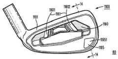
도면들을 계속 참조해 보면, 도 8은 본원에 기술된 골프 클럽 및 제조 방법의 일 실시형태에 따른 클럽 헤드 세트(80)의 클럽 헤드(800)의 배면도를 제시한다. 도 9는 골프 클럽 헤드(800)의 토우측 도면을 제시한다. 도 10은 클럽 헤드(800)가 분해되어 있는 상태인 클럽 헤드(800)의 바디(800)의 배면도를 보여준다. 클럽 헤드(800)는 클럽 헤드(100)(도 1~도 5)와 유사하며, 전방면(950)(도 9)과 샤프트 보어 축(806) 사이의 로프트 각도(955)(도 9)를 포함한다. 도 9의 예에서, 샤프트 보어 축(806)은 호젤(805)의 보어에 의해 획정되지만, 샤프트 보어 축(806)이 클럽 헤드 바디의 힐에서 샤프트 보어에 의해 획정될 수 있는 그 밖의 무(無)호젤 예가 존재할 수 있다. 도 8의 예에서, 클럽 헤드(800)는 또한 후방부(802)로서, 전방면(950)(도 9)의 반대쪽에 있고 후방부(802)의 토우 영역(810)과 힐 영역(820)의 사이에서 연장되는 후방면(860)을 구비하는 후방부(802)를 포함한다. 일부 실시형태에서, 후방부(802)는 또한 클럽 헤드(800)의 후방 측면으로도 지칭될 수 있다. 클럽 헤드(800)는 또한, 본 실시형태의 인서트(885, 895)를 포함한다. 인서트(885)는 무게추(185)(도 1, 도 3)와 유사할 수 있고, 후방부(802)에서 클럽 헤드(100)의 캐비티(180)(도 1, 도 3, 도 5)와 유사한 캐비티(1080)(도 10)에 삽입될 수 있다. 하측 토우 인서트(895)는 클럽 헤드(100)의 무게추(195)(도 1, 도 4)와 유사할 수 있다. 클럽 헤드(800)는, 이하에 더 설명되는 바와 같이, 2개 이상의 골프 클럽의 클럽 헤드 세트(80)의 일부를 포함한다.Continuing with the drawings, FIG. 8 illustrates a rear view of the
클럽 헤드(800)는 또한, 본 실시형태에서, 후방면(860)의 중앙에서 인서트 베이스(863)에 위치한 인서트(862)를 포함한다. 도 8에 도시된 바와 같이, 인서트(862)는 클럽 헤드(800)에 관한 로고 또는 그 밖의 식별 특징부를 포함할 수 있다. 인서트(862)는 클럽 헤드(800)의 소리, 진동, 주파수, 및/또는 질량 분포에 영향을 미치도록, 도 1, 도 3 및 도 4에서 무게추(185) 및/또는 무게추(195)에 대해 기술된 것과 같은 재료를 포함할 수 있는 실시형태가 존재할 수 있다.The
클럽 헤드(800)는, 중앙 영역(864)에 걸치어서 그리고 중앙 영역으로부터 등간격을 두고서 후방면(860)에 결합되어 있는 지지 바아(861)를 포함한다는 점에서, 클럽 헤드(100)(도 1~도 5)와 다르다. 지지 바아(861)는 힐 영역(820)의 지지 바아(8611)와, 토우 영역(810)의 지지 바아(8612)를 포함하며, 양 지지 바아 모두 후방면(860)으로부터 돌출된다. 그러나, 상이한 개수 및/또는 상이한 배열의 지지 바아를 갖는 다른 예들이 존재할 수 있다. 예를 들어, 추가적인 지지 바아가 지지 바아(8611)와 힐 영역(820)의 힐 단부의 사이에 배치될 수 있다. 마찬가지로, 추가적인 지지 바아가 지지 바아(8612)와 토우 영역(810)의 토우 단부의 사이에 배치될 수 있다. 몇몇 예에서, 인서트 베이스(863)는 또한 하나 이상의 지지 바아를 포함하는 것으로 고려될 수 있다. 예를 들어, 인서트 베이스(863)의 베이스 단부(8613, 8614)가 또한 몇몇 예에서 후방면(860)으로부터 돌출되는 지지 바아로서 고려될 수 있다. 또한, 인서트 베이스(863)가 후방면(860)으로부터 돌출되어 있어, 인서트 베이스(863) 자체가 지지 바아로서 고려될 수 있는 예들이 존재할 수 있다.The
본 실시형태에서, 지지 바아(8611, 8612)는 실질적으로 동일한 지지 바아 폭을 포함한다. 동일한 또는 그 밖의 실시형태에서, 지지 바아의 폭은 약 0.03 인치(0.75 밀리미터) 내지 약 0.5 인치(12.7 밀리미터)일 수 있다. 도 8의 예에서는 두 지지 바아(8611, 8612)에 대한 지지 바아의 폭이 일정하지만, 지지 바아의 폭이 지지 바아(8612 및/또는 8611)와 유사한 지지 바아의 길이를 따라 점차 가늘어지거나 또는 다른 방식으로 변화되는 다른 예들이 존재할 수 있다. 또한, 본 예에서는 지지 바아(861)에 대한 지지 바아의 두께가 또한 일정하지만, 지지 바아의 두께가 지지 바아(8611 및/또는 8612)와 유사한 지지 바아의 길이를 따라 후방면(860)으로부터 측정된 바와 같이, 점차 가늘어지거나 또는 다른 방식으로 변경될 수 있는 예들이 존재할 수 있다.In this embodiment, the support bars 8611 and 8612 include substantially the same support bar width. In the same or other embodiments, the width of the support bar may be from about 0.03 inches (0.75 millimeters) to about 0.5 inches (12.7 millimeters). In the example of FIG. 8, the width of the support bar relative to both
본 실시형태에서, 지지 바아(861)는 동일한 재료의 부재의 일부를 포함함으로써 후방면(860)과 일체를 이루고 있다. 예를 들어, 지지 바아(861)는 후방면(860)과 함께 주조, 단조, 또는 기계 가공될 수 있다. 지지 바아가 개개의 후방면과 일체를 이루지 못하고 개개의 후방면에 고정적으로 부착되어 있는 다른 실시형태들이 존재할 수 있다. 이러한 예에서, 지지 바아는 후방면에 용접, 경납땜, 에폭시 접합, 또는 그 밖의 방식으로 접합될 수 있다.In this embodiment, the
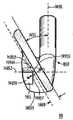
본 실시형태에서, 지지 바아(8611)는 중앙 영역(864)을 향하여 수평축(807)으로부터 측정되는 각도(8615)를 포함한다. 유사하게, 지지 바아(8612)는 또한 중앙 영역(864)을 향하여 수평축(807)으로부터 측정되는 각도(8616)를 포함한다. 수평축(807) 클럽 헤드(800)를 상반부와 하반부로 양분하는 축이다. 각도(8615 및/또는 8616)가 수평축(807)으로부터 약 30°~약 90°의 예각을 이루는 실시형태들이 존재할 수 있다. 동일한 또는 다른 실시형태에서, 지지 바아(8611 및 8612)는 중앙 영역(864)을 향해 수렴하도록 각도를 이루고 있다. 각도(8615 및/또는 8616)가 수평축(807)으로부터 둔각 및/또는 약 90°~약 150°의 각도를 이룰 수 있는 실시형태들이 또한 존재할 수 있다. 도 8의 예에서 각도들(8615 및 8616)은 모두 약 68°를 포함하지만, 각도들(8615 및 8616)이 서로 동일하지 않은 다른 실시형태들, 및/또는 적어도 하나의 각도(8615 및/또는 8616)가 중앙 영역(864)에 대해 예각을 이루지 않는 다른 실시형태들이 존재할 수 있다. 각도들(8615 및/또는 8616)은, 클럽 헤드 세트(80)의 서로 다른 클럽 헤드 전반에 걸쳐 일정하게 유지될 수 있거나, 또는 동일한 클럽 헤드 세트 내에서 클럽 헤드별로 다를 수 있다.In this embodiment, the
도 10은 분해되어 있는 상태인 클럽 헤드(800)의 바디(800)의 배면도를 보여준다. 이전 도면들을 건너뛰어 보면, 도 18은 도 8에서의 선 18-18을 따라 취한 클럽 헤드(800)의 단면도를 보여준다. 단순화를 위해, 도 18에는 하측 토우 인서트(895)에 대한 세부 구성이 빠져 있지만, 인서트(885)는 캐비티(1080)에 삽입된 것으로 도시되어 있다는 점에 주목해야 할 필요가 있다. 도 8, 도 10 및 도 18에 도시된 바와 같이, 클럽 헤드(800)의 후방부(802)는 힐 영역(820)과 토우 영역(810)의 사이에서 연장되는 후방 단부(870)를 포함하는데, 상기 후방 단부(870)는 클럽 헤드(100)의 제2 후방 단부(170)(도 1, 도 3~도 5)와 유사할 수 있다. 몇몇 예에서, 후방 단부(870)는 후방벽으로 지칭될 수 있다. 캐비티(1080)는 또한, 후방부(802)에서 후방면(860)과 후방 단부(870)의 사이에 위치해 있고, 캐비티의 힐 구역(1082), 캐비티의 토우 구역(1083), 캐비티의 중앙 구역(1181), 전방면(950)쪽에 배치된 캐비티의 내부 섹션(1084), 및 후방 단부(870)쪽에 배치된 캐비티의 외부 섹션(1885)을 포함한다. 본 예에서, 캐비티의 내부 섹션(1084)은 후방면(860)의 반대쪽에 배치되며, 캐비티의 외부 섹션(1885)은 후방 단부(870)의 반대쪽에 배치된다. 본 실시형태에서는, 도 18에 도시된 바와 같이, 캐비티(1080)는 캐비티의 힐 구역(1082) 또는 캐비티의 토우 구역(1083)에서의 폭보다 캐비티의 중앙 구역(1181)에서의 폭이 크다. 예를 들어, 캐비티의 내부 섹션(1084)은, 캐비티의 힐 구역(1082) 또는 캐비티의 토우 구역(1083)에서보다는 캐비티의 중앙 구역(1181)에서, 전방면(950)에 비해 얇다. 몇몇 예에서, 캐비티의 내부 섹션(1084)은 캐비티의 내벽으로 지칭될 수 있거나, 및/또는 캐비티의 외부 섹션(1885)은 캐비티의 외벽으로 지칭될 수 있다.10 shows a rear view of the
본 예에서, 전방면(950)과 캐비티의 내부 섹션(1084)의 노출면 사이의 거리가, 캐비티의 중앙 구역(1181)에서보다는 캐비티의 힐 구역(1082) 및 캐비티의 토우 구역(1083)에서 더 크다. 또한, 후방 단부(870)와 캐비티의 외부 섹션(1885)의 노출면 사이의 거리가, 캐비티의 중앙 구역(1181)에서보다는 캐비티의 힐 구역(1082) 및 캐비티의 토우 구역(1083)에서 클 수 있는 실시형태들이 존재할 수 있다.In this example, the distance between the
인서트(885)는 본 실시형태에서 인서트 힐 구역(1886), 인서트 토우 구역(1887), 및 인서트 중앙 구역(1888)을 포함하며, 인서트 중앙 구역(1888)이 인서트 힐 구역(1886) 또는 인서트 토우 구역(1887)보다 두껍도록 캐비티(1080)에 대해 상보적으로 형성된다. 도 18의 예에서, 인서트 힐 구역(1886) 및 인서트 토우 구역(1887)은 인서트 내벽(1889)을 따라 그리고 인서트 중앙 구역(1888)을 중심으로 서로에 대해 둔각을 이루고 있다. 마찬가지로, 캐비티의 내부 섹션(1084)은 인서트 내벽(1889)에 대해 상보적으로 둔각을 이루고 있다. 본 예에서, 인서트(885)가 클럽 헤드(800)에 대해 탑-투-솔 방향으로 삽입 가능하도록, 캐비티(1080)가 구성되어 있다. 또한, 인서트(885)가 다른 유사한 형상의 인서트와 교환 가능할 수 있는 예들도 존재할 수 있다.The
몇몇 예에서, 클럽 헤드(800)의 바디(801)의 재료는 적어도 약 5.0 g/㎤의 비중을 포함할 수 있거나, 및/또는 인서트(885)의 재료는 적어도 약 1.2 g/㎤의 비중을 포함할 수 있다. 동일한 또는 그 밖의 예에서, 인서트(885)의 질량은 약 10 g일 수 있다.In some instances, the material of the
캐비티(1080)와 인서트(885)에 대해 전술한 치수 관계 및 캐비티(1080)와 인서트(885) 사이의 치수 관계는, 예컨대 클럽 헤드(800)에 대한 질량 분포의 조절을 허용하기에 유리할 수 있다. 인서트(885)의 재료의 밀도가 클럽 헤드(800)의 바디(801)의 재료의 밀도보다 낮은 본 실시형태에서, 캐비티의 중앙 구역(1181)에 비해 캐비티의 힐 구역(1082) 및 캐비티의 토우 구역(1083)에서 캐비티의 내벽 섹션(1084)의 두께를 크게 하는 것과, 인서트 힐 구역(1886) 및 인서트 토우 구역(1887)에 비해 인서트 중앙 구역(1888)의 두께를 크게 하는 것은, 클럽 헤드(800)의 중심으로부터 멀어지게 그리고 힐 영역(820) 및 토우 영역(810)을 향해 질량을 재분배하는 것을 허용할 수 있다. 일례로서, 캐비티의 내부 섹션(1084)의 질량 분포가, 힐 영역(820)을 향해 그리고 토우 영역(810)을 향해 그리고 캐비티의 중앙 구역(1181)으로부터 멀어지게 이동된다. 또한, 인서트(885)의 질량 분포가 인서트 중앙 구역(1888)에 집중되며, 인서트 힐 구역(1886)을 향해 갈수록 그리고 인서트 토우 구역(1887)을 향해 갈수록 줄어든다.The dimensional relationships described above with respect to
이러한 질량 분포는, 클럽 헤드(800)의 중앙 영역에 대한 관성 모멘트를 증가시킬 수 있으며, 중심을 벗어난 임팩트 시에 클럽 헤드의 비틀림을 감소시킴으로써 게임 플레이를 개선할 수 있다. 예를 들어, 전술한 형상 및 구성으로 인해, 캐비티의 힐 구역(1082) 및 캐비티의 토우 구역(1083)에서 캐비티의 내부 섹션(1084)에 의해 야기되는 관성 모멘트의 일부분이, 인서트 힐 구역(1886) 및 인서트 토우 구역(1887)에서 인서트(885)에 의해 야기되는 관성 모멘트의 일부분보다 크다. 그 밖의 실시형태들에서는, 인서트(885)와 캐비티(1080)의 사이의 다른 형상 및/또는 밀도 관계가, 다양한 소기의 관성 모멘트 또는 질량 분포를 달성하는 데 사용될 수 있다.This mass distribution can increase the moment of inertia for the central region of the
도 8 및 도 18에 도시된 바와 같이, 인서트(885)는 캐비티(1080)에 부분적으로 수용되고, 이에 따라 인서트(885)의 파지부가 캐비티(1080)의 외부로 돌출되어, 예를 들어 인서트(885)를 캐비티(1080)에 삽입하거나 또는 인서트(885)를 캐비티(1080)로부터 제거하는 것이 허용 또는 촉진된다. 그러나, 다른 실시형태들에서, 인서트(885)는 캐비티(1080)로부터 돌출될 필요가 없다. 본 실시형태에서, 지지 바아(861)는 또한 후방면(860)으로부터 캐비티의 내부 섹션(1084)까지 연장되고, 캐비티의 내부 섹션(1084)은 후방면(860)에 대하여 적어도 지지 바아(861)와 동일한 두께로 형성되어, 인서트(885)를 캐비티(1080)에 삽입하거나 또는 인서트(885)를 캐비티(1080)로부터 제거하는 것을 지지 바아(861)가 방해하는 것을 방지한다.8 and 18, the
도면들을 되살펴 보면, 도 10~도 15는 클럽 헤드 세트(80)의 예시적인 클럽 헤드의 여러 도면을 보여준다. 도 10은 클럽 헤드(800)가 분해되어 있는 상태인 클럽 헤드(800)의 바디(800)의 배면도를 보여준다. 도 11은 클럽 헤드(1100)가 분해되어 있는 상태인 클럽 헤드 세트(80)의 클럽 헤드(1100)의 바디(1101)의 배면도를 보여준다. 도 12는 클럽 헤드(1200)가 분해되어 있는 상태인 클럽 헤드 세트(80)의 클럽 헤드(1200)의 바디(1201)의 배면도를 보여준다. 도 13은 도 10의 선 13-13을 따라 취한 클럽 헤드(800)의 단면도를 보여준다. 도 14는 도 11의 선 14-14를 따라 취한 클럽 헤드(1100)의 단면도를 보여준다. 도 15는 도 12의 선 15-15를 따라 취한 클럽 헤드(1200)의 단면도를 보여준다. 클럽 헤드(800, 1100, 1200)는 이하에 상세히 기술된 바와 같이 서로 유사할 수 있다.Referring back to the drawings, FIGS. 10-15 illustrate several views of an exemplary club head of the club head set 80. FIG. 10 shows a rear view of the
본 예에서, 클럽 헤드(800, 1100, 1200)는, 클럽 헤드 세트(80)가 2개 이상의 클럽 헤드를 포함할 수 있는 경우에 있어서, 관련 골프 클럽의 클럽 헤드 세트(80)의 일부분을 형성한다. 단순화를 위해 도 10~도 12에는 클럽 헤드 세트(80)의 클럽 헤드(800, 1100, 1200)만이 도시되어 있지만, 클럽 헤드 세트(80)는 3개 이상의 클럽 헤드를 포함할 수 있다. 또한, 클럽 헤드 세트(80)가 2개의 클럽 헤드만을 포함할 수 있는 다른 실시형태들도 존재할 수 있다. 클럽 헤드 세트(80)의 각 클럽 헤드는, 각각의 후방면으로부터 돌출되는 하나 이상의 지지 바아를 포함한다. 예를 들어, 도 8 및 도 10에 도시된 바와 같이, 클럽 헤드(800)는 앞서 상세히 기술된 바와 같이 후방면(860)으로부터 돌출되는 지지 바아(8611, 8612)를 포함하는 지지 바아(861)를 포함한다. 도 11에 도시된 바와 같이, 클럽 헤드(1100)는 지지 바아(1161)를, 즉 후방면(1160)으로부터 돌출되는 지지 바아(11611, 11612)를 포함한다. 추가적으로, 도 12에 도시된 바와 같이, 클럽 헤드(1200)는 지지 바아(1261)를, 즉 후방면(1260)으로부터 돌출되는 지지 바아(12611, 12612)를 포함한다.In this example, the
본 예에서, 클럽 헤드 세트(80)의 클럽 헤드의 로프트 각도는 2개 이상의 클럽 헤드에 걸쳐 점증적으로 변화된다. 예컨대, 클럽 헤드 세트(80)의 본 예에서, 클럽 헤드(800)는 전방면(950)과 샤프트 보어 축(806) 사이의 로프트 각도(955)(도 9)가 약 18.5°인 2-아이언 클럽 헤드를 포함하고(도 13); 클럽 헤드(1100)는 전방면(1450)과 샤프트 보어 축(1406)의 사이의 로프트 각도(1455)가 약 30.5°인 6-아이언 클럽 헤드를 포함하며(도 14); 클럽 헤드(1200)는 전방면(1550)과 샤프트 보어 축(1506)의 사이의 로프트 각도(1555)가 약 47°인 웨지-아이언 클럽 헤드를 포함한다(도 15). 결과적으로, 클럽 헤드(1200)의 로프트 각도(1555)는 클럽 헤드(1100)의 로프트 각도(1455)보다 크고, 이에 따라 클럽 헤드(800)의 로프트 각도(955)보다 크다.In this example, the loft angle of the club head of the club head set 80 is incrementally varied over two or more club heads. For example, in this example of the club head set 80, the
또한, 본 예에서, 하나 이상의 지지 바아의 특성값이 로프트 각도에 따라 2개 이상의 클럽 헤드에 걸쳐 점증적으로 변화된다. 예를 들어, 로프트 각도(1555)는 전술한 바와 같이 로프트 각도(1455)보다 크고, 따라서 골프 클럽(1200)의 지지 바아(1261)(도 12)의 속성값이 골프 클럽(1100)의 지지 바아(1161)(도 11)의 속성값보다 크다. 본 예에서, 변화를 겪는 지지 바아의 속성은 지지 바아의 폭이고, 이에 따라 지지 바아(1261)(도 12)의 폭이 지지 바아(1161)의 폭보다 크며(도 11), 지지 바아(1161)(도 11)의 폭이 지지 바아(861)(도 10)의 폭보다 크다.Also, in this example, the characteristic value of one or more support bars is incrementally varied over two or more clubheads according to the loft angle. For example, the
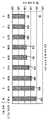
예시적인 클럽 헤드 세트(80)에 대하여 로프트 각도에 대한 지지 바아 폭의 변화가 도 16에 요약되어 있다. 본 예에서, 클럽 헤드 세트(80)는 2-아이언 헤드로서의 클럽 헤드(800)와, 3-아이언 헤드로서의 클럽 헤드(1630)와, 4-아이언 헤드로서의 클럽 헤드(1640)와, 5-아이언 헤드로서의 클럽 헤드(1650)와, 6-아이언 헤드로서의 클럽 헤드(1100)와, 7-아이언 헤드로서의 클럽 헤드(1670)와, 8-아이언 헤드로서의 클럽 헤드(1680)와, 9-아이언 헤드로서의 클럽 헤드(1690), 및 웨지-아이언 헤드로서의 클럽 헤드(1200)를 포함한다. 도 16으로부터 인지될 수 있는 바와 같이, 로프트 각도가 어느 한 클럽 헤드로부터 클럽 헤드 세트(80)의 다음 클럽 헤드로 갈수록 증가함에 따라, 지지 바아의 폭 속성값이 점증적으로 변화된다. 결과적으로, 로프트 각도가 큰 클럽에 대한 지지 바아 폭은, 로프트 각도가 작은 클럽에 대한 지지 바아 폭보다 크거나 같다. 그러나, 로프트 각도가 큰 클럽에 대한 지지 바아 폭이 로프트 각도가 작은 임의의 클럽의 지지 바아 폭보다 크도록, 로프트 각도가 증가할 때마다 하나 이상의 지지 바아의 특성값 및/또는 속성값이 점증적으로 변화될 수 있는 예들이 존재할 수 있다.The change in the support bar width relative to the loft angle for the exemplary club head set 80 is summarized in FIG. In this example, the club head set 80 includes a
이전 도면들을 건너뛰어 보면, 도 22에 도시된 바와 같이, 지지 바아 폭과 로프트 각도/클럽 헤드 번호 사이의 관계는 하나 이상의 범위 내에 놓일 수 있다. 예컨대, 클럽 헤드 세트(2281)는, 도 22에 나타내어진 바와 같이, 클럽 헤드마다 천차만별인 지지 바아 폭이 두꺼운 클럽 헤드를 포함한다. 마찬가지로, 다른 예에서, 클럽 헤드 세트(2282)는, 도 22에도 나타내어진 바와 같이, 클럽 헤드마다 천차만별인 지지 바아 폭이 얇은 클럽 헤드를 포함한다. 그 밖의 예 또는 변화율이 다른 클럽 세트에 대해서도 또한 가능하다.Looking at the previous drawings, the relationship between the support bar width and the loft angle / club head number can be within one or more ranges, as shown in FIG. For example, the club head set 2281 includes a club head having a thicker support bar width for each club head, as shown in Fig. Likewise, in another example, the club head set 2282 includes a club head having a narrow support bar width for each club head, as shown in Fig. It is also possible for other club sets with different or varying rates.
동일한 또는 그 밖의 예에서, 지지 바아 폭은, 하나 이상의 클럽 헤드 세트의 클럽 헤드에 대하여, 로프트 각도 및/또는 클럽 헤드 번호에 따라, 특정 범위 내에서 변화될 수 있다. 예를 들어:In the same or other example, the support bar width may vary within a certain range, depending on the loft angle and / or the club head number, for the club head of one or more club head sets. E.g:
2-아이언 헤드의 경우, 로프트 각도는 약 18°내지 약 20°로 이루어질 수 있고, 지지 바아 폭은 약 0.03 인치(0.75 밀리미터) 내지 대략 0.2 인치(5.1 밀리미터)로 이루어질 수 있으며;In the case of a two-iron head, the loft angle may be from about 18 DEG to about 20 DEG, and the support bar width may be from about 0.03 inches (0.75 millimeters) to about 0.2 inches (5.1 millimeters);
2-아이언 헤드의 경우, 로프트 각도는 약 20°내지 약 23°로 이루어질 수 있고, 지지 바아 폭은 약 0.04 인치(1.0 밀리미터) 내지 대략 0.21 인치(5.3 밀리미터)로 이루어질 수 있으며;In the case of a two-iron head, the loft angle may be from about 20 degrees to about 23 degrees, and the support bar width may be from about 0.04 inches (1.0 millimeters) to about 0.21 inches (5.3 millimeters);
4-아이언 헤드의 경우, 로프트 각도는 약 21°내지 약 25°로 이루어질 수 있고, 지지 바아 폭은 약 0.05 인치(1.3 밀리미터) 내지 대략 0.23 인치(5.8 밀리미터)로 이루어질 수 있으며;For a four-iron head, the loft angle may be from about 21 degrees to about 25 degrees, and the support bar width may be from about 0.05 inches (1.3 millimeters) to about 0.23 inches (5.8 millimeters);
5-아이언 헤드의 경우, 로프트 각도는 약 23°내지 약 28°로 이루어질 수 있고, 지지 바아 폭은 약 0.06 인치(1.5 밀리미터) 내지 대략 0.26 인치(6.6 밀리미터)로 이루어질 수 있으며;For a 5-iron head, the loft angle may be from about 23 degrees to about 28 degrees, and the support bar width may be from about 0.06 inches (1.5 millimeters) to about 0.26 inches (6.6 millimeters);
6-아이언 헤드의 경우, 로프트 각도는 약 26°내지 약 32°로 이루어질 수 있고, 지지 바아 폭은 약 0.07 인치(1.8 밀리미터) 내지 대략 0.30 인치(7.6 밀리미터)로 이루어질 수 있으며;In the case of a 6-iron head, the loft angle may be from about 26 degrees to about 32 degrees, and the support bar width may be from about 0.07 inches (1.8 millimeters) to about 0.30 inches (7.6 millimeters);
7-아이언 헤드의 경우, 로프트 각도는 약 29°내지 약 36°로 이루어질 수 있고, 지지 바아 폭은 약 0.08 인치(2.0 밀리미터) 내지 대략 0.34 인치(8.7 밀리미터)로 이루어질 수 있으며;For 7-iron heads, the loft angle may be from about 29 [deg.] To about 36 [deg.], And the support bar width may be from about 0.08 inches (2.0 millimeters) to about 0.34 inches (8.7 millimeters);
8-아이언 헤드의 경우, 로프트 각도는 약 34°내지 약 42°로 이루어질 수 있고, 지지 바아 폭은 약 0.09 인치(2.3 밀리미터) 내지 대략 0.39 인치(9.8 밀리미터)로 이루어질 수 있으며;For 8-iron heads, the loft angle may be from about 34 degrees to about 42 degrees, and the support bar width may be from about 0.09 inches (2.3 millimeters) to about 0.39 inches (9.8 millimeters);
9-아이언 헤드의 경우, 로프트 각도는 약 38°내지 약 45°로 이루어질 수 있고, 지지 바아 폭은 약 0.10 인치(2.5 밀리미터) 내지 대략 0.44 인치(11.2 밀리미터)로 이루어질 수 있으며; 및/또는For 9-iron heads, the loft angle may be from about 38 degrees to about 45 degrees, and the support bar width may be from about 0.10 inches (2.5 millimeters) to about 0.44 inches (11.2 millimeters); And / or
웨지-아이언 헤드의 경우, 로프트 각도는 약 42°내지 약 64°로 이루어질 수 있고, 지지 바아 폭은 약 0.11 인치(2.8 밀리미터) 내지 대략 0.50 인치(12.7 밀리미터)로 이루어질 수 있다.In the case of a wedge-iron head, the loft angle can be from about 42 degrees to about 64 degrees, and the support bar width can be from about 0.11 inches (2.8 millimeters) to about 0.50 inches (12.7 millimeters).
동일한 또는 다른 실시형태에서, 지지 바아의 하나 이상의 다른 특성값 또는 속성값은, 지지 바아 폭에 대해 전술한 방식과 유사한 방식으로, 지지 바아 폭을 제외하고서, 지지 바아 폭을 대신하여, 지지 바아 폭에 추가하여, 변화될 수 있다. 예를 들어, 일 실시형태에서, 다른 특성값 또는 속성값은, 로프트 각도에 따라 점증적으로 변화될 수 있는, 후방면으로부터 측정된 지지 바아 두께를 포함할 수 있다. 이러한 일례에서, 도 12의 클럽 헤드(1200)의 지지 바아(1261)의 두께는 도 11의 클럽 헤드(1100)의 지지 바아(1161)의 두께보다 두꺼울 수 있고, 및/또는 도 11의 클럽 헤드(1100)의 지지 바아(1161)의 두께는 도 10의 클럽 헤드(800)의 지지 바아(861)의 두께보다 두꺼울 수 있다.In the same or different embodiments, one or more other property values or property values of the support bar may be provided in a manner similar to that described above for the support bar width, except for the support bar width, In addition to the above. For example, in one embodiment, the other property value or attribute value may include the support bar thickness measured from the rear surface, which can be incrementally varied with the loft angle. In this example, the thickness of the
동일한 또는 다른 실시형태에서, 다른 특성값 또는 속성값은, 로프트 각도에 따라 점증적으로 변화될 수 있는, 지지 바아의 총 개수를 포함할 수 있다. 이러한 일 실시형태가, 클럽 헤드(800), 클럽 헤드(1100)와 유사한 클럽 헤드(1702), 및 클럽 헤드(1200)와 유사한 클럽 헤드(1703)를 포함하는 클럽 헤드 세트(171)에 대하여 도 17에 도시되어 있다. 도 17의 예에서, 클럽 헤드(1703)에 대한 로프트 각도는 클럽 헤드(1702)에 대한 로프트 각도보다 크고, 클럽 헤드(1702)에 대한 로프트 각도는 클럽 헤드(1701)에 대한 로프트 각도보다 크며, 이에 따라 클럽 헤드(1703)에 대한 지지 바아의 총 개수가 클럽 헤드(1702)에 대한 지지 바아의 총 개수보다 크고, 클럽 헤드(1702)에 대한 지지 바아의 총 개수가 클럽 헤드(1701)에 대한 지지 바아의 총 개수보다 크다. 일례에서, 지지 바아의 폭, 두께 및 각도는 단일 클럽 헤드의 각각의 지지 바아 대해 동일하게 유지된다. 다른 예에서, 하나 이상의 특성값 또는 속성값은 클럽 헤드마다 변화되거나, 및/또는 단일 클럽 헤드 내의 지지 바아들이 서로 다른 폭, 두께, 및/또는 각도를 가질 수 있다.In the same or different embodiments, other property values or attribute values may include the total number of support bars, which can be incrementally varied with the loft angle. This embodiment is also applicable to a club head set 170 that includes a
전술한 바와 같이 클럽 헤드 세트의 클럽 헤드의 후방면에 지지 바아가 합체되는 것은, 여러 가지 이유로 인해 유리할 수 있다. 예를 들어, 클럽 헤드의 후방면에서 중앙 영역에 인접하게 지지 바아를 배치함으로써, 골프 볼에 대한 임팩트와 연관된 응력을 보다 잘 견디도록, 전방면 및/또는 전방 플레이트에 대한 지지를 증가시킬 수 있다. 무게 절감 및/또는 무게 재분배를 고려하여 전방 플레이트의 두께가 최소화된 상황에서는, 상기한 추가적인 지지가 유용할 수 있다.The incorporation of the support bar into the rear face of the club head of the club head set as described above may be advantageous for a variety of reasons. For example, by placing the support bar adjacent the central region in the rear surface of the club head, support for the front and / or front plate can be increased to better withstand the stresses associated with the impact on the golf ball . In situations where the thickness of the front plate is minimized in view of weight savings and / or weight redistribution, such additional support may be useful.
도 12 및 도 15의 클럽 헤드(1200)와 유사한 웨지 헤드 등과 같은 쇼트 아이언의 경우에, 전방면(1550)의 정반대쪽에 있는 후방면(1260)에 지지 바아(1261) 등과 같이 폭이 넓고 및/또는 두꺼운 지지 바아를 배치함으로써, 클럽 헤드(1200)의 무게 중심을 그 전방을 향해 이동시키는 효과가 얻어질 수 있다. 이러한 무게 중심의 이동은, 전방면(1550)과 골프 볼 사이의 기어 효과를 감소시켜, 보다 나은 궤도 제어를 위해 전방면(1550)과의 임팩트 시에 골프 볼에 부여되는 스핀을 제한할 수 있다. 또한, 폭이 더 크거나 및/또는 두께가 더 큰 지지 바아로 인해, 임팩트 시에 표면 안정성이 추가되고 표면의 휨이 감소된 결과, 거리 제어 및 반복성이 개선될 수 있다. 몇몇 예에서는, 도 17의 클럽 헤드(1703)의 지지 바아(1761)의 경우에서와 같이, 지지 바아의 개수를 증가시킴으로써, 유사한 결과가 또한 얻어질 수 있다.A wide iron such as a
도 8, 도 10 및 도 13의 클럽 헤드(800)와 유사한 2-아이언 등과 같은 롱 아이언의 경우에, 지지 바아 폭, 지지 바 두께, 및/또는 지지 바아의 총 개수이든지 아니든지, 지지 바아의 관련 특성값 또는 속성값을 감소시킴으로써, 제어를 향상시키도록 클럽 헤드의 관성 모멘트가 증가될 수 있고, 이에 따라 관성 모멘트의 증가를 위해, 보다 큰 클럽 헤드(800)의 질량이 클럽 헤드(800)의 전방면(950)의 에지쪽에 분포될 수 있다. 추가적으로, 클럽 헤드의 전방면 및/또는 전방 플레이트의 보다 큰 굴곡을 허용함으로써, 관련 지지 바아의 특성값 감소로 인해, 보다 긴 및/또는 보다 꿰뚫고 나아가는 관통 비행 경로가 확보될 수 있다.In the case of a long iron, such as a two-iron or the like, similar to the
또한, 도시된 바와 같은 클럽 헤드 세트(80)의 경우, 지지 바아가 클럽 헤드의 후방면에서 보일 수 있으므로, 지지 바아의 배치가 제공하는 증가된 지지, 강도 및 제어 특징을 이해할 수 있는 사용자들에 대해. 사용자 신뢰도 향상이 달성될 수 있다.Further, in the case of the club head set 80 as shown, the support bar can be seen from the rear side of the club head, so that it is possible for users to understand the increased support, strength and control characteristics provided by the arrangement of the support bar about. An improvement in user reliability can be achieved.
도 8을 되살펴 보면, 클럽 헤드(800)는 또한, 인서트(885)와 관련 캐비티(1080)(도 10)에 추가하여 하측 토우 인서트(895)를 포함하는 것으로 도시되어 있다. 그러나, 하측 토우 인서트(895) 없이 인서트(885)와 캐비티(1080)를 포함하는 다른 실시형태, 및/또는 인서트(885)와 캐비티(1080) 없이 하측 토우 인서트(895)를 포함하는 다른 실시형태가 존재할 수 있다. 특징의 유사한 변화가 각 클럽 헤드 세트의 다른 클럽으로 확장 적용될 수 있다. 예컨대, 클럽 헤드 세트(80)의 클럽 헤드 중 전부 또는 일부는, 인서트(885) 및 관련 캐비티(1080)와 유사한 인서트 및 관련 캐비티에 추가하여, 하측 토우 인서트(895)와 유사한 하측 토우 인서트를 포함할 수 있다. 또한, 클럽 헤드 세트의 클럽 헤드 중 전부 또는 일부가 인서트(885) 및 관련 캐비티(1080)와 유사한 인서트 및 관련 캐비티를 포함할 수 있지만, 하측 토우 인서트(895)와 유사한 하측 토우 인서트가 없을 수 있는 실시형태들이 존재할 수 있다. 또한, 클럽 헤드 세트의 클럽 헤드 중 전부 또는 일부가 하측 토우 인서트(895)와 유사한 하측 토우 인서트를 포함할 수 있지만, 인서트(885) 및 관련 캐비티(1080)와 유사한 인서트 및 관련 캐비티가 없을 수 있는 실시형태들이 존재할 수 있다.8, the
도 8을 계속 살펴보면, 하측 토우 인서트(895)는 클럽 헤드(100)의 무게추(195)(도 1 및 도 4)와 유사할 수 있고, 본 예에서도 또한, 무게추를 포함한다. 하측 토우 인서트(895)는 후방부(802)의 하측 토우 섹션(811)에 배치되고, 클럽 헤드(800)는 둘레 무게추(875)를 포함하지만, 하측 토우 인서트(895)는 하측 토우 섹션(811)에만 배치된다. 본 예에서, 하측 토우 인서트(895)는 텅스텐 재료를 포함하며, 약 10 g/㎤의 비중을 갖는다. 본 예에서, 클럽 헤드 세트(80)의 다른 클럽 헤드는 또한, 하측 토우 인서트(895)와 유사한 대응 하측 토우 인서트를 포함한다.8, the lower
몇몇 예에서, 하측 토우 인서트(895) 및/또는 다른 유사한 인서트가, 클럽 헤드(800)의 질량 재분포에 영향을 미치도록, 하측 토우 섹션(811)에 배치될 수 있다. 예를 들어, 하측 토우 인서트(895)는, 클럽 헤드(800)의 질량 분포를 중앙 영역(861)으로부터 멀어지게 그리고 토우 영역(810) 및/또는 하측 토우 섹션(811)을 향해 이동시켜, 클럽 헤드(800)의 관성 모멘트를 증가시키도록 구성될 수 있다. 동일한 또는 그 밖의 예에서, 하측 토우 인서트(895)는 클럽 헤드(800)의 힐 또는 상측 힐 부분에서 호젤(805)의 질량에 대해 균형을 잡아주도록 구성될 수 있다. 실질적으로 서로 반대쪽에 있는 호젤(805)과 하측 토우 인서트(895)를 구비함으로써, 클럽 헤드(800)의 질량 분포는 클럽 헤드(800)의 단부를 향해 이동될 수 있고, 이에 따라 관성 모멘트와 관용 인자가 증가된다. 동일한 또는 그 밖의 예에서, 하측 토우 인서트(895)의 치수, 위치 및/또는 질량은, 클럽 헤드(800)의 무게 중심을 힐 영역(820) 및/또는 토우 영역(810)에 대해 소기의 위치로 조절 또는 정렬하도록 구성될 수 있다.In some instances, the lower side toe inserts 895 and / or other similar inserts may be disposed in the lower
전술한 바와 같이, 클럽 헤드 세트(80)의 클럽 헤드의 로프트 각도는 본 예에서 2개 이상의 클럽 헤드에 걸쳐 점증적으로 변화된다. 추가적으로, 대응 하측 토우 인서트의 특성값 또는 치수가 또한, 로프트 각도의 변화와 관련하여 클럽 헤드 세트(80)의 2개 이상의 클럽 헤드에 걸쳐 변화된다. 예를 들어, 각각의 하측 토우 인서트가 2개의 특성값을 포함하는 경우, 로프트 각도가 변화됨에 따라, 클럽 헤드 세트(80)의 클럽 헤드에 걸쳐 각각의 하측 토우 인서트에 대하여 상기 2개의 특성값이 서로에 대해 반비례의 관계로 변화될 수 있다. 일례로서, 하측 토우 인서트의 변경된 특성값은 점증적으로 변화될 수 있는 반면, 하측 토우 인서트의 역의 특성값은 로프트 각도가 변경됨에 따라 점감적으로 변경된다.As discussed above, the loft angle of the club head of the club head set 80 is incrementally varied over two or more club heads in this example. Additionally, the characteristic value or dimension of the corresponding lower side toe insert is also varied across two or more club heads of the club head set 80 with respect to changes in the loft angle. For example, if each lower side toe insert includes two characteristic values, the two characteristic values for each lower side toe insert over the club head of the club head set 80, as the loft angle changes, Can be changed in an inverse relationship with respect to each other. By way of example, the modified characteristic value of the lower toe insert can be incrementally changed, while the inverse characteristic value of the lower toe insert is changed pointily as the loft angle is changed.
로프트 각도에 대한 특성값의 변화는, 클럽 헤드(800, 1100, 1200)를 통해 클럽 헤드 세트(80)를 예로 들어, 도 10~도 15에 제시된 바로서 더 인지될 수 있다. 도 13~도 15에 도시된 바와 같이, 클럽 헤드(1200)의 로프트 각도(1555)는 클럽 헤드(1100)의 로프트 각도(1455)보다 크고, 이어서 로프트 각도(1455)는 클럽 헤드(800)의 로프트 각도(955)보다 크다. 또한, 본 실시형태의 경우, 로프트 각도가 클럽 헤드별로 증가함에 따라, 클럽 헤드의 각각의 깊이 축을 따라 측정되는 하측 토우 두께가 클럽 헤드별로 증가하는 경향이 있다. 동일한 그리고 다른 실시형태에서, 클럽 헤드의 하측 토우 두께는 클럽 헤드의 솔과 연관될 수 있거나 및/또는 클럽 헤드의 솔에 의해 한정될 수 있다. 일례로서, 클럽 헤드(1200)의 하측 토우 두께(15954)(도 15)가 클럽 헤드(1100)의 하측 토우 두께(14954)(도 14)보다 크고, 이어서 하측 토우 두께(14954)가 클럽 헤드(800)의 하측 토우 두께(13954)(도 13)보다 크다. 마찬가지로, 클럽 헤드(800)의 하측 토우 두께(13954)는 솔(13001)(도 13)의 두께에 의해 한정되고, 솔(13001)의 두께의 일부분을 포함하는 반면, 클럽 헤드(1200)의 하측 토우 두께(15954)는 솔(15001)(도 15)의 두께에 의해 한정되며, 솔(15001)의 두께의 일부분을 포함하고, 이에 따라 솔(15001)의 두께가 솔(13001)의 두께보다 크다.A change in the characteristic value for the loft angle may be perceived more immediately by the club head set 800, 1100, 1200, as shown in Figures 10-15, taking the club head set 80 as an example. The
클럽 헤드 세트(80)의 실시형태에서, 변경된 특성값은 하측 토우 인서트의 깊이일 수 있는 반면, 역의 특성값은 하측 토우 인서트의 면적일 수 있다. 일례로서, 클럽 헤드(800)의 경우, 하측 토우 인서트(895)의 인서트 깊이(13952)(도 13)는 깊이 축(13953)을 따라 측정되고, 깊이 축(13953)은 하측 토우 인서트(865)와 전방면(950)의 사이의 최소 거리 지점(13955)을 가로지르며, 인서트 면적(8951)(도 8, 도 10)은 깊이 축(13953)에 대해 실질적으로 수직한 하측 토우 인서트(895)의 단면적을 나타내고, 및/또는 깊이 축(13953)은 솔(13001)(도 13)에 대해 실질적으로 평행하거나 및/또는 샤프트 보어 축(806)에 대해 실질적으로 수직하다. 유사하게, 클럽 헤드(1100)의 경우, 인서트 깊이(14952)(도 14)는 깊이 축(14953)을 따라 측정되고, 깊이 축(14953)은 하측 토우 인서트(1195)와 전방면(1450)의 사이의 최소 거리 지점(14955)을 가로지르며, 인서트 면적(11951)(도 11)은 깊이 축(14953)에 대해 실질적으로 수직한 하측 토우 인서트(1195)의 단면적을 나타내고, 및/또는 깊이 축(14953)은 솔(14001)(도 14)에 대해 실질적으로 평행하거나 및/또는 샤프트 보어 축(1406)에 대해 실질적으로 수직하다. 다른 예로서, 클럽 헤드(1200)의 경우, 인서트 깊이(15952)(도 15)는 깊이 축(15953)을 따라 측정되고, 깊이 축(15953)은 하측 토우 인서트(1295)와 전방면(1550)의 사이의 최소 거리 지점(15955)을 가로지르며, 인서트 면적(12951)(도 12)은 깊이 축(15953)에 대해 실질적으로 수직한 하측 토우 인서트(1295)의 단면적을 나타내고, 및/또는 깊이 축(15953)은 솔(15001)(도 15)에 대해 실질적으로 평행하거나 및/또는 샤프트 보어 축(1506)에 대해 실질적으로 수직하다. 상기한 예들에서, 하측 토우 인서트 깊이(13952, 14952, 15952)의 변경된 특성값이 클럽 헤드(800)로부터 클럽 헤드(1200)로 가면서 증가되는 경우, 역의 특성값인 하측 토우 인서트의 면적(8951, 11951, 12951)은 클럽 헤드(800)로부터 클럽 헤드(1200)로 가면서 감소된다. 다른 실시형태에서는, 로프트 각도(955, 1455, 1555)가 증가함에 따라, 하측 토우 인서트 깊이(13952, 14952, 15952)가 증가된다.In an embodiment of the club head set 80, the modified characteristic value may be the depth of the lower side toe insert, while the opposite characteristic value may be the area of the lower side toe insert. 13) of the lower
동일한 또는 다른 실시형태에서, 변경되는 특성값들 또는 치수들 중 하나는, 개개의 클럽 헤드의 전방면과 하측 토우 인서트의 무게 중심 사이의 거리일 수 있다. 예를 들어, 하측 토우 인서트의 무게 중심과 대응하는 로프트 각도가 더 작은 클럽 헤드의 전방면 사이의 거리가, 하측 토우 인서트의 무게 중심과 대응하는 로프트 각도가 더 큰 클럽 헤드의 전방면 사이의 거리보다 클 수 있다. 일례로서, 하측 토우 인서트(895)의 무게 중심(13956)과 클럽 헤드(800)의 전방면(950)(도 13) 사이의 거리(13957)가, 하측 토우 인서트(1195)의 무게 중심(14956)과 클럽 헤드(1100)의 전방면(1450)(도 14) 사이의 거리(14957)보다 크며, 이어서 상기 거리(14957)가 하측 토우 인서트(1295)의 무게 중심(15956)과 클럽 헤드(1200)의 전방면(1550)(도 15) 사이의 거리(15957)보다 크다. 상기한 예들에서, 하측 토우 인서트 깊이(13952, 14952, 15952)의 변경된 특성값이 클럽 헤드(800)로부터 클럽 헤드(1200)로 가면서 증가되는 경우, 역의 특성값인 무게 중심 거리(13957, 14957, 15957)는 클럽 헤드(800)로부터 클럽 헤드(1200)로 가면서 감소된다. 다른 실시형태에서는, 로프트 각도(955, 1455, 1555)가 증가함에 따라, 무게 중심 거리(13957, 14957, 15957)가 감소된다.In the same or different embodiments, one of the characteristic values or dimensions to be modified may be the distance between the front face of the individual club head and the center of gravity of the lower side toe insert. For example, if the distance between the center of gravity of the lower toe insert and the front face of the club head having a smaller loft angle corresponding to the center of gravity of the lower toe insert is greater than the distance between the front face of the club head having a larger loft angle . As an example, the
전술한 로프트 각도에 기초한 클럽 헤드의 변화는, 하측 토우 인서트의 인서트 깊이가 변화되는 것을 허용할 수 있다. 예를 들어, 인서트(1295)의 인서트 깊이(15952)(도 15)가 인서트(1195)의 인서트 깊이(14952)(도 14)보다 크고, 이어서 상기 인서트 깊이(14952)가 하측 토우 인서트(895)의 인서트 깊이(13952)(도 13)보다 크다. 또한, 하측 토우 인서트와 개개의 클럽 헤드 전방면 사이의 거리가 이에 따라 변화될 수 있다. 본 예의 클럽 헤드 세트(80)에서, 클럽 헤드(800)의 인서트-대-페이스 거리(1360)(도 13)는 약 0.281 인치(7.14 밀리미터)로서, 이는 약 0.233 인치(5.92 밀리미터)인 클럽 헤드(1100)의 인서트-대-페이스 거리(1460)(도 14)보다 크며, 이어서 상기 인서트-대-페이스 거리(1460)는 약 0.195 인치(4.95 밀리미터)의 클럽 헤드(1200)의 인서트-대-페이스 거리(1560)(도 15)보다 크다.The variation of the club head based on the aforementioned loft angle may allow the insert depth of the lower toe insert to vary. 15) of the
하측 토우 인서트의 인서트 깊이, 하측 토우 인서트와 개개의 클럽 헤드 전방면 사이의 거리, 및/또는 하측 토우 인서트의 무게 중심과 개개의 클럽 헤드 전방면 사이의 거리에 있어서의 상기한 변화는, 클럽 헤드에 대한 질량 분포를 변화시킬 수 있고, 이에 따라 클럽 헤드의 특정 품질의 조절이 허용된다.The above change in the depth of the insert of the lower toe insert, the distance between the lower toe insert and the individual club head front surface, and / or the distance between the center of gravity of the lower toe insert and the individual club head front surface, The mass distribution for the club head can be varied, thereby allowing adjustment of the specific quality of the club head.
예를 들어, 로프트 각도가 더 작은 클럽 헤드에 대하여 인서트-대-페이스 거리를 증가시키거나 및/또는 인서트의 깊이를 얕게 만듦으로써, 이러한 클럽 헤드의 무게 중심이, 개개의 클럽 헤드 전방면으로부터 멀어지게 이동될 수 있고, 이에 따라 클럽 헤드의 다이나믹 로프트 및 부여 스핀을 증가시켜, 예를 들어 타격되는 볼에 대한 비행 궤적 및/또는 발사 각도를 증가시킬 수 있게 된다. 반대로, 로프트 각도가 더 큰 클럽 헤드에 대하여 인서트-대-페이스 거리를 줄이거나 및/또는 인서트의 깊이를 깊게 만듦으로써, 이러한 클럽 헤드의 무게 중심이, 개개의 클럽 헤드 전방면에 가까워지게 이동될 수 있고, 이에 따라 타격되는 볼에 대하여 꿰뚫고 나아가는 비행 경로를 증가시킬 수 있게 된다.For example, by increasing the insert-to-face distance and / or by making the depth of the insert shallower for a club head having a smaller loft angle, the center of gravity of such club head is moved away from the front of the individual club head Thereby increasing the dynamic loft and imparted spin of the club head, for example increasing the flight path and / or launch angle to the ball being struck. Conversely, by reducing the insert-to-face distance and / or depth of the insert to a clubhead having a larger loft angle, the center of gravity of such club head is moved closer to the front of the individual club head So that it is possible to increase the flight path penetrating through the ball being hit.
전술한 인서트 깊이의 변화는, 클럽 헤드의 서로 다른 하측 토우 인서트의 질량 변화를 야기할 수 있다. 이러한 질량 변화에 대응하기 위하여, 그리고 개개의 하측 토우 인서트를 이용하여 개개의 호젤에 대해 균형을 잡아주는 것과 같이 클럽 헤드의 다른 품질에 영향을 미칠 수 있게 하기 위하여, 하측 토우 인서트의 다른 특성값 또는 치수가 인서트 깊이의 변화에 대하여 정반대로 변화될 수 있다. 예를 들어, 하측 토우 인서트의 인서트 깊이가 증가함에 따라, 하측 토우 인서트의 면적이 감소될 수 있고, 이에 따라 모든 하측 토우 인서트가 실질적으로 유사한 질량을 포함한다. 일부 실시형태에서, 클럽 헤드 세트(80)의 하측 토우 인서트 각각의 질량은 약 10.25 그램이다. 동일한 또는 다른 예에서, 상기 질량은 약 5 그램 내지 약 50 그램일 수 있다. 클럽 헤드 세트(80)의 예에서, 인서트 깊이(13952)(도 13)로부터 인서트 깊이(14952)(도 14)로 그리고 인서트 깊이(14952)로부터 인서트 깊이(15952)(도 15)로 증가하는 것에 의해, 인서트 깊이가 변화됨에 따라, 인서트에 대한 대응 면적은, 인서트 면적(8951)(도 10)으로부터 인서트 면적(11951)(도 11)으로 그리고 인서트 면적(11951)(도 11)으로부터 인서트 면적(12951)(도 12)으로 하는 것에 의해, 정반대로 변화된다.Variations in the insert depth described above can cause mass changes in the different lower side toe inserts of the club head. In order to accommodate these mass changes and to enable different quality of the club head to be effected, such as balancing the individual hosel using individual lower side toe inserts, other property values of the lower side toe insert, The dimensions may be reversed with respect to changes in the insert depth. For example, as the insert depth of the lower side toe insert increases, the area of the lower side toe insert may be reduced, so that all of the lower side toe inserts contain substantially similar masses. In some embodiments, the mass of each of the lower tow inserts of the club head set 80 is about 10.25 grams. In the same or different examples, the mass may be from about 5 grams to about 50 grams. In the example of the club head set 80, an increase from the insert depth 13952 (FIG. 13) to the insert depth 14952 (FIG. 14) and from the
도 19는 클럽 헤드 세트(80)의 실시형태에 대하여 하측 토우 인서트로부터 전방면까지의 거리와 로프트 각도 사이의 예시적인 관계를 보여준다. 이전 도면들을 건너뛰어 보면, 도 23에 도시된 바와 같이, 전방면-대-하측 토우 무게추의 거리와 로프트 각도/클럽 헤드 번호 사이의 관계는 하나 이상의 범위 내에 놓일 수 있다. 예를 들어, 클럽 헤드 세트(2381)는, 도 23에 나타내어진 바와 같이, 클럽 헤드마다 천차만별인 전방면-대-하측 토우 무게추의 거리가 긴 클럽 헤드를 포함한다. 유사하게, 다른 예에서, 클럽 헤드 세트(2382)는, 도 23에 또한 나타내어진 바와 같이, 클럽 헤드마다 천차만별인 전방면-대-하측 토우 무게추의 거리가 짧은 클럽 헤드를 포함한다. 클럽 헤드 세트(2381)의 클럽 헤드는, 클럽 헤드 세트(2382)의 클럽 헤드의 솔과 비교하여, 클럽 헤드의 전후 방향에서 대체로 더 넓은 솔을 구비할 수 있다. 그 밖의 예 또는 변화율이 다른 클럽 세트에 대해서도 또한 가능하다.Figure 19 shows an exemplary relationship between the distance from the lower toe insert to the front face and the loft angle for the embodiment of the club head set 80. [ Looking at the previous drawings, the relationship between the distance of the front-to-lower toe weight and the loft angle / club head number can be in one or more ranges, as shown in Fig. For example, the club head set 2381 includes a club head having a long distance between front-to-side and bottom-to-top weight distances for each club head, as shown in FIG. Similarly, in another example, the club head set 2382 includes a club head having a short distance of front to side-to-bottom toe weight per club head, as also shown in FIG. The club head of the club head set 2381 may have a substantially wider brush in the fore and aft direction of the club head compared to the sole of the club head of the club head set 2382. It is also possible for other club sets with different or varying rates.
동일한 또는 그 밖의 예에서, 전방면-대-하측 토우 무게추의 거리는, 하나 이상의 클럽 헤드 세트의 클럽 헤드에 대하여, 로프트 각도 및/또는 클럽 헤드 번호에 따라, 특정 범위 내에서 변화될 수 있다. 예를 들어:In the same or other examples, the distance of the front-to-lower toe weight may vary within a certain range, depending on the loft angle and / or the club head number, for the club head of one or more club head sets. E.g:
2-아이언의 전방면-대-하측 토우 무게추의 거리는 약 0.050 인치(1.27 밀리미터) 내지 약 1.2 인치(28.08 밀리미터)로 이루어질 수 있고;The distance of the front-to-side toe weight of the 2-iron may range from about 0.050 inches (1.27 millimeters) to about 1.2 inches (28.08 millimeters);
3-아이언의 전방면-대-하측 토우 무게추의 거리는 약 0.048 인치(1.22 밀리미터) 내지 약 1.2 인치(28.08 밀리미터)로 이루어질 수 있고;The distance of the front-to-side toe weight of the 3-iron may be from about 0.048 inches (1.22 mm) to about 1.2 inches (28.08 mm);
4-아이언의 전방면-대-하측 토우 무게추의 거리는 약 0.046 인치(1.17 밀리미터) 내지 약 1.19 인치(27.85 밀리미터)로 이루어질 수 있고;The distance of the front-to-side toe weight of the 4-iron may be from about 0.046 inches (1.17 mm) to about 1.19 inches (27.85 mm);
5-아이언의 전방면-대-하측 토우 무게추의 거리는 약 0.044 인치(1.12 밀리미터) 내지 약 1.17 인치(27.38 밀리미터)로 이루어질 수 있고;The distance of the front-to-side toe weight of the 5-iron may range from about 0.044 inches (1.12 mm) to about 1.17 inches (27.38 mm);
6-아이언의 전방면-대-하측 토우 무게추의 거리는 약 0.042 인치(1.07 밀리미터) 내지 약 1.16 인치(27.14 밀리미터)로 이루어질 수 있고;The distance of the front-to-side toe weight of the 6-iron may be from about 0.042 inches (1.07 mm) to about 1.16 inches (27.14 mm);
7-아이언의 전방면-대-하측 토우 무게추의 거리는 약 0.040 인치(1.02 밀리미터) 내지 약 1.15 인치(26.91 밀리미터)로 이루어질 수 있고;The distance of the front-to-side toe weight of the 7-iron may range from about 0.040 inches (1.02 mm) to about 1.15 inches (26.91 mm);
8-아이언의 전방면-대-하측 토우 무게추의 거리는 약 0.038 인치(0.97 밀리미터) 내지 약 1.13 인치(26.44 밀리미터)로 이루어질 수 있고;The distance of the front-to-side toe weights of the 8-iron may be from about 0.038 inches (0.97 millimeters) to about 1.13 inches (26.44 millimeters);
9-아이언의 전방면-대-하측 토우 무게추의 거리는 약 0.036 인치(0.91 밀리미터) 내지 약 1.125 인치(26.33 밀리미터)로 이루어질 수 있고; 및/또는The distance of the front-to-side toe weight of the 9-iron can be from about 0.036 inches (0.91 mm) to about 1.125 inches (26.33 mm); And / or
웨지-아이언의 전방면-대-하측 토우 무게추의 거리는 약 0.034 인치(0.86 밀리미터) 내지 약 1.10 인치(25.74 밀리미터)로 이루어질 수 있다.The distance of the front-to-side toe weight of the wedge-iron may range from about 0.034 inches (0.86 millimeters) to about 1.10 inches (25.74 millimeters).
도 13~도 15를 되살펴 보면, 대상을 단순화하기 위해, 하측 토우 인서트와 관련하여, 로프트 각도가 큰 클럽 헤드와 로프트 각도가 작은 클럽 헤드 사이의 관계가, 클럽 헤드 세트(80)의 클럽 헤드(800, 1200)를 참조하여 이하에 기술될 것이다. 다른 클럽 헤드들 사이의 관계가, 클럽 헤드(800, 1200)에 관한 아래의 설명을 기반으로 추론되거나 덧붙여질 수 있다.Referring to Figs. 13 to 15, in order to simplify the object, in relation to the lower side toe insert, the relationship between the club head having a large loft angle and the club head having a small loft angle, Will be described below with reference to Figures 800 and 1200. The relationship between the other club heads may be deduced or appended based on the following description of the
본 예의 클럽 헤드 세트(80)에서, 클럽 헤드(800)의 하측 토우 인서트(895)와 클럽 헤드(1200)의 하측 토우 인서트(1295)는 실질적으로 유사한 질량을 갖는 무게추를 포함한다. 또한, 하측 토우 인서트(895, 1295)의 치수는 서로 대응하고, 이에 따라 하측 토우 인서트(895)의 인서트 깊이(13952)(도 13)가 하측 토우 인서트(1295)의 인서트 깊이(15952)(도 15)에 대응하며, 하측 토우 인서트(895)의 인서트 면적(8951)(도 10)이 하측 토우 인서트(1295)의 인서트 면적(12951)(도 12)에 대응한다. 인서트 면적(8951, 12951)은 본 실시형태 또는 다른 실시형태에서 개개의 하측 토우 인서트의 단면적 및/또는 후방 단부 면적을 나타낼 수 있다. 본 예에서, 하측 토우 인서트(1295)의 인서트 깊이(15952)가 하측 토우 인서트(895)의 인서트 깊이(13952)보다 크기 때문에, 하측 토우 인서트(895)의 인서트 면적(8951)이 하측 토우 인서트(1295)의 인서트 면적(12951)보다 크다. 그 결과, 인서트 면적과 인서트 깊이 치수가 서로 반비례 관계로 변경된다.In the club head set 80 of this example, the lower side toe inserts 895 of the
또한, 도 13 및 도 15에 도시된 바와 같이, 하측 토우 인서트(1595)와 전방면(1550) 사이의 인서트-대-페이스 거리(1560)가, 하측 토우 인서트(895)와 전방면(950) 사이의 인서트-대-페이스 거리(1360)보다 크다. 본 예에서, 인서트-대-페이스 거리(1560)는 전방면(1550)과 하측 토우 인서트(1295) 사이의 최단 거리를 포함하는 반면, 인서트-대-페이스 거리(1360)는 전방면(950)과 하측 토우 인서트(895)의 사이의 최단 거리를 포함한다. 개개의 클럽 헤드(800, 1200)의 전방면(950, 1550)과 하측 토우 인서트(895, 1295) 사이의 전술한 이러한 관계는, 전방면(950)에 대한 클럽 헤드(800)의 무게 중심의 근접도와 비교하여 클럽 헤드(1200)의 무게 중심이 전방면(1550)에 보다 가까이 위치할 수 있도록 개개의 질량 분포를 정의한다.13 and 15, the insert-to-
본 예에서, 두 하측 토우 인서트(895 및 1295)는 모두 클럽 헤드(800, 1200)의 개개의 하측 토우 섹션에서 보일 수 있다. 몇몇 예에서는, 이와 같이 하측 토우 인서트가 보일 수 있는 구성이, 개개의 하측 토우 인서트의 배치에 따라 제공되는 성능 및 제어 특징의 향상을 인지할 수 있다는 신뢰감을 사용자에게 불어 넣을 수 있다. 그러나, 하측 토우 인서트가 보이지 않을 수 있는 다른 실시형태가 존재할 수 있다. 예를 들어, 하측 토우 인서트(895)와 하측 토우 섹션(811) 사이의 계면이 뒤섞이거나 또는 그렇지 않으면 기계 가공 또는 연마 가공 단계 이후에 분간하기 어려워질 수 있다.In this example, both lower side toe inserts 895 and 1295 can all be seen in the respective lower side toe sections of the club heads 800 and 1200. In some instances, such a configuration that the lower toe insert can be seen can invite the user to feel a sense of perceived improvement in performance and control characteristics provided by the placement of the individual lower toe inserts. However, there may be other embodiments in which the lower toe insert may not be visible. For example, the interface between the lower
본 예의 클럽 헤드 세트(80)에서, 클럽 헤드(800)는 후방부(802)의 주위에 둘레 무게추(875)를 포함하며, 클럽 헤드(1200)는 후방부(1202)의 주위에 둘레 무게추(1275)를 포함한다. 둘레 무게추(875)는 하측 토우 섹션(811)에 마련된 캐비티를 포함하는데, 이 캐비티에 하측 토우 인서트(895)가 배치된다. 유사하게, 둘레 무게추(1275)는 하측 토우 섹션(1211)에 마련된 캐비티를 포함하는데, 이 캐비티에 하측 토우 인서트(1295)가 배치된다. 결과적으로, 이들 하측 토우 인서트는, 개개의 하측 토우 섹션에만 배치되면서도, 개개의 둘레 무게추와 통합될 수 있다. 또한, 본 예에서, 하측 토우 인서트(1295)는 클럽 헤드(800)에서 하측 토우 섹션(811)의 캐비티와 호환성이 없고, 하측 토우 인서트(895)는 클럽 헤드(1200)에서 하측 토우 섹션(1211)의 캐비티와 호환성이 없다.In the club head set 80 of this example, the
앞으로 나아가 보면, 도 20은 클럽 헤드 세트를 제공하기 위한 방법(2000)의 흐름도를 보여준다. 몇몇 예에서, 방법(2000)의 클럽 헤드 세트는 도 8~도 16 및 도 18, 도 19의 클럽 헤드 세트(80)와 유사할 수 있고 및/또는 도 17의 클럽 헤드 세트(171)와 유사할 수 있다.Moving forward, Figure 20 shows a flow diagram of a method 2000 for providing a club head set. In some instances, the club head set of method 2000 may be similar to the club head set 80 of FIGS. 8-16 and 18, 19 and / or may be similar to the club head set 171 of FIG. can do.
방법(2000)의 블록(2010)은, 클럽 헤드 세트의 제1 클럽 헤드를 제공하는 단계를 포함하는데, 상기 제1 클럽 헤드는 제1 후방면에 결합되는 하나 이상의 제1 지지 바아를 포함하는 것이고, 하나 이상의 제1 지지 바아는 제1 지지 바아 특성값을 포함하는 것이다. 몇몇 예에서, 제1 클럽 헤드는 클럽 헤드(1200)와 유사할 수 있고(도 12, 도 15, 도 16, 도 19), 하나 이상의 제1 지지 바아는, 후방면(1260)에 결합되는 지지 바아(1261)(도 12) 또는 후방면(1760)에 결합되는 지지 바아(1761)(도 17)와 유사할 수 있다. 동일한 또는 다른 예에서, 제1 지지 바아 특성값은 지지 바아 폭, 지지 바아 두께, 및/또는 지지 바아의 총 개수를 포함할 수 있다.
방법(2000)의 블록(2020)은, 클럽 헤드 세트의 제2 클럽 헤드를 제공하는 단계를 포함하는데, 상기 제2 클럽 헤드는 제2 후방면에 결합되는 하나 이상의 제2 지지 바아를 포함하는 것이고, 하나 이상의 제2 지지 바아는 제2 지지 바아 특성값을 포함하는 것이다. 몇몇 예에서, 제2 클럽 헤드는 클럽 헤드(800)와 유사할 수 있고(도 8~도 10, 도 13, 도 16~도 19), 하나 이상의 제2 지지 바아는, 후방면(860)에 결합되는 지지 바아(861)(도 8, 도 12, 도 17)와 유사할 수 있다. 동일한 또는 다른 예에서, 제2 지지 바아 특성값은 제2 지지 바아 폭, 제2 지지 바아 두께, 및/또는 제2 지지 바아의 총 개수를 포함할 수 있다.
방법(2000)의 블록(2030)은, 제2 클럽 헤드의 제2 로프트 각도보다 큰 제1 클럽 헤드의 제1 로프트 각도를 제공하는 단계를 포함한다. 몇몇 예에서, 제1 로프트 각도는 클럽 헤드(1200)의 로프트 각도(1555)(도 15)와 유사할 수 있고, 제2 로프트 각도는 클럽 헤드(800)의 로프트 각도(955)(도 9, 도 13)와 유사할 수 있다.
방법(2000)의 블록(2040)은, 제2 클럽 헤드의 제2 지지 바아 특성값보다 큰 제1 제1 클럽 헤드의 제1 지지 바아 특성값을 제공하는 단계를 포함한다. 결과적으로, 지지 바아 특성값은, 로프트 각도가 큰 클럽 헤드의 경우 클 것이다. 일례로서, 도 12의 클럽 헤드(1200)에 대한 제1 지지 바아 특성값은, 지지 바아(1261)의 지지 바아 폭을 포함하고, 도 10의 클럽 헤드(800)에 대한 제2 지지 바아 특성값은 지지 바아(861)의 지지 바아 폭을 포함한다. 도 8 및 도 12를 비교함으로써 그리고 도 16의 그래프를 참조함으로써 확인할 수 있는 바와 같이, 지지 바아(1261)(도 12)에 대한 지지 바아 폭은, 골프 클럽 세트(80)의 예에서 지지 바아(861)(도 10)에 대한 지지 바아 폭보다 크다. 지지 바아 특성값이 지지 바아 두께로 구성되는, 동일한 또는 다른 예에서, 지지 바아(1261)(도 12)에 대한 지지 바아 두께가 지지 바아(861)(도 10)에 대한 지지 바아 두께보다 두꺼울 수 있다. 도 17의 예에서, 지지 바아 특성값은 지지 바아의 총 개수를 포함하며, 도 17의 클럽 헤드(1703)를 클럽 헤드(800)에 대해 비교함으로써 확인할 수 있는 바와 같이, 클럽 헤드(1703)의 지지 바아(1761)의 총 개수는, 지지 바아(12611, 12612) 및 지지 바아(17613~17616)를 포함하고, 이에 따라 지지 바아(8611, 8612)를 포함하는 클럽 헤드(800)의 지지 바아(861)의 총 개수보다 크다.
방법(2000)에 대한 이상의 설명이 클럽 헤드 세트의 2개 이상의 클럽 헤드 전체에 걸쳐 확장될 수 있는 예들이 존재할 수 있다. 예를 들어, 방법(2000)은, 클럽 헤드 세트의 2개 이상의 클럽 헤드를 제공하는 단계와, 2개 이상의 클럽 헤드 각각에 대한 지지 바아 특성값을 제공하는 단계를 포함하는데, 상기 지지 바아 특성값은 2개 이상의 클럽 헤드에 걸친 로프트 각도 변화에 따라 2개 이상의 클럽 헤드에 걸쳐 점증적으로 변화되는 것이다. 이러한 일례에서, 2개 이상의 클럽 헤드는 블록(2010, 2020)의 제1 및 제2 클럽 헤드를 포함한다. 또한, 제1 클럽 헤드에 대한 지지 바아 특성값은 블록(2010, 2040)에 대하여 전술한 제1 지지 바아 특성값을 포함할 수 있고, 제2 클럽 헤드에 대한 지지 바아 특성값은 블록(2020, 2040)에 대하여 전술한 제2 지지 바아 특성값을 포함할 수 있다. 동일한 또는 다른 예에서, 2개 이상의 클럽 헤드 각각에 대한 지지 바아 특성값을 제공하는 단계는, 2개 이상의 클럽 헤드에 걸쳐 각각의 로프트 각도가 점증적으로 변화되는 경우, 2개 이상의 클럽 헤드에 걸쳐 지지 바아 특성값을 점증적으로 변화시키는 단계를 포함할 수 있다.There may be instances where the above discussion of method 2000 can be extended over two or more clubheads of the club head set. For example, the method 2000 includes providing two or more club heads of a club head set, and providing a support bar property value for each of the two or more club heads, Is incrementally changed over two or more club heads as the loft angle changes over two or more club heads. In this example, the two or more club heads include first and second club heads of
몇몇 예에서, 방법(2000)은 클럽 헤드 세트의 클럽 헤드에 대해 호젤을 제공하는 단계와, 호젤에 대해 균형을 잡아주기 위하여 클럽 헤드의 후방부에서 하측 토우 섹션에만 배치되는 균형 무게추를 제공하는 단계를 포함할 수 있다. 몇몇 예에서, 균형 무게추는 블록(2010)의 제1 클럽 헤드에 대해, 블록(2020)의 제2 클럽 헤드에 대해, 및/또는 방법(2000)의 골프 클럽 세트의 몇몇 또는 모든 클럽 헤드에 대해 제공될 수 있다. 몇몇 예에서, 균형 무게추는 하측 토우 인서트(895)(도 8, 도 10, 도 13) 및/또는 하측 토우 인서트(1295)(도 12, 도 15)와 유사할 수 있다.In some instances, the method 2000 may include providing a hosel for the club head of the club head set, and providing a balance weights disposed only on the lower toe section at the rear of the club head to balance against the hosel Step < / RTI > In some examples, the first club head of the
또한, 인서트가 마련되어 클럽 헤드의 후방부에서 캐비티에 배치될 수 있는 방법(2000)의 예가 또한 존재할 수 있다. 예를 들어, 제1 클럽 헤드의 제1 후방부는, 힐 영역과 토우 영역 사이에서 연장되는 후방벽과, 제1 후방면과 상기 후방벽 사이에 배치되는 제1 캐비티를 더 포함할 수 있다. 제1 캐비티는 캐비티의 힐 구역, 캐비티의 토우 구역, 캐비티의 중앙 구역, 제1 후방면의 반대쪽에 위치한 캐비티 내벽, 및 후방벽의 반대쪽에 위치한 캐비티 외벽을 포함할 수 있다. 또한, 제1 캐비티의 캐비티 내벽은, 제1 전방면에 대한 두께가, 캐비티의 중앙 구역에서보다 캐비티의 힐 구역 및 캐비티의 토우 구역에서 두꺼울 수 있다. 몇몇 예에서, 제1 캐비티는 클럽 헤드(1200)(도 12)의 캐비티(1280)와 유사할 수 있고, 클럽 헤드(800)(도 10)의 캐비티(1080)와도 유사할 수 있다. 또한, 제1 클럽 헤드는, 인서트 힐 구역, 인서트 토우 구역 및 인서트 중앙 구역을 포함하는 제1 인서트를 더 포함할 수 있는데, 상기 제1 인서트는 제1 캐비티에 적어도 부분적으로 수용되도록 구성되어 있고, 인서트 힐 구역 및 인서트 토우 구역 각각은 인서트 중앙 구역보다 얇다. 제1 인서트는 캐비티 내벽에 대해 상보적인 인서트 내벽을 포함할 수 있고, 이에 따라 인서트 힐 구역 및 인서트 토우 구역은 인서트 중앙 구역을 중심으로 그리고 인서트 내벽을 따라 서로에 대해 둔각을 이루고 있거나, 및/또는 캐비티 내벽은 인서트 내벽에 대해 상보적으로 둔각을 이루고 있다. 몇몇 예에서, 제1 인서트는 도 8 및 도 18에 대하여 전술한 바와 같이 인서트(885)와 유사할 수 있다. 이러한 배치 구성은, 예컨대 클럽 헤드(800)의 인서트(885) 및 캐비티(1080)(도 8, 도 10)에 대하여 전술한 바와 같이, 관성 모멘트를 증가시키도록 클럽 헤드의 중심으로부터 멀어지게 질량을 재분배하기에 유리할 수 있다.There may also be an example of a method 2000 in which an insert can be provided and placed in the cavity at the rear of the club head. For example, the first rear portion of the first club head may further include a rear wall extending between the heel region and the toe region, and a first cavity disposed between the first rear surface and the rear wall. The first cavity may include a heel zone of the cavity, a toe zone of the cavity, a central zone of the cavity, a cavity inner wall opposite the first rear surface, and a cavity outer wall opposite the rear wall. In addition, the cavity inner wall of the first cavity may be thicker in the heel region of the cavity and in the toe region of the cavity than in the central region of the cavity. In some examples, the first cavity may be similar to the
몇몇 예에서, 방법(2000)의 몇몇 블록은 하나 이상의 하위 블록으로 다시 나뉠 수 있다. 예를 들어, 블록(2010)은, 후방부의 캐비티 및 인서트 등과 같은, 제1 클럽 헤드의 상이한 부분을 제공하기 위해 전술한 바와 같이 여러 하위 블록으로 다시 나뉠 수 있다.In some instances, some of the blocks of method 2000 may be further divided into one or more sub-blocks. For example, the
동일한 또는 다른 예에서, 방법(2000)의 서로 다른 블록들 중의 하나 이상이 단일 블록으로 조합될 수 있거나 또는 동시에 수행될 수 있고, 및/또는 이러한 블록들의 순서가 변경될 수 있다. 예를 들어, 블록(2030)은 제1 클럽 헤드에 대한 블록(2010)과 동시에 일어날 수 있고, 제2 클럽 헤드에 대한 블록(2020)과 동시에 일어날 수 있다. 또한, 블록(2040)은 블록(2030)과 동시에 일어날 수 있다. 다른 예에서, 제1 클럽 헤드의 모든 세부 사항은 제1 블록에서 수행될 수 있으며, 제2 클럽 헤드의 모든 세부 사항은 제2 블록에서 수행될 수 있다.In the same or different example, one or more of the different blocks of the method 2000 may be combined into a single block, or may be performed simultaneously, and / or the order of such blocks may be changed. For example, block 2030 may occur simultaneously with
방법(2000)이 추가적인 또는 다른 블록을 포함할 수 있는 예들도 또한 존재할 수 있다. 일례로서, 방법(2000)은 또한 방법(2000)의 클럽 헤드 세트의 2개 이상의 클럽 헤드 각각에 대한 블록(2010) 및/또는 블록(2020)과 유사한 개개의 블록을 포함할 수 있다. 본원의 범주로부터 벗어나지 않으면서 방법(2000)에 대한 다른 변형들이 구현될 수 있다.There may also be instances where the method 2000 may include additional or different blocks. As an example, method 2000 may also include individual blocks similar to block 2010 and / or block 2020 for each of two or more clubheads of the club head set of method 2000. Other variations on method 2000 may be implemented without departing from the scope of the present disclosure.
더 나아가, 도 21은 클럽 헤드 세트를 제공하기 위한 방법(2100)의 흐름도를 보여준다. 몇몇 예에서, 방법(2100)의 클럽 헤드 세트는 도 1~도 16 및 도 19의 클럽 헤드 세트(80)와 유사할 수 있고 및/또는 도 17의 클럽 헤드 세트(171)와 유사할 수 있다.Further, FIG. 21 shows a flow diagram of a method 2100 for providing a club head set. In some instances, the club head set of method 2100 may be similar to the club head set 80 of FIGS. 1-16 and 19 and / or may be similar to the club head set 171 of FIG. 17 .
방법(2100)의 블록(2110)은, 클럽 헤드 세트의 제1 클럽 헤드를 제공하는 단계를 포함하는데, 상기 제1 클럽 헤드는 제1 캐비티를 포함하는 제1 후방 하측 토우 섹션과 제1 로프트 각도를 포함하는 것이다. 몇몇 예에서, 제1 클럽 헤드는 클럽 헤드(1200)(도 12, 도 15, 도 16, 도 19)와 유사할 수 있고, 이에 따라 제1 로프트 각도는 로프트 각도(1555)(도 15)와 유사할 수 있으며, 제1 캐비티는 클럽 헤드(1200)의 하측 토우 섹션(1211)의 캐비티(1596)(도 15)와 유사할 수 있다.
방법(2100)의 블록(2120)은 제1 캐비티에 제1 무게추를 제공하는 단계를 포함한다. 몇몇 예에서, 제1 무게추는 클럽 헤드(1200)의 캐비티(1596)에 마련된 하측 토우 인서트(1295)(도 15)와 유사할 수 있다.
방법(2100)의 블록(2130)은, 클럽 헤드 세트의 제2 클럽 헤드를 제공하는 단계를 포함하는데, 상기 제2 클럽 헤드는 제2 캐비티를 포함하는 제2 후방 하측 토우 섹션과 제2 로프트 각도를 포함하는 것이고, 제1 로프트 각도는 제2 로프트 각도보다 크다. 제2 클럽 헤드는 클럽 헤드(800)(도 8, 도 9, 도 10, 도 13, 도 17, 도 18)와 유사할 수 있고, 이에 따라 제2 로프트 각도는 로프트 각도(955)(도 9, 도 13)와 유사할 수 있으며, 제2 캐비티는 클럽 헤드(800)의 하측 토우 섹션(811)의 캐비티(1396)(도 13)와 유사할 수 있는 예들이 존재할 수 있다. 다른 예에서, 제2 클럽 헤드는 제1 클럽 헤드의 로프트 각도보다 작은 로프트 각도를 갖는 클럽 헤드 세트의 다른 클럽 헤드일 수 있다.
방법(2100)의 블록(2140)은, 제2 캐비티에 제2 무게추를 제공하는 단계를 포함하는데, 제1 무게추의 제1 깊이가 제2 무게추의 제2 깊이보다 크고, 제2 무게추의 제2 면적이 제1 무게추의 제1 면적보다 크다. 제2 무게추가 클럽 헤드(800)의 캐비티(1396)에 마련된 하측 토우 인서트(895)(도 13)와 유사할 수 있는 예들이 존재할 수 있다. 이러한 예에서, 제1 무게추의 제1 깊이 및 제1 면적은 각각 인서트 깊이(15952)(도 15) 및 인서트 면적(12951)(도 12)과 유사할 수 있고, 제2 깊이 및 제2 면적은 각각 인서트 깊이(13952)(도 13) 및 인서트 면적(8951)(도 10)과 유사할 수 있으며, 그 결과 하측 토우 인서트(1295)의 인서트 깊이(15952)는 하측 토우 인서트(895)의 인서트 깊이(3952)보다 크고, 하측 토우 인서트(895)의 인서트 면적(8951)은 하측 토우 인서트(1295)의 인서트 면적(12951)보다 크다.
제1 무게추 및 제2 무게추의 제1 면적 및 제2 면적 사이의 전술한 관계가, 제1 무게추 및 제2 무게추의 개개의 길이 및 폭을 변경함으로써 달성될 수 있는 구현예가 존재할 수 있다. 예를 들어, 제2 무게추의 제2 길이가 제1 무게추의 제1 길이보다 크게 형성될 수 있거나, 및/또는 제2 무게추의 제2 폭이 제1 무게추의 제1 폭보다 크게 형성될 수 있다. 면적(8951)(도 10)이 하측 토우 인서트(895)의 길이(8952) 및 폭(8953)에 의해 정해지고 면적(12951)(도 12)이 길이(12952) 및 폭(12953)에 의해 정해지는 클럽 헤드 세트(80)의 예에서, 길이(8952)가 길이(12952)보다 큰 결과로 및/또는 폭(8953)이 폭(12953)보다 큰 결과로, 하측 토우 인서트(895)의 면적(8951)이 하측 토우 인서트(1295)의 면적(12951)보다 클 수 있다. 본 예에서, 하측 토우 인서트(895)의 길이(8952)와 폭(8953)은 실질적으로 서로 유사하여, 약 0.475 인치(12.06 밀리미터)로 측정되고, 하측 토우 인서트(1295)의 길이(12952)와 폭(12953)도 또한 실질적으로 서로 유사하여, 약 0.425 인치(10.8 밀리미터)로 측정된다. 하측 인서트 무게추(1195)(도 11)의 대응하는 길이 및 폭은 대략 0.450 인치(11.43 밀리미터)이다. 그러나, 하측 토우 인서트의 길이 및 면적이 실질적으로 서로 유사할 필요가 없는 다른 실시형태들이 존재할 수 있다.There may be embodiments in which the aforementioned relationship between the first area and the second area of the first weight and the second weight can be achieved by varying the respective lengths and widths of the first weight and the second weight have. For example, the second length of the second weight may be greater than the first length of the first weight, and / or the second width of the second weight is greater than the first width of the first weight . The area 8951 (Figure 10) is defined by the
몇몇 실시형태에서, 방법(2100)의 블록(2140)은, 제1 무게추로부터 제1 전방면까지의 제1 최소 거리보다 큰 제2 무게추로부터 제2 전방면까지의 제2 최소 거리를 제공하는 단계를 더 포함할 수 있다. 동일한 또는 다른 실시형태에서, 블록(2140)은 또한, 제2 전방면에 대한 제2 클럽 헤드의 무게 중심의 근접도에 비해 제1 전방면에 보다 가까이 위치한 제1 클럽 헤드의 무게 중심을 제공하는 단계를 포함할 수 있다. 예를 들어, 제2 최소 거리는 클럽 헤드(1200)의 하측 토우 인서트(1295)와 전방면(1550) 사이의 인서트-대-페이스 거리(1560)(도 15)와 유사할 수 있고, 제1 최소 거리는 클럽 헤드(800)의 하측 토우 인서트(895)와 전방면(950) 사이의 인서트-대-페이스 거리(1360)(도 13)와 유사할 수 있다. 동일한 또는 다른 실시형태에서, 상기한 배치 구성은, 클럽 헤드(1200)와 같이, 로프트 각도가 큰 클럽 헤드의 무게 중심이, 클럽 헤드(800)와 같이, 로프트 각도가 작은 클럽 헤드의 무게 중심에 비해 개개의 전방면에 더 가까이 마련되는 것을 허용할 수 있다.In some embodiments, block 2140 of method 2100 provides a second minimum distance from a second weighting weight that is greater than the first minimum distance from the first weighting weight to the first front side The method comprising the steps of: In the same or other embodiment, block 2140 also provides a center of gravity of the first club head located closer to the first front face relative to the proximity of the center of gravity of the second club head to the second front face Step < / RTI > For example, the second minimum distance may be similar to the insert-to-face distance 1560 (FIG. 15) between the
방법(2000)에 대하여 및/또는 클럽 헤드(800, 1200)의 캐비티(1080)(도 10) 및 캐비티(1280)(도 12) 각각에 대하여, 그리고 인서트(885)(도 8, 도 18)와 유사한 인서트에 대하여 전술한 바와 유사하게, 방법(2100)의 클럽 헤드 세트의 클럽 헤드의 후방부에 마련된 캐비티에 배치되도록, 인서트가 제공될 수 있는 방법(2100)의 예들이 또한 존재할 수 있다. 예를 들어, 캐비티의 캐비티 내벽은 캐비티의 힐 구역 및 토우 구역에서보다 캐비티의 중앙 구역에서 더 얇을 수 있다. 유사하게, 인서트 중앙 구역은 상기 인서트에 대한 인서트 힐 및 토우 구역보다 두꺼울 수 있다. 이러한 배치 구성은, 예컨대 클럽 헤드(800)의 인서트(885) 및 캐비티(1080)(도 8, 도 10)에 대하여 전술한 바와 같이, 관성 모멘트를 증가시키도록 클럽 헤드의 중심으로부터 멀어지게 질량을 재분배하기에 유리할 수 있다.For the method 2000 and / or for each of the cavities 1080 (FIG. 10) and the cavities 1280 (FIG. 12) of the
전술한 설명이 클럽 헤드 세트의 2개 이상의 클럽 헤드 전부 또는 일부에 걸쳐 확장될 수 있는 방법(2100)의 실시형태가 또한 존재할 수 있다. 예를 들어, 방법(2100)은, 클럽 헤드 세트의 2개 이상의 클럽 헤드를 제공하는 단계, 및 개개의 클럽 헤드의 로프트 각도가 클럽 헤드 세트의 2개 이상의 클럽 헤드에 걸쳐 증가됨에 따라, 하측 토우 인서트의 깊이와 면적을 반비례 관계로 변화시키는 단계를 포함할 수 있다.There may also be embodiments of the method 2100 in which the foregoing description may extend over all or a portion of two or more clubheads of the club head set. For example, the method 2100 may include providing two or more club heads of a club head set, and providing a plurality of club head sets, each of the club head sets including at least two club heads, And varying the depth and area of the insert in inverse proportion.
몇몇 예에서, 방법(2100)의 몇몇 블록은 하나 이상의 하위 블록으로 다시 나뉠 수 있다. 예를 들어, 블록(2110)은, 후방부의 캐비티 및 인서트 등과 같은, 제1 클럽 헤드의 상이한 부분을 제공하기 위해 전술한 바와 같이 여러 하위 블록으로 다시 나뉠 수 있다. 다른 예로서, 블록(2140)은 또한, 제1 무게추의 질량과 실질적으로 유사한 제2 무게추의 질량을 제공하는 단계를 포함할 수 있다. 방법(2100)의 전반에 걸쳐서, 클럽 헤드 세트의 모든 하측 토우 인서트의 질량이 서로 실질적으로 유사하도록, 유사한 제공 단계들이 또한 실시될 수 있다.In some instances, some of the blocks of method 2100 may be further divided into one or more sub-blocks. For example, block 2110 may again be divided into several sub-blocks as described above to provide different portions of the first club head, such as rear cavity and inserts. As another example, block 2140 may also include providing a mass of a second weight that is substantially similar to the mass of the first weight. Throughout the method 2100, similar provisioning steps may also be implemented so that the masses of all the lower tow inserts of the club head set are substantially similar to one another.
동일한 또는 다른 예에서, 방법(2100)의 서로 다른 블록들 중의 하나 이상이 단일 블록으로 조합될 수 있거나 또는 동시에 수행될 수 있고, 및/또는 이러한 블록들의 순서가 변경될 수 있다. 예를 들어, 블록(2110)은 제1 클럽 헤드에 대한 블록(2120)과 동시에 일어날 수 있고, 및/또는 블록(2130)은 제2 클럽 헤드에 대한 블록(2140)과 동시에 일어날 수 있다.In the same or different examples, one or more of the different blocks of the method 2100 may be combined into a single block or concurrently, and / or the order of such blocks may be changed. For example, block 2110 may occur concurrently with
방법(2100)이 추가적인 또는 다른 블록을 포함할 수 있는 예들도 또한 존재할 수 있다. 일례로서, 방법(2100)은 또한 방법(2100)의 클럽 헤드 세트의 2개 이상의 클럽 헤드 각각에 대한 블록(2110) 및/또는 블록(2120)과 유사한 개개의 블록을 포함할 수 있다. 본원의 범주로부터 벗어나지 않으면서 방법(2100)에 대한 다른 변형들이 구현될 수 있다.There may also be instances where the method 2100 may include additional or different blocks. As an example, method 2100 may also include individual blocks similar to block 2110 and / or block 2120 for each of two or more clubheads of the club head set of method 2100. Other variations on the method 2100 can be implemented without departing from the scope of the present disclosure.
앞으로 넘어가 보면, 도 24는 클럽 헤드를 제공하기 위한 방법(2400)의 흐름도를 보여준다. 몇몇 예에서, 방법(2400)의 클럽 헤드는 도 8~도 10 및 도 18에 도시된 클럽 헤드(800)와 유사할 수 있다.Moving forward, Figure 24 shows a flow diagram of a method 2400 for providing a club head. In some instances, the club head of method 2400 may be similar to the
방법(2400)의 블록(2410)은, 방법(2400)의 골프 클럽 헤드용 인서트를 제공하는 단계를 포함한다. 몇몇 예에서, 인서트는 인서트(185)(도 1, 도 3) 및/또는 인서트(885)(도 8, 도 18)와 유사할 수 있다. 인서트는 힐, 토우, 및 중앙 구역을 포함할 수 있는데, 중앙 구역은 힐 및 토우 구역보다 두껍다.
방법(2400)의 블록(2420)은, 바디의 후방부에 인서트용 캐비티를 갖는 골프 클럽 헤드의 바디를 제공하는 단계를 포함한다. 바디를 제공하는 단계는, 바디의 후방부에 후방면 및 후방 단부를 제공하는 단계와, 상기 후방면과 상기 후방 단부의 사이에 캐비티를 제공하는 단계를 포함할 수 있다. 캐비티는, 후방면에 인접한 캐비티 내부 섹션, 후방 단부의 반대쪽에 있는 캐비티 외부 섹션, 캐비티의 힐 구역 및 토우 구역, 및 캐비티의 힐 구역 및 토우 구역보다 두꺼운 캐비티 중앙 구역을 포함할 수 있다. 몇몇 예에서, 바디는 클럽 헤드(800)의 바디(801)와 유사할 수 있고(도 8, 도 18), 후방면은 후방면(860)과 유사할 수 있으며(도 8, 도 18), 후방 단부는 후방 단부(870)와 유사할 수 있고(도 8, 도 18), 캐비티는 캐비티(1080)와 유사할 수 있다(도 10, 도 18).
방법(2400)의 블록(2430)은, 골프 클럽 헤드의 바디의 캐비티에 인서트를 삽입하는 단계를 포함한다. 몇몇 예에서, 블록(2430)은 캐비티에 인서트를 부착하거나 또는 다른 방식으로 결합하는 단계를 포함할 수 있다.
몇몇 예에서, 방법(2400)의 몇몇 블록은 하나 이상의 하위 블록으로 다시 나뉠 수 있다. 예를 들어, 블록(2420)은 클럽 헤드의 바디의 상이한 부분을 제공하기 위한 여러 하위 블록으로 다시 나뉠 수 있다.In some instances, some of the blocks of method 2400 may be further divided into one or more sub-blocks. For example, block 2420 may again be divided into several sub-blocks to provide different parts of the body of the club head.
동일한 또는 다른 예에서, 방법(2400)의 서로 다른 블록들 중의 하나 이상이 단일 블록으로 조합될 수 있거나 또는 동시에 수행될 수 있고, 및/또는 이러한 블록들의 순서가 변경될 수 있다. 예를 들어, 몇몇 예에서, 블록(2410)은 블록(2420)과 동시에 또는 이후에 일어날 수 있다. 다른 예에서, 블록(2410) 또는 블록(2420) 중 하나는 선택 사항일 수 있다. 방법(2400)이 추가적인 또는 다른 블록을 포함할 수 있는 예들도 또한 존재할 수 있다. 본원의 범주로부터 벗어나지 않으면서 방법(2400)에 대한 다른 변형들이 구현될 수 있다.In the same or different example, one or more of the different blocks of the method 2400 may be combined into a single block or may be concurrently performed, and / or the order of such blocks may be changed. For example, in some instances, block 2410 may occur at the same time as or after
도면들을 계속 참조해 보면, 도 25는 본원에 기술된 골프 클럽 및 제조 방법의 일 실시형태에 따른 클럽 헤드 세트(250)의 클럽 헤드(25000)의 배면도를 제시한다. 도 26은 클럽 헤드 세트(250)의 클럽 헤드(26000)의 배면도를 제시하고, 도 27도 또한 클럽 헤드 세트(250)의 클럽 헤드(27000)의 배면도를 제시한다. 클럽 헤드 세트(250)는, 후방면에 각각의 대각선 안정화 바아를 구비하는 클럽 헤드(25000)(도 25), 클럽 헤드(26000)(도 26), 및 클럽 헤드(27000)(도 27)와 같은, 하나 이상의 클럽 헤드를 포함한다. 아래에 기술되는 바와 같이, 상기한 대각선 안정화 바아는, 골프 볼과의 임팩트 시에 클럽 헤드의 진동을 억제하거나 및/또는 클럽 헤드의 변형을 감소시킴으로써, 클럽 헤드를 강화하는 데 사용될 수 있다. 또한, 동일한 또는 다른 예에서, 상기한 대각선 안정화 바아는, 클럽 헤드의 로프트 각도에 따라, 클럽 헤드의 타격 경로와 정렬되는 각도를 이룰 수 있고, 이에 따라 클럽 헤드가 변형에 대해 더 보강되거나 및/또는 예상되는 충돌 지점 또는 경로를 따라 진동이 흡수되거나 및/또는 충돌된 골프 볼에 대해 보다 나은 소기의 방향성 제어가 제공된다.Continuing with the drawings, FIG. 25 illustrates a rear view of the
도 25의 예에서, 클럽 헤드(25000)는 타격면의 반대쪽에 있는 후방면(25100)을 포함하는 웨지 아이언 헤드로서 도시되어 있다. 그러나, 로프트 각도가 더 크거나 작은 아이언 헤드 또는 아이언과 유사한 클럽 헤드 등과 같은, 다른 유형의 클럽 헤드가 사용될 수 있는 다른 실시형태가 존재할 수 있다. 클럽 헤드(25000)는 또한, 토우 영역(25210), 힐 영역(25220), 토우 단부(25230), 힐 단부(25240), 탑 레일 또는 상단부(25250), 및 솔 또는 하단부(25260)를 포함한다. 수직축(25290)은 상단부(25250)와 하단부(25260)를 관통하여 연장되어, 힐 영역(25220)과 토우 영역(25210)의 사이에서 클럽 헤드(25000)를 분할한다.In the example of FIG. 25, the
본 예에서, 클럽 헤드(25000)의 후방면(25100)은 토우 영역(25210)에 배치된 캐비티(25300)를 포함하는데, 캐비티(25300)는 캐비티 베이스(25310), 그리고 캐비티 베이스(25310)의 적어도 일부분의 경계를 획정하는 캐비티 벽(25320)을 포함한다. 본 예에서 캐비티 베이스(25310)는 후방면(25100)의 둘레부(25110)에 비해 함몰 형성되어 있고, 이에 따라 둘레부(25110)는 캐비티 베이스(25310)의 위로 돌출되어 캐비티 벽(25320)의 적어도 일부분을 형성한다. 그러나, 캐비티 벽(25320)이 캐비티 베이스(25310)의 경계를 완전히 형성하는 것은 아니거나 및/또는 둘레부(25110)가 캐비티 베이스(25310)의 위로 돌출되지 않을 수 있는, 다른 예가 존재할 수 있다. 몇몇 실시형태에서, 둘레부(25110)는 둘레 무게추이고, 및/또는 캐비티(25300)는 둘레부(25110)에 의해 획정되는 큰 후방 캐비티의 내부 또는 아래에 배치된다. 본 실시형태에서, 캐비티(25300)는 토우 영역(25210)에만 배치되지만, 캐비티(25300)가 힐 영역(25220) 안으로 적어도 부분적으로 연장될 수 있는 다른 실시형태가 존재할 수 있다.In this example, the
후방면(25100)은 또한, 수직축(25290)에 대해 대각선 방향으로 연장되며 캐비티 베이스(25310)로부터 돌출되는 안정화 바아(25400)를 포함한다. 안정화 바아(25400)의 길이는 실시형태에 따라 캐비티 베이스(25310)를 가로질러 완전히 또는 부분적으로 연장될 수도 있다. 도 25에 도시된 바와 같이, 바아 축(25410)은 안정화 바아(25400)의 길이를 따라 연장되며, 수직축(25290)과 교차하고, 수직축으로부터 후방면(25100)의 고위 토우 부분까지, 토우 단부(25230) 및 상단부(25250)를 향해 연장된다. 몇몇 예에서, 안정화 바아(25400) 및/또는 클럽 헤드 세트(250)의 다른 안정화 바아의 캐비티 베이스(25310)로부터의 두께 또는 높이는 약 0.010 인치 내지 약 0.25 인치일 수 있다. 동일한 또는 다른 예에서, 안정화 바아(25400) 및/또는 다른 안정화 바아 또는 클럽 헤드 세트(250)의 다른 클럽 헤드의 폭은 약 0.050 인치 내지 약 0.75 인치일 수 있다. 동일한 또는 다른 예에 있어서, 안정화 바아(25400)의 두께 또는 폭이, 후방면(25100)의 고위 토우 부분을 향해 갈수록 증가하거나 감소하도록, 그 길이를 따라 변할 수 있다. 본 예에서, 바아 축(25410)은 수직축(25290)에 대해 약 43°의 바아 각도(25420)를 이루고 있다. 수직축(25290)과 바아 축(25410) 사이의 각도가 약 40° 내지 약 50°의 범위일 수 있는 실시형태들이 존재할 수 있다. 클럽 헤드에 따라, 클럽 헤드 세트(250)의 다른 클럽 헤드는, 개개의 수직축과 바아 축 사이에, 약 25° 내지 약 65°의, 바아 각도(25420)와 유사한 바아 각도를 포함할 수 있다.The
이전 도면들을 건너뛰어 보면, 도 28은 골프 볼(28500)을 칠 태세가 되어 있는, 타격 경로(28100)를 따라 도시된 클럽 헤드(25000)의 "x-레이" 상면도를 보여준다. 본 예에서, 안정화 바아(25400)가 수직축(25290)(도 25)에 대해 바아 각도(25420)(도 25)를 이루고 있어, 클럽 헤드(25000)가 골프 볼(28500)과의 충돌 지점(28600)에 근접하는 경우, 바아 축(25410)(도 25)이 타격 경로(28100)와 실질적으로 정렬된다. 그 결과, 안정화 바아(25400)는, 예를 들어 수직축(25290)에 대해 평행하게 또는 수직하게 정렬되는 경우(도 25)보다, 골프 볼(28500)과의 충돌 시에 안정화 바아(25400)가 길이를 따라 충돌 응력 및/또는 주파수를 수용, 약화, 및/또는 소멸시키도록 더 양호하게 배치된다. 또한, 도 28의 상면도에서 보았을 때, 안정화 바아(25400)의 길이가 타격 경로(28100)와 실질적으로 평행하게 정렬되기 때문에, 안정화 바아(25400)는 타격 경로(28100)와 골프 볼(2500)의 비행 경로의 정렬을 강제하도록 일관성 및 방향성 제어를 또한 부여할 수 있다.Looking at the previous drawings, Fig. 28 shows a top view of the "x-ray" of the
도 28의 상면도로부터 확인할 수 있는 바와 같이, 클럽 헤드(25000)가 충돌 지점(28600)에 근접하면서 타겟 개방면 충돌각(28700)을 이루는 경우, 안정화 바아(25400)는 비행 경로(28100)와 실질적으로 정렬되는 각도를 이룬다. 몇몇 예에서, 하나 이상의 클럽 헤드는 약 30° 내지 약 50°의 타겟 개방면 충돌각에 대한 비행 경로(28100)와 실질적으로 정렬되는 각도를 이루는, 안정화 바아(25400)와 유사한 안정화 바아를 구비할 수 있다. 그러나, 클럽 헤드가 충돌 지점(28600)에 근접할 때 폐쇄면 충돌각을 이루거나 또는 정사각형인 경우, 안정화 바아가 대신에 비행 경로(28100)와 정렬되도록 각도를 이룰 수 있는 다른 예들도 또한 존재할 수 있다.28, when the
도 26을 되살펴 보면, 클럽 헤드(26000)는 클럽 헤드(25000)(도 25)의 수직축(25290)(도 25)과 유사한 수직축(26290), 및 안정화 바아(25400)(도 25)와 유사한 캐비티(26300)에 있는 안정화 바아(26400)를 포함한다. 안정화 바아(26400)는 수직축(26290)에 대해 바아 각(26420)을 이루고 있다. 도 27은, 클럽 헤드(25000)(도 25)의 수직축(25290)(도 25)과 유사한 수직축(27290), 및 안정화 바아(25400)(도 25)와 유사한 캐비티(27300)에 있는 안정화 바아(27400)를 포함하는 클럽 헤드(27000)를 보여준다. 안정화 바아(27400)는 수직축(27290)에 대해 바아 각(27420)을 이루고 있다.26, the
도 25~도 27의 클럽 헤드는 각각 클럽 헤드 세트(250)의 일부분이지만, 상이한 로프트를 포함함으로써 서로 다르다. 본 예에서, 클럽 헤드(27000)(도 27)의 로프트가 클럽 헤드(26000)(도 26)의 로프트보다 크며, 클럽 헤드(26000)(도 26)의 로프트가 클럽 헤드(25000)(도 25)의 로프트보다 크다. 클럽 헤드 세트(250)는, 클럽 헤드의 바아 각도가 클럽의 로프트에 기초하여 달라지도록 구성되어 있다. 예를 들어, 바아 각도(27420)(도 27)가 바아 각도(26420)(도 26)보다 크며, 바아 각도(26420)(도 26)가 바아 각도(25420)(도 25)보다 크다. 따라서, 클럽 헤드(26000)가 클럽 헤드(25000)(도 25)의 타겟 개방면 충돌각(28700)(도 28)보다 큰 타겟 개방면 충돌각을 이루는 경우, 안정화 바아(26400)(도 26)는 타격 경로(28100)(도 28)와 실질적으로 정렬될 것이다. 유사하게, 클럽 헤드(27000)가 클럽 헤드(26000)(도 26)에 대해 전술한 타겟 개방면 충돌각(28700)(도 28)보다 큰 타겟 개방면 충돌각을 이루는 경우, 안정화 바아(27400)(도 27)는 타격 경로(28100)(도 28)와 실질적으로 정렬될 것이다.The club heads of Figures 25-27 are each a part of the club head set 250, but are different from each other by including different lofts. In this example, the loft of the club head 27000 (Fig. 27) is greater than the loft of the club head 26000 (Fig. 26) and the loft of the club head 26000 ). The club head set 250 is configured such that the bar angle of the club head is varied based on the loft of the club. For example, the bar angle 27420 (Fig. 27) is greater than the bar angle 26420 (Fig. 26) and the bar angle 26420 (Fig. 26) is greater than the bar angle 25420 (Fig. 26) when the
이상의 설명과 일치하게, 본 예에서, 클럽 헤드(25000)(도 25)는 약 52°의 로프트를 이루고, 약 43°의 바아 각도(25420)를 이루며, 약 37°의 타겟 개방면 충돌각(28700)에 대해 구성된다. 클럽 헤드(26000)(도 26)는 약 56°의 로프트를 이루고, 약 44°의 바아 각도(26420)를 이루며, 약 38°의 타겟 개방면 충돌각에 대해 구성된다. 클럽 헤드(27000)(도 27)는 약 60°의 로프트를 이루고, 약 47°의 바아 각도(27420)를 이루며, 약 42°의 타겟 개방면 충돌각(28700)에 대해 구성된다.In accordance with the above description, in this example, the club head 25000 (Fig. 25) forms a loft at about 52 degrees, forms a
동일한 또는 다른 실시형태에서, 클럽 헤드 세트(250)는, 클럽 헤드(25000, 26000, 및/또는 27000) 중 하나 이상에 추가하여 또는 대신하여, 상이한 로프트 각도 및 대응 특성값을 갖는 다른 클럽 헤드를 포함할 수 있다. 예를 들어, 클럽 헤드 세트(250)는, 대응하는 바아 각도 및 타겟 개방면 충돌각 특성값을 갖는, 50°, 54°, 및/또는 58°의 로프트를 갖는 클럽 헤드 및/또는 로프트가 작은 아이언을 포함할 수 있다.In the same or other embodiments, the club head set 250 may include other club heads having different loft angles and corresponding property values, in addition to or instead of one or more of the club heads 25000, 26000, and / or 27000 . For example, the club head set 250 may include a club head having a loft of 50, 54, and / or 58 degrees and / or a loft having a corresponding bar angle and a target open- It may include an iron.
전술한 값들에 대해 여러 범위가 구현될 수 있다. 예를 들어, 클럽 헤드(25000)(도 25), 클럽 헤드(26000)(도 26), 클럽 헤드(27000)(도 27), 및/또는 클럽 헤드 세트(250)의 다른 클럽 헤드가 실시형태가 약 45° 내지 약 70°의 로프트를 이룰 수 있거나, 약 40° 내지 약 50°의 바아 각도를 이룰 수 있거나, 및/또는 약 30° 내지 약 50°의 타겟 개방면 충돌각에 대해 구성될 수 있는 실시형태들이 존재할 수 있다. 동일한 또는 다른 실시형태에서, 로프트가 작은 아이언이 포함되는 경우, 로프트는 약 18° 내지 약 70°의 범위일 수 있고, 바아 각도는 약 25° 내지 약 65°의 범위일 수 있다.Multiple ranges may be implemented for the above values. For example, the club head 25000 (Figure 25), the club head 26000 (Figure 26), the club head 27000 (Figure 27), and / or the other club head of the club head set 250, May achieve a loft of about 45 ° to about 70 °, or may achieve a bar angle of about 40 ° to about 50 °, and / or may be configured for a target opening collision angle of about 30 ° to about 50 ° There may be embodiments in which < / RTI > In the same or other embodiments, where the loft includes a small iron, the loft may range from about 18 degrees to about 70 degrees, and the bar angle may range from about 25 degrees to about 65 degrees.
도 25~도 27에서 확인할 수 있는 바와 같이, 클럽 헤드 세트(250)의 클럽 헤드는 개개의 후방면의 중간을 향해 모래시계형 지지부를 포함한다. 일례로서, 클럽 헤드(25000)는 후방면(25100)으로부터 돌출되는 모래시계형 지지부(25600)를 포함하는데, 모래시계형 지지부(25600)는 상측부(25630)와, 하측부(25640), 그리고 중간부(25650)를 포함한다. 모래시계형 지지부(25600)는 또한, 토우 측벽(25610)과 힐 측벽(25620)을 포함하여, 이들 사이에 상측부(25630)와, 하측부(25640), 그리고 중간부(25650)가 형성된다. 본 예에서, 캐비티 벽(25320)은 토우 측벽(25610)을 포함하고, 이에 따라 토우 측벽(25610)은 캐비티 베이스(25310)의 위로 돌출된다. 또한, 본 예에서, 캐비티(25700)의 캐비티 벽(25720)은 힐 측벽(25620)을 포함하고, 이에 따라 힐 측벽(25620)이 캐비티(25700)의 캐비티 베이스 위로 돌출된다.As can be seen in Figures 25-27, the club head of the club head set 250 includes an hourglass-shaped support towards the middle of the respective rear surface. As an example, the
모래시계형 지지부(25600)는 클럽 헤드(25000)에 여러 이점을 제공하도록 구성될 수 있다. 예를 들어, 상측부(25630)와 하측부(25640) 사이에서 그 질량의 대부분을 분할함으로써, 중간부(25650)가 상대적으로 가볍게 만들어진다. 이러한 배치 구성은, 중간부(25650)의 반대쪽 및/또는 캐비티(25300 또는 25700)의 반대쪽에 있는 타격면에서 중심 임팩트 히트에서의 안정성을 개선하도록, 중간부(25650)를 중심으로 한 관성 모멘트를 개선한다. 또한, 클럽 헤드(25000)에 있어서 높이 배치된 모래시계형 지지부의 상측부의 질량은, 최적의 발사 조건에 대한 무게 중심의 위치를 설정하고 관성 모멘트를 증가시키기에 유리할 수 있다. 몇몇 예에서, 모래시계형 지지부(25600)의 중간부(25650)는 후방면(25100)의 수평 중심선(25280)의 위에 배치될 수 있고, 이에 따라 클럽 헤드(25000)의 무게 중심을 더 상승시킬 수 있다. 모래시계형 지지부(25600)를 통해 전술한 바와 같이 무게 중심을 상승시킴으로써, 보다 안정적인 골프 볼 비행 경로를 위해, 발사 제어가 향상되거나, 발사 각도를 낮추는 것이 허용되거나, 및/또는 기어 효과 및 볼 스핀이 증가될 수 있다. 동일한 또는 다른 실시형태에서, 상측부(25630)는 모래시계형 지지부(25600)의 하측부(25640)보다 넓거나 및/또는 두꺼울 수 있다.The hourglass shaped
모래시계형 지지부(25600)의 토우 측벽(25610)은, 적어도 부분적으로 모래시계형 지지부(25600)의 상측부(25630)를 형성하는 상측 세그먼트(25611)를 포함한다. 동일한 또는 다른 예에서, 상측 세그먼트(25611)는 실질적으로 안정화 바아(25400)에 대해 평행하다. 이러한 평행 관계는, 타격 경로(28100)(도 8)에 대해 정렬될 때 보다 나은 골프 볼 방향성 제어를 부여하는 데 도움을 주거나, 및/또는 충돌 응력, 진동 및/또는 주파수를 보다 잘 수용, 약화 및/또는 소멸시키도록, 모래시계형 지지부(25600)의 상측 세그먼트(25611) 및/또는 다른 부분이 안정화 바아(25400)와 함께 작용하는 것을 허용할 수 있다. 토우 측벽(25610)은 또한, 본 예에서 하측 세그먼트(25612)를 포함하여, 적어도 부분적으로 모래시계형 지지부(25600)의 하측부(25640)를 형성한다. 몇몇 예에서, 하측 세그먼트(25612)는 안정화 바아(25400)에 대해 실질적으로 수직할 수 있고, 및/또는 안정화 바아에 대해 다른 각도를 이룰 수 있다.The
토우 측벽(25610)은 본 실시형태에서 모래시계형 지지부(25600)의 중간부(25650)를 따라 실질적으로 비선형이다. 특히, 본 예에서, 토우 측벽(25610)은 중간부에서 각을 이루고 있어, "U" 또는 "V"자 형상에 가까워지며, 이에 따라 토우 측벽(25610)의 상측부(25611)와 하측부(25612)의 사이에 약 80° 내지 약 100°의 각도가 존재할 수 있다.The
본 예에서, 후방면(25100)은 또한 힐 영역(25220)에 배치되는 캐비티(25700)를 포함한다. 캐비티(25700)는 캐비티(25300)와 유사할 수 있지만, 모래시계형 지지부(25600)의 힐 측벽(25620)을 포함하는 캐비티 벽(25720)을 포함한다. 도 25에서, 캐비티(25700) 및 캐비티(25300)는 양자 모두가 수평 중심선(25280)의 위에 배치된다. 본 예에서, 캐비티(25700)는 안정화 바아(25400)와 유사한 안정화 바아가 없다. 그러나, 폐쇄면 충돌각에 대해 구성되는 클럽 헤드에서와 같이, 안정화 바아가 캐비티(25700)에 제공될 수 있는 다른 실시형태들이 존재할 수 있다. 안정화 바아가 캐비티(25700)에 제공되는 상기한 예에서, 상기한 안정화 바아는 모래시계형 지지부(25600)의 힐 측벽(25620)의 상측 세그먼트에 대해 평행하거나, 안정화 바아(25400)의 각도에 대해 평행하거나, 안정화 바아(25400)의 각도에 대해 실질적으로 수직하거나, 및/또는 타겟 개방면 충돌각에 있으면서 클럽 헤드의 타격 경로와 정렬되는 것과 같이 다른 방식으로 각도를 이룰 수 있다. 캐비티(25700)가 안정화 바아를 포함하는 동일한 또는 다른 예에서, 캐비티(25300)는 안정화 바아(25400)를 포함할 수도 있고 또는 포함하지 않을 수도 있다.In the present example, the
도 25~도 27에서 확인할 수 있는 바와 같이, 클럽 헤드 세트(250)의 클럽 헤드는 또한, 클럽 헤드의 로프트 각도에 따라 달라질 수 있는 개개의 토우 무게추를 포함한다. 예를 들어, 도 25에서, 클럽 헤드(25000)는 토우 영역(25210)에서 하단부(25260)쪽에 배치되는 토우 무게추(25800)를 포함한다. 토우 무게추(25800)는 힐 영역(25240)쪽을 향하고 있는 무게추 표면(25810)을 포함하는데, 무게추 표면(25810)은 수직축(25290)에 대해 각도를 이루고 있다. 유사하게, 도 26에서 클럽 헤드(26000)는 수직축(25290)에 대해 각도를 이루고 있는 무게추 표면(26810)을 갖는 토우 무게추(26800)를 포함하고, 도 27에서 클럽 헤드(27000)는 수직축(27290)에 대해 각도를 이루고 있는 무게추 표면(27810)을 갖는 토우 무게추(27800)를 포함한다. 클럽 헤드 세트(250)의 본 예에서, 무게추 표면(25810)(도 25), 무게추 표면(26810)(도 26), 및 무게추 표면(27810)(도 27)의 각도는, 안정화 바아(25400)(도 25), 안정화 바아(26400)(도 26), 및 안정화 바아(27400)(도 27)의 각도에 대하여 전술한 변화와 유사하게, 개개의 클럽 헤드의 로프트에 따라 달라진다. 예를 들어, 클럽 헤드(27000)의 로프트가 클럽 헤드(26000)의 로프트보다 크며, 클럽 헤드(26000)의 로프트가 클럽 헤드(25000)의 로프트보다 큰 경우, 수직축에 대한 무게추 표면(27810)의 각도가 수직축에 대한 무게추 표면(26810)의 각도보다 크고, 수직축에 대한 무게추 표면(26810)의 각도가 수직축에 대한 무게추 표면(25810)의 각도보다 크다. 본 예에서, 소정 각도의 무게추 표면은 대응 안정화 바아와 실질적으로 평행하게 정렬되며, 이에 따라 무게추 표면(25810)은 실질적으로 안정화 바아(25400)(도 25)와 평행하고, 무게추 표면(26810)은 실질적으로 안정화 바아(26400)(도 26)와 평행하며, 무게추 표면(27810)은 실질적으로 안정화 바아(27400)(도 27)와 평행하다. 동일한 또는 다른 예에서, 무게추 표면의 이러한 각도 변화는, 예를 들어 클럽 헤드가 개개의 타겟 개방면 충돌각을 이루고 있는 경우, 개개의 타격 경로와 무게추 표면(25810, 26810, 27810)을 정렬함으로써, 안정화 바아(25400)(도 25), 안정화 바아(26400)(도 26) 및 안정화 바아(27400)(도 27) 사이의 변화에 대하여 전술한 바와 유사한 이점을 제공할 수 있다. 그러나, 클럽 헤드 세트(250)와 유사한 클럽 헤드 세트의 클럽 헤드가 개개의 토우 무게추를 포함할 필요가 없거나, 또는 반드시 클럽 헤드의 로프트 각도에 따라 변화되는 것은 아닌 개개의 토우 무게추를 포함할 수 있는, 다른 예들이 존재할 수 있다.As can be seen in Figures 25-27, the club head of the club head set 250 also includes an individual tow weight that can vary depending on the loft angle of the club head. For example, in FIG. 25, the
도면들을 계속 참조해 보면, 도 29는 클럽 헤드(29000)의 배면도를 보여준다. 클럽 헤드(29000)는 클럽 헤드(25000)(도 25)와 유사할 수 있지만, 안정화 바아(29400)를 포함한다. 안정화 바아(29400)는 안정화 바아(25400)(도 25)와 유사하지만, 클럽 헤드(29000)의 상측 토우 단부를 향해 갈수록 폭이 증가한다. 동일한 또는 다른 예에서, 안정화 바아(29400)는 또한, 또는 대안적으로, 클럽 헤드(29000)의 상측 토우 단부를 향해 갈수록 두께가 증가할 수 있다. 몇몇 예에서, 클럽 헤드의 상측 토우 단부를 향해 갈수록 안정화 바아의 폭 또는 두께를 증가시킴으로써, 고위 토우 영역에 대해 추가적인 구조적 지지가 제공될 수 있거나, 및/또는 골프 볼과의 충돌을 위해 정렬되는 넓은 경로를 따라 추가적인 보강 영역이 제공될 수 있다. 이러한 보강은 추가적으로 변형을 감소시킬 수 있고 임팩트에서 추가적인 응력을 흡수할 수 있다. 추가적으로, 폭 및/또는 두께의 증가를 통해, 스핀율 증가 또는 관성 모멘트 증대를 위하여, 클럽 헤드의 무게 중심을 보다 높이 배치할 수 있게 된다.Continuing to refer to the drawings, FIG. 29 shows a rear view of the
도 30은 클럽 헤드(30000)의 배면도를 보여준다. 클럽 헤드(30000)는 클럽 헤드(25000)(도 25)와 유사하지만, 안정화 바아(25400)(도 25)와 같이 단지 하나의 안정화 바아가 아니라 안정화 바아(30401) 및 안정화 바아(30402)를 포함한다. 본 예에 있어서, 안정화 바아(30401, 30402)는 안정화 바아(25400)(도 25)에 대해 전술한 바와 같이 각도를 이루지만, 안정화 바아(30401)의 폭이 안정화 바아(30402)의 폭보다 크며, 안정화 바아(30402)보다 클럽 헤드(30000)의 토우 단부에 더 가까이 배치된다. 동일한 또는 다른 예에서, 안정화 바아(30401)는, 안정화 바(30402)에 비해 폭이 더 큰 것에 추가하여 또는 대신하여, 안정화 바아(30402)에 비해 더 두껍거나 더 높을 수 있다. 마찬가지로, 동일한 또는 다른 예에서, 안정화 바아(30401, 30402)의 폭은 동일할 수 있다. 몇몇 실시형태에서, 추가적인 안정화 바아는 클럽 헤드의 토우 영역에 걸쳐 추가적인 구조적 지지를 제공할 수 있다. 단일 안정화 바가 특정 위치에서 보강을 제공하지만, 추가된 바아는 페이스의 보다 큰 단면에 대하여 지지를 증가시킬 수 있다.Fig. 30 shows a rear view of the
이어서, 도 31은 골프 클럽 헤드 세트를 제공하기 위한 방법(31000)의 흐름도를 보여준다. 몇몇 예에서, 방법(31000)의 골프 클럽 헤드 세트는 도 25~도 28에 대하여 기술된 골프 클럽 헤드 세트(250) 및/또는 도 29 및/또는 도 30의 클럽 헤드와 유사한 클럽 헤드를 포함하는 골프 클럽 헤드 세트와 유사할 수 있다. 골프 클럽 헤드 세트는 대각선 안정화 바아를 포함하는 하나 이상의 클럽 헤드를 포함할 수 있다.Next, FIG. 31 shows a flow diagram of a
방법(31000)의 블록(31100)은 제1 대각선 안정화 바아를 포함하는 제1 클럽 헤드를 제공하는 단계를 포함한다. 몇몇 예에서, 제1 클럽 헤드는 클럽 헤드(25000)(도 25), 클럽 헤드(29000)(도 29), 또는 클럽 헤드(30000)(도 30) 등과 같은, 전술한 클럽 헤드 세트(250)의 클럽 헤드 중 어느 하나와 유사할 수 있다. 제1 수직축은 제1 클럽 헤드의 제1 상단부 및 제1 하단부를 통과하여 그리고 제1 클럽 헤드의 제1 힐 영역과 제1 토우 영역 사이에서 연장되도록 획정될 수 있다. 몇몇 예에서, 제1 수직축은 수직축(25290)(도 25)과 유사할 수 있고, 제1 토우 영역은 토우 영역(25210)(도 25)과 유사할 수 있다.
블록(31100)은, 몇몇 예에서, 제1 클럽 헤드의 제1 후방면을 제공하는 하위 블록(31110)을 포함할 수 있다. 일례로서, 제1 후방면은 클럽 헤드(25000)의 후방면(25100)(도 25)과 유사할 수 있다. 제1 후방면은 제1 클럽 헤드의 제1 타격면의 반대쪽에 배치될 수 있다. 제1 클럽 헤드는, 예컨대 주조 또는 단조 프로세스를 통해 제공될 수도 있다.
이이서, 블록(31100)은 제1 클럽 헤드의 제1 토우 영역에서 제1 후방면에 제1 캐비티를 제공하는 하위 블록(31120)을 포함할 수 있다. 제1 캐비티는 제1 캐비티(25300)(도 25)와 유사할 수 있고, 캐비티 베이스(25310)와 유사한 제1 캐비티 베이스, 및 제1 캐비티 베이스의 경계를 획정하며 캐비티 벽(25320)(도 25)과 유사한 제1 캐비티 벽을 포함할 수 있다. 몇몇 예에서, 제1 클럽 헤드의 둘레부는 제1 캐비티 베이스 위로 돌출될 수도 있고, 및/또는 캐비티 베이스(25310)의 위로 돌출되는 둘레부(25110)에 대하여 도 25에 도시된 바와 같이 제1 캐비티 벽의 일부분을 형성할 수 있다. 동일한 또는 다른 예에서, 제1 후방면은, 제1 캐비티가 제1 클럽 헤드의 제1 토우 영역에만 배치되도록 구성될 수도 있다.
방법(31000)의 블록(31100)은 또한, 제1 캐비티로부터 돌출되고 제1 클럽 헤드의 수직축에 대해 제1 바아 각도를 이루는 제1 대각선 안정화 바아를 제1 캐비티의 내에 제공하는 하위 블록(31130)을 포함할 수 있다. 제1 대각선 안정화 바아는 안정화 바아(25400)(도 25)와 유사할 수 있고, 바아 축(25410)(도 25)과 유사하며 제1 바아의 길이를 따라 연장되는 제1 바아 축을 포함할 수 있다. 제1 바아 축은, 제1 수직축과 교차하고 제1 수직축으로부터 제1 클럽 헤드의 고위 토우 부분을 향해 연장되도록 정렬될 수 있다. 몇몇 예에서, 제1 대각선 안정화 바아는 제1 클럽 헤드와 함께 단조 또는 주조될 수도 있고, 및/또는 제1 클럽 헤드로부터 기계 가공될 수 있다. 제1 대각선 안정화 바아가 제1 후방면과 단일 재료의 부재를 포함하지 않는 다른 예들이 존재할 수 있다.
제1 클럽 헤드가 타격 경로를 따라 골프 볼과의 충돌 지점에 근접한 경우, 제1 바아 축이 제1 클럽 헤드의 타격 경로와 실질적으로 정렬될 수 있도록, 제1 바아 축이 제1 바아 각도를 이룰 수 있는 실시형태들이 존재할 수 있다. 몇몇 예에서, 이러한 제1 바아 축 및/또는 제1 안정화 바아의 정렬은, 타격 경로(28100)와 관련하여 안정화 바아(25400)에 대해 도 28을 참조하여 전술한 바와 같이 이루어질 수 있다. 동일한 또는 다른 예에서, 이러한 제1 바아 축 및/또는 제1 안정화 바아의 정렬은, 도 25~도 28의 클럽 헤드에 대하여 전술한 바와 같이 타겟 개방면 충돌각과 관련하여 구성될 수 있다.When the first bar shaft is close to the point of impact with the golf ball along the striking path, the first bar axis is at the first bar angle so that the first bar axis is substantially aligned with the striking path of the first club head There may be embodiments in which < / RTI > In some examples, alignment of the first bar axis and / or the first stabilization bar may be accomplished as described above with reference to FIG. 28 for
또한, 제1 대각선 안정화 바아에 대해 다른 구성을 갖는 실시형태가 존재할 수 있다. 일례로서, 몇몇 실시형태에서, 제1 대각선 안정화 바아의 두께 또는 폭 중의 적어도 하나는, 도 25 및 도 29에 대하여 전술한 바와 같이, 제1 클럽 헤드의 제1 상단부를 향해 갈수록 증가하도록 구성될 수도 있다. 다른 예로서, 도 30에 대하여 기술한 바와 같이, 제2 대각선 안정화 바아가 제1 대각선 안정화 바아에 대해 평행하게 제1 캐비티에 배치될 수 있다. 이러한 예에서, 제2 대각선 안정화 바아는 제1 대각선 안정화 바아보다 두께 및/또는 폭이 더 클 수 있고, 제1 대각선 안정화 바아보다 제1 클럽 헤드의 제1 토우 단부에 더 가까이 배치될 수 있다.There may also be embodiments with different configurations for the first diagonal stabilizing bar. As an example, in some embodiments, at least one of the thickness or width of the first diagonal stabilization bar may be configured to increase toward the first upper end of the first club head, as described above with respect to Figures 25 and 29 have. As another example, a second diagonal stabilization bar may be disposed in the first cavity in parallel to the first diagonal stabilization bar, as described with respect to FIG. In this example, the second diagonal stabilizing bar may be thicker and / or wider than the first diagonal stabilizing bar and may be disposed closer to the first toe end of the first club head than the first diagonal stabilizing bar.
몇몇 예에서, 블록(31100)은 제1 후방면으로부터 돌출되는 제1 모래시계형 지지부를 제공하는 하위 블록(31140)을 더 포함할 수 있다. 제1 모래시계형 지지부가 모래시계형 지지부(25600)(도 25)와 유사할 수 있는 예들이 존재할 수 있다. 제1 모래시계형 지지부는, 몇몇 예에서 제1 후방부에 기계 가공될 수 있지만, 제1 모래시계형 지지부가 제1 후방면과 단일 재료 부재를 포함할 필요가 없는 예들이 또한 존재할 수 있다. 몇몇 구현예에서, 제1 모래시계형 지지부는 모래시계형 지지부(25600)(도 25)의 상측 부분(25630), 하측 부분(25640) 및/또는 중간 부분(25650)과 각각 유사할 수 있는 상측 부분, 하측 부분 및 중간 부분을 포함할 수 있다. 제1 모래시계형 지지부는 또한, 모래시계형 지지부(25600)(도 25)의 힐 측벽(25620) 및/또는 토우 측벽(25610)과 각각 유사할 수 있는 힐 및 토우 모래시계 측벽을 포함할 수 있다. 몇몇 실시형태에서, 토우 모래시계 측벽은 블록(31120)의 제1 캐비티 위로 돌출될 수 있고, 및/또는 제1 캐비티 벽의 일부분을 포함할 수 있다. 토우 모래시계 측벽의 상측 세그먼트가 제1 대각선 안정화 바아의 제1 바아 축과 실질적으로 평행할 수 있는 예들이 또한 존재할 수 있다. 동일한 또는 다른 예에서, 토우 모래시계 측벽은, 도 25에서 토우 측벽(25610)에 대해 도시된 바와 같이, 제1 모래시계형 지지부의 중간 모래시계형 부분을 따라 비선형일 수 있다. 동일한 또는 다른 실시형태에서, 힐 모래시계 측벽은 제1 클럽 헤드의 제2 캐비티 위로 돌출될 수 있다. 예를 들어, 몇몇 실시형태에서, 이러한 제2 캐비티는 제1 클럽 헤드의 힐 영역에 배치될 수 있고, 및/또는 캐비티(25700)(도 25)와 유사할 수 있다.In some examples, block 31100 may further include a sub-block 31140 that provides a first hourglass-shaped support that projects from the first rear side. There may be instances where the first hourglass shaped support may be similar to the hourglass shaped support 25600 (FIG. 25). The first hourglass shaped support may be machined to the first rear portion in some instances, but there may also be instances where the first hourglass shaped support does not need to include a first back side and a single material member. In some implementations, the first hourglass-shaped support may include a
블록(31100)은, 몇몇 실시형태에서, 제1 클럽 헤드의 힐 영역을 향하고 있고 제1 무게추 각도를 이루고 있는 제1 무게추 표면을 포함하는 제1 토우 무게추를 제공하는 하위 블록(31150)을 포함할 수 있다. 제1 토우 무게추는, 제1 토우 영역에 그리고 제1 클럽 헤드의 제1 하단부를 향해 배치될 수 있고, 제1 무게추 표면은, 제1 클럽 헤드의 제1 수직축에 대해 제1 무게추 각도로 제1 힐 영역쪽을 향하고 있을 수 있다. 몇몇 예에서, 제1 토우 무게추는 토우 무게추(25800)와 유사할 수 있고, 제1 무게추 표면은 무게추 표면(25810)(도 25)과 유사할 수 있다. 동일한 또는 다른 예에서, 제1 토우 무게추는, 예를 들어 유사한 재료(들)를 포함함으로써 인서트(895)(도 8)와 유사할 수 있다.
몇몇 예에서, 방법(31000)은, 제2 대각선 안정화 바아를 포함하는 제2 클럽 헤드를 제공하는 블록(31200)을 포함할 수 있다. 제2 클럽 헤드는, 몇몇 예에서, 클럽 헤드(26000)(도 26) 또는 클럽 헤드(27000)(도 27) 중 어느 하나와 같은, 클럽 헤드 세트(250)의 클럽 헤드들 중의 다른 하나와 유사할 수 있다.In some examples, the
블록(31200)은, 제1 바아 각도보다 큰 제2 바아 각도를 이루는 제2 대각선 안정화 바아를 제공하는 하위 블록(31210)을 포함한다. 몇몇 예에서, 블록(31200)의 제2 클럽 헤드의 로프트는 블록(31100)의 제1 클럽 헤드의 로프트보다 클 수 있고, 이에 따라 로프트를 증가시킴으로써 바아 각도가 증가된다. 몇몇 실시형태에서, 제2 대각선 안정화 바아는 바아 각도(26420)(도 26)의 안정화 바아(26400)와 유사할 수 있다.
블록(31200)은 또한, 몇몇 예에서, 제1 무게추 각도보다 큰 제2 무게추 각도를 이루는 제2 무게추 표면을 갖는 제2 토우 무게추를 제공하는 하위 블록(31220)을 포함할 수 있다. 제2 토우 무게추가 무게추 표면(26810)을 갖는 토우 무게추(26800)와 유사할 수 있는 실시형태들이 존재할 수 있다.
몇몇 예에서, 방법(31000)의 서로 다른 블록들 중의 하나 이상이 단일 블록으로 조합될 수 있거나 또는 동시에 수행될 수 있고, 및/또는 이러한 블록들의 순서가 변경될 수 있다. 예를 들어, 하위 블록(31120, 31130)은, 제1 클럽 헤드의 주조, 단조 및/또는 기계 가공 시 등과 같이, 몇몇 예에서 하위 블록(31110)과 동시에 수행될 수 있다. 동일한 또는 다른 예에서, 방법(31000)의 블록은 여러 하위 블록으로 다시 나뉠 수 있다. 예를 들어, 하위 블록(31150)은, 용접에 의해 또는 접착제를 통해, 제1 클럽 헤드에 제1 토우 무게추를 결합하는 하위 블록을 포함할 수 있다. 방법(31000)이 추가적인 또는 다른 블록을 포함할 수 있는 예들도 또한 존재할 수 있다. 일례로서, 블록(31100) 및/또는 대응하는 하위 블록(31110, 31120, 31130, 31140 및/또는 31150)과 유사한 다른 블록이, 클럽 헤드(27000)(도 27) 또는 클럽 헤드 세트(250)의 다른 클럽 헤드의 경우와 같이, 제3 대각선 안정화 바아를 포함하는 제3 클럽 헤드를 제공하기 위해 제공될 수 있다. 또한, 방법(31000)이 전술한 단계들 중 일부만을 포함할 수 있는 예들이 존재할 수 있다. 예를 들어, 하위 블록(31150)은 몇몇 실시형태에서 선택 사양일 수 있다. 본원의 범주로부터 벗어나지 않으면서 방법(31000)에 대한 다른 변형들이 구현될 수 있다. 가변 특성값을 갖는 클럽 헤드 세트 및 관련 방법은 특정 실시형태를 참조하여 기술되었지만, 본 개시 내용의 사상 또는 범주로부터 벗어나지 않고서 다양한 변경이 실시될 수 있다. 상기한 옵션들의 추가적인 예들과 다른 실시형태들이 전술한 설명에 제공되어 있다. 따라서, 가변 특성값을 갖는 클럽 헤드 세트 및 관련 방법의 실시형태들에 대한 본원의 개시 내용은, 본 개시 내용의 범위를 예증하도록 의도되어 있고, 제한하는 것으로 의도되어 있지 않다. 예를 들어, 일 실시형태에서, 골프 클럽 헤드는, 도 1~도 5를 참조하여 기술된 다른 특징들과 함께 또는 이들 특징 없이, 도 1~도 5의 하나 이상의 특징을 가질 수 있다. 다른 예에서, 도 8~도 21에 관하여 전술한 클럽 헤드 세트는, 도 16 및 도 19에 열거된 것보다 많거나 적은 클럽 헤드를 포함할 수 있고, 로프트 각도, 지지 바아 특성값 및/또는 하측 토우 인서트 무게추 속성값들은 도 8~도 21의 예에서와 다를 수 있지만, 여전히 서로 관련되어 있다. 또 다른 예로서, 도 25~도 31에 대해 설명된 구현예에 따른 클럽 헤드는, 본 개시내용의 교시를 받아들이면서도, 직사각형, 삼각형, 사다리꼴, 원형, 초승달 모양 및/또는 장사방형 등과 같은 여러 형상의 대응 안정화 바아를 포함할 수 있거나, 및/또는 중실형, 와플형, 움푹 파인 형상, 허니컴형, 성장형 및/또는 퇴화형 패턴 등과 같은 여러 패턴의 대응 안정화 바아를 포함할 수 있다. 여러 도면들의 특징부들 중 하나 이상을 갖는 서로 다른 실시형태의 다른 치환이 마찬가지로 고려된다. 가변 특성값을 갖는 클럽 헤드 세트 및 관련 방법의 범위는 첨부된 청구범위에 따라 요구되는 정도로만 한정되어야 하는 것으로 의도되어 있다.In some instances, one or more of the different blocks of
도 32~도 34는 본원에 기술된 골프 클럽 및 제조 방법의 일 실시형태에 따른 골프 클럽 세트(45000)의 골프 클럽 헤드(4000)를 보여준다. 클럽 헤드(40000)는 클럽 헤드(100) 및 클럽 헤드(800)와 유사할 수 있고, 클럽 헤드(40000)를 포함하는 골프 클럽은, 클럽 헤드(100)를 포함하는 골프 클럽 및 클럽 헤드(800)를 포함하는 골프 클럽과 유사할 수 있다. 클럽 헤드(40000)는 전방면(40250)과 후방면(40860)을 갖는 타격면(40102), 토우 영역(40110), 토우 영역(40110)의 반대쪽에 있는 힐 영역(40120), 힐 영역(40120)에 있는 호젤(40105), 솔 영역(40130), 및 솔 영역(40130)의 반대쪽에 있는 탑 영역(40140)을 구비하는 바디(40101)를 포함한다. 솔 영역(40130)은 힐 영역(40120)으로부터 토우 영역(40110)까지 연장될 수 있고, 솔 영역(40130)은 전방면(40250)으로부터 후방 솔 에지(40165)까지 연장될 수 있다. 클럽 헤드(40000)는 또한 후방부(40802)로서, 전방면(40250)의 반대쪽에 있고 후방부(40802)의 토우 영역(40110)과 힐 영역(40120)의 사이에서 연장되는 후방면(40860)을 구비하는 후방부(40802)를 포함한다. 다른 실시형태에서, 골프 클럽 헤드(40000)는, 힐 영역(40120)에 상기 호젤(40105) 대신에 보어(도시 생략)를 구비할 수 있다.32-34 show the golf club head 4000 of the golf club set 45000 according to one embodiment of the golf club and manufacturing method described herein. The
도 32를 참조해 보면, 클럽 헤드(40000)는 후방면(40860)으로부터 돌출하는 지지 구조체(40200)를 더 포함한다. 지지 구조체(40200)는 중앙 지지 바아(40210)와 하측 지지 바아(40220)를 포함한다. 중앙 지지 바아(40210)는 중앙 영역에 배치되고, 타격면(40102)의 상단 부근에서부터 타격면(40102)의 하단 부근까지 연장된다. 또한, 중앙 지지 바아(40220)는 클럽 헤드(40000)의 힐에서 토우 방향으로 측정된[즉, 힐 영역(40120)에서부터 토우 영역(40110)으로 연장되는 방향에서 측정된] 폭(40212)을 포함한다. 도시된 실시형태에서, 중앙 지지 바아(40210)의 폭(40212)은, 클럽 헤드(40000)의 탑 영역(40140) 부근에서부터 솔 영역(40130) 부근을 향해 갈수록 증가한다. 다른 실시형태에서, 중앙 지지 바아(40210)의 폭(40212)은 일정하게 유지될 수 있고, 또는 중앙 지지 바아(40210)의 폭(40212)은 클럽 헤드(40000)의 탑 영역(40140) 부근에서부터 솔 영역(40130) 부근을 향해 갈수록 감소할 수 있다. 하측 지지 바아(40220)는 후방면(40860)의 중심 아래에 배치되고 클럽 헤드(40000)의 힐 영역(40120) 부근에서부터 토우 영역(40110) 부근으로 연장된다. 또한, 하측 지지 바아(40220)는 타격면(40102)의 상하 방향에서 측정된[즉, 탑 영역(40140)에서부터 솔 영역(40130)으로 연장되는 방향에서 측정된] 높이(40222)를 포함한다. 도시된 실시형태에서, 하측 지지 바아(40220)의 높이(40222)는, 클럽 헤드(40000)의 중앙 부근에서부터 힐 영역(40120) 부근 및 토우 영역(40110) 부근을 향해 갈수록 감소한다. 다른 실시형태들에서, 하측 지지 바아(40220)의 높이(40222)는, 클럽 헤드(40000)의 중앙 부근에서부터 힐 영역(40120) 부근 및 토우 영역(40110) 부근까지 일정할 수 있거나, 또는 하측 지지 바아(40220)의 높이(40222)는, 클럽 헤드(40000)의 중앙 부근에서부터 힐 영역(40120) 부근 및 토우 영역(40110) 부근을 향해 갈수록 증가할 수 있다.Referring to FIG. 32, the
본 실시형태에서, 지지 바아(40210)와 지지 바아(40220)는 일체로 형성되며, 후방면(40860)으로부터 측정된 지지 바아 두께가 실질적으로 동일하다. 도 32의 예에서는 두 지지 바아(40210, 40220)에 대한 지지 바아의 두께가 일정하지만, 지지 바아의 두께가 지지 바아의 길이를 따라 점차 가늘어지거나 또는 다른 방식으로 변화되는 다른 예들이 존재할 수 있다.In this embodiment, the
본 실시형태에서, 지지 바아(40210, 40220)는 동일한 재료의 부재의 일부를 포함함으로써 후방면(40860)과 일체를 이루고 있다. 예를 들어, 지지 바아(40861)는 후방면(40860)과 함께 주조, 단조, 또는 기계 가공될 수 있다. 지지 바아(40210, 40220)가 개개의 후방면과 일체를 이루지 못하고 개개의 후방면에 고정적으로 부착되어 있는 다른 실시형태들이 존재할 수 있다. 이러한 예에서, 지지 바아는 후방면에 용접, 경납땜, 에폭시 접합, 또는 그 밖의 방식으로 접합될 수 있다. 골프 클럽(40000)의 타격면(40102)은, 전방면(40250)으로부터 후방면(40860)까지의 수직 거리로서 측정된 두께를 포함한다. 도시된 실시형태에서, 타격면(40102)의 두께는 후술하는 바와 같이 타격면 구역에 따라 다르다. 다른 실시형태에서, 타격면(40102)의 두께는 실질적으로 일정할 수 있다.In this embodiment, the support bars 40210 and 40220 are integral with the
도 32를 참조해 보면, 타격면(40102)은 중앙 구역(40106), 힐 구역(40107), 토우 구역(40108), 및 둘레 구역(40109)을 구비한다. 중앙 구역(40106)은 중앙 지지 바아(40210)에 의해 보강된 타격면(40102)의 일부분을 포함한다. 힐 구역(40107)은 클럽 헤드(40000)의 힐 영역(40120) 부근의 지지 구조체(40200)로부터 보강받지 않는 타격면(40102)의 일부분을 포함한다. 토우 구역(40108)은 클럽 헤드(40000)의 토우 영역(40110) 부근의 지지 구조체(40200)로부터 보강받지 않는 타격면(40102)의 일부분을 포함한다. 둘레 구역(40109)은 중앙 구역(40106), 힐 구역(40107), 토우 구역(40108) 및 하측 지지 바아(40220)를 둘러싸는 클럽 헤드의 일부분을 포함한다.32, striking
도시된 실시형태에서, 힐 구역에서의 타격면의 두께는 토우 구역에서의 타격면의 두께와 대략 동일하다. 또한, 도시된 실시형태에서, 힐 구역 및 토우 구역에서의 타격면의 두께는, 중앙 구역에서의 타격면의 두께보다 작고, 중앙 구역에서의 타격면의 두께는 둘레 구역에서의 타격면의 두께보다 작다.In the illustrated embodiment, the thickness of the striking surface in the heel area is approximately equal to the thickness of the striking surface in the tow area. Also, in the illustrated embodiment, the thickness of the striking surface in the heel and toe zones is less than the thickness of the striking surface in the central zone, and the thickness of the striking surface in the central zone is less than the thickness of the striking surface in the perimeter zone small.
예를 들어, 도시된 실시형태에서, 힐 구역(40107)에서의 타격면(40102)의 두께는 약 0.075 인치(0.19 ㎝)이다. 다수의 실시형태에서, 힐 구역(40107)에서의 페이스 플레이트의 두께는 약 0.067 인치(0.17 ㎝) 내지 0.082 인치(0.21 ㎝)의 범위이다. 다른 실시형태에서, 힐 구역(40107)에서의 타격면(40102)의 두께는, 약 0.10 인치(0.25 ㎝) 미만, 약 0.09 인치(0.23 ㎝) 미만, 약 0.08 인치(0.20 ㎝) 미만, 또는 약 0.07 인치(0.18 ㎝) 미만일 수 있다.For example, in the illustrated embodiment, the thickness of
추가적인 예를 들면, 도시된 실시형태에서, 토우 구역(40108)에서의 타격면(40102)의 두께는 약 0.075 인치(0.19 ㎝)이다. 다수의 실시형태에서, 토우 구역(40108)에서의 페이스 플레이트의 두께는 약 0.067 인치(0.17 ㎝) 내지 0.082 인치(0.21 ㎝)의 범위이다. 다른 실시형태에서, 토우 구역(40108)에서의 타격면(40102)의 두께는, 약 0.10 인치(0.25 ㎝) 미만, 약 0.09 인치(0.23 ㎝) 미만, 약 0.08 인치(0.20 ㎝) 미만, 또는 약 0.07 인치(0.18 ㎝) 미만일 수 있다.As a further example, in the illustrated embodiment, the thickness of the
추가적인 예를 들면, 도시된 실시형태에서, 중앙 구역(40106)에서의 타격면(40102)의 두께는 약 0.085 인치이다. 다수의 실시형태에서, 중앙 구역(40106)에서의 페이스 플레이트의 두께는 약 0.078 인치(0.20 ㎝) 내지 0.092 인치(0.23 ㎝)의 범위이다. 다른 실시형태에서, 중앙 구역(40106)에서의 타격면(40102)의 두께는 약 0.065 인치(0.17 ㎝) 내지 0.15 인치(0.38 ㎝)의 범위일 수 있다. 예를 들어, 중앙 구역(40106)에서의 타격면(40102)의 두께는 약 0.065 인치(0.17 ㎝), 약 0.070 인치(0.18 ㎝), 약 0.075 인치(0.19 ㎝), 약 0.080 인치(0.20 ㎝), 약 0.085 인치(0.22 ㎝), 약 0.090 인치(0.23 ㎝), 약 0.095 인치(0.24 ㎝), 약 0.100 인치(0.25 ㎝), 약 0.105 인치(0.27 ㎝), 약 0.110 인치(0.28 ㎝), 또는 약 0.115 인치(0.29 ㎝)일 수 있다.As a further example, in the illustrated embodiment, the thickness of the
추가적인 예를 들면, 도시된 실시형태에서, 둘레 구역(40109)에서의 타격면(40102)의 두께는 약 0.160 인치(0.406 ㎝)이다. 다수의 실시형태에서, 둘레 구역(40109)에서의 페이스 플레이트의 두께는 약 0.140 인치(0.356 ㎝) 내지 0.180 인치(0.457 ㎝)의 범위이다. 다른 실시형태에서, 둘레 구역(40109)에서의 타격면(40102)의 두께는 약 0.260 인치(0.660 ㎝) 이하일 수 있다. 예를 들어, 둘레 구역(40109)에서의 타격면(40102)의 두께는 약 0.260 인치(0.660 ㎝) 이하, 약 0.240 인치(0.610 ㎝) 이하, 약 0.220 인치(0.559 ㎝) 이하, 약 0.200 인치(0.508 ㎝) 이하, 약 0.180 인치(0.457 ㎝) 이하, 약 0.160 인치(0.406 ㎝) 이하, 또는 약 0.140 인치(0.356 ㎝) 이하일 수 있다.As a further example, in the illustrated embodiment, the thickness of
다수의 실시형태에서, 타격면(40102)은 상측 영역과 하측 영역을 포함할 수 있다. 상기한 실시형태에서, 상측 영역은 타격면(40102)에 있어서 캐비티(40180) 위에 있는 영역 또는 캐비티(4018)의 상단과 타격면(40102)의 상단부의 사이에 있는 영역을 포함할 수 있다. 또한, 상기한 실시형태에서, 하측 영역은 타격면(40102)에 있어서 캐비티(40180) 앞에 또는 안에 있는 영역 또는 캐비티(4018)의 상단과 타격면(40102)의 하단부의 사이에 있는 영역을 포함할 수 있다.In many embodiments, striking
몇몇 실시형태에서, 상측 영역의 상부 두께는, 타격면(40102)의 상측 영역에 있어서 전방면(40250)에 실질적으로 수직한 방향에서 전방면(40250)으로부터 후방면(40860)까지 측정될 수 있다. 다수의 실시형태에서는, 상부 두께가 변화하여 최저 또는 최소 상부 두께가 정해질 수 있다. 다수의 실시형태에서, 최소 상부 두께는 0.06 인치(0.125 ㎝) 내지 0.12 인치(0.305 ㎝)일 수 있다. 다수의 실시형태에서, 최소 상부 두께는 0.12 인치(0.305 ㎝) 이하, 0.11 인치(0.279 ㎝) 이하, 0.10 인치(0.254 ㎝) 이하, 0.09 인치(0.2286 ㎝) 이하, 0.08 인치(0.2032 ㎝) 이하, 0.07 인치(0.1778 ㎝) 이하, 또는 0.06 인치(0.1524 ㎝) 이하일 수 있다. 예를 들어, 몇몇 실시형태에서, 최소 상부 두께는 약 0.06 인치(0.1524 ㎝), 0.07 인치(0.1778 ㎝), 0.08 인치(0.2032 ㎝), 0.09 인치(0.2286 ㎝), 또는 0.1 인치(0.254 ㎝)일 수 있다.In some embodiments, the top thickness of the top region can be measured from the
몇몇 실시형태에서, 하측 영역의 하부 두께는, 타격면(40102)의 하측 영역에 있어서 전방면(40250)에 실질적으로 수직한 방향에서 전방면(40250)으로부터 후방면(40860)까지 측정될 수 있다. 다수의 실시형태에서는, 하부 두께가 변화하여 최저 또는 최소 하부 두께가 정해질 수 있다. 다수의 실시형태에서, 최소 하부 두께는 최소 상부 두께보다 작을 수 있다. 일부 실시형태에서, 하측 영역의 최소 하부 두께는 0.05 인치(0.127 ㎝) 내지 0.10 인치(0.254 ㎝)일 수 있다. 다수의 실시형태에서, 최소 하부 두께는 0.10 인치(0.254 ㎝) 이하, 0.09 인치(0.2286 ㎝) 이하, 0.08 인치(0.2032 ㎝) 이하, 0.07 인치(0.1778 ㎝) 이하, 0.06 인치(0.1524 ㎝) 이하, 또는 0.05 인치(0.127 ㎝) 이하일 수 있다. 예를 들어, 몇몇 실시형태에서, 최소 하부 두께는 약 0.05 인치(0.127 ㎝), 0.06 인치(0.1524 ㎝), 0.07 인치(0.1778 ㎝), 0.08 인치(0.2032 ㎝), 또는 0.09 인치(0.2286 ㎝)일 수 있다.In some embodiments, the lower thickness of the lower region can be measured from the
다수의 실시형태에서, 최소 하부 두께는 최소 상부 두께보다 크다. 다른 실시형태에서, 최소 하부 두께는 최소 상부 두께보다 작을 수 있다. 다수의 실시형태에서, 전방면(40250)에 대해 실질적으로 수직한 방향에서 전방면(40250)으로부터 후방면(40860)까지 측정되는, 상측 영역 및 하측 영역을 포함하는 타격면(40102)의 최소 두께가, 0.11 인치(0.279 ㎝) 이하, 0.10 인치(0.254 ㎝) 이하, 0.09 인치(0.2286 ㎝) 이하, 0.08 인치(0.2032 ㎝) 이하, 0.07 인치(0.1778 ㎝) 이하, 0.06 인치(0.1524 ㎝) 이하, 또는 0.05 인치(0.127 ㎝) 이하일 수 있다.In many embodiments, the minimum bottom thickness is greater than the minimum top thickness. In other embodiments, the minimum bottom thickness may be less than the minimum top thickness. In many embodiments, the minimum thickness of the
도 33을 참조해 보면, 클럽 헤드(40000)의 전방면(40250)은 표면적을 포함한다. 도시된 실시형태에서, 전방면(40250)의 표면적은 약 4.0 in² 내지 약 5.5 in²의 범위이다. 다른 실시형태에서, 전방면(40250)의 표면적은 약 3.0 in² 내지 약 6.0 in²의 범위일 수 있다. 예를 들어, 전방면(40250)의 표면적은 약 3.00 in², 약 3.25 in², 약 3.50 in², 약 3.75 in², 약 4.00 in², 약 4.25 in², 약 4.50 in², 약 4.75 in², 약 5.00 in², 약 5.25 in², 약 5.50 in², 약 5.75 in², 또는 약 6.00 in²일 수 있다.Referring to Fig. 33, the
골프 클럽 헤드(40000)는 캐비티 인서트(40885)를 수용하도록 구성된 캐비티(40180)를 더 포함한다. 캐비티(40180)는, 후방부(40802)에서 후방면(40860)과 후방 단부(40870)의 사이에 위치해 있고, 캐비티의 힐 구역(40182), 캐비티의 토우 구역(40183), 캐비티의 중앙 구역(40181), 전방면(40250)쪽에 배치된 캐비티의 내부 섹션(40184), 및 후방 단부(40870)쪽에 배치된 캐비티의 외부 섹션(40885)을 포함한다. 본 예에서, 캐비티의 내부 섹션(40184)은 후방면(40860)의 반대쪽에 배치되며, 캐비티의 외부 섹션(40885)은 후방 단부(40870)의 반대쪽에 배치된다. 도시된 실시형태에서, 캐비티(40180)는 캐비티의 힐 구역(40182) 또는 캐비티의 토우 구역(40183)에서의 폭보다 캐비티의 중앙 구역(40181)에서의 폭이 크다.The
본 예에서, 전방면(40250)과 캐비티의 내부 섹션(40184)의 노출면 사이의 거리가, 캐비티의 중앙 구역(40181)에서보다는 캐비티의 힐 구역(40182) 및 캐비티의 토우 구역(40183)에서 더 크다. 또한, 후방 단부(40870)와 캐비티의 외부 섹션(40885)의 노출면 사이의 거리가, 캐비티의 중앙 구역(40181)에서보다는 캐비티의 힐 구역(40182) 및 캐비티의 토우 구역(40183)에서 클 수 있는 실시형태들이 존재할 수 있다. 도시된 실시형태에서, 캐비티(40180)는 약 4.5 입방 센티미터(cc) 내지 약 5.0 cc 범위의 체적을 갖는다. 다른 실시형태에서, 캐비티(40180)는 약 4.0 cc보다 큰 임의의 체적을 가질 수 있다. 예를 들어, 캐비티(40180)는 약 4.0 cc보다 큰, 약 4.1 cc보다 큰, 약 4.2 cc보다 큰, 약 4.3 cc보다 큰, 약 4.4 cc보다 큰, 약 4.5 cc보다 큰, 약 4.6 cc보다 큰, 약 4.7 cc보다 큰, 약 4.8 cc보다 큰, 약 4.9 cc보다 큰, 또는 약 5.0 cc보다 큰 체적을 가질 수 있다.In this example, the distance between the
캐비티(40180)는 캐비티 인서트(40885)를 수용하도록 구성되어 있다. 캐비티 인서트(40885)는 본 실시형태에서 인서트 힐 구역(40886), 인서트 토우 구역(40887), 및 인서트 중앙 구역(40888)을 포함하며, 인서트 중앙 구역(40888)이 인서트 힐 구역(40886) 또는 인서트 토우 구역(40887)보다 두껍도록 캐비티(40180)에 대해 상보적으로 형성된다. 도시된 실시형태에서, 인서트 힐 구역(40886) 및 인서트 토우 구역(40887)은 인서트 내벽(40889)을 따라 그리고 인서트 중앙 구역(40888)을 중심으로 서로에 대해 둔각을 이루고 있다. 마찬가지로, 캐비티의 내부 섹션(40184)은 인서트 내벽(40889)에 대해 상보적으로 둔각을 이루고 있다. 본 예에서, 인서트(40885)가 클럽 헤드(40000)에 대해 탑-투-솔 방향으로 삽입 가능하도록, 캐비티(40180)가 구성되어 있다. 또한, 인서트(40885)가 다른 유사한 형상의 인서트와 교환 가능할 수 있는 예들도 존재할 수 있다. 일부 실시형태에서, 인서트(40185)는 캐비티(40180)를 부분적으로만 차지하는 형상을 포함할 수 있거나, 인서트(40185)는 캐비티(40180)를 가득 채우는 형상을 포함할 수 있다.
본 실시형태에서, 인서트(40185)는, 후방면(40860) 부근에서 캐비티(40180)를 가득 채우는 형상을 포함할 수 있다. 도시된 실시형태에서, 인서트(40185)는 후방면(40860)에 인접한 캐비티(40180)의 개구를 지나서 약 0.15 인치(0.38 ㎝) 내지 약 2.0 인치(0.51 ㎝)의 거리만큼 연장된다.In this embodiment, the insert 40185 may include a shape that fills the
. 다른 실시형태에서, 인서트(40185)는 후방면(40860)에 인접한 캐비티(40180)를 지나서 약 0 인치 내지 약 0.25 인치(0.64 ㎝)의 거리만큼 연장될 수 있다. 다수의 실시형태에서, 타격면(40102)에 인접한 캐비티를 지나서 연장되는 인서트(40185)는, 골프 볼과의 충돌시 타격면(40102)에 대한 지지를 증가시킨다. 일부 실시형태에서, 타격면(40102)에 대한 지지를 증가시키도록 인서트(40185)가 캐비티(40180)를 지나 연장되는 거리에는, 한계가 존재한다. 예를 들어, 도시된 실시형태에서, 캐비티(40180)를 지나 약 0.25 인치(0.64 ㎝)보다 더 크게 연장되는 인서트는, 골프 볼과의 충돌 중에 타격면(40102)에 대한 지지를 더 증가시키지 않는다.. In another embodiment, the insert 40185 may extend a distance of about 0 inch to about 0.25 inch (0.64 cm) past the
다수의 실시형태에서, 클럽 헤드(40000)의 인서트(40185)는 현재의 디자인과 비교하여 후방면(40860) 또는 캐비티의 내부 섹션(40184)과의 접촉 면적이 증가된다. 예를 들어, 도시된 실시형태에서, 후방면(40860)과 인서트(40185)의 접촉 면적은 약 1.0 in²(6.45 ㎠)이다. 다른 실시형태에서, 후방면(40860)과 인서트(40185)의 접촉 면적은 약 0.9 in²(5.81 ㎠)보다 클 수 있거나, 약 1.0 in²(6.45 ㎠)보다 클 수 있거나, 약 1.1 in²(7.10 ㎠)보다 클 수 있거나, 약 1.2 in²(7.74 ㎠)보다 클 수 있거나, 약 1.3 in²(8.39 ㎠)보다 클 수 있거나, 약 1.4 in²(9.03 ㎠)보다 클 수 있거나, 약 1.5 in²(9.68 ㎠)보다 클 수 있다. 다수의 실시형태에서, 후방면(40860)과 인서트(40185)의 접촉 면적은, 전방면(40250)의 표면적의 약 18%~25%를 이룬다. 다른 실시형태에서, 후방면(40860)과 인서트(40185)의 접촉 면적은, 전방면(40250)의 표면적의 20%~45%, 20%~35%, 25%~40%, 25%~45%, 또는 30%~45%를 이룬다. 예를 들어, 일부 실시형태에서, 후방면(40860)과 인서트(40185)의 접촉 면적은, 전방면(40250)의 표면적의 약 18% 초과, 약 19% 초과, 약 20% 초과, 약 21% 초과, 약 22% 초과, 약 23% 초과, 약 24% 초과, 약 25% 초과를 이룬다.In many embodiments, the insert 40185 of the
또한, 다수의 실시형태에서, 인서트(40185)는 현재의 디자인과 비교하여 캐비티의 외부 섹션(40885) 또는 캐비티(40180)의 후방면과의 접촉 면적이 증가된다. 예를 들어, 도시된 실시형태에서, 후방면과 인서트(40185)의 접촉 면적은 약 0.8 in²(5.16 ㎠)이다. 다른 실시형태에서, 캐비티(40180)의 후방면과 인서트(40185)의 접촉 면적은 약 0.7 in²(4.52 ㎠)보다 클 수 있거나, 약 0.8 in²(5.16 ㎠)보다 클 수 있거나, 약 0.9 in²(5.81 ㎠)보다 클 수 있거나, 약 1.0 in²(6.45 ㎠)보다 클 수 있거나, 약 1.1 in²(7.10 ㎠)보다 클 수 있거나, 약 1.2 in²(7.74 ㎠)보다 클 수 있거나, 약 1.3 in²(8.39 ㎠)보다 클 수 있거나, 약 1.4 in²(9.03 ㎠)보다 클 수 있거나, 약 1.5 in²(9.68 ㎠)보다 클 수 있다. 다수의 실시형태에서, 캐비티(40180)의 후방면과 인서트(40185)의 접촉 면적은, 전방면(40250)의 표면적의 약 16%~25%를 이룬다. 예를 들어, 일부 실시형태에서, 캐비티(40180)의 후방면과 인서트(40185)의 접촉 면적은, 전방면(40250)의 표면적의 약 16% 초과, 약 17% 초과, 약 18% 초과, 약 19% 초과, 약 20% 초과, 약 21% 초과, 약 22% 초과, 약 23% 초과, 약 24% 초과, 또는 약 25% 초과를 이룬다.Also, in many embodiments, the insert 40185 has increased contact area with the exterior section 40885 of the cavity or with the rear surface of the
인서트(40185)와 후방면(40860) 사이의 증가된 접촉 면적은, 클럽 헤드(40000)의 진동을 감소시켜, 보다 나은 느낌을 만들어 낸다. 또한, 인서트(40185)와 클럽 헤드(40000)의 후방면(40860) 사이의 증가된 접촉 면적은, 골프 볼과의 충돌시 타격면(40102)에 대한 지지를 증가시킨다. 지지가 증가됨으로써, 타격면(40102)의 일부분을 얇게 만드는 것이 허용되며, 이에 따라 클럽 헤드의 무게를 줄이면서, 내구성을 유지하는 것이 가능해진다. 도시된 실시형태에서, 타격면(40102)의 가장 얇은 부분은 타격면(40102)의 토우 구역(40108) 및 힐 구역(40107)에 배치되고, 타격면(40102)의 전방면(40250)으로부터 후방면(40860)까지의 최소 거리로서 측정되는, 약 0.075 인치(0.19 ㎝)의 두께를 갖는다. 다른 실시형태에서, 타격면(40102)의 가장 얇은 부분은, 전방면(40250)으로부터 후방면(40860)까지의 최소 거리로서 측정되는, 약 0.100 인치(0.25 ㎝) 미만의, 약 0.090 인치(0.23 ㎝) 미만의, 약 0.080 인치(0.20 ㎝) 미만의, 약 0.075 인치(0.19 ㎝) 미만의, 또는 약 0.070 인치(0.18 ㎝) 미만의 두께를 가질 수 있다.The increased contact area between the insert 40185 and the
이들 또는 다른 실시형태에서, 타격면(40102)의 두께[즉, 중앙 구역(40106)의 두께, 힐 구역(40107)의 두께, 토우 구역(40108)의 두께, 둘레 구역(40109)의 두께, 또는 타격면(40102)의 가장 얇은 부분의 두께]는, 현재의 클럽 헤드 디자인과 비교하여, 최대 약 30%까지 감소될 수 있다. 일부 실시형태에서, 타격면(40102)의 두께는, 현재의 클럽 헤드 디자인과 비교하여, 약 20%~25%만큼 감소될 수 있다. 예를 들어, 도시된 실시형태에서, 타격면(40102)의 두께는, 현재의 클럽 헤드 디자인과 비교하여, 약 23%만큼 감소된다.In these or other embodiments, the thickness of the striking surface 40102 (i.e., the thickness of the
타격면(40102)을 얇게 만드는 것에 기인하여 클럽 헤드(40000)의 무게가 감소됨으로써, 관성 모멘트 및 관용성을 증가시키도록 추가 무게를 클럽 헤드의 둘레 영역에 배치하는 것이 허용된다. 다수의 실시형태에서, 추가 무게는 클럽 헤드(40000)의 고위 토우 영역(40910), 저위 토우 영역(40912), 또는 힐 영역(40120) 중의 적어도 하나에 배치된다.By reducing the weight of the
예를 들어, 도시된 실시형태에서, 약 13 그램 내지 약 15 그램의 무게가, 타격면(40102)으로부터 클럽 헤드(40000)의 고위 토우 영역(40910)으로 재배치된다. 다른 실시형태에서, 약 10 그램 내지 약 100 그램의 무게가, 타격면(40102)으로부터 클럽 헤드(40000)의 고위 토우 영역(40910)으로 재배치될 수 있다. 예를 들어, 일부 실시형태에서, 약 10 그램, 20 그램, 30 그램, 40 그램, 50 그램, 60 그램, 70 그램, 80 그램, 90 그램, 또는 100 그램의 무게가, 타격면(40102)으로부터 클럽 헤드(40000)의 고위 토우 영역(40910)으로 재배치될 수 있다.For example, in the illustrated embodiment, a weight of about 13 grams to about 15 grams is relocated from the
추가적인 예를 들면, 도시된 실시형태에서, 약 40 그램 내지 약 65 그램의 무게가, 타격면(40102)으로부터 클럽 헤드(40000)의 저위 토우 영역(40912)으로 재배치된다. 다른 실시형태에서, 약 10 그램 내지 약 100 그램의 무게가, 타격면(40102)으로부터 클럽 헤드(40000)의 저위 토우 영역(40912)으로 재배치될 수 있다. 예를 들어, 일부 실시형태에서, 약 10 그램, 20 그램, 30 그램, 40 그램, 50 그램, 60 그램, 70 그램, 80 그램, 90 그램, 또는 100 그램의 무게가, 타격면(40102)으로부터 클럽 헤드(40000)의 저위 토우 영역(40912)으로 재배치될 수 있다.As a further example, in the illustrated embodiment, a weight of about 40 grams to about 65 grams is relocated from the
추가적인 예를 들면, 도시된 실시형태에서, 약 65 그램 내지 약 85 그램의 무게가, 타격면(40102)으로부터 클럽 헤드(40000)의 힐 영역(40120)으로 재배치된다. 다른 실시형태에서, 약 10 그램 내지 약 100 그램의 무게가, 타격면(40102)으로부터 클럽 헤드(40000)의 힐 영역(40120)으로 재배치될 수 있다. 예를 들어, 일부 실시형태에서, 약 10 그램, 20 그램, 30 그램, 40 그램, 50 그램, 60 그램, 70 그램, 80 그램, 90 그램, 또는 100 그램의 무게가, 타격면(40102)으로부터 클럽 헤드(40000)의 힐 영역(40120)으로 재배치될 수 있다.As a further example, in the illustrated embodiment, a weight of about 65 grams to about 85 grams is relocated from the
다수의 실시형태에서, 타격면(40102)으로부터 클럽 헤드(40000)의 둘레부로 무게를 재배치하는 것은, 클럽 헤드의 관성 모멘트를 증가시킬 수 있고, 이에 따라 클럽 헤드의 관용성을 증가시킬 수 있다. 따라서, 다수의 실시형태에서, 저위 토우 캐비티 및 저위 토우 인서트는, 소기의 클럽 헤드 성능 특성을 달성하거나 또는 향상시키는 데 필요하지 않다. 본원에 기술된, 저위 토우 캐비티 및 저위 토우 인서트가 없는 클럽 헤드(40000)는, 얇아진 타격면이 없고 저위 토우 캐비티 및 저위 토우 인서트를 갖는 유사한 클럽 헤드와 비교하여, 관성 모멘트가 증가된다.In many embodiments, relocating the weight from the
예를 들어, 도시된 실시형태에서, 클럽 헤드(40000)는 약 80 g·in² 내지 130 g·in²(516 g·㎠ 내지 839 g·㎠)의 x-축에 대한 관성 모멘트를 갖는다. x-축은 클럽 헤드의 힐 영역(40120)에서부터 토우 영역(40110)까지 헤드의 무게 중심을 통과하여 연장된다. 상기한 또는 그 밖의 실시형태들에서, x-축에 대한 관성 모멘트는, 얇아진 타격면이 없고 저위 토우 캐비티 및 저위 토우 인서트를 갖는 유사한 클럽 헤드보다, 약 2.0% 내지 8.5% 크다. 다른 실시형태에서, 클럽 헤드(40000)는 약 80 g·in²(516 g·㎠) 초과의 x-축에 대한 관성 모멘트를 가질 수 있다. 예를 들어, 클럽 헤드(40000)는 약 90 g·in²(581 g·㎠) 초과, 약 100 g·in²(645 g·㎠) 초과, 약 110 g·in²(710 g·㎠) 초과, 약 120 g·in²(774 g·㎠) 초과, 또는 약 130 g·in²(839 g·㎠) 초과의 x-축에 대한 관성 모멘트를 가질 수 있다.For example, in the illustrated embodiment, the
추가적인 예를 들면, 도시된 실시형태에서, 클럽 헤드(40000)는 약 390 g·in² 내지 470 g·in²(2516 g·㎠ 내지 3032 g·㎠)의 y-축에 대한 관성 모멘트를 갖는다. y-축은 클럽 헤드의 상측 영역에서부터 하측 영역까지 헤드의 무게 중심을 통과하여 연장된다. 상기한 또는 그 밖의 실시형태들에서, y-축에 대한 관성 모멘트는, 얇아진 타격면이 없고 저위 토우 캐비티 및 저위 토우 인서트를 갖는 유사한 클럽 헤드보다, 약 2.5% 내지 7.5% 크다. 다른 실시형태에서, 클럽 헤드(40000)는 약 350 g·in²(2258 g·㎠) 초과의 y-축에 대한 관성 모멘트를 가질 수 있다. 예를 들어, 클럽 헤드(40000)는 약 350 g·in²(2258 g·㎠) 초과, 약 375 g·in²(2419 g·㎠) 초과, 약 400 g·in²(2580 g·㎠) 초과, 약 425 g·in²(2741 g·㎠) 초과, 약 450 g·in²(2903 g·㎠) 초과, 약 475 g·in²(3064 g·㎠) 초과, 또는 약 500 g·in²(3226 g·㎠) 초과의 y-축에 대한 관성 모멘트를 가질 수 있다.As a further example, in the illustrated embodiment, the
다수의 실시형태에서, 캐비티(40180)는 인서트(40185) 상의 하나 이상의 홈에 대응하는 하나 이상의 리브(도시 생략)를 더 포함한다. 하나 이상의 리브는 하나 이상의 홈의 단면 형상에 대응하는 단면 형상을 가질 수 있다. 하나 이상의 리브는 캐비티 내부 섹션(40184) 또는 캐비티 외부 섹션(40885) 상에 배치될 수 있다. 또한, 하나 이상의 홈은 하나 이상의 리브의 위치에 대응하게 인서트(40185)의 측면 상에 배치될 수 있다. 하나 이상의 홈은, 인서트(40185)를 캐비티(40180) 내에 고정시키도록 인서트(40185)를 캐비티(40180) 내에 배치할 때 하나 이상의 리브를 수용할 수 있다. 인서트(40185)는 에폭시 또는 다른 접합 물질을 사용하거나 사용하지 않고서 캐비티(40180)에 배치될 수 있다.In many embodiments, the
클럽 헤드(40000)는, 2개 이상의 클럽 헤드에 걸쳐 점증적으로 변화하는 로프트 각도를 갖는 2개 이상의 클럽 헤드를 포함하는 클럽 헤드의 세트(45000)의 일부분일 수 있다. 예를 들어, 클럽 헤드의 세트(45000)는 제1 로프트 각도를 갖는 제1 골프 클럽 헤드와, 제1 로프트 각도보다 큰 제2 로프트 각도를 갖는 제2 골프 클럽 헤드를 포함할 수 있다. 또한, 하나 이상의 추가적인 특성값은, 이하에 더 상세히 기술되는 바와 같이, 세트(45000) 내의 2개 이상의 골프 클럽 헤드에 걸쳐 변화될 수 있다.The
일부 실시형태에서, 타격면(40102)의 표면적은 세트(45000) 내의 2개 이상의 골프 클럽 헤드에 걸쳐 변화될 수 있다. 도시된 실시형태에서, 타격면(40102)의 표면적은 세트(45000) 내에서 로프트 각도가 증가함에 따라 증가한다. 예를 들어, 제1 골프 클럽 헤드는 제1 표면적을 갖고, 제2 골프 클럽 헤드는 제1 표면적보다 큰 제2 표면적을 갖는다.In some embodiments, the surface area of the
일부 실시형태에서, 중앙 지지 바아의 폭(40212)은 세트(45000) 내의 2개 이상의 골프 클럽 헤드에 걸쳐 변화될 수 있다. 예를 들어, 중앙 지지 바아의 폭(40212)은 세트(45000) 내에서 1개 이상의 골프 클럽 헤드의 로프트 각도가 증가함에 따라 증가할 수 있다. 이들 실시형태에서, 제1 골프 클럽 헤드는 중앙 지지 바아(40210)의 제1 폭을 가질 수 있고, 제2 골프 클럽 헤드는 상기 제1 폭보다 큰 중앙 지지 바아(40210)의 제2 폭을 가질 수 있다. 추가적인 예를 들면, 중앙 지지 바아의 폭(40212)은 세트(45000) 내에서 1개 이상의 골프 클럽 헤드의 로프트 각도가 증가함에 따라 감소할 수 있다. 이들 실시형태에서, 제1 골프 클럽 헤드는 중앙 지지 바아(40210)의 제1 폭을 가질 수 있고, 제2 골프 클럽 헤드는 상기 제1 폭보다 작은 중앙 지지 바아(40210)의 제2 폭을 가질 수 있다. 다른 실시형태에서, 중앙 지지 바아의 폭(40212)은 세트(45000) 내에서 1개 이상의 골프 클럽 헤드의 로프트 각도가 증가함에 따라 실질적으로 일정하게 유지될 수 있다.In some embodiments, the width 40212 of the center support bar can be varied over two or more golf club heads within the set 45000. For example, the width 40212 of the center support bar may increase as the loft angle of one or more golf club heads in set 45000 increases. In these embodiments, the first golf club head may have a first width of the
일부 실시형태에서, 중앙 지지 바아(40210)의 두께는 세트(45000) 내의 2개 이상의 골프 클럽 헤드에 걸쳐 변화될 수 있다. 예를 들어, 중앙 지지 바아(40210)의 두께는 세트(45000) 내에서 1개 이상의 골프 클럽 헤드의 로프트 각도가 증가함에 따라 증가할 수 있다. 이들 실시형태에서, 제1 골프 클럽 헤드는 중앙 지지 바아(40210)의 제1 두께를 가질 수 있고, 제2 골프 클럽 헤드는 상기 제1 두께보다 큰 중앙 지지 바아(40210)의 제2 두께를 가질 수 있다. 추가적인 예를 들면, 중앙 지지 바아(40210)의 두께는 세트(45000) 내에서 1개 이상의 골프 클럽 헤드의 로프트 각도가 증가함에 따라 감소할 수 있다. 이들 실시형태에서, 제1 골프 클럽 헤드는 중앙 지지 바아(40210)의 제1 두께를 가질 수 있고, 제2 골프 클럽 헤드는 상기 제1 두께보다 작은 중앙 지지 바아(40210)의 제2 두께를 가질 수 있다. 다른 실시형태에서, 중앙 지지 바아(40210)의 두께는 세트(45000) 내에서 1개 이상의 골프 클럽 헤드의 로프트 각도가 증가함에 따라 실질적으로 일정하게 유지될 수 있다.In some embodiments, the thickness of the
일부 실시형태에서, 하측 지지 바아(40220)의 높이(40222)는 세트(45000) 내의 2개 이상의 골프 클럽 헤드에 걸쳐 변화될 수 있다. 일부 실시형태에서, 하측 지지 바아(40220)의 높이(40222)는 세트(45000) 내의 2개 이상의 골프 클럽 헤드에 걸쳐 변화될 수 있다. 예를 들어, 하측 지지 바아(40220)의 높이(40222)는 세트(45000) 내에서 1개 이상의 골프 클럽 헤드의 로프트 각도가 증가함에 따라 증가할 수 있다. 이들 실시형태에서, 제1 골프 클럽 헤드는 하측 지지 바아(40220)의 제1 높이를 가질 수 있고, 제2 골프 클럽 헤드는 상기 제1 높이보다 큰 하측 지지 바아(40220)의 제2 높이를 가질 수 있다. 추가적인 예를 들면, 하측 지지 바아(40220)의 높이(40222)는 세트(45000) 내에서 1개 이상의 골프 클럽 헤드의 로프트 각도가 증가함에 따라 감소할 수 있다. 이들 실시형태에서, 제1 골프 클럽 헤드는 하측 지지 바아(40220)의 제1 높이를 가질 수 있고, 제2 골프 클럽 헤드는 상기 제1 높이보다 작은 하측 지지 바아(40220)의 제2 높이를 가질 수 있다. 다른 실시형태에서, 하측 지지 바아(40220)의 높이(40222)는 세트(45000) 내에서 1개 이상의 골프 클럽 헤드의 로프트 각도가 증가함에 따라 실질적으로 일정하게 유지될 수 있다. 일부 실시형태에서, 중앙 지지 바아(40210)의 두께는 세트(45000) 내의 2개 이상의 골프 클럽 헤드에 걸쳐 변화될 수 있다.In some embodiments, the
일부 실시형태에서, 하측 지지 바아(40220)의 두께는 세트(45000) 내의 2개 이상의 골프 클럽 헤드에 걸쳐 변화될 수 있다. 예를 들어, 하측 지지 바아(40220)의 두께는 세트(45000) 내에서 1개 이상의 골프 클럽 헤드의 로프트 각도가 증가함에 따라 증가할 수 있다. 이들 실시형태에서, 제1 골프 클럽 헤드는 하측 지지 바아(40220)의 제1 두께를 가질 수 있고, 제2 골프 클럽 헤드는 상기 제1 두께보다 큰 하측 지지 바아(40220)의 제2 두께를 가질 수 있다. 추가적인 예를 들면, 하측 지지 바아(40220)의 두께는 세트(45000) 내에서 1개 이상의 골프 클럽 헤드의 로프트 각도가 증가함에 따라 감소할 수 있다. 이들 실시형태에서, 제1 골프 클럽 헤드는 하측 지지 바아(40220)의 제1 두께를 가질 수 있고, 제2 골프 클럽 헤드는 상기 제1 두께보다 작은 하측 지지 바아(40220)의 제2 두께를 가질 수 있다. 다른 실시형태에서, 하측 지지 바아(40220)의 두께는 세트(45000) 내에서 1개 이상의 골프 클럽 헤드의 로프트 각도가 증가함에 따라 실질적으로 일정하게 유지될 수 있다.In some embodiments, the thickness of the
일부 실시형태에서, 후방면(40860) 또는 캐비티 내부 섹션(40184)과 인서트(40185)의 접촉 면적은 세트(45000) 내의 2개 이상의 골프 클럽 헤드에 걸쳐 변화될 수 있다. 예를 들어, 후방면(40860)과 인서트(40185)의 접촉 면적은 세트(45000) 내에서 1개 이상의 골프 클럽 헤드의 로프트 각도가 증가함에 따라 증가할 수 있다. 이들 실시형태에서, 제1 골프 클럽 헤드는 제1 접촉 면적을 가질 수 있고, 제2 골프 클럽 헤드는 제1 접촉 면적보다 큰 제2 접촉 면적을 가질 수 있다. 추가적인 예를 들면, 후방면(40860)과 인서트(40185)의 접촉 면적은 세트(45000) 내에서 1개 이상의 골프 클럽 헤드의 로프트 각도가 증가함에 따라 감소할 수 있다. 이들 실시형태에서, 제1 골프 클럽 헤드는 제1 접촉 면적을 가질 수 있고, 제2 골프 클럽 헤드는 제1 접촉 면적보다 작은 제2 접촉 면적을 가질 수 있다. 다른 실시형태에서, 후방면(40860)과 인서트(40185)의 접촉 면적은 세트(45000) 내에서 1개 이상의 골프 클럽 헤드의 로프트 각도가 증가함에 따라 실질적으로 일정하게 유지될 수 있다.In some embodiments, the contact area of the
일부 실시형태에서, 캐비티 외부 섹션(40885) 또는 캐비티(40180)의 후방면과 인서트(40185)의 접촉 면적은 세트(45000) 내의 2개 이상의 골프 클럽 헤드에 걸쳐 변화될 수 있다. 예를 들어, 캐비티 외부 섹션(40885)과 인서트(40185)의 접촉 면적은 세트(45000) 내에서 1개 이상의 골프 클럽 헤드의 로프트 각도가 증가함에 따라 증가할 수 있다. 이들 실시형태에서, 제1 골프 클럽 헤드는 제1 접촉 면적을 가질 수 있고, 제2 골프 클럽 헤드는 제1 접촉 면적보다 큰 제2 접촉 면적을 가질 수 있다. 추가적인 예를 들면, 캐비티 외부 섹션(40885)과 인서트(40185)의 접촉 면적은 세트(45000) 내에서 1개 이상의 골프 클럽 헤드의 로프트 각도가 증가함에 따라 감소할 수 있다. 이들 실시형태에서, 제1 골프 클럽 헤드는 제1 접촉 면적을 가질 수 있고, 제2 골프 클럽 헤드는 제1 접촉 면적보다 작은 제2 접촉 면적을 가질 수 있다. 다른 실시형태에서, 캐비티 외부 섹션(40885)과 인서트(40185)의 접촉 면적은 세트(45000) 내에서 1개 이상의 골프 클럽 헤드의 로프트 각도가 증가함에 따라 실질적으로 일정하게 유지될 수 있다.In some embodiments, the contact area of the cavity outer section 40885 or the rear face of the
일부 실시형태에서, 캐비티(40180)의 체적은 세트(45000) 내의 2개 이상의 골프 클럽 헤드에 걸쳐 변화될 수 있다. 예를 들어, 캐비티(40180)의 체적은 세트(45000) 내에서 1개 이상의 골프 클럽 헤드의 로프트 각도가 증가함에 따라 증가할 수 있다. 이들 실시형태에서, 제1 골프 클럽 헤드는 제1 체적을 가질 수 있고, 제2 골프 클럽 헤드는 제1 체적보다 큰 제2 체적을 가질 수 있다. 추가적인 예를 들면, 캐비티(40180)의 체적은 세트(45000) 내에서 1개 이상의 골프 클럽 헤드의 로프트 각도가 증가함에 따라 감소할 수 있다. 이들 실시형태에서, 제1 골프 클럽 헤드는 제1 체적을 가질 수 있고, 제2 골프 클럽 헤드는 제1 체적보다 작은 제2 체적을 가질 수 있다. 다른 실시형태에서, 캐비티(40180)의 체적은 세트(45000) 내에서 1개 이상의 골프 클럽 헤드의 로프트 각도가 증가함에 따라 실질적으로 일정하게 유지될 수 있다.In some embodiments, the volume of the
일부 실시형태에서, 인서트(40185)가 후방면(40860)에 인접한 캐비티(40180)를 지나 연장되는 거리는 세트(45000) 내의 2개 이상의 골프 클럽 헤드에 걸쳐 변화될 수 있다. 예를 들어, 인서트(40185)가 후방면(40860)에 인접한 캐비티(40180)를 지나 연장되는 거리는 세트(45000) 내에서 1개 이상의 골프 클럽 헤드의 로프트 각도가 증가함에 따라 증가할 수 있다. 이들 실시형태에서, 제1 골프 클럽 헤드는 제1 거리를 가질 수 있고, 제2 골프 클럽 헤드는 제1 거리보다 큰 제2 거리를 가질 수 있다. 추가적인 예를 들면, 인서트(40185)가 후방면(40860)에 인접한 캐비티(40180)를 지나 연장되는 거리는 세트(45000) 내에서 1개 이상의 골프 클럽 헤드의 로프트 각도가 증가함에 따라 감소할 수 있다. 이들 실시형태에서, 제1 골프 클럽 헤드는 제1 거리를 가질 수 있고, 제2 골프 클럽 헤드는 제1 거리보다 작은 제2 거리를 가질 수 있다. 다른 실시형태에서, 인서트(40185)가 후방면(40860)에 인접한 캐비티(40180)를 지나 연장되는 거리는 세트(45000) 내에서 1개 이상의 골프 클럽 헤드의 로프트 각도가 증가함에 따라 실질적으로 일정하게 유지될 수 있다.In some embodiments, the distance that the insert 40185 extends past the
일부 실시형태에서, 타격면(40102)의 두께는 세트(45000) 내의 2개 이상의 골프 클럽 헤드에 걸쳐 변화될 수 있다. 이들 실시형태에서, 타격면(40102)의 두께는, 중앙 구역(4016), 힐 구역(40107), 토우 구역(40108), 또는 둘레 구역(40109)을 포함하는 임의의 구역에서의 타격면의 두께를 나타낼 수 있다. 예를 들어, 타격면(40102)의 두께는 세트(45000) 내에서 1개 이상의 골프 클럽 헤드의 로프트 각도가 증가함에 따라 증가할 수 있다. 이들 실시형태에서, 제1 골프 클럽 헤드는 제1 타격면 두께를 가질 수 있고, 제2 골프 클럽 헤드는 제1 타격면 두께보다 큰 제2 타격면 두께를 가질 수 있다. 추가적인 예를 들면, 타격면(40102)의 두께는 세트(45000) 내에서 1개 이상의 골프 클럽 헤드의 로프트 각도가 증가함에 따라 감소할 수 있다. 이들 실시형태에서, 제1 골프 클럽 헤드는 제1 타격면 두께를 가질 수 있고, 제2 골프 클럽 헤드는 제1 타격면 두께보다 작은 제2 타격면 두께를 가질 수 있다. 다른 실시형태에서, 타격면(40102)의 두께는 세트(45000) 내에서 1개 이상의 골프 클럽 헤드의 로프트 각도가 증가함에 따라 실질적으로 일정하게 유지될 수 있다.In some embodiments, the thickness of the
일부 실시형태에서, x-축에 대한 클럽 헤드의 관성 모멘트는 세트(45000) 내의 2개 이상의 골프 클럽 헤드에 걸쳐 변화될 수 있다. 도시된 실시형태에서, x-축에 대한 관성 모멘트는 세트(45000) 내에서 1개 이상의 클럽 헤드의 로프트 각도가 증가함에 따라 증가한다. 이들 실시형태에서, 제1 골프 클럽 헤드는 x-축에 대한 제1 관성 모멘트를 가질 수 있고, 제2 골프 클럽 헤드는 x-축에 대한 제1 관성 모멘트보다 큰 x-축에 대한 제2 관성 모멘트를 가질 수 있다. 다른 실시형태에서, x-축에 대한 관성 모멘트는 세트(45000) 내에서 1개 이상의 클럽 헤드의 로프트 각도가 증가함에 따라 감소할 수 있다. 이들 실시형태에서, 제1 골프 클럽 헤드는 x-축에 대한 제1 관성 모멘트를 가질 수 있고, 제2 골프 클럽 헤드는 x-축에 대한 제1 관성 모멘트보다 작은 x-축에 대한 제2 관성 모멘트를 가질 수 있다. 또한, 다른 실시형태에서, x-축에 대한 관성 모멘트는 세트(45000) 내에서 1개 이상의 클럽 헤드의 로프트 각도가 증가함에 따라 실질적으로 일정하게 유지될 수 있다.In some embodiments, the moment of inertia of the club head relative to the x-axis may be varied over two or more golf club heads in set 45000. [ In the illustrated embodiment, the moment of inertia for the x-axis increases as the loft angle of one or more club heads in set 45000 increases. In these embodiments, the first golf club head may have a first moment of inertia about the x-axis, and the second golf club head may have a second inertia about the x-axis that is greater than the first moment of inertia about the x- It can have a moment. In another embodiment, the moment of inertia for the x-axis may decrease as the loft angle of one or more club heads in set 45000 increases. In these embodiments, the first golf club head may have a first moment of inertia about the x-axis, and the second golf club head may have a second inertia about the x-axis that is less than the first moment of inertia about the x- It can have a moment. Also, in other embodiments, the moment of inertia for the x-axis may remain substantially constant as the loft angle of one or more club heads in set 45000 increases.
일부 실시형태에서, y-축에 대한 클럽 헤드의 관성 모멘트는 세트(45000) 내의 2개 이상의 골프 클럽 헤드에 걸쳐 변화될 수 있다. 도시된 실시형태에서, y-축에 대한 관성 모멘트는 세트(45000) 내에서 1개 이상의 클럽 헤드의 로프트 각도가 증가함에 따라 증가한다. 이들 실시형태에서, 제1 골프 클럽 헤드는 y-축에 대한 제1 관성 모멘트를 가질 수 있고, 제2 골프 클럽 헤드는 y-축에 대한 제1 관성 모멘트보다 큰 y-축에 대한 제2 관성 모멘트를 가질 수 있다. 다른 실시형태에서, y-축에 대한 관성 모멘트는 세트(45000) 내에서 1개 이상의 클럽 헤드의 로프트 각도가 증가함에 따라 감소할 수 있다. 이들 실시형태에서, 제1 골프 클럽 헤드는 y-축에 대한 제1 관성 모멘트를 가질 수 있고, 제2 골프 클럽 헤드는 y-축에 대한 제1 관성 모멘트보다 작은 y-축에 대한 제2 관성 모멘트를 가질 수 있다. 또한, 다른 실시형태에서, y-축에 대한 관성 모멘트는 세트(45000) 내에서 1개 이상의 클럽 헤드의 로프트 각도가 증가함에 따라 실질적으로 일정하게 유지될 수 있다.In some embodiments, the moment of inertia of the club head relative to the y-axis may be varied over two or more golf club heads in set 45000. [ In the illustrated embodiment, the moment of inertia for the y-axis increases as the loft angle of one or more club heads in set 45000 increases. In these embodiments, the first golf club head may have a first moment of inertia about the y-axis, and the second golf club head may have a second inertia about the y-axis that is greater than the first moment of inertia about the y- It can have a moment. In another embodiment, the moment of inertia for the y-axis may decrease as the loft angle of one or more club heads in set 45000 increases. In these embodiments, the first golf club head may have a first moment of inertia about the y-axis, and the second golf club head may have a second inertia about the y-axis that is less than the first moment of inertia about the y- It can have a moment. Also, in other embodiments, the moment of inertia for the y-axis may remain substantially constant as the loft angle of one or more club heads in set 45000 increases.
일부 실시형태에서, 타격면(40102)으로부터 클럽 헤드의 둘레 영역[즉, 고위 토우 영역(40910), 저위 토우 영역(40912), 또는 힐 영역(40120)]으로 재배치된 무게의 양은, 세트(45000) 내의 2개 이상의 골프 클럽 헤드에 걸쳐 변화될 수 있다. 예를 들어, 도시된 실시형태에서, 타격면(40102)에서부터 고위 토우 영역(40910)으로 재배치된 무게의 양은, 세트(45000) 내에서 1개 이상의 클럽 헤드의 로프트 각도가 증가함에 따라 감소한다. 다른 실시형태에서, 타격면(40102)에서부터 고위 토우 영역(40910)으로 재배치된 무게의 양은, 세트(45000) 내에서 1개 이상의 클럽 헤드의 로프트 각도가 증가함에 따라 증가할 수 있거나, 또는 타격면(40102)에서부터 고위 토우 영역(40910)으로 재배치된 무게의 양은, 세트(45000) 내에서 1개 이상의 클럽 헤드의 로프트 각도가 증가함에 따라 실질적으로 일정하게 유지될 수 있다.In some embodiments, the amount of weight relocated from the
추가적인 예를 들면, 도시된 실시형태에서, 타격면(40102)에서부터 저위 토우 영역(40912)으로 재배치된 무게의 양은, 세트(45000) 내에서 1개 이상의 클럽 헤드의 로프트 각도가 증가함에 따라 증가한다. 다른 실시형태에서, 타격면(40102)에서부터 저위 토우 영역(40912)으로 재배치된 무게의 양은, 세트(45000) 내에서 1개 이상의 클럽 헤드의 로프트 각도가 증가함에 따라 감소할 수 있거나, 또는 타격면(40102)에서부터 저위 토우 영역(40912)으로 재배치된 무게의 양은, 세트(45000) 내에서 1개 이상의 클럽 헤드의 로프트 각도가 증가함에 따라 실질적으로 일정하게 유지될 수 있다.As a further example, in the illustrated embodiment, the amount of weight relocated from the
추가적인 예를 들면, 도시된 실시형태에서, 타격면(40102)에서부터 힐 영역(40120)으로 재배치된 무게의 양은, 세트(45000) 내에서 1개 이상의 클럽 헤드의 로프트 각도가 증가함에 따라 증가한다. 다른 실시형태에서, 타격면(40102)에서부터 힐 영역(40120)으로 재배치된 무게의 양은, 세트(45000) 내에서 1개 이상의 클럽 헤드의 로프트 각도가 증가함에 따라 감소할 수 있거나, 또는 타격면(40102)에서부터 힐 영역(40120)으로 재배치된 무게의 양은, 세트(45000) 내에서 1개 이상의 클럽 헤드의 로프트 각도가 증가함에 따라 실질적으로 일정하게 유지될 수 있다.As a further example, in the illustrated embodiment, the amount of weight relocated from
본원에 설명된 가변 특성값을 갖는 클럽 헤드 세트 및 관련 방법은 다양한 실시형태로 구현될 수 있고, 이들 실시형태에 대한 전술한 설명이 모든 가능한 실시형태의 완전한 설명을 나타내는 것이라고는 할 수 없다. 오히려, 도면의 상세한 설명 및 도면 자체는 적어도 하나의 바람직한 실시형태를 개시하고 있고, 추가적인 실시형태를 개시할 수도 있다.The club head set and related methods having variable characteristic values described herein can be implemented in various embodiments, and the above description of these embodiments does not necessarily represent a complete description of all possible embodiments. Rather, the detailed description of the drawings and the drawings themselves disclose at least one preferred embodiment and may disclose additional embodiments.
하나 이상의 청구된 요소의 교체는 교정이 아니라 재구성이 되는 것으로 여겨진다. 부가적으로, 이익, 다른 장점, 및 문제에 대한 해결책은 특정 실시형태와 관련하여 기술되었다. 그러나, 이익, 장점, 문제에 대한 해결책, 및 임의의 이익, 장점, 또는 해결책이 발현되게 하거나 더 확연해지게 할 수 있는, 임의의 요소 또는 요소들은, 상기한 이익, 장점, 해결책, 또는 요소가 해당 청구범위에 분명히 명시되어 있지 않으면, 임의의 청구항 또는 모든 청구항의 필수적인, 소기의, 또는 본질적인 특징부 또는 요소로서 해석되어서는 안 된다.Replacement of one or more claimed elements is considered to be reorganization, not calibration. Additionally, benefits, other advantages, and solutions to problems have been described with regard to specific embodiments. However, any element or element that may cause benefits, advantages, solutions to problems, and any benefit, advantage, or solution to occur or become more pronounced is not to be construed as a limitation of the invention, And should not be construed as an essential, desired, or essential feature or element of any claim or claim, unless explicitly stated in the claims.
게다가, 본원에 개시된 실시형태 및 한정은, 이러한 실시형태 및/또는 한정이, (1) 청구범위에 분명히 청구되지 않으면; 그리고 (2) 등가물의 원칙 하에서 청구범위의 분명한 요소 및/또는 한정의 등가물이거나 잠재적으로 등가물이면, 공중에 대한 기부의 원칙 하에서 공중에 전용되지 않는다.In addition, the embodiments and limitations set forth herein may be modified such that these embodiments and / or limitations are (1) not explicitly claimed in the claims; And (2) the equivalents or potentially equivalents of the clear elements and / or limitations of the claims under the principle of equivalence, they are not transferred to the public under the principle of donation to the public.
Claims (20)
Translated fromKorean탑 영역;
탑 영역의 반대쪽에 있는 솔 영역;
토우 영역;
토우 영역의 반대쪽에 있는 힐 영역;
중앙 지지 바아와 하측 지지 바아를 구비하는 지지 구조체;
전방면과 전방면의 반대쪽에 있는 후방면을 구비하고, 불균일한 두께를 갖는 타격면으로서, 타격면의 가장 얇은 부분이 타격면의 전방면으로부터 후방면까지의 최소 수직 거리로서 측정된 약 0.080 인치 이하의 두께를 갖는 것인 타격면; 및
인서트를 수용하도록 구성된 캐비티
를 포함하고, 상기 후방면과 상기 인서트의 접촉 면적은 상기 전방면의 표면적의 20%~40%를 이루는 것인 골프 클럽 헤드.As a golf club head,
Top area;
A sole area opposite the top area;
Toe area;
A heel region opposite the toe region;
A support structure having a central support bar and a lower support bar;
A striking surface having a non-uniform thickness, having a front surface and a rear surface opposite the front surface, wherein the thinnest portion of the striking surface has a thickness of about 0.080 inches, measured as the minimum vertical distance from the front surface of the striking surface to the back surface, A striking surface having a thickness less than or equal to the thickness of the striking surface; And
Cavity configured to accommodate insert
Wherein the contact area of the rear face and the insert is 20% to 40% of the front face area of the front face.
상기 중앙 지지 바아에 의해 보강된 상기 타격면의 일부분을 포함하는 중앙 구역;
상기 클럽 헤드의 힐 영역 부근의 지지 구조체로부터 보강받지 않는 상기 타격면의 일부분을 포함하는 힐 구역;
상기 클럽 헤드의 토우 영역 부근의 지지 구조체로부터 보강받지 않는 상기 타격면의 일부분을 포함하는 토우 구역; 및
상기 중앙 구역, 상기 힐 구역, 상기 토우 구역 및 상기 하측 지지 바아를 둘러싸는 상기 타격면의 일부분을 포함하는 둘레 구역을 포함하고;
상기 힐 구역에서의 타격면의 두께는 상기 토우 구역에서의 타격면의 두께와 대략 동일하며, 상기 힐 구역 및 토우 구역에서의 타격면의 두께는 상기 중앙 구역에서의 타격면의 두께보다 작고, 상기 중앙 구역에서의 타격면의 두께는 상기 둘레 구역에서의 타격면의 두께보다 작은 것인 골프 클럽 헤드.2. The apparatus of claim 1, wherein the striking surface comprises:
A central zone comprising a portion of the striking surface reinforced by the central support bar;
A heel zone comprising a portion of the striking surface that is not reinforced from a support structure in the vicinity of the heel region of the club head;
A toe zone comprising a portion of the striking surface that is not reinforced by the support structure in the vicinity of the toe region of the club head; And
A circumferential zone including the central zone, the heel zone, the tow zone and a portion of the striking surface surrounding the lower support bar;
Wherein the thickness of the striking surface in the heel zone is approximately the same as the thickness of the striking surface in the tow zone and the thickness of the striking surface in the heel zone and the tow zone is less than the thickness of the striking surface in the central zone, Wherein the thickness of the striking surface in the central zone is less than the thickness of the striking surface in the peripheral zone.
캐비티의 내부 섹션;
캐비티의 외부 섹션;
캐비티의 힐 구역;
캐비티의 토우 구역; 및
캐비티의 중앙 구역을 포함하고;
상기 캐비티는 캐비티의 힐 구역 또는 캐비티의 토우 구역에서의 폭보다 캐비티의 중앙 구역에서의 폭이 크며; 그리고
상기 전방면과 상기 캐비티의 내부 섹션의 노출면 사이의 거리가, 상기 캐비티의 중앙 구역에서보다는 상기 캐비티의 힐 구역 및 상기 캐비티의 토우 구역에서 더 큰 것인 골프 클럽 헤드.2. The apparatus of claim 1, wherein the cavity comprises:
An inner section of the cavity;
An outer section of the cavity;
The heel zone of the cavity;
The toe section of the cavity; And
A central zone of the cavity;
Wherein the cavity has a greater width in the central region of the cavity than in a heel region of the cavity or a toe region of the cavity; And
Wherein the distance between the front surface and the exposed surface of the inner section of the cavity is greater in the heel region of the cavity and the toe region of the cavity than in the central region of the cavity.
탑 영역;
탑 영역의 반대쪽에 있는 솔 영역;
토우 영역;
토우 영역의 반대쪽에 있는 힐 영역;
중앙 지지 바아와 하측 지지 바아를 구비하는 지지 구조체;
전방면과, 전방면의 반대쪽에 있는 후방면, 상단부, 상단부의 반대쪽에 있는 하단부, 상측 영역, 하측 영역 및 불균일한 두께를 갖는 타격면;
인서트를 수용하도록 구성된 캐비티를 포함하고,
상기 후방면과 상기 인서트의 접촉 면적은 상기 전방면의 표면적의 20%~40%를 이루며;
상기 타격면의 상측 영역은 상기 캐비티의 상단과 상기 타격면의 상단부의 사이에 배치되고, 0.090 인치 이하의 최소 상부 두께를 포함하며;
상기 타격면의 하측 영역은 상기 캐비티의 상단과 상기 타격면의 하단부의 사이에 배치되고, 0.10 인치 이하의 최소 하부 두께를 포함하는 것인 골프 클럽 헤드.As a golf club head,
Top area;
A sole area opposite the top area;
Toe area;
A heel region opposite the toe region;
A support structure having a central support bar and a lower support bar;
A rear surface opposite the front surface, a top surface, a bottom surface opposite the top surface, an upper surface, a lower surface, and a non-uniform thickness;
A cavity configured to receive the insert,
The contact area of the rear surface and the insert is 20% to 40% of the surface area of the front surface;
An upper region of the striking surface is disposed between an upper end of the cavity and an upper end of the striking surface and includes a minimum upper thickness of 0.090 inches or less;
Wherein a lower region of the striking surface is disposed between an upper end of the cavity and a lower end of the striking surface and includes a minimum lower thickness of 0.10 inches or less.
Applications Claiming Priority (5)
| Application Number | Priority Date | Filing Date | Title |
|---|---|---|---|
| US201662277342P | 2016-01-11 | 2016-01-11 | |
| US62/277,342 | 2016-01-11 | ||
| US201662318665P | 2016-04-05 | 2016-04-05 | |
| US62/318,665 | 2016-04-05 | ||
| PCT/US2017/012909WO2017123569A1 (en) | 2016-01-11 | 2017-01-11 | Club head sets with varying characteristics and related methods |
Publications (2)
| Publication Number | Publication Date |
|---|---|
| KR20180108657Atrue KR20180108657A (en) | 2018-10-04 |
| KR102797861B1 KR102797861B1 (en) | 2025-04-17 |
Family
ID=59311408
Family Applications (1)
| Application Number | Title | Priority Date | Filing Date |
|---|---|---|---|
| KR1020187023172AActiveKR102797861B1 (en) | 2016-01-11 | 2017-01-11 | Club head set having variable characteristic values and related methods |
Country Status (4)
| Country | Link |
|---|---|
| JP (2) | JP2019500976A (en) |
| KR (1) | KR102797861B1 (en) |
| GB (1) | GB2561794B (en) |
| WO (1) | WO2017123569A1 (en) |
Cited By (1)
| Publication number | Priority date | Publication date | Assignee | Title |
|---|---|---|---|---|
| KR102713894B1 (en)* | 2024-02-26 | 2024-10-11 | (주)데이비드 | Golf Club Head and Golf Club Set |
Families Citing this family (1)
| Publication number | Priority date | Publication date | Assignee | Title |
|---|---|---|---|---|
| KR102673215B1 (en)* | 2021-06-16 | 2024-06-10 | 아쿠쉬네트 컴퍼니 | Golf club having a damping element for ball speed control |
Citations (5)
| Publication number | Priority date | Publication date | Assignee | Title |
|---|---|---|---|---|
| US20040106466A1 (en)* | 2002-09-20 | 2004-06-03 | Callaway Golf Company | Iron golf club |
| US20080058113A1 (en)* | 2006-08-29 | 2008-03-06 | Karsten Manufacturing Corporation | Iron-type golf club heads with variable forward wall thickness dimensions |
| US20120077613A1 (en)* | 2007-07-25 | 2012-03-29 | Karsten Manufacturing Corporation | Club head sets with varying characteristics and related methods |
| US20130130827A1 (en)* | 2009-11-23 | 2013-05-23 | Nike, Inc. | Golf club with a support bracket |
| US8535177B1 (en)* | 2007-10-23 | 2013-09-17 | Taylor Made Golf Company, Inc. | Golf club head |
Family Cites Families (16)
| Publication number | Priority date | Publication date | Assignee | Title |
|---|---|---|---|---|
| JPH04241882A (en)* | 1991-01-14 | 1992-08-28 | Maruman Golf Corp | Iron club head |
| US5971868A (en)* | 1996-10-23 | 1999-10-26 | Callaway Golf Company | Contoured back surface of golf club face |
| US6454665B2 (en)* | 1999-11-23 | 2002-09-24 | Anthony J. Antonious | Iron type golf club head |
| JP2002253713A (en)* | 2001-03-06 | 2002-09-10 | Yokohama Rubber Co Ltd:The | Golf club head |
| JP2003033453A (en)* | 2001-07-23 | 2003-02-04 | Bridgestone Sports Co Ltd | Golf club head |
| US8777776B2 (en)* | 2003-05-21 | 2014-07-15 | Taylor Made Golf Company, Inc. | Golf club head having a composite face insert |
| US6921344B2 (en)* | 2003-08-13 | 2005-07-26 | Acushnet Company | Reinforced golf club head having sandwich construction |
| US8088022B2 (en)* | 2004-05-12 | 2012-01-03 | Cobra Golf Incorporated | Golf club head with top line insert |
| US7922604B2 (en)* | 2006-07-21 | 2011-04-12 | Cobra Golf Incorporated | Multi-material golf club head |
| JP4422741B2 (en)* | 2007-05-17 | 2010-02-24 | Sriスポーツ株式会社 | Iron type golf club head |
| US8690710B2 (en)* | 2007-07-25 | 2014-04-08 | Karsten Manufacturing Corporation | Club head sets with varying characteristics and related methods |
| US8753230B2 (en)* | 2007-07-25 | 2014-06-17 | Karsten Manufacturing Corporation | Club head sets with varying characteristics |
| US8202174B2 (en)* | 2010-02-22 | 2012-06-19 | Cobra Golf Incorporated | Golf club |
| CN102728037B (en)* | 2011-03-30 | 2014-10-01 | 古洛布莱株式会社 | Iron rod type golf rod head |
| US9421435B2 (en)* | 2013-07-22 | 2016-08-23 | Karsten Manufacturing Corporation | Golf club heads with sole cavity ports and related methods |
| US9545548B2 (en)* | 2014-02-17 | 2017-01-17 | Karsten Manufacturing Corporation | Golf club heads with arcuate port structures and tuning elements |
- 2017
- 2017-01-11WOPCT/US2017/012909patent/WO2017123569A1/ennot_activeCeased
- 2017-01-11GBGB1812660.7Apatent/GB2561794B/enactiveActive
- 2017-01-11KRKR1020187023172Apatent/KR102797861B1/enactiveActive
- 2017-01-11JPJP2018536137Apatent/JP2019500976A/enactivePending
- 2020
- 2020-08-26JPJP2020142501Apatent/JP7218331B2/enactiveActive
Patent Citations (5)
| Publication number | Priority date | Publication date | Assignee | Title |
|---|---|---|---|---|
| US20040106466A1 (en)* | 2002-09-20 | 2004-06-03 | Callaway Golf Company | Iron golf club |
| US20080058113A1 (en)* | 2006-08-29 | 2008-03-06 | Karsten Manufacturing Corporation | Iron-type golf club heads with variable forward wall thickness dimensions |
| US20120077613A1 (en)* | 2007-07-25 | 2012-03-29 | Karsten Manufacturing Corporation | Club head sets with varying characteristics and related methods |
| US8535177B1 (en)* | 2007-10-23 | 2013-09-17 | Taylor Made Golf Company, Inc. | Golf club head |
| US20130130827A1 (en)* | 2009-11-23 | 2013-05-23 | Nike, Inc. | Golf club with a support bracket |
Cited By (1)
| Publication number | Priority date | Publication date | Assignee | Title |
|---|---|---|---|---|
| KR102713894B1 (en)* | 2024-02-26 | 2024-10-11 | (주)데이비드 | Golf Club Head and Golf Club Set |
Also Published As
| Publication number | Publication date |
|---|---|
| JP2019500976A (en) | 2019-01-17 |
| GB201812660D0 (en) | 2018-09-19 |
| WO2017123569A1 (en) | 2017-07-20 |
| JP2020195804A (en) | 2020-12-10 |
| JP7218331B2 (en) | 2023-02-06 |
| GB2561794A (en) | 2018-10-24 |
| GB2561794B (en) | 2021-07-14 |
| KR102797861B1 (en) | 2025-04-17 |
Similar Documents
| Publication | Publication Date | Title |
|---|---|---|
| US8753230B2 (en) | Club head sets with varying characteristics | |
| US9975013B2 (en) | Club head sets with varying characteristics and related methods | |
| US11465018B2 (en) | Club head sets with varying characteristics and related methods | |
| US8657700B2 (en) | Club head sets with varying characteristics and related methods | |
| US9079080B2 (en) | Club head sets with varying characteristics and related methods | |
| US8690710B2 (en) | Club head sets with varying characteristics and related methods | |
| US8574094B2 (en) | Club head sets with varying characteristics and related methods | |
| KR102515872B1 (en) | Golf club head having a support to limit faceplate deformation | |
| US20080300065A1 (en) | Golf Club Heads and Methods to Manufacture Golf Club Heads | |
| KR102002177B1 (en) | Club head sets with varying characteristics and related methods | |
| US20170120112A1 (en) | Club head sets with varying characteristics and related methods | |
| GB2496719B (en) | Club head sets with varying characteristics and related methods | |
| US20040082404A1 (en) | Golf club face plate and method of manufacture | |
| KR102755832B1 (en) | Golf club heads with optimized characteristics and related methods | |
| KR102110986B1 (en) | Golf club heads with port structures, tuning elements, and related methods | |
| JP2004531298A (en) | Golf club set | |
| US20160354661A1 (en) | Golf Club Head or Other Ball Striking Device Having Reinforced Sole | |
| KR102665152B1 (en) | Golf club heads with ribs and related methods | |
| JP7218331B2 (en) | CLUB HEADSET WITH VARIABLE CHARACTERISTICS AND ASSOCIATED METHODS |
Legal Events
| Date | Code | Title | Description |
|---|---|---|---|
| PA0105 | International application | Patent event date:20180810 Patent event code:PA01051R01D Comment text:International Patent Application | |
| PG1501 | Laying open of application | ||
| A201 | Request for examination | ||
| PA0201 | Request for examination | Patent event code:PA02012R01D Patent event date:20220110 Comment text:Request for Examination of Application | |
| E902 | Notification of reason for refusal | ||
| PE0902 | Notice of grounds for rejection | Comment text:Notification of reason for refusal Patent event date:20240118 Patent event code:PE09021S01D | |
| E601 | Decision to refuse application | ||
| PE0601 | Decision on rejection of patent | Patent event date:20240920 Comment text:Decision to Refuse Application Patent event code:PE06012S01D | |
| PX0701 | Decision of registration after re-examination | Patent event date:20250115 Comment text:Decision to Grant Registration Patent event code:PX07013S01D | |
| X701 | Decision to grant (after re-examination) | ||
| GRNT | Written decision to grant | ||
| PR0701 | Registration of establishment | Comment text:Registration of Establishment Patent event date:20250415 Patent event code:PR07011E01D | |
| PR1002 | Payment of registration fee | Payment date:20250415 End annual number:3 Start annual number:1 | |
| PG1601 | Publication of registration |