KR20180105188A - Auxiliary positioning system and method - Google Patents
Auxiliary positioning system and methodDownload PDFInfo
- Publication number
- KR20180105188A KR20180105188AKR1020187023991AKR20187023991AKR20180105188AKR 20180105188 AKR20180105188 AKR 20180105188AKR 1020187023991 AKR1020187023991 AKR 1020187023991AKR 20187023991 AKR20187023991 AKR 20187023991AKR 20180105188 AKR20180105188 AKR 20180105188A
- Authority
- KR
- South Korea
- Prior art keywords
- component
- inner shaft
- effector
- cart
- bus
- Prior art date
- Legal status (The legal status is an assumption and is not a legal conclusion. Google has not performed a legal analysis and makes no representation as to the accuracy of the status listed.)
- Withdrawn
Links
- 238000000034methodMethods0.000titleclaimsdescription134
- 239000012636effectorSubstances0.000claimsabstractdescription156
- 238000010168coupling processMethods0.000claimsdescription58
- 230000008878couplingEffects0.000claimsdescription57
- 238000005859coupling reactionMethods0.000claimsdescription57
- 230000000694effectsEffects0.000claimsdescription36
- 229940079593drugDrugs0.000claimsdescription21
- 239000003814drugSubstances0.000claimsdescription21
- 238000012377drug deliveryMethods0.000claimsdescription19
- 239000012530fluidSubstances0.000claimsdescription14
- 239000013583drug formulationSubstances0.000claimsdescription12
- 238000003756stirringMethods0.000claimsdescription11
- 239000000126substanceSubstances0.000claimsdescription11
- 230000003287optical effectEffects0.000claimsdescription10
- 229910003460diamondInorganic materials0.000claimsdescription7
- 239000010432diamondSubstances0.000claimsdescription7
- 239000004480active ingredientSubstances0.000claims4
- 238000001356surgical procedureMethods0.000abstract1
- 230000000670limiting effectEffects0.000description20
- 230000008569processEffects0.000description13
- 208000007536ThrombosisDiseases0.000description12
- 238000002955isolationMethods0.000description12
- 239000000463materialSubstances0.000description10
- 230000006870functionEffects0.000description9
- 230000004913activationEffects0.000description5
- 230000007246mechanismEffects0.000description4
- 238000000926separation methodMethods0.000description4
- 238000013019agitationMethods0.000description3
- 239000000203mixtureSubstances0.000description3
- 230000004048modificationEffects0.000description3
- 238000012986modificationMethods0.000description3
- 210000005166vasculatureAnatomy0.000description3
- 230000009471actionEffects0.000description2
- 239000013543active substanceSubstances0.000description2
- 230000017531blood circulationEffects0.000description2
- 230000008859changeEffects0.000description2
- 230000004087circulationEffects0.000description2
- 239000000701coagulantSubstances0.000description2
- 230000003247decreasing effectEffects0.000description2
- 238000011161developmentMethods0.000description2
- 238000002405diagnostic procedureMethods0.000description2
- 238000001647drug administrationMethods0.000description2
- -1electrical wiresSubstances0.000description2
- 230000010102embolizationEffects0.000description2
- 239000003527fibrinolytic agentSubstances0.000description2
- 238000001914filtrationMethods0.000description2
- 238000009472formulationMethods0.000description2
- 239000007943implantSubstances0.000description2
- 230000002427irreversible effectEffects0.000description2
- 239000007788liquidSubstances0.000description2
- 238000002156mixingMethods0.000description2
- 239000013307optical fiberSubstances0.000description2
- 230000002441reversible effectEffects0.000description2
- 238000002560therapeutic procedureMethods0.000description2
- 229960000103thrombolytic agentDrugs0.000description2
- 230000002537thrombolytic effectEffects0.000description2
- 230000000699topical effectEffects0.000description2
- 206010002383Angina PectorisDiseases0.000description1
- 201000001320AtherosclerosisDiseases0.000description1
- 208000005189EmbolismDiseases0.000description1
- 102000008946FibrinogenHuman genes0.000description1
- 108010049003FibrinogenProteins0.000description1
- 108091000080PhosphotransferaseProteins0.000description1
- 208000010378Pulmonary EmbolismDiseases0.000description1
- 208000006011StrokeDiseases0.000description1
- 239000003146anticoagulant agentSubstances0.000description1
- 210000001367arteryAnatomy0.000description1
- QVGXLLKOCUKJST-UHFFFAOYSA-Natomic oxygenChemical compound[O]QVGXLLKOCUKJST-UHFFFAOYSA-N0.000description1
- 230000008901benefitEffects0.000description1
- 239000008280bloodSubstances0.000description1
- 210000004369bloodAnatomy0.000description1
- 210000004204blood vesselAnatomy0.000description1
- 239000003795chemical substances by applicationSubstances0.000description1
- 238000005345coagulationMethods0.000description1
- 230000015271coagulationEffects0.000description1
- 230000000295complement effectEffects0.000description1
- 238000013461designMethods0.000description1
- 230000001066destructive effectEffects0.000description1
- 208000037265diseases, disorders, signs and symptomsDiseases0.000description1
- 208000035475disorderDiseases0.000description1
- 238000006073displacement reactionMethods0.000description1
- 238000004090dissolutionMethods0.000description1
- 238000005516engineering processMethods0.000description1
- 230000005284excitationEffects0.000description1
- 229940012952fibrinogenDrugs0.000description1
- 239000012634fragmentSubstances0.000description1
- 230000005484gravityEffects0.000description1
- 238000011065in-situ storageMethods0.000description1
- 229910052738indiumInorganic materials0.000description1
- 238000001802infusionMethods0.000description1
- 208000028867ischemiaDiseases0.000description1
- 230000013011matingEffects0.000description1
- 239000002184metalSubstances0.000description1
- 208000010125myocardial infarctionDiseases0.000description1
- 235000018343nutrient deficiencyNutrition0.000description1
- 230000008520organizationEffects0.000description1
- 229910052760oxygenInorganic materials0.000description1
- 239000001301oxygenSubstances0.000description1
- 230000002093peripheral effectEffects0.000description1
- 102000020233phosphotransferaseHuman genes0.000description1
- 238000012545processingMethods0.000description1
- 102000004169proteins and genesHuman genes0.000description1
- 108090000623proteins and genesProteins0.000description1
- 230000000717retained effectEffects0.000description1
- 239000011343solid materialSubstances0.000description1
- 230000007480spreadingEffects0.000description1
- 239000000758substrateSubstances0.000description1
- 230000000153supplemental effectEffects0.000description1
- 230000009469supplementationEffects0.000description1
- 230000001502supplementing effectEffects0.000description1
- 230000009885systemic effectEffects0.000description1
- 230000001225therapeutic effectEffects0.000description1
- 239000010409thin filmSubstances0.000description1
- 230000009424thromboembolic effectEffects0.000description1
- 230000002885thrombogenetic effectEffects0.000description1
- 230000001960triggered effectEffects0.000description1
Images


Classifications
- A—HUMAN NECESSITIES
- A61—MEDICAL OR VETERINARY SCIENCE; HYGIENE
- A61M—DEVICES FOR INTRODUCING MEDIA INTO, OR ONTO, THE BODY; DEVICES FOR TRANSDUCING BODY MEDIA OR FOR TAKING MEDIA FROM THE BODY; DEVICES FOR PRODUCING OR ENDING SLEEP OR STUPOR
- A61M25/00—Catheters; Hollow probes
- A61M25/10—Balloon catheters
- A61M25/1011—Multiple balloon catheters
- A—HUMAN NECESSITIES
- A61—MEDICAL OR VETERINARY SCIENCE; HYGIENE
- A61B—DIAGNOSIS; SURGERY; IDENTIFICATION
- A61B17/00—Surgical instruments, devices or methods
- A61B17/22—Implements for squeezing-off ulcers or the like on inner organs of the body; Implements for scraping-out cavities of body organs, e.g. bones; for invasive removal or destruction of calculus using mechanical vibrations; for removing obstructions in blood vessels, not otherwise provided for
- A—HUMAN NECESSITIES
- A61—MEDICAL OR VETERINARY SCIENCE; HYGIENE
- A61B—DIAGNOSIS; SURGERY; IDENTIFICATION
- A61B1/00—Instruments for performing medical examinations of the interior of cavities or tubes of the body by visual or photographical inspection, e.g. endoscopes; Illuminating arrangements therefor
- A61B1/00131—Accessories for endoscopes
- A61B1/0014—Fastening element for attaching accessories to the outside of an endoscope, e.g. clips, clamps or bands
- A—HUMAN NECESSITIES
- A61—MEDICAL OR VETERINARY SCIENCE; HYGIENE
- A61B—DIAGNOSIS; SURGERY; IDENTIFICATION
- A61B17/00—Surgical instruments, devices or methods
- A61B17/32—Surgical cutting instruments
- A61B17/3205—Excision instruments
- A61B17/3207—Atherectomy devices working by cutting or abrading; Similar devices specially adapted for non-vascular obstructions
- A—HUMAN NECESSITIES
- A61—MEDICAL OR VETERINARY SCIENCE; HYGIENE
- A61M—DEVICES FOR INTRODUCING MEDIA INTO, OR ONTO, THE BODY; DEVICES FOR TRANSDUCING BODY MEDIA OR FOR TAKING MEDIA FROM THE BODY; DEVICES FOR PRODUCING OR ENDING SLEEP OR STUPOR
- A61M25/00—Catheters; Hollow probes
- A61M25/10—Balloon catheters
- A61M25/104—Balloon catheters used for angioplasty
- A—HUMAN NECESSITIES
- A61—MEDICAL OR VETERINARY SCIENCE; HYGIENE
- A61B—DIAGNOSIS; SURGERY; IDENTIFICATION
- A61B17/00—Surgical instruments, devices or methods
- A61B17/22—Implements for squeezing-off ulcers or the like on inner organs of the body; Implements for scraping-out cavities of body organs, e.g. bones; for invasive removal or destruction of calculus using mechanical vibrations; for removing obstructions in blood vessels, not otherwise provided for
- A61B17/22004—Implements for squeezing-off ulcers or the like on inner organs of the body; Implements for scraping-out cavities of body organs, e.g. bones; for invasive removal or destruction of calculus using mechanical vibrations; for removing obstructions in blood vessels, not otherwise provided for using mechanical vibrations, e.g. ultrasonic shock waves
- A61B17/22012—Implements for squeezing-off ulcers or the like on inner organs of the body; Implements for scraping-out cavities of body organs, e.g. bones; for invasive removal or destruction of calculus using mechanical vibrations; for removing obstructions in blood vessels, not otherwise provided for using mechanical vibrations, e.g. ultrasonic shock waves in direct contact with, or very close to, the obstruction or concrement
- A61B17/2202—Implements for squeezing-off ulcers or the like on inner organs of the body; Implements for scraping-out cavities of body organs, e.g. bones; for invasive removal or destruction of calculus using mechanical vibrations; for removing obstructions in blood vessels, not otherwise provided for using mechanical vibrations, e.g. ultrasonic shock waves in direct contact with, or very close to, the obstruction or concrement the ultrasound transducer being inside patient's body at the distal end of the catheter
- A—HUMAN NECESSITIES
- A61—MEDICAL OR VETERINARY SCIENCE; HYGIENE
- A61B—DIAGNOSIS; SURGERY; IDENTIFICATION
- A61B17/00—Surgical instruments, devices or methods
- A61B17/22—Implements for squeezing-off ulcers or the like on inner organs of the body; Implements for scraping-out cavities of body organs, e.g. bones; for invasive removal or destruction of calculus using mechanical vibrations; for removing obstructions in blood vessels, not otherwise provided for
- A61B17/221—Gripping devices in the form of loops or baskets for gripping calculi or similar types of obstructions
- A—HUMAN NECESSITIES
- A61—MEDICAL OR VETERINARY SCIENCE; HYGIENE
- A61B—DIAGNOSIS; SURGERY; IDENTIFICATION
- A61B17/00—Surgical instruments, devices or methods
- A61B17/00234—Surgical instruments, devices or methods for minimally invasive surgery
- A61B2017/00292—Surgical instruments, devices or methods for minimally invasive surgery mounted on or guided by flexible, e.g. catheter-like, means
- A—HUMAN NECESSITIES
- A61—MEDICAL OR VETERINARY SCIENCE; HYGIENE
- A61B—DIAGNOSIS; SURGERY; IDENTIFICATION
- A61B17/00—Surgical instruments, devices or methods
- A61B2017/00831—Material properties
- A61B2017/00876—Material properties magnetic
- A—HUMAN NECESSITIES
- A61—MEDICAL OR VETERINARY SCIENCE; HYGIENE
- A61B—DIAGNOSIS; SURGERY; IDENTIFICATION
- A61B17/00—Surgical instruments, devices or methods
- A61B17/22—Implements for squeezing-off ulcers or the like on inner organs of the body; Implements for scraping-out cavities of body organs, e.g. bones; for invasive removal or destruction of calculus using mechanical vibrations; for removing obstructions in blood vessels, not otherwise provided for
- A61B2017/22038—Implements for squeezing-off ulcers or the like on inner organs of the body; Implements for scraping-out cavities of body organs, e.g. bones; for invasive removal or destruction of calculus using mechanical vibrations; for removing obstructions in blood vessels, not otherwise provided for with a guide wire
- A61B2017/22039—Implements for squeezing-off ulcers or the like on inner organs of the body; Implements for scraping-out cavities of body organs, e.g. bones; for invasive removal or destruction of calculus using mechanical vibrations; for removing obstructions in blood vessels, not otherwise provided for with a guide wire eccentric
- A—HUMAN NECESSITIES
- A61—MEDICAL OR VETERINARY SCIENCE; HYGIENE
- A61B—DIAGNOSIS; SURGERY; IDENTIFICATION
- A61B17/00—Surgical instruments, devices or methods
- A61B17/22—Implements for squeezing-off ulcers or the like on inner organs of the body; Implements for scraping-out cavities of body organs, e.g. bones; for invasive removal or destruction of calculus using mechanical vibrations; for removing obstructions in blood vessels, not otherwise provided for
- A61B2017/22051—Implements for squeezing-off ulcers or the like on inner organs of the body; Implements for scraping-out cavities of body organs, e.g. bones; for invasive removal or destruction of calculus using mechanical vibrations; for removing obstructions in blood vessels, not otherwise provided for with an inflatable part, e.g. balloon, for positioning, blocking, or immobilisation
- A61B2017/22065—Functions of balloons
- A61B2017/22067—Blocking; Occlusion
- A—HUMAN NECESSITIES
- A61—MEDICAL OR VETERINARY SCIENCE; HYGIENE
- A61B—DIAGNOSIS; SURGERY; IDENTIFICATION
- A61B17/00—Surgical instruments, devices or methods
- A61B17/22—Implements for squeezing-off ulcers or the like on inner organs of the body; Implements for scraping-out cavities of body organs, e.g. bones; for invasive removal or destruction of calculus using mechanical vibrations; for removing obstructions in blood vessels, not otherwise provided for
- A61B2017/22082—Implements for squeezing-off ulcers or the like on inner organs of the body; Implements for scraping-out cavities of body organs, e.g. bones; for invasive removal or destruction of calculus using mechanical vibrations; for removing obstructions in blood vessels, not otherwise provided for after introduction of a substance
- A61B2017/22084—Implements for squeezing-off ulcers or the like on inner organs of the body; Implements for scraping-out cavities of body organs, e.g. bones; for invasive removal or destruction of calculus using mechanical vibrations; for removing obstructions in blood vessels, not otherwise provided for after introduction of a substance stone- or thrombus-dissolving
- A—HUMAN NECESSITIES
- A61—MEDICAL OR VETERINARY SCIENCE; HYGIENE
- A61B—DIAGNOSIS; SURGERY; IDENTIFICATION
- A61B17/00—Surgical instruments, devices or methods
- A61B17/32—Surgical cutting instruments
- A61B17/3205—Excision instruments
- A61B17/3207—Atherectomy devices working by cutting or abrading; Similar devices specially adapted for non-vascular obstructions
- A61B17/320758—Atherectomy devices working by cutting or abrading; Similar devices specially adapted for non-vascular obstructions with a rotating cutting instrument, e.g. motor driven
- A61B2017/320766—Atherectomy devices working by cutting or abrading; Similar devices specially adapted for non-vascular obstructions with a rotating cutting instrument, e.g. motor driven eccentric
- A—HUMAN NECESSITIES
- A61—MEDICAL OR VETERINARY SCIENCE; HYGIENE
- A61M—DEVICES FOR INTRODUCING MEDIA INTO, OR ONTO, THE BODY; DEVICES FOR TRANSDUCING BODY MEDIA OR FOR TAKING MEDIA FROM THE BODY; DEVICES FOR PRODUCING OR ENDING SLEEP OR STUPOR
- A61M25/00—Catheters; Hollow probes
- A61M25/10—Balloon catheters
- A61M25/1011—Multiple balloon catheters
- A61M2025/1015—Multiple balloon catheters having two or more independently movable balloons where the distance between the balloons can be adjusted, e.g. two balloon catheters concentric to each other forming an adjustable multiple balloon catheter system
- A—HUMAN NECESSITIES
- A61—MEDICAL OR VETERINARY SCIENCE; HYGIENE
- A61M—DEVICES FOR INTRODUCING MEDIA INTO, OR ONTO, THE BODY; DEVICES FOR TRANSDUCING BODY MEDIA OR FOR TAKING MEDIA FROM THE BODY; DEVICES FOR PRODUCING OR ENDING SLEEP OR STUPOR
- A61M25/00—Catheters; Hollow probes
- A61M25/10—Balloon catheters
- A61M2025/1043—Balloon catheters with special features or adapted for special applications
- A61M2025/1052—Balloon catheters with special features or adapted for special applications for temporarily occluding a vessel for isolating a sector
Landscapes
- Health & Medical Sciences (AREA)
- Life Sciences & Earth Sciences (AREA)
- Surgery (AREA)
- Heart & Thoracic Surgery (AREA)
- Engineering & Computer Science (AREA)
- General Health & Medical Sciences (AREA)
- Biomedical Technology (AREA)
- Animal Behavior & Ethology (AREA)
- Public Health (AREA)
- Veterinary Medicine (AREA)
- Vascular Medicine (AREA)
- Nuclear Medicine, Radiotherapy & Molecular Imaging (AREA)
- Medical Informatics (AREA)
- Molecular Biology (AREA)
- Orthopedic Medicine & Surgery (AREA)
- Biophysics (AREA)
- Child & Adolescent Psychology (AREA)
- Pulmonology (AREA)
- Anesthesiology (AREA)
- Hematology (AREA)
- Mechanical Engineering (AREA)
- Physics & Mathematics (AREA)
- Optics & Photonics (AREA)
- Pathology (AREA)
- Radiology & Medical Imaging (AREA)
- Surgical Instruments (AREA)
Abstract
Translated fromKorean
Description
Translated fromKorean뇌졸중, 폐색전증, 말초 혈전증, 죽상동맥경화증 등과 같은 많은 혈전색전성 장애는 혈관의 폐색을 특징으로 한다. 그러한 폐색은, 점탄성적이고 혈소판, 피브리노겐 및 기타 응고 단백질로 구성된 응고체에 의해서 조직의 국소적인 지역 내에서 유발될 수 있다. 동맥이 응고체에 의해서 폐색될 때, 조직 허혈(산소 및 영양소 부족)이 발생될 수 있다. 혈류의 재-구축 실패는 사지의 손상, 협심증, 심근경색, 뇌졸중 또는 심지어 사망까지 이를 수 있다. 혈전에 의한 정맥 순환의 폐색은, 수 많은 문제를 일으킬 수 있는 혈액 정체를 유발할 수 있다. 혈류의 재-구축 및 혈전의 제거는 매우 바람직하다.Many thromboembolic disorders, such as stroke, pulmonary embolism, peripheral thrombosis, atherosclerosis, and the like, are characterized by occlusion of the blood vessels. Such occlusion can be induced in localized areas of the tissue by coagulants which are viscoelastic and composed of platelets, fibrinogen and other coagulation proteins. When the arteries are occluded by coagulants, tissue ischemia (oxygen and nutrient deficiency) may occur. Failure to re-establish blood flow can lead to limb damage, angina, myocardial infarction, stroke, or even death. Obstruction of the venous circulation by thrombosis can lead to blood stagnation, which can cause numerous problems. Re-establishment of blood flow and removal of thrombus are highly desirable.
다른 국소적인 문제는 이물질의 존재이다. 순환부 내로 도입된 이물질은 카테터, 페이스-메이커 전극, 안내 와이어, 및 트롬보게닉 코일(thrombogenic coil)과 같은 잘못 배치된 색전증 물질의 단편일 수 있다.Another local problem is the presence of foreign matter. Foreign objects introduced into the circulation can be fragments of misplaced embolism materials such as catheters, face-making electrodes, guide wires, and thrombogenic coils.
많은 기존의 혈관내 시스템의 설계는, 혈전, 색전, 또는 이물질의 제거, 동맥 또는 정맥 여과, 국소적인 약물 또는 약제 투여 또는 다른 기능과 같은, 특정 기능을 조직의 국소적인 목표 지역에서 실시할 수 있는 그 능력을 제한한다.The design of many existing intravascular systems is based on the ability to perform certain functions in localized target areas of tissue, such as removal of blood clots, embolization, or debris, arterial or venous filtration, topical drug or drug administration, It limits its ability.
시술을 실시하기 위한 조직의 영역을 경계 짓기 위해서 이용될 수 있는 동심적 실린더 시스템이 당업계에 존재한다. 예시적인 동심적 실린더 시스템에서, 외부 실린더 및 내부 실린더의 단부들을 이용하여 조직의 섹션을 경계 지을 수 있고, 그에 의해서 시술의 실시를 위한 조직의 국소 영역을 생성할 수 있다.There are in the art a concentric cylinder system that can be used to border an area of an organization to perform the procedure. In an exemplary concentric cylinder system, the ends of the tissue can be bounded using the ends of the outer and inner cylinders, thereby creating a localized area of tissue for performing the procedure.
그러한 동심적 실린더 시스템이 조직의 경계 지어진 섹션을 생성하는데 있어서 효과적으로 이용될 수 있지만, 시술 실시를 위해서 이러한 국소화된 경계 지어진 영역 내로 기구를 도입하는 것이 어려울 수 있다. 예를 들어, 이러한 동심적 실린더 시스템의 근위 부분에서의 다른 특징부의 연결이 샤프트를 따른 접근을 방해할 수 있고, 이는 국소화된 경계 지어진 영역에 기구를 공급하는 것을 매우 어렵게 한다. 또한, 동심적 실린더 시스템의 샤프트에 실질적으로 평행하게 유지되도록 안내와이어의 경로를 제어하는 것이 어려울 수 있다. 예를 들어, 안내와이어가 맥관 구조의 분지로 전환될 수 있는 위험이 있다. 이러한 것은 조직의 국소화된 경계 지어진 영역을 향해서 안내 와이어를 따라 공급되는 임의 기구의 잘못된 배향을 초래할 수 있는데, 이는 그러한 기구가 또한 맥관 구조의 해당 분지로 잘못 배향될 수 있기 때문이다. 그러한 동심적 실린더 시스템의 근위 영역에 커플링될 수 있고 샤프트를 따라 제어된 방식으로 조직의 국소화된 경계 지어진 영역까지 공급될 수 있는 보조 시스템이 필요하다.While such a concentric cylinder system can be effectively used to create a bounded section of tissue, it may be difficult to introduce the instrument into this localized bounded area for the purpose of performing the procedure. For example, the connection of other features in the proximal portion of such a concentric cylinder system can interfere with access along the shaft, which makes it very difficult to supply the mechanism to the localized bounded region. It may also be difficult to control the path of the guide wire to remain substantially parallel to the shaft of the concentric cylinder system. For example, there is a risk that the guide wire can be converted into a branch of the vasculature structure. This can lead to the misalignment of any device fed along the guide wire towards the localized bounded area of the tissue because such a device may also be misoriented to the corresponding branch of the vasculature structure. There is a need for an auxiliary system that can be coupled to a proximal region of such a concentric cylinder system and can be supplied along the shaft in a controlled manner to localized,
따라서, 본원에서 예시적인 시스템, 방법 및 장치는, 기존의 동심적 실린더 시스템과 함께 용이하게 전개되어 조직의 국소 지역 내에서 부가적인 기능을 제공할 수 있는 보조 시스템을 제공한다. 특히, 본원에서 예시적인 시스템, 방법, 및 장치는, 조직의 국소화된 목표 지역에서 특정의 전문적인, 목표 시술을 실시하기 위해서 동심적 실린더 시스템에 장착될 수 있는 보조 장치를 제공한다. 예시적인 보조 장치는 동심적 실린더 시스템의 근위 부분에서 샤프트에 장착될 수 있는 한편, 동심적 실린더 시스템의 원위 부분은 조직 내강(lumen) 내의 관심 목표 영역에 배치된다. 본원에서 개시된 예시적인 보조 시스템은, 동심적 실린더 시스템의 샤프트를 따라 제어된 방식으로 조직의 국소화된 경계 지어진 영역까지 공급되도록 구성된다. 예시적인 보조 시스템은, 더 많은 수의 그리고 다양한 시술이 국소화된 목표 구역 내의 조직에서 실시될 수 있게 한다.Thus, exemplary systems, methods, and apparatus herein provide an auxiliary system that can be easily deployed with existing concentric cylinder systems to provide additional functionality within a localized area of tissue. In particular, exemplary systems, methods, and apparatus herein provide an assistive device that can be mounted to a concentric cylinder system to perform specific, specialized, targeted procedures in a localized target area of tissue. Exemplary ancillary devices may be mounted on the shaft in the proximal portion of the concentric cylinder system while the distal portion of the concentric cylinder system is disposed in the region of interest within the tissue lumen. An exemplary auxiliary system disclosed herein is configured to be fed to a localized, bounded area of tissue in a controlled manner along the shaft of a concentric cylinder system. Exemplary ancillary systems allow a greater number and variety of procedures to be performed in tissue within a localized target area.
예시적인 보조 장치는, 동심적 실린더 시스템을 이용하여 구축된 목표 구역 내의 치료를 개선 또는 변경하기 위해서 보조적으로 이용되는 단순화된 장치의 세트로서 구성될 수 있다. 비제한적인 예로서, 목표 구역은 동심적 실린더 시스템의 노출된 내부 실린더에 의해서 규정되는 길이에 의해서 구축될 수 있다.Exemplary ancillary devices may be configured as a simplified set of devices that are supplementarily used to improve or modify treatment within a target area established using a concentric cylinder system. As a non-limiting example, the target area may be constructed by a length defined by the exposed inner cylinder of the concentric cylinder system.
본원에서 예시적인 보조 시스템은, 비제한적인 예로서, 혈관내 시술 중에, 혈전, 색전, 또는 이물질의 제거, 동맥 또는 정맥 여과, 국소적인 약제 투여, 또는 다른 기능을 위해서 구성될 수 있다.Exemplary ancillary systems herein may be configured for removal of blood clots, embolization, or foreign bodies, arterial or venous filtration, topical drug administration, or other functions, such as, but not limited to, intra-vascular procedures.
본 개시 내용은 또한, 보조 특징부로서의 이펙터(effector) 전개 시스템을 동심적 실린더 시스템에 커플링하는 것을 허용하는 예시적인 시스템, 장치, 설비(apparatus) 및 방법을 제공한다.The present disclosure also provides exemplary systems, apparatus, apparatus, and methods that allow coupling an effector deployment system as an auxiliary feature to a concentric cylinder system.
본원의 예시적인 시스템, 방법, 및 장치는, 동심적 실린더 시스템의 내부 샤프트에 활주 가능하게 커플링되도록 구성된 장착 요소, 및 내부 샤프트의 근위 부분에서 장착 요소에 커플링되도록 그리고 외부 실린더의 원위 선단부와 동심적 실린더 시스템의 내부 실린더의 원위 선단부 사이에 있는 국소화된 목표 구역에 근접한 조직의 부분에 시술을 실시하도록 구성된 이펙터 구성요소를 포함하는 이펙터 전개 시스템을 제공한다.Exemplary systems, methods, and apparatus of the present disclosure include a mounting element configured to be slidably coupled to an inner shaft of a concentric cylinder system, and a coupling member coupled to the mounting element at a proximal portion of the inner shaft, There is provided an effector deployment system including an effector component configured to perform an operation on a portion of tissue proximate to a localized target region between a distal tip of an inner cylinder of a concentric cylinder system.
이펙터 전개 시스템을 이용하는 예시적인 방법은 동심적 실린더 시스템을 신체의 내강을 형성하는 조직의 국소화된 목표 구역에 근접하게 배치하는 단계를 포함하고, 국소화된 목표 구역은 외부 실린더의 원위 선단부와 동심적 실린더 시스템의 내부 실린더의 원위 선단부 사이에 위치된다. 동심적 실린더 시스템은 내부 샤프트 및 내부 샤프트의 적어도 일부를 둘러싸는 외부 실린더를 포함한다. 방법은 이펙터 전개 시스템을 내부 샤프트의 일부에 장착하는 단계로서, 이펙터 전개 시스템은 내부 샤프트에 활주 가능하게 커플링되도록 구성된 장착 요소 및 장착 요소에 커플링되고 조직의 부분에서 시술을 실시하도록 구성된 이펙터 구성요소를 포함하는, 단계, 장착 요소를 국소화된 목표 구역의 영역 내에서 내부 샤프트의 적어도 일부를 따라서 전진 또는 후퇴시키기 위한 힘을 인가하는 단계를 더 포함한다.An exemplary method of using an effect deployment system includes locating a concentric cylinder system proximate to a localized target region of tissue that forms a lumen of the body, the localized target region comprising a distal end of the outer cylinder and a concentric cylinder And is located between the distal end of the inner cylinder of the system. The concentric cylinder system includes an inner shaft and an outer cylinder surrounding at least a portion of the inner shaft. The method includes mounting an effect deployment system on a portion of an inner shaft wherein the effect deployment system includes a mounting element configured to be slidably coupled to an inner shaft and an effector coupling configured to effect a procedure on a portion of the tissue, Comprising the step of applying a force to advance or retract the mounting element along at least a portion of the inner shaft within the region of the localized target region.
본원의 예시적인 시스템, 방법, 및 장치는, 동심적 실린더 시스템의 내부 샤프트에 활주 가능하게 커플링되도록 구성된 장착 요소, 장착 요소에 커플링되도록 그리고 외부 실린더의 원위 선단부와 동심적 실린더 시스템의 내부 실린더의 원위 선단부 사이에 있는 국소화된 목표 구역에 근접한 조직의 부분에 시술을 실시하도록 구성된 이펙터 구성요소, 및 장착 요소의 근위 부분에 커플링되도록 그리고 장착 요소를 내부 샤프트의 적어도 일부를 따라서 전진 또는 후퇴시키기 위한 힘을 인가하도록 구성된 공급기 링키지를 포함하는 이펙터 전개 시스템을 제공한다.Exemplary systems, methods, and apparatus of the present disclosure include a mounting element configured to be slidably coupled to an inner shaft of a concentric cylinder system, a mounting element coupled to the mounting element, and a distal end of the outer cylinder and an inner cylinder An effect component configured to perform a procedure on a portion of the tissue proximate to the localized target area between the distal tip of the implant and a proximal portion of the implant, Lt; RTI ID = 0.0 > a < / RTI >
예시적인 이펙터 전개 시스템을 이용하는 예시적인 방법은, 국소화된 목표 구역이 외부 실린더의 원위 선단부와 동심적 실린더 시스템의 내부 실린더의 원위 선단부 사이에 위치되도록, 동심적 실린더 시스템을 신체의 내강을 형성하는 조직의 국소화된 목표 구역에 근접하게 배치하는 단계, 및 이펙터 전개 시스템을 내부 샤프트의 일부에 장착하는 단계를 포함한다. 이펙터 전개 시스템은 내부 샤프트에 활주 가능하게 커플링되도록 구성된 장착 요소, 장착 요소에 커플링된 공급기 링키지, 및 장착 요소에 커플링되고 조직의 부분에서 시술을 실시하도록 구성된 이펙터 구성요소를 포함한다. 예시적인 방법은 장착 요소를 국소화된 목표 구역의 영역 내에서 내부 샤프트의 적어도 일부를 따라서 전진 또는 후퇴시키기 위한 힘을 인가하기 위해서 공급기 링키지를 이용하는 단계를 더 포함한다.An exemplary method of using an exemplary effector deployment system is to position the concentric cylinder system in the tissue that forms the lumen of the body so that the localized target area is located between the distal end of the outer cylinder and the distal end of the inner cylinder of the concentric cylinder system Placing the effector deployment system on a portion of the inner shaft. ≪ RTI ID = 0.0 > [0002] < / RTI > The effect deployment system includes a mounting component configured to be slidably coupled to the inner shaft, a feeder linkage coupled to the mounting component, and an effector component coupled to the mounting component and configured to perform the procedure at a portion of the tissue. The exemplary method further includes using a feeder linkage to apply a force to advance or retract the mounting element along at least a portion of the inner shaft within the region of the localized target region.
본원의 예시적인 시스템, 방법, 및 장치는, 동심적 실린더 시스템의 내부 샤프트에 활주 가능하게 커플링되도록 구성된 카트(cart), 카트에 커플링되도록 그리고 외부 실린더의 원위 선단부와 동심적 실린더 시스템의 내부 실린더의 원위 선단부 사이에 있는 국소화된 목표 구역 내의 조직의 부분에 시술을 실시하도록 구성된 이펙터 구성요소, 카트에 커플링되도록 그리고 카트를 내부 샤프트의 적어도 일부를 따라서 전진 또는 후퇴시키기 위한 힘을 인가하도록 구성된 공급기 링키지, 및 카트를 내부 샤프트에 장착하도록 구성된 애플리케이터(applicator)를 포함하는 이펙터 전개 시스템을 제공한다.Exemplary systems, methods, and apparatus of the present disclosure include a cart configured to be slidably coupled to an inner shaft of a concentric cylinder system, a coupling member coupled to the cart and to a distal end of the outer cylinder and to an interior of the concentric cylinder system An effector component configured to perform a procedure on a portion of the tissue within the localized target area between the distal tip of the cylinder and the effector component configured to be coupled to the cart and to apply a force to advance or retract the cart along at least a portion of the inner shaft A feeder linkage, and an applicator configured to mount the cart on an inner shaft.
예시적인 이펙터 전개 시스템을 이용하는 예시적인 방법은, 국소화된 목표 구역이 외부 실린더의 원위 선단부와 동심적 실린더 시스템의 내부 실린더의 원위 선단부 사이에 위치되도록, 동심적 실린더 시스템을 신체의 내강을 형성하는 조직의 국소화된 목표 구역에 근접하게 배치하는 단계, 및 이펙터 전개 시스템을 내부 샤프트의 일부에 장착하기 위한 애플리케이터를 이용하는 단계를 포함한다. 이펙터 전개 시스템은 애플리케이터 및 내부 샤프트에 활주 가능하게 커플링되도록 구성된 카트, 카트의 근위 부분에 커플링된 공급기 링키지, 및 카트에 커플링되고 조직의 부분에서 시술을 실시하도록 구성된 이펙터 구성요소를 포함한다. 방법은 카트를 국소화된 목표 구역의 영역 내에서 내부 샤프트의 적어도 일부를 따라서 전진 또는 후퇴시키기 위한 힘을 인가하기 위해서 공급기 링키지를 이용하는 단계를 더 포함한다.An exemplary method of using an exemplary effector deployment system is to position the concentric cylinder system in the tissue that forms the lumen of the body so that the localized target area is located between the distal end of the outer cylinder and the distal end of the inner cylinder of the concentric cylinder system Placing the effector deployment system proximate to a localized target area of the effector deployment system, and using an applicator for mounting the effector deployment system to a portion of the inner shaft. The effect deployment system includes a cart configured to be slidably coupled to the applicator and the inner shaft, a feeder linkage coupled to the proximal portion of the cart, and an effector component coupled to the cart and configured to perform the procedure at a portion of the tissue . The method further includes using a feeder linkage to apply a force to advance or retract the cart along at least a portion of the inner shaft within the region of the localized target region.
본원의 예시적인 시스템, 방법, 및 장치는, 동심적 실린더 시스템의 내부 샤프트에 활주 가능하게 부착된 버스, 외부 실린더의 원위 선단부와 동심적 실린더 시스템의 내부 실린더의 원위 선단부 사이에 있는 국소화된 목표 구역 내의 조직의 부분에서 시술을 실시하도록 구성된 이펙터 구성요소, 버스를 내부 샤프트의 적어도 일부를 따라서 전진 또는 후퇴시키기 위한 힘을 인가하도록 구성된 공급기 링키지, 공급기 링키지를 버스에 커플링시키도록 구성된 소켓 수단, 및 소켓 수단을 이용한 커플링을 달성하도록 구성된 소켓 애플리케이터를 포함하는 이펙터 전개 시스템을 제공한다.Exemplary systems, methods, and apparatus of the present disclosure include a bus slidably attached to the inner shaft of a concentric cylinder system, a localized target region between the distal end of the outer cylinder and the distal end of the inner cylinder of the concentric cylinder system A feeder linkage configured to apply a force to advance or retract the bus along at least a portion of the inner shaft, socket means configured to couple the feeder linkage to the bus, and There is provided an effector deployment system including a socket applicator configured to achieve coupling using a socket means.
예시적인 이펙터 전개 시스템을 이용하는 예시적인 방법은, 국소화된 목표 구역이 외부 실린더의 원위 선단부와 동심적 실린더 시스템의 내부 실린더의 원위 선단부 사이에 위치되도록, 동심적 실린더 시스템을 신체의 내강을 형성하는 조직의 국소화된 목표 구역에 근접하게 배치하는 단계, 및 소켓 수단을 이용하여 이펙터 전개 시스템의 공급기 링키지를 버스에 커플링시키기 위한 소켓 애플리케이터를 이용하는 단계를 포함한다. 이펙터 전개 시스템은 또한 이펙터 구성요소를 포함한다. 버스는 동심적 실린더 시스템의 내부 샤프트에 활주 가능하게 부착되고, 소켓 수단은 공급기 링키지를 버스의 근위 부분에 커플링시키고, 이펙터 구성요소는 조직의 부분에서 시술을 실시하도록 구성된다. 방법은 버스를 국소화된 목표 구역의 영역 내에서 내부 샤프트의 적어도 일부를 따라서 전진 또는 후퇴시키기 위한 힘을 인가하기 위해서 공급기 링키지를 이용하는 단계를 더 포함한다.An exemplary method of using an exemplary effector deployment system is to position the concentric cylinder system in the tissue that forms the lumen of the body so that the localized target area is located between the distal end of the outer cylinder and the distal end of the inner cylinder of the concentric cylinder system And using a socket applicator for coupling the feeder linkage of the effector deployment system to the bus using the socket means. The effect development system also includes an effect component. The bus is slidably attached to the inner shaft of the concentric cylinder system and the socket means couples the feeder linkage to the proximal portion of the bus and the effector component is configured to perform the procedure at a portion of the tissue. The method further includes using a feeder linkage to apply a force to advance or retract the bus along at least a portion of the inner shaft within the region of the localized target region.
전술한 개념 및 이하에서 더 구체적으로 설명되는 부가적인 개념의 모든 조합이 (그러한 개념이 상호 불일치 하지 않는다면) 본원에서 개시된 본 발명의 청구 대상의 일부인 것으로 생각된다는 것을 이해하여야 한다. 특히, 본 개시 내용의 말미에 있는 청구범위에 기재된 청구 대상의 모든 조합이 본원에서 개시된 본 발명의 청구 대상의 일부인 것으로 생각된다. 또한, 참조로 포함된 임의의 개시 내용에서 나타날 수도 있는, 본원에서 명시적으로 이용된 용어가 본원에서 개시된 특별한 개념과 가장 일치되는 의미에 따라야 한다는 것을 이해하여야 한다.It is to be understood that all combinations of the above concepts and the additional concepts described in more detail below are considered to be part of the claimed subject matter disclosed herein (unless such concepts are mutually inconsistent). In particular, it is believed that all combinations of objects claimed in the claims at the end of this disclosure are part of the claimed subject matter disclosed herein. Also, it is to be understood that the terms explicitly used herein, which may appear in any disclosure incorporated by reference, are to be accorded the best consistent understanding as to the specific concepts disclosed herein.
당업자는, 도면이 주로 예시적인 목적을 위한 것이고 본원에서 설명된 본 발명의 청구 대상의 범위를 제한하기 위한 것이 아님을 이해할 것이다. 도면은 반드시 실체 축척이 아니며; 일부 경우에, 상이한 특징부들의 이해를 돕기 위해서 본원에서 개시된 본 발명의 청구 대상의 여러 양태가 도면에서 과장 또는 확대되어 도시될 수 있다. 도면에서, 유사한 참조 문자는 일반적으로 유사한 특징부(즉, 기능적으로 유사한 및/또는 구조적으로 유사한 요소)를 지칭한다.
도 1a 내지 도 1c는, 본 개시 내용의 원리에 따른, 예시적인 동심적 실린더 시스템을 도시한다.
도 2a 및 도 2b는, 본 개시 내용의 원리에 따른, 예시적인 이펙터 전개 시스템을 도시한다.
도 3a 내지 도 3c는, 본 개시 내용의 원리에 따른, 다른 예시적인 이펙터 전개 시스템을 도시한다.
도 4a 및 도 4b는, 본 개시 내용의 원리에 따른, 다른 예시적인 이펙터 전개 시스템을 도시한다.
도 5는, 본 개시 내용의 원리에 따른, 다른 예시적인 이펙터 전개 시스템을 도시한다.
도 6a 및 도 6b는, 본 개시 내용의 원리에 따른, 카트로서 구성된 예시적인 장착 요소를 도시한다.
도 6c는, 본 개시 내용의 원리에 따른, 버스로서 구성된 예시적인 장착 요소를 도시한다.
도 7a 내지 도 7d는, 본 개시 내용의 원리에 따른, 예시적인 소켓 수단을 도시한다.
도 8a 내지 도 8d는, 본 개시 내용의 원리에 따른, 다른 예시적인 이펙터 전개 시스템을 도시한다.
도 9a 내지 도 9c는, 본 개시 내용의 원리에 따른, 예시적인 애플리케이터를 도시한다.
도 10a 및 도 10b는, 본 개시 내용의 원리에 따른, 애플리케이터에 대한 카트의 커플링의 예를 도시한다.
도 11a의 (i) 내지 도 11c의 (iv)는, 본 개시 내용의 원리에 따른, 예시적인 이펙터 전개 시스템을 동심적 실린더 시스템에 커플링하기 위한 예시적인 프로세스 흐름을 도시한다.Those skilled in the art will understand that the drawings are primarily for illustrative purposes and are not intended to limit the scope of the claimed subject matter described herein. The drawing is not necessarily an entity scale; In some instances, various aspects of the claimed subject matter disclosed herein may be exaggerated or expanded in order to facilitate an understanding of the different features. In the drawings, like reference characters generally refer to like features (i.e., functionally similar and / or structurally similar elements).
Figures 1A-1C illustrate an exemplary concentric cylinder system, in accordance with the principles of the present disclosure.
Figures 2a and 2b illustrate an exemplary effector deployment system, in accordance with the principles of the present disclosure.
Figures 3A-3C illustrate another exemplary effector deployment system in accordance with the principles of the present disclosure.
Figures 4A and 4B illustrate another exemplary effector deployment system in accordance with the principles of the present disclosure.
FIG. 5 illustrates another exemplary effector deployment system in accordance with the principles of the present disclosure.
Figures 6A and 6B illustrate an exemplary mounting element configured as a cart, in accordance with the principles of the present disclosure.
Figure 6C illustrates an exemplary mounting element configured as a bus in accordance with the principles of the present disclosure.
Figures 7A-7D illustrate exemplary socket means in accordance with the principles of the present disclosure.
8A-8D illustrate another exemplary effector deployment system in accordance with the principles of the present disclosure.
Figures 9A-9C illustrate exemplary applicators in accordance with the principles of the present disclosure.
10A and 10B illustrate an example of coupling of a cart to an applicator, in accordance with the principles of the present disclosure.
Figures 11 (a) through 11 (c) illustrate an exemplary process flow for coupling an exemplary effector deployment system to a concentric cylinder system, in accordance with the principles of the present disclosure.
이하는, 이펙터 전개 시스템을 보조 시스템으로서 동심적 실린더 시스템에 커플링할 수 있게 하는, 시스템, 디바이스, 장치, 및 방법의 실시예와 관련한, 다양한 개념의 더 구체적인 설명이다. 개시된 개념이 임의의 특별한 실시 방식으로 제한되지 않기 때문에, 앞서서 기재한 그리고 이하에서 더 구체적으로 설명되는 여러 개념이 많은 방식 중 임의의 방식으로 실시될 수 있다는 것을 이해하여야 한다. 구체적인 구현예 및 적용예의 예가 주로 설명 목적으로 제공된다.The following is a more specific description of the various concepts in relation to embodiments of systems, devices, devices, and methods that enable coupling an effect deployment system to a concentric cylinder system as an auxiliary system. It is to be understood that the concepts described above are not to be construed as being limited to any particular embodiment, and that the several concepts described above and hereinafter to be more particularly described may be embodied in any of many ways. Examples of specific implementations and applications are provided primarily for illustrative purposes.
본원에서 사용된 바와 같이, "포함한다"는 포함하나 그러한 것으로 제한되지 않는다는 것을 의미하고, "포함하는"이라는 용어는 포함하나 그러한 것으로 제한되지 않는 것임을 의미한다. "기초로 하는"이라는 용어는 적어도 부분적으로 기초로 한다는 것을 의미한다.As used herein, "comprises" is intended to be inclusive and not to be limited to such, "comprising" means including but not limited to. The term "based on" means at least partially based.
본원의 원리의 다양한 예와 관련하여 본원에서 설명된 표면과 관련하여, "상단" 표면 및 "하단" 표면에 대한 모든 언급은 주로 기재 및 서로에 대한 여러 요소/구성요소의 상대적인 위치, 정렬 및/또는 배향을 나타내기 위해서 이용되고, 이러한 용어는 임의의 특별한 참조 프레임(예를 들어, 중력적인 참조 프레임)을 반드시 나타내는 것이 아니다. 따라서, 표면 또는 층의 "하단"에 대한 언급은, 표시된 표면 또는 층이 지면 표면에 대면될 것을 반드시 요구하는 것이 아니다. 유사하게, "위", "아래", "위에", "아래에" 등과 같은 용어가, 중력적인 참조 프레임과 같은 임의의 특별한 참조 프레임을 반드시 나타내는 것이 아니고, 오히려 여러 요소/구성요소의 표면에 대한, 그리고 서로에 대한 상대적인 위치, 정렬 및/또는 배향을 주로 나타내기 위해서 사용된다.With respect to the surfaces described herein with respect to the various examples of the principles herein, all references to "top" and "bottom" surfaces primarily refer to the relative positioning, alignment and / or orientation of various elements / Or orientation, and such terms are not necessarily indicative of any particular reference frame (e.g., gravity reference frame). Thus, reference to the "bottom" of a surface or layer does not necessarily require that the surface or layer being displayed confronts the ground surface. Similarly, terms such as "above", "below", "above", "below" and the like do not necessarily refer to any particular reference frame, such as a gravitational reference frame, Alignment and / or orientation relative to one another, and relative to one another.
"~에 배치된" 및 "~ 위에 배치된"이라는 용어는, "부분적으로 내재된"을 포함하는 "내재된"의 의미를 포함한다. 또한, 특징부(A)가 특징부(B) "에 배치된", "사이에 배치된" 또는 "위에 배치된"에 대한 언급은, 다른 층 및/또는 다른 구성요소가 특징부(A)와 특징부(B) 사이에 배치되는 예뿐만 아니라, 특징부(A)가 특징부(B)와 접촉되는 예를 포함한다.The terms " disposed "and" disposed on "include the meaning of" implied " including "partially implied ". It should also be noted that the feature A is referred to as being " disposed ", or "disposed on feature B" And an example in which the feature A is contacted with the feature B as well as the example in which the feature B is disposed between the feature B and the feature B.
본원에서 사용된 바와 같이, "근위"라는 용어는 동심적 실린더 시스템 또는, 비제한적으로 파지부 또는 다른 핸들과 같은, 사용자가 동작시키고자 하는 다른 기구의 부분을 향한 방향을 지칭한다. 본원에서 사용된 바와 같이, 용어 "원위"는 동심적 실린더 시스템, 또는 다른 기구의 파지부 또는 다른 핸들로부터 먼 방향을 지칭한다.As used herein, the term "proximal" refers to a direction towards a portion of a concentric cylinder system or other mechanism that the user wishes to operate, such as, but not limited to, a grip or other handle. As used herein, the term "distal" refers to a direction away from a fulcrum or other handle of a concentric cylinder system, or other mechanism.
많은 동심적 실린더 시스템을 이용한 특정 시술 중에, 전신 부작용을 최소화하면서 영역이 치료될 수 있게 하기 위해서, 혈관 영역을 국소화하기 위한 시도가 이루어진다. 동심적 실린더 시스템의 비제한적인 예가 도 1a 내지 도 1c와 관련하여 이하에서 설명된다. 그러한 동심적 실린더 시스템의 하나의 종류는 내부 샤프트의 원위 부분에 장착된 폐색 풍선을 이용하고, 그 비제한적인 예가 도 1b와 관련하여 설명된다. 폐색 풍선 격리 시스템은, 풍선에 대해서 원위적인 영역을 격리 풍선에 근위적인 영역으로부터 경계 지어 (본원에서 경계 지어진 구역 또는 "피치료(to-be-treated)" 구역으로 또한 지칭되는) 조직 내강의 목표 구역을 형성하기 위해서 이용될 수 있다. 본원에서 조직 내강은 조직 내에 존재하는 또는 형성된 임의의 오리피스, 통로, 중공부, 또는 다른 개구부일 수 있다. 그러한 동심적 실린더 시스템의 다른 종류는 이중-풍선 동심적 실린더 시스템이고, 그 비제한적인 예가 도 1c와 관련하여 설명된다. 동심적 실린더 시스템의 다른 비제한적인 예가 예를 들어 미국 특허 제8,721,592호, 제8,900,185호, 및 제9,028,442호에 개시되어 있다. 본원의 예시적인 보조적 디바이스가 또한, 비제한적으로 미국 특허 제8,062,251호 및 제8,251,948호에 개시된 시스템과 같은, 주입 카테터에 적용될 수 있다. 여러 예에서, 목표 구역은 조직 내강에 대한 맥관 구조 내의 위치에 구축된 제어된 구역 또는 다른 특정된 위치로서 규정될 수 있거나, 격리 풍선 또는 다른 폐색 구성요소에 의해서 경계 지어진(완전히 격리된 또는 부분적으로 격리된 것을 포함) 조직 내강의 일부일 수 있다.During certain procedures using a large number of concentric cylinder systems, attempts are made to localize the vessel region so that the region can be treated while minimizing systemic side effects. Non-limiting examples of concentric cylinder systems are described below with respect to Figs. 1A-1C. One type of such concentric cylinder system utilizes a closed balloon mounted on the distal portion of the inner shaft, a non-limiting example of which is described in connection with FIG. 1B. The occlusion balloon isolation system may be configured to provide a distal region for the balloon from a proximal region in the isolation balloon (a region bounded herein or also referred to as a "to-be-treated" region) May be used to form a zone. The tissue lumen may be any orifice, channel, hollow, or other opening that is present or formed in the tissue. Another type of such concentric cylinder system is a double-balloon concentric cylinder system, a non-limiting example of which is described with respect to FIG. Other non-limiting examples of concentric cylinder systems are disclosed, for example, in U.S. Patent Nos. 8,721,592, 8,900,185, and 9,028,442. Exemplary ancillary devices of the present application may also be applied to infusion catheters, such as, but not limited to, the systems disclosed in U.S. Patent Nos. 8,062,251 and 8,251,948. In various instances, the target region may be defined as a controlled region or other specified location constructed at a location within the vasculature of the tissue lumen, or may be defined as being bounded by an isolation balloon or other occlusion component Lt; RTI ID = 0.0 > isolated). ≪ / RTI >
본원에서 예시적인 시스템이 동심적 실린더 시스템과 관련하여 설명되었지만, 그러한 예시적인 시스템은, 본원에서 설명된 다른 예를 포함하여, 국소화된 혈관 영역을 목표로 하기 위해서 이용될 수 있는 다른 유형의 혈관내 시스템에 적용될 수 있다.Although an exemplary system herein is described in connection with a concentric cylinder system, such an exemplary system may include other types of vessels that may be utilized to target a localized vessel region, including other examples described herein System.
본원에서 설명된 이펙터 전개 시스템은, 조직 내강의 목표 구역에서 부가적인 또는 보충적인 시술을 실시하기 위해서, 동심적 실린더 시스템을 보조한다.The effect deployment system described herein assists the concentric cylinder system to perform additional or supplemental procedures in the target area of the tissue lumen.
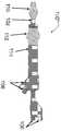
도 1a는 비제한적인 예시적 동심적 실린더 시스템(100)을 도시한다. 예시적인 동심적 실린더 시스템(100)은 내부 샤프트(102), 하나 이상의 내강을 포함하는 외부 샤프트(104), 외부 샤프트(104)의 하나 이상의 내강에 대한 연결부(106), 및 내부 샤프트(102)의 하나 이상의 내강에 대한 연결부(108)를 포함한다. 내부 샤프트의 근위 부분(109)이 또한 하나 이상의 내강을 포함할 수 있다. 예시적인 동심적 실린더 시스템(100)의 외부 실린더(104)는 조직 내강의 목표 구역의 근위 연부를 형성하는 한편, 내부 샤프트(102)는 외부 실린더(104)를 넘어서 연장되고 목표 구역의 원위 단부를 형성한다.FIG. 1A illustrates a non-limiting exemplary
도 1b의 비제한적인 예에 도시된 바와 같이, 동심적 실린더 시스템(100')은 또한 내부 샤프트(102)의 원위 단부에 배치된 전개 가능 또는 팽창 가능 구성요소(110)를 포함할 수 있다. 이러한 예에서, 전개 가능 또는 팽창 가능 구성요소(110)는 격리 풍선으로 도시되어 있다. 다른 예에서, 전개 가능 또는 팽창 가능 구성요소(110)는, 비제한적으로 전개 가능 네팅(netting)과 같이 조직 내강의 목표 구역을 경계 짓기 위해서 이용될 수 있는 당업계의 임의의 다른 기술, 또는 동심적 실린더 시스템(100')의 원위 단부에서 유체 유동을 감소 또는 방해하기 위해서 이용될 수 있는 임의의 다른 구성요소일 수 있다.As shown in the non-limiting example of FIG. 1B, the concentric cylinder system 100 'may also include a deployable or
도 1c의 비제한적인 예에 도시된 바와 같이, 동심적 실린더 시스템(100")은 또한 내부 샤프트(102)의 원위 단부에 근접 배치된 제1 전개 가능 또는 팽창 가능 구성요소(110), 및 외부 샤프트(104)의 원위 단부에 근접 배치된 제2 전개 가능 또는 팽창 가능 구성요소(112)를 포함할 수 있다. 제1 전개 가능 또는 팽창 가능 구성요소(110), 또는 제2 전개 가능 또는 팽창 가능 구성요소(112), 또는 그 둘 모두는, 비제한적으로 격리 풍선, 전개 가능 네팅, 또는 유체 유동을 감소 또는 방해하기 위해서 이용될 수 있는 임의의 다른 구성요소와 같이, 조직 내강의 목표 구역을 경계 짓기 위해서 이용될 수 있는 임의의 다른 기술일 수 있다.As shown in the non-limiting example of Figure 1C, the
본 개시 내용은, 동심적 실린더 시스템을 보조하는 예시적인 이펙터 전개 시스템을 제공한다. 이하에서 설명되는 바와 같이, 예시적인 이펙터 전개 시스템은, 그러한 시스템이 샤프트를 따를 수 있게 하는 장착 요소를 포함한다. 예를 들어, 장착 요소는, 동심적 실린더 시스템의 근위 샤프트 내측의 원위 풍선의 안내 와이어 또는 다른 샤프트를 따르게 될 수 있다. 예시적인 장착 요소는 본원의 보조 디바이스가 동심적 실린더 시스템과 동작적으로 조합될 수 있게 한다. 본원의 예시적인 보조 디바이스는, 조직 내강의 제어된 목표 구역 내의 희망 시술 또는 다른 동작을 수정 또는 개선하기 위해서 이용될 수 있는 이펙터 구성요소를 포함할 수 있다. 예시적인 이펙터 전개 시스템은 조작자가, 폐색 풍선 격리 시스템, 또는 동심적-실린더 시스템, 또는 다른 유사한 시스템을 이용하여 이펙터 구성요소를 적용함으로써 목표 구역으로서 경계 지어진 조직 내강의 부분 내에서 진단 시술 및/또는 치료 시술을 달성할 수 있게 한다. 다른 예에서, 이펙터 구성요소는, 경계 지어진 목표 구역 내의 치료 시술의 수정, 개선, 및/또는 보완이 적용될 수 있게 하는 부가적인 능력을 제공한다.The present disclosure provides an exemplary effector deployment system that assists concentric cylinder systems. As will be described below, an exemplary effector deployment system includes a mounting element that allows such a system to follow the shaft. For example, the mounting element may follow a guide wire or other shaft of a distal balloon inside the proximal shaft of the concentric cylinder system. Exemplary mounting elements allow the present auxiliary device to be operatively associated with a concentric cylinder system. An exemplary assistive device herein may include an effector component that may be utilized to modify or improve desired procedures or other operations within a controlled target area of tissue lumen. Exemplary effector deployment systems allow an operator to perform diagnostic procedures and / or procedures within the bounded tissue lumen as a target area by applying an effector component using an occlusion balloon isolation system, or a concentric-cylinder system, or other similar system Thereby achieving therapeutic treatment. In another example, the effector component provides additional capability to enable modification, enhancement, and / or supplementation of treatment procedures within the bounded target area.
도 2a는, 장착 요소(202) 및 적어도 하나의 이펙터 구성요소(204)를 포함하는 예시적인 이펙터 전개 시스템(200)을 도시한다.2A illustrates an exemplary
도 2b는 예시적인 동심적 실린더 시스템에 커플링된 예시적인 이펙터 전개 시스템(200)을 도시한다. 도 2b의 예에 도시된 바와 같이, 예시적인 이펙터 전개 시스템(200)의 장착 요소(202) 및 이펙터 구성요소(204)는 조직 내강의 목표 영역(208)에 근접 배치된 동심적 실린더 시스템의 내부 샤프트(206)의 부분에 커플링될 수 있다. 조직 내강의 전체 목표 구역은 격리 풍선들(210 및 212) 사이에서 경계 지어진다. 외부 샤프트(미도시)의 하나 이상의 내강에 대한 연결부(214) 및/또는 내부 샤프트(206)의 하나 이상의 내강에 대한 연결부(216)를 이용하여 조직 내강 내에서 시술을 실시할 수 있다.Figure 2B illustrates an exemplary
비제한적인 예로서, 이펙터 구성요소는, 조직 내강의 목표 구역 내에서 진단 또는 치료 시술, 또는 임의의 다른 유용한 행동을 실시하도록 구현될 수 있는 임의의 구성요소 또는 하위시스템일 수 있다. 여러 예시적인 이펙터 전개 시스템에서, 이펙터 구성요소는 "능동적" 구성요소 또는 "피동적" 구성요소일 수 있다. 본원에서 규정된 바와 같이, 피동적 이펙터 구성요소는, 조직 내강의 목표 구역에서 이펙터 전개 시스템을 배치하기 위해 필요한 힘 또는 에너지 보다 약간 더 큰 힘 또는 에너지를 이용하여 목표 구역 내에서 전개되거나 달리 동작될 수 있다. 대조적으로, 능동적 이펙터 구성요소는, 목표 구역 내외로 이펙터 전개 시스템을 이동시키는데 필요한 힘 및 링키지 외에도, 이펙터 전개 시스템이 목표 구역에 도달할 때 전개 또는 달리 동작시키기 위한 약간의 부가적인 양의 힘 또는 에너지를 필요로 한다.As a non-limiting example, the effector component may be any component or sub-system that may be implemented to perform diagnostic or therapeutic procedures, or any other useful behavior, within the targeted region of the lumen of tissue. In various exemplary effector deployment systems, an effector component may be a " active "component or a" passive "component. As defined herein, a passive effector component can be deployed or otherwise operated within a target area using a force or energy that is slightly greater than the force or energy required to position the effector deployment system in a target area of tissue lumen have. In contrast, the active effector component may include, in addition to the force and linkage necessary to move the effector deployment system into or out of the target area, some additional amount of force or energy to deploy or otherwise operate when the effector deployment system reaches the target area .
피동적 이펙터 구성요소의 비제한적인 예는 와이어 이펙터 구성요소의 나선, 메시 또는 네트워크, 교반 수단, 코일, 블레이드, 루프, 또는 약물 또는 약 전달 제형(formulation)을 포함한다. 약물 또는 약 제형은 피동적 이펙터 구성요소의 부분에서 벌크 구조물 또는 박막으로서 형성된 고체 재료일 수 있다. 약물 또는 약 제형은, 피동적 이펙터 구성요소가 조직의 목표 구역 내에 있을 때 활성제를 방출하기 위한 제형의 용해를 허용하는 피동적 이펙터 구성요소의 부분에 배치될 수 있다. 예시적인 피동적 이펙터 구성요소는 플라스틱, 금속, 또는 다른 재료로 형성될 수 있다. 나선형 이펙터 구성요소는, 목표 구역 내에서 액체를 교반하기 위해서(즉, 교반 수단으로서의 역할을 하기 위해서), 그에 의해서 목표 구역 내의 재료의 혼합을 개선하기 위해서, 목표 구역 내에서 전후로 이동될 수 있다. 교반 수단은, 목표 구역이 혈전을 포함하고 동심적 실린더 시스템이, 비제한적으로 우로키나제와 같은, 혈전 용해제를 목표 구역에 인가하기 위해서 이용되는 경우에 유리할 수 있다. 그러한 경우에, 혈전 및 혈전 용해제의 교반은 그 혼합을 개선할 수 있고 혈전 용해제에 의한 혈전 용해의 속도 또는 효율을 높이는데 도움을 줄 수 있다. 와이어 이펙터 구성요소의 예시적인 메시 또는 네트워크는, 혈전 내에 놓이도록 적절한 시간 기간 동안 혈전 내로 전진될 수 있다. 철수 시에, 피동적 이펙터 구성요소는 목표 구역의 외부로 혈전의 전부 또는 일부를 운송하거나 끌어낼 수 있고, 그에 의해서 피동적 혈전제거 시술을 실시할 수 있다.Non-limiting examples of passive effector components include spirals, meshes or networks of wire effector components, agitation means, coils, blades, loops, or drug or drug delivery formulations. The drug or drug formulation may be a solid material formed as a bulk structure or thin film in the portion of the passive effector component. The drug or drug formulation may be placed in the portion of the passive effector component that allows dissolution of the formulation to release the active agent when the passive effector component is within the target area of the tissue. Exemplary passive effector components may be formed of plastic, metal, or other materials. The helical effector component can be moved back and forth within the target area to improve the mixing of the material within the target area thereby to stir the liquid in the target area (i.e., to serve as a stirring means). Agitation means may be advantageous if the target region comprises thrombus and the concentric cylinder system is used to apply a thrombolytic agent to the target region, such as, but not limited to, a right kinase. In such cases, stirring of the thrombus and thrombolytic agent may improve its mixing and may help increase the rate or efficiency of thrombolytic thrombolysis. An exemplary mesh or network of wire effector components can be advanced into the thrombus for an appropriate period of time to be in the thrombus. Upon withdrawal, the passive effector component may transport or withdraw all or a portion of the thrombus out of the target area, thereby effecting a passive thrombus removal procedure.
능동적 이펙터 구성요소의 비제한적인 예는 팽창 가능 풍선 또는 성형된 팽창 가능 디바이스, 전개 가능 부재(네팅 또는 메시 포함), 약제 전달 모듈, 광학 구성요소, 초음파 구성요소, 전기 구성요소, 자기 구성요소, 유체 구성요소, 공압 구성요소, 화학적 구성요소, 기계적 구성요소, 약물 또는 약 전달 내강, 또는 목표 구역에서 조직 내강과 상호작용하는 다른 유사한 수단을 포함한다. 예에서, 펌프, 주사기, 또는 다른 구성요소를 이용하여 전달 내강을 통해 액체, 겔, 또는 다른 약물 또는 약 제형을 도입할 수 있다.Non-limiting examples of active effector components include inflatable balloons or molded inflatable devices, deployable members (including netting or mesh), drug delivery modules, optical components, ultrasonic components, electrical components, magnetic components, A fluid component, a pneumatic component, a chemical component, a mechanical component, a drug or drug delivery lumen, or other similar means of interacting with the tissue lumen in the target area. In an example, a pump, syringe, or other component can be used to introduce a liquid, gel, or other drug or drug formulation through the delivery lumen.
예에서, 팽창 가능 풍선은 또한 교반 수단 또는 능동적 혈전제거 수단으로서의 역할을 할 수 있다. 예시적인 전달 모듈은 플라스틱 관으로서 구성될 수 있고, 그러한 관은 원위 영역 위에 측면 포트를 포함하는 폐쇄 단부, 활성제를 포함하는 약물 또는 다른 혼합물이 내강의 근위 단부로부터 주입될 수 있고 목표 구역의 희망 영역으로 유출될 수 있도록 배열된 내부 내강을 갖는다.In the example, the inflatable balloon may also serve as agitation means or active thrombus removal means. An exemplary delivery module can be constructed as a plastic tube, which tube can be implanted from the proximal end of the lumen with a closed end comprising a lateral port over the distal region, a drug or other mixture comprising the active agent, As shown in Fig.
도 3a는, 공급기 링키지(305)의 원위 단부에 또는 그 부근에 커플링된 장착 요소(302)를 포함하는 다른 예시적인 이펙터 전개 시스템(300)을 도시한다.3A illustrates another exemplary
도 3b는 예시적인 동심적 실린더 시스템에 커플링된 예시적인 이펙터 전개 시스템(300)을 도시한다. 도 3b의 예에서 도시된 바와 같이, 장착 요소(302)는 예시적인 동심적 실린더 시스템의 내부 샤프트(306)의 근위 부분에 배치될 수 있다. 공급기 링키지(305)는, 장착 요소(302)를 조직 내강의 목표 구역의 목표 영역(308)의 근접부로 전진시키기 위해서 또는 그로부터 후퇴시키기 위해서 조작자가 장착 요소(302)를 내부 샤프트(306)를 따라 이동시킬 수 있도록 구성된다. 조직 내강의 전체 목표 구역은 격리 풍선들(310 및 312) 사이에서 경계 지어진다. 외부 샤프트(미도시)의 하나 이상의 내강에 대한 연결부(314) 및/또는 내부 샤프트(306)의 하나 이상의 내강에 대한 연결부(316)를 이용하여 조직 내강 내에서 시술을 실시할 수 있다.FIG. 3B illustrates an exemplary
도 3c는, 장착 요소(302)를 내부 샤프트(306)의 근위 부분으로부터 목표 구역 내에 배치된 예시적인 동심적 실린더 시스템의 원위 부분까지 전진시키기 위해서 이용된 공급기 링키지(305)의 결과로서, 예시적인 이펙터 전개 시스템(300)을 도시한다.Figure 3c shows an exemplary embodiment of the present invention as a result of the
도 4a는, 공급기 링키지(405)의 원위 단부에 또는 그 부근에 커플링된 장착 요소(402) 및 이펙터 구성요소(404)를 포함하는 다른 예시적인 이펙터 전개 시스템(400)을 도시한다.4A illustrates another exemplary
도 4b는 예시적인 동심적 실린더 시스템에 커플링된 예시적인 이펙터 전개 시스템(400)을 도시한다. 장착 요소(402) 및 이펙터 구성요소(404)는 내부 샤프트(406)의 원위 부분에 커플링되어 도시되어 있다. 공급기 링키지(405)는, 장착 요소(402) 및 이펙터 구성요소(404)를 조직 내강의 목표 구역의 목표 영역(408)의 근접부로 전진시키기 위해서 또는 그로부터 후퇴시키기 위해서 조작자가 장착 요소(402) 및 이펙터 구성요소(404)를 내부 샤프트(406)를 따라 이동시킬 수 있게 한다. 조직 내강의 전체 목표 구역은 격리 풍선들(410 및 412) 사이에서 경계 지어진다. 외부 샤프트(미도시)의 하나 이상의 내강에 대한 연결부(414) 및/또는 내부 샤프트(406)의 하나 이상의 내강에 대한 연결부(416)를 이용하여 조직 내강 내에서 시술을 실시할 수 있다.FIG. 4B illustrates an exemplary
예시적인 이펙터 전개 시스템에서, 피동적 이펙터 구성요소는, 동심적 실린더 시스템 또는 공급기 링키지의 샤프트의 이용을 통하는 것을 포함하여, 조직 내강의 목표 구역에서 이펙터 전개 시스템을 배치하기 위해서 요구되는 힘 또는 에너지 또는 그보다 약간 더 큰 힘 또는 에너지를 이용하여 목표 구역 내에서 전개되거나 달리 달성될 수 있다. 능동적 이펙터 구성요소는, 이펙터 전개 시스템이 목표 구역에 도달한 때, 전개 또는 달리 동작시키기 위해서 약간의 부가적인 양의 힘 또는 에너지를 필요로 할 수 있다. 예시적인 이펙터 전개 시스템은 부가적인 힘 또는 에너지를 능동적 이펙터 구성요소에 공급하기 위해서 적어도 하나의 부가적인 제어 연결부 구성요소를 더 포함한다.In an exemplary effector deployment system, the passive effector component may include a force or energy required to position the effector deployment system in a target area of tissue lumen, including through the use of a concentric cylinder system or shaft of the feeder linkage, May be developed or otherwise achieved within the target area using a slightly larger force or energy. The active effector component may require some additional amount of force or energy to deploy or otherwise operate when the effector deployment system reaches the target area. An exemplary effector deployment system further includes at least one additional control connection component for supplying additional force or energy to the active effector component.
예시적인 이펙터 전개 시스템에서, 하나 이상의 제어 연결부 구성요소가 능동적 이펙터 구성요소에 커플링되어 이펙터 구성요소를 작동시킬 수 있다. 예를 들어, 제어 연결부 구성요소는 공급기 링키지의 일체형 구성요소일 수 있고, 공급기 링키지에 커플링된 제2 구성요소일 수 있고, 또는 비제한적으로 제2 또는 제3 링키지와 같은, 공급기 링키지와 별개인 구성요소일 수 있다. 예를 들어, 제2 또는 제3 기계적 링키지가 작동되어, 바늘 또는 다른 구성요소를 전개시킴으로써 바늘 또는 다른 구성요소를 조직 내강에 대한 희망 위치에 배치할 수 있다. 하나 이상의 제어 연결부 구성요소를 이용하여, 동일 방향 또는 반대 방향으로 공급기 링키지에 힘을 인가할 수 있다. 예를 들어, 공급기 링키지가 장착 요소를 목표 구역을 향해 밀기 위해서 이용되는 경우에, 하나 이상의 제어 연결부 구성요소가 반대 방향으로 작동되어 이펙터 구성요소의 슬리브가 후퇴되게 함으로써 바늘 또는 다른 구성요소가 전개되게 할 수 있다.In an exemplary effector deployment system, one or more control connection components may be coupled to the active effector component to activate the effector component. For example, the control linkage component may be an integral component of the feeder linkage, and may be a second component coupled to the feeder linkage, or may include a feeder linkage, such as, but not limited to, a second or third linkage It can be a personal component. For example, a second or third mechanical linkage may be actuated to deploy the needle or other component to place the needle or other component in the desired location for the tissue lumen. One or more control linkage components may be used to apply force to the feeder linkage in the same or opposite direction. For example, when a feeder linkage is used to push a mounting element toward a target area, one or more control connector components may be actuated in the opposite direction to retract the sleeve of the effector component to cause the needle or other component to deploy can do.
예에서, 하나 이상의 제어 연결부 구성요소가 컴퓨팅 디바이스에 커플링될 수 있다. 컴퓨팅 디바이스의 하나 이상의 프로세싱 유닛은, 프로세서 실행 가능 명령어를 실행하여 하나 이상의 제어 연결부 구성요소가 이펙터 구성요소의 작동을 유발하도록 프로그래밍된다. 비제한적인 예로서, 프로세서 실행 가능 명령어의 실행을 기초로, 하나 이상의 제어 연결부 구성요소는 온도 변화, 전기 펄스의 인가, 광학 여기(optical excitation)의 인가, 초음파 임펄스의 생성, 내강을 통한 약물 또는 약 제형의 펌프, 또는 다른 활성화 또는 작동 수단을 사용하여 이펙터 구성요소를 작동시킬 수 있다.In the example, one or more control connection components may be coupled to the computing device. The one or more processing units of the computing device are programmed to execute processor executable instructions to cause one or more control connection components to trigger operation of the effector component. As a non-limiting example, based on the execution of processor executable instructions, one or more of the control connection components may be configured to perform various functions including, but not limited to, temperature changes, application of electrical pulses, application of optical excitation, generation of ultrasonic impulses, A pump of the drug formulation, or other activation or actuation means may be used to actuate the effector component.
도 3a, 도 3b, 도 3c, 도 4a 또는 도 4b 중 임의의 도면과 관련된 것을 포함하여, 본원의 임의의 예에서, 공급기 링키지가 다목적의 역할을 할 수 있다. 예에서, 공급기 링키지(405)는 이펙터 구성요소(404)를 유지하고 이펙터 구성요소(404)를 목표 구역의 내외로 전진시키기 위한 또는 장착 요소(402)를 목표 구역으로부터 내부 샤프트(406)의 근위 부분까지 후퇴시키기 위한 힘이 인가될 수 있게 하는 역할을 한다. 공급기 링키지(405)는 또한 그 원위 단부에서 또는 그 부근에서 이펙터 구성요소(404)에 커플링된다. 여러 예에서, 공급기 링키지(405)는 경직성 와이어, 마름모꼴 또는 가위형 링키지, 망원경식 라인, 또는 다른 일련의 강성 또는 반-강성 링크일 수 있다.In any of the examples herein, including in connection with any of the figures of Figures 3a, 3b, 3c, 4a or 4b, the feeder linkage can serve as a multipurpose. The
예시적인 이펙터 전개 시스템이 능동적 이펙터 구성요소를 포함하는 예에서, 공급기 링키지는, 능동적 이펙터 구성요소를 활성화 또는 작동시키는데 필요한, 및/또는 약제가 능동적 이펙터 구성요소에 의해서 분배되게 하는데 필요한 부가적인 에너지 또는 힘을 제공하기 위한 부가적인 구조물 또는 특징부를 포함할 수 있다. 그러한 부가적인 구조물 또는 특징부의 예는 내강, 부가적인 기계적 와이어, 광섬유, 전기 와이어, 유체 라인, 유압 라인, 공압 라인, 제어 아암, 또는 다른 활성화 수단을 포함한다. 비제한적인 예에서, 공급기 링키지는, 능동적 이펙터 구성요소를 전진 및 후퇴시키기 위한 풍선 팽창 내강을 가지는 샤프트를 포함할 수 있다. 다른 비제한적인 예에서, 공급기 링키지는 풍선 팽창 내강을 포함하는 가요성 샤프트를 밀고 당기기 위한 부가적인 와이어를 포함할 수 있다. 본원의 임의의 예에서, 공급기 링키지는, 원위 연결을 통해서 동심적 실린더 시스템의 원위 부분에서 구현될 수 있는, 능동적 이펙터 구성요소에 대한 지지 및 작동을 제공하기 위한 하나 이상의 능동적 수단을 포함할 수 있다.In an example where the example effector deployment system includes an active effector component, the feeder linkage may include additional energy necessary to activate or activate the active effector component and / or to allow the agent to be dispensed by the active effector component And may include additional features or features to provide force. Examples of such additional features or features include lumens, additional mechanical wires, optical fibers, electrical wires, fluid lines, hydraulic lines, pneumatic lines, control arms, or other activation means. In a non-limiting example, the feeder linkage may include a shaft having an inflatable lumen for advancing and retracting the active effector component. In another non-limiting example, the feeder linkage may include additional wires for pushing and pulling the flexible shaft including the balloon inflation lumen. In any of the examples herein, the feeder linkage may include one or more active means for providing support and operation for the active effector component, which may be implemented at the distal portion of the concentric cylinder system through a distal connection .
도 5는, 이중-요소 공급기 링키지(505-a, 505-b)의 원위 단부에 커플링된 장착 요소(502) 및 이펙터 구성요소(504)를 포함하는 비제한적인 예시적 이펙터 전개 시스템(500)을 도시한다. 이러한 예에서, 공급기 링키지 요소(505-a)는 장착 요소(502) 및 이펙터 구성요소(504)를 샤프트를 따라 전진 및 후퇴시키기 위해서 이용될 수 있고, 공급기 링키지 요소(505-b)는 이펙터 구성요소(504)에 대한 능동적 제어 및/또는 유체 접근을 제공하기 위한 능동적 수단으로서 이용될 수 있다. 비제한적인 예에서, 공급기 링키지 요소(505-b)는 내강, 부가적인 기계적 와이어, 광섬유, 전기 와이어, 유체 라인, 유압 라인, 공압 라인, 제어 아암, 또는 다른 활성화 수단을 포함할 수 있다.5 illustrates a non-limiting exemplary
도 2a, 도 2b, 도 3a, 도 3b, 도 3c, 도 4a 또는 도 4b 중 임의의 도면과 관련된 것을 포함한, 본원의 임의의 예에서, 장착 요소는 ("카트"로서 본원에서 지칭되는) 내부 샤프트로부터 제거 가능하도록 또는 (본원에서 "버스"로서 지칭되는) 내부 샤프트로부터 제거 가능하지 않도록 구성된다.In any of the examples herein, including in connection with any of the figures of Figures 2a, 2b, 3a, 3b, 3c, 4a or 4b, Is configured to be removable from the shaft or not removable from the inner shaft (referred to herein as the "bus").
본원의 임의의 예에서, 장착 요소의 내부 표면은 장착 요소의 적절한 기능을 가능하게 하는 재료로 형성되거나, 적어도 부분적으로 그러한 재료로 덮일 수 있다. 예를 들어, 재료는 바람직하게, 샤프트를 따른 장착 요소의 변위를 허용하기 위한, 그러나 또한 이펙터 구성요소의 사용 중에 장착 요소가 충분히 강한 샤프트의 파지를 인가하게 하기 위한, 동심적 실린더 시스템의 샤프트에 대한 충분한 양의 마찰을 제공한다.In any of the examples herein, the inner surface of the mounting element may be formed of, or at least partially covered by, a material that enables the proper functioning of the mounting element. For example, the material is preferably applied to the shaft of a concentric cylinder system to allow displacement of the mounting element along the shaft, but also to allow the mounting element to apply a grip of a shaft strong enough during use of the effector component Thereby providing a sufficient amount of friction.
도 6a는 카트(602)로서 구성된 장착 요소의 예를 도시한다. 예시적인 카트(602)는, 동심적 실린더 시스템에 대한 부착 수단으로서 샤프트(604)를 둘러싸는 (비제한적으로, 가지부와 같은) 하나 이상의 에워싸는 요소(603)를 포함한다. 명확성을 위해서, 샤프트(604)의 일부가 쇄선을 이용하여 도시되었다. 예시적인 에워싸는 요소(603)는, 카트(602)가 샤프트(604)를 따라 조직 내강의 목표 구역의 내외로 활주되거나 밀리는 동안, 카트(602)가 샤프트에 장착되어 유지될 수 있게 하고, 원하는 경우에 샤프트로부터 제거되게 할 수 있다. 예시적인 카트(602)가 제거 가능하다면, 카트(602)는 내부 샤프트의 근위 부분이 조직 내강 내의 제 위치에 있는 동안 동심적 실린더 시스템의 내부 샤프트의 원위 부분에 커플링될 수 있고, 목표 구역의 내외로 전진 및 철수될 수 있고, 그리고 또한 동심적 실린더 시스템을 조직 내강으로부터 제거할 필요가 없이 샤프트로부터 제거될 수 있다. 예시적인 이펙터 전개 시스템에서, 카트(602)는 공급기 링키지의 원위 단부에 장착될 수 있다.6A shows an example of a mounting element configured as a
도 6b는 카트(622)로서 구성된 장착 요소의 다른 예를 도시한다. 예시적인 카트(622)는, 동심적 실린더 시스템에 대한 부착 수단으로서 샤프트(624)를 둘러싸는 (비제한적으로 가지부(prong)와 같은) 에워싸는 요소(623-a, 623-b)를 포함한다. 명확성을 위해서, 샤프트(624)의 일부가 쇄선을 이용하여 도시되었다. 예시적인 에워싸는 요소(623-a, 623-b)는, 카트(622)가 샤프트(624)를 따라 조직 내강의 목표 구역의 내외로 활주되거나 밀리는 동안, 카트(622)가 샤프트에 장착되어 유지될 수 있게 하고, 원하는 경우에 샤프트로부터 제거되게 할 수 있다. 도 6a의 예와 유사하게, 카트(622)는 내부 샤프트의 근위 부분이 조직 내강 내의 제 위치에 있는 동안 동심적 실린더 시스템의 내부 샤프트의 원위 부분에 커플링될 수 있고, 목표 구역의 내외로 전진 및 철수될 수 있고, 그리고 또한 동심적 실린더 시스템을 조직 내강으로부터 제거할 필요가 없이 샤프트로부터 제거될 수 있다. 예시적인 이펙터 전개 시스템에서, 카트(622)는 공급기 링키지의 원위 단부에 장착될 수 있다.6B shows another example of a mounting element configured as a
도 6b에 도시된 바와 같이, 에워싸는 요소(623-a, 623-b)의 각각은, 예시적인 카트(622)가 샤프트(624)에 장착되고 그로부터 제거될 수 있게 하는 개구부 섹션(625-a, 625-b)을 포함한다. 도 6b의 예에서 도시된 바와 같이, 에워싸는 요소(623-a)의 개구부 섹션(625-a)은, 에워싸는 요소(623-b)의 개구부 섹션(625-b)에 비해서, 상이한 회전 위치에 있을 수 있다. 개구부 섹션(625-a 및 625-b)의 이러한 교번적인 정렬은, 힘이 인가되어 카트(622)가 목표 구역의 내외로 전진 또는 철수되게 하거나 임의의 이펙터 구성요소를 목표 구역 내에서 전개 또는 이용되게 할 때, 샤프트(624)로부터의 카트(622)의 의도하지 않은 디커플링을 방지할 수 있다.6B, each of the surrounding elements 623-a, 623-b includes an opening section 625-a, 622-b that allows the
도 6c는 버스(652)로서 구성된 장착 요소의 예를 도시한다. 예시적인 버스(652)는, 샤프트(654) 상에서 유지될 수 있고 버스를 조직 내강의 목표 구역 내외로의 전진 및 철수를 위해서 샤프트(654)를 따라서 활주되거나 밀릴 수 있는, 링, 실린더, 또는 다른 형태로 형성될 수 있다. 예시적인 이펙터 전개 시스템에서, 버스(652)는 공급기 링키지의 원위 단부에 커플링될 수 있다.6C shows an example of a mounting element configured as a
본원의 임의 예에서, 공급기 링키지는 하나 이상의 소켓 수단을 이용하여 장착 요소(즉, 카트 또는 버스)에 커플링될 수 있다. 예시적인 소켓 수단은, 공급기 링키지를 카트 또는 버스의 부분에 물리적으로 커플링시키기 위해서 커플링 또는 교합 메커니즘을 통해서 조합되는 둘 이상의 소켓 유닛으로서 형성될 수 있다. 예시적인 소켓 유닛은, 함께 교합되어 결합 구성을 형성하는, '좌측' 소켓 유닛 및 '우측' 소켓 유닛으로서, 또는 '근위' 소켓 유닛 및 '원위' 소켓 유닛으로서 형성될 수 있다. (밀거나 당기기 위한 힘을 포함하는) 힘이 소켓 유닛을 가로질러 공급기 링키지로부터 카트 또는 버스로 전달될 수 있도록 그리고 소켓 유닛이 분리되거나 달리 분해되지 않도록, 소켓 수단이 구성된다. 소켓 유닛들 사이의 커플링은 특정 커플링 과정을 이용하여 결합될 수 있고, 특정 디커플링 과정의 적용에 의해서 파괴되거나 디커플링될 수 있다. 유용한 힘을 전달하기 위해서 이용되는 동안을 포함한, 예시적인 이펙터 전개 시스템의 사용 절차 중에, 커플링 과정 및 디커플링 과정이 의도하지 않게 트리거링되지 않도록 예시적인 소켓 수단이 구성될 수 있다. 본원의 임의의 예에서, 소켓 수단은, 공급기 링키지와 카트 또는 버스 사이의 특정 기능을 구축하도록 구성된, 그리고 다양한 적용 가능한 커플링/디커플링 과정을 실시하도록 구성된, 임의 구성요소일 수 있다. 예를 들어, 소켓 수단은, 동심적 실린더 시스템의 근위 단부로부터 동심적 실린더 시스템의 원위 단부의 조직 내강의 목표 구역까지 내부 샤프트를 따라서 장착 요소를 활주시키기 위한 당김 또는 밀기 힘을 전달하도록 구성될 수 있다. 커플링/디커플링 과정의 비제한적인 예는, 비틀림, 나사산체결, 루프작업, 회전, 자기 커플링, 정전기 커플링, (후크-및-루프 체결부 또는 터치 체결부를 포함한) 기계적 커플링, 또는 커플링 및 디커플링의 화학적 수단을 기초로 하는 제어된 접착을 포함한다.In any of the examples herein, the feeder linkage may be coupled to the mounting element (i.e., cart or bus) using one or more socket means. Exemplary socket means may be formed as two or more socket units combined through a coupling or occlusal mechanism to physically couple the feeder linkage to a portion of the cart or bus. The exemplary socket unit may be formed as a 'left' socket unit and a 'right' socket unit, or as a 'proximal' socket unit and a 'distal' socket unit, which together mate to form a mating configuration. Socket means are configured such that forces (including forces to push or pull) can be transmitted from the feeder linkage across the socket unit to the cart or bus, and the socket unit is not separated or otherwise disassembled. Coupling between socket units can be combined using a specific coupling process and can be broken or decoupled by application of a particular decoupling process. During use procedures of the exemplary effector deployment system, including during use to deliver useful forces, exemplary socket means may be configured such that the coupling and decoupling processes are not inadvertently triggered. In any of the examples herein, the socket means may be any component configured to establish a particular function between the feeder linkage and the cart or bus, and configured to perform various applicable coupling / decoupling processes. For example, the socket means may be configured to transmit a pull or push force for sliding the mounting element along the inner shaft from the proximal end of the concentric cylinder system to the target section of the tissue lumen at the distal end of the concentric cylinder system have. Non-limiting examples of coupling / decoupling processes include torsion, threaded fastening, looping, rotation, magnetic coupling, electrostatic coupling, mechanical coupling (including hook-and-loop fastening or touch fastening) And controlled adhesion based on chemical means of ring and decoupling.
본원의 임의의 예에서, 소켓 수단은 또한, 적용 가능한 경우에 이펙터 활성화 제어의 전달을 포함한, 공급기 링키지와 능동적 이펙터 구성요소 사이의 희망 기능을 구축하도록 구성될 수 있다.In any of the examples herein, the socket means may also be configured to establish a desired function between the feeder linkage and the active effector component, including the delivery of the effector activation control, where applicable.
동심적 실린더 시스템의 원위 부분이 환자 내의 현장(in situ)에 배치되어 있는 동안, 동심적 실린더 시스템을 환자로부터 제거할 필요가 없이 그리고 구성요소를 안내와이어 상으로 나사체결할 필요가 없이, 본원의 예시적인 이펙터 전개 시스템의 기능이 변화될 수 있다.It is not necessary to remove the concentric cylinder system from the patient while the distal portion of the concentric cylinder system is deployed in situ within the patient and without having to screw the component onto the guidewire, The functionality of the exemplary effector deployment system may change.
이펙터 전개 시스템이 카트를 포함하는 예에서, 동심적 실린더 시스템의 내부 샤프트의 근위 부분에 카트가 커플링되기에 앞서서, 공급기 링키지를 카트에 커플링시키기 위해서 소켓 수단들이 결합될 수 있다. 이펙터 전개 시스템의 기능을 변화시키기 위해서, 카트가 내부 샤프트에 커플링되기에 앞서서, 공급기 링키지 및 이펙터 구성요소의 상이한 세트가 교체될 수 있고 소켓 수단을 통해서 동일한 카트(또는 상이한 카트)에 커플링될 수 있다.In an example in which the effect deployment system includes a cart, the socket means may be coupled to couple the feeder linkage to the cart prior to coupling the cart to the proximal portion of the inner shaft of the concentric cylinder system. To change the function of the effect deployment system, prior to coupling the cart to the inner shaft, a different set of feeder linkage and effector components can be replaced and coupled to the same cart (or different cart) .
이펙터 전개 시스템이 버스를 포함하는 임의 예에서, 동심적 실린더 시스템의 원위 부분이 환자 내의 현장에 배치되는 동안, 이펙터 전개 시스템의 기능이 변화될 수 있다. 버스가 내부 샤프트의 근위 부분에 배치될 때, 공급기 링키지 및 이펙터 구성요소의 상이한 세트가 교체될 수 있고 소켓 수단을 통해서 버스에 커플링될 수 있다.In any of the examples in which the effect deployment system includes a bus, the function of the effect deployment system can be changed while the distal portion of the concentric cylinder system is deployed in the patient's field. When the bus is placed in the proximal portion of the inner shaft, a different set of feeder linkage and effector components can be replaced and coupled to the bus through the socket means.
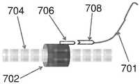
도 7a 내지 도 7c는, 공급기 링키지(701)를 샤프트(704)에 장착된 버스(702)에 커플링시키기 위해서 이용될 수 있는 비제한적인 예시적 소켓 수단을 도시한다.7A-7C illustrate non-limiting exemplary socket means that may be used to couple the
도 7a에 도시된 예시적인 소켓 수단은 원위 소켓 유닛(706) 및 근위 소켓 유닛(708)으로 형성된다. 근위 소켓 유닛(708)은 공급기 링키지(701)에 가역적으로 또는 비가역적으로 커플링될 수 있다. 원위 소켓 유닛(706)은 버스(702)에 가역적으로 또는 비가역적으로 커플링될 수 있다. 예시적인 소켓 수단의 원위 소켓 유닛(706)은 예시적인 소켓 수단의 근위 소켓 유닛(708)과 커플링되도록 구성된다. 일부 예에서, 원위 소켓 유닛(706)과 근위 소켓 유닛(708) 사이의 커플링 및 디커플링이 임의의 적용 가능한 커플링 및 디커플링 과정을 이용하여 가역적으로 결합될 수 있다. 다른 예에서, 소켓 수단은 원위 소켓 유닛(706)과 근위 소켓 유닛(708) 사이의 비가역적 부착을 위해서 구성될 수 있다. 원위 및 근위 소켓 유닛이 서로 비가역적으로 부착되는 예에서, 원위 소켓 유닛(706)은 버스(702)에 가역적으로 커플링될 수 있다.The exemplary socket means shown in FIG. 7A is formed with a
다른 예에서, 원위 소켓 유닛(706) 및 근위 소켓 유닛(708)은, 파괴적으로 가역적인 제거를 필요로 하는 방식으로 커플링될 수 있다. 예시적인 구현예에서, 근위 소켓 유닛(708)은, 파괴적인 수단을 이용하여서만, 예를 들어 절단 또는 파괴에 의해서만 원위 소켓 유닛(706)으로부터 분리될 수 있는 와이어 루프 또는 다른 유닛일 수 있다. 원위 소켓 유닛(706)은, 예를 들어, 절단된 또는 달리 파괴된 근위 소켓 유닛(708)의 상이한 섹션을 이용하여, 또는 전체적으로 상이한 근위 소켓 유닛(708)을 이용하여 재-사용될 수 있다. 다른 예시적인 구현예에서, 비가역적인 파괴적 수단을 이용하여, 예를 들어 절단 또는 파괴 모두에 의해서, 근위 소켓 유닛(708) 및 원위 소켓 유닛(706) 모두가 제거될 수 있다.In another example,
도 7b에 도시된 예시적인 소켓 수단은 원위 소켓 유닛(706') 및 근위 소켓 유닛(708')으로 형성된다. 이러한 비제한적인 예에서, 원위 소켓 유닛(706')은 루프 부착부로서 형성되고, 근위 소켓 유닛(708')은 후크 부착부로서 형성된다. 루프 부착부(원위 소켓 유닛(706'))와 후크 부착부(근위 소켓 유닛(708')) 사이의 커플링 및 디커플링이 임의의 적용 가능한 커플링 및 디커플링 기술을 이용하여 결합될 수 있다.The exemplary socket means shown in FIG. 7B is formed with a distal socket unit 706 'and a proximal socket unit 708'. In this non-limiting example, the distal socket unit 706 'is formed as a loop attachment, and the proximal socket unit 708' is formed as a hook attachment. Coupling and decoupling between the loop attachment (distal socket unit 706 ') and the hook attachment (proximal socket unit 708') can be combined using any applicable coupling and decoupling technique.
도 7c의 예에 도시된 바와 같이, 원위 소켓 유닛(706)을 근위 소켓 유닛(708)에 커플링하기에 앞서서, 이펙터 구성요소(710)가 근위 소켓 유닛(708) 뒤에서 공급기 링키지(701)에 커플링될 수 있다. 다른 예에서, 이펙터 구성요소(710)가 공급기 링키지(701)에 장착되기에 앞서서, 원위 소켓 유닛(706) 및 근위 소켓 유닛(708)을 이용하여 공급기 링키지(701)를 버스(702)에 커플링할 수 있다. 본원의 임의의 예에서, 소켓 수단은 또한 이펙터 활성화 제어의 전달을 포함한, 공급기 링키지(701)와 능동적 이펙터 구성요소(710) 사이의 희망 기능을 유지하도록 구성될 수 있다.Prior to coupling the
도 7d는, 공급기 링키지(701)를 샤프트(704)에 장착된 버스(702)에 커플링하기 위해서, 소켓 수단의 소켓 유닛(706 및 708)을 부착 또는 탈착하기 위해서 이용될 수 있는 비제한적인 예시적 소켓 애플리케이터(712)를 도시한다. 동작 시에, 소켓 애플리케이터(712)를 이용하여 소켓 유닛(706 및 708)을 가역적 또는 비가역적으로 커플링할 수 있다. 예에서, 열적 수단, 화학적 수단, 전기화학적 수단, 기계적 수단, 또는 임의의 다른 적용 가능한 수단을 통해서 소켓 유닛(706 및 708)을 커플링시키기 위해서 소켓 애플리케이터(712)가 이용될 수 있다.7D illustrates a non-limiting example of a
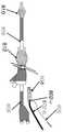
도 8a 내지 도 8d는, (커플링 부분(802-a) 및 핸들(802-b)을 가지는) 애플리케이터, 카트(804), 및 공급기 링키지(806)를 포함하는 비제한적인 예시적 이펙터 전개 시스템을 도시한다. 카트(804)가 사용 중에 제 위치에서 유지하기에 충분한 힘으로 내부 샤프트(808)를 파지하도록, 애플리케이터의 커플링 부분(802-a)은 카트(804)를 예시적인 동심적 실린더 시스템의 내부 샤프트(808)의 근위 부분에 장착하도록 구성된다. 핸들(802-b)은, 카트(804)의 용이한 적용을 허용하는 임의 형상으로 구성될 수 있다. 도 8a에 도시된 바와 같이, 애플리케이터의 핸들(802-b)은 카트(804)를 내부 샤프트(808)의 근위 부분에 근접시키기 위해서 이용될 수 있다. 도 8b에 도시된 바와 같이, 애플리케이터의 커플링 부분(802-a)을 이용하여 카트(804)를 내부 샤프트(808) 상에 배치할 수 있다.8A-8D illustrate a non-limiting exemplary effector deployment system (not shown) that includes an applicator (with coupling portion 802-a and handle 802-b), a
본원의 예시적인 애플리케이터를 이용하여 카트(804)를 개방하거나 개방 위치에서 유지할 수 있고, 그에 따라 카트가 내부 샤프트(808) 상에 더 용이하게 배치될 수 있다. 애플리케이터의 철수 시에, 본원에서 설명된 바와 같이 동작될 수 있도록, 카트(804)는 충분히 강하게 유지되어 내부 샤프트(808)에 커플링된다. 예를 들어, 카트(804)는, 카트(804)의 의도된 사용 경우의 부하 힘 하에서 디커플링되지 않고, 내부 샤프트(808)를 따라 원위 또는 근위 방향으로 밀릴 수 있거나 당겨질 수 있다.The
도 8c 및 도 8d에 도시된 바와 같이, 카트(804)가 커플링 부분(802-a)을 벗어나 내부 샤프트(808)의 근위 부분 상으로 활주될 수 있도록, 그에 따라 내부 샤프트(808) 상의 제 위치에 장착된 카트(804)를 남기도록, 애플리케이터가 구성된다.As shown in Figures 8c and 8d, the
애플리케이터가 제거되면, 공급기 링키지(806)를 이용하여 카트(304)를 내부 샤프트(808)의 근위 부분으로부터 예시적인 동심적 실린더 시스템의 원위 부분까지, 예를 들어 (도 8a 및 도 8b에 도시된) 원위 격리 풍선(810)과 근위 격리 풍선(812) 사이에 경계 지어진 목표 구역 내로 전진시킬 수 있다.When the applicator is removed, the
도 8a 내지 도 8d에 따른 이펙터 전개 시스템 예에서, 애플리케이터가 카트(804)를 내부 샤프트에 커플링시키기 위해서 이용되기에 앞서서, 또는 카트(804)가 내부 샤프트에 커플링된 후에, 이펙터 구성요소가 공급기 링키지 및/또는 카트(804)에 커플링될 수 있다.In the example of an effect deployment system according to Figs. 8a-8d, before the applicator is used to couple
도 9a는 전술한 예시적인 카트와 함께 이용될 수 있는 비제한적인 예시적 애플리케이터(900)를 도시한다. 예시적인 애플리케이터(900)는, 예시적인 카트에 커플링되는 커플링 부분(902) 및 샤프트에 대한 카트의 커플링을 보조하기 위해서 이용될 수 있는 연장부(904)를 포함한다.Figure 9A illustrates a non-limiting
도 9b는, 동심적 실린더 시스템의 예시적인 샤프트(906)에 장착된, 예시적인 애플리케이터의 커플링 부분(902)의 횡단면을 도시한다. 커플링 부분(902)의 중공형 내부 부분의 폭(di)은 샤프트(906)의 직경에 근접한다. 카트의 에워싸는 요소의 분리 및 확전(spreading)을 유발함으로써 이펙터 전개 시스템의 카트를 동심적 실린더 시스템의 샤프트에 커플링시키는 것을 보조하도록, 커플링 부분(902)의 외경(do)이 충분히 넓게 만들어질 수 있다. 예를 들어, 커플링 부분(902)은 카트의 에워싸는 요소가 분리되게 하는 외경(do)을 가지도록 만들어질 수 있고 동심적 실린더 시스템의 샤프트에 대한 더 용이한 커플링을 허용할 수 있다. 예에서, 애플리케이터의 외경(do)은 카트의 에워싸는 요소의 둘레에 근접할 수 있다.Figure 9B shows a cross-section of the
도 9c는 연장부(904)와 커플링 부분(902) 사이의 예시적인 애플리케이터의 섹션(908)의 확대된 화상을 도시한다. 도 9c의 예시적인 애플리케이터에서, 측방향 폭은 연장부(904)의 측방향 치수로부터 커플링 부분(902)의 외경(do)까지 점진적으로 증가된다. (비제한적으로 가지부 또는 다른 분리 가능 커플링 부재와 같은) 에워싸는 요소를 포함하는 예시적인 카트의 제거를 위해서, 애플리케이터의 섹션(908)의 점진적으로 증가되는 폭을 이용하여 가지부(또는 다른 분리 가능 커플링 부재)를 동심적 실린더 시스템의 샤프트로부터 점진적으로 분리할 수 있다.9C shows an enlarged view of an
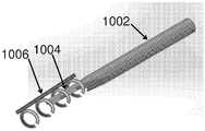
도 10a 및 도 10b는 카트(1006)를 예시적인 동심적 실린더 시스템의 샤프트로부터 커플링하기 위한 (커플링 부분(1002) 및 연장부(1004)를 가지는) 예시적인 애플리케이터의 사용을 도시한다. 도 10a에 도시된 바와 같이, 연장부(1004)는, 카트(1006)의 에워싸는 요소와 예시적인 동심적 실린더 시스템의 샤프트(미도시) 사이에 삽입될 수 있도록, 그 크기가 결정된다. 도 9c와 관련하여 설명된 바와 같이, 커플링 부분(1002)과 연장부(1004) 사이의 섹션의 치수를 점진적으로 증가시키는 것은, 카트(1006)의 (비제한적으로 가지부 또는 다른 분리 가능 커플링 부재와 같은) 에워싸는 요소의 점진적인 분리를 유발한다. 도 10b에 도시된 바와 같이, 카트(1006)의 에워싸는 요소는, 카트(1006)가 애플리케이터의 커플링 부분(1002) 상에 장착되는 지점에서 실질적으로 분리된다. 동작 시에, 도 10a 및 도 10b의 과정을 실시하여 카트(1006)를 애플리케이터의 커플링 부분(1002)에 장착할 수 있다. 샤프트에 근접 배치된 애플리케이터의 연장부(1004)로, 카트(1006)가 애플리케이터의 커플링 부분(1002)으로부터 연장부(1004)를 향해서 밀릴 수 있다. 이러한 역방향으로, 커플링 부분(1002)과 연장부(1004) 사이의 섹션의 점진적으로 감소되는 치수는 카트(1006)의 (가지부 또는 다른 분리 가능 커플링 부재를 포함하는) 에워싸는 요소가 동심적 실린더 시스템의 샤프트를 파지하게 한다.10A and 10B illustrate the use of an exemplary applicator (
도 10a 및 도 10b에 도시된 바와 같이, 예시적인 애플리케이터는 또한, 카트가 애플리케이터에 커플링되는 경우에 에워싸는 요소가 휴지 상태가 될 수 있게 하는, 비제한적으로 플랜지, 단편, 노치 또는 다른 특징부와 같은, 하나 이상의 장착 특징부(1008)를 포함할 수 있다.As shown in FIGS. 10A and 10B, the exemplary applicator may also include, without limitation, a flange, piece, notch, or other feature that allows the surrounding element to be in a rest state when the cart is coupled to the applicator And may include one or more mounting features 1008, such as the same.
전술한 바와 같이, 본원의 원리에 따른 예시적인 이펙터 전개 시스템은 장착 요소, 공급기 링키지, 및 이펙터 구성요소 중 둘 이상을 포함할 수 있다. 예시적인 이펙터 전개 시스템을 이용하여, 기본적인 동심적 실린더 시스템의 적어도 일부가 환자 내에서 전개되는 동안, 기본적인 동심적 실린더 시스템에 의해서 구축되는 목표 구역 내로 이펙터 수단을 가져갈 수 있다. 예시적인 이펙터 전개 시스템은 또한 기본적인 동심적 실린더 시스템을 제거하지 않고 장착 요소 및 이펙터 구성요소를 철수시키기 위해서 구성될 수 있다. 임의의 하나의 과정 또는 다수의 과정 중에, 하나 이상의 이펙터 전개 시스템을 이용하여 유사한 또는 상이한 이펙터 구성요소의 시퀀스를 목표 구역으로 가져갈 수 있고 희망에 따라 이펙터 구성요소를 구현할 수 있다는 것이 당업자에게 자명할 것이다.As discussed above, exemplary effector deployment systems in accordance with the principles herein may include two or more of a mounting element, a feeder linkage, and an effector component. An exemplary effect deployment system may be used to take effector means into a target area established by a basic concentric cylinder system while at least a portion of the basic concentric cylinder system is deployed in the patient. Exemplary effector deployment systems may also be configured to evacuate the mounting elements and effector components without removing the basic concentric cylinder system. It will be apparent to those skilled in the art that during any one or more of the processes, one or more effector deployment systems may be used to take a sequence of similar or different effector components to a target area and implement the effector components as desired .
도 11a의 (i) 내지 도 11c의 (iv)는, 예시적인 애플리케이터를 이용하여 예시적인 이펙터 전개 시스템을 동심적 실린더 시스템의 샤프트에 커플링하기 위한 예시적인 프로세스 흐름을 도시한다.Figures 11 (a) - (c) (iv) illustrate an exemplary process flow for coupling an exemplary effector deployment system to a shaft of a concentric cylinder system using an exemplary applicator.
도 11a의 (i) 내지 도 11a의 (iii)는 카트(1100)를 (커플링 부분(1102) 및 연장부(1104)를 가지는) 애플리케이터에 장착하기 위한 예시적인 카트-애플리케이터 조립 과정을 도시한다. 도 11a의 (i)에 도시된 바와 같이, 카트(1100)는 복수의 에워싸는 요소(1101)를 포함한다. 예시적인 카트-애플리케이터 조립 과정에서, 도 11a의 (ii)에 도시된 적용예의 연장부(1104)가 카트(1100)의 에워싸는 요소들 사이에 삽입된다. 도 9c와 관련하여 설명된 것과 유사하게, 커플링 부분(1102)과 연장부(1104) 사이의 애플리케이터의 섹션의 점진적으로 증가되는 치수는, 애플리케이터가 에워싸는 요소(1101)를 통해서 전진될 때, 카트(1100)의 에워싸는 요소(1101)의 점진적인 분리를 유발한다. 도 11a의 (iii)에 또한 도시된 바와 같이, 카트(1100)의 에워싸는 요소(1101)는, 카트(1100)가 애플리케이터의 커플링 부분(1102) 상에 장착되는 지점에서 실질적으로 분리된다.11A through 11A (iii) illustrate an exemplary cart-applicator assembly process for mounting
도 11b에 도시된 바와 같이, 카트가 장착된 예시적인 애플리케이터가 동심적 실린더 시스템의 샤프트(1110)의 근위 부분에 배치될 수 있고, 그에 따라 애플리케이터의 연장 부분(1104)이 동심적 실린더 시스템의 원위 부분을 향해서 지향된다.As shown in FIG. 11B, an exemplary applicator with a cart can be disposed in the proximal portion of the
도 11c의 (i) 내지 도 11c의 (iv)는, 카트(1100)를 예시적인 동심적 실린더 시스템의 샤프트(1110)에 커플링하기 위한, 예시적인 카트 배치 과정을 도시한다. 도 11c의 (ii)는 도 11c의(i)의 선 A―A'를 따른 횡단면도를 도시하여, 애플리케이터의 원위 부분(1102) 상에 배치된 카트(1100)를 보여주고, 애플리케이터는 동심적 실린더 시스템의 샤프트(1110) 상에 배치된다. 도 11c의(i)에 도시된 바와 같이, 애플리케이터의 연장부(1104)가 샤프트(1110)에 근접 배치된 상태에서, 에워싸는 요소(1101)를 애플리케이터의 커플링 부분(1102)으로부터 연장부(1004)를 향해서 이동시키기 위해서, 카트(1100)를 원위 방향으로 밀고, 애플리케이터를 근위 방향으로 당긴다. 이러한 예에서, 커플링 부분(1102)과 연장부(1104) 사이의 섹션의 점진적으로 감소되는 치수는 카트(1100)의 에워싸는 요소(1101)가 동심적 실린더 시스템의 샤프트(1110)를 파지하게 한다. 도 11c의 (iii)는 과정의 중간 스테이지를 도시하고, 여기에서 에워싸는 부재(1101)의 일부는 샤프트(1110)를 파지하는 한편, 다른 부분은 애플리케이터의 원위 부분(1102)에 겨냥되어(minted) 유지된다. 도 11c의 (iv)는 도 11c의 (iii)의 선 B―B'를 따른 횡단면도를 도시하여, 동심적 실린더 시스템의 샤프트(1110) 상에 배치되고 파지하는 카트(1100)의 에워싸는 요소(1101)를 보여준다. 애플리케이터의 완전 철수 상태에서, 카트(1100)의 에워싸는 요소(1101)의 전부가 샤프트(1110)를 에워싸고 파지한다. 이러한 방식으로, 애플리케이터는 카트를 동심적 실린더 시스템의 샤프트에 커플링하는 것을 달성한다.Figures 11C-11C illustrate an exemplary cart placement process for
요약하면, 본 개시 내용은, 이펙터 구성요소(들)이 내부 샤프트를 따라서 목표 구역 내로 밀려 날 수 있는 방식으로, 하나 이상의 이펙터 구성요소가 동심적 실린더 시스템의 내부 샤프트에 용이하게 커플링될 수 있는 능력을 가지고 구성된 예시적인 이펙터 전개 시스템을 제공한다. 하나 이상의 이펙터 구성요소가 목표 구역에 도달할 때, 예시적인 이펙터 전개 시스템은, 기본적인 동심적 실린더 시스템에 의해서 인가되는 치료를 수정, 개선 또는 보완하는 기능을 실시하기 위해서 목표 구역 내의 조직 내강과 상호작용할 수 있는 능력을 조작자에게 제공한다. 일부 예에서, 예시적인 이펙터 전개 시스템은 예시적인 이펙터 전개 시스템의 일부 구성요소를 동심적 실린더 시스템의 샤프트에 용이하게 적용하기 위한 상보적 애플리케이터 구성요소를 포함한다.In summary, the present disclosure is directed to a system and method that allows one or more effector components to be easily coupled to the inner shaft of a concentric cylinder system, such that the effector element (s) can be pushed into the target area along the inner shaft Lt; RTI ID = 0.0 > and / or < / RTI > capabilities. When one or more effector components reach the target area, the exemplary effector deployment system will interact with the tissue lumen in the target area to perform the function of modifying, improving or supplementing the therapy applied by the basic concentric cylinder system To the operator. In some instances, an exemplary effector deployment system includes complementary applicator components for facilitating application of some of the components of an exemplary effector deployment system to a shaft of a concentric cylinder system.
결론conclusion
다양한 본 발명의 실시예를 본원에서 설명하고 도시하였지만, 당업자는 본원에서 설명된 기능을 실시하기 위한 및/또는 결과 및/또는 하나 이상의 장점을 획득하기 위한 다양한 다른 수단 및/또는 구조를 용이하게 생각할 수 있을 것이고, 그러한 변경 및/또는 수정의 각각은 본원에서 설명된 본 발명의 실시예의 범위 내에 있는 것으로 간주된다. 보다 일반적으로, 당업자는, 본원에서 설명된 모든 매개변수, 치수, 재료, 및 구성이 예시적인 것으로서 의미된다는 것 그리고 실제의 매개변수, 치수, 재료 및/또는 구성이, 본 발명의 교시 내용이 이용되는 특정의 적용예 또는 적용예들에 따라서 달라질 것임을 용이하게 이해할 수 있을 것이다. 당업자는, 단지 일상적인 실험을 이용하여, 본원에서 설명된 특정의 발명적인 실시예에 대한 많은 균등물을 인지하거나 알아낼 수 있을 것이다. 그에 따라, 전술한 실시예가 단지 예로서 제시된 것이고, 첨부된 청구항 및 그 균등물의 범위 내에서, 본 발명의 실시예가 구체적으로 설명된 것과 달리 실행될 수 있다는 것을 이해할 수 있을 것이다. 본 개시 내용의 발명에 따른 실시예는 본원에서 설명된 각각의 개별적인 특징부, 시스템, 물품, 재료, 키트, 및/또는 방법에 관한 것이다. 또한, 둘 이상의 그러한 특징부, 시스템, 물품, 재료, 키트, 및/또는 방법의 임의 조합은, 그러한 특징부, 시스템, 물품, 재료, 키트, 및/또는 방법이 상호 불일치되지 않는다면, 본 개시 내용의 본 발명의 범위 내에 포함된다.While various embodiments of the present invention have been illustrated and described herein, those skilled in the art will readily appreciate that various other means and / or structures for implementing the functions described herein and / or for obtaining results and / or one or more advantages And each such modification and / or modification is deemed to be within the scope of the embodiments of the invention described herein. More generally, those skilled in the art will recognize that all parameters, dimensions, materials, and configurations described herein are meant to be exemplary and that actual parameters, dimensions, materials and / or configurations may be used, It will be readily understood that the invention will vary depending upon the particular application or application being employed. Those skilled in the art will recognize, or be able to ascertain using no more than routine experimentation, many equivalents to the specific inventive embodiments described herein. Accordingly, it is to be understood that the foregoing embodiments are presented by way of example only, and that within the scope of the appended claims and their equivalents, the embodiments of the invention may be practiced otherwise than as specifically described. The embodiments according to the present disclosure relate to each individual feature, system, article, material, kit, and / or method described herein. It should also be understood that any combination of two or more such features, systems, articles, materials, kits, and / or methods is intended to cover in the appended claims unless such features, systems, articles, materials, kits, and / Are included within the scope of the present invention.
본 발명의 전술한 실시예가 임의의 다양한 방식으로 구현될 수 있다. 예를 들어, (사용자-개시된 기계적 조작을 돕기 위한 컴퓨터-제어형 모터와 같은) 구현예의 일부 양태가 하드웨어, 소프트웨어, 또는 그 조합을 이용하여 구현될 수 있다. 실시예의 임의 양태가 적어도 부분적으로 소프트웨어로 구현될 때, 소프트웨어 코드가, 단일 컴퓨터 내에 제공되든지 또는 다수의 컴퓨터 사이에 분산되든지 간에, 임의의 적합한 프로세서 또는 프로세서들의 집합체 상에서 실시될 수 있다.The above-described embodiments of the present invention can be implemented in any of various ways. For example, some aspects of an implementation (such as a computer-controlled motor to assist a user-initiated mechanical operation) may be implemented using hardware, software, or a combination thereof. When any aspect of an embodiment is at least partially implemented in software, the software code may be implemented on any suitable processor or collection of processors, whether provided in a single computer or distributed among multiple computers.
"프로그램" 또는 "소프트웨어"라는 용어는, 전술한 바와 같은 본 기술의 다양한 양태를 구현하도록 컴퓨터 또는 다른 프로세서를 프로그래밍하는데 사용될 수 있는 임의의 유형의 컴퓨터 코드 또는 컴퓨터-실행 가능 명령어의 세트를 지칭하는 일반적인 의미로 여기에서 사용된다.The term "program" or "software" refers to any type of computer code or computer-executable instruction set that can be used to implement a computer or other processor to implement various aspects of the technology as described above It is used here in a general sense.
또한, 본원에서 설명된 기술은, 적어도 하나의 예가 제공된 방법으로서 구현될 수 있다. 방법의 일부로 수행되는 행위들이 임의의 적절한 방법으로 순서화될 수 있다. 따라서, 예시적인 실시예에서 순차적인 작용으로 도시되어 있지만, 동시적으로 일부 작용들을 실시하는 것을 포함할 수 있는, 도시된 것과 상이한 순서로 동작이 실시되는 실시예가 구성될 수 있다.Further, the techniques described herein may be implemented as a method in which at least one example is provided. Actions performed as part of the method may be ordered in any suitable manner. Thus, although illustrated in sequential operation in the exemplary embodiment, an embodiment may be constructed in which operations are performed in a different order than what is shown, which may include performing some actions simultaneously.
본원에서 규정되고 사용된 모든 정의는 사전적인 정의, 참조로 포함된 문헌에서의 정의 및/또는 규정된 용어의 통상적인 의미에 우선한다는 것을 이해하여야 할 것이다.It is to be understood that all definitions set forth and used herein supersede the prior definitions, definitions in the incorporated references and / or the ordinary meanings of the defined terms.
본원의 명세서 및 청구범위에서 사용된 바와 같은 부정관사("a" 및 "an")는, 반대로 명시적으로 표시되지 않는 한, "적어도 하나"를 의미하는 것으로 이해되어야 한다.As used in the specification and claims, " a "and" an ", as used herein, should be understood to mean "at least one ", unless the context clearly dictates otherwise.
본원의 명세서 및 청구범위에서 사용된 바와 같은 "및/또는"이라는 문구는, 그렇게 결합된 요소, 즉 일부 경우에 결합적으로 존재하고 다른 경우에 분리적으로 존재하는 요소의 "어느 하나 또는 양자 모두"를 의미하는 것으로 이해하여야 한다. "및/또는"으로 나열된 복수의 요소는 동일한 양식으로, 즉 그렇게 결합된 요소의 "하나 이상"으로 해석되어야 한다. "및/또는" 문구에 의해서 구체적으로 식별된 요소 이외의 다른 요소가, 구체적으로 식별된 요소와 관련되거나 관련되지 않든 간에, 선택적으로 존재할 수 있을 것이다. 그에 따라, 비제한적인 예로서, "A 및/또는 B"에 대한 언급은, "포함하는"과 같은 개방형(open-ended) 언어와 함께 사용될 때, 일 실시예에서, A 만을(선택적으로 B 이외의 요소를 포함한다) 지칭할 수 있고; 다른 실시예에서 B 만을(선택적으로 A 이외의 요소를 포함한다) 지칭할 수 있으며; 또 다른 실시예에서 A 및 B 모두(선택적으로 다른 요소를 포함한다); 등을 지칭할 수 있다.The phrase "and / or" as used herein in the specification and in the claims is intended to cover such integrated elements, that is, either or both of the elements, which in some cases are present in combination and in other cases are present in isolation "Should be understood as meaning. Multiple elements listed as "and / or" should be interpreted in the same manner, i.e., "one or more" Elements other than those specifically identified by the phrase "and / or ", whether or not related to the specifically identified element, may optionally be present. Thus, as a non-limiting example, reference to "A and / or B ", when used in conjunction with an open-ended language such as" Other < / RTI >elements); In another embodiment B alone (optionally including elements other than A); In yet another embodiment, both A and B (optionally including other elements); And so on.
본원의 명세서 및 청구 범위에서 사용된 바와 같이, "또는"은 앞서서 정의된 바와 같은 "및/또는"과 동일한 의미를 갖는 것으로 이해되어야 한다. 예를 들어, 목록에서 항목들을 분리할 때, "또는"이나 "및/또는"은 포괄적인 것으로, 즉, 많은 수의 요소 또는 요소의 목록 중, 그리고 선택적으로, 부가적으로 목록화되지 않은 항목 중 적어도 하나를, 그러나 하나 초과도 포함함, 포함하는 것으로 해석되어야 한다. "오직 하나"또는 "정확히 하나", 또는 청구범위에서 사용될 때, "~로 이루어진"과 같이 반대로 명확하게 표시된 용어들만이, 많은 수의 요소 또는 요소의 목록 중 정확히 하나의 요소의 포함을 지칭할 것이다. 일반적으로, 본원에서 사용된 바와 같은 "또는"이라는 용어는, "어느 하나", "~ 중 하나", "~ 중 단 하나", 또는 "~ 중 정확히 하나"와 같은, 배타성을 나타내는 용어가 선행될 때, 배타적인 택일적인 것(exclusive alternative)(즉, "둘 모두가 아닌, 둘 중 하나 또는 다른 하나")을 나타내는 것으로만 해석되어야한다. 청구범위에서 사용되는 경우, "~로 본질적으로 이루어진"은 특허법 분야에서 사용되는 통상적으로 의미를 가질 것이다.As used herein and in the specification and claims, "or" should be understood to have the same meaning as "and / or" as defined above. For example, "or" and / or "when separating items from a list are inclusive, i.e., in a list of a large number of elements or elements, and optionally, At least one of, but more than one of. When used in the context of "only one" or "exactly one ", or in the claims, the words clearly marked as such, such as " consisting of" refer to the inclusion of exactly one element in the list of a large number of elements or elements will be. In general, the term "or" as used herein is intended to encompass a term that refers to an exclusivity, such as "any one," "one of," " It should be construed as indicating an exclusive alternative (ie, "one or both, but not both"). As used in the claims, "consisting essentially of" will have its usual meaning as used in the patent law field.
본원의 명세서 및 청구범위에서 사용된 바와 같이, 하나 이상의 요소의 목록에 대한 언급에서 "적어도 하나"라는 문구는 요소의 목록 내의 임의의 하나 이상의 요소로부터 선택된 적어도 하나의 요소를 의미하는 것으로, 그러나 요소의 목록 내에 구체적으로 나열된 각각의 그리고 모든 요소의 적어도 하나를 반드시 포함하여야 하는 것이 아니고 요소의 목록 내의 요소의 임의 조합을 배제하는 것이 아님을 이해하여야 한다. 이러한 규정은 또한, 요소가, 구체적으로 식별된 해당 요소와 관련되든지 또는 관련되지 않든지 간에, "적어도 하나의"라는 문구가 인용된 요소의 목록 내에서 구체적으로 식별된 요소 이외로 선택적으로 존재할 수 있는 것을 허용한다. 그에 따라, 비제한적인 예로서, "A 및 B 중 적어도 하나"(또는, 균등하게, "A 또는 B 중 적어도 하나" 또는, 균등하게 "A 및/또는 B 중 적어도 하나")가, 일 실시예에서, 선택적으로 하나 초과의 A를 포함하고, B는 존재하지 않는(그리고 선택적으로 B 이외의 요소를 포함하는), 적어도 하나를 지칭할 수 있고; 다른 실시예에서, 선택적으로 하나 초과의 B를 포함하고, A는 존재하지 않는(그리고 선택적으로 A 이외의 요소를 포함하는), 적어도 하나를 지칭할 수 있고; 또 다른 실시예에서, (선택적으로 다른 요소를 포함하는), 선택적으로 하나 초과의 A를 포함하는 적어도 하나, 그리고 선택적으로 하나 초과의 B를 포함하는 적어도 하나; 등을 지칭할 수 있다.As used in the specification and claims herein, the phrase "at least one" in reference to a list of one or more elements means at least one element selected from any one or more elements in the list of elements, It should be understood that it is not necessary to include at least one of each and every element specifically listed in the list of elements, and does not exclude any combination of elements within the list of elements. Such a rule may also optionally be present other than specifically identified elements within the list of elements to which the phrase "at least one" relates, whether the element is related to the specifically identified element or not . Accordingly, as a non-limiting example, the phrase "at least one of A and B" (or equivalently, "at least one of A or B, In the examples, optionally including more than one A, B may refer to at least one that does not exist (and optionally includes elements other than B); In another embodiment, optionally including more than one B, A can refer to at least one that is not present (and optionally includes elements other than A); In yet another embodiment, at least one comprising (optionally including other elements), optionally at least one comprising more than one A, and optionally more than one B; And so on.
청구범위에서, 그리고 전술한 명세서에서, "포함한다", "갖는다", "수반한다", "구비한다", "내장한다", "관련된다", "유지한다", "~으로 구성되어 있다" 등과 같은 모든 전이적인 문구는 개방적인 것으로, 즉 포함하나 그러한 것으로 제한되지 않는 것을 의미하는 것으로 이해되어야 한다. 미국 특허청의 특허 심사편람, 섹션 2111.03에 기재된 바와 같이, "~으로 이루어진" 및 "본질적으로 ~로 이루어진"이라는 과도적 문구만이 각각 폐쇄형의 또는 절반-폐쇄형의 과도적 문구가 될 것이다.In the claims and in the foregoing specification, the terms "comprises", "having", "having", "having", "having", "having", "being related", "retaining" Quot ;, etc. are to be construed as being open-ended, i.e., including but not limited to. As described in Section 2111.03 of the US Patent and Trademark Office Patent Examination Handbook, only the transitional phrases "consisting of" and "consisting essentially of" shall each be a closed or half-closed transitional phrase.
Claims (66)
Translated fromKorean동심적 실린더 시스템의 내부 샤프트에 활주 가능하게 커플링되도록 구성된 장착 요소; 및
내부 샤프트의 근위 부분에서 장착 요소에 커플링되도록 그리고 외부 실린더의 원위 선단부와 동심적 실린더 시스템의 내부 실린더의 원위 선단부 사이에 있는 국소화된 목표 구역에 근접한 조직의 부분에 시술을 실시하도록 구성된 이펙터 구성요소를 포함하는, 시스템.It is an effect expansion system:
A mounting element configured to be slidably coupled to an inner shaft of the concentric cylinder system; And
An effector component configured to be coupled to the mounting element at the proximal portion of the inner shaft and to perform the procedure at a portion of the tissue proximate to the localized target region between the distal end of the outer cylinder and the distal end of the inner cylinder of the concentric cylinder system .
장착 요소가 카트이고, 카트는 내부 샤프트의 적어도 일부를 둘러싸도록 구성된 적어도 하나의 에워싸는 요소를 포함하고 내부 샤프트로부터 제거될 수 있는, 시스템.The method according to claim 1,
Wherein the mounting element is a cart and the cart includes at least one surrounding element configured to surround at least a portion of the inner shaft and can be removed from the inner shaft.
장착 요소가 버스이고, 버스는 내부 샤프트에 부착되는, 시스템.The method according to claim 1,
Wherein the mounting element is a bus and the bus is attached to an inner shaft.
이펙터 구성요소는, 와이어 이펙터 구성요소의 나선, 메시 또는 네트워크, 교반 수단, 코일, 블레이드, 루프, 또는 약물 또는 약 제형 중 하나 이상을 포함하는, 피동적 구성요소인, 시스템.The method according to claim 1,
Wherein the effector component is a passive component comprising at least one of a spiral, a mesh or network of wire effector components, a stirring means, a coil, a blade, a loop, or a drug or drug formulation.
이펙터 구성요소는, 팽창 가능 풍선, 전개 가능 부재, 약제 전달 모듈, 광학 구성요소, 초음파 구성요소, 전기 구성요소, 자기 구성요소, 유체 구성요소, 공압 구성요소, 화학적 구성요소, 기계적 구성요소, 또는 약물 또는 약 전달 내강 중 하나 이상을 포함하는, 능동적 구성요소인, 시스템.The method according to claim 1,
The effect component may be an inflatable balloon, a deployable member, a drug delivery module, an optical component, an ultrasonic component, an electrical component, a magnetic component, a fluid component, a pneumatic component, a chemical component, A drug, or a drug delivery lumen.
능동적 구성요소에 커플링된 능동적 구성요소 제어 연결부를 더 포함하고, 능동적 구성요소 제어 연결부는 능동적 구성요소를 작동시키도록 구성되는, 시스템.6. The method of claim 5,
Further comprising an active component control connection coupled to the active component, wherein the active component control connection is configured to operate the active component.
동심적 실린더 시스템을 신체의 내강을 형성하는 조직의 국소화된 목표 구역에 근접하게 배치하는 단계로서, 국소화된 목표 구역은 외부 실린더의 원위 선단부와 동심적 실린더 시스템의 내부 실린더의 원위 선단부 사이에 위치되고, 동심적 실린더 시스템은:
내부 샤프트; 및
내부 샤프트의 적어도 일부를 둘러싸는 외부 실린더를 포함하는, 단계;
이펙터 전개 시스템을 내부 샤프트의 일부에 장착하는 단계로서, 이펙터 전개 시스템은:
내부 샤프트에 활주 가능하게 커플링되도록 구성된 장착 요소; 및
장착 요소에 커플링되고 조직의 부분에서 시술을 실시하도록 구성된 이펙터 구성요소를 포함하는, 단계; 및
장착 요소를 국소화된 목표 구역의 영역 내에서 내부 샤프트의 적어도 일부를 따라서 전진 또는 후퇴시키기 위한 힘을 인가하는 단계를 포함하는, 방법.The method is:
Positioning the concentric cylinder system proximate to a localized target region of tissue forming a lumen of the body wherein the localized target region is located between the distal end of the outer cylinder and the distal end of the inner cylinder of the concentric cylinder system , The concentric cylinder system is:
Inner shaft; And
An outer cylinder surrounding at least a portion of the inner shaft;
Mounting an effector deployment system on a portion of an inner shaft, the effector deployment system comprising:
A mounting element configured to be slidably coupled to the inner shaft; And
An effector component coupled to the mounting element and configured to perform the procedure at a portion of the tissue; And
Applying a force to advance or retract the mounting element along at least a portion of the inner shaft within the region of the localized target region.
국소화된 목표 구역 내의 조직에서 시술을 실시하기 위해서 이펙터 구성요소를 작동시키는 단계를 더 포함하는, 방법.8. The method of claim 7,
Further comprising actuating an effector component to perform the procedure in tissue within the localized target area.
장착 요소가 카트이고, 카트는 내부 샤프트의 적어도 일부를 둘러싸도록 구성된 적어도 하나의 에워싸는 요소를 포함하고 내부 샤프트로부터 제거될 수 있는, 방법.8. The method of claim 7,
Wherein the mounting element is a cart and the cart includes at least one surrounding element configured to surround at least a portion of the inner shaft and can be removed from the inner shaft.
장착 요소가 버스이고, 버스는 내부 샤프트에 부착되는, 방법.8. The method of claim 7,
Wherein the mounting element is a bus and the bus is attached to an inner shaft.
이펙터 구성요소는, 와이어 이펙터 구성요소의 나선, 메시 또는 네트워크, 교반 수단, 코일, 블레이드, 루프, 또는 약물 또는 약 제형 중 하나 이상을 포함하는, 피동적 구성요소인, 방법.8. The method of claim 7,
Wherein the effector component is a passive component comprising at least one of a spiral, a mesh or network of wire effector components, a stirring means, a coil, a blade, a loop, or a drug or drug formulation.
이펙터 구성요소는, 팽창 가능 풍선, 전개 가능 부재, 약제 전달 모듈, 광학 구성요소, 초음파 구성요소, 전기 구성요소, 자기 구성요소, 유체 구성요소, 공압 구성요소, 화학적 구성요소, 기계적 구성요소, 또는 약물 또는 약 전달 내강 중 하나 이상을 포함하는, 능동적 구성요소인, 방법.8. The method of claim 7,
The effect component may be an inflatable balloon, a deployable member, a drug delivery module, an optical component, an ultrasonic component, an electrical component, a magnetic component, a fluid component, a pneumatic component, a chemical component, Wherein the active ingredient is at least one of a drug or a drug delivery lumen.
이펙터 전개 시스템은 능동적 구성요소에 커플링된 능동적 구성요소 제어 연결부를 더 포함하고, 능동적 구성요소 제어 연결부는 능동적 구성요소를 작동시키도록 구성되는, 방법.13. The method of claim 12,
Wherein the effector deployment system further comprises an active component control connection coupled to the active component, and wherein the active component control connection is configured to operate the active component.
동심적 실린더 시스템의 내부 샤프트에 활주 가능하게 커플링되도록 구성된 장착 요소;
장착 요소에 커플링되도록 그리고 외부 실린더의 원위 선단부와 동심적 실린더 시스템의 내부 실린더의 원위 선단부 사이에 있는 국소화된 목표 구역에 근접한 조직의 부분에 시술을 실시하도록 구성된 이펙터 구성요소; 및
장착 요소의 근위 부분에 커플링되도록 그리고 장착 요소를 내부 샤프트의 적어도 일부를 따라서 전진 또는 후퇴시키기 위한 힘을 인가하도록 구성된 공급기 링키지를 포함하는, 시스템.It is an effect expansion system:
A mounting element configured to be slidably coupled to an inner shaft of the concentric cylinder system;
An effector component configured to be coupled to the mounting element and to perform the procedure on a portion of the tissue proximate to the localized target region between the distal end of the outer cylinder and the distal end of the inner cylinder of the concentric cylinder system; And
And a feeder linkage configured to be coupled to the proximal portion of the mounting element and to apply a force to advance or retract the mounting element along at least a portion of the inner shaft.
장착 요소가 카트이고, 카트는 내부 샤프트의 적어도 일부를 둘러싸도록 구성된 적어도 하나의 에워싸는 요소를 포함하고 내부 샤프트로부터 제거될 수 있는, 시스템.15. The method of claim 14,
Wherein the mounting element is a cart and the cart includes at least one surrounding element configured to surround at least a portion of the inner shaft and can be removed from the inner shaft.
이펙터 구성요소는, 와이어 이펙터 구성요소의 나선, 메시 또는 네트워크, 교반 수단, 코일, 블레이드, 루프, 또는 약물 또는 약 제형 중 하나 이상을 포함하는, 피동적 구성요소인, 시스템.15. The method of claim 14,
Wherein the effector component is a passive component comprising at least one of a spiral, a mesh or network of wire effector components, a stirring means, a coil, a blade, a loop, or a drug or drug formulation.
이펙터 구성요소는, 팽창 가능 풍선, 전개 가능 부재, 약제 전달 모듈, 광학 구성요소, 초음파 구성요소, 전기 구성요소, 자기 구성요소, 유체 구성요소, 공압 구성요소, 화학적 구성요소, 기계적 구성요소, 또는 약물 또는 약 전달 내강 중 하나 이상을 포함하는, 능동적 구성요소인, 시스템.15. The method of claim 14,
The effect component may be an inflatable balloon, a deployable member, a drug delivery module, an optical component, an ultrasonic component, an electrical component, a magnetic component, a fluid component, a pneumatic component, a chemical component, A drug, or a drug delivery lumen.
능동적 구성요소에 커플링된 능동적 구성요소 제어 연결부를 더 포함하고, 능동적 구성요소 제어 연결부는 능동적 구성요소를 작동시키도록 구성되는, 시스템.18. The method of claim 17,
Further comprising an active component control connection coupled to the active component, wherein the active component control connection is configured to operate the active component.
공급기 링키지는 경직성 와이어, 마름모꼴 또는 가위형 링키지, 망원경식 라인, 또는 일련의 강성 또는 반-강성 링크 중 하나 이상을 포함하는, 시스템.15. The method of claim 14,
Wherein the feeder linkage comprises at least one of a rigid wire, a diamond or shear linkage, a telescopic line, or a series of rigid or semi-rigid links.
장착 요소가 버스이고, 버스는 내부 샤프트에 부착되는, 시스템.15. The method of claim 14,
Wherein the mounting element is a bus and the bus is attached to an inner shaft.
공급기 링키지를 버스에 커플링시키도록 구성된 소켓 수단을 더 포함하는, 시스템.21. The method of claim 20,
Further comprising socket means configured to couple the feeder linkage to the bus.
소켓 수단은:
제1 소켓 유닛; 및
제2 소켓 유닛을 포함하고;
제1 소켓 유닛은 제2 소켓 유닛과 부착부를 형성하도록 구성되고;
제1 소켓 유닛은 버스의 부분에 부착되고; 그리고
제2 소켓 유닛은 공급기 링키지의 원위 부분에 부착되는, 시스템.22. The method of claim 21,
Socket means:
A first socket unit; And
A second socket unit;
Wherein the first socket unit is configured to form an attachment with the second socket unit;
The first socket unit is attached to a portion of the bus; And
And the second socket unit is attached to a distal portion of the feeder linkage.
국소화된 목표 구역이 외부 실린더의 원위 선단부와 동심적 실린더 시스템의 내부 실린더의 원위 선단부 사이에 위치되도록, 동심적 실린더 시스템을 신체의 내강을 형성하는 조직의 국소화된 목표 구역에 근접 배치하는 단계로서, 동심적 실린더 시스템은:
내부 샤프트; 및
내부 샤프트의 적어도 일부를 둘러싸는 외부 실린더를 포함하는, 단계;
이펙터 전개 시스템을 내부 샤프트의 일부에 장착하는 단계로서, 이펙터 전개 시스템은:
내부 샤프트에 활주 가능하게 커플링되도록 구성된 장착 요소;
장착 요소에 커플링된 공급기 링키지; 및
장착 요소에 커플링되고 조직의 부분에서 시술을 실시하도록 구성된 이펙터 구성요소를 포함하는, 단계; 및
장착 요소를 국소화된 목표 구역의 영역 내에서 내부 샤프트의 적어도 일부를 따라서 전진 또는 후퇴시키기 위한 힘을 인가하기 위해서 공급기 링키지를 이용하는 단계를 포함하는, 방법.The method is:
Positioning the concentric cylinder system close to a localized target area of tissue forming a body lumen such that the localized target area is located between the distal end of the outer cylinder and the distal end of the inner cylinder of the concentric cylinder system, The concentric cylinder system is:
Inner shaft; And
An outer cylinder surrounding at least a portion of the inner shaft;
Mounting an effector deployment system on a portion of an inner shaft, the effector deployment system comprising:
A mounting element configured to be slidably coupled to the inner shaft;
A feeder linkage coupled to the mounting element; And
An effector component coupled to the mounting element and configured to perform the procedure at a portion of the tissue; And
Using a feeder linkage to apply a force to advance or retract the mounting element along at least a portion of the inner shaft within the region of the localized target zone.
국소화된 목표 구역 내의 조직에서 시술을 실시하기 위해서 이펙터 구성요소를 작동시키는 단계를 더 포함하는, 방법.24. The method of claim 23,
Further comprising actuating an effector component to perform the procedure in tissue within the localized target area.
장착 요소가 카트이고, 카트는 내부 샤프트의 적어도 일부를 둘러싸도록 구성된 적어도 하나의 에워싸는 요소를 포함하고 내부 샤프트로부터 제거될 수 있는, 방법.24. The method of claim 23,
Wherein the mounting element is a cart and the cart includes at least one surrounding element configured to surround at least a portion of the inner shaft and can be removed from the inner shaft.
이펙터 구성요소는, 와이어 이펙터 구성요소의 나선, 메시 또는 네트워크, 교반 수단, 코일, 블레이드, 루프, 또는 약물 또는 약 제형 중 하나 이상을 포함하는, 피동적 구성요소인, 방법.24. The method of claim 23,
Wherein the effector component is a passive component comprising at least one of a spiral, a mesh or network of wire effector components, a stirring means, a coil, a blade, a loop, or a drug or drug formulation.
이펙터 구성요소는, 팽창 가능 풍선, 전개 가능 부재, 약제 전달 모듈, 광학 구성요소, 초음파 구성요소, 전기 구성요소, 자기 구성요소, 유체 구성요소, 공압 구성요소, 화학적 구성요소, 기계적 구성요소, 또는 약물 또는 약 전달 내강 중 하나 이상을 포함하는, 능동적 구성요소인, 방법.24. The method of claim 23,
The effect component may be an inflatable balloon, a deployable member, a drug delivery module, an optical component, an ultrasonic component, an electrical component, a magnetic component, a fluid component, a pneumatic component, a chemical component, Wherein the active ingredient is at least one of a drug or a drug delivery lumen.
이펙터 전개 시스템은 능동적 구성요소에 커플링된 능동적 구성요소 제어 연결부를 더 포함하고, 능동적 구성요소 제어 연결부는 능동적 구성요소를 작동시키도록 구성되는, 방법.28. The method of claim 27,
Wherein the effector deployment system further comprises an active component control connection coupled to the active component, and wherein the active component control connection is configured to operate the active component.
공급기 링키지는 경직성 와이어, 마름모꼴 또는 가위형 링키지, 망원경식 라인, 또는 일련의 강성 또는 반-강성 링크 중 하나 이상을 포함하는, 방법.24. The method of claim 23,
Wherein the feeder linkage comprises at least one of a rigid wire, a diamond or shear linkage, a telescopic line, or a series of rigid or semi-rigid links.
장착 요소가 버스이고, 버스는 내부 샤프트에 부착되는, 방법.24. The method of claim 23,
Wherein the mounting element is a bus and the bus is attached to an inner shaft.
이펙터 전개 시스템은 공급기 링키지를 버스에 커플링시키도록 구성된 소켓 수단을 더 포함하는, 방법.31. The method of claim 30,
Wherein the effect deployment system further comprises socket means configured to couple the feeder linkage to the bus.
소켓 수단은:
제1 소켓 유닛; 및
제2 소켓 유닛을 포함하고;
제1 소켓 유닛은 제2 소켓 유닛과 부착부를 형성하도록 구성되고;
제1 소켓 유닛은 버스의 부분에 부착되고; 그리고
제2 소켓 유닛은 공급기 링키지의 원위 부분에 부착되는, 방법.32. The method of claim 31,
Socket means:
A first socket unit; And
A second socket unit;
Wherein the first socket unit is configured to form an attachment with the second socket unit;
The first socket unit is attached to a portion of the bus; And
And the second socket unit is attached to the distal portion of the feeder linkage.
동심적 실린더 시스템의 내부 샤프트에 활주 가능하게 커플링되도록 구성된 카트;
카트에 커플링되도록 그리고 외부 실린더의 원위 선단부와 동심적 실린더 시스템의 내부 실린더의 원위 선단부 사이에 있는 국소화된 목표 구역 내의 조직의 부분에 시술을 실시하도록 구성된 이펙터 구성요소;
카트에 커플링되도록 그리고 카트를 내부 샤프트의 적어도 일부를 따라서 전진 또는 후퇴시키기 위한 힘을 인가하도록 구성된 공급기 링키지; 및
카트를 내부 샤프트에 장착하도록 구성된 애플리케이터를 포함하는, 시스템.It is an effect expansion system:
A cart configured to be slidably coupled to the inner shaft of the concentric cylinder system;
An effector component configured to be coupled to the cart and to perform a procedure on a portion of tissue within a localized target area between a distal end of the outer cylinder and a distal end of the inner cylinder of the concentric cylinder system;
A feeder linkage configured to be coupled to the cart and to apply a force to advance or retract the cart along at least a portion of the inner shaft; And
And an applicator configured to mount the cart on an inner shaft.
카트는 내부 샤프트의 적어도 일부를 둘러싸도록 구성된 적어도 하나의 에워싸는 요소를 포함하고 내부 샤프트로부터 제거될 수 있는, 시스템.34. The method of claim 33,
Wherein the cart includes at least one surrounding element configured to surround at least a portion of the inner shaft and can be removed from the inner shaft.
이펙터 구성요소는, 와이어 이펙터 구성요소의 나선, 메시 또는 네트워크, 교반 수단, 코일, 블레이드, 루프, 또는 약물 또는 약 제형 중 하나 이상을 포함하는, 피동적 구성요소인, 시스템.34. The method of claim 33,
Wherein the effector component is a passive component comprising at least one of a spiral, a mesh or network of wire effector components, a stirring means, a coil, a blade, a loop, or a drug or drug formulation.
이펙터 수단은, 팽창 가능 풍선, 전개 가능 부재, 약제 전달 모듈, 광학 구성요소, 초음파 구성요소, 전기 구성요소, 자기 구성요소, 유체 구성요소, 공압 구성요소, 화학적 구성요소, 기계적 구성요소, 또는 약물 또는 약 전달 내강 중 하나 이상을 포함하는, 능동적 구성요소인, 시스템.34. The method of claim 33,
The effector means may comprise any one or more of inflatable balloon, deployable member, drug delivery module, optical component, ultrasonic component, electrical component, magnetic component, fluid component, pneumatic component, chemical component, mechanical component, 0.0 > and / or < / RTI > a drug delivery lumen.
능동적 구성요소에 커플링된 능동적 구성요소 제어 연결부를 더 포함하고, 능동적 구성요소 제어 연결부는 능동적 구성요소를 작동시키도록 구성되는, 시스템.37. The method of claim 36,
Further comprising an active component control connection coupled to the active component, wherein the active component control connection is configured to operate the active component.
공급기 링키지는 경직성 와이어, 마름모꼴 또는 가위형 링키지, 망원경식 라인, 또는 일련의 강성 또는 반-강성 링크 중 하나 이상을 포함하는, 시스템.34. The method of claim 33,
Wherein the feeder linkage comprises at least one of a rigid wire, a diamond or shear linkage, a telescopic line, or a series of rigid or semi-rigid links.
애플리케이터는, 카트에 커플링되도록 그리고 카트를 내부 샤프트에 장착하도록 구성된 원위 부분을 포함하는, 시스템.34. The method of claim 33,
Wherein the applicator comprises a distal portion configured to be coupled to the cart and configured to mount the cart to the inner shaft.
애플리케이터는, 동심적 실린더 시스템의 내부 샤프트 보다 좁은 측방향 치수를 가지는 연장된 부분을 더 포함하는, 시스템.40. The method of claim 39,
Wherein the applicator further comprises an elongated portion having a lateral dimension that is narrower than the inner shaft of the concentric cylinder system.
국소화된 목표 구역이 외부 실린더의 원위 선단부와 동심적 실린더 시스템의 내부 실린더의 원위 선단부 사이에 위치되도록, 동심적 실린더 시스템을 신체의 내강을 형성하는 조직의 국소화된 목표 구역에 근접 배치하는 단계로서, 동심적 실린더 시스템은:
내부 샤프트; 및
내부 샤프트의 적어도 일부를 둘러싸는 외부 실린더를 포함하는, 단계;
이펙터 전개 시스템을 내부 샤프트의 일부에 장착하기 위해서 애플리케이터를 이용하는 단계로서, 이펙터 전개 시스템은:
애플리케이터 및 내부 샤프트에 활주 가능하게 커플링되도록 구성된 카트;
카트의 근위 부분에 커플링된 공급기 링키지; 및
카트에 커플링되고 조직의 부분에서 시술을 실시하도록 구성된 이펙터 구성요소를 포함하는, 단계; 및
카트를 국소화된 목표 구역의 영역 내에서 내부 샤프트의 적어도 일부를 따라서 전진 또는 후퇴시키기 위한 힘을 인가하기 위해서 공급기 링키지를 이용하는 단계를 포함하는, 방법.The method is:
Positioning the concentric cylinder system close to a localized target area of tissue forming a body lumen such that the localized target area is located between the distal end of the outer cylinder and the distal end of the inner cylinder of the concentric cylinder system, The concentric cylinder system is:
Inner shaft; And
An outer cylinder surrounding at least a portion of the inner shaft;
Using an applicator to mount an effect deployment system on a portion of an inner shaft, the effect deployment system comprising:
A cart configured to be slidably coupled to the applicator and the inner shaft;
A feeder linkage coupled to the proximal portion of the cart; And
An effect component coupled to the cart and configured to perform the procedure at a portion of the tissue; And
And using a feeder linkage to apply a force to advance or retract the cart along at least a portion of the inner shaft within the region of the localized target region.
국소화된 목표 구역 내의 조직에서 시술을 실시하기 위해서 이펙터 구성요소를 작동시키는 단계를 더 포함하는, 방법.42. The method of claim 41,
Further comprising actuating an effector component to perform the procedure in tissue within the localized target area.
카트는 내부 샤프트의 적어도 일부를 둘러싸도록 구성된 적어도 하나의 에워싸는 요소를 포함하고 내부 샤프트로부터 제거될 수 있는, 방법.42. The method of claim 41,
Wherein the cart includes at least one surrounding element configured to surround at least a portion of the inner shaft and can be removed from the inner shaft.
이펙터 구성요소는, 와이어 이펙터 구성요소의 나선, 메시 또는 네트워크, 교반 수단, 코일, 블레이드, 루프, 또는 약물 또는 약 제형 중 하나 이상을 포함하는, 피동적 구성요소인, 방법.42. The method of claim 41,
Wherein the effector component is a passive component comprising at least one of a spiral, a mesh or network of wire effector components, a stirring means, a coil, a blade, a loop, or a drug or drug formulation.
이펙터 구성요소는, 팽창 가능 풍선, 전개 가능 부재, 약제 전달 모듈, 광학 구성요소, 초음파 구성요소, 전기 구성요소, 자기 구성요소, 유체 구성요소, 공압 구성요소, 화학적 구성요소, 기계적 구성요소, 또는 약물 또는 약 전달 내강 중 하나 이상을 포함하는, 능동적 구성요소인, 방법.42. The method of claim 41,
The effect component may be an inflatable balloon, a deployable member, a drug delivery module, an optical component, an ultrasonic component, an electrical component, a magnetic component, a fluid component, a pneumatic component, a chemical component, Wherein the active ingredient is at least one of a drug or a drug delivery lumen.
이펙터 전개 시스템은 능동적 구성요소에 커플링된 능동적 구성요소 제어 연결부를 더 포함하고, 능동적 구성요소 제어 연결부는 능동적 구성요소를 작동시키도록 구성되는, 방법.46. The method of claim 45,
Wherein the effector deployment system further comprises an active component control connection coupled to the active component, and wherein the active component control connection is configured to operate the active component.
공급기 링키지는 경직성 와이어, 마름모꼴 또는 가위형 링키지, 망원경식 라인, 또는 일련의 강성 또는 반-강성 링크 중 하나 이상을 포함하는, 방법.42. The method of claim 41,
Wherein the feeder linkage comprises at least one of a rigid wire, a diamond or shear linkage, a telescopic line, or a series of rigid or semi-rigid links.
애플리케이터는, 카트에 커플링되도록 그리고 카트를 내부 샤프트에 장착하도록 구성된 원위 부분을 포함하는, 방법.42. The method of claim 41,
Wherein the applicator comprises a distal portion configured to be coupled to the cart and configured to mount the cart on the inner shaft.
애플리케이터는, 동심적 실린더 시스템의 내부 샤프트 보다 좁은 측방향 치수를 가지는 연장된 부분을 더 포함하는, 방법.49. The method of claim 48,
Wherein the applicator further comprises an elongated portion having a lateral dimension that is narrower than the inner shaft of the concentric cylinder system.
동심적 실린더 시스템의 내부 샤프트에 활주 가능하게 부착된 버스;
외부 실린더의 원위 선단부와 동심적 실린더 시스템의 내부 실린더의 원위 선단부 사이에 있는 국소화된 목표 구역 내의 조직의 부분에서 시술을 실시하도록 구성된 이펙터 구성요소;
버스를 내부 샤프트의 적어도 일부를 따라서 전진 또는 후퇴시키기 위한 힘을 인가하도록 구성된 공급기 링키지;
공급기 링키지를 버스에 커플링시키도록 구성된 소켓 수단; 및
소켓 수단을 이용한 커플링을 달성하도록 구성된 소켓 애플리케이터를 포함하는, 시스템.It is an effect expansion system:
A bus slidably attached to the inner shaft of the concentric cylinder system;
An effector component configured to perform the procedure at a portion of the tissue within the localized target area between the distal end of the outer cylinder and the distal end of the inner cylinder of the concentric cylinder system;
A feeder linkage configured to apply a force to advance or retract the bus along at least a portion of the inner shaft;
Socket means configured to couple the feeder linkage to the bus; And
And a socket applicator configured to achieve coupling using the socket means.
이펙터 구성요소는, 와이어 이펙터 구성요소의 나선, 메시 또는 네트워크, 교반 수단, 코일, 블레이드, 루프, 또는 약물 또는 약 제형 중 하나 이상을 포함하는, 피동적 구성요소인, 시스템.51. The method of claim 50,
Wherein the effector component is a passive component comprising at least one of a spiral, a mesh or network of wire effector components, a stirring means, a coil, a blade, a loop, or a drug or drug formulation.
이펙터 수단은, 팽창 가능 풍선, 전개 가능 부재, 약제 전달 모듈, 광학 구성요소, 초음파 구성요소, 전기 구성요소, 자기 구성요소, 유체 구성요소, 공압 구성요소, 화학적 구성요소, 기계적 구성요소, 또는 약물 또는 약 전달 내강 중 하나 이상을 포함하는, 능동적 구성요소인, 시스템.51. The method of claim 50,
The effector means may comprise any one or more of inflatable balloon, deployable member, drug delivery module, optical component, ultrasonic component, electrical component, magnetic component, fluid component, pneumatic component, chemical component, mechanical component, 0.0 > and / or < / RTI > a drug delivery lumen.
능동적 구성요소에 커플링된 능동적 구성요소 제어 연결부를 더 포함하고, 능동적 구성요소 제어 연결부는 능동적 구성요소를 작동시키도록 구성되는, 시스템.53. The method of claim 52,
Further comprising an active component control connection coupled to the active component, wherein the active component control connection is configured to operate the active component.
공급기 링키지는 경직성 와이어, 마름모꼴 또는 가위형 링키지, 망원경식 라인, 또는 일련의 강성 또는 반-강성 링크 중 하나 이상을 포함하는, 시스템.51. The method of claim 50,
Wherein the feeder linkage comprises at least one of a rigid wire, a diamond or shear linkage, a telescopic line, or a series of rigid or semi-rigid links.
소켓 수단은:
제1 소켓 유닛; 및
제2 소켓 유닛을 포함하고;
제1 소켓 유닛은 제2 소켓 유닛과 부착부를 형성하도록 구성되고;
제1 소켓 유닛은 버스의 부분에 부착되고; 그리고
제2 소켓 유닛은 공급기 링키지의 원위 부분에 부착되는, 시스템.51. The method of claim 50,
Socket means:
A first socket unit; And
A second socket unit;
Wherein the first socket unit is configured to form an attachment with the second socket unit;
The first socket unit is attached to a portion of the bus; And
And the second socket unit is attached to a distal portion of the feeder linkage.
소켓 애플리케이터는 제1 소켓 유닛을 제2 소켓 유닛에 부착하도록 구성되는, 시스템.56. The method of claim 55,
Wherein the socket applicator is configured to attach the first socket unit to the second socket unit.
국소화된 목표 구역이 외부 실린더의 원위 선단부와 동심적 실린더 시스템의 내부 실린더의 원위 선단부 사이에 위치되도록, 동심적 실린더 시스템을 신체의 내강을 형성하는 조직의 국소화된 목표 구역에 근접 배치하는 단계로서, 동심적 실린더 시스템은:
내부 샤프트; 및
내부 샤프트의 적어도 일부를 둘러싸는 외부 실린더를 포함하는, 단계;
소켓 수단을 이용하여 이펙터 전개 시스템의 공급기 링키지를 버스에 커플링시키기 위해서 소켓 애플리케이터를 이용하는 단계로서, 이펙터 전개 시스템은 또한 이펙터 구성요소를 포함하고:
버스는 동심적 실린더 시스템의 내부 샤프트에 활주 가능하게 부착되고;
소켓 수단은 공급기 링키지를 버스의 근위 부분에 커플링시키고; 그리고
이펙터 구성요소는 조직의 부분에서 시술을 실시하도록 구성되는, 단계; 및
버스를 국소화된 목표 구역의 영역 내에서 내부 샤프트의 적어도 일부를 따라서 전진 또는 후퇴시키기 위한 힘을 인가하기 위해서 공급기 링키지를 이용하는 단계를 포함하는, 방법.The method is:
Positioning the concentric cylinder system close to a localized target area of tissue forming a body lumen such that the localized target area is located between the distal end of the outer cylinder and the distal end of the inner cylinder of the concentric cylinder system, The concentric cylinder system is:
Inner shaft; And
An outer cylinder surrounding at least a portion of the inner shaft;
Using a socket applicator to couple the feeder linkage of the effect deployment system to the bus using socket means, the effect deployment system also comprising an effector component:
The bus being slidably attached to an inner shaft of the concentric cylinder system;
The socket means couples the feeder linkage to the proximal portion of the bus; And
The effector component being configured to perform the procedure at a portion of the tissue; And
Using a feeder linkage to apply a force for advancing or retracting the bus along at least a portion of the inner shaft within the region of the localized target zone.
국소화된 목표 구역 내의 조직에서 시술을 실시하기 위해서 이펙터 구성요소를 작동시키는 단계를 더 포함하는, 방법.58. The method of claim 57,
Further comprising actuating an effector component to perform the procedure in tissue within the localized target area.
카트는 내부 샤프트의 적어도 일부를 둘러싸도록 구성된 적어도 하나의 에워싸는 요소를 포함하고 내부 샤프트로부터 제거될 수 있는, 방법.58. The method of claim 57,
Wherein the cart includes at least one surrounding element configured to surround at least a portion of the inner shaft and can be removed from the inner shaft.
장착 요소가 버스이고, 버스는 내부 샤프트에 부착되는, 방법.58. The method of claim 57,
Wherein the mounting element is a bus and the bus is attached to an inner shaft.
이펙터 구성요소는, 와이어 이펙터 구성요소의 나선, 메시 또는 네트워크, 교반 수단, 코일, 블레이드, 루프, 또는 약물 또는 약 제형 중 하나 이상을 포함하는, 피동적 구성요소인, 방법.58. The method of claim 57,
Wherein the effector component is a passive component comprising at least one of a spiral, a mesh or network of wire effector components, a stirring means, a coil, a blade, a loop, or a drug or drug formulation.
이펙터 구성요소는, 팽창 가능 풍선, 전개 가능 부재, 약제 전달 모듈, 광학 구성요소, 초음파 구성요소, 전기 구성요소, 자기 구성요소, 유체 구성요소, 공압 구성요소, 화학적 구성요소, 기계적 구성요소, 또는 약물 또는 약 전달 내강 중 하나 이상을 포함하는, 능동적 구성요소인, 방법.58. The method of claim 57,
The effect component may be an inflatable balloon, a deployable member, a drug delivery module, an optical component, an ultrasonic component, an electrical component, a magnetic component, a fluid component, a pneumatic component, a chemical component, Wherein the active ingredient is at least one of a drug or a drug delivery lumen.
이펙터 전개 시스템은 능동적 구성요소에 커플링된 능동적 구성요소 제어 연결부를 더 포함하고, 능동적 구성요소 제어 연결부는 능동적 구성요소를 작동시키도록 구성되는, 방법.63. The method of claim 62,
Wherein the effector deployment system further comprises an active component control connection coupled to the active component, and wherein the active component control connection is configured to operate the active component.
공급기 링키지는 경직성 와이어, 마름모꼴 또는 가위형 링키지, 망원경식 라인, 또는 일련의 강성 또는 반-강성 링크 중 하나 이상을 포함하는, 방법.58. The method of claim 57,
Wherein the feeder linkage comprises at least one of a rigid wire, a diamond or shear linkage, a telescopic line, or a series of rigid or semi-rigid links.
소켓 수단은:
제1 소켓 유닛; 및
제2 소켓 유닛을 포함하고;
제1 소켓 유닛은 제2 소켓 유닛과 부착부를 형성하도록 구성되고;
제1 소켓 유닛은 버스의 부분에 부착되고; 그리고
제2 소켓 유닛은 공급기 링키지의 원위 부분에 부착되는, 방법.58. The method of claim 57,
Socket means:
A first socket unit; And
A second socket unit;
Wherein the first socket unit is configured to form an attachment with the second socket unit;
The first socket unit is attached to a portion of the bus; And
And the second socket unit is attached to the distal portion of the feeder linkage.
소켓 애플리케이터는 제1 소켓 유닛을 제2 소켓 유닛에 부착하도록 구성되는, 방법.66. The method of claim 65,
Wherein the socket applicator is configured to attach the first socket unit to the second socket unit.
Applications Claiming Priority (1)
| Application Number | Priority Date | Filing Date | Title |
|---|---|---|---|
| PCT/US2016/014877WO2017131630A1 (en) | 2016-01-26 | 2016-01-26 | Adjunctive localization systems and devices |
Publications (1)
| Publication Number | Publication Date |
|---|---|
| KR20180105188Atrue KR20180105188A (en) | 2018-09-27 |
Family
ID=59398296
Family Applications (1)
| Application Number | Title | Priority Date | Filing Date |
|---|---|---|---|
| KR1020187023991AWithdrawnKR20180105188A (en) | 2016-01-26 | 2016-01-26 | Auxiliary positioning system and method |
Country Status (6)
| Country | Link |
|---|---|
| EP (1) | EP3407774A4 (en) |
| JP (1) | JP2019503797A (en) |
| KR (1) | KR20180105188A (en) |
| CN (1) | CN108882839B (en) |
| AU (1) | AU2016389786A1 (en) |
| WO (1) | WO2017131630A1 (en) |
Families Citing this family (2)
| Publication number | Priority date | Publication date | Assignee | Title |
|---|---|---|---|---|
| CN110338889A (en)* | 2019-07-20 | 2019-10-18 | 朱世新 | A kind of ganglion puncture needle |
| CN116688327A (en)* | 2023-06-27 | 2023-09-05 | 无锡帕母医疗技术有限公司 | Catheter device and heart failure therapeutic apparatus |
Family Cites Families (11)
| Publication number | Priority date | Publication date | Assignee | Title |
|---|---|---|---|---|
| CA1192465A (en)* | 1981-03-11 | 1985-08-27 | Edward A. Lottick | Removable switch electrocautery instruments |
| JP4121615B2 (en)* | 1997-10-31 | 2008-07-23 | オリンパス株式会社 | Endoscope |
| EP1028670B1 (en)* | 1997-11-07 | 2008-01-02 | Salviac Limited | An embolic protection device |
| US6280414B1 (en)* | 1998-09-30 | 2001-08-28 | Medtronic Ave, Inc. | Method and apparatus for local delivery of therapeutic agent |
| US8060207B2 (en) | 2003-12-22 | 2011-11-15 | Boston Scientific Scimed, Inc. | Method of intravascularly delivering stimulation leads into direct contact with tissue |
| US8182422B2 (en)* | 2005-12-13 | 2012-05-22 | Avantis Medical Systems, Inc. | Endoscope having detachable imaging device and method of using |
| CN2801192Y (en)* | 2005-05-26 | 2006-08-02 | 华中科技大学同济医学院附属同济医院 | Automatic expansion type esophagus dilating catheter |
| EP2283890A4 (en)* | 2008-03-21 | 2013-12-25 | Nipro Corp | Catheter balloon assembly |
| US20090318943A1 (en) | 2008-06-19 | 2009-12-24 | Tracee Eidenschink | Vascular intervention catheters with pacing electrodes |
| US9545216B2 (en)* | 2011-08-05 | 2017-01-17 | Mc10, Inc. | Catheter balloon methods and apparatus employing sensing elements |
| US8920311B2 (en)* | 2008-11-18 | 2014-12-30 | Aponos Medical Corp. | Adapter for attaching devices to endoscopes |
- 2016
- 2016-01-26WOPCT/US2016/014877patent/WO2017131630A1/ennot_activeCeased
- 2016-01-26KRKR1020187023991Apatent/KR20180105188A/ennot_activeWithdrawn
- 2016-01-26JPJP2018538758Apatent/JP2019503797A/enactivePending
- 2016-01-26CNCN201680083181.6Apatent/CN108882839B/enactiveActive
- 2016-01-26AUAU2016389786Apatent/AU2016389786A1/ennot_activeAbandoned
- 2016-01-26EPEP16888366.8Apatent/EP3407774A4/ennot_activeWithdrawn
Also Published As
| Publication number | Publication date |
|---|---|
| EP3407774A4 (en) | 2019-10-09 |
| EP3407774A1 (en) | 2018-12-05 |
| CN108882839B (en) | 2021-02-19 |
| WO2017131630A1 (en) | 2017-08-03 |
| CN108882839A (en) | 2018-11-23 |
| WO2017131630A8 (en) | 2017-08-31 |
| AU2016389786A1 (en) | 2018-08-09 |
| JP2019503797A (en) | 2019-02-14 |
Similar Documents
| Publication | Publication Date | Title |
|---|---|---|
| JP7333361B2 (en) | Device and method for forming a fistula | |
| US20240081903A1 (en) | Devices and methods for left atrial appendage closure | |
| JP6757394B2 (en) | Fistula making device and method for it | |
| KR102564232B1 (en) | Devices and methods for the removal of lenticular tissue | |
| CN107205751B (en) | Thrombus removal device and system for removing vascular thrombus from a blood vessel | |
| JP6545723B2 (en) | Intravascular thromboembolism removal device having multiple clot engaging elements | |
| US10159472B2 (en) | Method and device for vein ablation | |
| JP2017526463A (en) | Recovery device | |
| US11896252B2 (en) | Medical device to remove an obstruction from a body lumen, vessel or organ | |
| JP2014519904A (en) | Deployment mechanism for body cavity insertion device | |
| WO2011129893A1 (en) | Methods and devices for treating atrial fibrillation | |
| CN106132314A (en) | Disposal instruments for atrial appendage ligation | |
| US20150190140A1 (en) | Vessel occlusion devices, kits and methods | |
| JP7389489B2 (en) | Negative pressure gripping systems, methods and tools | |
| KR20180105188A (en) | Auxiliary positioning system and method | |
| US20240180573A1 (en) | Medical Instruments for Performing a Minimally-Invasive Procedure | |
| US11134965B2 (en) | Adjunctive localization systems and devices | |
| TWI720964B (en) | Adjunctive localization systems and devices | |
| WO2016027489A1 (en) | Method for stripping blood vessel and device for stripping blood vessel | |
| WO2025128583A2 (en) | Systems and methods for an ultrasound catheter | |
| WO2025193839A1 (en) | Systems and methods for enhanced operational parameters of an ultrasound catheter | |
| JP2016042990A (en) | Blood vessel ablation device and blood vessel ablation method | |
| JP2016042988A (en) | Blood vessel ablation device | |
| JP2016042989A (en) | Blood vessel ablation device |
Legal Events
| Date | Code | Title | Description |
|---|---|---|---|
| PA0105 | International application | Patent event date:20180821 Patent event code:PA01051R01D Comment text:International Patent Application | |
| PG1501 | Laying open of application | ||
| A201 | Request for examination | ||
| PA0201 | Request for examination | Patent event code:PA02012R01D Patent event date:20210119 Comment text:Request for Examination of Application | |
| PC1202 | Submission of document of withdrawal before decision of registration | Comment text:[Withdrawal of Procedure relating to Patent, etc.] Withdrawal (Abandonment) Patent event code:PC12021R01D Patent event date:20220701 |