KR20180103853A - Pilotable lumen medical devices - Google Patents
Pilotable lumen medical devicesDownload PDFInfo
- Publication number
- KR20180103853A KR20180103853AKR1020187017588AKR20187017588AKR20180103853AKR 20180103853 AKR20180103853 AKR 20180103853AKR 1020187017588 AKR1020187017588 AKR 1020187017588AKR 20187017588 AKR20187017588 AKR 20187017588AKR 20180103853 AKR20180103853 AKR 20180103853A
- Authority
- KR
- South Korea
- Prior art keywords
- medical device
- polymer electrolyte
- electrolyte layer
- electrodes
- carbon
- Prior art date
- Legal status (The legal status is an assumption and is not a legal conclusion. Google has not performed a legal analysis and makes no representation as to the accuracy of the status listed.)
- Granted
Links
Images


Classifications
- A—HUMAN NECESSITIES
- A61—MEDICAL OR VETERINARY SCIENCE; HYGIENE
- A61M—DEVICES FOR INTRODUCING MEDIA INTO, OR ONTO, THE BODY; DEVICES FOR TRANSDUCING BODY MEDIA OR FOR TAKING MEDIA FROM THE BODY; DEVICES FOR PRODUCING OR ENDING SLEEP OR STUPOR
- A61M25/00—Catheters; Hollow probes
- A61M25/01—Introducing, guiding, advancing, emplacing or holding catheters
- A61M25/0105—Steering means as part of the catheter or advancing means; Markers for positioning
- A61M25/0133—Tip steering devices
- A61M25/0158—Tip steering devices with magnetic or electrical means, e.g. by using piezo materials, electroactive polymers, magnetic materials or by heating of shape memory materials
- A—HUMAN NECESSITIES
- A61—MEDICAL OR VETERINARY SCIENCE; HYGIENE
- A61L—METHODS OR APPARATUS FOR STERILISING MATERIALS OR OBJECTS IN GENERAL; DISINFECTION, STERILISATION OR DEODORISATION OF AIR; CHEMICAL ASPECTS OF BANDAGES, DRESSINGS, ABSORBENT PADS OR SURGICAL ARTICLES; MATERIALS FOR BANDAGES, DRESSINGS, ABSORBENT PADS OR SURGICAL ARTICLES
- A61L29/00—Materials for catheters, medical tubing, cannulae, or endoscopes or for coating catheters
- A61L29/04—Macromolecular materials
- A61L29/041—Macromolecular materials obtained by reactions only involving carbon-to-carbon unsaturated bonds
- A—HUMAN NECESSITIES
- A61—MEDICAL OR VETERINARY SCIENCE; HYGIENE
- A61L—METHODS OR APPARATUS FOR STERILISING MATERIALS OR OBJECTS IN GENERAL; DISINFECTION, STERILISATION OR DEODORISATION OF AIR; CHEMICAL ASPECTS OF BANDAGES, DRESSINGS, ABSORBENT PADS OR SURGICAL ARTICLES; MATERIALS FOR BANDAGES, DRESSINGS, ABSORBENT PADS OR SURGICAL ARTICLES
- A61L29/00—Materials for catheters, medical tubing, cannulae, or endoscopes or for coating catheters
- A61L29/14—Materials characterised by their function or physical properties, e.g. lubricating compositions
- A—HUMAN NECESSITIES
- A61—MEDICAL OR VETERINARY SCIENCE; HYGIENE
- A61M—DEVICES FOR INTRODUCING MEDIA INTO, OR ONTO, THE BODY; DEVICES FOR TRANSDUCING BODY MEDIA OR FOR TAKING MEDIA FROM THE BODY; DEVICES FOR PRODUCING OR ENDING SLEEP OR STUPOR
- A61M25/00—Catheters; Hollow probes
- A61M25/0009—Making of catheters or other medical or surgical tubes
- A—HUMAN NECESSITIES
- A61—MEDICAL OR VETERINARY SCIENCE; HYGIENE
- A61M—DEVICES FOR INTRODUCING MEDIA INTO, OR ONTO, THE BODY; DEVICES FOR TRANSDUCING BODY MEDIA OR FOR TAKING MEDIA FROM THE BODY; DEVICES FOR PRODUCING OR ENDING SLEEP OR STUPOR
- A61M25/00—Catheters; Hollow probes
- A61M25/0043—Catheters; Hollow probes characterised by structural features
- A—HUMAN NECESSITIES
- A61—MEDICAL OR VETERINARY SCIENCE; HYGIENE
- A61M—DEVICES FOR INTRODUCING MEDIA INTO, OR ONTO, THE BODY; DEVICES FOR TRANSDUCING BODY MEDIA OR FOR TAKING MEDIA FROM THE BODY; DEVICES FOR PRODUCING OR ENDING SLEEP OR STUPOR
- A61M25/00—Catheters; Hollow probes
- A61M25/01—Introducing, guiding, advancing, emplacing or holding catheters
- A61M25/0105—Steering means as part of the catheter or advancing means; Markers for positioning
- A61M25/0113—Mechanical advancing means, e.g. catheter dispensers
- A—HUMAN NECESSITIES
- A61—MEDICAL OR VETERINARY SCIENCE; HYGIENE
- A61M—DEVICES FOR INTRODUCING MEDIA INTO, OR ONTO, THE BODY; DEVICES FOR TRANSDUCING BODY MEDIA OR FOR TAKING MEDIA FROM THE BODY; DEVICES FOR PRODUCING OR ENDING SLEEP OR STUPOR
- A61M25/00—Catheters; Hollow probes
- A61M25/01—Introducing, guiding, advancing, emplacing or holding catheters
- A61M25/09—Guide wires
- A61M25/09041—Mechanisms for insertion of guide wires
- C—CHEMISTRY; METALLURGY
- C08—ORGANIC MACROMOLECULAR COMPOUNDS; THEIR PREPARATION OR CHEMICAL WORKING-UP; COMPOSITIONS BASED THEREON
- C08L—COMPOSITIONS OF MACROMOLECULAR COMPOUNDS
- C08L27/00—Compositions of homopolymers or copolymers of compounds having one or more unsaturated aliphatic radicals, each having only one carbon-to-carbon double bond, and at least one being terminated by a halogen; Compositions of derivatives of such polymers
- C08L27/02—Compositions of homopolymers or copolymers of compounds having one or more unsaturated aliphatic radicals, each having only one carbon-to-carbon double bond, and at least one being terminated by a halogen; Compositions of derivatives of such polymers not modified by chemical after-treatment
- C08L27/12—Compositions of homopolymers or copolymers of compounds having one or more unsaturated aliphatic radicals, each having only one carbon-to-carbon double bond, and at least one being terminated by a halogen; Compositions of derivatives of such polymers not modified by chemical after-treatment containing fluorine atoms
- C08L27/16—Homopolymers or copolymers or vinylidene fluoride
- A—HUMAN NECESSITIES
- A61—MEDICAL OR VETERINARY SCIENCE; HYGIENE
- A61M—DEVICES FOR INTRODUCING MEDIA INTO, OR ONTO, THE BODY; DEVICES FOR TRANSDUCING BODY MEDIA OR FOR TAKING MEDIA FROM THE BODY; DEVICES FOR PRODUCING OR ENDING SLEEP OR STUPOR
- A61M25/00—Catheters; Hollow probes
- A61M25/0021—Catheters; Hollow probes characterised by the form of the tubing
- A61M2025/0042—Microcatheters, cannula or the like having outside diameters around 1 mm or less
- A—HUMAN NECESSITIES
- A61—MEDICAL OR VETERINARY SCIENCE; HYGIENE
- A61M—DEVICES FOR INTRODUCING MEDIA INTO, OR ONTO, THE BODY; DEVICES FOR TRANSDUCING BODY MEDIA OR FOR TAKING MEDIA FROM THE BODY; DEVICES FOR PRODUCING OR ENDING SLEEP OR STUPOR
- A61M25/00—Catheters; Hollow probes
- A61M25/0043—Catheters; Hollow probes characterised by structural features
- A61M2025/0058—Catheters; Hollow probes characterised by structural features having an electroactive polymer material, e.g. for steering purposes, for control of flexibility, for locking, for opening or closing
- A—HUMAN NECESSITIES
- A61—MEDICAL OR VETERINARY SCIENCE; HYGIENE
- A61M—DEVICES FOR INTRODUCING MEDIA INTO, OR ONTO, THE BODY; DEVICES FOR TRANSDUCING BODY MEDIA OR FOR TAKING MEDIA FROM THE BODY; DEVICES FOR PRODUCING OR ENDING SLEEP OR STUPOR
- A61M25/00—Catheters; Hollow probes
- A61M25/01—Introducing, guiding, advancing, emplacing or holding catheters
- A61M25/09—Guide wires
- A61M2025/09133—Guide wires having specific material compositions or coatings; Materials with specific mechanical behaviours, e.g. stiffness, strength to transmit torque
- A—HUMAN NECESSITIES
- A61—MEDICAL OR VETERINARY SCIENCE; HYGIENE
- A61M—DEVICES FOR INTRODUCING MEDIA INTO, OR ONTO, THE BODY; DEVICES FOR TRANSDUCING BODY MEDIA OR FOR TAKING MEDIA FROM THE BODY; DEVICES FOR PRODUCING OR ENDING SLEEP OR STUPOR
- A61M25/00—Catheters; Hollow probes
- A61M25/01—Introducing, guiding, advancing, emplacing or holding catheters
- A61M25/09—Guide wires
- A61M2025/09175—Guide wires having specific characteristics at the distal tip
- A—HUMAN NECESSITIES
- A61—MEDICAL OR VETERINARY SCIENCE; HYGIENE
- A61M—DEVICES FOR INTRODUCING MEDIA INTO, OR ONTO, THE BODY; DEVICES FOR TRANSDUCING BODY MEDIA OR FOR TAKING MEDIA FROM THE BODY; DEVICES FOR PRODUCING OR ENDING SLEEP OR STUPOR
- A61M2205/00—General characteristics of the apparatus
- A61M2205/02—General characteristics of the apparatus characterised by a particular materials
- A61M2205/0233—Conductive materials, e.g. antistatic coatings for spark prevention
- A—HUMAN NECESSITIES
- A61—MEDICAL OR VETERINARY SCIENCE; HYGIENE
- A61M—DEVICES FOR INTRODUCING MEDIA INTO, OR ONTO, THE BODY; DEVICES FOR TRANSDUCING BODY MEDIA OR FOR TAKING MEDIA FROM THE BODY; DEVICES FOR PRODUCING OR ENDING SLEEP OR STUPOR
- A61M2205/00—General characteristics of the apparatus
- A61M2205/02—General characteristics of the apparatus characterised by a particular materials
- A61M2205/0272—Electro-active or magneto-active materials
- A61M2205/0283—Electro-active polymers [EAP]
- Y—GENERAL TAGGING OF NEW TECHNOLOGICAL DEVELOPMENTS; GENERAL TAGGING OF CROSS-SECTIONAL TECHNOLOGIES SPANNING OVER SEVERAL SECTIONS OF THE IPC; TECHNICAL SUBJECTS COVERED BY FORMER USPC CROSS-REFERENCE ART COLLECTIONS [XRACs] AND DIGESTS
- Y02—TECHNOLOGIES OR APPLICATIONS FOR MITIGATION OR ADAPTATION AGAINST CLIMATE CHANGE
- Y02E—REDUCTION OF GREENHOUSE GAS [GHG] EMISSIONS, RELATED TO ENERGY GENERATION, TRANSMISSION OR DISTRIBUTION
- Y02E60/00—Enabling technologies; Technologies with a potential or indirect contribution to GHG emissions mitigation
- Y02E60/30—Hydrogen technology
- Y02E60/50—Fuel cells
- Y—GENERAL TAGGING OF NEW TECHNOLOGICAL DEVELOPMENTS; GENERAL TAGGING OF CROSS-SECTIONAL TECHNOLOGIES SPANNING OVER SEVERAL SECTIONS OF THE IPC; TECHNICAL SUBJECTS COVERED BY FORMER USPC CROSS-REFERENCE ART COLLECTIONS [XRACs] AND DIGESTS
- Y02—TECHNOLOGIES OR APPLICATIONS FOR MITIGATION OR ADAPTATION AGAINST CLIMATE CHANGE
- Y02P—CLIMATE CHANGE MITIGATION TECHNOLOGIES IN THE PRODUCTION OR PROCESSING OF GOODS
- Y02P70/00—Climate change mitigation technologies in the production process for final industrial or consumer products
- Y02P70/50—Manufacturing or production processes characterised by the final manufactured product
Landscapes
- Health & Medical Sciences (AREA)
- Life Sciences & Earth Sciences (AREA)
- Animal Behavior & Ethology (AREA)
- Veterinary Medicine (AREA)
- Public Health (AREA)
- General Health & Medical Sciences (AREA)
- Anesthesiology (AREA)
- Heart & Thoracic Surgery (AREA)
- Hematology (AREA)
- Biomedical Technology (AREA)
- Engineering & Computer Science (AREA)
- Pulmonology (AREA)
- Biophysics (AREA)
- Chemical & Material Sciences (AREA)
- Epidemiology (AREA)
- Chemical Kinetics & Catalysis (AREA)
- Medicinal Chemistry (AREA)
- Polymers & Plastics (AREA)
- Organic Chemistry (AREA)
- Media Introduction/Drainage Providing Device (AREA)
- Materials For Medical Uses (AREA)
Abstract
Translated fromKoreanDescription
Translated fromKorean관련 출원의 상호 참조Cross reference of related application
본 출원은, 전부 참조로 본원에 완전히 원용되는 2016 년 2 월 7 일에 출원된 미국 가출원 제 62/292,064 호에 종속되고 이를 우선권 주장한다.This application is a continuation-in-part of US Provisional Application No. 62 / 292,064, filed February 7, 2016, which is hereby incorporated by reference in its entirety.
연방정부 후원 연구 또는 개발에 관한 진술STATEMENT REGARDING FEDERALLY SPONSORED RESEARCH OR DEVELOPMENT
해당 없음.Not applicable.
본 발명은 조종가능한 루멘 내 의료 기기, 보다 특히, 신체의 루멘들로 도입되고 제어가능하게 이동되는 가요성의, 좁은 의료 기기 (예로, 마이크로-카테테르 또는 가이드와이어) 에 관한 것이다. 의료 기기는 신체 내 목표 해부학적 로케이션으로 의료 기기를 조종하기 위해 선택적으로 조작될 수 있는 원위, 리딩 말단에 전기적으로 작동가능한 굽힘가능 부분을 포함할 수도 있다.The present invention relates to a steerable lumen medical device, more particularly a flexible, narrow medical device (e.g., a micro-catheter or guide wire) that is introduced and controllably moved into the lumens of the body. The medical device may include a distal, electrically operable bendable portion at the leading end that may be selectively manipulated to manipulate the medical device at the target anatomical location within the body.
루멘 내 의료 기기들은 신체 내 로케이션 및 기기들을 사용하는 처리 방법들에 따라 다양한 구조들을 갖는다. 루멘 내 기기들은 일반적으로, 동맥 또는 정맥과 같은 루멘, 또는 인후, 요도, 신체의 오리피스 또는 일부 다른 해부학적 관과 같은 신체의 통로로 삽입되어 가이드될 수 있는 매우 가는, 가요성 튜브를 포함한다. 이러한 의료 기기들의 예로는 주사기들, 내시경들, 카테테르들 및 마이크로-카테테르들, 가이드 와이어들 및 다른 외과 기구들을 포함한다.Medical devices in the lumen have a variety of structures depending on the location in the body and the treatment methods using the devices. Lumen devices generally include a very thin, flexible tube that can be inserted and guided into the body passageway, such as a lumen such as an artery or vein, or a throat, a urethra, a body orifice, or some other anatomical tube. Examples of such medical devices include syringes, endoscopes, catheters and micro-catheters, guide wires and other surgical instruments.
일부 의료 기기들은, 외력의 인가에 의해 쉽게 구부러지는 가요성 재료를 일반적으로 포함하는 신체로 도입되기 위한 부분을 갖는다. 일부 의료 기기들에서, (보통 먼저 삽입된) 원위, 리딩 말단은 사용자에 의한 조종 메커니즘의 조작을 통하여 원하는 방향으로 선택적으로 구부러질 수도 있다. 의료 기기는 목표 루멘 또는 신체의 통로로 삽입되고 신체에서 원하는 로케이션에 의료 기기의 원위 말단을 배치하도록 이동될 수 있다.Some medical devices have a portion to be introduced into the body that generally includes a flexible material that is easily bent by the application of an external force. In some medical devices, the distal, leading end (usually first inserted) may be selectively bent in the desired direction through manipulation of the manipulation mechanism by the user. The medical device may be inserted into the target lumen or passage of the body and moved to place the distal end of the medical device in the desired location in the body.
최소 침습 수술 기술들에 대한 수요의 증가에 응답하여 신체에서 루멘 또는 통로 안으로 그리고/또는 통하여 의료기기를 삽입하고 그리고/또는 가이드하기 위한 수술 기술들이 제안되었다. 많은 수술 기술들은 불량한 방향 제어 또는 크고 무거운 조작 구성요소들을 제공한다.Surgical techniques have been proposed for inserting and / or guiding medical devices into and / or through the body in response to an increase in demand for minimally invasive surgical techniques. Many surgical techniques provide poor directional control or large and heavy manipulation components.
조종가능한 루멘 내 의료 기기의 실시형태들은 의료 기기의 작동부 (예컨대, 마이크로-카테테르 또는 가이드와이어) 의 개선된 조종 제어 및 신체 내 위치결정을 제공하고 상기 작동부는 신체 내 원하는 해부학적 로케이션에서 의료 기기의 작동부의 원위 말단을 배치하도록 루멘 및/또는 신체의 통로 안으로 그리고 통하여 이동시키도록 연장되면서 신체의 루멘 또는 신체의 통로 안으로 도입되고 조작되도록 되어 있다. 의료 기기의 실시형태들은 신체 내 원하는 로케이션에서 수술 절차 또는 다른 의료적 수술을 수행하기 위한 의료 기기의 작동부의 원위, 리딩 말단에 배치된 하나 이상 조작가능한 마이크로 수술 구성요소들의 이동 및 위치결정의 보다 정확한 제어를 제공한다.Embodiments of steerable lumen devices provide improved steering control and in-body positioning of an operating portion of a medical device (e. G., A micro-catheter or guide wire), and the operating portion is configured to be operable in a desired anatomical location And is introduced into and manipulated into the lumen or body passageway of the body while extending to move into and through the passage of the lumen and / or the body to position the distal end of the operative portion of the device. Embodiments of the medical device are more accurate in terms of movement and positioning of one or more operable microsurgical components disposed at the distal, leading end of the operating portion of the medical device for performing surgical procedures or other medical operations at desired locations within the body. Lt; / RTI >
루멘 또는 신체의 통로 안으로 그리고/또는 통하여 이동되기 위한 작동부 (예컨대, 마이크로-카테테르 또는 가이드와이어) 를 가지는 의료 기기의 일 실시형태는 원위 말단 및 근위 말단을 가지는 가는, 세장형의 가요성 부분, 세장형의 가요성 부분의 원위 말단에 인접하여 배치된 폴리머 전해질 층을 포함하는 이온성 전기 활성 폴리머 액추에이터를 포함한다. 이온성 전기 활성 폴리머 액추에이터는, 이하 더 상세히 검토되는 바와 같이, 부여된 전기장에 응답하여 양이온이 자유롭게 이동하는 폴리머 전해질 층을 포함하는 액추에이터이다. 전기장은 폴리머 전해질 층에 배치되는 복수의 각도상 분배된 전극들의 통전을 통하여 제공된다. 복수의 각도상 분배된 전극들은 폴리머 전해질 층의 외벽의 적어도 일부분 내에 매립되고, 그 위에 성막되고 그것에 대해 고정된 것이다. 각각의 복수의 전극들은, 외부 부재로 포위되고 전류원에 결합된 근위 말단 및 전극에 결합된 원위 말단을 가지는, 예를 들어, 금속 와이어와 같은 하나 이상의 도전성 도관을 통하여 전류원에 연결될 수도 있다. 복수의 전극들 중 하나 이상의 선택적 전기 통전은, 폴리머 전해질 층의 일측 또는 일부분을 따라 수축 및/또는 폴리머 전해질 층의 일측 또는 일부분을 따라 팽윤의 결과로서 폴리머 전해질 층이 변형되도록 한다. 폴리머 전해질 층 내 양이온은, 폴리머 전해질 층의 매트릭스 내에 유지되면서, 통전된 애노딕 전극을 향하여, 그리고 통전된 캐소딕 전극으로부터 멀어지게 이동할 것이라는 점을 이해할 것이다. 이것은 통전된 애노딕 전극에 인접한 부분이 팽윤되도록 하고 통전된 캐소딕 전극에 인접한 부분이 수축되도록 유발하여서, 폴리머 전해질 층이 구부러지도록 한다. 도전성 도관들을 통하여 전극들에 전달된 전기 신호들의 조정 제어는 의도된 방향으로 굽힘을 발생시킬 수 있음을 이해할 것이다. 일부 실시형태들에서, 복수의 전극들은 각각의 복수의 전극들에서 전기 신호 변화를 감지하도록 센싱 부재에 추가로 전기적으로 연결될 수도 있다. 그러므로, 센싱 부재는 이온성 전기 활성 폴리머 액추에이터가 변형되었는지 아닌지 검출할 수도 있다.One embodiment of a medical device having an actuating portion (e.g., a micro-catheter or guidewire) for movement into and / or through a lumen or body passageway includes a thin, elongated flexible portion having distal and proximal ends, And an ionically electroactive polymer actuator comprising a polymer electrolyte layer disposed adjacent the distal end of the elongate flexible portion. The ionically electroactive polymer actuator is an actuator comprising a polymer electrolyte layer in which cations move freely in response to an applied electric field, as will be discussed in more detail below. The electric field is provided through energization of a plurality of angularly distributed electrodes disposed in the polymer electrolyte layer. The plurality of angularly distributed electrodes are embedded in at least a portion of the outer wall of the polymer electrolyte layer, deposited thereon and secured thereto. Each plurality of electrodes may be connected to the current source through one or more conductive conduits, e.g., metal wires, having a proximal end surrounded by an outer member and coupled to a current source and a distal end coupled to the electrode. The selective electrical energization of one or more of the plurality of electrodes causes the polymer electrolyte layer to deform as a result of shrinkage along one or more portions of the polymer electrolyte layer and / or swelling along one or more portions of the polymer electrolyte layer. It will be appreciated that the cations in the polymer electrolyte layer will migrate toward the energized anodic electrode and away from the energized cathodic electrode while being held in the matrix of the polymer electrolyte layer. This causes the portion adjacent to the energized anodic electrode to swell and cause the portion adjacent to the energized cathodic electrode to shrink, causing the polymer electrolyte layer to bend. It will be appreciated that the adjustment control of the electrical signals delivered to the electrodes through the conductive conduits can cause bending in the intended direction. In some embodiments, the plurality of electrodes may be further electrically coupled to the sensing member to sense electrical signal changes at each of the plurality of electrodes. Therefore, the sensing member may detect whether the ionic electroactive polymer actuator is deformed or not.
의료 기기의 일 실시형태에서, 이온성 전기 활성 폴리머 액추에이터는 폴리머 전해질 층의 외벽 둘레에 등각도로 분배된 복수의 각도상 분배된 전극들을 포함할 수도 있다. 의료 기기의 일 실시형태에서, 이온성 전기 활성 폴리머 액추에이터는 의료 기기의 작동부 (예컨대, 마이크로-카테테르 또는 가이드와이어) 의 원위 말단에서 굽힘가능 부분에 포함될 수도 있다. 예를 들어, 제한 없이, 의료 기기의 굽힘가능 부분은, 일 실시형태에서, 약 120 도 (2.094 라디안) 만큼, 중심선들에서, 서로 분리되는 3 개의 각도상 분배된 전극들을 포함할 수도 있다. 다른 예로서, 제한 없이, 의료 기기의 굽힘가능 부분은 약 45 도 (0.785 라디안) 만큼, 중심선들에서, 분리되는 8 개의 각도상 분배된 전극들을 포함할 수도 있다. 각각의 복수의 전극들은 폴리머 전해질 층의 외벽 둘레에 원주방향 스팬을 차지하고, "각도상 분리" 는 따라서 인접한 전극의 인접한 에지에 훨씬 더 가까운 전극들의 인접한 에지들 대신에 전극들의 중심선들 관점에서 기술될 수 있다는 점을 이해할 것이다. 의료 기기의 일부 실시형태들에서, 전극들은 인접한 전극들 중간에 실질적 간극을 제공하는 방식으로 이격되어 있다.In one embodiment of the medical device, the ionic electroactive polymer actuator may comprise a plurality of angularly distributed electrodes equally distributed around the outer wall of the polymer electrolyte layer. In one embodiment of the medical device, the ionic electroactive polymer actuator may be included in the bendable portion at the distal end of the operating portion of the medical device (e.g., a micro-catheter or guide wire). For example, without limitation, the bendable portion of the medical device may include, in one embodiment, three angularly distributed electrodes that are separated from each other at centerlines by about 120 degrees (2.094 radians). As another example, without limitation, the bendable portion of the medical device may include eight angularly distributed electrodes that are separated from the centerlines by about 45 degrees (0.785 radians). Each of the plurality of electrodes occupies a circumferential span about the outer wall of the polymer electrolyte layer and the "angular separation" is thus described in terms of centerlines of the electrodes instead of the adjacent edges of the electrodes, which are much closer to the adjacent edge of the adjacent electrode I can understand it. In some embodiments of the medical device, the electrodes are spaced apart in such a way as to provide a substantial clearance between adjacent electrodes.
의료 기기의 다른 실시형태의 작동부의 원위 말단에서의 굽힘가능 부분에서, 폴리머 전해질 층의 외벽 둘레에 원주 방향으로 분배된 복수의 전극들은, 세장형의 가요성 부분의 인접한 내부 부재의 적어도 일부분과 함께, 복수의 전극들의 적어도 일부분 및 전극들에 의해 포위된 폴리머 전해질 층의 적어도 일부분이 함께 배치되는 보어를 가지는 외부 부재, 코팅, 시스 또는 다른 배리어에 의해 포위되는 이온성 전기 활성 폴리머 액추에이터가 제공된다. 외부 부재, 또는 외부 부재의 외벽은, 의료 기기의 세장형의 가요성 부분과, 의료 기기의 작동부가 도입되고 의료 기기의 세장형의 가요성 부분이 신체 내 목표 로케이션에 의료 기기의 작동부의 원위 말단을 위치결정하도록 연장되는 루멘 또는 신체의 통로의 내벽 사이에 원활한 슬라이딩 맞물림을 촉진하는 저마찰, 친수성 및/또는 매끄러운 재료를 포함할 수도 있다. 외부 부재는, 이에 제한되지 않지만, 나일론, 폴리우레탄 및/또는 예를 들어 PEBAX® 과 같은 열가소성 엘라스토머, 프랑스, 콜롱브 소재의 Arkema France Corporation 으로부터 입수가능한 폴리에테르 블록 아미드 재료를 포함한 하나 이상의 재료들을 포함할 수도 있다.A plurality of electrodes circumferentially distributed around the outer wall of the polymer electrolyte layer in the bendable portion at the distal end of the operative portion of the other embodiment of the medical device are joined together with at least a portion of the adjacent inner member of the elongate flexible portion An ionic electroactive polymer actuator is provided which is surrounded by an outer member, coating, sheath or other barrier having at least a portion of the plurality of electrodes and a bore in which at least a portion of the polymer electrolyte layer surrounded by the electrodes are disposed together. The outer member or the outer member wall of the outer member is configured such that the flexible elongate portion of the medical device and the elongated flexible portion of the medical device are inserted into the distal end of the operative portion of the medical device, Hydrophilic, and / or smooth material that promotes smooth sliding engagement between the lumens or the inner walls of the passageways of the body that extend to position the lumens. Outer member, whereby but are not limited to, nylon, polyurethane, and / or for example comprise one or more materials, including thermoplastic elastomers, France, available from Arkema France Corporation of Colombes material polyether block amide material, such as PEBAX® It is possible.
의료 기기의 일 실시형태에서, 폴리머 전해질 층의 굽힘에 영향을 미치도록 전기원으로부터 복수의 전극들 중 하나 이상으로 전기 신호들을 전도하는 복수의 도전성 도관들은 우수한 화학적 안정성 및 내식성을 위해 귀금속을 포함한다. 예를 들어, 제한 없이, 폴리머 전해질 층을 작동하도록 전류를 선택된 전극들에 전달하는 도전성 도관들은 고 전도성 백금, 백금 합금, 은 또는 은 합금을 포함할 수도 있고, 또는 도관들은, 화학적으로 안정적이고 내식성일 뿐만 아니라, 연성 (malleable) 이고 유리하게도 매우 낮은 굽힘 저항을 갖는 매우 가는 도전성 도관들로 형성될 수 있는 금 또는 금 합금을 포함할 수도 있다.In one embodiment of the medical device, the plurality of conductive conduits that conduct electrical signals from the electrical source to one or more of the plurality of electrodes to affect the bending of the polymer electrolyte layer comprises a noble metal for good chemical stability and corrosion resistance . For example, without limitation, the conductive conduits that deliver current to selected electrodes to operate the polymer electrolyte layer may include a high-conductivity platinum, a platinum alloy, a silver or a silver alloy, or the conduits may be chemically stable and corrosion- As well as gold or gold alloys which may be formed of very thin conductive conduits having a malleable and advantageously very low bending resistance.
이완되거나 비통전된 상태에서, 이온성 전기 활성 폴리머 액추에이터의 폴리머 전해질 층은 그것의 원래 형태로 유지된다.In the relaxed or nonconductive state, the polymer electrolyte layer of the ionic electroactive polymer actuator remains in its original form.
의료 기기의 세장형, 가요성 부분의 일 실시형태는 원위 말단, 근위 말단, 축선에 대한 반경방향 내부 보어, 및 반경방향 외벽을 가지는 세장형의, 가요성 내부 부재, 적어도 하나의 이온성 전기 활성 폴리머 액추에이터로서, 상기 액추에이터는 보어를 가지는 폴리머 전해질 층으로서, 상기 폴리머 전해질 층은 폴리머 전해질 층의 보어가 내부 부재의 보어와 정렬될 상태에서 내부 부재의 원위 말단에 인접하여 고정되는, 상기 폴리머 전해질 층, 적어도 하나의 폴리머 전해질 층 둘레에 원주 방향으로 분배된 복수의 전극들, 및 복수의 전극들 중 적어도 하나에 결합된 근위 말단 및 원위 말단을 각각 갖는 복수의 도전성 도관들을 포함하는, 상기 적어도 하나의 이온성 전기 활성 폴리머 액추에이터, 및 근위 말단, 원위 말단 및 상기 말단들 사이의 직경을 가지는 세장형의 가요성 중심 와이어로서, 상기 직경은 내부 부재의 보어의 직경보다 작아서 중심 와이어의 원위 말단이 내부 부재의 보어로 도입된 후 내부 부재의 원위 말단에 인접하여 중심 와이어의 원위 말단을 위치결정하도록 내부 부재의 보어를 통하여 밀릴 수 있는, 상기 세장형의 가요성 중심 와이어, 중심 와이어의 원위 말단에 결합되는 반경방향으로 압축된 탄성 스프링 부재를 포함하고, 상기 압축된 스프링 부재는, 미압축되거나 팽창된 구성에서, 팽창된 구성에서는 내부 부재의 보어의 직경을 초과하고 압축된 구성에서는 중심 와이어에 의해 내부 부재의 보어 내에 끼워져 위치결정되도록 크기가 정해지고, 이온성 전기 활성 폴리머 액추에이터의 폴리머 전해질 층은 (각각의 도전성 도관의 근위 말단에 추가로 결합될 수도 있는) 전류원으로부터 복수의 도전성 도관들 중 적어도 하나를 통하여 복수의 도전성 도관들 중 적어도 하나의 원위 말단에 결합된 복수의 전극들 중 적어도 하나로 안내된 하나 이상의 전기 신호들의 적용에 응답하여 비대칭적으로 변형되고, 중심 와이어는 스프링 부재를 내부 부재의 원위 말단에 바로 인접하여 위치시키는데 사용될 수 있고 내부 부재는, 내부 부재가 도입되는 루멘 내 장애물 (obstruction) 에 바로 인접하여 또는 그 안에 배치되고, 스프링 부재는, 압축된 스프링 부재가 내부 부재의 보어로부터 제거되어 팽창된 스프링 부재에 의해 그리핑되도록 장애물 내에서 반경방향으로 압축된 구성에으로부터 팽창된 구성으로 해제되도록 중심 와이어를 내부 부재에 대해 고정된 상태로 유지하면서 내부 부재를 후퇴시킴으로써 루멘 내 장애물과 맞물려 그리핑하도록 압축된 구성으로부터 팽창된 구성으로 팽창딜 수 있어서, 루멘으로부터 중심 와이어와 내부 부재를 함께 회수함으로써 장애물이 루멘으로부터 회수될 수 있도록 허용한다. 일 실시형태에서, 스프링 부재는 직렬로 정렬된 복수의 코일들을 갖는 코일 스프링이다. 다른 실시형태에서, 스프링 부재는 복수의 파형 또는 사인파 형상의 와이어들을 포함하고, 각각의 와이어는 일반적으로 관형 또는 원통형 형상의 스프링 어셈블리를 형성하도록 웨이브들 또는 피크들의 정점들에서 인접한 와이어의 웨이브들 또는 피크들의 정점들에 결합된다. 스프링 요소들은 반경방향으로 압축된 구성으로부터 반경방향으로 팽창된 구성으로 반경방향으로 팽창되므로 이런 유형의 팽창가능한 스프링 요소들이 일반적으로 신장된다는 점을 이해할 것이다.One embodiment of the elongate, flexible portion of the medical device includes a elongated, flexible inner member having a distal end, a proximal end, a radially inner bore with respect to the axis, and a radially outer wall, at least one ionic electroactive A polymer actuator comprising: a polymer electrolyte layer having a bore, the polymer electrolyte layer being secured adjacent a distal end of the inner member with the bore of the polymer electrolyte layer aligned with a bore of the inner member; A plurality of electrodes circumferentially distributed about the at least one polymer electrolyte layer and a plurality of conductive conduits each having a proximal end and a distal end coupled to at least one of the plurality of electrodes, An ionically electroactive polymer actuator, and a proximal end, a distal end, and a diameter between the ends Wherein the diameter is less than the diameter of the bore of the inner member such that the distal end of the center wire is introduced into the bore of the inner member and is adjacent to the distal end of the inner member, Said elongated flexible center wire being pivotable through a bore of an inner member to determine a radially compressed spring member, said radially compressed elastic spring member being coupled to a distal end of a center wire, The polymer electrolyte of the ionic electroactive polymer actuator is sized such that, in an expanded configuration, the diameter of the bore of the inner member in the expanded configuration is greater than the diameter of the bore of the inner member, and in the compressed configuration is sandwiched and positioned within the bore of the inner member by the center wire, (Which may be further coupled to the proximal end of each conductive conduit) Symmetrically deformed in response to application of one or more electrical signals guided to at least one of a plurality of electrodes coupled to a distal end of at least one of the plurality of conductive conduits through at least one of the plurality of conductive conduits, The wire can be used to position the spring member immediately adjacent the distal end of the inner member and the inner member is disposed immediately adjacent to or in the obstruction in the lumen into which the inner member is introduced, While maintaining the center wire stationary relative to the inner member so that the spring member is released from the bore of the inner member and released from the radially compressed configuration in the obstruction by gripping by the inflated spring member, By retracting the member, To be able to deal expanded the expanded configuration from the compressed configuration to the ping, by recovering the center wire and the inner member together from the lumen to allow the obstacle can be recovered from the lumen. In one embodiment, the spring member is a coil spring having a plurality of coils aligned in series. In another embodiment, the spring member comprises a plurality of corrugated or sinusoidal shaped wires, each of the corrugated wire or corrugated wire, Are coupled to the peaks of the peaks. It will be appreciated that spring elements of this type are generally stretched because they are radially expanded in a radially expanded configuration from a radially compressed configuration.
의료 기기의 일 실시형태는 의료 기기의 굽힘가능 부분 내에 배치되는 전기적 절연층을 포함한다. 이 절연층은, 루멘 또는 신체의 통로 내에 위치결정될 때 의료 기기의 유리한 조종을 제공하도록 포위 전극들로 전달된 전기 신호들에 의해 부여된 전기장에 응답하여 변형되므로 폴리머 전해질 층을 포함하지만 일치하는 가요성 절연 경계층을 제공한다.One embodiment of the medical device includes an electrically insulating layer disposed within the bendable portion of the medical device. This insulating layer is modified in response to an electric field imparted by the electrical signals delivered to the surrounding electrodes to provide favorable manipulation of the medical device when positioned in the passageway of the lumen or body and thus includes a polymer electrolyte layer, Insulating interfacial boundary layer.
폴리머 전해질 층은 전해질 (예컨대, 이온성 액체, 그러나 이에 제한되지 않음) 및 플루오로폴리머와 고유 전도성 폴리머로 구성된 군에서 선택된 폴리머를 포함한다. 의료 기기의 굽힘가능 부분에 이온성 전기 활성 폴리머 액추에이터를 제공하는데 사용하기 위한 관형 폴리머 전해질 층을 제조하는 방법의 일 실시형태는: 플루오로폴리머 및 고유 전도성 폴리머로 구성된 군에서 선택된 베이스 재료의 액체 분산액을 제공하는 단계, 상기 액체 분산액을 기판에 배치하는 단계, 상기 기판에 폴리머 필름을 형성하도록 선택된 베이스 재료의 액체 분산액을 경화하는 단계, 맨드릴에 상기 폴리머 필름을 둘러싸는 단계, 열 수축 튜브를 제공하는 단계, 상기 열 수축 튜브로 폴리머 필름 내에 둘러싸인 상기 맨드릴의 일부분을 커버하는 단계, 및 관형 폴리머 전해질 층을 형성하기 위해서 상기 폴리머 필름의 리플로우 (reflow) 를 유발하도록 상기 열 수축 튜브를 가열하는 단계를 포함한다.The polymer electrolyte layer comprises an electrolyte (e.g., an ionic liquid, but not limited to this) and a polymer selected from the group consisting of a fluoropolymer and a highly conductive polymer. One embodiment of a method of making a tubular polymer electrolyte layer for use in providing an ionic electroactive polymer actuator to a bendable portion of a medical device comprises: providing a liquid dispersion of a base material selected from the group consisting of a fluoropolymer and a highly conductive polymer , Placing the liquid dispersion on a substrate, curing the liquid dispersion of the base material selected to form the polymer film on the substrate, surrounding the polymer film on the mandrel, providing a heat shrink tube Covering the portion of the mandrel encapsulated within the polymer film with the heat shrink tubing and heating the heat shrink tubing to cause a reflow of the polymer film to form a tubular polymer electrolyte layer, .
폴리머 전해질 층은, 예를 들어, 그러나 제한 없이, 전해질 (예컨대, 물 또는 이온성 액체와 같은 용매) 을 함유한 폴리머 멤브레인을 포함할 수도 있다. 대안적으로, 폴리머 전해질은 다공성 폴리비닐리덴 플루오라이드 또는 폴리비닐리덴 디플루오라이드, 비닐리덴 디플루오라이드의 중합에 의해 생성되고, 이온성 액체 또는 염수를 함유하는 높은 비반응성 열가소성 플루오로폴리머를 포함할 수도 있다. 대안적으로, 폴리머 전해질은 폴리비닐리덴 플루오라이드 또는 폴리비닐리덴 디플루오라이드, 프로필렌 카보네이트 및 이온성 액체에 의해 형성된 겔을 포함할 수도 있다.The polymer electrolyte layer may include, for example but without limitation, a polymer membrane containing an electrolyte (e.g., a solvent such as water or an ionic liquid). Alternatively, the polymer electrolyte comprises a high non-reactive thermoplastic fluoropolymer produced by the polymerization of porous polyvinylidene fluoride or polyvinylidene difluoride, vinylidene difluoride and containing an ionic liquid or brine You may. Alternatively, the polymer electrolyte may comprise a gel formed by polyvinylidene fluoride or polyvinylidene difluoride, propylene carbonate and an ionic liquid.
의료 기기의 굽힘가능 부분에 이온성 전기 활성 폴리머 액추에이터를 제공하는데 사용하기 위한 관형 폴리머 전해질 층을 제조하는 방법의 일 실시형태에서, 베이스 재료를 형성하는데 사용하도록 선택된 재료는 플루오로폴리머 및/또는 고유 전도성 폴리머를 포함한다. 예를 들어, 재료는 퍼플루오르화 이오노머인 Nafion® 및 Flemion® 중 하나일 수도 있다. 방법의 다른 실시형태에서, 베이스 재료를 형성하는데 사용하도록 선택된 재료는 폴리비닐리덴 디플루오라이드 (PVDF) 중 하나 및/또는 이들의 공중합체 중 하나, 예를 들어, 폴리비닐리덴 디플루오라이드-코-클로로트리플루오로에틸렌 (P(VDF-CTFE)) 및 폴리비닐리덴 플루오라이드-코-헥사플루오로프로필렌 (P(VDF-HFP)) 중 하나를 포함하고, 이들은 플루오로폴리머이다. 방법의 또 다른 실시형태에서, 베이스 재료를 형성하는데 사용하도록 선택된 재료는 고유 전도성 폴리머 (ICP), 예를 들어, 폴리아닐린 (PANI), 폴리피롤 (Ppy), 폴리(3,4-에틸렌디옥시티오펜) (PEDOT) 및 폴리(p-페닐렌 설파이드)(PPS) 중 하나를 포함한다. 관형 폴리머 전해질 층을 제조하는 방법의 또 다른 실시형태에서, 베이스 재료를 형성하는데 사용하도록 선택된 재료는 위에서 열거하고 설명된 베이스 재료들 중 2 가지 이상의 조합물을 포함한다.In one embodiment of a method of making a tubular polymer electrolyte layer for use in providing an ionic electroactive polymer actuator to a bendable portion of a medical device, the material selected for use in forming the base material is a fluoropolymer and / Conductive polymer. For example, the material may be one of perfluorinated ionomers Nafion® and Flemion®. In another embodiment of the method, the material selected for use in forming the base material is one of polyvinylidene difluoride (PVDF) and / or one of their copolymers, for example, polyvinylidene difluoride-co (P (VDF-CTFE)) and polyvinylidene fluoride-co-hexafluoropropylene (P (VDF-HFP)), which are fluoropolymers. In another embodiment of the method, the material selected for use in forming the base material is selected from the group consisting of a high dielectric constant polymer (ICP), such as polyaniline (PANI), polypyrrole (Ppy), poly (3,4-ethylenedioxythiophene) (PEDOT) and poly (p-phenylene sulfide) (PPS). In another embodiment of the method of making the tubular polymer electrolyte layer, the material selected for use in forming the base material comprises two or more combinations of the base materials listed and described above.
관형 폴리머 전해질 층을 제조하는 방법의 일 실시형태는 액체 분산액을 형성하도록 베이스 재료를 휘발성 용매에 용해하는 단계를 포함한다. 이 단계에 사용될 수도 있는 휘발성 용매는, 이에 제한되지 않지만, 아세테이트, 알콜, 클로로포름, 에테르, 지방족 탄화수소, 방향족 탄화수소, 염소화 탄화수소 및 케톤을 포함한다.One embodiment of a method of making a tubular polymer electrolyte layer comprises dissolving a base material in a volatile solvent to form a liquid dispersion. Volatile solvents that may be used in this step include, but are not limited to, acetates, alcohols, chloroform, ethers, aliphatic hydrocarbons, aromatic hydrocarbons, chlorinated hydrocarbons, and ketones.
관형 폴리머 전해질 층을 제조하는 방법의 일 실시형태는 폴리테트라플루오로에틸렌 (PTFE) 또는 유리 중 하나를 포함하는 고체 기판으로 선택된 베이스 재료의 액체 분산액을 배치하는 단계를 포함한다. 하지만, 비접착 표면들을 가지는 다른 고체 기판들은 대체될 수도 있다.One embodiment of a method of making a tubular polymer electrolyte layer comprises placing a liquid dispersion of a base material selected as a solid substrate comprising one of polytetrafluoroethylene (PTFE) or glass. However, other solid substrates having non-adherent surfaces may be substituted.
관형 폴리머 전해질 층을 제조하는 방법의 실시형태의 제 1 실시예는, 10 ~ 20 중량% 의 알콜에 Nafion® 의 액체 분산액을 제조하는 단계, 15 ~ 25 ㎛ 의 두께를 형성하도록 독터 블레이드 방법을 사용해 평평한 PTFE 기판에 액체 분산액을 배치하는 단계, 68 ℉ (20 ℃) 에서 기판 상의 액체 분산액을 경화하는 단계, 176 ~ 248 ℉ (80 ~ 120 ℃) 에서 열 처리에 의해 휘발성 용매를 제거하는 단계, 내부 직경 및 벽 두께를 가지는 관형 형상으로 Nafion® 필름을 롤 업하도록 기판을 가로질러 맨드릴을 병진운동시키면서 맨드릴을 수동으로 회전시킴으로써 0.025" (0.635 ㎜) 의 외부 직경을 가지는 스테인리스 강 맨드릴 로드 둘레에 결과적으로 생성된 Nafion® 필름을 롤링하는 단계를 포함한다.A first embodiment of an embodiment of a method for producing a tubular polymer electrolyte layer comprises the steps of preparing a liquid dispersion of Nafion占 in 10 to 20% by weight alcohol, using a doctor blade method to form a thickness of 15 to 25 占 퐉 Placing a liquid dispersion on a flat PTFE substrate, curing the liquid dispersion on the substrate at 68 ((20 캜), removing the volatile solvent by heat treatment at 176 캜 to 248 ((80 캜 to 120 캜) By manually rotating the mandrel while translating the mandrel across the substrate to roll up the Nafion (R) film in a tubular shape with a diameter and wall thickness, the resultant round stainless steel mandrel rod having an outer diameter of 0.025 " (0.635 mm) And rolling the resulting Nafion (R) film.
결과적으로 생성된 폴리머 튜빙의 결과적으로 생성된 내부 직경 및 벽 두께는 맨드릴 크기, Nafion® 필름의 두께 및 롤링 단계 중 맨드릴을 Nafion® 필름으로 둘러쌀 수 있는 횟수에 의존한다. 롤링된 Nafion® 필름과 맨드릴은 플루오르화 에틸렌-프로필렌 (FEP) 열 수축 슬리브로 끼워진 후 392 ~ 446 ℉ (200 ~ 230 ℃) 의 열 수축 재료의 회복 온도로 가열된다. 가열 중, 롤링된 Nafion® 필름의 층들은 단일 균질한 폴리머 층으로 리플로우된다. 열 수축 튜브 및 맨드릴을 냉각 및 제거한 후, Nafion® 튜브는 롤링된 층들의 흔적 없이 균질한 모폴로지를 갖는다. 제조된 Nafion 튜브의 벽 두께의 공차는 상업적으로 압출된 Nafion 튜빙 (+/- 10%) 과 유사하지만 다량의 공간 및 장비를 요구할 수 있는 상업용 압출 장비를 필요로 하지 않으면서 제조된다.As a result, the result generated inside diameter and wall thickness of the resulting polymer tubing is dependent on the mandrel of the mandrel size, the thickness and the rolling step of the Nafion® films on the number of times that can be surrounded by Nafion® film. The rolled Nafion® film and mandrel are sandwiched between fluorinated ethylene-propylene (FEP) heat shrink sleeves and then heated to the recovery temperature of the heat shrinkable material at 392 to 446 ° F (200 to 230 ° C). During heating, the layers of rolled Nafion® film are reflowed into a single homogeneous polymer layer. After cooling and removing the heat shrink tube and mandrel, the Nafion® tube has homogeneous morphology with no trace of the rolled layers. The wall thickness tolerances of manufactured Nafion tubes are similar to commercially extruded Nafion tubing (+/- 10%) but are manufactured without the need for commercial extrusion equipment, which can require large amounts of space and equipment.
방법의 실시형태의 제 2 실시예는, 복수의 폴리[(비닐리덴 디플루오라이드)-코-(클로로트리플루오로에틸렌)](P(VDF-CTFE)) 펠릿들을 제공하는 단계, 4 시간 동안 약 122 ℉ (50 ℃) 로 아세톤에 펠릿들을 가열 및 교반함으로써 아세톤에 펠릿들을 용해하는 단계를 포함하는, PVDF 튜브를 제조하는 것이다. 제조된 분산액은 독터 블레이드를 사용해 평평한 PTFE 기판에 배치된다. 기판 및 그 위에 배치된 분산액은 30 분 동안 68 ℉ (20 ℃) 에서 경화되고 결과적으로 생성된 필름은 그 후 PTFE 기판으로부터 박리된다. 제조된 P(VDF-CTFE) 필름은 잔류 용매를 제거하도록 172 ℉ (80 ℃) 에서 진공 건조된다. 15 ~ 25 ㎛ 두께의 형성된 PVDF 필름은, 맨드릴을 수동으로 회전시키고 필름을 가로질러 맨드릴을 병진운동시킴으로써 0.025 인치 (0.635 ㎜) 의 외부 직경을 가지는 스테인리스 강 맨드릴 로드 둘레에 롤링된다. 롤링된 PVDF 필름을 갖는 맨드릴은 열 수축 폴리머 튜브 (예컨대, 플루오르화 에틸렌-프로필렌 (FEP)) 로 끼워지고 392 ~ 446℉ (200 ~ 230 ℃) 의 열 수축 재료의 회복 온도로 가열된다. 가열하면 롤링된 PVDF 필름의 층들이 단일 균질한 폴리머 튜브 벽으로 리플로우되도록 한다. 열 수축 튜브는, PVDF 튜브를 제거하기 위해서 맨드릴로부터 냉각 후 제거된다.A second embodiment of an embodiment of the method comprises the steps of providing a plurality of poly [(vinylidene difluoride) -co- (chlorotrifluoroethylene)] (P (VDF-CTFE) And dissolving the pellets in acetone by heating and stirring the pellets in acetone at about 122 DEG F (50 DEG C). The prepared dispersion was placed on a flat PTFE substrate using a doctor blade. The substrate and the dispersion disposed thereon are cured at 68 DEG F (20 DEG C) for 30 minutes and the resulting film is then peeled off from the PTFE substrate. The prepared P (VDF-CTFE) film is vacuum dried at 172 ° F (80 ° C) to remove residual solvent. A formed PVDF film of 15 to 25 占 퐉 thickness is rolled around a stainless steel mandrel rod having an outer diameter of 0.025 inch (0.635 mm) by manually rotating the mandrel and translating the mandrel across the film. The mandrel with the rolled PVDF film is sandwiched with a heat shrinkable polymer tube (e.g., fluorinated ethylene-propylene (FEP)) and heated to the recovery temperature of the heat shrinkable material at 392 to 446 ° F (200 to 230 ° C). Heating causes the layers of rolled PVDF film to reflow into a single homogeneous polymer tube wall. The heat shrink tube is removed after cooling from the mandrel to remove the PVDF tube.
이온성 전기 활성 폴리머 액추에이터를 추가로 제조하기 위해서, 제조된 Nafion 튜브 또는 PVDF 튜브는 전기 화학 프로세스와 같은 종래의 방법들을 사용해 금속 전극들 (예컨대, 백금 또는 금 전극들) 을 성막하도록 추가로 프로세싱될 수도 있다. 그 후, 와이어들 (예컨대, 금 와이어들) 은 도전성 도관들로서 역할을 하도록 전도성 페이스트 또는 레이저 용접을 사용해 제조된 금속 전극들로 추가로 통합 및 매립될 수 있다. 대안적으로, 일 실시형태에서, 제조된 Nafion 튜브 또는 PVDF 튜브는 관형 이온성 전기 활성 폴리머 액추에이터를 제공하는데 사용하기 위해 제공되고 이하 더 상세히 설명된 새로운 리플로우 방법을 사용해 탄소 기반 전극들을 성막하도록 추가로 프로세싱될 수도 있다. 그 후, 와이어들 (예로, 금 와이어들) 은 도전성 도관들로서 역할을 하도록 리플로우 방법 중 제조된 탄소 기반 전극들로 추가로 통합 및 매립될 수 있다.To further prepare an ionically electroactive polymer actuator, the Nafion tube or PVDF tube that is fabricated is further processed to form metal electrodes (e.g., platinum or gold electrodes) using conventional methods such as an electrochemical process It is possible. The wires (e.g., gold wires) can then be further integrated and embedded with metal electrodes made using conductive paste or laser welding to serve as conductive conduits. Alternatively, in one embodiment, the fabricated Nafion tube or PVDF tube is provided for use in providing a tubular ionic electroactive polymer actuator and is further adapted to deposit carbon-based electrodes using the new reflow method described in more detail below Lt; / RTI > The wires (e.g., gold wires) can then be further integrated and buried with the carbon-based electrodes fabricated in the reflow process to serve as conductive conduits.
일 실시형태에서, 리플로우 프로세스를 사용해 열 수축 튜브를 갖는 폴리머 전해질 층에 탄소 기반 전극들을 배치함으로써 의료 기기의 관형 이온성 전기 활성 폴리머 액추에이터를 제조하는 방법이 제공된다. 방법은: 반경방향 외벽을 갖는 폴리머 전해질 층을 제공하는 단계, 탄소 기반 전도성 분말의 혼합물을 휘발성 용매에 제공하는 단계, 각각 근위 말단 및 원위 말단을 갖는 복수의 도전성 도관들을 제공하는 단계, 탄소 전극 층을 형성하도록 폴리머 전해질 층의 외벽에 혼합물을 배치하는 단계, 각각의 도전성 도관의 원위 말단을 탄소 전극 층에 접촉하는 단계, 열 수축 튜브를 제공하는 단계, 열 수축 튜브로 폴리머 전해질 층과 그 위의 탄소 전극 층을 커버하는 단계, 및 이온성 전기 활성 폴리머 액추에이터를 형성하기 위해서 폴리머 전해질 층의 리플로우를 유발하도록 열 수축 튜브를 가열하는 단계를 포함할 수도 있다. 의료 기기의 관형 이온성 전기 활성 폴리머 액추에이터를 제조하는 방법의 다른 실시형태에서, 폴리머 전해질 층은 또한 전해질로 함침될 수도 있다. 예를 들어, 전해질은, 이에 제한되지 않지만, 1-에틸-3-메틸이미다졸리움 테트라플루오로보레이트 (EMI-BF4), 1-에틸-3-메틸이미다졸리움 비스(트리플루오로메틸술포닐)이미드 (EMI-TFSI) 또는 이들의 조합물을 포함한 이온성 액체일 수도 있다. 의료 기기의 관형 이온성 전기 활성 폴리머 액추에이터를 제조하는 방법의 또 다른 실시형태에서, 탄소 전극 층의 일부분은 획득된 탄소 기반 전극들의 도전율을 높이도록 하나 이상의 금속 층으로 추가로 커버된다. 여기에서, 금속 층은, 예를 들어, 금 층, 백금 층 또는 이들의 조합물일 수도 있지만, 이에 제한되지 않는다.In one embodiment, a method is provided for making a tubular ionic electroactive polymer actuator of a medical device by placing carbon-based electrodes in a polymer electrolyte layer having heat shrinkable tubes using a reflow process. The method comprises the steps of: providing a polymer electrolyte layer having radially outer walls, providing a mixture of carbon based conductive powders to a volatile solvent, providing a plurality of conductive conduits each having a proximal end and a distal end, Placing the mixture on the outer wall of the polymer electrolyte layer to form a polymer electrolyte layer, contacting the distal end of each conductive conduit with the carbon electrode layer, providing a heat shrink tube, Covering the carbon electrode layer, and heating the heat shrink tube to cause reflow of the polymer electrolyte layer to form the ionically electroactive polymer actuator. In another embodiment of the method of making a tubular ionic electroactive polymer actuator of a medical device, the polymer electrolyte layer may also be impregnated with an electrolyte. For example, the electrolyte may include, but is not limited to, 1-ethyl-3-methylimidazolium tetrafluoroborate (EMI-BF4), 1-ethyl-3-methylimidazolium bis (trifluoromethylsulfonyl ) Imide (EMI-TFSI), or a combination thereof. In another embodiment of the method of making a tubular ionic electroactive polymer actuator of a medical device, a portion of the carbon electrode layer is additionally covered with one or more metal layers to enhance the conductivity of the obtained carbon-based electrodes. Here, the metal layer may be, for example, a gold layer, a platinum layer, or a combination thereof, but is not limited thereto.
의료 기기의 관형 이온성 전기 활성 폴리머 액추에이터를 제조하는 방법의 다른 실시형태에서, 탄소 기반 전도성 분말은 카바이드 유래 탄소, 탄소 나노튜브, 탄소 에어로겔, 그래핀, 또는 이들의 조합물일 수도 있다. 일부 실시형태들에서, 탄소 기반 전도성 분말은 선택적으로 필러들, 예로 전이 금속 산화물 분말, 금속 분말 또는 이들의 조합물을 포함할 수도 있다. 일부 실시형태들에서, 탄소 기반 전도성 분말의 혼합물은 브러시 코팅 또는 스프레이 코팅을 사용해 폴리머 전해질 층의 외부면에 배치된다. 다른 실시형태들에서, 탄소 전극 층은 또한 열 수축 튜브를 가열한 후 복수의 전극들을 형성하도록 마이크로 기계가공된다.In another embodiment of the method of making a tubular ionic electroactive polymer actuator of a medical device, the carbon-based conductive powder may be a carbide-derived carbon, a carbon nanotube, a carbon aerogel, a graphene, or a combination thereof. In some embodiments, the carbon-based conductive powder may optionally include fillers, such as transition metal oxide powders, metal powders, or combinations thereof. In some embodiments, the mixture of carbon-based conductive powders is disposed on the outer surface of the polymer electrolyte layer using a brush coating or a spray coating. In other embodiments, the carbon electrode layer is also micromachined to form a plurality of electrodes after heating the heat shrink tube.
의료 기기의 일 실시형태에서, 굽힘가능 부분에서 이온성 전기 활성 폴리머 액추에이터에 전기 신호들을 적용함으로써 굽힘가능 부분의 굽힘을 제어하기 위해 전기 제어기가 제공된다. 전기 제어기는 세장형의, 가요성 부분의 근위 말단에 제공될 수도 있고 의료 기기의 적어도 하나의 이온성 전기 활성 폴리머 액추에이터를 조작하기 위해서 도전성 도관들에 의해 운반되고 복수의 전극들에 부여된 전하들을 선택적으로 제어하기 위해 도전성 도관들에 전기적으로 연결될 수도 있다. 다른 실시형태에서, 전기 제어기는 또한 주 제어기에 의해 명령을 받을 수도 있다. 주 제어기는 전기 제어기를 통하여 굽힘의 2 자유도를 제공하기 위해 적어도 하나의 이온성 전기 활성 폴리머 액추에이터에 굽힘 제어 신호들을 입력하기 위한 조작가능한 제어 부재를 포함할 수도 있다.In one embodiment of the medical device, an electrical controller is provided for controlling the bending of the bendable portion by applying electrical signals to the ionic electroactive polymer actuator at the bendable portion. The electrical controller may be provided at the proximal end of the elongated, flexible portion and may include electrical charges carried by the conductive conduits and imparted to the plurality of electrodes to manipulate the at least one ionic electroactive polymer actuator of the medical device And may be electrically connected to the conductive conduits for selective control. In another embodiment, the electrical controller may also be commanded by the main controller. The main controller may include an operable control member for inputting bending control signals to the at least one ionic electroactive polymer actuator to provide two degrees of freedom of bending through the electrical controller.
의료 기기를 조종가능하게 제어하기 위해서, 일부 실시형태들에서, 의료 기기는 상기 의료 기기 (예컨대, 가요성, 세장형의 부재 부분) 를 종으로 (lenghtwise) 이동시키기 위한 구동 어셈블리를 추가로 포함한다. 구동 어셈블리는, 그리핑 면을 구비한 제 1 회전 구동 부재, 상기 제 1 회전 구동 부재의 그리핑 면의 근위에 배치된 그리핑 면을 구비한 인접한 제 2 회전 구동 부재, 및 상기 제 1 회전 구동 부재 및 상기 제 2 회전 구동 부재 중 적어도 하나를 제어가능하게 회전시키도록 결합된 적어도 하나의 전기 동력 모터를 포함하고, 상기 의료 기기는 상기 제 1 회전 구동 부재의 그리핑 면과 상기 인접한 제 2 회전 구동 부재의 그리핑 면 중간에 배치되고 맞물려서 상기 제 1 회전 구동 부재와 상기 제 2 회전 구동 부재 중 하나의 회전은 상기 의료 기기를 축선방향으로 이동시킨다. 의료 기기를 조종가능하게 제어하는 일 실시형태에서, 상기 제 1 회전 구동 부재의 시계방향 회전 및 상기 인접한 제 2 회전 구동 부재의 반시계방향 회전은 상기 의료 기기를 제 1 방향으로 이동시키고; 상기 제 1 회전 구동 부재의 반시계방향 회전 및 상기 인접한 제 2 회전 구동 부재의 시계방향 회전은 상기 의료 기기를 상기 제 1 방향에 반대되는 제 2 방향으로 이동시킨다. 다른 실시형태에서, 구동 어셈블리는 또한 병진운동의 1 자유도를 제공하기 위해 구동 어셈블리에 전진 및 후퇴 제어 신호들을 입력시키기 위한 조작가능한 제어 부재를 포함하는 주 제어기에 의해 추가로 명령을 받을 수도 있다. 일부 실시형태들에서, 주 제어기는 굽힘 제어 신호들뿐만 아니라 전진 및 후퇴 신호들을 제공할 수도 있다.To controllably control the medical device, in some embodiments, the medical device further includes a drive assembly for moving the medical device (e.g., flexible, elongated member portion) lenghtwise . The drive assembly includes a first rotation drive member having a gripping surface, an adjacent second rotation drive member having a gripping surface disposed in proximity to the gripping surface of the first rotation drive member, And at least one electric motor coupled to controllably rotate at least one of the first rotation drive member and the second rotation drive member, wherein the medical device is configured to rotate the gripping surface of the first rotation drive member and the adjacent second rotation And the rotation of one of the first rotation drive member and the second rotation drive member moves the medical device in the axial direction. In one embodiment in which the medical device is controllable, the clockwise rotation of the first rotation drive member and the counterclockwise rotation of the adjacent second rotation drive member move the medical device in the first direction; The counterclockwise rotation of the first rotation drive member and the clockwise rotation of the adjacent second rotation drive member move the medical device in a second direction opposite to the first direction. In another embodiment, the drive assembly may also be commanded further by a primary controller comprising an operable control member for inputting forward and backward control signals to the drive assembly to provide one degree of freedom of translation motion. In some embodiments, the main controller may provide forward and backward signals as well as bending control signals.
의료 기기를 조종가능하게 제어하는 일 실시형태에서, 의료 기기는 케이스를 추가로 포함할 수도 있고, 상기 케이스는: 제 1 회전 구동 부재, 제 2 회전 구동 부재, 의료 기기가 통과하는 근위 포트, 의료 기기가 통과하는 원위 포트, 및 의료 기기의 와인딩들을 저장하기 위한 내부 캐비티를 포함한 밀봉된 내부 부분을 가지는 제 1 부분을 포함하고, 상기 케이스는 모터를 지지하는 제 2 부분을 추가로 포함한다. 다른 실시형태에서, 상기 케이스의 제 2 부분 및 상기 케이스의 제 1 부분은, 제 1 회전 부재 및 제 2 회전 부재 중 적어도 하나와 모터를 작동가능하게 맞물리게 하도록 서로 결합되도록 되어있다. 다른 실시형태들에서, 제 1 부분은, 예를 들어, 의료 기기에 의해 접촉되는 체액에 의한 사용 및 오염 후 버리게 될 수도 있다.In one embodiment, in which the medical device is controllably controllable, the medical device may further comprise a case comprising: a first rotational drive member, a second rotational drive member, a proximal port through which the medical device passes, A first portion having a sealed inner portion including a distal port through which the device passes, and an inner cavity for storing the windings of the medical device, the case further comprising a second portion for supporting the motor. In another embodiment, the second portion of the case and the first portion of the case are adapted to engage each other to operatively engage the motor with at least one of the first rotating member and the second rotating member. In other embodiments, the first portion may be discarded after use and contamination by, for example, body fluids contacted by the medical device.
일 실시형태에서, 인간의 신체의 루멘으로 도입되어 그것을 통하여 이동할 때 의료 기기를 원격으로 제어/위치결정하기 위해, 의료 기기는 주 제어기의 조작에 대응하는 신호를 송신하기 위해 주 제어기에 결합된 송신기; 및 제어기의 조작에 대응하도록 구동 어셈블리 및/또는 전기 제어기에 상기 송신기에 의해 송신된 신호를 수신하기 위해 구동 어셈블리 및 전기 제어기에 전기적으로 연결된 수신기를 추가로 포함할 수도 있다.In one embodiment, in order to remotely control / position the medical device when introduced into and moved through the lumen of the human body, the device includes a transmitter coupled to the main controller for transmitting signals corresponding to manipulation of the main controller, ; And a receiver electrically coupled to the drive assembly and the electrical controller for receiving signals transmitted by the transmitter to the drive assembly and / or the electrical controller to correspond to operations of the controller.
첨부된 예시적인 도면들은 실시형태들의 추가 이해를 제공하고, 본 출원에 통합되어 본 출원의 일부를 구성하며, 서술된 설명과 함께, 본 발명을 설명하는 역할을 한다. 첨부된 도면은 다음과 같이 간략하게 설명된다.The accompanying illustrative drawings provide a further understanding of the embodiments, are incorporated in and constitute a part of this application, and serve to explain the invention, together with the description given. The accompanying drawings are briefly described as follows.
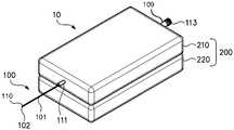
도 1 은 의료 기기의 연장가능한 작동부를 제어가능하게 연장 및 후퇴하는데 사용된 구성요소들을 포함하기 위한 케이스의 일 실시형태를 도시한 사시도이다.
도 2 는 도 1 의 의료 기기의 실시형태의 작동부의 원위 말단에 배치된 굽힘가능 부분 및 세장형의, 가요성 부분의 사시도이다.
도 3 은 굽힘 모드를 도시한 도 2 의 작동부의 원위 말단에서의 원위의, 굽힘가능 부분의 사시도이다.
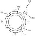
도 4a 는 폴리머 전해질 층 둘레에 분배된 4 개의 각도상 분배된 전극들에 적용된 제 1 선택된 세트의 4 개의 전기 신호들을 보여주는 도 2 및 도 3 의 굽힘가능 부분의 원위 말단의 횡단면도이다. 화살표는 4 개의 개별 전극들에 도시된 세트의 전기 신호들을 적용함으로써 발생된 굽힘 방향을 나타낸다.
도 4b 는 폴리머 전해질 층에 대해 배치되는 각도상 분배된 전극들에 적용된 제 2 선택된 세트의 4 개의 전기 신호들을 드러내는 도 4a 의 굽힘가능 부분의 원위 말단의 횡단면도이다. 화살표는 4 개의 개별 전극들에 도시된 전기 신호들을 적용함으로써 발생된 굽힘 방향을 나타낸다.
도 5 는 종방향 및 원주 방향으로 모두 분리된 복수의 개별 전극들을 가지는 일 실시형태의 의료 기기의 작동부의 세장형의, 가요성 부분 및 굽힘가능 부분의 대안적 실시형태의 사시도이다. 각각의 개별 전극은 전기 신호를 전극에 제공하는 도전성 도관에 연결된다.
도 6 은 도 1 내지 도 4b 의 의료 기기의 실시형태를 사용 및 제어하는데 사용되는 시스템들 및 구성요소들을 개략적으로 도시한 블록도이다.
도 7 은, 원위의, 굽힘가능 부분 및 세장형의, 가요성 부분을 포함하는, 의료 기기의 실시형태의 연장가능하고 조종가능한 작동부의 원위 말단의 종단면도이다.
도 8a 는 도 1 의 의료 기기의 실시형태의 케이스의 상부 케이스 부분의 사시도이고, 상기 케이스의 상부 케이스 부분은 내부에 배치된 구성요소들을 더 잘 드러내기 위해서 점선들로 나타낸다.
도 8b 는 도 1 의 의료 기기의 실시형태의 케이스의 하부 케이스 부분의 사시도이고, 상기 케이스의 하부 케이스 부분은 내부에 배치된 구성요소들을 더 잘 드러내기 위해서 점선들로 나타낸다.
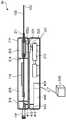
도 9 는 도 8a 및 도 8b 의 상부 케이스 부분과 하부 케이스 부분을 조립하여 제공된 의료 기기의 실시형태의 입면 단면도이다. 의료 기기는 주 제어기와 무선 통신한다.
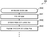
도 10 은 도 7a, 도 7b 및 도 8 에 도시된 의료 기기의 실시형태를 사용하여 수술을 수행하는 방법의 단계들을 보여주는 흐름도이다.
도 11 은 의료 기기의 실시형태의 작동부의 원위 말단에서 굽힘가능 부분에 굽힘을 부여하는 방법을 보여주는 흐름도이다.
도 12 는 작동부 및 케이스를 포함하는 의료 기기의 대안적 실시형태를 위한 제어 시스템 구조를 도시한 도 6 의 블록도의 변형예이다.
도 13 은 의료 기기의 실시형태의 작동부의 굽힘가능 부분의 폴리머 전해질 층을 포위하도록 다른 전극들과 배치된 전극에 적용된 전기 신호의 시간의 경과에 따른 변화를 도시한 그래프이다.
도 14 는 의료 기기의 실시형태의 작동부의 굽힘가능 부분의 폴리머 전해질 층으로 형성된 리세스들에서 개별 전극들의 대안적 분배를 도시한 횡단면도이다.
도 15 는 의료 기기의 작동부의 굽힘가능 부분에 대한 대안적 구성의 횡단면도이다.
도 16 은 의료 기기의 실시형태의 성능을 모니터링하는데 센싱 부재를 사용하고 의료 기기의 실시형태의 성능에 대한 외력의 영향을 결정하는 방법을 도시하는 흐름도이다.
도 17 은 의료 기기의 작동부를 제어가능하게 전진 및 인출하기 위한 의료 기기의 케이스 부분의 대안 실시형태를 도시한다.
도 18 은 내부의 구성요소들의 위치들을 드러내기 위해서 가이드 배럴이 제거된 대안적 케이스의 사시도이다.
도 19 는 의료 기기의 이 실시형태의 작동부의 구성요소들의 세부들을 드러내기 위해서 외부 부재의 섹션이 제거된 의료 기기의 작동부의 세장형의, 가요성 부분의 사시도이다.
도 20 은 의료 기기의 작동부의 세장형의, 가요성 부분의 실시형태의 횡단면도이다. 세장형의, 가요성 부분은 도전성 도관들 및 금속 보강 메시 또는 브레이드를 포함할 수도 있다.
도 21 은, 도전성 도관들 각각이 루멘 구조 내에 매립되고 각각의 도전성 도관 및 그것의 루멘 구조가 함께 외부 부재의 재료 내에 둘러싸여 있는 의료 기기의 작동부의 세장형의, 가요성 부분의 대안적 실시형태의 횡단면도이다.
도 22 는, 도전성 도관들 각각이 외부 부재에 의해 포위되는 단일, 관형 절연 부재 내에 둘러싸여 전기적으로 절연되는 의료 기기의 작동부의 세장형의, 가요성 부분의 대안적 실시형태의 횡단면도이다.
도 23 은 작동부 및 케이스를 포함하는 의료 기기의 대안적 실시형태를 위한 제어 시스템을 도시한 도 6 및 도 12 의 블록도들의 변형예이다.
도 24 는 의료 기기의 세장형의, 가요성 부분의 내부 부재의 외부면에 부착된 4 개의 도전성 도관들의 배치를 보여주는 도 5 의 일부분의 확대도이다.
도 25 는 의료 기기의 대안적 실시형태의 작동부의 굽힘가능 부분에 포함되는 이온성 전기 활성 폴리머 액추에이터의 확대 사시도이다.
도 26 은, 스프링 부재가, 반경방향으로 압축된 구성에서, 루멘 내 장애물에 인접하여 스프링 요소를 배치하도록 작동부의 보어를 통하여 전진된 중심 와이어에 결합된 의료 기기의 실시형태의 작동부의 원위 말단의 도면이다.
도 27 은, 작동부 및 중심 와이어로 제거하기 위한 장애물을 팽창하여 그리핑하도록, 중심 와이어를 고정 상태로 유지하면서 작동부의 보어의 인출에 의해 얻어진, 팽창된 구성의 스프링 부재의 도면이다.
도 28 은 도 26 및 도 27 에 의해 도시된 방법을 구현하는데 사용될 수 있는 스프링 부재의 대안적 실시형태이다.
도 29 는 도 1 의 의료 기기의 다른 실시형태의 작동부의 원위 말단에 배치된 굽힘가능 부분 및 세장형의, 가요성 부분의 사시도이다.
도 30 은 굽힘 모드를 보여주는 도 29 의 작동부의 원위 말단에서의 원위의, 굽힘가능 부분의 사시도이다.1 is a perspective view illustrating one embodiment of a case for containing components used to controllably extend and retract an extendible operative portion of a medical device.
Fig. 2 is a perspective view of a bendable portion and elongated, flexible portion disposed at the distal end of the operative portion of the embodiment of the medical device of Fig. 1;
Fig. 3 is a perspective view of a distal, bendable portion at the distal end of the actuating portion of Fig. 2 showing the bending mode. Fig.
4A is a cross-sectional view of the distal end of the bendable portion of FIGS. 2 and 3 showing a first selected set of four electrical signals applied to four angularly distributed electrodes distributed around the polymer electrolyte layer. The arrows indicate the bending directions generated by applying the set of electrical signals shown in the four separate electrodes.
4B is a cross-sectional view of the distal end of the bendable portion of FIG. 4A revealing a second selected set of four electrical signals applied to the angularly distributed electrodes disposed against the polymer electrolyte layer. The arrows indicate the bending directions generated by applying the electrical signals shown in the four individual electrodes.
Figure 5 is a perspective view of an alternate embodiment of a elongated, flexible and bendable portion of an operating portion of a medical device of an embodiment having a plurality of discrete electrodes both longitudinally and circumferentially separated. Each individual electrode is connected to a conductive conduit that provides an electrical signal to the electrode.
Figure 6 is a block diagram that schematically illustrates systems and components used to use and control the embodiment of the medical device of Figures 1 - 4b.
7 is a longitudinal section view of a distal end of an extendable and steerable operating portion of an embodiment of a medical device, including a distal, bendable portion and a elongated, flexible portion.
8A is a perspective view of an upper case portion of a case of an embodiment of the medical device of FIG. 1, wherein the upper case portion is shown in dashed lines to better reveal the components disposed therein.
Figure 8b is a perspective view of the lower case portion of the case of the embodiment of the medical device of Figure 1 and the lower case portion of the case is shown in dashed lines to better reveal the components disposed therein.
9 is a cross-sectional elevational view of an embodiment of a medical device provided with the upper and lower case portions of FIGS. 8A and 8B assembled. The medical device communicates wirelessly with the main controller.
10 is a flow chart illustrating steps of a method of performing an operation using an embodiment of the medical device shown in Figs. 7A, 7B, and 8. Fig.
11 is a flow chart showing a method of applying a bend to a bendable portion at a distal end of an operating portion of an embodiment of a medical device.
Figure 12 is a variation of the block diagram of Figure 6 illustrating a control system architecture for an alternative embodiment of a medical device including an operating portion and a case.
Fig. 13 is a graph showing a change over time of an electrical signal applied to electrodes arranged with other electrodes so as to surround a polymer electrolyte layer in a bendable portion of an operating portion of an embodiment of a medical instrument. Fig.
14 is a cross-sectional view illustrating alternative dispensing of discrete electrodes in recesses formed of a polymer electrolyte layer of a bendable portion of an operating portion of an embodiment of a medical device.
15 is a cross-sectional view of an alternative configuration for a bendable portion of an operating portion of the medical device.
16 is a flow chart illustrating a method of using a sensing member to monitor the performance of an embodiment of a medical device and determining the effect of an external force on the performance of an embodiment of the medical device.
Figure 17 shows an alternative embodiment of a case part of a medical device for controllably advancing and withdrawing an operating part of the medical device.
Figure 18 is a perspective view of an alternative case in which the guide barrel is removed to reveal the locations of internal components.
19 is a perspective view of the elongated, flexible portion of the operating portion of the medical device from which the section of the outer member is removed to reveal details of the components of the operating portion of this embodiment of the medical device.
20 is a cross-sectional view of an embodiment of a elongated, flexible portion of an operating portion of a medical device. The elongated, flexible portion may include conductive conduits and metal reinforcing mesh or braids.
Figure 21 shows an alternative embodiment of a elongated, flexible portion of an operating portion of a medical device in which each of the conductive conduits is embedded in a lumen structure and each conductive conduit and its lumen structure are enclosed within the material of the outer member. Sectional view.
22 is a cross-sectional view of an alternate embodiment of a elongated, flexible portion of an operating portion of a medical device in which each of the conductive conduits is surrounded and surrounded by a single, tubular insulating member surrounded by an outer member.
Figure 23 is a variation of the block diagrams of Figures 6 and 12 illustrating a control system for an alternative embodiment of a medical device including an operating portion and a case.
Figure 24 is an enlarged view of a portion of Figure 5 showing the placement of four conductive conduits attached to the outer surface of the inner member of the elongate, flexible portion of the medical device.
25 is an enlarged perspective view of an ionic electroactive polymer actuator included in a bendable portion of an operating portion of an alternative embodiment of a medical device.
Figure 26 is a side view of the distal end of the operative portion of the embodiment of the medical device coupled to the center wire advanced through the bore of the actuating portion to position the spring element adjacent the obstruction in the lumen, FIG.
27 is a view of a spring member of an expanded configuration obtained by pulling out the bore of the operating portion while keeping the center wire in a fixed state so as to expand and grip the obstacle for removal by the operating portion and the center wire.
28 is an alternative embodiment of a spring member that can be used to implement the method illustrated by Figs. 26 and 27. Fig.
29 is a perspective view of a bendable portion and elongated, flexible portion disposed at a distal end of an operative portion of another embodiment of the medical device of Fig.
Figure 30 is a perspective view of the distal, bendable portion at the distal end of the operating portion of Figure 29 showing the bending mode.
카테테르들 또는 가이드와이어들과 같은 의료 기기들은 동맥, 정맥, 인후, 외이도, 비강, 요도와 같은 루멘 또는 임의의 다수의 다른 루멘들 또는 신체의 통로들로 삽입되기에 충분히 가늘 수도 있다. 이 가는 카테테르들 (마이크로-카테테르들로도 지칭) 및 가이드와이어들은, 수술 절차 또는 의료적 수술을 수행하기 위한 로컬 액세스를 제공하도록 대상체 또는 환자의 절단 필요성을 막음으로써 실질적으로 단축된 회복 기간을 요구하는 비침습적 수술을 내과의사들이 수행할 수 있게 한다. 본원에 사용된 대로, 용어들 "대상체" 또는 "환자" 는 기기와 의료 개입의 수용자를 지칭한다. 특정 양태들에서, 환자는 인간 환자이다. 다른 양태들에서, 환자는 반려 동물, 사냥 동물, 축류 또는 가축이다.Medical devices such as catheters or guidewires may be sufficiently thin to be inserted into the lumens such as the arteries, veins, throat, ear canal, nasal cavity, urethra or any of a number of other lumens or passages in the body. These thin catheters (also referred to as micro-catheters) and guide wires require a substantially shortened recovery period by preventing the need to sever the subject or patient to provide local access to perform surgical procedures or medical operations This allows non-invasive surgery to be performed by physicians. As used herein, the terms "subject" or "patient" refer to a device and a recipient of medical intervention. In certain embodiments, the patient is a human patient. In other embodiments, the patient is a companion animal, a hunting animal, an axon, or a livestock.
다음 단락들은 의료 기기들을 사용해 외과 수술을 수행하거나 수행을 가능하게 하는데 사용될 수 있는 의료 기기들의 특정 실시형태들, 및 이를 위한 이러한 의료 기기의 제조를 가능하게 하는데 사용될 수 있는 방법들을 기술한다. 의료 기기들 및 방법들의 다른 실시형태들이 이하 첨부된 청구 범위 내에 있고, 이러한 실시형태들의 도면이 본 발명을 제한하지 않는다는 점을 이해할 것이다.The following paragraphs describe specific embodiments of medical devices that can be used to perform or enable performing surgical operations with the medical devices, and methods that can be used to enable the manufacture of such devices for that purpose. It will be appreciated that other embodiments of medical devices and methods are within the scope of the appended claims, and that the drawing of such embodiments does not limit the invention.
도 1 은 케이스 (200) 및 작동부 (100) 를 가지는 의료 기기 (10) 의 일 실시형태를 보여주는 사시도이다. 도 1 의 의료 기기 (10) 는 케이스 (200) 의 상부 케이스 부분 (210) 및 하부 케이스 부분 (220) 을 포함하고, 의료 기기 (10) 는 케이스 (200) 의 상부 케이스 부분 (210) 으로부터 연장가능하도록 세장형의, 가요성 부분 (101), 및 원위 말단 (102) 에 배치된 굽힘가능 부분 (110) (도 2) 을 포함하는 가요성, 세장형의 가는 작동부 (100) 를 추가로 포함한다. 세장형의, 가요성 부분 (101) 은 신체 (미도시) 의 루멘 (미도시) 으로 삽입될 수 있도록 충분히 가는 내부 부재 (120) (도 2) 를 포함한다. 또한, 내부 부재 (120) 는 충분히 가요성이고 실질적으로 축선방향으로 비압축성이어서, 작동부 (100) 의 원위 말단 (102) 은 신체 (미도시) 의 루멘으로 삽입된 후 작동부 (100) 의 세장형의, 가요성 부분 (101) 을 앞으로 밀거나 구동함으로써 내부 부재는 와인딩 경로를 가지는 루멘을 통하여 전진될 수 있다. 작동부 (100) 는 근위 말단 (109) 을 추가로 포함한다. 의료 기기 (10) 는 세장형 구조 (미도시) 의 이동을 가능하게 하도록 내부 보어 (140) (도 2) 를 포함하는 굽힘가능 부분 (110) 을 가지는 마이크로-카테테르일 수도 있다. 일 실시형태에서, 세장형 구조는 근위 말단 (109) 으로부터 내부 보어 (140) (도 2) 를 통하여 의료 기기 (10) 의 작동부 (100) 의 원위 말단 (102) 으로 공급될 수도 있다. 대안적으로, 의료 기기 (10) 는 내부 보어 (140) 가 없는 굽힘가능 부분 (110) 을 갖는 가이드와이어일 수도 있다 (예컨대, 도 29).Fig. 1 is a perspective view showing an embodiment of a
선택적으로, 작동부 (100) 의 근위 말단 (109) 은 작동부 (100) 의 근위 말단 (109) 에 메이팅 소켓 또는 다른 구조를 고정하는데 사용하기 위한, 예를 들어, 나사산 (113) 과 같은 패스너를 포함할 수도 있다. 선택적으로, 의료 기기 (10) 의 케이스 (200) 의 상부 케이스 부분 (210) 은, 케이스 (200) 너머로 연장되는 작동부 (100) 의 원위 부분 (102) 에 전진 방향성을 부여하기 위한 가이드 배럴 (211) 을 포함할 수도 있다.Alternatively, the
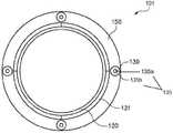
도 2 는 도 1 의 의료 기기 (10) (예컨대, 마이크로-카테테르) 의 실시형태의 작동부 (100) 의 원위 말단 (102) 에 배치된 굽힘가능 부분 (110) 및 세장형의, 가요성 부분 (101) 의 사시도이다. 작동부 (100) 의 굽힘가능 부분 (110) 은, 각도상 분배된 복수의 통전 가능한 전극들 (112) 중심에 그리고 세장형의, 가요성 부분 (101) 의 내부 부재 (120) 에 인접하여 배치된 폴리머 전해질 층 (139) 을 포함한 이온성 전기 활성 폴리머 액추에이터를 포함한다. 폴리머 전해질 층 (139) 의 외벽 (137) 을 포위하는 복수의 전극들 (112) 각각은, 연결된 전극 (112) 에 전기 신호 또는 전류가 공급될 수 있는 도전성 도관 (130) 의 원위 말단 (131) 에 연결된다. 폴리머 전해질 층 (139) 은, 세장형 구조의 원위 말단에서 배치된 이펙터 또는 수술 도구 또는 기구를 위치결정, 제어 및/또는 작동하도록 다른 세장형 구조들이 삽입될 수 있는 보어 (140) 를 포함한다. 폴리머 전해질 층 (139) 의 보어 (140) 는, 이완되거나 비통전된 상태에서, 축선 (141) 에 대해 중심에 있다. 도 2 의 굽힘가능 부분 (110) 은 직선 모드로 도시된다. 아래에서 더 상세하게 설명되는 바와 같이, 굽힘가능 부분 (110) 은 복수의 전극들 (112) 중 하나 이상의 선택적 통전에 의해 굽힘 모드로 선택적으로 제어가능하게 변형될 수 있다.Figure 2 illustrates a
의료 기기 (10) 의 일 실시형태에서, 도 2 의 굽힘가능 부분 (110) 의 이온성 전기 활성 폴리머 액추에이터는 이온성 폴리머-금속 복합체 (IPMC) 액추에이터이다. 의료 기기 (10) 의 일 실시형태에서, 이온성 전기 활성 폴리머 액추에이터는 우수한 이온 수송 특성을 갖는 Nafion® (Nafion® 은 E. I. DuPont de Nemours and Company 로부터 입수가능함) 의 퍼플루오르화 이오노머로 만들어진 폴리머 전해질 층 (139) 을 포함한다. 대안적으로, 의료 기기 (10) 의 이온성 전기 활성 폴리머 액추에이터의 다른 실시형태들은 Aciplex™ (일본, 도쿄의 Asahi Kasei Chemical Corp. 로부터 입수가능), Flemion® (미국, 펜실베니아주, 엑스톤의 AGC Chemical Americas, Inc. 로부터 입수가능) 또는 fumapem® F-series (독일 연방 공화국, Bietigheim-Bissingen 의 Fumatech BWT GmbH 로부터 입수가능) 와 같은 퍼플루오르화 이오노머를 포함하는 폴리머 전해질 층 (139) 을 포함할 수도 있다. 바람직한 실시형태에서, 퍼플루오르화 이오노머는 Nafion® 이다.In one embodiment of the
의료 기기 (10) 의 일 실시형태에서, 도전성 도관들 (130) 은 백금, 금, 탄소, 이들의 합금들 또는 이들의 조합물 중 하나를 포함할 수도 있다. 다른 실시형태들에서, 전극들 (112) 을 위한 재료는 탄소, 예로 카바이드 유래 탄소, 탄소 나노튜브들, 카바이드 유래 탄소 또는 이오노머의 복합체, 및 탄소 나노튜브와 이오노머의 복합체를 포함할 수도 있다. 폴리머 전해질 층 (139) 에 탄소 기반 전극들 (112) 을 배치하는 일 실시형태에 따른 방법이 본원에서 이하 검토될 것이다.In one embodiment of the
복수의 전극들 (112) 각각은, 도관 (130) 이 연결되는 전극 (112) 에 전기 신호가 적용될 수 있는 도전성 도관 (130) 의 원위 말단 (131) 에 연결되어서, 폴리머 전해질 층 (139) 내 금속 양이온이 적용된 전기 신호에 의해 결정된 방향으로 이동시킨다. 적용된 전기 신호에 의해 발생된 이런 양이온 영동은 폴리머 전해질 층 (139) 이 애노드 근위에 배치된 폴리머 전해질 층 (139) 의 부분에서 팽윤하도록 하고 남아있는 미팽윤된 부분의 방향으로 구부리거나 휘어지도록 한다. 결과적으로, 이온성 전기 활성 폴리머 액추에이터의 폴리머 전해질 층 (139) 의 굽힘 변형의 크기 및 방향은, 통전할 전극들 (112) 을 전략적으로 선택하고 도전성 도관들 (130) 을 통하여 전극들 (112) 에 적용된 전기 신호를 조절하여 제어될 수 있다.Each of the plurality of
도 2 에 도시된 대로, 폴리머 전해질 층 (139) 은 원형 보어 (140) 를 포함하고, 복수의 전극들 (112) 은 폴리머 전해질 층 (139) 의 원주에 대해 각도상으로 분배된다.2, the
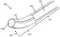
도 3 은 변형 또는 굽힘 모드를 보여주는 도 2 의 작동부 (100) 의 원위 말단 (102) 에서 굽힘가능 부분 (110) 의 사시도이다. 의료 기기 (10) 의 작동부 (100) 의 굽힘가능 부분 (110) 은, 폴리머 전해질 층 (139) 을 변형시키도록 전기 신호들의 선택적 적용을 통하여 도 2 에 도시된 직선 모드로부터 도 3 의 변형 또는 굽힘 모드로 작동되는 것으로 도시된다. 선택된 전극들 (112) 의 통전은, 화살표 (118) 로 나타낸 외력을 적용함으로써, 굽힘가능 부분 (110) 을 직선 모드로부터 굽힘 모드로 변형시킨다.Figure 3 is a perspective view of the
대안적으로, 복수의 전극들 (112) 중 하나 이상에 하나 이상의 전기 신호들의 적용 부재시 작동부 (100) 가 변형 모드로 있는 것으로 관찰되는 경우에, 관찰된 편향의 크기는 작동부 (100) 에 적용된 외력의 크기 및 방향을 결정하는데 사용될 수 있고, 또는 대안적으로, 전극들 (112) 로 공지된 전류의 적용이 작동부 (100) 의 굽힘가능 부분 (110) 의 예상된 변형을 발생시키지 못하는 경우에, 예상된 변형과 (존재하는 경우) 실제 변형 사이 차이는 의료 기기 (10) 의 작동부 (100) 의 원위 말단 (102) 에서 굽힘가능 부분 (110) 에 적용된 외력의 크기의 지표로서 사용될 수 있다.Alternatively, in the absence of application of one or more electrical signals to one or more of the plurality of
도 4a 는 폴리머 전해질 층 (139) 의 외벽 (137) 둘레에 배치되는 4 개의 원주 방향으로 분배된 전극들 (112) 에 적용된 제 1 선택된 세트의 4 개의 전기 신호들을 보여주는 도 2 및 도 3 의 작동부 (100) 의 굽힘가능 부분 (110) 의 원위 말단 (102) 의 횡단면도이다. 도 4a 는 화살표 (118) 의 방향으로 작동부 (100) 의 굽힘가능 부분 (110) 의 굽힘을 부여하도록 복수의 각도상 분배된 전극들 (112) 에 적용될 수도 있는 전기 신호들을 보여준다. 도 4a 의 상단에서 전극 (112) 에 양전하의 적용 이외에, 또한 도 4a 의 바닥에서 전극 (112) 에 음전하의 적용 이외에, 도 4a 의 굽힘가능 부분 (110) 의 좌측 및 우측에서 전극들 (112) 에 양전하의 적용은, 도 4a 의 상단에서 전극 (112) 에 양전하를 적용하고 나머지 전극들 (112) 에 음전하가 부여된 결과로 발생하는 것과 상이한 변형량을 유발할 수 있음을 이해할 것이다. 사용자는, 사용자가 원하는 변형을 발생시키는 복수의 전기 신호들을 선택할 수 있음을 이해할 것이다.4A illustrates the operation of FIGS. 2 and 3 showing four electrical signals of a first selected set applied to four circumferentially distributed
도 4b 는 폴리머 전해질 층 (139) 둘레에 배치되는 원주 방향으로 분배된 전극들 (112) 에 적용된 제 2 선택된 세트의 4 개의 전기 신호들을 드러내는 도 4a 의 연장가능한 작동부 (100) 의 굽힘가능 부분 (110) 의 원위 말단 (102) 의 횡단면도이다. 도 4b 는 도 4b 의 굽힘가능 부분 (110) 의 상단에서 전극 (112) 및 또한 도 4b 의 굽힘가능 부분 (110) 의 우측에서 전극 (112) 에 양전하의 적용을 도시하고, 도 4b 는 도 4b 의 바닥에서 전극 (112) 및 또한 도 4b 의 좌측에서 전극 (112) 에 음전하의 적용을 도시한다. 이 전하들의 적용으로부터 유발되는 폴리머 전해질 층 (139) 의 변형은 화살표 (118) 의 방향으로 이루어진다.Figure 4b illustrates the bendable portion < RTI ID = 0.0 > (100) < / RTI > of the
도 4a 및 도 4b 로부터, 의료 기기 (10) (예컨대, 마이크로-카테테르) 의 작동부 (100) 의 굽힘가능 부분 (110) 의 원위 말단 (102) 은 개별 전극들 (112) 각각에 부여된 전하들의 전략적 제어에 의한 다양한 정도의 변형 또는 편향으로 다수의 방향들로 구부러질 수 있다. 도 4a 및 도 4b 에 도시된 실시형태는 4 개의 전극들 (112) 을 포함한 굽힘가능 부분 (110) 을 보여주지만, 의료 기기 (10) 의 작동부 (100) 의 굽힘가능 부분 (110) 은 4 개 미만 또는 4 개 초과 전극들 (112) 을 포함할 수 있고, 이러한 다른 실시형태들은 상이한 편향 및 변형 방향성 용량들을 가지는 것을 이해할 것이다.4A and 4B, the
도 5 는 의료 기기 (10) (예컨대, 마이크로-카테테르) 의 작동부 (100) 의 굽힘가능 부분 (110) 의 대안적 실시형태의 사시도이다. 도 5 는, 작동부 (100) 의 굽힘가능 부분 (110) 의 길이를 따라 다양한 위치들에 복수의 전극들 (112a, 112b, 112c, 112d) 을 배치함으로써 폴리머 전해질 층 (139) 의 편향 및 변형의 크기 및 방향이 어떻게 맞추어질 수 있는지 보여준다. 제한하지 않고 예로서, 도 5 의 작동부 (100) 의 굽힘가능 부분 (110) 은 16 개의 원주 방향 및 축선방향으로 분배된 전극들 (112a, 112b, 112c, 112d) 을 포함할 수도 있고 제 1 세트의 4 개의 전극들 (112a) 은 작동부 (100) 의 굽힘가능 부분 (110) 의 원위 말단 (102) 근위에 배치되고, 제 2 세트의 4 개의 전극들 (112b) 은 제 1 세트의 전극들 (112a) 에 인접하여 배치되고, 제 3 세트의 4 개의 전극들 (112c) 은 제 2 세트의 전극들 (112b) 에 인접하여 배치되고, 제 4 세트의 전극들 (112d) 은 제 3 세트의 전극들 (112c) 에 인접하여 배치된다. 의료 기기 (10) 의 작동부 (100) 의 굽힘가능 부분 (110) 에 배치된 16 개의 전극들 (112a, 112b, 112c, 112d) (4 개의 세트들) 각각은, 각각 통전 전류를 각각의 전극들에 전달하기 위한, 16 개의 도전성 도관들 (130a, 130b, 130c, 130d) 중 하나에 연결된다. 도 5 에 도시된 작동부 (100) 의 굽힘가능 부분 (110) 의 실시형태는 축선방향으로 이격된 세트들의 전극들 (112) 중간의 감소된 굽힘 저항으로 인해 굽힘가능 부분 (110) 의 강화된 변형을 유발한다.5 is a perspective view of an alternative embodiment of the
도 6 은 도 1 내지 도 4b 의 의료 기기 (10) 의 실시형태에 대한 제어 시스템 구조를 개략적으로 도시한 블록도이다. 여기에서, 의료 기기 (10) 는 내부 보어 (140) 를 갖는 마이크로-카테테르 (예컨대, 도 2 내지 도 4b) 이거나 내부 보어 (140) 를 갖지 않는 가이드와이어 (예컨대, 도 29) 일 수도 있다. 의료 기기 (10) 는 루멘 또는 신체의 통로로 삽입하도록 된 작동부 (100) 및 작동부 (100) 의 세장형의, 가요성 부분 (101) 및 굽힘가능 부분 (110) 을 루멘 또는 신체의 통로 안으로 그것을 통하여 전진시키고 작동부 (100) 의 원위 말단 (102) 에서 굽힘가능 부분 (110) 을 선택적으로 구부리기 위한 구동 어셈블리 (300) (도 8a 내지 도 9) 를 갖는 케이스 (200) 를 포함한다. 도 6 은, 루멘 또는 신체의 통로 안으로 그것을 통하여 작동부 (100) 를 전진시키는데 사용하기 위한 구동 어셈블리 (300), 및 의료 기기 (10) 의 작동부 (100) 의 굽힘가능 부분 (110) 을 조작하기 위해서 복수의 전극들 (112) 에 부여되고 도전성 도관들 (130) 에 의해 운반되는 전하들을 선택적으로 제어하기 위한 전기 제어기 (400) 양자를 포함하는 케이스 (200) 의 제어 상호작용을 보여준다. 전기 제어기 (400) 는, 주 제어기 (500) 로부터 사용자의 입력 신호들에 응답하여, 전극들 (112) 에 적용된 전기 신호의 값들을 계산하는 프로세서 (미도시) 를 포함할 수도 있다. 무선으로, 전화로 및/또는 인터넷을 통하여, 도 6 의 의료 기기 (10) 의 케이스 (200) 와 통신하는, 환자의 로케이션 이외의 로케이션에 존재할 수 있는 주 제어기 (500) 가 도시된다. 도 6 에 도시된 일 실시형태에서, 의료 기기 (10) 의 주 제어기 (500) 는, 환자 (신체) 및 의료 기기 (10) 로부터 멀리 떨어진 외과의 (운영자 또는 사용자) 가 존재하는 곳에 있을 수 있다는 것을 이해할 것이다. 상기 실시형태에서, 의료 기기 (10) 는 주 제어기 (500) 를 포함할 것이고, 또는 대안적으로, 의료 기기 (10) 의 실시형태는 주 제어기 (500) 를 포함하지 않을 수도 있고 환자 및 케이스 (200) 와 함께 수술실에 존재하는 외과의에 의해 사용될 수도 있다. 주 제어기 (500) 는, 예를 들어, 전기 제어기 (400) 를 통하여 굽힘의 2 자유도를 제공하기 위해 굽힘가능 부분 (110) 의 전극들 (112) 에 굽힘 제어 신호들을 사용자가 입력시키기 위한 조이스틱, 및 병진운동의 1 자유도를 제공하기 위해 구동 어셈블리 (300) 에 전진 및 후퇴 제어 신호들을 사용자가 입력시키기 위한, 예를 들어, 트랙 볼 또는 트랙 휠과 같은 롤링 입력부를 포함할 수도 있다.6 is a block diagram schematically illustrating the structure of a control system for an embodiment of the
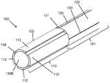
도 7 은, 원위의, 굽힘가능 부분 (110) 및 세장형의, 가요성 부분 (101) 을 포함한, 의료 기기 (10) (예컨대, 마이크로-카테테르) 의 실시형태의 연장가능하고 조종가능한 루멘 내 작동부 (100) 의 종단면도이다.Figure 7 shows an elongate, steerable lumen (not shown) of an embodiment of a medical device 10 (e.g., a micro-catheter), including a distal,
도 7 은 폴리머 전해질 층 (139) 및 복수의 포위 전극들 (112) 을 나타낸다. 각각의 전극 (112) 은 도전성 도관 (130) 에 전기적으로 결합된다. 굽힘가능 부분 (110) 은 작동부 (100) 의 내부 부재 (120) 에 인접하여 배치되고 정렬된다. 세장형의, 가요성 부분 (101) 은 내부 부재 (120), 도전성 도관들 (130), 전극들 (112) 및 폴리머 전해질 층 (139) 을 포위하도록 보호 외부 부재 (150) 를 추가로 포함할 수도 있다. 보호 외부 부재 (150) 는, 의료 기기 (10) 의 작동부 (100) 가 도입될 수 있는 루멘 또는 다른 신체의 통로의 내벽과 저마찰 슬라이딩 맞물림하도록 되어 있다. 의료 기기 (10) 의 마이크로-카테테르의 실시형태에서, 보어 (140) 는, 예를 들어, 이펙터, 절단 도구, 이미징 기기 (카메라), 광원, 스틴트, 스틴트 리트리버 또는 일부 다른 조작가능한 외과 기구와 같은 외과 기구가 수술 중 사용자에 의해 통과 및/또는 제어될 수 있는 통로를 제공한다. 대안적으로, 보어 (140) 는, 약물, 방사선원 또는 다른 재료가 루멘 또는 신체의 통로를 가지는 신체에 정확하게 배치하기 위해 주입될 수 있는 유체 관을 형성할 수도 있다. 도 7 은 작동부 (100) 의 세장형의, 가요성 부분 (101) 에 빈 보어 (140) 를 도시하지만, 이 보어 (140) 는 다수의 용도를 위해 의도된다. 또한, 작동부 (100) 의 보어 (140) 를 통하여 위치결정, 제어되거나 도입된 외과 기구가 굽힘가능 부분 (100) 에 인접하여 배치된 이펙터, 기구, 도구 또는 다른 도구에 연결될 수 있음을 이해될 것이다. 또한, 도 6 에 관하여 설명한 것들과 같은 보어 (140) 로 삽입된 와이어 또는 다른 세장형 가는 기기를 위치결정하기 위한 다른 기기들이 루멘 내에 작동부 (100) 를 위치결정하는데 사용된 기기들의 기능을 손상시키지 않으면서 보어 (140) 내에 와이어 또는 다른 기기를 위치결정하는데 사용될 수 있음을 이해할 것이다.7 shows a
도 8a 및 도 8b 는 함께 의료 기기 (10) 의 실시형태의 분해 사시도를 제공한다. 여기에서, 의료 기기 (10) 는 내부 보어 (140) 를 갖는 마이크로-카테테르 (예컨대, 도 2 내지 도 4b) 이거나 내부 보어 (140) 를 갖지 않는 가이드와이어 (예컨대, 도 29) 일 수도 있다.Figures 8A and 8B together provide an exploded perspective view of an embodiment of the
도 8a 는 도 1 의 의료 기기 (10) 의 실시형태의 케이스 (200; 도 1 참조) 의 상부 케이스 부분 (210) 의 사시도이고, 상기 상부 케이스 부분 (210) 은 내부에 배치된 의료 기기 (10) 의 구성요소들을 더 잘 드러내기 위해서 점선들로 나타낸다. 의료 기기 (10) 의 일 실시형태에서, 상부 케이스 부분 (210) 은 일회용일 수 있는데 왜냐하면 그것은 작동부가 삽입되고 작동부가 인출되는 환자의 루멘 또는 신체의 통로로 삽입되어 오염되는 작동부 (100) 를 포함하기 때문이다. 도 8a 에 도시된 상부 케이스 부분 (210) 은, 작동부 (100) 의 원위 말단 (102) 이 통과하는 가이드 배럴 (211) 을 포함한다. 가이드 배럴 (211) 은, 작동부 (100) 가 전진 및 인출하는 상부 케이스 부분 (210) 에서 애퍼처 (미도시) 를 가린다. 유사하게, 작동부 (100) 의 근위 말단 (109) 은 애퍼처 (115) 를 통과할 수도 있고 또는 애퍼처에 고정 배치될 수도 있다. 작동부 (100) 의 근위 말단 (109) 은 외과 기구 또는 도구와 연관된 메이팅 소켓 또는 연결부와 짝을 이루도록 나사산 (113; 도 1) 을 추가로 포함할 수도 있다. 상부 케이스 부분 (210) 내 캐비티 (215) 는 작동부 (100) 의 길이에 형성된 와인딩들 (116) 을 저장하는데 사용될 수도 있다. 작동부 (100) 의 와인딩들 (116) 은 굽힘가능 부분 (110) 을 포함하지 않지만, 도전성 도관들 (130) 과 내부 부재 (120; 예컨대, 도 7), 굽힘가능 부분 (110) 의 일부가 되거나 인접한 구성요소들을 공급하고, 위치결정하고 제어하는데 사용되는 작동부 (100) 의 양 구성요소들을 포함한다. 도 8a 의 상부 케이스 부분 (210) 은 제 1 회전 구동 부재 (330a) 및 인접한 제 2 회전 구동 부재 (330b) 를 포함한 구동 어셈블리 (300) 를 추가로 포함한다. 작동부 (100) 는 제 1 회전 구동 부재 (330a) 와 인접한 제 2 회전 구동 부재 (330b) 중간에 통과하는 것으로 나타나 있다. 제 1 회전 구동 부재 (330a) 의 시계방향 회전 및 인접한 제 2 회전 구동 부재 (330b) 의 반시계방향 회전은 환자의 루멘 또는 신체의 통로로부터 케이스 (200) 로 작동부 (100) 를 인출시킬 것이고, 제 1 회전 구동 부재 (330a) 의 반시계방향 회전 및 인접한 제 2 회전 구동 부재 (330b) 의 시계방향 회전은 케이스 (200) 로부터 작동부 (100) 의 원위 말단 (102) 이 도입된 환자의 루멘 또는 신체의 통로로 작동부 (100) 를 전진시키는 것을 이해할 것이다.8A is a perspective view of an
도 8b 는 도 1 의 의료 기기 (10) 의 실시형태의 케이스 (200; 도 1 참조) 의 하부 케이스 부분 (220) 의 사시도이고, 상기 하부 케이스 부분 (220) 은 내부에 배치된 의료 기기 (10) 의 구성요소들을 더 잘 드러내기 위해서 점선들로 나타낸다. 상부 케이스 부분 (210) 이 일회용인 의료 기기 (10) 의 일 실시형태에서, 하부 케이스 부분 (220) 은 반복된 사용을 위해 적합화될 수도 있고, 각각의 사용은 오염제거된 하부 케이스 부분 (220) 을 새로운 또는 개조된 상부 케이스 부분 (210) 과 짝을 이루는 것을 요구한다. 하부 케이스 부분 (220) 의 형상은 도 8a 의 상부 케이스 부분 (210) 의 형상에 대응하여서 조립된 케이스 (200) 를 제공하기 위해서 상부 케이스 부분 (210) 과 하부 케이스 부분 (220) 의 짝을 이루는 것을 용이하게 한다. 도 8b 의 하부 케이스 부분 (220) 은 낮은 오염 위험을 가지는 구성요소들, 및 각각의 사용 후 개조, 재생 및/또는 오염제거되는데 유용하도록 충분한 비용의 구성요소들을 포함한다.8B is a perspective view of a
하부 케이스 부분 (220) 내 또는 상에 배치되는 의료 기기 (10) 의 구성요소들은 상부 케이스 부분 (210) 내 또는 상에 배치되는 의료 기기 (10) 의 관련된 구성요소들과 맞물리도록 위치결정되어서 도 8a 의 상부 케이스 부분 (210) 과 도 8b 의 하부 케이스 부분 (220) 의 조립시 이런 관련된 구성요소들의 결합을 가능하게 한다. 예를 들어, 그러나 제한 없이, 가요성 작동부 (100) 와 맞물려 이동시키는 도 8a 의 상부 케이스 부분 (210) 의 구동 어셈블리 (300) 는 또한 중간 웜 기어 (320) 를 통하여 모터 (310) 와 맞물릴 수도 있다. 모터 (310) 는, 도 8a 에 도시된 상부 케이스 부분 (210) 의 제 1 회전 구동 부재 (330a) 에 형성된 대응하는 구동 소켓 (미도시) 으로 수용되도록 위치결정된 구동 피팅 (321) 을 제어가능하게 회전시키도록 웜 기어 (320) 를 구동한다. 도 8a 및 도 8b 에 도시된 실시형태에서, 인터페이스 기기 (420) 는 의료 기기 (10) 의 케이스 (200) 가 제어 신호들, 예를 들어, 신호들을 수신할 수 있도록 하여서 구동 어셈블리 (300) 를 사용해 작동부 (100) 를 전진 또는 인출시키고 외과의 또는 운영자 (예를 들어, 제한되지 않지만, 의료 의사들, 내과의사들, 외과 기술자들, 간호사들 또는 조무사들, 수의사들 등과 같은 다른 운영자들 또는 사용자들 포함) 에 의해 사용된 주 제어기 (500; 도 9) 로부터 굽힘가능 부분 (110) 을 사용해 작동부 (100) 의 원위 말단 (102) 에 굽힘을 부여한다.The components of the
도 9 는 도 8a 및 도 8b 의 상부 케이스 부분 (210) 및 하부 케이스 부분 (220) 의 조립에 의해 제공된 의료 기기 (10) 의 실시형태의 입면 단면도이다. 의료 기기 (10) 의 작동부 (100) 의 와인딩들 (116) 은 케이스 (200) 의 상부 케이스 부분 (210) 의 캐비티 (215) 내에 저장된다. 의료 기기 (10) 의 작동부 (100) 는 근위 말단 (109) 으로부터 와인딩들 (116) 을 통하여, 상부 케이스 부분 (210) 의 가이드 배럴 (211) 너머로 연장되는 작동부 (100) 의 원위 말단 (102) 까지 연장된다. 도 9 는, 의료 기기 (10) 의 케이스 (200) 에 대해 각각 작동부 (100) 를 제어가능하게 전진 및 인출시키도록 제 2 회전 구동 부재 (330b) 와 협동작용하는 제 1 회전 구동 부재 (330a) 의 소켓 (미도시) 과 구동 피팅 (321; 도 8b 참조) 이 맞물리는 방식으로 도시한다. 선택적으로, 상부 케이스 부분 (210) 은, 구동 어셈블리 (300) 의 제 1 회전 구동 부재 (330a) 및 제 2 회전 구동 부재 (330b) (도 8a) 를 수용하는 인접한 캐비티 (213) 로부터 작동부 (100) 의 와인딩들 (116) 을 수용하는 캐비티 (215) 를 분리하는 캐비티 벽 (214) 을 포함한다. 도 9 의 의료 기기 (10) 는, 하부 케이스 부분 (220) 에 배치되고 주 제어기 (500) 로부터 명령 신호들을 수신하고 작동부 (110) 의 굽힘가능 부분 (110) (예컨대, 도 2) 을 구부리도록 복수의 전극들 (112) (예컨대, 도 2) 을 통전하기 위해서 작동부 (100) 내에 복수의 도전성 도관들 (130) (도 2) 로 제어 전기 신호들을 발생시키는데 사용된 전기 제어기 (400) 를 추가로 포함한다. 전기 제어기 (400) 는 하부 케이스 부분 (220) 에 배치된 인터페이스 (402) 를 통하여 상부 케이스 부분 (210) 에 배치된 전류 분배기 (410) 로 전류를 릴레이한다. 전류 분배기 (410) 는 전기 제어기 (400) 와 의료 기기 (10) 의 작동부 (100) 사이 인터페이스이다. 의료 기기 (10) 의 작동부 (100) 의 근위 말단 (109) 은 전류 분배기 (410) 와 작동부 (100) 의 고정된 근위 말단 (109) 사이에 연장되는 복수의 전기 피더 와이어들 (411) 을 유지하도록 상부 케이스 부분 (210) 에 대해 고정된다. 상부 케이스 부분 (210) 의 분배기 캐비티 (216) 는, 인접한 와인딩들 (116) 에 존재할 수도 있는 오염원들로부터 피더 와이어들 (411) 및 관련된 단자들을 보호하도록 밀봉될 수 있다는 점을 이해할 것이다.9 is an elevational cross-sectional view of an embodiment of the
도 9 의 의료 기기의 실시형태에서, 전기 제어기 (400) 로부터 도전성 도관들 (130; 예컨대, 도 2) 로 전류를 전달하는데 제공된 복수의 피더 와이어들 (411) 의 수는 복수의 도전성 도관들 (130) 의 수와 일치할 것이다. 인터페이스 소켓 (415) 은 하부 케이스 부분 (220) 의 인터페이스 (420) 와 상부 케이스 부분 (210) 의 전류 분배기 (410) 중간에 배치될 수도 있다. 일 실시형태에서, 전기 제어기 (400) 는 무선 인터페이스 기기 (405) 를 포함할 수 있고 이 기기는 전기 제어기 (400) 및 구동 어셈블리 (300) 에 전기적으로 연결되고 전기 제어기 (400) 및 구동 어셈블리 (300) 가 주 제어기 (500) 와 무선으로 통신할 수 있도록 한다.9, the number of
도 10 은 도 8a 및 도 8b 에 도시된 의료 기기 (10) 의 실시형태를 사용해 환자의 신체에 대한 수술을 수행하는 방법 (600) 의 단계들을 보여주는 흐름도이다. 방법 (600) 은, 케이스 (200) 를 형성하도록 상부 케이스 부분 (210) 과 하부 케이스 부분 (220) 을 조립하는 단계 (610), 작동부 (100) 의 원위 말단 (102) 을 신체의 루멘으로 도입하는 단계 (620), 구동 어셈블리 (300) 를 사용해 환자의 루멘으로 작동부 (100) 를 앞으로 연장하는 단계 (630), 이미징 기기를 사용해 작동부 (100) 가 배치되는 루멘 또는 신체의 통로의 분지형 또는 굽힘 경로들을 검출하는 단계 (640), 이미징 기기를 사용해 관찰된 분지형 또는 굽힘 경로들을 통하여 원하는 방향으로 작동부 (100) 를 조종하도록 의료 기기 (10) 의 작동부 (100) 의 원위 말단 (102) 에서 굽힘가능 부분 (110) 을 구부리는 단계 (650), 및 작동부 (100) 의 원위 말단 (102) 으로 수술 부위에 도달하는 단계 (660) 를 포함한다.10 is a flow chart showing the steps of a
의학에 공지된 종래의 기술들 및 방법들은 상기 방법들 및 의료 기기 (10) 와 함께 사용될 수도 있다. 예를 들어, 그러나 제한 없이, 도 10 의 단계 (640) 는, 외과의가 작동부 (10) 가 도입되는 신체의 루멘의 "분지형 및 굽힘 경로들을 검출" 하도록 요구한다. 보다 구체적으로, 의료 기기 (10) 를 사용해 도 10 의 방법을 수행하는 외과의 또는 운영자는, 의료 기기 (10) 의 작동부 (100) 의 원위 말단 (102) 이 앞으로 밀리는 신체 내 루멘 또는 신체의 통로 (경로) 의 이미지들을, 라디오그래피, 자기 공명 이미징, 초음파, 엘라스토그래피, 촉각 이미징, 광음향 이미징, 단층 촬영 및 다른 이미징 기술들 및 기기들을 사용해 볼 수 있다. 이미징 기기는 환자와 룸에 존재할 수 있고 이미징 기기의 출력은, 가까운 곳에 있는 외과의를 위해, 하드와이어드 연결을 사용해, 그리고 원격 위치한 외과의 또는 운영자를 위해, 제한되지 않지만, 인터넷 또는 무선 통신과 같은 통신을 사용해 외과의 또는 운영자에게 전기적으로 전송될 수 있다는 점이 이해될 것이다.Conventional techniques and methods known in the medical art may also be used with the above methods and the
도 11 은 의료 기기 (10) 의 실시형태를 제어하고, 보다 구체적으로 의료 기기 (10) (예컨대, 마이크로-카테테르 또는 가이드와이어) 의 실시형태의 작동부 (100) 의 원위 말단 (102) 에서 굽힘가능 부분 (110) 에 굽힘을 부여하는 방법 (601) 을 보여주는 흐름도이다. 또한 도 2 및 도 9 를 참조하면, 방법 (601) 은 무선 인터페이스 기기 (405) 를 통하여 전기 제어기 (400) 에 의해 수신될 조작 신호를 주 제어기 (500) 를 사용해 발생시키는 단계 (641), 의료 기기 (10) 의 작동부 (100) 의 원위 말단 (102) 의 굽힘가능 부분 (110) 의 원하는 굽힘 방향 및 크기를 얻기 위해서 복수의 전극들 (112) 중 하나 이상에 적용될 전기 신호들을 결정하도록 전기 제어기 (400) 를 사용하는 단계 (642), 및 의료 기기 (10) 의 작동부 (100) 의 원위 말단 (102) 에서 원하는 운동을 얻기 위해서 도전성 도관들 (130) 을 통하여 복수의 전극들 (112) 중 하나 이상으로 안내될 결정된 전기 신호들을 적용하는 단계 (643) 를 포함한다.Figure 11 illustrates an embodiment of a
도 12 는 작동부 (100) 및 케이스 (200) 를 포함하는 의료 기기 (10; 예컨대, 도 1) 의 대안적 실시형태를 위한 제어 시스템 구조를 도시한 도 6 의 블록도의 변형예이다. 여기에서, 의료 기기 (10) 는 내부 보어 (140) 를 갖는 마이크로-카테테르 (예컨대, 도 2 내지 도 4b) 이거나 내부 보어 (140) 를 갖지 않는 가이드와이어 (예컨대, 도 29) 일 수도 있다. 작동부 (100) 는 굽힘가능 부분 (110) 및 세장형의, 가요성 부분 (101) 을 포함한다. 케이스 (200) 는 구동 어셈블리 (300) 및 전기 제어기 (400) 를 포함하고, 센싱 부재 (117) 를 추가로 포함한다. 센싱 부재 (117) 는, 복수의 전극들 (112) 각각에서 전기 신호 변화를 감지하도록 굽힘가능 부분 (110) 의 복수의 전극들 (112) 에 전기적으로 연결되는 굽힘가능 부분 센서이다. 보다 구체적으로, 센싱 부재 (117) 는 복수의 전극들 (112) 각각에서 퍼텐셜 변화를 모니터링하도록 복수의 전극들 (112) 각각에 개별적으로 전기 연결된다. 그러므로, 센싱 부재 (117) 는 시간의 경과에 따른 복수의 전극들 (112) 각각에서 퍼텐셜 변화를 기반으로 굽힘가능 부분 (110) 의 변형 또는 그것의 부재를 검출한다.12 is a variation of the block diagram of FIG. 6 illustrating a control system architecture for an alternative embodiment of a medical device 10 (e.g., FIG. 1) including an operating
예를 들어, 그러나 제한 없이, 작동부 (100) 의 굽힘가능 부분 (110) 및 세장형의, 가요성 부분 (120) 이 케이스 (200) 의 구동 어셈블리 (300) 를 사용해 앞으로 전진함에 따라, 센싱 부재 (117) 는 작동부 (100) 의 굽힘가능 부분 (110) 이 전진하는 루멘 또는 신체의 통로가 차단되는지 여부 또는 작동부 (100) 의 전진 운동을 막거나 손상시키기에 충분한 루멘 또는 신체의 통로 내에 굽힘 또는 장애물이 있는지 여부를 검출한다. 또한, 전기 신호가 전기 제어기 (400) 에 의해 복수의 전극들 (112) 각각에 적용되기 때문에, 전기 신호에 대한 피드백을 복수의 전극들 (112) 각각에서 받아들이고 그 피드백을 복수의 전극들 (112) 각각에 할당된 전기 신호들과 비교함으로써, 전기 제어기 (400) 에 의해 발생된 복수의 전기 신호들에 대응하는 의도된 굽힘 변형이 발생했는지 여부를 센싱 부재 (117) 가 결정할 수도 있다.For example, but without limitation, as the
센싱 부재 (117) 는 각각의 전극들 (112) 로 전기 신호들을 공급하는 각각의 도전성 도관들 (130) 에 전기적으로 연결된다. 통전된 전극 (112) 에 전달된 전기 신호의 특징 및 성질이 통전된 전극 (112) 에 인접하여 배치된 폴리머 전해질 층 (139) 에 부여된 손상되지 않은 변형을 결정할 때, 폴리머 전해질 층 (139) 의 실제 변형은 폴리머 전해질 층 (139) 에 작용하는 외력의 방향 및 크기를 결정하기 위해서 인접한 전극들로 전달된 전기 신호와 비교될 수 있음을 이해할 것이다.The sensing
도 13 은 의료 기기 (10) 의 실시형태의 작동부 (100) 의 굽힘가능 부분 (110) 의 폴리머 전해질 층 (139) 에 적용된 전류의 시간의 경과에 따른 변화를 도시한 그래프이다. 도 13 은 센싱 부재 (117) 를 사용해 모니터링된 전극 (112) 에서 발생하는 전기 신호의 변화를 보여주는 그래프이다. 도 13 의 실선은 복수의 전극들 (112) 중 어느 하나에서 감지된 전기 신호의 값을 나타낸다. 도 13 의 점선은, 주 제어기 (500) 로부터 입력 신호 및 전기 제어기 (400) 를 사용해 결정될 때 원하는 방향과 원하는 크기로 굽힘을 발생시키도록 전극 (112) 에 적용되는 전기 신호의 값을 나타낸다.13 is a graph showing a change over time of the current applied to the
센싱 부재 (117) 에 의해 감지된 전극 퍼텐셜의 변화는, 굽힘 제어를 위한 전기 제어기 (400) 에 의해 복수의 전극들 (112) 에 적용된 전기 신호에 의해, 그리고 외력에 의해 유발된다. 그러므로, 센싱 부재 (117) 는, 전기 제어기 (400) 가 굽힘 제어를 수행하는 방법을 고려함으로써 굽힘가능 부분 (110) 에 적용된 외력의 존재, 방향 및 크기를 결정하는데 사용될 수도 있다. 도 13 에 도시된 대로, 전기 신호는 t1 로 지정된 시간에서 전극 (112) 에 적용된다. 결과적으로, 센싱 부재 (117) 에 의해 감지된 전기 신호의 값은 시간 t1 에서 급격하게 증가한다. 따라서, 센싱 부재 (117) 는 감지된 값과 ΔVth, 전기 제어기 (400) 에 의해 적용된 값 사이 전기 신호 차이, 또는 ΔV 를 기반으로 굽힘가능 부분 (110) 에 적용될 수도 있는 임의의 외력의 방향 및 크기를 결정할 수도 있다.The change in the electrode potential sensed by the sensing
센싱 부재 (117) 는, 감지된 값과 주 제어기 (500) 에 의해 적용된 값 사이 차이가 미리 설정된 한계값, ΔVth 를 초과하는지 아닌지 여부에 따라 적용된 외력의 방향 및/또는 크기를 결정하도록 구성될 수도 있다. 예를 들어, 원위 말단 (102) 이 루멘 벽과 접촉할 때 또는 그것이 루멘 또는 신체의 통로를 따라 앞으로 밀리면서 슬라이딩 마찰될 때 작동부 (100) 는 소량의 외력을 부여받을 수도 있다. 그러므로, 작동부 (100) 의 루멘 내 이동 중 예상된 소량의 외력을 허용하고 한계값을 기반으로 외력 적용 여부를 결정함으로써 더 큰 크기의 외력의 적용을 검출할 수 있다.The sensing
도 13 은 동일한 규모의 변형으로 인해 전극에서 감지된 값과 구부릴 때 전극에 적용된 값을 보여주지만, 이것은 설명의 용이함을 위한 것이고 이 값들은 설치 위치와 와이어 특징에 따라 실제 상황에서는 달라질 수도 있다. 이 경우에, 와이어 특징에 적합한 계산 방법을 사용해, 구부릴 때 적용된 값을 기반으로 외력의 적용이 결정될 수 있다.Figure 13 shows the values sensed at the electrodes due to the same scale of deformation and the values applied to the electrodes at bending, but this is for ease of illustration and these values may vary in actual situations depending on the installation location and wire characteristics. In this case, the application of the external force can be determined based on the applied value when bending, using a calculation method suitable for the wire characteristic.
이런 예시적인 실시형태에서, 굽힘가능 부분 (110) 에 외력 감지 전극들을 부가하지 않고, 굽힘 제어를 위해 사용된 복수의 4 개의 전극들 (112) 을 사용함으로써 외력이 감지된다. 하지만, 이것은 단지 예시이고, 외력은 다양한 구조들을 사용해 감지될 수 있다.In this exemplary embodiment, external force is sensed by using a plurality of the four
도 14 는 의료 기기 (10) 의 실시형태의 작동부 (100) 의 굽힘가능 부분 (110) 에 복수의 전극들 (112) 의 대안적 분배를 도시한 횡단면도이다. 도 14 에 도시된 굽힘가능 부분 (110) 의 8 개의 전극들의 배열은 전기 제어기 (400) (미도시) 에 의해 발생된 전기 신호들에 응답하기 위한 4 개의 (모티브) 전극들 (112), 및 8 개의 전극들이 함께 배치되는 굽힘가능 부분 (110) 의 변형을 감지하기 위한 부가적 4 개의 감지 전극들 (112e) 을 포함한다. 도 14 의 굽힘가능 부분 (110) 의 실시형태는 전극들 (112, 112e) 을 배치하기 위한 외벽 (137) 을 가지는 폴리머 전해질 층 (139) 을 포함한다.14 is a cross-sectional view showing an alternative distribution of a plurality of
도 15 는 의료 기기 (10) 의 실시형태의 작동부 (100) 의 굽힘가능 부분 (110) 에 대한 대안적 구성의 횡단면도이다. 도 15 는 전극들 (112) 을 배치하기 위한 외벽 (137) 을 갖는 폴리머 전해질 층 (139) 을 도시한다. 각각의 인접한 쌍의 전극들 (112) 의 원주 방향으로 중간에 스트레인 게이지 (114) 가 있고 이 스트레인 게이지는, 의료 기기 (10) 의 작동부 (100) 가 전진되는 루멘 또는 신체의 통로와 물리적 상호작용의 결과로서 굽힘가능 부분 (110) 에 적용된 외력 및 하나 이상의 통전된 전극들 (112) 에 인접하여 배치된 폴리머 전해질 층 (139) 의 변형에 의해 인가된 내력의 결과로서 작동부 (100) 의 굽힘가능 부분 (110) 에 적용된 스트레인을 측정한다.Fig. 15 is a cross-sectional view of an alternative configuration for the
도 16 은 의료 기기 (10) 의 실시형태의 성능을 모니터링하는데 센싱 부재를 사용하고 의료 기기의 실시형태의 성능에 대한 외력의 영향을 결정하는 방법을 도시하는 흐름도이다. 여기에서, 의료 기기 (10) 는 내부 보어 (140) 를 갖는 마이크로-카테테르 (예컨대, 도 2 내지 도 4b) 이거나 내부 보어 (140) 를 갖지 않는 가이드와이어 (예컨대, 도 29) 일 수도 있다. 센싱 부재 (117) 는 굽힘가능 부분 (110) 의 복수의 전극들 (112) 에서 감지된 전기 신호의 변화를 연속적으로 모니터링하는데 사용될 수도 있다. 예를 들어, 전기 신호의 감지된 값은 복수의 전극들 (112) 각각의 퍼텐셜일 수도 있다.16 is a flow chart illustrating a method of using a sensing member to monitor the performance of an embodiment of the
센싱 부재 (117) 는 사용자가 구부림으로써 유도된 전기 신호 변화를 모니터링할 수도 있다. 즉, 센싱 부재 (117) 는 전기 제어기 (400) 또는 주 제어기 (500) 로부터 사용자의 굽힘에 대한 정보를 수신하고 센싱 부재 (117) 는 그 후 굽힘가능 부분 (110) 의 굽힘에 의해 유도된 전기 신호들의 변화를 모니터링한다. 그 후, 센싱 부재 (117) 는 내력 및 외력 양자로 인한 실제 굽힘에 의해 유도되는 전기 신호의 변화를 모니터링하고 전기 신호의 그런 변화를 의도된 굽힘을 나타내는 격리된 전기 신호와 비교한다.The sensing
(굽힘에 의해 유도된 변화를 제외한) 신호 변화가 모니터링 중 감지될 때, 센싱 부재 (117) 는 그 변화가 미리 설정된 한계값을 초과하는지 아닌지 결정하고, 초과한다면, 외력이 인가되는 것으로 결정한다. 또한, 이 단계에서, 외력의 방향 또는 외력의 양은 전극들 (112) 에서 변화에 대한 정보를 조합하여 계산될 수도 있다.When a signal change (excluding a change induced by bending) is sensed during monitoring, the sensing
일단 외력의 인가를 검출하면, 사용자에게 이것을 알리는 단계가 수행된다. 이 예시적인 실시형태에서, 센싱 부재 (117) 는 외력 발생 신호를 주 제어기 (500) 로 송신할 수도 있고, 주 제어기 (500) 를 통하여 사용자에게 알람 메시지, 알람 음, 또는 햅틱 피드백을 발생시킬 수도 있다. 이 경우에, 센싱 부재 (117) 는, 주 제어기 (500) 를 통하여, 굽힘가능 부분 (110) 에 인가되는 외력의 방향 및 크기를 모두 사용자에게 알릴 수도 있고 따라서 외력의 발생뿐만 아니라 작동부 (100) 와 맞물리는 장애물 너머로 전진시키기 위해 굽힘가능 부분 (110) 을 조작하는 방법을 사용자가 결정할 수 있게 한다. 작동부 (100) 가 과도한 힘으로 루멘 또는 신체의 통로를 통하여 전진된다면, 접촉된 신체 조직들에 대한 손상이 발생할 수 있다는 것을 이해할 것이다. 의료 기기 (10) 의 작동부 (100) 의 굽힘가능 부분 (110) 으로 외력 인가를 검출할 수 있는 능력은 사용자가 주 제어기 (500) 를 통하여 구동 어셈블리 (300) 를 비활성화시키거나 속도를 늦출 수 있게 한다.Once the application of the external force is detected, a step of informing the user of this is performed. In this exemplary embodiment, the sensing
도 1, 도 8a, 도 8b 및 도 9 에 도시된 의료 기기 (10) 의 실시형태들은 도 8a 에 도시된 상부 케이스 부분 (210) 의 제 1 회전 구동 부재 (330a) 에 형성된 대응하는 구동 소켓 (도 8a 에 미도시) 으로 수용되도록 위치결정된 모터 (310), 중간 웜 기어 (320) 및 구동 피팅 (321) 을 포함하는 구동 어셈블리 (300) 를 포함한다. 도 8b 에 도시된 제 1 회전 구동 부재 (330a) 및 제 2 회전 구동 부재 (330b) 는 그것에 의해 맞물린 이런 구동 구성요소들과 작동부 (100) 사이 표면 접촉량이 제한된다는 점을 이해할 것이다. 한편으로는, 도 8b 에 도시된 제 1 회전 구동 부재 (330a) 와 제 2 회전 구동 부재 (330b), 다른 한편으로는 작동부 (100) 사이 제한된 양의 표면 접촉 결과로서, 작동부 (100) 와 제 1 회전 구동 부재 (330a) 와 제 2 회전 구동 부재 (330b) 사이 결과적으로 생성된 마찰력이 또한 제한된다. 루멘 또는 신체의 통로 안으로 또는 그것을 통한 작동부 (100) 의 이동 및 전진에 대한 저항이 충분히 높다면, 신체에 계획된 수술을 수행하기 위해 원하는 위치로 작동부 (100) 를 원활하게 그리고 제어가능하게 이동시키는 것이 어려워질 수도 있다.Embodiments of the
도 17 은 의료 기기 (10) 의 작동부 (100) 를 제어가능하게 전진 및 인출하기 위한 의료 기기 (10) 의 케이스 (201) 부분의 대안적 실시형태를 도시한다. 여기에서, 의료 기기 (10) 는 내부 보어 (140) 를 갖는 마이크로-카테테르 (예컨대, 도 2 내지 도 4b) 이거나 내부 보어 (140) 를 갖지 않는 가이드와이어 (예컨대, 도 29) 일 수도 있다. 도 17 에 도시된 의료 기기 (10) 의 실시형태의 케이스 (201) 는 구동 부재들 (431a, 432a) 과 작동부 (100) 사이에 증가된 접촉 면적을 제공하여서, 결과적으로 이동에 대한 저항에 맞서 작동부 (100) 를 이동시키기 위한 증가된 마찰력을 제공하는 구동 어셈블리 (300) 를 포함한다. 도 17 의 케이스 (201) 의 구동 어셈블리 (300) 는 가이드 배럴 (411), 모터 (310a), 하나 이상의 중간 웜 기어들 (320a) 을 포함하고, 구동 어셈블리 (300) 는 하나 이상의 웜 기어들 (320a) 을 통하여 작동하는 모터 (310a) 에 의해 운전된다. 도 8a 및 도 8b 에 도시된 케이스 (200) 처럼, 도 17 의 케이스 (201) 는 케이스 상부 부분 (211), 및 케이스 상부 부분 (211) 과 맞물려 결합되도록 되어 있는 케이스 하부 부분 (221) 을 포함한다. 모터 (310a) 와 하나 이상의 웜 기어들 (320a) 은 케이스 상부 부분 (211) 에 배치되고 웜 기어 (320a) 는 구동 어셈블리 (300) 의 일부분인 구동 샤프트 (432) 에서 반대 모양의 소켓 (도 17 에 미도시) 과 맞물리게 웜 기어 (320a) 의 바닥에 배치된 구동 피팅 (도 17 에 미도시) 을 배치하도록 위치결정된다. 구동 어셈블리 (300) 는, 작동부 (100) 가 케이스 하부 부분 (221) 을 통하여 이동하는 케이스 하부 부분 (221) 을 통과하는 경로의 양측에 서로 대향하여 위치결정되는 한 쌍의 구동 스풀들 (431a, 432a) 을 포함한다. 구동 스풀 (431a) 은 제 1 벨트 (433) 를 통하여 보조 스풀 (431b) 에 결합되고 구동 스풀 (432a) 은 제 2 벨트 (434) (도 17 에 미도시 - 도 18 참조) 를 통하여 보조 스풀 (432b) (도 17 에 미도시 - 도 18 참조) 에 결합된다. 작동부 (100) 는 벨트들 (433, 434) 중간으로 통과하고 벨트들 (433, 434) 양자에 의해 맞물린다. 작동부 (100) 는 구동 스풀들 (431a, 432a) 을 구동하도록 모터 (310a) 를 작동함으로써 제어가능하게 화살표 (439) 의 방향으로 앞으로 밀리거나 (화살표 (439) 의 반대 방향으로) 인출된다. 벨트들 (433, 434) 과 작동부 (100) 사이 접촉 면적은, 도 8a 의 의료 기기 (10) 의 케이스 (200) 의 구동 어셈블리 (300) 의 제 1 회전 구동 부재 (330a) 와 제 2 회전 구동 부재 (330b) 사이 접촉 면적과 비교했을 때 도 17 에 도시된 의료 기기 (10) 의 케이스 (201) 의 구동 어셈블리 (300) 보다 실질적으로 더 큰 것을 이해할 것이다. 선택적으로, 한편으로는 벨트들 (433, 434), 다른 한편으로는 메이팅 구동 스풀들 (431a, 432a) 이 작동부 (100) 와 논슬립 맞물림을 촉진하도록 일련의 그루브들 (또는 다른 리세스들) 및/또는 리지들 (또는 다른 돌기들) 을 각각 포함할 수도 있다. 선택적으로, 한 쌍의 웜 기어들 (320a) 은 모터 (310a) 로부터 구동 스풀들 (431a, 431b) 로 토크를 균등하게 분배하도록 모터 샤프트 (409) 의 양측에 배치될 수도 있다. 선택적으로, 텐셔너들 (431c) 은 벨트들 (433, 434) 에서 적절한 장력의 조절 및 유지를 가능하게 하도록 제공될 수도 있다. 선택적으로, 구동 스풀들 (431a, 431b) 은 제어성을 개선하고 미끄러짐을 방지하도록 벨트들 (433, 434) 과 작동부 (100) 사이 논슬립 마찰 맞물림을 보장하기 위해서 작동부 (100) 와 맞물리도록 함께 바이어싱될 수도 있다. 선택적으로, 도 18 에서 볼 수 있듯이, 구동 스풀들 (431a, 431b) 중 하나는 동일한 목적을 위해 작동부 (100) 와 맞물리도록 바이어싱될 수도 있다.17 shows an alternative embodiment of a portion of the
도 18 은, 내부의 구성요소들의 위치들을 드러내기 위해서 가이드 배럴 (411) 이 제거된, 도 17 의 대안적 케이스 (201) 의 사시도이다. 구동 스풀들 (431a, 431b) 은, 그것들이 도 17 의 실시형태에서 하는 것처럼, 의료 기기 (10) 의 작동부 (100) 를 가로지르는 것으로 도시된다. 부가적으로, 도 18 의 의료 기기 (10) 의 케이스 (201) 의 실시형태는 슬롯 (435) 에 의해 허용되는 바와 같이 이동하도록 케이스 (201) 에 배치된 텐셔너 (437b) 를 포함한다. 도 18 에 도시된 텐셔너 (437b) 는, 벨트 (434) 를 구동 스풀 (431b) 과 논슬립 맞물림 상태로 유지하기 위해서 텐셔너 (437b) 를 벨트 (434) 와 맞물린 상태로 유지하는 하나 이상의 스프링들 (438) 을 사용해 벨트 (434) 와 맞물리게 바이어싱된 것으로 도시되어 있다.18 is a perspective view of the
도 19 는 의료 기기 (10) 의 이 실시형태의 작동부 (100) 의 내부의 세부들을 드러내기 위해서 외부 부재 (150) 의 섹션이 제거된 의료 기기 (10) 의 실시형태의 작동부 (100) 의 세장형의, 가요성 부분 (101) 의 사시도이다. 여기에서, 의료 기기 (10) 는 내부 보어 (140) 를 갖는 마이크로-카테테르 (예컨대, 도 2 내지 도 4b) 이거나 내부 보어 (140) 를 갖지 않는 가이드와이어 (예컨대, 도 29) 일 수도 있다. 외부 부재 (150) 는 도 19 의 우측에는 나타나 있지만 내부 부재 (120) 를 포함한 작동부 (100) 의 굽힘가능 부분 (110) 및 폴리머 전해질 층 (139) 둘레에 원주 방향으로 분배된 전극들 (112) 을 드러내기 위해서 도 19 의 좌측에서 제거된다. 각각의 전극 (112) 은 작동하여 폴리머 전해질 층 (139) 을 구부리도록 하나 이상의 선택된 전극(들) (112) 에 통전 전기 신호를 전달하는 도전성 도관 (130) 에 연결된다. 도 19 는 개선된 제어 및 조종성을 위해 작동부 (100) 의 비틀림 변형에 대한 강화된 저항과 축선방향 압축에 대한 강화된 저항 및 구조적 강성을 제공하도록 내부 부재 (120) 와 외부 부재 (150) 의 반경방향으로 중간에 브레이드되거나 권취되는 와이어 또는 필라멘트를 포함하는 보강 메시 (121) 를 또한 보여준다. 보강 메시 (121) 의 구조는 달라질 수도 있음을 이해할 것이다. 의료 기기 (10) 의 작동부 (100) 의 다른 실시형태들은 브레이드들 또는 메시와 달리 보강 와이어 (미도시) 의 원형 코일들을 포함할 수도 있다. 보강 메시 (121) 의 재료는, 스테인리스 강, 텅스텐 또는 나일론을 포함할 수도 있지만, 이에 제한되지 않는다. 의료 기기 (10) 의 작동부 (100) 의 일 실시형태에서, 전기 신호들이 작동부 (100) 의 굽힘가능 부분 (110) 으로 전달되는 도전성 도관들 (130) 은 다른 것들 중에서 대한민국, 경기도 소재의 MK Electron Co., Ltd. 로부터 입수가능한 복수의 매우 가는 와이어들을 포함한다. 이런 와이어들은 25 ㎛, 또는 15 ㎛ 이하의 직경을 가질 수도 있고, 높은 화학적 안정성을 발휘하는 금, 금-은 합금 또는 다른 고 전도성 금속들을 포함할 수도 있다. 이런 와이어들은 절연 매체에 매립될 수도 있고 다층 브레이드된 구성을 가질 수도 있다.19 shows an operating
도 20 은 의료 기기 (10) 의 실시형태의 작동부 (100) 의 세장형의, 가요성 부분 (101) 의 실시형태의 횡단면도이다. 여기에서, 의료 기기 (10) 는 내부 보어 (140) 를 갖는 마이크로-카테테르 (예컨대, 도 2 내지 도 4b) 이거나 내부 보어 (140) 를 갖지 않는 가이드와이어 (예컨대, 도 29) 일 수도 있다. 세장형의, 가요성 부분 (101) 이 내부 부재 (120) 와 보강 메시 (121) 를 포함한다는 점이 이해될 것이다. 절연층 (133) 은 누전을 방지하도록 보강 메시 (121) 를 도전성 도관들 (130) 로부터 격리시키도록 보강 메시 둘레에 배치된다. 도 20 에 도시된 대로 도전성 도관들 (130) 은 횡단면이 원형이고 외부 부재 (150) 와 보강 메시 (121) 사이 절연층 (133) 내에 규정된 공간 내에 형성된다. 도 20 에 도시된 세장형의, 가요성 부분 (101) 은, 도전성 도관들 (130) 을 외부 부재 (150) 로부터, 또한 보강 메시 (121) 로부터 추가로 절연하도록 절연 코팅 (134) 을 추가로 포함한다.20 is a cross-sectional view of an embodiment of the elongated,
도 21 은 내부 부재 (120), 보강 메시 (121) 및 도전성 도관들 (130) 을 가지는 의료 기기 (10) 의 실시형태의 작동부 (100) 의 세장형의, 가요성 부분 (101) 의 대안적 실시형태의 횡단면도이다. 여기에서, 의료 기기 (10) 는 내부 보어 (140) 를 갖는 마이크로-카테테르 (예컨대, 도 2 내지 도 4b) 이거나 내부 보어 (140) 를 갖지 않는 가이드와이어 (예컨대, 도 29) 일 수도 있다. 도 21 의 세장형의, 가요성 부분 (101) 은, 도전성 도관들 (130) 및 각각의 도전성 도관 (130) 둘레의 하나 이상의 루멘들 (135) 이 함께 외부 부재 (150) 의 재료 내에 캡슐화되거나 둘러싸여 있는 것을 보여준다. 여기에서 루멘들 (135) 은 외부 부재 (150) 내에 종방향으로 배치될 수도 있다. 각각의 루멘 (135) 은 외부 부재 (150) 와 외벽 (135b) 을 통과하는 내부 공간 (135a) 을 규정한다. 각각의 도전성 도관 (130) 은 각각의 루멘 (135) 의 각각의 내부 공간을 통하여 대응하게 배치될 수도 있어서, 각각의 도전성 도관 (130) 은 누전을 방지하도록 각각의 루멘 (135) 의 외벽 (135b) 에 의해 절연될 수 있다.21 shows an alternative of the elongated,
도 22 는 내부 부재 (120), 보강 메시 (121) 및 외부 부재 (150) 를 가지는 의료 기기 (10) 의 실시형태의 작동부 (100) 의 세장형의, 가요성 부분 (101) 의 대안적 실시형태의 횡단면도이다. 여기에서, 의료 기기 (10) 는 내부 보어 (140) 를 갖는 마이크로-카테테르 (예컨대, 도 2 내지 도 4b) 이거나 내부 보어 (140) 를 갖지 않는 가이드와이어 (예컨대, 도 29) 일 수도 있다. 도 22 의 세장형의, 가요성 부분 (101) 은 도전성 도관들 (130) 을 보강 메시 (121) 로부터 추가로 절연하기 위해서 보강 메시 (121) 를 포위하는 관형 절연 부재 (127) 를 추가로 포함한다.22 shows an alternate embodiment of elongated,
도 23 은 작동부 (100) 및 케이스 (200) 를 포함하는 의료 기기 (10) 의 대안적 실시형태를 위한 제어 시스템 (502) 을 도시한 도 6 및 도 12 의 블록도들의 변형예이다. 도 23 은 환자의 신체의 루멘 또는 통로 내에 도입된 작동부 (100) 를 가지는 의료 기기 (10) 를 원격으로 제어하기 위한 시스템을 도시한다. 여기에서, 의료 기기 (10) 는 내부 보어 (140) 를 갖는 마이크로-카테테르 (예컨대, 도 2 내지 도 4b) 이거나 내부 보어 (140) 를 갖지 않는 가이드와이어 (예컨대, 도 29) 일 수도 있다. 시스템 (502) 은 원격 주 제어기 (500) 와 원격으로 통신하는 로컬 통신 부재 (501) 를 포함한다. 외과의, 운영자 또는 사용자는, 작동부 (100), 의료 기기의 케이스 (200) 내 구동 어셈블리 (300), 및 전기 신호들을 굽힘가능 부분 (110) 으로 운반하는 도전성 도관들 (130) 을 포함하는 의료 기기 (10) 를 원격으로 작동하도록 주 제어기 (500) 를 사용한다. 도 23 은, 외과의, 운영자 또는 사용자가 주 제어기 (500) 및 로컬 통신 부재 (501) 를 사용해 원격 로케이션으로부터 의료 기기 (10) 를 원격으로 제어할 수도 있고, 주 제어기 (500) 와 로컬 통신 부재 (501) 가 전화 시스템들, 블루투스, 무선 802.11 통신부 및/또는 인터넷을 통하여 통신할 수도 있음을 보여준다.Figure 23 is a variation of the block diagrams of Figures 6 and 12 illustrating a
의료 기기 (10) 의 대안적 실시형태에서, 도전성 도관들 (130) 은, 도 24 와 관련하여 검토한 대로, 내부 부재 (120) 의 반경방향 외부면 (122) 에 매립된다.In an alternative embodiment of the
도 24 는 도 5 의 일부분의 확대도이고 내부 부재 (120) 의 외부면 (122) 으로 형성된 복수의 4 개의 평행하고 이격된 채널들 (123, 124, 125, 126) 내에 배치된 복수의 4 개의 도전성 도관들 (130a, 130b, 130c, 130d) 을 도시한다. 4 개의 도전성 도관들 (130a, 130b, 130c, 130d) 각각은 각 쌍의 인접한 채널들 (123, 124, 125, 126) 중간에 배치된 외부면 (122) 의 배리어 부분들 (129) 에 의해 서로 격리되는 것을 이해할 것이다.FIG. 24 is an enlarged view of a portion of FIG. 5 and illustrates a plurality of four parallel and spaced
도 2 내지 도 5 및 도 7 은 의료 기기 (10) 의 작동부 (100) 의 굽힘가능 부분 (110) 의 실시형태들을 도시하지만, 다른 실시형태들이 제작하기에 더 용이할 수도 있고 또는 신체 내 목표 로케이션에 루멘 내 의료 기기 (10) 를 조작 및 조종하기 위해서 발생된 전기 신호들에 대한 개선된 반응성을 제공할 수도 있음을 이해할 것이다. 하기 논의는 부가적 이점들을 제공하는 의료 기기 (10) 의 작동부 (100) 의 굽힘가능 부분 (110) 의 실시형태에 관련된다.Although FIGS. 2-5 and 7 illustrate embodiments of the
도 25 는 의료 기기 (10; 예컨대, 마이크로-카테테르) 의 대안적 실시형태의 작동부 (100) 의 굽힘가능 부분 (100) 에 포함되는 대안적 관형 폴리머 전해질 층 (139A) 의 확대 사시도이다. 도 25 는 폴리머 전해질 층 (139) 의 외벽 (137) 둘레에 원주 방향으로 분배된 복수의 전극들 (112) 을 가지는 굽힘가능 부분 (110) 을 도시한다. 도 25 의 전극들 (112) 은 각각 전원 (도 25 에서 미도시) 으로부터 전극들 (112) 로 하나 이상의 전기 신호들을 전송하기 위해 도전성 도관 (130) 에 결합된다. 도 25 의 굽힘가능 부분 (110) 은, 인접한 쌍들의 전극들 (112) 중간에 관형 폴리머 전해질 층 (139A) 의 외벽 (137) 보다 (이완된 조건에서) 굽힘가능 부분 (110) 의 축선 (141) 으로부터 반경방향으로 더 연장될 수도 있는 전극들 (112) 을 포함한다. 도 25 에 도시된 굽힘가능 부분 (110) 의 구성은, 이하 상세히 검토되는, 굽힘가능 부분 (110) 을 제조하기 위한 방법의 결과이다.25 is an enlarged perspective view of an alternative tubular
도 25 에 도시된 굽힘가능 부분 (110) 의 대안적 실시형태는, 미국, 델라웨어주, 윌밍턴 소재의 The Chemours Company 로부터 입수가능한, Nafion® 과 같은, 폴리머로부터 관형 폴리머 전해질 층 (139A) 을 형성함으로써 제조된다. 관형 폴리머 전해질 층 (139A) 의 외벽 (137) 은, 예를 들어, 샌드페이퍼와 같은 연마재를 사용해 또는 예를 들어, 샌드블래스팅과 같은 연마 프로세스에 의해 외벽 (137) 을 조면화한 (roughen) 후, 뒤이어 예를 들어, 과산화수소 (H2O2) 용액 및/또는 황산 (H2S04) 용액과 같은 환원제 및 탈이온수를 사용해 관형 폴리머 전해질 층 (139A) 의 조면화된 외벽 (137) 을 세정함으로써 프리-컨디셔닝된다. 관형 폴리머 전해질 층 (139A) 의 현재 조면화되고 세정된 외벽 (137) 은 그 후, 예를 들어, 백금과 같은 전도성 금속으로 성막 도금된다. 기판에 고체 코팅 또는 층을 성막하는 통상의 방법들이 사용될 수도 있음을 이해할 것이다. 방법의 일 실시형태에서, 무전해 화학 성막 프로세스는 관형 폴리머 전해질 층 (139A) 의 조면화 및 세정된 외벽 (137) 에 백금을 성막하는데 사용된다. 조면화 및 세정된 관형 이온성 전기 활성 폴리머 (139A) 는, 약 68 ℉ (20 ℃) 에서 몇 시간 동안, 예를 들어, [Pt(NH3)4]Cl2 를 포함한 용액과 같은 백금 착염 용액에 함침된다. 그 함침 단계 후, 예를 들어, 수소화붕소나트륨 (NaBH4) 과 같은 환원제를 함유한 수용액을 사용하는 환원 프로세스가 뒤따르고, 그동안 폴리머 중 백금 이온은 관형 폴리머 전해질 층 (139A) 의 외벽 (137) 에서 금속 형태로 화학적으로 환원된다.An alternative embodiment of the
예를 들어, 황산과 같은 환원제 및 탈이온수로 부가적 세정 후, 현재 백금 코팅된 관형 폴리머 전해질 층 (139A) 의 외벽 (137) 은 종래의 전기 화학 성막 프로세스를 사용해 금 (Au) 의 얇은 층으로 추가 도금될 수도 있어서, 결국 관형 폴리머 전해질 층 (139A) 의 외벽 (137) 에 형성될 현재 분할되지 않은 금속 전극들 (112) 의 두께 및 도전율을 증가시킨다. 금 성막 프로세스들 후, 관형 폴리머 전해질 층 (139A) 의 원주 방향 연속형 슬리브 형상의 백금 및 금 코팅된 외벽 (137) 은 마이크로 기계가공 프로세스를 사용해 4 개의 원주 방향으로 분배 및 격리된 금속 전극들 (112) 로 분할될 수 있다. 보다 구체적으로, 마이크로 엔드 밀 도구를 구비한 컴퓨터 제어된 밀링 기계는 백금-금 재료의 얇은 층, 선택적으로, 예를 들어, 이십 ~ 사십 (20 ~ 40) 미크론의 깊이에서 관형 폴리머 전해질 층 (139A) 의 하부 외벽 (137) 의 작은 부분을 기계적으로 제거하는데 사용될 수도 있다. 도 25 에서, 복수의 밀링된 그루브들 (136) 은, 이전의 원주 방향 연속 백금-금 전극이 복수의 금속 전극들 (112) 로 분할되었고, 각각은 도전성 도관 (130) 에 결합되는 경우를 나타낸다. 도 25 는 관형 폴리머 전해질 층 (139A) 의 외벽 (137) 에서 90° 로 떨어진 4 개의 동일한 크기와 원주 방향으로 분배된 금속 전극들 (112) 을 도시한다. 도 25 에 도시된 굽힘가능 부분 (110) 은 작동을 제공하도록 도관들 (130) 을 통해 금속 전극들 (112) 로 통전 전기 신호들을 선택적으로 도입함으로써 조작될 수 있다. 최종 단계에서, 분할된 백금-금 전극들 (112) 을 구비한 완성된 관형 폴리머 전해질 층 (139A) 은 세정되고 예를 들어, 염화 리튬과 같은 금속 염 용액에 침지함으로써 (전형적으로 리튬 이온을 사용해) 원하는 양이온 형태로 이온 교환된다. 이런 최종 침지 프로세스 동안, 관형 폴리머 전해질 층 (139A) 에서 수소 이온 (H+) 은 리튬 이온 (Li+) 과 교환된다.After additional cleaning with, for example, a reducing agent such as sulfuric acid and deionized water, the
관형 폴리머 전해질 층 (139A) 에 탄소 기반 전극들 (112) 을 배치하는 방법의 실시형태가 또한 제공된다. 일 실시예에서, 예컨대 도 25 에 도시된 굽힘가능 부분 (110) 은 리플로우 프로세스를 사용해 Nafion® 과 같은 폴리머로부터 관형 폴리머 전해질 층 (139A) 에 탄소 기반 전극들 (112) 을 형성함으로써 제조된다. 리플로우 프로세스에 의한 전극 통합은 고온 처리를 수반하므로, 본원에서 이하 제공된 예시적인 실시예는 이온성 액체와 같은 열적으로 안정적이고 비휘발성인 전해질과 적용가능한 습식 조립 방법이다.Embodiments of a method for disposing carbon-based
이 예시적인 실시예에서, 관형 폴리머 전해질 층 (139A) 은 그것의 외벽 (137) 을 연마재 (예컨대, 샌드페이퍼) 를 사용해 또는 연마 프로세스 (예컨대, 샌드블래스팅) 에 의해 조면화하고, 그 후 이에 제한되지 않지만, 환원제, 예를 들어, 과산화수소 (H2O2) 용액 및/또는 황산 (H2S04) 용액, 및 탈이온수를 사용해 세정함으로써 프리컨디셔닝된다. 조면화되고 세정된 관형 폴리머 전해질 층 (139A) 은 탄소 기반 전도성 분말, 예로 카바이드 유래 탄소, 탄소 나노튜브, 탄소 에어로겔, 그래핀, 또는 이들의 조합물로 추가로 성막 도금된다.In this exemplary embodiment, the tubular
이런 예시적인 실시예에서, 하나 이상의 전해질은, 습기를 제거하기 위해서 몇 시간 동안 약 100 ~ 약 140 ℃ 에서 진공 (30 Hg) 하에 먼저 건조된 세정된 관형 폴리머 전해질 층 (139A) 에 혼입된다. 그 후, 건조된 관형 폴리머 전해질 층 (139A) 은, 몇 시간 동안 상승된 온도에서 각각의 이온성 액체에 침지함으로써 이온성 액체 (예로, EMI-BF4 또는 EMI-TFSI 가 있지만, 이에 제한되지 않음) 로 함침된다.In this exemplary embodiment, the one or more electrolytes are incorporated into a cleaned tubular
이런 예시적인 실시예에서, 이온성 액체 함침된 후, 탄소 기반 전극들 (112) 의 층은 다음과 같이 관형 폴리머 전해질 층 (139A) 에 직접 제조된다. 카바이드 유래 탄소의 전도성 분말 재료 (또는 다른 탄소 동소체 (예컨대, 탄소 나노튜브, 탄소 에어로겔, 그래핀) 또는 이들의 혼합물이 있지만, 이에 제한되지 않음) 가 이소프로판올 (등) 의 휘발성 용매에 분산된다. 대안적인 실시형태에서, 전도성 분말은 전이 금속 산화물 분말 (예로, Mn02 또는 RUO2) 또는 금속 분말 (예로, Pt 또는 Au) 과 같은 필러들을 추가로 포함할 수도 있다. 알콜 (또는 PVDF) 중 이온성 폴리머 (Nafion) 분산액은 바인더용 전술한 전도성 분말 분산액에 추가로 첨가된다. 혼합물은 초음파 욕에서 처리에 의해 균질화된다. 제조된 전도성 분말 분산액은 그 후 탄소 기반 전극 (112) 층을 형성하도록 종래의 브러시 또는 스프레이 코팅 기술을 사용해 관형 폴리머 전해질 층 (139A) 에 직접 적용된다. 원하는 두께의 탄소 기반 전극 (112) 층을 달성한 후 휘발성 용매는 온화한 가열 프로세스에 의해 증발된다.In this exemplary embodiment, after the ionic liquid impregnation, a layer of carbon-based
획득된 탄소 기반 전극 (112) 층의 도전율은 이온성 전기 활성 폴리머 액추에이터를 위한 적절한 전기 기계적 기능성을 보장하기에 종종 부적합하다. 이런 예시적인 실시예에서, 획득된 탄소 기반 전극 (112) 층의 도전율은 획득된 층의 표면에 Au 마이크로와이어를 추가로 부착함으로써 또는 획득된 층에 Au 와이어를 매립함으로써 증가될 수도 있다. 부가적으로, 50 ~ 150 ㎚ 의 두께를 갖는 Au 포일은 고 전도성 전류 컬렉터로서 역할을 하도록 관형 폴리머 전해질 층 (139A) 둘레에 롤링될 수도 있다.The conductivity of the obtained carbon-based
그 후, 이런 예시적인 실시예에서, 탄소 기반 전극 (112) 층은 리플로우 프로세스에 의해 관형 폴리머 전해질 층 (139A) 과 일체화된다. 이 프로세스에서, 플루오르화 에틸렌-프로필렌 (FEP) 과 같은 열 수축 폴리머 튜브가 관형 폴리머 전해질 층 (139A) 에 끼워지고 열 수축 재료의 회복 온도까지 가열된다. 열 수축 튜브에 의한 공급된 열 및 인가된 압축 하중은 관형 폴리머 전해질 층 (139A) 으로부터 이온성 폴리머의 리플로우를 유발할 수도 있어서, 탄소 기반 전극 (112) 층과 Au 포일은 관형 폴리머 전해질 층 (139A) 과 열적으로 본딩된다. 이 리플로우 프로세스 후, 열 수축 튜브가 제거되고 탄소 기반 전극 (112) 층은 마이크로 기계가공 프로세스를 사용해 4 개의 격리된 탄소 기반 전극 섹터들 (112) 로 분할되고, 여기에서 마이크로 엔드 밀 도구를 구비한 컴퓨터 제어된 밀링 기계는 30 ~ 50 미크론의 깊이에서 관형 폴리머 전해질 층 (139A) 과 탄소-Au 복합체의 얇은 층을 기계적으로 제거하는데 사용된다. 이 프로세스는 2 자유도 작동을 달성하기 위해서 전력에 의해 독립적으로 제어될 수 있는 관형 폴리머 전해질 층 (139A) 에서 90° 마다 4 개의 동일한 크기의 탄소 기반 전극 섹터들 (112) 을 형성한다.Thereafter, in this exemplary embodiment, the carbon-based
다른 실시예에서, 예컨대, 도 25 에 도시된 굽힘가능 부분 (110) 은 리플로우 프로세스를 사용해 Nafion® 과 같은 폴리머로부터 관형 폴리머 전해질 층 (139A) 에 탄소 기반 전극들 (112) 을 형성하여 제조된다. 이 실시예는 휘발성 (예로, 수성) 전해질과 비휘발성 (이온성 액체) 전해질 양자와 적용가능한 건식 조립에 관한 것이다. 관형 폴리머 전해질 층 (139A) (Nafion®, DuPont) 은 전술한 대로 제공되어 프리-컨디셔닝된다. 탄소 기반 전극들 (112) 층을 컨디셔닝된 관형 폴리머 전해질 층 (139A) 에 제조하기 위해서, 카바이드 유래 탄소의 전도성 분말 재료 (또는 다른 탄소 동소체, 예컨대, 탄소 나노튜브, 탄소 에어로겔, 그래핀, 또는 이들의 혼합물들) 는 이소프로판올 (등) 의 휘발성 용매에 분산된다. 일부 실시형태들에서, 전도성 분말은 전이 금속 산화물 분말들 (예로, Mn02 또는 Ru02 가 있지만, 이에 제한되지 않음) 또는 금속 분말 (Pt 또는 Au 가 있지만, 이에 제한되지 않음) 을 추가로 포함할 수도 있다.In another embodiment, for example, the
이런 예시적인 실시예에서, 알콜 (또는 PVDF) 중 이온성 폴리머 (Nafion) 분산액은 바인더용 전도성 재료 분산액에 추가로 첨가된다. 혼합물은 초음파 욕에서 처리에 의해 균질화된다. 다음에, 제조된 전도성 분말 분산액은 이온성 액체 함침된 후 브러시 또는 스프레이 코팅 기술을 사용해 관형 폴리머 전해질 층 (139A) 에 직접 적용된다. 원하는 두께의 탄소 기반 전극들 (112) 층을 달성할 때까지 휘발성 용매는 온화한 가열 프로세스에 의해 증발된다.In this exemplary embodiment, an ionic polymer (Nafion) dispersion in alcohol (or PVDF) is additionally added to the conductive material dispersion for the binder. The mixture is homogenized by treatment in an ultrasonic bath. The resulting conductive powder dispersion is then applied directly to the tubular
획득된 층의 도전율은 이온성 전기 활성 폴리머 액추에이터를 위한 적절한 전기 기계적 기능성을 보장하기에 종종 부적합하다. 이 점에서, 이런 예시적인 실시예에서, 획득된 탄소 기반 전극 (112) 층의 도전율은 탄소 기반 전극 (112) 층의 표면에 Au 마이크로와이어를 부착함으로써 또는 탄소 기반 전극 (112) 층에 Au 와이어를 매립함으로써 증가될 수도 있다. 그 후, 탄소 기반 전극 (112) 층은 리플로우 프로세스에 의해 관형 폴리머 전해질 층 (139A) 과 일체화된다. 이 프로세스에서, 플루오르화 에틸렌-프로필렌 (FEP) 과 같은 열 수축 폴리머 튜브가 관형 폴리머 전해질 층 (139A) 에 끼워지고 열 수축 재료의 회복 온도까지 가열된다. 열 수축 튜브에 의한 공급된 열 및 인가된 압축 하중은 이온성 폴리머의 리플로우를 유발하여서, 탄소 기반 전극 (112) 층과 Au 포일은 관형 폴리머 전해질 층 (139A) 과 열적으로 본딩된다. 이 리플로우 프로세스 후, 열 수축 튜브가 제거된다. 부가적으로, 탄소 기반 전극들 (112) 층의 도전율은 무전해 화학 성막 및 추후 Au 의 전기 화학 성막을 사용해 얇은 Pt 층을 적용함으로써 추가로 증가될 수도 있다.The conductivity of the obtained layer is often unsuitable to ensure adequate electromechanical functionality for the ionic electroactive polymer actuator. In this regard, in this exemplary embodiment, the conductivity of the obtained carbon-based
그 후, 이런 예시적인 실시예에서, 탄소 기반 전극 (112) 층은 마이크로 기계가공 프로세스를 사용해 4 개의 격리된 전극 섹터들 (112) 로 분할되고, 여기에서 마이크로 엔드 밀 도구를 구비한 컴퓨터 제어된 밀링 기계는 30 ~ 50 미크론의 깊이에서 관형 폴리머 전해질 층 (139A) 과 탄소 기반 전극들 (112) 의 얇은 층을 기계적으로 제거하는데 사용된다. 따라서, 이 프로세스는 2 자유도 작동을 달성하기 위해서 전력에 의해 독립적으로 제어될 수 있는 관형 폴리머 전해질 층 (139A) 의 표면에 90° 마다 4 개의 동일한 크기의 전극 섹터들 (112) 을 형성한다.Thereafter, in this exemplary embodiment, the carbon-based
끝으로, 이런 예시적인 실시예에서, 전해질은 세정된 관형 폴리머 전해질 멤브레인 층 (139A) 에 혼입된다. 먼저, 관형 폴리머 전해질 층 (139A) 은 습기를 제거하기 위해서 몇 시간 동안 100 ~ 140 ℃ 에서 진공 (30 Hg) 하에 건조된다. 그 후, 건조된 관형 폴리머 전해질 층 (139A) 은, 몇 시간 동안 상승된 온도에서 각각의 이온성 액체에 침지함으로써 이온성 액체 (예로, EMI-BF4 또는 EMI-TFSI) 로 함침된다.Finally, in this exemplary embodiment, the electrolyte is incorporated into the cleaned tubular polymer
다른 실시형태에서, 전술한 대로 굽힘가능 부분 (110) 을 이동시키는데 사용된 의료 기기 (10) 의 가요성의 세장형 부분 (101) (도 1, 도 7, 도 8a, 도 8b, 도 17, 도 19 및 도 25 참조) 은 본 기술분야에 공지된 종래의 프로세스들을 사용해 형성될 수 있다. 대안적으로, 내부 부재 (120) 는 폴리테트라플루오로에틸렌 (PTFE) 재료, 브레이드된 와이어 또는 코일링된 와이어일 수도 있는 보강 메시 (121) (도 19 참조) 를 포함할 수도 있고, 외부 부재 (150) 는 맨드릴로서 사용되도록 가는 로드 또는 핀 위에 배치된다. 예를 들어, 25 ㎛ 의 작은 직경을 가지는 금 와이어들을 포함할 수도 있는 4 개의 도전성 도관들 (130) 은 정렬되어 예를 들어, 에폭시 접착제 또는, 보다 구체적으로, (예를 들어, 자외선 활성화와 같은) 광 활성화 접착제와 같은 접착제를 사용해 절연 튜브의 길이를 따라 고정된다. 예를 들어, 프랑스, 콜롱브 소재의 Arkema 로부터 입수가능한 PEBAX® 과 같은 탄성 재료를 포함하는 시스 또는 재킷으로서 기능하는 외부 부재 (150) 는 내부 부재 (120) 와 거기에 부착된 도전성 도관들 (130) 위에 피복된다. 내부 부재 (120), 보강 메시 (121) (예를 들어, 브레이드된 와이어 또는 코일링된 와이어일 수도 있음), 관형 절연 부재 (127) 및 외부 부재 (150) 는 리플로우 프로세스를 사용해 조립될 수도 있다. 폴리머 전해질 층 (139) 과 추후 결합하기 위해, 내부 부재 (120) 는 외부 부재 (150) 보다 길이가 더 길게 되어서, 외부 부재 (150) 의 원위 말단 너머로 더 연장되는 내부 부재 (120) 의 연장된 부분을 유발한다. 폴리머 전해질 층 (139) 은 내부 부재 (120) 의 연장된 부분 위에 배치되고 외부 부재 (150) 의 원위 말단 근위로 이동되고 도전성 도관들 (112) 은 에폭시를 사용해 폴리머 전해질 층 (139) 의 외부에 형성된 4 개의 전극들 (112) 에 연결된 후, 리플로우 프로세스가 뒤따른다.In another embodiment, the flexible elongated portion 101 (see Figures 1, 7, 8A, 8B, 17, and 18) of the
폴리머 전해질 층 (139) 은, 예를 들어, 일 밀리미터 (1 ㎜) 의 외부 직경, 예를 들어, 이십 밀리미터 (20 ㎜) 의 길이를 가질 수도 있다. 크기는 의도된 용도에 따라 달라질 수 있음을 이해할 것이다. 폴리머 전해질 층 (139) 은 폴리머 전해질 층 (139) 에 형성된 각각의 전극 (112) 에 부착하는 4 개의 스프링 장진형 프롱 접촉부들과 주문 제작된 커넥터 클램프를 사용해 수직 캔틸레버 구성으로 클램핑될 수도 있다 (도 25 참조). 폴리머 전해질 층 (139) 의 자유 길이는 최대 18 밀리미터 (18 ㎜) 이상일 수도 있다. 클램프로부터 전기 와이어들은 주문 제작된 제어기 기기에 연결될 수도 있다. 예를 들어, Plugable® USB 2.0 과 같은 디지털 현미경 카메라는 폴리머 전해질 층 (139) 의 작동 이미지들을 기록하는데 사용될 수도 있다.The
의료 기기 (10) (예컨대, 마이크로-카테테르) 의 일 실시형태에서, 내부 부재 (120) 의 보어 (140) 는 이펙터가 부착된 삽입된 중심 와이어 (270) 를 신체의 루멘 내 미리 정해진 위치까지 가이드하는데 사용될 수 있다. 예를 들어, 그러나 제한 없이, 도 26 은 반경방향 내부 보어 (140), 적어도 하나의 폴리머 전해질 층 (139) 을 포함하는 작동부 (100) 의 원위 말단 (102) 을 도시하고, 폴리머 전해질 층 (139) 은 내부 부재 (120) 와 정렬되어 작동부 (100) 의 원위 말단 (102) 에 인접하여 고정된다. 복수의 전극들 (112) 은 적어도 하나의 폴리머 전해질 층 (139) 둘레에 원주 방향으로 분배되고 복수의 도전성 도관들 (130) 을 통하여 전류원에 연결되고, 각각의 도관은 전류원 (미도시) 에 결합된 근위 말단 및 복수의 전극들 (112) 중 적어도 하나에 결합된 원위 말단을 갖는다. 근위 말단 (미도시), 원위 말단 (272), 및 작동부 (100) 의 내부 부재 (120) 의 보어 (140) 의 직경보다 작은, 상기 말단들 사이의 직경 (279) 을 가지는 세장형의 가요성 중심 와이어 (270) 는, 스프링 부재 (271) 가 중심 와이어 (270) 의 원위 말단 (272) 에 연결된 상태에서, 작동부 (100) 의 보어 (140) 로 도입된다. 스프링 부재 (271) 는, 중심 와이어 (270) 의 원위 말단 (272) 에 연결되면서, 작동부 (100) 의 보어 (140) 로 도입될 수 있도록 도 26 에 도시된 상태로 반경방향으로 압축된다. 중심 와이어 (270) 의 원위 말단 (272) 을 작동부 (110) 의 원위 말단 (102) 에 인접하여 위치결정하도록 스프링 부재 (271) 가 작동부 (100) 의 원위 말단 (102) 에서 굽힘가능 부분 (110) 의 보어 (140) 에 놓일 때까지 스프링 부재 (271) 와 중심 와이어 (270) 는 작동부 (100) 의 보어 (140) 를 통하여 밀린다. 스프링 부재 (271) 는 중심 와이어 (270) 의 원위 말단 (272) 에 결합된 반경방향으로 압축가능한 탄성 스프링 부재 (271) 이다. 스프링 부재 (271) 는 도 26 에 도시된 대로 팽창된 구성에서는 작동부 (100) 의 보어 (140) 의 직경 (279) 을 초과하고 반경방향으로 압축된 구성에서는 중심 와이어 (270) 에 의해 작동부 (100) 의 보어 (140) 내에 끼워지고 그 안에 위치결정되도록 크기가 정해진다. 중심 와이어 (270) 는 화살표 (291) 의 방향으로 전진하고 스프링 부재 (271) 를 작동부 (100) 의 원위 말단 (102) 에 바로 인접하여 위치시키는데 사용될 수 있고 작동부 (100) 는, 작동부 (100) 가 도입되는 혈관 (루멘) (290) 내 장애물 (293) 에 바로 인접하여 또는 그 안에 배치된다.In one embodiment of the medical device 10 (e.g., a micro-catheter), the
스프링 부재 (271) 는, 작동부 (100) 가 스프링 부재 (271) 에 대한 포위 위치로부터 인출되도록 중심 와이어 (270) 를 고정 상태로 유지하면서 화살표 (292) 의 방향으로 작동부 (100) 를 후퇴시킴으로써 혈관 (290) 내 장애물 (293) 과 맞물려 그리핑하도록 팽창될 수 있어서, 스프링 부재 (271) 를 반경방향으로 압축된 구성으로부터 도 27 에 도시된 팽창된 구성으로 해제시킨다. 도 27 은 장애물 (293) 이 팽창된 스프링 부재 (271) 에 의해 그리핑되어서, 혈관 (290) 으로부터 중심 와이어 (270) 와 작동부 (100) 를 함께 회수함으로써 장애물 (293) 이 혈관 (290) 으로부터 화살표 (292) 의 방향으로 회수될 수 있도록 허용하는 방법을 보여준다.The
일 실시형태에서, 스프링 부재 (271) 는 도 26 에 도시된 대로 복수의 코일들 (296) 을 직렬로 갖는 코일 스프링이다. 다른 실시형태에서, 스프링 부재 (271) 는 도 28 에 도시된 대로 복수의 파형 또는 사인파 형상의 와이어들 (294) 을 포함하고, 각각은 도 28 에 도시된 대로 일반적으로 관형 또는 원통형 형상의 스프링 어셈블리 (271A) 를 형성하도록 웨이브들 또는 피크들 (295) 의 정점들에서 인접한 와이어 (294) 의 웨이브들 또는 피크들 (295) 의 정점들에 결합된다. 스프링 요소들은 반경방향으로 압축된 구성으로부터 반경방향으로 팽창된 구성으로 반경방향으로 팽창되므로 이런 유형의 팽창가능한 스프링 요소들이 일반적으로 신장된다는 점을 이해할 것이다.In one embodiment, the
도 29 는 도 1 의 의료 기기 (10) 의 다른 실시형태의 작동부 (100) 의 원위 말단 (102) 에 배치된 굽힘가능 부분 (110) 및 세장형의, 가요성 부분 (101) 의 사시도이다. 마이크로-카테테르 (예컨대, 도 2 내지 도 4b 에 도시된 의료 기기) 와 달리, 도 29 는, 예를 들어, 가이드와이어일 수도 있는 내부 보어가 없는 의료 기기 (10) 를 도시한다. 작동부 (100) 의 굽힘가능 부분 (110) 은, 각도상 분배된 복수의 통전 가능한 전극들 (112) 중심에 그리고 세장형의, 가요성 부분 (101) 의 내부 부재 (120) 에 인접하여 배치된 폴리머 전해질 보디 (139B) 를 포함한 이온성 전기 활성 폴리머 액추에이터를 포함한다. 폴리머 전해질 보디 (139B) 의 외벽 (138) 을 포위하는 복수의 전극들 (112) 각각은, 연결된 전극 (112) 에 전기 신호 또는 전류가 공급될 수 있는 도전성 도관 (130) 의 원위 말단 (131) 에 연결된다. 가이드와이어의 기능 (예컨대, 지지, 조종, 추적, 가시성, 촉각 피드백, 윤활성, 및/또는 추적성) 을 증가시키도록, 나선형 코일이 보호 외부 부재 위에 선택적으로 추가로 커버되면서 세장형의, 가요성 부분 (101) 은 내부 부재 (120) 를 포위하는 보호 외부 부재 (미도시, 예로 커버 및/또는 코팅) 를 선택적으로 추가로 포함할 수도 있음을 이해할 것이다. 도 29 의 굽힘가능 부분 (110) 은 직선 모드로 도시되는데, 이것은 전술한 대로 복수의 전극들 (112) 중 하나 이상의 선택적 통전에 의해 굽힘 모드로 선택적으로 그리고 제어가능하게 변형될 수 있다.29 is a perspective view of a
도 30 은 변형 또는 굽힘 모드를 도시한 도 29 의 작동부 (100) 의 원위 말단 (102) 에서 굽힘가능 부분 (110) 의 사시도이다. 의료 기기 (10) 의 작동부 (100) 의 굽힘가능 부분 (110) 은, 폴리머 전해질 보디 (139B) 를 변형하도록 선택된 전극들 (112) 로 전기 신호들의 선택적 적용을 통하여 도 29 에 도시된 직선 모드로부터 도 30 의 변형 또는 굽힘 모드로 작동되는 것으로 도시된다. 선택된 전극들 (112) 의 통전은, 화살표 (118) 로 나타낸 외력을 적용함으로써 굽힘가능 부분 (110) 이 직선 모드로부터 굽힘 모드로 변형되도록 한다. 가이드와이어로서, 도 29 및 도 30 의 의료 기기 (10) 는 병변 또는 혈관 세그먼트에 도달하도록 혈관들을 탐색하는데 사용될 수도 있음을 이해할 것이다. 일단 의료 기기 (10) 의 굽힘가능 부분 (110) 이 그것의 목적지에 도달하면, 그것은 가이드로서 역할을 하여서 가이드와이어를 통과하기 위한 보어를 가지는 더 큰 카테테르들은 처리 부위로 더 용이하게 전달하기 위해 신속하게 따라갈 수 있다.30 is a perspective view of the
일부 실시형태들에서 의료 기기 (10) 는 세장형 가요성 부분 (101) 으로서, 외부 관형 층; 내부 관형 층으로서, 외부 관형 층과 내부 관형 층 사이에 공간이 형성되는, 상기 내부 관형 층; 상기 공간 내에 위치결정된 지지층으로서, 상기 지지층은 상기 내부 관형 층의 외부면에 커버되는 브레이드된 와이어, 코일 또는 이들의 조합물을 포함하는, 상기 세장형 가요성 부분 (101); 상기 세장형 가요성 부분 (101) 의 원위 말단 (102) 에 제공되고, 적용된 전기 신호에 응답하여 원하는 방향으로 굽힘가능한 이온성 전기 활성 폴리머 층을 포함하는 굽힘가능 부분 (110) 으로서, 상기 이온성 전기 활성 폴리머 층은 전해질을 포함하는 이오노머 관형 층 및 이오노머 관형 층과 접촉하게 배치된 복수의 전극들을 포함하는, 상기 굽힘가능 부분 (110); 및 가요성 세장형 부재의 공간을 따라 각각 배치되고 상기 전극들을 전기적으로 연결하는 복수의 와이어들을 포함하는 전달 부재를 포함한다. 일부 실시형태들에서, 와이어들은 절연층을 추가로 포함한다.In some embodiments, the
일부 실시형태들에서, 의료 기기는 가요성 세장형의 부재; 및 가요성 세장형의 부재의 원위 말단에 제공되고, 전기 활성 폴리머로 제조되고, 적용된 전기 신호에 응답하여 원하는 방향으로 굽힘가능한 굽힘 부재를 포함하고, 상기 굽힘 부재는 이온성 전기 활성 폴리머로 제조된 메인 보디 및 메인 보디와 접촉하게 배치된 복수의 전극들을 포함한다. 일부 실시형태들에서, 가요성 세장형의 부재 및 굽힘 부재의 외부면들은 친수성 재료로 코팅된다.In some embodiments, the medical device comprises a flexible elongated member; And a bending member provided at a distal end of the flexible elongate member and made of an electroactive polymer and capable of bending in a desired direction in response to an applied electrical signal, the bending member being made of an ionically electroactive polymer And a plurality of electrodes disposed in contact with the main body and the main body. In some embodiments, the flexible elongated member and the outer surfaces of the bending member are coated with a hydrophilic material.
일부 실시형태들에서, 굽힘가능 부분 (110) 은 굽힘가능 부분 (110) 을 커버하는 캡슐화 층을 추가로 포함한다. 일부 실시형태들에서, 가요성 내부 부재 (120) 및 굽힘가능 부분 (110) 은 친수성 재료로 코팅되고 그리고/또는 굽힘가능 부분 (110) 은 보강 메시와 도전성 도관 (130) 사이에 관형 절연 부재 (127) 를 추가로 포함한다. 일부 실시형태들에서, 외부 관형 부재는 복수의 절연층들을 추가로 포함한다. 일부 실시형태들에서, 각각의 와이어는 각각의 절연층을 각각 통과한다. 일부 실시형태들에서, 전극들은 Pt 전극들, Au 전극들, 탄소 전극들, 또는 이들의 조합물로 구성된 군에서 선택된다. 일부 실시형태들에서, 탄소 전극들은 카바이드 유래 탄소, 탄소 나노튜브, 그래핀, 카바이드 유래 탄소와 이오노머의 복합체, 및 탄소 나노튜브와 이오노머의 복합체로 구성된 군에서 선택된다. 일부 실시형태들에서, 전극들은 이온성 전기 활성 폴리머 층의 원주를 따라 대칭적으로 배치되고, 일부 실시형태들에서, 4 개의 전극들이 있다.In some embodiments, the
일부 실시형태들에서, 기기는 전기 신호들을 도전성 도관 (130) 을 통하여 전극들로 전송하고 굽힘가능 부분 (110) 의 굽힘을 유도하는 전기 제어기를 추가로 포함한다. 일부 실시형태들에서, 전기 제어기는 사용자 조작에 응답하여 전기 신호들을 발생시키도록 구성되어서 굽힘가능 부분 (110) 이 사용자 조작에 응답한다. 일부 실시형태들에서, 의료 기기는 카테테르 또는 가이드 와이어이다.In some embodiments, the device further comprises an electrical controller for transferring electrical signals to the electrodes via
일부 실시형태들에서, 기기는 가요성 내부 부재 (120) 를 종으로 이동시키도록 구성된 구동 어셈블리를 추가로 포함한다. 일부 실시형태들에서, 구동 어셈블리는 구동 어셈블리와 표면 사이에 작용하는 마찰 기반 메커니즘을 사용해 가요성 내부 부재 (120) 의 표면과 부분 접촉하도록 구성된다.In some embodiments, the device further includes a drive assembly configured to move the flexible
일부 실시형태들에서, 구동 어셈블리는 적어도 한 쌍의 회전 구동 부재들 (330a, 330b) 및 회전 구동 부재들 (330a, 330b) 을 작동하는 모터 (310) 를 포함한다. 가요성 내부 부재 (120) 는 한 쌍의 회전 구동 부재들 (330a, 330b) 사이로 통과하도록 배치되고 회전 구동 부재들 (330a, 330b) 의 작동으로 종으로 이동된다.In some embodiments, the drive assembly includes at least a pair of
일부 실시형태들에서, 한 쌍의 회전 구동 부재들 (330a, 330b) 은 회전가능하게 배치된 스풀들을 포함하고, 가요성 내부 부재 (120) 는 스풀들의 회전에 의해 한 쌍의 스풀들 사이에서 움직일 수 있도록 배치된다. 일부 실시형태들에서, 구동 시스템은 가요성 내부 부재 (120) 의 양측에 배치된 한 쌍의 벨트들을 포함하고, 가요성 내부 부재 (120) 는 벨트들의 작동에 의해 한 쌍의 벨트들 사이에 움직일 수 있도록 배치된다.In some embodiments, the pair of
일부 실시형태들에서, 의료 기기는 가요성 내부 부재 (120) 를 수용하는 상부 케이스 부분 (210); 및 상부 케이스 부분 (210) 으로부터 탈착가능한 하부 케이스 부분 (210) 을 추가로 포함하고, 구동 어셈블리의 일부 또는 전체 부품들 및 전기 제어 부재는 하부 케이스 부분 (210) 에 배치된다. 일부 실시형태들에서, 가동부들은 상부 케이스 부분 (210) 에 배치된다. 일부 실시형태들에서, 구동 어셈블리는 전기적으로 와이어들을 연결하고 상부 케이스 부분 (210) 내부에 있는 전류 분배기 (410); 구동력을 모터 (310) 로부터 가동부들로 전달하고, 하부 케이스 부분 (210) 에 제공되는 인터록킹부; 및 전기 제어기에 연결되고 하부 케이스 부분 (210) 에 제공되는 인터페이스 기기 (420) 를 추가로 포함한다. 일부 실시형태들에서, 상부 케이스 부분 (210) 과 하부 케이스 부분 (210) 은 함께 체결되고, 하부 케이스 부분 (210) 의 웜 기어 (320) 는 구동력을 전달하도록 상부 케이스 부분 (210) 의 가동부들에 연결되고, 하부 케이스 부분 (210) 의 인터페이스 기기 (420) 는 전기 신호들을 전기 제어기로부터 와이어들로 전송하도록 상부 케이스 부분 (210) 의 전류 분배기 (410) 에 연결된다. 일부 실시형태들은, 굽힘 부재에 변형이 발생할 때 굽힘가능 부분 (110) 에서 전기 신호를 감지하는 센싱 부재를 추가로 포함한다. 일부 실시형태들에서, 굽힘가능한 센싱 부재 (117) 는, 굽힘 부재에서 감지된 전기 신호들 중에서, 전기 제어 부재로부터 굽힘 제어에 의해 발생된 전기 신호를 고려해, 굽힘가능 부분 (110) 에 외력이 인가되는지 아닌지 결정하도록 구성된다. 일부 실시형태들은 전기 제어기 및 구동 어셈블리를 원격으로 지시하는 주 제어기를 추가로 포함한다. 일부 실시형태들에서 의료 기기는, 가요성 내부 부재 (120) 와 굽힘가능 부분 (110) 이 내부에 도관을 가지는 카테테르이고, 일부 실시형태들에서 의료 기기는 가이드 와이어이다. 일부 실시형태들에서 굽힘가능 부분 (110) 은 굽힘 부재를 커버하는 캡슐화 층을 추가로 포함한다. 일부 실시형태들에서, 가요성 내부 부재 (120) 와 굽힘가능 부분 (110) 의 외부면들은 친수성 재료로 코팅된다. 일부 실시형태들에서 의료 기기 와이어들은 절연층을 추가로 포함한다. 일부 실시형태들에서 굽힘가능 부분 (110) 은 보강 메시와 도전성 도관 (130) 사이 관형 절연 부재 (127) 를 추가로 포함한다. 일부 실시형태들에서, 외부 관형 부재는 복수의 절연층들을 추가로 포함한다. 일부 실시형태들에서, 각각의 와이어는 각각의 절연층을 각각 통과한다. 일부 실시형태들에서, 전극들은 Pt 전극들, Au 전극들, 탄소 전극들 또는 이들의 조합물이다. 일부 실시형태들에서, 이온성 전기 활성 폴리머 층은 카바이드 유래 탄소, 탄소 나노튜브, 그래핀, 카바이드 유래 탄소와 이오노머의 복합체, 및 탄소 나노튜브와 이오노머의 복합체로 구성된 탄소 기반 전극들을 추가로 포함한다. 일부 실시형태들에서 전극들은 이온성 전기 활성 폴리머 층의 원주를 따라 대칭적으로 배치된다. 일부 실시형태들에서 4 개의 전극들이 있다.In some embodiments, the medical device includes an
일부 실시형태들에서, 전기 제어기는 전기 신호들을 발생시키도록 구성되고, 구동 어셈블리는 사용자 조작에 응답하여 가요성 내부 부재 (120) 를 이동시키도록 구성된다.In some embodiments, the electrical controller is configured to generate electrical signals, and the drive assembly is configured to move the flexible
일부 실시형태들에서, 환자의 신체 내에 의료 기기의 위치결정을 원격으로 제어하기 위한 시스템은: 의료 기기가 환자의 신체 내에 위치결정되도록 원격으로 지시하는 주 제어기를 포함하는 원격 제어 부재; 및 원격 제어 부재와 의료 기기 사이에 제어 신호를 통신하도록 구성된 로컬 통신 부재를 포함한다. 일부 실시형태들에서, 통신 부재는 인터넷을 통하여 블루투스 또는 무선 802.11 통신을 사용해 정보를 무선으로 전송한다. 일부 실시형태들에서, 시스템 구동 어셈블리는 가요성 내부 부재 (120) 의 표면과 부분 접촉하고 구동 어셈블리와 표면 사이에 작용하는 마찰 기반 메커니즘을 기반으로 가요성 내부 부재 (120) 를 이동시키도록 구성된다. 일부 실시형태들에서, 시스템 구동 어셈블리는 적어도 한 쌍의 회전 구동 부재들 (330a, 330b) 및 회전 구동 부재들 (330a, 330b) 을 작동시키는 모터 (310) 를 포함하고, 가요성 내부 부재 (120) 는 한 쌍의 회전 구동 부재들 (330a, 330b) 사이에 통과하도록 배치되고 회전 구동 부재들 (330a, 330b) 의 작동과 함께 종으로 이동한다.In some embodiments, a system for remotely controlling the positioning of a medical device within a body of a patient includes: a remote control member comprising a main controller that remotely directs the medical device to be positioned within the body of the patient; And a local communication member configured to communicate a control signal between the remote control member and the medical device. In some embodiments, the communication member wirelessly transmits information over the Internet using Bluetooth or wireless 802.11 communication. In some embodiments, the system drive assembly is configured to move the flexible
시스템의 일부 실시형태들에서, 한 쌍의 회전 구동 부재들 (330a, 330b) 은 회전가능하게 배치되는 한 쌍의 스풀들을 포함하고, 가요성 내부 부재 (120) 는 스풀들의 회전에 의해 한 쌍의 스풀들 사이에 이동가능하도록 배치된다. 일부 실시형태들에서, 시스템의 한 쌍의 회전 구동 부재들 (330a, 330b) 은 가요성 내부 부재 (120) 의 양측에 배치되는 한 쌍의 벨트들을 포함하고, 가요성 내부 부재 (120) 는 벨트들의 작동에 의해 한 쌍의 벨트들 사이에 이동가능하도록 배치된다. 일부 실시형태들에서, 시스템은 관형 가요성 내부 부재 (120) 를 수용하는 상부 케이스 부분 (210); 및 상부 케이스 부분 (210) 으로부터 탈착가능하도록 배치된 하부 케이스 부분 (210) 을 추가로 포함하고, 구동 어셈블리의 일부 또는 전체 부품들 및 전기 제어기는 하부 케이스 부분 (210) 에 배치된다. 일부 실시형태들에서, 시스템의 회전 구동 부재들 (330a, 330b) 은 상부 케이스 부분 (210) 에 배치된다. 일부 실시형태들에서, 시스템의 구동 어셈블리는 전기적으로 와이어들을 연결하고 상부 케이스 부분 (210) 내부에 있는 전류 분배기 (410); 구동력을 모터 (310) 로부터 가동부들로 전달하고, 하부 케이스 부분 (210) 에 제공되는 웜 기어 (320); 및 전기 제어기에 연결되고 세컨딩 모듈에 제공되는 인터페이스 기기 (420) 를 추가로 포함한다. 시스템의 일부 실시형태들에서, 상부 케이스 부분 (210) 과 하부 케이스 부분 (210) 은 함께 체결되고, 하부 케이스 부분 (210) 의 웜 기어 (320) 는 구동력을 전달하도록 상부 케이스 부분 (210) 의 회전 구동 부재들 (330a, 330b) 에 연결되고, 하부 케이스 부분 (210) 의 인터페이스 기기 (420) 는 전기 신호들을 전기 제어기/프로세서로부터 와이어들로 전송하도록 상부 케이스 부분 (210) 의 전류 분배기 (410) 에 연결된다.In some embodiments of the system, the pair of
일부 실시형태들에서, 시스템은 굽힘 부재에 변형이 발생할 때 굽힘가능 부분 (110) 에서 전기 신호를 감지하는 센싱 부재 (117) 를 추가로 포함한다. 일부 실시형태들에서, 센싱 부재 (117) 는, 굽힘 부재에서 감지된 전기 신호들 중에서, 전기 제어 부재로부터 굽힘 제어에 의해 발생된 전기 신호를 고려해, 굽힘가능 부분 (110) 에 외력이 인가되는지 아닌지 결정하도록 구성된다. 일부 실시형태들에서 시스템은 전기 제어기 및 구동 어셈블리를 원격으로 지시하는 주 제어기를 추가로 포함한다. 시스템의 일부 실시형태들에서 의료 기기는, 가요성 내부 부재 (120) 와 굽힘가능 부분 (110) 이 내부에 도관을 가지는 카테테르이다. 일부 실시형태들에서 의료 기기는 가이드 와이어이다. 시스템의 일부 실시형태들에서 굽힘가능 부분 (110) 은 굽힘 부재를 커버하는 캡슐화 층을 추가로 포함한다. 시스템의 일부 실시형태들에서, 가요성 내부 부재 (120) 와 굽힘가능 부분 (110) 의 외부면들은 친수성 재료로 코팅된다. 시스템의 일부 실시형태들에서 와이어들은 절연층을 추가로 포함한다. 시스템의 일부 실시형태들에서 굽힘가능 부분 (110) 은 보강 메시와 도전성 도관 (130) 사이 관형 절연 부재 (127) 를 추가로 포함한다. 시스템의 일부 실시형태들에서, 외부 관형 부재는 복수의 절연층들을 추가로 포함한다. 시스템의 일부 실시형태들에서, 각각의 와이어는 각각의 절연층을 각각 통과한다. 시스템의 일부 실시형태들에서, 전극들은 Pt 전극들, Au 전극들, 탄소 전극들 또는 이들의 조합물이다. 시스템의 일부 실시형태들에서, 이온성 전기 활성 폴리머 층은 카바이드 유래 탄소, 탄소 나노튜브, 그래핀, 카바이드 유래 탄소와 이오노머의 복합체, 및 탄소 나노튜브와 이오노머의 복합체로 구성된 탄소 기반 전극들을 추가로 포함한다. 시스템의 일부 실시형태들에서 전극들은 이온성 전기 활성 폴리머 층의 원주를 따라 대칭적으로 배치된다. 시스템의 일부 실시형태들에서 4 개의 전극들이 있다. 시스템의 일부 실시형태들에서 전기 제어기는 전기 신호들을 발생시키도록 구성되고, 구동 어셈블리는 사용자 조작에 응답하여 가요성 내부 부재 (120) 를 이동시키도록 구성된다. 일부 실시형태들에서, 내부 부재 (120) 는 관형이다. 일부 실시형태들에서 전해질을 포함하는 이오노머 관형 층은 폴리머 전해질 층 (139) 이다. 일부 실시형태들에서 이온성 전기 활성 폴리머 층은 폴리머 전해질 층 (139) 및 복수의 전극들 (112) 을 포함한다.In some embodiments, the system further includes a
특정 실시형태들은 기기의 굽힘가능 부분 (110) 을 제조하기 위한 방법들을 포함하고, 상기 방법들은: 이오노머 튜브의 내부면에 대하여 폴리머 전해질 층 (139) 및 맨드릴을 제공하는 단계; 폴리머 전해질 층 (139) 의 외부면에 탄소 전극 층을 형성하는 단계로서, 탄소 기반 전도성 파워 (power) 의 혼합물이 폴리머 전해질 층 (139) 의 외부면에 적용되는, 상기 단계; 도전성 도관 (130) 을 상기 탄소 전극 층에 부착하는 단계로서, 도전성 도관 (130) 은 전기적으로 탄소 전극 층에 각각 연결되는 복수의 와이어들을 포함하는, 상기 단계; 탄소 전극 층과 폴리머 전해질 층 (139) 둘레에 커버된 열 수축 관형 층을 제공하는 단계; 폴리머 전해질 층 (139) 으로부터 이온성 전기 활성 폴리머의 리플로우를 유발하여서, 탄소 전극 층과 폴리머 전해질 층 (139) 이 열적으로 본딩되는, 열 수축 폴리머를 가열하는 단계; 및 굽힘 부재를 형성하도록 열 수축 관형 층 및 맨드릴을 제거하는 단계를 포함한다.Certain embodiments include methods for making a bendable portion (110) of a device, the methods comprising: providing a polymer electrolyte layer (139) and a mandrel with respect to an inner surface of the ionomer tube; Forming a carbon electrode layer on the outer surface of the
일부 실시형태들에서 상기 방법은: 백금 층을 탄소 전극 층에 형성하는 단계; 금 층을 백금 층에 형성하는 단계; 복수의 탄소 전극들로 분할되도록 탄소 전극 층을 마이크로 기계가공하는 단계; 및 전해질을 굽힘 부재로 혼입하는 단계로서, 굽힘가능 부분 (110) 은 습기를 제거하도록 건조되고 이온성 액체로 함침되는, 상기 단계를 추가로 포함한다. 일부 실시형태들에서, 백금 층은 무전해 화학 성막을 이용해 탄소 전극 층에 배치된다. 일부 실시형태들에서, 금 층은 전기 화학 성막을 이용해 백금 층에 배치된다. 일부 실시형태들에서, 마이크로 엔드 밀 도구를 구비한 컴퓨터 제어된 밀링 기계는 미리 정해진 깊이에서 탄소 전극 층 및 폴리머 전해질 층 (139) 으로부터 얇은 층을 기계적으로 제거하는데 사용된다. 일부 실시형태들에서, 미리 정해진 깊이는 약 30 ~ 약 50 미크론이다.In some embodiments, the method comprises: forming a platinum layer on a carbon electrode layer; Forming a gold layer on the platinum layer; Micromachining the carbon electrode layer to be divided into a plurality of carbon electrodes; And incorporating the electrolyte into the bending member, wherein the bendable portion (110) is dried to remove moisture and impregnated with the ionic liquid. In some embodiments, the platinum layer is disposed on the carbon electrode layer using an electroless chemically deposited film. In some embodiments, the gold layer is disposed on the platinum layer using an electrochemical deposition. In some embodiments, a computer-controlled milling machine with a micro-end mill tool is used to mechanically remove the thin layer from the carbon electrode layer and the
일부 실시형태들에서, 의료 기기의 굽힘가능 부분 (110) 을 제조하기 위한 방법은: 적어도 이온성 전기 활성 폴리머를 포함하는 폴리머 전해질 층 (139) 의 외부면에 대해 맨드릴을 제공하는 단계; 전해질을 굽힘 부재로 혼입하는 단계로서, 굽힘가능 부분 (110) 은 습기를 제거하도록 건조되고 이온성 액체로 함침되는, 상기 단계; 탄소 전극 층을 폴리머 전해질 층 (139) 에 형성하는 단계로서, 적어도 탄소 기반 전도성 파워가 휘발성 용매에서 분산되어서 탄소 전극의 혼합물을 형성하고 상기 혼합물은 폴리머 전해질 층 (139) 에 적용되어서 탄소 전극 층을 형성하는, 상기 단계; 도전성 도관 (130) 을 탄소 전극 층에 부착하는 단계로서, 도전성 도관 (130) 은 전기적으로 탄소 전극 층에 각각 연결되는 복수의 와이어들을 포함하는 상기 단계; 열 수축 폴리머를 탄소 전극 층 및 폴리머 전해질 층 (139) 둘레에 배치하는 단계; 폴리머 전해질 층 (139) 으로부터 이온성 전기 활성 폴리머의 리플로우를 유발하여서, 탄소 전극과 폴리머 전해질 층 (139) 이 열적으로 본딩되는, 열 수축 폴리머, 탄소 전극 층 및 폴리머 전해질 층 (139) 을 가열하는 단계; 및 굽힘 부재를 형성하도록 제 1 열 수축 재료 및 맨드릴을 제거하는 단계를 포함한다. 일부 실시형태들은 복수의 탄소 전극들로 분할되도록 탄소 전극 층을 마이크로 기계가공하는 단계들을 추가로 포함한다. 다른 실시형태들에서 마이크로 엔드 밀 도구를 구비한 컴퓨터 제어된 밀링 기계는 미리 정해진 깊이에서 탄소 전극 층 및 폴리머 전해질 층 (139) 으로부터 얇은 층을 기계적으로 제거하는데 사용되는 동안, 예를 들어 미리 정해진 깊이는 약 30 ~ 약 50 미크론이다.In some embodiments, a method for fabricating a bendable portion (110) of a medical device comprises: providing a mandrel against an outer surface of a polymer electrolyte layer (139) comprising at least an ionic electroactive polymer; Incorporating the electrolyte into the bending member, wherein the bendable portion (110) is dried to remove moisture and impregnated with an ionic liquid; Forming a carbon electrode layer in a
일부 실시형태들에서 굽힘가능 부분 (110) 은 습기를 제거하는데 사용되고, 그 후 이온성 액체로 함침된다. 일부 실시형태들에서 약 100 ~ 약 140 ℃ 에서 진공 하에 건조를 발생시킨다. 일부 실시형태들에서 이온성 액체는 1-에틸-3-메틸이미다졸리움 테트라플루오로보레이트 (EMI-BF4), 1-에틸-3-메틸이미다졸리움 비스(트리플루오로메틸술포닐)이미드 (EMI-TFSI) 또는 이들의 조합물이다. 일부 실시형태들에서 이온성 전기 활성 폴리머는 이온성 폴리머-금속 복합체 (IPMC) 이다. 일부 실시형태들에서 이온성 폴리머-금속 복합체 (IPMC) 는 Nafion 이다. 방법의 일부 실시형태들에서 탄소 기반 전도성 분말은 카바이드 유래 탄소, 탄소 나노튜브, 탄소 에어로겔, 그래핀, 또는 이들의 조합물로부터 선택된다. 일부 실시형태들에서 탄소 기반 전도성 분말은 전이 금속 산화물 분말 또는 금속 분말 또는 이들의 조합물을 추가로 포함한다. 일부 실시형태들에서 전이 금속 산화물 분말은 Mn02, Ru02 또는 이들의 조합물을 포함한다. 일부 실시형태들에서 금속 분말은 Pt, Au 또는 이들의 조합물을 포함한다. 일부 실시형태들에서 도전성 도관 (130) 을 탄소 전극 층에 부착하는 것은 폴리머 전해질 층 (139) 에 커버된 금 포일 층을 부착하는 단계를 추가로 포함한다.In some embodiments, the
방법의 일부 실시형태들에서 적어도 하나의 탄소 기반 전도성 분말은 탄소 전극 층을 형성하도록 폴리머 전해질 층 (139) 의 외부면에 적용되는 혼합물을 형성하기 위해서 휘발성 용매에 분산된다. 일부 실시형태들에서 혼합물은 탄소 전극 층을 형성하기 위해서 브러시 코팅 또는 스프레이 코팅을 사용해 폴리머 전해질 층 (139) 에 적용된다. 일부 실시형태들에서 휘발성 용매는 이소프로판올이다. 일부 실시형태들에서 폴리머 전해질 층 (139) 은 그것의 외부면을 조면화하고 세정하기 위해서 전처리된다. 일부 실시형태들에서 폴리머 전해질 층 (139) 의 외부면은, 이에 제한되지 않지만, 샌드페이퍼링 또는 샌드블래스팅과 같은 기계적 처리에 의해 조면화된다. 일부 실시형태들에서 폴리머 전해질 층 (139) 의 외부면은 과산화수소 (H2O2), 황산 (H2S04) 용액, 및 탈이온 (Dl) 수로 세정된다.In some embodiments of the method, at least one carbon-based conductive powder is dispersed in a volatile solvent to form a mixture that is applied to the outer surface of the
일부 실시형태들은 기기의 굽힘가능 부분 (110) 을 위해 관형 형상으로 폴리머 전해질 층 (139) 을 제조하기 위한 방법을 제공하고, 상기 방법은: 이온성 폴리머, 플루오로폴리머 및 고유 전도성 폴리머로 구성된 군에서 선택되는 베이스 재료의 액체 분산액을 제공하는 단계; 액체 분산액을 기판에 캐스팅하는 단계; 액체 분산액을 경화함으로써 폴리머 필름을 기판에 형성하는 단계; 맨드릴을 제공하는 단계로서, 맨드릴은 기판으로부터 제거되는 폴리머 필름으로 추가로 롤링되는, 상기 단계; 및 맨드릴 둘레에 롤링된 폴리머 필름을 커버하도록 열 수축 튜브를 제공하고, 폴리머 전해질 층 (139) 을 형성하도록 롤링된 폴리머 필름의 리플로우를 유발하도록 열 수축 튜브를 가열하는 단계를 포함한다. 일부 실시형태들에서 이온성 폴리머는 Nafion 또는 Flemion 을 포함한다. 일부 실시형태들에서 플루오로폴리머는 폴리[(비닐리덴 디플루오라이드)-코-(클로로트리플루오로에틸렌) (PVDF) 또는 이들의 공중합체를 포함한다. 일부 실시형태들에서, 공중합체는 폴리(비닐리덴 디플루오라이드-코-클로로트리플루오로에틸렌) (P(VDF-CTFE)) 또는 폴리(비닐리덴 플루오라이드-코-헥사플루오로프로필렌) (P(VDF-HFP)) 을 포함한다.Some embodiments provide a method for making a
일부 실시형태들에서 고유 전도성 폴리머는 폴리아닐린 (PANI), 폴리피롤 (Ppy), 폴리(3,4-에틸렌디옥시티오펜) (PEDOT), 또는 폴리(p-페닐렌 설파이드) (PPS) 를 포함한다. 일부 실시형태들에서 굽힘가능 부분 (110) 은 전기 활성 폴리머 액추에이터이다. 일부 실시형태들에서 의료 기기는 카테테르이다. 일부 실시형태들에서 기판은 PTFE 플레이트 또는 유리 플레이트이다. 일부 실시형태들에서 열 수축 튜브는 플루오르화 에틸렌-프로필렌 (FEP) 튜브이다. 일부 실시형태들에서 열 수축 튜브는 200 ~ 230 ℃ 의 온도로 가열된다.In some embodiments, the high dielectric constant polymer comprises polyaniline (PANI), polypyrrole (Ppy), poly (3,4-ethylenedioxythiophene) (PEDOT), or poly (p-phenylene sulfide) (PPS). In some embodiments, the
첨부된 청구범위에 규정된 바와 같은 본 발명의 기술적 특징에서 벗어나지 않으면서 본 발명의 전술한 예시적인 실시형태들에 대해 다양한 수정 또는 변경이 이루어질 수 있음을 주목해야 한다.It should be noted that various modifications or changes may be made to the above described exemplary embodiments of the invention without departing from the spirit of the invention as defined in the appended claims.
Claims (36)
Translated fromKorean원위 말단 및 근위 말단을 가지는 세장형의, 가요성 부분;
적어도 하나의 이온성 전기 활성 폴리머 액추에이터로서, 상기 액추에이터는:
상기 세장형의, 가요성 부분의 상기 원위 말단에 인접하여 고정된 적어도 하나의 폴리머 전해질 층, 및
상기 적어도 하나의 폴리머 전해질 층 둘레에 원주 방향으로 분배된 복수의 전극들을 포함하는, 상기 액추에이터;
상기 복수의 전극들 중 적어도 하나에 결합된 근위 말단 및 원위 말단을 각각 갖는 복수의 도전성 도관들을 포함하고,
상기 적어도 하나의 폴리머 전해질 층은 상기 복수의 도전성 도관들 중 적어도 하나를 통하여 상기 복수의 전극들 중 적어도 하나로 전기 신호의 적용에 응답하여 비대칭적으로 변형하는, 의료 기기.As a medical device,
A flexible elongated, flexible portion having a distal end and a proximal end;
At least one ionically electroactive polymer actuator, wherein the actuator comprises:
At least one polymer electrolyte layer secured adjacent the distal end of the elongate, flexible portion, and
The actuator comprising a plurality of electrodes circumferentially distributed about the at least one polymer electrolyte layer;
A plurality of conductive conduits each having a proximal end and a distal end coupled to at least one of the plurality of electrodes,
Wherein the at least one polymer electrolyte layer is asymmetrically deformed in response to application of an electrical signal to at least one of the plurality of electrodes through at least one of the plurality of conductive conduits.
상기 적어도 하나의 폴리머 전해질 층은 전해질, 및 플루오로폴리머 및 고유 전도성 폴리머로 구성된 군에서 선택된 폴리머를 포함하는, 의료 기기.The method according to claim 1,
Wherein the at least one polymer electrolyte layer comprises an electrolyte and a polymer selected from the group consisting of a fluoropolymer and a highly conductive polymer.
상기 플루오로폴리머는 퍼플루오르화 이오노머, 폴리비닐리덴 디플루오라이드 (PVDF) 또는 이들의 공중합체인, 의료 기기.3. The method of claim 2,
Wherein the fluoropolymer is a perfluorinated ionomer, polyvinylidene difluoride (PVDF) or a copolymer thereof.
상기 고유 전도성 폴리머는 폴리아닐린 (PANI), 폴리피롤 (Ppy), 폴리(3,4-에틸렌디옥시티오펜) (PEDOT), 폴리(p-페닐렌 설파이드) (PPS) 또는 이들의 조합물을 포함하는, 의료 기기.3. The method of claim 2,
Wherein the high dielectric constant polymer is selected from the group consisting of polyaniline (PANI), polypyrrole (Ppy), poly (3,4-ethylenedioxythiophene) (PEDOT), poly (p-phenylene sulfide) (PPS) Medical Equipment.
상기 복수의 전극들 각각은 백금, 금, 탄소 중 하나 및 백금, 금 및 탄소 중 둘 이상의 조합물을 포함하는, 의료 기기.The method according to claim 1,
Wherein each of the plurality of electrodes comprises one of platinum, gold, carbon and a combination of two or more of platinum, gold and carbon.
상기 복수의 전극들 각각은 카바이드 유래 탄소, 탄소 나노튜브, 그래핀, 카바이드 유래 탄소와 이오노머의 복합체, 및 탄소 나노튜브와 이오노머의 복합체 중 하나를 포함하는, 의료 기기.6. The method of claim 5,
Wherein each of the plurality of electrodes comprises one of carbide-derived carbon, carbon nanotube, graphene, a composite of carbon-derived carbon and ionomer, and a composite of carbon nanotube and ionomer.
상기 복수의 전극들은 상기 적어도 하나의 폴리머 전해질 층 둘레에 동일한 각도로 원주방향으로 분배되는, 의료 기기.The method according to claim 1,
Wherein the plurality of electrodes are circumferentially distributed at the same angle around the at least one polymer electrolyte layer.
상기 세장형의, 가요성 부분은:
상기 적어도 하나의 폴리머 전해질 층과 결합하도록 배치된 근위 말단 및 원위 말단을 가지는 세장형의, 가요성 내부 부재, 및
상기 내부 부재와 상기 복수의 도전성 도관들을 포위하는 외부 부재를 더 포함하는, 의료 기기.The method according to claim 1,
The elongated, flexible portion comprises:
A flexible elongated, flexible inner member having proximal and distal ends arranged to engage said at least one polymer electrolyte layer, and
Further comprising an outer member surrounding the inner member and the plurality of conductive conduits.
상기 내부 부재와 상기 적어도 하나의 폴리머 전해질 층은 보어를 더 형성하고, 상기 폴리머 전해질 층의 보어가 상기 내부 부재의 보어와 정렬된 상태에서 상기 폴리머 전해질 층은 상기 내부 부재의 원위 말단에 인접하여 고정되는, 의료 기기.9. The method of claim 8,
Wherein the inner member and the at least one polymer electrolyte layer further form a bore and the polymer electrolyte layer is fixed adjacent to the distal end of the inner member with the bore of the polymer electrolyte layer aligned with the bore of the inner member. Medical equipment.
상기 도전성 도관들 각각은 전기적으로 서로 격리되는, 의료 기기.The method according to claim 1,
Each of the conductive conduits being electrically isolated from one another.
상기 외부 부재는 상기 외부 부재 내에 매립된 복수의 루멘들을 포함하고, 각각의 루멘은 상기 복수의 도전성 도관들 각각을 통과하기 위해 상기 외부 부재를 따라 종방향으로 내부 공간을 가지는, 의료 기기.9. The method of claim 8,
Wherein the outer member includes a plurality of lumens embedded in the outer member and each lumen has an inner space longitudinally along the outer member to pass through each of the plurality of conductive conduits.
상기 복수의 도전성 도관들 각각은 그 위에 커버된 절연 코팅을 더 포함하는, 의료 기기.The method according to claim 1,
Wherein each of the plurality of conductive conduits further comprises an insulating coating covered thereon.
강화된 강성 및 강도를 제공하도록 상기 근위 말단과 상기 원위 말단 중간의 상기 내부 부재 둘레에 나선형으로 또는 혼교하여 (interweavingly) 둘러싼 적어도 하나의 와이어를 더 포함하는, 의료 기기.9. The method of claim 8,
Further comprising at least one wire spirally or interwovenly wrapped around the inner member at the proximal end and the distal end to provide enhanced stiffness and strength.
상기 적어도 하나의 와이어를 포위하는 절연 부재를 더 포함하는, 의료 기기.14. The method of claim 13,
Further comprising an insulating member surrounding said at least one wire.
상기 세장형의, 가요성 부분의 근위 말단에 제공되고 상기 의료 기기의 적어도 하나의 이온성 전기 활성 폴리머 액추에이터를 조작하기 위해서 상기 도전성 도관들에 의해 운반되고 복수의 전극들에 부여되는 전하들을 선택적으로 제어하기 위한 상기 도전성 도관들에 전기적으로 연결되는 전기 제어기를 더 포함하는, 의료 기기.The method according to claim 1,
A plurality of electrically conductive polymer actuators disposed on the proximal end of the elongate, flexible portion for selectively manipulating at least one ionic electroactive polymer actuator of the medical device, Further comprising an electrical controller electrically connected to the conductive conduits for control.
상기 전기 제어기를 통하여 굽힘의 2 자유도를 제공하기 위해 적어도 하나의 이온성 전기 활성 폴리머 액추에이터에 굽힘 제어 신호들을 입력하기 위한 조작가능한 제어 부재를 갖는 주 제어기를 더 포함하는, 의료 기기.16. The method of claim 15,
Further comprising a main controller having an operable control member for inputting bending control signals to the at least one ionic electroactive polymer actuator to provide two degrees of freedom of bending through the electrical controller.
상기 의료 기기를 종으로 (lengthwise) 이동시키도록 구성된 구동 어셈블리를 더 포함하고, 상기 구동 어셈블리는:
그리핑 면을 구비한 제 1 회전 구동 부재;
상기 제 1 회전 구동 부재의 그리핑 면의 근위에 배치된 그리핑 면을 구비한 인접한 제 2 회전 구동 부재; 및
상기 제 1 회전 구동 부재 및 상기 제 2 회전 구동 부재 중 적어도 하나를 제어가능하게 회전시키도록 결합된 적어도 하나의 전기 동력 모터를 포함하고,
상기 의료 기기는 상기 제 1 회전 구동 부재의 그리핑 면과 인접한 상기 제 2 회전 구동 부재의 그리핑 면 중간에 배치되고 맞물려서 상기 제 1 회전 구동 부재와 상기 제 2 회전 구동 부재 중 하나의 회전은 상기 의료 기기를 축선방향으로 이동시키는, 의료 기기.16. The method of claim 15,
Further comprising a drive assembly configured to move the medical device longitudinally, the drive assembly comprising:
A first rotation drive member having a gripping surface;
An adjacent second rotation drive member having a gripping surface disposed proximate to a gripping surface of the first rotation drive member; And
And at least one electric motor coupled to controllably rotate at least one of the first rotation drive member and the second rotation drive member,
Wherein the medical device is disposed in the middle of the gripping surface of the second rotation drive member adjacent to the gripping surface of the first rotation drive member and is engaged so that rotation of one of the first rotation drive member and the second rotation drive member A medical device that moves a medical device in an axial direction.
상기 제 1 회전 구동 부재의 시계방향 회전 및 인접한 상기 제 2 회전 구동 부재의 반시계방향 회전은 상기 의료 기기를 제 1 방향으로 이동시키고; 상기 제 1 회전 구동 부재의 반시계방향 회전 및 인접한 상기 제 2 회전 구동 부재의 시계방향 회전은 상기 의료 기기를 상기 제 1 방향에 반대되는 제 2 방향으로 이동시키는, 의료 기기.18. The method of claim 17,
The clockwise rotation of the first rotation drive member and the counterclockwise rotation of the second rotation drive member adjacent thereto move the medical device in the first direction; Wherein the counterclockwise rotation of the first rotation drive member and the clockwise rotation of the second rotation drive member adjacent to each other move the medical device in a second direction opposite to the first direction.
상기 전기 제어기를 통하여 굽힘의 2 자유도를 제공하기 위해 상기 적어도 하나의 이온성 전기 활성 폴리머 액추에이터에 굽힘 제어 신호들을 입력하고 그리고/또는 병진운동의 1 자유도를 제공하기 위해 상기 구동 어셈블리에 전진 및 후퇴 제어 신호들을 입력하기 위한 조작가능한 제어 부재를 갖는 주 제어기를 더 포함하는, 의료 기기.18. The method of claim 17,
Inputting bending control signals to the at least one ionic electroactive polymer actuator to provide two degrees of freedom of bending through the electrical controller and / or applying forward and backward control to the drive assembly to provide one degree of freedom of translational motion Further comprising a main controller having an operable control member for inputting signals.
케이스를 더 포함하고, 상기 케이스는:
상기 제 1 회전 구동 부재, 상기 제 2 회전 구동 부재, 상기 의료 기기가 통과하는 근위 포트, 상기 의료 기기가 통과하는 원위 포트, 및 상기 의료 기기의 와인딩들을 저장하기 위한 내부 캐비티를 포함한 밀봉된 내부 부분을 가지는 제 1 부분; 및
상기 모터를 지지하는 제 2 부분을 포함하는, 의료 기기.18. The method of claim 17,
Further comprising a case, the case comprising:
And a sealed inner portion including an inner cavity for storing the windings of the medical device and a proximal port through which the medical device passes, a distal port through which the medical device passes, A second portion having a first portion; And
And a second portion for supporting the motor.
상기 케이스의 제 2 부분 및 상기 케이스의 제 1 부분은, 상기 제 1 회전 구동 부재 및 상기 제 2 회전 구동 부재 중 적어도 하나와 상기 모터를 작동가능하게 맞물리게 하도록 서로 결합되도록 되어있는, 의료 기기.21. The method of claim 20,
Wherein the second portion of the case and the first portion of the case are adapted to engage each other to operably engage the motor with at least one of the first rotational drive member and the second rotational drive member.
상기 복수의 전극들 각각에서 전기 신호 변화를 감지하도록 상기 복수의 전극들에 전기적으로 연결되는 센싱 부재를 더 포함하는, 의료 기기.The method according to claim 1,
Further comprising a sensing member electrically connected to the plurality of electrodes to sense a change in an electrical signal at each of the plurality of electrodes.
상기 주 제어기의 조작에 대응하는 신호를 송신하기 위해 상기 주 제어기에 결합된 송신기; 및
상기 주 제어기의 조작에 대응하도록 상기 구동 어셈블리 및/또는 상기 전기 제어기에 상기 송신기에 의해 송신된 신호를 수신하기 위해 상기 구동 어셈블리 및 상기 전기 제어기에 전기적으로 연결된 수신기를 더 포함하는, 의료 기기.20. The method of claim 19,
A transmitter coupled to the main controller for transmitting a signal corresponding to an operation of the main controller; And
Further comprising a receiver electrically coupled to the drive assembly and the electrical controller for receiving signals transmitted by the transmitter to the drive assembly and / or the electrical controller to correspond to operations of the main controller.
평평한 표면을 가지는 기판을 제공하는 단계;
상기 폴리머 전해질 층에 원하는 크기의 직경을 가지는 맨드릴을 제공하는 단계;
플루오로폴리머 및 고유 전도성 폴리머로 구성된 군에서 선택된 베이스 재료의 액체 분산액의 체적을 제공하는 단계;
상기 액체 분산액을 상기 기판에 배치하는 단계;
상기 기판에 10 미크론 ~ 50 미크론의 두께를 가지는 경화된 폴리머 필름을 형성하도록 선택된 상기 베이스 재료의 액체 분산액을 경화하는 단계;
상기 폴리머 필름의 복수의 랩들로 형성된 일반적으로 관형 슬리브를 제공하도록 상기 맨드릴의 일부분에 상기 폴리머 필름을 둘러싸는 단계; 및
열 수축 튜브를 제공하는 단계;
상기 열 수축 튜브로 상기 맨드릴의 일부분 및 그 위의 일반적으로 관형 슬리브를 커버하는 단계; 및
균질한 관형 폴리머 전해질 층을 형성하기 위해서 상기 폴리머 필름의 리플로우 (reflow) 를 유발하도록 상기 열 수축 튜브를 가열하는 단계를 포함하는, 폴리머 전해질 층을 관형 형상으로 제조하는 방법.A method for producing a polymer electrolyte layer in a tubular shape,
Providing a substrate having a flat surface;
Providing a mandrel having a desired size diameter in the polymer electrolyte layer;
Providing a volume of a liquid dispersion of a base material selected from the group consisting of a fluoropolymer and a highly conductive polymer;
Disposing the liquid dispersion on the substrate;
Curing a liquid dispersion of the base material selected to form a cured polymer film having a thickness of 10 microns to 50 microns on the substrate;
Enclosing the polymer film on a portion of the mandrel to provide a generally tubular sleeve formed of a plurality of laps of the polymer film; And
Providing a heat shrink tube;
Covering the generally tubular sleeve on a portion of and above the mandrel with the heat shrink tubing; And
Heating the heat shrinkable tube to cause a reflow of the polymer film to form a homogeneous tubular polymer electrolyte layer.
상기 플루오로폴리머는 퍼플루오르화 이오노머, 폴리비닐리덴 디플루오라이드 (PVDF) 또는 이들의 공중합체를 포함하는, 폴리머 전해질 층을 관형 형상으로 제조하는 방법.25. The method of claim 24,
Wherein the fluoropolymer comprises a perfluorinated ionomer, polyvinylidene difluoride (PVDF), or a copolymer thereof.
상기 고유 전도성 폴리머는 폴리아닐린 (PANI), 폴리피롤 (Ppy), 폴리(3,4-에틸렌디옥시티오펜) (PEDOT), 폴리(p-페닐렌 설파이드) (PPS), 폴리비닐리덴 플루오라이드, 폴리비닐리덴 디플루오라이드 또는 프로필렌 카보네이트 중 하나 이상을 포함하는, 폴리머 전해질 층을 관형 형상으로 제조하는 방법.25. The method of claim 24,
The eutectic polymer may be at least one selected from the group consisting of polyaniline (PANI), polypyrol (Ppy), poly (3,4-ethylenedioxythiophene) (PEDOT), poly (p-phenylene sulfide) (PPS), polyvinylidene fluoride, A process for producing a polymer electrolyte layer in a tubular shape, comprising at least one of lidene difluoride or propylene carbonate.
상기 열 수축 튜브는 플루오르화 에틸렌-프로필렌 (FEP) 튜브인, 폴리머 전해질 층을 관형 형상으로 제조하는 방법.25. The method of claim 24,
Wherein the heat shrinkable tube is a fluorinated ethylene-propylene (FEP) tube.
상기 열 수축 튜브는 200 ~ 230 ℃ 의 온도로 가열되는, 폴리머 전해질 층을 관형 형상으로 제조하는 방법.25. The method of claim 24,
Wherein the heat shrinkable tube is heated to a temperature of 200 to 230 캜.
외벽을 갖는 폴리머 전해질 층을 제공하는 단계;
탄소 기반 전도성 분말의 혼합물을 휘발성 용매에 제공하는 단계;
근위 말단 및 원위 말단을 각각 가지는, 복수의 도전성 도관들을 제공하는 단계;
그 위에 탄소 전극 층을 형성하도록 상기 폴리머 전해질 층의 외벽에 혼합물을 배치하는 단계;
각각의 도전성 도관의 원위 말단을 상기 탄소 전극 층에 접촉하는 단계;
열 수축 튜브를 제공하는 단계;
상기 폴리머 전해질 층과 그 위의 탄소 전극 층을 상기 열 수축 튜브로 커버하는 단계; 및
이온성 전기 활성 폴리머 액추에이터를 형성시키기 위해서 상기 폴리머 전해질 층의 리플로우를 유발하도록 상기 열 수축 튜브를 가열하는 단계를 포함하는, 의료 기기의 이온성 전기 활성 폴리머 액추에이터를 관형 형상으로 제조하는 방법.A method of manufacturing an ionically electroactive polymer actuator of a medical device in a tubular shape,
Providing a polymer electrolyte layer having an outer wall;
Providing a mixture of carbon based conductive powders to a volatile solvent;
Providing a plurality of conductive conduits, each having a proximal end and a distal end;
Disposing a mixture on the outer wall of the polymer electrolyte layer to form a carbon electrode layer thereon;
Contacting the distal end of each conductive conduit with the carbon electrode layer;
Providing a heat shrink tube;
Covering the polymer electrolyte layer and the carbon electrode layer thereon with the heat shrinkable tube; And
Heating the heat shrinkable tube to cause reflow of the polymer electrolyte layer to form an ionically electroactive polymer actuator. ≪ RTI ID = 0.0 > 11. < / RTI >
상기 폴리머 전해질 층은 전해질로 추가로 함침되는, 의료 기기의 이온성 전기 활성 폴리머 액추에이터를 관형 형상으로 제조하는 방법.30. The method of claim 29,
Wherein the polymer electrolyte layer is further impregnated with an electrolyte. ≪ RTI ID = 0.0 > 11. < / RTI >
상기 전해질은 1-에틸-3-메틸이미다졸리움 테트라플루오로보레이트 (EMI-BF4), 1-에틸-3-메틸이미다졸리움 비스(트리플루오로메틸술포닐)이미드 (EMI-TFSI), 또는 이들의 조합물 중 하나 이상을 포함한 이온성 액체를 포함하는, 의료 기기의 이온성 전기 활성 폴리머 액추에이터를 관형 형상으로 제조하는 방법.30. The method of claim 29,
The electrolyte can be selected from the group consisting of 1-ethyl-3-methylimidazolium tetrafluoroborate (EMI-BF4), 1-ethyl-3-methylimidazolium bis (trifluoromethylsulfonyl) Wherein the ionic liquid comprises an ionic liquid comprising one or more of the following: an ionic liquid comprising one or more of the following:
상기 탄소 전극 층의 일부분은 하나 이상의 금속 층들로 추가로 커버되는, 의료 기기의 이온성 전기 활성 폴리머 액추에이터를 관형 형상으로 제조하는 방법.30. The method of claim 29,
Wherein a portion of the carbon electrode layer is further covered with one or more metal layers. ≪ RTI ID = 0.0 > 11. < / RTI >
상기 열 수축 튜브를 가열 후, 상기 탄소 전극 층은 복수의 전극들을 형성하도록 추가로 마이크로 기계가공되는, 의료 기기의 이온성 전기 활성 폴리머 액추에이터를 관형 형상으로 제조하는 방법.30. The method of claim 29,
Wherein the carbon electrode layer is further micromachined to form a plurality of electrodes after heating the heat shrinkable tube.
상기 탄소 기반 전도성 분말은 카바이드 유래 탄소, 탄소 나노튜브, 탄소 에어로겔, 그래핀, 또는 이들의 조합물을 포함하는, 의료 기기의 이온성 전기 활성 폴리머 액추에이터를 관형 형상으로 제조하는 방법.30. The method of claim 29,
Wherein the carbon based conductive powder comprises carbide derived carbon, carbon nanotubes, carbon aerogels, graphene, or a combination thereof.
상기 탄소 기반 전도성 분말은 전이 금속 산화물 분말, 금속 분말, 또는 이들의 조합물을 포함하는, 의료 기기의 이온성 전기 활성 폴리머 액추에이터를 관형 형상으로 제조하는 방법.30. The method of claim 29,
Wherein the carbon based conductive powder comprises a transition metal oxide powder, a metal powder, or a combination thereof.
상기 혼합물은 브러시 코팅 또는 스프레이 코팅을 사용해 상기 폴리머 전해질 층의 외벽에 배치되는, 의료 기기의 이온성 전기 활성 폴리머 액추에이터를 관형 형상으로 제조하는 방법.30. The method of claim 29,
Wherein the mixture is disposed on an outer wall of the polymer electrolyte layer using a brush coating or a spray coating.
Priority Applications (1)
| Application Number | Priority Date | Filing Date | Title |
|---|---|---|---|
| KR1020217042753AKR102478686B1 (en) | 2016-02-05 | 2017-02-03 | The manipulatable intraruminal medical device |
Applications Claiming Priority (3)
| Application Number | Priority Date | Filing Date | Title |
|---|---|---|---|
| US201662292064P | 2016-02-05 | 2016-02-05 | |
| US62/292,064 | 2016-02-05 | ||
| PCT/US2017/016513WO2017136729A1 (en) | 2016-02-05 | 2017-02-03 | Steerable intra-luminal medical device |
Related Child Applications (1)
| Application Number | Title | Priority Date | Filing Date |
|---|---|---|---|
| KR1020217042753ADivisionKR102478686B1 (en) | 2016-02-05 | 2017-02-03 | The manipulatable intraruminal medical device |
Publications (2)
| Publication Number | Publication Date |
|---|---|
| KR20180103853Atrue KR20180103853A (en) | 2018-09-19 |
| KR102436601B1 KR102436601B1 (en) | 2022-08-25 |
Family
ID=59500211
Family Applications (5)
| Application Number | Title | Priority Date | Filing Date |
|---|---|---|---|
| KR1020227043744AActiveKR102708262B1 (en) | 2016-02-05 | 2017-02-03 | The manipulatable intraruminal medical device |
| KR1020217042753AActiveKR102478686B1 (en) | 2016-02-05 | 2017-02-03 | The manipulatable intraruminal medical device |
| KR1020187017588AActiveKR102436601B1 (en) | 2016-02-05 | 2017-02-03 | Medical device in steerable lumen |
| KR1020247030828APendingKR20240142590A (en) | 2016-02-05 | 2017-02-03 | The manipulatable intraruminal medical device |
| KR1020227043745AActiveKR102708263B1 (en) | 2016-02-05 | 2017-02-03 | The manipulatable intraruminal medical device |
Family Applications Before (2)
| Application Number | Title | Priority Date | Filing Date |
|---|---|---|---|
| KR1020227043744AActiveKR102708262B1 (en) | 2016-02-05 | 2017-02-03 | The manipulatable intraruminal medical device |
| KR1020217042753AActiveKR102478686B1 (en) | 2016-02-05 | 2017-02-03 | The manipulatable intraruminal medical device |
Family Applications After (2)
| Application Number | Title | Priority Date | Filing Date |
|---|---|---|---|
| KR1020247030828APendingKR20240142590A (en) | 2016-02-05 | 2017-02-03 | The manipulatable intraruminal medical device |
| KR1020227043745AActiveKR102708263B1 (en) | 2016-02-05 | 2017-02-03 | The manipulatable intraruminal medical device |
Country Status (11)
| Country | Link |
|---|---|
| US (4) | US10960182B2 (en) |
| EP (1) | EP3274041A4 (en) |
| JP (4) | JP7084310B2 (en) |
| KR (5) | KR102708262B1 (en) |
| CN (3) | CN112138265B (en) |
| AU (3) | AU2017214568B9 (en) |
| BR (3) | BR112018009258B1 (en) |
| CA (3) | CA3123794A1 (en) |
| HK (1) | HK1249740A1 (en) |
| MX (3) | MX2018005998A (en) |
| WO (1) | WO2017136729A1 (en) |
Cited By (1)
| Publication number | Priority date | Publication date | Assignee | Title |
|---|---|---|---|---|
| KR20230017654A (en)* | 2021-07-28 | 2023-02-06 | 사회복지법인 삼성생명공익재단 | Microcatheter and microcatheter system |
Families Citing this family (23)
| Publication number | Priority date | Publication date | Assignee | Title |
|---|---|---|---|---|
| KR102708262B1 (en)* | 2016-02-05 | 2024-09-20 | 보드 오브 리전츠, 더 유니버시티 오브 텍사스 시스템 | The manipulatable intraruminal medical device |
| TWI683678B (en)* | 2017-07-31 | 2020-02-01 | 美商艾克斯公司 | Steerable medical device with braided structure and the preparing method thereof |
| EP3461526A1 (en)* | 2017-09-28 | 2019-04-03 | Koninklijke Philips N.V. | Invasive medical device and manufacturing method |
| CN116211476A (en) | 2017-12-29 | 2023-06-06 | 凯奇股份有限公司 | robot controller |
| CN108283757B (en)* | 2018-01-19 | 2020-11-13 | 武汉联影智融医疗科技有限公司 | Interventional catheter, guiding head of interventional catheter, interventional system and interventional method |
| US11969565B2 (en)* | 2018-02-09 | 2024-04-30 | Baylor University | Programmable medical wire system and method |
| US20210290242A1 (en)* | 2018-02-09 | 2021-09-23 | Baylor University | Programmable Medical Wire System and Method with Emitter and Detector |
| KR102184889B1 (en)* | 2018-04-19 | 2020-12-01 | (주)엘엔로보틱스 | Roller module for medical robot, driving apparatus for medical robot and medical robot |
| US12161822B2 (en)* | 2018-04-30 | 2024-12-10 | Board Of Regents Of The University Of Texas System | Introduction device including an electroactive tip on a guidewire |
| CN110870937A (en)* | 2018-08-31 | 2020-03-10 | 中国科学院苏州纳米技术与纳米仿生研究所 | Interventional medical intelligent catheter driving assembly, interventional medical intelligent catheter and control system |
| CN117958987A (en)* | 2018-09-19 | 2024-05-03 | 科林达斯公司 | Robot-assisted movement of elongate medical devices |
| WO2020077388A1 (en)* | 2018-10-18 | 2020-04-23 | Cathrx Ltd | Electrophysiology catheter and a method of fabricating thereof |
| JP7250947B2 (en)* | 2019-10-23 | 2023-04-03 | 朝日インテック株式会社 | Wire delivery device |
| CN113018645B (en)* | 2019-12-07 | 2021-11-19 | 贵州医科大学 | Blood vessel wall injection catheter system based on electrified expansion medicine bag |
| US20210236778A1 (en)* | 2020-01-24 | 2021-08-05 | Board Of Regents Of The University Of Texas System | Apparatus and method for deploying medical device using steerable guidewire |
| US20210290247A1 (en)* | 2020-03-23 | 2021-09-23 | Becton, Dickinson And Company | Vascular instrument delivery device and related systems and methods |
| CN111528768B (en)* | 2020-04-13 | 2022-12-06 | 珠海明象医用科技有限公司 | Endoscope with electrostrictive bending function |
| CN113827770B (en)* | 2020-06-23 | 2022-08-09 | 中国科学院上海硅酸盐研究所 | Manganese dioxide-poly (3, 4-ethylenedioxythiophene) biological coating capable of promoting bone activity and preparation method and application thereof |
| CN111938817B (en)* | 2020-08-05 | 2022-05-24 | 北京唯迈医疗设备有限公司 | Interventional operation robot guide wire action safety early warning method and system |
| US20240339654A1 (en)* | 2021-04-19 | 2024-10-10 | Board Of Regents, The University Of Texas System | Solid state electrolytes for high-rate all-solid-state metal batteries |
| EP4514261A1 (en)* | 2022-05-25 | 2025-03-05 | Boston Scientific Scimed, Inc. | Attachment mechanism for using an endoscope with a surgical robot |
| CN115869508A (en)* | 2022-11-17 | 2023-03-31 | 同济大学 | Flexible interventional catheter, catheter system and method of use |
| CN115999015A (en)* | 2022-12-15 | 2023-04-25 | 厦门大学深圳研究院 | Active bending catheter based on IPMC |
Citations (4)
| Publication number | Priority date | Publication date | Assignee | Title |
|---|---|---|---|---|
| JPH0810336A (en)* | 1994-06-30 | 1996-01-16 | Agency Of Ind Science & Technol | Medical tube |
| US20090105645A1 (en)* | 2007-08-21 | 2009-04-23 | Brian Kidd | Apparatus for selectively rotating and/or advancing an elongate device |
| EP1931411B1 (en)* | 2005-10-04 | 2013-04-10 | Clph, Llc | Methods for making catheters with lubricious linings |
| US20140180089A1 (en)* | 2012-12-21 | 2014-06-26 | Volcano Corporation | System and method for guidewire control |
Family Cites Families (201)
| Publication number | Priority date | Publication date | Assignee | Title |
|---|---|---|---|---|
| JPS6471686A (en) | 1987-09-09 | 1989-03-16 | Komatsu Mfg Co Ltd | Flexible arm robot |
| US5624380A (en) | 1992-03-12 | 1997-04-29 | Olympus Optical Co., Ltd. | Multi-degree of freedom manipulator |
| US5337732A (en) | 1992-09-16 | 1994-08-16 | Cedars-Sinai Medical Center | Robotic endoscopy |
| KR100197676B1 (en) | 1993-09-27 | 1999-06-15 | 윤종용 | Robot cleaner |
| AU754882B2 (en) | 1996-02-20 | 2002-11-28 | Computer Motion, Inc. | A method and apparatus for performing minimally invasive cardiac procedures |
| US6891317B2 (en)* | 2001-05-22 | 2005-05-10 | Sri International | Rolled electroactive polymers |
| JP3776571B2 (en)* | 1997-09-18 | 2006-05-17 | 株式会社東芝 | Functional element |
| US6714839B2 (en) | 1998-12-08 | 2004-03-30 | Intuitive Surgical, Inc. | Master having redundant degrees of freedom |
| US20020128661A1 (en) | 1998-02-24 | 2002-09-12 | Brock David L. | Surgical instrument |
| US8414598B2 (en) | 1998-02-24 | 2013-04-09 | Hansen Medical, Inc. | Flexible instrument |
| US6554844B2 (en) | 1998-02-24 | 2003-04-29 | Endovia Medical, Inc. | Surgical instrument |
| US6949106B2 (en) | 1998-02-24 | 2005-09-27 | Endovia Medical, Inc. | Surgical instrument |
| US6249076B1 (en)* | 1998-04-14 | 2001-06-19 | Massachusetts Institute Of Technology | Conducting polymer actuator |
| US6417638B1 (en) | 1998-07-17 | 2002-07-09 | Sensable Technologies, Inc. | Force reflecting haptic interface |
| US6398726B1 (en) | 1998-11-20 | 2002-06-04 | Intuitive Surgical, Inc. | Stabilizer for robotic beating-heart surgery |
| US6162171A (en) | 1998-12-07 | 2000-12-19 | Wan Sing Ng | Robotic endoscope and an autonomous pipe robot for performing endoscopic procedures |
| US6244644B1 (en) | 1999-01-25 | 2001-06-12 | The United States Of America As Represented By The Administrator Of The National Aeronautics And Space Administration | Compact dexterous robotic hand |
| US6594552B1 (en) | 1999-04-07 | 2003-07-15 | Intuitive Surgical, Inc. | Grip strength with tactile feedback for robotic surgery |
| EP1224918A3 (en) | 1999-05-10 | 2002-12-18 | endoVia Medical Inc. | Surgical instrument |
| US20070299422A1 (en) | 1999-06-21 | 2007-12-27 | Olle Inganas | Surgical device, method for operation thereof and body-implantable device |
| US6610151B1 (en) | 1999-10-02 | 2003-08-26 | Uri Cohen | Seed layers for interconnects and methods and apparatus for their fabrication |
| US6780151B2 (en) | 1999-10-26 | 2004-08-24 | Acmi Corporation | Flexible ureteropyeloscope |
| US6468203B2 (en) | 2000-04-03 | 2002-10-22 | Neoguide Systems, Inc. | Steerable endoscope and improved method of insertion |
| US6858005B2 (en) | 2000-04-03 | 2005-02-22 | Neo Guide Systems, Inc. | Tendon-driven endoscope and methods of insertion |
| US6610007B2 (en) | 2000-04-03 | 2003-08-26 | Neoguide Systems, Inc. | Steerable segmented endoscope and method of insertion |
| AU2001288462A1 (en) | 2000-08-30 | 2002-03-13 | Cerebral Vascular Applications Inc. | Medical instrument |
| US20030135204A1 (en) | 2001-02-15 | 2003-07-17 | Endo Via Medical, Inc. | Robotically controlled medical instrument with a flexible section |
| US6994708B2 (en) | 2001-04-19 | 2006-02-07 | Intuitive Surgical | Robotic tool with monopolar electro-surgical scissors |
| GB0114406D0 (en) | 2001-06-13 | 2001-08-08 | Oliver Crispin Consulting Ltd | Improvements in and relating to robotic arms |
| US6817974B2 (en) | 2001-06-29 | 2004-11-16 | Intuitive Surgical, Inc. | Surgical tool having positively positionable tendon-actuated multi-disk wrist joint |
| AU2002322374B2 (en) | 2001-06-29 | 2006-10-26 | Intuitive Surgical, Inc. | Platform link wrist mechanism |
| US6835173B2 (en) | 2001-10-05 | 2004-12-28 | Scimed Life Systems, Inc. | Robotic endoscope |
| EP1583462A4 (en) | 2002-06-13 | 2008-04-02 | Usgi Medical Inc | Shape lockable apparatus and method for advancing an instrument through unsupported anatomy |
| US20060058582A1 (en) | 2002-06-13 | 2006-03-16 | Usgi Medical Inc. | Disposable shapelocking system |
| US6679836B2 (en) | 2002-06-21 | 2004-01-20 | Scimed Life Systems, Inc. | Universal programmable guide catheter |
| US7063671B2 (en)* | 2002-06-21 | 2006-06-20 | Boston Scientific Scimed, Inc. | Electronically activated capture device |
| US6969395B2 (en) | 2002-08-07 | 2005-11-29 | Boston Scientific Scimed, Inc. | Electroactive polymer actuated medical devices |
| KR101087996B1 (en) | 2002-12-06 | 2011-12-01 | 인튜어티브 서지컬 인코포레이티드 | Minimally invasive surgical instruments |
| JP4593160B2 (en) | 2003-04-25 | 2010-12-08 | イーメックス株式会社 | Bending drive device and micro device |
| WO2004098040A1 (en)* | 2003-04-25 | 2004-11-11 | Eamex Corporation | Curve driver and microdevice |
| CA2427039C (en) | 2003-04-29 | 2013-08-13 | Kinectrics Inc. | High speed bi-directional solid state switch |
| EP2591820B1 (en) | 2003-05-21 | 2015-02-18 | The Johns Hopkins University | Devices and systems for minimally invasive surgery of the throat and other portions of mammalian body |
| US7090637B2 (en) | 2003-05-23 | 2006-08-15 | Novare Surgical Systems, Inc. | Articulating mechanism for remote manipulation of a surgical or diagnostic tool |
| US8172998B2 (en)* | 2003-08-21 | 2012-05-08 | Virginia Tech Intellectual Properties, Inc. | Ionic solvents used in ionic polymer transducers, sensors and actuators |
| US20050096502A1 (en) | 2003-10-29 | 2005-05-05 | Khalili Theodore M. | Robotic surgical device |
| US7411576B2 (en) | 2003-10-30 | 2008-08-12 | Sensable Technologies, Inc. | Force reflecting haptic interface |
| US8398693B2 (en)* | 2004-01-23 | 2013-03-19 | Boston Scientific Scimed, Inc. | Electrically actuated medical devices |
| JP2005216743A (en) | 2004-01-30 | 2005-08-11 | Seiko Epson Corp | Membrane electrode assembly manufacturing method, membrane electrode assembly, and fuel cell |
| US8517921B2 (en)* | 2004-04-16 | 2013-08-27 | Gyrus Acmi, Inc. | Endoscopic instrument having reduced diameter flexible shaft |
| US7678117B2 (en) | 2004-06-07 | 2010-03-16 | Novare Surgical Systems, Inc. | Articulating mechanism with flex-hinged links |
| US7824620B2 (en)* | 2004-09-21 | 2010-11-02 | The Trustees Of The University Of Pennsylvania | Nano- and micro-scale structures: methods, devices and applications thereof |
| JP4528136B2 (en) | 2005-01-11 | 2010-08-18 | 株式会社日立製作所 | Surgical device |
| EP1690652A1 (en) | 2005-02-11 | 2006-08-16 | Force Dimension S.à.r.l | Device for transmitting movements comprising a parallel kinematic structure and components thereof |
| US20060266642A1 (en) | 2005-03-14 | 2006-11-30 | Barbar Akle | Direct assembly process for fabrication of ionomeric polymer devices |
| JP4734018B2 (en) | 2005-04-26 | 2011-07-27 | オリンパスメディカルシステムズ株式会社 | Endoscope device |
| JP4732798B2 (en)* | 2005-05-19 | 2011-07-27 | 株式会社日立製作所 | Actuators and actuator modules |
| JP4679241B2 (en) | 2005-05-24 | 2011-04-27 | オリンパスメディカルシステムズ株式会社 | Endoscope |
| US20070027519A1 (en) | 2005-07-28 | 2007-02-01 | Ethicon Endo-Surgery, Inc. | Devices and methods for stent deployment |
| JP2007125256A (en)* | 2005-11-04 | 2007-05-24 | Terumo Corp | Medical tool |
| CA2630215A1 (en) | 2005-11-17 | 2007-05-24 | Micromuscle Ab | Medical devices and methods for their fabrication and use |
| US8377010B2 (en) | 2005-11-17 | 2013-02-19 | Becton, Dickinson And Company | Medical access device |
| US20070123750A1 (en) | 2005-11-30 | 2007-05-31 | General Electric Company | Catheter apparatus and methods of using same |
| GB0600170D0 (en) | 2006-01-06 | 2006-02-15 | Oliver Crispin Robotics Ltd | Improvements in and relating to robotic arms |
| US8439828B2 (en) | 2006-01-13 | 2013-05-14 | Olympus Medical Systems Corp. | Treatment endoscope |
| US8617054B2 (en) | 2006-01-13 | 2013-12-31 | Olympus Medical Systems Corp. | Medical treatment endoscope |
| US8092371B2 (en) | 2006-01-13 | 2012-01-10 | Olympus Medical Systems Corp. | Medical treatment endoscope |
| US7631834B1 (en) | 2006-02-24 | 2009-12-15 | Stealth Robotics, Llc | Aerial robot with dispensable conductive filament |
| US8414632B2 (en) | 2006-03-06 | 2013-04-09 | Boston Scientific Scimed, Inc. | Adjustable catheter tip |
| US8236010B2 (en) | 2006-03-23 | 2012-08-07 | Ethicon Endo-Surgery, Inc. | Surgical fastener and cutter with mimicking end effector |
| US8518024B2 (en) | 2006-04-24 | 2013-08-27 | Transenterix, Inc. | System and method for multi-instrument surgical access using a single access port |
| US20070249909A1 (en) | 2006-04-25 | 2007-10-25 | Volk Angela K | Catheter configurations |
| US7766896B2 (en)* | 2006-04-25 | 2010-08-03 | Boston Scientific Scimed, Inc. | Variable stiffness catheter assembly |
| US7951186B2 (en) | 2006-04-25 | 2011-05-31 | Boston Scientific Scimed, Inc. | Embedded electroactive polymer structures for use in medical devices |
| US8224485B2 (en) | 2006-05-24 | 2012-07-17 | Titan Medical Inc. | Snaking robotic arm with movable shapers |
| KR101477133B1 (en) | 2006-06-13 | 2014-12-29 | 인튜어티브 서지컬 인코포레이티드 | Minimally invasive surgical system |
| EP2040635A1 (en) | 2006-06-14 | 2009-04-01 | MacDonald Dettwiler & Associates Inc. | Surgical manipulator with right-angle pulley drive mechanisms |
| ATE525687T1 (en) | 2006-07-03 | 2011-10-15 | Force Dimension Technologies Sarl | ACTIVE GRIPPER FOR HAPTIC DEVICES |
| US7777399B2 (en) | 2006-07-31 | 2010-08-17 | Boston Scientific Scimed, Inc. | Medical balloon incorporating electroactive polymer and methods of making and using the same |
| US7909844B2 (en) | 2006-07-31 | 2011-03-22 | Boston Scientific Scimed, Inc. | Catheters having actuatable lumen assemblies |
| BRPI0714489B8 (en) | 2006-08-14 | 2021-06-22 | Cardiorobotics Inc | airship multi-articulated device |
| US8075576B2 (en) | 2006-08-24 | 2011-12-13 | Boston Scientific Scimed, Inc. | Closure device, system, and method |
| KR100810610B1 (en) | 2006-10-25 | 2008-03-07 | 삼성전자주식회사 | Belt tensioning device and robot arm having same |
| US8206429B2 (en) | 2006-11-02 | 2012-06-26 | Boston Scientific Scimed, Inc. | Adjustable bifurcation catheter incorporating electroactive polymer and methods of making and using the same |
| US9456877B2 (en) | 2006-12-01 | 2016-10-04 | Boston Scientific Scimed, Inc. | Direct drive instruments and methods of use |
| US7879004B2 (en) | 2006-12-13 | 2011-02-01 | University Of Washington | Catheter tip displacement mechanism |
| JP4398479B2 (en) | 2007-03-02 | 2010-01-13 | オリンパスメディカルシステムズ株式会社 | Endoscope device |
| KR100883337B1 (en) | 2007-03-19 | 2009-02-11 | 한양대학교 산학협력단 | Endoscope and its motion control system |
| US20080243175A1 (en) | 2007-03-28 | 2008-10-02 | Warsaw Orthopedic, Inc. | Surgical Gripping Tool Having Dual-Linkage, Force Multiplying Coupler and Shaped to Grip Multiple Size Rods |
| US8083669B2 (en) | 2007-06-22 | 2011-12-27 | Olympus Medical Systems Corp. | Medical device for maintaining state of treatment portion |
| US20090024086A1 (en) | 2007-07-20 | 2009-01-22 | Qiming Zhang | Micro-steerable catheter |
| US9370640B2 (en) | 2007-09-12 | 2016-06-21 | Novasentis, Inc. | Steerable medical guide wire device |
| US9220398B2 (en) | 2007-10-11 | 2015-12-29 | Intuitive Surgical Operations, Inc. | System for managing Bowden cables in articulating instruments |
| EP2209595B1 (en) | 2007-10-19 | 2021-09-01 | Force Dimension Technologies Sàrl | Device for movement between an input member and an output member |
| JP5237608B2 (en) | 2007-10-25 | 2013-07-17 | オリンパスメディカルシステムズ株式会社 | Medical equipment |
| US20090171161A1 (en) | 2007-12-10 | 2009-07-02 | Usgi Medical, Inc. | Steerable endoscopic instruments |
| US20090157048A1 (en) | 2007-12-18 | 2009-06-18 | Boston Scientific Scimed, Inc. | Spiral cut hypotube |
| CN101220168B (en)* | 2007-12-24 | 2010-11-24 | 南京航空航天大学 | A kind of porous perfluorinated ion exchange membrane and its preparation method and application |
| JP5325416B2 (en) | 2007-12-27 | 2013-10-23 | オリンパスメディカルシステムズ株式会社 | Endoscope body and endoscope |
| US20100262162A1 (en) | 2007-12-28 | 2010-10-14 | Terumo Kabushiki Kaisha | Medical manipulator and medical robot system |
| US8182418B2 (en) | 2008-02-25 | 2012-05-22 | Intuitive Surgical Operations, Inc. | Systems and methods for articulating an elongate body |
| US20090259141A1 (en) | 2008-03-21 | 2009-10-15 | Usgi Medical, Inc. | Steerable tool guide for use with flexible endoscopic medical devices |
| US20120238952A1 (en) | 2008-04-02 | 2012-09-20 | Usgi Medical, Inc. | Endoluminal surgical tool with small bend radius steering section |
| US8771260B2 (en) | 2008-05-30 | 2014-07-08 | Ethicon Endo-Surgery, Inc. | Actuating and articulating surgical device |
| GB0811971D0 (en) | 2008-06-30 | 2008-07-30 | Oliver Crispin Robotics Ltd | Robotic arm |
| US8347754B1 (en) | 2008-07-02 | 2013-01-08 | Titan Medical Inc. | Multi articulating robatic instrument |
| JP2010017483A (en) | 2008-07-14 | 2010-01-28 | Olympus Corp | Endoscope bending tube and endoscope with bending tube |
| US8133199B2 (en) | 2008-08-27 | 2012-03-13 | Boston Scientific Scimed, Inc. | Electroactive polymer activation system for a medical device |
| US9259274B2 (en) | 2008-09-30 | 2016-02-16 | Intuitive Surgical Operations, Inc. | Passive preload and capstan drive for surgical instruments |
| US8333129B2 (en) | 2008-10-29 | 2012-12-18 | S.A. Robotics | Robotic manipulator arm |
| US8348834B2 (en) | 2008-12-18 | 2013-01-08 | Ethicon Endo-Surgery, Inc. | Steerable surgical access devices and methods |
| US8920970B2 (en) | 2008-12-30 | 2014-12-30 | University Of Louisville Research Foundation | Anode materials for lithium-ion batteries |
| US8306656B1 (en) | 2009-01-12 | 2012-11-06 | Titan Medical Inc. | Method and system for performing medical procedure |
| US8454578B2 (en) | 2009-02-18 | 2013-06-04 | AUST Development, LLC | Apparatus and methods for making coated liners and tubular devices including such liners |
| FR2943906B1 (en) | 2009-04-03 | 2013-03-22 | Univ Pierre Et Marie Curie Paris 6 | SURGICAL INSTRUMENT. |
| US9254123B2 (en) | 2009-04-29 | 2016-02-09 | Hansen Medical, Inc. | Flexible and steerable elongate instruments with shape control and support elements |
| SG176213A1 (en) | 2009-05-29 | 2011-12-29 | Univ Nanyang Tech | Robotic system for flexible endoscopy |
| US8366604B2 (en) | 2009-06-03 | 2013-02-05 | Gyrus Acmi Inc. | Endoscope combined deflection control and lock |
| CN101955620A (en)* | 2009-07-15 | 2011-01-26 | 北京化工大学 | High dielectric composite material for filling organic metal modified carbon tube and preparation method thereof |
| US8483880B2 (en) | 2009-07-22 | 2013-07-09 | The Shadow Robot Company Limited | Robotic hand |
| US20110184231A1 (en) | 2009-07-28 | 2011-07-28 | Page Brett M | Deflectable instrument ports |
| WO2011013256A1 (en)* | 2009-07-28 | 2011-02-03 | 東京エレクトロン株式会社 | Actuator element and method for producing actuator element |
| CN102049773B (en) | 2009-10-29 | 2013-08-28 | 鸿富锦精密工业(深圳)有限公司 | Planar articulated robot |
| US20120296166A1 (en) | 2009-11-13 | 2012-11-22 | Kim Daniel H | Intradural endoscope |
| CN102573599B (en) | 2010-03-02 | 2015-05-06 | 奥林巴斯医疗株式会社 | Medical system and control method |
| WO2011111258A1 (en) | 2010-03-08 | 2011-09-15 | オリンパスメディカルシステムズ株式会社 | Medical device with multiple curving sections |
| US20130281924A1 (en) | 2010-04-13 | 2013-10-24 | Transenterix, Inc. | Segmented instrument shaft with antirotation features |
| US20110251599A1 (en) | 2010-04-13 | 2011-10-13 | Carson Shellenberger | Deflectable instrument shafts |
| US8915371B2 (en) | 2010-05-12 | 2014-12-23 | James Giocastro | Dual compartment dispenser |
| US8644988B2 (en) | 2010-05-14 | 2014-02-04 | Intuitive Surgical Operations, Inc. | Drive force control in medical instrument providing position measurements |
| US20130072913A1 (en) | 2010-05-17 | 2013-03-21 | Industry-University Cooperation Foundation Hanyang University Erica Campus | Medical device for surgery |
| US8672837B2 (en) | 2010-06-24 | 2014-03-18 | Hansen Medical, Inc. | Methods and devices for controlling a shapeable medical device |
| US20120071752A1 (en) | 2010-09-17 | 2012-03-22 | Sewell Christopher M | User interface and method for operating a robotic medical system |
| KR20120030174A (en) | 2010-09-17 | 2012-03-28 | 삼성전자주식회사 | Surgery robot system and surgery apparatus and method for providing tactile feedback |
| JP5191615B2 (en) | 2010-09-23 | 2013-05-08 | オリンパスメディカルシステムズ株式会社 | Bend catheter |
| JP5711380B2 (en) | 2010-10-22 | 2015-04-30 | メドロボティクス コーポレイション | Articulated robotic probe |
| KR101180820B1 (en) | 2010-11-25 | 2012-09-07 | 한국과학기술원 | Shape lockable apparatus for flexible tubes |
| KR101731969B1 (en) | 2010-12-03 | 2017-05-02 | 삼성전자주식회사 | Surgical instrument |
| JP5132846B2 (en) | 2010-12-28 | 2013-01-30 | オリンパスメディカルシステムズ株式会社 | Endoscopic treatment tool |
| US20120179097A1 (en) | 2011-01-06 | 2012-07-12 | Cully Edward H | Methods and apparatus for an adjustable stiffness catheter |
| US8578810B2 (en) | 2011-02-14 | 2013-11-12 | Intuitive Surgical Operations, Inc. | Jointed link structures exhibiting preferential bending, and related methods |
| JP6518403B2 (en) | 2011-02-18 | 2019-05-22 | インテュイティブ サージカル オペレーションズ, インコーポレイテッド | Fusion and cutting surgical instruments and related methods |
| WO2012120955A1 (en) | 2011-03-08 | 2012-09-13 | オリンパスメディカルシステムズ株式会社 | Insertion device |
| CN103079451B (en) | 2011-03-29 | 2015-07-15 | 奥林巴斯医疗株式会社 | Endoscope |
| JP6363501B2 (en) | 2011-04-06 | 2018-07-25 | メドロボティクス コーポレイション | Articulated surgical tool |
| JP6433293B2 (en) | 2011-06-02 | 2018-12-05 | メドロボティクス コーポレイション | Robot system |
| WO2012168936A1 (en) | 2011-06-09 | 2012-12-13 | Safeback Re-Entry Medical Ltd | Devices and methods for bypassing occlusions in vessels |
| US8998936B2 (en) | 2011-06-30 | 2015-04-07 | The Spectranetics Corporation | Reentry catheter and method thereof |
| US20130035537A1 (en)* | 2011-08-05 | 2013-02-07 | Wallace Daniel T | Robotic systems and methods for treating tissue |
| CN102306831B (en)* | 2011-08-12 | 2014-06-11 | 上海交通大学 | Gel polymer electrolyte membrane for lithium ion secondary battery and preparation method of gel polymer electrolyte membrane |
| FR2982084B1 (en) | 2011-11-02 | 2013-11-22 | Fabien Gaben | PROCESS FOR PRODUCING BATTERY ELECTRODES ENTIRELY SOLID |
| WO2013063675A1 (en) | 2011-11-04 | 2013-05-10 | Titan Medical Inc. | Apparatus and method for controlling an end-effector assembly |
| KR101833347B1 (en) | 2012-02-06 | 2018-02-28 | 삼성전자주식회사 | Link unit, arm module and apparatus for surgery having the same |
| US20130218005A1 (en) | 2012-02-08 | 2013-08-22 | University Of Maryland, Baltimore | Minimally invasive neurosurgical intracranial robot system and method |
| KR101917076B1 (en) | 2012-02-21 | 2018-11-09 | 삼성전자주식회사 | Link unit, and arm module having the same |
| US9147825B2 (en)* | 2012-03-07 | 2015-09-29 | Board of Regents of the Nevada System of Higher Education on behalf of the University of Nevado, Reno | Methods of fabricating multi-degree of freedom shaped electroactive polymer actuators/sensors for catheters |
| KR102025125B1 (en) | 2012-04-02 | 2019-11-04 | 삼성전자주식회사 | Driving device usable with robot arm and robot arm |
| US10383765B2 (en) | 2012-04-24 | 2019-08-20 | Auris Health, Inc. | Apparatus and method for a global coordinate system for use in robotic surgery |
| US20140142591A1 (en) | 2012-04-24 | 2014-05-22 | Auris Surgical Robotics, Inc. | Method, apparatus and a system for robotic assisted surgery |
| KR101405087B1 (en) | 2012-04-27 | 2014-06-10 | 한양대학교 에리카산학협력단 | An articulation for surgical instrument |
| KR20140008546A (en) | 2012-07-05 | 2014-01-22 | 삼성전자주식회사 | Surgical tool, surgical robot having the same and remote control robot system |
| US9248255B2 (en)* | 2012-11-14 | 2016-02-02 | Biosense Webster (Israel) Ltd. | Catheter with improved torque transmission |
| KR102079945B1 (en) | 2012-11-22 | 2020-02-21 | 삼성전자주식회사 | Surgical robot and method for controlling the surgical robot |
| US9375235B2 (en) | 2012-12-12 | 2016-06-28 | Boston Scientific Scimed, Inc. | Method and system for transhiatal esophagectomy |
| US20140163327A1 (en) | 2012-12-12 | 2014-06-12 | Boston Scientific Scimed, Inc | Method and system for remote thyroidectomy and parathyroidectomy |
| KR20140102465A (en) | 2013-02-14 | 2014-08-22 | 삼성전자주식회사 | Surgical robot and method for controlling the same |
| US9144370B2 (en) | 2013-02-28 | 2015-09-29 | Canon Usa Inc. | Mechanical structure of articulated sheath |
| KR102117270B1 (en) | 2013-03-06 | 2020-06-01 | 삼성전자주식회사 | Surgical robot system and method for controlling the same |
| KR20140110685A (en) | 2013-03-08 | 2014-09-17 | 삼성전자주식회사 | Method for controlling of single port surgical robot |
| US10149720B2 (en) | 2013-03-08 | 2018-12-11 | Auris Health, Inc. | Method, apparatus, and a system for facilitating bending of an instrument in a surgical or medical robotic environment |
| US10080576B2 (en) | 2013-03-08 | 2018-09-25 | Auris Health, Inc. | Method, apparatus, and a system for facilitating bending of an instrument in a surgical or medical robotic environment |
| KR102119534B1 (en) | 2013-03-13 | 2020-06-05 | 삼성전자주식회사 | Surgical robot and method for controlling the same |
| US9173713B2 (en) | 2013-03-14 | 2015-11-03 | Hansen Medical, Inc. | Torque-based catheter articulation |
| CN105307601B (en)* | 2013-03-14 | 2019-01-29 | 火山公司 | Assist thin vessels system guide wire |
| US9498601B2 (en) | 2013-03-14 | 2016-11-22 | Hansen Medical, Inc. | Catheter tension sensing |
| KR102117273B1 (en) | 2013-03-21 | 2020-06-01 | 삼성전자주식회사 | Surgical robot system and method for controlling the same |
| KR20140121581A (en) | 2013-04-08 | 2014-10-16 | 삼성전자주식회사 | Surgical robot system |
| US9193451B2 (en) | 2013-04-22 | 2015-11-24 | Ival O. Salyer | Aircraft using turbo-electric hybrid propulsion system for multi-mode operation |
| KR20140129702A (en) | 2013-04-30 | 2014-11-07 | 삼성전자주식회사 | Surgical robot system and method for controlling the same |
| KR102171873B1 (en) | 2013-05-08 | 2020-10-29 | 삼성전자주식회사 | Haptic glove and Surgical robot system |
| US9205560B1 (en) | 2013-06-24 | 2015-12-08 | Redwood Robotics, Inc. | System and method for failure detection of a robot actuator |
| KR102206198B1 (en) | 2013-07-10 | 2021-01-22 | 삼성전자주식회사 | Surgical robot system and method of controlling the same |
| KR20150017129A (en) | 2013-08-06 | 2015-02-16 | 삼성전자주식회사 | Surgical robot system and control method for the same |
| KR102306959B1 (en) | 2013-09-04 | 2021-10-01 | 삼성전자주식회사 | Surgical robot and control method thereof |
| US9364635B2 (en)* | 2013-09-20 | 2016-06-14 | Covidien Lp | Computer controlled steerable tip guide catheter |
| WO2015057990A1 (en) | 2013-10-18 | 2015-04-23 | Intuitive Surgical Operations, Inc. | Wrist mechanism for surgical instrument |
| EP3060157B1 (en) | 2013-10-24 | 2019-12-11 | Auris Health, Inc. | System for robotic-assisted endolumenal surgery |
| KR102237597B1 (en) | 2014-02-18 | 2021-04-07 | 삼성전자주식회사 | Master device for surgical robot and control method thereof |
| CN111938812B (en) | 2014-02-21 | 2024-06-21 | 直观外科手术操作公司 | Mechanical wrist joint with enhanced range of motion and related devices and methods |
| EP3119263A4 (en) | 2014-03-19 | 2018-06-27 | Endomaster Pte Ltd | Master slave flexible robotic endoscopy system |
| US10792464B2 (en) | 2014-07-01 | 2020-10-06 | Auris Health, Inc. | Tool and method for using surgical endoscope with spiral lumens |
| US9788910B2 (en) | 2014-07-01 | 2017-10-17 | Auris Surgical Robotics, Inc. | Instrument-mounted tension sensing mechanism for robotically-driven medical instruments |
| US10159533B2 (en) | 2014-07-01 | 2018-12-25 | Auris Health, Inc. | Surgical system with configurable rail-mounted mechanical arms |
| US20160270865A1 (en) | 2014-07-01 | 2016-09-22 | Auris Surgical Robotics, Inc. | Reusable catheter with disposable balloon attachment and tapered tip |
| US9561083B2 (en) | 2014-07-01 | 2017-02-07 | Auris Surgical Robotics, Inc. | Articulating flexible endoscopic tool with roll capabilities |
| US9744335B2 (en) | 2014-07-01 | 2017-08-29 | Auris Surgical Robotics, Inc. | Apparatuses and methods for monitoring tendons of steerable catheters |
| EP3200718A4 (en) | 2014-09-30 | 2018-04-25 | Auris Surgical Robotics, Inc | Configurable robotic surgical system with virtual rail and flexible endoscope |
| US10314463B2 (en) | 2014-10-24 | 2019-06-11 | Auris Health, Inc. | Automated endoscope calibration |
| JP2016189884A (en) | 2015-03-31 | 2016-11-10 | 国立研究開発法人産業技術総合研究所 | Polymer actuator drive catheter |
| US20160287279A1 (en) | 2015-04-01 | 2016-10-06 | Auris Surgical Robotics, Inc. | Microsurgical tool for robotic applications |
| US9622827B2 (en) | 2015-05-15 | 2017-04-18 | Auris Surgical Robotics, Inc. | Surgical robotics system |
| KR102708262B1 (en)* | 2016-02-05 | 2024-09-20 | 보드 오브 리전츠, 더 유니버시티 오브 텍사스 시스템 | The manipulatable intraruminal medical device |
- 2017
- 2017-02-03KRKR1020227043744Apatent/KR102708262B1/enactiveActive
- 2017-02-03CNCN202011021718.0Apatent/CN112138265B/enactiveActive
- 2017-02-03CNCN201780007564.XApatent/CN108601926B/enactiveActive
- 2017-02-03KRKR1020217042753Apatent/KR102478686B1/enactiveActive
- 2017-02-03KRKR1020187017588Apatent/KR102436601B1/enactiveActive
- 2017-02-03KRKR1020247030828Apatent/KR20240142590A/enactivePending
- 2017-02-03HKHK18109221.2Apatent/HK1249740A1/enunknown
- 2017-02-03BRBR112018009258-4Apatent/BR112018009258B1/enactiveIP Right Grant
- 2017-02-03JPJP2018541109Apatent/JP7084310B2/enactiveActive
- 2017-02-03CACA3123794Apatent/CA3123794A1/enactivePending
- 2017-02-03USUS15/562,690patent/US10960182B2/enactiveActive
- 2017-02-03CACA3004201Apatent/CA3004201C/enactiveActive
- 2017-02-03CACA3123797Apatent/CA3123797C/enactiveActive
- 2017-02-03EPEP17748276.7Apatent/EP3274041A4/enactivePending
- 2017-02-03MXMX2018005998Apatent/MX2018005998A/enunknown
- 2017-02-03WOPCT/US2017/016513patent/WO2017136729A1/ennot_activeCeased
- 2017-02-03BRBR122022007763-3Apatent/BR122022007763B1/enactiveIP Right Grant
- 2017-02-03BRBR122022007762-5Apatent/BR122022007762B1/enactiveIP Right Grant
- 2017-02-03AUAU2017214568Apatent/AU2017214568B9/enactiveActive
- 2017-02-03KRKR1020227043745Apatent/KR102708263B1/enactiveActive
- 2017-02-03CNCN202011021527.4Apatent/CN112138264B/enactiveActive
- 2018
- 2018-05-14MXMX2023008960Apatent/MX2023008960A/enunknown
- 2018-05-14MXMX2023008961Apatent/MX2023008961A/enunknown
- 2019
- 2019-12-03JPJP2019218517Apatent/JP7018921B2/enactiveActive
- 2020
- 2020-02-17USUS16/792,755patent/US11850378B2/enactiveActive
- 2020-02-17USUS16/792,765patent/US11918766B2/enactiveActive
- 2020-05-27AUAU2020203478Apatent/AU2020203478B2/enactiveActive
- 2020-05-28AUAU2020203523Apatent/AU2020203523B2/enactiveActive
- 2020-10-02JPJP2020167841Apatent/JP7126535B2/enactiveActive
- 2021
- 2021-10-21JPJP2021172357Apatent/JP7126597B2/enactiveActive
- 2024
- 2024-03-04USUS18/594,275patent/US20240252787A1/enactivePending
Patent Citations (4)
| Publication number | Priority date | Publication date | Assignee | Title |
|---|---|---|---|---|
| JPH0810336A (en)* | 1994-06-30 | 1996-01-16 | Agency Of Ind Science & Technol | Medical tube |
| EP1931411B1 (en)* | 2005-10-04 | 2013-04-10 | Clph, Llc | Methods for making catheters with lubricious linings |
| US20090105645A1 (en)* | 2007-08-21 | 2009-04-23 | Brian Kidd | Apparatus for selectively rotating and/or advancing an elongate device |
| US20140180089A1 (en)* | 2012-12-21 | 2014-06-26 | Volcano Corporation | System and method for guidewire control |
Cited By (1)
| Publication number | Priority date | Publication date | Assignee | Title |
|---|---|---|---|---|
| KR20230017654A (en)* | 2021-07-28 | 2023-02-06 | 사회복지법인 삼성생명공익재단 | Microcatheter and microcatheter system |
Also Published As
Similar Documents
| Publication | Publication Date | Title |
|---|---|---|
| JP7126597B2 (en) | Steerable intraluminal medical device | |
| HK40042581A (en) | Method of preparing a polymer electrolyte layer in tubular shape | |
| HK40042582A (en) | Method for preparing an ionic electroactive polymer actuator of a medical device | |
| HK40042581B (en) | Method of preparing a polymer electrolyte layer in tubular shape | |
| HK40042582B (en) | Method for preparing an ionic electroactive polymer actuator of a medical device |
Legal Events
| Date | Code | Title | Description |
|---|---|---|---|
| PA0105 | International application | Patent event date:20180620 Patent event code:PA01051R01D Comment text:International Patent Application | |
| PG1501 | Laying open of application | ||
| PA0201 | Request for examination | Patent event code:PA02012R01D Patent event date:20200117 Comment text:Request for Examination of Application | |
| E902 | Notification of reason for refusal | ||
| PE0902 | Notice of grounds for rejection | Comment text:Notification of reason for refusal Patent event date:20211028 Patent event code:PE09021S01D | |
| PA0104 | Divisional application for international application | Comment text:Divisional Application for International Patent Patent event code:PA01041R01D Patent event date:20211227 | |
| E701 | Decision to grant or registration of patent right | ||
| PE0701 | Decision of registration | Patent event code:PE07011S01D Comment text:Decision to Grant Registration Patent event date:20220520 | |
| GRNT | Written decision to grant | ||
| PR0701 | Registration of establishment | Comment text:Registration of Establishment Patent event date:20220823 Patent event code:PR07011E01D | |
| PR1002 | Payment of registration fee | Payment date:20220823 End annual number:3 Start annual number:1 | |
| PG1601 | Publication of registration | ||
| PR1001 | Payment of annual fee | Payment date:20250625 Start annual number:4 End annual number:4 |