KR20180103094A - Extensive Wireless Recognition Tag Charging - Google Patents
Extensive Wireless Recognition Tag ChargingDownload PDFInfo
- Publication number
- KR20180103094A KR20180103094AKR1020187022782AKR20187022782AKR20180103094AKR 20180103094 AKR20180103094 AKR 20180103094AKR 1020187022782 AKR1020187022782 AKR 1020187022782AKR 20187022782 AKR20187022782 AKR 20187022782AKR 20180103094 AKR20180103094 AKR 20180103094A
- Authority
- KR
- South Korea
- Prior art keywords
- energy
- tag
- transmitter
- sensor data
- received
- Prior art date
- Legal status (The legal status is an assumption and is not a legal conclusion. Google has not performed a legal analysis and makes no representation as to the accuracy of the status listed.)
- Withdrawn
Links
Images


Classifications
- H—ELECTRICITY
- H02—GENERATION; CONVERSION OR DISTRIBUTION OF ELECTRIC POWER
- H02J—CIRCUIT ARRANGEMENTS OR SYSTEMS FOR SUPPLYING OR DISTRIBUTING ELECTRIC POWER; SYSTEMS FOR STORING ELECTRIC ENERGY
- H02J50/00—Circuit arrangements or systems for wireless supply or distribution of electric power
- H02J50/40—Circuit arrangements or systems for wireless supply or distribution of electric power using two or more transmitting or receiving devices
- H—ELECTRICITY
- H02—GENERATION; CONVERSION OR DISTRIBUTION OF ELECTRIC POWER
- H02J—CIRCUIT ARRANGEMENTS OR SYSTEMS FOR SUPPLYING OR DISTRIBUTING ELECTRIC POWER; SYSTEMS FOR STORING ELECTRIC ENERGY
- H02J50/00—Circuit arrangements or systems for wireless supply or distribution of electric power
- H02J50/80—Circuit arrangements or systems for wireless supply or distribution of electric power involving the exchange of data, concerning supply or distribution of electric power, between transmitting devices and receiving devices
- G—PHYSICS
- G08—SIGNALLING
- G08C—TRANSMISSION SYSTEMS FOR MEASURED VALUES, CONTROL OR SIMILAR SIGNALS
- G08C17/00—Arrangements for transmitting signals characterised by the use of a wireless electrical link
- G08C17/02—Arrangements for transmitting signals characterised by the use of a wireless electrical link using a radio link
- H—ELECTRICITY
- H02—GENERATION; CONVERSION OR DISTRIBUTION OF ELECTRIC POWER
- H02J—CIRCUIT ARRANGEMENTS OR SYSTEMS FOR SUPPLYING OR DISTRIBUTING ELECTRIC POWER; SYSTEMS FOR STORING ELECTRIC ENERGY
- H02J50/00—Circuit arrangements or systems for wireless supply or distribution of electric power
- H02J50/20—Circuit arrangements or systems for wireless supply or distribution of electric power using microwaves or radio frequency waves
- H—ELECTRICITY
- H02—GENERATION; CONVERSION OR DISTRIBUTION OF ELECTRIC POWER
- H02J—CIRCUIT ARRANGEMENTS OR SYSTEMS FOR SUPPLYING OR DISTRIBUTING ELECTRIC POWER; SYSTEMS FOR STORING ELECTRIC ENERGY
- H02J50/00—Circuit arrangements or systems for wireless supply or distribution of electric power
- H02J50/90—Circuit arrangements or systems for wireless supply or distribution of electric power involving detection or optimisation of position, e.g. alignment
- H—ELECTRICITY
- H04—ELECTRIC COMMUNICATION TECHNIQUE
- H04Q—SELECTING
- H04Q9/00—Arrangements in telecontrol or telemetry systems for selectively calling a substation from a main station, in which substation desired apparatus is selected for applying a control signal thereto or for obtaining measured values therefrom
- H—ELECTRICITY
- H02—GENERATION; CONVERSION OR DISTRIBUTION OF ELECTRIC POWER
- H02J—CIRCUIT ARRANGEMENTS OR SYSTEMS FOR SUPPLYING OR DISTRIBUTING ELECTRIC POWER; SYSTEMS FOR STORING ELECTRIC ENERGY
- H02J7/00—Circuit arrangements for charging or depolarising batteries or for supplying loads from batteries
- H02J7/34—Parallel operation in networks using both storage and other DC sources, e.g. providing buffering
- H02J7/345—Parallel operation in networks using both storage and other DC sources, e.g. providing buffering using capacitors as storage or buffering devices
- H—ELECTRICITY
- H04—ELECTRIC COMMUNICATION TECHNIQUE
- H04Q—SELECTING
- H04Q2209/00—Arrangements in telecontrol or telemetry systems
- H04Q2209/40—Arrangements in telecontrol or telemetry systems using a wireless architecture
- H04Q2209/47—Arrangements in telecontrol or telemetry systems using a wireless architecture using RFID associated with sensors
- H—ELECTRICITY
- H04—ELECTRIC COMMUNICATION TECHNIQUE
- H04Q—SELECTING
- H04Q2209/00—Arrangements in telecontrol or telemetry systems
- H04Q2209/80—Arrangements in the sub-station, i.e. sensing device
- H04Q2209/88—Providing power supply at the sub-station
Landscapes
- Engineering & Computer Science (AREA)
- Computer Networks & Wireless Communication (AREA)
- Power Engineering (AREA)
- Physics & Mathematics (AREA)
- General Physics & Mathematics (AREA)
- Near-Field Transmission Systems (AREA)
- Radar Systems Or Details Thereof (AREA)
- Charge And Discharge Circuits For Batteries Or The Like (AREA)
Abstract
Translated fromKorean
Description
Translated fromKorean본 발명은 일반적으로 무선 인식(RFID) 태그를 위한 무선 에너지 전송에 관한 것으로서, 더 특별하게는 RFID 태그의 충전 범위를 확장하는 것에 관한 것이다.FIELD OF THE INVENTION The present invention relates generally to wireless energy transmission for radio frequency identification (RFID) tags, and more particularly to extending the charging range of an RFID tag.
무선 인식(Radio Frequency Identification, RFID) 태그들은 환경 센싱(sensing) 뿐만 아니라 창고에서의 물건 식별을 포함하는 다양한 다른 환경에서 사용된다. 태그의 에너지 저장 능력은 태그와 리더 간의 판독 범위를 제한한다. 태그의 처리 능력이 증가함에 따라, 한정된 저장 에너지의 소비 또한 증가하기 때문에, 판독 범위를 더 제한한다. 또한, 태그와 리더 사이의 전송 매체가 범위를 제한할 수 있다. 예를 들면, 제조를 용이하게 하기 위해 자동차에 내장된 태그 또는 의류품에 내장된 태그는 자유 공간 공기 이외에 태그와 리더 사이에 재료를 포함할 것이다.Radio Frequency Identification (RFID) tags are used in a variety of different environments including environmental sensing as well as object identification in a warehouse. The energy storage capacity of a tag limits the read range between the tag and the reader. As the processing power of the tag increases, the consumption of limited storage energy also increases, thus further limiting the read range. Also, the transmission medium between the tag and the reader may be limited in range. For example, to facilitate manufacturing, tags embedded in a vehicle or tags embedded in an article of clothing will include material between the tag and the reader, in addition to free space air.
일반적으로, 태그는 태그의 비용과 사이즈를 증가시키는 배터리로 에너지를 저장한다. 대안으로, 니어-필드(near-field) 기술들이 이용되고 있지만, 그런 기술들은 짧은 거리(예컨대, 센티미터 단위)로 제한되고, 유도성 또는 용량성 커플링에 의존한다. RFID 태그들은 위험한 높은 레벨의 전력을 사용하지 않으면서 한계가 없는 환경에서 긴 거리로 전력을 전송하거나, RFID 태그에 전력을 공급하는데 사용되는 충전 스테이션의 배치에 부당한 제한을 가하는 효율적인 방법을 요구한다.Generally, a tag stores energy in a battery that increases the cost and size of the tag. Alternatively, near-field techniques are used, but such techniques are limited to short distances (e.g., in centimeters) and depend on inductive or capacitive coupling. RFID tags require an efficient method of imposing undue restrictions on the placement of charging stations used to transmit power to long distances in an unrestricted environment without using dangerous high levels of power or to power the RFID tags.
본 발명에서는 광범위 무선 인식 태그 충전 시스템 및 방법이 제시된다.In the present invention, a system and method for charging a wide range wireless recognition tag are presented.
알 수 있는 바와 같이, 본 명세서에 개시된 실시 예는 적어도 다음을 포함한다. 일 실시 예에서, 광범위 RFID 태그 충전을 위한 시스템은 에너지 위치로 제1 에너지 빔을 지향시키는 제1 전송기를 포함한다. 제2 전송기는 에너지 위치로 제2 에너지 빔을 지향시키도록 구성된다. 제2 전송기는 물리적으로 제1 전송기와 분리된다. 태그는 에너지 위치에 있다. 태그는 에너지 위치로부터 수신 에너지를 저장하고, 센서 데이터를 감지하고, 태그가 에너지 위치에 있을 때로부터 한 주기 후에 리더로 센서 데이터를 전송하도록 구성된다. 컨트롤러는, 태그의 디바이스 응답에 응답하여 에너지 위치에서의 에너지 레벨을 최대화하기 위해, 에너지 위치에서 제1 에너지 빔의 제1 주파수를 제2 에너지 빔의 제2 주파수로 정렬하고, 제1 에너지 빔의 제1 위상 및 제1 극성 중 적어도 하나를 제2 에너지 빔의 각자의 제2 위상 및 각자의 제2 극성으로 정렬하도록 구성된다.As can be seen, the embodiments disclosed herein include at least the following. In one embodiment, a system for charging a wide range RFID tag includes a first transmitter directing a first energy beam to an energy location. The second transmitter is configured to direct the second energy beam to an energy position. The second transmitter is physically separate from the first transmitter. The tag is in the energy position. The tag is configured to store the received energy from the energy location, sense the sensor data, and send the sensor data to the reader one cycle after the tag is in the energy position. The controller aligns the first frequency of the first energy beam at a second frequency of the second energy beam at the energy position to maximize the energy level at the energy position in response to the device response of the tag, And to align at least one of the first phase and the first polarity with the second phase of each of the second energy beams and the second polarity thereof.
광범위 무선 인식 태그 충전을 위한 시스템의 다른 실시 예는, 다음 특징 중 하나, 또는 그들의 조합을 포함한다. 리더는 제1 에너지 빔을 지향시키는 제1 전송기와 통합되고, 제1 전송기의 안테나로 센서 데이터를 수신한다. 리더는 제1 에너지 빔을 지향시키는 제1 전송기와 통합되고, 제1 전송기의 안테나로 센서 데이터를 수신하고, 제2 리더는 제2 에너지 빔을 지향시키는 제2 전송기와 통합되고, 제2 전송기의 제2 안테나로 센서 데이터를 수신한다. 디바이스 응답은 후방 산란을 이용하여 태그로부터 전달된, 태그에서의 수신 신호 강도 지표와 수신 에너지의 크기 중 하나이다. 태그는 태그가 수신 에너지를 수신하는 것에 응답하여 동작 전압 레벨로 충전되도록 구성된 커패시터를 더 포함하고, 여기서 주기는 커패시터를 커패시터와 연결된 전압 모니터에 의해 측정되는 동작 전압 레벨로 충전하는 충전 시간과 같다. 태그는 커패시터가 동작 전압 레벨로 충전되지 않은 동안 태그의 메모리의 디폴트 콘텐트(default content)를 전송하도록 구성되고, 태그는 커패시터가 동작 전압 레벨로 충전된 후에 센서 데이터를 감지하고 전송하도록 구성된다. 메모리의 디폴트 콘텐트는 메모리의 클리어(cleared) 상태를 나타내는 클리어 데이터 값, 커패시터의 비충전 상태를 나타내는 세마포어(semaphore), 마지막 전송 이래 센서 데이터가 감지되었는지를 나타내는 세마포어, 메모리가 클리어된 시간을 나타내는 타임스탬프(timestamp) 값, 및 수신 에너지의 신호 강도를 나타내는 수신 신호 강도 지표 중 하나를 포함한다. 태그는 태그가 수신 에너지를 수신하는 것에 응답하여 센서 데이터를 감지하고, 태그의 메모리에 센서 데이터를 저장하고, 센서 데이터를 저장한 후 세마포어를 설정하도록 구성되고, 세마포어가 설정되고 리더에 의해 질의되는 경우에만 리더로 센서 데이터를 전송하도록 구성되고, 여기서 주기는 태그가 에너지 위치에 있은 후에 태그가 세마포어를 설정하는 감지 시간과 동일하다. 주기는 고정된 시간 기간이다. 에너지 위치는 주기 후에 새로운 에너지 위치로 이동되고, 에너지 위치는, 최소한 부분적으로, 다수의 참조 태그로부터 결정되고, 각 참조 태그는 각각의 참조 태그에서의 수신 에너지의 신호 강도에 상응하는 각각의 수신 신호 강도 지표를 전송한다. 컨트롤러는 컨트롤러가 각각의 제1 전송기 또는 제2 전송기와 동일한 주파수를 갖는 백그라운드 에너지를 검출하는데 응답하여 제1 전송기 및 제2 전송기 중 적어도 하나를 비활성화시키도록 구성된다.Other embodiments of the system for broadband wireless recognition tag charging include one or a combination of the following features. The reader is integrated with a first transmitter directing a first energy beam and receives sensor data with an antenna of a first transmitter. The reader is integrated with a first transmitter directing a first energy beam and receiving sensor data with an antenna of a first transmitter, the second reader being integrated with a second transmitter directing a second energy beam, And receives the sensor data with the second antenna. The device response is one of the magnitudes of the received signal strength indicator and received energy in the tag, delivered from the tag using backscattering. Tag further comprises a capacitor configured to charge the tag to an operating voltage level in response to receiving the received energy, wherein the period is equal to a charging time to charge the capacitor to a working voltage level measured by a voltage monitor coupled to the capacitor. The tag is configured to transmit a default content of the memory of the tag while the capacitor is not charged to the operating voltage level and the tag is configured to sense and transmit the sensor data after the capacitor is charged to the operating voltage level. The default content of the memory includes a clear data value indicating a cleared state of the memory, a semaphore indicating a non-charged state of the capacitor, a semaphore indicating whether sensor data has been detected since the last transmission, a time indicating a time when the memory is cleared A timestamp value, and a received signal strength indicator indicating the signal strength of the received energy. Tag is configured to sense the sensor data in response to receiving the received energy, store the sensor data in the memory of the tag, store the sensor data, and set the semaphore, and wherein the semaphore is set and queried by the reader , The period is equal to the detection time at which the tag sets the semaphore after the tag is in the energy position. The period is a fixed time period. The energy position is shifted to a new energy position after the period and the energy position is determined, at least in part, from a plurality of reference tags, each reference tag having a respective received signal corresponding to the signal strength of the received energy in each reference tag Transmit an intensity indicator. The controller is configured to deactivate at least one of the first transmitter and the second transmitter in response to the controller detecting background energy having the same frequency as the respective first transmitter or the second transmitter.
다른 실시 예에서, 광범위 무선 인식 태그 충전 방법은 제1 전송기에 의해 에너지 위치로 제1 에너지 빔을 지향시키는 것을 포함한다. 제1 전송기와 물리적으로 분리된 제2 전송기는 에너지 위치로 제2 에너지 빔을 지향시킨다. 태그는 에너지 위치에서 에너지 위치로부터 수신 에너지를 저장한다. 센서 데이터는 저장된 수신 에너지로 감지된다. 센서 데이터는 태그가 에너지 위치에 있은 때부터의 특정 주기 이후에 태그로부터 리더로 저장된 수신 에너지로 전송된다. 컨트롤러는 태그의 디바이스 응답에 응답하여 에너지 위치에서의 에너지 레벨을 최대화하기 위해 에너지 위치에서 제1 에너지 빔의 제1 주파수를 제2 에너지 빔의 제2 주파수로 정렬시키고 제1 에너지 빔의 제1 위상 및 제1 극성 중 적어도 하나를 제2 에너지 빔의 각각의 제2 위상 및 각각의 제2 극성으로 정렬시킨다.In another embodiment, the method of broadly radiocognition tag charging comprises directing a first energy beam to an energy position by a first transmitter. A second transmitter, physically separate from the first transmitter, directs the second energy beam to an energy position. The tag stores the received energy from the energy location at the energy location. The sensor data is sensed by the stored received energy. The sensor data is transmitted from the tag to the received energy stored in the reader after a certain period of time since the tag was in the energy position. The controller aligns the first frequency of the first energy beam at the energy location to the second frequency of the second energy beam in order to maximize the energy level at the energy position in response to the device response of the tag and adjusts the first phase of the first energy beam And at least one of the first polarity to each second phase of the second energy beam and each second polarity.
광범위 무선 인식 태그 충전 방법의 다른 실시 예는 다음 특징 중 하나 또는 그들의 조합을 포함한다. 태그의 디바이스 응답은 수신 신호 강도 지표(RSSI)로부터 결정되고, RSSI는 태그에서의 수신 에너지의 측정 값이다. 태그는 후방 산란을 이용하여 디바이스 응답을 통신하고, 디바이스 응답은 태그에서의 수신 에너지의 크기에 기반한다. 저장하는 것은 수신 에너지를 저장하도록 태그에 연결된 커패시터를 충전하는 것을 더 포함하고, 수신 에너지의 양을 결정하기 위해 측정된 커패시터의 동작 전압 레벨을 더 포함하고, 여기서 태그는 커패시터가 동작 전압 레벨로 충전되지 않은 동안 태그의 메모리의 디폴트 콘텐트를 전송하고, 태그는 커패시터가 동작 전압 레벨로 충전된 이후에 센서 데이터를 감지하고 전송한다. 센서 데이터는 센서 데이터를 감지한 후에 저장되고, 세마포어는 센서 데이터의 저장에 응답하여 설정되고, 세마포어가 설정된 때 리더에 의한 질의에 응답하여서만 저장된 센서 데이터는 전송된다. 에너지 위치는 각각의 참조 태그에서의 수신 에너지의 신호 강도에 상응하는 각각의 수신 신호 강도 지표를 전송하는 다수의 참조 태그로부터 결정된다. 제1 전송기 및 제2 전송기 중 적어도 하나는 컨트롤러가 각각의 제1 전송기 또는 제2 전송기와 동일한 주파수를 갖는 백그라운드(background) 에너지를 검출하는 것에 응답하여 비활성화된다.Other embodiments of the broad-band wireless recognition tag charging method include one or a combination of the following features. The device response of the tag is determined from the received signal strength indicator (RSSI), and RSSI is a measure of the received energy in the tag. The tag communicates the device response using backscattering, and the device response is based on the magnitude of the received energy in the tag. Storing further comprises charging a capacitor coupled to the tag to store received energy and further comprising a measured operating voltage level of the capacitor to determine an amount of received energy wherein the tag is charged to the operating voltage level The tag transmits the default content of the memory of the tag while the tag senses and transmits the sensor data after the capacitor is charged to the operating voltage level. The sensor data is stored after sensing the sensor data, the semaphore is set in response to the storage of the sensor data, and the stored sensor data is transmitted only in response to the query by the reader when the semaphore is set. The energy position is determined from a number of reference tags that transmit respective received signal strength indicators corresponding to the signal strength of the received energy at each reference tag. At least one of the first transmitter and the second transmitter is deactivated in response to the controller detecting background energy having the same frequency as the respective first transmitter or second transmitter.
다른 실시 예에서, 광범위 무선 인식 태그 충전 시스템은 다수의 물리적으로 분리된 전송기들을 포함한다. 각 전송기는 에너지 위치로 각각의 에너지 빔을 지향하도록 구성된다. 에너지 위치에서의 태그는 에너지 위치로부터의 수신 에너지를 저장하고, 센서 데이터를 감지하고, 태그에 연결된 커패시터가 동작 전압 레벨로 충전된 이후에 리더로 센서 데이터를 전송하도록 구성된다. 커패시터는 수신 에너지에 의해 충전된다. 컨트롤러는 태그의 디바이스 응답에 응답하여 에너지 위치에서의 에너지 레벨을 최대화하기 위해 에너지 위치에서 다수의 전송기들의 각각이 각각의 주파수와, 각각의 에너지 빔의 각각의 위상 및 각각의 극성 중 적어도 하나를 정렬시키도록 구성된다.In another embodiment, a wide ranging RFID tag charging system includes a plurality of physically separate transmitters. Each transmitter is configured to direct each energy beam to an energy position. The tag at the energy location is configured to store the received energy from the energy location, sense the sensor data, and transmit the sensor data to the reader after the capacitor connected to the tag is charged to the operating voltage level. The capacitor is charged by the received energy. In response to the device response of the tag, the controller is configured to cause each of the plurality of transmitters at the energy location to align at least one of the respective frequency, the respective phase of each energy beam, and the respective polarity in order to maximize the energy level at the energy position .
광범위 무선 인식 태그 충전 시스템의 다른 실시 예는 다음의 특징 중 하나 또는 그것들의 조합을 포함한다. 디바이스 응답은 후방 산란을 이용하여 태그로부터 전달된, 태그에서의 수신 신호 강도 지표와 수신 에너지의 크기 중 하나이다.Other embodiments of the broadly wireless recognized tag charging system include one or a combination of the following features. The device response is one of the magnitudes of the received signal strength indicator and received energy in the tag, delivered from the tag using backscattering.
본 발명에 따르면, 광범위 무선 인식 태그 충전 시스템 및 방법이 제시될 수 있다.According to the present invention, a system and method for charging a wide range wireless recognition tag can be presented.
본 발명은 예시적 방법으로 설명되었고, 동일 부호는 유사한 구성 요소를 나타내는 첨부 도면에 의해 제한되지 않는다. 도면들의 구성 요소들은 간단하고 명확하도록 도시되었고 반드시 축적대로 그려진 것은 아니다.
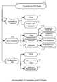
도 1은 전송기 및 RFID 리더의 동작 모드의 다양한 분류의 개략도이다.
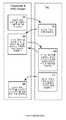
도 2는 RFID 태그 및 참조 태그의 동작 모드의 다양한 분류의 개략도이다.
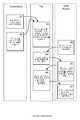
도 3은 통합된 전송기 및 RFID 리더를 갖는 시스템의 제1 실시 예의 개략도이다.
도 4는 도 3에서 보여진 시스템의 동작 방법의 흐름도이다.
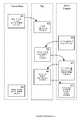
도 5는 분리된 RFID 센싱과 RFID 통신을 갖는 시스템의 제2 실시 예의 개략도이다.
도 6은 도 5에서 보여진 시스템의 동작 방법의 흐름도이다.
도 7은 제3 실시 예에 따른 버블-워킹(bubble-walking) 방법의 흐름도이다.
도 8은 RFID 참조 태그들을 갖는 버블-워킹을 이용하여 개선된 동작 범위를 갖는 시스템의 제4 실시 예의 개략도이다.
도 9는 도 8에서 보여진 시스템의 동작 방법의 흐름도이다.
도 10은 주파수 간섭을 최소화하면서 기존의 무선 기반 구조와 본 명세서의 실시 예들을 통합하는 방법의 흐름도이다.
도 11은 본 명세서의 실시 예에 따른 광범위 무선 인식 태그 충전 방법의 흐름도이다.The present invention has been described by way of example and not limited by the accompanying drawings in which like numerals represent like elements. The components of the figures are shown for simplicity and clarity and are not necessarily drawn to scale.
1 is a schematic diagram of various classes of operating modes of a transmitter and an RFID reader.
2 is a schematic diagram of various classes of operation modes of an RFID tag and a reference tag.
3 is a schematic diagram of a first embodiment of a system having an integrated transmitter and an RFID reader.
4 is a flow chart of the method of operation of the system shown in FIG.
5 is a schematic diagram of a second embodiment of a system having separate RFID sensing and RFID communication.
Figure 6 is a flow chart of the method of operation of the system shown in Figure 5;
7 is a flowchart of a bubble-walking method according to the third embodiment.
Figure 8 is a schematic diagram of a fourth embodiment of a system having an improved operating range using bubble-walking with RFID reference tags.
9 is a flow chart of the method of operation of the system shown in FIG.
10 is a flow diagram of a method for integrating embodiments of the present disclosure with an existing wireless infrastructure, while minimizing frequency interference.
11 is a flowchart of a method for charging a wide range wireless recognition tag according to an embodiment of the present invention.
본 명세서에서 개시된 시스템 및 방법의 실시 예는 RFID 태그와의 광범위 충전 및 통신을 제공하고, 그것에 의해 판독 범위를 확장하고 수동적 무선 인식 태그의 능력을 증가시킨다. 시스템은 무선 충전을 위한 서브 시스템 및 RFID 통신을 위한 서브 시스템을 포함한다. 본 명세서의 예시들은 EPC 클래스 1 제너레이션 2 프로토콜을 닮은 광범위 UHF RFID 프로토콜을 이용하지만 예시들은 어떠한 리더-토크-퍼스트(reader-talk-first) 또는 태그-토크-퍼스트(tag-talk-first) 프로토콜로 쉽게 일반화될 수 있다.Embodiments of the systems and methods disclosed herein provide a wide range of charging and communication with RFID tags, thereby extending the read range and increasing the capability of passive wirelessly recognized tags. The system includes a subsystem for wireless charging and a subsystem for RFID communication. The examples herein use a wide range of UHF RFID protocols resembling the EPC Class 1 Generation 2 protocol, but the examples can be implemented using any reader-talk-first or tag-talk-first protocol It can be easily generalized.
도 1 및 도 2는 상이한 태그, RFID 리더 및 전송기 구현을 위한 동작 모드의 예시적인 분류를 나타낸다. 상이한 실시 예들은 확장된 범위 동작을 초래하는 이러한 분류의 조합을 사용하여 아래에서 제시된다. 도 1을 참조하면, 우리는, 전송기들이 어떻게 RFID 리더와 연결되거나 통합되는지(110), 전송기들이 전력만을, 또는 전력과 데이터를 모두 전송하는지(120), 및 전송기에서 그것의 주파수, 위상 및 극성에 관한 결정이 RFID 태그로부터, 참조 태그로부터 또는 둘 모두 아닌 것에 기반하는지(130)에 기반하여 시스템을 분류한다. 일 실시 예에서, 전송기의 주파수는 RFID 태그 피드백 없이 국부적으로 조절된다.Figures 1 and 2 illustrate an exemplary classification of operating modes for different tag, RFID reader and transmitter implementations. The different embodiments are presented below using a combination of these classifications resulting in extended range operation. 1, we describe how transmitters are coupled to or integrated with an
도 2를 참조하면, 태그 측에서, 우리는 태그들이 전송기로부터 전력을 수신하고 RFID 리더와 통신하는 시스템들을 구별한다. 어떤 실시 예들에서, "전송기"는 또한 파워 액세스 포인트(PAP)로 언급된다. 일 실시 예에서, 전송기로부터 수신된 에너지 및 RFID 리더와의 통신은, 동일 주파수 범위에서(161) 동작하고 따라서 태그는 하나의 안테나만을 요구하고, 또는 선택적으로 상이한 주파수 범위에서(160) 동작한다. 또한, 태그들은, 동작을 위해 태그에 에너지가 계속 제공되기를 요구하는 기성품(off-the-shelf) 수동적 UHF RFID 태그 같은 매우 작은 정전 용량(171)으로부터 에너지가 수 분 동안에 저장될 수 있는 매우 큰 정전 용량(173)까지 변하는 상이한 에너지 저장 요건들(170)을 가질 수 있다. 태그들은 태그 설계에서 만들어질 필요가 있는 맞춤형 하드웨어(190)에 기반하여, 및 태그가 전송기들 또는 RFID 리더들로 그것의 RSSI 값을 되돌려 전달하는지(180)에 기반하여 구별될 수 있다. 또한, 태그는 태그일 때 RSSI 값을 전송할 수 있고(181), 수동적 또는 반 수동적 태그의 경우에 RSSI 값은 후방 산란 데이터로부터 추론된다(182).Referring to FIG. 2, on the tag side, we distinguish systems where tags receive power from a transmitter and communicate with an RFID reader. In some embodiments, a "transmitter" is also referred to as a power access point (PAP). In one embodiment, the energy received from the transmitter and communication with the RFID reader operate in the same frequency range (161) and thus the tag requires only one antenna, or alternatively operates in a different frequency range (160). In addition, the tags are very large, such as very
도 1 및 도 2의 예시적 분류는 (도 1로부터의) 전송기 분류 및 (도 2로부터의) 양립할 수 있는 태그 분류를 선택하는 것을 고려하여 다양한 가능한 조합들을 설명한다. 가능한 많은 조합들이 단일 시스템에서 양립할 수 있다. 예를 들면, 정해진 분류의 전송기는 다수의 상이한 분류의 태그들(또는 전송된 에너지의 수신기들)과 통신할 수 있고, 그것들로 전력을 제공할 수 있다. 다음의 실시 예들은 예시적 사용 예를 설명하도록 의도되고 전송기들 및 태그들의 상이한 조합된 분류를 한정하도록 해석되어선 안 된다.The exemplary classifications of FIGS. 1 and 2 illustrate various possible combinations considering the choice of transmitter classifications (from FIG. 1) and compatible classifications (from FIG. 2). As many combinations as possible are compatible in a single system. For example, a transmitter of a given class can communicate with and provide power to a number of different classifications of tags (or receivers of transmitted energy). The following embodiments are intended to illustrate exemplary uses and should not be construed as defining a different combined classification of transmitters and tags.
제1 실시 예:First Embodiment:
제1 실시 예는 RFID 리더와 전송기들을 통합함으로써 태그의 처리 능력을 확장하기 위한 방법을 제공한다. 전송기들은 연속파(continuous wave, CW) 에너지를 이용하여 태그에 전원을 공급하는데 필요한 전력을 전송할 뿐만 아니라 통신 데이터도 전송할 것이다. 통신 데이터 신호의 위상 또는 극성이 동기화되면(예를 들어, 둘 이상의 전송기들의 위상이 정렬되면) 통신 범위는 확장될 것이다. 통신 데이터 신호의 위상 및 극성이 모두 동기화되면 통신 범위는 더 확장될 것이다. 일 실시 예에서, 이 시스템은 수동적 센서 태그들의 처리 능력을 확장하는데 이용될 수 있다. 다른 실시 예에서, 시스템은 기성품 수동적 태그의 범위를 확장하는데 이용될 수 있다. 표준 RFID 프로토콜 또는 맞춤형 프로토콜들은 태그를 판독하는데 이용될 수 있다.The first embodiment provides a method for expanding the processing capability of a tag by integrating RFID readers and transmitters. Transmitters will use the continuous wave (CW) energy to transmit not only the power needed to power the tag but also the communication data. When the phase or polarity of the communication data signal is synchronized (e.g., when the phases of two or more transmitters are aligned), the communication range will be extended. When the phase and polarity of the communication data signal are all synchronized, the communication range will be further expanded. In one embodiment, the system can be used to extend the processing capabilities of passive sensor tags. In another embodiment, the system can be used to extend the range of ready-made passive tags. Standard RFID protocols or custom protocols can be used to read the tags.
도 3은 통합된 전송기 및 RFID 리더를 갖는 수동적 태그의 처리 능력을 향상하기 위한 시스템의 실시 예이다. 전송기들은 RFID 리더와 함께 통합되고 따라서 이 시스템은 도 1에서의 분류 117에 상응한다. 또한, 통합된 시스템은 태그에 전력을 공급하기 위해 연속파를 전송할 뿐만 아니라 RFID 데이터도 전송하므로, 그것은 도 1에서의 분류 122에 관한 것이다. 전송기 및 RFID 리더 시스템은 동일한 주파수 범위에서 동작한다(도 2의 161). 예를 들면, 전송기는 태그를 판독하기 위해 RFID 리더에 의해 사용되는 동일한 주파수로 태그로 전력을 전송한다. 태그는 센싱을 위한 전자기기를 깨우기 위해 에너지를 저장할 필요가 있고(도 2에서의 172 또는 173), 수동적 RFID 태그 및 센서 같은 맞춤형 하드웨어를 필요로 한다(193). RFID 태그는 RSSI를 획득하는 맞춤형 전자기기가 있으면 RSSI 값을 전송할 수 있고(181), 또는 태그는 단지 태그의 수신 신호를 후방 산란(backscatter)할 수 있고 RSSI는 RFID 리더에서 추론될 수 있다(182).Figure 3 is an embodiment of a system for enhancing the processing capability of a passive tag with an integrated transmitter and an RFID reader. The transmitters are integrated with the RFID reader and thus the system corresponds to the
도 3에서, RFID 리더 및 전송기들은 통합된다. 우리는 두 개의 상이한 수단을 고려한다. 첫 번째에서, 오직 하나의 전송기만이(예를 들면, 201) RFID 리더로서 행동하고, RFID 명령을 전송하고 태그의 데이터를 수신할 수 있다. 다른 모든 전송기들은 전송기/리더(201)와 동일한 주파수로 연속파 에너지를 전송할 뿐이다. 두 번째 수단에서, 모든 전송기들은 RFID 리더로서 행동하고 에너지 및 RFID 명령을 전송하고 태그의 데이터를 수신한다. 도 4에서 보여지는 프로토콜의 예에서, 우리는 첫 번째 수단을 고려할 것이다. 전송기들은 컴퓨터 시스템(220)으로부터 원격 제어된다. 태그(210)는 RFID 리더와의 통신을 위해 안테나와 수동적 태그 IC(211)를 포함한다. 또한, 태그는 커패시터(215) 같은 저장 요소, 커패시터(215)가 충분히 충전되면 센서 로직을 턴온하기 위한 전압 모니터링 회로(212), 및 센서 및 마이크로컨트롤러 시스템(213)으로 구성된다. 센서 데이터가 획득되면, 직렬 I2C 버스 같은 버스(214)를 사용하여 수동적 태그 IC(211)의 내부 메모리로 통신된다.In Figure 3, the RFID readers and transmitters are integrated. We consider two different means. In the first, only one transmitter (e. G., 201) acts as an RFID reader, transmits an RFID command, and receives data of the tag. All other transmitters only transmit the continuous wave energy at the same frequency as the transmitter /
이 실시 예에서, 센서(213)는 커패시터에 충분한 충전이 수집될 때까지 턴온되지 않을 것이고 따라서 태그는 수동적 태그로서 동작하고 비교적 큰 판독 범위를 달성할 것이다. 일반적으로, 판독 범위는 태그를 더 복잡하게 함으로써(예컨대, 더 많은 전자기기를 추가함으로써) 감소한다. 따라서, 태그(210)에서, 전력이 부족한 전자기기(213 같은)는 충분한 에너지가 모일 때까지 턴온되지 않을 것이다. 센싱을 위한 추가적 에너지는 커패시터(215)를 충전하기 위한 전송기를 턴온함으로써 수집될 것이다. 도 4는 도 3에서 나타난 시스템의 포로토콜의 수단을 보여 준다. 우리는 단 하나의 전송기가 RFID 리더와 통합되고/되거나 RFID 리더를 사용하는(예를 들면 201) 첫 번째 수단을 고려한다. 먼저, 리더(201)는 태그를 판독하는 것을 시작한다. 판독 범위 내에 다수의 태그들이 있을 수 있다. 리더(201)는 표준 RFID 프로토콜을 사용하여 하나의 태그(210)를 판독(예컨대, 단일화)한다. 리더가 명령을 태그로 전송한(301) 이후에, 태그는 ID 번호(ID)로 응답한다. 태그를 식별한 이후에, 리더(201)는 태그의 메모리의 콘텐트를 판독하기 위해 추가적인 명령들을 계속하여 전송한다. 명령을 READ 명령으로 부르기로 한다. READ 명령을 전송하는 동안에, 다른 전송기들(202, 203)은 태그로 추가의 에너지를 제공하기 위해 턴온 되고/되거나 지향될 것이다. 전송기들(202, 203)은 전송기/리더(201)와 동일한 주파수로 연속파 에너지를 전송하도록 정렬된다. 이 실시 예에서, 태그는 READ 명령에 대하여 동일한 메모리 위치의 콘텐트로 응답한다(312). 리더/전송기(201)는 태그로부터 응답을 수신하고 RSSI를 추출하여 전송기들의 위상을 조절하고 다른 READ 명령을 전송한다(302). 태그에 더 많은 에너지가 공급되면 태그 측의 커패시터는 충전될 것이다. 충분한 에너지가 제공되면 센서는 턴온될 것이고 센싱을 수행하여 메모리 위치에 감지된 데이터를 저장할 것이다. 이제 메모리 위치의 콘텐트는 이전과는 달라질 것이다(313). 다음에 READ 명령을 이용함으로써 그 메모리 위치를 판독한 이후에 리더는 새로운 값을 판독할 것이고 그것은 태그가 센싱을 수행했다는 것을 의미할 것이다(303). 그 예에서, 리더(201)는 다른 태그들을 판독하는 것을 진행할 것이다. 다양한 실시 예들에서, 태그의 메모리는 읽힐 때 클리어될 것이다. 다른 실시 예에서, 태그의 메모리는 메모리가 업데이트되었거나 클리어되었음(예컨대, 센서 데이터의 부재를 나타내는 예약된 값으로 설정됨)을 나타내는 세마포어를 포함한다. 다른 실시 예에서, 태그의 메모리는 메모리가 업데이트된 시간을 나타내기 위해 국부적 클럭의 타임스탬프를 포함한다.In this embodiment, the
다른 실시 예는 동일한 메모리 위치의 콘텐트를 전송하는 것 대신에 충분한 에너지가 제공되기 이전에 판독된 명령들에 응답하는 것과 같이 READ 명령에 응답하여 수신된 RSSI 값을 추정하고 RSSI 값을 전송할 수 있는 태그를 포함한다. 이러한 수단은 전송기들의 위상들을 조절하는데 유리하지만, 그것이 태그의 하드웨어를 더 복잡하게 하고 따라서 태그의 판독 범위에 영향을 미칠 수 있다.Another embodiment is a method for estimating a received RSSI value in response to a READ command, such as responding to commands that have been read before sufficient energy is provided, instead of transmitting content at the same memory location, . This means is advantageous in regulating the phases of the transmitters, but it makes the hardware of the tag more complicated and can therefore affect the read range of the tag.
범위를 확장하는 것에 더하여, 시스템은 태그의 국지화를 수행할 수 있다. 다수의 전송기들의 위상은 RFID 리더에서의 RSSI 값만큼 잘 알려지기 때문에 이 정보는 태그의 위치를 추정하는데 이용될 수 있다.In addition to extending the range, the system can perform localization of the tag. This information can be used to estimate the position of the tag since the phases of multiple transmitters are as well known as the RSSI value in the RFID reader.
제2 실시 예:Second Embodiment:
제2 실시 예는 센싱을 RFID 리더와의 통신으로부터 시간적으로 분리시킴으로써 태그들의 처리 능력을 확장하는 방법을 포함한다. 시스템은 하나 이상의 RFID 리더들과 적어도 두 개의 전송기들로 이루어진다. 센싱은 전송기에 의해 충전되었을 때 행해질 것이고 센싱된 데이터는 저장될 것이다. 데이터는 표준 RFID 인터페이스를 이용하여 판독될 수 있다. 이 시스템의 실시 예는, 여기서 설명된 다른 RFID 센서-태그 시스템과 비교하여, 센싱이 RFID 리더와의 통신과는 다른 시간에 행해지기 때문에 RFID 리더와의 통신 동안 센싱을 수행하기 위한 추가의 에너지를 제공할 필요가 없다. 다른 예에서 저장된 데이터의 많은 어레이들을 판독하는데 최적화된 맞춤형 프로토콜이 이용되는 반면, 일 실시 예에서 표준 RFID 프로토콜은 센싱된 데이터를 판독하는데 이용될 수 있다. 일 실시 예에서, 태그는 태그가 에너지 버블(bubble of energy)에 있을 때마다 충전될 수 있는데 반해, 다른 실시 예에서, 후방 산란을 통해 전송된 및/또는 통신된 RSSI 값은 태그 쪽으로 에너지를 지향하는데 이용될 수 있다. 본 명세서의 문맥 내에 사용된 용어 "에너지 버블"은 다수의 전송기들(예컨대, 201, 202, 203)에 의해 전송된 에너지가 전송기들에 의해 방출되는 에너지 빔들의 주파수, 위상, 극성 정렬의 적어도 하나의 건설적인 효과에 기인하여 "버블" 주변의 에너지보다 현저하게 큰 위치를 의미한다. 이 건설적 에너지가 발생하는 물리적 공간은 버블 형태와 유사할 수 있지만 그렇게 한정될 필요는 없다. 유사하게, 용어 "버블-워킹(bubble-walking)"은 하나 이상의 전송기들의 빔 스티어링(beam steering)을 변형함(위상 및/또는 극성을 변형하는 것을 포함함)으로써 에너지 버블이 다른 위치로 이동하는 것을 말한다.The second embodiment includes a method of extending the processing capabilities of the tags by temporally separating the sensing from communication with the RFID reader. The system comprises one or more RFID readers and at least two transmitters. The sensing will be done when it is charged by the transmitter and the sensed data will be stored. The data can be read using a standard RFID interface. Embodiments of this system can provide additional energy to perform sensing during communication with the RFID reader, as compared to other RFID sensor-tag systems described herein, since sensing is done at a different time than communication with the RFID reader There is no need to provide. In another example, a customized protocol optimized for reading many arrays of stored data is used, while in one embodiment a standard RFID protocol can be used to read the sensed data. In one embodiment, the tag may be charged whenever the tag is in a bubble of energy, while in other embodiments, the RSSI value transmitted and / or communicated through the backscatter may be energy directed towards the tag . ≪ / RTI > The term "energy bubble" as used in the context of this disclosure refers to the energy transmitted by a plurality of transmitters (e.g., 201, 202, 203) Quot; bubble "due to the constructive effect of " bubble ". The physical space in which this constructive energy occurs may be similar to the bubble shape, but need not be so limited. Similarly, the term " bubble-walking "modifies (including modifying the phase and / or polarity) the beam steering of one or more transmitters so that the energy bubble travels to another location It says.
도 5는, RFID 태그를 위한 질의를 개시하기 위한 RFID 리더(430), 태그의 저장 요소(415)를 충전하고 센싱(sensing)을 개시하기 위한 전송기들(401, 402, 403) 및 RFID 센서 태그(410)를 포함하는, 무선 인식(RFID) 태그들의 처리 능력을 개선하기 위한 시스템을 보여 준다. 우리가 도 1 및 도 2의 분류를 참조하면, 전송기들(401-403) 및 RFID 리더는 소프트웨어를 통해서만 연결되는 분리된 모듈들이고, 전송기들은 태그(121)에 전력을 공급하기 위해 연속파를 전송하기만 하고, 일 실시 예에서 수신기로부터 RFID 태그들로부터의 RSSI 피드백이 있고(132), 다른 실시 예에서 피드백이 없다(131). 전송기들은 RFID 리더(161)와 동일한 주파수에서(161) 또는 상이한 주파수에서(162) 동작한다. 예를 들면, 전송기들은, RFID 리더와 통신하기 위해 태그에 의해 사용되는 주파수와 동일한 또는 상이한 주파수로 태그로 에너지 빔을 전송한다. 도 5에서 보이는 예시에서, 전송기 및 RFID 리더 모두 동일한 주파수 범위에서 동작한다고 가정한다. 장시간 동안 에너지를 저장할 필요가 없기 때문에 저장 요소는 최소화될 수 있다(171). 일 실시 예에서, 태그는 전송기에 의해 에너지가 공급될 때 RSSI 값을 전송하고(181), 다른 실시 예에서, 태그는 전송기에 의해 에너지가 공급될 때 RSSI 값을 전송하지 않는다(183). 태그의 맞춤형 설계가 요구된다(193).5 shows an
이 예에서, RFID 리더(430) 및 전송기들(401, 402, 403)은 동일한 주파수 범위에서 동작하기 때문에, 연산 유닛(420)에서 실행되는 소프트웨어는 시간 다중화를 담당한다. 리더 및 전송기들은 시간 다중화된 방식으로 작동하기 때문에 기성품 리더가 사용될 수 있다.In this example, since the
이 실시 예는 RFID 통신으로부터 센싱 및 처리를 분리시킨다. 전송기들은 시간 주기 동안 어느 위치에서의 에너지 버블에 집중한다. 그 시간 주기 후에, 에너지 버블이 모든 공간이 커버될 때까지 공간에서의 인접한 위치에 집중된다. 유닛(413)에서의 센싱 및 처리는 태그가 전송기들에 의해 충전될 때(예컨대, 태그가 에너지 버블에 있을 때) 행해지고, 센싱된 데이터는 태그의 메모리(412)에 저장될 것이다. 전송기들이 관심있는 태그들 모두를 포함하는 전체 공간을 조명한 후, RFID 리더는 센싱된 데이터를 읽기 위해 턴온된다. 태그의 센서 및 마이크로컨트롤러(413)는 RFID 리더와 통신하는 동안 그것들이 턴온되기에 충분한 에너지가 없을 것이기 때문에 RFID 통신 동안에 턴오프될 것이다. 따라서 판독을 달성할 수 있는 범위는 10m를 넘는, 기존의 수동적 태그의 범위이다. 따라서, 이 실시 예는 태그 내에 추가적인 처리 능력을 부가하면서, 현재의 RFID 시스템들의 범위를 확장하지 않고 오히려 유지한다. 이것은 기존의 RFID 센서 태그들로는 수행될 수 없는데, 이는 그것들이 센서가 센싱을 수행하기 위해 RFID 리더로부터 에너지를 필요로 하고 따라서 판독 범위는 낮기 때문이다.This embodiment isolates sensing and processing from RFID communications. The transmitters focus on the energy bubble at any position during the time period. After that period of time, the energy bubble is concentrated at an adjacent location in space until all the space is covered. The sensing and processing in
도 6은 도 5에 설명된 시스템에 상응하는 프로토콜의 예시를 보여 준다. 도 6은 전송기들 및 RFID 리더가 동시에 동작하지 않음을 보여 준다. 첫 단계는 판독되기를 바라는 태그들을 포함하여, 환경에서 모든 전자 태그들을 충전하거나(501), 모든 공간을 스캐닝하는 것(502)을 포함한다. 태그가 전송기로부터 에너지를 수신하면, 그것은 센싱을 수행하고 센싱된 정보를 메모리에 저장하고 새로운 값이 태그의 메모리에 쓰였음을 나타내는 세마포어를 업데이트한다(511). RFID 리더가 태그들을 판독하면 그것은 개별적으로 태그들에게 질의한다. 태그의 ID를 판독한 후, RFID 리더는 메모리의 세마포어를 체크하기 위해 READ 명령을 전송한다(521). 태그는 세마포어가 저장된 메모리 위치의 콘텐트를 전송한다(512). 세마포어의 값이 "1"이면, 리더는 센서 데이터가 저장된 메모리 위치의 콘텐트가 전송되기를 요청하는 다른 READ 명령을 전송한다(522). 태그는 메모리 위치의 콘텐트를 읽고 데이터를 전송한다(513). 그 후, 태그는 세마포어의 값을 리셋한다. 그리고나서 리더는 다른 태그의 판독으로 진행할 수 있다(523). 다른 실시 예에서, 세마포어의 값은 후속의 READ 명령이 RFID 리더에 의해 전송되어야 함을 나타내기 위한, "0" 또는 어떤 다른 값이다. 태그가 충분한 에너지를 수신하지 않았음이 발생할 수도 있는 것과 같이 리더가 태그들 중 특정의 하나의 세마포어가 설정되지 않았음을 발견하면, (연산 유닛(420)에서 실행하는 것과 같은) 더 높은 레벨의 소프트웨어는 에너지 버블이 그 특정의 태그의 위치에 집중되는 기간을 증가시킬 수 있다.FIG. 6 shows an example of a protocol corresponding to the system described in FIG. Figure 6 shows that transmitters and RFID readers do not operate at the same time. The first step includes charging all electronic tags in the environment (501) and scanning (502) all space, including tags that wish to be read. When the tag receives energy from the transmitter, it performs sensing, stores the sensed information in memory, and updates the semaphore indicating that the new value has been written to the tag's memory (511). When the RFID reader reads the tags, it queries the tags individually. After reading the ID of the tag, the RFID interrogator transmits a READ command to check the semaphore of the memory (521). The tag transfers 512 the content of the memory location where the semaphore is stored. If the value of the semaphore is "1 ", the reader sends another READ command to request the content of the memory location where the sensor data is stored to be transmitted (522). The tag reads the content of the memory location and transmits the data (513). The tag then resets the value of the semaphore. The reader may then proceed to reading another tag (523). In another embodiment, the value of the semaphore is "0" or some other value to indicate that a subsequent READ command should be sent by the RFID reader. If the reader finds that a particular one of the tags has not been set up, such as may occur that the tag has not received sufficient energy, a higher level (such as running in the operation unit 420) Software can increase the period over which energy bubbles are concentrated at the location of that particular tag.
다른 실시 예에서, 전송기들 및 RFID 리더는 상이한 주파수 범위에서 동작할 것이다. 따라서, 시간 다중화가 요구될 것이다. 그러나, 태그는 최소한 두 개의 안테나와 두 개의 상응하는 RF 유닛을 가질 것이다.In other embodiments, the transmitters and the RFID reader will operate in different frequency ranges. Therefore, time multiplexing will be required. However, the tag will have at least two antennas and two corresponding RF units.
제3 실시 예:Third Embodiment:
제3 실시 예에서, 태그는 전송기들에 의해 충전되고 그리고 RFID 리더에 의해 빠르게 판독된다. 이 실시 예에서, 에너지 버블은 한 지점에 집중되고 그리고 이동되고, 다음에 하나의 RFID 판독 시퀀스가 뒤따른다. 일 실시 예에서, 태그는 표준 RFID 태그이다. 다른 실시 예에서, 태그는 전송기들 중 적어도 하나에 의해 조명될 때 그것의 RSSI 값을 후방 산란한다. 도 7은 제3 실시 예를 실행하는 시퀀스를 보여 준다.In a third embodiment, the tag is charged by transmitters and is read fast by an RFID reader. In this embodiment, the energy bubble is concentrated and moved to one point, followed by one RFID read sequence. In one embodiment, the tag is a standard RFID tag. In another embodiment, the tag scatters its RSSI value when illuminated by at least one of the transmitters. Fig. 7 shows a sequence for executing the third embodiment.
제4 실시 예:Fourth Embodiment:
제4 실시 예는 전송기들에 의해 전송되는 에너지의 버블-워킹을 이용한다. 먼저, 하나의 전송기 주변의 공간은 그 전송기에 의해서만 에너지 공급될 것이다. 전송기로부터 더 떨어진 영역들은 건설적 간섭으로부터 유리할 것이다. 에너지 버블은 공간에서의 한 위치에서 특정 시간 동안 형성되고 유지될 것이다. 다른 실시 예에서, 이것은 참조 태그들의 위치에 대해 어떠한 교정 없이 행해질 것이다. 다양한 실시 예들에서, 에너지 버블의 위치는 많은 알고리즘 중 하나 이상을 이용하여 추정된다. 일 실시 예에서, 버블의 위치는 전송기들의 위치, 알려진 전송 주파수 및 위상, 및 자유 공간 전파 모델의 가정에 기반하여 추정된다. 다른 실시 예에서, 에너지 버블의 위치는 참조 태그들을 이용하여 측정된다. 다양한 실시 예들에서, 참조 태그들은 알려진 위치들에 배치되고 전송기들에 의해 조명될 때 RSSI 값들을 제공한다. 에너지 버블의 위치가 측정된 후, 다른 위치들은 참조 태그들에 비하여 추정될 수 있다.The fourth embodiment utilizes the bubble-walking of the energy transmitted by the transmitters. First, the space around one transmitter will be energized only by that transmitter. Areas farther from the transmitter will benefit from constructive interference. The energy bubble will be formed and maintained for a certain time at a location in space. In another embodiment, this will be done without any correction to the location of the reference tags. In various embodiments, the location of the energy bubble is estimated using one or more of many algorithms. In one embodiment, the location of the bubble is estimated based on the location of the transmitters, the known transmit frequency and phase, and the assumption of the free space propagation model. In another embodiment, the position of the energy bubble is measured using reference tags. In various embodiments, the reference tags are located at known locations and provide RSSI values when illuminated by the transmitters. After the position of the energy bubble is measured, other positions may be estimated relative to the reference tags.
도 8은 RFID 센서 태그들의 범위(704)를 확장하기 위한 시스템을 보여 주고, 여기서 시스템은 RFID 태그를 위한 질의를 개시하기 위한 RFID 리더(730), RFID 리더와 통신하고 수퍼 커패시터(712) 같은 저장 요소를 갖는 적어도 하나의 RFID 태그(710), RFID 쪽으로 에너지를 지향하고 수퍼 커패시터를 충전할 수 있는 전송기들(701, 702, 703), 및 RFID 리더 및 전송기들 모두의 전송을 제어하는 컨트롤러(720)를 포함한다. 또한 다양한 실시 예들에서, 시스템은 특정 지점들로 에너지를 지향시키는 것을 돕기 위해 전략적 지점들에 배치된 참조 태그들(741, 742)을 포함한다.Figure 8 shows a system for extending the
도 1 및 도 2의 분류를 참조하면, 전송기들(701, 703, 703) 및 RFID 리더(730)는 소프트웨어로만 연결된(112, 116) 상이한 하드웨어 유닛들이고, 전송기들은 태그에 전력을 제공하기 위한 연속파를 전송할(121) 뿐이고, RFID 태그들로부터의 피드백은 없다(131). 그러나, 참조 태그들이 사용되면 그것들은 전송기들로 RSSI를 제공할 것이다(133). 다양한 실시 예들에서, 시스템들 모두가 동일한 주파수 범위에서 동작하는 것을 가정한, 도 7에서 보인 예시와는 대조적으로 전송기들은 RFID 리더와 동일한 주파수로(161), 또는 상이한 주파수로(162) 동작한다. 태그에서의 저장 요소는 클 필요가 있다(173). 태그는 전송기에 의해 조명될 때 RSSI를 전송하지 않는다(183). 큰 저장 요소가 필요하기 때문에 태그의 맞춤형 설계가 요구된다(190).1 and 2, the
도 9는 RFID 센서 태그를 판독하기 위한 프로토콜을 보여 준다. 전송기들은 몇 초간 특정 장소에 에너지를 집중시킨다(801). 태그가 그 장소에 있다면 그것의 저장 요소는 충전될 것이다(811). 그 후에, 전송기들은 턴오프되고 RFID 리더가 턴온된다. RFID 리더는 그것의 판독 범위에서 태그에 질의한다(821). 태그의 충전 요소가 충전되었다면, 태그는 반 수동적 태그로 행동할 수 있고 큰 판독 범위를 달성할 수 있다. 리더는 태그의 ID를 판독할 것이다. 태그가 센서 태그라면, 태그는 센싱을 수행할 것이고(812), 그리고 센싱된 데이터는 리더에 의해 판독될 것이다(822, 813). 이어서, 리더는 다른 태그들에 질의를 계속한다(823).다른 태그들이 응답하지 않은 후에, 전송기들은 다시 턴온되지만, 이제는 그것들은 몇 초간 다른 장소에 에너지를 집중시키고(802), 전체 과정이 반복된다.9 shows a protocol for reading an RFID sensor tag. The transmitters concentrate energy at a specific location for a few seconds (801). If the tag is in place, its storage element will be charged (811). Thereafter, the transmitters are turned off and the RFID reader is turned on. The RFID interrogator queries the tag in its read range (821). If the charging element of the tag is charged, the tag can act as a semi-passive tag and achieve a large read range. The reader will read the ID of the tag. If the tag is a sensor tag, the tag will perform the sensing (812), and the sensed data will be read by the reader (822, 813). Then, the reader continues to query the other tags (823). After the other tags do not respond, the transmitters are turned on again, but now they are focused on energy elsewhere for a few seconds (802) do.
일 실시 예에서, 알려진 위치에 있는 참조 태그들이 이용된다. 이 태그들은 RSSI를 검출할 수 있고 전송기들에 RSSI 값을 통신할 수 있다. 이 예에서, 그것들은 에너지 버블을 집중하는데 이용될 수 있다. 추가의 실시 예들에서, 수동적 센서 태그들(710)은 적어도 대략적으로 참조 태그들에 대해 알려진 위치에 있는 물체 내에 또는 그 위에 위치한다. 예를 들면, 수동적 센서 태그들은 조립 라인 상의 자동차에 있고, 참조 태그들은 수동적 센서 태그들이 판독될 수 있는, 조립 라인의 특정 위치에 위치한다. 이것은 에너지 버블이 예컨대, 수동적 센서 태그들로부터 RSSI를 수신할 필요 없이 물체 상의 또는 물체 내의 특정 위치들 상에 집중될 수 있게 한다.In one embodiment, reference tags at known locations are used. These tags can detect the RSSI and communicate the RSSI value to the transmitters. In this example, they can be used to focus the energy bubble. In further embodiments, the
다른 실시 예에서, 전송기들 및 RFID 리더는 하나의 시스템 내에 통합된다. 이 예에서, 기성품 수동적 태그들이 이용될 수 있다. 전송기들은 얼마 동안 한 곳에 에너지 버블을 집중할 것이고, 그리고 전송기들 중 하나는 리더로서 행동할 것이다. RFID 리더는 에너지 버블 내에 있는 태그들을 판독할 것이고 따라서 이 실시 예는 더 긴 범위를 달성할 수 있을 것이다.In another embodiment, the transmitters and the RFID reader are integrated into one system. In this example, ready-made passive tags can be used. Transmitters will concentrate energy bubbles in one place for some time, and one of the transmitters will act as a leader. The RFID reader will read the tags in the energy bubble and thus this embodiment will be able to achieve a longer range.
도 10은 RFID 시스템이 기성품 RFID 리더 및 동일한 주파수 대역에서 동작하는 다른 무선 장치와 공존하도록 설계된 실시 예의 방법을 보여 준다. 주파수 대역에서 (예컨대 컨트롤러에 의해) 약간의 에너지가 검출되면 전송기들은 전송하지 않을 것이다. 이런 방식으로, 전송기들은 기성품 RFID 배치들에 추가될 수 있으며 시간 다중 방식으로 그것들과 함께 작동할 수 있다.Figure 10 shows a method of an embodiment in which the RFID system is designed to coexist with an off-the-shelf RFID reader and other wireless devices operating in the same frequency band. If some energy is detected in the frequency band (e.g., by the controller), the transmitters will not transmit. In this way, transmitters can be added to off-the-shelf RFID deployments and can work with them in a time multiplexed fashion.
도 11은 광범위 RFID 태그 충전 방법을 나타내고 있다. 단계 1000에서, 제1 에너지 빔이 에너지 위치에 지향된다. 단계 1002에서, 제2 에너지 빔이 에너지 위치에 지향된다. 다른 실시 예들에서, 두 개를 초과하는 에너지 빔들이 이용되고, 각 에너지 빔은 에너지 위치에 지향된다. 여기서 사용된 용어 "에너지 위치"는 제1 및 제2 에너지 빔들의 건설적인 간섭에 기인하여 주변 영역보다 에너지 밀도가 더 큰 위치를 말한다.11 shows a method of charging a wide range RFID tag. In
단계 1004에서, 주파수와 각 에너지 빔의 위상 및 극성 중 적어도 하나는 정렬된다. 일 예에서, 제1 에너지 빔의 주파수는 제2 에너지 빔의 주파수로 정렬되고, 제1 에너지 빔 및 제2 에너지 빔의 위상들은 정렬된다. 용어 "정렬"은 에너지 위치에서 정렬하는 것을 나타낸다. 두 개의 각각의 빔들의 주파수를 "정렬하는 것"은 두 개의 빔들의 주파수를 동일하게 하는 것을 의미한다. 두 개의 각각의 빔들의 위상을 "정렬하는 것"은 두 개의 빔들의 위상을 동일하게 하는 것을 의미한다. 두 개의 각각의 빔들의 극성을 "정렬하는 것"은 두 개의 빔들의 극성을 동일하게 하는 것을 의미한다. 단계 1006에서, 태그는 에너지 위치에서 (예컨대, 커패시터를 충전함으로써) 수신된 에너지를 저장한다. 단계 1008에서, 태그는 센서 데이터를 감지한다. 단계 1010에서, 센서 데이터는 지연 후 리더로 전송된다.At
본 발명이 특정 실시 예들을 참조하여 설명되었지만, 아래의 청구 범위에 설명된 본 발명의 범위를 벗어나지 않고서 다양한 변형과 수정이 이루어질 수 있다. 따라서, 명세서 및 도면은 제한적인 의미라기보다는 예시적인 것으로 간주되어야 하고, 이러한 모든 변형은 본 발명의 범위 내에 포함되는 것으로 의도된다. 특정 실시 예들과 관련하여 본 명세서에 기술된 문제점들에 대한 어떤 이익들, 유리함들, 또는 해결책들은 청구 범위의 일부 또는 모든 것의 결정적인, 요구되는, 또는 필수적인 특징 또는 요소로 해석될 의도는 없다.Although the present invention has been described with reference to specific embodiments, various changes and modifications may be made without departing from the scope of the invention as set forth in the claims below. Accordingly, the specification and figures are to be regarded in an illustrative rather than a restrictive sense, and all such modifications are intended to be included within the scope of the present invention. Certain benefits, advantages, or solutions to the problems described herein with respect to particular embodiments are not intended to be construed as a critical, required, or essential feature or element of some or all of the claims.
달리 명시되지 않는 한, "제1" 및 "제2" 같은 용어는 그런 용어가 설명하는 요소들을 임의로 구별하는데 사용된다. 따라서, 이 용어들은 그런 요소의 시간적 또는 다른 우선 순위를 나타내도록 반드시 의도되지는 않는다.Unless otherwise indicated, terms such as " first "and" second "are used to arbitrarily distinguish between elements that the term describes. Accordingly, these terms are not necessarily intended to represent a temporal or other priority of such element.
201, 202, 203 : 리더/전송기
210 : 태그
211 : 수동적 태그 IC 212 : 전압 모니터링 회로
213 : 센서 및 마이크로컨트롤러 215 : 커패시터
220 : 컴퓨터 시스템
401, 402, 403 : 전송기
410 : 태그
411 : 수동적 태그 IC 412 : 메모리
413 : 센서 및 마이크로컨트롤러 415 : 커패시터
420 : 연산 유닛
430 : RFID 리더
701, 702, 703 : 전송기
710 : 수동적 센서 태그 712 : 커패시터
720 : 컨트롤러
730 : RFID 리더
741, 742 : 참조 태그201, 202, 203: reader / transmitter
210: Tag
211: passive tag IC 212: voltage monitoring circuit
213: Sensor and microcontroller 215: Capacitor
220: Computer system
401, 402, 403:
410: Tag
411: passive tag IC 412: memory
413: SENSORS AND MICROCONTROLLERS 415: CAPACITORS
420: Operation unit
430: RFID reader
701, 702, 703:
710: Passive sensor tag 712: Capacitor
720: Controller
730: RFID reader
741, 742: reference tag
Claims (20)
Translated fromKorean상기 에너지 위치로 제2 에너지 빔을 지향하도록 구성된 제2 전송기, 상기 제2 전송기는 상기 제1 전송기와 물리적으로 분리되고;
상기 에너지 위치에 있는 태그, 상기 태그는 상기 에너지 위치로부터의 수신 에너지를 저장하고, 센서 데이터를 감지하고, 상기 태그가 상기 에너지 위치에 있은 때로부터 특정 기간 후에 리더로 상기 센서 데이터를 전송하도록 구성되고; 및
상기 태그의 디바이스 응답에 응답하여 상기 에너지 위치에서의 에너지 레벨을 최대화하기 위해 상기 에너지 위치에서 상기 제1 에너지 빔의 제1 주파수를 상기 제2 에너지의 제2 주파수로, 상기 제1 에너지 빔의 제1 위상 및 제1 극성 중 적어도 하나를 상기 제2 에너지 빔의 각각의 제2 위상 및 각각의 제2 극성으로 정렬하도록 구성되는 컨트롤러를 포함하는 광범위 무선 인식 태그 충전 시스템.A first transmitter configured to direct a first energy beam to an energy location;
A second transmitter configured to direct a second energy beam to the energy location, the second transmitter being physically separate from the first transmitter;
A tag in the energy position, the tag is configured to store received energy from the energy location, to sense sensor data, and to transmit the sensor data to the reader after a certain period of time from when the tag was in the energy position ; And
In response to a device response of the tag, to maximize the energy level at the energy position, wherein the first frequency of the first energy beam at the energy position is converted to the second frequency of the second energy, And a controller configured to align at least one of the first phase and the first polarity to a respective second phase and second respective polarity of the second energy beam.
상기 리더는, 상기 제1 에너지 빔을 지향하고 상기 제1 전송기의 안테나로 상기 센서 데이터를 수신하는 상기 제1 전송기와 통합되는 시스템.The method according to claim 1,
Wherein the reader is integrated with the first transmitter directing the first energy beam and receiving the sensor data with the antenna of the first transmitter.
상기 리더는, 상기 제1 에너지 빔을 지향하고 상기 제1 전송기의 제1 안테나로 상기 센서 데이터를 수신하는 상기 제1 전송기와 통합되고, 제2 리더는, 상기 제2 에너지 빔을 지향하고 상기 제2 전송기의 제2 안테나로 상기 센서 데이터를 수신하는 상기 제2 전송기와 통합되는 시스템.The method according to claim 1,
Wherein the reader is integrated with the first transmitter directing the first energy beam and receiving the sensor data at a first antenna of the first transmitter, the second reader directs the second energy beam, 2 < / RTI > transmitter, the second transmitter receiving the sensor data.
상기 디바이스 응답은 후방 산란을 이용하여 상기 태그로부터 전달된, 상기 태그에서의 수신 신호 강도 지표 및 상기 수신 에너지의 크기 중 하나인 시스템.The method according to claim 1,
Wherein the device response is one of a received signal strength indicator at the tag and a magnitude of the received energy delivered from the tag using backscattering.
상기 태그는 상기 태그가 상기 수신 에너지를 수신하는데 응답하여 동작 전압 레벨로 충전되도록 구성된 커패시터를 더 포함하고, 상기 기간은 상기 커패시터에 연결된 전압 모니터에 의해 측정된 동작 전압 레벨로 상기 커패시터를 충전하는 충전 시간과 동일한 시스템.The method according to claim 1,
The tag further comprising a capacitor configured to charge the tag to an operating voltage level in response to receiving the received energy, wherein the duration is determined by a charge to charge the capacitor to an operating voltage level measured by a voltage monitor coupled to the capacitor. Same system as time.
상기 태그는 상기 커패시터가 상기 동작 전압 레벨로 충전되지 않은 동안에 상기 태그의 메모리의 디폴트 콘텐트를 전송하도록 구성되고, 상기 태그는 상기 커패시터가 상기 동작 전압 레벨로 충전된 후에 상기 센서 데이터를 감지하고 전송하도록 구성된 시스템.6. The method of claim 5,
Wherein the tag is configured to transmit default content of the memory of the tag while the capacitor is not charged to the operating voltage level, the tag being configured to detect and transmit the sensor data after the capacitor is charged to the operating voltage level Configured system.
상기 메모리의 상기 디폴트 콘텐트는 상기 메모리의 클리어 상태를 나타내는 클리어 데이터 값, 상기 커패시터의 비충전 상태를 나타내는 세마포어, 마지막 전송 이래로 상기 센서 데이터가 감지되었는지를 나타내는 세마포어, 상기 메모리가 클리어된 시간을 나타내는 타임스탬프 값, 및 상기 수신 에너지의 신호 강도를 나타내는 수신 신호 강도 지표 중 하나 이상을 포함하는 시스템.The method according to claim 6,
Wherein the default content of the memory comprises a clear data value indicating a clear state of the memory, a semaphore indicating a non-charged state of the capacitor, a semaphore indicating whether the sensor data has been sensed since the last transfer, a time indicating a time A received signal strength indicator, a stamp value, and a received signal strength indicator indicative of a signal strength of the received energy.
상기 태그는 상기 태그가 상기 수신 에너지를 수신하는데 응답하여 상기 센서 데이터를 감지하고, 상기 태그의 메모리에 상기 센서 데이터를 저장하고, 상기 센서 데이터의 저장 후에 세마포어를 설정하도록 구성되고, 상기 태그는 상기 세마포어가 설정되고 상기 리더에 의해 질의 받을 경우에만 상기 센서 데이터를 상기 리더로 전송하도록 구성되고, 상기 기간은 상기 태그가 상기 에너지 위치에 있은 후에 상기 태그가 상기 세마포어를 설정하는 감지 시간과 동일한 시스템.The method according to claim 1,
Wherein the tag is configured to sense the sensor data in response to the tag receiving the received energy, store the sensor data in a memory of the tag, and set a semaphore after storing the sensor data, And to send the sensor data to the reader only if the semaphore is set and queried by the reader, wherein the time period is the same as the detection time at which the tag sets the semaphore after the tag is in the energy position.
상기 기간은 고정된 시간 기간인 시스템.The method according to claim 1,
Wherein the period is a fixed time period.
상기 에너지 위치는 상기 기간 이후에 새로운 에너지 위치로 이동되고, 상기 에너지 위치는 최소한 부분적으로 다수의 참조 태그로부터 결정되고, 각각의 참조 태그는 각각의 참조 태그에서의 수신 에너지의 신호 강도에 상응하는 각각의 수신 신호 강도 지표를 전송하는 시스템.The method according to claim 1,
The energy position is shifted to a new energy position after the period, the energy position is determined at least partially from a plurality of reference tags, and each reference tag corresponds to a signal intensity of the received energy in each reference tag Of the received signal strength indicator.
상기 컨트롤러는 상기 컨트롤러가 각각의 제1 전송기 또는 제2 전송기와 동일한 주파수를 갖는 백그라운드 에너지를 검출하는 것에 응답하여 상기 제1 전송기 및 상기 제2 전송기 중 적어도 하나를 비활성화하도록 구성된 시스템.The method according to claim 1,
Wherein the controller is configured to deactivate at least one of the first transmitter and the second transmitter in response to the controller detecting background energy having the same frequency as the respective first transmitter or second transmitter.
상기 제1 전송기와 물리적으로 분리된 제2 전송기에 의해 상기 에너지 위치로 제2 에너지 빔을 지향하고,
상기 에너지 위치에서의 태그에 의해 상기 에너지 위치로부터의 수신 에너지를 저장하고,
저장된 수신 에너지로 센서 데이터를 감지하고,
상기 태그가 상기 에너지 위치에 있은 때부터 특정 기간 후에, 저장된 수신 에너지로 상기 태그로부터 리더로 상기 센서 데이터를 전송하고,
컨트롤러에 의해 상기 에너지 위치에서 상기 태그의 디바이스 응답에 응답하여 상기 에너지 위치에서의 에너지 레벨을 최대화하기 위해 상기 제1 에너지 빔의 제1 주파수를 상기 제2 에너지 빔의 제2 주파수로, 상기 제1 에너지 빔의 제1 위상 및 제1 극성 중 적어도 하나를 상기 제2 에너지 빔의 각각의 제2 위상 및 각각의 제2 극성으로 정렬하는 것을 포함하는 광범위 무선 인식 태그 충전 방법.Directing a first energy beam to an energy position by a first transmitter,
Directing a second energy beam to the energy location by a second transmitter physically separate from the first transmitter,
Storing received energy from the energy location by a tag at the energy location,
The sensor data is sensed by the stored received energy,
Transmitting the sensor data from the tag to the reader with a stored received energy after a certain period of time from when the tag is at the energy position,
A first frequency of the first energy beam to a second frequency of the second energy beam in response to a device response of the tag at the energy location by the controller to maximize an energy level at the energy location, And aligning at least one of a first phase and a first polarity of the energy beam to a respective second phase and second respective polarity of the second energy beam.
상기 태그의 상기 디바이스 응답은 수신 신호 강도 지표(RSSI)로부터 결정되고, 상기 RSSI는 상기 태그에서의 상기 수신 에너지의 측정된 값인 방법.13. The method of claim 12,
Wherein the device response of the tag is determined from a received signal strength indicator (RSSI), and wherein the RSSI is a measured value of the received energy in the tag.
상기 태그는 후방 산란을 이용하여 상기 디바이스 응답을 전달하고, 상기 디바이스 응답은 상기 태그에서의 상기 수신 에너지의 크기에 기반하는 방법.13. The method of claim 12,
Wherein the tag conveys the device response using backscattering and the device response is based on the magnitude of the received energy in the tag.
상기 저장하는 것은, 수신 에너지의 양을 결정하기 위해 커패시터의 동작 전압 레벨을 측정하는 것을 더 포함하는, 상기 수신 에너지를 저장하기 위하여 상기 태그에 연결된 커패시터를 충전하는 것을 더 포함하고,
상기 태그는 상기 커패시터가 상기 동작 전압 레벨로 충전되지 않은 동안에 상기 태그의 메모리의 디폴트 콘텐트를 전송하고,
상기 태그는 상기 커패시터가 상기 동작 전압 레벨로 충전된 후에 상기 센서 데이터를 감지하여 전송하는 방법.13. The method of claim 12,
Wherein the storing further comprises charging a capacitor coupled to the tag to store the received energy, further comprising measuring an operating voltage level of the capacitor to determine an amount of received energy,
The tag transmits the default content of the memory of the tag while the capacitor is not charged to the operating voltage level,
Wherein the tag senses and transmits the sensor data after the capacitor is charged to the operating voltage level.
상기 센서 데이터를 감지한 후에 상기 센서 데이터를 저장하고,
상기 센서 데이터를 저장한 것에 응답하여 세마포어를 설정하고,
상기 세마포어가 설정된 때에 상기 리더에 의한 질의에 응답하여서만 저장된 상기 센서 데이터를 전송하는 것을 더 포함하는 방법.13. The method of claim 12,
Storing the sensor data after sensing the sensor data,
Setting a semaphore in response to storing the sensor data,
And sending the stored sensor data only in response to a query by the reader when the semaphore is set.
각각의 참조 태그에서의 수신 에너지의 신호 강도에 상응하는 각각의 수신 신호 강도 지표를 전송하는 다수의 참조 태그들로부터 상기 에너지 위치를 결정하는 것을 더 포함하는 방법.13. The method of claim 12,
Further comprising determining the energy position from a plurality of reference tags transmitting respective received signal strength indicators corresponding to signal strengths of received energy in respective reference tags.
상기 컨트롤러가 각각의 제1 전송기 또는 제2 전송기와 동일한 주파수를 갖는 백그라운드 에너지를 검출하는데 응답하여 상기 제1 전송기 및 상기 제2 전송기 중 적어도 하나를 비활성화하는 것을 더 포함하는 방법.13. The method of claim 12,
Further comprising deactivating at least one of the first transmitter and the second transmitter in response to the controller detecting background energy having the same frequency as the respective first transmitter or second transmitter.
상기 에너지 위치에서의 태그, 상기 태그는 상기 에너지 위치로부터의 수신 에너지를 저장하고, 센서 데이터를 감지하고, 상기 태그에 연결된 커패시터가 동작 전압 레벨로 충전된 후에 리더로 상기 센서 데이터를 전송하도록 구성되고, 상기 커패시터는 상기 수신 에너지에 의해 충전되고; 및
상기 태그의 디바이스 응답에 응답하여 상기 에너지 위치에서의 에너지 레벨을 최대화하기 위해 상기 다수의 전송기들의 각각에 대하여 각각의 주파수와, 각각의 에너지 빔의 각각의 위상 및 각각의 극성 중 적어도 하나를 상기 에너지 위치에서 정렬하도록 구성된 컨트롤러를 포함하는 광범위 무선 인식 태그 충전 시스템.A plurality of physically separated transmitters, each transmitter being configured to direct each energy beam to an energy position;
A tag at the energy location, the tag is configured to store received energy from the energy location, sense the sensor data, and transmit the sensor data to the reader after the capacitor connected to the tag is charged to the operating voltage level , The capacitor being charged by the receive energy; And
For each of the plurality of transmitters, at least one of each frequency and each phase of each energy beam and each polarity of the plurality of transmitters in response to a device response of the tag to maximize an energy level at the energy location, Wherein the controller comprises a controller configured to align at a location.
상기 디바이스 응답은 후방 산란을 이용하여 상기 태그로부터 전달된, 상기 태그에서의 수신 신호 강도 지표 및 상기 수신 에너지의 크기 중 하나인 시스템.20. The method of claim 19,
Wherein the device response is one of a received signal strength indicator at the tag and a magnitude of the received energy delivered from the tag using backscattering.
Applications Claiming Priority (3)
| Application Number | Priority Date | Filing Date | Title |
|---|---|---|---|
| US201662276285P | 2016-01-08 | 2016-01-08 | |
| US62/276,285 | 2016-01-08 | ||
| PCT/IB2017/000174WO2017118914A1 (en) | 2016-01-08 | 2017-01-05 | Charging long-range radio frequency identification tags |
Publications (1)
| Publication Number | Publication Date |
|---|---|
| KR20180103094Atrue KR20180103094A (en) | 2018-09-18 |
Family
ID=59273551
Family Applications (1)
| Application Number | Title | Priority Date | Filing Date |
|---|---|---|---|
| KR1020187022782AWithdrawnKR20180103094A (en) | 2016-01-08 | 2017-01-05 | Extensive Wireless Recognition Tag Charging |
Country Status (5)
| Country | Link |
|---|---|
| EP (1) | EP3400641A4 (en) |
| JP (1) | JP2019504600A (en) |
| KR (1) | KR20180103094A (en) |
| CN (1) | CN108702035A (en) |
| WO (1) | WO2017118914A1 (en) |
Families Citing this family (7)
| Publication number | Priority date | Publication date | Assignee | Title |
|---|---|---|---|---|
| CN109831755B (en)* | 2019-03-22 | 2021-09-21 | 华南理工大学 | Wireless sensor network data collection method based on tunnel environment |
| CN114844532B (en)* | 2019-04-11 | 2024-06-07 | 奈克赛特公司 | Capacitor architecture for wireless communication tags |
| CN112311422B (en)* | 2019-07-29 | 2022-04-12 | 华为技术有限公司 | A kind of signal transmission method and device |
| WO2021163957A1 (en)* | 2020-02-20 | 2021-08-26 | Oppo广东移动通信有限公司 | Backscattering-based transmission methods, electronic device and storage medium |
| ES3034294T3 (en) | 2021-01-11 | 2025-08-14 | Nexite Ltd | Contactless and automatic operations of a retail store |
| EP4449301A1 (en) | 2021-12-13 | 2024-10-23 | Nexite Ltd. | Systems, methods, and devices for contactless and automatic operation of retail stores |
| WO2024011499A1 (en)* | 2022-07-14 | 2024-01-18 | Qualcomm Incorporated | Techniques for powering passive devices using multiple transmission/reception points |
Family Cites Families (21)
| Publication number | Priority date | Publication date | Assignee | Title |
|---|---|---|---|---|
| US7068991B2 (en)* | 1997-05-09 | 2006-06-27 | Parise Ronald J | Remote power recharge for electronic equipment |
| JP4441257B2 (en)* | 2003-12-26 | 2010-03-31 | 東芝プラントシステム株式会社 | Sensor information transmission IC tag device |
| JP4821117B2 (en)* | 2004-12-28 | 2011-11-24 | ブラザー工業株式会社 | RFID tag communication system |
| US8111143B2 (en)* | 2005-04-29 | 2012-02-07 | Hewlett-Packard Development Company, L.P. | Assembly for monitoring an environment |
| US8447234B2 (en)* | 2006-01-18 | 2013-05-21 | Qualcomm Incorporated | Method and system for powering an electronic device via a wireless link |
| JP2008204061A (en)* | 2007-02-19 | 2008-09-04 | Fujifilm Corp | Microwave power transmission system and microwave power transmission method |
| US8305190B2 (en)* | 2007-03-20 | 2012-11-06 | Golba Llc | Method and apparatus for power management for a radio frequency identification system |
| US8446248B2 (en)* | 2007-06-14 | 2013-05-21 | Omnilectric, Inc. | Wireless power transmission system |
| JP4893528B2 (en)* | 2007-08-10 | 2012-03-07 | 株式会社デンソーウェーブ | RF tag system and tag reader |
| US20090073066A1 (en)* | 2007-09-14 | 2009-03-19 | M/A-Com, Inc. | Grid Antenna |
| US8786440B2 (en)* | 2009-10-02 | 2014-07-22 | Checkpoint Systems, Inc. | Calibration of beamforming nodes in a configurable monitoring device system |
| JP2011199975A (en)* | 2010-03-18 | 2011-10-06 | Nec Corp | Device, system and method for noncontact power transmission |
| JP2014518502A (en)* | 2011-06-10 | 2014-07-28 | アクセス ビジネス グループ インターナショナル リミテッド ライアビリティ カンパニー | System and method for inductive power receiver detection, characterization and tracking |
| US9030161B2 (en)* | 2011-06-27 | 2015-05-12 | Board Of Regents, The University Of Texas System | Wireless power transmission |
| US9787103B1 (en)* | 2013-08-06 | 2017-10-10 | Energous Corporation | Systems and methods for wirelessly delivering power to electronic devices that are unable to communicate with a transmitter |
| KR20210096686A (en)* | 2012-11-05 | 2021-08-05 | 애플 인크. | Inductively coupled power transfer systems |
| US9110897B2 (en)* | 2012-11-16 | 2015-08-18 | Electronics And Telecommunications Research Institute | Sensor tag and method of providing service using the same |
| CN102998654A (en)* | 2012-11-23 | 2013-03-27 | 无锡儒安科技有限公司 | Method and device of label phase information and based on passive wireless radio frequency recognition |
| CN103915878A (en)* | 2013-01-06 | 2014-07-09 | 王薪 | Remote wireless power supply method |
| CN103559528A (en)* | 2013-10-15 | 2014-02-05 | 医惠科技(苏州)有限公司 | Method for wirelessly charging active RFID infant electronic tag |
| CN105095928A (en)* | 2014-05-23 | 2015-11-25 | 中兴通讯股份有限公司 | Passive RFID tag, RF read-write head, and RFID system |
- 2017
- 2017-01-05KRKR1020187022782Apatent/KR20180103094A/ennot_activeWithdrawn
- 2017-01-05WOPCT/IB2017/000174patent/WO2017118914A1/ennot_activeCeased
- 2017-01-05EPEP17735893.4Apatent/EP3400641A4/ennot_activeWithdrawn
- 2017-01-05JPJP2018535871Apatent/JP2019504600A/enactivePending
- 2017-01-05CNCN201780014998.2Apatent/CN108702035A/enactivePending
Also Published As
| Publication number | Publication date |
|---|---|
| CN108702035A (en) | 2018-10-23 |
| EP3400641A1 (en) | 2018-11-14 |
| JP2019504600A (en) | 2019-02-14 |
| EP3400641A4 (en) | 2019-05-15 |
| WO2017118914A1 (en) | 2017-07-13 |
Similar Documents
| Publication | Publication Date | Title |
|---|---|---|
| US10474852B2 (en) | Charging long-range radio frequency identification tags | |
| KR20180103094A (en) | Extensive Wireless Recognition Tag Charging | |
| JP6662855B2 (en) | Passive RFID sensor tag and RFID reader | |
| US9204485B2 (en) | Network node for a wireless sensor network | |
| US10802132B2 (en) | Position-sensing sensor and position-sensing system | |
| KR20130038553A (en) | Apparatus and method for recognizing location of object in location recognition system | |
| CN202854840U (en) | RFID reader with function of determining moving direction | |
| JP7212022B2 (en) | Module based on RFID transponders for transmitting information to reading devices | |
| JP2017527914A (en) | RFID reading method and RFID reader | |
| US11039538B2 (en) | Communication system including antennas on flexible circuit board | |
| US11831361B2 (en) | Systems and methods for machine learning based foreign object detection for wireless power transmission | |
| WO2017203340A1 (en) | A radio frequency identification (rfid) tag and a method of monitoring quality of service (qos) of a rfid tag | |
| CN104951815B (en) | Radio-frequency identification reader/writer and its antenna module and read-write component | |
| US9792469B1 (en) | Wireless physical property sensor with digital communications | |
| CN107968673B (en) | Communication device based on flexible circuit board | |
| US20120139724A1 (en) | Area Identification and Area Definition by Utilizing RF Technology | |
| CN113330642A (en) | Proximity sensor based on local oscillator frequency | |
| US20180349655A1 (en) | Wireless communication apparatus, host terminal, and wireless communication system | |
| JP2009075032A (en) | Location detection system | |
| US12141639B2 (en) | Power source-less sensor device | |
| KR101352914B1 (en) | Method for localizing object using signal collision of rfid readers | |
| KR102140614B1 (en) | Radio Frequency Identification System | |
| Zhao | Localization, sensing, energy delivery and communication in wirelessly powered systems | |
| KR20130130917A (en) | The system for measuring the train location | |
| JP2004326309A (en) | Radio transmitter/receiver and information collection system |
Legal Events
| Date | Code | Title | Description |
|---|---|---|---|
| PA0105 | International application | Patent event date:20180807 Patent event code:PA01051R01D Comment text:International Patent Application | |
| PG1501 | Laying open of application | ||
| PC1203 | Withdrawal of no request for examination |