KR20180103065A - Transplantation systems for vascular grafts and vascular grafts using flexible separation zones - Google Patents
Transplantation systems for vascular grafts and vascular grafts using flexible separation zonesDownload PDFInfo
- Publication number
- KR20180103065A KR20180103065AKR1020187020366AKR20187020366AKR20180103065AKR 20180103065 AKR20180103065 AKR 20180103065AKR 1020187020366 AKR1020187020366 AKR 1020187020366AKR 20187020366 AKR20187020366 AKR 20187020366AKR 20180103065 AKR20180103065 AKR 20180103065A
- Authority
- KR
- South Korea
- Prior art keywords
- implant
- core wire
- coil
- distal end
- proximal end
- Prior art date
- Legal status (The legal status is an assumption and is not a legal conclusion. Google has not performed a legal analysis and makes no representation as to the accuracy of the status listed.)
- Granted
Links
- 230000002792vascularEffects0.000titleclaimsdescription9
- 238000002054transplantationMethods0.000titleclaimsdescription6
- 238000000926separation methodMethods0.000titledescription27
- 239000007943implantSubstances0.000claimsabstractdescription125
- 238000000034methodMethods0.000claimsabstractdescription33
- 210000004204blood vesselAnatomy0.000claimsabstractdescription17
- 206010002329AneurysmDiseases0.000claimsdescription68
- 206010053648Vascular occlusionDiseases0.000claimsdescription26
- 208000021331vascular occlusion diseaseDiseases0.000claimsdescription26
- 238000002955isolationMethods0.000claimsdescription21
- 238000002513implantationMethods0.000claimsdescription19
- 229920000642polymerPolymers0.000claimsdescription18
- 230000008878couplingEffects0.000claimsdescription17
- 238000010168coupling processMethods0.000claimsdescription17
- 238000005859coupling reactionMethods0.000claimsdescription17
- 238000009432framingMethods0.000claimsdescription15
- 239000004593EpoxySubstances0.000claimsdescription12
- 239000000853adhesiveSubstances0.000claimsdescription10
- 230000001070adhesive effectEffects0.000claimsdescription10
- 229920000139polyethylene terephthalatePolymers0.000claimsdescription9
- 239000005020polyethylene terephthalateSubstances0.000claimsdescription9
- 239000011810insulating materialSubstances0.000claimsdescription8
- 230000002401inhibitory effectEffects0.000claimsdescription7
- 239000010935stainless steelSubstances0.000claimsdescription7
- 229910001220stainless steelInorganic materials0.000claimsdescription7
- 239000000463materialSubstances0.000claimsdescription6
- -1polyethylene terephthalatePolymers0.000claimsdescription5
- 230000009467reductionEffects0.000claimsdescription5
- 230000001954sterilising effectEffects0.000claimsdescription5
- 210000005166vasculatureAnatomy0.000claimsdescription5
- 230000000452restraining effectEffects0.000claims6
- 229910052751metalInorganic materials0.000claims4
- 239000002184metalSubstances0.000claims4
- 229920005992thermoplastic resinPolymers0.000claims2
- 239000008151electrolyte solutionSubstances0.000claims1
- 230000015541sensory perception of touchEffects0.000claims1
- GUVRBAGPIYLISA-UHFFFAOYSA-Ntantalum atomChemical compound[Ta]GUVRBAGPIYLISA-UHFFFAOYSA-N0.000claims1
- 208000006011StrokeDiseases0.000abstractdescription4
- 230000003073embolic effectEffects0.000description44
- 210000001367arteryAnatomy0.000description14
- BASFCYQUMIYNBI-UHFFFAOYSA-NplatinumChemical compound[Pt]BASFCYQUMIYNBI-UHFFFAOYSA-N0.000description13
- 239000011248coating agentSubstances0.000description12
- 238000000576coating methodMethods0.000description12
- 238000012546transferMethods0.000description9
- 210000004556brainAnatomy0.000description8
- 208000027418Wounds and injuryDiseases0.000description7
- 210000001627cerebral arteryAnatomy0.000description7
- 230000007547defectEffects0.000description7
- 238000012856packingMethods0.000description7
- 210000003462veinAnatomy0.000description7
- 239000008280bloodSubstances0.000description6
- 210000004369bloodAnatomy0.000description6
- 229910000679solderInorganic materials0.000description6
- 230000015572biosynthetic processEffects0.000description5
- 238000010292electrical insulationMethods0.000description5
- 239000003792electrolyteSubstances0.000description5
- 239000003550markerSubstances0.000description5
- 229910052697platinumInorganic materials0.000description5
- 201000008450Intracranial aneurysmDiseases0.000description4
- 230000010102embolizationEffects0.000description4
- 208000022211Arteriovenous MalformationsDiseases0.000description3
- 208000032851Subarachnoid HemorrhageDiseases0.000description3
- 208000007536ThrombosisDiseases0.000description3
- 230000005744arteriovenous malformationEffects0.000description3
- 230000017531blood circulationEffects0.000description3
- 238000010276constructionMethods0.000description3
- 238000010586diagramMethods0.000description3
- 230000006872improvementEffects0.000description3
- 230000007704transitionEffects0.000description3
- WFKWXMTUELFFGS-UHFFFAOYSA-NtungstenChemical compound[W]WFKWXMTUELFFGS-UHFFFAOYSA-N0.000description3
- 229910052721tungstenInorganic materials0.000description3
- 239000010937tungstenSubstances0.000description3
- 238000004804windingMethods0.000description3
- 208000005189EmbolismDiseases0.000description2
- 208000032843HemorrhageDiseases0.000description2
- 208000016988Hemorrhagic StrokeDiseases0.000description2
- 208000001435ThromboembolismDiseases0.000description2
- 208000007474aortic aneurysmDiseases0.000description2
- 230000008901benefitEffects0.000description2
- 208000034158bleedingDiseases0.000description2
- 230000000740bleeding effectEffects0.000description2
- 239000003795chemical substances by applicationSubstances0.000description2
- 230000008602contractionEffects0.000description2
- 238000007428craniotomyMethods0.000description2
- 229920006332epoxy adhesivePolymers0.000description2
- 239000000835fiberSubstances0.000description2
- PCHJSUWPFVWCPO-UHFFFAOYSA-NgoldChemical compound[Au]PCHJSUWPFVWCPO-UHFFFAOYSA-N0.000description2
- 229910052737goldInorganic materials0.000description2
- 239000010931goldSubstances0.000description2
- 208000020658intracerebral hemorrhageDiseases0.000description2
- 238000007917intracranial administrationMethods0.000description2
- 239000007788liquidSubstances0.000description2
- 230000005012migrationEffects0.000description2
- 238000013508migrationMethods0.000description2
- 229920001343polytetrafluoroethylenePolymers0.000description2
- 239000004810polytetrafluoroethyleneSubstances0.000description2
- 230000008569processEffects0.000description2
- 210000003625skullAnatomy0.000description2
- 238000001356surgical procedureMethods0.000description2
- 208000024891symptomDiseases0.000description2
- 229920002725thermoplastic elastomerPolymers0.000description2
- 206010002091AnaesthesiaDiseases0.000description1
- 206010048380Aneurysm rupturedDiseases0.000description1
- 208000019901Anxiety diseaseDiseases0.000description1
- 208000031104Arterial Occlusive diseaseDiseases0.000description1
- 206010003173Arterial ruptureDiseases0.000description1
- 201000001320AtherosclerosisDiseases0.000description1
- 206010008111Cerebral haemorrhageDiseases0.000description1
- JOYRKODLDBILNP-UHFFFAOYSA-NEthyl urethaneChemical compoundCCOC(N)=OJOYRKODLDBILNP-UHFFFAOYSA-N0.000description1
- 206010019196Head injuryDiseases0.000description1
- 206010020772HypertensionDiseases0.000description1
- 239000004642PolyimideSubstances0.000description1
- 239000004372Polyvinyl alcoholSubstances0.000description1
- 229910001260Pt alloyInorganic materials0.000description1
- 208000004717Ruptured AneurysmDiseases0.000description1
- RTAQQCXQSZGOHL-UHFFFAOYSA-NTitaniumChemical compound[Ti]RTAQQCXQSZGOHL-UHFFFAOYSA-N0.000description1
- 230000005856abnormalityEffects0.000description1
- WYTGDNHDOZPMIW-RCBQFDQVSA-NalstonineNatural productsC1=CC2=C3C=CC=CC3=NC2=C2N1C[C@H]1[C@H](C)OC=C(C(=O)OC)[C@H]1C2WYTGDNHDOZPMIW-RCBQFDQVSA-N0.000description1
- 230000037005anaesthesiaEffects0.000description1
- 210000003484anatomyAnatomy0.000description1
- 238000002399angioplastyMethods0.000description1
- 238000013176antiplatelet therapyMethods0.000description1
- 230000036506anxietyEffects0.000description1
- 210000000702aorta abdominalAnatomy0.000description1
- 208000021328arterial occlusionDiseases0.000description1
- QVGXLLKOCUKJST-UHFFFAOYSA-Natomic oxygenChemical compound[O]QVGXLLKOCUKJST-UHFFFAOYSA-N0.000description1
- 238000005452bendingMethods0.000description1
- 239000000560biocompatible materialSubstances0.000description1
- 230000000903blocking effectEffects0.000description1
- 210000005013brain tissueAnatomy0.000description1
- 210000000269carotid artery externalAnatomy0.000description1
- 230000002490cerebral effectEffects0.000description1
- 210000004298cerebral veinAnatomy0.000description1
- 230000004087circulationEffects0.000description1
- 238000004891communicationMethods0.000description1
- 238000005056compactionMethods0.000description1
- 238000001816coolingMethods0.000description1
- 210000004351coronary vesselAnatomy0.000description1
- 230000007423decreaseEffects0.000description1
- 230000001934delayEffects0.000description1
- 238000011161developmentMethods0.000description1
- 201000010099diseaseDiseases0.000description1
- 208000037265diseases, disorders, signs and symptomsDiseases0.000description1
- 238000004090dissolutionMethods0.000description1
- 238000005538encapsulationMethods0.000description1
- 230000001747exhibiting effectEffects0.000description1
- 238000002594fluoroscopyMethods0.000description1
- 239000003292glueSubstances0.000description1
- 210000004013groinAnatomy0.000description1
- 238000003780insertionMethods0.000description1
- 230000037431insertionEffects0.000description1
- 230000003902lesionEffects0.000description1
- 230000007774longtermEffects0.000description1
- 230000014759maintenance of locationEffects0.000description1
- 238000004519manufacturing processMethods0.000description1
- 230000013011matingEffects0.000description1
- 238000005259measurementMethods0.000description1
- 239000007769metal materialSubstances0.000description1
- 238000000465mouldingMethods0.000description1
- 230000007971neurological deficitEffects0.000description1
- 230000008729neurovascular lesionEffects0.000description1
- 208000025700neurovascular malformationDiseases0.000description1
- 235000015097nutrientsNutrition0.000description1
- 229910052760oxygenInorganic materials0.000description1
- 239000001301oxygenSubstances0.000description1
- 239000002245particleSubstances0.000description1
- 229920000052poly(p-xylylene)Polymers0.000description1
- 229920000728polyesterPolymers0.000description1
- 229920001721polyimidePolymers0.000description1
- 229920002451polyvinyl alcoholPolymers0.000description1
- 238000004382pottingMethods0.000description1
- 230000001681protective effectEffects0.000description1
- 230000005855radiationEffects0.000description1
- 238000011084recoveryMethods0.000description1
- 230000008439repair processEffects0.000description1
- 230000000630rising effectEffects0.000description1
- 239000000523sampleSubstances0.000description1
- 208000018316severe headacheDiseases0.000description1
- 238000004659sterilization and disinfectionMethods0.000description1
- 210000002784stomachAnatomy0.000description1
- 210000002330subarachnoid spaceAnatomy0.000description1
- 239000000126substanceSubstances0.000description1
- 210000001519tissueAnatomy0.000description1
- 239000010936titaniumSubstances0.000description1
- 229910052719titaniumInorganic materials0.000description1
- 230000007556vascular defectEffects0.000description1
- 230000000007visual effectEffects0.000description1
- XLYOFNOQVPJJNP-UHFFFAOYSA-NwaterSubstancesOXLYOFNOQVPJJNP-UHFFFAOYSA-N0.000description1
Images


Classifications
- A—HUMAN NECESSITIES
- A61—MEDICAL OR VETERINARY SCIENCE; HYGIENE
- A61B—DIAGNOSIS; SURGERY; IDENTIFICATION
- A61B17/00—Surgical instruments, devices or methods
- A61B17/12—Surgical instruments, devices or methods for ligaturing or otherwise compressing tubular parts of the body, e.g. blood vessels or umbilical cord
- A61B17/12022—Occluding by internal devices, e.g. balloons or releasable wires
- A61B17/12099—Occluding by internal devices, e.g. balloons or releasable wires characterised by the location of the occluder
- A61B17/12109—Occluding by internal devices, e.g. balloons or releasable wires characterised by the location of the occluder in a blood vessel
- A61B17/12113—Occluding by internal devices, e.g. balloons or releasable wires characterised by the location of the occluder in a blood vessel within an aneurysm
- A—HUMAN NECESSITIES
- A61—MEDICAL OR VETERINARY SCIENCE; HYGIENE
- A61B—DIAGNOSIS; SURGERY; IDENTIFICATION
- A61B17/00—Surgical instruments, devices or methods
- A61B17/12—Surgical instruments, devices or methods for ligaturing or otherwise compressing tubular parts of the body, e.g. blood vessels or umbilical cord
- A61B17/12022—Occluding by internal devices, e.g. balloons or releasable wires
- A61B17/12131—Occluding by internal devices, e.g. balloons or releasable wires characterised by the type of occluding device
- A61B17/12136—Balloons
- A—HUMAN NECESSITIES
- A61—MEDICAL OR VETERINARY SCIENCE; HYGIENE
- A61B—DIAGNOSIS; SURGERY; IDENTIFICATION
- A61B17/00—Surgical instruments, devices or methods
- A61B17/12—Surgical instruments, devices or methods for ligaturing or otherwise compressing tubular parts of the body, e.g. blood vessels or umbilical cord
- A61B17/12022—Occluding by internal devices, e.g. balloons or releasable wires
- A61B17/12131—Occluding by internal devices, e.g. balloons or releasable wires characterised by the type of occluding device
- A61B17/1214—Coils or wires
- A61B17/12145—Coils or wires having a pre-set deployed three-dimensional shape
- A—HUMAN NECESSITIES
- A61—MEDICAL OR VETERINARY SCIENCE; HYGIENE
- A61B—DIAGNOSIS; SURGERY; IDENTIFICATION
- A61B17/00—Surgical instruments, devices or methods
- A61B17/12—Surgical instruments, devices or methods for ligaturing or otherwise compressing tubular parts of the body, e.g. blood vessels or umbilical cord
- A61B17/12022—Occluding by internal devices, e.g. balloons or releasable wires
- A61B17/12131—Occluding by internal devices, e.g. balloons or releasable wires characterised by the type of occluding device
- A61B17/12168—Occluding by internal devices, e.g. balloons or releasable wires characterised by the type of occluding device having a mesh structure
- A61B17/12172—Occluding by internal devices, e.g. balloons or releasable wires characterised by the type of occluding device having a mesh structure having a pre-set deployed three-dimensional shape
- A—HUMAN NECESSITIES
- A61—MEDICAL OR VETERINARY SCIENCE; HYGIENE
- A61L—METHODS OR APPARATUS FOR STERILISING MATERIALS OR OBJECTS IN GENERAL; DISINFECTION, STERILISATION OR DEODORISATION OF AIR; CHEMICAL ASPECTS OF BANDAGES, DRESSINGS, ABSORBENT PADS OR SURGICAL ARTICLES; MATERIALS FOR BANDAGES, DRESSINGS, ABSORBENT PADS OR SURGICAL ARTICLES
- A61L31/00—Materials for other surgical articles, e.g. stents, stent-grafts, shunts, surgical drapes, guide wires, materials for adhesion prevention, occluding devices, surgical gloves, tissue fixation devices
- A61L31/02—Inorganic materials
- A61L31/022—Metals or alloys
- A—HUMAN NECESSITIES
- A61—MEDICAL OR VETERINARY SCIENCE; HYGIENE
- A61L—METHODS OR APPARATUS FOR STERILISING MATERIALS OR OBJECTS IN GENERAL; DISINFECTION, STERILISATION OR DEODORISATION OF AIR; CHEMICAL ASPECTS OF BANDAGES, DRESSINGS, ABSORBENT PADS OR SURGICAL ARTICLES; MATERIALS FOR BANDAGES, DRESSINGS, ABSORBENT PADS OR SURGICAL ARTICLES
- A61L31/00—Materials for other surgical articles, e.g. stents, stent-grafts, shunts, surgical drapes, guide wires, materials for adhesion prevention, occluding devices, surgical gloves, tissue fixation devices
- A61L31/14—Materials characterised by their function or physical properties, e.g. injectable or lubricating compositions, shape-memory materials, surface modified materials
- A61L31/18—Materials at least partially X-ray or laser opaque
- A—HUMAN NECESSITIES
- A61—MEDICAL OR VETERINARY SCIENCE; HYGIENE
- A61B—DIAGNOSIS; SURGERY; IDENTIFICATION
- A61B17/00—Surgical instruments, devices or methods
- A61B2017/00526—Methods of manufacturing
- A—HUMAN NECESSITIES
- A61—MEDICAL OR VETERINARY SCIENCE; HYGIENE
- A61B—DIAGNOSIS; SURGERY; IDENTIFICATION
- A61B17/00—Surgical instruments, devices or methods
- A61B17/12—Surgical instruments, devices or methods for ligaturing or otherwise compressing tubular parts of the body, e.g. blood vessels or umbilical cord
- A61B17/12022—Occluding by internal devices, e.g. balloons or releasable wires
- A61B2017/1205—Introduction devices
- A61B2017/12054—Details concerning the detachment of the occluding device from the introduction device
- A61B2017/12063—Details concerning the detachment of the occluding device from the introduction device electrolytically detachable
- A—HUMAN NECESSITIES
- A61—MEDICAL OR VETERINARY SCIENCE; HYGIENE
- A61B—DIAGNOSIS; SURGERY; IDENTIFICATION
- A61B90/00—Instruments, implements or accessories specially adapted for surgery or diagnosis and not covered by any of the groups A61B1/00 - A61B50/00, e.g. for luxation treatment or for protecting wound edges
- A61B90/39—Markers, e.g. radio-opaque or breast lesions markers
- A61B2090/3966—Radiopaque markers visible in an X-ray image
Landscapes
- Health & Medical Sciences (AREA)
- Surgery (AREA)
- Life Sciences & Earth Sciences (AREA)
- Veterinary Medicine (AREA)
- Vascular Medicine (AREA)
- Public Health (AREA)
- General Health & Medical Sciences (AREA)
- Animal Behavior & Ethology (AREA)
- Heart & Thoracic Surgery (AREA)
- Molecular Biology (AREA)
- Medical Informatics (AREA)
- Biomedical Technology (AREA)
- Engineering & Computer Science (AREA)
- Nuclear Medicine, Radiotherapy & Molecular Imaging (AREA)
- Reproductive Health (AREA)
- Epidemiology (AREA)
- Chemical & Material Sciences (AREA)
- Inorganic Chemistry (AREA)
- Neurosurgery (AREA)
- Physics & Mathematics (AREA)
- Optics & Photonics (AREA)
- Surgical Instruments (AREA)
Abstract
Translated fromKorean
Description
Translated fromKorean본 발명의 분야는 대체로 혈관(vascular)의 이상에 관한 치료를 위한 의료용 디바이스에 관한 것이다.Field of the Invention [0002] The field of the invention relates generally to medical devices for treatment of abnormalities of vascular.
출혈성 중풍(Hemorrhagic stroke)은 SAH(subarachnoid hemorrhage)의 결과로서 발생될 수 있으며, 이는 뇌 표면 상의 혈관(blood vessel)이 파열될 때 발생하여, 혈액이 뇌와 두개골 사이의 공간으로 나오게 한다. 이와 반대로, 뇌졸증은, 문제가 있는 뇌동맥이 파열되어 주위 조직으로 혈액이 뿜어져 나올 때 발생된다. 뇌동맥 출혈은 종종 두부 손상(head injury) 또는 동맥류 파열(burst aneurysm)에 의해 유발되며, 이는 높은 혈압으로 인해 초래될 수 있다. 뇌의 일 부분에서의 동맥 파열에 의해 혈액이 방출될 수 있으며, 이러한 혈액은 뇌의 다른 부분에 있는 동맥과 접촉하게 된다. 하나의 동맥에서의 파열은 이 동맥에 의해 물질을 공급받는 뇌 조직에 대한 물질 공급을 중단시킬 가능성이 있지만, 또한 주변의 동맥(달리 말하면 건강한 동맥)이 수축하게 되어, 주변의 동맥의 뇌 구조에서 산소 및 영양분을 빼앗는 결과를 초래할 가능성이 있다. 따라서, 뇌의 상대적으로 중요하지 않은 부분에 즉각적으로 영향을 주는 중풍은 훨씬 더 넓은 영역으로 퍼지게 될 수 있고, 보다 중요한 구조에 영향을 줄 수도 있다.Hemorrhagic stroke can occur as a result of SAH (subarachnoid hemorrhage), which occurs when a blood vessel on the brain surface ruptures, causing blood to flow into the space between the brain and the skull. Conversely, a stroke occurs when the problematic cerebral artery is ruptured and blood is pumped out into the surrounding tissues. Cerebral hemorrhage is often caused by head injury or burst aneurysm, which can be caused by high blood pressure. Blood can be released by arterial rupture in one part of the brain, and this blood comes into contact with arteries in other parts of the brain. Rupture in one artery may interrupt the supply of material to the brain tissue that is supplied by the artery, but it also causes contraction of the surrounding arteries (in other words, healthy arteries) Oxygen, and nutrients. Thus, a stroke that immediately affects a relatively unimportant part of the brain may spread to a much wider area and may affect more important structures.
현재로서는, 파열된 동맥류 또는 파열되지 않은 동맥류에 대한 뇌동맥 치료법에 있어서 2가지 치료 옵션(treatment option)이 존재한다. 한 가지 옵션은 외과적 클립핑(surgical clipping)이다. 외과적 클립핑의 목적은, 근처의 임의의 작은 천공이 형성된 동맥을 차폐시키지 않으면서 동맥을 정상적인 순환계로부터 절연시키는 것이다. 일반적인 마취 하에서, 두개골에서의 개방이 이루어지며, 이는 개두술이라고 불린다. 동맥류의 위치를 파악하기 위해 조심스럽게 뇌를 오므리게 된다. 소형 클립이 동맥류의 베이스(base) 또는 네크(neck)를 가로질러 배치되어 정상 혈액 유동이 진입하는 것을 차단한다. 상기 소형 클립은 작은 코일 스프링식 빨래집게와 같이 작동하며, 이때 상기 소형 클립의 블레이드는, 블레이드의 개방을 위해 압력이 인가될 때까지 타이트하게(tightly) 폐쇄된 상태로 유지된다. 클립은 티타늄 또는 다른 금속 재료로 제조되며, 해당 동맥에 영구적으로 남게 된다. 2번째 옵션은 신경혈관 색전술(neurovascular embolization)이며, 신경혈관 색전술은, AVM(arterio-venous malformations) 및 동맥류를 비롯하여 파열된 신경혈관 기형부 혹은 파열되기 쉬운 신경혈관 기형부를 뇌 순환계로부터 절연시켜, 두개내(頭蓋內)의 공간 내로의 1차 출혈 또는 2차 출혈을 방지하는 것이다.Currently, there are two treatment options in the treatment of cerebral arteries for ruptured aneurysms or unruptured aneurysms. One option is surgical clipping. The goal of surgical clipping is to insulate the artery from the normal circulation system without occluding any small perforated arteries in the vicinity. Under normal anesthesia, an opening in the skull is achieved, which is called craniotomy. To pinpoint the location of the aneurysm, the brain is carefully dislodged. A small clip is placed across the base or neck of the aneurysm to block entry of normal blood flow. The miniature clip acts like a small coil spring type laundry clamp, wherein the blade of the miniature clip is kept in a tightly closed state until pressure is applied to open the blade. The clip is made of titanium or other metallic material and remains permanently in the artery. The second option is neurovascular embolization. Neurovascular embolization isolates ruptured neurovascular anomalies or rupturable neurovascular malformations, including AVM (arterio-venous malformations) and aneurysms, from the brain circulatory system, To prevent primary bleeding or secondary bleeding into the (intracranial) space.
뇌혈관 색전술은, 내부 혈액 유동을 중단시키고 변병의 종말을 유도하기에 충분한 정도로 한 가지 또는 여러 가지의 색전 유발제(embolizing agent)를 카테터경유식으로 전개시키는 것에 의해 달성될 수 있다. 글루(glue), 액상 엠발릭(liquid embolics), 폐색용 풍선, 백금으로 된 마이크로코일(microcoil)(섬유가 부착되어 있는 것과 섬유가 부착되어 있지 않은 것) 및 스테인레스 강으로 된 마이크로코일(섬유가 부착되어 있는 것과 섬유가 부착되어 있지 않은 것), 그리고 폴리비닐 알코올 입자를 비롯한 여러 유형의 색전 유발제가 신경혈관 표시에 관해 승인된 바 있다. 마이크로코일은 신경혈관 병변의 색전형성을 위해 가장 일반적으로 채용되는 디바이스인데, 마이크로코일 기법은 뇌동맥류와 관련되는 혈관 내 수복 절차의 대부분에 채용되며, 영구적인 AVM 폐색을 수반하는 다수의 경우에 대해 채용된다. 신경혈관용 스텐트(neurovascular stent)가 엠발릭 코일(embolic coil)의 봉쇄를 위해 채용될 수 있다. 특정 유형의 동맥류에서는 다른 디바이스, 예컨대 유동 전환용 이식물(flow diversion implant) 또는 플로우 디스럽터식 이식물(flow disruptor implant)이 사용된다.Cerebral angioplasty can be accomplished by catheter-based deployment of one or more embolizing agents to a degree sufficient to interrupt the internal blood flow and induce the end of transition. The use of glue, liquid embolics, occlusion balloons, microcoils of platinum (with or without fibers) and micro-coils of stainless steel And no fibers attached), and several types of embolization agents, including polyvinyl alcohol particles, have been approved for neurovascular markings. Microcoils are the most commonly employed device for embolization of neurovascular lesions, and the microcoil technique is employed in most of the vascular repair procedures involving the cerebral aneurysms, and in many cases involving permanent AVM occlusion Is adopted. Neurovascular stents may be employed for containment of embolic coils. In certain types of aneurysms other devices, such as flow diversion implants or flow disruptor implants, are used.
다수의 뇌동맥은, 대뇌동맥륜를 구성하고 지주막 아래의 공간 내에 놓이는 주요한 혈관의 분기점에 형성되는 경향이 있다. 매년 미국에서 대략 40,000 명의 사람들이, 파열된 뇌동맥에 의해 유발되는 출혈성 중풍을 겪고 있으며, 이 사람들 중 대략 50%가 1개월 내에 사망하고, 나머지는 보통 심각한 신경 결손 후유증을 겪는다. 대부분의 뇌동맥은, SAH가 발생할 때까지 증상이 나타나지 않으며, 탐지되지 않은 상태로 유지된다. SAH는, 거의 주의를 유발하지 않거나 전혀 주의를 유발하지 않고 다수의 환자가 치료를 받을 수 있게 되기 전에 사망한다는 점으로 인해 비극적인 일이다. 혈관 파열에 선행하는 가장 일반적인 증상은, 돌발적이고 갑작스러운 심각한 두통이다.A large number of cerebral arteries constitute the great arteries of the cerebral artery and tend to form at the junctions of major blood vessels in the space below the subarachnoid space. Approximately 40,000 people in the United States each year suffer hemorrhagic stroke caused by a ruptured cerebral artery, approximately 50% of whom die within a month and the rest usually suffer from severe neurological deficit sequelae. Most cerebral arteries do not show symptoms until SAH occurs and remain undetected. SAH is a tragic event because it dies before a large number of patients can receive treatment, with little or no attention. The most common symptom preceding vascular tear is sudden and sudden severe headache.
혈관에서의 다른 기형은, 혈관용 이식물의 이송을 이용한 치료를 통해 이익을 볼 수 있다. 대동맥류는 보통 스텐트 이식편(stent graft)를 이용하여 치료된다. 아테롬성 동맥 경화증 그리고 신체 혈관의 다른 질병에 관한 치료를 위해 다양한 스텐트가 이용된다. 동맥류 폐색 및 혈관 폐색 양자 모두를 위해, 분리 가능한 풍선이 사용된 바 있다.Other anomalies in the blood vessels can benefit from treatment using transplantation of vascular grafts. Aortic aneurysms are usually treated with stent grafts. A variety of stents are used to treat atherosclerosis and other diseases of the body's blood vessels. For both aneurysm occlusion and vascular occlusion, detachable balloons have been used.
혈관에서의 문제는, 적절한 기민함으로 예컨대 급성 뇌졸증 문제를 해결하기 위해 여러 특징 중에서도 정확하고 용이한 분리성(detachability)을 갖는 신규의 개선된 시스템을 이용하여 그리고 이 시스템에 의해 해결된다.The problem in the blood vessels is solved by this system and with new and improved systems that have accurate and easy detachability among other features, for example, to solve acute stroke problems with appropriate agility.
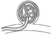
도 1은 본 발명의 실시예에 따른 혈관폐색용 이식 시스템의 측면 입면도이다.
도 2는 도 1의 혈관폐색용 이식 시스템을 위한 보호용 운송 튜브(shipping tube)의 사시도이다.
도 3은 도 1의 혈관폐색용 이식 시스템의 원위 선단부 부분의 상세도로서, 원(3) 내부에서 취한 도면이다.
도 3a는 가요성 분리 영역(flexible detachment zone)을 갖춘 혈관폐색용 이식 시스템의 원위 선단부 부분의 상세도이다.
도 3b는 가요성 분리 영역(flexible detachment zone)을 갖춘 혈관폐색용 이식 시스템의 원위 선단부 부분의 상세도이다.
도 3c는, 가요성 분리 영역이 없는 혈관폐색용 이식 시스템과 비교하여, 가요성 분리 영역을 갖춘 혈관폐색용 이식 시스템을 도시한 것이다.
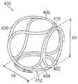
도 4는 본 발명의 일 실시예에 따른 혈관폐색용 이식물의 사시도이다.
도 5는 본 발명의 다른 실시예에 따른 혈관폐색용 이식물의 사시도이다.
도 6은 본 발명의 다른 실시예에 따른 혈관폐색용 이식물의 사시도이다.
도 7은 도 1의 단면도로서, 라인 7-7을 따라 취한 것이다.
도 8은 도 1의 단면도로서, 라인 8-8을 따라 취한 것이다.
도 9는 도 8에 도시된 혈관폐색용 이식 시스템의 천이 부분의 상세도로서, 원(9) 내부에서 취한 도면이다.
도 10은 본 발명의 실시예에 따른 혈관폐색용 이식물을 형성하기 위한 맨드릴(mandrel)의 사시도이다.
도 11은 전해식으로 분리 가능한 이식물 조립체에 전기적으로 결합되게 구성되는 전력 공급부의 사시도이다.
도 12는, 환자 내에 삽입되며 전해식으로 분리 가능한 이식물 조립체에 결합되는 전력 공급부의 회로도이다.
도 13은 전해식으로 분리 가능한 이식물의 분리 중에 시간의 경과에 따른 전력 공급부의 전기적 특성을 그래프로 제시한 것이다.
도 14는 가요성 분리 영역 부근의 영역에서 강도(stiffness)가 저하되는 혈관폐색용 이식 시스템의 단면도이다.
도 15a 내지 도 15g는, 도 1 내지 도 14의 혈관폐색용 이식 시스템을 이용하여 동맥류(aneurysm)를 폐색시키는 단계를 개략적으로 제시하는 일련의 도면이다.
도 16a 내지 도 16c는, 도 1 내지 도 14의 혈관폐색용 이식 시스템의 전해식 분리 시스템의 특정 실시예를 이용하는 팽창식 플로우 디스럽터 디바이스(expandable flow disruptor device)를 이용한, 동맥류 폐색의 전개 과정을 도시한 것이다.1 is a side elevational view of a vascular occlusion grafting system according to an embodiment of the present invention.
Figure 2 is a perspective view of a shipping shipping tube for the vascular occlusion implant system of Figure 1;
Fig. 3 is a detailed view of the distal end portion of the blood vessel closure implantation system of Fig. 1, taken from inside the
Figure 3a is a detail view of a distal tip portion of a vascular occlusion implant system with a flexible detachment zone.
FIG. 3B is a detail view of the distal tip portion of a vascular occlusion implant system with a flexible detachment zone.
Figure 3c shows an implantable vascular occlusion system with a flexible isolation region compared to an implantable vein occlusion system without a flexible isolation region.
4 is a perspective view of an implant for occluding a blood vessel according to an embodiment of the present invention.
5 is a perspective view of a vein occlusion implant according to another embodiment of the present invention.
6 is a perspective view of a vein occlusion implant according to another embodiment of the present invention.
Fig. 7 is a cross-sectional view of Fig. 1 taken along line 7-7.
Fig. 8 is a cross-sectional view of Fig. 1 taken along line 8-8.
FIG. 9 is a detailed view of a transition portion of the blood vessel clogging implantation system shown in FIG. 8, taken inside the circle 9. FIG.
10 is a perspective view of a mandrel for forming an implant for occlusion of blood vessels according to an embodiment of the present invention.
Figure 11 is a perspective view of a power supply configured to be electrically coupled to an electrolytically detachable implant assembly.
12 is a circuit diagram of a power supply coupled to an implantable implantable implant assembly inserted into a patient.
Figure 13 is a graphical representation of the electrical characteristics of the power supply over time during the separation of an electrolytically separable implant.
14 is a cross-sectional view of an implantable vein occlusion system in which stiffness is reduced in the area near the flexible isolation region;
Figs. 15A to 15G are a series of diagrams schematically showing steps for occluding an aneurysm using the grafting system for vascular occlusion of Figs. 1 to 14. Fig.
16A-16C illustrate an exploded view of an aneurysm occlusion procedure using an expandable flow disruptor device utilizing a specific embodiment of an electrolytic separation system of the vascular occlusion system of Figs. 1-14. FIG.
본 개시내용은, 뇌동맥 및 혈관 상의 다른 문제를 해결하기 위한 개선된 혈관폐색용 이식물과 관련 디바이스, 방법, 및 시스템을 제시한다. 이하의 특허 및 공보, 즉 미국 특허 출원 제8,002,822호; 2005년 6월 13일자로 출원된 국제 특허 공보 제WO 2005/0122961호; 2013년 4월 11일자로 출원된 미국 가특허 출원 제61/811,055호; 2013년 10월 18일자로 출원된 미국 가특허 출원 제61/888,240호; 2013년 12월 18일자로 출원된 미국 가특허 출원 제61/917,854호는 인용함으로써 그 전체 내용이 본원에 명시적으로 포함된다.The present disclosure provides improved devices, methods, and systems for implanting vascular occlusions to address other problems of the cerebral artery and veins. The following patents and publications: U.S. Patent Application No. 8,002,822; International Patent Publication No. WO 2005/0122961, filed June 13, 2005; U.S. Provisional Patent Application No. 61 / 811,055, filed April 11, 2013; U.S. Provisional Patent Application No. 61 / 888,240, filed October 18, 2013; U.S. Provisional Patent Application No. 61 / 917,854, filed December 18, 2013, which is expressly incorporated herein by reference in its entirety.
내강경유식으로 이송되는 폐색용 마이크로코일(microcoil)을 이용하여 파열된 두개내의(intracranial) 동맥류 및 파열되지 않은 두개내의 동맥류를 치료하는 것은, 외과적 클립핑(surgical clipping)에 비해 상대적으로 낮은 이환율 및 사망율을 나타낸다. 그러나, 여전히 많은 단점이 보고되고 있다. 마이크로코일은 보통 한 번에 하나씩 동맥류 내로 이송되며, 예컨대 형광투시법을 통해 각각의 마이크로코일을 볼 수 있도록 하는 것이 매우 중요하고, 마이크로코일은, 바람직한 위치로 이송되지 않으면, 동맥류로부터 안전하고 용이하게 회수될 수 있다. 마이크로카테터(microcatheter)는, 그 선단부가 동맥류의 네크(neck)에 이웃하게 되도록 배치되며, 마이크로코일은 상기 마이크로카테터의 내강을 통해 이송된다.Treatment of ruptured intracranial aneurysms and intracranial intracranial aneurysms using occlusion microcoils delivered to intact stomach implants has a relatively low morbidity and mortality compared to surgical clipping, Mortality rate. However, many disadvantages are still being reported. Microcoils are usually transported one at a time into the aneurysm, and it is very important to allow each microcoil to be seen, for example, by fluoroscopy, and the microcoil will not be transported to the desired location, . The microcatheter is disposed such that its tip is adjacent to the neck of the aneurysm, and the microcoil is transported through the lumen of the microcatheter.
마이크로카테터의 구성, 배치, 및 선단부 배향은 모두, 마이크로카테터가 얼마나 양호하게 동맥류 내외로의 마이크로코일의 이송을 지원하는지, 그리고 필요하다면, 동맥류 내외로의 마이크로코일의 제거를 지원하는지를 결정함에 있어서 중요한 인자이다. 마이크로코일의 이송 중에 과도한 저항을 겪게 된다면, 마이크로카테터는 "빠지게 될 수 있고"("back out"), 이에 따라 마이크로카테터의 지지 위치 및 동맥류에 대한 배향을 상실하게 된다. 마이크로코일의 이송 또는 제거 중에 발생할 수 있는, 상황을 더 복합하게 하는 한 가지 문제는, 마이크로코일의 권취부(winds)의 실제적인 신장(stretching)이다. 예를 들어, 마이크로코일의 일 부분에 대해 원하는 힘보다 큰 힘을 주도록 마이크로카테터의 선단부가 배치되게 하는 위치에 마이크로카테터가 존재하는 동안 마이크로코일이 마이크로카테터 내로 잡아당겨진다면, 마이크로코일은 마이크로카테터 내로 용이하게 활주할 수 없게 될 수 있고, 축방향의 인장력으로 인해 마이크로코일의 길이에 있어서 현저하면서도 영구적인 증가가 유발될 수 있다. 이때 마이크로코일은 그 기계적인 특징을 영구적으로 상실하게 되며, 신장된 영역에서의 방사선 불투과성이 감소하게 되는 현상을 겪게 된다. 이러한 마이크로코일은 폐기 및 대체되어야 할 필요가 있기 때문에, 전술한 특성을 갖는 코일의 신장은, 전술한 절차를 수행하는 신경중재치료자(neurointerventionalist)에게는 고비용일 수 있으며, 신장된 코일이 또한 갇히게 될 가능성이 있고 파괴될 가능성도 있으며 혹은 기존에 동맥류 내에 배치되어 있는 다른 마이크로코일과 의도치 않게 서로 맞물릴 수 있기 때문에, 상기 마이크로코일의 신장은 또한 전술한 절차에 방해가 될 수 있다. 또한, 동맥류 내에 기존에 배치되어 있었던 다른 마이크로코일이 해당 동맥류로부터 벗어나, 해당 동맥류가 유래하는 모동맥(parent artery) 내로 이동하게 되도록 할 가능성이 있고, 이는 상황을 복잡하게 하는 심각한 문제가 된다. 동맥류 내부에서 다수의 코일 질량(multi-coil mass) 내에 부분적으로 존재하고 마이크로카테터 내에 부분적으로 존재하며 추가적으로 전진 또는 후퇴하게 될 수 없는, 신장된 마이크로코일은, 응급 개두술을 필요로 할 수도 있고, 고도로 외과적인 현미 외과 수술 구조 절차를 필요로 할 수도 있다. 신장된 코일을 수습하기 위한 가능한 카테터경유식 방법들은 덜 바람직하다. 이들 방법은, 스텐트를 이용하여 모동맥의 내측벽에 대해 신장된 코일을 택킹(tacking)하는 단계; 동맥류 내에 존재하는 신장된 코일 부분을 붙잡아 제거하기 위한 스네어 디바이스(snare device)를 이용하는 단계; 또는 장기 항혈소판 요법을 환자에게 시행하는 단계로 이루어진다.The configuration, placement and tip orientation of the microcatheter are all important in determining how well a microcatheter supports the transfer of microcoils into and out of an aneurysm and, if necessary, the removal of microcoils into and out of the aneurysm It is an argument. If an excessive resistance is encountered during delivery of the microcoil, the microcatheter may "back out " and thus lose support for the microcatheter and orientation to the aneurysm. One problem that further complicates the situation that may occur during the transfer or removal of the micro-coil is the actual stretching of the windings of the micro-coil. For example, if the microcoil is pulled into the microcatheter while the microcatheter is in a position to allow the distal end of the microcatheter to be positioned to give a force greater than the desired force for a portion of the microcoil, It can not easily slide, and a significant and permanent increase in the length of the micro-coil due to the axial tensile force can be caused. At this time, the microcoils lose their mechanical characteristics permanently, and the radiation opacity in the elongated region is reduced. Because these microcoils need to be discarded and replaced, the elongation of the coil with the above-mentioned characteristics can be expensive to the neurointerventionalist performing the procedures described above, and the possibility that the elongated coil will also be trapped And the extension of the microcoil may also interfere with the procedure described above, as it may be destroyed or may inadvertently intermesh with other microcoils conventionally placed in an aneurysm. It is also possible that other microcoils previously placed in the aneurysm may be displaced from the aneurysm and migrate into the parent artery from which the aneurysm originates, which is a serious complication. An elongated microcoil that partially resides within a multi-coil mass within the aneurysm and is partially present in the microcatheter and can not be further advanced or retracted may require emergency craniotomy, Surgical procedures may require surgical procedures. Possible catheter-based methods for repairing elongated coils are less desirable. These methods include: tacking an elongated coil against the inner wall of the coronary artery using a stent; Using a snare device to capture and remove an elongated coil portion present in the aneurysm; Or long-term antiplatelet therapy to the patient.
동맥류 내에 제1 "프레이밍" 마이크로코일("framing" microcoil)을 배치하는 것은, 흔히 3차원 마이크로코일 또는 "복잡한" 마이크로코일(복수 개의 축 주위로 권취된 마이크로코일)을 이용하여 행해진다. 초기 프레이밍 마이크로코일은, 추후에 내부에 "충전용" 마이크로코일이 팩킹(packing)되는 베이스 구조이다. 제1 프레이밍 마이크로코일이 완전히 언코일(uncoil)된 동맥류 내로 배치될 때, 심지어 상기 제1 프레이밍 마이크로코일이 3차원 마이크로코일 또는 복잡한 마이크로코일이라면, 상기 마이크로코일의 제1 루프(loop)는, 동맥류 내부 주위에서 여러 번 루프를 이루는 대신, 동맥류로 진입한 이후에 동맥류로부터 빠져나올 수 있다. 이는 이전 마이크로코일의 부재로 인해 더 악화되는데, 이전 마이크로코일의 구조는 후속하여 배치되는 코일이 동맥류 내에 머무르도록 하는 데 도움이 되는 경향이 있다. 모든 루프가 실질적으로 동일한 직경으로 형성되는 마이크로코일은 특히 제1 프레이밍 마이크로코일로서 사용될 때 전술한 배출 현상을 나타내는 경향이 있다.Placing a first "framing" microcoil in an aneurysm is often done using a three-dimensional microcoil or a "complex" microcoil (a microcoil wound around a plurality of axes). The initial framing micro-coil is a base structure in which a "charging" micro-coil is packed inside. When the first framing micro-coil is placed into a completely uncoiled aneurysm, even if the first framing micro-coil is a three-dimensional micro-coil or a complex micro-coil, the first loop of the micro- Instead of looping several times around the inside, you can get out of the aneurysm after entering the aneurysm. This is exacerbated by the absence of a prior microcoil, the structure of previous microcoils tending to help ensure that the subsequently placed coils stay within the aneurysm. Microcoils in which all the loops are formed with substantially the same diameter tend to exhibit the aforementioned discharge phenomenon, especially when used as the first framing microcoil.
마이크로코일은, 코일링 과정(coiling procedure) 동안 또는 이 코일링 과정에 후속하여 추후 일자에 동맥류로부터 외부로 이동할 수 있다. 이렇게 이동된 마이크로코일의 루프(들)는 잠재적으로 치명적인 혈전색전증에 관한 병소가 될 수 있다. 마이크로코일의 일부의 이러한 이동은, 동맥류 내에서 코일 질량 내로 마이크로코일이 불완전하게 팩킹(packing)되기 때문일 수 있다.The microcoil can move out of the aneurysm outward during a coiling procedure or at a later date following this coiling procedure. The loop (s) of the microcoil thus moved may be a lesion related to potentially fatal thromboembolism. This movement of a portion of the micro-coil may be due to incomplete packing of the micro-coil within the coil mass within the aneurysm.
추가적으로, 마이크로코일의 불완전한 팩킹, 특히 동맥류의 네크에서의 마이크로코일의 불완전한 팩킹은 불완전한 혈전증을 유발시킬 수 있으며, 이에 따라 동맥류가 파열되기 쉽게 되도록 할 수 있고, 또는 기존에 동맥류가 파열된 경우에는 동맥류가 재차 파열되기 쉽게 되도록 할 수 있다. 네크에서의 불완전한 마이크로코일 팩킹을 나타내는 특정한 동맥류는 그럼에도 불구하고 초기에는 완전하게 혈색생성(trombose)을 나타낼 수 있다. 그러나, 이러한 동맥류는, 혈전 색전증의 동적 특징을 통해 여전히 재소통(recanalization)되는 경향을 나타낼 수 있다. 동맥류에서의 코일 질량의 압밀작용(compaction)은 재소통을 유발시킬 수 있는 다른 인자이다. 코일의 강도 또는 형상으로 인해 동맥류 내로 충분한 코일 질량을 팩킹할 수 없는 것은, 불충분한 코일 질량의 가능한 원인이다.In addition, incomplete packing of microcoils, especially incomplete packing of microcoils in the neck of an aneurysm, can lead to incomplete thrombosis, thereby making the aneurysm easier to rupture, or, in the case of an aneurysm ruptured, So that it can be easily ruptured again. Certain aneurysms exhibiting incomplete microcoil packing at the neck may nevertheless initially exhibit complete thrombosis at the beginning. However, such an aneurysm may still exhibit a tendency to recanalize through the dynamic characteristics of thromboembolism. Compaction of the coil mass in an aneurysm is another factor that can cause re-communication. The inability to pack sufficient coil mass into the aneurysm due to the strength or shape of the coil is a possible cause of insufficient coil mass.
다양한 분리 시스템을 이용하여 서로 다른 여러 제조자에 의해 분리 가능한 마이크로코일이 제공되고 있다. 모든 분리 시스템은 일부 동적 프로세스를 수반하지만, 일부 시스템은 다른 시스템보다 더 많은, 시스템의 물리적 이동을 수반한다. 기계적인 분리 시스템, 압력의 이용, 스크류식 결합 해제, 축방향 피스톤식 릴리스(axial pistoning release)는, 분리 중에 동맥류에서 이식물의 한정된 수준의 이동을 유발시키는 경향이 있다. 두개내의 동맥류에 있어서, 이러한 특성을 갖는 이동은 보통 바람직하지 않다. 마이크로코일의 움직임 또는 이동을 잠재적으로 유발시킬 수 있는 임의의 힘은 방지되어야 한다. 비-기계적인 시스템(화학적 시스템, 열적 시스템, 전해질 시스템)은 본질적으로 적은 움직임을 나타내지만, 종종 일관성의 부족을 겪기도 하며, 예컨대 코일의 분리에 관해 일관된 짧은 유지시간을 나타낸다. 이식물 코일 자체의 전기적 절연은 더 짧은 평균 코일 분리 시간에 도움을 주기는 하지만, 코일이 얼마나 신속하게 분리될 것인가에 대해서는 여전히 어느 정도의 비일관성이 존재한다. 10개 이상의 코일의 이식을 필요로 할 수 있는 큰 동맥류에 있어서, 긴 분리 시간 또는 예상 불가능한 분리 시간은 급증하며, 전술한 절차를 지연시킨다. 추가적으로, 단일한 긴 분리 시간은, 카테터 시스템에서의 환자의 움직임으로 인해, 전술한 분리 중에 불안성의 위험을 유발할 수 있다. 심지어 예컨대 특정 문턱값 미만의 전류의 측정을 통해, 분리가 이루어졌음을 표시하는 시스템은, 다른 사람들에게 완전한 신뢰를 받지 못하고 있다.Micro-coils are available which can be separated by different manufacturers using various separation systems. All separation systems involve some dynamic processes, but some systems involve more physical movement of the system than other systems. Mechanical separation systems, the use of pressure, screwed release, and axial pistoning release tend to induce a limited level of migration of the implant in the aneurysm during separation. For intracranial aneurysms, migration with this characteristic is usually undesirable. Any force that could potentially cause movement or movement of the micro-coil should be prevented. Non-mechanical systems (chemical systems, thermal systems, electrolyte systems) exhibit essentially small movements, but often suffer from a lack of consistency and exhibit a consistent short retention time, for example with respect to the separation of the coils. The electrical insulation of the implant coil itself helps a shorter average coil separation time, but there is still some degree of inconsistency as to how quickly the coil will be separated. For large aneurysms, which may require transplantation of more than 10 coils, the long or unexpected separation time increases rapidly and delays the procedure described above. Additionally, a single long separation time can cause a risk of anxiety during the above-described separation due to the patient's movement in the catheter system. Even with a measurement of the current, for example below a certain threshold, the system indicating that the separation has taken place has not been fully trusted by others.
다수의 분리 가능한 마이크로코일 시스템은, 프로시져 테이블(procedure table) 부근에서의 IV 폴(IV pole)에 보통 부착되는 분리 모듈(전원 등)을 포함한다. 보통 살균된 마이크로코일 이식물 및 이송 와이어에 살균되지 않은 모듈을 연결시키는 케이블 또는 도관이 존재한다. 주치의인 중재치료자(interventionalist)는 보통, 전술한 분리가 이루어지도록 하기 위해 모듈 상의 분리 버튼을 누르도록, 상기 절차를 위한 "세척절차를 거치지 않은" 치료실 내의 사람에게 요청해야만 한다.Many separable microcoil systems include a separation module (power supply, etc.) that usually attaches to an IV pole near the procedure table. There is usually a cable or conduit connecting the sterilized microcoil implant and the untransferred module to the transfer wire. The interventionalist, who is the primary care physician, should usually ask the person in the "untreated" room for the above procedure to press the detachment button on the module in order to ensure the above separation.
대부분의 분리 가능한 시스템은, 분리가 이루어지도록 허용하는 방식으로 구성되는, 분리 가능한 결합식 마이크로코일 이식물과 푸셔 와이어(pusher wire) 사이의 연결부에서 특정한 구조를 갖는다. 동맥류 내로의 마이크로코일의 반복적인 삽입 및 마이크로카테터 내로의 회수를 허용하는 안전한 커플링(coupling)을 구비할 필요가 있기 때문에, 전술한 연결부 중 다수의 연결부는 강도의 증가를 유발하게 된다. 이러한 강건한 섹션은 이식 중인 마이크로코일 바로 가까이에 존재하기 때문에, 이식 절차는 부정적인 영향을 받을 수 있고, 때때로 마이크로카테터가 빠지게 되도록 하며("back out"), 이에 따라 마이크로코일의 삽입에 대해 더 이상 충분한 지원을 제공하지 못한다. 이는 특히 구불구불한 혈관의 해부학적 구조에 통합되는 동맥류에 있어서 그러하다.Most detachable systems have a specific structure at the connection between the detachable mating microcoil implant and the pusher wire, which is configured in a manner that allows separation to occur. Because of the need to have a secure coupling that permits repeated insertion of microcoils into the aneurysm and recovery into the microcatheter, many of the above-described connections cause increased strength. Because this robust section is located immediately adjacent to the microcoil being implanted, the implantation procedure can be negatively impacted, sometimes causing the microcatheter to come out ("back out"), It does not provide support. This is especially true for aneurysms that are integrated into the anatomical structure of the serpentine blood vessels.
도 1은 푸셔 부재(104; pusher member)에 분리 가능하게 결합되는 마이크로코일 이식물(102)을 포함하는 혈관폐색용 이식 시스템(100)을 제시하고 있다. 푸셔 부재(104)는, 푸셔 부재(104)의 길이를 연장시키며 생체적합성 재료, 예컨대 스테인레스 강, 예를 들어 304 시리즈의 스테인레스 강으로 제조되는 코어 와이어(106; core wire)를 포함한다. 근위 단부(108)에서의 코어 와이어(106)의 직경은 0.008" 내지 0.018"일 수 있으며, 보다 구체적으로는 0.010" 내지 0.012"일 수 있다. 푸셔 부재(104)의 전기 절연된 영역(110)은, 코어 와이어(106)의 길이의 대부분에 걸쳐, 코어 와이어(106)의 최근위 단부로부터 대략 10 cm에 있는 제1 지점(112)과 코어 와이어(106)의 원위 단부(116) 부근의 제2 지점(114) 사이에서 연장된다. 코어 와이어(106)의 표면을 직접 덮고 있는 것은 폴리머 코팅(118), 예컨대 PTFE(폴리테트라플로오로 에틸렌), 파릴렌(Parylene) 또는 폴리이미드이며, 상기 폴리머 코팅은 대략 0.00005" 내지 대략 0.0010", 혹은 보다 구체적으로는 0.0001" 내지 0.0005"의 두께를 갖는다. 폴리머 커버 튜브(120)는 코어 와이어(106) 및 폴리머 코팅(118) 위에 고정된다. 폴리머 커버 튜브(120)는, 배관의 단부의 장력을 유지하면서 코어 와이어(106) 위에서[그리고 선택적으로 또한 폴리머 코팅(118) 위에서] 열 수축되는 폴리에틸렌 테레프탈레이트(PET) 수축 배관을 포함할 수 있다. 마커 코일(122; marker coil)(도 9 참고)은, 예컨대 코어 와이어(106) 위에 혹은 폴리머 코팅(118) 및 열 수축 배관 위에 마커 코일(122)을 배치함으로써 또는 이들 위에 폴리머 커버 튜브(120)를 접합시킴으로써 폴리머 코어 와이어(106)와 폴리머 커버 튜브(120) 사이에 개재될 수 있다. 코어 와이어(106)는, 푸셔 부재(104)의 전기 절연 영역(110)의 일부 전체에 걸쳐, 테이퍼(taper)를 포함하면서 근위 단부(108)에서의 직경으로부터 예컨대 0.005" 내지 0.006"의 직경으로 직경이 감소하는 천이 영역을 가질 수 있다. 원위 단부(116)에서의 코어 와이어(106)의 직경은, 푸셔 부재(104)의 전기 절연 영역(110)의 외부에 있는 원위 단부(116)의 일부를 포함하여, 0.002" 내지 0.003"일 수 있다. 선단부(124)는, 전기 절연 영역(110)을 완성시키기 위해 폴리머 커버 튜브(120)에 적용될 수 있다. 이는 도 9와 관련하여 보다 상세하게 설명된다. 마이크로코일 이식물(102)은 결합용 조인트(126)를 통해 푸셔 부재(104)에 분리 가능하게 결합되며, 이는 도 7과 관련하여 보다 상세하게 설명된다.1 illustrates a blood vessel
도 3은 마이크로코일 이식물(102)의 코일 조립체(128)를 제시한 것이다(용이하게 도시하기 위해 짧게 되어 있음). 엠발릭 코일(130; embolic coil)은 백금 또는 백금 합금으로 구성될 수 있으며, 예컨대 92% 백금/8% 텅스텐으로 구성될 수 있고, 0.001" 내지 0.004", 혹은 보다 구체적으로 0.00125" 내지 0.00325"의 직경을 갖는 와이어(144)로부터 촘촘하게 권취될 수 있다. 엠발릭 코일은 0.5 cm 내지 50 cm, 혹은 보다 구체적으로 1 cm 내지 40 cm 사이의 길이(똑바른 상태에서의 거리)를 가질 수 있다. 이후 마이크로코일 이식물(102) 내로의 조립 이전에, 엠발릭 코일(130)은, 도 4 내지 도 6 및 도 10과 관련하여 보다 상세하게 설명되는 바와 같이, 여러 가지 가능한 형상 중 하나의 형상으로 형성된다. 마이크로코일 이식물(102)의 엠발릭 코일(130)의 신장을 최소화하기 위해, 엠발릭 코일(130)의 근위 단부(134)와 원위 단부(136) 사이에 테더(132; tether)가 결속된다. 상기 테더는, 열가소성 엘라스토머, 예컨대 Engage® 스트랜드(strand) 또는 폴리에스터 스트랜드, 예를 들어 소정 직경의 폴리에틸렌 테레프탈레이트(PET)로 형성될 수 있다. 테더(132)의 직경은 Engage 스트랜드의 경우 0.0015" 내지 0.0030"일 수 있거나, 또는 보다 구체적으로 0.0022"일 수 있다. 테더(132)의 직경은 PET 스트랜드의 경우 0.00075" 내지 0.0015"일 수 있거나, 또는 보다 구체적으로 0.0010"일 수 있다. 엠발릭 코일(130)의 기본 외경은 0.009" 내지 0.019"일 수 있다. 엠발릭 코일(130)의 근위 단부(134) 및 원위 단부(136)에서 테더를 고정시키기 위해, 예컨대 미세한 핀셋을 이용한 신중한 핀칭(pinching) 및 성형에 의해, 2개의 직경 감소 부분(138, 140)이 엠발릭 코일(130)의 특정 권취부에 생성된다. 직경 감소 부분(140)의 단부(142)는 트리밍(trimming)되며, 테더(132)는 직경 감소 부분(140)의 와이어(144) 주위에서 하나 이상의 매듭(147, 148)으로 결속된다. 접착제 또는 에폭시, 예를 들어 자외선 경화형 접착제, 우레탄 접착제, 사전 혼합된 2액형 에폭시(two-part epoxy), 혹은 냉동 및 해동된 2액형 에폭시를 포함하는 선단부 피복(146; encapsulation)은 하나 이상의 매듭(147, 148)을 고정시키면서 직경 감소 부분(140)에 적용되며, 실질적으로 반구형 선단부(150)를 형성한다. 테더(132) 상에 끈으로 묶인 충분한 양의 슬랙(slack)/텐션부(tension)를 이용하여, 상기 테더는 하나 이상의 매듭(151, 152)에서 직경 감소 부분(138)에 결속된다. 접착제 또는 에폭시를 또한 포함하는 원통형 피복(154)은 하나 이상의 매듭(151, 152)을 고정시키면서 직경 감소 부분(138)에 적용된다. 원통형 피복(154)은, 코어 와이어(106)로부터의 엠발릭 코일(130)의 전기적 절연을 제공하며, 이에 따라 분리 중에 전해질에서 관련되는 재료의 기하학적 형상을 더 간단하게 할 수 있도록 한다. 테더(132)는 엠발릭 코일(130)의 신장을 최소화하기 위해 신장 억제 부재로서의 역할을 한다. 별도의 실시예에 있어서, 테더(132)는 다수의 실 또는 스트랜드의 폴리머 또는 마이크로케이블로 제조될 수 있다.Figure 3 shows the
다시 도 1로 돌아가면, 혈관폐색용 이식 시스템(100)의 푸셔 부재(104) 및 마이크로코일 이식물(102)의 최대 외경보다 약간 더 큰 직경을 갖는 내측 내강(156)을 갖춘 도입기 튜브(155)는 성형된 엠발릭 코일(130)을 직선화하는 데 사용되며, 마이크로카테터의 내강 내로 혈관폐색용 이식 시스템을 삽입하는 데 사용된다. 혈관폐색용 이식 시스템(100)은 도입기 튜브(155)와 함께 패키징되며, 도입기 튜브의 내측 내강(156) 내로 횐자의 몸 외부에서 조작된다, 혈관폐색용 이식 시스템(100) 및 도입기 튜브(155)는, 도 2에 도시된 보호용 운송 튜브(158) 내에 혈관폐색용 이식 시스템 및 도입기 튜브를 배치함으로써 살균을 위해 패키징된다. 푸셔 부재(104)의 근위 단부(108)는 연질 클립(160)에 의해 축방향으로 고정되어 유지된다.1, the
도 3a는 가요성 분리 영역을 포함하는 마이크로코일 이식 시스템(300)의 실시예를 도시한 것이다. 이러한 이식 시스템은, 폴리머 코팅(318)으로 코팅되고 폴리머 커버 튜브(320)로 덮인 코어 와이어(306)를 비롯하여, 푸셔 부재(304)에 분리 가능하게 결합되는 마이크로코일 이식물(302)을 포함한다. 폴리머 코팅(318), 폴리머 커버 튜브(320), 및 에폭시로 된 접착제로 형성된 선단부(324)는 전기적 절연 영역을 구성한다. 마이크로코일 이식 시스템(300)은, 분리 영역(362)과 관련하여 엠발릭 코일(330)의 변형된 구성을 제외하고는, 도 1의 혈관폐색용 이식 시스템(100)과 유사하다. 이러한 실시예에 있어서, 코어 와이어(306)는 푸셔 부재(304)의 원위 단부로부터 외부로 연장된다. 코어 와이어의 비절연 영역은 분리 영역(362)을 포함한다. 분리 영역(362)은, 마이크로코일 이식물(302)이 푸셔 부재(306)로부터 분리되도록 허용하는, 혈액폐색용 이식 시스템의 희생부이다. 분리 영역(362)에 대해 원위에서는, 커플러 코일(366; coupler coil)이 코어 와이어(306) 주위를 감싸고 있으며, 엠발릭 코일(330) 내에 동축으로 위치 설정되어 있다. 엠발릭 코일(330) 및 커플러 코일(366)은, 원통형 폴리머 코팅(354) 또는 피복에 의해 서로 전기적으로 절연되어 있다. 피복(354)은 예컨대 UV 접착제일 수 있다. 원통형 피복(354)은, 코어 와이어(306)으로부터의 엠발릭 코일(330)의 전기적 절연을 제공하며, 이에 따라 분리 중에 전해질에서 관련되는 재료의 기하학적 형상을 더 간단하게 할 수 있도록 한다. 이러한 동축 배치는, 종래 기술의 강건한(굽혀지지 않는) 영역보다 현저하게 짧은 강건 영역(점선으로 표시되어 있음)을 생성하는데, 이 강건 영역은 흔히 0.040"를 초과하는 길이를 갖는다. 도 3a에 도시된 구성은 0.010" 내지 0.030" 사이의 길이를 갖는 강건 영역을 갖추고 있다.FIG. 3A illustrates an embodiment of a
일부 다른 실시예에 있어서(도 1 및 도 7에서와 같은 실시예에 있어서), 엠발릭 코일 및 코어 와이어는 에폭시 또는 다른 절연 재료로 된 포팅 섹션(potted section) 및 커플러 코일과 함께 결합된다. 그러나, 도 3a의 실시예에 있어서, 코어 와이어(306)는 엠발릭 코일(330)의 근위 부분을 통해 연장된다. 커플러 코일(366)과 엠발릭 코일(330) 사이의 중첩 영역에 대해 원위에서, 테어(332)는 엠발릭 코일(330)의 원위 부분과 근위 부분을 연결시킨다. 도 3a에 도시된 구성은, 엠발릭 코일(330)의 근위 부분이 더욱 가요성을 갖도록 허용한다. 커플러 코일(366)을 엠발릭 코일(330)의 근위 부분 내에 동축으로 배치시키면, 강건한 에폭시 접합 섹션에 대한 필요성이 줄어들게 된다. 이러한 구성은 커플러 코일(366)에 대해 바로 원위에 있는 가요성 영역을 생성한다(도 3b 참고).In some alternative embodiments (as in the embodiments of FIGS. 1 and 7), the embolic coil and core wire are joined together with a potted section and a coupler coil of epoxy or other insulating material. 3A, the
도 3b는 신축 위치에서의 도 3a의 디바이스를 도시한 것이다. 가요성 분리 영역은 엠발릭 코일의 근위 부분 내에 동축으로 위치 설정되는 (도시되지 않은) 커플러 코일에 대해 바로 원위에 있다. 경질 영역 또는 강건 영역은 겨우 대략 0.020"(+/- 0.010")에 존재한다.Fig. 3b shows the device of Fig. 3a at the retracted position. The flexible isolation region is directly over the coupler coil (not shown) coaxially positioned within the proximal portion of the embolic coil. The hard or hardy area is only about 0.020 "(+/- 0.010").
도 3c는 시스템(100)(도 1에 도시되어 있음)에서의 이식물의 가요성과 시스템(300)(도 3에 도시되어 있음)의 이식물의 가요성을 비교한 것을 나타내고 있다. 시스템(300)은 짧아진 강건 영역을 가지며, 여기서 커플러 코일은 엠발릭 코일(330) 내에 배치된다. 시스템(100)은 엠발릭 코일(130)의 근위 부분과 결합용 조인트(126) 사이에 위치하는 에폭시 절연 영역을 갖는다. 시스템(300)의 더 짧은 에폭시 영역은, 엠발릭 코일(330)이 시스템(100)에 비해 더 가까이에서 신축을 개시하도록 허용하며, 시스템(100)에서는 이식물의 길이의 더 원위에 있는 아래부분에서 신축이 이루어진다.3C shows a comparison of the flexibility of the implant at system 100 (shown in FIG. 1) and the flexibility of implants at system 300 (shown in FIG. 3). The
도 3a 내지 도 3c에 도시된 이식 시스템(300)의 구성은, 커플러 코일과 엠발릭 코일 사이에 포팅 에폭시 섹션(potted epoxy section)을 갖는 실시예에 비해, 강건한 절연 접합 섹션의 길이 면에서 대략 50 %정도의 감소를 나타내며, 더 짧고 작은 커플러 코일을 제공한다. 그 결과, 엠발릭 코일의 근위 부분은 더 연질이 되고 더욱 가요성이 있게 되며, 이에 따라 이식 절차 중에 이송성이 개선되고 마이크로카테터의 킥백(kick back)이 감소된다. 전술한 디바이스의 가요성 향상은, 혈관 동맥류의 타이트한 공간 내에서의 마이크로코일의 일치성(conformability)의 향상을 허용한다. 가요성 분리 영역이 생성되도록 한 구성은, 마이크로카테터로부터 동맥류 내로 마이크로코일 이식물이 이송되는 동안 마이크로코일 이식물의 가요성을 현저하게 향상시킨다. 가요성 및 조작성(maneuverability)의 향상은, 동맥류의 네크에서 마이크로카테터가 그 위치를 잃어버리도록 할 가능성을 훨씬 줄여주며, 이에 따라 오배치된 마이크로코일의 발생 및 이로부터 유발되는 복잡성을 감소시킨다. 가요성 마이크로코일 이식물은, 이송 중에 관심 대상인 혈관 캐비티(vascular cavity)의 형상에 대해 더욱 일치할 수 있다.The configuration of the
코일들의 동축 구성은, 더 낮은 프로파일의 분리 영역(362)을 제공하는 추가적인 이익을 제공하여, 퍼스트 버튼식 분리의 일관성(first-button detachment consistency)의 향상을 유발한다. 원통형 피복 영역은 엠발릭 코일과 분리 영역 사이의 유효한 전기적 절연을 유지시킨다.The coaxial configuration of the coils provides additional benefit of providing a lower
도 4 내지 도 6은 본 발명의 3가지 상이한 실시예에 따른 혈관폐색용 이식물을 제시한 것이다. 도 4는, 엠발릭 코일(201)로 제조되고 동맥류 내에 배치될 때 회전 타원체에 근사한 상자 형상을 갖는 프레이밍 마이크로코일 이식물(200)을 제시하고 있다. 루프(202, 204, 206, 208, 210, 212)는 3개의 축 상에, 즉 좌표 원점(O)으로부터 음의 방향(-X)으로 그리고 양의 방향(+X)으로 연장되는 X 축; 좌표 원점(O)으로부터 음의 방향(-Y)으로 그리고 양의 방향(+X)으로 연장되는 Y 축; 그리고 좌표 원점(O)으로부터 음의 방향(-Z)으로 그리고 양의 방향(+Z)으로 연장되는 Z 축 상에서 권취된다. 직경 D1을 갖는 제1 루프(202)는 엠발릭 코일(201)의 제1 단부(214)에서 시작되어 소정 방향(216)으로 +X 축 주위로 연장된다. 도 4에 도시된 바와 같이, 제1 루프(202)는 대략 1.5회의 회전을 포함하지만, [다른 루프(204, 206, 208, 210, 212)와 마찬가지로] 1/2회의 회전 내지 10회의 회전을 포함할 수 있다. 반경 D2를 갖는 제2 루프(204)는 루프(202)로부터 계속되며, 소정 방향(218)으로 -Y 축 주위로 연장된다. 제3 루프(206)는 이후 소정 방향(220)으로 +Z 축 주위로 연장된다. 제4 루프(208)는 이후 소정 방향(222)으로 -X 축 주위로 연장된다. 제5 루프(210)는 이후 소정 방향(224)으로 +Y 축 주위로 연장된다. 그리고 마지막으로, 제6 루프(212)는 소정 방향(226)으로 -Z 축 주위로 연장된다. 도 4에서 알 수 있는 바와 같이, 루프(202, 204, 206, 208, 210, 212)의 형성에 후속하여, 엠발릭 코일(201)의 제2 단부(228)에 결합용 조인트(126)가 형성된다. 도 4에 도시된 루프의 정밀한 구성은 예시의 목적을 위한 것이며, 임의의 한정을 내포하려는 의도가 아니다. 상기 이식물은, 다양한 수 및 다양한 구성의 루프를 포함하는 대체로 회전 타원체인 다른 형태를 취할 수 있다.Figures 4 through 6 present implants for vascular occlusion according to three different embodiments of the present invention. Figure 4 shows a framing
프레이밍 마이크로코일 이식물(200)은 동맥류 내에 배치되는 초기 마이크로코일이 되도록 구성되며, 이에 따라 본 실시예에 있어서 루프(204, 206, 208, 210, 및 212)는 모두 D2와 대략 동일한 직경을 갖는다. 그러나, 제1 루프(202)는 동맥 내로 도입되는 첫번째 루프가 되도록 구성되며, 마이크로코일 이식물(200)이 코일링(coiling) 중에 동맥류 내에 머무르는 능력을 최대화하기 위해, 제1 루프(202)의 직경(D1)은 직경(D2)의 65% 내지 75%가 되며, 보다 구체적으로 직경(D2)의 약 70%가 된다. D2가 동맥류의 직경에 근사하게 되도록 선택된다고 가정하면, 마이크로코일 이식물(200)의 제1 루프(202)가 동맥류 내에 삽입될 때, 동맥류의 벽 주위에서 둘레방향으로 그 진로를 형성함에 따라, 제1 루프는 동맥류의 네크에서의 개구 위로 지나갈 때 동맥류의 직경에 못 미칠 것이며, 이에 따라 동맥류의 한정부 내에 유지될 것이다. 혈관폐색용 이식 시스템(100) 내로 마이크로코일 이식물(200)을 조립할 때, 테터(132)의 선택은 프레이밍 마이크로코일로서 양호하게 거동하는 마이크로코일 이식물(200)의 형성에 중요할 수 있으며, 동맥류의 프레이밍에 중요할 수도 있고, 후속 코일링, 즉 팩킹 및 마무리 양자 모두를 돕기 위한 지지 격자의 형성에 중요할 수도 있다. 예를 들면, 테더(132)는 5 mm 이하의 직경(D2)을 갖는 마이크로코일 이식물(200)에서 직경이 0.0009"인 PET 실로 제조될 수 있는 반면, 테더(132)는 5 mm 이상의 직경(D2)을 갖는 마이크로코일 이식물(200)에서 직경이 0.0022"인 Engage 실로 제조될 수 있다. 추가적으로, 92/8 Pt/W일 때, 와이어(144)의 직경은 0.0015" 내지 0.011"의 직경의 엠발릭 코일(130) 및 0.002" 내지 0.012"의 직경의 엠발릭 코일(130)과 같이 선택될 수 있다. 직경이 0.011"인 엠발릭 코일(130)은 4.5 mm 이하의 직경(D2)을 갖는 마이크로코일 이식물(200)의 구성을 위해 선택될 수 있으며, 직경이 0.012"인 엠발릭 코일(130)은 4.5 mm 이상의 직경(D2)을 갖는 마이크로코일 이식물(200)의 구성을 위해 선택될 수 있다. 6 mm 이상의 직경(D2)을 갖는 마이크로코일 이식물(200)에 있어서, 추가적인 프레이밍 마이크로코일 모델은 0.002" 이상의 와이어(144)로 권취된 0.013" 이상의 엠발릭 코일(130)을 갖도록 제조될 수 있다. 코일링 절차는 반드시 오직 하나의 프레이밍 마이크로코일만을 이용할 필요는 없다는 것, 그리고 이식 절차 중에 마이크로코일을 충전하고 마이크로코일을 마무리하기 위해 동맥류를 셋업(set up)하는 데 하나 이상의 프레이밍 마이크로코일이 사용될 수도 있다는 것에 주의해야 한다.The framing
도 10a로 돌아가면, 혈관폐색용 이식물을 형성하기 위한 맨드릴(500)은, 도 4의 마이크로코일 이식물(200)의 루프(202, 204, 206, 208, 210, 212)를 생성하기 위해 사용되는 6개의 아암(502, 504, 506, 508, 510, 512)을 갖는다. 제1 루프(202)는 제1 아암(502) 주위에 권취되고 제2 루프(204)는 제2 아암(504) 주위에 권취되며 제3 루프(206)는 제3 아암(506) 주위에 권취되고 제4 루프(208)는 제4 아암(508) 주위에 권취되며 제5 루프(210)는 제5 아암(510) 주위에 권취되고 제6 루프(212)는 제6 아암(512) 주위에 권취된다. 엠발릭 코일(130)의 와이어(144)는 엠발릭 코일(130)의 제1 단부(214)(도 4 참고)에서 길이에 대한 직선형 연장부(516) 내로 잡아당겨지고, 제1 아암(502)의 단부(518)에서 고정 요소(514) 내로 고정된다. 중량부(520)가 엠발릭 코일(130)의 극단(522)에 부착되며, 맨드릴(500)은 X 축(524)과 관련하여 소정 방향(526)으로 회전하고, 이에 따라 제1 루프(202)가 형성되도록 한다. 이때 맨드릴(500)의 위치는 각각의 연속적인 루프의 형성에 앞서 조정되며, 이에 따라 해당 루프가 형성되는 것인 어떠한 아암/축도 지면에 대해 대체로 평행하게 되고, 이 상황에서 중량부(520)는 [다림줄(plumb line)의 방식으로] 바닥에 대해 수직인 방향으로 팽팽한 엠발릭 코일(130)의 연장 길이를 잡아당기게 된다. 맨드릴(500) 상에서의 마이크로코일 이식물(200)의 형성이 완료되면, 와이어(144)의 길이를 신장시킴으로써 그리고 이 와이어를 아암(512)의 단부(530)에서 고정 요소(528)에 부착시킴으로써 제2 단부(228)(도 4 참고)가 고정된다. 마이크로코일 이식물(200)의 형성된 루프(202, 204, 206, 208, 210, 212)는 이제 맨드릴(500) 상에 견고하게 유지되며, 상기 루프의 형상은, 예컨대 섭씨 700 도에서 45 분 동안, 노 내에 루프를 배치함으로써 세팅된다. 실온으로의 냉각 이후에, 마이크로코일 이식물(200)의 형성된 루프는 맨드릴(500)로부터 신중하게 제거되며, 마이크로코일 이식물(200, 102) 및 혈관폐색용 이식 시스템(100)의 나머지 제조 단계가 행해진다. 특정한 경우의 마이크로코일 이식물(200)에 있어서, 맨드릴(500) 상에서의 제1 아암(502)의 직경은, 다른 루프(204, 206, 208, 210, 212)의 직경의 대략 70% 수준의 직경을 갖는 제1 루프(202)를 생성하도록 하기 위해 각각의 다른 아암(504, 506, 508, 510, 512)의 직경의 대략 70%가 된다.10A, a
도 5는 나선형 형상을 갖는 충전용 마이크로코일 이식물(300)을 제시한 것이다. 충전용 마이크로코일 이식물(300)은, 프레이밍 마이크로코일 이식물(200)과 유사한 권취 기법 및 세팅 기법으로 제조되지만, 충전용 마이크로코일 이식물(300)의 나선형 루프(302)는 단일 원통형 맨드릴(도시되어 있지 않음) 상에 권취된다. 충전용 마이크로코일 이식물(300)은, 제1 단부(314) 및 제2 단부(328)를 갖는 엠발릭 코일(130)로부터 형성된다. 충전용 마이크로코일 이식물(300)의 테더(132)(도 3 참고)는, 열가소성 엘라스토머, 예컨대 Engage를 비롯한 다양한 재료로 구성될 수 있다. Engage로부터 형성된 테더(132)의 직경은 0.002" 내지 0.00275"의 범위일 수 있으며 보다 구체적으로는 0.0022"일 수 있다. 충전용 마이크로코일 이식물(300)을 구성하기 위해 사용되는 엠발릭 코일(130)을 제조함에 있어서 사용되는 와이어(144)는, 대략 0.00175" 내지 0.00275"의 직경, 보다 구체적으로는 0.002" 내지 0.00225"의 직경을 갖는 92/8 Pt/W 와이어일 수 있다. 충전용 마이크로코일 이식물(300)의 엠발릭 코일(130)의 외경은 0.011" 내지 0.013", 보다 구체적으로는 대략 0.012"일 수 있다. 하나 이상의 마이크로코일 이식물(200)이 동맥류에 배치된 이후에 가능한 동맥류의 많은 체적을 패킹 및 충전하기 위해, 하나 이상의 충전용 마이크로코일 이식물(300)이 사용될 수 있다. 충전용 마이크로코일 이식물(300)의 비교적 연질인 특성은, 잠재적으로 적어도 파열될 수 있는(또는 재파열될 수 있는) 동맥류의 벽에 대해 잠재적으로 위험한 응력이 생성되지 않도록 하면서, 충분한 수준의 팩킹(packing)이 양호한 혈전증 및 폐색을 달성하게 하도록 허용한다. 충전용 마이크로코일 이식물(300)로서 나선형 형상의 마이크로코일을 사용하는 것 이외에, 나선형 형상의 마이크로코일은 마무리용 마이크로코일 이식물로서 또한 사용될 수 있으며, 상기 마무리용 마이크로코일 이식물은 동맥류의 네크에서의 충전 체적을 최대로 하면서 코일 질량과 양호하게 결합되게 동맥류의 네크에 배치되는 최종적인 하나 이상의 이식물이다. 이러한 마무리용 마이크로코일은 보통 더 작고, 대략 0.010"의 외경을 가지며, 0.001" 내지 0.00175", 보다 구체적으로 0.00125" 내지 0.0015"의 직경을 갖는 92/8 Pt/W 와이어로 권취된다. 마무리용 나선형 마이크로코일에서 사용되는 테더(132)는 0.001"의 PET 실을 포함할 수 있다.FIG. 5 shows a charging
도 6은, 도 4의 마이크로코일 이식물(200)과 매우 유사한, 3개 축에 권취된 제1 루프(402), 제2 루프(404), 제3 루프(406), 제4 루프(408), 제5 루프(410), 및 제6 루프(412)를 갖춘 복잡한 마이크로코일 이식물(400)을 제시한 것이다. 그러나, 다른 아암(504, 506, 508, 510, 512)과 유사한 직경을 갖는 제1 아암(502)을 포함한다면, 제1 루프(402)의 직경(D3)은 각각의 다른 루프(404, 406, 408, 410, 412)의 직경(D4)와 대략 동일하다. 이러한 구성의 복잡한 마이크로코일 이식물(400)은 프레이밍 마이크로코일 이식물로서 사용될 수 있지만, 대안으로 마무리용 마이크로코일 이식물로서 사용될 수도 있다. 다수의 치료 상황에서의 3차원 구조의 복잡성은, 그 맞물림 성능으로 인해, 코일 질량의 나머지를 이용하여 마무리용 마이크로코일 이식물의 보다 양호한 결합에 도움을 줄 수 있다. 따라서, 마무리용 마이크로코일 이식물이 동맥류로부터 외부로 모동맥 내로 이동할 가능성이 더 적어지게 된다.Figure 6 shows a
도 7은 결합용 조인트(126), 도 1의 혈관폐색용 이식 시스템(100)의 선단부(124), 및 상기 선단부(124)와 결합용 조인트(126) 사이의 분리 영역(162)을 제시한 것이다. 분리 영역(162)은 전기적 절연 영역(110)으로 덮이지 않은 근위 단부(108) 이외의, 코어 와이어(106)의 단지 일부이며, 환자의 혈류 내에 배치되도록 구성되는 코어 와이어(106)의 2개의 절연되지 않은 부분 중 오직 하나의 부분이다. 따라서, 도 11 내지 도 13에 따라 설명된 바와 같이, 분리 영역(162)은, 마이크로코일 이식물(102)이 푸셔 부재(104)로부터 분리되도록 허용하는, 혈액폐색용 이식 시스템(100)의 희생부이다. 테더(132), 엠발릭 코일(130)(도시되어 있지 않음), 및 코어 와이어(106)는, 예컨대 UV 접착제, 또는 다른 접착제 또는 에폭시로 커플러 코일(166) 및 포팅 섹션(164)과 함께 결합된다. 커플러 코일(166)은 0.001" 내지 0.002"의 직경의 백금/텅스텐(92%/8%) 와이어로 제조될 수 있으며, 0.006" 내지 0.009" 또는 보다 구체적으로는 0.007" 내지 0.008"의 외경을 가질 수 있다. 커플러 코일(166)은, 땜납, 예컨대 은 땜납 또는 금 땜납으로 코어 와이어(106)에 부착될 수 있다.Figure 7 shows the
도 8 및 도 9는 분리 영역(162)으로부터 대략 3 mm에 있는 푸셔 부재(104)의 단면을 제시한 것이다. 신장된 부분(170) 및 치밀하게 권취된 부분(168)을 포함하는 마커 코일(122; marker coil)이 코어 와이어(106)와 폴리머 커버 튜브(120) 사이에 개재된다. 마커 코일(122)은 0.002"의 직경의 백금/텅스텐(92%/8%) 와이어로 구성될 수 있으며, 0.008"의 외경을 가질 수 있다. 치밀하게 권취된 부분(168)은 신장된 부분(170)보다 더 방사선 불투과성이며, 이에 따라 분리 영역(162)이 분리 과정 동안 마이크로카테터의 바로 외부에 존재하는 것을 확인하기 위한 시각적 안내자로서 사용된다. 마커 코일(122)은, 땜납, 예컨대 은 땜납 또는 금 땜납으로 코어 와이어(106)에 부착될 수 있다.8 and 9 show a cross-section of the
도 11은 도 1의 혈관폐색용 이식 조립체(100)에 대한 전기적 결합을 위한 전력 공급부(700)를 제시한 것이다. 전력 공급부(700)는, 제어 모듈(706) 및 IV 폴(IV pole)에 부착하기 위한 폴 클램프(704; pole clamp)를 갖춘 배터리 동력식 전력 공급 모듈(702)을 포함한다. 제어 모듈(706)은 온/오프 버튼(716)을 포함하며, 제1 전극(708) 및 제2 전극(710)을 제공하는 제1 전기 클립(712) 및 제2 전기 클립(714)을 포함한다. 제어 모듈(706)은 전기 케이블(718)을 통해 전력 공급 모듈(702)에 전기적으로 연결되며, 제1 전기 클립(712) 및 제2 전기 클립(714)은 각각 절연된 전선(720, 722)을 통해 제어 모듈(706)에 연결된다.FIG. 11 shows a
도 11의 전력 공급부(700)의 회로도(800)인 도 12로 돌아가면, 전극(708)은 양극을 띠며, 말단 연결부(802)로 표시되고, 이 말단 연결부에서 제1 전기 클립(712)의 제1 전극(708)은 푸셔 부재(104)의 코어 와이어(106)의 절연되지 않은 근위 단부(108)에 연결된다. 전극(710)은 음극을 띠며, 말단 연결부(804)로 표시되고, 이 말단 연결부에서 제2 전기 클립(714)의 제2 전극(710)은 전도성 바늘 또는 프로브에 연결되며, 전도성 바늘 또는 프로브의 선단부는 예컨대 사타구니 영역 또는 어깨 영역에서 환자 내로 삽입된다. 제어된 DV 전압원(808)에 의해 전력을 공급받는 일정한 전류원(806)은 시스템 저항(810) 및 환자 내의 병렬 저항을 통해 연장되며, 전류는 절연되지 않은 분리 영역(도 7 참고)을 통해 코어 와이어(106) 및 환자를 통과한다. 도 13의 그래프(900)에 도시된 바와 같이, 일정한 전류(i)가 시간(t)에 걸쳐 유지되고, 이때 분리 영역(162)에서의 스테인레스 강의 전해질 용해로 인해 총 저항이 증가하기 때문에, 제어된 DC 전압원(808)은 전압(904)을 증가시킨다. 분리 영역(162)이 완전히 없어졌을 때, 전압(904)은 상승부(906; spike)에서 강제로 상향되어, 분리 알림을 트리거링(triggering)한다.Turning now to Fig. 12, which is a circuit diagram 800 of the
도 14는, 폴리머 코팅(1118)으로 코팅되고 폴리머 커버 튜브(1120)로 덮인, 스테인레스 강으로 된 코어 와이어(1106)를 비롯하여, 푸셔 부재(1104)에 분리 가능하게 결합되는 마이크로코일 이식물(1102)을 포함하는 혈관폐색용 이식 시스템(1100)을 제시하고 있다. 폴리머 코팅(1118), 폴리머 커버 튜브(1120), 및 에폭시로 된 접착제로 형성된 선단부(1124)는 전기적 절연 영역(1100)을 구성한다. 혈관폐색용 이식 시스템(1100)은, 도 14에 도시된 바와 같이, 마이크로코일 이식물(1102)과 푸셔 부재(1104)가 함께 결합되는 결합용 조인트(1126)에서의 변형된 구성을 제외하고는, 도 1의 혈관폐색용 이식 시스템(100)과 유사하다. 테더(1132)는, 엠발릭 코일(1130)의 직경 감소 부분(1138)에 대해 매듭(1152)에서 결속된다. 커플러 코일(1166)은 코어 와이어(1106)에 부착되며, 동축 구성으로 엠발릭 코일(1130) 내부에 삽입된다. 원통형 피복(1154)은, 코어 와이어(1106), 커플러 코일(1166), 엠발릭 코일(1130), 및 테더(1132)를 함께 연결시키기 위해 (예컨대, UV 접착제를 이용하여) 적용된다. 원통형 피복(1154)은, 코어 와이어(1106)으로부터의 엠발릭 코일(1130)의 전기적 절연을 제공하며, 이에 따라 분리 중에 전해질에서 관련되는 재료의 기하학적 형상을 더 간단하게 할 수 있도록 한다. 이러한 동축 배치는, 종래 기술의 강건 영역(굽혀지지 않는 영역)보다 현저하게 짧은 강건 영역(1172)을 생성하는데, 이 강건 영역은 흔히 0.040"를 초과하는 길이를 갖는다. 이러한 동축 배치를 이용하면, 0.015" 내지 0.030"의 강건 영역이 생성될 수 있으며, 보다 구체적으로는 0.020" 내지 0.025"의 강건 영역이 생성될 수 있다. 이는, 마이크로코일 이식물이 마이크로카테터로부터 동맥류 내로 이송될 때 마이크로코일 이식물(1102)의 가요성을 현저하게 증가시키며, 동맥류의 네크에서 마이크로카테터가 그 위치를 잃어버리도록 할 가능성을 훨씬 줄여주게 된다.14 depicts a
도 15a 내지 도 15g는 마이크로코일 이식물(16)을 이식하기 위한, 도 1의 혈관폐색용 이식 시스템의 사용을 제시한 것이다. 이식에 앞서, 상기 마이크로코일은 도 1에 제시된 바와 같이 푸셔 부재(14)에 결합된다.Figures 15A-15G illustrate the use of the implantable implantable vascular occlusion system of Figure 1 for implanting a
마이크로카테터(12)는 경피성 액세스 지점을 이용하여 맥관구조 내로 도입되며, 마이크로카테터는 뇌의 맥관구조를 향해 전진하게 된다. 마이크로카테터(12)의 전진을 촉진시키기 위해 가이드 카테터(guide catheter) 및/또는 가이드 와이어(guide wire)가 사용될 수 있다. 마이크로카테터(12)는, 도 15a에서 알 수 있는 바와 같이, 그 원위 단부가 동맥류(A)에 위치 설정될 때까지 전진하게 된다.The
마이크로코일 이식물(16)은, 도 15b에서 알 수 있는 바와 같이, 마이크로카테터(12)를 통해 동맥류(A)로 전진하게 된다. 마이크로코일 이식물(16) 및 푸셔 부재(14)는 맥관구조 내로의 마이크로카테터(12)의 도입에 앞서 마이크로카테터(12) 내에 사전에 위치 설정될 수도 있고, 마이크로코일 이식물 및 푸셔 부재는, 마이크로카테터(12)가 신체 내에 위치 설정된 이후에 마이크로카테터 내강의 근위 개구 내로 통과하게 될 수도 있다. 푸셔 부재(14)는, 마이크로카테터(12)로부터 동맥류(A) 내로 마이크로코일 이식물(16)을 전개하기 위해 마이크로카테터(12) 내에서 전진하게 된다. 마이크로코일 이식물(16)이 마이크로카테터(12)를 빠져나오면, 마이크로코일 이식물은 도 15c에 도시된 바와 같이 2차 형상을 갖게 된다.The
마이크로코일 이식물(16)은, 도 15d에서 알 수 있는 바와 같이, 분리 영역(도 7에서의 162)이 마이크로카테터(16)의 바로 외부에 위치 설정되게 하도록 위치 설정된다. 이를 구현하기 위해, 약간의 견인력이 마이크로카테터(16)에 인가되는 동안 푸셔 부재(14)에 대해 약간의 도입력이 부여될 수 있다. 마이크로코일 이식물(16)은 도 15e에서 알 수 있는 바와 같이 이후 푸셔 부재(14)로부터 전해식으로 분리되며, 푸셔 부재(14)는 도 15f에서 알 수 있는 바와 같이 마이크로카테터로부터 제거된다.The
추가적인 마이크로코일 이식물(16)이 이식되어야 하는 경우, 도 15b 내지 도 15f의 단계들이 반복된다. 이러한 방법은, 동맥류(A)를 충분히 채우기 위해 필요한 각각의 추가적인 마이크로코일 이식물(16)에 대해 반복된다. 일단 동맥류가 완전하게 폐색되면, 마이크로카테터(12)는, 도 15g에서 알 수 있는 바와 같이 제거된다.If
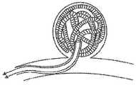
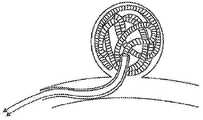
도 16a 및 도 16b는, 도 1 내지 도 14의 혈관폐색용 이식 시스템의 전해식 분리 시스템의 특정 실시예를 이용하는 팽창식 플로우 디스럽터 디바이스(expandable flow disruptor device)를 이용한, 동맥류 폐색의 전개 과정을 도시한 것이다. 본원에서 언급되는 이식 시스템(10)의 이송 및 전개는, 앞서 언급된 바와 같이 환자의 맥관구조의 치료를 위해 이식 디바이스(10) 또는 임의의 다른 적절하고 이식 가능한 의료용 디바이스를 우선 압축시킴으로써 행해질 수 있다. 마이크로카테터(51) 내에 또는 다른 적절한 이송 디바이스 내에 배치되어 있는 동안, 층(40)의 필라멘트 요소들은, 서로에 대해 그리고 마이크로카테터(51)의 길이방향 축에 대해 실질적으로 평행한 세장형의 뒤집히지 않은 구성을 취할 수 있다. 일단 이식 디바이스(10)가 마이크로카테터(51)의 원위 포트로부터 외부로 밀려나거나 또는 달리 반경방향 제약이 제거되면, 상기 필라멘트 요소의 원위 단부들은 이후 서로를 향해 축방향으로 수축하여, 도 16b에 도시된 바와 같이 혈관의 결함(60) 내에서 구형의 뒤집어진 구성을 나타낼 수 있다. 이식 디바이스(10)는 이후 마이크로카테터(51) 내에 배치되어 있으면서 원하는 치료 위치까지 이송될 수 있으며, 다음으로 마이크로카테터(51)의 원위 단부로부터 배출될 수 있거나 혹은 달리 전개될 수 있다. 다른 방법 실시예에 있어서, 마이크로카테터(51)는 우선 가이드 와이어(59) 위로 또는 다른 적절한 네비게이션 기법에 의해 원하는 치료 위치로 길을 찾아갈 수 있다. 마이크로카테터(51)의 원위 단부는, 마이크로카테터(51)의 원위 포트가 회수할 가이드 와이어(59) 및 치료할 혈관의 결함(60)을 향해 지향되거나 또는 상기 가이드 와이어 및 상기 결함 내에 배치되게 하도록 위치 설정될 수 있다. 이송 장치(92)에 고정된 이식 디바이스(10)는 이후 반경방향으로 제한될 수 있으며, 마이크로카테터(51)의 내측 내강의 근위 부분 내로 삽입될 수 있고, 상기 내측 내강을 통해 혈관의 결함(60)으로 멀리로 진행하게 될 수 있다. 일단 이송 시스템의 원위 선단부 또는 전개 포트가 혈관의 결함에 이웃한 원하는 위치에 또는 혈관의 결함 내에 위치 설정되면, 이식 디바이스(10)는 마이크로카테터(51)의 원위 단부로부터 외부로 전개될 수 있으며, 이에 따라 이식 디바이스가 도 16c에 도시된 바와 같이 반경방향으로 전개되기 시작할 수 있도록 허용한다. 이식 디바이스(10)가 이송 장치(92) 또는 마이크로카테터(51)의 원위 단부로부터 나오게 되면, 이식 디바이스(10)는 혈관의 결함(60) 내에서 확장 상태로의 확장을 시작할 수 있지만, 혈관의 결함(60)의 내측 표면에 의해 적어도 부분적으로 제한될 수도 있다. 이때, 이식 디바이스(10)는 이송 장치(92)로부터 분리될 수 있다.Figures 16a and 16b illustrate the development of aneurysm occlusion using an expandable flow disruptor device utilizing a specific embodiment of the electrolytic separation system of the vascular occlusion system of Figures 1-14. FIG. The transfer and deployment of the
다양한 다른 혈관용 이식물은, 도 1 내지 도 14의 혈관폐색용 이식 시스템의 전해식 분리 시스템의 특정 실시예를 이용할 수 있다. 예를 들면, 다양한 관형 이식물, 예컨대 스텐트 또는 관형 유동 전환용 이식물은 그 자체로 동맥을 폐색시키도록 이식될 수도 있고, 엠발릭 마이크로코일 또는 액상 엠발릭(liquid embolics)과 조합하여 동맥을 폐색시키도록 이식될 수도 있다. 스텐트 이식편은, 예컨대 복근의 대동맥의 동맥류에 이식될 수 있으며, 상기 스텐트 이식편은 본 발명의 분리 시스템을 포함한다. 본 발명의 분리 시스템을 포함하는 동맥류 네크부 차단용 이식물이 또한 이식될 수 있다.Various other vascular grafts may utilize specific embodiments of the electrolytic separation system of the vascular occlusion implant systems of Figs. 1-14. For example, various tubular implants, such as stents or tubular transitional implants, may themselves be implanted to occlude arteries, or may be implanted in combination with embolic microcoils or liquid embolics to occlude arteries . The stent graft can be implanted, for example, into an aortic aneurysm of the abdominal aorta, and the stent graft includes the separation system of the present invention. The implant for blocking the aneurysm neck portion including the separation system of the present invention can also be implanted.
Claims (33)
Translated fromKorean금속 와이어를 포함하고 근위 단부 및 원위 단부를 갖는 세장형의 나선형 코일;
상기 나선형 코일 내에서 축방향으로 연장되며 근위 단부 및 원위 단부를 갖는 세장형 신장 억제 부재로서, 신장 억제 부재의 근위 단부는 나선형 코일의 근위 단부에 고정되며, 신장 억제 부재의 원위 단부는 나선형 코일의 원위 단부에 고정되는 것인 신장 억제 부재;
코어 와이어의 원위 단부 주위를 감싸고 있는 커플링 코일(coupling coil)로서, 상기 나선형 코일 내에 동축으로 위치 설정되는 것인 커플링 코일;
상기 나선형 코일과 상기 커플링 코일 사이에 위치하는, 절연 재료로 된 원통형 절연 영역으로서, 상기 코어 와이어로부터 상기 나선형 코일을 전기적으로 절연시키도록 구성되는 원통형 절연 영역
을 포함하는 혈관폐색용 이식물.As vasoocclusive implants,
A elongated spiral coil comprising a metal wire and having a proximal end and a distal end;
Wherein the proximal end of the elongate restraining member is secured to the proximal end of the helical coil and the distal end of the elongate restraining member is secured to the proximal end of the helical coil An elongate restraining member secured to the distal end;
A coupling coil surrounding the distal end of the core wire, the coupling coil being coaxially positioned within the helical coil;
A cylindrical insulated area of insulating material positioned between the helical coil and the coupling coil, the cylindrical insulated area comprising a cylindrical insulated area configured to electrically isolate the helical coil from the core wire,
Gt; a < / RTI > vascular occlusion implant.
상기 푸셔 부재는 근위 단부 및 원위 단부를 갖고, 세장형 코어 와이어, 및 이 코어 와이어를 둘러싸는 폴리머 커버를 포함하며,
상기 코어 와이어의 원위 부분은 푸셔 부재의 원위 단부로부터 연장되고,
상기 이식물은,
금속 와이어를 포함하고 근위 단부 및 원위 단부를 갖는 세장형의 나선형 코일;
상기 나선형 코일 내에서 축방향으로 연장되며 근위 단부 및 원위 단부를 갖는 세장형 신장 억제 부재로서, 신장 억제 부재의 근위 단부는 나선형 코일의 근위 단부에 고정되며, 신장 억제 부재의 원위 단부는 나선형 코일의 원위 단부에 고정되는 것인 신장 억제 부재;
코어 와이어의 원위 단부 주위를 감싸고 있는 커플링 코일(coupling coil)로서, 상기 나선형 코일 내에 동축으로 위치 설정되는 것인 커플링 코일;
상기 나선형 코일과 상기 커플링 코일 사이에 위치하는, 절연 재료로 된 원통형 절연 영역으로서, 코어 와이어로부터 나선형 코일을 전기적으로 절연시키도록 구성되는 원통형 절연 영역
을 포함하는 것인 혈관폐색용 이식 시스템.1. An implantable graft system for occluding blood vessels comprising an implant and a pusher member,
Wherein the pusher member has a proximal end and a distal end and includes a elongate core wire and a polymeric cover surrounding the core wire,
The distal portion of the core wire extending from the distal end of the pusher member,
The implant,
A elongated spiral coil comprising a metal wire and having a proximal end and a distal end;
Wherein the proximal end of the elongate restraining member is secured to the proximal end of the helical coil and the distal end of the elongate restraining member is secured to the proximal end of the helical coil An elongate restraining member secured to the distal end;
A coupling coil surrounding the distal end of the core wire, the coupling coil being coaxially positioned within the helical coil;
A cylindrical insulative region of insulating material positioned between the helical coil and the coupling coil, the cylindrical insulative region comprising: a cylindrical insulative region configured to electrically isolate the helical coil from the core wire;
Wherein the blood vessel occlusion grafting system comprises:
상기 푸셔 부재의 근위 단부에서 이식물 조립체에 전기적으로 결합되는 전력 공급부
를 더 포함하는 혈관폐색용 이식 시스템.9. The method of claim 8,
A power supply electrically coupled to the implant assembly at the proximal end of the pusher member;
Further comprising a blood vessel closure system.
방사선 불투과성이고 기상 증착된 양전성의 탄탈 금속
을 더 포함하는 혈관폐색용 이식 시스템.9. The method of claim 8,
Radiopaque and vapor-deposited amphoteric tantalum metal
Further comprising a blood vessel closure system.
상기 전력 공급부를 이식물 조립체에 연결하도록 구성되는 살균 케이블
을 더 포함하며, 상기 살균 케이블은 살균 버튼을 포함하고, 촉각을 이용한 상기 살균 버튼의 조작에 의해 상기 전력 공급부가 작동하게 되는 것인 혈관폐색용 이식 시스템.15. The method of claim 14,
A sterilizing cable configured to connect the power supply to the implant assembly
Wherein the sterilizing cable comprises a sterilizing button and the power supply is activated by operation of the sterilizing button using a tactile sense.
혈관폐색용 이식 시스템을 제공하는 단계로서, 상기 혈관폐색용 이식 시스템은,
근위 단부 및 원위 단부를 갖는 푸셔 부재로서, 상기 푸셔 부재는 세장형 코어 와이어, 및 이 코어 와이어를 둘러싸는 폴리머 커버를 포함하며, 상기 코어 와이어의 원위 부분은 푸셔 부재의 원위 단부로부터 연장되는 것인 푸셔 부재;
금속 와이어를 포함하는 세장형의 나선형 코일을 갖고 근위 단부 및 원위 단부를 갖는 이식물;
상기 나선형 코일 내에 축방향으로 연장되고 근위 단부 및 원위 단부를 갖는 세장형 신장 억제 부재로서, 상기 신장 억제 부재의 근위 단부는 나선형 코일의 근위 단부에 고정되며, 상기 신장 억제 부재의 원위 단부는 나선형 코일의 원위 단부에 고정되는 것인 신장 억제 부재;
상기 코어 와이어의 원위 단부 주위를 감싸고 있는 커플링 코일로서, 상기 나선형 코일 내에 동축으로 위치 설정되는 것인 커플링 코일;
상기 나선형 코일과 상기 커플링 코일 사이에 위치하는, 절연 재료로 된 원통형 절연 영역으로서, 코어 와이어로부터 나선형 코일을 전기적으로 절연시키도록 구성되는 원통형 절연 영역
을 포함하는 것인 단계;
상기 혈관폐색용 이식 시스템을 포함하는 마이크로카테터를 환자의 맥관구조 내로 도입하는 단계;
상기 마이크로카테터를 동맥류로 전진시키는 단계;
분리 영역이 마이크로카테터 바로 외부에 위치 설정될 때까지, 상기 마이크로카테터의 원위 단부로부터 외부로 그리고 동맥류 내로 이식물을 밀어내는 단계;
상기 푸셔 부재로부터 이식물을 전해식으로 분리시키는 단계
를 포함하는 방법.As a method for treating aneurysm,
Providing a vascular occlusion grafting system, the vascular occlusion grafting system comprising:
A pusher member having a proximal end and a distal end, the pusher member comprising a elongate core wire and a polymeric cover surrounding the core wire, the distal portion of the core wire extending from a distal end of the pusher member A pusher member;
An implant having a elongated helical coil including a metal wire and having a proximal end and a distal end;
Wherein the proximal end of the elongation-inhibiting member is fixed to the proximal end of the helical coil and the distal end of the elongation-inhibiting member is connected to the distal end of the helical coil, To the distal end of the elongate member;
A coupling coil surrounding the distal end of the core wire, the coupling coil being coaxially positioned within the helical coil;
A cylindrical insulative region of insulating material positioned between the helical coil and the coupling coil, the cylindrical insulative region comprising: a cylindrical insulative region configured to electrically isolate the helical coil from the core wire;
≪ / RTI >
Introducing a microcatheter comprising the vascular occlusion transplantation system into a vasculature of a patient;
Advancing the microcatheter into an aneurysm;
Pushing the implant outward from the distal end of the microcatheter and into the aneurysm until the isolation region is positioned just outside the microcatheter;
Separating the implant from the pusher member in an electrolytic manner
≪ / RTI >
제2 이식물 상의 분리 영역이 마이크로카테터 바로 외부에 위치 설정될 때까지, 상기 마이크로카테터의 원위 단부로부터 외부로 그리고 동맥류 내로 제2 이식물을 밀어내는 단계;
상기 제2 이식물을 전해식으로 분리시키는 단계
를 더 포함하는 방법.31. The method of claim 30,
Pushing the second implant outwardly from the distal end of the microcatheter and into the aneurysm until the isolation area on the second implant is positioned just outside the microcatheter;
Separating the second implant into an electrolytic solution
≪ / RTI >
동맥류 내에 3차원 프레이밍 마이크로코일(framing microcoil)을 이식하는 단계
를 더 포함하는 방법.31. The method of claim 30,
Implanting a three-dimensional framing microcoil into an aneurysm
≪ / RTI >
Applications Claiming Priority (1)
| Application Number | Priority Date | Filing Date | Title |
|---|---|---|---|
| PCT/US2015/066605WO2017105479A1 (en) | 2015-12-18 | 2015-12-18 | Vascular implant system and processes with flexible detachment zones |
Publications (2)
| Publication Number | Publication Date |
|---|---|
| KR20180103065Atrue KR20180103065A (en) | 2018-09-18 |
| KR102359744B1 KR102359744B1 (en) | 2022-02-08 |
Family
ID=59057223
Family Applications (1)
| Application Number | Title | Priority Date | Filing Date |
|---|---|---|---|
| KR1020187020366AActiveKR102359744B1 (en) | 2015-12-18 | 2015-12-18 | Vascular Implantation System and Vascular Implantation Process Using Flexible Separation Area |
Country Status (5)
| Country | Link |
|---|---|
| EP (1) | EP3389510A4 (en) |
| JP (1) | JP2019502513A (en) |
| KR (1) | KR102359744B1 (en) |
| CN (1) | CN108697425A (en) |
| WO (1) | WO2017105479A1 (en) |
Cited By (1)
| Publication number | Priority date | Publication date | Assignee | Title |
|---|---|---|---|---|
| KR20210073548A (en)* | 2018-10-09 | 2021-06-18 | 마이크로포트 뉴로테크 (상하이) 컴퍼니 리미티드 | Embolization device and its spring coil |
Families Citing this family (6)
| Publication number | Priority date | Publication date | Assignee | Title |
|---|---|---|---|---|
| CN107374690A (en)* | 2017-08-16 | 2017-11-24 | 微创神通医疗科技(上海)有限公司 | Embolic coil conveying device and preparation method thereof |
| CN108814670A (en)* | 2018-10-12 | 2018-11-16 | 微创神通医疗科技(上海)有限公司 | Implantation material and embolization device |
| FI3941392T3 (en) | 2019-03-20 | 2025-07-28 | Inqb8 Medical Tech Llc | Aortic dissection implant |
| WO2020206147A1 (en)* | 2019-04-05 | 2020-10-08 | Balt Usa | Optimized detachment systems based on leverage from electrical locus targeting and related medical devices |
| WO2021011494A1 (en)* | 2019-07-13 | 2021-01-21 | Balt Usa | Coaxial coil detachment systems based on targeting and shock absorbing coil improvements |
| CN114176697B (en)* | 2021-12-20 | 2024-07-05 | 神遁医疗科技(上海)有限公司 | Embolic material and preparation method thereof |
Citations (4)
| Publication number | Priority date | Publication date | Assignee | Title |
|---|---|---|---|---|
| US5989242A (en)* | 1995-06-26 | 1999-11-23 | Trimedyne, Inc. | Therapeutic appliance releasing device |
| US20060135986A1 (en)* | 2004-12-22 | 2006-06-22 | Scimed Life Systems, Inc. | Vaso-occlusive device having pivotable coupling |
| US8425550B2 (en)* | 2004-12-01 | 2013-04-23 | Boston Scientific Scimed, Inc. | Embolic coils |
| US9011480B2 (en)* | 2012-01-20 | 2015-04-21 | Covidien Lp | Aneurysm treatment coils |
Family Cites Families (6)
| Publication number | Priority date | Publication date | Assignee | Title |
|---|---|---|---|---|
| US5984929A (en)* | 1997-08-29 | 1999-11-16 | Target Therapeutics, Inc. | Fast detaching electronically isolated implant |
| US9636115B2 (en)* | 2005-06-14 | 2017-05-02 | Stryker Corporation | Vaso-occlusive delivery device with kink resistant, flexible distal end |
| JP5366974B2 (en)* | 2007-12-21 | 2013-12-11 | マイクロベンション インコーポレイテッド | System and method for determining the position of a separation zone of a separable implant |
| US8657870B2 (en)* | 2009-06-26 | 2014-02-25 | Biosensors International Group, Ltd. | Implant delivery apparatus and methods with electrolytic release |
| US20120209310A1 (en)* | 2011-02-10 | 2012-08-16 | Stryker Nv Operations Limited | Vaso-occlusive device delivery system |
| WO2015095360A1 (en)* | 2013-12-18 | 2015-06-25 | Blockade Medical, LLC | Implant system and delivery method |
- 2015
- 2015-12-18EPEP15910944.6Apatent/EP3389510A4/ennot_activeWithdrawn
- 2015-12-18JPJP2018551747Apatent/JP2019502513A/enactivePending
- 2015-12-18WOPCT/US2015/066605patent/WO2017105479A1/ennot_activeCeased
- 2015-12-18KRKR1020187020366Apatent/KR102359744B1/enactiveActive
- 2015-12-18CNCN201580085817.6Apatent/CN108697425A/enactivePending
Patent Citations (4)
| Publication number | Priority date | Publication date | Assignee | Title |
|---|---|---|---|---|
| US5989242A (en)* | 1995-06-26 | 1999-11-23 | Trimedyne, Inc. | Therapeutic appliance releasing device |
| US8425550B2 (en)* | 2004-12-01 | 2013-04-23 | Boston Scientific Scimed, Inc. | Embolic coils |
| US20060135986A1 (en)* | 2004-12-22 | 2006-06-22 | Scimed Life Systems, Inc. | Vaso-occlusive device having pivotable coupling |
| US9011480B2 (en)* | 2012-01-20 | 2015-04-21 | Covidien Lp | Aneurysm treatment coils |
Cited By (1)
| Publication number | Priority date | Publication date | Assignee | Title |
|---|---|---|---|---|
| KR20210073548A (en)* | 2018-10-09 | 2021-06-18 | 마이크로포트 뉴로테크 (상하이) 컴퍼니 리미티드 | Embolization device and its spring coil |
Also Published As
| Publication number | Publication date |
|---|---|
| JP2019502513A (en) | 2019-01-31 |
| WO2017105479A1 (en) | 2017-06-22 |
| EP3389510A4 (en) | 2019-10-23 |
| KR102359744B1 (en) | 2022-02-08 |
| EP3389510A1 (en) | 2018-10-24 |
| CN108697425A (en) | 2018-10-23 |
Similar Documents
| Publication | Publication Date | Title |
|---|---|---|
| US9566072B2 (en) | Coil system | |
| US11849955B2 (en) | Delivery and detachment systems and methods for vascular implants | |
| US20240197335A1 (en) | Detachable Coil Incorporating Stretch Resistance | |
| CA2211512C (en) | Aneurysm closure device assembly | |
| KR102359744B1 (en) | Vascular Implantation System and Vascular Implantation Process Using Flexible Separation Area | |
| AU2015227530B2 (en) | A vasculature occlusion device detachment system with tapered corewire and heater activated fiber detachment | |
| US20170000495A1 (en) | Implant System and Delivery Method | |
| US20180271533A1 (en) | Vascular Implant System and Processes with Flexible Detachment Zones | |
| WO2025101491A1 (en) | Thermal-mechanical actuation and delivery for implantable devices | |
| AU4739199A (en) | Aneurysm closure device assembly |
Legal Events
| Date | Code | Title | Description |
|---|---|---|---|
| PA0105 | International application | Patent event date:20180716 Patent event code:PA01051R01D Comment text:International Patent Application | |
| PG1501 | Laying open of application | ||
| PA0201 | Request for examination | Patent event code:PA02012R01D Patent event date:20190812 Comment text:Request for Examination of Application | |
| E902 | Notification of reason for refusal | ||
| PE0902 | Notice of grounds for rejection | Comment text:Notification of reason for refusal Patent event date:20210223 Patent event code:PE09021S01D | |
| E701 | Decision to grant or registration of patent right | ||
| PE0701 | Decision of registration | Patent event code:PE07011S01D Comment text:Decision to Grant Registration Patent event date:20211104 | |
| GRNT | Written decision to grant | ||
| PR0701 | Registration of establishment | Comment text:Registration of Establishment Patent event date:20220203 Patent event code:PR07011E01D | |
| PR1002 | Payment of registration fee | Payment date:20220204 End annual number:3 Start annual number:1 | |
| PG1601 | Publication of registration |