KR20180101600A - Non-contact coated glass and related coating systems and methods - Google Patents
Non-contact coated glass and related coating systems and methodsDownload PDFInfo
- Publication number
- KR20180101600A KR20180101600AKR1020187024631AKR20187024631AKR20180101600AKR 20180101600 AKR20180101600 AKR 20180101600AKR 1020187024631 AKR1020187024631 AKR 1020187024631AKR 20187024631 AKR20187024631 AKR 20187024631AKR 20180101600 AKR20180101600 AKR 20180101600A
- Authority
- KR
- South Korea
- Prior art keywords
- glass
- coating
- coating layer
- product
- glass product
- Prior art date
- Legal status (The legal status is an assumption and is not a legal conclusion. Google has not performed a legal analysis and makes no representation as to the accuracy of the status listed.)
- Withdrawn
Links
Images


Classifications
- C—CHEMISTRY; METALLURGY
- C03—GLASS; MINERAL OR SLAG WOOL
- C03C—CHEMICAL COMPOSITION OF GLASSES, GLAZES OR VITREOUS ENAMELS; SURFACE TREATMENT OF GLASS; SURFACE TREATMENT OF FIBRES OR FILAMENTS MADE FROM GLASS, MINERALS OR SLAGS; JOINING GLASS TO GLASS OR OTHER MATERIALS
- C03C17/00—Surface treatment of glass, not in the form of fibres or filaments, by coating
- C03C17/001—General methods for coating; Devices therefor
- C03C17/002—General methods for coating; Devices therefor for flat glass, e.g. float glass
- C—CHEMISTRY; METALLURGY
- C03—GLASS; MINERAL OR SLAG WOOL
- C03B—MANUFACTURE, SHAPING, OR SUPPLEMENTARY PROCESSES
- C03B27/00—Tempering or quenching glass products
- C—CHEMISTRY; METALLURGY
- C03—GLASS; MINERAL OR SLAG WOOL
- C03C—CHEMICAL COMPOSITION OF GLASSES, GLAZES OR VITREOUS ENAMELS; SURFACE TREATMENT OF GLASS; SURFACE TREATMENT OF FIBRES OR FILAMENTS MADE FROM GLASS, MINERALS OR SLAGS; JOINING GLASS TO GLASS OR OTHER MATERIALS
- C03C17/00—Surface treatment of glass, not in the form of fibres or filaments, by coating
- C03C17/006—Surface treatment of glass, not in the form of fibres or filaments, by coating with materials of composite character
- C03C17/008—Surface treatment of glass, not in the form of fibres or filaments, by coating with materials of composite character comprising a mixture of materials covered by two or more of the groups C03C17/02, C03C17/06, C03C17/22 and C03C17/28
- C03C17/009—Mixtures of organic and inorganic materials, e.g. ormosils and ormocers
- C—CHEMISTRY; METALLURGY
- C03—GLASS; MINERAL OR SLAG WOOL
- C03C—CHEMICAL COMPOSITION OF GLASSES, GLAZES OR VITREOUS ENAMELS; SURFACE TREATMENT OF GLASS; SURFACE TREATMENT OF FIBRES OR FILAMENTS MADE FROM GLASS, MINERALS OR SLAGS; JOINING GLASS TO GLASS OR OTHER MATERIALS
- C03C17/00—Surface treatment of glass, not in the form of fibres or filaments, by coating
- C03C17/06—Surface treatment of glass, not in the form of fibres or filaments, by coating with metals
- C03C17/10—Surface treatment of glass, not in the form of fibres or filaments, by coating with metals by deposition from the liquid phase
- C—CHEMISTRY; METALLURGY
- C03—GLASS; MINERAL OR SLAG WOOL
- C03C—CHEMICAL COMPOSITION OF GLASSES, GLAZES OR VITREOUS ENAMELS; SURFACE TREATMENT OF GLASS; SURFACE TREATMENT OF FIBRES OR FILAMENTS MADE FROM GLASS, MINERALS OR SLAGS; JOINING GLASS TO GLASS OR OTHER MATERIALS
- C03C17/00—Surface treatment of glass, not in the form of fibres or filaments, by coating
- C03C17/22—Surface treatment of glass, not in the form of fibres or filaments, by coating with other inorganic material
- C03C17/225—Nitrides
- C—CHEMISTRY; METALLURGY
- C03—GLASS; MINERAL OR SLAG WOOL
- C03C—CHEMICAL COMPOSITION OF GLASSES, GLAZES OR VITREOUS ENAMELS; SURFACE TREATMENT OF GLASS; SURFACE TREATMENT OF FIBRES OR FILAMENTS MADE FROM GLASS, MINERALS OR SLAGS; JOINING GLASS TO GLASS OR OTHER MATERIALS
- C03C17/00—Surface treatment of glass, not in the form of fibres or filaments, by coating
- C03C17/22—Surface treatment of glass, not in the form of fibres or filaments, by coating with other inorganic material
- C03C17/23—Oxides
- C03C17/245—Oxides by deposition from the vapour phase
- C—CHEMISTRY; METALLURGY
- C03—GLASS; MINERAL OR SLAG WOOL
- C03C—CHEMICAL COMPOSITION OF GLASSES, GLAZES OR VITREOUS ENAMELS; SURFACE TREATMENT OF GLASS; SURFACE TREATMENT OF FIBRES OR FILAMENTS MADE FROM GLASS, MINERALS OR SLAGS; JOINING GLASS TO GLASS OR OTHER MATERIALS
- C03C17/00—Surface treatment of glass, not in the form of fibres or filaments, by coating
- C03C17/22—Surface treatment of glass, not in the form of fibres or filaments, by coating with other inorganic material
- C03C17/23—Oxides
- C03C17/25—Oxides by deposition from the liquid phase
- C03C17/256—Coating containing TiO2
- C—CHEMISTRY; METALLURGY
- C03—GLASS; MINERAL OR SLAG WOOL
- C03C—CHEMICAL COMPOSITION OF GLASSES, GLAZES OR VITREOUS ENAMELS; SURFACE TREATMENT OF GLASS; SURFACE TREATMENT OF FIBRES OR FILAMENTS MADE FROM GLASS, MINERALS OR SLAGS; JOINING GLASS TO GLASS OR OTHER MATERIALS
- C03C17/00—Surface treatment of glass, not in the form of fibres or filaments, by coating
- C03C17/34—Surface treatment of glass, not in the form of fibres or filaments, by coating with at least two coatings having different compositions
- C03C17/3411—Surface treatment of glass, not in the form of fibres or filaments, by coating with at least two coatings having different compositions with at least two coatings of inorganic materials
- C03C17/3417—Surface treatment of glass, not in the form of fibres or filaments, by coating with at least two coatings having different compositions with at least two coatings of inorganic materials all coatings being oxide coatings
- C—CHEMISTRY; METALLURGY
- C03—GLASS; MINERAL OR SLAG WOOL
- C03C—CHEMICAL COMPOSITION OF GLASSES, GLAZES OR VITREOUS ENAMELS; SURFACE TREATMENT OF GLASS; SURFACE TREATMENT OF FIBRES OR FILAMENTS MADE FROM GLASS, MINERALS OR SLAGS; JOINING GLASS TO GLASS OR OTHER MATERIALS
- C03C21/00—Treatment of glass, not in the form of fibres or filaments, by diffusing ions or metals in the surface
- C—CHEMISTRY; METALLURGY
- C03—GLASS; MINERAL OR SLAG WOOL
- C03C—CHEMICAL COMPOSITION OF GLASSES, GLAZES OR VITREOUS ENAMELS; SURFACE TREATMENT OF GLASS; SURFACE TREATMENT OF FIBRES OR FILAMENTS MADE FROM GLASS, MINERALS OR SLAGS; JOINING GLASS TO GLASS OR OTHER MATERIALS
- C03C2218/00—Methods for coating glass
- C03C2218/10—Deposition methods
- C03C2218/11—Deposition methods from solutions or suspensions
- Y—GENERAL TAGGING OF NEW TECHNOLOGICAL DEVELOPMENTS; GENERAL TAGGING OF CROSS-SECTIONAL TECHNOLOGIES SPANNING OVER SEVERAL SECTIONS OF THE IPC; TECHNICAL SUBJECTS COVERED BY FORMER USPC CROSS-REFERENCE ART COLLECTIONS [XRACs] AND DIGESTS
- Y02—TECHNOLOGIES OR APPLICATIONS FOR MITIGATION OR ADAPTATION AGAINST CLIMATE CHANGE
- Y02P—CLIMATE CHANGE MITIGATION TECHNOLOGIES IN THE PRODUCTION OR PROCESSING OF GOODS
- Y02P40/00—Technologies relating to the processing of minerals
- Y02P40/50—Glass production, e.g. reusing waste heat during processing or shaping
- Y02P40/57—Improving the yield, e-g- reduction of reject rates
Landscapes
- Chemical & Material Sciences (AREA)
- Materials Engineering (AREA)
- Engineering & Computer Science (AREA)
- Organic Chemistry (AREA)
- Chemical Kinetics & Catalysis (AREA)
- Geochemistry & Mineralogy (AREA)
- General Chemical & Material Sciences (AREA)
- Life Sciences & Earth Sciences (AREA)
- Inorganic Chemistry (AREA)
- Composite Materials (AREA)
- Physics & Mathematics (AREA)
- Thermal Sciences (AREA)
- Surface Treatment Of Glass (AREA)
- Application Of Or Painting With Fluid Materials (AREA)
- Re-Forming, After-Treatment, Cutting And Transporting Of Glass Products (AREA)
Abstract
Translated fromKoreanDescription
Translated fromKorean본 출원은 2016년 1월 26일에 출원된 미국 가 특허출원 제62/287,186호의 우선권을 주장하며, 이의 전체적인 내용은 여기에 참조로서 병합된다.This application claims priority of U.S. Provisional Patent Application No. 62 / 287,186, filed January 26, 2016, the entire contents of which are incorporated herein by reference.
본 개시는 일반적으로 코팅된 유리 (유리-세라믹을 포함함) 물질에 관한 것이며, 특히 비-접촉 환경에서 유리에 코팅 물질이 적용되거나 또는 코팅이 형성되는 물질에 관한 것이다.This disclosure relates generally to coated glass (including glass-ceramics) materials, and particularly to materials to which a coating material is applied to or formed from a glass in a non-contact environment.
유리 물질은 전자 제품, 디스플레이에서, 빌딩 창문과 같은 건축 적용분야에서, 자동차 창문과 같은 자동차 적용분야에서 등을 포함하여 많은 용도를 갖는다. 많은 적용분야에서, 유리 물질은 저 방사율, 반사 성질, 대전-방지 성질, 내스크래치성, 등과 같이, 유리에 원하는 기능을 제공하는 표면 상에서 하나 이상의 코팅층을 포함할 수 있다.Glass materials have many uses, including in electronics, in displays, in architectural applications such as building windows, in automotive applications such as automotive windows, and the like. In many applications, the glass material may include one or more coating layers on the surface that provide the desired function to the glass, such as low emissivity, reflective properties, antistatic properties, scratch resistance, and the like.
본 개시는 비-접촉 코팅된 유리 및 관련된 코팅 시스템 및 방법을 제공하는 것을 목적으로 한다.The present disclosure is directed to providing non-contact coated glass and related coating systems and methods.
본 개시의 하나의 구현예는 유리에 코팅층을 적용하는 공정에 관한 것이다. 상기 공정은 제1 표면 및 제1 표면에 대향하는 제2 표면을 갖는 유리 제품을 제공하는 단계를 포함한다. 상기 공정은 유리 제품의 제1 표면에 제1 코팅 전구체 물질을 적용하는 단계를 포함한다. 상기 공정은 가스 베어링을 통해 상기 유리 제품을 지지하는 단계를 포함한다. 상기 공정은 상기 유리 제품이 가스 베어링에 의해 지지되는 동안, 상기 유리 제품 및 상기 코팅 전구체 물질을 유리 제품의 유리 전이 온도 위로 가열하는 단계를 포함한다. 가열하는 단계 동안, 제1 코팅 전구체 물질의 성질은 변화하여, 제1 코팅층이 제1 전구체 물질로부터 유리 제품의 제1 표면 상에 형성된다.One embodiment of the present disclosure relates to a process for applying a coating layer to a glass. The process includes providing a glass article having a first surface and a second surface opposite the first surface. The process includes applying a first coating precursor material to a first surface of a glass article. The process includes supporting the glass product through a gas bearing. The process includes heating the glass product and the coating precursor material above the glass transition temperature of the glass article while the glass article is supported by the gas bearing. During the heating step, the properties of the first coating precursor material change, so that a first coating layer is formed on the first surface of the glass article from the first precursor material.
본 개시의 추가적인 구현예는 코팅된 유리 제품에 관한 것이다. 코팅된 유리 제품은 제1 주 표면, 상기 제1 주 표면에 대향하는 제2 주 표면, 및 적어도 50중량%의 이산화 규소의 유리 물질을 포함한다. 코팅된 유리 제품은 제1 주 표면 상에 위치한 제1 코팅층을 포함하고, 제1 코팅층은 유리 제품의 유리 물질과는 다른 물질로부터 형성된다. 제1 코팅층은 제1 코팅층과 유리 제품 사이의 경계면으로부터 유리 제품의 중심을 향해 확장하는 유리 제품의 물질 내에 위치한 제1 확산 영역을 포함한다. 제1 확산 영역 내에서, 상기 제1 코팅층의 물질의 농도는 유리 제품 안으로 깊이가 증가함에 따라 감소하며, 상기 확산 영역은 50 nm보다 큰 깊이를 갖는다.A further embodiment of the disclosure relates to a coated glass article. The coated glass article comprises a first major surface, a second major surface opposite the first major surface, and a glass material of at least 50 wt% silicon dioxide. The coated glass article comprises a first coating layer located on the first major surface and the first coating layer is formed from a material different from the glass material of the glass product. The first coating layer includes a first diffusion region located within the material of the glass article extending from the interface between the first coating layer and the glass article toward the center of the glass article. Within the first diffusion region, the concentration of the material of the first coating layer decreases as the depth into the glass product increases, and the diffusion region has a depth greater than 50 nm.
본 개시의 추가적인 구현예는 유리 시트를 코팅하는 시스템에 관한 것이다. 상기 시스템은 유리 시트에 열을 전달하는 가열 요소 (heating element)를 포함하는 가열 스테이션을 포함하고, 가열 스테이션은 가열 동안 유리 시트가 제1 채널 내에 위치하도록 제1 채널을 한정 (define)한다. 유리 시트는 제1 주 표면, 제2 주 표면, 및 제1 및 제2 주 표면 사이의 두께를 포함한다. 상기 시스템은 대향하는 제1 및 제2 히트 싱크 표면을 포함하는 냉각 스테이션을 포함하고, 제1 및 제2 히트 싱크 표면은 그 사이에서 제2 채널을 한정하여 냉각 동안 유리 시트가 제2 채널 내에 위치하도록 한다. 상기 시스템은 제1 및 제2 채널에 가압된 가스를 전달하는 가스 베어링을 포함하여, 유리 시트가 가열 단계 동안 가열 스테이션의 표면을 접촉하지 않고 제1 채널 내에서 가스에 의해 지지되도록 하고, 유리 시트가 냉각 단계 동안 제1 및 제2 히트 싱크 표면을 접촉하지 않고 제2 채널 내에서 가스에 의해 지지되도록 한다. 상기 시스템은 가스 베어링과 연통된 유리 코팅 전구체 물질의 공급원을 포함하여, 유리 시트가 가스에 의해 지지되는 동안, 유리 코팅 전구체 물질이 유리 시트의 제1 주 표면 및 제2 주 표면 중 적어도 하나에 가압된 가스를 통해 전달되도록 한다.A further embodiment of the present disclosure relates to a system for coating glass sheets. The system includes a heating station including a heating element for transferring heat to the glass sheet, wherein the heating station defines a first channel such that the glass sheet is located within the first channel during heating. The glass sheet includes a thickness between the first major surface, the second major surface, and the first and second major surfaces. The system includes a cooling station comprising opposing first and second heat sink surfaces, wherein the first and second heat sink surfaces define a second channel therebetween to allow the glass sheet to be positioned within the second channel . The system includes a gas bearing that delivers pressurized gas to the first and second channels such that the glass sheet is supported by the gas in the first channel without contacting the surface of the heating station during the heating step, To be supported by the gas in the second channel without contacting the first and second heat sink surfaces during the cooling step. The system includes a source of glass coated precursor material in communication with the gas bearing such that the glass coated precursor material is pressed against at least one of the first major surface and the second major surface of the glass sheet while the glass sheet is supported by the gas. Thereby allowing the gas to pass through.
추가적인 특징 및 장점은 이하의 상세한 설명에서 설명될 것이며, 부분적으로는 그 설명으로부터 통상의 기술자에게 쉽게 명백하거나, 또는 상세한 설명, 청구 범위, 및 첨부된 도면에 기재된 구현예를 실행함으로써 인식될 것이다.Additional features and advantages will be set forth in part in the description that follows and, in part, will be readily apparent to those skilled in the art from a reading of the specification, or may be learned by practice of the embodiments described in the detailed description, the claims and the accompanying drawings.
전술한 일반적인 설명 및 다음의 상세한 설명 모두는 단순히 예시적인 것이고, 청구범위의 속성 및 특징을 이해하기 위한 개요 또는 틀을 제공하도록 의도된 것으로 이해되어야 한다.It is to be understood that both the foregoing general description and the following detailed description are exemplary only and are intended to provide an overview or framework for understanding the nature and characteristics of the claims.
첨부된 도면은 본 개시의 추가적인 이해를 제공하기 위해 포함되고, 본 명세서의 일부로서 병합되며 그 일부를 구성한다. 도면은 하나 이상의 구현예를 예시하고, 명세서와 함께 다양하 구현예의 원리 및 작동을 설명하는 역할을 한다.BRIEF DESCRIPTION OF THE DRAWINGS The accompanying drawings are included to provide a further understanding of the disclosure, and are incorporated in and constitute a part of this specification. The drawings illustrate one or more embodiments and, together with the specification, serve to explain the principles and operation of the various embodiments.
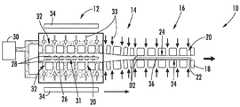
도 1은 예시적인 구현예에 따른 코팅 시스템의 단면 도표이다.
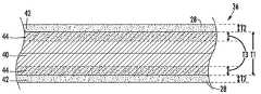
도 2는 예시적인 구현예에 따른 코팅된 유리 시트의 부분 단면도이다.
도 3은 또 다른 예시적인 구현예에 따른 코팅 시스템의 단면 도표이다.
도 4는 또 다른 예시적인 구현예에 따른 코팅 시스템의 단면 도표이다.
도 5는 또 다른 예시적인 구현예에 따른 코팅 시스템의 도표이다.
도 6은 또 다른 예시적인 구현예에 따른 코팅 시스템의 도표이다.
도 7은 또 다른 예시적인 구현예에 따른 코팅 시스템의 도표이다.
도 8은 또 다른 예시적인 구현예에 따른 코팅 시스템의 도표이다.
도 9는 또 다른 예시적인 구현예에 따른 코팅 시스템의 도표이다.
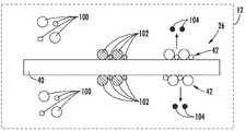
도 10은 또 다른 예시적인 구현예에 따른 코팅 시스템의 도표이다.
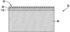
도 11은 예시적인 구현예에 따른 코팅된 유리 시트의 부분 단면도이다.
도 12는 예시적인 구현예에 따른 하중 하에서 도 11의 코팅된 유리 시트의 부분 단면도이다.
도 13은 예시적인 구현예에 따른 코팅되고, 열적으로 템퍼링된 유리 시트의 부분 단면도이다.
도 14는 예시적인 구현예에 따른 유리 또는 유리-세라믹 제품에 대하여 추정된 인장 응력 대 두께의 그래프이다.
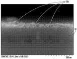
도 15는 예시적인 구현예에 따른 유리 시트 상에 코팅된 SiO2 입자의 SEM 이미지이다.
도 16은 예시적인 구현예에 따라 코팅된 유리 시트 안으로 Cu 및 Cl 확산을 나타내는 DSIMS 플롯이다.
도 17은 예시적인 구현예에 따라 유리 시트 상에 코팅된 BN 입자를 나타내는 AFM 지형 이미지이다.
도 18은 예시적인 구현예에 따라 유리 시트 상에 코팅된 TiO2입자의 SEM 이미지이다.
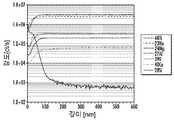
도 19는 예시적인 구현예에 따라 코팅된 유리 시트 안으로 Ti 확산을 나타내는 DSIMS 플롯이다.
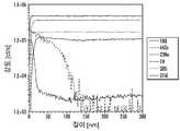
도 20은 예시적인 구현예에 따라 코팅된 유리 시트 안으로 Zn 확산을 나타내는 DSIMS 플롯이다.1 is a cross-sectional view of a coating system according to an exemplary embodiment.
Figure 2 is a partial cross-sectional view of a coated glass sheet according to an exemplary embodiment.
3 is a cross-sectional view of a coating system according to another exemplary embodiment.
4 is a cross-sectional view of a coating system according to another exemplary embodiment.
5 is a diagram of a coating system according to another exemplary embodiment.
6 is a diagram of a coating system according to another exemplary embodiment.
7 is a diagram of a coating system according to another exemplary embodiment.
8 is a diagram of a coating system according to another exemplary embodiment.
9 is a diagram of a coating system according to another exemplary embodiment.
10 is a diagram of a coating system according to another exemplary embodiment.
11 is a partial cross-sectional view of a coated glass sheet in accordance with an exemplary embodiment.
Figure 12 is a partial cross-sectional view of the coated glass sheet of Figure 11 under load according to an exemplary embodiment.
Figure 13 is a partial cross-sectional view of a coated, thermally tempered glass sheet according to an exemplary embodiment.
14 is a graph of the estimated tensile stress versus thickness for a glass or glass-ceramic article in accordance with an exemplary embodiment.
15 is an SEM image of SiO2 particles coated on a glass sheet according to an exemplary embodiment.
Figure 16 is a DSIMS plot showing Cu and Cl diffusion into a coated glass sheet according to an exemplary embodiment.
Figure 17 is an AFM topographic image showing BN particles coated on a glass sheet according to an exemplary embodiment.
18 is an SEM image of TiO2 particles coated on a glass sheet according to an exemplary embodiment.
Figure 19 is a DSIMS plot showing Ti diffusion into a coated glass sheet according to an exemplary embodiment.
Figure 20 is a DSIMS plot showing Zn diffusion into a coated glass sheet according to an exemplary embodiment.
일반적으로 도면을 참조하면, 코팅된 유리 (유리-세라막을 포함함) 제품 및 코팅된 유리 제품을 형성하는 시스템 및 방법의 다양한 구현예가 나타난다. 여기서 논의된 다양한 구현예에서, 코팅된 유리 제품은, 적어도 부분적으로, 비-접촉 코팅 형성 시스템에서 형성되고, 특히, 유리 제품의 주 표면과 접촉하지 않고, 유리 제품 상에 코팅이 형성되거나 및/또는 코팅 물질이 유리 제품에 적용된다. 다양한 구현예에서, 유리 제품 상의 코팅이 형성되거나 또는 코팅 물질이 유리 제품에 적용되는 동안, 이 비-접촉 코팅 형성은 양면 (double-sided) 가스 베어링 내에서 유리 제품을 지지하는 시스템에 의해 제공된다.Referring generally to the drawings, there are various implementations of systems and methods for forming coated glass (including glass-ceramics) products and coated glass products. In various embodiments discussed herein, a coated glass article is at least partially formed in a non-contact coating forming system, and in particular, does not contact the major surface of the glass article, and a coating is formed on the glass article and / Or coating material is applied to the glass product. In various embodiments, the non-contact coating formation is provided by a system that supports the glass article in a double-sided gas bearing, while a coating on the glass article is formed or the coating material is applied to the glass article .
다양한 구현예에서, 이 비-접촉 코팅 형성은 유리 제품에 다양한 특성을 갖는 코팅층을 제공할 수 있다고 믿어지고, 고체 (solid) 접촉-기반 또는 고체 지지-기반 코팅 시스템에서는 달성할수 있다고 믿어지지 않는다. 하기에서 보다 상세히 설명되는 바와 같이, 이러한 성질은 낮은 코팅 결함률, 높은 유리 표면 평활성, 낮은 코팅 두께 변동성, 등을 포함한다. 특정 구현예에 있어서, 여기에 논의된 비-접촉, 가스 베어링 지지 시스템은 유리 시트의 양 면에 코팅 형성을 가능하게 하기 때문에, 고도로 일관된 코팅이 유리 제품의 다중 표면들 (예를 들어, 유리 시트의 대향하는 주 표면들) 상에서 달성될 수 있다고 믿어진다. 이것은 고체 지지 구조 (예를 들어, 롤러, 벨트, 등)를 통해 코팅하는 동안 유리 제품을 지지하는 많은 유형의 종래 코팅 시스템과 대비되는 것이라고 믿어진다.In various embodiments, this non-contact coating formation is believed to be capable of providing a coating layer having various properties in a glass product and is not believed to be achievable in a solid contact-based or solid support-based coating system. As described in more detail below, such properties include low coating defect rates, high glass surface smoothness, low coating thickness variability, and the like. In certain embodiments, the non-contact, gas bearing support system discussed herein enables coating formation on both sides of the glass sheet, so that a highly consistent coating can be applied to multiple surfaces of the glass article (e.g., Lt; / RTI > on the opposite major surfaces). This is believed to be in contrast to many types of conventional coating systems that support glassware during coating through solid support structures (e.g., rollers, belts, etc.).
특정 구현예에서, 여기에 논의된 지지하는 가스 베어링 구조는 코팅 전구체 물질로부터 유리 제품 상에 코팅을 형성하기 위하여 유리 제품에 열을 전달하는 가열 스테이션으로서 구성된다. 여기에 논의된 가열된 가스 베어링 배열은, 유리 제품이 가스 베어링에 의해 지지되는 동안, 높은 수준의 열을 예비-코팅된 유리 제품에 신속하게 전달할 수 있다. 특정 구현예에서, 이들 높은 열 수준은, 상기 제품이 가스 베어링에 의해 지지되는 동안, 전구체 물질로부터 코팅층을 형성하기 위해, 코팅 전구체 물질의 성질을 변경시킴으로써 코팅층을 형성할 수 있다. 다양한 구현예에서, 여기에 논의된 가스 베어링 가열 시스템으로 달성된 높은 열전달 속도 및 온도는 적어도 몇몇 유형의 종래의 코팅 시스템에 비하여 이점을 제공한다고 믿어진다. 예를 들어, 여기에 논의된 가열된 가스 베어링 배열 (arrangements)은 많은 박막 침착 기술이 필요로 하는 진공 조건을 필요로 하지 않는다. 또한, 가열된 가스 베어링 배열에서 달성 가능한 고온은 적어도 몇몇 유형의 종래의 코팅 시스템과 비교하여 덜 휘발성인 코팅 전구체 물질의 사용을 허용할 수 있다.In certain embodiments, the supporting gas bearing structure discussed herein is configured as a heating station that transfers heat from the coating precursor material to the glass article to form a coating on the glass article. The heated gas bearing arrangement discussed herein can quickly deliver a high degree of heat to the pre-coated glass product while the glass product is supported by the gas bearing. In certain embodiments, these high thermal levels can form a coating layer by altering properties of the coating precursor material to form a coating layer from the precursor material while the article is supported by a gas bearing. In various embodiments, the high heat transfer rates and temperatures achieved with the gas bearing heating systems discussed herein are believed to provide advantages over at least some types of conventional coating systems. For example, the heated gas bearing arrangements discussed herein do not require vacuum conditions that many thin film deposition techniques require. In addition, the high temperatures achievable in a heated gas bearing arrangement can allow the use of less volatile coating precursor materials compared to at least some types of conventional coating systems.
또한, 특정 구현예에서, 여기에 기재된 시스템 및 방법은 가스 베어링에 지지 가스를 공급하는 가스 스트림을 통하여, 유리 제품의 표면 상에 코팅 전구체 물질을 전달하도록 구성된다. 이러한 구현예에서, 코팅 전구체 물질은 가열 전에 또는 가열과 동시에 유리 제품에 적용될 수 있다. 또한, 이러한 구현예는 코팅 전구체 물질층 및 최종 코팅층 모두가 (예를 들어, 가열을 통해 형성한 다음에) 형성 동안 고체 지지체 구조에 의해 접촉되지 않는 코팅된 유리 제품을 제공한다.Further, in certain embodiments, the systems and methods described herein are configured to deliver a coating precursor material onto a surface of a glass article through a gas stream that supplies a support gas to the gas bearing. In this embodiment, the coating precursor material can be applied to the glass product before or simultaneously with heating. This embodiment also provides a coated glass article in which both the coating precursor material layer and the final coating layer are not contacted by the solid support structure during formation (e.g., after being formed through heating).
또한, 특정 구현예에서, 여기에 기재된 시스템 및 방법은, 유리 제품이 가스 베어링에 의해 지지된 채로 유지되는 동안, 코팅 물질 적용 및/또는 코팅 형성 다음에 코팅된 유리 제품을 냉각시키도록 작용을 하는 가스 베어링-기반 냉각 스테이션을 포함한다. 이러한 구현예에서, 유리 제품 및 코팅은, 코팅된 유리 제품이 고체 지지체와 접촉하기 전에, 상대적으로 낮은 온도로 (예를 들어, 유리 제품의 유리 전이 온도 미만으로, 코팅 물질의 녹는점 미만으로, 실온으로, 등) 냉각될 수 있다.In addition, in certain embodiments, the system and method described herein may be used to provide a method of cooling a coated glass article after application of the coating material and / or coating formation, while the glass article is held supported by the gas bearing Gas bearing-based cooling station. In such embodiments, the glass article and the coating may be applied to the glass article at a relatively low temperature (e.g., below the glass transition temperature of the glass article, below the melting point of the coating article, Room temperature, etc.).
또한, 특정 구현예에서, 여기에 기재된 시스템 및 방법은, 코팅된 유리로부터 가스 베어링의 물질로 주로 열 전도를 통하여 코팅 물질 적용 및 코팅 형성 다음에 코팅된 유리 제품을 냉각시키는 작용을 하는 전도성, 가스 베어링-기반 냉각 스테이션을 포함한다. 이러한 냉각 스테이션은 가열된, 코팅된 유리 제품을 대향하는 가스 베어링 표면들 사이의 작은 갭인 공기 베어링 구조로 지지하여, 작은 갭 거리 (예를 들어, 200 ㎛ 미만, 100 ㎛ 미만, 25 ㎛ 미만)가 각각의 유리 제품 표면들 사이에 및 각각의 대향하는 가스 베어링 표면들 사이에 위치하도록 한다. 유리 제품을 주로 전도를 통하여 냉각시킴으로써, 유리 제품 내의 높은 온도 차이가 냉각 단계 동안 발생될 수 있고, 이것은 차례로 유리 제품 내에서 높은 수준의 열 템퍼링을 가져올 수 있다. 따라서, 이러한 구현예에서, 본 개시의 시스템 및 방법은, 종래의 열 템퍼링 시스템에서 이전에 달성될 수 있다고는 믿어지지 않는, 높은 수준의 템퍼링 및/또는 높은 표면 가상 온도를 갖는 비-접촉 코팅된 유리 제품을 형성할 수 있다.Further, in certain embodiments, the systems and methods described herein provide a conductive, gas < RTI ID = 0.0 > material that acts to cool a coated glass article after application of the coating material and coating formation, And a bearing-based cooling station. This cooling station supports a heated, coated glass article with an air bearing structure, which is a small gap between opposing gas bearing surfaces, such that a small gap distance (e.g., less than 200 microns, less than 100 microns, less than 25 microns) To be located between each of the glass product surfaces and between each of the opposing gas bearing surfaces. By cooling the glass product mainly through conduction, a high temperature difference in the glass product can be generated during the cooling step, which in turn can lead to a high degree of thermal tempering within the glass product. Thus, in this embodiment, the systems and methods of the present disclosure are suitable for use in non-contact coated < RTI ID = 0.0 > A glass product can be formed.
도 1을 참조하면, 유리 제품에 코팅층을 적용하기 위한 시스템 (10) 및 관련된 방법이 나타나고 기재된다. 일반적으로 시스템 (10)은 가열 영역 (12), 전이 영역 (14) 및 냉각 영역 (16)을 포함한다. 나타낸 구현예에서, 영역 (12, 14 및 16)들 각각은 공기 베어링 (18)으로 나타낸, 대향하는 가스 베어링을 포함한다. 일반적으로, 공기 베어링 (18)은 대향하는 공기 베어링 표면들 (24) 사이에서 정의된 베어링 채널 (22) 안으로 공기를 전달하는 다수의 공극 또는 공급 채널 (20)을 포함한다. 공급 채널 (20)을 통해 베어링 채널 (22)에 공급된 공기는 충분히 큰 속도 또는 압력으로 공급되어, 유리 제품 (26)이 베어링 채널 (22) 내에서 지지되도록 하고, 유리 제품이 베어링 표면 (24)과 접촉하지 않도록 한다. 다양한 구현예에서, 유리 표면들과 대향하는 공기 베어링 표면 사이의 공기 베어링 갭은 1 mm 미만, 600 ㎛ 미만, 400 ㎛ 미만, 300 ㎛ 미만, 200 ㎛ 미만, 등과 같이 시스템 (10) 내에서 유리 제품 (26)을 지지하도록 크기가 정해질 수 있다. 다양한 구현예에서, 시스템 (10)은 불연속 유리 시트를 코팅하는데 사용될 수 있고, 다른 구현예에서, 시스템 (10)은 롤-투-롤 코팅 시스템과 같이 길거나 또는 연속적인 유리 시트를 코팅하는데 사용될 수 있다.Referring to FIG. 1, a
공기 베어링 (18)은 임의의 적절한 공기 지지체 시스템일 수 있다. 다양한 구현예에서, 공기 베어링 몸체는 구성에 있어서 고체이거나 다공성일 수 있다. 공기 베어링 몸체에 적한한 물질은 알루미늄, 청동, 탄소 또는 그라파이트, 스테인리스강, 등을 포함하지만 이에 제한되지 않는다. 공기 베어링 몸체 치수는 유리 시트의 크기를 다루기에 충분하도록, 및 베어링 채널 (22) 내에서 유리 제품을 효율적이고 효과적으로 지지하도록, 및 유리 제품 (26)에 열 전달 (가열 또는 냉각)을 효율적이고 효과적으로 허용하도록 설계될 수 있다. 베어링 몸체가 다공성인 경우, 상기 몸체는 가스를 흐르게하기 위한 추가적인 개구 또는 구멍을 여전히 포함할 수 있고, 및/또는 흐름을 제공하기 위해 다공성 구조를 사용할 수 있다.The
일반적으로, 유리 제품 (26)은 유리 제품 (26)의 하나 이상의 표면에 적용된 하나 이상의 코팅 전구체 물질층 (28)을 포함한다. 도 1에서 나타낸 구현예에서, 유리 제품 (26)은 유리 제품 (26)의 대향하는 제1 및 제2 주 표면의 모두에 (예를 들어, 도 1의 방향에서 상부 및 하부 표면) 코팅 전구체 물질층 (28)을 포함한다. 다양한 구현예에서, 상기 제품 (26)의 오직 하나의 표면만이 코팅 전구체 물질층 (28)으로 코팅되고, 또 다른 구현예에서, (유리 제품 (26)의 상부 및 하부 표면 사이에서 확장하는) 주변 에지 표면이 코팅 전구체 물질층 (28)으로 코팅된다.Generally, the
도 1에서 나타낸 구현예에서, 코팅 전구체 물질의 공급원 (30)은 공기 베어링 (18)에 가압된 공기를 전달하는 공기 공급원과 연통한다. 이러한 구현예에서, 코팅 전구체 물질 (32)은 공급 채널 (20)을 통해 베어링 채널 (22) 안으로 화살표 (33)에 의해 나타낸 베어링 지지 공기와 함께 이동한다. 이러한 구현예에서, 코팅 전구체 물질 (32)은, 유리 제품 (26)이 가열 영역 (12) 내에서 공기 베어링 (18)에 의해 지지되는 동안, 유리 제품 (26)에 적용되어 코팅 전구체 물질층 (28)을 형성한다. 다양한 구현예에서, 코팅 전구체 물질의 공급원 (30)은 공기 베어링 (18)의 양측과 연통되어, 코팅 전구체 물질 (30)이 유리 제품 (26)의 양측에 전달되고, 코팅 전구체 물질층 (28)을 제품 (26)의 양쪽 주 표면들에 형성한다. 다양한 구현예에서, 코팅 전구체 물질 (32)은 여기에 논의된 코팅 전구체 물질 및/또는 코팅 반응물 중 임의의 것일 수 있으며, 다양한 입자, 가스, 반응성 전구체, 바인더, 담체 등을 포함할 수 있다.In the embodiment shown in FIG. 1, the
나타낸 구현예에서, 가열 영역 (12)은 하나 이상의 가열 요소 (34)를 포함한다. 가열 요소 (34)는 가열 영역 (12) 내의 베어링 (18)의 베어링 몸체의 고체 부분과 및/또는 베어링 채널 (22)의 가열된 영역 부분에 전달된 공기와 연통한다. 특정 구현예에서, 가열 요소 (34)는, 가열 영역 (12) 내의 베어링 채널 (22)에 전달된 공기를 가열하는, 베어링 (18)의 가열된 영역 부분 내에 위치되거나 내장된 카트리지 가열 요소일 수 있다. 일반적으로, 가열 요소 (34)는 열을 발생시켜, 유리 제품 (26)이 가열 영역 (12) 내에 있는 동안 가열되게 한다.In the illustrated embodiment, the
다양한 구현예에서, 가열 요소 (34)는 코팅 전구체 물질층 (28)의 하나 이상의 물리적 성질을 변화시키기에 충분한 열을 발생시켜 아래에서 보다 상세히 논의된 최종 유리 제품에서 코팅층을 형성한다. 다양한 구현예에서, 가열 영역 (12) 내에서 변화된 코팅 전구체 물질층 (28)의 물리적 성질은 벌크 물질 조성의 변화 (예를 들어, 희생 캐리어 물질의 번-오프), 화학적 조성의 변화 (예를 들어, 산화, 추가적인 코팅 전구체 물질과 화학 반응, 분해, "크래킹", 등), 전구체 입자의 형상의 변화, 유리 제품 (26)의 물질 안으로 확산, 유리 제품 (26)의 물질 안으로 확산 프로파일의 변화, 상기 제품 (26)의 표면에 대하여 위치의 변화 (예를 들어, 제품 (26)의 물질 안으로 입자의 매립), 등을 포함할 수 있다. 특정 구현예에서, 코팅 전구체 물질층 (28)은 유기금속 전구체 물질을 포함하고, 가열 영역 (12) 내에서 열은 유기금속 전구체를 "크랙"하여 코팅층을 형성하는데 사용된다. 또 다른 구현예에서, 코팅 전구체 물질층 (28)은 전구체 물질의 재결합 및 부산물의 생성을 포함한다.In various embodiments, the
다양한 구현예에서, 가열 영역 (12)은, 700℃보다 큰 온도 및 유리 물질의 연화점 아래로 제품 (26) 및 코팅 전구체 물질층 (28)을 가열하기 위하여 (예를 들어, 가열 영역 (12) 내에서 제품 (26)의 체류 시간 (예를 들어, 몇몇 구현예에서 10-15 초) 및 가열 요소 (34)에 의해 생성된 에너지의 결합을 통해) 구성된다. 다른 구현예에서, 가열 영역 (12)은 유리 연화점 위로 제품 (26)을 가열하도록 구성된다. 다양한 구현예에서, 가열 영역 (12)은 제품 (26) 및 코팅 전구체층 (28)을 제품 (26)의 물질의 유리 전이 온도보다 큰 온도로 가열하도록 구성된다. 몇몇 이러한 (및 아래에서 좀더 상세히 설명된) 구현예에서, 가열된 제품 (26)은 그 다음에 냉각 영역 (16)에서 급격히 냉각되어 (예를 들어, 유리 제품을 열적으로 템퍼링하기 위해) 표면 압축 응력 및 중심 인장 및/또는 높은 표면 가상 온도를 형성시킨다.In various embodiments, the
다양한 구현예에서, 가열 영역 (12) 내에서 공정 온도는 유리 조성, 유리 두께, 유리 성질 (CTE, 등), 코팅 반응 키네틱스, 원하는 강화의 수준, 원하는 가상 온도, 등을 포함하는 다수의 인자에 의존한다. 몇몇 구현예에서, 시스템 (10)은 유리 제품 (26)을 유리 전이 온도 및 리틀톤 연화점 사이의 온도로, 또는 몇몇 구현예에서, 훨씬 더 높은 온도로 가열한다. 몇몇 구현예에서, 시스템 (10)은 유리 제품 (26)을 620 ℃보다 큰 온도로, 구체적으로 약 (예를 들어, 플러스 또는 마이너스 1%) 620 내지 약 800 ℃, 약 640 내지 약 770 ℃, 약 660 내지 약 750 ℃, 약 680 내지 약 750 ℃, 약 690 내지 약 740 ℃, 또는 약 690 내지 약 730 ℃의 온도로 가열한다. 예를 들어, SLG의 경우, 시스템 (10)은 유리 제품 (26)을 640 ℃보다 큰 온도로, 구체적으로 약 (예를 들어, 플러스 또는 마이너스 1%) 640 내지 약 730 ℃ 또는 약 690 내지 약 730 ℃의 온도로 가열한다. 몇몇 구현예에서, 가열 영역 (12)에 진입하는 제품 (26)은 예열되어, 제품 (26)의 온도를 (예를 들어, 실온부터 최종온도로 보다는) 예열 온도로부터 최종 온도로 상승시킬 수 있다.In various embodiments, the processing temperature in the
몇몇 구현예에서, 공기 베어링 (18)의 고온 영역 부분과 유리 제품 (26)의 상부 및 하부 표면 사이의, 갭 (31)은 대략 0.05" (1.27 mm) 내지 0.125" (3.175 mm) 또는 그 이상으로 비교적 크고, 몇몇 구현예에서, 유리 제품 (26)은 고온 영역 공기 베어링 (18)으로부터 유리 제품 (26) 안으로 열 복사를 통해 가열된다. 몇몇 구현예에서, 고온 영역 갭 (31)은 유리 제품 (26)의 각각의 측면 상에서 150 미크론 내지 500 미크론만큼 작을 수 있다. 이러한 작은 갭 가열 영역에서, 제품 (26)의 가열은 상당히 주로 공기 베어링 (18)의 몸체들로부터 제품 (26)으로의 열의 전도를 통해서일 수 있다. 또한, 몇몇 구현예에서, 이들 작은 갭들은 베어링이 더 좋은 "강성", 즉, 유리를 집중화하여 연화된 상태에 있는 동안에 유리를 평평하게 하는 능력을 가질 수 있게 하기 때문에, 장점이라고 믿어진다. 몇몇 구현예에서, 상기 공정은 최초 가열 단계에서, 예를 들어, 공기 베어링 (18)에 의해 공급된 압력을 통해, 유리 시트를 재형성시켜, 유리 시트를 편평하게 할 수 있다.In some embodiments, the
가열 영역 (12) 내에서 가열 및/또는 코팅한 다음에, 가열된 유리 제품 (26)은 전이 영역 (14)을 통해 냉각 영역 (16) 안으로 이동된다. 도 1의 구현예에서 나타낸 바와 같이, 대향하는 베어링 표면들 (24) 사이의 거리는 냉각 영역 (16)에서 보다는 가열 영역 (12)에서 더 크고, 전이 영역 (14) 내의 대향하는 베어링 표면들 (24)은 가열 영역 (12) 내의 더 큰 거리로부터, D1으로 나타낸 바와 같이, 냉각 영역 (16)에서 더 작은 거리로의 전이를 제공하는 테이퍼된 형상을 갖는다. 몇몇 구현예에서, 추가의 저온 코팅 적용 영역은 냉각 영역 (16)의 뒤를 따르며, 저온 코팅은 코팅된 유리 제품 (36)이 냉각 영역 (16)을 나간 후에 적용되어, 예를 들어, 초소수성 코팅을 형성한다.After heating and / or coating in the
다양한 구현예에서, 냉각 영역 (16) 내에서, 유리 제품 (26)은 냉각되어 원하는 대로, 코팅된 유리 제품 (36)으로 나타낸, 적절한 유리 제품 또는 코팅 조성물을 형성한다. 특정 구현예에서, 유리 제품 (26)이 공기 베어링 (18)에 의해 지지되는 동안, 냉각 영역 (16) 내에서, 유리 제품 (26)은 유리 제품 (26)의 물질의 유리 전이 온도 아래로 냉각된다. 또 다른 구현예에서, 유리 제품 (26)이 공기 베어링 (18)에 의해 지지되는 동안, 냉각 영역 (16) 내에서, 유리 제품 (26)은 실온으로 냉각된다. 이 냉각은 전구체 코팅된 제품 (26)으로부터 냉각된, 코팅된 유리 제품 (36)을 형성시킨다.In various embodiments, within the cooling
나타낸 특정 구현예에서, 냉각 영역 (16)은, 가열된 유리 제품 (26) 및 코팅 전구체층 (28)이 제품 (26)으로부터 베어링 (18)으로 열의 전도성 전달에 의해 실질적으로 냉각되어 코팅된 유리 제품 (36)을 형성하도록 구성된다. 다양한 구현예에서, 실질적인 전도성 냉각은, 유리 제품 (26)의 외부 표면 및 베어링 표면 (24) 사이의 거리 (D2)가 비교적 작도록, 유리 제품의 두께에 대하여 베어링 채널 (22)의 크기를 정함으로써 달성된다. 다양한 구현예에서, 채널 (22)은, 가열 동안 가열된 제품 (26)을 떠나는 열 에너지의 적어도 20%가 갭 (D2)을 가로질러, 공기 베어링 (18)의 몸체에 의해 수용되도록, 구체적으로는 가열 동안 가열된 제품 (26)을 떠나는 열 에너지의 적어도 50%가 갭 (D2)을 가로질러, 공기 베어링 (18)의 몸체에 의해 수용되도록, 크기가 정해진다.In the particular embodiment shown, the
특정 구현예에서, D2는 200 ㎛보다 작고, 구체적으로는 10 ㎛보다 크고 200 ㎛보다 작으며, 출원인은 이들 작은 공기 베어링 갭이, 비교적 작은 공기 유속 (예를 들어, 대류적으로 냉각시키는 것보다는 유리 제품 (26)를 지지하기 위해 선택된 유속)과 결합될 때, 위에서 설명된 높은 수준의 전도성 열 전달을 결과한다는 것을 확인하였다. 다양한 구현예에서, 냉각 영역 (16)은 제품 (26)의 주 표면들의 단위 면적당 450 kW/m2 보다 큰 공기 베어링 (18)에 대한 열전달 속도를 갖는다. 하기에서 좀더 상세히 기재되는 바와 같이, 몇몇 이러한 구현예에서, 냉각 영역 (16)에 의해 제공된 신속한 전도성 냉각은 최종 코팅된 유리 제품 (36) 내에서 표면 압축 응력 및 중심 인장을 형성함으로써 유리 제품 (26)을 열적으로 템퍼링한다. 몇몇 구현예에서, 공기 베어링 (18)의 냉각 영역 (16) 부분은 (예를 들어, 베어링 몸체를 통한 냉각 유체의 흐름을 통하여) 활발히 냉각되어, 특히 연속 시스템에서 높은 냉각 속도를 더욱 촉진시킨다.In certain embodiments, D2 is less than 200 microns, specifically greater than 10 microns and less than 200 microns, and the Applicant believes that these small air bearing gaps can be achieved at relatively small air flow rates (e.g., (The flow rate selected to support the glass product 26), resulting in a high level of conductive heat transfer as described above. In various embodiments, the
다양한 구현예에서, 시스템 (10) 및 관련된 공정은 임의의 시스템 또는 공정일 수 있거나, 또는 다음의 미국 특허 출원, 2015년 7월 30일에 출원한 제14/814,232호, 및 2015년 7월 30일에 출원한 제14/814,181호, 및 2015년 10월 2일에 출원한 제62/236,296호에 기재된 시스템 성분, 요소, 특징 또는 공정 단계의 어느 것을 조합하여 포함할 수 있다. 이들 3개 모두는 그 전체가 참고로 여기에 포함된다. 다양한 구현예에서, 유리 제품 (26) 및/또는 유리 제품 (36)은 임의의 유리 제품 또는 물질일 수 있고, 다음의 미국 특허 출원, 2015년 7월 30일에 출원한 제14/814,232호, 2015년 7월 30일에 출원한 제14/814,181호, 및 2015년 10월 2일에 출원한 제62/236,296호에 기재된 유리 제품 특징, 특성, 등의 임의의 것을 임의로 조합하여 포함할 수 있다. 이들 3개 모두는 그 전체가 참고로 여기에 포함된다.In various implementations, the
다양한 구현예에서, 출원인은 가열 영역 (12)과 같은 비-접촉, 공기 베어링 기반 가열 영역을 이용하는 것이 넓은 범위의 코팅 물질에 대하여, 다양한 종래의 코팅 시스템과 비교하여, 다수의 장점 및/또는 독특한 유리 코팅 특성 및 특징을 제공한다고 믿는다. 예를 들어, 진공 화학 기상 증착 (CVD)와 같은 다양한 진공-기반 코팅 기술과 비교하여, 가열 영역 (12)은 코팅 형성을 위한 진공 조건을 반드시 필요로 하지 않으며, 여기에 논의된 코팅 공정은, 건물 창문, 차량 창문 및 대형 디스플레이용으로 사용된 대형 유리 제품과 같은, 어떤 유리 제품을 코팅하는데 좀더 효율적이고, 견고하고, 경제적인 접근을 제공한다. 또한, 고도로 반응성이고 휘발성인 코팅 전구체 물질 (예를 들어, 대기의 CVD 코팅 공정)을 사용하는 몇몇 코팅 기술과 비교하여, 가열 영역 (12)에 의해 전달된 고온은 소정의 코팅 형성에 필요한 반응을 일으키는 고열 키네틱스에 의존함으로써 더 작은 반응성이거나 휘발성인 코팅 전구체 물질을 사용하는 코팅 형성을 가능하게 한다.In various embodiments, applicants have found that the use of a non-contacting, air bearing based heating region, such as
또한, 유리 코팅 적용 및/또는 코팅층 형성 동안 고온을 사용하는 것은 전형적으로 유리 제품 품질의 감소를 일으키고 (예를 들어, 높은 수준의 휘어짐, 증가된 표면 거칠기, 등), 이것은 고체 지지체와 접촉으로부터 결과된 것이며, 한편 유리 제품은 증가된 온도에 기인하여 연화된다. 여기에 논의된 비-접촉 코팅 공정은 유리 제품 품질에서 동일한 감소 없이 코팅 동안 고온을 사용하는 것을 가능하게 한다고 믿어진다. 적어도 몇몇 구현예에서, 여기에 논의된 비-접촉 코팅 공정은 또한 코팅 결함을 감소시키고 핀홀 형성 가능성을 감소시킴으로써 우수한 코팅 품질을 결과한다고 믿어진다. 본 시스템 및 방법은 코팅 적용 및/또는 형성 동안 및 유리 제품의 냉각 동안 가열된 유리 제품을 지지하기 위하여 공기 베어링을 사용함으로써 이러한 문제를 해결한다. 또한, 유리 제품 상에 코팅층을 코팅하기 또는 형성하기 위하여 공기-베어링 기반 가열 및 냉각 공정의 사용은 CVD 기술에 전형적인 회분식 공정과는 대조적으로 연속 제조 공정을 가능하게 한다.In addition, the use of high temperatures during glass coating applications and / or coating layer formation typically results in a reduction in glass product quality (e.g., high levels of warpage, increased surface roughness, etc.) While the glass product is softened due to the increased temperature. It is believed that the non-contact coating processes discussed herein enable the use of high temperatures during coating without the same reduction in glass product quality. It is believed that in at least some embodiments, the non-contact coating process discussed herein also results in good coating quality by reducing coating defects and reducing the likelihood of pinhole formation. The present systems and methods solve this problem by using air bearings to support the heated glass product during coating application and / or formation and during cooling of the glass product. In addition, the use of air-bearing based heating and cooling processes to coat or form coatings on glassware enables continuous manufacturing processes as opposed to typical batch processes for CVD techniques.
또한, 고온 코팅 적용 또는 형성은 가열 영역 (12) 내에서 고온에 의해 제공된 유리 제품 안으로 높은 수준의 확산으로 형성되는 코팅층을 허용할 수 있다. 이러한 높은 확산 속도는 코팅 물질과 유리 제품 사이의 높은 수준의 결합을 제공할 수 있다. 마모 저항성 코팅과 같은 몇몇 적용을 위하여, 가열 영역 (12) 내에서 고온에 의해 생성된 확산 프로파일은 코팅층의 물리적 성질로부터 유리 제품의 물리적 성질로의 점진적인 전이을 제공한다고 믿어지고, 이 점진적인 전이는 유리 표면에 인접한 코팅 확산이 거의 없거나 전혀 없는 코팅 적용보다 더 균등하게 접촉 응력을 분포시킬 것이라고 믿어진다.In addition, the application or formation of a high temperature coating may allow a coating layer to be formed with a high level of diffusion into the glass product provided by the high temperature within the
또한, 양면 공기 베어링 지지체는 하나의 가열/코팅 단계에서 동일한 조건 하에서 동시에 유리 제품의 양 면에 코팅이 적용되거나 및/또는 형성되는 것을 허용한다. 이 시스템 및 공정은 고도로 균일하거나 서로 동일한 물리적 및/또는 화학적 성질을 갖는 유리 제품의 양 표면들 상에 코팅층이 형성되는 것을 허용한다.In addition, the double-sided air bearing support allows the coating to be applied and / or formed on both sides of the glass article simultaneously under the same conditions in one heating / coating step. The system and process allow a coating to be formed on both surfaces of a glass article having highly uniform or identical physical and / or chemical properties.
도 2를 참조하면, 코팅층 형성 및 냉각에 이어 최종 코팅된 유리 제품 (36)의 상세한 단면도가 나타난다. 나타낸 구현예에서, 유리 제품 (36)은 유리 물질 (40)을 포함하고, 코팅층 (42)은 유리 물질 (40)의 대향하는 주 표면들 상에 위치한다. 코팅층 (42)은 시스템 (10)을 통해 처리한 다음에 코팅 전구체 물질 (28)로부터 형성된 층이고, 몇몇 구현예에서, 코팅 전구체 물질 (28) 또는 이들의 일부는 형성 다음에 코팅층 (42) 내에 남아 있는다.Referring to FIG. 2, a detailed cross-sectional view of the final coated
다양한 구현예에서, 코팅층 (42)은 유리 물질 (40)의 주 표면의 전부 또는 실질적으로 전부를 덮는 인접하고, 연속적인 코팅층이다. 코팅층 (42)은 각각 일반적으로 단일 층의 등각 코팅으로 나타내어지고, 각각의 코팅층 (42)은 각각의 층에서 다른 기능성을 제공하는 다른 물질의 다중 층을 포함할 수 있고, 이산적인 입자를 포함할 수 있고, 변경된 표면 구조체를 포함할 수 있고, 변경된 표면 화학을 포함할 수 있고, 및/또는 이들 층 유형 중 임의의 패턴화된 영역 또는 지역을 포함할 수 있다. 몇몇 구현예에서, 패턴화된 코팅층 (42)은 유리 표면의 코팅되지 않은 섹션 또는 유리의 다르게 코팅된 섹션에 의해 차단된 하나 이상의 코팅 영역을 포함하는 하나 이상의 코팅층일 수 있다. 이러한 구현예에서, 패턴화된 코팅층 (42)은 유리의 주 표면의 (예를 들어, 전부보다 적은) 일부를 덮는다. 이러한 구현예에서, 패턴화된 코팅층 (42)은 유리 제품의 전체 표면을 완전히 코팅하지 않는다. 몇몇 이러한 구현예에서, 패턴화된 코팅층 (42)은, 코팅 기능성이 유리 표면의 소정의 섹션에서만 오직 제공되는 다양한 적용을 위한 코팅층일 수 있다. 특정 구현예에서, 패턴화된 코팅층 (42)은 유리 제품의 특정 부분에서 잡는 것을 향상시키기 위해 증가된 표면 거칠기의 영역 및/또는 유리 제품을 따라서 다른 굴절률의 영역을 제공할 수 있다.In various embodiments, the
유리 제품 (36)의 유리 물질 (40)은 두께 (T1)를 가지며, 각각의 코팅층 (42)은 두께 (T2)를 갖는다. 다양한 구현예에서, T1은, 특정 적용에 대해 필요할 수 있는 바와 같이, 10 ㎛ 내지 15 mm, 및 구체적으로는 10 ㎛ 내지 7 mm이다. 특정 구현예에서, 유리 제품 (36)은 6 mm의 두께를 갖는 소다-석회 건축 유리이다. 특정 구현예에서, T1은 매우 낮은 두께이고, 이러한 구현예에서, 시스템 (10)에 의해 제공된 전도성 템퍼링 및/또는 공기 베어링 지지체는 고체 접촉 기반 지지체 시스템 및/또는 종래의 열 템퍼링 시스템과 비교하여 T1이 특히 낮은 것을 허용한다. 이러한 구현예에서, T1은 10 ㎛ 내지 2 mm이고, 좀더 구체적으로는 100 ㎛ 내지 2 mm이다. 다양한 구현예에서, T2는 또한 특정 코팅 적용 또는 코팅 물질에 기초하여 선택될 수 있다. 일반적으로, T2는 T1보다 작으며, 예를 들어 T1의 50% 미만이고, T1의 10% 미만이고, T1의 1% 미만이고, 0.001% 내지 10%이다. 다양한 구현예에서, T2는 1 nm 내지 1000 nm이다.The
유리 제품 (36)은 유리 물질 (40)의 주 표면에 인접한 확산 영역 (44)을 포함한다. 이해되는 바와 같이, 확산 영역 (44)은, 특히 가열 영역 (12) 내에서 가열하는 동안, 코팅층 (42)의 하나 이상의 성분이 유리 물질 (40) 안으로 이동한 영역이다. 다양한 구현예에서, 유리가 코팅 동안 상대적으로 낮은 온도에 있는 코팅 시스템과 비교하여, 출원인은 확산 영역 (44)이, 가열 영역 (12) 내의 높은 온도에 기인하여 및/또는 유리 제품 (26)이 가열 영역 (12) 내에서 보내는 시간의 양에 기인하여, 특히 깊을 수 있다고 믿는다. 또한, 출원인은 확산 영역 (44)이, 유리가 코팅 동안 상대적으로 낮은 온도에 있는 코팅 시스템과 비교하여, 코팅 물질로부터 유리 물질로의 점진적 전이의 영역을 제공한다고 믿는다. 적어도 몇몇 구현예에서, 출원인은 확산 영역 (44)에 의해 제공된 깊이 및/또는 전이가 개선된 코팅 기능성을 제공한다고 믿는다. 예를 들어, 출원인은 여기에 논의된 확산 영역 (44)이 유리 안으로 거의 또는 전혀 확산이 없는 유리보다 개선된 코팅-대-유리 계면을 결과할 수 있다고 믿으며, 이 개선된 코팅-대-유리 계면은 코팅 쪼개짐 (spalling) 및/또는 박리의 위험성을 감소/제거한다고 믿어진다.The
도 2에서 나타낸 바와 같이, 확산 영역 (44)은 T3으로 나타낸 두께를 갖는다. 다양한 구현예에서, T3은 50 nm보다 크고, 구체적으로는 50 nm 보다 크고 2 ㎛보다 작으며, 좀더 구체적으로는 50 nm보다 크고 1.5 ㎛보다 작다. 다양한 구현예에서, 확산 깊이 (T3)는 코팅 물질의 농도가 유리의 표면에서의 코팅 물질의 농도의 10% 내지 20%, 좀더 구체적으로는 유리의 표면에서의 코팅 물질의 농도의 15%인 곳인 유리 내의 깊이이다. 이해되는 바와 같이, 확산 영역 (44)의 깊이는 가열 영역 (12)의 온도, 유리 제품 (26)이 가열 영역 (12)에서 보내는 시간, 확산 코팅 성분의 충전 (charge), 확산 코팅 성분의 크기, 등을 포함하는 다양한 인자에 의존할 것이다. 다양한 구현예에서, 확산 영역 (44)은 X-선 광전자 분광법 (XPS) 또는 동적 이차 이온 질량 분광법 (DSIMS) 또는 유리 물질 안으로 화학 조성물의 깊이 프로파일링을 허용하는 임의의 다른 적절한 기술과 같은 방법을 사용하여 특징화될 수 있다.As shown in FIG. 2, the
다양한 구현예에서, 코팅층의 두께 (T2) 및 확산 영역의 깊이 (T3)는 제품 (36)의 길이 또는 폭을 따라 변할 수 있다. 이러한 구현예에서, T2 및 T3는 제품 (26)이 가열 영역 (12)을 횡단하는 속도를 제어함으로써 제어될 수 있다. 또한, 확산 영역 (44)의 깊이 및/또는 조성 프로파일은 제품 (26)이 가열 영역 (12)을 횡단하면서 상이한 시간에서 온도를 변화시킴으로서 더욱 제어될 수 있다. 제품 (26)의 상부 또는 하부 표면을 따라 코팅의 구배 또는 변화는, 유리 제품 (26)이 가열 영역 (12)을 횡단하는 동안, 공기 베어링 (18)의 길이 또는 폭을 가로질러 공간적으로 기체 또는 전구체 전달 조성물을 변화시킴으로써 및/또는 시간에 따라 기체 또는 전구체 전달 조성물을 변화시킴으로써, 형성될 수 있다. 특정 구현예에서, 코팅층 (42) 및/또는 확산층 (44)은 이들 기술들을 결합함으로써 3 차원 모두로 변화되게 형성된다.In various embodiments, the thickness (T2) of the coating layer and the depth (T3) of the diffusion region may vary along the length or width of the product (36). In this embodiment, T2 and T3 can be controlled by controlling the speed at which the
일반적으로, 확산 영역 (44)은 일반적으로 유리 물질 (40)의 표면과 확산 영역 (44)의 가장-내부 또는 가장 깊은 부분의 사이에서 확산 프로파일을 정의한다. 다양한 구현예에서, 확산 영역 (44)에서, 하나 이상의 코팅 성분의 농도는 유리 물질 (40) 안으로의 거리가 증가함에 따라 감소한다. 몇몇 구현예에서, 코팅 성분의 농도는 유리 물질 (40) 안으로 거리가 증가함에 따라 선형적으로 감소하고, 다른 구현예에서, 코팅 성분의 농도는 유리 물질 (40) 안으로 거리가 증가함에 따라 비선형적으로 감소한다.Generally, the
특정 구현예에서, 시스템 (10) 내에서 제공된 비-접촉, 공기 베어링 지지체는 상부 및 하부 코팅층 (42) 둘다의 다양한 성질이 서로 고도로 일치한다는 것을 보장한다. 특정 구현예에서, 이 높은 수준의 일치성은 상부 및 하부 코팅층 (42) 모두에 대한 전구체가 가열 영역 (12) 내에서 동일한 조건 하에서 동시에 (예를 들어, 각각의 유리 표면을 별도의, 순차적 단계에서 코팅하는 유리 코팅 공정과는 대조적으로) 적용되었거나 및/또는 형성되었다는 사실로부터 적어도 부분적으로 결과된 것이다. 특정 구현예에서, 상부 및 하부 양쪽 코팅층 (42)의 두께 (T2)는 서로의 10%이내이고, 구체적으로는 서로의 1% 이내이고, 좀더 구체적으로는 서로의 0.1%이내이다. 특정 구현예에서, 상부 및 하부 양쪽 확산 영역 (44)의 두께 (T3)는 서로의 10%이내이고, 구체적으로는 서로의 1% 이내이고, 좀더 구체적으로는 서로의 0.1%이내이다.In certain embodiments, the non-contacting, air bearing support provided within the
몇몇 구현예에서, 코팅 강도, 코팅 완전성, 코팅 견고성, 굴절률, 전기적 시트 저항성, 광학 투과율, 반사율, 경도, 탄성 계수, 등과 같은 다른 성질은 상부 및 하부 코팅층 (42) 사이에서 동일하거나 또는 유사할 수 있다 (예를 들어, 서로의 10%, 5%, 1% 또는 0.1% 이내). 다양한 구현예에서, 상부 및 하부 코팅층 (42)의 전기 저항 사이의 차이는 5% 미만, 좀더 구체적으로는 3% 미만과 같이 낮다. 다양한 구현예에서, 상부 및 하부 코팅층 (42)의 광학 투과율 사이의 차이는 5% 미만, 좀더 구체적으로는 3% 미만과 같이 낮다. 다양한 구현예에서, 상부 및 하부 코팅층 (42)의 반사율 사이의 차이는 5% 미만, 좀더 구체적으로는 3% 미만과 같이 낮다. 다양한 구현예에서, 상부 및 하부 코팅층 (42)의 경도 및/또는 영률 (영의 모듈러스)사이의 차이는 5% 미만, 좀더 구체적으로는 3% 미만과 같이 낮다.In some embodiments, other properties such as coating strength, coating integrity, coating firmness, refractive index, electrical sheet resistance, optical transmittance, reflectivity, hardness, modulus of elasticity, etc. may be the same or similar between the top and bottom coatings 42 (For example, within 10%, 5%, 1%, or 0.1% of each other). In various embodiments, the difference between the electrical resistances of the upper and lower coating layers 42 is as low as less than 5%, more specifically less than 3%. In various embodiments, the difference between the optical transmittances of the upper and lower coating layers 42 is as low as less than 5%, more specifically less than 3%. In various embodiments, the difference between the reflectance of the upper and lower coating layers 42 is as low as less than 5%, more specifically less than 3%. In various embodiments, the difference between the hardness and / or Young's modulus (Young's modulus) of the upper and lower coating layers 42 is as low as less than 5%, more specifically less than 3%.
다양한 구현예에서, 넓은 범위의 다른 코팅은 시스템 (10)을 사용하여 적용되고 및/또는 형성될 수 있다. 다양한 구현예에서, 전구체 코팅층 (28)의 물질은 넓은 범위의 성질을 제공하는 코팅을 형성하도록 선택될 수 있다. 다양한 구현예에서, 전구체 코팅층 (28)의 물질은 저 방사율 코팅 (예를 들어, 열 관리용), 대전-방지 코팅, 눈부심-방지 코팅, 눈부심-방시 (예를 들어, 불화물 코팅), 반사-방지 코팅, 저 마찰성 코팅, 항균 코팅, 유리 틴트, 마모 또는 스크래치 저항성 코팅, 방수 코팅, 수용성 코팅, 연관된 유리 제품의 압축 응력/강도/템퍼링을 증가시키는 코팅, 등 중 하나 이상을 형성하도록 선택될 수 있다. 몇몇 구현예에서, 코팅은 유기 또는 무기 기판에 적층 목적을 위해 접착력을 증가시키도록 적용될 수 있다. 또한 여기에 논의된 바와 같이, 코팅 전구체층 (28)의 물질은 제품의 광학적 성질을 변화시키는 코팅을 형성하도록 선택될 수 있으며, 이는 제품의 표면 질감, 거칠기, 등과 같은 물리적 표면 성질을 변화시키고, 및/또는 제품의 화학적 표면 성질을 변화시킨다.In various implementations, a wide range of other coatings may be applied and / or formed using the
몇몇 구현예에서, 전구체 코팅층 (28)으로부터 형성된 코팅층은 유리의 것과는 다른 열 팽창 계수 (CTE)를 갖는 물질로부터 형성될 수 있다. 코팅의 CTE가 유리 물질 (40)의 CTE보다 더 큰 적어도 몇몇 구현예에서, 코팅층은 압축 상태에 있고, 유리 물질 (40)은 인장 상태에 있다. 코팅의 CTE가 유리 물질 (40)의 CTE보다 더 작은 적어도 몇몇 구현예에서, 코팅층은 인장 상태에 있고, 유리 물질 (40)은 압축 상태에 있다. 몇몇 이러한 구현예에서, 증가된 CTE 코팅층으로 압축 응력을 부여하는 것은 열적 또는 화학적 템퍼링과 유사하게 더 강한 손상 저항성 유리 제품을 제공한다. 다른 구현예에서, 감소된 CTE 코팅층으로 인장 표면 응력을 부여하는 것은 비상 방출/접근 패널, 화재 경보, 비상 탈출구, 및 기타 "여기를 깨뜨리시오 (break here)" 제품과 같은 소정의 적용에서 용도를 발견할 수 있는 약화된 유리 제품을 제공한다. 몇몇 구현예에서, 위에서 논의한 바와 같이, 초기 균열 핵형성을 방지하기 위하여 코팅층에서 압축이 형성되도록, 확산 영역을 갖는 코팅은 더 낮은 CTE를 갖도록 유리의 표면을 변경시키는데 사용될 수 있다.In some embodiments, the coating layer formed from
다양한 구현예에서, 전구체 코팅층 (28)은 무기 코팅 물질의 하나 이상의 층일 수 있다. 다양한 구현예에서, 전구체 코팅층 (28)은 (산소의 존재하에서) 금속 산화물, (질소의 존재하에서) 질화물, (아세틸렌의 존재하에서) 탄화물, 황화물, 셀레나이드, 유기금속 물질 등을 형성하기 위해 금속 전구체를 포함할 수 있다. 다양한 구현예에서, 전구체 코팅층 (28)은 SiO2, Ag 염 (예를 들어, AgCl), Cu 염 (예를 들어, CuCl), Na 염 (예를 들어, NaCl), BN, TiO2, ZnO, MgF2, 알루미늄-도핑된 ZnO, 리튬 염, Cu, Au, Ag, Al, Sn, C, 산화물, 질화물, 탄화물, 황화물, 셀레나이드, 불화물, 알루미늄 산질화물, TiN, TiSi2, 유기금속 물질, 비정질 실리콘, 다결정 실리콘 및 불소 도핑된 SnO2 중 하나 이상을 포함할 수 있다. 다양한 구현예에서, 전구체 코팅층 (28)은 용액에서 코팅 물질 또는 고체 물질 (예를 들어, 미립자 물질)일 수 있다. 특정 구현예에서, 전구체 코팅층 (28)은 고체 염 또는 고체 유기금속 물질 (예를 들어, 미립자 물질)일 수 있거나, 또는 염 또는 유기금속 용액일 수 있다. 다양한 구현예에서, 전구체 코팅층 (28)은 캐리어 또는 바인더에 의해 지지된 하나 이상의 전구체 물질을 포함할 수 있다. 다양한 구현예에서, 전구체 코팅층 (28)은 수용액에서 하나 이상의 코팅 전구체 물질을 포함할 수 있다. 몇몇 구현예에서, 전구체 코팅층 (28)은 코팅층을 형성하기 위해 가열 영역 (12) 내에서 가열된 조건 하에서 반응하는 하나 이상의 반응성 성분을 포함할 수 있다. 이러한 구현예에서, 전구체 코팅층 (28) 내의 다수의 반응성 성분들은 반응하여 코팅층을 형성할 수 있고 및/또는 전구체 코팅층 (28)의 반응성 성분은 가열 영역 (12) 내에서 베어링 채널 (22)에 전달된 가스 (예를 들어, 산소, 질소, 등)와 반응할 수 있다. 몇몇 구현예에서, 전구체 코팅층 (28)은 가열 영역 (12) 내의 고온을 이용하여 크래킹되는 가스상 전구체 물질로부터 형성될 수 있다. 몇몇 구현예에서, 전구체 코팅층 (28)은 용액 및/또는 가스로서 적용된 유기금속 물질로부터 형성될 수 있다. 몇몇 구현예에서, 전구체 코팅층 (28)은 유리 제품 주위에 밀폐식 탄소층을 형성하는 탄소 물질일 수 있다.In various embodiments, the
다양한 구현예에서, 코팅된 유리 제품 (36)의 유리 물질 (40)은 다른 적용에 대하여 필요에 따라 임의의 적합한 유리 또는 유리-세라믹 물질일 수 있다. 다양한 구현예에서, 유리 물질 (40)은 중량 기준으로 적어도 50%, 좀더 구체적으로는 적어도 70%의 이산화 규소 (SiO2)를 포함하는 임의의 유리일 수 있다. 몇몇 고려된 구현예에서, (유리 제품 (36)과 같은) 여기에 논의된 공정 및 시스템을 통하여 코팅된 및/또는 강화된 유리는 비정질 물질, 결정질 물질 또는 유리-세라믹 물질과 같은 이들의 조합을 포함할 수 있다. (유리 제품 (36)과 같은) 여기에 논의된 공정 및 시스템을 통하여 코팅된 및/또는 강화된 유리는 소다-석회 유리 (SLG), 알칼리 알루미노실리케이트 유리, 알칼리 함유 보로실리케이트 유리, 알칼리 알루미노포스포실리케이트 유리, 알칼리 보론-알루미늄-포스포실리케이트 유리 또는 알칼리 알루미노보로실리케이트 유리를 포함할 수 있다. 다양한 구현예에서, 코팅된 유리 제품 (36)은 이중창, 모노리식 건축 유리, 건축 창유리, 커버 유리, 카운터 탑 같은 건축 표면용 유리, 구조용 유리, 자동차 유리, 디스플레이 유리, 증착 기판, 전자 기판, 등을 포함하는 매우 다양한 용도에 적합하다. 고려된 구현예에서, 여기에 논의된 유리 제품은 모노리식 유리 또는 적층된 유리로부터 형성될 수 있다. 고려된 구현예에서, 여기에 개시된 코팅된 제품은 창과 같은 유리 시트일 수 있고, 및/또는 하나 이상의 곡률, 범프, 압흔, 롤링 웨이브, 등을 갖는 유리 제품과 같은 편평한 시트가 아닐 수 있다.In various embodiments, the
도 3을 참조하면, 시스템 (10)이 또 다른 예시적 구현예에 따라 나타내어져 있고, 여기서 시스템 (10)은 냉각 다음에 다중-성분 코팅층 또는 다중-층 코팅층을 형성하기 위하여 유리 제품 (26) 상에 전구체 코팅 물질의 다중 층을 적용하도록 구성된다. 이 구현예에서, 시스템 (10)은 추가 가열 영역 (50)으로 나타낸, 하나 이상의 추가 가열된 영역을 포함한다. 이 구현예에서, 코팅 전구체 물질의 제2 공급원 (52)은 공기 베어링 (18)에 가압된 공기를 전달하는 공기 공급원과 연통한다. 이러한 구현예에서, 제2 코팅 전구체 물질 (54)은 추가 가열 영역 (50) 내의 베어링 채널 (22) 안으로 베어링 공기와 함께 이동한다.Referring to Figure 3, a
하나의 이러한 구현예에서, 제2 코팅 전구체 물질 (54)은 제1 코팅 전구체 물질 (32)의 상부에 외부층을 형성한다. 몇몇 이러한 구현예에서, 가열 동안, 제1 전구체 물질 (32)로부터 형성된 내부 부분 및 제2 코팅 전구체 물질 (54)로부터 형성된 외부 부분을 갖는 다중-층 코팅층 (42)이 형성된다. 다른 구현예에서, 제1 전구체 물질 (32)은 제1 반응물이고, 제2 전구체 물질 (54)은 제2 반응물이며, 이들은 추가 가열 영역 (50) 내에서 가열되는 동안 서로 반응하여, 제1 전구체 물질 (32) 및 제2 전구체 물질 (54)의 반응 생성물로부터 형성된 코팅층 (42)을 형성한다. 다른 구현예에서, 다중-성분 코팅층 또는 다중-층 코팅은, 유리 제품 (26)이 단일 가열 영역 내에서 있는 동안, 다른 코팅 물질들의 흐름을 타이밍(timing)함으로써 형성될 수 있다.In one such embodiment, the second
도 4를 참조하면, 시스템 (10)이 또 다른 예시적인 구현예에 따라 나타내어져 있고, 여기서 시스템 (10)은 유리 제품 (26)이 가열 영역 (12) 안으로 진입하기전에 코팅 전구체 물질 (62)을 적용하도록 구성된 예비 코팅 영역 (60)을 포함한다. 이러한 구현예에서, 코팅 영역 (60)은 비-공기 베어링 기반 코팅 시스템이고, 여기서 코팅 전구체 물질 (62)은 가열 영역 (12)에 들어가기 전에 공급원 (64)으로부터 유리 제품 (26)에 적용된다. 코팅 영역 (60)은 스핀-코팅, 스프레이 코팅, 안개 코팅, 딥 코팅, 에어로졸-유형 코팅, 정전기-기반 코팅, 등을 포함하는 임의의 적합한 코팅 공정을 포함할 수 있다. 이러한 구현예에서, 가열 영역 (12)은 층 (42)과 같은, 코팅층을 형성하기 위해 물질의 물리적 성질을 변화시키는 전구체 물질 (62)로 코팅된 제품 (26)에 열을 적용할 수 있다. 몇몇 구현예에서, 가열 영역 (12)은 위에서 논의된 바와 같이, 코팅 전구체 물질 (32)을 전달할 수 있다. 하나의 이러한 구현예에서, 전구체 물질 (32)은 코팅 영역 (60)에 의해 적용된 전구체 물질 (62)의 층 상에 외부층을 형성하여, 다중-층 코팅 (42)이 냉각 다음에 형성된다. 또 다른 이러한 구현예에서, 제1 전구체 물질 (32)은 제1 반응물이고, 전구체 물질 (62)은 제2 반응물이며, 추가 가열 영역 (50) 내에서 가열되는 동안 이들은 서로 반응하여, 제1 전구체 물질 (32) 및 제2 전구체 물질 (62)의 반응 생성물로부터 형성된 코팅층 (42)을 형성한다.Referring to Figure 4, a
도 5를 참조하면, 시스템 (10)을 이용하여 코팅된 유리 제품을 형성하는 공정의 다양한 구현예가 나타내어져 있다. 도 5(a)에서, 코팅 전에 유리 제품 (26)은 가열 영역 (12)에 전달되고, 가스 상 반응물 (70) 및 열은 가열 영역 (12)에 전달되어, 코팅층 (42)이 냉각 다음에 유리 제품 (26) 상에 형성되도록 한다.Referring to FIG. 5, various implementations of a process for forming a coated glass article using the
도 5(b)에서, 코팅 전구체 물질 (62)과 같은 코팅 전구체 물질은 유리 제품 (26)의 하나의 표면에 적용되고, 다른 표면은 코팅되지 않은 채로 남는다. 제품 (26)은 그 다음에 가열 영역 (12)으로 전달되고, 가스 상 반응물 (70) 및 열은 가열 영역 (12)에 의해 전달되어, 냉각 다음에, 단일 코팅층 (42)이 코팅된 유리 제품 (36) 상에 형성되고, 반면에 하부 표면은 코팅되지 않은 상태로 남는다. 다양한 구현예에서, 가스 상 반응물 (70)은 대기(atmospheric), 산소 함유, 질소 함유 또는 기타 캐리어 또는 반응성 가스 함유 혼합물 또는 이의 조합을 포함하는 가스 혼합물로 전달될 수 있다.5 (b), a coating precursor material, such as
도 5(c)에서, 코팅 전구체 물질 (62)과 같은 코팅 전구체 물질은 유리 제품 (26)의 상부 표면 및 하부 표면 둘다에 적용된다. 제품 (26)은 그 다음에 가열 영역 (12)에 전달되고, 가스 상 반응물 (70) 및 열은 가열 영역 (12)에 의해 전달되어, 코팅층 (42)은 냉각 다음에 코팅된 유리 제품 (36)의 상부 및 하부 표면 둘다에 형성된다.In Figure 5 (c), a coating precursor material, such as
도 5(d)에서, 코팅 전구체 물질 (62)과 같은 제1 코팅 전구체 물질은 유리 제품 (26)의 하나의 표면 상에 적용되고, 전구체 물질 (72)로 나타낸, 상이한 코팅 전구체 물질이 유리 제품 (26)의 또 다른 표면에 적용된다. 제품 (26)은 그 다음에 가열 영역 (12)에 전달되고, 가스 상 반응물 (70) 및 열은 가열 영역 (12)에 의해 전달되어, 냉각 다음에 코팅층 (42)이 코팅된 유리 제품 (36)의 상부 표면 상에 전구체 물질 (62)로부터 형성되도록 하고, 냉각 다음에 코팅층 (74)이 코팅된 유리 제품 (36)의 하부 표면 상에 전구체 물질 (72)로부터 형성되도록 한다. 이 구현예에서, 코팅된 유리 제품 (36)은 코팅된 유리 제품 (36)의 상부 및 하부 표면 상에 상이한 코팅층을 포함한다.5 (d), a first coating precursor material, such as
도 6을 참조하면, 코팅된 유리 제품을 형성하는 공정이 예시적인 구현예에 따라 나타내어져 있다. 이 구현예에서, 코팅 전구체층 (28)은 유리 제품 (26)의 하나 이상의 표면에 적용된다. 코팅 전구체층 (28)은 코팅 스테이션 (60)과 같은 예비 코팅 공정에 의하여 및/또는 가열 영역 (12) 내의 공기 베어링에 의하여 전달된 공기를 통하여 적용될 수 있다. 이 특정 구현예에서, 코팅 전구체층 (28)은 반응물 및 희생 바인더 물질을 포함한다. 다음으로, 유리 제품 (26)은 코팅된 제품 (36)을 형성하는 시스템 (10)을 통해 처리된다. 이 구현예에서, 코팅층 (42)은 층 (28)의 희생 바인더 물질의 번-아웃 (burn-off)을 통하여 코팅 전구체층 (28)의 적어도 조성을 변화시킴으로써 형성되며, 코팅층 (42)을 형성하는 주로 반응물 성분을 남긴다. 도 6의 특정 구현예에서, 세척 또는 에칭 단계 (76)가 수행되어 임의의 남아있는 바인더 및/또는 반응물을 제거하고 최종 코팅층 (78)을 형성한다. 확대된 삽입부에서 나타낸 바와 같이, 코팅층 (42)과 유사하게, 층 (78)은 코팅된 제품 (36)의 유리 물질 (40) 내에서 확산 영역 (44)을 포함한다.Referring to Figure 6, a process for forming a coated glass article is illustrated in accordance with an exemplary embodiment. In this embodiment, the
도 7을 참조하면, 코팅된 유리 제품을 형성하는 공정이 예시적인 구현예에 따라 나타내어져 있다. 이 구현예에서, 코팅 전구체층 (28)은 유리 제품 (26)의 하나 이상의 표면에 적용된다. 코팅 전구체층 (28)은 코팅 스테이션 (60)과 같은 예비 코팅 공정에 의하여 및/또는 가열 영역 (12) 내의 공기 베어링에 의하여 전달된 공기를 통하여 적용될 수 있다. 이 특정 구현예에서, 코팅 전구체층 (28)은 다수의 코팅 입자 (80)를 포함하고, 희생 바인더 물질 (82)에 의해 지지된다. 다양한 구현예에서, 입자 (80)는 SiO2 입자 및/또는 TiO2입자이다. 다음으로, 유리 제품 (26)은 코팅된 제품 (36)을 형성하는 시스템 (10)을 통해 처리된다. 이 구현예에서, 코팅층 (42)은 가열 영역 (12) 내의 열에 의해 야기된 층 (28)의 희생 바인더 (82)의 번-아웃을 통해 코팅 전구체층 (28)의 적어도 조성을 변화시킴으로써 형성된다. 또한 이 구현예에서, 가열 영역 (12) 내의 열은 또한 입자 (80)를 유리 물질 (40)에 매립 또는 융합시킨다. 몇몇 구현예에서, 매립된 입자 (80)는 코팅된 유리 제품 (36)에 원하는 코팅 기능을 제공하는 물질로부터 형성된다.Referring to Figure 7, a process for forming a coated glass article is illustrated in accordance with an exemplary embodiment. In this embodiment, the
다른 구현예에서, 입자 (80)는 제품 (36)의 유리 부분 (40)의 외부 표면에 표면 구조체 또는 원하는 표면 거칠기를 형성하거나 또는 각인시키기 위하여 사용될 수 있다. 이러한 구현예에서, 단계 (84)에서, 제품 (36)은 세척되거나 또는 에칭되어 유리 부분 (40)으로부터 입자 (80)를 제거한다. 이는 입자 (80)의 크기에 기초하여 크기가 졍해지고 형상화된 표면 특징을 갖는 질감이 있는 외부 표면 (85)을 갖는 유리 제품 (36)을 남긴다. 다양한 구현예에서, 질감이 있는 외부 표면 (85)은 하류의 침착된 층 등에 결합하기 위한 증가된 면적, 화학 기능성, 원하는 광학 성질을 제공할 수 있다.In another embodiment, the
도 8을 참조하면, 코팅된 유리 제품을 형성하는 공정이 예시적인 구현예에 따라 나타내어져 있다. 이 구현예에서, 코팅 전구체층 (28)은 유리 제품 (26)의 하나 이상의 표면에 적용된다. 코팅 전구체층 (28)은 코팅 스테이션 (60)과 같은 예비 코팅 공정에 의하여 및/또는 가열 영역 (12) 내의 공기 베어링에 의하여 전달된 공기를 통하여 적용될 수 있다. 이 특정 구현예에서, 코팅 전구체층 (28)은 다수의 코팅 입자 (86)를 포함한다. 몇몇 구현예에서, 코팅 입자 (86)는 바인더 물질 없이 적용된다. 다음으로, 유리 제품 (26)은 코팅된 제품 (36)을 형성하는 시스템 (10)을 통해 처리된다. 이 구현예에서, 코팅층 (42)은 예를 들어 가열 영역 (12) 내의 열에 의해 발생된 용융을 통하여, 코팅 전구체층 (28)의 입자 (86)의 적어도 형상을 변화시킴으로써 형성된다. 도 8에서 나타낸 바와 같이, 이 용융은 입자가 변형되고, 매립되고, 퍼지게되는 것 등을 초래하여 성형된 입자 (88)를 형성한다. 하나의 구현예에서, 성형된 입자 (88)는 질감이 있는 표면을 제품 (36)에 제공한다. 하나의 구현예에서, 성형된 입자 (88)는 제품 (36)에 눈부심-방지 성질을 제공하는 SiO2 입자일 수 있다.Referring to Figure 8, a process for forming a coated glass article is illustrated in accordance with an exemplary embodiment. In this embodiment, the
하나의 구현예에서, 입자 (86)는 유리 물질 (40)의 것보다 더 낮은 용융 온도를 갖는 유리 물질로부터 형성된다. 하나의 이러한 구현예에서, 입자 (86)는 용융되어, 성형된 입자 (88)가 렌즈로 작용하도록 형상을 형성한다. 다양한 구현예에서, 입자 (86)는 나노-크기의 입자 및/또는 마이크로-크기의 입자일 수 있다. 이러한 구현예에서, 용융되고 성형된 입자 (88)의 형상은 원하는 점도, 표면 에너지 및/또는 표면 장력을 갖는 입자 (86)에 대한 물질을 선택함으로써 제어될 수 있다.In one embodiment, the
도 9를 참조하면, 코팅된 유리 제품을 형성하는 공정이 예시적인 구현예에 따라 나타내어져 있다. 이 구현예에서, 코팅 전구체층 (28)은 유리 제품 (26)의 하나 이상의 표면에 적용된다. 코팅 전구체층 (28)은 코팅 스테이션 (60)과 같은 예비 코팅 공정에 의하여 및/또는 가열 영역 (12) 내의 공기 베어링에 의하여 전달된 공기를 통하여 적용될 수 있다. 이 특정 구현예에서, 코팅 전구체층 (28)은 코팅 물질 전구체의 다수의 분리된 방울 (90)을 포함한다. 상기 나타낸 구현예에서, 코팅 전구체 방울 (90)은 희생 바인더/잉크 물질에 의해 지지된 다수의 코팅 입자 (92)를 포함한다. 방울 (90)로 코팅한 다음에, 유리 제품 (26)은 코팅된 제품 (36)을 형성하는 시스템 (10)을 통해 처리된다. 이 구현예에서, 코팅층 (42)은 가열 영역 (12) 내의 열에 의해 발생된 각각의 전구체 방울 (90)의 희생 바인더/잉크 물질의 번-아웃을 통해 코팅 전구체층 (28)의 적어도 조성을 변화시킴으로써 형성된다. 또한, 몇몇 구현예에서, 가열 영역 (12) 내의 열은 또한 입자 (92)가 용융되거나 또는 서로 융합하게 하여, 코팅된 유리 제품 (36)의 유리 물질 (40)에서 결합되거나 또는 매립된 코팅 구조체 (94)를 형성시킨다. 성형된 입자 (88)와 유사하게, 구조체 (94)는 렌즈로 작용하도록 성형될 수 있다.Referring to FIG. 9, a process for forming a coated glass article is illustrated in accordance with an exemplary embodiment. In this embodiment, the
도 10을 참조하면, 코팅된 유리 제품을 형성하는 공정이 예시적인 구현예에 따라 나타내어져 있다. 도 10은 가열 영역 (12)을 통해 유리 제품 상에 CVD-유형 코팅을 형성하는 단계를 개략적으로 나타낸다. 도 10에서 나타낸 바와 같이, 가열 영역 (12) 내에서, 반응성 코팅 전구체 (100)는 제품 (26)의 유리 물질 (40) 상으로 향한다. 이러한 구현예에서, 반응성 코팅 전구체는, 도 1에서 코팅 전구체 (32)에 관하여 논의한 바와 같이, 공기 베어링 공기 흐름을 통하여 전달될 수 있다. 가열 영역 (12) 내의 열에 의해 구동된, 반응성 코팅 전구체 (100)는 흡착 및/또는 표면 반응을 겪고 표면 부착된 코팅 전구체 (102)를 형성한다. 공정이 계속되면서, 가열 영역 (12) 내의 열에 의해 구동된, 필름 성장은 반응성 전구체 (100)로부터 코팅층 (42)을 계속 형성한다. 몇몇 이러한 구현예에서, 휘발성 부산물 (104)은 공정 동안 방출된다. 그러나, 출원인은, 적어도 몇몇 CVD-유형 공정과 비교하여, 영역 (12)의 높은 열이 더 적은 또는 덜 휘발성인 부산물 (104)을 방출하는 반응성 전구체로부터 코팅을 형성하는 것을 허용한다고 믿는다. 반응성 전구체 (100)는 비활성 (Ar)일 수 있거나, 또는 금속 산화물 (예를 들어, 산소 함유 가스를 가짐) 또는 금속 질화물 (예를 들어, 질소를 가짐) 또는 금속 탄화물 (예를 들어, 아세틸렌을 가짐) 또는 기타 및 이들의 조합 (산탄화물, 산질화물, 등)의 형성과 같이, 반응성 성분으로서 역할을 할 수 있는 상이한 캐리어 가스를 사용하여 첨가될 수 있다. 또 다른 구현예에서, 다양한 도판트가 반응성 코팅 전구체 (100)와 함께 공기 베어링 공기 흐름을 통해 전달되어, 예를 들어, 추가적인 성질을 부여하거나 또는 성질 향상을 위해 (즉, 전도성) 원하는 양의 도판트 수준을 형성한다.Referring to FIG. 10, a process for forming a coated glass article is illustrated in accordance with an exemplary embodiment. Figure 10 schematically shows the step of forming a CVD-type coating on a glass article through a
도 11 및 도 12을 참조하면, 내 스크래치성 코팅층을 포함하는 예시적인 구현예에 따른 코팅된 유리 제품 (36)이 나타내어져 있다. 이 구현예에서, 코팅층 (42)은 단단하고, 높은 모듈러스 물질 (예를 들어, SiO2 및 AlON가 교호하는 적층)로부터 형성된다. 또한, 이러한 구현예에서, 유리 물질 (40)은 상대적으로 낮은 모듈러스를 갖는 층 (42)에 인접한 표면 유리층 (110)을 갖는다. 단단한 (hard) 코팅을 갖는 몇몇 유리 제품에서, 단단하고, 높은 모듈러스의 코팅 (42)은 다소 유연성인 (compliant) 유리층 (110)으로 지지되고, 하중 또는 압입 하에서, 상기 코팅은 상부 유연성 유리층에 의해 제공된 낮은 수준의 저항 때문에 형성하는 응력 집중 (concentrations) 때문에 균열되는 경향이 있다. 출원인은 확산 영역 (44)과 같은 여기에 논의된 확산 영역이, 단단하고 높은 모듈러스의 코팅 (42) 및 좀더 유연성인 유리층 (110)으로부터 좀더 점진적인 전이를 제공하는, 모듈러스 구배를 제공하고, 이것은 하중 하에서 응력 분포를 개선하고, 코팅 (42)이 균열될 수 있는 가능성을 감소시킨다고 믿는다.Referring to Figs. 11 and 12, a
전술한 바와 같이, 몇몇 구현예에서, 시스템 (10)의 냉각 영역 (16)은, 실질적으로 전도성 냉각을 통해서와 같이, 유리 제품 (26)을 급속히 냉각하도록 구성된다. 이러한 구현예에서, 유리 제품 (26)의 급속 냉각은 제품의 표면에서 높은 가상 온도를 갖는 최종 코팅된 유리 제품 (36)을 결과한다. 몇몇 이러한 구현예에서, 유연성 유리층 (110)은 층 (110) 내에서 덜 밀집한 유리 매트릭스를 결과하는 높은 가상 온도를 가질 수 있으며, 출원인은 이것이 충격 하에서 힘이 분포되는 방법을 변경할 수 있다고 믿는다. 또한, 단단한 층 (42)과 인터페이스하는 유리층 (110)의 표면에서의 높은 가상 온도는 코팅층 (42)에서 형성되는 균열의 능력이 계면을 가로질러 유리 물질 (40) 안으로 전파되는 것을 제한한다고 믿어지고, 이것은 결국 유리가 코팅층 (42)에서 균열에 의해 약화되는 가능성을 제한한다. 이것은 코팅층 내의 균열이 유리 제품 안으로 전파되어, 그에 의해 유리를 약화시키는 경향이 있는 통상적인 단단한 코팅된 제품과는 대조적이다. 따라서, 출원인은 냉각 영역 (16)에 의해 제공된 급속 냉각에 의해 형성된 높은-가상 온도 제품을 이용함으로써, 단단한 코팅층 (42)이 유리 강도를 손상시키지 않으면서 적용될 수 있다고 믿는다.As described above, in some embodiments, the
특정 구현예에서, 최종 코팅된 유리 제품 (36)은 유리 물질 (40)의 유리 전이 온도 위로 적어도 50 ℃의 코팅층 (42)과 인터페이스하는 표면에서 가상 온도를 갖는다. 예시적인 구현예에 따르면, 유리 제품 (36)은 제품 (36)의 주 표면에서 또는 그 근처에서와 같은 그의 일부에서, 적어도 500℃와 같은, 적어도 600℃ 또는 몇몇 실시예에서는 심지어 적어도 700℃와 같은 특히 높은 가상 온도를 갖는다. 몇몇 이러한 구현예에서, 유리 제품 (36)은 소다-석회 유리 (SLG)로부터 형성된다. 예시적인 구현예에 따르면, 유리 제품 (36)은 제품 (36)의 주 표면에서 또는 그 근처에서와 같은 그의 일부에서, 적어도 10℃ 이상, 적어도 30℃ 이상, 적어도 50℃ 이상, 적어도 70℃ 이상, 또는 심지어 적어도 100℃ 이상과 같은, 동일한 화학 조성의 어닐링된 유리에 비해 특히 높은 가상 온도를 갖는다. 높은 가상 온도는 강화 시스템에서 가열 영역으로부터 냉각 영역으로의 급속 전이 및 냉각 영역 (16) 내의 높은 냉각 속도에 기인하여 현재 개시된 진보적인 기술에 의해 적어도 부분적으로 달성될 수 있다. 출원인은 높은 가상 온도가 유리의 증가된 손상 저항과 대응되거나 관련될 수 있다고 믿는다. 표면 가상 온도는 시차 주사 열량계, 푸리에 변환 적외 분광법, 브릴루앙 분광법, 또는 라만 분광법을 포함하는 임의의 적합한 방법에 의해 결정될 수 있다.In certain embodiments, the final coated
도 13 및 14를 참조하면, 예시적인 구현예에 따른 코팅된 유리 제품 (36)이 나타내어지고, 여기서 냉각 영역 (16) 내에서의 냉각은 전술한 바와 같은 주로 전도를 통해서 높은 열 전달 속도로 일어난다. 특히, 도 13은 예시적인 구현예에 따라 높은 표면 압축 응력 및/또는 높은 중심 인장을 갖는 유리 물질 (40)의 열적으로 강화된 시트의 개략적인 부분 단면도를 나타낸다.13 and 14, there is shown a
도 13에서 나타낸 바와 같이, 강화된 유리 제품 (36) (예를 들어, 시트, 빔, 플레이트)는 제1 주 표면 (112), 제2 주 표면 (114) 및 그 사이에서 확장하는 몸체 (117)를 포함한다. 제2 주 표면 (114)은 제1 주 표면 (112)으로부터 몸체 (117)의 반대 측면 상에 있으며, 제품 (36)의 두께 (T1)가 제1 및 제2 주 표면 (112, 114) 사이의 거리로 정의된다. 이해되는 바와 같이, 제품 (36)은 두께 (T1)에 직교하는 제1 또는 제2 주 표면 (112, 114) 중 하나의 제1 치수로 정의된 폭, 및 두께 (T1)와 폭 둘다에 직교하는 제1 또는 제2 주 표면 (112, 114) 중 하나의 제2 치수로 정의된 길이를 또한 포함한다.13, the reinforced glass product 36 (e.g., a sheet, beam, plate) includes a first
예시적인 구현예에서, 유리 제품 (36)의 두께 (T1)는 유리 제품 (36)의 길이 및/또는 폭보다 작다. 도 13에서 나타낸 바와 같이, 유리 제품 (36)은, 시트의 중심 부분에서 영구적인 열적으로 유도된 중심 인장 응력 (120) (즉, 장력)의 영역과 균형을 이루는 제1 및 제2 주 표면에서 및/또는 그 근처에서 영구적인 열적으로 유도된 압축 응력 (116 및 118)의 영역을 더욱 갖는다.In an exemplary embodiment, the thickness T1 of the
시스템 (10) 및 관련된 공정은 매우 다양한 두께 범위를 갖는 유리 시트 또는 제품을 코팅하고 강화하는데 사용될 수 있다. 다양한 구현예에서, 유리 제품 (36)의 두께 (T1)는 끝점값에 추가하여, 0.2 mm, 0.28 mm, 0.4 mm, 0.5 mm, 0.55 mm, 0.7 mm, 1 mm, 1.1 mm, 1.5 mm, 1.8 mm, 2 mm, 및 3.2 mm를 포함하는 0.1 mm 내지 5.7 또는 6.0 mm의 범위이다. 고려된 구현예는 0.1 내지 20 mm, 0.1 내지 16 mm, 0.1 내지 12 mm, 0.1 내지 8 mm, 0.1 내지 6 mm, 0.1 내지 4 mm, 0.1 내지 3 mm, 0.1 내지 2 mm, 0.1 내지 2 mm 미만, 0.1 내지 1.5 mm, 0.1 내지 1 mm, 0.1 내지 0.7 mm, 0.1 내지 0.5 mm 및 0.1 내지 0.3 mm 범위의 두께 (T1)를 갖는 열적으로 강화된 유리 제품 (36)을 포함한다.The
몇몇 구현예에서, 두께가 3 mm 이하인 유리 시트가 사용된다. 몇몇 구현예에서, 유리 두께는 약 (예를 들어 플러스 또는 마이너스 1%) 8 mm 이하, 약 6 mm 이하, 약 3 mm 이하, 약 2.5 mm 이하, 약 2 mm 이하, 약 1.8 mm 이하, 약 1.6 mm 이하, 약 1.4 mm 이하, 약 1.2 mm 이하, 약 1 mm 이하, 약 0.8 mm 이하, 약 0.7 mm 이하, 약 0.6 mm 이하, 약 0.5 mm 이하, 약 0.4 mm 이하, 약 0.3 mm 이하, 또는 약 0.28 mm 이하이다. 다양한 구현예에서, 유리 제품 (36)은 2.5 cm 이하, 1 cm 이하, 5 mm 이하, 2.5 mm 이하, 2 mm 이하, 1.7 mm 이하, 1.5 mm 이하, 1.2 mm 이하, 또는 심지어 1 mm 이하와 같은, 고려된 구현예에서는, 0.8 mm 이하와 같은 5 cm보다 얇은 두께 (T1)를 가지며; 및/또는 두께 (T1)는 적어도 50 ㎛, 적어도 100 ㎛, 적어도 300 ㎛와 같은 적어도 10 ㎛이다.In some embodiments, a glass sheet having a thickness of 3 mm or less is used. In some embodiments, the glass thickness is less than or equal to about 8 mm, less than or equal to about 6 mm, less than or equal to about 3 mm, less than or equal to about 2.5 mm, less than or equal to about 2 mm, less than or equal to about 1.8 mm, about 0.4 mm or less, about 1.4 mm or less, about 1.2 mm or less, about 1 mm or less, about 0.8 mm or less, about 0.7 mm or less, about 0.6 mm or less, about 0.5 mm or less, 0.28 mm or less. In various embodiments, the
몇몇 구현예에서, 열적으로 강화된 유리 시트는 높은 종횡비를 가지며, 즉 길이 및 폭 대 두께 비가 크다. 여기에 논의된 열 템퍼링 공정은 고압 또는 대량의 공기에 의존하지 않기 때문에, 표면 거칠기 및 평탄성과 같은 다양한 유리 시트 성질은 여기에 논의된 가스 베어링 및 높은 열 전달 속도 시스템의 사용에 의해 템퍼링 이후에 유지될 수 있다. 유사하게, 여기에 논의된 열 템퍼링 공정은 높은 종횡비의 유리 시트 (즉, 길이 대 두께, 또는 폭 대 두께의 높은 비를 갖는 시트)가 원하는 또는 필요한 형상을 유지하면서 열적으로 강화되는 것을 허용한다. 구체적으로, 대략 적어도 10:1, 적어도 20:1, 및 최대 1000:1 및 이를 넘는 길이 대 두께 및/또는 폭 대 두께 비를 갖는 시트가 강화될 수 있다. 고려된 구현예에서, 적어도 200:1, 적어도 500:1, 적어도 1000:1, 적어도 2000:1, 적어도 4000:1의 종횡비를 갖는 시트가 강화될 수 있다. 예시적인 구현예에 따르면, 강화된 유리 제품 (36)의 길이는, 폭의 2배보다 크고, 폭의 5배보다 크고, 및/또는 폭의 50배 이하와 같이, 폭보다 크거나 같다. 몇몇 이러한 구현예에서, 강화된 유리 제품 (36)의 폭은, 두께 (T1)의 2배보다 크고, 두께 (T1)의 5배보다 크고, 및/또는 두께 (T1)의 50배 이하와 같이, 두께 (T1)보다 크거나 같다.In some embodiments, the thermally enhanced glass sheet has a high aspect ratio, i. E., A large length to width ratio. Because the thermal tempering processes discussed herein do not rely on high pressure or large amounts of air, various glass sheet properties, such as surface roughness and flatness, are maintained after tempering by use of the gas bearings and high heat transfer rate systems discussed herein . Similarly, the thermal tempering process discussed herein allows a high aspect ratio glass sheet (i.e., a sheet having a high ratio of length to thickness, or width to thickness) to be thermally enhanced while maintaining the desired or required shape. Specifically, a sheet having a length to thickness ratio and / or width to thickness ratio of at least about 10: 1, at least 20: 1, and up to 1000: 1 and greater can be reinforced. In a contemplated embodiment, a sheet having an aspect ratio of at least 200: 1, at least 500: 1, at least 1000: 1, at least 2000: 1, at least 4000: According to an exemplary embodiment, the length of the reinforced
건물 창문, 자동차 창문, 디스플레이, 등을 위한 유리에서와 같은 몇몇 구현예에서, 유리 제품 (36)의 길이는 적어도 3 cm, 적어도 5 cm, 적어도 7.5 cm, 적어도 20 cm, 적어도 50 cm와 같이 적어도 1 cm이고, 및/또는 10 m 이하, 7.5 m 이하, 5 m 이하와 같이 50 m 이하이다. 몇몇 이러한 구현예에서, 유리 제품 (36)의 폭은 적어도 3 cm, 적어도 5 cm, 적어도 7.5 cm, 적어도 20 cm, 적어도 50 cm와 같이 적어도 1 cm이고, 및/또는 10 m 이하, 7.5 m 이하, 5 m 이하와 같이 50 m 이하이다.In some embodiments, such as in a glass for a building window, an automobile window, a display, etc., the length of the
몇몇 구현예에서, 유리 제품 (36)의 제1 또는 제2 표면 (112, 114) 중 적어도 하나는 비교적 큰 표면적을 갖는다. 다양한 구현예에서, 제1 및/또는 제2 표면 (112, 114) 적어도 100 mm2, 예를들어, 적어도 900 mm2, 적어도 2500 mm2, 적어도 5000 mm2, 적어도 100 cm2, 적어도 900 cm2, 적어도 2500 cm2, 적어도 5000 cm2, 및/또는 2500 m2이하, 예를 들어, 100 m2이하, 5000 cm2이하, 2500 cm2이하, 1000 cm2이하, 500 cm2이하, 100 cm2이하의 면적을 갖는다. 이와 같이, 유리 제품 (36)은, 여기에 논의된 전도성 열 템퍼링에 의한 것을 제외하고는, 여기에 논의된 유리 시트의 두께, 표면 품질, 및/또는 스트레인 균질성을 가지면서, 특히 열적으로 강화하는 것이 어렵거나 또는 불가능한 비교적 큰 표면적을 가질 수 있다. 또한, 여기에 논의된 방법 및 시스템에 의한 것을 제외하고는, 이온-교환 또는 유리의 유형의 변화에 의존하지 않고, 응력 프로파일, 특히 응력 프로파일의 음의 인장 응력 부분 (일반적으로 도 14 참조)을 달성하는 것이 어렵거나 불가능할 수 있다.In some embodiments, at least one of the first or
전술한 바와 같이, 시스템 (10)의 비-접촉 본성은 적어도 몇몇 다른 고온, 접촉-기반 코팅 시스템과 비교하여, 높은 수준의 평탄도로 표면을 갖는 유리 제품을 생산한다. 다양한 구현예에서, 여기에 논의된 코팅 시스템은 운반, 가열 및 코팅 동안 유리 물질을 지지하기 위해 제어된 가스 베어링을 사용하고, 몇몇 구현예에서, 유리 시트 또는 코팅의 평탄도를 제어하고 및/또는 개선하는 것을 돕는데 사용될 수 있어서, 특히 얇고 및/또는 고도로 강화된 유리 시트에 대하여 종전에 얻을 수 있는 것보다 더 높은 정도의 평탄도를 결과한다. 여기에 구현된 코팅된 및/또는 열적으로 강화된 유리 시트의 평탄도 (flatness)는 제1 또는 제2 표면 중 하나를 따라 임의의 50 mm 길이를 따라 100 ㎛ 이하의 총 인디케이터 런-아웃 (total indicator run-out (TIR)), 제1 또는 제2 표면 중 하나의 50 mm 길이 내에서 300 ㎛ 이하의 TIR, 제1 또는 제2 표면 중 하나의 50 mm 길이 내에서 200 ㎛ 이하의 TIR, 100 ㎛ 이하의 TIR, 또는 70 ㎛ 이하의 TIR를 포함할 수 있다. 예시적인 구현예에서, 평탄도는 유리 시트의 임의의 50 mm 이하의 프로파일을 따라 측정된다. 고려된 구현예에서, 여기에 개시된 두께를 갖는 시트는 제1 또는 제2 표면 중 하나의 20 mm 길이 내에서 200 ㎛ TIR 이하의 평탄도, 예를 들어, 100 ㎛ TIR 이하의 평탄도, 70 ㎛ TIR 이하의 평탄도, 50 ㎛ TIR 이하의 평탄도를 갖는다.As noted above, the non-contact nature of the
전술한 바와 같이, 여기에 논의된 열적으로 강화된 유리 시트는 예를 들어, 도 13에서 나타낸 영역 (116, 118)에서 놀라울 정도로 높은 표면 압축 응력, 예를 들어, 도 13에서 나타낸 영역 (120)에서 놀라울 정도로 높은 중심 인장 응력, 및/또는 고유한 응력 프로파일 (도 14 참조)을 가질 수 있다. 이것은 여기에 논의된 유리 제품 (36)의 낮은 두께 및/또는 기타 고유한 물리적 성질 (예를 들어, 매안 낮은 거칠기, 높은 정도의 평탄도, 다양한 광학 성질, 가상 온도 성질, 등)을 고려하면 특히 사실이다.As discussed above, the thermally-enhanced glass sheet discussed herein can have a surprisingly high surface compressive stress, for example, in
여기에 개시된 전도성 템퍼링 공정 및 시스템에 의해 형성된 (예를 들어, 도 13에서 나타낸 영역 (116, 118)에서) 유리의 압축 응력은 유리의 두께 (T1)의 함수로서 변할 수 있다. 다양한 구현예에서, 유리, 예를 들어 3 mm의 두께를 갖는 유리 제품 (36)은 적어도 80 MPa, 적어도 100 MPa, 적어도 150 MPa, 적어도 200 MPa, 적어도 250 MPa, 적어도 300 MPa, 적어도 350 MPa, 적어도 400 MPa, 및/또는 1 GPa 이하의 압축 응력 (예를 들어, 표면 압축 응력)을 갖는다. 고려된 구현예에서, 2 mm 이하의 두께를 갖는 유리는 적어도 80 MPa, 적어도 100 MPa, 적어도 150 MPa, 적어도 175 MPa, 적어도 200 MPa, 적어도 250 MPa, 적어도 300 MPa, 적어도 350 MPa, 적어도 400 MPa, 및/또는 1 GPa 이하의 압축 응력을 갖는다. 고려된 구현예에서, 1.5 mm 이하의 두께를 갖는 유리는 적어도 80 MPa, 적어도 100 MPa, 적어도 150 MPa, 적어도 175 MPa, 적어도 200 MPa, 적어도 250 MPa, 적어도 300 MPa, 적어도 MPa, 및/또는 1 GPa 이하의 압축 응력을 갖는다. 고려된 구현예에서, 1 mm 이하의 두께를 갖는 유리는 적어도 80 MPa, 적어도 100 MPa, 적어도 150 MPa, 적어도 175 MPa, 적어도 200 MPa, 적어도 250 MPa, 적어도 300 MPa, 및/또는 1 GPa 이하의 압축 응력을 갖는다. 고려된 구현예에서, 0.5 mm 이하의 두께를 갖는 유리는 적어도 50 MPa, 적어도 80 MPa, 적어도 100 MPa, 적어도 150 MPa, 적어도 175 MPa, 적어도 200 MPa, 적어도 250 MPa, 및/또는 1 GPa 이하의 압축 응력을 갖는다.The compressive stresses of the glass formed by the conductive tempering processes and systems disclosed herein (e.g., in
몇몇 구현예에서, 여기에 개시된 공정 및 시스템에 의해 형성된 유리에서 열적으로 유도된 중심 인장은 (예를 들어, 도 14에서 나타낸 영역 (120)에서) 40 MPa 초과, 50 MPa 초과, 75 MPa 초과, 100 MPa 초과일 수 있다. 다른 구현예에서, 열적으로 유도된 중심 인장은 300 MPa 미만, 또는 400 MPa 미만일 수 있다. 몇몇 구현예에서, 열적으로 유도된 중심 인장은 약 50 MPa 내지 약 300 MPa, 약 60 MPa 내지 약 200 MPa, 약 70 MPa 내지 약 150 MPa, 또는 약 80 MPa 내지 약 140 MPa일 수 있다. 몇몇 구현예에서, 열적으로 유도된 유리 시트는 높은 박막성 (thinness)을 갖고, 즉 특히 얇다. 매우 높은 열 전달률이 여기에 논의된 시스템 및 방법을 통해 적용될 수 있기 때문에, 중요한 열 효과가, 예를 들어, 적어도 10 또는 심지어 적어도 20 MPa의 중심 인장이 0.3 mm 두께 미만의 소다-석회 유리의 시트에서 생산될 수 있다. 실제로, 매우 얇은 시트, 적어도 0.1 mm 만큼 얇은 시트가 열적으로 강화될 수 있다.In some embodiments, the thermally induced center tension in the glass formed by the processes and systems disclosed herein is greater than 40 MPa, greater than 50 MPa, greater than 75 MPa, May be greater than 100 MPa. In other embodiments, the thermally induced center tension may be less than 300 MPa, or less than 400 MPa. In some embodiments, the thermally induced center tension may be from about 50 MPa to about 300 MPa, from about 60 MPa to about 200 MPa, from about 70 MPa to about 150 MPa, or from about 80 MPa to about 140 MPa. In some embodiments, the thermally induced glass sheet has high thinness, i. E. Because very high heat transfer rates can be applied through the systems and methods discussed herein, significant thermal effects can be achieved, for example, by a sheet of soda-lime glass having a center tensile of at least 10 or even at least 20 MPa, . ≪ / RTI > In practice, a very thin sheet, a sheet thinner by at least 0.1 mm, can be thermally strengthened.
도 14를 참조하면, 25℃의 실온 및 표준 대기압에서, 도 13의 강화된 유리 제품 (36)의 개념적 응력 프로파일 (122)은 양의 인장 응력 하에 있는 강화된 유리 제품 (36)의 내부 부분 (120) 및 음의 인장 응력 (예를 들어, 양의 압축 응력) 하에 있는 내부 부분 (120)과 인접하고 외부에 있는 강화된 유리 제품 (36)의 부분 (116, 118)을 나타낸다. 출원인은 음의 인장 응력이 적어도 부분적으로 강화된 유리 제품을 관통하는 균열의 개시 및/또는 전파를 제한함으로써 강화된 유리 제품 (36)을 보강한다고 믿는다.14, at room temperature and standard atmospheric pressure of 25 DEG C, the
여기에 개시된 바와 같은 강화된 유리 제품 (36)의 비교적 큰 표면적 및/또는 얇은 두께가 주어지면, 응력 프로파일 (122)에서의 인장 응력은 내부 부분 (120)의 양의 인장 응력과 내부 부분 (120)에 인접하고 외부에 있는 영역 (116, 118)의 음의 인장 응력의 사이에서 급격히 전이한다. 이 급격한 전이는 변화가 발생하는 두께에 걸쳐서 두께의 거리로, 예를 들면, 1 mm의 거리, 예를 들면, 500 ㎛, 250 ㎛, 100 ㎛의 거리로 (이것은 변화율을 정량화하는데 사용된 거리이고, 이것은 제품 두께의 일부일 수 있으며, 반드시 제품 기하학 구조의 치수일 필요는 없다) 나누어진 응력의 크기로 (예를 들어, 100 MPa, 200 MPa, 250 MPa, 300 MPa, 400 MPa, 양 및 음의 인장 응력 (+σ, -σ)의 피크 값들에서의 차이) 표현될 수 있는 인장 응력의 변화율 (즉, 기울기)로 이해될 수 있다. 몇몇 이러한 구현예에서, 인장 응력의 변화율은 1 mm로 나누어진 7000 MPa를 초과하지 않으며, 예를 들어, 1 mm로 나누어진 5000 MPa보다 크지 않다. 고려된 구현예에서, 양 및 음의 인장 응력의 피크 값의 차이는 적어도 50 MPa, 예를 들어, 적어도 100 MPa, 적어도 150 MPa, 적어도 200 MPa, 적어도 250 MPa, 적어도 300 MPa, 적어도 400 MPa, 적어도 500 MPa이고, 및/또는 50 GPa보다 크지 않다. 고려된 구현예에서, 유리 제품 (36)은 적어도 50 MPa 크기, 예를 들어, 적어도 150 MPa, 적어도 200 MPa, 적어도 250 MPa, 적어도 300 MPa, 적어도 400 MPa, 적어도 500 MPa의 피크 음의 인장 응력을 갖는다. 여기에 논의된 시스템 및 방법에 의해 발생된 가파른 인장 곡선 전이는 주어진 두께에 대해 유리 시트의 표면에서 더 큰 크기의 음의 인장 응력을 달성할 수 있는 능력을 나타낸 것으로 믿어지고 및/또는 여기에 개시된 바와 같은 다이싱 (dicing)을 위한 파쇄 가능성 (fragmentation potential)을 달성하는 것과 같은, 더 높은 정도의 음의 인장 응력으로 더 얇은 유리 제품을 제조한다고 믿어진다. 종래의 열 템퍼링 접근방법은 이러한 가파른 인장 응력 곡선을 달성할 수 없을 수도 있다.Given a relatively large surface area and / or a thin thickness of the reinforced
예시적인 구현예에 따르면, 인장 응력의 높은 변화율은 두께의 적어도 2%, 예를 들어, 두께의 적어도 5%, 두께의 적어도 10%, 두께의 적어도 15%, 또는 유리 제품 (36)의 두께의 적어도 25%인 응력 프로파일 (122)의 두께 방향 스트레치에 걸쳐 유지되는 전술한 크기들 중 적어도 하나 이상이다. 고려된 구현예에서, 강화는 강화된 유리 제품 (36) 안으로 깊이 확장하여, 인장 응력의 높은 변화율을 갖는 두께 방향 스트레치는 제1 표면으로부터 두께 안으로 20%와 80% 사이의 깊이의 중심에 위치한다.According to an exemplary embodiment, the high rate of change in tensile stress is at least 2% of the thickness, for example at least 5% of the thickness, at least 10% of the thickness, at least 15% of the thickness, And at least one of the above-described sizes maintained over the thickness direction stretch of the
적어도 몇몇 고려된 구현예에서, 강화된 유리 제품 (36)은 도 14에서 점선 (126)으로 개념적으로 나타낸, 이온 함량의 관점에서, 조성의 변화를 포함한다. 좀더 구체적으로,이러한 구현예에서, 강화된 유리 제품 (36)의 조성은 응력 프로파일 (122)에 영향을 주는 교환되거나 또는 주입된 이온을 포함한다. 몇몇 이러한 구현예에서, 교환된 또는 주입된 이온은 음의 인장 응력 하에서 강화된 유리 제품 (36)의 부분 (116, 118)을 통해 완전히 확장하지 않으며, 왜냐하면 음의 인장 응력은 또한 여기에 논의된 바와 같은 열 템퍼링의 결과이기 때문이다.In at least some contemplated embodiments, the reinforced
따라서, 이온 교환 강도 증가를 갖는 인장 응력 프로파일 (122)의 곡선은, 곡선의 접선이 불연속 또는 갑작스러운 변화 (124)의 어느 한 측면 상에서 서로 다른 방향으로 불연속 또는 갑작스러운 변화 (124)를 포함한다. 갑작스러운 변화 (124)는 음의 인장 응력 하에 부분 (116, 118) 내에 위치되어서, 인장 응력이 불연속 또는 갑작스러운 변화 (124)에 바로 인접한 어느 하나의 측면에서 음이 되도록 한다. 불연속 또는 갑작스러운 변화 (124)는 상이한 이온 함량의 깊이에 대응할 수 있고, 그러나 몇몇 이러한 구현예에서, 음의 인장 응력 하에 있는 부분 (116, 118)의 다른 부분은 양의 인장 응력 하에 있는 부분 (120)과 이온 함량의 관점에서 동일한 조성을 여전히 갖는다.Thus, the curves of the
이온-교환 또는 주입을 갖거나 또는 갖지 않은 적어도 몇몇 강화된 유리 제품 (36)의 경우, 음의 인장 응력 하에 있고, 내부 부분 (120)에 인접하면서 외부에 있는 강화된 유리 제품 (36)의 부분 (116, 118)의 적어도 일부의 조성은, 양의 인장 응력 하에 있는 내부 부분 (120)의 적어도 일부의 조성과 동일하다. 이러한 구현예에서, 응력 프로파일의 음의 인장 응력의 적어도 일부는 강화된 유리 제품 (36)의 조성 (예를 들어, 이온 조성)의 변화와 무관하다. 이러한 구조는 적은 화학적 템퍼링으로 및/또는 적은 화학적 템퍼링 없이 충분한 강도를 제공함으로써 적어도 어느 정도로 강화된 유리 제품 (36)의 조성을 단순화할 수 있다. 특정 구현예에서, 유리 제품은 화학적으로 템퍼링되지 않아서, 유리 물질 (40)의 조성은 (적어도 코팅 확산 영역 (44)의 내부에서) 일정하다.In the case of at least some reinforced
구체적인 코팅Specific coating실시예Example
SiOSiO22 나노입자 Nanoparticle
다양한 구현예에서, 코팅층 (42)은 SiO2 마이크로입자 및/또는 나노입자로부터 형성될 수 있다. 하나의 시험에서, 샘플은 Coring® Gorilla® 유리 상에 탈이온수를 사용하여 30 wt% 내지 5 wt%의 닛산 케미컬즈로부터 구입할 수 있는 스노우텍스 SiO2 입자의 희석된 용액을 스핀 코팅 (5 초에서 0-500 rpm, 10 초 체류 동안 500 rpm, 5초에서 500-1000 rpm, 30 초 체류 동안 1000 rpm)하여 제조되었다. 샘플은 사용하기 전에 오븐에서 건조되었다. 3개 샘플은 시스템 (10)과 같은 비-접촉 가열/냉각 시스템을 통해 이동되었고, 구체적으로, 가열 영역 (12)과 같은 비-접촉 가열 영역 내에서 820 ℃에서 10, 20 또는 30 초 동안 가열되었다. 샘플은 SEM으로 분석되기 전에 세척 (Crestline)되었다. 도 15는 30 초 샘플의 SEM 이미지를 나탄낸다. 도 15에서 알 수 있는 바와 같이, SiO2 입자 (130)는 유리 물질 (40)의 표면 안으로 용해되고 매립된다. 특정 구현예에서, SiO2 입자 (130)는 눈부심-방지 코팅으로 기능할 수 있다.In various embodiments, the
은 및/또는Silver and / or구리 염Copper salt
다양한 구현예에서, 코팅층 (42)은 유리 물질 안으로 확산하는 Ag 또는 Cu 염 용액과 같은 금속 이온 용액으로부터 형성될 수 있다. 몇몇 구현예에서, 이것은 항균 표면을 형성할 수 있고, 또 다른 구현예에서, 코팅은 약간의 착색된 색조를 코팅된 유리에 부가할 수 있다. 하나의 시험에서, 구리(I) 염화물 (0.5 wt%)은 PVP 바인더 (폴리비닐피롤리돈, CuCl에 대하여 5 wt%)를 사용하여 수용액에 분산되었다. 분산액은 스핀 코팅을 사용하여 Coring® Gorilla® 유리의 시트 상에 코팅되었다. 3개 샘플은 시스템 (10)과 같은 비-접촉 가열/냉각 시스템을 통해 이동되었고, 구체적으로, 가열 영역 (12)과 같은 비-접촉 가열 영역 내에서 820 ℃에서 10, 20 또는 30 초 동안 가열되었다. 샘플은 DSIMS으로 분석되기 전에 세척 (Crestline)되었다. 샘플의 확산 프로파일은 유리의 영역에서 높은 수준의 구리 염 침전물이 검출된 영역에서 및 낮은 수준의 구리 염 침전물이 검출된 영역에서 DSIMS를 사용하여 분석되었다. 도 16은 샘플의 DSIMS 분석을 나타내고, 침전물 영역 내에서 10 초 가열된 샘플에서의 약 800 nm의 깊이까지 및 침전물 영역 내에서 30 초 가열된 샘플에서의 약 1400 nm의 깊이까지 실질적인 Cu(I) 확산을 나타낸다. Cu(II)의 좀더 낮은 확산 속도가 Cu(II)SO4 용액을 사용하는 동일한 시험 절차 하에서 발견되었다.In various embodiments, the
BNBN 코팅 coating
다양한 구현예에서, 코팅층 (42)은 BN 예비코팅 또는 BN 입자 코팅으로부터 형성될 수 있다. 다양한 구현예에서, 가열 다음에, 유리 안으로 B 확산은 그것을 수용성으로 만들고, 추가로, 남아있는 BN은 가열 다음에 린스되어 질감이있는 표면을 남길 수 있다. 하나의 시험에서, BN은 캔 BN 소스로부터 스프레이되었고, 코팅된 유리는 시스템 (10)과 같은 비-접촉 가열/냉각 시스템을 통해 이동되었고, 구체적으로, 가열 영역 (12)과 같은 비-접촉 가열 영역 내에서 670-700 ℃에서 10-15 초 동안 가열되었다. 도 17은 세척 다음에 유리의 지형을 나타내는 원자력 현미경 (AFM) 이미지를 나타내고, 이것은 약 50 nm의 높이를 갖는 BN 입자 피크 (132) 및 약 50 nm의 깊이를 갖는 제거된 BN 입자로부터 형성되었다고 믿어지는 골 (134)을 나타낸다. 이것은 약 2.5 nm의 최대 피크 및 약 2.5 nm의 최소 골을 갖는 코팅되지 않은 유리와 비교된다. 특정 구현예에서, 도 17에서 나타낸 BN 미립자 코팅은 눈부심-방지 코팅으로서 기능할 수 있다.In various embodiments, the
TiOTiO22ZnOZnO22 및/또는 And / orAZOAZO 코팅 coating
다양한 구현예에서, 코팅층 (42)은 TiO2, ZnO2 및/또는 알루미늄-도핑된 ZO (AZO) 물질로부터 형성될 수 있다. 특정 구현예에서, TiO2는 바인더 물질을 사용하여 적용되고, AZO는 스퍼터 코팅된다. 이러한 구현예에서, 입자는 가열 영역 (12) 내에서 가열되는 동안 표면 내로 가라 앉거나 및/또는 유리 물질 내로 확산된다. 하나의 시험에서, 5% TiO2는 Coring® Gorilla® 유리의 시트에 적용되었다. 샘플은 시스템 (10)과 같은 비-접촉 가열/냉각 시스템을 통해 이동되었고, 구체적으로, 가열 영역 (12)과 같은 비-접촉 가열 영역 내에서 820 ℃에서 20 초 동안 가열되었다. 도 18은 샘플의 SEM 이미지를 나타낸다. 도 18에서 알 수 있는 바와 같이, TiO2 입자 (136)는 유리 물질 (40)의 표면 안으로 용해되고 매립된다.In various embodiments, the
도 19는 샘플의 DSIMS 분석을 나타내고, 샘플에서 약 150 nm의 깊이까지 실질적인 Ti 확산을 나타낸다. 도 19의 다른 플롯, Na, Mg, Al, K, Ca, 및 Si 플롯은 Ti 확산 영역의 외부에서 실질적으로 일정한 농도를 나타내는 유리 물질의 성분이다. 특정 구현예에서, Ti 확산 영역은 유리 강도를 개선시키는데 사용될 수 있고, 이러한 구현예에서, Ti 코팅은 냉각 다음에 유리 물질의 표면 압축을 증가시키는 것으로 믿어진다.Figure 19 shows a DSIMS analysis of the sample showing substantial Ti diffusion up to a depth of about 150 nm in the sample. The other plots of FIG. 19, Na, Mg, Al, K, Ca, and Si plots are components of the glass material that exhibit a substantially constant concentration outside the Ti diffusion region. In certain embodiments, the Ti diffusion region can be used to improve glass strength, and in this embodiment, the Ti coating is believed to increase the surface compression of the glass material after cooling.
또 다른 시험에서, Coring® Gorilla® 유리의 시트는 1% 알루미늄 도핑을 갖는 AZO - 아연 산화물로 스퍼터 코팅되었다. 샘플은 시스템 (10)과 같은 비-접촉 가열/냉각 시스템을 통해 이동되었고, 구체적으로, 가열 영역 (12)과 같은 비-접촉 가열 영역 내에서 820 ℃에서 20 초 동안 가열되었다. AZO 코팅은 5-10% 아세트산 수용액을 사용하여 에칭되었다. 도 20은 샘플의 DSIMS 분석을 나타내고, 샘플에서 약 100 nm의 깊이까지 실질적인 Zn 확산을 나타내고, 도 20의 다른 플롯, O, Na, H, Si, 및 Al 플롯은 Zn 확산 영역의 외부에서 실질적으로 일정한 농도를 나타내는 유리 물질의 성분이다.In another test, the sheet of Coring® Gorilla® glass was sputter coated with AZO-zinc oxide with 1% aluminum doping. The sample was moved through a non-contact heating / cooling system, such as
리튬 염Lithium salt
다양한 구현예에서, 여기에 논의된 시스템 및 공정은 가열 영역 (12) 내에서 변형점 위로 유리 제품의 가열로 인하여 유리 물질 안으로 리튬 이온의 확산을 허용한다. 이 공정은 표준 코팅 기술과 통상적으로 연관된 균열이나 손상 없이 유리 안으로 Li 이온 확산을 허용한다고 믿어진다. 몇몇 구현예에서, 리튬 이온 코팅 및/또는 확산 영역은 유리 안으로의 물 확산 장벽을 부여하고, 유리를 좀더 화학적으로 안정하게 만든다. 몇몇 구현예에서, 이 공정은 높은 표면 압축 응력 (예를 들어, 유리 템퍼링에 통상적으로 사용된 칼륨 이온-교환보다 더 높음)을 생산하는 Li 이온-교환을 제공한다. 하나의 실시예로서, 만약 이것이 나트륨 유리 상에 수행되었다면, 이제 표면 교환의 일부는 더 높은 압축 응력을 결과하는 Li-K일 것이다.In various embodiments, the systems and processes discussed herein allow diffusion of lithium ions into the glass material due to heating of the glass product above the strain points in the
낮은 방사율 및 태양광 제어 코팅Low emissivity and solar control coating
여기에 논의된 바와 같이, 층 (42)과 같은 코팅층은 매우 다양한 낮은 방사율 코팅일 수 있다. 하나의 구현예에서, 낮은 방사율 코팅은 SnO2의 제1 층, SiO2의 제2 층 및 불소 도핑된 SnO2 층을 갖는 다중-층 코팅이다. 특정 구현예에서, 낮은 방사율 코팅층 (42)은 SnO2의 25 nm 층, SiO2의 25 nm 층, 약 (예를 들어, 플러스 또는 마이너스 1%) 0.5 ㎛의 두께를 갖는 1% F 도핑된 SnO2의 층을 포함한다. 이러한 구현예에서, 처음 두 개의 25 nm 층은 불소 도핑된 주석 산화물 층의 무지갯빛을, 표면으로부터 그것을 변위시킴으로써, 최소화하도록 작용한다. 또한, SnO2 코팅은 또한 마모 저항성을 제공할 수 있고, 용기에 대하여 고온 엔드 코팅으로 사용될 수 있다.As discussed herein, the coating layer, such as
다른 구현예에서, 여기에 논의된 코팅층은 미국 특허 제3,850,679호에 기재돈 가시광선 및 적외선 모두를 흡수하는 코발트, 철 및 크롬의 혼합 산화물을 포함하는 태양광 제어 코팅일 수 있으며, 이것은 그 전체가 참조로 여기에 포함되며, 이러한 코팅은 중성 그레이 색 또는 연한 색을 가질 수 있다. 다른 구현예에서, 여기에 논의된 코팅층은 금속 산화물보다 적은 흡수로 빛 및 열을 반사하는, 티타늄 질화물 및/또는 티타늄 실리사이드 또는 실리콘을 포함하는 태양광 제어 코팅일 수 있다. 몇몇 구현예에서, 주석 산화물의 상부 층은 티타늄 질화물 및/또는 티타늄 실리사이드 또는 실리콘 층을 보호할 수 있다. 다양한 추가적인 코팅은 미국 특허 제4,690,871호 및 미국 특허 제5,057,375호에 기재되어 있고, 이들은 그 전체가 참조로 여기에 포함된다.In another embodiment, the coating layer discussed herein can be a solar control coating comprising a mixed oxide of cobalt, iron and chromium to absorb both visible and infrared visible light as described in U.S. Patent No. 3,850,679, Incorporated herein by reference, and such coatings may have neutral gray or light colors. In other embodiments, the coating layer discussed herein may be a solar control coating comprising titanium nitride and / or titanium suicide or silicon, which reflects light and heat with less absorption than metal oxides. In some embodiments, the top layer of tin oxide may protect the titanium nitride and / or the titanium silicide or the silicon layer. A variety of additional coatings are described in U.S. Patent No. 4,690,871 and U.S. Patent No. 5,057,375, both of which are incorporated herein by reference in their entirety.
비정질 및/또는Amorphous and / or다결정성Polycrystalline 실리콘 silicon
다양한 구현예에서, 출원인은 여기에 논의된 시스템 및 방법이 비정질 (amorphous) 실리콘 (a-Si) 및/또는 다결정성 (polycrystalline) 실리콘 (p-Si)의 코팅을 형성하는데 사용될 수 있다고 믿는다. 이러한 구현예에서, 시스템 (10)은 비정질 실리콘 (a-Si)을 생산하기 위하여 ~650 ℃의 유리 온도에서 전형적으로 빠른 침착 속도를 갖는 실란 가스, SiH4를 반응시키는데 사용될 수 있다. 온도가 높을수록 다결정성 실리콘 (p-Si)을 결과한다. 이러한 코팅을 갖는 유리는 OLED 적용분야와 같은 다양한 적용분야에서 사용될 수 있다.In various embodiments, applicants believe that the systems and methods discussed herein can be used to form a coating of amorphous silicon (a-Si) and / or polycrystalline silicon (p-Si). In this embodiment, the
SiOSiO22 필름 침착 Film deposition
다양한 구현예에서, 출원인은 여기에 논의된 시스템 및 방법이 SiO2 필름 코팅을 형성하는데 사용될 수 있다고 믿는다. 이러한 구현예에서, 시스템 (10)은 실란 가스를 갖는 산소의 존재를 이용한다. 상기 물질은 발화성이므로, 저농도의 실란이 분말 (특히) 형성보다는 필름 형성을 결과하도록 사용될 것이다. 에틸렌 (라디칼 트랩)은 사용될 수 있지만, 600 ℃ 이상의 유리 온도를 전형적으로 사용한다. (1.45와는 반대로 2까지) 더 큰 굴절률을 갖는 실리콘 아산화물은 산소보다는 이산화탄소 또는 아산화질소의 존재하에서 실란을 사용하여 생산될 수 있다. 소다-석회 유리 또는 다른 나트륨 함유 유리의 경우, 디클로로실란은 산소의 존재하에서 반응하여 SiO2 필름을 생산할 수 있다. TEOS (테트라에틸오쏘실리케이트)는 산소와 반응하여 SiO2를 형성할 수 있으나, 반응 속도는 700 ℃ 아래에서 느리며, 따라서 TEOS를 사용하는 구현예에서, 가열 영역 (12)은 700 ℃ 위에서 작동한다. 템퍼링을 위해 더 높은 온도를 사용하는 몇몇 유리 물질 경우에 (예를 들어, 고릴라 유리, 디스플레이 유리 기판), SiO2 필름은 반응을 촉진하기 위해 트리에틸포스파이트를 사용하거나 사용하지 않고 침착될 수 있는 TEOS를 사용하여 침착될 수 있다. 다른 구현예에서, 기타 유기 실란은, 다른 연화점의 유리의 템퍼링을 위해 사용될 수 있는 바와 같이, 적절한 온도 범위 및 반응 키네틱스에 대해 또한 사용될 수 있다.In various embodiments, Applicants believe that the systems and methods discussed herein can be used to form SiO2 film coatings. In this embodiment, the
기타 금속 산화물 코팅Other metal oxide coatings
다른 구현예에서, 유기금속 전구체 (알루미늄 산화물에 대한 트리에틸-디알루미늄 트리-sec-부톡사이드를 포함함)는 대응하는 금속 산화물 코팅을 생산하는데 사용될 수 있다.In another embodiment, an organometallic precursor (including triethyl-di-aluminum tri-sec-butoxide to aluminum oxide) can be used to produce the corresponding metal oxide coating.
AgAg 코팅 coating
하나의 구현예에서, 시스템 (10)은 Ag 코팅과 같은 금속 코팅을 갖는 유리 제품을 형성하는데 사용될 수 있다. 이러한 구현예에서, 금속 나노입자는 유리 상에 코팅되고, 유리는 가열 영역 (12) 내에서 가열되어, 나노입자가 부분적으로 또는 완전히 유리 표면에 가라앉거나 매립되도록 한다. 산화물 형성을 방지하기 위해, 금속 산화물 코팅이 원하는 마지막 생성물이 아니면, 비산화 환경이 사용될 수 있다. 대안적으로, 금속 이온은 바인더를 사용하거나 사용하지 않고 유리 표면 상에 코팅될 수 있고, 후속적으로 환원 환경에서 가열 영역 (12)으로 가열되어, 금속 이온을 그의 금속 형태로 환원시킬 수 있다.In one embodiment, the
TiNTiN,,TiSiTiSi22
다양한 구현예에서, 이산화 탄소 및 아산화 질소가 다양한 금속 산화물의 반응/침착 속도를 조정하기 위해 사용될 수 있기 때문에, 금속 질화물은 가열 영역 (12)으로 암모니아와 같은 질소 함유 가스를 사용하여 만들어질 수 있다. 하나의 이러한 구현예에서, 티타늄 질화물은 질소 함유 가스의 존재에서 가열 영역 (12) 내에서 500 ℃ 이상의 온도로 가열된 유리 기판 상에 형성될 수 있다. 유사하게 또 다른 구현예에서, 가열 영역 (12) 내에서 유리 제품과 TiCl4와 SiH4의 반응은, 가열 영역 (12) 내에서 600-650 ℃의 온도로 가열될 때, 유리 제품 (26) 상에 형성된 티타늄 실리사이드 코팅을 결과할 것이다.In various embodiments, the metal nitride can be made using a nitrogen-containing gas such as ammonia into the
SiOSiO22 및 AndAlONAlon 다중-층 코팅 Multi-layer coating
다양한 구현예에서, SiO2 및 AlON의 교호적인 적층은 고온 유리 제품 (26) 상에 침착되어, SiO2 및 AlON 또는 기타 금속 산화물 / 산질화물 / 질화물 적층된 구조체를 포함하는 내스크래치성 코팅을 생산할 수 있다. 다중-층 코팅을 생산하기 위하여, 상이한 전구체는, 위에서 도 3에서 나타낸 다-단계 코팅 시스템을 이용하는 것과 같이, 유리 상에 순차적으로 도입될 수 있다. 다른 구현예에서, 반사-방지 코팅 다중층은 높은 및 낮은 굴절률 물질의 교호층의 유사한 코팅 전략을 사용하여 생산될 수 있다.In various embodiments, SiO2, and alternating stack of AlON are deposited on the hot glass (26), to produce a scratch resistant coating comprising SiO2, and AlON, or other metal oxide / oxynitride / nitride stack of the structure . To produce a multi-layer coating, different precursors may be sequentially introduced onto the glass, such as using the multi-step coating system shown in Figure 3 above. In other embodiments, the anti-reflection coating multilayer may be produced using a similar coating strategy of alternating layers of high and low refractive index materials.
밀페식Wheat 탄소 코팅 Carbon coating
다양한 구현예에서, 코팅층 (42)은 밀폐식 탄소 코팅층일 수 있다. 다양한 구현예에서, 밀페식 탄소 코팅 형성은 고온 (700-1000 ℃)을 사용하며, 출원인은 종래의 코팅 공정이 높은 용융 온도 기판에 이러한 코팅을 제한한다고 믿는다. 다양한 구현예에서, 가열 영역 (12)은 유리의 Tg 위로 100 ℃보다 크게 제품 (26)과 같은 유리 제품을 가열할 수 있고, 그 동안 공기 베어링은 밀페식 탄소 코팅 형성을 허용하는 최소 왜곡으로 이들 온도에서 제품을 지지한다.In various embodiments, the
몇몇 고려된 구현예에서, 여기에 개시된 바와 같은, 코팅된 유리 제품은 유리 물질로부터 형성된 유리 제품을 포함한다. 유리 제품은 여기에 개시된 바와 같은 유리 및/또는 유리-세라믹을 적어도 주로 포함한다. 몇몇 이러한 구현예에서, 유리 제품은 제1 주 표면을 갖고, 확산 영역을 포함한다. 확산 영역은 유리 제품의 제1 주 표면으로부터 유리 제품의 중심을 향하여 유리 제품의 유리 물질 안으로 확장하는 코팅 물질을 갖는다. 확산 영역 내에서, 코팅 물질의 농도는 유리 제품 안으로 깊이가 증가함에 따라 감소하고 (예를 들어, 선형적으로, 지수적으로, 일반적으로는, 불균일한 방식으로), 여기서 확산 영역은 유리 제품의 제1 주 표면으로부터 유리 제품의 폭방향중심을 향하여 50 nm 초과, 예를 들어, 100 nm 초과, 150 nm 초과 및/또는 제품의 폭의 25% 이하와 같은, 제품을 통해 절반 이하의 깊이를 갖는다. 다른 고려된 구현예에서, 확산 영역의 깊이는 50 nm 이하일 수 있다.In some contemplated embodiments, a coated glass article, as disclosed herein, comprises a glass article formed from a glass material. The glass product comprises at least mainly glass and / or glass-ceramics as disclosed herein. In some such embodiments, the glass article has a first major surface and comprises a diffusion region. The diffusion zone has a coating material extending from the first major surface of the glass article towards the center of the glass article into the glass material of the glass article. Within the diffusion zone, the concentration of the coating material decreases (e.g., linearly, exponentially, generally in a non-uniform manner) as the depth into the glass product increases Such as, for example, greater than 50 nm, such as greater than 100 nm, greater than 150 nm, and / or 25% or less of the width of the article, toward the center of the width of the glass product from the first major surface . In other contemplated implementations, the depth of the diffusion region may be 50 nm or less.
적어도 부분적으로 여기에 개시된 공정으로 인해, 유리 제품의 제1 주 표면으로부터 먼쪽으로 향하는 코팅된 유리 제품의 외부 표면은 제1 주 표면 안으로 코팅의 확산에도 불구하고 일반적으로 편평하다. 이러한 제품은 통상의 기술자에게는 놀랍거나 반-직관적일 수 있는데, 왜냐하면, 여기에 개시된 바와 같이, 리튬 또는 구리와 같은, 유리 물질 안으로 확산하는 코팅은, 코팅이 예를 들어 적어도 50 nm의 깊이로 확산하기 위하여, 유리 물질의 유리 전이 온도 이상으로 유리 물질의 가열을 필요로 할 수 있기 때문이다. 유리 물질의 이러한 가열 및 연화는 코팅된 유리 제품의 하부면을 변형시킬 것으로 전형적으로 예상될 수 있고, 상기 코팅된 유리 제품은, 유리 제품의 제1 주 표면으로부터 먼쪽으로 향하는 코팅된 유리 제품의 외부 표면에 부착되거나 및/또는 그 표면을 변형시킬 수 있는, 세터 보드와 같은 고체 표면에 의해 전통적으로 지지될 수 있다. 그러나, 여기에 개시된 기술로 인하여, 유리 제품의 제1 주 표면으로부터 먼쪽으로 향하는 코팅된 유리 제품의 외부 표면은 50 mm 프로파일을 따라 및/또는 제1 주 표면으로부터 먼쪽으로 향하는 외부 표면을 완전히 가로지른 프로파일을 따라 적어도 50 ㎛ 총 인디케이터 런-아웃으로, 예를 들어, 적어도 40 ㎛ 총 인디케이터 런-아웃으로, 및/또는 적어도 30 ㎛ 총 인디케이터 런-아웃으로 편평해질 수 있다. 다른 이러한 구현예에서, 제1 주 표면으로부터 먼쪽으로 향하는 외부 표면은 그렇게 편평하지 않을 수 있다.The outer surface of the coated glass article facing away from the first major surface of the glass product is generally flat despite the diffusion of the coating into the first major surface due at least in part to the process disclosed herein. Such a product can be surprising or semi-intuitive to a typical technician because a coating that diffuses into a glass material, such as lithium or copper, as disclosed herein, , It may be necessary to heat the glass material above the glass transition temperature of the glass material. Such heating and softening of the glass material can typically be expected to modify the lower surface of the coated glass product and the coated glass product can be heated and softened by heating the surface of the coated glass article facing away from the first major surface of the glass product Can be traditionally supported by a solid surface, such as a setter board, which can adhere to and / or modify the surface of the substrate. However, due to the techniques disclosed herein, the outer surface of the coated glass article that faces away from the first major surface of the glass article may be completely cut along the 50 mm profile and / or across the outer surface facing away from the first major surface Out at least with a total indicator run-out of at least 50 [mu] m, for example, with a total indicator run-out of at least 40 [mu] m and / or with a total indicator run-out of at least 30 [mu] m. In other such embodiments, the outer surface facing away from the first major surface may not be so flat.
이러한 구현예의 적어도 일부에 따른 코팅 물질 및 유리 물질은 서로 관련되어, 유리 물질을 균열시키지 않고, 50 nm 초과 (예를 들어, 75 nm 초과, 100 nm 초과)의 깊이까지 특정 유리 물질 안으로의 특정 코팅 물질의 확산은 유리의 적어도 유리 전이 온도로 유리 물질을 가열하는 것을 필요로 한다. 고려된 구현예에서, 코팅 물질은 구리 및/또는 리튬이거나 또는 이를 포함하고, 유리 물질은 소다 석회 유리이다. 다른 고려된 구현예에서, 코팅 물질은 여기에 개시된 다른 코팅 중 일부 또는 어느 것 및/또는 여기에 개시된 유리 물질 중 일부 또는 어느 것이거나 또는 이를 포함한다.The coating material and the glass material according to at least a part of this embodiment are interrelated to each other to prevent the glass material from cracking and to a specific coating into a particular glass material to a depth greater than 50 nm (e.g., greater than 75 nm, greater than 100 nm) The diffusion of the material requires heating the glass material to at least the glass transition temperature of the glass. In a contemplated embodiment, the coating material is or comprises copper and / or lithium, and the glass material is soda lime glass. In other contemplated embodiments, the coating material includes some or all of the other coatings disclosed herein, and / or some or all of the glass materials disclosed herein.
청구항 26의 코팅된 유리 제품에 있어서, 코팅 물질 및 유리 물질은 유리 물질을 균열시키지 않으면서 유리 물질 안으로 50 nm보다 큰 깊이로 코팅 물질이 확산하도록 유리의 적어도 유리 전이 온도로 유리 물질을 가열하는 것을 필요로 한다.26. The coated glass article of
예시적 구현예에 따르면, 유리 제품의 제1 주 표면으로부터 먼쪽으로 향하는 코팅된 유리 제품의 외부 표면은 평방 센티미터의 면적 (예를 들어, 창문의 크기와 같은 적어도 3 cm2, 적어도 10 cm2, 적어도 50 cm2, 및/또는 적어도 10 m2이하)을 갖고, 및/또는 그 면적의 모두는 5 ㎛를 초과하는 (예를 들어, 7 ㎛ 초과, 10 ㎛ 초과, 및/또는 1 cm 이하; 또는 대안적으로 50 nm 초과, 100 nm 초과, 및/또는 100 ㎛ 이하) 치수를 갖는 접착 및/또는 마모로부터 10개 미만의 표면 결함 (예를 들어, 5개 미만의 이러한 표면 결함, 2개 이하의 이러한 표면 결함)을 가지며, 몇몇 이러한 구현예에서, 제1 주 표면 먼쪽으로 향하는 외부 표면의 인접한 부분에 대하여 적어도 50 nm, 예를 들어 적어도 150 nm의 최대 깊이를 갖는다. 코팅된 유리 제품의 이러한 고품질 후면은 여기에 개시된 제품에 대하여, 특히 여기에 개시된 얇은 제품에 대하여 놀라운 것일 수 있고, 여기서 후면 표면 손상은 종래의 코팅된 유리 제품의 한계일 수 있고, 여기서 제품은 코팅 공정 동안 지지되고, 상기 지지는 코팅된 유리 제품의 기능성 또는 유용성을 제한할 수 있는 결함을 발생시킬 수 있다.According to an exemplary embodiment, the outer surface of the coated glass article facing away from the first major surface of the glass product has an area of square centimeters (e.g., at least 3 cm2 , at least 10 cm2 , At least 50 cm2 , and / or at least 10 m2 , And / or all of its area is greater than 5 占 퐉 (e.g., greater than 7 占 퐉, greater than 10 占 퐉, and / or 1 cm or less; alternatively greater than 50 nm, greater than 100 nm, (E. G., Less than 5 such surface defects, no more than 2 such surface defects) from adhesion and / or abrasion with a thickness of less than 100 < RTI ID = 0.0 & At least 50 nm, for example at least 150 nm, for an adjacent portion of the outer surface facing away from the first major surface. This high quality backside of coated glassware may be surprising for the products disclosed herein, especially for the thin products disclosed herein, where backside surface damage can be a limitation of conventional coated glassware, Which is capable of producing defects which may limit the functionality or utility of the coated glass product.
예시적인 구현예에 따르면, 여기에 개시된 기술은 제품의 대향하는 주 표면들 상에 코팅을 갖는 코팅된 유리 제품의 제조를 용이하게 하며, 여기서 코팅은 각각의 면에서 약 동일한 깊이로 제품 안으로 확산한다. 이러한 제품은 코팅이 제품의 안으로 확산하기 위하여 유리 제품의 양면을 코팅하기 위해 별도의 가열 주기에 의존하는 통상의 기술자에게 예측되지 않을 수 있는데, 왜냐하면 코팅은 먼저 한 쪽 면 안으로 적용되고 확산될 수 있고, 제품과 함께 그 다음에 뒤집어지고 재가열되어 두번째 면 안으로 코팅을 확산시켜, 서로 실질적으로 다른 깊이로 확산하는 대향하는 면들 상에서의 코팅 및 제품 안으로 첫번째 코팅의 계속된 확산을 결과하기 때문이다. 이러한 비대칭성은 이러한 코팅된 유리 제품의 일관된 사용을 위하여 더 깊이 확산된 코팅의 마킹 또는 다른 방식으로 표시하는 것을 요구할 수 있고, 및/또는 각각의 코팅된 유리 제품의 강도에 영향을 주거나 (예를 들어, 감소시키는) 및/또는 각각의 코팅된 유리 제품을 휘게 만드는 응력을 발생시킬 수 있다. 그러나, 적어도 몇몇 고려된 구현예에서, 코팅(들)은 여기에 개시된 바와 같은 유리 제품의 대향하는 표면들 상에 동시에 적용되거나 및/또는 동시에 확산될 수 있다.According to an exemplary embodiment, the techniques disclosed herein facilitate the manufacture of a coated glass article having a coating on opposing major surfaces of the article, wherein the coating diffuses into the article at approximately the same depth on each side . Such a product may not be foreseen to the ordinary skilled artisan depending on a separate heating cycle to coat both sides of the glass product in order to spread the coating in the product since the coating may first be applied and spread on one side , Which is then inverted and reheated to diffuse the coating into the second side resulting in continued spreading of the coating and the first coating into the article on opposite sides that diffuse to substantially different depths from each other. This asymmetry may require marking or otherwise marking of deeper diffused coatings for consistent use of such coated glass products, and / or may affect the strength of each coated glass product (e.g., , ≪ / RTI > reduced) and / or stresses that warp each coated glass article. However, in at least some contemplated embodiments, the coating (s) may be applied simultaneously and / or simultaneously on opposite surfaces of the glass article as disclosed herein.
예시적 구현예에 따르면, 코팅된 유리 제품은 제1 주 표면 및 제1 주 표면에 대향하는 제2 주 표면을 갖는 유리 제품을 포함한다. 코팅된 유리 제품은 제1 주 표면 상에 위치한 제1 코팅층을 더욱 포함하고, 여기서 제1 코팅층은 여기에 개시된 바와 같은 코팅 물질 및 유리 물질의 확산된 조합 또는 오직 코팅 물질만과 같은, 유리 제품의 물질과는 다른 물질로부터 형성된다. 몇몇 이러한 구현예에서, 제1 코팅층은 유리 제품의 상기 물질 내에 위치하며, 제1 코팅층과 유리 제품 사이의 계면으로부터 유리 제품의 중심을 향하여 확산하는 제1 확산 영역을 포함한다. 계면은 유리 제품의 제1 표면일 수 있다. 여기에 개시된 바와 같이, 몇몇 구현예에서, 제1 확산 영역 내에서, 제1 코팅층의 물질의 농도는, 유리 제품 안으로 깊이가 증가함에 따라, 감소한다. 몇몇 이러한 구현예에서, 코팅된 유리 물질은 제2 주 표면 상에 위치한 제2 코팅층을 더욱 포함하고, 여기서 제2 코팅층은 또한, 제1 코팅층과 동일한 물질 및/또는 여기에 개시된 임의의 다른 코팅 물질과 같은, 유리 제품의 유리 물질과는 다른 물질로부터 형성된다. 몇몇 구현예에서, 제2 코팅층은 마찬가지로 유리 제품의 물질 내에서 위치하며, 제2 코팅층과 유리 제품의 사이의 계면 (예를 들어, 제2 주 표면)으로부터 유리 제품의 중심을 향하여 확장하는 제2 확산 영역을 포함한다. 제2 확산 영역 내에서, 제2 코팅층의 물질의 농도는 유리 제품 안으로 깊이가 증가함에 따라 감소한다. 구현예에 따르면, 제1 및 제2 확산 영역 각각은 50 nm 초과, 예를 들어 100 nm 초과, 예를 들어 150 nm 초과의 깊이를 갖는다. 여기에 개시된 기술에 기인하여 적어도 부분적으로, 제2 확산 영역의 깊이는 제1 확산 영역의 깊이의 30% 이내이며, 예를 들어, 20% 이내, 10% 이내, 약 5% 이내이며, 및/또는 동등한 깊이에 훨씬 근접하며, 다른 제조 공정으로 인해 비대칭인 코팅된 유리 제품에 비하여 코팅된 유리 제품에 개선된 대칭성을 제공한다.According to an exemplary embodiment, the coated glass article comprises a glass article having a first major surface and a second major surface opposite the first major surface. The coated glass article further comprises a first coating layer located on the first major surface, wherein the first coating layer is a diffused combination of a coating material and a glass material as disclosed herein or a combination of glass material It is formed from a material different from the material. In some such embodiments, the first coating layer is located within the material of the glass product and includes a first diffusion region that diffuses from the interface between the first coating layer and the glass product toward the center of the glass product. The interface may be the first surface of the glass article. As disclosed herein, in some embodiments, within the first diffusion region, the concentration of the material of the first coating layer decreases as the depth into the glass product increases. In some such embodiments, the coated glass material further comprises a second coating layer located on the second major surface, wherein the second coating layer is also coated with the same material as the first coating layer and / or any other coating material disclosed herein , ≪ / RTI > which is different from the glass material of the glass product. In some embodiments, the second coating layer is likewise located within the material of the glass article, and the second coating layer is located between the second coating layer and the glass article (e.g., the second major surface) Diffusion region. Within the second diffusion region, the concentration of the material of the second coating layer decreases as the depth into the glass product increases. According to an embodiment, each of the first and second diffusion regions has a depth greater than 50 nm, for example greater than 100 nm, for example greater than 150 nm. At least in part due to the techniques disclosed herein, the depth of the second diffusion region is within 30% of the depth of the first diffusion region, for example within 20%, within 10%, within about 5%, and / Or equivalent depth, and provides improved symmetry of the coated glass product compared to asymmetric coated glass products due to other manufacturing processes.
달리 명시적으로 언급되지 않는 한, 여기서 기재된 임의의 방법은 그의 단계들이 특정 순서대로 수행될 것을 요구하는 것으로 해석되어서는 안된다. 따라서, 방법 청구항이 그 단계가 따라야할 순서를 실제로 기재하지 않거나, 또는 단계들이 특정 순서로 한정된다고 청구항 또는 명세서에서 달리 구체적으로 기재되어 있지 않는 경우, 어떤 특정한 순서가 유추되는 것은 아니다. 또한, 여기에 사용된 바와 같은, 단수로 표현된 용어는 하나 이상의 성분 또는 구성요소를 포함하는 것으로 의도되며, 오직 하나를 의미하는 것으로 이해되도록 의도되지 않는다.Unless expressly stated otherwise, any method described herein should not be interpreted as requiring that its steps be performed in a particular order. Accordingly, no specific order is to be construed unless the method claim does not actually describe the order in which the step should be followed, or where the steps are not specifically described in the claims or the specification to the particular order. Also, as used herein, the singular terms are intended to include one or more elements or components, and are not intended to be construed as referring to only one.
다양한 변경 및 변형은 개시된 구현예의 사상 또는 범주를 벗어나지 만들어질 수 있다는 것이 통상의 기술자에게 명백할 것이다. 구현예의 사상 및 실체를 포함하는 개시된 구현예의 변경, 조합, 서브-조합 및 변형이 통상의 기술자에게 일어날 수 있기 때문에, 개시된 구현예는 첨부된 청구 범위 및 이의 균등물의 범주 내의 모든 것을 포함하는 것으로 해석되어야 한다.It will be apparent to those of ordinary skill in the art that various changes and modifications can be made without departing from the spirit or scope of the disclosed embodiments. Since changes, combinations, subcombinations, and variations of the disclosed embodiments, including the spirit and scope of implementation, may occur to those of ordinary skill in the art, the disclosed embodiments are to be interpreted as including all things within the scope of the appended claims and their equivalents. .
Claims (32)
Translated fromKorean제1 표면 및 제1 표면에 대향하는 제2 표면을 갖는 유리 제품을 제공하는 단계;
상기 유리 제품의 제1 표면에 제1 코팅 전구체 물질을 적용하는 단계;
가스 베어링을 통해 상기 유리 제품을 지지하는 단계; 및
상기 유리 제품이 가스 베어링에 의해 지지되는 동안, 상기 유리 제품 및 상기 코팅 전구체 물질을 유리 제품의 유리 전이 온도 위로 가열하는 단계;를 포함하고,
여기서 가열하는 단계 동안, 제1 코팅 전구체 물질의 성질은 변화하여, 제1 코팅층이 제1 전구체 물질로부터 유리 제품의 제1 표면 상에 형성되는 유리에 코팅층을 적용시키는 공정.Applying a coating layer to the glass:
Providing a glass article having a first surface and a second surface opposite the first surface;
Applying a first coating precursor material to a first surface of the glass article;
Supporting the glass product through a gas bearing; And
Heating the glass product and the coating precursor material over a glass transition temperature of the glass product while the glass product is supported by the gas bearing,
Wherein during the heating step the properties of the first coating precursor material are changed such that the first coating layer is applied to the glass from the first precursor material being formed on the first surface of the glass product.
상기 유리 제품의 온도가 유리 전이 온도의 위에 있을 때, 및 유리 제품이 가스 베어링에 의해 지지되는 동안, 상기 제1 코팅 전구체는 유리 제품의 제1 표면에 적용되는 유리에 코팅층을 적용시키는 공정.The method according to claim 1,
Wherein the first coating precursor is applied to the glass applied to the first surface of the glass product while the temperature of the glass product is above the glass transition temperature and while the glass product is supported by the gas bearing.
상기 제1 코팅층을 형성하기 위해 가열하는 동안 변하는 제1 코팅 전구체의 성질은 화학적 조성, 산화 상태, 형상, 확산 깊이 및 확산 프로파일 중 적어도 하나인 유리에 코팅층을 적용시키는 공정.The method according to claim 1,
Wherein the properties of the first coating precursor varying during heating to form the first coating layer are at least one of a chemical composition, an oxidation state, a shape, a diffusion depth and a diffusion profile.
상기 제1 코팅 전구체는 유리 제품을 가열하는 단계 동안 가스 베어링에 의해 전달된 가스를 통해 제1 표면에 적용되는 유리에 코팅층을 적용시키는 공정.The method according to claim 1,
Wherein the first coating precursor is applied to the glass applied to the first surface through the gas delivered by the gas bearing during the heating of the glass product.
상기 제1 코팅층은 제1 코팅층과 유리 제품 사이의 경계면으로부터 유리 제품의 중심을 향해 확장하는 유리 제품의 물질 내에 위치한 확산 영역을 포함하며, 여기서 확산 영역 내에서, 깊이가 유리 제품 안으로 증가함에 따라 상기 코팅층의 성분의 농도는 감소하는 유리에 코팅층을 적용시키는 공정.The method according to claim 1,
Wherein the first coating layer comprises a diffusion region located in the material of the glass product extending from the interface between the first coating layer and the glass product towards the center of the glass product, wherein in the diffusion region, as the depth increases into the glass product, A process for applying a coating layer to a glass whose concentration of a component of the coating layer is decreased.
상기 확산 영역의 깊이는 50 nm보다 큰 유리에 코팅층을 적용시키는 공정.The method of claim 5,
Wherein the depth of the diffusion region is greater than 50 nm.
상기 유리 제품의 제2 표면에 제2 코팅 전구체 물질을 적용시키는 단계를 더욱 포함하며, 여기서 가열하는 단계 동안, 제2 코팅 전구체 물질의 성질은 변화하여, 제2 코팅층이 제2 전구체 물질로부터 유리 제품의 제2 표면 상에 형성되는 유리에 코팅층을 적용시키는 공정.The method of claim 6,
Applying a second coating precursor material to the second surface of the glass product wherein during the heating step the properties of the second coating precursor material are changed such that the second coating layer is transferred from the second precursor material to the glass product Applying a coating layer to the glass formed on the second surface of the substrate.
상기 제1 코팅 전구체 물질은 제2 코팅 전구체 물질과 동일하고, 여기서 제2 코팅층은 제2 코팅층과 유리 제품 사이의 경계면으로부터 유리 제품의 중심을 향해 확장하는 유리 제품의 물질 내에 위치한 제2 확산 영역을 포함하며, 여기서 제2 확산 영역 내에서, 깊이가 유리 제품 안으로 증가함에 따라 제2 코팅층의 성분의 농도는 감소하는 유리에 코팅층을 적용시키는 공정.The method of claim 7,
Wherein the first coating precursor material is the same as the second coating precursor material wherein the second coating layer comprises a second diffusion region located in the material of the glass article extending from the interface between the second coating layer and the glass article towards the center of the glass article Wherein in the second diffusion zone, the coating layer is applied to the glass in which the concentration of the components of the second coating layer decreases as the depth increases into the glass product.
상기 제2 확산 영역의 깊이는 50 nm보다 크고, 여기서 상기 제1 코팅층의 확산 영역의 깊이 및 상기 제2 코팅층의 제2 확산 영역의 깊이는 서로의 10% 내에 있는 유리에 코팅층을 적용시키는 공정.The method of claim 8,
Wherein the depth of the second diffusion region is greater than 50 nm, wherein the depth of the diffusion region of the first coating layer and the depth of the second diffusion region of the second coating layer are within 10% of each other.
상기 제1 코팅층의 측정된 성질은 제2 코팅층의 측정된 물리적 성질의 10% 이내에 있고, 여기서 제1 및 제2 코팅층의 측정된 성질은 전기 저항, 굴절률, 광학적 투과율, 반사율, 경도 및 탄성 계수 중 적어도 하나인 유리에 코팅층을 적용시키는 공정.The method of claim 8,
The measured properties of the first coating layer are within 10% of the measured physical properties of the second coating layer, wherein the measured properties of the first and second coating layers are selected from among electrical resistance, refractive index, optical transmittance, reflectance, A process for applying a coating layer to at least one glass.
상기 유리 제품이 가스 베어링에 의해 지지되는 동안, 상기 유리 제품 및 상기 제1 코팅층을 유리 제품의 유리 전이 온도 아래로 냉각시키는 단계를 더욱 포함하는 유리에 코팅층을 적용시키는 공정.The method according to claim 1,
Further comprising cooling the glass product and the first coating layer below the glass transition temperature of the glass product while the glass product is supported by the gas bearing.
상기 가열하는 단계 동안, 상기 제품은 유리 전이 온도보다 위이며 유리 물질의 연화점보다 아래인 온도로 가열되고, 여기서 냉각 단계 동안, 냉각 동안 상기 제품으로부터의 열전달율은 제1 표면의 면적에 대하여 450 kW/m2보다 큰 유리에 코팅층을 적용시키는 공정.The method of claim 11,
During the heating step, the product is heated to a temperature above the glass transition temperature and below the softening point of the glass material, wherein during the cooling step, the heat transfer rate from the product during cooling is 450 kW / m <2 & gt ;.
상기 냉각 단계는 히트 싱크를 포함하는 냉각 스테이션에서 발생하며, 여기서 유리 제품은 가스 베어링으로부터의 가스에 의해 지지되고, 히트 싱크로부터 이격되어, 갭이 유리 제품의 제1 표면 및 반대편 히트 싱크 표면의 사이에 위치하며, 여기서 갭은 200 ㎛보다 작고, 여기서 상기 유리 제품은 가열된 유리 제품으로부터 히트 싱크로 전도에 의해 갭을 가로질러 열에너지를 전달함으로써 냉각되어, 갭을 가로질러 가열된 제품을 떠나는 열에너지의 20%를 초과하는 양은 히트 싱크에 의해 수용되는 유리에 코팅층을 적용시키는 공정.The method of claim 12,
Wherein the cooling step occurs at a cooling station comprising a heat sink wherein the glass product is supported by gas from a gas bearing and spaced from the heat sink such that the gap is between the first surface of the glass article and the opposite heat sink surface Wherein the gap is less than 200 microns, wherein the glass product is cooled by transferring thermal energy across the gap from the heated glass product to the heat sink by conduction, % Is applied to the glass that is received by the heat sink.
냉각 단계 동안, 표면 압축 응력 및 중심 인장 응력이 상기 유리 제품 내에서 생성되고, 여기서 상기 표면 압축 응력은 150 MPa보다 큰 유리에 코팅층을 적용시키는 공정.14. The method of claim 13,
During the cooling step, a surface compressive stress and a central tensile stress are generated in the glass product, wherein the surface compressive stress is applied to a glass of greater than 150 MPa.
상기 제1 코팅 전구체 물질은 유리 제품의 유리 물질과 다르고, 여기서 상기 제1 코팅 전구체 물질은 SiO2, Ag 염, Cu 염, Na 염, BN, TiO2, ZnO, MgF2, 알루미늄-도핑된 ZnO, 리튬 염, Cu, Au, Ag, Al, Sn, C, 산화물, 질화물, 탄화물, 황화물, 셀레나이드, 불화물, 알루미늄 산질화물, TiN, TiSi2, 유기금속 물질, 비정질 실리콘, 다결정 실리콘 및 불소 도핑된 SnO2중 적어도 하나를 포함하고, 여기서 유리 제품은 적어도 50 중량%의 이산화 규소이고, 여기서 제1 코팅층은, 유리 제품의 제1 표면을 덮는 연속적이고 근접한 코팅 및 유리 제품의 제1 표면의 전부보다 적은 것을 덮는 패턴화된 코팅층 중 적어도 하나인 유리에 코팅층을 적용시키는 공정.The method according to claim 1,
The first coating precursor material is different from the glass material of the glass, wherein the first coating precursor material is SiO2, Ag salts, Cu salts, Na salts, BN, TiO2, ZnO, MgF2, Al-doped ZnO , Lithium salt, Cu, Au, Ag, Al, Sn, C, oxide, nitride, carbide, sulfide, selenide, fluoride, aluminum oxynitride, TiN, TiSi2 , organometallic material, amorphous silicon, the SnO and includes at least one of2, wherein the glass part is of silicon dioxide of at least 50% by weight, wherein the first coating layer, the whole of the first surface of the continuous, close to the coating covering the first surface of the glass products and glass products And applying a coating layer to at least one of the patterned coating layers that cover the less than the patterned coating layer.
유리 제품; 및
제1 코팅층을 포함하고,
상기 유리 제품은:
제1 주 표면;
상기 제1 주 표면에 대향하는 제2 주 표면; 및
적어도 50중량%의 이산화 규소의 유리 물질을 포함하고,
상기 제1 코팅층은 상기 제1 주 표면 상에 위치하고, 상기 제1 코팅층은 유리 제품의 유리 물질과는 다른 물질로부터 형성되고, 상기 제1 코팅층은 제1 코팅층과 유리 제품 사이의 경계면으로부터 유리 제품의 중심을 향해 확장하는 유리 제품의 물질 내에 위치한 제1 확산 영역을 포함하며, 여기서 제1 확산 영역 내에서, 상기 제1 코팅층의 물질의 농도는 유리 제품 안으로 깊이가 증가함에 따라 감소하며;
여기서 상기 확산 영역은 50 nm보다 큰 깊이를 갖는 코팅된 유리 제품.Coated glass products are:
glassware; And
A first coating layer,
The glass product comprises:
A first major surface;
A second major surface opposite the first major surface; And
At least 50% by weight of a glass material of silicon dioxide,
Wherein the first coating layer is formed on the first main surface and the first coating layer is formed of a material different from the glass material of the glass product and the first coating layer is formed of a glass product from the interface between the first coating layer and the glass product Wherein the concentration of the material of the first coating layer decreases as the depth into the glass product increases, wherein the concentration of the substance in the first coating layer decreases within the first diffusion region;
Wherein said diffusion region has a depth greater than 50 nm.
상기 제2 주 표면 상에 위치한 제2 코팅층을 더욱 포함하며, 상기 제2 코팅층은 유리 제품의 유리 물질과는 다른 물질로부터 형성되고, 상기 제2 코팅층은 제2 코팅층과 유리 제품 사이의 경계면으로부터 유리 제품의 중심을 향해 확장하는 유리 제품의 물질 내에 위치한 제2 확산 영역을 포함하며, 여기서 제2 확산 영역 내에서, 상기 제2 코팅층의 물질의 농도는 유리 제품 안으로 깊이가 증가함에 따라 감소하는 코팅된 유리 제품.18. The method of claim 16,
Wherein the second coating layer is formed from a material different from the glass material of the glass product and the second coating layer is formed of glass from the interface between the second coating layer and the glass product, Wherein the concentration of the material of the second coating layer decreases as the depth into the glass product increases, wherein the concentration of the material in the second coating layer decreases as the depth into the glass product increases, glassware.
제1 및 제2 코팅층 각각은 제1 및 제2 주 표면의 사이에서 측정된 유리 제품의 평균 두께의 0.001 % 내지 10%의 두께를 갖는 코팅된 유리 제품.18. The method of claim 17,
Wherein each of the first and second coating layers has a thickness between 0.001% and 10% of the average thickness of the glass product measured between the first and second major surfaces.
제2 확산 영역은 50 nm보다 큰 깊이를 갖고, 상기 제2 확산 영역의 깊이는 제1 확산 영역의 깊이의 1 % 이내인 코팅된 유리 제품.18. The method of claim 17,
The second diffusion region has a depth greater than 50 nm and the depth of the second diffusion region is within 1% of the depth of the first diffusion region.
상기 제1 코팅층은 SiO2, Ag 염, Cu 염, Na 염, BN, TiO2, ZnO, MgF2, 알루미늄-도핑된 ZnO, 리튬 염, Cu, Au, Ag, Al, Sn, C, 산화물, 질화물, 탄화물, 황화물, 셀레나이드, 불화물, 알루미늄 산질화물, TiN, TiSi2, 유기금속 물질, 비정질 실리콘, 다결정 실리콘 및 불소 도핑된 SnO2중 적어도 하나를 포함하는 코팅된 유리 제품.18. The method of claim 16,
The first coating layer is SiO2, Ag salts, Cu salts, Na salts, BN, TiO2, ZnO, MgF2, Al-doped ZnO, lithium salt, Cu, Au, Ag, Al, Sn, C, an oxide, A coated glass article comprising at least one of a nitride, a carbide, a sulphide, a selenide, a fluoride, an aluminum oxynitride, TiN, TiSi2 , an organometallic material, amorphous silicon, polycrystalline silicon and fluorine doped SnO2 .
상기 제1 및 제2 주 표면은 제1 및 제2 주 표면의 50 mm 프로파일을 따라 적어도 50 ㎛의 총 인디케이터 런-아웃으로 평탄한 코팅된 유리 제품.18. The method of claim 16,
Wherein the first and second major surfaces are planar with a total indicator run-out of at least 50 [mu] m along a 50 mm profile of the first and second major surfaces.
상기 제1 주 표면 상에서 측정된 표면 가상 온도는 유리 제품의 유리 전이 온도 위로 적어도 50 ℃인 코팅된 유리 제품.18. The method of claim 16,
Wherein the surface virtual temperature measured on the first major surface is at least 50 DEG C above the glass transition temperature of the glass product.
상기 제1 주 표면 및 제2 주 표면의 압축 응력은 150 MPa보다 큰 코팅된 유리 제품.18. The method of claim 16,
Wherein the compressive stresses of the first major surface and the second major surface are greater than 150 MPa.
상기 제1 코팅층은 저 방사 코팅, 대전-방지 코팅, 눈부심-방지 코팅, 눈부심-방지, 반사-방지 코팅, 저 마찰 코팅, 항균 코팅, 유리 틴트, 마모 또는 스크래치 내성 코팅, 내수성 코팅, 수용성 코팅 및 표면 압축 응력을 증가시키는 코팅 중 적어도 하나인 코팅된 유리 제품.18. The method of claim 16,
The first coating layer may be applied to the surface of a substrate to be coated with a coating composition selected from the group consisting of low radiation coating, antistatic coating, anti-glare coating, anti-glare, anti-reflection coating, low friction coating, antimicrobial coating, glass tint, abrasion or scratch resistant coating, And a coating that increases surface compressive stress.
유리 시트에 열을 전달하는 가열 요소를 포함하는 가열 스테이션, 상기 가열 스테이션은 제1 채널을 한정하여, 가열 동안 유리 시트가 제1 채널 내에 위치하도록 하고, 상기 유리 시트는 제1 주 표면, 제2 주 표면, 및 제1 및 제2 주 표면 사이의 두께를 포함함;
대향하는 제1 및 제2 히트 싱크 표면을 포함하는 냉각 스테이션, 제1 및 제2 히트 싱크 표면은 그 사이에서 제2 채널을 한정하여, 냉각 동안 유리 시트가 제2 채널 내에 위치하도록 함;
가열 동안 가열 스테이션의 표면을 접촉하지 않고 유리 시트가 제1 채널 내에서 가스에 의해 지지되도록, 및 냉각 동안 제1 및 제2 히트 싱크 표면을 접촉하지 않고 유리 시트가 제2 채널 내에서 가스에 의해 지지되도록, 제1 및 제2 채널에 가압된 가스를 전달하는 가스 베어링; 및
유리 시트가 가스에 의해 지지되는 동안, 유리 코팅 전구체 물질이 유리 시트의 제1 주 표면 및 제2 주 표면 중 적어도 하나에 가압된 가스를 통해 전달되도록, 가스 베어링과 연통된 유리 코팅 전구체 물질의 공급원;을 포함하는 유리 시트를 코팅하는 시스템.A system for coating a glass sheet comprising:
A heating station comprising a heating element for transmitting heat to a glass sheet, said heating station defining a first channel such that during heating the glass sheet is located in a first channel, said glass sheet having a first major surface, A thickness between the major surface and the first and second major surfaces;
A cooling station comprising opposing first and second heat sink surfaces, the first and second heat sink surfaces defining a second channel therebetween such that the glass sheet is positioned within the second channel during cooling;
Such that the glass sheet is supported by the gas in the first channel without contacting the surface of the heating station during heating and without contacting the first and second heat sink surfaces during cooling, A gas bearing for delivering pressurized gas to the first and second channels to be supported; And
A source of glass coated precursor material in communication with the gas bearing such that the glass coated precursor material is transferred through the pressurized gas to at least one of the first major surface and the second major surface of the glass sheet while the glass sheet is supported by the gas. ≪ / RTI >
유리 및/또는 유리-세라믹을 적어도 주로 포함하는 유리 물질로부터 형성되고, 제1 주 표면을 포함하는 유리 제품;
상기 유리 제품의 제1 주 표면으로부터 유리 제품의 중심을 향하며, 유리 제품의 유리 물질 안으로 확장하는 코팅 물질을 포함하는 확산 영역;을 포함하고,
여기서 확산 영역 내에서, 코팅 물질의 농도는 유리 제품 안으로 깊이가 증가함에 따라 감소하고, 여기서 확산 영역은 유리 제품의 제1 주 표면으로부터 유리 제품의 폭방향 중심을 향하여 50 nm보다 큰 깊이를 갖고;
여기서 유리 제품의 제1 주 표면으로부터 먼 쪽으로 향하는 코팅된 유리 제품의 외부 표면은 50 mm 프로파일을 따라 및/또는 제1 주 표면으로부터 먼 쪽으로 향하는 외부 표면을 완전히 가로지르는 프로파일을 따라 적어도 50 ㎛ 총 인디케이터 런-아웃으로 평탄한 코팅된 유리 제품.Coated glass products are:
A glass product formed from a glass material comprising at least primarily glass and / or glass-ceramics and comprising a first major surface;
And a diffusion region including a coating material extending from the first major surface of the glass product toward the center of the glass product and extending into the glass material of the glass product,
Wherein the concentration of the coating material decreases as the depth increases into the glass product wherein the diffusion region has a depth greater than 50 nm from the first major surface of the glass product toward the widthwise center of the glass product;
Wherein the outer surface of the coated glass article facing away from the first major surface of the glass product is at least 50 [mu] m in total along a profile of 50 mm and / or along a profile completely traversing the outer surface facing away from the first major surface Flat coated glass products with run-out.
상기 코팅 물질 및 유리 물질은 유리 물질을 균열시키지 않으면서 유리 물질 안으로 50 nm보다 큰 깊이로 코팅 물질이 확산하도록 유리의 적어도 유리 전이 온도로 유리 물질을 가열하는 것을 필요로 하는 코팅된 유리 제품.27. The method of claim 26,
The coating material and the glass material need to heat the glass material to at least the glass transition temperature of the glass so that the coating material diffuses into the glass material to a depth greater than 50 nm without cracking the glass material.
상기 코팅 물질은 리튬 또는 구리를 포함하고, 상기 유리 물질은 소다 석회 유리를 포함하는 코팅된 유리 제품.27. The method of claim 26,
Wherein the coating material comprises lithium or copper and the glass material comprises soda lime glass.
유리 및/또는 유리-세라믹을 적어도 주로 포함하는 유리 물질로부터 형성되고, 제1 주 표면을 포함하는 유리 제품;
상기 유리 제품의 제1 주 표면으로부터 유리 제품의 중심을 향하며 유리 제품의 유리 물질 안으로 확장하는 코팅 물질을 포함하는 확산 영역;을 포함하고,
여기서, 확산 영역 내에서, 코팅 물질의 농도는 유리 제품 안으로 깊이가 증가함에 따라 감소하고, 여기서 확산 영역은 유리 제품의 제1 주 표면으로부터 유리 제품의 폭방향 중심을 향하여 50 nm보다 큰 깊이를 갖고;
여기서 유리 제품의 제1 주 표면으로부터 먼 쪽으로 향하는 코팅된 유리 제품의 외부 표면은 제2 주 표면의 50 mm 프로파일을 따라 및/또는 외부 표면을 완전히 가로지르는 프로파일을 따라 적어도 50 ㎛ 총 인디케이터 런-아웃으로 평탄하고,
여기서 유리 제품의 제1 주 표면으로부터 먼 쪽으로 향하는 코팅된 유리 제품의 외부 표면은 적어도 1 제곱 센티미터의 면적을 갖거나 및/또는 그의 모든 면적이 제1 주 표면으로부터 먼 쪽으로 향하는 외부 표면의 인접한 부분에 대하여 적어도 50 nm의 최대 깊이 및 5 마이크로미터보다 큰 치수를 갖는 접착 또는 마모로부터 10보다 작은 표면 결함을 갖는 코팅된 유리 제품.Coated glass products are:
A glass product formed from a glass material comprising at least primarily glass and / or glass-ceramics and comprising a first major surface;
And a diffusion region extending from the first major surface of the glass product toward the center of the glass product and extending into the glass material of the glass product,
Wherein the concentration of the coating material decreases as the depth into the glass product increases, wherein the diffusion region has a depth greater than 50 nm from the first major surface of the glass product towards the center of the width of the glass product ;
Wherein the outer surface of the coated glass article facing away from the first major surface of the glass product is at least 50 占 퐉 total indicator run-out along a 50 mm profile of the second major surface and / In addition,
Wherein the outer surface of the coated glass article facing away from the first major surface of the glass product has an area of at least 1 square centimeter and / or all of its area is adjacent to an outer surface facing away from the first major surface Coated glass article having a surface defect of less than 10 from adhesion or abrasion having a maximum depth of at least 50 nm and a dimension greater than 5 micrometers.
상기 코팅 물질 및 유리 물질은 유리 물질을 균열시키지 않으면서 유리 물질 안으로 50 nm보다 큰 깊이로 코팅 물질이 확산하도록 유리의 적어도 유리 전이 온도로 유리 물질을 가열하는 것이 필요한 코팅된 유리 제품.29. The method of claim 29,
The coating material and the glass material need to heat the glass material to at least the glass transition temperature of the glass so that the coating material diffuses into the glass material to a depth greater than 50 nm without cracking the glass material.
상기 코팅 물질은 리튬 또는 구리를 포함하고, 상기 유리 물질은 소다 석회 유리를 포함하는 코팅된 유리 제품.29. The method of claim 29,
Wherein the coating material comprises lithium or copper and the glass material comprises soda lime glass.
제1 주 표면 및 상기 제1 주 표면에 대향하는 제2 주 표면을 포함하는 유리 제품;
상기 제1 주 표면 상에 위치한 제1 코팅층, 상기 제1 코팅층은 유리 제품의 물질과는 다른 물질로부터 형성되고, 상기 제1 코팅층은 제1 코팅층과 유리 제품 사이의 경계면으로부터 유리 제품의 중심을 향해 확장하는 유리 제품의 물질 내에 위치한 제1 확산 영역을 포함하며, 여기서 제1 확산 영역 내에서, 상기 제1 코팅층의 물질의 농도는 유리 제품 안으로 깊이가 증가함에 따라 감소하며;
상기 제2 주 표면 상에 위치한 제2 코팅층, 상기 제2 코팅층은 유리 제품의 유리 물질과는 다른 물질로부터 형성되고, 상기 제2 코팅층은 제2 코팅층과 유리 제품 사이의 경계면으로부터 유리 제품의 중심을 향해 확장하는 유리 제품의 물질 내에 위치한 제2 확산 영역을 포함하며, 여기서 제2 확산 영역 내에서, 상기 제2 코팅층의 물질의 농도는 유리 제품 안으로 깊이가 증가함에 따라 감소하며;를 포함하고,
여기서 제1 및 제2 확산 영역 각각은 50 nm보다 큰 깊이를 갖고,
여기서 제2 확산 영역의 깊이는 제1 확산 영역의 깊이의 30% 이내인 코팅된 유리 제품.Coated glass products are:
A glass article comprising a first major surface and a second major surface opposite the first major surface;
A first coating layer located on the first major surface, the first coating layer being formed from a material different from the material of the glass product, the first coating layer being disposed from the interface between the first coating layer and the glass article toward the center of the glass article Wherein the concentration of the substance of the first coating layer decreases as the depth of the glass product increases, within a first diffusion region, wherein the concentration of the substance in the first coating layer is reduced;
The second coating layer being formed on the second main surface, the second coating layer being formed of a material different from the glass material of the glass product, and the second coating layer being formed from the center of the glass product from the interface between the second coating layer and the glass product Wherein the concentration of the material of the second coating layer decreases as the depth into the glass product increases, wherein the concentration of the substance in the second coating layer decreases within the second diffusion region,
Wherein each of the first and second diffusion regions has a depth greater than 50 nm,
Wherein the depth of the second diffusion region is within 30% of the depth of the first diffusion region.
Applications Claiming Priority (3)
| Application Number | Priority Date | Filing Date | Title |
|---|---|---|---|
| US201662287186P | 2016-01-26 | 2016-01-26 | |
| US62/287,186 | 2016-01-26 | ||
| PCT/US2017/014857WO2017132213A1 (en) | 2016-01-26 | 2017-01-25 | Non-contact coated glass and related coating system and method |
Publications (1)
| Publication Number | Publication Date |
|---|---|
| KR20180101600Atrue KR20180101600A (en) | 2018-09-12 |
Family
ID=59359658
Family Applications (1)
| Application Number | Title | Priority Date | Filing Date |
|---|---|---|---|
| KR1020187024631AWithdrawnKR20180101600A (en) | 2016-01-26 | 2017-01-25 | Non-contact coated glass and related coating systems and methods |
Country Status (5)
| Country | Link |
|---|---|
| US (2) | US11795102B2 (en) |
| JP (1) | JP2019503971A (en) |
| KR (1) | KR20180101600A (en) |
| CN (1) | CN108602715A (en) |
| WO (1) | WO2017132213A1 (en) |
Families Citing this family (6)
| Publication number | Priority date | Publication date | Assignee | Title |
|---|---|---|---|---|
| US9110230B2 (en) | 2013-05-07 | 2015-08-18 | Corning Incorporated | Scratch-resistant articles with retained optical properties |
| EP3676416A1 (en) | 2017-08-31 | 2020-07-08 | Pilkington Group Limited | Chemical vapor deposition process for forming a silicon oxide coating |
| TWI821234B (en) | 2018-01-09 | 2023-11-11 | 美商康寧公司 | Coated articles with light-altering features and methods for the production thereof |
| CN108636391A (en)* | 2018-04-29 | 2018-10-12 | 华中科技大学 | A kind of load type titanium dioxide photocatalytic material and preparation method thereof |
| WO2020012783A1 (en)* | 2018-07-13 | 2020-01-16 | セントラル硝子株式会社 | Laminated glass for automotive windshields, and method for producing same |
| US12147009B2 (en) | 2020-07-09 | 2024-11-19 | Corning Incorporated | Textured region to reduce specular reflectance including a low refractive index substrate with higher elevated surfaces and lower elevated surfaces and a high refractive index material disposed on the lower elevated surfaces |
Family Cites Families (338)
| Publication number | Priority date | Publication date | Assignee | Title |
|---|---|---|---|---|
| US2145119A (en) | 1935-04-17 | 1939-01-24 | Corning Glass Works | Tempering glass articles |
| US2177336A (en) | 1935-07-01 | 1939-10-24 | Corning Glass Works | Glass vessel |
| BE524291A (en) | 1951-04-21 | |||
| US3169900A (en) | 1955-01-31 | 1965-02-16 | Libbey Owens Ford Glass Co | Stress pattern tempered glass sheet and method of making the same |
| FR1271096A (en) | 1960-07-15 | 1961-09-08 | Tempering process for glass sheets and resulting products | |
| US3409422A (en) | 1961-09-22 | 1968-11-05 | Ppg Industries Inc | Method and apparatus for forming a compound bend in a glass sheet on a gas support bed |
| US3223499A (en) | 1962-06-04 | 1965-12-14 | Pittsburgh Plate Glass Co | Method of treating and conveying glass sheets |
| GB1112781A (en) | 1961-09-22 | 1968-05-08 | Pittsburgh Plate Glass Co | Method and apparatus for bending a glass sheet |
| US3293015A (en) | 1961-09-22 | 1966-12-20 | Pittsburgh Plate Glass Co | Method and apparatus for tempering glass sheets on a gas support bed |
| US3223501A (en) | 1962-05-18 | 1965-12-14 | Pittsburgh Plate Glass Co | Method and apparatus for treating glass on a pressurized fluid bed |
| US3225349A (en) | 1962-12-17 | 1965-12-21 | Gen Electric | Moving target indicating radar system |
| US3279906A (en) | 1963-02-27 | 1966-10-18 | Ford Motor Co | Apparatus for press forming and tempering of glass |
| US3332759A (en) | 1963-11-29 | 1967-07-25 | Permaglass | Method of and apparatus for manufacturing glass sheets on a gas support bed |
| NO116133B (en) | 1964-03-13 | 1969-02-03 | Ppg Industries Inc | |
| NL137693C (en) | 1964-03-25 | |||
| US3223549A (en) | 1964-11-09 | 1965-12-14 | Pittsburgh Plate Glass Co | Coating of glass sheet while deformable and supported on gas |
| US3374078A (en) | 1964-12-24 | 1968-03-19 | Pittsburgh Plate Glass Co | Apparatus for supporting and heating glass sheets on a gas bed |
| GB1190372A (en) | 1966-04-25 | 1970-05-06 | Pilkington Brothers Ltd | Improvements in or relating to the Treatment of Glass Sheets |
| US3637453A (en) | 1966-06-17 | 1972-01-25 | Owens Illinois Inc | Glass-ceramic articles having an integral compressive stress surface layer |
| GB1160284A (en) | 1966-11-17 | 1969-08-06 | Libbey Owens Ford Company Form | Tempering |
| DE1596712B2 (en) | 1966-12-28 | 1971-10-28 | Wartenberg, Erwin W., Dr., 7000 Stuttgart | PROCESS FOR MANUFACTURING TENSIONED GLASSES |
| US3556757A (en)* | 1968-02-05 | 1971-01-19 | Corning Glass Works | Alkali metal salt bath with alkali metal acetate additive for treatment of glasses and glass-ceramics |
| GB1253681A (en) | 1968-02-27 | 1971-11-17 | Pilkington Brothers Ltd | Improvements in or relating to the toughening of glass |
| US3890128A (en) | 1968-02-27 | 1975-06-17 | Pilkington Brothers Ltd | Method of toughening glass |
| US3497340A (en) | 1968-07-29 | 1970-02-24 | Ppg Industries Inc | Method of tempering and reshaping glass sheets |
| LU56873A1 (en)* | 1968-09-12 | 1970-03-13 | ||
| US3607169A (en) | 1968-11-07 | 1971-09-21 | Exxon Research Engineering Co | Method for producing evacuated glass microspheres |
| BE743569A (en) | 1968-12-24 | 1970-06-22 | ||
| GB1282720A (en) | 1969-01-08 | 1972-07-26 | Triplex Safety Glass Co | Improvements in or relating to the toughening of glass |
| IL33620A (en) | 1969-01-08 | 1974-06-30 | Pilkington Brothers Ltd | Method of toughening glass by quenching in oil and products obtained thereby |
| US3558415A (en) | 1969-01-13 | 1971-01-26 | Ppg Industries Inc | Glass window having a compressively stressed outer glass sheet |
| US3673049A (en) | 1970-10-07 | 1972-06-27 | Corning Glass Works | Glass laminated bodies comprising a tensilely stressed core and a compressively stressed surface layer fused thereto |
| US3830540A (en) | 1971-01-21 | 1974-08-20 | Ppg Industries Inc | Treating glass sheets |
| GB1359885A (en) | 1971-03-01 | 1974-07-17 | Wartenberg E W | Thermally treating glass |
| US3744921A (en) | 1971-05-07 | 1973-07-10 | Cooper Ind Inc | Glue gun construction |
| BE787880A (en) | 1971-08-24 | 1973-02-23 | Ppg Industries Inc | COOLING MODULE |
| US3931438A (en) | 1971-11-08 | 1976-01-06 | Corning Glass Works | Differential densification strengthening of glass-ceramics |
| GB1411140A (en) | 1972-08-14 | 1975-10-22 | Mcmaster H A | Fluid-flow nozzle assembly for glass-tempering blastheads and a blasthead including such an assembly |
| SU443845A1 (en) | 1972-12-02 | 1974-09-25 | Саратовский Филиал Государственного Научно-Исследовательского Института Стекла | Gas cushion making device |
| US3850679A (en) | 1972-12-15 | 1974-11-26 | Ppg Industries Inc | Chemical vapor deposition of coatings |
| US3794476A (en) | 1972-12-26 | 1974-02-26 | Ppg Industries Inc | Method for thermally tempering glass sheet by liquid quenching |
| GB1442320A (en) | 1973-07-20 | 1976-07-14 | Pilkington Brothers Ltd | Apparatus and method for toughening glass |
| US3929442A (en) | 1974-05-07 | 1975-12-30 | Ppg Industries Inc | Tempering glass sheets by heat of sublimation |
| US3883339A (en) | 1974-05-07 | 1975-05-13 | Ppg Industries Inc | Method of two stage tempering of glass |
| US3988628A (en) | 1974-06-13 | 1976-10-26 | General Electric Company | Metal halide lamp with titania-silicate barrier zone in fused silica envelope |
| US4170460A (en)* | 1975-01-27 | 1979-10-09 | Ppg Industries, Inc. | Method of making colored glass articles |
| JPS51103920A (en) | 1975-03-07 | 1976-09-14 | Libbey Owens Ford Co | MAGESHORISARETAUSUDENOKYOKAITAGARASUNOSEIZOHOHOTO SORENISHOSURUSOCHI |
| US3973943A (en) | 1975-03-12 | 1976-08-10 | Ppg Industries, Inc. | Apparatus for supporting shaped glass sheets for tempering |
| SU537960A1 (en) | 1975-05-30 | 1976-12-05 | Государственный научно-исследовательский институт стекла | The method of tempering glass sheets |
| US3994711A (en) | 1975-09-15 | 1976-11-30 | Mcmaster Harold | Glass tempering system including oscillating roller furnace |
| SU548188A1 (en) | 1975-09-19 | 1982-09-07 | Саратовский Филиал Государственного Научно-Исследовательского Института Стекла | Method for making sheet glass from glass melt |
| GB1512163A (en) | 1976-03-05 | 1978-05-24 | Triplex Safety Glass Co | Toughened glass sheets |
| JPS52134622A (en) | 1976-05-07 | 1977-11-11 | Asahi Glass Co Ltd | Process for tempering glass article |
| US4107460A (en)* | 1976-12-06 | 1978-08-15 | Threshold Technology, Inc. | Apparatus for recognizing words from among continuous speech |
| IE47093B1 (en) | 1977-06-23 | 1983-12-14 | Triplex Safety Glass Co | Improvements in or relating to toughened glass sheets and method for their production |
| IE47350B1 (en) | 1977-09-29 | 1984-02-22 | Pilkington Brothers Ltd | Fluidised beds |
| LU80019A1 (en) | 1978-07-21 | 1980-02-14 | Bfg Glassgroup | PROCESS AND DEVICE FOR HEAT TREATING GLASS AND PRODUCT OBTAINED |
| US4372774A (en) | 1978-08-17 | 1983-02-08 | Pilkington Brothers Limited | Thermal treatment of glass |
| NZ191307A (en) | 1978-08-17 | 1981-11-19 | Pilkington Brothers Ltd | Thermally toughening glass in fluidised bed |
| US4204845A (en) | 1978-09-25 | 1980-05-27 | Ppg Industries, Inc. | Method of heat treating moving glass sheets on modified gas bed |
| JPS5919050B2 (en) | 1979-01-29 | 1984-05-02 | 旭硝子株式会社 | Tempered glass plate, method and apparatus for manufacturing the tempered glass plate |
| US4214886A (en) | 1979-04-05 | 1980-07-29 | Corning Glass Works | Forming laminated sheet glass |
| US4286052A (en)* | 1980-01-10 | 1981-08-25 | Ppg Industries, Inc. | Method for making stained glass photomasks using stabilized glass |
| DE3001944C2 (en) | 1980-01-21 | 1982-04-29 | Schott Glaswerke, 6500 Mainz | Process for the thermal toughening of glass |
| JPS56155030A (en) | 1980-04-30 | 1981-12-01 | Ishizuka Glass Ltd | Quenched tempered glass container |
| JPS56155031A (en) | 1980-04-30 | 1981-12-01 | Ishizuka Glass Ltd | Quenched tempered glass container |
| US4314836A (en) | 1980-08-04 | 1982-02-09 | Ppg Industries, Inc. | Glass sheet tempering apparatus with nozzle arrangement providing fluid escape paths and method of tempering glass sheets |
| US4319907A (en) | 1980-09-15 | 1982-03-16 | Ppg Industries, Inc. | Method for bending and tempering an apertured glass sheet |
| JPS5767035A (en) | 1980-10-07 | 1982-04-23 | Ishizuka Glass Ltd | Tempered glass container and its manufacture |
| JPS5767036A (en) | 1980-10-07 | 1982-04-23 | Ishizuka Glass Ltd | Tempered glass container |
| FR2515635B1 (en) | 1981-10-29 | 1986-03-14 | Ceraver | METHOD FOR MANUFACTURING A TEMPERED GLASS DIELECTRIC FOR ELECTRICAL INSULATOR AND INSULATOR THEREFROM |
| JPS5888132A (en) | 1981-11-18 | 1983-05-26 | Nippon Sheet Glass Co Ltd | Method and apparatus for manufacture of tempered glass |
| JPS5891042A (en) | 1981-11-26 | 1983-05-30 | Nippon Sheet Glass Co Ltd | Tempered glass |
| NL8300160A (en) | 1982-02-01 | 1983-09-01 | Pilkington Brothers Plc | THERMAL TIGHTENING OF GLASS. |
| JPS598627A (en) | 1982-07-02 | 1984-01-17 | Asahi Glass Co Ltd | Heat treated glass plate and its manufacturing method |
| JPS598626A (en) | 1982-07-02 | 1984-01-17 | Asahi Glass Co Ltd | Heat treated glass plate and its manufacturing method |
| JPS5925734B2 (en) | 1982-07-06 | 1984-06-20 | 旭硝子株式会社 | Glass plate heat treatment method |
| JPS598630A (en) | 1982-07-06 | 1984-01-17 | Asahi Glass Co Ltd | Method for heat-treating glass plate |
| JPS5925736B2 (en) | 1982-07-06 | 1984-06-20 | 旭硝子株式会社 | Improved method for manufacturing heat-treated glass plates |
| JPS5925735B2 (en) | 1982-07-06 | 1984-06-20 | 旭硝子株式会社 | Manufacturing method of heat treated glass plate |
| JPS5957923A (en) | 1982-09-29 | 1984-04-03 | Nippon Sheet Glass Co Ltd | Apparatus for manufacturing tempered bent glass |
| SU1098916A1 (en) | 1982-12-16 | 1984-06-23 | Борский Ордена Ленина Стекольный Завод Им.М.Горького | Apparatus for creating fluidized bed in tempering glass |
| US4470838A (en) | 1983-02-28 | 1984-09-11 | Glasstech, Inc. | Composite blasthead for quench station of glass sheet tempering system |
| FR2547575B1 (en) | 1983-06-14 | 1985-10-04 | Saint Gobain Vitrage | GLASS TEMPERING IMPROVEMENT |
| US5285517A (en)* | 1983-06-24 | 1994-02-08 | Canyon Materials, Inc. | High energy beam sensitive glasses |
| JPS6172637A (en) | 1984-09-17 | 1986-04-14 | Central Glass Co Ltd | Tempering of flag glass |
| GB2149777B (en) | 1983-11-16 | 1987-06-24 | Central Glass Co Ltd | Method of toughening glass sheet by quenching |
| JPS60171245A (en) | 1984-02-17 | 1985-09-04 | Asahi Glass Co Ltd | Film coated glass plate |
| JPS6158827A (en) | 1984-08-31 | 1986-03-26 | Kawamura Kogyo Kk | Preparation of tempered glass cover |
| JPS6236030A (en) | 1985-08-08 | 1987-02-17 | Sasaki Glass Kk | Method and apparatus for tempering mouth part of glass ware by air cooling |
| SU1655920A1 (en) | 1986-01-21 | 1991-06-15 | Предприятие П/Я А-7840 | Glass hardening device |
| US4690871A (en) | 1986-03-10 | 1987-09-01 | Gordon Roy G | Protective overcoat of titanium nitride films |
| SE448252B (en) | 1986-03-18 | 1987-02-02 | Skf Ab | GAS STORAGE WITH A STORAGE AREA ORGANIZED ON A GAS TRANSFERABLE ELEMENT AS WELL AS TO MAKE A SUCH STOCK |
| US4985275A (en) | 1986-06-05 | 1991-01-15 | Ushio Denki Kabushiki Kaisha | Method for producing a fused silica envelope for discharge lamp |
| JPS63270330A (en) | 1987-04-24 | 1988-11-08 | Ishizuka Glass Ltd | How to improve the heat resistance of soda lime glass containers |
| GB8717959D0 (en) | 1987-07-29 | 1987-09-03 | Pilkington Brothers Plc | Coated glass |
| US5057375A (en) | 1988-04-15 | 1991-10-15 | Gordon Roy G | Titanium silicide-coated glass windows |
| US4913720A (en) | 1988-09-29 | 1990-04-03 | Glasstech, Inc. | Glass sheet modulated quenching |
| JP2791479B2 (en) | 1988-10-08 | 1998-08-27 | 王子製紙株式会社 | Retardation measurement method |
| JPH0649586B2 (en) | 1988-12-28 | 1994-06-29 | 旭硝子株式会社 | Heat-treated glass plate and its manufacturing method |
| JPH0623068B2 (en) | 1989-04-05 | 1994-03-30 | セントラル硝子株式会社 | How to strengthen flat glass |
| JPH0629148B2 (en) | 1989-05-31 | 1994-04-20 | セントラル硝子株式会社 | Heat treatment method for glass plate |
| JPH0653585B2 (en) | 1989-07-12 | 1994-07-20 | 旭硝子株式会社 | Heat treatment method for glass plate |
| US5121329A (en) | 1989-10-30 | 1992-06-09 | Stratasys, Inc. | Apparatus and method for creating three-dimensional objects |
| JPH0624994B2 (en) | 1990-03-19 | 1994-04-06 | セントラル硝子株式会社 | Heat treatment method for glass plate |
| FI86055C (en) | 1990-07-04 | 1992-07-10 | Tamglass Oy | ANORDNING FOER VAERMEHAERDNING AV GLASSKIVOR. |
| US5213440A (en)* | 1991-09-26 | 1993-05-25 | Yeh Jien Wei | Method of making yellow transparent tempered glass and glass product |
| FR2691454B1 (en)* | 1992-05-21 | 1994-07-08 | Saint Gobain Vitrage Int | METHOD AND DEVICE FOR OBTAINING BOMBED GLASS SHEETS. |
| FI91247C (en) | 1992-06-15 | 1994-06-10 | Aulis Bertin | Procedure for the pre-treatment of coated glass for heat treatment |
| US5795659A (en) | 1992-09-05 | 1998-08-18 | International Inc. | Aluminide-silicide coatings coated products |
| US5500287A (en)* | 1992-10-30 | 1996-03-19 | Innovation Associates, Inc. | Thermal insulating material and method of manufacturing same |
| US5735923A (en) | 1993-07-30 | 1998-04-07 | Asahi Glass Company Ltd. | Method of and apparatus for cooling and tempering a glass plate |
| JP3598538B2 (en) | 1993-07-30 | 2004-12-08 | 旭硝子株式会社 | Method and apparatus for quenching and strengthening glass plate |
| JP3505755B2 (en) | 1993-12-09 | 2004-03-15 | 旭硝子株式会社 | Glass plate heat treatment equipment |
| JPH07267664A (en) | 1994-03-23 | 1995-10-17 | Asahi Glass Co Ltd | Blow-out fluid temperature and pressure control method in the production of heat-treated glass. |
| US5672191A (en)* | 1994-06-20 | 1997-09-30 | Gas Research Institute | Forced convection heating apparatus and process for heating glass sheets therewithin |
| CH686304A5 (en) | 1994-07-08 | 1996-02-29 | Vetrotech Ag | A method for manufacturing flat or curved glass plates. |
| CA2159296C (en)* | 1994-10-14 | 2007-01-30 | Michel J. Soubeyrand | Glass coating method and glass coated thereby |
| US5654057A (en) | 1994-12-28 | 1997-08-05 | Hoya Corporation | Sheet glass flattening method, method of manufacturing glass substrate for an information recording disk using flattened glass, method of manufacturing a magnetic recording disk using glass substrate, and magnetic recording medium |
| US5643649A (en)* | 1995-07-31 | 1997-07-01 | International Business Machines Corporation | Method for improving the flatness of glass disk substrates |
| JP2003040635A (en) | 1995-10-16 | 2003-02-13 | Central Glass Co Ltd | Production method for fireproof glass |
| JPH09183626A (en) | 1995-12-28 | 1997-07-15 | Central Glass Co Ltd | Reinforced thin glass plate |
| TR199701411T1 (en) | 1996-03-21 | 1998-06-22 | Lisec Peter | Process and plant for hardening glass sheets. |
| US6183565B1 (en) | 1997-07-08 | 2001-02-06 | Asm International N.V | Method and apparatus for supporting a semiconductor wafer during processing |
| US6532134B1 (en) | 1996-07-26 | 2003-03-11 | International Business Machines Corporation | Silicon coating on air bearing surface for magnetic thin film heads |
| JPH10158020A (en) | 1996-11-25 | 1998-06-16 | Fuji Photo Optical Co Ltd | Nozzle for injection molding of glass |
| KR100218143B1 (en) | 1997-04-08 | 1999-09-01 | 유병섭 | Tempered Glass Manufacturing Equipment |
| US6079227A (en) | 1997-06-05 | 2000-06-27 | Nippon Sheet Glass Co., Ltd. | Method for manufacturing bent and tempered glass sheet and apparatus for manufacturing the same |
| US6180237B1 (en) | 1997-06-13 | 2001-01-30 | Asahi Glass Company Ltd. | Tempered glass |
| JPH11199257A (en) | 1997-06-13 | 1999-07-27 | Asahi Glass Co Ltd | Tempered glass plate, cooling method and cooling device for glass plate |
| CN1091313C (en) | 1997-08-12 | 2002-09-18 | 鸿海精密工业股份有限公司 | Electrical connector with shielding housing |
| FR2768142B1 (en) | 1997-09-11 | 1999-11-05 | Saint Gobain Vitrage | DEVICE FOR COOLING BOMBED GLASS SHEETS |
| US6353283B1 (en) | 1997-10-20 | 2002-03-05 | Corning Incorporated | Implosion-resistant cathode ray tube envelope |
| FR2775476B1 (en) | 1998-03-02 | 2000-04-14 | Saint Gobain Vitrage | GLASS SHEET FOR THERMALLY TEMPERED |
| US6200665B1 (en) | 1998-06-08 | 2001-03-13 | Asahi Glass Company Ltd. | Stepped glass sheet |
| JP4438126B2 (en) | 1998-06-08 | 2010-03-24 | 旭硝子株式会社 | Stepped glass plate |
| US5938808A (en) | 1998-07-31 | 1999-08-17 | Glasstech, Inc. | Process for cryogenically quenching glass sheets |
| US5931981A (en) | 1998-07-31 | 1999-08-03 | Glasstech, Inc. | Process for quenching glass sheets with a cryogenic liquid and pressurized air |
| US6336775B1 (en) | 1998-08-20 | 2002-01-08 | Matsushita Electric Industrial Co., Ltd. | Gas floating apparatus, gas floating-transporting apparatus, and thermal treatment apparatus |
| JP2000072463A (en) | 1998-08-21 | 2000-03-07 | Asahi Glass Co Ltd | Method and apparatus for strengthening glass sheet |
| JP2000103632A (en) | 1998-09-30 | 2000-04-11 | Asahi Glass Co Ltd | Tempered glass, method and apparatus for manufacturing tempered glass |
| EP1124765B1 (en) | 1998-10-21 | 2013-04-03 | Glasstech, Inc. | Uniform distribution quenching of formed glass sheets |
| RU2151750C1 (en) | 1998-11-11 | 2000-06-27 | Шутов Александр Иванович | Glass quenching method |
| JP2000172202A (en) | 1998-12-09 | 2000-06-23 | Canon Inc | Flat panel image display device and method of manufacturing the same |
| NL1012004C2 (en) | 1999-05-07 | 2000-11-13 | Asm Int | Method for moving wafers as well as ring. |
| JP2000327355A (en) | 1999-05-13 | 2000-11-28 | Asahi Glass Co Ltd | Glass plate support ring |
| JP4069400B2 (en) | 1999-06-17 | 2008-04-02 | 旭硝子株式会社 | Glass plate air cooling strengthening device |
| DE60044233D1 (en) | 1999-06-17 | 2010-06-02 | Asahi Glass Co Ltd | DEVICE AND METHOD FOR AIR-COOLED REINFORCEMENT OF GLASS CHEESES |
| JP2001026434A (en) | 1999-07-13 | 2001-01-30 | Nippon Sheet Glass Co Ltd | Device for rapidly cooling glass |
| PL194385B1 (en) | 1999-09-01 | 2007-05-31 | Pilkington Plc | Improvements in or relating to tempered glazings, and glass for use therein |
| US6713180B1 (en) | 1999-09-01 | 2004-03-30 | Pilkington Plc | Improvements in or relating to tempered glazings and glass for use therein |
| FI109292B (en) | 1999-11-01 | 2002-06-28 | Uniglass Engineering Oy | Method and apparatus for heating glass |
| WO2001034531A1 (en) | 1999-11-11 | 2001-05-17 | Nippon Sheet Glass Co., Ltd. | Flat glass to be tempered |
| US20010007723A1 (en) | 1999-12-24 | 2001-07-12 | Takahiro Tokumoto | Glass substrate for magnetic recording medium, manufacturing method thereof, and magnetic recording medium incorporating the glass substrate |
| NL1013984C2 (en) | 1999-12-29 | 2001-07-02 | Asm Int | Method and device for treating substrates. |
| NL1013989C2 (en) | 1999-12-29 | 2001-07-02 | Asm Int | Method and device for treating a wafer. |
| KR100942738B1 (en) | 2000-03-16 | 2010-02-17 | 더 칠드런스 호스피탈 오브 필라델피아 | Method of regulating capsular polysaccharide production of pneumococcal |
| DE10017698B9 (en)* | 2000-04-08 | 2007-11-29 | Schott Ag | Cleaning-friendly glass ceramic body |
| JP2001307662A (en) | 2000-04-18 | 2001-11-02 | Asahi Glass Co Ltd | Glass panel for cathode ray tube |
| US6442017B1 (en) | 2000-08-09 | 2002-08-27 | Server Technology, Inc. | Battery-power distribution panel for network equipment |
| GB0020471D0 (en) | 2000-08-19 | 2000-10-11 | Pilkington Plc | Glass compositions |
| DE10045479A1 (en) | 2000-09-14 | 2002-04-04 | Schott Glas | Method and device for contactless storage and transportation of flat glass |
| JP3726664B2 (en) | 2000-09-18 | 2005-12-14 | 日本板硝子株式会社 | Filter substrate for display and display device |
| EP1215039B1 (en) | 2000-12-06 | 2012-06-06 | Asahi Glass Company, Limited | Laminated glass and glass plate used for producing laminated glass |
| US20040107733A1 (en) | 2001-01-18 | 2004-06-10 | Hideo Yashizawa | Method and apparatus for forcedly cooling sheet glass and tempered sheet glass |
| EP1245545B1 (en) | 2001-03-30 | 2011-08-10 | Asahi Glass Company Ltd. | Glass plate and method for tempering a glass plate |
| JP5334005B2 (en) | 2001-04-27 | 2013-11-06 | 旭硝子株式会社 | Tempered glass plate |
| RU2199496C2 (en) | 2001-06-27 | 2003-02-27 | Белгородская государственная технологическая академия строительных материалов | Sheet glass hardening unit |
| ATE297365T1 (en) | 2001-08-09 | 2005-06-15 | Isg Interver Special Glass Ltd | METHOD AND DEVICE FOR PRODUCING A TEMPERED GLASS SHEET |
| US6826929B2 (en) | 2001-09-19 | 2004-12-07 | Premakaran T. Boaz | Method for simultaneously heating and cooling glass to produce tempered glass |
| JP2003137603A (en) | 2001-10-25 | 2003-05-14 | Sun Tec Corp Kk | Thermally tempered glass formed body having photocatalyst layer and method of manufacturing the same |
| TWI222423B (en) | 2001-12-27 | 2004-10-21 | Orbotech Ltd | System and methods for conveying and transporting levitated articles |
| JP2003261344A (en) | 2002-03-08 | 2003-09-16 | Nippon Sheet Glass Co Ltd | Method for manufacturing thermally tempered glass article and manufacturing apparatus used for the same |
| JP3875130B2 (en) | 2002-03-26 | 2007-01-31 | 株式会社東芝 | Display device and manufacturing method thereof |
| JP4109491B2 (en) | 2002-05-07 | 2008-07-02 | 日本板硝子株式会社 | Translucent glass panel |
| JP2003342030A (en) | 2002-05-27 | 2003-12-03 | Asahi Glass Co Ltd | Cooling reinforcement method of glass plate |
| JP4722371B2 (en) | 2002-06-11 | 2011-07-13 | 旭硝子株式会社 | Method and apparatus for producing tempered glass |
| KR20020061567A (en) | 2002-06-19 | 2002-07-24 | 유병섭 | A cooling device of strengthened glass manufacture system |
| EP1380550B1 (en) | 2002-07-10 | 2011-09-21 | Asahi Glass Co., Ltd. | Tempered glass sheet having a central zone of higher compressive stress, process and apparatus therefor |
| JP4539037B2 (en) | 2002-07-10 | 2010-09-08 | 旭硝子株式会社 | Tempered glass plate, manufacturing method thereof and manufacturing apparatus |
| JP4397196B2 (en) | 2002-09-04 | 2010-01-13 | セントラル硝子株式会社 | Thermally tempered glass and manufacturing method and apparatus thereof |
| US7694532B1 (en) | 2002-09-19 | 2010-04-13 | Boaz Premakaran T | System and method for tempering glass containers |
| RU2237621C1 (en) | 2003-01-27 | 2004-10-10 | Белгородская государственная технологическая академия строительных материалов | Glass hardening process |
| US7022627B2 (en) | 2003-10-31 | 2006-04-04 | Asm International N.V. | Method for the heat treatment of substrates |
| US7410355B2 (en) | 2003-10-31 | 2008-08-12 | Asm International N.V. | Method for the heat treatment of substrates |
| US7566673B2 (en)* | 2003-10-31 | 2009-07-28 | Konica Minolta Opto, Inc. | Glass substrate for an information recording medium and information recording medium employing it |
| US7362422B2 (en) | 2003-11-10 | 2008-04-22 | Baker Hughes Incorporated | Method and apparatus for a downhole spectrometer based on electronically tunable optical filters |
| DE10354411A1 (en) | 2003-11-21 | 2005-06-23 | Linde Ag | Burner control for fire polishing glass |
| TW200519062A (en)* | 2003-12-01 | 2005-06-16 | Samsung Corning Prec Glass Co | Apparatus and method for coating a film on a glass substrate |
| JP4557606B2 (en) | 2004-06-01 | 2010-10-06 | 日本板硝子株式会社 | Folded glass plate |
| DE102004037491B4 (en)* | 2004-07-26 | 2008-02-28 | Schott Ag | Apparatus and method for tempering elongated, hollow articles of glass and using the device |
| JP4059238B2 (en) | 2004-09-16 | 2008-03-12 | ソニー株式会社 | Digital signal processing apparatus and digital signal processing method |
| US7908885B2 (en) | 2004-11-08 | 2011-03-22 | New Way Machine Components, Inc. | Non-contact porous air bearing and glass flattening device |
| MXGT04000019A (en)* | 2004-12-10 | 2005-06-08 | Luis Rendon Granados Juan | Chemical process for an anti-reflective glass by immersion in an acid solution for simultaneously and continuously producing one or several pieces and/or sheets of glass, the same having standard and variable dimensions. |
| SG158175A1 (en) | 2004-12-27 | 2010-01-29 | Silence Therapeutics Ag | Lipid complexes coated with peg and their use |
| US20070271957A1 (en) | 2004-12-27 | 2007-11-29 | The Furukawa Electric Co., Ltd. | Process for Producing Glass Strip, Glass Strip and Glass Substrate |
| US20060150683A1 (en)* | 2005-01-11 | 2006-07-13 | Glasstech, Inc. | Apparatus and method for glass sheet quenching |
| US20060179722A1 (en) | 2005-02-02 | 2006-08-17 | Spindler Robert G | Edge treatment for glass panes |
| KR200388025Y1 (en) | 2005-03-08 | 2005-06-30 | 주식회사 태평양 | Mascara Brush |
| WO2006110145A1 (en) | 2005-04-11 | 2006-10-19 | Ppg Industries Ohio, Inc. | Method of and apparatus for strengthening edges of one or more glass sheets |
| DE102005033908B3 (en) | 2005-07-15 | 2006-05-18 | Schott Ag | Cooling process to manufacture plate glass capable of conversion to ceramic condition |
| RU2299184C1 (en) | 2005-11-14 | 2007-05-20 | Открытое акционерное общество "Саратовский институт стекла" | Device for strengthening lower surface of float-glass band |
| US8234883B2 (en) | 2005-11-29 | 2012-08-07 | Ppg Industries Ohio, Inc. | Apparatus and method for tempering glass sheets |
| JP4811647B2 (en) | 2006-01-17 | 2011-11-09 | 独立行政法人産業技術総合研究所 | Manufacturing method of glass molded product |
| JP4889337B2 (en) | 2006-03-28 | 2012-03-07 | コバレントマテリアル株式会社 | Glass round bar spiral processing equipment |
| KR100690381B1 (en) | 2006-06-08 | 2007-03-12 | 케미테크산업 주식회사 | Manufacturing method of reinforced safety mirror |
| KR20140135846A (en) | 2006-08-14 | 2014-11-26 | 아사히 가라스 가부시키가이샤 | Heat-resistant tempered glass and process for producing the same |
| US8074473B2 (en) | 2006-12-01 | 2011-12-13 | Glasstech, Inc. | Method for quenching formed glass sheets |
| CN101426648A (en) | 2006-12-30 | 2009-05-06 | Mogem有限公司 | Window for display device, manufacturing method thereof and wireless terminal unit comprising the same |
| US8776548B2 (en) | 2007-01-30 | 2014-07-15 | Corning Incorporated | Ultra thin glass drawing and blowing |
| KR20100022491A (en) | 2007-05-25 | 2010-03-02 | 코닝 인코포레이티드 | Apparatus for handling a glass sheet |
| EP2164347B1 (en) | 2007-07-10 | 2016-06-29 | DSM IP Assets B.V. | Yeast autolysates |
| KR100918577B1 (en) | 2007-11-29 | 2009-09-24 | 주식회사 신성씨앤씨 | Tempered Glass and Manufacturing Method |
| EP2236547A4 (en) | 2008-01-24 | 2013-01-23 | Sumitomo Chemical Co | SURFACE-TREATED FIBER, RESIN COMPOSITION AND MOLDED ARTICLE OF THE COMPOSITION |
| US8233433B2 (en) | 2008-02-26 | 2012-07-31 | Kyocera Corporation | Apparatus, system and method for initiating WLAN service using beacon signals |
| US8232218B2 (en) | 2008-02-29 | 2012-07-31 | Corning Incorporated | Ion exchanged, fast cooled glasses |
| KR100937889B1 (en) | 2008-04-21 | 2010-01-21 | (주)국제안전유리 | Manufacturing Process of Tempered Glass |
| US20090291209A1 (en)* | 2008-05-20 | 2009-11-26 | Asm International N.V. | Apparatus and method for high-throughput atomic layer deposition |
| CN103043900A (en) | 2008-08-08 | 2013-04-17 | 康宁股份有限公司 | Strengthened glass articles and methods of making |
| US8713967B2 (en) | 2008-11-21 | 2014-05-06 | Corning Incorporated | Stable glass sheet and method for making same |
| KR20100058109A (en) | 2008-11-24 | 2010-06-03 | 삼성전자주식회사 | A method and apparatus of displaying background image of portable terminal using position information |
| WO2010076903A1 (en) | 2008-12-29 | 2010-07-08 | Dug-Kyu Kim | Touch screen window for applying to display panel such as lcd panel and method for preparing the same |
| US20100162761A1 (en) | 2008-12-30 | 2010-07-01 | Stephen Carney | Flame polishing of flat glass |
| US20100279068A1 (en) | 2009-05-04 | 2010-11-04 | Glen Bennett Cook | Embossed glass articles for anti-fingerprinting applications and methods of making |
| KR20120030412A (en) | 2009-05-08 | 2012-03-28 | 코닝 인코포레이티드 | Glass articles with polymer overmolds and methods for forming the same |
| US8568849B2 (en)* | 2009-05-20 | 2013-10-29 | Ming Kun Shi | Surface treated film and/or laminate |
| EP2440967B1 (en) | 2009-06-11 | 2018-03-21 | Switch Materials, Inc. | Variable transmittance optical filter and uses thereof |
| KR101173072B1 (en) | 2009-08-27 | 2012-08-13 | 한국산업기술대학교산학협력단 | High Quality Non-polar/Semi-polar Semiconductor Device on Tilted Substrate and Manufacturing Method thereof |
| CN101671112B (en) | 2009-09-18 | 2012-11-21 | 信义超薄玻璃(东莞)有限公司 | Glass air cushion bed device with enhanced heat treatment |
| NL2003836C2 (en) | 2009-11-19 | 2011-05-23 | Levitech B V | Floating wafer track with lateral stabilization mechanism. |
| JP5267436B2 (en) | 2009-11-20 | 2013-08-21 | 旭硝子株式会社 | Glass substrate for information recording medium and magnetic disk |
| KR101093947B1 (en) | 2009-12-29 | 2011-12-13 | 김한곤 | Thin Glass Reinforced Heat Treatment Equipment Using Trolley Conveyor |
| JP2013516387A (en) | 2010-01-07 | 2013-05-13 | コーニング インコーポレイテッド | Shock-resistant glass plate |
| FI126760B (en) | 2010-01-11 | 2017-05-15 | Glaston Services Ltd Oy | Method and apparatus for supporting glass sheets and heating them with hot gas pad |
| KR20110087774A (en) | 2010-01-27 | 2011-08-03 | 삼성코닝정밀소재 주식회사 | Tempered Glass Manufacturing System |
| NL2004177C2 (en) | 2010-02-01 | 2011-08-03 | Levitech B V | Dynamic fluid valve and method for establishing the same. |
| AU2011212982B9 (en) | 2010-02-02 | 2014-10-02 | Apple Inc. | Enhanced chemical strengthening glass of covers for portable electronic devices |
| JP5644129B2 (en) | 2010-02-12 | 2014-12-24 | 日本電気硝子株式会社 | Tempered plate glass and manufacturing method thereof |
| WO2011103143A1 (en)* | 2010-02-16 | 2011-08-25 | The University Of North Carolina At Chapel Hill | Array of micromolded structures for sorting adherent cells |
| JP4803304B2 (en) | 2010-02-22 | 2011-10-26 | カシオ計算機株式会社 | Image processing apparatus and program |
| KR101149306B1 (en) | 2010-03-23 | 2012-05-24 | 삼성코닝정밀소재 주식회사 | Apparatus for manufacturing a tempered glass |
| JP5821841B2 (en) | 2010-03-30 | 2015-11-24 | 旭硝子株式会社 | Method and apparatus for strengthening glass plate |
| KR20110112503A (en) | 2010-04-07 | 2011-10-13 | 허성관 | Plate glass strengthening device |
| US9302937B2 (en) | 2010-05-14 | 2016-04-05 | Corning Incorporated | Damage-resistant glass articles and method |
| KR20130100235A (en) | 2010-05-20 | 2013-09-10 | 쌩-고벵 글래스 프랑스 | Glass substrates for high temperature applications |
| US8839644B2 (en) | 2010-05-25 | 2014-09-23 | Emhart Glass S.A. | Post-manufacture glass container thermal strengthening method |
| US8650908B2 (en) | 2010-05-25 | 2014-02-18 | Emhart Glass S.A. | Post-manufacture glass container thermal strengthening on a conveyor |
| KR101000677B1 (en) | 2010-06-18 | 2010-12-10 | 정숙자 | Laminated Glass Tempered Heat Treatment Equipment |
| JP4993046B2 (en)* | 2010-06-29 | 2012-08-08 | コニカミノルタアドバンストレイヤー株式会社 | Manufacturing method of glass substrate for information recording medium |
| NL2005049C2 (en) | 2010-07-07 | 2012-01-10 | Levitech B V | Method and apparatus for contactlessly advancing substrates. |
| KR101032825B1 (en) | 2010-07-28 | 2011-05-06 | 김한곤 | Curved heat treatment device for thin glass |
| KR101218224B1 (en) | 2010-11-12 | 2013-01-03 | 삼성코닝정밀소재 주식회사 | Apparatus for manufacturing a tempered glass |
| CA2812161A1 (en) | 2010-12-13 | 2012-06-21 | Cardinal Fg Company | System and method for producing patterned heat-strengthened glass |
| KR20120070450A (en) | 2010-12-21 | 2012-06-29 | 엘지이노텍 주식회사 | Tempered glass substrate and method for manufacturing the same |
| KR101248380B1 (en) | 2010-12-30 | 2013-03-28 | 삼성코닝정밀소재 주식회사 | Apparatus and method for manufacturing a patterned and tempered glass |
| WO2012096053A1 (en)* | 2011-01-11 | 2012-07-19 | 旭硝子株式会社 | Method for cutting reinforced glass plate |
| RU2464243C1 (en) | 2011-02-22 | 2012-10-20 | Открытое акционерное общество "Обнинское научно-производственное предприятие "Технология" | Method of hardening glass articles |
| KR101286131B1 (en) | 2011-03-14 | 2013-07-15 | 포항공과대학교 산학협력단 | fabrication method of silicate glass including Lead sulfide quantum dots containing silver nano-particle |
| CN106673458B (en) | 2011-03-16 | 2019-07-02 | 苹果公司 | The controlled chemistry of thin glass is strengthened |
| US9725359B2 (en) | 2011-03-16 | 2017-08-08 | Apple Inc. | Electronic device having selectively strengthened glass |
| US8679599B2 (en) | 2011-03-29 | 2014-03-25 | Corning Incorporated | Light-weight strengthened, low-emittance vacuum insulated glass (VIG) windows |
| US8460755B2 (en) | 2011-04-07 | 2013-06-11 | Stratasys, Inc. | Extrusion-based additive manufacturing process with part annealing |
| AT510416B1 (en) | 2011-04-18 | 2012-04-15 | Inova Lisec Technologiezentrum | METHOD AND DEVICE FOR HARDENING GLASS |
| TWI525052B (en) | 2011-04-18 | 2016-03-11 | 康寧公司 | Methods and apparatus for convective heat treatment of thin glass sheets |
| CA2833614C (en) | 2011-04-20 | 2021-08-03 | National Research Council Of Canada | Locally-active anticoagulants and anti-inflammatory agents |
| US9003835B2 (en) | 2011-05-31 | 2015-04-14 | Corning Incorporated | Precision roll forming of textured sheet glass |
| WO2012166761A1 (en) | 2011-05-31 | 2012-12-06 | Corning Incorporated | Precision glass roll forming process and apparatus |
| WO2013001841A1 (en) | 2011-06-30 | 2013-01-03 | Hoya株式会社 | Glass substrate for magnetic disk and method for manufacturing same |
| CN102863146A (en) | 2011-07-06 | 2013-01-09 | 常州亚玛顿股份有限公司 | Physical toughened glass, solar cell panel and manufacture methods of physical toughened glass and solar cell panel |
| TWI497732B (en) | 2011-07-06 | 2015-08-21 | Changzhou Almaden Stock Co Ltd | Physical tempered glass, solar cell top cover, solar cell backplane structure and solar panel |
| NL2007114C2 (en) | 2011-07-14 | 2013-01-15 | Levitech B V | Floating substrate monitoring and control device, and method for the same. |
| TWI572480B (en) | 2011-07-25 | 2017-03-01 | 康寧公司 | Laminated and ion-exchanged strengthened glass laminates |
| KR101379061B1 (en) | 2011-08-11 | 2014-03-28 | (주)엘지하우시스 | Heat strengthened vacuum glass |
| JP5790303B2 (en) | 2011-08-21 | 2015-10-07 | 日本電気硝子株式会社 | Method for producing tempered glass sheet |
| KR20130024484A (en) | 2011-08-31 | 2013-03-08 | 삼성코닝정밀소재 주식회사 | Manufacture method for tempered glass and manufacture apparatus for tempered glass |
| CN103827051A (en) | 2011-09-22 | 2014-05-28 | 旭硝子株式会社 | Glass plate for tempering |
| KR101120262B1 (en) | 2011-09-23 | 2012-03-16 | 주식회사 도우인시스 | Furnace apparatus for manufacturing of tempered glass |
| US9850162B2 (en) | 2012-02-29 | 2017-12-26 | Corning Incorporated | Glass packaging ensuring container integrity |
| WO2013074779A1 (en) | 2011-11-16 | 2013-05-23 | Corning Incorporated | Ion exchangeable glass with high crack initiation threshold |
| US10106457B2 (en) | 2011-11-23 | 2018-10-23 | Corning Incorporated | Vapor deposition systems and processes for the protection of glass sheets |
| CN103253857A (en) | 2012-02-20 | 2013-08-21 | 王世忠 | Thermal tempering production method and equipment for thin glass |
| TWI564262B (en) | 2012-02-29 | 2017-01-01 | 康寧公司 | High cte potassium borosilicate core glasses and glass articles comprising the same |
| WO2013130665A2 (en) | 2012-02-29 | 2013-09-06 | Corning Incorporated | Low cte, ion-exchangeable glass compositions and glass articles comprising the same |
| US20130255314A1 (en) | 2012-03-27 | 2013-10-03 | Douglas C. Allan | Method for fusion drawing ion-exchangeable glass |
| CN103359934B (en) | 2012-03-31 | 2018-02-13 | 肖特玻璃科技(苏州)有限公司 | Resistance to deformation high yield strength zirconium Boroalumino silicate glasses in light weight |
| CN102659305A (en) | 2012-04-18 | 2012-09-12 | 无锡海达安全玻璃有限公司 | Novel semi-tempering process for back plate glass of thin-film solar cells |
| US9365446B2 (en) | 2012-05-14 | 2016-06-14 | Richard Green | Systems and methods for altering stress profiles of glass |
| US9512029B2 (en) | 2012-05-31 | 2016-12-06 | Corning Incorporated | Cover glass article |
| JP2014031865A (en) | 2012-08-06 | 2014-02-20 | Oiles Ind Co Ltd | Air bearing device and application apparatus |
| JPWO2014030682A1 (en) | 2012-08-24 | 2016-07-28 | 旭硝子株式会社 | Tempered glass |
| US20140065401A1 (en) | 2012-08-31 | 2014-03-06 | Corning Incorporated | Glass articles with high flexural strength and method of making |
| US20150218045A1 (en) | 2012-08-31 | 2015-08-06 | Corning Incorporated | Edge treating a cut edge of a glass piece |
| US9796621B2 (en)* | 2012-10-15 | 2017-10-24 | Saxon Glass Technologies, Inc. | Strengthened glass and methods for making using heat treatment |
| DE102012020609B4 (en) | 2012-10-19 | 2014-11-27 | Audi Ag | Operating element for a motor vehicle and method for producing a control element |
| US9925714B2 (en) | 2012-11-21 | 2018-03-27 | Stratasys, Inc. | Method for printing three-dimensional items wtih semi-crystalline build materials |
| KR101467082B1 (en) | 2013-03-07 | 2014-12-01 | 김한곤 | Heat treat apparatus for tempering a thin glass |
| KR101825276B1 (en) | 2013-03-15 | 2018-02-02 | 쇼오트 글라스 테크놀로지스 (쑤저우) 코퍼레이션 리미티드. | Chemically toughened flexible ultrathin glass |
| NL2010471C2 (en) | 2013-03-18 | 2014-09-24 | Levitech B V | Substrate processing apparatus. |
| WO2014182553A1 (en)* | 2013-05-07 | 2014-11-13 | Corning Incorporated | Process and apparatus for forming shaped glass articles |
| JP6333961B2 (en) | 2013-05-10 | 2018-05-30 | コーニング インコーポレイテッド | Laser welding of transparent glass sheet using low melting point glass or absorbing thin film |
| TWI642643B (en) | 2013-06-14 | 2018-12-01 | 康寧公司 | Laminated sealing foil |
| US10131574B2 (en) | 2013-06-17 | 2018-11-20 | Corning Incorporated | Antimicrobial glass articles and methods of making and using same |
| CN103319082B (en) | 2013-06-27 | 2015-09-16 | 长治市晟龙实业有限公司 | The manufacture method of ultra-thin thermal reinforced glass |
| JP6490684B2 (en) | 2013-07-25 | 2019-03-27 | コーニング インコーポレイテッド | Method and apparatus for forming glass ribbon |
| WO2015031148A1 (en) | 2013-08-26 | 2015-03-05 | Corning Incorporated | Methods for localized annealing of chemically strengthened glass |
| EP3038827A2 (en) | 2013-08-29 | 2016-07-06 | Corning Incorporated | Thin glass laminate structures |
| WO2015033562A1 (en) | 2013-09-09 | 2015-03-12 | 日本板硝子株式会社 | Glass composition and strengthened glass sheet |
| FI126763B (en) | 2013-09-25 | 2017-05-15 | Glaston Finland Oy | Method and apparatus for curing glass sheets |
| FI126983B (en) | 2013-10-03 | 2017-09-15 | Glaston Finland Oy | Method of transporting a glass plate on an air-carrying table in a heating oven |
| WO2015057886A1 (en) | 2013-10-15 | 2015-04-23 | Wolf And Associates, Inc. | Three-dimensional printer systems and methods |
| IL229012A (en) | 2013-10-21 | 2016-06-30 | Micron 3Dp Ltd | Detachable filament guide and nozzle module for 3d printers |
| JP2015086080A (en) | 2013-10-28 | 2015-05-07 | 旭硝子株式会社 | Physically tempered glass and method for producing physically tempered glass |
| US9552836B2 (en) | 2013-12-23 | 2017-01-24 | Seagate Technology Llc | Slider including one or more fluid pathways, and related apparatuses and methods |
| KR101413626B1 (en) | 2013-12-31 | 2014-08-06 | 김호권 | Manufacturing Apparatus and Process of Glass Plate using Chemical Reinforcement |
| US20150307385A1 (en) | 2014-04-25 | 2015-10-29 | Massachusetts Institute Of Technology | Methods and apparatus for additive manufacturing of glass |
| US9868254B2 (en) | 2014-05-30 | 2018-01-16 | Apple Inc. | Method and apparatus for three dimensional printing of colored objects |
| WO2015195419A2 (en) | 2014-06-19 | 2015-12-23 | Corning Incorporated | Strengthened glass with deep depth of compression |
| MX2017001386A (en) | 2014-07-31 | 2017-08-21 | Corning Inc | Thermally tempered glass and methods and apparatuses for thermal tempering of glass. |
| WO2017019837A1 (en) | 2015-07-30 | 2017-02-02 | Corning Incorporated | Thermally strengthened architectural glass and related systems and methods |
| CN104211288B (en) | 2014-08-25 | 2017-05-03 | 中国南玻集团股份有限公司 | Glass tempering processing system and glass air cushion heating device thereof |
| CN104355530A (en) | 2014-09-03 | 2015-02-18 | 宁波市合鑫玻璃科技有限公司 | Production process for flat tempered glass |
| DE102014013528B4 (en)* | 2014-09-12 | 2022-06-23 | Schott Ag | Coated glass or glass-ceramic substrate with stable multifunctional surface properties, method for its production and its use |
| CN104260569A (en) | 2014-09-26 | 2015-01-07 | 惠州市颂誉玻璃有限公司 | 3D (three dimensional) printing method on glass surface |
| CN115504681A (en) | 2014-10-07 | 2022-12-23 | 康宁股份有限公司 | Glass article with defined stress distribution and method for its production |
| CN104310773A (en) | 2014-10-15 | 2015-01-28 | 芜湖新利德玻璃制品有限公司 | Cesium-potassium salt masking liquid, cesium-potassium glass and preparation method of cesium-potassium salt masking liquid and cesium-potassium glass |
| WO2016094282A1 (en) | 2014-12-08 | 2016-06-16 | Corning Incorporated | Laminated glass article with low compaction and method for forming the same |
| CN104479282B (en) | 2014-12-11 | 2018-04-27 | 四川威玻股份有限公司 | A kind of glass fiber compound material for 3D printing and preparation method thereof |
| JP6324632B2 (en) | 2015-01-06 | 2018-05-16 | フィリップス ライティング ホールディング ビー ヴィ | Printer head for 3D printing |
| WO2017020041A1 (en) | 2015-07-30 | 2017-02-02 | Corning Incorporated | Thermally strengthened glass and related systems and methods |
| US11167528B2 (en) | 2015-10-14 | 2021-11-09 | Corning Incorporated | Laminated glass article with determined stress profile and method for forming the same |
| GB201519082D0 (en) | 2015-10-28 | 2015-12-09 | Vlyte Innovations Ltd | An autonomous vehicle that minimizes human reactions |
| US20170158543A1 (en) | 2015-12-05 | 2017-06-08 | Spiral Arts, Inc. | Method and Apparatus For Additive Manufacturing of Objects Using Droplets of Molten Glass |
| CN205275454U (en) | 2016-01-12 | 2016-06-01 | 中建材衢州金格兰石英有限公司 | Automatic flame polish device of quartz glass stick |
| CN106045283B (en) | 2016-07-31 | 2018-12-18 | 中国科学院宁波材料技术与工程研究所 | A kind of glass melting extrusion 3D printing device |
| GB201614208D0 (en) | 2016-08-19 | 2016-10-05 | Pilkington Group Ltd | Switchable glazing unit |
| WO2018089562A1 (en) | 2016-11-09 | 2018-05-17 | Corning Incorporated | Dimmable window pane with reduced bow and insulated glazing unit comprising the same |
| US20190030861A1 (en) | 2017-07-27 | 2019-01-31 | Corning Incorporated | Composite laminate with high depth of compression |
| US11697617B2 (en) | 2019-08-06 | 2023-07-11 | Corning Incorporated | Glass laminate with buried stress spikes to arrest cracks and methods of making the same |
- 2017
- 2017-01-19USUS15/410,320patent/US11795102B2/enactiveActive
- 2017-01-25KRKR1020187024631Apatent/KR20180101600A/ennot_activeWithdrawn
- 2017-01-25WOPCT/US2017/014857patent/WO2017132213A1/ennot_activeCeased
- 2017-01-25JPJP2018538653Apatent/JP2019503971A/enactivePending
- 2017-01-25CNCN201780008203.7Apatent/CN108602715A/enactivePending
- 2023
- 2023-09-26USUS18/372,822patent/US20240010550A1/enactivePending
Also Published As
| Publication number | Publication date |
|---|---|
| US20240010550A1 (en) | 2024-01-11 |
| US11795102B2 (en) | 2023-10-24 |
| JP2019503971A (en) | 2019-02-14 |
| WO2017132213A1 (en) | 2017-08-03 |
| CN108602715A (en) | 2018-09-28 |
| US20170210666A1 (en) | 2017-07-27 |
Similar Documents
| Publication | Publication Date | Title |
|---|---|---|
| US20240010550A1 (en) | Non-contact coated glass and related coating system and method | |
| US10358383B2 (en) | Wear-resistant liquid-based coatings for glass | |
| EP2906418B1 (en) | Articles having retained strength | |
| JP6169586B2 (en) | Glass article having infrared reflectivity and method for producing the article | |
| EP2517261B1 (en) | Silicon thin film solar cell having improved underlayer coating | |
| CN102712527B (en) | The method of surface structuration, textured surface and purposes is made by ion etching | |
| EP1338576A1 (en) | Highly tetrahedral amorphous carbon coating on glass | |
| US9023480B2 (en) | Glass substrate for chemical strengthening, and method for producing same | |
| JP5564744B2 (en) | Method for producing surface-treated glass plate | |
| EP2371778A1 (en) | Method for producing toughened flat glass with anti-reflective properties | |
| EP2517259B1 (en) | Silicon thin film solar cell having improved haze and method of making the same | |
| EP2016032A1 (en) | A method for producing functional glass surfaces by changing the composition of the original surface | |
| EP2691343B1 (en) | Coated tinted glass article and method of making same | |
| EP3085672B1 (en) | Glass sheet manufacturing method | |
| US20130316140A1 (en) | Silicon Thin Film Solar Cell Having Improved Underlayer Coating | |
| WO2001028949A1 (en) | Glass sheet with metal oxide film, method of manufacturing the same, and double-glazing unit using the same | |
| US20060141265A1 (en) | Solar control coated glass composition with reduced haze | |
| JP2002316837A (en) | Glass sheet and solar battery using the same | |
| CN105009301B (en) | High Haze Substrates for Solar Cells | |
| JP3886759B2 (en) | Method for producing titanium oxide thin film-coated glass plate | |
| WO2003082759A1 (en) | Glass substrate having thin film formed thereon and method for preparation thereof |
Legal Events
| Date | Code | Title | Description |
|---|---|---|---|
| PA0105 | International application | Patent event date:20180827 Patent event code:PA01051R01D Comment text:International Patent Application | |
| PG1501 | Laying open of application | ||
| PC1203 | Withdrawal of no request for examination |