KR20180099702A - System and method for performing surgery on a patient at a target site defined by a virtual object - Google Patents
System and method for performing surgery on a patient at a target site defined by a virtual objectDownload PDFInfo
- Publication number
- KR20180099702A KR20180099702AKR1020187018701AKR20187018701AKR20180099702AKR 20180099702 AKR20180099702 AKR 20180099702AKR 1020187018701 AKR1020187018701 AKR 1020187018701AKR 20187018701 AKR20187018701 AKR 20187018701AKR 20180099702 AKR20180099702 AKR 20180099702A
- Authority
- KR
- South Korea
- Prior art keywords
- localizer
- data
- image data
- target
- target site
- Prior art date
- Legal status (The legal status is an assumption and is not a legal conclusion. Google has not performed a legal analysis and makes no representation as to the accuracy of the status listed.)
- Granted
Links
Images


Classifications
- A—HUMAN NECESSITIES
- A61—MEDICAL OR VETERINARY SCIENCE; HYGIENE
- A61B—DIAGNOSIS; SURGERY; IDENTIFICATION
- A61B34/00—Computer-aided surgery; Manipulators or robots specially adapted for use in surgery
- A61B34/20—Surgical navigation systems; Devices for tracking or guiding surgical instruments, e.g. for frameless stereotaxis
- A—HUMAN NECESSITIES
- A61—MEDICAL OR VETERINARY SCIENCE; HYGIENE
- A61B—DIAGNOSIS; SURGERY; IDENTIFICATION
- A61B34/00—Computer-aided surgery; Manipulators or robots specially adapted for use in surgery
- A61B34/30—Surgical robots
- A—HUMAN NECESSITIES
- A61—MEDICAL OR VETERINARY SCIENCE; HYGIENE
- A61B—DIAGNOSIS; SURGERY; IDENTIFICATION
- A61B34/00—Computer-aided surgery; Manipulators or robots specially adapted for use in surgery
- A61B34/70—Manipulators specially adapted for use in surgery
- A—HUMAN NECESSITIES
- A61—MEDICAL OR VETERINARY SCIENCE; HYGIENE
- A61B—DIAGNOSIS; SURGERY; IDENTIFICATION
- A61B5/00—Measuring for diagnostic purposes; Identification of persons
- A61B5/06—Devices, other than using radiation, for detecting or locating foreign bodies ; Determining position of diagnostic devices within or on the body of the patient
- A61B5/065—Determining position of the probe employing exclusively positioning means located on or in the probe, e.g. using position sensors arranged on the probe
- A—HUMAN NECESSITIES
- A61—MEDICAL OR VETERINARY SCIENCE; HYGIENE
- A61B—DIAGNOSIS; SURGERY; IDENTIFICATION
- A61B90/00—Instruments, implements or accessories specially adapted for surgery or diagnosis and not covered by any of the groups A61B1/00 - A61B50/00, e.g. for luxation treatment or for protecting wound edges
- A61B90/03—Automatic limiting or abutting means, e.g. for safety
- A—HUMAN NECESSITIES
- A61—MEDICAL OR VETERINARY SCIENCE; HYGIENE
- A61B—DIAGNOSIS; SURGERY; IDENTIFICATION
- A61B90/00—Instruments, implements or accessories specially adapted for surgery or diagnosis and not covered by any of the groups A61B1/00 - A61B50/00, e.g. for luxation treatment or for protecting wound edges
- A61B90/36—Image-producing devices or illumination devices not otherwise provided for
- A61B90/361—Image-producing devices, e.g. surgical cameras
- A—HUMAN NECESSITIES
- A61—MEDICAL OR VETERINARY SCIENCE; HYGIENE
- A61B—DIAGNOSIS; SURGERY; IDENTIFICATION
- A61B90/00—Instruments, implements or accessories specially adapted for surgery or diagnosis and not covered by any of the groups A61B1/00 - A61B50/00, e.g. for luxation treatment or for protecting wound edges
- A61B90/36—Image-producing devices or illumination devices not otherwise provided for
- A61B90/37—Surgical systems with images on a monitor during operation
- A—HUMAN NECESSITIES
- A61—MEDICAL OR VETERINARY SCIENCE; HYGIENE
- A61B—DIAGNOSIS; SURGERY; IDENTIFICATION
- A61B17/00—Surgical instruments, devices or methods
- A61B2017/00681—Aspects not otherwise provided for
- A61B2017/00734—Aspects not otherwise provided for battery operated
- A—HUMAN NECESSITIES
- A61—MEDICAL OR VETERINARY SCIENCE; HYGIENE
- A61B—DIAGNOSIS; SURGERY; IDENTIFICATION
- A61B34/00—Computer-aided surgery; Manipulators or robots specially adapted for use in surgery
- A61B34/20—Surgical navigation systems; Devices for tracking or guiding surgical instruments, e.g. for frameless stereotaxis
- A61B2034/2046—Tracking techniques
- A61B2034/2048—Tracking techniques using an accelerometer or inertia sensor
- A—HUMAN NECESSITIES
- A61—MEDICAL OR VETERINARY SCIENCE; HYGIENE
- A61B—DIAGNOSIS; SURGERY; IDENTIFICATION
- A61B34/00—Computer-aided surgery; Manipulators or robots specially adapted for use in surgery
- A61B34/20—Surgical navigation systems; Devices for tracking or guiding surgical instruments, e.g. for frameless stereotaxis
- A61B2034/2046—Tracking techniques
- A61B2034/2051—Electromagnetic tracking systems
- A—HUMAN NECESSITIES
- A61—MEDICAL OR VETERINARY SCIENCE; HYGIENE
- A61B—DIAGNOSIS; SURGERY; IDENTIFICATION
- A61B34/00—Computer-aided surgery; Manipulators or robots specially adapted for use in surgery
- A61B34/20—Surgical navigation systems; Devices for tracking or guiding surgical instruments, e.g. for frameless stereotaxis
- A61B2034/2046—Tracking techniques
- A61B2034/2055—Optical tracking systems
- A—HUMAN NECESSITIES
- A61—MEDICAL OR VETERINARY SCIENCE; HYGIENE
- A61B—DIAGNOSIS; SURGERY; IDENTIFICATION
- A61B34/00—Computer-aided surgery; Manipulators or robots specially adapted for use in surgery
- A61B34/20—Surgical navigation systems; Devices for tracking or guiding surgical instruments, e.g. for frameless stereotaxis
- A61B2034/2046—Tracking techniques
- A61B2034/2063—Acoustic tracking systems, e.g. using ultrasound
- A—HUMAN NECESSITIES
- A61—MEDICAL OR VETERINARY SCIENCE; HYGIENE
- A61B—DIAGNOSIS; SURGERY; IDENTIFICATION
- A61B34/00—Computer-aided surgery; Manipulators or robots specially adapted for use in surgery
- A61B34/20—Surgical navigation systems; Devices for tracking or guiding surgical instruments, e.g. for frameless stereotaxis
- A61B2034/2046—Tracking techniques
- A61B2034/2065—Tracking using image or pattern recognition
- A—HUMAN NECESSITIES
- A61—MEDICAL OR VETERINARY SCIENCE; HYGIENE
- A61B—DIAGNOSIS; SURGERY; IDENTIFICATION
- A61B34/00—Computer-aided surgery; Manipulators or robots specially adapted for use in surgery
- A61B34/20—Surgical navigation systems; Devices for tracking or guiding surgical instruments, e.g. for frameless stereotaxis
- A61B2034/2068—Surgical navigation systems; Devices for tracking or guiding surgical instruments, e.g. for frameless stereotaxis using pointers, e.g. pointers having reference marks for determining coordinates of body points
- A—HUMAN NECESSITIES
- A61—MEDICAL OR VETERINARY SCIENCE; HYGIENE
- A61B—DIAGNOSIS; SURGERY; IDENTIFICATION
- A61B34/00—Computer-aided surgery; Manipulators or robots specially adapted for use in surgery
- A61B34/20—Surgical navigation systems; Devices for tracking or guiding surgical instruments, e.g. for frameless stereotaxis
- A61B2034/2072—Reference field transducer attached to an instrument or patient
- A—HUMAN NECESSITIES
- A61—MEDICAL OR VETERINARY SCIENCE; HYGIENE
- A61B—DIAGNOSIS; SURGERY; IDENTIFICATION
- A61B90/00—Instruments, implements or accessories specially adapted for surgery or diagnosis and not covered by any of the groups A61B1/00 - A61B50/00, e.g. for luxation treatment or for protecting wound edges
- A61B90/36—Image-producing devices or illumination devices not otherwise provided for
- A61B2090/364—Correlation of different images or relation of image positions in respect to the body
- A—HUMAN NECESSITIES
- A61—MEDICAL OR VETERINARY SCIENCE; HYGIENE
- A61B—DIAGNOSIS; SURGERY; IDENTIFICATION
- A61B90/00—Instruments, implements or accessories specially adapted for surgery or diagnosis and not covered by any of the groups A61B1/00 - A61B50/00, e.g. for luxation treatment or for protecting wound edges
- A61B90/39—Markers, e.g. radio-opaque or breast lesions markers
- A61B2090/3937—Visible markers
- A61B2090/3945—Active visible markers, e.g. light emitting diodes
Landscapes
- Health & Medical Sciences (AREA)
- Life Sciences & Earth Sciences (AREA)
- Surgery (AREA)
- Engineering & Computer Science (AREA)
- General Health & Medical Sciences (AREA)
- Public Health (AREA)
- Veterinary Medicine (AREA)
- Biomedical Technology (AREA)
- Heart & Thoracic Surgery (AREA)
- Medical Informatics (AREA)
- Molecular Biology (AREA)
- Animal Behavior & Ethology (AREA)
- Nuclear Medicine, Radiotherapy & Molecular Imaging (AREA)
- Robotics (AREA)
- Pathology (AREA)
- Oral & Maxillofacial Surgery (AREA)
- Human Computer Interaction (AREA)
- Physics & Mathematics (AREA)
- Biophysics (AREA)
- Manipulator (AREA)
- Gynecology & Obstetrics (AREA)
- Radiology & Medical Imaging (AREA)
- Surgical Instruments (AREA)
- Closed-Circuit Television Systems (AREA)
- Processing Or Creating Images (AREA)
Abstract
Translated fromKoreanDescription
Translated fromKorean본 출원은, 그의 전체 내용 및 개시가 본원에 참조로 병합된, 2015년 12월 31일자로 출원된 미국 특허 가출원 제62/273,543호에 대한 우선권 및 이익을 청구한다.This application claims priority to and benefit of U.S. Provisional Patent Application No. 62 / 273,543, filed December 31, 2015, the entire contents of which are incorporated herein by reference.
본 발명은 일반적으로 가상 객체에 의해 정의된 타깃 부위에서 환자에게 수술을 수행하기 위한 시스템 및 방법에 관한 것이다.The present invention generally relates to a system and method for performing surgery on a patient at a target site defined by a virtual object.
내비게이션 시스템은 사용자가 객체를 정확하게 위치시키는데 도움을 준다. 예를 들어, 내비게이션 시스템은 산업, 우주 항공 및 의료 응용들에 사용된다. 의료 분야에서, 내비게이션 시스템은 외과의가 환자의 타깃 부위에 대하여 수술 기구를 정확하게 배치하는데 도움을 준다. 타깃 부위는 대개, 조직 제거와 같은 어떤 형태의 치료가 필요하다. 일부 경우, 타깃 부위는 3-D 모델과 같은 가상 객체를 사용하여 내비게이션 시스템에 정의된다. 가상 객체의 표현은 수술 중에 사용자에게 표시되어 타깃 부위에 대한 상기 기구의 치료 단부의 위치를 시각화하는 것을 돕는다. 예를 들어, 타깃 부위는 환자의 뼈와 연관될 수 있고 가상 객체는 기구의 치료 단부에 의해 제거될 뼈의 양을 정의할 수 있다.The navigation system helps the user position the object precisely. For example, navigation systems are used in industrial, aerospace and medical applications. In the medical field, the navigation system helps the surgeon accurately position the surgical instrument against the target area of the patient. The target site usually requires some form of treatment, such as tissue removal. In some cases, the target site is defined in the navigation system using virtual objects such as a 3-D model. A representation of the virtual object is displayed to the user during surgery to help visualize the location of the treatment end of the instrument relative to the target site. For example, the target site may be associated with the patient ' s bone and the virtual object may define the amount of bone to be removed by the treatment end of the device.
종래의 내비게이션 시스템은 추적기와 협력하여 기구 및 타깃 부위와 관련된 위치 및/또는 방향 데이터, 예를 들어, 제거될 뼈의 양을 제공하는 로컬라이저를 사용한다. 로컬라이저는 대개 추적기의 시야를 갖도록 배치된다. 추적기는 상기 기구 및 환자와 협력하여 움직이기 위해 상기 기구 및 환자에게 고정된다. 환자에게 부착된 추적기는 치료될 뼈에 부착되어 뼈의 딱딱한 성질로 인해 타깃 부위에 대해 단단한 관계를 유지한다. 기구와 환자 상에 별도의 추적기를 사용하여, 기구의 치료 단부를 타깃 부위 내에 유지하도록 정확히 위치시킬 수 있다.Conventional navigation systems use a localizer to cooperate with a tracker to provide location and / or orientation data related to the instrument and target site, e.g., the amount of bone to be removed. The localizer is usually arranged to have a view of the tracker. A tracker is fixed to the device and the patient to move in cooperation with the device and the patient. The tracker attached to the patient is attached to the bone to be treated and maintains a firm relationship to the target site due to the rigid nature of the bone. A separate tracker on the instrument and the patient can be used to accurately position the therapeutic end of the instrument to be held within the target site.
종종, 타깃 부위는 수술 중에 회피해야만 하는 연조직과 같은 민감한 해부학적 구조에 인접하여 위치한다. 이러한 민감한 해부학적 구조는 그의 탄성 및/또는 연성 특성으로 인해 추적기에 대하여 이동할 수 있기 때문에, 이러한 민감한 해부학적 구조는 종래의 추적기를 이용하여 추적하기가 어렵다. 종종, 수술 동안에 피해야만 하는 타깃 부위 근처에 견인기 또는 다른 도구가 위치한다. 상기 견인기 또는 다른 도구는 환자를 치료하는데 사용되는 기구와 동일한 방식으로 추적될 수 있지만, 견인기 및 다른 도구에 추적기를 추가하면 내비게이션 시스템의 비용과 복잡성이, 특히 상기 내비게이션 시스템에 의해 추적될 객체의 수를 증가시킴에 의해, 많이 증가할 수 있다. 결과적으로, 현재의 수술 절차에서 회피는 사용자의 책임일 때가 있으므로 민감한 해부학적 구조 및 타깃 부위 근처에 있을 수 있는 비 추적 도구를 피하기 위해 사용자가 극도의 주의를 기울여야만 한다.Often, the target site is located adjacent to a sensitive anatomical structure, such as a soft tissue that must be avoided during surgery. Such sensitive anatomical structures are difficult to track with conventional trackers, because these sensitive anatomical structures can move relative to the tracker due to their elastic and / or ductile nature. Often, a retractor or other tool is located near the target site, which should be avoided during surgery. The retractor or other tool may be tracked in the same manner as the instrument used to treat the patient, but adding a tracker to the retractor and other tools may reduce the cost and complexity of the navigation system, particularly the number of objects to be tracked by the navigation system , It can be increased a lot. As a result, avoidance in current surgical procedures may be the responsibility of the user, so the user must exercise extreme care to avoid sensitive anatomical structures and non-tracking tools that may be located near the target site.
따라서, 민감한 해부학적 구조 및/또는 수술 중에 회피되어야 하는 다른 구조물의 식별을 다루는 내비게이션 시스템 및 방법이 당업계에 필요하다.Accordingly, there is a need in the art for a navigation system and method that addresses the identification of sensitive anatomical structures and / or other structures that must be avoided during surgery.
일 실시형태에서, 가상 객체에 의해 정의된 타깃 부위에서 수술을 수행하기 위한 수술용 내비게이션 시스템이 제공된다. 수술용 내비게이션 시스템은 환자에게 부착되는 환자 추적기를 포함한다. 로컬라이저는 환자 추적기와 협력하여 수술 중에 타깃 부위와 관련된 로컬라이저 데이터를 생성한다. 수술용 내비게이션 시스템은 또한, 타깃 부위 및 상기 타깃 부위를 둘러싸는 표면과 연관된 이미지 데이터를 생성하도록 비전 장치를 포함한다. 로컬라이저 및 비전 장치와 통신하는 내비게이션 컴퓨터는, 로컬라이저 데이터 및 이미지 데이터에 기반하여 타깃 부위의 외부에서 회피될 영역을 결정하도록 구성된다.In one embodiment, a surgical navigation system is provided for performing surgery at a target site defined by a virtual object. The surgical navigation system includes a patient tracker attached to the patient. The localizer cooperates with the patient tracker to generate localizer data associated with the target site during surgery. The surgical navigation system also includes a vision device for generating image data associated with the target portion and a surface surrounding the target portion. A navigation computer communicating with the localizer and the vision device is configured to determine an area to be avoided from the outside of the target site based on the localizer data and the image data.
다른 실시형태에서, 가상 객체에 의해 정의된 타깃 부위에서 수술을 수행하기 위한 로봇식 수술 시스템이 제공된다. 로봇식 수술 시스템은 로봇 장치를 포함한다. 엔드 이펙터는 타깃 부위를 치료하기 위해 로봇 장치에 연결된다. 로봇식 수술 시스템은 또한 환자에게 부착되는 환자 추적기를 포함한다. 로컬라이저는 환자 추적기와 협력하여 수술 중에 타깃 부위와 관련된 로컬라이저 데이터를 생성한다. 로봇식 수술 시스템은 타깃 부위 및 상기 타깃 부위를 둘러싼 표면과 관련된 이미지 데이터를 생성하도록 비전 장치를 포함한다. 로컬라이저 및 비전 장치와 통신하는 내비게이션 컴퓨터는, 로컬라이저 데이터 및 이미지 데이터에 기반하여 수술 중에 타깃 부위의 외부에서 회피할 영역을 결정하도록 구성된다. 내비게이션 컴퓨터는 로봇 장치와 통신하여, 상기 로봇 장치는 회피할 영역을 피하면서 타깃 부위에 대하여 엔드 이펙터를 이동시키도록 작동된다.In another embodiment, a robotic surgical system is provided for performing surgery at a target site defined by a virtual object. The robotic surgical system includes a robotic device. The end effector is connected to the robot device to treat the target site. The robotic surgical system also includes a patient tracker attached to the patient. The localizer cooperates with the patient tracker to generate localizer data associated with the target site during surgery. The robotic surgical system includes a vision device for generating image data related to the target portion and the surface surrounding the target portion. A navigation computer in communication with the localizer and the vision device is configured to determine an area to avoid from outside the target site during surgery based on the localizer data and the image data. The navigation computer communicates with the robotic device such that the robotic device is actuated to move the end effector relative to the target site while avoiding the area to avoid.
다른 실시형태에서, 가상 객체에 의해 정의된 타깃 부위에서 수술을 수행하기 위한 방법이 제공된다. 상기 방법은 환자 추적기가 환자에게 부착되어 있는 동안에 상기 타깃 부위와 관련된 로컬라이저 데이터를 생성하는 단계를 포함한다. 타깃 부위 및 상기 타깃 부위를 둘러싼 표면과 관련된 이미지 데이터도 생성된다. 상기 방법은 상기 로컬라이저 데이터 및 상기 이미지 데이터에 기반하여 상기 수술 중에 상기 타깃 부위의 외부에서 회피할 영역을 결정하는 단계를 더 포함한다.In another embodiment, a method is provided for performing surgery at a target site defined by a virtual object. The method includes generating localizer data associated with the target site while the patient tracker is attached to the patient. Image data related to the target portion and the surface surrounding the target portion are also generated. The method further includes determining an area to avoid from outside the target site during the operation based on the localizer data and the image data.
이들 시스템 및 방법은 몇 가지 이점을 제공한다. 예를 들어, 비전 장치를 사용하여 이미지 데이터를 그리고 로컬라이저를 사용하여 로컬라이저 데이터 모두를 포획함에 의해, 내비게이션 컴퓨터는 타깃 부위의 외부에 위치하는 회피할 영역을 식별할 수 있다. 결과적으로, 일부 실시형태에서 이들 시스템 및 방법은, 다른 방법으로는, 추적하기 어려운 민감한 해부학적 구조를 회피하고 별도의 추적기를 구비하지 않은 타깃 부위 근처의 다른 도구를 회피하기 위해 수술 기구의 정확한 배치를 제공한다.These systems and methods offer several advantages. For example, by capturing both image data using a vision device and localizer data using a localizer, the navigation computer can identify areas to avoid that are located outside the target site. Consequently, in some embodiments, these systems and methods can be used in other ways to avoid precise placement of surgical instruments to avoid sensitive anatomical structures that are difficult to track and avoid other tools near the target site that do not have a separate tracker Lt; / RTI >
본 발명의 이점은 첨부한 도면과 관련하여 고려될 때에 다음의 상세한 설명을 참조함으로써 더 잘 이해 될 수 있으므로 용이하게 이해될 것이다.
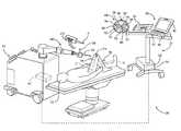
도 1은 로컬라이저 및 비전 장치를 포함하는 로봇식 수술 시스템의 사시도이다.
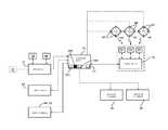
도 2는 로봇식 수술 시스템을 제어하기 위한 제어 시스템의 개략도이다.
도 3은 로봇식 수술 시스템에 사용되는 좌표계의 사시도이다.
도 4는 회피할 영역을 정의하는 가상 객체를 산출하기 위해 로컬라이저로부터의 로컬라이저 데이터와 결합되는 비전 장치로부터의 이미지 데이터의 도시이다.
도 5는 환자를 치료하는 방법에 의해 수행되는 단계들의 흐름도이다.The advantages of the present invention will be better understood by reference to the following detailed description when considered in connection with the accompanying drawings, and will be readily understood.
Figure 1 is a perspective view of a robotic surgical system including a localizer and a vision device.
2 is a schematic diagram of a control system for controlling a robotic surgical system.
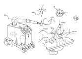
3 is a perspective view of a coordinate system used in a robotic surgical system.
4 is an illustration of image data from a vision device coupled with localizer data from a localizer to yield a virtual object defining an area to avoid.
5 is a flow chart of steps performed by a method of treating a patient.
도 1에 도시된 바와 같이, 환자(22)를 치료하기 위한 시스템(20)이 도시된다. 시스템(20)은 의료 시설의 수술실과 같은 수술 환경에 도시된다. 도시된 실시형태에서, 시스템(20)은 가공 스테이션(24) 및 가디언스 스테이션(26)을 포함한다. 가디언스 스테이션(26)은 수술실 내의 다양한 객체의 운동을 추적하도록 설치된다. 이러한 객체는, 예를 들어 수술 기구(30), 환자의 대퇴골(F) 및 환자의 경골(T)을 포함한다. 가이던스 스테이션(26)은 객체들의 상대 위치 및 방향을 사용자에게 표시하기 위한 목적으로, 경우에 따라서는, 타깃 부위에 대한 수술 기구(30)의 움직임을 제어 또는 제한하기 위한 목적으로 이들 객체들을 추적한다. 수술 기구(30)는 가공 스테이션(24)의 일부로서 도시된다. 그러나, 다른 실시형태에서, 수술 기구(30)는 사용자에 의해 수동으로 유지되고 이동된다.As shown in FIG. 1, a
수술 기구(30)에 의해 치료될 타깃 부위는 가상 객체에 의해 정의된다. 도시된 실시형태에서, 대퇴골(F)과 관련된 대퇴골 타깃 부위(TS)가 도시된다. 물론, 경골(T) 타깃 부위와 같은 몇몇 다른 타깃 부위도 가능하며, 각 부위는 그 자체의 별개의 가상 객체에 의해 정의된다. 타깃 부위를 나타내는 가상 객체는 사용자에 의해 사전-동작으로 설정되고 및/또는 치료될 재료의 양, 수술 기구(30)에 대한 궤적, 수술 기구(30)에 의해 절단되는 면, 천공될 보어 등을 정의하도록 자동 생성된다. 도시된 실시형태에서, 가상 객체(VB)(도 4 참조)는 대퇴골(F)로부터 제거될 재료의 양을 정의한다. 어떤 경우에는, 가상 객체가 수술중에, 즉 수술 절차 중에 설정되거나 재설정된다. 여기에 설명된 설명은 정형수술 절차 절차에 관한 것이지만, 본원에 기재된 시스템 및 방법은 임의의 유형의 수술 절차에도 마찬가지로 적합하다는 것을 알아야 한다.The target site to be treated by the
가디언스 스테이션(26)은 내비게이션 컴퓨터(34)를 수용하는 내비게이션 카트 어셈블리(32)를 포함한다. 내비게이션 인터페이스는 내비게이션 컴퓨터(34)와 작동 통신한다. 내비게이션 인터페이스는 살균 분야의 외부에 위치되도록 적응된 제 1 디스플레이(36) 및 살균 분야의 내부에 위치되도록 적응된 제 2 디스플레이(38)를 포함한다. 디스플레이(36,38)는 내비게이션 카트 어셈블리(32)에 조정 가능하게 장착된다. 키보드 및 마우스와 같은 제 1 및 제 2 입력 장치(40,42)는 내비게이션 컴퓨터(34)에 정보를 입력하거나, 그렇지 않으면, 내비게이션 컴퓨터(34)의 특정 양상을 선택/제어하는데 사용될 수 있다. 터치 스크린(미도시) 또는 음성 구동을 포함하는 다른 입력 장치가 고려된다.The
로컬라이저(44)가 내비게이션 컴퓨터(34)와 통신한다. 도시된 실시형태에서, 로컬라이저(44)는 광학 로컬라이저이며, 로컬라이저 카메라 유닛(46)을 포함한다. 로컬라이저 카메라 유닛(46)은 하나 이상의 광학 위치 센서(50)를 수용하는 외부 케이싱(48)을 갖는다. 일부 실시형태에서, 적어도 2개의 광학 센서(50)가 사용되며, 바람직하게는 3개, 4개 또는 그 이상이 사용된다. 광학 센서(50)는 3개의 별개의 전하 결합 소자(CCD)일 수 있다. 일 실시형태에서, 3개의 1차원 CCD가 사용된다. 다른 실시형태들에서, 개별적인 CCD, 또는 2개 이상의 CCD들을 각각 갖는 별개의 로컬라이저 카메라 유닛들이 또한 수술실 주위에 배열될 수 있음을 이해해야 한다. CCD는 적외선 신호를 감지한다. 또한, 로컬라이저(44)는 상이한 방식(modalities)을 사용할 수 있고, 전자기 로컬라이저, RF 로컬라이저, 초음파 로컬라이저, 또는 객체를 추적할 수 있는 임의의 다른 종래의 로컬라이저일 수 있다.A
로컬라이저 카메라 유닛(46)은 이상적으로는 장애물이 없는 아래 설명된 추적기의 시야로 광학 센서(50)를 위치시키기 위해 조정 가능한 암에 장착된다. 일부 실시형태에서, 로컬라이저 카메라 유닛(46)은 회전 조인트를 중심으로 회전함으로써 적어도 하나의 자유도로 조정 가능하다. 다른 실시형태에서, 로컬라이저 카메라 유닛(46)은 약 2 이상의 자유도로 조절 가능하다.The
로컬라이저 카메라 유닛(46)은 광학 센서(50)와 통신하여 광학 센서(50)로부터 신호를 수신하는 로컬라이저 카메라 제어기(52)를 포함한다. 로컬라이저 카메라 제어기(52)는 유선 또는 무선 접속(미도시)을 통해 내비게이션 컴퓨터(34)와 통신한다. 이러한 연결 중 하나는 고속 통신 및 등시성 실시간 데이터 전송을 위한 직렬 버스 인터페이스 표준인 IEEE 1394 인터페이스일 수 있다. 상기 접속에는 회사별 프로토콜(company specific protocol)을 사용할 수도 있다. 다른 실시형태에서, 광학 센서(50)는 내비게이션 컴퓨터(34)와 직접 통신한다.The
위치 및 방향 신호 및/또는 데이터는 객체를 추적하기 위한 목적으로 내비게이션 컴퓨터(34)로 전송된다. 내비게이션 카트 어셈블리(32), 디스플레이(36, 38) 및 로컬라이저 카메라 유닛(46)은 여기에 참조로 병합된, 2010년 5월 25일자로 발행된 "수술 시스템"이라는 명칭(Malackowski 외)의 미국 특허 제7,725,162호에 설명된 것과 유사할 수 있다.The position and direction signals and / or data are transmitted to the
내비게이션 컴퓨터(34)는 여기에 설명된 기능을 수행하는데 필요한 디스플레이(36, 38), 중앙 처리 장치(CPU) 및/또는 다른 프로세서(62), 메모리(미도시) 및 저장 장치(미도시)를 갖는다. 내비게이션 컴퓨터(34)는 아래에서 설명되는 바와 같이 소프트웨어로 로딩된다. 소프트웨어는 로컬라이저 카메라 유닛(46)으로부터 수신된 신호를 추적되는 객체의 위치 및 방향을 나타내는 로컬라이저 데이터로 변환한다.The
가이던스 스테이션(26)은 본원에서 추적기(tracker)로도 지칭되는 복수의 추적 장치들(54, 56, 58)로 동작 가능하다. 도시된 실시형태에서, 하나의 추적기(54)가 환자의 대퇴골(F)에 단단히 부착되고 또 다른 추적기(56)가 환자의 경골(T)에 단단히 부착된다. 추적기(54, 56)는 뼈의 부분들에 단단히 부착된다. 추적기(54, 56)는 여기에 참조로 병합된 미국 특허 제7,725,162호에 개시된 방식으로 대퇴골(F) 및 경골(T)에 부착될 수 있다. 추적기(54, 56)는 또한, 여기에 참조로 병합된 2014년 1월 16일 출원한 "시선 오차를 표시 및 감소시키기 위한 내비게이션 시스템 및 방법"이라는 명칭의 미국 특허출원 공보문 제2014/0200621호에 도시된 방식으로 장착될 수 있다. 또 다른 실시형태에서, 추적기(54, 56)는 해부학적 구조의 다른 조직에 장착될 수 있다.The
기구 추적기(58)는 수술 기구(30)에 견고하게 부착된다. 기구 추적기(58)는 제조 중에 수술 기구(30)에 통합될 수 있거나 수술 절차를 준비하기 위해 수술 기구(30)에 개별적으로 장착될 수 있다. 기구 추적기(58)에 의해 추적되는 수술 기구(30)의 치료 단부는 회전 버, 전기 절제 장치, 다른 에너지 애플리케이터 등일 수 있다.The
추적기(54, 56, 58)는 내부 배터리로 전원을 공급받는 배터리일 수 있거나 또는 로컬라이저 카메라 유닛(46)과 마찬가지로 바람직하게 외부 전력을 수신하는 내비게이션 컴퓨터(34)를 통해 전력을 수신하는 리드를 가질 수 있다.The
도시된 실시형태에서, 수술 기구(30)는 가공 스테이션(24)의 조작기(66)에 부착된다. 조작기(66)는 또한, 로봇 장치 또는 로봇 암이라고도 칭해질 수 있다. 이러한 배치는 그의 개시 내용이 참조로 여기에 병합된 "다중 모드에서 수술 기구를 제어할 수 있는 수술 조작기"라는 명칭의 미국 특허 제9,119,655호에 도시된다. 다른 실시형태에서, 수술 기구(30)는 그의 위치 및/또는 방향에 대한 임의의 로봇식 제약 없이 수동으로 조작된다는 것을 이해해야 한다. 수술 기구(30)는 의학/수술 절차를 수행하는데 유용한 임의의 수술 기구(도구라고도 함)일 수 있다. 수술 기구(30)는 버링(burring) 기구, 전기수술 기구, 초음파 기구, 리머, 임팩터, 시상 톱 또는 다른 기구일 수 있다. 일부 실시형태에서, 다수의 수술 기구가 환자를 치료하기 위해 사용되고, 각각은 로컬라이저(44)에 의해 개별적으로 추적된다.In the illustrated embodiment, the
로컬라이저(44)의 광학 센서(50)는 추적기(54, 56, 58)로부터 광신호를 수신한다. 도시된 실시형태에서, 추적기(54, 56, 58)는 능동 추적기이다. 이 실시형태에서, 각각의 추적기(54, 56, 58)는 광신호를 광학 센서(50)에 전송하기 위한 적어도 3개의 능동 추적 소자 또는 마커를 갖는다. 능동 마커는 예를 들어, 적외선과 같은 광을 전달하는 발광 다이오드 또는 LED(60)일 수 있다. 광학 센서(50)는 바람직하게는 100 Hz 이상, 보다 바람직하게는 300 Hz 이상, 가장 바람직하게는 500 Hz 이상의 샘플링 속도를 갖는다. 일부 실시형태에서, 광학 센서(50)는 8000 Hz의 샘플링 속도를 갖는다. 샘플링 속도는 광학 센서(50)가 순차적으로 점화된 LED(60)로부터 광신호를 수신하는 속도이다. 일부 실시형태에서, LED(60)로부터의 광신호는 각 추적기(54, 56, 58)마다 상이한 속도로 점화된다.The
도 2를 참조하면, 각각의 LED(60)는 내비게이션 컴퓨터(34)로/로부터 데이터를 송신/수신하는 연관된 추적기(54, 56, 58)의 하우징 내에 위치된 추적기 제어기(61)에 연결된다. 일 실시형태에서, 추적기 제어기(61)는 내비게이션 컴퓨터(34)와의 유선 접속을 통해 수 메가바이트/초 정도의 데이터를 전송한다. 다른 실시형태에서, 무선 접속이 사용될 수 있다. 이들 실시형태에서, 내비게이션 컴퓨터(34)는 추적기 제어기로부터 데이터를 수신하기 위한 송수신기(미도시)를 갖는다.2, each
다른 실시형태에서, 추적기(54, 56, 58)는 로컬라이저 카메라 유닛(46)으로부터 방출된 광을 반사하는 반사기와 같은 수동 마커(미도시)를 가질 수 있다. 반사된 광은 다음으로 광학 센서(50)에 의해 수신된다. 능동 및 수동 배치가 당업계에 잘 알려져 있다.In other embodiments, the
일부 실시형태에서, 추적기들(54, 56, 58)은 여기에 참조로 병합된 "광학 및 비-광학 센서를 포함한 내비게이션 시스템"이라는 명칭의 2015년 4월 14일 공표한, Wu의 미국 특허 제9,008,757호에 개시된 추적기들과 같은 자이로스코프 센서 및 가속도계도 포함한다.In some embodiments, the
내비게이션 컴퓨터(34)는 내비게이션 프로세서(62)를 포함한다. 내비게이션 프로세서(62)는 내비게이션 컴퓨터(34)의 동작을 제어하기 위해 하나 이상의 프로세서를 포함할 수 있음을 알아야 한다. 프로세서는 임의의 유형의 마이크로 프로세서 또는 멀티 프로세서 시스템 또는 다른 유형의 프로세서일 수 있다. 프로세서라는 용어는 임의의 실시형태의 범위를 단일 프로세서로 제한되지 않는다.The
로컬라이저 카메라 유닛(46)은 추적기(54,56,58)의 LED(60)로부터 광학 신호를 수신하고, 로컬라이저(44)에 대한 추적기(54,56,58)의 LED(60)의 위치에 관련한 신호를 내비게이션 프로세서(62)로 출력한다. 수신된 광학(및 일부 실시형태에서 비-광학 신호)에 기반하여, 내비게이션 프로세서(62)는 공지된 삼각 측량 방법(triangulation method)과 같은, 로컬라이저(44)에 대한 추적기(54, 56, 58)의 상대 위치 및 배향을 나타내는 데이터를 생성한다. 일부 실시형태에서, 데이터는 로컬라이저 카메라 제어기(52)에 의해 생성된 다음 내비게이션 컴퓨터(34)로 전송된다.The
수술 절차의 시작 전에, 부가 데이터가 내비게이션 프로세서(62)에 로딩된다. 내비게이션 프로세서(62)는 추적기들(54, 56, 58)의 위치 및 방향 및 이전에 로딩된 데이터에 기반하여, 대퇴골 타깃 부위(TS)와 같은 치료 단부가 적용되어야 하는 타깃 부위에 대한 수술 기구(30)의 방향 및 상기 수술 기구(30)의 치료 단부의 위치(예를 들어, 수술 바의 중심)를 결정한다. 일부 실시형태에서, 내비게이션 프로세서(62)는 이들 데이터를 조작기 제어기(64)에 전송한다. 조작기 제어기(64)는 다음으로 상기 데이터를 이용하여 그의 개시 내용이 참조로 여기에 병합된 "다중 모드에서 수술 기구를 제어할 수 있는 수술 조작기"라는 명칭의 미국 특허 제9,119,655호에 개시된 바와 같이 조작기(66)를 제어한다. 일 실시형태에서, 조작기(66)는 외과의에 의해 설정된 가상 객체에 대해 제어된다. 본원에 기술된 실시형태에서, 가상 객체(VB)는 수술 기구(30)에 의해 제거될 대퇴골(F)의 재료의 양을 정의한다. 따라서, 가상 객체(VB)는 수술 기구(30)의 치료 단부가 머무를 가상 경계(즉, 수술 기구의 치료 단부와 관련된 별도의 가상 객체가 머무르기 위한)를 제공한다.Before the start of the surgical procedure, additional data is loaded into the
내비게이션 프로세서(62)는 또한, 타깃 부위에 대한 치료 단부의 상대 위치를 나타내는 이미지 신호를 생성한다. 이러한 이미지 신호는 디스플레이(36, 38)에인가된다. 이들 신호에 기반하여 디스플레이(36, 38)는 외과의 및 스태프가 타깃 부위에 대한 치료 단부의 상대 위치를 가상으로 볼 수 있게하는 이미지를 생성한다. 대부분의 경우, 이미지는 한 번에 하나의 타깃 부위에 대한 치료 단부를 도시한다. 예를 들어, 대퇴골(F)과 경골(T)이 모두 치료되는 수술 절차에서, 물질이 대퇴골(F)로부터 제거되는 동안 대퇴골 타깃 부위(TS) 및 대퇴골 타깃 부위(TS)에 대한 수술 기구(30)의 치료 단부의 상대 위치는 시각적으로 표현될 수 있다. 유사하게, 사용자가 대퇴골(F)로부터 물질을 제거하는 것을 끝내고 경골(T)으로부터 물질을 제거할 준비가 되면, 디스플레이(36, 38)는 경골(T)과 관련된 타깃 부위에 대한 수술 기구(30)의 치료 단부의 배치만을 예시할 수 있다.The
도 3을 참조하면, 객체들의 추적은 일반적으로 로컬라이저 좌표계(LCLZ)를 참조하여 수행된다. 로컬라이저 좌표계(LCLZ)는 원점과 방향(x, y 및 z 축의 집합)을 가진다. 상기 절차 동안, 한 가지 목적은 로컬라이저 좌표계(LCLZ)를 공지된 위치에 유지하는 것이다. 로컬라이저 카메라 유닛(46)에 장착된 가속도계(미도시)는 로컬라이저 카메라 유닛(46)이 부주의하게 수술 요원에 의해 충돌될 때 발생할 수 있는 바와 같이, 로컬라이저 좌표계(LCLZ)의 갑작스러운 또는 예상치 못한 움직임을 추적하는데 사용될 수 있다.Referring to FIG. 3, tracking of objects is generally performed with reference to a localizer coordinate system (LCLZ). The localizer coordinate system (LCLZ) has the origin and orientation (a set of x, y, and z axes). During this procedure, one purpose is to maintain the localizer coordinate system LCLZ in a known location. An accelerometer (not shown) mounted to the
추적되는 각 추적기(54, 56, 58) 및 객체는 또한 로컬라이저 좌표계(LCLZ)로부터 분리된 그의 고유의 좌표계를 갖는다. 예를 들어, 추적기들(54, 56, 58)은 뼈 추적기 좌표계(BTRK1), 뼈 추적기 좌표계(BTRK2) 및 기구 추적기 좌표계(TLTR)를 갖는다.Each
도시된 실시형태에서, 가디언스 스테이션(26)은 뼈에 단단히 부착된 뼈 추적기(54, 56)의 위치를 모니터링함으로써 환자의 대퇴골(F) 및 경골(T)의 위치를 모니터링한다. 대퇴골 좌표계는 FBONE이고 경골 좌표계는 TBONE이며, 이들은 뼈 추적기(54, 56)가 단단히 부착된 뼈의 좌표계이다.In the illustrated embodiment, the
절차의 시작 이전에, 대퇴골(F) 및 경골(또는 다른 실시형태에서 다른 조직 또는 구조)의 수술 전 영상과 같은 관심있는 해부학적 구조의 수술 전 영상이 생성된다. 이러한 이미지는 환자의 해부학적 구조에 대한 MRI 스캔, 방사선 스캔 또는 전산화 단층 촬영(CT) 스캔을 기반으로 할 수 있다. 이러한 이미지는 대퇴골(F) 및 경골(T)의 가상 모델 및/또는 수술 기구(30)에 의해 처리될 다른 해부학적 구조와 같은 관심있는 해부학적 구조의 가상 모델을 개발하는데 사용된다. 종종 가상 모델은 치료되는 전체 해부학적 구조 또는 처리될 상기 해부학적 구조의 적어도 일부를 나타내는 데이터와 타깃 부위를 정의하는 가상 객체를 나타내는 데이터를 포함하는 3-D 모델이다. 도시된 실시형태에서, 대퇴골의 가상 모델(VM)은 가상 객체(VB) 및 대퇴골(F)의 일부를 나타내는 모델 데이터를 포함하는 3-D 모델이다(도 4 참조). 가상 객체(VB)는 수술 절차 중에 대퇴골(F)로부터 제거될 물질의 양 및 타깃 부위(TS)를 정의한다. 가상 객체는 가상 모델 내에서 정의될 수 있고 메쉬 표면, 구조적인 입체 기하학(constructive solid geometry)(CSG), 보셀(voxels) 또는 다른 가상 객체 표현 기술을 사용하여 표현될 수 있다.Prior to the start of the procedure, preoperative images of the anatomical structures of interest, such as pre-operative images of the femur (F) and the tibia (or other tissue or structure in another embodiment) are generated. Such an image may be based on an MRI scan, a radiation scan, or a computed tomography (CT) scan of the patient's anatomical structure. This image is used to develop a virtual model of the anatomical structure of interest, such as a virtual model of the femur F and tibia T and / or other anatomical structures to be processed by the
수술 전 영상 및/또는 가상 모델은 당업계의 공지된 방법을 사용하여 대퇴부 좌표계(FBONE) 및 경골 좌표계(TBONE)에 매핑된다. 이러한 수술 전의 이미지 및/또는 가상 모델은 대퇴 좌표계(FBONE) 및 경골 좌표계(TBONE)에 고정된다. 수술 전 영상을 촬영하는 것의 대안으로 기구학 연구, 뼈 추적 및 기타 방법을 통해 수술실에서 치료 계획을 개발할 수 있다. 이전에 설명한 3-D 가상 모델을 생성하는 데에도 이러한 동일한 방법을 사용할 수 있다.The pre-operative images and / or virtual models are mapped to the femoral coordinate system (FBONE) and tibial coordinate system (TBONE) using methods known in the art. These pre-operative images and / or virtual models are fixed in the femur coordinate system (FBONE) and the tibial coordinate system (TBONE). As an alternative to pre-operative imaging, treatment planning can be developed in the operating room through kinematic studies, bone tracking, and other methods. This same method can be used to create the 3-D virtual model described previously.
본 명세서에 개시된 절차의 초기 단계 동안, 뼈 추적기(54, 56)는 환자의 뼈에 단단히 부착된다. 좌표계(FBONE, TBONE)의 포즈(위치 및 방향)는 각각 좌표계(BTRK1, BTRK2)에 매핑된다. 일 실시형태에서, 여기에 참조로 병합된 Malackowski 등의 미국 특허 제7,725,162호에 개시된 바와 같은, 자신의 추적기(PT)(도 1 참조)를 갖는 포인터 기구(P)(도 1 참조)는 대퇴골 좌표계(FBONE) 및 경골 좌표계(TBONE)를 뼈 추적기 좌표계들(BTRK1, BTRK2)에 각각 등록하도록 사용될 수 있다. 상기 뼈들과 그의 추적기들(54, 56) 사이의 고정 관계가 주어지면, 대퇴골 좌표계(FBONE) 및 경골 좌표계(TBONE)에서의 대퇴골(F) 및 경골(T)의 위치 및 방향은 뼈 추적기 좌표계들(BTRK1, BTRK2)로 변환될 수 있으므로, 로컬라이저 카메라 유닛(46)은 추적기(54, 56)를 추적함으로써 대퇴골(F) 및 경골(T)을 추적 할 수 있다. 이러한 포즈-설명 데이터는 조작기 제어기(64) 및 내비게이션 프로세서(62) 모두와 통합된 메모리에 저장된다.During the early stages of the procedure described herein, the
수술 기구(30)(에너지 애플리케이터의 말단으로도 지칭됨)의 치료 단부는 그 자체의 좌표계(EAPP)를 갖는다. 좌표계(EAPP)의 원점은, 예를 들어, 수술용 절단 버의 중심을 나타낼 수 있다. 좌표계(EAPP)의 포즈는 절차가 시작되기 전에 기구 추적기 좌표계(TLTR)의 포즈에 고정된다. 따라서, 이들 좌표계(EAPP, TLTR)의 서로에 대한 포즈가 결정된다. 포즈-기술 데이터는 조작기 제어기(64) 및 내비게이션 프로세서(62)와 통합된 메모리에 저장된다.The treatment end of the surgical instrument 30 (also referred to as the end of the energy applicator) has its own coordinate system (EAPP). The origin of the coordinate system (EAPP) may represent, for example, the center of the surgical cutting burr. The poses of the coordinate system (EAPP) are fixed in the poses of the instrument tracker coordinate system (TLTR) before the procedure starts. Thus, the poses of these coordinate systems (EAPP, TLTR) relative to each other are determined. The pose-description data is stored in a memory integrated with the
도 2를 참조하면, 로컬라이제이션 엔진(100)은 내비게이션 컴퓨터(34)의 부분으로 간주될 수 있는 소프트웨어 모듈이다. 로컬라이제이션 엔진(100)의 컴포넌트들은 내비게이션 프로세서(62)상에서 실행된다. 로컬라이제이션 엔진(100)은 조작기 제어기(64) 및/또는 내비게이션 프로세서(62)상에서 실행될 수 있다.Referring to FIG. 2, the
로컬라이제이션 엔진(100)은 로컬라이저 카메라 제어기(42)로부터 광학-기반 신호를 입력으로서 수신하고, 몇몇 실시형태들에서, 추적기 제어기(미도시)로부터 비-광학 기반 신호를 수신한다. 이들 신호에 기반하여, 로컬라이제이션 엔진(100)은 로컬라이저 좌표계(LCLZ)에서 뼈 추적기 좌표계(BTRK1, BTRK2)의 포즈를 결정한다. 기구 추적기(58)를 위해 수신된 동일한 신호에 기반하여, 로컬라이제이션 엔진(100)은 로컬라이저 좌표계(LCLZ)에서 기구 추적기 좌표계(TLTR)의 포즈를 결정한다.The
로컬라이제이션 엔진(100)은 추적기들(44, 46, 48)의 포즈를 나타내는 신호를 좌표 변환기(102)로 전송한다. 좌표 변환기(102)는 내비게이션 프로세서(52) 상에서 실행되는 소프트웨어 모듈이다. 좌표 변환기(102)는 뼈 추적기들(54,56)과 환자의 수술-전 이미지들 및/또는 가상 모델들 사이의 관계를 정의하는 데이터를 참조한다. 좌표 변환기(102)는 또한, 기구 추적기(48)에 대한 수술 기구의 치료 단부의 포즈를 나타내는 데이터를 저장한다.The
절차 동안, 좌표 변환기(102)는 로컬라이저(44)에 대한 추적기(54, 56, 58)의 상대 포즈를 표시하는 데이터를 수신한다. 이들 데이터 및 사전에 로딩된 데이터에 기반하여, 좌표 변환기(102)는 로컬라이저 좌표계(LCLZ)에 대한 좌표계(EAPP) 및 뼈 좌표계(FBONE, TBONE)의 상대 위치와 방향을 표시하는 데이터를 생성한다.During the procedure, the coordinate
그 결과, 좌표 변환기(102)는, 치료 단부가 적용되는 타깃 부위에 대한 수술 기구(30)의 치료 단부의 위치 및 방향을 표시하는 데이터를 생성한다. 이들 데이터를 나타내는 이미지 신호는 디스플레이들(36,38)에 전송되어, 외과의 및 스태프가 이 정보를 볼 수 있게 한다. 특정 실시형태들에서, 이들 데이터를 나타내는 다른 신호는 조작기(66) 및 수술 기구(30)의 대응하는 이동을 안내하기 위해 조작기 제어기(64)에 전송될 수 있다. 따라서, 이 데이터는 또한 수술 기구(30)의 치료 단부의 가상 위치를 나타내며, 이는 또한, 가상 모델 및 가상 객체에 대해 별도의 가상 객체로서 모델링될 수 있다.As a result, the coordinate
도 1을 다시금 참조하면, 가이던스 스테이션(26)은 비전 장치(72)를 더 포함한다. 도시된 실시형태에서, 비전 장치는 로컬라이저 카메라 유닛(46)에 장착된다. 다른 실시형태에서, 비전 장치(72)는 별도의 조정 가능한 암에 장착되어 로컬라이저 카메라 유닛(46)과 별도로 비전 장치(72)를 위치시킨다. 비전 장치(72)는 바람직하게는 장애물이 없는 타깃 부위의 시야로 배치된다. 비전 장치(72)는 내비게이션 컴퓨터(34)와 작동 통신하는 비전 제어기(73)를 갖는다. 비전 장치(72)는 또한 실시간으로 3-D 이미지를 캡처할 수 있는 이미징 장치 또는 디지털 이미징 장치로 지칭될 수 있다. 적합한 비전 장치의 한 예는 Microsoft Corporation에서 판매하는 상용 Kinect SDK 또는 유사한 Kinect 모델이다. 다른 실시형태에서, 비전 장치(72)는 레이저 어레이 또는 스테레오 카메라 시스템을 포함할 수 있다.Referring again to Fig. 1, the
비전 장치(72)는 하나 이상의 이미지 센서(78, 79)를 지지하는 외부 하우징(76)을 갖는다. 이미지 센서 중 하나는 깊이 이미지를 식별하는데 사용되는 깊이 이미지 센서(78)일 수 있고, 다른 이미지 센서는 컬러 이미지를 생성하는데 사용되는 컬러 이미지 센서(79)일 수 있다. 양쪽의 이미지 센서(78, 79)는 CMOS 센서 또는 다른 적절한 센서의 형태일 수 있다. 또한, 광원(80)은 하우징(76) 내에 지지되어 깊이 이미지 센서(78)의 시야 내의 표면에 의해 반사된 광을 발생시키고 전달한다.The
센서(78, 79) 및 광원(80)은 비전 좌표계(VIS)(도 3 참조)에 대한 시야 내의 상기 표면의 거리를 결정하기 위해 비전 제어기(73)와 통신한다. 일 실시형태에서, 광원(80)은 적외선을 방출하고, 비전 제어기(73)는 적외선이 시야의 표면에서 반사되어 깊이 이미지 센서(78)로 복귀하는데 필요한 경과 시간을 결정한다. 이 프로세스는 복수의 반복에 걸쳐 되풀이되어 비전 장치(72)로부터 상기 비전 장치(72)의 시야 내의 표면까지의 거리를 결정하여 포인트 클라우드(202)가 생성될 수 있다(도 4 참조).The
내비게이션 컴퓨터(34)는 비전 제어기(73)와 통신하여 포인트 클라우드(202)를 나타내는 신호 및/또는 데이터를 수신한다. 이미지 생성기 모듈을 포함하는 이미징 소프트웨어는 내비게이션 컴퓨터(34)상에 로딩되어 내비게이션 프로세서(62)에 의해 실행되어 비전 장치(72)의 시야에 기반하여 포인트 클라우드(202)를 생성한다. 포인트 클라우드(202)는 비전 좌표계(VIS)에서 생성된다. 포인트 클라우드(202)는 비전 장치(72)의 시야 내의 표면에 대응하는 비전 좌표계(VIS) 내의 이미지 데이터 포인트들의 세트이다. 이들 이미지 데이터 포인트는 x, y, z 좌표에 의해 정의된다. 포인트 클라우드(202)는 이미지 데이터 파일로서 보관되거나 저장될 수 있다.The
비전 장치(72)를 로컬라이저 카메라 유닛(46)에 통합함으로써, 비전 좌표계(VIS)는 로컬라이저 좌표계(LCLZ)에 쉽게 등록될 수 있는데, 왜냐하면 광학 센서(50)에 대한 이미지 센서(78,79)의 위치 또는 이미지 센서(78,79)에 대한 광학 센서(50)의 위치가 알려져 고정되기 때문이다. 제조 중에, 비전 장치(72)는 좌표 변환기(102)를 통해 비전 좌표계(VIS)가 로컬라이저 좌표계(LCLZ)로 변환될 필요가 없도록 동일한 좌표계에 대한 데이터를 생성하기 위해 로컬라이저(44)에 대해 캘리브레이션 될 수 있다.By integrating the
비전 장치(72)가 로컬라이저 카메라 유닛(46)으로부터 분리되는 것과 같은 다른 실시형태에서, 비전 장치(72)는 하우징(76)에 견고하게 장착된 추적기(미도시)를 구비하여 비전 좌표계(VIS) 및 로컬라이저 좌표계(LCLZ) 사이의 관계를 설립할 수 있다. 예를 들어, 추적기의 좌표계와 비전 좌표계(VIS) 사이의 관계를 정의하는 사전 로딩된 데이터를 사용하여, 좌표 변환기(102)는 로컬라이저 좌표계(LCLZ) 내의 추적기의 위치에 기반하여, 비전 좌표계(VIS)를 로컬라이저 좌표계(LCLZ)로 변활할 수 있다.In another embodiment, in which the
도 4를 참조하면, 비전 장치(72)는 비전 장치(72)의 시야 내에 있는 타깃 부위 및 상기 타깃 부위를 둘러싸는 표면의 이미지를 수집한다. 도시된 실시형태에서, 비전 장치(72)는 비전 장치(72)의 시야 내에 있는 타깃 부위(TS) 및 상기 타깃 부위(TS)를 둘러싸는 표면들의 이미지를 수집한다. 내비게이션 컴퓨터(34)는 비전 제어기(73)와 협력하여 타깃 부위(TS) 및 상기 타깃 부위(TS)를 둘러싸는 표면의 포인트 클라우드(202)를 생성하며, 이는 타깃 부위(TS) 및 상기 타깃 부위(TS)를 둘러싸는 표면과 관련된 이미지 데이터를 정의한다.4, the
이미지 데이터가 생성되는 것과 동시에, 로컬라이저 데이터도 생성된다. 내비게이션 컴퓨터(34)는 로컬라이저 좌표계(LCLZ)에서 타깃 부위를 정의하는 가상 모델 및 가상 객체의 위치 및 방향을 결정하기 위해 로컬라이저(44)와 협력한다. 도시된 실시형태에서, 내비게이션 컴퓨터(34)는 로컬라이저(44)와 협력하여 로컬라이저 좌표계(LCLZ)에서 대퇴골(F)의 가상 모델(VM)의 위치 및 방향 및 가상 객체(VB)의 위치 및 방향을 결정한다. 이러한 로컬라이저 데이터는 가상 모델(VM) 및 가상 객체(VB)를 정의하는 모델 데이터를 포함한다. 어떤 경우, 모델 데이터는 가상 모델(VM)과 연관된 포인트 클라우드 및 가상 객체(VB)와 연관된 별도의 포인트 클라우드 형태의 데이터 포인트들을 포함한다.At the same time that the image data is generated, localizer data is also generated. The
도 4를 계속 참조하면, 내비게이션 프로세서(62)는 병합된(merged) 데이터를 산출하기 위해 로컬라이저 데이터 및 이미지 데이터를 병합하는 소프트웨어 모듈인 데이터 병합 모듈(101)(도 1 참조)을 실행한다(일단 로컬라이저 데이터 및 이미지 데이터는 공통 좌표계에 위치하거나 그로 변환된다). 병합된 데이터는 타깃 부위(TS) 외부의 수술 중에 회피할 영역(R)을 정의하는 제 2 가상 객체(VR)를 나타낸다. 이러한 데이터 병합은 도 4의 화살표로 설명된다. 도시된 실시형태에서, 제 2 가상 객체(VR)를 나타내는 병합된 데이터는(1) 타깃 부위(TS)의 외부에 있는 수술 기구(30)에 의해 회피되어야 하는 뼈와 관련된 데이터 포인트(204); (2) 타깃 부위(TS)의 외부에 있는 수술 기구(30)에 의해 회피되어야 하는 노출된 연조직과 관련된 데이터 포인트(206); (3) 수술 기구(30)에 의해 회피되어야 하는 견인기와 관련된 데이터 포인트(208); 및(4) 타깃 부위(TS)의 외부에 있는 환자의 피부와 관련된 데이터 포인트(210)를 포함한다.4, the
도 4에 도시된 것과 같은 일부 실시형태에서, 병합된 데이터는 로컬라이저 데이터 및 이미지 데이터가 병합된 후에 가상 객체(VB)의 외부에 위치한 좌표를 갖는 포인트 클라우드(202)의 모든 데이터 포인트들을 포함한다. 어떤 경우에는, 타깃 부위(TS)가 연조직 또는 다른 민감한 해부학적 구조에 의해 적어도 부분적으로 가려지는 경우와 같이, 수술 부위(30)의 치료 단부가 타깃 부위(TS)에 도달하는 경로가 완전히 명확하지 않은 경우, 제 2 가상 객체(VR)의 부분으로서 타깃 부위(TS) 외부의 모든 가시적인 표면을 정의하는 것은 특히 유리할 수 있어서, 수술 기구(30)는 타깃 부위(TS)의 외부에 위치하는 임의의 민감한 해부학적 구조, 도구 등을 회피할 수 있다.4, the merged data includes all the data points of the
제 2 가상 객체(VR)를 표현하고, 회피할 영역(R)을 정의하는 병합된 데이터는 내비게이션 프로세서(62)에 의해 처리되어 그의 표현은 디스플레이(38, 39)상에서 사용자에게 디스플레이될 수 있으며, 사용자는 영역(R)에 대해 수술 기구(30)의 위치 및 방향을 시각화할 수 있다. 일부 경우, 회피할 영역(R)을 가상으로 정의하는 데이터 포인트는 메쉬 표면, 구조적인 입체 기하학(constructive solid geometry; CSG) , 보셀(voxels), 또는 다양한 가상 객체 표현 기술을 사용하는 다른 가상 객체 유형으로 변환될 수 있다. 또한, 내비게이션 프로세서(62)는 제 2 가상 객체(VR)의 크기 및 영역(R)의 범위를 타깃 부위(TS)로부터 사전 정의된 거리로 자동으로 제한할 수 있거나, 또는 사용자는 제 2 가상 객체(VR)의 외주를 정의하는 것을 포함하여, 제 2 가상 객체를 수동으로 정제(refine)할 수 있다.The merged data representing the second virtual object VR and defining the area R to be avoided is processed by the
제 2 가상 객체(VR)는 상기 제 2 가상 객체(VR)에 의해 정의된 영역(R) 내의 일부 조직의 탄성 및/또는 가요 특성으로 인해 수술 절차 동안에 구성(예를 들어, 크기, 모양, 위치 등)이 변경될 수 있음을 유의해야 한다. 추가로, 영역(R)은 견인기가 조정될 때 또는 추가 도구 또는 장비를 비전 장치(72)의 시야의 안팎으로 가져올 때 변경될 수 있다. 즉, 회피할 영역(R)의 특성은 동적이며, 계속해서 변화할 수 있지만, 본원에 설명된 내비게이션 기술을 사용하여, 사용자가 상기 영역(R)에 대한 변화와 무관하게 수술 절차 동안에 회피할 영역(R)을 회피할 수 있도록 각각의 새로운 세트의 이미지 데이터 및 로컬라이저 데이터로 제 2 가상 객체(VR)가 계속해서(예를 들어, 사전 정의된 주파수로) 업데이트될 수 있다.The second virtual object VR may be configured (e.g., size, shape, position (s)) during the surgical procedure due to the elastic and / or flexible nature of some tissue within the region R defined by the second virtual object Etc.) may be changed. Additionally, the area R may be changed when the retractor is adjusted or when bringing additional tools or equipment into or out of the vision of the
회피할 영역(R)을 정의하는 제 2 가상 객체(VR)는 또한 조작기 제어기(64)로 전송되어 수술 기구(30)의 치료 단부가 진입되는 것을 방지하는 "노 플라이(no-fly)"영역으로서 취급될 수 있다. 그 결과, 조작기(66)가 자율 모드에서 작동할 때, 조작기(66)는 영역(R)을 피하기 위해 수술 기구(30)의 위치 지정을 제어할 수 있고, 이에 따라 보존될 연조직 및 뼈와 같은 민감한 해부학적 구조, 및 타깃 부위(TS) 근방에 위치한 견인기, 흡인 튜브 등과 같은 도구를 회피할 수 있다.The second virtual object (VR) defining the area R to be avoided is also referred to as an " no-fly "region < RTI ID = 0.0 > As shown in FIG. As a result, when the
도 5를 참조하면, 회피할 영역(R)을 결정하는 방법의 일 실시형태가 도시된다. 단계(300)에서, 외과의 또는 다른 의료 전문가는 환자를 위한 수술 계획을 생성한다. 수술 계획은 수행할 수술 절차와 수행할 치료를 식별한다. 수술 계획은 종종 MRI 또는 CT 스캔에서 가져온 이미지와 같은 수술 전 이미지를 기반으로 하며, 이 이미지는 환자의 해부학적 구조의 3-D 가상 모델(VM)로 변환된다. 수술 절차 동안 치료될 타깃 부위(target site)(TS)를 정의하는 가상 객체(VB)가 또한, 수술 계획의 부분으로서 생성되어 3-D 가상 모델(VM)과 함께 연관된다.Referring to FIG. 5, an embodiment of a method for determining an area R to be avoided is shown. At
단계(302)에서, 제거될 뼈의 타깃 볼륨과 같이, 타깃 부위(TS)에서 처리될 물질의 타깃 볼륨을 정의하는 가상 모델(VM) 및 가상 객체(VM)에 관련한 데이터가 내비게이션 컴퓨터(34)에 전달되어 상기 내비게이션 컴퓨터(34)에 저장될 것이다.In
단계(304)에서, 다음으로 로컬라이저 데이터가 생성된다. 로컬라이저 데이터는 로컬라이저 좌표계(LCLZ)에서 가상 모델(VM) 및 가상 객체(VB)의 위치 및 방향과 관련된 데이터를 포함한다. 이미지 데이터는 단계(306)에서 동시에 생성되므로, 내비게이션 중의 각 시간 단계에서, 대응하는 로컬라이저 데이터 및 이미지 데이터가 존재한다. 이미지 데이터는 타깃 부위(TS)의 표면 및 타깃 부위(TS) 외부의 표면을 포함하는 비전 장치(72)의 시야에서 표면의 위치 및 방향을 포함하는 포인트 클라우드(202)를 포함한다.In
단계(308)에서, 내비게이션 컴퓨터(34)의 데이터 병합 모듈(101)은 로컬라이저 데이터 및 이미지 데이터를 평가한다. 특히, 데이터 병합 모듈(101)은 이미지 데이터(예를 들어, 포인트 클라우드(202))로부터의 데이터 포인트를 로컬라이저 데이터(예를 들어, 가상 객체(VB)에 대한 데이터 포인트)로부터의 데이터 포인트와 병합한다. 단계(310)에서, 데이터 병합 모듈(101)은 다음으로, 가상 객체(VB)의 외부에 있는 이미지 데이터로부터의 모든 데이터 포인트를 식별한다. 이러한 나머지 데이터 세트는 회피할 영역(R)을 산출하고, 다음으로 수술 기구(30)에 의해 회피 될 제 2 가상 객체(VR)로서 내비게이션 컴퓨터(34)의 메모리에 저장된다. 단계(312)에서, 사용자는 영역(R)을 회피하면서 타깃 부위로부터 타깃 볼륨의 조직을 제거하기 위해 수술 기구(30)를 수동적으로 또는 로봇식으로 작동한다. 단계(304) 내지 단계(312)는 수술 절차가 완료될 때까지, 예를 들어, 모든 조직이 타깃 부위(TS)로부터 제거딜 때까지 각 처리 시간 단계 동안에 반복된다. 결과적으로, 상기 방법은 수술 절차 동안 영역(R)에 대한 변화를 보상할 수 있다.At
다른 실시형태에서, 로컬라이저 데이터 및 이미지 데이터를 병합하기 위해 여기에 설명된 시스템 및 방법은 유사하게, 영역(R)과 같은, 회피할 영역을 정의하는 가상 객체 이외의 다른 유형의 가상 객체를 생성하도록 수행될 수 있다는 것을 이해해야 한다. 예를 들어, 로컬라이저 데이터 및 이미지 데이터는 제거될 물질의 볼륨, 수술 기구(30)에 대한 원하는 궤적 등과 같은 타깃 부위를 정의하는 가상 객체를 산출하기 위해 병합될 수 있다. 부가적으로, 이미지 데이터와 로컬라이저 데이터는 다른 용도로 병합될 수 있다.In another embodiment, the system and method described herein for merging localizer data and image data similarly generates a virtual object of a type other than a virtual object that defines a region to avoid, such as region R It should be understood that the invention may be practiced in various ways. For example, localizer data and image data may be merged to yield a virtual object defining a target site, such as the volume of material to be removed, the desired trajectory for the
당업자라면 알 수 있는 바와 같이, 본 실시형태들의 측면들은 컴퓨터 판독 가능 프로그램 코드가 구현된 하나 이상의 컴퓨터 판독 가능한 매체(들)로 구현된 컴퓨터 프로그램 제품의 형태를 취할 수 있다. 여기에 기술된 방법론을 수행하기 위한 명령어 또는 코드를 포함하는 컴퓨터 소프트웨어는 하나 이상의 관련된 메모리 장치(예를 들어, ROM, 고정식 또는 착탈식 메모리)에 저장될 수 있으며, 이용 준비가 되면, 부분적으로 또는 전체적으로 로딩되어(예를 들어, RAM에), CPU에 의해 구현될 수 있다. 그러한 소프트웨어는 펌웨어, 상주 소프트웨어(resident software), 마이크로 코드 등을 포함하지만 이에 한정되지는 않는다.As will be appreciated by those skilled in the art, aspects of the embodiments may take the form of a computer program product embodied in one or more computer readable media (s) in which computer readable program code is embodied. Computer software, including instructions or code for carrying out the methodologies described herein, may be stored in one or more associated memory devices (e.g., ROM, fixed or removable memory) and, when ready for use, (E. G., In RAM) and may be implemented by the CPU. Such software includes, but is not limited to, firmware, resident software, microcode, and the like.
전술한 설명에서 몇몇 실시형태들이 논의되었다. 그러나, 여기에서 논의된 실시형태들은 본 발명을 포괄적으로 나타내거나 임의의 특정 형태로 본 발명을 제한하려는 것은 아니다. 사용된 용어는 제한보다는 설명의 성격을 띤다. 전술한 설명에 비추어 많은 수정 및 변형이 가능하며, 본 발명은 구체적으로 기술된 것과 다르게 실시될 수 있다.Several embodiments have been discussed in the foregoing description. However, the embodiments discussed herein are not intended to be exhaustive or to limit the invention to any particular form. The terms used are descriptive rather than restrictive. Many modifications and variations are possible in light of the above teachings, and the invention may be practiced otherwise than as specifically described.
Claims (15)
Translated fromKorean환자에 부착되도록 구성된 추적기와;
상기 환자 상의 타깃 부위와 관련된 로컬라이저 데이터를 생성하도록 상기 추적기와 협력하도록 구성되는 로컬라이저로서, 상기 타깃 부위는 가상 객체에 의해 정의되는, 상기 로컬라이저와;
상기 타깃 부위 및 상기 타깃 부위를 둘러싼 표면들과 관련된 이미지 데이터를 생성하도록 구성된 비전 장치와;
상기 로컬라이저 데이터 및 상기 이미지 데이터에 기반하여 상기 타깃 부위의 외부에 있는 회피할 영역을 결정하도록 상기 로컬라이저 및 상기 비전 장치에 결합된 내비게이션 컴퓨터를 포함하는, 수술용 내비게이션 시스템.As a surgical navigation system,
A tracker configured to be attached to the patient;
A localizer configured to cooperate with the tracker to generate localizer data associated with a target region on the patient, the target region being defined by a virtual object;
A vision device configured to generate image data associated with surfaces surrounding the target portion and the target portion;
And a navigation computer coupled to the localizer and to the vision device to determine an area to be avoided external to the target site based on the localizer data and the image data.
상기 내비게이션 컴퓨터는 상기 로컬라이저 데이터 및 상기 이미지 데이터를 분석함에 의해 상기 회피할 영역을 결정하도록 구성되는, 수술용 내비게이션 시스템.The method according to claim 1,
Wherein the navigation computer is configured to determine the area to avoid by analyzing the localizer data and the image data.
상기 내비게이션 컴퓨터는 상기 영역을 정의하는 제 2 가상 객체를 생성하도록 구성되는, 수술용 내비게이션 시스템.4. The method according to any one of claims 1 to 3,
Wherein the navigation computer is configured to generate a second virtual object that defines the region.
상기 내비게이션 컴퓨터는 상기 로컬라이저 데이터 및 상기 이미지 데이터를 공통 좌표계로 결합하도록 구성된 좌표 변환 모듈인, 수술용 내비게이션 시스템.4. The method according to any one of claims 1 to 3,
Wherein the navigation computer is a coordinate transformation module configured to combine the localizer data and the image data into a common coordinate system.
상기 내비게이션 컴퓨터는 병합된 데이터를 형성하도록 상기 이미지 데이터 및 상기 로컬라이저 데이터를 병합함에 의해 상기 회피할 영역을 결정하도록 상기 공통 좌표계에서 상기 이미지 데이터 및 상기 로컬라이저 데이터를 측정하도록 구성된 데이터 병합 모듈을 갖는, 수술용 내비게이션 시스템.5. The method of claim 4,
The navigation computer having a data merge module configured to measure the image data and the localizer data in the common coordinate system to determine the area to avoid by merging the image data and the localizer data to form merged data , Surgical navigation system.
상기 내비게이션 컴퓨터는 상기 타깃 부위의 외부에 있는 상기 타깃 부위를 둘러싼 표면들을 표현하는 상기 회피할 영역을 정의하기 위해 상기 병합된 데이터의 적어도 일부를 선택하도록 구성되는, 수술용 내비게이션 시스템.6. The method of claim 5,
Wherein the navigation computer is configured to select at least a portion of the merged data to define the avoidance area that represents surfaces surrounding the target site external to the target site.
상기 비전 장치에 의해 생성된 상기 이미지 데이터는 상기 타깃 부위의 외부에 있는 상기 타깃 부위를 둘러싼 상기 표면들의 적어도 일부의 3차원 맵(map)을 포함하는, 수술용 내비게이션 시스템.7. The method according to any one of claims 1 to 6,
Wherein the image data generated by the vision device comprises a three-dimensional map of at least a portion of the surfaces surrounding the target portion external to the target portion.
상기 3차원 맵은 포인트 클라우드(point cloud), 랜지 맵(range map), 플레인(plane), 라인(line), 또는 단일 포인트 중의 하나 이상을 포함하는, 수술용 내비게이션 시스템.8. The method of claim 7,
Wherein the three-dimensional map comprises at least one of a point cloud, a range map, a plane, a line, or a single point.
로봇식 장치와;
상기 로봇식 장치에 결합된 엔드 이펙터와;
환자에게 부착되도록 구성되는 추적기와;
상기 환자 상의 타깃 부위와 관련된 로컬라이저 데이터를 생성하도록 상기 추적기와 협력하도록 구성되는 로컬라이저로서, 상기 타깃 부위는 가상 객체에 의해 정의되는, 상기 로컬라이저와;
상기 타깃 부위 및 상기 타깃 부위를 둘러싼 표면들과 관련된 이미지 데이터를 생성하도록 구성된 비전 장치와;
상기 로컬라이저 및 상기 비전 장치에 결합되고 상기 로컬라이저 데이터 및 상기 이미지 데이터에 기반하여 상기 타깃 부위의 외부에 있는 회피할 영역을 결정하도록 구성된 내비게이션 컴퓨터를 포함하고,
상기 로봇식 장치가, 상기 회피할 영역을 회피하면서 상기 타깃 부위에 대하여 상기 엔드 이펙터를 이동시키도록 동작 가능하게 상기 로봇식 장치에 결합되는, 로봇식 수술 시스템.As a robotic surgical system,
A robotic device;
An end effector coupled to the robotic device;
A tracker configured to attach to a patient;
A localizer configured to cooperate with the tracker to generate localizer data associated with a target region on the patient, the target region being defined by a virtual object;
A vision device configured to generate image data associated with surfaces surrounding the target portion and the target portion;
And a navigation computer coupled to the localizer and the vision device and configured to determine an area to be avoided that is external to the target area based on the localizer data and the image data,
Wherein the robotic device is operatively coupled to the robotic device such that the robotic device is operable to move the end effector relative to the target portion while avoiding the avoiding region.
상기 환자 상의 타깃 부위와 관련된 로컬라이저 데이터를 생성하는 단계로서, 상기 타깃 부위는 가상 객체에 의해 정의되는, 상기 생성 단계와;
상기 타깃 부위 및 상기 타깃 부위를 둘러싼 표면들과 관련된 이미지 데이터를 생성하는 단계와;
상기 로컬라이저 데이터 및 상기 이미지 데이터에 기반하여 상기 타깃 부위의 외부에 있는 회피할 영역을 결정하는 단계를 포함하는, 방법.CLAIMS 1. A method for operating a surgical system comprising a tracker attached to a patient, a localizer, a vision device, and a navigation computer,
Generating localizer data associated with a target region on the patient, the target region being defined by a virtual object;
Generating image data associated with surfaces surrounding the target portion and the target portion;
Determining an area to be avoided external to the target site based on the localizer data and the image data.
상기 로컬라이저 데이터 및 상기 이미지 데이터에 기반하여 상기 타깃 부위의 외부에 있는 상기 회피할 영역을 결정하는 단계는, 상기 로컬라이저 데이터 및 상기 이미지 데이터를 분석하여 상기 영역을 정의하는 제 2 가상 객체를 생성하는 단계를 포함하는, 방법.11. The method of claim 10,
Wherein the step of determining the avoiding area outside the target area based on the localizer data and the image data comprises analyzing the localizer data and the image data to generate a second virtual object defining the area ≪ / RTI >
상기 로컬라이저 데이터 및 상기 이미지 데이터에 기반하여 상기 타깃 부위의 외부에 있는 상기 회피할 영역을 결정하는 단계는, 상기 로컬라이저 데이터 및 상기 이미지 데이터를 공통 좌표계로 결합하는 단계를 포함하는, 방법.12. The method according to any one of claims 10 and 11,
Wherein determining the avoidance area outside of the target site based on the localizer data and the image data comprises combining the localizer data and the image data into a common coordinate system.
상기 로컬라이저 데이터 및 상기 이미지 데이터에 기반하여 상기 타깃 부위의 외부에 있는 상기 회피할 영역을 결정하는 단계는,
상기 공통 좌표계에서 상기 이미지 데이터 및 상기 로컬라이저 데이터를 측정하는 단계와;
병합된 데이터를 형성하도록 상기 이미지 데이터 및 상기 로컬라이저 데이터를 병합하는 단계와;
상기 타깃 부위의 외부에 있는 상기 타깃 부위를 둘러싼 표면들을 표현하는 상기 회피할 영역을 정의하도록 상기 병합된 데이터의 적어도 일부를 선택하는 단계를 포함하는, 방법.13. The method of claim 12,
Wherein the determining of the avoidance area outside the target site based on the localizer data and the image data comprises:
Measuring the image data and the localizer data in the common coordinate system;
Merging the image data and the localizer data to form merged data;
Selecting at least a portion of the merged data to define the avoidance region that represents surfaces surrounding the target portion outside of the target portion.
상기 타깃 부위 및 상기 타깃 부위를 둘러싼 표면들과 관련된 상기 이미지 데이터를 생성하는 단계는, 상기 타깃 부위의 외부에 있는 상기 타깃 부위를 둘러싼 상기 표면들의 적어도 일부의 3차원 맵을 생성하는 단계를 포함하는, 방법.14. The method according to any one of claims 10 to 13,
Wherein generating the image data associated with surfaces surrounding the target portion and the target portion comprises generating a three dimensional map of at least a portion of the surfaces surrounding the target portion outside the target portion , Way.
상기 타깃 부위의 외부에 있는 상기 타깃 부위를 둘러싼 상기 표면들의 상기 적어도 일부의 상기 3차원 맵을 생성하는 단계는 포인트 클라우드, 랜지 맵(range map), 플레인(plane), 라인(line), 또는 단일 포인트 중의 하나 이상을 포함하는, 방법.15. The method of claim 14,
Wherein the step of generating the three-dimensional map of the at least a portion of the surfaces surrounding the target portion outside the target portion comprises the steps of: generating a point cloud, a range map, a plane, a line, Gt; a < / RTI > point.
Priority Applications (1)
| Application Number | Priority Date | Filing Date | Title |
|---|---|---|---|
| KR1020257011191AKR20250050139A (en) | 2015-12-31 | 2016-12-29 | System and methods for performing surgery on a patient at a target site defined by a virtual object |
Applications Claiming Priority (3)
| Application Number | Priority Date | Filing Date | Title |
|---|---|---|---|
| US201562273543P | 2015-12-31 | 2015-12-31 | |
| US62/273,543 | 2015-12-31 | ||
| PCT/US2016/069152WO2017117369A1 (en) | 2015-12-31 | 2016-12-29 | System and methods for performing surgery on a patient at a target site defined by a virtual object |
Related Child Applications (1)
| Application Number | Title | Priority Date | Filing Date |
|---|---|---|---|
| KR1020257011191ADivisionKR20250050139A (en) | 2015-12-31 | 2016-12-29 | System and methods for performing surgery on a patient at a target site defined by a virtual object |
Publications (2)
| Publication Number | Publication Date |
|---|---|
| KR20180099702Atrue KR20180099702A (en) | 2018-09-05 |
| KR102794946B1 KR102794946B1 (en) | 2025-04-14 |
Family
ID=57861267
Family Applications (2)
| Application Number | Title | Priority Date | Filing Date |
|---|---|---|---|
| KR1020257011191APendingKR20250050139A (en) | 2015-12-31 | 2016-12-29 | System and methods for performing surgery on a patient at a target site defined by a virtual object |
| KR1020187018701AActiveKR102794946B1 (en) | 2015-12-31 | 2016-12-29 | System and method for performing surgery on a patient at a target site defined by a virtual object |
Family Applications Before (1)
| Application Number | Title | Priority Date | Filing Date |
|---|---|---|---|
| KR1020257011191APendingKR20250050139A (en) | 2015-12-31 | 2016-12-29 | System and methods for performing surgery on a patient at a target site defined by a virtual object |
Country Status (8)
| Country | Link |
|---|---|
| US (4) | US10667868B2 (en) |
| EP (2) | EP3397188B1 (en) |
| JP (3) | JP6944939B2 (en) |
| KR (2) | KR20250050139A (en) |
| CN (2) | CN108472096B (en) |
| AU (4) | AU2016380277B2 (en) |
| CA (1) | CA3009787A1 (en) |
| WO (1) | WO2017117369A1 (en) |
Families Citing this family (50)
| Publication number | Priority date | Publication date | Assignee | Title |
|---|---|---|---|---|
| CN108472096B (en) | 2015-12-31 | 2021-11-16 | 史赛克公司 | System and method for performing a procedure on a patient at a target site defined by a virtual object |
| EP3463164B1 (en) | 2016-05-23 | 2023-01-11 | MAKO Surgical Corp. | Systems and methods for identifying and tracking physical objects during a robotic surgical procedure |
| AU2017340607B2 (en) | 2016-10-05 | 2022-10-27 | Nuvasive, Inc. | Surgical navigation system and related methods |
| US11751948B2 (en)* | 2016-10-25 | 2023-09-12 | Mobius Imaging, Llc | Methods and systems for robot-assisted surgery |
| WO2018097831A1 (en) | 2016-11-24 | 2018-05-31 | Smith Joshua R | Light field capture and rendering for head-mounted displays |
| US11432898B2 (en)* | 2017-03-14 | 2022-09-06 | Intellijoint Surgical Inc. | Tracing platforms and intra-operative systems and methods using same |
| US11096754B2 (en)* | 2017-10-04 | 2021-08-24 | Mako Surgical Corp. | Sterile drape assembly for surgical robot |
| AU2018383641B2 (en) | 2017-12-14 | 2023-06-15 | Mako Surgical Corp. | View angle-independent visual representation of a cut procedure |
| CN108294825B (en)* | 2017-12-26 | 2019-08-02 | 刘洋 | Registration arrangement and method for surgical navigational |
| CN108309450B (en)* | 2017-12-27 | 2021-04-27 | 刘洋 | Positioning and registering system and method for surgical navigation |
| US11291507B2 (en) | 2018-07-16 | 2022-04-05 | Mako Surgical Corp. | System and method for image based registration and calibration |
| CA3053904A1 (en)* | 2018-08-31 | 2020-02-29 | Orthosoft Inc. | System and method for tracking bones |
| US10623660B1 (en) | 2018-09-27 | 2020-04-14 | Eloupes, Inc. | Camera array for a mediated-reality system |
| US10925593B2 (en) | 2019-02-12 | 2021-02-23 | Edward Rustamzadeh | Lateral retractor system for minimizing muscle damage in spinal surgery |
| US12016543B2 (en) | 2019-02-12 | 2024-06-25 | Edward Rustamzadeh | Lateral retractor system for minimizing muscle damage in spinal surgery |
| US10624623B1 (en)* | 2019-02-12 | 2020-04-21 | Edward Rustamzadeh | Lateral retractor system for minimizing muscle damage in spinal surgery |
| US11246582B2 (en) | 2019-02-12 | 2022-02-15 | Edward Rustamzadeh | Dual-motion rotation and retraction system for minimizing muscle damage in spinal surgery |
| US10363023B1 (en) | 2019-02-12 | 2019-07-30 | Edward Rustamzadeh | Lateral retractor system for minimizing muscle damage in spinal surgery |
| US10631842B1 (en) | 2019-02-12 | 2020-04-28 | Edward Rustamzadeh | Lateral retraction system for minimizing muscle damage in spinal surgery |
| EP3934558A4 (en)* | 2019-03-07 | 2022-12-14 | PROCEPT BioRobotics Corporation | Robotic arms and methods for tissue resection and imaging |
| WO2021003401A1 (en)* | 2019-07-03 | 2021-01-07 | Stryker Corporation | Obstacle avoidance techniques for surgical navigation |
| KR102274167B1 (en)* | 2019-09-05 | 2021-07-12 | 큐렉소 주식회사 | Robot positioning guide apparautus, method therof and system comprising the same |
| US11612440B2 (en) | 2019-09-05 | 2023-03-28 | Nuvasive, Inc. | Surgical instrument tracking devices and related methods |
| CN110711031B (en)* | 2019-10-31 | 2021-11-23 | 武汉联影智融医疗科技有限公司 | Surgical navigation system, coordinate system registration system, method, device, and medium |
| WO2021126788A1 (en)* | 2019-12-16 | 2021-06-24 | Intuitive Surgical Operations, Inc. | Systems for facilitating guided teleoperation of a non-robotic device in a surgical space |
| CN111265299B (en)* | 2020-02-19 | 2023-08-18 | 上海理工大学 | Operation navigation system based on optical fiber shape sensing |
| US10949986B1 (en) | 2020-05-12 | 2021-03-16 | Proprio, Inc. | Methods and systems for imaging a scene, such as a medical scene, and tracking objects within the scene |
| WO2022047720A1 (en)* | 2020-09-04 | 2022-03-10 | Shanghai United Imaging Healthcare Co., Ltd. | Systems and methods for assisting in placing surgical instrument into subject |
| US11295460B1 (en) | 2021-01-04 | 2022-04-05 | Proprio, Inc. | Methods and systems for registering preoperative image data to intraoperative image data of a scene, such as a surgical scene |
| CN114948067B (en)* | 2021-02-18 | 2025-04-15 | 杭州柳叶刀机器人有限公司 | Filing depth control method, device and hip replacement robot |
| WO2022208414A1 (en) | 2021-03-31 | 2022-10-06 | Moon Surgical Sas | Co-manipulation surgical system for use with surgical instruments for performing laparoscopic surgery |
| US12167900B2 (en) | 2021-03-31 | 2024-12-17 | Moon Surgical Sas | Co-manipulation surgical system having automated preset robot arm configurations |
| US11844583B2 (en) | 2021-03-31 | 2023-12-19 | Moon Surgical Sas | Co-manipulation surgical system having an instrument centering mode for automatic scope movements |
| US11832909B2 (en) | 2021-03-31 | 2023-12-05 | Moon Surgical Sas | Co-manipulation surgical system having actuatable setup joints |
| US11819302B2 (en) | 2021-03-31 | 2023-11-21 | Moon Surgical Sas | Co-manipulation surgical system having user guided stage control |
| US12042241B2 (en) | 2021-03-31 | 2024-07-23 | Moon Surgical Sas | Co-manipulation surgical system having automated preset robot arm configurations |
| US12178418B2 (en) | 2021-03-31 | 2024-12-31 | Moon Surgical Sas | Co-manipulation surgical system having a coupling mechanism removeably attachable to surgical instruments |
| US11812938B2 (en) | 2021-03-31 | 2023-11-14 | Moon Surgical Sas | Co-manipulation surgical system having a coupling mechanism removeably attachable to surgical instruments |
| USD1002842S1 (en) | 2021-06-29 | 2023-10-24 | Edward Rustamzadeh | Combination surgical spinal dilator and retractor system |
| CN113476141B (en)* | 2021-06-30 | 2023-02-10 | 苏州微创畅行机器人有限公司 | Pose control method, optical navigation system applicable to pose control method and surgical robot system |
| US12016642B2 (en) | 2021-09-08 | 2024-06-25 | Proprio, Inc. | Constellations for tracking instruments, such as surgical instruments, and associated systems and methods |
| DE102021128478A1 (en)* | 2021-11-02 | 2023-05-04 | B. Braun New Ventures GmbH | Surgical navigation system with improved instrument tracking and navigation procedures |
| US12261988B2 (en) | 2021-11-08 | 2025-03-25 | Proprio, Inc. | Methods for generating stereoscopic views in multicamera systems, and associated devices and systems |
| WO2023220605A2 (en) | 2022-05-09 | 2023-11-16 | Proprio, Inc. | Methods and systems for calibrating instruments within an imaging system, such as a surgical imaging system |
| AU2023329913A1 (en) | 2022-08-26 | 2025-03-13 | Mako Surgical Corp. | Selectively automated robotic surgical system |
| US11839442B1 (en) | 2023-01-09 | 2023-12-12 | Moon Surgical Sas | Co-manipulation surgical system for use with surgical instruments for performing laparoscopic surgery while estimating hold force |
| US11986165B1 (en) | 2023-01-09 | 2024-05-21 | Moon Surgical Sas | Co-manipulation surgical system for use with surgical instruments for performing laparoscopic surgery while estimating hold force |
| US12370001B2 (en) | 2023-01-09 | 2025-07-29 | Moon Surgical Sas | Co-manipulation surgical system having automated user override detection |
| EP4497406A1 (en)* | 2023-07-25 | 2025-01-29 | Ecential Robotics | Surgical robotic system and method for defining a restricted access volume for such a surgical robotic system |
| CN119257716A (en)* | 2024-09-11 | 2025-01-07 | 北京纳通医用机器人科技有限公司 | Kirschner wire fixation mechanism, bone channel preparation device and preparation method thereof |
Citations (2)
| Publication number | Priority date | Publication date | Assignee | Title |
|---|---|---|---|---|
| KR20150127031A (en)* | 2013-03-13 | 2015-11-16 | 스트리커 코포레이션 | System for establishing virtual constraint boundaries |
| KR20150127032A (en)* | 2013-03-13 | 2015-11-16 | 스트리커 코포레이션 | System for arranging objects in an operating room in preparation for surgical procedures |
Family Cites Families (299)
| Publication number | Priority date | Publication date | Assignee | Title |
|---|---|---|---|---|
| US1066786A (en)* | 1911-10-11 | 1913-07-08 | Charles C Bielitz | Locking device for telephones. |
| US4962463A (en) | 1988-07-01 | 1990-10-09 | Digital Equipment Corporation | Video imaging device with image altering controls and related method |
| US6347240B1 (en) | 1990-10-19 | 2002-02-12 | St. Louis University | System and method for use in displaying images of a body part |
| US6405072B1 (en) | 1991-01-28 | 2002-06-11 | Sherwood Services Ag | Apparatus and method for determining a location of an anatomical target with reference to a medical apparatus |
| US6675040B1 (en) | 1991-01-28 | 2004-01-06 | Sherwood Services Ag | Optical object tracking system |
| US5662111A (en) | 1991-01-28 | 1997-09-02 | Cosman; Eric R. | Process of stereotactic optical navigation |
| US5279309A (en) | 1991-06-13 | 1994-01-18 | International Business Machines Corporation | Signaling device and method for monitoring positions in a surgical operation |
| US6963792B1 (en) | 1992-01-21 | 2005-11-08 | Sri International | Surgical method |
| US6788999B2 (en) | 1992-01-21 | 2004-09-07 | Sri International, Inc. | Surgical system |
| US5603318A (en) | 1992-04-21 | 1997-02-18 | University Of Utah Research Foundation | Apparatus and method for photogrammetric surgical localization |
| US5517990A (en) | 1992-11-30 | 1996-05-21 | The Cleveland Clinic Foundation | Stereotaxy wand and tool guide |
| DE4304571A1 (en) | 1993-02-16 | 1994-08-18 | Mdc Med Diagnostic Computing | Procedures for planning and controlling a surgical procedure |
| US5623582A (en) | 1994-07-14 | 1997-04-22 | Immersion Human Interface Corporation | Computer interface or control input device for laparoscopic surgical instrument and other elongated mechanical objects |
| US5584796A (en) | 1994-08-10 | 1996-12-17 | Cohen; Barry J. | Apparatus and method for retracting and viewing bodily tissues on remote display device |
| DE69531994T2 (en) | 1994-09-15 | 2004-07-22 | OEC Medical Systems, Inc., Boston | SYSTEM FOR POSITION DETECTION BY MEANS OF A REFERENCE UNIT ATTACHED TO A PATIENT'S HEAD FOR USE IN THE MEDICAL AREA |
| US6646541B1 (en) | 1996-06-24 | 2003-11-11 | Computer Motion, Inc. | General purpose distributed operating room control system |
| US5695501A (en) | 1994-09-30 | 1997-12-09 | Ohio Medical Instrument Company, Inc. | Apparatus for neurosurgical stereotactic procedures |
| US5891157A (en) | 1994-09-30 | 1999-04-06 | Ohio Medical Instrument Company, Inc. | Apparatus for surgical stereotactic procedures |
| ATE228338T1 (en) | 1994-10-07 | 2002-12-15 | Univ St Louis | SURGICAL NAVIGATION ARRANGEMENT INCLUDING REFERENCE AND LOCATION SYSTEMS |
| US5765561A (en) | 1994-10-07 | 1998-06-16 | Medical Media Systems | Video-based surgical targeting system |
| US6978166B2 (en) | 1994-10-07 | 2005-12-20 | Saint Louis University | System for use in displaying images of a body part |
| US5882206A (en) | 1995-03-29 | 1999-03-16 | Gillio; Robert G. | Virtual surgery system |
| US5649956A (en) | 1995-06-07 | 1997-07-22 | Sri International | System and method for releasably holding a surgical instrument |
| US5814038A (en) | 1995-06-07 | 1998-09-29 | Sri International | Surgical manipulator for a telerobotic system |
| JPH10505286A (en) | 1995-06-20 | 1998-05-26 | シン ング、ワン | Articulated arm for medical procedures |
| JPH0970780A (en) | 1995-09-06 | 1997-03-18 | Fanuc Ltd | Tool shape correcting method of robot |
| DE19639615C5 (en) | 1996-09-26 | 2008-11-06 | Brainlab Ag | Reflector referencing system for surgical and medical instruments |
| US6351659B1 (en) | 1995-09-28 | 2002-02-26 | Brainlab Med. Computersysteme Gmbh | Neuro-navigation system |
| US5682886A (en) | 1995-12-26 | 1997-11-04 | Musculographics Inc | Computer-assisted surgical system |
| US6063095A (en) | 1996-02-20 | 2000-05-16 | Computer Motion, Inc. | Method and apparatus for performing minimally invasive surgical procedures |
| US6436107B1 (en) | 1996-02-20 | 2002-08-20 | Computer Motion, Inc. | Method and apparatus for performing minimally invasive surgical procedures |
| US5971976A (en) | 1996-02-20 | 1999-10-26 | Computer Motion, Inc. | Motion minimization and compensation system for use in surgical procedures |
| US5855583A (en) | 1996-02-20 | 1999-01-05 | Computer Motion, Inc. | Method and apparatus for performing minimally invasive cardiac procedures |
| US6699177B1 (en) | 1996-02-20 | 2004-03-02 | Computer Motion, Inc. | Method and apparatus for performing minimally invasive surgical procedures |
| US5952796A (en) | 1996-02-23 | 1999-09-14 | Colgate; James E. | Cobots |
| CA2205782C (en) | 1996-03-21 | 2002-10-22 | Newnes Machine Ltd. | Position-based integrated motion controlled curve sawing |
| US6017354A (en) | 1996-08-15 | 2000-01-25 | Stryker Corporation | Integrated system for powered surgical tools |
| US6024576A (en) | 1996-09-06 | 2000-02-15 | Immersion Corporation | Hemispherical, high bandwidth mechanical interface for computer systems |
| US6331116B1 (en) | 1996-09-16 | 2001-12-18 | The Research Foundation Of State University Of New York | System and method for performing a three-dimensional virtual segmentation and examination |
| US5824085A (en) | 1996-09-30 | 1998-10-20 | Integrated Surgical Systems, Inc. | System and method for cavity generation for surgical planning and initial placement of a bone prosthesis |
| US5880976A (en) | 1997-02-21 | 1999-03-09 | Carnegie Mellon University | Apparatus and method for facilitating the implantation of artificial components in joints |
| US6205411B1 (en) | 1997-02-21 | 2001-03-20 | Carnegie Mellon University | Computer-assisted surgery planner and intra-operative guidance system |
| DE29704393U1 (en) | 1997-03-11 | 1997-07-17 | Aesculap Ag, 78532 Tuttlingen | Device for preoperative determination of the position data of endoprosthesis parts |
| JPH11156672A (en) | 1997-08-25 | 1999-06-15 | Yoshiaki Kakino | Numerical control device, and machine tool having it |
| US6097168A (en) | 1997-08-25 | 2000-08-01 | Toshiba Kikai Kabushiki Kaisha | Position control apparatus and method of the same, numerical control program preparation apparatus and method of the same, and methods of controlling numerical control machine tool |
| AU9036098A (en) | 1997-08-28 | 1999-03-16 | Microdexterity Systems | Parallel mechanism |
| US6434507B1 (en) | 1997-09-05 | 2002-08-13 | Surgical Navigation Technologies, Inc. | Medical instrument and method for use with computer-assisted image guided surgery |
| US6021343A (en) | 1997-11-20 | 2000-02-01 | Surgical Navigation Technologies | Image guided awl/tap/screwdriver |
| EP1035953B1 (en) | 1997-12-06 | 2003-08-06 | Elan Schaltelemente GmbH & Co. KG | Monitoring and control device for monitoring a technical facility subject to enhanced safety requirements, especially a handling device |
| US6228089B1 (en) | 1997-12-19 | 2001-05-08 | Depuy International Limited | Device for positioning and guiding a surgical instrument during orthopaedic interventions |
| WO1999037220A1 (en) | 1998-01-23 | 1999-07-29 | Sm Scienzia Machinale S.R.L. | Orthopaedic surgery apparatus for guiding a tool and for supporting a limb |
| US6692485B1 (en) | 1998-02-24 | 2004-02-17 | Endovia Medical, Inc. | Articulated apparatus for telemanipulator system |
| US6810281B2 (en) | 2000-12-21 | 2004-10-26 | Endovia Medical, Inc. | Medical mapping system |
| DE19814630B4 (en) | 1998-03-26 | 2011-09-29 | Carl Zeiss | Method and apparatus for manually controlled guiding a tool in a predetermined range of motion |
| US6157873A (en) | 1998-04-09 | 2000-12-05 | Motoman, Inc. | Robot programming system and method |
| US6233504B1 (en) | 1998-04-16 | 2001-05-15 | California Institute Of Technology | Tool actuation and force feedback on robot-assisted microsurgery system |
| ATE272365T1 (en) | 1998-05-28 | 2004-08-15 | Orthosoft Inc | INTERACTIVE AND COMPUTER-ASSISTED SURGICAL SYSTEM |
| US6421048B1 (en) | 1998-07-17 | 2002-07-16 | Sensable Technologies, Inc. | Systems and methods for interacting with virtual objects in a haptic virtual reality environment |
| US6117143A (en) | 1998-09-11 | 2000-09-12 | Hybex Surgical Specialties, Inc. | Apparatus for frameless stereotactic surgery |
| US6033415A (en) | 1998-09-14 | 2000-03-07 | Integrated Surgical Systems | System and method for performing image directed robotic orthopaedic procedures without a fiducial reference system |
| US6311100B1 (en) | 1998-09-14 | 2001-10-30 | Mass. Institute Of Technology | Tool path generator for computer aided manufacturing |
| DE19846687C2 (en) | 1998-10-09 | 2001-07-26 | Auer Dorothee | Auxiliary surgical device for use in performing medical procedures and methods for generating an image in the context of medical procedures |
| US6195618B1 (en) | 1998-10-15 | 2001-02-27 | Microscribe, Llc | Component position verification using a probe apparatus |
| US6704694B1 (en) | 1998-10-16 | 2004-03-09 | Massachusetts Institute Of Technology | Ray based interaction system |
| DE19848765C2 (en) | 1998-10-22 | 2000-12-21 | Brainlab Med Computersyst Gmbh | Position verification in camera images |
| AU1525400A (en) | 1998-11-18 | 2000-06-05 | Microdexterity Systems, Inc. | Medical manipulator for use with an imaging device |
| US6468265B1 (en) | 1998-11-20 | 2002-10-22 | Intuitive Surgical, Inc. | Performing cardiac surgery without cardioplegia |
| JP4542710B2 (en) | 1998-11-23 | 2010-09-15 | マイクロデクステラティー・システムズ・インコーポレーテッド | Surgical manipulator |
| US6522906B1 (en) | 1998-12-08 | 2003-02-18 | Intuitive Surgical, Inc. | Devices and methods for presenting and regulating auxiliary information on an image display of a telesurgical system to assist an operator in performing a surgical procedure |
| US6322567B1 (en) | 1998-12-14 | 2001-11-27 | Integrated Surgical Systems, Inc. | Bone motion tracking system |
| US6430434B1 (en) | 1998-12-14 | 2002-08-06 | Integrated Surgical Systems, Inc. | Method for determining the location and orientation of a bone for computer-assisted orthopedic procedures using intraoperatively attached markers |
| DE19914455B4 (en) | 1999-03-30 | 2005-07-14 | Siemens Ag | Method for determining the movement of an organ or therapeutic area of a patient and a system suitable for this purpose |
| US6466815B1 (en) | 1999-03-30 | 2002-10-15 | Olympus Optical Co., Ltd. | Navigation apparatus and surgical operation image acquisition/display apparatus using the same |
| DE19915060A1 (en) | 1999-04-01 | 2000-11-02 | Erbe Elektromedizin | Surgical instrument |
| US7084867B1 (en) | 1999-04-02 | 2006-08-01 | Massachusetts Institute Of Technology | Haptic interface system for collision detection and applications therefore |
| US8229549B2 (en) | 2004-07-09 | 2012-07-24 | Tyco Healthcare Group Lp | Surgical imaging device |
| IL130835A0 (en) | 1999-07-07 | 2001-01-28 | Mdc Ltd | Concentrically expansible needle retractor |
| US6304050B1 (en) | 1999-07-19 | 2001-10-16 | Steven B. Skaar | Means and method of robot control relative to an arbitrary surface using camera-space manipulation |
| DE19946948A1 (en) | 1999-09-30 | 2001-04-05 | Philips Corp Intellectual Pty | Method and arrangement for determining the position of a medical instrument |
| US7366562B2 (en) | 2003-10-17 | 2008-04-29 | Medtronic Navigation, Inc. | Method and apparatus for surgical navigation |
| US7747312B2 (en) | 2000-01-04 | 2010-06-29 | George Mason Intellectual Properties, Inc. | System and method for automatic shape registration and instrument tracking |
| US20010034530A1 (en) | 2000-01-27 | 2001-10-25 | Malackowski Donald W. | Surgery system |
| DE10004764A1 (en) | 2000-02-03 | 2001-08-09 | Philips Corp Intellectual Pty | Method for determining the position of a medical instrument |
| US20010025183A1 (en) | 2000-02-25 | 2001-09-27 | Ramin Shahidi | Methods and apparatuses for maintaining a trajectory in sterotaxi for tracking a target inside a body |
| WO2001074266A1 (en) | 2000-03-30 | 2001-10-11 | The Board Of Trustees Of The Leland Stanford Junior University | Apparatus and method for calibrating an endoscope |
| US6535756B1 (en) | 2000-04-07 | 2003-03-18 | Surgical Navigation Technologies, Inc. | Trajectory storage apparatus and method for surgical navigation system |
| US6711432B1 (en) | 2000-10-23 | 2004-03-23 | Carnegie Mellon University | Computer-aided orthopedic surgery |
| US6336931B1 (en) | 2000-05-17 | 2002-01-08 | Yeh-Liang Hsu | Automatic bone drilling apparatus for surgery operation |
| GB0015683D0 (en) | 2000-06-28 | 2000-08-16 | Depuy Int Ltd | Apparatus for positioning a surgical instrument |
| US6837892B2 (en) | 2000-07-24 | 2005-01-04 | Mazor Surgical Technologies Ltd. | Miniature bone-mounted surgical robot |
| US6494882B1 (en) | 2000-07-25 | 2002-12-17 | Verimetra, Inc. | Cutting instrument having integrated sensors |
| US6902560B1 (en) | 2000-07-27 | 2005-06-07 | Intuitive Surgical, Inc. | Roll-pitch-roll surgical tool |
| US20040059194A1 (en) | 2002-07-18 | 2004-03-25 | Minnesota Scientific, Inc. | Method and apparatus for replacing knee-joint |
| EP1365686A4 (en) | 2000-09-23 | 2009-12-02 | Ramin Shahidi | Endoscopic targeting method and system |
| DE10047698A1 (en) | 2000-09-25 | 2002-04-11 | Zeiss Carl | Medical therapy and / or diagnostic device with a position detection device |
| JP4014792B2 (en) | 2000-09-29 | 2007-11-28 | 株式会社東芝 | manipulator |
| US6757416B2 (en) | 2000-12-04 | 2004-06-29 | Ge Medical Systems Global Technology Company, Llc | Display of patient image data |
| US7892243B2 (en) | 2001-01-16 | 2011-02-22 | Microdexterity Systems, Inc. | Surgical manipulator |
| US6676669B2 (en) | 2001-01-16 | 2004-01-13 | Microdexterity Systems, Inc. | Surgical manipulator |
| US6929606B2 (en) | 2001-01-29 | 2005-08-16 | Depuy Spine, Inc. | Retractor and method for spinal pedicle screw placement |
| ES2304430T3 (en) | 2001-01-29 | 2008-10-16 | The Acrobot Company Limited | ROBOTS WITH ACTIVE LIMITATION. |
| WO2002060330A1 (en) | 2001-01-29 | 2002-08-08 | Stephen Ritland | Retractor and method for spinal pedicle screw placement |
| EP1364183B1 (en) | 2001-01-30 | 2013-11-06 | Mako Surgical Corp. | Tool calibrator and tracker system |
| US6514259B2 (en) | 2001-02-02 | 2003-02-04 | Carnegie Mellon University | Probe and associated system and method for facilitating planar osteotomy during arthoplasty |
| US20030135204A1 (en) | 2001-02-15 | 2003-07-17 | Endo Via Medical, Inc. | Robotically controlled medical instrument with a flexible section |
| DE10108547B4 (en) | 2001-02-22 | 2006-04-20 | Siemens Ag | Operating system for controlling surgical instruments based on intra-operative X-ray images |
| DE60232315D1 (en) | 2001-02-27 | 2009-06-25 | Smith & Nephew Inc | SURGICAL NAVIGATION SYSTEM FOR PARTIAL KNEE JOINT CONSTRUCTION |
| DE10110093A1 (en) | 2001-03-02 | 2002-09-26 | Juergen Wahrburg | Device for displaying the spatial position of a surgical instrument during an operation and for comparison of actual and theoretical positions so that a correction signal can be generated |
| JP4439812B2 (en) | 2001-03-26 | 2010-03-24 | エルビー メディカル ゲーエムベーハー | Material excision or material processing method and device system |
| US7056123B2 (en) | 2001-07-16 | 2006-06-06 | Immersion Corporation | Interface apparatus with cable-driven force feedback and grounded actuators |
| US6728599B2 (en) | 2001-09-07 | 2004-04-27 | Computer Motion, Inc. | Modularity system for computer assisted surgery |
| US6785572B2 (en) | 2001-11-21 | 2004-08-31 | Koninklijke Philips Electronics, N.V. | Tactile feedback and display in a CT image guided robotic system for interventional procedures |
| US6793653B2 (en) | 2001-12-08 | 2004-09-21 | Computer Motion, Inc. | Multifunctional handle for a medical robotic system |
| EP1321105B1 (en) | 2001-12-18 | 2003-08-20 | BrainLAB AG | Superposition of patient X-ray or scanning imaging data and superficial video images |
| US6815659B2 (en) | 2002-01-14 | 2004-11-09 | Palantyr Research, Llc | Optical system and method of making same |
| US6947786B2 (en) | 2002-02-28 | 2005-09-20 | Surgical Navigation Technologies, Inc. | Method and apparatus for perspective inversion |
| US7831292B2 (en) | 2002-03-06 | 2010-11-09 | Mako Surgical Corp. | Guidance system and method for surgical procedures with improved feedback |
| US8010180B2 (en) | 2002-03-06 | 2011-08-30 | Mako Surgical Corp. | Haptic guidance system and method |
| TW200304608A (en) | 2002-03-06 | 2003-10-01 | Z Kat Inc | System and method for using a haptic device in combination with a computer-assisted surgery system |
| US9155544B2 (en) | 2002-03-20 | 2015-10-13 | P Tech, Llc | Robotic systems and methods |
| US8983776B2 (en) | 2002-03-28 | 2015-03-17 | Jason A. Dean | Programmable robotic apparatus |
| US20030187431A1 (en) | 2002-03-29 | 2003-10-02 | Simonson Robert E. | Apparatus and method for targeting for surgical procedures |
| US6757582B2 (en) | 2002-05-03 | 2004-06-29 | Carnegie Mellon University | Methods and systems to control a shaping tool |
| US7055789B2 (en) | 2002-05-14 | 2006-06-06 | Automation Tool Company | Articulating tool arm with positional feedback |
| JP4439393B2 (en) | 2002-06-17 | 2010-03-24 | メイザー サージカル テクノロジーズ リミテッド | Robots for use with orthopedic inserts |
| WO2004001569A2 (en) | 2002-06-21 | 2003-12-31 | Cedara Software Corp. | Computer assisted system and method for minimal invasive hip, uni knee and total knee replacement |
| AU2003257309A1 (en) | 2002-08-13 | 2004-02-25 | Microbotics Corporation | Microsurgical robot system |
| US6892090B2 (en) | 2002-08-19 | 2005-05-10 | Surgical Navigation Technologies, Inc. | Method and apparatus for virtual endoscopy |
| DE10239673A1 (en) | 2002-08-26 | 2004-03-11 | Markus Schwarz | Device for machining parts |
| US7166114B2 (en) | 2002-09-18 | 2007-01-23 | Stryker Leibinger Gmbh & Co Kg | Method and system for calibrating a surgical tool and adapter thereof |
| JP2006509609A (en) | 2002-10-04 | 2006-03-23 | オルトソフト インコーポレイテッド | Computer-aided hip replacement surgery |
| US7660623B2 (en) | 2003-01-30 | 2010-02-09 | Medtronic Navigation, Inc. | Six degree of freedom alignment display for medical procedures |
| EP1605810A2 (en) | 2003-02-04 | 2005-12-21 | Z-Kat, Inc. | Computer-assisted knee replacement apparatus and method |
| US7492930B2 (en) | 2003-02-04 | 2009-02-17 | Aesculap Ag | Method and apparatus for capturing information associated with a surgical procedure performed using a localization device |
| JP3993546B2 (en) | 2003-09-08 | 2007-10-17 | オリンパス株式会社 | In-subject introduction apparatus and wireless in-subject information acquisition system |
| US20050054895A1 (en) | 2003-09-09 | 2005-03-10 | Hoeg Hans David | Method for using variable direction of view endoscopy in conjunction with image guided surgical systems |
| JP3708097B2 (en) | 2003-10-08 | 2005-10-19 | ファナック株式会社 | Robot manual feeder |
| US7840253B2 (en) | 2003-10-17 | 2010-11-23 | Medtronic Navigation, Inc. | Method and apparatus for surgical navigation |
| US7466303B2 (en) | 2004-02-10 | 2008-12-16 | Sunnybrook Health Sciences Center | Device and process for manipulating real and virtual objects in three-dimensional space |
| US7990374B2 (en) | 2004-06-29 | 2011-08-02 | Sensable Technologies, Inc. | Apparatus and methods for haptic rendering using data in a graphics pipeline |
| US7772541B2 (en) | 2004-07-16 | 2010-08-10 | Luna Innnovations Incorporated | Fiber optic position and/or shape sensing based on rayleigh scatter |
| US7440793B2 (en) | 2004-07-22 | 2008-10-21 | Sunita Chauhan | Apparatus and method for removing abnormal tissue |
| DE102004042489B4 (en) | 2004-08-31 | 2012-03-29 | Siemens Ag | Medical examination or treatment facility with associated method |
| SE529122C2 (en) | 2004-09-24 | 2007-05-02 | Jokab Safety Ab | Protective device for area restriction and surveillance |
| JP3950883B2 (en) | 2004-10-06 | 2007-08-01 | キヤノン株式会社 | Electrophotographic image forming apparatus |
| US9216015B2 (en) | 2004-10-28 | 2015-12-22 | Vycor Medical, Inc. | Apparatus and methods for performing brain surgery |
| US7561733B2 (en) | 2004-11-15 | 2009-07-14 | BrainLAG AG | Patient registration with video image assistance |
| US9002432B2 (en) | 2004-11-15 | 2015-04-07 | Brainlab Ag | Method and device for calibrating a medical instrument |
| DE102004057933A1 (en) | 2004-12-01 | 2006-06-08 | Fraunhofer-Gesellschaft zur Förderung der angewandten Forschung e.V. | A method and apparatus for navigating and positioning an object relative to a patient |
| EP1833390B1 (en) | 2004-12-09 | 2010-05-12 | Stryker Corporation | Wireless system for providing instrument and implant data to a surgical navigation unit |
| US7930014B2 (en) | 2005-01-11 | 2011-04-19 | Volcano Corporation | Vascular image co-registration |
| JP4528136B2 (en) | 2005-01-11 | 2010-08-18 | 株式会社日立製作所 | Surgical device |
| WO2006086223A2 (en) | 2005-02-08 | 2006-08-17 | Blue Belt Technologies, Inc. | Augmented reality device and method |
| US7967742B2 (en) | 2005-02-14 | 2011-06-28 | Karl Storz Imaging, Inc. | Method for using variable direction of view endoscopy in conjunction with image guided surgical systems |
| WO2006091494A1 (en) | 2005-02-22 | 2006-08-31 | Mako Surgical Corp. | Haptic guidance system and method |
| EP1868486A4 (en) | 2005-04-01 | 2012-11-14 | Verathon Medical Canada Ulc | Video retractor |
| US9421019B2 (en) | 2005-04-07 | 2016-08-23 | Omnilife Science, Inc. | Robotic guide assembly for use in computer-aided surgery |
| US8073528B2 (en) | 2007-09-30 | 2011-12-06 | Intuitive Surgical Operations, Inc. | Tool tracking systems, methods and computer products for image guided surgery |
| US9492240B2 (en) | 2009-06-16 | 2016-11-15 | Intuitive Surgical Operations, Inc. | Virtual measurement tool for minimally invasive surgery |
| US10555775B2 (en) | 2005-05-16 | 2020-02-11 | Intuitive Surgical Operations, Inc. | Methods and system for performing 3-D tool tracking by fusion of sensor and/or camera derived data during minimally invasive robotic surgery |
| US8320612B2 (en) | 2005-06-09 | 2012-11-27 | Naviswiss Ag | System and method for the contactless determination and measurement of a spatial position and/or a spatial orientation of bodies, method for the calibration and testing, in particular, medical tools as well as patterns or structures on, in particular, medical tools |
| US20060287583A1 (en) | 2005-06-17 | 2006-12-21 | Pool Cover Corporation | Surgical access instruments for use with delicate tissues |
| DE102005028746B4 (en) | 2005-06-21 | 2018-02-22 | Siemens Healthcare Gmbh | Method for determining the position and orientation of an object, in particular a catheter, from two-dimensional x-ray images |
| WO2007017642A1 (en) | 2005-08-05 | 2007-02-15 | Depuy Orthopädie Gmbh | Computer assisted surgery system |
| US7835784B2 (en) | 2005-09-21 | 2010-11-16 | Medtronic Navigation, Inc. | Method and apparatus for positioning a reference frame |
| US20070135686A1 (en) | 2005-12-14 | 2007-06-14 | Pruitt John C Jr | Tools and methods for epicardial access |
| US9241767B2 (en) | 2005-12-20 | 2016-01-26 | Intuitive Surgical Operations, Inc. | Method for handling an operator command exceeding a medical device state limitation in a medical robotic system |
| DE102005062445A1 (en) | 2005-12-27 | 2007-07-05 | Siemens Ag | Producing x-ray image involves recording first x-ray image representing object in patient, producing object image from x-ray image containing image information, recording second x-ray image in object region, combining images |
| JP2009531116A (en) | 2006-03-31 | 2009-09-03 | コーニンクレッカ フィリップス エレクトロニクス エヌ ヴィ | Local error compensation system in electromagnetic tracking system |
| EP1854425A1 (en) | 2006-05-11 | 2007-11-14 | BrainLAB AG | Position determination for medical devices with redundant position measurement and weighting to prioritise measurements |
| EP2023811B1 (en) | 2006-05-17 | 2018-08-08 | NuVasive, Inc. | Surgical trajectory monitoring system |
| WO2007136769A2 (en) | 2006-05-19 | 2007-11-29 | Mako Surgical Corp. | Method and apparatus for controlling a haptic device |
| WO2007136739A2 (en) | 2006-05-19 | 2007-11-29 | Mako Surgical Corp. | A method and apparatus for controlling a haptic device |
| US8560047B2 (en) | 2006-06-16 | 2013-10-15 | Board Of Regents Of The University Of Nebraska | Method and apparatus for computer aided surgery |
| US20090192523A1 (en) | 2006-06-29 | 2009-07-30 | Intuitive Surgical, Inc. | Synthetic representation of a surgical instrument |
| US9718190B2 (en) | 2006-06-29 | 2017-08-01 | Intuitive Surgical Operations, Inc. | Tool position and identification indicator displayed in a boundary area of a computer display screen |
| US20080021283A1 (en) | 2006-07-24 | 2008-01-24 | Joseph Kuranda | Apparatus and method for retracting tissue of a patient during an orthopaedic surgical procedure |
| US8231610B2 (en) | 2006-09-06 | 2012-07-31 | National Cancer Center | Robotic surgical system for laparoscopic surgery |
| US8343048B2 (en) | 2006-10-31 | 2013-01-01 | Lanx, Inc. | Retractor system |
| DE102006051919B4 (en) | 2006-10-31 | 2016-09-01 | Siemens Healthcare Gmbh | A method for providing a 3D X-ray image data set of the heart of a patient |
| US20080108912A1 (en)* | 2006-11-07 | 2008-05-08 | General Electric Company | System and method for measurement of clinical parameters of the knee for use during knee replacement surgery |
| EP2126646B1 (en) | 2006-12-27 | 2012-08-22 | Mako Surgical Corp. | Apparatus and method for providing an adjustable positive stop in space |
| US7987001B2 (en) | 2007-01-25 | 2011-07-26 | Warsaw Orthopedic, Inc. | Surgical navigational and neuromonitoring instrument |
| US20080183068A1 (en) | 2007-01-25 | 2008-07-31 | Warsaw Orthopedic, Inc. | Integrated Visualization of Surgical Navigational and Neural Monitoring Information |
| EP1952779B1 (en) | 2007-02-01 | 2012-04-04 | BrainLAB AG | Method and system for Identification of medical instruments |
| US9179984B2 (en) | 2007-02-19 | 2015-11-10 | Medtronic Navigation, Inc. | Multi-configuration tracking array and related method |
| WO2008103383A1 (en) | 2007-02-20 | 2008-08-28 | Gildenberg Philip L | Videotactic and audiotactic assisted surgical methods and procedures |
| US7950306B2 (en) | 2007-02-23 | 2011-05-31 | Microdexterity Systems, Inc. | Manipulator |
| EP2148629B1 (en) | 2007-04-16 | 2012-06-06 | NeuroArm Surgical, Ltd. | Frame mapping and force feedback methods, devices and systems |
| EP1990021B1 (en) | 2007-05-09 | 2011-07-06 | BrainLAB AG | Medical instrument with separate transmission unit for controlling software to support treatment and instrument system |
| US8655429B2 (en) | 2007-06-29 | 2014-02-18 | Accuray Incorporated | Robotic arm for a radiation treatment system |
| US20090024140A1 (en) | 2007-07-20 | 2009-01-22 | Searete Llc, A Limited Liability Corporation Of The State Of Delaware | Surgical feedback system |
| WO2009045827A2 (en) | 2007-09-30 | 2009-04-09 | Intuitive Surgical, Inc. | Methods and systems for tool locating and tool tracking robotic instruments in robotic surgical systems |
| WO2009059330A2 (en) | 2007-11-01 | 2009-05-07 | University Of Utah Research Foundation | Integrated surgical cutting system |
| US20090157059A1 (en) | 2007-12-14 | 2009-06-18 | Searete Llc, A Limited Liability Corporation Of The State Of Delaware | Surgical instrument navigation system |
| GB0800835D0 (en) | 2008-01-17 | 2008-02-27 | Cardioprec Ltd | Retractor |
| US9168104B2 (en) | 2008-06-23 | 2015-10-27 | John Richard Dein | Intra-operative system for identifying and tracking surgical sharp objects, instruments, and sponges |
| US8382372B2 (en) | 2008-07-09 | 2013-02-26 | Siemens Aktiengesellschaft | Medical apparatus |
| US9717403B2 (en) | 2008-12-05 | 2017-08-01 | Jeffrey B. Kleiner | Method and apparatus for performing retro peritoneal dissection |
| KR101049507B1 (en) | 2009-02-27 | 2011-07-15 | 한국과학기술원 | Image-guided Surgery System and Its Control Method |
| EP2236104B1 (en) | 2009-03-31 | 2013-06-19 | BrainLAB AG | Medicinal navigation image output with virtual primary images and real secondary images |
| JP5562583B2 (en) | 2009-06-24 | 2014-07-30 | カール シュトルツ ゲゼルシャフト ミット ベシュレンクテル ハフツング ウント コンパニー コマンディートゲゼルシャフト | Medical robot system |
| EP2467798B1 (en) | 2009-08-17 | 2020-04-15 | Mazor Robotics Ltd. | Device for improving the accuracy of manual operations |
| EP2298223A1 (en)* | 2009-09-21 | 2011-03-23 | Stryker Leibinger GmbH & Co. KG | Technique for registering image data of an object |
| DE102009043069A1 (en) | 2009-09-25 | 2011-04-07 | Siemens Aktiengesellschaft | Visualization method and imaging system |
| KR101598774B1 (en) | 2009-10-01 | 2016-03-02 | (주)미래컴퍼니 | Apparatus and Method for processing surgical image |
| US10045882B2 (en) | 2009-10-30 | 2018-08-14 | The Johns Hopkins University | Surgical instrument and systems with integrated optical sensor |
| US20120059378A1 (en) | 2009-11-25 | 2012-03-08 | James David Farrell | Efficient Sculpting System |
| US8694075B2 (en) | 2009-12-21 | 2014-04-08 | General Electric Company | Intra-operative registration for navigated surgical procedures |
| US9115998B2 (en) | 2010-01-19 | 2015-08-25 | Orthosoft Inc. | Tracking system and method |
| US8954132B2 (en) | 2010-02-12 | 2015-02-10 | Jean P. HUBSCHMAN | Methods and systems for guiding an emission to a target |
| US8974380B2 (en) | 2010-02-24 | 2015-03-10 | Meni-Med Ltd | Surgical retractor |
| US9901405B2 (en) | 2010-03-02 | 2018-02-27 | Orthosoft Inc. | MEMS-based method and system for tracking a femoral frame of reference |
| EP2547278B2 (en) | 2010-03-17 | 2019-10-23 | Brainlab AG | Flow control in computer-assisted surgery based on marker positions |
| WO2011128766A2 (en) | 2010-04-13 | 2011-10-20 | Picard Frederic | Methods and systems for object tracking |
| EP2561239A4 (en) | 2010-04-22 | 2014-08-06 | Blue Belt Tech Inc | Navigated freehand surgical tool and kit |
| CA2797116A1 (en) | 2010-04-22 | 2011-10-27 | Blue Belt Technologies, Llc | Reconfigurable navigated surgical tool tracker |
| CA2797302C (en) | 2010-04-28 | 2019-01-15 | Ryerson University | System and methods for intraoperative guidance feedback |
| US8945140B2 (en) | 2010-06-18 | 2015-02-03 | Vantage Surgical Systems, Inc. | Surgical procedures using instrument to boundary spacing information extracted from real-time diagnostic scan data |
| CN103037799B (en) | 2010-08-02 | 2016-03-09 | 约翰霍普金斯大学 | For tool changing interface and the control algolithm of the operating robot that cooperates |
| US20120071752A1 (en) | 2010-09-17 | 2012-03-22 | Sewell Christopher M | User interface and method for operating a robotic medical system |
| US8679125B2 (en) | 2010-09-22 | 2014-03-25 | Biomet Manufacturing, Llc | Robotic guided femoral head reshaping |
| US8657809B2 (en) | 2010-09-29 | 2014-02-25 | Stryker Leibinger Gmbh & Co., Kg | Surgical navigation system |
| US9119655B2 (en) | 2012-08-03 | 2015-09-01 | Stryker Corporation | Surgical manipulator capable of controlling a surgical instrument in multiple modes |
| US20120190965A1 (en) | 2011-01-24 | 2012-07-26 | Shawn Schaerer | MR Compatible Stereoscopic Viewing Device for use in the Bore of an MR Magnet |
| US9381085B2 (en) | 2011-06-23 | 2016-07-05 | Stryker Corporation | Prosthetic implant and method of implantation |
| US8498744B2 (en) | 2011-06-30 | 2013-07-30 | Mako Surgical Corporation | Surgical robotic systems with manual and haptic and/or active control modes |
| US9188973B2 (en) | 2011-07-08 | 2015-11-17 | Restoration Robotics, Inc. | Calibration and transformation of a camera system's coordinate system |
| EP2734168B1 (en) | 2011-07-22 | 2015-09-16 | Stryker Corporation | Multi-position limb holder |
| US9204939B2 (en) | 2011-08-21 | 2015-12-08 | M.S.T. Medical Surgery Technologies Ltd. | Device and method for assisting laparoscopic surgery—rule based approach |
| US9707043B2 (en) | 2011-09-02 | 2017-07-18 | Stryker Corporation | Surgical instrument including housing, a cutting accessory that extends from the housing and actuators that establish the position of the cutting accessory relative to the housing |
| US9060794B2 (en) | 2011-10-18 | 2015-06-23 | Mako Surgical Corp. | System and method for robotic surgery |
| US9510771B1 (en) | 2011-10-28 | 2016-12-06 | Nuvasive, Inc. | Systems and methods for performing spine surgery |
| US20160345917A1 (en) | 2011-10-28 | 2016-12-01 | Navigate Surgical Technologies, Inc. | Method for making a three-dimensionally trackable apparatus |
| WO2013132501A1 (en) | 2012-03-07 | 2013-09-12 | M.S.T. Medical Surgery Technologies Ltd. | Overall endoscopic control system |
| US10945801B2 (en) | 2012-05-22 | 2021-03-16 | Mako Surgical Corp. | Soft tissue cutting instrument and method of use |
| US9615728B2 (en) | 2012-06-27 | 2017-04-11 | Camplex, Inc. | Surgical visualization system with camera tracking |
| US9642606B2 (en) | 2012-06-27 | 2017-05-09 | Camplex, Inc. | Surgical visualization system |
| US9220570B2 (en) | 2012-06-29 | 2015-12-29 | Children's National Medical Center | Automated surgical and interventional procedures |
| CN107198567B (en) | 2012-08-03 | 2021-02-09 | 史赛克公司 | Systems and methods for robotic surgery |
| US9008757B2 (en) | 2012-09-26 | 2015-04-14 | Stryker Corporation | Navigation system including optical and non-optical sensors |
| US10178368B2 (en) | 2012-10-23 | 2019-01-08 | Intuitive Surgical Operations, Inc. | Stereo imaging system with automatic disparity adjustment for displaying close range objects |
| US20140128727A1 (en)* | 2012-11-08 | 2014-05-08 | Navident Technologies, Inc. | Surgical location monitoring system and method using natural markers |
| EP2928406B1 (en) | 2012-12-07 | 2019-02-20 | University of Houston System | Surgical procedure management systems |
| BR112015013808A2 (en) | 2012-12-17 | 2017-07-11 | Koninklijke Philips Nv | point-of-view tracking and imaging device, and computer-readable media for point-of-view tracking and imaging |
| US10398449B2 (en) | 2012-12-21 | 2019-09-03 | Mako Surgical Corp. | Systems and methods for haptic control of a surgical tool |
| WO2014102561A1 (en) | 2012-12-26 | 2014-07-03 | Verathon Medical (Canada) Ulc | Video retractor |
| EP4309613B1 (en) | 2013-01-16 | 2025-07-23 | Stryker Corporation | Navigation systems for indicating line-of-sight errors |
| US10039474B2 (en) | 2013-01-28 | 2018-08-07 | The Johns Hopkins University | System for tracking microsurgical instrumentation |
| EP2950763A1 (en) | 2013-02-04 | 2015-12-09 | The Cleveland Clinic Foundation | Instrument depth tracking for oct-guided procedures |
| US9782159B2 (en) | 2013-03-13 | 2017-10-10 | Camplex, Inc. | Surgical visualization systems |
| US10433763B2 (en) | 2013-03-15 | 2019-10-08 | Synaptive Medical (Barbados) Inc. | Systems and methods for navigation and simulation of minimally invasive therapy |
| CN105050527B (en) | 2013-03-15 | 2018-03-27 | 圣纳普医疗(巴巴多斯)公司 | Intelligent positioning system and method therefor |
| US9629595B2 (en) | 2013-03-15 | 2017-04-25 | Hansen Medical, Inc. | Systems and methods for localizing, tracking and/or controlling medical instruments |
| EP3019109B1 (en) | 2013-07-08 | 2022-09-28 | Brainlab AG | Single-marker navigation |
| US9283048B2 (en) | 2013-10-04 | 2016-03-15 | KB Medical SA | Apparatus and systems for precise guidance of surgical tools |
| US8880151B1 (en) | 2013-11-27 | 2014-11-04 | Clear Guide Medical, Llc | Surgical needle for a surgical system with optical recognition |
| EP3080778B1 (en)* | 2013-12-09 | 2019-03-27 | Koninklijke Philips N.V. | Imaging view steering using model-based segmentation |
| US20150297311A1 (en) | 2013-12-23 | 2015-10-22 | Camplex, Inc. | Surgical visualization systems |
| KR20170035831A (en) | 2014-03-14 | 2017-03-31 | 시냅티브 메디컬 (바베이도스) 아이엔씨. | Intelligent positioning system and methods therefore |
| US10154882B2 (en) | 2014-03-24 | 2018-12-18 | University Of Houston System | Global laparoscopy positioning systems and methods |
| KR20150128049A (en)* | 2014-05-08 | 2015-11-18 | 삼성전자주식회사 | Surgical robot and control method thereof |
| EP3811891B8 (en)* | 2014-05-14 | 2025-01-08 | Stryker European Operations Holdings LLC | Navigation system and processor arrangement for tracking the position of a work target |
| DE102014007909A1 (en) | 2014-05-27 | 2015-12-03 | Carl Zeiss Meditec Ag | Surgical microscope |
| DE102014007908A1 (en) | 2014-05-27 | 2015-12-03 | Carl Zeiss Meditec Ag | Surgical System |
| US10405844B2 (en) | 2014-07-16 | 2019-09-10 | Shaw P. Wan | Surgical retractor with light |
| AU2015299752B2 (en) | 2014-08-05 | 2020-09-03 | Paul S. D'URSO | Surgical access retractor |
| CN107072719A (en) | 2014-09-08 | 2017-08-18 | 皇家飞利浦有限公司 | Optical shape sensing for instrument tracking in orthopedics |
| US9402691B2 (en) | 2014-09-16 | 2016-08-02 | X-Nav Technologies, LLC | System for determining and tracking movement during a medical procedure |
| US9833254B1 (en) | 2014-10-03 | 2017-12-05 | Verily Life Sciences Llc | Controlled dissection of biological tissue |
| EP3224804B1 (en) | 2014-11-27 | 2021-02-24 | Koninklijke Philips N.V. | Apparatus for determining positions of an interventional instrument in a projection image |
| WO2016130946A1 (en) | 2015-02-13 | 2016-08-18 | Think Surgical, Inc. | Laser gauge for robotic calibration and monitoring |
| US20160278864A1 (en) | 2015-03-19 | 2016-09-29 | Medtronic Navigation, Inc. | Apparatus And Method For Instrument And Gesture Based Image Guided Surgery |
| GB2556727B (en) | 2015-06-22 | 2021-11-03 | Synaptive Medical Inc | System and method for mapping navigation space to patient space in a medical procedure |
| CN108024806B (en) | 2015-07-21 | 2022-07-01 | 3D集成公司 | Cannula assembly kit, trocar assembly kit, sleeve assembly, minimally invasive surgical system and method thereof |
| WO2017059870A1 (en) | 2015-10-09 | 2017-04-13 | 3Dintegrated Aps | A laparoscopic tool system for minimally invasive surgery |
| EP3397184A1 (en) | 2015-12-29 | 2018-11-07 | Koninklijke Philips N.V. | System, control unit and method for control of a surgical robot |
| CN108472096B (en)* | 2015-12-31 | 2021-11-16 | 史赛克公司 | System and method for performing a procedure on a patient at a target site defined by a virtual object |
| AU2017224228B2 (en) | 2016-02-26 | 2022-03-24 | Think Surgical, Inc. | Method and system for guiding user positioning of a robot |
| CN120419981A (en) | 2016-03-13 | 2025-08-05 | 乌泽医疗有限公司 | Devices and methods for use with bone surgery |
| US10413366B2 (en) | 2016-03-16 | 2019-09-17 | Synaptive Medical (Bardbados) Inc. | Trajectory guidance alignment system and methods |
| EP3449859B1 (en) | 2016-04-28 | 2024-07-03 | Sony Group Corporation | Control device, control method and surgical system |
| IL245560B2 (en) | 2016-05-09 | 2024-05-01 | Elbit Systems Ltd | Localized optical coherence tomography images for ophthalmological surgical procedures |
| EP3463164B1 (en) | 2016-05-23 | 2023-01-11 | MAKO Surgical Corp. | Systems and methods for identifying and tracking physical objects during a robotic surgical procedure |
| US10973585B2 (en) | 2016-09-21 | 2021-04-13 | Alcon Inc. | Systems and methods for tracking the orientation of surgical tools |
| US20180116732A1 (en) | 2016-10-18 | 2018-05-03 | The Board Of Trustees Of The Leland Stanford Junior University | Real-time Three Dimensional Display of Flexible Needles Using Augmented Reality |
| DE102016223841A1 (en) | 2016-11-30 | 2018-05-30 | Siemens Healthcare Gmbh | Calculate a calibration parameter of a robot tool |
| JP7583513B2 (en) | 2017-01-18 | 2024-11-14 | ケービー メディカル エスアー | Universal instrument guide for robotic surgical systems, surgical instrument system |
| CA2957977C (en) | 2017-02-15 | 2019-03-26 | Synaptive Medical (Barbados) Inc. | Sensored surgical tool and surgical intraoperative tracking and imaging system incorporating same |
| WO2018154491A1 (en) | 2017-02-22 | 2018-08-30 | Orthosoft Inc. | Bone and tool tracking in robotized computer-assisted surgery |
| US20170209225A1 (en) | 2017-04-10 | 2017-07-27 | Danling Wu | Stereotactic medical procedure using sequential references and system thereof |
| EP3391810A1 (en) | 2017-04-19 | 2018-10-24 | Dental Monitoring | Dental photography device |
| US10624702B2 (en) | 2017-04-28 | 2020-04-21 | Medtronic Navigation, Inc. | Automatic identification of instruments |
| CN110234292A (en) | 2017-06-23 | 2019-09-13 | 直观外科手术操作公司 | System and method for navigating to a target location during a medical procedure |
| US10022192B1 (en) | 2017-06-23 | 2018-07-17 | Auris Health, Inc. | Automatically-initialized robotic systems for navigation of luminal networks |
| EP3441977B1 (en) | 2017-08-08 | 2024-08-07 | Siemens Healthineers AG | Method and system for supporting medical personnel |
| US10506991B2 (en) | 2017-08-31 | 2019-12-17 | Biosense Webster (Israel) Ltd. | Displaying position and optical axis of an endoscope in an anatomical image |
| US10806525B2 (en) | 2017-10-02 | 2020-10-20 | Mcginley Engineered Solutions, Llc | Surgical instrument with real time navigation assistance |
| EP3691545A4 (en) | 2017-10-04 | 2022-02-16 | Mobius Imaging, LLC | SYSTEMS AND METHODS FOR PERFORMING SPINAL SURGERY WITH LATERAL APPROACH |
- 2016
- 2016-12-29CNCN201680077037.1Apatent/CN108472096B/enactiveActive
- 2016-12-29WOPCT/US2016/069152patent/WO2017117369A1/ennot_activeCeased
- 2016-12-29JPJP2018534657Apatent/JP6944939B2/enactiveActive
- 2016-12-29KRKR1020257011191Apatent/KR20250050139A/enactivePending
- 2016-12-29USUS15/393,876patent/US10667868B2/enactiveActive
- 2016-12-29AUAU2016380277Apatent/AU2016380277B2/enactiveActive
- 2016-12-29CNCN202111252571.0Apatent/CN113925610B/enactiveActive
- 2016-12-29EPEP16829205.0Apatent/EP3397188B1/enactiveActive
- 2016-12-29CACA3009787Apatent/CA3009787A1/ennot_activeAbandoned
- 2016-12-29EPEP20192993.2Apatent/EP3777749A3/ennot_activeWithdrawn
- 2016-12-29KRKR1020187018701Apatent/KR102794946B1/enactiveActive
- 2020
- 2020-05-21USUS16/880,335patent/US11103315B2/enactiveActive
- 2021
- 2021-07-15USUS17/376,594patent/US11806089B2/enactiveActive
- 2021-09-10JPJP2021147657Apatent/JP2022002711A/enactivePending
- 2022
- 2022-03-15AUAU2022201768Apatent/AU2022201768B2/enactiveActive
- 2023
- 2023-09-20USUS18/370,435patent/US12364548B2/enactiveActive
- 2024
- 2024-03-18JPJP2024042173Apatent/JP2024095686A/enactivePending
- 2024-05-14AUAU2024203195Apatent/AU2024203195B2/enactiveActive
- 2025
- 2025-08-29AUAU2025223869Apatent/AU2025223869A1/enactivePending
Patent Citations (2)
| Publication number | Priority date | Publication date | Assignee | Title |
|---|---|---|---|---|
| KR20150127031A (en)* | 2013-03-13 | 2015-11-16 | 스트리커 코포레이션 | System for establishing virtual constraint boundaries |
| KR20150127032A (en)* | 2013-03-13 | 2015-11-16 | 스트리커 코포레이션 | System for arranging objects in an operating room in preparation for surgical procedures |
Also Published As
| Publication number | Publication date |
|---|---|
| AU2024203195B2 (en) | 2025-06-05 |
| CN113925610A (en) | 2022-01-14 |
| US20240000518A1 (en) | 2024-01-04 |
| US20210338341A1 (en) | 2021-11-04 |
| AU2016380277A1 (en) | 2018-07-12 |
| AU2022201768B2 (en) | 2024-02-15 |
| WO2017117369A1 (en) | 2017-07-06 |
| AU2022201768A1 (en) | 2022-04-07 |
| AU2025223869A1 (en) | 2025-09-18 |
| EP3397188B1 (en) | 2020-09-09 |
| JP2022002711A (en) | 2022-01-11 |
| EP3777749A3 (en) | 2021-07-21 |
| US12364548B2 (en) | 2025-07-22 |
| CN113925610B (en) | 2024-08-13 |
| KR20250050139A (en) | 2025-04-14 |
| US11103315B2 (en) | 2021-08-31 |
| JP6944939B2 (en) | 2021-10-06 |
| CA3009787A1 (en) | 2017-07-06 |
| KR102794946B1 (en) | 2025-04-14 |
| JP2019501718A (en) | 2019-01-24 |
| EP3777749A2 (en) | 2021-02-17 |
| CN108472096B (en) | 2021-11-16 |
| AU2016380277B2 (en) | 2021-12-16 |
| CN108472096A (en) | 2018-08-31 |
| US20200281663A1 (en) | 2020-09-10 |
| JP2024095686A (en) | 2024-07-10 |
| US20170189125A1 (en) | 2017-07-06 |
| US10667868B2 (en) | 2020-06-02 |
| EP3397188A1 (en) | 2018-11-07 |
| US11806089B2 (en) | 2023-11-07 |
| AU2024203195A1 (en) | 2024-05-30 |
Similar Documents
| Publication | Publication Date | Title |
|---|---|---|
| US11806089B2 (en) | Merging localization and vision data for robotic control | |
| US11937881B2 (en) | Systems and methods for identifying and tracking physical objects during a robotic surgical procedure | |
| US11844574B2 (en) | Patient-specific preoperative planning simulation techniques |
Legal Events
| Date | Code | Title | Description |
|---|---|---|---|
| PA0105 | International application | Patent event date:20180629 Patent event code:PA01051R01D Comment text:International Patent Application | |
| PG1501 | Laying open of application | ||
| A201 | Request for examination | ||
| PA0201 | Request for examination | Patent event code:PA02012R01D Patent event date:20211228 Comment text:Request for Examination of Application | |
| E902 | Notification of reason for refusal | ||
| PE0902 | Notice of grounds for rejection | Comment text:Notification of reason for refusal Patent event date:20240120 Patent event code:PE09021S01D | |
| E601 | Decision to refuse application | ||
| PE0601 | Decision on rejection of patent | Patent event date:20240906 Comment text:Decision to Refuse Application Patent event code:PE06012S01D | |
| AMND | Amendment | ||
| PX0901 | Re-examination | Patent event code:PX09012R01I Patent event date:20250107 Comment text:Amendment to Specification, etc. | |
| PX0701 | Decision of registration after re-examination | Patent event date:20250110 Comment text:Decision to Grant Registration Patent event code:PX07013S01D | |
| X701 | Decision to grant (after re-examination) | ||
| A107 | Divisional application of patent | ||
| PA0104 | Divisional application for international application | Comment text:Divisional Application for International Patent Patent event code:PA01041R01D Patent event date:20250407 | |
| GRNT | Written decision to grant | ||
| PR0701 | Registration of establishment | Comment text:Registration of Establishment Patent event date:20250408 Patent event code:PR07011E01D | |
| PR1002 | Payment of registration fee | Payment date:20250409 End annual number:3 Start annual number:1 | |
| PG1601 | Publication of registration |