KR20180092164A - Apparatus and method for processing singal in wireless communication system - Google Patents
Apparatus and method for processing singal in wireless communication systemDownload PDFInfo
- Publication number
- KR20180092164A KR20180092164AKR1020170017584AKR20170017584AKR20180092164AKR 20180092164 AKR20180092164 AKR 20180092164AKR 1020170017584 AKR1020170017584 AKR 1020170017584AKR 20170017584 AKR20170017584 AKR 20170017584AKR 20180092164 AKR20180092164 AKR 20180092164A
- Authority
- KR
- South Korea
- Prior art keywords
- bit
- combination
- symbol
- bits
- symbols
- Prior art date
- Legal status (The legal status is an assumption and is not a legal conclusion. Google has not performed a legal analysis and makes no representation as to the accuracy of the status listed.)
- Abandoned
Links
Images


Classifications
- H—ELECTRICITY
- H04—ELECTRIC COMMUNICATION TECHNIQUE
- H04L—TRANSMISSION OF DIGITAL INFORMATION, e.g. TELEGRAPHIC COMMUNICATION
- H04L25/00—Baseband systems
- H04L25/02—Details ; arrangements for supplying electrical power along data transmission lines
- H04L25/03—Shaping networks in transmitter or receiver, e.g. adaptive shaping networks
- H04L25/03891—Spatial equalizers
- H—ELECTRICITY
- H04—ELECTRIC COMMUNICATION TECHNIQUE
- H04L—TRANSMISSION OF DIGITAL INFORMATION, e.g. TELEGRAPHIC COMMUNICATION
- H04L1/00—Arrangements for detecting or preventing errors in the information received
- H04L1/004—Arrangements for detecting or preventing errors in the information received by using forward error control
- H04L1/0045—Arrangements at the receiver end
- H04L1/0054—Maximum-likelihood or sequential decoding, e.g. Viterbi, Fano, ZJ algorithms
- H—ELECTRICITY
- H04—ELECTRIC COMMUNICATION TECHNIQUE
- H04L—TRANSMISSION OF DIGITAL INFORMATION, e.g. TELEGRAPHIC COMMUNICATION
- H04L25/00—Baseband systems
- H04L25/02—Details ; arrangements for supplying electrical power along data transmission lines
- H04L25/03—Shaping networks in transmitter or receiver, e.g. adaptive shaping networks
- H04L25/03006—Arrangements for removing intersymbol interference
- H04L25/03012—Arrangements for removing intersymbol interference operating in the time domain
- H04L25/03019—Arrangements for removing intersymbol interference operating in the time domain adaptive, i.e. capable of adjustment during data reception
- H04L25/03057—Arrangements for removing intersymbol interference operating in the time domain adaptive, i.e. capable of adjustment during data reception with a recursive structure
- H—ELECTRICITY
- H04—ELECTRIC COMMUNICATION TECHNIQUE
- H04L—TRANSMISSION OF DIGITAL INFORMATION, e.g. TELEGRAPHIC COMMUNICATION
- H04L25/00—Baseband systems
- H04L25/02—Details ; arrangements for supplying electrical power along data transmission lines
- H04L25/06—DC level restoring means; Bias distortion correction ; Decision circuits providing symbol by symbol detection
- H04L25/067—DC level restoring means; Bias distortion correction ; Decision circuits providing symbol by symbol detection providing soft decisions, i.e. decisions together with an estimate of reliability
- H—ELECTRICITY
- H04—ELECTRIC COMMUNICATION TECHNIQUE
- H04L—TRANSMISSION OF DIGITAL INFORMATION, e.g. TELEGRAPHIC COMMUNICATION
- H04L27/00—Modulated-carrier systems
- H04L27/01—Equalisers
- H—ELECTRICITY
- H04—ELECTRIC COMMUNICATION TECHNIQUE
- H04L—TRANSMISSION OF DIGITAL INFORMATION, e.g. TELEGRAPHIC COMMUNICATION
- H04L27/00—Modulated-carrier systems
- H04L27/32—Carrier systems characterised by combinations of two or more of the types covered by groups H04L27/02, H04L27/10, H04L27/18 or H04L27/26
- H04L27/34—Amplitude- and phase-modulated carrier systems, e.g. quadrature-amplitude modulated carrier systems
- H04L27/36—Modulator circuits; Transmitter circuits
- H—ELECTRICITY
- H04—ELECTRIC COMMUNICATION TECHNIQUE
- H04L—TRANSMISSION OF DIGITAL INFORMATION, e.g. TELEGRAPHIC COMMUNICATION
- H04L27/00—Modulated-carrier systems
- H04L27/32—Carrier systems characterised by combinations of two or more of the types covered by groups H04L27/02, H04L27/10, H04L27/18 or H04L27/26
- H04L27/34—Amplitude- and phase-modulated carrier systems, e.g. quadrature-amplitude modulated carrier systems
- H04L27/38—Demodulator circuits; Receiver circuits
- H—ELECTRICITY
- H04—ELECTRIC COMMUNICATION TECHNIQUE
- H04L—TRANSMISSION OF DIGITAL INFORMATION, e.g. TELEGRAPHIC COMMUNICATION
- H04L1/00—Arrangements for detecting or preventing errors in the information received
- H04L1/004—Arrangements for detecting or preventing errors in the information received by using forward error control
- H04L1/0045—Arrangements at the receiver end
- H—ELECTRICITY
- H04—ELECTRIC COMMUNICATION TECHNIQUE
- H04L—TRANSMISSION OF DIGITAL INFORMATION, e.g. TELEGRAPHIC COMMUNICATION
- H04L25/00—Baseband systems
- H04L25/02—Details ; arrangements for supplying electrical power along data transmission lines
- H04L25/03—Shaping networks in transmitter or receiver, e.g. adaptive shaping networks
- H04L25/03006—Arrangements for removing intersymbol interference
- H04L2025/0335—Arrangements for removing intersymbol interference characterised by the type of transmission
- H04L2025/03375—Passband transmission
- H04L2025/0342—QAM
- H—ELECTRICITY
- H04—ELECTRIC COMMUNICATION TECHNIQUE
- H04L—TRANSMISSION OF DIGITAL INFORMATION, e.g. TELEGRAPHIC COMMUNICATION
- H04L2201/00—Algorithms used for the adjustment of time-domain equalizers
- H04L2201/06—Algorithms used for the adjustment of time-domain equalizers using the output of a maximum likelihood decoder (Viterbi detector)
Landscapes
- Engineering & Computer Science (AREA)
- Computer Networks & Wireless Communication (AREA)
- Signal Processing (AREA)
- Power Engineering (AREA)
- Artificial Intelligence (AREA)
- Radio Transmission System (AREA)
Abstract
Description
Translated fromKorean본 개시(disclosure)는 일반적으로 무선 통신 시스템에 관한 것으로, 보다 구체적으로 신호를 처리하기 위한 장치 및 방법에 관한 것이다.BACKGROUND OF THE INVENTION [0002] This disclosure relates generally to wireless communication systems, and more specifically to apparatus and methods for processing signals.
4G(4th generation) 통신 시스템 상용화 이후 증가 추세에 있는 무선 데이터 트래픽 수요를 충족시키기 위해, 개선된 5G(5th generation) 통신 시스템 또는 pre-5G 통신 시스템을 개발하기 위한 노력이 이루어지고 있다. 이러한 이유로, 5G 통신 시스템 또는 pre-5G 통신 시스템은 4G 네트워크 이후(Beyond 4G Network) 통신 시스템 또는 LTE(Long Term Evolution) 시스템 이후(Post LTE) 시스템이라 불리어지고 있다.Efforts are underway to develop improved 5G (5th generation) communication systems or pre-5G communication systems to meet the increasing demand for wireless data traffic after commercialization of 4G (4th generation) communication systems. For this reason, a 5G communication system or a pre-5G communication system is referred to as a 4G network (Beyond 4G Network) communication system or a LTE (Long Term Evolution) system (Post LTE) system.
높은 데이터 전송률을 달성하기 위해, 5G 통신 시스템은 초고주파(mmWave) 대역(예를 들어, 60기가(60GHz) 대역과 같은)에서의 구현이 고려되고 있다. 초고주파 대역에서의 전파의 경로손실 완화 및 전파의 전달 거리를 증가시키기 위해, 5G 통신 시스템에서는 빔포밍(beamforming), 거대 배열 다중 입출력(massive MIMO), 전차원 다중입출력(Full Dimensional MIMO, FD-MIMO), 어레이 안테나(array antenna), 아날로그 빔형성(analog beam-forming), 및 대규모 안테나(large scale antenna) 기술들이 논의되고 있다.To achieve a high data rate, 5G communication systems are being considered for implementation in very high frequency (mmWave) bands (e.g., 60 gigahertz (60GHz) bands). In the 5G communication system, beamforming, massive MIMO, full-dimensional MIMO, and FD-MIMO are used in order to mitigate the path loss of the radio wave in the very high frequency band and to increase the propagation distance of the radio wave. ), Array antennas, analog beam-forming, and large scale antenna technologies are being discussed.
또한 시스템의 네트워크 개선을 위해, 5G 통신 시스템에서는 진화된 소형 셀, 개선된 소형 셀(advanced small cell), 클라우드 무선 액세스 네트워크(cloud radio access network, cloud RAN), 초고밀도 네트워크(ultra-dense network), 기기 간 통신(Device to Device communication, D2D), 무선 백홀(wireless backhaul), 이동 네트워크(moving network), 협력 통신(cooperative communication), CoMP(Coordinated Multi-Points), 및 수신 간섭제거(interference cancellation) 등의 기술 개발이 이루어지고 있다.In addition, in order to improve the network of the system, the 5G communication system has developed an advanced small cell, an advanced small cell, a cloud radio access network (cloud RAN), an ultra-dense network, (D2D), a wireless backhaul, a moving network, cooperative communication, Coordinated Multi-Points (CoMP), and interference cancellation Have been developed.
이 밖에도, 5G 시스템에서는 진보된 코딩 변조(Advanced Coding Modulation, ACM) 방식인 FQAM(Hybrid Frequency Shift Keying and Quadrature Amplitude Modulation) 및 SWSC(Sliding Window Superposition Coding)과, 진보된 접속 기술인 FBMC(Filter Bank Multi Carrier), NOMA(Non Orthogonal Multiple Access), 및 SCMA(Sparse Code Multiple Access) 등이 개발되고 있다.In addition, in the 5G system, the Advanced Coding Modulation (ACM) scheme, Hybrid Frequency Shift Keying and Quadrature Amplitude Modulation (FQAM) and Sliding Window Superposition Coding (SWSC), and the Advanced Connection Technology (FBMC) ), Non-Orthogonal Multiple Access (NOMA), and Sparse Code Multiple Access (SCMA).
정수 강압(integer forcing, IF) 수신기는 다중 안테나 시스템에서 최대 다이버시티를 달성하는 선형 수신기로서 주목 받고 있다. 수신단에서 선형 부호의 선형성을 이용하여 부호어의 조합을 복호하기 위해서, 송신단의 각 안테나에서 차수가 소수(prime)인 변조 방식이 전제된다. 그러나, 다양한 이동 통신 및 방송 통신 표준에서 2M-QAM 기반의 변조 방식이 사용되고 있기 때문에, 차수가 소수인 변조 방식을 사용하는 수신기는 실제 시스템에 바로 적용되기 어렵다.An integer forcing (IF) receiver has attracted attention as a linear receiver that achieves maximum diversity in a multi-antenna system. In order to decode the combination of codewords using the linearity of the linear code at the receiving end, a modulation scheme in which the order is prime in each antenna of the transmitting end is presupposed. However, since a modulation scheme based on2M- QAM is used in various mobile communication and broadcasting communication standards, a receiver using a modulation scheme with a small number of orders is difficult to apply directly to an actual system.
이를 해결하기 위하여, MLC(multiple level coding) 기반의 2M-QAM 심볼을 이용하는 방식이 고려될 수 있다. 그러나, MLC 기반의 2M-QAM 심볼을 이용하는 방식은 2M-QAM 심볼을 구성하는 비트 레벨(bit-level) 별로 부호화기 및 복호기를 구현해야 하기 때문에, 변조 차수가 증가함에 따라 계층 별 구성되는 부호의 길이가 감소한다.To solve this problem, a method using a 2M -QAM symbol based on MLC (multiple level coding) can be considered. However, since a scheme using an MLC-based 2M -QAM symbol requires implementation of an encoder and a decoder for each bit-level constituting a 2M -QAM symbol, Is reduced.
상술한 바와 같은 논의를 바탕으로, 본 개시(disclosure)는, 무선 통신 시스템에서 신호를 처리하기 위한 장치 및 방법을 제공한다.Based on the above discussion, the disclosure provides an apparatus and method for processing signals in a wireless communication system.
또한, 본 개시는, 무선 통신 시스템에서 단층 부호화(single level coding, SLC) 기반의 정수 강압(integer forcing, IF) 기법을 사용하기 위한 장치 및 방법을 제공한다.The present disclosure also provides an apparatus and method for using a single level coding (SLC) based integer forcing (IF) technique in a wireless communication system.
또한, 본 개시는, 무선 통신 시스템에서 입력되는 비트들에 대응하는 하나의 부호어를 결정하기 위한 장치 및 방법을 제공한다.The present disclosure also provides an apparatus and method for determining one codeword corresponding to bits input in a wireless communication system.
또한, 본 개시는, 무선 통신 시스템에서 부호화된 비트들에 네추럴 라벨링(natural labeling)을 적용하기 위한 장치 및 방법을 제공한다.The present disclosure also provides an apparatus and method for applying natural labeling to coded bits in a wireless communication system.
또한, 본 개시는, 무선 통신 시스템에서 이진 변조된 심볼의 조합의 1부터 m-1번째까지 비트들에 대한 사후 확률(a posteriori probability, APP)를 이용하여 이진 변조된 심볼의 조합의 m번째 비트에 대한 APP를 결정하기 위한 장치 및 방법을 제공한다.The present disclosure is also directed to a method and apparatus for estimating the mth bit of a combination of binary modulated symbols using a posteriori probability (APP) for
또한, 본 개시는, 무선 통신 시스템에서 이진 변조된 심볼의 조합의 m번째 비트에 대한 APP를 이용하여 이진 변조된 심볼의 조합의 m번째 비트에 대한 LLR(log likelihood ratio)을 결정하기 위한 장치 및 방법을 제공한다.The present disclosure also relates to an apparatus for determining a log likelihood ratio (LLR) for an m-th bit of a combination of binary modulated symbols using APP for an m-th bit of a combination of binary modulated symbols in a wireless communication system, and ≪ / RTI >
본 개시(disclosure)의 다양한 실시 예들에 따르면, 무선 통신 시스템에서 수신단의 동작 방법은 송신단으로부터 신호를 수신하는 과정과, 수신된 신호에 대하여 정수 강압(integer forcing, IF) 등화를 수행하는 과정과, 등화 행렬에 기반하여 결정된 상기 신호에 대한 각 비트의 사후 확률(a posteriori probability) 및 상기 신호에 대한 우도(likelihood) 값을 이용하여 상기 각 비트의 LLR(log likelihood ratio) 값을 결정하는 과정과, 상기 LLR 값을 이용하여 상기 신호를 복호하는 과정을 포함한다.According to various embodiments of the disclosure, a method of operating a receiver in a wireless communication system includes receiving a signal from a transmitter, performing integer forcing (IF) equalization on the received signal, Determining a log likelihood ratio (LLR) value of each bit using a posteriori probability of each bit for the signal determined based on the equalization matrix and a likelihood value for the signal; And decoding the signal using the LLR value.
본 개시의 다양한 실시 예들에 따르면, 무선 통신 시스템에서 송신단의 동작 방법은 상기 송신단에 입력되는 비트들에 대응하는 부호어를 결정하는 과정과, 상기 부호어의 각 비트들을 이진 변조하는 과정과, 상기 이진 변조된 비트들에 기반하여 생성된 이진 변조된 심볼들을 결합하는 과정과, 수신단에게 상기 결합된 이진 변조된 심볼들을 송신하는 과정을 포함한다.According to various embodiments of the present disclosure, a method of operating a transmitter in a wireless communication system includes determining a codeword corresponding to bits input to the transmitter, performing binary modulation on each bit of the codeword, Combining the generated binary modulated symbols based on the binary modulated bits, and transmitting the combined binary modulated symbols to the receiving end.
본 개시의 다양한 실시 예들에 따르면, 무선 통신 시스템에서 수신단 장치는 송신단으로부터 신호를 수신하는 송수신부와, 수신된 신호에 대하여 IF 등화를 수행하고, 등화 행렬에 기반하여 결정된 상기 신호에 대한 각 비트의 사후 확률 및 상기 신호에 대한 우도 값을 이용하여 상기 각 비트의 LLR 값을 결정하며, 상기 LLR 값을 이용하여 상기 신호를 복호하는 제어부를 포함한다.According to various embodiments of the present disclosure, in a wireless communication system, a receiving end apparatus includes a transmitting / receiving unit for receiving a signal from a transmitting end, an IF unit for performing IF equalization on the received signal, Determining a LLR value of each bit using a posteriori probability and a likelihood value for the signal, and decoding the signal using the LLR value.
본 개시의 다양한 실시 예들에 따르면, 무선 통신 시스템에서 송신단 장치는 상기 송신단에 입력되는 비트들에 대응하는 부호어를 결정하고, 상기 부호어의 각 비트들을 이진 변조하고, 상기 이진 변조된 비트들에 기반하여 생성된 이진 변조된 심볼들을 결합하는 제어부와, 수신단에게 상기 결합된 이진 변조된 심볼들을 송신하는 송수신부를 포함한다.According to various embodiments of the present disclosure, in a wireless communication system, a transmitting end unit determines a codeword corresponding to bits input to the transmitting end, performs binary modulation on each bit of the codeword, And a transmitting and receiving unit for transmitting the combined binary-modulated symbols to a receiving end.
본 개시(disclosure)의 다양한 실시 예들에 따른 장치 및 방법은, 단층 부호화(single level coding, SLC) 기반의 정수 강압(integer forcing, IF) 검출을 수행할 수 있다.An apparatus and method according to various embodiments of the disclosure may perform single level coding (SLC) based integer forcing (IF) detection.
또한, 본 개시의 다양한 실시 예들에 따른 장치 및 방법은, 안테나 당 2개의 부호기 및 복호기로 송수신기를 구현할 수 있다.Further, an apparatus and method according to various embodiments of the present disclosure may implement a transceiver with two encoders and decoders per antenna.
또한, 본 개시의 다양한 실시 예들에 따른 장치 및 방법은, 복호 지연을 감소시킬 수 있다.Moreover, the apparatus and method according to various embodiments of the present disclosure can reduce the decoding delay.
또한, 본 개시의 다양한 실시 예들에 따른 장치 및 방법은, 실효 잡음을 감소시킬 수 있다.Further, the apparatus and method according to various embodiments of the present disclosure can reduce the effective noise.
본 개시에서 얻을 수 있는 효과는 이상에서 언급한 효과들로 제한되지 않으며, 언급하지 않은 또 다른 효과들은 아래의 기재로부터 본 개시가 속하는 기술 분야에서 통상의 지식을 가진 자에게 명확하게 이해될 수 있을 것이다.The effects obtainable from the present disclosure are not limited to the effects mentioned above, and other effects not mentioned can be clearly understood by those skilled in the art from the description below will be.
도 1은 본 개시의 다양한 실시 예들에 따른 무선 통신 시스템의 예를 도시한다.
도 2는 본 개시의 다양한 실시 예들에 따른 무선 통신 시스템에서 송신단 또는 수신단의 기능적 구성의 예를 도시한다.
도 3은 본 개시의 다양한 실시 예들에 따른 무선 통신 시스템에서 단층 부호화(single level coding, SLC)에 기반하여 신호를 송신하기 위한 송신단의 구조의 예를 도시한다.
도 4는 본 개시의 다양한 실시 예들에 따른 무선 통신 시스템에서 심볼 구성의 예를 도시한다.
도 5a 내지 도 5c는 본 개시의 다양한 실시 예들에 따른 무선 통신 시스템에서 수신된 신호를 처리하기 위한 수신단의 구조의 예를 도시한다.
도 6은 본 개시의 다양한 실시 예들에 따른 무선 통신 시스템에서 SLC에 기반하여 신호를 송신하기 위한 동작 방법의 예를 도시한다.
도 7은 본 개시의 다양한 실시 예들에 따른 무선 통신 시스템에서 SLC에 기반하여 수신된 신호를 처리하기 위한 동작 방법의 예를 도시한다.
도 8은 본 개시의 다양한 실시 예들에 따른 무선 통신 시스템에서 SLC에 기반하여 수신된 신호를 처리하기 위한 다른 동작 방법의 예를 도시한다.
도 9는 본 개시의 다양한 실시 예들에 따른 무선 통신 시스템에서 SLC에 기반하여 수신된 신호의 각 비트에 대한 로그 우도비(log likelihood ratio, LLR)를 결정하기 위한 동작 방법의 예를 도시한다.
도 10a는 본 개시의 다양한 실시 예들에 따른 무선 통신 시스템에서 이진 변조된 심볼의 조합에 대한 사후확률(a posteriori probability, APP)로부터의 이진 변조된 심볼에 대한 APP의 결정의 예를 도시한다.
도 10b는 본 개시의 다양한 실시 예들에 따른 무선 통신 시스템에서 이진 변조된 심볼에 대한 APP로부터의 이진 변조된 심볼의 합에 대한 APP의 결정의 예를 도시한다.
도 10c는 본 개시의 다양한 실시 예들에 따른 무선 통신 시스템에서 이진 변조된 심볼의 합에 대한 APP로부터의 이진 변조된 심볼의 조합의 합에 대한 APP의 결정의 예를 도시한다.
도 10d는 본 개시의 다양한 실시 예들에 따른 무선 통신 시스템에서 이진 변조된 심볼의 조합의 합에 대한 APP로부터의 LLR의 결정의 예를 도시한다.
도 11은 본 개시의 다양한 실시 예들에 따른 무선 통신 시스템에서 SLC에 기반하는 송신단 및 수신단의 예를 도시한다.
도 12는 본 개시의 다양한 실시 예들에 따른 무선 통신 시스템에서 수신단의 FER(frame error rate) 성능의 예를 도시한다.1 illustrates an example of a wireless communication system in accordance with various embodiments of the present disclosure.
2 shows an example of the functional configuration of a transmitting end or a receiving end in a wireless communication system according to various embodiments of the present disclosure.
3 illustrates an example of a structure of a transmitter for transmitting a signal based on single level coding (SLC) in a wireless communication system according to various embodiments of the present disclosure.
4 illustrates an example of symbol configuration in a wireless communication system according to various embodiments of the present disclosure.
Figures 5A-5C illustrate examples of the structure of a receiving end for processing received signals in a wireless communication system according to various embodiments of the present disclosure.
6 illustrates an example of an operation method for transmitting a signal based on SLC in a wireless communication system according to various embodiments of the present disclosure.
7 illustrates an example of an operational method for processing a received signal based on SLC in a wireless communication system in accordance with various embodiments of the present disclosure.
Figure 8 illustrates an example of another method of operation for processing a received signal based on SLC in a wireless communication system in accordance with various embodiments of the present disclosure.
9 illustrates an example of an operation method for determining a log likelihood ratio (LLR) for each bit of a received signal based on SLC in a wireless communication system according to various embodiments of the present disclosure.
10A shows an example of determination of APP for a binary modulated symbol from a posteriori probability (APP) for a combination of binary modulated symbols in a wireless communication system according to various embodiments of the present disclosure.
10B shows an example of determination of APP for the sum of binary modulated symbols from APP for a binary modulated symbol in a wireless communication system according to various embodiments of the present disclosure.
10C shows an example of APP determination for a sum of a combination of binary modulated symbols from an APP for a sum of binary modulated symbols in a wireless communication system according to various embodiments of the present disclosure.
10D shows an example of the determination of the LLR from APP for the sum of the combinations of binary modulated symbols in a wireless communication system according to various embodiments of the present disclosure.
11 shows an example of a transmitter and a receiver based on SLC in a wireless communication system according to various embodiments of the present disclosure.
Figure 12 illustrates an example of the receiver's frame error rate (FER) performance in a wireless communication system in accordance with various embodiments of the present disclosure.
본 개시에서 사용되는 용어들은 단지 특정한 실시 예를 설명하기 위해 사용된 것으로, 다른 실시 예의 범위를 한정하려는 의도가 아닐 수 있다. 단수의 표현은 문맥상 명백하게 다르게 뜻하지 않는 한, 복수의 표현을 포함할 수 있다. 기술적이거나 과학적인 용어를 포함해서 여기서 사용되는 용어들은 본 개시에 기재된 기술 분야에서 통상의 지식을 가진 자에 의해 일반적으로 이해되는 것과 동일한 의미를 가질 수 있다. 본 개시에 사용된 용어들 중 일반적인 사전에 정의된 용어들은, 관련 기술의 문맥상 가지는 의미와 동일 또는 유사한 의미로 해석될 수 있으며, 본 개시에서 명백하게 정의되지 않는 한, 이상적이거나 과도하게 형식적인 의미로 해석되지 않는다. 경우에 따라서, 본 개시에서 정의된 용어일지라도 본 개시의 실시 예들을 배제하도록 해석될 수 없다.The terms used in this disclosure are used only to describe certain embodiments and may not be intended to limit the scope of other embodiments. The singular expressions may include plural expressions unless the context clearly dictates otherwise. Terms used herein, including technical or scientific terms, may have the same meaning as commonly understood by one of ordinary skill in the art. The general predefined terms used in this disclosure may be interpreted as having the same or similar meaning as the contextual meanings of the related art and, unless explicitly defined in the present disclosure, include ideally or in an excessively formal sense . In some cases, the terms defined in this disclosure can not be construed to exclude embodiments of the present disclosure.
이하에서 설명되는 본 개시의 다양한 실시 예들에서는 하드웨어적인 접근 방법을 예시로서 설명한다. 하지만, 본 개시의 다양한 실시 예들에서는 하드웨어와 소프트웨어를 모두 사용하는 기술을 포함하고 있으므로, 본 개시의 다양한 실시 예들이 소프트웨어 기반의 접근 방법을 제외하는 것은 아니다.In the various embodiments of the present disclosure described below, a hardware approach is illustrated by way of example. However, the various embodiments of the present disclosure do not exclude a software-based approach, since various embodiments of the present disclosure include techniques that use both hardware and software.
본 개시는 무선 통신 시스템에서 신호를 처리하는 장치 및 방법에 관한 것이다.The present disclosure relates to an apparatus and method for processing signals in a wireless communication system.
본 개시에서 이용되는 부호화 방식(예: 단층 부호화(single level coding, SLC))을 지칭하는 용어, 수신 신호에 대한 지표(metric)(예: 사후확률(a posteriori probability, APP), 로그 우도비(log likelihood ratio, LLR))을 지칭하는 용어, 제어 정보를 지칭하는 용어, 메시지들을 지칭하는 용어, 장치의 구성 요소를 지칭하는 용어 등은 설명의 편의를 위해 예시된 것이다. 따라서, 본 발명이 후술되는 용어들에 한정되는 것은 아니며, 동등한 기술적 의미를 가지는 다른 용어가 사용될 수 있다.The term refers to a coding scheme (e.g., single level coding (SLC)) used in the present disclosure, a metric for a received signal (e.g., a posteriori probability, APP, log likelihood ratio (LLR)), a term referring to control information, a term referring to messages, a term referring to components of the apparatus, etc. are illustrated for convenience of explanation. Accordingly, the present invention is not limited to the following terms, and other terms having equivalent technical meanings can be used.
도 1은 본 개시의 다양한 실시 예들에 따른 무선 통신 시스템의 예를 도시한다. 도 1을 참고하면, 무선 통신 시스템은 송신단(transmitting node) 110 및 수신단(receiving node) 120을 포함한다.1 illustrates an example of a wireless communication system in accordance with various embodiments of the present disclosure. Referring to FIG. 1, a wireless communication system includes a transmitting
도 1을 참고하면, 송신단 110은 수신단 120으로 제어 정보를 송신하고, 데이터를 송신할 수 있다. 또한, 수신단 120은 송신단 110으로 제어 정보를 송신하고, 데이터를 수신할 수 있다. 여기서, 제어 정보는 채널 관련 정보, 수신기(receiver) 관련 능력 정보, 송신기(transmitter) 관련 능력 정보, 데이터에 적용될 전송 기법 관련 정보, 희망하는 전송 기법 관련 정보, 자원 할당 관련 정보 중 적어도 하나를 포함할 수 있다.Referring to FIG. 1, the transmitting
송신단 110은 다수의 전송 기법들을 지원한다. 여기서, 전송 기법들은 송신 데이터를 무선 신호로 변환하는 동안 적용되는 신호 처리 기술들로서, 채널 코딩 및 변조, 아날로그 변환, 주파수 변환 등의 절차에 관련될 수 있다. 즉, 전송 기법은 송신 데이터를 처리하기 위한 하나의 신호 처리 규칙(rule) 또는 신호 처리 규칙들의 조합을 의미한다. 구체적으로, 전송 기법들은 채널 코딩 및 변조의 결합에 대한 규칙, 비트 및 심볼(bit to symbol) 매핑에 대한 규칙, 심볼 및 안테나 간 매핑에 대한 규칙, 자원 매핑에 대한 규칙, 자원 할당에 대한 규칙, 기준 신호(reference signal, RS) 할당에 대한 규칙 중 적어도 하나 또는 둘 이상의 조합으로 정의될 수 있다. 송신단 110은 수신단 120으로부터 수신되는 제어 정보 또는 송신단 110에 의해 측정된 정보에 기초하여 다수의 전송 기법들 중 하나를 선택하고, 송신 데이터에 적용할 수 있다.The transmitting
수신단 120은 다수의 수신 알고리즘들을 지원한다. 예를 들어, 수신단 120은 ML(maximum likelihood), ZF(zero forcing), MMSE(minimum mean square error), MMSE-SIC(successive interference cancelation), IF(integer-forcing) 디코딩(decoding), IF 검출(detection) 중 적어도 하나를 지원할 수 있다. IF 디코딩 및 IF 검출은 유효(effective) 채널 행렬의 정수화에 기초한 알고리즘들이다. 수신단 120은 수신단 120으로부터 수신되는 제어 정보 또는 송신단 110에 의해 측정된 정보에 기초하여 다수의 수신 알고리즘들 중 하나를 선택하고, 수신 데이터의 처리를 위해 사용할 수 있다.The receiving
송신단 110 및 수신단 120은 데이터의 송신 방향에 따른 구분이다. 따라서, 하나의 장치는 경우에 따라 송신단 110으로 동작하거나, 수신단 120으로 동작할 수 있다. 예를 들어, 하향링크 통신 시, 송신단 110은 기지국, 수신단 120은 단말일 수 있다. 다른 예로, 상향링크 통신 시, 송신단 110은 단말, 수신단120은 기지국일 수 있다. 또한, D2D(device to device) 통신 시, 송신단 110은 단말, 수신단 120은 다른 단말일 수 있다. 여기서, D2D 통신은 사이드링크(sidelink) 통신으로 지칭될 수 있다. 또한, 송신단 110은 기지국, 수신단 120은 다른 기지국일 수 있다. 나열된 예시들 외, 송신단 110 및 수신단 120은 다른 다양한 장치들일 수 있다.The transmitting
일 실시 예에 따라, 송신단 110은 NT개의 송신 안테나를 구비하고, 수신단 120은 NR개의 수신 안테나를 구비할 수 있다. 나아가, 일 실시 예에 따른 무선 통신 시스템은 2M-QAM(quadrature amplitude modulation) 기반의 IF-MIMO(integer forcing-multiple input multiple output) 시스템일 수 있다. 이 경우, 수신 신호 모델은 하기 <수학식 1>과 같다.According to an embodiment, the

여기서, yc는 수신 신호 벡터, Hc는 채널 행렬, sc는 송신 신호 벡터, nc는 백색 가우시안 잡음 벡터를 의미한다. 일부 실시 예들에서, 수신단 120은 채널 행렬을 알고 있을 수 있다. 복소수 값을 갖는 상기 <수학식 1>의 IF-MIMO 수신 신호 모델은 하기 <수학식 2>와 같이 실수 값을 갖는 동일한 수신 신호 모델로 표현될 수 있다.Here, yc denotes a received signal vector, Hc denotes a channel matrix, sc denotes a transmission signal vector, and nc denotes a white Gaussian noise vector. In some embodiments, the receiving

여기서, Re(yc-)는 수신 신호 벡터의 실수 성분, Im(yc)는 수신 신호 벡터의 허수 성분, Re(H-c)는 채널 행렬의 실수 성분, Im(Hc)는 채널 행렬의 허수 성분, Re(sc)는 송신 신호 벡터의 실수 성분, Im(sc)는 송신 신호 벡터의 허수 성분, Re(nc)는 백색 가우시안 잡음 벡터의 실수 성분, Im(nc)는 백색 가우시안 잡음 벡터의 허수 성분을 의미한다. 이 경우, 실수 값을 갖는 수신 신호 모델에서, 송신단 110의 송신 안테나의 수는 2NT개이고, 수신단 120의 수신 안테나의 수는 2NR개이며, 변조 방식은 2M/2-PAM(pulse amplitude modulation)이 될 수 있다. 이하 설명에서, 무선 통신 시스템은 실수 값을 갖는 수신 신호 모델에서 2M/2-PAM 기반의 IF-MIMO 시스템으로 가정되지만, 다양한 실시 예들은 변조 방식 및 전송 방식에 제한되지 않는다.Here, Re (yc-) is the real component of the received signal vector, Im (yc) is the imaginary component of the received signal vector, Re (H-c) is the real component of the channel matrix, Im (Hc) is a channel matrix the imaginary component, Re (sc) is the real component, Im (sc) of the transmission signal vector is the imaginary component, Re (nc) of the transmission signal vector is the real component of the white Gaussian noise vector, Im (nc) is Means an imaginary component of a white Gaussian noise vector. In this case, in the received signal model having a real value, the number of transmitting antennas of the transmitting
도 2는 본 개시의 다양한 실시 예들에 따른 무선 통신 시스템에서 송신단 또는 수신단의 기능적 구성의 예를 도시한다. 이하 사용되는 '...부', '...기' 등의 용어는 적어도 하나의 기능이나 동작을 처리하는 단위를 의미하며, 이는 하드웨어나 소프트웨어, 또는, 하드웨어 및 소프트웨어의 결합으로 구현될 수 있다.2 shows an example of the functional configuration of a transmitting end or a receiving end in a wireless communication system according to various embodiments of the present disclosure. Hereinafter, terms such as "part" and "group" refer to a unit for processing at least one function or operation, which may be implemented by hardware, software, or a combination of hardware and software have.
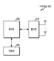
도 2을 참고하면, 송신단 110 또는 수신단 120은 통신부 210, 저장부 220, 제어부 230를 포함한다.Referring to FIG. 2, the transmitting
통신부 210은 무선 채널을 통해 신호를 송수신하기 위한 기능들을 수행한다. 예를 들어, 통신부 210은 시스템의 물리 계층 규격에 따라 기저대역 신호 및 비트열(bit sequence) 간 변환 기능을 수행한다. 예를 들어, 데이터 송신 시, 통신부 210은 송신 비트열을 부호화 및 변조함으로써 변조 심볼들을 생성한다. 또한, 데이터 수신 시, 통신부 210은 기저대역 신호를 복조 및 복호화를 통해 수신 비트열을 복원한다. 또한, 통신부 210은 기저대역 신호를 RF(radio frequency) 대역 신호로 상향변환한 후 안테나를 통해 송신하고, 안테나를 통해 수신되는 RF 대역 신호를 기저대역 신호로 하향변환한다. 예를 들어, 통신부 210은 인코더(encoder), 디코더(decoder), 변조기(modulator), 복조기(demodulator), DAC(digital to analog convertor), ADC(analog to digital convertor), 송신 필터, 수신 필터, 증폭기, 믹서(mixer), 오실레이터(oscillator), 등을 포함할 수 있다.The
또한, 통신부 210은 다수의 RF 체인들을 포함할 수 있다. 나아가, 통신부 210은 빔포밍(beamforming)을 수행할 수 있다. 빔포밍을 위해, 통신부 210은 다수의 안테나들 또는 안테나 요소(element)들을 통해 송수신되는 신호들 각각의 위상 및 크기를 조절, 즉, 아날로그 빔포밍을 수행할 수 있다. 또는, 통신부 210은 디지털 신호에 대한 빔포밍, 즉, 디지털 빔포밍을 수행할 수 있다.In addition, the
또한, 통신부 210은 서로 다른 주파수 대역의 신호들을 처리하기 위해 서로 다른 통신 모듈들을 포함할 수 있다. 나아가, 통신부 210은 서로 다른 다수의 무선 접속 기술들을 지원하기 위해 다수의 통신 모듈들을 포함할 수 있다. 예를 들어, 서로 다른 무선 접속 기술들은 블루투스 저 에너지(bluetooth low energy, BLE), Wi-Fi(Wireless Fidelity), WiGig(WiFi Gigabyte), 셀룰러 망(예: LTE, LTE-A, 5G(5th generation) 망) 등을 포함할 수 있다. 또한, 서로 다른 주파수 대역들은 극고단파(SHF:super high frequency)(예: 2.5GHz, 5GHz) 대역, mm파(millimeter wave)(예: 30GHz, 60GHz) 대역을 포함할 수 있다.In addition, the
통신부 210은 상술한 바와 같이 신호를 송신 및 수신한다. 이에 따라, 통신부 210은 송신기, 수신기 또는 송수신기로 지칭될 수 있다. 또한, 이하 설명에서 무선 채널을 통해 수행되는 송신 및 수신은 통신부 210에 의해 상술한 바와 같은 처리가 수행되는 것을 포함하는 의미로 사용된다.The
저장부 220은 송신단 110 또는 수신단 120의 동작을 위한 기본 프로그램, 응용 프로그램, 설정 정보 등의 데이터를 저장한다. 저장부 220은 휘발성 메모리, 비휘발성 메모리 또는 휘발성 메모리와 비휘발성 메모리의 조합으로 구성될 수 있다. 그리고, 저장부 220은 제어부 230의 요청에 따라 저장된 데이터를 제공한다.The
제어부 230은 송신단 110 또는 수신단 120의 전반적인 동작들을 제어한다. 예를 들어, 제어부 230은 통신부 210를 통해 신호를 송신 및 수신한다. 또한, 제어부 230은 저장부 220에 데이터를 기록하고, 읽는다. 이를 위해, 제어부 230은 적어도 하나의 프로세서(processor) 또는 마이크로(micro) 프로세서를 포함하거나, 또는, 프로세서의 일부일 수 있다. 또한, 통신부 210의 일부 및 제어부 230은 CP(communication processor)라 지칭될 수 있다. 특히, 제어부 230은 후술되는 다양한 실시 예들에 따라 송신단 110 또는 수신단 120이 제어 정보를 교환하고, 전송 기법 또는 수신 알고리즘을 선택하도록 제어한다. 예를 들어, 제어부 230은 송신단 110 또는 수신단 120이 후술하는 다양한 실시 예들에 따른 절차를 수행하도록 제어할 수 있다.The
도 2는 송신단 110 또는 수신단 120의 구성을 예시한다. 여기서, 도 2의 구성이 기지국의 구성인 경우, 백홀(backhaul) 망과 통신을 수행하기 위한 인터페이스를 제공하는 백홀 통신부가 더 포함될 수 있다.2 illustrates a configuration of a transmitting
도 3은 본 개시의 다양한 실시 예들에 따른 무선 통신 시스템에서 SLC에 기반하여 신호를 송신하기 위한 송신단의 구조의 예를 도시한다. 이하 사용되는 '...부', '...기' 등의 용어는 적어도 하나의 기능이나 동작을 처리하는 단위를 의미하며, 이는 하드웨어나 소프트웨어, 또는, 하드웨어 및 소프트웨어의 결합으로 구현될 수 있다. 도 3에 예시된 구성은 송신단 110의 통신부 210의 구성으로서 이해될 수 있다.3 shows an example of the structure of a transmitting end for transmitting a signal based on SLC in a wireless communication system according to various embodiments of the present disclosure. Hereinafter, terms such as "part" and "group" refer to a unit for processing at least one function or operation, which may be implemented by hardware, software, or a combination of hardware and software have. The configuration illustrated in FIG. 3 can be understood as a configuration of the
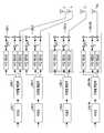
도 3을 참고하면, 송신단 110의 통신부 210는 부호부들 310-1 내지 310-2NT, 직병렬 변환부들 320-1 내지 320-2NT, 및 변조부들 330-1 내지 330-2NT를 포함한다. 실수 값을 갖는 2M/2-PAM 기반의 수신 신호 모델의 예로서, 송신단 110은 2NT 개의 송신 안테나를 포함할 수 있다. 부호부들 310-1 내지 310-2NT, 직병렬 변환부들 320-1 내지 320-2NT, 및 변조부들 330-1 내지 330-2NT은 다수의 안테나 경로들을 구성하며, 안테나 경로들 각각의 동작은 실질적으로 동일하다. 따라서, 이하 설명의 편의를 위해, 안테나 경로들을 대표하여, n번째 안테나 경로를 구성하는 부호부 310-n, 직병렬 변환부 320-n, 변조부 330-n의 동작이 설명된다.3, the
부호부 310-n은 송신단 110에서 생성된 정보어에 대한 부호어(codeword)를 생성한다. 즉, 부호부 310-n은 송신단 110의 채널 인코딩을 수행한다.The code unit 310-n generates a codeword for the information word generated in the
직병렬 변환부 320-n은 생성된 부호어를 M/2개의 비트 스트림들로 분리한다. 다시 말해, 직병렬 변환부 320-n은 생성된 부호어를 M/2개의 비트 스트림으로 병렬화하고, 병렬화된 비트 스트림을 변조부 330-n에 전달한다.The deserializer 320-n separates the generated codewords into M / 2 bit streams. In other words, the deserialization unit 320-n parallelizes the generated codewords to M / 2 bit streams, and transmits the parallelized bit stream to the modulator 330-n.
변조부 330-n은 직병렬 변환부 320-n으로부터 전달 받은 M/2개의 비트 스트림들로부터 2M/2-PAM 심볼을 생성한다. 이를 위해, 변조부 330-n은 적어도 하나의 이진 변조부(binary modulator), 적어도 하나의 곱셈부, 적어도 하나의 가산부를 포함할 수 있다. 적어도 하나의 이진 변조부는 입력되는 비트를 이진 변조함으로써, 0 또는 1에 대응하는 크기의 심볼을 생성한다. 예를 들어, 변조부 330-n은 2M/2개의 이진 변조부들을 포함할 수 있다. 이 경우, 도 4와 같이, 변조부 330-n은 M/2개의 이진 변조된 심볼들 x(m) (m=1, 2, ..., M/2)을 생성할 수 있다.The modulator 330-n generates 2M / 2 -PAM symbols fromM / 2 bit streams received from the deserializer 320-n. To this end, the modulator 330-n may include at least one binary modulator, at least one multiplier, and at least one adder. At least one binary modulation unit generates a symbol of a size corresponding to 0 or 1 by binary-modulating the input bit. For example, the modulation section 330-n may include 2M / 2 binary modulation sections. In this case, as shown in FIG. 4, the modulator 330-n may generate M / 2 binary modulated symbols x(m) (m = 1, 2, ..., M / 2).
변조부 330-n은 M/2개의 비트 스트림들로부터 생성된 이진 변조된 심볼들로부터 2M/2-PAM 심볼을 생성한다. 변조부 330-n은 '2M/2-PAM 변조부'로 지칭될 수 있다. 구체적으로, 변조부 330-n의 적어도 하나의 곱셈부는 M/2개의 이진 변조된 심볼들을 서로 다른 2의 거듭 제곱 크기로 각각 스케일링한다. 예를 들어, 도 4를 참고하면, 이진 변조된 심볼 x1은 20으로 스케일링되고, 이진 변조된 심볼 x2는 21로 스케일링되며, 이진 변조된 심볼 xM/2은 2M/2-1로 스케일링될 수 있다. 그리고, 변조부 330-n의 적어도 하나의 가산부는 스케일링된 이진 변조된 심볼들을 모두 더함으로써 2M/2-PAM 심볼을 생성한다. 예를 들어, 도 4를 참고하면, 2M/2-PAM 심볼 s는 M/2개의 이진 변조된 심볼들 x(m)의 합으로 구성될 수 있다. 이 경우, 변조부 330-n으로 입력된 비트들 및 2M/2-PAM 심볼 s 간 비트 매핑 관계는 네추럴 라벨링(natural labeling)될 수 있다. 네추럴 라벨링은 CM(coded modulation)의 한 방식으로서, 성상도 점의 순서에 따라 비트들이 나타내는 십진수(digit)가 1씩 증가하도록 맵핑하는 방법이다. 네추럴 라벨링은 그 기술적 의미에 따라 "네추럴 맵핑" 또는 이와 동등한 기술적 의미를 가지는 다른 명칭으로 지칭될 수 있다.The modulator 330-n generates 2M / 2 -PAM symbols from the binary modulated symbols generated from the M / 2 bit streams. The modulation section 330-n may be referred to as a "2M / 2- PAM modulation section ". Specifically, at least one multiplier of the modulator 330-n scales each of the M / 2 binary-modulated symbols with a power of two different magnitudes. For example, referring to FIG. 4, the binary modulated symbol x1 is scaled to 20 , the binary modulated symbol x2 is scaled to 21 , and the binary modulated symbol xM/2 is 2M / 2- 1 < / RTI > Then, at least one adder of the modulator 330-n generates a 2M / 2 -PAM symbol by adding all of the scaled binary modulated symbols. For example, referring to FIG. 4, a 2M / 2 -PAM symbol s may be composed of the sum of M / 2 binary modulated symbols x(m) . In this case, the bit mapping relationship between the bits input to the modulator 330-n and the2M / 2- PAM symbol s may be natural labeling. Natural labeling is a method of coded modulation (CM), in which mapping is performed such that the digits represented by the bits are incremented by 1 in order of constellation points. Natural labeling may be referred to as " native mapping "or other name having equivalent technical meaning depending on its technical meaning.
일부 실시 예들에서, 송신단 110의 2NT개의 송신 안테나들을 통해 송신되는 2NT개의 2M/2-PAM 심볼들은 하기 <수학식 3>과 같이 벡터 s로 표현될 수 있다.In some embodiments,T 2N of2 M / 2 -PAM symbols sent on theT 2N transmission antennas of the

여기서,s는 2NT개의 2M/2-PAM 심볼들을 포함하는 송신 신호 벡터,x(m)은 2M/2-PAM 심볼에 할당된 m번째 비트에 의해 생성된 이진 변조된 심볼들을 포함하는 벡터를 의미한다.Wheres is a transmitted signal vector comprising 2NT 2M / 2 -PAM symbols, andx(m) comprises binary modulated symbols generated by mth bits assigned to 2M / 2 -PAM symbols Vector.
도 3에서, 하나의 부호부 310-n이 하나의 변조부 330-n과 연결되는 송신단 110의 구조로 인하여, 송신단 110은 실수부와 허수부 각각에 독립적으로 부호화 및 2M/2-PAM 변조를 수행할 수 있다.In FIG. 3, due to the structure of the transmitting
도 5a 내지 도 5c는 본 개시의 다양한 실시 예들에 따른 무선 통신 시스템에서 수신된 신호를 처리하기 위한 수신단의 구조의 예를 도시한다. 이하 사용되는 '...부', '...기' 등의 용어는 적어도 하나의 기능이나 동작을 처리하는 단위를 의미하며, 이는 하드웨어나 소프트웨어, 또는, 하드웨어 및 소프트웨어의 결합으로 구현될 수 있다. 도 5a 내지 5c에 예시된 구성은 수신단 120의 통신부 210의 구성으로서 이해될 수 있다.Figures 5A-5C illustrate examples of the structure of a receiving end for processing received signals in a wireless communication system according to various embodiments of the present disclosure. Hereinafter, terms such as "part" and "group" refer to a unit for processing at least one function or operation, which may be implemented by hardware, software, or a combination of hardware and software have. The configuration illustrated in Figs. 5A to 5C can be understood as a configuration of the
도 5a는 IF 디코딩을 지원하는 수신기 120의 구조를 예시한다. 도 5a를 참고하면, 수신단 120은 선형 조합부(linear combining unit) 511, 복호부들 513-1 내지 513-2NR, 조합 해제부(combination solving unit) 515를 포함한다. 선형 조합부 511은 '선형 등화부(linear equalizer)'로, 조합 해제부 515는 '선형 등식 해제부(linear equation solving unit)'로 지칭될 수 있다.5A illustrates a structure of a
선형 조합부 511은 무선 채널을 거쳐 수신된 안테나 별 수신 신호들에 등화 행렬(equalization matrix)을 곱한다. 등화 행렬은 유효(effective) 채널 행렬을 정수 행렬로 변환하기 위해 사용된다. 또한, 등화 행렬은 유효 잡음을 감소시키고, 유효 채널 행렬을 풀-랭크(full rank) 행렬로 변환하기 위해 사용될 수 있다. 따라서, 등화 행렬 및 채널 행렬의 곱은 '정수화된(integerized) 유효 채널 행렬', '정수 값 행렬(integer-valued matrix)'이라 지칭될 수 있다. 이를 위해, 선형 조합부 511은 채널 행렬, 채널 품질 등에 기초하여 등화 행렬을 결정하거나, 수신단 120 내의 다른 블록으로부터 등화 행렬을 제공받는다. 선형 조합부 511의 연산에 따라, 선형 합산된 코드워드를 나타내는 신호들 및 유효 잡음이 합산된 신호들이 출력된다. 선형 조합부 511의 연산은 ZF, MMSE와 같은 선형 수신 알고리즘에서 수행되는 채널 인버전(channel inversion)과 달리, 조합된 부호어들을 생성한다. 다시 말해, 송신단 110에서 송신된 부호어들의 조합을 통해 생성된 다른 부호어들이 출력된다. 이때, 다른 부호어들 역시 유효한 부호어들을 구성할 수 있다.The
복호부들 513-1 내지 513-2NR은 선형 조합부 511로부터 출력된 조합된 부호어들에 대한 복호를 수행한다. 이때, 복호부들 513-1 내지 513-2NR 각각은 SISO(single input single output) 복호부와 같이 동작할 수 있다. 다시 말해, 복호부들 513-1 내지 513-2NR 각각은 다른 안테나로부터의 간섭은 고려하지 아니하고 복호를 수행한다.The decoding units 513-1 through 513-2NR perform decoding on the combined codewords output from the
조합 해제부 515는 복호부들 513-1 내지 513-2NR로부터 출력된 디코딩 결과를 선형 조합부 511에서 수행된 조합에 대응하는 역변환을 수행한다. 즉, 조합 해제부 513는 선형 조합부 511에 의한 비트들의 조합을 해제한다. 이에 따라, 송신단 110에서 생성된 부호어들의 부호화를 수행하기 전 비트들이 추정될 수 있다. 즉, 조합 해제부 511은 송신단 110에서 생성된 부호어들의 부호화를 수행하기 전 비트들의 추정된 비트들(estimated bits)을 출력한다.
도 5a는 IF 수신 알고리즘의 한 종류인 IF 디코딩 알고리즘을 위한 구조이다. IF 수신 알고리즘의 다른 종류로, IF 검출이 있다. 도 5b는 IF 검출을 지원하는 수신기 120의 구조를 예시한다. 도 5b를 참고하면, 수신단 120은 선형 조합부 521, LLR 계산부 523, LLR 변환부 525, 복호부들 527-1 내지 527-2NR, 조합 해제부 529를 포함한다. 선형 조합부 521은 '선형 등화부'로, 조합 해제부 529는 '선형 등식 해제부'로 지칭될 수 있다.5A is a structure for an IF decoding algorithm which is one kind of an IF reception algorithm. Another type of IF reception algorithm is IF detection. 5B illustrates the structure of a
선형 조합부 521은 무선 채널을 거쳐 수신된 안테나 별 수신 신호들에 등화 행렬을 곱한다. 선형 조합부 521의 연산에 따라, 선형 합산된 부호어를 나타내는 신호들 및 유효 잡음이 합산된 신호들이 출력된다. 이에 따라, 송신단 110에서 송신된 부호어들의 조합을 통해 생성된 다른 부호어들이 출력된다. 이때, 도 4a의 선형 조합부 521과 달리, 선형 조합부 521은 시점 t마다 서로 다른 정수화된 유효 채널 행렬을 생성할 수 있다. 즉, IF 디코딩 알고리즘은 하나의 정수화된 유효 채널 행렬을 이용하나, IF 검출 알고리즘은 다수의 정수화된 유효 채널 행렬들을 이용한다. 예를 들어, t번째 수신 신호에 대한 채널 행렬을 Ht라 할 때, 선형 등화에 의해 Ht에 Bt가 곱해진다(t=1, 2, ..., T). 이에 따라, 정수화된 유효 채널 행렬들 A1, A2, ..., AT가 생성된다. 즉, 정수화된 유효 채널 행렬이 시점 t에 따라 변화할 수 있다.The
LLR 계산부 523은 주어진 정수화된 유효 채널 행렬을 이용하여 LLR 값들을 산출한다. 즉, 선형 조합부 521에 의해 At가 결정되면, LLR 계산부 523은 At를 이용하여 t번째 수신 신호에서 각 수신 안테나별로 심볼 합에 대한 LLR 값들을 산출한다.The
LLR 변환부 525는 LLR 값들을 새로운 유효 채널 행렬에 부합하도록 변환한다. 새로운 유효 채널 행렬은 새로운 정수 값 행렬(integer-valued matrix)


복호부들 527-1 내지 527-2NR는 LLR 변환부 525로부터 출력된 LLR 값들을 이용하여 부호어들에 대한 복호를 수행한다. 이때, 복호부들 527-1 내지 527-2NR 각각은 SISO 디코더와 같이 동작할 수 있다. 그리고, 조합 해제부 529는 복호부들 527-1 내지 527-2NR로부터 출력된 복호 결과를 새로운 정수 값 행렬

도 5c는 본 개시의 다양한 실시 예들에 따른 무선 통신 시스템에서 SLC에 기반하여 수신된 신호를 처리하기 위한 수신단 120의 구조의 예를 도시한다. 이하 사용되는 '...부', '...기' 등의 용어는 적어도 하나의 기능이나 동작을 처리하는 단위를 의미하며, 이는 하드웨어나 소프트웨어, 또는, 하드웨어 및 소프트웨어의 결합으로 구현될 수 있다.5C illustrates an example of the structure of a receiving
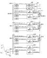
도 5c를 참고하면, 수신단 120은 등화부 531, 복조부들 532-1 내지 532-M/2, 제1 확률계산부들 533-1 내지 533-M/2-1, 확률합성부들 534-1 내지 534-M/2-2, 제2 확률계산부들 535-1 내지 535-M/2-1, 복호부 536, 및 복원부 537을 포함한다.5C, the
등화부 531은 송신단 110으로부터 수신된 신호에 IF 등화를 수행한다. 즉, 등화부 531은 수신된 안테나 별 수신 신호들에 등화 행렬을 곱함으로써, 유효 채널 행렬을 정수 행렬로 변환한다. 이에 따라, 등화부 531은 선형 합산된 코드워드들을 나타내는 합(summed) 심볼들, 즉, 합 심볼 벡터를 출력한다. 여기서, 합 심볼들 각각은 심볼들이 선형 조합된 결과로서, '심볼 조합들'로 지칭될 수 있다. 등화부 531은 선형 조합부 511 또는 선형 조합부 521에 상응하는 구성요소일 수 있다.The
복조부 532-1은 등화부 531로부터 출력된 심볼 조합 벡터 내의 각 심볼 조합의 1번째 비트의 APP를 결정한다. 제1 확률계산부 533-1은 심볼 조합의 1번째 비트에 대한 APP를 이용하여 심볼의 1번째 비트에 대한 APP를 결정한다. 제2 확률 계산부 535-1은 심볼의 1번째 비트에 대한 APP를 이용하여 심볼의 2번째 비트에 대한 APP를 결정하기 위한 1번째 비트에 대한 APP를 결정한다.The demodulator 532-1 determines APP of the first bit of each symbol combination in the symbol combination vector output from the
복조부 532-2는 제2 확률계산부 535-1로부터 출력된 심볼의 2번째 비트에 대한 APP를 결정하기 위한 1번째 비트에 대한 APP를 이용하여 심볼 조합의 2번째 비트의 APP를 결정한다. 제1 확률계산부 533-2는 심볼 조합의 2번째 비트에 대한 APP를 이용하여 심볼의 2번째 비트에 대한 APP를 결정한다. 확률합성부 534-2는 제1 확률계산부 533-2로부터 출력된 심볼의 2번째 비트에 대한 APP 및 제1 확률계산부 533-1로부터 출력된 심볼의 1번째 비트에 대한 APP를 이용하여 심볼의 1번째 및 2번째 비트들의 합에 대한 APP를 결정한다. 제2 확률계산부 535-2는 확률합성부 534-2로부터 출력된 심볼의 1번째 및 2번째 비트들의 합에 대한 APP를 이용하여 심볼 조합의 1번째 및 2번째 비트들의 합에 대한 APP를 결정한다.The demodulator 532-2 uses the APP for the first bit to determine the APP for the second bit of the symbol output from the second probability calculator 535-1 to determine the APP of the second bit of the symbol combination. The first probability calculation unit 533-2 uses the APP for the second bit of the symbol combination to determine the APP for the second bit of the symbol. The probability synthesizing unit 534-2 receives the APP for the second bit of the symbol output from the first probability calculating unit 533-2 and the APP for the first bit of the symbol output from the first probability calculating unit 533-1, Lt; RTI ID = 0.0 > 1 < / RTI > The second probability calculation unit 535-2 determines APP for the sum of the first and second bits of the symbol combination using APP for the sum of the first and second bits of the symbol output from the probability synthesis unit 534-2 do.
상술한 복조부 532-2, 제1 확률계산부 533-2, 확률합성부 354-2, 제2 확률계산부 353-2의 동작과 유사한 동작들이 복조부 532-3 내지 532-M/2-1, 제1 확률계산부 533-2 내지 533-M/2-1, 확률합성부 354-2 내지 534-M/2-1, 제2 확률계산부 535-2 내지 535-M/2-1에 의해 반복된다. 이에 따라, 복조부 532-M/2는 제2 확률계산부 535-M/2-1로부터 출력된 심볼 조합의 1번째 내지 M/2-1번째 비트들에 대한 APP를 이용하여 심볼 조합의 M/2번째 비트의 APP를 결정한다. 복호부 536은 복조부들 532-1 내지 532-M/2로부터 출력된 각 APP를 이용하여 심볼 조합에 대한 각 LLR을 생성하고, LLR을 이용하여 복호를 수행한다. 복원부 537은 복호부 536로부터 출력된 조합 심볼에 대한 복호 결과를 이용하여 정보어를 복원한다. 복원부 537은 조합 해제부 515 또는 조합 해제부 529와 상응하는 구성요소일 수 있다.Operations similar to those of the demodulation unit 532-2, the first probability calculation unit 533-2, the probability synthesis unit 354-2, and the second probability calculation unit 353-2 are performed by the demodulation units 532-3 to 532-M / 2- 1, the first probability calculator 533-2 to 533-M / 2-1, the probability synthesizer 354-2 to 534-M / 2-1, the second probability calculator 535-2 to 535-M / Lt; / RTI > Accordingly, the demodulator 532-M / 2 uses the APP for the first through M / 2 < -1 > bits of the symbol combination output from the second probability calculator 535-M / / 2 < / RTI > The
도 6은 본 개시의 다양한 실시 예들에 따른 무선 통신 시스템에서 SLC에 기반하여 신호를 송신하기 위한 동작 방법의 예를 도시한다. 도 6은 송신단 110의 동작 방법을 예시한다.6 illustrates an example of an operation method for transmitting a signal based on SLC in a wireless communication system according to various embodiments of the present disclosure. 6 illustrates an operation method of the transmitting
도 6을 참고하면, 601 단계에서, 송신단은 각 송신 경로에 입력되는 비트들에 대응하는 부호어를 결정한다. 즉, 송신단은 부호화를 수행한다. 이는, 송신단이 SLC에 기반하여 신호를 송신하기 위하여, 비트 레벨 별로 부호어를 맵핑하지 않고, 입력되는 비트들 전체에 대해 하나의 부호어를 맵핑하기 때문이다. 여기서, 입력되는 비트들은 정보어로 지칭될 수 있다.Referring to FIG. 6, in step 601, a transmitter determines a codeword corresponding to bits input to each transmission path. That is, the transmitting end performs encoding. This is because the transmitting terminal maps one codeword to all the input bits without mapping the codeword for each bit level in order to transmit the signal based on the SLC. Here, the input bits may be referred to as information words.
603 단계에서, 송신단은 부호어의 각 비트들을 이진 변조한다. 즉, 송신단은 부호어를 다수의 비트 스트림들로 분할하고, 각 비트 스트림에 대하여 이진 변조를 수행한다. 이에 따라, 각 비트에 대응하는 이진 변조된 심볼들이 생성된다.In step 603, the transmitter performs binary modulation on each bit of the codeword. That is, the transmitting end divides the codeword into a plurality of bit streams, and performs binary modulation on each bit stream. Thus, binary modulated symbols corresponding to each bit are generated.
605 단계에서, 송신단은 이진 변조된 심볼들을 결합한다. 예를 들어, 송신단은 이진 변조된 심볼들을 이용하여 부호어의 적어도 일부에 대응하는 PAM 심볼을 생성한다. 구체적으로, 송신단은 이진 변조된 심볼들 각각을 20, 21, 22, ..., 2M/2-1 크기로 스케일링한 후, 합산함으로써, 2M/2-PAM 심볼을 생성할 수 있다. 이로 인해, 성상도 점의 순서에 따라 상기 비트들이 나타내는 값이 1씩 증가하도록 비트 값과 성상도 점을 맵핑하는 네추럴 라벨링이 적용될 수 있다.In step 605, the transmitter combines the binary modulated symbols. For example, the transmitting end uses the binary modulated symbols to generate a PAM symbol corresponding to at least a portion of the codeword. Specifically, the transmitting terminal scales each of the binary-modulated symbols into 20 , 21 , 22 , ..., 2M/ 2-1 magnitudes and then sums them to generate a 2M / 2 -PAM symbol . As a result, natural labeling may be applied to map bit values and constellation points so that the values indicated by the bits increase by 1 in the order of constellation points.
607 단계에서, 송신단은 수신단 120에게 생성된 심볼을 송신한다. PAM 심볼들은 각 송신 안테나에 대하여 생성되며, 송신단은 다수의 송신 안테나들을 통해 PAM 심볼들을 송신할 수 있다.In
도 7은 본 개시의 다양한 실시 예들에 따른 무선 통신 시스템에서 SLC에 기반하여 수신된 신호를 처리하기 위한 동작 방법의 예를 도시한다. 도 7은 수신단 120의 동작 방법을 예시한다.7 illustrates an example of an operational method for processing a received signal based on SLC in a wireless communication system in accordance with various embodiments of the present disclosure. FIG. 7 illustrates a method of operation of the receiving
도 7을 참고하면, 701 단계에서, 수신단은 신호를 수신한다. 즉, 수신단은 다수의 수신 안테나들을 통해 송신단(예: 송신단 110)에서 다수의 송신 안테나들을 통해 송신된 신호들을 수신한다. 예를 들어, 수신된 신호는 하기 <수학식 4>와 같을 수 있다.Referring to FIG. 7, in step 701, the receiving end receives a signal. That is, the receiving end receives signals transmitted through a plurality of transmitting antennas at a transmitting end (e.g., transmitting end 110) through a plurality of receiving antennas. For example, the received signal may be expressed by Equation (4) below.

여기서, y는 수신 신호 벡터, H는 채널 행렬, s는 송신 신호 벡터, n은 백색 가우시안 잡음 벡터, x(m)은 2M/2-PAM 심볼에 할당된 m번째 비트에 의해 생성된 이진 변조된 심볼들을 포함하는 벡터를 의미한다.Where y is the received signal vector, H is the channel matrix, s is the transmit signal vector, n is the white Gaussian noise vector, x(m) is the binary modulation generated by the mth bit allocated to the2M / ≪ / RTI >
703 단계에서, 수신단은 수신된 신호에 대하여 IF 등화를 수행할 수 있다. 다시 말해, 수신단은 수신된 안테나 별 수신 신호들에 등화 행렬을 곱함으로써, 유효 채널 행렬을 정수 행렬로 변환한다. 이에 따라, 선형 합산된 부호어들을 나타내는 심볼 조합 벡터가 생성된다. 예를 들어, IF 등화가 수행된 신호는 하기 <수학식 5>와 같을 수 있다.In step 703, the receiving end can perform IF equalization on the received signal. In other words, the receiving terminal multiplies the received signals for each received antenna by an equalization matrix, thereby converting the effective channel matrix into an integer matrix. Thus, a symbol combination vector representing linearly summed codewords is generated. For example, a signal on which IF equalization has been performed may be expressed by Equation (5).

여기서,


여기서,

705 단계에서, 수신단은 등화 행렬에 기반하여 결정된 각 비트의 APP들 및 수신된 신호에 대한 우도(likelihood) 값을 이용하여 각 비트의 LLR 값들을 결정한다. 구체적으로, 수신단은 등화 행렬에 기반하여 심볼 조합을 구성하는 각 비트의 APP들을 결정하고, APP들을 이용하여 LLR 값들을 결정한다. 이때, 하나의 비트(예: m번째 비트)의 APP를 결정하기 위해, 수신단은 하위 비트들(예: 1번째 내지 m-1 번째 비트들)의 APP를 이용할 수 있다. 그리고, 하위 비트들의 APP를 결정하기 위해, 수신단은 심볼 조합의 하위 비트들의 개별 APP들을 등화 행렬에 기반하여 조합 전 심볼에 대한 개별 APP들로 변환한 후, 개별 APP들을 합산함으로써 비트들의 APP를 생성하고, 등화 행렬에 기반하여 심볼 조합을 구성하는 비트들의 APP를 결정할 수 있다.In step 705, the receiver determines the LLR values of each bit using the APPs of each bit determined based on the equalization matrix and a likelihood value of the received signal. Specifically, the receiver determines the APPs of each bit constituting the symbol combination based on the equalization matrix, and determines the LLR values using the APPs. At this time, in order to determine the APP of one bit (e.g., m-th bit), the receiving end can use the APP of the lower bits (e.g., 1st through m-1th bits). Then, in order to determine the APP of the lower bits, the receiving end converts the individual APPs of the lower bits of the symbol combination into individual APPs for the pre-combination symbol based on the equalization matrix, and then generates APPs of bits by summing the individual APPs And determine the APP of the bits constituting the symbol combination based on the equalization matrix.
707 단계에서, 수신단은 LLR 값들을 이용하여 신호를 복호한다. 이후, IF 기법에 따라, 수신단은 등화 행렬의 역행렬을 이용하여 복호 결과로부터 정보어들을 복원할 수 있다.In step 707, the receiver decodes the signal using the LLR values. Thereafter, according to the IF scheme, the receiving end can recover the information words from the decoding result using the inverse matrix of the equalization matrix.
도 8은 본 개시의 다양한 실시 예들에 따른 무선 통신 시스템에서 SLC에 기반하여 수신된 신호를 처리하기 위한 다른 동작 방법의 예를 도시한다. 도 8은 수신단 120의 동작 방법을 예시한다.Figure 8 illustrates an example of another method of operation for processing a received signal based on SLC in a wireless communication system in accordance with various embodiments of the present disclosure. 8 illustrates a method of operation of the receiving
도 8을 참고하면, 801 단계에서, 수신단 120은 IF 등화가 수행된 신호로부터 결정된 심볼의 조합의 m번째 비트에 대한 APP를 결정한다. 구체적으로, 수신단 120은 심볼의 조합의 1부터 m-1번째까지 비트들에 대한 APP로부터 심볼의 조합의 m번째 비트에 대한 APP를 결정한다.Referring to FIG. 8, in
803 단계에서, 수신단 120은 결정된 APP에 대한 심볼의 조합의 비트가 M/2번째 비트인지 여부를 결정한다. 즉, 수신단 120은 심볼의 조합의 M/2번째 비트의 APP를 결정하였는지 여부를 확인할 수 있다.In step 803, the receiving
만약, 결정된 APP에 대한 심볼의 조합의 비트가 M/2번째 비트가 아닌 경우, 805 단계에서, 수신단 120은 심볼의 조합의 1부터 m번째까지의 비트들의 합에 대한 APP를 결정한다. 이 후, 수신단 120은 705 단계로 진행하여, 심볼의 조합의 1부터 m번째까지 비트들의 합에 대한 APP로부터 심볼의 조합의 m+1번째 비트에 대한 APP를 결정한다.If the bit of the combination of symbols for the determined APP is not M / 2-th bit, in
반면, 결정된 APP에 대한 심볼의 조합의 비트가 M/2번째 비트인 경우, 807 단계에서, 수신단 120은 심볼의 조합의 m번째 비트에 대한 LLR을 결정한다. 구체적으로, 수신단 120은 심볼의 조합의 m번째 비트에 대한 APP로부터 심볼의 조합의 m번째 비트에 대한 LLR을 결정한다.On the other hand, if the bit of the combination of symbols for the determined APP is M / 2-th bit, in
809 단계에서, 수신단 120은 심볼의 조합을 복호한다. 구체적으로, 수신단 120은 심볼의 조합의 m번째 비트에 대한 LLR을 이용하여 m번째 비트에 해당하는 심볼의 조합을 복호한다.In
811 단계에서, 수신단 120은 복호된 m번째 비트에 해당하는 심볼의 조합을 이용하여 정보어를 복원한다. 예를 들어, 정보어는 복호된 m번째 비트에 해당하는 심볼의 조합에 상기 <수학식 5>의 정수 행렬 A의 역행렬인 A-1를 적용하여 복원될 수 있다. 일부 실시 예들에서, 정보어는 복호된 m번째 비트에 해당하는 심볼의 조합에 새로운 정수 값 행렬
도 9는 본 개시의 다양한 실시 예들에 따른 무선 통신 시스템에서 SLC에 기반하여 수신된 신호의 각 비트에 대한 LLR을 결정하기 위한 동작 방법의 예를 도시한다. 도 9는 수신단 120의 동작 방법을 예시한다.9 illustrates an example of an operation method for determining an LLR for each bit of a received signal based on SLC in a wireless communication system according to various embodiments of the present disclosure. 9 illustrates a method of operation of the receiving
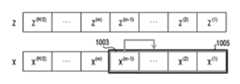
도 9를 참고하면, 901 단계에서, 수신단 120은 심볼의 조합의 m-1번째 비트에 대한 APP로부터 심볼의 m-1번째 비트에 대한 APP를 결정한다. 예를 들어, 도 10a를 참고하면, 심볼 x의 m-1번째 비트 x(m-1) 1003에 대한 APP는 심볼의 조합 z의 m-1번째 비트 z(m-1) 1001에 대한 APP에 기반하여 결정될 수 있다. 이 경우, 심볼 x의 m-1번째 비트 x(m-1) 1003에 대한 APP는 하기 <수학식 7>과 같을 수 있다.Referring to FIG. 9, in step 901, the receiving

여기서,


903 단계에서, 수신단 120은 심볼의 m-1번째 비트에 대한 APP로부터 심볼의 1부터 m-1번째까지 비트들의 합에 대한 APP를 결정한다. 예를 들어, 도 10b를 참고하면, 심볼 x의 1부터 m-1번째까지 비트들 x(1), x(2), ..., x(m-1) 의 합 1005에 대한 APP는 심볼 x의 m-1번째 비트 x(m-1) 1003에 대한 APP에 기반하여 결정될 수 있다. 이 경우, 심볼 x의 1부터 m-1번째까지 비트들 x(1), x(2), ..., x(m-1)의 합 1005에 대한 APP는 하기 <수학식 8>과 같을 수 있다.In

여기서,

905 단계에서, 수신단 120은 심볼의 1부터 m-1번째까지 비트들의 합에 대한 APP로부터 심볼의 조합의 1부터 m-1번째까지 비트들의 합에 대한 APP를 결정한다. 예를 들어, 도 10c를 참고하면, 심볼의 조합 z의 1부터 m-1번째까지 비트들 z(1), z(2), ..., z(m-1) 의 합 1007에 대한 APP는 심볼 x의 1부터 m-1번째까지 비트들 x(1), x(2), ..., x(m-1) 의 합 1005에 대한 APP에 기반하여 결정될 수 있다. 이 경우, 심볼의 조합 z의 1부터 m-1번째까지 비트들 z(1), z(2), ..., z(m-1)의 합 1007에 대한 APP는 하기 <수학식 9>와 같을 수 있다.In

여기서,

907 단계에서, 수신단 120은 심볼의 조합의 1부터 m-1번째까지 비트들에 대한 APP로부터 심볼의 조합의 m번째 비트에 대한 APP를 결정한다. 예를 들어, 도 10d를 참고하면, 심볼의 조합의 m번째 비트 z(m) 1009에 대한 APP는 심볼의 조합 z의 1부터 m-1번째까지 비트들 z(1), z(2), ..., z(m-1) 1007에 대한 APP에 기반하여 결정될 수 있다. 이 경우, 심볼의 조합의 m번째 비트 z(m) 1009에 대한 APP는 하기 <수학식 10>과 같을 수 있다.In

여기서,


여기서,


909 단계에서, 수신단 120은 심볼의 조합의 m번째 비트에 대한 APP 로부터 심볼의 조합의 m번째 비트에 대한 LLR을 결정한다. 여기서, LLR은 심볼의 조합의 m번째 비트가 0일 확률과 심볼의 조합의 m번째 비트가 1일 확률의 비율에 로그(log)를 취한 값을 의미할 수 있다. 예를 들어, 심볼의 조합의 m번째 비트에 대한 LLR은 하기 <수학식 12>와 같을 수 있다.In

여기서,


다른 예를 들어, 심볼의 조합의 첫번째 비트에 대한 LLR은 하기 <수학식 13>과 같을 수 있다.For another example, the LLR for the first bit of the combination of symbols may be equal to Equation (13).

여기서,


도 11은 본 개시의 다양한 실시 예들에 따른 무선 통신 시스템에서 SLC에 기반하는 송신단 110 및 수신단 120의 예를 도시한다.11 shows an example of a SLC-based
도 11을 참고하면, 24-QAM 기반의 IF-MIMO 시스템에서 송신단 110은 8개의 송신 안테나들을 포함한다. 예를 들어, 송신단 110은 송신 안테나들 1101, 1102, 1103, 1104, 1105, 1106, 및 1107을 포함할 수 있다. 24-QAM 기반의 IF-MIMO 시스템에서 수신단 120은 8개의 수신 안테나들을 포함한다. 예를 들어, 수신단 120은 수신 안테나들 1111, 1112, 1113, 1114, 1115, 1116, 및 1117을 포함할 수 있다.Referring to FIG. 11, in the 24 -QAM-based IF-MIMO system, the
도 11은 24-QAM 기반의 IF-MIMO 시스템에서 송신단 110 및 수신단 120의 예를 도시되었으나, 송신단 110 및 수신단 120의 구조는 제한되지 않는다. 이하, 도 12에서는 24-QAM 기반의 IF-MIMO 시스템에서 수신단 120의 FER(frame error rate) 성능이 도시된다.11 shows an example of the transmitting
도 12는 본 개시의 다양한 실시 예들에 따른 무선 통신 시스템에서 수신단의 FER 성능의 예를 도시한다.12 illustrates an example of the FER performance of a receiver in a wireless communication system according to various embodiments of the present disclosure.
도 12를 참고하면, IF-MIMO 시스템에서 SLC에 기반하여 신호를 수신하는 수신단 120의 FER(frame error rate) 성능은 무선 통신 시스템에서 MMSE(minimum mean square error)에 기반하여 신호를 수신하는 수신단 130의 FER 성능보다 뛰어나다. 예를 들어, FER이 10-2인 경우, 수신단 120이 SLC에 기반하여 수신한 신호의 SNR(signal to noise ratio)은 22인 반면, 수신단 130이 MMSE에 기반하여 수신한 신호의 SNR은 30일 수 있다.12, the frame error rate (FER) performance of the receiving
본 개시의 청구항 또는 명세서에 기재된 실시 예들에 따른 방법들은 하드웨어, 소프트웨어, 또는 하드웨어와 소프트웨어의 조합의 형태로 구현될(implemented) 수 있다.Methods according to the claims of the present disclosure or the embodiments described in the specification may be implemented in hardware, software, or a combination of hardware and software.
소프트웨어로 구현하는 경우, 하나 이상의 프로그램(소프트웨어 모듈)을 저장하는 컴퓨터 판독 가능 저장 매체가 제공될 수 있다. 컴퓨터 판독 가능 저장 매체에 저장되는 하나 이상의 프로그램은, 전자 장치(device) 내의 하나 이상의 프로세서에 의해 실행 가능하도록 구성된다(configured for execution). 하나 이상의 프로그램은, 전자 장치로 하여금 본 개시의 청구항 또는 명세서에 기재된 실시 예들에 따른 방법들을 실행하게 하는 명령어(instructions)를 포함한다.When implemented in software, a computer-readable storage medium storing one or more programs (software modules) may be provided. One or more programs stored on a computer-readable storage medium are configured for execution by one or more processors in an electronic device. The one or more programs include instructions that cause the electronic device to perform the methods in accordance with the embodiments of the present disclosure or the claims of the present disclosure.
이러한 프로그램(소프트웨어 모듈, 소프트웨어)은 랜덤 액세스 메모리 (random access memory), 플래시(flash) 메모리를 포함하는 불휘발성(non-volatile) 메모리, 롬(ROM: Read Only Memory), 전기적 삭제가능 프로그램가능 롬(EEPROM: Electrically Erasable Programmable Read Only Memory), 자기 디스크 저장 장치(magnetic disc storage device), 컴팩트 디스크 롬(CD-ROM: Compact Disc-ROM), 디지털 다목적 디스크(DVDs: Digital Versatile Discs) 또는 다른 형태의 광학 저장 장치, 마그네틱 카세트(magnetic cassette)에 저장될 수 있다. 또는, 이들의 일부 또는 전부의 조합으로 구성된 메모리에 저장될 수 있다. 또한, 각각의 구성 메모리는 다수 개 포함될 수도 있다.Such programs (software modules, software) may be stored in a computer readable medium such as a random access memory, a non-volatile memory including a flash memory, a ROM (Read Only Memory), an electrically erasable programmable ROM (EEPROM), a magnetic disc storage device, a compact disc-ROM (CD-ROM), a digital versatile disc (DVDs) An optical storage device, or a magnetic cassette. Or a combination of some or all of these. In addition, a plurality of constituent memories may be included.
또한, 상기 프로그램은 인터넷(Internet), 인트라넷(Intranet), LAN(Local Area Network), WLAN(Wide LAN), 또는 SAN(Storage Area Network)과 같은 통신 네트워크, 또는 이들의 조합으로 구성된 통신 네트워크를 통하여 접근(access)할 수 있는 부착 가능한(attachable) 저장 장치(storage device)에 저장될 수 있다. 이러한 저장 장치는 외부 포트를 통하여 본 개시의 실시 예를 수행하는 장치에 접속할 수 있다. 또한, 통신 네트워크상의 별도의 저장장치가 본 개시의 실시 예를 수행하는 장치에 접속할 수도 있다.In addition, the program may be transmitted through a communication network composed of a communication network such as the Internet, an Intranet, a LAN (Local Area Network), a WLAN (Wide LAN), or a SAN (Storage Area Network) And can be stored in an attachable storage device that can be accessed. Such a storage device may be connected to an apparatus performing an embodiment of the present disclosure via an external port. Further, a separate storage device on the communication network may be connected to an apparatus performing the embodiments of the present disclosure.
상술한 본 개시의 구체적인 실시 예들에서, 개시에 포함되는 구성 요소는 제시된 구체적인 실시 예에 따라 단수 또는 복수로 표현되었다. 그러나, 단수 또는 복수의 표현은 설명의 편의를 위해 제시한 상황에 적합하게 선택된 것으로서, 본 개시가 단수 또는 복수의 구성 요소에 제한되는 것은 아니며, 복수로 표현된 구성 요소라 하더라도 단수로 구성되거나, 단수로 표현된 구성 요소라 하더라도 복수로 구성될 수 있다.In the specific embodiments of the present disclosure described above, the elements included in the disclosure have been expressed singular or plural, in accordance with the specific embodiments shown. It should be understood, however, that the singular or plural representations are selected appropriately according to the situations presented for the convenience of description, and the present disclosure is not limited to the singular or plural constituent elements, And may be composed of a plurality of elements even if they are expressed.
한편 본 개시의 상세한 설명에서는 구체적인 실시 예에 관해 설명하였으나, 본 개시의 범위에서 벗어나지 않는 한도 내에서 여러 가지 변형이 가능함은 물론이다. 그러므로 본 개시의 범위는 설명된 실시 예에 국한되어 정해져서는 아니 되며 후술하는 특허청구의 범위뿐만 아니라 이 특허청구의 범위와 균등한 것들에 의해 정해져야 한다.While the invention has been described in connection with what is presently considered to be the most practical and preferred embodiment, it is to be understood that the invention is not limited to the disclosed embodiments. Therefore, the scope of the present disclosure should not be limited to the embodiments described, but should be determined by the scope of the appended claims, as well as the appended claims.
Claims (20)
Translated fromKorean송신단으로부터 신호를 수신하는 과정과,
수신된 신호에 대하여 정수 강압(integer forcing, IF) 등화를 수행하는 과정과,
등화 행렬에 기반하여 결정된 상기 신호에 대한 각 비트의 사후 확률(a posteriori probability) 및 상기 신호에 대한 우도(likelihood) 값을 이용하여 상기 각 비트의 LLR(log likelihood ratio) 값을 결정하는 과정과,
상기 LLR 값을 이용하여 상기 신호를 복호하는 과정을 포함하는 방법.
A method of operating a receiver in a wireless communication system,
Receiving a signal from a transmitting end;
Performing integer forcing (IF) equalization on the received signal;
Determining a log likelihood ratio (LLR) value of each bit using a posteriori probability of each bit for the signal determined based on the equalization matrix and a likelihood value for the signal;
And decoding the signal using the LLR value.
상기 각 비트의 LLR 값을 결정하는 과정은,
상기 수신된 신호의 심볼의 조합의 제1 비트에 대한 사후 확률로부터 상기 심볼의 상기 제1 비트에 대한 사후 확률을 결정하는 과정을 포함하는 방법.
The method according to claim 1,
Wherein the step of determining the LLR value of each bit comprises:
Determining a posterior probability for the first bit of the symbol from a posterior probability for a first bit of a combination of symbols of the received signal.
상기 각 비트의 LLR 값을 결정하는 과정은,
상기 심볼의 상기 제1 비트에 대한 상기 사후 확률에 기반하여, 상기 심볼의 상기 제1 비트 및 제2 비트에 대한 사후 확률을 결정하는 과정을 더 포함하는 방법.
The method of claim 2,
Wherein the step of determining the LLR value of each bit comprises:
Further comprising determining a posterior probability for the first and second bits of the symbol based on the posterior probability for the first bit of the symbol.
상기 각 비트의 LLR 값을 결정하는 과정은,
상기 심볼의 상기 제1 비트 및 상기 제2 비트에 대한 상기 사후 확률에 기반하여 상기 심볼의 조합의 상기 제1 비트 및 상기 제2 비트에 대한 사후 확률을 결정하는 과정을 더 포함하는 방법.
The method of claim 3,
Wherein the step of determining the LLR value of each bit comprises:
Further comprising determining a posterior probability for the first bit and the second bit of the combination of symbols based on the posterior probabilities for the first bit and the second bit of the symbol.
상기 각 비트의 LLR 값을 결정하는 과정은,
상기 심볼의 상기 조합의 상기 제1 비트 및 상기 제2 비트에 대한 상기 사후 확률에 기반하여 상기 심볼의 상기 조합의 제3 비트에 대한 사후 확률을 결정하는 과정을 더 포함하는 방법.
The method of claim 4,
Wherein the step of determining the LLR value of each bit comprises:
Further comprising determining a posterior probability for a third bit of the combination of the symbol based on the posterior probability for the first bit and the second bit of the combination of the symbol.
상기 각 비트의 LLR 값을 결정하는 과정은,
상기 심볼의 상기 조합의 상기 제3 비트에 대한 사후 확률에 기반하여 상기 심볼의 상기 조합의 상기 제3 비트에 대한 LLR 값을 결정하는 과정을 더 포함하는 방법.
The method of claim 5,
Wherein the step of determining the LLR value of each bit comprises:
Further comprising determining an LLR value for the third bit of the combination of the symbol based on a posterior probability for the third bit of the combination of the symbol.
상기 수신된 신호는, 비트들에 기반하여 생성된 심볼들을 포함하고,
상기 비트들에 대한 부호어는, 상기 송신단에 입력되는 비트들에 대응하는 방법.
The method according to claim 1,
Wherein the received signal comprises symbols generated based on the bits,
Wherein a codeword for the bits corresponds to bits input to the transmitting end.
상기 신호에 대한 상기 각 비트는, 동일 도메인에서 성상도 점의 순서에 따라 상기 비트들이 나타내는 값이 1씩 증가하도록 비트 값과 성상도 점을 맵핑하는 네추럴 라벨링(natural labeling)이 적용된 방법.
The method according to claim 1,
Wherein each bit for the signal is assigned a natural labeling that maps bit values and constellation points so that the value represented by the bits is incremented by one in the order of constellation points in the same domain.
상기 송신단에 입력되는 비트들에 대응하는 부호어를 결정하는 과정과,
상기 부호어의 각 비트들을 이진 변조하는 과정과,
상기 이진 변조된 비트들에 기반하여 생성된 이진 변조된 심볼들을 결합하는 과정과,
수신단에게 상기 결합된 이진 변조된 심볼들을 송신하는 과정을 포함하는 방법.
A method of operating a transmitting end in a wireless communication system,
Determining a codeword corresponding to bits input to the transmitter;
Performing binary modulation on each bit of the codeword,
Combining the generated binary modulated symbols based on the binary modulated bits,
And transmitting the combined binary modulated symbols to a receiving end.
상기 부호어의 상기 각 비트들은, 동일 도메인에서 성상도 점의 순서에 따라 상기 각 비트들이 나타내는 값이 1씩 증가하도록 비트 값과 성상도 점을 맵핑하는 네추럴 라벨링(natural labeling)이 적용된 방법.
The method of claim 9,
Wherein each bit of the codeword is mapped to a bit value and a constellation point so that a value represented by each bit is incremented by 1 in the order of constellation points in the same domain.
송신단으로부터 신호를 수신하는 송수신부와,
수신된 신호에 대하여 정수 강압(integer forcing, IF) 등화를 수행하고, 등화 행렬에 기반하여 결정된 상기 신호에 대한 각 비트의 사후 확률(a posteriori probability) 및 상기 신호에 대한 우도(likelihood) 값을 이용하여 상기 각 비트의 LLR(log likelihood ratio) 값을 결정하며, 상기 LLR 값을 이용하여 상기 신호를 복호하는 제어부를 포함하는 장치.
A receiving terminal apparatus in a wireless communication system,
A transmission / reception unit for receiving a signal from a transmission terminal,
Performing integer forcing (IF) equalization on the received signal, using a posteriori probability of each bit for the signal determined based on the equalization matrix and a likelihood value for the signal Determining a log likelihood ratio (LLR) value of each bit, and decoding the signal using the LLR value.
상기 제어부는, 상기 수신된 신호의 심볼의 조합의 제1 비트에 대한 사후 확률로부터 상기 심볼의 상기 제1 비트에 대한 사후 확률을 결정하는 장치.
The method of claim 11,
Wherein the control unit determines a posterior probability for the first bit of the symbol from a posterior probability for a first bit of a combination of symbols of the received signal.
상기 제어부는, 상기 심볼의 상기 제1 비트에 대한 상기 사후 확률에 기반하여, 상기 심볼의 상기 제1 비트 및 제2 비트에 대한 사후 확률을 결정하는 장치.
The method of claim 12,
Wherein the control unit determines a posterior probability for the first and second bits of the symbol based on the posterior probability for the first bit of the symbol.
상기 제어부는, 상기 심볼의 상기 제1 비트 및 상기 제2 비트에 대한 상기 사후 확률에 기반하여 상기 심볼의 조합의 상기 제1 비트 및 상기 제2 비트에 대한 사후 확률을 결정하는 장치.
14. The method of claim 13,
Wherein the control unit determines a posterior probability for the first bit and the second bit of the combination of symbols based on the posterior probabilities for the first bit and the second bit of the symbol.
상기 제어부는, 상기 심볼의 상기 조합의 상기 제1 비트 및 상기 제2 비트에 대한 상기 사후 확률에 기반하여 상기 심볼의 상기 조합의 제3 비트에 대한 사후 확률을 결정하는 장치.
15. The method of claim 14,
Wherein the control unit determines a posterior probability for a third bit of the combination of the symbols based on the posterior probabilities for the first bit and the second bit of the combination of the symbols.
상기 제어부는, 상기 심볼의 상기 조합의 상기 제3 비트에 대한 사후 확률에 기반하여 상기 심볼의 상기 조합의 상기 제3 비트에 대한 LLR 값을 결정하는 장치.
16. The method of claim 15,
Wherein the control unit determines an LLR value for the third bit of the combination of the symbols based on a posterior probability for the third bit of the combination of the symbols.
상기 수신된 신호는, 비트들에 기반하여 생성된 심볼들을 포함하고,
상기 비트들에 대한 부호어는, 상기 송신단에 입력되는 비트들에 대응하는 장치.
The method of claim 11,
Wherein the received signal comprises symbols generated based on the bits,
Wherein the codeword for the bits corresponds to the bits input to the transmitting end.
상기 신호에 대한 상기 각 비트는, 동일 도메인에서 성상도 점의 순서에 따라 상기 비트들이 나타내는 값이 1씩 증가하도록 비트 값과 성상도 점을 맵핑하는 네추럴 라벨링(natural labeling)이 적용된 장치.
18. The method of claim 17,
Wherein each bit for the signal is mapped to a natural labeling that maps a bit value and a constellation point so that the value represented by the bits increases by 1 in the order of constellation points in the same domain.
상기 송신단에 입력되는 비트들에 대응하는 부호어를 결정하고, 상기 부호어의 각 비트들을 이진 변조하고, 상기 이진 변조된 비트들에 기반하여 생성된 이진 변조된 심볼들을 결합하는 제어부와,
수신단에게 상기 결합된 이진 변조된 심볼들을 송신하는 송수신부를 포함하는 장치.
A transmitting terminal apparatus in a wireless communication system,
A controller for determining a codeword corresponding to bits input to the transmitting end, performing a binary modulation on each bit of the codeword, and combining the binary modulated symbols generated based on the binary modulated bits,
And a transmitting and receiving unit for transmitting the combined binary modulated symbols to a receiving end.
상기 부호어의 상기 각 비트들은, 동일 도메인에서 성상도 점의 순서에 따라 상기 비트들이 나타내는 값이 1씩 증가하도록 비트 값과 성상도 점을 맵핑하는 네추럴 라벨링(natural labeling)이 적용된 장치.
The method of claim 19,
Wherein each bit of the codeword is assigned a natural labeling that maps a bit value and a constellation point so that a value represented by the bit is incremented by 1 in the order of constellation points in the same domain.
Priority Applications (2)
| Application Number | Priority Date | Filing Date | Title |
|---|---|---|---|
| KR1020170017584AKR20180092164A (en) | 2017-02-08 | 2017-02-08 | Apparatus and method for processing singal in wireless communication system |
| US15/891,265US10461890B2 (en) | 2017-02-08 | 2018-02-07 | Apparatus and method for processing signal in wireless communication system |
Applications Claiming Priority (1)
| Application Number | Priority Date | Filing Date | Title |
|---|---|---|---|
| KR1020170017584AKR20180092164A (en) | 2017-02-08 | 2017-02-08 | Apparatus and method for processing singal in wireless communication system |
Publications (1)
| Publication Number | Publication Date |
|---|---|
| KR20180092164Atrue KR20180092164A (en) | 2018-08-17 |
Family
ID=63038372
Family Applications (1)
| Application Number | Title | Priority Date | Filing Date |
|---|---|---|---|
| KR1020170017584AAbandonedKR20180092164A (en) | 2017-02-08 | 2017-02-08 | Apparatus and method for processing singal in wireless communication system |
Country Status (2)
| Country | Link |
|---|---|
| US (1) | US10461890B2 (en) |
| KR (1) | KR20180092164A (en) |
Families Citing this family (5)
| Publication number | Priority date | Publication date | Assignee | Title |
|---|---|---|---|---|
| KR102570904B1 (en)* | 2016-10-06 | 2023-08-25 | 삼성전자주식회사 | Integer forcing scheme for multi user mimo communication |
| CN110148292A (en)* | 2019-06-28 | 2019-08-20 | 湖南纳雷科技有限公司 | A kind of wireless remote control decoding method and coding and decoding device |
| CN111162822B (en)* | 2019-12-05 | 2021-01-26 | 东南大学 | Method and system for acquiring large-scale MIMO beam domain statistical channel information |
| US11558115B1 (en)* | 2021-07-14 | 2023-01-17 | Huawei Technologies Co., Ltd. | System and method for interference cancellation in optical transmission |
| KR20240136111A (en)* | 2023-03-06 | 2024-09-13 | 삼성전자주식회사 | Transmitting circuit providing encoded data, electronic device including the same, and method of operating the electronic device including the same |
Family Cites Families (6)
| Publication number | Priority date | Publication date | Assignee | Title |
|---|---|---|---|---|
| KR101456002B1 (en)* | 2007-06-26 | 2014-11-03 | 엘지전자 주식회사 | Digital broadcasting system and data processing method |
| WO2011092697A1 (en)* | 2010-01-28 | 2011-08-04 | Ramot At Tel-Aviv University Ltd. | Transmission system with isi channel and method of operating thereof |
| US8964857B2 (en)* | 2010-10-20 | 2015-02-24 | Lg Electronics Inc. | Receiving system and method for processing digital broadcast signal in the receiving system |
| EP3001585B1 (en)* | 2014-09-29 | 2017-07-12 | Alcatel Lucent | Optical coherent receiver with forward error correction and parallel decoding |
| US10182439B2 (en)* | 2016-02-16 | 2019-01-15 | Samsung Electronics Co., Ltd | Method and apparatus for data-aided iterative channel estimation |
| KR102459190B1 (en) | 2016-04-25 | 2022-10-27 | 삼성전자주식회사 | Method and apparatus for receiving data in multiple input multiple output communication system |
- 2017
- 2017-02-08KRKR1020170017584Apatent/KR20180092164A/ennot_activeAbandoned
- 2018
- 2018-02-07USUS15/891,265patent/US10461890B2/enactiveActive
Also Published As
| Publication number | Publication date |
|---|---|
| US10461890B2 (en) | 2019-10-29 |
| US20180227079A1 (en) | 2018-08-09 |
Similar Documents
| Publication | Publication Date | Title |
|---|---|---|
| US8867647B2 (en) | Transmit diversity using low code rate spatial multiplexing | |
| CN103354466B (en) | For CQI and rank perdiction method and the device of list sphere decoding and ML MIMO receiver | |
| RU2663708C1 (en) | Method and device for data transmission | |
| US10461890B2 (en) | Apparatus and method for processing signal in wireless communication system | |
| KR20180119381A (en) | Method and apparatus for channel estimation in wireless communication system | |
| KR102409113B1 (en) | Apparatus and method for frequency lattice modulation in a wireless communication | |
| US10454535B2 (en) | Apparatus and method for receiving signal in wireless communication system | |
| US11374680B2 (en) | Method and apparatus for performing encoding and decoding in wireless communication system | |
| KR20170127810A (en) | SCHEME FOR COMMUNICATION USING Integer-Forcing Scheme IN WIRELESS COMMUNICATION SYSTEM | |
| KR20090048642A (en) | Wireless communication system, scheduling method and mobile station | |
| US10993232B2 (en) | Apparatus and method for channel feedback in wireless communication system | |
| KR102486149B1 (en) | Apparatus and method for peak to average power reduction in wireless communication system | |
| KR102409208B1 (en) | Apparatus and method for determining polar code in wireless communication system | |
| US10411944B2 (en) | Transmission method, transmission device, reception method, and reception device | |
| US11283657B2 (en) | Device and method for processing received signal in wireless communication system | |
| CN103188007B (en) | Self adaptation sends beam shaping | |
| KR102827228B1 (en) | Apparatus and method for reconstrucing downlink channel in wireless communication system | |
| US10090892B1 (en) | Apparatus and a method for data detecting using a low bit analog-to-digital converter | |
| KR20210031287A (en) | Apparatus and method for precoding data in wireless communication system | |
| KR102631277B1 (en) | Systems and methods for de-correlating coded signals in dual port transmissions | |
| US12225535B2 (en) | Method and device for multiplexing uplink control channels in wireless communication system | |
| KR101077749B1 (en) | Quasi-orthogonal space-time block encoder, decoder and methods for space-time encoding and decoding orthogonal frequency division multiplexed signals in a multiple-input multiple-output system | |
| KR20250113221A (en) | Mimo detection circuit and method for generating log-likelihood ratio |
Legal Events
| Date | Code | Title | Description |
|---|---|---|---|
| PA0109 | Patent application | St.27 status event code:A-0-1-A10-A12-nap-PA0109 | |
| PG1501 | Laying open of application | St.27 status event code:A-1-1-Q10-Q12-nap-PG1501 | |
| PN2301 | Change of applicant | St.27 status event code:A-3-3-R10-R13-asn-PN2301 St.27 status event code:A-3-3-R10-R11-asn-PN2301 | |
| PN2301 | Change of applicant | St.27 status event code:A-3-3-R10-R13-asn-PN2301 St.27 status event code:A-3-3-R10-R11-asn-PN2301 | |
| R18-X000 | Changes to party contact information recorded | St.27 status event code:A-3-3-R10-R18-oth-X000 | |
| A201 | Request for examination | ||
| PA0201 | Request for examination | St.27 status event code:A-1-2-D10-D11-exm-PA0201 | |
| PC1902 | Submission of document of abandonment before decision of registration | St.27 status event code:N-1-6-B10-B11-nap-PC1902 |