KR20180070451A - Heater and system for heating an aerosol generating substrate - Google Patents
Heater and system for heating an aerosol generating substrateDownload PDFInfo
- Publication number
- KR20180070451A KR20180070451AKR1020170101348AKR20170101348AKR20180070451AKR 20180070451 AKR20180070451 AKR 20180070451AKR 1020170101348 AKR1020170101348 AKR 1020170101348AKR 20170101348 AKR20170101348 AKR 20170101348AKR 20180070451 AKR20180070451 AKR 20180070451A
- Authority
- KR
- South Korea
- Prior art keywords
- electrically conductive
- holder
- conductive track
- sheet
- heater
- Prior art date
- Legal status (The legal status is an assumption and is not a legal conclusion. Google has not performed a legal analysis and makes no representation as to the accuracy of the status listed.)
- Pending
Links
- 238000010438heat treatmentMethods0.000titleclaimsabstractdescription95
- 239000000443aerosolSubstances0.000titleclaimsabstractdescription91
- 239000000758substrateSubstances0.000titleclaimsabstractdescription23
- 239000011247coating layerSubstances0.000claimsabstractdescription34
- 238000003475laminationMethods0.000claimsabstract3
- 238000000034methodMethods0.000claimsdescription32
- 239000004809TeflonSubstances0.000claimsdescription4
- 229920006362Teflon®Polymers0.000claimsdescription4
- 239000011521glassSubstances0.000claimsdescription4
- 239000000203mixtureSubstances0.000claimsdescription3
- 238000001467acupunctureMethods0.000abstractdescription3
- 230000002093peripheral effectEffects0.000abstract1
- 235000019504cigarettesNutrition0.000description84
- 244000061176Nicotiana tabacumSpecies0.000description54
- 235000002637Nicotiana tabacumNutrition0.000description54
- 238000001816coolingMethods0.000description40
- 239000000463materialSubstances0.000description39
- 230000006870functionEffects0.000description27
- 230000007423decreaseEffects0.000description21
- 230000008569processEffects0.000description13
- 239000002775capsuleSubstances0.000description12
- 238000004140cleaningMethods0.000description10
- 239000007788liquidSubstances0.000description10
- 238000010586diagramMethods0.000description9
- MCMNRKCIXSYSNV-UHFFFAOYSA-NZirconium dioxideChemical compoundO=[Zr]=OMCMNRKCIXSYSNV-UHFFFAOYSA-N0.000description8
- 230000008859changeEffects0.000description7
- MTHSVFCYNBDYFN-UHFFFAOYSA-Ndiethylene glycolChemical compoundOCCOCCOMTHSVFCYNBDYFN-UHFFFAOYSA-N0.000description7
- 239000004626polylactic acidSubstances0.000description7
- 239000000126substanceSubstances0.000description7
- PEDCQBHIVMGVHV-UHFFFAOYSA-NGlycerineChemical compoundOCC(O)COPEDCQBHIVMGVHV-UHFFFAOYSA-N0.000description6
- DNIAPMSPPWPWGF-UHFFFAOYSA-NPropylene glycolChemical compoundCC(O)CODNIAPMSPPWPWGF-UHFFFAOYSA-N0.000description6
- 239000000919ceramicSubstances0.000description6
- 238000001514detection methodMethods0.000description6
- 239000000835fiberSubstances0.000description6
- 238000003780insertionMethods0.000description6
- 230000037431insertionEffects0.000description6
- BASFCYQUMIYNBI-UHFFFAOYSA-NplatinumChemical compound[Pt]BASFCYQUMIYNBI-UHFFFAOYSA-N0.000description6
- 229920000747poly(lactic acid)Polymers0.000description6
- 239000008187granular materialSubstances0.000description5
- PNEYBMLMFCGWSK-UHFFFAOYSA-Naluminium oxideInorganic materials[O-2].[O-2].[O-2].[Al+3].[Al+3]PNEYBMLMFCGWSK-UHFFFAOYSA-N0.000description4
- 239000011248coating agentSubstances0.000description4
- 238000000576coating methodMethods0.000description4
- 239000002131composite materialSubstances0.000description4
- 239000004020conductorSubstances0.000description4
- 230000000694effectsEffects0.000description4
- 229910052751metalInorganic materials0.000description4
- 239000002184metalSubstances0.000description4
- 239000002420orchardSubstances0.000description4
- 239000000779smokeSubstances0.000description4
- 244000223760Cinnamomum zeylanicumSpecies0.000description3
- LYCAIKOWRPUZTN-UHFFFAOYSA-NEthylene glycolChemical compoundOCCOLYCAIKOWRPUZTN-UHFFFAOYSA-N0.000description3
- NEIHULKJZQTQKJ-UHFFFAOYSA-N[Cu].[Ag]Chemical compound[Cu].[Ag]NEIHULKJZQTQKJ-UHFFFAOYSA-N0.000description3
- 239000000654additiveSubstances0.000description3
- 235000017803cinnamonNutrition0.000description3
- -1flavoringsSubstances0.000description3
- 239000003349gelling agentSubstances0.000description3
- 235000011187glycerolNutrition0.000description3
- PCHJSUWPFVWCPO-UHFFFAOYSA-NgoldChemical compound[Au]PCHJSUWPFVWCPO-UHFFFAOYSA-N0.000description3
- 229910052737goldInorganic materials0.000description3
- 239000010931goldSubstances0.000description3
- BSIDXUHWUKTRQL-UHFFFAOYSA-Nnickel palladiumChemical compound[Ni].[Pd]BSIDXUHWUKTRQL-UHFFFAOYSA-N0.000description3
- 239000003921oilSubstances0.000description3
- 229910052697platinumInorganic materials0.000description3
- 239000002994raw materialSubstances0.000description3
- 229910052710siliconInorganic materials0.000description3
- 239000010703siliconSubstances0.000description3
- 239000002002slurrySubstances0.000description3
- WFKWXMTUELFFGS-UHFFFAOYSA-NtungstenChemical compound[W]WFKWXMTUELFFGS-UHFFFAOYSA-N0.000description3
- 229910052721tungstenInorganic materials0.000description3
- 239000010937tungstenSubstances0.000description3
- XLYOFNOQVPJJNP-UHFFFAOYSA-NwaterSubstancesOXLYOFNOQVPJJNP-UHFFFAOYSA-N0.000description3
- NOOLISFMXDJSKH-UTLUCORTSA-N(+)-NeomentholChemical compoundCC(C)[C@@H]1CC[C@@H](C)C[C@@H]1ONOOLISFMXDJSKH-UTLUCORTSA-N0.000description2
- NOOLISFMXDJSKH-UHFFFAOYSA-NDL-mentholNatural productsCC(C)C1CCC(C)CC1ONOOLISFMXDJSKH-UHFFFAOYSA-N0.000description2
- 239000004642PolyimideSubstances0.000description2
- 230000001154acute effectEffects0.000description2
- 239000000956alloySubstances0.000description2
- 229910045601alloyInorganic materials0.000description2
- 229920002301cellulose acetatePolymers0.000description2
- 229910010293ceramic materialInorganic materials0.000description2
- 239000003610charcoalSubstances0.000description2
- 239000000470constituentSubstances0.000description2
- 230000008878couplingEffects0.000description2
- 238000010168coupling processMethods0.000description2
- 238000005859coupling reactionMethods0.000description2
- 238000005520cutting processMethods0.000description2
- 230000008021depositionEffects0.000description2
- 239000002019doping agentSubstances0.000description2
- 239000000796flavoring agentSubstances0.000description2
- 235000019634flavorsNutrition0.000description2
- 238000004519manufacturing processMethods0.000description2
- 230000007246mechanismEffects0.000description2
- 229940041616mentholDrugs0.000description2
- 239000004014plasticizerSubstances0.000description2
- 229920001721polyimidePolymers0.000description2
- 238000012545processingMethods0.000description2
- 238000000926separation methodMethods0.000description2
- 238000003860storageMethods0.000description2
- 230000000007visual effectEffects0.000description2
- 239000000080wetting agentSubstances0.000description2
- SNICXCGAKADSCV-JTQLQIEISA-N(-)-NicotineChemical compoundCN1CCC[C@H]1C1=CC=CN=C1SNICXCGAKADSCV-JTQLQIEISA-N0.000description1
- ALSTYHKOOCGGFT-KTKRTIGZSA-N(9Z)-octadecen-1-olChemical compoundCCCCCCCC\C=C/CCCCCCCCOALSTYHKOOCGGFT-KTKRTIGZSA-N0.000description1
- QTBSBXVTEAMEQO-UHFFFAOYSA-MAcetateChemical compoundCC([O-])=OQTBSBXVTEAMEQO-UHFFFAOYSA-M0.000description1
- 240000007087Apium graveolensSpecies0.000description1
- 235000015849Apium graveolens Dulce GroupNutrition0.000description1
- 235000010591AppioNutrition0.000description1
- UXVMQQNJUSDDNG-UHFFFAOYSA-LCalcium chlorideChemical compound[Cl-].[Cl-].[Ca+2]UXVMQQNJUSDDNG-UHFFFAOYSA-L0.000description1
- 240000007436Cananga odorataSpecies0.000description1
- OKTJSMMVPCPJKN-UHFFFAOYSA-NCarbonChemical compound[C]OKTJSMMVPCPJKN-UHFFFAOYSA-N0.000description1
- 239000010369CascaraSubstances0.000description1
- 229920003043Cellulose fiberPolymers0.000description1
- 240000003538Chamaemelum nobileSpecies0.000description1
- 235000007866Chamaemelum nobileNutrition0.000description1
- 240000007154Coffea arabicaSpecies0.000description1
- 244000018436Coriandrum sativumSpecies0.000description1
- 235000002787Coriandrum sativumNutrition0.000description1
- FBPFZTCFMRRESA-FSIIMWSLSA-ND-GlucitolNatural productsOC[C@H](O)[C@H](O)[C@@H](O)[C@H](O)COFBPFZTCFMRRESA-FSIIMWSLSA-N0.000description1
- 240000002943Elettaria cardamomumSpecies0.000description1
- 241000196324EmbryophytaSpecies0.000description1
- 241000556215Frangula purshianaSpecies0.000description1
- 108010010803GelatinProteins0.000description1
- 229920002148Gellan gumPolymers0.000description1
- 241000208152GeraniumSpecies0.000description1
- 240000004670Glycyrrhiza echinataSpecies0.000description1
- 235000001453Glycyrrhiza echinataNutrition0.000description1
- 235000006200Glycyrrhiza glabraNutrition0.000description1
- 235000017382Glycyrrhiza lepidotaNutrition0.000description1
- 235000010254Jasminum officinaleNutrition0.000description1
- 240000005385Jasminum sambacSpecies0.000description1
- 244000178870Lavandula angustifoliaSpecies0.000description1
- 235000010663Lavandula angustifoliaNutrition0.000description1
- 229910012851LiCoO 2Inorganic materials0.000description1
- 229910052493LiFePO4Inorganic materials0.000description1
- WHXSMMKQMYFTQS-UHFFFAOYSA-NLithiumChemical compound[Li]WHXSMMKQMYFTQS-UHFFFAOYSA-N0.000description1
- 235000007232Matricaria chamomillaNutrition0.000description1
- 235000006679Mentha X verticillataNutrition0.000description1
- 244000024873Mentha crispaSpecies0.000description1
- 235000014749Mentha crispaNutrition0.000description1
- 235000002899Mentha suaveolensNutrition0.000description1
- 235000001636Mentha x rotundifoliaNutrition0.000description1
- 244000179970Monarda didymaSpecies0.000description1
- 235000010672Monarda didymaNutrition0.000description1
- 235000017276SalviaNutrition0.000description1
- 240000007164Salvia officinalisSpecies0.000description1
- 240000000513Santalum albumSpecies0.000description1
- 235000008632Santalum albumNutrition0.000description1
- 229920002472StarchPolymers0.000description1
- 229930006000SucroseNatural products0.000description1
- CZMRCDWAGMRECN-UGDNZRGBSA-NSucroseChemical compoundO[C@H]1[C@H](O)[C@@H](CO)O[C@@]1(CO)O[C@@H]1[C@H](O)[C@@H](O)[C@H](O)[C@@H](CO)O1CZMRCDWAGMRECN-UGDNZRGBSA-N0.000description1
- 235000009470Theobroma cacaoNutrition0.000description1
- 244000299461Theobroma cacaoSpecies0.000description1
- RTAQQCXQSZGOHL-UHFFFAOYSA-NTitaniumChemical compound[Ti]RTAQQCXQSZGOHL-UHFFFAOYSA-N0.000description1
- 244000250129Trigonella foenum graecumSpecies0.000description1
- 235000001484Trigonella foenum graecumNutrition0.000description1
- 244000273928Zingiber officinaleSpecies0.000description1
- 235000006886Zingiber officinaleNutrition0.000description1
- 150000001242acetic acid derivativesChemical class0.000description1
- 239000001110calcium chlorideSubstances0.000description1
- 229910001628calcium chlorideInorganic materials0.000description1
- 229910052799carbonInorganic materials0.000description1
- 235000005300cardamomoNutrition0.000description1
- 229940058505cascaraDrugs0.000description1
- CKFRRHLHAJZIIN-UHFFFAOYSA-Ncobalt lithiumChemical compound[Li].[Co]CKFRRHLHAJZIIN-UHFFFAOYSA-N0.000description1
- 235000016213coffeeNutrition0.000description1
- 235000013353coffee beverageNutrition0.000description1
- 235000020057cognacNutrition0.000description1
- 239000003086colorantSubstances0.000description1
- 238000004040coloringMethods0.000description1
- 238000002485combustion reactionMethods0.000description1
- 238000004891communicationMethods0.000description1
- 150000001875compoundsChemical class0.000description1
- 238000011109contaminationMethods0.000description1
- 230000001276controlling effectEffects0.000description1
- 230000003247decreasing effectEffects0.000description1
- SZXQTJUDPRGNJN-UHFFFAOYSA-Ndipropylene glycolChemical compoundOCCCOCCCOSZXQTJUDPRGNJN-UHFFFAOYSA-N0.000description1
- 238000007599dischargingMethods0.000description1
- 238000001035dryingMethods0.000description1
- 238000010292electrical insulationMethods0.000description1
- 239000003995emulsifying agentSubstances0.000description1
- 230000007717exclusionEffects0.000description1
- 239000000284extractSubstances0.000description1
- 238000001125extrusionMethods0.000description1
- 239000000945fillerSubstances0.000description1
- 238000011049fillingMethods0.000description1
- 239000003205fragranceSubstances0.000description1
- 235000021433fructose syrupNutrition0.000description1
- 229920000159gelatinPolymers0.000description1
- 239000008273gelatinSubstances0.000description1
- 235000019322gelatineNutrition0.000description1
- 235000011852gelatine dessertsNutrition0.000description1
- 238000001879gelationMethods0.000description1
- 239000000216gellan gumSubstances0.000description1
- 235000010492gellan gumNutrition0.000description1
- 235000008397gingerNutrition0.000description1
- 230000020169heat generationEffects0.000description1
- 238000007654immersionMethods0.000description1
- 239000001102lavandula veraSubstances0.000description1
- 235000018219lavenderNutrition0.000description1
- 239000010410layerSubstances0.000description1
- 229940010454licoriceDrugs0.000description1
- 239000004973liquid crystal related substanceSubstances0.000description1
- 229910052744lithiumInorganic materials0.000description1
- GELKBWJHTRAYNV-UHFFFAOYSA-Klithium iron phosphateChemical compound[Li+].[Fe+2].[O-]P([O-])([O-])=OGELKBWJHTRAYNV-UHFFFAOYSA-K0.000description1
- 210000004072lungAnatomy0.000description1
- 150000004667medium chain fatty acidsChemical class0.000description1
- 229910001092metal group alloyInorganic materials0.000description1
- 239000007769metal materialSubstances0.000description1
- 229960002715nicotineDrugs0.000description1
- SNICXCGAKADSCV-UHFFFAOYSA-NnicotineNatural productsCN1CCCC1C1=CC=CN=C1SNICXCGAKADSCV-UHFFFAOYSA-N0.000description1
- 229940055577oleyl alcoholDrugs0.000description1
- XMLQWXUVTXCDDL-UHFFFAOYSA-Noleyl alcoholNatural productsCCCCCCC=CCCCCCCCCCCOXMLQWXUVTXCDDL-UHFFFAOYSA-N0.000description1
- 230000003287optical effectEffects0.000description1
- 230000003647oxidationEffects0.000description1
- 238000007254oxidation reactionMethods0.000description1
- 239000005022packaging materialSubstances0.000description1
- 239000002304perfumeSubstances0.000description1
- 229920001223polyethylene glycolPolymers0.000description1
- 238000010298pulverizing processMethods0.000description1
- 230000001105regulatory effectEffects0.000description1
- 238000011160researchMethods0.000description1
- 230000008054signal transmissionEffects0.000description1
- 230000000391smoking effectEffects0.000description1
- 239000007787solidSubstances0.000description1
- 239000008275solid aerosolSubstances0.000description1
- 239000011343solid materialSubstances0.000description1
- 239000002904solventSubstances0.000description1
- 239000000600sorbitolSubstances0.000description1
- 239000008107starchSubstances0.000description1
- 235000019698starchNutrition0.000description1
- 239000005720sucroseSubstances0.000description1
- UWHCKJMYHZGTIT-UHFFFAOYSA-Ntetraethylene glycolChemical compoundOCCOCCOCCOCCOUWHCKJMYHZGTIT-UHFFFAOYSA-N0.000description1
- 239000002562thickening agentSubstances0.000description1
- ZIBGPFATKBEMQZ-UHFFFAOYSA-Ntriethylene glycolChemical compoundOCCOCCOCCOZIBGPFATKBEMQZ-UHFFFAOYSA-N0.000description1
- UFTFJSFQGQCHQW-UHFFFAOYSA-NtriforminChemical compoundO=COCC(OC=O)COC=OUFTFJSFQGQCHQW-UHFFFAOYSA-N0.000description1
- 235000001019trigonella foenum-graecumNutrition0.000description1
- 239000000341volatile oilSubstances0.000description1
- 238000009941weavingMethods0.000description1
- 239000002023woodSubstances0.000description1
Images


Classifications
- A—HUMAN NECESSITIES
- A24—TOBACCO; CIGARS; CIGARETTES; SIMULATED SMOKING DEVICES; SMOKERS' REQUISITES
- A24F—SMOKERS' REQUISITES; MATCH BOXES; SIMULATED SMOKING DEVICES
- A24F40/00—Electrically operated smoking devices; Component parts thereof; Manufacture thereof; Maintenance or testing thereof; Charging means specially adapted therefor
- A24F40/50—Control or monitoring
- A24F40/53—Monitoring, e.g. fault detection
- A24F47/008—
- A—HUMAN NECESSITIES
- A24—TOBACCO; CIGARS; CIGARETTES; SIMULATED SMOKING DEVICES; SMOKERS' REQUISITES
- A24B—MANUFACTURE OR PREPARATION OF TOBACCO FOR SMOKING OR CHEWING; TOBACCO; SNUFF
- A24B15/00—Chemical features or treatment of tobacco; Tobacco substitutes, e.g. in liquid form
- A24B15/10—Chemical features of tobacco products or tobacco substitutes
- A24B15/16—Chemical features of tobacco products or tobacco substitutes of tobacco substitutes
- A24B15/167—Chemical features of tobacco products or tobacco substitutes of tobacco substitutes in liquid or vaporisable form, e.g. liquid compositions for electronic cigarettes
- A—HUMAN NECESSITIES
- A24—TOBACCO; CIGARS; CIGARETTES; SIMULATED SMOKING DEVICES; SMOKERS' REQUISITES
- A24F—SMOKERS' REQUISITES; MATCH BOXES; SIMULATED SMOKING DEVICES
- A24F40/00—Electrically operated smoking devices; Component parts thereof; Manufacture thereof; Maintenance or testing thereof; Charging means specially adapted therefor
- A24F40/40—Constructional details, e.g. connection of cartridges and battery parts
- A—HUMAN NECESSITIES
- A24—TOBACCO; CIGARS; CIGARETTES; SIMULATED SMOKING DEVICES; SMOKERS' REQUISITES
- A24F—SMOKERS' REQUISITES; MATCH BOXES; SIMULATED SMOKING DEVICES
- A24F40/00—Electrically operated smoking devices; Component parts thereof; Manufacture thereof; Maintenance or testing thereof; Charging means specially adapted therefor
- A24F40/50—Control or monitoring
- A24F40/57—Temperature control
- A—HUMAN NECESSITIES
- A24—TOBACCO; CIGARS; CIGARETTES; SIMULATED SMOKING DEVICES; SMOKERS' REQUISITES
- A24F—SMOKERS' REQUISITES; MATCH BOXES; SIMULATED SMOKING DEVICES
- A24F40/00—Electrically operated smoking devices; Component parts thereof; Manufacture thereof; Maintenance or testing thereof; Charging means specially adapted therefor
- A24F40/85—Maintenance, e.g. cleaning
- A—HUMAN NECESSITIES
- A61—MEDICAL OR VETERINARY SCIENCE; HYGIENE
- A61M—DEVICES FOR INTRODUCING MEDIA INTO, OR ONTO, THE BODY; DEVICES FOR TRANSDUCING BODY MEDIA OR FOR TAKING MEDIA FROM THE BODY; DEVICES FOR PRODUCING OR ENDING SLEEP OR STUPOR
- A61M11/00—Sprayers or atomisers specially adapted for therapeutic purposes
- A61M11/04—Sprayers or atomisers specially adapted for therapeutic purposes operated by the vapour pressure of the liquid to be sprayed or atomised
- A61M11/041—Sprayers or atomisers specially adapted for therapeutic purposes operated by the vapour pressure of the liquid to be sprayed or atomised using heaters
- A61M11/042—Sprayers or atomisers specially adapted for therapeutic purposes operated by the vapour pressure of the liquid to be sprayed or atomised using heaters electrical
- A—HUMAN NECESSITIES
- A61—MEDICAL OR VETERINARY SCIENCE; HYGIENE
- A61M—DEVICES FOR INTRODUCING MEDIA INTO, OR ONTO, THE BODY; DEVICES FOR TRANSDUCING BODY MEDIA OR FOR TAKING MEDIA FROM THE BODY; DEVICES FOR PRODUCING OR ENDING SLEEP OR STUPOR
- A61M15/00—Inhalators
- A61M15/0065—Inhalators with dosage or measuring devices
- A61M15/0068—Indicating or counting the number of dispensed doses or of remaining doses
- A61M15/008—Electronic counters
- A—HUMAN NECESSITIES
- A61—MEDICAL OR VETERINARY SCIENCE; HYGIENE
- A61M—DEVICES FOR INTRODUCING MEDIA INTO, OR ONTO, THE BODY; DEVICES FOR TRANSDUCING BODY MEDIA OR FOR TAKING MEDIA FROM THE BODY; DEVICES FOR PRODUCING OR ENDING SLEEP OR STUPOR
- A61M15/00—Inhalators
- A61M15/06—Inhaling appliances shaped like cigars, cigarettes or pipes
- H—ELECTRICITY
- H05—ELECTRIC TECHNIQUES NOT OTHERWISE PROVIDED FOR
- H05B—ELECTRIC HEATING; ELECTRIC LIGHT SOURCES NOT OTHERWISE PROVIDED FOR; CIRCUIT ARRANGEMENTS FOR ELECTRIC LIGHT SOURCES, IN GENERAL
- H05B3/00—Ohmic-resistance heating
- H05B3/10—Heating elements characterised by the composition or nature of the materials or by the arrangement of the conductor
- H05B3/16—Heating elements characterised by the composition or nature of the materials or by the arrangement of the conductor the conductor being mounted on an insulating base
- H—ELECTRICITY
- H05—ELECTRIC TECHNIQUES NOT OTHERWISE PROVIDED FOR
- H05B—ELECTRIC HEATING; ELECTRIC LIGHT SOURCES NOT OTHERWISE PROVIDED FOR; CIRCUIT ARRANGEMENTS FOR ELECTRIC LIGHT SOURCES, IN GENERAL
- H05B3/00—Ohmic-resistance heating
- H05B3/20—Heating elements having extended surface area substantially in a two-dimensional plane, e.g. plate-heater
Landscapes
- Health & Medical Sciences (AREA)
- Engineering & Computer Science (AREA)
- Life Sciences & Earth Sciences (AREA)
- General Health & Medical Sciences (AREA)
- Veterinary Medicine (AREA)
- Public Health (AREA)
- Anesthesiology (AREA)
- Biomedical Technology (AREA)
- Heart & Thoracic Surgery (AREA)
- Hematology (AREA)
- Animal Behavior & Ethology (AREA)
- Pulmonology (AREA)
- Bioinformatics & Cheminformatics (AREA)
- Chemical & Material Sciences (AREA)
- Chemical Kinetics & Catalysis (AREA)
- General Chemical & Material Sciences (AREA)
- Biophysics (AREA)
- Secondary Cells (AREA)
- Resistance Heating (AREA)
- Disinfection, Sterilisation Or Deodorisation Of Air (AREA)
- Battery Mounting, Suspending (AREA)
Abstract
Translated fromKoreanDescription
Translated fromKorean에어로졸 형성기질에 삽입되어 에어로졸 형성기질을 가열하기 위한 히터 및 해당 히터를 포함하는 시스템에 관한 것이다.A heater for heating an aerosol forming substrate inserted into an aerosol forming substrate, and a system comprising the heater.
에어로졸 형성기질을 가열하기 위한 다양한 히터의 구조에 대하여 연구가 진행 중이다. 특히, 에어로졸 형성기질 내에 삽입되어 에어로졸 형성기질을 가열하는 히터의 경우, 에어로졸 형성기질에 삽입이 원활하도록 매끄러운 표면을 가지며, 삽입되는 과정에서 마찰력으로 인하여 히터가 손상되지 않도록 해야 한다.Research is underway on the structure of various heaters for heating aerosol forming substrates. Particularly, in the case of a heater which is inserted into an aerosol forming substrate to heat an aerosol forming substrate, it has a smooth surface for smooth insertion into the aerosol forming substrate, and the heater must be prevented from being damaged due to friction during insertion.
에어로졸 형성기질을 가열하기 위한 히터 및 시스템을 제공하는데 있다. 본 실시예가 이루고자 하는 기술적 과제는 상기된 바와 같은 기술적 과제들로 한정되지 않으며, 이하의 실시예들로부터 또 다른 기술적 과제들이 유추될 수 있다.And to provide a heater and a system for heating an aerosol forming substrate. The technical problem to be solved by this embodiment is not limited to the above-mentioned technical problems, and other technical problems can be deduced from the following embodiments.
일 측면에 따른 히터는 튜브 형상의 기저부 및 기저부의 일 말단에 형성된 침첨부를 포함하는 가열, 양 면 각각에 전기 전도성 트랙이 형성되고, 기저부의 외주면의 적어도 일부를 감싸는 제 1 시트, 제 1 시트의 적어도 일부를 감싸고 강성을 가지는 제 2 시트, 및 가열부, 제 1 시트 및 제 2 시트를 포함하는 적층 구조에 의해 형성되는 계단 표면(stepped surface)을 평탄화하기 위한 코팅층을 포함할 수 있다.A heater according to one aspect, comprising: a first sheet having a tube-shaped base portion and an acupuncture formed at one end of the base portion, the first sheet having an electrically conductive track formed on each of the two surfaces and surrounding at least a portion of an outer circumferential surface of the base portion, And a coating layer for planarizing a stepped surface formed by a laminated structure including a heating portion, a first sheet and a second sheet.
다른 측면에 따르면, 에어로졸 형성기질을 가열하기 위하는 가열 시스템은 에어로졸 형성기질의 내부에 삽입되어 에어로졸 형성기질을 가열하는 히터 및 튜브 형상의 기저부 및 기저부의 일 말단에 형성된 침첨부를 포함하는 가열부, 양 면 각각에 전기 전도성 트랙이 형성되고, 기저부의 외주면의 적어도 일부를 감싸는 제 1 시트, 제 1 시트의 적어도 일부를 감싸고 강성을 가지는 제 2 시트, 및 가열부, 제 1 시트 및 제 2 시트를 포함하는 적층 구조에 의해 형성되는 계단 표면을 평탄화하기 위한 코팅층을 포함하는 히터를 포함할 수 있다.According to another aspect, a heating system for heating an aerosol forming substrate includes a heater including a heater and a tubular base inserted into the interior of the aerosol forming substrate to heat the aerosol forming substrate, a heater including a needle formed at one end of the base, An electrically conductive track is formed on each of both sides, a first sheet surrounding at least a portion of an outer circumferential surface of the base portion, a second sheet surrounding at least a portion of the first sheet and having rigidity, and a heating portion, And a coating layer for planarizing the step surface formed by the laminated structure including the heater.
도 1은 일 실시 예에 따른 에어로졸 생성 장치 및 궐련의 사용을 설명하기 위한 도면이다.
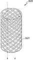
도 2는 일 실시 예에 따른 히터의 구조를 설명하기 위한 도면이다.
도 3은 일 실시 예에 따른 계단 평면을 설명하기 위한 도면이다.
도 4는 일 실시 예에 따른 전기 전도성 트랙들을 설명하기 위한 도면이다.
도 5는 일 실시 예에 따른 에어로졸 형성기질을 가열하기 위한 시스템을 설명하기 위한 도면이다.
도 6은 에어로졸 생성 장치의 일 예를 도시한 구성도이다.
도 7a 및 도 7b는 홀더의 일 예를 여러 측면에서 도시한 도면들이다.
도 8은 크래들의 일 예를 도시한 구성도이다.
도 9a 및 도 9b는 크래들의 일 예를 여러 측면에서 도시한 도면들이다.
도 10은 홀더가 크래들에 삽입되는 일 예를 도시한 도면이다.
도 11은 홀더가 크래들에 삽입된 상태에서 틸트되는 일 예를 도시한 도면이다.
도 12a 내지 도 12b는 홀더가 크래들에 삽입된 예들을 도시한 도면들이다.
도 13은 홀더 및 크래들이 동작하는 일 예를 설명하기 위한 흐름도이다.
도 14은 홀더가 동작하는 일 예를 설명하기 위한 흐름도이다.
도 15는 크래들이 동작하는 일 예를 설명하기 위한 흐름도이다.
도 16은 홀더에 궐련이 삽입된 일 예를 도시한 도면이다.
도 17a 및 도 17b는 궐련의 일 예를 도시한 구성도이다.
도 18a 내지 도 18f는 궐련의 냉각 구조물의 예들을 도시한 도면들이다.1 is a view for explaining the use of an aerosol generating device and a cigarette according to an embodiment.
2 is a view for explaining a structure of a heater according to an embodiment.
3 is a view for explaining a step plane according to an embodiment.
4 is a view for explaining electrically conductive tracks according to one embodiment.
5 is a diagram illustrating a system for heating an aerosol forming substrate in accordance with one embodiment.
6 is a configuration diagram showing an example of an aerosol generating apparatus.
7A and 7B are views showing various examples of the holder.
8 is a configuration diagram showing an example of a cradle.
9A and 9B are views showing various examples of the cradle.
10 is a view showing an example in which the holder is inserted into the cradle.
11 is a view showing an example in which the holder is tilted in a state of being inserted into the cradle.
12A to 12B are views showing examples in which the holder is inserted into the cradle.
13 is a flowchart for explaining an example in which the holder and the cradle operate.
14 is a flowchart for explaining an example in which the holder operates.
15 is a flowchart for explaining an example in which the cradle operates.
16 is a view showing an example in which a cigarette is inserted into a holder.
Figs. 17A and 17B are structural diagrams showing examples of cigarettes. Fig.
18A to 18F are views showing examples of the cooling structure of the cigarette.
본 실시 예들에서 사용되는 용어는 본 실시 예들에서의 기능을 고려하면서 가능한 현재 널리 사용되는 일반적인 용어들을 선택하였으나, 이는 당 분야에 종사하는 기술자의 의도 또는 판례, 새로운 기술의 출현 등에 따라 달라질 수 있다. 또한, 특정한 경우는 출원 인이 임의로 선정한 용어도 있으며, 이 경우 해당되는 부분에서 상세히 그 의미를 기재할 것이다. 따라서, 본 실시 예들에서 사용되는 용어는 단순한 용어의 명칭이 아닌, 그 용어가 가지는 의미와 본 실시 예들 전반에 걸친 내용을 토대로 정의되어야 한다.Although the terms used in the present embodiments have been selected in consideration of the functions in the present embodiments, it is possible to use the presently widely used general terms, but this may vary depending on the intention or circumstance of a person skilled in the art, the emergence of a new technique or the like. In addition, in certain cases, there may be a term arbitrarily selected by the applicant, in which case the meaning thereof will be described in detail. Therefore, the terms used in the embodiments should be defined based on the meaning of the term, not on the name of a simple term, but on the contents throughout the embodiments.
명세서 전체에서, 어떤 부분이 다른 부분과 연결되어 있다고 할 때, 이는 직접적으로 연결되어 있는 경우뿐만 아니라, 그 중간에 다른 소자를 사이에 두고 전기적으로 연결되어 있는 경우도 포함한다. 또한 어떤 부분이 어떤 구성요소를 포함한다고 할 때, 이는 특별히 반대되는 기재가 없는 한 다른 구성요소를 제외하는 것이 아니라 다른 구성요소를 더 포함할 수 있는 것을 의미한다. 또한, 본 실시 예들에서 기재된 구성요소들의 용어는 적어도 하나의 기능이나 동작을 프로세싱하는 단위를 의미하며, 이는 하드웨어 또는 소프트웨어로 구현되거나 하드웨어와 소프트웨어의 결합으로 구현될 수 있다.Throughout the specification, when a part is connected to another part, it includes not only a case where it is directly connected but also a case where the part is electrically connected with another part in between. Also, when a component includes an element, it is understood that the element may include other elements, not the exclusion of any other element unless specifically stated otherwise. Furthermore, the terms of the components described in these embodiments refer to a unit for processing at least one function or operation, which may be implemented in hardware or software, or a combination of hardware and software.
본 실시 예들에서 “에어로졸 생성 물질”은 에어로졸을 발생시킬 수 있는 물질을 의미하며, 에어로졸 형성기질을 의미할 수도 있다. 에어로졸은 휘발성 화합물을 포함할 수 있다. 에어로졸 생성물질은 고체 또는 액체일 수 있다.In the present embodiments, the term " aerosol producing material " means a material capable of generating an aerosol, and may mean an aerosol forming substrate. Aerosols may include volatile compounds. The aerosol producing material may be solid or liquid.
예를 들면, 고체의 에어로졸 생성물질은 판상엽 담배, 각초, 재구성 담배 등 담배 원료를 기초로하는 고체 물질을 포함할 수 있으며, 액체의 에어로졸 생성물질은 니코틴, 담배 추출물 및 다양한 향미제를 기초로하는 액체 물질을 포함할 수 있다. 물론 상기 예시에 제한되지 않는다.For example, solid aerosol producing materials may include solid materials based on tobacco raw materials, such as tobacco leaves, tobacco plants, reconstituted tobacco, etc., and aerosol producing liquids may be based on nicotine, tobacco extract and various flavors ≪ / RTI > Of course, the present invention is not limited to the above example.
본 실시 예들에서 “에어로졸 생성 장치”는, 사용자의 입을 통해 사용자의 폐로 직접적으로 흡입 가능한 에어로졸을 발생시키기 위해 에어로졸 생성 물질을 이용하여 에어로졸을 생성하는 장치일 수 있다. 예를 들면, 에어로졸 발생 장치는 사용자가 손으로 쥘 수 있는 홀더(holder)일 수 있다.In the present embodiments, the "aerosol generating device" may be an apparatus for generating an aerosol using an aerosol generating material to generate an aerosol that can be sucked directly into the user's lungs through the wearer's mouth. For example, the aerosol generating device may be a holder that the user can hold by hand.
도 1은 일 실시 예에 따른 에어로졸 생성 장치 및 궐련의 사용을 설명하기 위한 도면이다.1 is a view for explaining the use of an aerosol generating device and a cigarette according to an embodiment.
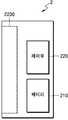
도 1을 참조하면, 에어로졸 생성 장치(1)(이하, '홀더'라고 함)는 원통 형상으로 제작될 수 있으나 이에 제한되지 아니한다. 사용자는 홀더(1)를 기존의 일반 궐련과 같이, 파지하여 사용할 수 있다.Referring to FIG. 1, the aerosol generating apparatus 1 (hereinafter, referred to as 'holder') may be manufactured in a cylindrical shape, but is not limited thereto. The user can grip and use the
홀더(1)의 내부에는 배터리에 의해 공급된 전력에 의해 전기적으로 가열되는 히터(100)가 구비된다. 히터(100)는 홀더(1)의 일 말단에 형성된 빈 공간(또는 캐비티)(20) 내에 위치되도록 고정되어 있다. 궐련(3)은 홀더(1)의 빈 공간(20) 내로 수용 가능하며, 수용된 경우 히터(100)는 궐련(3)의 일 말단에 마련된 에어로졸 생성물질(21)의 내부를 관통할 수 있다. 한편, 궐련(3)은 담배, 연초 등과 같은 다양한 용어들로도 사용될 수 있다. 궐련(3)은 일 단에는 에어로졸 생성물질(21)이 패키징되고 타 단에는 필터(22)가 구비된 흡연용 물품으로서, 에어로졸 생성물질(21)과 필터(22)는 서로 맞닿도록 래퍼로 감싸져 있다.Inside the
궐련(3) 내의 에어로졸 생성물질(21)은 가열된 히터(100)에 의하여 온도가 상승하고, 이에 따라 에어로졸이 생성된다. 생성된 에어로졸은 궐련(3)의 필터(22)를 통하여 사용자에게 전달될 수 있다. 여기서, 히터(100)는 에어로졸 생성물질(21)을 연소되지 않는 온도까지 가열할 수 있다. 다시 말해, 히터(100)가 에어로졸 생성물질(21)의 발화점보다 낮은 온도로 에어로졸 생성물질(21)을 가열함으로써, 에어로졸 생성물질(21)로부터 에어로졸이 발생될 수 있다.The
히터(100)는 배터리로부터 공급된 전력에 의하여 전기적으로 가열된다. 도 1에 도시된 히터(100)는 에어로졸 생성물질(21)로 삽입되는 일 말단이 예각으로 마감된, 하나의 봉침(needle) 형태일 수 있다. 하지만, 이에 제한되지 않고, 히터(100)는 관형 히터(100), 복수 개의 봉침형 히터(100)들 등 다양한 형태로 구현될 수 있고, 히터(100)의 일 말단은 뾰족한 형태 대신에 완곡한 다른 형태 등으로도 구현될 수 있다. 즉, 히터(100)는, 상술한 기능을 수행할 수 있는 경우라면, 그 형태는 제한 없이 채용될 수 있다.The
도 2는 일 실시 예에 따른 히터(100)의 구조를 설명하기 위한 도면이다.2 is a view for explaining a structure of the
일 실시 예에 따른, 히터(100)는 가열부(215), 가열부(215)의 일부를 감싸는 제 1 시트(225), 제 1 시트(225)를 보호하는 제 2 시트(235) 및 코팅층(245)을 포함할 수 있다.According to one embodiment, the
일 실시 예에 따른, 가열부(215)는 봉침형 구조를 가질 수 있다. 또한, 가열부(215)는 기저부 및 침첨부를 포함할 수 있다. 예를 들어, 가열부(215)의 기저부는 원통형으로 형성될 수 있으나 이에 제한되지 않는다. 또한, 가열부(215)의 침첨부는, 에어로졸 형성기질에 삽입이 용이하도록 기저부의 일말 단에 형성될 수 있다. 이 때, 기저부와 침첨부는 일체로서 형성될 수 있다. 또는, 기저부와 침첨부는 별개로 제작된 후 접합될 수 있다.According to one embodiment, the heating portion 215 may have a needle-like structure. Also, the heating portion 215 may include a base portion and an acupuncture. For example, the base portion of the heating portion 215 may be formed in a cylindrical shape, but is not limited thereto. In addition, the immersion of the heating unit 215 can be formed at one end of the base to facilitate insertion into the aerosol forming substrate. At this time, the base and the needle can be integrally formed. Alternatively, the base and needle attachment may be fabricated separately and then joined.
가열부(215)는 열 전도성 물질을 포함할 수 있다. 예를 들어, 열 전도성 물질은 알루미나(Alumina) 또는 지르코니아(zirconia) 등을 포함하는 세라믹(ceramic), 아노다이징(anodizing)된 금속, 코팅된 금속, 폴리이미드(polyimide: PI) 등을 포함할 수 있으나 이에 제한되지 아니한다.The heating portion 215 may include a thermally conductive material. For example, the thermally conductive material may include ceramic, anodized metal, coated metal, polyimide (PI), etc., including alumina or zirconia But is not limited thereto.
일 실시 예에 따른, 제 1 시트(225)는 가열부(215)의 적어도 일부를 감쌀 수 있다. 예를 들어, 제 1 시트(225)는 히터(100)의 기저부의 외주면의 적어도 일부를 감쌀 수 있다. 제 1 시트(225)의 양 단면 각각에는 전기 전도성 트랙이 형성될 수 있다.According to one embodiment, the first sheet 225 may cover at least a portion of the heating portion 215. For example, the first sheet 225 may cover at least a portion of the outer circumferential surface of the base portion of the
또한, 제 1 시트(225)의 양 단면 중 일 면에 형성된 제 1 전기 전도성 트랙은 배터리로부터 전력을 공급 받을 수 있다. 제 1 전기 전도성 트랙에 전류가 흐름에 따라, 전기 전도성 트랙의 온도가 상승할 수 있다. 또한, 전기 전도성 트랙의 온도가 상승함에 따라, 전기 전도성 트랙에 인접한 가열부(215)에 열이 전달됨으로써 가열부(215)가 가열될 수 있다.Further, the first electrically conductive track formed on one side of both ends of the first sheet 225 can be supplied with power from the battery. As current flows through the first electrically conductive track, the temperature of the electrically conductive track can rise. Also, as the temperature of the electrically conductive track rises, the heating portion 215 can be heated by transferring heat to the heating portion 215 adjacent to the electrically conductive track.
제 1 전기 전도성 트랙의 저항의 소비 전력에 따라, 제 1 전기 전도성 트랙의 가열 온도가 결정될 수 있다. 또한, 제 1 전기 전도성 트랙의 저항의 소비 전력에 기초하여, 제 1 전기 전도성 트랙의 저항 값이 설정될 수 있다.Depending on the power consumption of the resistance of the first electrically conductive track, the heating temperature of the first electrically conductive track can be determined. Further, based on the power consumption of the resistance of the first electrically conductive track, the resistance value of the first electrically conductive track can be set.
예를 들어, 제 1 전기 전도성 트랙의 저항 값은 상온 섭씨 25도에서, 0.5 ohm와 1.2 ohm 사이의 값을 가질 수 있으나 이에 제한되지 아니한다. 이 때, 제 1 전기 전도성 트랙의 저항 값은 제 1 전기 전도성 트랙의 구성 물질, 길이, 너비, 두께 및 패턴에 의하여 설정될 수 있다.For example, the resistance value of the first electrically conductive track may have a value between 0.5 ohms and 1.2 ohms at 25 degrees Celsius, but is not limited thereto. At this time, the resistance value of the first electrically conductive track can be set by the material, length, width, thickness and pattern of the first electrically conductive track.
제 1 전기 전도성 트랙은 저항 온도 계수 특성에 따라, 온도가 상승할수록 내부 저항의 크기가 증가할 수 있다. 예를 들어, 소정의 온도 구간에서 제 1 전기 전도성 트랙의 온도와 저항의 크기는 비례할 수 있다.The first electrically conductive track may have an increased internal resistance as the temperature rises, depending on the resistance temperature coefficient characteristic. For example, the temperature of the first electrically conductive track and the magnitude of the resistance may be proportional to each other in a predetermined temperature range.
예를 들어, 제 1 전기 전도성 트랙에 소정의 전압이 인가되고, 제 1 전기 전도성 트랙에 흐르는 전류가 전류 감지기를 통하여 측정될 수 있다. 또한, 측정된 전류와 인가된 전압의 비율을 통하여 제 1 전기 전도성 트랙의 저항이 산출될 수 있다. 산출된 저항에 기초하여, 제 1 전기 전도성 트랙의 저항 온도 계수 특성에 따라, 제 1 전기 전도성 트랙 또는 가열부(215)의 온도가 추정될 수 있다.For example, a predetermined voltage may be applied to the first electrically conductive track, and the current flowing through the first electrically conductive track may be measured through the current sensor. Further, the resistance of the first electrically conductive track can be calculated through the ratio of the measured current to the applied voltage. Based on the calculated resistance, the temperature of the first electrically conductive track or heating portion 215 can be estimated, depending on the resistance temperature coefficient characteristic of the first electrically conductive track.
예를 들어, 제 1 전기 전도성 트랙은 텅스텐, 금, 백금, 은 구리, 니켈 팔라듐, 또는 이들의 조합을 포함할 수 있다. 또한, 제 1 전기 전도성 트랙은 적절한 도핑재에 의해 도핑될 수 있고, 합금을 포함할 수 있다.For example, the first electrically conductive track may comprise tungsten, gold, platinum, silver copper, nickel palladium, or combinations thereof. Also, the first electrically conductive track may be doped by a suitable dopant and may comprise an alloy.
제 1 시트(225)의 양 단면 중 일 면 또는 다른 일 면에는 가열부(215)의 온도를 감지하기 위해 이용되는 저항 온도 계수 특성을 가지는 제 2 전기 전도성 트랙을 포함할 수 있다. 제 2 전기 전도성 트랙은 저항 온도 계수 특성에 따라, 온도가 상승할수록 내부 저항의 크기가 증가할 수 있다. 예를 들어, 소정의 온도 구간에서 제 2 전기 전도성 트랙의 온도와 저항의 크기는 비례할 수 있다.The first sheet 225 may include a second electrically conductive track having a resistance temperature coefficient characteristic used to sense the temperature of the heating section 215 on one side or both sides of both sides. The second electrically conductive track may have an increased internal resistance as the temperature rises, depending on the resistance temperature coefficient characteristic. For example, the temperature of the second electrically conductive track and the magnitude of the resistance may be proportional in a predetermined temperature interval.
제 2 전기 전도성 트랙은 가열부(215)와 인접하게 배치될 수 있다. 이에 따라, 가열부(215)의 온도가 상승할 경우, 인접한 제 2 전기 전도성 트랙의 온도도 상승할 수 있다. 제 2 전기 전도성 트랙에 소정의 전압이 인가되고, 제 2 전기 전도성 트랙에 흐르는 전류가 전류 감지기를 통하여 측정될 수 있다. 또한, 측정된 전류와 인가된 전압의 비율을 통하여 제 2 전기 전도성 트랙의 저항이 결정될 수 있다. 결정된 저항에 기초하여, 제 2 전기 전도성 트랙의 저항 온도 계수 특성에 따라, 가열부(215)의 온도가 결정될 수 있다.The second electrically conductive track may be disposed adjacent to the heating portion 215. Accordingly, when the temperature of the heating section 215 rises, the temperature of the adjacent second electrically conductive track can also rise. A predetermined voltage is applied to the second electrically conductive track and the current flowing in the second electrically conductive track can be measured through the current sensor. Also, the resistance of the second electrically conductive track can be determined through the ratio of the measured current to the applied voltage. Based on the determined resistance, the temperature of the heating section 215 can be determined according to the resistance temperature coefficient characteristic of the second electrically conductive track.
제 2 전기 전도성 트랙의 온도에 따라 제 2 전기 전도성 트랙의 저항 값이 변할 수 있다. 따라서, 제 2 전기 전도성 트랙의 저항 값의 변화에 기초하여, 제 2 전기 전도성 트랙의 온도 변화를 측정할 수 있다. 예를 들어, 제 2 전기 전도성 트랙의 저항 값은 상온 섭씨 25도에서 7 ohm와 18 ohm 사이의 저항 값을 가질 수 있으나 이에 제한되지 아니한다. 이 때, 제 2 전기 전도성 트랙의 저항 값은 제 2 전기 전도성 트랙의 구성 물질, 길이, 너비, 두께 및 패턴에 의하여 설정될 수 있다.The resistance value of the second electrically conductive track can vary depending on the temperature of the second electrically conductive track. Thus, based on the change in the resistance value of the second electrically conductive track, the temperature change of the second electrically conductive track can be measured. For example, the resistance value of the second electrically conductive track may have a resistance value between 7 ohms and 18 ohms at 25 degrees Celsius, but is not limited thereto. At this time, the resistance value of the second electrically conductive track can be set by the material, length, width, thickness and pattern of the second electrically conductive track.
예를 들어, 제 2 전기 전도성 트랙은 텅스텐, 금, 백금, 은 구리, 니켈 팔라듐, 또는 이들의 조합을 포함할 수 있다. 또한, 제 2 전기 전도성 트랙은 적절한 도핑재에 의해 도핑되거나 합금을 포함할 수 있다.For example, the second electrically conductive track may comprise tungsten, gold, platinum, silver copper, nickel palladium, or combinations thereof. In addition, the second electrically conductive track may be doped with an appropriate dopant or may comprise an alloy.
제 1 전기 전도성 트랙은 전기적 접속부를 통하여 배터리와 연결될 수 있다. 상술한 바와 같이 배터리로부터 전력을 공급받음에 따라, 제 1 전기 전도성 트랙의 온도가 증가할 수 있다.The first electrically conductive track may be connected to the battery through an electrical connection. As described above, as the electric power is supplied from the battery, the temperature of the first electrically conductive track may increase.
제 2 전기 전도성 트랙은 DC(direct current) 전압이 인가되는 전기적 접속부를 포함할 수 있다. 제 2 전기 전도성 트랙의 전기적 접속부는 제 1 전기 전도성 트랙의 전기적 접속부와 분리된다. 또한, 제 2 전기 전도성 트랙에 인가되는 DC 전압이 일정한 경우, 제 2 전기 전도성 트랙의 저항에 기초하여 제 2 전기 전도성 트랙에 흐르는 전류의 크기가 결정될 수 있다.The second electrically conductive track may include an electrical connection to which a direct current (DC) voltage is applied. The electrical connection of the second electrically conductive track is separated from the electrical connection of the first electrically conductive track. Further, when the DC voltage applied to the second electrically conductive track is constant, the magnitude of the current flowing through the second electrically conductive track can be determined based on the resistance of the second electrically conductive track.
제 2 전기 전도성 트랙은 OP Amp(Operating Amplifier)와 연결될 수 있다. OP Amp는 외부로부터 DC 전력을 공급받는 전력 공급부, 제 2 전기 전도성 트랙과 전기적으로 연결되고 DC 전압 및/또는 전류를 인가 받는 입력부, 및 입력부에 인가된 DC 전압 및/또는 전류에 기초하여 신호를 출력하는 출력부를 포함할 수 있다.The second electrically conductive track may be coupled to an OP Amp (Operating Amplifier). The OP Amp includes a power supply supplied with DC power from the outside, an input portion electrically connected to the second electrically conductive track and receiving the DC voltage and / or current, and a signal based on the DC voltage and / or current applied to the input portion. And an output unit for outputting the output signal.
OP Amp는 전력 공급부를 통하여 DC 전압을 인가받을 수 있다. 또한, OP Amp는 입력부를 통하여 DC 전압을 인가받을 수 있다. 이 때, OP Amp의 입력부를 통하여 인가되는 DC 전압의 크기 및 OP Amp의 전력 공급부를 통하여 인가되는 DC 전압의 크기는 동일할 수 있다. 또한, OP Amp의 입력부에 인가되는 DC 전압은 제 2 전기 전도성 트랙의 전기적 접속부에 인가되는 DC 전압과 동일할 수 있다.The OP Amp can receive the DC voltage through the power supply. Also, the OP Amp can receive the DC voltage through the input unit. At this time, the magnitude of the DC voltage applied through the input portion of the OP Amp and the magnitude of the DC voltage applied through the power supply portion of the OP Amp may be the same. Also, the DC voltage applied to the input of the OP Amp may be the same as the DC voltage applied to the electrical connection of the second electrically conductive track.
제 2 전기 전도성 트랙의 전기적 접속부 및 OP Amp의 입력부는 제 1 전기 전도성 트랙의 전기적 접속부와 분리될 수 있다The electrical connections of the second electrically conductive track and the input of the OP Amp may be separate from the electrical connections of the first electrically conductive track
제 2 전기 전도성 트랙의 온도가 변함에 따라, 제 2 전기 전도성 트랙의 저항 값이 변할 수 있다. 따라서, 제 2 전기 전도성 트랙은 온도를 제어 변수로 하는 가변 저항으로서 기능을 하고, 제 2 전기 전도성 트랙의 저항 값이 변함에 따라, 제 2 전기 전도성 트랙과 전기적으로 연결된 OP Amp의 입력부에 유입되는 전류가 변한다. 제 2 전기 전도성 트랙의 저항 값이 증가함에 따라, 제 2 전기 전도성 트랙과 전기적으로 연결된 OP Amp의 입력부에 유입되는 전류가 감소한다. 이 때, 제 2 전기 전도성 트랙의 저항 값이 변하여도, OP Amp의 입력부에 인가되는 DC 전압은 일정할 수 있다.As the temperature of the second electrically conductive track changes, the resistance value of the second electrically conductive track may change. Thus, the second electrically conductive track functions as a variable resistor with the temperature as a control variable, and as the resistance value of the second electrically conductive track changes, it flows into the input of the OP amp electrically connected to the second electrically conductive track The current changes. As the resistance value of the second electrically conductive track increases, the current flowing into the input of the OP Amp electrically connected to the second electrically conductive track decreases. At this time, even if the resistance value of the second electrically conductive track is changed, the DC voltage applied to the input portion of the OP Amp can be constant.
OP Amp의 입력부에 유입되는 전류가 변함에 따라, OP Amp의 출력부에서 출력되는 신호의 전압 및/또는 전류가 변할 수 있다. 예를 들어, OP Amp의 입력 전류가 증가함에 따라 OP Amp의 출력 전압이 증가할 수 있다. 다른 일 예로서, OP Amp의 입력 전류가 증가함에 따라 OP Amp의 출력 전압이 감소할 수 있다.As the current flowing into the input portion of the OP Amp changes, the voltage and / or current of the signal output from the output portion of the OP Amp may change. For example, as the input current of the OP Amp increases, the output voltage of the OP Amp may increase. As another example, as the input current of the OP Amp increases, the output voltage of the OP Amp may decrease.
또한, OP Amp의 입력부에 일정한 DC 전압이 인가될 때, 제 2 전기 전도성 트랙의 온도와 저항 값의 관계, 제 2 전기 전도성 트랙의 저항 값과 OP Amp에 인가되는 입력 전류의 관계, 및 OP Amp의 입력 전류 및 출력 전압의 관계는 실험적으로 획득되거나 설정될 수 있다. 따라서, OP Amp의 출력 전압 및/또는 출력 전압의 변화를 측정하여, 제 2 전기 전도성 트랙의 온도 및/또는 온도의 변화를 감지할 수 있다.Further, when a constant DC voltage is applied to the input portion of the OP Amp, the relationship between the temperature and the resistance value of the second electrically conductive track, the relationship between the resistance value of the second electrically conductive track and the input current applied to the OP Amp, The relationship between the input current and the output voltage of the inverter can be experimentally obtained or set. Thus, changes in the output voltage and / or the output voltage of the OP Amp can be measured to detect changes in the temperature and / or temperature of the second electrically conductive track.
예를 들어, OP Amp는 입력부에 유입되는 입력 전류가 증가함에 따라, OP Amp의 출력부의 전압이 증가하는 특성을 가질 수 있다. 이 경우, 제 1 전기 도성 트랙에 전원이 공급됨에 따라 히터의 온도가 증가한다. 이에 따라, 제 2 전기 전도성 트랙의 온도는 증가한다. 이 때, 제 2 전기 전도성 트랙의 저항이 증가함으로 인하여, OP Amp의 입력부에 인가되는 입력 전류의 크기가 감소할 수 있다. 따라서, OP Amp의 출력부의 전압이 감소한다. 반대로, 제 1 전기 전도성 트랙에 전력 공급이 차단되거나 제 1 전기 전도성 트랙의 공급 전력이 감소하여, 히터의 온도가 감소함에 따라, OP Amp의 출력부의 전압이 증가한다.For example, the OP Amp may have a characteristic in which the voltage of the output portion of the OP Amp increases as the input current flowing into the input portion increases. In this case, the temperature of the heater increases as power is supplied to the first electroconductive track. As a result, the temperature of the second electrically conductive track increases. At this time, since the resistance of the second electrically conductive track is increased, the magnitude of the input current applied to the input portion of the OP Amp can be reduced. Thus, the voltage at the output of the OP Amp decreases. Conversely, as the power supply to the first electrically conductive track is cut off or the supply power of the first electrically conductive track decreases, the voltage at the output of the OP Amp increases as the temperature of the heater decreases.
다른 일 예로서, OP Amp는 입력부에 유입되는 입력 전류가 증가 함에 따라 출력부의 전압이 감소하는 특성을 가질 수 있다. 이 경우, 제 1 전기 도성 트랙에 전원이 공급됨에 따라 히터의 온도가 증가한다. 이에 따라, 제 2 전기 전도성 트랙의 온도는 증가한다. 이 때, 제 2 전기 전도성 트랙의 저항이 증가함으로 인하여, OP Amp의 입력부에 인가되는 입력 전류의 크기가 감소할 수 있다. 따라서, OP Amp의 출력부의 전압이 증가한다. 반대로, 제 1 전기 전도성 트랙에 전력 공급이 차단되거나 제 1 전기 전도성 트랙의 공급 전력이 감소하여, 히터의 온도가 감소함에 따라, OP Amp의 출력부의 전압이 감소한다.As another example, the OP Amp may have a characteristic in which the voltage of the output portion decreases as the input current flowing into the input portion increases. In this case, the temperature of the heater increases as power is supplied to the first electroconductive track. As a result, the temperature of the second electrically conductive track increases. At this time, since the resistance of the second electrically conductive track is increased, the magnitude of the input current applied to the input portion of the OP Amp can be reduced. Thus, the voltage at the output of the OP Amp increases. Conversely, as the power supply to the first electrically conductive track is cut off or the supply power of the first electrically conductive track decreases, the voltage of the output of the OP Amp decreases as the temperature of the heater decreases.
OP Amp의 출력부는 프로세서와 연결될 수 있다. 예를 들어, 프로세서는 MCU(Micro Controller Unit)일 수 있다. 프로세서는 OP Amp의 출력 전압에 기초하여, 제 2 전기 전도성 트랙 또는 가열부의 온도를 감지할 수 있다. 또한, 프로세서는 가열부의 온도에 기초하여 제 1 전기 전도성 트랙에 공급되는 공급 전압을 조정할 수 있다.The output of the OP Amp can be connected to the processor. For example, the processor may be an MCU (Micro Controller Unit). The processor can sense the temperature of the second electrically conductive track or heating section based on the output voltage of the OP Amp. The processor can also adjust the supply voltage supplied to the first electrically conductive track based on the temperature of the heating section.
일 실시 예에 따른, 제 1 전기 전도성 트랙 및 제 2 전기 전도성 트랙은 제 1 시트(225)의 양 단면 각각에 형성될 수 있다. 예를 들어, 제 1 전기 전도성 트랙은 제 1 시트(225)의 양 단면 중 가열부(215)와 접촉하는 일면에 포함되고, 제 2 전기 전도성 트랙은 다른 일면에 포함될 수 있다. 다른 일 예로서, 제 2 전기 전도성 트랙은 제 1 시트(225)의 양 단면 중 가열부(215)와 접촉하는 일면에 포함되고, 제 1 전기 전도성 트랙은 다른 일면에 포함될 수 있다.According to one embodiment, the first electrically conductive track and the second electrically conductive track may be formed on each of both sides of the first sheet 225. For example, the first electrically conductive track may be included on one side of the first sheet 225 that contacts the heating portion 215, and the second electrically conductive track may be included on the other side. As another example, the second electrically conductive track may be included on one side of the first sheet 225 that contacts the heating portion 215, and the first electrically conductive track may be included on the other side.
다른 일 실시 예에 따른, 제 1 전기 전도성 트랙 및 제 2 전기 전도성 트랙은 제 1 시트(225)의 양 단면 중 동일한 일면에 포함될 수 있다. 예를 들어, 제 1 전기 전도성 트랙 및 제 2 전기 전도성 트랙은 제 1 시트(225)의 양 단면 중 가열부(215)와 접촉하는 일면에 포함될 수 있다. 다른 일 예로서, 제 1 전기 전도성 트랙 및 제 2 전기 전도성 트랙은 제 1 시트(225)의 양 단면 중 가열부(215)와 접촉하지 않는 일면에 포함될 수 있다.According to another embodiment, the first electrically conductive track and the second electrically conductive track may be included on the same one of both sides of the first sheet 225. For example, the first electrically conductive track and the second electrically conductive track may be included on one side of the first sheet 225 that contacts the heating section 215 on both sides. As another example, the first electrically conductive track and the second electrically conductive track may be included on one side of the first sheet 225 that is not in contact with the heating portion 215 on both sides.
예를 들어, 제 1 시트(225)는 세라믹 합성 물질로 구성된 그린 시트(green sheet)일 수 있다. 이 때, 세라믹은 알루미나, 지르코나 등의 화합물을 포함할 수 있으나 이에 제한되지 아니한다.For example, the first sheet 225 may be a green sheet composed of a ceramic composite material. At this time, the ceramics may include, but not limited to, alumina, zirconia and the like.
일 실시 예에 따른, 제 2 시트(235)는 제 1 시트(225)의 적어도 일부를 감쌀 수 있다. 또한, 제 2 시트(235)는 강성을 가질 수 있다.According to one embodiment, the second sheet 235 may wrap at least a portion of the first sheet 225. Further, the second sheet 235 may have rigidity.
따라서, 제 2 시트(235)는 히터(100)가 에어로졸 형성기질에 삽입될 때 제 1 시트(225)와 전기 전도성 트랙들을 보호한다.Thus, the second sheet 235 protects the first sheet 225 and the electrically conductive tracks when the
예를 들어, 제 2 시트(235)는 세라믹 합성 물질로서 구성된 그린 시트일 수 있다. 이 때, 세라믹은 알루미나, 지르코나 등의 화합물을 포함할 수 있으나 이에 제한되지 아니한다.For example, the second sheet 235 may be a green sheet configured as a ceramic composite material. At this time, the ceramics may include, but not limited to, alumina, zirconia and the like.
제 2 시트(235)는, 히터(100)가 궐련(3)에 용이하게 삽입되도록 하고 히터(100)의 내구성을 향상시키기 위하여, 유약(glaze)으로 코팅될 수 있다. 제 2 시트(235)가 유약으로 코팅됨에 따라, 제 2 시트(235)의 강성은 증가할 수 있다.The second sheet 235 can be coated with a glaze to easily insert the
가열부(215), 제 1 시트(225) 및 제 2 시트(235) 각각은, 동일한 재료군, 예를 들어, 알루미나, 지르코나 등의 화합물인 세라믹 등에서 선택적으로 제작될 수 있다.Each of the heating unit 215, the first sheet 225 and the second sheet 235 can be selectively manufactured from the same material group, for example, ceramic such as alumina, zirconia or the like.
또한, 제 1 전기 전도성 트랙 및 제 2 전기 전도성 트랙 각각은 동일한 재료군, 예를 들어, 텅스텐, 금, 백금, 은 구리, 니켈 팔라듐, 또는 이들의 조합 등에서 선택적으로 제작될 수 있다. 이 때, 제 1 전기 전도성 트랙의 구성 물질 및 제 2 전기 전도성 트랙의 구성 물질이 동일한 경우라도, 제 1 전기 전도성 트랙 및 제 2 전기 전도성 트랙의 저항 값은, 트랙의 길이, 너비, 또는 패턴의 차이로 인하여 서로 다를 수 있다.In addition, each of the first electrically conductive track and the second electrically conductive track may be selectively made of the same material group, for example, tungsten, gold, platinum, silver copper, nickel palladium, or combinations thereof. At this time, even if the constituent material of the first electrically conductive track and the constituent material of the second electrically conductive track are the same, the resistance values of the first electrically conductive track and the second electrically conductive track are not limited to the length, May be different due to differences.
일 실시 예에 따라, 가열부(215)의 가열을 위한 제 1 전기 전도성 트랙은 가열부(215), 제 1 시트(225) 또는 제 2 시트(235)에 포함될 수 있다. 또는, 제 1 전기 전도성 트랙과 같이 가열부(215)의 가열을 위한 복 수의 전기 전도성 트랙들이 가열부(215), 제 1 시트(225) 및 제 2 시트(235) 중 적어도 하나에 포함될 수 있다.According to one embodiment, a first electrically conductive track for heating the heating portion 215 may be included in the heating portion 215, the first sheet 225, or the second sheet 235. Alternatively, multiple electrically conductive tracks for heating of the heating portion 215, such as a first electrically conductive track, may be included in at least one of the heating portion 215, the first sheet 225 and the second sheet 235 have.
일 실시 예에 따라, 가열부(215)의 온도를 감지하기 위한 제 2 전기 전도성 트랙은 가열부(215), 제 1 시트(225) 또는 제 2 시트(235)에 포함될 수 있다. 또는, 제 2 전기 전도성 트랙과 같이 가열부(215)의 온도를 감지하기 위한 복수의 전기 전도성 트랙들이 가열부(215), 제 1 시트(225) 및 제 2 시트(235) 중 적어도 하나에 포함될 수 있다.According to one embodiment, a second electrically conductive track for sensing the temperature of the heating portion 215 may be included in the heating portion 215, the first sheet 225, or the second sheet 235. Alternatively, a plurality of electrically conductive tracks for sensing the temperature of the heating portion 215, such as a second electrically conductive track, may be included in at least one of the heating portion 215, the first sheet 225 and the second sheet 235 .
일 실시 예에 따른, 가열부(215)의 가열을 위한 제 1 전기 전도성 트랙 및 가열부(215)의 온도를 감지하기 위한 제 2 전기 전도성 트랙은 가열부(215), 제 1 시트(225) 및 제 2 시트(235) 중 동일한 부분에 각각 포함될 수 있다. 또는, 가열부(215)의 가열을 위한 제 1 전기 전도성 트랙 및 가열부(215)의 온도를 감지하기 위한 제 2 전기 전도성 트랙은 가열부(215), 제 1 시트(225) 및 제 2 시트(235) 중 서로 다른 부분에 각각 포함될 수 있다.A first electrically conductive track for heating the heating portion 215 and a second electrically conductive track for sensing the temperature of the heating portion 215 according to one embodiment includes a heating portion 215, a first sheet 225, And the second sheet 235, respectively. Alternatively, the first electrically conductive track for heating the heating portion 215 and the second electrically conductive track for sensing the temperature of the heating portion 215 may include a heating portion 215, a first sheet 225, (235), respectively.
일 실시 예에 따른, 히터(100)에 코팅층(245)이 구비됨에 따라, 가열부(215), 제 1 시트(225) 및 제 2 시트(235)를 포함하는 적층 구조에 의해 형성되는 계단 표면(stepped surface)이 평탄화 될 수 있다. 예를 들어, 제 1 시트(225)의 가장자리 및 제 2 시트(235)의 가장자리가 일치하지 않거나 제 1 시트(225)와 제 2 시트(235)의 두께로 인하여, 계단 평면(255)이 형성될 수 있다. 예를 들어, 계단 평면(255)으로 인하여, 히터(100)가 에어로졸 형성기질에 삽입될 때 마찰이 증가할 수 있다. 또한, 계단 평면(255)에 에어로졸 형성기질로부터 생성되는 증착물 또는 잔류물이 끼어 히터(100)가 오염되고, 이로 인하여 히터(100)의 열 전도율이 감소하는 등 히터(100)의 성능이 저하될 수 있다. 따라서, 계단 평면(255)을 평탄화하기 위하여, 히터(100)의 외면에 코팅층(245)이 형성될 수 있다.The stepped surface formed by the laminated structure including the heating portion 215, the first sheet 225 and the second sheet 235 as the coating layer 245 is provided on the
코팅층(245)으로 형성되는 히터(100)의 외면은 가열부(215)의 침첨부에 대응하는 코팅층(245)의 침첨부, 및 가열부(215)의 기저부, 제 1 시트(225) 및 제 2 시트(235)에 대응하는 코팅층(245)의 기저부를 포함할 수 있다. 이 때, 코팅층(245)의 침첨부로부터 코팅층(245)의 기저부로 이어지는 부분은, 계단 평면(255)이나 요철부가 없는 매끄러운 외면을 가질 수 있다.The outer surface of the
코팅층(245)은 내열성 조성물을 포함할 수 있다. 예를 들어, 코팅층(245)은 유리막 코팅층, 테플론 코팅층 및 더몰론 코팅층의 단일 코팅층을 포함할 수 있으나 이에 제한되지 아니한다. 또한, 코팅층(245)은 유리막 코팅층, 테플론 코팅층 및 더몰론 코팅층 중 두 개 이상의 조합으로 구성된 복합 코팅층을 포함할 수 있으나 이에 제한되지 아니한다.The coating layer 245 may comprise a heat resistant composition. For example, the coating layer 245 may include, but is not limited to, a single coating layer of a glass coating layer, a Teflon coating layer, and a molar coating layer. In addition, the coating layer 245 may include, but is not limited to, a composite coating layer composed of a combination of two or more of a glass coating layer, a Teflon coating layer, and a molar coating layer.
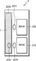
도 3은 일 실시 예에 따른 도 2의 계단 평면(도 2의 255)을 설명하기 위한 도면이다.FIG. 3 is a view for explaining the step plane (255 in FIG. 2) of FIG. 2 according to one embodiment.
도 3에는 히터의 기저부와 기저부를 감싸는 제 1 시트(225) 및 제 2 시트(235)의 계단 평면(도 2의 255)이 형성될 수 있다.In FIG. 3, a step plane (255 in FIG. 2) of the first sheet 225 and the second sheet 235 surrounding the base and the base of the heater may be formed.
예를 들어, 제 1 시트(225)의 두께에 의하여 테라스(terrace)(221)가 형성될 수 있다. 또한, 제 2 시트(235)의 두께에 의하여 테라스(231)가 형성될 수 있다.For example, a
또한, 가열대의 침첨부와 기저부의 경계선과 제 1 시트(225)의 가장자리가 일치하지 않아 스텝(step)(211)이 형성될 수 있다. 또한, 제 1 시트(225)의 가장자리와 제 2 시트(235)의 가장자리가 일치하지 않아 스텝(222)이 형성될 수 있다.In addition, a
이 때, 계단 평면(도 2의 255)으로 인하여 형성되는 공간에 에어로졸 형성기질의 증착물 또는 찌꺼기가 끼어 히터(100)가 오염될 수 있다. 도 1에서 상술한 바와 같이 코팅층(도 2의 245)은 계단 평면(도 2의 255)으로 생긴 틈을 채워, 계단 평면(도 2의 255)을 평탄화 할 수 있다.At this time, the space formed by the step plane (255 in FIG. 2) may contaminate the deposition material or residue of the aerosol forming substrate to contaminate the
도 4는 일 실시 예에 따른 전기 전도성 트랙들(320, 340)을 설명하기 위한 도면이다.4 is a diagram for describing electrically conductive tracks 320 and 340 according to one embodiment.
제 1 시트(225)의 제 1 면(310)은 제 1 전기 전도성 트랙(320)을 포함하고, 제 2 면(330)은 제 2 전기 전도성 트랙(340)을 포함할 수 있다.The first surface 310 of the first sheet 225 may include a first electrically conductive track 320 and the second surface 330 may comprise a second electrically conductive track 340.
제 1 전기 전도성 트랙(320)은 내부에 전류가 흐름에 따라 히터(100)의 가열부(215)를 가열할 수 있다. 전기 전도성 트랙은 커넥션을 통해서 외부 전력원에 연결될 수 있다. 또한, 외부 전력원으로부터 전기 전도성 트랙에 전력이 공급됨에 따라, 전기 전도성 트랙 내부에 전류가 흐를 수 있다. 이에 따라, 전기 전도성 트랙이 발열되어, 인접한 가열부(도 2의 215)에 열을 전달함으로써, 가열부(도 2의 215)를 가열할 수 있다.The first electrically conductive track 320 can heat the heating portion 215 of the
예를 들어, 제 1 면(310)의 제 1 전기 전도성 트랙(320)은 커브형, 메시형 등 다양한 패턴으로 형성될 수 있다.For example, the first electrically conductive track 320 of the first side 310 may be formed in various patterns, such as a curved, mesh, or the like.
제 1 시트(225)의 제 2 면(330)에는 가열부(도 2의 215)의 온도를 감지하기 위해 이용되는 저항 온도 계수 특성을 가지는 제 2 전기 전도성 트랙(340)을 포함할 수 있다. 상술한 바와 같이, 제 2 전기 전도성 트랙(340)은 저항 온도 계수 특성에 따라, 온도가 상승할수록 내부 저항의 크기가 증가할 수 있다. 예를 들어, 일정한 온도 구간에서 제 2 전기 전도성 트랙(340)의 온도와 저항의 크기는 비례할 수 있다.The second surface 330 of the first sheet 225 may include a second electrically conductive track 340 having a resistance temperature coefficient characteristic used to sense the temperature of the heating portion 215 (FIG. 2). As described above, the size of the internal resistance of the second electrically conductive track 340 may increase as the temperature rises, depending on the resistance temperature coefficient characteristic. For example, the temperature of the second electrically conductive track 340 and the magnitude of the resistance may be proportional to each other at a constant temperature interval.
제 2 전기 전도성 트랙(340)은 가열부(도 2의 215)와 인접하게 배치될 수 있다. 예를 들어 가열부(215)가 가열됨에 따라 가열부(215)로부터 제 2 전기 전도성 트랙(340)에 열이 전달될 수 있다. 가열부(215)의 온도가 상승할 경우 제 2 전기 전도성 트랙(340)의 온도도 상승하고, 제 2 전기 전도성 트랙(340)의 저항이 증가할 수 있다. 반대로, 가열부(215)의 온도가 감소할 경우 제 2 전기 전도성 트랙(340)의 온도도 감소함에 따라, 제 2 전기 전도성 트랙(340)의 저항이 감소할 수 있다.The second electrically conductive track 340 may be disposed adjacent to the heating portion (215 of FIG. 2). Heat may be transferred from the heating portion 215 to the second electrically conductive track 340 as the heating portion 215 is heated, for example. When the temperature of the heating portion 215 rises, the temperature of the second electrically conductive track 340 also rises, and the resistance of the second electrically conductive track 340 may increase. Conversely, as the temperature of the heating portion 215 decreases, the resistance of the second electrically conductive track 340 may decrease as the temperature of the second electrically conductive track 340 also decreases.
제 2 전기 전도성 트랙(340)은 커넥션을 통하여 제어부(미도시)와 연결될 수 있다. 예를 들어, 제 2 전기 전도성 트랙(340)은 가열부(도 2의 215)의 온도를 제어하는 프로세서, 예를 들어, 제 2 전기 전도성 트랙(340)은 제어부(미도시)에 연결될 수 있다. 제 2 전기 전도성 트랙(340)의 저항과 온도의 관계를 이용하여, 제 2 전기 전도성 트랙(340)의 전압 및 전류로부터 제 2 전기 전도성 트랙(340)의 저항이 결정되고, 결정된 저항으로부터 가열부(215)의 온도가 결정될 수 있다. 제 2 전기 전도성 트랙(340)을 이용하여 결정된 온도에 기초하여, 제 1 전기 전도성 트랙(320)에게 공급되는 전력이 조정될 수 있다.The second electrically conductive track 340 may be connected to a control (not shown) via a connection. For example, the second electrically conductive track 340 may be connected to a controller (not shown) that controls the temperature of the heating portion (215 of FIG. 2), for example, the second electrically conductive track 340 . The resistance of the second electrically conductive track 340 is determined from the voltage and current of the second electrically conductive track 340 using the relationship between the resistance and temperature of the second electrically conductive track 340, The temperature of the liquid crystal layer 215 can be determined. Based on the temperature determined using the second electrically conductive track 340, the power supplied to the first electrically conductive track 320 can be adjusted.
제 2 전기 전도성 트랙(340)은 가열부(도 2의 215)로부터 온도를 전달받기 위하여 가열부(215)와 인접하게 배치될 수 있다. 또한, 제 2 면(330)의 제 1 전기 전도성 트랙(340)은 커브형, 메시형 등 다양한 패턴으로 형성될 수 있다.The second electrically conductive track 340 may be disposed adjacent the heating portion 215 to receive temperature from the heating portion (215 of FIG. 2). In addition, the first electrically conductive track 340 of the second surface 330 may be formed in various patterns such as a curved shape, a mesh shape, and the like.
제 1 전기 전도성 트랙(320)을 포함하는 제 1 면(310)은 제 1 시트(225)의 양 단면 중 가열부(도 2의 215)와 접촉하는 일면이고, 제 2 전기 전도성 트랙(340)을 포함하는 제 2 면(330)은 가열부(도 2의 215)와 접촉하지 않는 타면일 수 있다. 반대로, 제 2 전기 전도성 트랙(340)을 포함하는 제 2 면(330)은 가열부(도 2의 215)와 접촉하는 일면이고, 제 1 전기 전도성 트랙(320)을 포함하는 제 1 면(310)은 가열부(도 2의 215)와 접촉하지 않는 타면일 수 있다.The first surface 310 including the first electrically conductive track 320 is one surface that contacts the heating portion 215 of FIG. 2 on both ends of the first sheet 225 and the second electrically conductive track 340, The second surface 330 may be a surface not contacting the heating portion 215 of FIG. Conversely, the second surface 330 comprising the second electrically conductive track 340 is one surface that contacts the heating portion (215 of FIG. 2), and the first surface 310 including the first electrically conductive track 320 (Not shown in Fig. 2).
도 4는 제 1 전기 전도성 트랙(320) 및 제 2 전기 전도성 트랙(340)이 제 1 시트(225)의 양 단면 각각에 배치되는 실시 예를 설명하기 위한 도면으로서, 상술한 바와 같이, 제 1 전기 전도성 트랙(320) 및 제 2 전기 전도성 트랙(340)은 제 1 시트(225)의 동일한 면에 형성될 수 있다.4 is a view for explaining an embodiment in which the first electrically conductive track 320 and the second electrically conductive track 340 are disposed on both sides of the first sheet 225, The electrically conductive track 320 and the second electrically conductive track 340 may be formed on the same side of the first sheet 225.
도 5는 일 실시 예에 따른 에어로졸 형성기질을 가열하기 위한 시스템(500)을 설명하기 위한 도면이다.FIG. 5 is a diagram illustrating a
도 5를 참고하면, 시스템(500)은 히터(100), 배터리(510) 및 제어부(520)를 포함할 수 있다. 히터(100)는 도 2의 히터(100)에 대응하므로, 히터(100)에 대한 설명은 도 2에서 상술한 설명으로 대신하도록 한다.Referring to FIG. 5, the
배터리(510)는 제 1 커넥터(530)를 통하여 히터(100)와 연결될 수 있다. 예를 들어, 배터리(510)는 히터(100)의 제 1 시트의 제 1 전기 전도성 트랙과 전기적으로 연결되어, 제 1 전기 전도성 트랙에게 전력을 공급할 수 있다.The
배터리(510)는 전력원 및 전력을 공급하기 위한 회로부를 포함할 수 있다. 예를 들어, 배터리(510)는 제 1 커넥터(530)를 통하여 제 1 전기 전도성 트랙에게 공급 전압을 제공할 수 있다. 공급 전압은 직류 또는 교류 전압, 일정한 주기를 가지는 펄스 전압, 또는 주기가 변동하는 펄스 전압일 수 있으나 이에 제한되지 아니한다.The
제어부(520)는 프로세서를 포함할 수 있다. 예를 들어, 프로세서는 MCU일 수 있으나 이에 제한되지 아니한다.The control unit 520 may include a processor. For example, the processor may be but is not limited to an MCU.
제어부(520)는 제 2 커넥터(540)를 통하여 히터(100)와 연결될 수 있다. 예를 들어, 제어부(520)는 히터(100)의 제 1 시트의 제 2 전기 전도성 트랙과 전기적으로 연결되어, 히터(100)의 온도를 결정할 수 있다. 또한, 제어부(520)는 결정된 히터(100)의 온도에 기초하여 히터(100)의 온도를 조정할 수 있다. 예를 들어, 제어부(520)는 결정된 히터(100)의 온도에 기초하여, 히터(100)의 온도를 조정할지 여부를 결정할 수 있다. 제어부(520)는 히터(100)의 온도를 조정한다는 결정에 기초하여, 배터리(510)로부터 히터(100)에게 공급되는 전력을 조정할 수 있다. 예를 들어, 제어부(520)는 배터리(510)로부터 히터(100)에게 공급되는 펄스 전압의 크기 또는 주기를 조정할 수 있다.The controller 520 may be connected to the
일 실시 예에 따른 제어부(510)는 OP Amp를 포함할 수 있다.The
제 2 전기 전도성 트랙은 제 2 커넥터(540)를 통하여 OP Amp와 연결될 수 있다. OP Amp는 외부로부터 DC 전력을 공급받는 전력 공급부, 제 2 전기 전도성 트랙과 전기적으로 연결되고 DC 전압 및/또는 전류를 인가 받는 입력부, 및 입력부에 인가된 DC 전압 및/또는 전류에 기초하여 전기적 신호를 출력하는 출력부를 포함할 수 있다.The second electrically conductive track may be connected to the OP Amp through the
OP Amp는 전력 공급부를 통하여 DC 전압을 인가받을 수 있다. 또한, OP Amp는 입력부를 통하여 DC 전압을 인가받을 수 있다. 이 때, OP Amp의 입력부를 통하여 인가되는 DC 전압의 크기 및 OP Amp의 전력 공급부를 통하여 인가되는 DC 전압의 크기는 동일할 수 있다. 또한, OP Amp의 입력부에 인가되는 DC 전압은 제 2 전기 전도성 트랙의 제 2 커넥터(540)에 인가되는 DC 전압과 동일할 수 있다.The OP Amp can receive the DC voltage through the power supply. Also, the OP Amp can receive the DC voltage through the input unit. At this time, the magnitude of the DC voltage applied through the input portion of the OP Amp and the magnitude of the DC voltage applied through the power supply portion of the OP Amp may be the same. Also, the DC voltage applied to the input of the OP Amp may be the same as the DC voltage applied to the
제 2 전기 전도성 트랙의 제 2 커넥터(540) 및 OP Amp의 입력부는 제 1 전기 전도성 트랙의 제 1 커넥터(530)와 분리될 수 있다.The input of the
제 2 전기 전도성 트랙의 온도가 변함에 따라, 제 2 전기 전도성 트랙의 저항 값이 변할 수 있다. 따라서, 제 2 전기 전도성 트랙은 온도를 제어 변수로 하는 가변 저항으로서 기능을 하고, 제 2 전기 전도성 트랙의 저항 값이 변함에 따라, 제 2 전기 전도성 트랙과 전기적으로 연결된 OP Amp의 입력부에 유입되는 전류가 변한다. 제 2 전기 전도성 트랙의 저항 값이 증가함에 따라, 제 2 전기 전도성 트랙과 전기적으로 연결된 OP Amp의 입력부에 유입되는 전류가 감소한다. 이 때, 제 2 전기 전도성 트랙의 저항 값이 변하여도, OP Amp의 입력부에 인가되는 DC 전압은 일정할 수 있다.As the temperature of the second electrically conductive track changes, the resistance value of the second electrically conductive track may change. Thus, the second electrically conductive track functions as a variable resistor with the temperature as a control variable, and as the resistance value of the second electrically conductive track changes, it flows into the input of the OP amp electrically connected to the second electrically conductive track The current changes. As the resistance value of the second electrically conductive track increases, the current flowing into the input of the OP Amp electrically connected to the second electrically conductive track decreases. At this time, even if the resistance value of the second electrically conductive track is changed, the DC voltage applied to the input portion of the OP Amp can be constant.
OP Amp의 입력부에 유입되는 전류가 변함에 따라, OP Amp의 출력부에서 출력되는 신호의 전압 및/또는 전류가 변할 수 있다. 예를 들어, OP Amp의 입력 전류가 증가함에 따라 OP Amp의 출력 전압이 증가할 수 있다. 다른 일 예로서, OP Amp의 입력 전류가 증가함에 따라 OP Amp의 출력 전압이 감소할 수 있다.As the current flowing into the input portion of the OP Amp changes, the voltage and / or current of the signal output from the output portion of the OP Amp may change. For example, as the input current of the OP Amp increases, the output voltage of the OP Amp may increase. As another example, as the input current of the OP Amp increases, the output voltage of the OP Amp may decrease.
또한, OP Amp의 입력부에 일정한 DC 전압이 인가될 때, 제 2 전기 전도성 트랙의 온도와 저항 값의 관계, 제 2 전기 전도성 트랙의 저항 값과 OP Amp에 인가되는 입력 전류의 관계, 및 OP Amp의 입력 전류 및 출력 전압의 관계는 실험적으로 획득되거나 설정될 수 있다. 따라서, OP Amp의 출력 전압 및/또는 출력 전압의 변화를 측정하여, 제 2 전기 전도성 트랙의 온도 및/또는 온도의 변화를 감지할 수 있다.Further, when a constant DC voltage is applied to the input portion of the OP Amp, the relationship between the temperature and the resistance value of the second electrically conductive track, the relationship between the resistance value of the second electrically conductive track and the input current applied to the OP Amp, The relationship between the input current and the output voltage of the inverter can be experimentally obtained or set. Thus, changes in the output voltage and / or the output voltage of the OP Amp can be measured to detect changes in the temperature and / or temperature of the second electrically conductive track.
예를 들어, OP Amp는 입력부에 유입되는 입력 전류가 증가함에 따라, OP Amp의 출력부의 전압이 증가하는 특성을 가질 수 있다. 이 경우, 제 1 전기 도성 트랙에 전원이 공급됨에 따라 히터의 온도가 증가한다. 이에 따라, 제 2 전기 전도성 트랙의 온도는 증가한다. 이 때, 제 2 전기 전도성 트랙의 저항이 증가함으로 인하여, OP Amp의 입력부에 인가되는 입력 전류의 크기가 감소할 수 있다. 따라서, OP Amp의 출력부의 전압이 감소한다. 반대로, 제 1 전기 전도성 트랙에 전력 공급이 차단되거나 제 1 전기 전도성 트랙의 공급 전력이 감소하여, 히터의 온도가 감소함에 따라, OP Amp의 출력부의 전압이 증가한다.For example, the OP Amp may have a characteristic in which the voltage of the output portion of the OP Amp increases as the input current flowing into the input portion increases. In this case, the temperature of the heater increases as power is supplied to the first electroconductive track. As a result, the temperature of the second electrically conductive track increases. At this time, since the resistance of the second electrically conductive track is increased, the magnitude of the input current applied to the input portion of the OP Amp can be reduced. Thus, the voltage at the output of the OP Amp decreases. Conversely, as the power supply to the first electrically conductive track is cut off or the supply power of the first electrically conductive track decreases, the voltage at the output of the OP Amp increases as the temperature of the heater decreases.
다른 일 예로서, OP Amp는 입력부에 유입되는 입력 전류가 증가 함에 따라 출력부의 전압이 감소하는 특성을 가질 수 있다. 이 경우, 제 1 전기 도성 트랙에 전원이 공급됨에 따라 히터의 온도가 증가한다. 이에 따라, 제 2 전기 전도성 트랙의 온도는 증가한다. 이 때, 제 2 전기 전도성 트랙의 저항이 증가함으로 인하여, OP Amp의 입력부에 인가되는 입력 전류의 크기가 감소할 수 있다. 따라서, OP Amp의 출력부의 전압이 증가한다. 반대로, 제 1 전기 전도성 트랙에 전력 공급이 차단되거나 제 1 전기 전도성 트랙의 공급 전력이 감소하여, 히터의 온도가 감소함에 따라, OP Amp의 출력부의 전압이 감소한다.As another example, the OP Amp may have a characteristic in which the voltage of the output portion decreases as the input current flowing into the input portion increases. In this case, the temperature of the heater increases as power is supplied to the first electroconductive track. As a result, the temperature of the second electrically conductive track increases. At this time, since the resistance of the second electrically conductive track is increased, the magnitude of the input current applied to the input portion of the OP Amp can be reduced. Thus, the voltage at the output of the OP Amp increases. Conversely, as the power supply to the first electrically conductive track is cut off or the supply power of the first electrically conductive track decreases, the voltage of the output of the OP Amp decreases as the temperature of the heater decreases.
OP Amp의 출력부는 프로세서와 연결될 수 있다. 프로세서는, 예를 들어, MCU일 수 있다. 프로세서는 OP Amp의 출력 전압에 기초하여, 제 2 전기 전도성 트랙 또는 가열부의 온도를 감지할 수 있다. 또한, 프로세서는 가열부의 온도에 기초하여 제 1 전기 전도성 트랙에 공급되는 공급 전압을 조정할 수 있다.The output of the OP Amp can be connected to the processor. The processor may be, for example, an MCU. The processor can sense the temperature of the second electrically conductive track or heating section based on the output voltage of the OP Amp. The processor can also adjust the supply voltage supplied to the first electrically conductive track based on the temperature of the heating section.
도 6은 에어로졸 생성 장치의 일 예를 도시한 구성도이다.6 is a configuration diagram showing an example of an aerosol generating apparatus.
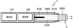
도 6을 참조하면, 홀더(1)는 배터리(110), 제어부(120) 및 히터(2130)를 포함한다. 또한, 홀더(1)는 케이스(2140)에 의하여 형성된 내부 공간을 포함한다. 홀더(1)의 내부 공간에는 궐련이 삽입될 수 있다.Referring to Fig. 6, the
도 6에 도시된 홀더(1)에는 본 실시예와 관련된 구성요소들만이 도시되어 있다. 따라서, 도 6에 도시된 구성요소들 외에 다른 범용적인 구성요소들이 홀더(1)에 더 포함될 수 있음을 본 실시예와 관련된 기술분야에서 통상의 지식을 가진 자라면 이해할 수 있다.Only the components related to the present embodiment are shown in the
궐련이 홀더(1)에 삽입되면, 홀더(1)는 히터(2130)를 가열한다. 궐련 내의 에어로졸 생성 물질은 가열된 히터(2130)에 의하여 온도가 상승하고, 이에 따라 에어로졸이 생성된다. 생성된 에어로졸은 궐련의 필터를 통하여 사용자에게 전달된다. 다만, 궐련이 홀더(1)에 삽입되지 않은 경우에도 홀더(1)는 히터(2130)를 가열할 수 있다.When the cigarette is inserted into the
케이스(2140)는 홀더(1)에서 분리될 수 있다. 예를 들어, 사용자가 케이스(2140)를 시계 방향 또는 반 시계 방향으로 돌림으로써, 케이스(2140)는 홀더(1)에서 분리될 수 있다.The
또한, 케이스(2140)의 말단(2141)이 형성하는 구멍의 직경은 케이스(2140)와 히터(2130)에 의하여 형성된 공간의 직경에 비하여 작게 제작될 수 있고, 이 경우 홀더(1)에 삽입되는 궐련의 가이드 역할을 수행할 수 있다.The diameter of the hole formed by the
배터리(110)는 홀더(1)가 동작하는데 이용되는 전력을 공급한다. 예를 들어, 배터리(110)는 히터(2130)가 가열될 수 있도록 전력을 공급할 수 있고, 제어부(120)가 동작하는데 필요한 전력을 공급할 수 있다. 또한, 배터리(110)는 홀더(1)에 설치된 디스플레이, 센서, 모터 등이 동작하는데 필요한 전력을 공급할 수 있다.The
배터리(110)는 리튬인산철(LiFePO4) 배터리일 수 있으나, 상술한 예에 한정되지 않는다. 예를 들어, 배터리(110)는 산화 리튬 코발트(LiCoO2) 배터리, 리튬 티탄산염 배터리 등이 해당될 수 있다.The
또한, 배터리(110)는 직경이 10mm이고, 길이가 37mm인 원기둥의 형상일 수 있으나, 이에 한정되지 않는다. 배터리(110)의 용량은 120mAh 이상 일 수 있고, 충전이 가능한 배터리 이거나 일회용 배터리 일 수 있다. 예를 들어, 배터리(110)가 충전이 가능한 경우, 배터리(110)의 충전율(C-rate)은 10C, 방전율(C-rate)는 16C 내지 20C 일 수 있으나, 이에 한정되지 않는다. 또한, 안정적인 사용을 위하여, 배터리(110)는 충/방전이 8000회 진행된 경우에도, 전체 용량의 80% 이상이 확보될 수 있도록 제작될 수 있다.Also, the
여기에서, 배터리(110)의 완전 충전 및 완전 방전 여부는, 배터리(110)에 저장된 전력이 배터리(110)의 전체 용량 대비 어느 수준인가에 의하여 판단될 수 있다. 예를 들어, 배터리(110)에 저장된 전력이 전체 용량의 95% 이상인 경우에, 배터리(110)가 완전 충전되었다고 판단될 수 있다. 또한, 배터리(110)에 저장된 전력이 전체 용량의 10% 이하인 경우에, 배터리(110)가 완전 방전되었다고 판단될 수 있다. 그러나, 배터리(110)의 완전 충전 및 완전 방전 여부에 대한 판단 기준은 상술한 예에 한정되지 않는다.Here, whether the
히터(2130)는 배터리(110)로부터 공급된 전력에 의하여 가열된다. 궐련이 홀더(1)에 삽입되면, 히터(2130)는 궐련의 내부에 위치한다. 따라서, 가열된 히터(2130)는 궐련 내의 에어로졸 생성 물질의 온도를 상승시킬 수 있다.The
히터(2130)는 원기둥과 원뿔이 조합된 형상일 수 있다. 예를 들어, 히터(2130)는 직경이 약 2mm, 길이가 약 23mm인 원기둥 형상을 갖고, 히터(2130)의 말단(2131)은 예각으로 마감될 수 있으나, 이에 한정되지 않는다. 다시 말해, 히터(2130)는 궐련의 내부에 삽입될 수 있는 형태라면 제한 없이 해당될 수 있다. 또한, 히터(2130)는 일부 부분만 가열될 수도 있다. 예를 들어, 히터(2130)의 길이가 23mm라고 가정하면, 히터(2130)의 말단(2131)으로부터 12mm만 가열되고, 히터(2130)의 나머지 부분은 가열되지 않을 수도 있다.The
히터(2130)는 전기 저항성 히터일 수 있다. 예를 들어, 히터(2130)에는 전기 전도성 트랙(track)을 포함하고, 전기 전도성 트랙에 전류가 흐름에 따라 히터(2130)가 가열될 수 있다.The
안정적인 사용을 위하여, 히터(2130)에는 3.2 V, 2.4 A, 8 W의 규격에 따른 전력이 공급될 수 있으나, 이에 한정되지 않는다. 예를 들어, 히터(2130)에 전력이 공급되는 경우, 히터(2130)의 표면 온도는 400℃ 이상으로 상승할 수 있다. 히터(2130)에 전력이 공급되기 시작한 때부터 15초가 초과되기 이전에 히터(2130)의 표면 온도는 약 350℃까지 상승할 수 있다.For stable use, the
홀더(1)에는 별도의 온도 감지 센서가 구비될 수 있다. 또는, 홀더(1)에 온도 감지 센서가 구비되지 않고, 히터(2130)가 온도 감지 센서의 역할을 수행할 수도 있다. 예를 들어, 히터(2130)에는 발열을 위한 제 1 전기 전도성 트랙 이외에 온도 감지를 위한 제 2 전기 전도성 트랙이 더 포함될 수 있다.The
예를 들어, 제 2 전기 전도성 트랙에 걸리는 전압 및 제 2 전기 전도성 트랙에 흐르는 전류가 측정되면, 저항(R)이 결정될 수 있다. 이 때, 아래의 수학식 1에 의하여 제 2 전기 전도성 트랙의 온도(T)가 결정될 수 있다.For example, when the voltage across the second electrically conductive track and the current through the second electrically conductive track are measured, the resistance R can be determined. At this time, the temperature (T) of the second electrically conductive track can be determined by the following equation (1).

수학식 1에서, R은 제 2 전기 전도성 트랙의 현재 저항 값을 의미하고, R0는 온도 T0(예를 들어, 0℃)에서의 저항 값을 의미하고, α는 제 2 전기 전도성 트랙의 저항 온도 계수를 의미한다. 전도성 물질(예를 들어, 금속)은 고유의 저항 온도 계수를 갖고 있는바, 제 2 전기 전도성 트랙을 구성하는 전도성 물질에 따라 α는 미리 결정될 수 있다. 따라서, 제 2 전기 전도성 트랙의 저항(R)이 결정되는 경우, 상기 수학식 1에 의하여 제 2 전기 전도성 트랙의 온도(T)가 연산될 수 있다.In the equation (1), R denotes a current resistance value of the second electrically conductive track, R0 denotes a resistance value at a temperature T0 (for example, 0 占 폚),? Quot; The conductive material (e.g., metal) has a resistive temperature coefficient inherent thereto, so that? Can be predetermined according to the conductive material constituting the second electrically conductive track. Thus, when the resistance R of the second electrically conductive track is determined, the temperature T of the second electrically conductive track can be calculated by Equation (1) above.
히터(2130)는 적어도 하나의 전기 전도성 트랙(제 1 전기 전도성 트랙 및 제 2 전기 전도성 트랙)으로 구성될 수 있다. 예를 들어, 히터(2130)는 2개의 제 1 전기 전도성 트랙 및 1개 또는 2개의 제 2 전기 전도성 트랙으로 구성될 수 있으나, 이에 한정되지 않는다.The
전기 전도성 트랙은 전기 저항성 물질을 포함한다. 일 예로서, 전기 전도성 트랙은 금속 물질로 제작될 수 있다. 다른 예로서, 전기 전도성 트랙은 전기 전도성 세라믹 물질, 탄소, 금속 합금 또는 세라믹 물질과 금속의 합성 물질로 제작될 수 있다.The electrically conductive track includes an electrically resistive material. As an example, the electrically conductive track can be made of a metallic material. As another example, an electrically conductive track can be made of an electrically conductive ceramic material, a carbon, a metal alloy, or a composite of a ceramic material and a metal.
또한, 홀더(1)는 온도 감지 센서의 역할을 수행하는 전기 전도성 트랙 및 온도 감지 센서를 모두 포함할 수 있다.Further, the
제어부(120)는 홀더(1)의 동작을 전반적으로 제어한다. 구체적으로, 제어부(120)는 배터리(110) 및 히터(2130)뿐 만 아니라 홀더(1)에 포함된 다른 구성들의 동작을 제어한다. 또한, 제어부(120)는 홀더(1)의 구성들 각각의 상태를 확인하여, 홀더(1)가 동작 가능한 상태인지 여부를 판단할 수도 있다.The
제어부(120)는 적어도 하나의 프로세서를 포함한다. 프로세서는 다수의 논리 게이트들의 어레이로 구현될 수도 있고, 범용적인 마이크로 프로세서와 이 마이크로 프로세서에서 실행될 수 있는 프로그램이 저장된 메모리의 조합으로 구현될 수도 있다. 또한, 다른 형태의 하드웨어로 구현될 수도 있음을 본 실시예가 속하는 기술분야에서 통상의 지식을 가진 자라면 이해할 수 있다.The
예를 들어, 제어부(120)는 히터(2130)의 동작을 제어할 수 있다. 제어부(120)는 히터(2130)가 소정의 온도까지 가열되거나 적절한 온도를 유지할 수 있도록 히터(2130)에 공급되는 전력의 양 및 전력이 공급되는 시간을 제어할 수 있다. 또한, 제어부(120)는 배터리(110)의 상태(예를 들어, 배터리(110)의 잔량 등)를 확인하고, 필요한 경우 알림 신호를 생성할 수 있다.For example, the
또한, 제어부(120)는 사용자의 퍼프(puff)의 유무 및 퍼프의 강도를 확인할 수 있고, 퍼프의 수를 카운팅할 수 있다. 또한, 제어부(120)는 홀더(1)가 작동하고 있는 시간을 계속하여 확인할 수 있다. 또한, 제어부(120)는 후술할 크래들(2)이 홀더(1)와 결합되었는지 여부를 확인하고, 크래들(2)과 홀더(1)의 결합 또는 분리에 따라 홀더(1)의 동작을 제어할 수 있다.In addition, the
한편, 홀더(1)는 배터리(110), 제어부(120) 및 히터(2130) 외에 범용적인 구성들을 더 포함할 수 있다.Meanwhile, the
예를 들어, 홀더(1)는 시각 정보의 출력이 가능한 디스플레이 또는 촉각 정보의 출력을 위한 모터를 포함할 수 있다. 일 예로서, 홀더(1)에 디스플레이가 포함되는 경우, 제어부(120)는 디스플레이를 통하여, 사용자에게 홀더(1)의 상태에 대한 정보(예를 들어, 홀더의 사용 가능 여부 등), 히터(2130)에 대한 정보(예를 들어, 예열 시작, 예열 진행, 예열 완료 등), 배터리(110)와 관련된 정보(예를 들어, 배터리(110)의 잔여 용량, 사용 가능 여부 등), 홀더(1)의 리셋과 관련된 정보(예를 들어, 리셋 시기, 리셋 진행, 리셋 완료 등), 홀더(1)의 청소와 관련된 정보(예를 들어, 청소 시기, 청소 필요, 청소 진행, 청소 완료 등), 홀더(1)의 충전과 관련된 정보(예를 들어, 충전 필요, 충전 진행, 충전 완료 등), 퍼프와 관련된 정보(예를 들어, 퍼프 횟수, 퍼프 종료 예고 등) 또는 안전과 관련된 정보(예를 들어, 사용시간 경과 등) 등을 전달 할 수 있다. 다른 예로서, 홀더(1)에 모터가 포함되는 경우, 제어부(120)는 모터를 이용하여 진동 신호를 생성함으로써, 사용자에게 상술한 정보들을 전달할 수 있다.For example, the
또한, 홀더(1)는 사용자가 홀더(1)의 기능을 제어할 수 있는 적어도 하나의 입력 장치(예를 들어, 버튼) 및/또는 크래들(2)과 결합되는 단자를 포함할 수 있다. 예를 들어, 사용자는 홀더(1)의 입력 장치를 이용하여 다양한 기능들을 실행할 수 있다. 사용자가 입력 장치를 누르는 횟수(예를 들어, 1회, 2회 등) 또는 입력 장치를 누르고 있는 시간(예를 들어, 0.1초, 0.2초 등)을 조절함으로써, 홀더(1)의 복수의 기능들 중 원하는 기능을 실행할 수 있다. 사용자가 입력 장치를 작동시킴에 따라, 홀더(1)는 히터(2130)를 예열하는 기능, 히터(2130)의 온도를 조절하는 기능, 궐련이 삽입되는 공간을 청소하는 기능, 홀더(1)가 작동 가능한 상태인지를 점검하는 기능, 배터리(110)의 잔량(가용 전력)을 표시하는 기능, 홀더(1)의 리셋 기능 등이 수행될 수 있다. 그러나, 홀더(1)의 기능은 상술한 예들에 한정되지 않는다.The
또한, 홀더(1)는 퍼프 감지 센서, 온도 감지 센서 및/또는 궐련 삽입 감지 센서를 포함할 수 있다. 예를 들어, 퍼프 감지 센서는 일반적인 압력 센서에 의하여 구현될 수 있고, 궐련 삽입 감지 센서는 일반적인 정전용량형 센서 또는 저항 센서에 의하여 구현될 수 있다. 또한, 홀더(1)는 궐련이 삽입된 상태에서도 외부 공기가 유입/유출 될 수 있는 구조로 제작될 수 있다.Further, the
도 7a 및 도 7b는 홀더의 일 예를 여러 측면에서 도시한 도면들이다.7A and 7B are views showing various examples of the holder.
도 7a는 홀더(1)를 제 1 방향에서 바라본 예를 도시한 도면이다. 도 7a에 도시된 바와 같이, 홀더(1)는 원통형으로 제작될 수 있으나, 이에 한정되지 않는다. 홀더(1)의 케이스(2140)는 사용자의 동작에 의하여 분리될 수 있으며, 케이스(2140)의 말단(2141)으로 궐련이 삽입될 수 있다. 또한, 홀더(1)에는 사용자가 홀더(1)를 제어할 수 있는 버튼(2150) 및 화면(image)이 출력되는 디스플레이(2160)가 포함될 수 있다.7A is a view showing an example of the
도 7b는 홀더(1)를 제 2 방향에서 바라본 예를 도시한 도면이다. 홀더(1)는 크래들(2)과 결합되는 단자(2170)를 포함할 수 있다. 홀더(1)의 단자(2170)가 크래들(2)의 단자(2260)와 결합함으로써, 크래들(2)의 배터리(210)가 공급하는 전력에 의하여 홀더(1)의 배터리(110)가 충전될 수 있다. 또한, 단자(2170)와 단자(2260)를 통하여, 크래들(2)의 배터리(210)가 공급하는 전력에 의하여 홀더(1)가 동작할 수도 있고, 홀더(1)와 크래들(2)간에 통신(신호의 송수신)이 가능하다. 예를 들어, 단자(2170)는 4개의 마이크로 핀(pin)들로 구성될 수 있으나, 이에 한정되지 않는다.7B is a view showing an example in which the
도 8은 크래들의 일 예를 도시한 구성도이다.8 is a configuration diagram showing an example of a cradle.
도 8을 참조하면, 크래들(2)은 배터리(210) 및 제어부(220)를 포함한다. 또한, 크래들(2)은 홀더(1)가 삽입될 수 있는 내부 공간(2230)을 포함한다. 예를 들어, 내부 공간(2230)은 크래들(2)의 일 측면에 형성될 수 있다. 따라서, 크래들(2)이 별도의 뚜껑을 포함하지 않더라도 홀더(1)가 크래들(2)에 삽입되고 고정될 수 있다.Referring to FIG. 8, the
도 8에 도시된 크래들(2)에는 본 실시예와 관련된 구성요소들만이 도시되어 있다. 따라서, 도 8에 도시된 구성요소들 외에 다른 범용적인 구성요소들이 크래들(2)에 더 포함될 수 있음을 본 실시예와 관련된 기술분야에서 통상의 지식을 가진 자라면 이해할 수 있다.Only the components related to the present embodiment are shown in the
배터리(210)는 크래들(2)이 동작하는데 이용되는 전력을 공급한다. 또한, 배터리(210)는 홀더(1)의 배터리(110)를 충전하는 전력을 공급할 수 있다. 예를 들어, 홀더(1)가 크래들(2)에 삽입되어 홀더(1)의 단자(2170)와 크래들(2)의 단자(2260)가 결합하는 경우, 크래들(2)의 배터리(210)는 홀더(1)의 배터리(110)에 전력을 공급할 수 있다.The
또한, 홀더(1)와 크래들(2)이 결합된 경우, 배터리(210)는 홀더(1)가 동작하는데 이용되는 전력을 공급할 수 있다. 예를 들어, 홀더(1)의 단자(2170)와 크래들(2)의 단자(2260)가 결합되면, 홀더(1)의 배터리(110)가 방전되었는지 여부를 불문하고, 홀더(1)는 크래들(2)의 배터리(210)가 공급하는 전력을 이용하여 동작할 수 있다.Further, when the
배터리(210) 종류의 예는 도 6을 참조하여 상술한 배터리(110)의 예와 동일할 수 있다. 배터리(210)의 용량은 배터리(110)의 용량보다 클 수 있고, 예를 들어 배터리(210)의 용량은 3000mAh 이상이 될 수 있다, 다만, 배터리(210)의 용량은 상술한 예에 한정되지 않는다.An example of the type of the
제어부(220)는 크래들(2)의 동작을 전반적으로 제어한다. 제어부(220)는 크래들(2)의 모든 구성들의 동작을 제어할 수 있다. 또한, 제어부(220)는 홀더(1)와 크래들(2)이 결합되었는지를 판단하고, 크래들(2)과 홀더(1)의 결합 또는 분리에 따라 크래들(2)의 동작을 제어할 수 있다.The
예를 들어, 홀더(1)와 크래들(2)이 결합되면, 제어부(220)는 배터리(210)의 전력을 홀더(1)에 공급함으로써, 배터리(110)를 충전하거나 히터(2130)를 가열시킬 수 있다. 따라서, 배터리(110)의 잔량이 적은 경우에도, 사용자는 홀더(1)와 크래들(2)을 결합하여 연속적으로 흡연할 수 있다.For example, when the
제어부(120)는 적어도 하나의 프로세서를 포함한다. 프로세서는 다수의 논리 게이트들의 어레이로 구현될 수도 있고, 범용적인 마이크로 프로세서와 이 마이크로 프로세서에서 실행될 수 있는 프로그램이 저장된 메모리의 조합으로 구현될 수도 있다. 또한, 다른 형태의 하드웨어로 구현될 수도 있음을 본 실시예가 속하는 기술분야에서 통상의 지식을 가진 자라면 이해할 수 있다.The
한편, 크래들(2)은 배터리(210) 및 제어부(220) 외에 범용적인 구성들을 더 포함할 수 있다. 예를 들어, 크래들(2)은 시각 정보의 출력이 가능한 디스플레이를 포함할 수 있다. 예를 들어, 크래들(2)에 디스플레이가 포함되는 경우, 제어부(220)는 디스플레이에 표시될 신호를 생성함으로써, 사용자에게 배터리(210)(예를 들어, 배터리(210)의 잔여 용량, 사용 가능 여부 등)와 관련된 정보, 크래들(2)의 리셋(예를 들어, 리셋 시기, 리셋 진행, 리셋 완료 등)과 관련된 정보, 홀더(1)의 청소(예를 들어, 청소 시기, 청소 필요, 청소 진행, 청소 완료 등)와 관련된 정보, 크래들(2)의 충전(예를 들어, 충전 필요, 충전 진행, 충전 완료 등)과 관련된 정보 등을 전달 할 수 있다.Meanwhile, the
또한, 크래들(2)은 사용자가 크래들(2)의 기능을 제어할 수 있는 적어도 하나의 입력 장치(예를 들어, 버튼), 홀더(1)와 결합하는 단자(2260) 및/또는 배터리(210)의 충전을 위한 인터페이스(예를 들어, USB 포트 등)를 포함할 수 있다.The
예를 들어, 사용자는 크래들(2)의 입력 장치를 이용하여 다양한 기능들을 실행할 수 있다. 사용자가 입력 장치를 누르는 횟수 또는 입력 장치를 누르고 있는 시간을 조절함으로써, 크래들(2)의 복수의 기능들 중 원하는 기능을 실행할 수 있다. 사용자가 입력 장치를 작동시킴에 따라, 크래들(2)은 홀더(1)의 히터(2130)를 예열하는 기능, 홀더(1)의 히터(2130)의 온도를 조절하는 기능, 홀더(1) 내의 궐련이 삽입되는 공간을 청소하는 기능, 크래들(2)이 작동 가능한 상태인지를 점검하는 기능, 크래들(2)의 배터리(210)의 잔량(가용 전력)을 표시하는 기능, 크래들(2)의 리셋 기능 등이 수행될 수 있다. 그러나, 크래들(2)의 기능은 상술한 예들에 한정되지 않는다.For example, the user can perform various functions using the input device of the
도 9a 및 도 9b는 크래들의 일 예를 여러 측면에서 도시한 도면들이다.9A and 9B are views showing various examples of the cradle.
도 9a는 크래들(2)을 제 1 방향에서 바라본 예를 도시한 도면이다. 크래들(2)의 일 측면에는 홀더(1)가 삽입될 수 있는 공간(2230)이 있다. 또한, 크래들(2)이 뚜껑과 같은 별도의 고정 수단을 포함하지 않더라도 홀더(1)가 크래들(2)에 삽입되고 고정될 수 있다. 또한, 크래들(2)에는 사용자가 크래들(2)를 제어할 수 있는 버튼(2240) 및 화면(image)이 출력되는 디스플레이(2250)가 포함될 수 있다.9A is a view showing an example in which the
도 9b는 크래들(2)을 제 2 방향에서 바라본 예를 도시한 도면이다. 크래들(2)에는 삽입된 홀더(1)와 결합되는 단자(2260)를 포함할 수 있다. 단자(2260)가 홀더(1)의 단자(2170)와 결합함으로써, 크래들(2)의 배터리(210)가 공급하는 전력에 의하여 홀더(1)의 배터리(110)가 충전될 수 있다. 또한, 단자(2170)와 단자(2260)을 통하여, 크래들(2)의 배터리(210)가 공급하는 전력에 의하여 홀더(1)가 동작할 수도 있고, 홀더(1)와 크래들(2)간의 신호의 송수신이 가능하다. 예를 들어, 단자(2260)는 4개의 마이크로 핀(pin)들로 구성될 수 있으나, 이에 한정되지 않는다.9B is a view showing an example in which the
상술한 바와 같이, 홀더(1)는 크래들(2)의 내부 공간(2230)에 삽입될 수 있다. 또한, 홀더(1)는 크래들(2)의 내부에 완전히 삽입될 수도 있고, 크래들(2)에 삽입된 상태에서 틸트(tilt)될 수도 있다. 이하에서는, 홀더(1)가 크래들(2)에 삽입되는 예들을 설명한다.The
도 10은 홀더가 크래들에 삽입되는 일 예를 도시한 도면이다.10 is a view showing an example in which the holder is inserted into the cradle.
도 10을 참조하면, 홀더(1)가 크래들(2)에 삽입된 일 예가 도시되어 있다. 홀더(1)가 삽입될 공간(2230)이 크래들(2)의 일 측면에 존재하므로, 삽입된 홀더(1)는 크래들(2)의 다른 측면들에 의하여 외부에 노출되지 않을 수 있다. 따라서, 크래들(2)은, 홀더(1)를 외부에 노출시키지 않기 위한 다른 구성(예를 들어, 뚜껑)을 포함하지 않을 수 있다.Referring to Fig. 10, an example in which the
크래들(2)에는 홀더(1)와의 결착 강도를 높이기 위하여 적어도 하나의 결착 부재(2271, 2272)가 포함될 수 있다. 또한, 홀더(1)에도 적어도 하나의 결착 부재(2181)가 포함될 수 있다. 여기에서, 결착 부재(2181, 2271, 2272)는 자석이 될 수 있으나, 이에 한정되지 않는다. 도 10에는, 설명의 편의를 위하여, 홀더(1)가 하나의 결착 부재(2181)를 포함하고, 크래들(2)이 두 개의 결착 부재들(2271, 2272)을 포함하는 것으로 도시하였으나, 결착 부재(2181, 2271, 2272)의 수는 이에 한정되지 않는다.At least one binding
홀더(1)는 제 1 위치에 결착 부재(2181)를 포함할 수 있고, 크래들(2)은 제 2 위치 및 제 3 위치에 각각 결착 부재(2271, 2272)를 포함할 수 있다. 이때, 제 1 위치와 제 3 위치는 홀더(1)가 크래들(2)에 삽입되는 경우에 서로 마주보는 위치일 수 있다.The
홀더(1) 및 크래들(2)에 결착 부재(2181, 2271, 2272)가 포함됨에 따라, 홀더(1)가 크래들(2)의 일 측면에 삽입되더라도, 홀더(1)와 크래들(2)이 더욱 강하게 결착될 수 있다. 다시 말해, 홀더(1) 및 크래들(2)에 단자(2170, 2260) 이외에 결착 부재(2181, 2271, 2272)가 더 포함됨에 따라, 홀더(1)와 크래들(2)이 더욱 강하게 결착될 수 있다. 따라서, 크래들(2)에 별도의 구성(예를 들어, 뚜껑)이 없더라도, 삽입된 홀더(1)가 크래들(2)로부터 쉽게 분리되지 않을 수 있다.As the
또한, 단자들(2170, 2260) 및/또는 결착 부재들(2181, 2271, 2272)에 의하여 홀더(1)가 크래들(2)에 완전히 삽입되었다고 판단되면, 제어부(220)은 배터리(210)의 전력을 이용하여 홀더(1)의 배터리(110)를 충전할 수 있다.When the
도 11은 홀더가 크래들에 삽입된 상태에서 틸트되는 일 예를 도시한 도면이다.11 is a view showing an example in which the holder is tilted in a state of being inserted into the cradle.
도 11을 참조하면, 홀더(1)가 크래들(2)의 내부에서 틸트되어 있다. 여기에서, 틸트는 홀더(1)가 크래들(2)에 삽입된 상태에서 일정 각도로 기울여지는 것을 의미한다.Referring to Fig. 11, the
도 10에 도시된 바와 같이, 홀더(1)가 크래들(2)에 완전히 삽입되는 경우, 사용자는 흡연을 할 수 없다. 다시 말해, 홀더(1)가 크래들(2)에 완전히 삽입되면, 홀더(1)에 궐련이 삽입될 수 없다. 따라서, 홀더(1)가 크래들(2)에 완전히 삽입된 상태에서는 사용자가 흡연을 할 수 없다.As shown in Fig. 10, when the
도 11에 도시된 바와 같이, 홀더(1)가 틸트되면, 홀더(1)의 말단(2141)이 외부로 노출된다. 따라서, 사용자는 말단(2141)에 궐련을 삽입하고, 생성된 에어로졸을 흡입(흡연)할 수 있다. 틸트 각(θ)은 궐련이 홀더(1)의 말단(2141)에 삽입될 때, 궐련이 꺽이거나 훼손되지 않을 수 있도록 충분한 각도가 확보될 수 있다. 예를 들어, 홀더(1)는 말단(2141)에 포함된 궐련 삽입 구멍 전체가 외부로 노출될 수 있는 만큼 틸트될 수 있다. 예를 들어, 틸트 각(θ)의 범위는 0°초과 180°이하가 될 수 있고, 바람직하게는 10°이상 90°이하가 될 수 있다. 더 바람직하게는, 틸트 각(θ)의 범위는 10°이상 20°이하, 10°이상 30°이하, 10°이상 40°이하, 10°이상 50°이하, 또는 10°이상 60°이하가 될 수 있다.As shown in Fig. 11, when the
또한, 홀더(1)가 틸트되더라도, 홀더(1)의 단자(2170)와 크래들(2)의 단자(2260)는 서로 결합되어 있다. 따라서, 홀더(1)의 히터(2130)는 크래들(2)의 배터리(210)가 공급하는 전력에 의하여 가열될 수 있다. 따라서, 홀더(1)의 배터리(110)의 잔량이 적거나 없는 경우에도, 홀더(1)는 크래들(2)의 배터리(210)를 이용하여 에어로졸을 생성할 수 있다.Even if the
도 11에는 홀더(1)가 하나의 결착 부재(2182)를 포함하고, 크래들(2)이 두 개의 결착 부재들(2273, 2274)을 포함하는 예가 도시되어 있다. 예를 들어, 결착 부재들(2182, 2273, 2274) 각각의 위치는 도 10을 참조하여 상술한 바와 같다. 만약, 결착 부재들(2182, 2273, 2274)이 자석이라고 가정하면, 결착 부재(2274)의 자석 강도가 결착 부재(2273)의 자석 강도보다 클 수 있다. 따라서, 홀더(1)가 틸트되더라도, 결착 부재(182) 및 결착 부재(2274)에 의하여, 홀더(1)는 크래들(2)과 완전히 분리되지 않을 수 있다.Fig. 11 shows an example in which the
또한, 단자들(2170, 2260) 및/또는 결착 부재들(2182, 2273, 2274)에 의하여 홀더(1)가 틸트되었다고 판단되면, 제어부(220)은 배터리(210)의 전력을 이용하여, 홀더(1)의 히터(2130)를 가열하거나, 배터리(110)를 충전할 수 있다.When the
도 12a 내지 도 12b는 홀더가 크래들에 삽입된 예들을 도시한 도면들이다.12A to 12B are views showing examples in which the holder is inserted into the cradle.
도 12a에는 홀더(1)가 크래들(2)에 완전히 삽입된 예가 도시되어 있다. 홀더(1)가 크래들(2)에 완전히 삽입되는 경우, 사용자가 홀더(1)에 접촉하는 것을 최소화하기 위하여, 크래들(2)의 내부 공간(2230)이 충분히 확보되도록 제작될 수 있다. 홀더(1)가 크래들(2)에 완전히 삽입되면, 제어부(220)는, 홀더(1)의 배터리(110)가 충전될 수 있도록, 배터리(210)의 전력을 홀더(1)에 공급한다.Fig. 12A shows an example in which the
도 12b에는 홀더(1)가 크래들(2)에 삽입된 상태에서 틸트된 예가 도시되어 있다. 홀더(1)가 틸트되면, 제어부(220)는, 홀더(1)의 배터리(110)가 충전되거나, 홀더(1)의 히터(2130)가 가열될 수 있도록, 배터리(210)의 전력을 홀더(1)에 공급한다.12B shows an example in which the
도 13은 홀더 및 크래들이 동작하는 일 예를 설명하기 위한 흐름도이다.13 is a flowchart for explaining an example in which the holder and the cradle operate.
도 13에 도시된 에어로졸을 생성하는 방법은 도 6에 도시된 홀더(1) 또는 도 8에 도시된 크래들(2)에서 시계열적으로 처리되는 단계들로 구성된다. 따라서, 이하에서 생략된 내용이라 하더라도 도 6에 도시된 홀더(1) 및 도 8에 도시된 크래들(2)에 관하여 이상에서 기술된 내용은 도 13의 방법에도 적용됨을 알 수 있다.The method of generating the aerosol shown in Fig. 13 consists of steps that are processed in a time-series manner in the
2710 단계에서, 홀더(1)는 크래들(2)에 삽입되었는지 여부를 판단한다. 예를 들어, 제어부(120)는 홀더(1) 및 크래들(2)의 단자들(2170, 2260)이 서로 연결되었는지 및/또는 결착 부재들(2181, 2271, 2272)이 동작하는지에 따라 홀더(1)가 크래들(2)에 삽입되었는지 여부를 판단할 수 있다.In
홀더(1)가 크래들(2)에 삽입된 경우에는 2720 단계로 진행하고, 홀더(1)가 크래들(2)가 분리된 경우에는 2730 단계로 진행한다.If the
2720 단계에서, 크래들(2)은 홀더(1)가 틸트되었는지 여부를 판단한다. 예를 들어, 제어부(220)는 홀더(1) 및 크래들(2)의 단자들(2170, 2260)이 서로 연결되었는지 및/또는 결착 부재들(2182, 2273, 2274)이 동작하는지에 따라 홀더(1)가 틸트되었는지 여부를 판단할 수 있다.In
2720 단계에서는 크래들(2)이 홀더(1)의 틸트 여부를 판단하는 것으로 설명하였으나, 이에 한정되지 않는다. 다시 말해, 홀더(1)의 틸트 여부는 홀더(1)의 제어부(120)에 의하여 판단될 수도 있다.In
홀더(1)가 틸트된 경우에는 2740 단계로 진행하고, 홀더(1)가 틸트되지 않은 경우(즉, 홀더(1)가 크래들(2)에 완전히 삽입된 경우)에는 2770 단계로 진행한다.When the
2730 단계에서, 홀더(1)는 홀더(1)의 사용 조건을 만족하는지 여부를 판단한다. 예를 들어, 제어부(120)는 배터리(110)의 잔량 및 홀더(1)의 다른 구성들이 정상적으로 동작할 수 있는지를 체크함으로써 사용 조건이 만족되었는지 여부를 판단할 수 있다.In
홀더(1)의 사용 조건이 만족된 경우에는 2740 단계로 진행하고, 그렇지 않은 경우에는 절차를 종료한다.If the use condition of the
2740 단계에서, 홀더(1)는 사용자에게 사용 가능 상태임을 알린다. 예를 들어, 제어부(120)는 홀더(1)의 디스플레이에 사용 가능함을 알리는 화면(image)을 출력할 수도 있고, 홀더(1)의 모터를 제어하여 진동 신호를 생성할 수도 있다.In
2750 단계에서, 히터(2130)가 가열된다. 일 예로서, 홀더(1)가 크래들(2)로부터 분리된 경우, 홀더(1)의 배터리(110)의 전력에 의하여 히터(2130)가 가열될 수 있다. 다른 예로서, 홀더(1)가 틸트된 경우, 크래들(2)의 배터리(210)의 전력에 의하여 히터(2130)가 가열될 수 있다.In
홀더(1)의 제어부(120) 또는 크래들(2)의 제어부(220)는 히터(2130)의 온도를 실시간으로 확인하여 히터(2130)에 공급되는 전력의 양 및 히터(2130)에 전력이 공급되는 시간을 조절할 수 있다. 예를 들어, 제어부(120, 220)는 홀더(1)에 포함된 온도 감지 센서 또는 히터(2130)의 전기 전도성 트랙을 통하여 히터(2130)의 온도를 실시간으로 확인할 수 있다.The
2760 단계에서, 홀더(1)는 에어로졸 생성 기작(mechanism)을 수행한다. 예를 들어, 제어부(120, 220)는 사용자가 퍼프를 수행함에 따라 변하는 히터(2130)의 온도를 확인하여 히터(2130)에 공급되는 전력의 양을 조절하거나 히터(2130)에 전력의 공급을 중단할 수 있다. 또한, 제어부(120, 220)는 사용자의 퍼프 횟수를 카운팅할 수 있고, 일정한 퍼프 횟수(예를 들어, 1500회)에 도달하면 홀더의 청소가 필요함을 알리는 정보를 출력할 수 있다.In
2770 단계에서, 크래들(2)은 홀더(1)의 충전을 수행한다. 예를 들어, 제어부(220)는 크래들(2)의 배터리(210) 전력을 홀더(1)의 배터리(110)에 공급함으로써 홀더(1)를 충전시킬 수 있다.In
한편, 제어부(120, 220)는 사용자의 퍼프 횟수 또는 홀더(1)의 동작 시간에 따라 홀더(1)의 동작을 정지시킬 수도 있다. 이하, 도 14를 참조하여, 제어부(120, 220)가 홀더(1)의 동작을 정지시키는 일 예를 설명한다.Meanwhile, the
도 14는 홀더가 동작하는 다른 예를 설명하기 위한 흐름도이다.14 is a flowchart for explaining another example in which the holder operates.
도 14에 도시된 에어로졸을 생성하는 방법은 도 6에 도시된 홀더(1) 및 도 8에서 도시된 크래들(2)에서 시계열적으로 처리되는 단계들로 구성된다. 따라서, 이하에서 생략된 내용이라 하더라도 도 6에 도시된 홀더(1) 또는 도 8에 도시된 크래들(2)에 관하여 이상에서 기술된 내용은 도 14의 방법에도 적용됨을 알 수 있다.The method of producing the aerosol shown in Fig. 14 consists of the steps of the
2810 단계에서, 제어부(120, 220)는 사용자가 퍼프하였는지 여부를 판단한다. 예를 들어, 제어부(120, 220)는 홀더(1)에 포함된 퍼프 감지 센서를 통하여 사용자가 퍼프하였는지를 판단할 수 있다.In
2820 단계에서, 사용자의 퍼프에 따라 에어로졸이 생성된다. 제어부(120, 220)가 사용자의 퍼프 및 히터(2130)의 온도에 따라 히터(2130)에 공급되는 전력을 조절할 수 있음은 도 13을 참조하여 상술한 바와 같다. 또한, 제어부(120, 220)는 사용자의 퍼프 횟수를 카운팅한다.In
2830 단계에서, 제어부(120, 220)는 사용자의 퍼프 횟수가 퍼프 제한 횟수 이상인지 여부를 판단한다. 예를 들어, 퍼프 제한 횟수가 14회로 설정되었다고 가정하면, 제어부(120, 220)는 카운팅된 퍼프 횟수가 14회 이상인지 여부를 판단한다.In
한편, 사용자의 퍼프 횟수가 퍼프 제한 횟수에 근접한 경우(예를 들어, 사용자의 퍼프 횟수가 12회인 경우), 제어부(120, 220)는 디스플레이 또는 진동 모터를 통하여 경고 신호를 출력할 수 있다.On the other hand, when the number of puffs of the user is close to the number of puff limitation (for example, when the number of puffs of the user is 12), the
만약, 사용자의 퍼프 횟수가 퍼프 제한 횟수 이상인 경우에는 2850 단계로 진행하고, 사용자의 퍼프 횟수가 퍼프 제한 횟수보다 적을 경우에는 2840 단계로 진행한다.If the number of puffs of the user is equal to or greater than the puff limit number, the process proceeds to step 2850. If the number of puffs of the user is less than the puff limit number,
2840 단계에서, 제어부(120, 220)는 홀더(1)가 동작한 시간이 동작 제한 시간 이상인지 여부를 판단한다. 여기에서, 홀더(1)가 동작한 시간은 홀더가 동작을 시작한 시점부터 현재까지 누적된 시간을 의미한다. 예를 들어, 동작 제한 시간이 10분으로 설정되었다고 가정하면, 제어부(120, 220)는 홀더(1)가 10분 이상 동작하고 있는지를 판단한다.In
한편, 홀더(1)의 동작 시간이 동작 제한 시간에 근접한 경우(예를 들어, 홀더(1)가 8분 동안 동작하고 있는 경우), 제어부(120, 220)는 디스플레이 또는 진동 모터를 통하여 경고 신호를 출력할 수 있다.On the other hand, when the operation time of the
만약, 홀더(1)가 동작 제한 시간 이상으로 동작하고 있는 경우에는 2850 단계로 진행하고, 홀더(1)의 동작 시간이 동작 제한 시간보다 적은 경우에는 2820 단계로 진행한다.If the operation time of the
2850 단계에서, 제어부(120, 220)는 홀더의 동작을 강제 종료한다. 다시 말해, 제어부(120, 220)는 홀더의 에어로졸 생성 기작을 중지시킨다. 예를 들어, 제어부(120, 220)는 히터(2130)에 공급되는 전력을 차단함으로써, 홀더의 동작을 강제 종료할 수 있다.In
도 15은 크래들이 동작하는 일 예를 설명하기 위한 흐름도이다.15 is a flowchart for explaining an example in which the cradle operates.
도 15에 도시된 흐름도는 도 8에 도시된 크래들(2)에서 시계열적으로 처리되는 단계들로 구성된다. 따라서, 이하에서 생략된 내용이라 하더라도 도 8에 도시된 크래들(2)에 관하여 이상에서 기술된 내용은 도 15의 흐름도에도 적용됨을 알 수 있다.The flowchart shown in Fig. 15 consists of the steps that are processed in a time-series manner in the
도 15에는 도시되지 않았으나, 이하에서 설명할 크래들(2)의 동작은, 홀더(1)가 크래들(2)에 삽입되었는지 여부를 불문하고 수행될 수 있다.Although not shown in Fig. 15, the operation of the
2910 단계에서, 크래들(2)의 제어부(220)는 버튼(2240)이 눌려졌는지 여부를 판단한다. 만약, 버튼(2240)이 눌려진 경우에는 2920 단계로 진행하고, 버튼(2240)이 눌려지지 않은 경우에는 2930 단계로 진행한다.In
2920 단계에서, 크래들(2)은 배터리의 상태를 표시한다. 예를 들어, 제어부(220)는 배터리(210)의 현재 상태(예를 들어, 잔량량 등)에 대한 정보를 디스플레이(2250)에 출력할 수 있다.In
2930 단계에서, 크래들(2)의 제어부(220)는 크래들(2)에 케이블이 연결되었는지 여부를 판단한다. 예를 들어, 제어부(220)는 크래들(2)에 포함된 인터페이스(예를 들어, USB 포트 등)에 케이블이 연결되었는지 여부를 판단한다. 만약, 크래들(2)에 케이블이 연결된 경우에는 2940 단계로 진행하고, 그렇지 않은 경우에는 절차를 종료한다.In
2940 단계에서, 크래들(2)은 충전 동작을 수행한다. 예를 들어, 크래들(2)은 연결된 케이블을 통하여 공급되는 전력을 이용하여 배터리(210)를 충전한다.In
상술한 바와 같이, 홀더(1)에는 궐련이 삽입될 수 있다. 궐련은 에어로졸 생성 물질을 포함하고, 가열된 히터(2130)에 의하여 에어로졸이 생성된다.As described above, the cigarette can be inserted into the
이하, 도 16 내지 도 18f를 참조하여, 홀더(1)에 삽입될 수 있는 궐련의 예를 설명한다.Hereinafter, with reference to Figs. 16 to 18F, an example of a cigarette which can be inserted into the
도 16은 홀더에 궐련이 삽입된 일 예를 도시한 도면이다.16 is a view showing an example in which a cigarette is inserted into a holder.
도 16을 참조하면, 궐련(3)은 케이스(2140)의 말단(2141)을 통하여 홀더(1)에 삽입될 수 있다. 궐련(3)이 삽입되면, 히터(2130)는 궐련(3)의 내부에 위치된다. 따라서, 가열된 히터(2130)에 의하여 궐련(3)의 에어로졸 생성 물질이 가열되고, 이에 따라 에어로졸이 생성된다.16, the
궐련(3)은 일반적인 연소형 궐련과 유사할 수 있다. 예를 들어, 궐련(3)은 에어로졸 생성 물질을 포함하는 제 1 부분(3310)과 필터 등을 포함하는 제 2 부분(3320)으로 구분될 수 있다. 한편, 일 실시예에 따른 궐련(3)은 제 2 부분(3320)에 에어로졸 생성 물질을 포함할 수도 있다. 예를 들어, 과립 또는 캡슐의 형태로 만든 에어로졸 생성 물질이 제 2 부분(3320)에 삽입될 수도 있다.The
홀더(1)의 내부에는 제 1 부분(3310) 전체가 삽입되고, 제 2 부분(3320)은 외부에 노출될 수 있다. 또는, 홀더(1)의 내부에 제 1 부분(3310)의 일부만 삽입될 수도 있고, 제 1 부분(3310) 및 제 2 부분(3320)의 일부가 삽입될 수도 있다.The entire
사용자는 제 2 부분(3320)을 입으로 문 상태에서 에어로졸을 흡입할 수 있다. 이때, 에어로졸은 외부 공기와 혼합되어 사용자의 입으로 전달된다. 도 16에 도시된 바와 같이, 외부 공기는 궐련(3)의 표면에 형성된 적어도 하나의 구멍(hole)을 통하여 유입(3110)될 수도 있고, 홀더(1)에 형성된 적어도 하나의 공기 통로를 통하여 유입(3120)될 수도 있다. 예를 들어, 홀더(1)에 형성된 공기 통로는 사용자에 의하여 개폐될 수 있도록 제작될 수도 있다.The user may inhale the aerosol from the
도 17a 및 도 17b는 궐련의 일 예를 도시한 구성도이다.Figs. 17A and 17B are structural diagrams showing examples of cigarettes. Fig.
도 17a 및 도 17b를 참조하면, 궐련(3)은 담배 로드(3300), 제 1 필터 세그먼트(3321), 냉각 구조물(3322) 및 제 2 필터 세그먼트(3323)을 포함한다. 도 16을 참조하여 상술한 제 1 부분(3310)은 담배 로드(3300)를 포함하고, 제 2 부분(3320)은 제 1 필터 세그먼트(3321), 냉각 구조물(3322) 및 제 2 필터 세그먼트(3323)을 포함한다.17A and 17B, the
한편, 도 17a와 도 17b를 비교하면, 도 17b의 궐련(3)은 도 17a의 궐련(3)에 비하여 제 4 래퍼(3334)를 더 포함한다.17A and 17B, the
다만, 도 17a 및 도 17b에 도시된 궐련(3)의 구조는 일 예에 불과하며, 일부 구성이 생략될 수 있다. 예를 들어, 궐련(3)에는 제 1 필터 세그먼트(3321), 냉각 구조물(3322) 및 제 2 필터 세그먼트(3323) 중 하나 이상이 포함되지 않을 수 있다.However, the structure of the
담배 로드(3300)는 에어로졸 생성 물질을 포함한다. 예를 들어, 에어로졸 생성 물질은 글리세린, 프로필렌 글리콜, 에틸렌 글리콜, 디프로필렌 글리콜, 디에틸렌 글리콜, 트리에틸렌 글리콜, 테트라에틸렌 글리콜 및 올레일 알코올 중 적어도 하나를 포함할 수 있다. 담배 로드(3300)의 길이는 약 7mm 내지 15mm일 수 있거나, 바람직하게, 약 12mm가 될 수 있다. 또한, 담배 로드(3300)의 직경은 7mm 내지 9mm일 수 있거나, 바람직하게, 약 7.9mm일 수 있다. 담배 로드(3300)의 길이 및 직경은 전술한 수치범위에 한정되지 않는다.The
또한, 담배 로드(3300)는 풍미제, 습윤제 및/또는 아세테이트 화합물과 같은 다른 첨가 물질을 함유할 수 있다. 예를 들어, 풍미제는 감초, 자당, 과당 시럽, 이소감미제(isosweet), 코코아, 라벤더, 시나몬, 카르다몸, 셀러리, 호로파, 카스카릴라, 백단, 베르가못, 제라늄, 벌꿀 에센스, 장미 오일, 바닐라, 레몬 오일, 오렌지 오일, 민트 오일, 계피, 케러웨이, 코냑, 자스민, 카모마일, 멘톨, 계피, 일랑일랑, 샐비어, 스피어민트, 생강, 고수 또는 커피 등을 포함할 수 있다. 또한, 습윤제는 글리세린 또는 프로필렌 글리콜 등을 포함할 수 있다.In addition, the
일 예로서, 담배 로드(3300)는 담배 각초들로 충전될 수 있다. 여기에서, 담배 각초들은 담배 시트를 잘게 분쇄함으로써 생성될 수 있다.As an example, the
넓은 담배 시트가 좁은 공간의 담배 로드(3300)에 채워지기 위해서는, 담배 시트가 용이하게 접힐 수 있도록 하는 공정이 추가적으로 요구된다. 따라서, 담배 로드(3300)를 담배 시트로 충전하는 것에 비하여, 담배 로드(3300)를 담배 각초들로 충전하는 것이 더 용이하며, 담배 로드(3300)를 생산하는 공정의 생산성 및 효율이 더 높아질 수 있다.In order for the wide tobacco sheet to be filled in the
다른 예로서, 담배 로드(3300)는 담배 시트가 세절된 복수의 담배 가닥들로 충전될 수 있다. 예를 들어, 담배 로드(3300)는 복수의 담배 가닥들이 서로 같은 방향(평행)으로 또는 무작위로 합쳐져서 형성될 수 있다. 하나의 담배 가닥은 가로 길이가 1 mm, 세로 길이가 12mm, 두께(높이)가 0.1 mm인 직육면체 형상으로 제조될 수 있으나, 이에 한정되지 않는다.As another example, the
담배 로드(3300)가 담배 시트로 충전되는 것과 비교하여, 담배 가닥들로 충전된 담배 로드(3300)는 더 많은 양의 에어로졸이 발생될 수 있다. 동일한 공간에 충전되는 것을 가정하면, 담배 시트에 비하여, 담배 가닥들이 더 넓은 표면적을 보장한다. 넓은 표면적은 에어로졸 생성 물질이 외부 공기와 접촉하는 기회가 더 많음을 의미한다. 따라서, 담배 로드(3300)가 담배 가닥들로 충전될 경우, 담배 시트로 충전된 것에 비하여 더 많은 에어로졸이 생성될 수 있다.Compared to the
또한, 궐련(3)을 홀더(1)에서 분리할 때, 담배 가닥들로 충전된 담배 로드(3300)가 담배 시트로 충전된 것에 비하여 보다 더 용이하게 분리될 수 있다. 담배 시트에 비교하여, 담배 가닥들이 히터(2130)와 접촉하여 생성되는 마찰력이 더 작다. 따라서, 담배 로드(3300)가 담배 가닥들로 충전될 경우, 담배 시트로 충전된 것에 비하여 홀더(1)로부터 더 용이하게 분리될 수 있다.Further, when the
담배 시트는 담배 원료를 슬러리 형태로 분쇄한 후 슬러리를 건조시킴에 따라 형성될 수 있다. 예를 들어, 슬러리에는 에어로졸 생성 물질이 15 내지 30% 첨가될 수 있다. 담배 원료는 담배 잎 조각, 담배 줄기, 담배 처리 중 발생된 담배 분진 및/또는 담배 잎의 주요 옆편 스트립일 수 있다. 또한, 담배 시트에는 목재 셀룰로오스 섬유와 같은 다른 첨가제가 함유될 수도 있다.The tobacco sheet may be formed by pulverizing the tobacco raw material into a slurry form and then drying the slurry. For example, 15 to 30% of the aerosol product may be added to the slurry. The tobacco raw materials may be tobacco leaf slices, tobacco stalks, tobacco dusts generated during tobacco processing, and / or major side strips of tobacco leaves. The tobacco sheet may also contain other additives such as wood cellulose fibers.
제 1 필터 세그먼트(3321)은 셀룰로오스 아세테이트 필터일 수 있다. 예를 들어, 제 1 필터 세그먼트(3321)는 내부에 중공을 포함하는 튜브 형태일 수 있다. 제 1 필터 세그먼트(3321)의 길이는 약 7mm 내지 15mm일 수 있거나, 바람직하게, 약 7 mm가 될 수 있다. 제1 필터 세그먼트(3321)의 길이는 약 7mm보다 짧을 수 있으나, 적어도 하나의 궐련 요소(예를 들어, 냉각요소, 캡슐, 아세테이트 필터 등)의 기능이 훼손되지 않는 정도의 길이를 가지는 것이 바람직하다. 제1 필터 세그먼트(3321)의 길이는 전술한 수치범위에 한정되지 않는다. 한편, 제1 필터 세그먼트(3321)의 길이는 확장 가능하며, 제1 필터 세그먼트(3321)의 길이에 따라 궐련(3) 전체의 길이가 조절될 수 있다.The
제 2 필터 세그먼트(3323)도 셀룰로오스 아세테이트 필터일 수 있다. 예를 들어, 제 2 필터 세그먼트(3323)는 중공을 포함하는 리세스 필터로 제작될 수도 있으나, 이에 한정되지 않는다. 제 2 필터 세그먼트(3323)의 길이는 약 5mm 내지 15mm일 수 있거나, 바람직하게, 약 12mm가 될 수 있다. 제2 필터 세그먼트(3323)의 길이는 전술한 수치범위에 한정되지 않는다.The
또한, 제 2 필터 세그먼트(3323)에는 적어도 하나의 캡슐(3324)이 포함될 수 있다. 여기에서, 캡슐(3324)은 향료를 포함하는 내용액을 피막으로 감싼 구조일 수 있다. 예를 들어, 캡슐(3324)은 구형 또는 원통형의 형상을 갖을 수 있다. 캡슐(3324)의 직경은 2mm 이상일 수 있거나, 바람직하게 2~4mm일 수 있다.Also, at least one
캡슐(3324)의 피막을 형성하는 재료는 전분 및/또는 겔화제일 수 있다. 예를 들어, 겔화제로서는 젤란 검이나 젤라틴이 사용될 수 있다. 또한, 캡슐(3324)의 피막을 형성하는 재료로서 겔화 조제(助劑)가 더 이용될 수도 있다. 여기에서, 겔화 조제로서는, 예를 들면, 염화 칼슘이 사용될 수 있다. 또한, 캡슐(3324)의 피막을 형성하는 재료로서 가소제가 더 이용될 수도 있다. 여기에서, 가소제로서는 글리세린 및/또는 소르비톨이 이용될 수 있다. 또한, 캡슐(3324)의 피막을 형성하는 재료로서 착색료가 더 이용될 수도 있다.The material forming the capsule of the
예를 들어, 캡슐의 내용액에 포함되는 향료로서는 멘톨, 식물의 정유(精油) 등이 이용될 수 있다. 또한, 내용액에 포함되는 향료의 용매로서는, 예를 들면, 중쇄지방산 트리글리세리드(MCT)가 이용될 수 있다. 또한, 내용액은 색소, 유화제(乳化劑), 증점제(增粘劑) 등의 다른 첨가제를 함유할 수도 있다.For example, as the fragrance contained in the content liquid of the capsule, menthol, plant essential oil and the like can be used. As the solvent of the flavor included in the content liquid, for example, a medium chain fatty acid triglyceride (MCT) may be used. In addition, the content liquid may contain other additives such as coloring matters, emulsifying agents, thickening agents and the like.
냉각 구조물(3322)은 히터(2130)가 담배 로드(3300)을 가열함으로써 생성된 에어로졸을 냉각시킨다. 따라서, 사용자는 적당한 온도로 냉각된 에어로졸을 흡입할 수 있다. 냉각 구조물(3322)의 길이는 약 10mm 내지 20mm일 수 있거나, 바람직하게, 약 14mm가 될 수 있다. 냉각 구조물(3322)의 길이는 전술한 수치범위에 한정되지 않는다.The
예를 들어, 냉각 구조물(3322)은 폴리락트 산 으로 제작될 수 있다. 냉각 구조물(3322)은 단위 면적 당 표면적(즉, 에어로졸과 접촉하는 표면적)을 늘리기 위하여 다양한 형태들로 제작될 수 있다. 냉각 구조물(3322)의 다양한 예들은 도 18a 내지 도 18f를 참조하여 후술한다.For example, the
담배 로드(3300) 및 제 1 필터 세그먼트(3321)은 제 1 래퍼(3331)에 의하여 포장될 수 있다. 예를 들어, 제 1 래퍼(3331)는 내유성을 갖는 종이류 포장재로 제작될 수 있다.The
냉각 구조물(3322) 및 제 2 필터 세그먼트(3323)는 제 2 래퍼(3332)에 의하여 포장될 수 있다. 또한, 궐련(3) 전체는 제 3 래퍼(3333)에 의하여 재포장될 수 있다. 예를 들어, 제 2 래퍼(3332) 및 제 3 래퍼(3333)은 일반적인 종이류 포장재로 제작될 수 있다. 선택적으로, 제 2 래퍼(3332)는 내유하드 권지 또는 PLA 가향지일 수 있다. 또한, 제 2 래퍼(3332)는 제 2 필터 세그먼트(3323) 부분을 포장하고, 추가적으로 제 2 필터 세그먼트(3323) 및 냉각 구조물(3322)을 더 포장할 수 있다.The
도 17b를 참조하면, 궐련(3)은 제 4 래퍼(3334)를 포함할 수 있다. 담배 로드(3300)와 제 1 필터 세그먼트(3321) 중 적어도 하나는 제 4 래퍼(3334)에 의하여 포장될 수 있다. 다시 말해, 담배 로드(3300)만 제 4 래퍼(3334)에 의하여 포장될 수도 있고, 담배 로드(3300) 및 제 1 필터 세그먼트(3321)가 제 4 래퍼(3334)에 의하여 포장될 수도 있다. 예를 들어, 제 4 래퍼(3334)는 종이류 포장재로 제작될 수 있다.Referring to Fig. 17B, the
제 4 래퍼(3334)는 종이류 포장재의 일 표면 또는 양 표면에 소정의 물질이 도포(또는, 코팅)됨으로써 생성될 수 있다. 여기에서, 소정의 물질의 예로서는 실리콘이 해당될 수 있으나, 이에 한정되지 않는다. 실리콘은 온도에 따른 변화가 적은 내열성, 산화되지 않는 내산화성, 각종 약품에 대한 저항성, 물에 대한 발수성, 또는 전기 절연성 등의 특성을 갖는다. 다만, 실리콘이 아니더라도, 상술한 특성들을 갖는 물질이라면 제한 없이 제 4 래퍼(3334)에 도포(또는, 코팅)될 수 있다.The
한편, 도 17b에는 궐련(3)이 제 1 래퍼(3331) 및 제 4 래퍼(3334)를 모두 포함하는 것으로 도시되어 있으나, 이에 한정되지 않는다. 다시 말해, 궐련(3)이 제 1 래퍼(3331) 및 제 4 래퍼(3334) 중 어느 하나만 포함할 수도 있다.17B, the
제 4 래퍼(3334)는 궐련(3)이 연소되는 현상을 방지할 수 있다. 예를 들어, 담배 로드(3300)가 히터(2130)에 의하여 가열되면, 궐련(3)이 연소될 가능성이 있다. 구체적으로, 담배 로드(3300)에 포함된 물질들 중 어느 하나의 발화점 이상으로 온도가 상승될 경우, 궐련(3)이 연소될 수 있다. 이러한 경우에도, 제 4 래퍼(3334)는 불연성 물질을 포함하므로, 궐련(3)이 연소되는 현상이 방지될 수 있다.The
또한, 제 4 래퍼(3334)는 궐련(3)에서 생성되는 물질들에 의하여 홀더(1)가 오염되는 것을 방지할 수 있다. 사용자의 퍼프에 의하여, 궐련(3) 내에서 액체 물질들이 생성될 수 있다. 예를 들어, 궐련(3)에서 생성된 에어로졸이 외부 공기에 의하여 냉각됨으로써, 액체 물질들(예를 들어, 수분 등)이 생성될 수 있다. 제 4 래퍼(3334)가 담배 로드(3300) 및/또는 제 1 필터 세그먼트(3321)를 포장함에 따라, 궐련(3) 내에서 생성된 액체 물질들이 궐련(3)의 외부로 새어 나가는 것이 방지될 수 있다. 따라서, 홀더(1)의 케이스(2140) 등이 궐련(3)에서 생성된 액체 물질들에 의하여 오염되는 현상이 방지될 수 있다.In addition, the
도 18a 내지 도 18f는 궐련의 냉각 구조물의 예들을 도시한 도면들이다.18A to 18F are views showing examples of the cooling structure of the cigarette.
예를 들어, 도 18a 내지 도 18f에 도시된 냉각 구조물은 순수한 폴리락트 산(PLA)으로 생산된 섬유들을 이용하여 제작될 수 있다.For example, the cooling structure shown in Figs. 18A to 18F can be fabricated using fibers produced with pure polylactic acid (PLA).
일 예로서, 필름(시트)를 충전하여 냉각 구조물을 필름(시트)을 제작하는 경우, 필름(시트)가 외부의 충격에 의하여 부스러질 수 있다. 이 경우, 냉각 구조물이 에어로졸을 냉각하는 효과가 감소된다.As one example, when a film (sheet) is filled and the cooling structure is made into a film (sheet), the film (sheet) may be broken by an external impact. In this case, the effect of the cooling structure cooling the aerosol is reduced.
다른 예로서, 압출 성형 등에 의하여 냉각 구조물을 제작하는 경우, 구조물의 절단 등의 공정이 추가됨에 따라 공정의 효율이 낮아진다. 또한, 냉각 구조물을 다양한 형상들로 제작하는 것에도 한계가 있다.As another example, when a cooling structure is manufactured by extrusion molding or the like, the efficiency of the process is lowered as a process such as cutting of the structure is added. Also, there are limitations in manufacturing the cooling structure in various shapes.
일 실시예에 따른 냉각 구조물을 폴리락트 산 섬유들을 이용하여 제작함(예를 들어, 직조)에 따라, 냉각 구조물이 외부 충격에 의하여 변형되거나 기능을 상실하게 될 위험이 낮아질 수 있다. 또한, 섬유들을 조합하는 방식을 변경함으로써, 다양한 형상을 갖는 냉각 구조물을 제작할 수 있다.Depending upon the fabrication (e.g., weaving) of the cooling structure according to one embodiment using polylactic acid fibers, the risk that the cooling structure will be deformed or lost by external impact may be reduced. Further, by changing the manner of combining the fibers, a cooling structure having various shapes can be manufactured.
또한, 섬유들을 이용하여 냉각 구조물을 제작함으로써, 에어로졸과 접촉하는 표면적이 증대된다. 따라서, 냉각 구조물의 에어로졸 냉각 효과가 더욱 향상될 수 있다.Further, by making the cooling structure using the fibers, the surface area in contact with the aerosol is increased. Therefore, the effect of cooling the aerosol of the cooling structure can be further improved.
도 18a를 참조하면, 냉각 구조물(3510)은 원통형으로 제작될 수 있고, 냉각 구조물(3510)의 단면에는 적어도 하나의 공기 통로(3511)가 형성되도록 제작될 수 있다.Referring to FIG. 18A, the
도 18b를 참조하면, 냉각 구조물(3520)은 복수의 섬유들이 서로 얽힌 구조물로 제작될 수 있다. 이때, 에어로졸은 섬유들 사이로 흐를 수 있고, 냉각 구조물(3520)의 형태에 따라 와류가 형성될 수도 있다. 형성된 와류는 냉각 구조물(3520)에서 에어로졸이 접촉하는 면적을 넓혀주고, 에어로졸이 냉각 구조물(3520) 내에 머무는 시간을 증가시켜 준다. 따라서, 가열된 에어로졸이 효과적으로 냉각될 수 있다.Referring to FIG. 18B, the
도 18c를 참조하면, 냉각 구조물(3530)은 복수 개의 다발(3531)들이 모아진 형태로 제작될 수도 있다.Referring to FIG. 18C, the
도 18d를 참조하면, 냉각 구조물(3540)은 폴리락트 산, 각초 또는 숯 각각으로 제조된 과립들로 충전될 수 있다. 또한, 과립은 폴리락트 산, 각초 및 참숯의 혼합물로 제조될 수도 있다. 한편, 과립은 폴리락트 산, 각초 및/또는 숯 외에도 에어로졸의 냉각 효과를 증가시킬 수 있는 요소를 더 포함할 수도 있다.Referring to Fig. 18D, the
도 18e를 참조하면, 냉각 구조물(3550)은 제 1 단면(3551) 및 제 2 단면(3552)을 포함할 수 있다.Referring to Figure 18E, the
제 1 단면(3551)은 제 1 필터 세그먼트(3321)과 접경하며, 에어로졸이 유입되는 공극을 포함할 수 있다. 제 2 단면(3552)은 제 2 필터 세그먼트(3323)와 접경하며, 에어로졸이 방출될 수 있는 공극을 포함할 수 있다. 예를 들어, 제 1 단면(3551)과 제 2 단면(3552)은 직경이 동일한 단일 공극을 포함할 수 있으나, 제 1 단면(3551)과 제 2 단면(3552)에 포함되는 공극의 직경 및 수는 이에 제한되지 않는다.The
더불어, 냉각 구조물(3550)은 제 1 단면(3551)과 제 2 단면(3552) 사이에, 복수의 공극들이 포함된 제 3 단면(3553)을 포함할 수 있다. 예를 들어, 제 3 단면(3553)에 포함된 복수의 공극들의 직경은 제 1 단면(3551) 및 제 2 단면(3552)에 포함된 공극의 직경보다 작을 수 있다. 또한, 제 3 단면(3553)에 포함된 공극들의 수는 제 1 단면(3551) 및 제 2 단면(3552)에 포함된 공극의 수 보다 많을 수 있다.In addition, the
도 18f를 참조하면, 냉각 구조물(3560)은 제 1 필터 세그먼트(3321)와 접경하는 제 1 단면(3561) 및 제 2 필터 세그먼트(3323)와 접경하는 제 2 단면(3562)을 포함할 수 있다. 또한, 냉각 구조물(3560)은 하나 이상의 관형 요소(3563)를 포함할 수 있다. 예를 들어, 관형 요소(3563)는 제 1 단면(3561)과 제 2 단면(3562)을 관통할 수 있다. 또한, 관형 요소(3563)는 미세다공질 포장재로 포장될 수 있고, 에어로졸의 냉각 효과를 증가시킬 수 있는 충전재(예를 들어, 도 18d를 참조하여 상술한 과립)로 충전될 수 있다.18F, the
한편, 상술한 방법은 컴퓨터에서 실행될 수 있는 프로그램으로 작성 가능하고, 컴퓨터로 읽을 수 있는 기록매체를 이용하여 상기 프로그램을 동작시키는 범용 디지털 컴퓨터에서 구현될 수 있다. 또한, 상술한 방법에서 사용된 데이터의 구조는 컴퓨터로 읽을 수 있는 기록매체에 여러 수단을 통하여 기록될 수 있다. 상기 컴퓨터로 읽을 수 있는 기록매체는 마그네틱 저장매체(예를 들면, 롬, 램, USB, 플로피 디스크, 하드 디스크 등), 광학적 판독 매체(예를 들면, 시디롬, 디브이디 등)와 같은 저장매체를 포함한다.Meanwhile, the above-described method can be implemented in a general-purpose digital computer that can be created as a program that can be executed by a computer and operates the program using a computer-readable recording medium. In addition, the structure of the data used in the above-described method can be recorded on a computer-readable recording medium through various means. The computer-readable recording medium includes a storage medium such as a magnetic storage medium (e.g., ROM, RAM, USB, floppy disk, hard disk, etc.), optical reading medium (e.g. CD ROM, do.
본 실시예와 관련된 기술 분야에서 통상의 지식을 가진 자는 상기된 기재의 본질적인 특성에서 벗어나지 않는 범위에서 변형된 형태로 구현될 수 있음을 이해할 수 있을 것이다. 그러므로 개시된 방법들은 한정적인 관점이 아니라 설명적인 관점에서 고려되어야 한다. 본 발명의 범위는 전술한 설명이 아니라 특허청구범위에 나타나 있으며, 그와 동등한 범위 내에 있는 모든 차이점은 본 발명에 포함된 것으로 해석되어야 할 것이다.It will be understood by those skilled in the art that various changes in form and details may be made therein without departing from the spirit and scope of the invention as defined by the appended claims. Therefore, the disclosed methods should be considered from an illustrative point of view, not from a restrictive point of view. The scope of the present invention is defined by the appended claims rather than by the foregoing description, and all differences within the scope of equivalents thereof should be construed as being included in the present invention.
Claims (11)
Translated fromKorean양 면 각각에 전기 전도성 트랙이 형성되고, 상기 기저부의 외주면의 적어도 일부를 감싸는 제 1 시트;
상기 제 1 시트의 적어도 일부를 감싸고 강성을 가지는 제 2 시트; 및
상기 가열부, 상기 제 1 시트 및 상기 제 2 시트를 포함하는 적층 구조에 의해 형성되는 계단 표면(stepped surface)을 평탄화하기 위한 코팅층을 포함하는, 히터.A heating unit including a tubular base and a needle attached to one end of the base;
An electrically conductive track formed on each of both sides, the first sheet surrounding at least a portion of an outer circumferential surface of the base;
A second sheet surrounding at least a portion of the first sheet and having rigidity; And
And a coating layer for planarizing a stepped surface formed by the lamination structure including the heating section, the first sheet and the second sheet.
상기 코팅층은 내열성 조성물을 포함하는, 히터.The method according to claim 1,
Wherein the coating layer comprises a heat resistant composition.
상기 코팅층은 유리막 코팅층, 테플론 코팅층, 및 더몰론 코팅층 중 적어도 하나의 코팅층을 포함하는, 히터.The method according to claim 1,
Wherein the coating layer comprises a coating layer of at least one of a glass coating layer, a Teflon coating layer, and a molar coating layer.
상기 복수의 전기 전도성 트랙은,
상기 제 1 시트의 양 단면 중 제 1 면 상에 형성되고, 상기 가열부의 온도를 감지하기 위해 이용되는 저항 온도 계수 특성을 가지는 제 1 전기 전도성 트랙, 및
상기 제 1 시트의 양 단면 중 제 2 면 상에 형성되고, 내부에 전류가 흐름에 따라 상기 가열부를 가열하도록 구성된 제 2 전기 전도성 트랙을 포함하는, 히터.The method according to claim 1,
Wherein the plurality of electrically conductive tracks comprise:
A first electrically conductive track formed on a first one of both ends of the first sheet and having a resistance temperature coefficient characteristic used to sense the temperature of the heating section,
And a second electrically conductive track formed on a second one of both ends of the first sheet and configured to heat the heating section as current flows therein.
상기 제 1 시트의 양 단면 중, 상기 제 1 면은 상기 가열부와 접촉하는 일면이며 상기 제 2 면은 상기 가열부와 접촉하지 않는 타면인, 히터.5. The method of claim 4,
Wherein the first surface of the first sheet is in contact with the heating portion and the second surface is in contact with the heating portion.
상기 제 1 시트의 양 단면 중, 상기 제 2 면은 상기 가열부와 접촉하는 일면이며, 상기 제 1 면은 상기 가열부와 접촉하지 않는 타면인, 히터.5. The method of claim 4,
Wherein the second surface of the first sheet is in contact with the heating portion and the first surface is in contact with the heating portion.
상기 에어로졸 형성기질의 내부에 삽입되어 상기 에어로졸 형성기질을 가열하는 히터; 및
튜브 형상의 기저부 및 상기 기저부의 일 말단에 형성된 침첨부를 포함하는 가열부,
양 면 각각에 전기 전도성 트랙이 형성되고, 상기 기저부의 외주면의 적어도 일부를 감싸는 제 1 시트,
상기 제 1 시트의 적어도 일부를 감싸고 강성을 가지는 제 2 시트, 및
상기 가열부, 상기 제 1 시트 및 상기 제 2 시트를 포함하는 적층 구조에 의해 형성되는 계단 표면을 평탄화하기 위한 코팅층을 포함하는 히터를 포함하는, 시스템.In a heating system for heating an aerosol forming substrate,
A heater inserted into the aerosol forming substrate to heat the aerosol forming substrate; And
A heating portion including a tubular base portion and a needle portion formed at one end of the base portion,
An electrically conductive track formed on each of both sides, a first sheet surrounding at least a portion of an outer circumferential surface of the base,
A second sheet surrounding at least a portion of the first sheet and having rigidity,
And a coating layer for planarizing the step surface formed by the lamination structure including the heating section, the first sheet and the second sheet.
상기 코팅층은 유리막 코팅층, 테플론 코팅층, 및 더몰론 코팅층 중 적어도 하나의 코팅층을 포함하는, 시스템.8. The method of claim 7,
Wherein the coating layer comprises a coating layer of at least one of a glass coating layer, a Teflon coating layer, and a molar coating layer.
상기 복수의 전기 전도성 트랙은,
상기 제 1 시트의 양 단면 중 제 1 면 상에 형성되고, 상기 가열부의 온도를 감지하기 위해 이용되는 저항 온도 계수 특성을 가지는 제 1 전기 전도성 트랙, 및
상기 제 1 시트의 양 단면 중 제 2 면 상에 형성되고, 내부에 전류가 흐름에 따라 상기 가열부를 가열하도록 구성된 제 2 전기 전도성 트랙을 포함하는, 시스템.8. The method of claim 7,
Wherein the plurality of electrically conductive tracks comprise:
A first electrically conductive track formed on a first one of both ends of the first sheet and having a resistance temperature coefficient characteristic used to sense the temperature of the heating section,
And a second electrically conductive track formed on a second one of both ends of the first sheet and configured to heat the heating section as current flows therein.
상기 제 1 시트의 양 단면 중, 상기 제 1 면은 상기 가열부와 접촉하는 일면이며 상기 제 2 면은 상기 가열부와 접촉하지 않는 타면인, 시스템.10. The method of claim 9,
Wherein the first surface of the first sheet is in contact with the heating portion and the second surface is in contact with the heating portion.
상기 제 1 시트의 양 단면 중, 상기 제 2 면은 상기 가열부와 접촉하는 일면이며, 상기 제 1 면은 상기 가열부와 접촉하지 않는 타면인, 시스템.10. The method of claim 9,
Wherein the first surface of the first sheet is in contact with the heating portion and the second surface is in contact with the heating portion.
Priority Applications (72)
| Application Number | Priority Date | Filing Date | Title |
|---|---|---|---|
| UAA202104884AUA128565C2 (en) | 2016-12-16 | 2017-11-06 | A heater for heating the aerosolizing material and an aerosol generation device |
| RU2020124651ARU2755883C2 (en) | 2016-12-16 | 2017-11-06 | Aerosol-generating system |
| UAA202105050AUA129451C2 (en) | 2016-12-16 | 2017-11-06 | AEROSOL GENERATING DEVICE |
| KR1020170146697AKR102171333B1 (en) | 2016-12-16 | 2017-11-06 | Method and apparatus for generating generating aerosols |
| DK20188967.2TDK3750415T3 (en) | 2016-12-16 | 2017-11-06 | AEROSOL-GENERATING METHOD AND APPARATUS |
| RU2020124653ARU2739789C2 (en) | 2016-12-16 | 2017-11-06 | Aerosol generation device |
| UAA202105049AUA128007C2 (en) | 2016-12-16 | 2017-11-06 | AEROSOL GENERATION DEVICE |
| EP20188985.4AEP3750416A3 (en) | 2016-12-16 | 2017-11-06 | Aerosol generation method and apparatus |
| CA3175959ACA3175959C (en) | 2016-12-16 | 2017-11-06 | Aerosol generation method and apparatus |
| CN202111492692.2ACN114468360B (en) | 2016-12-16 | 2017-11-06 | Aerosol generating method and device |
| UAA202004867AUA127543C2 (en) | 2016-12-16 | 2017-11-06 | AEROSOL GENERATION SYSTEM |
| RU2020124652ARU2749137C2 (en) | 2016-12-16 | 2017-11-06 | Device and method for aerosol generation |
| CA3175968ACA3175968A1 (en) | 2016-12-16 | 2017-11-06 | Aerosol generation method and apparatus |
| PT201889672TPT3750415T (en) | 2016-12-16 | 2017-11-06 | Aerosol generation method and apparatus |
| CN202211609705.4ACN115736355B (en) | 2016-12-16 | 2017-11-06 | Heater for heating aerosol-forming substrate and aerosol generating device |
| CN202010762996.5ACN111713750B (en) | 2016-12-16 | 2017-11-06 | Aerosol Generating System |
| EP20188949.0AEP3750414A3 (en) | 2016-12-16 | 2017-11-06 | Aerosol generation method and apparatus |
| CN201780084891.5ACN110325058B (en) | 2016-12-16 | 2017-11-06 | Aerosol generating method and device |
| CN202010760990.4ACN111869935B (en) | 2016-12-16 | 2017-11-06 | Aerosol generating device |
| RU2020124657ARU2750465C2 (en) | 2016-12-16 | 2017-11-06 | Aerosol-generating apparatus |
| PL20188967.2TPL3750415T3 (en) | 2016-12-16 | 2017-11-06 | Aerosol generation method and apparatus |
| CA3179539ACA3179539C (en) | 2016-12-16 | 2017-11-06 | Aerosol generation method and apparatus |
| CN202510204283.XACN119769785A (en) | 2016-12-16 | 2017-11-06 | Aerosol generating device |
| EP21210360.0AEP3991577A3 (en) | 2016-12-16 | 2017-11-06 | Aerosol generation method and apparatus |
| UAA201907939AUA125699C2 (en) | 2016-12-16 | 2017-11-06 | METHOD AND DEVICE FOR OBTAINING AEROSOL |
| CA3047236ACA3047236C (en) | 2016-12-16 | 2017-11-06 | Aerosol generation method and apparatus |
| ES20188967TES2985159T3 (en) | 2016-12-16 | 2017-11-06 | Aerosol generating procedure and apparatus |
| UAA202105048AUA128566C2 (en) | 2016-12-16 | 2017-11-06 | Cigarette |
| CN202111512626.7ACN114680379A (en) | 2016-12-16 | 2017-11-06 | Aerosol generation method and device |
| JP2019554453AJP6878618B2 (en) | 2016-12-16 | 2017-11-06 | Aerosol generation method and its equipment |
| RU2020124610ARU2736923C2 (en) | 2016-12-16 | 2017-11-06 | Aerosol generation device and method |
| CN202010760979.8ACN111869934A (en) | 2016-12-16 | 2017-11-06 | Aerosol-generating system and holder device |
| UAA202004869AUA127393C2 (en) | 2016-12-16 | 2017-11-06 | AEROSOL GENERATION SYSTEM AND NOZZLE WHICH IS INSERTED INTO THE INTERIOR SPACE OF THE AEROSOL GENERATION SYSTEM |
| RU2019121813ARU2732869C1 (en) | 2016-12-16 | 2017-11-06 | Aerosol generation device and method |
| EP20188967.2AEP3750415B1 (en) | 2016-12-16 | 2017-11-06 | Aerosol generation method and apparatus |
| UAA202004868AUA127487C2 (en) | 2016-12-16 | 2017-11-06 | AEROSOL GENERATION DEVICE |
| US16/469,643US11627759B2 (en) | 2016-12-16 | 2017-11-06 | Aerosol generation method and apparatus |
| RU2020124609ARU2743646C2 (en) | 2016-12-16 | 2017-11-06 | Device and method for aerosol generation |
| RU2020124607ARU2740356C2 (en) | 2016-12-16 | 2017-11-06 | Aerosol generation system |
| HUE20188967AHUE066163T2 (en) | 2016-12-16 | 2017-11-06 | Aerosol generation method and apparatus |
| CN202111493697.7ACN114343237B (en) | 2016-12-16 | 2017-11-06 | Aerosol generating method and device |
| EP21210366.7AEP3991578A3 (en) | 2016-12-16 | 2017-11-06 | Aerosol generation method and apparatus |
| PH1/2022/551913APH12022551913A1 (en) | 2016-12-16 | 2017-11-06 | Aerosol generation method and apparatus |
| CA3213819ACA3213819A1 (en) | 2016-12-16 | 2017-11-06 | Aerosol generation method and apparatus |
| RU2020124658ARU2750462C2 (en) | 2016-12-16 | 2017-11-06 | Aerosol-generating system and holder used in an aerosol-generating system |
| EP17880867.1AEP3556230A4 (en) | 2016-12-16 | 2017-11-06 | AEROSOL GENERATION METHOD AND DEVICE |
| PCT/KR2017/012486WO2018110834A2 (en) | 2016-12-16 | 2017-11-06 | Aerosol generation method and apparatus |
| EP21210377.4AEP3991579A3 (en) | 2016-12-16 | 2017-11-06 | Aerosol generation method and apparatus |
| KR1020180090910AKR102124636B1 (en) | 2017-08-09 | 2018-08-03 | A heater installed in an aerosol generating apparatus |
| PH12019501361APH12019501361A1 (en) | 2016-12-16 | 2019-06-14 | Aerosol generation method and apparatus |
| PH12020551222APH12020551222A1 (en) | 2016-12-16 | 2020-07-28 | Aerosol generation method and apparatus |
| PH12020551229APH12020551229A1 (en) | 2016-12-16 | 2020-07-28 | Aerosol generation method and apparatus |
| PH12020551224APH12020551224A1 (en) | 2016-12-16 | 2020-07-28 | Aerosol generation method and apparatus |
| JP2020128347AJP6799191B2 (en) | 2016-12-16 | 2020-07-29 | Aerosol generation system and holder device |
| JP2020128346AJP6861875B2 (en) | 2016-12-16 | 2020-07-29 | Aerosol generator |
| JP2020128345AJP6799190B2 (en) | 2016-12-16 | 2020-07-29 | Aerosol generation system |
| US16/944,495US11246341B2 (en) | 2016-12-16 | 2020-07-31 | Aerosol generation method and apparatus |
| US16/944,354US11252993B2 (en) | 2016-12-16 | 2020-07-31 | Aerosol generation method and apparatus |
| US16/944,950US11457661B2 (en) | 2016-12-16 | 2020-07-31 | Aerosol generation method and apparatus |
| JP2021075028AJP7230098B2 (en) | 2016-12-16 | 2021-04-27 | Aerosol generation system |
| US17/540,018US11882870B2 (en) | 2016-12-16 | 2021-12-01 | Aerosol generation method and apparatus |
| US17/540,035US11871781B2 (en) | 2016-12-16 | 2021-12-01 | Aerosol generation method and apparatus |
| US17/540,042US12029238B2 (en) | 2016-12-16 | 2021-12-01 | Aerosol generation method and apparatus |
| JP2022001508AJP7388797B2 (en) | 2016-12-16 | 2022-01-07 | Aerosol generation method and device |
| JP2022001506AJP7277620B2 (en) | 2016-12-16 | 2022-01-07 | Aerosol generation method and device |
| JP2022001507AJP7388796B2 (en) | 2016-12-16 | 2022-01-07 | Aerosol generation method and device |
| JP2023021861AJP2023056005A (en) | 2016-12-16 | 2023-02-15 | Aerosol generation system |
| US18/175,089US20230210166A1 (en) | 2016-12-16 | 2023-02-27 | Aerosol generation method and apparatus |
| US19/019,813US20250151781A1 (en) | 2016-12-16 | 2025-01-14 | Aerosol generation method and apparatus |
| US19/019,761US20250151780A1 (en) | 2016-12-16 | 2025-01-14 | Aerosol generation method and apparatus |
| US19/019,720US20250151779A1 (en) | 2016-12-16 | 2025-01-14 | Aerosol generation method and apparatus |
| US19/019,667US20250151778A1 (en) | 2016-12-16 | 2025-01-14 | Aerosol generation method and apparatus |
Applications Claiming Priority (8)
| Application Number | Priority Date | Filing Date | Title |
|---|---|---|---|
| KR20160172889 | 2016-12-16 | ||
| KR1020160172889 | 2016-12-16 | ||
| KR1020170046938 | 2017-04-11 | ||
| KR20170046938 | 2017-04-11 | ||
| KR1020170077586 | 2017-06-19 | ||
| KR1020170077586AKR20180070436A (en) | 2016-12-16 | 2017-06-19 | Method and apparatus for generating generating aerosols |
| KR1020170100888 | 2017-08-09 | ||
| KR1020170100888 | 2017-08-09 |
Related Child Applications (1)
| Application Number | Title | Priority Date | Filing Date |
|---|---|---|---|
| KR1020180010838ADivisionKR102082948B1 (en) | 2016-12-16 | 2018-01-29 | Heater and system for heating an aerosol generating substrate |
Publications (1)
| Publication Number | Publication Date |
|---|---|
| KR20180070451Atrue KR20180070451A (en) | 2018-06-26 |
Family
ID=62788542
Family Applications (8)
| Application Number | Title | Priority Date | Filing Date |
|---|---|---|---|
| KR1020170101348APendingKR20180070451A (en) | 2016-12-16 | 2017-08-09 | Heater and system for heating an aerosol generating substrate |
| KR1020170101350APendingKR20180070452A (en) | 2016-12-16 | 2017-08-09 | Aerosol generating system |
| KR1020170119664AActiveKR102135893B1 (en) | 2016-12-16 | 2017-09-18 | Apparatus for generating aerosols |
| KR1020180010838AActiveKR102082948B1 (en) | 2016-12-16 | 2018-01-29 | Heater and system for heating an aerosol generating substrate |
| KR1020180010839AActiveKR102065070B1 (en) | 2016-12-16 | 2018-01-29 | Aerosol generating system |
| KR1020190017391AActiveKR102052714B1 (en) | 2016-12-16 | 2019-02-14 | Aerosol generating system |
| KR1020190018812AActiveKR102033034B1 (en) | 2016-12-16 | 2019-02-18 | Heater and system for heating an aerosol generating substrate |
| KR1020190033721AActiveKR102033038B1 (en) | 2016-12-16 | 2019-03-25 | Aerosol generating system |
Family Applications After (7)
| Application Number | Title | Priority Date | Filing Date |
|---|---|---|---|
| KR1020170101350APendingKR20180070452A (en) | 2016-12-16 | 2017-08-09 | Aerosol generating system |
| KR1020170119664AActiveKR102135893B1 (en) | 2016-12-16 | 2017-09-18 | Apparatus for generating aerosols |
| KR1020180010838AActiveKR102082948B1 (en) | 2016-12-16 | 2018-01-29 | Heater and system for heating an aerosol generating substrate |
| KR1020180010839AActiveKR102065070B1 (en) | 2016-12-16 | 2018-01-29 | Aerosol generating system |
| KR1020190017391AActiveKR102052714B1 (en) | 2016-12-16 | 2019-02-14 | Aerosol generating system |
| KR1020190018812AActiveKR102033034B1 (en) | 2016-12-16 | 2019-02-18 | Heater and system for heating an aerosol generating substrate |
| KR1020190033721AActiveKR102033038B1 (en) | 2016-12-16 | 2019-03-25 | Aerosol generating system |
Country Status (2)
| Country | Link |
|---|---|
| KR (8) | KR20180070451A (en) |
| CN (1) | CN208192126U (en) |
Cited By (1)
| Publication number | Priority date | Publication date | Assignee | Title |
|---|---|---|---|---|
| CN109288139A (en)* | 2018-11-27 | 2019-02-01 | 上海新型烟草制品研究院有限公司 | A heating assembly for aerosol generating device and aerosol generating device |
Families Citing this family (36)
| Publication number | Priority date | Publication date | Assignee | Title |
|---|---|---|---|---|
| RU2737855C1 (en) | 2017-03-30 | 2020-12-03 | Кей Ти Энд Джи Корпорейшн | Aerosol generation device and holder to accommodate device thereof |
| US12102131B2 (en) | 2017-04-11 | 2024-10-01 | Kt&G Corporation | Aerosol generating device and method for providing adaptive feedback through puff recognition |
| JP6959429B2 (en) | 2017-09-06 | 2021-11-02 | ケーティー・アンド・ジー・コーポレーション | Aerosol generator |
| KR102330296B1 (en)* | 2018-07-05 | 2021-11-24 | 주식회사 케이티앤지 | Apparatus for generating aerosols |
| WO2020019122A1 (en)* | 2018-07-23 | 2020-01-30 | 湖北中烟工业有限责任公司 | Electric heating cigarette appliance having temperature and period adjustment functions |
| JP7129485B2 (en)* | 2018-09-11 | 2022-09-01 | 京セラ株式会社 | Heater and heating tool with the same |
| EP3863446A1 (en)* | 2018-10-12 | 2021-08-18 | JT International SA | Aerosol generation device and heating chamber therefor |
| JP7267408B2 (en) | 2018-10-12 | 2023-05-01 | ジェイティー インターナショナル エス.エイ. | Aerosol generator and heating chamber therefor |
| US20220046990A1 (en)* | 2018-10-12 | 2022-02-17 | Jt International S.A. | Aerosol Generation Device And Heating Chamber Therefor |
| EP3863441B1 (en)* | 2018-10-12 | 2024-12-04 | JT International S.A. | Aerosol generation device, and heating chamber therefor |
| GB201817535D0 (en)* | 2018-10-29 | 2018-12-12 | Nerudia Ltd | Smoking substitute consumable |
| KR102270185B1 (en)* | 2018-12-11 | 2021-06-28 | 주식회사 케이티앤지 | Apparatus for generating aerosol |
| KR102219853B1 (en)* | 2019-01-16 | 2021-02-24 | 주식회사 케이티앤지 | Method for controlling aerosol generating apparatus using multiple geomagnetic sensors and apparatus thereof |
| JP7153738B2 (en)* | 2019-05-21 | 2022-10-14 | 雲南中煙工業有限責任公司 | Hollow support element containing hollow temperature-reducing member, and tobacco stick containing such hollow support element |
| EP3982768A1 (en)* | 2019-06-13 | 2022-04-20 | JT International SA | An aerosol generating system, an aerosol generating device and an aerosol generating article |
| KR102269573B1 (en) | 2019-06-17 | 2021-06-24 | 주식회사 케이티앤지 | Heater assembly and aerosol generating device comprising thereof |
| KR102480482B1 (en)* | 2019-07-05 | 2022-12-23 | 주식회사 케이티앤지 | Aerosol generating device |
| KR102397449B1 (en)* | 2019-07-23 | 2022-05-12 | 주식회사 케이티앤지 | Aerosol generating device |
| US20220361574A1 (en)* | 2019-09-06 | 2022-11-17 | Jt International Sa | Aerosol Generation Device and Heating Chamber Therefor |
| KR102413551B1 (en) | 2019-10-21 | 2022-06-27 | 주식회사 케이티앤지 | Aerosol generating device including holder generating aerosol and cradle for holder, and cradle for holder generating aerosol |
| CN112369682A (en)* | 2019-11-05 | 2021-02-19 | 湖北中烟工业有限责任公司 | Smoking device |
| KR102431330B1 (en) | 2019-11-12 | 2022-08-10 | 주식회사 케이티앤지 | Aerosol generating device and operation method thereof |
| EP3987955A4 (en)* | 2019-11-29 | 2023-01-25 | Japan Tobacco Inc. | SUCTION DEVICE, TERMINAL, INFORMATION PROCESSING METHOD AND PROGRAM |
| KR20210073373A (en)* | 2019-12-10 | 2021-06-18 | 주식회사 케이티앤지 | Aerosol generating article comprising tobacco sheet and aerosol generating system using the same |
| KR102405812B1 (en)* | 2020-06-19 | 2022-06-07 | 주식회사 케이티앤지 | Heater and aerosol generating device comprising thereof |
| EP3984383B1 (en)* | 2020-10-15 | 2023-08-23 | JT International SA | A smoking article with a heated segment comprising a tobacco product |
| CN113508926B (en)* | 2021-06-24 | 2024-08-20 | 深圳麦时科技有限公司 | Aerosol generating device |
| CN113647691B (en)* | 2021-07-23 | 2024-08-02 | 深圳麦时科技有限公司 | Heating assembly and aerosol generating device |
| KR102716620B1 (en)* | 2021-10-06 | 2024-10-14 | 주식회사 케이티앤지 | Aerosol generating article and aerosol generating device used with the same |
| KR20230052172A (en) | 2021-10-12 | 2023-04-19 | 주식회사 이노아이티 | Metal fiber plane heater for aerosol generator |
| WO2023085816A1 (en)* | 2021-11-11 | 2023-05-19 | Kt&G Corporation | Aerosol generating device |
| KR102680647B1 (en)* | 2021-11-11 | 2024-07-03 | 주식회사 케이티앤지 | Aerosol generating device |
| KR102844465B1 (en)* | 2021-11-11 | 2025-08-11 | 주식회사 케이티앤지 | Aerosol generating device with surpport providing air to aerosol generating article |
| KR102713766B1 (en)* | 2022-01-19 | 2024-10-07 | 주식회사 케이티앤지 | Device for generating aerosol |
| CN120456843A (en)* | 2023-02-15 | 2025-08-08 | 韩国烟草人参公社 | Aerosol generating device and control method thereof |
| WO2024258261A1 (en)* | 2023-06-16 | 2024-12-19 | 주식회사 케이티앤지 | Heater and aerosol generation device comprising same |
Family Cites Families (16)
| Publication number | Priority date | Publication date | Assignee | Title |
|---|---|---|---|---|
| KR100636287B1 (en) | 2005-07-29 | 2006-10-19 | 주식회사 케이티앤지 | Electric Cigarette Heaters |
| WO2009027959A1 (en)* | 2007-08-28 | 2009-03-05 | Oglesby & Butler Research & Development Limited | A gas powered heating unit and a heat not burn vaporising device |
| JP4739433B2 (en) | 2009-02-07 | 2011-08-03 | 和彦 清水 | Smokeless smoking jig |
| EP2253233A1 (en)* | 2009-05-21 | 2010-11-24 | Philip Morris Products S.A. | An electrically heated smoking system |
| EP2316286A1 (en)* | 2009-10-29 | 2011-05-04 | Philip Morris Products S.A. | An electrically heated smoking system with improved heater |
| GB201001944D0 (en)* | 2010-02-05 | 2010-03-24 | Kind Consumer Ltd | A simulated smoking device |
| AU2012342570B2 (en)* | 2011-11-21 | 2016-11-24 | Philip Morris Products S.A. | Ejector for an aerosol-generating device |
| EP2797445B1 (en)* | 2011-12-30 | 2016-05-04 | Philip Morris Products S.a.s. | Aerosol generating device with improved temperature distribution |
| AR091509A1 (en)* | 2012-06-21 | 2015-02-11 | Philip Morris Products Sa | ARTICLE TO SMOKE TO BE USED WITH AN INTERNAL HEATING ELEMENT |
| HUE036091T2 (en)* | 2012-12-28 | 2018-06-28 | Philip Morris Products Sa | Heating assembly for an aerosol generating system |
| GB2518598B (en) | 2013-08-30 | 2016-06-01 | Nicoventures Holdings Ltd | Apparatus with battery power control |
| GB201413027D0 (en)* | 2014-02-28 | 2014-09-03 | Beyond Twenty Ltd | Beyond 4 |
| KR101837885B1 (en)* | 2014-05-02 | 2018-03-12 | 니뽄 다바코 산교 가부시키가이샤 | Non-combustion-type flavor inhaler and computer-readable medium |
| KR20160001476U (en)* | 2014-10-28 | 2016-05-10 | 하기성 | Electronic cigarette |
| JP6637486B2 (en)* | 2015-04-02 | 2020-01-29 | 日本たばこ産業株式会社 | Flavor inhaler |
| JP3207506U (en)* | 2016-06-22 | 2016-11-17 | 佐藤 雅昭 | Portable charger case with heated cigarette storage room |
- 2017
- 2017-08-09KRKR1020170101348Apatent/KR20180070451A/enactivePending
- 2017-08-09KRKR1020170101350Apatent/KR20180070452A/enactivePending
- 2017-09-18KRKR1020170119664Apatent/KR102135893B1/enactiveActive
- 2017-12-18CNCN201721768739.2Upatent/CN208192126U/ennot_activeCeased
- 2018
- 2018-01-29KRKR1020180010838Apatent/KR102082948B1/enactiveActive
- 2018-01-29KRKR1020180010839Apatent/KR102065070B1/enactiveActive
- 2019
- 2019-02-14KRKR1020190017391Apatent/KR102052714B1/enactiveActive
- 2019-02-18KRKR1020190018812Apatent/KR102033034B1/enactiveActive
- 2019-03-25KRKR1020190033721Apatent/KR102033038B1/enactiveActive
Cited By (2)
| Publication number | Priority date | Publication date | Assignee | Title |
|---|---|---|---|---|
| CN109288139A (en)* | 2018-11-27 | 2019-02-01 | 上海新型烟草制品研究院有限公司 | A heating assembly for aerosol generating device and aerosol generating device |
| CN109288139B (en)* | 2018-11-27 | 2024-02-13 | 上海新型烟草制品研究院有限公司 | Heating component and aerosol generating device for aerosol generating device |
Also Published As
| Publication number | Publication date |
|---|---|
| KR20180070452A (en) | 2018-06-26 |
| CN208192126U (en) | 2018-12-07 |
| KR20190019113A (en) | 2019-02-26 |
| KR102135893B1 (en) | 2020-07-21 |
| KR20180070514A (en) | 2018-06-26 |
| KR102082948B1 (en) | 2020-04-28 |
| KR20180070513A (en) | 2018-06-26 |
| KR20180070454A (en) | 2018-06-26 |
| KR102065070B1 (en) | 2020-01-10 |
| KR102052714B1 (en) | 2019-12-09 |
| KR102033038B1 (en) | 2019-10-16 |
| KR102033034B1 (en) | 2019-10-16 |
| KR20190035643A (en) | 2019-04-03 |
| KR20190020305A (en) | 2019-02-28 |
Similar Documents
| Publication | Publication Date | Title |
|---|---|---|
| KR20190019113A (en) | Heater and system for heating an aerosol generating substrate | |
| US11470882B2 (en) | Device for holding smoking member, and smoking member system | |
| KR102033037B1 (en) | Method and apparatus for generating generating aerosols | |
| KR102033039B1 (en) | Method and apparatus for providing adaptive feedback through puff recognition | |
| US11882870B2 (en) | Aerosol generation method and apparatus | |
| US11641879B2 (en) | Aerosol generation device and control method for aerosol generation device | |
| US11771138B2 (en) | Aerosol generating device and method for providing smoking restriction function in aerosol generating device | |
| EP3610747A2 (en) | Aerosol generating device and method for providing adaptive feedback through puff recognition | |
| EP3610743A2 (en) | Aerosol generation system of preheating heater | |
| EP3610748B1 (en) | Device for holding smoking member, and smoking member system | |
| US11432593B2 (en) | Device for cleaning smoking member, and smoking member system |
Legal Events
| Date | Code | Title | Description |
|---|---|---|---|
| PA0109 | Patent application | Patent event code:PA01091R01D Comment text:Patent Application Patent event date:20170809 | |
| A107 | Divisional application of patent | ||
| PA0107 | Divisional application | Comment text:Divisional Application of Patent Patent event date:20180129 Patent event code:PA01071R01D | |
| PG1501 | Laying open of application | ||
| PC1204 | Withdrawal of earlier application forming a basis of a priority claim | Patent event date:20170809 Comment text:Patent Application Patent event code:PC12041R01I |