KR20180069897A - A machine for manufacturing a substantially cylindrical article - Google Patents
A machine for manufacturing a substantially cylindrical articleDownload PDFInfo
- Publication number
- KR20180069897A KR20180069897AKR1020187014293AKR20187014293AKR20180069897AKR 20180069897 AKR20180069897 AKR 20180069897AKR 1020187014293 AKR1020187014293 AKR 1020187014293AKR 20187014293 AKR20187014293 AKR 20187014293AKR 20180069897 AKR20180069897 AKR 20180069897A
- Authority
- KR
- South Korea
- Prior art keywords
- substantially rigid
- rigid element
- container
- station
- conveyor
- Prior art date
- Legal status (The legal status is an assumption and is not a legal conclusion. Google has not performed a legal analysis and makes no representation as to the accuracy of the status listed.)
- Granted
Links
Images


Classifications
- B—PERFORMING OPERATIONS; TRANSPORTING
- B65—CONVEYING; PACKING; STORING; HANDLING THIN OR FILAMENTARY MATERIAL
- B65B—MACHINES, APPARATUS OR DEVICES FOR, OR METHODS OF, PACKAGING ARTICLES OR MATERIALS; UNPACKING
- B65B43/00—Forming, feeding, opening or setting-up containers or receptacles in association with packaging
- B65B43/42—Feeding or positioning bags, boxes, or cartons in the distended, opened, or set-up state; Feeding preformed rigid containers, e.g. tins, capsules, glass tubes, glasses, to the packaging position; Locating containers or receptacles at the filling position; Supporting containers or receptacles during the filling operation
- B65B43/44—Feeding or positioning bags, boxes, or cartons in the distended, opened, or set-up state; Feeding preformed rigid containers, e.g. tins, capsules, glass tubes, glasses, to the packaging position; Locating containers or receptacles at the filling position; Supporting containers or receptacles during the filling operation from supply magazines
- A—HUMAN NECESSITIES
- A24—TOBACCO; CIGARS; CIGARETTES; SIMULATED SMOKING DEVICES; SMOKERS' REQUISITES
- A24F—SMOKERS' REQUISITES; MATCH BOXES; SIMULATED SMOKING DEVICES
- A24F40/00—Electrically operated smoking devices; Component parts thereof; Manufacture thereof; Maintenance or testing thereof; Charging means specially adapted therefor
- A24F40/70—Manufacture
- A24F47/006—
- A—HUMAN NECESSITIES
- A24—TOBACCO; CIGARS; CIGARETTES; SIMULATED SMOKING DEVICES; SMOKERS' REQUISITES
- A24C—MACHINES FOR MAKING CIGARS OR CIGARETTES
- A24C5/00—Making cigarettes; Making tipping materials for, or attaching filters or mouthpieces to, cigars or cigarettes
- A—HUMAN NECESSITIES
- A24—TOBACCO; CIGARS; CIGARETTES; SIMULATED SMOKING DEVICES; SMOKERS' REQUISITES
- A24C—MACHINES FOR MAKING CIGARS OR CIGARETTES
- A24C5/00—Making cigarettes; Making tipping materials for, or attaching filters or mouthpieces to, cigars or cigarettes
- A24C5/02—Cigarette-filling machines
- A24C5/06—Cigarette-filling machines with pressing-chamber
- A—HUMAN NECESSITIES
- A24—TOBACCO; CIGARS; CIGARETTES; SIMULATED SMOKING DEVICES; SMOKERS' REQUISITES
- A24D—CIGARS; CIGARETTES; TOBACCO SMOKE FILTERS; MOUTHPIECES FOR CIGARS OR CIGARETTES; MANUFACTURE OF TOBACCO SMOKE FILTERS OR MOUTHPIECES
- A24D1/00—Cigars; Cigarettes
- A24D1/22—Cigarettes with integrated combustible heat sources, e.g. with carbonaceous heat sources
- A—HUMAN NECESSITIES
- A24—TOBACCO; CIGARS; CIGARETTES; SIMULATED SMOKING DEVICES; SMOKERS' REQUISITES
- A24F—SMOKERS' REQUISITES; MATCH BOXES; SIMULATED SMOKING DEVICES
- A24F40/00—Electrically operated smoking devices; Component parts thereof; Manufacture thereof; Maintenance or testing thereof; Charging means specially adapted therefor
- A24F40/40—Constructional details, e.g. connection of cartridges and battery parts
- B—PERFORMING OPERATIONS; TRANSPORTING
- B65—CONVEYING; PACKING; STORING; HANDLING THIN OR FILAMENTARY MATERIAL
- B65B—MACHINES, APPARATUS OR DEVICES FOR, OR METHODS OF, PACKAGING ARTICLES OR MATERIALS; UNPACKING
- B65B1/00—Packaging fluent solid material, e.g. powders, granular or loose fibrous material, loose masses of small articles, in individual containers or receptacles, e.g. bags, sacks, boxes, cartons, cans, or jars
- B65B1/04—Methods of, or means for, filling the material into the containers or receptacles
- B65B1/10—Methods of, or means for, filling the material into the containers or receptacles by rotary feeders
- B—PERFORMING OPERATIONS; TRANSPORTING
- B65—CONVEYING; PACKING; STORING; HANDLING THIN OR FILAMENTARY MATERIAL
- B65B—MACHINES, APPARATUS OR DEVICES FOR, OR METHODS OF, PACKAGING ARTICLES OR MATERIALS; UNPACKING
- B65B1/00—Packaging fluent solid material, e.g. powders, granular or loose fibrous material, loose masses of small articles, in individual containers or receptacles, e.g. bags, sacks, boxes, cartons, cans, or jars
- B65B1/20—Reducing volume of filled material
- B65B1/24—Reducing volume of filled material by mechanical compression
- B—PERFORMING OPERATIONS; TRANSPORTING
- B65—CONVEYING; PACKING; STORING; HANDLING THIN OR FILAMENTARY MATERIAL
- B65B—MACHINES, APPARATUS OR DEVICES FOR, OR METHODS OF, PACKAGING ARTICLES OR MATERIALS; UNPACKING
- B65B1/00—Packaging fluent solid material, e.g. powders, granular or loose fibrous material, loose masses of small articles, in individual containers or receptacles, e.g. bags, sacks, boxes, cartons, cans, or jars
- B65B1/30—Devices or methods for controlling or determining the quantity or quality or the material fed or filled
- B65B1/36—Devices or methods for controlling or determining the quantity or quality or the material fed or filled by volumetric devices or methods
- B65B1/38—Devices or methods for controlling or determining the quantity or quality or the material fed or filled by volumetric devices or methods by pistons co-operating with measuring chambers
- B65B1/385—Devices or methods for controlling or determining the quantity or quality or the material fed or filled by volumetric devices or methods by pistons co-operating with measuring chambers moving in an endless path
- B—PERFORMING OPERATIONS; TRANSPORTING
- B65—CONVEYING; PACKING; STORING; HANDLING THIN OR FILAMENTARY MATERIAL
- B65B—MACHINES, APPARATUS OR DEVICES FOR, OR METHODS OF, PACKAGING ARTICLES OR MATERIALS; UNPACKING
- B65B43/00—Forming, feeding, opening or setting-up containers or receptacles in association with packaging
- B65B43/42—Feeding or positioning bags, boxes, or cartons in the distended, opened, or set-up state; Feeding preformed rigid containers, e.g. tins, capsules, glass tubes, glasses, to the packaging position; Locating containers or receptacles at the filling position; Supporting containers or receptacles during the filling operation
- B65B43/46—Feeding or positioning bags, boxes, or cartons in the distended, opened, or set-up state; Feeding preformed rigid containers, e.g. tins, capsules, glass tubes, glasses, to the packaging position; Locating containers or receptacles at the filling position; Supporting containers or receptacles during the filling operation using grippers
- B—PERFORMING OPERATIONS; TRANSPORTING
- B65—CONVEYING; PACKING; STORING; HANDLING THIN OR FILAMENTARY MATERIAL
- B65B—MACHINES, APPARATUS OR DEVICES FOR, OR METHODS OF, PACKAGING ARTICLES OR MATERIALS; UNPACKING
- B65B43/00—Forming, feeding, opening or setting-up containers or receptacles in association with packaging
- B65B43/42—Feeding or positioning bags, boxes, or cartons in the distended, opened, or set-up state; Feeding preformed rigid containers, e.g. tins, capsules, glass tubes, glasses, to the packaging position; Locating containers or receptacles at the filling position; Supporting containers or receptacles during the filling operation
- B65B43/50—Feeding or positioning bags, boxes, or cartons in the distended, opened, or set-up state; Feeding preformed rigid containers, e.g. tins, capsules, glass tubes, glasses, to the packaging position; Locating containers or receptacles at the filling position; Supporting containers or receptacles during the filling operation using rotary tables or turrets
- B—PERFORMING OPERATIONS; TRANSPORTING
- B65—CONVEYING; PACKING; STORING; HANDLING THIN OR FILAMENTARY MATERIAL
- B65B—MACHINES, APPARATUS OR DEVICES FOR, OR METHODS OF, PACKAGING ARTICLES OR MATERIALS; UNPACKING
- B65B43/00—Forming, feeding, opening or setting-up containers or receptacles in association with packaging
- B65B43/42—Feeding or positioning bags, boxes, or cartons in the distended, opened, or set-up state; Feeding preformed rigid containers, e.g. tins, capsules, glass tubes, glasses, to the packaging position; Locating containers or receptacles at the filling position; Supporting containers or receptacles during the filling operation
- B65B43/52—Feeding or positioning bags, boxes, or cartons in the distended, opened, or set-up state; Feeding preformed rigid containers, e.g. tins, capsules, glass tubes, glasses, to the packaging position; Locating containers or receptacles at the filling position; Supporting containers or receptacles during the filling operation using roller-ways or endless conveyors
- B—PERFORMING OPERATIONS; TRANSPORTING
- B65—CONVEYING; PACKING; STORING; HANDLING THIN OR FILAMENTARY MATERIAL
- B65B—MACHINES, APPARATUS OR DEVICES FOR, OR METHODS OF, PACKAGING ARTICLES OR MATERIALS; UNPACKING
- B65B43/00—Forming, feeding, opening or setting-up containers or receptacles in association with packaging
- B65B43/42—Feeding or positioning bags, boxes, or cartons in the distended, opened, or set-up state; Feeding preformed rigid containers, e.g. tins, capsules, glass tubes, glasses, to the packaging position; Locating containers or receptacles at the filling position; Supporting containers or receptacles during the filling operation
- B65B43/54—Means for supporting containers or receptacles during the filling operation
- B65B43/56—Means for supporting containers or receptacles during the filling operation movable stepwise to position container or receptacle for the reception of successive increments of contents
- B—PERFORMING OPERATIONS; TRANSPORTING
- B65—CONVEYING; PACKING; STORING; HANDLING THIN OR FILAMENTARY MATERIAL
- B65B—MACHINES, APPARATUS OR DEVICES FOR, OR METHODS OF, PACKAGING ARTICLES OR MATERIALS; UNPACKING
- B65B57/00—Automatic control, checking, warning, or safety devices
- B—PERFORMING OPERATIONS; TRANSPORTING
- B65—CONVEYING; PACKING; STORING; HANDLING THIN OR FILAMENTARY MATERIAL
- B65B—MACHINES, APPARATUS OR DEVICES FOR, OR METHODS OF, PACKAGING ARTICLES OR MATERIALS; UNPACKING
- B65B57/00—Automatic control, checking, warning, or safety devices
- B65B57/10—Automatic control, checking, warning, or safety devices responsive to absence, presence, abnormal feed, or misplacement of articles or materials to be packaged
- B65B57/16—Automatic control, checking, warning, or safety devices responsive to absence, presence, abnormal feed, or misplacement of articles or materials to be packaged and operating to stop, or to control the speed of, the machine as a whole
- B—PERFORMING OPERATIONS; TRANSPORTING
- B65—CONVEYING; PACKING; STORING; HANDLING THIN OR FILAMENTARY MATERIAL
- B65B—MACHINES, APPARATUS OR DEVICES FOR, OR METHODS OF, PACKAGING ARTICLES OR MATERIALS; UNPACKING
- B65B7/00—Closing containers or receptacles after filling
- B65B7/16—Closing semi-rigid or rigid containers or receptacles not deformed by, or not taking-up shape of, contents, e.g. boxes or cartons
- B65B7/28—Closing semi-rigid or rigid containers or receptacles not deformed by, or not taking-up shape of, contents, e.g. boxes or cartons by applying separate preformed closures, e.g. lids, covers
- B65B7/2807—Feeding closures
- B—PERFORMING OPERATIONS; TRANSPORTING
- B65—CONVEYING; PACKING; STORING; HANDLING THIN OR FILAMENTARY MATERIAL
- B65B—MACHINES, APPARATUS OR DEVICES FOR, OR METHODS OF, PACKAGING ARTICLES OR MATERIALS; UNPACKING
- B65B7/00—Closing containers or receptacles after filling
- B65B7/16—Closing semi-rigid or rigid containers or receptacles not deformed by, or not taking-up shape of, contents, e.g. boxes or cartons
- B65B7/28—Closing semi-rigid or rigid containers or receptacles not deformed by, or not taking-up shape of, contents, e.g. boxes or cartons by applying separate preformed closures, e.g. lids, covers
- B65B7/2821—Closing semi-rigid or rigid containers or receptacles not deformed by, or not taking-up shape of, contents, e.g. boxes or cartons by applying separate preformed closures, e.g. lids, covers applying plugs or threadless stoppers
Landscapes
- Engineering & Computer Science (AREA)
- Mechanical Engineering (AREA)
- Microelectronics & Electronic Packaging (AREA)
- Quality & Reliability (AREA)
- Manufacturing Of Cigar And Cigarette Tobacco (AREA)
- Lining Or Joining Of Plastics Or The Like (AREA)
Abstract
Translated fromKorean
Description
Translated fromKorean본 발명은 담배 가공 산업의 실질적으로 원통형 물품을 제조하기 위한 기계 및 방법에 관한 것이다.The present invention relates to a machine and method for producing a substantially cylindrical article of the tobacco processing industry.
최근에, 종래의 담배를 대체하는 몇몇의 새로운 흡연 물품들이 제안되었다. 상기 새로운 흡연 물품들은 흡연자에게 가능한 한 담배와 유사한 경험을 제공하기 위해 만들어진다.Recently, several new smoking articles have been proposed replacing conventional cigarettes. The new smoking articles are made to provide a smoker-like experience as much as possible.
특히, 발열 요소와 풍미 발생 재료를 포함하는 흡연 물품들이 제안되었다. 사용 시에, 발열 요소는 풍미 발생 재료를 가열하며, 이는 결과적으로 흡입 중에 사용자에 의해 흡입되는 풍미 물질을 방출한다.In particular, smoking articles containing a heating element and a flavor generating material have been proposed. In use, the heating element heats the flavor-producing material, which results in the release of flavor material that is inhaled by the user during inhalation.
이러한 유형의 흡연 물품의 예가 공개 번호 US2015/0013703을 가진 특허 출원 내에 서술된다.An example of this type of smoking article is described within the patent application having the disclosure number US2015 / 0013703.
현재, 위에서 설명된 유형 및 다른 유사한 유형의 물품들의 제조는 대부분 손으로 수행되거나 또는 인력의 사용을 계속적으로 요구하는 기초적인 기계들로 수행된다. 결과적으로, 제조는 느리며 (즉, 낮은 생산성) 얻어진 물품들은 매우 가변적인 품질을 가진다(그리고, 전반적으로 낮은 품질이다).Presently, the manufacture of the above-described types and other similar types of articles is performed mostly by hand or by basic machines which continually require the use of the force. As a result, the manufacture is slow (i.e., low productivity) and the obtained products have very variable quality (and overall low quality).
공개 번호 EP1228709A1을 가진 특허 출원은 다성분 필터의 제조를 위한 장치를 서술한다. 특히, 튜브형 요소가 작업 스테이션으로 공급되는 것이 서술되며, 여기서 필터링 재료는 튜브형 요소 내부로 공급된다. 회전 유닛은 튜브형 요소를 회전시킨다.The patent application with open number EP1228709A1 describes a device for the manufacture of a multi-component filter. In particular, it is described that the tubular element is fed to a work station, wherein the filtering material is fed into the tubular element. The rotating unit rotates the tubular element.
본 발명의 목적은 종래 기술의 단점들을 적어도 부분적으로 극복할 수 있으며 동시에 값싸고 쉽게 시행할 수 있는 기계와 방법을 제공하는 것이다.It is an object of the present invention to provide a machine and method which can at least partly overcome the disadvantages of the prior art and at the same time cheap and easy to implement.
본 발명에 따르면, 이하에서 인용되는 독립항에 기재된 바에 따른, 그리고, 바람직하게는 언급된 독립항을 직접 또는 간접적으로 인용하는 청구항들 중 어느 하나에 기재된 바에 따른 기계가 제공된다.According to the present invention, there is provided a machine according to any one of the claims cited directly or indirectly, as set forth in the independent claims cited below, and preferably, the stated independent claims.
본 발명은 비제한적인 실시예들의 예들을 도시한 첨부된 도면들을 참조하면서 설명될 것이다.
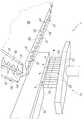
도 1은 본 발명에 따른 기계의 개략적인 평면도이며;
도 2는 도 1의 부분을 확대된 축척으로 도시하며;
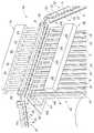
도 3은 도 1의 기계의 개략적인 정면도이며;
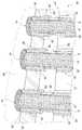
도 4는 도면의 기계 및/또는 본 발명에 따른 방법을 사용하여 얻을 수 있는 물품의 개략적인 단면도이며;
도 5는 도 4의 물품의 대체 실시예의 개략적인 단면도이며;
도 6은 도 1의 기계의 상세 사시도이며;
도 7은 도 1의 기계의 충전 유닛의 위에서 본 사시도이며;
도 8a와 8b는 두 개의 상이한 작동 구성들에서 도 1의 기계의 충전 유닛의 상세 측면 사시도들이며;
도 9는 명료성을 위해 부분적으로 단면 처리되고 부분들이 제거된, 도 8a와 8b의 충전 유닛의 상세 사시도이며;
도 10은 명료성을 위해 부분적으로 단면 처리되고 부분들이 제거된, 도 7의 충전 유닛의 부분 사시도이며;
도 11은 명료성을 위해 부분들이 제거된, 도 10의 충전 스테이션의 사시도이며;
도 12는 도 1의 기계의 부분(특히, 삽입 조립체)의 사시도이며;
도 13 내지 15는 도 12의 부분의 연속적인 작동 구성들에서의 측면 개략도들이며;
도 16은 도 12의 부분을 포함하는 도 1의 기계의 부분의 사시도이며;
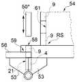
도 17은 도 1의 기계의 추가 부분(특히, 추가 삽입 조립체)의 사시도이며;
도 18 내지 20은 도 17의 부분의 상세 구성의 연속적인 작동 단계들을 (측면도들로) 개략적으로 도시한다.The invention will now be described with reference to the accompanying drawings, which illustrate examples of non-limiting embodiments.
1 is a schematic plan view of a machine according to the invention;
Figure 2 shows the portion of Figure 1 in an enlarged scale;
Figure 3 is a schematic front view of the machine of Figure 1;
4 is a schematic cross-sectional view of the article of the drawing and / or article obtainable using the method according to the invention;
Figure 5 is a schematic cross-sectional view of an alternative embodiment of the article of Figure 4;
Figure 6 is a detailed perspective view of the machine of Figure 1;
Figure 7 is a perspective view from above of the charging unit of the machine of Figure 1;
Figures 8a and 8b are detailed side perspective views of the charging unit of the machine of Figure 1 in two different operating configurations;
Fig. 9 is a detailed perspective view of the filling unit of Figs. 8a and 8b, partially cut away and removed for clarity;
10 is a partial perspective view of the filling unit of FIG. 7, partially cut away and removed for clarity;
Figure 11 is a perspective view of the filling station of Figure 10, with portions removed for clarity;
Figure 12 is a perspective view of a portion of the machine of Figure 1 (in particular, an insertion assembly);
Figures 13 to 15 are side schematic views in successive operating configurations of the portion of Figure 12;
Figure 16 is a perspective view of a portion of the machine of Figure 1 including the portion of Figure 12;
Figure 17 is a perspective view of an additional portion of the machine of Figure 1, particularly an additional insertion assembly;
Figs. 18-20 schematically show (in side view) successive operating steps of the detailed construction of the part of Fig.
도 1에서, 1은 담배 가공 산업의 실질적으로 원통형 물품들(2)(도 4와 5 참조)을 제조하기 위한 전체 기계를 나타낸다. 각각의 물품(2)은: 튜브형 몸체(tubular body)(3); 용기 요소(container element)(4); 및 실질적으로 단단한 요소(rigid element)(9)를 포함한다. 상기 용기 요소(4)는 튜브형 몸체(3)의 일단부(5)의 영역 내에 배치되며, 외부로 향한 단부 개구(end opening)(6)와, 적어도 하나의 측벽(7)과, 상기 단부 개구(5) 반대쪽의 바닥벽(8)을 가진다. 상기 단단한 요소(9)는 부분적으로 용기 요소(4)의 내부에 배치되며, 상기 단부 개구(6)를 통해 용기 요소(4)의 외부로 돌출된 (그리고, 특히, 일단부(5)를 통해 튜브형 몸체(3)의 외부로) 돌출된 단부(10)를 가진다.1, 1 represents an entire machine for manufacturing substantially cylindrical articles 2 (see Figs. 4 and 5) of the tobacco processing industry. Each article (2) comprises: a tubular body (3); A container element (4); And a substantially rigid element (9). The
몇몇의 실시예들에 따르면, 상기 용기 요소(4)는 종이 재료 또는 이와 유사한 것으로 만들어진다(따라서, 쉽게 변형 가능하다).According to some embodiments, the
특히, 상기 바닥벽(8)은 적어도 부분적으로 기체 투과성이다. 특정 실시예들에 따르면, 상기 바닥벽(8)은 다수의 구멍들을 구비한다.In particular, the
유리하게는, 상기 용기 요소(특히, 도 4와 5 참조)는 단부 개구(6)의 둘레로 연장된 칼라(collar)(11)를 가진다. 더욱 명확하게는, 상기 칼라(11)는 상기 측벽(7)의 단부 에지가 접힘으로써 형성된다.Advantageously, the container element (see FIGS. 4 and 5 in particular) has a
몇몇의 경우에, 상기 실질적으로 단단한 요소(9)는 발열 요소(탄소질의 - 예컨대, 탄소)를 포함한다(더욱 명확하게는, 발열 요소이다).In some cases, the substantially
특히, 상기 실질적으로 단단한 요소(9)와 용기 요소(4)는 실질적으로 합체된다. 상기 실질적으로 단단한 요소(9)는 용기 요소(4)와 형상 결합된다.In particular, the substantially
도 5는 실시예의 유리한 예를 도시하며, 여기서 상기 측벽(7)은 (추가적인) 변형부(deformation)(12)(보다 명확하게는, 용기 요소(4)의 내측을 향한 접힘부(fold))를 가지며, 실질적으로 단단한 요소(9)는 상기 변형부(12)와 결합하는 각개의 변형부(13)(오목부(depression))를 가진다. 상기 변형부들(12, 13)은 상기 용기 요소(4) 내부에 실질적으로 단단한 요소(9)의 위치 결정을 안정시키기 위해 서로 협력한다.Figure 5 shows an advantageous embodiment of an embodiment in which the
추가적으로 또는 선택적으로, 실질적으로 단단한 요소(9)를 용기 요소(4)에 결합하기 위해 접착제가 제공될 수 있다.Additionally or alternatively, an adhesive may be provided to join the substantially
각각의 물품(2)은, 추가적으로, 상기 용기 요소(4) 내부에서 상기 실질적으로 단단한 요소(9)와 상기 바닥벽(8) 사이에 배치된 성긴 재료(loose material)(14)(더욱 명확하게는, 풍미 발생 재료)를 포함한다.Each
상기 성긴 재료(14)는 일반적으로 분말 또는 입상 재료(특히, 분말)이다. 예를 들어, 상기 성긴 재료(14)는 담배(담배 입자들, 또는 더욱 명확하게는 담배 분말들)를 포함한다(더욱 구체적으로, 담배로 구성된다).The
대체 실시예들에 따르면, 상기 물품들(2)은 (성긴 재료(14) 대신에) 느슨하지 않은 재료(고체, 한 조각)를 포함한다.According to alternative embodiments, the
특정한 비제한적인 예들에 따르면, 상기 물품(2)은 또한 상기 단부(5) 반대쪽의 상기 튜브형 몸체(3)의 일단부(16)의 영역 내에 배치된 필터(15)를 포함한다.According to certain non-limiting examples, the
몇몇의 비제한적인 실시예들(도 1)에 따르면, 상기 기계(1)는 상기 용기 요소(4)를 위한 공급 조립체(feeding assembly)(17)를 포함하며, 이 공급 조립체는, 그 자체가 알려진 유형이며 개략적으로 도시된 공급용 저장고(feeding store)(18)를 포함하며, 이 공급용 저장고는 (단부 개구가 위쪽을 향하도록) 수직으로 지향된 상기 용기 요소들(4)을 제공하도록 구성된다. 특히, 공급용 저장고는, 상기 칼라(11)와 상호 작용하는 가이드들(guides)의 도움으로 상기 용기 요소들(4)을 선택하고 꺼내는 내부 컨베이어를 포함한다. 상기 비제한적인 실시예에 따르면, 상기 기계(1)는 상기 용기 요소들을 상기 저장고(18)로부터 작업 컨베이어(20)로 이송하는 컨베이어(19)(특히, 드럼(drum))를 포함한다.According to some non-limiting embodiments (FIG. 1), the
비제한적인 실시예들에 따르면, 상기 컨베이어(20)는 단속적인 동작으로, 즉, 상기 컨베이어(20)가 이동하는 동작 단계들(motion steps)과 상기 컨베이어(20)가 정지하는 정지 단계들의 주기적인 교번(cyclic alternation)을 제공하는 비연속적인 동작으로 회전하도록 설정된다. 상기 컨베이어(20)는 컨베이어(20) 자체의 주변부에 형성되며 그룹들로 분할된 다수의 시트들(seats)(21)을 구비한다. 특히, 각각의 그룹은 (평면에서, 상기 컨베이어(20)의 표면상에 다각형을 형성하도록) 직선을 따라서 배치된 다수의 시트들(21)을 가진다. 도 6에 도시된 바와 같이, 각각의 그룹은 일직선으로 배치된 14개의 시트들(21)을 가진다.According to non-limiting embodiments, the
동일한 그룹의 시트들(21)에 담겨 있는 물품들(2)의 제조 공정의 다음 단계들(예를 들어, 성긴 재료(14)의 로딩(loading), 실질적으로 단단한 요소(9)의 삽입과 같은 단계들)은 동시에 수행되며, 즉, 동일한 그룹의 시트들(21) 내에 담겨 있는 모든 용기 요소들(4)에서 동시에 일어난다.The following steps of the manufacturing process of the
도 6에 도시된 바와 같이, 상기 저장고(18)에서 나와서 컨베이어(19) 상에 정렬된 다수의 연속된 비어 있는 용기 요소들(4)은 픽업 스테이션(pick-up station)(PS)의 영역 내로 공급되며, 이 영역 내에 배치된 아암(22)은 각각의 그룹 내의 시트들(21)의 수와 동일한 다수의 흡입 부재들(sucking members)(23)(즉, 14개의 흡입 부재들(23))을 가지며 상기 컨베이어(20) 위에 배치된다.As shown in Figure 6, a plurality of successive
상기 아암(22)은 정지 상승 위치(rest raised position)와 하강 위치(lowered position) 사이에서 수직으로 이동 가능하다. 사용 시에, 상기 아암(22)은 상기 컨베이어(19)의 영역 내에서 하강 위치로 이동하며, 상기 부재들(23)은 상기 용기 요소들(4)로 들어가서 이들을 (흡입에 의해) 픽업한다; 이 시점에서, 상기 아암(22)은 상승하고 시트들(21) 위에서 이동하며, 그 다음에 각각의 용기 요소(4)를 각자의 시트(21) 내부로 가져오기 위해 하강한다. 이어서, 상기 부재들(23)은 비활성화되고, 상승하여 상기 컨베이어(19)로 복귀한다.The
유리하게는, 상기 아암(22)은 이동 수단(그 자체가 알려진 유형이며 도시되어 있지 않음)을 구비하며, 이는 상기 부재들(23)을 상기 컨베이어 요소(19)로부터 용기 요소들(4)을 픽업하기 위해 요구되는 (도 6에 도시된 바와 같은) 닫힌 배치 형태(closed configuration)로부터 용기 요소들(4)을 (서로 이격된) 시트들(21) 내부로 삽입하기 위해 필요한 열린 배치 형태로 이동시킴으로써, 상기 부재들(23)을 서로 이격되게 하도록 구성된다.Advantageously, the
이 시점에서, 상기 컨베이어(20)는 용기 요소들(4)을 픽업 스테이션(PS)으로부터 로딩 스테이션(CS)으로 공급하며, 상기 로딩 스테이션(CS)은 각각의 용기 요소(4) 내부로 성긴 재료(14)를 삽입하도록 구성된 충전 유닛(filling unit)(24) 아래에서 이동한다.At this point the
도 7에 도시된 것을 참조하면, 상기 충전 유닛(24)은 담배 분말을 이송하기 위한 스크류 컨베이어에 의해 만들어진 고정된 상부 호퍼(hopper)(25)를 포함한다. 상기 스크류 컨베이어는, 수직 축을 가진 외부 튜브형 슬리브(26)를 포함하며, 상기 슬리브(26)는 다음에 하부 호퍼(27) 내로 배출되는 담배 분말을 위한 로딩 마우스(loading mouth)의 상단부의 영역 내에 제공된다.7, the filling
상기 하부 챔버(27) 내에 담배 분말을 수집하기 위한 고리형 챔버(C)가 존재하며, 이는 원통형 측벽(28)에 의해 한정된다. 상기 상부 호퍼(25)의 배출 마우스는 수집 챔버(C)의 영역 내에 배치되며, 수집 챔버(C)의 영역에 대해 정반대쪽에는 한 쌍의 스크래퍼 요소들(scraper elements)이 수용되고, 한 쌍의 스크래퍼 요소들 각각은 29와 30으로 표시되고 잇따라 배치된다. 특히, 상기 스크래퍼 요소(29)는 분말 재료의 거친 스크래핑(rough scraping)을 달성하기 위해 제공되며; 상기 스크래퍼 요소(29)는 상기 원통형 측벽(28)에 연결되고, 수집 챔버(C)의 폭과 동일한 크기를 가진 격벽(bulkhead)으로 만들어진다. 상기 스크래퍼 요소(29)로부터 하류에 분말 재료의 섬세한 스크래핑(fine scraping)을 달성하기 위해 추가 스크래퍼 요소(30)가 제공되며; 상기 스크래퍼 요소(30)는 원통형 측벽(28)에 고정되고 수집 챔버(C)의 폭보다 작은 크기를 가진 격벽으로 만들어진다.There is an annular chamber (C) for collecting the tobacco powder in the lower chamber (27), which is defined by the cylindrical side wall (28). The discharge mouth of the
상기 충전 유닛(24)은, 상기 하부 호퍼(27) 아래에 배치되고 비어 있는 용기 요소들(4)을 성긴 재료(14)로 충전하도록 만들어진 다수의 디스크들을 포함하며, 다수의 디스크들은 공통 수직 회전축 둘레를 주어진 피치(pitch)로 회전하도록 만들어진다.The charging
특히, 상기 수집 챔버(C)의 바닥 벽을 형성하는 디스크(31)는 원통형 측벽(28)에 연결되며, 상기 디스크(31) 자체의 주변부에 형성되고 그룹들로 분할된 다수의 관통-구멍들(32)을 구비하며; 각각의 그룹은 각각의 그룹의 시트들(21)의 수와 동일하며 직선으로 배열된 다수의 구멍들(32)(즉, 도면에는 오직 10개가 도시되어 있지만, 14개의 구멍들(32))을 가진다Particularly, the
도 8과 9에 더욱 명확하게 도시된 바와 같이, 상기 디스크(31) 아래에 추가 디스크(33)가 제공되며, 상기 추가 디스크(33)에도 각각의 그룹의 시트들(21)의 수와 동일하며 직선으로 배열된 다수의 관통-구멍들(34)(즉, 도면에는 오직 10개가 도시되어 있지만, 14개의 구멍들(34))이 디스크(33) 자체의 주변부에 형성된다.An
상기 디스크(33)의 구멍들(34)은 디스크(31)의 구멍들(32)과 직접 마주봄으로써, 각개의 쌍의 신축 가이드들(telescopic guides)(35, 36)에 의해 다량의 분말 담배를 수용하기 위한 다수의 격실들(compartments)(S)을 형성한다. 특히, 상부 가이드 요소(35)는 구멍(32) 내부에 삽입되고 대응되는 구멍(34) 내부에 수용된 각개의 하부 가이드 요소(36)와 협력하여 분말 담배를 수집하기 위한 격실(S)을 형성한다.The
상기 두 개의 디스크들(31 및 33)은 서로에 대해 수직 방향으로 이동할 수 있으며, 이에 의해 상호간 거리와 단일의 격실(S)의 부피가 상부 가이드 요소(35)의 어깨부(shoulder)(38)가 하부 가이드요소(36)의 상부 에지(39)에 접하는 (그리고, 두 개의 디스크들(31, 33)이 서로로부터 가능한 최소 거리를 두고 배치되는) 최소 부피와 상기 두 개의 디스크들(31 및 32)이 서로로부터 가능한 최대 거리를 두고 배치되는 최대 부피 사이에서 변하게 된다.The two
바람직한 실시예에 따르면, 상기 디스크(33)는 고정됨에 반해, 상기 디스크(31)는 상기 격실(S)의 최소 부피와 최대 부피에 각각 대응되는 두 개의 극한 위치들 사이에서 수직 방향으로 이동할 수 있으며, 이와 반대도 가능하다.According to a preferred embodiment, the
단일의 격실(S)의 부피(즉, 두 개의 디스크들(31, 32) 사이의 상대적인 거리)는 용기 요소(4) 내부로 삽입될 분말 담배의 무게(즉, 양)에 따라 물품들(2)의 제조 공정의 예비 단계에서 결정된다. 선택적으로 또는 추가적으로, 성긴 재료(14)의 충전이 가능한 한 정확하게 되도록 하기 위해, 이후의 측정값에 근거한 피드백에 따라서 상기 격실(S)의 부피는 변한다.The volume of a single compartment S (i.e., the relative distance between the two
상기 격실(S)은 상부 호퍼(25)로부터 주입되는 담배 분말로 충전되며, 상기 수집 챔버(C) 내부에 직렬로 배치된 두 개의 스크래퍼 요소들(29, 30)의 작동은 각각의 격실(S)의 내부에 담긴 분말 담배의 양을 조절하고 동등하게 만든다.The compartments S are filled with tobacco powder injected from the
도 8, 9 및 11에 도시된 바와 같이, 각각의 격실(S)은 바닥에서 추가 디스크(40)에 의해 폐쇄되며, 상기 추가 디스크(40)는 상기 디스크(33) 아래에 배치되며, 미세-천공형(micro-perforated) 플라스틱 재료로 만들어지며 서로로부터 독립적인 다수의 섹터들(sectors)(40*)로 분할된 고리형 요소로 설계된다. 각각의 섹터(40*)는, 섹터(40*) 자체의 내측 에지 가까이에 형성되며 직선으로 배치되고 각각의 그룹 내의 시트들(21)의 수와 동일한 다수의 관통-구멍들(41)(즉, 14개의 구멍들(41))을 구비한다.8, 9 and 11, each compartment S is closed by an
각각의 섹터(40*)는 두 개의 단부 위치들, (도 8a에 도시된) 전진 위치(advanced position)와 (도 8b에 도시된) 후퇴 위치(retracted position) 사이에서 이동할 수 있으며, 반대도 같다. 전진 위치에서, 상기 섹터(40*)는 단일 격실(S)의 바닥 벽(base wall)을 형성하며 외측 에지는 원통형 측벽(28) 및 두 개의 디스크들(31, 33)의 외측 표면들과 동일 면상에 있다.Each
전진 위치로부터 상기 섹터(40*)는 후퇴하여 후퇴 위치에 배치될 때까지 상기 충전 유닛(24)의 외측을 향해 돌출되도록 제어되며, 후퇴 위치에서 각각의 구멍(41)은 각개의 구멍(34)과 마주보는 위치에 배치된다. 다시 말하면, 각각의 구멍(41)은 각개의 격실(S)의 영역 내에 정확하게 배치된다.From the forward position, the
마지막으로, 도 10에 도시된 바와 같이, 상기 충전 유닛(24)은 상기 디스크(40) 아래에 배치된 추가 디스크(42)를 포함하며, 상기 추가 디스크(42)는 상기 디스크(42) 자체의 외측 에지 가까이에 형성되고 그룹들로 분할된 다수의 관통-개구들(43)을 구비하며; 각각의 그룹은, 직선으로 배치되고 각각의 그룹 내의 시트들(21)의 수와 동일한 다수의 개구들(43)(즉, 14개의 개구들(43))을 가진다.10, the charging
특히, 상기 개구들(43)은 상기 섹터(40*)를 사이에 두고 각개의 격실(S)의 영역 내에 정확하게 배치된다. 상기 개구들(43)은, 내측에 아래쪽으로 지향된 안내 캐비티(guiding cavity)(44)를 형성하기 위한 고리형 U-형상 에지에 의해 한정된다. 상기 안내 캐비티(44)는 성긴 재료(14)(특히, 분말 담배)의 유출과 퇴적을 상당히 감소시키도록 상기 용기 요소(4)의 상부 에지를 위한 가이드로서의 역할을 한다.In particular, the
도 7에 도시된 바와 같이, 상기 스크래퍼 요소(30) 다음에, 상기 수집 챔버(C) 내부에 아암(45)이 수용되며, 상기 아암(45)은 다수의 푸셔 요소들(pusher elements)(46)을 구비한다. 특히, 상기 아암(45)은, 직선으로 배치되고 각각의 그룹의 시트들(21)의 수와 동일한 다수의 푸셔 요소들(즉, 14개의 푸셔 요소들(46))을 가진다. 상기 아암(45)은 상승 위치와 전진 작동 위치 사이에서 수직 방향으로 이동할 수 있으며, 전진 작동 위치에서 각각의 푸셔 요소(46)는 각개의 격실(S) 내부에 적어도 부분적으로 삽입되며, 반대도 같다.7, after the
상기 로딩 스테이션(CS)의 영역 내에, (도 10에 부분적으로 도시된 바와 같이) 상기 디스크(42) 아래에 배치되며 다수의 지지 요소들(48)을 구비하는 아암(47)이 제공된다. 특히, 상기 아암(47)은, 일직선으로 배치되며 각각의 그룹 내의 시트들(21)의 수와 동일한 다소의 지지 요소들(즉, 14개의 지지 요소들(48))을 가진다.Within the region of the loading station CS there is provided an
상기 로딩 스테이션(CS)에서, 상기 디스크들(31, 32, 40, 42)은 각각의 격실(S)이 각개의 푸셔 요소(46)와 각개의 지지 요소(48) 영역 내에 배치되도록 허용하는 위치에 정지된다. 상기 아암(47)은 정지 위치와 상승 작동위치 사이에서 수직 방향으로 이동할 수 있으며, 반대도 같다.In the loading station CS, the
상기 로딩 스테이션(CS)에서, 상기 용기 요소(5)에 담배 분말을 로딩하는 아래의 단계들이 연속해서 일어난다.In the loading station CS, the following steps of loading the tobacco powder into the
- 상기 컨베이어(20)는 로딩 스테이션(CS)의 영역 내의 비어 있는 용기 요소들(4)을 상기 디스크(42) 아래로 그리고 상기 아암(47) 위로 이송한다;- the conveyor (20) transfers empty container elements (4) in the region of the loading station (CS) under the disk (42) and onto the arm (47);
- 상기 시트들(21) 내의 죠오들(jaws)은 각개의 용기 요소들(4)을 해제하며, 용기 요소들 각각은 각개의 지지 요소(48)에 의해 지지된다;The jaws in the
- 상기 아암(47)은 정지 위치로부터 상승 작동 위치로 이동하도록 작동된다: 이렇게 하여 각각의 지지 요소(48)는 각개의 용기 요소들(4)을 상부 에지가 연관된 안내 캐비티(44) 내에 삽입될 때까지 상승시킨다;The
- 격실(S) 내에 담겨 있는 담배 분말이 용기 요소(4)를 향해 내려가도록 허용하기 위해, 각각의 구멍(41)이 각개의 구멍(34)과 각개의 격실(S)의 영역 내에 배치되도록 상기 섹터(40*)는 전진 위치로부터 후퇴 위치까지 이동한다;To allow each
- 상기 아암(45)은 상승 위치로부터 전진 작동 위치로 하강됨으로써, 각각의 푸셔 요소(46)는 각개의 격실(S) 내부로 삽입된다; 전진 작동 위치 쪽으로의 상기 아암(45)의 이동은, 푸셔 요소들(46)이 용기 요소들(4) 내부로의 담배 분발의 하강을 동반하는 제1 단계와, 용기 요소들(4)이 충전된 때, 상기 아암(45)이 안내 캐비티(44)와 결합 해제된 용기 요소들(4)의 하향 이동을 동반하는 제2 단계로 분할된다;- the arm (45) is lowered from the raised position to the advanced operating position such that each pusher element (46) is inserted into the respective compartment (S); The movement of the
- 전진 작동 위치에 도달한 때, 상기 아암(45)은 상승 위치로 복귀할 때까지 다시 뒤로 이동하며 격실(S)로부터 밖으로 돌출된다;When reaching the forward operating position, the
- 상기 아암(45)의 이동과 동시에, 상기 아암(47)은 상승 작동 위치로부터 정지 위치로 이동하도록 작동되며, 정지 위치에서 아암(47)은 담배 분말을 담고 있는 용기 요소들(4)을 용기 요소(4)를 유지하기 위한 죠오들(jaws)을 구비한 각개의 시트(21) 내로 이송한다;At the same time as the movement of the
- 상기 섹터(40*)는 후퇴 위치로부터 다시 전진 위치에 배치될 때까지 전진 이동함으로써, 격실들(S)과 개구들(43) 사이의 연통을 방지한다.- the
- 상기 충전 유닛(24)의 디스크들(31, 33, 40, 42)은 마지막으로 회전을 시작하며, 상기 컨베이어(20)는 담배를 담고 있는 용기 요소들(4)을 전진 이송한다.The
담배 분말을 담고 있는 용기 요소들(5)의 하강을 동반하는 상기 아암(45)의 이동은 담배 분말의 덩어리를 원하는 밀도가 얻어질 때까지 약간 압축하는 것을 허용한다는 것을 주목하여야 한다.It should be noted that the movement of the
상기 기계(1)에 관하여 지금까지 설명된 것은 어떤 특정한 비제한적인 실시예들에 관한 것으로서 고려된다.What has been described so far in relation to the
본 발명의 제1 측면에 따르면, 담배 가공 산업의 실질적으로 원통형 물품들(2)(도 4와 5 참조)을 제조하기 위한 기계(1)(특히, 도 1 내지 3)가 제공된다. 각각의 물품(2)은 위에서 설명된 바와 같다.According to a first aspect of the present invention, there is provided a machine 1 (particularly Figs. 1 to 3) for manufacturing substantially cylindrical articles 2 (see Figs. 4 and 5) of the tobacco processing industry. Each
상기 기계(1)는, 성긴 재료(14)를 담고 있는 적어도 하나의 용기 요소(4)를 삽입 스테이션(IS)(예를 들어, 도 12 참조)을 통과하는 주어진 경로(P1)를 따라서 이동시키도록 구성되며, 상기 용기 요소(4)를 수용하기 위한 적어도 하나의 시트(21)를 포함하는 컨베이어(20); 각개의 실질적으로 단단한 요소(9)를 상기 용기 요소(4) 내에 삽입시키도록 구성되며, 삽입 스테이션(IS)의 영역 내에 배치되고, 실질적으로 단단한 요소(9)를 용기 요소(4) 내에 부분적으로 삽입하기 위해 상기 단단한 요소(9)를 상기 단부 개구(6)를 통과하도록 아래쪽으로 미는 푸싱 유닛(pushing unit)(50)을 포함하는 삽입 조립체(49); 및 상기 푸싱 유닛(50)의 밀기(push)에 상반되는 저항(resistance)을 상기 바닥벽에 인가하기 위한 콘트라스트 수단(contrast means)(51);을 포함한다. 이 방식으로, 실질적으로 단단한 요소를, 재현할 수 있으며, 빠르고 정확한 방식으로, 용기 요소(4)의 낮은 손상 위험성을 가지며 삽입하는 것이 가능하다.The
특히, 상기 시트(21)는 상기 측벽(7)과 접촉되도록 구성된 적어도 하나의 내부 측면을 구비한다. 이 방식에서, (바람직한 실시예들에서, 무게가 가볍고 비교적 연약한 재료인) 상기 측벽(7)이 안정화되며, 따라서 용기 요소를 손상시키는 위험을 추가적으로 현저히 감소시킨다는 것을 주목하라.In particular, the
유리하게는, 상기 콘트라스트 수단(51)은 상기 바닥벽(8)과 접촉하기 위해 위쪽으로 이동하도록 구성된 적어도 하나의 이동식 헤드(52)를 포함한다.Advantageously, the contrast means (51) comprises at least one movable head (52) configured to move upwards to contact the bottom wall (8).
또한, 이러한 장치는 상기 용기 요소(4)의 손상 위험을 감소시킨다(이 경우에, 특히, 상기 바닥벽(8)은 운반 및 시트(21) 내부로의 삽입 중에 낮은 응력을 받는다).This arrangement also reduces the risk of damage to the container element 4 (in this case, in particular, the
유리하게는, 상기 컨베이어(20)는 적어도 두 개의 죠오들(jaws)(53)을 포함하며, 상기 죠오들(53) 중 적어도 하나는 다른 하나에 대해 움직일 수 있어서, 상기 죠오들(53)은 열린 형태(예컨대, 도 6)로부터 상기 시트(21)를 형성하는 닫힌 형태(예컨대, 도 12)로 움직일 수 있다. 특히, 상기 두 개의 죠오들(53) 중 적어도 하나는 다른 것에 대해 회전 가능하다(더욱 명확하게는, 선회(swivel)할 수 있다). 더욱 명확하게는, 두 개의 죠오들(53)이 이동할 수 있다(선회할 수 있다).Advantageously, the
더욱 구체적으로, 상기 시트(21)는 용기 요소(4)를 수용하도록 설계되며, 용기 요소의 칼라는 상기 시트(21)의 외부에 (바로) 배치됨으로써 상기 칼라는 칼라 자체의 (상부) 표면과 접촉한다.More specifically, the
위에서 설명된 죠오들(53)은 (단독으로 또는 상기 이동식 헤드와 조합하여)상기 용기 요소(4)를 특히 부드럽게 대하도록 허용한다는 것을 주목하라.Note that the
몇몇의 실시예들에 따르면, 상기 기계(1)는 상기 죠오들(53)을 움직이기 위한 액추에이터들(도시되지 않았지만 알려진 유형의; 예를 들어, 중심 운동 소스(central motion source)에 연결된 전기 모터 또는 운동학적 메커니즘)을 포함한다.According to some embodiments, the
유리하게는, 상기 시트(21)는 (상기 이동식 헤드(52)의 통과를 허용하기 위해) 아래쪽으로 열려 있다, 유리하게는, 상기 시트(21)는 (상기 푸싱 유닛(50)의 푸셔(50*)의 통과를 허용하기 위해) 위쪽으로 열려 있다.Advantageously, the
실시예들의 몇몇 예들에 따르면, 상기 기계(1)는 또한 공급 조립체(54)를 포함하며(예를 들어, 도 12와 13), 상기 공급 조립체(54)는 실질적으로 단단한 요소(9)를 삽입 스테이션(IS)으로 공급하도록 구성되며, 실질적으로 단단한 요소(9)를 상기 푸싱 유닛(50)이 실질적으로 단단한 요소(9)를 상기 단부 개구(6)를 통과하도록 미는 방향에 대해 횡방향으로 이동시키기 위한 이송 장치(55)를 포함한다(특히, 도 13 내지 15 참조).According to some examples of embodiments, the
유리하게는, 상기 이송 장치(55)는 두 개의 하프-쉘들(half-shells)(56, 57)을 포함하며, 이들은 이들 사이에 실질적으로 단단한 요소(9)를 수용하기 위해 서로 결합되도록 구성된다. 특히, 작동 수단(actuating means)(도시되지 않았지만 알려진 유형의; 예를 들어, 중심 운동 소스(central motion source)에 연결된 전기 모터 또는 운동학적 메커니즘)이 제1 및 제2 하프-쉘들을 (별도로 그리고 함께) 이동시키기 위해 제공된다.Advantageously, the
더욱 명확하게는, 상기 작동 수단은 (하프-쉘(57)과 관계없이; 더욱 구체적으로, 하프-쉘(57)을 실질적으로 움직이지 않도록 유지하면서) 하프-쉘(56)을 삽입 스테이션(IS)을 통과하도록 이동시키며, 상기 하프-쉘들(56, 57)을 함께 수집 스테이션(collection station)(RS)(이 영역에서, 실질적으로 단단한 요소(9)가 하프-쉘(57)로 제공된다)으로부터 삽입 스테이션(IS)으로 이동시키도록 구성된다.More specifically, the actuating means is configured to move the half-
유리하게는, 상기 하프-쉘들(56, 57)은, 결합된 형태에서, (적어도 부분적으로) 위쪽을 향한 통로 개구(passage opening)(58)를 가진다. 상기 푸싱 유닛(50)의 푸셔(50*)는 실질적으로 단단한 요소(9)와 접촉하여 단단한 요소(9)를 상기 용기 요소(4) 쪽으로 밀기 위해 상기 통로 개구(58)를 통과하도록 구성된다.Advantageously, the half-
특히, 상기 통로 개구(58)는 (오직) 상기 하프-쉘(57)에만 형성된다. 더욱 구체적으로, 상기 하프-쉘(57)은, 상부(upper portion)(59)와 하부(lower portion)(60)를 포함하며, 상기 상부(59)는 실질적으로 단단한 요소(9)의 제1 (상부) 부분을 둘러싸도록 구성되고, 실질적으로 단단한 요소(9)의 통과를 허용하도록 구성된 위쪽을 향한 상기 개구(58)를 구비하며; 상기 하부(60)는 상기 하프-쉘(56)과 협력하여 실질적으로 단단한 요소(9)의 제2 (하부) 부분을 둘러싸도록 구성된다.In particular, the
몇몇의 실시예들에 따르면, 상기 공급 조립체(feeding assembly)(54)는 실질적으로 단단한 요소(9)를 이송 장치(55)로, 특히 상기 수집 스테이션(RS)으로 이송하기 위한 적어도 하나의 공급 채널(61)을 포함한다.According to some embodiments, the feeding
특히, 상기 채널(61)은 단단한 요소(9)를 길이 방향으로 그리고 아래쪽으로(특히, 실질적으로 수직으로) 공급하도록 구성된다.In particular, the
더욱, 명확하게는, 상기 공급 채널(61)은 실질적으로 단단한 요소(9)가 상기 공급 채널(61) 자체 내부에서 중력에 의해 이동하도록 아래쪽으로 지향된다(상부로부터 하부로 연장된다).More specifically, the
특정 실시예들에 따르면, 상기 공급 채널(61)은 차례로 쌓인 실질적으로 단단한 요소들(9)의 기둥을 수용하도록 구성된다.According to certain embodiments, the
특히, 상기 공급 채널(61)은 실질적으로 단단한 요소를 상기 통로 개구(58)를 통과하여 가져다 주도록 구성된다.In particular, the feed channel (61) is configured to bring substantially rigid elements through the passage opening (58).
몇몇의 실시예들에 따르면, 상기 공급 조립체(54)는 잇따라 배치된 다수의 공급 채널들(61)과 분배 장치(distribution device)(62)를 포함한다. 특히, 상기 분배 장치(62)는 실질적으로 단단한 요소(9)를 상이한 채널들(61)로 가져오도록 구성된다.According to some embodiments, the
유리하게는, 상기 분배 장치(62)는 실질적으로 단단한 요소들(9)을 상기 이송 장치(55) 반대쪽의 상기 공급 채널들(61)의 (상측) 단부들(64)로 공급하도록 구성된 변형 가능한 덕트(deformable duct)(63)를 포함한다.Advantageously, the dispensing
특히, 상기 기계(1)는(더욱 구체적으로, 상기 공급 조립체(54)는), 상기 변형 가능한 덕트(63)의 하나의 배출 단부(65)를 상기 공급 채널들(61)의 연속 방향과 평행한 방향으로 이동시키는 추가 작동 수단(도시되지 않았지만 알려진 유형의; 예를 들어, 중심 운동 소스(central motion source)에 연결된 전기 모터 또는 운동학적 메커니즘)을 포함한다. 이렇게 하여, 상기 배출 단부(65)는 실질적으로 단단한 요소(9)를 실제로 요구하는 채널(61)의 영역 내로 이동되며, 따라서 상기 채널(61)은 보충된다.In particular, the machine 1 (more particularly, the feed assembly 54) is configured such that one
유리하게는, 상기 추가 작동 수단은 또한 상기 공급 채널들(61)의 연속 방향과 평행한 방향에 대해 횡방향으로 상기 배출 단부(65)를 이동시키도록 구성된다. 이렇게 하여, (특히, 상기 단부들(64)이 전방 및/또는 후방으로 이동함에 의해) 공급을 요구하지 않는 채널들(61)로 공급하는 것을 방지할 수 있다.Advantageously, said additional actuating means are also configured to move said
유리하게는, 상기 공급 채널들(61)의 연속에 대해 오프셋 된 (그리고 평행한) 지지면(support surface)이 제공되며, 상기 배출 단부(65)는 실질적으로 단단한 요소들(9)이 배출 단부로부터 빠져나오는 것을 방지하도록 상기 지지면 상에서 슬라이딩할 수 있다.Advantageously, a support surface is provided which is offset (and parallel) with respect to the continuation of said
몇몇의 실시예들에 따르면, 상기 기계(1)는(더욱 구체적으로, 상기 공급 조립체(54)는), 상기 공급 채널(61) 내부에 실질적으로 단단한 요소(9)의 존재를 검출하기 위한 (도시되지 않았지만 알려진 유형의) 센서들; 및 상기 센서들에 의해 검출된 것에 따라 추가 작동 수단을 작동시키도록 설계된 (도시되지 않았지만 알려진 유형의) 제어 유닛;을 포함한다. 예를 들어, 상기 센서들은 채널(61) 내에 담긴 실질적으로 단단한 요소들(9)의 기둥이 최소 높이 아래이거나 또는 최대 높이 위일 때 신호를 발생시킬 수 있다.According to some embodiments, the machine 1 (more particularly, the supply assembly 54) is configured to detect the presence of a substantially
상기한 바와 같은 실질적으로 단단한 요소들(9)의 공급은 특히 효율적이고 정확하다.The supply of substantially
몇몇의 실시예들에 따르면, 상기 공급 조립체(54)는 (그 자체가 알려진 유형의) 적어도 하나의 저장고(54*)와, 실질적으로 단단한 요소들을 상기 분배 장치(62)로 가져오기 위한 컨베이어(62*)를 포함한다. 유리하게는, 상기 저장고(62*) 내에, 필요에 따라 지향된 단단한 요소들(9)을 선택하고 픽업할 수 있는 선택 및 수집 시스템이 제공된다.According to some embodiments, the
본 발명의 제2 측면에 따르면, 담배 가공 산업의 실질적으로 원통형 물품들(2)(도 4와 5 참조)을 제조하기 위한 기계(1)(특히, 도 1 내지 3)가 제공된다. 각각의 물품(2)은 위에서 설명한 바와 같다.According to a second aspect of the present invention, there is provided a machine 1 (particularly Figs. 1 to 3) for manufacturing substantially cylindrical articles 2 (see Figs. 4 and 5) of the tobacco processing industry. Each
상기 기계(1)는 컨베이어(66)와 삽입 조립체(70)를 포함하며, 상기 컨베이어(66)는, 실질적으로 단단한 요소(9)와 용기 요소(4)를 포함하는 (특히, 구성되는) 적어도 하나의 결합된 요소(67)를 삽입 스테이션(IS2)을 통과하는 주어진 경로(P2)를 따라서 이동시키도록 구성되고, 적어도 하나의 시트(seat)(68)를 포함한다. 상기 시트(68)는 결합된 요소(67)를 수용하도록 설계되고, 실질적으로 단단한 요소(9)를 차단하며 삽입 스테이션(IS2)의 영역에서 상기 용기 요소(4)를 적어도 부분적으로 자유롭게 놓아두도록 구성된 차단 장치(69)를 포함한다. 상기 삽입 조립체(70)는, 결합된 요소(67)를 대응되는 튜브형 몸체(3) 내부로 적어도 부분적으로 삽입하도록 구성되며, 삽입 스테이션(IS2)의 영역 내에 배치되고, (특히, 용기 요소(4)의 적어도 부분이 튜브형 몸체(3) 내부로 삽입되도록) 결합된 요소(67)와 튜브형 몸체(3) 중 하나를 다른 하나 쪽으로 밀기 위한 푸싱 유닛(71)을 포함한다.The
더욱 명확하게는, 상기 푸싱 유닛(71)은 튜브형 몸체(3)를 결합된 요소(67) 쪽으로 밀도록 구성된다.More specifically, the pushing
(도면들에 도시된 바와 같은) 몇몇의 실시예들에 따르면, 상기 컨베이어는 결합된 요소들(67)의 그룹을 단속적인 동작으로(즉, 동작 단계들(motion steps)의 주기적인 교번(cyclic alternation)을 제공하는 비연속적인 동작으로) 삽입 스테이션(IS2)으로 공급하도록 구성됨으로써, 정지 단계에서, 상기 푸싱 유닛(71)은 다수의 결합된 요소들(67)을 각개의 튜브형 몸체들(3) 내로 삽입한다.According to some embodiments (as shown in the figures), the conveyor may move the group of associated
몇몇의 경우에, 상기 푸싱 유닛(71)은 각개의 튜브형 몸체(3)를 동시에 밀도록 구성된 다수의 푸셔들을 포함한다.In some cases, the pushing
특히, 상기 컨베이어(66)는 결합된 요소(67)를 (결합된 요소(67)의 길이 방향 연장에 대하여) 횡방향으로 이동시키도록 구성된다. 더욱 명확하게는, 상기 컨베이어(66)MS 결합된 요소(67)를 수평으로 이동시키도록 구성된다.In particular, the
특히, 상기 컨베이어(66)는 홈(groove)(72)을 횡방향으로 이동시키도록 구성된다.In particular, the
도면들에 도시된 예에 따르면, 상기 시트(68)는 시트(68) 자체 내에 배치된 용기 요소(4)의 단부 개구(6)(실질적으로 단단한 요소(9)가 결합된 단부 개구)가 측방향으로(특히, 실질적으로 수평으로) 지향되도록 구성된다.According to the example shown in the figures, the
(도시된 예에서와 같은) 일부 경우에, 상기 컨베이어(66)는 튜브형 몸체(3)을 수용하도록 설계된 적어도 하나의 홈(72)을 포함한다. 상기 시트(68)는 상기 홈(72)의 열린 단부와 마주보도록 (상기 홈의 길이 방향 연장의 방향으로) 배치된다. 특히, 상기 시트(68)는 개구(73)를 포함하며, (결합된 요소(67)가 시트(68) 내에 배치된 때) 상기 개구(73)는 결합된 요소(67)에 의해 횡단되도록 구성되고 상기 홈(72)을 향하며 상기 홈(72)과 마주본다. 다시 말하면, 상기 결합된 요소(67)는 (상기 컨베이어(66)에 의해 운반된 때) 상기 시트(72)의 개구(73)를 통해 연장되며, 이 개구는 상기 홈(72) 쪽을 향한다.In some cases (such as in the illustrated example), the
유리하게는, 상기 삽입 조립체(70)는, 튜브형 몸체(3)를 수용하도록 설계된 제2 홈(74)을 구비한 플레이트(73)(도 18-20); 및 상기 플레이트(73)를 정지 위치(도 18)와 작동 위치(도 19와 20) 사이에서 이동시키기 위한 작동 수단(도시되지 않았지만 알려진 유형의; 예를 들어, 중심 운동 소스(central motion source)에 연결된 전기 모터 또는 운동학적 메커니즘);을 포함하며, 상기 정지 위치에서 상기 플레이트(73) 자체는 컨베이어(66)로부터 분리되고, 상기 작동 위치에서 상기 플레이트(73)는 컨베이어(66)에 결합됨으로써, 상기 홈(74)이 상기 홈(72)과 마주보게 되고(상기 홈(74)이 상기 홈(72)의 상부에 배치되고), 이에 따라 함께 튜브형 채널을 형성하며, 튜브형 채널은 그 내부에서 튜브형 몸체(3)의 슬라이딩을 허용하도록 형상화된다.Advantageously, the
상기 플레이트(73)는 튜브형 몸체(3)를 올바로 지향되도록 유지하는 것을 도우며, 이에 따라, 결합된 요소(67)가 튜브형 몸체(3) 자체 내에 더욱 정확하게 삽입되도록 만든다.The
유리하게는, 상기 차단 장치(69)는, 실질적으로 단단한 요소(9)의 적어도 일 부분을 차단하도록 구성된 차단 요소(75); 상기 용기 요소(4)를 적어도 부분적으로 둘러싸기 위한 차단 요소(76); 및 상기 용기 요소(4)의 적어도 일부분이 걸리지 않고 튜브형 몸체(3) 내부로 삽입될 수 있도록 상기 차단 요소(75)와는 독립적으로 (더욱 명확하게는, 상기 차단 요소(75)에 대하여) 상기 차단 요소(76)를 이동시키기 위한 작동 수단(도시되지 않았지만 알려진 유형의; 예를 들어, 중심 운동 소스에 연결된 전기 모터 또는 운동학적 메커니즘);을 포함한다.Advantageously, the shielding
유리하게는, 상기 시트(68)는 상기 칼라(11)가 상기 차단 요소(75)의 외측 표면과 접촉하여 배치되도록 구성된다.Advantageously, the
몇몇의 실시예들에 따르면, 상기 기계(1)는 공급 조립체(77)를 포함하며, 상기 공급 조립체(77)는 튜브형 몸체(3)를 컨베이어(66)로, 특히, 각개의 홈(72) 내부로 공급하도록 구성되며, 특히, 튜브형 몸체(3)를 각개의 홈(72) 내부로 길이 방향으로 (그리고 수평으로) 밀기 위한 푸싱 조립체(8)를 구비한다.According to some embodiments, the
몇몇의 경우에, 상기 공급 조립체(77)는 저장고(79)를 포함하며, 상기 저장고(79) 내에는 많은 튜브형 몸체들(3)이 실질적으로 수평 방향으로 유지된다. 특히, 상기 푸싱 조립체(78)는 튜브형 몸체(3)를 상기 저장고(79)로부터(더욱 정확하게는, 상기 저장고(79)의 하부 출구로부터) 이동시키도록 구성된다.In some cases, the
유리하게는, 상기 컨베이어(66)는 결합된 요소들(67)의 그룹을 실질적으로 동시에 삽입 스테이션(IS2) 내로 가져오기 위해 단속적인 동작으로 이동하도록 구성된다. 상기 삽입 조립체(70)는 다수의 결합된 요소들(67) 각각을 적어도 부분적으로 각개의 튜브형 몸체(3) 내부로 삽입하도록 구성된다.Advantageously, the
도시된 바와 같은 몇몇의 경우에, 상기 기계(1)는 또한 컨베이어(66)로부터 물품들(2)의 그룹을 픽업하여 추가 출력 컨베이어로 공급하도록 구성된 배출 아암(66*)을 포함한다.In some cases, as shown, the
유리하게는, 본 발명의 제1 측면의 기계(1)로 표시된 것은 본 발명의 제2 측면의 기계(1)에 대해 표시된 것과의 조합이다.Advantageously, the
본 발명의 제3 측면에 따르면, 담배 가공 산업의 실질적으로 원통형 물품들(2)(도 4와 5 참조)을 제조하기 위한 방법이 제공된다. 각각의 물품(2)은 상기한 바와 같다.According to a third aspect of the present invention, there is provided a method for manufacturing substantially cylindrical articles 2 (see Figs. 4 and 5) of the tobacco processing industry. Each
상기 방법은, 위쪽으로 향하는 단부 개구(6)를 가진 용기 요소(4)를 로딩 스테이션(CS)과 상기 로딩 스테이션(CS)으로부터 하류에 배치된 제1 삽입 스테이션(IS)을 통과하는 주어진 경로(P1)를 따라서 운반하기 위한 운반 단계(conveying step); 상기 로딩 스테이션(CS)의 영역 내에서 상기 용기 요소(4) 내부로 성긴 재료(loose material)(14)가 삽입되는 로딩 단계; 상기 로딩 단계 이후에 일어나는 제1 삽입 단계로서, 상기 제1 삽입 단계 중에 실질적으로 단단한 요소(9)가 아래쪽으로 이동함으로써 (적어도) 부분적으로 상기 용기 요소(4) 내부로 삽입됨으로써, 결합된 요소(67)를 얻는, 제1 삽입 단계; 및 제1 삽입 단계 이후에 일어나는 제2 삽입 단계로서, 제2 삽입 단계 중에 (담배 가공 산업의 실질적으로 원통형 물품(2)을 얻기 위해) 상기 결합된 요소(67)가 적어도 부분적으로 튜브형 몸체(3) 내부로 삽입되는, 제2 삽입 단계;를 포함한다.The method comprises the steps of loading a container element (4) with an upwardly facing end opening (6) through a loading station (CS) and a given path through a first inserting station (IS) disposed downstream from the loading station Lt; RTI ID = 0.0 > P1) < / RTI > A loading step in which a loose material (14) is inserted into the container element (4) in the region of the loading station (CS); A first inserting step occurring after said loading step, wherein during said first inserting step the substantially rigid element (9) is moved downwardly (at least partially) by being inserted into said container element (4) 67), < / RTI > And a second inserting step subsequent to the first inserting step wherein the combined element (67) is at least partly inserted into the tubular body (3) during the second inserting step (to obtain a substantially cylindrical article (2) And a second inserting step of inserting the second inserting step.
몇몇의 실시예들에 따르면, 상기 방법은 제1 삽입 단계 이후에 일어나는 회전 단계를 포함하며, 상기 회전 단계 중에 상기 결합된 요소(67)는 회전됨으로써 (실질적으로 단단한 요소가 결합된) 상기 단부 개구(6)는 본질적으로 측방향으로 (특히, 수평으로) 향하며; 상기 제2 삽입 단계 중에, 상기 결합된 요소(67)를 적어도 부분적으로 상기 튜브형 몸체(3) 내부로 삽입하기 위해, 상기 결합된 요소(67)와 상기 튜브형 몸체(3) 중 적어도 하나는 실질적으로 수평 방향으로 이동한다.According to some embodiments, the method includes a rotating step occurring after the first inserting step, during which the combined element (67) is rotated so that the end opening (where the substantially rigid element is engaged) (6) is essentially laterally (in particular, horizontally) oriented; During the second inserting step, at least one of the combined element (67) and the tubular body (3) is adapted to substantially at least partially insert the combined element (67) into the tubular body And moves in the horizontal direction.
유리하게는, 상기 방법은 상기 제1 삽입 단계 이후에 그리고 상기 회전 단계 전에 일어나는 이송 단계(transfer step)를 포함하며, 상기 이송 단계 중에, 상기 결합된 요소(67)는 상단부와 하단부에서 두 개의 차단 요소들(blocking elements)(80 및 81)에 의해 고정된다. 상기 차단 요소들(80, 81)은 마주보는 방향으로 (하나가 다른 하나를 향해) 이동(집게-모양의(tong-like) 이동)하여 (상기 결합된 요소(67)를 픽업함으로써) 실질적으로 단단한 요소(9) 및 용기 요소(4) 각각과 접촉되고, (실질적으로 단단한 요소(9)가 결합된) 상기 단부 개구(6)를 위쪽으로 향하도록 유지하며, 그리고, 상기 결합된 요소(67)는 (실질적으로 수평축 둘레로) 자전(rotate on itself)하게 되는 픽업 유닛(82*)에 의해 측방향으로 픽업된다.Advantageously, the method comprises a transfer step occurring after the first inserting step and before the rotating step, wherein during the transfer step, the combined element (67) has two blocks at the top and bottom, Are fixed by blocking
특히, 상기 이송 단계는 상기 경로들(P1과 P2) 사이에 배치된 이송 스테이션(TS)의 영역 내에서 일어나며, 상기 결합된 요소(67)는 상기 경로(P1)로부터 상기 경로(P2)로 이송된다. 더욱 명확하게는, 상기 이송은 (상기 픽업 유닛(82*)을 포함하는) 이송 장치(82)에 의해 달성된다.In particular, the transferring step takes place in the region of the transfer station TS arranged between the paths P1 and P2, and the combined
몇몇의 실시예들에 따르면, 이송 단계 중에, 상기 픽업 유닛(82*)은 (특히 실질적으로 수평축 둘레로 자전한 후에) 결합된 요소(67)를 실질적으로 수평 컨베이어(66) 상에 배치한다.According to some embodiments, during the conveying step, the pick-up
몇몇의 실시예들에 따르면, 상기 방법은 수송 단계(transport step)를 포함하며, 상기 수송 단계 중에 결합된 요소(67)는 삽입 스테이션(IS2)을 통과하는 주어진 경로(P2)를 따라서 이동되며, 상기 삽입 스테이션(IS2)의 영역 내에서 제2 삽입 단계가 일어난다. 특히, 상기 삽입 단계 중에, 결합된 요소(67)는 (실질적으로 단단한 요소(6)와 결합된) 단부 개구(6)가 측방향으로(특히, 수평으로) 지향된 상태이다.According to some embodiments, the method comprises a transport step, during which the combined
유리하게는, 상기 운반 단계 중에 (그리고, 특히, 상기 이송 및 수송 단계들 중에), 용기 요소들(4)의 그룹은 (그리고 결합된 요소들(67), 각각은) 단속적인 동작으로(즉, 동작 단계들(motion steps)과 정지 단계들의 주기적인 교번(cyclic alternation)을 제공하는 비연속적인 동작으로) 함께 운반됨으로써, 정지 단계(stationary step) 중에 (다수의) 실질적으로 단단한 요소들(9) 각각은 상기 그룹의 각개의 용기 요소(4) 내부로 실질적으로 동시에 삽입된다.Advantageously, the group of container elements 4 (and the associated
추가적으로 또는 선택적으로, 상기 이송 및 수송 단계들 중에, 결합된 요소들(67)의 그룹은 단속적인 동작으로(즉, 동작 단계들(motion steps)과 정지 단계들의 주기적인 교번(cyclic alternation)을 제공하는 비연속적인 동작으로) 함께 운반됨으로써, 정지 단계(stationary step) 중에 상기 그룹의 결합된 요소들(67) 각각은 각개의 튜브형 몸체(3) 내부로 (실질적으로 동시에) 삽입된다.Additionally or alternatively, during said transporting and transporting steps, the group of associated
유리하게는, 상기 방법은, 로딩 단계 이후에 그리고 제1 삽입 단계 전에 일어나는 제1 제어 단계를 포함하며, 상기 제1 제어 단계 중에, 상기 용기 요소(4) 내의 성긴 재료(14)의 양이 추정되고(검출되고); 특히, 운반 단계 중에, 상기 용기 요소(4)는 (상기 경로(P1)를 따라서) 로딩 스테이션(CS)와 삽입 스테이션(IS) 사이에 배치된 제어 스테이션(VS)을 통과하도록 운반되고, 상기 제어 스테이션(VS)의 영역 내에서 상기 제1 제어가 일어난다. 특히, 상기 제1 제어 단계 중에, (레이저 탐침(laser probe)(83)에 의해 - 도 7) 상기 용기 요소(4) 내에 담긴 성긴 재료(4)의 수준이 검출된다.Advantageously, the method comprises a first control step after the loading step and before the first insertion step, wherein during said first control step, the amount of spongy material (14) in said container element (4) is estimated (Detected); In particular during the transport phase the
유리하게는, 상기 방법은 제1 삽입 단계 이후에 (그리고, 특히, 제1 제어 단계에서) 그리고 제2 삽입 단계 전에 일어나는 제거 단계(removal step)를 포함하며, 상기 제거 단계 중에, 결합된 요소(67)는 주어진 경로(P1)로부터 제거된다. 특히, 상기 제어 단계는 상기 경로(P1)를 따라서 삽입 스테이션(IS)으로부터 하류에 (더욱 명확하게는, 상기 이송 스테이션(TS)으로부터 상류에) 배치된 제거 스테이션(WS)에서 일어난다.Advantageously, the method comprises a removal step occurring after the first insertion step (and in particular in the first control step) and before the second insertion step, during which the combined element ( 67 are removed from the given path P1. In particular, the control step takes place at a removal station WS arranged downstream (more precisely upstream from the transport station TS) from the insertion station IS along the path P1.
이런 방식으로, 제1 제어 단계 이후에 결함이 있는 것으로 입증된 결합된 요소들(67)을 제거하는 것이 가능하다. 선택적으로 또는 추가적으로, (더욱 정확한) 추가적인 샘플 제어를 위해, 제거된 결합된 요소(67)의 (또는 제거된 결합된 요소들(67)의) 무게를 측정하는 것이 가능하다. 이 경우에, 제거된 결합된 요소(67)는 (또는 제거된 결합된 요소들(67)은) 무게가 측정될 수 있다.In this way it is possible to remove the combined
유리하게는, 상기 방법은, 제2 제어 단계를 포함하며, 상기 제2 제어 단계 중에, 실질적으로 단단한 요소(9)를 용기 요소(4) 내부로 삽입하기 위해 가해진 힘이 검출된다. 이런 방식으로, 결합된 요소(67)가 정확한 특징들을 가진다는 것이 입증된다.Advantageously, the method comprises a second control step in which, during said second control step, a force applied to insert a substantially rigid element (9) into the container element (4) is detected. In this way, it is evident that the combined
이러한 점에 관해서, 검출된 힘이 과도할 경우, 이는 실질적으로 단단한 요소(9)가 측벽(7)과 부정확하게 접촉되어 있다는 (아마도 측벽을 변형시킨다는) 사실에 기인한 것일 수 있다. 측정된 힘이 낮을 경우에는, 이는 용기 요소(4)의 부분이 실질적으로 단단한 요소(9)에 대하여 너무 헐겁다는 사실에 기인한 것일 수 있다.In this regard, if the detected force is excessive, it may be due to the fact that the substantially
추가적으로 또는 선택적으로, 상기 방법은 제3 제어 단계를 포함하며, 상기 제3 제어 단계 중에, (실질적으로 원통형 물품(2)이 정확한 특징들을 가진다는 것을 입증하기 위해) 결합된 요소(67)를 튜브형 몸체(3) 내부로 삽입하기 위해 가해진 힘이 검출된다Additionally or alternatively, the method comprises a third control step, wherein during the third control step, the combined element (67) (in order to prove that the substantially cylindrical article (2) has correct characteristics) A force applied for inserting into the
몇몇의 실시예들에 따르면, 상기 방법은 도포 단계(application step)를 포함하며, 상기 도포 단계 중에, 접착제가 측벽(7) 내부에 도포된다. 상기 도포 단계는 제1 삽입 단계 전에 일어나며, 바람직하게는 로딩 단계 후에 일어난다. 상기 도포 단계는 유리하게는 상기 경로(P1)를 따라서 로딩 스테이션(CS)과 삽입 스테이션(IS) 사이에 배치된 도포 스테이션의 영역 내에서 수행된다. 특히, 접착제는 분무기(sprayer)에 의해 (방울들로) 도포된다.According to some embodiments, the method includes an application step during which an adhesive is applied to the interior of the
특히, 상기 방법은 본 발명의 제1 및/또는 제2 측면에 따른 기계(1)에 의해 시행된다.In particular, the method is carried out by the machine (1) according to the first and / or second aspect of the present invention.
Claims (15)
Translated fromKorean각각의 물품(2)은, 튜브형 몸체(tubular body)(3); 상기 튜브형 몸체(3)의 제1 단부의 영역 내에 배치되며, 외부로 향하는 단부 개구(end opening)(6)와, 적어도 하나의 측벽(7)과, 상기 단부 개구(6) 반대쪽의 바닥벽(8)을 가지는 용기 요소(container element)(4); 상기 용기 요소(4) 내부에 부분적으로 수용되며, 상기 단부 개구(6)를 통해 상기 용기 요소(4)의 외부로 돌출되는 단부(end portion)(10)를 가지는 실질적으로 단단한 요소(rigid element)(9); 및 상기 실질적으로 단단한 요소(9)와 상기 바닥벽(8) 사이의 상기 용기 요소(4) 내부에 배치되는 성긴 재료(loose material)(14);를 포함하며,
상기 기계(1)는, 상기 성긴 재료(14)를 담고 있는 적어도 하나의 용기 요소(4)를 삽입 스테이션(insertion assembly)(IS)을 통과하는 주어진 경로(P1)를 따라서 이동시키도록 구성되며, 상기 용기 요소(4)를 수용하도록 설계되고 상기 측벽(7)과 접촉되도록 구성된 적어도 하나의 내부 측면을 구비하는 적어도 하나의 시트(seat)(21)를 포함하는 컨베이어(20); 각개의 실질적으로 단단한 요소(9)를 상기 용기 요소(4) 내부로 삽입하도록 설계되며, 상기 삽입 스테이션(IS)의 영역 내에 배치되고, 상기 실질적으로 단단한 요소(9)를 상기 용기 요소(4) 내부로 부분적으로 삽입하기 위해, 상기 실질적으로 단단한 요소(9)를 상기 단부 개구(6)를 통과하도록 아래쪽으로 밀기 위한 푸싱 유닛(pushing unit)(50)을 포함하는 삽입 조립체(insertion assembly)(49); 및 상기 푸싱 유닛(50)에 의해 가해진 밀기(push)에 상반되는 저항(resistance)을 상기 바닥벽(8)에 인가하기 위한 콘트라스트 수단(contrast means)(51);을 포함하는, 기계.1. A machine for producing substantially cylindrical articles (2) of the tobacco processing industry;
Each article 2 comprises a tubular body 3; An end opening 6 disposed in the region of the first end of the tubular body 3 and facing outwardly and at least one side wall 7 and a bottom wall opposite the end opening 6 A container element (4) having an inlet (8); A substantially rigid element having an end portion 10 partially received within the container element 4 and projecting outwardly of the container element 4 through the end opening 6, (9); And a loose material (14) disposed within said container element (4) between said substantially rigid element (9) and said bottom wall (8)
The machine 1 is configured to move at least one container element 4 containing the coarse material 14 along a given path P1 through an insertion assembly IS, A conveyor (20) comprising at least one seat (21) designed to receive said container element (4) and having at least one inner side surface adapted to contact said side wall (7); Is designed to insert a respective substantially rigid element (9) into the container element (4) and is arranged in the region of the insertion station (IS), the substantially rigid element (9) An insertion assembly 49 comprising a pushing unit 50 for pushing said substantially rigid element 9 downwardly through said end opening 6 for partial insertion therein, ); And contrast means (51) for applying opposing resistance to the bottom wall (8) against a push applied by the pushing unit (50).
상기 콘트라스트 수단(51)은 상기 바닥벽(8)과 접촉하기 위해 위쪽으로 이동하도록 구성된 적어도 하나의 이동 가능한 헤드(52)를 포함하는, 기계.The method according to claim 1,
Wherein the contrast means (51) comprises at least one movable head (52) configured to move upwards to contact the bottom wall (8).
상기 컨베이어(20)는 적어도 두 개의 죠오들(jaws)(58)을 포함하며, 상기 죠오들 중 적어도 하나는 다른 하나에 대하여 움직일 수 있어서, 상기 죠오들(58)은 열린 형태로부터 상기 시트(21)를 형성하는 닫힌 형태로 움직일 수 있는, 기계.3. The method according to claim 1 or 2,
The conveyor (20) includes at least two jaws (58), at least one of which can move relative to the other such that the jaws (58) ), Which can be moved in a closed form.
상기 컨베이어(20)는 두 개의 죠오들(jaws)(58)을 포함하며, 상기 죠오들 중 적어도 하나는 다른 하나에 대하여 회전할 수 있어서, 상기 죠오들(58)은 열린 형태로부터 상기 시트(21)를 형성하는 닫힌 형태로 움직일 수 있는, 기계.The apparatus according to any one of the preceding claims,
The conveyor 20 includes two jaws 58 and at least one of the jaws can rotate relative to the other such that the jaws 58 extend from the open form to the seat 21 ), Which can be moved in a closed form.
공급 조립체(feeding assembly)(54)를 포함하며, 상기 공급 조립체는 상기 실질적으로 단단한 요소(9)를 상기 삽입 스테이션(IS)으로 공급하도록 구성되고, 상기 푸싱 유닛(50)이 상기 실질적으로 단단한 요소(9)를 상기 단부 개구(6)를 통과하도록 미는 방향에 대해 횡방향으로 상기 실질적으로 단단한 요소(9)를 이동시키기 위한 이송 장치(transfer device)(55)를 포함하는, 기계.The apparatus according to any one of the preceding claims,
Wherein the feed assembly is configured to feed the substantially rigid element to the inserting station and wherein the pushing unit comprises a substantially rigid element, Comprises a transfer device (55) for moving said substantially rigid element (9) transversely with respect to the direction of pushing said end opening (9) through said end opening (6).
상기 이송 장치(55)는 제1 및 제2 하프-쉘(half-shell)(56, 57)과, 상기 제1 및 제2 하프-쉘(56, 57)을 이동시키기 위한 작동 수단(actuation means)을 포함하며, 상기 제1 및 제2 하프-쉘은 상기 실질적으로 단단한 요소(9)를 그들 사이에 수용하기 위해 서로 결합되도록 구성되는, 기계.6. The method of claim 5,
The transfer device 55 comprises first and second half-shells 56 and 57 and actuating means for moving the first and second half-shells 56 and 57 Shell, wherein the first and second half-shells are configured to engage each other to receive the substantially rigid element (9) therebetween.
상기 제1 및 제2 하프-쉘(56, 57)은, 결합된 형태일 때, 적어도 부분적으로 위쪽으로 향하는 통로 개구(passage opening)(58)를 가지며; 상기 푸싱 유닛(50)은, 상기 실질적으로 단단한 요소(9)와 접촉되어 상기 실질적으로 단단한 요소(9)를 상기 용기 요소(4)를 향해 밀기 위해 상기 통로 개구(58)를 통과하도록 구성된 적어도 하나의 푸셔(pusher)(50*)를 포함하는, 기계.The method according to claim 5 or 6,
The first and second half-shells (56, 57) have passage openings (58) at least partially upwardly directed when in their combined form; The pushing unit 50 includes at least one pushing member 50 configured to contact the substantially rigid element 9 and to pass through the passage opening 58 to push the substantially rigid element 9 toward the container element 4. [ And a pusher (50 *) of a second body (50).
상기 작동 수단은 상기 제1 하프-쉘(56)을 상기 삽입 스테이션(IS)을 통과하도록 이동시키며 상기 제1 및 제2 하프-쉘(56, 57)을 함께 수집 스테이션(collection station)(RS)으로부터 상기 삽입 스테이션(IS)으로 이동시키도록 구성되고, 상기 수집 스테이션(RS)의 영역 내에서 상기 실질적으로 단단한 요소(9)가 상기 제2 하프-쉘(57)로 공급되는, 기계.8. The method according to claim 6 or 7,
The operating means moves the first half-shell 56 through the insertion station IS and collects the first and second half-shells 56 and 57 together into a collection station RS, Shell (57), wherein the substantially rigid element (9) is fed into the second half-shell (57) in the region of the collection station (RS).
상기 제2 하프-쉘(57)은, 상기 실질적으로 단단한 요소(9)의 제1 부분을 둘러싸도록 구성되고, 위쪽으로 향하며 상기 실질적으로 단단한 요소(9)의 통과를 허용하도록 구성된 통로 개구(58)를 구비하는 상부(upper portion)(59); 및 상기 실질적으로 단단한 요소(9)의 제2 부분을 둘러싸기 위해 상기 제1 하프-쉘(56)과 협력하도록 구성된 하부(lower portion)(60);를 포함하는, 기계.9. The method according to any one of claims 6 to 8,
The second half-shell (57) is configured to surround a first portion of the substantially rigid element (9) and has a passage opening (58) configured to face upward and to allow passage of the substantially rigid element An upper portion 59 provided with an upper portion 59; And a lower portion (60) configured to cooperate with said first half-shell (56) to surround a second portion of said substantially rigid element (9).
상기 공급 조립체(54)는 상기 실질적으로 단단한 요소(9)를 상기 이송 장치(55)로, 특히 상기 수집 스테이션(RS)으로 이송하도록 구성된 적어도 하나의 공급 채널(feeding channel)(61)을 포함하는, 기계.10. The method according to any one of claims 5 to 9,
The feeding assembly 54 comprises at least one feeding channel 61 configured to convey the substantially rigid element 9 to the conveying device 55 and in particular to the collecting station RS , machine.
상기 공급 채널(61)은 아래쪽으로 지향됨으로써, 상기 실질적으로 단단한 요소(9)는 상기 공급 채널(61) 자체의 내부에서 중력을 이용하여 이동하며; 특히, 상기 공급 채널(61)은 차례로 쌓이도록 배치된 실질적으로 단단한 요소들(9)의 기둥(column)을 수용하도록 구성되는, 기계.11. The method of claim 10,
The feed channel (61) is oriented downward so that the substantially rigid element (9) moves using gravity within the feed channel (61) itself; In particular, the feed channel (61) is configured to receive a column of substantially rigid elements (9) arranged to be stacked in turn.
상기 제2 하프-쉘(57)은, 상기 실질적으로 단단한 요소(9)의 제1 부분을 둘러싸도록 구성되고 위쪽으로 향하며 상기 실질적으로 단단한 요소(9)의 통과를 허용하도록 구성된 통로 개구(58)를 구비하는 상부(upper portion)(59)를 포함하며; 상기 공급 채널(61)은 상기 실질적으로 단단한 요소(9)를 상기 통로 개구(8)를 통과하여 가져다 주도록 구성되는, 기계.The method according to claim 10 or 11,
The second half-shell (57) comprises a passage opening (58) configured to surround a first portion of the substantially rigid element (9) and upwardly directed and configured to allow passage of the substantially rigid element (9) And an upper portion (59) having an upper portion Wherein said feed channel (61) is configured to bring said substantially rigid element (9) through said passage opening (8).
상기 공급 조립체(54)는, 잇따라 배치된 다수의 공급 채널들(61)과 분배 장치(distribution device)(62)를 포함하며, 상기 분배 장치는 상기 실질적으로 단단한 요소들(9)을 상기 이송 장치(55) 반대쪽의 상기 공급 채널들(61)의 단부들(64)로 공급하도록 구성된 변형 가능한 덕트(deformable duct)(63)를 포함하는, 기계.13. The method according to any one of claims 10 to 12,
The supply assembly 54 includes a plurality of successive supply channels 61 and a distribution device 62 which distributes the substantially rigid elements 9 to the transfer device < RTI ID = 0.0 > (63) configured to feed the end portions (64) of the supply channels (61) on opposite sides of the feed channel (55).
상기 변형 가능한 덕트(63)의 배출 단부(65)를 상기 공급 채널들(61)의 연속과 평행한 방향으로 이동시키도록 설계된 추가 작동 수단을 포함하며; 특히, 상기 추가 작동 수단은 또한 상기 배출 단부(65)를 상기 공급 채널들(61)의 연속과 평행한 방향에 대해 횡방향으로 이동시키도록 구성되는, 기계.14. The method of claim 13,
Further operative means designed to move the discharge end (65) of the deformable duct (63) in a direction parallel to the continuity of the supply channels (61); In particular, the further operating means is also configured to move the discharge end 65 transversely with respect to a direction parallel to the continuation of the supply channels (61).
상기 공급 채널들(61) 내부에 실질적으로 단단한 요소들(9)의 존재를 검출하도록 구성된 센서들; 및 상기 센서들에 의해 검출된 것에 따라 상기 추가 작동 수단을 작동시키도록 설계된 제어 유닛;을 포함하는, 기계.15. The method of claim 14,
Sensors configured to detect the presence of substantially rigid elements (9) within the supply channels (61); And a control unit designed to actuate the further actuating means as detected by the sensors.
Applications Claiming Priority (3)
| Application Number | Priority Date | Filing Date | Title |
|---|---|---|---|
| IT102015000062991 | 2015-10-19 | ||
| ITUB2015A004735AITUB20154735A1 (en) | 2015-10-19 | 2015-10-19 | Welder device and method for its realization. |
| PCT/IB2016/056276WO2017068506A1 (en) | 2015-10-19 | 2016-10-19 | Machine for producing substantially cylindrical articles |
Publications (2)
| Publication Number | Publication Date |
|---|---|
| KR20180069897Atrue KR20180069897A (en) | 2018-06-25 |
| KR102680630B1 KR102680630B1 (en) | 2024-07-03 |
Family
ID=55273373
Family Applications (1)
| Application Number | Title | Priority Date | Filing Date |
|---|---|---|---|
| KR1020187014293AActiveKR102680630B1 (en) | 2015-10-19 | 2016-10-19 | Machine for manufacturing substantially cylindrical articles |
Country Status (8)
| Country | Link |
|---|---|
| US (1) | US10856574B2 (en) |
| EP (1) | EP3364799B1 (en) |
| JP (1) | JP6927987B2 (en) |
| KR (1) | KR102680630B1 (en) |
| CN (1) | CN108135279B (en) |
| IT (1) | ITUB20154735A1 (en) |
| PL (1) | PL3364799T3 (en) |
| WO (1) | WO2017068506A1 (en) |
Families Citing this family (13)
| Publication number | Priority date | Publication date | Assignee | Title |
|---|---|---|---|---|
| ITUB20154987A1 (en)* | 2015-10-19 | 2017-04-19 | Gd Spa | Welder device and method for its realization. |
| USD861751S1 (en)* | 2018-05-15 | 2019-10-01 | Mb2 Cup Development Llc | Cartridge maker |
| EP3300848B1 (en) | 2016-09-28 | 2019-10-23 | Braun GmbH | Electric shaver |
| EP3784576B1 (en) | 2018-04-26 | 2024-08-21 | Mpi, Llc | Folded package |
| US11918032B2 (en) | 2018-04-26 | 2024-03-05 | Mpi, Llc | Packer station of a packaging apparatus and system |
| AU2019301719A1 (en)* | 2018-07-11 | 2021-02-18 | Flat Planet Limited | Flower cartridge for herb delivery |
| CN113498320B (en)* | 2019-01-21 | 2024-12-27 | 吉第联合股份公司 | Machine and method for producing electronic cigarette cartridges |
| PL3975760T3 (en)* | 2019-05-31 | 2023-06-19 | G.D S.P.A. | Machine and method for making a sub-unit of a smoking article |
| IT201900007680A1 (en)* | 2019-05-31 | 2020-12-01 | Gd Spa | MACHINE AND METHOD FOR MAKING A SUB-UNIT OF A SMOKING ARTICLE |
| IT201900007689A1 (en)* | 2019-05-31 | 2020-12-01 | Gd Spa | MACHINE AND METHOD FOR MAKING A SUB-UNIT OF A SMOKING ARTICLE |
| EP4070672A4 (en)* | 2019-10-11 | 2024-07-24 | Ccobato (Shenzhen) Technology Co., Ltd | Heat-not-burn vapor generating body and preparation method therefor, tobacco product and vapor generating body |
| US11794438B2 (en) | 2020-12-07 | 2023-10-24 | Mark W. Holderman | Packaging apparatus, system, and method for forming filled cones |
| US12004557B2 (en) | 2020-12-07 | 2024-06-11 | Mpi, Llc | Packaging apparatus, system, and method for forming filled cones |
Citations (4)
| Publication number | Priority date | Publication date | Assignee | Title |
|---|---|---|---|---|
| JPS6344493A (en)* | 1986-08-07 | 1988-02-25 | ロ−ベルト・ボツシユ・ゲゼルシヤフト・ミツト・ベシユレンクテル・ハフツング | Machine for selecting, filling and closing sleeve-shaped case |
| JP2002262850A (en)* | 2001-01-29 | 2002-09-17 | Hauni Maschinenbau Ag | Method and apparatus for producing multiple filter |
| WO2006048767A1 (en)* | 2004-11-05 | 2006-05-11 | Philip Morris Products S.A. | Vertical filter filling machine and process |
| WO2014142079A1 (en)* | 2013-03-11 | 2014-09-18 | 日本たばこ産業株式会社 | Combustion heat source and flavour inhaler |
Family Cites Families (11)
| Publication number | Priority date | Publication date | Assignee | Title |
|---|---|---|---|---|
| DE69120970T2 (en)* | 1991-03-28 | 1997-02-20 | Leiras Oy, Turku | DEVICE FOR PRODUCING SUBCUTANEOUS CAPSULES |
| US6336896B1 (en) | 1999-11-12 | 2002-01-08 | Chieh-Hsueh Hsu | Automatic filter tip attaching machine |
| ITBO20040238A1 (en) | 2004-04-22 | 2004-07-22 | Gd Spa | CIGARETTE FILTER AND RELATED METHOD OF REALIZATION |
| EP2338360B1 (en) | 2008-09-17 | 2018-04-18 | Yonglin Liang | Alexipharmic cigarette filter material and its preparation |
| DE102009041318A1 (en)* | 2009-09-15 | 2011-03-31 | Hauni Maschinenbau Ag | Inserting filter segments in filter strands |
| WO2013146951A2 (en) | 2012-03-30 | 2013-10-03 | 日本たばこ産業株式会社 | Carbon heat source and flavour inhalation tool |
| PL2844090T3 (en)* | 2012-04-30 | 2018-01-31 | Philip Morris Products Sa | Two-part multi-component combiner |
| ITBO20120584A1 (en)* | 2012-10-26 | 2014-04-27 | Gd Spa | MACHINE FOR REALIZING CIGARETTES WITH ADJUSTABLE VENTILATION. |
| WO2014136719A1 (en) | 2013-03-05 | 2014-09-12 | 日本たばこ産業株式会社 | Combustion heat source, flavor inhaler, and method for producing combustion heat source |
| TWI663923B (en) | 2013-05-21 | 2019-07-01 | 菲利浦莫里斯製品股份有限公司 | Method for combining segments of a smoking article, combiner for combining such segments and use of such method and combiner in the manufacture of smoking articles |
| PL3119678T3 (en)* | 2014-03-21 | 2019-03-29 | G.D Societa' Per Azioni | Machine and method for producing electronic-cigarette cartridges |
- 2015
- 2015-10-19ITITUB2015A004735Apatent/ITUB20154735A1/enunknown
- 2016
- 2016-10-19WOPCT/IB2016/056276patent/WO2017068506A1/ennot_activeCeased
- 2016-10-19PLPL16812824Tpatent/PL3364799T3/enunknown
- 2016-10-19EPEP16812824.7Apatent/EP3364799B1/enactiveActive
- 2016-10-19USUS15/767,678patent/US10856574B2/enactiveActive
- 2016-10-19CNCN201680061033.4Apatent/CN108135279B/enactiveActive
- 2016-10-19JPJP2018538964Apatent/JP6927987B2/enactiveActive
- 2016-10-19KRKR1020187014293Apatent/KR102680630B1/enactiveActive
Patent Citations (4)
| Publication number | Priority date | Publication date | Assignee | Title |
|---|---|---|---|---|
| JPS6344493A (en)* | 1986-08-07 | 1988-02-25 | ロ−ベルト・ボツシユ・ゲゼルシヤフト・ミツト・ベシユレンクテル・ハフツング | Machine for selecting, filling and closing sleeve-shaped case |
| JP2002262850A (en)* | 2001-01-29 | 2002-09-17 | Hauni Maschinenbau Ag | Method and apparatus for producing multiple filter |
| WO2006048767A1 (en)* | 2004-11-05 | 2006-05-11 | Philip Morris Products S.A. | Vertical filter filling machine and process |
| WO2014142079A1 (en)* | 2013-03-11 | 2014-09-18 | 日本たばこ産業株式会社 | Combustion heat source and flavour inhaler |
Also Published As
| Publication number | Publication date |
|---|---|
| KR102680630B1 (en) | 2024-07-03 |
| EP3364799A1 (en) | 2018-08-29 |
| EP3364799B1 (en) | 2021-10-13 |
| CN108135279A (en) | 2018-06-08 |
| ITUB20154735A1 (en) | 2017-04-19 |
| CN108135279B (en) | 2021-01-22 |
| JP2018537121A (en) | 2018-12-20 |
| US20180303159A1 (en) | 2018-10-25 |
| WO2017068506A1 (en) | 2017-04-27 |
| JP6927987B2 (en) | 2021-09-01 |
| US10856574B2 (en) | 2020-12-08 |
| PL3364799T3 (en) | 2021-12-20 |
Similar Documents
| Publication | Publication Date | Title |
|---|---|---|
| KR20180069897A (en) | A machine for manufacturing a substantially cylindrical article | |
| KR20180072773A (en) | A machine for manufacturing a substantially cylindrical article | |
| KR20180072772A (en) | A machine for manufacturing a substantially cylindrical article | |
| JP6845229B2 (en) | E-cigarette cartridge manufacturing machine and equipment for manufacturing packages containing e-cigarette cartridges | |
| KR20180059497A (en) | A machine for manufacturing an electronic cigarette cartridge | |
| JP7200227B2 (en) | Filling unit for manufacturing machines for the production of disposable cartridges for e-cigarettes | |
| JP7159298B2 (en) | Manufacturing machine for the production of disposable cartridges for electronic cigarettes | |
| JP7157145B2 (en) | Manufacturing machine for the production of disposable cartridges for electronic cigarettes | |
| JP7189205B2 (en) | Manufacturing machine for the production of disposable cartridges for electronic cigarettes | |
| IT201600072773A1 (en) | Machine for manufacturing industry articles |
Legal Events
| Date | Code | Title | Description |
|---|---|---|---|
| PA0105 | International application | St.27 status event code:A-0-1-A10-A15-nap-PA0105 | |
| P11-X000 | Amendment of application requested | St.27 status event code:A-2-2-P10-P11-nap-X000 | |
| P13-X000 | Application amended | St.27 status event code:A-2-2-P10-P13-nap-X000 | |
| PG1501 | Laying open of application | St.27 status event code:A-1-1-Q10-Q12-nap-PG1501 | |
| P22-X000 | Classification modified | St.27 status event code:A-2-2-P10-P22-nap-X000 | |
| A201 | Request for examination | ||
| PA0201 | Request for examination | St.27 status event code:A-1-2-D10-D11-exm-PA0201 | |
| P22-X000 | Classification modified | St.27 status event code:A-2-2-P10-P22-nap-X000 | |
| P22-X000 | Classification modified | St.27 status event code:A-2-2-P10-P22-nap-X000 | |
| E902 | Notification of reason for refusal | ||
| PE0902 | Notice of grounds for rejection | St.27 status event code:A-1-2-D10-D21-exm-PE0902 | |
| E13-X000 | Pre-grant limitation requested | St.27 status event code:A-2-3-E10-E13-lim-X000 | |
| P11-X000 | Amendment of application requested | St.27 status event code:A-2-2-P10-P11-nap-X000 | |
| P13-X000 | Application amended | St.27 status event code:A-2-2-P10-P13-nap-X000 | |
| E701 | Decision to grant or registration of patent right | ||
| PE0701 | Decision of registration | St.27 status event code:A-1-2-D10-D22-exm-PE0701 | |
| PR0701 | Registration of establishment | St.27 status event code:A-2-4-F10-F11-exm-PR0701 | |
| PR1002 | Payment of registration fee | St.27 status event code:A-2-2-U10-U12-oth-PR1002 Fee payment year number:1 | |
| PG1601 | Publication of registration | St.27 status event code:A-4-4-Q10-Q13-nap-PG1601 |