KR20180061145A - Surgical trays, tools and methods for implanting hip replacement prostheses - Google Patents
Surgical trays, tools and methods for implanting hip replacement prosthesesDownload PDFInfo
- Publication number
- KR20180061145A KR20180061145AKR1020187005074AKR20187005074AKR20180061145AKR 20180061145 AKR20180061145 AKR 20180061145AKR 1020187005074 AKR1020187005074 AKR 1020187005074AKR 20187005074 AKR20187005074 AKR 20187005074AKR 20180061145 AKR20180061145 AKR 20180061145A
- Authority
- KR
- South Korea
- Prior art keywords
- cup
- acetabular
- test
- femoral
- ball
- Prior art date
- Legal status (The legal status is an assumption and is not a legal conclusion. Google has not performed a legal analysis and makes no representation as to the accuracy of the status listed.)
- Granted
Links
- 238000000034methodMethods0.000titleclaimsabstractdescription9
- 238000011540hip replacementMethods0.000titleclaimsabstractdescription5
- 238000012360testing methodMethods0.000claimsabstractdescription77
- 238000001356surgical procedureMethods0.000claimsabstractdescription11
- 239000007943implantSubstances0.000claimsdescription41
- 210000000689upper legAnatomy0.000claimsdescription19
- 210000000988bone and boneAnatomy0.000claimsdescription11
- 210000000588acetabulumAnatomy0.000claimsdescription10
- 210000001624hipAnatomy0.000claimsdescription10
- 229920000642polymerPolymers0.000claimsdescription5
- 238000003780insertionMethods0.000claimsdescription4
- 230000037431insertionEffects0.000claimsdescription4
- 238000004513sizingMethods0.000claimsdescription4
- 238000002360preparation methodMethods0.000claimsdescription3
- 238000003825pressingMethods0.000claimsdescription3
- 238000010079rubber tappingMethods0.000claims1
- 210000003484anatomyAnatomy0.000abstract1
- 238000002513implantationMethods0.000abstract1
- 229910000831SteelInorganic materials0.000description4
- 239000010959steelSubstances0.000description4
- 210000004394hip jointAnatomy0.000description2
- 101150013568US16 geneProteins0.000description1
- 238000005520cutting processMethods0.000description1
- 230000002439hemostatic effectEffects0.000description1
- 230000006641stabilisationEffects0.000description1
- 238000011105stabilizationMethods0.000description1
- 210000003813thumbAnatomy0.000description1
Images


Classifications
- A—HUMAN NECESSITIES
- A61—MEDICAL OR VETERINARY SCIENCE; HYGIENE
- A61B—DIAGNOSIS; SURGERY; IDENTIFICATION
- A61B50/00—Containers, covers, furniture or holders specially adapted for surgical or diagnostic appliances or instruments, e.g. sterile covers
- A61B50/30—Containers specially adapted for packaging, protecting, dispensing, collecting or disposing of surgical or diagnostic appliances or instruments
- A61B50/33—Trays
- A—HUMAN NECESSITIES
- A61—MEDICAL OR VETERINARY SCIENCE; HYGIENE
- A61B—DIAGNOSIS; SURGERY; IDENTIFICATION
- A61B17/00—Surgical instruments, devices or methods
- A61B17/56—Surgical instruments or methods for treatment of bones or joints; Devices specially adapted therefor
- A61B17/58—Surgical instruments or methods for treatment of bones or joints; Devices specially adapted therefor for osteosynthesis, e.g. bone plates, screws or setting implements
- A61B17/88—Osteosynthesis instruments; Methods or means for implanting or extracting internal or external fixation devices
- A61B17/92—Impactors or extractors, e.g. for removing intramedullary devices
- A—HUMAN NECESSITIES
- A61—MEDICAL OR VETERINARY SCIENCE; HYGIENE
- A61B—DIAGNOSIS; SURGERY; IDENTIFICATION
- A61B50/00—Containers, covers, furniture or holders specially adapted for surgical or diagnostic appliances or instruments, e.g. sterile covers
- A61B50/20—Holders specially adapted for surgical or diagnostic appliances or instruments
- A—HUMAN NECESSITIES
- A61—MEDICAL OR VETERINARY SCIENCE; HYGIENE
- A61B—DIAGNOSIS; SURGERY; IDENTIFICATION
- A61B50/00—Containers, covers, furniture or holders specially adapted for surgical or diagnostic appliances or instruments, e.g. sterile covers
- A61B50/30—Containers specially adapted for packaging, protecting, dispensing, collecting or disposing of surgical or diagnostic appliances or instruments
- A61B50/34—Baskets
- A—HUMAN NECESSITIES
- A61—MEDICAL OR VETERINARY SCIENCE; HYGIENE
- A61F—FILTERS IMPLANTABLE INTO BLOOD VESSELS; PROSTHESES; DEVICES PROVIDING PATENCY TO, OR PREVENTING COLLAPSING OF, TUBULAR STRUCTURES OF THE BODY, e.g. STENTS; ORTHOPAEDIC, NURSING OR CONTRACEPTIVE DEVICES; FOMENTATION; TREATMENT OR PROTECTION OF EYES OR EARS; BANDAGES, DRESSINGS OR ABSORBENT PADS; FIRST-AID KITS
- A61F2/00—Filters implantable into blood vessels; Prostheses, i.e. artificial substitutes or replacements for parts of the body; Appliances for connecting them with the body; Devices providing patency to, or preventing collapsing of, tubular structures of the body, e.g. stents
- A61F2/0095—Packages or dispensers for prostheses or other implants
- A—HUMAN NECESSITIES
- A61—MEDICAL OR VETERINARY SCIENCE; HYGIENE
- A61F—FILTERS IMPLANTABLE INTO BLOOD VESSELS; PROSTHESES; DEVICES PROVIDING PATENCY TO, OR PREVENTING COLLAPSING OF, TUBULAR STRUCTURES OF THE BODY, e.g. STENTS; ORTHOPAEDIC, NURSING OR CONTRACEPTIVE DEVICES; FOMENTATION; TREATMENT OR PROTECTION OF EYES OR EARS; BANDAGES, DRESSINGS OR ABSORBENT PADS; FIRST-AID KITS
- A61F2/00—Filters implantable into blood vessels; Prostheses, i.e. artificial substitutes or replacements for parts of the body; Appliances for connecting them with the body; Devices providing patency to, or preventing collapsing of, tubular structures of the body, e.g. stents
- A61F2/02—Prostheses implantable into the body
- A61F2/30—Joints
- A61F2/32—Joints for the hip
- A61F2/34—Acetabular cups
- A—HUMAN NECESSITIES
- A61—MEDICAL OR VETERINARY SCIENCE; HYGIENE
- A61F—FILTERS IMPLANTABLE INTO BLOOD VESSELS; PROSTHESES; DEVICES PROVIDING PATENCY TO, OR PREVENTING COLLAPSING OF, TUBULAR STRUCTURES OF THE BODY, e.g. STENTS; ORTHOPAEDIC, NURSING OR CONTRACEPTIVE DEVICES; FOMENTATION; TREATMENT OR PROTECTION OF EYES OR EARS; BANDAGES, DRESSINGS OR ABSORBENT PADS; FIRST-AID KITS
- A61F2/00—Filters implantable into blood vessels; Prostheses, i.e. artificial substitutes or replacements for parts of the body; Appliances for connecting them with the body; Devices providing patency to, or preventing collapsing of, tubular structures of the body, e.g. stents
- A61F2/02—Prostheses implantable into the body
- A61F2/30—Joints
- A61F2/32—Joints for the hip
- A61F2/36—Femoral heads ; Femoral endoprostheses
- A61F2/3609—Femoral heads or necks; Connections of endoprosthetic heads or necks to endoprosthetic femoral shafts
- A—HUMAN NECESSITIES
- A61—MEDICAL OR VETERINARY SCIENCE; HYGIENE
- A61F—FILTERS IMPLANTABLE INTO BLOOD VESSELS; PROSTHESES; DEVICES PROVIDING PATENCY TO, OR PREVENTING COLLAPSING OF, TUBULAR STRUCTURES OF THE BODY, e.g. STENTS; ORTHOPAEDIC, NURSING OR CONTRACEPTIVE DEVICES; FOMENTATION; TREATMENT OR PROTECTION OF EYES OR EARS; BANDAGES, DRESSINGS OR ABSORBENT PADS; FIRST-AID KITS
- A61F2/00—Filters implantable into blood vessels; Prostheses, i.e. artificial substitutes or replacements for parts of the body; Appliances for connecting them with the body; Devices providing patency to, or preventing collapsing of, tubular structures of the body, e.g. stents
- A61F2/02—Prostheses implantable into the body
- A61F2/30—Joints
- A61F2/46—Special tools for implanting artificial joints
- A61F2/4603—Special tools for implanting artificial joints for insertion or extraction of endoprosthetic joints or of accessories thereof
- A61F2/4609—Special tools for implanting artificial joints for insertion or extraction of endoprosthetic joints or of accessories thereof of acetabular cups
- A—HUMAN NECESSITIES
- A61—MEDICAL OR VETERINARY SCIENCE; HYGIENE
- A61F—FILTERS IMPLANTABLE INTO BLOOD VESSELS; PROSTHESES; DEVICES PROVIDING PATENCY TO, OR PREVENTING COLLAPSING OF, TUBULAR STRUCTURES OF THE BODY, e.g. STENTS; ORTHOPAEDIC, NURSING OR CONTRACEPTIVE DEVICES; FOMENTATION; TREATMENT OR PROTECTION OF EYES OR EARS; BANDAGES, DRESSINGS OR ABSORBENT PADS; FIRST-AID KITS
- A61F2/00—Filters implantable into blood vessels; Prostheses, i.e. artificial substitutes or replacements for parts of the body; Appliances for connecting them with the body; Devices providing patency to, or preventing collapsing of, tubular structures of the body, e.g. stents
- A61F2/02—Prostheses implantable into the body
- A61F2/30—Joints
- A61F2/46—Special tools for implanting artificial joints
- A61F2/4637—Special tools for implanting artificial joints for connecting or disconnecting two parts of a prosthesis
- A—HUMAN NECESSITIES
- A61—MEDICAL OR VETERINARY SCIENCE; HYGIENE
- A61F—FILTERS IMPLANTABLE INTO BLOOD VESSELS; PROSTHESES; DEVICES PROVIDING PATENCY TO, OR PREVENTING COLLAPSING OF, TUBULAR STRUCTURES OF THE BODY, e.g. STENTS; ORTHOPAEDIC, NURSING OR CONTRACEPTIVE DEVICES; FOMENTATION; TREATMENT OR PROTECTION OF EYES OR EARS; BANDAGES, DRESSINGS OR ABSORBENT PADS; FIRST-AID KITS
- A61F2/00—Filters implantable into blood vessels; Prostheses, i.e. artificial substitutes or replacements for parts of the body; Appliances for connecting them with the body; Devices providing patency to, or preventing collapsing of, tubular structures of the body, e.g. stents
- A61F2/02—Prostheses implantable into the body
- A61F2/30—Joints
- A61F2/46—Special tools for implanting artificial joints
- A61F2/4684—Trial or dummy prostheses
- A—HUMAN NECESSITIES
- A61—MEDICAL OR VETERINARY SCIENCE; HYGIENE
- A61B—DIAGNOSIS; SURGERY; IDENTIFICATION
- A61B17/00—Surgical instruments, devices or methods
- A61B17/16—Instruments for performing osteoclasis; Drills or chisels for bones; Trepans
- A61B17/1613—Component parts
- A61B17/1615—Drill bits, i.e. rotating tools extending from a handpiece to contact the worked material
- A—HUMAN NECESSITIES
- A61—MEDICAL OR VETERINARY SCIENCE; HYGIENE
- A61B—DIAGNOSIS; SURGERY; IDENTIFICATION
- A61B17/00—Surgical instruments, devices or methods
- A61B17/16—Instruments for performing osteoclasis; Drills or chisels for bones; Trepans
- A61B17/1655—Instruments for performing osteoclasis; Drills or chisels for bones; Trepans for tapping
- A—HUMAN NECESSITIES
- A61—MEDICAL OR VETERINARY SCIENCE; HYGIENE
- A61B—DIAGNOSIS; SURGERY; IDENTIFICATION
- A61B17/00—Surgical instruments, devices or methods
- A61B17/16—Instruments for performing osteoclasis; Drills or chisels for bones; Trepans
- A61B17/1659—Surgical rasps, files, planes, or scrapers
- A—HUMAN NECESSITIES
- A61—MEDICAL OR VETERINARY SCIENCE; HYGIENE
- A61B—DIAGNOSIS; SURGERY; IDENTIFICATION
- A61B17/00—Surgical instruments, devices or methods
- A61B17/16—Instruments for performing osteoclasis; Drills or chisels for bones; Trepans
- A61B17/17—Guides or aligning means for drills, mills, pins or wires
- A—HUMAN NECESSITIES
- A61—MEDICAL OR VETERINARY SCIENCE; HYGIENE
- A61B—DIAGNOSIS; SURGERY; IDENTIFICATION
- A61B17/00—Surgical instruments, devices or methods
- A61B2017/0042—Surgical instruments, devices or methods with special provisions for gripping
- A61B2017/00446—Surgical instruments, devices or methods with special provisions for gripping for use only by lefthanded or only by righthanded persons
- A61B2017/00451—Surgical instruments, devices or methods with special provisions for gripping for use only by lefthanded or only by righthanded persons by lefthanded persons
- A—HUMAN NECESSITIES
- A61—MEDICAL OR VETERINARY SCIENCE; HYGIENE
- A61B—DIAGNOSIS; SURGERY; IDENTIFICATION
- A61B50/00—Containers, covers, furniture or holders specially adapted for surgical or diagnostic appliances or instruments, e.g. sterile covers
- A61B50/30—Containers specially adapted for packaging, protecting, dispensing, collecting or disposing of surgical or diagnostic appliances or instruments
- A61B2050/3007—Stackable casings
- A—HUMAN NECESSITIES
- A61—MEDICAL OR VETERINARY SCIENCE; HYGIENE
- A61B—DIAGNOSIS; SURGERY; IDENTIFICATION
- A61B50/00—Containers, covers, furniture or holders specially adapted for surgical or diagnostic appliances or instruments, e.g. sterile covers
- A61B50/30—Containers specially adapted for packaging, protecting, dispensing, collecting or disposing of surgical or diagnostic appliances or instruments
- A61B2050/3008—Containers specially adapted for packaging, protecting, dispensing, collecting or disposing of surgical or diagnostic appliances or instruments having multiple compartments
- A—HUMAN NECESSITIES
- A61—MEDICAL OR VETERINARY SCIENCE; HYGIENE
- A61F—FILTERS IMPLANTABLE INTO BLOOD VESSELS; PROSTHESES; DEVICES PROVIDING PATENCY TO, OR PREVENTING COLLAPSING OF, TUBULAR STRUCTURES OF THE BODY, e.g. STENTS; ORTHOPAEDIC, NURSING OR CONTRACEPTIVE DEVICES; FOMENTATION; TREATMENT OR PROTECTION OF EYES OR EARS; BANDAGES, DRESSINGS OR ABSORBENT PADS; FIRST-AID KITS
- A61F2/00—Filters implantable into blood vessels; Prostheses, i.e. artificial substitutes or replacements for parts of the body; Appliances for connecting them with the body; Devices providing patency to, or preventing collapsing of, tubular structures of the body, e.g. stents
- A61F2/02—Prostheses implantable into the body
- A61F2/30—Joints
- A61F2002/30001—Additional features of subject-matter classified in A61F2/28, A61F2/30 and subgroups thereof
- A61F2002/30316—The prosthesis having different structural features at different locations within the same prosthesis; Connections between prosthetic parts; Special structural features of bone or joint prostheses not otherwise provided for
- A61F2002/30329—Connections or couplings between prosthetic parts, e.g. between modular parts; Connecting elements
- A61F2002/30331—Connections or couplings between prosthetic parts, e.g. between modular parts; Connecting elements made by longitudinally pushing a protrusion into a complementarily-shaped recess, e.g. held by friction fit
- A61F2002/30332—Conically- or frustoconically-shaped protrusion and recess
- A—HUMAN NECESSITIES
- A61—MEDICAL OR VETERINARY SCIENCE; HYGIENE
- A61F—FILTERS IMPLANTABLE INTO BLOOD VESSELS; PROSTHESES; DEVICES PROVIDING PATENCY TO, OR PREVENTING COLLAPSING OF, TUBULAR STRUCTURES OF THE BODY, e.g. STENTS; ORTHOPAEDIC, NURSING OR CONTRACEPTIVE DEVICES; FOMENTATION; TREATMENT OR PROTECTION OF EYES OR EARS; BANDAGES, DRESSINGS OR ABSORBENT PADS; FIRST-AID KITS
- A61F2/00—Filters implantable into blood vessels; Prostheses, i.e. artificial substitutes or replacements for parts of the body; Appliances for connecting them with the body; Devices providing patency to, or preventing collapsing of, tubular structures of the body, e.g. stents
- A61F2/02—Prostheses implantable into the body
- A61F2/30—Joints
- A61F2002/30001—Additional features of subject-matter classified in A61F2/28, A61F2/30 and subgroups thereof
- A61F2002/30316—The prosthesis having different structural features at different locations within the same prosthesis; Connections between prosthetic parts; Special structural features of bone or joint prostheses not otherwise provided for
- A61F2002/30329—Connections or couplings between prosthetic parts, e.g. between modular parts; Connecting elements
- A61F2002/30405—Connections or couplings between prosthetic parts, e.g. between modular parts; Connecting elements made by screwing complementary threads machined on the parts themselves
- A—HUMAN NECESSITIES
- A61—MEDICAL OR VETERINARY SCIENCE; HYGIENE
- A61F—FILTERS IMPLANTABLE INTO BLOOD VESSELS; PROSTHESES; DEVICES PROVIDING PATENCY TO, OR PREVENTING COLLAPSING OF, TUBULAR STRUCTURES OF THE BODY, e.g. STENTS; ORTHOPAEDIC, NURSING OR CONTRACEPTIVE DEVICES; FOMENTATION; TREATMENT OR PROTECTION OF EYES OR EARS; BANDAGES, DRESSINGS OR ABSORBENT PADS; FIRST-AID KITS
- A61F2/00—Filters implantable into blood vessels; Prostheses, i.e. artificial substitutes or replacements for parts of the body; Appliances for connecting them with the body; Devices providing patency to, or preventing collapsing of, tubular structures of the body, e.g. stents
- A61F2/02—Prostheses implantable into the body
- A61F2/30—Joints
- A61F2/30767—Special external or bone-contacting surface, e.g. coating for improving bone ingrowth
- A61F2/30771—Special external or bone-contacting surface, e.g. coating for improving bone ingrowth applied in original prostheses, e.g. holes or grooves
- A61F2002/30772—Apertures or holes, e.g. of circular cross section
- A61F2002/30784—Plurality of holes
- A—HUMAN NECESSITIES
- A61—MEDICAL OR VETERINARY SCIENCE; HYGIENE
- A61F—FILTERS IMPLANTABLE INTO BLOOD VESSELS; PROSTHESES; DEVICES PROVIDING PATENCY TO, OR PREVENTING COLLAPSING OF, TUBULAR STRUCTURES OF THE BODY, e.g. STENTS; ORTHOPAEDIC, NURSING OR CONTRACEPTIVE DEVICES; FOMENTATION; TREATMENT OR PROTECTION OF EYES OR EARS; BANDAGES, DRESSINGS OR ABSORBENT PADS; FIRST-AID KITS
- A61F2/00—Filters implantable into blood vessels; Prostheses, i.e. artificial substitutes or replacements for parts of the body; Appliances for connecting them with the body; Devices providing patency to, or preventing collapsing of, tubular structures of the body, e.g. stents
- A61F2/02—Prostheses implantable into the body
- A61F2/30—Joints
- A61F2/32—Joints for the hip
- A61F2/34—Acetabular cups
- A61F2002/348—Additional features
- A61F2002/3483—Additional features having a convex shape, e.g. hemispherical heads
- A—HUMAN NECESSITIES
- A61—MEDICAL OR VETERINARY SCIENCE; HYGIENE
- A61F—FILTERS IMPLANTABLE INTO BLOOD VESSELS; PROSTHESES; DEVICES PROVIDING PATENCY TO, OR PREVENTING COLLAPSING OF, TUBULAR STRUCTURES OF THE BODY, e.g. STENTS; ORTHOPAEDIC, NURSING OR CONTRACEPTIVE DEVICES; FOMENTATION; TREATMENT OR PROTECTION OF EYES OR EARS; BANDAGES, DRESSINGS OR ABSORBENT PADS; FIRST-AID KITS
- A61F2/00—Filters implantable into blood vessels; Prostheses, i.e. artificial substitutes or replacements for parts of the body; Appliances for connecting them with the body; Devices providing patency to, or preventing collapsing of, tubular structures of the body, e.g. stents
- A61F2/02—Prostheses implantable into the body
- A61F2/30—Joints
- A61F2/32—Joints for the hip
- A61F2/36—Femoral heads ; Femoral endoprostheses
- A61F2/3609—Femoral heads or necks; Connections of endoprosthetic heads or necks to endoprosthetic femoral shafts
- A61F2002/3611—Heads or epiphyseal parts of femur
- A61F2002/3615—Heads or epiphyseal parts of femur having a concave shape, e.g. hemispherical cups
- A—HUMAN NECESSITIES
- A61—MEDICAL OR VETERINARY SCIENCE; HYGIENE
- A61F—FILTERS IMPLANTABLE INTO BLOOD VESSELS; PROSTHESES; DEVICES PROVIDING PATENCY TO, OR PREVENTING COLLAPSING OF, TUBULAR STRUCTURES OF THE BODY, e.g. STENTS; ORTHOPAEDIC, NURSING OR CONTRACEPTIVE DEVICES; FOMENTATION; TREATMENT OR PROTECTION OF EYES OR EARS; BANDAGES, DRESSINGS OR ABSORBENT PADS; FIRST-AID KITS
- A61F2/00—Filters implantable into blood vessels; Prostheses, i.e. artificial substitutes or replacements for parts of the body; Appliances for connecting them with the body; Devices providing patency to, or preventing collapsing of, tubular structures of the body, e.g. stents
- A61F2/02—Prostheses implantable into the body
- A61F2/30—Joints
- A61F2/46—Special tools for implanting artificial joints
- A61F2/4603—Special tools for implanting artificial joints for insertion or extraction of endoprosthetic joints or of accessories thereof
- A61F2002/4622—Special tools for implanting artificial joints for insertion or extraction of endoprosthetic joints or of accessories thereof having the shape of a forceps or a clamp
- A—HUMAN NECESSITIES
- A61—MEDICAL OR VETERINARY SCIENCE; HYGIENE
- A61F—FILTERS IMPLANTABLE INTO BLOOD VESSELS; PROSTHESES; DEVICES PROVIDING PATENCY TO, OR PREVENTING COLLAPSING OF, TUBULAR STRUCTURES OF THE BODY, e.g. STENTS; ORTHOPAEDIC, NURSING OR CONTRACEPTIVE DEVICES; FOMENTATION; TREATMENT OR PROTECTION OF EYES OR EARS; BANDAGES, DRESSINGS OR ABSORBENT PADS; FIRST-AID KITS
- A61F2/00—Filters implantable into blood vessels; Prostheses, i.e. artificial substitutes or replacements for parts of the body; Appliances for connecting them with the body; Devices providing patency to, or preventing collapsing of, tubular structures of the body, e.g. stents
- A61F2/02—Prostheses implantable into the body
- A61F2/30—Joints
- A61F2/46—Special tools for implanting artificial joints
- A61F2/4603—Special tools for implanting artificial joints for insertion or extraction of endoprosthetic joints or of accessories thereof
- A61F2002/4629—Special tools for implanting artificial joints for insertion or extraction of endoprosthetic joints or of accessories thereof connected to the endoprosthesis or implant via a threaded connection
- A—HUMAN NECESSITIES
- A61—MEDICAL OR VETERINARY SCIENCE; HYGIENE
- A61F—FILTERS IMPLANTABLE INTO BLOOD VESSELS; PROSTHESES; DEVICES PROVIDING PATENCY TO, OR PREVENTING COLLAPSING OF, TUBULAR STRUCTURES OF THE BODY, e.g. STENTS; ORTHOPAEDIC, NURSING OR CONTRACEPTIVE DEVICES; FOMENTATION; TREATMENT OR PROTECTION OF EYES OR EARS; BANDAGES, DRESSINGS OR ABSORBENT PADS; FIRST-AID KITS
- A61F2/00—Filters implantable into blood vessels; Prostheses, i.e. artificial substitutes or replacements for parts of the body; Appliances for connecting them with the body; Devices providing patency to, or preventing collapsing of, tubular structures of the body, e.g. stents
- A61F2/02—Prostheses implantable into the body
- A61F2/30—Joints
- A61F2/46—Special tools for implanting artificial joints
- A61F2/4637—Special tools for implanting artificial joints for connecting or disconnecting two parts of a prosthesis
- A61F2002/4638—Tools for performing screwing, e.g. nut or screwdrivers, or particular adaptations therefor
- A—HUMAN NECESSITIES
- A61—MEDICAL OR VETERINARY SCIENCE; HYGIENE
- A61F—FILTERS IMPLANTABLE INTO BLOOD VESSELS; PROSTHESES; DEVICES PROVIDING PATENCY TO, OR PREVENTING COLLAPSING OF, TUBULAR STRUCTURES OF THE BODY, e.g. STENTS; ORTHOPAEDIC, NURSING OR CONTRACEPTIVE DEVICES; FOMENTATION; TREATMENT OR PROTECTION OF EYES OR EARS; BANDAGES, DRESSINGS OR ABSORBENT PADS; FIRST-AID KITS
- A61F2/00—Filters implantable into blood vessels; Prostheses, i.e. artificial substitutes or replacements for parts of the body; Appliances for connecting them with the body; Devices providing patency to, or preventing collapsing of, tubular structures of the body, e.g. stents
- A61F2/02—Prostheses implantable into the body
- A61F2/30—Joints
- A61F2/46—Special tools for implanting artificial joints
- A61F2/4637—Special tools for implanting artificial joints for connecting or disconnecting two parts of a prosthesis
- A61F2002/4641—Special tools for implanting artificial joints for connecting or disconnecting two parts of a prosthesis for disconnecting
- A—HUMAN NECESSITIES
- A61—MEDICAL OR VETERINARY SCIENCE; HYGIENE
- A61F—FILTERS IMPLANTABLE INTO BLOOD VESSELS; PROSTHESES; DEVICES PROVIDING PATENCY TO, OR PREVENTING COLLAPSING OF, TUBULAR STRUCTURES OF THE BODY, e.g. STENTS; ORTHOPAEDIC, NURSING OR CONTRACEPTIVE DEVICES; FOMENTATION; TREATMENT OR PROTECTION OF EYES OR EARS; BANDAGES, DRESSINGS OR ABSORBENT PADS; FIRST-AID KITS
- A61F2/00—Filters implantable into blood vessels; Prostheses, i.e. artificial substitutes or replacements for parts of the body; Appliances for connecting them with the body; Devices providing patency to, or preventing collapsing of, tubular structures of the body, e.g. stents
- A61F2/02—Prostheses implantable into the body
- A61F2/30—Joints
- A61F2/46—Special tools for implanting artificial joints
- A61F2002/4681—Special tools for implanting artificial joints by applying mechanical shocks, e.g. by hammering
Landscapes
- Health & Medical Sciences (AREA)
- Life Sciences & Earth Sciences (AREA)
- Orthopedic Medicine & Surgery (AREA)
- Animal Behavior & Ethology (AREA)
- Public Health (AREA)
- Engineering & Computer Science (AREA)
- Biomedical Technology (AREA)
- Heart & Thoracic Surgery (AREA)
- Veterinary Medicine (AREA)
- General Health & Medical Sciences (AREA)
- Transplantation (AREA)
- Surgery (AREA)
- Vascular Medicine (AREA)
- Cardiology (AREA)
- Oral & Maxillofacial Surgery (AREA)
- Nuclear Medicine, Radiotherapy & Molecular Imaging (AREA)
- Medical Informatics (AREA)
- Molecular Biology (AREA)
- Physical Education & Sports Medicine (AREA)
- Prostheses (AREA)
- Surgical Instruments (AREA)
Abstract
Translated fromKoreanDescription
Translated fromKorean본 발명은 역고관절 보철물과 관련하여 사용되는 수술 도구 및 방법에 관한 것이다. 더 구체적으로, 본 발명은 고관절 치환 수술에 사용되는 기구 트레이, 수술 도구, 및 시험용 임플란트와 관련 있다.The present invention relates to surgical tools and methods used in connection with an inverse hip prosthesis. More specifically, the present invention relates to instrument trays, surgical instruments, and test implants used in hip replacement surgery.
역고관절 보철물은 미국 특허번호 8,313,531 B2와 8,540,779 B2에 기재되어 있다. 보철물과 재수술 방법 또한 미국 특허번호 8,992,627 B2에 설명되어 있다. 이러한 3개의 특허의 개시 내용은 본 문서에 전부 참조로서 포함된다.The inverse hip prosthesis is described in U.S. Patent Nos. 8,313,531 B2 and 8,540,779 B2. Prosthesis and reoperation are also described in U.S. Patent No. 8,992,627 B2. The disclosures of these three patents are incorporated herein by reference in their entirety.
상기 참조된 특허에 기재된 바와 같이, 역고관절 보철물은 일반적으로 비구컵에서 스템에 부착된 비구볼과 대퇴부 스템에 부착되는 대퇴부 컵을 포함하며, 상기 대퇴부 컵은 비구 볼 상에서 관절로 이어진다. 본 발명의 외과용 트레이, 도구 및 방법은 외과의가 시험용 임플란트 및 전문 외과용 도구를 사용하여 환자에게 임플란트하기 위하여, 크기 및 각도에 기반하여 역고관절 보철물의 최적 구성 요소를 식별할 수 있게 한다. 본 발명에서는 수술 도구를 의미하기 위해 때때로 "도구"라는 용어를 사용한다.As described in the above referenced patent, the inverse hip prosthesis generally includes a acetabular cup attached to the stem and a femoral cup attached to the stem in an acetabular cup, the femoral cup leading to a joint on the acetabular. The surgical trays, tools, and methods of the present invention enable the surgeon to identify the optimal components of the inferior hip prosthesis based on size and angle to implant to the patient using the trial implants and professional surgical tools. In the present invention, the term "tool" is sometimes used to mean a surgical tool.
도1A 및 도1B는 임플란트 수술을 위한 대퇴부를 준비하기 위한 도구를 포함하는 트레이의 세트를 도시한다.
도2A, 도2B 및 도2C는 임플란트 수술을 위한 비구를 준비하기 위한 도구를 포함하는 트레이의 세트를 도시한다.
도3A,도3B 및 도3C는 상기 비구컵과 비구볼의 크기를 정하고 임플란트하기 위한 시험용 임플란트 및 도구를 포함하는 트레이의 세트를 도시한다.
도4A, 도4B, 및 도4C는 상기 대퇴부 컵의 크기를 정하고 임플란트하기 위한 시험용 임플란트 및 도구를 포함하는 트레이의 세트를 도시한다.
도5A, 도5B, 도5C, 도5D 및 도5E는 시험용 비구컵의 입면도, 단면도 및 투시도이다.
도6A, 도6B, 도6C 및 도6D는 상기 시험용 비구컵과 함께 사용하기 위한 제1시험용 비구볼의 입면도, 단면도 및 투시도를 포함한다.
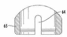
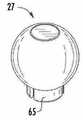
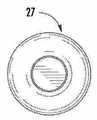
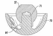
도7A, 도7B, 도7C, 도7D, 도7E 및 도7F는 임플란트된 비구컵과 함께 사용하기 위한 제2시험용 비구볼의 입면도, 단면도, 상세도 및 투시도를 포함한다.
도8A, 도8B, 도8C, 도8D 및 도8E는 도7A 내지 도7F에 도시된 타입인 제2시험용 비구볼의 다양한 도면, 및 비구컵의 스템 상에 위치하는 상기 볼의 입면도와 단면도를 포함한다.
도9A, 도9B 및 도9C는 시험용 비구컵을 설치 및 제거하는 데에 사용되는 핸들의 투시도 및 입면도를 도시하며 비구의 대표 부분에 있는 시험용 비구컵 내에 나사 결합되는 핸들의 단면도를 도시한다.
도10A, 도10B, 도10C, 도10D, 도10E 및 도10F는 제1시험용 대퇴부 컵의 입면도, 단면도, 상세도 및 투시도를 포함한다.
도11A, 도11B, 도11C, 도11D, 도11E 및 도11F는 도10A 내지 도10F에 도시되는 타입인 제1시험용 대퇴부 컵의 추가 도면, 및 제1대퇴부 임플란트에서의 상기 컵의 투시도와 입면도를 포함한다.
도12A, 도12B, 도12C, 도12D, 도12E 및 도12F는 제2시험용 대퇴부 컵의 입면도, 단면도, 상세도 및 투시도를 도시한다.
도13A, 도13B, 도13C, 도13D, 도13E, 도13F 및 도13G는 도12A 내지 도12F에 도시되는 타입인 제2시험용 대퇴부 컵의 추가 도면, 및 제2대퇴부 임플란트에서의 상기 컵의 투시도, 입면도 및 단면도를 도시한다.
도14는 시험용 비구컵에서의 제1시험용 비구볼 및 상기 컵으로부터 상기 볼을 부착하고 제거하는 데에 사용되는 도구를 도시하는 단면도이다.
도15는 제1시험용 비구볼 상의 관절 연결하는 위치에 있는 제1시험용 대퇴부 컵을 도시하는 단면도이다.
도16A, 도16B, 도16C, 도16D, 도16E, 도16F, 도16G 및 도16H는 프레스 조립체 및 그것의 구성 요소의 다양한 도면을 도시하며, 상기 프레스 조립체는 대퇴부 컵의 라이너를 가압하는 데에 사용된다.
도17은 그 안에 대퇴부 컵이 있는 도16A 내지 도16H의 프레스 조립체의 입면도이다.
도18은 도17의 단면도이다.
도19는 삽입-제거 도구의 투시도이다.
도20은 도19의 도구의 입면도이다.
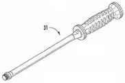
도21은 상기 삽입-제거 도구와 함께 사용하기 위해 맞추어지는 시험용 비구볼의 또 다른 실시예의 입면도이다.
도22는상기 도구가 비구컵으로부터의 볼의 제거를 용이하게 하기 위해 도21의 시험용 비구볼과 접촉하는 경우에, 도19 및 도20의 도구의 위치를 도시하는 투시도이다.
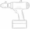
도23은 수술에 사용되는 종래의 전기 드릴의 입면도이다.Figures 1A and 1B show a set of trays comprising a tool for preparing the thigh for implant surgery.
Figures 2A, 2B and 2C illustrate a set of trays comprising a tool for preparing a acetabulum for implant surgery.
Figures 3A, 3B and 3C illustrate a set of trays comprising test implants and tools for sizing and implanting the acetabular and acetabular balls.
Figures 4A, 4B, and 4C illustrate a set of trays including test implants and tools for sizing and implanting the femoral cup.
5A, 5B, 5C, 5D, and 5E are elevation, cross-sectional, and perspective views of the test acetabular cup.
6A, 6B, 6C, and 6D illustrate elevation views, cross-sectional views, and perspective views of a first test acetabular ball for use with the acetabular cup for testing.
Figures 7A, 7B, 7C, 7D, 7E and 7F illustrate an elevation, cross-sectional, detail and perspective views of a second test acetabular for use with an implanted acetabular cup.
Figures 8A, 8B, 8C, 8D and 8E illustrate various views of a second test acetabular ball of the type shown in Figures 7A-7F, and elevation and cross-sectional views of the ball positioned on the stem of the acetabular cup do.
Figures 9A, 9B and 9C show perspective and elevation views of the handle used to install and remove the acetabular cup for testing and show cross-sectional views of the handle screwed into the test acetabular cup in the representative portion of the acetabulum;
Figures 10A, 10B, 10C, 10D, 10E and 10F illustrate elevation, cross-sectional, detail and perspective views of a first test femoral cup.
Figs. 11A, 11B, 11C, 11D, 11E and 11F are further views of a first test femoral cup of the type shown in Figs. 10A-10F, and a perspective view and elevation view of the cup in the first thigh- .
12A, 12B, 12C, 12D, 12E and 12F illustrate elevation, cross-sectional, detail and perspective views of a second test femoral cup.
FIGS. 13A, 13B, 13C, 13D, 13E, 13F and 13G are further views of a second test femoral cup of the type shown in FIGS. 12A-12F, and of the cup in the second femoral implant A perspective view, an elevation view, and a cross-sectional view.
14 is a cross-sectional view showing a first test acetabular ball in a test acetabular cup and a tool used for attaching and removing the ball from the cup.
15 is a cross-sectional view showing a first test femoral cup at a joint-connecting position on a first test acetabular ball;
16A, 16B, 16C, 16D, 16E, 16F, 16G and 16H illustrate various views of the press assembly and its components, which presses the liner of the thigh cup .
Figure 17 is an elevational view of the press assembly of Figures 16A-16H with a femoral cup therein.
18 is a cross-sectional view of Fig.
Figure 19 is a perspective view of an insertion-removal tool.
Figure 20 is an elevational view of the tool of Figure 19;
Figure 21 is an elevational view of another embodiment of a test acetabular ball adapted for use with the insert-removal tool.
Figure 22 is a perspective view showing the location of the tool of Figures 19 and 20 when the tool is in contact with the test acetabular of Figure 21 to facilitate removal of the ball from the acetabular cup.
23 is an elevational view of a conventional electric drill used in surgery.
고관절 임플란트 수술을 위한 대퇴골을 준비하는 데에 사용되는 도구는 각각 도1A 및 도1B의 제1세트의 강철 트레이(1 및 2)에 포함되어 있다. 트레이(1)는 리머(3), 오른손용 핸들(4) 및 왼손용 핸들(5)을 포함한다. 또한 T-핸들(6)과 박스 뼈절단기(7)도 트레이(1)에 포함된다. 대퇴골두를 절단함으로써 대퇴골이 수술 준비가 된 후, 상기 박스뼈 절단기(7)는 상기 리머(3)의 정확한 위치 결정을 위한 가이드로서 대퇴골의 초기 개구를 만들기 위한 중심 펀치로서 사용된다. 그런 다음, 리머(3)의 근위 단부(3a)와 접촉하도록 맞추어지는 상기 T-핸들(6)은 상기 리머에 부착되고 외과의는 상기 리머(3)의 말단부(3b)를 초기 개구부에 위치시키고 압력을 가하면서 핸들을 회전시켜 대퇴골에 포켓을 생성한다. 트레이(2)와 관련하여 후술되는 바와 같이, 오른손용 핸들(4) 및 왼손용 핸들(5) 각각은 브로치(8)의 사용에 대비하여 상기 리머를 회전시켜 대퇴골에 깊은 포켓을 만들기 위해 상기 리머의 근위 단부(3a)와 접촉하도록 맞추어진다. 상기 오른손용 핸들(4)은 오른손잡이 외과의에 의해 사용되고 상기 왼손용 핸들(5)은 왼손잡이 외과의에 의해 사용된다.The tools used to prepare the femur for hip joint implant surgery are included in the first set of
트레이(2)는 2개 이상의 상이한 크기의 브로치(8)의 세트를 포함한다. 상기 브로치들은 9mm에서(도1B의 왼손쪽) 21mm(도1B의 오른손쪽)까지의 크기를 갖는다. 도면에서, 왼쪽에서 오른쪽으로 가는 각각의 브로치(8)는 왼쪽의 것보다 1mm씩 더 크다. 도면으로부터 알 수있는 바와 같이, 상기 브로치들은 테이퍼되고 각각의 브로치의 크기는 브로치의 상단, 즉 근위 단부(8a)에서 최대 직경을 나타낸다. 래습(rasp)로도 알려진 상기 브로치(8)는 깊은 포켓에 삽입되고 망치(9)를 사용하여 근위 단부(8a)에서 대퇴골 내로 두드려진다. 핸들(10)은 대퇴부 임플란트(75)의 근위 단부 또는 그에 근접하여 나사형 리세스(75a)에 나사 결합되고(도13 참조), 대퇴부 임플란트를 대퇴골에 임플란트하는 데에 사용된다.The
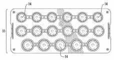
고관절 이식 수술을 위한 비구를 준비하는 데에 사용되는 도구는 각각 도2A, 도2B 및 도2C의 제2세트의 강철 트레이(11, 12 및 13)에 포함된다. 트레이(11, 12)는 상응하는 크기의 비구컵을 수용하기에 적합한 크기로 비구골을 절단하는 데에 사용되는 2개 이상의(도2A와 도2B에서는 25개로 도시됨) 상이한 크기의 비구골 절단기(14)를 점증적으로 포함한다. 드라이브 샤프트와 드라이브 샤프트 핸들은 드릴(140)(도23 참조)을 비구골 절단기(14)에 연결시키는 데에 사용된다. 트레이(13)는 2개의 상이한 크기의 드라이브 샤프트(15) 및 2개의 드라이브 샤프트 핸들(16)을 도시한다. 상기 드라이브 샤프트는 뼈 절단기에 연결되도록 맞추어지는 말단부(15b) 및 상기 드라이브 샤프트 핸들(16)의 말단부(16b)에 연결되도록 맞추어지는 근위 단부(15a)를 구비한다. 상기 드라이브 샤프트 핸들(16)의 근위 단부(16a)는 드릴(140)의 척 (141)에 연결되도록 맞추어진다.The tools used to prepare the acetabulum for the hip joint transplant surgery are included in the second set of
비구컵 및 비구볼을 임플란트 하기 위한 시험용 임플란트 및 도구는 도3A, 도3B 및 도3C의 제3세트의 강철 트레이(21, 22 및 23)에 각각 포함된다.Test implants and tools for implanting the acetabular and acetabular balls are included in the third set of
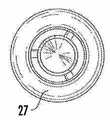
트레이(21)는 드릴 가이드 핸들(24), 2개 이상의 드릴 비트(25), 2개 이상의 드릴 가이드(26), 2개 이상의 제2시험용 비구볼(27) 및 시험용 비구볼 삽입-제거 도구(28)를 포함한다. 각각의 드릴 비트(25)는 상응하는 크기의 드릴 가이드를 구비한다.The
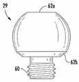
트레이(22)는 2개 이상의 제1시험용 비구볼(29), 2개 이상의 시험용 비구컵(30) 및 범용 핸들(31)을 포함한다.The
트레이(23)는 비구컵 임팩터 조립체의 요소를 포함한다. 이것은 또 다른 범용 핸들(31), 비구컵 핸들(32), 그것의 근위 단부에 손잡이(34)를 구비하는 내측 샤프트(33), 2개의 전경 가이드 로드(35), 적어도 하나 및 바람직하게는 3개의 콜렛(38) 및 적어도 하나 및 바람직하게는 3개의 비구볼 임팩터(37)를 포함한다. 경사 및 전경 가이드(36)는 상기 비구컵 핸들(32) 상의 적절한 위치에서 가이드(36)를 유지하기 위한 엄지 나사(도시되지 않음)를 구비한다. 이는 2016년 7월 15일에 출원되어 함께 계류 중인 국제 출원번호 PCT/US16/42441에 상세히 설명되어 있다.The
대퇴부 컵을 임플란트하기 위한 시험용 임플란트 및 도구는 각각 도4A, 도4B 및 도4C의 제4세트의 강철 트레이(41, 42 및 43)에 포함된다.Test implants and tools for implanting the femoral cup are included in the fourth set of
트레이(41 및 42)는 2개 이상의 제1시험용 대퇴부 컵(44)만을 포함한다. 이러한 제1시험용 대퇴부 컵(44)들은 크기, 목 길이 및 오프셋 각도가 다를 수 있다. 이들은 바람직하게는 상기 브로치가 상기 대퇴골로부터 제거되기 전에 트레이(2)의 브로치(8)의 근위 단부에 일시적으로 부착되도록 맞추어진다. 선택적으로, 이들은 도11E 및 도11F에 도시된 바와 같이 대퇴부 임플란트(49)의 근위 단부에 일시적으로 부착될 수 있다.The
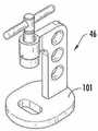
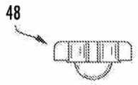
트레이(43)는 상기 대퇴부 임플란트(49)에 일시적으로 부착되도록 맞추어지는 2개 이상의 제2시험용 대퇴부 컵(45)들을 포함한다 (도11E 및 도11F 참조). 또한 상기 트레이는 폴리머라이너를 대퇴부 컵 내로 가압하기 위한 프레스(46), 대퇴부 컵 로케이터(47) 및 플런저(48, 48a)를 포함한다 (도16C, 도16D, 도16E 및 도16F를 참조).The
상술한 트레이에 포함되는 다양한 구성 요소를 보다 구체적으로 보면, 도5A 내지 도5E는 상기 시험용 비구컵(30)의 다양한 도면을 도시한다. 도5E는 시험용 비구컵의 투시도이다. 도5A는 측면 입면도이며 도5D는 도5A의 단면도이다. 도5B는 상기 입면도이며 도5C는 하부 입면도이다.5A through 5E illustrate various views of the
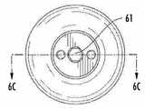
상기 시험용 비구컵(30)은 비구골의 준비된 표면 및 내부 오목한 표면에 피트되도록 맞추어지는 외측 표면을 갖는다. 상기 외측 표면은 바람직하게는 볼록한 표면이다. 내측으로 나사형 개구부(51)를 구비하는 스템(50)은 오목한 표면의 바닥으로부터 연장되고 상기 컵은 복수의 선택적인 관통 개구부(52)에 의해 특징지어진다. 상기 나사형개구부(51)는 상기 컵(30)을 장착하고 상기 비구로부터 제거하는 데에 사용되는 범용 핸들(31)의 나사부를 수용한다(도9C 참조). 또한 개구부(51)의 나사부는 도6A 내지 도6D에 도시된 제1시험용 비구볼(29)을 수용한다. 본 발명의 시험용 비구볼은 반구형이며, 후술하는 바와 같이 평평한 부분 및 사면을 포함할 수 있다. 도6D는 시험용 비구볼(29)의 투시도이며, 도6A는 측면 입면도이며, 도6B는 상부 입면도이며 도6C는 단면도이다. 상기 나사형 부분(60)은 개구부(51) 내로 나사 결합된다. 육각형 개구부(61)는 평평한 부분(62a)에 도시되어 있으며, 볼(29)을 컵(30)과 나사 결합 및 해제 시키는 데에 사용되는 도구(28)(도 3A 참조)를 수용한다. 선택적 경사진 부분(62b)은 나사 결합 부분(60)에 근접하고 볼(29)의 베이스를 둘러싸는 경사진 에지를 생성한다.The
도7 및 도8은 제2시험용 비구볼(27)과 관련 있다.Figs. 7 and 8 relate to the second
도7A 내지 도7F는 상기 볼(27)의 다양한 도면을 도시한다. 상기 볼(27)은 보철물에 대한 최적의 볼 크기를 결정하기 위해 임플란트된 비구컵(70)(도8D 및 도8E 참조)에 일시적으로 부착될 수 있다. 도8A 내지 도8C는 상이한 크기의 제2시험용 비구볼(27)을 도시한다.Figs. 7A-7F show various views of the
도7F 및 도8C는 볼(27)의 투시도이며, 도7A 및 도8A는 볼(27)의 측면 입면도이며, 도7B 및 도8B는 상부 입면도이다. 도7C는 볼(27)의 하부 입면도이며 도7D는 도7A의 단면선(7D)을 따라 취하는 단면도이다. 도7D의 원으로 둘러싸인 부분(7E)의 상세도가 도7E에 도시되어 있다.Figs. 7F and 8C are perspective views of the
제2시험용 비구볼(27)은 식별 크기 정보를 각인(imprint)하는 데에 사용되는 평평한 상부 부분(62)으로 구성된다. 상기 볼(27)은 비구컵(70)의 스템(71) 위에 피트되는 크기의 개구부(63)를 구비한다. 돌출부(65)의 측면 상에 슬롯(64)이 제공되어 스템(71) 상에 볼을 위치시키고 상기 스템으로부터 제거하는 것을 용이하게 한다.The second
범용 핸들(31)이 도9B에서 측면 입면도로, 도9A에서 투시도로 도시되어 있다. 도9C는 비구골(80)의 대표 부분에 있는 시험용 비구컵(30) 내로 나사 결합되는 범용 핸들(31)의 단면도이다. 핸들(31)은 시험용 컵(30)을 비구골(80) 내로 위치시키는 데에 사용된다.The
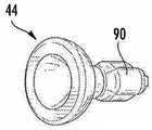
제1시험용 대퇴부 컵(44)의 복수의 도면이 도10에 도시되어 있다. 도11은 대퇴부 임플란트(49) 내의 컵(44)의 도면뿐만 아니라 컵(44)의 더 많은 도면을 도시한다.A plurality of views of the first test
제1시험용 대퇴부 컵(44)의 3개의 상이한 투시도는 도10F, 도11A 및 도11C에 도시되어 있다. 상이한 각도로부터 취하는 컵(44)의 측면 입면도는 도10A, 도11B 및 도11D에 도시되어 있다. 도 10B는 상부 입면도, 도 10C는 하부 입면도이고 도 10D는 도10A의 단면선(10D)를 따라 취해진 단면도이다. 도10E는 도10D의 원으로 둘러싸인 부분(10E)으로부터 취하는 상세도이다. 도11F는 임플란트(49)에 부착되는 컵(44)의 측면 입면도이며 도11E는 임플란트(49)에 부착되는 컵(44)의 투시도이다.Three different perspective views of the first test
제1시험용 대퇴부 컵(44)은 제1오목한 부분(91)으로부터 멀리 연장하는(즉, 반대로) 스템의 형상을 갖는 베이스 부분(90)을 구비한다. 베이스 부분(90) 내에는 상기 브로치(8)의 근위 단부 또는 임플란트(49)의 스템을 수용하는 개구부(92)가 포함된다. 슬롯(93 및 93a)은 컵을 브로치 또는 스템 상에 위치시키거나 제거하는 것을 보다 쉽게 하도록 제공된다.The first test
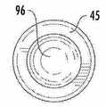
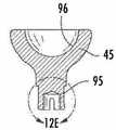
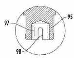
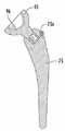
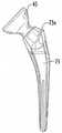
제2시험용 대퇴부 컵(45)은 도12A 내지 도12F에서 복수의 도면으로 도시된다. 도13A 내지 도13G는 대퇴부 임플란트(75)내의 컵(45)의 도면뿐만 아니라 컵(45)의 더 많은 도면을 도시한다. 컵(45)의 투시도는 도12F 및 도13D에 도시되고, 측면 입면도는 도12A 및 도13A에서 도시되고, 상부 입면도는 도12B 및 도13C에서 도시되고, 하부 입면도는 도12C 및 도13B에서 도시된다. 도12D는 도12A의 단면선(12D)을 따라 취하는 단면도이며 도12E는 도12D의 원으로 둘러싸인 부분(12E)으로부터 취하는 상세도이다. 도13E는 임플란트(75)의 컵(45)의 투시도이며, 도13G는 임플란트(75) 내의 컵(45)의 측면 입면도이며, 도13F는 도13G의 단면도이다.The second test
제2시험용 대퇴부 컵(45)은 제2오목한 부분(96)로부터 멀리 연장하며 대퇴부 임플란트 (75) 내에 수용되도록 맞추어지는 스템(95)을 구비한다. 스템(95)의 개구부(97)는 컵(45)을 대퇴부 임플란트(75)에 부착시키고 그로부터 제거하는 것을 용이하게 하기 위해 슬롯(98)과 협력하여 작동한다.The second test
도14는 시험용 비구볼(29)의 육각형 개구부 내에 삽입되는 상기 시험용 비구볼 삽입-제거 도구(28)를 단면으로 도시한다. 이는 상기 볼을 시험용 비구컵(30) 내로 나사결합 및 밖으로 분해하기 위한 상기 볼에 대한 도구의 위치이며, 상기 컵(30)은 비구골(80)의 대표 부분에 도시된다.Figure 14 shows in cross-section the test acetabular ball insertion-
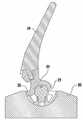
시험용 대퇴부 컵(44)은 도15에서 시험용 비구볼(29) 상의 위치에 도시된다. 상기 대퇴부 컵(44)은 임플란트(49)에 부착되며 시험용 비구컵(30)은 비구골(80) 내에 도시된다.The test
폴리머 라이너를 상기 대퇴부 컵 내로 가압하는 데에 사용되는 프레스(46)의 요소들은 도16에 도시되어 있다. 프레스(46)의 투시도는 도16A에 도시되어 있다. 도16A 내지 도16F 및 도17과 도18을 참조해보면, 상기 프레스는 베이스 상에 부착되는 브래킷(102)을 구비하는 베이스(101)로 이루어져 있다. 프레스 바(103)는 샤프트(104) 상에 제공되며 실린더(105)는 상기 샤프트(104)의 말단부에 제공된다. 상기 실린더(105)는 적절한 크기의 플런저(48)와 접촉하여 가압한다. 그 안에 대퇴부 컵(110)을 구비하는 대퇴부 컵 로케이터(47)는 베이스(101) 상에 위치한다. 도18에서 단면으로 도시된 바와 같이 폴리머라이너(111)의 오목한 부분은 플런저(106) 상에 위치하고 상기 라이너(111)의 볼록한 부분은 대퇴부 컵(110)의 오목한 부분 위에 위치한다. 그런 다음 안정화 핸들(108)을 유지하면서 실린더(105)가 플런저 상에서 접촉하고 아래로 가압하도록 하는 프레스바(103)를 사용해 라이너(111)가 대퇴부 컵(110)의 오목한 부분에서의 위치 내에 스냅(snap)될 때까지 상기 플런저(48)가 아래쪽으로 가압된다.The elements of the
삽입-제거 도구(120)는 도19 및 도20에 도시되어 있다. 상기 도구는 크기와 구성 면에서 지혈집게와 유사하다. 상기 도구는 이것의 근위 단부에서의 핸들(121) 및 래칫 부분(122)을 포함한다. 힌지(123)는 지렛대를 제공하도록 위치하고 그리퍼(124)들은 말단부에 배치된다. 상기 힌지(123)와 그리퍼(124)들 사이에 위치하는 도구의 부분은 선택적으로 각질 수 있다(예를 들어 약 20도로)(도시되지 않음).The insertion-
이러한 적용에서, 도구(120)의 바람직한 용도는 비구컵(70)으로부터 시험용 비구볼(27a)을 제거하는 것이다. 도22는 이러한 목적을 위해 볼(27a) 상에 위치하는 도구(120)를 도시한다. 상기 볼(27a)은 볼을 움켜쥐고 비구컵(70)의 상기 스템(71)으로부터(도8E 참조) 이를 당기도록 제공되는 원주 방향 그루브의 형태로 홈(130)의 추가된 특징을 갖는 상술한 볼(27)과 동일한 특징을 모두 갖는다.In this application, a preferred use of the
21 : 트레이
24 : 드릴 가이드 핸들
25 : 드릴 비트
26 : 드릴 가이드
27 : 제2시험용 비구볼
28 : 시험용 비구볼 삽입-제거 도구21: Tray
24: Drill guide handle
25: Drill bit
26: Drill guide
27: second test acetabular ball
28: Insertion of test acetabular balls - removal tool
Claims (20)
Translated fromKorean임플란트 수술을 위한 대퇴부 준비용 도구를 포함하는 트레이의 제1세트;
임플란트 수술을 위한 비구 준비용 도구를 포함하는 트레이의 제2세트;
역고관절 비구컵 및 비구볼의 크기를 정하고, 위치시키고 및 임플란트하기 위한 시험용 임플란트 및 도구를 포함하는 트레이의 제3세트; 및
역고관절 보철물과 함께 사용하기 위한 대퇴부 컵의 크기를 정하고 임플란트하기 위한 시험용 임플란트 및 도구를 포함하는 트레이의 제4세트를 포함하는 것을 특징으로 하는 기구.In a surgical tray instrument and its components for use in hip replacement surgery,
A first set of trays comprising a thigh preparation tool for implant surgery;
A second set of trays comprising a tool for preparing an acetabulum for implant surgery;
A third set of trays comprising test implants and tools for sizing, positioning and implanting inverted hip acetabular cups and acetabular balls; And
A fourth set of trays comprising test implants and tools for sizing and implanting the femoral cup for use with the inverse hip prosthesis.
대퇴부 내로의 삽입을 위한 말단부 및 근위 단부를 구비하는 리머;
상기 리머의 근위 단부로 연결되도록 맞추어지는 오른손잡이용 핸들 및 왼손잡이용 핸들;
상기 리머의 근위 단부로 연결되도록 맞추어지는 T-핸들;
박스 뼈 절단기;
상기 대퇴부에 상응하는 크기의 개구부를 생성하도록 각각 크기가 정해지는 2개 이상의 브로치들;
브로치를 상기 대퇴부 내로 두드리기 위한 망치; 및
대퇴부 임플란트의 근위 단부 내로 나사 결합되도록 맞추어지는 나사형 부분을 구비하는 핸들을 포함하는 것을 특징으로 하는 기구.The apparatus of claim 1, wherein the first set of tools of the tray comprises:
A reamer having a distal end and a proximal end for insertion into the femur;
A left-handed handle and a left-handed handle adapted to be connected to the proximal end of the reamer;
A T-handle adapted to be connected to the proximal end of the reamer;
Box bone cutter;
Two or more broaches each sized to create an opening of a size corresponding to the thigh;
A hammer for tapping the broach into the femur; And
And a handle having a threaded portion that fits snugly into the proximal end of the femoral implant.
2개 이상의 상이한 크기의 비구골 절단기;
뼈 절단기에 연결되도록 맞추어지는 말단부를 구비하는 드라이브 샤프트;
상기 드라이브 샤프트의 근위 단부에 연결되도록 맞추어지는 드라이브 샤프트 핸들을 포함하는 것을 특징으로 하는 기구.The apparatus of claim 1, wherein the tool in the second set of trays
Two or more different sized acetabular osteotomies;
A drive shaft having a distal end adapted to be connected to the bone cutter;
And a drive shaft handle adapted to be connected to the proximal end of the drive shaft.
상기 드라이브 샤프트 핸들의 말단부는 상기 드라이브 샤프트에 연결되도록 맞추어지며 상기 드라이브 샤프트 핸들의 근위 단부는 드릴에 연결되도록 맞추어지는 것을 특징으로 하는 기구.In the apparatus of paragraph 3,
Wherein the distal end of the drive shaft handle is adapted to be connected to the drive shaft and the proximal end of the drive shaft handle is adapted to be connected to the drill.
드릴 가이드 핸들;
2개 이상의 드릴 비트;
2개 이상의 드릴 가이드;
2개 이상의 제2시험용 비구볼;
시험용 비구볼 삽입-제거 도구;
2개 이상의 제1시험용 비구볼;
2개 이상의 시험용 비구컵;
또 다른 범용 핸들을 포함하는 비구컵 임팩터 조립체의 요소들;
비구컵 핸들;
그의 근위 단부에 손잡이를 구비하는 내측 샤프트;
2개의 전경 가이드 로드;
콜렛; 및
비구볼 임팩터를 포함하는 것을 특징으로 하는 기구.The apparatus of claim 1, wherein the tool in the third set of trays comprises:
Drill guide handle;
Two or more drill bits;
Two or more drill guides;
Two or more second test acetabular balls;
Test acetabular ball insertion - removal tool;
Two or more first test acetabular balls;
Two or more test acetabular cups;
Elements of an acetabular impactor assembly including another universal handle;
Acetabular cup handle;
An inner shaft having a handle at its proximal end;
Two foreground guide rods;
Collet; And
And an acetabular impactor.
브로치 또는 대퇴부 임플란트의 근위 단부에 일시적으로 부착되도록 맞추어지는 2개 이상의 제1시험용 대퇴부컵;
상기 대퇴부 임플란트에 일시적으로 부착되도록 맞추어지는 2개 이상의 제2시험용 대퇴부 컵; 및
폴리머 라이너를 대퇴부 컵 내로 가압하기 위한 프레스, 대퇴부 컵 로케이터 및 플런저를 포함하는 것을 특징으로 하는 기구.The apparatus of claim 1, wherein the tool in the fourth set of trays comprises:
Two or more first test femoral cups adapted to be temporarily attached to the proximal end of the broach or femoral implant;
Two or more second test femoral cups adapted to be temporarily attached to the femoral implant; And
A press for pressing the polymer liner into the femoral cup, a femoral cup locator and a plunger.
비구골의 준비된 표면에 피트되도록 맞추어지는 외측 표면을 구비하는 컵; 및
내측 오목한 표면;
선택적인 관통 개구부를 구비하는 상기 외측 및 내측 표면; 및
그의 바닥으로부터 연장하고 내측으로 나사 결합하는 스템을 구비하는 내측 오목한 표면을 포함하는 것을 특징으로 하는 시험용 비구컵.In the acetabulum test cup for inverted hip prostheses:
A cup having an outer surface adapted to fit on a prepared surface of an acetabular bone; And
Inner concave surface;
Said outer and inner surfaces having optional through openings; And
And an inner concave surface extending from a bottom thereof and having an inwardly threaded stem.
그곳으로부터 연장하는 스템을 구비하는 반구형 볼 및 상기 스템의 반대편에 볼 표면 상의 평평한 부분을 포함하는 것을 특징으로 하는 시험용 비구볼.In the acetabular test for inverted hip prostheses,
A hemispherical ball having a stem extending therefrom, and a flat portion on the ball surface opposite the stem.
상기 스템은 외측으로 나사 결합되는 것을 특징으로 하는 볼.The ball of claim 9,
Wherein the stem is threaded outwardly.
상기 스템은 비구컵의 스템을 수용하도록 크기가 정해지는 개구부를 포함하는 것을 특징으로 하는 볼.The ball of claim 9,
Characterized in that the stem comprises an opening dimensioned to receive the stem of the acetabular cup.
상기 평평한 부분의 중심에 위치하는 개구부를 추가로 포함하며, 상기 개구부는 상기 나사형 부분이 시험용 비구컵의 내측 나사형 스템 내로 나사 결합되는 경우에 상기 볼을 조이고 느슨하게 하기 위한 도구를 수용하도록 크기와 모양이 정해지는 것을 특징으로 하는 볼.11. The ball of claim 10,
Further comprising an opening located in the center of the flat portion, the opening being sized and shaped to receive a tool for tightening and loosening the ball when the threaded portion is threaded into the inner threaded stem of the test acetabular cup Wherein the ball is characterized by being determined.
비구 볼 상에서 관절로 이어지도록 맞추어지는 오목한 표면을 구비하는 컵;
상기 오목한 표면의 반대편의 상기 컵의 외부 표면으로부터 연장하고, 브로치의 근위 단부 또는 대퇴부 임플란트의 근위 단부에 부착되도록 맞추어지는 상기 스템을 포함하는 것을 특징으로 하는 시험용 대퇴부 컵.In a test femoral cup for an inferior hip prosthesis,
A cup having a concave surface that fits over the acetabulum to the joint;
The stem extending from the outer surface of the cup opposite the recessed surface and adapted to attach to the proximal end of the broach or the proximal end of the femoral implant.
상기 스템은 브로치의 근위 단부 또는 대퇴부 임플란트의 근위 단부를 수용하도록 맞추어지는 것을 특징으로 하는 컵.14. The cup of claim 13,
Wherein the stem is adapted to receive the proximal end of the broach or the proximal end of the femoral implant.
상기 스템은 대퇴부 임플란트의 근위 단부 내에서 수용되도록 맞추어지는 것을 특징으로 하는 컵.14. The cup of claim 13,
Wherein the stem is adapted to be received within the proximal end of the femoral implant.
상기 실린더에 대향하는 베이스 상에 위치하는 대퇴부 컵 로케이터를 포함하며;
대퇴부 컵은 상기 대퇴부 컵 로케이터 내에 위치하고 위쪽으로 향한 위치에 있는 오목한 표면을 구비하고 폴리머 라이너는 상기 실린더가 상기 플런저 상에 접촉 및 가압하도록 하는 상기 프레스 바를 이용하여 상기 플런저가 아래쪽으로 밀어지는 경우 상기 라이너가 상기 대퇴부 컵 내의 위치 내로 스냅(snap)되도록 플런저 상에 위치된 오목한 부분 및 상기 대퇴부 컵의 오목한 부분 위에 위치된 볼록한 부분을 구비하는 것을 특징으로 하는 프레스.A press for pressing a polymeric liner into a femoral cup for an inverse hip prosthesis, the base having a bracket attached thereon, the bracket having a shaft at a proximal end, the cylinder having a press bar and a cylinder adapted to press on the plunger at the distal end, A base adapted to receive the bore;
A femoral cup locator located on a base opposite said cylinder;
The femoral cup is positioned within the femoral cup locator and has a concave surface in an upwardly facing position and the polymer liner is pressed against the plunger when the plunger is pushed downward using the press bar to cause the cylinder to contact and press on the plunger, Comprises a concave portion located on the plunger and a convex portion located above the concave portion of the femoral cup to snap into position within the femoral cup.
상기 도구는 래칫 부분에 근접하는 근위 단부에서 핸들, 말단부에서 그리퍼들 및 상기 근위 단부와 말단부 사이에 배치되는 힌지를 포함하며, 상기 그리퍼들은 상기 시험용 비구볼의 원주 방향 그루브를 움켜쥐도록 맞추어지는 것을 특징으로 하는 도구.A tool for inserting or removing a test acetabular ball of claim 17,
The tool includes a handle at the proximal end proximate the ratchet portion, grippers at the distal end, and a hinge disposed between the proximal end and the distal end, the grippers being adapted to grip the circumferential groove of the test acetabular ball Features a tool.
대퇴부 준비용 도구를 사용하여 상기 대퇴부를 준비하고, 비구를 준비하기위한 도구를 사용하여 비구를 준비하는 단계;
그런 다음 상기 비구에 상기 시험용 비구컵 및 시험용 비구볼을 위치시키고 상기 대퇴부에 상기 시험용 대퇴부 임플란트를 위치시키며, 상기 임플란트의 적절한 크기가 확인될 때까지 이러한 과정을 반복하는 단계; 및
그런 다음 상기 시험용 임플란트를 제거하고 적절한 크기의 영구 임플란트를 임플란트하는 단계를 포함하는 것을 특징으로 하는 방법.A surgical method using tools and a test implant from the surgical tray and components of claim 1, the method comprising:
Preparing the thigh using the thigh preparation tool and preparing the acetabulum using a tool for preparing the acetabulum;
Placing the test acetabular cup and the test acetabular ball on the acetabulum, placing the test femoral implant on the femur, and repeating the procedure until the proper size of the implant is verified; And
And removing the test implant and implanting a permanent implant of an appropriate size.
드릴 가이드는 상기 영구 비구컵을 상기 비구에 부착하기 위해 나사를 수용하도록 상기 비구에 구멍을 뚫는 데에 사용되는 것을 특징으로 하는 방법.20. The method of claim 19,
Wherein the drill guide is used to perforate the acetabular cup to receive a screw to attach the permanent acetabular cup to the acetabular cup.
Priority Applications (1)
| Application Number | Priority Date | Filing Date | Title |
|---|---|---|---|
| KR1020257003717AKR20250024117A (en) | 2015-08-21 | 2016-08-15 | Surgical trays, instruments and methods for implanting a hip replacement prosthesis |
Applications Claiming Priority (3)
| Application Number | Priority Date | Filing Date | Title |
|---|---|---|---|
| US201562208127P | 2015-08-21 | 2015-08-21 | |
| US62/208,127 | 2015-08-21 | ||
| PCT/US2016/047031WO2017034845A1 (en) | 2015-08-21 | 2016-08-15 | Surgical trays, instruments and methods for implanting a hip replacement prosthesis |
Related Child Applications (1)
| Application Number | Title | Priority Date | Filing Date |
|---|---|---|---|
| KR1020257003717ADivisionKR20250024117A (en) | 2015-08-21 | 2016-08-15 | Surgical trays, instruments and methods for implanting a hip replacement prosthesis |
Publications (2)
| Publication Number | Publication Date |
|---|---|
| KR20180061145Atrue KR20180061145A (en) | 2018-06-07 |
| KR102781887B1 KR102781887B1 (en) | 2025-03-13 |
Family
ID=58100597
Family Applications (2)
| Application Number | Title | Priority Date | Filing Date |
|---|---|---|---|
| KR1020257003717APendingKR20250024117A (en) | 2015-08-21 | 2016-08-15 | Surgical trays, instruments and methods for implanting a hip replacement prosthesis |
| KR1020187005074AActiveKR102781887B1 (en) | 2015-08-21 | 2016-08-15 | Surgical trays, instruments and methods for implanting hip replacement prostheses |
Family Applications Before (1)
| Application Number | Title | Priority Date | Filing Date |
|---|---|---|---|
| KR1020257003717APendingKR20250024117A (en) | 2015-08-21 | 2016-08-15 | Surgical trays, instruments and methods for implanting a hip replacement prosthesis |
Country Status (11)
| Country | Link |
|---|---|
| US (2) | US20180214233A1 (en) |
| EP (2) | EP3337429B1 (en) |
| JP (2) | JP7022433B2 (en) |
| KR (2) | KR20250024117A (en) |
| CN (2) | CN108135705B (en) |
| AU (3) | AU2016311057B2 (en) |
| BR (1) | BR112018003256B1 (en) |
| CA (1) | CA2995820A1 (en) |
| ES (1) | ES2940910T3 (en) |
| WO (1) | WO2017034845A1 (en) |
| ZA (1) | ZA201801046B (en) |
Families Citing this family (9)
| Publication number | Priority date | Publication date | Assignee | Title |
|---|---|---|---|---|
| US11457992B2 (en)* | 2016-07-08 | 2022-10-04 | Stryker European Operations Holdings Llc | Storage assembly for a medical device |
| JP1621250S (en) | 2017-05-22 | 2018-12-25 | ||
| US10478262B2 (en) | 2017-12-04 | 2019-11-19 | Depuy Ireland Unlimited Company | Orthopaedic instrument system including an instrument caddy and method for assembling a surgical instrument |
| CN108836496A (en)* | 2018-07-03 | 2018-11-20 | 杭州埃杜医疗科技有限公司 | A kind of hip joint prosthesis instrument packet |
| US11103367B2 (en) | 2019-02-15 | 2021-08-31 | Encore Medical, L.P. | Acetabular liner |
| JP7270063B2 (en)* | 2019-05-14 | 2023-05-09 | ローサイ・オーソペディックス・リミテッド | A set of tools for introducing implants |
| US11992412B2 (en)* | 2020-03-18 | 2024-05-28 | In2Bones Usa, Llc | Radial head fracture treatment system |
| USD952182S1 (en)* | 2020-05-26 | 2022-05-17 | DePuy Synthes Products, Inc. | Lid for a medical implant and/or instrument case |
| US20240307145A1 (en)* | 2023-03-16 | 2024-09-19 | NovoSource, LLC | Surgical kit and methods of forming the same |
Citations (5)
| Publication number | Priority date | Publication date | Assignee | Title |
|---|---|---|---|---|
| US5156626A (en)* | 1990-06-29 | 1992-10-20 | Zimmer, Inc. | Set of provisional prosthesis instrumentation |
| US20070260256A1 (en)* | 2006-05-05 | 2007-11-08 | Beaule Paul E | Surgical instrument tray, hip resurfacing kit, and method of resurfacing a femoral head to preserve femoral head vascularity |
| US20110186456A1 (en)* | 2008-07-10 | 2011-08-04 | Depuy International Ltd | Container and system of containers of surgical instruments for knee surgery |
| KR20130004589A (en)* | 2010-03-08 | 2013-01-11 | 힙 이노베이션 테크놀러지 엘엘씨 | Interlocking reverse hip and revision prosthesis |
| US20140012264A1 (en)* | 2011-04-13 | 2014-01-09 | Total Joint Orthopedics | Total hip arthroplasty |
Family Cites Families (60)
| Publication number | Priority date | Publication date | Assignee | Title |
|---|---|---|---|---|
| US4206517A (en) | 1977-12-01 | 1980-06-10 | Biomedical Engineering Corp. | Floating center prosthetic joint |
| CA1240101A (en)* | 1983-05-06 | 1988-08-09 | Michael J. Pappas | Multi-component prosthesis with increased wall flexibility facilitating component assembly |
| GB8819589D0 (en)* | 1988-08-17 | 1988-09-21 | Minnesota Mining & Mfg | Acetabular component of hip joint prosthesis |
| US5122145A (en)* | 1990-11-09 | 1992-06-16 | Fishbane Bruce M | Measuring device for use in total hip replacement |
| US5284483A (en) | 1992-09-16 | 1994-02-08 | Zimmer, Inc. | Acetabular cup inserting instrument |
| US5954727A (en) | 1993-10-29 | 1999-09-21 | Howmedica Inc. | Acetabular cup positioning tool and method of positioning an acetabular cup |
| DE59409052D1 (en) | 1994-04-25 | 2000-02-10 | Sulzer Orthopaedie Ag Baar | Removal instrument for a shaft of a hip joint prosthesis or a corresponding rasp |
| US5824483A (en) | 1994-05-18 | 1998-10-20 | Pence Inc. | Conformationally-restricted combinatiorial library composition and method |
| US6652260B2 (en) | 1996-03-11 | 2003-11-25 | The Board Of Trustees Of The University Of Arkansas | Composite allograft press |
| US5824078A (en)* | 1996-03-11 | 1998-10-20 | The Board Of Trustees Of The University Of Arkansas | Composite allograft, press, and methods |
| US5879401A (en)* | 1996-05-17 | 1999-03-09 | Johnson & Johnson Professional, Inc. | Acetabular trial |
| US6395004B1 (en)* | 1997-11-14 | 2002-05-28 | Sulzer Orthopedics Inc. | Orthopedic trial prosthesis and saw guide instrument |
| US6991656B2 (en) | 2000-04-26 | 2006-01-31 | Dana Mears | Method and apparatus for performing a minimally invasive total hip arthroplasty |
| US6565575B2 (en) | 2001-02-16 | 2003-05-20 | Randall J. Lewis | Method and apparatus for removing an acetabular cup |
| US6723102B2 (en) | 2001-06-14 | 2004-04-20 | Alexandria Research Technologies, Llc | Apparatus and method for minimally invasive total joint replacement |
| US20030163203A1 (en)* | 2002-02-26 | 2003-08-28 | Nycz Jeffrey H. | Acetabular component with removable screw hole plugs |
| US7306629B2 (en) | 2003-07-03 | 2007-12-11 | Zimmer, Inc. | Femoral head assembly with variable offset |
| GB0420346D0 (en)* | 2004-09-13 | 2004-10-13 | Finsbury Dev Ltd | Tool |
| GB0500510D0 (en)* | 2005-01-11 | 2005-02-16 | Benoist Girard Sas | Retentive and removable trial beaaring inser |
| US7785331B2 (en) | 2005-06-30 | 2010-08-31 | Depuy Products, Inc. | Acetabular liner extraction device, kit and associated method |
| CN105030296A (en) | 2006-02-06 | 2015-11-11 | 康复米斯公司 | Patient selectable joint arthroplasty devices and surgical tools |
| US7727282B2 (en) | 2006-03-17 | 2010-06-01 | Biomet Manufacturing Corp. | Method and apparatus for implanting a prosthesis |
| JP5296667B2 (en)* | 2006-03-20 | 2013-09-25 | スミス アンド ネフュー インコーポレーテッド | Acetabular cup assembly for multiple bearing elements |
| EP2004269B1 (en) | 2006-03-28 | 2016-08-10 | Spatz-Fgia Inc. | Floating gastrointestinal anchor |
| US7904015B2 (en)* | 2006-12-15 | 2011-03-08 | Xerox Corporation | Cut sheet media handling transport |
| US8556897B2 (en)* | 2007-02-09 | 2013-10-15 | Christopher G. Sidebotham | Modular spherical hollow reamer assembly for medical applications |
| US8262667B1 (en) | 2007-02-23 | 2012-09-11 | Holmed Corporation | Multi-diameter implant forceps |
| US9161844B2 (en)* | 2007-04-03 | 2015-10-20 | Finsbury (Development) Limited | Method of using a trial acetabular cup for insertion of an acetabular prosthesis |
| US7981161B2 (en)* | 2007-08-17 | 2011-07-19 | Howmedica Osteonics Corp. | Disposable neck trial adapter |
| US8348668B2 (en) | 2008-09-25 | 2013-01-08 | Simply Dental Ab | Dental implant, and superstructure therefore |
| JP5508733B2 (en)* | 2009-02-09 | 2014-06-04 | 京セラメディカル株式会社 | Tension measuring device for artificial joint replacement |
| WO2011005191A1 (en) | 2009-07-10 | 2011-01-13 | Milux Holding S.A. | Hip joint device and method |
| US20140156011A1 (en)* | 2010-03-08 | 2014-06-05 | Hip Innovation Techonology LLC | Modified Reverse Joint and Revision Prosthesis |
| AU2011255626A1 (en)* | 2010-05-18 | 2012-12-20 | Smith & Nephew, Inc. | Revision hip implants and prosthesis systems |
| BR112013004411A2 (en)* | 2010-08-26 | 2016-05-31 | Smith & Nephew Inc | implants, surgical methods, and instrumentation for use in femoracetabular invasion surgeries |
| US20120059383A1 (en) | 2010-09-03 | 2012-03-08 | Zimmer, Inc. | Instrument for placement and implantation of a prosthetic component |
| JP3165299U (en) | 2010-10-27 | 2011-01-13 | 日本メディカルマテリアル株式会社 | Ball extractor |
| KR20130129246A (en)* | 2010-12-17 | 2013-11-27 | 아브니르 메디컬 아이엔씨. | Method and system for aligning a prosthesis during surgery |
| US9023112B2 (en)* | 2011-02-24 | 2015-05-05 | Depuy (Ireland) | Maintaining proper mechanics THA |
| ES2635496T3 (en)* | 2011-04-06 | 2017-10-04 | Depuy Synthes Products Llc | Modular Orthopedic Hip Prosthesis |
| US8747481B2 (en)* | 2011-04-21 | 2014-06-10 | Brian Ted Maurer | Reverse joint replacement device and methods thereof |
| ES2558460T3 (en)* | 2011-08-13 | 2016-02-04 | Hip Innovation Technology Llc | Acetabular locking screws and their combination with an acetabular cup for inverted hip |
| EP2750633A4 (en) | 2011-09-01 | 2014-09-24 | Hip Innovation Technology Llc | Lined femoral cup |
| US9668745B2 (en) | 2011-12-19 | 2017-06-06 | Depuy Ireland Unlimited Company | Anatomical concentric spheres THA |
| US8998994B2 (en) | 2012-02-07 | 2015-04-07 | Biomet Manufacturing, Llc | Humeral implant having a floating bearing |
| US9272061B2 (en) | 2012-02-07 | 2016-03-01 | Estes Design And Manufacturing, Inc. | Sterilization tray for instruments |
| US20130226183A1 (en) | 2012-02-27 | 2013-08-29 | Ping Xie | Surgical kit and a facilitated protocol for the implantation of acetabular prosthesis |
| US9926116B2 (en)* | 2012-04-27 | 2018-03-27 | Bemis Company, Inc. | Packaging for medical articles such as a size varying series of orthopedic implants |
| US20130304225A1 (en)* | 2012-05-08 | 2013-11-14 | Richard D. Komistek | Optimal contact mechanics for a tha |
| US8906102B2 (en) | 2012-05-31 | 2014-12-09 | Howmedica Osteonics Corp. | Lateral entry insert for cup trial |
| AU2013312765A1 (en) | 2012-09-06 | 2015-04-16 | Memorial Sloan-Kettering Cancer Center | Cell selective proteome labeling |
| WO2014039779A1 (en)* | 2012-09-07 | 2014-03-13 | Medtronic Xomed, Inc. | Modular instrument tray |
| US9114014B2 (en)* | 2012-11-07 | 2015-08-25 | Scott Kelley | Methods and devices for a surgical hip replacement procedure |
| GB201317285D0 (en)* | 2013-09-30 | 2013-11-13 | Depuy Ireland | An instrument for positioning a cup component of an orthopaedic joint prosthesis |
| MX377086B (en)* | 2013-11-27 | 2025-03-07 | Nippon Steel Corp | IMPACT ENERGY ABSORBING PART. |
| US9895201B2 (en)* | 2015-02-27 | 2018-02-20 | Flex Operating Room, Llc | Cantilever organizational rack system for supporting surgical instrumentation |
| CN112773580B (en)* | 2015-07-27 | 2024-06-18 | 黑普创新技术有限责任公司 | Ball and cup impactor for implanting hip joint prosthesis |
| KR20180063880A (en) | 2015-07-27 | 2018-06-12 | 힙 이노베이션 테크놀러지 엘엘씨 | Femoral cup or femoral ball extractor |
| AU2016298060B2 (en)* | 2015-07-27 | 2021-04-01 | Hip Innovation Technology, LLC | Tool and method for separating a femoral cup from an acetabular ball in an implanted hip prosthesis |
| US10245149B2 (en)* | 2015-08-03 | 2019-04-02 | Nicholas John Loffredo | Reverse total hip replacement |
- 2016
- 2016-08-15EPEP16839815.4Apatent/EP3337429B1/enactiveActive
- 2016-08-15EPEP23153159.1Apatent/EP4209199A1/enactivePending
- 2016-08-15WOPCT/US2016/047031patent/WO2017034845A1/ennot_activeCeased
- 2016-08-15USUS15/746,304patent/US20180214233A1/enactivePending
- 2016-08-15JPJP2018509606Apatent/JP7022433B2/enactiveActive
- 2016-08-15ESES16839815Tpatent/ES2940910T3/enactiveActive
- 2016-08-15KRKR1020257003717Apatent/KR20250024117A/enactivePending
- 2016-08-15CACA2995820Apatent/CA2995820A1/enactivePending
- 2016-08-15KRKR1020187005074Apatent/KR102781887B1/enactiveActive
- 2016-08-15CNCN201680048600.2Apatent/CN108135705B/enactiveActive
- 2016-08-15CNCN202110233289.1Apatent/CN112842614B/enactiveActive
- 2016-08-15AUAU2016311057Apatent/AU2016311057B2/enactiveActive
- 2016-08-15BRBR112018003256-5Apatent/BR112018003256B1/enactiveIP Right Grant
- 2018
- 2018-02-15ZAZA201801046Apatent/ZA201801046B/enunknown
- 2020
- 2020-03-23USUS16/826,809patent/US12121373B2/enactiveActive
- 2021
- 2021-05-27JPJP2021089079Apatent/JP2021180844A/enactivePending
- 2021-11-17AUAU2021269355Apatent/AU2021269355B2/enactiveActive
- 2023
- 2023-04-03AUAU2023202032Apatent/AU2023202032B2/enactiveActive
Patent Citations (5)
| Publication number | Priority date | Publication date | Assignee | Title |
|---|---|---|---|---|
| US5156626A (en)* | 1990-06-29 | 1992-10-20 | Zimmer, Inc. | Set of provisional prosthesis instrumentation |
| US20070260256A1 (en)* | 2006-05-05 | 2007-11-08 | Beaule Paul E | Surgical instrument tray, hip resurfacing kit, and method of resurfacing a femoral head to preserve femoral head vascularity |
| US20110186456A1 (en)* | 2008-07-10 | 2011-08-04 | Depuy International Ltd | Container and system of containers of surgical instruments for knee surgery |
| KR20130004589A (en)* | 2010-03-08 | 2013-01-11 | 힙 이노베이션 테크놀러지 엘엘씨 | Interlocking reverse hip and revision prosthesis |
| US20140012264A1 (en)* | 2011-04-13 | 2014-01-09 | Total Joint Orthopedics | Total hip arthroplasty |
Also Published As
| Publication number | Publication date |
|---|---|
| AU2021269355B2 (en) | 2023-05-11 |
| JP2018525118A (en) | 2018-09-06 |
| CN108135705A (en) | 2018-06-08 |
| ES2940910T3 (en) | 2023-05-12 |
| AU2016311057A1 (en) | 2018-03-08 |
| US20180214233A1 (en) | 2018-08-02 |
| AU2023202032B2 (en) | 2024-05-09 |
| US12121373B2 (en) | 2024-10-22 |
| CN108135705B (en) | 2021-03-16 |
| EP3337429A4 (en) | 2019-11-06 |
| WO2017034845A1 (en) | 2017-03-02 |
| BR112018003256B1 (en) | 2022-10-04 |
| JP7022433B2 (en) | 2022-02-18 |
| JP2021180844A (en) | 2021-11-25 |
| EP3337429B1 (en) | 2023-02-15 |
| CN112842614A (en) | 2021-05-28 |
| NZ779020A (en) | 2024-07-26 |
| HK1251443A1 (en) | 2019-02-01 |
| BR112018003256A2 (en) | 2018-09-25 |
| ZA201801046B (en) | 2019-11-27 |
| US20200222141A1 (en) | 2020-07-16 |
| NZ739971A (en) | 2021-10-29 |
| CA2995820A1 (en) | 2017-03-02 |
| EP3337429A1 (en) | 2018-06-27 |
| KR20250024117A (en) | 2025-02-18 |
| AU2023202032A1 (en) | 2023-05-04 |
| EP4209199A1 (en) | 2023-07-12 |
| CN112842614B (en) | 2024-08-30 |
| KR102781887B1 (en) | 2025-03-13 |
| AU2016311057B2 (en) | 2021-12-09 |
| AU2021269355A1 (en) | 2021-12-16 |
Similar Documents
| Publication | Publication Date | Title |
|---|---|---|
| AU2023202032B2 (en) | Surgical trays, instruments and methods for implanting a hip replacement prosthesis | |
| US12295852B2 (en) | Canal sparing humeral implant and related methods | |
| US20210353432A1 (en) | Prosthetic implant removal tool and tool set | |
| EP3328319B1 (en) | Drill guide for acetabular cup fasteners | |
| CA3172424A1 (en) | Prosthetic implant removal tool and tool set | |
| HK40043057A (en) | Surgical trays, instruments and methods for implanting a hip replacement prosthesis | |
| NZ739971B2 (en) | Surgical trays, instruments and methods for implanting a hip replacement prosthesis | |
| HK1251443B (en) | Surgical trays, instruments and methods for implanting a hip replacement prosthesis |
Legal Events
| Date | Code | Title | Description |
|---|---|---|---|
| PA0105 | International application | Patent event date:20180221 Patent event code:PA01051R01D Comment text:International Patent Application | |
| PG1501 | Laying open of application | ||
| PA0201 | Request for examination | Patent event code:PA02012R01D Patent event date:20210810 Comment text:Request for Examination of Application | |
| E902 | Notification of reason for refusal | ||
| PE0902 | Notice of grounds for rejection | Comment text:Notification of reason for refusal Patent event date:20230521 Patent event code:PE09021S01D | |
| E902 | Notification of reason for refusal | ||
| PE0902 | Notice of grounds for rejection | Comment text:Notification of reason for refusal Patent event date:20240130 Patent event code:PE09021S01D | |
| E701 | Decision to grant or registration of patent right | ||
| PE0701 | Decision of registration | Patent event code:PE07011S01D Comment text:Decision to Grant Registration Patent event date:20241227 | |
| A107 | Divisional application of patent | ||
| PA0104 | Divisional application for international application | Comment text:Divisional Application for International Patent Patent event code:PA01041R01D Patent event date:20250205 | |
| GRNT | Written decision to grant | ||
| PR0701 | Registration of establishment | Comment text:Registration of Establishment Patent event date:20250311 Patent event code:PR07011E01D | |
| PR1002 | Payment of registration fee | Payment date:20250311 End annual number:3 Start annual number:1 | |
| PG1601 | Publication of registration |