KR20180059086A - Generator and mobile device having the same - Google Patents
Generator and mobile device having the sameDownload PDFInfo
- Publication number
- KR20180059086A KR20180059086AKR1020160158244AKR20160158244AKR20180059086AKR 20180059086 AKR20180059086 AKR 20180059086AKR 1020160158244 AKR1020160158244 AKR 1020160158244AKR 20160158244 AKR20160158244 AKR 20160158244AKR 20180059086 AKR20180059086 AKR 20180059086A
- Authority
- KR
- South Korea
- Prior art keywords
- gear
- barrel
- connecting members
- coupled
- gears
- Prior art date
- Legal status (The legal status is an assumption and is not a legal conclusion. Google has not performed a legal analysis and makes no representation as to the accuracy of the status listed.)
- Ceased
Links
Images


Classifications
- F—MECHANICAL ENGINEERING; LIGHTING; HEATING; WEAPONS; BLASTING
- F03—MACHINES OR ENGINES FOR LIQUIDS; WIND, SPRING, OR WEIGHT MOTORS; PRODUCING MECHANICAL POWER OR A REACTIVE PROPULSIVE THRUST, NOT OTHERWISE PROVIDED FOR
- F03D—WIND MOTORS
- F03D15/00—Transmission of mechanical power
- F03D15/10—Transmission of mechanical power using gearing not limited to rotary motion, e.g. with oscillating or reciprocating members
- F—MECHANICAL ENGINEERING; LIGHTING; HEATING; WEAPONS; BLASTING
- F03—MACHINES OR ENGINES FOR LIQUIDS; WIND, SPRING, OR WEIGHT MOTORS; PRODUCING MECHANICAL POWER OR A REACTIVE PROPULSIVE THRUST, NOT OTHERWISE PROVIDED FOR
- F03D—WIND MOTORS
- F03D3/00—Wind motors with rotation axis substantially perpendicular to the air flow entering the rotor
- F—MECHANICAL ENGINEERING; LIGHTING; HEATING; WEAPONS; BLASTING
- F03—MACHINES OR ENGINES FOR LIQUIDS; WIND, SPRING, OR WEIGHT MOTORS; PRODUCING MECHANICAL POWER OR A REACTIVE PROPULSIVE THRUST, NOT OTHERWISE PROVIDED FOR
- F03D—WIND MOTORS
- F03D9/00—Adaptations of wind motors for special use; Combinations of wind motors with apparatus driven thereby; Wind motors specially adapted for installation in particular locations
- F03D9/20—Wind motors characterised by the driven apparatus
- F03D9/25—Wind motors characterised by the driven apparatus the apparatus being an electrical generator
- F—MECHANICAL ENGINEERING; LIGHTING; HEATING; WEAPONS; BLASTING
- F16—ENGINEERING ELEMENTS AND UNITS; GENERAL MEASURES FOR PRODUCING AND MAINTAINING EFFECTIVE FUNCTIONING OF MACHINES OR INSTALLATIONS; THERMAL INSULATION IN GENERAL
- F16H—GEARING
- F16H3/00—Toothed gearings for conveying rotary motion with variable gear ratio or for reversing rotary motion
- F16H3/44—Toothed gearings for conveying rotary motion with variable gear ratio or for reversing rotary motion using gears having orbital motion
- F16H3/46—Gearings having only two central gears, connected by orbital gears
- F—MECHANICAL ENGINEERING; LIGHTING; HEATING; WEAPONS; BLASTING
- F16—ENGINEERING ELEMENTS AND UNITS; GENERAL MEASURES FOR PRODUCING AND MAINTAINING EFFECTIVE FUNCTIONING OF MACHINES OR INSTALLATIONS; THERMAL INSULATION IN GENERAL
- F16H—GEARING
- F16H3/00—Toothed gearings for conveying rotary motion with variable gear ratio or for reversing rotary motion
- F16H3/44—Toothed gearings for conveying rotary motion with variable gear ratio or for reversing rotary motion using gears having orbital motion
- F16H3/62—Gearings having three or more central gears
- H—ELECTRICITY
- H02—GENERATION; CONVERSION OR DISTRIBUTION OF ELECTRIC POWER
- H02N—ELECTRIC MACHINES NOT OTHERWISE PROVIDED FOR
- H02N1/00—Electrostatic generators or motors using a solid moving electrostatic charge carrier
- H02N1/002—Electrostatic motors
- H—ELECTRICITY
- H02—GENERATION; CONVERSION OR DISTRIBUTION OF ELECTRIC POWER
- H02N—ELECTRIC MACHINES NOT OTHERWISE PROVIDED FOR
- H02N1/00—Electrostatic generators or motors using a solid moving electrostatic charge carrier
- H02N1/04—Friction generators
- H—ELECTRICITY
- H02—GENERATION; CONVERSION OR DISTRIBUTION OF ELECTRIC POWER
- H02N—ELECTRIC MACHINES NOT OTHERWISE PROVIDED FOR
- H02N1/00—Electrostatic generators or motors using a solid moving electrostatic charge carrier
- H02N1/06—Influence generators
- H—ELECTRICITY
- H02—GENERATION; CONVERSION OR DISTRIBUTION OF ELECTRIC POWER
- H02N—ELECTRIC MACHINES NOT OTHERWISE PROVIDED FOR
- H02N1/00—Electrostatic generators or motors using a solid moving electrostatic charge carrier
- H02N1/06—Influence generators
- H02N1/08—Influence generators with conductive charge carrier, i.e. capacitor machines
- H—ELECTRICITY
- H02—GENERATION; CONVERSION OR DISTRIBUTION OF ELECTRIC POWER
- H02K—DYNAMO-ELECTRIC MACHINES
- H02K7/00—Arrangements for handling mechanical energy structurally associated with dynamo-electric machines, e.g. structural association with mechanical driving motors or auxiliary dynamo-electric machines
- H02K7/10—Structural association with clutches, brakes, gears, pulleys or mechanical starters
- H02K7/116—Structural association with clutches, brakes, gears, pulleys or mechanical starters with gears
- H—ELECTRICITY
- H02—GENERATION; CONVERSION OR DISTRIBUTION OF ELECTRIC POWER
- H02K—DYNAMO-ELECTRIC MACHINES
- H02K7/00—Arrangements for handling mechanical energy structurally associated with dynamo-electric machines, e.g. structural association with mechanical driving motors or auxiliary dynamo-electric machines
- H02K7/18—Structural association of electric generators with mechanical driving motors, e.g. with turbines
- H02K7/1807—Rotary generators
- H02K7/1823—Rotary generators structurally associated with turbines or similar engines
- H02K7/183—Rotary generators structurally associated with turbines or similar engines wherein the turbine is a wind turbine
- Y—GENERAL TAGGING OF NEW TECHNOLOGICAL DEVELOPMENTS; GENERAL TAGGING OF CROSS-SECTIONAL TECHNOLOGIES SPANNING OVER SEVERAL SECTIONS OF THE IPC; TECHNICAL SUBJECTS COVERED BY FORMER USPC CROSS-REFERENCE ART COLLECTIONS [XRACs] AND DIGESTS
- Y02—TECHNOLOGIES OR APPLICATIONS FOR MITIGATION OR ADAPTATION AGAINST CLIMATE CHANGE
- Y02E—REDUCTION OF GREENHOUSE GAS [GHG] EMISSIONS, RELATED TO ENERGY GENERATION, TRANSMISSION OR DISTRIBUTION
- Y02E10/00—Energy generation through renewable energy sources
- Y02E10/70—Wind energy
- Y02E10/72—Wind turbines with rotation axis in wind direction
- Y—GENERAL TAGGING OF NEW TECHNOLOGICAL DEVELOPMENTS; GENERAL TAGGING OF CROSS-SECTIONAL TECHNOLOGIES SPANNING OVER SEVERAL SECTIONS OF THE IPC; TECHNICAL SUBJECTS COVERED BY FORMER USPC CROSS-REFERENCE ART COLLECTIONS [XRACs] AND DIGESTS
- Y02—TECHNOLOGIES OR APPLICATIONS FOR MITIGATION OR ADAPTATION AGAINST CLIMATE CHANGE
- Y02E—REDUCTION OF GREENHOUSE GAS [GHG] EMISSIONS, RELATED TO ENERGY GENERATION, TRANSMISSION OR DISTRIBUTION
- Y02E10/00—Energy generation through renewable energy sources
- Y02E10/70—Wind energy
- Y02E10/74—Wind turbines with rotation axis perpendicular to the wind direction
Landscapes
- Engineering & Computer Science (AREA)
- General Engineering & Computer Science (AREA)
- Mechanical Engineering (AREA)
- Chemical & Material Sciences (AREA)
- Combustion & Propulsion (AREA)
- Life Sciences & Earth Sciences (AREA)
- Sustainable Development (AREA)
- Sustainable Energy (AREA)
- Power Engineering (AREA)
- Connection Of Motors, Electrical Generators, Mechanical Devices, And The Like (AREA)
Abstract
Translated fromKoreanDescription
Translated fromKorean본 발명은 필요한 전력을 안정적으로 생산하는 발전장치 및 이를 포함한 모바일 기기에 관한 것이다.BACKGROUND OF THE
기존의 화석연료를 연소시킴으로써 발생하는 열에너지를 통해 전력을 생산하는 발전장치는 발전 과정에서 오염물질 배출이 수반되는 단점이 존재하였다.There is a disadvantage that a power generation device that generates electric power through heat energy generated by burning an existing fossil fuel is accompanied with pollutant discharge during power generation.
이러한 화석연료의 대체로서 자연에 존재하는 태양광, 수력, 풍력 등을 이용한 친환경 발전장치들이 널리 사용되고 있으나, 종래의 태양광, 수력, 풍력 발전장치들은 발전의 효율성과 설치비용을 감안하여 대형으로 제작할 수 밖에 없다는 한계점이 존재하였다.As a substitute for such fossil fuels, eco-friendly power generation devices using solar, hydro, and wind power, which are present in nature, are widely used. However, conventional solar power, hydro power and wind power generation devices are manufactured in a large size considering power generation efficiency and installation cost There was a limit to the inevitability.
최근에는, 자연뿐만 아니라 생활환경 주변에 존재하는 버려지는 에너지를 활용하는 에너지 하베스팅(harvesting) 기술이 개발되고 있다. 에너지 하베스팅 기술을 이용한 발전장치는 물리적인 압력을 인가함으로써 전압을 발생시키는 압전효과, 마찰대전에 의해 전압을 발생시키는 정전효과, 온도 차이를 통해 전류를 흐르게 하는 열전효과 등을 활용하여 전력을 생산하거나, 인체의 움직임에서 발생되는 진동에너지나, 차량 및 열차의 통행량이 많은 도로 또는 선로에서 발생되는 진동과 열을 통해 전력을 생산하고 있다. 하지만, 종래의 에너지 하베스팅이 적용된 발전장치들은, 외부로부터의 에너지의 유입량이 균일하지 못한 경우, 필요로 하는 일정한 발전량을 지속적으로 생산하는 데에 어려움이 있었다.In recent years, energy harvesting technology has been developed that utilizes abandoned energy that exists not only in nature but also in the living environment. Power generation equipment using energy harvesting technology utilizes piezoelectric effect that generates voltage by applying physical pressure, electrostatic effect that generates voltage by friction charging, and thermoelectric effect that makes current flow through temperature difference. Or generate vibrations and heat generated by vibrational energy generated by movement of the human body, roads or lines with high traffic volumes of vehicles and trains. However, in the conventional power generation apparatuses employing energy harvesting, when the inflow of energy from the outside is not uniform, it is difficult to continuously produce the required constant power generation amount.
본 발명의 목적은 외부에 존재하는 에너지를 구동력으로 활용하여 필요한 전력을 균일하게 생산하는 발전장치 및 이를 포함한 모바일 기기를 제공하는 데 있다.An object of the present invention is to provide a power generation device that uniformly produces necessary power by utilizing external energy as driving force, and a mobile device including the power generation device.
상기 목적을 달성하기 위한 본 발명은, 외부로부터 구동력을 전달받아 회전하는 배럴; 상기 배럴의 회전력을 전달받아 회전축을 일정한 회전 속도로 회전시키는 변환부; 및 상기 회전축으로부터 회전력을 전달받아 구동하는 정전 발전부;를 포함하는 발전장치를 제공한다.According to an aspect of the present invention, there is provided a barrel comprising: a barrel rotatably receiving a driving force from the outside; A conversion unit that receives the rotation force of the barrel and rotates the rotation axis at a constant rotation speed; And an electrostatic generator which receives rotational force from the rotation shaft and drives the electrostatic generator.
상기 변환부는, 상기 배럴의 내측에 배치되어 상기 회전축과 연결되고, 서로 다른 기어 비를 갖는 복수의 기어 셋; 및 상기 복수의 기어 셋 중 어느 하나와 상기 배럴을 선택적으로 연결시키는 복수의 연결부재;를 포함할 수 있다.Wherein the conversion unit includes: a plurality of gears disposed inside the barrel and connected to the rotation shaft, the gears having different gear ratios; And a plurality of connecting members for selectively connecting any one of the plurality of gear sets and the barrel.
상기 복수의 기어 셋은 제1 및 제 2 기어 셋을 포함하고, 상기 제1 기어 셋은 상기 회전축에 결합된 제1 태양 기어, 상기 제1 태양 기어와 치합되는 다수의 제1 유성 기어 및 상기 다수의 제1 유성 기어와 치합되는 제1 링 기어를 포함하며, 상기 제2 기어 셋은 상기 회전축에 결합된 제2 태양 기어, 상기 제2 태양 기어와 치합되는 제2 링 기어를 포함할 수 있다.Wherein the plurality of gear sets comprises a first and a second gear set, the first gear set including a first sun gear coupled to the rotating shaft, a plurality of first planetary gears meshing with the first sun gear, The second gear set may include a second sun gear coupled to the rotation shaft and a second ring gear meshed with the second sun gear.
상기 제1 및 제2 링 기어는 직경이 동일한 내치 기어(internal gear)이고, 상기 제1 태양 기어, 상기 제2 태양 기어 및 상기 제1 유성 기어는 직경이 서로 다른 평 기어(spur gear)일 수 있다.Wherein the first and second ring gears are internal gears having the same diameter, and the first sun gear, the second sun gear, and the first planetary gear are spur gears having different diameters have.
상기 제1 기어 셋은 상기 다수의 제1 유성 기어가 각각 회전 가능하게 결합하는 제1 캐리어를 포함하고, 상기 제1 캐리어는 상기 배럴의 외부에 고정될 수 있다.The first gear set includes a first carrier to which each of the plurality of first planetary gears rotatably engages, and the first carrier can be fixed to the outside of the barrel.
상기 복수의 기어 셋은, 상기 회전축에 결합된 제3 태양 기어, 상기 제3 태양 기어와 치합되는 다수의 제3 유성 기어 및 상기 다수의 제3 유성 기어와 치합되는 제3 링 기어를 구비한 제3 기어 셋을 더 포함하고, 상기 제3 링 기어는 상기 제1 및 제2 링 기어와 직경이 동일한 내치 기어이며, 상기 제3 태양 기어 및 상기 제3 유성 기어는, 상기 제1 태양 기어, 상기 제2 태양 기어 및 상기 제1 유성 기어와 직경이 서로 다른 평 기어일 수 있다.The plurality of gear sets includes a third sun gear coupled to the rotating shaft, a plurality of third planetary gears meshed with the third sun gear, and a third ring gear meshed with the plurality of third planetary gears, Wherein the third sun gear and the third planetary gear further comprise a third sun gear and a third sun gear, wherein the third sun gear, the third sun gear and the third sun gear are identical in diameter to the first and second ring gears, The second sun gear, and the first planetary gear and a spur gear having a different diameter from the first planetary gear.
상기 제3 기어 셋은 상기 다수의 제3 유성 기어가 각각 회전 가능하게 결합하는 제3 캐리어를 더 포함하고, 상기 제3 캐리어는 상기 배럴의 외부에 고정될 수 있다.The third gear set may further include a third carrier to which the plurality of third planetary gears rotatably engage, and the third carrier may be fixed to the outside of the barrel.
상기 복수의 연결부재는 상기 배럴에 결합된 제1 및 제2 연결부재를 포함하고, 상기 제1 및 제2 연결부재는 상기 회전축을 향하는 제1 방향으로 이동하여 상기 제1 및 제2 링 기어와 결합되고, 상기 제1 방향과 반대되는 제2 방향으로 이동하여 상기 제1 및 제2 링 기어와 분리될 수 있다.Wherein the plurality of connecting members includes first and second connecting members coupled to the barrel, wherein the first and second connecting members move in a first direction toward the rotating shaft to rotate the first and second ring gears And moved in a second direction opposite to the first direction to be separated from the first and second ring gears.
상기 제1 및 제2 연결부재는 각각 상기 제1 및 제2 링 기어의 외주부의 형상과 대응하는 결합홈을 포함할 수 있다.The first and second connecting members may include coupling grooves corresponding to the shapes of the outer peripheral portions of the first and second ring gears, respectively.
상기 제1 및 제2 연결부재는 상기 제1 및 제2 링 기어의 외주부의 곡률과 동일한 곡률을 갖는 호의 형상일 수 있다.The first and second connecting members may be in the shape of an arc having a curvature equal to the curvature of the outer peripheral portion of the first and second ring gears.
상기 배럴은 원통 형상으로 구성되며, 외주면에 형성된 복수의 슬롯을 포함하고, 상기 복수의 슬롯은 각각 상기 제1 및 제2 연결부재가 상기 제1 방향과 상기 제2 방향으로 이동 가능하게 삽입될 수 있다.Wherein the barrel is formed in a cylindrical shape and includes a plurality of slots formed on an outer circumferential surface of the barrel, wherein the plurality of slots each allow the first and second connecting members to be movably inserted in the first direction and the second direction have.
상기 제1 연결부재는 복수로 구성되어 상기 배럴의 외주면을 따라 동일한 간격으로 배치되고, 상기 제2 연결부재는 복수로 구성되어 상기 배럴의 외주면을 따라 동일한 간격으로 배치될 수 있다.The first connecting members may be plurally arranged at equal intervals along the outer circumferential surface of the barrel, and the second connecting members may be plurally arranged at equal intervals along the outer circumferential surface of the barrel.
상기 제1 및 제2 기어 셋은 금속 재질로 이루어지고, 상기 제1 및 제2 연결부재는, 우레탄 재질로 이루어지며 상기 제1 및 제2 링 기어의 외주부와 각각 끼움 결합할 수 있다.The first and second gear sets may be made of a metal material, and the first and second connecting members may be made of a urethane material and may be respectively fitted to the outer peripheral portions of the first and second ring gears.
상기 변환부는 상기 제1 및 제2 연결부재가 서로 다른 방향으로 이동하도록 상기 제1 및 제2 연결부재에 힘을 인가하는 구동부를 더 포함할 수 있다.The converting unit may further include a driving unit that applies a force to the first and second connecting members such that the first and second connecting members move in different directions.
상기 구동부는, 상기 제1 및 제2 연결부재에 각각 결합된 제1 및 제2 마그네트; 및 상기 제1 및 제2 마그네트에 자기력을 가하는 제1 및 제2 전자석을 포함할 수 있다.The driving unit may include: first and second magnets coupled to the first and second connecting members, respectively; And first and second electromagnets for applying a magnetic force to the first and second magnets.
상기 구동부는, 상기 제1 방향으로 이동하여 상기 제1 및 제2 연결부재를 가압하는 제1 및 제2 가압부재; 상기 제1 및 제2 가압부재에 결합된 제1 및 제2 마그네트; 및 상기 제1 및 제2 마그네트에 자기력을 가하는 제1 및 제2 전자석;을 포함할 수 있다.The driving unit may include: first and second pressing members moving in the first direction to press the first and second connecting members; First and second magnets coupled to the first and second biasing members; And first and second electromagnets for applying a magnetic force to the first and second magnets.
상기 구동부는 상기 제1 방향으로 이동한 제1 및 제2 가압부재가 상기 제2 방향으로 복귀하도록 상기 제1 및 제2 가압부재에 힘을 가하는 제1 및 제2 탄성부재를 포함할 수 있다.The driving unit may include first and second elastic members for applying a force to the first and second pressing members such that the first and second pressing members moved in the first direction return in the second direction.
상기 구동부는 양단이 상기 제1 및 제2 연결부재에 피봇(pivot) 가능하게 연결된 제1 시소부재를 더 포함하고, 상기 시소부재는 상기 제1 및 제2 연결부재 중 어느 하나에 인가된 힘의 방향과 반대되는 방향으로 상기 제1 및 제2 연결부재 중 다른 하나에 힘을 가할 수 있다.Wherein the driving unit further includes a first seesection member pivotally connected at both ends to the first and second connecting members, wherein the seesaw member is configured to receive a force applied to one of the first and second connecting members To the other one of the first and second connection members.
상기 복수의 기어 셋은, 상기 회전축에 결합된 제3 태양 기어, 상기 제3 태양기어와 치합되는 다수의 제3 유성기어 및 상기 다수의 제3 유성 기어와 치합되는 제3 링 기어를 구비한 제3 기어 셋을 더 포함하고, 상기 복수의 연결부재는, 상기 배럴에 결합되어 상기 제1 방향으로 이동하여 상기 제3 링 기어와 결합되고, 상기 제2 방향으로 이동하여 상기 제3 링 기어와 분리되는 제3 연결부재를 더 포함하며, 상기 구동부는 양단이 상기 제2 및 제3 연결부재에 피봇 가능하게 연결된 제2 시소부재를 더 포함할 수 있다.The plurality of gear sets includes a third sun gear coupled to the rotating shaft, a plurality of third planetary gears meshed with the third sun gear, and a third ring gear meshed with the plurality of third planetary gears, Wherein the plurality of connecting members are coupled to the barrel and move in the first direction to engage with the third ring gear and move in the second direction to separate from the third ring gear The driving unit may further include a second seesection member pivotally connected at both ends to the second and third connecting members.
상기 변환부는, 상기 회전축의 회전 속도를 측정하는 제1 센서; 및 상기 제1 센서로부터 측정된 회전 속도에 따라 상기 회전축이 일정한 회전 속도로 회전하도록 상기 구동부를 제어하는 제어부;를 포함할 수 있다.The conversion unit may include: a first sensor for measuring a rotation speed of the rotation shaft; And a controller for controlling the driving unit such that the rotation shaft rotates at a constant rotation speed according to the rotation speed measured from the first sensor.
상기 변환부는 상기 정전 발전부의 출력 전압을 측정하는 제2 센서를 더 포함하고, 상기 제어부는 상기 제2 센서로부터 측정된 출력 전압에 따라 상기 구동부를 제어할 수 있다.The converter may further include a second sensor for measuring an output voltage of the electrostatic generator, and the controller may control the driver according to an output voltage measured by the second sensor.
케이스; 상기 케이스의 내측에 배치된 랙 기어; 상기 랙 기어를 유동 가능하게 지지하는 스윙 부재; 및 상기 배럴에 결합되어 상기 랙 기어와 치합되는 피니언 기어;를 포함할 수 있다.case; A rack gear disposed inside the case; A swing member for movably supporting the rack gear; And a pinion gear coupled to the barrel and meshing with the rack gear.
상기 배럴에 결합된 구동축; 및 상기 구동축에 연결된 임펠러;를 포함할 수 있다.A driving shaft coupled to the barrel; And an impeller connected to the drive shaft.
상기 정전 발전부는, 상기 회전축에 결합되어 회전하며, 일면에 배치된 다수의 제1 대전체를 포함하는 제1 대전 플레이트; 및 상기 다수의 제1 대전체와 접촉 또는 인접하도록 배치된 다수의 제2 대전체를 일면에 구비한 제2 대전 플레이트;를 포함할 수 있다.The electrostatic generator includes a first charging plate coupled to the rotating shaft and including a plurality of first magnets arranged on one surface thereof; And a second charging plate having a plurality of second bases disposed on or in contact with the plurality of first bases as a whole on one surface thereof.
또한, 상기 목적을 달성하기 위해, 배터리를 구비한 본체; 및 상기 본체 내에 배치되어 상기 배터리에 전원을 인가하는 발전장치;를 포함하고, 상기 발전장치는, 외력에 의해 흔들리는 상기 본체로부터 구동력을 전달받아 회전하는 배럴; 상기 배럴의 회전력을 전달받아 회전축을 일정한 회전 속도로 회전시키는 변환부; 및 상기 회전축으로부터 회전력을 전달받아 구동하는 정전 발전부;를 포함하는 모바일 기기를 제공할 수 있다.According to another aspect of the present invention, there is provided a battery pack comprising: a main body having a battery; And a power generating device disposed in the main body and applying power to the battery, wherein the power generating device includes: a barrel rotated by receiving a driving force from the main body shaken by an external force; A conversion unit that receives the rotation force of the barrel and rotates the rotation axis at a constant rotation speed; And an electrostatic generator which receives rotational force from the rotation shaft and drives the electrostatic generator.
본 발명의 일 실시 예에 따른 발전장치에 외부로부터 불균일한 구동력이 가해지더라도, 변환부를 통해 균일한 구동력을 정전 발전부로 제공함에 따라 필요한 전력을 안정적으로 발생시킬 수 있는 이점이 있다.Even when a non-uniform driving force is applied to the power generation apparatus according to an embodiment of the present invention, a uniform driving force is provided to the electrostatic power generation unit through the conversion unit, and thus the required power can be stably generated.
도 1은 본 발명의 일 실시 예에 따른 발전장치의 구성을 개략적으로 나타내는 블록도이다.
도 2는 본 발명의 일 실시 예에 따른 발전장치를 나타내는 사시도이다,
도 3은 도 2에 도시된 발전장치의 분해 사시도이다.
도 4는 도 3에 도시된 발전장치의 배럴, 변환부 및 정전 발전부의 세부구성을 나타내는 분해 사시도이다.
도 5는 도 3에 도시된 발전장치의 배럴, 변환부 및 정전 발전부의 단면도이다.
도 6 내지 도 8은 도 5에 도시된 변환부의 동작을 나타내는 확대 단면도이다.
도 9는 본 발명의 일 실시 예에 따른 발전장치를 포함한 모바일 기기를 나타내는 사시도이다.
도 10은 본 발명의 다른 실시 예에 따른 발전장치를 나타내는 사시도이다.
도 11은 도 10에 도시된 발전장치의 분해 사시도이다.
도 12는 본 발명의 또 다른 실시 예에 따른 발전장치가 결합된 차량의 일부분을 도시한 사시도이다.
도 13은 도 12에 도시된 발전장치의 분해 사시도이다.1 is a block diagram schematically showing a configuration of a power generation apparatus according to an embodiment of the present invention.
2 is a perspective view showing a power generating apparatus according to an embodiment of the present invention;
3 is an exploded perspective view of the power generating apparatus shown in Fig.
Fig. 4 is an exploded perspective view showing a detailed configuration of the barrel, the conversion section, and the electrostatic electricity generating section of the power generation apparatus shown in Fig. 3;
5 is a cross-sectional view of the barrel, the conversion unit, and the electrostatic generator of the power generation apparatus shown in Fig.
6 to 8 are enlarged sectional views showing the operation of the conversion unit shown in Fig.
9 is a perspective view illustrating a mobile device including a power generation device according to an embodiment of the present invention.
10 is a perspective view illustrating a power generation apparatus according to another embodiment of the present invention.
11 is an exploded perspective view of the power generation apparatus shown in Fig.
12 is a perspective view showing a part of a vehicle to which a power generating device according to another embodiment of the present invention is coupled.
13 is an exploded perspective view of the power generating apparatus shown in Fig.
이하, 본 발명의 실시 예들을 첨부된 도면을 참고하여 상세히 설명한다. 이하 설명되는 실시 예들은 본 발명의 기술적인 특징을 이해하기에 가장 적합한 실시 예 들을 기초로 하여 설명될 것이며, 설명되는 실시 예들에 의해 본 발명의 기술적인 특징이 제한되는 것이 아니라, 이하, 설명되는 실시 예들과 같이 본 발명이 구현될 수 있다는 것을 예시한다.Hereinafter, embodiments of the present invention will be described in detail with reference to the accompanying drawings. The embodiments described below will be described on the basis of embodiments best suited to understand the technical characteristics of the present invention and the technical features of the present invention are not limited by the embodiments described, Illustrate that the present invention may be implemented with embodiments.
따라서, 본 발명은 아래 설명된 실시 예들을 통해 본 발명의 기술 범위 내에서 다양한 변형 실시가 가능하며, 이러한 변형 실시 예는 본 발명의 기술 범위 내에 속한다 할 것이다. 그리고 이하 설명되는 실시 예의 이해를 돕기 위하여 첨부된 도면에 기재된 부호에 있어서, 각 실시 예에서 동일한 작용을 하는 구성요소 중 관련된 구성요소는 동일 또는 연장 선상의 숫자로 표기하였다.Therefore, it is intended that the present invention covers the modifications and variations of this invention provided they come within the scope of the appended claims and their equivalents. In order to facilitate the understanding of the embodiments described below, in the reference numerals shown in the accompanying drawings, among the components having the same function in each embodiment, the related components are denoted by the same or an extension line number.
또한, 실시 예들을 설명함에 있어 사용된 제1, 제2 등의 용어는 다양한 구성요소들을 설명하는데 사용될 수 있지만, 상기 구성요소들은 상기 용어들에 의해 한정되어서는 안된다. 상기 용어들은 하나의 구성요소를 다른 구성요소로부터 구별하는 목적으로만 사용될 수 있다. 예를 들어, 본 발명의 권리 범위를 벗어나지 않으면서 제1 구성요소는 제2 구성요소로 명명될 수 있고, 유사하게 제2 구성요소도 제1 구성요소로 명명될 수 있다.Furthermore, although the terms first, second, etc. used in describing the embodiments may be used to describe various elements, the elements should not be limited by the terms. The terms may only be used for the purpose of distinguishing one element from another. For example, without departing from the scope of the present invention, the first component may be referred to as a second component, and similarly, the second component may also be referred to as a first component.
아울러, 첨부한 도면을 통해 설명하는 본 발명의 다양한 실시 예에 따른 발전장치는 그 크기에 제한이 없으며, 발전장치를 구성하는 각 구성요소의 크기나 두께는 설명의 명료성을 위하여 과장되어 있을 수 있다.In addition, the size of the power generating apparatus according to various embodiments of the present invention described in the accompanying drawings is not limited, and the size and thickness of each constituent element of the power generating apparatus may be exaggerated for clarity of explanation .
도 1은 본 발명의 일 실시 예에 따른 발전장치(1)의 구성을 개략적으로 나타내는 블록도이다.1 is a block diagram schematically showing a configuration of a
도 1을 참조하면, 본 발명의 일 실시 예에 따른 발전장치(1)는 외부로부터 구동력을 전달받아 회전하는 배럴(10), 배럴(10)의 회전력을 전달받아 회전축(S)을 일정한 회전 속도로 회전시키는 변환부(20) 및 회전축(S)으로부터 회전력을 전달받아 구동하는 정전 발전부(30)를 포함한다.1, a
배럴(10)은 외력에 의한 발전장치(1) 자체의 움직임으로 인해 발생되는 진동이나 발전장치(1) 외부의 풍력, 수력 등과 같은 구동원으로부터 구동력을 전달받아 회전할 수 있다. 다만, 외부로부터 구동력이 불균일하게 배럴(10)에 전달되는 경우, 배럴(10) 역시 불균일한 속도로 회전한다.The
아울러, 발전장치(1)는 외부의 구동력을 배럴(10)에 전달하여 배럴(10)을 회전시키는 동력 전달부(40)를 추가로 포함할 수 있다.The
변환부(20)는 회전하는 배럴(10)로부터 회전력을 전달받아 정전 발전부(30)와 연결된 회전축(S)을 일정한 속도로 회전시킬 수 있다. 즉, 변환부(20)는 배럴(10)의 회전 속도가 균일 및 불균일한 모든 경우에 있어서, 미리 설정된 일정한 회전 속도로 회전축(S)을 회전시켜 정전 발전부(30)로 균일한 구동력을 제공할 수 있다. 이에 따라 정전 발전부(30)는 필요한 전력을 안정적으로 생산할 수 있다.The converting
구체적으로, 변환부(20)는 복수의 기어 셋(210), 복수의 연결부재(220), 구동부(230), 제어부(240) 및 센서부(250)를 포함한다.More specifically, the converting
복수의 연결부재(220)는 배럴(10)상에서 이동 가능하게 결합되며, 복수의 기어 셋(210) 중 어느 하나와 배럴(10)을 선택적으로 연결시킬 수 있다. 즉, 복수의 연결부재(220) 중 어느 하나만이 그와 대응되는 기어 셋과 결합함으로써, 배럴(10)의 회전력이 복수의 기어 셋(210) 중 어느 하나를 통해서만 회전축(S)에 전달될 수 있다.The plurality of connecting members 220 are movably coupled on the
이를 위해, 구동부(230)는 배럴(10)이 일정하지 않은 속도로 회전하더라도 회전축(S)이 일정한 속도로 회전할 수 있도록, 복수의 연결부재(220) 중 어느 하나를 이동시켜 복수의 기어 셋(210) 중 어느 하나에 선택적으로 결합시킬 수 있다.The driving
또한, 제어부(240)를 통해 구동부(230)를 제어할 수 있다.In addition, the driving
아울러, 변환부(20)는 센서부(250)를 통해 배럴(10) 또는 회전축(S)의 회전 속도나 정전 발전부(30)에서 발전되는 전력의 양을 측정할 수 있다. 제어부(240)는 센서부(250)로부터 전달받은 측정값을 통해 구동부(230)가 회전축(S)을 일정한 속도로 회전시킬 수 있도록 더욱 정밀하게 구동부(230)를 제어할 수 있다.The converting
발전장치(1)의 세부적인 구성 및 구조에 대해서는 다음에서 살펴보기로 한다.The detailed configuration and structure of the
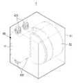
도 2는 본 발명의 일 실시 예에 따른 발전장치(1)를 나타내는 사시도이며, 도 3은 도 2에 도시된 발전장치(1)의 분해 사시도이다.FIG. 2 is a perspective view showing a
도 2 및 도 3을 참조하면, 발전장치(1)는 외관을 형성하는 제1 케이스(51)와, 제1 케이스(51) 내부에 배치된 제2 케이스(52)와, 제2 케이스(52) 내부에 배치된 배럴(10), 변환부(20) 및 정전 발전부(30)와, 동력 전달부(40)를 포함할 수 있다. 발전장치(1)는 배럴(10), 변환부(20) 및 정전 발전부(30)를 감싸는 제2 케이스(52)를 생략할 수 있다. 이 경우, 배럴(10), 변환부(20) 및 정전 발전부(30)는 제1 케이스(51) 내부에 직접 배치되는 구조도 가능하다.2 and 3, the
동력 전달부(40)는 제1 케이스(51)의 내측에 배치되며 외부로부터 전달된 구동력을 배럴(10)에 전달한다.The
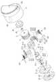
동력 전달부(40)는 랙 기어(41) 및 랙 기어(41)에 치합되는 피니언 기어(42)로 구성된다.The
랙 기어(41)는 길이방향을 따라 배치된 다수의 치(411)를 포함하며, 랙 기어(41)에는 랙 기어(41)를 유동 가능하게 지지하는 스윙 부재(431)가 결합된다.The
도 2 및 도 3에 도시된 바와 같이, 스윙 부재(431)는 탄성력을 가진 압축 스프링 일 수 있으며, 다수로 구성되어 랙 기어(411)의 양단에 결합될 수 있다.2 and 3, the
구체적으로, 스윙 부재(431)는 제1 케이스(51)의 내벽에 일단이 결합되고 타단이 랙 기어(41)에 결합됨으로써 랙 기어(41)와 제1 케이스(51)를 서로 연결할 수 있다.Specifically, the
따라서, 랙 기어(41)는 발전장치(1)의 움직임에 의해 유동 가능한 스윙 부재(431)를 통해 제1 케이스(51)와 연결될 수 있으며, 이를 통해, 랙 기어(41)는 제1 케이스(51) 내에서 길이방향을 따라 유동 가능하게 배치될 수 있다.The
따라서, 발전장치(1)가 외력에 의해 흔들리거나 진동하는 경우, 스윙 부재(431)에 연결된 랙 기어(41)는 길이방향을 따라 왕복 운동할 수 있다.Therefore, when the
아울러, 발전장치(1)는 랙 기어(41)의 일측과 제1 케이스(51) 사이에 배치되어 랙 기어(41)의 왕복 운동을 가이드하는 롤러부(60)를 포함할 수 있다.The
롤러부(60)는 제1 케이스(51)의 내측벽에 결합될 수 있으며, 랙 기어(41)의 길이방향을 따라 배치된 다수의 롤러(61)와 다수의 롤러(61)가 결합된 다수의 롤러 축(62)을 포함할 수 있으며, 다수의 롤러 축(62)은 롤러 지지부재(63)에 결합되어 제1 케이스(51)의 내측벽 상에 지지될 수 있다.The
랙 기어(41)는 스윙 부재(431)에 의해 길이방향을 따라 왕복 운동을 하므로, 다수의 롤러 축(62)은 랙 기어(41)의 길이방향과 수직하게 배치되는 것이 바람직하다.The
다수의 롤러(61)는 랙 기어(41)의 일측면을 지지하고 랙 기어(41)의 왕복 운동에 따라 회전할 수 있으며, 이를 통해, 랙 기어(41)의 왕복운동을 가이드 할 수 있다.The plurality of
따라서, 발전장치(1)가 외력에 의해 불규칙한 방향으로 흔들리더라도 랙 기어(41)는 길이방향을 따라 왕복운동 할 수 있으며, 이를 통해, 랙 기어(41)에 치합된 피니언 기어(42)가 안정적으로 회전할 수 있다.The
길이방향을 따라 왕복 운동하는 랙 기어(41)에 치합됨으로써 회전하는 피니언 기어(42)는, 배럴(10)의 일측에 결합됨으로써 배럴(10)을 회전시킬 수 있으며, 배럴(10)의 회전력을 통해 정전 발전부(30)가 구동함으로써 전력을 생산할 수 있다.The
배럴(10), 변환부(20) 및 정전 발전부(30)의 세부 구성에 대해서는 다음에서 상술하기로 한다.The detailed configuration of the
도 4는 도 3에 도시된 발전장치(1)의 배럴(10), 변환부(20) 및 정전 발전부(30)의 세부구성을 나타내는 분해 사시도이고, 도 5는 도 4에 도시된 발전장치(1)의 배럴(10), 변환부(20) 및 정전 발전부(30)의 단면도이다.4 is an exploded perspective view showing a detailed configuration of the
이하에서는, 도 4 및 도 5를 참조하여 발전장치(1)의 세부적이 구조에 대해 배럴(10), 변환부(20) 및 정전 발전부(30)를 중심으로 설명한다.Hereinafter, with reference to Figs. 4 and 5, the detailed structure of the
전술한 바와 같이, 배럴(10), 변환부(20) 및 정전 발전부(30)는 제2 케이스(52) 내부에 배치된다.The
제2 케이스(52)는 대략 원통의 형상일 수 있으며, 배럴(10)에 결합되어 배럴(10)에 회전력을 인가하는 피니언 기어(42)는 제2 케이스(52)의 일측에 형성된 개구로부터 일부가 돌출됨으로써 랙 기어(41)와 치합될 수 있다.The
또한, 피니언 기어(42)와 배럴(10)은 커플러(421)를 통해 연결됨으로써 피니언 기어(42)와 랙 기어(41)가 배럴(10)에 간섭됨이 없이 서로 치합될 수 있다.The
배럴(10)은 회전이 용이하도록 원통 또는 원기둥의 형상일 수 있으며, 원의 형상인 윗면과 밑면 중 어느 하나에 결합된 커플러(421)를 통해 피니언 기어(42)와 결합할 수 있다. 이하에서는 설명의 편의를 위해, 배럴(10)에서 커플러(421)가 결합된 면을 윗면으로 칭하고, 윗면과 반대되는 면을 아랫면, 윗면과 아랫면을 연결하는 면을 옆면으로 칭한다.The
배럴(10)의 옆면에는 후술하는 복수의 연결부재(220)가 이동 가능하게 삽입되는 슬롯(11)이 형성될 수 있다. 슬롯(11)에 대해서는 후술하기로 한다.The side surface of the
전술한 바와 같이, 변환부(20)는 복수의 기어 셋(210), 복수의 연결부재(220), 구동부(230), 제어부(240) 및 센서부(250)를 포함한다.As described above, the converting
복수의 기어 셋(210)은 회전축(S)과 연결되고, 서로 다른 기어 비를 갖는 제1 내지 제3 기어 셋(211 내지 213)을 포함한다.The plurality of gear sets 210 includes first to third gear sets 211 to 213 connected to the rotation axis S and having different gear ratios.
도 4 및 도 5에 도시된 바와 같이, 제1 내지 제3 기어 셋(211 내지 213)은 배럴(10)의 내측에서 회전축(S)에 서로 평행하게 결합된다.As shown in FIGS. 4 and 5, the first to third gear sets 211 to 213 are coupled to the rotation axis S in parallel with each other inside the
이를 통해, 배럴(10)이 불규칙한 회전 속도로 회전하더라도, 서로 다른 기어 비를 갖는 제1 내지 제3 기어 셋(211 내지 213) 중 어느 하나가 배럴(10)과 선택적으로 결합함으로써, 회전축(S)의 회전 속도를 일정하게 유지할 수 있다.Thus, even if the
예를 들어, 제1 기어 셋(211)은 배럴(10)의 회전 속도보다 느린 속도로 회전축(S)을 회전시킬 수 있는 기어 비로 구성될 수 있으며, 제2 기어 셋(212)은 배럴(10)의 회전 속도와 동일한 속도로 회전축(S)을 회전시킬 수 있는 기어 비로 구성될 수 있고, 제3 기어 셋(213)은 배럴(10)의 회전 속도보다 빠른 속도로 회전축(S)을 회전시킬 수 있는 기어 비로 구성될 수 있다.For example, the first gear set 211 may be configured with a gear ratio capable of rotating the rotational axis S at a speed slower than the rotational speed of the
따라서, 회전축(S)이 미리 설정된 기준 범위보다 빠른 속도로 회전하면 제1 기어 셋(211)을 배럴(10)과 연결시킴으로써 회전축(S)의 회전 속도를 감속하고, 회전축(S)이 미리 설정된 기준 범위 내의 속도로 회전하면 제2 기어 셋(212)을 배럴(10)과 연결시키며, 회전축(S)이 미리 설정된 기준 범위보다 느린 속도로 회전하면 제3 기어 셋(213)을 배럴(10)과 연결시킴으로써 회전축(S)의 회전 속도를 가속할 수 있다.The rotation speed of the rotation shaft S is reduced by connecting the first gear set 211 to the
구체적으로, 제1 기어 셋(211)은 회전축(S)에 결합된 제1 태양 기어(2111), 제1 태양 기어(2111)와 치합되는 다수의 제1 유성 기어(2112), 및 다수의 제1 유성 기어(2112)와 치합되는 제1 링 기어(2113)를 포함한다.Specifically, the first gear set 211 includes a
또한, 제2 기어 셋(212)은 회전축(S)에 결합된 제2 태양 기어(2121) 및 제2 태양 기어(2121)와 치합되는 제2 링 기어(2122)를 포함한다.The second gear set 212 also includes a
아울러, 제3 기어 셋(213)은 회전축(S)에 결합된 제3 태양 기어(2131), 제3 태양 기어(2131)와 치합되는 다수의 제3 유성 기어(2132), 및 다수의 제3 유성 기어(2132)와 치합되는 제3 링 기어(2133)를 포함한다.The third gear set 213 includes a
도 4에 도시된 바와 같이, 제1 내지 제3 링 기어(2113, 2122, 2133)는 직경이 서로 동일한 내치 기어(internal gear)일 수 있으며, 제1 태양 기어(2111), 제1 유성 기어(2112), 제2 태양 기어(2121), 제3 태양 기어(2131) 및 제3 유성 기어(2132)는 직경이 서로 다른 평 기어(spur gear)로 구성될 수 있다.4, the first to third ring gears 2113, 2122 and 2133 may be internal gears having the same diameter, and the
제1 기어 셋(211)을 구성하는 다수의 제1 유성 기어(2112)는 제1 캐리어(2112a)에 회전 가능하게 고정되며, 제1 캐리어(2112a)는 배럴(10)의 외부에 고정된다.A plurality of first
예를 들어, 제1 캐리어(2112a)의 일단에는 다수의 제1 유성 기어(2112)가 각각의 회전 중심을 기준으로 회전 가능하게 결합되며, 제1 캐리어(2112a)의 일단과 반대되는 타단은 배럴(10), 커플러(421) 및 피니언 기어(42)를 순차적으로 관통하여 제2 케이스(52)에 고정될 수 있다.For example, a plurality of first
도 4에 도시된 바와 같이, 제1 캐리어(2112a)가 피니언 기어(42), 커플러(421), 배럴(10)의 회전에 간섭됨이 없이 제2 케이스(52)에 고정될 수 있도록, 피니언 기어(42), 커플러(421), 배럴(10)은 각각 제1 캐리어(2112a)의 타단부가 관통하는 중공을 포함한다.The
이를 통해, 제1 링 기어(2113)가 회전하면 다수의 제1 유성 기어(2112)는 각각의 회전 중심을 기준으로 회전할 수 있다, 즉, 다수의 제1 유성 기어(2112)는 제1 캐리어(2112a)에 고정됨으로써 제1 링 기어(2113)의 내주면을 따라 공전하지 않고 고정된 위치에서 자전할 수 있으며, 따라서 제1 태양 기어(2111)가 제1 기어 셋(211)의 기어 비에 따라 회전할 수 있다.Accordingly, when the
또한, 다수의 제1 유성 기어(2112)는 동일한 간격으로 배치된 3개의 기어로 이루어 질 수 있으며, 제1 유성 기어(2112)의 지름은 제1 태양 기어(2111)의 지름보다 작게 구성될 수 있다.The diameter of the first
따라서, 제1 링 기어(2113)가 회전하면, 다수의 제1 유성 기어(2112)가 회전하고, 제1 유성 기어(2112)에 치합된 제1 태양 기어(2111)는 배럴(10)의 회전 속도보다 느린 회전 속도로 회전한다. 따라서, 회전축(S) 역시 배럴(10)보다 느린 회전 속도로 회전하게 되며, 이를 통해, 회전축(S)의 회전 속도를 감속할 수 있다.When the
제2 기어 셋(212)을 구성하는 제2 링 기어(2122)의 내측에는 제2 태양 기어(2121)가 치합된다. 예를 들어, 도 4 및 도 5에 도시된 바와 같이 제2 링 기어(2122)의 내측에는 제2 태양 기어(2121)가 삽입 결합될 수 있으며, 따라서, 제2 링 기어(2122)가 회전 속도와 동일한 속도로 제2 태양 기어(2121)가 회전할 수 있다.The
이를 통해, 제2 기어 셋(212)은 배럴(10)의 회전 속도와 동일한 속도로 회전축(S)을 회전시킬 수 있는 기어 비로 구성될 수 있다.The second gear set 212 can be configured with a gear ratio capable of rotating the rotation axis S at the same speed as the rotation speed of the
아울러, 제2 기어 셋(212)을 구성하는 제2 태양 기어(2121)와 제2 링 기어(2122)는 별도의 치합 구조 없이 일체로 형성된 디스크일 수 있다.In addition, the
제3 기어 셋(213)을 구성하는 다수의 제3 유성 기어(2132)는 제3 캐리어(2132a)에 회전 가능하게 고정되며, 제3 캐리어(2132a)는 배럴(10)의 외부에 고정된다.A plurality of third
예를 들어, 제3 캐리어(2132a)의 일단에는 다수의 제3 유성 기어(2132)가 각각의 회전 중심을 기준으로 회전 가능하게 결합되며, 일단과 반대되는 타단은 제2 케이스(52)에 고정된다.For example, a plurality of third
구체적으로, 도 4에 도시된 바와 같이, 제3 캐리어(2132a)는 제2 케이스(52)의 옆면에 결합되어 회전축(S)을 향해 연장 형성된 캐리어 지지부재(522)에 결합될 수 있다.4, the
이를 통해, 제3 링 기어(2133)가 회전하면 다수의 제3 유성 기어(2132)는 각각의 회전 중심을 기준으로 회전할 수 있다, 즉, 다수의 제3 유성 기어(2132)는 제3 캐리어(2132a)에 고정됨으로써 제3 링 기어(2133)의 내주면을 따라 공전하지 않고 고정된 위치에서 자전할 수 있으며, 따라서, 제3 태양 기어(2131)가 제3 기어 셋(213)의 기어 비에 따라 회전할 수 있다.Accordingly, when the
또한, 다수의 제3 유성 기어(2132)는 동일한 간격으로 배치된 3개의 기어로 이루어 질 수 있으며, 제3 유성 기어(2112)의 지름은 제3 태양 기어(2131)의 지름보다 크게 구성될 수 있다.The diameter of the third
따라서, 제3 링 기어(2133)가 회전하면, 다수의 제3 유성 기어(2132)가 회전하고, 제3 유성 기어(2132)에 치합된 제3 태양 기어(2131)는 배럴(10)의 회전 속도보다 빠른 회전 속도로 회전한다. 따라서, 회전축(S) 역시 배럴(10)보다 빠른 회전 속도로 회전하게 되며, 이를 통해, 회전축(S)의 회전 속도를 가속할 수 있다.When the
이상에서는, 복수의 기어 셋(210)이 배럴(10)의 회전 속도에 대응하여 회전축(S)의 회전 속도를 감속, 유지 및 가속하는 제1 내지 제3 기어 셋(211 내지 213)으로 구성됨을 일 예로서 설명하였으나, 이에 한정됨이 기어 셋의 수는 가감될 수 있으며, 기어 셋의 수가 늘어나는 경우 회전축(S)의 회전 속도를 더욱 정밀하게 조절할 수 있다. 이처럼, 복수의 기어 셋은 회전축(S)의 회전 속도를 변경시킬 수 있는 다양한 구조로 변형이 가능하다.The plurality of gear sets 210 are constituted by the first to third gear sets 211 to 213 for reducing, maintaining and accelerating the rotational speed of the rotating shaft S in correspondence with the rotational speed of the
복수의 연결부재(220)는 다수로 구성될 수 있으며, 배럴(10)에 결합된 제1 내지 제3 연결부재(221 내지 223)를 포함한다.The plurality of connecting members 220 may include a plurality of connecting
배럴(10)에 결합된 제1 내지 제3 연결부재(221 내지 223)는 배럴(10)의 회전에 따라 함께 회전할 수 있으며, 제1 내지 제3 링 기어(2113, 2122, 2133)에 선택적으로 결합됨으로써 배럴(10)의 회전력을 제1 내지 제3 링 기어(2113, 2122, 2133)에 선택적으로 전달할 수 있다.The first to
제1 내지 제3 연결부재(221 내지 223)는 제1 내지 제3 링 기어(2113, 2122, 2133)와 마주하는 위치에 배치되며, 예를 들어, 제1 내지 제3 링 기어(2113, 2122, 2133)의 각 외주면과 마주하도록 배럴(10)상에 배치될 수 있다.The first to
제1 내지 제3 연결부재(221 내지 223)는 회전축(S)을 향하는 제1 방향으로 이동하여 각각 제1 내지 제3 링 기어(2113, 2122, 2133)와 결합될 수 있으며, 제1 방향과 반대되는 제2 방향으로 이동하여 제1 내지 제3 링 기어(2113, 2122, 2133)와 분리될 수 있다.The first to
제1 내지 제3 연결부재(221 내지 223)는 제1 내지 제3 연결부재(221 내지 223)의 외주면의 곡률과 동일한 곡률을 갖는 호의 형상일 수 있다.The first to third connecting
또한, 배럴(10)의 외주면에는 제1 내지 제3 연결부재(221 내지 223)의 형상과 대응하는 복수의 슬롯(11)이 형성될 수 있으며, 제1 내지 제3 연결부재(221 내지 223)는 복수의 슬롯(11)에 이동 가능하게 삽입될 수 있다. 이를 통해, 제1 내지 제3 연결부재(221 내지 223)는 복수의 슬롯(11) 상에서 제1 방향과 제2 방향으로 이동할 수 있다.A plurality of
아울러, 복수의 슬롯(11)에는 제1 내지 제3 연결부재(221 내지 223)의 제1 방향과 제2 방향으로의 이동을 가이드 하는 가이드 홈(미도시)이 형성되고, 제1 내지 제3 연결부재(211 내지 223)의 각 외면에는 가이드 홈에 슬라이딩 가능하게 삽입되는 가이드 돌기(미도시)가 형성됨으로써, 제1 내지 제3 연결부재(221 내지 223)의 제1 방향 및 제2 방향으로의 이동이 정확하게 가이드 될 수 있다.The plurality of
또한, 제1 내지 제3 연결부재(221 내지 223)가 제1 방향 및 제2 방향으로 이동함에 따라 배럴(10)로부터 분리되지 않도록, 배럴(10)의 옆면의 두께는 제1 내지 제3 연결부재(221 내지 223)의 이동구간보다 크게 구성되는 것이 바람직하다.The thickness of the side surface of the
아울러, 도 4에 도시된 바와 같이, 제1 내지 제3 연결부재(221 내지 223)는 각각, 복수로 구성되어 배럴(10)의 외주면을 따라 동일한 간격으로 배치될 수 있다.4, each of the first to third connecting
구체적으로, 제1 내지 제3 연결부재(221 내지 223)는 각각, 한 쌍의 연결부재로 이루어질 수 있으며, 한 쌍의 연결부재가 링 기어를 중심으로 서로 대칭되게 배치된 상태에서 링 기어에 결합됨으로써, 배럴(10)과 제1 내지 제3 링 기어(2113, 2122, 2133)를 더욱 견고하게 결합시킬 수 있다.Specifically, each of the first to
나아가, 제1 내지 제3 연결부재(221 내지 223)는 각각 제1 내지 제3 링 기어(2113, 2122, 2133)의 외주부의 형상과 대응하는 제1 내지 제3 결합홈(221G, 222G, 223G)을 포함할 수 있다.Further, the first to
이를 통해, 제1 내지 제3 링 기어(2113, 2122, 2133)는 제1 내지 제3 결합홈(221G, 222G, 223G)에 각각 삽입 결합될 수 있다.Accordingly, the first to third ring gears 2113, 2122, and 2133 can be inserted into the first to
또한, 제1 내지 제3 결합홈(221G, 222G, 223G)에 제1 내지 제3 링 기어(2113, 2122, 2133)가 삽입 결합될 수 있도록, 제1 내지 제3 연결부재(221 내지 223)는 각각 제1 내지 제3 링 기어(2113, 2122, 2133)의 높이보다 높게 구성되는 것이 바람직하다.The first to third connecting
아울러, 제1 내지 제3 기어 셋(211 내지 213)은 금속 재질로 이루어지고, 제1 내지 제3 연결부재(221 내지 223)는 금속과의 마찰력이 큰 우레탄 재질로 이루어질 수 있으며, 이를 통해, 제1 내지 제3 연결부재(211 내지 223)가 제1 방향으로 이동하면 제1 내지 제3 링 기어(2113, 2122, 2133)의 각 외주부가 제1 내지 제3 결합홈(221G, 222G, 223G)에 견고하게 끼움 결합될 수 있다.In addition, the first to third gear sets 211 to 213 are made of a metal material, and the first to third connecting
이를 통해, 배럴(10)이 회전하는 동안에도, 제1 내지 제3 연결부재(211 내지 223)가 각각 선택적으로 제1 방향 및 제2 방향으로 이동함으로써 제1 내지 제3 링 기어(2113, 2122, 2133)와 견고하게 결합될 수 있으며, 이를 통해, 배럴(10)의 회전력이 제1 내지 제3 기어 셋(211 내지 213)에 손실 없이 선택적으로 전달될 수 있다.This allows the first to
구동부(230)는 제1 내지 제3 연결부재(221 내지 223)가 제1 방향으로 이동함으로써 제1 내지 제3 링 기어(2113, 2122, 2133)와 결합되고, 제2 방향으로 이동함으로써 제1 내지 제3 링 기어(2113, 2122, 2133)와 분리될 수 있도록, 제1 내지 제3 연결부재(221 내지 223)에 힘을 인가할 수 있다.The driving
도 4에 도시된 바와 같이, 제1 내지 제3 연결부재(221 내지 223)가 각각 복수로 구성되어 배럴(10) 상에서 서로 대칭적으로 배치된 경우, 구동부(230) 역시 복수로 구성되어 배럴(10)의 옆면의 일측에 배치된 제1 내지 제3 연결부재(221 내지 223)와 배럴(10)의 옆면의 타측에 배치된 제1 내지 제3 연결부재(221 내지 223)에 각각 힘을 인가할 수 있다.4, when a plurality of first to third connecting
구동부(230)의 구성 및 구조에 대해서는 다음에서 상술하기로 한다.The structure and structure of the
정전 발전부(30)는 직접적인 마찰 대전에 의해 전압을 발생시키거나, 이격 배치된 대전체와 대전체 사이의 정전 유도를 통해 전압을 발생시킬 수 있으며, 정전 발전부(30)는 예를 들어 직접 대전 방식 또는 간접 정전 유도 방식의 TENG(Triboelectric Nanogenerator)일 수 있다.The
구체적으로, 정전 발전부(30)는, 회전축(S)에 결합되어 회전하며 일면에 배치된 다수의 제1 대전체(311)를 포함하는 제1 대전 플레이트(31)와 다수의 제1 대전체(311)와 접촉 또는 인접하도록 배치된 다수의 제2 대전체(321)를 일면에 구비한 제2 대전 플레이트(32)를 포함한다.Specifically, the electrostatic generator (30) includes a first charging plate (31) including a plurality of first generators (311) which are coupled to the rotating shaft (S) And a
제1 대전 플레이트(31)는 회전축(S)에 결합됨으로써 회전축(S)의 회전에 따라 회전할 수 있으며, 디스크 형상일 수 있다.The
제1 대전 플레이트(31)의 일면에는 다수의 제1 대전체(311)가 방사상으로 배치될 수 있으며, 제1 대전 플레이트(31)의 회전에 따라 다수의 제1 대전체(311)는 회전할 수 있다.A plurality of first
제2 대전 플레이트(32)는 제1 대전 플레이트(31)와 마주하는 일면에 배치된 다수의 제2 대전체(321)를 포함하며, 일면과 반대되는 타면은 제2 케이스(52)에 고정된다.The
따라서, 제1 대전 플레이트(31)가 회전축(S)에 연결되어 회전함으로써 다수의 제1 대전체(311)는 회전할 수 있으며, 이를 통해, 다수의 제1 대전체(311)와 마주하도록 배치된 다수의 제2 대전체(321)와 대전됨으로써, 정전 발전부(30)는 전력을 생산할 수 있다.Accordingly, the
전술한 제1 대전체(311)와 제2 대전체(321)는, 회전에 의한 상호간의 대전을 통해 전력이 생산될 수 있으며, 이를 위해, 제1 대전체(311)는 금속재질로 이루어지고, 제2 대전체(321)는 PDMS(polydiemethylsiloxane), PA(Polyamide), PU (polyurethane), PTFE(polytetrafluoroethylene) 등과 같은 중합체(폴리머)로 이루어질 수 있다.The first
아울러, 제1 대전체(311)는 금속재질 및 산화알루미늄, 산화티타늄, 산화 규소 등과 같은 금속 산화물로 이루어지고, 제2 대전체(321)는 PVDF(poly vinylidene fluoride), PVC(poly vinyl chloride), PVF(Polyvinyl fluoride), TGS(Tri Glycerin Sulphate), PZT(Lead Zirconate Titanate), PST(Lead Stannic Titanate) 등과 같은 초전물질로 이루어질 수 있다.The second
다만, 전술한 제1 대전체(311)와 제2 대전체(321)를 구성하는 물질은 서로 대체될 수 있으며, 상기 물질 외에도 제1 대전체(311)와 제2 대전체(321)는, 제1 대전체(311)의 회전에 의해 대전됨으로써 전력이 생성될 수 있는 다양한 물질들로 대체될 수 있다.However, in addition to the above-described materials, the first
도 6 내지 도 8은 도 5에 도시된 변환부(20)의 동작을 나타내는 확대 단면도이다.6 to 8 are enlarged sectional views showing the operation of the
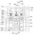
전술한 바와 같이, 구동부(230)는 복수로 구성되어 배럴(10)의 옆면 양측에 각각 배치될 수 있으나, 그 구성 및 동작은 동일하므로, 설명의 편의를 위해, 도 6 내지 도 8에서는 변환부(20)의 일부분만을 확대하여 도시하였다.As described above, the driving
이하에서는 도 5 내지 도 8을 참조하여, 구동부(230)를 중심으로 변환부(20)의 구조에 대해 상세히 설명한다.Hereinafter, the structure of the converting
구동부(230)는 제1 연결부재(221)에 힘을 가하는 제1 구동유닛(231), 제2 연결부재(222)에 힘을 가하는 제2 구동유닛(232) 및 제3 연결부재(223)에 힘을 가하는 제3 구동유닛(233)을 포함한다.The driving
제1 내지 제3 구동유닛(231 내지 233)은 각각 제1 내지 제3 연결부재(221 내지 223)와 마주하도록 배치될 수 있으며, 제1 내지 제3 구동유닛(231 내지 233)의 제1 내지 제3 가압부재(2311, 2321, 2331)가 제1 방향으로 이동하여 제1 내지 제3 연결부재(221 내지 223)를 가압함으로써, 제1 내지 제3 연결부재(221 내지 223)와 제1 내지 제3 링 기어(2113, 2122, 213)를 결합시킬 수 있다.The first to
제1 구동유닛(231)은 제1 연결부재(221)의 외주면과 마주하도록 배치된 제1 가압부재(2311), 제1 가압부재(2311)에 결합된 제1 마그네트(2312), 제1 마그네트(2312)와 마주하도록 배치되어 제1 마그네트(2312)에 자기력을 인가할 수 있는 제1 전자석(2313), 제1 가압부재(2311)와 제1 마그네트(2312)를 연결하는 제1 로드(rod; 2314) 및 제1 가압부재(2311)와 제1 마그네트(2312) 사이에 배치된 제1 탄성부재(2315)를 포함한다.The
또한, 제2 구동유닛(232)은 제2 연결부재(222)의 외주면과 마주하도록 배치된 제2 가압부재(2321), 제2 마그네트(2322), 제2 전자석(2323), 제2 로드(2324) 및 제2 탄성부재(2325)를 포함하며, 제3 구동유닛(233)은 제3 연결부재(223)의 외주면과 마주하도록 배치된 제3 가압부재(2331), 제3 마그네트(2332), 제3 전자석(2333), 제3 로드(2334) 및 제3 탄성부재(2335)를 포함한다.The
제2 및 제3 구동유닛(232, 233)의 구조는 제1 구동유닛(231)의 구조와 동일하므로, 이하에서는 제1 구동유닛(231)의 구조를 중심으로 설명하겠으며, 제1 구동유닛(231)의 구조와 중복되는 제2 및 제3 구동유닛(232, 233)에 대한 설명은 생략하기로 한다.The structure of the second and
제1 가압부재(2311)는 제1 연결부재(221)와 마주하도록 배치되며, 제1 연결부재(221)와 일정 간격으로 이격되게 배치됨으로써, 제1 구동유닛(231)이 가동되지 않는 상태에서는 제1 가압부재(2311)가 회전하는 배럴(10)과 간섭되지 않도록 배치될 수 있다.The first pressing
또한, 제1 가압부재(2311)는 제1 연결부재(221)를 용이하게 가압할 수 있도록, 제1 연결부재(221)의 외주면과 대응하는 형상일 수 있으며, 예를 들어, 제1 연결부재(221)의 외주면의 곡률과 동일한 곡률을 갖는 호의 형상일 수 있다.The first pressing
제1 가압부재(2311)는 제1 마그네트(2312)와 결합되며, 제1 가압부재(2311)와 제1 마그네트(2312)는 제1 로드(2314)를 통해 서로 연결될 수 있다.The first pressing
구체적으로, 제1 로드(2314)는 제1 가압부재(2311) 및 제1 마그네트(2312) 보다 단면적이 작은 기둥의 형상일 수 있으며, 일단이 제1 가압부재(2311)의 중앙부와 연결되고, 타단이 제1 마그네트(2312)의 중앙부와 연결된다.Specifically, the
따라서, 제1 전자석(2313)에 의해 제1 마그네트(2312)에 자기력이 가해지면, 제1 마그네트(2312), 제1 로드(2314) 및 제1 가압부재(2311)는 함께 이동할 수 있다.Therefore, when a magnetic force is applied to the
아울러, 제1 로드(2314)는 제2 케이스(52)의 내측에 배치된 구동부 케이스(521)에 이동 가능하게 삽입됨으로써, 제1 가압부재(2311), 제1 마그네트(2312) 및 제1 로드(2314)가 제2 케이스(52)에 이동 가능하게 지지될 수 있다.The
구체적으로, 구동부 케이스(521)의 내부에는 제1 전자석(2313) 및 제1 마그네트(2312)가 배치되고, 구동부 케이스(521)에는 회전축(S)을 향하는 방향으로 형성된 제1 구동홀(미도시)이 형성되고, 제1 구동홀에는 제1 로드(2314)가 이동 가능하게 삽입될 수 있다.Specifically, the
아울러, 제1 가압부재(2311)는 구동부 케이스(521)의 외측에서 제1 로드(2314)의 일단과 결합될 수 있으며, 이를 통해, 제1 가압부재(2311)의 제1 방향 및 제2 방향으로의 이동이 제1 구동홀을 따라 이동하는 제1 로드(2314)에 의해 가이드 될 수 있다. 이를 위해, 제1 구동홀의 직경은 제1 로드(2314)의 직경 이상이고 제1 가압부재(2311)의 직경 이하인 것이 바람직하다.The first pressing
또한, 제1 가압부재(2311)가 제1 방향 또는 제2 방향으로 이동함에 따라, 제1 가압부재(2311)와 제1 마그네트(2312)의 서로 마주하는 일면이 구동부 케이스(521)에 간섭됨으로써, 제1 가압부재(2311)의 이동거리가 제한될 수 있다.Further, as the first pressing
제1 전자석(2313)은 제2 케이스(52)에 고정된 전자석 지지부재(2301)에 결합되고, 구동부 케이스(521)의 내부에서 제1 마그네트(2312)와 마주하도록 배치된다.The
전자석 지지부재(2301)의 내부에는 제1 전자석(2313)에 전류를 공급할 수 있는 전선(미도시)이 배치될 수 있다.An electric wire (not shown) capable of supplying an electric current to the
제1 전자석(2313)에 전류가 인가되면 제1 전자석(2313)은 제1 마그네트(2312)에 자기력을 인가할 수 있으며, 전류의 방향에 따라 제1 마그네트(2312)에 척력 또는 인력을 가하도록 자기장을 형성할 수 있다.When a current is applied to the
제1 전자석(2313)이 제1 마그네트(2312)에 척력을 가하면, 제1 마그네트(2312)는 제1 방향으로 이동하게 되며, 따라서, 제1 가압부재(2311)는 제1 연결부재(221)를 가압할 수 있다.The
이를 통해, 제1 연결부재(221)와 제1 링 기어(2113)가 결합될 수 있으며, 배럴(10)의 회전력이 제1 연결부재(221)를 통해 제1 기어 셋(211)으로 전달됨으로써 회전축(S)이 회전할 수 있다.The
아울러, 제1 가압부재(2311)와 제1 마그네트(2312) 사이에는 제1 방향으로 이동한 제1 가압부재(2311)가 제2 방향으로 복귀하도록 제1 가압부재(2311)에 힘을 가하는 제1 탄성부재(2315)가 배치된다.The first pressing
도 5 내지 도 8에 도시된 바와 같이, 제1 탄성부재(2315)는 제1 로드(2314)를 감싸도록 배치된 압축 스프링일 수 있으며, 제1 마그네트(2312)와 구동부 케이스(521) 사이에 배치되어 구동부 케이스(521)에 지지됨으로써, 제1 방향으로 이동하는 제1 마그네트(2312)에 대해 제2 방향으로 탄성력을 가할 수 있다.5 to 8, the first
전술한 바와 같이, 제1 전자석(2313)에 전류가 인가되어 제1 마그네트(2312)에 척력을 가하는 자기장이 형성되면, 제1 마그네트(2312)는 제1 가압부재(2311)를 제1 방향으로 이동시키며, 이를 통해 제1 연결부재(221)와 제1 링 기어(2113)가 결합된다.When a current is applied to the
이를 위해, 제1 전자석(2313)이 제1 마그네트(2312)에 인가하는 척력은 제1 탄성부재(2315)의 제2 방향으로 가하는 탄성력보다 크도록 제1 전자석(2315)에 전류가 가해지는 것이 바람직하다.To this end, a repulsive force applied to the
제1 연결부재(221)와 제1 링 기어(2113)가 결합되면, 제1 전자석(2315)에 인가되는 전류를 차단함으로써 제1 마그네트(2312)에 가해지는 자기장이 해제되며, 제1 탄성부재(2315)의 탄성력에 의해 제1 마그네트(2312) 및 이에 결합된 제1 가압부재(2311)는 제2 방향으로 이동하여 복귀하게 된다.When the
이를 통해, 제1 전자석(2313)에 순간적으로 전류를 인가해 준 뒤 전류를 차단함으로써, 제1 가압부재(2311)가 제1 방향으로 이동하여 제1 연결부재(221)를 가압한 뒤 곧바로 제2 방향으로 복귀할 수 있으며, 제1 가압부재(221)가 회전하는 배럴(10)에 간섭되는 것을 방지할 수 있다. 아울러, 이를 통해, 제1 전자석(2313)의 작동을 위해 사용되는 전력량 역시 최소화할 수 있다.The
전술한 바와 같이, 제2 구동유닛(232) 및 제3 구동유닛(233)의 구성은 전술한 제1 구동유닛(231)의 구성과 동일하며, 제2 구동유닛(232)의 제2 연결부재(222)는 제2 가압부재(2321)에 의해 가압됨으로써 제2 링 기어(2122)와 결합할 수 있으며, 제3 구동유닛(233)의 제3 연결부재(223)는 제3 가압부재(2331)에 의해 가압됨으로써 제3 링 기어(2133)와 결합할 수 있다.As described above, the configurations of the
또한, 구동부(230)는 제1 내지 제3 연결부재(221 내지 223) 중 어느 하나가 제1 방향으로 이동하는 경우, 나머지 2개의 연결부재를 제2 방향으로 이동시키는 시소부(234; seesaw member)를 포함한다.The driving
시소부(234)는 제1 및 제2 연결부재(221, 222)에 피봇(pivot) 가능하게 연결된 제1 시소부재(2341a)와 제2 및 제3 연결부재(222, 223)에 피봇 가능하게 연결된 제2 시소부재(2341b)를 포함할 수 있다.The
제1 시소부재(2341a)는 제1 및 제2 연결부재(221, 222) 중 어느 하나에 인가된 힘의 방향과 반대되는 방향으로 제1 및 제2 연결부재(221, 222) 중 다른 하나에 힘을 가할 수 있으며, 제2 시소부재(2341b)는 제2 및 제3 연결부재(222, 223) 중 어느 하나에 인가된 힘의 방향과 반대되는 방향으로 제2 및 제3 연결부재(222, 223) 중 다른 하나에 힘을 가할 수 있다.The first
구체적으로, 제1 시소부재(2341a)는 제1 전자석(2313)의 척력에 의해 제1 연결부재(221)가 제1 방향으로 이동하면, 지렛대의 원리에 의해 제2 연결부재(222)를 제2 방향으로 이동시킬 수 있으며, 제2 전자석(2323)의 척력에 의해 제2 연결부재(222)가 제1 방향으로 이동하면 제1 연결부재(221)를 제2 방향으로 이동시킬 수 있다.More specifically, when the first connecting
아울러, 제2 시소부재(2341b)는 제2 전자석(2323)의 척력에 의해 제2 연결부재(222)가 제1 방향으로 이동하면, 지렛대의 원리에 의해 제3 연결부재(223)를 제2 방향으로 이동시킬 수 있으며, 제3 전자석(2333)의 척력에 의해 제3 연결부재(223)가 제1 방향으로 이동하면 제2 연결부재(222)를 제2 방향으로 이동시킬 수 있다.When the second connecting
도 5 내지 도 8에 도시된 바와 같이, 제1 연결부재(221)와 제2 연결부재(222) 사이에는 제1 시소부재(2341a)의 중앙 하단부를 지지하는 제1 시소축(2342a)이 배치될 수 있다.5 to 8, a
제1 시소부재(2341a)의 일단은 제1 연결부재(221)에 피봇 가능하게 연결될 수 있으며, 예를 들어, 제1 연결부재(221)에 형성된 돌출부(2211)가 제1 시소부재(2341a)의 일단에 형성된 장공에 삽입됨으로써, 제1 시소부재(2341a)의 일단이 제1 연결부재(221)에 피봇 가능하게 연결될 수 있다.One end of the first
아울러, 제2 연결부재(222)에 형성된 돌출부(2221)가 제1 시소부재(2341a)의 타단에 형성된 결합구멍에 삽입됨으로써, 제1 시소부재(2341a)의 타단이 제2 연결부재(222)에 피봇 가능하게 연결될 수 있다.The
따라서, 제1 가압부재(2311)가 제1 방향으로 이동함으로써 제1 연결부재(221)가 제1 방향으로 이동하는 경우, 제1 시소부재(2341a)의 일단은 제1 방향으로 이동하게 되고, 제1 시소축(2342a)을 중심으로 제1 시소부재(2341a)의 타단은 제2 방향으로 이동함으로써 제1 시소부재(2341a)의 타단과 연결된 제2 연결부재(222)는 제2 방향으로 이동하게 된다.Therefore, when the first pressing
이를 통해, 제1 전자석(2313)에 전류를 인가하여 제1 마그네트(2312)에 척력을 가하면, 제1 가압부재(2311)가 제1 방향으로 이동함으로써 제1 연결부재(221)를 가압할 수 있으며, 이를 통해, 제1 연결부재(221)와 제1 링 기어(2113)가 결합될 수 있다.As a result of applying a repulsive force to the
아울러, 제1 연결부재(221)가 제1 방향으로 이동함과 동시에, 제1 시소부재(2341a)의 타단이 제2 방향으로 이동함으로써 제2 연결부재(222)가 제2 방향으로 이동하게 되고, 이를 통해, 제2 연결부재(222)와 제2 링 기어(2122)는 분리될 수 있다.At the same time that the first connecting
다시, 제2 전자석(2323)에 전류를 인가하여 제2 마그네트(2322)에 척력을 가하면, 제2 가압부재(2321)가 제1 방향으로 이동함으로써 제2 연결부재(222)를 가압할 수 있으며, 이를 통해, 제2 연결부재(222)와 제2 링 기어(2122)가 결합할 수 있다.When the
또한, 제2 연결부재(222)가 제1 방향으로 이동함과 동시에, 제1 시소부재(2341a)의 일단은 제2 방향으로 이동함으로써 제1 연결부재(221) 역시 제2 방향으로 이동하게 되고, 이를 통해, 제1 연결부재(221)와 제1 링 기어(2113)는 분리될 수 있다.Also, as the second connecting
이처럼, 제1 시소부재(2341a)를 통해, 제1 및 제2 연결부재(221, 222) 중 어느 하나가 제1 방향으로 이동하는 경우, 제1 및 제2 연결부재(221, 222) 중 다른 하나를 제2 방향으로 동시에 이동시켜줄 수 있으며, 제1 및 제2 연결부재(221, 222) 중 어느 하나만이 제1 및 제2 링 기어(2113, 2122)에 결합되어 회전축(S)에 회전력을 전달할 수 있다.When either one of the first and second connecting
아울러, 제2 연결부재(222)와 제3 연결부재(223) 사이에는 제2 시소부재(2341b)의 중앙 하단부를 지지하는 제2 시소축(2342b)이 배치될 수 있다.A
제2 시소부재(2341b)의 일단은 제3 연결부재(223)에 피봇 가능하게 연결될 수 있으며, 예를 들어, 제3 연결부재(223)에 형성된 돌출부(2213)가 제2 시소부재(2341b)의 일단에 형성된 장공에 삽입됨으로써, 제2 시소부재(2341b)의 일단이 제3 연결부재(223)에 피봇 가능하게 연결될 수 있다.One end of the second
아울러, 제2 연결부재(222)에 형성된 돌출부(2221)가 제2 시소부재(2341b)의 타단에 형성된 결합구멍에 삽입됨으로써, 제2 시소부재(2341b)의 타단이 제2 연결부재(222)에 피봇 가능하게 연결될 수 있다.The
따라서, 제3 가압부재(2331)가 제1 방향으로 이동함으로써 제3 연결부재(223)가 제1 방향으로 이동하는 경우, 제2 시소부재(2341b)의 일단은 제1 방향으로 이동하게 되고, 제2 시소축(2342b)을 중심으로 제2 시소부재(2341b)의 타단은 제2 방향으로 이동함으로써, 제2 시소부재(2341a)의 타단과 연결된 제2 연결부재(222)는 제2 방향으로 이동하게 된다.Therefore, when the third pressing
이를 통해, 제3 전자석(2333)에 전류를 인가하여 제3 마그네트(2332)에 척력을 가하면, 제3 가압부재(2331)가 제1 방향으로 이동함으로써 제1 연결부재(223)를 가압할 수 있으며, 이를 통해, 제3 연결부재(223)와 제3 링 기어(2133)가 결합될 수 있다.As a result, when a current is applied to the
아울러, 제3 연결부재(223)가 제1 방향으로 이동함과 동시에, 제2 시소부재(2341b)의 타단이 제2 방향으로 이동함으로써 제2 연결부재(222)가 제2 방향으로 이동하게 되고, 이를 통해 제2 연결부재(222)와 제2 링 기어(2122)는 분리될 수 있다.At the same time that the third connecting
다시, 제2 전자석(2323)에 전류를 인가하여 제2 마그네트(2322)에 척력을 가하면, 제2 가압부재(2321)가 제1 방향으로 이동함으로써 제2 연결부재(222)를 가압할 수 있으며, 이를 통해, 제2 연결부재(222)와 제2 링 기어(2122)가 결합할 수 있다.When the
또한, 제2 연결부재(222)가 제1 방향으로 이동함과 동시에, 제2 시소부재(2341b)의 일단은 제2 방향으로 이동함으로써 제3 연결부재(223) 역시 제2 방향으로 이동하게 되고, 이를 통해, 제3 연결부재(223)와 제3 링 기어(2133)는 분리될 수 있다. 아울러, 전술한 바와 같이, 제2 연결부재(222)가 제1 방향으로 이동함과 동시에, 제1 시소부재(2341a)의 일단도 제2 방향으로 이동함으로써 제1 연결부재(221)와 제1 링 기어(2113)가 분리될 수 있다.Also, as the second connecting
이처럼, 제2 시소부재(2341b)를 통해 제2 및 제3 연결부재(222, 223) 중 어느 하나를 제1 방향으로 이동시켜줌으로써, 제2 및 제3 연결부재(222, 223) 중 다른 하나를 제2 방향으로 동시에 이동시켜줄 수 있으며, 이를 통해 제2 및 제3 연결부재(222, 223) 중 어느 하나만이 제2 및 제3 링 기어(2122, 2133)에 결합되어 회전축(S)에 회전력을 전달할 수 있다.By moving any one of the second and third connecting
전술한 시소부(234)를 통해 간단한 동작만으로도 제1 내지 제3 연결부재(211, 222, 223)와 제1 내지 제3 링 기어(113, 2122, 2133)와의 결합을 선택적으로 전환할 수 있다.The coupling between the first to
아울러, 전술한 구동부(230)는 제어부(240)에 의해 제어될 수 있다.In addition, the driving
구체적으로, 제어부(240)는 제1 내지 제3 전자석(2313, 2323, 2333) 중 어느 하나에 전류를 인가하여 자기장을 형성함으로써, 제1 내지 제3 연결부재(221 내지 223) 중 어느 하나가 제1 내지 제3 링 기어(2113, 2122, 2133)와 연결될 수 있도록 제어할 수 있다.Specifically, the
또한, 변환부(30)는 센서부(250)를 포함할 수 있으며, 센서부(250)는 발전장치(1)의 작동 상태를 감지하는 다수의 센서를 포함할 수 있다.The
본 발명의 일 실시 예에 따른 정전 발전부(30)는 회전축(S)에 연결된 제1 대전 플레이트(31)의 회전에 의해 전력이 생산되는바, 사용자가 필요로 하는 일정한 전력을 지속적으로 생산하기 위해서는, 회전축(S)의 회전 속도가 일정한 것이 바람직하다.The
다만, 외부로부터 구동력을 전달받아 회전하는 배럴(10)은 불규칙한 속도로 회전할 수 있는바, 제어부(240) 및 센서부(250)를 통해 구동부(230)를 제어하여 회전축(S)의 회전 속도를 일정한 속도로 유지시켜 줌으로써 정전 발전부(30)를 통해 일정한 전력을 안정적으로 생산할 수 있다.The
구체적으로, 센서부(250)는 회전축(S)의 회전 속도를 측정하는 제1 센서(미도시)를 포함할 수 있다.Specifically, the
제1 센서는 회전축(S)의 회전 속도를 실시간으로 측정할 수 있으며, 제어부(240)는 측정된 회전축(S)의 회전 속도에 따라 회전축(S)이 일정한 속도로 회전할 수 있도록 구동부(230)를 제어할 수 있다.The
아울러, 센서부(250)는 정전 발전부(30)의 출력 전압을 측정하는 제2 센서(미도시)를 더 포함할 수 있으며, 제어부(240)는 제2 센서로부터 측정된 출력 전압에 따라 구동부(230)를 제어하여 회전축(S)의 회전 속도를 제어할 수 있다.In addition, the
또한, 센서부(250)는 배럴(10)의 회전 속도를 측정하는 제3 센서를 더 포함할 수 있으며, 측정된 배럴(10)의 회전 속도에 따라 회전축(S)이 일정한 속도로 회전할 수 있도록 구동부(230)를 제어할 수 있다.The
제어부(240) 및 센서부(250)를 통한 구동부(230)의 제어에 대해서는 이하에서 상술하기로 한다.Control of the
이하에서는 도 6 내지 도 8을 참조하여, 제어부(240) 및 센서부(250)를 통한 구동부(230)의 제어 및 구동부(230)의 동작에 대해 상세히 설명한다.Hereinafter, the operation of the
발전장치(1)가 외력에 의해 불규칙한 속도로 흔들리는 경우, 랙 기어(41) 역시 불규칙한 속도로 왕복 운동을 하므로, 피니언 기어(42) 및 피니언 기어(42)에 연결된 배럴(10) 역시 불규칙한 속도로 회전한다.The
이때, 제1 센서를 통해 측정된 회전축(S)의 회전 속도가 기 설정된 기준 속도보다 빠르게 회전하는 경우, 도 6에 도시된 바와 같이, 제어부(240)는 제1 전자석(2313)에 전류를 가하여 제1 마그네트(2312)에 척력을 가할 수 있으며, 이를 통해 제1 연결부재(221)와 제1 링 기어(2113)가 결합될 수 있다.6, the
전술한 바와 같이, 제1 기어 셋(211)은 회전축(S)의 회전 속도를 감속할 수 있으므로, 제1 연결부재(221)와 제1 링 기어(2113)가 결합됨으로써 회전축(S)의 회전 속도가 기 설정된 기준 속도 이내로 감속될 수 있다.The first gear set 211 can decelerate the rotation speed of the rotation shaft S so that the
이를 통해, 회전축(S)에 의해 회전하는 제1 대전 플레이트(31)의 회전 속도 역시 기 설정된 기준 속도로 전환시켜줌으로써 정전 발전부(30)를 통해 생산하는 전력량을 기 설정된 범위 이내로 조절할 수 있다. 아울러, 제1 연결부재(221)가 제1 방향으로 이동하는 경우, 제2 연결부재(222)는 제2 방향으로 이동함으로써 제2 링 기어(2122)와 분리될 수 있다.The rotation speed of the
또한, 제2 센서를 통해 정전 발전부(30)의 출력 전압을 측정할 수 있다.Further, the output voltage of the
제2 센서를 통해 측정된 정전 발전부(30)의 출력 전압이 기 설정된 기준 전압보다 높은 경우, 제어부(240)는 제1 연결부재(221)와 제1 링 기어(2113)를 결합시킴으로써 회전축(S)의 회전 속도를 감속시킬 수 있으며, 이를 통해 정전 발전부(30)에서 출력되는 전압을 기 설정된 범위 내에 속하도록 낮출 수 있다.When the output voltage of the
이를 통해, 정전 발전부(30)에서 생산되는 전력의 크기를 사용자가 필요로 하는 일정 범위 내로 유지할 수 있다.As a result, the magnitude of the electric power produced by the
아울러, 제3 센서를 통해 배럴(10)의 회전 속도를 측정하고, 배럴(10)의 회전 속도가 기 설정된 기준 속도보다 빠른 경우, 제어부(240)는 제1 전자석(2313)에 전류를 가하여 제1 마그네트(2312)에 척력을 가할 수 있으며, 이를 통해 제1 연결부재(221)와 제1 링 기어(2113)가 결합될 수 있다.When the rotational speed of the
따라서, 회전축(S)의 회전 속도를 배럴(10)의 회전 속도보다 느리게 변환할 수 있으며, 회전축(S)의 회전 속도를 기 설정된 범위 내로 제어할 수 있다.Therefore, the rotational speed of the rotary shaft S can be changed to be slower than the rotational speed of the
이후, 제1 센서를 통해 측정된 회전축(S)의 회전 속도가 기 설정된 기준 속도범위 내에서 회전하는 경우, 도 7에 도시된 바와 같이, 제어부(240)는 제2 전자석(2323)에 전류를 가하여 제2 마그네트(2322)에 척력을 가할 수 있으며, 이를 통해 제2 연결부재(222)와 제2 링 기어(2122)가 결합될 수 있다.7, when the rotation speed of the rotary shaft S measured through the first sensor rotates within a preset reference speed range, the
전술한 바와 같이, 제2 기어 셋(212)은 회전축(S)의 회전 속도를 일정한 속도로 유지할 수 있으므로, 제2 연결부재(222)와 제2 링 기어(2122)가 결합됨으로써 회전축(S)의 회전 속도는 기 설정된 기준 속도로 유지될 수 있다.The second gear set 212 can maintain the rotating speed of the rotating shaft S at a constant speed so that the second connecting
아울러, 제2 연결부재(222)가 제1 방향으로 이동함과 동시에, 제1 시소부재(2341a)에 의해 제1 연결부재(221)는 제2 방향으로 이동함으로써 제1 링 기어(2113)와 분리될 수 있다.The second connecting
또한, 제2 연결부재(222)가 제1 방향으로 이동함과 동시에, 제2 시소부재(2341b)에 의해 제3 연결부재(223)는 제2 방향으로 이동함으로써 제3 링 기어(2133)와 분리될 수 있다.The second connecting
아울러, 제2 센서를 통해 측정된 정전 발전부(30)의 출력 전압이 기 설정된 기준 전압범위에 속하는 경우, 제어부(240)는 제2 연결부재(222)와 제2 링 기어(2122)를 결합시킴으로써 회전축(S)의 회전 속도를 일정하게 유지할 수 있으며, 이를 통해 정전 발전부(30)에서 출력되는 전압을 유지할 수 있다.When the output voltage of the
아울러, 제3 센서를 통해 배럴(10)의 회전 속도를 측정하고, 배럴(10)의 회전 속도가 기 설정된 기준 속도범위 내에 속하는 경우, 제어부(240)는 구동부(230)를 통해 제2 연결부재(222)와 제2 링 기어(2122)를 결합시킬 수 있으며, 회전축(S)의 회전 속도를 기 설정된 범위 내로 유지할 수 있다.When the rotational speed of the
나아가, 제1 센서를 통해 측정된 회전축(S)의 회전 속도가 기 설정된 기준 속도보다 느린 경우, 도 8에 도시된 바와 같이, 제어부(240)는 제3 전자석(2333)에 전류를 가하여 제3 마그네트(2332)에 척력을 가할 수 있으며, 이를 통해 제3 연결부재(223)와 제3 링 기어(2133)가 결합될 수 있다.8, the
전술한 바와 같이, 제3 기어 셋(213)은 회전축(S)의 회전 속도를 가속할 수 있으므로, 제3 연결부재(223)와 제3 링 기어(2133)가 결합됨으로써 회전축(S)의 회전 속도는 기 설정된 기준 속도로 가속될 수 있다.The third gear set 213 can accelerate the rotation speed of the rotation shaft S and the
아울러, 제3 연결부재(223)가 제1 방향으로 이동함과 동시에, 제2 시소부재(2341b)에 의해 제2 연결부재(222)는 제2 방향으로 이동함으로써 제2 링 기어(2122)와 분리될 수 있다.The
아울러, 제2 센서를 통해 측정된 정전 발전부(30)의 출력 전압이 기 설정된 기준 전압범위보다 낮은 경우, 제어부(240)는 제3 연결부재(223)와 제3 링 기어(2133)를 결합시킴으로써 회전축(S)의 회전 속도를 가속할 수 있으며, 이를 통해 정전 발전부(30)에서 출력되는 전압을 상승시킬 수 있다.When the output voltage of the
아울러, 제3 센서를 통해 배럴(10)의 회전 속도를 측정하고, 배럴(10)의 회전 속도가 기 설정된 기준 속도보다 느린 경우, 제어부(240)는 구동부(230)를 통해 제3 연결부재(223)와 제3 링 기어(2133)를 결합시킬 수 있으며, 회전축(S)의 회전 속도를 기 설정된 범위까지 가속할 수 있다.If the rotation speed of the
전술한 제어부(240)를 통한 구동부(230)의 제어는 센서부(250)에 센싱과 함께 실시간으로 이루어 질 수 있다.The control of the
즉, 회전축(S)의 회전 속도, 정전 발전부(30)의 출력 전압 또는 배럴(10)의 회전 속도를 센서부(250)를 통해 실시간으로 측정하고, 제어부(240)는 센서부(250)를 통해 실시간으로 측정된 값에 대응하여 제1 내지 제3 연결부재(221 내지 223)를 제1 내지 제3 링 기어(2113, 2122, 2133)에 선택적으로 결합시키도록 구동부(230)를 제어함으로써, 회전축(S)의 회전 속도를 일정하게 유지할 수 있으며, 정전 발전부(30)를 통해 생산되는 전력 역시 일정하게 유지할 수 있다.That is, the
전술한 구동부(230)는 제1 내지 제3 전자석(2313, 2323, 2333)을 통해 제1 내지 제3 마그네트(2312, 2322, 2332)에 척력을 가해줌으로써 제1 내지 제3 가압부재(2311, 2321, 2331)를 제1 방향으로 이동시킴과 동시에, 제1 및 제2 시소부재(2341a, 2341b)를 통해 제1 내지 제3 링 기어(2113, 2122, 2133)에 결합된 제1 내지 제3 연결부재(221, 222, 223)를 분리시킬 수 있었다. 이를 통해, 구동부(230)의 작동에 필요한 전력량을 최소화할 수 있다.The driving
아울러, 구동부(230)는 제1 내지 제3 가압부재(2311, 2321, 2331)에 각각 결합된 제1 내지 제3 솔레노이드를 포함할 수 있으며, 이를 통해, 제1 내지 제3 가압부재(2311, 2321, 2331)를 개별적으로 제1 방향 및 제2 방향으로 이동시킬 수 있다.The driving
이외에도 구동부(230)의 구성은 제1 내지 제3 연결부재(221 내지 223)와 제1 내지 제3 링 기어(2113, 2122, 2133)와 선택적으로 결합시킬 수 있는 다양한 구성으로 대체가 가능하며, 구동부(230)의 작동에 필요한 전력은 정전 발전부(30)를 통해 생산되는 전력보다 작도록 최소화하는 것이 바람직하다.In addition, the driving
도 9는 본 발명의 일 실시 예에 따른 발전장치(1)를 포함한 모바일 기기(1000)를 나타내는 사시도이다.9 is a perspective view showing a
모바일 기기(1000)는 사용자의 신체에 착용되는 웨어러블 기기 일 수 있으며, 예를 들어, 도 9에 도시된 바와 같이, 사용자의 손목에 착용될 수 있는 스마트 워치일 수 있다.The
다만, 본 발명의 일 실시 예에 따른 발전장치(1)를 포함한 모바일 기기(1000)는 스마트 워치 외에도, 스마트 폰, 노트북, 무선 이어폰, 태블릿 PC 등과 같은 전자기기일 수 있으며, 도 9에서는 설명의 편의를 위해 모바일 기기(1000)가 스마트 워치인 것을 일 예로서 도시하였다.However, the
도 9를 참조하면, 모바일 기기(1000)는 배터리(미도시)를 구비한 본체(1001)를 포함할 수 있으며, 본체(1001)의 내부에는 발전장치(1)가 배치될 수 있다.9, the
모바일 기기(1000)의 본체(1001)에는 화면을 표시할 수 있는 디스플레이부(1002)가 배치될 수 있으며, 디스플레이부(1002)는 사용자의 터치입력을 감지하는 터치입력부(미도시)를 더 포함할 수 있다.A
발전장치(1)는 본체(1001)의 배터리와 연결되어, 정전 발전부(30)를 통해 생산한 전력을 배터리로 전송할 수 있으며, 이를 통해, 배터리를 충전할 수 있다.The
예를 들어, 사용자의 손목에 결합된 스마트 워치(1000)는 사용자의 움직임에 의해 흔들릴 수 있으며, 이에 따라 발전장치(1)의 랙 기어(41)가 왕복 운동함으로써 피니언 기어(42)를 회전시킬 수 있으며, 이를 통해, 배럴(10)이 회전하여 정전 발전부(30)가 구동할 수 있다.For example, the
아울러, 발전장치(1)는 본체(1001) 내의 다수의 전자부품들이 실장된 인쇄회로기판에 직접적으로 연결되어, 다수의 전자부품들에 직접적으로 전력을 전송할 수 있다.In addition, the
발전장치(1)는 모바일 기기(1000)의 내부에 배치될 수 있는 크기로 구성되는 것이 바람직하며, 발전장치(1)가 결합되는 모바일 기기(1000)의 종류 및 크기에 따라 발전장치(1)의 크기는 가변될 수 있으며, 발전장치(1)가 생산하는 전력의 크기 역시 다양하게 변경될 수 있다.It is preferable that the
전술한 바와 같이, 발전장치(1)의 정전 발전부(30)는 변환부(20)에 의해 회전축(S)의 회전 속도가 일정하게 제어됨으로써, 사용자가 필요로 하는 기 설정된 범위 내의 전압을 일정하게 생산할 수 있다.As described above, the
상기 기 설정된 범위 내의 전압이란, 예를 들어, 모바일 기기(1000)의 배터리가 방전되더라도 모바일 기기(1000)의 전원이 유지되는 최소한의 전압값으로 설정될 수 있으며, 이를 통해, 모바일 기기(1000)의 사용시간을 연장할 수 있다.The voltage within the predetermined range may be set to a minimum voltage value at which the power of the
또한, 배터리가 방전되지 않더라도 지속적으로 배터리에 기 설정된 전압을 가해줌으로써 배터리를 지속적으로 충전할 수 있는바, 모바일 기기(1000)의 사용시간이 연장될 수 있다.In addition, even if the battery is not discharged, the battery can be continuously charged by constantly applying a predetermined voltage to the battery, so that the use time of the
이처럼, 본 발명의 일 실시 예에 따른 발전장치(1)는 모바일 기기(1000)에 결합됨으로써, 사용자에 의한 발전장치(1)의 움직임을 구동력으로 하여 전력을 생산할 수 있다.As described above, the
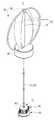
도 10은 본 발명의 다른 실시 예에 따른 발전장치(2)를 나타내는 사시도이며, 도 11은 도 10에 도시된 발전장치(2)의 분해 사시도이다.Fig. 10 is a perspective view showing a
이하에서는 도 10 및 도 11을 참조하여, 본 발명의 다른 실시 예에 따른 발전장치(2)에 대해 설명한다.Hereinafter, a
도 10 및 도 11을 참조하면, 발전장치(2)는 배럴(10), 변환부(20), 정전 발전부(30), 임펠러(70; impeller), 제3 케이스(80) 및 임펠러 지지부(90)를 포함한다.10 and 11, the
본 발명의 다른 실시 예에 따른 발전장치(2)의 구성요소 중 배럴(10), 변환부(20) 및 정전 발전부(30)의 구조는 도 1 내지 도 9를 통해 설명한 본 발명의 일 실시 예에 따른 발전장치(1)의 구조와 동일하므로 중복되는 설명은 생략하겠으며, 이하에서는 본 발명의 일 실시 예에 따른 발전장치(1)와의 차이점을 중심으로 설명하겠다.The structure of the
배럴(10), 변환부(20) 및 정전 발전부(30)는 제3 케이스(80)의 내부에 배치된다.The
임펠러(70)는 한 쌍의 날개(71)와 한 쌍의 날개(71)가 결합된 임펠러 축(72)을 포함할 수 있으며, 임펠러 축(72)의 일단은 커플러(421)를 통해 배럴(10)과 연결될 수 있다.The
아울러, 도 10 및 도 11에 도시된 바와 같이, 제3 케이스(80)에는 임펠러(70)를 지지하는 임펠러 지지부(90)가 결합될 수 있다.10 and 11, the
임펠러 지지부(90)는 대략적인 링 형상으로 구성되어 제3 케이스(80)와 결합하는 고리부(91)와 임펠러 축(72)의 타단이 회전 가능하게 지지되는 회전 지지부(92)를 포함한다.The
임펠러(70)는 고리부(91) 사이에 회전 가능하게 배치되며, 발전장치(2) 외부의 풍력이나 수력과 같은 구동력이 한 쌍의 날개(71)에 전달됨으로써 임펠러 축(72)을 중심으로 회전할 수 있다. 이를 통해, 배럴(10)이 회전할 수 있으며, 정전 발전부(30)를 통해 전력을 생산할 수 있다.The
아울러, 제1 기어 셋(211)을 구성하는 다수의 제1 유성 기어(2112)는 제1 캐리어(2112a')의 일단에 회전 가능하게 결합될 수 있으며, 도 10 및 도 11에 도시된 바와 같이, 제1 캐리어(2112a')의 일단과 반대되는 타단은 배럴(10), 커플러(421) 및 임펠러 축(72)을 순차적으로 관통하여 회전 지지부(92)에 고정될 수 있도록 길이방향을 따라 연장 형성될 수 있다. 이를 통해, 제1 링 기어(2113)가 회전하면 다수의 제1 유성 기어(2112)는 각각의 회전 중심을 기준으로 회전할 수 있다.In addition, a plurality of first
전술한 임펠러(70)의 구조는 외부의 풍력 및 수력에 따라 회전할 수 있는 종래의 다양한 프로펠러 구조로 변형될 수 있으며, 이에 따라, 임펠러 지지부(90)의 구조 역시 다양하게 변형될 수 있다.The structure of the
본 발명의 다른 실시 예에 따른 발전장치(2)는 외부의 풍력 또는 수력이 불규칙적으로 유동함으로써, 임펠러(70)가 불규칙적으로 회전하더라도, 변환부(20)를 통해 회전축(S)을 일정한 속도로 회전시킬 수 있다. 따라서, 정전 발전부(30)를 통해 일정한 전력을 균일하게 생산할 수 있다.The
아울러, 발전장치(2)는 다양한 크기로 구성될 수 있다. 예를 들어, 발전장치(2)는 종래의 대형 풍력발전기와 동일한 크기로 구성됨으로써 대용량의 전력을 균일하게 생산할 수 있다.In addition, the
또한, 발전장치(2)는 자전거나 차량의 외부에 부착될 수 있는 크기로 제작됨으로써 자전거나 차량의 공기저항을 구동력으로 활용하여 전력을 균일하게 생산할 수 있다.Also, since the
이외에도, 발전장치(2)는 최근에 널리 사용되는 액션 캠(action cam)과 같은 모바일 기기에 결합됨으로써, 사용자의 움직임에 따른 공기저항을 구동력으로 활용하여 균일한 전력을 생산할 수 있다.In addition, the
도 12는 본 발명의 또 다른 실시 예에 따른 발전장치(3)가 결합된 차량(2000)의 일부분을 도시한 사시도이며, 도 13은 도 12에 도시된 발전장치(3)의 분해 사시도이다.12 is a perspective view showing a part of a
이하에서는 도 12 및 도 13을 참조하여, 본 발명의 또 다른 실시 예에 따른 발전장치(3)에 대해 설명한다.Hereinafter, a
본 발명의 또 다른 실시 예에 따른 발전장치(3)의 구성요소 중 배럴(10), 변환부(20) 및 정전 발전부(30)의 구조는 도 1 내지 도 9를 통해 설명한 본 발명의 일 실시 예에 따른 발전장치(1)의 구조와 동일하므로 중복되는 설명은 생략하겠으며, 이하에서는 전술한 실시 예에 따른 발전장치들(1, 2)과의 차이점을 중심으로 설명하겠다.The structure of the
도 12 및 도 13을 참조하면, 본 발명의 또 다른 실시 예에 따른 발전장치(3)는 차량(2000)의 바퀴(W)와 접촉하도록 차량(2000)에 결합됨으로써, 바퀴(W)로부터 직접적으로 회전력을 인가받아 정전 발전부(30)를 구동할 수 있다.12 and 13, the
구체적으로, 발전장치(3)는 배럴(10), 변환부(20) 및 정전 발전부(30)가 다수로 구성되고, 다수의 배럴(10), 변환부(20) 및 정전 발전부(30)는 발전장치 지지부재(2100)에 결합되어 지지될 수 있다.Specifically, the
발전장치 지지부재(2100)는 다수의 배럴(10), 변환부(20) 및 정전 발전부(30)가 고정되는 고리부(2101)와 다수의 고리부(2101)상에 결합된 다수의 고정부(2012)를 포함할 수 있으며, 다수의 고정부(2102)가 차량(2000)에 결합됨으로써, 발전장치(3)가 차량(2000)에 고정될 수 있다.The power
다수의 배럴(10)의 각 커플러(421)에는 바퀴(W)와 접하는 다수의 마찰롤러(42')가 결합된다.A plurality of friction rollers 42 ', which are in contact with the wheels W, are coupled to the
마찰롤러(42')는 회전하는 바퀴(W)로부터 회전력을 전달받아 배럴(10)을 회전시킬 수 있으며, 고무재질로 이루어진 바퀴(W)와의 마찰력을 높일 수 있도록 금속재질로 구성되는 것이 바람직하다.The friction roller 42 'is preferably made of a metal material so as to rotate the
아울러, 다수의 마찰롤러(42')는 바퀴(W)의 외주면을 따라 일정한 간격으로 배치될 수 있다.In addition, the plurality of friction rollers 42 'may be disposed at regular intervals along the outer circumferential surface of the wheel W.
또한, 발전장치 지지부재(2100)는 차량(2000)의 서스펜션(미도시)에 결합됨으로써, 차량(2000)의 구동에 따란 바퀴(W)의 유동에 대응하여 유동할 수 있으며, 이를 통해, 차량(2000)의 구동에 있어 마찰롤러(42')가 바퀴(W)의 외주면과 지속적으로 접할 수 있다.The
아울러, 다수의 배럴(10), 변환부(20), 정전 발전부(30) 및 마찰롤러(42')는 각각, 다수의 제4 케이스(52') 내에 배치될 수 있으며, 제4 케이스(52')는 마찰롤러(42')와 바퀴(W)가 접하도록 개방된 개구를 포함한다.In addition, the plurality of
이를 통해, 차량(2000)의 바퀴(W)가 회전하면, 바퀴(W)의 외주면에 접하는 다수의 마찰롤러(42')가 회전함으로써 다수의 배럴(10)이 회전할 수 있으며, 이를 통해, 다수의 정전 발전부(30)가 구동하여 일정한 전력을 생산할 수 있다.As a result, when the wheel W of the
본 발명의 또 다른 실시 예에 따른 발전장치(3)를 통해 생산되는 전력은 차량(2000) 내부의 다양한 전자장치에 대한 보조전원으로 사용될 수 있으며, 차량(2000)의 배터리에 전력을 전송함으로써 배터리를 충전할 수 있다.The power produced by the
전술한 본 발명의 다양한 실시 예에 따른 발전장치(1 내지 3)는 전술한 모바일 기기, 차량 외에도 전력을 사용하는 다양한 기기에 적용될 수 있으며, 다양한 기기에 균일한 전력을 일정하게 공급해 줄 수 있다.The
이러한, 본 발명의 다양한 실시 예에 따른 발전장치(1 내지 3)는 발전장치(1 내지 3) 주변에 존재하는 에너지를 구동력으로 활용하여 균일한 전력을 생산한다는 점에서, 에너지의 활용 및 환경적인 측면에서의 장점이 존재한다.The
이상에서는 본 발명의 다양한 실시 예를 각각 개별적으로 설명하였으나, 각 실시 예들은 반드시 단독으로 구현되어야만 하는 것은 아니며, 각 실시 예들의 구성 및 동작은 적어도 하나의 다른 실시 예들과 조합되어 구현될 수도 있다.While the present invention has been particularly shown and described with reference to exemplary embodiments thereof, it is to be understood that the invention is not limited to the disclosed exemplary embodiments.
또한, 이상에서는 본 발명의 바람직한 실시 예에 대하여 도시하고 설명하였지만, 본 발명은 상술한 특정의 실시 예에 한정되지 아니하며, 청구범위에서 청구하는 본 발명의 요지를 벗어남이 없이 당해 발명이 속하는 기술분야에서 통상의 지식을 가진 자에 의해 다양한 변형실시가 가능한 것은 물론이고, 이러한 변형실시들은 본 발명의 기술적 사상이나 전망으로부터 개별적으로 이해되서는 안될 것이다.While the present invention has been particularly shown and described with reference to exemplary embodiments thereof, it is to be understood that the invention is not limited to the disclosed exemplary embodiments, but, on the contrary, It should be understood that various modifications may be made by those skilled in the art without departing from the spirit and scope of the present invention.
1, 2, 3; 발전장치10; 배럴
20; 변환부30; 정전 발전부
40; 동력 전달부S; 회전축
210; 복수의 기어 셋220; 복수의 연결부재
230; 구동부240; 제어부
250; 센서부1000; 모바일 기기
2000; 차량W; 바퀴1, 2, 3;
20;
40; A power transmission portion S; Rotating shaft
210; A plurality of gear sets 220; A plurality of connecting members
230; A driving
250; A
2000; Vehicle W; wheel
Claims (25)
Translated fromKorean상기 배럴의 회전력을 전달받아 회전축을 일정한 회전 속도로 회전시키는 변환부; 및
상기 회전축으로부터 회전력을 전달받아 구동하는 정전 발전부;를 포함하는 발전장치.A barrel rotatably receiving a driving force from the outside;
A conversion unit that receives the rotation force of the barrel and rotates the rotation axis at a constant rotation speed; And
And an electrostatic generator which receives rotational force from the rotational shaft and drives the electrostatic generator.
상기 변환부는,
상기 배럴의 내측에 배치되어 상기 회전축과 연결되고, 서로 다른 기어 비를 갖는 복수의 기어 셋; 및
상기 복수의 기어 셋 중 어느 하나와 상기 배럴을 선택적으로 연결시키는 복수의 연결부재;를 포함하는 것을 특징으로 하는 발전장치.The method according to claim 1,
Wherein,
A plurality of gears disposed inside the barrel and connected to the rotating shaft, the gears having different gear ratios; And
And a plurality of connecting members for selectively connecting any one of the plurality of gear sets to the barrel.
상기 복수의 기어 셋은 제1 및 제 2 기어 셋을 포함하고,
상기 제1 기어 셋은 상기 회전축에 결합된 제1 태양 기어, 상기 제1 태양 기어와 치합되는 다수의 제1 유성 기어 및 상기 다수의 제1 유성 기어와 치합되는 제1 링 기어를 포함하며,
상기 제2 기어 셋은 상기 회전축에 결합된 제2 태양 기어, 상기 제2 태양 기어와 치합되는 제2 링 기어를 포함하는 것을 특징으로 하는 발전장치.3. The method of claim 2,
Wherein the plurality of gear sets includes first and second gear sets,
The first gear set includes a first sun gear coupled to the rotation shaft, a plurality of first planetary gears meshed with the first sun gear, and a first ring gear meshed with the plurality of first planetary gears,
Wherein the second gear set includes a second sun gear coupled to the rotating shaft, and a second ring gear meshed with the second sun gear.
상기 제1 및 제2 링 기어는 직경이 동일한 내치 기어(internal gear)이고,
상기 제1 태양 기어, 상기 제2 태양 기어 및 상기 제1 유성 기어는 직경이 서로 다른 평 기어(spur gear)인 것을 특징으로 하는 발전장치.The method of claim 3,
The first and second ring gears are internal gears having the same diameter,
Wherein the first sun gear, the second sun gear, and the first planetary gear are spur gears having different diameters.
상기 제1 기어 셋은 상기 다수의 제1 유성 기어가 각각 회전 가능하게 결합하는 제1 캐리어를 포함하고,
상기 제1 캐리어는 상기 배럴의 외부에 고정되는 것을 특징으로 하는 발전장치.5. The method of claim 4,
Wherein the first gear set includes a first carrier each of which rotatably engages with the plurality of first planetary gears,
And the first carrier is fixed to the outside of the barrel.
상기 복수의 기어 셋은, 상기 회전축에 결합된 제3 태양 기어, 상기 제3 태양 기어와 치합되는 다수의 제3 유성 기어 및 상기 다수의 제3 유성 기어와 치합되는 제3 링 기어를 구비한 제3 기어 셋을 더 포함하고,
상기 제3 링 기어는 상기 제1 및 제2 링 기어와 직경이 동일한 내치 기어이며,
상기 제3 태양 기어 및 상기 제3 유성 기어는, 상기 제1 태양 기어, 상기 제2 태양 기어 및 상기 제1 유성 기어와 직경이 서로 다른 평 기어인 것을 특징으로 하는 발전장치.6. The method of claim 5,
The plurality of gear sets includes a third sun gear coupled to the rotating shaft, a plurality of third planetary gears meshed with the third sun gear, and a third ring gear meshed with the plurality of third planetary gears, Further comprising three gear sets,
The third ring gear is an internal gear having the same diameter as the first and second ring gears,
Wherein the third sun gear and the third planetary gear are spur gears different in diameter from the first sun gear, the second sun gear, and the first planetary gear.
상기 제3 기어 셋은 상기 다수의 제3 유성 기어가 각각 회전 가능하게 결합하는 제3 캐리어를 더 포함하고,
상기 제3 캐리어는 상기 배럴의 외부에 고정되는 것을 특징으로 하는 발전장치.The method according to claim 6,
The third gear set further comprises a third carrier to which the plurality of third planetary gears respectively rotatably engage,
And the third carrier is fixed to the outside of the barrel.
상기 복수의 연결부재는 상기 배럴에 결합된 제1 및 제2 연결부재를 포함하고,
상기 제1 및 제2 연결부재는 상기 회전축을 향하는 제1 방향으로 이동하여 상기 제1 및 제2 링 기어와 결합되고, 상기 제1 방향과 반대되는 제2 방향으로 이동하여 상기 제1 및 제2 링 기어와 분리되는 것을 특징으로 하는 발전장치.The method of claim 3,
Wherein the plurality of connecting members include first and second connecting members coupled to the barrel,
Wherein the first and second linking members move in a first direction toward the rotation axis and engage with the first and second ring gears and move in a second direction opposite to the first direction, And is separated from the ring gear.
상기 제1 및 제2 연결부재는 각각 상기 제1 및 제2 링 기어의 외주부의 형상과 대응하는 결합홈을 포함하는 것을 특징으로 하는 발전장치.9. The method of claim 8,
Wherein the first and second connecting members each include an engaging groove corresponding to a shape of an outer peripheral portion of the first and second ring gears.
상기 제1 및 제2 연결부재는 상기 제1 및 제2 링 기어의 외주부의 곡률과 동일한 곡률을 갖는 호의 형상인 것을 특징으로 하는 발전장치.10. The method of claim 9,
Wherein the first and second connecting members are shaped like arcs having the same curvature as the curvature of the outer peripheral portion of the first and second ring gears.
상기 배럴은 원통 형상으로 구성되며, 외주면에 형성된 복수의 슬롯을 포함하고,
상기 복수의 슬롯은 각각 상기 제1 및 제2 연결부재가 상기 제1 방향과 상기 제2 방향으로 이동 가능하게 삽입되는 것을 특징으로 하는 발전장치.11. The method of claim 10,
Wherein the barrel is formed in a cylindrical shape and includes a plurality of slots formed on an outer circumferential surface thereof,
Wherein the plurality of slots are inserted into the first and second connecting members so as to be movable in the first direction and the second direction, respectively.
상기 제1 연결부재는 복수로 구성되어 상기 배럴의 외주면을 따라 동일한 간격으로 배치되고,
상기 제2 연결부재는 복수로 구성되어 상기 배럴의 외주면을 따라 동일한 간격으로 배치되는 것을 특징으로 하는 발전장치.11. The method of claim 10,
Wherein the first connecting member is composed of a plurality of first connecting members arranged at equal intervals along an outer peripheral surface of the barrel,
Wherein the second connecting member is composed of a plurality of second connecting members arranged at equal intervals along an outer circumferential surface of the barrel.
상기 제1 및 제2 기어 셋은 금속 재질로 이루어지고,
상기 제1 및 제2 연결부재는, 우레탄 재질로 이루어지며 상기 제1 및 제2 링 기어의 외주부와 각각 끼움 결합하는 것을 특징으로 하는 발전장치.10. The method of claim 9,
Wherein the first and second gear sets are made of a metal material,
Wherein the first and second connecting members are made of a urethane material, and are fitted to the outer peripheral portions of the first and second ring gears, respectively.
상기 변환부는 상기 제1 및 제2 연결부재가 서로 다른 방향으로 이동하도록 상기 제1 및 제2 연결부재에 힘을 인가하는 구동부를 더 포함하는 것을 특징으로 하는 발전장치.9. The method of claim 8,
Wherein the converting unit further includes a driving unit that applies a force to the first and second connecting members such that the first and second connecting members move in different directions.
상기 구동부는,
상기 제1 및 제2 연결부재에 각각 결합된 제1 및 제2 마그네트; 및
상기 제1 및 제2 마그네트에 자기력을 가하는 제1 및 제2 전자석을 포함하는 것을 특징으로 하는 발전장치.15. The method of claim 14,
The driving unit includes:
First and second magnets coupled to the first and second coupling members, respectively; And
And first and second electromagnets for applying magnetic force to the first and second magnets.
상기 구동부는,
상기 제1 방향으로 이동하여 상기 제1 및 제2 연결부재를 가압하는 제1 및 제2 가압부재;
상기 제1 및 제2 가압부재에 결합된 제1 및 제2 마그네트; 및
상기 제1 및 제2 마그네트에 자기력을 가하는 제1 및 제2 전자석;을 포함하는 것을 특징으로 하는 발전장치.15. The method of claim 14,
The driving unit includes:
First and second pressing members moving in the first direction to press the first and second connecting members;
First and second magnets coupled to the first and second biasing members; And
And first and second electromagnets for applying magnetic force to the first and second magnets.
상기 구동부는 상기 제1 방향으로 이동한 제1 및 제2 가압부재가 상기 제2 방향으로 복귀하도록 상기 제1 및 제2 가압부재에 힘을 가하는 제1 및 제2 탄성부재를 포함하는 것을 특징으로 하는 발전장치.17. The method of claim 16,
The driving unit includes first and second elastic members that apply a force to the first and second pressing members such that the first and second pressing members moved in the first direction return to the second direction. .
상기 구동부는 양단이 상기 제1 및 제2 연결부재에 피봇(pivot) 가능하게 연결된 제1 시소부재를 더 포함하고,
상기 시소부재는 상기 제1 및 제2 연결부재 중 어느 하나에 인가된 힘의 방향과 반대되는 방향으로 상기 제1 및 제2 연결부재 중 다른 하나에 힘을 가하는 것을 특징으로 하는 발전장치.18. The method of claim 17,
Wherein the driving unit further includes a first seesection member pivotally connected at both ends to the first and second connecting members,
Wherein the seesaw member applies force to the other one of the first and second connection members in a direction opposite to a direction of a force applied to any one of the first and second connection members.
상기 복수의 기어 셋은, 상기 회전축에 결합된 제3 태양 기어, 상기 제3 태양기어와 치합되는 다수의 제3 유성기어 및 상기 다수의 제3 유성 기어와 치합되는 제3 링 기어를 구비한 제3 기어 셋을 더 포함하고,
상기 복수의 연결부재는, 상기 배럴에 결합되어 상기 제1 방향으로 이동하여 상기 제3 링 기어와 결합되고, 상기 제2 방향으로 이동하여 상기 제3 링 기어와 분리되는 제3 연결부재를 더 포함하며,
상기 구동부는 양단이 상기 제2 및 제3 연결부재에 피봇 가능하게 연결된 제2 시소부재를 더 포함하는 것을 특징으로 하는 발전장치.19. The method of claim 18,
The plurality of gear sets includes a third sun gear coupled to the rotating shaft, a plurality of third planetary gears meshed with the third sun gear, and a third ring gear meshed with the plurality of third planetary gears, Further comprising three gear sets,
The plurality of connecting members further include a third connecting member coupled to the barrel and moving in the first direction to engage with the third ring gear and move in the second direction to separate from the third ring gear In addition,
Wherein the driving unit further includes a second seesection member pivotally connected at both ends to the second and third connecting members.
상기 변환부는,
상기 회전축의 회전 속도를 측정하는 제1 센서; 및
상기 제1 센서로부터 측정된 회전 속도에 따라 상기 회전축이 일정한 회전 속도로 회전하도록 상기 구동부를 제어하는 제어부;를 포함하는 것을 특징으로 하는 발전장치.15. The method of claim 14,
Wherein,
A first sensor for measuring a rotational speed of the rotating shaft; And
And a controller for controlling the drive unit such that the rotation shaft rotates at a constant rotation speed according to a rotation speed measured from the first sensor.
상기 변환부는 상기 정전 발전부의 출력 전압을 측정하는 제2 센서를 더 포함하고,
상기 제어부는 상기 제2 센서로부터 측정된 출력 전압에 따라 상기 구동부를 제어하는 것을 특징으로 하는 발전장치.21. The method of claim 20,
Wherein the converting unit further comprises a second sensor for measuring an output voltage of the electrostatic generator,
Wherein the control unit controls the driving unit according to an output voltage measured by the second sensor.
케이스;
상기 케이스의 내측에 배치된 랙 기어;
상기 랙 기어를 유동 가능하게 지지하는 스윙 부재; 및
상기 배럴에 결합되어 상기 랙 기어와 치합되는 피니언 기어;를 포함하는 것을 특징으로 하는 발전장치.The method according to claim 1,
case;
A rack gear disposed inside the case;
A swing member for movably supporting the rack gear; And
And a pinion gear coupled to the barrel and meshing with the rack gear.
상기 배럴에 결합된 구동축; 및
상기 구동축에 연결된 임펠러;를 포함하는 것을 특징으로 하는 발전장치.The method according to claim 1,
A driving shaft coupled to the barrel; And
And an impeller connected to the drive shaft.
상기 정전 발전부는,
상기 회전축에 결합되어 회전하며, 일면에 배치된 다수의 제1 대전체를 포함하는 제1 대전 플레이트; 및
상기 다수의 제1 대전체와 접촉 또는 인접하도록 배치된 다수의 제2 대전체를 일면에 구비한 제2 대전 플레이트;를 포함하는 것을 특징으로 하는 발전장치.The method according to claim 1,
The electrostatic-
A first charging plate rotatably coupled to the rotating shaft, the first charging plate comprising a plurality of first bases disposed on one surface; And
And a second charging plate provided on one surface of the plurality of second bases arranged in contact with or adjacent to the plurality of first bases as a whole.
상기 본체 내에 배치되어 상기 배터리에 전원을 인가하는 발전장치;를 포함하고,
상기 발전장치는,
외력에 의해 흔들리는 상기 본체로부터 구동력을 전달받아 회전하는 배럴;
상기 배럴의 회전력을 전달받아 회전축을 일정한 회전 속도로 회전시키는 변환부; 및
상기 회전축으로부터 회전력을 전달받아 구동하는 정전 발전부;를 포함하는 모바일 기기.A body having a battery; And
And a power generator disposed in the main body for applying power to the battery,
The power generation device includes:
A barrel rotated by receiving a driving force from the main body shaken by an external force;
A conversion unit that receives the rotation force of the barrel and rotates the rotation axis at a constant rotation speed; And
And an electrostatic generator which receives rotational force from the rotation shaft and drives the electrostatic generator.
Priority Applications (3)
| Application Number | Priority Date | Filing Date | Title |
|---|---|---|---|
| KR1020160158244AKR20180059086A (en) | 2016-11-25 | 2016-11-25 | Generator and mobile device having the same |
| US15/402,623US10598161B2 (en) | 2016-11-25 | 2017-01-10 | Generator and mobile device having the same |
| CN201710117241.8ACN108111049B (en) | 2016-11-25 | 2017-03-01 | Generator and mobile device with generator |
Applications Claiming Priority (1)
| Application Number | Priority Date | Filing Date | Title |
|---|---|---|---|
| KR1020160158244AKR20180059086A (en) | 2016-11-25 | 2016-11-25 | Generator and mobile device having the same |
Related Child Applications (1)
| Application Number | Title | Priority Date | Filing Date |
|---|---|---|---|
| KR1020180092362ADivisionKR101905481B1 (en) | 2018-08-08 | 2018-08-08 | Generator and mobile device having the same |
Publications (1)
| Publication Number | Publication Date |
|---|---|
| KR20180059086Atrue KR20180059086A (en) | 2018-06-04 |
Family
ID=62193205
Family Applications (1)
| Application Number | Title | Priority Date | Filing Date |
|---|---|---|---|
| KR1020160158244ACeasedKR20180059086A (en) | 2016-11-25 | 2016-11-25 | Generator and mobile device having the same |
Country Status (3)
| Country | Link |
|---|---|
| US (1) | US10598161B2 (en) |
| KR (1) | KR20180059086A (en) |
| CN (1) | CN108111049B (en) |
Families Citing this family (2)
| Publication number | Priority date | Publication date | Assignee | Title |
|---|---|---|---|---|
| CN111327225B (en)* | 2020-03-11 | 2023-05-26 | 电子科技大学 | A barbell-type friction nanogenerator integrated self-powered sensor and its preparation method |
| CN116231947B (en)* | 2023-03-17 | 2024-04-16 | 国网江苏省电力有限公司电力科学研究院 | Energy harvesting device and self-powered vibration monitoring device for transmission lines |
Family Cites Families (26)
| Publication number | Priority date | Publication date | Assignee | Title |
|---|---|---|---|---|
| BE538344A (en)* | 1954-06-03 | |||
| JPH07170722A (en)* | 1993-08-31 | 1995-07-04 | Minoru Uchiumi | Automatic starter and electrostatic generator shafts |
| EP0905587B1 (en)* | 1997-09-26 | 2002-11-13 | Seiko Epson Corporation | Electronically controlled mechanical timepiece |
| WO2000054113A1 (en)* | 1999-03-08 | 2000-09-14 | Seiko Epson Corporation | Starting device for electromagnetic converter, and timepiece device |
| CN2516750Y (en)* | 2001-09-24 | 2002-10-16 | 象山振星机械有限公司 | Stepless speed regulater |
| JP2004274909A (en)* | 2003-03-10 | 2004-09-30 | Calsonic Kansei Corp | Stepping motor |
| US7439712B2 (en) | 2006-02-21 | 2008-10-21 | Mccowen Clint | Energy collection |
| KR200435711Y1 (en) | 2006-07-07 | 2007-02-09 | 주식회사 태원기전 | Roof type wind power generator |
| US20090066177A1 (en)* | 2007-08-30 | 2009-03-12 | Loke Donald R | Micro Kinetic energy device for powering portable electronic devices |
| AU2010221880B2 (en)* | 2009-03-09 | 2016-05-26 | Lee, Young Su | Power transmission apparatus using a planetary gear |
| US8293091B2 (en) | 2009-06-26 | 2012-10-23 | Mccormick And Munson Technologies, Llc | Electrically enhanced cellulose filtration system |
| JP2012115118A (en) | 2010-11-28 | 2012-06-14 | Shinyoh Sangyo Co Ltd | Private power generator capable of constant-voltage power generation driven by high-voltage drive motor |
| US20130069487A1 (en) | 2011-03-27 | 2013-03-21 | Ocean Energy Management Limited | Electrical energy generator using piezoelectric crystals |
| US9178446B2 (en) | 2011-08-30 | 2015-11-03 | Georgia Tech Research Corporation | Triboelectric generator |
| TW201346130A (en) | 2012-05-04 | 2013-11-16 | Pan-Chien Lin | Single-stage large-scale speed-increasing gearbox for fans |
| US9595894B2 (en) | 2012-09-21 | 2017-03-14 | Georgia Tech Research Corporation | Triboelectric nanogenerator for powering portable electronics |
| US8519596B1 (en) | 2013-01-23 | 2013-08-27 | K-Technology Usa, Inc. | Graphene triboelectric charging device and a method of generating electricity by the same |
| US8536760B1 (en) | 2013-01-23 | 2013-09-17 | K-Technology Usa, Inc. | Ball-electric power generator |
| US9571009B2 (en) | 2013-03-01 | 2017-02-14 | Georgia Tech Research Corporation | Rotating cylindrical and spherical triboelectric generators |
| CN104373295B (en) | 2013-08-15 | 2017-03-08 | 纳米新能源(唐山)有限责任公司 | Hybrid wind power generation plant |
| CN106134064B (en)* | 2014-03-28 | 2020-01-07 | 西铁城时计株式会社 | Power Generation Units and Portable Electronic Equipment |
| KR20150144154A (en) | 2014-06-16 | 2015-12-24 | 박철훈 | Transmission apparatus of a straight line structure using of ling-gear |
| CN204004213U (en)* | 2014-07-14 | 2014-12-10 | 李家洲 | A kind of stepless transition speed change gear |
| US9394875B2 (en) | 2014-08-05 | 2016-07-19 | Georgia Tech Research Corporation | System for harvesting water wave energy |
| US9331603B2 (en) | 2014-08-07 | 2016-05-03 | Ion Power Group, Llc | Energy collection |
| CN204852200U (en)* | 2015-05-31 | 2015-12-09 | 曹建峰 | Gear box |
- 2016
- 2016-11-25KRKR1020160158244Apatent/KR20180059086A/ennot_activeCeased
- 2017
- 2017-01-10USUS15/402,623patent/US10598161B2/enactiveActive
- 2017-03-01CNCN201710117241.8Apatent/CN108111049B/enactiveActive
Also Published As
| Publication number | Publication date |
|---|---|
| US20180149143A1 (en) | 2018-05-31 |
| CN108111049A (en) | 2018-06-01 |
| US10598161B2 (en) | 2020-03-24 |
| CN108111049B (en) | 2022-05-31 |
Similar Documents
| Publication | Publication Date | Title |
|---|---|---|
| Xu et al. | Triboelectric nanogenerator for ocean wave graded energy harvesting and condition monitoring | |
| Gu et al. | A survey on dielectric elastomer actuators for soft robots | |
| Yamaguchi et al. | A robot hand using electro-conjugate fluid: Grasping experiment with balloon actuators inducing a palm motion of robot hand | |
| US7626319B2 (en) | Three-dimensional electroactive polymer actuated devices | |
| US7750532B2 (en) | Electroactive polymer actuated motors | |
| JP6670611B2 (en) | Dielectric elastomer motor | |
| US7915789B2 (en) | Electroactive polymer actuated lighting | |
| JP6607847B2 (en) | Power generation device and portable electric device | |
| US20070200457A1 (en) | High-speed acrylic electroactive polymer transducers | |
| CN108141151B (en) | Energy Conversion System and Method | |
| JP6545280B2 (en) | Friction generator | |
| JP2009516491A (en) | Screw drive polyhedral ultrasonic motor | |
| JP2013155609A (en) | Wave power generation device | |
| CN107175657A (en) | A kind of permanent magnetism variation rigidity drive module for flexible robot | |
| KR101555796B1 (en) | Energy generator | |
| KR20180059086A (en) | Generator and mobile device having the same | |
| He et al. | Piezoelectric motor based on synchronized switching control | |
| KR101905481B1 (en) | Generator and mobile device having the same | |
| JP2012002237A (en) | Small reduction gear and small diameter high torque motor using the same | |
| CN112152557A (en) | Piezoelectricity driven solar cell panel intelligent regulation device | |
| CN108518323B (en) | A kind of machine driving power generator for human body walking energy regenerating | |
| KR20120029540A (en) | A producing system for rotary power using eccentricity power | |
| CN212460960U (en) | A Periodically Excited Ring Vibration Motion Mechanism | |
| JP6856744B2 (en) | Rotating motor | |
| CN109291073B (en) | A drive device for discrete rotation of robot two-degree-of-freedom joints |
Legal Events
| Date | Code | Title | Description |
|---|---|---|---|
| A201 | Request for examination | ||
| PA0109 | Patent application | Patent event code:PA01091R01D Comment text:Patent Application Patent event date:20161125 | |
| PA0201 | Request for examination | ||
| E902 | Notification of reason for refusal | ||
| PE0902 | Notice of grounds for rejection | Comment text:Notification of reason for refusal Patent event date:20171107 Patent event code:PE09021S01D | |
| E601 | Decision to refuse application | ||
| PE0601 | Decision on rejection of patent | Patent event date:20180516 Comment text:Decision to Refuse Application Patent event code:PE06012S01D Patent event date:20171107 Comment text:Notification of reason for refusal Patent event code:PE06011S01I | |
| PG1501 | Laying open of application | ||
| E601 | Decision to refuse application | ||
| E801 | Decision on dismissal of amendment | ||
| PE0601 | Decision on rejection of patent | Patent event date:20180706 Comment text:Decision to Refuse Application Patent event code:PE06012S01D Patent event date:20171107 Comment text:Notification of reason for refusal Patent event code:PE06011S01I | |
| PE0801 | Dismissal of amendment | Patent event code:PE08012E01D Comment text:Decision on Dismissal of Amendment Patent event date:20180706 Patent event code:PE08011R01I Comment text:Amendment to Specification, etc. Patent event date:20180618 Patent event code:PE08011R01I Comment text:Amendment to Specification, etc. Patent event date:20180104 | |
| PA0107 | Divisional application | Comment text:Divisional Application of Patent Patent event date:20180808 Patent event code:PA01071R01D |