KR20180056685A - System and method for non-obstacle area detection - Google Patents
System and method for non-obstacle area detectionDownload PDFInfo
- Publication number
- KR20180056685A KR20180056685AKR1020187010748AKR20187010748AKR20180056685AKR 20180056685 AKR20180056685 AKR 20180056685AKR 1020187010748 AKR1020187010748 AKR 1020187010748AKR 20187010748 AKR20187010748 AKR 20187010748AKR 20180056685 AKR20180056685 AKR 20180056685A
- Authority
- KR
- South Korea
- Prior art keywords
- vertical
- horizontal
- obstacle
- map
- depth
- Prior art date
- Legal status (The legal status is an assumption and is not a legal conclusion. Google has not performed a legal analysis and makes no representation as to the accuracy of the status listed.)
- Granted
Links
Images


Classifications
- G—PHYSICS
- G06—COMPUTING OR CALCULATING; COUNTING
- G06V—IMAGE OR VIDEO RECOGNITION OR UNDERSTANDING
- G06V20/00—Scenes; Scene-specific elements
- G06V20/50—Context or environment of the image
- G06V20/56—Context or environment of the image exterior to a vehicle by using sensors mounted on the vehicle
- G06K9/00791—
- G06K9/6292—
- G—PHYSICS
- G06—COMPUTING OR CALCULATING; COUNTING
- G06T—IMAGE DATA PROCESSING OR GENERATION, IN GENERAL
- G06T7/00—Image analysis
- G06T7/10—Segmentation; Edge detection
- G06T7/11—Region-based segmentation
- G—PHYSICS
- G06—COMPUTING OR CALCULATING; COUNTING
- G06T—IMAGE DATA PROCESSING OR GENERATION, IN GENERAL
- G06T7/00—Image analysis
- G06T7/20—Analysis of motion
- G—PHYSICS
- G06—COMPUTING OR CALCULATING; COUNTING
- G06T—IMAGE DATA PROCESSING OR GENERATION, IN GENERAL
- G06T7/00—Image analysis
- G06T7/50—Depth or shape recovery
- G—PHYSICS
- G06—COMPUTING OR CALCULATING; COUNTING
- G06T—IMAGE DATA PROCESSING OR GENERATION, IN GENERAL
- G06T7/00—Image analysis
- G06T7/50—Depth or shape recovery
- G06T7/507—Depth or shape recovery from shading
- G—PHYSICS
- G06—COMPUTING OR CALCULATING; COUNTING
- G06V—IMAGE OR VIDEO RECOGNITION OR UNDERSTANDING
- G06V20/00—Scenes; Scene-specific elements
- G06V20/50—Context or environment of the image
- G06V20/56—Context or environment of the image exterior to a vehicle by using sensors mounted on the vehicle
- G06V20/588—Recognition of the road, e.g. of lane markings; Recognition of the vehicle driving pattern in relation to the road
- G—PHYSICS
- G06—COMPUTING OR CALCULATING; COUNTING
- G06F—ELECTRIC DIGITAL DATA PROCESSING
- G06F18/00—Pattern recognition
- G06F18/20—Analysing
- G06F18/25—Fusion techniques
- G06F18/254—Fusion techniques of classification results, e.g. of results related to same input data
- G—PHYSICS
- G06—COMPUTING OR CALCULATING; COUNTING
- G06T—IMAGE DATA PROCESSING OR GENERATION, IN GENERAL
- G06T2207/00—Indexing scheme for image analysis or image enhancement
- G06T2207/10—Image acquisition modality
- G06T2207/10028—Range image; Depth image; 3D point clouds
- G—PHYSICS
- G06—COMPUTING OR CALCULATING; COUNTING
- G06T—IMAGE DATA PROCESSING OR GENERATION, IN GENERAL
- G06T2207/00—Indexing scheme for image analysis or image enhancement
- G06T2207/30—Subject of image; Context of image processing
- G06T2207/30248—Vehicle exterior or interior
- G06T2207/30252—Vehicle exterior; Vicinity of vehicle
- G06T2207/30256—Lane; Road marking
Landscapes
- Engineering & Computer Science (AREA)
- Theoretical Computer Science (AREA)
- Physics & Mathematics (AREA)
- General Physics & Mathematics (AREA)
- Computer Vision & Pattern Recognition (AREA)
- Multimedia (AREA)
- Data Mining & Analysis (AREA)
- Artificial Intelligence (AREA)
- Life Sciences & Earth Sciences (AREA)
- Bioinformatics & Cheminformatics (AREA)
- Bioinformatics & Computational Biology (AREA)
- Evolutionary Biology (AREA)
- Evolutionary Computation (AREA)
- General Engineering & Computer Science (AREA)
- Image Analysis (AREA)
- Traffic Control Systems (AREA)
- Image Processing (AREA)
- Measurement Of Velocity Or Position Using Acoustic Or Ultrasonic Waves (AREA)
Abstract
Translated fromKorean
Description
Translated fromKorean본 개시는 일반적으로 전자 디바이스들에 관한 것이다. 보다 구체적으로, 본 개시는 비 장애물 영역 검출을 위한 시스템 및 방법에 관한 것이다.This disclosure generally relates to electronic devices. More particularly, this disclosure relates to systems and methods for non-obstructive region detection.
지난 수십년 동안, 전자 디바이스의 사용이 보편화되었다. 특히, 전자 기술의 진보는 점점 더 복잡하고 유용한 전자 디바이스들의 비용을 감소시켰다. 비용 절감과 소비자 수요는 전자 디바이스들의 사용을 확산시켜 이들이 현대 사회에서 실제로 유비쿼터스화되었다. 전자 디바이스들의 사용이 확대됨에 따라, 전자 디바이스들의 새롭고 개선된 특징에 대한 요구도 확대되었다. 보다 구체적으로, 새로운 기능을 수행하거나 및/또는 기능을 보다 빠르게, 보다 효율적으로 또는 보다 높은 품질로 수행하는 전자 디바이스들이 종종 추구된다.Over the past several decades, the use of electronic devices has become commonplace. In particular, advances in electronics have reduced the cost of increasingly complex and useful electronic devices. Cost savings and consumer demand have spread the use of electronic devices, making them virtually ubiquitous in modern society. As the use of electronic devices has expanded, the need for new and improved features of electronic devices has also expanded. More specifically, electronic devices that perform new functions and / or perform functions faster, more efficiently, or with higher quality are often sought.
일부 전자 디바이스들 (예 : 카메라, 비디오 캠코더, 디지털 카메라, 휴대 전화, 스마트 폰, 컴퓨터, 텔레비전 등) 은 이미지를 캡처 및/또는 활용한다. 예를 들어, 스마트폰은 정지 및/또는 비디오 이미지를 캡처 및/또는 처리할 수도 있다. 자동차 및 자율 차량 애플리케이션들에서, 장애물 검출은 이미지를 처리하는 것에 의해 수행될 수도 있다. 이미지를 처리하는 것은 상대적으로 많은 양의 시간, 메모리 및 에너지 리소스들을 요구할 수도 있다. 요구되는 리소스들은 처리의 복잡성에 따라 달라질 수도 있다.Some electronic devices (e.g., cameras, video camcorders, digital cameras, cell phones, smart phones, computers, televisions, etc.) capture and / or utilize images. For example, the smartphone may capture and / or process still images and / or video images. In automotive and autonomous vehicle applications, obstacle detection may be performed by processing the image. Processing an image may require a relatively large amount of time, memory, and energy resources. The resources required may vary depending on the complexity of the process.
일부 복잡한 처리 작업은 구현하기가 어려울 수도 있다. 예를 들어, 일부 플랫폼은 처리, 메모리 및/또는 에너지 리소스들이 제한적일 수도 있다. 또한, 일부 애플리케이션들은 시간에 민감할 수도 있다. 이러한 논의에서 알 수 있듯이, 이미지 처리를 향상시키는 시스템과 방법이 이로울 수도 있다.Some complex processing tasks may be difficult to implement. For example, some platforms may have limited processing, memory and / or energy resources. Also, some applications may be time sensitive. As can be seen from these discussions, systems and methods that enhance image processing may be beneficial.
개요summary
전자 디바이스에 의해 수행되는 방법이 설명된다. 그 방법은 수직 비 장애물 (non-obstacle) 추정을 결정하기 위하여 깊이 맵의 수직 처리를 수행하는 단계를 포함한다. 그 방법은 또한 수평 비 장애물 추정을 결정하기 위하여 깊이 맵의 수평 처리를 수행하는 단계를 포함한다. 그 방법은 수직 비 장애물 추정 및 수평 비 장애물 추정을 결합하는 단계를 더 포함한다. 그 방법은 수직 및 수평 비 장애물 추정들의 결합에 기초하여 비 장애물 맵을 생성하는 단계를 추가로 포함한다.A method performed by an electronic device is described. The method includes performing a vertical processing of the depth map to determine a vertical non-obstacle estimate. The method also includes performing horizontal processing of the depth map to determine a horizontal non-obstacle estimation. The method further includes combining a vertical non-obstacle estimation and a horizontal non-obstacle estimation. The method further includes generating a non-obstacle map based on a combination of vertical and horizontal non-obstacle estimates.
수직 처리를 수행하는 것은 깊이 맵을 세그먼트들로 분할하는 것을 포함할 수도 있다. 적어도 하나의 세그먼트는 열 (column) 에 다수의 픽셀들을 포함할 수도 있다. 선형 모델 파라미터들은 수직 비 장애물 추정을 결정하기 위해 적어도 하나의 세그먼트에 대해 추정될 수도 있다. 수직 비 장애물 추정을 위한 신뢰도 값 (reliability value) 을 포함하는 수직 신뢰도 맵이 생성될 수도 있다.Performing the vertical processing may include dividing the depth map into segments. The at least one segment may include a plurality of pixels in a column. Linear model parameters may be estimated for at least one segment to determine a vertical non-obstacle estimate. A vertical reliability map including a reliability value for vertical non-obstacle estimation may be generated.
수직 신뢰도 맵을 결정하는 것은 추정된 선형 모델 파라미터들과 미리 결정된 선형 모델 파라미터들 사이의 차이에 기초하여 주어진 세그먼트에 대한 세그먼트 피팅 오차 (segment fitting error) 를 결정하는 것을 포함할 수도 있다. 주어진 세그먼트에 대한 신뢰도 값은 세그먼트 피팅 오차와 수직 추정 임계치를 비교함으로써 결정될 수도 있다. 주어진 세그먼트에 대한 신뢰도 값은 주어진 세그먼트 내의 적어도 하나의 픽셀에 적용될 수도 있다.Determining the vertical reliability map may include determining a segment fitting error for a given segment based on a difference between the estimated linear model parameters and predetermined linear model parameters. The confidence value for a given segment may be determined by comparing the segment fitting error and the vertical estimation threshold. The confidence value for a given segment may be applied to at least one pixel in a given segment.
미리 결정된 선형 모델 파라미터들은 복수의 도로 조건 모델 (road condition model) 중에서 선택될 수도 있다. 복수의 도로 조건 모델들은 대응하는 선형 모델 파라미터 세트를 가질 수도 있다.The predetermined linear model parameters may be selected from a plurality of road condition models. The plurality of road condition models may have a corresponding set of linear model parameters.
수평 처리를 수행하는 것은 깊이 맵의 적어도 하나의 픽셀 행 (row) 에 대한 깊이 히스토그램을 얻는 것을 포함할 수도 있다. 지형 라인 (terrain line) 은 깊이 히스토그램으로부터 결정될 수도 있다. 수평 비 장애물 추정은 지형 라인으로부터의 적어도 하나의 픽셀의 깊이 값의 거리에 기초하여 결정될 수도 있다. 수평 비 장애물 추정에 대한 신뢰도 값을 포함하는 수평 신뢰도 맵이 생성될 수도 있다.Performing the horizontal processing may include obtaining a depth histogram for at least one pixel row of the depth map. The terrain line may be determined from the depth histogram. The horizontal non-obstacle estimation may be determined based on the distance of the depth value of at least one pixel from the terrain line. A horizontal reliability map including a confidence value for the horizontal non-obstacle estimation may be generated.
수평 신뢰도 맵을 생성하는 것은 주어진 픽셀의 깊이 값이 깊이 히스토그램의 모드의 범위 내에 있는지 여부를 결정하는 것을 포함할 수도 있다. 주어진 픽셀의 깊이 값이 깊이 히스토그램의 모드의 범위 내에 있을 때 주어진 픽셀은 높은 신뢰도 값을 가질 수도 있다.Creating a horizontal reliability map may include determining whether the depth value of a given pixel is within the range of the mode of the depth histogram. A given pixel may have a high confidence value when the depth value of a given pixel is within the range of the mode of the depth histogram.
수직 비 장애물 추정 및 수평 비 장애물 추정의 결합은 수직 처리 및 수평 처리 양자 모두를 병렬로 수행하는 것을 포함할 수도 있다. 수직 비 장애물 추정 및 수평 비 장애물 추정은 수직 신뢰도 맵 및 수평 신뢰도 맵에 기초하여 병합될 수도 있다.The combination of vertical non-obstacle estimation and horizontal non-obstacle estimation may include performing both vertical processing and horizontal processing in parallel. The vertical non-obstacle estimates and the horizontal non-obstacle estimates may be merged based on the vertical reliability map and the horizontal reliability map.
주어진 픽셀은 수직 신뢰도 맵 및 수평 신뢰도 맵 양자 모두가 주어진 픽셀에 대해 높은 신뢰도 값을 특징으로 하는 비 장애물 맵에서 비 장애물 영역으로 식별될 수도 있다. 주어진 픽셀은 수직 신뢰도 맵 또는 수평 신뢰도 맵 중 적어도 하나가 주어진 픽셀에 대해 낮은 신뢰도 값을 특징으로 하는 비 장애물 맵에서 장애물 영역으로 식별될 수도 있다. 주어진 픽셀은 수직 신뢰도 맵 및 수평 신뢰도 맵이 주어진 픽셀에 대해 상이한 신뢰도 값들을 특징으로 하는 주어진 픽셀의 좌표에 기초하여 비 장애물 맵에서 비 장애물 영역 또는 장애물 영역으로서 식별될 수도 있다.A given pixel may be identified as a non-obstructive region in a non-obstacle map in which both the vertical reliability map and the horizontal confidence map are characterized by a high confidence value for a given pixel. A given pixel may be identified as an obstacle region in a non-obstacle map in which at least one of the vertical reliability map or the horizontal reliability map is characterized by a low confidence value for a given pixel. A given pixel may be identified as a non-obstructive region or an obstacle region in the non-obstacle map based on the coordinates of a given pixel characterized by different reliability values for a given pixel in the vertical reliability map and horizontal reliability map.
수직 비 장애물 추정 및 수평 비 장애물 추정의 결합은 깊이 맵의 수직 처리를 수행하는 것을 포함할 수도 있다. 수직 신뢰도 맵은 모델 피팅 신뢰성 (model fitting confidence) 에 기초하여 얻어질 수도 있다. 수직 신뢰도 맵의 신뢰할 수 있는 지역은 비 장애물 영역으로 식별될 수도 있다. 신뢰할 수 없는 지역이 비 장애물 영역인지 여부를 결정하기 위해 수직 신뢰도 맵의 신뢰할 수 없는 지역에 대해 수평 처리가 수행될 수도 있다.The combination of vertical non-obstacle estimates and horizontal non-obstacle estimates may include performing vertical processing of the depth map. The vertical reliability map may be obtained based on model fitting confidence. A reliable region of the vertical reliability map may be identified as a non-obstructive region. Horizontal processing may be performed on the unreliable region of the vertical reliability map to determine whether the untrusted region is a non-obstructive region.
수직 비 장애물 추정 및 수평 비 장애물 추정의 결합은 깊이 맵의 수평 처리를 수행하는 것을 포함할 수도 있다. 수평 신뢰도 맵은 깊이 히스토그램 거리에 기초하여 얻어질 수도 있다. 수평 신뢰도 맵의 신뢰할 수 있는 지역은 비 장애물 영역으로서 식별될 수도 있다. 수평 신뢰도 맵의 신뢰할 수 없는 지역들에 대한 수직 처리는 신뢰할 수 없는 지역들이 비 장애물 영역인지 여부를 결정하기 위해 수행될 수도 있다.The combination of vertical non-obstacle estimation and horizontal non-obstacle estimation may include performing horizontal processing of the depth map. A horizontal reliability map may be obtained based on the depth histogram distance. A reliable region of the horizontal reliability map may be identified as a non-obstructive region. Vertical processing of unreliable regions of the horizontal reliability map may be performed to determine whether untrusted regions are non-obstructive regions.
비 장애물 맵은 오브젝트 검출 알고리즘 또는 차선 검출 알고리즘 중 적어도 하나에 의해 사용되는 관심 지역을 식별하는데 사용될 수도 있다.The non-obstacle map may be used to identify a region of interest used by at least one of an object detection algorithm or a lane detection algorithm.
전자 디바이스가 또한 설명된다. 그 전자 디바이스는 수직 비 장애물 추정을 결정하기 위하여 깊이 맵의 수직 처리를 수행하도록 구성된다. 그 전자 디바이스는 또한, 수평 비 장애물 추정을 결정하기 위하여 깊이 맵의 수평 처리를 수행하도록 구성된다. 그 전자 디바이스는 또한 수직 비 장애물 추정 및 수평 비 장애물 추정을 결합하도록 구성된다. 그 전자 디바이스는 추가적으로, 수직 및 수평 비 장애물 추정들의 결합에 기초하여 비 장애물 맵을 생성하도록 구성된다.An electronic device is also described. The electronic device is configured to perform vertical processing of the depth map to determine a vertical non-obstacle estimation. The electronic device is also configured to perform horizontal processing of the depth map to determine a horizontal non-obstacle estimation. The electronic device is also configured to combine a vertical non-obstacle estimation and a horizontal non-obstacle estimation. The electronic device is further configured to generate a non-obstacle map based on a combination of vertical and horizontal non-obstacle estimates.
장치가 또한 설명된다. 그 장치는 수직 비 장애물 추정을 결정하기 위하여 깊이 맵의 수직 처리를 수행하는 수단을 포함한다. 그 장치는 또한 수평 비 장애물 추정을 결정하기 위하여 깊이 맵의 수평 처리를 수행하는 수단을 포함한다. 그 장치는 수직 비 장애물 추정 및 수평 비 장애물 추정을 결합하는 수단을 더 포함한다. 그 장치는 수직 및 수평 비 장애물 추정들의 결합에 기초하여 비 장애물 맵을 생성하는 수단을 추가로 포함한다.The device is also described. The apparatus includes means for performing a vertical processing of the depth map to determine a vertical non-obstacle estimation. The apparatus also includes means for performing horizontal processing of the depth map to determine a horizontal non-obstacle estimation. The apparatus further includes means for combining the vertical non-obstacle estimation and the horizontal non-obstacle estimation. The apparatus further comprises means for generating a non-obstacle map based on a combination of vertical and horizontal non-obstacle estimates.
컴퓨터 프로그램 제품이 또한 설명된다. 컴퓨터 프로그램 제품은 명령들을 갖는 비일시적 유형의 컴퓨터 판독가능 매체를 포함한다. 그 명령들은 전자 디바이스로 하여금 수직 비 장애물 추정을 결정하기 위하여 깊이 맵의 수직 처리를 수행하게 하기 위한 코드를 포함한다. 그 명령들은 또한, 전자 디바이스로 하여금 수평 비 장애물 추정을 결정하기 위하여 깊이 맵의 수평 처리를 수행하게 하기 위한 코드를 포함한다. 그 명령들은, 전자 디바이스로 하여금 수직 비 장애물 추정 및 수평 비 장애물 추정을 결합하게 하기 위한 코드를 더 포함한다. 그 명령들은 전자 디바이스로 하여금 수직 및 수평 비 장애물 추정들의 결합에 기초하여 비 장애물 맵을 생성하게 하기 위한 코드를 추가로 포함한다.A computer program product is also described. A computer program product includes a non-transitory type computer readable medium having instructions. The instructions include code for causing the electronic device to perform a vertical processing of the depth map to determine a vertical non-obstacle estimation. The instructions also include code for causing the electronic device to perform horizontal processing of the depth map to determine a horizontal non-obstacle estimation. The instructions further comprise code for causing the electronic device to combine the vertical non-obstacle estimation and the horizontal non-obstacle estimation. The instructions further include code for causing the electronic device to generate a non-obstacle map based on a combination of vertical and horizontal non-obstacle estimates.
도 1은 비장애물 영역 검출을 수행하도록 구성된 전자 디바이스를 나타내는 블록도이다;
도 2는 비 장애물 결정 모듈을 나타내는 블록도이다;
도 3은 비 장애물 영역 검출을 수행하는 방법을 나타내는 흐름도이다;
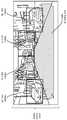
도 4a 내지 도 4d는 깊이 맵의 수직 처리의 예를 나타낸다;
도 5는 수직 처리를 이용하여 비 장애물 영역 검출을 수행하는 방법을 나타내는 흐름도이다;
도 6a 내지 도 6d는 깊이 맵의 수평 처리의 예를 나타낸다;
도 7은 수평 처리를 이용하여 비 장애물 영역 검출을 수행하는 방법을 나타내는 흐름도이다;
도 8은 비 장애물 맵을 결정하기 위해 수직 비 장애물 추정 및 수평 비 장애물 추정을 결합하는 방법을 나타내는 흐름도이다;
도 9는 비 장애물 맵을 결정하기 위해 수직 비 장애물 추정 및 수평 비 장애물 추정을 결합하는 또 다른 방법을 나타내는 흐름도이다;
도 10은 비 장애물 맵을 결정하기 위해 수직 비 장애물 추정 및 수평 비 장애물 추정을 결합하는 또 다른 방법을 나타내는 흐름도이다;
도 11a 내지 도 11b 는 이미지 내의 비 장애물 영역을 결정하는 예를 나타낸다;
도 12a 내지 도 12b 는 이미지 내의 비 장애물 영역을 결정하는 또 다른 예를 나타낸다;
도 13a 내지 도 13b 는 비 장애물 영역으로부터의 거리를 결정하는 예를 나타낸다;
도 14는 오브젝트 검출 알고리즘에 의해 사용된 관심 지역 (ROI) 을 식별하기 위해 비 장애물 맵을 사용하는 예를 나타낸다;
도 15는 차선 검출 알고리즘에 의해 사용된 ROI 를 식별하기 위해 비 장애물 맵을 사용하는 예를 나타낸다;
도 16은 추정된 선형 모델 파라미터에 기초하여 도로를 분류하는 방법을 나타내는 흐름도이다; 그리고
도 17은 전자 디바이스 내에 포함될 수도 있는 특정 컴포넌트를 나타낸다.1 is a block diagram illustrating an electronic device configured to perform non-obstacle area detection;
2 is a block diagram illustrating a non-obstacle determination module;
3 is a flow chart illustrating a method of performing non-obstacle area detection;
Figures 4A-4D show an example of vertical processing of a depth map;
5 is a flow chart illustrating a method of performing non-obstacle area detection using vertical processing;
6A to 6D show an example of horizontal processing of a depth map;
7 is a flow chart illustrating a method for performing non-obstacle area detection using horizontal processing;
8 is a flow chart illustrating a method of combining vertical non-obstacle estimation and horizontal non-obstacle estimation to determine a non-obstacle map;
9 is a flow chart illustrating another method of combining vertical non-obstacle estimation and horizontal non-obstacle estimation to determine a non-obstacle map;
10 is a flow chart illustrating another method of combining vertical non-obstacle estimation and horizontal non-obstacle estimation to determine a non-obstacle map;
11A-11B illustrate an example of determining a non-obstructive region in an image;
12A-12B illustrate another example of determining a non-obstructive region within an image;
13A-13B illustrate an example of determining the distance from the non-obstructive region;
14 shows an example of using a non-obstacle map to identify a region of interest (ROI) used by the object detection algorithm;
15 shows an example of using a non-obstacle map to identify the ROI used by the lane detection algorithm;
16 is a flowchart showing a method of classifying roads based on estimated linear model parameters; And
Figure 17 shows a specific component that may be included in an electronic device.
상세한 설명details
많은 애플리케이션들에서, 장애물 회피를 위해 지역 또는 환경 내의 비 오브젝트 영역을 식별하는 것이 유리하다. 예를 들어, 고급 운전자 보조 시스템 (ADAS) 의 경우, 장애물 회피를 위해 차 전방의 주행 가능 영역을 식별하는 것이 중요하다. 장애물 회피가 중요한 또 다른 시나리오는 자율 차량 (예 : 무인 항공기 (UAV) 또는 자율 자동차) 가 사람의 입력 없이 그의 환경을 감지하고 네비게이팅하는 차량 자동화이다.In many applications, it is advantageous to identify non-object regions in a region or environment for obstacle avoidance. For example, in the case of an advanced driver assistance system (ADAS), it is important to identify the drivable area ahead of the car in order to avoid obstacles. Another scenario where obstacle avoidance is important is vehicle automation in which an autonomous vehicle (such as an unmanned aerial vehicle (UAV) or autonomous vehicle) senses and navigates its environment without human input.
전형적으로, 장애물 회피의 문제는, 관심 오브젝트 (예를 들어, 보행자, 자동차, 이륜차) 가 검출되고 오브젝트 검출/인식 알고리즘을 통해 식별될 수도 있고 경고가 운전자에게 예방조치를 취하기 위해 제공되는, 다른 방향으로부터 고려된다. 예를 들어, 장애물 검출은 교통 표지 (예 : 속도 제한 표지, 정지 표지, 거리 표지 등) 을 검출 및 식별하기 위해 이용될 수도 있다. 그러나 이 접근법은 느리고 부정확할 수도 있다. 게다가 모든 오브젝트 클래스는 사전에 교육을 받아야 하므로, 새로운 오브젝트 클래스를 추가하기가 어렵다.The problem of obstacle avoidance is typically addressed in other directions (e.g., pedestrian, automobile, motorcycle) that may be detected and identified through an object detection / recognition algorithm and alert provided to the driver to take precautions . For example, obstacle detection may be used to detect and identify traffic signs (e.g., speed limit signs, stop signs, street signs, etc.). However, this approach may be slow and inaccurate. In addition, it is difficult to add new object classes because all object classes must be trained in advance.
본 명세서에 설명된 시스템 및 방법에서, 오브젝트를 식별하는 대신에, 장애물 또는 오브젝트가 없는 지역이 식별된다. 이러한 지역들은 움직일 수 있는 영역이라고 할 수도 있다. 즉, 이 3 차원 지역은 이동이 가능한 비 장애물 영역이다. 예를 들어, 비 장애물 영역이 도로에서 식별될 수도 있다. 비 장애물 영역을 식별할 때, 비 장애물 영역을 사용하여 도로 프로파일링, 속도 제어, 더 빠르고 더 신뢰적인 오브젝트, 및 차선 검출과 같은 다양한 다른 애플리케이션을 수행할 수도 있다.In the systems and methods described herein, instead of identifying an object, an area without an obstacle or object is identified. These areas can be said to be movable areas. That is, the three-dimensional region is a movable non-obstacle region. For example, non-obstructive zones may be identified on the road. When identifying non-obstructive regions, non-obstructive regions may be used to perform various other applications such as road profiling, speed control, faster and more reliable objects, and lane detection.
여기에 기재된 시스템 및 방법은 깊이 맵을 분석함으로써 비 장애물 영역을 식별하는데 사용될 수도 있다. 일 구현에서, 깊이 맵은 스테레오 이미지 쌍으로부터 생성될 수도 있다. 도로 시나리오에서, 전방의 개방 공간은 깊이 도메인에서 도로를 기술하는 선형 모델로 매핑될 수도 있다. 도로 세그먼트들의 깊이를 사용하여, 선형 모델 파라미터들이 추정될 수도 있다. 추정된 선형 모델 파라미터는 이전의 (예를 들어, 사전 결정된) 모델 파라미터와 비교될 수도 있다. 피팅이 달성되면, 세그먼트들이 개방 영역의 일부로 선언된다. 스테레오 이미지 쌍이 이용가능하지 않은 경우, 모션으로부터의 구조와 같은 방법이, 모노 카메라 입력 시퀀스를 사용하여 깊이 맵을 얻는데 사용될 수 있다.The systems and methods described herein may be used to identify non-obstructive regions by analyzing depth maps. In one implementation, the depth map may be generated from a stereo image pair. In road scenarios, the open space ahead may be mapped to a linear model describing the road in the depth domain. Using the depths of the road segments, linear model parameters may be estimated. The estimated linear model parameters may be compared with previous (e.g., predetermined) model parameters. Once the fitting is achieved, the segments are declared as part of the open area. If a stereo image pair is not available, the same method as the structure from motion can be used to obtain the depth map using the mono camera input sequence.
여기에 설명된 시스템 및 방법은 하나 이상의 이미지들의 수직 처리 및 수평 처리의 지능형 결합에 기초하여 비 장애물 맵의 결정을 제공한다. 비 장애물 영역을 식별하는 것을 수행하는 시스템 및 방법은 아래에서 더 자세히 설명된다.The systems and methods described herein provide for the determination of a non-obstacle map based on an intelligent combination of vertical processing and horizontal processing of one or more images. Systems and methods for performing the identification of non-obstructive regions are described in more detail below.
도 1은 비장애물 영역 검출을 수행하도록 구성된 전자 디바이스 (102) 를 나타내는 블록도이다. 전자 디바이스 (102) 는 또한, 무선 통신 디바이스, 이동 디바이스, 이동국, 가입자국, 클라이언트, 클라이언트 국, 사용자 장비 (UE), 원격 국, 액세스 단말, 이동 단말, 단말, 사용자 단말, 가입자 유닛 등으로 지칭될 수도 있다. 전자 디바이스들의 예들로는 랩톱 또는 데스크톱 컴퓨터들, 셀룰러 폰들, 스마트 폰들, 무선 모뎀들, e-리더들, 태블릿 디바이스들, 게이밍 시스템들, 로봇들, 항공기, 무인 항공기 (unmanned aerial vehicle : UAV), 자동차 등을 포함한다. 이러한 디바이스들 중 일부는 하나 이상의 산업 표준에 따라 작동할 수도 있다.1 is a block diagram illustrating an electronic device 102 configured to perform non-obstacle area detection. The electronic device 102 may also be referred to as a wireless communication device, a mobile device, a mobile station, a subscriber station, a client, a client station, a user equipment (UE), a remote station, an access terminal, a mobile terminal, . Examples of electronic devices include, but are not limited to, laptop or desktop computers, cellular phones, smart phones, wireless modems, e-readers, tablet devices, gaming systems, robots, aircraft, unmanned aerial vehicle And the like. Some of these devices may operate in accordance with one or more industry standards.
많은 시나리오에서, 전자 디바이스 (102) 는 장면의 비 장애물 맵 (126) 을 사용할 수도 있다. 일 예에서, 스마트폰은 비점유 공간을 식별하기 위하여 장면의 비 장애물 맵 (126) 을 생성할 수도 있다. 또 다른 예에서, 자동차는 검출된 교통 표지, 신호 및/또는 다른 오브젝트에 기초하여 자동차의 속도, 조향, 주차 등을 조절하기 위해 비 장애물 맵 (126) 을 사용할 수도 있는 고급 운전자 보조 시스템 (ADAS) 을 포함할 수도 있다. 또 다른 예에서, 무인 항공기 (UAV) 는 비행 중에 기록된 비디오로부터 비 장애물 맵 (126) 을 생성할 수도 있고, 검출된 오브젝트들 (예를 들어, 건물, 표지, 사람, 패키지 등) 에 기초하여 네비게이팅할 수도 있고, 검출된 패키지 등을 픽업하거나 및/또는 배달할 수도 있다. 많은 다른 예가 본 명세서에 개시된 시스템 및 방법에 따라 구현될 수도 있다. 예를 들어, 여기에 개시된 시스템 및 방법은 비 장애물 맵 (126) 을 사용하여 검출된 하나 이상의 오브젝트들에 기초하여 하나 이상의 액션들 (예를 들어, 무언가를 가져오고, 무언가를 조립하고, 아이템을 검색하는 등) 을 수행하는 로봇에서 구현될 수 있다.In many scenarios, the electronic device 102 may use a non-obstacle map 126 of the scene. In one example, the smartphone may generate a non-obstacle map 126 of the scene to identify unoccupied spaces. In another example, the vehicle may be an advanced driver assistance system (ADAS) that may use a non-obstacle map 126 to adjust the speed, steering, parking, etc. of the vehicle based on the detected traffic sign, signal and / . In another example, an unmanned aerial vehicle (UAV) may generate a non-obstacle map 126 from the recorded video during flight and may be based on detected objects (e.g., buildings, Navigate, pick up and / or deliver the detected package, and so on. Many other examples may be implemented in accordance with the systems and methods disclosed herein. For example, the systems and methods disclosed herein may use one or more actions based on one or more objects detected using the non-obstacle map 126 to retrieve one or more actions (e.g., to bring something, Searching, and so on).
전자 디바이스 (102) 는 하나 이상의 카메라들을 포함할 수도 있다. 카메라는 이미지 센서 (104), 및 광학 시스템 (108) 의 시야 내에 위치된 오브젝트들의 이미지를 이미지 센서 (104) 상에 포커싱하는 광학 시스템 (108) (예를 들어, 렌즈) 를 포함할 수도 있다. 전자 디바이스 (102) 는 또한 카메라 소프트웨어 애플리케이션 및 디스플레이 스크린을 포함할 수도 있다. 카메라 애플리케이션이 실행중일 때, 광학 시스템 (108) 의 시야 내에 위치한 오브젝트들의 이미지들 (114) 은 이미지 센서 (104) 에 의해 기록될 수도 있다. 이 이미지들 (114) 은 메모리 버퍼 (112) 에 저장될 수도 있다. 일부 구현에서, 카메라는 전자 디바이스 (102) 로부터 분리될 수도 있고 전자 디바이스 (102) 는 전자 디바이스 (102) 외부의 하나 이상의 카메라들로부터 이미지 데이터를 수신할 수도 있다.The electronic device 102 may include one or more cameras. The camera may include an image sensor 104 and an optical system 108 (e.g., a lens) that focuses an image of the objects located within the field of view of the optical system 108 onto the image sensor 104. The electronic device 102 may also include a camera software application and a display screen. When the camera application is running, images 114 of objects located within the field of view of the optical system 108 may be recorded by the image sensor 104. These images 114 may be stored in the memory buffer 112. In some implementations, the camera may be separate from the electronic device 102 and the electronic device 102 may receive image data from one or more cameras external to the electronic device 102.
본 시스템 및 방법이 캡처된 이미지들 (114) 의 측면에서 설명되었지만, 여기서 논의된 기술들은 임의의 디지털 이미지에 대해 사용될 수도 있다. 그러므로, 비디오 프레임 및 디지털 이미지라는 용어는 본 명세서에서 상호교환가능하게 사용될 수도 있다.Although the present systems and methods are described in terms of captured images 114, the techniques discussed herein may be used for any digital image. Therefore, the terms video frame and digital image may be used interchangeably herein.
많은 애플리케이션들에서, 전자 디바이스 (102) 가 장애물이 없는 영역을 식별하는 것이 유리하다. 예를 들어, ADAS 의 경우, 장애물 회피를 위해 차 전방의 주행 가능 영역을 식별하는 것이 중요하다. 일부 접근법에서, 이 문제는 다른 방향으로부터 고려된다. 이러한 접근법에서, 관심 오브젝트 (예를 들어, 보행자, 자동차, 이륜차) 가 오브젝트 검출 및 인식 알고리즘을 통해 식별되고 경고들이 운전자에게 예방 조치를 취하기 위해 제공된다.In many applications, it is advantageous for the electronic device 102 to identify an unobstructed region. For example, in the case of ADAS, it is important to identify the drivable area ahead of the car for obstacle avoidance. In some approaches, this problem is considered from the other direction. In this approach, objects of interest (e.g., pedestrians, cars, motorcycles) are identified through object detection and recognition algorithms and alerts are provided to take precautions to the driver.
다른 접근법들은 이미지 (114) 의 수직 처리 또는 수평 처리 중 하나를 수행함으로써 비 장애물 영역을 결정할 수도 있다. 수직 처리 및 수평 처리 각각은 이미지 (114) 에서 비 장애물 영역을 추정할 수도 있다. 그러나, 각 접근법은 독립적으로 수행될 때 한계가 있다.Other approaches may determine the non-obstructive region by performing one of vertical processing or horizontal processing of the image 114. [ Vertical processing and horizontal processing each may estimate a non-obstructive region in image 114. However, each approach has its limitations when performed independently.
도로가 기울어져 있을 때 수평 처리는 잘못된 비 장애물 추정을 제공할 수도 있다. 수직 처리는 이미지 (114) 에 대한 세그먼트화를 수행할 수도 있다. 세그먼트들이 큰 경우, 피팅이 보다 신뢰적이다. 그러나 오브젝트들의 부분들은 역시 비 장애물 (즉, 장애물이 없는) 영역으로서 포함될 수 있다. 예를 들어, 수직 처리를 사용하여, 자동차 또는 보행자의 바닥과 꼭대기가 비 장애물 영역으로서 잘못 식별될 수도 있다. 또한, 보도는 수직 처리 접근법으로 비 장애물 영역으로 잘못 식별될 수 있다. 그러나, 세그먼트가 작으면, 비 장애물 영역의 잘못된 검출이 일어날 수도 있다.Horizontal processing may provide false non-obstacle estimates when the road is tilted. Vertical processing may also perform segmentation on image 114. If the segments are large, the fitting is more reliable. However, portions of the objects may also be included as non-obstructive (i.e., non-obstructive) regions. For example, using vertical processing, the bottom and top of a car or pedestrian may be misidentified as a non-obstructed area. Also, sidewalks can be misdetected as non-obstructed areas by a vertical processing approach. However, if the segment is small, erroneous detection of the non-obstacle area may occur.
여기에 설명된 시스템 및 방법은 하나 이상의 이미지들 (114) 의 수직 처리 및 수평 처리의 지능형 결합에 기초하여 비 장애물 맵 (126) 의 결정을 제공한다. 설명된 시스템 및 방법에서, 오브젝트들을 식별하는 대신에, 비 장애물 맵 (126) 은 깊이 맵의 수직 처리 및 수평 처리를 결합함으로써 결정될 수도 있다. 일 구현에서, 깊이 맵은 하나 이상의 이미지들로부터 획득될 수도 있다. 또 다른 구현에서, 깊이 맵은 깊이 데이터 획득 프로세스 (예를 들어, LIDAR) 로부터 획득될 수도 있다.The systems and methods described herein provide for the determination of the non-obstacle map 126 based on the intelligent combination of vertical processing and horizontal processing of the one or more images 114. In the described system and method, instead of identifying the objects, the non-obstacle map 126 may be determined by combining vertical and horizontal processing of the depth map. In one implementation, a depth map may be obtained from one or more images. In another implementation, the depth map may be obtained from a depth data acquisition process (e.g., LIDAR).
일 구현에서, 전자 디바이스 (102) 는 비 장애물 맵 (126) 을 결정하기 위한 비 장애물 결정 모듈 (116) 을 포함할 수도 있다. 비 장애물 결정 모듈 (116) 은 깊이 맵을 획득하기 위한 깊이 맵 생성기 (118) 를 포함할 수도 있다. 비 장애물 결정 모듈 (116) 은 또한 수직 비 장애물 추정을 결정하기 위해 깊이 맵의 수직 처리를 수행하기 위한 수직 추정 모듈 (120) 을 포함할 수도 있다. 비 장애물 결정 모듈 (116) 은 수평 비 장애물 추정을 결정하기 위해 깊이 맵의 수평 처리를 수행하기 위한 수평 추정 모듈 (122) 을 더 포함할 수도 있다.In one implementation, the electronic device 102 may include a non-obstacle determination module 116 for determining a non-obstacle map 126. The non-obstacle determination module 116 may include a depth map generator 118 for obtaining a depth map. The non-obstacle determination module 116 may also include a
추정 결합기 (124) 는 비 장애물 맵 (126) 을 결정하기 위해 수직 비 장애물 추정 및 수평 비 장애물 추정을 결합할 수도 있다. 일 구현에서, 추정 결합기 (124) 는 추정과 관련된 신뢰도 값에 기초하여 수직 비 장애물 추정 및 수평 비 장애물 추정을 지능적으로 결합할 수도 있다. 비 장애물 맵 (126) 은 하나 이상의 이미지들 (114) 중 어느 영역이 비 장애물 영역인지 그리고 어느 영역이 장애물 영역인지를 표시할 수도 있다. 비 장애물 맵 (126) 을 생성하는 것에 대한 보다 자세한 사항은 도 2와 관련하여 주어진다.The estimated combiner 124 may combine the vertical non-obstacle estimates and the horizontal non-obstacle estimates to determine the non-obstacle map 126. In one implementation, the estimated combiner 124 may intelligently combine the vertical non-obstacle estimates and the horizontal non-obstacle estimates based on the confidence values associated with the estimates. The non-obstacle map 126 may indicate which of the one or more images 114 is a non-obstacle area and which area is an obstacle area. More details about generating the non-obstacle map 126 are given in connection with FIG.
일례에서, 비 장애물 맵 (126) 은 도로상의 장애물 (예를 들어, 오브젝트들) 이 없는 비 장애물 영역을 포함할 수도 있다. 이미지 (114) 의 수직 처리와 수평 처리를 결합함으로써, 오 검출 (false detection) 이 제거될 수도 있다. 또한, 결합된 접근법은 보다 신뢰적인 비 장애물 추정을 제공할 수도 있다.In one example, the non-obstacle map 126 may include a non-obstacle area without obstacles (e.g., objects) on the road. By combining vertical processing and horizontal processing of image 114, false detection may be eliminated. The combined approach may also provide a more reliable non-obstacle estimation.
기술된 시스템 및 방법은 다양한 다른 애플리케이션들의 속도를 높이기 위해 사용될 수도 있다. 예를 들어, 전자 디바이스 (102) 는 오브젝트 검출, 장면 이해, 도로 프로파일링 및 차선 검출과 같은 다른 애플리케이션들을 위해 비 장애물 맵 (126) 을 사용할 수도 있다. 기술된 시스템 및 방법은 또한 현재 차선 검출 알고리즘이 다룰 수 없는 도로 커브 (road curb) 검출의 문제를 해결할 수도 있다. 기술된 시스템 및 방법은 속도가 도로의 지형에 기초하여 조정되는 자율 주행에 더욱 도움이 될 수도 있다.The described systems and methods may be used to speed up various other applications. For example, the electronic device 102 may use a non-obstacle map 126 for other applications such as object detection, scene understanding, road profiling, and lane detection. The described systems and methods may also solve the problem of road curb detection that current lane detection algorithms can not handle. The described systems and methods may be even more helpful for autonomous running where the speed is adjusted based on the terrain of the road.
도 2는 비 장애물 결정 모듈 (216) 을 나타내는 블록도이다. 비 장애물 결정 모듈 (216) 은 전자 디바이스 또는 무선 디바이스 내에서 구현될 수도 있다. 비 장애물 결정 모듈 (216) 은 깊이 맵 생성기 (218), 수직 추정 모듈 (220), 수평 추정 모듈 (222) 및 추정 결합기 (224) 를 포함할 수도 있다. 비 장애물 결정 모듈 (216), 깊이 맵 생성기 (218), 수직 추정 모듈 (220), 수평 추정 모듈 (222) 및 추정 결합기 (224) 는, 도 1과 관련하여 위에서 설명된, 비 장애물 결정 모듈 (116), 깊이 맵 생성기 (118), 수직 추정 모듈 (120), 수평 추정 모듈 (122), 및 추정 결합기 (124) 의 구성들일 수도 있다.FIG. 2 is a block diagram illustrating a non-obstacle determination module 216. FIG. The non-obstacle determination module 216 may be implemented within an electronic device or a wireless device. The non-obstacle determination module 216 may include a depth map generator 218, a vertical estimation module 220, a horizontal estimation module 222 and an estimated combiner 224. The non-obstacle determination module 216, the depth map generator 218, the vertical estimation module 220, the horizontal estimation module 222 and the estimated combiner 224 are connected to a non-obstacle determination module (not shown) 116, a depth map generator 118, a
깊이 맵 생성기 (218) 는 하나 이상의 이미지들 (214) 을 수신할 수도 있다. 일 구성에서, 하나 이상의 이미지들 (214) 은 도 1과 관련하여 기술된 바와 같이, 카메라 (예를 들어, 이미지 센서 (104) 및 광학 시스템 (108)) 를 통해 획득될 수도 있다. 일 구현에서, 깊이 맵 생성기 (218) 는 스테레오 이미지 쌍을 수신할 수도 있다. 또 다른 구현에서, 하나 이상의 이미지들 (214) 은 비디오 모노 이미지로부터 나올 수도 있다. 이미지 (214) 는 픽셀들로 구성된 디지털 이미지일 수도 있다.The depth map generator 218 may receive one or more images 214. In one configuration, one or more images 214 may be acquired through a camera (e.g., image sensor 104 and optical system 108), as described in connection with FIG. In one implementation, depth map generator 218 may receive a stereo image pair. In another implementation, one or more images 214 may come from a video mono image. The image 214 may be a digital image composed of pixels.
깊이 맵 생성기 (218) 는 하나 이상의 이미지들 (214) 로부터 깊이 맵 (230) 을 획득할 수도 있다. 깊이 맵 (230) 은 하나 이상의 이미지들 (214) 의 픽셀들에 대응하는 픽셀들 (232) 을 포함할 수도 있다. 깊이 맵 (230) 내의 각 픽셀 (232) 은 깊이 값 (234) 을 갖는다. 깊이 값 (234) 은 카메라에 대한 픽셀 (232) 의 거리를 표시한다. 예를 들어, 더 높은 깊이 값 (234) 을 갖는 픽셀 (232) 은 더 낮은 깊이 값 (234) 을 갖는 픽셀 (232) 보다 카메라에 더 근접함을 표시할 수도 있다. 깊이 맵 (230) 의 예가 도 4a 내지 도 4d 와 관련하여 논의된다.The depth map generator 218 may obtain the depth map 230 from the one or more images 214. The depth map 230 may include pixels 232 corresponding to the pixels of the one or more images 214. Each pixel 232 in the depth map 230 has a
본 명세서에 설명된 알고리즘은 각 픽셀 (232) 에 대해 깊이 값 (234) 을 필요로 하지 않는다는 것에 유의해야 한다. 예를 들어, 깊이 맵 (230) 은 홀들을 가질 수도 있다. 이들 홀들의 깊이 값 (234) 은 처리를 시작하기 전에 채워질 수도 있다.It should be noted that the algorithm described herein does not require a
스테레오 이미지 쌍의 경우에, 깊이 맵 생성기 (218) 는 디스패리티를 추정하기 위해 픽셀들 (232) 간의 대응 관계를 구할 수도 있다. 디스패리티로부터, 깊이 맵 생성기 (218) 는 각 픽셀 (232) 에 대한 깊이 값 (234) 을 결정할 수도 있다. 대안적으로, 비디오 모노 이미지로, 깊이 맵 생성기 (218) 는 비디오의 모션에 기초하여 각 픽셀 (232) 에 대한 깊이 값 (234) 을 결정할 수도 있다.In the case of a stereo image pair, the depth map generator 218 may find a correspondence between the pixels 232 to estimate the disparity. From the disparity, the depth map generator 218 may determine the
깊이 맵 (230) 은 수직 추정 모듈 (220) 및 수평 추정 모듈 (222) 에 제공될 수도 있다. 수직 추정 모듈 (220) 은 깊이 맵 (230) 의 수직 처리를 수행하여 수직 비 장애물 추정 (242) 을 결정할 수도 있다. 수평 추정 모듈 (222) 은 깊이 맵 (230) 의 수평 처리를 수행하여 수평 비 장애물 추정 (258) 을 결정할 수도 있다.The depth map 230 may be provided to the vertical estimation module 220 and the horizontal estimation module 222. Vertical estimation module 220 may also perform vertical processing of depth map 230 to determine vertical non-obstacle estimation 242. The horizontal estimation module 222 may also perform horizontal processing of the depth map 230 to determine the horizontal non-obstacle estimation 258.
수직 추정 모듈 (220) 은 깊이 맵 (230) 을 세그먼트들 (236) 로 분할할 수도 있다. 각 세그먼트 (236) 는 깊이 맵 (230) 의 열 (column) 에 다수의 픽셀들 (232) 을 포함할 수도 있다. 즉, 수직 추정 모듈 (220) 은 깊이 맵 (230) 의 수직 세그먼트들 (236) 을 처리할 수도 있다. 세그먼트 (236) 는 깊이 맵 (230) 내의 픽셀들 (232) 의 열의 일부일 수도 있다. 예를 들어, 세그먼트 (236) 는 10-15개 픽셀들 (232) 의 벡터일 수도 있다. 세그먼트들 (236) 은 중첩되거나 중첩되지 않을 수도 있다.The vertical estimation module 220 may divide the depth map 230 into segments 236. Each segment 236 may include a plurality of pixels 232 in a column of depth maps 230. That is, the vertical estimation module 220 may process the vertical segments 236 of the depth map 230. Segment 236 may be part of the row of pixels 232 in depth map 230. For example, segment 236 may be a vector of 10-15 pixels 232. Segments 236 may or may not overlap.
수직 추정 모듈 (220) 은 각각의 세그먼트 (236) 에 대한 선형 모델 파라미터를 추정하여 수직 비 장애물 추정 (242) 을 결정할 수도 있다. 수직 방향의 각 세그먼트 (236) 는 선형 모델을 통해 추정될 수도 있다. 선형 모델은 다음과 같이 표현될 수도 있다.Vertical estimation module 220 may determine a vertical non-obstacle estimate 242 by estimating a linear model parameter for each segment 236. Each segment 236 in the vertical direction may be estimated through a linear model. The linear model may be expressed as:

식중 y는 픽셀 (232) 의 깊이 값 (234) 이고, x는 픽셀 (232) 의 좌표이고, p1 및 p2는 추정된 선형 모델 파라미터 (238) 이다. 추정 오차가 수직 추정 임계치 (246) 보다 작고 선형 피트가 소정의 기울기를 갖는다면, 이는 유효한 자유 공간 (비 장애물 영역 (266)) 으로 라벨링될 수도 있다. 일 구현에서, 0보다 큰 기울기는 비 장애물을 나타내는 반면, 0 보다 작거나 같은 기울기는 오브젝트 또는 장애물을 나타낸다. 이 접근법의 예가 도 4a 내지 도 4d 와 관련하여 논의된다.Where y is the
행렬 형태에서, 식 (1) 의 선형 모델은 식 (2) 에 의해 주어진다.In matrix form, the linear model of equation (1) is given by equation (2).

식 (2) 에서, y는 깊이 값들 (234) 의 n × 1 벡터이고, x는 수직 차원에서 모델 좌표에 대한 n × 2 설계 행렬 (즉, n 행, 2 열의 행렬) 이고, p1 및 p2는 추정 선형 모델 파라미터 (238) 이다. n의 값은 깊이 맵 세그먼트 (236) 내의 픽셀들 (232) 의 수에 대응한다.In equation (2), y is an nx 1 vector of
하나의 접근법에서, p1 및 p2는 최소 제곱 해를 사용하여 풀어질 수도 있다. 이 접근법에서, p는 미지의 계수 p1 및 p2의 벡터이다. 정규 방정식은 다음에 의해 주어진다In one approach, p1 and p2 may be solved using a least squares solution. In this approach, p is a vector of unknown coefficients p1 and p2 . The normal equation is given by

여기서,XT 은 설계 행렬 X의 전치 (transpose) 이다. 식 (4) 에서 p 에 대해 풀면, 추정된 선형 모델 파라미터 (238) (즉, p1 및 p2) 가 얻어진다.WhereXT is the transpose of the design matrix X. Solving for p in equation (4), the estimated linear model parameters 238 (i.e., p1 and p2 ) are obtained.

최적화된 구현에서, 행렬 역변환 항 (matrix inversion term)
수직 추정 모듈 (220) 은 수직 비 장애물 추정 (242) 에 대한 신뢰도 값 (250) 수직 신뢰도 맵 (248) 을 결정할 수도 있다. 일 구현에서, 수직 추정 모듈 (220) 은 추정된 선형 모델 파라미터들 (238) 과 미리 결정된 선형 모델 파라미터들 (240) 사이의 차이에 기초하여 각 세그먼트 (236) 에 대한 세그먼트 피팅 오차 (244) 를 결정할 수도 있다. 미리 결정된 모델 파라미터들은 [pM1, pM2] 로 지칭될 수도 있다. 수직 추정 모듈 (220) 은 미리 결정된 모델 파라미터가 임계치 (TH1) 와의 비교에 의해 추정된 파라미터 [p1, p2] 에 얼마나 가까운지를 체크할 수도 있다. 예를 들어,
수직 추정 임계치 (246) 는 추정된 선형 모델 파라미터들 (238) 이 훈련된 모델 파라미터들에 피팅되는지를 결정할 수도 있다. 미리 결정된 선형 모델 파라미터들 (240) 은 복수의 도로 조건 모델 중에서 선택될 수도 있다. 복수의 도로 조건 모델들의 각각은 대응하는 선형 모델 파라미터들 (240) 의 세트를 가질 수도 있다. 도로 조건 모델의 예들은 평탄한 평면, 언덕, 계곡 등을 포함한다. 사전 결정된 선형 모델 파라미터들 (240) 은 트레이닝에 의해 결정될 수도 있다.The
수직 추정 모듈 (220) 은 식 (5) 에 따라 추정된 선형 모델 파라미터들 (238) 을 사용하여 추정된 깊이 값


추정된 선형 모델 파라미터들 (238) 에 의한 깊이 추정 오차

세그먼트 피팅 오차 (244 (s2))는 식 (7) 에 따라 결정될 수도 있으며, 여기서 n은 세그먼트 (236) 의 길이이다.The segment fitting error 244 (s2 ) may be determined according to equation (7), where n is the length of the segment 236.

세그먼트 피팅 오차 (244) 는 수직 처리를 위한 신뢰도 메트릭으로서 사용될 수도 있다. 수직 추정 모듈 (220) 은 각 세그먼트 (236) 의 세그먼트 피팅 오차 (244) 와 수직 추정 임계치 (246) 를 비교함으로써 각 세그먼트 (236) 에 대한 수직 신뢰도 값 (250) 을 결정할 수도 있다.Segment fitting error 244 may be used as a confidence metric for vertical processing. The vertical estimation module 220 may determine the
수직 추정 임계치 (246) 는 미리 결정된 선형 모델 파라미터들 (240) 에 기초할 수도 있다. 수직 추정 임계치 (246 )는 어떤 미리 결정된 선형 모델 파라미터들 (240) 이 사용되는지에 따라 변할 수도 있다. 예를 들어, 평탄한 도로에 대한 미리 결정된 선형 모델 파라미터 (240) 가 사용되면, 수직 추정 임계치 (246) 는 하나의 값을 가질 수도 있다. 언덕에 대한 미리 결정된 선형 모델 파라미터 (240) 가 사용되면, 수직 추정 임계치 (246) 는 상이한 값을 가질 수도 있다.The
수직 추정 모듈 (220) 은 세그먼트 피팅 오차 (244) 와 수직 추정 임계치 (246) 사이의 차이의 절대 값을 체크할 수도 있다. 주어진 세그먼트 (236) 에 대한 세그먼트 피팅 오차 (244) 가 수직 추정 임계치 (246) 보다 작을 때 주어진 세그먼트 (236) 는 높은 수직 신뢰도 값 (250) 을 가질 수도 있다. 반대로, 주어진 세그먼트 (236) 에 대한 세그먼트 피팅 오차 (244) 가 수직 추정 임계치 (246) 보다 크거나 같을 때 주어진 세그먼트 (236) 는 낮은 수직 신뢰도 값 (250) 을 가질 수도 있다. 따라서, 세그먼트 피팅 오차 (244) 와 수직 추정 임계치 (246) 간의 차이가 작은 경우, 세그먼트 (236) 는 비 장애물 영역 (266) 의 일부로 고려된다. 그 차이가 큰 경우, 세그먼트 (236) 는 비 장애물 영역 (266) 의 일부로 고려되지 않는다.The vertical estimation module 220 may check the absolute value of the difference between the segment fitting error 244 and the
주어진 세그먼트 (236) 에 대한 신뢰도 값 (250) 을 결정할 때, 수직 추정 모듈 (220) 은 바이너리 맵을 얻기 위해 수직 신뢰도 맵 (248) 을 임계화할 수도 있다. 주어진 세그먼트 (236) 에 대한 신뢰도 값 (250) 은 임계치와 비교되어 세그먼트 (236) 가 비 오브젝트 영역 (예를 들어, 이동 가능) 인지 또는 오브젝트 영역 (예를 들어, 비 이동 가능 영역) 인지 를 결정할 수도 있다. 수직 신뢰도 맵 (248) 은 깊이 맵 (230) 내의 픽셀들 (232) 의 신뢰도 값 (250) 을 포함할 수도 있다. 따라서, 수직 신뢰도 맵 (248) 은 세그먼트 (236) 당 뿐만 아니라 깊이 픽셀 (232) 당 피팅 신뢰성을 갖는 맵이다.When determining the
수평 추정 모듈 (222) 은 깊이 맵 (230) 의 수평 처리를 수행하여 수평 비 장애물 추정 (258) 을 결정할 수도 있다. 수평 처리는 깊이 맵 (230) 의 픽셀들 (232) 의 각 행에 대한 깊이 히스토그램 (252) 을 얻는 것을 포함할 수도 있다. 깊이 히스토그램 (252) 의 예가 도 6a 내지 도 6d 와 관련하여 설명된다. 깊이 히스토그램 (252) 은 또한 디스패리티 히스토그램으로 지칭될 수도 있다.The horizontal estimation module 222 may also perform horizontal processing of the depth map 230 to determine the horizontal non-obstacle estimation 258. Horizontal processing may include obtaining a depth histogram 252 for each row of pixels 232 of depth map 230. An example of the depth histogram 252 is described with reference to FIGS. 6A through 6D. The depth histogram 252 may also be referred to as a disparity histogram.
일 구현에서, 깊이 히스토그램 (252) 은 깊이 맵 (230) 내의 각 행에 대한 히스토그램을 획득함으로써 획득될 수도 있다. 예를 들어, 깊이 맵 (230) 으로부터의 픽셀들 (232) 의 행에 대하여, 행 내 픽셀들 (232) 에 대응하는 깊이 값들 (234) 에 대해 히스토그램이 생성될 수도 있다.In one implementation, the depth histogram 252 may be obtained by obtaining a histogram for each row in the depth map 230. For example, for a row of pixels 232 from depth map 230, a histogram may be generated for
수평 추정 모듈 (222) 은 깊이 히스토그램 (252) 으로부터 지형 라인 (254) 을 결정할 수도 있다. 지형 라인 (254) 의 종점들의 y 좌표는 가장 가까운 그리고 가장 먼 자유 공간 거리를 결정한다.The horizontal estimation module 222 may determine the terrain line 254 from the depth histogram 252. The y coordinate of the end points of the topographic line 254 determines the closest and farthest free space distance.
지형 라인 (254) 은 라인 추출 접근법을 사용하여 결정될 수도 있다. 허프 (Hough) 변환이 깊이 히스토그램 (252) 에 대해 적용될 수도 있다. 허프 변환은 깊이 히스토그램 (252) 으로부터 다수의 라인 세그먼트를 추출할 수도 있다. 예를 들어, 허프 변환은 10-20 개의 작은 라인들을 생성할 수도 있다. 라인 세그먼트들은 병합되어 지형 라인 (254) 을 형성할 수도 있다. 일 구현에서, 지형 라인 (254) 의 각도는 비 장애물 공간의 기울기 특성에 기초하여 (예를 들어, -20 도와 -40 도 사이에서) 제한될 수도 있다.Terrain line 254 may be determined using a line extraction approach. A Hough transform may be applied to the depth histogram 252. [ The Hough transform may also extract a number of line segments from the depth histogram 252. For example, a Hough transform may produce 10-20 small lines. The line segments may be merged to form the topographic line 254. In one implementation, the angle of the terrain line 254 may be limited (e.g., between -20 degrees and -40 degrees) based on the slope characteristic of the non-obstacle space.
수평 추정 모듈 (222) 은 지형 라인 (254) 으로부터 각 픽셀 (232) 의 깊이 값 (234) 의 거리에 기초하여 각 픽셀 (232) 에 대한 수평 비 장애물 추정 (258) 을 결정할 수도 있다. 지형 라인 (254) 의 수평 추정 임계치 (260) 내에 놓이는 깊이 값 (234) 을 갖는 픽셀 (232) 은 비 장애물 영역 (266) 으로서 식별될 수도 있다. 예를 들어, 픽셀 (232) 의 깊이 값 (234) 이 지형 라인 (254) 의 소정의 디스패리티 범위 내에 있으면, 그 픽셀 (232) 은 비 장애물 영역 (266) 으로서 라벨링될 수도 있다. 픽셀 (232) 의 깊이 값 (234) 이 지형 라인 (254) 의 소정의 디스패리티 범위 밖에 있으면, 그 픽셀 (232) 은 장애물 영역 (268) 으로서 라벨링될 수도 있다.The horizontal estimation module 222 may determine the horizontal non-obstacle estimate 258 for each pixel 232 based on the distance of the
수평 추정 모듈 (222) 은 또한 깊이 히스토그램 (252) 거리에 기초하여 수평 신뢰도 맵 (262) 을 결정할 수도 있다. 수평 신뢰도 맵 (262) 은 각 픽셀 (232) 의 수평 비 장애물 추정 (258) 에 대한 신뢰도 값 (264) 을 포함할 수도 있다.The horizontal estimation module 222 may also determine the horizontal reliability map 262 based on the depth histogram 252 distance. The horizontal reliability map 262 may include a
깊이 히스토그램 (252) 의 모드 (256) 까지의 거리는 수평 처리를 위한 신뢰도 메트릭으로서 사용될 수도 있다. 수평 추정 모듈 (222) 은 각 픽셀 (232) 의 깊이 값 (234) 이 깊이 히스토그램 (252) 의 모드 (256) 의 신뢰도 임계치 (261) 내에 있는지 여부를 결정할 수도 있다. 주어진 픽셀 (232) 의 깊이 값 (234) 이 깊이 히스토그램 (252) 의 모드 (256) 의 신뢰도 임계치 (261) 내에 있을 때 주어진 픽셀 (232) 은 높은 신뢰도 값 (264) 을 가질 수도 있다.The distance to depth 256 of depth histogram 252 may be used as a confidence metric for horizontal processing. The horizontal estimation module 222 may determine whether the
추정 결합기 (224) 는 비 장애물 맵 (226) 을 결정하기 위해 수직 비 장애물 추정 (242) 및 수평 비 장애물 추정 (258) 을 결합할 수도 있다. 이 결합은 수직 신뢰도 값 (250) 및 수평 신뢰도 값 (264) 에 기초할 수도 있다. 하나의 접근법에서, 수직 처리 및 수평 처리는 병렬로 수행될 수도 있고 결과적인 비 장애물 추정 (242, 258) 은 병합된다. 또 다른 접근법에서, 수직 처리 및 수평 처리는 순차적으로 수행될 수도 있고 결과적인 비 장애물 추정은 병합된다.The estimated combiner 224 may combine the vertical non-obstacle estimates 242 and the horizontal non-obstacle estimates 258 to determine the non-obstacle map 226. This combination may be based on the
병렬 처리 접근법을 위해, 수직 처리와 수평 처리 양자 모두가 병렬로 수행될 수도 있다. 예를 들어, 수직 추정 모듈 (220) 은 수직 처리를 수행할 수도 있고, 수평 추정 모듈 (222) 은 전술한 바와 같이 수평 처리를 동시에 수행할 수도 있다. 추정 결합기 (224) 는 각각의 픽셀 (232) 을 비 장애물 영역 (266) 또는 장애물 영역 (268) 으로 식별함으로써 비 장애물 맵 (226) 을 생성할 수도 있다. 이 식별은 수직 신뢰도 맵 (248) 의 수직 신뢰도 값 (250) 및 수평 신뢰도 맵 (262) 의 수평 신뢰도 값 (264) 에 기초할 수도 있다.For the parallel processing approach, both vertical processing and horizontal processing may be performed in parallel. For example, the vertical estimation module 220 may perform vertical processing and the horizontal estimation module 222 may simultaneously perform horizontal processing as described above. The estimated combiner 224 may generate a non-obstacle map 226 by identifying each pixel 232 as a non-obstructive region 266 or an obstructive region 268. [ This identification may be based on the vertical confidence values 250 of the vertical confidence map 248 and the horizontal confidence values 264 of the horizontal confidence map 262.
수직 신뢰도 맵 (248) 및 수평 신뢰도 맵 (262) 양자 모두가 픽셀 (232) 이 높은 신뢰도를 갖는다고 나타낼 경우, 픽셀 (232) 은 비 장애물 맵 (226) 에서 비 장애물 영역 (266) 으로서 식별될 수도 있다. 즉, 주어진 픽셀 (232) 은 수직 신뢰도 맵 (248) 및 수평 신뢰도 맵 (262) 양자 모두가 주어진 픽셀 (232) 에 대해 높은 신뢰도 값을 특징으로 하는 비 장애물 맵 (226) 에서 비 장애물 영역 (266) 으로 식별될 수도 있다.When both the vertical reliability map 248 and the horizontal reliability map 262 indicate that the pixel 232 has high reliability, the pixel 232 is identified as the non-obstacle area 266 in the non-obstacle map 226 It is possible. That is, a given pixel 232 may be displayed in a non-obstacle map 226 that is characterized by a high confidence value for a given pixel 232, both in the vertical reliability map 248 and the horizontal confidence map 262, ). ≪ / RTI >
일 구현에서, 이것은 수직 신뢰도 맵 (248) 및 수평 신뢰도 맵 (262) 을 각각의 임계치로 임계화함으로써 달성될 수도 있다. 예를 들어, 주어진 픽셀 (232) 의 수직 신뢰도 값 (250) 및 수평 신뢰도 값 (264) 이 임계치보다 큰 경우, 픽셀 (232) 은 비 장애물 영역 (266) 으로 식별될 수도 있다. 수직 신뢰도 맵 (248) 및 수평 신뢰도 맵 (262) 양자 모두가 낮은 신뢰도를 나타내는 경우, 픽셀 (232) 은 장애물 영역 (268) 으로 라벨링될 수도 있다.In one implementation, this may be accomplished by thresholding the vertical reliability map 248 and the horizontal reliability map 262 to respective thresholds. For example, pixel 232 may be identified as non-obstructive region 266 if the
수직 신뢰도 맵 (248) 또는 수평 신뢰도 맵 (262) 중 어느 하나가 높은 신뢰도를 나타내고 다른 하나가 낮은 신뢰도를 나타내는 경우에, 하나 이상의 상이한 병합 접근법들이 수행될 수도 있다. 하나의 접근법에서, 수직 신뢰도 맵 (248) 또는 수평 신뢰도 맵 (262) 중 적어도 하나가 주어진 픽셀 (232) 이 낮은 신뢰도를 갖는다고 나타낼 경우, 주어진 픽셀 (232) 은 비 장애물 맵 (226) 에서 장애물 영역 (268) 으로서 식별된다. 즉, 주어진 픽셀 (232) 은 수직 신뢰도 맵 (248) 또는 수평 신뢰도 맵 (262) 중 적어도 하나가 주어진 픽셀 (232) 에 대해 낮은 신뢰도 값을 특징으로 하는 비 장애물 맵 (226) 에서의 장애물 영역 (268) 으로서 식별될 수도 있다. 이 접근법에서, 신뢰도 맵들 (248, 262) 중 하나가 낮은 신뢰도를 나타내는 경우, 픽셀 (232) 은 그 신뢰도 맵 (248, 262) 에만 기초하여 라벨링될 수도 있다.One or more of the different merge approaches may be performed if either the vertical reliability map 248 or the horizontal reliability map 262 indicates high reliability and the other indicates low reliability. In one approach, given that at least one of the vertical reliability map 248 or the horizontal reliability map 262 indicates that a given pixel 232 has low reliability, then a given pixel 232 may be included in the non-obstacle map 226, Area 268. < / RTI > That is, a given pixel 232 may be located in an obstacle region 226 in a non-obstacle map 226 where at least one of the vertical reliability map 248 or the horizontal reliability map 262 is characterized by a low confidence value for a given pixel 232 268 < / RTI > In this approach, if one of the reliability maps 248, 262 indicates low reliability, the pixel 232 may be labeled based only on its reliability map 248, 262.
또 다른 접근법에서, 수직 신뢰도 맵 (248) 및 수평 신뢰도 맵 (262) 은 주어진 픽셀 (232) 에 대해 상이한 신뢰도 값 (250, 264) 을 특징으로 한다. 이 경우, 주어진 픽셀 (232) 은 주어진 픽셀 (232) 의 좌표에 기초하여 비 장애물 영역 (266) 또는 장애물 영역 (268) 으로 식별될 수도 있다. 이러한 접근법에서, 신뢰도 맵들 (248, 262) 양자 모두가 신뢰도의 측면에서 서로 가깝다면 (예를 들어, 하나가 다른 것보다 높음), 픽셀 (232) 좌표를 고려함으로써 판정이 더 향상될 수도 있다.In another approach, the vertical reliability map 248 and the horizontal reliability map 262 are characterized by different confidence values 250, 264 for a given pixel 232. In this case, a given pixel 232 may be identified as a non-obstructive region 266 or an obstructive region 268 based on the coordinates of a given pixel 232. In this approach, the determination may be further improved by considering the pixel 232 coordinates if both of the reliability maps 248 and 262 are close to each other in terms of reliability (e.g., one is higher than the other).
일례에서, RHij는 수평 처리로부터의 i 번째 및 j 번째 픽셀 (232) 에 대한 수평 신뢰도 값 (264) 이고, RVij는 수직 처리로부터의 수직 신뢰도 값 (250) 이다 (여기서 신뢰도 값들 (250, 264) 양자 모두는 상이한 방법들에 의해 획득된다면 정규화된다). |RHij-RVij|<TH이면, 이는 신뢰도 맵들 (248, 262) 의 근사를 나타낼 것이다. 또한, RHij는 RVi+n, j+n 과 비교될 수 있는데, 여기서 n은 <N이다 (예를 들어, 720p 해상도에 대해 N=5 이다).In one example, RHij is the
순차적 처리 접근법을 위해, 수직 처리 또는 수평 처리 중 어느 하나가 먼저 수행될 수도 있다. 제 1 처리가 수행된 후에, 전체 깊이 맵 (230) 에 대해 신뢰도 맵 (예를 들어, 수직 신뢰도 맵 (248) 또는 수평 신뢰도 맵 (262) 중 어느 하나) 이 계산될 수도 있다. 신뢰도가 충족되지 않는 픽셀들 (232) 에 대해서는, 제 2 처리가 호출된다. 제 1 및 제 2 처리의 결과는 병합되어 비 장애물 맵 (226) 을 획득할 수도 있다. 수직 처리로 시작하는 순차적 처리의 예가 도 9와 관련하여 설명된다. 수평 처리로 시작하는 순차적 처리의 예가 도 10과 관련하여 설명된다.For a sequential processing approach, either vertical processing or horizontal processing may be performed first. After the first process is performed, a confidence map (e.g., either vertical confidence map 248 or horizontal confidence map 262) may be calculated for the entire depth map 230. For pixels 232 whose reliability is not satisfied, a second process is called. The results of the first and second processes may be merged to obtain the non-obstacle map 226. [ An example of sequential processing that begins with a vertical processing is described with reference to FIG. An example of sequential processing that begins with horizontal processing is described with respect to FIG.
비 장애물 결정 모듈 (216) 은 비 장애물 맵 (226) 의 추가적인 처리를 수행할 수도 있다. 일 구현에서, 비 장애물 결정 모듈 (216) 은 이상치 제거 (outlier removal) 를 수행할 수도 있다. 예를 들어, 적은 수의 픽셀 (232) 이 비 장애물 영역 (266) 내에서 잘못 라벨링된 장애물 영역 (268) 일 수도 있다. 비 장애물 결정 모듈 (216) 은 이러한 이상치들을 식별하고 그들의 상태를 비 장애물 또는 장애물 중 어느 하나로 변경할 수도 있다. 비 장애물 결정 모듈 (216) 은 비 장애물 맵 (226) 의 추가적인 필터링을 수행하여 이를 후속 동작들을 위해 준비할 수도 있다.The non-obstacle determination module 216 may perform additional processing of the non-obstacle map 226. In one implementation, the non-obstacle determination module 216 may perform outlier removal. For example, a small number of pixels 232 may be an obstacle region 268 that is mislabeled within the non-obstructive region 266. The non-obstacle determination module 216 may identify these outliers and change their status to either a non-obstacle or an obstacle. The non-obstacle determination module 216 may perform additional filtering of the non-obstacle map 226 to prepare it for subsequent operations.
비 장애물 맵 (226) 은 상이한 동작들을 위해 사용될 수도 있다. 일 구현에서, 비 장애물 맵 (226) 은 오브젝트 검출 알고리즘에 의해 사용되는 관심 지역을 식별하는데 사용될 수도 있다. 이것은, 도 14와 관련하여 설명되는 바처럼 달성될 수도 있다. 또 다른 구현에서, 비 장애물 맵 (226) 은 차선 검출 알고리즘에 의해 사용되는 관심 지역을 식별하는데 사용될 수도 있다. 이것은, 도 15와 관련하여 설명되는 바처럼 달성될 수도 있다.The non-obstacle map 226 may be used for different operations. In one implementation, the non-obstacle map 226 may be used to identify the region of interest used by the object detection algorithm. This may be accomplished as described in connection with FIG. In another implementation, the non-obstacle map 226 may be used to identify the area of interest used by the lane detection algorithm. This may be accomplished as described in connection with FIG.
도 2에 나타낸 바와 같이, 나타낸 컴포넌트들 중 하나 이상은 프로세서 (228) 에 의해 선택적으로 구현될 수도 있다. 예를 들어, 비 장애물 결정 모듈 (216) 은 프로세서 (228) 에 의해 구현될 수도 있다. 일부 구성들에서, 상이한 프로세서들이 상이한 컴포넌트들을 구현하는데 사용될 수도 있다 (예를 들어, 하나의 프로세서가 깊이 맵 생성기 (218) 를 구현할 수도 있고, 또 다른 프로세서가 수직 추정 모듈 (220) 을 구현하는데 사용될 수도 있고, 또 다른 프로세스가 수평 추정 모듈 (222) 을 구현하는데 사용될 수도 있고, 또 다른 프로세서가 추정 결합기 (224) 를 구현하는데 사용될 수도 있다).As shown in FIG. 2, one or more of the components shown may be selectively implemented by the processor 228. For example, non-obstacle determination module 216 may be implemented by processor 228. In some arrangements, different processors may be used to implement different components (e.g., one processor may implement depth map generator 218 and another processor may be used to implement vertical estimation module 220) Another process may be used to implement the horizontal estimation module 222 and another processor may be used to implement the estimated combiner 224).
이미지 (214) 를 회전시키고 대각 처리를 수행하는 것이 가능하다는 것에 유의해야 한다. 이미지 (214) 가 회전되면, 수직 및 수평 처리는 대각 처리가 될 수도 있다. 그러므로, 수직 및 수평 처리라는 용어들이 본 명세서에서 사용되었지만, 대응하는 좌표 매핑으로 회전된 이미지를 통해 상이한 섹션에 걸쳐 처리가 적용될 수도 있음이 인식될 수도 있다.It is noted that it is possible to rotate image 214 and perform diagonal processing. If the image 214 is rotated, the vertical and horizontal processing may be diagonal processing. Thus, although the terms vertical and horizontal processing are used herein, it may be appreciated that processing may be applied across different sections over the rotated image with corresponding coordinate mappings.
도 3은 비 장애물 영역 검출을 수행하는 방법 (300) 을 나타내는 흐름도이다. 방법 (300) 은 도 1을 참조하여, 전자 디바이스 (102), 예를 들어 비 장애물 결정 모듈 (116) 에 의해 구현될 수도 있다. 전자 디바이스 (102) 는 하나 이상의 이미지들 (214) 로부터 깊이 맵 (230) 을 획득할 수도 있다 (302). 일 구현에서, 전자 디바이스 (102) 는 스테레오 이미지 쌍으로부터 깊이 맵 (230) 을 생성할 수도 있다. 또 다른 구현에서, 전자 디바이스 (102) 는 비디오 모노 이미지 쌍으로부터 깊이 맵 (230) 을 생성할 수도 있다. 깊이 맵 (230) 내의 각 픽셀 (232) 은 깊이 값 (234) 을 가질 수도 있다.3 is a flow chart illustrating a
전자 디바이스 (102) 는 수직 비 장애물 추정 (242) 을 결정하기 위해 깊이 맵 (230) 의 수직 처리를 수행할 수도 있다 (304). 수직 처리는 깊이 맵 (230) 을 세그먼트들 (236) 로 분할하는 것을 포함할 수도 있다. 각 세그먼트 (236) 는 열에 다수의 픽셀들 (232) 을 포함할 수도 있다. 전자 디바이스 (102) 는 각각의 세그먼트 (236) 에 대한 선형 모델 파라미터 (238) 를 추정하여 수직 비 장애물 추정 (242) 을 결정할 수도 있다. 전자 디바이스 (102) 는 수직 비 장애물 추정 (242) 에 대한 신뢰도 값 (250) 을 포함하는 수직 신뢰도 맵 (248) 을 결정할 수도 있다.Electronic device 102 may perform vertical processing of depth map 230 to determine vertical non-obstacle estimation 242 (304). Vertical processing may include dividing the depth map 230 into segments 236. [ Each segment 236 may include a plurality of pixels 232 in a column. The electronic device 102 may determine the vertical non-obstacle estimate 242 by estimating the linear model parameters 238 for each segment 236. [ The electronic device 102 may determine a vertical reliability map 248 that includes a
전자 디바이스 (102) 는 수평 비 장애물 추정 (258) 을 결정하기 위해 깊이 맵 (230) 의 수평 처리를 수행할 수도 있다 (306). 수평 처리는 깊이 맵 (230) 의 픽셀들 (232) 의 각 행에 대한 깊이 히스토그램 (252) 을 얻는 것을 포함할 수도 있다. 전자 디바이스 (102) 는 깊이 히스토그램 (252) 으로부터 지형 라인 (254) 을 결정할 수도 있다. 전자 디바이스 (102) 는 지형 라인 (254) 으로부터 각 픽셀 (232) 의 깊이 값 (234) 의 거리에 기초하여 각 픽셀 (232) 에 대한 수평 비 장애물 추정 (258) 을 결정할 수도 있다. 전자 디바이스 (102) 는 또한, 각 픽셀 (232) 의 수평 비 장애물 추정 (258) 에 대한 신뢰도 값 (264) 을 포함하는 수평 신뢰도 맵 (262) 을 결정할 수도 있다.The electronic device 102 may perform horizontal processing of the depth map 230 to determine a horizontal non-obstacle estimation 258 (306). Horizontal processing may include obtaining a depth histogram 252 for each row of pixels 232 of depth map 230. The electronic device 102 may determine the terrain line 254 from the depth histogram 252. [ The electronic device 102 may determine the horizontal non-obstacle estimate 258 for each pixel 232 based on the distance of the
전자 디바이스 (102) 는 비 장애물 맵 (226) 을 결정하기 위해 수직 비 장애물 추정 (242) 및 수평 비 장애물 추정 (258) 을 결합할 수도 있다 (308). 일 구현에서, 전자 디바이스 (102) 는 병렬 수직 처리 및 수평 처리를 수행할 수도 있다. 이 구현에서, 전자 디바이스 (102) 는 도 10과 관련하여 설명된 바처럼, 수직 비 장애물 추정 (242) 및 수평 비 장애물 추정 (258) 을 결합할 수도 있다. 또 다른 구현에서, 전자 디바이스 (102) 는 도 11a 및 도 11b 와 관련하여 설명된 바와 같이, 수직 처리로 시작하는 순차 처리를 수행할 수도 있다. 또 다른 구현에서, 전자 디바이스 (102) 는 도 12a 및 도 12b 와 관련하여 설명된 바와 같이, 수평 처리로 시작하는 순차 처리를 수행할 수도 있다.The electronic device 102 may combine the vertical non-obstacle estimation 242 and the horizontal non-obstacle estimation 258 to determine a non-obstacle map 226 (308). In one implementation, the electronic device 102 may perform parallel vertical processing and horizontal processing. In this implementation, the electronic device 102 may combine the vertical non-obstacle estimation 242 and the horizontal non-obstacle estimation 258, as described in connection with FIG. In another implementation, the electronic device 102 may perform sequential processing that begins with a vertical processing, as described in connection with Figs. 11A and 11B. In another implementation, the electronic device 102 may perform sequential processing that begins with a horizontal process, as described in connection with Figs. 12A and 12B.
도 4a 내지 도 4d는 깊이 맵 (430) 의 수직 처리의 예를 나타낸다. 깊이 맵 (430) 은 하나 이상의 이미지들 (404) 로부터 생성될 수도 있다. 깊이 맵 (430) 은 원래 이미지(들) (404) 의 픽셀들에 대응하는 위치들을 포함할 수도 있다. 깊이 맵 (430) 내의 각 위치 (예를 들어, 좌표) 는 원래 이미지(들) (404) 의 픽셀에 대응하는 수평 좌표 (472) 및 수직 좌표 (474a) 를 가질 수도 있다.Figs. 4A to 4D show examples of the vertical processing of the
깊이 맵 (430) 은 원래의 해상도로부터 깊이가 계산되는 경우 원래 이미지 (404) 의 크기와 매칭될 수도 있다. 깊이 맵 (430) 의 시각화에서, 깊이 값 (434) 은 원래 이미지 (404) 의 대응하는 좌표로부터 획득될 수도 있다. 비 장애물 맵 (226) 을 생성할 때 깊이 맵 (430) 의 시각화는 생성될 수도 또는 생성되지 않을 수도 있음에 유의해야 한다.The
깊이 맵 (430) 의 각 픽셀 (232) 은 깊이 값 (434) 을 가질 수도 있다. 이 예에서, 깊이 값들 (434a) 은 0 내지 120의 범위일 수도 있는데, 0은 가장 먼 거리를 나타내고, 120은 가장 가까운 거리를 나타낸다. 깊이 값들 (434) 에 대해 상이한 값들이 사용될 수도 있음에 유의해야 한다.Each pixel 232 of the
일 구현에서, 깊이 맵핑에 대한 디스패리티는 다음의 식에 의해 설명될 수 있다. Z = fB/d, 식중 Z는 카메라 Z 축에 따른 거리이고, f는 초점 거리 (픽셀 단위) 이고, B는 베이스라인 (미터 단위) 이고, d는 디스패리티 (픽셀 단위) 이다. 디스패리티가 작으면, 깊이가 크다. 깊이는 미터 단위로 구해질 수 있다.In one implementation, the disparity for depth mapping can be described by the following equation. Where Z is the distance along the camera Z axis, f is the focal length in pixels, B is the baseline in meters, and d is the disparity in pixels. If the disparity is small, the depth is large. Depth can be found in meters.
스테레오 이미지들 (404) 로부터의 깊이 추정 알고리즘은 전적으로 신뢰할만한 것은 아닐 수도 있다는 것에 유의해야 한다. 예를 들어, 깊이 추정 알고리즘은 특정 지역에서 깊이 값들 (434) 을 할당할 수 없을 수도 있다. 누락 깊이 값들 (434) 을 채우기 위해 깊이 채우기 알고리즘이 사용될 수도 있다. 예를 들어, 이웃하는 깊이 값 (434) 은 인접한 영역으로 전파될 수도 있다. 그 전파는 좌측로부터 또는 우측로부터일 수도 있다. 대안적으로, 누락 깊이 값들 (434) 은 상단 및 하단뿐만 아니라 좌측과 우측 사이에서 보간함으로써 채워질 수도 있다.It should be noted that the depth estimation algorithm from the stereo images 404 may not be entirely reliable. For example, the depth estimation algorithm may not be able to allocate depth values 434 in a particular region. A depth fill algorithm may be used to fill the missing depth values 434. For example, neighboring depth values 434 may propagate to adjacent regions. The radio wave may be from the left side or from the right side. Alternatively, the missing depth values 434 may be filled by interpolating between the left and right as well as the top and bottom.
이 예는 제 1 열 (470a) 및 제 2 열 (470b) 을 보여준다. 제 1 열 그래프 (475a) 에서, 깊이 값들 (434b) 이 제 1 열 (470a) 내의 픽셀들 (232) 에 대해 보여져 있다. 이 제 1 열 그래프 (475a) 에서, 깊이 값들 (434b) 은 제 1 열 (470a) 로부터의 픽셀들 (232) 의 수직 좌표 (474b) 에 대해 플롯된다. 이 예에서, 0에서 40까지 그리고 400 픽셀 이후에 0 값인 것은 거기에 할당된 깊이가 없기 때문임에 유의해야 한다. 스테레오 이미지들은 보정될 수도 있기 때문에, 보정 후 매칭 시야 (FOV) 를 갖지 않을 수도 있다. 깊이 추정은 오직 동일한 FOV 내에서만 수행될 수도 있다.This example shows a first column 470a and a second column 470b. In the first column graph 475a, depth values 434b are shown for the pixels 232 in the first column 470a. In this first column graph 475a, the depth values 434b are plotted against the vertical coordinates 474b of the pixels 232 from the first column 470a. In this example, it should be noted that 0 to 40 and 400 pixels after the zero value are due to the lack of assigned depth. Since the stereo images may be corrected, they may not have a matching field of view (FOV) after correction. Depth estimation may be performed only within the same FOV.
제 2 열 그래프 (475b) 에서, 깊이 값들 (434c) 이 제 2 열 (470b) 내의 픽셀들 (232) 에 대해 보여져 있다. 이 제 2 열 그래프 (475b) 에서, 깊이 값들 (434c) 은 제 2 열 (470b) 내의 픽셀들 (232) 의 수직 좌표 (474c) 에 대해 플롯된다. 0에서 150까지의 점선은 알고리즘 결과를 보여주는 매핑이다. 맵핑은 경사진 (즉, 기울어진) 라인으로만 될 수도 있다 (이는 비 오브젝트 도로 영역을 명시함). 평탄한 라인들인 오브젝트들로 매핑하기 위해, 동일한 알고리즘을 사용할 수도 있지만, 매핑 파라미터들은 변경될 수도 있다.In the second column graph 475b, depth values 434c are shown for the pixels 232 in the second column 470b. In this second column graph 475b, the depth values 434c are plotted against the vertical coordinates 474c of the pixels 232 in the second column 470b. Dotted lines from 0 to 150 are mappings showing the algorithm results. The mapping may only be a sloping (i.e., slanted) line (which specifies a non-object road area). The same algorithm may be used to map to objects that are flat lines, but the mapping parameters may be changed.
그래프들 (475a,b) 의 실선은 원래의 깊이 값들로부터 나온다. 점선은 설명된 시스템 및 방법에 따라 생성된다. 매핑은 점선의 기울기에 기초할 수도 있음에 유의해야 한다. 이들 그래프들 (475a,b) 에서, 0보다 큰 기울기는 비 장애물 영역 (266) 을 나타낸다. 0 보다 작거나 같은 기울기는 장애물 영역 (268) 을 나타낸다.The solid lines of the graphs 475a, b come from the original depth values. Dotted lines are generated according to the systems and methods described. It should be noted that the mapping may be based on the slope of the dotted line. In these graphs 475a, b, a slope greater than zero represents the non-obstructive region 266. [ A slope less than or equal to zero represents the obstacle region 268.
수직 처리 동안, 전자 디바이스 (102) 는 깊이 맵 (430) 을 세그먼트들 (236) 로 분할할 수도 있다. 각 세그먼트 (236) 는 열 (470) 에 다수의 픽셀들 (232) 을 포함할 수도 있다. 예를 들어, 세그먼트 (236) 는 10-15개 픽셀들 (232) 의 벡터일 수도 있다. 전자 디바이스 (102) 는 도 2와 관련하여 설명된 바처럼, 수직 비 장애물 추정 (242) 을 결정할 수도 있고 선형 모델 파라미터들 (238) 을 추정할 수도 있다. 추정 오차가 임계치 (246) 보다 작고 선형 피트가 소정의 기울기를 갖는다면, 세그먼트 (236) 는 유효한 비 장애물 영역 (266) 으로서 라벨링될 수도 있다.During vertical processing, the electronic device 102 may divide the
도 5는 수직 처리를 이용하여 비 장애물 영역 검출을 수행하는 방법 (500) 을 나타내는 흐름도이다. 방법 (500) 은, 전자 디바이스 (102), 예를 들어 비 장애물 결정 모듈 (116) 에 의해 구현될 수도 있다. 전자 디바이스 (102) 는 깊이 맵 (430) 을 세그먼트들 (236) 로 분할할 수도 있다 (502). 각 세그먼트 (236) 는 열 (470) 에 수 n 의 픽셀들 (232) 을 포함할 수도 있다. 일 구현에서, n은 10개 픽셀들 (232) 과 같을 수도 있다.5 is a flow diagram illustrating a
전자 디바이스 (102) 는 각각의 세그먼트 (236) 에 대한 선형 모델 파라미터 (238) 를 추정하여 수직 비 장애물 추정 (242) 을 결정할 수도 있다 (504). 이것은 상술한 식 1-4에 따라 달성될 수도 있다.The electronic device 102 may determine a vertical non-obstacle estimate 242 by estimating a linear model parameter 238 for each segment 236 (504). This may be accomplished according to equations 1-4 above.
전자 디바이스 (102) 는 수직 비 장애물 추정 (242) 에 대한 신뢰도 값 (250) 을 포함하는 수직 신뢰도 맵 (248) 을 결정할 수도 있다 (506). 예를 들어, 전자 디바이스 (102) 는 추정된 선형 모델 파라미터들 (238) 과 미리 결정된 선형 모델 파라미터들 (240) 사이의 차이에 기초하여 각 세그먼트 (236) 에 대한 세그먼트 피팅 오차 (244) 를 결정할 수도 있다. 세그먼트 피팅 오차 (244) 는 상기 식 5-7에 따라 결정될 수도 있다. 미리 결정된 선형 모델 파라미터들 (240) 은 복수의 도로 조건 모델 (예를 들어, 평탄, 언덕, 계곡) 중에서 선택될 수도 있다. 복수의 도로 조건 모델들의 각각은 대응하는 선형 모델 파라미터들 (240) 의 세트를 가질 수도 있다.The electronic device 102 may determine a vertical reliability map 248 that includes a
전자 디바이스 (102) 는 각 세그먼트 (236) 의 세그먼트 피팅 오차 (244) 와 수직 추정 임계치 (246) 를 비교함으로써 각 세그먼트 (236) 에 대한 신뢰도 값 (250) 을 결정할 수도 있다. 주어진 세그먼트 (236) 에 대한 세그먼트 피팅 오차 (244) 가 수직 추정 임계치 (246) 보다 작을 때 주어진 세그먼트 (236) 는 높은 신뢰도 값 (250) 을 가질 수도 있다.The electronic device 102 may determine the
전자 디바이스 (102) 는 주어진 세그먼트 (236) 에 대한 신뢰도 값 (250) 을 주어진 세그먼트 (236) 내의 각 픽셀 (232) 에 적용할 수도 있다. 따라서, 수직 신뢰도 맵 (248) 에서의 각 픽셀 (232) 은 수직 비 - 장애물 추정 (242) 의 신뢰성을 나타내는 신뢰도 값 (250) 을 가질 수도 있다.The electronic device 102 may apply a
도 6a 내지 도 6d는 깊이 맵 (630) 의 수평 처리의 예를 나타낸다. 깊이 맵 (630) 은 하나 이상의 이미지들 (114) 로부터 생성될 수도 있다. 도 6a에 나타낸 깊이 맵 (630) 은 도 4b와 관련하여 설명된 동일한 깊이 맵 (430) 이다 (페이지에 피팅되게 압축된다). 깊이 맵 (630) 은 원래 이미지(들) (114) 의 픽셀들에 대응하는 위치들을 포함할 수도 있다. 깊이 맵 (630) 내의 각 위치는 원래 이미지(들) (114) 의 픽셀들 (232) 에 대응하는 수평 좌표 (672) 및 수직 좌표 (674) 를 가질 수도 있다.6A to 6D show an example of the horizontal processing of the depth map 630. Fig. The depth map 630 may be generated from one or more images 114. The depth map 630 shown in FIG. 6A is the same depth map 430 (compressed to fit on the page) described with respect to FIG. 4B. The depth map 630 may include positions corresponding to the pixels of the original image (s) 114. Each location within the depth map 630 may have a horizontal coordinate 672 and a vertical coordinate 674 corresponding to the pixels 232 of the original image (s) 114.
전자 디바이스 (102) 는 또한 깊이 히스토그램 (652) 을 생성할 수도 있다. 깊이 히스토그램 (652) 은 깊이 맵 (630) 내의 각 행에 대한 깊이들의 히스토그램을 획득함으로써 생성될 수도 있다. 예를 들어, 깊이 히스토그램 (652) 은 깊이 맵 (630) 을 수직축에 투영함으로써 생성될 수도 있다.The electronic device 102 may also generate a
깊이 히스토그램 (652) 은 이미지 (114) 내의 각 행에 대해 계산될 수도 있다. 깊이 히스토그램 (652) 내 빈 (bin) 의 수는 이미지 (114) 내 최대 디스패리티 값의 수에 대응한다. 예를 들어, 720p 이미지에 대해 150 일 수 있거나 또는 더 큰 해상도 이미지에 대해 더 클 수 있고 더 작은 해상도 이미지에 대해 더 작을 수 있다. 도 6b 의 우측에 있는 x 축은 디스패리티 값에 대응하고, 이미지 (114) 내의 강도 값은 그 디스패리티 값에 대한 히스토그램 카운트에 대응한다. 음영이 어두울수록 디스패리티 값이 높아지며, 음영이 밝을수록 히스토그램의 디스패리티 값은 낮아진다. 이 예에서, 디스패리티 빈 (disparity bin) 의 최대 수는 150 이다. 깊이 히스토그램 (652) 에서, 디스패리티 값들은 수직 좌표 (674) 에 대해 플롯된다.A
전자 디바이스 (102) 는 라인 세그먼트들 (676) 을 추출하기 위해 깊이 히스토그램 (652) 에 허프 변환을 적용할 수도 있다. 허프 변환은 깊이 히스토그램 (252) 으로부터 다수의 라인 세그먼트 (676) 를 추출할 수도 있다. 예를 들어, 허프 변환은 10-20 개의 작은 라인 세그먼트들 (676) 을 생성할 수도 있다.Electronic device 102 may apply a Hough transform to
라인 세그먼트들 (676) 는 병합되어 지형 라인 (654) 을 형성할 수도 있다. 지형 라인 (254) 의 종점들의 x 좌표는 가장 가까운 그리고 가장 먼 자유 공간 거리를 결정한다. 일 구현에서, 지형 라인 (254) 의 각도는 비 장애물 공간이 소정 기울기 특성을 가짐에 따라 (예를 들어, -20 도와 -40 도 사이에서) 제한될 수도 있다.The
깊이 히스토그램 (652) 이 음의 기울기를 갖는 라인을 제공하면, 그것은 장애물이 없는 차량 전방의 도로 세그먼트에 대응한다. 장애물은 90도 직선의 수직 라인으로 표시될 것이다. 지형 라인 (254) 은 깊이 값이 이미지 (114) 의 행에서 분석될 때 카메라 전방에서의 깊이 값이 서서히 감소함을 나타낸다. 오브젝트가 있는 경우, 오브젝트는 소정 수의 행에 대해 동일한 깊이 값을 가질 것이다. 이 경우, 깊이 값은 감소하지 않을 것이다. 기울기 (즉, 지형 라인 (254) 의 각도) 는 도로가 가질 수 있는 최대 기울기에 따라 선정될 수도 있다.If the
전자 디바이스 (102) 는 비 장애물 영역 (266) 으로서 지형 라인 (654) 의 수평 추정 임계치 (260) 내에 있는 깊이 값들 (634) 로 픽셀들 (232) 을 라벨링할 수도 있다. 지형 라인 (654) 의 수평 추정 임계치 (260) 밖에 놓이는 깊이 값들 (634) 을 갖는 그러한 픽셀들 (232) 은 장애물 영역들 (268) 로서 라벨링될 수도 있다.The electronic device 102 may label the pixels 232 with depth values 634 that are within the horizontal estimation threshold 260 of the
도 7은 수평 처리를 이용하여 비 장애물 영역 검출을 수행하는 방법 (700) 을 나타내는 흐름도이다. 방법 (700) 은, 전자 디바이스 (102), 예를 들어 비 장애물 결정 모듈 (116) 에 의해 구현될 수도 있다. 전자 디바이스 (102) 는 깊이 맵 (230) 의 픽셀들 (232) 의 각 행에 대한 깊이 히스토그램 (252) 을 획득할 수도 있다. 이것은, 도 6a 내지 도 6d 와 관련하여 설명되는 바처럼 달성될 수도 있다.7 is a flow diagram illustrating a
전자 디바이스 (102) 는 깊이 히스토그램 (252) 으로부터 지형 라인 (254) 을 결정할 수도 있다 (704). 이것은, 도 6a 내지 도 6d 와 관련하여 설명되는 바처럼 달성될 수도 있다.Electronic device 102 may determine terrain line 254 from depth histogram 252 (704). This may be accomplished as described in connection with Figures 6A-6D.
전자 디바이스 (102) 는 지형 라인 (254) 으로부터 각 픽셀 (232) 의 깊이 값 (234) 의 거리에 기초하여 각 픽셀 (232) 에 대한 수평 비 장애물 추정 (258) 을 결정할 수도 있다 (706). 지형 라인 (654) 의 수평 추정 임계치 (260) 내에 놓이는 깊이 값들 (634) 을 갖는 그러한 픽셀들 (232) 은 비 장애물 영역들 (266) 로서 라벨링될 수도 있다. 지형 라인 (654) 의 수평 추정 임계치 (260) 밖에 놓이는 깊이 값들 (634) 을 갖는 그러한 픽셀들 (232) 은 장애물 영역들 (268) 로서 라벨링될 수도 있다.The electronic device 102 may determine a horizontal non-obstacle estimate 258 for each pixel 232 based on the distance of the
전자 디바이스 (102) 는, 각 픽셀 (232) 의 수평 비 장애물 추정 (258) 에 대한 신뢰도 값 (264) 을 포함하는 수평 신뢰도 맵 (262) 을 결정할 수도 있다 (708). 예를 들어, 깊이 히스토그램 (252) 의 모드 (256) 까지의 거리는 수평 처리를 위한 신뢰도 메트릭으로서 사용될 수도 있다. 전자 디바이스 (102) 는 각 픽셀 (232) 의 깊이 값 (234) 이 깊이 히스토그램 (252) 의 모드 (256) 의 신뢰도 임계치 (261) 내에 있는지 여부를 결정할 수도 있다. 주어진 픽셀 (232) 의 깊이 값 (234) 이 깊이 히스토그램 (252) 의 모드 (256) 의 신뢰도 임계치 (261) 내에 있을 때 주어진 픽셀 (232) 은 높은 신뢰도 값 (264) 을 가질 수도 있다.The electronic device 102 may determine 708 a horizontal reliability map 262 that includes a
도 8은 비 장애물 맵 (226) 을 결정하기 위해 수직 비 장애물 추정 (242) 및 수평 비 장애물 추정 (258) 을 결합하는 방법 (800) 을 나타내는 흐름도이다. 방법 (800) 은, 전자 디바이스 (102), 예를 들어 비 장애물 결정 모듈 (116) 에 의해 구현될 수도 있다. 이 방법 (800) 에서, 전자 디바이스 (102) 는 수직 처리 및 수평 처리를 병렬로 수행할 수도 있다.8 is a flow diagram illustrating a
전자 디바이스 (102) 는 수직 비 장애물 추정 (242) 을 결정하기 위해 깊이 맵 (230) 의 수직 처리를 수행할 수도 있다 (802). 이것은, 도 5와 관련하여 설명되는 바처럼 달성될 수도 있다.The electronic device 102 may perform vertical processing of the depth map 230 to determine a vertical non-obstacle estimation 242 (802). This may be accomplished as described in connection with FIG.
전자 디바이스 (102) 는 모델 피팅 신뢰성에 기초하여 수직 신뢰도 맵 (248) 을 획득할 수도 있다 (804). 이것은, 도 5와 관련하여 설명되는 바처럼 달성될 수도 있다.The electronic device 102 may obtain a vertical reliability map 248 based on the model fitting reliability (804). This may be accomplished as described in connection with FIG.
전자 디바이스 (102) 는 수평 비 장애물 추정 (258) 을 결정하기 위해 깊이 맵 (230) 의 수평 처리를 수행할 수도 있다 (806). 이것은, 도 7과 관련하여 설명되는 바처럼 달성될 수도 있다.The electronic device 102 may perform horizontal processing of the depth map 230 to determine a horizontal non-obstacle estimation 258 (806). This may be accomplished as described in connection with FIG.
전자 디바이스 (102) 는 깊이 히스토그램 (252) 거리에 기초하여 수평 신뢰도 맵 (262) 을 획득할 수도 있다 (808). 이것은, 도 7과 관련하여 설명되는 바처럼 달성될 수도 있다.The electronic device 102 may obtain a horizontal confidence map 262 based on the depth histogram 252 distance (808). This may be accomplished as described in connection with FIG.
단계들 (802, 804, 806, 808) 은 병렬로 수행될 수도 있음에 유의해야 한다. 예를 들어, 전자 디바이스 (102) 가 수직 처리 단계들 (802 및 804) 을 수행하는 동안, 전자 디바이스 (102) 는 수평 처리 단계들 (806 및 808) 을 동시에 수행할 수도 있다.It should be noted that
전자 디바이스 (102) 는 비 장애물 맵 (226) 을 획득하기 위해 수직 비 장애물 추정 (242) 및 수평 비 장애물 추정 (258) 을 병합할 수도 있다 (810). 이 병합은 수직 신뢰도 맵 (248) 및 수평 신뢰도 맵 (262) 에 기초할 수도 있다.The electronic device 102 may merge the vertical non-obstacle estimation 242 and the horizontal non-obstacle estimation 258 to obtain a non-obstacle map 226 (810). This merging may be based on the vertical reliability map 248 and the horizontal reliability map 262.
수직 신뢰도 맵 (248) 및 수평 신뢰도 맵 (262) 양자 모두가 픽셀 (232) 이 높은 신뢰도를 갖는다고 나타낼 경우, 픽셀 (232) 은 비 장애물 맵 (226) 에서 비 장애물 영역 (266) 으로서 식별될 수도 있다. 예를 들어, 수직 신뢰도 맵 (248) 이 높은 수직 신뢰도 값 (250) 을 나타내고 수평 신뢰도 맵 (262) 이 높은 수평 신뢰도 값 (264) 을 나타내는 경우, 픽셀 (232) 은 비 장애물 맵 (226) 에서 비 장애물 영역 (266) 으로서 라벨링될 수도 있다.When both the vertical reliability map 248 and the horizontal reliability map 262 indicate that the pixel 232 has high reliability, the pixel 232 is identified as the non-obstacle area 266 in the non-obstacle map 226 It is possible. For example, if the vertical reliability map 248 represents a high
수직 신뢰도 맵 (248) 또는 수평 신뢰도 맵 (262) 중 어느 하나가 높은 신뢰도를 나타내고 다른 하나가 낮은 신뢰도를 나타내는 경우에, 하나 이상의 상이한 병합 접근법들이 수행될 수도 있다. 하나의 접근법에서, 수직 신뢰도 맵 (248) 또는 수평 신뢰도 맵 (262) 중 적어도 하나가 주어진 픽셀 (232) 이 낮은 신뢰도 값 (250, 264) 을 갖는다고 나타낼 경우, 주어진 픽셀 (232) 은 비 장애물 맵 (226) 에서 장애물 영역 (268) 으로서 식별된다. 또 다른 접근법에서, 수직 신뢰도 맵 (248) 및 수평 신뢰도 맵 (262) 은 상이한 신뢰도 값 (250, 264) 을 나타낼 수도 있다. 이 경우, 주어진 픽셀 (2332) 은 주어진 픽셀 (232) 의 좌표에 기초하여 비 장애물 영역 (266) 또는 장애물 영역 (268) 으로 식별될 수도 있다.One or more of the different merge approaches may be performed if either the vertical reliability map 248 or the horizontal reliability map 262 indicates high reliability and the other indicates low reliability. In one approach, if at least one of the vertical reliability map 248 or the horizontal reliability map 262 indicates that a given pixel 232 has low confidence values 250 and 264, then a given pixel 232 may be a non- And is identified as an obstacle region 268 in the map 226. In another approach, vertical confidence map 248 and horizontal confidence map 262 may represent different confidence values 250, 264. In this case, a given pixel 2332 may be identified as a non-obstacle region 266 or an obstacle region 268 based on the coordinates of a given pixel 232.
도 9는 비 장애물 맵 (226) 을 결정하기 위해 수직 비 장애물 추정 (242) 및 수평 비 장애물 추정 (258) 을 결합하는 또 다른 방법 (900) 을 나타내는 흐름도이다. 방법 (900) 은, 전자 디바이스 (102), 예를 들어 비 장애물 결정 모듈 (116) 에 의해 구현될 수도 있다. 이 방법 (900) 에서, 전자 디바이스 (102) 는 수평 처리가 뒤 따르는 수직 처리의 순차적 적용을 수행할 수도 있다.9 is a flow diagram illustrating another
전자 디바이스 (102) 는 수직 비 장애물 추정 (242) 을 결정하기 위해 깊이 맵 (230) 의 수직 처리를 수행할 수도 있다 (902). 이것은, 도 5와 관련하여 설명되는 바처럼 달성될 수도 있다.The electronic device 102 may perform vertical processing of the depth map 230 to determine a vertical non-obstacle estimation 242 (902). This may be accomplished as described in connection with FIG.
전자 디바이스 (102) 는 모델 피팅 신뢰성에 기초하여 수직 신뢰도 맵 (248) 을 획득할 수도 있다 (904). 이것은, 도 5와 관련하여 설명되는 바처럼 달성될 수도 있다.The electronic device 102 may obtain a vertical reliability map 248 based on model fitting reliability (904). This may be accomplished as described in connection with FIG.
전자 디바이스 (102) 는 수직 신뢰도 맵 (248) 에 기초하여 신뢰할 수 있는 지역들을 비 장애물 영역 (266) 으로서 식별할 수도 있다 (906). 예를 들어, 수직 신뢰도 맵 (248) 에서 높은 수직 신뢰도 값 (250) 을 갖는 각각의 픽셀 (232) 은 비 장애물 맵 (226) 에서 비 장애물 영역 (266) 으로서 라벨링될 수도 있다.The electronic device 102 may identify 906 reliable regions based on the vertical reliability map 248 as the non-obstacle region 266. [ For example, each pixel 232 having a high
전자 디바이스 (102) 는 신뢰할 수 없는 지역이 비 장애물 영역 (266) 인지 여부를 결정하기 위해 수직 신뢰도 맵 (248) 의 신뢰할 수 없는 지역에 대해 수평 처리를 수행할 수도 있다 (908). 예를 들어, 전자 디바이스 (102) 는 낮은 신뢰도 값 (250) 을 갖는 픽셀들 (232) 의 적어도 하나의 행에 대해 수평 처리를 수행할 수도 있다. 행의 길이는 이미지 (114) 만큼 넓을 수 있거나 또는 이미지 폭보다 짧을 수 있다는 것에 유의해야 한다. 수평 처리는 도 7과 관련하여 기술된 바와 같이 달성되어 수평 비 장애물 추정 (258) 을 결정할 수도 있다. 비 장애물 맵 (226) 은 신뢰할 수 없는 지역들의 수평 신뢰도 맵 (262) 의 결과에 기초하여 업데이트될 수도 있다.The electronic device 102 may perform a
도 10은 비 장애물 맵 (226) 을 결정하기 위해 수직 비 장애물 추정 (242) 및 수평 비 장애물 추정 (258) 을 결합하는 또 다른 방법 (1000) 을 나타내는 흐름도이다. 방법 (1000) 은, 전자 디바이스 (102), 예를 들어 비 장애물 결정 모듈 (116) 에 의해 구현될 수도 있다. 이 방법 (1000) 에서, 전자 디바이스 (102) 는 수직 처리가 뒤 따르는 수평 처리의 순차적 적용을 수행할 수도 있다.10 is a flow diagram illustrating another
전자 디바이스 (102) 는 수평 비 장애물 추정 (258) 을 결정하기 위해 깊이 맵 (230) 의 수평 처리를 수행할 수도 있다 (1002). 이것은, 도 7과 관련하여 설명되는 바처럼 달성될 수도 있다.The electronic device 102 may perform horizontal processing of the depth map 230 to determine a horizontal non-obstacle estimation 258 (1002). This may be accomplished as described in connection with FIG.
전자 디바이스 (102) 는 깊이 히스토그램 (252) 거리에 기초하여 수평 신뢰도 맵 (262) 을 획득할 수도 있다 (1004). 이것은, 도 7과 관련하여 설명되는 바처럼 달성될 수도 있다.The electronic device 102 may acquire a horizontal reliability map 262 based on the depth histogram 252 distance (1004). This may be accomplished as described in connection with FIG.
전자 디바이스 (102) 는 수평 신뢰도 맵 (262) 에 기초하여 신뢰할 수 있는 지역들을 비 장애물 영역 (266) 으로서 식별할 수도 있다 (1006). 예를 들어, 수평 신뢰도 맵 (262) 에서 높은 수평 신뢰도 값 (264) 을 갖는 각각의 픽셀 (232) 은 비 장애물 맵 (226) 에서 비 장애물 영역 (266) 으로서 라벨링될 수도 있다.The electronic device 102 may identify 1006 reliable regions based on the horizontal reliability map 262 as the non-obstacle region 266 (1006). For example, each pixel 232 having a high
전자 디바이스 (102) 는 신뢰할 수 없는 지역이 비 장애물 영역 (266) 인지 여부를 결정하기 위해 수평 신뢰도 맵 (262) 의 신뢰할 수 없는 지역에 대해 수직 처리를 수행할 수도 있다 (1008). 예를 들어, 전자 디바이스 (102) 는 낮은 수평 신뢰도 값 (264) 을 갖는 픽셀들 (232) 의 하나 이상의 열(들) 에 대해 수직 처리를 수행할 수도 있다. 픽셀들 (232) 의 하나 이상의 열(들) 은 이미지 (114) 처럼 클 수도 있거나 또는 이미지 높이보다 작을 수 있다.The electronic device 102 may perform
수직 처리는 도 5과 관련하여 기술된 바와 같이 달성되어 수직 비 장애물 추정 (242) 을 결정할 수도 있다. 비 장애물 맵 (226) 은 신뢰할 수 없는 지역의 수직 신뢰도 맵 (248) 의 결과에 기초하여 업데이트될 수도 있다.Vertical processing may be accomplished as described in connection with FIG. 5 to determine the vertical non-obstacle estimate 242. The non-obstacle map 226 may be updated based on the result of the unreliable area vertical reliability map 248.
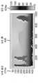
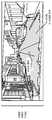
도 11a 내지 도 11b 는 이미지 (1114) 내의 비 장애물 영역 (1166) 을 결정하는 예를 나타낸다. 이 예에서, 원래 이미지 (1114a) 는 일방 도로의 이미지이다.11A-11B illustrate an example of determining the
처리된 이미지 (1114b) 는 본 명세서에 설명된 시스템 및 방법에 따라 결정된 비 장애물 영역 (1166) 을 도시한다. 처리된 이미지 (1114b) 는 최종 결과가 아닌 알고리즘의 중간 단계로부터의 예를 보여준다. 이것은 더 처리되어야 하는 비 장애물 맵 (126) 에 홀 (hole) 들이 있을 수 있음을 보여주는 것이다. 또한 이것은 수직 처리만으로부터의 결과를 나타낸다.The processed image 1114b illustrates a
비 장애물 영역 (1166) 은 도로에 대응하는 개방 영역을 포함한다. 비 장애물 영역 (1166) 내의 소정 이상치 영역 (1178) 은 비 장애물 영역 (1166) 의 일부로서 식별되지 않았다. 본 명세서에 사용된 이상치 (outlier) 는 이미지 (1114b) 내의 깊이 값이 미리 결정된 모델에서 피팅되지 않았다는 것을 의미한다. 이것은 깊이 값의 가능한 잘못된 추정 (예 : 입력 깊이 값이 완벽하지 않을 수도 있음) 으로 인해 발생할 수 있으므로, 일부 영역은 홀 (또는 이상치) 들로 나타난다. 이들 이상치 영역 (1178) 들은 이미지 (1114) 의 추가 처리를 수행함으로써 제거될 수도 있다.The
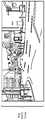
도 12a 내지 도 12b 는 이미지 (1214) 내의 비 장애물 영역 (1266) 을 결정하는 또 다른 예를 나타낸다. 이 예에서, 원래 이미지 (1214a) 는 교차로의 이미지이다. 처리된 이미지 (1214b) 는 본 명세서에 설명된 시스템 및 방법에 따라 결정된 비 장애물 영역 (1266) 을 도시한다.12A-12B illustrate another example of determining the
도 13a 내지 도 13b 는 비 장애물 영역 (1366) 으로부터의 거리 (1380) 를 결정하는 예를 나타낸다. 이 예는 도 11a 내지 도 11b 와 관련하여 기술된 도로의 처리된 이미지 (1314) 를 보여준다. 비 장애물 영역 (1366) 은 본 명세서에 설명된 시스템 및 방법에 따라 결정된다.13A-13B illustrate an example of determining the distance 1380 from the
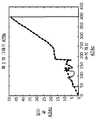
도 13b 의 깊이 맵 (1330) 에서, x 및 y 좌표는 좌표 위치이고, 음영은 깊이를 나타낸다. 이 예에서, 깊이 맵 (1330) 은 비 장애물 영역 (1366) 에 대한 깊이 정보를 포함한다. 깊이 맵 (1330) 은 카메라 전방에 여유 공간이 얼마나 멀리 있을지를 나타낸다.In the
깊이 맵 (1330) 으로부터 깊이 값들 (234) 을 사용하여, 전자 디바이스 (102)는 비 장애물 영역 (1366b) 과 관련된 다양한 거리들을 결정할 수도 있다. 예를 들어, 전자 디바이스 (102) 는 비 장애물 영역 (1366b) 에서 가장 먼 거리가 이미지 센서 (104) 로부터 45-50 미터 사이에 있다고 결정할 수도 있다. 유사하게, 전자 디바이스 (102) 는 가장 가까운 차가 이미지 센서 (104) 로부터 약 11 미터인 것으로 결정할 수도 있다.Using depth values 234 from
도 14는 오브젝트 검출 알고리즘에 의해 사용된 관심 지역 (ROI) (1482) 을 식별하기 위해 비 장애물 맵 (226) 을 사용하는 예를 나타낸다. 이 예는 도 11a 내지 도 11b 와 관련하여 기술된 도로의 처리된 이미지 (1414) 를 보여준다. 비 장애물 영역 (1466) 은 본 명세서에 설명된 시스템 및 방법에 따라 결정된다.FIG. 14 shows an example of using the non-obstacle map 226 to identify the region of interest (ROI) 1482 used by the object detection algorithm. This example shows a processed image 1414 of the road described in connection with Figs. 11A-11B. The non-obstructive region 1466 is determined according to the systems and methods described herein.
다음으로, 전자 디바이스 (102) 는 잠재적인 장애물 영역 (268) 에 대한 하나 이상의 ROI (1482) 를 식별할 수도 있다. 예를 들어, 전자 디바이스 (102) 는 비 장애물 맵 (226) 으로부터 장애물 영역 (268) 을 식별할 수도 있다. 일 구현에서, 비 장애물 영역 (1466) 으로 라벨링되지 않은 픽셀 (232) 은 장애물 영역 (268) 으로 식별될 수도 있다. 이들 장애물 영역 (268) 은 하나 이상의 ROI (1482) 에 포함될 수도 있다. 이 예에서, 전자 디바이스 (102) 는 잠재적인 오브젝트 영역으로서 4 개의 ROI (1482a-d) 들을 식별한다.Next, the electronic device 102 may identify one or more ROIs 1482 for a potential obstacle region 268. For example, the electronic device 102 may identify the obstacle region 268 from the non-obstacle map 226. In one implementation, pixels 232 that are not labeled as non-obstructive regions 1466 may be identified as obstacle regions 268. These obstacle regions 268 may be included in one or more ROIs 1482. In this example, the electronic device 102 identifies four
전자 디바이스 (102) 는 식별된 ROI (1482) 에서 오브젝트 검출기를 실행시킬 수도 있다. 예를 들어, 전자 디바이스 (102) 는 ROI (1482) 가 자동차, 교통 신호, 보행자, 차선, 커브 등을 포함하는지 여부를 검출할 수도 있다.The electronic device 102 may execute an object detector at the identified ROI 1482. For example, the electronic device 102 may detect whether the ROI 1482 includes an automobile, a traffic signal, a pedestrian, a lane, a curve, and the like.
비 장애물 영역 (1466) 을 식별하는 것은 먼저 오브젝트 검출을 위한 검색 영역을 감소시킨다. 이로 인해 오브젝트 검출을 위해 수행되는 처리 량이 줄어들 수도 있다.Identifying the non-obstacle region 1466 first reduces the search area for object detection. This may reduce the amount of processing performed for object detection.
도 15는 차선 검출 알고리즘에 의해 사용된 관심 지역 (ROI) (1582) 을 식별하기 위해 비 장애물 맵 (226) 을 사용하는 예를 나타낸다. 이 예는 도로의 처리된 이미지 (1514) 를 보여준다. 비 장애물 영역 (1566) 은 본 명세서에 설명된 시스템 및 방법에 따라 결정된다.FIG. 15 shows an example of using the non-obstacle map 226 to identify the region of interest (ROI) 1582 used by the lane detection algorithm. This example shows a processed image 1514 of the road. The
다음으로, 전자 디바이스 (102) 는 도로변 및/또는 커브에 대한 하나 이상의 ROI (1582) 를 식별할 수도 있다. 예를 들어, 전자 디바이스 (102) 는 비 장애물 맵 (226) 으로부터 장애물 영역 (268) 을 식별할 수도 있다. 이 예에서, 전자 디바이스 (102) 는 잠재적인 도로변 및/또는 커브으로서 비 장애물 영역 (1566) 의 측면상에서 2개의 ROI (1582a-b) 를 식별한다.Next, the electronic device 102 may identify one or more ROIs 1582 for roadside and / or curves. For example, the electronic device 102 may identify the obstacle region 268 from the non-obstacle map 226. In this example, the electronic device 102 identifies two
전자 디바이스 (102) 는 식별된 ROI (1582a-b) 에서 차선 검출기를 실행시킬 수도 있다. 비 장애물 영역 (1566) 을 식별하는 것은 먼저 차선 검출을 위한 검색 영역을 감소시킨다. 이로 인해 차선 검출을 위해 수행되는 처리 량이 줄어들 수도 있다.The electronic device 102 may execute the lane detector at the identified
도 16은 추정된 선형 모델 파라미터 (238) 에 기초하여 도로를 분류하는 방법 (1600) 을 나타내는 흐름도이다. 방법 (1600) 은, 전자 디바이스 (102), 예를 들어 비 장애물 결정 모듈 (116) 에 의해 구현될 수도 있다.16 is a flow diagram illustrating a
전자 디바이스 (102) 는 도로 이미지 (114) 로부터 깊이 맵 (230) 을 획득할 수도 있다 (1602). 깊이 맵 (230) 은, 도 2 와 관련하여 설명되는 바처럼 생성될 수도 있다.The electronic device 102 may obtain a depth map 230 from the road image 114 (1602). The depth map 230 may be generated as described with respect to FIG.
전자 디바이스 (102) 는 선형 모델 파라미터 (238) 를 추정하기 위해 세그먼트 피팅을 수행할 수도 있다 (1604). 추정된 선형 모델 파라미터 (238) 는 도 2와 관련하여 설명된 바와 같이 결정될 수도 있다.The electronic device 102 may perform segment fitting to estimate a linear model parameter 238 (1604). The estimated linear model parameters 238 may be determined as described in connection with FIG.
전자 디바이스 (102) 는 추정된 선형 모델 파라미터 (238) 에 기초하여 도로를 분류할 수도 있다 (1606). 예를 들어, 전자 디바이스 (102) 는 추정된 선형 모델 파라미터들 (238) 과 복수의 미리 결정된 선형 모델 파라미터들 (240) 을 비교할 수도 있다. 위에 설명된 바처럼, 미리 결정된 선형 모델 파라미터들 (240) 은 복수의 도로 조건 모델들과 연관될 수도 있다. 복수의 도로 조건 모델들의 각각은 대응하는 선형 모델 파라미터들 (240) 의 세트를 가질 수도 있다. 도로 조건 모델의 예들은 평탄한 평면, 경사 (예를 들어, 언덕), 계곡, 불규칙한 도로 등을 포함한다.The electronic device 102 may classify roads based on the estimated linear model parameters 238 (1606). For example, the electronic device 102 may compare the estimated linear model parameters 238 with a plurality of predetermined linear model parameters 240. As described above, the predetermined linear model parameters 240 may be associated with a plurality of road condition models. Each of the plurality of road condition models may have a corresponding set of linear model parameters 240. Examples of road condition models include flat planes, slopes (e.g., hills), valleys, irregular roads, and the like.
일 구현에서, 미리 결정된 선형 모델 파라미터들 (240) 은 트레이닝을 통해 획득될 수 있다. 사전 라벨링된 테스트 데이터가 사용될 수 있으며, 사전 라벨링된다는 것은 평탄한 도로 또는 불규칙한 도로 등의 라벨링된 이미지 (114) 및 깊이 맵 (230) 을 지칭한다. 이 데이터로 미리 결정된 선형 모델 파라미터 (240) 가 생성될 수도 있다.In one implementation, predetermined linear model parameters 240 may be obtained through training. Pre-labeled test data can be used and being pre-labeled refers to labeled image 114 and depth map 230, such as flat roads or irregular roads. A predetermined linear model parameter 240 may be generated with this data.
전자 디바이스 (102) 는 미리 결정된 선형 모델 파라미터들 (240) 중 어느 것이 추정된 선형 모델 파라미터들 (238) 에 가장 잘 피팅되는지를 결정할 수도 있다. 도로는 추정된 선형 모델 파라미터들 (238) 에 가장 잘 피팅되는 도로 조건 모델에 따라 분류될 수도 있다 (1606). 따라서, 도로를 분류 (1606) 함으로써, 전자 디바이스 (102) 는 도로 이미지 (114) 에서 자유 공간의 유형을 결정할 수도 있다.The electronic device 102 may determine which of the predetermined linear model parameters 240 is best fitted to the estimated linear model parameters 238. [ The road may be classified according to the road condition model best fit to the estimated linear model parameters 238 (1606). Thus, by classifying
도 17은 전자 디바이스 (1702) 내에 포함될 수도 있는 특정 컴포넌트들을 나타낸다. 전자 디바이스 (1702) 는 카메라, 비디오 캠코더, 디지털 카메라, 휴대폰, 스마트폰, 컴퓨터 (예 : 데스크톱 컴퓨터, 랩톱 컴퓨터 등), 태블릿 디바이스, 미디어 플레이어, 텔레비전, 자동차, 개인용 카메라, 액션 카메라, 감시 카메라, 장착 카메라, 접속 카메라, 로봇, 항공기, 드론, 무인 항공기 (UAV), 헬스케어 장비, 게이밍 콘솔, 개인 휴대 정보 단말기 (PDA), 셋톱 박스 등일 수도 있거나 또는 이들 내부에 포함될 수도 있다. 전자 디바이스 (1702) 는 프로세서 (1728) 를 포함한다. 프로세서 (1728) 는 범용 단일 또는 다중 칩 마이크로프로세서 (예를 들어, ARM), 전용 마이크로프로세서 (예를 들어, 디지털 신호 프로세서 (DSP)), 마이크로제어기, 프로그램가능 게이트 어레이 등일 수도 있다. 프로세서 (1728) 는 중앙 처리 장치 (CPU) 로 지칭될 수도 있다. 단지 단일 프로세서 (1728) 가 전자 디바이스 (1702) 에 도시되었지만, 대안의 구성에서, 프로세서들 (예를 들어, ARM 및 DSP) 의 조합이 사용될 수 있다.FIG. 17 shows specific components that may be included in the electronic device 1702. FIG. The electronic device 1702 may be a camera, a video camcorder, a digital camera, a mobile phone, a smart phone, a computer (e.g., a desktop computer, a laptop computer, etc.), a tablet device, a media player, But may be, or may be incorporated within, a camera, a connection camera, a robot, an aircraft, a drones, a UAV, a healthcare equipment, a gaming console, a personal digital assistant (PDA) The electronic device 1702 includes a processor 1728. The processor 1728 may be a general purpose single or multi-chip microprocessor (e.g., ARM), a dedicated microprocessor (e.g., a digital signal processor (DSP)), a microcontroller, a programmable gate array, or the like. Processor 1728 may be referred to as a central processing unit (CPU). Although only a single processor 1728 is shown in the electronic device 1702, in an alternative configuration, a combination of processors (e.g., ARM and DSP) may be used.
전자 디바이스 (1702) 는 또한 메모리 (1739) 를 포함한다. 메모리 (1739) 는 전자 정보를 저장할 수 있는 임의의 전자 컴포넌트일 수도 있다. 메모리 (1739) 는 랜덤 액세스 메모리 (RAM), 읽기 전용 메모리 (ROM), 자기 디스크 저장 매체, 광학 저장 매체, RAM 에서의 플래시 메모리 디바이스들, 프로세서와 함께 포함된 온보드 메모리, EPROM 메모리, EEPROM 메모리, 레지스트 및 기타 등등으로서 구체화될 수도 있으며, 이들의 조합을 포함한다.The electronic device 1702 also includes a memory 1739. Memory 1739 may be any electronic component capable of storing electronic information. The memory 1739 may be implemented as a random access memory (RAM), a read only memory (ROM), a magnetic disk storage medium, an optical storage medium, flash memory devices in RAM, on-board memory included with the processor, EPROM memory, Resist, and the like, or a combination thereof.
데이터 (1721a) 및 명령들 (1741a) 은 메모리 (1739) 에 저장될 수도 있다. 명령들 (1741a) 은 여기에 개시된 하나 이상의 방법들을 구현하기 위해 프로세서 (1728) 에 의해 실행가능할 수도 있다. 명령들 (1741a) 을 실행하는 것은, 메모리 (1739) 에 저장된 데이터의 사용을 수반할 수도 있다. 프로세서 (1728) 가 명령들 (1741) 을 실행할 때, 명령들 (1741b) 의 다양한 부분들이 프로세서 (1728) 상으로 로딩될 수도 있고, 여러 개의 데이터 (1721b) 가 프로세서 (1728) 상으로 로딩될 수도 있다.
전자 디바이스 (1702) 는 또한, 전자 디바이스 (1702) 로 그리고 전자 디바이스 (1702) 로부터 신호들의 송신 및 수신을 허용하기 위한 송신기 (1725) 및 수신기 (1727) 를 포함할 수도 있다. 송신기 (1725) 및 수신기 (1727) 는 총칭하여 트랜시버 (1729) 로 지칭될 수도 있다. 하나 이상의 안테나들 (1737a-b) 은 트랜시버 (1729) 에 전기적으로 연결될 수도 있다. 전자 디바이스 (1702) 는 또한, (미도시의) 다수의 송신기들, 다수의 수신기들, 다수의 트랜시버들 및/또는 추가 안테나들을 포함할 수도 있다.The electronic device 1702 may also include a
전자 디바이스 (1702) 는 디지털 신호 프로세서 (DSP) (1731) 를 포함할 수도 있다. 전자 디바이스 (1702) 는 또한 통신 인터페이스 (1733) 를 포함할 수도 있다. 통신 인터페이스 (1733) 는 하나 이상의 종류의 입력 및/또는 출력을 가능하게 할 수도 있다. 예를 들어, 통신 인터페이스 (1733) 는 다른 디바이스들을 전자 디바이스 (1702) 에 링크하기 위한 하나 이상의 포트들 및/또는 통신 디바이스들을 포함할 수도 있다. 부가적으로 또는 대안적으로, 통신 인터페이스 (1733) 는 하나 이상의 다른 인터페이스 (예를 들어, 터치스크린, 키패드, 키보드, 마이크로폰, 카메라 등) 를 포함할 수도 있다. 예를 들어, 통신 인터페이스 (1733) 는 사용자로 하여금 전자 디바이스 (1702) 와 상호작용할 수 있게 할 수도 있다.The electronic device 1702 may include a digital signal processor (DSP) 1731. The electronic device 1702 may also include a
전자 디바이스 (1702) 의 다양한 컴포넌트들은 함께 하나 이상의 버스들에 의해 연결될 수도 있고, 버스들은 전력 버스, 제어 신호 버스, 상태 신호 버스, 데이터 버스 등을 포함할 수도 있다. 명료성을 위해, 다양한 버스들이 버스 시스템 (1723) 으로서 도 17 에 나타나 있다.The various components of the electronic device 1702 may be coupled together by one or more busses, and the busses may include a power bus, a control signal bus, a status signal bus, a data bus, and the like. For clarity, various busses are shown in FIG. 17 as
본 개시에 따르면, 전자 디바이스 내의 회로는 하나 이상의 이미지들로부터 깊이 맵을 얻도록 적응될 수도 있다. 깊이 맵 내의 각 픽셀은 깊이 값을 가질 수도 있다. 동일한 회로, 상이한 회로 또는 그 동일한 또는 상이한 회로의 제 2 섹션은 수직 비 장애물 추정을 결정하기 위해 깊이 맵의 수직 처리를 수행하도록 적용될 수도 있다. 동일한 회로, 상이한 회로 또는 그 동일한 또는 상이한 회로의 제 3 섹션은 수평 비 장애물 추정을 결정하기 위해 깊이 맵의 수평 처리를 수행하도록 적용될 수도 있다. 동일한 회로, 상이한 회로 또는 그 동일한 또는 상이한 회로의 제 4 섹션은 비 장애물 맵을 결정하기 위하여 수직 비 장애물 추정 및 수평 비 장애물 추정을 결합하도록 적용될 수도 있다. 또한, 동일한 회로, 상이한 회로 또는 동일 또는 상이한 회로의 제 5 섹션은 상술한 기능성을 제공하는 회로(들) 또는 회로(들)의 섹션(들) 의 구성을 제어하도록 적응될 수도 있다.According to the present disclosure, a circuit in an electronic device may be adapted to obtain a depth map from one or more images. Each pixel in the depth map may have a depth value. The same circuit, different circuit or a second section of the same or different circuit may be adapted to perform the vertical processing of the depth map to determine the vertical non-obstacle estimation. The same circuit, different circuit or a third section of the same or different circuit may be applied to perform horizontal processing of the depth map to determine the horizontal non-obstacle estimation. The same circuit, different circuit or a fourth section of the same or different circuit may be adapted to combine the vertical non-obstacle estimation and the horizontal non-obstacle estimation to determine a non-obstacle map. In addition, a fifth section of the same circuit, different circuit, or the same or different circuit may be adapted to control the configuration of the section (s) of the circuit (s) or circuit (s) providing the functionality described above.
용어 "결정하는 것" 은 광범위하게 다양한 행위들을 포함하고, 따라서, "결정하는 것" 은 계산, 컴퓨팅, 프로세싱, 도출, 조사, 룩업 (예를 들면, 테이블, 데이터베이스 또는 다른 데이터 구조에서의 룩업), 확인하는 것 등을 포함할 수 있다. 또한, "결정하는 것" 은 수신하는 것 (예를 들면, 정보를 수신하는 것), 액세스하는 것 (예컨대, 메모리에서 데이터에 액세스하는 것) 등을 포함할 수 있다. 또한, "결정하는 것" 은 해결하는 것, 선택하는 것, 선정하는 것, 확립하는 것 등을 포함할 수 있다.The term " determining " encompasses a wide variety of behaviors, and thus " determining " includes computing, computing, processing, deriving, searching, looking up (e.g., lookup in a table, database, , ≪ / RTI > verification, and the like. Also, " determining " may include receiving (e.g., receiving information), accessing (e.g., accessing data in memory), and the like. In addition, " determining " may include resolving, selecting, selecting, establishing, and the like.
어구 "에 기초하여" 는, 다르게 분명히 명시되지 않는 한 "에만 기초하여" 를 의미하지 않는다. 즉, 어구 "에 기초하여" 는 "에만 기초하여" 및 "에 적어도 기초하여" 양자 모두를 설명한다.On the basis of the word " does not mean " based solely on " unless explicitly stated otherwise. In other words, " based on the phrase " describes both " based on "
용어 "프로세서" 는 범용 프로세서, 중앙 처리 장치 (CPU), 마이크로프로세서, 디지털 신호 프로세서 (DSP), 제어기, 마이크로제어기, 상태 머신 및 기타 등등을 망라하는 것으로 폭넓게 해석되야 한다. 일부 상황들하에서, "프로세서" 는 ASIC (application specific integrated circuit), 프로그램가능 로직 디바이스 (PLD), 필드 프로그램가능 게이트 어레이 (FPGA) 등을 지칭할 수도 있다. 용어 "프로세서" 는 프로세싱 디바이스들의 조합, 예를 들어, DSP 와 마이크로프로세서의 조합, 복수의 마이크로프로세서, DSP 코어와 결합한 하나 이상의 마이크로프로세서, 또는 임의의 다른 이러한 구성을 지칭할 수도 있다.The term " processor " should be broadly interpreted as encompassing a general purpose processor, a central processing unit (CPU), a microprocessor, a digital signal processor (DSP), a controller, a microcontroller, a state machine, In some situations, a " processor " may refer to an application specific integrated circuit (ASIC), a programmable logic device (PLD), a field programmable gate array (FPGA) The term " processor " may refer to a combination of processing devices, e.g., a combination of a DSP and a microprocessor, a plurality of microprocessors, one or more microprocessors in conjunction with a DSP core, or any other such configuration.
용어 "메모리" 는 전자 정보를 저장할 수 있는 임의의 전자 컴포넌트를 망라하는 것으로 폭넓게 해석되야 한다. 용어 메모리는, 랜덤 액세스 메모리 (RAM), 읽기 전용 메모리 (ROM), 비휘발성 랜덤 액세스 메모리 (NVRAM), 프로그램가능 읽기 전용 메모리 (PROM), 소거가능 프로그램가능 읽기 전용 메모리 (EPROM), 전기 소거가능 PROM (EEPROM), 플래시 메모리, 자기 또는 광학 데이터 저장, 레지스터 등과 같은 다양한 타입의 프로세서 판독가능 매체를 지칭할 수도 있다. 프로세서가 메모리로부터 정보를 판독하거나 및/또는 메모리에 정보를 기입할 수 있다면, 메모리는 프로세서와 전자 통신한다고 한다. 프로세서에 내장된 메모리는 프로세서와 전자 통신한다.The term " memory " should be broadly interpreted as encompassing any electronic component capable of storing electronic information. The term memory may be a random access memory (RAM), a read only memory (ROM), a nonvolatile random access memory (NVRAM), a programmable read only memory (PROM), an erasable programmable read only memory (EPROM) May refer to various types of processor readable media such as PROM (EEPROM), flash memory, magnetic or optical data storage, registers, and the like. If the processor is able to read information from and / or write information to memory, it is said that the memory is in electronic communication with the processor. The memory built into the processor communicates electronically with the processor.
용어들 "명령들" 및 "코드" 는 임의의 타입의 컴퓨터 판독가능 스테이트먼트 (statement) (들) 을 포함하는 것으로 폭넓게 해석되야 한다. 예를 들어, 용어 "명령들" 및 "코드" 는 하나 이상의 프로그램들, 루틴들, 서브루틴들, 함수들, 프로시저들 등을 지칭할 수도 있다. "명령들" 및 "코드" 는 단일 컴퓨터 판독가능 표현 또는 많은 컴퓨터 판독가능 표현들을 포함할 수도 있다.The terms " instructions " and " code " should be broadly interpreted as including any type of computer readable statement (s). For example, the terms " instructions " and " code " may refer to one or more programs, routines, subroutines, functions, procedures, &Quot; Commands " and " code " may include a single computer readable representation or many computer readable representations.
여기에 기술된 기능들은 하드웨어에 의해 실행되는 소프트웨어 또는 펌웨어에서 구현될 수도 있다. 기능들은 컴퓨터 판독가능 매체 상의 하나 이상의 명령들로서 저장될 수도 있다. 용어들 "컴퓨터 판독가능 매체" 또는 "컴퓨터 프로그램 제품" 은 컴퓨터 또는 프로세서에 의해 액세스될 수 있는 임의의 유형의 저장 매체를 지칭한다. 비한정적 예로서, 컴퓨터 판독가능 매체는 RAM, ROM, EEPROM, CD-ROM 또는 다른 광학 디스크 저장, 자기 디스크 저장 또는 다른 자기 저장 디바이스들, 또는 명령 또는 데이터 구조의 형태로 원하는 프로그램 코드를 반송 또는 저장하는데 사용될 수 있고 컴퓨터에 의해 액세스될 수 있는 임의의 다른 매체를 포함할 수도 있다. 여기에 설명된 바와 같이, 디스크 (disk) 및 디스크 (disc) 는 CD (compact disc), 레이저 디스크 (laser disc), 광 디스크 (optical disc), DVD (digital versatile disc), 플로피 디스크 (floppy disk) 및 블루레이® 디스크 (Blu-ray® disc) 를 포함하며, 여기서, 디스크 (disk) 는 일반적으로 데이터를 자기적으로 재생하지만, 디스크 (disc) 는 레이저를 이용하여 광학적으로 데이터를 재생한다. 컴퓨터 판독가능 매체는 유형 및 비일시적일 수도 있다는 것에 유의해야 한다. 용어 "컴퓨터 프로그램 제품" 은, 컴퓨팅 디바이스 또는 프로세서에 의해 실행, 프로세싱 또는 컴퓨팅될 수도 있는 코드 또는 명령들 (예를 들어, "프로그램") 과 조합한 컴퓨팅 디바이스 또는 프로세서를 지칭한다. 여기서 사용된 바처럼, 용어 "코드" 는 컴퓨팅 디바이스 또는 프로세서에 의해 실행가능한 소프트웨어, 명령들, 코드 또는 데이터를 지칭할 수도 있다.The functions described herein may be implemented in software or firmware executed by hardware. The functions may be stored as one or more instructions on a computer readable medium. The terms "computer-readable medium" or "computer program product" refers to any type of storage medium that can be accessed by a computer or processor. By way of example, and not limitation, computer readable media may carry or store desired program code in the form of RAM, ROM, EEPROM, CD-ROM or other optical disk storage, magnetic disk storage or other magnetic storage devices, And any other medium that can be accessed by a computer. As described herein, a disk and a disc can be a compact disc, a laser disc, an optical disc, a digital versatile disc (DVD), a floppy disc, and a Blu-ray® disc including (Blu-ray® disc), wherein the disk (disk), but generally reproduce data magnetically, disk (disc) and reproduces the data optically with lasers. It should be noted that the computer-readable medium may be of a type and non-transient. The term " computer program product " refers to a computing device or processor in combination with code or instructions (e.g., " program ") that may be executed, processed or computed by a computing device or processor. As used herein, the term " code " may refer to software, instructions, code or data executable by a computing device or processor.
소프트웨어 또는 명령들은 또한, 송신 매체 상에서 송신될 수도 있다. 예를 들어, 소프트웨어가 동축 케이블, 광섬유 케이블, 연선 (twisted pair), 디지털 가입자 라인 (DSL), 또는 적외선, 전파 (radio), 및 마이크로파와 같은 무선 기술을 사용하여 웹사이트, 서버, 또는 다른 원격 소스로부터 송신되는 경우, 그 동축 케이블, 광섬유 케이블, 연선, DSL, 또는 적외선, 전파, 및 마이크로파와 같은 무선 기술은 매체의 정의 내에 포함된다.The software or commands may also be transmitted on a transmission medium. For example, the software may use a wireless technology such as coaxial cable, fiber optic cable, twisted pair, digital subscriber line (DSL), or infrared, radio, When transmitted from a source, the coaxial cable, fiber optic cable, twisted pair, DSL, or wireless technologies such as infrared, radio waves, and microwaves are included within the definition of the medium.
본원에 개시된 방법들은 설명된 방법을 달성하기 위한 하나 이상의 단계들 또는 행동들을 포함한다. 방법 단계들 및/또는 행동들은 청구항들의 범위로부터 이탈함이 없이 서로 상호교환될 수도 있다. 즉, 단계들 또는 행위들의 특정 순서가, 설명되고 있는 방법의 적절한 동작을 위해 필요하지 않으면, 특정 단계들 및/또는 행위들의 순서 및/또는 사용은 청구항들의 범위로부터 이탈함이 없이 수정될 수도 있다.The methods disclosed herein include one or more steps or actions for achieving the described method. The method steps and / or actions may be interchanged with one another without departing from the scope of the claims. That is, the order and / or use of certain steps and / or actions may be modified without departing from the scope of the claims, unless a particular order of steps or acts is required for proper operation of the method being described .
또한, 본원에 설명된 방법들 및 기법들을 수행하는 모듈들 및/또는다른 적절한 수단이 다운로드될 수도 있거나 및/또는, 그렇지 않으면 디바이스에 의해 획득될 수도 있다는 것이 인식되야 한다. 예를 들어, 디바이스는 본원에 설명된 방법들을 수행하기 위한 수단의 전달을 가능하게 하기 위한 서버에 연결될 수도 있다. 다르게는, 본원에 기재된 다양한 방법들은 저장 수단 (예를 들어, 랜덤 액세스 메모리 (RAM), 읽기 전용 메모리 (ROM), 물리적 저장 매체, 이를테면 컴팩트 디스크 (CD) 또는 플로피 디스크 등) 을 통해 제공되어, 디바이스는, 그 디바이스에 저장 수단을 연결 또는 제공할 시에 그 다양한 방법들을 획득할 수도 있다.It should also be appreciated that modules and / or other suitable means for performing the methods and techniques described herein may be downloaded and / or otherwise obtained by the device. For example, the device may be coupled to a server to enable delivery of the means for performing the methods described herein. Alternatively, the various methods described herein may be provided through storage means (e.g., random access memory (RAM), read only memory (ROM), physical storage media such as a compact disk (CD) A device may obtain its various methods when connecting or providing storage means to the device.
청구항들은 위에 예시된 바로 그 구성 및 컴포넌트들에 한정되지 않는다는 것이 이해되야 한다. 청구항들의 범위로부터 이탈함이 없이 본원에 기재된 시스템, 방법 및 장치의 배열, 동작 및 상세들에서 다양한 수정, 변경 및 변형들이 이루어질 수도 있다.It is to be understood that the claims are not limited to just the exact constructions and components illustrated above. Various modifications, changes, and variations may be made in the arrangement, operation and details of the systems, methods and apparatus described herein without departing from the scope of the claims.
Claims (30)
Translated fromKorean수직 비 장애물 추정을 결정하기 위하여 깊이 맵의 수직 처리를 수행하는 단계;
수평 비 장애물 추정을 결정하기 위하여 상기 깊이 맵의 수평 처리를 수행하는 단계;
상기 수직 비 장애물 추정 및 상기 수평 비 장애물 추정을 결합하는 단계; 및
상기 수직 비 장애물 추정 및 상기 수평 비 장애물 추정의 결합에 기초하여 비 장애물 맵을 생성하는 단계
를 포함하는, 전자 디바이스에 의해 수행되는 방법.A method performed by an electronic device,
Performing vertical processing of the depth map to determine a vertical non-obstacle estimation;
Performing horizontal processing of the depth map to determine a horizontal non-obstacle estimation;
Combining the vertical non-obstacle estimation and the horizontal non-obstacle estimation; And
Generating a non-obstacle map based on the combination of the vertical non-obstacle estimation and the horizontal non-
The method comprising the steps of:
수직 처리를 수행하는 단계는
세그먼트들로 상기 깊이 맵을 분할하는 단계로서, 적어도 하나의 세그먼트는 열에 다수의 픽셀들을 포함하는, 상기 깊이 맵을 분할하는 단계;
상기 수직 비 장애물 추정을 결정하기 위해 적어도 하나의 세그먼트에 대한 선형 모델 파라미터들을 추정하는 단계; 및
상기 수직 비 장애물 추정을 위한 신뢰도 값을 포함하는 수직 신뢰도 맵을 생성하는 단계를 포함하는, 전자 디바이스에 의해 수행되는 방법.The method according to claim 1,
The step of performing the vertical processing
Dividing the depth map into segments, the at least one segment including a plurality of pixels in a column; dividing the depth map;
Estimating linear model parameters for at least one segment to determine the vertical non-obstacle estimation; And
And generating a vertical reliability map including a confidence value for the vertical non-obstacle estimation.
상기 수직 신뢰도 맵을 결정하는 단계는
상기 추정된 선형 모델 파라미터들과 미리 결정된 선형 모델 파라미터들 사이의 차이에 기초하여 주어진 세그먼트에 대한 세그먼트 피팅 오차를 결정하는 단계;
상기 세그먼트 피팅 오차와 수직 추정 임계치를 비교함으로써 상기 주어진 세그먼트에 대한 신뢰도 값을 결정하는 단계; 및
상기 주어진 세그먼트 내의 적어도 하나의 픽셀에 상기 주어진 세그먼트에 대한 신뢰도 값을 적용하는 단계를 포함하는, 전자 디바이스에 의해 수행되는 방법.3. The method of claim 2,
The step of determining the vertical reliability map
Determining a segment fitting error for a given segment based on a difference between the estimated linear model parameters and predetermined linear model parameters;
Determining a confidence value for the given segment by comparing the segment fitting error with a vertical estimation threshold; And
Applying a confidence value for the given segment to at least one pixel in the given segment.
상기 미리 결정된 선형 모델 파라미터는 복수의 도로 조건 모델 중에서 선택되며, 상기 복수의 도로 조건 모델은 대응하는 선형 모델 파라미터 세트를 갖는, 전자 디바이스에 의해 수행되는 방법.The method of claim 3,
Wherein the predetermined linear model parameter is selected from a plurality of road condition models and the plurality of road condition models has a corresponding set of linear model parameters.
수평 처리를 수행하는 단계는
상기 깊이 맵의 적어도 하나의 픽셀 행에 대한 깊이 히스토그램을 획득하는 단계;
상기 깊이 히스토그램으로부터 지형 라인을 결정하는 단계;
상기 지형 라인으로부터의 적어도 하나의 픽셀의 깊이 값의 거리에 기초하여 수평 비 장애물 추정을 결정하는 단계; 및
상기 수평 비 장애물 추정을 위한 신뢰도 값을 포함하는 수평 신뢰도 맵을 생성하는 단계를 포함하는, 전자 디바이스에 의해 수행되는 방법.The method according to claim 1,
The step of performing horizontal processing
Obtaining a depth histogram for at least one pixel row of the depth map;
Determining a topographic line from the depth histogram;
Determining a horizontal non-obstacle estimate based on a distance of a depth value of at least one pixel from the terrain line; And
And generating a horizontal reliability map including a confidence value for the horizontal non-obstacle estimation.
상기 수평 신뢰도 맵을 생성하는 단계는
주어진 픽셀의 상기 깊이 값이 상기 깊이 히스토그램의 모드의 범위 내에 있는지 여부를 결정하는 단계로서, 상기 주어진 픽셀의 깊이 값이 상기 깊이 히스토그램의 모드의 범위 내에 있을 때, 상기 주어진 픽셀은 높은 신뢰도 값을 갖는, 상기 결정하는 단계를 포함하는, 전자 디바이스에 의해 수행되는 방법.6. The method of claim 5,
The step of generating the horizontal reliability map
Determining whether the depth value of a given pixel is within a range of a mode of the depth histogram, wherein when the depth value of the given pixel is within the range of the mode of the depth histogram, the given pixel has a high confidence value ≪ / RTI > wherein said determining is performed by said electronic device.
상기 수직 비 장애물 추정 및 상기 수평 비 장애물 추정을 결합하는 단계는
상기 수직 처리와 상기 수평 처리 양자 모두를 병렬로 수행하는 단계; 및
수직 신뢰도 맵 및 수평 신뢰도 맵에 기초하여 상기 수직 비 장애물 추정 및 상기 수평 비 장애물 추정을 병합하는 단계를 포함하는, 전자 디바이스에 의해 수행되는 방법.The method according to claim 1,
The step of combining the vertical non-obstacle estimation and the horizontal non-
Performing both the vertical processing and the horizontal processing in parallel; And
And merging the vertical non-obstacle estimation and the horizontal non-obstacle estimation based on the vertical reliability map and the horizontal reliability map.
주어진 픽셀은 상기 수직 신뢰도 맵 및 상기 수평 신뢰도 맵 양자 모두가 상기 주어진 픽셀에 대해 높은 신뢰도 값을 특징으로 하는 상기 비 장애물 맵에서의 비 장애물 영역으로 식별되는, 전자 디바이스에 의해 수행되는 방법.8. The method of claim 7,
Wherein a given pixel is identified by a non-obstructive region in the non-obstacle map in which both the vertical reliability map and the horizontal confidence map are characterized by a high confidence value for the given pixel.
주어진 픽셀은 상기 수직 신뢰도 맵 또는 상기 수평 신뢰도 맵 중 적어도 하나가 상기 주어진 픽셀에 대해 낮은 신뢰도 값을 특징으로 하는 상기 비 장애물 맵에서의 장애물 영역으로 식별되는, 전자 디바이스에 의해 수행되는 방법.8. The method of claim 7,
Wherein a given pixel is identified by an obstacle region in the non-obstacle map in which at least one of the vertical reliability map or the horizontal reliability map is characterized by a low confidence value for the given pixel.
주어진 픽셀은 상기 수직 신뢰도 맵 및 상기 수평 신뢰도 맵이 상기 주어진 픽셀에 대해 상이한 신뢰도 값들을 특징으로 하는 상기 주어진 픽셀의 좌표에 기초하여 상기 비 장애물 맵에서의 비 장애물 영역 또는 장애물 영역으로서 식별되는, 전자 디바이스에 의해 수행되는 방법.8. The method of claim 7,
Wherein a given pixel is identified as a non-obstacle region or an obstacle region in the non-obstacle map based on the coordinates of the given pixel characterized by different reliability values for the given pixel, the vertical reliability map and the horizontal reliability map. A method performed by a device.
상기 수직 비 장애물 추정 및 상기 수평 비 장애물 추정을 결합하는 단계는
상기 깊이 맵의 수직 처리를 수행하는 단계;
모델 피팅 신뢰성에 기초하여 수직 신뢰도 맵을 획득하는 단계;
상기 수직 신뢰도 맵의 신뢰할 수 있는 지역을 비 장애물 영역으로서 식별하는 단계; 및
상기 신뢰할 수 없는 지역이 비 장애물 영역인지 여부를 결정하기 위해 상기 수직 신뢰도 맵의 신뢰할 수 없는 지역에 대해 수평 처리를 수행하는 단계를 포함하는, 전자 디바이스에 의해 수행되는 방법.The method according to claim 1,
The step of combining the vertical non-obstacle estimation and the horizontal non-
Performing a vertical processing of the depth map;
Obtaining a vertical reliability map based on model fitting reliability;
Identifying a reliable region of the vertical reliability map as a non-obstructive region; And
And performing a horizontal process on an unreliable region of the vertical reliability map to determine whether the untrusted region is a non-obstructive region.
상기 수직 비 장애물 추정 및 상기 수평 비 장애물 추정을 결합하는 단계는
상기 깊이 맵의 수평 처리를 수행하는 단계;
깊이 히스토그램 거리에 기초하여 수평 신뢰도 맵을 획득하는 단계;
상기 수평 신뢰도 맵의 신뢰할 수 있는 지역을 비 장애물 영역으로서 식별하는 단계; 및
상기 신뢰할 수 없는 지역이 비 장애물 영역인지 여부를 결정하기 위해 상기 수평 신뢰도 맵의 신뢰할 수 없는 지역에 대해 수직 처리를 수행하는 단계를 포함하는, 전자 디바이스에 의해 수행되는 방법.The method according to claim 1,
The step of combining the vertical non-obstacle estimation and the horizontal non-
Performing horizontal processing of the depth map;
Obtaining a horizontal reliability map based on the depth histogram distance;
Identifying a reliable region of the horizontal reliability map as a non-obstructive region; And
And performing a vertical processing on an unreliable region of the horizontal reliability map to determine whether the untrusted region is a non-obstructive region.
상기 비 장애물 맵은 오브젝트 검출 알고리즘 또는 차선 검출 알고리즘 중 적어도 하나에 의해 사용되는 관심 지역을 식별하는데 사용되는, 전자 디바이스에 의해 수행되는 방법.The method according to claim 1,
Wherein the non-obstacle map is used to identify a region of interest used by at least one of an object detection algorithm or a lane detection algorithm.
수직 비 장애물 추정을 결정하기 위하여 깊이 맵의 수직 처리를 수행하고;
수평 비 장애물 추정을 결정하기 위하여 상기 깊이 맵의 수평 처리를 수행하고;
상기 수직 비 장애물 추정 및 상기 수평 비 장애물 추정을 결합하고; 그리고
상기 수직 비 장애물 추정 및 상기 수평 비 장애물 추정의 결합에 기초하여 비 장애물 맵을 생성하도록 구성된, 전자 디바이스.As an electronic device,
Performing a vertical processing of the depth map to determine a vertical non-obstacle estimation;
Performing a horizontal processing of the depth map to determine a horizontal non-obstacle estimation;
Combining the vertical non-obstacle estimation and the horizontal non-obstacle estimation; And
And to generate a non-obstacle map based on the combination of the vertical non-obstacle estimation and the horizontal non-obstacle estimation.
상기 전자 디바이스가 수직 처리를 수행하도록 구성되는 것은, 상기 전자 디바이스가
세그먼트들로 상기 깊이 맵을 분할하는 것으로서, 적어도 하나의 세그먼트는 열에 다수의 픽셀들을 포함하는, 상기 깊이 맵을 분할하고;
상기 수직 비 장애물 추정을 결정하기 위해 적어도 하나의 세그먼트에 대한 선형 모델 파라미터들을 추정하고; 그리고
상기 수직 비 장애물 추정을 위한 신뢰도 값을 포함하는 수직 신뢰도 맵을 생성하도록 구성되는 것을 포함하는, 전자 디바이스.15. The method of claim 14,
Wherein the electronic device is configured to perform a vertical process,
Dividing the depth map into segments, wherein the at least one segment comprises a plurality of pixels in a column;
Estimate linear model parameters for at least one segment to determine the vertical non-obstacle estimate; And
And generate a vertical reliability map including a confidence value for the vertical non-obstacle estimation.
상기 전자 디바이스가 수평 처리를 수행하도록 구성되는 것은, 상기 전자 디바이스가
상기 깊이 맵의 적어도 하나의 픽셀 행에 대한 깊이 히스토그램을 획득하고;
상기 깊이 히스토그램으로부터 지형 라인을 결정하고;
상기 지형 라인으로부터의 적어도 하나의 픽셀의 깊이 값의 거리에 기초하여 수평 비 장애물 추정을 결정하고; 그리고
상기 수평 비 장애물 추정을 위한 신뢰도 값을 포함하는 수평 신뢰도 맵을 생성하도록 구성되는 것을 포함하는, 전자 디바이스.15. The method of claim 14,
Wherein the electronic device is configured to perform a horizontal process,
Obtain a depth histogram for at least one row of pixels of the depth map;
Determine a feature line from the depth histogram;
Determining a horizontal non-obstacle estimate based on a distance of a depth value of at least one pixel from the terrain line; And
And generate a horizontal reliability map including a confidence value for the horizontal non-obstacle estimation.
상기 전자 디바이스가 상기 수직 비 장애물 추정 및 상기 수평 비 장애물 추정을 결합하도록 구성되는 것은, 상기 전자 디바이스가
상기 수직 처리와 상기 수평 처리 양자 모두를 병렬로 수행하고; 그리고
수직 신뢰도 맵 및 수평 신뢰도 맵에 기초하여 상기 수직 비 장애물 추정 및 상기 수평 비 장애물 추정을 병합하도록 구성되는 것을 포함하는, 전자 디바이스.15. The method of claim 14,
Wherein the electronic device is configured to combine the vertical non-obstacle estimation and the horizontal non-obstacle estimation,
Performing both the vertical processing and the horizontal processing in parallel; And
And to combine the vertical non-obstacle estimation and the horizontal non-obstacle estimation based on a vertical reliability map and a horizontal reliability map.
상기 전자 디바이스가 상기 수직 비 장애물 추정 및 상기 수평 비 장애물 추정을 결합하도록 구성되는 것은, 상기 전자 디바이스가
상기 깊이 맵의 수직 처리를 수행하고;
모델 피팅 신뢰성에 기초하여 수직 신뢰도 맵을 획득하고;
상기 수직 신뢰도 맵의 신뢰할 수 있는 지역을 비 장애물 영역으로서 식별하고; 그리고
상기 신뢰할 수 없는 지역이 비 장애물 영역인지 여부를 결정하기 위해 상기 수직 신뢰도 맵의 신뢰할 수 없는 지역에 대해 수평 처리를 수행하도록 구성되는 것을 포함하는, 전자 디바이스.15. The method of claim 14,
Wherein the electronic device is configured to combine the vertical non-obstacle estimation and the horizontal non-obstacle estimation,
Performing a vertical processing of the depth map;
Obtain a vertical reliability map based on model fitting reliability;
Identify a reliable region of the vertical reliability map as a non-obstructive region; And
And to perform a horizontal process on the unreliable region of the vertical reliability map to determine whether the untrusted region is a non-obstructive region.
상기 전자 디바이스가 상기 수직 비 장애물 추정 및 상기 수평 비 장애물 추정을 결합하도록 구성되는 것은, 상기 전자 디바이스가
상기 깊이 맵의 수평 처리를 수행하고;
깊이 히스토그램 거리에 기초하여 수평 신뢰도 맵을 획득하고;
상기 수평 신뢰도 맵의 신뢰할 수 있는 지역을 비 장애물 영역으로서 식별하고; 그리고
상기 신뢰할 수 없는 지역이 비 장애물 영역인지 여부를 결정하기 위해 상기 수평 신뢰도 맵의 신뢰할 수 없는 지역에 대해 수직 처리를 수행하도록 구성되는 것을 포함하는, 전자 디바이스.15. The method of claim 14,
Wherein the electronic device is configured to combine the vertical non-obstacle estimation and the horizontal non-obstacle estimation,
Performing a horizontal processing of the depth map;
Acquiring a horizontal reliability map based on the depth histogram distance;
Identify a reliable region of the horizontal reliability map as a non-obstructive region; And
And configured to perform vertical processing on the unreliable region of the horizontal reliability map to determine whether the untrusted region is a non-obstructive region.
수평 비 장애물 추정을 결정하기 위하여 상기 깊이 맵의 수평 처리를 수행하는 수단;
상기 수직 비 장애물 추정 및 상기 수평 비 장애물 추정을 결합하는 수단; 및
상기 수직 비 장애물 추정 및 상기 수평 비 장애물 추정의 결합에 기초하여 비 장애물 맵을 생성하는 수단
을 포함하는, 장치.Means for performing a vertical processing of the depth map to determine a vertical non-obstacle estimation;
Means for performing horizontal processing of the depth map to determine a horizontal non-obstacle estimation;
Means for combining the vertical non-obstacle estimation and the horizontal non-obstacle estimation; And
Means for generating a non-obstacle map based on the combination of the vertical non-obstacle estimation and the horizontal non-
/ RTI >
상기 수직 처리를 수행하는 수단은
세그먼트들로 상기 깊이 맵을 분할하는 수단으로서, 적어도 하나의 세그먼트는 열에 다수의 픽셀들을 포함하는, 상기 깊이 맵을 분할하는 수단;
상기 수직 비 장애물 추정을 결정하기 위해 적어도 하나의 세그먼트에 대한 선형 모델 파라미터들을 추정하는 수단; 및
상기 수직 비 장애물 추정을 위한 신뢰도 값을 포함하는 수직 신뢰도 맵을 생성하는 수단을 포함하는, 장치.21. The method of claim 20,
The means for performing the vertical processing
Means for dividing the depth map into segments, the at least one segment comprising a plurality of pixels in a column;
Means for estimating linear model parameters for at least one segment to determine the vertical non-obstacle estimation; And
And means for generating a vertical reliability map including a confidence value for the vertical non-obstacle estimation.
상기 수평 처리를 수행하는 수단은
상기 깊이 맵의 적어도 하나의 픽셀 행에 대한 깊이 히스토그램을 획득하는 수단;
상기 깊이 히스토그램으로부터 지형 라인을 결정하는 수단;
상기 지형 라인으로부터의 적어도 하나의 픽셀의 깊이 값의 거리에 기초하여 수평 비 장애물 추정을 결정하는 수단; 및
상기 수평 비 장애물 추정을 위한 신뢰도 값을 포함하는 수평 신뢰도 맵을 생성하는 수단을 포함하는, 장치.21. The method of claim 20,
The means for performing the horizontal processing
Means for obtaining a depth histogram for at least one row of pixels of the depth map;
Means for determining a feature line from the depth histogram;
Means for determining a horizontal non-obstacle estimate based on a distance of a depth value of at least one pixel from the terrain line; And
And means for generating a horizontal reliability map including a confidence value for the horizontal non-obstacle estimation.
상기 수직 비 장애물 추정 및 상기 수평 비 장애물 추정을 결합하는 수단은
상기 수직 처리와 상기 수평 처리 양자 모두를 병렬로 수행하는 수단; 및
수직 신뢰도 맵 및 수평 신뢰도 맵에 기초하여 상기 수직 비 장애물 추정 및 상기 수평 비 장애물 추정을 병합하는 수단을 포함하는, 장치.21. The method of claim 20,
The means for combining the vertical non-obstacle estimation and the horizontal non-
Means for performing both the vertical processing and the horizontal processing in parallel; And
And means for merging the vertical non-obstacle estimates and the horizontal non-obstacle estimates based on a vertical reliability map and a horizontal reliability map.
상기 수직 비 장애물 추정 및 상기 수평 비 장애물 추정을 결합하는 수단은
상기 깊이 맵의 수직 처리를 수행하는 수단;
모델 피팅 신뢰성에 기초하여 수직 신뢰도 맵을 획득하는 수단;
상기 수직 신뢰도 맵의 신뢰할 수 있는 지역을 비 장애물 영역으로서 식별하는 수단; 및
상기 신뢰할 수 없는 지역이 비 장애물 영역인지 여부를 결정하기 위해 상기 수직 신뢰도 맵의 신뢰할 수 없는 지역에 대해 수평 처리를 수행하는 수단을 포함하는, 장치.21. The method of claim 20,
The means for combining the vertical non-obstacle estimation and the horizontal non-
Means for performing a vertical processing of the depth map;
Means for obtaining a vertical reliability map based on model fitting reliability;
Means for identifying a trusted region of the vertical reliability map as a non-obstructive region; And
And means for performing a horizontal processing on an unreliable region of the vertical reliability map to determine whether the untrusted region is a non-obstructive region.
상기 수직 비 장애물 추정 및 상기 수평 비 장애물 추정을 결합하는 수단은
상기 깊이 맵의 수평 처리를 수행하는 수단;
깊이 히스토그램 거리에 기초하여 수평 신뢰도 맵을 획득하는 수단;
상기 수평 신뢰도 맵의 신뢰할 수 있는 지역을 비 장애물 영역으로서 식별하는 수단; 및
상기 신뢰할 수 없는 지역이 비 장애물 영역인지 여부를 결정하기 위해 상기 수평 신뢰도 맵의 신뢰할 수 없는 지역에 대해 수직 처리를 수행하는 수단을 포함하는, 장치.21. The method of claim 20,
The means for combining the vertical non-obstacle estimation and the horizontal non-
Means for performing horizontal processing of the depth map;
Means for obtaining a horizontal reliability map based on a depth histogram distance;
Means for identifying a trusted region of the horizontal reliability map as a non-obstructive region; And
And means for performing a vertical processing on an unreliable region of the horizontal reliability map to determine whether the untrusted region is a non-obstructive region.
수직 비 장애물 추정을 결정하기 위하여 전자 디바이스로 하여금 깊이 맵의 수직 처리를 수행하게 하기 위한 코드;
수평 비 장애물 추정을 결정하기 위하여 상기 전자 디바이스로 하여금 상기 깊이 맵의 수평 처리를 수행하게 하기 위한 코드;
상기 전자 디바이스로 하여금 상기 수직 비 장애물 추정 및 상기 수평 비 장애물 추정을 결합하게 하기 위한 코드; 및
상기 전자 디바이스로 하여금 상기 수직 비 장애물 추정 및 상기 수평 비 장애물 추정의 결합에 기초하여 비 장애물 맵을 생성하게 하기 위한 코드를 포함하는, 컴퓨터 프로그램 제품.18. A computer program product comprising a non-transitory type computer readable medium having stored thereon instructions,
Code for causing the electronic device to perform vertical processing of the depth map to determine a vertical non-obstacle estimation;
Code for causing the electronic device to perform horizontal processing of the depth map to determine a horizontal non-obstacle estimation;
Code for causing the electronic device to combine the vertical non-obstacle estimation and the horizontal non-obstacle estimation; And
And code for causing the electronic device to generate a non-obstacle map based on the combination of the vertical non-obstacle estimates and the horizontal non-obstacle estimates.
상기 전자 디바이스로 하여금 수직 처리를 수행하게 하기 위한 코드는
상기 전자 디바이스로 하여금 세그먼트들로 상기 깊이 맵을 분할하게 하기 위한 코드로서, 적어도 하나의 세그먼트는 열에 다수의 픽셀들을 포함하는, 상기 깊이 맵을 분할하게 하기 위한 코드;
상기 전자 디바이스로 하여금 상기 수직 비 장애물 추정을 결정하기 위해 적어도 하나의 세그먼트에 대한 선형 모델 파라미터들을 추정하게 하기 위한 코드; 및
상기 전자 디바이스로 하여금 상기 수직 비 장애물 추정을 위한 신뢰도 값을 포함하는 수직 신뢰도 맵을 생성하기 위한 코드를 포함하는, 컴퓨터 프로그램 제품.27. The method of claim 26,
The code for causing the electronic device to perform the vertical processing includes:
Code for causing the electronic device to divide the depth map into segments, the at least one segment including a plurality of pixels in a column;
Code for causing the electronic device to estimate linear model parameters for at least one segment to determine the vertical non-obstacle estimation; And
And code for generating a vertical reliability map that includes the reliability value for the vertical non-obstacle estimation by the electronic device.
상기 전자 디바이스로 하여금 수평 처리를 수행하게 하기 위한 코드는
상기 전자 디바이스로 하여금 상기 깊이 맵의 적어도 하나의 픽셀 행에 대한 깊이 히스토그램을 획득하게 하기 위한 코드;
상기 전자 디바이스로 하여금 상기 깊이 히스토그램으로부터 지형 라인을 결정하게 하기 위한 코드;
상기 전자 디바이스로 하여금 상기 지형 라인으로부터의 적어도 하나의 픽셀의 깊이 값의 거리에 기초하여 수평 비 장애물 추정을 결정하게 하기 위한 코드; 및
상기 전자 디바이스로 하여금 상기 수평 비 장애물 추정을 위한 신뢰도 값을 포함하는 수평 신뢰도 맵을 생성하기 위한 코드를 포함하는, 컴퓨터 프로그램 제품.27. The method of claim 26,
The code for causing the electronic device to perform the horizontal processing includes:
Code for causing the electronic device to obtain a depth histogram for at least one row of pixels of the depth map;
Code for causing the electronic device to determine a terrain line from the depth histogram;
Code for causing the electronic device to determine a horizontal non-obstacle estimate based on a distance of a depth value of at least one pixel from the terrain line; And
And code for generating a horizontal reliability map that includes the reliability value for the horizontal non-obstacle estimation by the electronic device.
상기 전자 디바이스로 하여금 상기 수직 비 장애물 추정 및 상기 수평 비 장애물 추정을 결합하게 하기 위한 코드는
상기 전자 디바이스로 하여금 상기 수직 처리와 상기 수평 처리 양자 모두를 병렬로 수행하게 하기 위한 코드; 및
상기 전자 디바이스로 하여금 수직 신뢰도 맵 및 수평 신뢰도 맵에 기초하여 상기 수직 비 장애물 추정 및 상기 수평 비 장애물 추정을 병합하게 하기 위한 코드를 포함하는, 컴퓨터 프로그램 제품.27. The method of claim 26,
The code for causing the electronic device to combine the vertical non-obstacle estimation and the horizontal non-
Code for causing the electronic device to perform both the vertical processing and the horizontal processing in parallel; And
And code for causing the electronic device to merge the vertical non-obstacle estimation and the horizontal non-obstacle estimation based on a vertical reliability map and a horizontal reliability map.
상기 전자 디바이스로 하여금 상기 수직 비 장애물 추정 및 상기 수평 비 장애물 추정을 결합하게 하기 위한 코드는
상기 전자 디바이스로 하여금 상기 깊이 맵의 수직 처리를 수행하게 하기 위한 코드;
상기 전자 디바이스로 하여금 모델 피팅 신뢰성에 기초하여 수직 신뢰도 맵을 획득하게 하기 위한 코드;
상기 전자 디바이스로 하여금 상기 수직 신뢰도 맵의 신뢰할 수 있는 지역을 비 장애물 영역으로서 식별하게 하기 위한 코드; 및
상기 전자 디바이스로 하여금 상기 신뢰할 수 없는 지역이 비 장애물 영역인지 여부를 결정하기 위해 상기 수직 신뢰도 맵의 신뢰할 수 없는 지역에 대해 수평 처리를 수행하게 하기 위한 코드를 포함하는, 컴퓨터 프로그램 제품.27. The method of claim 26,
The code for causing the electronic device to combine the vertical non-obstacle estimation and the horizontal non-
Code for causing the electronic device to perform vertical processing of the depth map;
Code for causing the electronic device to obtain a vertical reliability map based on model fitting reliability;
Code for causing the electronic device to identify a trusted region of the vertical reliability map as a non-obstructive region; And
And code for causing the electronic device to perform horizontal processing on an unreliable region of the vertical reliability map to determine whether the untrusted region is a non-obstructive region.
Applications Claiming Priority (3)
| Application Number | Priority Date | Filing Date | Title |
|---|---|---|---|
| US14/858,471US9761000B2 (en) | 2015-09-18 | 2015-09-18 | Systems and methods for non-obstacle area detection |
| US14/858,471 | 2015-09-18 | ||
| PCT/US2016/045042WO2017048383A1 (en) | 2015-09-18 | 2016-08-01 | Systems and methods for non-obstacle area detection |
Publications (2)
| Publication Number | Publication Date |
|---|---|
| KR20180056685Atrue KR20180056685A (en) | 2018-05-29 |
| KR102761786B1 KR102761786B1 (en) | 2025-02-03 |
Family
ID=56738213
Family Applications (1)
| Application Number | Title | Priority Date | Filing Date |
|---|---|---|---|
| KR1020187010748AActiveKR102761786B1 (en) | 2015-09-18 | 2016-08-01 | Method, device and readable medium for detecting non-obstruction area |
Country Status (8)
| Country | Link |
|---|---|
| US (4) | US9761000B2 (en) |
| EP (1) | EP3350746A1 (en) |
| JP (1) | JP6794436B2 (en) |
| KR (1) | KR102761786B1 (en) |
| CN (1) | CN108027877B (en) |
| JO (1) | JO3741B1 (en) |
| TW (1) | TWI618028B (en) |
| WO (1) | WO2017048383A1 (en) |
Families Citing this family (29)
| Publication number | Priority date | Publication date | Assignee | Title |
|---|---|---|---|---|
| US9761000B2 (en) | 2015-09-18 | 2017-09-12 | Qualcomm Incorporated | Systems and methods for non-obstacle area detection |
| US10282623B1 (en)* | 2015-09-25 | 2019-05-07 | Apple Inc. | Depth perception sensor data processing |
| EP3185208A1 (en)* | 2015-12-22 | 2017-06-28 | Thomson Licensing | Method for determining missing values in a depth map, corresponding device, computer program product and non-transitory computer-readable carrier medium |
| CN107563256A (en)* | 2016-06-30 | 2018-01-09 | 北京旷视科技有限公司 | Aid in driving information production method and device, DAS (Driver Assistant System) |
| JP6838340B2 (en)* | 2016-09-30 | 2021-03-03 | アイシン精機株式会社 | Peripheral monitoring device |
| DE102017205093A1 (en)* | 2017-03-27 | 2018-09-27 | Conti Temic Microelectronic Gmbh | Method and system for predicting sensor signals of a vehicle |
| WO2018180104A1 (en)* | 2017-03-31 | 2018-10-04 | パイオニア株式会社 | Determination device, determination method, program for determination, and data structure |
| US10486485B1 (en)* | 2017-04-19 | 2019-11-26 | Zoox, Inc. | Perception based suspension control |
| US11214143B2 (en)* | 2017-05-02 | 2022-01-04 | Motional Ad Llc | Visually obstructed object detection for automated vehicle using V2V/V2I communications |
| JP6780611B2 (en)* | 2017-08-25 | 2020-11-04 | トヨタ自動車株式会社 | Autonomous driving device |
| CN109657523B (en)* | 2017-10-10 | 2021-03-30 | 北京京东乾石科技有限公司 | A drivable area detection method and device |
| CN109829351B (en)* | 2017-11-23 | 2021-06-01 | 华为技术有限公司 | Lane information detection method, device and computer readable storage medium |
| KR102323394B1 (en)* | 2018-01-22 | 2021-11-08 | 삼성전자주식회사 | Apparatus and method for assisting driving of a vehicle |
| KR102859653B1 (en)* | 2018-03-29 | 2025-09-16 | 소니그룹주식회사 | Signal processing device and signal processing method, computer-readable medium, and mobile device |
| CN110796633A (en)* | 2019-09-10 | 2020-02-14 | 浙江大华技术股份有限公司 | Unmanned aerial vehicle landing safety detection method and device, computer equipment and storage medium |
| FR3102739A1 (en)* | 2019-11-06 | 2021-05-07 | Psa Automobiles Sa | Method and system for a driver assistance system of a motor vehicle to differentiate between types of road intersections |
| CN111192283A (en)* | 2019-12-26 | 2020-05-22 | 昆山伟宇慧创智能科技有限公司 | Height limiting rod detection and height calculation method |
| FR3107359B1 (en) | 2020-02-18 | 2022-02-25 | Thales Sa | METHOD AND DEVICE FOR DETERMINING ALTITUDE OBSTACLES |
| CN113496146B (en)* | 2020-03-19 | 2024-08-13 | 苏州科瓴精密机械科技有限公司 | Automatic working system, automatic walking equipment, control method thereof and computer readable storage medium |
| CN111307159B (en)* | 2020-03-19 | 2022-11-18 | 哈尔滨工程大学 | Multi-AUV three-dimensional collaborative route planning method |
| JP7516090B2 (en)* | 2020-03-31 | 2024-07-16 | キヤノン株式会社 | Image processing device, image processing method, and program |
| CN112150490B (en)* | 2020-09-30 | 2024-02-02 | 北京小狗吸尘器集团股份有限公司 | Image detection method, device, electronic equipment and computer readable medium |
| CN115482350A (en)* | 2021-05-31 | 2022-12-16 | 梅卡曼德(北京)机器人科技有限公司 | Robot-based non-planar structure determination method, device, electronic equipment and storage medium |
| FR3129511B1 (en)* | 2021-11-23 | 2024-10-25 | Multitec Innovation | Parking assistance system for a vehicle equipped with a mobile platform, such as a rear or side tailgate lift, and corresponding method |
| CN117542005A (en)* | 2022-07-26 | 2024-02-09 | 鸿海精密工业股份有限公司 | Depth recognition model training method, image depth recognition method and related equipment |
| US12103553B2 (en) | 2022-10-11 | 2024-10-01 | Toyota Motor Engineering & Manufacturing North America, Inc. | Object detection system |
| US12436540B2 (en)* | 2023-04-07 | 2025-10-07 | Wing Aviation Llc | Using UAV flight patterns to enhance machine vision detection of obstacles |
| CN116884236B (en)* | 2023-06-26 | 2024-04-16 | 中关村科学城城市大脑股份有限公司 | Traffic flow collection device and traffic flow collection method |
| CN118135294B (en)* | 2024-02-26 | 2024-11-22 | 上海锡鼎实业有限公司 | Method, system, device and medium for identifying circuit connection relationship |
Citations (4)
| Publication number | Priority date | Publication date | Assignee | Title |
|---|---|---|---|---|
| KR20100119559A (en)* | 2008-01-29 | 2010-11-09 | 톰슨 라이센싱 | Method and system for converting 2d image data to stereoscopic image data |
| US20130163821A1 (en)* | 2011-12-22 | 2013-06-27 | Ganmei YOU | Method and device for detecting road region as well as method and device for detecting road line |
| CN104350749A (en)* | 2012-06-13 | 2015-02-11 | 高通股份有限公司 | Derivation of depth map estimate |
| JP2015075800A (en)* | 2013-10-07 | 2015-04-20 | 日立オートモティブシステムズ株式会社 | Object detection device and vehicle using the same |
Family Cites Families (16)
| Publication number | Priority date | Publication date | Assignee | Title |
|---|---|---|---|---|
| JP3352655B2 (en)* | 1999-09-22 | 2002-12-03 | 富士重工業株式会社 | Lane recognition device |
| JP2005251106A (en)* | 2004-03-08 | 2005-09-15 | Mitsubishi Electric Corp | Lane recognition device |
| US7889949B2 (en)* | 2007-04-30 | 2011-02-15 | Microsoft Corporation | Joint bilateral upsampling |
| DE102009009047A1 (en)* | 2009-02-16 | 2010-08-19 | Daimler Ag | Method for object detection |
| JP5502448B2 (en)* | 2009-12-17 | 2014-05-28 | 富士重工業株式会社 | Road surface shape recognition device |
| TR201010439A2 (en) | 2010-12-14 | 2012-07-23 | Vestel Elektroni̇k San. Ve Ti̇c. A.Ş. | Up-sampling of depth data |
| EP2615597B1 (en)* | 2010-12-15 | 2017-05-10 | Honda Motor Co., Ltd. | Lane recognition device |
| JP2012243049A (en)* | 2011-05-19 | 2012-12-10 | Fuji Heavy Ind Ltd | Environment recognition device and environment recognition method |
| CN103123722B (en) | 2011-11-18 | 2016-04-27 | 株式会社理光 | Road object detection method and system |
| CN103679127B (en)* | 2012-09-24 | 2017-08-04 | 株式会社理光 | The method and apparatus for detecting the wheeled region of pavement of road |
| CN103679691B (en)* | 2012-09-24 | 2016-11-16 | 株式会社理光 | Continuous lane segmentation object detecting method and device |
| CN103854008B (en) | 2012-12-04 | 2019-10-18 | 株式会社理光 | Road surface detection method and device |
| US9483829B2 (en)* | 2013-09-04 | 2016-11-01 | International Business Machines Corporation | Efficient visual surface finding |
| US9552633B2 (en)* | 2014-03-07 | 2017-01-24 | Qualcomm Incorporated | Depth aware enhancement for stereo video |
| CN104899869B (en)* | 2015-05-14 | 2017-09-01 | 浙江大学 | Plane and obstacle detection method based on RGB‑D camera and attitude sensor |
| US9761000B2 (en) | 2015-09-18 | 2017-09-12 | Qualcomm Incorporated | Systems and methods for non-obstacle area detection |
- 2015
- 2015-09-18USUS14/858,471patent/US9761000B2/enactiveActive
- 2016
- 2016-08-01JPJP2018513810Apatent/JP6794436B2/enactiveActive
- 2016-08-01WOPCT/US2016/045042patent/WO2017048383A1/ennot_activeCeased
- 2016-08-01KRKR1020187010748Apatent/KR102761786B1/enactiveActive
- 2016-08-01EPEP16753762.0Apatent/EP3350746A1/enactivePending
- 2016-08-01CNCN201680053167.1Apatent/CN108027877B/enactiveActive
- 2016-08-07JOJOP/2016/0174Apatent/JO3741B1/enactive
- 2016-08-15TWTW105125931Apatent/TWI618028B/enactive
- 2017
- 2017-08-24USUS15/685,390patent/US9905015B2/enactiveActive
- 2018
- 2018-01-16USUS15/872,672patent/US10395377B2/enactiveActive
- 2019
- 2019-07-11USUS16/509,043patent/US20190333229A1/ennot_activeAbandoned
Patent Citations (4)
| Publication number | Priority date | Publication date | Assignee | Title |
|---|---|---|---|---|
| KR20100119559A (en)* | 2008-01-29 | 2010-11-09 | 톰슨 라이센싱 | Method and system for converting 2d image data to stereoscopic image data |
| US20130163821A1 (en)* | 2011-12-22 | 2013-06-27 | Ganmei YOU | Method and device for detecting road region as well as method and device for detecting road line |
| CN104350749A (en)* | 2012-06-13 | 2015-02-11 | 高通股份有限公司 | Derivation of depth map estimate |
| JP2015075800A (en)* | 2013-10-07 | 2015-04-20 | 日立オートモティブシステムズ株式会社 | Object detection device and vehicle using the same |
Non-Patent Citations (2)
| Title |
|---|
| P. Lombardi et al. ‘Unified stereovision for ground, road, and obstacle detection’, IEEE Proceedings. Intelligent Vehicles Symposium, 2005, pp 783-788 (2005.06.08.)** |
| Y.Gao et al. ‘U-V-Disparity based Obstacle Detection with 3D Camera and Steerable Filter, 2011 IEEE Intelligent Vehicles Symposium (IV), pp 957-962 (2011.06.09.)** |
Also Published As
| Publication number | Publication date |
|---|---|
| US9761000B2 (en) | 2017-09-12 |
| JO3741B1 (en) | 2021-01-31 |
| CN108027877A (en) | 2018-05-11 |
| US10395377B2 (en) | 2019-08-27 |
| CN108027877B (en) | 2022-10-18 |
| KR102761786B1 (en) | 2025-02-03 |
| JP2018530825A (en) | 2018-10-18 |
| TWI618028B (en) | 2018-03-11 |
| TW201724007A (en) | 2017-07-01 |
| US20170084038A1 (en) | 2017-03-23 |
| US9905015B2 (en) | 2018-02-27 |
| EP3350746A1 (en) | 2018-07-25 |
| WO2017048383A1 (en) | 2017-03-23 |
| JP6794436B2 (en) | 2020-12-02 |
| US20180012367A1 (en) | 2018-01-11 |
| US20180158193A1 (en) | 2018-06-07 |
| US20190333229A1 (en) | 2019-10-31 |
Similar Documents
| Publication | Publication Date | Title |
|---|---|---|
| KR102761786B1 (en) | Method, device and readable medium for detecting non-obstruction area | |
| EP3627180B1 (en) | Sensor calibration method and device, computer device, medium, and vehicle | |
| EP3338248B1 (en) | Systems and methods for object tracking | |
| CN110119148B (en) | Six-degree-of-freedom attitude estimation method and device and computer readable storage medium | |
| US9811732B2 (en) | Systems and methods for object tracking | |
| US12315181B2 (en) | Advanced driver assist system, method of calibrating the same, and method of detecting object in the same | |
| US10573018B2 (en) | Three dimensional scene reconstruction based on contextual analysis | |
| Zhou et al. | Moving object detection and segmentation in urban environments from a moving platform | |
| TWI595450B (en) | Object detection system | |
| CN114581876B (en) | Method for constructing lane detection model and lane line detection method in complex scenes | |
| CN115187941A (en) | Target detection and positioning method, system, device and storage medium | |
| Lee et al. | Temporally consistent road surface profile estimation using stereo vision | |
| CN110689556A (en) | Tracking method and device and intelligent equipment | |
| US20250196863A1 (en) | Generating a road-height profile | |
| BR112018005430B1 (en) | SYSTEMS AND METHODS FOR DETECTING AREAS WITHOUT OBSTACLES | |
| CN117622118A (en) | Method, device, equipment, medium and vehicle for determining obstacle orientation | |
| CN120071617A (en) | Method and related equipment for determining target movement track of object | |
| CN104978547A (en) | Object detection system |
Legal Events
| Date | Code | Title | Description |
|---|---|---|---|
| PA0105 | International application | Patent event date:20180416 Patent event code:PA01051R01D Comment text:International Patent Application | |
| PG1501 | Laying open of application | ||
| PA0201 | Request for examination | Patent event code:PA02012R01D Patent event date:20210715 Comment text:Request for Examination of Application | |
| E902 | Notification of reason for refusal | ||
| PE0902 | Notice of grounds for rejection | Comment text:Notification of reason for refusal Patent event date:20240419 Patent event code:PE09021S01D | |
| E701 | Decision to grant or registration of patent right | ||
| PE0701 | Decision of registration | Patent event code:PE07011S01D Comment text:Decision to Grant Registration Patent event date:20241029 | |
| GRNT | Written decision to grant | ||
| PR0701 | Registration of establishment | Comment text:Registration of Establishment Patent event date:20250124 Patent event code:PR07011E01D | |
| PR1002 | Payment of registration fee | Payment date:20250124 End annual number:3 Start annual number:1 | |
| PG1601 | Publication of registration |