KR20180054638A - Shovel - Google Patents
ShovelDownload PDFInfo
- Publication number
- KR20180054638A KR20180054638AKR1020187008225AKR20187008225AKR20180054638AKR 20180054638 AKR20180054638 AKR 20180054638AKR 1020187008225 AKR1020187008225 AKR 1020187008225AKR 20187008225 AKR20187008225 AKR 20187008225AKR 20180054638 AKR20180054638 AKR 20180054638A
- Authority
- KR
- South Korea
- Prior art keywords
- display
- image
- target surface
- bucket
- displayed
- Prior art date
- Legal status (The legal status is an assumption and is not a legal conclusion. Google has not performed a legal analysis and makes no representation as to the accuracy of the status listed.)
- Granted
Links
- 238000000034methodMethods0.000claimsdescription10
- 239000003086colorantSubstances0.000claimsdescription3
- 238000010586diagramMethods0.000description13
- 239000000446fuelSubstances0.000description13
- 238000003384imaging methodMethods0.000description9
- 230000006870functionEffects0.000description8
- 238000006243chemical reactionMethods0.000description7
- 239000000498cooling waterSubstances0.000description7
- 239000003921oilSubstances0.000description7
- WTHDKMILWLGDKL-UHFFFAOYSA-Nurea;hydrateChemical compoundO.NC(N)=OWTHDKMILWLGDKL-UHFFFAOYSA-N0.000description6
- 230000001133accelerationEffects0.000description4
- 239000010720hydraulic oilSubstances0.000description4
- 230000007246mechanismEffects0.000description4
- 238000009412basement excavationMethods0.000description3
- 230000008859changeEffects0.000description3
- 238000006073displacement reactionMethods0.000description3
- 239000012530fluidSubstances0.000description3
- 239000011435rockSubstances0.000description3
- 241000270666TestudinesSpecies0.000description2
- XSQUKJJJFZCRTK-UHFFFAOYSA-NUreaChemical compoundNC(N)=OXSQUKJJJFZCRTK-UHFFFAOYSA-N0.000description2
- 239000004202carbamideSubstances0.000description2
- 239000002826coolantSubstances0.000description2
- 238000001514detection methodMethods0.000description2
- 239000002828fuel tankSubstances0.000description2
- 230000001105regulatory effectEffects0.000description2
- XLYOFNOQVPJJNP-UHFFFAOYSA-NwaterSubstancesOXLYOFNOQVPJJNP-UHFFFAOYSA-N0.000description2
- 206010028980NeoplasmDiseases0.000description1
- 241000283973Oryctolagus cuniculusSpecies0.000description1
- 238000009825accumulationMethods0.000description1
- 201000011510cancerDiseases0.000description1
- 238000004891communicationMethods0.000description1
- 239000000470constituentSubstances0.000description1
- 238000010276constructionMethods0.000description1
- 230000001276controlling effectEffects0.000description1
- 230000001186cumulative effectEffects0.000description1
- 230000000994depressogenic effectEffects0.000description1
- 239000004973liquid crystal related substanceSubstances0.000description1
- 239000012528membraneSubstances0.000description1
- 238000012986modificationMethods0.000description1
- 230000004048modificationEffects0.000description1
- 238000003825pressingMethods0.000description1
- 239000004065semiconductorSubstances0.000description1
- 239000007858starting materialSubstances0.000description1
Images


Classifications
- E—FIXED CONSTRUCTIONS
- E02—HYDRAULIC ENGINEERING; FOUNDATIONS; SOIL SHIFTING
- E02F—DREDGING; SOIL-SHIFTING
- E02F9/00—Component parts of dredgers or soil-shifting machines, not restricted to one of the kinds covered by groups E02F3/00 - E02F7/00
- E02F9/26—Indicating devices
- E02F9/261—Surveying the work-site to be treated
- E—FIXED CONSTRUCTIONS
- E02—HYDRAULIC ENGINEERING; FOUNDATIONS; SOIL SHIFTING
- E02F—DREDGING; SOIL-SHIFTING
- E02F9/00—Component parts of dredgers or soil-shifting machines, not restricted to one of the kinds covered by groups E02F3/00 - E02F7/00
- E02F9/20—Drives; Control devices
- E02F9/2004—Control mechanisms, e.g. control levers
- E—FIXED CONSTRUCTIONS
- E02—HYDRAULIC ENGINEERING; FOUNDATIONS; SOIL SHIFTING
- E02F—DREDGING; SOIL-SHIFTING
- E02F9/00—Component parts of dredgers or soil-shifting machines, not restricted to one of the kinds covered by groups E02F3/00 - E02F7/00
- E02F9/20—Drives; Control devices
- E02F9/2025—Particular purposes of control systems not otherwise provided for
- E02F9/2029—Controlling the position of implements in function of its load, e.g. modifying the attitude of implements in accordance to vehicle speed
- E—FIXED CONSTRUCTIONS
- E02—HYDRAULIC ENGINEERING; FOUNDATIONS; SOIL SHIFTING
- E02F—DREDGING; SOIL-SHIFTING
- E02F9/00—Component parts of dredgers or soil-shifting machines, not restricted to one of the kinds covered by groups E02F3/00 - E02F7/00
- E02F9/20—Drives; Control devices
- E02F9/22—Hydraulic or pneumatic drives
- E02F9/2278—Hydraulic circuits
- E02F9/2285—Pilot-operated systems
- E—FIXED CONSTRUCTIONS
- E02—HYDRAULIC ENGINEERING; FOUNDATIONS; SOIL SHIFTING
- E02F—DREDGING; SOIL-SHIFTING
- E02F9/00—Component parts of dredgers or soil-shifting machines, not restricted to one of the kinds covered by groups E02F3/00 - E02F7/00
- E02F9/26—Indicating devices
- E02F9/264—Sensors and their calibration for indicating the position of the work tool
- E02F9/265—Sensors and their calibration for indicating the position of the work tool with follow-up actions (e.g. control signals sent to actuate the work tool)
- H—ELECTRICITY
- H04—ELECTRIC COMMUNICATION TECHNIQUE
- H04N—PICTORIAL COMMUNICATION, e.g. TELEVISION
- H04N7/00—Television systems
- H04N7/18—Closed-circuit television [CCTV] systems, i.e. systems in which the video signal is not broadcast
- H04N7/181—Closed-circuit television [CCTV] systems, i.e. systems in which the video signal is not broadcast for receiving images from a plurality of remote sources
Landscapes
- Engineering & Computer Science (AREA)
- Mining & Mineral Resources (AREA)
- Civil Engineering (AREA)
- General Engineering & Computer Science (AREA)
- Structural Engineering (AREA)
- Multimedia (AREA)
- Signal Processing (AREA)
- Component Parts Of Construction Machinery (AREA)
- Operation Control Of Excavators (AREA)
Abstract
Translated fromKoreanDescription
Translated fromKorean본 발명은 쇼벨에 관한 것이다.The present invention relates to a shovel.
건설기계로서의 쇼벨을 조작하는 조작자에게는, 어태치먼트에 의한 굴삭 등의 작업을 효율적이고 또한 정확하게 행하기 위하여, 숙련된 조작기술이 요구된다. 따라서, 쇼벨의 조작경험이 적은 조작자라도 작업을 효율적이고 또한 정확하게 행할 수 있도록, 쇼벨의 조작을 가이드하는 기능(이하, "머신가이던스 기능"이라고 칭함)을 갖는 쇼벨이 알려져 있다(예를 들면, 특허문헌 1 참조).In order to efficiently and precisely perform an operation such as excavation by an attachment, an operator who operates a shovel as a construction machine is required to have a skilled operation technique. Therefore, a shovel having a function of guiding the operation of the shovel (hereinafter referred to as "machine guidance function") is known in order to efficiently and precisely carry out the operation of the operator who has little experience with the operation of the shovel See Document 1).
머신가이던스 기능을 갖는 쇼벨에서는, 예를 들면 운전석의 사선 전방에 설치되어 있는 표시장치의 화면 상에 작업상태 등의 정보가 표시된다. 쇼벨의 조작자는, 표시장치에 표시되어 있는 정보로부터, 쇼벨에 의한 작업상태를 확인할 수 있다.In a shovel having a machine guidance function, for example, information such as a work state is displayed on a screen of a display device provided in front of a diagonal line of a driver's seat. The operator of the shovel can confirm the operation state of the shovel from the information displayed on the display device.
표시장치는, 조작자의 시야에 있어서 방해가 되지 않도록, 그 크기가 제한된다. 따라서, 표시장치의 화면은 작아지기 때문에, 조작자는 표시장치의 화면을 주시하지 않으면 원하는 정보를 얻을 수 없는 경우가 있다.The display device is limited in size so as not to interfere with the view of the operator. Therefore, since the screen of the display device is small, the operator may not be able to obtain desired information unless he / she is watching the screen of the display device.
또, 쇼벨의 조작자는, 통상, 운전석의 전방에 위치하는 버킷의 치선(齒先)이나 굴삭장소를 보면서 조작을 행하기 때문에, 조작 중에 표시장치를 장시간 볼 수 없다. 따라서, 쇼벨의 조작자가 조작 중에 표시장치를 볼 수 있는 시간은 매우 단시간이며, 그 시간 내에 표시장치에 표시되어 있는 화상으로부터 원하는 정보를 확인하는 것은 어려운 경우가 있다.Further, the operator of the shovel usually performs the operation while looking at the tooth line of the bucket located at the front of the driver's seat and the excavating place, so that the display device can not be seen for a long time during the operation. Therefore, the time for the operator of the shovel to view the display device during operation is very short, and it may be difficult to confirm desired information from the image displayed on the display device within that time.
본 발명은 상기를 감안하여 이루어진 것으로서, 작업정보를 확인하면서 효율적이고 또한 정확하게 작업을 행하는 것이 가능한 쇼벨을 제공하는 것을 목적으로 한다.SUMMARY OF THE INVENTION The present invention has been made in view of the above, and an object thereof is to provide a shovel capable of efficiently and accurately performing work while confirming work information.
본 발명의 일 양태에 관한 쇼벨에 의하면, 주행동작을 행하는 하부 주행체와, 상기 하부 주행체에 선회 가능하게 탑재되는 상부 선회체와, 상기 상부 선회체에 탑재되는 운전실과, 작업을 행하는 작업부위를 포함하는 어태치먼트와, 상기 운전실 내에 마련되어 있는 표시장치를 갖고, 상기 표시장치는, 상기 작업부위의 자세와 작업목표면을 나타내는 작업가이던스 표시부를 포함하는 화상을 표시하며, 상기 어태치먼트의 조작 중과 비조작 중에, 상기 작업가이던스 표시부의 표시내용을 변경한다.According to one aspect of the present invention, there is provided a shovel comprising: a lower traveling body for performing a traveling operation; an upper swinging body pivotally mounted on the lower traveling body; a cab mounted on the upper swinging body; And a display device provided in the cabin, wherein the display device displays an image including a work guidance display portion that indicates a posture of the working portion and a work target surface, wherein the operation of the attachment during the operation of the attachment and the non- The display content of the job guidance display unit is changed.
본 발명의 실시형태에 의하면, 작업정보를 확인하면서 효율적이고 또한 정확하게 작업을 행하는 것이 가능한 쇼벨이 제공된다.According to the embodiment of the present invention, there is provided a shovel capable of efficiently and accurately performing work while confirming work information.
도 1은 실시형태에 있어서의 쇼벨을 예시하는 측면도이다.
도 2는 실시형태에 있어서의 쇼벨의 컨트롤러를 포함하는 접속 구성을 예시하는 도이다.
도 3은 실시형태에 있어서의 컨트롤러 및 머신가이던스장치의 구성을 예시하는 도이다.
도 4는 실시형태에 있어서의 쇼벨에 의한 비탈면 굴삭작업을 예시하는 도이다.
도 5는 실시형태에 있어서의 쇼벨의 캐빈 내의 운전석에서 전방을 본 모습을 예시하는 도이다.
도 6은 실시형태에 있어서의 표시장치의 비조작 중 화면을 예시하는 도이다.
도 7은 실시형태에 있어서의 표시장치의 조작 중 화면을 예시하는 도이다.
도 8은 실시형태에 있어서의 표시장치의 조작 중 화면을 예시하는 도이다.
도 9는 실시형태에 있어서의 표시장치의 조작 중 화면을 예시하는 도이다.1 is a side view illustrating a shovel in the embodiment.
Fig. 2 is a diagram illustrating a connection configuration including a controller of a shovel in the embodiment; Fig.
3 is a diagram exemplifying a configuration of a controller and a machine guidance device in the embodiment.
Fig. 4 is a diagram illustrating a slope excavation operation by a shovel in the embodiment. Fig.
5 is a diagram illustrating a front view of a driver's seat in a cabin of a Shovel in the embodiment;
6 is a diagram illustrating a non-operation screen of the display device in the embodiment.
7 is a diagram illustrating a screen during operation of the display device in the embodiment.
8 is a diagram illustrating a screen during operation of the display device in the embodiment.
9 is a diagram illustrating a screen during operation of the display device in the embodiment.
이하, 도면을 참조하여 발명을 실시하기 위한 형태에 대하여 설명한다. 각 도면에 있어서, 동일 구성부분에는 동일 부호를 붙여, 중복된 설명을 생략하는 경우가 있다.BEST MODE FOR CARRYING OUT THE INVENTION Hereinafter, modes for carrying out the invention will be described with reference to the drawings. In the drawings, the same constituent parts are denoted by the same reference numerals, and redundant description may be omitted.
도 1은 실시형태에 있어서의 쇼벨을 예시하는 측면도이다.1 is a side view illustrating a shovel in the embodiment.
쇼벨의 하부 주행체(1)에는, 선회기구(2)를 통하여 상부 선회체(3)가 탑재되어 있다. 상부 선회체(3)에는, 붐(4)이 장착되어 있다. 붐(4)의 선단에는 암(5)이 장착되어 있고, 암(5)의 선단에는 엔드어태치먼트(작업부위)로서 버킷(6)이 장착되어 있다. 엔드어태치먼트로서는, 비탈면용 버킷, 준설용(浚渫用) 버킷, 브레이커 등이 장착되어도 된다.An upper revolving
붐(4), 암(5), 및 버킷(6)은, 어태치먼트의 일례로서 굴삭어태치먼트를 구성하고, 붐실린더(7), 암실린더(8), 및 버킷실린더(9)에 의하여 각각 유압 구동된다. 붐(4)에는 붐각도센서(S1)가 장착되고, 암(5)에는 암각도센서(S2)가 장착되며, 버킷(6)에는 버킷각도센서(S3)가 장착되어 있다. 굴삭어태치먼트에는, 버킷틸트기구가 마련되어도 된다. 붐각도센서(S1), 암각도센서(S2), 및 버킷각도센서(S3)를 "자세센서"라고 칭하는 경우도 있다.The
붐각도센서(S1)는, 붐(4)의 회동(回動)각도를 검출한다. 붐각도센서(S1)는, 예를 들면 수평면에 대한 경사를 검출하여, 상부 선회체(3)에 대한 붐(4)의 회동각도를 검출하는 가속도센서이다.The boom angle sensor S1 detects the rotation angle of the
암각도센서(S2)는, 암(5)의 회동각도를 검출한다. 암각도센서(S2)는, 예를 들면 수평면에 대한 경사를 검출하여, 붐(4)에 대한 암(5)의 회동각도를 검출하는 가속도센서이다.The rock angle sensor (S2) detects the rotation angle of the arm (5). The dark angle sensor S2 is, for example, an acceleration sensor that detects a tilt with respect to a horizontal plane and detects a rotation angle of the
버킷각도센서(S3)는, 버킷(6)의 회동각도를 검출한다. 버킷각도센서(S3)는, 예를 들면 수평면에 대한 경사를 검출하여, 암(5)에 대한 버킷(6)의 회동각도를 검출하는 가속도센서이다.The bucket angle sensor (S3) detects the rotation angle of the bucket (6). The bucket angle sensor S3 is, for example, an acceleration sensor for detecting a tilt with respect to a horizontal plane and detecting a tilt angle of the
굴삭어태치먼트가 버킷틸트기구를 구비하는 경우, 버킷각도센서(S3)는, 틸트축을 중심으로 한 버킷(6)의 회동각도를 추가적으로 검출한다. 붐각도센서(S1), 암각도센서(S2), 및 버킷각도센서(S3)는, 가변저항기를 이용한 퍼텐쇼미터, 대응하는 유압실린더의 스트로크 양을 검출하는 스트로크센서, 연결핀을 중심으로 한 회동각도를 검출하는 로터리인코더 등이어도 된다.When the digging attachment has a bucket tilting mechanism, the bucket angle sensor S3 additionally detects the rotation angle of the
상부 선회체(3)는, 엔진(11) 등의 동력원, 차체 경사센서(S4)가 탑재되고, 커버(3a)에 의하여 덮여 있다. 차체 경사센서(S4)는, 상부 선회체(3)의 경사각도를 검출한다. 차체 경사센서(S4)는, 예를 들면 수평면에 대한 경사를 검출하여, 상부 선회체(3)의 경사각도를 검출하는 가속도센서이다.The upper revolving
상부 선회체(3)의 커버(3a) 상부에는, 촬상장치(80)가 마련되어 있다. 촬상장치(80)는, 상부 선회체(3)로부터 캐빈(10)을 향하여, 좌측을 촬상하는 좌측 카메라(80L), 우측을 촬상하는 우측 카메라(80R), 후방을 촬상하는 후방 카메라(80B)를 갖는다. 좌측 카메라(80L), 우측 카메라(80R), 및 후방 카메라(80B)는, 예를 들면 CCD나 CMOS 등의 촬상소자를 갖는 디지털카메라이며, 각각 촬영한 화상을 캐빈(10) 내에 마련되어 있는 표시장치(40)로 보낸다.An
상부 선회체(3)에는, 운전실로서의 캐빈(10)이 마련되어 있다. 캐빈(10)의 정부(頂部)에는, GPS 장치(GNSS 수신기)(G1)가 마련되어 있다. GPS 장치(G1)는, 쇼벨의 위치를 GPS 기능에 의하여 검출하고, 위치데이터를 컨트롤러(30) 내의 머신가이던스장치(50)에 공급한다. 또, 캐빈(10) 내에는, 컨트롤러(30), 표시장치(40), 음성출력장치(43), 입력장치(45), 및 기억장치(47)가 마련되어 있다.The upper revolving
컨트롤러(30)는, 쇼벨의 구동제어를 행하는 주(主)제어부로서 기능한다. 컨트롤러(30)는, CPU 및 내부 메모리를 포함하는 연산처리장치로 구성되어 있다. 컨트롤러(30)의 각종 기능은, CPU가 내부 메모리에 저장되어 있는 프로그램을 실행함으로써 실현된다.The
컨트롤러(30)는, 쇼벨의 조작을 가이드하는 머신가이던스장치(50)로서도 기능한다. 머신가이던스장치(50)는, 예를 들면 조작자가 설정한 목표지형의 표면인 목표면과 어태치먼트의 작업부위의 거리 등과 같은 작업정보를 조작자에게 알린다. 목표면과 어태치먼트의 작업부위의 거리는, 예를 들면 엔드어태치먼트로서의 버킷(6)의 선단(치선), 버킷(6)의 배면, 엔드어태치먼트로서의 브레이커의 선단 등과 목표면의 사이의 거리이다. 머신가이던스장치(50)는, 표시장치(40)나 음성출력장치(43) 등을 통하여, 작업정보를 조작자에게 알려, 쇼벨의 조작을 가이드한다.The
본 실시형태에서는, 머신가이던스장치(50)가 컨트롤러(30)에 포함되어 있지만, 머신가이던스장치(50)와 컨트롤러(30)는 별개로 마련되어도 된다. 이 경우, 머신가이던스장치(50)는, 컨트롤러(30)와 마찬가지로, CPU 및 내부 메모리를 포함하는 연산처리장치로 구성된다. 머신가이던스장치(50)의 각종 기능은, CPU가 내부 메모리에 저장된 프로그램을 실행함으로써 실현된다.In the present embodiment, the
표시장치(40)는, 컨트롤러(30)에 포함되는 머신가이던스장치(50)로부터의 지령에 따라 각종 작업정보를 포함하는 화상을 표시한다. 표시장치(40)는, 예를 들면 머신가이던스장치(50)에 접속되는 차재 액정디스플레이이다.The
음성출력장치(43)는, 컨트롤러(30)에 포함되는 머신가이던스장치(50)로부터의 음성출력 지령에 따라 각종 음성정보를 출력한다. 음성출력장치(43)는, 예를 들면 머신가이던스장치(50)에 접속되는 차재 스피커를 포함한다. 또, 음성출력장치(43)는, 버저 등의 경보기를 포함해도 된다.The
입력장치(45)는, 쇼벨의 조작자가 머신가이던스장치(50)를 포함하는 컨트롤러(30)에 각종 정보를 입력하기 위한 장치이다. 입력장치(45)는, 예를 들면 표시장치(40)의 표면에 마련되는 멤브레인스위치를 포함하여 구성된다. 또, 입력장치(45)는, 터치패널 등을 포함하여 구성되어도 된다.The
기억장치(47)는, 각종 정보를 기억하기 위한 장치이다. 기억장치(47)는, 예를 들면 반도체 메모리 등의 불휘발성 기억매체이다. 기억장치(47)는, 머신가이던스장치(50)를 포함하는 컨트롤러(30) 등이 출력하는 각종 정보를 기억한다.The
게이트로크레버(49)는, 캐빈(10)의 도어와 운전석의 사이에 마련되어, 쇼벨이 잘못 조작되는 것을 방지하는 기구이다. 조작자가 운전석에 착석하여 게이트로크레버(49)를 당겨 올리면, 조작자는 캐빈(10)으로부터 나갈 수 없음과 함께 각종 조작장치가 조작 가능해진다. 조작자가 게이트로크레버(49)를 눌러 내리면, 조작자는 캐빈(10)으로부터 나갈 수 있게 됨과 함께, 각종 조작장치는 조작 불가능하게 된다.The
도 2는 실시형태에 있어서의 쇼벨의 컨트롤러(30)를 포함하는 접속 구성을 예시하는 도이다.2 is a diagram illustrating a connection configuration including the
표시장치(40)는, 캐빈(10)에 마련되어, 머신가이던스장치(50)로부터 공급되는 작업정보 등을 포함하는 화상을 표시한다. 표시장치(40)는, 예를 들면 Controller Area Network(CAN), Local Interconnect Network(LIN) 등의 통신네트워크, 전용선 등을 통하여 머신가이던스장치(50)를 포함하는 컨트롤러(30)에 접속되어 있다.The
표시장치(40)는, 화상 표시부(41)에 표시하는 화상을 생성하는 변환처리부(40a)를 갖는다. 변환처리부(40a)는, 촬상장치(80)로부터 얻어지는 화상데이터에 근거하여 화상 표시부(41) 상에 표시하는 촬영화상을 포함하는 화상을 생성한다. 표시장치(40)에는, 좌측 카메라(80L), 우측 카메라(80R), 및 후방 카메라(80B)의 각각으로부터 화상데이터가 입력된다.The display device (40) has a conversion processing section (40a) for generating an image to be displayed on the image display section (41). The
또, 변환처리부(40a)는, 컨트롤러(30)로부터 표시장치(40)에 입력되는 각종 데이터 중 화상 표시부(41)에 표시시키는 데이터를 화상신호로 변환한다. 컨트롤러(30)로부터 표시장치(40)에 입력되는 데이터는, 예를 들면 엔진냉각수의 온도를 나타내는 데이터, 작동유의 온도를 나타내는 데이터, 요소수의 잔량을 나타내는 데이터, 연료의 잔량을 나타내는 데이터 등을 포함한다.The
변환처리부(40a)는, 변환한 화상신호를 화상 표시부(41)에 출력하고, 촬영화상이나 각종 데이터에 근거하여 생성한 화상을 화상 표시부(41)에 표시시킨다.The
다만, 변환처리부(40a)는, 표시장치(40)가 아닌, 예를 들면 컨트롤러(30)에 마련되어도 된다. 이 경우, 촬상장치(80)는, 컨트롤러(30)에 접속된다.However, the
표시장치(40)는, 입력부로서의 스위치패널(42)을 갖는다. 스위치패널(42)은, 각종 하드웨어스위치를 포함하는 패널이다. 스위치패널(42)은, 라이트스위치(42a), 와이퍼스위치(42b), 및 윈도와셔스위치(42c)를 갖는다.The
라이트스위치(42a)는, 캐빈(10)의 외부에 장착되는 라이트의 점등·소등을 전환하기 위한 스위치이다. 와이퍼스위치(42b)는, 와이퍼의 작동·정지를 전환하기 위한 스위치이다. 또, 윈도와셔스위치(42c)는, 윈도와셔액을 분사하기 위한 스위치이다.The
표시장치(40)는, 축전지(70)로부터 전력의 공급을 받아 동작한다. 축전지(70)는, 엔진(11)의 얼터네이터(11a)(발전기)로 발전한 전력으로 충전된다. 축전지(70)의 전력은, 컨트롤러(30) 및 표시장치(40) 이외의 쇼벨의 전장품(72) 등에도 공급된다. 또, 엔진(11)의 스타터(11b)는, 축전지(70)로부터의 전력으로 구동되어, 엔진(11)을 시동시킨다.The
엔진(11)은, 메인펌프(14) 및 파일럿펌프(15)에 접속되고, 엔진제어장치(ECU)(74)에 의하여 제어된다. ECU(74)로부터는, 엔진(11)의 상태를 나타내는 각종 데이터(예를 들면, 수온센서(11c)로 검출되는 냉각수온(물리량)을 나타내는 데이터 등)가 컨트롤러(30)에 상시 송신된다. 컨트롤러(30)는 내부의 일시기억부(메모리)(30a)에 이 데이터를 축적하고, 적절히 표시장치(40)에 송신할 수 있다.The
메인펌프(14)는, 고압유압라인을 통하여 작동유를 컨트롤밸브(17)에 공급하기 위한 유압펌프이다. 메인펌프(14)는, 예를 들면 사판식(斜板式) 가변용량형 유압펌프이다.The
파일럿펌프(15)는, 파일럿라인을 통하여 각종 유압제어기기에 작동유를 공급하기 위한 유압펌프이다. 파일럿펌프(15)는, 예를 들면 고정용량형 유압펌프이다.The
컨트롤밸브(17)는, 쇼벨에 있어서의 유압시스템을 제어하는 유압제어장치이다. 컨트롤밸브(17)는, 예를 들면 붐실린더(7), 암실린더(8), 버킷실린더(9), 주행용 유압모터, 및 선회용 유압모터 등에, 메인펌프(14)가 토출하는 작동유를 선택적으로 공급한다. 다만, 이하에서는, 붐실린더(7), 암실린더(8), 버킷실린더(9), 주행용 유압모터, 및 선회용 유압모터를, "유압액추에이터"라고 하는 경우가 있다.The
조작레버(26A~26C)는, 캐빈(10) 내에 마련되고, 조작자에 의하여 유압액추에이터의 조작에 이용된다. 조작레버(26A~26C)가 조작되면, 파일럿펌프로부터 유압액추에이터의 각각에 대응하는 유량제어밸브의 파일럿포트에 작동유가 공급된다. 각 파일럿포트에는, 대응하는 조작레버(26A~26C)의 조작방향 및 조작량에 따른 압력의 작동유가 공급된다.The operation levers 26A to 26C are provided in the
본 실시형태에서는, 조작레버(26A)는, 붐조작레버이다. 조작자가 조작레버(26A)를 조작하면, 붐실린더(7)를 유압 구동시켜, 붐(4)을 조작할 수 있다. 조작레버(26B)는, 암조작레버이다. 조작자가 조작레버(26B)를 조작하면, 암실린더(8)를 유압 구동시켜, 암(5)을 조작할 수 있다. 조작레버(26C)는, 버킷조작레버이다. 조작자가 조작레버(26C)를 조작하면, 버킷실린더(9)를 유압 구동시켜, 버킷(6)을 조작할 수 있다. 다만, 쇼벨에는, 조작레버(26A~26C) 외에, 주행용 유압모터나 선회용 유압모터 등을 구동시키는 조작레버, 조작페달 등이 마련되어도 된다.In the present embodiment, the
컨트롤러(30)는, 예를 들면 이하에서 설명하는 각종 데이터를 취득한다. 컨트롤러(30)가 취득한 데이터는, 일시기억부(30a)에 저장된다.The
가변용량식 유압펌프인 메인펌프(14)의 레귤레이터(14a)는, 사판각도(斜板角度)를 나타내는 데이터를 컨트롤러(30)에 보낸다. 또, 토출압력센서(14b)는, 메인펌프(14)의 토출압력을 나타내는 데이터를 컨트롤러(30)에 보낸다. 이들 데이터(물리량을 나타내는 데이터)는 일시기억부(30a)에 저장된다. 또, 메인펌프(14)가 흡입하는 작동유가 저장된 탱크와 메인펌프(14)의 사이의 관로에 마련되어 있는 유온센서(14c)는, 관로를 흐르는 작동유의 온도를 나타내는 데이터를 컨트롤러(30)에 보낸다.The
압력센서(15a, 15b)는, 조작레버(26A~26C)가 조작되었을 때에 컨트롤밸브(17)에 보내지는 파일럿압을 검출하고, 검출한 파일럿압을 나타내는 데이터를 컨트롤러(30)에 보낸다. 조작레버(26A~26C)에는, 스위치버튼(27)이 마련되어 있다. 조작자는, 조작레버(26A~26C)를 조작하면서 스위치버튼(27)을 조작함으로써, 컨트롤러(30)에 지령신호를 보낼 수 있다.The
쇼벨의 캐빈(10) 내에는, 엔진회전수 조정다이얼(75)이 마련되어 있다. 엔진회전수 조정다이얼(75)은, 엔진의 회전수를 조정하기 위한 다이얼이며, 예를 들면 엔진회전수를 단계적으로 전환할 수 있다. 본 실시형태에서는, 엔진회전수 조정다이얼(75)은, SP모드, H모드, A모드, 및 아이들링모드의 4단계로 엔진회전수를 전환할 수 있도록 마련되어 있다. 엔진회전수 조정다이얼(75)은, 엔진회전수의 설정상태를 나타내는 데이터를 컨트롤러(30)에 보낸다. 다만, 도 2에는, 엔진회전수 조정다이얼(75)에 의하여 H모드가 선택된 상태가 나타나 있다.In the
SP모드는, 작업량을 우선시하고자 하는 경우에 선택되는 회전수모드이며, 가장 높은 엔진회전수를 이용한다. H모드는, 작업량과 연비를 양립하고자 하는 경우에 선택되는 회전수모드이며, 두번째로 높은 엔진회전수를 이용한다. A모드는, 연비를 우선시시키면서 저소음으로 쇼벨을 가동시키고자 하는 경우에 선택되는 회전수모드이며, 세번째로 높은 엔진회전수를 이용한다. 아이들링모드는, 엔진을 아이들링 상태로 하고자 하는 경우에 선택되는 회전수모드이며, 가장 낮은 엔진회전수를 이용한다. 엔진(11)은, 엔진회전수 조정다이얼(75)로 설정된 회전수모드의 엔진회전수로 일정하게 회전수가 제어된다.The SP mode is a rotation speed mode selected when priority is given to the work amount, and the highest engine speed is used. The H mode is a speed mode selected when both the work amount and the fuel consumption are desired, and the second highest engine speed is used. The A mode is a speed mode selected when the showbell is to be operated with low noise while giving priority to fuel economy, and uses the third highest engine speed. The idling mode is a speed mode selected when the engine is to be in the idling state, and uses the lowest engine speed. The number of revolutions of the
다음으로, 쇼벨의 컨트롤러(30) 및 머신가이던스장치(50)에 마련되어 있는 각종 기능에 대하여 설명한다. 도 3은 실시형태에 있어서의 컨트롤러(30) 및 머신가이던스장치(50)의 구성을 예시하는 도이다.Next, various functions provided in the
컨트롤러(30)는, 엔진컨트롤러(74)를 포함하는 쇼벨 전체의 동작을 제어한다. 컨트롤러(30)는, 게이트로크레버(49)가 눌러 내려져 있는 상태에서는, 게이트로크밸브(49a)를 폐쇄상태로 하고, 게이트로크레버(49)가 당겨 올려져 있는 상태에서는, 게이트로크밸브(49a)를 개방상태로 하도록 제어한다. 게이트로크밸브(49a)는, 컨트롤밸브(17)와 조작레버(26A~26C) 등의 사이의 유로에 마련되어 있는 전환밸브이다. 여기에서는, 게이트로크밸브(49a)는, 컨트롤러(30)로부터의 지령에 의하여 개폐하는 구성으로 되어 있지만, 게이트로크레버(49)와 기계적으로 접속되어, 게이트로크레버(49)의 동작에 따라 개폐하는 구성이어도 된다.The
게이트로크밸브(49a)는, 폐쇄상태에 있어서, 컨트롤밸브(17)와 조작레버(26A~26C) 등의 사이의 작동유의 흐름을 차단하여 조작레버(26A~26C) 등의 조작을 무효로 한다. 또, 게이트로크밸브(49a)는, 개방상태에 있어서, 컨트롤밸브(17)와 조작레버 등의 사이에서 작동유를 연통시켜 조작레버(26A~26C) 등의 조작을 유효하게 한다.The
컨트롤러(30)는, 게이트로크밸브(49a)가 개방상태가 되고, 조작레버(26A~26C)의 조작이 유효하게 된 상태에서, 압력센서(15a, 15b)에 의하여 검출되는 파일럿압으로부터, 각 레버의 조작량을 검출한다.The
컨트롤러(30)는, 쇼벨 전체의 동작의 제어에 더하여, 머신가이던스장치(50)에 의한 가이던스를 행할지 여부를 제어한다. 구체적으로는, 컨트롤러(30)는, 쇼벨이 휴지(休止) 중이라고 판정했을 때는, 머신가이던스장치(50)에 의한 가이던스를 중지하도록, 머신가이던스장치(50)에 가이던스중지 지령을 보낸다.The
또, 컨트롤러(30)는, 오토아이들링스톱 지령을 엔진컨트롤러(74)에 대하여 출력할 때에, 가이던스중지 지령을 머신가이던스장치(50)에 출력해도 된다. 혹은, 컨트롤러(30)는, 게이트로크레버(49)가 눌러 내려진 상태에 있다고 판정한 경우에, 가이던스중지 지령을 머신가이던스장치(50)에 출력해도 된다.The
다음으로, 머신가이던스장치(50)에 대하여 설명한다. 머신가이던스장치(50)는, 붐각도센서(S1), 암각도센서(S2), 버킷각도센서(S3), 차체 경사센서(S4), GPS 장치(G1), 입력장치(45) 등으로부터, 컨트롤러(30)에 공급되는 각종 신호 및 데이터를 수신한다.Next, the
머신가이던스장치(50)는, 수신한 신호 및 데이터에 근거하여 버킷(6) 등의 어태치먼트의 실제의 동작위치를 산출한다. 그리고, 머신가이던스장치(50)는, 어태치먼트의 실제의 동작위치와 목표면을 비교하여, 예를 들면 버킷(6)과 목표면의 사이의 거리 등을 산출한다. 머신가이던스장치(50)는, 쇼벨의 선회중심축에서 버킷(6)의 치선까지의 거리나, 목표면의 경사각도 등도 산출하여, 이것들을 작업정보로서 표시장치(40)에 송신한다.The
다만, 머신가이던스장치(50)와 컨트롤러(30)가 별도로 마련되어 있는 경우에는, 머신가이던스장치(50)와 컨트롤러(30)는, CAN(Controller Area Network)을 통하여 서로 통신 가능하게 접속된다.When the
머신가이던스장치(50)는, 높이산출부(503), 비교부(504), 표시제어부(505), 및 가이던스데이터출력부(506)를 갖는다.The
높이산출부(503)는, 붐각도센서(S1), 암각도센서(S2) 및 버킷각도센서(S3)의 검출신호로부터 구해지는 붐(4), 암(5) 및 버킷(6)의 각도로부터, 버킷(6)의 선단(치선)의 높이를 산출한다.The
비교부(504)는, 높이산출부(503)가 산출한 버킷(6)의 선단(치선)의 높이와 가이던스데이터출력부(506)로부터 출력되는 가이던스데이터에 있어서 나타나는 목표면의 위치를 비교한다. 또, 비교부(504)는, 쇼벨에 대한 목표면의 경사각도를 구한다. 높이산출부(503)나 비교부(504)에 있어서 구해진 각종 데이터는, 기억장치(47)에 기억된다.The
표시제어부(505)는, 비교부(504)에 의하여 구해진 버킷(6)의 높이나 목표면의 경사각도 등을, 작업정보로서 표시장치(40)에 송신한다. 표시장치(40)는, 촬상장치(80)로부터 보내지는 촬영화상과 함께, 표시제어부(505)로부터 보내지는 작업정보를 화면에 표시한다. 표시장치(40)의 표시화면 구성에 대해서는 후술한다. 또, 표시제어부(505)는, 버킷(6)이 목표면보다 낮은 위치가 된 경우 등에는, 음성출력장치(43)를 통하여 조작자에게 경보를 발할 수 있다.The
도 4는 실시형태에 있어서의 쇼벨이 버킷(6)에 의하여 비탈면(경사면)을 굴삭하는 작업을 행하고 있는 모습을 예시하는 도이다. 또, 도 5는 실시형태에 있어서의 쇼벨의 캐빈(10) 내의 운전석에서 전방을 본 모습을 예시하는 도이다.Fig. 4 is a diagram illustrating a state in which the shovel in the embodiment performs an operation of excavating the sloped surface (inclined surface) by the
도 5에 나타내는 바와 같이, 캐빈(10)의 전면의 창에서는, 버킷(6)을 볼 수 있다. 캐빈(10)에는, 중앙에 운전석(10a)이 마련되고, 그 양쪽에 조작레버(26A, 26B)가 배치되어 있다. 조작자는, 운전석(10a)에 앉아, 왼손으로 조작레버(26A)를 조작하고, 오른손으로 조작레버(26B)를 조작함으로써, 버킷(6)을 원하는 위치로 이동시켜 굴삭작업을 행한다.As shown in Fig. 5, the
운전석(10a)의 우측 전방(전면의 창의 우측 아래)에는, 표시장치(40)의 화상 표시부(41) 및 스위치패널(42)이 배치되어 있다. 쇼벨의 조작자는, 시야에 들어온 화상 표시부(41)로부터 작업정보를 읽으면서, 창 밖의 버킷(6)을 보면서 양손으로 조작레버(26A, 26B) 등을 조작하게 된다.An
여기에서, 조작자는, 조작 중에는 창 밖의 버킷(6)을 주시하게 되기 때문에, 시야에 들어온 화상 표시부(41)에 표시되어 있는 정보를 세세한 부분까지 읽는 것은 곤란하다. 따라서, 본 실시형태에서는, 어태치먼트의 조작 중과 비조작 중에, 표시장치(40)의 화상 표시부(41)에 표시되는 내용이 변경된다.Here, since the operator looks at the
쇼벨에 있어서의 조작 중 또는 비조작 중의 판정은, 컨트롤러(30)가 압력센서(15a, 15b)의 검출결과에 근거하여 행한다. 예를 들면, 컨트롤러(30)는, 조작레버(26A~26C) 중 어느 하나가 조작되어, 압력센서(15a, 15b)에 의하여 검출되는 파일럿압이 소정값 이상이 된 경우에 어태치먼트가 조작 중이라고 판정한다. 또, 컨트롤러(30)는, 압력센서(15a, 15b)에 의하여 검출되는 파일럿압이 소정값 미만인 경우에는 어태치먼트가 비조작 중이라고 판정한다.The
이와 같이, 컨트롤러(30)는, 센서(15a, 15b)에 의하여 검출되는 파일럿압으로부터 어태치먼트의 조작상태를 판정하고, 어태치먼트가 조작되고 있지 않은 상태를 "비조작 중"이라고 판정한다. 또, 컨트롤러(30)는, 어태치먼트가 조작되고 있는 상태를 "조작 중"이라고 판정한다. 컨트롤러(30)는, 어태치먼트가 비조작 중인지, 조작 중인지를 나타내는 조작신호를 표시장치(40)에 송신한다.Thus, the
다만, 컨트롤러(30)에 의한 비조작 중과 조작 중의 판정기준은, 상기와는 달라도 된다. 컨트롤러(30)는, 예를 들면 붐각도센서(S1), 암각도센서(S2) 및 버킷각도센서(S3)로부터의 출력신호의 변화에 근거하여, 어태치먼트의 조작상태를 판정해도 된다. 또, 예를 들면 암(5) 및 버킷(6) 중 어느 하나가 조작되고 있는 상태를 조작 중으로 하고, 붐(4)이 조작되고 있는 상태이더라도, 암(5) 및 버킷(6)이 조작되고 있지 않으면 비조작 중으로 판정해도 된다. 또, 게이트로크레버의 상태에 따라, 조작 중인지 비조작 중인지를 판정해도 된다.However, the determination criterion during the non-operation by the
표시장치(40)의 변환처리부(40a)는, 컨트롤러(30)로부터 송신되는 비조작 중 또는 조작 중인 것을 나타내는 조작신호에 따라, 화상 표시부(41)에 표시되는 내용을 변경한다. 구체적으로는, 액추에이터의 비조작 중에는, 머신가이던스장치(50)로부터 송신되는 작업정보를 상세하게 표시하고, 액추에이터의 조작 중에는 작업정보 등의 표시내용을 간략화한다.The
이와 같이, 본 실시형태에서는, 쇼벨의 조작 중과 비조작 중에, 표시장치(40)의 화상 표시부(41)의 표시내용을 변경하고, 조작 중에 있어서의 화상 표시부(41)의 표시내용을 간략화함으로써, 조작자가 조작하면서도 필요한 정보를 독취할 수 있게 되어 있다.As described above, in the present embodiment, the display content of the
다음으로, 표시장치(40)에 표시되는 화면 구성에 대하여 설명한다.Next, the screen configuration displayed on the
도 6은 실시형태에 있어서의 표시장치(40)의 화상 표시부(41)에 표시되는 비조작 중 화면(41V1)을 예시하는 도이다.Fig. 6 exemplifies a non-operation screen 41V1 displayed on the
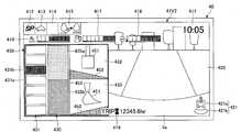
도 6에 나타내는 바와 같이, 비조작 중 화면(41V1)은, 시각 표시부(411), 회전수모드 표시부(412), 주행모드 표시부(413), 어태치먼트 표시부(414), 엔진제어상태 표시부(415), 요소수잔량 표시부(416), 연료잔량 표시부(417), 냉각수온 표시부(418), 엔진가동시간 표시부(419), 촬영화상 표시부(420), 작업가이던스 표시부(430)를 갖는다. 각부에 표시되는 화상은, 표시장치(40)의 변환처리부(40a)에 의하여, 컨트롤러(30)로부터 송신되는 각종 데이터 및 촬상장치(80)로부터 송신되는 촬영화상으로 생성된다.6, the non-operation screen 41V1 includes a
시각 표시부(411)는 현재의 시각을 표시한다. 도 6에 나타내는 예에서는, 디지털표시가 채용되어, 현재 시각(10시 5분)이 나타나 있다.The
회전수모드 표시부(412)는, 엔진회전수 조정다이얼(75)에 의하여 설정되어 있는 회전수모드를 화상 표시한다. 회전수모드는, 예를 들면 상기한 SP모드, H모드, A모드 및 아이들링모드의 4개를 포함한다. 도 6에 나타내는 예에서는, SP모드를 나타내는 기호 "SP"가 표시되어 있다.The rotation speed
주행모드 표시부(413)는 주행모드를 표시한다. 주행모드는, 가변용량펌프를 이용한 주행유압모터의 설정상태를 나타낸다. 예를 들면, 주행모드는, 저속모드 및 고속모드를 가지며, 저속모드에서는 "거북이" 모양의 마크가 표시되고, 고속모드에서는 "토끼" 모양의 마크가 표시된다. 도 6에 나타내는 예에서는, "거북이" 모양의 마크가 표시되어 있어, 조작자는 저속모드가 설정되어 있는 것을 인식할 수 있다.The traveling
어태치먼트 표시부(414)는, 장착되어 있는 어태치먼트를 나타내는 화상을 표시한다. 쇼벨에는, 버킷(6), 착암기, 그래플, 리프팅마그넷 등의 다양한 엔드어태치먼트가 장착된다. 어태치먼트 표시부(414)는, 예를 들면 이들 엔드어태치먼트모양의 마크 및 어태치먼트에 대응하는 번호를 표시한다. 본 실시형태에서는, 엔드어태치먼트로서 버킷(6)이 장착되어 있고, 도 6에 나타내는 바와 같이, 어태치먼트 표시부(414)는 공란으로 되어 있다. 엔드어태치먼트로서 착암기가 장착되어 있는 경우에는, 예를 들면 어태치먼트 표시부(414)에는 착암기모양의 마크가, 착암기의 출력의 크기를 나타내는 숫자와 함께 표시된다.The
엔진제어상태 표시부(415)는, 엔진(11)의 제어상태를 표시한다. 도 6에 나타내는 예에서는, 엔진(11)의 제어상태로서 "자동감속·자동정지모드"가 선택되어 있다. 다만, "자동감속·자동정지모드"는, 엔진부하가 작은 상태의 계속시간에 따라, 엔진회전수를 자동적으로 저감시키고, 나아가서는 엔진(11)을 자동적으로 정지시키는 제어상태를 의미한다. 그 외에, 엔진(11)의 제어상태로는, "자동감속모드", "자동정지모드", "수동감속모드" 등이 있다.The engine control
요소수잔량 표시부(416)는, 요소수탱크에 저장되어 있는 요소수의 잔량상태를 화상 표시한다. 도 6에 나타내는 예에서는, 현재의 요소수의 잔량상태를 나타내는 바그래프가 표시되어 있다. 다만, 요소수의 잔량은, 요소수탱크에 마련되어 있는 요소수잔량센서가 출력하는 데이터에 근거하여 표시된다.The urea remaining
연료잔량 표시부(417)는, 연료탱크에 저장되어 있는 연료의 잔량상태를 표시한다. 도 6에 나타내는 예에서는, 현재의 연료의 잔량상태를 나타내는 바그래프가 표시되어 있다. 다만, 연료의 잔량은, 연료탱크에 마련되어 있는 연료잔량센서가 출력하는 데이터에 근거하여 표시된다.The remaining fuel
냉각수온 표시부(418)는, 엔진냉각수의 온도상태를 표시한다. 도 6에 나타내는 예에서는, 엔진냉각수의 온도상태를 나타내는 바그래프가 표시되어 있다. 다만, 엔진냉각수의 온도는, 엔진(11)에 마련되어 있는 수온센서(11c)가 출력하는 데이터에 근거하여 표시된다.The cooling water ON
엔진가동시간 표시부(419)는, 엔진(11)의 누적가동시간을 표시한다. 도 6에 나타내는 예에서는, 운전자에 의하여 카운트가 리스타트된 후의 가동시간의 누적이, 단위 "hr(시간)"과 함께 표시되어 있다. 엔진가동시간 표시부(419)에는, 쇼벨이 제조된 후 전체기간의 생애가동시간 또는 조작자에 의하여 카운트가 리스타트된 후의 구간가동시간이 표시된다.The engine operation
촬영화상 표시부(420)는, 촬상장치(80)에 의하여 촬영된 화상을 표시한다. 도 6에 나타내는 예에서는, 촬영화상 표시부(420)에, 후방 카메라(80B)에 의하여 촬영된 화상이 표시되어 있다. 촬영화상 표시부(420)에는, 좌측 카메라(80L) 또는 우측 카메라(80R)에 의하여 촬상된 촬상화상이 표시되어도 된다. 또, 촬영화상 표시부(420)에는, 좌측 카메라(80L), 우측 카메라(80R), 및 후방 카메라(80B) 중 복수의 카메라에 의하여 촬영된 화상이 나열되도록 표시되어도 된다. 또한, 촬영화상 표시부(420)에는, 좌측 카메라(80L), 우측 카메라(80R), 및 후방 카메라(80B)에 의하여 각각 촬상된 촬상화상이 합성된 부감화상 등이 표시되어도 된다.The captured
다만, 각 카메라는, 촬영하는 화상에, 상부 선회체(3)의 커버(3a)의 일부가 포함되도록 설치되어 있다. 표시되는 화상에 커버(3a)의 일부가 포함됨으로써, 조작자는, 촬영화상 표시부(420)에 표시되는 물체와 쇼벨의 사이의 거리감을 파악하기 쉬워진다.However, each camera is provided so that a part of the
촬영화상 표시부(420)에는, 표시 중의 촬영화상을 촬영한 촬상장치(80)의 방향을 나타내는 촬상장치아이콘(421)이 표시되어 있다. 촬상장치아이콘(421)은, 쇼벨의 상면에서 보았을 때의 형상을 나타내는 쇼벨아이콘(421a)과, 표시 중의 촬상화상을 촬상한 촬상장치(80)의 방향을 나타내는 띠형상의 방향표시아이콘(421b)으로 구성되어 있다.The picked-up
도 6에 나타내는 예에서는, 쇼벨아이콘(421a)의 하측(어태치먼트의 반대측)에 방향표시아이콘(421b)이 표시되어 있고, 촬영화상 표시부(420)에는, 후방 카메라(80B)에 의하여 촬영된 쇼벨의 후방의 화상이 표시되어 있는 것이 나타나 있다. 예를 들면, 촬영화상 표시부(420)에 우측 카메라(80R)에 의하여 촬영된 화상이 표시되어 있는 경우에는, 쇼벨아이콘(421a)의 우측에 방향표시아이콘(421b)이 표시된다. 또, 예를 들면 촬영화상 표시부(420)에 좌측 카메라(80L)에 의하여 촬영된 화상이 표시되어 있는 경우에는, 쇼벨아이콘(421a)의 좌측에 방향표시아이콘(421b)이 표시된다.6, a
조작자는, 예를 들면 캐빈(10) 내에 마련되어 있는 화상전환스위치를 압하함으로써, 촬영화상 표시부(420)에 표시하는 화상을 다른 카메라에 의하여 촬영된 화상 등으로 전환할 수 있다.The operator can switch the image displayed on the photographed
다만, 쇼벨에 촬상장치(80)가 마련되어 있지 않은 경우에는, 촬영화상 표시부(420) 대신에, 다른 정보가 표시되어도 된다.However, in the case where the
작업가이던스 표시부(430)는, 위치표시화상(431), 제1 목표면 표시화상(432), 제2 목표면 표시화상(433), 수치정보화상(434)을 포함하여, 각종 작업정보를 표시한다.The job
위치표시화상(431)은, 복수의 바(431a)가 상하로 배열된 바그래프이며, 어태치먼트의 작업부위(예를 들면 버킷(6)의 선단)에서 목표면까지의 거리를 표시한다. 본 실시형태에서는, 버킷(6)의 선단에서 목표면까지의 거리에 따라, 7개의 바 중 1개가, 다른 바와는 다른 색으로 표시되는 버킷위치 표시바(431b)(도 6에서는 위에서 3번째 바)가 된다. 여기에서, 위치표시화상(431)에 표시되는 작업부위의 위치는, 작업부위 선단의 좌우방향에 있어서의 임의의 위치가 미리 설정되어 있다. 표시되는 작업부위의 위치는, 예를 들면 작업부위 선단의 중앙부, 좌단부, 또는 우단부 등이다. 또, 표시되는 작업부위의 위치는, 작업내용이나 작업현장에 있어서 임의로 변경되어도 된다. 또, 작업부위의 배면부와 목표면의 상대거리를 표시해도 된다. 다만, 위치표시화상(431)은, 버킷(6)의 선단에서 목표면까지의 거리를 보다 고정밀도로 표시할 수 있도록, 복수의 화상을 포함해도 된다. 예를 들면, 복수의 바그래프를 표시하여, 각각에 작업부위 선단의 좌우방향에 있어서의 다른 위치와 목표면의 상대거리를 나타내도 된다. 이 경우에는, 예를 들면 작업부위 선단의 좌단부와 목표면의 상대거리를 나타내는 바그래프와, 작업부위 선단의 우단부와 목표면의 상대거리를 나타내는 바그래프를 표시한다. 작업자가 작업부위와 목표면의 위치관계를 보다 상세하게 파악하는 것이 가능해진다. 여기에서, 복수의 바(431a) 중 중앙의 바(한가운데의 바)는, 목표면에 대응한다. 이로 인하여, 세로방향(위치표시화상(431)에 있어서 복수의 바(431a)가 나열되는 상하방향)에서 중앙의 바(한가운데의 바)만을 다른 바와 다른 색으로 해도 된다. 이와 같이, 목표면은, 복수의 바(431a)의 세로방향의 중앙영역에 설정된다.The
위치표시화상(431)에 있어서 표시되는 바그래프에서는, 예를 들면 버킷(6)의 선단이 목표면보다 위에 존재하는 경우에는, 목표면으로부터의 거리에 따라 상측의 바가 버킷위치 표시바(431b)로서 다른 바(431a)와는 다른 색으로 표시된다. 또, 버킷(6)의 선단이 목표면보다 아래에 존재하는 경우에는, 마찬가지로 목표면으로부터의 거리에 따라 하측의 바가 버킷위치 표시바(431b)로서 다른 바(431a)와는 다른 색으로 표시된다. 이와 같이, 버킷위치 표시바(431b)는, 버킷(6)의 선단의 목표면에 대한 위치 및 목표면까지의 거리에 따라 상하로 움직이도록 표시된다. 조작자는, 위치표시화상(431)을 봄으로써, 버킷(6)의 선단의 목표면에 대한 위치 및 목표면까지의 거리를 파악할 수 있다.In the bar graph displayed on the
제1 목표면 표시화상(432)은, 버킷(6)과 목표면의 관계를 모식적으로 표시한다. 제1 목표면 표시화상(432)에는, 조작자가 캐빈(10)에 앉아 쇼벨의 전방을 보았을 때의 버킷(6)과 목표면이, 버킷아이콘(451) 및 목표면(452)으로 모식적으로 표시된다. 버킷아이콘(451)은, 버킷(6)을 캐빈(10)에서 본 형태로 나타나 있다. 목표면(452)은, 실제의 목표면에 대한 버킷(6)의 경사각도(도 6에 나타내는 예에서는 10.0°)와 함께 표시된다. 버킷아이콘(451)과 목표면(452)의 간격은, 실제의 버킷(6)의 선단에서 목표면까지의 거리에 따라 변화하도록 표시된다. 또, 버킷(6)의 경사각도도 마찬가지로, 실제의 버킷(6)과 목표면의 위치관계에 따라 변화하도록 표시된다.The first target
조작자는, 제1 목표면 표시화상(432)을 봄으로써, 버킷(6)과 목표면의 위치관계나, 목표면의 경사각도를 파악할 수 있다. 다만, 제1 목표면 표시화상(432)에는, 조작자의 시인성을 높이기 위하여, 실제의 경사각도보다 커지도록 목표면(452)을 표시해도 된다. 조작자는, 제1 목표면 표시화상(432)에 표시되는 목표면(452)으로부터 대략의 경사각도를 인식할 수 있다. 또, 조작자는, 정확한 경사각도를 알고자 하는 경우에는, 목표면(452)의 아래에 수치가 표시되어 있는 경사각도를 봄으로써, 실제의 경사각도를 알 수 있다.The operator can grasp the positional relationship between the
제2 목표면 표시화상(433)은, 측면에서 보았을 때의 버킷(6)과 목표면의 관계를 모식적으로 표시한다. 제2 목표면 표시화상(433)에는, 버킷아이콘(451), 목표면(452)이 표시된다. 버킷아이콘(451)은, 버킷(6)을 측면에서 본 형태로 나타나 있다. 목표면(452)은, 수평면에 대한 경사각도(도 6에 나타내는 예에서는 20.0°)와 함께 표시된다. 버킷아이콘(451)과 목표면(452)의 간격은, 실제의 버킷(6)의 선단에서 목표면까지의 거리에 따라 변화하도록 표시된다. 또, 경사각도는, 실제의 버킷(6)과 목표면의 위치관계에 따라 변화하도록 표시된다.The second target
조작자는, 제2 목표면 표시화상(433)을 봄으로써, 버킷(6)과 목표면의 위치관계나, 목표면의 경사각도를 파악할 수 있다. 다만, 제2 목표면 표시화상(433)에는, 조작자의 시인성을 높이기 위하여 실제의 경사각도보다 커지도록 목표면(452)을 표시해도 된다. 조작자는, 제2 목표면 표시화상(433)에 표시되는 목표면(452)으로부터 대략의 경사각도를 인식할 수 있다. 또, 조작자는, 정확한 경사각도를 알고자 하는 경우에는, 목표면(452)의 아래에 수치가 표시되어 있는 경사각도를 봄으로써, 실제의 경사각도를 알 수 있다.The operator can grasp the positional relationship between the
수치정보화상(434)은, 버킷(6)의 선단과 목표면의 위치관계 등을 나타내는 각종 수치를 표시한다. 수치정보화상(434)에는, 상부 선회체(3)의 기준에 대한 선회각도(도 6에 나타내는 예에서는 120.0°)가 쇼벨을 나타내는 아이콘과 함께 표시되고 있다. 또, 수치정보화상(434)에는, 목표면에서 버킷(6)의 선단까지의 높이(버킷(6)의 선단과 목표면의 수직방향의 거리이며, 도 6에 나타내는 예에서는 0.23m)가, 목표면의 위치관계를 나타내는 아이콘과 함께 표시되어 있다. 도 6에서는, 미리 설정된 작업부위인 버킷의 임의의 개소와 목표면의 위치관계가 수치로 표시되어 있다. 작업부위의 날끝, 혹은 배면의 좌우 양단과 목표면의 위치관계를 각각 수치로 표시하고자 하는 경우에는, 아이콘과 수치정보의 복수 세트를 병렬로 표시해도 된다.The
쇼벨의 비조작 중에는, 이상에서 설명한 비조작 중 화면(41V1)이 표시장치(40)의 화상 표시부(41)에 표시된다. 조작자는, 수치정보화상(434)에 표시되는 각종 수치로부터, 버킷(6)과 목표면의 상대적 위치관계 등을, 수치정보로서 구체적으로 확인할 수 있다. 다만, 수치정보화상(434)에는, 상기 이외의 다른 수치정보가 표시되어도 된다.During the non-operation of the shovel, the non-operation screen 41V1 described above is displayed on the
도 7은 실시형태에 있어서의 표시장치(40)의 화상 표시부(41)에 표시되는 조작 중 화면(41V2)을 예시하는 도이다.7 is a diagram illustrating an in-operation screen 41V2 displayed on the
조작자에 의하여 어태치먼트가 조작되면, 컨트롤러(30)가 조작 중인 것을 나타내는 조작신호를 표시장치(40)에 송신하고, 도 7에 예시되는 조작 중 화면(41V2)이 표시장치(40)의 화상 표시부(41)에 표시된다.When the attachment is operated by the operator, an operation signal indicating that the
도 7에 나타내는 바와 같이, 조작 중 화면(41V2)은, 비조작 중 화면(41V1)과 동일하게, 시각 표시부(411), 회전수모드 표시부(412), 주행모드 표시부(413), 어태치먼트 표시부(414), 엔진제어상태 표시부(415), 요소수잔량 표시부(416), 연료잔량 표시부(417), 냉각수온 표시부(418), 엔진가동시간 표시부(419), 촬영화상 표시부(420), 작업가이던스 표시부(430)를 갖는다.7, the in-operation screen 41V2 includes a
비조작 중 화면(41V1)과 조작 중 화면(41V2)은, 작업가이던스 표시부(430)의 구성이 다르다. 조작 중 화면(41V2)의 작업가이던스 표시부(430)는, 위치표시화상(431), 제1 목표면 표시화상(432), 제2 목표면 표시화상(433), 목표면 표시화상(435)을 갖는다. 조작 중 화면(41V2)에서는, 비조작 중 화면(41V1)에 비하여, 위치표시화상(431)이 크게 표시되고, 제1 목표면 표시화상(432) 및 제2 목표면 표시화상(433)이 작게 표시된다. 또, 조작 중 화면(41V2)에서는, 비조작 중 화면(41V1)에 있어서 표시되고 있던 수치정보화상(434)이 표시되지 않고, 목표면 표시화상(435)이 표시된다.The non-operation screen 41V1 and the operation screen 41V2 are different in the configuration of the job
조작 중 화면(41V2)에 있어서의 위치표시화상(431)은, 비조작 중 화면(41V1)에 있어서의 각 바(431a)가 확대되어 표시된다. 또, 위치표시화상(431)의 옆에 나열되도록, 목표면 표시화상(435)이 표시되어 있다. 이와 같이, 작업가이던스 표시부(430)에 있어서의 표시내용의 변경방법으로서, 예를 들면 위치표시화상(431)의 표시형태가 변화한다.The
목표면 표시화상(435)은, 예를 들면 다른 색으로 표시되는 2개의 영역(435a, 435b)으로 구성되고, 영역(435a)과 영역(435b)의 경계가 목표면(452)의 위치를 나타내고 있다. 다만, 목표면 표시화상(435)은, 다른 색으로 표시되는 3개 이상의 영역으로 구성되고, 어느 하나의 경계에서 목표면(452)의 위치를 나타내도 된다.The target
본 실시형태에서는, 목표면 표시화상(435)에 있어서 목표면(452)을 나타내는 영역(435a)과 영역(435b)의 경계가, 위치표시화상(431)에 있어서 위에서 4번째 바(431a)에 대응하는 위치에 형성되어 있다.The boundary between the
이와 같은 구성에 있어서, 위치표시화상(431)은, 버킷(6)의 선단이 목표면보다 위에 존재하는 경우에는, 버킷(6)의 선단과 목표면의 거리에 따라 상측 3개의 바 중 어느 하나가 버킷위치 표시바(431b)로서 다른 바(431a)와는 다른 색으로 표시된다. 또, 위치표시화상(431)은, 버킷(6)의 선단이 목표면 근방에 존재하는 경우에는, 위에서(아래에서) 4번째 바가 버킷위치 표시바(431b)로서 다른 바(431a)와는 다른 색으로 표시된다. 또, 위치표시화상(431)은, 버킷(6)의 선단이 목표면보다 아래에 존재하는 경우에는, 버킷(6)의 선단과 목표면의 거리에 따라 하측 3개의 바 중 어느 하나가 버킷위치 표시바(431b)로서 다른 바(431a)와는 다른 색으로 표시된다.In this configuration, when the tip of the
이와 같이, 조작 중 화면(41V2)에서는, 위치표시화상(431)이 비조작 중 화면(41V1)보다 확대되고, 추가로 목표면 표시화상(435)과 함께 표시된다. 이로 인하여, 조작자는, 조작 중 화면(41V2)을 주시하지 않고, 버킷(6)을 조작하면서, 버킷(6)의 선단과 목표면의 위치관계를 용이하게 파악하는 것이 가능해진다. 따라서, 조작자는, 버킷(6)의 선단과 목표면의 위치관계를 확인하면서 정확하게 작업을 행하는 것이 가능해진다.In this way, in the in-operation screen 41V2, the
다만, 도 8에 나타내는 바와 같이, 위치표시화상(431)은, 목표면 표시화상(435) 위에 겹쳐 표시되어도 된다. 위치표시화상(431)과 목표면 표시화상(435)이 겹쳐 표시됨으로써, 버킷(6)의 선단과 목표면의 위치관계를 보다 용이하게 파악하는 것이 가능해진다. 또, 도 9에 나타내는 바와 같이, 위치표시화상(431)에 있어서 목표면 근방을 나타내는 바를, 목표면 표시바(431c)로서 버킷위치 표시바(431b)나 다른 바(431a)와는 다른 색으로 표시해도 된다. 이와 같은 표시에 의하여, 버킷(6)의 선단과 목표면의 위치관계를 용이하게 파악하는 것이 가능해진다. 또한, 예를 들면 조작자가 위치표시화상(431) 및 목표면 표시화상(435)의 표시를 도 7에서 도 9에 나타내는 구성으로 전환할 수 있도록, 캐빈(10) 내에 표시전환스위치가 마련되어도 된다. 조작자가 보기 쉬운 표시 구성으로 적절히 전환함으로써, 보다 정확하게 작업을 행하는 것이 가능해진다. 다만, 목표면 표시바(431c)의 색을 다른 바(431a)와 동일한 색으로 해도 된다. 이 경우에도, 목표면은, 복수의 바(431a)의 세로방향의 중앙영역에 설정된다.However, as shown in Fig. 8, the
또, 조작 중 화면(41V2)의 작업가이던스 표시부(430)에서는, 비조작 중 화면(41V1)보다, 제1 목표면 표시화상(432) 및 제2 목표면 표시화상(433)이 축소되어 표시된다. 제1 목표면 표시화상(432) 및 제2 목표면 표시화상(433)에는, 비조작 중 화면(41V1)에는 표시되고 있던 목표면의 경사각도나 선회중심축으로부터 버킷(6)의 선단까지의 거리 등과 같은 수치가 표시가 생략되어 있다.In the operation
예를 들면 상기한 각 수치가 제1 목표면 표시화상(432) 및 제2 목표면 표시화상(433)에 표시되었다고 해도, 조작자는 어태치먼트의 조작 중에는 조작 중 화면(41V2)을 주시할 수 없기 때문에, 이들 수치를 확인하는 것이 곤란하다. 따라서, 상기한 각 수치의 표시를 생략하고, 제1 목표면 표시화상(432) 및 제2 목표면 표시화상(433)을, 버킷아이콘(451)과 목표면(452)의 관계를 간략화하여 표시하도록 구성하고 있다.For example, even if the above-described respective values are displayed on the first target
수치가 생략됨으로써, 제1 목표면 표시화상(432) 및 제2 목표면 표시화상(433)의 시인성이 향상되어, 조작자는, 조작 중에 있어서 버킷(6)과 목표면의 위치관계를 확인하면서, 정확하게 작업을 행하는 것이 가능해진다.By omitting the numerical value, the visibility of the first target
또, 제1 목표면 표시화상(432) 및 제2 목표면 표시화상(433)에는, 버킷아이콘(451)이, 실제의 버킷(6)의 형상을 과장한 형태로 나타나 있다. 또, 목표면(452)은, 실제의 경사각도보다 크게 표시되어 있다. 이와 같이, 실제의 버킷(6)과 목표면의 위치관계를 과장하여 표시함으로써, 조작자가 조작 중에 버킷(6)과 목표면의 위치관계를 확인하기 쉬워진다.The
이상에서 설명한 바와 같이, 본 실시형태에 있어서의 쇼벨에서는, 어태치먼트의 조작 중과 비조작 중에, 표시장치(40)의 화상 표시부(41)에 표시되는 내용이 변경된다. 조작 중에는, 비조작 중보다 위치표시화상(431)이 확대되어, 목표면 표시화상(435)과 함께 표시된다. 또, 비조작 중에는 표시되고 있던 각종 수치가 조작 중에는 비표시가 된다. 따라서, 조작자는, 표시장치(40)의 화상 표시부(41)를 주시하지 않아도, 버킷(6)과 목표면의 위치관계를 용이하게 파악할 수 있어, 버킷(6)과 목표면의 위치관계를 확인하면서, 정확하게 작업을 행하는 것이 가능해진다.As described above, in the shovel in the present embodiment, the contents displayed on the
다만, 비조작 중 화면(41V1) 및 조작 중 화면(41V2)은, 상기 이외에, 연비를 표시하는 연비 표시부, 작동유탱크 내의 작동유의 온도상태를 표시하는 작동유온 표시부 등을 가져도 된다. 도 6 및 도 7에 나타내는 예에서는, 요소수잔량 표시부(416), 연료잔량 표시부(417), 및 냉각수온 표시부(418)가 바그래프 표시되어 있지만, 예를 들면 바늘표시 등이어도 되고, 각 영역의 표시방식은 본 실시형태에 예시되는 것에 한정되지 않는다. 또, 각 영역의 배치 등은, 본 실시형태에 있어서 예시되는 구성에 한정되지 않는다.However, the non-operating screen 41V1 and the operating screen 41V2 may have a fuel consumption display portion for displaying fuel consumption, an operating oil on display portion for displaying the temperature state of the operating oil in the working oil tank, and the like. 6 and 7, the ellipsis remaining
이상, 실시형태에 관한 쇼벨에 대하여 설명했지만, 본 발명은 상기 실시형태에 한정되는 것은 아니고, 본 발명의 범위 내에서 다양한 변형 및 개량이 가능하다.The shovel according to the embodiment has been described above, but the present invention is not limited to the above embodiment, and various modifications and improvements are possible within the scope of the present invention.
본 국제출원은, 2015년 9월 15일에 출원된 일본 특허출원 2015-182160호에 근거하여 우선권을 주장하는 것이며, 일본 특허출원 2015-182160호의 전체 내용을 본 국제출원에 원용한다.This international application claims priority based on Japanese Patent Application No. 2015-182160 filed on September 15, 2015, and the entire contents of Japanese Patent Application No. 2015-182160 are incorporated herein by reference.
1 하부 주행체
3 상부 선회체
4 붐
5 암
6 버킷
10 캐빈(운전실)
40 표시장치
80 촬상장치
420 촬영화상 표시부
430 작업가이던스 표시부
431 위치표시화상
434 수치정보화상
435 목표면 표시화상1 Lower traveling body
3 upper swivel
4 boom
5 Cancer
6 buckets
10 cabin (cab)
40 display device
80 imaging device
420 Photographed image display section
430 Operation guidance display
431 Position display image
434 Numerical information image
435 Target surface display image
Claims (9)
Translated fromKorean상기 하부 주행체에 선회 가능하게 탑재되는 상부 선회체와,
상기 상부 선회체에 탑재되는 운전실과,
작업을 행하는 작업부위를 포함하는 어태치먼트와,
상기 운전실 내에 마련되어 있는 표시장치를 갖고,
상기 표시장치는, 상기 작업부위의 자세와 작업목표면을 나타내는 작업가이던스 표시부를 포함하는 화상을 표시하며, 상기 어태치먼트의 조작 중과 비조작 중에, 상기 작업가이던스 표시부의 표시내용을 변경하는 것을 특징으로 하는 쇼벨.A lower traveling body for performing a traveling operation,
An upper revolving structure rotatably mounted on the lower traveling body,
A cab mounted on the upper revolving body,
An attachment including a work site for performing work,
And a display device provided in the cab,
Wherein the display device displays an image including a working guidance display portion indicating the attitude of the working portion and the working target surface and changes the display content of the working guidance display portion during the operation of the attachment and the non- Shovel.
상기 표시장치는, 상기 작업부위와 목표면의 위치관계를 나타내는 위치표시화상을 상기 작업가이던스 표시부에 표시하고, 상기 어태치먼트의 조작 중에는, 상기 어태치먼트의 비조작 중보다, 상기 위치표시화상을 확대하여 표시하는 것을 특징으로 하는 쇼벨.The method according to claim 1,
Wherein the display device displays a position display image indicating a positional relationship between the working portion and the target surface on the job guidance display portion and displays the position display image in an enlarged manner during the operation of the attachment, .
상기 표시장치는, 상기 어태치먼트의 조작 중에는, 상기 목표면의 상측을 나타내는 영역과, 상기 목표면의 하측을 나타내는 영역이 다른 색으로 나타나는 목표면 표시화상을, 상기 위치표시화상과 함께 상기 작업가이던스 표시부에 표시하는 것을 특징으로 하는 쇼벨.3. The method of claim 2,
The display device displays a target surface display image in which an area representing the upper side of the target surface and an area representing the lower side of the target surface appear in different colors during the operation of the attachment, On the display screen.
상기 표시장치는, 상기 위치표시화상을, 상기 목표면 표시화상 위에 겹쳐 표시하는 것을 특징으로 하는 쇼벨.The method of claim 3,
Wherein the display device displays the position display image on the target surface display image in a superimposed manner.
상기 표시장치는, 상기 어태치먼트의 조작 중에는, 상기 어태치먼트에 의한 작업에 관한 수치정보를 상기 작업가이던스 표시부에 표시하고, 상기 어태치먼트의 비조작 중에는, 상기 수치정보를 비표시로 하는 것을 특징으로 하는 쇼벨.The method according to claim 1,
Wherein the numerical information relating to the operation by the attachment is displayed on the operation guidance display part during the operation of the attachment and the numerical information is set to non-display during the non-operation of the attachment.
주위를 촬상하는 촬상장치를 갖고,
상기 표시장치는, 상기 촬상장치에 의한 촬영화상을 표시하는 촬영화상 표시부를 포함하는 화상을 표시하는 것을 특징으로 하는 쇼벨.The method according to claim 1,
And an image pickup device for picking up the surroundings,
Wherein the display device displays an image including a picked-up image display section that displays a picked-up image by the image pickup apparatus.
상기 위치표시화상은, 미리 설정되어 있는 상기 작업부위의 좌우방향에 있어서의 위치와 목표면의 위치관계를 나타내는 것을 특징으로 하는 쇼벨.3. The method of claim 2,
Wherein the position display image indicates a positional relationship between a position in the left and right direction of the work part set in advance and a target surface.
상기 위치표시화상은, 각각 미리 설정되어 있는 상기 작업부위의 좌우방향에 있어서의 다른 위치와 목표면의 위치관계를 나타내는 복수의 화상을 포함하는 것을 특징으로 하는 쇼벨.3. The method of claim 2,
Wherein the position display image includes a plurality of images each indicating a positional relationship between a target position and a different position in a left-right direction of the workpiece set in advance.
상기 위치표시화상의 세로방향의 중앙영역에, 상기 목표면이 설정되어 있는 것을 특징으로 하는 쇼벨.3. The method of claim 2,
And the target surface is set in a center region in the longitudinal direction of the position display image.
Applications Claiming Priority (3)
| Application Number | Priority Date | Filing Date | Title |
|---|---|---|---|
| JP2015182160 | 2015-09-15 | ||
| JPJP-P-2015-182160 | 2015-09-15 | ||
| PCT/JP2016/077137WO2017047654A1 (en) | 2015-09-15 | 2016-09-14 | Shovel |
Publications (2)
| Publication Number | Publication Date |
|---|---|
| KR20180054638Atrue KR20180054638A (en) | 2018-05-24 |
| KR102522714B1 KR102522714B1 (en) | 2023-04-14 |
Family
ID=58288856
Family Applications (1)
| Application Number | Title | Priority Date | Filing Date |
|---|---|---|---|
| KR1020187008225AActiveKR102522714B1 (en) | 2015-09-15 | 2016-09-14 | shovel |
Country Status (6)
| Country | Link |
|---|---|
| US (1) | US10927528B2 (en) |
| EP (1) | EP3351692B1 (en) |
| JP (1) | JP6965160B2 (en) |
| KR (1) | KR102522714B1 (en) |
| CN (1) | CN108026715B (en) |
| WO (1) | WO2017047654A1 (en) |
Families Citing this family (17)
| Publication number | Priority date | Publication date | Assignee | Title |
|---|---|---|---|---|
| WO2018043299A1 (en)* | 2016-08-31 | 2018-03-08 | 株式会社小松製作所 | Work machine graphics display system, work machine remote control system, work machine, and work machine graphics display method |
| KR20180130110A (en)* | 2016-11-29 | 2018-12-06 | 가부시키가이샤 고마쓰 세이사쿠쇼 | Work equipment control device and work machine |
| WO2018155567A1 (en)* | 2017-02-22 | 2018-08-30 | 住友建機株式会社 | Excavator |
| JP6564804B2 (en)* | 2017-03-29 | 2019-08-21 | 日立建機株式会社 | Operation guide device |
| KR102492415B1 (en) | 2017-08-09 | 2023-01-26 | 스미토모 겐키 가부시키가이샤 | Shovel, shovel display device and shovel display method |
| CN110462143B (en) | 2017-08-09 | 2022-11-01 | 住友建机株式会社 | Shovel, display device for shovel, and display method for shovel |
| JP6878226B2 (en)* | 2017-09-19 | 2021-05-26 | 日立建機株式会社 | Work machine |
| JP7117843B2 (en)* | 2017-12-26 | 2022-08-15 | 日立建機株式会社 | working machine |
| JP7141894B2 (en)* | 2018-09-05 | 2022-09-26 | 日立建機株式会社 | working machine |
| JP7286287B2 (en) | 2018-09-14 | 2023-06-05 | 株式会社小松製作所 | Work machine display system and its control method |
| KR102413519B1 (en)* | 2019-03-28 | 2022-06-27 | 히다치 겡키 가부시키 가이샤 | working machine |
| JP7246297B2 (en)* | 2019-12-16 | 2023-03-27 | 日立建機株式会社 | construction machinery |
| JP7207575B2 (en)* | 2020-06-11 | 2023-01-18 | 日本精機株式会社 | Work support system, work support method |
| JP7438999B2 (en)* | 2021-02-12 | 2024-02-27 | ヤンマーホールディングス株式会社 | Work machine display control system, work machine display system, work machine, work machine display control method, and work machine display control program |
| JP2024020856A (en)* | 2022-08-02 | 2024-02-15 | ヤンマーホールディングス株式会社 | Display devices and construction machinery |
| USD1061552S1 (en) | 2022-12-21 | 2025-02-11 | Caterpillar Inc. | Display screen or portion thereof with graphical user interface |
| US12227145B2 (en)* | 2023-01-20 | 2025-02-18 | Caterpillar Inc. | Machine security system |
Citations (11)
| Publication number | Priority date | Publication date | Assignee | Title |
|---|---|---|---|---|
| US20090009308A1 (en)* | 2005-08-05 | 2009-01-08 | Komatsu Ltd. | Display Device Mounted in Working Vehicle and Display Method For the Display Device |
| JP2009173195A (en)* | 2008-01-25 | 2009-08-06 | Sumitomo (Shi) Construction Machinery Manufacturing Co Ltd | Display system for construction machine |
| US20110178677A1 (en)* | 2010-01-20 | 2011-07-21 | Caterpillar Trimble Control Technologies Llc | Machine control and guidance system incorporating a portable digital media device |
| US20120330500A1 (en)* | 2010-09-30 | 2012-12-27 | Komatsu Ltd. | Guidance output device and guidance output method |
| KR20130044338A (en)* | 2011-02-22 | 2013-05-02 | 가부시키가이샤 고마쓰 세이사쿠쇼 | Hydraulic shovel display system and method for controlling same |
| KR20130124304A (en)* | 2010-09-29 | 2013-11-13 | 히다치 겡키 가부시키 가이샤 | Display system for working machine |
| JP2014074315A (en)* | 2012-10-05 | 2014-04-24 | Komatsu Ltd | Display system of excavator and excavator |
| JP2014148893A (en) | 2014-05-30 | 2014-08-21 | Komatsu Ltd | Display system of hydraulic shovel |
| EP2778293A2 (en)* | 2013-03-14 | 2014-09-17 | Kabushiki Kaisha Topcon | Construction machine control system |
| JP2014205955A (en)* | 2013-04-10 | 2014-10-30 | 株式会社小松製作所 | Construction management device of excavator, construction management device of hydraulic shovel, excavator, and construction management system |
| KR20150066212A (en)* | 2013-12-06 | 2015-06-16 | 두산인프라코어 주식회사 | Apparatus for selecting screen mode and method |
Family Cites Families (65)
| Publication number | Priority date | Publication date | Assignee | Title |
|---|---|---|---|---|
| JPS60115972A (en) | 1983-11-28 | 1985-06-22 | Fuji Xerox Co Ltd | Developing device of copying machine |
| ZA948824B (en)* | 1993-12-08 | 1995-07-11 | Caterpillar Inc | Method and apparatus for operating geography altering machinery relative to a work site |
| US5854988A (en) | 1996-06-05 | 1998-12-29 | Topcon Laser Systems, Inc. | Method for controlling an excavator |
| US6744372B1 (en) | 1997-02-27 | 2004-06-01 | Jack B. Shaw | Crane safety devices and methods |
| US6270038B1 (en) | 1999-04-22 | 2001-08-07 | Sikorsky Aircraft Corporation | Unmanned aerial vehicle with counter-rotating ducted rotors and shrouded pusher-prop |
| AU2001262968A1 (en)* | 2000-05-05 | 2001-11-20 | Robert A. Hasara | Laser-guided construction equipment |
| JP2002047694A (en)* | 2000-07-31 | 2002-02-15 | Komatsu Ltd | Display of construction machinery |
| JP2003013471A (en)* | 2001-06-28 | 2003-01-15 | Komatsu Ltd | Hydraulic excavator combined with crane operation |
| KR20030003015A (en) | 2001-06-28 | 2003-01-09 | 가부시키가이샤 고마쓰 세이사쿠쇼 | Excavator |
| JP4750970B2 (en)* | 2001-06-28 | 2011-08-17 | 株式会社小松製作所 | Crane work hydraulic excavator |
| JP2003241833A (en) | 2002-02-18 | 2003-08-29 | Hitachi Ltd | Information distribution service and information collection system by mobile robot |
| JP4025140B2 (en)* | 2002-08-07 | 2007-12-19 | 日立建機株式会社 | Excavator display system and program thereof |
| JP4362452B2 (en)* | 2005-02-07 | 2009-11-11 | 青木あすなろ建設株式会社 | Work equipment construction support system |
| EP1899930B1 (en) | 2005-06-30 | 2010-08-11 | Planum Vision Ltd. | Surveillance system and method for detecting forbidden movement along a predetermined path |
| JP2007147588A (en) | 2005-11-01 | 2007-06-14 | Hitachi Constr Mach Co Ltd | Position measuring system for working machine |
| JP2008011193A (en) | 2006-06-29 | 2008-01-17 | Wintel Kk | 1.2 ghz video radio system |
| JP2008195142A (en)* | 2007-02-09 | 2008-08-28 | Aisin Aw Co Ltd | Operation supporting device and method for on-vehicle equipment |
| JP4943899B2 (en) | 2007-03-05 | 2012-05-30 | 株式会社日立国際電気 | Image display method and image display program |
| US7798449B2 (en) | 2007-08-13 | 2010-09-21 | Raytheon Company | Method and system for inflight refueling of unmanned aerial vehicles |
| US9736368B2 (en) | 2013-03-15 | 2017-08-15 | Spatial Cam Llc | Camera in a headframe for object tracking |
| US9043052B2 (en) | 2008-05-27 | 2015-05-26 | Wilfred So | System and method for multiple vehicles moving a common payload |
| JP2010200398A (en) | 2009-02-23 | 2010-09-09 | Chugoku Electric Power Co Inc:The | Power consumption addition system |
| JP4937291B2 (en) | 2009-03-30 | 2012-05-23 | 住友建機株式会社 | Construction machinery |
| JP2010248777A (en) | 2009-04-15 | 2010-11-04 | Caterpillar Sarl | Management system of working machine |
| JP2011058269A (en) | 2009-09-10 | 2011-03-24 | Caterpillar Sarl | Position management device of work machine |
| DE102010038661B4 (en) | 2010-07-29 | 2020-07-02 | Deere & Company | Harvester with a sensor attached to an aircraft |
| JP5367665B2 (en)* | 2010-09-17 | 2013-12-11 | 日立建機株式会社 | Work machine display system |
| JP2012092500A (en)* | 2010-10-22 | 2012-05-17 | Yanmar Co Ltd | Work vehicle |
| JP5690113B2 (en) | 2010-10-22 | 2015-03-25 | 日本信号株式会社 | Autonomous mobile service provision system |
| JP5246672B2 (en) | 2011-02-17 | 2013-07-24 | 独立行政法人科学技術振興機構 | Robot system |
| JP4831443B1 (en) | 2011-02-25 | 2011-12-07 | 孝郎 林 | Power supply system with anti-theft function |
| JP5328830B2 (en) | 2011-03-24 | 2013-10-30 | 株式会社小松製作所 | Hydraulic excavator calibration apparatus and hydraulic excavator calibration method |
| US8761933B2 (en) | 2011-08-02 | 2014-06-24 | Microsoft Corporation | Finding a called party |
| EP2570769A1 (en) | 2011-09-13 | 2013-03-20 | Hexagon Technology Center GmbH | Geodesic measuring system and method with multiple target tracking functionality |
| JP5586568B2 (en) | 2011-11-15 | 2014-09-10 | 株式会社小松製作所 | Construction machine information display device, construction machine information display method, and construction machine information display computer program |
| JP5941663B2 (en)* | 2011-11-30 | 2016-06-29 | 住友建機株式会社 | Construction machine monitoring system |
| JP5888956B2 (en) | 2011-12-13 | 2016-03-22 | 住友建機株式会社 | Excavator and surrounding image display method of the excavator |
| US8824779B1 (en) | 2011-12-20 | 2014-09-02 | Christopher Charles Smyth | Apparatus and method for determining eye gaze from stereo-optic views |
| JP6029306B2 (en) | 2012-03-29 | 2016-11-24 | 住友建機株式会社 | Perimeter monitoring equipment for work machines |
| JP5480941B2 (en)* | 2012-08-02 | 2014-04-23 | 株式会社小松製作所 | Excavator display system and control method thereof. |
| US9043098B2 (en) | 2012-10-05 | 2015-05-26 | Komatsu Ltd. | Display system of excavating machine and excavating machine |
| JP6014484B2 (en) | 2012-12-21 | 2016-10-25 | セコム株式会社 | Autonomous mobile robot |
| JP6258582B2 (en) | 2012-12-28 | 2018-01-10 | 株式会社小松製作所 | Construction machine display system and control method thereof |
| JP6195450B2 (en) | 2013-01-31 | 2017-09-13 | セコム株式会社 | Autonomous flying robot |
| JP6545430B2 (en) | 2013-03-19 | 2019-07-17 | 住友重機械工業株式会社 | Shovel |
| JP6073168B2 (en) | 2013-03-27 | 2017-02-01 | 住友建機株式会社 | Excavator |
| JP6505356B2 (en)* | 2013-07-17 | 2019-04-24 | 住友建機株式会社 | Shovel |
| JP6187967B2 (en) | 2013-09-04 | 2017-08-30 | みこらった株式会社 | Defense device and defense system |
| US9816785B2 (en) | 2013-10-31 | 2017-11-14 | Aerovironment, Inc. | Interactive weapon targeting system displaying remote sensed image of target area |
| CN104797463B (en) | 2013-11-19 | 2017-03-15 | 株式会社小松制作所 | The display device and its display packing of working truck |
| AU2015204838B2 (en) | 2014-01-10 | 2020-01-02 | Pictometry International Corp. | Unmanned aircraft structure evaluation system and method |
| JP5940579B2 (en) | 2014-03-20 | 2016-06-29 | ヤフー株式会社 | Movement control device, movement control method, and movement control system |
| JP6358826B2 (en) | 2014-03-27 | 2018-07-18 | 株式会社沖データ | Semiconductor device, exposure head, and image forming apparatus |
| JP6648971B2 (en) | 2014-03-27 | 2020-02-19 | 株式会社フジタ | Structure inspection device |
| US9429867B2 (en) | 2014-03-27 | 2016-08-30 | Oki Data Corporation | Semiconductor apparatus, exposing head, and image forming apparatus |
| WO2015180180A1 (en) | 2014-05-30 | 2015-12-03 | SZ DJI Technology Co., Ltd. | Systems and methods for uav docking |
| EP3418455B1 (en) | 2014-06-20 | 2020-04-08 | Sumitomo Heavy Industries, Ltd. | Shovel and control method thereof |
| JP5775632B2 (en) | 2014-09-16 | 2015-09-09 | 株式会社トプコン | Aircraft flight control system |
| DE102014218749A1 (en) | 2014-09-18 | 2016-03-24 | Bayerische Motoren Werke Aktiengesellschaft | Support of an operator of a work machine by means of an unmanned flying object |
| GB2533140A (en) | 2014-12-11 | 2016-06-15 | Caterpillar Inc | Drone |
| WO2015125979A1 (en) | 2015-04-28 | 2015-08-27 | 株式会社小松製作所 | Work machine perimeter monitoring device, and work machine perimeter monitoring method |
| US20170247107A1 (en) | 2016-02-29 | 2017-08-31 | GeoScout, Inc. | Rotary-wing vehicle and system |
| JP6639960B2 (en)* | 2016-03-07 | 2020-02-05 | 住友建機株式会社 | Excavator |
| US10721859B2 (en) | 2017-01-08 | 2020-07-28 | Dolly Y. Wu PLLC | Monitoring and control implement for crop improvement |
| US10592934B2 (en) | 2018-03-30 | 2020-03-17 | The Travelers Indemnity Company | Systems and methods for automated multi-object damage analysis |
- 2016
- 2016-09-14JPJP2017539948Apatent/JP6965160B2/enactiveActive
- 2016-09-14KRKR1020187008225Apatent/KR102522714B1/enactiveActive
- 2016-09-14WOPCT/JP2016/077137patent/WO2017047654A1/ennot_activeCeased
- 2016-09-14EPEP16846525.0Apatent/EP3351692B1/enactiveActive
- 2016-09-14CNCN201680053545.6Apatent/CN108026715B/enactiveActive
- 2018
- 2018-03-13USUS15/919,481patent/US10927528B2/enactiveActive
Patent Citations (11)
| Publication number | Priority date | Publication date | Assignee | Title |
|---|---|---|---|---|
| US20090009308A1 (en)* | 2005-08-05 | 2009-01-08 | Komatsu Ltd. | Display Device Mounted in Working Vehicle and Display Method For the Display Device |
| JP2009173195A (en)* | 2008-01-25 | 2009-08-06 | Sumitomo (Shi) Construction Machinery Manufacturing Co Ltd | Display system for construction machine |
| US20110178677A1 (en)* | 2010-01-20 | 2011-07-21 | Caterpillar Trimble Control Technologies Llc | Machine control and guidance system incorporating a portable digital media device |
| KR20130124304A (en)* | 2010-09-29 | 2013-11-13 | 히다치 겡키 가부시키 가이샤 | Display system for working machine |
| US20120330500A1 (en)* | 2010-09-30 | 2012-12-27 | Komatsu Ltd. | Guidance output device and guidance output method |
| KR20130044338A (en)* | 2011-02-22 | 2013-05-02 | 가부시키가이샤 고마쓰 세이사쿠쇼 | Hydraulic shovel display system and method for controlling same |
| JP2014074315A (en)* | 2012-10-05 | 2014-04-24 | Komatsu Ltd | Display system of excavator and excavator |
| EP2778293A2 (en)* | 2013-03-14 | 2014-09-17 | Kabushiki Kaisha Topcon | Construction machine control system |
| JP2014205955A (en)* | 2013-04-10 | 2014-10-30 | 株式会社小松製作所 | Construction management device of excavator, construction management device of hydraulic shovel, excavator, and construction management system |
| KR20150066212A (en)* | 2013-12-06 | 2015-06-16 | 두산인프라코어 주식회사 | Apparatus for selecting screen mode and method |
| JP2014148893A (en) | 2014-05-30 | 2014-08-21 | Komatsu Ltd | Display system of hydraulic shovel |
Also Published As
| Publication number | Publication date |
|---|---|
| KR102522714B1 (en) | 2023-04-14 |
| CN108026715B (en) | 2021-06-18 |
| JP6965160B2 (en) | 2021-11-10 |
| US10927528B2 (en) | 2021-02-23 |
| US20180202130A1 (en) | 2018-07-19 |
| EP3351692A1 (en) | 2018-07-25 |
| EP3351692B1 (en) | 2025-01-22 |
| CN108026715A (en) | 2018-05-11 |
| JPWO2017047654A1 (en) | 2018-06-28 |
| WO2017047654A1 (en) | 2017-03-23 |
| EP3351692A4 (en) | 2018-09-05 |
Similar Documents
| Publication | Publication Date | Title |
|---|---|---|
| KR102522714B1 (en) | shovel | |
| US12065808B2 (en) | Shovel, display device for shovel, and display method for shovel | |
| CN108884668B (en) | Excavator | |
| US11001992B2 (en) | Shovel, display method, and mobile terminal | |
| EP3438356B1 (en) | Shovel | |
| JP2017110472A (en) | Shovel | |
| JP2017210729A (en) | Shovel | |
| JP7455632B2 (en) | Excavators and shovel management devices |
Legal Events
| Date | Code | Title | Description |
|---|---|---|---|
| PA0105 | International application | Patent event date:20180322 Patent event code:PA01051R01D Comment text:International Patent Application | |
| PG1501 | Laying open of application | ||
| A201 | Request for examination | ||
| PA0201 | Request for examination | Patent event code:PA02012R01D Patent event date:20210312 Comment text:Request for Examination of Application | |
| E902 | Notification of reason for refusal | ||
| PE0902 | Notice of grounds for rejection | Comment text:Notification of reason for refusal Patent event date:20220822 Patent event code:PE09021S01D | |
| E90F | Notification of reason for final refusal | ||
| PE0902 | Notice of grounds for rejection | Comment text:Final Notice of Reason for Refusal Patent event date:20230217 Patent event code:PE09021S02D | |
| E701 | Decision to grant or registration of patent right | ||
| PE0701 | Decision of registration | Patent event code:PE07011S01D Comment text:Decision to Grant Registration Patent event date:20230404 | |
| GRNT | Written decision to grant | ||
| PR0701 | Registration of establishment | Comment text:Registration of Establishment Patent event date:20230412 Patent event code:PR07011E01D | |
| PR1002 | Payment of registration fee | Payment date:20230412 End annual number:3 Start annual number:1 | |
| PG1601 | Publication of registration |