KR20180038407A - Guide wire - Google Patents
Guide wireDownload PDFInfo
- Publication number
- KR20180038407A KR20180038407AKR1020177003508AKR20177003508AKR20180038407AKR 20180038407 AKR20180038407 AKR 20180038407AKR 1020177003508 AKR1020177003508 AKR 1020177003508AKR 20177003508 AKR20177003508 AKR 20177003508AKR 20180038407 AKR20180038407 AKR 20180038407A
- Authority
- KR
- South Korea
- Prior art keywords
- resin layer
- end portion
- guide wire
- outer diameter
- coil
- Prior art date
- Legal status (The legal status is an assumption and is not a legal conclusion. Google has not performed a legal analysis and makes no representation as to the accuracy of the status listed.)
- Granted
Links
Images


Classifications
- A—HUMAN NECESSITIES
- A61—MEDICAL OR VETERINARY SCIENCE; HYGIENE
- A61M—DEVICES FOR INTRODUCING MEDIA INTO, OR ONTO, THE BODY; DEVICES FOR TRANSDUCING BODY MEDIA OR FOR TAKING MEDIA FROM THE BODY; DEVICES FOR PRODUCING OR ENDING SLEEP OR STUPOR
- A61M25/00—Catheters; Hollow probes
- A61M25/01—Introducing, guiding, advancing, emplacing or holding catheters
- A61M25/09—Guide wires
- A—HUMAN NECESSITIES
- A61—MEDICAL OR VETERINARY SCIENCE; HYGIENE
- A61B—DIAGNOSIS; SURGERY; IDENTIFICATION
- A61B17/00—Surgical instruments, devices or methods
- A61B17/22—Implements for squeezing-off ulcers or the like on inner organs of the body; Implements for scraping-out cavities of body organs, e.g. bones; for invasive removal or destruction of calculus using mechanical vibrations; for removing obstructions in blood vessels, not otherwise provided for
- A61B2017/22038—Implements for squeezing-off ulcers or the like on inner organs of the body; Implements for scraping-out cavities of body organs, e.g. bones; for invasive removal or destruction of calculus using mechanical vibrations; for removing obstructions in blood vessels, not otherwise provided for with a guide wire
- A61B2017/22042—Details of the tip of the guide wire
- A—HUMAN NECESSITIES
- A61—MEDICAL OR VETERINARY SCIENCE; HYGIENE
- A61M—DEVICES FOR INTRODUCING MEDIA INTO, OR ONTO, THE BODY; DEVICES FOR TRANSDUCING BODY MEDIA OR FOR TAKING MEDIA FROM THE BODY; DEVICES FOR PRODUCING OR ENDING SLEEP OR STUPOR
- A61M25/00—Catheters; Hollow probes
- A61M25/01—Introducing, guiding, advancing, emplacing or holding catheters
- A61M25/09—Guide wires
- A61M2025/09058—Basic structures of guide wires
- A61M2025/09083—Basic structures of guide wires having a coil around a core
- A—HUMAN NECESSITIES
- A61—MEDICAL OR VETERINARY SCIENCE; HYGIENE
- A61M—DEVICES FOR INTRODUCING MEDIA INTO, OR ONTO, THE BODY; DEVICES FOR TRANSDUCING BODY MEDIA OR FOR TAKING MEDIA FROM THE BODY; DEVICES FOR PRODUCING OR ENDING SLEEP OR STUPOR
- A61M25/00—Catheters; Hollow probes
- A61M25/01—Introducing, guiding, advancing, emplacing or holding catheters
- A61M25/09—Guide wires
- A61M2025/09133—Guide wires having specific material compositions or coatings; Materials with specific mechanical behaviours, e.g. stiffness, strength to transmit torque
- A—HUMAN NECESSITIES
- A61—MEDICAL OR VETERINARY SCIENCE; HYGIENE
- A61M—DEVICES FOR INTRODUCING MEDIA INTO, OR ONTO, THE BODY; DEVICES FOR TRANSDUCING BODY MEDIA OR FOR TAKING MEDIA FROM THE BODY; DEVICES FOR PRODUCING OR ENDING SLEEP OR STUPOR
- A61M25/00—Catheters; Hollow probes
- A61M25/01—Introducing, guiding, advancing, emplacing or holding catheters
- A61M25/09—Guide wires
- A61M2025/09175—Guide wires having specific characteristics at the distal tip
- A—HUMAN NECESSITIES
- A61—MEDICAL OR VETERINARY SCIENCE; HYGIENE
- A61M—DEVICES FOR INTRODUCING MEDIA INTO, OR ONTO, THE BODY; DEVICES FOR TRANSDUCING BODY MEDIA OR FOR TAKING MEDIA FROM THE BODY; DEVICES FOR PRODUCING OR ENDING SLEEP OR STUPOR
- A61M25/00—Catheters; Hollow probes
- A61M25/01—Introducing, guiding, advancing, emplacing or holding catheters
- A61M25/09—Guide wires
- A61M2025/09191—Guide wires made of twisted wires
Landscapes
- Health & Medical Sciences (AREA)
- Life Sciences & Earth Sciences (AREA)
- Biophysics (AREA)
- Pulmonology (AREA)
- Engineering & Computer Science (AREA)
- Anesthesiology (AREA)
- Biomedical Technology (AREA)
- Heart & Thoracic Surgery (AREA)
- Hematology (AREA)
- Animal Behavior & Ethology (AREA)
- General Health & Medical Sciences (AREA)
- Public Health (AREA)
- Veterinary Medicine (AREA)
- Media Introduction/Drainage Providing Device (AREA)
Abstract
Translated fromKoreanDescription
Translated fromKorean본 발명은, 혈관이나 소화 기관에 삽입되는 가이드 와이어에 관한 것이다.The present invention relates to a guide wire inserted into a blood vessel or digestive organs.
종래, 혈관, 담관(膽管), 췌관(膵管) 등에 협착부(狹窄部) 또는 폐색부(閉塞部)가 형성되면, 혈액, 담즙(膽汁)(담액(膽液)), 췌액(膵液) 등의 흐름이 나빠져 버린다. 이러한 협착부 또는 폐색부를 치료하는 방법으로서, 카테터를 이용한 치료 방법이 널리 행해지고 있다.Conventionally, when a constriction or an occlusion portion is formed in a blood vessel, a bile duct, a pancreatic duct or the like, blood, bile (pus liquid), pancreatic juice (pancreatic juice) The flow is getting worse. As a method of treating such a stenosis or occlusion, a treatment method using a catheter has been widely practiced.
일반적으로, 카테터를 협착부 또는 폐색부로 안내하기 위해서, 가이드 와이어가 이용된다. 가이드 와이어와 혈관, 담관, 췌관 등의 관벽과의 마찰 저항이 높은 경우, 시술자는, 가이드 와이어를 협착부 또는 폐색부까지 삽입하는 것이 곤란하게 된다. 그래서, 가이드 와이어를 협착부 또는 폐색부까지 삽입하기 쉽게 하기 위해서, 코일체 전체 길이에 걸쳐서, 코일체의 외주를 피복하는 수지층을 구비한 가이드 와이어가 알려져 있다(예를 들면, 하기 특허 문헌 1 및 특허 문헌 2를 참조).Generally, a guide wire is used to guide the catheter to the constriction or obstruction. When the frictional resistance between the guide wire and a tube wall such as a blood vessel, a bile duct, or a pancreatic duct is high, it is difficult for a practitioner to insert the guide wire into the narrowed portion or the occluded portion. To facilitate insertion of the guide wire into the narrowed portion or the closed portion, a guide wire having a resin layer covering the outer periphery of the coil over the entire length of the coil is known (see, for example, Patent Documents 1 and 2) Patent Document 2).
특허 문헌 1의 가이드 와이어에서는, 코일체의 외주에 전체 길이에 걸쳐서 수지막(樹脂膜)(수지층)이 피복되어 있다. 마찬가지로, 특허 문헌 2의 가이드 와이어에서는, 코일체의 외주에 전체 길이에 걸쳐서 수지 피막층이 피복되어 있다.In the guide wire of Patent Document 1, a resin film (resin film) (resin layer) covers the entire length of the outer periphery of the coil. Likewise, in the guide wire of
이러한 가이드 와이어에서는, 마찰 저항을 줄일 수 있기 때문에, 가이드 와이어를 협착부 또는 폐색부까지 삽입하기 쉬운 한편, 코일체 전체 길이가 수지층에 피복되어 있음으로써, 가이드 와이어의 회전 성능이 나쁘다(가이드 와이어의 조작성이 떨어진다)고 하는 문제나, 가이드 와이어의 선단부의 강성이 높아지기 쉽다고 하는 문제가 있었다.In such a guide wire, since the frictional resistance can be reduced, the guide wire can easily be inserted into the narrowed portion or the closed portion, while the overall length of the coil is covered with the resin layer, The operability is deteriorated) and the rigidity of the distal end portion of the guide wire tends to be high.
본 발명은, 이러한 사정을 감안하여 이루어진 것이며, 가이드 와이어의 삽입성을 유지하면서, 가이드 와이어의 회전 성능(가이드 와이어의 조작성)을 향상시키고, 또한, 수지층의 선단으로부터 박리될(벗겨질) 우려도 저감된 가이드 와이어를 제공하는 것을 과제로 한다.SUMMARY OF THE INVENTION The present invention has been made in view of the above circumstances, and it is an object of the present invention to improve the rotational performance (guideability of the guide wire) of the guide wire while maintaining the insertion property of the guide wire and also to prevent peeling The present invention also provides a guidewire that is reduced in size.
상기 과제는, 이하에 열거되는 수단에 의해 해결이 된다.The above-mentioned problems are solved by the means listed below.
본 발명의 형태 1은, 코어 샤프트와, 상기 코어 샤프트의 외주에 권회(卷回)된 코일체와, 상기 코일체의 외주를 피복하고, 굵은 외경을 가지는 후단부와, 상기 후단부보다도 선단측에서 상기 코어 샤프트와 상기 코일체와의 사이에 위치하고, 상기 후단부보다도 가는 외경을 가지는 선단부와, 상기 후단부와 상기 선단부와의 사이에서 선단측을 향해 외경이 축소되는 테이퍼부를 가지는 수지층을 구비하며, 상기 선단부에서의 상기 코일체는, 상기 수지층에 피복되어 있지 않고, 노출되어 있는 것을 특징으로 한 가이드 와이어이다.A first aspect of the present invention is a core shaft comprising a core shaft, a coiled body wound around the core shaft, a rear end portion covering the outer periphery of the coil body and having a large outer diameter, And a resin layer located between the core shaft and the coil and having a tapered portion whose outer diameter is reduced toward the tip end side between the rear end portion and the tip end portion having a smaller outer diameter than the rear end portion And the coil body at the tip end portion is not covered with the resin layer but is exposed.
본 발명의 형태 2는, 상기 수지층의 상기 선단부는, 상기 코어 샤프트에 고착되어 있는 것을 특징으로 한 형태 1에 기재된 가이드 와이어이다.A second aspect of the present invention is the guide wire according to the first aspect, wherein the tip of the resin layer is fixed to the core shaft.
본 발명의 형태 3은, 상기 수지층의 상기 선단부에는, 상기 선단부의 상기 외경보다도 굵은 외경을 가지는 팽륭(膨隆, 부풀어 오르고 튀어나옴)부가 마련되어 있는 것을 특징으로 한 형태 1 또는 형태 2에 기재된 가이드 와이어이다.According to a third aspect of the present invention, in the distal end portion of the resin layer, there is provided a protruding portion (bulge, bulge, protruding portion) having an outer diameter larger than the outer diameter of the distal end portion. to be.
본 발명의 형태 4는, 상기 수지층의 상기 테이퍼부와 상기 수지층의 상기 후단부와의 경계에, 상기 코어 샤프트와 상기 코일체와 상기 수지층을 고착하는 고착부를 구비하고 있는 것을 특징으로 한 형태 1 내지 형태 3 중 어느 하나에 기재된 가이드 와이어이다.A fourth aspect of the present invention is characterized in that a fixing portion is provided at a boundary between the tapered portion of the resin layer and the rear end portion of the resin layer to fix the core shaft and the coil body and the resin layer to each other A guide wire according to any one of the first to third aspects.
본 발명의 형태 5는, 상기 코일체는, 복수의 소선이 나선 모양으로 귄회되어 형성되어 있으며, 상기 수지층의 상기 선단부는, 횡단면에서 볼 때, 상기 코일체의 인접하는 상기 소선 사이에 들어가 있는 것을 특징으로 한 형태 1 내지 형태 4 중 어느 하나에 기재된 가이드 와이어이다.According to a fifth aspect of the present invention, in the coin body, a plurality of elemental wires are formed in a spiral shape, and the distal end portion of the resin layer is interposed between adjacent elemental wires of the coil Wherein the guide wire is a guide wire according to any one of the first to fourth aspects.
본 발명의 형태 6은, 상기 코일체는, 상기 수지층의 상기 후단부에 위치하는 가는 코일 외경을 가지는 소경부(小徑部)와, 상기 수지층의 상기 선단부에 위치하고, 상기 소경부보다도 굵은 코일 외경을 가지는 대경부(大徑部)와, 상기 수지층의 상기 테이퍼부에 위치하고, 선단측을 향해 코일 외경이 확대되는 확경부를 가지고 있으며, 상기 코일체의 상기 대경부에서의 상기 코일 외경은, 상기 수지층의 상기 후단부에서의 외경보다도 크게 되어 있는 것을 특징으로 한 형태 1 내지 형태 5 중 어느 하나에 기재된 가이드 와이어이다.According to a sixth aspect of the present invention, in the coin body, a small diameter portion having a fine coil outer diameter located at the rear end of the resin layer and a small diameter portion located at the tip end of the resin layer, A large diameter portion having a coil outer diameter and a large diameter portion located in the tapered portion of the resin layer and having a coil outer diameter enlarged toward the tip side, Is a guide wire according to any one of the first to fifth aspects, characterized in that the outer diameter of the guide layer is larger than the outer diameter of the resin layer at the rear end.
본 발명의 형태 1의 가이드 와이어에서는, 코일체의 외주를 피복하고, 굵은 외경을 가지는 후단부와, 후단부보다도 선단측에서 코어 샤프트와 코일체와의 사이에 위치하고, 후단부보다도 가는 외경을 가지는 선단부를 가지는 수지층을 구비하며, 선단부에서의 코일체가, 수지층에 피복되어 있지 않고, 노출되어 있는 구성으로 했다. 이것에 의해, 가이드 와이어의 삽입성을 유지하면서, 가이드 와이어의 회전 성능(가이드 와이어의 조작성)을 향상시키고, 또한, 수지층이 선단으로부터 박리될(벗겨질) 우려도 저감될 수 있다.A guidewire according to a first aspect of the present invention is a guidewire that covers the outer periphery of a coil and has a rear end portion having a large outer diameter and a rear end portion located between the core shaft and the coil body at the distal end side than the rear end portion, And a resin layer having a tip end portion, and the coil body at the tip end portion is not covered with the resin layer but is exposed. This can improve the rotational performance of the guide wire (operability of the guide wire) while preventing the insertion of the guide wire, and also reduce the possibility that the resin layer is peeled off (peeled off) from the tip end.
본 발명의 형태 2의 가이드 와이어에서는, 수지층의 선단부가, 코어 샤프트에 고착되어 있기 때문에, 가이드 와이어를 만곡된 혈관, 담관, 췌관 등에 삽입한 경우에도, 수지층의 선단이 코일체로부터 외부로 돌출될 우려나, 수지층이 선단으로부터 박리될(벗겨질) 우려를 저감할 수 있다.In the guide wire according to the second aspect of the present invention, since the distal end portion of the resin layer is fixed to the core shaft, even when the guide wire is inserted into a curved blood vessel, a bile duct, a pancreatic duct or the like, It is possible to reduce the risk of protrusion or the possibility that the resin layer will peel off (peel off) from the tip.
본 발명의 형태 3의 가이드 와이어에서는, 수지층의 선단부에, 선단부의 외경보다도 굵은 외경을 가지는 팽륭부가 마련되어 있다. 그 때문에, 가이드 와이어를 만곡된 혈관, 담관, 췌관 등에 삽입했을 때에, 수지층이 선단으로부터 박리되려고(벗겨지려고) 한 경우에도, 수지층의 선단부에 마련된 팽륭부가 코일체의 내주면에 걸려, 앵커(anchor) 효과에 의해, 수지층이 박리될(벗겨질) 우려를 더 저감할 수 있다.In the guide wire according to the third aspect of the present invention, the distal end portion of the resin layer is provided with an overhang portion having an outer diameter larger than the outer diameter of the distal end portion. Therefore, even when the resin layer is to be peeled (peeled off) from the tip when inserting the guide wire into the bent blood vessel, the bile duct, the pancreatic duct or the like, the swelling portion provided at the distal end of the resin layer is caught by the inner circumferential surface of the coil, anchor effect, it is possible to further reduce the concern that the resin layer is peeled off (peeled off).
본 발명의 형태 4의 가이드 와이어에서는, 수지층의 테이퍼부와 수지층의 후단부와의 경계에, 코어 샤프트와 코일체와 수지층을 고착하는 고착부가 마련되어 있다. 가이드 와이어를 협착부 또는 폐색부까지 삽입할 때, 수지층의 테이퍼부와 수지층의 후단부와의 경계에서, 혈관, 담관, 췌관 등의 관벽과의 마찰 저항이 높아진다. 사전에, 고착부에 의해 수지층을 코일체 및 코어 샤프트와 고착하고 있기 때문에, 가이드 와이어의 삽입시에서의 테이퍼부와 후단부와의 경계에서의 수지층의 박리(벗겨짐)를 저감할 수 있다.In the guide wire according to the fourth aspect of the present invention, a fixing portion for fixing the core shaft, the coil body and the resin layer is provided at the boundary between the tapered portion of the resin layer and the rear end portion of the resin layer. The frictional resistance between the tapered portion of the resin layer and the rear end portion of the resin layer is increased when the guidewire is inserted into the narrowed portion or the occluded portion with a wall of a blood vessel, a bile duct, a pancreatic duct or the like. Since the resin layer is fixed to the coil body and the core shaft by the fixing portion in advance, peeling (peeling) of the resin layer at the boundary between the tapered portion and the rear end portion at the time of inserting the guide wire can be reduced .
본 발명의 형태 5의 가이드 와이어에서는, 코일체가, 복수의 소선이 나선 모양으로 귄회되어 형성되어 있으며, 수지층의 선단부는, 횡단면에서 볼 때, 코일체의 인접하는 소선 사이에 들어가 있다. 그 때문에, 수지층의 선단부와 코일체와의 앵커 효과에 의해, 수지층의 박리(벗겨짐)를 더 저감할 수 있다.In the guide wire according to the fifth aspect of the present invention, the coil body is formed by spirally winding a plurality of element wires, and the tip end of the resin layer is sandwiched between adjacent element wires of the coil when viewed from the cross section. Therefore, the peeling (peeling) of the resin layer can be further reduced by the anchor effect between the tip of the resin layer and the coil.
본 발명의 형태 6의 가이드 와이어에서는, 코일체가, 수지층의 후단부에 위치하는 가는 코일 외경을 가지는 소경부와, 수지층의 선단부에 위치하고, 소경부보다도 굵은 코일 외경을 가지는 대경부와, 수지층의 테이퍼부에 위치하고, 선단측을 향해 코일 외경이 확대되는 확경부를 가지고 있으며, 코일체의 대경부에서의 코일 외경은, 수지층의 후단부에서의 외경보다도 크게 되어 있다. 그 때문에, 가이드 와이어를 만곡된 혈관, 담관, 췌관 등에 삽입한 경우에도, 수지층의 테이퍼부와 수지층의 후단부와의 경계가, 혈관, 담관, 췌관 등의 관벽에 접촉될 우려가 저감되고, 그 결과, 가이드 와이어의 삽입시에서의 테이퍼부와 후단부와의 경계에서의 수지층의 박리(벗겨짐)를 더 저감할 수 있다.The guide wire of the sixth aspect of the present invention is characterized in that the coil body has a small diameter portion having a small coil outer diameter located at the rear end of the resin layer and a large diameter portion having a coil outer diameter larger than that of the small diameter portion, And a coil portion located in the taper portion of the resin layer and having a coil outer diameter enlarged toward the tip side. The outer diameter of the coil at the large diameter portion of the coil is larger than the outer diameter at the rear end portion of the resin layer. Therefore, even when the guide wire is inserted into a curved blood vessel, a bile duct, a pancreatic duct or the like, the possibility that the boundary between the tapered portion of the resin layer and the rear end portion of the resin layer comes into contact with the wall of the blood vessel, bile duct or pancreatic duct is reduced As a result, peeling (peeling) of the resin layer at the boundary between the tapered portion and the rear end portion at the time of inserting the guide wire can be further reduced.
도 1은, 제1 실시 형태의 가이드 와이어를 나타낸 도면이다.
도 2는, 도 1의 A-A단면도이다.
도 3은, 도 1의 B-B단면도이다.
도 4는, 도 1의 C-C단면도이다.
도 5는, 제2 실시 형태의 가이드 와이어를 나타낸 도면이다.
도 6은, 제3 실시 형태의 가이드 와이어를 나타낸 도면이다.
도 7은, 제4 실시 형태의 가이드 와이어를 나타낸 도면이며, 도 6의 변형예이다.
도 8은, 제5 실시 형태의 가이드 와이어를 나타낸 도면이다.
도 9는, 제6 실시 형태의 가이드 와이어를 나타낸 도면이다.
도 10은, 도 9의 D-D단면도이다.
도 11은, 제7 실시 형태의 가이드 와이어의 도 10에 상당하는 단면도이다.
도 12는, 제8 실시 형태의 가이드 와이어를 나타낸 도면이다.1 is a view showing a guide wire of a first embodiment.
2 is a sectional view taken along the line A-A in Fig.
3 is a sectional view taken along the line B-B in Fig.
4 is a cross-sectional view taken along line C-C of Fig.
5 is a view showing the guide wire of the second embodiment.
Fig. 6 is a view showing the guide wire of the third embodiment. Fig.
Fig. 7 is a view showing the guide wire of the fourth embodiment, and is a modification of Fig. 6. Fig.
8 is a view showing the guide wire of the fifth embodiment.
Fig. 9 is a view showing the guide wire of the sixth embodiment. Fig.
10 is a sectional view taken along the line D-D in Fig.
Fig. 11 is a sectional view corresponding to Fig. 10 of the guide wire of the seventh embodiment. Fig.
12 is a view showing the guide wire of the eighth embodiment.
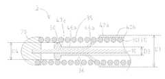
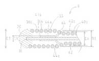
도 1~도 4를 참조하면서, 제1 실시 형태의 가이드 와이어(1)를 설명한다. 도 1에서는, 도면에 나타낸 좌측이 체내에 삽입되는 선단측(원위측(遠位側)), 우측이 의사 등의 시술자에 의해서 조작되는 후단측(근위측(近位側))으로 되어 있다. 도 2는, 도 1의 A-A단면을 나타낸 도면이고, 도 3은, 도 1의 B-B단면을 나타낸 도면이며, 도 4는, 도 1의 C-C단면을 나타낸 도면이다.The guide wire 1 of the first embodiment will be described with reference to Figs. 1 to 4. Fig. In Fig. 1, the left side shown in the drawing is the distal end side (distal side) where it is inserted into the body, and the right side is the rear end side (proximal side) operated by the practitioner such as a doctor. Fig. 2 is a sectional view taken along the line A-A in Fig. 1, Fig. 3 is a sectional view taken along the line B-B in Fig. 1, and Fig. 4 is a sectional view taken along the line C-C in Fig.
가이드 와이어(1)는, 예를 들면, 카테터를 협착부(狹窄部) 또는 폐색부(閉塞部)로 안내하기 위해서 이용되는 가이드 와이어이다. 도 1에 나타내는 바와 같이, 가이드 와이어(1)는, 주로, 코어 샤프트(10)와, 선단 고착부(20)와, 코일체(30)와, 수지층(樹脂層)(40)으로 이루어진다.The guide wire 1 is, for example, a guide wire used for guiding a catheter to a stenosis portion or a closed portion. 1, the guide wire 1 is mainly composed of a
코어 샤프트(10)는, 스테인리스강(SUS304, SUS316 등)이나 Ni-Ti합금의 초탄성 합금 등으로 형성되어 있다.The
코일체(30)는, 코어 샤프트(10)의 외주에, 방사선 불투과성을 가지는 소선(31)을 권회(卷回)하여 형성되어 있다. 코일체(30)를 구성하는 소선(31)에 이용하는 재료로서, 예를 들면, 금, 백금, 텅스텐, 이들 원소로 이루어지는 합금 등을 들 수 있다. 코일체(30)가 방사선 불투과성의 소선(31)으로 형성되어 있음으로써, 시술자는, 방사선 투시 화상(畵像)하에서 코일체(30)의 위치를 파악할 수 있다.The
선단 고착부(20)는, 코어 샤프트(10)의 선단과 코일체(30)의 선단을 고착하고 있으며, 납재(材)(알루미늄합금 납, 은 납, 금 납 등)나 금속 납땜(Au-Sn합금, Ag-Sn합금 등)으로 형성되어 있다.The tip
수지층(40)은, 코일체(30)의 외주를 피복하고, 굵은 외경(D1)을 가지는 후단부(42)와, 후단부(42)보다도 선단측에서 코어 샤프트(10)와 코일체(30)와의 사이에 위치하고, 후단부(42)보다도 가는 외경(D2)을 가지는 선단부(46)와, 후단부(42)와 선단부(46)와의 사이에서 선단측을 향해 외경이 D1으로부터 D2로 축소되는 테이퍼부(44)를 가진다.The
이 수지층(40)에 이용하는 재료로서, 폴리우레탄, 폴리에틸렌, 폴리염화비닐, 폴리에스테르, 폴리프로필렌, 폴리아미드, PTFE 등의 불소계 수지, 실리콘 수지 등을 들 수 있다.Examples of the material used for the
도 1 및 도 2에 나타내는 바와 같이, 수지층(40)의 선단부(46)는, 코어 샤프트(10)와 코일체(30)와의 사이에 위치한다. 도 1 및 도 3에 나타내는 바와 같이, 수지층(40)의 테이퍼부(44)는, 선단측에서 코일체(30)의 내부에 위치하는 한편, 후단측에서 코일체(30)의 외주에 위치한다. 도 1 및 도 4에 나타내는 바와 같이, 수지층(40)의 후단부(42)는, 코일체(30)의 외주에 위치한다.The
코일체(30)의 외주면(35)은, 선단측에서는 수지층(40)에 피복되어 있지 않고, 노출되어 있는 한편, 후단측에서는 수지층(40)의 테이퍼부(44)와 후단부(42)에 피복되어 있다(도 1을 참조). 그 때문에, 수지층(40)의 선단부(46)에서의 코일체(30)는, 수지층(40)에 피복되어 있지 않고, 노출되어 있다.The outer
그 때문에, 가이드 와이어(1)는, 수지층(40)의 후단부(42)에 의해 가이드 와이어(1)의 삽입성을 유지하면서, 수지층(40)에 피복되어 있지 않고, 노출된 코일체(30)에 의해 가이드 와이어(1)의 회전 성능(가이드 와이어(1)의 조작성)을 향상시킬 수 있다. 또, 수지층(40)의 선단부(46)가 코일체(30)의 내부에 위치하기 때문에, 가이드 와이어(1)를 혈관, 담관, 췌관 등에 삽입했을 때에, 수지층(40)이, 그 선단(47)으로부터 박리될(벗겨질) 우려도 저감될 수 있다.The guidewire 1 is not covered with the
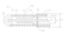
다음으로, 도 5를 참조하면서, 제2 실시 형태의 가이드 와이어(2)를 설명한다. 도 1에 나타낸 가이드 와이어(1)와의 차이점만을 설명하면, 가이드 와이어(2)에서는, 수지층(40a)은, 코일체(30)의 외주를 피복하고, 굵은 외경(D1)을 가지는 후단부(42a)와, 후단부(42a)보다도 선단측에서 코어 샤프트(10)와 코일체(30)와의 사이에 위치하고, 후단부(42a)보다도 가는 외경(D3)을 가지는 선단부(46a)와, 후단부(42a)와 선단부(46a)와의 사이에서 선단측을 향해 외경이 D1으로부터 D3로 축소되는 테이퍼부(44a)를 가진다. 그리고, 수지층(40a)의 선단부(46a)가, 코어 샤프트(10)에 고착되어 있다.Next, the
그 때문에, 가이드 와이어(2)를 만곡된 혈관, 담관, 췌관 등에 삽입한 경우에도, 수지층(40a)의 선단(47a)이 코일체(30)의 소선(31) 사이로부터 외부로 돌출될 우려나, 수지층(40a)이, 그 선단(47a)으로부터 박리될(벗겨질) 우려를 더 저감할 수 있다.Therefore, even when the
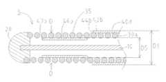
다음으로, 도 6을 참조하면서, 제3 실시 형태의 가이드 와이어(3)를 설명한다. 도 5에 나타낸 가이드 와이어(2)와의 차이점만을 설명하면, 가이드 와이어(3)에서는, 수지층(40b)이, 후단부(42a)와 테이퍼부(44a)와 선단부(46a)를 가지고 있고, 이 선단부(46a)의 선단(47a)에는, 선단부(46a)의 외경(D3)보다도 굵은 외경(D4)을 가지는 팽륭부(50)가 마련되어 있다. 그리고, 수지층(40b)의 선단부(46a) 및 팽륭부(50)는, 코어 샤프트(10)에 고착되어 있다.Next, the
가이드 와이어(3)에서는, 팽륭부(50)는, 수지층(40b)과 동일한 재료로 일체적으로 형성되어 있지만, 이것에 한정되지 않는다. 팽륭부(50)는, 수지층(40b)의 선단부(46a)와는 다른 재료에 의해, 형성해도 괜찮다.In the
팽륭부(50)가, 수지층(40b)의 선단(47a)에 마련되어 있음으로써, 가이드 와이어(3)를 만곡된 혈관, 담관, 췌관 등에 삽입했을 때에, 수지층(40b)이 선단(47a)으로부터 박리되려고(벗겨지려고) 한 경우에도, 수지층(40b)의 선단부(46a)에 마련된 팽륭부(50)가 코일체(30)의 내주면(36)에 걸려, 앵커(anchor) 효과에 의해, 수지층(40b)이 박리될(벗겨질) 우려를 더 저감할 수 있다.When the
또, 도 6에 나타낸 가이드 와이어(3)에서는, 수지층(40b)의 선단부(46a) 및 팽륭부(50)가, 코어 샤프트(10)에 고착되어 있다. 그러나, 이것에 한정되지 않고, 도 7의 제4 실시 형태의 가이드 와이어(4)에 나타내는 바와 같이, 팽륭부(50a)만이 코어 샤프트(10)에 고착되어 있어도 좋다. 도 1에 나타낸 가이드 와이어(1)와의 차이점만을 설명하면, 가이드 와이어(4)에서는, 수지층(40c)이, 후단부(42)와 테이퍼부(44)와 선단부(46)를 가지고 있으며, 이 선단부(46)의 선단(47)에는, 선단부(46)의 외경(D2)보다도 굵은 외경(D4)을 가지는 팽륭부(50a)가 마련되어 있다.6, the
가이드 와이어(4)에서는, 팽륭부(50a)는, 수지층(40c)와 동일한 재료로 일체적으로 형성되어 있지만, 이것에 한정되지 않는다. 팽륭부(50a)는, 수지층(40c)의 선단부(46)와는 다른 재료에 의해, 형성해도 좋다.In the guide wire 4, the
팽륭부(50a)가, 수지층(40c)의 선단(47)에 마련되어 있음으로써, 가이드 와이어(4)를 만곡된 혈관, 담관, 췌관 등에 삽입했을 때에, 수지층(40c)이 선단(47)으로부터 박리되려고(벗겨지려고) 한 경우에도, 수지층(40c)의 선단부(46)에 마련된 팽륭부(50a)가 코일체(30)의 내주면(36)에 걸려, 앵커 효과에 의해, 수지층(40c)이 박리될(벗겨질) 우려를 더 저감할 수 있다.The
다음으로, 도 8을 참조하면서, 제5 실시 형태의 가이드 와이어(5)를 설명한다. 도 1에 나타낸 가이드 와이어(1)와의 차이점만을 설명하면, 가이드 와이어(5)에서는, 수지층(40)의 테이퍼부(44)와 수지층(40)의 후단부(42)와의 경계에, 코어 샤프트(10)와 코일체(30)와 수지층(40)을 고착하는 고착부(60)가 마련되어 있다.Next, the
가이드 와이어(5)에서는, 사전에, 고착부(60)에 의해, 수지층(40)이, 코일체(30) 및 코어 샤프트(10)와 고착되어 있다. 이것에 의해, 가이드 와이어(5)를 협착부 또는 폐색부까지 삽입할 때, 수지층(40)의 테이퍼부(44)와 수지층(40)의 후단부(42)와의 경계에서, 혈관, 담관, 췌관 등의 관벽과의 마찰 저항이 높아지는 경우에도, 가이드 와이어(5)의 삽입시에, 테이퍼부(44)와 후단부(42)와의 경계에서, 수지층(40)이 박리되는(벗겨지는) 것을 더 저감할 수 있다.In the
또, 가이드 와이어(5)에서는, 고착부(60)로서, 접착제를 이용하고 있지만, 그 재료는, 특별히 한정되지 않는다.In the
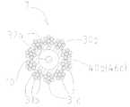
다음으로, 도 9를 참조하면서, 제6 실시 형태의 가이드 와이어(6)를 설명한다. 도 1에 나타낸 가이드 와이어(1)와의 차이점만을 설명하면, 가이드 와이어(6)에서는, 코일체(30a)가, 10개의 소선(31a)이 나선 모양으로 귄회되어 형성되어 있다(도 10을 참조). 또, 도 9에 나타내는 바와 같이, 수지층(40d)은, 코일체(30a)의 외주를 피복하고, 굵은 외경(D1)을 가지는 후단부(42b)와, 후단부(42b)보다도 선단측에서 코어 샤프트(10)와 코일체(30a)와의 사이에 위치하고, 후단부(42b)보다도 가는 외경(D5)을 가지는 선단부(46b)와, 후단부(42b)와 선단부(46b)와의 사이에서 선단측을 향해 외경이 D1으로부터 D5로 축소되는 테이퍼부(44b)를 가진다.Next, the
도 9의 D-D단면인 도 10에 나타내는 바와 같이, 수지층(40d)의 선단부(46b)는, 횡단면에서 볼 때, 코일체(30a)의 인접하는 소선(31a)의 소선 사이(32)에 들어가고 있다.10, the
이것에 의해, 가이드 와이어(6)에서는, 수지층(40d)의 선단부(46b)와 코일체(30a)와의 앵커 효과에 의해(환언하면, 수지층(40d)의 선단부(46b)가, 인접하는 소선(31a)의 소선 사이(32)에 걸려 있음으로써), 수지층(40)의 선단부(46b)가 박리되는(벗겨지는) 것을 더 저감할 수 있다.As a result, in the
또, 도 10에 나타낸 가이드 와이어(6)에서는, 코일체(30a)가, 10개의 소선(31a)이 나선 모양으로 귄회되어 형성되어 있다. 그러나, 이것에 한정되지 않고, 도 11의 제7 실시 형태의 가이드 와이어(7)에 나타내는 바와 같이, 코일체(30a) 대신에, 7개의 소선(31b)을 나선 모양으로 권회한 연선(撚線)(31c)을 미리 준비해 두고, 이 연선(31c)을 10개 묶어 나선 모양으로 귄회하여 형성한 코일체(30b)를 이용해도 좋다. 이 때, 도 11에 나타내는 바와 같이, 수지층(40e)의 선단부(46c)는, 횡단면에서 볼 때, 코일체(30b)의 인접하는 연선(31c)의 소선 사이(32a)에 들어가 있다.In the
이것에 의해, 가이드 와이어(7)에서는, 수지층(40e)의 선단부(46c)와 코일체(30b)와의 앵커 효과에 의해(환언하면, 수지층(40e)의 선단부(46c)가, 인접하는 연선(31c)의 소선 사이(32a)에 걸려 있음으로써), 수지층(40e)의 선단부(46c)가 박리 되는(벗겨지는) 것을 더 저감할 수 있다.As a result, in the
코일체(30a)를 구성하는 소선(31a), 또는, 코일체(31b)를 구성하는 소선(31b)에 이용하는 재료로서, 가이드 와이어(1)의 소선(30)과 마찬가지로, 예를 들면, 금, 백금, 텅스텐, 이들 원소로 이루어지는 합금 등을 들 수 있다. 또, 코일체(30a)를 구성하는 소선(31a)의 갯수는, 10개로 한정되지 않고, 복수개이면 괜찮다. 또, 코일체(30b)를 구성하는 연선(31c)의 갯수도, 10개로 한정되지 않고, 복수개이면 괜찮다. 게다가, 이 연선(31c)을 구성하는 소선(31b)의 갯수도, 7개로 한정되지 않고, 복수개이면 괜찮다.As the material used for the
다음으로, 도 12를 참조하면서, 제8 실시 형태의 가이드 와이어(8)를 설명한다. 도 5에 나타낸 가이드 와이어(2)와의 차이점만을 설명하면, 가이드 와이어(8)에서는, 코일체(30c)가, 수지층(40a)의 후단부(42a)에 위치하는 가는 코일 외경(D6)을 가지는 소경부(62)와, 수지층(40a)의 선단부(46a)에 위치하고, 소경부(62)보다도 굵은 코일 외경(D7)을 가지는 대경부(66)와, 수지층(40a)의 테이퍼부(44a)에 위치하고, 선단측을 향해 코일 외경이 D6로부터 D7로 확대되는 확경부(64)를 가지고 있다. 또, 코일체(30c)의 대경부(66)에서의 코일 외경(D7)은, 수지층(40a)의 후단부(42a)에서의 외경(D1)보다도 크게 되어 있다(D7>D1).Next, the guide wire 8 of the eighth embodiment will be described with reference to Fig. 5, the
그 때문에, 가이드 와이어(8)를 만곡된 혈관, 담관, 췌관 등에 삽입한 경우에도, 수지층(40a)의 테이퍼부(44a)와 수지층(40a)의 후단부(42a)와의 경계가, 혈관, 담관, 췌관 등의 관벽에 접촉될 우려가 저감되고, 그 결과, 가이드 와이어(8)의 삽입시에서의 수지층(40a)의 박리(벗겨짐)를 더 저감할 수 있다.The boundary between the
또, 가이드 와이어(3, 4)와 마찬가지로, 가이드 와이어(5, 6, 7, 8)에서, 선단부(46, 46a, 46b, 46c)의 선단(47, 47a, 47b)에, 팽륭부(50, 50a)를 마련해도 좋다.The distal ends 47, 47a, 47b of the distal ends 46, 46a, 46b, 46c of the
또, 가이드 와이어(5)와 마찬가지로, 가이드 와이어(2, 3, 4, 6, 7, 8)에서, 테이퍼부(44a, 44b)와 후단부(42a, 42b)와의 경계에, 코어 샤프트(10)와 코일체(30, 30a, 30b, 30c)와 수지층(40a~40e)을 고착하는 고착부(60)를 마련해도 괜찮다.In the
게다가, 가이드 와이어(8)와 마찬가지로, 가이드 와이어(1, 3, 4, 5, 6, 7)에서, 코일체(30, 30a, 30b)가, 수지층(40~40e)의 후단부(42, 42a, 42b)에 위치하는 가는 코일 외경(D6)을 가지는 소경부(62)와, 수지층(40~40e)의 선단부(46~46c)에 위치하고, 소경부(62)보다도 굵은 코일 외경(D7)을 가지는 대경부(66)와, 수지층(40~40e)의 테이퍼부(44, 44a, 44b)에 위치하고, 선단측을 향해 코일 외경이 D6로부터 D7로 확대되는 확경부(64)를 가지고, 또한, 코일체(30, 30a, 30b)의 대경부(66)에서의 코일 외경(D7)이, 수지층(40~40e)의 후단부(42, 42a, 42b)에서의 외경(D1)보다도 크게 해도 괜찮다(D7>D1).In addition, in the
또, 상기에서 설명한 가이드 와이어(1~8)에서는, 수지층(40~40e)의 선단부(46~46c)의 선단(47, 47a, 47b)은, 선단 고착부(20)로부터 후단측으로 이간(離間)되어 있었지만, 이것에 한정되지 않는다. 예를 들면, 수지층(40~40e)의 선단부(46~46c)의 선단(47, 47a, 47b)과 선단 고착부(20)을 서로 고착해도 좋다.In the guide wires 1 to 8 described above, the ends 47, 47a and 47b of the distal ends 46 to 46c of the resin layers 40 to 40e are spaced from the distal
1~8 : 가이드 와이어10 :코어 샤프트
20 : 선단 고착부30, 30a, 30b, 30c : 코일체
31, 31a, 31b : 소선31c : 연선
32, 32a : 소선 사이35 : 외주면
40, 40a, 40b, 40c, 40d, 40e : 수지층
42, 42a, 42b : 후단부44, 44a, 44b : 테이퍼부
46, 46a, 46b, 46c : 선단부47, 47a, 47b : 선단
50, 50a : 팽륭부60 : 고착부
62 : 소경부64 : 확경부
66 : 대경부1 to 8: guide wire 10: core shaft
20:
31, 31a, 31b:
32, 32a: between wires 36: outer circumferential surface
40, 40a, 40b, 40c, 40d, 40e:
42, 42a, 42b:
46, 46a, 46b, 46c:
50, 50a: a swelling part 60: a fixing part
62: small-diameter portion 64:
66: Large neck
Claims (6)
Translated fromKorean상기 코어 샤프트의 외주에 권회(卷回)된 코일체와,
상기 코일체의 외주를 피복하고, 굵은 외경(外徑)을 가지는 후단부와, 상기 후단부보다도 선단측에서 상기 코어 샤프트와 상기 코일체와의 사이에 위치하고, 상기 후단부보다도 가는 외경을 가지는 선단부와, 상기 후단부와 상기 선단부와의 사이에서 선단측을 향해 외경이 축소되는 테이퍼부를 가지는 수지층(樹脂層)을 구비하며,
상기 선단부에서의 상기 코일체는, 상기 수지층에 피복되어 있지 않고, 노출되어 있는 것을 특징으로 한 가이드 와이어.A core shaft,
A coil body wound around an outer periphery of the core shaft,
A rear end portion having a large outer diameter and covering the outer periphery of the coil body and a distal end portion located between the core shaft and the coil body at a distal end side of the rear end portion and having a smaller outer diameter than the rear end portion, And a resin layer (resin layer) having a tapered portion whose outer diameter is reduced toward the tip side between the rear end portion and the tip end portion,
Wherein the coil unit at the distal end portion is not covered with the resin layer but is exposed.
상기 수지층의 상기 선단부는, 상기 코어 샤프트에 고착되어 있는 것을 특징으로 한 가이드 와이어.The method according to claim 1,
And the distal end portion of the resin layer is fixed to the core shaft.
상기 수지층의 상기 선단부에는, 상기 선단부의 상기 외경보다도 굵은 외경을 가지는 팽륭부(膨隆部)가 마련되어 있는 것을 특징으로 한 가이드 와이어.The method according to claim 1 or 2,
Wherein the distal end portion of the resin layer is provided with a swollen portion having an outer diameter larger than the outer diameter of the distal end portion.
상기 수지층의 상기 테이퍼부와 상기 수지층의 상기 후단부와의 경계에, 상기 코어 샤프트와 상기 코일체와 상기 수지층을 고착하는 고착부를 구비하고 있는 것을 특징으로 한 가이드 와이어.The method according to any one of claims 1 to 3,
And a fixing portion for fixing the core shaft, the coil body and the resin layer to the boundary between the taper portion of the resin layer and the rear end portion of the resin layer.
상기 코일체는, 복수의 소선(素線)이 나선 모양으로 귄회되어 형성되어 있으며,
상기 수지층의 상기 선단부는, 횡단면에서 볼 때, 상기 코일체의 인접하는 상기 소선 사이에 들어가 있는 것을 특징으로 한 가이드 와이어.The method according to any one of claims 1 to 4,
The coils are formed by spirally winding a plurality of element wires,
Wherein the distal end portion of the resin layer is sandwiched between adjacent strands of the coiled member when viewed from a cross section.
상기 코일체는, 상기 수지층의 상기 후단부에 위치하는 가는 코일 외경을 가지는 소경부(小徑部)와, 상기 수지층의 상기 선단부에 위치하고, 상기 소경부보다도 굵은 코일 외경을 가지는 대경부(大徑部)와, 상기 수지층의 상기 테이퍼부에 위치하고, 선단측을 향해 코일 외경이 확대되는 확경부를 가지고 있으며,
상기 코일체의 상기 대경부에서의 상기 코일 외경은, 상기 수지층의 상기 후단부에서의 외경보다도 크게 되어 있는 것을 특징으로 한 가이드 와이어.The method according to any one of claims 1 to 5,
Wherein the coil body includes a small diameter portion having a fine coil outer diameter located at the rear end of the resin layer and a large diameter portion having a coil outer diameter larger than that of the small diameter portion And a diameter-enlarged portion located in the tapered portion of the resin layer and having an outer diameter enlarged toward the tip side,
Wherein an outer diameter of the coil at the large diameter portion of the coil body is larger than an outer diameter at the rear end portion of the resin layer.
Applications Claiming Priority (1)
| Application Number | Priority Date | Filing Date | Title |
|---|---|---|---|
| PCT/JP2016/075978WO2018042652A1 (en) | 2016-09-05 | 2016-09-05 | Guide wire |
Publications (2)
| Publication Number | Publication Date |
|---|---|
| KR20180038407Atrue KR20180038407A (en) | 2018-04-16 |
| KR102131490B1 KR102131490B1 (en) | 2020-07-07 |
Family
ID=61281904
Family Applications (1)
| Application Number | Title | Priority Date | Filing Date |
|---|---|---|---|
| KR1020177003508AActiveKR102131490B1 (en) | 2016-09-05 | 2016-09-05 | Guide wire |
Country Status (6)
| Country | Link |
|---|---|
| US (1) | US10792474B2 (en) |
| EP (1) | EP3508246B1 (en) |
| JP (1) | JP6319777B1 (en) |
| KR (1) | KR102131490B1 (en) |
| CN (1) | CN108064179B (en) |
| WO (1) | WO2018042652A1 (en) |
Families Citing this family (3)
| Publication number | Priority date | Publication date | Assignee | Title |
|---|---|---|---|---|
| EP4059557A3 (en)* | 2017-09-30 | 2022-09-28 | Asahi Intecc Co., Ltd. | Guide wire |
| CN111432870B (en)* | 2018-02-07 | 2022-08-30 | 朝日英达科株式会社 | guide wire |
| US20230135237A1 (en)* | 2021-04-16 | 2023-05-04 | Bard Peripheral Vascular, Inc. | Strength-adjustable guidewire |
Citations (5)
| Publication number | Priority date | Publication date | Assignee | Title |
|---|---|---|---|---|
| JPH0351060A (en)* | 1989-06-29 | 1991-03-05 | Cook Inc | Wire guide |
| US5549580A (en)* | 1995-01-23 | 1996-08-27 | Cordis Corporation | Catheter having a flexible distal tip and method of manufacturing |
| US5830155A (en)* | 1995-10-27 | 1998-11-03 | Cordis Corporation | Guidewire assembly |
| JP2007075531A (en) | 2005-09-16 | 2007-03-29 | Piolax Medical Device:Kk | Medical guide wire |
| JP2008307367A (en) | 2007-05-11 | 2008-12-25 | Terumo Corp | Guide wire |
Family Cites Families (34)
| Publication number | Priority date | Publication date | Assignee | Title |
|---|---|---|---|---|
| US4554929A (en)* | 1983-07-13 | 1985-11-26 | Advanced Cardiovascular Systems, Inc. | Catheter guide wire with short spring tip and method of using the same |
| US4922924A (en)* | 1989-04-27 | 1990-05-08 | C. R. Bard, Inc. | Catheter guidewire with varying radiopacity |
| US5107852A (en)* | 1990-04-02 | 1992-04-28 | W. L. Gore & Associates, Inc. | Catheter guidewire device having a covering of fluoropolymer tape |
| US5178158A (en)* | 1990-10-29 | 1993-01-12 | Boston Scientific Corporation | Convertible guidewire-catheter with soft tip |
| US5443907A (en)* | 1991-06-18 | 1995-08-22 | Scimed Life Systems, Inc. | Coating for medical insertion guides |
| JP3694524B2 (en)* | 1993-08-23 | 2005-09-14 | ボストン サイエンティフィック コーポレイション | Improved balloon catheter |
| US5840046A (en)* | 1996-06-21 | 1998-11-24 | Medtronic, Inc. | Guidewire having hydrophilic coating |
| US6183420B1 (en)* | 1997-06-20 | 2001-02-06 | Medtronic Ave, Inc. | Variable stiffness angioplasty guide wire |
| US20040082879A1 (en)* | 2000-01-28 | 2004-04-29 | Klint Henrik S. | Endovascular medical device with plurality of wires |
| US20040064069A1 (en)* | 2002-09-30 | 2004-04-01 | Reynolds Brian R. | Medical device with support member |
| US8167821B2 (en)* | 2003-02-26 | 2012-05-01 | Boston Scientific Scimed, Inc. | Multiple diameter guidewire |
| US7407507B2 (en)* | 2003-06-18 | 2008-08-05 | Nipro Corporation | Balloon catheter suited to kissing techniques |
| JP3940161B1 (en)* | 2006-07-03 | 2007-07-04 | 朝日インテック株式会社 | Medical guidewire, medical guidewire and microcatheter assembly, and medical guidewire, balloon catheter and guiding catheter assembly |
| US7896820B2 (en)* | 2006-12-26 | 2011-03-01 | Terumo Kabushiki Kaisha | Guide wire |
| JP2008237253A (en)* | 2007-03-23 | 2008-10-09 | Terumo Corp | Guide wire |
| JP5295104B2 (en)* | 2007-05-09 | 2013-09-18 | 独立行政法人科学技術振興機構 | Guidewire and stent |
| GB0802634D0 (en)* | 2008-02-13 | 2008-03-19 | Renishaw Plc | Catheter |
| US8002715B2 (en)* | 2008-05-30 | 2011-08-23 | Boston Scientific Scimed, Inc. | Medical device including a polymer sleeve and a coil wound into the polymer sleeve |
| JP5147569B2 (en)* | 2008-06-30 | 2013-02-20 | テルモ株式会社 | Guide wire |
| AU2010225987B2 (en)* | 2009-03-19 | 2015-09-03 | Japan Lifeline Co., Ltd. | Medical guide wire |
| US8403867B2 (en)* | 2009-05-14 | 2013-03-26 | Medtronic Vascular, Inc. | Concentric guidewire assembly |
| WO2010134364A1 (en)* | 2009-05-20 | 2010-11-25 | 日本ライフライン株式会社 | Medical guide wire |
| JP5024908B2 (en)* | 2010-01-21 | 2012-09-12 | 朝日インテック株式会社 | Medical guidewire |
| US9320868B2 (en)* | 2010-03-26 | 2016-04-26 | Flip Technologies Limited | Catheter and a method for manufacturing a catheter |
| JP4896245B2 (en)* | 2010-03-31 | 2012-03-14 | 朝日インテック株式会社 | Guide wire |
| JP2012005704A (en)* | 2010-06-25 | 2012-01-12 | Asahi Intecc Co Ltd | Balloon catheter |
| JP5382953B2 (en)* | 2011-01-28 | 2014-01-08 | 朝日インテック株式会社 | Guide wire |
| JP5424499B2 (en)* | 2011-04-18 | 2014-02-26 | 朝日インテック株式会社 | Medical guidewire |
| JP2013013449A (en)* | 2011-06-30 | 2013-01-24 | Asahi Intecc Co Ltd | Guidewire |
| JP2013106854A (en)* | 2011-11-22 | 2013-06-06 | Asahi Intecc Co Ltd | Guidewire |
| JP5404840B2 (en)* | 2012-03-29 | 2014-02-05 | 日本ライフライン株式会社 | Medical guidewire |
| JP6046804B2 (en)* | 2013-04-01 | 2016-12-21 | テルモ株式会社 | COIL, GUIDEWIRE AND COIL MANUFACTURING METHOD |
| JP5954748B2 (en)* | 2014-04-25 | 2016-07-20 | 朝日インテック株式会社 | catheter |
| JP6344762B2 (en)* | 2014-05-21 | 2018-06-20 | 朝日インテック株式会社 | catheter |
- 2016
- 2016-09-05JPJP2016571364Apatent/JP6319777B1/enactiveActive
- 2016-09-05KRKR1020177003508Apatent/KR102131490B1/enactiveActive
- 2016-09-05EPEP16834166.7Apatent/EP3508246B1/enactiveActive
- 2016-09-05WOPCT/JP2016/075978patent/WO2018042652A1/ennot_activeCeased
- 2016-09-05CNCN201680002241.7Apatent/CN108064179B/enactiveActive
- 2017
- 2017-03-06USUS15/450,850patent/US10792474B2/enactiveActive
Patent Citations (5)
| Publication number | Priority date | Publication date | Assignee | Title |
|---|---|---|---|---|
| JPH0351060A (en)* | 1989-06-29 | 1991-03-05 | Cook Inc | Wire guide |
| US5549580A (en)* | 1995-01-23 | 1996-08-27 | Cordis Corporation | Catheter having a flexible distal tip and method of manufacturing |
| US5830155A (en)* | 1995-10-27 | 1998-11-03 | Cordis Corporation | Guidewire assembly |
| JP2007075531A (en) | 2005-09-16 | 2007-03-29 | Piolax Medical Device:Kk | Medical guide wire |
| JP2008307367A (en) | 2007-05-11 | 2008-12-25 | Terumo Corp | Guide wire |
Also Published As
| Publication number | Publication date |
|---|---|
| WO2018042652A1 (en) | 2018-03-08 |
| CN108064179B (en) | 2020-10-30 |
| EP3508246B1 (en) | 2021-08-11 |
| KR102131490B1 (en) | 2020-07-07 |
| US10792474B2 (en) | 2020-10-06 |
| JP6319777B1 (en) | 2018-05-09 |
| US20180064913A1 (en) | 2018-03-08 |
| JPWO2018042652A1 (en) | 2018-09-06 |
| EP3508246A1 (en) | 2019-07-10 |
| EP3508246A4 (en) | 2020-07-22 |
| CN108064179A (en) | 2018-05-22 |
Similar Documents
| Publication | Publication Date | Title |
|---|---|---|
| JP4743800B2 (en) | catheter | |
| JP5954748B2 (en) | catheter | |
| EP3347079B1 (en) | Catheter | |
| EP3162405B1 (en) | Catheter | |
| KR20180048436A (en) | catheter | |
| JPH06504706A (en) | catheter guide wire | |
| KR20170018761A (en) | Catheter and ballon catheter | |
| US10821264B1 (en) | Mixed coil catheter and process for making same | |
| CN113181513B (en) | Guide wire | |
| KR20180038407A (en) | Guide wire | |
| US11484687B2 (en) | Catheter | |
| US11027094B2 (en) | Tubular body and catheter having tubular body | |
| JP5110716B2 (en) | catheter | |
| US12151069B2 (en) | Guide wire | |
| JP7251765B2 (en) | CATHETER AND CATHETER MAKING METHOD | |
| EP3744379B1 (en) | Catheter | |
| JP2018038832A (en) | Guide wire | |
| JP2024040728A (en) | catheter | |
| WO2022118845A1 (en) | Catheter | |
| JP2024082393A (en) | Guidewires |
Legal Events
| Date | Code | Title | Description |
|---|---|---|---|
| PA0105 | International application | Patent event date:20170208 Patent event code:PA01051R01D Comment text:International Patent Application | |
| A201 | Request for examination | ||
| AMND | Amendment | ||
| PA0201 | Request for examination | Patent event code:PA02012R01D Patent event date:20171108 Comment text:Request for Examination of Application | |
| PG1501 | Laying open of application | ||
| E902 | Notification of reason for refusal | ||
| PE0902 | Notice of grounds for rejection | Comment text:Notification of reason for refusal Patent event date:20190624 Patent event code:PE09021S01D | |
| AMND | Amendment | ||
| E601 | Decision to refuse application | ||
| PE0601 | Decision on rejection of patent | Patent event date:20200128 Comment text:Decision to Refuse Application Patent event code:PE06012S01D Patent event date:20190624 Comment text:Notification of reason for refusal Patent event code:PE06011S01I | |
| X091 | Application refused [patent] | ||
| AMND | Amendment | ||
| PX0901 | Re-examination | Patent event code:PX09011S01I Patent event date:20200128 Comment text:Decision to Refuse Application Patent event code:PX09012R01I Patent event date:20190920 Comment text:Amendment to Specification, etc. Patent event code:PX09012R01I Patent event date:20171108 Comment text:Amendment to Specification, etc. | |
| PX0701 | Decision of registration after re-examination | Patent event date:20200511 Comment text:Decision to Grant Registration Patent event code:PX07013S01D Patent event date:20200413 Comment text:Amendment to Specification, etc. Patent event code:PX07012R01I Patent event date:20200128 Comment text:Decision to Refuse Application Patent event code:PX07011S01I Patent event date:20190920 Comment text:Amendment to Specification, etc. Patent event code:PX07012R01I Patent event date:20171108 Comment text:Amendment to Specification, etc. Patent event code:PX07012R01I | |
| X701 | Decision to grant (after re-examination) | ||
| GRNT | Written decision to grant | ||
| PR0701 | Registration of establishment | Comment text:Registration of Establishment Patent event date:20200701 Patent event code:PR07011E01D | |
| PR1002 | Payment of registration fee | Payment date:20200701 End annual number:3 Start annual number:1 | |
| PG1601 | Publication of registration |