KR20180031634A - Tethered filter assemblies and methods for use thereof - Google Patents
Tethered filter assemblies and methods for use thereofDownload PDFInfo
- Publication number
- KR20180031634A KR20180031634AKR1020177035360AKR20177035360AKR20180031634AKR 20180031634 AKR20180031634 AKR 20180031634AKR 1020177035360 AKR1020177035360 AKR 1020177035360AKR 20177035360 AKR20177035360 AKR 20177035360AKR 20180031634 AKR20180031634 AKR 20180031634A
- Authority
- KR
- South Korea
- Prior art keywords
- filter
- wire
- tethered
- mesh
- filter assembly
- Prior art date
- Legal status (The legal status is an assumption and is not a legal conclusion. Google has not performed a legal analysis and makes no representation as to the accuracy of the status listed.)
- Granted
Links
Images


Classifications
- A—HUMAN NECESSITIES
- A61—MEDICAL OR VETERINARY SCIENCE; HYGIENE
- A61F—FILTERS IMPLANTABLE INTO BLOOD VESSELS; PROSTHESES; DEVICES PROVIDING PATENCY TO, OR PREVENTING COLLAPSING OF, TUBULAR STRUCTURES OF THE BODY, e.g. STENTS; ORTHOPAEDIC, NURSING OR CONTRACEPTIVE DEVICES; FOMENTATION; TREATMENT OR PROTECTION OF EYES OR EARS; BANDAGES, DRESSINGS OR ABSORBENT PADS; FIRST-AID KITS
- A61F2/00—Filters implantable into blood vessels; Prostheses, i.e. artificial substitutes or replacements for parts of the body; Appliances for connecting them with the body; Devices providing patency to, or preventing collapsing of, tubular structures of the body, e.g. stents
- A61F2/01—Filters implantable into blood vessels
- A61F2/013—Distal protection devices, i.e. devices placed distally in combination with another endovascular procedure, e.g. angioplasty or stenting
- A—HUMAN NECESSITIES
- A61—MEDICAL OR VETERINARY SCIENCE; HYGIENE
- A61B—DIAGNOSIS; SURGERY; IDENTIFICATION
- A61B17/00—Surgical instruments, devices or methods
- A61B17/22—Implements for squeezing-off ulcers or the like on inner organs of the body; Implements for scraping-out cavities of body organs, e.g. bones; for invasive removal or destruction of calculus using mechanical vibrations; for removing obstructions in blood vessels, not otherwise provided for
- A61B17/22031—Gripping instruments, e.g. forceps, for removing or smashing calculi
- A—HUMAN NECESSITIES
- A61—MEDICAL OR VETERINARY SCIENCE; HYGIENE
- A61F—FILTERS IMPLANTABLE INTO BLOOD VESSELS; PROSTHESES; DEVICES PROVIDING PATENCY TO, OR PREVENTING COLLAPSING OF, TUBULAR STRUCTURES OF THE BODY, e.g. STENTS; ORTHOPAEDIC, NURSING OR CONTRACEPTIVE DEVICES; FOMENTATION; TREATMENT OR PROTECTION OF EYES OR EARS; BANDAGES, DRESSINGS OR ABSORBENT PADS; FIRST-AID KITS
- A61F2/00—Filters implantable into blood vessels; Prostheses, i.e. artificial substitutes or replacements for parts of the body; Appliances for connecting them with the body; Devices providing patency to, or preventing collapsing of, tubular structures of the body, e.g. stents
- A61F2/01—Filters implantable into blood vessels
- A61F2/011—Instruments for their placement or removal
- A—HUMAN NECESSITIES
- A61—MEDICAL OR VETERINARY SCIENCE; HYGIENE
- A61B—DIAGNOSIS; SURGERY; IDENTIFICATION
- A61B17/00—Surgical instruments, devices or methods
- A61B2017/00743—Type of operation; Specification of treatment sites
- A61B2017/00778—Operations on blood vessels
- A61F2002/011—
- A—HUMAN NECESSITIES
- A61—MEDICAL OR VETERINARY SCIENCE; HYGIENE
- A61F—FILTERS IMPLANTABLE INTO BLOOD VESSELS; PROSTHESES; DEVICES PROVIDING PATENCY TO, OR PREVENTING COLLAPSING OF, TUBULAR STRUCTURES OF THE BODY, e.g. STENTS; ORTHOPAEDIC, NURSING OR CONTRACEPTIVE DEVICES; FOMENTATION; TREATMENT OR PROTECTION OF EYES OR EARS; BANDAGES, DRESSINGS OR ABSORBENT PADS; FIRST-AID KITS
- A61F2/00—Filters implantable into blood vessels; Prostheses, i.e. artificial substitutes or replacements for parts of the body; Appliances for connecting them with the body; Devices providing patency to, or preventing collapsing of, tubular structures of the body, e.g. stents
- A61F2/01—Filters implantable into blood vessels
- A61F2/013—Distal protection devices, i.e. devices placed distally in combination with another endovascular procedure, e.g. angioplasty or stenting
- A61F2002/015—Stop means therefor
- A—HUMAN NECESSITIES
- A61—MEDICAL OR VETERINARY SCIENCE; HYGIENE
- A61F—FILTERS IMPLANTABLE INTO BLOOD VESSELS; PROSTHESES; DEVICES PROVIDING PATENCY TO, OR PREVENTING COLLAPSING OF, TUBULAR STRUCTURES OF THE BODY, e.g. STENTS; ORTHOPAEDIC, NURSING OR CONTRACEPTIVE DEVICES; FOMENTATION; TREATMENT OR PROTECTION OF EYES OR EARS; BANDAGES, DRESSINGS OR ABSORBENT PADS; FIRST-AID KITS
- A61F2/00—Filters implantable into blood vessels; Prostheses, i.e. artificial substitutes or replacements for parts of the body; Appliances for connecting them with the body; Devices providing patency to, or preventing collapsing of, tubular structures of the body, e.g. stents
- A61F2/01—Filters implantable into blood vessels
- A61F2002/016—Filters implantable into blood vessels made from wire-like elements
- A—HUMAN NECESSITIES
- A61—MEDICAL OR VETERINARY SCIENCE; HYGIENE
- A61F—FILTERS IMPLANTABLE INTO BLOOD VESSELS; PROSTHESES; DEVICES PROVIDING PATENCY TO, OR PREVENTING COLLAPSING OF, TUBULAR STRUCTURES OF THE BODY, e.g. STENTS; ORTHOPAEDIC, NURSING OR CONTRACEPTIVE DEVICES; FOMENTATION; TREATMENT OR PROTECTION OF EYES OR EARS; BANDAGES, DRESSINGS OR ABSORBENT PADS; FIRST-AID KITS
- A61F2/00—Filters implantable into blood vessels; Prostheses, i.e. artificial substitutes or replacements for parts of the body; Appliances for connecting them with the body; Devices providing patency to, or preventing collapsing of, tubular structures of the body, e.g. stents
- A61F2/01—Filters implantable into blood vessels
- A61F2002/018—Filters implantable into blood vessels made from tubes or sheets of material, e.g. by etching or laser-cutting
- A—HUMAN NECESSITIES
- A61—MEDICAL OR VETERINARY SCIENCE; HYGIENE
- A61F—FILTERS IMPLANTABLE INTO BLOOD VESSELS; PROSTHESES; DEVICES PROVIDING PATENCY TO, OR PREVENTING COLLAPSING OF, TUBULAR STRUCTURES OF THE BODY, e.g. STENTS; ORTHOPAEDIC, NURSING OR CONTRACEPTIVE DEVICES; FOMENTATION; TREATMENT OR PROTECTION OF EYES OR EARS; BANDAGES, DRESSINGS OR ABSORBENT PADS; FIRST-AID KITS
- A61F2230/00—Geometry of prostheses classified in groups A61F2/00 - A61F2/26 or A61F2/82 or A61F9/00 or A61F11/00 or subgroups thereof
- A61F2230/0063—Three-dimensional shapes
- A61F2230/0067—Three-dimensional shapes conical
- A—HUMAN NECESSITIES
- A61—MEDICAL OR VETERINARY SCIENCE; HYGIENE
- A61F—FILTERS IMPLANTABLE INTO BLOOD VESSELS; PROSTHESES; DEVICES PROVIDING PATENCY TO, OR PREVENTING COLLAPSING OF, TUBULAR STRUCTURES OF THE BODY, e.g. STENTS; ORTHOPAEDIC, NURSING OR CONTRACEPTIVE DEVICES; FOMENTATION; TREATMENT OR PROTECTION OF EYES OR EARS; BANDAGES, DRESSINGS OR ABSORBENT PADS; FIRST-AID KITS
- A61F2250/00—Special features of prostheses classified in groups A61F2/00 - A61F2/26 or A61F2/82 or A61F9/00 or A61F11/00 or subgroups thereof
- A61F2250/0004—Special features of prostheses classified in groups A61F2/00 - A61F2/26 or A61F2/82 or A61F9/00 or A61F11/00 or subgroups thereof adjustable
- A61F2250/001—Special features of prostheses classified in groups A61F2/00 - A61F2/26 or A61F2/82 or A61F9/00 or A61F11/00 or subgroups thereof adjustable for adjusting a diameter
- A—HUMAN NECESSITIES
- A61—MEDICAL OR VETERINARY SCIENCE; HYGIENE
- A61F—FILTERS IMPLANTABLE INTO BLOOD VESSELS; PROSTHESES; DEVICES PROVIDING PATENCY TO, OR PREVENTING COLLAPSING OF, TUBULAR STRUCTURES OF THE BODY, e.g. STENTS; ORTHOPAEDIC, NURSING OR CONTRACEPTIVE DEVICES; FOMENTATION; TREATMENT OR PROTECTION OF EYES OR EARS; BANDAGES, DRESSINGS OR ABSORBENT PADS; FIRST-AID KITS
- A61F2250/00—Special features of prostheses classified in groups A61F2/00 - A61F2/26 or A61F2/82 or A61F9/00 or A61F11/00 or subgroups thereof
- A61F2250/0058—Additional features; Implant or prostheses properties not otherwise provided for
- A61F2250/0059—Additional features; Implant or prostheses properties not otherwise provided for temporary
- A—HUMAN NECESSITIES
- A61—MEDICAL OR VETERINARY SCIENCE; HYGIENE
- A61F—FILTERS IMPLANTABLE INTO BLOOD VESSELS; PROSTHESES; DEVICES PROVIDING PATENCY TO, OR PREVENTING COLLAPSING OF, TUBULAR STRUCTURES OF THE BODY, e.g. STENTS; ORTHOPAEDIC, NURSING OR CONTRACEPTIVE DEVICES; FOMENTATION; TREATMENT OR PROTECTION OF EYES OR EARS; BANDAGES, DRESSINGS OR ABSORBENT PADS; FIRST-AID KITS
- A61F2250/00—Special features of prostheses classified in groups A61F2/00 - A61F2/26 or A61F2/82 or A61F9/00 or A61F11/00 or subgroups thereof
- A61F2250/0058—Additional features; Implant or prostheses properties not otherwise provided for
- A61F2250/0069—Sealing means
Landscapes
- Health & Medical Sciences (AREA)
- Life Sciences & Earth Sciences (AREA)
- Engineering & Computer Science (AREA)
- Public Health (AREA)
- Veterinary Medicine (AREA)
- Biomedical Technology (AREA)
- Heart & Thoracic Surgery (AREA)
- Vascular Medicine (AREA)
- General Health & Medical Sciences (AREA)
- Animal Behavior & Ethology (AREA)
- Cardiology (AREA)
- Transplantation (AREA)
- Oral & Maxillofacial Surgery (AREA)
- Surgery (AREA)
- Orthopedic Medicine & Surgery (AREA)
- Nuclear Medicine, Radiotherapy & Molecular Imaging (AREA)
- Medical Informatics (AREA)
- Molecular Biology (AREA)
- Surgical Instruments (AREA)
Abstract
Translated fromKoreanDescription
Translated fromKorean본 출원은 개괄적으로 의료 수술 중에 사용하기 위한 필터 조립체에 관한 것으로, 보다 상세하게는, 폐색 물질을 포집하기 위한 테더형 메쉬 필터에 관한 것이다.The present application relates generally to filter assemblies for use during medical surgeries, and more particularly, to a mesh type filter for capturing occlusion material.
다양한 혈관 수술 중에, 색전 물질 등의 입자가 혈관 벽에서 제거될 수 있다. 예를 들어, 죽종절제 중에, 불림기(macerator)를 사용하여 동맥 내의 플라크를 연마할 수 있는데, 그로 인해 플라크의 입자가 동맥 벽에서 떨어져 나와 혈류로 들어갈 수 있다. 제거된 입자를 포획하지 않거나 혈류에서 제거하지 않으면, 입자는 다른 곳에서 폐색이나 색전증을 유발할 수 있다. 입자의 크기 및 폐색이 발생하는 곳에 따라, 폐색은 심각한 합병증을 유발할 수 있다. 예를 들어, 폐색이 심장에서 일어나면, 갑자기 심근 경색이나 심장 마비가 발생할 수 있다.During various vascular surgeries, particles such as embolic materials may be removed from the vessel wall. For example, during an aneurysm, a plaque within the artery can be polished using a macerator, which can cause particles of plaque to fall off the arterial wall and enter the bloodstream. If the removed particles are not captured or removed from the bloodstream, the particles may cause occlusion or embolism elsewhere. Depending on the size of the particles and where the occlusion occurs, occlusion can lead to serious complications. For example, if a blockage occurs in the heart, sudden cardiac infarction or heart attack can occur.
제거된 입자로 인한 폐색의 위험을 줄이기 위해서 필터를 사용할 수 있다. 이 필터는 의료 수술 중에 혈류에서 잠재적으로 폐색 물질을 포집하고 모으는 데 사용할 수 있다. 필터는 의료 수술의 위치로부터 하류에서 혈관의 내강에 위치될 수 있다. 필터는 작은 입자와 혈액은 통과할 수 있게 하면서, 폐색을 유발하기에 충분히 큰 입자를 포집하도록 설계할 수 있다. 수술이 종료된 후, 필터는 포집된 입자와 함께 혈관에서 제거할 수 있다.A filter can be used to reduce the risk of blockage due to removed particles. This filter can be used to collect and collect potentially occlusive substances from the bloodstream during medical procedures. The filter may be located in the lumen of the vessel downstream from the location of the medical operation. The filter can be designed to capture particles large enough to cause occlusion, allowing small particles and blood to pass through. After the operation is terminated, the filter can be removed from the vessel along with the captured particles.
도 1은 필터 조립체의 일 예를 제공한다. 테더형 필터 조립체(100)는 전방단(도시 생략) 및 후방단(101a)을 지닌 필터 와이어(101)를 갖는다. 필터 조립체(100)는 전방단(110a) 및 후방단(110b)을 지닌 필터(110)를 추가로 갖는다. 필터(110)의 전방단(110a)은 필터 와이어(101)의 후방단(101a)에 결합될 수 있으며, 필터(110)의 후방단(110b)은 가요성 부재(105)에 결합될 수 있다. 가요성 부재(105)는 필터 와이어(101) 또는 필터(110)보다 덜 경질의 재료로 형성될 수 있다. 필터(110)의 후방단(110b)은 적어도 필터 와이어(101)의 축방향을 따라 자유도를 가질 수 있다.Figure 1 provides an example of a filter assembly. The tethered
필터(110)는 장경(長徑, major diameter) (106)을 갖는 메쉬(102)를 구비할 수 있다. 메쉬(102)는 일련의 공극을 생성하도록 이격되어 있는 메쉬 부재를 구비할 수 있다. 공극은 혈류 내 폐색 물질 같은 특정 크기의 입자를 수집하거나 통과시킬 수 있는 크기를 가질 수 있다. 필터(110)는 개구 직경(107)내로 함께 개방되는 2개 이상의 지지부재(103)를 추가로 구비할 수 있다. 개구 직경(107)은 메쉬(102)의 장경(106)보다 작다. 개구 직경(107)은 지지부재(103)가 메쉬(102)에 부착되는 지점에 배치된다.The
또한, 필터(110)는 팽창 가능할 수도 있다. 혈관 내에 배치하기 전에, 필터(110)는 압축되어 슬리브 또는 외피(sheath)안에 감싸질 수 있다. 전개 중에, 필터(110)는 혈관 내에서 어느 한 위치로 이동된 후 슬리브에 대해 이동될 수 있으며, 이는 필터(110)가 팽창되어 혈관의 직경을 채울 수 있게 한다. 일단 팽창되면, 필터(110)의 메쉬(102)는 혈관의 내부면과 실질적으로 접촉할 수 있다. 메쉬(102)는 혈관을 통해 흐르는 혈액 내의 입자를 포집하도록 동작할 수 있다.In addition, the
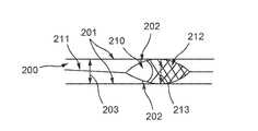
필터 조립체(100)와 같은 기존의 필터 조립체는 혈류에 포함되어 있는 특정 입자를 모을 수 있지만, 몇 가지 단점을 지닌다. 도 2에서, 필터(210) 및 필터 와이어(211)를 갖는 필터 조립체는 환자의 혈관에 배치된다. 혈관은 혈관 내강(vessel lumen) (200) 및 혈관 벽(201)을 갖는다. 필터(210)는 혈관 내에 끼워져서 이 필터(210)의 메쉬(212)가 혈관 벽(201)의 내부면과 실질적으로 접촉하도록 하는 크기를 가질 수 있다. 그와 같이, 팽창된 상태 (가령, 자유로운 상태)에서, 필터(210)는 메쉬(212)가 혈관 벽(201)과 접촉할 때까지 증가하는 장경(213)을 가질 수 있다.Conventional filter assemblies, such as
필터 와이어(211)의 전방단(도시 생략)은 환자의 외부에 위치될 수 있으며, 필터 와이어(211)의 후방단은 혈관 내강(200) 내에 위치될 수 있다. 폐색 물질을 담지하고 있는 혈액이 필터(210)를 통해 흘러감에 따라서, 폐색 물질(도시 생략)의 일부는 필터(210)의 메쉬(212)에 의해서 포집될 수 있다. 그러나, 필터(210)의 원추 형상으로 인해, 메쉬(212)의 전방단과 혈관 벽(201) 사이에는 공간이 존재할 수 있으며, 이 공간에 폐색 물질의 축적물(202)이 있을 수 있다. 따라서, 필터(210)가 혈관으로부터 제거되는 경우, 도 2와 같이 축적된 폐색 물질 축적물(202)은 혈류내로 방출될 수 있다. 그러한 폐색 물질은 다른 혈관의 하류에 머무를 수 있다.The front end (not shown) of the
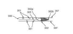
필터 조립체가 혈관 벽의 내부에 대해 유지되지 않는 경우, 폐색 물질은 또한 필터 조립체를 우회하여 폐색의 위험을 야기할 수도 있다. 도 3에 도시한 바와 같이, 필터 조립체가 혈관 내에서 적절하게 전개되는 경우, 필터 조립체의 필터(302)는 혈관의 혈관 벽(307)과 실질적으로 접촉한다. 그러한 상태에서, 필터(302)는 혈관의 내강(300)을 통해 이송되는 혈류 내의 폐색 물질(301)을 포집할 수 있다.If the filter assembly is not held against the interior of the vessel wall, the occluding material may also bypass the filter assembly and cause a risk of occlusion. As shown in FIG. 3, when the filter assembly is properly deployed in a blood vessel, the
필터(302)의 전방단(302a)은 필터 와이어(305)에 부착될 수 있으며, 필터(302)의 후방단(302b)은 구속되지 않을 수 있다. 필터 와이어(305)를 전방으로 급격하게 당기면, 축방향으로 구속되지 않은 필터(302)의 후방단(302b)이 필터 와이어(305) 및 필터(302)의 전방단(302a)과 함께 즉시 이송될 수 없기 때문에, 필터(302)는 붕괴될 수 있다 (도 4 참조). 붕괴 시, 필터(302)는 더 이상 혈관 벽(307)과 접촉하지 않을 수 있고, 폐색 물질(401)은 필터(302)와 혈관 벽(307) 사이의 영역에서 필터(302)를 지나서 이송될 수 있다.The
또 다른 문제는 필터 조립체에 의해 포집된 폐색 물질이 너무 커서 의료 기구(503)를 통한 제거가 불가한 경우에 발생할 수 있다. 예를 들어, 도 5에 도시한 바와 같이, 혈관 벽(505) 내로 전개된 필터(502)는 다양한 크기를 지닌 폐색 물질을 포집할 수 있다. 흡인 카테터 등의 의료 기구(503)는, 그 후방단이 필터(502)에 결합되어 폐색 물질을 진공 흡입하는 필터 와이어(504) 상에 도입될 수 있다. 그러나, 의료 기구(503)는 필터(502) 내의 모든 폐쇄 물질을 제거하지 못할 수도 있다. 한편, 의료 기구(503)는 너무 작은 개구를 가져 도 5에 도시된 입자(501) 같은 큰 폐색 물질을 제거할 수 없다. 다른 한편으로, 필터 와이어(504) 상에 도입된 의료 기구(503)는 지지부재(506)에 의해 필터(502)에 들어가는 것이 차단되어 폐색 물질들을 모두 제거할 수는 없다. 따라서, 의료 기구(503)의 개구에 끼워질 수 있지만 필터(502)의 먼쪽 단에 위치되는 입자(500) 같은 작은 폐색 물질은 혈관으로부터 완전히 제거될 수 없다. 게다가, 의료 기구(503)는 큰 입자(501) 뒤에 모아진 작은 입자(500)까지 도달하지 못할 수 있다.Another problem may arise if the occlusion material captured by the filter assembly is too large to be removed through the
입자(501)를 의료 기구(503)에 의해 진공 흡입할 수 있는 더 작은 입자들로 분해하기 위해, 기계적 혈전제거 불림기를 혈관 내에 도입할 수 있다. 그러나, 기계적 혈전제거 불림기는 입자(501)를 분해하기 위해 필터(502)에 들어가는 것이 지지부재(506)에 의해서 차단될 수 있다.A mechanical thrombectomy device can be introduced into the blood vessel to break down the
허용 가능한 양의 폐색 물질이 필터(502)로부터 제거되지 않는 경우, 다양한 합병증이 발생할 수 있다. 예를 들어, 환자로부터 필터(502)를 제거할 때, 폐색 물질의 일부가 풀리게 되어 필터(502)로부터 빠져 나와서, 폐색전의 위험을 증가시킬 수 있다. 제거 중에 필터(502)가 폐색 물질로 가득차게 되면, 혈관 벽(505)에 대한 필터(502)의 측면의 스크래핑으로 인해 혈종 및 추가적인 응고의 위험을 증가시킬 수 있다. 또한, 그의 가득 찬 크기로 인해 기존 접근 채널(channel)을 통해 혈관으로부터 필터(502)를 제거할 수 없으면, 필터(502)는 수술적인 비효율을 생성하고, 수술의 후기 단계에서 이용할 필요가 있는 장치에 대한 접근을 차단할 수 있다. 따라서, 공지된 테더형 메쉬 필터의 이 같은 한계를 극복하기 위해 신규의 테더형 메쉬 필터가 필요하다.If an acceptable amount of occlusion material is not removed from the
본 발명은 테더형 메쉬 필터의 전술한 및 그 밖의 단점과 결점을 극복한다. 특정 실시예와 관련하여 본 발명을 설명하지만, 본 발명은 이들 실시예로 한정되지 않는다는 것을 이해할 것이다. 반대로, 본 발명은 본 발명의 범위 내에 포함될 수 있는 모든 대안, 변형 및 균등물을 포함한다.The present invention overcomes the above and other disadvantages and drawbacks of the tethered mesh filter. While the invention will be described in conjunction with specific embodiments, it will be understood that the invention is not limited to these embodiments. On the contrary, the invention includes all alternatives, modifications and equivalents that may be included within the scope of the present invention.
본 발명의 일 측면에 따르면, 필터 조립체는 필터를 포함한다. 필터는 지지부재를 포함하는 전방부와 메쉬를 포함하는 후방부를 구비할 수 있다. 전방부는 제 1장경을 가지며 후방부는 제 2장경을 갖는다. 제 1상태에서, 제 2장경은 제 1장경보다 작을 수 있다.According to an aspect of the invention, the filter assembly includes a filter. The filter may have a front portion including a support member and a rear portion including a mesh. The front portion has a first long diameter and the rear portion has a second long diameter. In the first state, the second long diameter may be smaller than the first long diameter.
다른 측면에 따르면, 필터 조립체는 필터 와이어, 내강을 포함하는 관형 부재 및 필터를 포함한다. 필터는 지지부재를 포함하는 전방부와 메쉬를 포함하는 후방부를 구비할 수 있다. 관형 부재는 필터의 전방단에 부착될 수 있고, 필터 와이어는 필터의 후방단에 부착될 수 있다. 필터는, 이 필터의 특정 상태에 따라 변화될 수 있는 장경을 갖는다.According to another aspect, a filter assembly includes a filter wire, a tubular member including a lumen, and a filter. The filter may have a front portion including a support member and a rear portion including a mesh. The tubular member can be attached to the front end of the filter, and the filter wire can be attached to the rear end of the filter. The filter has a long diameter that can be changed according to the specific state of the filter.
또 다른 측면에 따르면, 필터 조립체는 제 1메쉬를 포함하는 제 1부분, 지지부재를 포함하는 제 2부분, 및 제 2메쉬를 포함하는 제 3부분을 갖는 필터를 구비한다. 제 1부분은 제 1장경을 가지며, 제 2부분은 제 2장경을 가지며, 제 3부분은 제 3장경을 갖는다. 필터는 제 1상태로 있으며, 제 1부분은 제 2부분 및 제 3부분에 근접하게 배치되고, 제 2부분은 제 3부분에 근접하게 배치되며, 제 1장경, 제 2장경, 및 제 3장경은 서로 동일하다.According to another aspect, a filter assembly includes a filter having a first portion including a first mesh, a second portion including a support member, and a third portion including a second mesh. The first part has a first long diameter, the second part has a second long diameter, and the third part has a third long diameter. The filter is in a first state, the first portion is disposed proximate to the second portion and the third portion, the second portion is disposed proximate the third portion, and the first long shaft, the second long shaft, Are the same.
본 발명의 상기 및 그 밖의 목적과 장점은 첨부 도면 및 그의 설명으로부터 명백해질 것이다.These and other objects and advantages of the present invention will become apparent from the accompanying drawings and the description thereof.
본 발명에 개시한 내용을 용이하게 이해할 수 있도록, 본 개시의 측면을 첨부 도면에 예로서 도시한다.To facilitate the understanding of what is disclosed herein, aspects of the present disclosure are shown by way of example in the accompanying drawings.
도 1은 혈관 내의 폐색 물질을 포집하는 필터 조립체의 단면도이다.
도 2는 필터 조립체의 측면이 혈관 벽과 접촉하는 혈관 내로 전개된 필터 조립체를 도시하는 혈관의 단면도이다.
도 3은 혈관 내로 전개된 필터 조립체를 향해 이송되는 폐색 물질을 도시하는 혈관의 단면도이다.
도 4는 혈관 내로 전개된 필터 조립체를 지나서 이송되는 폐색 물질을 도시하는 혈관의 단면도이다.
도 5는 필터 조립체에 의해 포집된 폐색 물질을 제거하기 위해 혈관 내로 도입된 의료 기구를 도시하는 혈관의 단면도이다.
도 6은 본 발명 개시의 제 1예시적인 측면에 따라 혈관 내의 폐색 물질을 포집하는 필터 조립체의 단면도이다.
도 7은 혈관 내로 전개된 도 6의 필터 조립체를 도시하는 혈관의 단면도이다.
도 8은 본 발명 개시의 제 2예시적인 측면에 따라 혈관 내의 폐색 물질을 포집하는 필터 조립체의 단면도이다. 필터 조립체는 도 8에서 제 1상태로 도시되어 있다.
도 9는 제 2상태로 있는 도 8의 필터 조립체의 단면도이다.
도 10은 제 3상태로 있는 도 8의 필터 조립체의 단면도이다.
도 11은 본 발명 개시의 측면들에 따른 필터 조립체의 와이어 위치에 대해 필터 조립체의 외피 위치를 잠금하는 로킹 장치의 사시도이다.
도 12는 본 개시의 제 3예시적인 측면에 따라 혈관 내의 폐색 물질을 포집하는 필터 조립체의 단면도이다. 필터 조립체는 도 12에서 제 1상태로 도시되어 있다.
도 13은 제 2상태로 있는 도 12의 필터 조립체의 단면도이다.
도 14는 제 2상태로 전개되고 혈관 내의 폐색 물질을 포집하도록 위치된 도 12의 필터 조립체를 도시하는 단면도이다.
도 15는 본 발명 개시의 제 4예시적인 측면에 따라 혈관 내의 폐색 물질을 포집하는 필터 조립체의 화상이다.
도 16, 도 17 및 도 18은 다수의 상이한 상태로 있는 도 15의 필터 조립체를 도시하는 화상이다.
도 19는 본 개시의 제 5예시적인 측면에 따라 혈관 내의 폐색 물질을 포집하는 필터 조립체의 단면도이다. 필터 조립체는 도 19에서 제 1상태로 도시되어 있다.
도 20은 제 2상태로 있는 도 19의 필터 조립체의 단면도이다.
도 21은 본 발명 개시의 제 6예시적인 측면에 따라 혈관 내의 폐색 물질을 포집하는 필터 조립체의 단면도이다.
도 22는 제 1상태로 혈관 내로 전개된 도 21의 필터 조립체를 도시하는 혈관의 단면도이다.
도 23은 제 2상태로 혈관 내로 전개되고 혈관 내의 폐색 물질을 포집하도록 위치된 도 21의 필터 조립체를 도시하는 혈관의 단면도이다.
도 24는 도 21의 필터 조립체에 의해 포집된 폐색 물질을 제거하기 위해 혈관 내로 도입된 의료기구를 도시하는 혈관의 단면도이다.
도 25는 제 3상태로 혈관 내로 전개되고 혈관 내의 폐색 물질을 포집하도록 위치된 도 21의 필터 조립체를 도시하는 혈관의 단면도이다.
이들 예시적인 테더형 필터 조립체의 측면들을 도면을 참조하여 설명하되, 전체에 걸쳐 동일한 참조 부호는 동일한 부분을 나타낸다.BRIEF DESCRIPTION OF THE DRAWINGS Figure 1 is a cross-sectional view of a filter assembly that captures occlusions in a vessel.
FIG. 2 is a cross-sectional view of a blood vessel showing a filter assembly deployed into a blood vessel with a side of the filter assembly in contact with the blood vessel wall. FIG.
Figure 3 is a cross-sectional view of a vessel showing obstruction material being delivered into the filter assembly deployed into the vessel.
Figure 4 is a cross-sectional view of a vessel showing occlusion material being delivered past the filter assembly deployed into the vessel.
5 is a cross-sectional view of a blood vessel showing a medical device introduced into a blood vessel to remove occluded material trapped by the filter assembly.
Figure 6 is a cross-sectional view of a filter assembly that captures occlusive material in a vessel according to a first exemplary aspect of the present disclosure.
7 is a cross-sectional view of a blood vessel illustrating the filter assembly of FIG. 6 deployed into a blood vessel.
8 is a cross-sectional view of a filter assembly that captures occlusive material in a vessel according to a second exemplary aspect of the present disclosure; The filter assembly is shown in the first state in Fig.
Figure 9 is a cross-sectional view of the filter assembly of Figure 8 in a second state.
Figure 10 is a cross-sectional view of the filter assembly of Figure 8 in a third state;
11 is a perspective view of a locking device that locks the jacket position of the filter assembly relative to the wire position of the filter assembly according to aspects of the present disclosure;
12 is a cross-sectional view of a filter assembly that captures occlusive material in a vessel according to a third exemplary aspect of the present disclosure; The filter assembly is shown in the first state in FIG.
Figure 13 is a cross-sectional view of the filter assembly of Figure 12 in a second state.
14 is a cross-sectional view of the filter assembly of FIG. 12 that is deployed to a second state and positioned to capture occlusion material in a blood vessel.
Figure 15 is an image of a filter assembly that captures occlusive material in a vessel according to a fourth exemplary aspect of the present disclosure.
Figures 16, 17 and 18 are images illustrating the filter assembly of Figure 15 in a number of different states.
19 is a cross-sectional view of a filter assembly that captures occlusive material in a vessel according to a fifth exemplary aspect of the present disclosure. The filter assembly is shown in a first state in Fig.
Figure 20 is a cross-sectional view of the filter assembly of Figure 19 in a second state.
Figure 21 is a cross-sectional view of a filter assembly that captures occlusive material in a vessel according to a sixth exemplary aspect of the present disclosure.
22 is a cross-sectional view of a blood vessel showing the filter assembly of FIG. 21 deployed into a blood vessel into a first state;
23 is a cross-sectional view of a blood vessel showing the filter assembly of FIG. 21 deployed into the vessel into a second state and positioned to capture occlusion material in the vessel.
24 is a cross-sectional view of a blood vessel illustrating a medical device introduced into a blood vessel to remove occluded material captured by the filter assembly of FIG.
25 is a cross-sectional view of a blood vessel showing the filter assembly of FIG. 21 deployed into a vessel in a third state and positioned to capture occlusion material in the vessel.
The aspects of these exemplary tethered filter assemblies are described with reference to the drawings, wherein like reference numerals refer to like parts throughout.
본원에 개시된 시스템 및 방법은 기존의 필터 조립체와 관련된 단점을 극복하는 테더형 메쉬 필터를 제공한다. 본원에 개시된 시스템 및 방법은 메쉬 및 지지부재를 포함하는 폐색 물질을 포집하기 위한 필터 조립체를 제공하며, 여기서 필터의 장경은 지지부재를 따라 배치될 수 있다. 메쉬와 지지부재는 1 이상의 자유도로 이동할 수 있게 결합된다.The systems and methods disclosed herein provide a tethered mesh filter that overcomes the disadvantages associated with conventional filter assemblies. The systems and methods disclosed herein provide a filter assembly for trapping occlusion material comprising a mesh and a support member, wherein the long diameter of the filter can be disposed along the support member. The mesh and the support member are movably coupled in one or more degrees of freedom.
이제 도 6을 참조하면, 제 1예시적인 측면이 도시되어 있다. 필터 조립체(650)는 테더형 필터(600)를 포함할 수 있다. 테더형 필터(600)는 메쉬(604)와 지지부재(605)를 포함한다. 메쉬(604)는 개구 직경(602)을 가질 수 있고, 지지부재(605)는 장경(601)을 가질 수 있다. 자유로운 상태나 팽창된 상태에서, 지지부재(605)의 장경(601)은 메쉬(604)의 개구 직경(602)보다 크다.Referring now to FIG. 6, a first exemplary aspect is illustrated. The
테더형 필터(600)는 전방단(600a) 및 후방단(600b)을 가질 수 있다. 지지부재(605)는 지점(606)에 굴곡을 갖고서 형성될 수 있다. 특히, 지지부재(605)는 테더형 필터(600)의 전방단(600a)에서 서로 접촉할 수 있고, 테더형 필터(600)의 길이를 따라 이어지는 중심축으로부터 외측으로 굴곡점(606)까지 연장될 수 있다. 굴곡점(606)에서, 지지부재(605)는 테더형 필터(600)의 중심축을 향해 후방으로 연장될 수 있다. 따라서, 지지부재(605)의 장경(601)은 굴곡점(606)에 위치될 수 있다.The
메쉬(604)는 원추형으로 형성될 수 있고 테더형 필터(600)의 후방단(600b)까지 지지부재(605)와의 접촉점으로부터 내부로 연장될 수 있다. 따라서, 메쉬(604)의 개구 직경(602)은 메쉬(604)의 전방단에 위치된다.The mesh 604 may be conically shaped and extend inwardly from the point of contact with the
테더형 필터(600)는 팽창 가능하다. 혈관 내에 배치하기 전에, 테더형 필터(600)는 압축되어 외피(도 6에 도시 생략)안에 감싸질 수 있다. 전개 중에, 테더형 필터(600)는 혈관 내의 어느 한 위치로 이동될 수 있고, 외피가 제거되어, 테더형 필터(600)가 혈관의 직경까지 팽창할 수 있게 한다.The
테더형 필터(600)는 혈관 내에 끼워져서 메쉬(604)가 혈관과 실질적으로 접촉하도록 하는 크기를 가질 수 있다. 메쉬(604)와의 접촉을 가능케 하기 위해, 지지부재(605)의 장경(601) 및 메쉬(604)의 개구 직경(602)은 혈관의 내경과 같거나 그보다 클 수 있다.The
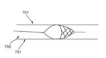
도 7에 도시된 혈관은 혈관 벽(701)과 혈관 내강(700)을 갖는다. 필터(600)가 혈관 내강(700) 내로 전개되면, 필터(600)는 접선을 가질 수 있고 혈관 벽(701)의 내부면과 실질적으로 접촉할 수 있다. 혈관 벽(701)의 내부면과 필터(600) 간의 접촉이 지지부재(605)를 따르는 지점 및 메쉬(604)로부터 더 상류에서 시작하므로, 메쉬(604)의 전방단과 혈관 벽(701) 사이에는 공간이 존재하지 않는다. 따라서, 폐색 물질은 필터(600)와 혈관 벽(701) 사이에 축적될 수 없으며, 이는 테더형 필터(600) 가 혈관에서 제거되는 동안 그러한 물질이 혈류로 다시 빠져 나갈 위험을 감소시킨다.The blood vessel shown in Fig. 7 has a
도 8에 도시된 제 2예시적인 측면에 따르면, 필터 조립체(850)는 와이어(800), 튜브(801) 및 테더형 필터(802)를 포함한다. 와이어(800)는 전방단(800a) 및 후방단(800b)을 갖고; 튜브(801)는 전방단(80la) 및 후방단(801b)을 가지며, 전방단(80la)과 후방단(801b) 사이에는 내강(808)이 있고; 테더형 필터(802)는 전방단(802a) 및 후방단(802b)을 갖는다. 와이어(800)는 튜브(801)의 내강(808)을 통해 환자의 외부로부터 테더형 필터(802)의 후방단(802b)까지 연장될 수 있다. 테더형 필터(802)의 전방단(802a)은 튜브(801)의 후방단(801b)에 결합될 수 있다. 테더형 필터(802)의 후방단(802b)은 와이어(800)의 후방단(800b)에 결합될 수 있다. 따라서, 와이어(800)에 대한 튜브(801)의 축방향 이동으로 테더형 필터(802)의 형상이 변화될 수 있다.8, the
테더형 필터(800)는 도 8에서 제 1위치로 도시되어 있다. 제 1위치에서, 테더형 필터(800)는 구속되지 않거나 자유로운 상태일 수 있다. 노출된 와이어(800)는 제 1길이(805)를 가질 수 있다. 테더형 필터(802)는 제 1길이(806) 및 제 1개구 직경(807)을 가질 수 있다. 테더형 필터(802)의 개구 직경(807)은 목표 혈관의 직경과 같거나 그보다 클 수 있다.The
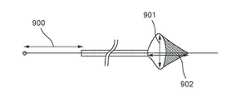
도 9는 제 2위치에 있는 테더형 필터(800)를 도시한다. 제 2위치에서, 테더형 필터(802)는 제 1길이(806)보다 작은 제 2길이(902) 및 제 1개구 직경(807)보다 큰 제 2개구 직경(901)을 가지도록 구속될 수 있다. 와이어(800)는 전방으로 당겨질 수 있으며, 튜브(801)는 후방으로 밀려서 테더형 필터(802)를 제 2위치에 구속할 수 있다. 와이어(800)는, 노출된 와이어(800)의 제 1길이(805)보다 큰 노출된 와이어(800)의 제 2길이(900)를 가질 수 있다.Figure 9 shows a
도 10은 제 3위치에 있는 테더형 필터(800)를 도시한다. 제 3위치에서 테더형 필터(802)는 구속되어, 제 1길이(806)보다 큰 제 3길이(1002) 및 제 1개구 직경(807)보다 작은 제 3개구 직경(1001)을 가질 수 있다.Figure 10 shows a
와이어(800)는 후방으로 밀릴 수 있거나, 튜브(804)는 전방으로 당겨져 테더형 필터(802)를 제 3위치에 구속할 수 있다. 와이어(800)는, 노출된 와이어(800)의 제 1길이(805)보다 작은 노출된 와이어의 제 3길이(1000)를 가질 수 있다.The
테더형 필터(802)가 도 8에 도시된 구속되지 않은 위치에 있는 경우, 테더형 필터(802)는 도 6에 도시된 필터(600)와 마찬가지로 기능할 수 있다. 테더형 필터(802)가 도 9 및 도 10에 도시된 형상 같이, 다른 형상으로 구속되는 경우, 필터는 각각 증가되거나 감소된 혈관과의 접촉을 가질 수 있다.When the
일부 측면에서, 테더형 필터(802)는 도 11에 도시된 로킹 장치(1100)를 사용하여 특정 형상으로 로킹될 수 있다. 로킹 장치(1100)는 튜브 커플러(1105) 및 와이어 커플러(1101)를 포함할 수 있다. 튜브 커플러(1105)는 튜브(1102)에 선택적으로 결합될 수 있고, 와이어 커플러(1101)는 와이어(1103)에 선택적으로 결합될 수 있다. 튜브(1102)는 튜브(801)에 대응할 수 있고, 와이어(1103)는 와이어(800)에 대응할 수 있다.In some aspects, the
와이어 커플러(1101)는 튜브 커플러(1105)의 연장부재(1104)의 축을 따라 슬라이딩될 수 있다. 와이어 커플러(1101) 및 튜브 커플러(1105)는 그들의 각 위치에서 선택적으로 언로킹되거나 로킹될 수 있다. 구체적으로, 와이어 커플러(1101) 및 튜브 커플러(1105)는 여러 상이한 방식으로 서로에 대해 자기 위치에서 로킹될 수 있다. 예를 들어, 와이어 커플러(1101)는 와이어 커플러(1101)와 연장부재(1104) 간의 마찰 또는 간섭을 이용하여 연장부재(1104)를 따라 자기 위치에서 로킹될 수 있다. 다른 예로서, 와이어 커플러(1101)는 클램핑 레버 또는 그 밖의 레버 설계를 이용하여 연장부재(1104)를 따라 자기 위치에서 유지될 수 있다. 또 다른 예로서, 와이어 커플러(1101)는 연장부재(1104)를 따라 이산점의 어느 한 위치에서 로킹되는 연동 홈 또는 노치를 통해 연장부재(1104)를 따라 그 위치에서 로킹될 수 있다.The
튜브 커플러(1105) 및 와이어 커플러(1101)는 각각 튜브(1102) 및 와이어(1103)에 선택적으로 결합되고 서로에 대해 선택적으로 자기 위치에서 로킹될 때, 필터(802)의 구속 및 비 구속을 가능케 할 수 있다. 또한, 튜브(1102)와 와이어(1103)가 선택적으로 분리될 때, 튜브 커플러(1105) 및 와이어 커플러(1101)는 어떤 방해도 받지 않고 의료 기구가 튜브 - 와이어 조립체를 통과할 수 있게 한다.The
테더형 필터(802)가 특정 형상으로 로킹되는 경우, 테더형 필터(802)는, 와이어(800)의 임의의 움직임이 튜브(801)의 동일한 이동을 가져오고 필터(802)의 형상에 아무런 영향을 주지 않으므로, 와이어(800)의 임의의 급격한 움직임에 관계없이 혈관과 동일한 접촉 정도를 유지할 수 있다. 와이어(800)의 임의의 급격한 이동에 관계없이 동일한 접촉 정도를 유지함으로써, 폐색 물질은 테더형 필터(802)와 혈관 벽 사이의 공간을 통해 테더형 필터(802)를 지나서 흐를 수 없게 된다. 따라서, 폐색 물질이 테더형 필터(802)를 통과하여 이송됨으로 인한 폐색전과 관련된 합병증을 최소화할 수 있다.When the
제 3예시적인 측면에 따른 필터 조립체가 도 12에 도시되어 있다. 필터 조립체(1250)는 와이어(1200), 튜브(1201), 및 테더형 필터(1203)를 포함한다. 테더형 필터(1203)는 메쉬(1202) 및 지지부재(1205)를 갖는다. 테더형 필터(1203)는 지지부재(1205)를 따라 지점(1204)에 위치된 장경을 갖는다.A filter assembly according to a third exemplary aspect is shown in Fig. The
메쉬(1202)는 테더형 필터(1203)의 전방영역(1207)에 위치되고, 지지부재(1205)는 테더형 필터(1203)의 후방영역(1208)에 위치된다. 그러므로, 도 12에 도시한 바와 같이, 전방영역(1207)에 위치된 메쉬(1202)의 전방단은 튜브(1201)의 후방단에 결합될 수 있고, 후방영역(1208)에 위치된 지지부재(1205)의 후방단은 와이어(1200)의 후방단에 결합될 수 있다. 게다가, 메쉬(1202)의 후방단은 지지부재(1205)의 전방단에 결합될 수 있다.The
필터 조립체(1250)는 (메쉬(1202)를 포함한) 전방영역(1207)이 튜브(1201)의 후방단에 결합 시 테더형 필터(1203)의 제 1자유도를 가능케 할 수 있다. 필터 조립체(1250)는 (메쉬(1202)를 포함한) 전방영역(1207)이 후방영역(1208)에 결합 시 테더형 필터(1203)의 제 2자유도를 추가로 가능케 할 수 있다. 그러한 결합은 테더형 필터(1203)의 반전을 가능케 할 수 있으며, 도 13에 도시한 바와 같이, 메쉬(1202)는 후방영역(1208)의 내부에서 접힐 수 있다.The
도 12에서, 테더형 필터(1203)는 제 1위치에 도시되어 있다. 제 1위치에서, 테더형 필터(1203)는 구속되지 않거나 자유로운 상태일 수 있다. 도 13에서, 테더형 필터(1203)는 제 2위치에 도시되어 있다. 제 2위치에서, 테더형 필터(1203)는 메쉬(1202)가 후방영역(1208)의 내부에서 접힌 상태로 구속될 수 있다.In Fig. 12, the
테더형 필터(1203)를 제 2위치에 구속시키는 한 가지 방법은 와이어(1200)를 전방으로 당기는 것일 수 있다. 그의 후방단에서 와이어(1200)에 결합된 후방영역(1208)은 다음에, 와이어(1200)와 함께 전방으로 이동할 수 있다. 후방영역(1208)이 전방으로 이동하기 시작함에 따라, 메쉬(1202)는 그 자체를 따라 반전되거나 접히기 시작할 수 있다. 와이어(1200)가 전방으로 최대량으로 당겨지면, 메쉬(1202)는 완전히 반전되어 지지부재(1205) 내에 위치될 수 있다.One way to constrain the
테더형 필터(1203)를 제 2위치에 구속시키는 두번째 방법은 튜브(1201)를 후방으로 미는 것일 수 있다. 튜브(1207)가 후방으로 이동함에 따라, 전방영역(1207)의 메쉬(1202)는 다시 그 자체를 따라 반전되거나 접힐 수 있다.A second way of restraining the tethered
도 14에 도시한 바와 같이, 테더형 필터(1203)가 혈관(1400)의 내강(1305) 내로 전개되고 완전히 반전된 상태로 전이되는 경우, 테더형 필터(1203)는 혈관 벽(1404)과 실질적으로 접촉할 수 있다. 구체적으로, 테더형 필터(1203)의 지지부재(1205)는 혈관 벽(1404)과 실질적으로 접촉할 수 있다. 메쉬(1202)도 혈관 벽(1404)과 실질적인 접촉을 이룰 수 있다. 전개됨에 따라, 테더형 필터(1203)는 작은 폐색 물질(1403) 및 큰 폐색 물질(1402) 같은 혈류 내의 폐색 물질을 포집할 수 있다.14, when the
테더형 필터(1203)에 의해 포집된 폐색 물질을 제거하기 위해, 흡인 카테터 또는 기계적 혈전제거 불림기 같은 의료 기구(1405)를 와이어(1200) 상에서 혈관(1400) 내로 도입할 수 있다. 그의 반전 위치에 있는 테더형 필터(1203)는 의료 기구(1405)가 포집된 폐색 물질과 접촉하도록 할 수 있다. 따라서, 의료 기구(1405)가 기계적 혈전제거 불림기인 경우, 기계적 혈전제거 불림기는 큰 폐색 물질(1402)을 더 작은 입자들로 분해하는데 사용할 수 있다. 그리고, 의료 기구(1405)가 흡인 카테터인 경우, 흡인 카테터는 테더형 필터(1203)로부터 작은 폐색 물질(1403)을 효과적으로 제거하는데 사용할 수 있다.A
특정 측면에서, 흡인 카테터는 추가적인 와이어(도시 생략)를 사용하여 혈관(1400) 내로 도입할 수 있다. 흡인 카테터는 먼저 와이어(1200) 상에 삽입될 수 있고, 흡인 카테터의 후방단이 테더형 필터(1203)에 근접하거나 또는 그와 접촉할 때까지 와이어(1200)를 따라 이동될 수 있다. 다음에, 추가적인 와이어의 후방단이 테더형 필터(1203)에 근접하거나 그와 접촉할 때까지 추가적인 와이어는 흡인 카테터 내로 도입될 수도 있다. 다음에, 흡인 카테터가 제거되고, 그의 후방단이 다시 한번 테더형 필터(1203)에 근접하거나 접촉할 때까지 와이어(1200) 대신에 추가적인 와이어 상에 카테터가 재삽입될 수 있다. 다음에, 추가적인 와이어가 제거될 수 있다. 이제, 흡인 카테터는 와이어(1200) 또는 그 안에 배치된 추가적인 와이어 없이 테더형 필터(1203)로부터 폐색 물질(1403) 같은 폐색 물질을 보다 효과적으로 제거할 수 있다.In particular aspects, the suction catheter may be introduced into the
도 15에 도시된 제 4예시적인 측면에 따르면, 필터 조립체(1550)는 와이어(1504), 튜브(1500) 및 테더형 필터(1502)를 포함한다. 테더형 필터(1502)는 전방영역(1512) 및 후방영역(1514)을 갖는다. 전방영역(1512)은 일련의 공극을 생성하는 일련의 부재를 구비한다. 공극은 메쉬(1506)를 생성한다. 후방영역(1514)은 지지부재(1508)를 포함한다. 테더형 필터(1502)는 메쉬(1506)를 따라 지점(1510)에 위치된 장경을 갖는다.According to a fourth exemplary aspect shown in FIG. 15, the
와이어(1504)는 전방단(도시 생략) 및 후방단(1500a)에서 튜브(1500) 밖으로 연장될 수 있다. 테더형 필터(1502)의 전방단(1502a)은 튜브(1500)의 후방단(1500a)에 결합될 수 있다. 테더형 필터(1502)의 후방단(1502b)은 와이어(1504)의 후방단(1504a)에 결합될 수 있다. 또한, 테더형 필터(1502)의 후방단(1502b)은 또 다른 와이어(1516)에 결합될 수도 있다. 와이어(1516)는 와이어(1504)보다 큰 유연성을 가질 수 있다.The
도 15에서, 테더형 필터(1502)는 제 1위치에 도시되어 있다. 제 1위치에서, 테더형 필터(1502)는 구속되지 않거나 또는 자유로운 상태일 수 있다. 도 16 내지 도 18에서, 테더형 필터(1502)는 그의 구속되지 않은 위치로부터 도 18에 도시된 반전 위치로 변한다. 일부 측면에서, 테더형 필터(1502)는 와이어(1504)를 전방으로 이동(도 15 도시 상태를 기준하여 우측 방향으로 잡아당김)함으로써 반전 위치로 변화될 수 있고, 다른 측면에서, 테더형 필터(1502)는 튜브(1500)를 와이어(1516) 측 방향으로 밀어 이동시킴으로써 반전 위치로 변화될 수 있다.In Fig. 15, the
테더형 필터(1502)가 그의 구속되지 않은 위치로부터 반전 위치로 변함에 따라, 메쉬(1506)는 먼저 길이가 압축되고, 이어서 길이가 다시 팽창될 수 있다. 도 18에 도시된 반전 위치에서, 메쉬(1506)는 후방영역(1514)의 내부에 위치된다.As the
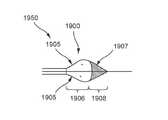
도 19는 제 5측면에 따른 필터 조립체(1950)를 도시한다. 필터 조립체(1950)는 테더형 필터(1900)를 포함한다. 테더형 필터(1900)는 지지부재(1905) 및 메쉬(1907)를 갖는다. 지지부재(1905)는 테더형 필터(1900)의 전방영역(1906)에 위치되고, 메쉬(1907)는 테더형 필터(1900)의 후방영역(1908)에 위치된다.Figure 19 shows a
테더형 필터(1900)는 자유로운 상태 또는 구속되지 않은 상태로 도 19에 도시되어 있다. 도 20에서, 테더형 필터(1900)는 지지부재(1905)가 메쉬(1907)의 내부에 위치되는 제 2상태로 변화된다. 메쉬(1907) 내에서 지지부재(1905)는 메쉬(1907) 내부의 일부에 대한 접근을 차단할 수 있다. 그러한 구성은, 메쉬(1907)의 후방단으로부터 일정 거리만큼 떨어져 의료기구를 위치시키는 것이 바람직한 경우, 예를 들어 광 또는 센서 등의 특정 의료기구와 함께 사용하는 것이 바람직하다.The
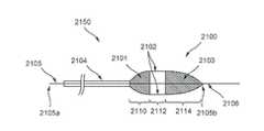
도 21은 제 6예시적인 측면을 도시하며, 필터 조립체(2150)는 테더형 필터(2100), 튜브(2104), 및 와이어(2105)를 포함한다. 테더형 필터(2100)는 제 1메쉬(2101), 제 2메쉬(2103), 및 지지부재(2102)를 포함한다. 제 1메쉬(2101 )는 필터(2100)의 제 1전방영역(2110)에 위치될 수 있고; 제 2메쉬(2103)는 필터(2100)의 후방영역(2114)에 위치될 수 있고; 지지부재(2102)는 필터(2100)의 제 2전방영역(2112)에 위치될 수 있다. 제 2전방영역(2112)은 제 1전방영역(2110)에 대해 후방일 수 있고, 후방영역(2114)은 제 1전방영역(2110) 및 제 2전방영역(2112) 모두에 대해 후방일 수 있다.FIG. 21 illustrates a sixth exemplary aspect, wherein
제 1메쉬(2101)는 전방단에서 튜브(2104)에, 그리고 후방단에서 지지부재(2102)에 결합될 수 있다. 지지부재(2102)는 후방단에서 제 2메쉬(2103)에 결합될 수 있다.The
와이어(2105)는 전방단(2105a) 및 후방단(2105b)을 가질 수 있다. 전방단(2105a)는 튜브(2104)의 외부에 위치될 수 있다. 후방단(2105b)은 제 2메쉬(2103)의 후방단에 결합될 수 있다. 필터 조립체(2150)는 또한 와이어(2105)보다 유연한 추가적인 와이어(2106)도 포함할 수 있다. 추가적인 와이어(2106)의 전방단은 제 2메쉬(2103)의 후방단에 결합될 수 있다.The
도 21에 도시한 바와 같이, 테더형 필터(2100)는 제 1위치에 있다. 제 1위치에서, 테더형 필터(2100)는 구속되지 않거나 자유로운 상태일 수 있다. 그의 제 1위치에 있는 필터 조립체(2150)는 도 22에 도시한 바와 같이, 환자의 신체 내에서 혈관 내강(2200) 내로 전개되어 구속될 수 있다. 제 1메쉬(2101), 지지부재(2102) 및 제 2메쉬(2103)는 혈관 벽(2201)과 실질적으로 접촉한다.As shown in Fig. 21, the
전개됨에 따라, 튜브(2104)의 전방단(2104a)은 환자의 신체 외부에 위치될 수 있고, 와이어(2105)의 전방단(2105a)도 환자의 신체 외부에 위치될 수 있다. 와이어(2105)의 전방단(2105a)은 튜브(2104)의 전방단(2104a) 밖으로 연장될 수 있다.The
도 23에서, 테더형 필터(2100)는 혈관 내강(2200)에서 제 2위치로 전개된다. 제 2위치에서, 테더형 필터(2100)는, 제 1전방영역(2110)의 적어도 일부가 테더형 필터(2100)의 제 2전방영역(2112) 내에 위치되는 경우로 구속된다. 테더형 필터(2100)를 제 2위치에 구속시키는 한 가지 방법은 와이어(2105)의 전방단(2105a)을 도시 상태를 기준하여 우측 방향으로 잡아당겨 이동시키거나 또는 튜브(2104)의 전방단(2104a)으로부터 떨어져 이동시키는 것이다. 테더형 필터(2100)를 제 2위치에 구속시키는 또 다른 방법은 튜브(2104)의 전방단(2104a)을 제 2메쉬(2103) 측을 향해 밀어 이동시키는 것이다.23, the
제 2위치로 전개될 때, 제 1전방영역(2110)의 전방단, 제 2전방영역(2112) 및 후방영역(2114)의 전방단은 혈관 벽(2101)과 실질적으로 접촉한다. 제 1메쉬(2101)는 제 1일반 형상 및 크기의 폐색 물질(2301)을 포집할 수 있다. 제 1일반 형상 및 크기의 폐색 물질(2301)보다 작은 제 2일반 형상 및 크기의 폐색 물질(2302)은 테더형 필터(2100)를 통과하여 혈류를 통해서 계속 갈 수 있다.The front end of the first
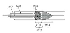
도 24에서, 제 1일반 형상 및 크기의 폐색 물질(2301)은 제 1메쉬(2101) 내에 포집된 것으로 도시되어 있다. 도 12에 도시된 필터 조립체(1250)와 마찬가지로, 제 1메쉬(2101)는 의료 기구(2400)가 테더형 필터(2100)의 전방영역(2110) 내로 튜브(2104) 상에 삽입되도록 허용할 수 있다. 의료 기구(2400)는 폐색 물질(2301)을 더 작은 크기로 분해하는데 사용할 수 있는 기계적 혈전제거 기구일 수 있거나, 전방영역(2110)으로부터 폐색 물질(2301)을 제거하는데 사용할 수 있는 흡인 카테터일 수 있다.24, a first general shape and size of occluding
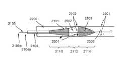
도 25에서, 테더형 필터(2100)는 혈관 내강(2200) 안에서 제 3위치에 도시되어 있다. 제 3위치에서,제 1전방영역(2110) 및 제 2전방영역(2112)의전방단은 혈관 벽(2201)과 실질적으로 접촉하지 않지만, 제 2전방영역(2112)의 후방단 및 후방영역(2114)의 전방단은 혈관 벽(2201)과 실질적으로 접촉한다. 또한, 제 1전방영역(2110)은 제 2전방영역(2112) 내에 위치되지 않는다. 테더형 필터(2100)를 제 3위치로 이동시키기 위해, 와이어(2105)의 전방단(2105a)이 후방으로 또는 튜브(2104)의 전방단(2104a)을 향해 이동될 수 있거나, 튜브(2104)가 전방으로 이동될 수 있다.In Fig. 25, the
테더형 필터(2100)가 제 2위치에서 제 3위치로 이동될 때, 제 1메쉬(2101)로부터 제거되지 않은 폐색 물질(2501) 같은 임의의 폐색 물질이 풀려나게 되는데, 이는 제 1메쉬(2101)가 그의 구속 상태에서 그의 구속되지 않은 상태로 다시 반전될 수 있기 때문에, 즉 오목한 형상과는 반대로 볼록한 형상으로 변화될 수 있기 때문이다. 그럼에도 불구하고, 전방영역(2110) 및 제 2전방영역(2112)의 전방단이 혈관 벽(2201)과 접촉하지 않기 때문에, 최소 크기의 폐색 물질(2501)은 제 1전방영역(2110) 및 제 2전방영역(2112)에서 후방영역(2114)으로 하류로 흐를 수 있으며, 제 2메쉬(2103)에 의해 포획될 수 있다. 작은 크기의 폐색 물질(2502)은 테더형 필터(2100)를 자유롭게 통과할 수 있다. 다음에, 테더형 필터(2100)는 후방영역(2114) 내의 폐색 물질(2501)과 함께 환자의 신체로부터 제거될 수 있다.When the
본원에 개시된 시스템 및 방법은 필터 와이어 및 필터를 포함하는 필터 조립체를 제공한다. 필터는 제 1장경을 갖고 다수의 지지부재를 포함하는 전방부와; 제 2장경을 갖고 메쉬를 포함하는 후방부를 포함하고 있다. 필터 와이어는 필터의 전방단에 부착된다. 그리고, 필터가 구속되지 않은 상태로 있을 때, 제 2장경은 제 1장경보다 작다. 필터의 지지부재는 구속되지 않은 상태에서 제 1장경의 위치에 대응하는 지점에서 굴곡을 가질 수 있다.The systems and methods disclosed herein provide filter assemblies that include filter wires and filters. The filter includes a front portion having a first long diameter and including a plurality of support members; And a rear portion having a second longest diameter and including a mesh. The filter wire is attached to the front end of the filter. And, when the filter is in an unconstrained state, the second longest diameter is smaller than the first longest diameter. The support member of the filter may have a curvature at a position corresponding to the position of the first long shaft in the unconstrained state.
또한, 필터는 전개된 상태를 가질 수도 있으며, 이때 필터 조립체는 혈관의 내강 안에 배치되고, 제 2장경은 제 1장경과 동일하다.The filter may also have a deployed condition, wherein the filter assembly is disposed in the lumen of the blood vessel, and the second long diameter is the same as the first long diameter.
또한, 본원에 개시된 시스템 및 방법은 필터 와이어, 관형 부재 및 필터를 포함하는 필터 조립체를 제공한다. 관형 부재는 벽과 그 안에 내강을 구비하며, 필터 와이어의 제 1부분은 관형 부재의 내강 안에 배치되고 필터 와이어의 제 2부분은 관형 부재의 전방단에 근접하게 배치된다. 필터는 다수의 지지부재 및 메쉬를 포함하며, 필터는 장경을 갖는다. 필터의 전방단은 관형 부재의 후방단에 부착되고, 필터의 후방단은 필터 와이어의 후방단에 부착된다. 필터는 구속되지 않은 상태로부터 제 1구속 상태로 변화될 수 있으며, 이때 제 1구속 상태에서 필터의 장경은 구속되지 않은 상태에서 필터의 장경보다 크고, 제 1구속 상태에서 필터 와이어의 제 2부분의 길이는 구속되지 않은 상태에서 필터 와이어의 제 2부분의 길이보다 크다.In addition, the systems and methods disclosed herein provide filter assemblies including filter wires, tubular members, and filters. The tubular member has a wall and a lumen therein, wherein a first portion of the filter wire is disposed in the lumen of the tubular member and a second portion of the filter wire is disposed proximate the front end of the tubular member. The filter includes a plurality of support members and a mesh, and the filter has a long diameter. The front end of the filter is attached to the rear end of the tubular member, and the rear end of the filter is attached to the rear end of the filter wire. The filter can be changed from the unconstrained state to the first restrained state wherein the long diameter of the filter in the first restrained state is greater than the long diameter of the filter in the unrestrained state and in the first restrained state, The length is greater than the length of the second portion of the filter wire in unconstrained state.
일 측면에서, 필터는 구속되지 않은 상태에서 제 2구속 상태로 추가로 변하고, 구속되지 않은 상태로부터 제 2구속 상태로 추가로 변화되며, 이때는 구속되지 않은 상태에서 필터의 장경보다 작고, 또한 제 1구속 상태에서 필터 와이어의 제 2부분의 길이는 구속되지 않은 상태에서 필터 와이어의 제 2부분의 길이보다 작다.In one aspect, the filter further changes from a non-restrained state to a second restrained state, and further changes from a non-restrained state to a second restrained state, wherein the restrained state is less than the long- The length of the second portion of the filter wire in the constrained state is less than the length of the second portion of the filter wire in the unconstrained state.
또 다른 측면에서, 필터 조립체는 로킹 장치를 더 포함한다. 로킹 장치는 필터 와이어에 부착되는 제 1부재와, 관형 부재에 부착되는 제 2부재를 포함한다. 제 2부재는 슬라이딩부를 포함할 수 있으며, 제 1부재는 제 2부재의 슬라이딩부에 부착되고, 제 1부재는 슬라이딩부의 길이에 의해 규정된 축을 따라 이동하며, 제 1부재는 슬라이딩부의 길이에 의해 규정된 축을 따라 자기 위치에서 로킹된다. 제 1부재는 마찰 접촉, 레버 및 노치 중 적어도 하나를 이용하여 자기 위치에서 로킹될 수 있다. 로킹 장치는 필터 와이어 및 관형 부재로부터 선택적으로 분리될 수 있다.In yet another aspect, the filter assembly further includes a locking device. The locking device includes a first member attached to the filter wire and a second member attached to the tubular member. The second member may include a sliding portion, wherein the first member is attached to the sliding portion of the second member, the first member moves along the axis defined by the length of the sliding portion, and the first member is fixed by the length of the sliding portion And is locked at its own position along the prescribed axis. The first member may be locked in its magnetic position using at least one of a frictional contact, a lever and a notch. The locking device can be selectively separated from the filter wire and the tubular member.
또한, 본원에 개시된 시스템 및 방법은 필터 와이어, 관형 부재 및 필터를 포함하는 필터 조립체도 제공하며, 필터는 메쉬를 포함하는 전방부와 다수의 지지부재를 포함하는 후방부를 구비한다. 관형 부재는 벽 및 내강을 구비하며, 필터 와이어의 제 1부분은 관형 부재의 내강 안에 배치되고 필터 와이어의 제 2부분은 관형 부재의 전방단에 근접하게 배치된다. 필터의 전방단은 관형 부재의 후방단에 부착될 수 있고, 필터의 후방단은 필터 와이어의 후방단에 부착될 수 있다.The system and method disclosed herein also provides a filter assembly comprising a filter wire, a tubular member and a filter, the filter having a front portion including a mesh and a rear portion including a plurality of support members. The tubular member has walls and lumens wherein a first portion of the filter wire is disposed in the lumen of the tubular member and a second portion of the filter wire is disposed proximate the front end of the tubular member. The front end of the filter can be attached to the rear end of the tubular member and the rear end of the filter can be attached to the rear end of the filter wire.
일 측면에서, 필터는 구속되지 않은 상태로부터 구속 상태로 변화되며, 여기서 필터의 전방부는 구속되지 않은 상태에서 필터의 후방부에 근접하게 배치되고, 필터의 전방부는 구속 상태에서 필터의 후방부 내에 배치되며, 구속 상태에서 필터 와이어의 제 2부분의 길이는 구속되지 않은 상태에서 필터 와이어의 제 2부분의 길이보다 크다.In one aspect, the filter is changed from the unconstrained state to the restrained state, wherein the front portion of the filter is disposed proximate to the rear portion of the filter in an unrestrained state, and the front portion of the filter is disposed within the rear portion of the filter in the restrained state And the length of the second portion of the filter wire in the constrained state is greater than the length of the second portion of the filter wire in the unconstrained state.
또한, 본원에 개시된 시스템 및 방법은 필터 와이어, 관형 부재 및 필터를 포함하는 필터 조립체도 제공하며, 필터는 제 1메쉬를 포함하는 제 1전방부와, 다수의 지지부재를 포함하는 제 2전방부와, 제 2메쉬를 포함하는 후방부를 구비한다. 관형 부재는 벽과 그 안에 내강을 구비하며, 필터 와이어의 제 1부분은 관형 부재의 내강 안에 배치되고, 필터 와이어의 제 2부분은 관형 부재의 전방단에 근접하게 배치된다. 필터의 전방단은 관형 부재의 후방단에 부착될 수 있고, 필터의 후방단은 필터 와이어의 후방단에 부착될 수 있다.The system and method disclosed herein also provides a filter assembly comprising a filter wire, a tubular member and a filter, the filter comprising a first front portion including a first mesh, a second front portion including a plurality of support members, And a rear portion including a second mesh. The tubular member has a wall and a lumen therein, wherein a first portion of the filter wire is disposed in the lumen of the tubular member and a second portion of the filter wire is disposed proximate the front end of the tubular member. The front end of the filter can be attached to the rear end of the tubular member and the rear end of the filter can be attached to the rear end of the filter wire.
일 측면에서, 필터는 구속되지 않은 상태로부터 구속 상태로 변화되며, 여기서 필터의 제 1전방부는 구속되지 않은 상태에서 필터의 제 2전방부에 근접하게 배치되고, 필터의 제 1전방부는 구속 상태에서 필터의 제 2전방부 내에 배치되고, 구속 상태에서 필터 와이어의 제 2부분의 길이는 구속되지 않은 상태에서 필터 와이어의 제 2부분의 길이보다 크다.In one aspect, the filter is changed from the unconstrained state to the restrained state, wherein the first front portion of the filter is disposed proximate to the second front portion of the filter in an unconstrained state, and the first front portion of the filter is in a restrained state And the length of the second portion of the filter wire in the constrained state is greater than the length of the second portion of the filter wire in the unconstrained state.
또한, 본원에 개시된 시스템 및 방법은 필터의 전개 방법도 제공하고, 이 방법은 필터를 혈관계에 삽입하는 단계와, 필터를 혈관계 내에서 미리 결정된 위치로 이동시키는 단계와, 혈관계로부터 외피를 제거하여 필터를 제 1상태로 전개하는 단계와, 제 1상태로부터 제 2상태로 변화시키는 단계를 포함하고, 제 2상태에서 필터의 전방부는 필터의 후방부 내에 배치되고, 제 2상태에서 필터는 미리 결정된 위치에 근접한 혈관계에서 이동하는 입자를 수용하고 유지한다. 일 측면에서, 필터를 혈관계에 삽입하는 단계는 접근 장치 내에 배치된 외피에 필터를 삽입하는 단계를 포함할 수 있고, 외피의 적어도 일부 및 접근 장치의 일부는 혈관계 내에 배치된다.The system and method disclosed herein also provide a method of deploying a filter, comprising the steps of inserting a filter into the vascular system, moving the filter to a predetermined position in the vascular system, removing the envelope from the vascular system, Wherein the front portion of the filter is disposed within the rear portion of the filter in the second state and the filter in the second state is positioned at a predetermined position Lt; RTI ID = 0.0 > vascular < / RTI > In one aspect, inserting the filter into the vascular system may include inserting a filter into the sheath disposed within the access device, wherein at least a portion of the sheath and a portion of the access device are disposed within the vascular system.
또한, 본원에 개시된 시스템 및 방법은 필터를 사용하여 입자를 제거하는 방법도 제공하며, 이 방법은 필터의 제 1와이어 상에 카테터를 제 1미리 결정된 위치까지 삽입하는 단계를 포함하고, 필터는 혈관계 내에 배치되며, 카테터의 후방단은 제 1미리 결정된 위치에서 필터에 근접하며, 카테터는 내강을 포함한다. 이 방법은 제 2와이어를 카테터의 내강 안으로 제 2미리 결정된 위치까지 삽입하는 단계를 더 포함하고, 제 2미리 결정된 위치에서 제 2와이어의 후방단은 필터에 근접한다. 이 방법은 또한 카테터를 제거하는 단계와; 카테터를 제 2와이어 상에 제 3미리 결정된 위치까지 삽입하는 단계로, 제 3미리 결정된 위치에서 카테터의 후방단은 필터에 근접한 단계와; 제 2와이어를 제거하는 단계와; 카테터를 사용하여 필터 내에 유지된 입자를 제거하는 단계도 포함한다. 일 측면에서, 제 3미리 결정된 위치에서 카테터의 후방단은 필터 내에 배치될 수 있다.The system and method disclosed herein also provides a method of removing particles using a filter, the method comprising inserting a catheter onto a first wire of a filter to a first predetermined position, The rear end of the catheter is proximate to the filter at a first predetermined position, and the catheter includes a lumen. The method further comprises inserting a second wire into the lumen of the catheter to a second predetermined location, wherein the back end of the second wire at a second predetermined location is proximate to the filter. The method also includes removing the catheter; Inserting the catheter to a third predetermined position on the second wire, the posterior end of the catheter at a third predetermined position proximate to the filter; Removing the second wire; And removing the particles retained in the filter using a catheter. In one aspect, the back end of the catheter at a third predetermined location can be disposed within the filter.
또한, 본원에 개시된 시스템 및 방법은 필터를 사용하여 입자를 제거하는 방법도 제공하며, 이 방법은 필터의 와이어 상에 흡인 카테터를 미리 결정된 위치까지 삽입하는 단계를 포함하고, 필터는 혈관계 내에 배치되며, 미리 결정된 위치에서 흡인 카테터의 후방단은 필터 내에 배치된다. 이 방법은 흡인 카테터를 사용하여 필터에 유지된 입자를 제거하는 단계를 더 포함한다.In addition, the systems and methods disclosed herein also provide a method of removing particles using a filter, the method comprising inserting a suction catheter onto a wire of the filter to a predetermined position, wherein the filter is disposed within the vascular system , The rear end of the suction catheter at a predetermined position is disposed in the filter. The method further comprises removing particles retained in the filter using a suction catheter.
또한, 본원에 개시된 시스템 및 방법은 필터를 사용하여 입자를 제거하는 방법도 제공하며, 이 방법은 필터의 와이어 상에 혈전제거 기구를 미리 결정된 위치까지 삽입하는 단계를 포함하고, 필터는 혈관계 내에 배치되고, 미리 결정된 위치에서 혈전제거 기구의 후방단은 필터 내에 배치된다. 이 방법은 혈전제거 기구를 사용하여 필터에 유지된 입자를 다수의 작은 부분들로 분리하는 단계를 더 포함한다.The system and method disclosed herein also provide a method of removing particles using a filter, the method comprising inserting a thrombus removal mechanism onto a wire of the filter to a predetermined position, wherein the filter is disposed within the vascular system And the rear end of the thrombus removing device at a predetermined position is disposed in the filter. The method further comprises separating the particles held in the filter into a plurality of small portions using a thrombus removal mechanism.
본 발명의 원리에 따라 다양한 측면들을 다양한 실시예들의 설명에 의해 예시함과 아울러, 실시예를 매우 상세하게 설명하였으나, 이들 실시예는 본 발명의 범위를 어떤 식으로든 그러한 세부사항으로 한정하거나 제한하려는 것은 아니다. 본원에 도시하고 설명한 다양한 특징들은 단독으로 또는 임의의 조합으로 사용할 수 있다. 추가적인 장점 및 수정이 당업자에게는 쉽게 보일 것이다. 그러므로, 보다 넓은 측면에서 본 발명은 도시하고 설명한 특정 세부사항, 대표적인 장치 및 방법과 예시적인 예로 제한되지 않는다. 따라서, 일반적인 발명의 개념 범위로부터 벗어남이 없이 그러한 세부사항으로부터 변화가 이루어질 수 있다.While the embodiments have been described in great detail with various aspects in accordance with the principles of the present invention illustrated and described in conjunction with the description of various embodiments, these embodiments are not intended to limit or limit the scope of the invention in any way to such details. It is not. The various features shown and described herein may be used alone or in any combination. Additional advantages and modifications will readily appear to those skilled in the art. Therefore, in a broader aspect, the invention is not limited to the specific details, representative apparatus and method, and illustrative examples shown and described. Accordingly, changes may be made in the details without departing from the scope of the general inventive concept.
Claims (10)
Translated fromKorean제 1장경을 갖고 지지부재를 포함하는 전방부와;
제 2장경을 갖고 메쉬를 포함하는 후방부를 포함하고 있으며,
상기 제 2장경은 상기 제 1장경보다 작은 것을 특징으로 하는 필터 조립체.A filter assembly comprising a filter, the filter comprising:
A front portion having a first long diameter and including a supporting member;
And a rear portion having a second longest diameter and including a mesh,
And the second long diameter is smaller than the first long diameter.
상기 관형 부재는 상기 필터의 전방단에 부착되고, 상기 필터 와이어는 상기 필터의 후방단에 부착되는 필터 조립체.3. The device of claim 2, further comprising a tubular member, wherein the tubular member comprises a lumen,
Wherein the tubular member is attached to a front end of the filter and the filter wire is attached to a rear end of the filter.
상기 필터가 혈관의 내강에 있을 때, 상기 메쉬의 일부는 상기 혈관과 접촉하는 필터 조립체.7. The apparatus according to claim 6, wherein the filter is fitted in the lumen of the blood vessel in a compressed state,
Wherein a portion of the mesh contacts the vessel when the filter is in the lumen of the vessel.
상기 필터 와이어에 부착되는 제 1부재와;
상기 관형 부재에 부착되는 제 2부재를 포함하고,
상기 제 1부재는 상기 제 2부재의 일부를 따라 슬라이딩하며, 상기 제 1부재는 상기 제 2부재의 일부를 따라 어느 한 위치에서 로킹되는 필터 조립체.
10. The locking device according to any one of claims 7 to 9, further comprising a locking device,
A first member attached to the filter wire;
And a second member attached to the tubular member,
Wherein the first member slides along a portion of the second member and the first member is locked at a location along a portion of the second member.
Applications Claiming Priority (3)
| Application Number | Priority Date | Filing Date | Title |
|---|---|---|---|
| US201562162570P | 2015-05-15 | 2015-05-15 | |
| US62/162,570 | 2015-05-15 | ||
| PCT/US2016/031977WO2016186939A1 (en) | 2015-05-15 | 2016-05-12 | Tethered filter assemblies and methods for use thereof |
Publications (2)
| Publication Number | Publication Date |
|---|---|
| KR20180031634Atrue KR20180031634A (en) | 2018-03-28 |
| KR102139168B1 KR102139168B1 (en) | 2020-07-29 |
Family
ID=57275829
Family Applications (1)
| Application Number | Title | Priority Date | Filing Date |
|---|---|---|---|
| KR1020177035360AExpired - Fee RelatedKR102139168B1 (en) | 2015-05-15 | 2016-05-12 | Tethered filter assemblies and methods for use thereof |
Country Status (5)
| Country | Link |
|---|---|
| US (1) | US20160331506A1 (en) |
| EP (1) | EP3294208B1 (en) |
| KR (1) | KR102139168B1 (en) |
| CA (1) | CA2986004C (en) |
| WO (1) | WO2016186939A1 (en) |
Families Citing this family (8)
| Publication number | Priority date | Publication date | Assignee | Title |
|---|---|---|---|---|
| JP6460742B2 (en)* | 2014-11-21 | 2019-01-30 | テルモ株式会社 | Medical device |
| EP3505091B1 (en) | 2016-08-29 | 2022-09-21 | Terumo Kabushiki Kaisha | Medical device |
| JP2019187458A (en)* | 2016-08-29 | 2019-10-31 | テルモ株式会社 | Suction catheter, suction system, and treatment method |
| CN111818870B (en)* | 2018-03-13 | 2023-12-08 | 泰尔茂株式会社 | Removal device and removal system |
| CN112638317B (en) | 2018-05-30 | 2024-07-02 | 艾露姆技术股份有限公司 | Integrated thrombectomy and filtration device and method of use |
| CN110575225B (en)* | 2018-06-07 | 2024-10-15 | 微创神通医疗科技(上海)有限公司 | Thrombolysis device and interventional medical system |
| US11383068B2 (en) | 2018-07-20 | 2022-07-12 | eLum Technologies, Inc. | Neurovascular distal access support catheters, aspiration catheters, or device shafts |
| EP3908211B1 (en)* | 2019-01-08 | 2024-10-09 | Progressive Neuro, Inc. | System for vasculature obstruction removal |
Citations (5)
| Publication number | Priority date | Publication date | Assignee | Title |
|---|---|---|---|---|
| WO2003077799A2 (en) | 2002-03-12 | 2003-09-25 | Ev3 Inc. | Everting blood filter device |
| US20040153118A1 (en)* | 2003-01-30 | 2004-08-05 | Clubb Thomas L. | Embolic filters having multiple layers and controlled pore size |
| US6939361B1 (en)* | 1999-09-22 | 2005-09-06 | Nmt Medical, Inc. | Guidewire for a free standing intervascular device having an integral stop mechanism |
| US8647359B2 (en)* | 2002-01-10 | 2014-02-11 | Boston Scientific Scimed, Inc. | Distal protection filter |
| KR20150042816A (en) | 2012-08-10 | 2015-04-21 | 더블유.엘. 고어 앤드 어소시에이트스, 인코포레이티드 | Dual net vascular filtration devices and related systems and methods |
Family Cites Families (8)
| Publication number | Priority date | Publication date | Assignee | Title |
|---|---|---|---|---|
| US5911734A (en)* | 1997-05-08 | 1999-06-15 | Embol-X, Inc. | Percutaneous catheter and guidewire having filter and medical device deployment capabilities |
| US6361545B1 (en)* | 1997-09-26 | 2002-03-26 | Cardeon Corporation | Perfusion filter catheter |
| US6375670B1 (en)* | 1999-10-07 | 2002-04-23 | Prodesco, Inc. | Intraluminal filter |
| US7214237B2 (en)* | 2001-03-12 | 2007-05-08 | Don Michael T Anthony | Vascular filter with improved strength and flexibility |
| US20040093012A1 (en)* | 2002-10-17 | 2004-05-13 | Cully Edward H. | Embolic filter frame having looped support strut elements |
| US7331976B2 (en)* | 2003-04-29 | 2008-02-19 | Rex Medical, L.P. | Distal protection device |
| US8216269B2 (en)* | 2005-11-02 | 2012-07-10 | Cook Medical Technologies Llc | Embolic protection device having reduced profile |
| CA2673213A1 (en)* | 2007-03-20 | 2008-09-25 | Minvasys | Apparatus and methods for stent delivery with embolic protection |
- 2016
- 2016-05-12CACA2986004Apatent/CA2986004C/enactiveActive
- 2016-05-12EPEP16796967.4Apatent/EP3294208B1/enactiveActive
- 2016-05-12USUS15/152,654patent/US20160331506A1/ennot_activeAbandoned
- 2016-05-12WOPCT/US2016/031977patent/WO2016186939A1/ennot_activeCeased
- 2016-05-12KRKR1020177035360Apatent/KR102139168B1/ennot_activeExpired - Fee Related
Patent Citations (5)
| Publication number | Priority date | Publication date | Assignee | Title |
|---|---|---|---|---|
| US6939361B1 (en)* | 1999-09-22 | 2005-09-06 | Nmt Medical, Inc. | Guidewire for a free standing intervascular device having an integral stop mechanism |
| US8647359B2 (en)* | 2002-01-10 | 2014-02-11 | Boston Scientific Scimed, Inc. | Distal protection filter |
| WO2003077799A2 (en) | 2002-03-12 | 2003-09-25 | Ev3 Inc. | Everting blood filter device |
| US20040153118A1 (en)* | 2003-01-30 | 2004-08-05 | Clubb Thomas L. | Embolic filters having multiple layers and controlled pore size |
| KR20150042816A (en) | 2012-08-10 | 2015-04-21 | 더블유.엘. 고어 앤드 어소시에이트스, 인코포레이티드 | Dual net vascular filtration devices and related systems and methods |
Also Published As
| Publication number | Publication date |
|---|---|
| EP3294208A1 (en) | 2018-03-21 |
| CA2986004C (en) | 2020-06-30 |
| KR102139168B1 (en) | 2020-07-29 |
| US20160331506A1 (en) | 2016-11-17 |
| WO2016186939A1 (en) | 2016-11-24 |
| EP3294208B1 (en) | 2023-12-13 |
| EP3294208A4 (en) | 2018-12-26 |
| CA2986004A1 (en) | 2016-11-24 |
Similar Documents
| Publication | Publication Date | Title |
|---|---|---|
| KR102139168B1 (en) | Tethered filter assemblies and methods for use thereof | |
| EP3813727B1 (en) | Integrated thrombectomy and filter device | |
| US20210137667A1 (en) | Intravascular guidewire filter system for pulmonary embolism protection and embolism removal or maceration | |
| US7537601B2 (en) | Apparatus for capturing objects beyond an operative site utilizing a capture device delivered on a medical guide wire | |
| US7056328B2 (en) | Apparatus for capturing objects beyond an operative site utilizing a capture device delivered on a medical guide wire | |
| US8679148B2 (en) | Distal protection device | |
| KR102258237B1 (en) | Ischemic stroke device | |
| KR102245406B1 (en) | Embolic protection device | |
| US8568465B2 (en) | Device for rechanneling a cavity, organ path or vessel | |
| US20140074150A1 (en) | Method and apparatus for capturing objects beyond an operative site in medical procedures | |
| US7918820B2 (en) | Device for, and method of, blocking emboli in vessels such as blood arteries | |
| WO2001072205A2 (en) | Method and apparatus for capturing objects beyond an operative site in medical procedures | |
| JP2002537943A (en) | Minimally invasive medical device placement and retrieval system | |
| AU2004233843A1 (en) | Distal protection device | |
| EP1292356A2 (en) | Method and apparatus for capturing objects beyond an operative site utilizing a capture device delivered on a medical guide wire |
Legal Events
| Date | Code | Title | Description |
|---|---|---|---|
| A201 | Request for examination | ||
| PA0105 | International application | St.27 status event code:A-0-1-A10-A15-nap-PA0105 | |
| PA0201 | Request for examination | St.27 status event code:A-1-2-D10-D11-exm-PA0201 | |
| T11-X000 | Administrative time limit extension requested | St.27 status event code:U-3-3-T10-T11-oth-X000 | |
| P11-X000 | Amendment of application requested | St.27 status event code:A-2-2-P10-P11-nap-X000 | |
| P13-X000 | Application amended | St.27 status event code:A-2-2-P10-P13-nap-X000 | |
| P11-X000 | Amendment of application requested | St.27 status event code:A-2-2-P10-P11-nap-X000 | |
| P13-X000 | Application amended | St.27 status event code:A-2-2-P10-P13-nap-X000 | |
| R15-X000 | Change to inventor requested | St.27 status event code:A-3-3-R10-R15-oth-X000 | |
| R16-X000 | Change to inventor recorded | St.27 status event code:A-3-3-R10-R16-oth-X000 | |
| PG1501 | Laying open of application | St.27 status event code:A-1-1-Q10-Q12-nap-PG1501 | |
| E902 | Notification of reason for refusal | ||
| PE0902 | Notice of grounds for rejection | St.27 status event code:A-1-2-D10-D21-exm-PE0902 | |
| T11-X000 | Administrative time limit extension requested | St.27 status event code:U-3-3-T10-T11-oth-X000 | |
| E13-X000 | Pre-grant limitation requested | St.27 status event code:A-2-3-E10-E13-lim-X000 | |
| P11-X000 | Amendment of application requested | St.27 status event code:A-2-2-P10-P11-nap-X000 | |
| P13-X000 | Application amended | St.27 status event code:A-2-2-P10-P13-nap-X000 | |
| E90F | Notification of reason for final refusal | ||
| PE0902 | Notice of grounds for rejection | St.27 status event code:A-1-2-D10-D21-exm-PE0902 | |
| T11-X000 | Administrative time limit extension requested | St.27 status event code:U-3-3-T10-T11-oth-X000 | |
| E13-X000 | Pre-grant limitation requested | St.27 status event code:A-2-3-E10-E13-lim-X000 | |
| P11-X000 | Amendment of application requested | St.27 status event code:A-2-2-P10-P11-nap-X000 | |
| P13-X000 | Application amended | St.27 status event code:A-2-2-P10-P13-nap-X000 | |
| P22-X000 | Classification modified | St.27 status event code:A-2-2-P10-P22-nap-X000 | |
| E701 | Decision to grant or registration of patent right | ||
| PE0701 | Decision of registration | St.27 status event code:A-1-2-D10-D22-exm-PE0701 | |
| GRNT | Written decision to grant | ||
| PR0701 | Registration of establishment | St.27 status event code:A-2-4-F10-F11-exm-PR0701 | |
| PR1002 | Payment of registration fee | St.27 status event code:A-2-2-U10-U12-oth-PR1002 Fee payment year number:1 | |
| PG1601 | Publication of registration | St.27 status event code:A-4-4-Q10-Q13-nap-PG1601 | |
| P22-X000 | Classification modified | St.27 status event code:A-4-4-P10-P22-nap-X000 | |
| PR1001 | Payment of annual fee | St.27 status event code:A-4-4-U10-U11-oth-PR1001 Fee payment year number:4 | |
| PC1903 | Unpaid annual fee | St.27 status event code:A-4-4-U10-U13-oth-PC1903 Not in force date:20240724 Payment event data comment text:Termination Category : DEFAULT_OF_REGISTRATION_FEE | |
| PC1903 | Unpaid annual fee | St.27 status event code:N-4-6-H10-H13-oth-PC1903 Ip right cessation event data comment text:Termination Category : DEFAULT_OF_REGISTRATION_FEE Not in force date:20240724 |