KR20180020319A - Embedded components in interposer board for improving power gain(distribution) and power loss(dissipation) in interconnect configuration - Google Patents
Embedded components in interposer board for improving power gain(distribution) and power loss(dissipation) in interconnect configurationDownload PDFInfo
- Publication number
- KR20180020319A KR20180020319AKR1020187004487AKR20187004487AKR20180020319AKR 20180020319 AKR20180020319 AKR 20180020319AKR 1020187004487 AKR1020187004487 AKR 1020187004487AKR 20187004487 AKR20187004487 AKR 20187004487AKR 20180020319 AKR20180020319 AKR 20180020319A
- Authority
- KR
- South Korea
- Prior art keywords
- circuit board
- main circuit
- power
- board
- adapter
- Prior art date
- Legal status (The legal status is an assumption and is not a legal conclusion. Google has not performed a legal analysis and makes no representation as to the accuracy of the status listed.)
- Ceased
Links
- 238000000034methodMethods0.000claimsabstractdescription20
- 229920001971elastomerPolymers0.000claimsdescription15
- 239000000806elastomerSubstances0.000claimsdescription15
- 239000003990capacitorSubstances0.000claims2
- 230000005611electricityEffects0.000claims2
- 229920000642polymerPolymers0.000claims1
- 238000005476solderingMethods0.000abstractdescription3
- 239000013536elastomeric materialSubstances0.000description11
- 239000000463materialSubstances0.000description8
- 230000006835compressionEffects0.000description5
- 238000007906compressionMethods0.000description5
- 229910000679solderInorganic materials0.000description4
- 239000004593EpoxySubstances0.000description3
- 238000007747platingMethods0.000description3
- RYGMFSIKBFXOCR-UHFFFAOYSA-NCopperChemical compound[Cu]RYGMFSIKBFXOCR-UHFFFAOYSA-N0.000description2
- 239000011248coating agentSubstances0.000description2
- 238000000576coating methodMethods0.000description2
- 239000004020conductorSubstances0.000description2
- 229910052802copperInorganic materials0.000description2
- 239000010949copperSubstances0.000description2
- 229910052709silverInorganic materials0.000description2
- 239000004332silverSubstances0.000description2
- -1but not limited toInorganic materials0.000description1
- 239000002184metalSubstances0.000description1
- 229910052751metalInorganic materials0.000description1
- 238000001465metallisationMethods0.000description1
- 230000001131transforming effectEffects0.000description1
Images


Classifications
- H—ELECTRICITY
- H05—ELECTRIC TECHNIQUES NOT OTHERWISE PROVIDED FOR
- H05K—PRINTED CIRCUITS; CASINGS OR CONSTRUCTIONAL DETAILS OF ELECTRIC APPARATUS; MANUFACTURE OF ASSEMBLAGES OF ELECTRICAL COMPONENTS
- H05K3/00—Apparatus or processes for manufacturing printed circuits
- H05K3/30—Assembling printed circuits with electric components, e.g. with resistor
- H—ELECTRICITY
- H05—ELECTRIC TECHNIQUES NOT OTHERWISE PROVIDED FOR
- H05K—PRINTED CIRCUITS; CASINGS OR CONSTRUCTIONAL DETAILS OF ELECTRIC APPARATUS; MANUFACTURE OF ASSEMBLAGES OF ELECTRICAL COMPONENTS
- H05K1/00—Printed circuits
- H05K1/18—Printed circuits structurally associated with non-printed electric components
- H—ELECTRICITY
- H01—ELECTRIC ELEMENTS
- H01L—SEMICONDUCTOR DEVICES NOT COVERED BY CLASS H10
- H01L23/00—Details of semiconductor or other solid state devices
- H01L23/48—Arrangements for conducting electric current to or from the solid state body in operation, e.g. leads, terminal arrangements ; Selection of materials therefor
- H01L23/488—Arrangements for conducting electric current to or from the solid state body in operation, e.g. leads, terminal arrangements ; Selection of materials therefor consisting of soldered or bonded constructions
- H01L23/498—Leads, i.e. metallisations or lead-frames on insulating substrates, e.g. chip carriers
- H01L23/49827—Via connections through the substrates, e.g. pins going through the substrate, coaxial cables
- H—ELECTRICITY
- H01—ELECTRIC ELEMENTS
- H01L—SEMICONDUCTOR DEVICES NOT COVERED BY CLASS H10
- H01L23/00—Details of semiconductor or other solid state devices
- H01L23/48—Arrangements for conducting electric current to or from the solid state body in operation, e.g. leads, terminal arrangements ; Selection of materials therefor
- H01L23/488—Arrangements for conducting electric current to or from the solid state body in operation, e.g. leads, terminal arrangements ; Selection of materials therefor consisting of soldered or bonded constructions
- H01L23/498—Leads, i.e. metallisations or lead-frames on insulating substrates, e.g. chip carriers
- H01L23/49838—Geometry or layout
- H—ELECTRICITY
- H01—ELECTRIC ELEMENTS
- H01L—SEMICONDUCTOR DEVICES NOT COVERED BY CLASS H10
- H01L23/00—Details of semiconductor or other solid state devices
- H01L23/48—Arrangements for conducting electric current to or from the solid state body in operation, e.g. leads, terminal arrangements ; Selection of materials therefor
- H01L23/488—Arrangements for conducting electric current to or from the solid state body in operation, e.g. leads, terminal arrangements ; Selection of materials therefor consisting of soldered or bonded constructions
- H01L23/498—Leads, i.e. metallisations or lead-frames on insulating substrates, e.g. chip carriers
- H01L23/49866—Leads, i.e. metallisations or lead-frames on insulating substrates, e.g. chip carriers characterised by the materials
- H—ELECTRICITY
- H01—ELECTRIC ELEMENTS
- H01L—SEMICONDUCTOR DEVICES NOT COVERED BY CLASS H10
- H01L23/00—Details of semiconductor or other solid state devices
- H01L23/48—Arrangements for conducting electric current to or from the solid state body in operation, e.g. leads, terminal arrangements ; Selection of materials therefor
- H01L23/50—Arrangements for conducting electric current to or from the solid state body in operation, e.g. leads, terminal arrangements ; Selection of materials therefor for integrated circuit devices, e.g. power bus, number of leads
- H—ELECTRICITY
- H05—ELECTRIC TECHNIQUES NOT OTHERWISE PROVIDED FOR
- H05K—PRINTED CIRCUITS; CASINGS OR CONSTRUCTIONAL DETAILS OF ELECTRIC APPARATUS; MANUFACTURE OF ASSEMBLAGES OF ELECTRICAL COMPONENTS
- H05K1/00—Printed circuits
- H05K1/02—Details
- H05K1/0213—Electrical arrangements not otherwise provided for
- H05K1/0216—Reduction of cross-talk, noise or electromagnetic interference
- H05K1/023—Reduction of cross-talk, noise or electromagnetic interference using auxiliary mounted passive components or auxiliary substances
- H05K1/0231—Capacitors or dielectric substances
- H—ELECTRICITY
- H05—ELECTRIC TECHNIQUES NOT OTHERWISE PROVIDED FOR
- H05K—PRINTED CIRCUITS; CASINGS OR CONSTRUCTIONAL DETAILS OF ELECTRIC APPARATUS; MANUFACTURE OF ASSEMBLAGES OF ELECTRICAL COMPONENTS
- H05K1/00—Printed circuits
- H05K1/02—Details
- H05K1/0213—Electrical arrangements not otherwise provided for
- H05K1/0216—Reduction of cross-talk, noise or electromagnetic interference
- H05K1/023—Reduction of cross-talk, noise or electromagnetic interference using auxiliary mounted passive components or auxiliary substances
- H05K1/0234—Resistors or by disposing resistive or lossy substances in or near power planes
- H—ELECTRICITY
- H05—ELECTRIC TECHNIQUES NOT OTHERWISE PROVIDED FOR
- H05K—PRINTED CIRCUITS; CASINGS OR CONSTRUCTIONAL DETAILS OF ELECTRIC APPARATUS; MANUFACTURE OF ASSEMBLAGES OF ELECTRICAL COMPONENTS
- H05K1/00—Printed circuits
- H05K1/02—Details
- H05K1/0296—Conductive pattern lay-out details not covered by sub groups H05K1/02 - H05K1/0295
- H05K1/0298—Multilayer circuits
- H—ELECTRICITY
- H05—ELECTRIC TECHNIQUES NOT OTHERWISE PROVIDED FOR
- H05K—PRINTED CIRCUITS; CASINGS OR CONSTRUCTIONAL DETAILS OF ELECTRIC APPARATUS; MANUFACTURE OF ASSEMBLAGES OF ELECTRICAL COMPONENTS
- H05K1/00—Printed circuits
- H05K1/02—Details
- H05K1/11—Printed elements for providing electric connections to or between printed circuits
- H05K1/111—Pads for surface mounting, e.g. lay-out
- H—ELECTRICITY
- H05—ELECTRIC TECHNIQUES NOT OTHERWISE PROVIDED FOR
- H05K—PRINTED CIRCUITS; CASINGS OR CONSTRUCTIONAL DETAILS OF ELECTRIC APPARATUS; MANUFACTURE OF ASSEMBLAGES OF ELECTRICAL COMPONENTS
- H05K1/00—Printed circuits
- H05K1/02—Details
- H05K1/14—Structural association of two or more printed circuits
- H05K1/141—One or more single auxiliary printed circuits mounted on a main printed circuit, e.g. modules, adapters
- G—PHYSICS
- G01—MEASURING; TESTING
- G01R—MEASURING ELECTRIC VARIABLES; MEASURING MAGNETIC VARIABLES
- G01R1/00—Details of instruments or arrangements of the types included in groups G01R5/00 - G01R13/00 and G01R31/00
- G01R1/02—General constructional details
- G01R1/06—Measuring leads; Measuring probes
- G01R1/067—Measuring probes
- G01R1/073—Multiple probes
- G01R1/07307—Multiple probes with individual probe elements, e.g. needles, cantilever beams or bump contacts, fixed in relation to each other, e.g. bed of nails fixture or probe card
- G01R1/07364—Multiple probes with individual probe elements, e.g. needles, cantilever beams or bump contacts, fixed in relation to each other, e.g. bed of nails fixture or probe card with provisions for altering position, number or connection of probe tips; Adapting to differences in pitch
- G01R1/07378—Multiple probes with individual probe elements, e.g. needles, cantilever beams or bump contacts, fixed in relation to each other, e.g. bed of nails fixture or probe card with provisions for altering position, number or connection of probe tips; Adapting to differences in pitch using an intermediate adapter, e.g. space transformers
- H—ELECTRICITY
- H01—ELECTRIC ELEMENTS
- H01L—SEMICONDUCTOR DEVICES NOT COVERED BY CLASS H10
- H01L24/00—Arrangements for connecting or disconnecting semiconductor or solid-state bodies; Methods or apparatus related thereto
- H01L24/01—Means for bonding being attached to, or being formed on, the surface to be connected, e.g. chip-to-package, die-attach, "first-level" interconnects; Manufacturing methods related thereto
- H01L24/10—Bump connectors ; Manufacturing methods related thereto
- H01L24/12—Structure, shape, material or disposition of the bump connectors prior to the connecting process
- H01L24/13—Structure, shape, material or disposition of the bump connectors prior to the connecting process of an individual bump connector
- H—ELECTRICITY
- H01—ELECTRIC ELEMENTS
- H01L—SEMICONDUCTOR DEVICES NOT COVERED BY CLASS H10
- H01L2924/00—Indexing scheme for arrangements or methods for connecting or disconnecting semiconductor or solid-state bodies as covered by H01L24/00
- H01L2924/01—Chemical elements
- H01L2924/01057—Lanthanum [La]
- H—ELECTRICITY
- H01—ELECTRIC ELEMENTS
- H01L—SEMICONDUCTOR DEVICES NOT COVERED BY CLASS H10
- H01L2924/00—Indexing scheme for arrangements or methods for connecting or disconnecting semiconductor or solid-state bodies as covered by H01L24/00
- H01L2924/01—Chemical elements
- H01L2924/01078—Platinum [Pt]
- H—ELECTRICITY
- H01—ELECTRIC ELEMENTS
- H01L—SEMICONDUCTOR DEVICES NOT COVERED BY CLASS H10
- H01L2924/00—Indexing scheme for arrangements or methods for connecting or disconnecting semiconductor or solid-state bodies as covered by H01L24/00
- H01L2924/10—Details of semiconductor or other solid state devices to be connected
- H01L2924/11—Device type
- H01L2924/14—Integrated circuits
- H—ELECTRICITY
- H05—ELECTRIC TECHNIQUES NOT OTHERWISE PROVIDED FOR
- H05K—PRINTED CIRCUITS; CASINGS OR CONSTRUCTIONAL DETAILS OF ELECTRIC APPARATUS; MANUFACTURE OF ASSEMBLAGES OF ELECTRICAL COMPONENTS
- H05K1/00—Printed circuits
- H05K1/02—Details
- H05K1/0213—Electrical arrangements not otherwise provided for
- H—ELECTRICITY
- H05—ELECTRIC TECHNIQUES NOT OTHERWISE PROVIDED FOR
- H05K—PRINTED CIRCUITS; CASINGS OR CONSTRUCTIONAL DETAILS OF ELECTRIC APPARATUS; MANUFACTURE OF ASSEMBLAGES OF ELECTRICAL COMPONENTS
- H05K1/00—Printed circuits
- H05K1/18—Printed circuits structurally associated with non-printed electric components
- H05K1/182—Printed circuits structurally associated with non-printed electric components associated with components mounted in the printed circuit board, e.g. insert mounted components [IMC]
- H05K1/185—Components encapsulated in the insulating substrate of the printed circuit or incorporated in internal layers of a multilayer circuit
- H—ELECTRICITY
- H05—ELECTRIC TECHNIQUES NOT OTHERWISE PROVIDED FOR
- H05K—PRINTED CIRCUITS; CASINGS OR CONSTRUCTIONAL DETAILS OF ELECTRIC APPARATUS; MANUFACTURE OF ASSEMBLAGES OF ELECTRICAL COMPONENTS
- H05K2201/00—Indexing scheme relating to printed circuits covered by H05K1/00
- H05K2201/04—Assemblies of printed circuits
- H05K2201/049—PCB for one component, e.g. for mounting onto mother PCB
- H—ELECTRICITY
- H05—ELECTRIC TECHNIQUES NOT OTHERWISE PROVIDED FOR
- H05K—PRINTED CIRCUITS; CASINGS OR CONSTRUCTIONAL DETAILS OF ELECTRIC APPARATUS; MANUFACTURE OF ASSEMBLAGES OF ELECTRICAL COMPONENTS
- H05K2201/00—Indexing scheme relating to printed circuits covered by H05K1/00
- H05K2201/10—Details of components or other objects attached to or integrated in a printed circuit board
- H05K2201/10227—Other objects, e.g. metallic pieces
- H05K2201/10378—Interposers
- H—ELECTRICITY
- H05—ELECTRIC TECHNIQUES NOT OTHERWISE PROVIDED FOR
- H05K—PRINTED CIRCUITS; CASINGS OR CONSTRUCTIONAL DETAILS OF ELECTRIC APPARATUS; MANUFACTURE OF ASSEMBLAGES OF ELECTRICAL COMPONENTS
- H05K2201/00—Indexing scheme relating to printed circuits covered by H05K1/00
- H05K2201/10—Details of components or other objects attached to or integrated in a printed circuit board
- H05K2201/10613—Details of electrical connections of non-printed components, e.g. special leads
- H05K2201/10621—Components characterised by their electrical contacts
- H05K2201/10636—Leadless chip, e.g. chip capacitor or resistor
- Y—GENERAL TAGGING OF NEW TECHNOLOGICAL DEVELOPMENTS; GENERAL TAGGING OF CROSS-SECTIONAL TECHNOLOGIES SPANNING OVER SEVERAL SECTIONS OF THE IPC; TECHNICAL SUBJECTS COVERED BY FORMER USPC CROSS-REFERENCE ART COLLECTIONS [XRACs] AND DIGESTS
- Y02—TECHNOLOGIES OR APPLICATIONS FOR MITIGATION OR ADAPTATION AGAINST CLIMATE CHANGE
- Y02P—CLIMATE CHANGE MITIGATION TECHNOLOGIES IN THE PRODUCTION OR PROCESSING OF GOODS
- Y02P70/00—Climate change mitigation technologies in the production process for final industrial or consumer products
- Y02P70/50—Manufacturing or production processes characterised by the final manufactured product
- Y—GENERAL TAGGING OF NEW TECHNOLOGICAL DEVELOPMENTS; GENERAL TAGGING OF CROSS-SECTIONAL TECHNOLOGIES SPANNING OVER SEVERAL SECTIONS OF THE IPC; TECHNICAL SUBJECTS COVERED BY FORMER USPC CROSS-REFERENCE ART COLLECTIONS [XRACs] AND DIGESTS
- Y10—TECHNICAL SUBJECTS COVERED BY FORMER USPC
- Y10T—TECHNICAL SUBJECTS COVERED BY FORMER US CLASSIFICATION
- Y10T29/00—Metal working
- Y10T29/49—Method of mechanical manufacture
- Y10T29/49002—Electrical device making
- Y10T29/49117—Conductor or circuit manufacturing
- Y10T29/49124—On flat or curved insulated base, e.g., printed circuit, etc.
- Y10T29/4913—Assembling to base an electrical component, e.g., capacitor, etc.
Landscapes
- Engineering & Computer Science (AREA)
- Microelectronics & Electronic Packaging (AREA)
- Physics & Mathematics (AREA)
- General Physics & Mathematics (AREA)
- Condensed Matter Physics & Semiconductors (AREA)
- Computer Hardware Design (AREA)
- Power Engineering (AREA)
- Electromagnetism (AREA)
- Geometry (AREA)
- Manufacturing & Machinery (AREA)
- Combinations Of Printed Boards (AREA)
- Coupling Device And Connection With Printed Circuit (AREA)
- Structure Of Printed Boards (AREA)
- Production Of Multi-Layered Print Wiring Board (AREA)
Abstract
Translated fromKoreanDescription
Translated fromKorean본 발명은 메인 회로 보드에 접속되는 인터포저 보드 또는 어댑터 보드 안에 직접 정전용량 또는 저항을 부착 및 내장하기 위해 제공된다. 어댑터 보드는 솔더링, 전도성 탄성중합체 접속, 스프링 핀 또는 당업자에 알려진 임의의 다른 방법에 의한 전기적 접속에 의해 메인 회로 보드에 접속될 수 있다.
The present invention is provided for attaching and embedding direct capacitance or resistance in an interposer board or adapter board connected to a main circuit board. The adapter board may be connected to the main circuit board by soldering, conductive elastomeric connections, spring pins, or by electrical connection by any other method known to those skilled in the art.
인쇄 회로 기판(PCB)의 하부면 및/또는 상부면에 전기 부품을 부착할 때, 원하는 해당 IC 상의 지점의 정전용량의 거리 때문에 전력 손실 문제가 있다. 집적 회로의 입출력 포인트에 해당하거나, 테스트 보드의 경우 테스트 소켓의 포인트에 해당하는 인쇄회로의 접촉 패드에 정전용량을 직접 물리적으로 배치하는 것은 불가능하다. 비슷하게, 전기 부품과 저항의 거리 때문에 부적합한 전력 낭비 문제가 있다. 다시 말해서, 인쇄 회로 보드 상의 접촉 패드에 저항을 물리적으로 배치하는 것은 쉽지 않다.When attaching electrical components to the bottom and / or top surface of a printed circuit board (PCB), there is a power loss problem due to the distance of the capacitance of the point on the desired IC. It is impossible to physically place the capacitance directly on the contact pad of the printed circuit corresponding to the input / output point of the integrated circuit or, in the case of the test board, to the point of the test socket. Similarly, there is an inadequate power dissipation problem due to the distance of electrical components and resistance. In other words, it is not easy to physically place a resistor on a contact pad on a printed circuit board.
따라서, 정전용량 또는 저항의 가장 가까운 배치를 제공하는 방법 및 장치를 갖는 것이 바람직한데, 전력을 낭비(저항)하거나 PCB 상의 전기 부품에 전력을 분배(정전용량)하여 더 나은 전력 분배 또는 전력 손실 개선을 제공하기 때문에 전력 변경 부품이라고 불릴 것이다. 원하는 다른 시간에 다른 회로가 필요한 주회로 기판을 교체할 필요없이 이러한 목적을 달성할 수 있도록 하는 것이 더욱 바람직하다.
Accordingly, it is desirable to have a method and apparatus that provide the closest arrangement of capacitance or resistance, which can either dissipate power (resist) or distribute (capacitively) power to electrical components on the PCB to provide better power distribution or improved power dissipation Which will be referred to as a power changing component. It is further desirable to be able to accomplish this objective without having to replace the main circuit board requiring another circuit at any desired time.
본 발명의 목적은 인쇄 회로 기판(PCB)의 하부면 및/또는 상부면에 전기 부품을 부착할 때, 원하는 해당 IC 상의 지점의 정전용량의 거리 때문에 전력 손실 문제를 해결하는 방법을 제공하는 것이다.
It is an object of the present invention to provide a method for solving the power loss problem due to the distance of the capacitance of the point on the desired IC when attaching the electric part to the lower and / or upper surface of the printed circuit board (PCB).
본 발명에 따르는 주회로 보드(PCB)에 부착된 전기 부품에 대한 전력 분배 또는 전력 손실 개선을 제공하기 위한 방법은,A method for providing power distribution or power loss improvement for an electrical component attached to a main circuit board (PCB)
어댑터 보드의 비아들 사이의 하나 이상의 어댑터 보드 내부에 전력 변경 부품을 내장하는 단계;
Embedding a power changing component within one or more adapter boards between vias of the adapter board;
상기 어댑터 보드를 주회로 보드에 연결 또는 부착하는 단계;Connecting or attaching the adapter board to the main circuit board;
내장된 전력 변경 부품을 포함하는 어댑터 보드의 일부가 개구를 통해 비아가 도전되는 것을 허용하기 위해 비아 또는 블라인드가 배치된 곳 너머로 배치되도록 주회로 보드의 비아 또는 블라인드 너머로 상기 하나 이상의 전력 변경 부품을 배치하여, 상기 전력 변경 부품이 상기 전력 변경 부품이 상기 전기 부품과의 더욱 가까운 접점을 가져 전력 분배 또는 전력 손실을 증가시키도록 하는, 주회로 보드의 비아 또는 블라인드 너머로 상기 하나 이상의 전력 변경 부품을 배치하는 단계를 포함하는 것을 구성적 특징으로 한다.
A portion of the adapter board including the embedded power changing component is disposed over the vias or blinds of the main circuit board so that the vias or blinds are disposed beyond where the vias are placed to allow the vias to be electrically conductive Wherein the power modifying component places the at least one power modifying component over a via or blind of the main circuit board such that the power modifying component has a closer contact with the electrical component to increase power dissipation or power loss The method comprising the steps of:
본 발명에 따르는 전력 변경 부품은 정전용량 또는 저항의 가장 가까운 배치를 제공하여 주회로 보드(PCB)에 부착된 전기 부품에 대한 전력 분배 또는 전력 손실 개선을 얻을 수 있다.
The power changing component according to the present invention provides the closest arrangement of capacitances or resistances to obtain a power distribution or power loss improvement for electrical components attached to the main circuit board (PCB).
도1은 본 게시물에 따라 주회로 기판에 접속하기 위해 주회로 기판 위에 배치되는, 인터포저 보드의 내장형 부품을 나타내는 분해단면도이다.
도2는 미세한 피치에 대해 또 다른 것의 상부에 수직으로 정렬된 비아를 나타내는 본 게시물의 다른 실시예이다.
도3은 내장된 부품이 어댑터 보드내에 수직으로 정렬된 본 게시물의 다른 실시예이다.
도4는 어댑터 보드 내에 내장된 정전용량 및 저항을 나타내는 본 게시물의 일 실시예이다.
도5는 본 게시물의 다른 실시예의 분해 단면도이다.
도6a는 패드의 수가 도5, 8, 및 9의 실시예의 패드의 수와 상이한 본 게시물의 다른 실시예의 분해 단면도이다.
도6b는 수정된 인쇄 회로 보드(수정된 pc 보드)의 측면을 마주보는 어댑터 보드 또는 주회로 기판의 인터페이스 측면 중 하나 위의 트레이스 라우팅을 예시하는데, 여기서 트레이스 라우팅은 본 게시물의 도5, 도6a, 도8 및 도9의 실시예에 따라 주회로 기판상의 인터페이스 층 및 어댑터 보드의 인터페이스 층 위에 가능하다.
도7은 도5의 실시예의 수정된 PC 보드이다.
도8은 수정된 PC 보드가 필요 없고, 어댑터 보드는 전도성 탄성중합체 물질로 코팅된 랜드를 갖는, 본 게시물의 다른 실시예이다.
도9는 수정된 PC 보드가 필요 없고, 주회로 기판은 전도성 탄성중합체 물질로 코팅된 랜드를 갖는, 본 게시물의 다른 실시예이다.1 is an exploded cross-sectional view showing an embedded part of an interposer board, which is disposed on a main circuit board for connection to a main circuit board according to this publication;
Figure 2 is another embodiment of the present disclosure showing vias vertically aligned on top of another for a fine pitch.
Figure 3 is another embodiment of the present post where the built-in components are vertically aligned within the adapter board.
Figure 4 is one embodiment of this post showing the capacitance and resistance built into the adapter board.
5 is an exploded cross-sectional view of another embodiment of the present disclosure.
6A is an exploded cross-sectional view of another embodiment of the present disclosure in which the number of pads differs from the number of pads in the embodiments of Figs. 5, 8, and 9;
6B illustrates trace routing on one of the interface sides of the adapter board or main circuit board facing the side of the modified printed circuit board (modified pc board), where trace routing is shown in FIGS. 5, 6A , On the interface layer on the main circuit board and on the interface layer of the adapter board according to the embodiment of Figures 8 and 9.
Figure 7 is a modified PC board of the embodiment of Figure 5;
Figure 8 is another embodiment of the present post, in which a modified PC board is not needed and the adapter board has a land coated with a conductive elastomeric material.
Figure 9 is another embodiment of the present post, in which a modified PC board is not required and the main circuit board has a land coated with a conductive elastomeric material.
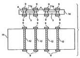
도면을 참고하면, 도1은 어댑터 보드(10)에 전력 변형 부품(5)이 내장되는 본 게시물의 실시예를 나타낸다. 내장된 부품(5)은 도1에 도시된 바와 같이 비아(11) 사이에 배치될 수 있다. 도1에서, 내장된 부품(5)은 어댑터 보드(10) 내에 내장된 부품(5)을 구비한 어댑터 보드(10) 상부에서 연장된 패드 사이에 배치된다. 결합 물질(7)은 연장된 패드(9a)의 하부면에 부품(5)의 단부(8)를 접속하는 구리, 은 등과 같은 솔더, 도전성 에폭시 또는 전통적인 도금 기술과 같은, 그러나 이에 국한되지는 않는 도전성 물질이다. 마찬가지로, 비아(11)는 구리, 은 등과 같은 임의의 전통적인 도금 기술에 의한 전도성 에폭시 또는 솔더의 금속화를 통해 구성될 수 있다. 따라서, 연장된 패드(9a)는 전도성 물질(7)에 의해 부품(5)의 단부(8)에 연결되고, 주회로 보드(15)의 비아(12)와의 접촉을 만들기 전에 어댑터 보드(10)를 통해 연장되는 비아(11)로부터 이격되고, 어댑터 보드(10)에 부착되거나 연결된다. 이러한 방식으로, 주회로 보드(15)는 재활용될 수 있고 내장된 부품(5)이 마모되거나 주회로 보드(15)가 다른 회로 구조에 대해 사용되는 경우 무시할 필요가 없다. 주회로 보드(15)는 비싸고, 이는 내장된 부품(5)를 사용하여 저항기(도3 및 도4 참고)에 의한 전력 손실을 감소시키고 정전용량에 대한 전력 이득(배분)을 개선하기 위한 실질적인 방법이지만 여전히 미래에 동일한 시간에 사용하기 위해 주회로 보드(15)를 사용하지 않는다. 어댑터 보드(10)는 전도성 탄성중합체 접속 또는 스프링 핀 또는 공지된 임의의 다른 방식을 사용하는 접속 및, 솔더링을 포함하는 임의의 전통적인 방식으로 주회로 보드(15)에 연결될 수 있다.
Referring to the drawings, Fig. 1 shows an embodiment of this publication in which a
도2는 서로의 상부에 블라인드(11a)를 정렬함으로써 핑거 피치가 가능한 본 게시물의 다른 실시예를 도시한다. 이 실시예에서, 도2처럼 비아(11)로부터 이격되어 연장되는 인터포저의 패드를 갖기보다는 블라인드(11a)는 연장되는 한 셋트와 수직으로 정렬되어,어댑터 보드(10)의 상부로부터 내장된 부품(5)의 단부 및 어댑터 보드(10)의 저면에서 패드로부터 상부로 연장되는 다른 셋과 패드가 접속하는 것을 허용한다. 블라인드(11a)는 도1의 실시예를 위해 접속 물질에 대해 기재된 바와 같이 단부에 접속될 수 있다.
Fig. 2 shows another embodiment of the present post in which finger pitch is possible by aligning the
도3은 어댑터 보드(10)에 저항(5a)을 내장함으로써 개선되는 전력 손실의 다른 실시예를 도시한다. 부품(5a)은 패드(9a 및 9b) 사이에 배치되고, 실제로 어댑터 보드(10)에 대한 비아처럼 작용하여서 전기 접속이 어댑터 보드(10)에 내장된 저항(5a)을 통과한다. 패드(9)는 각각 패드(9a 및 9b) 및 저항(5a)의 종점에서 개구를 통해 저항(5a)에 접속된다. 개구는 솔더, 금속 도금 또는 전도성 에폭시로 채워질 수 있다. 어댑터 보드(10)가 다층의 PC 보드라는 것을 이해할 수 있을 것이다.
Fig. 3 shows another embodiment of the power loss improved by embedding the
도4는 도1의 내장된 부품(5) 및 도3의 내장된 저항을 동일한 어댑터 보드(10)에 함께 사용하여 본 게시물의 다른 실시예를 도시한다. 어댑터 보드(10)가 다층의 PC 보드라는 것을 이해할 수 있을 것이다.
Fig. 4 shows another embodiment of this publication using the embedded
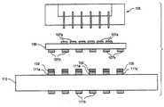
도5는 본 게시물의 전기 커넥터를 예시하는데, 커넥터는 기계적 압축 구조(105), 접속 랜드 또는 패드(107)를 구비한 어댑터 보드(106)(어댑터 보드는 도5에 도시되지 않은 부품을 그 안에 갖고 있는 것을 이해할 것이다), 및 개조된 PC 보드(108)의 양면 상에서 각각 랜드(109a 및 109b) 상에 구성된 전도성 탄성 중합체 물질(109)을 구비한 개조된 PC 보드(108); 및 접속 랜드(111)를 갖는 주회로 보드를 갖는다. 본 게시물에 대한 압축 구조(105)의 사용의 비제한적인 실시예는 집적 회로(IC) 칩(103)과 같은 테스트 회로를 수용하기 위해 적용된다. 핀(105b)은 어댑터 보드(106)의 패드(107)와 소켓(105a)에 내장된 IC 칩(103)의 전기적 접속을 형성하기 위해 제공된다. 어댑터 보드(106)의 접속 랜드 또는 패드(107) 및 주회로 보드(10)의 접속 랜드(111)의 접속 랜드 또는 패드(107)는 어댑터 보드(106) 및 개조된 PC 보드(108) 및 주회로 보드(110)가 기계적인 압축 구조(105)에 의해 함께 압축되는 경우 개조된 PC 보드(108)의 랜드 또는 패드(109a, 109b) 상에 위치하는 탄성중합체 물질과의 접점 안으로 삽입된다. 탄성 중합체 물질(109)은 등방성 또는 이방성 탄성중합체 물질 중 하나일 수 있다. 따라서 탄성중합체 물질을 그 위에서 이동시킴으로써 개조된 PC 보드(108)는 커넥터(208)로서 규정된 패드의 역할을 한다. 다른 방법으로는, 개조된 PC 보드(108)가 이방성 시트 탄성 중합체로 교체될 수 있다.5 illustrates an electrical connector of the present post, which includes a
보드를 함께 압축함으로써, 어댑터 보드(106) 및 주회로 보드(110) 사이에 전기적 접속을 제공함으로써, 압축 구조(105) 및 주회로 보드(110) 사이에 피치 및/또는 풋프린트를 조정한다. 개조된 PC 보드(108)의 양면 상에 랜드를 사용하여, 우수한 접속은 미국특허 제6,854,985에 개시된 바와 같이, 전도성 탄성 중합체 물질을 배치(패드 위치에 등방성 탄성중합체 물질을 배치하는 것을 포함하지만 이에 국한되지는 않음)함으로써 이뤄지거나, 접속 영역의 전체 표면에 걸쳐 이방성 물질을 배치함으로써 이뤄진다. 패드 위치에 등방성 탄성중합체 물질을 사용하는 장점은 훌륭한 경로설정(routing) 밀도 및 저렴한 비용이 실현될 수 있다는 것이다.
The pitch and / or footprint is adjusted between the
거친 패드에 미세한 패드를 접속함으로써 피치를 변환시키는 피치 변경으로 알려진 것 이외에, 반대로 본 게시물은 핀 맵 스크램블링으로 알려진, 기계적 압축 구조물(105)의 소켓(105a)에 내장된 테스트 회로(IC 칩(103)과 같은)의 접속점(104)에 접속된 핀(105b1-6)으로부터 주회로 보드(110)의 패드(111) 및 어댑터 보드(106)의 패드(109)까지의 전기접속을 재경로설정(reroute)하기 위해 제공된다. 도6a에 도시된 바와 같이, 어댑터 보드(106)가 재경로설정되어 그 전기적 경로(112)는 주회로 보드(110) 상의 대응하는 랜드 또는 패드(111)에 접속할 필요가 없을 뿐만 아니라 피치를 변경할 필요도 없다. 따라서 구조물(105) 상의 핀(105b-1)은 어댑터 보드(106)의 제 1 면(106a) 상의 패드(107-1)에 접속될 수 있고, 패드(107-1)는 전기적 경로(112)를 통해 어댑터 보드(106)의 제 2 면(106b)상의 제 1 패드(107-5) 보다는 패드(107-6)에 접속되도록 재경로설정될 수 있다. 다음으로 패드(107-6)는 주회로 보드(110)의 마주보는 표면(110a) 상의 패드(111-2)에 접속된다. 어떤 가능한 재경로설정도 이러한 방식으로 이뤄질 수 있다. 이 방식으로 본 게시물은 회로의 재경로설정을 원하는 대로 허용한다. 그밖에 어댑터 보드(106) 및 주회로 보드(110)용 패드의 수는 필요에 따라 변경될 수 있다. 그밖에, 도6a의 실시예에서는, 도5의 개조된 PC 보드가 필요 없으며 도9도 같은 경우이다.In contrast to what is known as a pitch change that transforms the pitch by connecting fine pads to rough pads, this post, on the contrary, is based on a test circuit (IC chip 103) built into
도6b는 핀 맵 스크램블링으로 알려진 본 게시물의 개선된 트레이스 라우팅(112)의 가능한 일 예를 예시한다. 개조된 PC 보드(108) 각각의 측면 상에 전도성 탄성중합체 랜드(109)를 배치한 결과로, 트레이스 라우팅(112)이 개조된 PC 보드(108)와 어댑터 보드(106) 사이 및 개조된 PC 보드(108)와 주회로 보드(110) 사이의 인터페이스 층상의 접속 랜드 어레이 주변 및 안에 가능하다. 어댑터 보드(106)의 재경로설정의 특성이 도5, 6a, 8 및 9의 실시예에 대해 영향을 미친다는 것이 이해된다.
Figure 6B illustrates one possible example of
도7은 본 게시물의 개조된 PC 보드(108)에 따라 가능한 실시예를 예시한다. PC 보드(108)는 도시된 바와 같이 PC 보드의 양 표면상에 등방성 물질을 사용하여 랜드를 배치함으로써 개조된다. 도7이 일 표면을 도시하고 있기는 하지만, 다른 표면도 유사하게 배열된다는 것을 이해할 수 있을 것이다. 탄성중합체 물질은 개조된 PC 보드(108)의 양 측면상의 패드상에 배치된 탄성중합체 페이스트일 수 있다.
Figure 7 illustrates a possible embodiment according to the modified
도8은 어댑터 보드(106)와 주회로 보드(110) 사이에 개조된 PC 보드(108)가 필요없는 제 2 실시예를 예시한다. 대신에 주회로 보드(110)의 랜드(111a)를 마주보는 어댑터 보드(106) 표면상의 랜드(107b)는 전도성 탄성중합체 물질(109)로 코팅된다. 따라서, 본 게시물의 도5의 경우와 마찬가지로, 개조된 PC 보드(108)의 패드(109a, 109b)를 각각 코팅하는 대신에, 주회로 보드(110)의 랜드(111a)를 마주보는 어댑터 보드(106)의 랜드(107b)는 탄설중합체 물질(109)로 코팅된다.
8 illustrates a second embodiment in which a
도9는 어댑터 보드(106) 및 주회로 보드(110) 사이의 개조된 PC 보드(108)가 필요없는 제 3 실시예를 예시한다. 대신에 어댑터 보드(106)의 랜드(107b)를 마주보는 주회로 보드(110)의 표면상의 랜드(111)는 전도성 탄성중합체 물질(109)로 코팅된다. 따라서, 본 게시물의 도5의 경우와 마찬가지로, 개조된 PC 보드(108)의 패드(109a, 109b)를 각각 코팅하는 대신에, 어댑터 보드(106)의 랜드(107b)를 마주보는 주회로 보드(110)의 랜드(111a)는 탄성중합체 페이스트(109)로 코팅된다.
9 illustrates a third embodiment in which there is no need for a retrofitted
특정 실시예가 도시되고 기재되었지만, 본 발명이 이에 한정되지 않으며, 첨부된 청구 내용의 사상 안에서 구현된다는 것을 이해할 수 있을 것이다.
Although specific embodiments have been shown and described, it will be understood that the invention is not so limited, but embodied within the spirit of the appended claims.
103 : IC 칩106 : 어댑터 보드
107 : 패드108 : 개조된 PC 보드
109 : 탄성중합체 물질110 : 주회로 보드
111 : 패드112 : 전기적 경로103: IC chip 106: adapter board
107: Pad 108: Modified PC board
109: elastomer material 110: main circuit board
111: pad 112: electrical path
Claims (12)
Translated fromKorean하나 이상의 전력 변경 부품을 압축 상태로(compressed state)로 적어도 하나의 어댑터 보드 내부에서 어댑터 보드의 비아들 사이에 내장하는 단계 - 상기 하나 이상의 전력 변경 부품은 상기 어댑터 보드의 패드와 전기접촉하는 단자를 가지며, 상기 패드는 패드 상부에 정의된 등방성(isotropic) 또는 비등방성(anisotropic)의 도전성 탄성중합체(conductive elastomer)를 구비하여, 전기가 상기 하나 이상의 전력 변경 부품을 통해 흘러 상기 전력 변경 부품이 상기 전기 부품에 근접하게 되어 하나 이상의 전력 변경 부품과 상기 전기 부품 사이의 전기적 길이가 감소되며, 상기 등방성 또는 비등방성의 도전성 탄성중합체에 의한 인덕턴스가 감소됨 - ;
상기 어댑터 보드를 상기 전기 부품과 상기 주회로 보드 사이에 샌드위칭시켜(sandwiching) 상기 어댑터 보드를 상기 주회로 보드에 연결하는 단계; 및
내장된 하나 이상의 전력 변경 부품을 주회로 보드의 비아 또는 블라인드 비아(blind vias)를 넘어선 위치까지 연장하여 배치하는 단계 - 내장된 전력 변경 부품을 포함하는 어댑터 보드의 일부분이 주회로 보드를 형성하는 인쇄 회로 보드의 비아 또는 블라인드 비아(blind vias)가 위치된 곳을 지나 배치되어 주회로 보드의 비아가 개구부를 통해 도전되고, 상기 등방성의 도전성 탄성중합체를 패드 위치에 배치하는 것에 의해 또는 비등방성의 도전성 탄성중합체를 주회로 보드의 연결 영역(connecting region)의 전체 표면에 거쳐 배치하는 것에 의해 전력 변경 부품은 전기 부품에 근접한 접점을 갖게 되어 양호한 접촉 및 큰 라우팅 밀도를 획득되고 전력 분배 및 전력 손실이 개선됨;
를 포함하는 것을 특징으로 하는 방법.
1. A method for providing power distribution or power loss improvement to an electrical component attached to a printed circuit board forming a main circuit board,
Embedding one or more power modifying components in vias in an adapter board within at least one adapter board in a compressed state wherein the one or more power modifying members include a terminal in electrical contact with a pad of the adapter board Wherein the pad comprises an isotropic or anisotropic conductive elastomer defined on the pad such that electricity flows through the at least one power altering component so that the power modifying component is electrically The electrical length between the at least one power modifying part and the electrical part is reduced and the inductance by the isotropic or anisotropic conductive elastomer is reduced;
Connecting the adapter board to the main circuit board by sandwiching the adapter board between the electrical component and the main circuit board; And
Extending the built-in one or more power changing parts to a position beyond the vias or blind vias of the main circuit board; - installing a portion of the adapter board including the built- By placing vias or blind vias of the circuit board over the vias of the main circuit board through the openings and placing the isotropic conductive elastomer at the pad location or by providing an anisotropic conductive elastomeric By disposing the polymer across the entire surface of the connecting region of the main circuit board, the power modifying component has a contact proximate to the electrical component, resulting in good contact and large routing density and improved power distribution and power loss;
≪ / RTI >
상기 전력 변경 부품은 커패시터인
방법.
The method according to claim 1,
The power changing component is a capacitor
Way.
상기 전력 변경 부품은 저항인
방법.
The method according to claim 1,
The power changing part is a resistance-
Way.
상기 어댑터 보드와 주회로 보드의 비아는 미세 피치를 제공하기 위해 적층되어 수직으로 정렬되는
방법.
The method according to claim 1,
The vias of the adapter board and the main circuit board are stacked and vertically aligned to provide a fine pitch
Way.
적어도 하나의 어댑터 보드의 내측에서 또한 어댑터 보드의 비아들 사이에 압축된 상태로 내장된 하나 이상의 전력 변경 부품 - 상기 하나 이상의 전력 변경 부품은 상기 어댑터 보드의 패드와 전기접촉하는 단자를 가지며, 상기 패드는 패드 상부에 정의된 등방성(isotropic) 또는 비등방성(anisotropic)의 도전성 탄성중합체(conductive elastomer)를 구비하여, 전기가 상기 하나 이상의 전력 변경 부품을 통해 흘러 상기 전력 변경 부품이 상기 전기 부품에 근접하게 되고, 상기 등방성의 도전성 탄성중합체를 패드 위치에 배치하는 것에 의해 또는 비등방성의 도전성 탄성중합체를 주회로 보드의 연결 영역(connecting region)의 전체 표면에 거쳐 배치하는 것에 의해 하나 이상의 전력 변경 부품과 상기 전기 부품 사이의 전기적 길이가 감소되며, 양호한 접촉 및 큰 라우팅 밀도를 획득되고 상기 패드에 정의된 등방성의 또는 비등방성의 도전성 탄성중합체의 도전성 탄성중합체에 의한 인덕턴스가 감소됨 - ; 를 포함하고,
상기 어댑터 보드는 전기 부품과 주회로 보드의 사이에 샌드위칭되고, 상기 어댑터 보드는 주회로 보드에 연결 또는 부착되고,
내장된 하나 이상의 전력 변경 부품을 주회로 보드를 형성하는 인쇄 회로 보드의 비아 또는 블라인드 비아를 넘어선 위치까지 연장하여 배치되고, 내장된 하나 이상의 전력 변경 부품을 포함하는 어댑터 보드의 일부분은 어댑터 보드의 비아가 개구부를 통해 도전되는 것을 허용하기 위해 주회로 보드의 비아 또는 블라인드 비아가 위치되는 곳을 지나 배치되어 전력 변경 부품은 전기 부품에 근접한 접점을 갖게 되어 전력 분배 및 전력 손실이 개선되는
주회로 보드를 형성하는 인쇄 회로 보드에 부착된 전기 부품에 대한 전력 분배 또는 전력 손실을 개선하기 위한 장치.
An apparatus for improving power dissipation or power loss for an electrical component attached to a printed circuit board forming a main circuit board,
One or more power changing parts embedded in a compressed state inside of at least one adapter board and also between vias of the adapter board, said at least one power changing part having a terminal in electrical contact with the pad of the adapter board, Isotropic or anisotropic conductive elastomer defined above the pad such that electricity flows through the at least one power modifying part such that the power modifying part is proximate to the electrical component By placing the isotropic conductive elastomer at a pad location or by placing an anisotropic conductive elastomer over the entire surface of the connecting region of the main circuit board, The electrical length between the parts is reduced, Obtains the density and the inductance of the conductive elastomer, a conductive elastomer of the isotropic or anisotropic defined on the pad is reduced; Lt; / RTI >
Wherein the adapter board is sandwiched between the electrical component and the main circuit board, the adapter board is connected to or attached to the main circuit board,
A portion of the adapter board including at least one power change part embedded therein is disposed extending beyond a via or blind via of a printed circuit board forming a main circuit board, Is placed past the location of the vias or blind vias of the main circuit board to allow it to be conducted through the openings so that the power changing component has a contact proximate the electrical component to improve power distribution and power loss
An apparatus for improving power distribution or power loss for an electrical component attached to a printed circuit board forming a main circuit board.
상기 전력 변경 부품은 커패시터인
주회로 보드를 형성하는 인쇄 회로 보드에 부착된 전기 부품에 대한 전력 분배 또는 전력 손실을 개선하기 위한 장치.
6. The method of claim 5,
The power changing component is a capacitor
An apparatus for improving power distribution or power loss for an electrical component attached to a printed circuit board forming a main circuit board.
상기 전력 변경 부품은 저항인
주회로 보드를 형성하는 인쇄 회로 보드에 부착된 전기 부품에 대한 전력 분배 또는 전력 손실을 개선하기 위한 장치.
6. The method of claim 5,
The power changing part is a resistance-
An apparatus for improving power distribution or power loss for an electrical component attached to a printed circuit board forming a main circuit board.
상기 도전성 탄성중합체는 상기 어댑터 보드와 상기 주회로 보드 사이에 전기적 연결을 제공하고 상기 도전성 탄성중합체는 상기 주회로 보드의 적어도 하나의 표면 상에 위치되는
주회로 보드를 형성하는 인쇄 회로 보드에 부착된 전기 부품에 대한 전력 분배 또는 전력 손실을 개선하기 위한 장치.
6. The method of claim 5,
Wherein the conductive elastomer provides an electrical connection between the adapter board and the main circuit board and the conductive elastomer is located on at least one surface of the main circuit board
An apparatus for improving power distribution or power loss for an electrical component attached to a printed circuit board forming a main circuit board.
상기 비등방성의 도전성 탄성중합체가 정의된 패드는 어댑터 보드와 주회로 보드 사이에 전기적 연결을 제공하는
주회로 보드를 형성하는 인쇄 회로 보드에 부착된 전기 부품에 대한 전력 분배 또는 전력 손실을 개선하기 위한 장치.
6. The method of claim 5,
The pads defining the anisotropic conductive elastomer may be used to provide an electrical connection between the adapter board and the main circuit board
An apparatus for improving power distribution or power loss for an electrical component attached to a printed circuit board forming a main circuit board.
상기 하나 이상의 전력 변경 부품이 내장된 어댑터 보드는 주회로 보드에 솔더링(soldered)되는
주회로 보드를 형성하는 인쇄 회로 보드에 부착된 전기 부품에 대한 전력 분배 또는 전력 손실을 개선하기 위한 장치.
6. The method of claim 5,
The adapter board in which the at least one power changing part is embedded is soldered to the main circuit board
An apparatus for improving power distribution or power loss for an electrical component attached to a printed circuit board forming a main circuit board.
상기 어댑터 보드는 다층 보드인
주회로 보드를 형성하는 인쇄 회로 보드에 부착된 전기 부품에 대한 전력 분배 또는 전력 손실을 개선하기 위한 장치.6. The method of claim 5,
The adapter board is a multilayer board
An apparatus for improving power distribution or power loss for an electrical component attached to a printed circuit board forming a main circuit board.
상기 어댑터 보드는 두개의 면을 가진(two sided) 인쇄 회로 보드인
주회로 보드를 형성하는 인쇄 회로 보드에 부착된 전기 부품에 대한 전력 분배 또는 전력 손실을 개선하기 위한 장치.
6. The method of claim 5,
The adapter board is a two sided printed circuit board
An apparatus for improving power distribution or power loss for an electrical component attached to a printed circuit board forming a main circuit board.
Applications Claiming Priority (3)
| Application Number | Priority Date | Filing Date | Title |
|---|---|---|---|
| US27666109P | 2009-09-15 | 2009-09-15 | |
| US61/276,661 | 2009-09-15 | ||
| PCT/US2010/000049WO2011034555A1 (en) | 2009-09-15 | 2010-01-08 | Embedded components in interposer board for improving power gain (distribution) and power loss (dissipation) in interconnect configuration |
Related Parent Applications (1)
| Application Number | Title | Priority Date | Filing Date |
|---|---|---|---|
| KR1020127009404ADivisionKR20120068908A (en) | 2009-09-15 | 2010-01-08 | Embedded components in interposer board for improving power gain(distribution) and power loss(dissipation) in interconnect configuration |
Publications (1)
| Publication Number | Publication Date |
|---|---|
| KR20180020319Atrue KR20180020319A (en) | 2018-02-27 |
Family
ID=43758935
Family Applications (2)
| Application Number | Title | Priority Date | Filing Date |
|---|---|---|---|
| KR1020187004487ACeasedKR20180020319A (en) | 2009-09-15 | 2010-01-08 | Embedded components in interposer board for improving power gain(distribution) and power loss(dissipation) in interconnect configuration |
| KR1020127009404ACeasedKR20120068908A (en) | 2009-09-15 | 2010-01-08 | Embedded components in interposer board for improving power gain(distribution) and power loss(dissipation) in interconnect configuration |
Family Applications After (1)
| Application Number | Title | Priority Date | Filing Date |
|---|---|---|---|
| KR1020127009404ACeasedKR20120068908A (en) | 2009-09-15 | 2010-01-08 | Embedded components in interposer board for improving power gain(distribution) and power loss(dissipation) in interconnect configuration |
Country Status (9)
| Country | Link |
|---|---|
| US (2) | US9107330B2 (en) |
| EP (1) | EP2478751A4 (en) |
| JP (3) | JP2013504894A (en) |
| KR (2) | KR20180020319A (en) |
| CN (2) | CN102648667B (en) |
| MY (1) | MY165331A (en) |
| SG (2) | SG179125A1 (en) |
| TW (1) | TWI563752B (en) |
| WO (1) | WO2011034555A1 (en) |
Families Citing this family (22)
| Publication number | Priority date | Publication date | Assignee | Title |
|---|---|---|---|---|
| KR101332873B1 (en) | 2011-10-11 | 2013-12-19 | 세미텍 주식회사 | Interposer for providing capacitance and lead frame type semiconductor package using the same |
| KR101254180B1 (en)* | 2012-08-16 | 2013-04-18 | 주식회사 세미콘테스트 | Test socket for testing semiconductor |
| CN103687288B (en)* | 2012-09-11 | 2017-04-05 | 上海耐普微电子有限公司 | The connection member and attachment structure of printed circuit board (PCB) |
| CN104517535B (en)* | 2013-09-27 | 2017-11-07 | 鸿富锦精密工业(深圳)有限公司 | Display device, spliced display and display panel |
| CN104852172B (en)* | 2014-02-19 | 2017-12-29 | 联想(北京)有限公司 | A kind of electronic equipment and circuit board connection method |
| US20160065334A1 (en)* | 2014-08-29 | 2016-03-03 | R&D Circuits, Inc | Structure and Implementation Method for implementing an embedded serial data test loopback, residing directly under the device within a printed circuit board |
| DE112016001535T5 (en) | 2015-03-31 | 2018-03-08 | Technoprobe S.P.A | Probe card for a tester of electronic devices with improved filter characteristics |
| US10321575B2 (en) | 2015-09-01 | 2019-06-11 | Qualcomm Incorporated | Integrated circuit (IC) module comprising an integrated circuit (IC) package and an interposer with embedded passive components |
| CN106298732A (en)* | 2016-09-29 | 2017-01-04 | 中国电子科技集团公司第四十三研究所 | A kind of adapter plate structure for system in package |
| US11696409B2 (en)* | 2016-09-30 | 2023-07-04 | Intel Corporation | Vertical embedded component in a printed circuit board blind hole |
| CN109669059B (en)* | 2017-10-17 | 2021-03-16 | 中华精测科技股份有限公司 | Circuit structure for adjusting power signal impedance and its semiconductor test interface system |
| JP2019090632A (en)* | 2017-11-13 | 2019-06-13 | リード・エレクトロニクス株式会社 | IC inspection device |
| CN113056963B (en) | 2018-09-19 | 2022-06-24 | 特斯拉公司 | Mechanical Architecture for Multi-Chip Modules |
| TW202044678A (en)* | 2019-04-30 | 2020-12-01 | 美商山姆科技公司 | Power interposer with bypass capacitors |
| JP7385240B2 (en)* | 2019-05-31 | 2023-11-22 | コネクトフリー株式会社 | Software development equipment and software development program |
| CN112448561B (en) | 2019-08-30 | 2022-04-15 | 台达电子企业管理(上海)有限公司 | Power module and preparation method thereof |
| US12342450B2 (en) | 2020-01-08 | 2025-06-24 | Delta Electronics (Shanghai) Co., Ltd | Power supply apparatus, load and electronic device |
| CN113097190B (en) | 2020-01-08 | 2024-08-13 | 台达电子企业管理(上海)有限公司 | Power module and electronic device |
| US11812545B2 (en) | 2020-01-08 | 2023-11-07 | Delta Electronics (Shanghai) Co., Ltd | Power supply system and electronic device |
| KR102812686B1 (en)* | 2020-06-22 | 2025-05-27 | 엘지이노텍 주식회사 | Communication module |
| CN114247484B (en)* | 2020-09-24 | 2023-06-23 | 京东方科技集团股份有限公司 | Microfluidic devices and microfluidic systems |
| CN113140538A (en)* | 2021-04-21 | 2021-07-20 | 上海闻泰信息技术有限公司 | Adapter plate, packaging structure and manufacturing method of adapter plate |
Family Cites Families (28)
| Publication number | Priority date | Publication date | Assignee | Title |
|---|---|---|---|---|
| JPH03155694A (en)* | 1989-11-14 | 1991-07-03 | Fujitsu Ltd | Manufacture of aluminum nitride multilayer circuit board |
| JPH08240635A (en)* | 1995-03-03 | 1996-09-17 | Nec Corp | Inspecting equipment of printed wiring board |
| US6011307A (en)* | 1997-08-12 | 2000-01-04 | Micron Technology, Inc. | Anisotropic conductive interconnect material for electronic devices, method of use and resulting product |
| US6020629A (en)* | 1998-06-05 | 2000-02-01 | Micron Technology, Inc. | Stacked semiconductor package and method of fabrication |
| US6456502B1 (en)* | 1998-09-21 | 2002-09-24 | Compaq Computer Corporation | Integrated circuit device/circuit board connection apparatus |
| US6854985B1 (en)* | 1998-12-16 | 2005-02-15 | Paricon Technologies Corporation | Elastomeric interconnection device and methods for making same |
| JP3860380B2 (en)* | 1999-04-06 | 2006-12-20 | 富士通株式会社 | Wiring board and chip module using the same |
| JP4953499B2 (en)* | 1999-09-02 | 2012-06-13 | イビデン株式会社 | Printed wiring board |
| US6399896B1 (en)* | 2000-03-15 | 2002-06-04 | International Business Machines Corporation | Circuit package having low modulus, conformal mounting pads |
| US6970362B1 (en)* | 2000-07-31 | 2005-11-29 | Intel Corporation | Electronic assemblies and systems comprising interposer with embedded capacitors |
| JP4863562B2 (en)* | 2001-03-13 | 2012-01-25 | イビデン株式会社 | Printed wiring board and printed wiring board manufacturing method |
| JP2001298274A (en)* | 2001-03-13 | 2001-10-26 | Matsushita Electric Ind Co Ltd | Electronic circuit components |
| JP2003037341A (en)* | 2001-07-23 | 2003-02-07 | Shin Etsu Polymer Co Ltd | Conductive contact element, film type connector and its connection structure |
| JP3879461B2 (en)* | 2001-09-05 | 2007-02-14 | 日立電線株式会社 | Wiring board and manufacturing method thereof |
| US7249954B2 (en)* | 2002-02-26 | 2007-07-31 | Paricon Technologies Corporation | Separable electrical interconnect with anisotropic conductive elastomer for translating footprint |
| JP2004241583A (en)* | 2003-02-05 | 2004-08-26 | Ngk Spark Plug Co Ltd | Wiring board |
| JP4377617B2 (en)* | 2003-06-20 | 2009-12-02 | 日本特殊陶業株式会社 | Capacitor, semiconductor element with capacitor, wiring board with capacitor, and electronic unit including semiconductor element, capacitor, and wiring board |
| JP2005116489A (en)* | 2003-10-02 | 2005-04-28 | Kasasaku Electronics:Kk | Connector device |
| WO2006046461A1 (en)* | 2004-10-29 | 2006-05-04 | Murata Manufacturing Co., Ltd. | Multilayer substrate incorporating chip type electronic component and production method therefor |
| JP4736451B2 (en)* | 2005-02-03 | 2011-07-27 | パナソニック株式会社 | MULTILAYER WIRING BOARD, MANUFACTURING METHOD THEREOF, AND SEMICONDUCTOR PACKAGE AND ELECTRONIC DEVICE USING MULTILAYER WIRING BOARD |
| JP4654133B2 (en)* | 2005-02-09 | 2011-03-16 | 日本特殊陶業株式会社 | Wiring board |
| CN101010800B (en)* | 2005-07-13 | 2012-02-01 | 松下电器产业株式会社 | Mounting substrate, mounting body, and electronic equipment using mounting substrate and mounting body |
| US7640655B2 (en)* | 2005-09-13 | 2010-01-05 | Shinko Electric Industries Co., Ltd. | Electronic component embedded board and its manufacturing method |
| CN100542379C (en)* | 2006-03-15 | 2009-09-16 | 日月光半导体制造股份有限公司 | Substrate with embedded components and manufacturing method thereof |
| JP4975507B2 (en)* | 2007-04-17 | 2012-07-11 | 日本特殊陶業株式会社 | Wiring board with built-in capacitor |
| JP2009135391A (en)* | 2007-11-02 | 2009-06-18 | Denso Corp | Electronic device and method of manufacturing the same |
| US7766667B2 (en)* | 2007-12-18 | 2010-08-03 | Russell James V | Separable electrical connectors using isotropic conductive elastomer interconnect medium |
| JP2009224616A (en)* | 2008-03-17 | 2009-10-01 | Shinko Electric Ind Co Ltd | Electronic component built-in board and method of manufacturing the same, and semiconductor device |
- 2010
- 2010-01-08KRKR1020187004487Apatent/KR20180020319A/ennot_activeCeased
- 2010-01-08MYMYPI2012001174Apatent/MY165331A/enunknown
- 2010-01-08WOPCT/US2010/000049patent/WO2011034555A1/enactiveApplication Filing
- 2010-01-08JPJP2012529728Apatent/JP2013504894A/enactivePending
- 2010-01-08CNCN201080051570.3Apatent/CN102648667B/enactiveActive
- 2010-01-08SGSG2012017810Apatent/SG179125A1/enunknown
- 2010-01-08SGSG10201405623QApatent/SG10201405623QA/enunknown
- 2010-01-08KRKR1020127009404Apatent/KR20120068908A/ennot_activeCeased
- 2010-01-08EPEP10817530Apatent/EP2478751A4/ennot_activeWithdrawn
- 2010-01-08CNCN201610658524.9Apatent/CN106449589A/enactivePending
- 2010-08-27TWTW099128788Apatent/TWI563752B/ennot_activeIP Right Cessation
- 2014
- 2014-04-30USUS14/120,152patent/US9107330B2/enactiveActive
- 2014-06-06USUS14/297,737patent/US20140283379A1/ennot_activeAbandoned
- 2015
- 2015-09-02JPJP2015172752Apatent/JP2016026385A/enactivePending
- 2018
- 2018-02-01JPJP2018016227Apatent/JP2018093215A/enactivePending
Also Published As
| Publication number | Publication date |
|---|---|
| CN102648667B (en) | 2016-09-07 |
| TWI563752B (en) | 2016-12-21 |
| WO2011034555A1 (en) | 2011-03-24 |
| US9107330B2 (en) | 2015-08-11 |
| EP2478751A1 (en) | 2012-07-25 |
| CN102648667A (en) | 2012-08-22 |
| JP2018093215A (en) | 2018-06-14 |
| KR20120068908A (en) | 2012-06-27 |
| MY165331A (en) | 2018-03-21 |
| US20140283379A1 (en) | 2014-09-25 |
| SG179125A1 (en) | 2012-04-27 |
| EP2478751A4 (en) | 2013-01-23 |
| US20140268613A1 (en) | 2014-09-18 |
| CN106449589A (en) | 2017-02-22 |
| JP2016026385A (en) | 2016-02-12 |
| JP2013504894A (en) | 2013-02-07 |
| SG10201405623QA (en) | 2014-11-27 |
| TW201112545A (en) | 2011-04-01 |
Similar Documents
| Publication | Publication Date | Title |
|---|---|---|
| KR20180020319A (en) | Embedded components in interposer board for improving power gain(distribution) and power loss(dissipation) in interconnect configuration | |
| US7782629B2 (en) | Embedding an electronic component between surfaces of a printed circuit board | |
| US7766667B2 (en) | Separable electrical connectors using isotropic conductive elastomer interconnect medium | |
| US8792248B2 (en) | Method for providing improved power distribution or power dissipation to an electrical component attached to main circuit board | |
| JP4365166B2 (en) | Capacitor, multilayer wiring board, and semiconductor device | |
| KR100543853B1 (en) | Capacitors with extended surface lands and methods of manufacturing the same | |
| KR101539212B1 (en) | Electric circuit arrangement having an MID-circuit mount and a connection interface connected thereto | |
| JPWO2005006003A1 (en) | LSI test socket for BGA | |
| US6859352B1 (en) | Capacitor sheet | |
| US20020055283A1 (en) | Multiple line grid connector | |
| EP2428105A1 (en) | Method and apparatus for improving power and loss for interconect configurations | |
| CN219068491U (en) | Nested printed circuit board | |
| US6950315B2 (en) | High frequency module mounting structure in which solder is prevented from peeling | |
| US20070052084A1 (en) | High density interconnect assembly comprising stacked electronic module | |
| JP2005293903A (en) | module |
Legal Events
| Date | Code | Title | Description |
|---|---|---|---|
| A107 | Divisional application of patent | ||
| A201 | Request for examination | ||
| PA0104 | Divisional application for international application | Comment text:Divisional Application for International Patent Patent event code:PA01041R01D Patent event date:20180213 Application number text:1020127009404 Filing date:20120412 | |
| PA0201 | Request for examination | ||
| PG1501 | Laying open of application | ||
| E902 | Notification of reason for refusal | ||
| PE0902 | Notice of grounds for rejection | Comment text:Notification of reason for refusal Patent event date:20180508 Patent event code:PE09021S01D | |
| E902 | Notification of reason for refusal | ||
| PE0902 | Notice of grounds for rejection | Comment text:Notification of reason for refusal Patent event date:20190117 Patent event code:PE09021S01D | |
| E601 | Decision to refuse application | ||
| PE0601 | Decision on rejection of patent | Patent event date:20190529 Comment text:Decision to Refuse Application Patent event code:PE06012S01D Patent event date:20190117 Comment text:Notification of reason for refusal Patent event code:PE06011S01I Patent event date:20180508 Comment text:Notification of reason for refusal Patent event code:PE06011S01I |