KR20180018918A - Combined wireless control system for roof zone in vehicle - Google Patents
Combined wireless control system for roof zone in vehicleDownload PDFInfo
- Publication number
- KR20180018918A KR20180018918AKR1020160101960AKR20160101960AKR20180018918AKR 20180018918 AKR20180018918 AKR 20180018918AKR 1020160101960 AKR1020160101960 AKR 1020160101960AKR 20160101960 AKR20160101960 AKR 20160101960AKR 20180018918 AKR20180018918 AKR 20180018918A
- Authority
- KR
- South Korea
- Prior art keywords
- unit
- signal
- sunroof
- operation switch
- control
- Prior art date
- Legal status (The legal status is an assumption and is not a legal conclusion. Google has not performed a legal analysis and makes no representation as to the accuracy of the status listed.)
- Granted
Links
- 230000005540biological transmissionEffects0.000claimsabstractdescription19
- 238000000034methodMethods0.000claimsdescription13
- 230000004913activationEffects0.000claimsdescription4
- 230000007257malfunctionEffects0.000abstractdescription16
- 230000008054signal transmissionEffects0.000abstractdescription7
- 239000011521glassSubstances0.000description4
- 238000006243chemical reactionMethods0.000description3
- 238000010586diagramMethods0.000description2
- 241001074085Scophthalmus aquosusSpecies0.000description1
- 230000002708enhancing effectEffects0.000description1
- 239000000446fuelSubstances0.000description1
- 238000012986modificationMethods0.000description1
- 230000004048modificationEffects0.000description1
- 238000009423ventilationMethods0.000description1
Images

Classifications
- B—PERFORMING OPERATIONS; TRANSPORTING
- B60—VEHICLES IN GENERAL
- B60R—VEHICLES, VEHICLE FITTINGS, OR VEHICLE PARTS, NOT OTHERWISE PROVIDED FOR
- B60R25/00—Fittings or systems for preventing or indicating unauthorised use or theft of vehicles
- B60R25/20—Means to switch the anti-theft system on or off
- B60R25/24—Means to switch the anti-theft system on or off using electronic identifiers containing a code not memorised by the user
- B60R25/245—Means to switch the anti-theft system on or off using electronic identifiers containing a code not memorised by the user where the antenna reception area plays a role
- B—PERFORMING OPERATIONS; TRANSPORTING
- B60—VEHICLES IN GENERAL
- B60J—WINDOWS, WINDSCREENS, NON-FIXED ROOFS, DOORS, OR SIMILAR DEVICES FOR VEHICLES; REMOVABLE EXTERNAL PROTECTIVE COVERINGS SPECIALLY ADAPTED FOR VEHICLES
- B60J5/00—Doors
- B60J5/10—Doors arranged at the vehicle rear
- B—PERFORMING OPERATIONS; TRANSPORTING
- B60—VEHICLES IN GENERAL
- B60J—WINDOWS, WINDSCREENS, NON-FIXED ROOFS, DOORS, OR SIMILAR DEVICES FOR VEHICLES; REMOVABLE EXTERNAL PROTECTIVE COVERINGS SPECIALLY ADAPTED FOR VEHICLES
- B60J7/00—Non-fixed roofs; Roofs with movable panels, e.g. rotary sunroofs
- B60J7/02—Non-fixed roofs; Roofs with movable panels, e.g. rotary sunroofs of sliding type, e.g. comprising guide shoes
- B60J7/04—Non-fixed roofs; Roofs with movable panels, e.g. rotary sunroofs of sliding type, e.g. comprising guide shoes with rigid plate-like element or elements, e.g. open roofs with harmonica-type folding rigid panels
- B60J7/043—Sunroofs e.g. sliding above the roof
- B—PERFORMING OPERATIONS; TRANSPORTING
- B60—VEHICLES IN GENERAL
- B60J—WINDOWS, WINDSCREENS, NON-FIXED ROOFS, DOORS, OR SIMILAR DEVICES FOR VEHICLES; REMOVABLE EXTERNAL PROTECTIVE COVERINGS SPECIALLY ADAPTED FOR VEHICLES
- B60J7/00—Non-fixed roofs; Roofs with movable panels, e.g. rotary sunroofs
- B60J7/02—Non-fixed roofs; Roofs with movable panels, e.g. rotary sunroofs of sliding type, e.g. comprising guide shoes
- B60J7/04—Non-fixed roofs; Roofs with movable panels, e.g. rotary sunroofs of sliding type, e.g. comprising guide shoes with rigid plate-like element or elements, e.g. open roofs with harmonica-type folding rigid panels
- B60J7/057—Driving or actuating arrangements e.g. manually operated levers or knobs
- B—PERFORMING OPERATIONS; TRANSPORTING
- B60—VEHICLES IN GENERAL
- B60R—VEHICLES, VEHICLE FITTINGS, OR VEHICLE PARTS, NOT OTHERWISE PROVIDED FOR
- B60R16/00—Electric or fluid circuits specially adapted for vehicles and not otherwise provided for; Arrangement of elements of electric or fluid circuits specially adapted for vehicles and not otherwise provided for
- B60R16/005—Electro-mechanical devices, e.g. switched
- B—PERFORMING OPERATIONS; TRANSPORTING
- B60—VEHICLES IN GENERAL
- B60R—VEHICLES, VEHICLE FITTINGS, OR VEHICLE PARTS, NOT OTHERWISE PROVIDED FOR
- B60R16/00—Electric or fluid circuits specially adapted for vehicles and not otherwise provided for; Arrangement of elements of electric or fluid circuits specially adapted for vehicles and not otherwise provided for
- B60R16/02—Electric or fluid circuits specially adapted for vehicles and not otherwise provided for; Arrangement of elements of electric or fluid circuits specially adapted for vehicles and not otherwise provided for electric constitutive elements
- B60R16/023—Electric or fluid circuits specially adapted for vehicles and not otherwise provided for; Arrangement of elements of electric or fluid circuits specially adapted for vehicles and not otherwise provided for electric constitutive elements for transmission of signals between vehicle parts or subsystems
- B—PERFORMING OPERATIONS; TRANSPORTING
- B60—VEHICLES IN GENERAL
- B60R—VEHICLES, VEHICLE FITTINGS, OR VEHICLE PARTS, NOT OTHERWISE PROVIDED FOR
- B60R16/00—Electric or fluid circuits specially adapted for vehicles and not otherwise provided for; Arrangement of elements of electric or fluid circuits specially adapted for vehicles and not otherwise provided for
- B60R16/02—Electric or fluid circuits specially adapted for vehicles and not otherwise provided for; Arrangement of elements of electric or fluid circuits specially adapted for vehicles and not otherwise provided for electric constitutive elements
- B60R16/03—Electric or fluid circuits specially adapted for vehicles and not otherwise provided for; Arrangement of elements of electric or fluid circuits specially adapted for vehicles and not otherwise provided for electric constitutive elements for supply of electrical power to vehicle subsystems or for
- B60R16/0315—Electric or fluid circuits specially adapted for vehicles and not otherwise provided for; Arrangement of elements of electric or fluid circuits specially adapted for vehicles and not otherwise provided for electric constitutive elements for supply of electrical power to vehicle subsystems or for using multiplexing techniques
- B—PERFORMING OPERATIONS; TRANSPORTING
- B60—VEHICLES IN GENERAL
- B60R—VEHICLES, VEHICLE FITTINGS, OR VEHICLE PARTS, NOT OTHERWISE PROVIDED FOR
- B60R25/00—Fittings or systems for preventing or indicating unauthorised use or theft of vehicles
- B60R25/01—Fittings or systems for preventing or indicating unauthorised use or theft of vehicles operating on vehicle systems or fittings, e.g. on doors, seats or windscreens
- E—FIXED CONSTRUCTIONS
- E05—LOCKS; KEYS; WINDOW OR DOOR FITTINGS; SAFES
- E05F—DEVICES FOR MOVING WINGS INTO OPEN OR CLOSED POSITION; CHECKS FOR WINGS; WING FITTINGS NOT OTHERWISE PROVIDED FOR, CONCERNED WITH THE FUNCTIONING OF THE WING
- E05F15/00—Power-operated mechanisms for wings
- E05F15/60—Power-operated mechanisms for wings using electrical actuators
- E05F15/603—Power-operated mechanisms for wings using electrical actuators using rotary electromotors
- E—FIXED CONSTRUCTIONS
- E05—LOCKS; KEYS; WINDOW OR DOOR FITTINGS; SAFES
- E05F—DEVICES FOR MOVING WINGS INTO OPEN OR CLOSED POSITION; CHECKS FOR WINGS; WING FITTINGS NOT OTHERWISE PROVIDED FOR, CONCERNED WITH THE FUNCTIONING OF THE WING
- E05F15/00—Power-operated mechanisms for wings
- E05F15/70—Power-operated mechanisms for wings with automatic actuation
- E05F15/77—Power-operated mechanisms for wings with automatic actuation using wireless control
Landscapes
- Engineering & Computer Science (AREA)
- Mechanical Engineering (AREA)
- Computer Networks & Wireless Communication (AREA)
- Selective Calling Equipment (AREA)
Abstract
Translated fromKorean
Description
Translated fromKorean본 발명은 차량의 루프 영역 통합 무선 제어 시스템에 관한 것으로서, 더 상세하게는 차량의 루프 영역(선루프, 테일게이트)에서의 유선에 의한 신호 전달 방식을 무선통신에 의한 신호 전달 방식으로 변경함으로써 종래의 유선 방식에서의 전선 상호 간의 간섭, 노이즈 발생, 전선의 단선 및 단락에 의한 작동 불량 또는 오작동 문제를 해소할 수 있는 차량의 루프 영역 통합 무선 제어 시스템에 관한 것이다.BACKGROUND OF THE INVENTION 1. Field of the Invention The present invention relates to a loop-area integrated radio control system for a vehicle, and more particularly, to a loop-area integrated radio control system for a vehicle in which a signal transmission method by a wired line in a loop region (sunroof, tail gate) To a loop area integrated radio control system for a vehicle capable of eliminating malfunctions or malfunctions due to interference between wires in a wire system, noise generation, disconnection and short circuit of electric wires.
차량에 설치된 창유리가 운전자의 시야를 확보하고, 탑승자의 조망을 위해 설치된 것과는 달리 선루프는 루프 패널에 개구부를 형성하여 차량의 실내를 밝게 해주고 심리적으로 공간을 크게 하여 탑승자에게 해방감을 부여함과 동시에 환기를 원활하게 하여 차량 실내의 쾌적성을 향상시키는 역할을 한다.Unlike a windowpane installed in a vehicle securing a driver's view and being installed for a passenger's viewpoint, the sunroof forms an opening in the roof panel to brighten the interior of the vehicle and increase the psychological space for the passenger, Thereby enhancing the comfort of the interior of the vehicle.
이러한 선루프는 루프 패널의 개구부를 덮는 패널의 동작에 따라 슬라이드형(sliding type)과 틸트업형(Tilt-up type) 등으로 분류된다. 슬라이드형은 선루프의 글래스 패널이 루프 패널을 따라 슬라이딩하면서 루프 패널의 개구부를 개폐시키는 것으로, 이와 같은 슬라이딩형은 다시 선루프의 글래스 패널이 루프 패널의 상면을 따라 슬라이딩하는 아우터(outer) 슬라이드형과 글래스 패널이 루프 패널의 하면을 따라 슬라이딩하는 이너(inner) 슬라이드형으로 분류된다. 그리고 틸트업형은 글래스 패널의 후방 끝부분이 들어 올려지는 형으로 차량 실내의 환기를 주목적으로 한다.Such a sunroof is classified into a sliding type and a tilt-up type according to the operation of the panel covering the opening of the roof panel. In the slide type, the glass panel of the sunroof slides along the roof panel to open and close the opening of the roof panel. In the sliding type, the glass panel of the sunroof slides along the upper surface of the roof panel. And an inner slide type in which the glass panel slides along the lower surface of the roof panel. The tilt-up type is a type in which the rear end portion of the glass panel is lifted up, and ventilation of the interior of the vehicle is the main purpose.
이상과 같은 종래 선루프에 있어서, 차량의 루프 영역(예를 들면, 선루프, 테일게이트)의 시스템들은 오버헤드 콘솔(overhead console)에 조작 스위치가 설치되어 있고, 이 스위치들은 선루프 및 테일게이트에 전선(유선)으로(wire to wire) 연결되어 있으며, 이러한 전선(유선)에 의해 각 시스템을 동작시키고 제어에 필요한 신호를 송수신한다.In the conventional sun roof as described above, systems of a loop region (e.g., a sunroof, a tail gate) of a vehicle are provided with operating switches on an overhead console, (Wire to wire), and these wires (wires) operate each system and send and receive signals necessary for control.
그런데 이상과 같은 유선 구조에서는 각 시스템의 구동에 필요한 전선들이 오버헤드 콘솔에서 루프 및 차량의 후방까지 연결되어야 하며, 이로 인해 전선들의 상호 간섭 문제와, 전기적인 노이즈(noise)가 발생하는 문제가 있다. 또한, 전선의 단선 및 쇼트(단락)에 의한 작동 불량, 오작동 등이 발생하는 문제가 있다.However, in the above-mentioned wired structure, the wires necessary for driving each system must be connected from the overhead console to the roof and the rear of the vehicle, thereby causing mutual interference between the wires and electrical noise . Further, there is a problem that malfunction or malfunction occurs due to disconnection or short circuit of the electric wire.
한편, 등록특허공보 제10-1394107호(특허문헌 1)에는 "차량용 선루프의 위치 제어 방법 및 장치"가 개시되어 있는바, 이에 따른 차량용 선루프의 위치 제어 장치는, 차량 전방에 설치된 제1 LF(Low Frequency) 안테나로부터 송신된 제1 신호 및 차량 후방에 설치된 제2 LF 안테나로부터 송신된 제2 신호를 수신하는 LF 수신부; 상기 제1 신호 및 상기 제2 신호의 세기를 분석하여 상기 제1 LF 안테나와 차량용 선루프 간의 거리 및 상기 제2 LF 안테나와 상기 차량용 선루프 간의 거리를 각각 계산하고, 상기 제1 LF 안테나와 차량용 선루프 간의 거리 및 상기 제2 LF 안테나와 차량용 선루프 간의 거리에 기반하여 상기 차량용 선루프의 현재 위치 정보를 생성하는 위치 정보 생성부; 및 상기 현재 위치 정보를 이용하여 상기 차량용 선루프의 위치 제어 정보를 생성하는 위치 제어 정보 생성부를 포함하여 구성되는 것을 특징으로 한다.On the other hand, Japanese Patent Application Laid-Open No. 10-1394107 (Patent Document 1) discloses "a method and apparatus for controlling the position of a vehicle sunroof" An LF receiving unit for receiving a first signal transmitted from an LF (Low Frequency) antenna and a second signal transmitted from a second LF antenna installed in the rear of the vehicle; Calculating a distance between the first LF antenna and the vehicle's sunroof and a distance between the second LF antenna and the vehicle's sunroof by analyzing the intensity of the first signal and the second signal, A position information generator for generating current position information of the vehicle sunroof based on a distance between the sunroofs and a distance between the second LF antenna and the vehicle sunroof; And a position control information generator for generating position control information of the vehicle sunroof using the current position information.
이상과 같은 특허문헌 1의 경우, 선루프 제어기의 온/오프 상태와 관계없이 차량용 선루프의 절대 위치를 검출할 수 있고, 종래의 선루프 제어기와 같은 초기화 작업이 불필요하며, 선루프 제어기가 오프인 상태에서 선루프의 위치가 변경되더라도 선루프의 위치 제어가 가능한 장점이 있다. 하지만, 이 선루프 역시 오버헤드 콘솔의 조작 스위치들이 선루프 및 테일게이트에 전선으로 연결된 유선 시스템으로 되어 있어, 위에서와 같은 전선들의 상호 간섭 문제와, 전기적인 노이즈가 발생하는 문제, 전선의 단선 및 쇼트(단락)에 의한 작동 불량, 오작동 등이 발생하는 문제를 근본적으로 내포하고 있다.In the case of Patent Document 1 as described above, the absolute position of the vehicle sunroof can be detected regardless of the ON / OFF state of the sunroof controller, the initialization operation like the conventional sunroof controller is unnecessary, The position of the sunroof can be controlled even if the position of the sunroof changes. However, this sunroof is also a wired system in which the operation switches of the overhead console are connected to the sunroof and the tail gate by electric wires, so that there is a problem of mutual interference of the electric wires, electric noise, A malfunction due to a short circuit, malfunction, and the like occur.
본 발명은 상기와 같은 종래 기술의 문제점을 개선하기 위하여 창출된 것으로서, 종래의 차량의 루프 영역(선루프, 테일게이트)에서의 유선에 의한 신호 전달 방식을 무선통신에 의한 신호 전달 방식으로 변경함으로써, 종래의 유선 방식에서의 전선 상호 간의 간섭, 노이즈 발생, 전선의 단선 및 단락에 의한 작동 불량 또는 오작동 문제를 해소할 수 있는 차량의 루프 영역 통합 무선 제어 시스템을 제공함에 그 목적이 있다.SUMMARY OF THE INVENTION The present invention has been made in order to solve the problems of the prior art as described above, and it is an object of the present invention to provide a signal transmission method by wire in a loop region (sunroof, tail gate) And an object of the present invention is to provide a loop-area integrated wireless control system for a vehicle that can solve the problem of malfunction or malfunction due to interference between wires in a conventional wired system, noise generation, wire disconnection and short circuit.
상기의 목적을 달성하기 위하여 본 발명에 따른 차량의 루프 영역 통합 무선 제어 시스템은,According to an aspect of the present invention, there is provided a loop area integrated radio control system for a vehicle,
오버헤드 콘솔 스위치 박스에 설치되며, 선루프 조작 스위치와 테일게이트 (tailgate) 조작 스위치를 구비하고, 선루프 및 테일게이트의 무선 제어를 위한 신호를 전송하기 위한 무선 통신 수단을 구비하는 조작 스위치부;An operation switch unit installed in the overhead console switch box and having a sunroof operation switch and a tailgate operation switch and wireless communication means for transmitting a signal for radio control of the sunroof and the tail gate;
상기 조작 스위치부와 무선 통신을 위한 무선 통신부를 구비하며, 상기 조작 스위치부로부터의 무선 전송 신호를 수신하여 선루프 제어에 반영하는 선루프 유니트; 및A sunroof unit having a wireless communication unit for wireless communication with the operation switch unit and receiving a wireless transmission signal from the operation switch unit and reflecting the wireless transmission signal to the sunroof control; And
상기 조작 스위치부와 무선 통신을 위한 무선 통신부를 구비하며, 상기 조작 스위치부로부터의 무선 전송 신호를 수신하여 테일게이트 제어에 반영하는 테일게이트 유니트를 포함하는 점에 그 특징이 있다.And a tail gate unit that includes a wireless communication unit for wireless communication with the operation switch unit and receives a wireless transmission signal from the operation switch unit and reflects the wireless transmission signal to the tail gate control.
여기서, 바람직하게는 상기 조작 스위치부와 선루프 유니트 또는 테일게이트 유니트 간의 무선 통신에 있어서, 상기 선루프 유니트와 상기 테일게이트 유니트에는 각 유니트를 식별할 수 있는 서로 다른 ID가 부여되고, 상기 조작 스위치부로부터의 무선 제어 신호에 포함되어 있는 ID와 부합될 경우에 해당 유니트가 동작할 수 있도록 하는 통신 프로토콜이 사용될 수 있다.Preferably, in the radio communication between the operation switch unit and the sunroof unit or the tail gate unit, the sunroof unit and the tail gate unit are given different IDs for identifying each unit, A communication protocol that allows the corresponding unit to operate when it matches an ID included in the radio control signal from the control unit can be used.
또한, 상기 조작 스위치부는, 선루프 시스템 구동용 조작 스위치와 테일게이트 구동용 조작 스위치를 구비하는 스위치부와; 스위치부의 스위치가 조작됨에 따라 발생한 신호를 제1 신호 제어부에서 판단할 수 있는 전자 신호로 변환해주는 스위치신호 입력부와; 스위치신호 입력부를 통해 입력된 신호의 정보를 분석 및 판단하여 정확한 구동신호를 전송할 수 있도록 제어하는 제1 신호 제어부와; 제1 신호 제어부에서 제공된 디지털 신호를 아날로그 형태의 무선 전송에 적합한 신호로 변환하는 무선신호 변환부와; 무선신호 변환부에 의해 변환된 무선 신호를 송출하는 안테나부; 및 BCM(Body Control Module)과의 통신으로 와이어를 통해 제어신호를 송/수신하는 와이어 통신부를 포함하여 구성될 수 있다.Further, the operation switch unit may include: a switch unit having a sunroof system drive operation switch and a tail gate drive operation switch; A switch signal input unit for converting a signal generated as a switch of the switch unit is operated into an electronic signal that can be determined by the first signal control unit; A first signal controller for analyzing information of a signal input through the switch signal input unit and controlling the signal to transmit an accurate driving signal; A radio signal converter for converting the digital signal provided by the first signal controller into a signal suitable for radio transmission in analog form; An antenna unit for transmitting the radio signal converted by the radio signal converting unit; And a wire communication unit for transmitting / receiving a control signal through a wire in communication with a BCM (Body Control Module).
여기서, 바람직하게는 상기 조작 스위치부가 설치된 오버헤드 콘솔 스위치 박스에 배터리 전원을 공급해 줌으로써 스위치 박스를 차량 내에서 이동시키면서 사용이 가능하도록 하는 배터리부를 더 포함할 수 있다.The battery charger may further include a battery unit for supplying battery power to the overhead console switch box provided with the operation switch unit so that the switch box can be used while being moved within the vehicle.
또한, 상기 제1 신호 제어부는 BCM으로부터 입력되는 제어신호를 수신하여 조작 스위치부의 시스템 전체의 구동을 제어하는 역할도 수행한다.The first signal control unit also receives a control signal input from the BCM and controls the operation of the entire system of the operation switch unit.
또한, 상기 선루프 유니트는, 루프 어셈블리 시스템의 모터를 구동시키기 위한 구동신호를 출력하는 선루프 제어부와; BCM과의 통신으로 와이어를 통해 제어신호를 송/수신하며, 상기 BCM을 통해 수신한 제어신호를 상기 선루프 제어부로 전달하는 와이어 통신부; 및 상기 모터의 구동에 따른 캠축의 위치를 측정하고, 측정된 위치 정보 데이터를 상기 선루프 제어부로 전송하는 홀센서부를 더 포함할 수 있다.The sunroof unit may include a sunroof control unit for outputting a driving signal for driving a motor of the roof assembly system; A wire communication unit for transmitting / receiving a control signal through a wire in communication with the BCM, and transmitting a control signal received through the BCM to the sunroof control unit; And a hall sensor unit for measuring the position of the cam shaft in accordance with the driving of the motor and transmitting the measured position information data to the sunroof control unit.
또한, 상기 선루프 유니트의 무선 통신부는, 상기 조작 스위치부로부터 전송된 무선 신호를 수신하는 안테나부와; 안테나부를 통해 입력된 무선 신호를 디지털 신호로 변환하여 출력하는 무선신호 변환부; 및 무선신호 변환부로부터 출력된 디지털 신호를 입력받아 사용자에 의해 입력된 명령에 반응하기 위한 제어신호를 선루프 제어부에 전달하는 제2 신호 제어부를 포함하여 구성될 수 있다.The wireless communication unit of the sunroof unit may further include: an antenna unit that receives the wireless signal transmitted from the operation switch unit; A radio signal converting unit for converting a radio signal input through the antenna unit into a digital signal and outputting the digital signal; And a second signal controller for receiving a digital signal output from the wireless signal converter and transmitting a control signal for responding to a command input by the user to the sunroof controller.
또한, 상기 테일게이트 유니트는, 루프 어셈블리 시스템의 모터를 구동시키기 위한 구동신호를 출력하는 테일게이트 제어부와; BCM과의 통신으로 와이어를 통해 제어신호를 송/수신하며, 상기 BCM을 통해 수신한 제어신호를 상기 테일게이트 제어부로 전달하는 와이어 통신부; 및 상기 모터의 구동에 따른 캠축의 위치를 측정하고, 측정된 위치 정보 데이터를 상기 테일게이트 제어부로 전송하는 홀센서부를 더 포함할 수 있다.The tail gate unit may include: a tail gate control unit for outputting a drive signal for driving a motor of the roof assembly system; A wire communication unit for transmitting / receiving a control signal through a wire in communication with the BCM and transmitting a control signal received through the BCM to the tail gate control unit; And a hall sensor unit for measuring the position of the camshaft in accordance with driving of the motor and transmitting the measured position information data to the tailgate control unit.
또한, 상기 테일게이트 유니트의 무선 통신부는, 상기 조작 스위치부로부터 전송된 무선 신호를 수신하는 안테나부와; 안테나부를 통해 입력된 무선 신호를 디지털 신호로 변환하여 출력하는 무선신호 변환부; 및 무선신호 변환부로부터 출력된 디지털 신호를 입력받아 사용자에 의해 입력된 명령에 반응하기 위한 제어신호를 테일게이트 제어부에 전달하는 제3 신호 제어부를 포함하여 구성될 수 있다.The wireless communication unit of the tail gate unit may further include: an antenna unit that receives the wireless signal transmitted from the operation switch unit; A radio signal converting unit for converting a radio signal input through the antenna unit into a digital signal and outputting the digital signal; And a third signal controller for receiving a digital signal output from the wireless signal converter and transmitting a control signal for responding to a command input by a user to a tailgate controller.
또한, 상기 선루프 유니트와 테일게이트 유니트는 각 유니트의 와이어 통신부와 BCM과의 와이어(유선) 통신을 통해 활성화 정보를 획득하여 활성화되도록 구성될 수 있다.In addition, the sunroof unit and the tail gate unit may be configured to activate and acquire activation information through wire (wire) communication between the wire communication unit of each unit and the BCM.
이와 같은 본 발명에 의하면, 종래의 차량의 루프 영역(선루프, 테일게이트)에서의 유선에 의한 신호 전달 방식을 무선통신에 의한 신호 전달 방식으로 변경함으로써, 종래의 유선 방식에서의 전선 상호 간의 간섭, 노이즈 발생, 전선의 단선 및 단락에 의한 작동 불량 또는 오작동 문제를 해소할 수 있는 장점이 있다.According to the present invention, by changing the signal transmission scheme by the wire in the loop region (sunroof, tail gate) of the conventional vehicle to the signal transmission scheme by wireless communication, , Malfunctions due to noise generation, wire breakage and short circuit, or malfunctions can be solved.
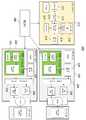
도 1은 일반적인 차량의 선루프 및 테일게이트 조작 스위치부, 선루프 유니트, 테일게이트 유니트의 각 위치와 신호 제공용 하네스 경로를 나타낸 도면이다.
도 2는 본 발명의 실시예에 따른 차량의 루프 영역 통합 무선 제어 시스템의 구성을 개략적으로 나타낸 도면이다.Fig. 1 is a view showing the positions of the sunroof and tail gate operation switch unit, the sunroof unit, the tail gate unit, and the harness path for providing signals in a general vehicle.
2 is a diagram schematically showing a configuration of a loop-area integrated radio control system for a vehicle according to an embodiment of the present invention.
본 명세서 및 청구범위에 사용된 용어나 단어는 통상적이거나 사전적인 의미로 한정되어 해석되지 말아야 하며, 발명자는 그 자신의 발명을 가장 최선의 방법으로 설명하기 위해 용어의 개념을 적절하게 정의할 수 있다는 원칙에 입각하여 본 발명의 기술적 사상에 부합하는 의미와 개념으로 해석되어야 한다.The terms and words used in the present specification and claims should not be construed as limited to ordinary or dictionary terms and the inventor can properly define the concept of the term to describe its invention in the best way Should be construed in accordance with the principles and meanings and concepts consistent with the technical idea of the present invention.
명세서 전체에서, 어떤 부분이 어떤 구성요소를 "포함"한다고 할 때, 이는 특별히 반대되는 기재가 없는 한 다른 구성요소를 제외하는 것이 아니라 다른 구성요소를 더 포함할 수 있다는 것을 의미한다. 또한, 명세서에 기재된 "…부", "…기", "모듈", "장치" 등의 용어는 적어도 하나의 기능이나 동작을 처리하는 단위를 의미하며, 이는 하드웨어나 소프트웨어 또는 하드웨어 및 소프트웨어의 결합으로 구현될 수 있다.Throughout the specification, when an element is referred to as "comprising ", it means that it can include other elements as well, without excluding other elements unless specifically stated otherwise. Also, the terms " part, "" module, "and" device " Lt; / RTI >
이하 첨부된 도면을 참조하여 본 발명의 실시예를 상세히 설명한다.Hereinafter, embodiments of the present invention will be described in detail with reference to the accompanying drawings.
도 1은 일반적인 차량의 선루프 및 테일게이트 조작 스위치부, 선루프 유니트, 테일게이트 유니트의 각 위치와 신호 제공용 하네스 경로를 나타낸 도면이다.Fig. 1 is a view showing the positions of the sunroof and tail gate operation switch unit, the sunroof unit, the tail gate unit, and the harness path for providing signals in a general vehicle.
도 1을 참조하면, 일반적으로 차량의 운전석 위쪽의 오버헤드 콘솔에 부착되어 있는 스위치 박스에 선루프 조작 스위치와 테일게이트 조작 스위치가 설치되어 있으며, 이 스위치들은 와이어(전선) 하네스가 차량의 A 필러, 차량 하단부 및 차량의 C 필러를 통하여 선루프 제어 유니트 및 테일게이트 제어 유니트로 연결되어 있다. 따라서, 전술한 바와 같이, 이상과 같은 유선 구조에서는 전선들의 상호 간섭 문제와, 전기적인 노이즈(noise)가 발생하는 문제가 있다. 또한, 전선의 단선 및 쇼트(단락)에 의한 작동 불량, 오작동 등이 발생하는 문제가 있다.Referring to FIG. 1, generally, a switch box attached to an overhead console above a driver's seat of a vehicle is provided with a sunroof operation switch and a tail gate operation switch. These switches connect the wire (electric wire) , The lower end of the vehicle, and the C-pillar of the vehicle, to the sunroof control unit and the tailgate control unit. Therefore, as described above, there is a problem that mutual interference of electric wires and electric noise occur in the above-mentioned wire structure. Further, there is a problem that malfunction or malfunction occurs due to disconnection or short circuit of the electric wire.
본 발명은 이상과 같은 종래 유선 구조에서 하네스를 제거하고 하네스를 통하여 제공하는 신호 및 제어정보를 무선 통신을 통해 선루프 제어 유니트, 테일게이트 제어 유니트에 제공함으로써 유선 구조에서의 문제를 해소하고자 한다.The present invention eliminates the problem in the wire structure by removing the harness from the conventional wired structure and providing signal and control information through the harness to the sunroof control unit and the tail gate control unit through wireless communication.
도 2는 본 발명의 실시예에 따른 차량의 루프 영역 통합 무선 제어 시스템의 구성을 개략적으로 나타낸 도면이다.2 is a diagram schematically showing a configuration of a loop-area integrated radio control system for a vehicle according to an embodiment of the present invention.
도 2를 참조하면, 본 발명에 따른 차량의 루프 영역 통합 무선 제어 시스템(200)은 크게 조작 스위치부(210), 선루프 유니트(220) 및 테일게이트 유니트(230)를 포함하여 구성된다.Referring to FIG. 2, the loop area integrated
조작 스위치부(210)는 차량의 운전석의 위쪽의 오버헤드 콘솔 스위치 박스에 설치되며, 선루프 조작 스위치와 테일게이트 조작 스위치를 구비하고, 선루프 및 테일게이트의 무선 제어를 위한 신호를 전송하기 위한 무선 통신 수단을 구비한다. 여기서, 이와 같은 조작 스위치부(210)는 선루프 시스템 구동용 조작 스위치와 테일게이트 구동용 조작 스위치를 구비하는 스위치부(211)와, 그 스위치부(211)의 스위치가 조작됨에 따라 발생한 신호를 제1 신호 제어부(213)에서 판단할 수 있는 전자 신호로 변환해주는 스위치신호 입력부(212)와, 그 스위치신호 입력부(212)를 통해 입력된 신호의 정보를 분석 및 판단하여 정확한 구동신호를 전송할 수 있도록 제어하는 제1 신호 제어부(213)와, 그 제1 신호 제어부(213)에서 제공된 디지털 신호를 아날로그 형태의 무선 전송에 적합한 신호로 변환하는 무선신호 변환부(214)와, 그 무선신호 변환부(214)에 의해 변환된 무선 신호를 송출하는 안테나부(215) 및 BCM(Body Control Module)(240)과의 통신으로 와이어를 통해 제어신호를 송/수신하는 와이어(유선) 통신부(216)를 포함하여 구성될 수 있다. 여기서, 상기 무선신호 변환부(214)와 안테나부(215)는 조작 스위치부(210)의 무선 통신 수단을 구성하는 것으로서 이 무선 통신 수단은 제1 신호 제어부(213)를 함께 포함할 수도 있다.The
여기서, 또한 이상과 같은 조작 스위치부(210)는 바람직하게는 조작 스위치부(210)가 설치된 오버헤드 콘솔 스위치 박스에 배터리 전원을 공급해 줌으로써 스위치 박스를 차량 내에서 이동시키면서, 즉, 차량에 탑승한 탑승자 누구나 스위치 박스를 사용이 가능하도록 하는 배터리부(217)를 더 포함할 수 있다.Here, the
또한, 상기 제1 신호 제어부(213))는 BCM(240)으로부터 입력되는 제어신호를 수신하여 조작 스위치부(210)의 시스템 전체의 구동을 제어하는 역할도 수행한다.In addition, the
선루프 유니트(220)는 상기 조작 스위치부(210)와 무선 통신을 위한 무선 통신부를 구비하며, 상기 조작 스위치부(210)로부터의 무선 전송 신호를 수신하여 선루프 제어에 반영한다. 여기서, 이와 같은 선루프 유니트(220)의 무선 통신부는, 상기 조작 스위치부(210)로부터 전송된 무선 신호를 수신하는 안테나부(221)와, 안테나부(221)를 통해 입력된 무선 신호를 디지털 신호로 변환하여 출력하는 무선신호 변환부(222) 및 무선신호 변환부(222)로부터 출력된 디지털 신호를 입력받아 사용자에 의해 입력된 명령에 반응하기 위한 제어신호를 후술하는 선루프 제어부(224)에 전달하는 제2 신호 제어부(223)를 포함하여 구성될 수 있다.The
여기서, 또한 이상과 같은 선루프 유니트(220)는 루프 어셈블리 시스템의 모터를 구동시키기 위한 구동신호를 출력하는 선루프 제어부(224)와, BCM(240)과의 통신으로 와이어를 통해 제어신호를 송/수신하며, 상기 BCM(240)을 통해 수신한 제어신호를 상기 선루프 제어부(224)로 전달하는 와이어 통신부(225) 및 상기 모터의 구동에 따른 캠축의 위치를 측정하고, 측정된 위치 정보 데이터를 상기 선루프 제어부(224)로 전송하는 홀센서부(226)를 더 포함할 수 있다.The above-described
테일게이트 유니트(230)는 상기 조작 스위치부(210)와 무선 통신을 위한 무선 통신부를 구비하며, 상기 조작 스위치부(210)로부터의 무선 전송 신호를 수신하여 테일게이트 제어에 반영한다. 이와 같은 테일게이트 유니트(230)의 무선 통신부는 상기 조작 스위치부(210)로부터 전송된 무선 신호를 수신하는 안테나부(231)와, 안테나부(231)를 통해 입력된 무선 신호를 디지털 신호로 변환하여 출력하는 무선신호 변환부(232) 및 무선신호 변환부(232)로부터 출력된 디지털 신호를 입력받아 사용자에 의해 입력된 명령에 반응하기 위한 제어신호를 후술하는 테일게이트 제어부(234)에 전달하는 제3 신호 제어부(233)를 포함하여 구성될 수 있다. The
또한, 이상과 같은 테일게이트 유니트(230)는 루프 어셈블리 시스템의 모터를 구동시키기 위한 구동신호를 출력하는 테일게이트 제어부(234)와, BCM(240)과의 통신으로 와이어를 통해 제어신호를 송/수신하며, 상기 BCM(240)을 통해 수신한 제어신호를 상기 테일게이트 제어부(234)로 전달하는 와이어 통신부(235) 및 상기 모터의 구동에 따른 캠축의 위치를 측정하고, 측정된 위치 정보 데이터를 상기 테일게이트 제어부(234)로 전송하는 홀센서부(236)를 더 포함할 수 있다.The
또한, 상기 선루프 유니트(220)와 테일게이트 유니트(230)는 각 유니트의 와이어 통신부(225)(235)와 BCM(240)과의 와이어(유선) 통신을 통해 활성화 정보를 획득하여 활성화되도록 구성될 수 있다.The
여기서, 바람직하게는 상기 조작 스위치부(210)와 선루프 유니트(220) 또는 테일게이트 유니트(230) 간의 무선 통신에 있어서, 상기 선루프 유니트(220)와 상기 테일게이트 유니트(230)에는 각 유니트를 식별할 수 있는 서로 다른 ID가 부여되고, 상기 조작 스위치부(210)로부터의 무선 제어 신호에 포함되어 있는 ID와 부합될 경우에 해당 유니트가 동작할 수 있도록 하는 통신 프로토콜이 사용될 수 있다.Preferably, in the wireless communication between the
이상의 설명과 같이, 본 발명에 따른 차량의 루프 영역 통합 무선 제어 시스템은 종래의 차량의 루프 영역(선루프, 테일게이트)에서의 유선(하네스)에 의한 신호 전달 방식을 무선통신에 의한 신호 전달 방식으로 변경함으로써, 종래의 유선 방식에서의 전선 상호 간의 간섭, 노이즈 발생, 전선의 단선 및 단락에 의한 작동 불량 또는 오작동 문제를 근본적으로 해소할 수 있는 장점이 있다.As described above, the loop-area integrated radio control system for a vehicle according to the present invention can be applied to a signal transmission system by wire (harness) in a loop region (sunroof, tail gate) It is possible to fundamentally solve the problem of malfunction or malfunction due to interference between wires in a conventional wired system, generation of noise, disconnection and short circuit of electric wires, and the like.
또한, 하네스의 제거에 따른 무게 감축으로 차량의 연비를 향상시킬 수 있고, 조작 스위치부가 설치된 오버헤드 콘솔 스위치 박스에 배터리부에 의한 배터리 전원을 공급해 줌으로써, 스위치 박스를 차량 내부에서 이동시키면서 탑승자 중 누구나 자유롭게 스위치를 조작할 수 있는 장점이 있다.In addition, by reducing the weight due to removal of the harness, the fuel consumption of the vehicle can be improved. By supplying the battery power by the battery unit to the overhead console switch box provided with the operation switch unit, There is an advantage that the switch can be operated freely.
이상, 바람직한 실시예를 통하여 본 발명에 관하여 상세히 설명하였으나, 본 발명은 이에 한정되는 것은 아니며, 본 발명의 기술적 사상을 벗어나지 않는 범위 내에서 다양하게 변경, 응용될 수 있음은 당해 기술분야의 통상의 기술자에게 자명하다. 따라서, 본 발명의 진정한 보호 범위는 다음의 청구범위에 의하여 해석되어야 하며, 그와 동등한 범위 내에 있는 모든 기술적 사상은 본 발명의 권리 범위에 포함되는 것으로 해석되어야 할 것이다.While the present invention has been particularly shown and described with reference to exemplary embodiments thereof, it is to be understood that the invention is not limited to the disclosed exemplary embodiments, but many variations and modifications may be made without departing from the spirit and scope of the invention. Be clear to the technician. Accordingly, the true scope of protection of the present invention should be construed according to the following claims, and all technical ideas within the scope of the same should be construed as being included in the scope of the present invention.
210: 조작 스위치부 211: 스위치부
212: 스위치신호 입력부 213: 제1 신호 제어부
214,222,232: 무선신호 변환부 215,221,231: 안테나부
216,225,235: 와이어 통신부 217: 배터리부
220: 선루프 유니트 223: 제2 신호 제어부
224: 선루프 제어부 226,236: 홀센서부
233: 제3 신호 제어부 234: 테일게이트 제어부210: operation switch section 211: switch section
212: switch signal input unit 213: first signal control unit
214, 222, 232: radio
216, 225, 235: wire communication unit 217:
220: Sunroof unit 223: Second signal control unit
224: a
233: Third signal control unit 234: Tail gate control unit
Claims (11)
Translated fromKorean상기 조작 스위치부와 무선 통신을 위한 무선 통신부를 구비하며, 상기 조작 스위치부로부터의 무선 전송 신호를 수신하여 선루프 제어에 반영하는 선루프 유니트; 및
상기 조작 스위치부와 무선 통신을 위한 무선 통신부를 구비하며, 상기 조작 스위치부로부터의 무선 전송 신호를 수신하여 테일게이트 제어에 반영하는 테일게이트 유니트를 포함하는 차량의 루프 영역 통합 무선 제어 시스템.
An operation switch unit installed in the overhead console switch box and having a sunroof operation switch and a tailgate operation switch and wireless communication means for transmitting a signal for radio control of the sunroof and the tail gate;
A sunroof unit having a wireless communication unit for wireless communication with the operation switch unit and receiving a wireless transmission signal from the operation switch unit and reflecting the wireless transmission signal to the sunroof control; And
And a tail gate unit that has a wireless communication unit for wireless communication with the operation switch unit and receives a wireless transmission signal from the operation switch unit and reflects the wireless transmission signal to the tail gate control.
상기 조작 스위치부와 선루프 유니트 또는 테일게이트 유니트 간의 무선 통신에 있어서, 상기 선루프 유니트와 상기 테일게이트 유니트에는 각 유니트를 식별할 수 있는 서로 다른 ID가 부여되고, 상기 조작 스위치부로부터의 무선 제어 신호에 포함되어 있는 ID와 부합될 경우에 해당 유니트가 동작할 수 있도록 하는 통신 프로토콜이 사용된 것을 특징으로 하는 차량의 루프 영역 통합 무선 제어 시스템.The method according to claim 1,
In the wireless communication between the operation switch unit and the sunroof unit or the tailgate unit, the sunroof unit and the tailgate unit are given different IDs for identifying each unit, and the radio control unit And a communication protocol that allows the unit to operate when the ID matches the ID included in the signal is used.
상기 조작 스위치부는,
선루프 시스템 구동용 조작 스위치와 테일게이트 구동용 조작 스위치를 구비하는 스위치부;
상기 스위치부의 스위치가 조작됨에 따라 발생한 신호를 제1 신호 제어부에서 판단할 수 있는 전자 신호로 변환해주는 스위치신호 입력부;
상기 스위치신호 입력부를 통해 입력된 신호의 정보를 분석 및 판단하여 정확한 구동신호를 전송할 수 있도록 제어하는 제1 신호 제어부;
상기 제1 신호 제어부에서 제공된 디지털 신호를 아날로그 형태의 무선 전송에 적합한 신호로 변환하는 무선신호 변환부;
상기 무선신호 변환부에 의해 변환된 무선 신호를 송출하는 안테나부; 및
BCM(Body Control Module)과의 통신으로 와이어를 통해 제어신호를 송/수신하는 와이어 통신부를 포함하는 차량의 루프 영역 통합 무선 제어 시스템.
The method according to claim 1,
The operation switch unit,
A switch unit including an operation switch for driving a sunroof system and an operation switch for driving a tail gate;
A switch signal input unit for converting a signal generated by a switch of the switch unit into an electronic signal that can be determined by the first signal controller;
A first signal controller for analyzing information of a signal input through the switch signal input unit and controlling the signal to transmit an accurate driving signal;
A radio signal converter for converting the digital signal provided by the first signal controller into a signal suitable for radio transmission in analog form;
An antenna unit for transmitting the radio signal converted by the radio signal converter; And
And a wire communication unit for transmitting / receiving a control signal via a wire in communication with a BCM (Body Control Module).
상기 조작 스위치부가 설치된 오버헤드 콘솔 스위치 박스에 배터리 전원을 공급해 줌으로써 스위치 박스를 차량 내에서 이동시키면서 사용이 가능하도록 하는 배터리부를 더 포함하는 차량의 루프 영역 통합 무선 제어 시스템.The method of claim 3,
Further comprising a battery unit for supplying battery power to an overhead console switch box provided with the operation switch unit so that the switch box can be used while being moved within the vehicle.
상기 제1 신호 제어부는 상기 BCM으로부터 입력되는 제어신호를 수신하여 조작 스위치부의 시스템 전체의 구동을 제어하는 역할을 수행하는 것을 특징으로 하는 차량의 루프 영역 통합 무선 제어 시스템.
The method of claim 3,
Wherein the first signal control unit receives a control signal input from the BCM and controls the operation of the entire system of the operation switch unit.
상기 선루프 유니트는,
루프 어셈블리 시스템의 모터를 구동시키기 위한 구동신호를 출력하는 선루프 제어부;
BCM과의 통신으로 와이어를 통해 제어신호를 송/수신하며, 상기 BCM을 통해 수신한 제어신호를 상기 선루프 제어부로 전달하는 와이어 통신부; 및
상기 모터의 구동에 따른 캠축의 위치를 측정하고, 측정된 위치 정보 데이터를 상기 선루프 제어부로 전송하는 홀센서부를 더 포함하는 차량의 루프 영역 통합 무선 제어 시스템.
The method according to claim 1,
Wherein the sunroof unit comprises:
A sunroof control unit for outputting a driving signal for driving a motor of the roof assembly system;
A wire communication unit for transmitting / receiving a control signal through a wire in communication with the BCM, and transmitting a control signal received through the BCM to the sunroof control unit; And
And a hall sensor unit for measuring the position of the camshaft in accordance with the driving of the motor and transmitting the measured position information data to the sunroof control unit.
상기 선루프 유니트의 무선 통신부는,
상기 조작 스위치부로부터 전송된 무선 신호를 수신하는 안테나부;
상기 안테나부를 통해 입력된 무선 신호를 디지털 신호로 변환하여 출력하는 무선신호 변환부; 및
상기 무선신호 변환부로부터 출력된 디지털 신호를 입력받아 사용자에 의해 입력된 명령에 반응하기 위한 제어신호를 상기 선루프 제어부에 전달하는 제2 신호 제어부를 포함하는 차량의 루프 영역 통합 무선 제어 시스템.
The method according to claim 6,
Wherein the wireless communication unit of the sunroof unit comprises:
An antenna unit for receiving a radio signal transmitted from the operation switch unit;
A radio signal converting unit for converting a radio signal input through the antenna unit into a digital signal and outputting the digital signal; And
And a second signal controller for receiving a digital signal output from the radio signal converter and transmitting a control signal for responding to a command input by a user to the sunroof controller.
상기 테일게이트 유니트는,
루프 어셈블리 시스템의 모터를 구동시키기 위한 구동신호를 출력하는 테일게이트 제어부;
BCM과의 통신으로 와이어를 통해 제어신호를 송/수신하며, 상기 BCM을 통해 수신한 제어신호를 상기 테일게이트 제어부로 전달하는 와이어 통신부; 및
상기 모터의 구동에 따른 캠축의 위치를 측정하고, 측정된 위치 정보 데이터를 상기 테일게이트 제어부로 전송하는 홀센서부를 더 포함하는 차량의 루프 영역 통합 무선 제어 시스템.
The method according to claim 1,
Wherein the tail gate unit comprises:
A tail gate controller for outputting a drive signal for driving a motor of the loop assembly system;
A wire communication unit for transmitting / receiving a control signal through a wire in communication with the BCM and transmitting a control signal received through the BCM to the tail gate control unit; And
Further comprising a hall sensor unit for measuring a position of a camshaft driven by the motor and transmitting the measured position information data to the tailgate control unit.
상기 테일게이트 유니트의 무선 통신부는,
상기 조작 스위치부로부터 전송된 무선 신호를 수신하는 안테나부;
상기 안테나부를 통해 입력된 무선 신호를 디지털 신호로 변환하여 출력하는 무선신호 변환부; 및
상기 무선신호 변환부로부터 출력된 디지털 신호를 입력받아 사용자에 의해 입력된 명령에 반응하기 위한 제어신호를 상기 테일게이트 제어부에 전달하는 제3 신호 제어부를 포함하는 차량의 루프 영역 통합 무선 제어 시스템.
9. The method of claim 8,
The wireless communication unit of the tail gate unit includes:
An antenna unit for receiving a radio signal transmitted from the operation switch unit;
A radio signal converting unit for converting a radio signal input through the antenna unit into a digital signal and outputting the digital signal; And
And a third signal controller for receiving a digital signal output from the radio signal converter and transmitting a control signal for responding to a command input by the user to the tailgate controller.
상기 선루프 유니트는 상기 와이어 통신부와 BCM과의 와이어(유선) 통신을 통해 활성화 정보를 획득하여 활성화되도록 구성된 것을 특징으로 하는 차량의 루프 영역 통합 무선 제어 시스템.
The method according to claim 6,
Wherein the front loop unit is configured to activate and acquire activation information through wire (wire) communication between the wire communication unit and the BCM.
상기 테일게이트 유니트는 상기 와이어 통신부와 BCM과의 와이어(유선) 통신을 통해 활성화 정보를 획득하여 활성화되도록 구성된 것을 특징으로 하는 차량의 루프 영역 통합 무선 제어 시스템.9. The method of claim 8,
Wherein the tail gate unit is configured to activate and acquire activation information through wire (wire) communication between the wire communication unit and the BCM.
Priority Applications (1)
| Application Number | Priority Date | Filing Date | Title |
|---|---|---|---|
| KR1020160101960AKR101867388B1 (en) | 2016-08-10 | 2016-08-10 | Combined wireless control system for roof zone in vehicle |
Applications Claiming Priority (1)
| Application Number | Priority Date | Filing Date | Title |
|---|---|---|---|
| KR1020160101960AKR101867388B1 (en) | 2016-08-10 | 2016-08-10 | Combined wireless control system for roof zone in vehicle |
Publications (2)
| Publication Number | Publication Date |
|---|---|
| KR20180018918Atrue KR20180018918A (en) | 2018-02-22 |
| KR101867388B1 KR101867388B1 (en) | 2018-07-24 |
Family
ID=61386968
Family Applications (1)
| Application Number | Title | Priority Date | Filing Date |
|---|---|---|---|
| KR1020160101960AActiveKR101867388B1 (en) | 2016-08-10 | 2016-08-10 | Combined wireless control system for roof zone in vehicle |
Country Status (1)
| Country | Link |
|---|---|
| KR (1) | KR101867388B1 (en) |
Cited By (2)
| Publication number | Priority date | Publication date | Assignee | Title |
|---|---|---|---|---|
| CN114056259A (en)* | 2020-08-06 | 2022-02-18 | 上海汽车集团股份有限公司 | Roof domain controller and roof domain control system |
| KR20230030849A (en) | 2021-08-26 | 2023-03-07 | (주)티에이치엔 | Roof zone controller for a vehicle |
Citations (6)
| Publication number | Priority date | Publication date | Assignee | Title |
|---|---|---|---|---|
| JP2005075267A (en)* | 2003-09-03 | 2005-03-24 | Auto Network Gijutsu Kenkyusho:Kk | In-car control system |
| JP2005081861A (en)* | 2003-09-04 | 2005-03-31 | Auto Network Gijutsu Kenkyusho:Kk | On-vehicle control system |
| KR20090045975A (en)* | 2007-11-05 | 2009-05-11 | 현대자동차주식회사 | Door window and sunroof integrated control system of automobile |
| JP2009251961A (en)* | 2008-04-07 | 2009-10-29 | Calsonic Kansei Corp | Wireless switch |
| KR101394107B1 (en) | 2012-12-12 | 2014-05-13 | 현대오트론 주식회사 | Method and apparatus for controlling position of sunroof of vehicle |
| KR20150065989A (en)* | 2013-12-05 | 2015-06-16 | 주식회사 동희홀딩스 | Apparatus for controlling the driving of sun roof using internal network of vehicle |
- 2016
- 2016-08-10KRKR1020160101960Apatent/KR101867388B1/enactiveActive
Patent Citations (6)
| Publication number | Priority date | Publication date | Assignee | Title |
|---|---|---|---|---|
| JP2005075267A (en)* | 2003-09-03 | 2005-03-24 | Auto Network Gijutsu Kenkyusho:Kk | In-car control system |
| JP2005081861A (en)* | 2003-09-04 | 2005-03-31 | Auto Network Gijutsu Kenkyusho:Kk | On-vehicle control system |
| KR20090045975A (en)* | 2007-11-05 | 2009-05-11 | 현대자동차주식회사 | Door window and sunroof integrated control system of automobile |
| JP2009251961A (en)* | 2008-04-07 | 2009-10-29 | Calsonic Kansei Corp | Wireless switch |
| KR101394107B1 (en) | 2012-12-12 | 2014-05-13 | 현대오트론 주식회사 | Method and apparatus for controlling position of sunroof of vehicle |
| KR20150065989A (en)* | 2013-12-05 | 2015-06-16 | 주식회사 동희홀딩스 | Apparatus for controlling the driving of sun roof using internal network of vehicle |
Cited By (3)
| Publication number | Priority date | Publication date | Assignee | Title |
|---|---|---|---|---|
| CN114056259A (en)* | 2020-08-06 | 2022-02-18 | 上海汽车集团股份有限公司 | Roof domain controller and roof domain control system |
| CN114056259B (en)* | 2020-08-06 | 2024-04-30 | 上海汽车集团股份有限公司 | Roof area controller and roof area control system |
| KR20230030849A (en) | 2021-08-26 | 2023-03-07 | (주)티에이치엔 | Roof zone controller for a vehicle |
Also Published As
| Publication number | Publication date |
|---|---|
| KR101867388B1 (en) | 2018-07-24 |
Similar Documents
| Publication | Publication Date | Title |
|---|---|---|
| US7012401B2 (en) | Inverter system of automotive motor | |
| CN103556901B (en) | Automotive window intelligent regulating system and control method thereof | |
| US11299923B2 (en) | Drive arrangement for a closure element of a motor vehicle | |
| US7699381B2 (en) | Windbreak device | |
| CN102069763A (en) | Vehicle body controller and control method thereof | |
| US10220687B2 (en) | Vehicle electrical system | |
| US6369529B1 (en) | Remote power seat control system and method | |
| US10464497B2 (en) | Roof box | |
| KR101867388B1 (en) | Combined wireless control system for roof zone in vehicle | |
| US7184871B2 (en) | Distributed control unit | |
| CZ336397A3 (en) | Arrangement of an auxiliary heating body of a vehicle with a control device and handling section situated inside the vehicle | |
| KR100965431B1 (en) | Window control device of car | |
| JP2018024396A (en) | On-vehicle apparatus control system | |
| CN107406045A (en) | Power Distribution Devices for Automobiles | |
| US20180337556A1 (en) | Non-contact power transmission structure for sliding door | |
| US7268506B2 (en) | Power window system | |
| US11738703B2 (en) | Power supply system in vehicle door | |
| CN110325403B (en) | top module | |
| CN103342117A (en) | Wireless car body control module | |
| CN113492776A (en) | Central control unit for the interior of a motor vehicle | |
| CN220220648U (en) | Automobile panoramic sunroof and back door control system and automobile | |
| KR20210082834A (en) | Apparatus for controlling door of vehicle | |
| JP3284033B2 (en) | Power window and door locking / unlocking control device | |
| CN205857989U (en) | Door lock for vehicle, door lock for vehicle motor, vehicle door latch system and vehicle | |
| KR101878230B1 (en) | System and method for automatically controlling opening degree of sunroof in vehicle |
Legal Events
| Date | Code | Title | Description |
|---|---|---|---|
| A201 | Request for examination | ||
| PA0109 | Patent application | Patent event code:PA01091R01D Comment text:Patent Application Patent event date:20160810 | |
| PA0201 | Request for examination | ||
| E902 | Notification of reason for refusal | ||
| PE0902 | Notice of grounds for rejection | Comment text:Notification of reason for refusal Patent event date:20170918 Patent event code:PE09021S01D | |
| PG1501 | Laying open of application | ||
| PE0701 | Decision of registration | Patent event code:PE07011S01D Comment text:Decision to Grant Registration Patent event date:20180315 | |
| PR0701 | Registration of establishment | Comment text:Registration of Establishment Patent event date:20180607 Patent event code:PR07011E01D | |
| PR1002 | Payment of registration fee | Payment date:20180607 End annual number:3 Start annual number:1 | |
| PG1601 | Publication of registration | ||
| PR1001 | Payment of annual fee | Payment date:20210607 Start annual number:4 End annual number:4 | |
| PR1001 | Payment of annual fee | Payment date:20220603 Start annual number:5 End annual number:5 | |
| PR1001 | Payment of annual fee | Payment date:20230607 Start annual number:6 End annual number:6 | |
| PR1001 | Payment of annual fee | Payment date:20240603 Start annual number:7 End annual number:7 |