KR20180017128A - Robot and Robot System - Google Patents
Robot and Robot SystemDownload PDFInfo
- Publication number
- KR20180017128A KR20180017128AKR1020187000808AKR20187000808AKR20180017128AKR 20180017128 AKR20180017128 AKR 20180017128AKR 1020187000808 AKR1020187000808 AKR 1020187000808AKR 20187000808 AKR20187000808 AKR 20187000808AKR 20180017128 AKR20180017128 AKR 20180017128A
- Authority
- KR
- South Korea
- Prior art keywords
- robot
- hand
- cartilage
- ear
- cartilage conduction
- Prior art date
- Legal status (The legal status is an assumption and is not a legal conclusion. Google has not performed a legal analysis and makes no representation as to the accuracy of the status listed.)
- Granted
Links
- 210000000845cartilageAnatomy0.000claimsabstractdescription257
- 230000033001locomotionEffects0.000claimsabstractdescription52
- 230000036760body temperatureEffects0.000claimsabstractdescription14
- 238000000034methodMethods0.000claimsdescription198
- 230000006854communicationEffects0.000claimsdescription104
- 238000004891communicationMethods0.000claimsdescription101
- 210000004728ear cartilageAnatomy0.000claimsdescription62
- 230000007246mechanismEffects0.000claimsdescription44
- 210000003128headAnatomy0.000claimsdescription38
- 230000005856abnormalityEffects0.000claimsdescription25
- 238000012790confirmationMethods0.000claimsdescription12
- 238000010792warmingMethods0.000claimsdescription9
- 241000746998TragusSpecies0.000claimsdescription3
- 230000002159abnormal effectEffects0.000abstractdescription7
- 230000008569processEffects0.000description176
- 210000003811fingerAnatomy0.000description80
- 210000000988bone and boneAnatomy0.000description70
- 230000006870functionEffects0.000description69
- 230000001413cellular effectEffects0.000description58
- 210000004247handAnatomy0.000description56
- 238000001514detection methodMethods0.000description54
- 210000000613ear canalAnatomy0.000description38
- 238000012545processingMethods0.000description31
- 238000012544monitoring processMethods0.000description28
- 210000003813thumbAnatomy0.000description28
- 238000010586diagramMethods0.000description22
- 230000004044responseEffects0.000description21
- 238000013508migrationMethods0.000description20
- 230000005012migrationEffects0.000description20
- 238000003860storageMethods0.000description17
- 230000005540biological transmissionEffects0.000description15
- 210000000216zygomaAnatomy0.000description15
- 210000005069earsAnatomy0.000description14
- 230000001133accelerationEffects0.000description12
- 230000008859changeEffects0.000description10
- 230000001055chewing effectEffects0.000description10
- 230000008901benefitEffects0.000description9
- 210000000883ear externalAnatomy0.000description9
- 230000005236sound signalEffects0.000description9
- 238000005259measurementMethods0.000description8
- 238000005452bendingMethods0.000description7
- 230000000694effectsEffects0.000description7
- 230000007704transitionEffects0.000description7
- 125000002066L-histidyl groupChemical group[H]N1C([H])=NC(C([H])([H])[C@](C(=O)[*])([H])N([H])[H])=C1[H]0.000description6
- 238000007726management methodMethods0.000description6
- 210000001595mastoidAnatomy0.000description6
- 238000012986modificationMethods0.000description6
- 230000004048modificationEffects0.000description6
- 210000003454tympanic membraneAnatomy0.000description6
- 230000009471actionEffects0.000description5
- 238000009434installationMethods0.000description5
- 230000018984masticationEffects0.000description5
- 238000010077masticationMethods0.000description5
- 230000002354daily effectEffects0.000description4
- 230000003203everyday effectEffects0.000description4
- 210000004936left thumbAnatomy0.000description4
- 230000036651moodEffects0.000description4
- 238000003825pressingMethods0.000description4
- 210000004935right thumbAnatomy0.000description4
- 238000010438heat treatmentMethods0.000description3
- 230000029058respiratory gaseous exchangeEffects0.000description3
- 238000012546transferMethods0.000description3
- 235000001674Agaricus brunnescensNutrition0.000description2
- 206010039740ScreamingDiseases0.000description2
- 238000004458analytical methodMethods0.000description2
- 210000003423ankleAnatomy0.000description2
- 238000004040coloringMethods0.000description2
- 230000000295complement effectEffects0.000description2
- 238000009223counselingMethods0.000description2
- 210000003414extremityAnatomy0.000description2
- 210000005224forefingerAnatomy0.000description2
- 230000010365information processingEffects0.000description2
- 210000001503jointAnatomy0.000description2
- 238000012423maintenanceMethods0.000description2
- 239000000463materialSubstances0.000description2
- 230000013011matingEffects0.000description2
- 230000003340mental effectEffects0.000description2
- 230000008450motivationEffects0.000description2
- 230000003287optical effectEffects0.000description2
- 239000002245particleSubstances0.000description2
- 238000005316response functionMethods0.000description2
- 230000000007visual effectEffects0.000description2
- 206010011469CryingDiseases0.000description1
- 206010016326Feeling coldDiseases0.000description1
- 241000282412HomoSpecies0.000description1
- 208000019695Migraine diseaseDiseases0.000description1
- 230000032683agingEffects0.000description1
- 238000004873anchoringMethods0.000description1
- 238000013459approachMethods0.000description1
- 230000009118appropriate responseEffects0.000description1
- 230000037396body weightEffects0.000description1
- 210000003109clavicleAnatomy0.000description1
- 230000002153concerted effectEffects0.000description1
- 239000000470constituentSubstances0.000description1
- 230000013228contact guidanceEffects0.000description1
- 230000010485copingEffects0.000description1
- 239000013013elastic materialSubstances0.000description1
- 210000002310elbow jointAnatomy0.000description1
- 239000000284extractSubstances0.000description1
- 210000001145finger jointAnatomy0.000description1
- 238000007730finishing processMethods0.000description1
- 238000010304firingMethods0.000description1
- 210000002478hand jointAnatomy0.000description1
- 230000004886head movementEffects0.000description1
- 238000007654immersionMethods0.000description1
- 239000004973liquid crystal related substanceSubstances0.000description1
- 210000004932little fingerAnatomy0.000description1
- 210000004072lungAnatomy0.000description1
- 238000004519manufacturing processMethods0.000description1
- 239000013521masticSubstances0.000description1
- 235000012054mealsNutrition0.000description1
- 206010027599migraineDiseases0.000description1
- 238000010422paintingMethods0.000description1
- 230000008439repair processEffects0.000description1
- 210000003625skullAnatomy0.000description1
- 238000012360testing methodMethods0.000description1
- 210000003857wrist jointAnatomy0.000description1
Images


Classifications
- B—PERFORMING OPERATIONS; TRANSPORTING
- B25—HAND TOOLS; PORTABLE POWER-DRIVEN TOOLS; MANIPULATORS
- B25J—MANIPULATORS; CHAMBERS PROVIDED WITH MANIPULATION DEVICES
- B25J11/00—Manipulators not otherwise provided for
- B25J11/008—Manipulators for service tasks
- B25J11/009—Nursing, e.g. carrying sick persons, pushing wheelchairs, distributing drugs
- B—PERFORMING OPERATIONS; TRANSPORTING
- B25—HAND TOOLS; PORTABLE POWER-DRIVEN TOOLS; MANIPULATORS
- B25J—MANIPULATORS; CHAMBERS PROVIDED WITH MANIPULATION DEVICES
- B25J11/00—Manipulators not otherwise provided for
- B25J11/0005—Manipulators having means for high-level communication with users, e.g. speech generator, face recognition means
- B—PERFORMING OPERATIONS; TRANSPORTING
- B25—HAND TOOLS; PORTABLE POWER-DRIVEN TOOLS; MANIPULATORS
- B25J—MANIPULATORS; CHAMBERS PROVIDED WITH MANIPULATION DEVICES
- B25J15/00—Gripping heads and other end effectors
- B25J15/0009—Gripping heads and other end effectors comprising multi-articulated fingers, e.g. resembling a human hand
- B—PERFORMING OPERATIONS; TRANSPORTING
- B25—HAND TOOLS; PORTABLE POWER-DRIVEN TOOLS; MANIPULATORS
- B25J—MANIPULATORS; CHAMBERS PROVIDED WITH MANIPULATION DEVICES
- B25J9/00—Programme-controlled manipulators
- B25J9/0009—Constructional details, e.g. manipulator supports, bases
- B—PERFORMING OPERATIONS; TRANSPORTING
- B25—HAND TOOLS; PORTABLE POWER-DRIVEN TOOLS; MANIPULATORS
- B25J—MANIPULATORS; CHAMBERS PROVIDED WITH MANIPULATION DEVICES
- B25J9/00—Programme-controlled manipulators
- B25J9/10—Programme-controlled manipulators characterised by positioning means for manipulator elements
- B25J9/1005—Programme-controlled manipulators characterised by positioning means for manipulator elements comprising adjusting means
- B25J9/101—Programme-controlled manipulators characterised by positioning means for manipulator elements comprising adjusting means using limit-switches, -stops
- H—ELECTRICITY
- H04—ELECTRIC COMMUNICATION TECHNIQUE
- H04R—LOUDSPEAKERS, MICROPHONES, GRAMOPHONE PICK-UPS OR LIKE ACOUSTIC ELECTROMECHANICAL TRANSDUCERS; DEAF-AID SETS; PUBLIC ADDRESS SYSTEMS
- H04R1/00—Details of transducers, loudspeakers or microphones
- H—ELECTRICITY
- H04—ELECTRIC COMMUNICATION TECHNIQUE
- H04R—LOUDSPEAKERS, MICROPHONES, GRAMOPHONE PICK-UPS OR LIKE ACOUSTIC ELECTROMECHANICAL TRANSDUCERS; DEAF-AID SETS; PUBLIC ADDRESS SYSTEMS
- H04R1/00—Details of transducers, loudspeakers or microphones
- H04R1/10—Earpieces; Attachments therefor ; Earphones; Monophonic headphones
- H04R1/1016—Earpieces of the intra-aural type
- H—ELECTRICITY
- H04—ELECTRIC COMMUNICATION TECHNIQUE
- H04R—LOUDSPEAKERS, MICROPHONES, GRAMOPHONE PICK-UPS OR LIKE ACOUSTIC ELECTROMECHANICAL TRANSDUCERS; DEAF-AID SETS; PUBLIC ADDRESS SYSTEMS
- H04R1/00—Details of transducers, loudspeakers or microphones
- H04R1/10—Earpieces; Attachments therefor ; Earphones; Monophonic headphones
- H04R1/1041—Mechanical or electronic switches, or control elements
- H—ELECTRICITY
- H04—ELECTRIC COMMUNICATION TECHNIQUE
- H04R—LOUDSPEAKERS, MICROPHONES, GRAMOPHONE PICK-UPS OR LIKE ACOUSTIC ELECTROMECHANICAL TRANSDUCERS; DEAF-AID SETS; PUBLIC ADDRESS SYSTEMS
- H04R1/00—Details of transducers, loudspeakers or microphones
- H04R1/10—Earpieces; Attachments therefor ; Earphones; Monophonic headphones
- H04R1/1058—Manufacture or assembly
- H04R1/1075—Mountings of transducers in earphones or headphones
- H—ELECTRICITY
- H04—ELECTRIC COMMUNICATION TECHNIQUE
- H04R—LOUDSPEAKERS, MICROPHONES, GRAMOPHONE PICK-UPS OR LIKE ACOUSTIC ELECTROMECHANICAL TRANSDUCERS; DEAF-AID SETS; PUBLIC ADDRESS SYSTEMS
- H04R17/00—Piezoelectric transducers; Electrostrictive transducers
- H—ELECTRICITY
- H04—ELECTRIC COMMUNICATION TECHNIQUE
- H04R—LOUDSPEAKERS, MICROPHONES, GRAMOPHONE PICK-UPS OR LIKE ACOUSTIC ELECTROMECHANICAL TRANSDUCERS; DEAF-AID SETS; PUBLIC ADDRESS SYSTEMS
- H04R2460/00—Details of hearing devices, i.e. of ear- or headphones covered by H04R1/10 or H04R5/033 but not provided for in any of their subgroups, or of hearing aids covered by H04R25/00 but not provided for in any of its subgroups
- H04R2460/09—Non-occlusive ear tips, i.e. leaving the ear canal open, for both custom and non-custom tips
- H—ELECTRICITY
- H04—ELECTRIC COMMUNICATION TECHNIQUE
- H04R—LOUDSPEAKERS, MICROPHONES, GRAMOPHONE PICK-UPS OR LIKE ACOUSTIC ELECTROMECHANICAL TRANSDUCERS; DEAF-AID SETS; PUBLIC ADDRESS SYSTEMS
- H04R2460/00—Details of hearing devices, i.e. of ear- or headphones covered by H04R1/10 or H04R5/033 but not provided for in any of their subgroups, or of hearing aids covered by H04R25/00 but not provided for in any of its subgroups
- H04R2460/11—Aspects relating to vents, e.g. shape, orientation, acoustic properties in ear tips of hearing devices to prevent occlusion
- H—ELECTRICITY
- H04—ELECTRIC COMMUNICATION TECHNIQUE
- H04R—LOUDSPEAKERS, MICROPHONES, GRAMOPHONE PICK-UPS OR LIKE ACOUSTIC ELECTROMECHANICAL TRANSDUCERS; DEAF-AID SETS; PUBLIC ADDRESS SYSTEMS
- H04R2460/00—Details of hearing devices, i.e. of ear- or headphones covered by H04R1/10 or H04R5/033 but not provided for in any of their subgroups, or of hearing aids covered by H04R25/00 but not provided for in any of its subgroups
- H04R2460/13—Hearing devices using bone conduction transducers
- H—ELECTRICITY
- H04—ELECTRIC COMMUNICATION TECHNIQUE
- H04R—LOUDSPEAKERS, MICROPHONES, GRAMOPHONE PICK-UPS OR LIKE ACOUSTIC ELECTROMECHANICAL TRANSDUCERS; DEAF-AID SETS; PUBLIC ADDRESS SYSTEMS
- H04R2499/00—Aspects covered by H04R or H04S not otherwise provided for in their subgroups
- H04R2499/10—General applications
- H04R2499/11—Transducers incorporated or for use in hand-held devices, e.g. mobile phones, PDA's, camera's
- H—ELECTRICITY
- H04—ELECTRIC COMMUNICATION TECHNIQUE
- H04R—LOUDSPEAKERS, MICROPHONES, GRAMOPHONE PICK-UPS OR LIKE ACOUSTIC ELECTROMECHANICAL TRANSDUCERS; DEAF-AID SETS; PUBLIC ADDRESS SYSTEMS
- H04R25/00—Deaf-aid sets, i.e. electro-acoustic or electro-mechanical hearing aids; Electric tinnitus maskers providing an auditory perception
- H04R25/40—Arrangements for obtaining a desired directivity characteristic
- H04R25/407—Circuits for combining signals of a plurality of transducers
- H—ELECTRICITY
- H04—ELECTRIC COMMUNICATION TECHNIQUE
- H04R—LOUDSPEAKERS, MICROPHONES, GRAMOPHONE PICK-UPS OR LIKE ACOUSTIC ELECTROMECHANICAL TRANSDUCERS; DEAF-AID SETS; PUBLIC ADDRESS SYSTEMS
- H04R5/00—Stereophonic arrangements
- H04R5/027—Spatial or constructional arrangements of microphones, e.g. in dummy heads
- H—ELECTRICITY
- H04—ELECTRIC COMMUNICATION TECHNIQUE
- H04R—LOUDSPEAKERS, MICROPHONES, GRAMOPHONE PICK-UPS OR LIKE ACOUSTIC ELECTROMECHANICAL TRANSDUCERS; DEAF-AID SETS; PUBLIC ADDRESS SYSTEMS
- H04R5/00—Stereophonic arrangements
- H04R5/04—Circuit arrangements, e.g. for selective connection of amplifier inputs/outputs to loudspeakers, for loudspeaker detection, or for adaptation of settings to personal preferences or hearing impairments
- H—ELECTRICITY
- H04—ELECTRIC COMMUNICATION TECHNIQUE
- H04R—LOUDSPEAKERS, MICROPHONES, GRAMOPHONE PICK-UPS OR LIKE ACOUSTIC ELECTROMECHANICAL TRANSDUCERS; DEAF-AID SETS; PUBLIC ADDRESS SYSTEMS
- H04R7/00—Diaphragms for electromechanical transducers; Cones
- H04R7/02—Diaphragms for electromechanical transducers; Cones characterised by the construction
- H04R7/04—Plane diaphragms
- H04R7/045—Plane diaphragms using the distributed mode principle, i.e. whereby the acoustic radiation is emanated from uniformly distributed free bending wave vibration induced in a stiff panel and not from pistonic motion
Landscapes
- Engineering & Computer Science (AREA)
- Robotics (AREA)
- Mechanical Engineering (AREA)
- Physics & Mathematics (AREA)
- Acoustics & Sound (AREA)
- Signal Processing (AREA)
- Health & Medical Sciences (AREA)
- General Health & Medical Sciences (AREA)
- Audiology, Speech & Language Pathology (AREA)
- Human Computer Interaction (AREA)
- Neurosurgery (AREA)
- Otolaryngology (AREA)
- Nursing (AREA)
- Telephone Function (AREA)
- Telephone Set Structure (AREA)
Abstract
Translated fromKoreanDescription
Translated fromKorean본 발명은 로봇 및 로봇 시스템에 관한 것이다.The present invention relates to a robot and a robot system.
사람과의 커뮤니케이션이 가능한 다양한 로봇이 제안되어 있다. 예를 들어 특허문헌 1에서는, 수록한 특정 개인의 목소리로 발화함과 함께 등록해 둔 그 사람의 습관에 기초하여 동시에 사지를 동작시켜, 애정 등을 연출할 수 있는 인간형 로봇이 제안되어 있다. 한편, 독거자의 워칭 시스템으로서는, 특허문헌 2에 있어서, 워칭 대상으로 되는 거주자의 주거에 설치한 인체 감지 센서, 거주자가 장착하는 가속도 센서의 양쪽으로부터 검출한 데이터를 수신하여, 거주자의 행동이나 상태, 거주자의 주거에 발생한 이벤트를 판단하는 것이 제안되어 있다. 또한 저작 상태 인식 장치로서, 특허문헌 3에서는, 외이도 내에 삽입되어 외이도의 변형량을 검지하는 검지부로부터의 검지 파형에 기초하여 저작 횟수를 카운트하는 것이 제안되어 있다. 또한 예로부터 알려져 있었던 기도(氣導) 및 골전도 외에, 제3 전도 루트로서 새로이 발견된 연골 전도에 대해서는, 특허문헌 4에 있어서, 외이도 입구부 주위의 귀 연골에 접촉시킨 진동원의 진동에 의하여 외이도 내부의 연골 표면으로부터 기도음이 발생하고, 외이도 내를 나아가 고막에 도달하는 것이 설명되어 있다.Various robots capable of communicating with people have been proposed. For example, Patent Literature 1 proposes a humanoid robot capable of playing a limb at the same time based on the habits of a person recorded with the voice of a specific individual recorded together with the recorded voice, and being able to direct affection and the like. On the other hand, as a stand-alone watching system, in
그러나 로봇 및 로봇을 활용한 로봇 시스템에 대해서는 더 검토해야 할 과제가 많다.However, there are many more issues to be considered for robotic systems using robots and robots.
본 발명의 과제는, 상기를 감안하여, 사람과의 적절한 커뮤니케이션이 가능한 로봇 및 로봇을 활용한 로봇 시스템을 제공하는 데 있다.In view of the above, it is an object of the present invention to provide a robot system utilizing a robot and a robot capable of proper communication with a person.
상기 과제를 해결하기 위하여, 본 발명은, 손과, 상기 손에 설치되고 사람의 귀 연골에 진동을 전달하기 위한 연골 전도 진동원을 갖는 것을 특징으로 하는 로봇을 제공한다. 이것에 의하여, 자연스런 동작에 의한 로봇과 사람의, 연골 전도에 의한 커뮤니케이션이 가능해진다.In order to solve the above problems, the present invention provides a robot having a hand and a cartilage conduction vibration source for transmitting vibration to a human ear cartilage provided in the hand. Thereby, communication by cartilage conduction between a robot and a person by natural motion becomes possible.
구체적인 특징에 의하면, 로봇은 양 손을 갖고, 상기 양 손의 각각에 상기 연골 전도 진동원이 설치된다. 이것에 의하여, 예를 들어 로봇의 양 손으로 사람의 안면을 부드럽게 감싸는 듯한 위안이 있는 연출로 연골 전도에 의한 로봇과 사람의 커뮤니케이션이 가능해진다. 또한 스테레오에 의한 청취도 가능해진다. 다른 구체적인 특징에 의하면, 로봇은, 상기 손에 손가락을 갖고, 상기 연골 전도 진동원은 상기 손가락에 설치된다. 이것에 의하여, 보다 효율이 좋은 연골 전도가 가능해진다. 보다 상세한 특징에 의하면, 상기 손 전체를 귀 연골에 접촉하도록 인도함과 함께, 상기 손가락을 이주(耳珠)로 인도하도록 조정하는 관절 기구를 갖는다. 이것에 의하여, 적절한 연골 전도를 위한 조절이 가능해진다.According to a specific feature, the robot has both hands, and the cartilage conduction vibration source is provided in each of the hands. This makes it possible for the robot to communicate with humans through cartilage conduction by, for example, directing the robot to comfortably wrap the face of the person with both hands. It is also possible to listen by stereo. According to another specific characteristic, the robot has a finger in the hand, and the cartilage conduction vibration source is installed on the finger. Thus, more efficient cartilage conduction becomes possible. According to a more detailed feature, it has a joint mechanism for guiding the entire hand to come into contact with the cartilage of the ear, and to adjust the finger to lead to the tragus. This enables adjustment for proper cartilage conduction.
다른 구체적인 특징에 의하면, 로봇은, 상기 양 손이 연골 전도를 위하여 각각 양 귀의 연골에 접촉할 때, 상기 양 손이 양자의 상대 위치는 유지하면서 안면의 움직임을 구속하지 않도록 제어하는 제어부를 갖는다. 이것에 의하여, 속박감이 없는 연골 전도가 가능해진다.According to another specific characteristic, the robot has a control section for controlling the hands so as not to restrain the movement of the face while maintaining the relative positions of both hands when the two hands come into contact with the cartilage of both hands for cartilage conduction. Thus, cartilage conduction without binding feeling becomes possible.
다른 구체적인 특징에 의하면, 로봇은 외관이 가동 눈을 갖고, 상기 눈의 시선이 상기 양 손 사이를 향하도록 동조하여 움직여진다. 이것에 의하여, 로봇과의 사이에서 보다 친밀한 연골 전도에 의한 커뮤니케이션이 가능해진다. 다른 구체적인 특징에 의하면, 로봇은 외관이 가동 입 기구를 갖고, 상기 입 기구는 상기 연골 전도 진동원의 진동에 의하여 전달되는 음성과 연동하여 움직이도록 제어된다. 이것에 의하여, 자연스런 연골 전도에 의한 커뮤니케이션이 가능해진다.According to another specific feature, the robot is moved by synchronizing with the eye having the movable eye, and the line of sight of the eye is directed between the both hands. This makes it possible to communicate with the robot more intimately by the cartilage conduction. According to another specific characteristic, the robot has a movable mouth mechanism, and the mouth mechanism is controlled to move in conjunction with the sound transmitted by the vibration of the cartilage conduction vibration source. Thus, communication by natural cartilage conduction becomes possible.
다른 구체적인 특징에 의하면, 로봇은, 상기 연골 전도 진동원의 진동을 귀 연골에 전달하도록 상기 손이 귀 연골에 접촉할 때, 그 접촉압을 제한하는 리미터를 갖는다. 이것에 의하여, 안전한 연골 전도에 의한 커뮤니케이션이 가능해진다. 다른 구체적인 특징에 의하면, 로봇은, 상기 연골 전도 진동원의 진동을 귀 연골에 전달하도록 상기 손을 귀 연골에 접촉시킬 때, 동의를 구하는 커뮤니케이션 수단을 갖는다. 이것에 의하여, 불쾌감이 없는 연골 전도에 의한 커뮤니케이션이 가능해진다.According to another specific feature, the robot has a limiter that limits the contact pressure when the hand contacts the ear cartilage to transmit the vibration of the cartilage conduction vibration source to the ear cartilage. Thus, communication by safe cartilage conduction becomes possible. According to another specific feature, the robot has a communication means for obtaining agreement when the hand is brought into contact with the ear cartilage to transmit the vibration of the cartilage conduction vibration source to the ear cartilage. Thus, communication by cartilage conduction without discomfort becomes possible.
다른 구체적인 특징에 의하면, 로봇은, 상기 연골 전도 진동원의 진동을 귀 연골에 전달하도록 상기 손을 귀 연골에 접촉시킬 때, 사전에 안전 확인을 행하는 제어부를 갖는다. 이것에 의하여, 안전성이 높은 연골 전도에 의한 커뮤니케이션이 가능해진다. 다른 구체적인 특징에 의하면, 로봇은 이상 검지 수단을 갖고, 상기 연골 전도 진동원의 진동을 귀 연골에 전달하도록 상기 손을 귀 연골에 접촉시킬 때 상기 이상 검지 수단이 이상을 검지했을 때, 상기 손의 귀 연골에 대한 접촉이 해제된다. 이것에 의하여, 만일의 경우에 있어서의 문제를 회피할 수 있다.According to another specific feature, the robot has a control portion that performs safety confirmation beforehand when the hand contacts the ear cartilage to transmit the vibration of the cartilage conduction vibration source to the ear cartilage. Thus, communication by cartilage conduction with high safety is enabled. According to another specific characteristic, the robot has an abnormality detecting means, and when the abnormality detecting means detects an abnormality when the hand is brought into contact with the ear cartilage to transmit the vibration of the cartilage conduction vibration source to the ear cartilage, The contact with the ear cartilage is released. Thus, it is possible to avoid the problem in case of emergency.
다른 구체적인 특징에 의하면, 로봇은 상기 손을 귀 연골로 인도하는 외력에 저항하지 않도록 로봇의 팔을 보유 지지하는 관절 기구를 갖는다. 이것에 의하여, 로봇과 접촉하고자 하는 사람이, 자신의 손으로 로봇의 손을 자신의 귀 연골로 용이하게 인도할 수 있다. 다른 구체적인 특징에 의하면, 로봇은, 상기 연골 전도 진동원이 사람의 편측의 귀에 진동을 전달함과 함께, 상기 사람의 머리의 움직임에 대하여 상기 손을 추종시키는 추종 수단을 갖는다. 이것에 의하여, 편측의 귀에 진동을 전달하는 경우에도 사람의 머리의 움직임으로 인하여 접촉이 끊기는 것을 방지할 수 있다.According to another specific feature, the robot has a joint mechanism for holding the arm of the robot so as not to resist an external force for guiding the hand to the ear cartilage. Thus, a person who wants to contact with the robot can easily guide the robot's hand to his / her ear cartilage with his or her own hand. According to another specific characteristic, the robot has following means for causing the cartilage conduction vibration source to transmit vibration to the ear of one side of the person, and to follow the hand with respect to the movement of the head of the person. Thus, even when vibrations are transmitted to the ear of one side, it is possible to prevent the contact from being cut off due to the movement of the head of the person.
다른 구체적인 특징에 의하면, 로봇의 상기 손은, 상기 연골 전도 진동원이 설치되는 제1 손가락과, 사람의 머리부의 중량을 지지하는 제2 손가락을 갖는다. 이것에 의하여, 예를 들어 횡와해 있는 사람의 머리를 안아 일으키는 로봇의 동작에 수반하여 연골 전도에 의한 자연스런 커뮤니케이션이 가능해진다.According to another specific feature, the hand of the robot has a first finger on which the cartilage conduction vibration source is installed and a second finger that supports the weight of the head of the person. Thus, for example, natural communication by cartilage conduction becomes possible along with the operation of the robot that hugs the head of a person who is lying on the side.
본 발명의 그 외의 구체적인 특징에 의하면, 손과, 상기 손을 사람의 체온으로 가온하는 히터를 갖는 것을 특징으로 하는 로봇이 제공된다. 이것에 의하여, 불쾌한 냉감을 수반하지 않고 로봇과 사람의 접촉이 가능해진다.According to another specific feature of the present invention, there is provided a robot having a hand and a heater for warming the hand with the temperature of a person. This makes it possible to contact the robot with the person without accompanying an unpleasant cold feeling.
본 발명의 그 외의 구체적인 특징에 의하면, 사람의 귀 연골에 진동을 전달하기 위한 연골 전도 진동원이 손에 설치됨과 함께 다수의 사람에게 공용되는 로봇과, 상기 다수의 사람에게 개별적으로 장착되기 위한 것으로서 적어도 상기 귀 연골의 일부를 덮는 장신구를 갖고, 상기 장신구를 통하여 간접적으로 상기 연골 전도 진동원의 진동을 상기 다수의 사람 중 한 사람의 귀 연골에 전달하는 것을 특징으로 하는 로봇 시스템이 제공된다. 이것에 의하여, 누가 접촉했는지 알 수 없는 로봇의 손을 공용하는 데에도 불구하고, 위생적으로 연골 전도의 이점을 향수할 수 있는 청취 시스템을 실현할 수 있다. 상기 장신구는, 구체적으로는, 예를 들어 이어 워머, 헤어 밴드, 이어 커프 및 귀 장착용 캐릭터 굿즈 중 어느 하나이다.According to another specific characteristic of the present invention, there is provided a robot comprising: a robot having a cartilage conduction vibration source for transmitting vibration to a human ear cartilage in a hand and shared by a plurality of people; A robot system having an ornament covering at least a part of the ear cartilage and indirectly transmitting the vibration of the cartilage conduction vibration source to the ear cartilage of one of the plurality of persons through the ornament. Thus, it is possible to realize a listening system capable of enjoying the advantage of hygienic cartilage conduction despite the fact that the robot hand shares the hand of the robot which can not know who made contact. Specifically, the ornaments are, for example, any one of ear warmers, hair bands, ear cuffs, and ear-fitting character goods.
본 발명의 그 외의 구체적인 특징에 의하면, 장착자를 특정하기 위한 정보를 유지하는 정보 유지부가 상기 장신구에 설치됨과 함께, 상기 로봇에 상기 정보를 판독하는 수단이 설치된다. 이것에 의하여, 장신구의 장착자의 요망에 세심히 대응할 수 있는 로봇 시스템이 실현되므로, 장신구를 장착할 동기 부여가 가능해진다.According to another specific feature of the present invention, an information holding unit for holding information for specifying a wearer is provided in the ornamental unit, and means for reading the information in the robot is provided. Thus, a robot system capable of coping with the demand of the wearer of the ornaments is realized, so that motivation for mounting the ornaments becomes possible.
본 발명의 그 외의 구체적인 특징에 의하면, 다수의 장착자에게 개별적으로 장착됨과 함께 장착자를 특정하기 위한 정보를 유지하는 정보 유지부가 설치된 장신구와, 상기 정보를 판독하는 수단이 설치된 로봇을 갖는 것을 특징으로 하는 로봇 시스템이 제공된다. 이것에 의하여, 로봇은 개별의 장착자 각각에 적합한 대응을 취할 수 있다.According to another specific feature of the present invention, there is provided an information processing apparatus comprising: an ornament equipped with an information holding section which is individually mounted to a plurality of mounters and which holds information for specifying a wearer; and a robot provided with means for reading the information Is provided. Thus, the robot can take appropriate actions for each of the individual mounters.
상기와 같이 본 발명에 의하면, 사람과의 적절한 커뮤니케이션이 가능한 로봇 및 로봇을 활용한 로봇 시스템이 제공된다.As described above, according to the present invention, there is provided a robot system utilizing a robot and a robot capable of proper communication with a person.
도 1은 본 발명의 실시예 1의 시스템 구성도이다(실시예 1).
도 2는 도 1의 실시예 1의 상세 구성의 블록도이다.
도 3은 연골 전도를 설명하는 귀의 단면도이다.
도 4는 연골 전도의 효과를 나타내는 실측 데이터의 일례를 나타내는 그래프이다.
도 5는 실시예 1에 있어서의 귀 장착부의 기능을 도시하는 흐름도이다.
도 6은 실시예 1에 있어서의 휴대 전화의 기능을 도시하는 흐름도이다.
도 7은 실시예 1에 있어서의 주거 내 모니터부의 기능을 도시하는 흐름도이다.
도 8은 본 발명의 실시예 2의 시스템 구성도이다(실시예 2).
도 9는 본 발명의 실시예 3의 시스템 구성도이다(실시예 3).
도 10은 도 9의 실시예 3의 로봇의 블록도이다.
도 11은 실시예 3의 로봇 제어부(240)의 기능을 도시하는 흐름도이다.
도 12는 도 11의 스텝 S140의 상세를 도시하는 흐름도이다.
도 13은 본 발명의 실시예 4의 시스템 구성도이다(실시예 4).
도 14는 실시예 4의 블록도이다.
도 15는 실시예 4의 제어부의 기능의 일부를 도시하는 흐름도이다.
도 16은 본 발명의 실시예 5의 시스템 구성도이다(실시예 5).
도 17은 실시예 5의 블록도이다.
도 18은 실시예 5의 제어부의 기능을 도시하는 흐름도이다.
도 19는 도 18의 스텝 S258의 상세를 도시하는 흐름도이다.
도 20은 실시예 5에 있어서 장신구를 통한 접촉의 상태를 도시하는 측면도이다.
도 21은 실시예 5에 있어서의 은행 전체의 시스템 블록도이다.
도 22는 도 21의 은행 제어부의 기능을 도시하는 흐름도이다.
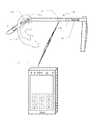
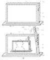
도 23은 본 발명의 실시예 6에 관한 사시도이다(실시예 6).1 is a system configuration diagram of Embodiment 1 of the present invention (Embodiment 1).
2 is a block diagram of the detailed configuration of the embodiment 1 of Fig.
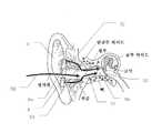
3 is a cross-sectional view of the ear illustrating cartilage conduction.
4 is a graph showing an example of actual measurement data showing the effect of cartilage conduction.
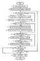
5 is a flow chart showing the function of the ear mount in the first embodiment.
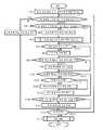
6 is a flowchart showing the functions of the cellular phone in the first embodiment.
7 is a flowchart showing the functions of the monitoring unit in the residence in the first embodiment.
8 is a system configuration diagram of
FIG. 9 is a system configuration diagram of Embodiment 3 of the present invention (Embodiment 3). FIG.
10 is a block diagram of the robot according to the third embodiment of Fig.
11 is a flowchart showing functions of the
Fig. 12 is a flowchart showing details of step S140 in Fig.
13 is a system configuration diagram of a fourth embodiment of the present invention (Embodiment 4).
14 is a block diagram of the fourth embodiment.
15 is a flowchart showing a part of the functions of the control unit according to the fourth embodiment.
16 is a system configuration diagram of a fifth embodiment of the present invention (Embodiment 5).
17 is a block diagram of the fifth embodiment.
18 is a flowchart showing the functions of the control unit according to the fifth embodiment.
Fig. 19 is a flowchart showing details of step S258 in Fig.
20 is a side view showing the state of contact through the ornaments in Example 5. Fig.
21 is a system block diagram of the entire bank in the fifth embodiment.
22 is a flowchart showing the function of the bank control unit of FIG.
Fig. 23 is a perspective view according to
실시예 1Example 1
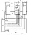
도 1은, 본 발명의 실시 형태에 관한 실시예 1의 시스템 구성도이다. 실시예 1은 주거(2) 내의 워칭 시스템을 구성하고 있으며, 대이륜(對耳輪)과 이주(耳珠) 사이에 끼워져 이갑개강(耳甲介腔)에 들어맞음으로써 워칭 대상자의 귀(4)의 구멍의 주변 연골에 접촉하는 귀 장착부(6)(귀 구조와 구별하기 위하여 파선으로 도시), 귀 장착부(6)와 근거리 통신에 의하여 정보 교환하는 주거 내 모니터부(8), 및 워칭 대상자의 휴대 전화(10)를 포함한다. 휴대 전화(10)는 귀 장착부(6) 및 주거 내 모니터부(8)와 근거리 통신에 의하여 정보 교환한다.1 is a system configuration diagram of Embodiment 1 according to an embodiment of the present invention. Embodiment 1 constitutes a watching system in a
귀 장착부(6)는 휴대 전화(10)와의 근거리 통신에 의하여 휴대 전화(10)의 헤드셋으로서 기능하며, 휴대 전화(10)를, 예를 들어 의복의 주머니에 넣은 채의 상태에서도 통화가 가능하다. 귀 장착부(6)는 또한 단독으로 보청기로서도 기능한다. 이 헤드셋으로서의 기능 및 보청기로서의 기능은 후술하는 연골 전도를 이용한 것이다. 귀 장착부(6)는 저작 센서를 더 구비하며, 저작 운동에 의한 이주 등의 이동 또는 외이도의 변형을 검지한다. 또한 귀 장착부(6)는, 구멍(6a)을 갖는 링형의 형상을 하고 있으며, 장착 시에 있어서도 외이도 입구는 개방되어 있어 구멍(6a)을 통하여 외계의 소리를 듣는 것이 가능함과 함께, 외이도의 폐색감이 없는 쾌적한 장착을 가능하게 한다. 또한 후술하는 바와 같이 필요에 따라 구멍(6a)을 손가락으로 폐쇄하거나 또는 손바닥으로 덮음으로써, 연골 전도에 있어서의 외이도 폐쇄 효과를 얻어 보다 큰 소리를 들을 수 있다.The
주거 내 모니터부(8)는, 귀 장착부(6) 및 휴대 전화(10)와 근거리 통신하기 위한 근거리 통신부(12), 및 외부와 항시 접속된 인터넷 통신을 행하는 디지털 통신부(14)를 갖는다. 제어부(16)는, 근거리 통신부(12) 및 디지털 통신부(14)를 포함하는 주거 내 모니터부(8) 전체의 제어를 행한다. 기억부(18)는 제어부(16)의 제어에 필요한 프로그램을 기억함과 함께, 제어 등에 관련한 다양한 데이터를 일시 기억한다.The in-
이상의 구성에 의하여 주거 내 모니터부(8)는, 귀 장착부(6)로부터의 저작 운동의 검지 결과를 근거리 통신에 의하여 수신하여, 일상 생활에서 예측되는 저작 운동이 검지되지 않을 때는 이상 상태의 가능성이 있다고 보고 디지털 통신부(14)로부터 워칭 업자에게 그 취지의 통보를 행한다. 또한 주거 내 모니터부(8)는, 귀 장착부(6)의 헤드셋 기능에 의하여 검지되는 워칭 대상자의 음성 유무에 관한 정보를 근거리 통신으로 수신하여, 소정 기간 음성이 검지되지 않는 경우 또는 비명 등의 긴급성이 있는 음성 신호를 검지했을 경우에 이상 상태의 가능성이 있다고 보고 디지털 통신부(14)로부터 워칭 업자에게 그 취지의 통보를 행한다.According to the above configuration, the in-
또한 휴대 전화(10)는, 귀 장착부(6)로부터의 저작 운동의 검지 결과를 근거리 통신에 의하여 수신하여, 일상 생활에서 예측되는 저작 운동이 검지되지 않을 때는 이상 상태의 가능성이 있다고 보고 미리 등록해 둔 원격지의 가족 등의 휴대 전화로의 자동 발호를 행하여, 응답이 있으면 자동 음성으로 그 취지의 통보를 행한다. 또한 휴대 전화(10)는, 귀 장착부(6)의 헤드셋 기능에 의하여 검지되는 워칭 대상자의 음성 유무에 관한 정보를 근거리 통신으로 수신하여, 소정 기간 음성이 검지되지 않는 경우 또는 비명 등의 긴급성이 있는 음성 신호를 검지했을 경우에 이상 상태의 가능성이 있다고 보고 상기 원격지의 가족 등의 휴대 전화로의 자동 발호를 행하여, 응답이 있으면 그 취지의 통보를 행한다.The
또한 휴대 전화(10)에서는, 일상 생활에서 예측되는 저작 운동이 검지되었을 경우에도 상기 원격지의 가족 등의 휴대 전화로의 자동 발호를 행하여, 응답이 있으면 자동 음성으로 이상 없음이라는 취지의 통보를 행한다. 또한 워칭 대상자의 통상 음성의 검지에 기초해서도 상기 원격지의 가족 등의 휴대 전화로의 자동 발호를 적절히 행하여, 응답이 있으면 자동 음성으로 이상 없음이라는 취지의 통보를 행한다. 이것에 의하여 원격지의 가족 등은, 워칭 대상자가 세끼 식사를 규칙적으로 하고 있는 것이나 일상적으로 기대되는 회화의 존재, 또는 미리 설정된 시간대에 있어서의 규칙적인 발성 상황(일상적인 쇼핑에서의 회화나 나날이 불경을 외고 있는 것 등)을 알고 안심할 수 있다. 또한 이 경우, 워칭 대상자가 의도하고 있지 않는데도 휴대 전화(10)의 자동 발호가 행해져 회화의 내용이 들려 버리게 된다. 이는, 가족이라고는 하더라도 워칭 대상자에게 있어서는 프라이버시상 바람직하지 않으므로, 후술하는 바와 같이 음성의 유무라는 사실만 통보하고 회화의 내용은 판별할 수 없도록 한다.Further, in the
도 2는, 도 1에 도시한 본 발명의 실시예 1의 상세 구성의 블록도이다. 도 1과 공통되는 부분에는 동일한 번호를 붙여, 필요가 없는 한 설명을 생략한다. 주거 내 모니터부(8)의 구성은 도 1에 도시한 바와 같은데, 주거 내 모니터부(8) 전체에 급전하는 전원부(20)를 갖는다. 전원부(20)는 주거(2) 내의 가정용 전원으로부터 급전을 받는다.Fig. 2 is a block diagram showing the detailed configuration of the first embodiment of the present invention shown in Fig. 1 are denoted by the same reference numerals, and a description thereof is omitted unless necessary. The
한편, 휴대 전화(10)는 도 2에 도시한 바와 같이 휴대전화 기능부(22)를 가지며, 안테나(24)에 의하여 무선 전화 회선으로 통화를 행한다. 근거리 통신부(26)는 귀 장착부(6) 및 주거 내 모니터부(8) 각각의 근거리 통신부(36 및 12)와 통신한다. 또한 GPS부(28)는, 귀 장착부(6)를 장착한 워칭 대상자가 휴대 전화(10)를 갖고 외출했을 때의 위치를 검지하여, 필요에 따라 상기 원격지의 가족 등의 휴대 전화 또는 워칭 업자와 통신함으로써 워칭 대상자의 위치 정보를 제공한다. 제어부(30)는, 휴대전화 기능부(22), 근거리 통신부(26) 및 GPS부(28)를 포함하는 휴대 전화(10) 전체의 제어를 행한다. 기억부(32)는 제어부(30)의 제어에 필요한 프로그램을 기억함과 함께, 제어 등에 관련한 다양한 데이터를 일시 기억한다. 충전 가능한 축전지를 갖는 전원부(34)는 휴대 전화(10) 전체에 급전한다. 또한 도 2에서는 간단화를 위하여, 도 1에 도시되어 있는 대형 터치 패널형 액정 표시부, 마이크, 스피커, 근접 센서, 내측 카메라 등, 휴대 전화(10)가 통상 구비하는 구성의 도시를 생략하고 있다.On the other hand, the
도 2에 도시한 바와 같이, 귀 장착부(6)는, 휴대 전화(10)의 근거리 통신부(26) 및 주거 내 모니터부(8)의 근거리 통신부(12)와 근거리 통신하는 근거리 통신부(36)를 갖는다. 그리고 저작 센서(38)는, 귀 장착부(6)를 장착한 워칭 대상자의 저작 운동에 의한 이주 등의 이동 또는 외이도의 변형을 검지하여, 워칭 대상자의 저작 유무를 검출한다. 저작 센서(38)로서는 스트레인 게이지 또는 압전 소자 등으로 구성한다. 제어부(40)는, 저작 운동을 검출하면 근거리 통신부(36) 및 근거리 통신부(26)를 통하여 휴대 전화(10)에 그 취지를 전달한다. 또한 일상 생활에서 예측되는 저작 운동이 검지되지 않을 때는 이상 상태의 가능성이 있다고 보고 근거리 통신부(36)로부터 근거리 통신부(26)를 통하여 휴대 전화(10)에, 또한 근거리 통신부(36)로부터 근거리 통신부(12)를 통하여 주거 내 모니터부(8)에 그 취지를 전달한다.2, the
귀 장착부(6)의 연골 전도 진동원(42)(예를 들어 압전 바이모프 소자를 채용)은, 근거리 통신에 의하여 휴대 전화(10)로부터 수신한 통화 상대의 음성 신호에 의하여 진동하며, 이 진동을 귀 장착부(6)에 접촉해 있는 귀 연골에 전달함으로써 후술하는 연골 전도에 의하여 통화 상대의 목소리를 듣는 것을 가능하게 한다. 골전도 마이크(44)는 골전도에 의한 자신의 목소리를 습득하여, 근거리 통신에 의하여 휴대 전화(10)에 자신의 목소리 음성 신호를 송신함으로써 회화를 성립시킨다. 이와 같이 하여 귀 장착부(6)는 휴대 전화(10)의 헤드셋으로서 기능한다. 외부 기도음 마이크(46)는, 근처에 있는 대화 상대의 생(生)기도음을 습득하여 얻은 음성 신호에 의하여 연골 전도 진동원(42)을 진동시킨다. 이것에 의하여 귀 장착부(6)는 단독으로 보청기로서도 기능한다. 제어부(40)는 이러한 헤드셋의 기능 및 보청기의 기능에 대해서도 귀 장착부(6)를 제어한다. 또한 헤드셋 기능에 있어서의 골전도 마이크(44)는, 상기와 같이 워칭 대상자가 일상 생활 속에서 상정되는 목소리를 내고 있는지의 여부를 워칭하기 위한 음성 센서로서도 기능한다. 충전 가능한 축전지를 갖는 전원부(48)는 귀 장착부(6) 전체에 급전한다.The cartilage conduction vibration source 42 (employing, for example, a piezoelectric bimorph element) of the
여기서 연골 전도에 대하여 설명한다. 연골 전도는 본원 발명자에 의하여 발견된 현상이며, 이주 등의 외이도 입구부 주위의 연골에 전달된 진동에 의하여 연골부 외이도 표면이 진동하여, 외이도 내에서 기도음을 발생시키는 현상이다. 그리고 외이도 내에서 발생한 기도음은 외이도 내를 더 안쪽으로 나아가 고막에 도달한다. 이와 같이 연골 전도에 의하여 들리는 소리의 주요부는 고막을 통하여 들리는 소리이다. 단, 고막에서 들리는 것은 통상의 기도음과 같이 외이도 외부로부터 외이도에 침입한 소리가 아니라, 어디까지나 외이도 내부에서 발생한 기도음이다.Here, the cartilage conduction is described. The cartilage conduction is a phenomenon found by the inventor of the present invention, and is a phenomenon in which the surface of the cartilage outer ear surface vibrates due to vibration transmitted to the cartilage around the entrance of the outer ear canal such as migraine, thereby generating a sound in the ear canal. The airway in the auditory canal leads to the inside of the auditory canal and reaches the eardrum. Thus, the main part of the sound heard by cartilage conduction is the sound heard through the eardrum. However, it is not the sound that entered from the outside of the ear canal like the normal prayer sound but the prayer sound that occurred inside the ear canal.
도 3은 상술한 것을 설명하기 위한 귀의 단면도이며, 귀(4)의 구조와 본 발명에 사용되는 귀 장착부(6)와의 관계를 도시한다. 화살표(52)는, 연골 전도 진동원(42)에 의하여 진동하는 귀 장착부(6)의 진동이 고막(50)에 전달되는 경로를 도시하고 있다. 귀 장착부(6)로부터 발생하는 진동은, 화살표(52)로 나타낸 바와 같이, 먼저 접촉 부분으로부터 외이도 입구부 주위의 연골(54)에 전도된다. 연골(54)의 진동은 그 표면(연골부 외이도)으로부터 외이도 내에 기도음을 발생시킨다. 그리고 이 기도음은 외이도 내를 나아가 골부 외이도(56)를 거쳐 고막(50)에 도달한다. 또한 귀 장착부(6)의 구멍(6a)으로부터는, 화살표(58)(통상의 소리가 들리는 경로)로 나타낸 바와 같이 구멍(6a)을 통하여 외계의 기도음이 외이도에 침입하여 고막(50)에 도달한다. 이것에 의하여 외이도의 폐색감 없이 쾌적하게 귀 장착부(6)를 장착할 수 있다.3 is a cross-sectional view of the ear for explaining the above-described one, showing the relationship between the structure of the
도 4는, 연골 전도의 효과를 나타내는 실측 데이터의 일례를 나타내는 그래프이다. 도 4의 그래프는, 연골 전도 진동원에 의하여 진동하는 진동체의 외벽 표면을 이륜에 대한 접촉 없이 외이도 입구부 주변의 귀 연골의 적어도 일부에 접촉시켰을 때의, 외이도 입구부로부터 1㎝ 안쪽의 외이도 내의 음압을 주파수와의 관계로 나타내는 것이다. 그래프의 종축은 음압(㏈SPL)이고, 횡축은 대수 눈금의 주파수(㎐)이다. 또한 그래프에는, 진동체의 외벽 표면과 외이도 입구부 주변 연골의 접촉압의 관계에 있어서, 비접촉 상태(진동체의 외벽 표면으로부터 발생하는 기도음만이 들리는 상태)의 음압을 실선으로, 접촉압 10중량그램에 있어서의 음압을 파선으로, 접촉압 250중량그램에 있어서의 음압을 1점 쇄선으로, 접촉압의 증가에 의하여 외이도가 폐쇄된 상태(접촉압 500중량그램)에 있어서의 음압을 2점 쇄선으로 각각 나타내고 있다. 도시한 바와 같이, 음압은 비접촉 상태로부터 접촉압 10중량그램으로의 접촉에 의하여 증가하고, 또한 250중량그램으로의 접촉압 증가에 의하여 증가하며, 이 상태로부터 나아가 500중량그램으로 접촉압을 증가시킴으로써 음압이 더욱 증가한다.4 is a graph showing an example of measured data showing the effect of cartilage conduction. The graph of Fig. 4 shows the results obtained when the outer wall surface of the vibrating body vibrating by the cartilage conduction vibration source was brought into contact with at least a part of the ear cartilage around the entrance of the ear canal without contact with the two- In terms of the frequency. The vertical axis of the graph is the sound pressure (dBSPL), and the horizontal axis is the frequency (Hz) of the logarithmic scale. In the graph, the sound pressure in the non-contact state (only the airway sound generated from the outer wall surface of the vibrating body is heard) in the relationship between the outer wall surface of the vibrating body and the contact pressure between the cartilage around the entrance of the outer ear canal is indicated by solid lines, The sound pressure in weight grams is indicated by a broken line, the sound pressure at a contact pressure of 250 weight grams is indicated by a one-dot chain line, the sound pressure in a state in which the ear canal is closed by a contact pressure increase (contact pressure 500 weight gram) Respectively. As shown, the negative pressure increases by contact with 10 grams of contact pressure from the non-contact state and by an increase in contact pressure to 250 grams of grams, increasing the contact pressure from this state to 500 grams of grams The sound pressure is further increased.
도 4의 그래프로부터 밝혀진 바와 같이, 진동체의 외벽 표면을 이륜에 대한 접촉 없이 외이도 입구부 주변의 귀 연골의 적어도 일부에 접촉시켰을 때, 비접촉 상태에 비하여, 외이도 입구부로부터 1㎝ 안쪽의 외이도 내에 있어서의 음압이 음성의 주요한 주파수 대역(500㎐ 내지 2300㎐)에 있어서 적어도 10㏈ 증가해 있음을 알 수 있다(실선으로 나타내는 비접촉 상태와 1점 쇄선으로 나타내는 상태를 비교 참조).4, when the outer wall surface of the vibrating body is brought into contact with at least a part of the ear cartilage around the entrance of the ear canal without contact with the two-wheeled portion, compared with the non-contact state, (The comparison between the non-contact state indicated by the solid line and the state indicated by the one-dot chain line) is increased by at least 10 dB in the main frequency band (500 Hz to 2300 Hz) of the sound.
또한 도 4의 그래프로부터 밝혀진 바와 같이, 진동체의 외벽 표면을 이륜에 대한 접촉 없이 외이도 입구부 주변의 귀 연골의 적어도 일부에 접촉시켰을 때, 접촉압의 변화에 따라 외이도 입구부로부터 1㎝ 안쪽의 외이도 내에 있어서의 음압이 음성의 주요한 주파수 대역(500㎐ 내지 2500㎐)에 있어서 적어도 5㏈ 변화되어 있음을 알 수 있다(파선으로 나타내는 약간의 접촉 상태와 1점 쇄선으로 나타내는 상태에서의 접촉 상태를 비교 참조).4, when the outer wall surface of the vibrating body was brought into contact with at least a part of the ear cartilage around the ear canal entrance portion without contact with the two-wheeled portion, It can be seen that the sound pressure in the ear canal is changed by at least 5 dB in the main frequency band (500 Hz to 2500 Hz) of the sound (a slight contact state indicated by the broken line and a contact state shown by the one- Compare).
이상으로부터, 귀 장착부(6)에 기도음을 발생시키기 위한 구조(예를 들어 통상 이어폰의 진동판)이 없더라도, 연골 전도 진동원(42)의 진동을 접촉에 의하여 귀 연골에 전달함으로써 필요한 음압이 얻어지는 것을 알 수 있다. 또한 기도음을 발생시키기 위한 구조가 불필요하기 때문에, 귀 장착부(6)는, 구멍(6a)을 갖는 링형 등의 형상으로 할 수 있으며, 장착 시에 있어서도 구멍(6a)을 통하여 외계의 소리를 듣는 것이 가능함과 함께, 외이도의 폐색감이 없는 쾌적한 장착이 가능해지는 것을 알 수 있다.As described above, even if there is no structure (for example, a diaphragm of a normal earphone) for generating the airway sound in the
또한 도 4의 그래프로부터 밝혀진 바와 같이, 진동체의 외벽 표면을 귀 연골의 적어도 일부에 의하여 강하게 접촉시킴으로써 외이도 입구부를 폐쇄(도 4의 실측에서는, 이주의 외측으로부터 진동체의 외벽 표면을 압박하여 이주가 절곡됨으로써 외이도 입구를 폐쇄하는 상태로서 측정)했을 때, 비접촉 상태에 비하여, 외이도 입구부로부터 1㎝ 안쪽의 외이도 내에 있어서의 음압이 음성의 주요한 주파수 대역(300㎐ 내지 1800㎐)에 있어서 적어도 20㏈ 증가해 있음을 알 수 있다. 이는 외이도 폐쇄 효과에 의한 것이다(실선으로 나타내는 비접촉 상태와 2점 쇄선으로 나타내는 외이도가 폐쇄된 상태를 비교 참조).4, the outer wall surface of the vibrating body is strongly contacted by at least part of the ear cartilage, thereby closing the entrance of the outer ear canal (in the actual side of Fig. 4, the outer wall surface of the vibrating body is pressed against the outer wall surface of the vibrating body, The sound pressure inside the ear canal 1 cm inward from the ear canal entrance portion is at least 20 (zero) in the main frequency band (300 Hz to 1800 Hz) of the sound in comparison with the noncontact state when the ear canal is folded ㏈ increase. This is due to the effect of the occlusion of the ear canal (see the comparison between the non-contact state indicated by the solid line and the occluded state of the ear canal indicated by the two-dot chain line).
또한 도 4에 있어서의 측정은 모두 연골 전도 진동원의 출력을 변화시키지 않는 상태에 있어서의 것이다. 또한 이륜에 대한 접촉 없이 진동체의 외벽 표면을 외이도 입구부 주변의 귀 연골의 적어도 일부에 접촉시키는 상태로 하여, 도 4에 있어서의 측정은 진동체의 외벽 표면을 이주 외측으로부터 접촉시키는 상태에서 행하고 있다. 또한 도 4에 있어서의 외이도가 폐쇄된 상태에서의 측정은, 상기와 같이 이주를 외측으로부터 보다 강하게 압박함으로써 이주가 절곡됨으로써 외이도를 폐쇄하는 상태를 창출함으로써 행하고 있다.The measurement in Fig. 4 is performed in a state in which the output of the cartilage conduction vibration source is not changed. The outer wall surface of the vibrating body is brought into contact with at least a part of the ear cartilage around the entrance portion of the ostium without contact with the two rings, and the measurement in Fig. 4 is performed in a state in which the outer wall surface of the vibrating body comes in contact with the outside have. The measurement in the state in which the external ear canal is closed as shown in Fig. 4 is performed by creating a state of closing the ear canal by bending the diaphragm by pressing the diaphragm from the outside more strongly as described above.
상기와 같은 외이도 폐쇄 효과는, 실시예 1의 경우, 구멍(6a)에 손가락을 대고 누름으로써 구멍(6a)이 폐쇄됨과 함께 귀 장착부(6)의 연골에 대한 접촉압을 높임으로써 실현할 수 있다. 또는, 그 대신 손바닥으로 귀(4) 전체를 덮는 것에 의해서도 외이도 폐쇄 효과를 얻을 수 있다. 이와 같이 실시예 1에 있어서도, 필요에 따라 구멍(6a)을 손가락으로 폐쇄하거나 또는 손바닥으로 덮음으로써 보다 큰 소리를 들을 수 있음을 알 수 있다.The effect of closing the ear canal as described above can be realized by pressing the hole 6a with the finger to close the hole 6a and increasing the contact pressure to the cartilage of the
또한 도 4의 측정 그래프는 어디까지나 일례이며, 자세히 보면 개인차가 있다. 또한 도 4의 측정 그래프는 현상의 단순화 및 표준화를 위하여 진동체의 외벽 표면을 이주 외측에 한정하고, 적은 면적으로 접촉시키는 상태에서 측정을 행하고 있다. 그러나 접촉에 의한 음압의 증가는 연골과의 접촉 면적에도 의존하며, 이륜에 대한 접촉 없이 진동체의 외벽 표면을 외이도 입구부 주변의 귀 연골에 접촉시키는 경우, 외이도 입구부 주위의 보다 넓은 연골 부분에 접촉시키면 음압의 증가는 더욱 높아진다. 이상을 고려하면, 도 4의 측정 그래프에 나타낸 수치는 연골 전도를 이용한 구성을 나타내는 일반성을 갖는 것이며, 불특정 다수의 피험자에 의한 재현성이 있는 것이다. 또한 도 4의 측정 그래프는, 외이도 입구부를 폐쇄할 때 이주를 외측으로부터 압박함으로써 접촉압을 증가시켜 이주를 절곡하는 것에 의한 것인데, 진동체의 외벽을 외이도 입구부에 압입하여 이를 폐쇄했을 경우에도 마찬가지의 결과가 얻어진다.The measurement graph of FIG. 4 is only an example, and there are individual differences in detail. In addition, the measurement graph of Fig. 4 measures the state in which the outer wall surface of the vibrating body is limited to the outside of the diaphragm and contacted with a small area for simplification and standardization of the phenomenon. However, the increase in sound pressure due to contact also depends on the area of contact with the cartilage, and when the outer wall surface of the vibrating body contacts the ear cartilage around the entrance of the vibrator without contact with the two wheels, The contact pressure increases even more. Taking the above into consideration, the numerical values shown in the measurement graph of Fig. 4 are those having generality showing a configuration using cartilage conduction, and reproducibility by an unspecified number of subjects. The measurement graph of FIG. 4 also shows that when the outer ear canal is closed, the immersion is pressed from the outside to increase the contact pressure to bend the migration. Even when the outer wall of the vibrating body is press-fitted into the entrance portion of the outer ear canal to close the same Is obtained.
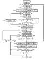
도 5는, 실시예 1의 워칭 시스템에 있어서의 귀 장착부(6)의 제어부(40)의 기능을 도시하는 흐름도이다. 흐름은, 충전을 위하여 도시하지 않은 충전기에 접속되어 있었던 귀 장착부(6)를 충전기로부터 제거함으로써 개시된다. 흐름이 개시되면, 스텝 S2에서 휴대 전화(10)와의 근거리 통신을 위한 페어링 상황을 확인하여, 미설정이면 페어링 설정을 자동으로 행한다. 이어서, 스텝 S4에서 외부 기도음 마이크(46) 및 골전도 마이크(44)를 온으로 한다. 이것에 의하여, 귀 장착부(6)는 보청기로서 기능하게 됨과 함께, 골전도 마이크(44)에 의한 워칭 대상자의 음성 검지 대기 상태로 된다. 또한 흐름에서는 생략하고 있지만, 저작 센서(38)는 흐름 개시로부터 종료까지의 사이, 항시 온 상태에 있으며 저작 검지 대기 상태에 있다.5 is a flowchart showing the function of the
다음으로 스텝 S6에 있어서 저작 센서(38)가 저작 운동을 검지했는지의 여부를 체크한다. 그리고 검지가 있으면 스텝 S8로 진행하고, 근거리 통신으로 휴대 전화(10)에 검지 신호를 송신함과 함께, 스텝 S10에서 근거리 통신으로 주거 내 모니터부(8)에 검지 신호를 송신하고, 스텝 S12로 이행한다. 한편, 스텝 S6에서 저작 운동이 검지되지 않는 경우에는 직접 스텝 S12로 이행한다.Next, in step S6, it is checked whether or not the
스텝 S12에서는, 골전도 마이크(44)가 워칭 대상자의 음성을 검지했는지의 여부를 체크한다. 그리고 검지가 있으면 스텝 S14로 진행하고, 근거리 통신으로 휴대 전화(10)에, 검지한 음성 신호를 송신함과 함께, 이와 병행하여 스텝 S16에서 근거리 통신으로 주거 내 모니터부(8)에, 검지한 음성 신호를 송신한다. 스텝 S12 내지 스텝 S16은 간이화된 도시로 되어 있지만, 실제로는, 이들 스텝에 있어서는 골전도 마이크(44)에 음성이 검지되기 시작한 후로부터 그 후의 소정 시간(예를 들어 10초), 골전도 마이크(44)로부터의 음성 신호를 휴대 전화(10) 및 주거 내 모니터부(8)에 병행하여 계속해서 송신한다. 이때, 음성이 소정 시간 이상 계속되고 있더라도 소정 시간에 송신을 끊고, 반대로 소정 시간 내에 무음으로 되더라도 소정 시간 내에는 골전도 마이크(44)의 출력 송신을 계속한다. 상기와 같은 스텝 S12 내지 스텝 S16에 의한 소정 시간의 음성 신호 송신이 종료되면 스텝 S20으로 이행한다. 한편, 스텝 S12에서 음성 신호의 검지가 없으면 즉시 스텝 S20으로 이행한다.In step S12, it is checked whether or not the
스텝 S20에서는, 워칭 대상자에 의하여 휴대 전화(10)로부터 발호 조작이 행해지고 상대가 이에 응답했는지의 여부, 또는 외부로부터 휴대 전화(10)로의 착신이 있고 워칭 대상자가 응답 조작을 했는지의 여부를 체크한다. 그리고 그 중 어느 것에 해당하는 경우에는 스텝 S22로 진행하고 외부 기도음 마이크(46)를 오프함과 함께 골전도 마이크(44)의 온은 계속하고, 스텝 S24로 이행한다. 이것에 의하여, 귀 장착부(6)는 휴대 전화(10)의 헤드셋으로서 기능하게 되어, 외부 기도음 마이크(46)로부터 통화에 불필요한 소리가 들어가지 않도록 한다.In step S20, it is checked whether or not a calling operation has been performed by the
스텝 S24에서는, 전화를 끊음으로써 스텝 S20에서 시작된 통화가 종료되었는지의 여부를 체크한다. 그리고 통화 종료가 검지되었을 때는 스텝 S26으로 진행하고, 외부 기도음 마이크(46)를 온함과 함께 골전도 마이크(44)의 온 상태를 계속하고, 스텝 S28로 이행한다. 이것에 의하여, 귀 장착부(6)는 보청기로서의 기능으로 복귀됨과 함께, 골전도 마이크(44)에 의한 워칭 대상자의 음성 검지 대기 상태가 계속된다. 한편, 스텝 S24에서 통화 종료가 검지되지 않는 경우에는 스텝 S24가 반복되고, 통화 종료를 대기한다. 또한 스텝 S20에서 발호 응답 또는 착신 응답이 검지되지 않는 경우에는 직접 스텝 S28로 이행한다.In step S24, it is checked whether or not the call started in step S20 is ended by hanging up the telephone. When the end of the call is detected, the flow advances to step S26 to turn on the
스텝 S28에서는, 전원부(48)의 축전지가 소모되어 있는지의 여부를 체크한다. 축전지가 소모되어 있지 않으면 스텝 S30으로 이행하여, 귀 장착부(6)가 충전을 위하여 도시하지 않은 충전기에 접속되었는지의 여부를 체크한다. 이 스텝은, 축전지가 소모되어 있지 않더라도 귀 장착부(6)를 귀(4)로부터 제거하고 충전하는 경우에 대응하고 있다. 스텝 S30에서 충전 접속이 검지되면 스텝 S32로 이행하고, 종료 처리를 행하여 흐름을 종료한다. 이는, 귀 장착부(6)가 귀(4)로부터 제거되어 워칭 기능을 할 수 없게 되어 있는 상태임에도 불구하고, 잘못해서 동작 상태로 유지되는 것을 방지하는 의의가 있다. 한편, 스텝 S30에서 충전 접속이 검지되지 않으면 스텝 S6에 복귀되고, 이하, 축전지가 소모되거나 충전 접속이 행해지거나 하지 않는 한, 스텝 S6 내지 스텝 S30이 반복되고, 귀 장착부(6)는 적절히 보청기 기능, 워칭 기능, 휴대 전화(10)의 헤드셋 기능을 유지한다. 또한 스텝 S28에서 축전지의 소모가 검지되었을 경우에도 스텝 S32로 이행하여, 종료 처리를 행하여 흐름을 종료한다.In step S28, it is checked whether or not the storage battery of the
도 6은, 실시예 1에 있어서의 휴대 전화(10)의 제어부(30)의 기능을 도시하는 흐름도이다. 또한 도 6의 흐름은, 워칭에 관한 기능을 중심으로 하여 동작을 추출하여 도시하고 있으며, 휴대 전화(10)에는 통상의 휴대 전화 기능을 비롯한, 도 6의 흐름에 표기하고 있지 않은 제어부(30)의 동작이 존재한다. 휴대 전화(10)의 하드 구성 자체는 통상의 것이며, 도 6에서 추출하고 있는 기능은 귀 장착부(6)에 부속된 소프트웨어로서 인스톨되는 것이다.6 is a flowchart showing the functions of the
휴대 전화(10)의 전원 스위치를 온함으로써 도 6의 흐름이 개시되고, 스텝 S42에서 통상 휴대 전화 모드를 설정한다. 이어서 스텝 S44에서 귀 장착부(6)와의 근거리 통신을 위한 페어링 상황을 체크한다. 그리고 페어링이 설정되어 있으면 귀 장착부(6)와 제휴한 휴대 전화(10)에 의한 워칭이 가능하므로, 스텝 S46으로 이행한다.The flow of FIG. 6 is started by turning on the power switch of the
스텝 S46에서는, 귀 장착부(6)로부터 새로운 저작 검지 신호를 수신했는지의 여부를 체크하여, 수신이 있으면 스텝 S48로 진행하고, 미리 등록해 둔 원격지의 가족 등의 휴대 전화에 워칭자의 무사를 알리는 메일을 자동 송신한다. 또한 스텝 S48에서는, 미리 설정해 둠으로써 메일 대신 미리 등록해 둔 원격지의 가족 등의 휴대 전화로의 자동 발호를 행하여, 응답이 있으면 워칭자의 무사를 알리는 자동 음성의 송신을 행한다. 메일과 발호의 양쪽을 행하도록 설정할 수도 있다. 저작 검지에 대해서는 기본적으로 하루에 3번이라 번잡하지 않다고 생각되므로, 이와 같이 저작 검지 신호를 검지할 때마다 원격지의 가족 등에게 무사를 통지하여 안심시킨다. 또한 이러한 무사의 통지가 번잡하다고 원격지의 가족이 생각하는 경우에는 스텝 S48을 생략하도록 미리 설정해 둘 수 있다.In step S46, it is checked whether or not a new authoring detection signal has been received from the
이어서 스텝 S50으로 이행하고, 기억부(32)에 있어서의 저작 검지 신호의 수신 이력을 새로운 수신에 기초하여 일시(日時) 정보부에서 갱신함과 함께 그 시점의 GPS신호를 아울러 기억하고, 스텝 S52로 진행한다. 한편, 스텝 S46에서 저작 검지 신호의 수신이 확인되지 않았을 때는 직접 스텝 S52로 이행한다.Subsequently, the flow advances to step S50. In step S50, the reception history of the authoring detection signal in the
스텝 S52에서는, 기억부(32)의 수신 이력에 기초하여, 전회의 저작 검지 신호의 수신으로부터 소정 기간 내에 새로운 저작 검지 신호의 수신이 있었는지의 여부를 체크한다. 소정 기간 내의 새로운 저작 검지 신호의 수신이 없으면 스텝 S54로 진행하고, 미리 등록해 둔 원격지의 가족 등의 휴대 전화에 자동 발호를 행하여, 응답이 있으면 이상의 가능성이 있다는 취지의 자동 음성을 송신하고 스텝 S56으로 이행한다. 스텝 S54에서는, 추가로 그 시점의 GPS 정보에 기초하여 워칭자의 현재 위치를 통보하는 자동 음성을 송신한다. 한편, 스텝 S52에서 소정 기간 내에 새로운 저작 검지 신호의 수신이 있었던 것이 수신 이력에서 확인되었을 때는 직접 스텝 S56으로 이행한다.In step S52, based on the reception history of the
스텝 S56에서는, 귀 장착부(6)의 골전도 마이크(44)가 취한 음성 신호의 수신이 있었던 것인지의 여부를 체크한다. 그리고 음성 신호의 수신이 있으면 스텝 S58로 진행하고, 음성 신호의 내용(포함되는 단어 등)의 음성 식별, 음성 신호의 강도나 톤의 패턴 등에 기초하여, 수신한 음성이 비명이나 구조 요청인지의 여부(긴급성)을 체크한다. 그리고 비명 또는 구조 요청 음성일 가능성이 높을 때(긴급성이 높다고 판단되었을 때)는 스텝 S60으로 진행하고, 미리 등록해 둔 원격지의 가족 등의 휴대 전화에 자동 발호를 행하여, 응답이 있으면 수신한 음성 그 자체를 전송하고 스텝 S62로 이행한다. 한편, 스텝 S58에 있어서, 수신한 음성이 통상의 회화 음성이며 비명이나 구조 요청이 아니라고(긴급성이 낮다고) 판단되었을 때는 직접 스텝 S62로 이행한다.In step S56, it is checked whether or not a voice signal taken by the
스텝 S62에서는, 수신한 음성 신호가 규칙적인 생활 패턴에 기초하여 미리 설정되는 시간대(예를 들어 일상의 쇼핑이나 불경을 외는 시간대)에 있어서 수신한 것인지의 여부를 체크한다. 그리고 해당하면 스텝 S64로 진행하고, 미리 등록해 둔 원격지의 가족 등의 휴대 전화에 워칭자의 무사를 알리는 메일을 자동 송신하고 스텝 S66으로 이행한다. 한편, 스텝 S62에 있어서, 수신한 음성 신호가 미리 설정된 시간대에 있어서 수신한 것이 아니었을 때는 직접 스텝 S66으로 이행한다. 또한 스텝 S48과 마찬가지로 하여 메일 대신 자동 발호와 자동 음성의 송신이 행해지도록 하거나, 또는 양자가 행해지도록 설정해 둘 수도 있다. 또한 이러한 무사의 통지가 번잡하다고 원격지의 가족이 생각하는 경우에는 스텝 S62 및 스텝 S64를 생략하도록 미리 설정해 둘 수도 있다. 스텝 S64에 있어서 송신되는 음성은, 실제로 골전도 마이크(44)가 취한 음성 신호가 아니라 음성 신호의 수신이 있었다는 사실만을 통지하는 것이며, 스텝 S60과는 달리 워칭 대상자의 회화 내용은 알 수 없어 프라이버시가 유지된다.In step S62, it is checked whether or not the received voice signal is received in a time zone preset in advance based on a regular life pattern (for example, a time zone other than daily shopping or disrespect). Then, the process advances to step S64 to automatically transmit a mail informing the surrogate to the cellular phone of a family member or the like of a remote place that has been registered in advance, and the process proceeds to step S66. On the other hand, if the received voice signal was not received in the predetermined time period in step S62, the process directly proceeds to step S66. It is also possible to set the automatic calling and the automatic voice transmission instead of the mail or the both to be performed in the same manner as in step S48. Further, in the case where the remotely located family thinks that the notification of the unauthorized use is troublesome, the steps S62 and S64 may be set to be omitted in advance. The voice transmitted in step S64 is not a voice signal actually taken by the
스텝 S66에서는, 기억부(32)에 있어서의 음성 신호의 수신 이력을 새로운 수신에 기초하여 일시 정보부에서 갱신함과 함께, 그 시점의 GPS신호를 아울러 기억하고 스텝 S68로 진행한다. 한편, 스텝 S56에서 골전도 마이크(44)가 취한 음성 신호의 수신이 확인되지 않았을 경우에는 직접 스텝 S68로 이행한다.In step S66, the reception history of the voice signal in the
스텝 S68에서는, 기억부(32)의 수신 이력에 기초하여, 전회의 음성 신호의 수신으로부터 소정 기간 내에 새로운 음성 신호의 수신이 있었던 것인지의 여부를 체크한다. 소정 기간 내의 새로운 음성 신호의 수신이 없으면 스텝 S70으로 진행하고, 미리 등록해 둔 상기의 원격지의 가족 등의 휴대 전화에 자동 발호를 행하여, 응답이 있으면 이상의 가능성이 있다는 취지의 자동 음성을 송신하고 스텝 S72로 이행한다. 스텝 S70에 있어서도, 추가로 그 시점의 GPS 정보에 기초하여 워칭자의 현재 위치를 통보하는 자동 음성을 송신한다. 한편, 스텝 S68에서 소정 기간 내에 새로운 음성 신호의 수신이 있었던 것이 수신 이력에서 확인되었을 때는 직접 스텝 S72로 이행한다. 또한 스텝 S44에서 귀 장착부(6)와의 페어링의 설정이 확인되지 않는 경우에는 직접 스텝 S72로 이행하며, 워칭을 위한 여러 스텝은 실행하지 않고 통상 휴대 전화로서 기능한다.In step S68, based on the reception history of the
스텝 S72에서는, 전원부(34)의 축전지가 소모되어 있는지의 여부를 체크한다. 축전지가 소모되어 있지 않으면 스텝 S44로 복귀되며, 이하, 축전지의 소모가 검지되지 않는 한 스텝 S44 내지 스텝 S72가 반복되고, 휴대 전화(10)는 워칭에 있어서의 다양한 사태에 대응한다. 한편, 스텝 S72에서 축전지의 소모가 검지되었을 경우에는 스텝 S74로 이행하고, 종료 처리를 행하여 흐름을 종료한다.In step S72, it is checked whether or not the battery of the
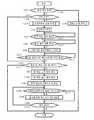
도 7은, 실시예 1에 있어서의 주거 내 모니터부(8)의 제어부(16)의 기능을 도시하는 흐름도이다. 흐름은, 주거 내 모니터부(8)를 설치하고 가정용 전원에 접속하는 것, 또는 주거 내 모니터부(8)의 전원을 온함으로써 개시되며, 스텝 S82에서 워칭 업자와의 통신을 위한 인터넷 상시 접속을 자동 설정함과 함께 귀 장착부(6)와의 근거리 통신 등 제휴의 자동 테스트를 행하고, 스텝 S84로 이행한다.7 is a flowchart showing the functions of the
스텝 S84에서는, 귀 장착부(6)와의 근거리 통신이 가능한 상태에서 불가능한 상태로 천이했는지의 여부를 체크한다. 이는, 워칭 대상자가 외출하여 근거리 통신 권역 외로 나간 것인지의 여부의 체크에 상당한다. 해당하지 않으면 스텝 S86으로 진행하고, 귀 장착부(6)와의 근거리 통신이 불가능한 상태에서 가능한 상태로 천이했는지의 여부를 체크한다. 이는, 워칭 대상자가 귀가하여 근거리 통신 권역 내로 복귀했는지의 여부의 체크에 상당한다. 해당하면 스텝 S88에서, 상기 미리 등록해 둔 원격지의 가족 등의 휴대 전화로의 자동 메일 송신을 행하여, 워칭 대상자가 귀가한 것을 통지한다.In step S84, it is checked whether or not a transition from a state in which short-range communication with the
또한 스텝 S90에서는 휴대 전화(10)와의 사이에서 자동 근거리 통신을 행하여, 근거리 통신 상태가 도 2에 도시하는 시스템 구성 상태로 복귀한 것을 확인하는 처리를 행한다. 이는, 워칭 대상자의 외출 중, 휴대 전화(10)도 워칭 대상자에 휴대되어 주거 내 모니터부(8)의 근거리 통신 권역 외로 나가 있었던 것이 상정되기 때문이다. 만일 스텝 S90에 있어서 휴대 전화(10)와 근거리 통신할 수 있음이 확인되지 않는 때는, 스텝 S90 내에 있어서 그 취지를 워칭 업자 및 원격지의 가족 등의 휴대 전화에 통지한다.In step S90, automatic close-range communication is performed with the
스텝 S90에서는, 또한 주거 내 모니터부(8)의 기억부(18)와 휴대 전화(10)의 기억부(32)에 있어서의, 귀 장착부(6)로부터의 수신 이력의 크로스 체크와 정보 교환을 행하여 양자의 정보를 일치시킨다. 이는, 주로 워칭 대상자가 외출하여 주거 내 모니터부(8)가 귀 장착부(6)로부터의 수신을 할 수 없는 사이, 수신 정보가 누락되므로, 그 사이의 수신 정보를 휴대 전화(10)로부터 수취하는 것에 해당한다. 이것에 의하여, 실제로는 귀 장착부(6)로부터 송신이 행해졌는데도, 주거 내 모니터부(8)에서는 귀 장착부(6)로부터 소정 시간 이상 송신이 없는 이상 상태라고 오인하는 등의 문제를 방지할 수 있다. 상기와 같은 수신 이력의 크로스 체크에 의한 양자의 정보를 일치시키는 기능은, 반대로 주거(2) 내에 있어서 휴대 전화(10)의 축전지가 소모되어 있어 충전까지의 사이, 귀 장착부(6)로부터의 수신 정보가 누락되는 경우의 대한 대응으로서도 의의가 있다.In step S90, a cross check of the reception history from the
스텝 S90의 처리가 끝나면 스텝 S92로 진행하고, 귀 장착부(6)로부터 새로운 저작 검지 신호를 수신했는지의 여부를 체크한다. 수신이 있으면 스텝 S94로 진행하고, 기억부(18)에 있어서의 저작 검지 신호의 수신 이력을 새로운 수신에 기초하여 일시 정보부에서 갱신하고 스텝 S96로 진행한다. 한편, 스텝 S92에서 저작 검지 신호의 수신이 확인되지 않았을 때는 직접 스텝 S96으로 이행한다.When the processing of step S90 is finished, the process proceeds to step S92, and it is checked whether or not a new mood detection signal is received from the
스텝 S96에서는, 기억부(18)의 수신 이력에 기초하여, 전회의 저작 검지 신호의 수신으로부터 소정 기간 내에 새로운 저작 검지 신호의 수신이 있었던 것인지의 여부를 체크한다. 소정 기간 내의 새로운 저작 검지 신호의 수신이 없으면 스텝 S98로 진행하고, 미리 계약되어 있는 워칭 업자에게 이상의 가능성이 있다는 취지의 자동 통보를 행하고 스텝 S100으로 이행한다. 한편, 스텝 S96에서 소정 기간 내에 새로운 저작 검지 신호의 수신이 있었던 것이 수신 이력에서 확인되었을 때는 이상 없음으로 보고 스텝 S100으로 이행한다.In step S96, based on the reception history of the
스텝 S100에서는, 귀 장착부(6)의 골전도 마이크(44)가 취한 음성 신호의 수신이 있었던 것인지의 여부를 체크한다. 그리고 음성 신호의 수신이 있으면 스텝 S102로 진행하고, 음성 신호의 내용(포함되는 단어 등)의 음성 식별, 음성 신호의 강도나 톤의 패턴 등에 기초하여, 수신한 음성이 비명이나 구조 요청인지의 여부를 체크한다. 그리고 비명 또는 구조 요청 음성일 가능성이 높을 때는 스텝 S104로 진행하고, 상기 워칭 업자에게 수신한 음성 그 자체를 전송하고 스텝 S106으로 이행한다. 한편, 스텝 S102에 있어서, 수신한 음성이 통상의 회화 음성이며 비명이나 구조 요청이 아니라고 판단되었을 때는 직접 스텝 S106으로 이행한다.In step S100, it is checked whether or not a voice signal taken by the
스텝 S106에서는, 기억부(18)에 있어서의 음성 신호의 수신 이력을 새로운 수신에 기초하여 일시 정보부에서 갱신하고 스텝 S108로 진행한다. 한편, 스텝 S100에서 골전도 마이크(44)가 취한 음성 신호의 수신이 확인되지 않았을 경우에는 직접 스텝 S108로 이행한다.In step S106, the reception history of the voice signal in the
스텝 S108에서는, 기억부(18)의 수신 이력에 기초하여, 전회의 음성 신호의 수신으로부터 소정 기간 내에 새로운 음성 신호의 수신이 있었던 것인지의 여부를 체크한다. 소정 기간 내의 새로운 음성 신호의 수신이 없으면 스텝 S110으로 진행하고, 상기 워칭 업자에게 이상의 가능성이 있다는 취지의 자동 통보를 행하고 스텝 S112로 이행한다. 한편, 스텝 S108에서 소정 기간 내에 새로운 음성 신호의 수신이 있었던 것이 수신 이력에서 확인되었을 때는 직접 스텝 S112로 이행한다. 또한 스텝 S84에서 귀 장착부(6)와의 근거리 통신이 가능한 상태에서 불가능한 상태로 천이한 것이 검지되었을 때는, 스텝 S114로 이행하여 상기 미리 등록해 둔 원격지의 가족 등의 휴대 전화에의 자동 메일 송신을 행하여, 워칭 대상자가 외출한 것을 통지하고 스텝 S112로 이행한다. 이 경우, 귀 장착부(6)로부터 신호를 받을 수 없어 워칭은 불가능하므로, 워칭 기능의 실행은 워칭 대상자가 휴대하는 휴대 전화(10)에 위임되며, 주거 내 모니터부(8)로서의 워칭 기능의 실행은 없다.In step S108, based on the reception history of the
스텝 S112에서는, 주거 내 모니터부(8)의 전원이 오프되었는지의 여부를 체크한다. 전원 오프에는 정전 등에 있어서의 급전의 단절도 포함된다. 전원의 오프가 없으면 스텝 S84에 복귀되며, 이하, 전원이 오프되지 않는 한 스텝 S84 내지 스텝 S114가 반복되고, 주거 내 모니터부(8)는 워칭에 있어서의 다양한 사태에 대응한다. 한편, 스텝 S112에서 전원 오프가 검지되었을 경우에는 스텝 S116으로 이행하고, 종료 처리를 행하여 흐름을 종료한다.In step S112, it is checked whether or not the power source of the in-
실시예 2Example 2
도 8은, 본 발명의 실시 형태에 관한 실시예 2의 시스템 구성도이다. 실시예 2도 주거 내의 워칭 시스템을 구성하고 있으며, 안경형의 귀 장착부(106)를 사용한 것이다. 그 외의 구성은 도 1, 2의 실시예 1과 공통이므로, 공통 부분에는 동일한 번호를 붙여 설명을 생략한다. 도 8에서는 간단화를 위하여, 주거(2) 및 주거 내 모니터부(8)의 도시를 생략하고 있지만, 그 구성은 도 1, 2의 실시예 1과 공통이다.8 is a system configuration diagram of
본 발명에 있어서의 연골 전도 진동원, 골전도 마이크 및 저작 센서는 모두 압전 소자를 사용하여 구성할 수 있으므로, 공통의 압전 소자를 연골 전도 진동원, 골전도 마이크 및 저작 센서로서 겸용하는 것이 가능하다. 도 8의 실시예 2에 있어서, 연골 전도 진동원, 골전도 마이크 및 저작 센서로서 겸용되는 압전 바이모프 소자(142)는, 안경다리가 귀(4)뿌리의 연골에 얹혀지는 부분에 설치되어 있다. 이와 같은 구성에 의하여 압전 바이모프 소자(142)의 진동이 귀(4)뿌리 연골에 전달되어 연골 전도를 일으킨다. 또한 골전도에 의한 음성이 압전 바이모프 소자(142)에 의하여 습득된다. 또한 저작에 의한 귀(4)뿌리 부근의 움직임이 압전 바이모프 소자(142)에 의하여 검지된다. 겸용에 있어서는, 제어부(140)의 신호 처리에 의하여 압전 바이모프 소자(142)의 입출력 신호의 추출이나 분리가 행해진다. 그때, 본래는 보청기의 기능을 위하여 대화 상대의 음성을 습득하기 위하여 설치되어 있는 외부 기도음 마이크(46)를 이용하여 워칭 대상자 자신의 음성을 기도(氣導)로 습득하도록 하여, 압전 바이모프 소자(142)에 있어서의 입출력 신호의 추출이나 분리를 위한 정보로서 이용한다. 실시예 2에 있어서도 외이도 입구는 개방되어 있어 외계의 소리를 듣는 것이 가능함과 함께, 외이도의 폐색감이 없는 쾌적한 귀 장착부(106)의 장착을 가능하게 한다. 또한 필요에 따라 외이도 입구를 손가락으로 폐쇄하거나 또는 귀(4) 전체를 손바닥으로 덮음으로써, 연골 전도에 있어서의 외이도 폐쇄 효과를 얻어 보다 큰 소리를 들을 수 있다.Since the cartilage conduction vibration source, bone conduction microphone and chewing sensor in the present invention can all be constructed using piezoelectric elements, it is possible to use a common piezoelectric element as a cartilage conduction vibration source, a bone conduction microphone and a chewing sensor . In the second embodiment shown in Fig. 8, the
이상의 각 실시예에 나타낸 다양한 특징의 실시는 개개의 실시예에 한정되는 것은 아니며, 그 이점을 향수 가능한 한 다른 실시예에서도 실시 가능하다. 또한 각 실시예에 나타낸 다양한 특징은 다양하게 변형하여 실시하는 것이 가능하다. 이들 변형은 적절히 조합하여 실시하는 것이 가능함과 함께, 일부 변형 전의 상태와 조합하여 실시하는 것도 가능하다.The implementation of the various features shown in each of the above embodiments is not limited to the individual embodiments, and can be practiced in other embodiments as far as the advantages can be appreciated. The various features shown in the embodiments can be variously modified and implemented. These modifications can be properly combined and can be combined with some modifications.
예를 들어 실시예 1과 같은 구성에 있어서, 실시예 2와 같이 연골 전도 진동원, 골전도 마이크 및 저작 센서 중 어느 하나의 기능을 하나의 압전 바이모프 소자에서 겸용하도록 구성해도 된다. 반대로 실시예 2에 있어서, 연골 전도 진동원, 골전도 마이크 및 저작 센서를 각각 최적의 별개의 소자로 구성하고, 각각 최적의 위치에 분산 배치하도록 구성해도 된다.For example, as in the case of the first embodiment, the function of any one of the cartilage conduction vibration source, the bone conduction microphone and the chewing sensor may be used in one piezoelectric bimorph element as in the second embodiment. Conversely, in the second embodiment, the cartilage conduction vibration source, the bone conduction microphone, and the chewing sensor may be constituted by separate optimum elements, and may be arranged so as to be dispersedly arranged at the optimum positions.
또한 각 실시예에서는, 워칭 대상자의 목소리를 습득하는 데 골전도 마이크를 채용하고 있지만, 이를 기도음 마이크로 구성(예를 들어 외부 기도음 마이크(46)와 겸용)하도록 해도 된다.In each of the embodiments, a bone conduction microphone is used to acquire the voice of the person to be watched. However, the bone conduction microphone may be used in combination with the airway micro structure (for example, the external airway microphone 46).
실시예 3Example 3
도 9는, 본 발명의 실시 형태에 따른 실시예 3의 시스템 구성도이다. 실시예 3은, 연골 전도에 의하여 사람과 커뮤니케이션 가능한 로봇으로서 구성되며, 실시예 1과 마찬가지로 하여 주거 내의 워칭 시스템을 구성함과 함께, 워칭 대상자와의 인간적인 커뮤니케이션이 가능하게 되어 있다. 도 9의 실시예 3은, 도 1의 실시예 1에 있어서의 귀 장착부(6)의 부분이 실시예 3에서는 로봇(206)으로 되어 있는 점을 제외하면 실시예 1과 공통이므로, 로봇(206) 및 워칭 대상자(201) 이외의 도시를 생략함과 함께, 공통 부분의 설명에 대해서도 필요가 없는 한 생략한다.9 is a system configuration diagram of a third embodiment according to the embodiment of the present invention. The third embodiment is configured as a robot capable of communicating with a person by cartilage conduction. In the same manner as the first embodiment, a walking system in a residence is constituted, and human communication with a person to be monitored is enabled. The third embodiment shown in Fig. 9 is common to the first embodiment except that the
로봇(206)은, 실시예 1과 마찬가지로 하여 근거리 통신에 의하여, 도 1에 도시하는 주거 내 모니터부(8), 및 워칭 대상자(201)의 휴대 전화(10)와 근거리 통신에 의하여 정보 교환한다. 로봇(206)은, 머리부(203)의 좌우의 귀(205)의 부분에 1쌍의 스테레오 외부 기도음 마이크를 갖고, 워칭 대상자(201)의 음성을 습득함과 함께, 머리부(203)의 좌우의 눈(207)의 부분에 1쌍의 3D 카메라를 갖고, 워칭 대상자(201)의 화상을 촬상한다. 스테레오 외부 기도음 마이크 및 3D 카메라는 각각 워칭 대상자(201)를 워칭하기 위한 센서로서 기능하며, 검지 결과는 도 1에 도시하는 주거 내 모니터부(8), 휴대 전화(10)에 송신된다. 또한 로봇(206)의 머리부(203)의 입 기구(209)의 부분에는 기도음 스피커가 설치되어 있어, 워칭 대상자(201)에 대한 발화가 가능하게 되어 있다. 이때, 로봇(206)의 입 기구(209)는 발화와 연동하여 움직이도록 되어 있다. 또한 로봇(206)의 머리부(203)에 설치된 외부 기도음 마이크 및 기도음 스피커는, 도 1에 도시하는 휴대 전화(10)의 외부 송수화 장치로서도 기능한다.The
다음으로, 로봇(206)을 사용한 연골 전도에 대하여 설명한다. 로봇(206)의 오른손(211) 가운뎃손가락(213)에는 압전 바이모프 소자 등을 포함하는 연골 전도 진동원이 배치되어 있어, 가운뎃손가락(213)의 손끝이 효율적으로 진동하도록 되어 있다. 또한 연골 전도 진동원의 진동은 오른손(211) 전체에도 전달되므로, 오른손(211)의 어느 부분으로부터라도 연골 전도는 가능하다. 도 9에서는, 가운뎃손가락(213)의 손끝이 워칭 대상자(201)의 왼쪽 귀의 이주(232)에 접촉하여 최선의 연골 전도를 실현하고 있는 상태를 도시한다. 또한 도 9에는 도시되지 않지만, 로봇(206)의 왼손 가운뎃손가락에도 마찬가지의 연골 전도 진동원이 배치되어 있으며, 워칭 대상자(201)의 오른쪽 귀의 이주에 접촉해 있다. 이것에 의하여, 통상과 같이 양 귀로 기도음을 듣는 것과 마찬가지의 스테레오로의 연골 전도가 가능해진다. 또한 로봇(206)의 입 기구(209)는, 기도음 스피커로부터의 발화의 경우와 마찬가지로 하여, 연골 전도에 의하여 전달되는 음성과 연동하여 로봇(206)의 입 기구(209)가 움직이도록 되어 있다.Next, the cartilage conduction using the
도 9에 도시한 바와 같이, 로봇(206)은 워칭 대상자(201)의 안면을 양 손으로 부드럽게 감싸 자애에 찬 분위기에서 말 거는 상태로 되므로, 워칭 대상자(201)는 위안받은 심리 상태에서 로봇(206)의 목소리를 들 수 있다. 이 연출로 인하여, 로봇(206)의 양 손이 워칭 대상자(201)의 안면을 사이에 끼우는 압력이 과도해지지 않도록, 로봇(206)의 오른팔(215) 및 왼팔(217)은 가압 리미터가 설치되어 있다.9, the
또한 워칭 대상자(201)가 구속감을 느끼지 않도록, 좌우의 손 사이의 적절한 압력이 결정된 후에는 좌우의 손이 그 상대 간격을 유지한 채 워칭 대상자(201)의 안면의 자유로운 움직임에 맞추어 저항 없이 추종하도록, 로봇(206)의 동체(219)에 대하여 로봇(206)의 오른팔(215) 및 왼팔(217)의 관절이 제어된다. 또한 처음에 로봇(206)이 워칭 대상자(201)에 접촉할 때 냉감을 느끼지 않도록, 로봇(206)의 양 손은, 워칭 대상자(201)의 안면을 감싸는 동작에 들어가기 전에 사람의 체온으로 가온된다. 또한 워칭 대상자(201)의 안면을 양 손으로 부드럽게 감싸고 말 거는 연출과의 어긋남이 발생하지 않도록, 로봇(206)의 좌우의 눈(207)은 외관이 가동으로 되어 있으며, 머리부(203)의 방향 및 좌우의 눈(207)의 외관상의 시선은, 워칭 대상자(201)의 시선을 부주의하게 떼지 않고, 위압감이 없는 범위에서 자연스레 움직여서 추종한다.After the appropriate pressure between the right and left hands is determined so that the subject 201 does not sense restraint, the left and right hands follow the free movement of the
이상과 같은 연골 전도에 의한 발화는, 워칭 대상자(201)의 청력이 고령 등으로 인하여 저하되어 있는 경우나 주위의 소음이 큰 경우에 유용하며, 기도음 스피커가 울부짖는 듯한 상황을 회피할 수 있다. 또한 주위의 음량이 큰 경우 등에 있어서 워칭 대상자(201)의 목소리를 습득하기 위하여, 로봇(206)의 오른손(211) 엄지손가락(221)에는 골전도 마이크가 설치되어 있으며, 광대뼈 등으로부터의 골전도음을 습득하도록 구성된다. 후술하는 바와 같이 로봇(206)의 왼쪽에도 마찬가지의 골전도 마이크가 설치되며, 오른손(211)측의 골전도 마이크와 상보적으로 골전도음을 습득한다. 또한 골전도 마이크에 대해서는, 실시예 2와 마찬가지로 하여 압전 바이모프 소자를 포함하는 연골 전도 진동원을 골전도 마이크로서 겸용해도 된다. The above-described firing by cartilage conduction is useful when the hearing ability of the subject 201 is lowered due to aging or the like, or when the ambient noise is large, and the situation in which the airway speaker is crying can be avoided . A bone conduction microphone is provided on the
도 10은, 도 9에 도시한 본 발명의 실시예 3의 로봇(206)의 블록도이다. 도 9와 공통되는 부분에는 동일한 번호를 붙여, 필요가 없는 한 설명을 생략한다. 또한 상기와 같이 실시예 3은, 도 1에 도시한 주거 내 모니터부(8), 및 휴대 전화(10)와의 통신에 대해서는 실시예 1과 공통이어서, 도 10에서는 근거리 통신부(236)를 도시하는 데에 그치게 하여 설명을 생략한다.10 is a block diagram of the
도 10에 도시한 바와 같이, 로봇(206)은, 머리부(203)의 좌우의 귀(205)(도 9 참조)의 부분에 1쌍의 스테레오 외부 기도음 마이크(246)를 가지며, 워칭 대상자(201)의 음성을 포함하는 외부 음성을 스테레오로 습득한다. 또한 머리부(203)는, 좌우의 눈(207)의 부분에 3D 카메라(1쌍의 카메라)(238)를 가지며, 워칭 대상자(201)의 화상을 촬상한다. 또한 상술한 머리부(203)의 방향 및 좌우의 눈(207)의 시선의 추종은, 3D 카메라(238)의 화상의 분석에 기초하여 워칭 대상자(201)의 안면 및 눈의 인식을 함으로써 행한다. 또한 로봇(206)의 머리부(203)의 입 기구(209)의 부분에는 기도음 스피커(223)가 설치되어, 상술한 바와 같이 워칭 대상자(201)에 대한 발화가 가능하게 되어 있다. 입 기구(209)는 기도음 스피커(223)에 의한 로봇(206)의 발화와 연동하여 움직이도록 되어 있다.10, the
도 10에 도시한 바와 같이, 로봇의 오른손(211) 가운뎃손가락(213a)에는 압전 바이모프 소자 등을 포함하는 연골 전도 진동원(242a)가 배치되어 있어, 가운뎃손가락(213a)의 손끝이 효율적으로 진동하도록 되어 있다. 상술한 바와 같이, 연골 전도 진동원(242a)의 진동은 오른손(211) 전체에도 전해지므로, 오른손(211)의 어느 부분이 귀 연골에 접촉하더라도 연골 전도는 가능하다. 또한 상술한 바와 같이 로봇(206)의 입 기구(209)는, 연골 전도 진동원(242a)의 진동에 의하여 전달되는 음성과 연동하여 움직이도록 되어 있다. 가운뎃손가락(213a)에는 또한 감압 센서 등을 포함하는 촉각 센서(231a)가 설치되어 있는데, 이에 대해서는 후술한다. 또한 로봇의 오른손(211) 엄지손가락(221a)에는 골전도 마이크(244a)가 설치되어 있으며, 광대뼈 등으로부터의 골전도음을 습득한다. 또한 상술한 바와 같이 골전도 마이크(244a)에 대해서는, 실시예 2와 마찬가지로 하여 압전 바이모프 소자를 포함하는 연골 전도 진동원(242a)을 골전도 마이크로서 겸용해도 된다. 또한 번잡함을 회피하기 위하여 도시를 생략하고 있지만, 엄지손가락(221a)에도 가운뎃손가락(213a)의 촉각 센서(231a)와 마찬가지의 촉각 센서가 설치되어 있는데, 이에 대해서도 후술한다. 오른손(211)에는 또한 히터(225a)가 설치되어 있으며, 워칭 대상자(201)의 안면을 감싸는 동작에 들어가기 전에 스위치가 온되어 오른손(211) 전체를 사람의 체온으로 가온한다.10, a cartilage
도 10에 도시한 바와 같이, 오른팔(215)에는 우측 관절 기구(227a)가 설치되어 있으며, 워칭 대상자(201)의 안면을 우측(워칭 대상자(201)로부터 보면 좌측)으로부터 감싸고 말 거는 등의 동작을 행한다. 우측 관절 기구(227a)는, 간단화를 위하여 견관절의 부분에만 도시하고 있지만, 팔꿈치 관절, 손목 관절 및 손가락 관절을 포함하는 오른손(211) 및 오른팔(215)의 제 관절 전체를 대표하여 도시하는 것으로 한다. 또한 우측 관절 기구(227a)는, 후술하는 바와 같이 좌측 관절 기구(227b)와 연동하여, 워칭 대상자(201)의 안면을 양 손으로 부드럽게 감싸고 말 거는 연출을 행할 때, 좌우의 손 사이의 적절한 압력이 결정된 후에는 좌우의 손이 그 상대 간격을 유지한 채 워칭 대상자(201)의 안면의 자유로운 움직임에 맞추어 저항 없이 추종하도록 제어된다.10, the
도 10에 있어서의 왼팔(217) 및 왼손(229)의 구성은 오른팔(215) 및 오른손(211)의 구성과 마찬가지이므로, 우측에 있어서 가운뎃손가락(213a)처럼 각각 「a」를 붙이고 있던 구성을, 좌측에 있어서는 가운뎃손가락(213b)처럼 대응하는 구성에 각각 「b」를 붙여 도시하여, 설명을 생략한다. 또한 좌우에 설치된 구성 요소 중, 연골 전도 진동원(242a, 242b)은 고막을 경유하는 연골 전도의 원리에 기초하여 스테레오 청취가 가능하다. 이에 반해, 골전도 마이크(244a, 244b)에 대해서는, 골전도의 성질상, 두개골이 동일한 진동을 습득하므로 스테레오 마이크를 구성하는 것은 아니며, 접촉 상태를 상호 보완하기 위하여 좌우에 설치되어 있는 것이다. 따라서 후술하는 바와 같이, 한쪽 엄지손가락의 접촉 위치를 미세 수정함으로써 최상의 골전도 접촉 위치를 충분히 확보할 수 있는 경우에는, 다른 쪽 엄지손가락에 있어서의 골전도 마이크를 생략해도 된다.The configuration of the
우측 관절 기구(227a) 및 좌측 관절 기구(227b)는, 연골 전도에 의한 워칭 대상자(201)와의 커뮤니케이션을 행할 때, 3D 카메라(238)에 의한 화상의 분석에 기초하여 인식되는 워칭 대상자(201)의 안면을 향하여 오른손(211) 및 왼손(229)을 뻗는다. 또한 우측 관절 기구(227a) 및 좌측 관절 기구(227b)에는 각각 부하 검지 센서가 설치되어 있으며, 팔, 손, 손가락이 무언가에 닿아, 프리한 상태에서의 움직임 이외의 부하가 가해졌는지의 여부를 검지한다. 그리고 부하가 가해진 경우, 그 부하가 관절의 어느 부분에 있어서 어느 정도의 강도로 가해지고 있는지를 식별한다.The right
우측 관절 기구(227a) 및 좌측 관절 기구(227b)의 부하 검지 센서가 부하를 검지하고, 3D 카메라(238)에 의한 화상으로부터, 그 원인이 양 손에 의하여 워칭 대상자(201)의 안면이 감싸였기 때문이라고 판단되면, 가압 리미터가 작동하여 워칭 대상자(201)의 안면을 사이에 끼우는 압력을 제한한다. 그리고 좌우의 가운뎃손가락(213a 및 213b)의 각각의 손끝에 설치된 촉각 센서(231a 및 231b)의 출력과 3D 카메라(238)에 의한 화상을 모니터하면서, 오른손(211) 및 왼손(229)의 위치 및 좌우의 가운뎃손가락(213a 및 213b)의 굽힘 상태를 미세 수정한다. 이것에 의하여, 좌우의 가운뎃손가락(213a 및 213b)이 워칭 대상자(201)의 이주에 접촉하도록 한다(도 9에 도시된 상태의 실현). 마찬가지로, 좌우의 엄지손가락(221a 및 221b)에 대해서도, 각각의 손끝에 설치된 촉각 센서(도시 생략)의 출력과 3D 카메라(238)에 의한 화상을 모니터하면서, 좌우의 엄지손가락(221a 및 221b)의 굽힘 상태를 미세 수정하여, 워칭 대상자(201)의 광대뼈에 접촉하도록 한다.When the load detecting sensor of the right articulating
또한 우측 관절 기구(227a) 및 좌측 관절 기구(227b)는, 좌우의 손 사이의 적절한 압력이 결정된 후에는 좌우의 손이 그 상대 간격을 유지한 채 평행 이동하여, 워칭 대상자(201)의 안면의 자유로운 움직임에 맞추어 저항 없이 추종하도록 제어한다. 이 추종은, 오른팔(215) 및 왼팔(217)이 자유 상태에 있을 때 그들의 중량에 저항하여 오른팔(215) 및 왼팔(217)을 들어올려 정지시키고 있는 상태를 기준으로 하고 있으므로, 오른팔(215) 및 왼팔(217)의 하중이 안면에 가해지는 일도 없다. 그리고 이러한 상태에 있어서, 우측 관절 기구(227a) 및 좌측 관절 기구(227b)의 부하 검지 센서가 안면의 움직임에 기초하는 상하 좌우 방향의 부하를 검지하면, 그에 응답하여 좌우의 손의 상대 간격을 유지한 채 종속적으로 좌우의 우측 관절 기구(227a) 및 좌측 관절 기구(227b)를 구동하도록 한다. 이것에 의하여, 워칭 대상자(201)는 로봇(206)의 양 손에 안면을 감싸이면서도 구속되지 않고 연골 전도 상태를 계속한 채 안면을 움직일 수 있다.After the appropriate pressures between the left and right hands are determined, the right and
이상의 기능은, 기억부(218)에 저장된 프로그램에 기초하여 제어부(240)에 의하여 달성된다. 또한 제어부(240)는, 3D 카메라(238)에 접속된 전용의 화상 처리 기능부를 포함한다. 제어부(240)는, 또한 연골 전도 진동원(242a, 242b)에 접속된 전용의 압전 바이모프 구동 기능부를 포함함과 함께, 이 압전 바이모프 구동 기능부, 기도음 스피커(223) 및 골전도 마이크(244a, 244b)에 접속된 전용의 음성 처리 기능부를 포함한다. 또한 기억부(218)는, 제어부(240)의 기능을 위한 다양한 데이터를 1차적으로 저장한다. 충전지를 포함하는 전원부(248)는 로봇(206)의 각 구성 요소에 대하여 각각에 필요한 전압으로 급전을 행한다. 또한 상기 제어부(240), 기억부(218), 전원부(248) 및 근거리 통신부(236)는, 예를 들어 로봇(206)의 동체(219)에 내장해 두면 된다. The above functions are accomplished by the
도 11은, 도 10의 실시예 3의 로봇(206)에 있어서의 제어부(240)의 기능을 도시하는 흐름도이다. 흐름은, 로봇(206)의 주전원 스위치에 의한 전원부(248)로부터의 급전 개시에 의하여 스타트된다. 흐름이 스타트된다, 스텝 S122에서 주거 내 모니터부(8), 및 워칭 대상자(201)의 휴대 전화(10)(도 1 참조)와의 근거리 통신을 위한 페어링 상황을 확인하여, 미설정이면 페어링 설정을 자동으로 행한다. 이어서, 스텝 S124에서 통상 워칭 기능을 개시하는 처리를 행한다. 이 통상 워칭 기능은, 기본적으로는, 도 1 내지 도 8에서 설명한 실시예 1 또는 실시예 2에 있어서의 워칭 기능에 준한 것이며, 실시예 3의 경우에는 스테레오 외부 기도음 마이크(246) 및 3D 카메라(238)가 워칭 센서로서 기능한다.11 is a flowchart showing the function of the
이어서, 스텝 S126에서 이상의 유무를 체크하여, 이상이 없으면 스텝 S128로 이행하여 정상 보고 타이밍인지의 여부를 체크한다. 그리고 정상 보고 타이밍이 아니면 스텝 S130으로 이행한다. 한편, 스텝 S128에서 정상 보고 타이밍인 것이 확인되면 스텝 S132로 이행하여, 정상 보고 처리를 행하고 스텝 S130으로 이행한다. 이 정상 보고 처리는 실시예 1 또는 실시예 2와 공통이다.Then, in step S126, the presence or absence of abnormality is checked. If there is no abnormality, the process proceeds to step S128, and it is checked whether or not it is the normal reporting timing. If it is not the normal reporting timing, the process proceeds to step S130. On the other hand, if it is confirmed in step S128 that the normal reporting timing is reached, the process proceeds to step S132, normal report processing is performed, and the process proceeds to step S130. This normal reporting process is common with the first embodiment or the second embodiment.
스텝 S130에서는, 워칭 대상자(201)와의 회화를 개시해야 할지의 여부의 판단이 이루어진다. 예를 들어 워칭 대상자(201)가 데이 케어로부터 귀가했을 때나 로봇(206)이 수리를 마치고 돌아왔을 때 등과 같이 워칭 대상자(201)와 로봇(206)이 시간을 두고 안면을 맞댔을 때, 또는 워칭 대상자(201)가 로봇(206)에 근접해 왔을 때, 또는 워칭 대상자(201)가 로봇(206)에 말 걸었을 때, 또는 워칭 대상자(201)의 상태를 관찰하여 로봇(206)이 자발적으로 말 걸고자 할 때 등이 「회화를 개시해야 한다」는 판단이 이루어지는 케이스이다.In step S130, it is determined whether or not conversation with the subject 201 to be started should be started. For example, when the subject 201 and the
스텝 S130에서 회화 개시의 판단이 이루어지면 스텝 S134로 나아가, 우선은, 스테레오 외부 기도음 마이크(246) 및 기도음 스피커(223)가 온되어, 통상의 기도음에 의한 회화가 준비된다. 이어서, 스텝 S136에 있어서, 워칭 대상자(201)가 연골 전도에 의하여 회화를 해야 하는 등록자인지의 여부를 체크한다. 이 등록은, 청력이 고령 등으로 인하여 저하되어 있는 경우나, 워칭 대상자(201) 본인의 기호에 의하여 미리 행해 둘 수 있다. 스텝 S136에서 연골 전도 등록자인 것이 확인되지 않는 경우에는, 스텝 S138로 나아가, 주위의 기도음이 소정 이상인지의 여부를 체크한다. 워칭 환경에서는 통상의 소음이 존재할 가능성은 작지만, 거실 내에 있어서 많은 사람이 도처에서 담소하고 있는 경우, 주위의 기도음이 소정 이상으로 되어, 로봇(206)과 워칭 대상자(201)에 의한 기도음에 의한 개인적인 회화가 곤란해지는 경우가 있다. 스텝 S138에 있어서, 주위의 기도음이 소정 이상이라고 판단되면 스텝 S140으로 이행한다. 한편, 스텝 S136에 있어서, 워칭 대상자(201)가 연골 전도에 의하여 회화를 해야 하는 등록자라고 판단된 경우에는, 곧바로 스텝 S140으로 이행한다.If it is determined in step S130 that the conversation is started, the flow advances to step S134. In step S134, first, the stereo
스텝 S140에서는, 연골 전도를 위하여 로봇(206)의 양 손을 워칭 대상자(201)의 양 귀에 접촉시키기 위한 처리가 행해진다. 그 상세는 후술한다. 스텝 S140의 양 손 접촉 처리가 완료되면 스텝 S142로 나아가, 로봇(206)의 양 손의 가운뎃손가락(213a, 213b)이 워칭 대상자(201)의 양 귀의 이주에, 양 손의 엄지손가락(221a, 221b)이 워칭 대상자(201)의 양 광대뼈에 각각 접촉해 있는 것의 확인이 행해진다. 그리고 이 확인이 되면 스텝 S144로 나아가, 스테레오 외부 기도음 마이크(246) 및 기도음 스피커(223)를 오프함과 함께, 골전도 마이크(244a, 244b) 및 연골 전도 진동원(242a, 242b)을 각각 온하고 스텝 S146으로 이행한다. 이것에 의하여, 기도음에 의한 회화가 연골 전도 및 골전도 마이크에 의한 회화로 전환된다.In step S140, a process for bringing both hands of the
한편, 스텝 S142에 있어서 상기 이주 및 광대뼈에 대한 접촉이 확인되지 않는 경우에는, 직접 스텝 S146으로 이행한다. 이미 설명한 바와 같이, 연골 전도는 로봇(206)의 손 및 손가락의 어딘가가 워칭 대상자(201)의 양 귀의 연골의 어느 부분에 접촉하면 가능해지므로, 스텝 S140의 양 손 접촉 처리 내에 있어서 이 상태가 확인된 경우, 스테레오 외부 기도음 마이크(246) 및 기도음 스피커(223)의 온 상태를 유지한 채, 골전도 마이크(244a, 244b) 및 연골 전도 진동원(242a, 242b)이 각각 온된다. 이에 반해, 스텝 S140의 양 손 접촉 처리 내에 있어서 로봇(206)의 손과 워칭 대상자(201)의 접촉이 실행되지 않은 경우에는, 로봇(206)의 양 손을 워칭 대상자(201) 쪽으로 뻗는 처리는 행해지지 않고, 골전도 마이크(244a, 244b) 및 연골 전도 진동원(242a, 242b)의 온도 행해지지 않으므로, 스테레오 외부 기도음 마이크(246) 및 기도음 스피커(223)에 의한 회화가 속행되게 된다. 이들 스텝 S140의 양 손 접촉 처리의 상세에 대해서는 후술한다.On the other hand, if it is determined in step S142 that the contact with the migration and the cheekbones is not confirmed, the process directly proceeds to step S146. As described above, since the cartilage conduction becomes possible when a part of the hand and fingers of the
또한 스텝 S138에 있어서, 주위의 기도음이 소정 이상이라고 판단되지 않는 경우에는 직접 스텝 S146으로 이행한다. 이 경우에는, 로봇(206)의 양 손을 워칭 대상자(201) 쪽으로 뻗는 처리는 행해지지 않으며, 스테레오 외부 기도음 마이크(246) 및 기도음 스피커(223)에 의한 회화가 속행되게 된다.If it is determined in step S138 that the ambient sound of the surroundings is not equal to or greater than the predetermined value, the process directly proceeds to step S146. In this case, a process of extending both hands of the
스텝 S146에서는 이상의 유무가 체크된다. 이는 스텝 S126에 있어서 이상 없음으로서 개시된 회화 중에 있어서 예기치 못한 사태가 발생하는 것에 대응하는 것이다. 이 단계에서는, 로봇(206)의 손에 의한 연골 전도가 실행되고 있을 가능성이 있으므로, 로봇(206)에 있어서의 워칭을 위한 센서 기능이 증가하게 된다. 구체적으로는, 골전도 마이크(244a, 244b), 촉각 센서(231a, 231b) 등이 이상 검지에 기여함과 함께, 예를 들어 워칭 대상자(201)가 쓰러지거나 한 경우, 안면을 감싸고 있는 손을 통하여 관절 기구(227a, 227b)의 부하 검지 센서에 정상이 아닌 부하가 걸리므로, 3D 카메라(238)에 의한 화상과 함께 세심한 이상 검지가 가능해진다.In step S146, the presence or absence of abnormality is checked. This corresponds to the occurrence of an unexpected situation during the conversation started as an error in step S126. At this stage, since the cartilage conduction by the hand of the
스텝 S146에서 이상이 검지되지 않는 경우, 스텝 S148로 이행하여 회화가 종료되었는지의 여부의 판단이 행해진다. 이 판단은, 서로의 무언 상태가 소정 시간 이상 계속됐는지의 여부의 체크, 및 회화 내용의 분석과 회화 종료에 특유의 키워드의 유무 등에 의하여 종합적으로 행해진다. 회화 종료라는 판단이 이루어지지 않는 경우에는 스텝 S136으로 되돌아가, 이하, 회화 종료라는 판단이 이루어지기까지 스텝 S136 내지 스텝 S148이 반복된다. 이 반복에 의하여, 아직 연골 전도가 실행되고 있지 않은 상태에 있어서 스텝 S138에서 주위의 음량이 소정 이상으로 된 경우, 연골 전도로의 이행이 가능해진다. 또한 기도음에 의한 커뮤니케이션으로부터, 연골 전도로의 커뮤니케이션으로의 이행은 일 방향의 것이다. 즉, 가령, 상기 반복에 있어서 스텝 S138에서 주위의 음량이 작아졌기 때문이라고 해서, 일단 개시한 연골 전도에 의한 커뮤니케이션에 대해서는 이를 기도음에 의한 커뮤니케이션으로 되돌리는 기능은 없다. 따라서 일련의 회화 도중에는, 연골 전도 커뮤니케이션과 기도음 커뮤니케이션 사이의 번잡스런 왕복 전환이 행해지는 일은 없다. 단, 이상이 있는 경우, 로봇(206)의 손이 워칭 대상자(201)의 안면을 감싼 채의 상태를 계속하는 것은 위험하며, 상기 반복에 있어서 스텝 S146이 이에 대응하고 있다. 그 상세는 후술한다.When an abnormality is not detected in step S146, the process proceeds to step S148, and it is judged whether or not the conversation is ended. This determination is made comprehensively by checking whether or not the mutual state of each other has continued for a predetermined time or longer, analyzing the conversation contents, and presence or absence of a keyword specific to the conclusion of conversation. If it is determined that the conversation is not ended, the process returns to step S136, and steps S136 to S148 are repeated until the determination of conversation completion is made. By this repetition, in the state in which the cartilage conduction is not yet carried out, in the case where the ambient sound volume is equal to or more than a predetermined value in step S138, the transition to the cartilage conduction path becomes possible. Also, the transition from communication by prayer sound to communication by cartilage conduction is one direction. In other words, for example, in the above-described repetition, since the volume of the surroundings is reduced in step S138, there is no function of returning communication by prayer sound to the communication by the once started cartilage conduction. Thus, during a series of conversations, there is no single roundtrip transfer between cartilage conduction and prayer communication. However, if there is an abnormality, it is dangerous that the hand of the
스텝 S148에서 회화 종료라는 판단이 이루어지면 스텝 S150으로 이행하여, 연골 전도 상태인지의 여부를 체크한다. 그리고 연골 전도 상태이면 스텝 S152로 이행하여, 로봇(206)의 양 손을 퇴피시켜 워칭 대상자(201)의 안면을 해방하고, 스텝 S154로 이행한다. 한편, 스텝 S150에 있어서 연골 전도 상태가 검지되지 않으면 통상 기도음에 의한 회화이며, 워칭 대상자(201)의 구속은 없으므로 직접 스텝 S154로 이행한다.If it is determined in step S148 that the conversation is ended, the process proceeds to step S150 to check whether or not the cartilage is in the cartilage conduction state. If the cartilage is in the conductive state, the process proceeds to step S152 where both hands of the
여기서, 이상이 있는 경우에 관한 처리에 대하여 설명한다. 스텝 S126에 있어서 이상 상태가 검지되면 스텝 S156으로 이행하여, 이상 대응 처리를 행하고 스텝 S150으로 이행한다. 이 이상 대응 처리는 기본적으로는 실시예 1 또는 실시예 2와 공통되는 통보 처리이지만, 실시예 3은 로봇(206)에 의하여 구성되므로, 로봇(206)이 파악한 워칭 대상자(201)의 상황에 따라, 가능하고 또한 긴급도가 위험성을 상회하면 미리 프로그램된 응급 처치를 행한다. 또한 스텝 S146에 있어서 회화 중에 이상이 검지된 경우에도 스텝 S156으로 이행하여 이상 대응 처리를 행함과 함께 스텝 S150으로 이행한다. 여기서 중요한 것은, 상기와 같이 회화가 연골 전도로 행해지고 있던 경우에 있어서 어떠한 이상 상태가 발생한 경우, 가령 로봇(206)의 손이 워칭 대상자(201)의 안면을 둘러싼 채의 상태를 계속하면 위험하다. 여기에 있어서 스텝 S146에서 이상이 검지되면 회화 종료의 판단이 없더라도 스텝 S136 내지 스텝 S148의 반복 루프로부터 빠져나와, 스텝 S156의 이상 대응 처리를 경유하여 스텝 S150에 이른다. 그리고 스텝 S150에서 연골 전도 상태였던 것이 확인되면 스텝 S152로 이행하여, 로봇(206)의 양 손을 퇴피시켜 워칭 대상자(201)의 안면을 해방한다.Here, the processing relating to the case where there is an abnormality will be described. If an abnormality is detected in step S126, the process proceeds to step S156, the abnormality handling process is performed, and the process proceeds to step S150. This abnormality handling process is basically a notification process common to the first embodiment or the second embodiment. The third embodiment is configured by the
스텝 S154에서는, 로봇(206)의 주전원 스위치의 오프 또는 전원부(248)의 충전지 소모에 의하여 로봇(206)으로의 급전이 정지됐는지의 여부의 체크가 행해진다. 급전 정지가 확인되지 않는 경우에는 스텝 S126으로 되돌아간다. 또한 스텝 S130에서 회화 개시가 검지되지 않은 경우에는, 곧바로 스텝 S126으로 되돌아간다. 이하, 스텝 S154에서 급전 정지가 확인되기까지 스텝 S126 내지 스텝 S154를 반복하여, 로봇(206)의 다양한 상황 변화에 대응한다. 한편, 스텝 S154에서 급전 정지가 확인되면 스텝 S158에 이르러, 소정의 종료 처리를 행하고 흐름을 종료한다. 또한 이 종료 처리에는, 페일 세이프로서, 만일 로봇(206)의 양 손이 워칭 대상자의 안면에 접촉한 채인 경우, 이를 퇴피시키는 기능이 포함된다.In step S154, it is checked whether or not the feeding to the
도 12는, 도 11의 스텝 S140에 있어서의 양 손 접촉 처리의 상세를 도시하는 흐름도이다. 흐름이 스타트되면 스텝 S162에서 이미 스텝 S140이 실행되어, 손이 워칭 대상자(201)에 접촉 완료인지의 여부를 체크한다. 그리고 접촉 완료인 것이 검지되면, 곧바로 흐름을 종료하고, 스텝 S140에서는 아무 것도 행해지지 않게 된다. 이 경우, 도 11의 흐름에서는, 스텝 S138에서 주위 음량이 소정 이상인 것이 검지되더라도 도중의 스텝 S140 내지 S144에서 아무것도 행해지지 않아, 실질적으로 직접 스텝 S146에 이른 것과 동등한 결과로 된다. 이와 같이 하여, 스텝 S140의 실행에 의하여 어떠한 형태로 워칭 대상자(201)로의 손의 접촉이 실현되면, 이후, 회화의 도중에 스텝 S140을 반복하여 상태를 변화시키거나 동일한 처리를 집요하게 반복하거나 하는 것을 회피할 수 있다.Fig. 12 is a flowchart showing the details of the both-hand contact processing in step S140 in Fig. If the flow is started, step S140 is already executed in step S162, and it is checked whether or not the hand has contacted the subject 201 to be monitored. When it is detected that the contact has been completed, the flow immediately ends, and nothing is done in step S140. In this case, in the flow of FIG. 11, even if the ambient sound volume is detected to be equal to or higher than the predetermined level in step S138, nothing is done in steps S140 to S144 in the middle, and substantially the same result as the step S146 is directly reached. When the hand contact with the
한편, 스텝 S162에서 로봇(206)의 손의 접촉이 확인되지 않으면 스텝 S164로 나아가, 손의 히터(225a, 225b)의 사람의 체온으로의 급속 가온을 개시하고 스텝 S166으로 이행한다. 스텝 S166에서는 접촉 동의 커뮤니케이션 처리를 행한다. 일반적으로 스킨십(이 경우, 로봇(206)이 상대)은 받아들일 의향이 있는 경우 대단히 기분 좋지만, 경우에 따라서는 극히 불쾌하다. 따라서 로봇(206)은, 도 11의 스텝 S130 내지 스텝 S138의 제 판단을 거쳐 스텝 S140에 이르렀다고 하더라도, 갑자기 일방적인 행동은 취하지 않고 워칭 대상자(201)의 의사를 존중하여 도 12의 스텝 S166에서 접촉에 대한 동의를 촉구한다. 이때 스텝 S166에서 행해지는 커뮤니케이션은, 기도음에 의한 언어 정보만에 의한 「얼굴을 만져도 될까요?」라는 직재적인 것에 한하지 않으며, 예를 들어 먼저 포옹하듯이 양 손을 크게 펼치고 나서 상대를 놀래키지 않도록 공손하게 안면을 감싸는 동작으로 이행하는 등의 보디 랭귀지여도 된다. 또한 이러한 동작에 「조용히 말씀드릴까요?」 등의 암시적인 말 걸기를 곁들인 종합적인 커뮤니케이션을 시도하도록해도 된다. 그리고 이러한 밑작업을 하면서 3D 카메라(238) 및 스테레오 외부 기도음 마이크(246)에 의하여 상대의 상태를 관찰하고 스텝 S168로 이행한다.On the other hand, if the contact of the hand of the
스텝 S168에서는, 워칭 대상자(201)의 거부의 말 또는 얼굴을 돌리는 등의 거부의 동작에 의한 워칭 대상자(201)의 의사 표시가 없는지 체크하여, 접촉 거부 의사 표시가 없는 것으로 판단할 수 있으면 스텝 S170으로 이행한다. 스텝 S170에서는, 워칭 대상자(201)가 휠체어 사용자인지의 여부를 체크한다. 이는 휠체어 사용자이면 비교적 안면의 위치가 안정되어 있어, 로봇(206)의 손으로 접촉압을 가하더라도 전도 등의 위험이 적기 때문이다. 스텝 S170에서 휠체어 사용자인 것이 확인되지 않으면, 스텝 S172의 착석 안내 처리로 이행한다. 이 처리에서는, 의자의 유무 및 위치의 확인과, 워칭 대상자(201)로의 착석 권장 안내 방송 및 의자로의 안내, 착석의 확인 등을 행한다. 이어서, 스텝 S174에서 워칭 대상자(201)의 안면에 손을 접촉시키더라도 위험이 없는지의 여부의 최종 확인을 행한다. 이 확인은, 워칭 대상자(201)의 착석 확인을 최선으로 하지만, 선 채라고 하더라도 착석 안내 처리를 통하여 워칭 대상자(201)의 다리와 허리에 불안이 없어, 다소 안면에 압력이 가해지더라도 전도의 위험성이 적은 것이 확인된 경우도 포함한다.In step S168, it is determined whether there is a pseudo-indication of the
스텝 S174에서 안전 확인이 되면 스텝 S176으로 이행하여, 양 손을 안면으로 뻗는 방향과 시선의 방향을 일치시키는 시선 동조를 개시하고 스텝 S178로 나아간다. 스텝 S178에서는 양 손으로 안면을 감싸기 위하여 3D 카메라(238)의 정보에 기초하여 우측 관절 기구(227a)와 좌측 관절 기구(227b)를 구동하는 양 손 조절 처리를 실행하고 스텝 S180으로 나아간다. 스텝 S180에서는, 양 손이 안면에 접촉하는 것에 의한 부하가 우측 관절 기구(227a) 및 좌측 관절 기구(227b)의 부하 검지 센서에 의하여 검지되었는지의 여부를 체크한다. 그리고 검지가 없으면 스텝 S178로 되돌아가, 양 손이 안면에 접촉하기까지 스텝 S178 및 스텝 S180을 반복한다. 그리고 스텝 S180에서 부하가 검지되면 스텝 S182로 나아가, 가압 리미터를 온하여 워칭 대상자(201)의 안면을 사이에 끼우는 압력이 과도해지지 않도록 제한을 개시한다.If it is determined in step S174 that the safety is confirmed, the process proceeds to step S176 to start visual line synchronization in which the direction of both hands extends to the face and the direction of the line of sight, and the process proceeds to step S178. In step S178, a hand adjustment process for driving the right
이 상태에서, 로봇(206)의 양 손(손가락을 포함함)의 어딘가가 워칭 대상자(201)의 양 귀 연골의 어딘가에 접촉한 것으로 판단할 수 있으므로, 스텝 S184로 나아가, 골전도 마이크(244a, 244b) 및 연골 전도 진동원(242a, 242b)을 온하고 스텝 S186으로 나아간다. 이 상태에서는, 기도음 스피커(223) 및 골전도 마이크(244a, 244b)도 온 상태에서 병용된다. 또한 스텝 S186에서는, 기도음 스피커(223)만으로부터의 발화의 경우와 마찬가지로 하여, 입 기구(209)가 연골 전도 진동원(242a, 242b)의 진동에 의한 음성과 연동하여 움직이도록 동조를 계속시킨다. 스텝 S186에 의한 동조는, 도 12의 스텝 S144에 있어서 기도음 스피커(223)가 오프로 되더라도 계속된다.In this state, since it can be determined that somewhere in both hands (including fingers) of the
이어서 스텝 S188에 의한 양 손 간격 유지/관절 탈력 처리가 개시된다. 이는, 이미 설명한 바와 같이, 양 손이 그 상대 간격을 유지한 채 평행 이동함과 함께 워칭 대상자(201)의 안면의 자유로운 움직임에 맞추어 저항 없이 추종하도록 우측 관절 기구(227a) 및 좌측 관절 기구(227b)가, 말하자면 탈력 상태에서 추종하도록 제어하는 처리이다. 이 처리는 스텝 S188로부터 흐름이 진행되더라도 계속된다.Then, the both-hand space maintaining / joint releasing process is started in step S188. This is because, as described above, the right and left
또한 스텝 S190에서는, 좌우의 가운뎃손가락(213a, 213b)의 굽힘 상태를 미세 수정하면서 손끝이 워칭 대상자(201)의 이주에 접촉하도록 함과 함께, 좌우의 엄지손가락(221a 및 221b)의 굽힘 상태를 미세 수정하여, 워칭 대상자(201)의 광대뼈에 접촉하도록 하는 처리가 개시된다. 이어서, 스텝 S192에서는, 상기의 결과로서 가운뎃손가락(213a, 213b)이 이주에, 엄지손가락(221a, 221b)이 광대뼈에 접촉했는지의 여부가 체크되고, 접촉이 확인되지 않으면 스텝 S194로 나아간다. 스텝 S194에서는, 스텝 S190이 개시되고 나서 소정 시간이 경과했는지의 여부를 체크하고, 소정 시간의 경과가 없으면 스텝 S190으로 되돌아간다. 이하, 스텝 S190으로부터 스텝 S194가 반복된다. 그 반복의 그 중에서, 스텝 S192에서 이주 및 광대뼈로의 손가락의 접촉이 확인되면 흐름을 종료하고, 도 11의 스텝 S142로 이행한다. 이 경우, 이미 설명한 바와 같이 스텝 S142 내지 스텝 S144로 진행하게 되어, 스테레오 외부 기도음 마이크(246) 및 기도음 스피커(223)가 오프되게 된다. 한편, 스텝 S194에서 소정 시간의 경과가 확인된 경우에도 흐름을 종료하고, 도 11의 스텝 S142로 이행한다. 이 경우에는, 도 11에 있어서 스텝 S144를 경유하지 않고, 스테레오 외부 기도음 마이크(246) 및 기도음 스피커(223)가 온으로 병용된 채 스텝 S146으로 이행하게 된다.In step S190, the fingertips of the left and
한편 스텝 S168에 있어서, 약간이라도 접촉 거부의 의사 표시가 있다는 판단이 이루어진 때는 스텝 S196으로 나아가, 손의 히터(225a, 225b)에 의한 사람의 체온으로의 가온을 정지시키고 흐름을 종료한다. 마찬가지로, 스텝 S174에 있어서 안전 확인이 되지 않는 경우에도, 스텝 S196으로 나아가, 손의 히터(225a, 225b)에 의한 사람의 체온으로의 가온을 정지시키고 흐름을 종료한다. 이들 경우에는 모두, 로봇(206)의 손과 워칭 대상자(201)의 접촉에 의한 연골 전도는 행해지지 않으며, 기도음에 의한 커뮤니케이션이 계속된다.On the other hand, if it is determined in step S168 that there is a slight indication of contact rejection, the process proceeds to step S196, where heating by the handheaters 225a and 225b to the body temperature is stopped and the flow is terminated. Likewise, even if the safety confirmation is not made in step S174, the process proceeds to step S196 to stop the warming of the person's body temperature by the
이상의 각 실시예에 나타낸 다양한 특징의 실시는, 개개의 실시예에 한정하는 것은 아니며, 그 이점을 향수 가능한 한, 다른 실시예에서도 실시 가능하다. 또한 각 실시예에 나타낸 다양한 특징은 다양하게 변형되어 실시하는 것이 가능하다. 이들 변형은 적절히 조합하여 실시하는 것이 가능함과 함께, 일부 변형 전의 상태와 조합하여 실시하는 것도 가능하다. The implementation of the various features shown in each of the above embodiments is not limited to the embodiments, but can be practiced in other embodiments as long as the advantages can be appreciated. Further, various features shown in the embodiments can be variously modified. These modifications can be properly combined and can be combined with some modifications.
예를 들어 실시예 3의 로봇 구성에 있어서, 골전도 마이크를 엄지손가락에, 연골 전도 진동원을 가운뎃손가락에 설치하고 있지만 이에 한정되는 것은 아니며, 예를 들어 연골 전도 진동원을 집게손가락에 설치해도 된다. 또한 한 손에 대하여 복수의 연골 전도 진동원을 한 손의 복수의 손가락에 각각 설치해도 된다. 또한 실시예 3에서는 연골 전도에 들어갈 때 손의 히터의 사람의 체온으로의 가온을 스타트시키고 있지만, 항상 히터를 온하여 로봇의 손 온도를 사람의 체온에 유지하여, 다른 목적으로 워칭 대상자에 접촉했을 때도 냉감을 느끼지 않도록 하는 것도 가능하다.For example, in the robot configuration of the third embodiment, the bone conduction microphone is provided on the thumb and the cartilage conduction vibration source is provided on the fingertip. However, the present invention is not limited to this. For example, do. Further, a plurality of cartilage conduction vibration sources for one hand may be provided on a plurality of fingers of one hand, respectively. In Example 3, warming to the human body temperature of the heater of the hand is started when entering the cartilage conduction, but the heater is always turned on to keep the temperature of the hand of the robot at the human body temperature, It is also possible to avoid feeling cold.
또한 도 11의 흐름에서는, 스텝 S136에서 등록 완료된 연골 전도 등록자인 것이 확인되었을 때, 또는 스텝 S138에서 주위의 음량이 커졌을 때밖에 스텝 S140의 양 손 접촉 처리에 들어가지 않도록 되어 있지만, 이들 경우에 추가하여, 워칭 대상자(201)로부터의 자유로운 의사 표시(예를 들어 워칭 대상자(201)로부터 희망한다는 취지의 발언이 스테레오 외부 기도음 마이크(246)에서 확인되었을 때, 또는 3D 카메라(238)에서 워칭 대상자(201)가 연골 전도를 원하는 동작을 하고 있는 것이 확인된 때, 또는 워칭 대상자(201)가 스스로 로봇(206)의 손을 잡아 자신의 귀로 인도했을 때 등)에 기초하여 인터럽트를 걸고, 도 11의 스텝 S140으로 이행하도록 구성해도 된다.In the flow of FIG. 11, it is arranged so that only when the registered cartilage conduction registrant is confirmed in step S136 or when the ambient sound volume is increased in step S138, the two-hand contact process of step S140 is not entered. (For example, when a statement indicating that the subject is desired to be watched from the subject 201 is confirmed by the stereo external air-borne microphone 246) or from the
또한 실시예 3의 로봇의 손에는 워칭 대상자의 이주와 손끝의 접촉을 확인하기 위한 촉각 센서가 설치되어 있지만, 이를 광학적인 근접 센서로 대신해도 되고, 또한 촉각 센서와 광학적인 근접 센서를 병용해도 된다.In addition, the tactile sensor for confirming the contact of the fingertip and the migration of the person to be monitored is provided in the robot hand of the third embodiment, but this may be replaced with an optical proximity sensor, or a tactile sensor and an optical proximity sensor may be used in combination .
실시예 4Example 4
도 13은, 본 발명의 실시 형태에 따른 실시예 4의 시스템 구성도이다. 실시예 4는, 도 9 내지 도 12에 도시한 실시예 3과 마찬가지로 하여, 연골 전도에 의하여 사람과 커뮤니케이션 가능한 로봇(306)으로서 구성된다. 그리고 실시예 1과 마찬가지로 하여 주거 내의 워칭 시스템을 구성함과 함께, 실시예 3의 로봇(206)과 마찬가지로 하여 워칭 대상자(201)와의 인간적인 커뮤니케이션이 가능하게 되어 있다. 도 13의 실시예 4는, 실시예 3과 공통 부분이 많으므로, 마찬가지의 부분에는 동일한 번호를 붙여, 필요가 없는 한 설명을 생략한다.13 is a system configuration diagram of a fourth embodiment according to the embodiment of the present invention.
도 13에 도시하는 실시예 4가 도 9에 도시하는 실시예 3과 상이한 것은, 로봇(306)의 손의 구조 및 그 제어이다. 이것에 의하여, 실시예 4의 로봇(306)은, 도 13에 도시한 바와 같이, 침대(350)에 횡와해 있는 워칭 대상자(201)를 안아 일으켜 연골 전도에 의한 커뮤니케이션을 취할 수 있다. 또한 실시예 4의 로봇(306)은, 실시예 3의 로봇(206)과 마찬가지로 하여, 자립해 있는 워칭 대상자(201)와의 커뮤니케이션을 취하는 것도 가능하다.The fourth embodiment shown in Fig. 13 is different from the third embodiment shown in Fig. 9 in the structure of the hand of the
다음으로 도 13에 기초하여, 횡와해 있는 워칭 대상자(201)와의 커뮤니케이션에 관한 로봇(306)의 기능에 대하여 상세히 설명한다. 로봇(306)은, 커뮤니케이션에 있어서, 도 13에 도시한 바와 같이, 양 손으로 워칭 대상자(201)를 약간 안아 일으켜 로봇(306)의 안면에 대향시키도록 한다. 이것에 의하여, 침대(350) 옆에 선 로봇(306)이 횡와해 있는 워칭 대상자(201)를 접촉 없이 내려다보는 것에 비하여, 보다 친근감이 증대된 커뮤니케이션이 가능해진다.Next, the function of the
도 13의 상태에 있어서의 각 손가락의 기능에 대하여 설명하면, 먼저, 워칭 대상자(201)의 후두부 및 목에 받쳐진 가운뎃손가락(313), 약손가락(351) 및 새끼손가락(352)이 주로 워칭 대상자(201)의 상반신의 체중을 지지한다. 그리고 연골 전도 진동원이 설치된 엄지손가락(321)이 워칭 대상자(201)의 이주(232)에 접촉하여, 연골 전도에 의하여 로봇(306)으로부터의 음성을 전달한다. 또한 골전도 마이크가 설치된 집게손가락(354)이 워칭 대상자(201)의 유양돌기에 접촉하여, 골전도에 의하여 워칭 대상자(201)의 음성을 습득한다.The functions of the respective fingers in the state shown in Fig. 13 will be described. First, the back of the subject 201 and the
도 14는, 도 13에 도시한 본 발명의 실시예 4의 로봇(306)의 블록도이다. 도 13과 공통되는 부분에는 동일한 번호를 붙여, 필요가 없는 한 설명을 생략한다. 또한 상기와 같이 실시예 4는 실시예 3과 공통되는 바가 많으므로, 실시예 3과 상이한 오른손(211)의 구성을 제어부(340)와의 관계에서 도시하고 있다. 그리고 그 외의 부분에 대해서는, 실시예 3의 블록도인 도 10 및 그 설명을 유용하기로 하며, 도 14에서는 도시를 생략 또는 간략화하고 있다. 또한 도 14에 도시한 부분에 대해서도, 도 10과 공통되는 부분에 대해서는 동일한 번호를 붙여, 설명을 생략한다.Fig. 14 is a block diagram of a
도 14에서 밝혀진 바와 같이, 로봇(306)의 오른손(211) 가운뎃손가락(313)에는 제1 연골 전도 진동원(242a) 및 제1 촉각 센서(231a)가 설치되어 있다. 한편, 로봇(306)의 오른손(211) 엄지손가락(321)에는 제1 골전도 마이크(244a)가 설치되어 있어, 광대뼈 등으로부터의 골전도음을 습득한다. 이들 구성은, 도 10에 도시한 연골 전도 진동원(242a), 촉각 센서(231a) 및 골전도 마이크(244a)와 동일한 것이며, 실시예 3과 마찬가지로 하여, 도 9와 같이 자립해 있는 워칭 대상자(201)와의 커뮤니케이션을 취할 때 사용된다.14, a first cartilage
다음으로, 도 13과 같이 횡와해 있는 워칭 대상자(201)와의 커뮤니케이션을 취할 때 기능하는 구성에 대하여 설명한다. 엄지손가락(321)에는 제2 연골 전도 진동원(342a)이 설치되며, 워칭 대상자(201)의 이주(232)에 접촉함으로써 연골 전도에 의하여 로봇(306)으로부터의 음성을 전달한다. 또한 엄지손가락(321)에는, 워칭 대상자(201)의 이주(232)로의 접촉 상태를 모니터하여 양호한 연골 전도를 실현 유지하기 위한 제2 촉각 센서(331a)가 설치되어 있다. 한편, 집게손가락(354)에는 제2 골전도 마이크(344a)가 설치되며, 워칭 대상자(201)의 유양돌기에 접촉함으로써 골전도에 의하여 워칭 대상자(201)의 음성을 습득한다. 이들 제2 연골 전도 진동원(342a), 제2 촉각 센서(331a) 및 제2 골전도 마이크(344a)는, 앞서 설명한 제1 연골 전도 진동원(242a), 제1 촉각 센서(231a) 및 제1 골전도 마이크(244a)로 전환됨으로써, 어느 한쪽이 기능한다.Next, a configuration that functions when communicating with the
또한 도 14에 도시한 바와 같이, 가운뎃손가락(313), 약손가락(351) 및 새끼손가락(352)과 오른손(211) 사이에는 안아 일으키기용 손가락 조절 기구(355)가 설치되며, 워칭 대상자(201)의 후두부 및 목에 받쳐진 이들 손가락이 워칭 대상자(201)의 상반신의 체중을 지지할 수 있도록 각 손가락을 지지한다. 이때 우측 관절 기구(227a)도 워칭 대상자(201)의 상반신의 체중을 지지할 수 있도록 오른손(211) 및 오른팔(215)을 지지한다. 단, 워칭 대상자(201)의 머리를 과도하게 구속하지 않도록, 우측 관절 기구(227)는 수직 방향의 위치를 유지한 채, 수평 방향으로는 워칭 대상자(201)의 머리의 자유로운 움직임에 맞추어 저항 없이 추종하도록 제어한다. 또한 상하 방향에 대해서도, 소정 이상의 워칭 대상자(201)의 머리의 움직임이 있었을 때는 이에 저항하지 않고 추종함으로써, 쾌적하게 워칭 대상자(201)의 상반신의 체중을 지지한다.14, a
이상의 구성에 의하여, 실시예 4에서는, 도 13에 도시한 바와 같이, 침대(350)에 횡와해 있는 워칭 대상자(201)를 자연스레 안아 일으켜, 보다 친근감이 증대되고 또한 쾌적한 상태에 있어서 연골 전도에 의한 커뮤니케이션을 취할 수 있다. According to the above-described configuration, in
도 15는, 도 14에 도시하는 실시예 4의 로봇(306)에 있어서의 제어부(340)의 기능의 일부를 도시하는 흐름도이다. 상기와 같이 실시예 4는 실시예 3과 공통되는 바가 많으므로, 제어부(340) 전체의 기능을 도시하는 흐름도에 대해서는 도 11에 있어서의 실시예 3의 것을 유용한다. 달리 말하면 도 15의 흐름도는, 도 11의 흐름도에 있어서의 스텝 S140의 양 손 접촉 처리의 상세로서 설명한다. 또한 도 11의 흐름도를 실시예 4의 것으로서 유용할 때, 스텝 S152의 양 손 퇴피 처리에 있어서, 워칭 대상자(201)의 안면을 해방하는 것에 앞서, 대상자(201)의 머리를 천천히 침대(350)로 되돌리는 처리를 행한다. 또한 실시예 3에 있어서도 공통되지만, 스텝 S152의 양 손 퇴피 처리가 종료되면 손의 히터(225a)의 가온도 정지된다.Fig. 15 is a flowchart showing a part of functions of the
그런데 도 15의 흐름도는, 도 11의 흐름이 스텝 S140에 이르면 스타트되고, 스텝 S202에서 이미 스텝 S140이 실행되어 로봇(306)의 손이 워칭 대상자(201)에 접촉 완료인지의 여부를 체크한다. 그리고 접촉 완료인 것이 검지되면, 이미 연골 전도가 달성되어 있는 것으로 판단하여, 곧바로 흐름을 종료한다. 이 경우, 스텝 S140에서는 아무것도 행해지지 않게 된다.The flowchart in Fig. 15 starts when the flow of Fig. 11 reaches step S140. Step S140 is already executed in step S202, and it is checked whether or not the hand of the
한편, 스텝 S202에서 로봇(306)의 손의 접촉이 확인되지 않으면 스텝 S204로 나아가, 손의 히터(225a, 225b)의 사람의 체온으로의 급속 가온을 개시하고 스텝 S206으로 이행한다. 스텝 S206에서는 접촉 동의 커뮤니케이션 처리를 행하여, 워칭 대상자(201)의 의사를 존중하여 안아 올리기 접촉에 대한 동의를 촉구한다. 이때의 커뮤니케이션은 실시예 3과 마찬가지이다. 그리고 3D 카메라(238) 및 스테레오 외부 기도음 마이크(246)에 의하여 상대의 응답을 기다리면서 상태를 관찰하고 스텝 S208로 이행한다.On the other hand, if the touch of the hand of the
스텝 S208에서는, 워칭 대상자(201)의 거부의 말 또는 거부의 동작에 의한 워칭 대상자(201)의 의사 표시가 없는지 체크하고, 접촉 거부 의사 표시가 없는 것으로 판단되면 스텝 S210으로 이행한다. 스텝 S210에서는, 워칭 대상자(201)가 횡와자인지의 여부를 체크한다. 스텝 S210에서 워칭 대상자(201)가 횡와자인 것이 확인되면, 제1 연골 전도 진동원(242a), 제1 촉각 센서(231a) 및 제1 골전도 마이크(244a)를 부동작 상태로 함과 함께, 제2 연골 전도 진동원(342a), 제2 촉각 센서(331a) 및 제2 골전도 마이크(344a)를 동작 상태로 한다. 이것에 의하여, 엄지손가락(321)에 의한 연골 전도가 행해지는 상태로의 전환이 완료되므로 스텝 S214로 이행한다.In step S208, it is checked whether or not there is a false indication of the
스텝 S214에서는, 양 손을 안면으로 뻗는 방향과 시선의 방향을 일치시키는 시선 동조를 개시하고 스텝 S216으로 나아간다. 스텝 S216에서는, 3D 카메라(238)의 정보에 기초하여 좌우의 관절 기구(227a, 227b) 및 안아 일으키기용 손가락 조절 기구(355)를 구동하여, 로봇(306)의 가운뎃손가락(313)으로부터 새끼손가락(352)을 워칭 대상자(201)의 후두부 및 목 뒤에 받치고 안아 일으키는 처리를 실행하고, 스텝 S218로 나아간다. 스텝 S218에서는, 안아 올린 상태에 있어서 엄지손가락(321)과 집게손가락(354)의 굽힘 상태를 제2 촉각 센서(331a)(필요에 따라서 제1 촉각 센서(231a)도 병용, 이하도 마찬가지) 및 3D 카메라(238)의 정보에 의하여 미세 조정하여, 각각 이주 및 유양돌기에 접촉시키는 처리를 행하고 스텝 S220으로 이행한다. 스텝 S220에서는, 제2 촉각 센서(331a) 및 3D 카메라(238)의 정보에 의하여 상기 접촉이 실현됐는지의 여부를 체크한다. 확인이 없으면 스텝 S218로 되돌아가, 접촉이 확인되기까지 스텝 S218과 스텝 S220을 반복한다. 그리고 스텝 S220에서 접촉이 확인되면 스텝 S222로 나아가, 가압 리미터를 온하여 워칭 대상자(201)의 안면을 양 손의 엄지손가락(321) 및 집게손가락(354) 사이에 끼우는 압력이 과도해지지 않도록 제한을 개시한다.In step S214, visual line synchronization is performed to align the direction of the eyes and the direction in which both hands extend to the face, and the process proceeds to step S216. In step S216, the right and left
이어서, 스텝 S224로 나아가, 제2 골전도 마이크(344a) 및 제2 연골 전도 진동원(342a)을 온하고 스텝 S226으로 나아간다. 스텝 S226에서는, 입 기구(209)가 제2 연골 전도 진동원(342a)의 진동에 의한 음성과 연동하여 움직이도록 동조시키고, 스텝 S228로 이행한다.Subsequently, the flow advances to step S224 to turn on the second
스텝 S228에서는, 양 손의 엄지손가락 사이의 간격 및 양 손 집게손가락 사이의 간격을 각각 유지한 채 수평 방향으로 양 손이 병행 이동할 수 있도록 관절을 탈력시키는 처리가 개시된다. 이는, 이미 설명한 바와 같이, 로봇(306)의 손가락이 워칭 대상자(201)를 구속하지 않고 머리의 자유로운 움직임에 맞추어 양 손이 탈력 상태에서 추종하도록 제어하는 처리이다. 이 처리는 스텝 S228로부터 흐름이 진행되더라도 계속된다.In step S228, a process is started to depress the joint so that both hands can move in parallel in the horizontal direction while maintaining the distance between the thumbs of both hands and the distance between both hands. This is a processing for controlling the hands of the
스텝 S228의 처리가 개시되면 스텝 S230으로 나아가, 제2 촉각 센서(331a) 및 3D 카메라(238)의 정보에 의하여 엄지손가락(321)과 집게손가락(354)이 각각 이주 및 유양돌기에 접촉해 있는지 재확인한다. 그리고 스텝 S230에서 접촉이 재확인되면 흐름을 종료한다. 이 결과, 흐름은 도 11의 스텝 S142로 이행하게 된다. 한편, 스텝 S230에서 접촉이 재확인되지 않으면 스텝 S232로 나아간다. 스텝 S232에서는, 스텝 S218이 개시되고 나서 소정 시간이 경과했는지의 여부를 체크하고, 소정 시간의 경과가 없으면 스텝 S218로 되돌아간다. 이하, 스텝 S218 내지 스텝 S232가 반복된다. 그 반복 중에서, 스텝 S230에서 이주 및 유양돌기로의 손가락의 접촉이 확인되거나 또는 스텝 S232에서 소정 시간의 경과가 확인되면, 흐름을 종료하고 도 11의 스텝 S142로 이행한다. 또한 스텝 S142의 처리는, 횡와자에 대한 대응의 경우 「이주·유양돌기 접촉 확인?」으로 대체하는 것으로 한다.When the process of step S228 is started, the process proceeds to step S230, and the information of the second
한편, 스텝 S208에 있어서, 워칭 대상자(201)가 약간이라도 접촉 거부의 의사 표시를 하고 있다는 판단이 이루어졌을 때는 스텝 S234로 나아가, 손의 히터(225a)에 의한 사람의 체온으로의 가온을 정지시키고 흐름을 종료한다. 이 경우에는, 로봇(306)의 손과 워칭 대상자(201)의 접촉에 의한 연골 전도는 행해지지 않으며, 기도음에 의한 커뮤니케이션이 계속된다.On the other hand, if it is determined in step S208 that the subject 201 to be kept is slightly indicating that he / she is willing to refuse the contact, the process proceeds to step S234 to stop warming the person's body temperature by the
또한 스텝 S210에 있어서, 워칭 대상자(201)가 횡와자인 것이 확인되지 않는 경우에는 스텝 S236으로 이행하고, 제2 연골 전도 진동원(342a), 제2 촉각 센서(331a) 및 제2 골전도 마이크(344a)를 부동작 상태로 함과 함께, 제1 연골 전도 진동원(242a), 제1 촉각 센서(231a) 및 제1 골전도 마이크(244a)를 동작 상태로 한다. 이것에 의하여, 가운뎃손가락(313)에 의한 연골 전도가 행해지는 상태로의 전환이 완료되므로 스텝 S238의 자립자 처리로 이행하고, 처리가 완료되면 흐름을 종료한다. 또한 스텝 S238의 자립자 처리는 도 12의 스텝 S170 내지 스텝 S196과 동일한 것이다.If it is not confirmed in step S210 that the subject 201 is side-by-side, the process proceeds to step S236 where the second cartilage
실시예 5Example 5
도 16은, 본 발명의 실시 형태에 따른 실시예 5의 시스템 구성도이다. 실시예 5는, 도 9 내지 도 12에 도시한 실시예 3과 마찬가지로 하여, 연골 전도에 의하여 사람과 커뮤니케이션 가능한 로봇(406)으로서 구성된다. 그러나 로봇(406)은 은행에 있어서의 고객 응대 시스템으로서 구성된다. 그리고 다수의 고객이 방문해 있는 은행의 소음 하에서의 특정한 고객과의 원활한 커뮤니케이션을 가능하게 함과 함께, 프라이버시 보호의 관점에서도 유용한 시스템을 제공한다. 도 16의 실시예 5는, 실시예 3과 공통 부분이 많으므로, 마찬가지의 부분에는 동일한 번호를 붙여 필요가 없는 한 설명을 생략한다.16 is a system configuration diagram of a fifth embodiment according to the embodiment of the present invention. The fifth embodiment is configured as a
도 16에 도시하는 실시예 5가, 도 9에 도시하는 실시예 3과 상이한 것은, 로봇(406)이 한 손으로 고객의 귀에 접촉하더라도 양호한 연골 전도를 유지할 수 있도록 하는 점, 다수의 고객과 순차 접촉할 때의 위생 문제에 대처하는 점, 및 고객에 대한 세심한 응대를 가능하게 하는 점이다. 도 16에 도시한 바와 같이, 로봇(406)은 오른손(211)만으로 고객(401)의 왼쪽 귀에 접촉해 있다. 구체적으로는, 도 9의 실시예 3과 마찬가지로 하여, 가운뎃손가락(413)이 이주(232)에 접촉하고, 엄지손가락(421)이 광대뼈에 접촉해 있다(마찬가지로 하여 왼손(213)만으로 고객(401)의 오른쪽 귀에 접촉하는 것도 가능함). 그리고 고객(401)이 머리를 움직였을 때 이에 추종하여 접촉을 유지하기 위하여, 그 손가락에 가속도 센서를 구비하고 있다. 또한 고객(401)과의 세심한 커뮤니케이션을 위한 IC 태그 리더를 손가락에 구비하고 있다. 이들의 상세에 대해서는 후술한다.The
도 17은, 도 16에 도시한 본 발명의 실시예 5의 로봇(406)의 블록도이다. 도 16과 공통되는 부분에는 동일한 번호를 붙여, 필요가 없는 한 설명을 생략한다. 또한 상기와 같이 실시예 5는, 실시예 3과 공통되는 바가 많으므로, 실시예 4의 경우와 마찬가지로 하여, 실시예 3과 상이한 오른손(211)의 구성을 제어부(440)와의 관계에서 도시하고 있다. 그리고 그 외의 부분에 대해서는 실시예 3의 블록도인 도 10 및 그 설명을 유용하는 것으로 하고, 도 17에서는 도시를 생략 또는 간략화하고 있다. 또한 도 17에 도시한 부분에 대해서도, 도 10과 공통되는 부분에 대해서는 동일한 번호를 붙여, 설명을 생략한다.17 is a block diagram of a
도 17에서 밝혀진 바와 같이, 로봇(406)의 오른손(211) 가운뎃손가락(413)에는 연골 전도 진동원(442a), 촉각 센서(431a)에 추가하여, 가속도 센서(456)가 설치되어 있다. 가속도 센서(456)는, 접촉 마찰에 의하여 머리의 움직임에 끌려 가는 가운뎃손가락(413)의 가속도를 검출한다. 그리고 가속도 센서(456)가 검지하는 가속도의 정보, 촉각 센서(431a)가 검지하는 접촉압의 변화의 정보, 및 3D 카메라(238)가 검지하는 머리의 움직임의 정보를 종합하여 제어부(440)는, 머리의 움직임을 판정한다. 그리고 이 판정에 기초하여 우측 관절 기구(227)를 구동하여, 머리의 움직임에 오른손(211)의 움직임을 추종시킨다. 이것에 의하여, 고객(401)의 머리가 움직이더라도 가운뎃손가락(413)과 이주의 접촉 및 엄지손가락(421)과 광대뼈의 접촉이 유지된다.17, an
도 17에 도시한 바와 같이, 약손가락(451)에는 IC 태그 리더(457)가 구비되어 있다. 이는, 고객(401)에게 배포되는 장신구(후술)에 로봇(406)의 오른손(211)이 접촉했을 때, 그 장신구에 설치되어 있는 IC 태그의 정보를 판독하기 위한 것이다. 또한 도 16과 같이, 로봇(406)이 직접 고객(401)의 귀에 접촉하는 경우에 있어서는, IC 태그 리더(457)가 고객 정보를 판독하는 일은 없다. 상기 장신구와 그 의의에 대해서는 후술한다.As shown in Fig. 17, the
도 18은, 도 17의 실시예 5의 로봇(406)에 있어서의 제어부(440)의 기능을 도시하는 흐름도이다. 흐름은, 로봇(406)의 주전원 스위치에 의한 급전 개시로 스타트된다. 흐름이 스타트되면, 스텝 S242에서 은행 관리부와의 근거리 통신을 위한 페어링 상황을 확인하여, 미설정이면 페어링 설정을 자동으로 행한다. 이어서, 스텝 S246에서 통상 응대 기능을 개시하는 처리를 행한다. 이 통상 응대 기능은, 은행에 있어서 로봇(406)이 통상의 기도음에 의하여 고객(401)과 회화하여 응대하는 기능이다.18 is a flowchart showing the function of the
이어서, 스텝 S248에서 고객(401)과의 회화를 개시해야 하는 상황인지의 여부의 판단이 이루어진다. 스텝 S248에서 회화 개시의 판단이 이루어지면 스텝 S250으로 나아가, 우선은, 스테레오 외부 기도음 마이크(246) 및 기도음 스피커(223)(도 10 참조)가 온되어, 통상의 기도음에 의한 회화가 준비된다. 이어서, 스텝 S252에 있어서, 고객(401)이 연골 전도에 의하여 회화를 해야 하는 등록자(후술)인지의 여부를 체크한다. 스텝 S252에서 연골 전도 등록자인 것이 확인되지 않는 경우에는 스텝 S254로 나아가, 주위의 기도음이 소정 이상인지의 여부를 체크한다. 은행이 고객으로 혼잡할 때 등, 주위의 기도음이 소정 이상으로 되어, 로봇(406)과 특정한 고객(401)에 의한 개인적인 회화가 곤란해지는 경우의 파악이 이 스텝의 목적이다. 스텝 S254에 있어서, 주위의 기도음이 소정 이상이라고 판단되면 스텝 S256으로 이행한다. 스텝 S256에서는, 연골 전도를 위하여 로봇(406)이 귀에 접촉하는 것에 고객(401)이 동의하고 있는지의 여부를 체크한다. 그리고 동의가 확인되면 스텝 S258로 이행한다. 한편, 스텝 S252에 있어서, 고객(401)이 등록자라고 판단된 경우에는 곧바로 스텝 S258로 이행한다.Then, in step S248, it is determined whether or not the conversation with the
스텝 S258에서는, 연골 전도를 위하여 로봇(406)의 한 손을 고객(401)의 한쪽 귀에 접촉시킴과 함께 이를 유지하기 위한 처리가 개시된다. 그 상세는 후술한다. 스텝 S258의 한 손 접촉 처리가 개시되면 스텝 S260으로 나아가, 로봇(406)의 가운뎃손가락(413)이 워칭 고객(401)의 이주에, 또한 엄지손가락(421)이 고객(401)의 광대뼈에 각각 접촉해 있는 것의 확인이 행해진다. 그리고 이 확인이 되면 스텝 S262로 나아가, 스테레오 외부 기도음 마이크(246) 및 기도음 스피커(223)(도 10 참조)를 오프함과 함께, 골전도 마이크(244a) 및 연골 전도 진동원(442a)를 각각 온하고 스텝 S264로 이행한다. 이것에 의하여, 기도음에 의한 회화가 연골 전도 및 골전도 마이크(244a)에 의한 회화로 전환된다.In step S258, a process for bringing one hand of the
이어서, 스텝 S264에서는, 고객(401)이 연골 전도에 의하여 회화를 해야 하는 등록자(후술)인지의 여부를 체크하여, 등록자인 것이 확인되면 스텝 S266로 나아가 IC 태그 관리 처리를 행하고, 스텝 S268로 이행한다. 스텝 S266에 있어서의 IC 태그 관리 처리의 내용은 후술한다. 한편, 스텝 S264에서 고객(401)이 등록자인 것이 확인되지 않으면 스텝 S270으로 이행하고, 로봇(406)의 손이 직접 고객(401)에 접촉하는 상태(도 16의 상태)에 있어서의 일반 메뉴 처리를 행하고, 스텝 S268로 이행한다.Then, in step S264, it is checked whether or not the
또한 스텝 S260에 있어서 상기 이주 및 광대뼈로의 접촉이 확인되지 않는 경우에는 직접 스텝 S268로 이행한다. 또한 스텝 S254에 있어서, 주위의 기도음이 소정 이상이라고 판단되지 않은 경우, 또는 스텝 S256에 있어서 연골 전도를 위하여 로봇(406)이 귀에 접촉하는 것에 대한 고객(401)의 동의가 확인되지 않은 경우에도 직접 스텝 S268로 이행한다. 이들 경우, 로봇(406)의 한 손을 고객(401)의 귀에 접촉시키는 처리는 행해지지 않으며, 골전도 마이크(244a) 및 연골 전도 진동원(442a)의 온도 행해지지 않으므로, 스테레오 외부 기도음 마이크(246) 및 기도음 스피커(223)에 의한 회화가 속행되게 된다.If the migration and contact with the cheekbones are not confirmed in step S260, the process directly proceeds to step S268. If it is not determined in step S254 that the ambient sound is equal to or more than a predetermined value or if the consent of the
스텝 S268은 로봇(406)에 의한 고객(401)에 대한 회화 응대가 종료되었는지의 여부의 판단이 행해진다. 이 판단은, 실시예 3과 마찬가지로 하여, 서로의 무언 상태가 소정 시간 이상 계속됐는지의 여부의 체크, 및 회화 내용의 분석과 회화 종료에 특유의 키워드의 유무 등에 의하여 종합적으로 행해진다. 스텝 S268에서 회화 응대 종료라는 판단이 이루어지지 않는 경우에는, 스텝 S252로 되돌아가, 이하 회화 응대 종료라는 판단이 이루어질 때까지 스텝 S252 내지 스텝 S268이 반복된다. 이 반복에 의하여, 아직 연골 전도가 실행되어 있지 않은 상태에 있어서 스텝 S254에서 주위의 음량이 소정 이상으로 된 경우 등에 있어서, 연골 전도로의 이행이 가능해진다.In step S268, it is determined whether or not the conversation of the
한편, 스텝 S268에서 회화 응대 종료라는 판단이 이루어지면 스텝 S272로 이행하여, 연골 전도 상태인지의 여부를 체크한다. 그리고 연골 전도 상태이면 스텝 S274로 이행하여, 로봇(406)의 한 손을 퇴피시키고, 스텝 S276으로 이행한다. 이때, 후술하는 바와 같이 고객(401)이 자기 손으로 로봇(406)의 손을 귀에 대고 있는 경우, 고객(401)의 손을 밀어내지 않도록, 고객(401)의 손의 부하를 모니터하면서 고객(401)이 자연스레 손을 떼기까지 공손한 퇴피 행동을 실행한다. 한편, 스텝 S272에서 연골 전도 상태가 아닌 것이 확인되면 직접 스텝 S276으로 이행한다.On the other hand, if it is determined in step S268 that the conversation is completed, the process proceeds to step S272 to check whether or not the cartilage is in the cartilage conduction state. If the cartilage is in the conductive state, the process proceeds to step S274, where one hand of the
스텝 S276에서는, 로봇(406)의 주전원 스위치의 오프 또는 전원부(248)(도 10 참조)의 충전지의 소모에 의하여 로봇(406)로의 급전이 정지됐는지의 여부의 체크가 행해진다. 급전 정지가 확인되지 않는 경우에는 스텝 S248로 되돌아간다. 이하, 스텝 S276에서 급전 정지가 확인되기까지 스텝 S248 내지 스텝 S276을 반복하여, 로봇(406)의 다양한 상황 변화에 대응한다. 한편, 스텝 S276에서 급전 정지가 확인되면 스텝 S278에 이르러, 소정의 종료 처리를 행하고 흐름을 종료한다. 또한 이 종료 처리에는, 페일 세이프로서, 만일 로봇(406)의 한 손이 고객(406)의 안면의 방향으로 뻗은 채인 경우, 이를 퇴피시키는 기능이 포함된다. 그 퇴피 시에는, 스텝 S274에서 설명한 것과 마찬가지로 고객(406)의 손을 밀어내지 않는 등의 안전 조치가 강구된다.In step S276, it is checked whether or not the feeding to the
도 19는, 도 18의 스텝 S258에 있어서의 한 손 접촉·유지 처리의 상세를 도시하는 흐름도이다. 흐름이 스타트되면, 스텝 S282에 있어서, 로봇(406)의 손이 고객(401)에 접촉 완료인지의 여부를 체크한다. 접촉 완료인 것이 검지되지 않는 경우, 스텝 S284로 나아가, 손의 히터(225a)에 의한 사람의 체온으로의 급속 가온을 개시하고 스텝 S286으로 이행한다. 스텝 S286에서는, 접촉 안내 커뮤니케이션 처리를 행한다. 안내는 주로 기도음에 의하여 행해지지만, 로봇(406)의 가슴에 표시부를 설치하여 시각적으로 행해도 된다. 또한 그 내용은 기본적으로는 연골 전도에 의한 커뮤니케이션 그 자체의 설명이지만, 고객(401) 자신의 손으로 로봇(406)의 손을 잡고 귀로 인도하는 방법이나, 로봇(406)이 자동으로 고객(401)의 안면에 손을 뻗어 접촉을 시도하는 방법 등의 구체적인 접촉 방법을 소개함과 함께, 그 선택을 바라는 커뮤니케이션을 포함한다. 이러한 커뮤니케이션을 거쳐 스텝 S288로 나아간다.Fig. 19 is a flowchart showing the details of one-hand contact / maintenance processing in step S258 in Fig. When the flow is started, in step S282, it is checked whether or not the hand of the
스텝 S288에서는, 고객(401)이 자신의 손으로 로봇(406)의 손을 잡고 귀로 인도하는 방법을 선택한 것인지의 여부를 판단한다. 이 판단은, 고객(401)의 선택 응답뿐 아니라, 고객(401)이 갑자기 로봇(406)의 손을 잡고 자신의 귀로 인도하는 동작을 시작해 버린 것의 검지에 의한 경우도 포함한다. 스텝 S288에서 고객(401)이 손 잡음 접촉을 선택하고 있지 않다고 판단된 경우에는 스텝 S290으로 나아가, 로봇(406)의 한 손을 고객(401)의 안면으로 뻗는 방향과 로봇(406)의 시선 방향을 일치시키는 시선 동조를 개시하고 스텝 S292로 나아간다.In step S288, it is determined whether the
스텝 S292에서는, 자동으로 한 손을 뻗어 손가락을 고객(401)의 귀에 접촉시키기 위하여, 3D 카메라(238)의 정보에 기초하여 우측 관절 기구(227a)(또는 좌측 관절 기구(227b)에서도 가능)를 구동하는 한 손 조절 처리를 실행하고, 스텝 S294로 나아간다. 스텝 S294에서는, 한 손이 안면에 접촉하는 것에 의한 부하가 우측 관절 기구(227a)의 부하 검지 센서에 의하여 검지되었는지의 여부를 체크한다. 그리고 검지가 없으면 스텝 S292로 되돌아가, 한 손이 안면에 접촉하기까지 스텝 S292 및 스텝 S294를 반복한다. 그리고 스텝 S294에서 부하가 검지되면 가압 리미터를 온하여 로봇(406)의 손이 고객(401)의 안면을 편측으로부터 누르는 압력이 과도해지지 않도록 제한을 개시하고, 스텝 S296으로 나아간다. 상기 가압 리미터는, 로봇(406)이 고객(401)을 횡 방향으로 넘어뜨려 버리는 등의 사고를 방지한다.In step S292, the
한편, 스텝 S288에서 고객(401)이 자신의 손으로 로봇(406)의 손을 잡고 귀로 인도하는 방법이 선택되었다고 판단하면, 스텝 S298의 관절 탈력 처리로 이행하여, 고객(401)의 손의 움직임에 저항하지 않고 로봇(406)의 손을 인도되는 채로 한다. 또한 이 탈력 처리는, 로봇(406)의 손의 자중의 부하를 고객(401)의 손에 가하지 않도록 하기 위하여, 로봇(406)의 팔의 상하 방향을 무중량 상태에서 균형을 이루게 함과 함께 상하 좌우로는 저항 없이 움직이도록 로봇(406)의 동체(219)(도 10 참조)에 지지한다. 스텝 S298에 있어서, 고객(401) 자신의 손으로 로봇(406)의 한 손이 안면에 접촉한 것이 확인되면 스텝 S296으로 이행한다.On the other hand, if it is determined in step S288 that the
스텝 S296에서는, 골전도 마이크(244a) 및 연골 전도 진동원(442a)를 온하고 스텝 S300으로 나아간다. 이 상태에서는, 기도음 스피커(223)(도 10 참조) 및 골전도 마이크(244a)도 온 상태에서 병용된다. 스텝 S300에서는, 기도음 스피커(223)만으로부터의 발화의 경우와 마찬가지로 하여, 입 기구(209)(도 10 참조)가 연골 전도 진동원(442a)의 진동에 의한 음성과 연동하여 움직이도록 동조를 계속시킨다. 스텝 S300에 의한 동조는, 도 18의 스텝 S262에 있어서 기도음 스피커(223)가 오프로 되더라도 계속된다.In step S296, the
이어서 스텝 S302에 의한 손가락 조절 처리가 개시된다. 이는, 가운뎃손가락(413)의 굽힘 상태를 미세 수정하면서 손끝이 고객(401)의 이주에 접촉하도록 함과 함께, 엄지손가락(421)의 굽힘 상태를 미세 수정하여 고객(401)의 광대뼈에 접촉하도록 하는 처리가 개시된다. 이어서, 스텝 S304에서는, 상기의 결과로서 가운뎃손가락(413)이 이주에 접촉하고, 엄지손가락(421)이 광대뼈에 접촉했는지의 여부가 체크되어, 접촉이 확인되면 스텝 S306로 나아가 정상적인 접촉 상태를 접촉 센서(431a)의 압력 및 3D 카메라(238)(도 10 참조)의 화상으로서 등록한다. 그 후에, 스텝 S308로 나아가, 가속도 센서(456) 및 접촉 센서(431a)의 출력 변화의 모니터를 개시한다. 또한 스텝 S310에서 3D 카메라(238)에 의한 안면 인식 위치의 변화의 모니터를 개시한다.Then, the finger adjustment process in step S302 is started. This allows the fingertip to contact the migration of the
그리고 스텝 S312에서, 가속도 센서(456), 접촉 센서(431a)의 출력 변화 및 3D 카메라(238)에 의한 안면 인식 위치의 변화가 있었는지의 여부를 체크한다. 그리고 어떠한 변화가 있으면 스텝 S314로 이행하고, 검지된 머리의 움직임에 로봇(406)의 손을 추종시키는 추종 처리를 행하고 흐름을 종료한다. 이들 처리는 이미 설명한 바와 같이, 접촉 마찰에 의하여 머리의 움직임에 끌려 가서 움직이는 가운뎃손가락(413)의 가속도를 가속도 센서(456)에서 검출함과 함께, 촉각 센서(431a)가 검지하는 접촉압의 변화(머리가 로봇(406)의 손으로부터 떨어지는 방향으로 움직이면 감압, 머리가 로봇(406)의 손을 누르는 방향으로 움직이면 승압)를 검출하고, 또한 3D 카메라(238)가 검지하는 머리의 움직임의 정보도 가미하여 종합적으로 제어부(440)에 의하여 머리의 움직임을 판정하고, 그 움직임을 보상하는 방향으로 로봇(406)의 손을 추종시킴으로써, 고객(401)의 머리가 움직이더라도 가운뎃손가락(413)과 이주의 접촉 및 엄지손가락(421)과 광대뼈의 접촉을 유지하는 처리이다. 또한 스텝 S312에서 가속도 센서(456), 접촉 센서(431a)의 출력 변화 및 3D 카메라(238)에 의한 안면 인식 위치의 변화가 모두 검출되지 않은 경우에는, 머리는 정지되어 있다고 생각되므로 곧바로 흐름을 종료한다.In step S312, it is checked whether or not there has been a change in the output of the
한편, 스텝 S304에서 가운뎃손가락(413)과 이주의 접촉 및 엄지손가락(421)과 광대뼈의 접촉이 확인되지 않는 경우, 스텝 S316으로 이행하고, 스텝 S302가 개시되고 나서 소정 시간이 경과했는지의 여부를 체크한다. 그리고 소정 시간이 경과하고 있지 않으면 스텝 S302로 되돌아가, 스텝 S304에서 접촉이 검지되거나 스텝 S316에서 소정 시간의 경과가 검지되기까지 스텝 S302, 스텝 S304 및 스텝 S316의 루프를 반복한다. 그리고 스텝 S316에서 소정 시간의 경과가 검지된 경우에는 곧바로 흐름을 종료한다. 이상의 어느 것에 의하여 도 19의 흐름이 종료되면 도 18의 스텝 S260으로 이행한다.On the other hand, if it is determined in step S304 that the contact between the
도 20은, 도 16 내지 도 19에서 설명한 실시예 5에 있어서 로봇(406)의 가운뎃손가락(413)이 장신구를 개재하여 고객(401)의 이주(232)에 접촉해 있는 상태를 도시하는 측면도이다. 전체 시스템은 도 16과 공통되지만 접촉 부분 이외의 도시는 생략하고 있다. 도 20의 (A)는 장신구의 일례로서 이어 워머(461)가 양 귀에 장착되어 있다. 그리고 이주(232)는 이어 워머(461) 아래에 가려지고, 로봇(406)의 가운뎃손가락(413)은 이어 워머(461)을 개재하여 간접적으로 고객(401)의 이주(232)에 접촉해 있다.20 is a side view showing a state in which the
한편, 도 20의 (B)는 장신구의 일례로서 헤어 밴드(462)가 머리에 장착되어 있다. 그리고 이주(232)는 헤어 밴드(462) 아래에 가려지고, 로봇(406)의 가운뎃손가락(413)은 헤어 밴드(462)를 개재하여 간접적으로 고객(401)의 이주(232)에 접촉해 있다. 또한 도 20의 (C)는 장신구의 일례로서 이어 커프(463)가 이주에 장착되어 있다. 그리고 로봇의 가운뎃손가락(413)은 이어 커프(463) 상으로부터 간접적으로 고객(401)의 이주에 접촉해 있다. 또한 도 20의 (D)는 장신구의 일례로서 어린이용 캐릭터 굿즈(464)이 귀에 장착되어 있다. 그리고 이주는 어린이용 캐릭터 굿즈(464) 아래에 가려지고, 로봇(406)의 가운뎃손가락(413)은 어린이용 캐릭터 굿즈(464)를 개재하여 간접적으로 고객(401)의 이주에 접촉해 있다. 이들 장신구는, 은행을 방문한 고객(401)이 자신의 개인 정보 및 상담 요건을 등록하는 것과 교환조로 선물로서 고객(401)에게 배포된다. 그리고 장신구에는 IC 태그가 설치되어 있으며, 고객 ID가 은행 관리부에 의하여 기입되어 있다. 로봇(406)의 손(예를 들어 약손가락(451))에는 도 17에 도시한 바와 같이 IC 태그 리더(457)가 설치되어 있으며, 도 20과 같이 로봇(406)의 손이 장신구에 근접하면 그 고객(401)의 ID를 판독할 수 있다.On the other hand, FIG. 20 (B) shows a
도 20에 도시하는 장신구는 위생면의 대책으로서도 의의가 있다. 은행에는 불특정 다수의 고객이 방문하며, 로봇(406)의 손은 다수의 고객의 귀에 접촉하게 되는데, 그때, 위생면의 관점에서 누구를 접촉했는지 알 수 없는 로봇(406)의 손으로 접촉되는 것을 꺼리는 고객도 존재한다. 도 20에 도시하는 장신구는, 귀를 덮음으로써 로봇(406)의 손이 직접 고객의 피부에 접촉하는 것을 방지하여, 이러한 고객의 요망에 부응할 수 있다. 그리고 장신구를 장착하는 것은, IC 태그에 의하여 고객(401)을 특정할 수 있다는 이점이 있으며, 미리 등록한 상담 요건에 따라, 고객마다 적절하고도 세심한 응대가 가능해진다. 따라서 고객은 장신구라는 선물을 받을 수 있음과 함께 위생면의 이점, 및 보다 적절한 응대를 받는다는 이점을 향수할 수 있으므로, 로봇(406)과의 접촉을 바라고 은행을 방문하는 인센티브가 더욱 높아진다.The ornaments shown in Fig. 20 are also significant as measures against the hygiene. An unspecified number of customers visit the bank, and the hands of the
도 21은 실시예 5에 있어서의 은행 전체의 시스템 블록도이며, IC 태그의 기능에 관한 부분을 추출하여 도시하고 있다. 도 17 및 도 20과 동일한 부분에는 동일한 번호를 붙여, 필요가 없는 한 설명을 생략한다.FIG. 21 is a system block diagram of the whole bank in the fifth embodiment, and shows a part related to the function of the IC tag. 17 and 20 are denoted by the same reference numerals, and the description thereof is omitted unless necessary.
도 21에 있어서, 은행 관리부(472)는, 고객이 로봇(406)과 접촉하기 전에 고객을 응대한다. 그리고 접수 데이터 입력부(476)(접수 조작자가 입력하는 키보드 또는 은행 카드 리더)에 의하여 고객을 특정함과 함께, 그 고객이 상의하고자 하는 요건 정보를 입력한다. 은행 제어부(478)는, 상기와 같이 하여 입력된 정보를 고객 데이터베이스(480)에 저장함과 함께, IC 태그 리더(482)에 의하여 고객 ID를 장신구(461)(이어 워머(461)로 대표하여 도시)의 IC 태그(470)에 기입하고, 접수한 고객에게 장신구(461)를 선물로서 배포한다.In FIG. 21, the
다음으로, 도 20과 같이, 배포된 장신구(461)를 장착한 고객(401)이 로봇(406)에 접촉하면, 약손가락(451)에 설치된 IC 태그 리더(457)는, 장신구(461)에 설치된 IC 태그(470)에 기입된 고객 ID를 판독하여, 근거리 통신부(213a)로부터 은행 관리부(472)의 근거리 통신부(474)에 대하여 현재 접촉해 있는 고객(401)의 특정 정보를 송신한다. 이것에 의하여, 은행 관리부(472)는 고객 데이터베이스(480)에 저장되어 있던 해당하는 고객(401)의 요건 정보를 판독하여, 근거리 통신부(474)로부터 로봇(406)의 근거리 통신부(213a)에 회신한다. 이것에 의하여, 로봇(406)은 미리 등록된 상담 요건을 따라 특정한 고객(401)과 커뮤니케이션하는 것이 가능해진다. 커뮤니케이션은, 로봇(406)의 가운뎃손가락(413)에 설치된 연골 전도 진동원(442a)의 진동이 장신구(461)를 통하여 간접적으로 이주(232)에 전달됨으로써, 또한 골전도 마이크(244a)가 고객(401)의 발언을 픽업함으로써 행해진다.Next, as shown in Fig. 20, when the
도 22는, 도 21의 은행 제어부(478)의 기능을 도시하는 흐름도이다. 흐름은 은행의 당일 영업 개시와 함께 스타트되며, 스텝 320에서 고객 등록에 관련되는 응대가 요구되고 있는지의 여부를 체크한다. 요구가 있으면 스텝 S322로 이행하고, 요구가 고객의 신규 등록인지의 여부를 체크한다. 신규 등록이면, 스텝 S324에 있어서 고객과의 사이에서 프라이버시 보호에 관한 상호 양해 처리를 행하고 스텝 S326으로 이행한다. 스텝 S326에서는 고객 ID를 부여한다.22 is a flowchart showing the function of the
이어서 스텝 S328에서 고객 정보의 입력이 완료됐는지의 여부를 체크하여, 완료이면 스텝 S330에서 고객의 용건 정보의 입력이 완료됐는지의 여부를 체크한다. 그리고 이것도 완료되면 스텝 S332로 이행하여, 부여한 ID별로 고객 정보 및 용건 정보를 고객 데이터베이스(480)에 저장하고 스텝 S334로 이행한다. 스텝 S334에서는 등록한 고객에 배포하는 장신구의 IC 태그로의 ID 기입이 완료됐는지의 여부를 체크하여, 완료가 확인하면 스텝 S336으로 이행한다. 또한 이때 고객으로의 장신구의 배포가 행해진다. 한편, 스텝 S322에서 신규 등록이 요구되어 있지 않으면, 등록이 완료되고 장신구도 배포된 상태라고 판단되어, 직접 스텝 S336으로 이행한다.Then, in step S328, it is checked whether or not the input of the customer information is completed. If the input of the customer information is completed, it is checked in step S330 whether the inputting of the customer's requirement information is completed. When this is completed, the process proceeds to step S332. The customer information and the usage information for each ID are stored in the
스텝 S336에서는, 로봇(406)이, 접촉해 있는 고객(401)의 고객 ID를 IC 태그 리더(457)에 의하여 판독하여 송신해 왔는지의 여부를 체크한다. 그리고 송신이 있으면 스텝 S338로 나아가, 수신한 고객 ID에 대응하는 고객 정보를 고객 데이터베이스(480)로부터 판독한다. 또한 스텝 S340으로 나아가, 수신한 고객 ID에 대응하는 용건 정보를 고객 데이터베이스(480)로부터 판독한다. 그리고 스텝 S342에서 이들 판독 데이터를 로봇(406)에 송신한다.In step S336, the
이어서, 스텝 S344에서, 로봇(406)으로부터 연골 전도에 기초하는 회화 기록을 수신했는지의 여부를 체크한다. 그리고 수신한 회화 기록이 있으면 스텝 S346으로 나아가, 고객 ID별로 회화 정보로서 이를 분석함과 함께 정리하여 고객 데이터베이스(480)에 기입하고 스텝 S348로 이행한다. 스텝 S344에서 수신이 확인되지 않으면 직접 스텝 S348로 이행한다. 스텝 S348에서는 로봇(406)에 의한 고객(401)으로의 응대가 종료되었는지의 여부를 체크하고, 종료가 아니면 스텝 S344로 되돌아가, 응대의 종료까지 스텝 S344 내지 스텝 S348을 반복한다. 그리고 스텝 S348에서 응대 종료가 검지되면 흐름을 종료한다.Subsequently, in step S344, it is checked whether or not a conversation record based on the cartilage conduction is received from the
한편, 스텝 S336에서, 로봇(406)이 고객 ID를 판독하여 송신해 온 것이 확인되지 않으면 곧바로 흐름을 종료한다. 또한 스텝 320에 있어서 고객 등록에 관련하는 응대의 요구가 확인되지 않는 경우에는 스텝 S350으로 나아가, IC 태그(470)에 의한 처리를 수반하지 않는 일반 응대 처리를 행하고 흐름을 종료한다.On the other hand, if it is not confirmed in step S336 that the
실시예 6Example 6
도 23은, 본 발명의 실시 형태에 따른 실시예 6에 관한 사시도이며, 실시예 5와 마찬가지의 은행에 있어서의 응대 시스템으로서 구성된다. 단, 실시예 5가 인간형 로봇을 이용한 시스템인 데 반해, 실시예 6은 고객이 대면하는 디스플레이와,이 디스플레이의 측면에 구비되고, 고객이 자신의 손으로 자신의 귀로 인도할 수 있는 신축 자재의 연골 전도 송수화부를 갖는 시스템으로서 구성된다.FIG. 23 is a perspective view of
이하, 도 23에 기초하여 상세히 설명한다. 도 23의 (A)는 설치형 응대 장치(701)의 정면도이며, 설치형 응대 장치(701)는 터치 패널을 겸한 대화면 표시부(705)를 구비한다. 설치형 응대 장치(701)에는, 그 우변에 있어서, 자유 조인트(703)로 접속된 신축 자재의 연골 전도 송수화부(781)가 구비되어 있다. 연골 전도 송수화부(781)는, 상단부가 연골 전도부(724)로 되어 있음과 함께, 중간 부분에 마이크(723)가 설치되어 있다. 연골 전도 송수화부(781)는, 후술하는 바와 같이 연골 전도부(724)를 상방으로 인출 가능한 신축 자재 구조로 되어 있다. 또한 도 23의 (A)는, 기본적으로는 연골 전도 송수화부(781)를 사용하지 않고 설치형 응대 장치(701)의 우변에 수납한 상태를 도시하고 있다. Hereinafter, this will be described in detail with reference to FIG. 23A is a front view of the installation
한편, 도 23의 (B)는 설치형 응대 장치(701)의 연골 전도 송수화부(781)를 이용하는 경우의 상태를 도시한다. 도 23의 (B)에서 밝혀진 바와 같이, 고객 자신의 손에 의하여, 화살표(781a)의 방향으로 슬라이드부(781c)를 슬라이드시켜 연골 전도부(724)를 상방으로 인출함과 함께, 화살표(781b)의 방향으로 연골 전도부(724)를 전방으로 쓰러뜨리는 것이 가능하게 되어 있다. 또한 상기와 같이 연골 전도 송수화부(781)는 자유 조인트(703)에 의하여 설치형 응대 장치(701)에 접속되어 있으므로, 쓰러뜨리는 방향은 전방에 한정하지 않으며 임의의 방향으로 쓰러뜨릴 수 있다.On the other hand, FIG. 23 (B) shows a state in which the cartilage conduction /
상기 구성에 의하여, 대화면 표시부(705)에 표시되는 은행 정보를 보는 자세인 채, 인출한 연골 전도부(724)를 고객 자신의 손으로 귀 연골에 대고 은행의 소음 하에서도 음성에 의한 은행 정보를 들을 수 있다. 한편, 자신의 목소리는 이러한 상태에 있어서 입 근처에 오는 마이크(723)에 의하여 습득할 수 있다. 또한 연골 전도부(724)는 자중에 의하여 쓰러지거나 고객에 가중을 가하거나 하지 않도록 균형을 이루고 있음과 함께, 고객의 손의 움직임에 저항하지 않도록 탈력 상태에서 지지된다. 이 점은 실시예 5와 공통이다.With the above configuration, the cartilage
또한 도 23의 (B)에 도시한 바와 같이, 대화면 표시부(705)에 연골 전도부(724)를 인출하는 방법을 표시하고, 첫 고객이 정확히 연골 전도에 의한 은행과의 커뮤니케이션을 취할 수 있도록 한다.As shown in FIG. 23 (B), a method of fetching the cartilage
이상의 각 실시예에 나타낸 다양한 특징의 실시는 개개의 실시예에 한정되는 것은 아니며, 그 이점을 향수 가능한 한, 다른 실시예에서도 실시 가능하다. 또한 각 실시예에 나타낸 다양한 특징은, 다양하게 변형되어 실시하는 것이 가능하다. 이들 변형은 적절히 조합하여 실시하는 것이 가능함과 함께, 일부 변형 전의 상태와 조합하여 실시하는 것도 가능하다. 예를 들어 실시예 5에 관련되어 도 20 내지 도 22에 도시한 장신구를 사용하는 구성은, 도 23에 도시한 실시예 6에서도 응용 가능하다. The implementation of the various features shown in each of the above embodiments is not limited to the embodiments, but can be practiced in other embodiments as long as the advantages can be appreciated. The various features shown in the embodiments can be variously modified. These modifications can be properly combined and can be combined with some modifications. For example, the configuration using the ornaments shown in Figs. 20 to 22 in connection with the fifth embodiment is also applicable to the sixth embodiment shown in Fig.
또한 실시예 5에 있어서 고객 ID를 유지하는 수단으로서 IC 태그를 나타내고 있지만, 이러한 정보 유지 수단으로서 채용 가능한 것은 IC 태그에 한정되지 않으며, 바코드 또는 2차원 바코드여도 된다. 또한 정보 유지 수단에 고객 ID를 직접 유지시키는 구성에 한정되지 않으며, 장신구를 구별 가능한 장신구 ID를 유지시키고, 어느 장신구를 어느 고객에게 배포했는지를 관련짓는 정보를 고객 데이터베이스에 유지해 두면, 장신구 ID를 판독함으로써, 간접적으로 장착자를 특정할 수 있다.In the fifth embodiment, the IC tag is shown as a means for holding the customer ID. However, the IC tag is not limited to the IC tag and may be a barcode or a two-dimensional barcode. In addition, the present invention is not limited to the configuration in which the customer ID is directly held in the information holding means. If the customer database keeps information relating to which jewelry is distributed to which customer, the ornament ID is read So that the wearer can be indirectly specified.
또한 실시예 5의 도 19에 있어서 설명한 한 손 접촉·유지 처리는, 도 20에 도시한 바와 같이 장신구를 통하여 간접적으로 이주 등에 진동을 전달하는 경우에 있어서도 유효한 것은 물론이다.It is needless to say that the hand contact / holding treatment described in the
<총괄><Overview>
이하에서는, 본 명세서 내에 개시되어 있는 다양한 실시예의 특징에 대하여 총괄적으로 설명한다.In the following, features of various embodiments disclosed herein will be summarized.
본 명세서 내에 개시되어 있는 실시예의 특징은, 연골 전도 진동원과 워칭 검지 센서를 갖고, 외이도 입구를 개방한 상태에서 귀에 장착되는 워칭 검지 장치와, 상기 워칭 검지 장치와의 사이의 근거리 통신에 의하여 상기 워칭 검지 센서로부터의 워칭 정보를 수신하는 워칭 통보 장치를 갖는 것을 특징으로 하는 워칭 시스템을 제공한다. 이것에 의하여, 쾌적한 워칭 검지 장치의 장착이 가능해진다.A characteristic of the embodiment disclosed in this specification is that the present invention is characterized in that it includes a face detection device having a cartilage conduction vibration source and a face detection sensor and with an ear canal opening being opened, And a watching notification device for receiving the watching information from the watching detection sensor. This makes it possible to install a pleasant watching detection device.
구체적인 특징에 의하면, 상기 워칭 검지 장치는 외부 기도음 마이크를 갖고, 상기 외부 기도음 마이크에서 습득한 음성 신호에 의하여 상기 연골 전도 진동원을 진동시킴으로써 보청기로서 기능한다. 이것에 의하여, 일상적으로 사용되는 보청기를 이용하여 워칭을 행할 수 있다. 다른 구체적인 특징에 의하면, 상기 워칭 검지 장치는, 근거리 통신에 의하여 상기 워칭 통보 장치로부터 수신한 음성 신호에 의하여 상기 연골 전도 진동원을 진동시킨다. 이것에 의하여, 휴대 전화 등, 다른 장치로부터의 음성 신호를 듣는 장치를 이용하여 워칭을 행할 수 있다.According to a specific feature of the present invention, the watch detection device has an external airway microphone and functions as a hearing aid by vibrating the cartilage conduction vibration source by a voice signal acquired from the external airway microphone. Thus, it is possible to perform watching by using a hearing aid which is routinely used. According to another specific characteristic of the present invention, the above-described watch detection apparatus vibrates the cartilage conduction vibration source by a voice signal received from the watching notification apparatus by near field communication. Thus, it is possible to perform watching using a device for listening to a voice signal from another device such as a cellular phone.
다른 구체적인 특징에 의하면, 상기 워칭 검지 센서는 저작 운동 센서이다. 다른 구체적인 특징에 의하면, 상기 워칭 검지 센서는 음성 센서이다. 예를 들어 상기 음성 센서는 골전도 마이크 또는 기도음 마이크이다.According to another specific characteristic, the watching detection sensor is a masticating motion sensor. According to another specific characteristic, the above-mentioned footing detection sensor is a voice sensor. For example, the voice sensor is a bone conduction microphone or a breathing microphone.
다른 구체적인 특징에 의하면, 상기 워칭 통보 장치는, 워칭 검지 센서로부터 소정 시간 검지 신호를 수신할 수 없을 때 외부로의 통보를 행한다.According to another specific characteristic, the watching notification apparatus notifies the outside when the detection signal can not be received for a predetermined time from the watching detection sensor.
본 명세서 내에 개시되어 있는 실시예의 다른 특징에 의하면, 워칭 검지 장치와, 상기 워칭 검지 장치와의 사이의 근거리 통신에 의하여 상기 워칭 검지 장치로부터 워칭 정보를 수신하는 복수의 워칭 통보 장치를 갖고, 상기 복수의 워칭 통보 장치 사이에서 수신한 워칭 정보의 교환을 행하는 것을 특징으로 하는 워칭 시스템이 제공된다. 이것에 의하여, 하나의 워칭 통보 장치에 의한 워칭 정보의 수신에 누락이 있더라도, 다른 워칭 통보 장치가 수신하는 워칭 정보를 공유할 수 있어, 복수의 워칭 통보 장치 사이에서 혼란이 발생하는 것을 방지할 수 있다.According to another aspect of the embodiments disclosed in this specification, there is provided a face detection apparatus and a plurality of watching notification apparatuses for receiving the watching information from the above-described face detection apparatus by close-range communication between the apparatus and the face detection apparatus, And the watching information is exchanged between the watching notification apparatuses of the first and second apparatuses. This makes it possible to share the watching information received by the other watching notifying device even if there is a lack of reception of the watching information by one watching notifying device, thereby preventing confusion among the plurality of watching notifying devices have.
본 명세서 내에 개시되어 있는 실시예의 다른 특징에 의하면, 워칭 검지 장치와, 상기 워칭 검지 장치와의 사이의 근거리 통신에 의하여 상기 워칭 검지 장치로부터 워칭 정보를 수신하는 복수의 워칭 통보 장치를 갖고, 상기 복수의 워칭 통보 장치는 상기 워칭 정보에 기초하여 상이한 통보를 행하는 것을 특징으로 하는 워칭 시스템이 제공된다. 이것에 의하여, 성질이 상이한 복수의 워칭 통보 장치의 각각에 적합한 워칭이 가능해진다. 구체적인 특징에 의하면, 상기 복수의 워칭 통보 장치는 휴대 전화, 및 주거 내에 설치되는 통보 장치를 포함한다.According to another aspect of the embodiments disclosed in this specification, there is provided a face detection apparatus and a plurality of watching notification apparatuses for receiving the watching information from the above-described face detection apparatus by close-range communication between the apparatus and the face detection apparatus, Wherein the watching notification device of the watching device performs different notifications based on the watching information. This makes it possible to watch each of a plurality of the watching notification apparatuses having different properties. According to a specific feature, the plurality of watching notification devices include a cellular phone and a notification device installed in the residence.
본 명세서 내에 개시되어 있는 실시예의 다른 특징에 의하면, 음성 센서를 갖는 워칭 검지 장치와, 상기 워칭 검지 장치와의 사이의 근거리 통신에 의하여 상기 워칭 검지 센서로부터의 워칭 정보를 수신하는 워칭 통보 장치를 갖고, 상기 워칭 통보 장치는, 상기 음성 센서가 습득하는 음성 신호의 유무를 외부에 통보함과 함께 음성 신호의 내용은 통보하지 않는 것을 특징으로 하는 워칭 시스템이 제공된다. 이것에 의하여, 워칭 대상자의 프라이버시가 보호된다. 구체적인 특징에 의하면, 상기 워칭 통보 장치는, 상기 음성 센서가 습득하는 음성 신호의 긴급성을 판단하여, 긴급성이 높을 때는 예외로서 음성 신호의 내용을 통보한다. 이것에 의하여, 예를 들어 비명이나 구조 요청에 있어서 육성에 의한 구체적인 통보를 얻을 수 있다.According to another aspect of the embodiments disclosed in this specification, there is provided an apparatus for detecting a position of a subject, comprising: a face detection device having a voice sensor; and a watch notification device for receiving the footprint information from the face detection sensor by close- , The watching notification apparatus notifies the outside of the presence or absence of a voice signal acquired by the voice sensor and does not notify the contents of the voice signal. Thus, the privacy of the person to be watched is protected. According to a specific feature, the watching notification device determines the urgency of a voice signal acquired by the voice sensor, and notifies the contents of the voice signal as an exception when the urgency is high. Thus, for example, in the case of screaming or rescue request, specific notification by fostering can be obtained.
본 명세서 내에 개시되어 있는 실시예의 다른 특징에 의하면, 연골 전도 진동원과 워칭 검지 센서를 갖고, 외이도 입구를 개방한 상태에서 귀에 장착되는 것을 특징으로 하는 워칭 검지 장치가 제공된다. 이것에 의하여, 쾌적한 워칭 검지 장치의 장착이 가능해진다.According to another aspect of the embodiment disclosed in this specification, there is provided a footing detecting device having a cartilage conduction vibration source and a footing detection sensor, and being mounted on the ear with the entrance of the external ear canal being opened. This makes it possible to install a pleasant watching detection device.
구체적인 특징에 의하면, 상기 워칭 검지 장치는 외부 기도음 마이크를 갖고, 상기 외부 기도음 마이크에서 습득한 음성 신호에 의하여 상기 연골 전도 진동원을 진동시킴으로써 보청기로서 기능한다. 다른 구체적인 특징에 의하면, 근거리 통신에 의하여 상기 워칭 통보 장치로부터 수신한 음성 신호에 의하여 상기 연골 전도 진동원을 진동시켜, 휴대 전화 등, 다른 장치로부터의 음성 신호를 듣는 장치로서 기능한다.According to a specific feature of the present invention, the watch detection device has an external airway microphone and functions as a hearing aid by vibrating the cartilage conduction vibration source by a voice signal acquired from the external airway microphone. According to another specific characteristic, the apparatus functions as a device for vibrating the cartilage conduction vibration source by a voice signal received from the watching notification device by near-field communication and listening to a voice signal from another device such as a cellular phone.
다른 구체적인 특징에 의하면, 상기 워칭 검지 센서는 저작 운동 센서이다. 보다 구체적인 특징에 의하면, 상기 저작 운동 센서는 상기 연골 전도 진동원과 겸용할 수 있다. 다른 구체적인 특징에 의하면, 상기 워칭 검지 센서는 음성 센서이다. 보다 구체적으로는, 상기 음성 센서는 골전도 마이크이다. 더욱 구체적으로는, 상기 골전도 마이크는 상기 연골 전도 진동원과 겸용할 수 있다.According to another specific characteristic, the watching detection sensor is a masticating motion sensor. According to a more specific feature, the chewing motion sensor can also be used as the cartilage conduction vibration source. According to another specific characteristic, the above-mentioned footing detection sensor is a voice sensor. More specifically, the voice sensor is a bone conduction microphone. More specifically, the bone conduction microphone can also be used as the cartilage conduction vibration source.
다른 구체적인 특징에 의하면, 상기 워칭 검지 센서는, 보청기 기능을 위한 기도음 마이크를 갖고, 상기 골전도 마이크가 사용될 때 상기 기도음 마이크를 오프한다. 다른 구체적인 특징에 의하면, 상기 음성 센서는 기도음 마이크이다.According to another specific feature, the above-described footing detection sensor has a breathing microphone for a hearing aid function, and turns off the breathing microphone when the bone conduction microphone is used. According to another specific feature, the voice sensor is a praying microphone.
본 명세서 내에 개시되어 있는 실시예의 다른 특징에 의하면, 음성 센서로부터의 워칭 정보의 취득부와, 상기 취득부가 취득한 음성 신호의 유무를 외부에 통보함과 함께 음성 신호의 내용은 통보하지 않는 통보부를 갖는 것을 특징으로 하는 워칭 통보 장치가 제공된다. 이것에 의하여, 워칭 대상자의 프라이버시가 보호된다. 구체적인 특징에 의하면, 상기 통보부는, 상기 취득부가 취득한 음성 신호의 긴급성을 판단하여, 긴급성이 높을 때는 예외로서 음성 신호의 내용을 통보한다.According to another aspect of the embodiment disclosed in this specification, there is provided an information processing apparatus including: a fetching unit for fetching information from a speech sensor; and a notifying unit for notifying the externally presence or absence of a voice signal acquired by the obtaining unit and not notifying the contents of the voice signal And a warning notifying device is provided. Thus, the privacy of the person to be watched is protected. According to a specific feature, the notification unit determines the urgency of the audio signal acquired by the acquisition unit, and notifies the contents of the audio signal as an exception when the urgency is high.
또한 본 명세서 중에 개시되어 있는 실시예는, 손과, 상기 손에 설치된 연골 전도 진동원을 갖는 것을 특징으로 하는 로봇을 제공한다. 이것에 의하여, 자연스런 동작에 의한 로봇과 사람의, 연골 전도에 의한 커뮤니케이션이 가능해진다.In addition, the embodiment disclosed in the present specification provides a robot having a hand and a cartilage conduction vibration source installed in the hand. Thereby, communication by cartilage conduction between a robot and a person by natural motion becomes possible.
구체적인 특징에 의하면, 로봇은 양 손을 갖고, 상기 양 손의 각각에 상기 연골 전도 진동원이 설치된다. 이것에 의하여, 예를 들어 로봇의 양 손으로 사람의 안면을 부드럽게 감싸는 듯한, 위안이 있는 연출로 연골 전도에 의한 로봇과 사람의 커뮤니케이션이 가능해진다. 또한 스테레오에 의한 청취도 가능해진다.According to a specific feature, the robot has both hands, and the cartilage conduction vibration source is provided in each of the hands. This makes it possible, for example, to communicate with the robot by human cartilage conduction through a concerted presentation that seems to wrap the human face smoothly with both hands of the robot. It is also possible to listen by stereo.
다른 구체적인 특징에 의하면, 로봇은 상기 손에 손가락을 갖고, 상기 연골 전도 진동원은 상기 손가락에 설치된다. 이것에 의하여, 보다 효율이 좋은 연골 전도가 가능해진다.According to another specific characteristic, the robot has a finger in the hand, and the cartilage conduction vibration source is installed on the finger. Thus, more efficient cartilage conduction becomes possible.
보다 상세한 특징에 의하면, 상기 손 전체를 귀 연골에 접촉하도록 인도함과 함께, 상기 손가락을 이주로 인도하도록 조정하는 관절 기구를 갖는다. 이것에 의하여, 적절한 연골 전도를 위한 조절이 가능해진다.According to a more detailed feature there is provided a joint mechanism for guiding the entire hand in contact with the cartilage of the ear and for adjusting the finger to guide the finger into the transplant. This enables adjustment for proper cartilage conduction.
다른 구체적인 특징에 의하면, 양 손이 연골 전도를 위하여 각각 양 귀의 연골에 접촉할 때, 상기 양 손이 양자의 상대 위치는 유지하면서 안면의 움직임을 구속하지 않도록 제어하는 제어부를 로봇이 갖는다. 이것에 의하여, 속박감이 없는 연골 전도가 가능해진다.According to another specific feature, the robot has a control unit that controls both hands so as not to restrain the movement of the face while maintaining the relative positions of both hands when the two hands come into contact with cartilage of both hands for cartilage conduction. Thus, cartilage conduction without binding feeling becomes possible.
다른 구체적인 특징에 의하면, 로봇은 외관이 가동 눈을 갖고, 상기 눈의 시선이 상기 양 손 사이를 향하도록 동조하여 움직여진다. 이것에 의하여, 로봇과의 사이에서 보다 친밀한 연골 전도에 의한 커뮤니케이션이 가능해진다.According to another specific feature, the robot is moved by synchronizing with the eye having the movable eye, and the line of sight of the eye is directed between the both hands. This makes it possible to communicate with the robot more intimately by the cartilage conduction.
다른 구체적인 특징에 의하면, 로봇은 외관이 가동 입 기구를 갖고, 상기 입 기구는, 상기 연골 전도 진동원의 진동에 의하여 전달되는 음성과 연동하여 움직이도록 제어된다. 이것에 의하여, 자연스런 연골 전도에 의한 커뮤니케이션이 가능해진다.According to another specific characteristic, the robot has a movable mouth mechanism, and the mouth mechanism is controlled to move in conjunction with the sound transmitted by the vibration of the cartilage conduction vibration source. Thus, communication by natural cartilage conduction becomes possible.
다른 구체적인 특징에 의하면, 상기 연골 전도 진동원의 진동을 귀 연골에 전달하도록 상기 손이 귀 연골에 접촉할 때, 그 접촉압을 제한하는 리미터를 로봇이 갖는다. 이것에 의하여, 안전한 연골 전도에 의한 커뮤니케이션이 가능해진다.According to another specific feature, the robot has a limiter that limits the contact pressure when the hand contacts the ear cartilage to transmit the vibration of the cartilage conduction vibration source to the ear cartilage. Thus, communication by safe cartilage conduction becomes possible.
다른 구체적인 특징에 의하면, 상기 연골 전도 진동원의 진동을 귀 연골에 전달하도록 상기 손을 귀 연골에 접촉시킬 때, 동의를 구하는 커뮤니케이션 수단을 로봇이 갖는다. 이것에 의하여, 불쾌감이 없는 연골 전도에 의한 커뮤니케이션이 가능해진다.According to another specific feature, when the hand is brought into contact with the ear cartilage to transmit the vibration of the cartilage conduction vibration source to the ear cartilage, the robot has communication means for obtaining agreement. Thus, communication by cartilage conduction without discomfort becomes possible.
다른 구체적인 특징에 의하면, 상기 연골 전도 진동원의 진동을 귀 연골에 전달하도록 상기 손을 귀 연골에 접촉시킬 때, 사전에 안전 확인을 행하는 제어부를 로봇이 갖는다. 이것에 의하여, 안전성이 높은 연골 전도에 의한 커뮤니케이션이 가능해진다.According to another specific feature, the robot has a control section for performing safety confirmation in advance when the hand is brought into contact with the ear cartilage to transmit the vibration of the cartilage conduction vibration source to the ear cartilage. Thus, communication by cartilage conduction with high safety is enabled.
다른 구체적인 특징에 의하면, 로봇은 이상 검지 수단을 갖고, 상기 연골 전도 진동원의 진동을 귀 연골에 전달하도록 상기 손을 귀 연골에 접촉시킬 때, 상기 이상 검지 수단이 이상을 검지했을 때, 상기 손의 귀 연골에 대한 접촉이 해제된다. 이것에 의하여, 만일의 경우에 있어서의 문제를 피할 수 있다.According to another specific characteristic, the robot has an abnormality detecting means, and when the hand touches the ear cartilage to transmit the vibration of the cartilage conduction vibration source to the ear cartilage, when the abnormality detecting means detects an abnormality, The contact with the ear cartilage is released. Thus, the problem in case of emergency can be avoided.
본 명세서 중에 개시되어 있는 실시예의 다른 특징에 의하면, 손과, 상기 손을 사람의 체온으로 가온하는 히터를 갖는 것을 특징으로 하는 로봇이 제공된다. 이것에 의하여, 쾌적한 스킨십을 실현할 수 있다.According to another aspect of the embodiment disclosed in the present specification, there is provided a robot having a hand and a heater for warming the hand with a human body temperature. This makes it possible to realize a comfortable skinning.
또한 본 명세서 중에 개시되어 있는 실시예는, 사람의 귀 연골에 진동을 전달하기 위한 연골 전도부와, 상기 사람이 장착하고 적어도 상기 귀 연골의 일부를 덮는 장신구를 갖고, 상기 장신구를 통하여 간접적으로 상기 연골 전도부의 진동을 상기 귀 연골에 전달하는 것을 특징으로 하는 연골 전도 청취 시스템을 제공한다. 이것에 의하여, 연골 전도부가 직접 귀 연골에 접촉하는 점에서 발생하는 문제점을 해결할 수 있다. 구체적인 특징에 의하면, 상기 연골 전도부는 다수의 사람에게 공용됨과 함께, 상기 장신구는 상기 다수의 사람에게 개별적으로 장착된다. 이것에 의하여, 누가 접촉했는지 알 수 없는 연골 전도부를 공용하는 데에도 불구하고, 위생적으로 연골 전도의 이점을 향수할 수 있는 청취 시스템을 실현할 수 있다.The embodiment disclosed in this specification also includes a cartilage conduction portion for transmitting vibration to a human ear cartilage and an ornament that covers at least a part of the ear cartilage to which the human is attached and indirectly connects the cartilage through the ornament, And transmitting vibration of the conductive part to the ear cartilage. Thus, it is possible to solve the problem that occurs when the cartilage conductive portion directly contacts the ear cartilage. According to a specific feature, the cartilage conductive portion is shared by a plurality of persons, and the ornaments are individually mounted to the plurality of persons. Thus, it is possible to realize a listening system capable of enjoying the advantage of hygienic cartilage conduction despite sharing the cartilage conduction portion which can not know who made contact.
다른 구체적인 특징에 의하면, 상기 장신구는, 이어 워머, 헤어 밴드, 이어 커프 및 귀 장착용 캐릭터 굿즈 중 어느 하나로서 구성된다. 이것에 의하여, 자연스레 장신구를 장착하는 동기 부여가 가능해진다.According to another specific feature, the ornament is configured as any one of an ear warmer, a hair band, an ear cuff, and an ear-mounting character goods. This makes it possible to naturally motivate the mounting of the ornaments.
다른 구체적인 특징에 의하면, 본 실시예의 연골 전도 청취 시스템은 은행의 응대 시스템으로서 구성된다. 이것에 의하여, 누가 접촉했는지 알 수 없는 연골 전도부를 공용하는 데에도 불구하고, 위생적으로 연골 전도의 이점을 향수할 수 있는 본 발명의 청취 시스템의 이점을 적합하게 활용할 수 있다.According to another specific feature, the cartilage conduction listening system of this embodiment is configured as a bank's response system. This makes it possible to appropriately utilize the advantage of the listening system of the present invention, which can enjoy the benefits of hygienic cartilage conduction despite the sharing of the cartilage conduction portion, which can not know who has contacted.
또한 그 외의 구체적인 특징에 의하면, 본 실시예의 연골 전도 청취 시스템은, 장착자를 특정하기 위한 정보를 유지하는 정보 유지부를 상기 장신구에 설치함과 함께, 상기 연골 전도부가 상기 장신구를 통하여 상기 연골 전도부의 진동을 상기 귀 연골에 전달할 수 있는 상태에 있어서 상기 정보를 판독하는 수단을 갖는다. 이것에 의하여, 장착자의 요망에 세심히 대응할 수 있는 청취 시스템을 제공할 수 있으므로, 장신구를 장착하는 동기 부여가 가능해진다. 보다 구체적인 특징에 의하면, 상기 정보는 장착자의 정보이다. 다른 보다 구체적인 특징에 의하면, 상기 정보는 장신구를 특정하는 정보임과 함께 장착자와 장신구의 관계를 나타내는 정보를 유지하는 관계 정보 유지 수단이 설치된다.According to another specific characteristic, in the cartilage conduction listening system of the present embodiment, an information holding section for holding information for specifying a wearer is installed in the ornamental section, and the cartilage conduction section transmits vibrations of the cartilage conduction section To the ear cartilage in a state capable of transmitting the information to the cartilage. Thus, it is possible to provide a listening system capable of responding to the demand of the wearer with care, thereby enabling motivation to attach the ornaments. According to a more specific feature, the information is information of a wearer. According to another more specific feature, the information is information specifying the ornament, and relational information holding means for holding information indicating the relationship between the wearer and the ornament is provided.
본 실시예의 그 외의 구체적인 특징에 의하면, 상기 연골 전도부는 로봇의 손가락에 설치된다. 이것에 의하여, 귀 연골에 대한 접촉의 흥미가 증대되어, 유효하게 연골 전도를 활용할 수 있다.According to another specific characteristic of the present embodiment, the cartilage conductive portion is provided on the finger of the robot. Thereby, interest of contact with the ear cartilage is increased, and cartilage conduction can be effectively utilized.
보다 구체적인 특징에 의하면, 상기 로봇의 손가락을 상기 사람이 상기 귀 연골로 인도할 때, 그에 저항하지 않도록 상기 로봇의 팔을 보유 지지하는 관절 기구가 상기 로봇에 설치된다. 이것에 의하여, 확실히 연골 전도부를 귀 연골로 인도할 수 있음과 함께, 사람과 로봇 사이에서 연골 전도를 위한 원활한 협동이 가능해진다.According to a more specific feature, when the fingers of the robot are guided to the ear cartilage by the person, a joint mechanism for holding the arms of the robot so as not to resist the fingers is installed in the robot. As a result, the cartilage conduction portion can be surely guided to the ear cartilage, and smooth cooperation for cartilage conduction between the human and the robot becomes possible.
다른 보다 구체적인 특징에 의하면, 상기 연골 전도부가 상기 사람의 편측의 귀에 진동을 전달함과 함께, 상기 사람의 머리의 움직임에 대하여 상기 로봇의 손가락을 추종시키는 추종 수단이 설치된다. 이것에 의하여, 편측의 귀에 진동을 전달하는 데에도 불구하고, 사람의 머리의 움직임에 의하여 진동 전달이 끊기는 일이 없도록 할 수 있다.According to another more specific feature, the cartilage conductive portion transmits vibration to one ear of the person and a follow-up means is provided to follow the finger of the robot with respect to the movement of the head of the person. This makes it possible to prevent vibration transmission from being cut off by the movement of the head of a person despite the fact that vibration is transmitted to the ear of one side.
본 실시예의 다른 특징에 의하면, 사람의 귀 연골에 진동을 전달하기 위한 연골 전도부와, 상기 연골 전도부를 가동적으로 지지하는 지지부를 갖고, 상기 지지부는, 상기 사람이 상기 귀 연골로 인도할 때, 그에 저항하지 않도록 상기 연골 전도부를 지지하는 것을 특징으로 하는 연골 전도 청취 시스템이 제공된다. 이것에 의하여, 사용자에게 불쾌감을 부여하지 않고 확실히 연골 전도부를 귀 연골로 인도할 수 있다. 구체적인 특징에 의하면, 상기 연골 전도부는 로봇의 손가락에 설치된다. 다른 구체적인 특징에 의하면, 본 실시예의 연골 전도 청취 시스템은 표시 화면을 갖고, 상기 연골 전도부는 상기 지지부에 의하여 상기 표시 화면에 지지된다.According to another aspect of the present invention, there is provided a cartilage delivery apparatus comprising: a cartilage conduction portion for transmitting vibration to a human ear cartilage; and a support portion for movably supporting the cartilage conduction portion, And the cartilage conduction portion is supported so as not to resist the cartilage conduction. Thus, the cartilage conduction portion can be reliably guided to the ear cartilage without giving the user an uncomfortable feeling. According to a specific feature, the cartilage conductive portion is provided on the finger of the robot. According to another specific characteristic, the cartilage conduction listening system of this embodiment has a display screen, and the cartilage conduction portion is supported on the display screen by the support portion.
본 실시예의 다른 특징에 의하면, 사람의 귀 연골에 진동을 전달하기 위하여 로봇의 손가락에 설치되는 연골 전도부와, 상기 연골 전도부가 상기 사람의 편측의 귀에 진동을 전달할 때 상기 사람의 머리의 움직임에 대하여 상기 로봇의 손가락을 추종시키는 상기 로봇에 설치된 추종 수단을 갖는 것을 특징으로 하는 연골 전도 청취 시스템이 제공된다. 이것에 의하여, 편측의 귀에 진동을 전달하는 데에도 불구하고, 사람의 머리의 움직임에 의하여 진동 전달이 끊기는 일이 없도록 할 수 있다.According to another aspect of the present invention, there is provided a cartographic apparatus comprising: a cartilage conduction portion provided on a finger of a robot for transmitting vibration to a human ear cartilage; and a controller for controlling the movement of the human head when the cartilage conduction portion transmits vibrations to one ear And a tracking means provided on the robot for following the finger of the robot. This makes it possible to prevent vibration transmission from being cut off by the movement of the head of a person despite the fact that vibration is transmitted to the ear of one side.
본 실시예의 다른 특징에 의하면, 사람의 귀 연골에 진동을 전달하기 위하여 로봇의 제1 손가락에 설치되는 연골 전도부를 갖고, 상기 로봇의 제2 손가락으로 상기 사람의 머리부를 지지하는 것을 특징으로 하는 연골 전도 청취 시스템이 제공된다. 이것에 의하여, 예를 들어 횡와해 있는 사람을 자연스레 일으켜 커뮤니케이션을 도모할 수 있다.According to another aspect of the present invention, there is provided a cartilage having a cartilage conductive portion provided on a first finger of a robot for transmitting vibration to a human ear cartilage, and supporting the head of the person with a second finger of the robot A conduction listening system is provided. In this way, communication can be planned by, for example, naturally occurring people who are lying down.
구체적인 특징에 의하면, 상기 로봇의 좌우의 손의 상기 제1 손가락에 각각 설치되고, 각각 상기 사람의 좌우의 귀 연골에 진동을 전달함과 함께, 상기 로봇의 좌우의 손의 상기 제2 손가락으로 상기 사람의 머리부를 지지한다. 다른 구체적인 특징에 의하면, 상기 제1 손가락은 엄지손가락이고, 상기 제2 손가락은 가운뎃손가락이다.According to a specific feature of the present invention, the first and second fingers of the left and right hands of the robot respectively transmit vibrations to the left and right ear cartilage of the person, It supports the head of a person. According to another specific feature, the first finger is a thumb, and the second finger is a finger.
본 실시예의 다른 특징에 의하면, 상기와 같은 다양한 연골 전도 청취 시스템에 사용되는 적합한 로봇이 제공된다.According to another aspect of this embodiment, a suitable robot for use in the various cartilage conduction listening systems as described above is provided.
본 발명은 사람과 커뮤니케이션 가능한 로봇, 내지는 은행 등에 있어서의 응대 시스템에 적용할 수 있다.The present invention can be applied to a response system in a robot, a bank or the like that can communicate with a person.
211, 213: 손
242a, 242b: 연골 전도 진동원
206: 로봇
213: 손가락
227a, 227b: 관절 기구
227a, 227b, 240: 제어부
207: 눈
209: 입 기구
225a, 225b: 히터
240: 리미터
223, 215, 217, 240: 커뮤니케이션 수단
240: 제어부
246, 238, 227a, 227b: 이상 검지부
321, 313, 413, 724: 연골 전도부
461, 462, 463, 464: 장신구
470: 정보 유지부
457: 정보를 판독하는 수단
480: 관계 정보 유지 수단
227a: 관절 기구
431a, 456, 238, 440: 추종 수단
227a: 지지부
705: 표시 화면
321: 제1 손가락
313: 제2 손가락211, 213: hand
242a, 242b: cartilage conduction vibration source
206: Robot
213: Finger
227a, 227b:
227a, 227b, 240:
207: Eyes
209: mouthpiece
225a, 225b: heater
240: Limiter
223, 215, 217, 240: means of communication
240:
246, 238, 227a, and 227b:
321, 313, 413, 724: cartilage conductive portion
461, 462, 463, 464: ornaments
470:
457: Means for reading information
480: Relation information maintenance means
227a: articulation
431a, 456, 238, 440: follow-up means
227a:
705: Display screen
321: 1st finger
313: 2nd finger
Claims (20)
Translated fromKorean양 손을 갖고, 상기 양 손의 각각에 상기 연골 전도 진동원이 설치된 것을 특징으로 하는 로봇.The method according to claim 1,
And the cartilage conduction vibration source is provided on each of the hands.
상기 손에 손가락을 갖고, 상기 연골 전도 진동원은 상기 손가락에 설치되어 있는 것을 특징으로 하는 로봇.The method according to claim 1,
Wherein the finger has a finger in the hand, and the cartilage conduction vibration source is provided on the finger.
상기 손 전체를 귀 연골에 접촉하도록 인도함과 함께, 상기 손가락을 이주(耳珠)로 인도하도록 조정하는 관절 기구를 갖는 것을 특징으로 하는 로봇.The method of claim 3,
And a joint mechanism for guiding the entire hand in contact with the cartilage of the ear and adjusting the finger to guide the finger into the tragus.
상기 양 손이 연골 전도를 위하여 각각 양 귀의 연골에 접촉할 때, 상기 양 손이 양자의 상대 위치는 유지하면서 안면의 움직임을 구속하지 않도록 제어하는 제어부를 갖는 것을 특징으로 하는 로봇.3. The method of claim 2,
And a controller for controlling the hands so as not to restrain the movement of the face while maintaining the relative positions of both hands when the hands contact the cartilage of both hands for cartilage conduction.
외관이 가동 눈을 갖고, 상기 눈의 시선이 상기 양 손 사이를 향하도록 동조하여 움직여지는 것을 특징으로 하는 로봇.3. The method of claim 2,
Wherein the robot is tuned such that its outer appearance has movable eyes and the line of sight of the eyes is directed between the two hands.
외관이 가동 입 기구를 갖고, 상기 입 기구는 상기 연골 전도 진동원의 진동에 의하여 전달되는 음성과 연동하여 움직이는 것을 특징으로 하는 로봇.The method according to claim 1,
And the mouth mechanism moves in conjunction with the voice transmitted by the vibration of the cartilage conduction vibration source.
상기 손을 사람의 체온으로 가온하는 히터를 갖는 것을 특징으로 하는 로봇.The method according to claim 1,
And a heater for warming the hand with a human body temperature.
상기 연골 전도 진동원의 진동을 귀 연골에 전달하도록 상기 손이 귀 연골에 접촉할 때, 그 접촉압을 제한하는 리미터를 갖는 것을 특징으로 하는 로봇.The method according to claim 1,
And a limiter for limiting the contact pressure when the hand contacts the ear cartilage to transmit the vibration of the cartilage conduction vibration source to the ear cartilage.
상기 연골 전도 진동원의 진동을 귀 연골에 전달하도록 상기 손을 귀 연골에 접촉시킬 때, 동의를 구하는 커뮤니케이션 수단을 갖는 것을 특징으로 하는 로봇.The method according to claim 1,
And a communication means for obtaining agreement when the hand is brought into contact with the ear cartilage to transmit the vibration of the cartilage conduction vibration source to the ear cartilage.
상기 연골 전도 진동원의 진동을 귀 연골에 전달하도록 상기 손을 귀 연골에 접촉시킬 때, 사전에 안전 확인을 행하는 제어부를 갖는 것을 특징으로 하는 로봇.The method according to claim 1,
And a control unit for performing safety confirmation in advance when the hand is brought into contact with the ear cartilage to transmit the vibration of the cartilage conduction vibration source to the ear cartilage.
이상 검지 수단을 갖고, 상기 연골 전도 진동원의 진동을 귀 연골에 전달하도록 상기 손을 귀 연골에 접촉시킬 때 상기 이상 검지 수단이 이상을 검지했을 때, 상기 손의 귀 연골에 대한 접촉을 해제하는 것을 특징으로 하는 로봇.The method according to claim 1,
Wherein when the abnormality detecting means detects an abnormality when the hand is brought into contact with the ear cartilage so as to transmit vibration of the cartilage conduction vibration source to the ear cartilage, .
상기 손을 귀 연골로 인도하는 외력에 저항하지 않도록 로봇의 팔을 보유 지지하는 관절 기구를 갖는 것을 특징으로 하는 로봇.The method according to claim 1,
And a joint mechanism for holding the arm of the robot so as not to resist an external force for guiding the hand to the ear cartilage.
상기 연골 전도 진동원이 사람의 편측의 귀에 진동을 전달함과 함께, 상기 사람의 머리의 움직임에 대하여 상기 손을 추종시키는 추종 수단을 갖는 것을 특징으로 하는 로봇.The method according to claim 1,
Wherein the cartilage conduction vibration source has vibrating means for transmitting vibrations to one ear of a person and a follower means for following the hand with respect to movement of the head of the person.
상기 손은, 상기 연골 전도 진동원이 설치되는 제1 손가락과, 사람의 머리부의 중량을 지지하는 제2 손가락을 갖는 것을 특징으로 하는 로봇.The method according to claim 1,
Wherein the hand has a first finger on which the cartilage conduction vibration source is installed and a second finger which supports the weight of the head of the person.
상기 장신구는, 이어 워머, 헤어 밴드, 이어 커프 및 귀 장착용 캐릭터 굿즈 중 어느 하나로서 구성되는 것을 특징으로 하는 로봇 시스템.18. The method of claim 17,
Wherein the ornament is configured as any one of an ear warmer, a hair band, an ear cuff, and an ear-mounting character goods.
장착자를 특정하기 위한 정보를 유지하는 정보 유지부를 상기 장신구에 설치함과 함께, 상기 로봇에 상기 정보를 판독하는 수단이 설치된 것을 특징으로 하는 로봇 시스템.18. The method of claim 17,
An information holding unit for holding information for specifying a wearer is installed in the ornamental unit and a means for reading the information is provided to the robot.
Applications Claiming Priority (5)
| Application Number | Priority Date | Filing Date | Title |
|---|---|---|---|
| JP2015141168AJP6667172B2 (en) | 2015-07-15 | 2015-07-15 | robot |
| JPJP-P-2015-141168 | 2015-07-15 | ||
| JPJP-P-2016-138187 | 2016-07-13 | ||
| JP2016138187AJP6783451B2 (en) | 2016-07-13 | 2016-07-13 | Listening system and robots used in listening system |
| PCT/JP2016/070848WO2017010547A1 (en) | 2015-07-15 | 2016-07-14 | Robot and robot system |
Publications (2)
| Publication Number | Publication Date |
|---|---|
| KR20180017128Atrue KR20180017128A (en) | 2018-02-20 |
| KR102056550B1 KR102056550B1 (en) | 2019-12-16 |
Family
ID=57757284
Family Applications (1)
| Application Number | Title | Priority Date | Filing Date |
|---|---|---|---|
| KR1020187000808AActiveKR102056550B1 (en) | 2015-07-15 | 2016-07-14 | Robots and Robotic Systems |
Country Status (6)
| Country | Link |
|---|---|
| US (1) | US10967521B2 (en) |
| EP (1) | EP3323567B1 (en) |
| KR (1) | KR102056550B1 (en) |
| CN (1) | CN107848125B (en) |
| TW (1) | TWI631983B (en) |
| WO (1) | WO2017010547A1 (en) |
Families Citing this family (4)
| Publication number | Priority date | Publication date | Assignee | Title |
|---|---|---|---|---|
| JP6794918B2 (en)* | 2017-04-28 | 2020-12-02 | トヨタ自動車株式会社 | Image transmission program and image transmission device |
| US11950039B2 (en)* | 2019-02-13 | 2024-04-02 | Yukka Magic Llc | Ringed-shaped biometric earpiece |
| CN111062048B (en)* | 2019-12-31 | 2022-10-04 | 深圳市工匠社科技有限公司 | Secure transmission method and related device |
| JP1753085S (en)* | 2022-10-11 | 2023-09-14 | Image for icon |
Family Cites Families (626)
| Publication number | Priority date | Publication date | Assignee | Title |
|---|---|---|---|---|
| US2045404A (en) | 1933-05-24 | 1936-06-23 | Sonotone Corp | Piezoelectric vibrator device |
| JPS518161B1 (en) | 1970-05-07 | 1976-03-15 | ||
| JPS5246695B2 (en) | 1973-06-15 | 1977-11-26 | ||
| JPS5194220A (en) | 1975-02-15 | 1976-08-18 | Denkishingo shindohenkansochi | |
| JPS5236894A (en) | 1975-09-16 | 1977-03-22 | Hidetaka Takeda | Ear plug |
| JPS5588497A (en) | 1978-12-25 | 1980-07-04 | Matsushita Electric Ind Co Ltd | Ear receiver |
| JPS5821267Y2 (en) | 1979-07-16 | 1983-05-06 | 松下電器産業株式会社 | telephone receiver |
| JPS5689086A (en) | 1979-12-20 | 1981-07-20 | Seiko Epson Corp | Display device for digital watch |
| JPS5690018A (en) | 1979-12-21 | 1981-07-21 | Ihara Chem Ind Co Ltd | Preparation of organic bromide |
| US4351166A (en) | 1980-11-10 | 1982-09-28 | Juliette Belin | Ring |
| JPS57162611A (en) | 1981-03-31 | 1982-10-06 | Kurita Water Ind Ltd | Flocculation reacting tank |
| JPS57169312U (en) | 1981-04-18 | 1982-10-25 | ||
| JPS58182398A (en) | 1982-04-19 | 1983-10-25 | Takeshi Yoshii | Magnetic bone conduction and eardrum oscillation microphone in common use of transmission and reception |
| JPS60116800U (en) | 1984-01-17 | 1985-08-07 | イ−スタンエレクトリツク株式会社 | hearing aid |
| JPS62208680A (en) | 1986-03-07 | 1987-09-12 | Murata Mfg Co Ltd | Laminar bymorph |
| US4736250A (en) | 1986-11-28 | 1988-04-05 | Tektronix, Inc. | Digital camera frame capture circuit |
| JPS63115728U (en) | 1987-01-22 | 1988-07-26 | ||
| JPS63140753U (en) | 1987-03-06 | 1988-09-16 | ||
| USRE34525E (en) | 1987-06-24 | 1994-02-01 | Lazzaroni; John J. | Motorcycle helmet microphone mount and plug mount |
| FR2629624B1 (en) | 1988-04-05 | 1990-11-16 | Framatome Sa | METHOD FOR DETERMINING AND EVALUATING THE RETURN CAPACITY OF A PRESSURIZED WATER NUCLEAR REACTOR |
| JPH0262199A (en) | 1988-08-02 | 1990-03-02 | B Shriver Simeon | Bone-conductive sound catching device and method |
| US5125032A (en) | 1988-12-02 | 1992-06-23 | Erwin Meister | Talk/listen headset |
| JPH02182098A (en) | 1989-01-07 | 1990-07-16 | Hiroshi Osada | Headphone for stereophonic |
| JP2770389B2 (en) | 1989-03-20 | 1998-07-02 | ソニー株式会社 | Wireless headphone system |
| JPH0329424A (en) | 1989-06-27 | 1991-02-07 | Oki Electric Ind Co Ltd | Echo canceller circuit for hand-free telephone call |
| JPH03117995A (en) | 1989-09-29 | 1991-05-20 | Mitsubishi Electric Corp | Color signal contour correction device |
| JPH0490298A (en) | 1990-08-02 | 1992-03-24 | Matsushita Electric Ind Co Ltd | Hearing aid |
| JPH04303815A (en) | 1991-03-30 | 1992-10-27 | I Utsudo:Kk | Temple of psectacles body |
| JP3235865B2 (en) | 1991-06-03 | 2001-12-04 | パイオニア株式会社 | Ear speakers |
| US5956682A (en) | 1991-06-06 | 1999-09-21 | Lj Laboratories, Llc | Picture frame with associated audio messages and position sensitive or speech recognition device |
| JPH0541297A (en) | 1991-07-31 | 1993-02-19 | Ishikawajima Harima Heavy Ind Co Ltd | Vacuum exhaust device for SOR device |
| JP2894035B2 (en) | 1991-09-18 | 1999-05-24 | 日産自動車株式会社 | Active noise control device |
| JPH05183618A (en) | 1991-12-27 | 1993-07-23 | Sony Corp | Telephone set |
| US5295193A (en) | 1992-01-22 | 1994-03-15 | Hiroshi Ono | Device for picking up bone-conducted sound in external auditory meatus and communication device using the same |
| JPH05292167A (en) | 1992-04-13 | 1993-11-05 | Sony Corp | Telephone set |
| US5323468A (en) | 1992-06-30 | 1994-06-21 | Bottesch H Werner | Bone-conductive stereo headphones |
| JP3101842B2 (en) | 1992-07-06 | 2000-10-23 | アツデン株式会社 | Directional microphone device |
| HU212134B (en) | 1993-07-27 | 1998-06-29 | László Holakovszky | An image, preferably a TV-imaging device, attached to glasses |
| JP2698320B2 (en) | 1993-08-31 | 1998-01-19 | 日本電信電話株式会社 | Permanent input system, Permanent intention communication system, Permanent music keyboard system, Permanent Braille input / output system |
| JPH07107146A (en) | 1993-10-05 | 1995-04-21 | Mitsubishi Electric Corp | Cordless telephone device using bone conduction earphone microphone |
| JPH07131268A (en) | 1993-10-29 | 1995-05-19 | Casio Comput Co Ltd | Telephone |
| JPH0739150U (en) | 1993-12-14 | 1995-07-14 | アツデン株式会社 | Mobile phone |
| JP3907215B2 (en) | 1994-01-18 | 2007-04-18 | 富士通テン株式会社 | Noise control device |
| JP3193583B2 (en) | 1994-04-12 | 2001-07-30 | 株式会社ブリヂストン | Method for molding unvulcanized tire of flat pneumatic radial tire |
| JP3003950U (en) | 1994-05-09 | 1994-11-01 | 株式会社京浜特殊印刷 | Amplifier for learning foreign language |
| CN2198618Y (en) | 1994-05-19 | 1995-05-24 | 刘瓒澄 | Stereo TV glass |
| JPH0833026A (en) | 1994-07-15 | 1996-02-02 | Nitsuko Corp | Battery support for radio equipment |
| JPH0879338A (en) | 1994-08-30 | 1996-03-22 | Sanyo Electric Co Ltd | Portable telephone set |
| JP3009206U (en) | 1994-09-19 | 1995-04-04 | リオン電子株式会社 | Piezoelectric drive type transport device |
| JPH0890986A (en) | 1994-09-28 | 1996-04-09 | Pilot Corp:The | Writing utensil |
| JPH08102780A (en) | 1994-09-30 | 1996-04-16 | Nippon Telegr & Teleph Corp <Ntt> | Hearing aid for telephone |
| JPH08111703A (en) | 1994-10-07 | 1996-04-30 | Matsushita Electric Ind Co Ltd | Mobile radio telephone |
| JP3418808B2 (en) | 1995-02-27 | 2003-06-23 | 富士通株式会社 | Mobile communication terminals |
| JPH08242273A (en) | 1995-03-02 | 1996-09-17 | Tdk Corp | Incoming call vibrator |
| JPH08256080A (en) | 1995-03-16 | 1996-10-01 | Sharp Corp | Portable information equipment |
| JPH0923256A (en) | 1995-07-07 | 1997-01-21 | Oki Electric Ind Co Ltd | Structure for telephone set |
| KR0161916B1 (en) | 1995-07-14 | 1998-12-01 | 구자홍 | Circuit of correcting carrier frequency error in bs receiver |
| CN1141856A (en) | 1995-08-02 | 1997-02-05 | 楚树湘 | Photoelectric sculpturing method |
| US5686882A (en) | 1996-02-20 | 1997-11-11 | Giani; Sandra M. | Silent alarm band |
| US5687244A (en) | 1996-03-28 | 1997-11-11 | Stanton Magnetics, Inc. | Bone conduction speaker and mounting system |
| JP2888287B2 (en) | 1996-07-25 | 1999-05-10 | 日本電気株式会社 | Telephone |
| AU3358297A (en) | 1996-07-29 | 1998-02-20 | Nihon Belbon Seiki | Wristwatchlike telephone set |
| JPH1065996A (en) | 1996-08-23 | 1998-03-06 | Olympus Optical Co Ltd | Head wearable display device |
| KR100229033B1 (en) | 1996-09-24 | 1999-11-01 | 윤종용 | Apparatus and method for saving power in a nonvolatile memory |
| JP3172827B2 (en) | 1996-10-28 | 2001-06-04 | 正雄 遠藤 | Sound recognition method and apparatus for hearing impaired |
| JPH10200608A (en) | 1997-01-10 | 1998-07-31 | Shuichi Osawa | Portable telephone set |
| KR19980063410A (en) | 1997-08-19 | 1998-10-07 | 양승택 | Telephone with handcuffs for both bone and airway hearing |
| JPH11112672A (en) | 1997-09-30 | 1999-04-23 | Mitsubishi Electric Corp | Multipoint communication device |
| JPH11163980A (en) | 1997-12-01 | 1999-06-18 | Daisan Kikaku Kk | Incoming call sensor accessory for portable telephone |
| JP2589555Y2 (en) | 1997-12-04 | 1999-01-27 | 日本電気株式会社 | Battery storage structure |
| JP3050147U (en) | 1997-12-24 | 1998-06-30 | 嘉正 平田 | Simplified mobile phone for the hearing impaired |
| JP3298578B2 (en) | 1998-03-18 | 2002-07-02 | 日本電信電話株式会社 | Wearable command input device |
| JP3067762B2 (en) | 1998-03-18 | 2000-07-24 | 日本電信電話株式会社 | Wearable communication device |
| EP0951883B1 (en) | 1998-03-18 | 2005-07-27 | Nippon Telegraph and Telephone Corporation | Wearable communication device with bone conduction transducer |
| JPH11298595A (en) | 1998-04-10 | 1999-10-29 | Mitsubishi Electric Corp | Communication device |
| JP3207158B2 (en) | 1998-05-11 | 2001-09-10 | 株式会社テムコジャパン | Headset with bone-conducting speaker and microphone |
| JPH11352138A (en) | 1998-06-04 | 1999-12-24 | Seiko Instruments Inc | Magnetic force microscope |
| JP2000013294A (en) | 1998-06-24 | 2000-01-14 | Nippon Telegr & Teleph Corp <Ntt> | Wireless handset |
| JP3160714B2 (en) | 1998-07-08 | 2001-04-25 | 株式会社シコー技研 | Portable wireless communication device |
| US6463157B1 (en) | 1998-10-06 | 2002-10-08 | Analytical Engineering, Inc. | Bone conduction speaker and microphone |
| US6950126B1 (en) | 1998-11-19 | 2005-09-27 | Nikon Corporation | Camera capable of communicating with other communication device |
| JP4281182B2 (en) | 1998-11-19 | 2009-06-17 | 株式会社ニコン | Camera with communication function |
| JP3623127B2 (en) | 1998-12-25 | 2005-02-23 | 松下電器産業株式会社 | Headphone device |
| JP3064055U (en) | 1999-02-08 | 1999-12-14 | 照美 森屋 | Thin mobile phone with an appropriate distance between earpiece and mouthpiece |
| JP3537128B2 (en) | 1999-04-01 | 2004-06-14 | 日本電信電話株式会社 | headphone |
| JP2000324217A (en) | 1999-05-07 | 2000-11-24 | Ntt Docomo Inc | Sound information transmission device in portable device and portable device |
| JP2000339793A (en) | 1999-05-28 | 2000-12-08 | Sony Corp | Reproducing device |
| JP3322849B2 (en) | 1999-06-03 | 2002-09-09 | 株式会社テムコジャパン | Mobile communication device with bone conduction speaker |
| JP3066305U (en) | 1999-08-02 | 2000-02-18 | 博次 高野 | Hearing aid |
| JP4142836B2 (en) | 1999-10-29 | 2008-09-03 | 株式会社インターナショナル インテリジェント インフォメーション | Penphone PDA |
| JP3750910B2 (en) | 1999-12-13 | 2006-03-01 | セイコーインスツル株式会社 | Information processing apparatus and information processing method |
| JP3541765B2 (en) | 1999-12-21 | 2004-07-14 | 日本電気株式会社 | Videophone equipment |
| JP2003529976A (en) | 2000-01-07 | 2003-10-07 | アサナス ルイス | Machine-acoustic transducer and multimedia flat film speaker |
| JP3070222U (en) | 2000-01-11 | 2000-07-28 | 勲 伊藤 | Bone conduction receiver |
| JP2001287183A (en) | 2000-01-31 | 2001-10-16 | Matsushita Electric Works Ltd | Automatic conveyance robot |
| JP2001268211A (en) | 2000-03-21 | 2001-09-28 | Xanavi Informatics Corp | Hands-free device for telephone |
| JP3511088B2 (en)* | 2000-04-10 | 2004-03-29 | 独立行政法人航空宇宙技術研究所 | Pressure distribution sensor for multi-joint care robot control |
| JP3556151B2 (en) | 2000-05-09 | 2004-08-18 | 株式会社テムコジャパン | Transmitter / receiver using bone conduction speaker |
| JP2001333161A (en) | 2000-05-18 | 2001-11-30 | Nec Corp | Portable terminal |
| JP2001339504A (en) | 2000-05-26 | 2001-12-07 | Sharp Corp | Wireless communication equipment |
| JP2001352395A (en) | 2000-06-07 | 2001-12-21 | Sony Corp | Mobile terminal |
| EP1292913B1 (en) | 2000-06-12 | 2005-08-17 | United Parcel Service Of America, Inc. | System and method for real-time tracking of packages |
| CN1193570C (en) | 2000-06-21 | 2005-03-16 | 精工爱普生株式会社 | Coordinated processing of incoming mobile phones and radios |
| JP2002084575A (en) | 2000-06-21 | 2002-03-22 | Seiko Epson Corp | Wearable wireless communication device, mobile phone device, control method thereof, control method of wireless communication system, control program, and recording medium |
| JP2002016720A (en) | 2000-06-29 | 2002-01-18 | Matsushita Electric Ind Co Ltd | Information communication equipment |
| JP4626019B2 (en) | 2000-07-05 | 2011-02-02 | 株式会社ニコン | Glasses frame |
| US20040105566A1 (en) | 2000-07-27 | 2004-06-03 | International Business Machines Corporation | Body set type speaker unit |
| JP2002036158A (en)* | 2000-07-27 | 2002-02-05 | Yamaha Motor Co Ltd | Electronic appliance having autonomous function |
| JP3745602B2 (en) | 2000-07-27 | 2006-02-15 | インターナショナル・ビジネス・マシーンズ・コーポレーション | Body set type speaker device |
| JP2002041411A (en) | 2000-07-28 | 2002-02-08 | Nippon Telegr & Teleph Corp <Ntt> | Text-to-speech robot, control method thereof, and recording medium storing text-to-speech robot control program |
| JP4059618B2 (en) | 2000-07-31 | 2008-03-12 | 株式会社ケンウッド | Communication terminal |
| JP3949912B2 (en) | 2000-08-08 | 2007-07-25 | 株式会社エヌ・ティ・ティ・ドコモ | Portable electronic device, electronic device, vibration generator, notification method by vibration and notification control method |
| US6754359B1 (en) | 2000-09-01 | 2004-06-22 | Nacre As | Ear terminal with microphone for voice pickup |
| AU2001282620A1 (en) | 2000-09-04 | 2002-03-22 | Applied Electronics Laboratories, Inc. | Display window having voice input/output function |
| JP3831190B2 (en) | 2000-10-02 | 2006-10-11 | 株式会社エヌ・ティ・ティ・ドコモ | Actuator support device and body-worn type transmission / reception device including the actuator support device |
| JP3312902B2 (en) | 2000-11-24 | 2002-08-12 | 株式会社テムコジャパン | Mobile phone attachment for the hearing impaired |
| JP2002171321A (en) | 2000-11-30 | 2002-06-14 | Toshiba Corp | Mobile wireless terminal |
| JP2002223475A (en) | 2001-01-25 | 2002-08-09 | Nec Telecom Syst Ltd | Mobile communication terminal, wrist watch and call reception system, and call reception method |
| TW510139B (en) | 2001-01-26 | 2002-11-11 | Kirk Acoustics As | An electroacoustic transducer and a coil and a magnet circuit therefor |
| JP3404384B2 (en) | 2001-02-09 | 2003-05-06 | 太平洋セメント株式会社 | Piezoelectric transformer inverter |
| JP2002262377A (en) | 2001-02-28 | 2002-09-13 | Taiyo Yuden Co Ltd | Bone conduction pickup element and its unit |
| US7616771B2 (en) | 2001-04-27 | 2009-11-10 | Virginia Commonwealth University | Acoustic coupler for skin contact hearing enhancement devices |
| JP3532535B2 (en) | 2001-05-31 | 2004-05-31 | 株式会社テムコジャパン | Handset device |
| JP2002368839A (en) | 2001-06-06 | 2002-12-20 | Matsushita Electric Ind Co Ltd | Telephone and method of correcting audio signal frequency of the telephone |
| JP3763570B2 (en) | 2001-06-28 | 2006-04-05 | 松下電器産業株式会社 | Speaker system, portable terminal device, and electronic device |
| WO2003005485A1 (en) | 2001-07-05 | 2003-01-16 | Eta Sa Manufacture Horlogere Suisse | Irst-worm electronic instrument with antenna |
| JP2003101625A (en) | 2001-07-05 | 2003-04-04 | Mieko Tsuyusaki | Portable telephone set, and telephone set |
| JP2003032343A (en) | 2001-07-17 | 2003-01-31 | Mitsubishi Electric Corp | Mobile phone |
| JP2003032768A (en) | 2001-07-19 | 2003-01-31 | Matsushita Electric Ind Co Ltd | headphone |
| JP3699018B2 (en) | 2001-07-25 | 2005-09-28 | 埼玉日本電気株式会社 | Automatic volume control device for telephone |
| JP3834494B2 (en) | 2001-09-19 | 2006-10-18 | 株式会社ケンウッド | Piezoelectric speaker device |
| JP2003173375A (en) | 2001-09-28 | 2003-06-20 | Toshiba Corp | Life management terminal device, life management method and life management system |
| JP2003174495A (en) | 2001-09-28 | 2003-06-20 | Nec Corp | Folding portable information terminal |
| JP2003103220A (en) | 2001-09-28 | 2003-04-08 | Nec Tokin Corp | Living body conductive actuator |
| JP2003111175A (en) | 2001-10-01 | 2003-04-11 | Yukio Masuda | Speech transmission and receiving system |
| JP2003125473A (en) | 2001-10-10 | 2003-04-25 | Nec Tokin Corp | Housing case vibration piezoelectric actuator and portable electronic apparatus |
| JP3532544B2 (en) | 2001-10-30 | 2004-05-31 | 株式会社テムコジャパン | Transmitter / receiver for mounting a face or cap strap |
| JP4313560B2 (en) | 2001-10-31 | 2009-08-12 | パナソニック株式会社 | mobile phone |
| JP3678694B2 (en) | 2001-11-02 | 2005-08-03 | Necビューテクノロジー株式会社 | Interactive terminal device, call control method thereof, and program thereof |
| JP2003145048A (en) | 2001-11-16 | 2003-05-20 | Nec Tokin Corp | Bone conduction vibrating actuator and portable electronic apparatus |
| JP2003169115A (en) | 2001-11-29 | 2003-06-13 | Kyocera Corp | Foldable mobile phone |
| US6639987B2 (en) | 2001-12-11 | 2003-10-28 | Motorola, Inc. | Communication device with active equalization and method therefor |
| JP2003188985A (en) | 2001-12-20 | 2003-07-04 | Matsushita Electric Ind Co Ltd | Wireless headset, helmet using the same, internet telephone system, vehicle hands-free system, communication system, credit processing system, and cash service system |
| JP4202640B2 (en) | 2001-12-25 | 2008-12-24 | 株式会社東芝 | Short range wireless communication headset, communication system using the same, and acoustic processing method in short range wireless communication |
| US20030119566A1 (en) | 2001-12-26 | 2003-06-26 | E-Lead Electronic Co., Ltd. | Hand-free device equipped with expansion function modules |
| JP2003211087A (en) | 2002-01-22 | 2003-07-29 | Nec Tokin Corp | Vibration actuator and display device |
| JP2003218989A (en) | 2002-01-24 | 2003-07-31 | Fdk Corp | Incoming device |
| DE60324665D1 (en) | 2002-01-25 | 2008-12-24 | Sonion Horsens As | FLEXIBLE MEMBRANE WITH INTEGRATED COIL |
| US20030174856A1 (en) | 2002-01-25 | 2003-09-18 | Leif Johannsen | Flexible diaphragm with integrated coil |
| JP4203246B2 (en) | 2002-03-14 | 2008-12-24 | 京セラ株式会社 | Portable communication device |
| JP2003274470A (en) | 2002-03-19 | 2003-09-26 | Denso Corp | Bone conduction voice vibration detecting element, manufacturing method of bone conduction voice vibration detecting element, and voice recognition system |
| GB0207732D0 (en) | 2002-04-03 | 2002-05-15 | Ttpcomm Ltd | Wireless communication terminals |
| JP2003300015A (en) | 2002-04-05 | 2003-10-21 | Nec Tokin Corp | Method for driving vibration actuator, and portable device |
| JP2003319022A (en) | 2002-04-26 | 2003-11-07 | Sanyo Electric Co Ltd | Portable telephone device |
| WO2003093950A2 (en) | 2002-05-06 | 2003-11-13 | David Goldberg | Localized audio networks and associated digital accessories |
| JP2003348208A (en) | 2002-05-29 | 2003-12-05 | Temuko Japan:Kk | Portable telephone set provided with bone-conduction speaker |
| JP3090729U (en) | 2002-06-13 | 2002-12-26 | 蕃夫 鈴木 | Pen-type separate handset for writing |
| JP3535143B2 (en) | 2002-07-01 | 2004-06-07 | 日立マクセル株式会社 | Ear-mounted sound information transmitter |
| WO2004012068A1 (en) | 2002-07-25 | 2004-02-05 | Sonion Horsens A/S | Mobile handset and assembly having multi-loudspeaker system |
| CN1720763B (en) | 2002-07-26 | 2013-06-12 | 奥克利有限公司 | Glasses |
| JP3985094B2 (en) | 2002-07-30 | 2007-10-03 | 透 加藤 | Bone-conduction speaker device and communication system |
| JP3937982B2 (en) | 2002-08-29 | 2007-06-27 | ソニー株式会社 | INPUT / OUTPUT DEVICE AND ELECTRONIC DEVICE HAVING INPUT / OUTPUT DEVICE |
| AU2003261871A1 (en)* | 2002-08-30 | 2004-03-19 | Asahi Kasei Kabushiki Kaisha | Microphone and communication interface system |
| AU2002951326A0 (en) | 2002-09-11 | 2002-09-26 | Innotech Pty Ltd | Communication apparatus and helmet |
| JP2004166174A (en) | 2002-09-20 | 2004-06-10 | Junichi Suzuki | External auditory meatus insertion type bone conduction receiver, and external auditory meatus insertion type bone conduction hearing aid |
| JP3889342B2 (en) | 2002-10-03 | 2007-03-07 | 日本電信電話株式会社 | Wearable communication device |
| WO2004034734A1 (en) | 2002-10-08 | 2004-04-22 | Nec Corporation | Array device and portable terminal |
| NZ539237A (en) | 2002-10-09 | 2006-11-30 | Univ East Carolina | Frequency altered feedback for treating non-stuttering pathologies |
| JP3875178B2 (en) | 2002-11-05 | 2007-01-31 | 日本電信電話株式会社 | Headphone device |
| JP4244130B2 (en) | 2002-11-07 | 2009-03-25 | ソニー・エリクソン・モバイルコミュニケーションズ株式会社 | Mobile terminal system and mobile terminal device |
| JP4712294B2 (en) | 2002-11-08 | 2011-06-29 | 株式会社半導体エネルギー研究所 | Display device |
| SG143934A1 (en) | 2002-11-08 | 2008-07-29 | Semiconductor Energy Lab | Display appliance |
| JP2004173018A (en) | 2002-11-20 | 2004-06-17 | Toshiba Life Engineering Kk | Communication system for helmet |
| JP2004187031A (en) | 2002-12-04 | 2004-07-02 | Temuko Japan:Kk | Mobile phone using bone conduction speaker |
| JP2004190699A (en) | 2002-12-06 | 2004-07-08 | Sony Corp | Clip and clip clamping method |
| CN2575916Y (en) | 2002-12-13 | 2003-09-24 | 深圳市天霆实业发展有限公司 | Digital distributing frame for communication |
| JP2004205839A (en) | 2002-12-25 | 2004-07-22 | Fuji Iryoki:Kk | Hearing aid |
| JP4069294B2 (en) | 2002-12-26 | 2008-04-02 | Tdk株式会社 | Earphone, audio transmission device |
| JP2004266321A (en) | 2003-01-22 | 2004-09-24 | Hitachi Maxell Ltd | Ear-mounted communication device |
| JP2004233316A (en) | 2003-02-03 | 2004-08-19 | Matsushita Electric Ind Co Ltd | Clock with wireless communication function |
| JP2004252626A (en) | 2003-02-19 | 2004-09-09 | Tokyo Shinyu:Kk | Message transmission method to information terminal device |
| US7409234B2 (en) | 2003-03-07 | 2008-08-05 | Cardo Systems, Inc. | Wireless communication headset with exchangeable attachments |
| JP4121398B2 (en) | 2003-03-10 | 2008-07-23 | ソフトバンクモバイル株式会社 | Mobile phone |
| JP2004289443A (en) | 2003-03-20 | 2004-10-14 | Tdk Corp | Vibrating device and cell phone using the same |
| US7098776B2 (en) | 2003-04-16 | 2006-08-29 | Massachusetts Institute Of Technology | Methods and apparatus for vibrotactile communication |
| JP2004357198A (en) | 2003-05-30 | 2004-12-16 | Sharp Corp | earphone |
| KR100548357B1 (en) | 2003-06-23 | 2006-02-02 | 엘지전자 주식회사 | Receiving signal amplification level automatic control device and method of portable terminal |
| JP2005020234A (en) | 2003-06-25 | 2005-01-20 | Nec Commun Syst Ltd | Mobile phone |
| US7442164B2 (en) | 2003-07-23 | 2008-10-28 | Med-El Elektro-Medizinische Gerate Gesellschaft M.B.H. | Totally implantable hearing prosthesis |
| JP4380246B2 (en) | 2003-08-22 | 2009-12-09 | パイオニア株式会社 | earphone |
| JP2005074257A (en) | 2003-08-28 | 2005-03-24 | One Plus:Kk | Sanitary seal |
| US20070053530A1 (en) | 2003-09-02 | 2007-03-08 | Toshiba Ha Products Co., Ltd | Bone-conduction speaker device |
| JP2005080135A (en) | 2003-09-02 | 2005-03-24 | Toshiba Corp | Bone conduction speaker built-in pad |
| GB0321617D0 (en) | 2003-09-10 | 2003-10-15 | New Transducers Ltd | Audio apparatus |
| US7257372B2 (en) | 2003-09-30 | 2007-08-14 | Sony Ericsson Mobile Communications Ab | Bluetooth enabled hearing aid |
| JP2005142729A (en) | 2003-11-05 | 2005-06-02 | Casio Comput Co Ltd | Wristwatch type communication device |
| JP4542328B2 (en) | 2003-11-06 | 2010-09-15 | 京セラ株式会社 | Foldable mobile terminal |
| JP2005151292A (en) | 2003-11-18 | 2005-06-09 | Tdk Corp | Bone conduction speaker and glasses employing the same |
| JP4272040B2 (en) | 2003-11-28 | 2009-06-03 | 京セラ株式会社 | Mobile communication terminal |
| JP3958739B2 (en) | 2003-12-12 | 2007-08-15 | Necトーキン株式会社 | Acoustic vibration generator |
| JP3965383B2 (en) | 2003-12-17 | 2007-08-29 | 松下電器産業株式会社 | Mobile terminal device |
| US7079876B2 (en) | 2003-12-23 | 2006-07-18 | Isaac Levy | Wireless telephone headset built into eyeglasses |
| CA2530194A1 (en) | 2003-12-26 | 2005-07-21 | Temco Japan Co., Ltd. | Acoustic apparatus using bone-conduction speaker |
| CN1843019A (en) | 2004-01-16 | 2006-10-04 | 株式会社坦姆科日本 | Portable telephone using bone conduction device |
| CA2535671A1 (en) | 2004-01-16 | 2005-07-28 | Temco Japan Co., Ltd. | Portable telephone using bone conduction device |
| JP2005223717A (en) | 2004-02-06 | 2005-08-18 | Sharp Corp | Audio amplifier |
| JP2005229324A (en) | 2004-02-13 | 2005-08-25 | Hiroshi Fukamizu | Bone conduction speaker |
| US7443283B2 (en) | 2004-02-19 | 2008-10-28 | Massachusetts Institute Of Technology | Methods and apparatus for connecting an intimate group by exchanging awareness cues and text, voice instant messages, and two-way voice communications |
| US7499686B2 (en) | 2004-02-24 | 2009-03-03 | Microsoft Corporation | Method and apparatus for multi-sensory speech enhancement on a mobile device |
| KR20070015126A (en) | 2004-03-05 | 2007-02-01 | 가부시기가이샤 템코 재팬 | Bone conduction device |
| KR100911595B1 (en) | 2004-03-09 | 2009-08-07 | 호야 가부시키가이샤 | Method and system for obtaining mask blank information, method for providing mask blank information, method for supporting transfer mask manufacture and manufacturing transfer mask, and method for manufacturing and providing mask blank |
| WO2005091670A1 (en) | 2004-03-19 | 2005-09-29 | Temco Japan Co., Ltd. | Bone conduction device unit, and portable telephone and headset using the same |
| CN1961563A (en) | 2004-03-31 | 2007-05-09 | 株式会社坦姆科日本 | Talking device using bone conduction speaker |
| WO2005096664A1 (en) | 2004-03-31 | 2005-10-13 | Temco Japan Co., Ltd. | Hybrid speaker and hybrid speaker unit |
| JP4073890B2 (en) | 2004-04-22 | 2008-04-09 | シャープ株式会社 | Thin film circuit board, piezoelectric speaker device and display device including the same, and sound source built-in display device |
| US8526646B2 (en) | 2004-05-10 | 2013-09-03 | Peter V. Boesen | Communication device |
| JP2005328125A (en) | 2004-05-12 | 2005-11-24 | Nec Tokin Corp | Earphone |
| JP2005340927A (en) | 2004-05-24 | 2005-12-08 | Toyota Industries Corp | Mobile radio receiver with self power generating function |
| JP2005348193A (en) | 2004-06-04 | 2005-12-15 | Nec Tokin Corp | Receiver |
| JP2005352024A (en) | 2004-06-09 | 2005-12-22 | Murata Mfg Co Ltd | Glasses type interface device and security system |
| US20050276164A1 (en) | 2004-06-12 | 2005-12-15 | Scott Amron | Watch adapted to rotate a displayed image so as to appear in a substantially constant upright orientation |
| JP2006005625A (en) | 2004-06-17 | 2006-01-05 | Nec Tokin Corp | Acoustic vibration generating device |
| JP4126291B2 (en)* | 2004-06-23 | 2008-07-30 | 三菱重工業株式会社 | Robot control program updating method and system |
| JP2006011591A (en) | 2004-06-23 | 2006-01-12 | Denso Corp | Individual authentication system |
| JP2006007919A (en) | 2004-06-24 | 2006-01-12 | Mazda Motor Corp | Operating unit for vehicle |
| US7555136B2 (en) | 2004-06-25 | 2009-06-30 | Victorion Technology Co., Ltd. | Nasal bone conduction wireless communication transmitting device |
| JP2006019812A (en) | 2004-06-30 | 2006-01-19 | Panasonic Mobile Communications Co Ltd | Mobile phone and method for molding casing of mobile phone |
| US7734310B2 (en) | 2004-07-08 | 2010-06-08 | Panasonic Corporation | Mobile terminal device |
| TWI241831B (en) | 2004-07-28 | 2005-10-11 | Dbtel Inc | Caller identification device and method thereof |
| WO2006011604A1 (en) | 2004-07-30 | 2006-02-02 | Matsushita Electric Industrial Co., Ltd. | Loudspeaker system, mobile terminal device, an electronic device |
| JP2006050056A (en) | 2004-08-02 | 2006-02-16 | Matsushita Electric Ind Co Ltd | Foldable portable radio |
| JP2006051300A (en) | 2004-08-09 | 2006-02-23 | Tadao Sato | Method for observing biological blood flow |
| JP2006066972A (en) | 2004-08-24 | 2006-03-09 | Nec Tokin Corp | Speaker device |
| JP2006067049A (en) | 2004-08-25 | 2006-03-09 | Nec Tokin Corp | Composite speaker |
| KR100851089B1 (en) | 2004-08-27 | 2008-08-08 | 빅토리온 테크놀러지 씨오., 엘티디. | Nasal conduction wireless communication transmitter |
| CN1791283B (en) | 2004-12-16 | 2010-06-23 | 致胜科技股份有限公司 | Nasal bone conduction hearing aid |
| KR100640891B1 (en) | 2004-09-02 | 2006-11-02 | 엘지전자 주식회사 | Wireless TV power on / off device and method |
| JP2006074671A (en) | 2004-09-06 | 2006-03-16 | Taiyo Yuden Co Ltd | Headset |
| WO2006028045A1 (en) | 2004-09-07 | 2006-03-16 | Temco Japan Co., Ltd. | Spectacle type communication device |
| JP2006086581A (en) | 2004-09-14 | 2006-03-30 | Nec Tokin Corp | Wireless communication function attached headset, wireless communication system, and computer program |
| JP4535819B2 (en) | 2004-09-24 | 2010-09-01 | Necアクセステクニカ株式会社 | Drive circuit and portable device including the drive circuit |
| JP2006109326A (en) | 2004-10-08 | 2006-04-20 | Nec Corp | Security system for portable terminal and security method therefor |
| US7283850B2 (en) | 2004-10-12 | 2007-10-16 | Microsoft Corporation | Method and apparatus for multi-sensory speech enhancement on a mobile device |
| JP2006115060A (en) | 2004-10-13 | 2006-04-27 | Makitekku:Kk | Ear insertion type earphone |
| US7522065B2 (en) | 2004-10-15 | 2009-04-21 | Microsoft Corporation | Method and apparatus for proximity sensing in a portable electronic device |
| JP4267554B2 (en) | 2004-10-29 | 2009-05-27 | ホシデン株式会社 | Display structure of electronic device and electronic device provided with the same |
| JP4462011B2 (en) | 2004-11-01 | 2010-05-12 | 日本電気株式会社 | Mobile terminal device with TV function and TV antenna / input pen |
| JP4541111B2 (en) | 2004-11-17 | 2010-09-08 | Necトーキン株式会社 | Method of using bone conduction speaker and method of using bone conduction receiver |
| JP4188304B2 (en) | 2004-11-26 | 2008-11-26 | ホシデン株式会社 | Piezoelectric actuator, flat panel speaker |
| JP2006155734A (en) | 2004-11-29 | 2006-06-15 | Kyocera Corp | Portable device, portable device set, and disk drive device protection method |
| JP2006157318A (en) | 2004-11-29 | 2006-06-15 | Nec Tokin Corp | Bone conduction speaker unit |
| CN1617632A (en) | 2004-11-30 | 2005-05-18 | 陈奚平 | Head acoustic device and sound track reproducing method |
| JP2006165702A (en) | 2004-12-02 | 2006-06-22 | Taiyo Yuden Co Ltd | Piezoelectric sounder and electronic apparatus |
| US20060158064A1 (en) | 2004-12-02 | 2006-07-20 | Kazuo Asakawa | Piezoelectric sounding body and electronic device |
| JP4649971B2 (en) | 2004-12-08 | 2011-03-16 | 日本電気株式会社 | Headset and mobile communication system |
| JP2006166300A (en) | 2004-12-10 | 2006-06-22 | Ricoh Co Ltd | Mobile terminal, communication system, audio silencing method, program, and recording medium in mobile terminal |
| FI20041625L (en) | 2004-12-17 | 2006-06-18 | Nokia Corp | Method for converting an ear canal signal, ear canal converter and headphones |
| JP4355652B2 (en) | 2004-12-27 | 2009-11-04 | 埼玉日本電気株式会社 | Electronic equipment and dustproof structure |
| JP4266923B2 (en) | 2004-12-27 | 2009-05-27 | 埼玉日本電気株式会社 | Flat panel speaker mounting method, electronic device assembling method, gasket member, diaphragm, and flat panel speaker |
| JPWO2006075440A1 (en) | 2005-01-11 | 2008-06-12 | 日本電気株式会社 | Piezoelectric actuator and electronic device |
| JP2006197267A (en) | 2005-01-13 | 2006-07-27 | Toshiba Corp | Bone conduction speaker built-in pillow |
| JP4715208B2 (en) | 2005-01-14 | 2011-07-06 | 日本電気株式会社 | Mobile phone |
| JP4558526B2 (en) | 2005-01-28 | 2010-10-06 | Necトーキン株式会社 | Bone conduction speaker |
| KR20070119613A (en) | 2005-01-31 | 2007-12-20 | 가부시키가이샤 아키타덴시시스테무즈 | Bone conduction speaker sets, electronic devices, electronic translation systems, hearing support systems, navigation devices and mobile phones |
| JP2006217088A (en) | 2005-02-01 | 2006-08-17 | Sharp Corp | Auditory transmission system |
| JP2006217321A (en) | 2005-02-04 | 2006-08-17 | Matsushita Electric Ind Co Ltd | Headset and communication system |
| JP2006229647A (en) | 2005-02-18 | 2006-08-31 | Nec Tokin Corp | Acoustic vibrator for bone conduction |
| SE528279C2 (en) | 2005-02-21 | 2006-10-10 | Entific Medical Systems Ab | Vibrator for bone conductive hearing aid |
| JP4346567B2 (en) | 2005-02-21 | 2009-10-21 | シャープ株式会社 | Portable information terminal |
| JP2006238072A (en) | 2005-02-25 | 2006-09-07 | Nec Tokin Corp | Acoustic vibration generating piezoelectric bimorph element |
| JP2006245799A (en) | 2005-03-01 | 2006-09-14 | Nec Saitama Ltd | Electronic apparatus, and method of controlling alarm output and alarm output control program in apparatus |
| JP3798799B2 (en) | 2005-03-18 | 2006-07-19 | 松下電器産業株式会社 | Video phone equipment |
| DE502005003191D1 (en) | 2005-03-21 | 2008-04-24 | Delphi Tech Inc | steering wheel assembly |
| KR100703402B1 (en) | 2005-03-24 | 2007-04-03 | 삼성전자주식회사 | Handheld terminal with camera lens module for shooting in multiple directions |
| JP2006283541A (en) | 2005-04-03 | 2006-10-19 | Kaiji Suzuki | Backing member body of sticking finishing material and finishing construction method using backing member body of its sticking finishing material |
| JP2005341543A (en) | 2005-04-04 | 2005-12-08 | Noriyuki Sugimoto | Portable telephone set with power saving type automatic video recording function |
| US8448326B2 (en) | 2005-04-08 | 2013-05-28 | Microsoft Corporation | Method of manufacturing an accelerometer |
| JP2006295786A (en) | 2005-04-14 | 2006-10-26 | Matsushita Electric Ind Co Ltd | Data transmission / reception system, data transmission method, and wireless communication terminal device |
| JP2006303618A (en) | 2005-04-15 | 2006-11-02 | Hosiden Corp | Speaker driving system |
| KR200389666Y1 (en) | 2005-04-29 | 2005-07-18 | 박세준 | Bicycle having a charger |
| JP4308799B2 (en) | 2005-05-09 | 2009-08-05 | ホシデン株式会社 | Piezoelectric actuator and flat panel speaker using the same |
| CN2800681Y (en) | 2005-05-16 | 2006-07-26 | 郁令友 | Watch type blue tooth earphone structure |
| KR100633052B1 (en) | 2005-05-23 | 2006-10-12 | 삼성전자주식회사 | Magnetic field generating device for the hearing impaired in mobile communication terminal |
| KR100690767B1 (en) | 2005-05-24 | 2007-03-09 | 엘지전자 주식회사 | Mobile communication terminal |
| JP2006333058A (en) | 2005-05-26 | 2006-12-07 | Takao Kanbe | Bone conduction mobile phone |
| JP2006339914A (en) | 2005-05-31 | 2006-12-14 | Sharp Corp | Electronics |
| US8331603B2 (en) | 2005-06-03 | 2012-12-11 | Nokia Corporation | Headset |
| JP2006345025A (en) | 2005-06-07 | 2006-12-21 | Matsushita Electric Ind Co Ltd | Telephone device and voice processing method thereof |
| US8028344B2 (en) | 2005-06-17 | 2011-10-04 | Artisent, Inc. | Hinged attachment of headgear to a helmet |
| JP2007003702A (en) | 2005-06-22 | 2007-01-11 | Ntt Docomo Inc | Noise removal apparatus, communication terminal, and noise removal method |
| JP2007006369A (en) | 2005-06-27 | 2007-01-11 | Pioneer Electronic Corp | Remote controller and viewing system including the same |
| JP2007010518A (en) | 2005-06-30 | 2007-01-18 | Canon Inc | Target substance detection method and detection apparatus using cantilever sensor |
| US7822215B2 (en) | 2005-07-07 | 2010-10-26 | Face International Corp | Bone-conduction hearing-aid transducer having improved frequency response |
| JP4548783B2 (en) | 2005-07-08 | 2010-09-22 | Necトーキン株式会社 | headphone |
| JP2007019898A (en) | 2005-07-08 | 2007-01-25 | Toshiba Corp | Mobile phone |
| JP2007020051A (en) | 2005-07-11 | 2007-01-25 | Hitachi Ltd | Electronic equipment and sensor network system |
| US20070127757A2 (en) | 2005-07-18 | 2007-06-07 | Soundquest, Inc. | Behind-The-Ear-Auditory Device |
| WO2007011846A2 (en) | 2005-07-18 | 2007-01-25 | Soundquest, Inc. | In-ear auditory device and methods of using same |
| JP2007028469A (en) | 2005-07-21 | 2007-02-01 | Nec Tokin Corp | Acoustic vibration generating element, manufacturing method thereof, and acoustic vibration generating apparatus |
| JP2007051395A (en) | 2005-08-18 | 2007-03-01 | Nippon Mmi Technology Kk | Communication system for helmet |
| JP4072864B2 (en) | 2005-09-05 | 2008-04-09 | アイテック株式会社 | Eyeglass frames for modern |
| JP4511437B2 (en) | 2005-09-09 | 2010-07-28 | Necトーキン株式会社 | Piezoelectric device for generating acoustic signals |
| JP2007081276A (en) | 2005-09-16 | 2007-03-29 | Ariose Electronics Co Ltd | Piezoelectric ceramic composite and piezoelectric actuator, piezoelectric wrapper, or piezoelectric buzzer composed thereof |
| JP4369976B2 (en) | 2005-09-20 | 2009-11-25 | 株式会社テムコジャパン | Bone conduction speaker holder and bone conduction speaker unit using the same |
| JP2007096386A (en) | 2005-09-27 | 2007-04-12 | Akita Denshi Systems:Kk | Speaker |
| JP4683635B2 (en) | 2005-09-30 | 2011-05-18 | Necトーキン株式会社 | Receiver |
| US11428937B2 (en) | 2005-10-07 | 2022-08-30 | Percept Technologies | Enhanced optical and perceptual digital eyewear |
| JP2007104603A (en) | 2005-10-07 | 2007-04-19 | Sony Corp | Portable sound driver |
| JP2007104548A (en) | 2005-10-07 | 2007-04-19 | Nec Tokin Corp | Ear receiving device |
| WO2007046269A1 (en) | 2005-10-17 | 2007-04-26 | Pioneer Corporation | Information presenting apparatus, information presenting method, information presenting program, and computer readable recording medium |
| JP2007133698A (en) | 2005-11-10 | 2007-05-31 | Sony Ericsson Mobilecommunications Japan Inc | Portable terminal |
| JP2007165938A (en) | 2005-11-18 | 2007-06-28 | Nec Tokin Corp | Earphone device |
| JP2007142920A (en) | 2005-11-21 | 2007-06-07 | Hosiden Corp | Flat panel speaker and electronic device using the same |
| US20070117594A1 (en) | 2005-11-22 | 2007-05-24 | Motorola, Inc. | Method and system for selective deactivation of a main display |
| CN1984505A (en) | 2005-12-16 | 2007-06-20 | 株式会社坦姆科日本 | Bone conduction receiver |
| JP2007180827A (en) | 2005-12-27 | 2007-07-12 | Citizen Electronics Co Ltd | Panel-type speaker |
| JP2007189578A (en) | 2006-01-16 | 2007-07-26 | Nec Tokin Corp | Receiving device and portable telephone |
| JP2007214883A (en) | 2006-02-09 | 2007-08-23 | Nec Tokin Corp | Receiving device |
| CN101022678A (en) | 2006-02-13 | 2007-08-22 | 致胜科技股份有限公司 | Osteoacusis multi-sound channel device |
| JP2007228508A (en) | 2006-02-27 | 2007-09-06 | Nec Tokin Corp | Receiver |
| JP4931907B2 (en) | 2006-02-27 | 2012-05-16 | パナソニック株式会社 | Wearable terminal, portable image pickup and sound pickup apparatus, and apparatus, method, and program for realizing the same |
| WO2007099707A1 (en) | 2006-02-28 | 2007-09-07 | Temco Japan Co., Ltd. | Glasses type sound/communication device |
| CN101536549B (en) | 2006-03-22 | 2013-04-24 | 骨声通信有限公司 | Method and system for bone conduction sound propagation |
| JP4849319B2 (en) | 2006-03-31 | 2012-01-11 | 株式会社国際電気通信基礎技術研究所 | Magnetic resonance imaging device |
| US8469712B2 (en) | 2006-03-31 | 2013-06-25 | Research In Motion | Handheld electronic device including indication of a selected data source, and associated method |
| JP2007281916A (en) | 2006-04-07 | 2007-10-25 | Nittetsu Elex Co Ltd | Earphone microphone |
| JP4761459B2 (en) | 2006-04-10 | 2011-08-31 | Necトーキン株式会社 | Piezoelectric vibration unit and piezoelectric speaker |
| KR101128170B1 (en) | 2006-05-10 | 2012-03-23 | 엘지전자 주식회사 | Portable terminal having acoustic transducer and the control method |
| JP3833243B1 (en) | 2006-05-15 | 2006-10-11 | 真一 坂本 | Incoming call notification method for mobile phones |
| WO2007133055A1 (en) | 2006-05-17 | 2007-11-22 | Sung-Ho Kim | Bone conduction headset |
| JP2007307124A (en) | 2006-05-18 | 2007-11-29 | Azden Corp | Speech communication device used in mri system |
| JP4471958B2 (en) | 2006-06-15 | 2010-06-02 | ツインバード工業株式会社 | Waterproof case |
| JP4771475B2 (en) | 2006-06-19 | 2011-09-14 | Necトーキン株式会社 | Bone conduction speaker |
| JP2008000709A (en) | 2006-06-23 | 2008-01-10 | Mitsubishi Rayon Co Ltd | Method for producing heteropolyacid catalyst for methacrylic acid production |
| JP4886392B2 (en)* | 2006-06-30 | 2012-02-29 | シナノケンシ株式会社 | Power assist device |
| JP4587991B2 (en) | 2006-07-07 | 2010-11-24 | 株式会社エヌ・ティ・ティ・ドコモ | Mobile phone |
| JP4861079B2 (en) | 2006-07-10 | 2012-01-25 | Necトーキン株式会社 | Bone conduction receiver |
| KR20080009602A (en) | 2006-07-24 | 2008-01-29 | 엘지전자 주식회사 | Bone conduction audio transceiver and method |
| US20100222639A1 (en) | 2006-07-27 | 2010-09-02 | Cochlear Limited | Hearing device having a non-occluding in the canal vibrating component |
| JP2008042324A (en) | 2006-08-02 | 2008-02-21 | Toyota Motor Corp | Vibration generator and speaker device |
| JP4358846B2 (en) | 2006-08-15 | 2009-11-04 | 株式会社エヌ・ティ・ティ・ドコモ | Mobile terminal device and operation support method thereof |
| JP4553879B2 (en) | 2006-08-30 | 2010-09-29 | 富士通株式会社 | Electronics |
| US20090290730A1 (en) | 2006-09-07 | 2009-11-26 | Temco Japan Co., Ltd. | Bone conduction speaker |
| KR100857877B1 (en) | 2006-09-14 | 2008-09-17 | 유메디칼 주식회사 | Pure sound hearing inspection device that can be closed |
| JP2008085417A (en) | 2006-09-26 | 2008-04-10 | Yamaha Corp | Speaker sound enhancing apparatus |
| JP2008092164A (en) | 2006-09-29 | 2008-04-17 | Sharp Corp | Mobile device |
| JP2008092313A (en) | 2006-10-03 | 2008-04-17 | Kyocera Corp | Bone conduction audio output device |
| KR100829811B1 (en) | 2006-11-06 | 2008-05-19 | 주식회사 바이오사운드랩 | Wireless headset detachable from glasses |
| JP2008124531A (en) | 2006-11-08 | 2008-05-29 | Nec Electronics Corp | Semiconductor device and audio processor chip |
| JP2008121796A (en) | 2006-11-13 | 2008-05-29 | Jtekt Corp | Hydraulically actuated clutch device and driving force transmission device using the clutch device as a clutch mechanism |
| US20080123893A1 (en) | 2006-11-27 | 2008-05-29 | Inter Brands Co. | Eyeglass frame assembly |
| JP2008135991A (en) | 2006-11-28 | 2008-06-12 | Kyocera Corp | Mobile phone and audio output control method |
| JP4899096B2 (en) | 2006-12-04 | 2012-03-21 | 並木精密宝石株式会社 | Mobile phone with bone conduction speaker |
| JP2008141687A (en) | 2006-12-05 | 2008-06-19 | Funai Electric Co Ltd | Portable terminal equipment |
| JP4281791B2 (en) | 2006-12-11 | 2009-06-17 | 株式会社日立製作所 | Information communication terminal system |
| US8006002B2 (en) | 2006-12-12 | 2011-08-23 | Apple Inc. | Methods and systems for automatic configuration of peripherals |
| JP2008148086A (en) | 2006-12-12 | 2008-06-26 | Wecom Kenkyusho:Kk | Cartilage conduction speaker |
| JP2008153783A (en) | 2006-12-14 | 2008-07-03 | Hitachi Ltd | Wireless communication system and wireless terminal device |
| JP4786519B2 (en)* | 2006-12-19 | 2011-10-05 | 三菱重工業株式会社 | Method for acquiring information necessary for service for moving object by robot, and object movement service system by robot using the method |
| JP5401759B2 (en) | 2007-01-16 | 2014-01-29 | ソニー株式会社 | Audio output device, audio output method, audio output system, and audio output processing program |
| JP4401396B2 (en) | 2007-01-16 | 2010-01-20 | 株式会社エヌ・ティ・ティ・ドコモ | Sound output device |
| JP4282721B2 (en) | 2007-01-31 | 2009-06-24 | 株式会社東芝 | Mobile terminal device |
| JP2008227806A (en) | 2007-03-12 | 2008-09-25 | Yamaha Corp | Bone conduction speaker system |
| JP2008227123A (en) | 2007-03-13 | 2008-09-25 | Seiko Epson Corp | Method and apparatus for manufacturing piezoelectric vibrator |
| KR101353417B1 (en) | 2007-03-16 | 2014-01-22 | 엘지전자 주식회사 | Portable terminal |
| JP2008229531A (en) | 2007-03-22 | 2008-10-02 | Citizen Electronics Co Ltd | Driving method of magnetic driving type plane vibrator |
| JP5034595B2 (en) | 2007-03-27 | 2012-09-26 | ソニー株式会社 | Sound reproduction apparatus and sound reproduction method |
| US20080239061A1 (en) | 2007-03-30 | 2008-10-02 | Cok Ronald S | First portable communication device |
| CN201035260Y (en) | 2007-04-02 | 2008-03-12 | 严世熙 | Glasses with integrated bone conduction technology |
| JP2008263383A (en) | 2007-04-11 | 2008-10-30 | Sony Ericsson Mobilecommunications Japan Inc | Apparatus and method for canceling generated sound |
| US20100098269A1 (en) | 2008-10-16 | 2010-04-22 | Sonitus Medical, Inc. | Systems and methods to provide communication, positioning and monitoring of user status |
| JP5010985B2 (en) | 2007-05-30 | 2012-08-29 | 株式会社日立製作所 | Sensor node |
| GB0710378D0 (en) | 2007-05-31 | 2007-07-11 | New Transducers Ltd | Audio apparatus |
| CN101321196A (en) | 2007-06-04 | 2008-12-10 | 邓维波 | Connection type wireless earphone |
| JP2009010593A (en) | 2007-06-27 | 2009-01-15 | Yamaha Corp | Portable communication terminal |
| US8238967B1 (en) | 2007-07-03 | 2012-08-07 | Kyocera Corporation | Controlling a wireless device with a wireless headset |
| US8340310B2 (en) | 2007-07-23 | 2012-12-25 | Asius Technologies, Llc | Diaphonic acoustic transduction coupler and ear bud |
| JP2009022261A (en) | 2007-07-23 | 2009-02-05 | Masanori Okihiro | Globefish freezing tightening |
| JP2009044510A (en) | 2007-08-09 | 2009-02-26 | Ntt Docomo Inc | Mobile device, server, and video playback method in mobile device |
| US8433080B2 (en) | 2007-08-22 | 2013-04-30 | Sonitus Medical, Inc. | Bone conduction hearing device with open-ear microphone |
| PL2186205T3 (en) | 2007-08-27 | 2013-08-30 | Jb Scient Llc | Communication privacy mask |
| TW200913653A (en) | 2007-09-12 | 2009-03-16 | da-peng Zheng | Watch-type body-temperature-charged interruption-free mobile phone device |
| JP2009077260A (en) | 2007-09-21 | 2009-04-09 | Pioneer Electronic Corp | Information processing apparatus, information processing method and the like |
| JP2009088942A (en) | 2007-09-28 | 2009-04-23 | Cosmo Gear Kk | Earphone apparatus |
| KR100954562B1 (en) | 2007-10-01 | 2010-04-22 | (주)디오컴 | Multichannel headset |
| JP2009094986A (en) | 2007-10-12 | 2009-04-30 | Nec Tokin Corp | Telephone receiver |
| JP2009111820A (en) | 2007-10-31 | 2009-05-21 | Nippon Mmi Technology Kk | Bone conduction earphone |
| JP4882113B2 (en) | 2007-11-02 | 2012-02-22 | Necカシオモバイルコミュニケーションズ株式会社 | Vibrator structure of casing and portable electronic device |
| JP2009118396A (en) | 2007-11-09 | 2009-05-28 | Nec Tokin Corp | Transceiver apparatus |
| SG152939A1 (en) | 2007-11-22 | 2009-06-29 | Creative Tech Ltd | An ear bud earphone with variable noise isolation, a cushion for an ear bud earphone and a corresponding method |
| US20090156186A1 (en) | 2007-12-12 | 2009-06-18 | Lyle Ruthie D | Method and system for managing contacts in a mobile communications device |
| JP2009147680A (en) | 2007-12-14 | 2009-07-02 | Yamatatsugumi:Kk | Mobile phone |
| US20090158423A1 (en) | 2007-12-14 | 2009-06-18 | Symbol Technologies, Inc. | Locking mobile device cradle |
| KR100922337B1 (en) | 2007-12-15 | 2009-10-21 | 구연영 | Earphones with rubber shocks |
| GB0725111D0 (en) | 2007-12-21 | 2008-01-30 | Wolfson Microelectronics Plc | Lower rate emulation |
| JP2009159577A (en) | 2007-12-25 | 2009-07-16 | Haruo Matsuda | Solid sonic speaker system |
| JP5024035B2 (en) | 2007-12-27 | 2012-09-12 | コスモギア株式会社 | PTT remote control device, hands-free call system, and hands-free call method |
| JP2009171249A (en) | 2008-01-16 | 2009-07-30 | Sony Corp | Sound collection device, recording device, and recording method |
| JP5088150B2 (en)* | 2008-01-18 | 2012-12-05 | トヨタ自動車株式会社 | Robot and robot control method |
| JP5526042B2 (en) | 2008-02-11 | 2014-06-18 | ボーン・トーン・コミュニケイションズ・リミテッド | Acoustic system and method for providing sound |
| WO2009105115A2 (en) | 2008-02-22 | 2009-08-27 | T-Mobile Usa, Inc. | Data exchange initiated by tapping devices |
| JP2009246954A (en) | 2008-02-22 | 2009-10-22 | Nec Tokin Corp | Earphone device |
| JP5141696B2 (en) | 2008-02-22 | 2013-02-13 | 日本電気株式会社 | Biometric authentication device, biometric authentication method, and biometric authentication program |
| JP5019615B2 (en) | 2008-02-29 | 2012-09-05 | Necトーキン株式会社 | Vibration generator |
| JP2009232443A (en) | 2008-02-29 | 2009-10-08 | Nec Tokin Corp | Receiver |
| US20090226020A1 (en) | 2008-03-04 | 2009-09-10 | Sonitus Medical, Inc. | Dental bone conduction hearing appliance |
| US8150075B2 (en) | 2008-03-04 | 2012-04-03 | Sonitus Medical, Inc. | Dental bone conduction hearing appliance |
| EP2254345A4 (en) | 2008-03-17 | 2012-08-29 | Temco Japan | Bone conduction speaker and listening device using same |
| US8216287B2 (en) | 2008-03-31 | 2012-07-10 | Cochlear Limited | Tangential force resistant coupling for a prosthetic device |
| JP2009260883A (en) | 2008-04-21 | 2009-11-05 | Three S Denki Seisakusho:Kk | Earphone for person with hearing loss |
| JP2009267616A (en) | 2008-04-23 | 2009-11-12 | Asahi Kasei Electronics Co Ltd | Acoustic transducer, and method of manufacturing the same |
| WO2009133873A1 (en) | 2008-04-30 | 2009-11-05 | Sato Kenji | Acoustic device |
| WO2009136498A1 (en) | 2008-05-08 | 2009-11-12 | 株式会社テムコジャパン | Vibration-proof supporting method and vibration-proof supporting structure for microphones |
| KR101039090B1 (en) | 2008-05-21 | 2011-06-20 | 박의봉 | Speaker device |
| JPWO2009141912A1 (en) | 2008-05-23 | 2011-09-29 | 日本エムエムアイテクノロジー株式会社 | Earphone device |
| CN101594161A (en) | 2008-05-29 | 2009-12-02 | 株式会社威克姆研究所 | Bone conduction voice collector |
| JP3144392U (en) | 2008-06-16 | 2008-08-28 | 真幸電機株式会社 | Bone conduction device attached to headphones |
| JP5146147B2 (en) | 2008-06-25 | 2013-02-20 | コスモギア株式会社 | Bone conduction microphone / speaker communication device |
| JP4631939B2 (en) | 2008-06-27 | 2011-02-16 | ソニー株式会社 | Noise reducing voice reproducing apparatus and noise reducing voice reproducing method |
| JPWO2010005045A1 (en) | 2008-07-09 | 2012-01-05 | 初則 廣重 | Thin microphone and helmet with microphone |
| CN201216023Y (en) | 2008-07-18 | 2009-04-01 | 航宇救生装备有限公司 | Bone conduction type earphone |
| JP5206234B2 (en) | 2008-08-27 | 2013-06-12 | 富士通株式会社 | Noise suppression device, mobile phone, noise suppression method, and computer program |
| AU2009287904B2 (en) | 2008-09-04 | 2015-02-12 | Temco Japan Co., Ltd. | Ear muff-type headset for two-way communication |
| US8265329B2 (en) | 2008-09-05 | 2012-09-11 | Apple Inc. | Compact housing for portable electronic device with internal speaker |
| JP2010068299A (en) | 2008-09-11 | 2010-03-25 | Yamaha Corp | Earphone |
| CN101355823A (en) | 2008-09-18 | 2009-01-28 | 陈奚平 | Insert earphone using bone conduction loudspeaker |
| KR101006207B1 (en) | 2008-09-25 | 2011-01-07 | 김형호 | Headset with noise blocking means |
| JP2010087810A (en) | 2008-09-30 | 2010-04-15 | Wecom Kenkyusho:Kk | Ear canal type bone conduction receiver |
| JP5246695B2 (en) | 2008-10-03 | 2013-07-24 | リオン株式会社 | Hearing aid |
| KR101014077B1 (en) | 2008-10-14 | 2011-02-10 | 엘지이노텍 주식회사 | Wireless headset |
| JP2010094799A (en) | 2008-10-17 | 2010-04-30 | Littleisland Inc | Humanoid robot |
| US8872775B2 (en) | 2008-10-27 | 2014-10-28 | Nec Corporation | Information processing apparatus |
| JP4680291B2 (en) | 2008-10-31 | 2011-05-11 | 哲郎 渡邊 | Multifunctional vibration generator |
| TW201018982A (en) | 2008-11-04 | 2010-05-16 | Neovictory Technology Co Ltd | Sphenoid temporal bone conduction communication and/or hearing aid device |
| WO2010052720A1 (en) | 2008-11-10 | 2010-05-14 | Bone Tone Communications Ltd. | An earpiece and a method for playing a stereo and a mono signal |
| JP2010124287A (en) | 2008-11-20 | 2010-06-03 | Sharp Corp | Cellular phone |
| US8301443B2 (en) | 2008-11-21 | 2012-10-30 | International Business Machines Corporation | Identifying and generating audio cohorts based on audio data input |
| CN101753221A (en) | 2008-11-28 | 2010-06-23 | 新兴盛科技股份有限公司 | Butterfly temporal bone conduction communication and/or hearing aid device |
| TWI391880B (en) | 2008-12-05 | 2013-04-01 | Univ Chang Gung | Wearable motion sensing device and method thereof |
| US8630425B2 (en) | 2008-12-12 | 2014-01-14 | Cisco Technology, Inc. | Apparatus, system, and method for audio communications |
| JP2010147727A (en) | 2008-12-17 | 2010-07-01 | Scalar Corp | Mounting instrument for head-mounted display, head-mounted display, and endoscopic surgery system |
| JP5269618B2 (en) | 2009-01-05 | 2013-08-21 | 株式会社オーディオテクニカ | Bone conduction microphone built-in headset |
| US20100178957A1 (en) | 2009-01-13 | 2010-07-15 | Chao Chen | Mobile device having an impact resistant input |
| JP5228932B2 (en) | 2009-01-16 | 2013-07-03 | 沖電気工業株式会社 | SOUND SIGNAL ADJUSTMENT DEVICE, PROGRAM AND METHOD, AND TELEPHONE DEVICE |
| JP5409656B2 (en) | 2009-01-22 | 2014-02-05 | パナソニック株式会社 | Hearing aid |
| US8290546B2 (en) | 2009-02-23 | 2012-10-16 | Apple Inc. | Audio jack with included microphone |
| CN105717989B (en) | 2009-02-27 | 2020-02-21 | 艾卡姆有限公司 | Headset-based telecom platform |
| JP2010207963A (en)* | 2009-03-10 | 2010-09-24 | Nippon Telegr & Teleph Corp <Ntt> | Attached device of robot hand |
| JP2010224665A (en) | 2009-03-19 | 2010-10-07 | Sony Corp | Light-tactility conversion system, and method for providing tactile feedback |
| JP2010232755A (en) | 2009-03-26 | 2010-10-14 | Kddi Corp | Hands-free communication device, directivity adjustment method, directivity adjustment program |
| JP5433280B2 (en) | 2009-04-07 | 2014-03-05 | 日立オムロンターミナルソリューションズ株式会社 | Information processing apparatus, portable terminal, and function control program |
| WO2010116510A1 (en) | 2009-04-09 | 2010-10-14 | 日本エムエムアイテクノロジー株式会社 | Microphone device, and headset device |
| JP2010258701A (en) | 2009-04-23 | 2010-11-11 | Ntt Docomo Inc | Communication terminal and volume level adjustment method |
| JP2010268336A (en) | 2009-05-18 | 2010-11-25 | Panasonic Corp | Information terminal with touch panel |
| EP2438765A1 (en) | 2009-06-02 | 2012-04-11 | Koninklijke Philips Electronics N.V. | Earphone arrangement and method of operation therefor |
| JP2010283541A (en) | 2009-06-03 | 2010-12-16 | Fujitsu Ltd | Portable wireless communication device and control method thereof |
| JP5257262B2 (en) | 2009-06-18 | 2013-08-07 | 富士通モバイルコミュニケーションズ株式会社 | Mobile communication device |
| DE102009030070A1 (en) | 2009-06-22 | 2010-12-23 | Sennheiser Electronic Gmbh & Co. Kg | Transport and / or storage containers for rechargeable wireless handset |
| JP2011008503A (en) | 2009-06-25 | 2011-01-13 | Denso Wave Inc | Security terminal equipment |
| JP2011010791A (en) | 2009-07-01 | 2011-01-20 | Infoscience Corp | Device for recognizing mastication condition |
| JP2011015193A (en) | 2009-07-02 | 2011-01-20 | Funai Electric Co Ltd | Voice output device |
| JP5246455B2 (en) | 2009-07-09 | 2013-07-24 | 日本電気株式会社 | Event notification device, event notification method, program, and recording medium |
| JP5104820B2 (en) | 2009-07-10 | 2012-12-19 | 株式会社島津製作所 | Display device |
| JP5611550B2 (en) | 2009-07-13 | 2014-10-22 | シャープ株式会社 | Mobile phone, mobile phone control method, and program |
| KR20090082879A (en) | 2009-07-13 | 2009-07-31 | 허은 | Bicycle direction indicator |
| KR20110006838A (en) | 2009-07-15 | 2011-01-21 | (주)본웨이브 | Bone conduction vibrator |
| US20110169622A1 (en) | 2009-07-16 | 2011-07-14 | Patent Navigation Inc. | Enhanced communication through vibration |
| JP2011035560A (en) | 2009-07-30 | 2011-02-17 | Fujitsu Toshiba Mobile Communications Ltd | Loudspeaker |
| US8948824B2 (en) | 2009-08-05 | 2015-02-03 | Apple Inc. | Electronic devices with clips |
| AU2010288620B2 (en) | 2009-08-25 | 2014-10-09 | Vusiongroup | High efficiency regulated charge pump |
| JP5368911B2 (en) | 2009-08-27 | 2013-12-18 | 京セラ株式会社 | Electronics |
| JP5306944B2 (en) | 2009-08-31 | 2013-10-02 | 日本写真印刷株式会社 | Mounting structure of speaker touch panel |
| US9107466B2 (en) | 2009-08-31 | 2015-08-18 | Rawlings Sporting Goods Company, Inc. | Batting helmet having localized impact protection |
| CN102483665B (en) | 2009-08-31 | 2014-12-10 | 日本写真印刷株式会社 | Mount structure of touch panel with vibrating function |
| TWI554076B (en) | 2009-09-04 | 2016-10-11 | 普露諾洛股份有限公司 | Remote phone manager |
| JP2011059376A (en) | 2009-09-10 | 2011-03-24 | Pioneer Electronic Corp | Headphone with noise reduction device |
| JP2011087142A (en) | 2009-10-15 | 2011-04-28 | Prefectural Univ Of Hiroshima | Stick type bone conduction hearing aid |
| US8831934B2 (en) | 2009-10-27 | 2014-09-09 | Phonak Ag | Speech enhancement method and system |
| JP5434521B2 (en) | 2009-11-25 | 2014-03-05 | 株式会社Jvcケンウッド | headphone |
| US20110143769A1 (en) | 2009-12-16 | 2011-06-16 | Microsoft Corporation | Dual display mobile communication device |
| JP5531605B2 (en) | 2009-12-21 | 2014-06-25 | 明子 中谷 | Bone conduction speaker and bone conduction headphone device |
| JP5407848B2 (en) | 2009-12-25 | 2014-02-05 | 富士通株式会社 | Microphone directivity control device |
| EP2629551B1 (en) | 2009-12-29 | 2014-11-19 | GN Resound A/S | Binaural hearing aid |
| TW201123815A (en) | 2009-12-31 | 2011-07-01 | C Media Electronics Inc | Method for providing background sound to communication device and system applying the method |
| US20110180542A1 (en) | 2010-01-22 | 2011-07-28 | Ryan Drollinger | Methods for reducing fluid loss in fluid-bearing systems |
| JP2011223556A (en) | 2010-03-25 | 2011-11-04 | Kyocera Corp | Portable terminal device |
| JP5382204B2 (en) | 2010-03-30 | 2014-01-08 | 富士通株式会社 | Telephone and voice adjustment method for telephone |
| JP2011212167A (en) | 2010-03-31 | 2011-10-27 | Japan Health Science Foundation | Transducer for inputting biological information, biological information transmitter, biological information monitoring device and biological information monitoring system |
| JP5650431B2 (en) | 2010-04-14 | 2015-01-07 | ラピスセミコンダクタ株式会社 | Charge pump type boosting circuit and boosting method |
| JP5465076B2 (en) | 2010-04-23 | 2014-04-09 | 京セラ株式会社 | Mobile terminal device |
| US20110263200A1 (en) | 2010-04-26 | 2011-10-27 | Sony Ericsson Mobile Communications Ab | Vibrating motor disposed external to electronic device |
| KR20110121012A (en) | 2010-04-30 | 2011-11-07 | 이동원 | Hearing loss prevention headset |
| JP4843721B2 (en) | 2010-04-30 | 2011-12-21 | 株式会社東芝 | Television apparatus, electronic device, and swing support mechanism |
| KR101688139B1 (en) | 2010-05-14 | 2016-12-20 | 엘지전자 주식회사 | Mobile terminal |
| US20110316289A1 (en) | 2010-05-24 | 2011-12-29 | Gregory Trimarche | Bicycle with a flywheel accessory for generating electrical power |
| CN102065357B (en) | 2010-05-25 | 2014-06-04 | 瑞声声学科技(深圳)有限公司 | Electromagnetic loudspeaker |
| US8515089B2 (en) | 2010-06-04 | 2013-08-20 | Apple Inc. | Active noise cancellation decisions in a portable audio device |
| US9099077B2 (en) | 2010-06-04 | 2015-08-04 | Apple Inc. | Active noise cancellation decisions using a degraded reference |
| WO2011159349A1 (en) | 2010-06-14 | 2011-12-22 | Audiotoniq, Inc. | Hearing aid system |
| US8761421B2 (en) | 2011-01-14 | 2014-06-24 | Audiotoniq, Inc. | Portable electronic device and computer-readable medium for remote hearing aid profile storage |
| US9167339B2 (en) | 2010-07-07 | 2015-10-20 | Iii Holdings 4, Llc | Hearing damage limiting headphones |
| US20120010735A1 (en) | 2010-07-09 | 2012-01-12 | Eyal Gilboa | Earpiece attaching system and method |
| JP5655683B2 (en) | 2010-07-15 | 2015-01-21 | ヤマハ株式会社 | Electrostatic speaker and method of manufacturing electrostatic speaker |
| JP5685771B2 (en) | 2010-07-20 | 2015-03-18 | 株式会社Wecom研究所 | Ear hole type bone conduction receiver that can also be used as an earphone for healthy people |
| JP2012034064A (en) | 2010-07-28 | 2012-02-16 | Kyocera Corp | Portable electronic apparatus |
| CA2807808A1 (en) | 2010-08-09 | 2012-02-16 | #3248362 Nova Scotia Limited | Personal listening device |
| KR20120015209A (en) | 2010-08-11 | 2012-02-21 | 나상일 | Helmet type audio output device using vibration unit |
| CN201845183U (en) | 2010-09-03 | 2011-05-25 | 康佳集团股份有限公司 | Wireless wrist watch matched with mobile phone for use |
| JP4880059B1 (en) | 2010-09-24 | 2012-02-22 | 西日本高速道路メンテナンス関西株式会社 | Headphone for helmet and helmet having the headphone |
| US8515110B2 (en) | 2010-09-30 | 2013-08-20 | Audiotoniq, Inc. | Hearing aid with automatic mode change capabilities |
| JP2012109663A (en) | 2010-11-15 | 2012-06-07 | Sharp Corp | Bone conduction transmitting/receiving apparatus |
| US10687150B2 (en) | 2010-11-23 | 2020-06-16 | Audiotoniq, Inc. | Battery life monitor system and method |
| US8816536B2 (en) | 2010-11-24 | 2014-08-26 | Georgia-Pacific Consumer Products Lp | Apparatus and method for wirelessly powered dispensing |
| JP2013128161A (en) | 2011-12-16 | 2013-06-27 | Hitachi Media Electoronics Co Ltd | Module used for mobile communication terminal and mobile communication terminal |
| US9313306B2 (en) | 2010-12-27 | 2016-04-12 | Rohm Co., Ltd. | Mobile telephone cartilage conduction unit for making contact with the ear cartilage |
| JP5215377B2 (en) | 2010-12-27 | 2013-06-19 | 裕司 細井 | mobile phone |
| US8521239B2 (en) | 2010-12-27 | 2013-08-27 | Rohm Co., Ltd. | Mobile telephone |
| US8918149B2 (en) | 2010-12-27 | 2014-12-23 | Rohm Co., Ltd. | Mobile telephone |
| JP5837368B2 (en) | 2011-09-02 | 2015-12-24 | 株式会社ファインウェル | mobile phone |
| JP5663735B2 (en) | 2011-02-14 | 2015-02-04 | 株式会社ファインウェル | Mobile phone, mobile phone system, and transmission / reception unit |
| JP6282025B2 (en) | 2011-10-03 | 2018-02-21 | 株式会社ファインウェル | mobile phone |
| KR101604521B1 (en) | 2010-12-27 | 2016-03-17 | 로무 가부시키가이샤 | Transmitter/receiver unit and receiver unit |
| JP2012142679A (en) | 2010-12-28 | 2012-07-26 | Sanyo Electric Co Ltd | Video telephone apparatus |
| CN102161202B (en)* | 2010-12-31 | 2012-11-14 | 中国科学院深圳先进技术研究院 | Full-view monitoring robot system and monitoring robot |
| US9218735B2 (en) | 2011-01-06 | 2015-12-22 | Koninklijke Philips N.V. | Wireless patient monitoring system and method for monitoring the physiological status of a patient having a network access point |
| US8525868B2 (en) | 2011-01-13 | 2013-09-03 | Qualcomm Incorporated | Variable beamforming with a mobile platform |
| JP5648490B2 (en) | 2011-01-19 | 2015-01-07 | 凸版印刷株式会社 | Anti-counterfeit label |
| US9152130B2 (en) | 2011-01-19 | 2015-10-06 | Ph Technical Labs, Llc | Mobile communication watch utilizing projected directional sound |
| JP2012156781A (en) | 2011-01-26 | 2012-08-16 | Nec Casio Mobile Communications Ltd | Portable communication terminal |
| CN102075633B (en) | 2011-02-11 | 2013-11-06 | 华为终端有限公司 | Information prompt method and mobile terminal |
| WO2012114772A1 (en) | 2011-02-24 | 2012-08-30 | 京セラ株式会社 | Electronic device |
| JP5783352B2 (en) | 2011-02-25 | 2015-09-24 | 株式会社ファインウェル | Conversation system, conversation system ring, mobile phone ring, ring-type mobile phone, and voice listening method |
| JP2012182553A (en) | 2011-02-28 | 2012-09-20 | Toshiba Corp | Reproduction device, audio data correction device, and reproduction method |
| JP5742340B2 (en) | 2011-03-18 | 2015-07-01 | ソニー株式会社 | Mastication detection device and mastication detection method |
| US20120253236A1 (en) | 2011-04-04 | 2012-10-04 | Snow Buddy L | Methods and apparatuses for delivering external therapeutic stimulation to animals and humans |
| US20120283746A1 (en)* | 2011-05-02 | 2012-11-08 | Hstar Technologies | Mobile Medical Robotic System |
| JP5482730B2 (en) | 2011-05-23 | 2014-05-07 | 株式会社Jvcケンウッド | Hanger hanger, earphone, and method of manufacturing earphone |
| JP2012249097A (en) | 2011-05-27 | 2012-12-13 | Kyocera Corp | Speech output device |
| JP5689751B2 (en) | 2011-06-09 | 2015-03-25 | Kddi株式会社 | Mobile terminal device |
| US20130133424A1 (en)* | 2011-06-10 | 2013-05-30 | Aliphcom | System-based motion detection |
| JP2013005212A (en) | 2011-06-16 | 2013-01-07 | Kddi Corp | Portable terminal device |
| TW201304562A (en) | 2011-07-08 | 2013-01-16 | Pi-Fen Lin | Wireless headset with touch pen |
| US9020168B2 (en) | 2011-08-30 | 2015-04-28 | Nokia Corporation | Apparatus and method for audio delivery with different sound conduction transducers |
| JP5838676B2 (en) | 2011-09-12 | 2016-01-06 | セイコーエプソン株式会社 | Arm-mounted electronic device and control method thereof |
| JP5918660B2 (en) | 2011-09-13 | 2016-05-18 | Kddi株式会社 | Audio transmission device |
| JP2013255212A (en)* | 2011-09-13 | 2013-12-19 | Kddi Corp | Telephone call device |
| JP5676003B2 (en) | 2011-09-30 | 2015-02-25 | 京セラ株式会社 | Portable electronic devices |
| US8631357B2 (en) | 2011-10-31 | 2014-01-14 | Apple Inc. | Dual function scroll wheel input |
| JP2013105272A (en) | 2011-11-11 | 2013-05-30 | Canon Inc | Display control device and method, program, and storage medium |
| JP2013115638A (en) | 2011-11-29 | 2013-06-10 | Sanyo Electric Co Ltd | Television telephone device |
| JP2013115800A (en) | 2011-12-01 | 2013-06-10 | Goldendance Co Ltd | Ear-hooked hearing aid |
| JP5464674B2 (en) | 2011-12-20 | 2014-04-09 | Necインフロンティア株式会社 | Proximity sensor false detection prevention method, false detection prevention device, false detection prevention program, and terminal including false detection prevention device |
| JP2013128896A (en) | 2011-12-22 | 2013-07-04 | Kddi Corp | Vibration device |
| US20130177188A1 (en) | 2012-01-06 | 2013-07-11 | Audiotoniq, Inc. | System and method for remote hearing aid adjustment and hearing testing by a hearing health professional |
| US9208146B2 (en) | 2012-01-17 | 2015-12-08 | Sin El Gim | System for providing universal communication that employs a dictionary database |
| JP6284704B2 (en) | 2012-12-07 | 2018-02-28 | 株式会社ファインウェル | How to use stereo earphones and earphones |
| TWI660618B (en) | 2012-01-20 | 2019-05-21 | 日商精良股份有限公司 | Mobile phone |
| JP2014229991A (en) | 2013-05-20 | 2014-12-08 | 裕司 細井 | Earphone |
| JP5901374B2 (en) | 2012-03-22 | 2016-04-06 | 株式会社ファインウェル | mobile phone |
| JP5590345B2 (en) | 2012-02-01 | 2014-09-17 | シャープ株式会社 | Input/output device, input/output method, and input/output program |
| JP2013168775A (en) | 2012-02-15 | 2013-08-29 | Nec Saitama Ltd | Mobile phone |
| JP5822396B2 (en) | 2012-03-23 | 2015-11-24 | シャープ株式会社 | Mobile phone device and control method |
| WO2013145740A1 (en) | 2012-03-29 | 2013-10-03 | 京セラ株式会社 | Electronic apparatus, panel unit, and unit for electronic apparatus |
| WO2013145739A1 (en) | 2012-03-29 | 2013-10-03 | 京セラ株式会社 | Electronic apparatus and panel unit |
| TW201342313A (en) | 2012-04-10 | 2013-10-16 | Nat Univ Tsing Hua | Voice recognition nursing method and system thereof |
| JP5738797B2 (en) | 2012-04-23 | 2015-06-24 | 京セラ株式会社 | Portable terminal device, program, and sound output control method |
| JP5973218B2 (en) | 2012-04-26 | 2016-08-23 | 京セラ株式会社 | Electronics |
| US9998836B2 (en) | 2012-05-01 | 2018-06-12 | Kyocera Corporation | Electronic device, control method, and control program |
| JP6017828B2 (en) | 2012-05-02 | 2016-11-02 | 京セラ株式会社 | Electronic device, control method, and control program |
| JP5886126B2 (en) | 2012-05-02 | 2016-03-16 | リオン株式会社 | Earphone and listening device using it |
| JP5108161B1 (en) | 2012-05-07 | 2012-12-26 | 勝男 人見 | Safety confirmation system for singles |
| JP5995519B2 (en) | 2012-05-14 | 2016-09-21 | 京セラ株式会社 | Electronics |
| JP5972042B2 (en) | 2012-05-16 | 2016-08-17 | 京セラ株式会社 | Electronics |
| JP5952092B2 (en) | 2012-05-29 | 2016-07-13 | 京セラ株式会社 | Electronics |
| JP2013255091A (en)* | 2012-06-07 | 2013-12-19 | Kyocera Corp | Acoustic transmission device |
| JP2014003488A (en) | 2012-06-19 | 2014-01-09 | Kyocera Corp | Acoustic transmission device |
| CN202652216U (en) | 2012-06-27 | 2013-01-02 | 中国移动通信集团公司 | short range wireless communication device |
| TWI724317B (en) | 2012-06-29 | 2021-04-11 | 日商精良股份有限公司 | Headphones and stereo headphones |
| WO2014020877A1 (en) | 2012-07-30 | 2014-02-06 | 京セラ株式会社 | Electronic apparatus |
| JP5806178B2 (en) | 2012-07-31 | 2015-11-10 | 京セラ株式会社 | Ear part for vibration detection, head model for vibration detection, measuring apparatus and measuring method |
| KR101358881B1 (en) | 2012-09-21 | 2014-02-06 | 주식회사 라비오텍 | Bone conduction pillow with sleep function and sleep guide function |
| US9288584B2 (en) | 2012-09-25 | 2016-03-15 | Gn Resound A/S | Hearing aid for providing phone signals |
| US9351090B2 (en) | 2012-10-02 | 2016-05-24 | Sony Corporation | Method of checking earphone wearing state |
| JP6091842B2 (en) | 2012-10-29 | 2017-03-08 | 株式会社システムクラフト | Resident monitoring device, resident monitoring program and resident monitoring method |
| TWM452360U (en) | 2012-11-02 | 2013-05-01 | Univ Southern Taiwan Sci & Tec | Hearing disorder people feel watch |
| CN203039851U (en) | 2012-11-08 | 2013-07-03 | 长春芬达电子有限公司 | Bone conduction hearing aid earphone |
| US10159296B2 (en) | 2013-01-18 | 2018-12-25 | Riddell, Inc. | System and method for custom forming a protective helmet for a customer's head |
| US9055366B2 (en) | 2013-01-22 | 2015-06-09 | Apple Inc. | Multi-driver earbud |
| JP6030479B2 (en) | 2013-02-26 | 2016-11-24 | Kddi株式会社 | Audio output device |
| JP5941427B2 (en) | 2013-03-28 | 2016-06-29 | ビッグローブ株式会社 | Information processing apparatus, wearing state detection method, and program |
| US20140305714A1 (en) | 2013-04-16 | 2014-10-16 | Ming-Chang Huang | Apparatus for powering a movable carrier |
| CN203181220U (en) | 2013-04-25 | 2013-09-04 | 中国人民解放军总医院 | Combination-glasses-type single-channel or double-channel piezoelectric ceramics bone conduction hearing aid |
| JP6240401B2 (en) | 2013-04-25 | 2017-11-29 | 京セラ株式会社 | Sound reproducing device and sound collecting type sound reproducing device |
| JP2014232905A (en) | 2013-05-28 | 2014-12-11 | リオン株式会社 | Earphone and hearing device using the same |
| WO2014208085A1 (en) | 2013-06-26 | 2014-12-31 | 京セラ株式会社 | Measurement device and measurement system |
| KR102179812B1 (en) | 2013-07-18 | 2020-11-17 | 엘지전자 주식회사 | Watch type mobile terminal |
| JP6275449B2 (en) | 2013-10-31 | 2018-02-07 | 株式会社ファインウェル | Transmitter / receiver, name tag, and contactless IC card |
| JP6262474B2 (en) | 2013-09-09 | 2018-01-17 | 株式会社ファインウェル | Stereo earphone |
| JP2015061285A (en) | 2013-09-20 | 2015-03-30 | 株式会社ファインウェル | Call transmission/reception device and call transmission/reception method |
| JP6356488B2 (en) | 2014-05-23 | 2018-07-11 | 株式会社ファインウェル | Mobile phone, mobile phone usage method and usage media |
| CN108551507A (en) | 2013-08-23 | 2018-09-18 | 罗姆股份有限公司 | Exhalation/incoming call communication, receiver, earphone, business card, non-contact IC card, mobile phone and its application method |
| US9532135B2 (en) | 2013-09-03 | 2016-12-27 | Temco Japan Co., Ltd | Bone conduction speaker unit |
| US11412334B2 (en) | 2013-10-23 | 2022-08-09 | Cochlear Limited | Contralateral sound capture with respect to stimulation energy source |
| EP3062491B1 (en) | 2013-10-24 | 2019-02-20 | FINEWELL Co., Ltd. | Bracelet-type transmission/reception device and bracelet-type notification device |
| JP6298641B2 (en) | 2014-01-23 | 2018-03-20 | 株式会社ファインウェル | Notification device |
| JP6315434B2 (en) | 2013-10-24 | 2018-04-25 | 株式会社ファインウェル | Transmitter / receiver |
| JP6108551B2 (en) | 2013-10-28 | 2017-04-05 | 俊道 妻木 | Operation assistance device |
| JP6515392B2 (en) | 2013-10-29 | 2019-05-22 | ゴールデンダンス株式会社 | Voice vibration generator |
| JP6228994B2 (en) | 2014-01-30 | 2017-11-08 | 京セラ株式会社 | Piezoelectric element and piezoelectric vibration device including the same, portable terminal, sound generator, sound generator, electronic device |
| CN105979855B (en) | 2014-02-11 | 2019-05-28 | 苹果公司 | Detect limbs wearing wearable electronics |
| US10827268B2 (en) | 2014-02-11 | 2020-11-03 | Apple Inc. | Detecting an installation position of a wearable electronic device |
| US9565285B2 (en) | 2014-02-20 | 2017-02-07 | Apple Inc. | Cellular network communications wireless headset and mobile device |
| CA2947885A1 (en) | 2014-05-08 | 2015-11-12 | Bell Sports, Inc. | Expanded field of view for full-face motorcycle helmet |
| SG10201402803RA (en)* | 2014-06-02 | 2016-01-28 | Yizhong Zhang | A mobile automatic massage apparatus |
| CN104076929B (en)* | 2014-07-21 | 2017-04-12 | 谷逍驰 | Hand action acquisition device provided with force feedback and realizing by utilizing mechanical structure |
| US10817056B2 (en)* | 2014-07-21 | 2020-10-27 | Shenzhen Dexta Robotics Co. Ltd. | Hand exoskeleton force feedback system |
| US9471102B2 (en) | 2014-08-28 | 2016-10-18 | Pebble Technology, Corp. | Connection by securing device with integrated circuitry layer |
| US20160058091A1 (en) | 2014-08-28 | 2016-03-03 | Sony Corporation | Mounting device and imaging device |
| CN107113481B (en) | 2014-12-18 | 2019-06-28 | 株式会社精好 | Cartilage conduction hearing device using electromagnetic vibration unit and electromagnetic vibration unit |
| US9552707B1 (en) | 2015-01-12 | 2017-01-24 | Shantanu Bala | Wearable device that indicates the passage of time as a tactile sensation moving across the surface of a person's skin |
| US9367087B1 (en) | 2015-03-03 | 2016-06-14 | Pebble Technology Corp. | Securing device for connecting to a display device |
| JP3200747U (en) | 2015-06-19 | 2015-11-05 | 株式会社システック | Disaster prevention helmet |
| WO2017005199A1 (en)* | 2015-07-07 | 2017-01-12 | Origami Group Limited | Wrist and finger communication device |
| JP6551929B2 (en) | 2015-09-16 | 2019-07-31 | 株式会社ファインウェル | Watch with earpiece function |
| CN108351524A (en) | 2015-12-10 | 2018-07-31 | 英特尔公司 | For vibrating the system for carrying out voice capture and generation via nose |
| US10778824B2 (en) | 2016-01-19 | 2020-09-15 | Finewell Co., Ltd. | Pen-type handset |
- 2016
- 2016-07-14EPEP16824527.2Apatent/EP3323567B1/enactiveActive
- 2016-07-14USUS15/743,723patent/US10967521B2/enactiveActive
- 2016-07-14CNCN201680041763.8Apatent/CN107848125B/enactiveActive
- 2016-07-14KRKR1020187000808Apatent/KR102056550B1/enactiveActive
- 2016-07-14WOPCT/JP2016/070848patent/WO2017010547A1/ennot_activeCeased
- 2016-07-15TWTW105122452Apatent/TWI631983B/enactive
Also Published As
| Publication number | Publication date |
|---|---|
| EP3323567A4 (en) | 2019-04-03 |
| KR102056550B1 (en) | 2019-12-16 |
| CN107848125A (en) | 2018-03-27 |
| HK1255537A1 (en) | 2019-08-23 |
| EP3323567A1 (en) | 2018-05-23 |
| WO2017010547A1 (en) | 2017-01-19 |
| EP3323567B1 (en) | 2020-02-12 |
| CN107848125B (en) | 2021-04-27 |
| TWI631983B (en) | 2018-08-11 |
| US20190381672A1 (en) | 2019-12-19 |
| US10967521B2 (en) | 2021-04-06 |
| TW201707759A (en) | 2017-03-01 |
Similar Documents
| Publication | Publication Date | Title |
|---|---|---|
| EP3759944B1 (en) | Health monitoring with ear-wearable devices and accessory devices | |
| US20210185458A1 (en) | Health monitoring with ear-wearable devices and accessory devices | |
| US8994647B2 (en) | Input device, wearable computer, and input method | |
| US20130343585A1 (en) | Multisensor hearing assist device for health | |
| US12374335B2 (en) | Local artificial intelligence assistant system with ear-wearable device | |
| JP2013013540A (en) | Auricle-installed apparatus | |
| KR102056550B1 (en) | Robots and Robotic Systems | |
| JP2016505889A (en) | Communication glasses with safety function zone | |
| KR20170033400A (en) | Watching system, watching detection device, and watching notification device | |
| US11716580B2 (en) | Health monitoring with ear-wearable devices and accessory devices | |
| US11107343B2 (en) | System and method of user mobility monitoring | |
| JP4163407B2 (en) | Mental status determination system | |
| JP6982906B2 (en) | Listening system and robot used for listening system | |
| JP6667172B2 (en) | robot | |
| JP6783451B2 (en) | Listening system and robots used in listening system | |
| JP7448922B2 (en) | conversation aid | |
| HK1255537B (en) | Robot and robot system | |
| JP3207464U (en) | Wearable imaging device | |
| CN111295895B (en) | Body-worn device, multi-purpose device and method | |
| KR20180035547A (en) | Wearable based personal auto recording device and its operation method | |
| JP2025048980A (en) | system | |
| WO2024228091A1 (en) | Monitoring sociability of a user |
Legal Events
| Date | Code | Title | Description |
|---|---|---|---|
| A201 | Request for examination | ||
| PA0105 | International application | Patent event date:20180110 Patent event code:PA01051R01D Comment text:International Patent Application | |
| PA0201 | Request for examination | ||
| PG1501 | Laying open of application | ||
| N231 | Notification of change of applicant | ||
| PN2301 | Change of applicant | Patent event date:20180918 Comment text:Notification of Change of Applicant Patent event code:PN23011R01D | |
| E902 | Notification of reason for refusal | ||
| PE0902 | Notice of grounds for rejection | Comment text:Notification of reason for refusal Patent event date:20190625 Patent event code:PE09021S01D | |
| E701 | Decision to grant or registration of patent right | ||
| PE0701 | Decision of registration | Patent event code:PE07011S01D Comment text:Decision to Grant Registration Patent event date:20191002 | |
| GRNT | Written decision to grant | ||
| PR0701 | Registration of establishment | Comment text:Registration of Establishment Patent event date:20191210 Patent event code:PR07011E01D | |
| PR1002 | Payment of registration fee | Payment date:20191210 End annual number:3 Start annual number:1 | |
| PG1601 | Publication of registration | ||
| PR1001 | Payment of annual fee | Payment date:20221011 Start annual number:4 End annual number:4 | |
| PR1001 | Payment of annual fee | Payment date:20231026 Start annual number:5 End annual number:5 | |
| PR1001 | Payment of annual fee | Payment date:20241113 Start annual number:6 End annual number:6 |