KR20180010636A - Input device including a plurality of sensors - Google Patents
Input device including a plurality of sensorsDownload PDFInfo
- Publication number
- KR20180010636A KR20180010636AKR1020160093080AKR20160093080AKR20180010636AKR 20180010636 AKR20180010636 AKR 20180010636AKR 1020160093080 AKR1020160093080 AKR 1020160093080AKR 20160093080 AKR20160093080 AKR 20160093080AKR 20180010636 AKR20180010636 AKR 20180010636A
- Authority
- KR
- South Korea
- Prior art keywords
- sensor
- electronic device
- input device
- acoustic signal
- analyzer
- Prior art date
- Legal status (The legal status is an assumption and is not a legal conclusion. Google has not performed a legal analysis and makes no representation as to the accuracy of the status listed.)
- Withdrawn
Links
Images


Classifications
- G—PHYSICS
- G06—COMPUTING OR CALCULATING; COUNTING
- G06F—ELECTRIC DIGITAL DATA PROCESSING
- G06F3/00—Input arrangements for transferring data to be processed into a form capable of being handled by the computer; Output arrangements for transferring data from processing unit to output unit, e.g. interface arrangements
- G06F3/01—Input arrangements or combined input and output arrangements for interaction between user and computer
- G06F3/03—Arrangements for converting the position or the displacement of a member into a coded form
- G06F3/041—Digitisers, e.g. for touch screens or touch pads, characterised by the transducing means
- G06F3/0416—Control or interface arrangements specially adapted for digitisers
- G06F3/0418—Control or interface arrangements specially adapted for digitisers for error correction or compensation, e.g. based on parallax, calibration or alignment
- G—PHYSICS
- G06—COMPUTING OR CALCULATING; COUNTING
- G06F—ELECTRIC DIGITAL DATA PROCESSING
- G06F3/00—Input arrangements for transferring data to be processed into a form capable of being handled by the computer; Output arrangements for transferring data from processing unit to output unit, e.g. interface arrangements
- G06F3/01—Input arrangements or combined input and output arrangements for interaction between user and computer
- G06F3/03—Arrangements for converting the position or the displacement of a member into a coded form
- G06F3/041—Digitisers, e.g. for touch screens or touch pads, characterised by the transducing means
- G06F3/043—Digitisers, e.g. for touch screens or touch pads, characterised by the transducing means using propagating acoustic waves
- G—PHYSICS
- G06—COMPUTING OR CALCULATING; COUNTING
- G06F—ELECTRIC DIGITAL DATA PROCESSING
- G06F3/00—Input arrangements for transferring data to be processed into a form capable of being handled by the computer; Output arrangements for transferring data from processing unit to output unit, e.g. interface arrangements
- G06F3/01—Input arrangements or combined input and output arrangements for interaction between user and computer
- G06F3/03—Arrangements for converting the position or the displacement of a member into a coded form
- G06F3/033—Pointing devices displaced or positioned by the user, e.g. mice, trackballs, pens or joysticks; Accessories therefor
- G06F3/0346—Pointing devices displaced or positioned by the user, e.g. mice, trackballs, pens or joysticks; Accessories therefor with detection of the device orientation or free movement in a 3D space, e.g. 3D mice, 6-DOF [six degrees of freedom] pointers using gyroscopes, accelerometers or tilt-sensors
- G—PHYSICS
- G06—COMPUTING OR CALCULATING; COUNTING
- G06F—ELECTRIC DIGITAL DATA PROCESSING
- G06F3/00—Input arrangements for transferring data to be processed into a form capable of being handled by the computer; Output arrangements for transferring data from processing unit to output unit, e.g. interface arrangements
- G06F3/01—Input arrangements or combined input and output arrangements for interaction between user and computer
- G06F3/03—Arrangements for converting the position or the displacement of a member into a coded form
- G06F3/041—Digitisers, e.g. for touch screens or touch pads, characterised by the transducing means
- G06F3/0416—Control or interface arrangements specially adapted for digitisers
Landscapes
- Engineering & Computer Science (AREA)
- General Engineering & Computer Science (AREA)
- Theoretical Computer Science (AREA)
- Physics & Mathematics (AREA)
- Human Computer Interaction (AREA)
- General Physics & Mathematics (AREA)
- Acoustics & Sound (AREA)
- User Interface Of Digital Computer (AREA)
Abstract
Translated fromKoreanDescription
Translated fromKorean본 발명은 입력 장치에 관한 것으로, 좀 더 상세하게는 복수의 센서들을 포함하는 입력 장치에 관한 것이다.The present invention relates to an input device, and more particularly to an input device including a plurality of sensors.
전자 기기(Electronic equipment)의 기능을 조작하기 위해 주로 조작 키, 버튼, 마우스, 또는 터치 스크린 등과 같은 입력 장치들이 개발되어왔다. 일반적으로 터치 스크린은 전자 기기의 전면에 부착될 수 있다. 터치 스크린은 유저의 터치 정보를 전자 기기 내부로 전달할 수 있다.BACKGROUND OF THE INVENTION Input devices such as operating keys, buttons, mice, or touch screens have been developed to manipulate the functions of electronic equipment. Generally, the touch screen can be attached to the front of the electronic device. The touch screen can transmit the touch information of the user to the inside of the electronic device.
최근, 전자 기기의 기능이 발전됨에 따라, 전자 기기의 입력 수단도 발전되고 있다. 전자 기기의 전면에 입력 장치가 배치되는 것과 더불어, 후면 또는 측면에도 입력 장치가 배치될 수 있다. 그러나 입력 장치가 전자 기기의 전면, 후면, 측면 모두에 배치됨에 따라, 전자 기기가 불필요한 정보를 수신하게 되는 문제점이 있었다.BACKGROUND ART [0002] With the recent development of functions of electronic devices, input means of electronic devices are being developed. In addition to the input device disposed on the front surface of the electronic device, the input device may be disposed on the rear surface or the side surface. However, since the input device is disposed on both the front, back, and sides of the electronic device, there is a problem that the electronic device receives unnecessary information.
본 발명은 상술한 기술적 과제를 해결하기 위한 것으로, 본 발명은 복수의 센서들을 포함하는 입력 장치를 제공할 수 있다.SUMMARY OF THE INVENTION The present invention has been made to solve the above-mentioned technical problems, and it is an object of the present invention to provide an input device including a plurality of sensors.
본 발명의 실시 예에 따른 입력 장치는 제 1 센서, 제 2 센서, 및 센서 컨트롤러를 포함할 수 있다. 제 1 센서는 음향 신호 발생기에 의해 생성된 제 1 음향 신호를 수신할 수 있다. 제 2 센서는 상기 제 1 음향 신호와 다른 비정상 신호를 수신할 수 있다. 센서 컨트롤러는 상기 제 1 센서의 제 1 감지 결과 및 상기 제 2 센서의 제 2 감지 결과를 수신하고, 상기 감지 결과들을 상기 전자 기기로 출력할 수 있다. 상기 제 1 음향 신호는 상기 전자 기기의 적어도 일부를 덮는 하우징을 통해 상기 제 1 센서로 수신될 수 있다.An input device according to an embodiment of the present invention may include a first sensor, a second sensor, and a sensor controller. The first sensor may receive the first acoustic signal generated by the acoustic signal generator. The second sensor may receive an abnormal signal different from the first acoustic signal. The sensor controller may receive the first sensing result of the first sensor and the second sensing result of the second sensor, and output the sensing results to the electronic device. The first acoustic signal may be received by the first sensor through a housing covering at least a portion of the electronic device.
본 발명의 실시 예에 따른 입력 장치는 음향 신호 및 이와 다른 신호를 감지할 수 있다. 본 발명의 실시 예에 따른 입력 장치는 음향 신호를 감지하여 유저의 터치 동작을 인식할 수 있다. 본 발명의 실시 예에 따른 입력 장치는 음향 신호와 다른 신호를 감지하여 전자 기기가 비정상 상태에 놓였는지를 감지할 수 있다.An input device according to an embodiment of the present invention may sense acoustic signals and other signals. The input device according to the embodiment of the present invention can recognize a touch operation of a user by sensing an acoustic signal. The input device according to the embodiment of the present invention can sense whether the electronic device is in an abnormal state by sensing a signal different from the acoustic signal.
도 1은 본 발명의 실시 예에 따른 입력 장치가 적용된 전자 기기를 예시적으로 보여주는 도면이다.
도 2는 본 발명의 실시 예에 따른 입력 장치를 예시적으로 보여주는 블록도이다.
도 3 및 도 4는 본 발명의 실시 예에 따른 입력 장치가 적용된 전자 기기의 후면을 예시적으로 보여주는 도면이다.
도 5는 본 발명의 실시 예에 따른 입력 장치를 예시적으로 보여주는 블록도이다.
도 6은 본 발명의 실시 예에 따른 입력 장치가 적용된 전자 기기를 예시적으로 보여주는 도면이다.
도 7은 본 발명의 실시 예에 따른 입력 장치가 적용된 전자 기기를 예시적으로 보여주는 도면이다.
도 8은 본 발명의 실시 예에 따른 입력 장치가 적용된 컴퓨터 시스템을 예시적으로 나타내는 블록도이다.1 is a diagram illustrating an example of an electronic device to which an input device according to an embodiment of the present invention is applied.
2 is a block diagram illustrating an exemplary input device according to an embodiment of the present invention.
FIG. 3 and FIG. 4 illustrate a rear view of an electronic device to which an input device according to an embodiment of the present invention is applied.
5 is a block diagram illustrating an exemplary input device according to an embodiment of the present invention.
6 is a diagram illustrating an example of an electronic device to which an input device according to an embodiment of the present invention is applied.
7 is a diagram illustrating an example of an electronic device to which an input device according to an embodiment of the present invention is applied.
8 is a block diagram exemplarily showing a computer system to which an input device according to an embodiment of the present invention is applied.
아래에서는, 본 발명의 기술 분야에서 통상의 지식을 가진 자가 본 발명을 용이하게 실시할 수 있을 정도로, 본 발명의 실시 예들이 명확하고 상세하게 기재될 것이다.In the following, embodiments of the present invention will be described in detail and in detail so that those skilled in the art can easily carry out the present invention.
도 1은 본 발명의 실시 예에 따른 입력 장치가 적용된 전자 기기를 예시적으로 보여주는 도면이다. 여기서, 전자 기기는 스마트폰(Smart phone), 태블릿(Tablet), 스마트 워치(Smart watch), PDA(Personal digital assistance), 웨어러블 장치(Wearable device), 또는 디지털 카메라(Digital camera)와 같은 모바일 장치(Mobile device)일 수 있다. 전자 기기는 모바일 장치 외 스마트 TV(Smart TV), 프린터(Printer), 스캐너(Scanner), 또는 컴퓨터일 수 있다. 도 1을 참조하면, 전자 기기(10)는 하우징(Housing, 11), 음향 신호 발생기(Sound generator, 12), 디스플레이(Display, 13), 및 입력 장치(Input device, 100)를 포함할 수 있다.1 is a diagram illustrating an example of an electronic device to which an input device according to an embodiment of the present invention is applied. Here, the electronic device may be a mobile device such as a smart phone, a tablet, a smart watch, a personal digital assistance (PDA), a wearable device, or a digital camera Mobile device). The electronic device may be a mobile TV, a smart TV, a printer, a scanner, or a computer. 1, an
하우징(11)은 전자 기기(10)의 테두리를 따라 배치될 수 있다. 도 1을 참조하면, 하우징(11)은 전자 기기(10)의 테두리의 전부가 아닌 일부(도 1의 굵은 선)에 배치될 수 있다. 하우징(11)은 전자 기기(10)의 적어도 일부를 덮을 수 있다. 예시적으로 도 1에서, 전자 기기(10)를 정면(Front)에서 바라보면, 하우징(11)은 전자 기기(10)의 정면 중 일부만 덮을 수 있다. 이 경우, 하우징(11)이 덮이지 않은 부분에는 후술할 디스플레이(13)가 배치될 수 있다. 전자 기기(10)를 후면(Rear)에서 바라보면, 하우징(11)은 전자 기기(10)의 후면 모두를 덮을 수 있다.The
하우징(11)은 전자 기기(10)를 보호하기 위해 다양한 재질로 제작될 수 있다. 예를 들면, 하우징(11)은 금속, 유리, 플라스틱, 또는 합성 수지 등일 수 있다. 하우징(11)에 의해 전자 기기(10)의 내부 구성요소들(미도시)은 외부의 충격으로부터 보호될 수 있다.The
음향 신호 발생기(12)는 음향 신호(Acoustic signal)를 생성할 수 있다. 생성된 음향 신호는 하우징(11)을 따라 전자 기기(10)의 임의의 부분으로 전송될 수 있다. 좀 더 구체적으로, 음향 신호는 전자 기기(10)의 후면을 따라 전송될 수 있다. 이를 위해, 하우징(11)은 음향 신호가 전달될 수 있는 재질로 제작될 수 있다. 음향 신호를 효과적으로 전달하기 위해, 음향 신호 발생기(12)는 절연체(Insulator, 미도시)를 통해 하우징(11)에 부착될 수도 있다. 유저(User)가 손가락을 통해 하우징(11)에 접촉하는 경우, 하우징(11)을 따라 전송되는 음향 신호는 변경될 수 있다. 예를 들어, 음향 신호의 주파수, 진폭, 위상, 또는 도달 위치 등이 변경될 수 있다. 유저의 제어에 의해 음향 신호가 변경되므로, 변경된 음향 신호에는 유저의 제어 정보가 포함될 수 있다.The
디스플레이(Display, 13)에는 유저와 전자 기기(10)간의 인터페이스가 표시될 수 있다. 이를 위해, 전자 기기(10)의 테두리 전부가 하우징(11)으로 둘러 쌓이는 대신에, 전자 기기(10)의 테두리 일부에 디스플레이(13)가 배치될 수 있다. 도 1을 참조하면, 디스플레이(13)는 전자 기기(10)의 전면에 배치될 수 있다. 디스플레이(13)는 유저와 전자 장치(10) 사이의 인터페이스 역할을 수행할 수 있다. 디스플레이(13)는 LCD(Liquid Crystal Display), OLED(Organic Light Emitting Diode), AMOLED(Active Matrix OLED), 또는 LED(Light Emitting Diode)를 포함할 수 있다.An interface between the user and the
입력 장치(100)는 전자 기기(10)의 내부에 배치될 수 있다. 좀 더 구체적으로, 입력 장치(100)는 하우징(11)에 의해 보호될 수 있다. 입력 장치(100)는 음향 신호 발생기(12)에서 생성된 음향 신호를 수신할 수 있다. 이를 위해, 입력 장치(100)는 절연체(미도시)를 통해 하우징(11)에 부착될 수 있다. 다만, 입력 장치(100)의 위치는 도 1에 도시된 것에 한정되지 않는다. 입력 장치(100)는 전자 기기(10)의 후면 또는 측면에 부착될 수 있다.The
본 발명의 실시 예에 따른 입력 장치(100)는 음향 신호를 수신할 수 있다. 본 발명의 실시 예에 따른 입력 장치(100)는 상술한 음향 신호 외에 다른 신호도 동시에 수신할 수 있다. 여기서, 다른 신호란 전자 기기(10)로 입력되는 비정상 신호들(Abnormal signals)을 의미할 수 있다. 예를 들면, 비정상 신호들은 전자 기기(10)가 낙하되면서 발생하는 진동 신호, 또는 음향 신호일 수 있다. 또는 비정상 신호들은 전자 기기(10)에 충격이 가해지면서 발생되는 진동 신호, 또는 음향 신호일 수 있다. 즉, 비정상 신호들은 전자 기기(10)가 비정상 상태에 놓인 경우에 발생되는 신호들을 의미할 수 있다.The
전자 기기(10)는 입력 장치(100)를 통해 음향 신호 및 비정상 신호들을 모두 수신할 수 있다. 전자 기기(10)는 입력 장치(100)를 통해 음향 신호 및 비정상 신호들을 구별할 수 있다. 이를 통해, 전자 기기(10)는 비정상 신호들은 필터링(Filtering)하고, 음향 신호를 판별하여 유저의 제어 정보를 인식할 수 있다. 좀 더 구체적으로, 전자 기기(10)는 비정상 신호들을 수신한 경우, 음향 신호를 노이즈(Noise)로 판별하고 이를 필터링 할 수 있다.The
도 2는 본 발명의 실시 예에 따른 입력 장치를 예시적으로 보여주는 블록도이다. 도 2는 도 1을 참조하여 설명될 것이다. 도 2를 참조하면, 입력 장치(200)는 제 1 센서(Sensor, 210), 제 2 센서(220), 및 센서 컨트롤러(Sensor controller, 230)를 포함할 수 있다.2 is a block diagram illustrating an exemplary input device according to an embodiment of the present invention. Fig. 2 will be described with reference to Fig. Referring to FIG. 2, the
제 1 센서(210)는 음향 신호를 수신할 수 있다. 전술한 대로, 음향 신호는 하우징(11, 도 1 참조)을 통해 전송될 수 있다. 예를 들어, 제 1 센서는 음향 센서(Acoustic sensor)일 수 있다. 제 1 센서(210)는 수신한 음향 신호를 센서 컨트롤러(230)로 출력할 수 있다. 제 1 센서(210)는 센서 컨트롤러(230)로부터 전력을 공급받을 수 있다.The
제 2 센서(220)는 비정상 신호들(Abnormal signals)을 수신할 수 있다. 전술한 대로, 비정상 신호들은 유저의 제어와 관계 없이 발생될 수 있다. 제 2 센서(220)는 수신한 비정상 신호들을 센서 컨트롤러(230)로 출력할 수 있다. 제 2 센서(220)는 센서 컨트롤러(230)로부터 전력을 공급받을 수 있다.The
제 2 센서는 압력 센서, 근접 센서, 자이로 센서(Gvro sensor), 가속도 센서, 자기 센서(Magnetic sensor), 온도 센서, 또는 지자기 센서(Terrestrial magnetism sensor) 중 어느 하나일 수 있다.The second sensor may be any one of a pressure sensor, a proximity sensor, a gyro sensor, an acceleration sensor, a magnetic sensor, a temperature sensor, or a terrestrial magnetism sensor.
예를 들어, 제 2 센서(220)는 압력 센서일 수 있다. 전자 기기(10, 도 1 참조)에 낙하로 인하여 강한 충격이 발생된 경우, 제 2 센서(220)는 상술한 강한 충격을 감지할 수 있다. 구체적으로, 전자 기기(10, 도 1 참조)는 제 2 센서(220)를 통해 비정상 동작(낙하)을 감지 또는 수신할 수 있다. 이 경우, 전자 기기(10, 도 1 참조)는 제 1 센서(210)를 통해 수신된 음향 신호를 필터링 할 수 있다.For example, the
추가적으로, 제 1 센서(210)는 비정상 신호들을 더 수신할 수 있다. 이 경우, 제 1 센서(210)는 음향 신호뿐만 아니라 비정상 신호들을 더 감지할 수 있다. 제 1 센서(210)는 수신한 음향 신호 또는 비정상 신호들을 센서 컨트롤러(230)로 출력할 수 있다.Additionally, the
도시되진 않았지만, 입력 장치(200)는 제 2 센서(220) 외에 추가 센서들을 더 포함할 수도 있다. 추가 센서들은 제 2 센서(220)와 동일하게 비정상 신호들을 수신할 수 있다. 센서들이 추가될수록, 입력 장치(200)는 전자 기기(10, 도 1 참조)가 비정상 상태인지를 좀 더 수월하게 감지할 수 있다.Although not shown, the
센서 컨트롤러(230)는 제 1 센서(210)로부터 제 1 감지 결과를 수신할 수 있다. 센서 컨트롤러(230)는 제 2 센서(220)로부터 제 2 감지 결과를 수신할 수 있다. 센서 컨트롤러(230)는 제 1 센서(210) 및 제 2 센서(220)에 전력을 공급할 수 있다.The
센서 컨트롤러(230)는 수신한 제 1 감지 결과 및 제 2 감지 결과를 전자 기기(10, 도 1 참조)로 출력(Output Data)할 수 있다. 좀 더 구체적으로, 센서 컨트롤러(230)는 수신한 제 1 감지 결과 및 제 2 감지 결과를 프로세서(도 8 후술)로 출력할 수 있다. 이를 위해, 센서 컨트롤러(230)는 ADC(Analog to Digital Converter, 미도시)를 포함할 수 있다. 제 1 감지 결과 및 제 2 감지 결과는 아날로그 신호일 수 있다. ADC는 제 1 감지 결과 및 제 2 감지 결과를 디지털화할 수 있다. 제 1 감지 결과 및 제 2 감지 결과는 디지털화 된 후, 전자 기기(10, 도 1 참조)로 각각 출력될 수 있다.The
센서 컨트롤러(230)는 전자 기기(10, 도 1 참조)의 제어(Input Data)를 참조하여, 제 1 센서(210) 및 제 2 센서(220)를 제어할 수 있다. 예를 들어, 전자 기기(10, 도 1 참조)가 저전력 모드에서 동작하는 경우, 센서 컨트롤러(230)는 전자 기기(10, 도 1 참조)의 제어를 참조하여, 제 1 센서(210) 및 제 2 센서(220)를 턴 오프(Turn off)할 수 있다.The
본 발명의 실시 예에 따른 입력 장치(200)는 시스템 인 패키지(System in Package) 또는 SoC(System on Chip) 형태로 제작될 수 있다. 입력 장치(200)가 시스템 인 패키지 또는 SoC로 제작되는 경우, 입력 장치(200)는 전자 기기(10, 도 1 참조)의 임의의 위치에 부착되는데 유리하다. 예를 들면, 입력 장치(200)는 전자 기기(10, 도 1 참조)의 후면 또는 측면에 배치될 수 있다. 좀 더 구체적으로, 입력 장치(200)의 위치는 음향 신호 발생기(12, 도 1 참조)의 위치 또는 유저의 터치 영역을 참조하여 설정될 수 있다.The
도 3 및 도 4는 본 발명의 실시 예에 따른 입력 장치가 적용된 전자 기기의 후면을 예시적으로 보여주는 도면이다. 도 3 및 도 4를 참조하면, 전자 기기(30)는 하우징(31) 내부에 음향 신호 발생기(32) 및 입력 장치(300)를 포함할 수 있다. 도 3은 유저가 전자 기기(30)에 터치를 수행하지 않는 경우에 관한 것이다. 도 4는 유저가 전자 기기(30)에 터치를 수행하는 경우에 관한 것이다.FIG. 3 and FIG. 4 illustrate a rear view of an electronic device to which an input device according to an embodiment of the present invention is applied. 3 and 4, the
도 3을 참조하면, 음향 신호 발생기(32)는 제 1 음향 신호(Acoustic signal)를 생성할 수 있다. 제 1 음향 신호는 하우징(31)을 통해 입력 장치(300)로 전송될 수 있다. 이 때, 유저가 전자 기기(30)에 터치를 수행하지 않으므로, 전자 기기(30)는 입력 장치(300)를 통해 유저로부터 입력이 없는 상태로 인식할 수 있다.Referring to FIG. 3, the
도 4를 참조하면, 도 3의 경우와 마찬가지로 음향 신호 발생기(32)는 제 1 음향 신호를 생성할 수 있다. 제 1 음향 신호는 하우징(31)을 통해 입력 장치(300)로 전송될 수 있다. 이 때, 유저는 전자 기기(30)에 터치를 수행할 수 있다. 터치로 인해, 제 1 음향 신호는 제 2 음향 신호로 변경될 수 있다. 좀 더 구체적으로, 제 2 음향 신호는 제 1 음향 신호에서 주파수, 진폭, 또는 위상 등이 변경된 신호를 의미할 수 있다.Referring to FIG. 4, the
도 3과 달리, 도 4에서 입력 장치(300)는 제 1 음향 신호 대신에 제 2 음향 신호를 수신할 수 있다. 전자 기기(30)는 입력 장치(300)를 통해 유저의 터치 동작을 인식할 수 있다. 좀 더 구체적으로, 전자 기기(30)는 입력 장치(300)를 통해 수신한 제 1 음향 신호 및 제 2 음향 신호의 차이점을 분석하여 유저의 터치 동작을 인식할 수 있다. 즉, 유저는 본 발명의 실시 예에 따른 입력 장치(300)가 적용된 전자 기기(30)를 터치하여, 전자 기기(30)의 소리 또는 화면 등을 제어할 수 있다.Unlike FIG. 3, the
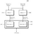
도 5는 본 발명의 실시 예에 따른 입력 장치를 예시적으로 보여주는 블록도이다. 도 5를 참조하면, 입력 장치(400)는 제 1 센서(410), 제 2 센서(420), 및 센서 컨트롤러(430)를 포함할 수 있다. 제 1 센서(410) 및 제 2 센서(420)는 도 2에서 설명된 것과 대체로 동일하다.5 is a block diagram illustrating an exemplary input device according to an embodiment of the present invention. Referring to FIG. 5, the
도 2에서 센서 컨트롤러(230, 도 2 참조)는 제 1 감지 결과 및 제 2 감지 결과를 전자 기기(10, 도 1 참조)로 전송할 수 있다. 이와 달리 도 5에서 센서 컨트롤러(430)는 제 1 감지 결과 및 제 2 감지 결과를 처리할 수 있다. 이를 위해, 센서 컨트롤러(430)는 제 1 분석기(Analyzer, 431) 및 제 2 분석기(432)를 포함할 수 있다.2, the sensor controller 230 (see FIG. 2) may transmit the first sensing result and the second sensing result to the electronic device 10 (see FIG. 1). In FIG. 5, the
제 1 분석기(431)는 제 1 센서(410)로부터 제 1 감지 결과(Sensing result)를 수신할 수 있다. 제 1 분석기(431)는 제 1 감지 결과를 참조하여 유저의 터치 동작을 인식할 수 있다. 제 1 분석기(431)는 제 1 감지 결과를 참조하여 전자 기기(10, 도 1 참조)가 비정상 상태에 놓인 것인지도 감지할 수 있다. 즉, 제 1 분석기(431)는 제 1 감지 결과를 참조하여, 유저의 터치 동작을 분석하거나 비정상 신호들을 분석할 수 있다. 이를 위해, 제 1 분석기(431) 내부에는 레지스터(미도시)를 포함할 수 있다. 상술한 레지스터에는 유저의 터치 동작에 따라 변형되는 음향 신호들의 정보가 저장될 수 있다. 상술한 레지스터에는 비정상 상태에 따른 신호들의 정보가 저장될 수 있다.The
제 2 분석기(432)는 제 2 센서(420)로부터 제 2 감지 결과를 수신할 수 있다. 제 2 분석기(432)는 제 2 감지 결과를 참조하여, 전자 기기(10, 도 1 참조)가 비정상 상태에 놓인 것인지 감지할 수 있다. 제 2 분석기(432)는 제 2 감지 결과를 참조하여, 비정상 신호들을 분석할 수 있다. 이를 위해, 제 1 분석기(431) 내부에는 레지스터(미도시)를 포함할 수 있다. 상술한 레지스터에는 비정상 상태에 따른 신호들의 정보가 저장될 수 있다. 제 2 분석기(432)는 상술한 감지 결과를 제 1 분석기(431)로 출력할 수 있다.The
제 1 분석기(431)는 제 2 분석기(432)의 결과를 참조하여, 제 1 센서(410)가 감지한 음향 신호를 필터링 할 수 있다. 좀 더 구체적으로, 제 1 분석기(431)는 제 1 감지 결과를 필터링 할 수 있다. 전자 기기(10, 도 1 참조)가 비정상 상태에 놓인 경우에 발생되는 음향 신호는 유저가 의도하지 않은 음향 신호일 수 있다. 따라서, 제 1 분석기(431)는 유저가 의도하지 않은 음향 신호를 분석할 수 있다. 상술한 분석 결과는 전자 기기(10, 도 1 참조)로 전송될 수 있다.The
정리하면, 본 발명의 실시 예에 따른 입력 장치(200, 도 2 참조)는 음향 신호 및 비정상 신호들을 감지하고 이를 전자 기기(10, 도 1 참조)로 전송할 수 있다. 다른 실시 예에 있어서, 본 발명의 실시 예에 따른 입력 장치(400, 도 5 참조)는 음향 신호 및 비정상 신호들을 감지, 분석, 필터링 하여 전자 기기(10, 도 1 참조)로 전송할 수 있다.In summary, an input device 200 (see FIG. 2) according to an embodiment of the present invention can detect acoustic signals and abnormal signals and transmit them to the electronic device 10 (see FIG. 1). In another embodiment, an input device 400 (see FIG. 5) according to an embodiment of the present invention may sense, analyze, and filter acoustic signals and abnormal signals and transmit them to the electronic device 10 (see FIG. 1).
도 6은 본 발명의 실시 예에 따른 입력 장치가 적용된 전자 기기를 예시적으로 보여주는 도면이다. 도 6을 참조하면, 전자 기기(50)는 하우징(51), 음향 신호 발생기(52), 디스플레이(53), 및 입력 장치(500)를 포함할 수 있다. 하우징(51), 음향 신호 발생기(52), 디스플레이(53), 및 입력 장치(500)는 도 1에서 설명된 것과 대체로 동일하다.6 is a diagram illustrating an example of an electronic device to which an input device according to an embodiment of the present invention is applied. 6, the
도 6을 참조하면, 입력 장치(500)는 도 1에서 도시된 입력 장치(100)와 달리 절연체(540)를 더 포함할 수 있다. 입력 장치(500)는 절연체(540)를 통해 하우징(51)에 부착될 수 있다. 따라서, 절연체(540)는 입력 장치(500) 내에서 하우징(51)과 부착을 고려하여 배치가 설정될 수 있다.Referring to FIG. 6, the
절연체(540)는 상술한 음향 신호 또는 비정상 신호의 전달 효율을 증가시키는 매질을 포함할 수 있다. 도시되진 않았지만, 도 5에 도시된 제 1 센서(410) 및 제 2 센서(420)는 절연체(540) 내부에 배치될 수도 있다. 이 경우, 제 1 센서(410, 도 5 참조) 및 제 2 센서(420, 도 5 참조)는 절연체(540)에 의해 보호될 수 있다.The
도 7은 본 발명의 실시 예에 따른 입력 장치가 적용된 전자 기기를 예시적으로 보여주는 도면이다. 도 7을 참조하면, 전자 기기(60)는 하우징(61), 플라스틱 커버(Plastic cover, 63), 디스플레이(64), 제 1 영역(65), 제 2 영역(66), PCB(Printed circuit board, 67), 및 입력 장치(600)를 포함할 수 있다. 하우징(61), 디스플레이(64), 및 입력 장치(600)는 도 1에서 설명된 것과 대체로 동일하다.7 is a diagram illustrating an example of an electronic device to which an input device according to an embodiment of the present invention is applied. 7, the electronic device 60 includes a
플라스틱 커버(63)는 전자 기기(60)의 전면에 하우징(61)의 일부와 함께 배치될 수 있다. 플라스틱 커버(63)는 투명한 재질을 포함할 수 있다. 플라스틱 커버(63)는 외부 충격으로부터 디스플레이(64)를 보호할 수 있다.The
제 1 영역(65) 및 제 2 영역(66)에는 전자 기기(60)의 구성 요소들(미도시)이 배치될 수 있다. 예를 들면, 프로세서(Processor), 스토리지 모듈(Storage module), 네트워크 모듈(Network module), 메모리 모듈(Memory module), 안테나 모듈(Antenna module), 또는 배터리(Battery) 등은 제 1 영역(65) 및 제 2 영역(66)에 나뉘어 배치될 수 있다.Components (not shown) of the electronic device 60 may be disposed in the
전자 기기(60)의 구성 요소들은 다양한 형태들의 패키지를 이용하여 PCB(67)에 부착될 수 있다. 예를 들면, PoP(Package on Package), CSP(Chip Scale Package), PDIP(Plastic Dual in Line Package), CERDIP(Ceramic Dual in Line Package), TQFP(Thin Quad Flat Package), SSOP(Shrink Small Outline Package), TSOP(Thin Small Outline Package), WFP(Wafer-level Fabricated Package), WSP(Wafer-level Processed Stack Package) 등과 같은 패키지들이 사용될 수 있다.The components of the electronic device 60 may be attached to the
제 1 영역(65)은 PCB(67)와 디스플레이(64) 사이의 공간을 의미할 수 있다. 제 2 영역(66)은 PCB(67)와 후면의 하우징(61) 사이의 공간을 의미할 수 있다. 제 1 영역(65) 및 제 2 영역(66)에 배치된 구성 요소들은 솔더 볼(Solder ball) 또는 범프(Bump)를 통해 PCB(67)와 연결될 수 있다.The
본 발명의 실시 예에 따른 입력 장치(600)는 제 2 영역에 배치될 수 있다. 좀 더 구체적으로, 입력 장치(600)는 PCB(67)와 후면의 하우징(61) 사이에 배치될 수 있다. 도시되진 않았지만, 입력 장치(600)는 전자 기기(60)의 측면에 부착되도록 배치될 수도 있다.The
도 8은 본 발명의 실시 예에 따른 입력 장치가 적용된 컴퓨터 시스템을 예시적으로 나타내는 블록도이다. 도 8을 참조하면, 컴퓨터 시스템(1000)은 프로세서(1100), 유저 인터페이스(User Interface, 1200), 디스플레이 모듈(Display module, 1300), 스토리지 모듈(Storage Module, 1400), 네트워크 모듈(Network Module, 1500), 및 메모리 모듈(1600)을 포함할 수 있다.8 is a block diagram exemplarily showing a computer system to which an input device according to an embodiment of the present invention is applied. 8, a
프로세서(1100)는 컴퓨터 시스템(1000)에 포함된 구성 요소들, 운영체제(OS; Operating System)를 구동시킬 수 있다. 예시적으로, 프로세서(1100)는 컴퓨터 시스템(1000)에 포함된 구성 요소들을 제어하는 컨트롤러들, 인터페이스들, 그래픽 엔진 등을 포함할 수 있다. 프로세서(1100)는 시스템-온-칩(SoC; System-on-Chip)으로 제공될 수 있다.The
유저 인터페이스(1200)는 프로세서(1100)에 데이터 또는 명령어를 입력하거나 또는 외부 장치로 데이터를 출력하는 인터페이스들을 포함할 수 있다. 예시적으로, 유저 인터페이스(1200)는 키보드, 키패드, 버튼, 터치 패널, 터치 스크린, 터치 패드, 터치 볼, 카메라, 마이크, 자이로스코프 센서(Gyroscope sensor), 진동 센서, 압전 소자 등과 같은 사용자 입력 인터페이스들을 포함할 수 있다. 본 발명의 실시 예에 따른 입력 장치는 유저 인터페이스(1200)에 포함될 수 있다.The
디스플레이 모듈(1300)은 영상을 표시할 수 있다. 디스플레이 모듈(1300)은 디스플레이 구동 회로(미도시)로부터 디스플레이 데이터를 전송 받을 수 있다. 여기서, 디스플레이 구동 회로는 디스플레이 모듈(1300)을 구동할 수 있다. 디스플레이 구동 회로는 프로세서(1100)에서 전송된 디스플레이 데이터를 처리하고, 처리된 디스플레이 데이터를 디스플레이 모듈(1300)로 전송할 수 있다. 디스플레이 구동 회로는 집적 회로(Integrated Circuit)로 구현될 수 있다. 디스플레이 구동 회로는 프로세서(1100) 내부에서 구현될 수도 있고, 외부에서 별도로 구현될 수도 있다.The
디스플레이 모듈(1300)은 유기 발광 패널(Organic Light Emitting Display Panel), 액정 표시 패널(Liquid Crystal Display Panel), 플라즈마 표시 패널(Plasma Display Panel), 전기영동 표시 패널(Electrophoretic Display Panel), 또는 일렉트로웨팅 표시 패널(Electrowetting Display Panel) 등을 포함할 수 있다.The
스토리지 모듈(1400)은 데이터를 저장할 수 있다. 예를 들어, 스토리지 모듈(1400)은 프로세서(1100)로부터 수신한 데이터를 저장할 수 있다. 또는 스토리지 모듈(1400)은 스토리지 모듈(1400)에 저장된 데이터를 프로세서(1100)로 전달할 수 있다. 예시적으로, 스토리지 모듈(1400)은 EPROM(Erasable Programmable Read-Only Memory), 낸드 플래시 메모리(Nand Flash Memory), 노어 플래시 메모리(Nor Flash Memory), PRAM(Phase-change Memory), ReRAM(Resistive Random Access Memory), FeRAM(Ferroelectric Random Access Memory) 등과 같은 불휘발성 반도체 메모리 소자로 구현될 수 있다.
네트워크 모듈(1500)은 외부 장치들과 통신을 수행할 수 있다. 예시적으로, 네트워크 모듈(1500)은 CDMA(Code Division Multiple Access), GSM(Global System for Mobile Communication), WCDMA(Wideband CDMA), CDMA-2000, TDMA(Time Division Multiple Access), LTE(Long Term Evolution), Wimax(Worldwide Interoperability for Microwave Access), WLAN(Wireless LAN), UWB(Ultra Wide Band), 블루투스(Bluetooth), WI-DI(Wireless Display) 등과 같은 무선 통신을 지원할 수 있다.The
메모리 모듈(1600)은 컴퓨터 시스템(1000)의 주 메모리, 동작 메모리, 버퍼 메모리 또는 캐시(Cache) 메모리로 동작할 수 있다. 메모리 모듈(1600)은 DRAM, SRAM(Static Random Access Memory) 등과 같은 휘발성 메모리 또는 PRAM, ReRAM, FeRAM 등과 같은 불휘발성 메모리들을 포함할 수 있다.
시스템 버스(System Bus, 1700)는 프로세서(1100), 유저 인터페이스(1200), 디스플레이 모듈(1300), 스토리지 모듈(1400), 네트워크 모듈(1500), 및 메모리 모듈(1600)을 서로 전기적으로 연결할 수 있다.The
위에서 설명한 내용은 본 발명을 실시하기 위한 구체적인 예들이다. 본 발명에는 위에서 설명한 실시 예들뿐만 아니라, 단순하게 설계 변경하거나 용이하게 변경할 수 있는 실시 예들도 포함될 것이다. 또한, 본 발명에는 상술한 실시 예들을 이용하여 앞으로 용이하게 변형하여 실시할 수 있는 기술들도 포함될 것이다.The above description is a concrete example for carrying out the present invention. The present invention includes not only the above-described embodiments, but also embodiments that can be simply modified or easily changed. In addition, the present invention includes techniques that can be easily modified by using the above-described embodiments.
10, 30, 50, 60, 1000: 전자 기기
11, 31, 51, 61: 하우징
12, 32, 52: 음향 신호 발생기
13, 53, 64: 디스플레이
100, 200, 300, 400, 500, 600: 입력 장치
210, 410: 제 1 센서
220, 420: 제 2 센서
230, 430: 센서 컨트롤러
63: 플라스틱 커버
65: 제 1 영역
66: 제 2 영역
1100: 프로세서
1200: 유저 인터페이스
1300: 디스플레이 모듈
1400: 스토리지 모듈
1500: 네트워크 모듈
1600: 메모리 모듈
1700: 시스템 버스10, 30, 50, 60, 1000: Electronic device
11, 31, 51, 61: housing
12, 32, 52: a sound signal generator
13, 53, 64: Display
100, 200, 300, 400, 500, 600: input device
210, 410: first sensor
220, 420: second sensor
230, and 430: a sensor controller
63: Plastic cover
65: First area
66: second region
1100: Processor
1200: User Interface
1300: Display module
1400: Storage module
1500: Network module
1600: memory module
1700: System bus
Claims (11)
Translated fromKorean음향 신호 발생기에 의해 생성된 제 1 음향 신호를 수신하는 제 1 센서;
상기 제 1 음향 신호와 다른 비정상 신호를 수신하는 제 2 센서; 및
상기 제 1 센서의 제 1 감지 결과 및 상기 제 2 센서의 제 2 감지 결과를 수신하고, 상기 감지 결과들을 상기 전자 기기로 출력하는 센서 컨트롤러(Sensor controller)를 포함하되,
상기 제 1 음향 신호는 상기 전자 기기의 적어도 일부를 덮는 하우징을 통해 상기 제 1 센서로 수신되는 입력 장치.An input device for an electronic device,
A first sensor for receiving a first acoustic signal generated by a sound signal generator;
A second sensor for receiving an abnormal signal different from the first acoustic signal; And
And a sensor controller for receiving the first sensing result of the first sensor and the second sensing result of the second sensor and outputting the sensing results to the electronic device,
Wherein the first acoustic signal is received by the first sensor through a housing covering at least a portion of the electronic device.
상기 입력 장치는 상기 전자 기기의 후면 또는 측면에 부착되는 입력 장치.The method according to claim 1,
Wherein the input device is attached to a back surface or a side surface of the electronic device.
상기 제 2 센서는 압력 센서, 근접 센서, 자이로 센서(Gvro sensor), 가속도 센서, 자기 센서(Magnetic sensor), 온도 센서, 또는 지자기 센서(Terrestrial magnetism sensor) 중 어느 하나인 입력 장치.The method according to claim 1,
Wherein the second sensor is any one of a pressure sensor, a proximity sensor, a gyro sensor, an acceleration sensor, a magnetic sensor, a temperature sensor, or a terrestrial magnetism sensor.
상기 제 1 센서는 상기 비정상 신호를 더 수신하는 입력 장치.The method according to claim 1,
Wherein the first sensor further receives the abnormal signal.
유저(User)의 상기 전자 기기에 대한 터치(Touch)에 의해서 상기 제 1 음향 신호는 변형되고, 상기 제 1 센서는 상기 제 1 음향 신호가 변형된 제 2 음향 신호를 더 수신하는 입력 장치.The method according to claim 1,
Wherein the first sound signal is deformed by a touch of the user to the electronic device and the first sensor further receives the second sound signal in which the first sound signal is deformed.
상기 센서 컨트롤러는:
상기 제 1 감지 결과를 참조하여 상기 유저의 상기 전자 기기에 대한 터치를 분석하는 제 1 분석기; 및
상기 제 2 감지 결과를 참조하여 상기 비정상 신호들을 분석하는 제 2 분석기를 포함하고, 상기 제 1 분석기 및 상기 제 2 분석기의 결과들을 상기 전자 기기로 출력하는 입력 장치.6. The method of claim 5,
The sensor controller comprises:
A first analyzer for analyzing a touch of the user with respect to the electronic device by referring to the first sensing result; And
And a second analyzer for analyzing the abnormal signals with reference to the second detection result, wherein the second analyzer outputs the results of the first analyzer and the second analyzer to the electronic device.
상기 제 1 분석기는 상기 제 1 감지 결과를 참조하여 상기 비정상 신호들을 더 분석하는 입력 장치.The method according to claim 6,
Wherein the first analyzer further analyzes the abnormal signals with reference to the first detection result.
상기 제 1 분석기는 상기 제 2 분석기의 결과를 참조하여 상기 제 1 음향 신호 또는 상기 제 2 음향 신호를 필터링(Filtering)하는 입력 장치.8. The method of claim 7,
Wherein the first analyzer filters the first acoustic signal or the second acoustic signal with reference to a result of the second analyzer.
상기 하우징에 부착되는 절연체(Insulator)를 더 포함하는 입력 장치.3. The method of claim 2,
And an insulator attached to the housing.
상기 절연체는 상기 제 1 센서, 상기 제 2 센서, 또는 상기 센서 컨트롤러를 보호하는 입력 장치.10. The method of claim 9,
Wherein the insulator protects the first sensor, the second sensor, or the sensor controller.
상기 절연체는 상기 제 1 음향 신호 또는 상기 비정상 신호의 전달 효율을 증가시키는 매질을 포함하는 입력 장치.
11. The method of claim 10,
Wherein the insulator comprises a medium for increasing transmission efficiency of the first acoustic signal or the abnormal signal.
Priority Applications (2)
| Application Number | Priority Date | Filing Date | Title |
|---|---|---|---|
| KR1020160093080AKR20180010636A (en) | 2016-07-22 | 2016-07-22 | Input device including a plurality of sensors |
| US15/273,741US20180024691A1 (en) | 2016-07-22 | 2016-09-23 | Input device including a plurality of sensors |
Applications Claiming Priority (1)
| Application Number | Priority Date | Filing Date | Title |
|---|---|---|---|
| KR1020160093080AKR20180010636A (en) | 2016-07-22 | 2016-07-22 | Input device including a plurality of sensors |
Publications (1)
| Publication Number | Publication Date |
|---|---|
| KR20180010636Atrue KR20180010636A (en) | 2018-01-31 |
Family
ID=60988025
Family Applications (1)
| Application Number | Title | Priority Date | Filing Date |
|---|---|---|---|
| KR1020160093080AWithdrawnKR20180010636A (en) | 2016-07-22 | 2016-07-22 | Input device including a plurality of sensors |
Country Status (2)
| Country | Link |
|---|---|
| US (1) | US20180024691A1 (en) |
| KR (1) | KR20180010636A (en) |
Family Cites Families (8)
| Publication number | Priority date | Publication date | Assignee | Title |
|---|---|---|---|---|
| EP2486474B1 (en)* | 2009-10-07 | 2020-03-04 | Elliptic Laboratories AS | User interfaces |
| US9165550B2 (en)* | 2009-11-19 | 2015-10-20 | Otter Products, Llc | Acoustic isolation mechanism with membrane |
| EP2524288A1 (en)* | 2010-01-13 | 2012-11-21 | Elo Touch Solutions, Inc. | Noise reduction in electronic device with touch sensitive surface |
| US8681128B2 (en)* | 2011-10-14 | 2014-03-25 | Elo Touch Solutions, Inc. | Acoustic touch apparatus |
| US9201546B2 (en)* | 2012-03-09 | 2015-12-01 | Elo Touch Solutions, Inc. | Acoustic touch apparatus with multi-touch capability |
| WO2013140130A1 (en)* | 2012-03-21 | 2013-09-26 | Elliptic Laboratories As | Signal processing for acoustic user input |
| FR2995703B1 (en)* | 2012-09-14 | 2015-12-25 | Commissariat Energie Atomique | SYSTEM AND METHOD FOR DETECTING THE ACTUATION OF A FUNCTION MATERIALIZED BY A PREDETERMINED PATH ON A TOUCH SURFACE OF AN OBJECT |
| US20160179461A1 (en)* | 2014-12-17 | 2016-06-23 | Microsoft Technology Licensing, Llc | Tactile input produced sound based user interface |
- 2016
- 2016-07-22KRKR1020160093080Apatent/KR20180010636A/ennot_activeWithdrawn
- 2016-09-23USUS15/273,741patent/US20180024691A1/ennot_activeAbandoned
Also Published As
| Publication number | Publication date |
|---|---|
| US20180024691A1 (en) | 2018-01-25 |
Similar Documents
| Publication | Publication Date | Title |
|---|---|---|
| KR102120930B1 (en) | User input method of portable device and the portable device enabling the method | |
| US10397388B2 (en) | Extended features for network communication | |
| KR102562001B1 (en) | Electronic device with light emitting device | |
| US10725657B2 (en) | Method for displaying graphical user interface and mobile terminal | |
| TWI461663B (en) | Devices with displays and related methods involving light sensing with photovoltaic arrays | |
| JP6759341B2 (en) | How to display multiple application windows on a mobile terminal, and mobile terminals | |
| WO2013150998A1 (en) | Mobile electronic device | |
| US20130167074A1 (en) | Device, method, and storage medium storing program | |
| US20140085259A1 (en) | System for providing a user interface for use by portable and other devices | |
| RU2008142904A (en) | MULTI-FUNCTION KEY WITH SCROLL | |
| KR101215915B1 (en) | Handheld electronic device with motion-controlled cursor | |
| US10116787B2 (en) | Electronic device, control method, and non-transitory storage medium | |
| KR20140028084A (en) | Method for auto-switching user interface of handheld terminal device and handheld terminal device thereof | |
| ES2952284T3 (en) | Icon display method and terminal device | |
| CN107609439A (en) | Method, device, storage medium and terminal for processing radio frequency interference | |
| US11669053B2 (en) | Electronic device and computer-readable non-transitory recording medium | |
| JPWO2008023667A1 (en) | Portable electronic device and method for controlling portable electronic device | |
| US9974026B2 (en) | Terminal control method and terminal | |
| EP3204844B1 (en) | Device operated through opaque cover and system | |
| ES2997010T3 (en) | Content input method and terminal device | |
| EP3598338A1 (en) | Fingerprint acquisition method and related product | |
| CN101308438B (en) | Multifunctional device, method for switching functions thereof, and related electronic device | |
| US20150309649A1 (en) | Display driving integrated circuit, system including the same and display driving method | |
| US20120293436A1 (en) | Apparatus, method, computer program and user interface | |
| KR102223606B1 (en) | Method of controlling touch screen and electronic device thereof |
Legal Events
| Date | Code | Title | Description |
|---|---|---|---|
| PA0109 | Patent application | Patent event code:PA01091R01D Comment text:Patent Application Patent event date:20160722 | |
| PG1501 | Laying open of application | ||
| PC1203 | Withdrawal of no request for examination |