KR20180008601A - Transmission medium having multiple cores and methods for use therewith - Google Patents
Transmission medium having multiple cores and methods for use therewithDownload PDFInfo
- Publication number
- KR20180008601A KR20180008601AKR1020177035866AKR20177035866AKR20180008601AKR 20180008601 AKR20180008601 AKR 20180008601AKR 1020177035866 AKR1020177035866 AKR 1020177035866AKR 20177035866 AKR20177035866 AKR 20177035866AKR 20180008601 AKR20180008601 AKR 20180008601A
- Authority
- KR
- South Korea
- Prior art keywords
- wave
- dielectric
- electromagnetic waves
- core
- wire
- Prior art date
- Legal status (The legal status is an assumption and is not a legal conclusion. Google has not performed a legal analysis and makes no representation as to the accuracy of the status listed.)
- Withdrawn
Links
- 230000005540biological transmissionEffects0.000titleclaimsabstractdescription271
- 238000000034methodMethods0.000titleclaimsdescription69
- 230000001902propagating effectEffects0.000claimsabstractdescription30
- 230000000670limiting effectEffects0.000claimsdescription66
- 239000004020conductorSubstances0.000claimsdescription43
- 239000006260foamSubstances0.000claimsdescription38
- 239000003989dielectric materialSubstances0.000claimsdescription27
- 230000002411adverseEffects0.000claimsdescription18
- 230000003287optical effectEffects0.000claimsdescription13
- 239000011358absorbing materialSubstances0.000claims2
- 239000003575carbonaceous materialSubstances0.000claims1
- 238000004891communicationMethods0.000description202
- 230000006854communicationEffects0.000description202
- 239000002609mediumSubstances0.000description168
- 230000001939inductive effectEffects0.000description107
- 238000010586diagramMethods0.000description72
- 238000010168coupling processMethods0.000description61
- 230000008878couplingEffects0.000description60
- 238000005859coupling reactionMethods0.000description60
- 238000007726management methodMethods0.000description59
- 238000005516engineering processMethods0.000description33
- 238000003860storageMethods0.000description31
- 238000009826distributionMethods0.000description27
- 230000005672electromagnetic fieldEffects0.000description26
- 239000012212insulatorSubstances0.000description26
- 238000012360testing methodMethods0.000description24
- 239000000463materialSubstances0.000description23
- 239000002184metalSubstances0.000description19
- 230000006870functionEffects0.000description18
- 230000006698inductionEffects0.000description18
- 238000012423maintenanceMethods0.000description18
- 238000012545processingMethods0.000description18
- 230000000694effectsEffects0.000description16
- 230000001413cellular effectEffects0.000description15
- 238000013461designMethods0.000description14
- 230000000644propagated effectEffects0.000description14
- 239000003570airSubstances0.000description13
- 230000000116mitigating effectEffects0.000description13
- 238000012549trainingMethods0.000description13
- 230000008569processEffects0.000description12
- -1polyethylenePolymers0.000description11
- 239000004698PolyethyleneSubstances0.000description9
- 238000001514detection methodMethods0.000description9
- 230000007613environmental effectEffects0.000description9
- 230000001965increasing effectEffects0.000description9
- 238000009413insulationMethods0.000description9
- 229920000573polyethylenePolymers0.000description9
- 238000013473artificial intelligenceMethods0.000description8
- 230000006855networkingEffects0.000description8
- 239000000835fiberSubstances0.000description7
- 230000003595spectral effectEffects0.000description7
- 230000008859changeEffects0.000description6
- 239000000203mixtureSubstances0.000description6
- 239000002689soilSubstances0.000description6
- XLYOFNOQVPJJNP-UHFFFAOYSA-NwaterSubstancesOXLYOFNOQVPJJNP-UHFFFAOYSA-N0.000description6
- 238000004458analytical methodMethods0.000description5
- 238000012937correctionMethods0.000description5
- 230000009977dual effectEffects0.000description5
- 230000011664signalingEffects0.000description5
- 230000001052transient effectEffects0.000description5
- 239000004809TeflonSubstances0.000description4
- 229920006362Teflon®Polymers0.000description4
- 238000010521absorption reactionMethods0.000description4
- 238000006243chemical reactionMethods0.000description4
- 235000009508confectioneryNutrition0.000description4
- 238000013500data storageMethods0.000description4
- 230000005684electric fieldEffects0.000description4
- 239000000284extractSubstances0.000description4
- 238000001914filtrationMethods0.000description4
- 238000002955isolationMethods0.000description4
- 230000007257malfunctionEffects0.000description4
- 230000007246mechanismEffects0.000description4
- 230000005055memory storageEffects0.000description4
- 238000003909pattern recognitionMethods0.000description4
- 239000011295pitchSubstances0.000description4
- 229920003023plasticPolymers0.000description4
- 239000004033plasticSubstances0.000description4
- 230000005855radiationEffects0.000description4
- 230000004044responseEffects0.000description4
- 238000012706support-vector machineMethods0.000description4
- OKTJSMMVPCPJKN-UHFFFAOYSA-NCarbonChemical compound[C]OKTJSMMVPCPJKN-UHFFFAOYSA-N0.000description3
- 239000004677NylonSubstances0.000description3
- 241000711981SaisSpecies0.000description3
- 230000003321amplificationEffects0.000description3
- 229910052799carbonInorganic materials0.000description3
- 238000005259measurementMethods0.000description3
- 238000003199nucleic acid amplification methodMethods0.000description3
- 229920001778nylonPolymers0.000description3
- 230000010287polarizationEffects0.000description3
- 238000001228spectrumMethods0.000description3
- 230000001360synchronised effectEffects0.000description3
- 241001270131Agaricus moelleriSpecies0.000description2
- 239000004952PolyamideSubstances0.000description2
- 230000009471actionEffects0.000description2
- 239000012080ambient airSubstances0.000description2
- 238000013459approachMethods0.000description2
- 238000013475authorizationMethods0.000description2
- 230000015572biosynthetic processEffects0.000description2
- 230000010267cellular communicationEffects0.000description2
- 239000011248coating agentSubstances0.000description2
- 238000000576coating methodMethods0.000description2
- 238000004590computer programMethods0.000description2
- 230000001419dependent effectEffects0.000description2
- 238000009434installationMethods0.000description2
- 239000011810insulating materialSubstances0.000description2
- 238000004519manufacturing processMethods0.000description2
- 238000012986modificationMethods0.000description2
- 230000004048modificationEffects0.000description2
- 239000002086nanomaterialSubstances0.000description2
- 239000000615nonconductorSubstances0.000description2
- 230000002093peripheral effectEffects0.000description2
- 230000010363phase shiftEffects0.000description2
- 229920002647polyamidePolymers0.000description2
- 230000002829reductive effectEffects0.000description2
- 230000008093supporting effectEffects0.000description2
- 238000012546transferMethods0.000description2
- 108700026140MAC combinationProteins0.000description1
- 230000002745absorbentEffects0.000description1
- 239000002250absorbentSubstances0.000description1
- 230000001154acute effectEffects0.000description1
- 230000006978adaptationEffects0.000description1
- 239000000853adhesiveSubstances0.000description1
- 230000001070adhesive effectEffects0.000description1
- 230000004075alterationEffects0.000description1
- 238000003491arrayMethods0.000description1
- QVGXLLKOCUKJST-UHFFFAOYSA-Natomic oxygenChemical compound[O]QVGXLLKOCUKJST-UHFFFAOYSA-N0.000description1
- 239000011324beadSubstances0.000description1
- 230000006399behaviorEffects0.000description1
- 230000007175bidirectional communicationEffects0.000description1
- 230000002457bidirectional effectEffects0.000description1
- 239000000872bufferSubstances0.000description1
- 230000003139buffering effectEffects0.000description1
- 239000003990capacitorSubstances0.000description1
- 230000015556catabolic processEffects0.000description1
- 238000005253claddingMethods0.000description1
- 238000013145classification modelMethods0.000description1
- 230000003750conditioning effectEffects0.000description1
- 238000010276constructionMethods0.000description1
- 230000007797corrosionEffects0.000description1
- 238000005260corrosionMethods0.000description1
- 238000003066decision treeMethods0.000description1
- 230000007423decreaseEffects0.000description1
- 230000003247decreasing effectEffects0.000description1
- 230000002950deficientEffects0.000description1
- 238000006731degradation reactionMethods0.000description1
- 238000005538encapsulationMethods0.000description1
- 239000000945fillerSubstances0.000description1
- 239000011888foilSubstances0.000description1
- 239000007789gasSubstances0.000description1
- 229920001903high density polyethylenePolymers0.000description1
- 239000004700high-density polyethyleneSubstances0.000description1
- 238000003384imaging methodMethods0.000description1
- 230000006872improvementEffects0.000description1
- 230000000977initiatory effectEffects0.000description1
- 239000004973liquid crystal related substanceSubstances0.000description1
- 230000007774longtermEffects0.000description1
- 238000002156mixingMethods0.000description1
- 238000010295mobile communicationMethods0.000description1
- 238000012544monitoring processMethods0.000description1
- 230000005404monopoleEffects0.000description1
- 230000007935neutral effectEffects0.000description1
- NJPPVKZQTLUDBO-UHFFFAOYSA-NnovaluronChemical compoundC1=C(Cl)C(OC(F)(F)C(OC(F)(F)F)F)=CC=C1NC(=O)NC(=O)C1=C(F)C=CC=C1FNJPPVKZQTLUDBO-UHFFFAOYSA-N0.000description1
- 238000005457optimizationMethods0.000description1
- 229910052760oxygenInorganic materials0.000description1
- 239000001301oxygenSubstances0.000description1
- 230000000704physical effectEffects0.000description1
- 229920002635polyurethanePolymers0.000description1
- 239000004814polyurethaneSubstances0.000description1
- 230000001737promoting effectEffects0.000description1
- 230000002285radioactive effectEffects0.000description1
- 238000011084recoveryMethods0.000description1
- 230000008439repair processEffects0.000description1
- 230000002441reversible effectEffects0.000description1
- 239000007787solidSubstances0.000description1
- 238000010183spectrum analysisMethods0.000description1
- 230000003068static effectEffects0.000description1
- 238000006467substitution reactionMethods0.000description1
- 239000000758substrateSubstances0.000description1
- 230000007704transitionEffects0.000description1
- 230000007723transport mechanismEffects0.000description1
- 239000006163transport mediaSubstances0.000description1
- 230000001960triggered effectEffects0.000description1
- 238000011144upstream manufacturingMethods0.000description1
Images

Classifications
- H—ELECTRICITY
- H01—ELECTRIC ELEMENTS
- H01P—WAVEGUIDES; RESONATORS, LINES, OR OTHER DEVICES OF THE WAVEGUIDE TYPE
- H01P3/00—Waveguides; Transmission lines of the waveguide type
- H01P3/02—Waveguides; Transmission lines of the waveguide type with two longitudinal conductors
- H01P3/06—Coaxial lines
- H—ELECTRICITY
- H01—ELECTRIC ELEMENTS
- H01P—WAVEGUIDES; RESONATORS, LINES, OR OTHER DEVICES OF THE WAVEGUIDE TYPE
- H01P3/00—Waveguides; Transmission lines of the waveguide type
- H01P3/16—Dielectric waveguides, i.e. without a longitudinal conductor
- H—ELECTRICITY
- H04—ELECTRIC COMMUNICATION TECHNIQUE
- H04B—TRANSMISSION
- H04B3/00—Line transmission systems
- H04B3/02—Details
- H04B3/32—Reducing cross-talk, e.g. by compensating
- H—ELECTRICITY
- H04—ELECTRIC COMMUNICATION TECHNIQUE
- H04B—TRANSMISSION
- H04B3/00—Line transmission systems
- H04B3/54—Systems for transmission via power distribution lines
- H—ELECTRICITY
- H04—ELECTRIC COMMUNICATION TECHNIQUE
- H04B—TRANSMISSION
- H04B2203/00—Indexing scheme relating to line transmission systems
- H04B2203/54—Aspects of powerline communications not already covered by H04B3/54 and its subgroups
- H04B2203/5404—Methods of transmitting or receiving signals via power distribution lines
- H04B2203/5425—Methods of transmitting or receiving signals via power distribution lines improving S/N by matching impedance, noise reduction, gain control
- H—ELECTRICITY
- H04—ELECTRIC COMMUNICATION TECHNIQUE
- H04B—TRANSMISSION
- H04B2203/00—Indexing scheme relating to line transmission systems
- H04B2203/54—Aspects of powerline communications not already covered by H04B3/54 and its subgroups
- H04B2203/5462—Systems for power line communications
- H04B2203/5483—Systems for power line communications using coupling circuits
- H04B2203/5487—Systems for power line communications using coupling circuits cables
- H—ELECTRICITY
- H04—ELECTRIC COMMUNICATION TECHNIQUE
- H04B—TRANSMISSION
- H04B3/00—Line transmission systems
- H04B3/54—Systems for transmission via power distribution lines
- H04B3/56—Circuits for coupling, blocking, or by-passing of signals
Landscapes
- Engineering & Computer Science (AREA)
- Computer Networks & Wireless Communication (AREA)
- Signal Processing (AREA)
- Power Engineering (AREA)
- Near-Field Transmission Systems (AREA)
- Cable Transmission Systems, Equalization Of Radio And Reduction Of Echo (AREA)
- Waveguides (AREA)
- Aerials With Secondary Devices (AREA)
Abstract
Translated fromKoreanDescription
Translated fromKorean관련 출원들에 대한 상호-참조Cross-references to related applications
본 출원은 2015년 5월 14일에 출원된, 미국 특허 출원 일련 번호 제14/712,014호의 일부 계속 출원인, 2015년 7월 16일에 출원된 미국 특허 출원 번호 제14/800,745호에 대한 우선권을 주장한다. 앞서 말한 것의 내용은 여기에 전체적으로 제시된 것처럼 참조로서 본 출원으로 통합된다.This application claims priority to U.S. Patent Application Serial No. 14 / 800,745 filed on July 16, 2015, which is a continuation-in-part of U.S. Patent Application Serial No. 14 / 712,014, filed May 14, do. The content of which is incorporated herein by reference as if set forth in its entirety herein.
본 개시는 통신 네트워크에서 마이크로파 송신을 통한 통신들에 관한 것이다.The present disclosure relates to communications via microwave transmission in a communication network.
스마트폰들 및 다른 휴대용 디바이스들이 점점 더 어디서나 볼 수 있게 되고, 데이터 사용이 증가함에 따라, 매크로셀 기지국 디바이스들 및 기존의 무선 기반시설은 결과적으로 증가된 수요를 처리하기 위해 보다 높은 대역폭 능력을 요구한다. 부가적인 이동 대역폭을 제공하기 위해, 소형 셀 배치가, 종래의 매크로셀들보다 훨씬 더 작은 면적들에 대한 커버리지를 제공하는 마이크로셀들 및 피코셀들을 갖고, 추구된다.As smartphones and other portable devices become more visible everywhere and as data usage increases, macro cell base station devices and existing wireless infrastructure require higher bandwidth capabilities to handle increased demand as a result do. In order to provide additional mobile bandwidth, a small cell layout is sought, with microcells and picocells providing coverage for areas much smaller than conventional macrocells.
또한, 대부분의 집들 및 비즈니스들은 음성, 비디오 및 인터넷 브라우징 등과 같은 서비스들에 대한 광대역 데이터 액세스에 의존하도록 성장하고 있다. 광대역 액세스 네트워크들은 위성, 4G 또는 5G 무선, 전력 라인 통신, 파이버, 케이블, 및 전화 네트워크들을 포함한다.In addition, most homes and businesses are growing to rely on broadband data access for services such as voice, video and Internet browsing. Broadband access networks include satellite, 4G or 5G wireless, power line communications, fiber, cable, and telephone networks.
본 발명의 목적은 다수의 코어들을 갖는 송신 매체 및 그와 함께 사용하기 위한 방법들을 제공하는 것이다.It is an object of the present invention to provide a transmission medium having a plurality of cores and methods for use therewith.
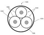
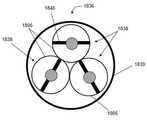
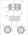
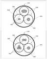
본 개시의 양상들은, 예를 들면, 전자기파들을 전파하기 위한 송신 매체를 포함할 수 있다. 송신 매체는 각각의 코어를 따라 종 방향으로 복수의 전자기파들의 전자기파를 선택적으로 유도하기 위한 복수의 코어들, 및 각각의 코어의 전자기파의 노출을 감소시키기 위해 각각의 코어의 적어도 일 부분을 둘러싸는 셸을 포함할 수 있다.Aspects of the present disclosure may include, for example, a transmission medium for propagating electromagnetic waves. The transmission medium includes a plurality of cores for selectively directing electromagnetic waves of a plurality of electromagnetic waves in a longitudinal direction along respective cores, and a shell surrounding at least a portion of each of the cores to reduce the exposure of the electromagnetic waves of each core. . ≪ / RTI >
참조가 이제 첨부한 도면들에 대해 이루어질 것이며, 이것은 반드시 일정한 비율로 그려지는 것은 아니다.Reference will now be made to the accompanying drawings, which are not necessarily drawn to scale.
도 1은 여기에서 설명된 다양한 양상들에 따른 유도-파 통신 시스템의 예시적인 비-제한적 실시예를 예시한 블록도.
도 2는 여기에서 설명된 다양한 양상들에 따른 송신 디바이스의 예시적인, 비-제한적 실시예를 예시한 블록도.
도 3은 여기에서 설명된 다양한 양상들에 따른 전자기장 분포의 예시적인, 비-제한적 실시예를 예시한 그래픽 다이어그램.
도 4는 여기에서 설명된 다양한 양상들에 따른 전자기장 분포의 예시적인, 비-제한적 실시예를 예시한 그래픽 다이어그램.
도 5a는 여기에서 설명된 다양한 양상들에 따른 주파수 응답의 예시적인, 비-제한적 실시예를 예시한 그래픽 다이어그램.
도 5b는 여기에서 설명된 다양한 양상들에 따른 다양한 동작 주파수들에서 유도 전자기파들의 장들을 묘사한 절연 와이어의 세로 단면의 예시적인, 비-제한적 실시예들을 예시한 그래픽 다이어그램.
도 6은 여기에서 설명된 다양한 양상들에 따른 전자기장 분포의 예시적인, 비-제한적 실시예를 예시한 그래픽 다이어그램.
도 7은 여기에서 설명된 다양한 양상들에 따른 아크 커플러의 예시적인, 비-제한적 실시예를 예시한 블록도.
도 8은 여기에서 설명된 다양한 양상들에 따른 아크 커플러의 예시적인, 비-제한적 실시예를 예시한 블록도.
도 9a는 여기에서 설명된 다양한 양상들에 따른 스터브 커플러의 예시적인, 비-제한적 실시예를 예시한 블록도.
도 9b는 여기에서 설명된 다양한 양상들에 따른 전자기 분포의 예시적인, 비-제한적 실시예를 예시한 다이어그램.
도 10a 및 도 10b는 여기에서 설명된 다양한 양상들에 따른 커플러들 및 트랜시버들의 예시적인, 비-제한적 실시예들을 예시한 블록도들.
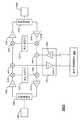
도 11은 여기에서 설명된 다양한 양상들에 따른 이중 스터브 커플러의 예시적인, 비-제한적 실시예를 예시한 블록도.
도 12는 여기에서 설명된 다양한 양상들에 따른 리피터 시스템의 예시적인, 비-제한적 실시예를 예시한 블록도.
도 13은 여기에서 설명된 다양한 양상들에 따른 양방향 리피터의 예시적인, 비-제한적 실시예를 예시한 블록도.
도 14는 여기에서 설명된 다양한 양상들에 따른 도파관 시스템의 예시적인, 비-제한적 실시예를 예시한 블록도.
도 15는 여기에서 설명된 다양한 양상들에 따른 유도-파 통신 시스템의 예시적인, 비-제한적 실시예를 예시한 블록도.
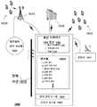
도 16a 및 도 16b는 여기에서 설명된 다양한 양상들에 따른 전력 그리드 통신 시스템을 관리하기 위한 시스템의 예시적인, 비-제한적 실시예를 예시한 블록도들.
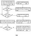
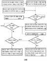
도 17a는 도 16a 및 도 16b의 시스템의 통신 네트워크에서 발생한 교란들을 검출하고 완화시키기 위한 방법의 예시적인, 비-제한적 실시예의 흐름도.
도 17b는 도 16a 및 도 16b의 시스템의 통신 네트워크에서 발생한 교란들을 검출하고 완화시키기 위한 방법의 예시적인, 비-제한적 실시예의 흐름도.
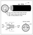
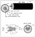
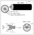
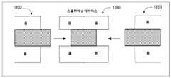
도 18a, 도 18b, 및 도 18c는 유도 전자기파들을 전파하기 위한 송신 매체의 예시적인, 비-제한적 실시예를 예시한 블록도들.
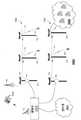
도 18d는 여기에서 설명된 다양한 양상들에 따른 번들링된 송신 미디어의 예시적인, 비-제한적 실시예를 예시한 블록도.
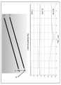
도 18e는 여기에서 설명된 다양한 양상들에 따른 도 18d의 번들링된 송신 미디어의 제 1 및 제 2 송신 매체들 사이에서의 크로스-토크를 묘사한 플롯의 예시적인, 비-제한적 실시예를 예시한 블록도.
도 18f는 여기에서 설명된 다양한 양상들에 따른 크로스-토크를 완화시키기 위해 번들링된 송신 미디어의 예시적인, 비-제한적 실시예를 예시한 블록도.
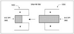
도 18g 및 도 18h는 도 18a, 도 18b, 또는 도 18c의 송신 매체와 함께 사용될 수 있는 커넥터 구성들의 예시적인, 비-제한적 실시예들을 예시한 블록도들.
도 18i는 유도 전자기파들을 전파하기 위한 송신 매체들의 예시적인, 비-제한적 실시예들을 예시한 블록도.
도 18j는 여기에서 설명된 다양한 양상들에 따른 크로스-토크를 완화시키기 위해 번들링된 송신 미디어의 예시적인, 비-제한적 실시예들을 예시한 블록도.
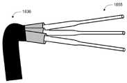
도 18k는 여기에서 설명된 다양한 양상들에 따른 안테나들로서 사용을 위해 번들링된 송신 미디어로부터 노출된 스터브들의 예시적인, 비-제한적 실시예를 예시한 블록도.
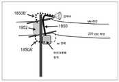
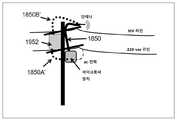
도 19a 및 도 19b는 전신주들에 의해 지지된 전력 라인들 상에서 유도 전자기파들을 유발하기 위해 사용된 도 18a의 송신 매체의 예시적인, 비-제한적 실시예들을 예시한 블록도들.
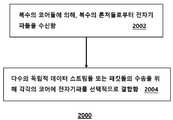
도 20은 방법의 예시적인, 비-제한적 실시예의 흐름도.
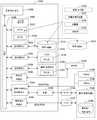
도 21은 여기에서 설명된 다양한 양상들에 따른 컴퓨팅 환경의 예시적인, 비-제한적 실시예의 블록도.
도 22는 여기에서 설명된 다양한 양상들에 따른 이동 네트워크 플랫폼의 예시적인, 비-제한적 실시예의 블록도.
도 23은 여기에서 설명된 다양한 양상들에 따른 통신 디바이스의 예시적인, 비-제한적 실시예의 블록도.1 is a block diagram illustrating an exemplary non-limiting embodiment of an inductive-wave communication system in accordance with various aspects described herein.
2 is a block diagram illustrating an example, non-limiting embodiment of a transmitting device in accordance with various aspects described herein.
3 is a graphic diagram illustrating an exemplary, non-limiting embodiment of an electromagnetic field distribution according to various aspects described herein.
4 is a graphic diagram illustrating an exemplary, non-limiting embodiment of an electromagnetic field distribution according to various aspects described herein.
5A is a graphical diagram illustrating an example, non-limiting embodiment of a frequency response in accordance with various aspects described herein.
Figure 5B is a graphic diagram illustrating exemplary, non-limiting embodiments of a longitudinal section of an insulated wire depicting fields of inductive electromagnetic waves at various operating frequencies in accordance with various aspects described herein.
6 is a graphical diagram illustrating an exemplary, non-limiting embodiment of an electromagnetic field distribution according to various aspects described herein.
7 is a block diagram illustrating an exemplary, non-limiting embodiment of an arc coupler according to various aspects described herein.
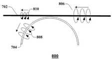
8 is a block diagram illustrating an example, non-limiting embodiment of an arc coupler according to various aspects described herein.
9A is a block diagram illustrating an example, non-limiting embodiment of a stub coupler in accordance with various aspects described herein.
9B is a diagram illustrating an example, non-limiting embodiment of an electromagnetic distribution according to various aspects described herein.
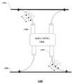
10A and 10B are block diagrams illustrating exemplary, non-limiting embodiments of couplers and transceivers in accordance with various aspects described herein.
11 is a block diagram illustrating an example, non-limiting embodiment of a dual stub coupler in accordance with various aspects described herein.
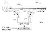
12 is a block diagram illustrating an exemplary, non-limiting embodiment of a repeater system in accordance with various aspects described herein.
13 is a block diagram illustrating an exemplary, non-limiting embodiment of a bi-directional repeater in accordance with various aspects described herein.
14 is a block diagram illustrating an example, non-limiting embodiment of a waveguide system according to various aspects described herein.
15 is a block diagram illustrating an example, non-limiting embodiment of an inductive-wave communication system in accordance with various aspects described herein.
16A and 16B are block diagrams illustrating an example, non-limiting embodiment of a system for managing a power grid communication system in accordance with various aspects described herein.
17A is a flow diagram of an exemplary, non-limiting embodiment of a method for detecting and mitigating disturbances in communication networks of the systems of Figs. 16A and 16B;
17B is a flow diagram of an exemplary, non-limiting embodiment of a method for detecting and mitigating disturbances occurring in the communication network of the system of Figs. 16A and 16B;
18A, 18B and 18C are block diagrams illustrating an exemplary, non-limiting embodiment of a transmission medium for propagating inductive electromagnetic waves.
18D is a block diagram illustrating an example, non-limiting embodiment of a bundled transmission medium in accordance with various aspects described herein.
18E illustrates an exemplary, non-limiting embodiment of a plot depicting the cross-talk between the first and second transmission media of the bundled transmission medium of FIG. 18D according to the various aspects described herein. Block diagram.
18F is a block diagram illustrating an exemplary, non-limiting embodiment of a transmission medium bundled to mitigate cross-talk according to various aspects described herein.
Figures 18g and 18h are block diagrams illustrating exemplary, non-limiting embodiments of connector configurations that can be used with the transmission medium of Figure 18a, Figure 18b, or Figure 18c.
Figure 18i is a block diagram illustrating exemplary, non-limiting embodiments of transmission media for propagating inductive electromagnetic waves.
18J is a block diagram illustrating exemplary, non-limiting embodiments of transmission media bundled to mitigate cross-talk in accordance with various aspects set forth herein.
18k is a block diagram illustrating an exemplary, non-limiting embodiment of exposed stubs from transmission media bundled for use as antennas in accordance with various aspects described herein.
Figs. 19A and 19B are block diagrams illustrating exemplary, non-limiting embodiments of the transmission medium of Fig. 18A used to induce inductive electromagnetic waves on power lines supported by poles; Fig.
20 is a flow diagram of an exemplary, non-limiting embodiment of a method.
Figure 21 is a block diagram of an exemplary, non-limiting embodiment of a computing environment in accordance with various aspects set forth herein.
22 is a block diagram of an exemplary, non-limiting embodiment of a mobile network platform in accordance with various aspects described herein.
23 is a block diagram of an exemplary, non-limiting embodiment of a communication device in accordance with various aspects described herein.
하나 이상의 실시예들이 이제 도면들을 참조하여 설명되며, 유사한 참조 숫자들은 전체에 걸쳐 유사한 요소들을 나타내기 위해 사용된다. 다음의 설명에서, 설명의 목적들을 위해, 다수의 세부사항들이 다양한 실시예들의 철저한 이해를 제공하기 위해 제시된다. 그러나, 다양한 실시예들은 이들 세부사항들 없이(및 임의의 특정한 네트워킹된 환경 또는 표준에 적용하지 않고) 실시될 수 있다는 것이 명백하다.One or more embodiments are now described with reference to the drawings, wherein like reference numerals are used to refer to like elements throughout. In the following description, for purposes of explanation, numerous specific details are set forth in order to provide a thorough understanding of various embodiments. However, it is evident that various embodiments may be practiced without these details (and without applying to any particular networked environment or standard).
실시예에서, 유도 파 통신 시스템은 유도 전자기파들을 통해 데이터 또는 다른 시그널링과 같은 통신 신호들을 전송하고 수신하기 위해 제공된다. 유도 전자기파들은, 예를 들면, 송신 매체에 바인딩되거나 또는 그것에 의해 유도되는 표면파들 또는 다른 전자기파들을 포함한다. 다양한 송신 미디어는 예시적인 실시예들로부터 벗어나지 않고 유도 파 통신들과 함께 이용될 수 있다는 것이 이해될 것이다. 이러한 송신 미디어의 예들은 단독으로 또는 하나 이상의 조합들로, 다음 중 하나 이상을 포함할 수 있다: 절연되는지 여부에 관계없이, 및 단일-가닥 또는 다중-가닥인지에 관계없이, 와이어들; 와이어 번들들, 케이블들, 로드(rod)들, 레일들, 파이프들을 포함한 다른 형태들 또는 구성들의 도체들; 유전체 파이프들, 로드들, 레일들, 또는 다른 유전체 부재들과 같은 부도체들; 도체들 및 유전체 재료들의 조합들; 또는 다른 유도 파 송신 미디어.In an embodiment, a guided wave communication system is provided for transmitting and receiving communication signals, such as data or other signaling, via inductive electromagnetic waves. Inductive electromagnetic waves include, for example, surface waves or other electromagnetic waves that are bound to or introduced by a transmission medium. It will be appreciated that the various transmission media may be used with inductive wave communications without departing from the exemplary embodiments. Examples of such transmission media, either alone or in combinations of one or more, may include one or more of the following: irrespective of whether they are insulated and whether they are single-stranded or multi-stranded; Conductors of other types or configurations, including wire bundles, cables, rods, rails, and pipes; Non-conductors such as dielectric pipes, rods, rails, or other dielectric members; Combinations of conductors and dielectric materials; Or other guided wave transmission media.
송신 매체 상에서의 유도 전자기파들의 유발은 주입되거나 또는 그 외 전기 회로의 부분으로서 송신 매체를 통해 송신되는 임의의 전기 전위, 전하 또는 전류에 독립적일 수 있다. 예를 들면, 송신 매체가 와이어인 경우에, 와이어에서의 작은 전류가 와이어를 따라 유도 파들의 전파에 응답하여 형성될 수 있는 동안, 이것은 와이어 표면을 따르는 전자기파의 전파에 기인할 수 있으며, 전기 회로의 부분으로서 와이어로 주입되는 전기 전위, 전하 또는 전류에 응답하여 형성되지 않는다는 것이 이해될 것이다. 와이어 상에서 이동하는 전자기파들은 그러므로 와이어 표면을 따라 전파하도록 회로에 요구하지 않는다. 와이어는 그러므로 회로의 부분이 아닌 단일 와이어 송신 라인이다. 또한, 몇몇 실시예들에서, 와이어는 필요하지 않으며, 전자기파들은 와이어가 아닌 단일 라인 송신 매체를 따라 전파할 수 있다.The induction of inductive electromagnetic waves on the transmission medium may be independent of any electrical potential, charge or current that is injected or transmitted through the transmission medium as part of other electrical circuitry. For example, when the transmission medium is a wire, it may be due to the propagation of electromagnetic waves along the wire surface, while a small current in the wire can be formed in response to the propagation of the guide waves along the wire, Charge, or current injected into the wire as part of the < / RTI > The electromagnetic waves traveling on the wire therefore do not require the circuit to propagate along the wire surface. The wire is therefore a single wire transmission line rather than a part of the circuit. Also, in some embodiments, no wires are needed, and electromagnetic waves can propagate along a single line transmission medium rather than a wire.
보다 일반적으로, 본 개시에 의해 설명된 바와 같이 "유도 전자기파들" 또는 "유도 파들"은 물리적 오브젝트에 적어도 부분적으로 바인딩되거나 또는 그것에 의해 유도되도록 및 물리 오브젝트의 송신 경로를 따라 전파되도록 송신 매체(예로서, 나선 또는 다른 도체, 유전체, 절연 와이어, 도관 또는 다른 중공 요소, 유전체 또는 절연체 또는 다른 와이어 번들에 의해 코팅되고, 커버되거나 또는, 둘러싸여진 절연 와이어들의 번들, 또는 또 다른 형태의 고체, 액체, 또는 그 외 비-기체 송신 매체)의 적어도 부분인 물리 오브젝트의 존재에 의해 영향을 받는다. 이러한 물리 오브젝트는 송신 매체의 인터페이스(예로서, 외부 표면, 내부 표면, 외부 및 내부 표면들 사이에서의 내부 부분 또는 송신 매체의 요소들 사이에서의 다른 경계)에 의해, 유도 전자기파들의 전파를 유도하는 송신 매체의 적어도 부분으로서 동작할 수 있으며, 이것은 결국 전송 디바이스로부터 수신 디바이스로의 송신 경로를 따라 에너지, 데이터 및/또는 다른 신호들을 운반할 수 있다.More generally, "inductive electromagnetic waves" or "induced waves ", as described by this disclosure, are intended to be at least partially bound to or derived from a physical object and to be propagated along the transmission path of the physical object A bundle of insulating wires that are coated, covered, or surrounded by a spiral or other conductor, dielectric, insulating wire, conduit or other hollow element, dielectric or insulator or other wire bundle, or another type of solid, Or other non-gaseous transmission medium) that is at least part of the physical object. These physical objects can be used to guide the propagation of inductive electromagnetic waves by the interface of the transmission medium (e.g., the outer surface, the inner surface, the inner portion between the outer and inner surfaces, or other boundaries between elements of the transmission medium) May act as at least a portion of the transmission medium, which may eventually carry energy, data and / or other signals along the transmission path from the transmitting device to the receiving device.
비유도 전자기파들에 의해 이동된 거리의 제곱만큼 반대로 강도가 감소하는 비유도(또는 무한한) 전자기파들과 같은 무선 신호들의 자유 공간 전파와 달리, 유도 전자기파들은 비유도 전자기파들에 의해 경험된 것보다 적은 단위 거리당 규모에서의 손실을 갖고 송신 매체를 따라 전파될 수 있다.Unlike free-space propagation of radio signals, such as non-inductive (or infinite) electromagnetic waves whose intensity decreases inversely by the square of the distance traveled by the non-inductive electromagnetic waves, the inductive electromagnetic waves are less than experienced by non-inductive electromagnetic waves And can propagate along the transmission medium with loss at the scale per unit distance.
전기 신호들과 달리, 유도 전자기파들은 전송 디바이스 및 수신 디바이스 사이에서의 별개의 전기적 리턴 경로를 요구하지 않고 전송 디바이스로부터 수신 디바이스로 전파될 수 있다. 결과로서, 유도 전자기파들은 전도성 구성요소들(예로서, 유전체 스트립) 없이 송신 매체를 따라, 또는 단지 단일 도체(예로서, 단일 나선 또는 절연 와이어)를 갖는 송신 매체를 통해 전송 디바이스로부터 수신 디바이스로 전파될 수 있다. 송신 매체가 하나 이상의 전도성 구성요소들을 포함하며 송신 매체를 따라 전파되는 유도 전자기파들이 유도 전자기파들의 방향으로 하나 이상의 전도성 구성요소들에서 흐르는 전류를 발생시킬지라도, 이러한 유도 전자기파들은 전송 디바이스 및 수신 디바이스 사이에서의 전기적 리턴 경로 상에서 반대 전류들의 흐름을 요구하지 않고 전송 디바이스로부터 수신 디바이스로 송신 매체를 따라 전파될 수 있다.Unlike electrical signals, inductive electromagnetic waves can propagate from a transmitting device to a receiving device without requiring a separate electrical return path between the transmitting device and the receiving device. As a result, the inductive electromagnetic waves propagate along the transmission medium without conducting components (e.g., dielectric strips), or from the transmitting device to the receiving device via a transmission medium having only a single conductor (e.g., a single helix or insulating wire) . Although the transmission medium includes one or more conductive elements and the inductive electromagnetic waves propagating along the transmission medium generate a current flowing in the one or more conductive elements in the direction of the inductive electromagnetic waves, May be propagated along the transmission medium from the transmitting device to the receiving device without requiring a flow of counter currents on the electrical return path of the receiving device.
비-제한적인 예시에서, 전도성 미디어에 의해 전송 및 수신 디바이스들 사이에서 전기 신호들을 송신 및 수신하는 전기 시스템들을 고려하자. 이러한 시스템들은 일반적으로 전기적으로 별개의 순방향 및 리턴 경로들에 의존한다. 예를 들면, 절연체에 의해 분리되는 접지 차폐부 및 중심 도체를 가진 동축 케이블을 고려하자. 통상적으로, 전기 시스템에서 전송(또는 수신) 디바이스의 제 1 단자는 중심 도체에 연결될 수 있으며, 전송(또는 수신) 디바이스의 제 2 단자는 접지 차폐부에 연결될 수 있다. 전송 디바이스가 제 1 단자를 통해 중심 도체에 전기 신호를 주입하면, 전기 신호는 중심 도체를 따라 전파되어 중심 도체에 순방향 전류들을 야기할 것이며, 접지 차폐부에서 전류들을 리턴시킬 것이다. 동일한 조건들이 2 단자 수신 디바이스를 위해 이용한다.In a non-limiting example, consider electrical systems that transmit and receive electrical signals between transmitting and receiving devices by a conductive medium. These systems generally depend on electrically distinct forward and return paths. For example, consider a coaxial cable with a ground shield and a center conductor separated by an insulator. Typically, in an electrical system, a first terminal of a transmitting (or receiving) device may be coupled to a center conductor, and a second terminal of the transmitting (or receiving) device may be coupled to a ground shield. When the transmitting device injects an electrical signal to the center conductor through the first terminal, the electrical signal will propagate along the center conductor to cause forward currents to the center conductor and return currents at the ground shield. The same conditions are used for the two-terminal receiving device.
반대로, 전기적 리턴 경로 없이 유도 전자기파들을 송신 및 수신하기 위한 송신 매체(다른 것들 중에서 동축 케이블을 포함한)의 상이한 실시예들을 이용할 수 있는, 본 개시에서 설명된 바와 같은 유도 파 통신 시스템을 고려하자. 일 실시예에서, 예를 들면, 본 개시의 유도 파 통신 시스템은 동축 케이블의 외부 표면을 따라 전파되는 유도 전자기파들을 유발하도록 구성될 수 있다. 유도 전자기파들은 접지 차폐부 상에서 순방향 전류들을 야기할 것이지만, 유도 전자기파들은 유도 전자기파들이 동축 케이블의 외부 표면을 따라 전파될 수 있게 하도록 리턴 전류들에 요구하지 않는다. 유도 전자기파들의 송신 및 수신을 위한 유도 파 통신 시스템에 의해 사용된 다른 송신 미디어에서도 마찬가지일 수 있다. 예를 들면, 나선, 또는 절연 와이어의 외부 표면상에서 유도 파 통신 시스템에 의해 유발된 유도 전자기파들은 전기적 리턴 경로 없이 나선 또는 절연된 나선을 따라 전파될 수 있다.Conversely, consider an inductive wave communication system as described in this disclosure, which can utilize different embodiments of the transmission medium (including coaxial cable among others) for transmitting and receiving inductive electromagnetic waves without an electrical return path. In one embodiment, for example, the guided wave communication system of the present disclosure can be configured to induce inductive electromagnetic waves propagating along the outer surface of the coaxial cable. Inductive electromagnetic waves will cause forward currents on the ground shield, but inductive electromagnetic waves do not require return currents to allow inductive electromagnetic waves to propagate along the outer surface of the coaxial cable. And may be the same in other transmission media used by the inductive wave communication system for transmitting and receiving inductive electromagnetic waves. For example, inducted electromagnetic waves induced by a guided wave communication system on the outer surface of a spiral, or insulating wire, can propagate along a spiral or insulated spiral without an electrical return path.
결과적으로, 전송 디바이스에 의해 주입된 전기 신호들의 전파를 가능하게 하기 위해 별개의 도체들 상에서 순방향 및 역방향 전류들을 운반하기 위한 둘 이상의 도체들을 요구하는 전기 시스템들은 송신 매체의 인터페이스를 따라 유도 전자기파들의 전파를 가능하게 하기 위해 전기적 리턴 경로의 요구 없이 송신 매체의 인터페이스상에서 유도 전자기파들을 유발하는 유도 파 시스템들과는 완전히 다르다.As a result, electrical systems that require two or more conductors to carry forward and reverse currents on separate conductors to enable propagation of electrical signals injected by the transmitting device can be used along with the propagation of inductive electromagnetic waves Which induces induced electromagnetic waves on the interface of the transmission medium without the need for an electrical return path.
본 개시에서 설명된 바와 같이 유도 전자기파들은 송신 매체에 바인딩되거나 또는 그것에 의해 유도되도록 및 송신 매체의 외부 표면상에서 또는 그것을 따라 사소하지 않은 거리들을 전파하도록 주로 또는 실질적으로 송신 매체의 밖에 있는 전자기장 구조를 가질 수 있다는 것이 추가로 주의된다. 다른 실시예들에서, 유도 전자기파들은 송신 매체에 바인딩되거나 또는 그것에 의해 유도되도록 및 송신 매체 내에서 사소하지 않은 거리들을 전파하도록 주로 또는 실질적으로 송신 매체 안에 있는 전자기장 구조를 가질 수 있다. 다른 실시예들에서, 유도 전자기파들은 송신 매체에 바인딩되거나 또는 그것에 의해 유도되도록 및 송신 매체를 따라 사소하지 않은 거리들을 전파하도록 부분적으로 송신 매체의 안쪽에 및 부분적으로 그것의 밖에 있는 전자기장 구조를 가질 수 있다. 실시예에서, 원하는 전자 장 구조는 원하는 송신 거리, 송신 매체 자체의 특성들, 및 송신 매체의 밖에서의 환경 조건들/특성들(예로서, 비, 안개, 대기 조건들의 존재 등)을 포함하여, 다양한 인자들에 기초하여 달라질 수 있다.As described in this disclosure, inductive electromagnetic waves have an electromagnetic field structure that is primarily or substantially outside the transmission medium so as to be bound to or induced by the transmission medium and to propagate distances along the outer surface of the transmission medium or along the non- It is further noted that it can be. In other embodiments, the inductive electromagnetic waves may have an electromagnetic field structure that is primarily or substantially in the transmission medium so as to be bound to or induced by the transmission medium and to propagate non-trivial distances within the transmission medium. In other embodiments, the inductive electromagnetic waves may have an electromagnetic field structure that is partially bounded within or partially outside the transmission medium so as to be bound to or induced by the transmission medium and propagate non-trivial distances along the transmission medium have. In an embodiment, the desired electromagnetic field structure includes the desired transmission distance, the characteristics of the transmission medium itself, and the environmental conditions / characteristics (e.g., non-fog, presence of atmospheric conditions, etc.) And may vary based on various factors.
여기에서 설명된 다양한 실시예들은, 밀리미터-파 주파수들(예로서, 30 내지 300GHz)에서 송신 매체로 및 그로부터 유도 전자기파들을 론칭하고 및/또는 추출하기 위한 "도파관 결합 디바이스들, "도파관 커플러들"로서 또는 보다 간단히 "커플러들", "결합 디바이스들" 또는 "론처들"로서 불리울 수 있는, 결합 디바이스들에 관한 것이며, 여기에서 파장은 와이어의 둘레 또는 다른 단면 치수, 또는 300MHz 내지 30GHz와 같은 하위 마이크로파 주파수들과 같은 결합 디바이스 및/또는 송신 매체의 하나 이상의 치수들에 비교하여 작을 수 있다. 송신들은, 유전체 재료의 스트립, 아크 또는 다른 길이; 혼(horn), 단극, 로드, 슬롯 또는 다른 안테나; 안테나들의 어레이; 자기 공진 공동, 또는 다른 공진 커플러; 코일, 스트립 라인, 도파관 또는 다른 결합 디바이스와 같은, 결합 디바이스에 의해 유도된 파동들로서 전파하기 위해 발생될 수 있다. 동작 시, 결합 디바이스는 송신기 또는 송신 매체로부터 전자기파를 수신한다. 전자기파의 전자기장 구조는 결합 디바이스의 안쪽에서, 결합 디바이스의 밖에서 또는 그것의 몇몇 조합으로 운반될 수 있다. 결합 디바이스가 송신 매체에 아주 근접할 때, 전자기파의 적어도 일 부분은 송신 매체에 결합하거나 또는 그것에 바인딩되며, 유도 전자기파들로서 계속해서 전파된다. 상호 방식으로, 결합 디바이스는 송신 매체로부터 유도 파들을 추출하며 이들 전자기파들을 수신기로 전달할 수 있다.The various embodiments described herein include "waveguide coupling devices," "waveguide couplers" for launching and / or extracting electromagnetic waves to and from a transmission medium at millimeter-wave frequencies (eg, 30 to 300 GHz) Or more simply as "couplers," " coupling devices, "or" launchers ", wherein the wavelength is a wavelength or other cross-sectional dimension of the wire, or such as 300 MHz to 30 GHz The transmission may be small compared to one or more of the dimensions of the coupling device and / or transmission medium, such as lower microwave frequencies. Transmissions may be in the form of strips, arcs or other lengths of dielectric material; horns, monopoles, Such as a coil, stripline, waveguide or other coupling device, such as an antenna, an array of antennas, a self-resonating cavity, or other resonant coupler, The electromagnetic field structure of the electromagnetic wave may be generated from the inside of the coupling device, outside of the coupling device, or from the outside of the coupling device. At least a portion of the electromagnetic waves are coupled to or coupled to the transmission medium and continue to propagate as inductive electromagnetic waves when the coupling device is very close to the transmission medium. Extracts the guided waves from the transmission medium, and transmits these electromagnetic waves to the receiver.
예시적인 실시예에 따르면, 표면파는 와이어의 외부 또는 바깥쪽 표면과 같은, 송신 매체의 표면, 또는 상이한 속성들(예로서, 유전체 속성들)을 가진 또 다른 유형의 매체에 인접하거나 또는 그것에 노출되는 와이어의 또 다른 표면에 의해 유도되는 유도 파의 유형이다. 실제로, 예시적인 실시예에서, 표면파를 유도하는 와이어의 표면은 두 개의 상이한 유형들의 미디어 사이에서의 전이 표면을 나타낼 수 있다. 예를 들면, 아무것도 안 덮인 또는 절연되지 않은 와이어의 경우에, 와이어의 표면은 공기 또는 자유 공간에 노출되는 아무것도 안 덮인 또는 절연되지 않은 와이어의 바깥쪽 또는 외부 전도성 표면일 수 있다. 또 다른 예로서, 절연 와이어의 경우에, 와이어의 표면은, 절연체, 공기, 및/또는 도체의 속성들(예로서, 유전체 속성들)에서의 상대적 차이들에 의존하여 및 유도 파의 주파수 및 전파 모드 또는 모드들에 추가로 의존하여, 와이어의 절연체 부분을 충족시키는 와이어의 전도성 부분일 수 있거나, 또는 그 외 공기 또는 자유 공간에 노출되는 와이어의 절연체 표면일 수 있거나, 또는 그 외 와이어의 절연체 표면 및 와이어의 절연체 부분을 충족시키는 와이어의 전도성 부분 사이에서의 임의의 재료 영역일 수 있다.According to an exemplary embodiment, a surface wave is applied to a surface of a transmission medium, such as an outer or outer surface of a wire, or to a surface of a transmission medium adjacent to or exposed to another type of medium having different properties (e.g., dielectric properties) It is a type of guided wave induced by another surface of the wire. Indeed, in an exemplary embodiment, the surface of the wire leading to the surface wave can exhibit a transition surface between two different types of media. For example, in the case of a wire that is not covered or insulated, the surface of the wire may be the outside or outside conductive surface of the wire that is not covered or insulated from anything exposed to air or free space. As another example, in the case of an insulated wire, the surface of the wire may depend on the relative differences in the properties of the insulator, air, and / or conductor (e.g., dielectric properties) May be a conductive portion of the wire that meets the insulator portion of the wire or may be an insulator surface of the wire exposed to the other air or free space or may be an insulator surface of the other wire And any conductive material portion of the wire that meets the insulator portion of the wire.
예시적인 실시예에 따르면, 유도 파와 함께 사용된 와이어 또는 다른 송신 매체("에 대한" 용어는 원형 또는 대체로 원형 장 분포, 대칭적 전자기장 분포(예로서, 전기장, 자기장, 전자기장 등) 또는 적어도 부분적으로 와이어 또는 다른 송신 매체 주위에서의 다른 기본 모드와 같은 기본 유도 파 전파 모드들을 포함할 수 있다. 또한, 유도 파가 와이어 또는 다른 송신 매체"에 대해" 전파될 때, 그것은 기본 파 전파 모드들(예로서, 영차 모드들)뿐만 아니라, 부가적으로 또는 대안적으로 와이어 또는 다른 송신 매체 주위에서 비-원형 장 분포들을 갖는 고차 유도 파 모드들(예로서, 1차 모드들, 2차 모드들 등), 비대칭 모드들 및/또는 다른 유도(예로서, 표면) 파들과 같은 비-기본 파 전파 모드들을 또한 포함하는 유도 파 전파 모드에 따라 그렇게 할 수 있다. 여기에서 사용된 바와 같이, 용어("유도 파 모드")는 유도 파 통신 시스템의 송신 매체, 결합 디바이스 또는 다른 시스템 구성요소의 유도 파 전파 모드를 나타낸다.According to an exemplary embodiment, the term "on " used in connection with a guided wave may refer to a circular or generally circular field distribution, a symmetrical electromagnetic field distribution (e.g., an electric field, a magnetic field, And other fundamental modes around the wire or other transmission medium. Also, when a guided wave is propagated "about " to a wire or other transmission medium, (E.g., primary modes, secondary modes, etc.) having non-circular field distributions around the wire or other transmission medium, as well as, or alternatively, , Asymmetric modes, and / or other non-fundamental wave propagation modes, such as induction (e.g., surface) waves. As used herein, the term ("guided-wave mode") refers to the guided wave propagation mode of a transmission medium, coupling device or other system component of a guided wave communication system.
예를 들면, 이러한 비-원형 장 분포들은 비교적 더 높은 전계 강도에 의해 특성화된 하나 이상의 축방향 로브들 및/또는 비교적 저-전계 강도, 영-전계 강도 또는 실질적으로 영-전계 강도에 의해 특성화된 하나 이상의 널들 또는 널 영역들을 갖고 일방적이거나 또는 다각적일 수 있다. 뿐만 아니라, 장 분포는 그 외, 예시적인 실시예에 따라, 와이어 주위에서의 하나 이상의 각도 영역들이 방위각 배향의 하나 이상의 다른 각도 영역들보다 높은 전기 또는 자기 장 강도(또는 그것의 조합)를 갖도록 와이어 주위에서 방위각 배향의 함수로서 달라질 수 있다. 유도 파 고차 모드들 또는 비대칭 모드들의 상대적 배향들 또는 위치들은 유도 파가 와이어를 따라 이동함에 따라 달라질 수 있다는 것이 이해될 것이다.For example, these non-circular field distributions can be characterized by one or more axial lobes characterized by a relatively higher field strength and / or a combination of one or more axial lobes characterized by relatively low-field strength, zero-field strength or substantially zero- And may be one-sided or multi-layered with one or more nulls or null regions. In addition, the field distribution may also be determined such that, according to an exemplary embodiment, one or more angular regions around the wire have a higher electrical or magnetic field strength (or a combination thereof) than one or more other angular regions of azimuthal orientation. Can be varied as a function of azimuthal orientation in the surroundings. It will be appreciated that the relative orientations or locations of the guided wave higher order modes or asymmetric modes may vary as the guided wave moves along the wire.
여기에서 사용된 바와 같이, 용어("밀리미터-파")는 30GHz 내지 300GHz의 "밀리미터-파 주파수 대역" 내에 있는 전자기파들/신호들을 나타낼 수 있다. 용어("마이크로파")는 300MHz 내지 300GHz의 "마이크로파 주파수 대역" 내에 있는 전자기파들/신호들을 나타낼 수 있다. 용어("라디오 주파수" 또는 "RF")는 10kHz 내지 1THz의 "라디오 주파수 대역" 내에 있는 전자기파들/신호들을 나타낼 수 있다. 본 개시에서 설명된 바와 같이 무선 신호들, 전기 신호들, 및 유도 전자기파들은 예를 들면, 밀리미터-파 및/또는 마이크로파 주파수 대역들 내, 이상 또는 이하에 있는 주파수들에서와 같은, 임의의 바람직한 주파수 범위에서 동작하도록 구성될 수 있다는 것이 이해된다. 특히, 결합 디바이스 또는 송신 매체가 전도성 요소를 포함할 때, 결합 디바이스에 의해 운반되며 및/또는 송신 매체를 따라 전파되는 유도 전자기파들의 주파수는 전도성 요소에서 전자들의 평균 충돌 주파수 미만일 수 있다. 뿐만 아니라, 결합 디바이스에 의해 운반되며 및/또는 송신 매체를 따라 전파되는 유도 전자기파들의 주파수는 비-광학 주파수, 예로서 1THz에서 시작하는 광학 주파수들의 범위 미만의 라디오 주파수일 수 있다.As used herein, the term ("millimeter-wave") may refer to electromagnetic waves / signals within a "millimeter-wave frequency band" of 30 GHz to 300 GHz. The term ("microwave") may refer to electromagnetic waves / signals within a "microwave frequency band" of 300 MHz to 300 GHz. The term ("radio frequency" or "RF") may refer to electromagnetic waves / signals within a "radio frequency band" of 10 kHz to 1 THz. The wireless signals, electrical signals, and inductive electromagnetic waves, as described in this disclosure, may be transmitted at any desired frequency, for example, at millimeter-wave and / or microwave frequency bands, It is to be understood that the invention is not limited to these embodiments. In particular, when the coupling device or the transmission medium comprises a conductive element, the frequency of the inductive electromagnetic waves carried by the coupling device and / or propagating along the transmission medium may be less than the average impact frequency of the electrons in the conductive element. In addition, the frequency of the inductive electromagnetic waves carried by the coupling device and / or propagating along the transmission medium may be a non-optical frequency, for example a radio frequency below the range of optical frequencies starting at 1 THz.
여기에서 사용된 바와 같이, 용어("안테나")는 무선 신호들을 송신/방사하거나 또는 수신하기 위해 송신 또는 수신 시스템의 부분인 디바이스를 나타낸다.As used herein, the term ("antenna") refers to a device that is part of a transmitting or receiving system for transmitting / radiating or receiving wireless signals.
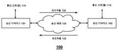
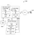
이제 도 1을 참조하면, 유도 파 통신 시스템의 예시적인, 비-제한적 실시예를 예시한 블록도(100)가 도시된다. 동작 시, 송신 디바이스(101)는 송신 매체(125)를 통해 데이터를 송신 디바이스(102)로 운반하기 위해 데이터를 포함하며 유도 파들(120)을 발생시키는 통신 네트워크 또는 다른 통신 디바이스로부터 하나 이상의 통신 신호들(110)을 수신한다. 송신 디바이스(102)는 유도 파들(120)을 수신하며 그것들을 통신 네트워크 또는 다른 통신 디바이스로의 송신을 위한 데이터를 포함하는 통신 신호들(112)로 변환한다. 유도 파들(120)은 위상 시프트 키잉, 주파수 시프트 키잉, 직교 진폭 변조, 진폭 변조, 직교 주파수 분할 다중화와 같은 다중-캐리어 변조와 같은 변조 기술을 통해 및 주파수 분할 다중화, 시간 분할 다중화, 코드 분할 다중화, 상이한 파 전파 모드들을 통한 다중화와 같은 다수의 액세스 기술들을 통해 및 다른 변조 및 액세스 전략들을 통해 데이터를 운반하도록 변조될 수 있다.Referring now to FIG. 1, there is shown a block diagram 100 illustrating an exemplary, non-limiting embodiment of a waveguide communication system. In operation, the transmitting device 101 receives data from the communication network or other communication device that includes the data to carry the data to the transmitting device 102 via the
통신 네트워크 또는 네트워크들은 이동 데이터 네트워크, 셀룰러 음성 및 데이터 네트워크, 무선 근거리 네트워크(예로서, WiFi 또는 802.xx 네트워크), 위성 통신 네트워크, 개인 영역 네트워크 또는 다른 무선 네트워크와 같은 무선 통신 네트워크를 포함할 수 있다. 통신 네트워크 또는 네트워크들은 또한 전화 네트워크, 이더넷 네트워크, 근거리 네트워크, 인터넷과 같은 광역 네트워크, 광대역 액세스 네트워크, 케이블 네트워크, 광섬유 네트워크, 또는 다른 유선 네트워크와 같은 유선 통신 네트워크를 포함할 수 있다. 통신 디바이스들은 네트워크 에지 디바이스, 브리지 디바이스 또는 홈 게이트웨이, 셋-탑 박스, 광대역 모뎀, 전화 어댑터, 액세스 포인트, 기지국, 또는 다른 고정된 통신 디바이스, 자동차 게이트웨이 또는 자동차와 같은 이동 통신 디바이스, 랩탑 컴퓨터, 태블릿, 스마트폰, 셀룰러 전화, 또는 다른 통신 디바이스를 포함할 수 있다.The communication network or networks may include a wireless communication network, such as a mobile data network, a cellular voice and data network, a wireless local area network (e.g., a WiFi or 802.xx network), a satellite communication network, a personal area network or other wireless network have. The communication network or networks may also include wired communication networks such as a telephone network, an Ethernet network, a local area network, a wide area network such as the Internet, a broadband access network, a cable network, a fiber optic network, or other wired network. The communication devices may be a network edge device, a bridge device or a home gateway, a set-top box, a broadband modem, a telephone adapter, an access point, a base station or other fixed communication device, a mobile communication device such as a car gateway or a car, , A smart phone, a cellular telephone, or other communication device.
예시적인 실시예에서, 유도 파 통신 시스템(100)은 송신 디바이스(102)가 송신 매체(125)를 통해 다른 데이터를 송신 디바이스(101)로 운반하기 위해 다른 데이터를 포함하며 유도 파들(122)을 발생시키는 통신 네트워크 또는 디바이스로부터 하나 이상의 통신 신호들(112)을 수신하는 양-방향 방식으로 동작할 수 있다. 이러한 동작 모드에서, 송신 디바이스(101)는 유도 파들(122)을 수신하며 그것을 통신 네트워크 또는 디바이스로의 송신을 위한 다른 데이터를 포함하는 통신 신호들(110)로 변환한다. 유도 파들(122)은 위상 시프트 키잉, 주파수 시프트 키잉, 직교 진폭 변조, 진폭 변조, 직교 주파수 분할 다중화와 같은 다중-캐리어 변조와 같은 변조 기술을 통해 및 주파수 분할 다중화, 시간 분할 다중화, 코드 분할 다중화, 상이한 파 전파 모드들을 통한 다중화와 같은 다수의 액세스 기술들을 통해 및 다른 변조 및 액세스 전략들을 통해 데이터를 운반하도록 변조될 수 있다.The guided
송신 매체(125)는 절연체 또는 다른 유전체 커버, 코팅 또는 다른 유전체 재료와 같은 유전체 재료에 의해 둘러싸여진 적어도 하나의 내부 부분을 가진 케이블을 포함할 수 있으며, 상기 유전체 재료는 외부 표면 및 대응하는 둘레를 갖는다. 예시적인 실시예에서, 송신 매체(125)는 전자기파의 송신을 유도하기 위해 단일-와이어 송신으로서 동작한다. 송신 매체(125)가 단일 와이어 송신 시스템으로서 구현될 때, 그것은 와이어를 포함할 수 있다. 와이어는 절연되거나 또는 절연되지 않으며, 단일-가닥 또는 다중-가닥(예로서, 편조)일 수 있다. 다른 실시예들에서, 송신 매체(125)는 와이어 번들들, 케이블들, 로드들, 레일들, 파이프들을 포함한 다른 형태들 또는 구성들의 도체들을 포함할 수 있다. 또한, 송신 매체(125)는 유전체 파이프들, 로드들, 레일들, 또는 다른 유전체 부재들과 같은 부도체들; 도체들 및 유전체 재료들의 조합들을 포함할 수 있으며, 도체들은 유전체 재료들 또는 다른 유도 파 송신 미디어가 없다. 송신 매체(125)는 그 외 이전에 논의된 송신 미디 중 임의의 것을 포함할 수 있다는 것이 주의되어야 한다.
뿐만 아니라, 이전에 논의된 바와 같이, 유도 파들(120 및 122)은 자유 공간/공기를 통한 라디오 송신들 또는 전기 회로를 경유하여 와이어의 도체를 통해 전기 전력 또는 신호들의 종래의 전파와 대조될 수 있다. 유도 파들(120 및 122)의 전파 외에, 송신 매체(125)는 선택적으로 하나 이상의 전기 회로들의 부분으로서 종래의 방식으로 전기 전력 또는 다른 통신 신호들을 전파하는 하나 이상의 와이어들을 포함할 수 있다.In addition, as discussed previously, the guide waves 120 and 122 can be contrasted with the conventional propagation of electrical power or signals through the conductors of the wire via radio transmissions or electrical circuits via free space / air have. In addition to the propagation of the induction waves 120 and 122, the
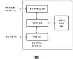
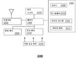
이제 도 2를 참조하면, 송신 디바이스의 예시적인, 비-제한적 실시예를 예시한 블록도(200)가 도시된다. 송신 디바이스(101 또는 102)는 통신 인터페이스(I/F)(205), 트랜시버(210) 및 커플러(220)를 포함한다.Referring now to FIG. 2, a block diagram 200 illustrating an exemplary, non-limiting embodiment of a transmitting device is shown. The transmitting device 101 or 102 includes a communication interface (I / F) 205, a transceiver 210 and a coupler 220.
동작의 예에서, 통신 인터페이스(205)는 데이터를 포함하는 통신 신호(110 또는 112)를 수신한다. 다양한 실시예들에서, 통신 인터페이스(205)는 LTE 또는 다른 셀룰러 음성 및 데이터 프로토콜, WiFi 또는 802.11 프로토콜, WIMAX 프로토콜, 초광대역 프로토콜, 블루투스 프로토콜, 지그비(Zigbee) 프로토콜, 직접 방송 위성(DBS) 또는 다른 위성 통신 프로토콜 또는 다른 무선 프로토콜과 같은 무선 표준 프로토콜에 따라 무선 통신 신호를 수신하기 위한 무선 인터페이스를 포함할 수 있다. 또한 또는 대안으로, 통신 인터페이스(205)는 이더넷 프로토콜, 범용 직렬 버스(USB) 프로토콜, 케이블 데이터 서비스 인터페이스 규격(DOCSIS) 프로토콜, 디지털 가입자 회선(DSL) 프로토콜, 파이어와이어(IEEE 1394) 프로토콜, 또는 다른 유선 프로토콜에 따라 동작하는 유선 인터페이스를 포함한다. 표준-기반 프로토콜들 외에, 통신 인터페이스(205)는 다른 유선 또는 무선 프로토콜과 함께 동작할 수 있다. 또한, 통신 인터페이스(205)는 선택적으로 MAC 프로토콜, 수송 프로토콜, 애플리케이션 프로토콜 등을 포함한 다수의 프로토콜 계층들을 포함하는 프로토콜 스택과 함께 동작할 수 있다.In an example of operation, the communication interface 205 receives a communication signal 110 or 112 containing data. In various embodiments, the communications interface 205 may be implemented using any of a variety of communications technologies, including but not limited to, LTE or other cellular voice and data protocols, WiFi or 802.11 protocols, WIMAX protocols, ultra-wideband protocols, Bluetooth protocols, Zigbee protocols, A wireless interface for receiving a wireless communication signal in accordance with a wireless standard protocol such as a satellite communication protocol or other wireless protocol. The communication interface 205 may also or alternatively comprise one or more of the following protocols: Ethernet protocol, Universal Serial Bus (USB) protocol, Cable Data Service Interface Specification (DOCSIS) protocol, Digital Subscriber Line (DSL) protocol, FireWire And a wired interface that operates according to a wired protocol. In addition to the standards-based protocols, the communication interface 205 may operate with other wired or wireless protocols. In addition, the communication interface 205 may optionally operate in conjunction with a protocol stack including a plurality of protocol layers including a MAC protocol, a transport protocol, an application protocol, and the like.
동작의 예에서, 트랜시버(210)는 데이터를 운반하기 위해 통신 신호(110 또는 112)에 기초하여 전자기파를 발생시킨다. 전자기파는 적어도 하나의 캐리어 주파수 및 적어도 하나의 대응하는 파장을 갖는다. 캐리어 주파수는 60GHz와 같은, 30GHz 내지 300GHz의 밀리미터-파 주파수 대역 또는 30 내지 40GHz의 범위에서의 캐리어 주파수 또는 26 내지 30GHz, 11GHz, 6GHz 또는 3GHz와 같은 마이크로파 주파수 범위에서의 300MHz 내지 30GHz의 하위 주파수 대역 내에 있을 수 있지만, 다른 캐리어 주파수들이 다른 실시예들에서 가능하다는 것이 이해될 것이다. 일 동작 모드에서, 트랜시버(210)는 단지 송신 매체(125)에 의해 유도되거나 또는 그것에 바인딩되는 유도 전자기파로서 마이크로파 또는 밀리미터-파 대역에서 전자기 신호의 송신을 위한 통신 신호 또는 신호들(110 또는 112)을 상향 변환한다. 또 다른 동작 모드에서, 통신 인터페이스(205)는 통신 신호(110 또는 112)를 기저대역 또는 근 기저대역 신호로 변환하거나 또는 통신 신호(110 또는 112)로부터 데이터를 추출하며 트랜시버(210)는 통신을 위한 데이터, 기저대역 또는 근 기저대역 신호로 고-주파수 캐리어를 변조한다. 트랜시버(210)는 상이한 프로토콜의 페이로드에서의 캡슐화에 의해 또는 간단한 주파수 시프팅에 의해 통신 신호(110 또는 112)의 하나 이상의 데이터 통신 프로토콜들을 보존하도록 통신 신호(110 또는 112)를 통해 수신된 데이터를 변조할 수 있다. 대안으로, 트랜시버(210)는 그 외 통신 신호(110 또는 112)를 통해 수신된 데이터를 통신 신호(110 또는 112)의 데이터 통신 프로토콜 또는 프로토콜들과 상이한 프로토콜로 변환할 수 있다.In an example of operation, transceiver 210 generates an electromagnetic wave based on communication signal 110 or 112 to carry data. The electromagnetic wave has at least one carrier frequency and at least one corresponding wavelength. The carrier frequency may be a carrier frequency in the millimeter-wave frequency band of 30 GHz to 300 GHz, such as 60 GHz, or a carrier frequency in the range of 30 to 40 GHz, or a lower frequency band of 300 MHz to 30 GHz in the microwave frequency range of 26 to 30 GHz, 11 GHz, 6 GHz, But it will be appreciated that other carrier frequencies are possible in other embodiments. In one mode of operation, the transceiver 210 is merely an inductive electromagnetic wave that is induced by or bound to the
동작의 예에서, 커플러(220)는 통신 신호 또는 신호들(110 또는 112)을 운반하기 위해 유도 전자기파로서 송신 매체(125)에 전자기파를 결합한다. 이전 설명은 송신기로서 트랜시버(210)의 동작에 초점을 맞췄지만, 트랜시버(210)는 또한 커플러(220)를 통해 단일 와이어 송신 매체로부터 다른 데이터를 운반하는 전자기파들을 수신하도록 및 다른 데이터를 포함하는 통신 인터페이스(205)를 통해 통신 신호들(110 또는 112)을 발생시키도록 동작할 수 있다. 부가적인 유도 전자기파가 또한 송신 매체(125)를 따라 전파되는 다른 데이터를 운반하는 실시예들을 고려하자. 커플러(220)는 또한 송신 매체(125)로부터의 이러한 부가적인 전자기파를 수신을 위해 트랜시버(210)에 결합할 수 있다.In an example of operation, the coupler 220 couples electromagnetic waves to the
송신 디바이스(101 또는 102)는 선택적 트레이닝 제어기(230)를 포함한다. 예시적인 실시예에서, 트레이닝 제어기(230)는 독립형 프로세서 또는 송신 디바이스(101 또는 102)의 하나 이상의 다른 구성요소들과 공유되는 프로세서에 의해 구현된다. 트레이닝 제어기(230)는 유도 전자기파를 수신하기 위해 결합된 적어도 하나의 원격 송신 디바이스로부터 트랜시버(210)에 의해 수신된 피드백 데이터에 기초하여 유도 전자기파들에 대한 캐리어 주파수들, 변조 기법들 및/또는 유도 파 모드들을 선택한다.The transmitting device (101 or 102) includes an optional training controller (230). In an exemplary embodiment,
예시적인 실시예에서, 원격 송신 디바이스(101 또는 102)에 의해 송신된 유도 전자기파는 또한 송신 매체(125)를 따라 전파되는 데이터를 운반한다. 원격 송신 디바이스(101 또는 102)로부터의 데이터는 피드백 데이터를 포함하도록 생성될 수 있다. 동작 시, 커플러(220)는 또한 송신 매체(125)로부터 유도 전자기파를 결합하며 트랜시버는 전자기파를 수신하며 피드백 데이터를 추출하기 위해 전자기파를 프로세싱한다.In an exemplary embodiment, the inductive electromagnetic wave transmitted by the remote transmitting device 101 or 102 carries data that is also propagated along the
예시적인 실시예에서, 트레이닝 제어기(230)는 복수의 후보 주파수들, 캐리어 주파수를 선택하기 위한 변조 기법들 및/또는 송신 모드들, 스루풋, 신호 세기, 감소된 전파 손실 등과 같은, 성능을 강화하기 위한 변조 기법 및/또는 송신 모드를 평가하기 위해 피드백 데이터에 기초하여 동작한다.In an exemplary embodiment,
다음의 예를 고려하자: 송신 디바이스(101)는 송신 매체(125)에 결합된 원격 송신 디바이스(102)로 향해진 대응하는 복수의 후보 주파수들 및/또는 후보 모드들에서 파일럿 파들 또는 다른 테스트 신호들과 같은 테스트 신호들로서 복수의 유도 파들을 전송함으로써 트레이닝 제어기(230)의 제어 하에서 동작을 시작한다. 유도 파들은, 또한 또는 대안으로, 테스트 데이터를 포함할 수 있다. 테스트 데이터는 신호의 특정한 후보 주파수 및/또는 유도-파 모드를 표시할 수 있다. 실시예에서, 원격 송신 디바이스(102)에서의 트레이닝 제어기(230)는 적절히 수신된 유도 파들 중 임의의 것으로부터 테스트 신호들 및/또는 테스트 데이터를 수신하며 최상의 후보 주파수 및/또는 유도 파 모드, 수용 가능한 후보 주파수들 및/또는 유도 파 모드들의 세트, 또는 후보 주파수들 및/또는 유도 파 모드들의 순위를 결정한다. 후보 주파수(들) 또는/및 유도-모드(들)의 이러한 선택은 수신 신호 세기, 비트 에러 레이트, 패킷 에러 레이트, 신호 대 잡음 비, 전파 손실 등과 같은 하나 이상의 최적화 기준들에 기초하여 트레이닝 제어기(230)에 의해 발생된다. 트레이닝 제어기(230)는 후보 주파수(들) 또는/및 유도 파 모드(들)의 선택을 나타내는 피드백 데이터를 생성하며 피드백 데이터를 송신 디바이스(101)로의 송신을 위해 트랜시버(210)로 전송한다. 송신 디바이스(101 및 102)는 그 후 후보 주파수(들) 또는/및 유도 파 모드(들)의 선택에 기초하여 서로 데이터를 전달할 수 있다.Consider the following example: the transmitting device 101 is configured to transmit pilot waves or other test signals in a corresponding plurality of candidate frequencies and / or candidate modes directed to a remote transmitting device 102 coupled to the
다른 실시예들에서, 테스트 신호들 및/또는 테스트 데이터를 포함하는 유도 전자기파들은 이들 파동들을 개시하는 송신 디바이스(101)의 트레이닝 제어기(230)에 의한 수신 및 분석을 위해 원격 송신 디바이스(102)에 의해 송신 디바이스(101)로 반사되고, 반복되거나 또는 그 외 루프백된다. 예를 들면, 송신 디바이스(101)는 물리 반사기가 라인 상에서 스위칭되는 테스트 모드를 개시하기 위해 원격 송신 디바이스(102)로 신호를 전송할 수 있고, 종단 임피던스가 반사들을 야기하기 위해 변경되고, 루프 백 모드가 소스 송신 디바이스(102)로 다시 전자기파들을 결합하기 위해 스위칭 온되며 및/또는 리피터 모드가 전자기파들을 증폭시키고 이를 소스 송신 디바이스(102)로 다시 재송신하기 위해 인에이블된다. 소스 송신 디바이스(102)에서의 트레이닝 제어기(230)는 적절히 수신된 유도 파들 중 임의의 것으로부터 테스트 신호들 및/또는 테스트 데이터를 수신하며 후보 주파수(들) 또는/및 유도 파 모드(들)의 선택을 결정한다.In other embodiments, inductive electromagnetic waves, including test signals and / or test data, are transmitted to the remote transmitting device 102 for reception and analysis by the
상기 절차가 동작의 스타트-업 또는 초기화 모드에서 설명되었지만, 각각의 송신 미디어(101 또는 102)는 테스트 신호들을 전송하고, 정상 송신들과 같은 비-테스트를 통해 후보 주파수들 또는 유도 파 모드들을 평가하거나 또는 그 외 다른 시간들에서 또는 연속적으로 또한 후보 주파수들 또는 유도 파 모드들을 평가할 수 있다. 예시적인 실시예에서, 송신 디바이스들(101 및 102) 사이에서의 통신 프로토콜은 후보 주파수들 및 유도 파 모드들의 서브세트의 전체 검사 또는 보다 제한된 검사가 검사되고 평가되는 요청-시 또는 주가적 테스트 모드를 포함할 수 있다. 다른 동작의 모드들에서, 이러한 테스트 모드로의 재-진입은 교란, 날씨 조건들 등으로 인한 성능의 저하에 의해 트리거될 수 있다. 예시적인 실시예에서, 트랜시버(210)의 수신기 대역폭은 모든 후보 주파수들을 수신하기 위해 충분히 넓거나 또는 스위핑되거나 또는 트랜시버(210)의 수신기 대역폭이 모든 후보 주파수들을 수신하기 위해 충분히 넓거나 또는 스위핑되는 트레이닝 모드로 트레이닝 제어기(230)에 의해 선택적으로 조정될 수 있다.Although the above procedure is described in the start-up or initialization mode of operation, each transmission medium 101 or 102 transmits test signals and evaluates candidate frequencies or derived wave modes via non-test such as normal transmissions. Or at other times or continuously and also to evaluate candidate frequencies or derived wave modes. In the exemplary embodiment, the communication protocol between the transmitting devices 101 and 102 is a request-to-access or an exponential test mode in which a full or more limited check of candidate frequencies and subsets of derived wave modes is examined and evaluated . ≪ / RTI > In other modes of operation, re-entry into this test mode may be triggered by degradation of performance due to disturbance, weather conditions, and the like. In an exemplary embodiment, the receiver bandwidth of the transceiver 210 is sufficiently wide or swept to receive all candidate frequencies, or the receiver bandwidth of the transceiver 210 is sufficiently wide or swept to receive all candidate frequencies, May be selectively adjusted by the training controller (230).
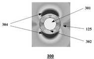
이제 도 3을 참조하면, 전자기장 분포의 예시적인, 비-제한적 실시예를 예시한 그래픽 다이어그램(300)이 도시된다. 이 실시예에서, 공기 중의 송신 매체(125)는 단면에 도시된 바와 같이, 내부 도체(301) 및 유전체 재료의 절연 재킷(302)을 포함한다. 다이어그램(300)은 대칭적 및 비-기본 유도 파 모드를 가진 유도 파의 전파에 의해 발생된 상이한 전자기장 세기들을 나타내는 상이한 그레이-스케일들을 포함한다.Referring now to FIG. 3, there is shown a graphical diagram 300 illustrating an exemplary, non-limiting embodiment of an electromagnetic field distribution. In this embodiment, the
특히, 전자기장 분포는 절연 송신 매체를 따르는 유도 전자기파 전파를 강화하며 단-대-단 송신 손실을 감소시키는 모달 "스윗 스팟(sweet spot)"에 대응한다. 이러한 특정한 모드에서, 전자기파들은 송신 매체의 외부 표면 - 이 경우에, 절연 재킷(302)의 외부 표면을 따라 전파하도록 송신 매체(125)에 의해 유도된다. 전자기파들은 부분적으로 절연체에 내장되며 부분적으로 절연체의 외부 표면상에서 방사한다. 이러한 방식으로, 전자기파들은 낮은 전파 손실을 갖고 긴 거리들에서 전자기파 전파를 가능하게 하도록 절연체에 "약간" 결합된다.In particular, the electromagnetic field distribution corresponds to a modal "sweet spot " which enhances the inductive electromagnetic wave propagation along the insulated transmission medium and reduces the end-to-end transmission loss. In this particular mode, the electromagnetic waves are induced by the
도시된 바와 같이, 유도 파는 주로 또는 실질적으로 전자파들을 유도하도록 작용하는 송신 매체(125)의 밖에 있는 장(field) 구조를 갖는다. 도체(301) 안에서의 영역들은 약간의 장을 갖거나 또는 갖지 않는다. 마찬가지로 절연 재킷(302) 안에서의 영역들은 낮은 전계 강도를 갖는다. 다수의 전자기장 세기는 절연 재킷(302)의 외부 표면에서 및 그것에 매우 근접하여 로브들(304)에서 분포된다. 비대칭 유도 파 모드의 존재는 절연 재킷(302)의 외부 표면의 최상부 및 최하부에서(다이어그램의 배향에서) 높은 전자기장 세기들에 의해 도시된다 - 절연 재킷(302)의 다른 측면들 상에서의 매우 작은 전계 강도들과 대조적으로.As shown, the guided wave has a field structure that is primarily or substantially outside the
도시된 예는 1.1cm의 직경을 가진 와이어 및 0.36cm의 두께의 유전체 절연에 의해 유도된 38GHz 전자기파에 대응한다. 전자기파는 송신 매체(125)에 의해 유도되며 다수의 전계 강도는 외부 표면의 제한된 거리 내에서 절연 재킷(302)의 밖에 있는 공기에서 집중되기 때문에, 유도 파는 매우 낮은 손실을 갖고 송신 매체(125) 아래로 종 방향으로 전파될 수 있다. 도시된 예에서, 이러한 "제한된 거리"는 송신 매체(125)의 최대 단면 치수의 절반 미만인 외부 표면으로부터의 거리에 대응한다. 이 경우에, 와이어의 최대 단면 치수는 1.82cm의 전체 직경에 대응하지만, 이 값은 송신 매체(125)의 크기 및 형태에 따라 달라질 수 있다. 예를 들면, 송신 매체(125)가 .3cm의 높이 및 .4cm의 폭을 가진 직사각형 형태이면, 최대 단면 치수는 .5cm의 대각선일 것이며 대응하는 제한된 거리는 .25cm일 것이다. 다수의 전계 강도를 포함한 면적의 치수들은 또한 주파수에 따라 달라지며, 일반적으로 캐리어 주파수들이 감소함에 따라 증가한다.The illustrated example corresponds to a 38 GHz electromagnetic wave induced by a wire with a diameter of 1.1 cm and a dielectric isolation of 0.36 cm thick. Since the electromagnetic waves are induced by the
커플러들 및 송신 미디어와 같은, 유도 파 통신 시스템의 구성요소들은 각각의 유도 파 모드에 대한 그 자신의 컷-오프 주파수들을 가질 수 있다는 것이 또한 주의되어야 한다. 컷-오프 주파수는 일반적으로 특정한 유도 파 모드가 상기 특정한 구성요소에 의해 지원되도록 설계되는 최저 주파수를 제시한다. 예시적인 실시예에서, 도시된 전파의 특정한 비대칭 모드는 이러한 특정한 비대칭 모드를 위한 하위 컷-오프 주파수(Fc)의 제한된 범위(Fc 내지 2Fc와 같은) 내에 있는 주파수를 가진 전자기파에 의해 송신 매체(125) 상에서 유발된다. 하위 컷-오프 주파수(Fc)는 송신 매체(125)의 특성에 특정적이다. 예를 들면, 절연 재킷(302)에 의해 둘러싸여진 내부 도체(301)를 포함하여 도시된 바와 같이, 이러한 컷오프 주파수는 절연 재킷(302)의 치수들 및 속성들 및 잠재적으로 내부 도체(301)의 치수들 및 속성들에 기초하여 달라질 수 있으며 실험적으로 원하는 모드 패턴을 갖는 것으로 결정될 수 있다. 그러나, 유사한 효과들이 내부 도체 없이 중공 유전체 또는 절연체에 대해 발견될 수 있다는 것이 주의되어야 한다. 이 경우에, 컷오프 주파수는 중공 유전체 또는 절연체의 치수들 및 속성들에 기초하여 달라질 수 있다.It should also be noted that components of the waveguide communication system, such as couplers and transmission media, may have their own cut-off frequencies for each of the waveguide modes. The cut-off frequency generally suggests the lowest frequency at which a particular wave mode is designed to be supported by the particular component. In an exemplary embodiment, the specific asymmetric mode of the illustrated radio wave is detected by an electromagnetic wave having a frequency within a limited range (such as Fc to 2Fc) of the sub-cut-off frequency Fc for this particular asymmetric mode, ). ≪ / RTI > The lower cut-off frequency Fc is specific to the characteristics of the
하위 컷-오프 주파수보다 낮은 주파수들에서, 비대칭 모드는 송신 매체(125)에서 유발하기 어려우며 거의 사소한 거리들에 대해 전파하는 데 실패한다. 주파수가 컷-오프 주파수 이상의 주파수들의 제한된 범위 이상으로 증가함에 따라, 비대칭 모드는 절연 재킷(302)의 점점 더 안쪽으로 시프트한다. 컷-오프 주파수보다 훨씬 더 큰 주파수들에서, 전계 강도는 더 이상 절연 재킷의 바깥쪽에 집중되지 않으며, 주로 절연 재킷(302)의 안쪽에 집중된다. 송신 매체(125)가 전자기파에 강한 유도를 제공하며 전파가 여전히 가능하지만, 범위들은 절연 재킷(302) 내에서의 전파로 인해 증가된 손실들에 의해 보다 제한된다 -- 주변 공기와 대조적으로.At frequencies lower than the lower cut-off frequency, the asymmetric mode is difficult to induce in the
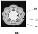
이제 도 4를 참조하면, 전자기장 분포의 예시적인, 비-제한적 실시예를 예시한 그래픽 다이어그램(400)이 도시된다. 특히, 도 3과 유사한, 단면도(400)가 유사한 요소들을 나타내기 위해 사용된 공통 참조 번호들을 갖고 도시된다. 도시된 예는 1.1cm의 직경을 가진 와이어 및 0.36cm의 두께의 유전체 절연에 의해 유도된 60GHz 파에 대응한다. 유도 파의 주파수가 이러한 특정한 비대칭 모드의 컷-오프 주파수의 제한된 범위 이상이기 때문에, 많은 전계 강도가 절연 재킷(302)의 안쪽으로 시프트되었다. 특히, 전계 강도는 절연 재킷(302)의 주로 안쪽에 집중된다. 송신 매체(125)가 전자기파에 강한 유도를 제공하며 전파가 여전히 가능하지만, 범위들은, 절연 재킷(302) 내에서의 전파로 인한 증가된 손실들에 의해, 도 3의 실시예와 비교할 때보다 더 제한된다.Referring now to FIG. 4, there is shown a graphical diagram 400 illustrating an exemplary, non-limiting embodiment of an electromagnetic field distribution. In particular, a
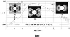
이제 도 5a를 참조하면, 주파수 응답의 예시적인, 비-제한적 실시예를 예시한 그래픽 다이어그램이 도시된다. 특히, 다이어그램(500)은 200cm 절연 매체 전압 와이어에 대한 3개의 포인트들에서 전자기장 분포들(510, 520 및 530)을 갖고 오버레이된, 주파수의 함수로서 단-대-단 손실(dB로)의 그래프를 보여준다. 절연체 및 주변 공기 사이에서의 경계는 각각의 전자기장 분포에서 참조 번호(525)에 의해 표현된다.Referring now to FIG. 5A, a graphical diagram illustrating an exemplary, non-limiting embodiment of a frequency response is shown. In particular, diagram 500 is a graph of end-to-end losses (in dB) as a function of frequency, overlaid with
도 3과 함께 논의된 바와 같이, 도시된 전파의 원하는 비대칭 모드의 예는 이러한 특정한 비대칭 모드에 대한 송신 매체의 하위 컷-오프 주파수(Fc)의 제한된 범위(Fc 내지 2Fc와 같은) 내에 있는 주파수를 가진 전자기파에 의해 송신 매체(125) 상에 유발된다. 특히, 6GHz에서의 전자기장 분포(520)는 절연된 송신 매체를 따라 전자기파 전파를 강화하며 단-대-단 송신 손실을 감소시키는 이러한 모달 "스윗 스팟" 내에 있다. 이러한 특정한 모드에서, 유도 파들은 부분적으로 절연체에 내장되며 부분적으로 절연체의 외부 표면상에서 방사한다. 이러한 방식으로, 전자기파들은 낮은 전파 손실을 갖고 긴 거리들에서 유도 전자기파 전파를 가능하게 하도록 절연체에 "약간" 결합된다.As discussed in conjunction with FIG. 3, an example of the desired asymmetric mode of the illustrated radio wave is a frequency within a limited range (such as Fc to 2Fc) of the lower cut-off frequency Fc of the transmission medium for this particular asymmetric mode Lt; RTI ID = 0.0 > 125 < / RTI > In particular, the
3GHz에서 전자기장 분포(510)에 의해 표현된 하위 주파수들에서, 비대칭 모드가 보다 세게 방사하여 보다 높은 전파 손실들을 발생시킨다. 9GHz에서 전자기장 분포(530)에 의해 표현된 상위 주파수들에서, 비대칭 모드는 절연 재킷의 점점 더 안쪽으로 시프트하여 너무 많은 흡수를 제공하고, 다시 보다 높은 전파 손실들을 발생시킨다.At the lower frequencies represented by the
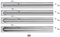
이제 도 5b를 참조하면, 다양한 동작 주파수들에서 유도 전자기파들의 장들을 묘사한, 절연 와이어와 같은, 송신 매체(125)의 세로 단면의 예시적인, 비-제한적 실시예들을 예시한 그래픽 다이어그램(550)이 도시된다. 다이어그램(556)에 도시된 바와 같이, 유도 전자기파들이 모달 "스윗 스팟"에 대응하는 대략 컷오프 주파수(fc)에 있을 때, 유도 전자기파들은 흡수가 감소되도록 절연 와이어에 느슨하게 결합되며, 유도 전자기파들의 장들은 환경(예로서, 공기)으로 방사된 양을 감소시키기 위해 충분히 바인딩된다. 유도 전자기파들의 장들의 흡수 및 방사가 낮기 때문에, 전파 손실들이 결과적으로 낮아서, 유도 전자기파들이 보다 긴 거리들에 대해 전파될 수 있게 한다.5b, a graphical diagram 550 illustrating exemplary, non-limiting embodiments of a longitudinal section of a
다이어그램(554)에서 도시된 바와 같이, 전파 손실들은 유도 전자기파들의 동작 주파수가 대략 컷오프 주파수(fc) 두 배 이상 - 또는 "스윗 스팟"의 범위 이상으로 불리우는 - 으로 증가할 때 증가한다. 전자기파의 전계 강도의 많은 것이 절연 층 안에서 구동되어, 전파 손실들을 증가시킨다. 컷오프 주파수(fc)보다 훨씬 더 높은 주파수들에서, 유도 전자기파들은 다이어그램(552)에서 도시된 바와 같이, 와이어의 절연 층에서 집중되는 유도 전자기파들에 의해 방출된 장들의 결과로서 절연 와이어에 강하게 바인딩된다. 이것은 결과적으로 절연 층에 의한 유도 전자기파들의 흡수로 인해 전파 손실들을 더 올린다. 유사하게, 전파 손실들은, 다이어그램(558)에서 도시된 바와 같이, 유도 전자기파들의 동작 주파수가 실질적으로 컷오프 주파수(fc) 미만일 때 증가한다. 컷오프 주파수(fc)보다 훨씬 더 낮은 주파수들에서, 유도 전자기파들은 절연 와이어에 약하게(또는 명목상) 바인딩되며 그에 의해 환경(예로서, 공기)으로 방사하려는 경향이 있으며, 이것은 결과적으로, 유도 전자기파들의 방사로 인한 전파 손실들을 높인다.As shown in diagram 554, the propagation losses increase when the operating frequency of the inductive electromagnetic waves increases to approximately - twice or more the cutoff frequency (fc ) - or more than the range of the "sweet spot ". Much of the electric field strength of the electromagnetic wave is driven in the insulating layer, thereby increasing the propagation losses. At frequencies much higher than the cutoff frequency (fc ), the inductive electromagnetic waves are strongly bound to the insulated wire as a result of the fields emitted by the inductive electromagnetic waves concentrated in the insulating layer of the wire, as shown in diagram 552 do. This results in a further increase in propagation losses due to the absorption of the induced electromagnetic waves by the insulating layer. Similarly, the propagation losses, and an increased time, the cut-off frequency substantially the operating frequency of the induced electromagnetic waves (fc) below, as shown in the diagram (558). At frequencies much lower than the cutoff frequency (fc ), the inductive electromagnetic waves tend to weakly (or nominally) bind to the insulating wire and thereby radiate to the environment (e.g., air) Thereby increasing propagation losses due to radiation.
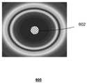
이제 도 6을 참조하면, 전자기장 분포의 예시적인, 비-제한적 실시예를 예시한 그래픽 다이어그램(600)이 도시된다. 이 실시예에서, 송신 매체(602)는, 단면에 도시된 바와 같이, 나선이다. 다이어그램(300)은 단일 캐리어 주파수에서 대칭적 및 기본 유도 파 모드를 가진 유도 파의 전파에 의해 발생된 상이한 전자기장 세기들을 표현한 상이한 그레이-스케일들을 포함한다.Referring now to FIG. 6, there is shown a graphical diagram 600 illustrating an exemplary, non-limiting embodiment of an electromagnetic field distribution. In this embodiment, the
이러한 특정한 모드에서, 전자기파들은 송신 매체의 외부 표면 - 이 경우에, 나선의 외부 표면을 따라 전파하도록 송신 매체(602)에 의해 유도된다. 전자기파들은 낮은 전파 손실을 갖고 긴 거리들에서 전자기파 전파를 가능하게 하도록 와이어에 "약간" 결합된다. 도시된 바와 같이, 유도 파는 전자기파들을 유도하도록 작용하는 송신 매체(602)의 실질적으로 밖에 있는 장 구조를 갖는다. 도체(625) 안쪽의 영역들은 약간의 장을 갖거나 또는 갖지 않는다.In this particular mode, the electromagnetic waves are induced by the
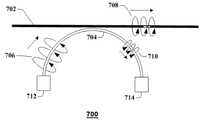
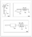
이제 도 7을 참조하면, 아크 커플러의 예시적인, 비-제한적 실시예를 예시한 블록도(700)가 도시된다. 특히 결합 디바이스는 도 1과 함께 제공된 송신 디바이스(101 또는 102)와 같은, 송신 디바이스에서의 사용을 위해 제공된다. 결합 디바이스는 송신기 회로(712) 및 종단 또는 댐퍼(714)에 결합된 아크 커플러(704)를 포함한다. 아크 커플러(704)는 유전체 재료, 또는 다른 저-손실 절연체(예로서, 테프론, 폴리에틸렌 등)로 만들어지거나, 또는 전도(예로서, 금속성, 비-금속성 등) 재료, 또는 앞서 말한 재료들의 임의의 조합으로 만들어질 수 있다. 도시된 바와 같이, 아크 커플러(704)는 도파관으로서 동작하며 아크 커플러(704)의 도파관 표면 주위에서 유도 파로서 전파하는 파동(706)을 갖는다. 도시된 실시예에서, 아크 커플러(704)의 적어도 일 부분은, 와이어 상에서 유도 파(708)를 론칭하기 위해 여기에서 설명된 바와 같이, 아크 커플러(704) 및 와이어(702) 또는 다른 송신 매체 사이에서의 결합을 가능하게 하기 위해, 와이어(702) 또는 다른 송신 매체(송신 매체(125)와 같은) 가까이에 위치될 수 있다. 아크 커플러(704)는 곡선 아크 커플러(704)의 일 부분이 와이어(702)에 거의 관계가 없으며, 그것에 평행하거나 또는 대체로 평행하도록 위치될 수 있다. 와이어에 평행하는 아크 커플러(704)의 부분은 곡선의 꼭대기, 또는 곡선의 접선이 와이어(702)에 평행하는 임의의 포인트일 수 있다. 아크 커플러(704)가 그에 따라 배치되거나 또는 위치될 때, 아크 커플러(704)를 따라 이동하는 파동(706)은, 적어도 부분적으로, 와이어(702)에 결합하며, 와이어(702)의 와이어 표면 주위에서 또는 그 주위를 및 와이어(702)를 따라 종 방향으로 유도 파(708)로서 전파된다. 유도 파(708)는 와이어(702) 또는 다른 송신 매체에 의해 유도되거나 또는 그것에 바인딩되는 표면파 또는 다른 전자기파로서 특성화될 수 있다.Referring now to FIG. 7, there is shown a block diagram 700 illustrating an exemplary, non-limiting embodiment of an arc coupler. In particular, the coupling device is provided for use in a transmitting device, such as the transmitting device 101 or 102 provided with Fig. The coupling device includes a
와이어(702)에 결합하지 않는 파동(706)의 일 부분은 아크 커플러(704)를 따라 파동(710)으로서 전파된다. 아크 커플러(704)는 와이어(702)로의 파동(706)의 결합 또는 비-결합의 원하는 레벨을 달성하기 위해 와이어(702)에 관하여 다양한 위치들에서 구성되며 배열될 수 있다는 것이 이해될 것이다. 예를 들면, 와이어(702)에, 평행하거나 또는 대체로 평행한 아크 커플러(704)의 곡률 및/또는 길이, 뿐만 아니라 그것의 이격 거리(실시예에서, 0 이격 거리를 포함할 수 있는)는 예시적인 실시예들에서 벗어나지 않고 변경될 수 있다. 마찬가지로, 와이어(702)에 관하여 아크 커플러(704)의 배열은 와이어(702) 및 아크 커플러(704)의 각각의 고유 특성들(예로서, 두께, 조성, 전자기 속성들 등), 뿐만 아니라 파동들(706 및 708)의 특성들(예로서, 주파수, 에너지 레벨 등)에 대한 고려들에 기초하여 변경될 수 있다.A portion of the
유도 파(708)는, 와이어(702)가 구부러지고 휠지라도, 와이어(702)에 평행하거나 또는 대체로 평행한 채로 있다. 와이어(702)에서의 구부러짐들은 송신 손실들을 증가시킬 수 있으며, 이것은 또한 와이어 직경들, 주파수, 및 재료들에 의존한다. 아크 커플러(704)의 치수들이 효율적인 전력 전달을 위해 선택된다면, 파동(706)에서의 전력의 대부분은, 파동(710)에 남아있는 적은 전력을 갖고, 와이어(702)로 전달된다. 유도 파(708)는, 기본 송신 모드를 갖고 또는 그것 없이, 와이어(702)에 평행하거나 또는 대체로 평행하는 경로를 따라 이동하면서, 비-기본 또는 비대칭인 모드들을 갖는 것을 포함하여, 여전히 사실상(여기에서 논의된 바와 같이) 다중-모드일 수 있다는 것이 이해될 것이다. 실시예에서, 비-기본 또는 비대칭 모드들은 송신 손실들을 최소화하며 및/또는 증가된 전파 거리들을 획득하기 위해 이용될 수 있다.The
용어(평행)는 일반적으로 종종 실제 시스템들에서 정확하게 달성 가능하지 않은 기하학적 구성임이 주의된다. 따라서, 본 개시에서 이용된 바와 같이 용어(평행)는 본 개시에서 개시된 실시예들을 설명하기 위해 사용될 때 정확한 구성보다는 근사치를 나타낸다. 실시예에서, 대체로 평행은 모든 치수들에서 실제 평행의 30도 내에 있는 근사치들을 포함할 수 있다.It is noted that the term (parallel) is generally a geometric configuration that is often not accurately achievable in real systems. Accordingly, the term (parallel) as used in this disclosure refers to an approximation rather than an exact configuration when used to describe the embodiments disclosed in this disclosure. In an embodiment, substantially parallel may include approximations within 30 degrees of actual parallelism at all dimensions.
실시예에서, 파동(706)은 하나 이상의 파 전파 모드들을 보일 수 있다. 아크 커플러 모드들은 커플러(704)의 형태 및/또는 설계에 의존할 수 있다. 파동(706)의 하나 이상의 아크 커플러 모드들은 와이어(702)를 따라 전파하는 유도 파(708)의 하나 이상의 파 전파 모드들을 발생시키고, 영향을 미치거나, 또는 영향을 줄 수 있다. 그러나 유도 파(706)에 존재하는 유도 파 모드들은 유도 파(708)의 유도 파 모드들과 동일하거나 또는 상이할 수 있다는 것이 특히 주의되어야 한다. 이러한 방식으로, 유도 파(706)의 하나 이상의 유도 파 모드들은 유도 파(708)로 전달되지 않을 수 있으며, 또한 유도 파(708)의 하나 이상의 유도 파 모드들은 유도 파(706)에 존재하지 않았을 수 있다. 특정한 유도 파 모드에 대한 아크 커플러(704)의 컷-오프 주파수는 상기 동일한 모드에 대한 와이어(702) 또는 다른 송신 매체의 컷오프 주파수와 상이할 수 있다는 것이 또한 주의되어야 한다. 예를 들면, 와이어(702) 또는 다른 송신 매체가 특정한 유도 파 모드에 대한 그것의 컷오프 주파수보다 약간 위에서 동작될 수 있지만, 아크 커플러(704)는 낮은 손실을 위해 상기 동일한 모드에 대한 그것의 컷-오프 주파수 위에서, 예를 들면, 보다 큰 결합 및 전력 전달을 유발하기 위해 상기 동일한 모드에 대한 그것의 컷-오프 주파수 약간 아래, 또는 상기 모드에 대한 아크 커플러의 컷오프 주파수에 관하여 몇몇 다른 포인트에서 잘 작동될 수 있다.In an embodiment, wave 706 may exhibit one or more wave propagation modes. The ac coupler modes may depend on the type and / or design of the
실시예에서, 와이어(702) 상에서의 파 전파 모드들은 양쪽 파동들(706 및 708) 모두가 각각 아크 커플러(704) 및 와이어(702)의 밖 주위에서 전파되므로 아크 커플러 모드들과 유사할 수 있다. 몇몇 실시예들에서, 파동(706)이 와이어(702)에 결합함에 따라, 모드들은 형태를 변경할 수 있거나, 또는 새로운 모드들이 아크 커플러(704) 및 와이어(702) 사이에서의 결합으로 인해, 생성되거나 또는 발생될 수 있다. 예를 들면, 아크 커플러(704) 및 와이어(702)의 크기, 재료, 및/또는 임피던스에서의 차이들은 아크 커플러 모드들에 존재하지 않는 부가적인 모드들을 생성하고 및/또는 아크 커플러 모드들 중 일부를 억제할 수 있다. 파 전파 모드들은 기본 가로 전자기 모드(Quasi-TEM00)를 포함할 수 있으며, 여기에서 단지 작은 전기 및/또는 자기장들만이 전파의 방향으로 연장되며, 전기 및 자기 장들은 유도 파가 와이어를 따라 전파되는 동안 방사상 바깥쪽으로 연장된다. 이러한 유도 파 모드는 도넛 형일 수 있으며, 여기에서 적은 전자기장들이 아크 커플러(704) 또는 와이어(702) 내에 존재한다.Wave propagation modes on
파동들(706 및 708)은 장들이 방사상 바깥쪽으로 연장되는 기존 TEM 모드를 포함할 수 있으며, 또한 다른, 비-기본(예로서, 비대칭, 상위-레벨 등) 모드들을 포함할 수 있다. 특정한 파 전파 모드들이 상기 논의되지만, 이용된 주파수들, 아크 커플러(704)의 설계, 와이어(702)의 치수들 및 조성, 뿐만 아니라 그것의 표면 특성들, 존재한다면 그것의 절연, 주변 환경의 전자기 속성들 등에 기초하여, 가로 전기(TE) 및 가로 자기(TM) 모드들과 같은 다른 파 전파 모드들이 마찬가지로 가능하다. 주파수, 와이어(702)의 전기적 및 물리적 특성들 및 생성되는 특정한 파 전파 모드들에 의존하여, 유도 파(708)는 산화된 비절연 와이어, 비산화된 비절연 와이어, 절연 와이어의 전도성 표면을 따라 및/또는 절연 와이어의 절연 표면을 따라 이동할 수 있다는 것이 주의되어야 한다.The
실시예에서, 아크 커플러(704)의 직경은 와이어(702)의 직경보다 작다. 사용되는 밀리미터-대역 파장에 대해, 아크 커플러(704)는 파동(706)을 형성하는 단일 도파관 모드를 지원한다. 이러한 단일 도파관 모드는 그것이 유도 파(708)로서 와이어(702)에 결합함에 따라 변할 수 있다. 아크 커플러(704)가 더 크다면, 하나 이상의 도파관 모드가 지원될 수 있지만, 이들 부가적인 도파관 모드들은 효율적으로 와이어(702)에 결합되지 않을 수 있으며, 보다 높은 결합 손실들이 발생할 수 있다. 그러나, 몇몇 대안적인 실시예들에서, 아크 커플러(704)의 직경은, 예를 들면, 보다 높은 결합 손실들이 바람직한 경우에 또는 그 외 결합 손실들을 감소시키기 위해 다른 기술들(예로서, 테이퍼링과의 임피던스 정합 등)과 함께 사용될 때, 와이어(702)의 직경과 같거나 또는 그보다 클 수 있다.In an embodiment, the diameter of the
실시예에서, 파동들(706 및 708)의 파장은 크기가 비교 가능하거나, 또는 아크 커플러(704) 및 와이어(702)의 둘레보다 작다. 예에서, 와이어(702)가 0.5cm의 직경을 가지며, 약 1.5cm의 대응하는 둘레를 갖는다면, 송신의 파장은, 70GHz 이상의 주파수에 대응하여, 약 1.5cm 이하이다. 또 다른 실시예에서, 송신 및 캐리어-파 신호의 적절한 주파수는 30 내지 100GHz의 범위, 아마도 약 30 내지 60GHz, 및 일 예에서 약 38GHz이다. 실시예에서, 아크 커플러(704) 및 와이어(702)의 둘레가 송신의 파장에 크기가 비교 가능하거나, 또는 그것보다 클 때, 파동들(706 및 708)은 여기에서 설명된 다양한 통신 시스템들을 지원하기 위해 충분한 거리들에 걸쳐 전파하는 기본 및/또는 비-기본(대칭 및/또는 비대칭) 모드들을 포함한 다수의 파 전파 모드들을 보일 수 있다. 파동들(706 및 708)은 그러므로 하나 이상의 유형의 전기 및 자기장 구성을 포함할 수 있다. 실시예에서, 유도 파(708)가 와이어(702) 아래로 전파됨에 따라, 전기 및 자기장 구성들은 와이어(702)의 단에서 단으로 동일한 채로 있을 것이다. 다른 실시예들에서, 유도 파(708)가 송신 손실들 또는 산란으로 인해 간섭(왜곡 또는 장애물들)에 맞닥뜨리거나 또는 에너지를 손실하므로, 전기 및 자기장 구성들은 유도 파(708)가 와이어(702) 아래로 전파됨에 따라 변할 수 있다.In an embodiment, the wavelengths of
실시예에서, 아크 커플러(704)는 나일론, 테프론, 폴리에틸렌, 폴리아미드, 또는 다른 플라스틱들로 구성될 수 있다. 다른 실시예들에서, 다른 유전체 재료들이 가능하다. 와이어(702)의 와이어 표면은 아무것도 안 덮인 금속 표면을 갖고 금속성일 수 있거나, 또는 플라스틱, 유전체, 절연체 또는 다른 코팅, 재킷 또는 시스(sheathing)를 사용하여 절연될 수 있다. 실시예에서, 유전체 또는 그 외 비-전도/절연 도파관은 맨/금속 와이어 또는 절연 와이어와 쌍을 이룰 수 있다. 다른 실시예들에서, 금속 및/또는 전도성 도파관은 맨/금속 와이어 또는 절연 와이어와 쌍을 이룰 수 있다. 실시예에서, 와이어(702)의 아무것도 안 덮인 금속 표면상에서의 산화 층(예로서, 산소/공기로의 아무것도 안 덮인 금속 표면의 노출에서 비롯된)은 또한 몇몇 절연체들 또는 시스들에 의해 제공된 것들과 유사한 절연 또는 유전체 속성들을 제공할 수 있다.In an embodiment, the
파동들(706, 708 및 710)의 그래픽 표면들은 단지 파동(706)이 예를 들면, 단일 와이어 송신 라인으로서 동작하는 와이어(702) 상에서 유도 파(708)를 유발하거나 또는 그 외 론칭하는 원리들을 예시하기 위해서만 제공된다는 것이 주의된다. 파동(710)은 유도 파(708)의 발생 후 아크 커플러(704) 상에 남아있는 파동(706)의 부분을 나타낸다. 이러한 파 전파의 결과로서 발생된 실제 전기 및 자기 장들은 이용된 주파수들, 특정한 파 전파 모드 또는 모드들, 아크 커플러(704)의 설계, 와이어(702)의 치수들 및 조성, 뿐만 아니라 그것의 표면 특성들, 그것의 선택적 절연, 주변 환경의 전자기 속성들 등에 의존하여 달라질 수 있다.The graphical surfaces of waves 706,708 and 710 may be used only to generate
아크 커플러(704)는 파동(710)으로부터 남겨진 방사선 또는 에너지를 흡수할 수 있는 종단 회로 또는 댐퍼(714)를 아크 커플러(704)의 단부에 포함할 수 있다. 종단 회로 또는 댐퍼(714)는 송신기 회로(712)를 향해 반사하는 파동(710)으로부터 남겨진 방사선 또는 에너지를 방지하고 및/또는 최소화할 수 있다. 실시예에서, 종단 회로 또는 댐퍼(714)는 종단 저항기들, 및/또는 반사를 감쇠시키기 위해 임피던스 정합을 수행하는 다른 구성요소들을 포함할 수 있다. 몇몇 실시예들에서, 결합 효율들이 충분히 높으며, 및/또는 파동(710)이 충분히 작다면, 종단 회로 또는 댐퍼(714)를 사용하는 것은 필요하지 않을 수 있다. 단순성을 위해, 이들 송신기(712) 및 종단 회로들 또는 댐퍼들(714)은 다른 도면들에서 묘사되지 않을 수 있지만, 이들 실시예들에서, 송신기 및 종단 회로들 또는 댐퍼들이 가능하게는 사용될 수 있다.The
뿐만 아니라, 단일 유도 파(708)를 발생시키는 단일 아크 커플러(704)가 제공되지만, 와이어(702)를 따라 상이한 포인트들에 및/또는 와이어에 대해 상이한 방위각 배향들에서 위치된 다수의 아크 커플러들(704)이 동일한 또는 상이한 주파수들에서, 동일한 또는 상이한 위상들에서, 동일한 또는 상이한 파 전파 모드들에서 다수의 유도 파들(708)을 발생시키고 수신하기 위해 이용될 수 있다.In addition, although a
아크 커플러의 예시적인, 비-제한적 실시예를 예시한 도 8, 블록도(800)가 도시된다. 도시된 실시예에서, 커플러(704)의 적어도 일 부분은 여기에서 설명된 바와 같이, 유도 파(808)로서 유도 파(806)의 일 부분을 추출하도록, 아크 커플러(704) 및 와이어(702) 또는 다른 송신 매체 사이에서의 결합을 가능하게 하기 위해, 와이어(702) 또는 다른 송신 매체(송신 매체(125)와 같은) 가까이에 위치될 수 있다. 아크 커플러(704)는 곡선 아크 커플러(704)의 일 부분이 와이어(702)에 거의 관계가 없으며, 그것에 평행하거나 또는 대체로 평행하도록 위치될 수 있다. 와이어에 평행하는 아크 커플러(704)의 부분은 곡선의 꼭대기, 또는 곡선의 접선이 와이어(702)에 평행하는 임의의 포인트일 수 있다. 아크 커플러(704)가 그에 따라 배치되거나 또는 위치될 때, 와이어(702)를 따라 이동하는 파동(806)은, 적어도 부분적으로, 아크 커플러(704)에 결합하며, 아크 커플러(704)를 따라 유도 파(808)로서 수신 디바이스(명확하게 도시되지 않음)로 전파된다. 아크 커플러에 결합하지 않은 파(806)의 일 부분은 와이어(702) 또는 다른 송신 매체를 따라 파동(810)으로서 전파된다.A block diagram 800 of FIG. 8 illustrating an exemplary, non-limiting embodiment of an arc coupler is shown. At least a portion of the
실시예에서, 파동(806)은 하나 이상의 파 전파 모드들을 보일 수 있다. 아크 커플러 모드들은 커플러(704)의 형태 및/또는 설계에 의존할 수 있다. 유도 파(806)의 하나 이상의 모드들은 아크 커플러(704)를 따라 전파되는 유도 파(808)의 하나 이상의 유도-파 모드들을 발생시키고, 그것에 영향을 미치거나, 또는 영향을 줄 수 있다. 그러나 유도 파(806)에 존재하는 유도 파 모드들은 유도 파(808)의 유도 파 모드들과 동일하거나 또는 상이할 수 있다는 것이 특히 주의되어야 한다. 이러한 방식으로, 유도 파(806)의 하나 이상의 유도 파 모드들은 유도 파(808)로 전달되지 않을 수 있으며, 더욱이 유도 파(808)의 하나 이상의 유도 파 모드들은 유도 파(806)에 존재하지 않았을 수 있다.In an embodiment, wave 806 may exhibit one or more wave propagation modes. The ac coupler modes may depend on the type and / or design of the
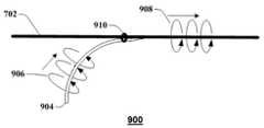
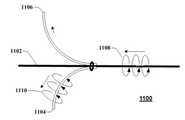
이제 도 9a를 참조하면, 스터브 커플러의 예시적인, 비-제한적 실시예를 예시한 블록도(900)가 도시된다. 특히 스터브 커플러(904)를 포함하는 결합 디바이스는 도 1과 함께 제공된 송신 디바이스(101 또는 102)와 같은, 송신 디바이스에서의 사용을 위해 제공된다. 스터브 커플러(904)는 유전체 재료, 또는 다른 저-손실 절연체(예로서, 테프론, 폴리에틸렌 등)로 만들어지거나, 또는 전도(예로서, 금속, 비-금속 등) 재료, 또는 앞서 말한 재료들의 임의의 조합으로 만들어질 수 있다. 도시된 바와 같이, 스터브 커플러(904)는 도파관으로서 동작하며 스터브 커플러(904)의 도파관 표면 주위에서 유도 파로서 전파되는 파동(906)을 갖는다. 도시된 실시예에서, 스터브 커플러(904)의 적어도 일 부분은, 와이어 상에서 유도 파(908)를 론칭하기 위해 여기에서 설명된 바와 같이, 스터브 커플러(904) 및 와이어(702) 또는 다른 송신 매체 사이에서의 결합을 가능하게 하기 위해, 와이어(702) 또는 다른 송신 매체(송신 매체(125)와 같은) 가까이에 위치될 수 있다.Referring now to FIG. 9A, a block diagram 900 illustrating an exemplary, non-limiting embodiment of a stub coupler is shown. In particular, a coupling device comprising a
실시예에서, 스터브 커플러(904)는 곡선이며, 스터브 커플러(904)의 단부는 와이어(702)에 묶이고, 체결되거나, 또는 그 외 기계적으로 결합될 수 있다. 스터브 커플러(904)의 단부가 와이어(702)에 체결될 때, 스터브 커플러(904)의 단부는 와이어(702)에 평행하거나 또는 대체로 평행한다. 대안적으로, 단부를 넘어 유전체 도파관의 또 다른 부분은 체결된 또는 결합된 부분이 와이어(702)에 평행하거나 또는 대체로 평행하도록 와이어(702)에 체결되거나 또는 결합될 수 있다. 파스너(910)는 스터브 커플러(904)로부터 분리되거나 또는 스터브 커플러(904)의 통합 구성요소로서 구성되는 나일론 케이블 타이 또는 다른 유형의 비-전도/유전체 재료일 수 있다. 스터브 커플러(904)는 와이어(702)를 둘러싸지 않고 와이어(702)에 인접할 수 있다.In an embodiment, the
도 7과 함께 설명된 아크 커플러(704)와 같이, 스터브 커플러(904)가 와이어(702)에 평행한 단부를 갖고 위치될 때, 스터브 커플러(904)를 따라 이동하는 유도 파(906)는 와이어(702)에 결합하며, 와이어(702)의 와이어 표면 주위에서 유도 파(908)로서 전파된다. 예시적인 실시예에서, 유도 파(908)는 표면파 또는 다른 전자기파로서 특성화될 수 있다.When the
파들(906 및 908)의 그래픽 표현들은 단지 파가 예를 들면, 단일 파 송신 라인으로서 동작하는 와이어(702) 상에서 유도 파(908)를 유발하거나 또는 그 외 론칭하는 원리들을 예시하기 위해 제공된다. 이러한 파 전파의 결과로서 발생된 실제 전기 및 자기 장들은 커플러의 형태 및/또는 설계, 와이어에 대한 유전체 도파관의 상대적 위치, 이용된 주파수들, 스터브 커플러(904)의 설계, 와이어(702)의 치수들 및 조성, 뿐만 아니라 그것의 표면 특성들, 그것의 선택적 절연, 주변 환경의 전자기 속성들 등 중 하나 이상에 의존하여 달라질 수 있다.The graphical representations of the
실시예에서, 스터브 커플러(904)의 단부는 결합 효율들을 증가시키기 위해 와이어(702)를 향해 테이퍼링할 수 있다. 실제로, 스터브 커플러(904)의 단부의 테이퍼링은 본 개시의 예시적인 실시예에 따라, 와이어(702)에 임피던스 정합을 제공하며 반사들을 감소시킬 수 있다. 예를 들면, 스터브 커플러(904)의 단부는 도 9a에 예시된 바와 같이 파동들(906 및 908) 사이에서의 원하는 레벨의 결합을 획득하기 위해 점진적으로 테이퍼링될 수 있다.In an embodiment, the end of the
실시예에서, 파스너(910)는 파스터(910) 및 스터브 커플러의 단부 사이에 스터브 커플러(904)의 짧은 길이가 있도록 위치될 수 있다. 최대 결합 효율들은 파스너(910)를 지나 있는 스터브 커플러(904)의 단부의 길이가 어떤 주파수가 송신되든 적어도 긴 여러 개의 파장들에 있을 때 이 실시예에서 실현된다.In an embodiment, the
이제 도 9b로 가면, 여기에서 설명된 다양한 양상들에 따른 전자기 분포의 예시적인, 비-제한적 실시예를 예시한 다이어그램(950)이 도시된다. 특히, 전자기 분포는 유전체 재료로 구성된 예시적인 스터브 커플러에서 도시된, 커플러(952)를 포함하는 송신 디바이스에 대해 2차원으로 보여진다. 커플러(952)는 와이어(702) 또는 다른 송신 매체의 외부 표면을 따라 유도 파로서 전파를 위해 전자기파를 결합한다.Turning now to FIG. 9B, a diagram 950 illustrating an exemplary, non-limiting embodiment of an electromagnetic distribution according to the various aspects described herein is shown. In particular, the electromagnetic distribution is shown in two dimensions for a transmitting device including a
커플러(952)는 대칭적 유도 파 모드를 통해 x0에서 접합으로 전자기파를 유도한다. 커플러(952)를 따라 전파되는 전자기파의 에너지의 일부가 커플러(952)의 밖에 있지만, 이러한 전자파의 다수의 에너지는 커플러(952) 내에 포함된다. x0에서의 접합은 송신 매체의 최하부에 대응하는 방위각에서 와이어(702) 또는 다른 송신 매체에 전자기파를 결합한다. 이러한 결합은 방향(956)에서 적어도 하나의 유도 파 모드를 통해 와이어(702) 또는 다른 송신 매체의 외부 표면을 따라 전파되도록 유도되는 전자기파를 유발한다. 유도 전자기파의 다수의 에너지는 밖에 있거나, 또는 와이어(702) 또는 다른 송신 매체의 외부 표면에 매우 근접해 있다. 도시된 예에서, x0에서의 접합은 와이어(702) 또는 다른 송신 매체의 표면을 지나가게 하는, 도 3과 함께 제공된 1차 모드와 같은, 대칭 모드 및 적어도 하나의 비대칭 표면 모드 양쪽 모두를 통해 전파되는 전자기파를 형성한다.
유도 파들의 그래픽 표현들이 단지 유도 파 결합 및 전파의 예를 예시하기 위해 제공된다는 것이 주의된다. 이러한 파 전파의 결과로서 발생된 실제 전기 및 자기장들은 이용된 주파수, 커플러(952)의 설계 및/또는 구성, 와이어(702) 또는 다른 송신 매체의 치수들 및 조성, 뿐만 아니라 그것의 표면 특성들, 존재한다면 그것의 절연, 주변 환경의 전자기 속성들 등에 의존하여 달라질 수 있다.It is noted that the graphical representations of the guided waves are provided only to illustrate examples of guided wave coupling and propagation. The actual electrical and magnetic fields generated as a result of this wave propagation may vary depending on the frequency used, the design and / or configuration of the
이제 도 10a로 가면, 여기에서 설명된 다양한 양상들에 따른 커플러 및 트랜시버 시스템의 예시적인, 비-제한적 실시예의 블록도(1000)가 예시된다. 시스템은 송신 디바이스(101 또는 102)의 예이다. 특히, 통신 인터페이스(1008)는 통신 인터페이스(205)의 예이고, 스터브 커플러(1002)는 커플러(220)의 예이며, 송신기/수신기 디바이스(1006), 다이플렉서(1016), 전력 증폭기(1014), 저 잡음 증폭기(1018), 주파수 믹서들(1010 및 1020) 및 국소 발진기(1012)는 총괄하여 트랜시버(210)의 예를 형성한다.Turning now to FIG. 10A, a block diagram 1000 of an exemplary, non-limiting embodiment of a coupler and transceiver system according to various aspects described herein is illustrated. The system is an example of a transmitting device 101 or 102. Particularly, the
동작 시, 송신기/수신기 디바이스(1006)는 파동들(예로서, 스터브 커플러(1002)로의 유도 파(1004))을 론칭하며 수신한다. 유도 파들(1004)은 통신 인터페이스(1008)에 의해 호스트 디바이스, 기지국, 이동 디바이스들, 빌딩 또는 다른 디바이스로부터 수신되며 그것으로 전송된 신호들을 수송하기 위해 사용될 수 있다. 통신 인터페이스(1008)는 시스템(1000)의 일체형 부분일 수 있다. 대안적으로, 통신 인터페이스(1008)는 시스템(1000)에 테더링될 수 있다. 통신 인터페이스(1008)는 호스트 디바이스, 기지국, 이동 디바이스들, 빌딩 또는 적외선 데이터 연관(IrDA) 프로토콜 또는 다른 가시선 광학 프로토콜과 같은 적외선 프로토콜을 포함한 다양한 무선 시그널링 프로토콜들(예로서, LTE, WiFi, WiMAX, IEEE 802.xx 등) 중 임의의 것을 이용한 다른 디바이스로 인터페이스하기 위한 무선 인터페이스를 포함할 수 있다. 통신 인터페이스(1008)는 또한 이더넷 프로토콜, 범용 직렬 버스(USB) 프로토콜, 케이블 데이터 서비스 인터페이스 규격(DOCSIS) 프로토콜, 디지털 가입자 회선(DSL) 프로토콜, 파이어와이어(IEEE 1394) 프로토콜, 또는 다른 유선 또는 광학 프로토콜과 같은 프로토콜을 통해 호스트 디바이스, 기지국, 이동 디바이스들, 빌딩 또는 다른 디바이스와 통신하기 위한 광섬유 라인, 동축 케이블, 꼬임 쌍, 카테고리 5(CAT-5) 케이블 또는 다른 적절한 유선 또는 광학 매체들과 같은 유선 인터페이스를 포함할 수 있다. 시스템(100)이 리피터로서 기능하는 실시예들에 대해, 통신 인터페이스(1008)는 필요하지 않을 수 있다.In operation, the transmitter /
통신 인터페이스(1008)의 출력 신호들(예로서, Tx)은 주파수 믹서(1010)에서 국소 발진기(1012)에 의해 발생된 캐리어 파(예로서, 밀리미터-파 캐리어 파)와 조합될 수 있다. 주파수 믹서(1010)는 통신 인터페이스(1008)로부터 출력 신호들을 주파수 시프트하기 위해 헤테로다인 기술들 또는 다른 주파수 시프팅 기술들을 사용할 수 있다. 예를 들면, 통신 인터페이스(1008)로 및 그로부터 전송된 신호들은 장기 진화(LTE) 무선 프로토콜 또는 다른 3G, 4G, 5G 또는 그 이상의 음성 및 데이터 프로토콜, 지그비, WIMAX, 초광대역 또는 IEEE 802.11 무선 프로토콜; 이더넷 프로토콜, 범용 직렬 버스(USB) 프로토콜, 케이블 데이터 서비스 인터페이스 규격(DOCSIS) 프로토콜, 디지털 가입자 회선(DSL) 프로토콜, 파이어와이어(IEEE 1394) 프로토콜과 같은 유선 프로토콜 또는 다른 유선 또는 무선 프로토콜에 따라 포맷팅된 직교 주파수 분할 다중화(OFDM) 신호들과 같은 변조된 신호들일 수 있다. 예시적인 실시예에서, 이러한 주파수 변환은 아날로그 도메인에서 행해질 수 있으며, 그 결과, 주파수 시프팅은 기지국, 이동 디바이스들, 또는 빌딩-내 디바이스들에 의해 사용된 통신 프로토콜의 유형에 상관없이 행해질 수 있다. 새로운 통신 기술들이 개발됨에 따라, 통신 인터페이스(1008)는 업그레이드되거나(예로서, 소프트웨어, 펌웨어, 및/또는 하드웨어를 갖고 업그레이드) 또는 대체될 수 있으며 주파수 시프팅 및 송신 장치가 남아있을 수 있어서, 업그레이드들을 단순화한다. 캐리어 파는 그 후 전력 증폭기("PA")(1014)로 전송될 수 있으며 다이플렉서(1016)를 통해 송신기 수신기 디바이스(1006)를 통해 송신될 수 있다.The output signals (e.g., Tx) of
통신 인터페이스(1008)로 향해지는 송신기/수신기 디바이스(1006)로부터 수신된 신호들은 다이플렉서(1016)를 통해 다른 신호들로부터 분리될 수 있다. 수신된 신호는 그 후 증폭을 위해 저 잡음 증폭기("LNA")(1018)로 전송될 수 있다. 국소 발진기(1012)로부터의 도움으로 주파수 믹서(1020)는 수신된 신호(몇몇 실시예들에서 밀리미터-파 대역 또는 약 38GHz에 있는)를 네이티브 주파수로 다운시프트할 수 있다. 통신 인터페이스(1008)는 그 후 입력 포트(Rx)에서 송신을 수신할 수 있다.Signals received from the transmitter /
실시예에서, 송신기/수신기 디바이스(1006)는 원통형 또는 비-원통형 금속(예를 들면, 실시예에서 중공일 수 있지만, 반드시 일정한 비율로 그려지는 것은 아니다) 또는 다른 전도 또는 비-전도 도파관을 포함할 수 있으며 스터브 커플러(1002)의 단부는 송신기/수신기 디바이스(1006)가 송신을 발생시킬 때, 유도 파가 스터브 커플러(1002)에 결합하며 스터브 커플러(1002)의 도파관 표면 주위에서 유도 파(1004)로서 전파되도록 도파관 또는 송신기/수신기 디바이스(1006)에 또는 그것에 근접하여 위치될 수 있다. 몇몇 실시예들에서, 유도 파(1004)는 부분적으로 스터브 커플러(1002)의 외부 표면상에서 및 부분적으로 스터브 커플러(1002)의 안쪽에서 전파될 수 있다. 다른 실시예들에서, 유도 파(1004)는 대체로 또는 완전히 스터브 커플러(1002)의 외부 표면상에서 전파될 수 있다. 다른 실시예들에서, 유도 파(1004)는 대체로 또는 완전히 스터브 커플러(1002)의 안쪽에서 전파될 수 있다. 이러한 후자의 실시예에서, 유도 파(1004)는 도 7의 와이어(702)와 같은 송신 매체로의 결합을 위해 스터브 커플러(1002)(도 4에 도시된 테이퍼링된 단부와 같은)의 단부에서 방사할 수 있다. 유사하게, 유도 파(1004)가 인입한다면(와이어(702)로부터 스터브 커플러(1002)에 결합된), 유도 파(1004)는 그 후 송신기/수신기 디바이스(1006)에 들어가며 원통형 도파관 또는 전도 도파관에 결합한다. 송신기/수신기 디바이스(1006)가 별개의 도파관을 포함하는 것으로 도시되지만 -- 안테나, 공동 공진기, 클라이스트론(klystron), 마그네트론, 이동 파 튜브, 또는 다른 방사 요소가, 별개의 도파관을 갖고 또는 그것 없이, 커플러(1002) 상에 유도 파를 유발하기 위해 이용될 수 있다.In an embodiment, the transmitter /
실시예에서, 스터브 커플러(1002)는 그 안에 임의의 금속 또는 그 외 전도 재료들 없이, 유전체 재료(또는 또 다른 적절한 절연 재료)로 전체적으로 구성될 수 있다. 스터브 커플러(1002)는 나일론, 테프론, 폴리에틸렌, 폴리아미드, 다른 플라스틱들, 또는 비-전도이며 적어도 부분적으로 이러한 재료들의 외부 표면상에서 전자기파들의 송신을 가능하게 하기에 적합한 다른 재료로 구성될 수 있다. 또 다른 실시예에서, 스터브 커플러(1002)는 전도/금속성인 코어를 포함할 수 있으며, 외부 유전체 표면을 갖는다. 유사하게, 스터브 커플러(1002)에 의해 유발된 전자기파들을 전파하기 위해 또는 스터브 커플러(1002)에 전자기파들을 공급하기 위해 스터브 커플러(1002)에 결합하는 송신 매체는, 맨 또는 절연 와이어인 것 외에, 그 안에 임의의 금속성 또는 그 외 전도 재료들 없이, 유전체 재료(또는 또 다른 적절한 절연 재료)로 전체적으로 구성될 수 있다.In an embodiment, the
도 10a는 송신기 수신기 디바이스(1006)의 개구가 스터브 커플러(1002)보다 훨씬 더 넓다는 것을 보여주지만, 이것은 일정한 비율이 아니며, 다른 실시예들에서, 스터브 커플러(1002)의 폭은 비교 가능하거나 또는 중공 도파관의 개구보다 약간 더 작다는 것이 주의된다. 실시예에서, 송신기/수신기 디바이스(1006)로 삽입되는 커플러(1002)의 단부는 반사를 감소시키며 결합 효율들을 증가시키기 위해 아래로 테이퍼링한다는 것이 또한 도시되지 않는다.10A shows that the aperture of the
스터브 커플러(1002)에 결합하기 전에, 송신기/수신기 디바이스(1006)에 의해 발생된 유도 파의 하나 이상의 도파관 모드들은 유도 파(1004)의 하나 이상의 파 전파 모드들을 유발하기 위해 스터브 커플러(1002)에 결합할 수 있다. 유도 파(1004)의 파 전파 모드들은 중공 금속 도파관 및 유전체 도파관의 상이한 특성들로 인해 중공 금속 도파관 모드들과 상이할 수 있다. 예를 들면, 유도 파(1004)의 파 전파 모드들은 기본 가로 전자기 모드(Quasi-TEM00)를 포함할 수 있으며, 여기에서 단지 작은 전기 및/또는 자기장들만이 전파의 방향으로 연장되며, 전기 및 자기 장들은 유도 파가 스터브 커플러(1002)를 따라 전파되는 동안 스터브 커플러(1002)로부터 방사상 바깥쪽으로 연장된다. 기본 가로 전자기 모드 파 전파 모드는 중공인 도파관 안에 존재하거나 또는 존재하지 않을 수 있다. 그러므로, 송신기/수신기 디바이스(1006)에 의해 사용되는 중공 금속 도파관 모드들은 스터브 커플러(1002)의 파 전파 모드들에 효과적으로 및 효율적으로 결합할 수 있는 도파관 모드들이다.Before coupling to the
송신기/수신기 디바이스(1006) 및 스터브 커플러(1002)의 다른 구성들 또는 조합들이 가능하다는 것이 이해될 것이다. 예를 들면, 스터브 커플러(1002')는 도 10b의 기준(1000')에 의해 묘사된 바와 같이 송신기/수신기 디바이스(1006')(대응하는 회로는 도시되지 않음)의 중공 금속 도파관의 외부 표면에 대하여 접선으로 또는 병렬로(갭을 갖거나 또는 없이) 위치될 수 있다. 기준(1000')에 의해 도시되지 않은, 또 다른 실시예에서, 스터브 커플러(1002')는 송신기/수신기 디바이스(1006')의 중공 금속 도파관의 축과 축방향으로 동조되는 스터브 커플러(1002')의 축 없이 송신기/수신기 디바이스(1006')의 중공 금속 도파관 안에 위치될 수 있다. 이들 실시예들 중 어느 하나에서, 송신기/수신기 디바이스(1006')에 의해 발생된 유도 파는 기본 모드(예로서, 대칭 모드) 및/또는 비-기준 모드(예로서, 비대칭 모드)를 포함한 스터브 커플러(1002') 상에서 유도 파(1004')의 하나 이상의 파 전파 모드들을 유발하기 위해 스터브 커플러(1002')의 표면에 결합할 수 있다.It will be appreciated that other configurations or combinations of transmitter /
일 실시예에서, 유도 파(1004')는 부분적으로 스터브 커플러(1002')의 외부 표면상에서 및 부분적으로 스터브 커플러(1002')의 안쪽에서 전파될 수 있다. 또 다른 실시예에서, 유도 파(1004')는 대체로 또는 완전히 스터브 커플러(1002')의 외부 표면상에서 전파될 수 있다. 다른 실시예들에서, 유도 파(1004')는 대체로 또는 완전히 스터브 커플러(1002')의 안쪽에서 전파될 수 있다. 이러한 후자의 실시예에서, 유도 파(1004')는 도 9의 와이어(702)와 같은 송신 매체에 결합하기 위해 스터브 커플러(1002')의 단부(도 9에 도시된 테이퍼링된 단부와 같은)에서 방사할 수 있다.In one embodiment, the guided wave 1004 'can partially propagate on the outer surface of the stub coupler 1002' and partly inside the stub coupler 1002 '. In yet another embodiment, the guiding wave 1004 'may propagate generally or completely on the outer surface of the stub coupler 1002'. In other embodiments, the guided wave 1004 'may propagate substantially or completely within the stub coupler 1002'. In this latter embodiment, the guiding wave 1004 'is applied to the end of the stub coupler 1002' (such as the tapered end shown in Fig. 9) for coupling to a transmission medium such as the
송신기/수신기 디바이스(1006)의 다른 구성들이 가능하다는 것이 추가로 이해될 것이다. 예를 들면, 기준(1000")으로서 도 10b에 묘사된, 송신기/수신기 디바이스(1006")의 중공 금속 도파관(대응하는 회로는 도시되지 않음)은 스터브 커플러(1002)의 사용 없이 도 4의 와이어(702)와 같은 송신 매체의 외부 표면에 대하여 접선으로 또는 병렬로(갭을 갖거나 또는 그것 없이) 위치될 수 있다. 이 실시예에서, 송신기/수신기 디바이스(1006")에 의해 발생된 유도 파는 기본 모드(예로서, 대칭 모드) 및/또는 비-기본 모드(예로서, 비대칭 모드)를 포함한 와이어(702) 상에서 유도 파(908)의 하나 이상의 파 전파 모드들을 유도하기 위해 와이어(702)의 표면에 결합할 수 있다. 또 다른 실시예에서, 와이어(702)는 와이어(702)의 축이 스터브 커플러(1002)의 사용 없이 중공 금속 도파관의 축과 동축으로(또는 동축이 아닌) 동조되도록 송신기/수신기 디바이스(1006''')(대응하는 회로는 도시되지 않음)의 중공 금속 도파관 안에 배치될 수 있다 - 도 10b 기준(1000''') 참조. 이 실시예에서, 송신기/수신기 디바이스(1006''')에 의해 발생된 유도 파는 기본 모드(예로서, 대칭 모드) 및/또는 비-기준 모드(예로서, 비대칭 모드)를 포함하여 와이어 상에 유도 파(908)의 하나 이상의 파 전파 모드들을 유도하기 위해 와이어(702)의 표면에 결합할 수 있다.It will further be appreciated that other configurations of the transmitter /
1000" 및 1000'''의 실시예들에서, 절연 외부 표면을 가진 와이어(702)에 대해, 유도 파(908)는 부분적으로 절연체의 외부 표면상에 및 부분적으로 절연체의 안쪽에서 전파될 수 있다. 실시예들에서, 유도 파(908)는 대체로 또는 완전히 절연체의 외부 표면상에서, 또는 대체로 또는 완전히 절연체의 안쪽에서 전파될 수 있다. 1000" 및 1000'''의 실시예들에서, 나 도체인 와이어(702)에 대해, 유도 파(908)는 부분적으로 도체의 외부 표면상에서 및 부분적으로 도체의 안쪽에서 전파될 수 있다. 또 다른 실시예에서, 유도 파(908)는 대체로 또는 완전히 도체의 외부 표면상에서 전파될 수 있다.For the 1000 "and 1000 " 'embodiments, for a
이제 도 11을 참조하면, 이중 스터브 커플러의 예시적인, 비-제한적 실시예를 예시한 블록도(1100)가 도시된다. 특히, 이중 커플러 설계는, 도 1과 함께 제공된 송신 디바이스(101 또는 102)와 같은, 송신 디바이스에서의 사용을 위해 제공된다. 실시예에서, 둘 이상의 커플러들(스터브 커플러들(1104 및 1106)과 같은)은 유도 파(1108)를 수신하기 위해 와이어(1102) 주위에 배치될 수 있다. 실시예에서, 하나의 커플러는 유도 파(1108)를 수신하기에 충분하다. 상기 경우에, 유도 파(1108)는 커플러(1104)에 결합하며 유도 파(1110)로서 전파된다. 유도 파(1108)의 장 구조가 특정한 유도 파 모드(들) 또는 다양한 외부 인자로 인해 와이어(1102) 주위에서 진동하거나 또는 파도 모양을 이룬다면, 커플러(1106)는 유도 파(1108)가 커플러(1106)에 결합하도록 위치될 수 있다. 몇몇 실시예들에서, 4개 이상의 커플러들은, 와이어(1102) 주위에서 진동하거나 또는 회전할 수 있고, 상이한 방위각 배향들에서 유발되었거나 또는 예를 들면, 로브들 및/또는 배향 의존적인 널들 또는 다른 비대칭들을 가진 비-기본 또는 고차 모드들을 갖는 유도 파들을 수신하도록, 예로서, 서로에 대하여 90도 또는 또 다른 간격에서, 와이어(1102)의 일 부분 주위에 위치될 수 있다. 그러나, 예시적인 실시예들에서 벗어나지 않고 와이어(1102)의 일 부분 주위에 위치된 4개 미만 또는 그 이상의 커플러들이 있을 수 있다는 것이 이해될 것이다.Referring now to FIG. 11, there is shown a block diagram 1100 illustrating an exemplary, non-limiting embodiment of a dual stub coupler. In particular, the dual coupler design is provided for use in a transmitting device, such as the transmitting device 101 or 102 provided with FIG. In an embodiment, two or more couplers (such as
커플러들(1106 또는 1104)이 스터브 커플러들로서 예시되지만, 아크 커플러들, 안테나 또는 혼 커플러들, 자기 커플러들 등을 포함한 여기에서 설명된 커플러 설계들 중 임의의 다른 것이 마찬가지로 사용될 있다는 것이 주의되어야 한다. 몇몇 예시적인 실시예들은 와이어(1102)의 적어도 일 부분 주위에 복수의 커플러들을 제공하지만, 이러한 복수의 커플러들은 또한 다수의 커플러 서브구성요소들을 가진 단일의 커플러 시스템의 부분으로서 고려될 수 있다는 것이 또한 이해될 것이다. 예를 들면, 둘 이상의 커플러들은 단일 시스템에 따라 커플러들이 사전-배치되거나 또는 서로에 대하여 조정 가능하도록(모터 또는 다른 작동기와 같은 제어 가능한 메커니즘을 갖고 수동으로 또는 자동으로) 단일 설치에서 와이어 주위에 설치될 수 있는 단일 시스템으로서 제조될 수 있다.Although
커플러들(1106 및 1104)에 결합된 수신기들은 신호 품질을 최대화하기 위해 양쪽 커플러들(1106 및 1104)로부터 수신된 신호들을 조합하기 위해 다이버시티 조합을 사용할 수 있다. 다른 실시예들에서, 커플러들(1104 및 1106) 중 하나 또는 다른 것이 미리 결정된 임계치 이상인 송신을 수신한다면, 수신기들은 어떤 신호를 사용할지를 결정할 때 선택 다이버시티를 사용할 수 있다. 뿐만 아니라, 복수의 커플러들(1106 및 1104)에 의한 수신이 예시되지만, 동일한 구성에서의 커플러들(1106 및 1104)에 의한 송신이 마찬가지로 발생할 수 있다. 특히, 광범위한 다중-입력 다중-출력(MIMO) 송신 및 수신 기술들이 송신들을 위해 이용될 수 있으며 여기에서 도 1과 함께 제공된 송신 디바이스(101 또는 102)와 같은, 송신 디바이스는 다수의 트랜시버들 및 다수의 커플러들을 포함한다.Receivers coupled to
파동들(1108 및 1110)의 그래픽 표현들이 단지, 유도 파(1108)가 커플러(1104) 상에 파동(1110)을 유발하거나 또는 그 외 론칭한다는 원리들을 예시하기 위해 제공된다는 것이 주의된다. 이러한 파 전파의 결과로서 발생된 실제 전기 및 자기장들은 이용된 주파수들, 커플러(1104)의 설계, 파동(1102)의 치수 및 조성, 뿐만 아니라 그것의 표면 특성들, 만약에 있다면 그것의 절연, 주변 환경의 전자기 속석들 등에 의존하여 달라질 수 있다.It is noted that the graphical representations of
이제 도 12를 참조하면, 리피터 시스템의 예시적인, 비-제한적 실시예를 예시한 블록도(1200)가 도시된다. 특히, 리피터 디바이스(1210)는, 도 1과 함께 제공된 송신 디바이스(101 또는 102)와 같은, 송신 디바이스에서의 사용을 위해 제공된다. 이 시스템에서, 두 개의 커플러들(1204 및 1214)은 와이어(1202)를 따라 전파되는 유도 파들(1205)이 파동(1206)으로서(예로서, 유도 파로서) 커플러(1204)에 의해 추출되며, 그 후 리피터 디바이스(1210)에 의해 부스팅되거나 또는 반복되며 파동(1216)으로서(예로서, 유도 파로서) 커플러(1214)로 론칭되도록 와이어(1202) 또는 다른 송신 매체 가까이에 위치될 수 있다. 파동(1216)은 그 후 와이어(1202) 상에 론칭되며 유도 파(1217)로서 와이어(1202)를 따라 계속해서 전파될 수 있다. 실시예에서, 리피터 디바이스(1210)는, 예를 들면, 와이어(1202)가 전력 라인이거나 또는 그 외 전력-운반 도체를 포함할 때, 와이어(1202)와의 자기 결합을 통해 부스팅하거나 또는 반복하기 위해 이용된 전력의 적어도 일 부분을 수신할 수 있다. 커플러들(1204 및 1214)은 스터브 커플러들로서 예시되지만, 아크 커플러들, 안테나 또는 혼 커플러들, 자기 커플러들 등을 포함하여 여기에서 설명된 커플러 설계들 중 임의의 다른 것이 마찬가지로 사용될 수 있다는 것이 주의되어야 한다.Referring now to FIG. 12, a block diagram 1200 illustrating an exemplary, non-limiting embodiment of a repeater system is shown. In particular, the repeater device 1210 is provided for use in a transmitting device, such as the transmitting device 101 or 102 provided with FIG. In this system, the two
몇몇 실시예들에서, 리피터 디바이스(1210)는 파동(1206)과 연관된 송신으 반복할 수 있으며, 다른 실시예들에서, 리피터 디바이스(1210)는 통신 신호들(110 또는 112)로서 또 다른 네트워크 및/또는 하나 이상의 다른 디바이스들로 이러한 데이터 또는 신호들을 공급하며 및/또는 또 다른 네트워크 및/또는 하나 이상의 다른 디바이스들로부터 통신 신호들(110 또는 112)을 수신하기 위해 파동(1206)으로부터 데이터 또는 다른 신호들을 추출하며 그 안에 수신된 통신 신호들(110 또는 112)을 내장한 유도 파(1216)를 론칭하는 통신 인터페이스(205)를 포함할 수 있다. 리피터 구성에서, 수신기 도파관(1208)은 커플러(1204)로부터 파동(1206)을 수신할 수 있으며 송신기 도파관(1212)는 유도 파(1217)로서 커플러(1214)로 유도 파(1216)를 론칭할 수 있다. 수신기 도파관(1208) 및 송신기 도파관(1212) 사이에서, 유도 파(1206) 및/또는 유도 파(1216) 자체에 내장된 신호는 유도 파 통신들과 연관된 신호 손실 및 다른 비효율들에 대해 정정하기 위해 증폭될 수 있거나 또는 신호는 그 안에 포함되며 송신을 위해 재발생된 데이터를 추출하기 위해 수신되고 프로세싱될 수 있다. 실시예에서, 수신기 도파관(1208)은 신호로부터 데이터를 추출하고, 예를 들면 에러 정정 코드들을 이용하여 데이터 에러들을 정정하도록 데이터를 프로세싱하며, 정정된 데이터를 갖고 업데이트된 신호를 재발생시키도록 구성될 수 있다. 송신기 도파관(1212)은 그 후 그 안에 내장된 업데이트된 신호를 갖고 유도 파(1216)를 송신할 수 있다. 실시예에서, 유도 파(1206)에 내장된 신호는 송신으로부터 추출되며 통신 신호들(110 또는 112)로서 통신 인터페이스(205)를 통해 또 다른 네트워크 및/또는 하나 이상의 다른 디바이스들과의 통신을 위해 프로세싱될 수 있다. 유사하게, 통신 인터페이스(205)에 의해 수신된 통신 신호들(110 또는 112)은 송신기 도파관(1212)에 의해 발생되며 커플러(1214)로 론칭되는 유도 파(1216)의 송신으로 삽입될 수 있다.In some embodiments, the repeater device 1210 may repeat the transmission associated with the
도 12는 각각 좌측으로 들어가고 우측으로 나오는 유도 파 송신들(1206 및 1216)을 도시하지만, 이것은 단지 단순화이며 제한적이도록 의도되지 않는다는 것이 주의된다. 다른 실시예들에서, 수신기 도파관(1208) 및 송신기 도파관(1212)은 또한 각각 송신기들 및 수신기들로서 기능할 수 있어서, 리피터 디바이스(1210)가 양-방향이도록 허용한다.Figure 12 shows
실시예에서, 리피터 디바이스(1210)는 와이어(1202) 또는 다른 송신 매체상에서 비연속성들 또는 장애물들이 있는 위치들에 위치될 수 있다. 와이어(1202)가 전력 라인인 경우에, 이들 장애물들은 변압기들, 연결들, 전신주들, 및 다른 이러한 전력 라인 디바이스들을 포함할 수 있다. 리피터 디바이스(1210)는 유도(예로서, 표면) 파들이 라인 상에서 이들 장애물들을 넘도록 도우며 동시에 송신 전력을 부스팅할 수 있다. 다른 실시예들에서, 커플러는 리피터 디바이스의 사용 없이 장애물을 넘기 위해 사용될 수 있다. 상기 실시예에서, 커플러의 양쪽 단부들은 와이어에 묶이거나 또는 체결될 수 있으며, 따라서 장애물에 의해 차단되지 않고 이동할 유도 파에 대한 경로를 제공한다.In an embodiment, repeater device 1210 may be located at locations where there are discontinuities or obstructions on
이제 도 13으로 가면, 여기에서 설명된 다양한 양상들에 따른 양방향 리피터의 예시적인, 비-제한적 실시예의 블록도(1300)가 예시된다. 특히, 양방향 리피터 디바이스(1306)는 도 1과 함께 제공된 송신 디바이스(101 또는 102)와 같은, 송신 디바이스에서의 사용을 위해 제공된다. 커플러들은 스터프 커플러들로서 예시되지만, 아크 커플러들, 안테나 또는 혼 커플러들, 자기 커플러들 등을 포함하여 여기에서 설명된 커플러 설계들 중 임의의 다른 것이 마찬가지로 사용될 수 있다는 것이 주의되어야 한다. 양방향 리피터(1306)는 둘 이상의 와이어들 또는 다른 송신 미디어가 존재할 때의 경우에 다이버시티 경로들을 이용할 수 있다. 유도 파 송신들이 절연 와이어들, 비-절연 와이어들 또는 다른 유형들의 송신 미디어와 같은 상이한 유형들의 송신 매체에 대한 상이한 송신 효율들 및 결합 효율들을 가지며 노출된다면 요소들에 덧붙여, 날씨, 및 다른 대기 조건들에 의해 영향을 받을 수 있으므로, 특정한 시간들에서 상이한 송신 미디어 상에서 선택적으로 송신하는 것이 유리할 수 있다. 다양한 실시예들에서, 다양한 송신 미디어는 이러한 지명이 하나의 송신 매체의 또 다른 것에 대한 선호를 표시하는지 여부에 관계없이, 1차, 2차, 3차 등으로서 지정될 수 있다.Turning now to FIG. 13, a block diagram 1300 of an exemplary, non-limiting embodiment of a bi-directional repeater in accordance with various aspects described herein is illustrated. In particular, a
도시된 실시예에서, 송신 미디어는 절연 또는 비절연 와이어(1302) 및 절연 또는 비절연 와이어(1304)(여기에서 각각 와이어들(1302 및 1304)로서 불리운)를 포함한다. 리피터 디바이스(1306)는 와이어(1302)를 따라 이동하는 유도 파를 수신하기 위해 수신기 커플러(1308)를 사용하며 와이어(1304)를 따라 유도 파로서 송신기 도파관(1310)을 사용하여 송신을 반복한다. 다른 실시예들에서, 리피터 디바이스(1306)는 와이어(1304)로부터 와이어(1302)로 스위칭할 수 있거나, 또는 동일한 경로들을 따라 송신들을 반복할 수 있다. 리피터 디바이스(1306)는 센서들을 포함할 수 있거나, 또는 송신에 영향을 줄 수 있는 조건들을 나타내는 센서들(또는 도 16a에 묘사된 네트워크 관리 시스템(1601))과 통신할 수 있다. 센서들로부터 수신된 피드백에 기초하여, 리피터 디바이스(1306)는 동일한 와이어를 따라 송신을 유지할지에 대한 결정을 하거나, 또는 송신을 다른 와이어로 전달할 수 있다.In the illustrated embodiment, the transmission media includes an insulated or
이제 도 14로 가면, 양방향 리피터 시스템의 예시적인, 비-제한적 실시예를 예시한 블록도(1400)가 예시된다. 특히, 양방향 리피터 시스템은 도 1과 함께 제공된 송신 디바이스(101 또는 102)와 같은, 송신 디바이스에서의 사용을 위해 제공된다. 양방향 리피터 시스템은 분산 안테나 시스템 또는 백홀(backhaul) 시스템에 위치된 다른 결합 디바이스들로부터 송신들을 수신하며 송신하는 도파관 결합 디바이스들(1402 및 1404)을 포함한다.Turning now to FIG. 14, a block diagram 1400 illustrating an exemplary, non-limiting embodiment of a bi-directional repeater system is illustrated. In particular, a bi-directional repeater system is provided for use in a transmitting device, such as the transmitting device 101 or 102 provided with Fig. The bi-directional repeater system includes
다양한 실시예들에서, 도파관 결합 디바이스(1402)는 또 다른 도파관 결합 디바이스로부터 송신을 수신할 수 있으며, 여기에서 송신은 복수의 서브캐리어들을 갖는다. 다이플렉서(1406)는 다른 송신들로부터 송신을 분리하며, 상기 송신을 저-잡음 증폭기("LNA")(1408)로 향하게 한다. 주파수 믹서(1428)는, 국소 발진기(1412)로부터의 도움으로, 송신을(몇몇 실시예들에서 밀리미터-파 대역 또는 약 38GHz에 있는) 분산 안테나 시스템을 위한 셀룰러 대역(~1.9GHz), 네이티브 주파수, 또는 백홀 시스템을 위한 다른 주파수로 다운시프트할 수 있다. 추출기(또는 역다중화기)(1432)는 서브캐리어 상에서 신호를 추출하며 통신 인터페이스(205)로의 결합을 위해 전력 증폭기(1424)에 의한 선택적 증폭, 버퍼링 또는 격리를 위해 출력 구성요소(1422)로 신호를 향하게 할 수 있다. 통신 인터페이스(205)는 전력 증폭기(1424)로부터 수신된 신호들을 추가로 프로세싱하거나 또는 그 외 기지국, 이동 디바이스들, 빌딩 등과 같은 다른 디바이스들로 무선 또는 유선 인터페이스를 통해 이러한 신호들을 송신할 수 있다. 이 위치에서 추출되지 않은 신호들에 대해, 추출기(1432)는 그것들을 또 다른 주파수 믹서(1436)로 재지향시킬 수 있으며, 여기에서 신호들은 국소 발진기(1414)에 의해 발생된 캐리어 파를 변조하기 위해 사용된다. 캐리어 파는, 그것의 서브캐리어들을 갖고, 전력 증폭기("PA")(1416)로 향해지며, 도파관 결합 디바이스(1404)에 의해, 다이플렉서(1420)를 통해, 또 다른 시스템으로 재송신된다.In various embodiments, the
LNA(1426)는 통신 인터페이스(205)에 의해 수신되는 신호들을 증폭시키고, 버퍼링하거나 또는 격리하며 그 후 도파관 결합 디바이스(1404)로부터 수신된 신호들과 신호를 병합하는 다중화기(1434)로 신호를 전송하기 위해 사용될 수 있다. 결합 디바이스(1404)로부터 수신된 신호들은 다이플렉서(1420)에 의해 분리되었으며, 그 후 LNA(1418)를 통해 통과되며, 주파수 믹서(1438)에 의해 주파수가 다운시프트된다. 신호들이 다중화기(1434)에 의해 조합될 때, 그것들은 주파수 믹서(1430)에 의해 주파수가 업시프트되고, 그 후 PA(1410)에 의해 부스팅되며, 도파관 결합 디바이스(1402)에 의해 또 다른 시스템으로 송신된다. 실시예에서 양방향 리피터 시스템은 단지 출력 디바이스(1422)가 없는 리피터일 수 있다. 이 실시예에서, 다중화기(1434)는 이용되지 않을 것이며 LNA(1418)으로부터의 신호들은 이전에 설명된 바와 같이 믹서(1430)로 향해질 것이다. 몇몇 실시예들에서, 양방향 리피터 시스템은 또한 두 개의 별개의 및 분리된 단방향 리피터들을 사용하여 구현될 수 있다는 것이 이해될 것이다. 대안적인 실시예에서, 양방향 리피터 시스템은 또한 부스터이거나 또는 다운시프팅 및 업시프팅 없이 재송신들을 수행할 수 있다. 실제로 예시적인 실시예에서, 재송신들은 신호 또는 유도 파의 재송신 이전에, 신호 또는 유도 파를 수신하는 것 및 몇몇 신호 또는 유도 파 프로세싱 또는 재성형, 필터링, 및/또는 증폭을 수행하는 것에 기초할 수 있다.
이제 도 15를 참조하면, 유도 파 통신 시스템의 예시적인, 비-제한적 실시예를 예시한 블록도(1500)가 도시된다. 이러한 다이어그램은 도 1과 함께 제공된 유도 파 통신 시스템과 같은, 유도 파 통신 시스템이 사용될 수 있는 대표적인 환경을 묘사한다.Referring now to FIG. 15, a block diagram 1500 illustrating an exemplary, non-limiting embodiment of a waveguide communication system is shown. This diagram depicts an exemplary environment in which a guided wave communication system, such as the guided wave communication system provided with Fig. 1, may be used.
부가적인 기지국 서비스들에 네트워크 연결성을 제공하기 위해, 코어 네트워크의 네트워크 디바이스들에 통신 셀들(예로서, 마이크로셀들 및 매크로셀들)을 연결하는 백홀 네트워크가 그에 따라 확대된다. 유사하게, 분산 안테나 시스템에 네트워크 연결성을 제공하기 위해, 기지국 디바이스들 및 그것들의 분산 안테나들을 연결하는 확장된 통신 시스템이 바람직하다. 도 15에 도시된 것과 같은 유도 파 통신 시스템(1500)은 대안적인, 증가된, 또는 부가적인 네트워크 연결성을 가능하게 하기 위해 제공될 수 있으며 도파관 결합 시스템은 단일-와이어 송신 라인(예로서, 유틸리티 라인)으로서 동작하며, 도파관으로서 사용될 수 있으며 및/또는 그 외 전자기파의 송신을 유도하도록 동작하는 와이어와 같은 송신 매체상에서 유도 파(예로서, 표면파) 통신들을 송신 및/또는 수신하기 위해 제공될 수 있다.To provide network connectivity to additional base station services, a backhaul network that connects communication cells (e.g., microcells and macrocells) to network devices of the core network is accordingly extended. Similarly, to provide network connectivity to a distributed antenna system, an extended communication system that connects base station devices and their distributed antennas is desirable. The guided
유도 파 통신 시스템(1500)은 중앙국(1501) 및/또는 매크로셀 사이트(1502)에 통신 가능하게 결합되는 하나 이상의 기지국 디바이스들(예로서, 기지국 디바이스(1504))을 포함하는 분배 시스템(1550)의 제 1 인스턴스를 포함할 수 있다. 기지국 디바이스(1504)는 유선(예로서, 파이버 및/또는 케이블)에 의해, 또는 무선(예로서, 마이크로파 무선) 연결에 의해 매크로셀 사이트(1502) 및 중앙국(1501)에 연결될 수 있다. 분배 시스템(1560)의 제 2 인스턴스는 무선 음성 및 데이터 서비스들을 이동 디바이스(1522)에 및 거주용 및/또는 상업용 시설(1542)(여기에서 시설들(1542)로서 불리우는)에 제공하기 위해 사용될 수 있다. 시스템(1500)은 도 15에 도시된 바와 같이 음성 및/또는 데이터 서비스들을 이동 디바이스들(1522 내지 1524) 및 시설들(1542)에 제공하기 위해 분배 시스템들(1550 및 1560)의 부가적인 인스턴스들을 가질 수 있다.
매크로셀 사이트(1502)와 같은 매크로셀들은 이동 네트워크 및 기지국 디바이스(1504)로의 전용 연결들을 가질 수 있거나 또는 또 다른 연결을 공유하며 및/또는 그 외 사용할 수 있다. 중앙국(1501)은 미디어 콘텐트를 분배하고 및/또는 인터넷 서비스 제공자(ISP) 서비스들을 이동 디바이스들(1522 내지 1524) 및 시설들(1542)로 제공하기 위해 사용될 수 있다. 중앙국(1501)은 위성들의 무리(1530)(그 중 하나는 도 15에서 도시된다) 또는 콘텐트의 다른 소스들로부터 미디어 콘텐트를 수신하며, 이러한 콘텐트를 분배 시스템(1550 및 1560)의 제 1 및 제 2 인스턴스들을 통해 이동 디바이스들(1522 내지 1524) 및 시설들(1542)로 분배할 수 있다. 중앙국(1501)은 또한 인터넷 데이터 서비스들을 이동 디바이스들(1522 내지 1524) 및 시설들(1542)로 제공하기 위해 인터넷(1503)에 통신적으로 결합될 수 있다.Macro cells, such as
기지국 디바이스(1504)는 전신주(1516) 상에 장착되거나, 또는 그것에 부착될 수 있다. 다른 실시예들에서, 기지국 디바이스(1504)는 변압기들 및/또는 전력 라인 가까이에 위치된 다른 위치들 가까이에 있을 수 있다. 기지국 디바이스(1504)는 이동 디바이스들(1522 및 1524)을 위한 이동 네트워크로의 연결성을 가능하게 할 수 있다. 각각, 전신주들(1518 및 1520) 상에 또는 그 가까이에 장착된, 안테나들(1512 및 1514)은 기지국 디바이스(1504)로부터 신호들을 수신하며 안테나들(1512 및 1514)이 기지국 디바이스(1504)에 또는 그 가까이에 위치된 경우보다 훨씬 더 넓은 면적을 통해 이들 신호들을 이동 디바이스들(1522 및 1524)로 송신할 수 있다.
도 15는 단순성을 위해, 하나의 기지국 디바이스를 갖고, 분배 시스템들(1550 및 1560)의 각각의 인스턴스에서, 3개의 전신주들을 디스플레이한다는 것이 주의된다. 다른 실시예들에서, 전신주(1516)는 분산 안테나들 및/또는 시설들(1542)로의 테더링된 연결들을 가진 보다 많은 기지국 디바이스들, 및 보다 많은 전신주들을 가질 수 있다.It is noted that for simplicity, Fig. 15 has one base station device and, in each instance of
도 1과 함께 제공된 송신 디바이스(101 또는 102)와 같은, 송신 디바이스(1506)는 전신주들(1516, 1518, 및 1520)을 연결하는 유틸리티 또는 전력 라인(들)을 통해 기지국 디바이스(1504)로부터 안테나들(1512 및 1514)로 신호를 송신할 수 있다. 신호를 송신하기 위해, 라디오 소스 및/또는 송신 디바이스(1506)는 기지국 디바이스(1504)로부터 신호를 상향 변환하거나(예로서, 주파수 믹싱을 통해) 또는 그 외 기지국 디바이스(1504)로부터 마이크로파 대역 신호로 신호를 변환하며 송신 디바이스(1506)는 이전 실시예들에서 설명된 바와 같이 유틸리티 라인 또는 다른 와이어를 따라 이동하는 유도 파로서 전파되는 마이크로파 대역파를 론칭한다. 전신주(1518)에서, 또 다른 송신 디바이스(1508)는 유도 파를 수신하며(및 선택적으로 요구에 따라 또는 원하는 대로 증폭시킬 수 있거나 또는 그것을 수신하고 그것을 재생성하기 위해 리피터로서 동작할 수 있다) 유틸리티 라인 또는 다른 와이어 상에서 유도 파로서 그것을 앞으로 전송한다. 송신 디바이스(1508)는 또한 마이크로파 대역 유도 파로부터 신호를 추출하며 그것을 주파수에서 아래로 시프트하거나 또는 그 외 그것을 그것의 원래 셀룰러 대역 주파수(예로서, 1.9GHz 또는 다른 정의된 셀룰러 주파수) 또는 또 다른 셀룰러(또는 비-셀룰러) 대역 주파수로 변환할 수 있다. 안테나(1512)는 다운시프트된 신호를 이동 디바이스(1522)로 무선 송신할 수 있다. 프로세스는 필요에 따라 또는 바람직한 대로, 송신 디바이스(1510), 안테나(1514) 및 이동 디바이스(1524)에 의해 반복될 수 있다.A
이동 디바이스들(1522 및 1524)로부터의 송신들은 또한 각각 안테나들(1512 및 1514)에 의해 수신될 수 있다. 송신 디바이스들(1508 및 1510)은 업시프트하거나 또는 그 외 셀룰러 대역 신호들을 마이크로파 대역으로 변환하며 유도 파(예로서, 표면파 또는 다른 전자기파) 송신들로서 전력 라인(들)을 통해 기지국 디바이스(1504)로 신호들을 송신할 수 있다.Transmissions from
중앙국(1501)에 의해 수신된 미디어 콘텐트는 이동 디바이스들(1522) 및 시설들(1542)로의 분배를 위해 기지국 디바이스(1504)를 통해 분산 시스템(1560)의 제 2 인스턴스에 공급될 수 있다. 송신 디바이스(1510)는 하나 이상의 유선 연결들 또는 무선 인터페이스에 의해 시설들(1542)로 테더링될 수 있다. 하나 이상의 유선 연결들은, 제한 없이, 전력 라인, 동축 케이블, 파이버 케이블, 꼬임 쌍 케이블, 유도 파 송신 매체 또는 미디어 콘텐트의 분포를 위한 및/또는 인터넷 서비스들을 제공하기 위한 다른 적절한 유선 매체들을 포함할 수 있다. 예시적인 실시예에서, 송신 디바이스(1510)로부터의 유선 연결들은 하나 이상의 대응하는 서비스 면적 인터페이스들(SAI들 - 도시되지 않음) 또는 페데스탈들(pedestals)에 위치된 하나 이상의 매우 높은 비트 레이트 디지털 가입자 회선(VDSL)에 통신적으로 결합될 수 있으며, 각각의 SAI 또는 페데스탈은 시설들(1542)의 일 부분에 서비스들을 제공한다. VDSL 모뎀들은 선택적으로 미디어 콘텐트를 분배하고 및/또는 시설들(1542)에 위치된 게이트들(도시되지 않음)로 인터넷 서비스들을 제공하기 위해 사용될 수 있다. SAI들 또는 페데스탈들은 또한 전력 라인, 동축 케이블, 파이버 케이블, 꼬임 쌍 케이블, 유도 파 송신 매체 또는 다른 적절한 유선 매체들과 같은 유선 매체를 통해 시설들(1542)에 통신적으로 결합될 수 있다. 다른 예시적인 실시예들에서, 송신 디바이스(1510)는 SAI들 또는 페데스탈들과 같은 중간 인터페이스들 없이 시설들(1542)로 직접 통신적으로 결합될 수 있다.The media content received by the
또 다른 예시적인 실시예에서, 시스템(1500)은 다이버시티 경로들을 이용할 수 있으며, 여기에서 둘 이상의 유틸리티 라인들 또는 다른 와이어들이 전신주들(1516, 1518, 및 1520) 사이에서 묶여지며(예로서, 예를 들면, 전신주들(1516 및 1520) 사이에서의 둘 이상의 와이어들) 기지국/매크로셀 사이트(1502)로부터의 중복 송신들은 유틸리티 라인들 또는 다른 와이어들의 표면 아래로 유도 파들로서 송신된다. 유틸리티 라인들 또는 다른 와이어들은 절연되거나 또는 절연되지 않을 수 있으며, 송신 손실들을 야기하는 환경 조건들에 의존하여, 결합 디바이스들은 절연된 또는 절연되지 않은 유틸리티 라인들 또는 다른 와이어들로부터 신호들을 선택적으로 수신할 수 있다. 선택은 와이어들의 신호-대-잡음 비의 측정들에 기초하거나, 또는 결정된 날씨/환경 조건들(예로서, 수분 검출기들, 날씨 예보들 등)에 기초할 수 있다. 시스템(1500)을 갖는 다이버시티 경로들의 사용은 교번하는 라우팅 능력들, 부하 밸런싱, 증가된 부하 핸들링, 동시의 양방향 또는 동기식 통신들, 확산 스펙트럼 통신들 등을 가능하게 할 수 있다.In another exemplary embodiment, the
도 15에서 송신 디바이스들(1506, 1508, 및 1510)의 사용은, 단지 예로서이며, 다른 실시예들에서, 다른 사용들이 가능하다는 것이 주의된다. 예를 들면, 송신 디바이스들은 기지국 디바이스들로의 네트워크 연결성을 제공하는, 백홀 통신 시스템에서 사용될 수 있다. 송신 디바이스들(1506, 1508, 및 1510)은 절연되는지 또는 절연되지 않는지에 관계없이, 와이어를 통해 유도 파 통신들을 송신하는 것이 바람직한 많은 상황들에서 사용될 수 있다. 송신 디바이스들(1506, 1508, 및 1510)은 높은 전압들을 운반할 수 있는 와이어들과의 무 접촉 또는 제한된 물리적 및/또는 전기적 접촉으로 인한 다른 결합 디바이스들에 대한 개선들이다. 송신 디바이스는 유전체가 절연체로서 동작하므로, 와이어로부터 떨어져 위치되며(예로서, 와이어로부터 이격되며) 및/또는 그것이 와이어와 전기적으로 접촉하지 않는 한 와이어 상에 위치될 수 있어서, 저렴하고, 용이하며, 및/또는 덜 복잡한 설치를 허용한다. 그러나, 이전에 주지된 바와 같이, 전도 또는 비-유전체 커플러들이, 예를 들면, 와이어들이 전화 네트워크, 케이블 텔레비전 네트워크, 광대역 데이터 서비스, 광 섬유 통신 시스템 또는 낮은 전압들을 이용하거나 또는 절연된 송신 라인들을 가진 다른 네트워크에 대응하는 구성들에서 이용될 수 있다.It is noted that the use of transmitting
기지국 디바이스(1504) 및 매크로셀 사이트(1502)가 실시예에서 예시되지만, 다른 네트워크 구성들이 마찬가지로 가능하다는 것이 추가로 주의된다. 예를 들면, 액세스 포인트들 또는 다른 무선 게이트웨이들과 같은 디바이스들은 무선 근거리 네트워크, 무선 개인 영역 네트워크 또는 802.11 프로토콜, WIMAX 프로토콜, 초광대역 프로토콜, 블루투스 프로토콜, 지그비 프로토콜 또는 다른 무선 프로토콜과 같은 통신 프로토콜에 따라 동작하는 다른 무선 네트워크와 같은 다른 네트워크들의 범위를 연장하기 위해 유사한 방식을 이용될 수 있다.It is further noted that while
이제 도 16a 및 도 16b를 참조하면, 전력 그리드 통신 시스템을 관리하기 위한 시스템의 예시적인, 비-제한적 실시예를 예시한 블록도들이 도시된다. 도 16a를 고려하면, 도파관 시스템(1602)은 도 15와 함께 제공된 시스템과 같은, 유도 파 통신 시스템에서의 사용을 위해 제공된다. 도파관 시스템(1602)은 센서들(1604), 전력 관리 시스템(1605), 적어도 하나의 통신 인터페이스(205)를 포함하는 송신 디바이스(101 또는 102), 트랜시버(210) 및 커플러(220)를 포함할 수 있다.Referring now to Figures 16A and 16B, block diagrams illustrating an exemplary, non-limiting embodiment of a system for managing a power grid communication system are shown. 16A, waveguide system 1602 is provided for use in a waveguide communication system, such as the system provided with Fig. The waveguide system 1602 includes a transceiver 210 and a coupler 220, including
도파관 시스템(1602)은 본 개시에서 설명된 실시예들에 따른 유도 파 통신들을 가능하게 하기 위한 전력 라인(1610)에 결합될 수 있다. 예시적인 실시예에서, 송신 디바이스(101 또는 102)는 본 개시에서 설명된 바와 같이 전력 라인(1610)의 표면을 따라 종 방향으로 전파되는 전력 라인(1610)의 표면상에 전자기파들을 유발하기 위한 커플러(220)를 포함한다. 송신 디바이스(101 또는 102)는 또한 동일한 전력 라인(1610) 상에서 전자기파들을 재송신하기 위한 또는 도 12 내지 도 13에서 도시된 바와 같이 전력 라인들(1610) 사이에서 전자기파들을 라우팅하기 위한 리피터로서 작용할 수 있다.The waveguide system 1602 may be coupled to a
송신 디바이스(101 또는 102)는 예를 들면, 원래 주파수 범위에서 동작하는 신호를 전력 라인(1610)의 표면을 따라 전파되는 대응하는 유도 전자기파들을 유발하기 위해 커플러를 따라 전파되는 캐리어 주파수에서 동작하고, 그것을 보이거나, 또는 그것과 연관된 전자기파들로 상향-변환하도록 구성된 트랜시버(210)를 포함한다. 캐리어 주파수는 전자기파들의 대역폭을 정의하는 상부 및 하부 컷오프 주파수들을 가진 중심 주파수에 의해 표현될 수 있다. 전력 라인(1610)은 전도 표면 또는 절연 표면을 가진 와이어(예로서, 단일-가닥 또는 다중-가닥)일 수 있다. 트랜시버(210)는 또한 커플러(220)로부터 신호들을 수신하며 캐리어 주파수에서 동작하는 전자기파들을 그것들의 원래 주파수에서의 신호들로 하향-변환할 수 있다.The transmitting device 101 or 102 operates at a carrier frequency that propagates along the coupler, for example, to cause a signal operating in the original frequency range to induce corresponding inductive electromagnetic waves propagating along the surface of the
상향-변환을 위해 송신 디바이스(101 또는 102)의 통신 인터페이스(205)에 의해 수신된 신호들은 제한 없이 통신 인터페이스(205)의 유선 또는 무선 인터페이스를 통해 중앙국(1611), 통신 인터페이스(205)의 유선 또는 무선 인터페이스를 통해 기지국(1614)에 의해 공급된 신호들, 통신 인터페이스(205)의 유선 또는 무선 인터페이스를 통한 전달을 위해 이동 디바이스들(1620)에 의해 기지국(1614)으로 송신된 무선 신호들, 통신 인터페이스(205)의 유선 또는 무선 인터페이스를 통해 빌딩-내 통신 디바이스들(1618)에 의해 공급된 신호들, 및/또는 통신 인터페이스(205)의 무선 통신 범위에서 로밍하는 이동 디바이스들(1612)에 의해 통신 인터페이스(205)로 공급된 무선 신호들을 포함할 수 있다. 도파관 시스템(1602)이, 도 12 내지 도 13에서 도시된 바와 같이, 리피터로서 기능하는 실시예들에서, 통신 인터페이스(205)는 도파관 시스템(1602)에 포함되거나 또는 포함되지 않을 수 있다.Signals received by the communication interface 205 of the transmitting device 101 or 102 for up-conversion may be transmitted to the central station 1611, the communication interface 205 via the wired or wireless interface of the communication interface 205, Signals supplied by
전력 라인(1610)의 표면을 따라 전파되는 전자기파들은 데이터 페이로드를 포함하며 네트워킹 정보(하나 이상의 목적지 도파관 시스템들(1602)을 식별하기 위한 헤더 정보와 같은)를 추가로 포함하는 패킷들 또는 데이터의 프레임들을 포함하도록 변조되며 포맷팅될 수 있다. 네트워킹 정보는 중앙국(1611), 기지국(1614), 이동 디바이스들(1620), 또는 빌딩-내 디바이스들(1618), 또는 그것의 조합과 같은 원래 디바이스 또는 도파관 시스템(1602)에 의해 제공될 수 있다. 부가적으로, 변조된 전자기파들은 신호 교란들을 완화시키기 위한 에러 정정 데이터를 포함할 수 있다. 네트워킹 정보 및 에러 정정 데이터는 그것으로 향해진 송신들을 검출하기 위해, 및 목적지 도파관 시스템(1602)에 통신적으로 결합된 수신인 통신 디바이스들로 향해진 음성 및/또는 데이터 신호들을 포함하는 에러 정정 데이터 송신들을 하향-변환하며 그것으로 프로세싱하기 위해 목적지 도파관 시스템(1602)에 의해 사용될 수 있다.Electromagnetic waves propagating along the surface of the
이제 도파관 시스템(1602)의 센서들(1604)을 참조하면, 센서들(1604)은 온도 센서들(1604a), 교란 검출 센서(1604b), 에너지 손실 센서(1604c), 잡음 센서(1604d), 진동 센서(1604e), 환경(예로서, 날씨) 센서(1604f), 및/또는 이미지 센서(1604g) 중 하나 이상을 포함할 수 있다. 온도 센서(1604a)는 주위 온도, 송신 디바이스(101 또는 102)의 온도, 전력 라인(1610)의 온도, 온도 차이들(예로서, 세트포인트 또는 기준치에 비교하여, 송신 디바이스(101 또는 102 및 1610, 등) 사이에서 또는 그것의 임의의 조합을 측정하기 위해 사용될 수 있다. 일 실시예에서, 온도 메트릭들은 기지국(1614)에 의해 주기적으로 수집되고 네트워크 관리 시스템(1601)으로 보고될 수 있다.Now referring to the
교란 검출 센서(1604b)는 전력 라인(1610) 상에서 전자기파들의 전파를 방해할 수 있는 다운스트림 교란의 존재를 나타낼 수 있는, 신호 반사들과 같은 교란들을 검출하기 위해 전력 라인(1610) 상에서 측정들을 수행할 수 있다. 신호 반사는, 예를 들면, 송신 디바이스(101 또는 102)로부터 아래쪽으로 위치된 전력 라인(1610)에서의 교란으로부터 송신 디바이스(101 또는 102)로 전체적으로 또는 부분적으로 반사하는 송신 디바이스(101 또는 102)에 의해 전력 라인(1610) 상에서 송신된 전자기파에서 비롯된 왜곡을 나타낼 수 있다.Disturbance detection sensor 1604b performs measurements on
신호 반사들은 전력 라인(1610) 상에서 장애물들에 의해 야기될 수 있다. 예를 들면, 나뭇가지는 나뭇가지가 전력 라인(1610) 상에 있거나, 또는 코로나 방전을 야기할 수 있는 전력 라인(1610)에 매우 근접해 있을 때 전자기파 반사들을 야기할 수 있다. 전자기파 반사들을 야기할 수 있는 다른 장애물들은 제한 없이, 전력 라인(1610) 상에 얽혀 있는 오브젝트(예로서, 의류, 신발끈으로 전력 라인(1610) 주위에 감긴 신발), 전력 라인(1610) 상에서의 부식 형성 또는 얼음 형성을 포함할 수 있다. 전력 그리드 구성요소들은 또한 전력 라인들(1610)의 표면상에서 전자기파들의 전파로 방해하거나 또는 막을 수 있다. 신호 반사들을 야기할 수 있는 전력 그리드 구성요소들의 예시들은 제한 없이 변압기 및 슬라이싱된 전력 라인들을 연결하기 위한 접합부를 포함한다. 전력 라인(1610) 상에서의 예각은 또한 전자기파 반사들을 야기할 수 있다.The signal reflections can be caused by obstacles on the
교란 검출 센서(1604b)는 전력 라인(1610)에서 얼마나 많은 다운스트림 교란이 송신들을 감쇠하는지를 결정하기 위해 송신 디바이스(101 또는 102)에 의해 송신된 원래 전자기파들의 크기들에 전자기파 반사들의 크기들을 비교하기 위해 회로를 포함할 수 있다. 교란 검출 센서(1604b)는 반사된 파들에 대한 스펙트럼 분석을 수행하기 위한 스펙트럼 분석기 회로를 추가로 포함할 수 있다. 스펙트럼 분석기 회로에 의해 생성된 스펙트럼 데이터는 예를 들면, 스펙트럼 데이터에 가장 가깝게 매칭되는 스펙트럼 프로파일에 기초하여 교란의 유형을 식별하기 위해 패턴 인식, 전문가 시스템, 곡선 맞춤, 매칭 필터링 또는 다른 인공 지능, 분류 또는 비교 기술을 통해 스펙트럼 프로파일들과 비교될 수 있다. 스펙트럼 프로파일들은 교란 검출 센서(1604b)의 메모리에 저장될 수 있거나 또는 교란 검출 센서(1604b)에 의해 원격으로 액세스 가능할 수 있다. 프로파일들은 교란 검출 센서(1604b)가 국소적으로 교란들을 식별할 수 있게 하기 위해 전력 라인들(1610) 상에서 접하게 될 수 있는 상이한 교란들을 모델링하는 스펙트럼 데이터를 포함할 수 있다. 알려진 경우 교란의 식별은 기지국(1614)에 의해 네트워크 관리 시스템(1601)으로 보고될 수 있다. 교란 검출 센서(1604b)는 또한 전자기파 반사에 대한 왕복 시간을 결정하기 위해 테스트 신호들로서 전자기파들을 송신하기 위해 송신 디바이스(101 또는 102)를 이용할 수 있다. 교란 검출 센서(1604b)에 의해 측정된 왕복 시간은 반사가 발생하는 포인트까지 전자기파에 의해 이동되는 거리를 산출하기 위해 사용될 수 있으며, 이것은 교란 검출 센서(1604b)가 송신 디바이스(101 또는 102)로부터 전력 라인(1610) 상에서의 다운스트림 교란으로의 거리를 산출할 수 있게 한다.The disturbance detection sensor 1604b compares the magnitudes of the electromagnetic wave reflections to the magnitudes of the original electromagnetic waves transmitted by the transmitting device 101 or 102 to determine how many downstream disturbances attenuate the transmissions in the
산출된 거리는 기지국(1614)에 의해 네트워크 관리 시스템(1601)으로 보고될 수 있다. 일 실시예에서, 전력 라인(1610) 상에서 도파관 시스템(1602)의 위치는 네트워크 관리 시스템(1601)에 알려져 있을 수 있으며, 네트워크 관리 시스템(1601)은 전력 그리드의 알려진 토폴로지에 기초하여 전력 라인(1610) 상에서의 교란의 위치를 결정하기 위해 사용할 수 있다. 또 다른 실시예에서, 도파관 시스템(1602)은 전력 라인(1610) 상에서 교란의 위치의 결정을 돕기 위해 네트워크 관리 시스템(1601)에 그것의 위치를 제공할 수 있다. 도파관 시스템(1602)의 위치는 도파관 시스템(1602)의 메모리에 저장된 도파관 시스템(1602)의 사전-프로그램된 위치로부터 도파관 시스템(1602)에 의해 획득될 수 있거나, 또는 도파관 시스템(1602)은 도파관 시스템(1602)에 포함된 GPS 수신기(도시되지 않음)를 사용하여 그것의 위치를 결정할 수 있다.The calculated distance may be reported to the
전력 관리 시스템(1605)은 도파관 시스템(1602)의 앞서 언급된 구성요소들에 에너지를 제공한다. 전력 관리 시스템(1605)은 태양 전지들로부터, 또는 전력 라인(1610)에 결합된 변압기(도시되지 않음)로부터, 또는 전력 라인(1610) 또는 또 다른 근처의 전력 라인으로의 유도 결합에 의해 에너지를 수신할 수 있다. 전력 관리 시스템(1605)은 또한 임시 전력을 도파관 시스템(1602)에 제공하기 위해 백업 배터리 및/또는 슈퍼 커패시터 또는 다른 커패시터 회로를 포함할 수 있다. 에너지 센서(1604c)의 손실은 도파관 시스템(1602)이 전력 상태의 손실 및/또는 몇몇 다른 오작동의 발생을 가질 때 검출하기 위해 사용될 수 있다. 예를 들면, 에너지 센서(1604c)의 손실은 결함이 있는 태양 전지들로 인한 전력의 손실, 그것들로 하여금 오작동하게 하는 태양 전지들 상에서의 장애물, 전력 라인(1610) 상에서의 전력의 손실이 있을 때, 및/또는 백업 전력 시스템이 백업 배터리의 만료, 또는 슈퍼 커패시터에서의 검출 가능한 결함으로 인해 오작동할 때 검출할 수 있다. 오작동 및/또는 전력의 손실이 발생할 때, 에너지 센서(1604c)의 손실은 기지국(1614)에 의해 네트워크 관리 시스템(1601)을 통지할 수 있다.The power management system 1605 provides energy to the aforementioned components of the waveguide system 1602. The power management system 1605 may be configured to provide energy by inductive coupling from solar cells or from a transformer (not shown) coupled to the
잡음 센서(1604d)는 전력 라인(1610) 상에서 전자기파들의 송신에 악영향을 줄 수 있는 전력 라인(1610) 상에서의 잡음을 측정하기 위해 사용될 수 있다. 잡음 센서(1604d)는 예상되지 않은 전자기 간섭, 잡음 버스트들, 또는 전력 라인(1610)의 표면상에서 변조된 전자기파들의 수신을 중단할 수 있는 교란들의 다른 소스들을 감지할 수 있다. 잡음 버스트는 예를 들면, 코로나 방전, 또는 다른 잡음의 소스에 의해 야기될 수 있다. 잡음 센서(1604d)는 잡음 프로파일들의 내부 데이터베이스로부터 또는 패턴 인식, 전문가 시스템, 곡선 맞춤, 매칭된 필터링 또는 다른 인공 지능, 분류 또는 비교 기술을 통해 잡음 프로파일들을 저장하는 원격으로 위치된 데이터베이스로부터 도파관 시스템(1602)에 의해 획득된 잡음 프로파일에 측정된 잡음을 비교할 수 있다. 비교로부터, 잡음 센서(1604d)는 예를 들면, 측정된 잡음에 가장 가까운 매칭을 제공하는 잡음 프로파일에 기초하여 잡음 소스(예로서, 코로나 방전 또는 기타)를 식별할 수 있다. 잡음 센서(1604d)는 또한 비트 에러 레이트, 패킷 손실 레이트, 지터, 패킷 재송신 요청들 등과 같은 송신 메트릭들을 측정함으로써 잡음이 어떻게 송신들에 영향을 주는지를 검출할 수 있다. 잡음 센서(1604d)는 기지국(1614)에 의해 다른 것들 중에서, 잡음 소스들의 아이덴티티, 그것들의 발생 시간, 및 송신 메트릭들을 네트워크 관리 시스템(1601)으로 보고할 수 있다.Noise sensor 1604d may be used to measure noise on
진동 센서(1604e)는 전력 라인(1610) 상에서 2D 또는 3D 진동들을 검출하기 위해 가속도계들 및/또는 자이로스코프들을 포함할 수 있다. 진동들은 도파관 시스템(1602)에서 국소적으로 저장되거나, 또는 패턴 인식, 전문가 시스템, 곡선 맞춤, 매칭된 필터링 또는 다른 인공 지능, 분류 또는 비교 기술을 통해 원격 데이터베이스로부터 도파관 시스템(1602)에 의해 획득될 수 있는 진동 프로파일들에 비교될 수 있다. 진동 프로파일들은, 예를 들면, 측정된 진동들에 가장 가까운 매칭을 제공하는 진동 프로파일에 기초하여, 예를 들면, 돌풍들로부터 떨어진 나무들을 구별하기 위해 사용될 수 있다. 이러한 분석의 결과들은 진동 센서(1604e)에 의해 기지국(1614)을 거쳐 네트워크 관리 시스템(1601)으로 보고될 수 있다.Vibration sensor 1604e may include accelerometers and / or gyroscopes to detect 2D or 3D vibrations on
환경 센서(1604f)는 다른 것들 중에서, 대기압, 주위 온도(온도 센서(1604a)에 의해 제공될 수 있는), 풍속, 습도, 풍향, 및 강우를 측정하기 위한 바로미터를 포함할 수 있다. 환경 센서(1604f)는 원 정보를 수집하며 패턴 인식, 전문가 시스템, 지식-기반 시스템 또는 다른 인공 지능, 분류 또는 다른 날씨 모델링 및 예측 기술을 통해 그것들이 발생하기 전에 날씨 조건들을 예측하기 위해 원격 데이터베이스 또는 도파관 시스템(1602)의 메모리로부터 획득될 수 있는 환경 프로파일들에 그것을 비교함으로써 이러한 정보를 프로세싱할 수 있다. 환경 센서(1604f)는 원 데이터뿐만 아니라 그것의 분석을 네트워크 관리 시스템(1601)으로 보고할 수 있다.The environmental sensor 1604f may include among other things a barometer for measuring atmospheric pressure, ambient temperature (which may be provided by the temperature sensor 1604a), wind speed, humidity, wind direction, and rainfall. The environmental sensor 1604f collects the raw information and provides a remote database or a database to predict the weather conditions before they occur through pattern recognition, expert systems, knowledge-based systems or other artificial intelligence, classification or other weather modeling and prediction techniques. This information can be processed by comparing it to environmental profiles that can be obtained from the memory of the waveguide system 1602. [ The environmental sensor 1604f can report the original data as well as its analysis to the
이미지 센서(1604g)는 도파관 시스템(1602)의 부근에 있는 이미지들을 캡처하기 위한 디지털 카메라(예로서, 전하 결합 디바이스 또는 CCD 이미저, 적외선 카메라 등)일 수 있다. 이미지 센서(1604g)는 다수의 관점들로부터(예로서, 최상부 표면, 최하부 표면, 좌측 표면, 우측 표면 등) 전력 라인(1610)을 검사하기 위한 카메라의 움직임(예로서, 실제 위치 또는 초점들/줌들)을 제어하기 위해 전기 기계 메커니즘을 포함할 수 있다. 대안적으로, 이미지 센서(1604g)는 어떤 전기 기계 메커니즘도 다수의 관점들을 획득하기 위해 요구되지 않도록 설계될 수 있다. 이미지 센서(1604g)에 의해 생성된 이미징 데이터의 수집 및 검색은 네트워크 관리 시스템(1601)에 의해 제어될 수 있거나 또는 자체적으로 수집되며 이미지 센서(1604g)에 의해 네트워크 관리 시스템(1601)으로 보고될 수 있다.Image sensor 1604g may be a digital camera (e.g., a charge coupled device or a CCD imager, an infrared camera, etc.) for capturing images in the vicinity of waveguide system 1602. Image sensor 1604g includes a camera motion (e.g., an actual position or focus / focus) for inspecting
전력 라인들(1610)(또는 전자기파들의 임의의 다른 형태의 송신 매체) 상에서 전자기파 송신들의 전파를 방해할 수 있는 교란들을 검출하고, 예측하며 및/또는 완화시키킬 목적들로 도파관 시스템(1602) 및/또는 전력 라인들(1610)과 연관된 원격 측정 정보를 수집하는데 적합할 수 있는 다른 센서들이 도파관 시스템(1602)에 의해 이용될 수 있다.Predicts, and / or mitigates disturbances that may interfere with the propagation of electromagnetic wave transmissions on power lines 1610 (or any other type of transmission medium of electromagnetic waves). Or other sensors that may be suitable for collecting telemetry information associated with
이제 도 16b를 참조하면, 블록도(1650)는 여기에서 설명된 다양한 양상들에 따라 그 안에 내장되거나 또는 그것과 연관된 통신 시스템(1655) 및 전력 그리드(1653)를 관리하기 위한 시스템의 예시적인, 비-제한적 실시예를 예시한다. 통신 시스템(1655)은 전력 그리드(1653)의 전력 라인들(1610)에 결합된 복수의 도파관 시스템들(1602)을 포함한다. 통신 시스템(1655)에서 사용된 도파관 시스템들(1602)의 적어도 일 부분은 기지국(1614) 및/또는 네트워크 관리 시스템(1601)과 직접 통신할 수 있다. 기지국(1614) 또는 네트워크 관리 시스템(1601)에 직접 연결되지 않는 도파관 시스템들(1602)은 기지국(1614) 또는 네트워크 관리 시스템(1601)에 연결된 다른 다운스트림 도파관 시스템들(1602)을 거쳐 기지국(1614) 또는 네트워크 관리 시스템(1601)과의 통신 세션들에 참여할 수 있다.Referring now to FIG. 16B, a block diagram 1650 illustrates an exemplary, non-limiting example of a system for managing communication system 1655 and power grid 1653 embedded in or associated with, in accordance with various aspects described herein, Non-limiting examples are illustrated. Communication system 1655 includes a plurality of waveguide systems 1602 coupled to
네트워크 관리 시스템(1601)은 각각, 전력 그리드(1653) 및 통신 시스템(1655)과 연관된 상태 정보를, 각각의 엔티티에 제공하기 위해 통신 서비스 제공자(1654)의 장비 및 공익 기업(1652)의 장비에 통신적으로 결합될 수 있다. 네트워크 관리 시스템(1601), 공익 기업(1652)의 장비, 및 통신 서비스 제공자(1654)는 상태 정보를 제공할 목적들을 위해 및/또는 전력 그리드(1653) 및/또는 통신 시스템(1655)의 관리 시 이러한 인력에 지시하기 위해 공익 기업 인력(1656)에 의해 이용된 통신 디바이스들 및/또는 통신 서비스 제공자 인력(1658)에 의해 이용된 통신 디바이스들을 액세스할 수 있다.The
도 17a는 도 16a 및 도 16b의 시스템들의 통신 네트워크에서 발생한 교란들을 검출하고 완화시키기 위한 방법(1700)의 예시적인, 비-제한적 실시예의 흐름도를 예시한다. 방법(1700)은 도파관 시스템(1602)이 변조된 전자기파들 또는 전력 라인(1610)의 표면을 따라 이동하는 또 다른 유형의 전자기파들에 내장되거나, 또는 그것의 부분을 형성하는 메시지들을 송신하고 수신하는 단계(1702)로 시작될 수 있다. 메시지들은 통신 시스템(1655)에 통신적으로 결합된 통신 디바이스들 사이에서 교환된 음성 메시지들, 스트리밍 비디오, 및/또는 다른 데이터/정보일 수 있다. 단계(1704)에서, 도파관 시스템(1602)의 센서들(1604)은 감지 데이터를 수집할 수 있다. 실시예에서, 감지 데이터는 단계(1702)의 메시지들의 송신 및/또는 수신 이전, 그 동안, 또는 그 후 단계(1704)에서 수집될 수 있다. 단계(1706)에서, 도파관 시스템(1602)(또는 센서들(1604) 자체)은 도파관 시스템(1602)에서 비롯되거나(예로서, 그에 의해 송신되거나) 또는 그것에 의해 수신된 통신들에 영향을 줄 수 있는 통신 시스템(1655)에서의 교란의 실제 또는 예측된 발생을 감지 데이터로부터 결정할 수 있다. 도파관 시스템(1602)(또는 센서들(1604))은 이러한 결정을 하기 위해 온도 데이터, 신호 반사 데이터, 에너지 손실 데이터, 잡음 데이터, 진동 데이터, 환경 데이터, 또는 그것의 임의의 조합을 프로세싱할 수 있다. 도파관 시스템(1602)(또는 센서들(1604))은 또한 통신 시스템(1655)에서 교란의 소스 및/또는 그것의 위치를 검출하고, 식별하고, 추정하거나, 또는 예측할 수 있다. 교란이 단계(1708)에서 검출/식별되지도 예측/추정되지도 않는다면, 도파관 시스템(1602)은 그것이 전력 라인(1610)의 표면을 따라 이동하는 변조된 전자기파들에 내장되거나, 또는 그것의 부분을 형성하는 메시지들을 계속해서 송신하고 수신하는 단계(1702)로 진행할 수 있다.17A illustrates a flow diagram of an exemplary, non-limiting embodiment of a
단계(1708)에서, 교란이 발생할 것으로 검출/식별되거나 또는 예측/추정되면, 도파관 시스템(1602)은 교란이 통신 시스템(1655)에서 메시지들의 송신 또는 수신에 악영향을 주는지(또는 대안적으로, 악영향을 줄 가능성이 있는지 또는 그것이 악영향을 줄 수 있는 정도)를 결정하기 위해 단계(1710)로 나아갈 수 있다. 일 실시예에서, 지속 기간 임계치 및 발생 빈도 임계치는 통신 시스템(1655)에서 교란이 통신들에 악영향을 줄 때를 결정하기 위해 단계(1710)에서 사용될 수 있다. 단지 예시 목적들만을 위해, 지속 기간 임계치가 500ms로 설정되지만, 발생 빈도 임계치는 10초의 관찰 기간에서 발생하는 5개 교란들로 설정된다고 가정하자. 따라서, 500ms 이상의 지속 기간을 가진 교란은 지속 기간 임계치를 트리거할 것이다. 부가적으로, 10초 시간 간격에서 5회 이상 발생하는 임의의 교란은 발생 빈도 임계치를 트리거할 것이다.At step 1708, if a disturbance is detected / identified or predicted / estimated to occur, waveguide system 1602 determines whether the disturbance has an adverse effect on the transmission or reception of messages in communication system 1655 (or alternatively, (Or the degree to which it may adversely affect) the amount of time it takes to proceed to step 1710. In one embodiment, the duration threshold and occurrence frequency threshold may be used in step 1710 to determine when perturbations in communications system 1655 adversely affect communications. For purposes of illustration only, assume that the duration threshold is set to 500 ms, but the occurrence frequency threshold is set to five perturbations that occur in an observation period of 10 seconds. Thus, a disturbance with a duration of more than 500 ms will trigger the duration threshold. Additionally, any disturbance that occurs more than five times in a 10 second time interval will trigger the occurrence frequency threshold.
일 실시예에서, 교란은 지속 기간 임계치 단독으로 초과될 때 통신 시스템들(1655)에서 신호 무결성에 악영향을 주는 것으로 고려될 수 있다. 또 다른 실시예에서, 교란은 지속 기간 임계치 및 발생 빈도 임계치 양쪽 모두가 초과될 때 통신 시스템(1655)에서 신호 무결성에 악영향을 주는 것으로 고려될 수 있다. 후자의 실시예는 따라서 통신 시스템(1655)에서 신호 무결성에 악영향을 주는 교란들을 분류하기 위한 전자의 실시예보다 더 보수적이다. 많은 다른 알고리즘들 및 연관된 파라미터들 및 임계치들이 예시적인 실시예들에 따라 단계(1710)를 위해 이용될 수 있다는 것이 이해될 것이다.In one embodiment, perturbations can be considered to adversely affect signal integrity in communications systems 1655 when exceeded by a duration threshold alone. In yet another embodiment, perturbations can be considered to adversely affect signal integrity in the communication system 1655 when both the duration threshold and the occurrence frequency threshold are exceeded. The latter embodiment is therefore more conservative than the former embodiment for classifying perturbations that adversely affect signal integrity in communication system 1655. [ It will be appreciated that many other algorithms and associated parameters and thresholds may be used for step 1710 in accordance with the illustrative embodiments.
다시 방법(1700)을 참조하면, 단계(1710)에서, 단계(1708)에서 검출된 교란이 악영향을 받은 통신들에 대한 조건을 충족시키지 않는다면(예로서, 지속 기간 임계치를 초과하지도 발생 빈도를 초과하지도 않은), 도파관 시스템(1602)은 단계(1702)로 나아가며 메시지들을 계속해서 프로세싱할 수 있다. 예를 들면, 단계(1708)에서 검출된 교란이 10초 시간 기간에서 단일 발생과 함께 1msec의 지속 기간을 갖는다면, 임계치는 초과되지 않을 것이다. 결과적으로, 이러한 교란은 통신 시스템(1655)에서 신호 무결성에 대한 명목상 효과를 갖는 것으로 고려될 수 있으며 따라서 교란이 완화를 요구하는 것으로 플래깅되지 않을 것이다. 플래깅되지 않을지라도, 교란의 발생, 그것의 발생 시간, 그것의 발생 빈도, 스펙트럼 데이터, 및/또는 다른 유용한 정보는 모니터링 목적들을 위해 원격 측정 데이터로서 네트워크 관리 시스템(1601)으로 보고될 수 있다.Referring again to
다시 단계(1710)를 참조하면, 다른 한편으로 교란이 통신들에 악영향을 주기 위한 조건을 충족시킨다면(예로서, 임계치들 중 하나 또는 양쪽 모두를 초과하는), 도파관 시스템(1602)은 단계(1712)로 나아가며 사건을 네트워크 관리 시스템(1601)으로 보고할 수 있다. 보고는 센서들(1604)에 의해 수집된 원 감지 데이터, 도파관 시스템(1602)에 의해 알려진다면 교란에 대한 기술, 교란의 발생 시간, 교란의 발생 빈도, 교란과 연관된 위치, 비트 에러 레이트, 패킷 손실 레이트, 재송신 요청들, 지터, 대기 시간 등과 같은 파라미터 판독들을 포함할 수 있다. 교란이 도파관 시스템(1602)의 하나 이상의 센서들에 의한 예측에 기초한다면, 보고는 예상된 교란의 유형, 및 예측 가능하다면, 교란의 예상된 발생 시간, 및 예측이 도파관 시스템(1602)의 센서들(1604)에 의해 수집된 이력적 감지 데이터에 기초할 때 예측된 교란의 예상된 발생 빈도를 포함할 수 있다.Referring again to step 1710, if the disturbance meets the conditions for adversely affecting communications (e.g., exceeding one or both of the thresholds), the waveguide system 1602 proceeds to step 1712 ) And report the event to the
단계(1714)에서, 네트워크 관리 시스템(1601)은 완화, 우회, 또는 정정 기술을 결정할 수 있으며, 이것은 교란의 위치가 결정될 수 있다면 교란을 회피하기 위해 트래픽을 재라우팅하도록 도파관 시스템(1602)에 지시하는 것을 포함할 수 있다. 일 실시예에서, 교란을 검출하는 도파관 결합 디바이스(1402)는 도파관 시스템(1602)으로 하여금 트래픽을 상이한 송신 매체로 재라우팅하며 교란을 회피할 수 있게 하기 위해 교란에 의해 영향을 받은 1차 전력 라인으로부터 2차 전력 라인으로 도파관 시스템(1602)을 연결하도록 도 13 내지 도 14에 도시된 것과 같은 리피터에 지시할 수 있다. 도파관 시스템(1602)이 리피터로서 구성되는 실시예에서, 도파관 시스템(1602) 자체는 1차 전력 라인으로부터 2차 전력 라인으로 트래픽의 재라우팅을 수행할 수 있다. 양방향 통신들을 위해(예로서, 전 또는 반-이중 통신들), 리피터는 도파관 시스템(1602)에 의한 프로세싱을 위해 2차 전력 라인으로부터 다시 1차 전력 라인으로 트래픽을 재라우팅하도록 구성될 수 있다는 것이 추가로 주의된다.In step 1714, the
또 다른 실시예에서, 도파관 시스템(1602)은 교란을 회피하는 방식으로 1차 전력 라인으로부터 일시적으로 2차 전력 라인으로 및 다시 1차 전력 라인으로 트래픽을 재지향시키도록 교란의 위쪽으로 위치된 제 1 리피터 및 교란의 아래쪽으로 위치된 제 2 리피터에 지시함으로써 트래픽을 재지향시킬 수 있다. 양방향 통신들을 위해(예로서, 전 또는 반-이중 통신들), 리피터들은 트래픽을 2차 전력 라인으로부터 다시 1차 전력 라인으로 재라우팅하도록 구성될 수 있다는 것이 추가로 주의된다.In another embodiment, the waveguide system 1602 is configured to receive the first (first) power line located upstream of the disturbance to redirect traffic from the primary power line to the secondary power line and back to the primary power line in a manner that avoids perturbation The traffic can be redirected by pointing to a repeater and a second repeater located below the disturbance. It is further noted that for bi-directional communications (e.g., full or half-duplex communications), repeaters can be configured to reroute traffic from the secondary power line back to the primary power line.
2차 전력 라인 상에서 발생한 기존의 통신 세션들을 중단하는 것을 회피하기 위해, 네트워크 관리 시스템(1601)은 교란을 피하기 위해 1차 전력 라인으로부터 멀리 데이터 및/또는 음성 트래픽을 재지향시키기 위해 2차 전력 라인의 사용되지 않은 시간 슬롯(들) 및/또는 주파수 대역(들)을 이용하도록 리피터(들)에 지시하기 위해 도파관 시스템(1602)을 향할 수 있다.In order to avoid aborting existing communication sessions that occur on the secondary power line, the
단계(1716)에서, 트래픽이 교란을 회피하기 위해 재라우팅되는 동안, 네트워크 관리 시스템(1601)은 공익 기업(1652)의 장비 및/또는 통신 서비스 제공자(1654)의 장비에 통지할 수 있으며, 이것은 결과적으로 검출된 교란 및 알려진다면 그것의 위치에 대해 공익 기업(1656)의 인력 및/또는 통신 서비스 제공자(1658)의 인력에 통지할 수 있다. 어느 하나의 당사자로부터의 필드 인력은 교란의 결정된 위치에서 교란을 해결하는 것을 처리할 수 있다. 일단 교란이 공익 기업의 인력 및/또는 통신 서비스 제공자의 인력에 의해 제거되거나 또는 그 외 완화된다면, 이러한 인력은 네트워크 관리 시스템(1601), 및/또는 공익 기업 및/또는 통신 서비스 제공자의 장비에 통신적으로 결합된 필드 장비(예로서, 랩탑 컴퓨터, 스마트폰 등)를 이용하여 그것들 각각의 회사들 및/또는 네트워크 관리 시스템(1601)에 통지할 수 있다. 통지는 교란이 어떻게 완화되었는지에 대한 설명 및 통신 시스템(1655)의 토폴로지를 변경할 수 있는 전력 라인들(1610)에 대한 임의의 변화들을 포함할 수 있다.At step 1716, the
일단 교란이 해결되면(판단(1718)에서 결정된 바와 같이), 네트워크 관리 시스템(1601)은 단계(1720)에서 도파관 시스템(1602)에 의해 사용된 이전 라우팅 구성을 회복하기 위해 또는 교란을 완화시키기 위해 사용된 회복 전략이 통신 시스템(1655)의 새로운 네트워크 토폴로지를 야기한다면 새로운 라우팅 구성에 따라 트래픽을 라우팅하도록 도파관 시스템(1602)에 지시할 수 있다. 또 다른 실시예에서, 도파관 시스템(1602)은 교란이 제거되었을 때를 결정하기 위해 전력 라인(1610) 상에서 테스트 신호들을 송신함으로써 교란의 완화를 모니터링하도록 구성될 수 있다. 일단 도파관 시스템(1602)이 교란의 부재를 검출하면, 그것이 통신 시스템(1655)의 네트워크 토폴로지가 변하지 않았음을 결정한다면 네트워크 관리 시스템(1601)에 의한 도움 없이 그것의 라우팅 구성을 자동으로 회복하거나, 또는 그것은 검출된 새로운 네트워크 토폴로지에 적응하는 새로운 라우팅 구성을 이용할 수 있다.Once the disturbance is resolved (as determined in decision 1718), the
도 17b는 도 16a 및 도 16b의 시스템의 통신 네트워크에서 발생한 교란들을 검출하고 완화시키기 위한 방법(1750)의 예시적인, 비-제한적 실시예의 흐름도를 예시한다. 일 실시예에서, 방법(1750)은 네트워크 관리 시스템(1601)이 공익 기업(1652)의 장비 또는 통신 서비스 제공자(1654)의 장비로부터 유지보수 스케줄과 연관된 유지보수 정보를 수신하는 단계(1752)로 시작할 수 있다. 네트워크 관리 시스템(1601)은 단계(1754)에서 유지보수 정보로부터 유지보수 스케줄 동안 수행될 유지보수 활동들을 식별할 수 있다. 이들 활동들로부터, 네트워크 관리 시스템(1601)은 유지보수에서 비롯된 교란을 검출할 수 있다(예로서, 전력 라인(1610)의 스케줄링된 교체, 전력 라인(1610) 상에서의 도파관 시스템(1602)의 스케줄링된 교체, 전력 그리드(1653)에서 전력 라인들(1610)의 스케줄링된 재구성 등).FIG. 17B illustrates a flow diagram of an exemplary, non-limiting embodiment of a
또 다른 실시예에서, 네트워크 관리 시스템(1601)은 단계(1755)에서 하나 이상의 도파관 시스템들(1602)로부터 원격 측정 정보를 수신할 수 있다. 원격 측정 정보는 다른 것들 중에서 원격 측정 정보를 제출한 각각의 도파관 시스템(1602)의 아이덴티티, 각각의 도파관 시스템(1602)의 센서들(1604)에 의해 취해진 측정들, 각각의 도파관 시스템(1602)의 센서들(1604)에 의해 검출된 예측된, 추정된, 또는 실제 교란들에 관한 정보, 각각의 도파관 시스템(1602)과 연관된 위치 정보, 검출된 교란의 추정된 위치, 교란의 식별 등을 포함할 수 있다. 네트워크 관리 시스템(1601)은 원격 측정 정보로부터 도파관의 동작들에 반대일 수 있는 교란의 유형, 와이어 표면을 따르는 전자기파들의 송신, 또는 양쪽 모두를 결정할 수 있다. 네트워크 관리 시스템(1601)은 또한 교란을 분리하며 식별하기 위해 다수의 도파관 시스템들(1602)로부터 원격 측정 정보를 사용할 수 있다. 부가적으로, 네트워크 관리 시스템(1601)은 다른 도파관 시스템들(1602)로부터 유사한 원격 측정 정보를 수신함으로써 교란의 위치를 삼각 측량하고 및/또는 교란의 식별을 검증하기 위해 영향을 받은 도파관 시스템(1602)의 부근에 있는 도파관 시스템들(1602)로부터 원격 측정 정보를 요청할 수 있다.In another embodiment,
또 다른 실시예에서, 네트워크 관리 시스템(1601)은 단계(1756)에서 유지보수 필드 인력으로부터 스케줄링되지 않은 활동 보고를 수신할 수 있다. 스케줄링도지 않은 유지보수는 계획되지 않은 필드 호출들의 결과로서 또는 필드 호출들 또는 스케줄링된 유지보수 활동들 동안 발견된 예상되지 않은 필드 이슈들의 결과로서 발생할 수 있다. 활동 보고는 필드 인력이 통신 시스템(1655) 및/또는 전력 그리드(1653)에서 발견된 이슈들을 처리하는 것에서 비롯된 전력 그리드(1653)의 토폴로지 구성에 대한 변화들, 하나 이상의 도파관 시스템들(1602)(그것의 교체 또는 수리와 같은)에 대한 변화들, 만약에 있다면 수행된 교란들의 완화 등을 식별할 수 있다.In yet another embodiment, the
단계(1758)에서, 네트워크 관리 시스템(1601)은, 단계들(1752 내지 1756)에 따라 수신된 보고들로부터, 교란이 유지보수 스케줄에 기초하여 발생할지, 또는 교란이 원격 측정 데이터에 기초하여 발생하였거나 또는 발생할 것으로 예측되는지, 또는 교란이 필드 활동 보고에서 식별된 계획되지 않은 유지보수로 인해 발생하였는지를 결정할 수 있다. 이들 보고들 중 임의의 것으로부터, 네트워크 관리 시스템(1601)은 검출된 또는 예측된 교란이 영향을 받은 도파관 시스템들(1602) 또는 통신 시스템(1655)의 다른 도파관 시스템들(1602)에 의해 트래픽의 재라우팅을 요구하는지를 결정할 수 있다.In
교란이 단계(1758)에서 검출되거나 또는 예측될 때, 네트워크 관리 시스템(1601)은 그것이 교란을 피하기 위해 트래픽을 재라우팅하도록 하나 이상의 도파관 시스템들(1602)에 지시할 수 있는 단계(1760)로 나아갈 수 있다. 교란이 전력 그리드(1653)의 영구적인 토폴로지 변화로 인해 영구적일 때, 네트워크 관리 시스템(1601)은 단계(1770)로 나아가며 단계들(1762, 1764, 1766, 및 1772)을 건너뛸 수 있다. 단계(1770)에서, 네트워크 관리 시스템(1601)은 새로운 토폴로지에 적응하는 새로운 라우팅 구성을 사용하도록 하나 이상의 도파관 시스템들(1602)에 지시할 수 있다. 그러나, 교란이 하나 이상의 도파관 시스템들(1602)에 의해 공급된 원격 측정 정보로부터 검출되었을 때, 네트워크 관리 시스템(1601)은 공익 기업(1656) 또는 통신 서비스 제공자(1658)의 유지보수 인력에 교란의 위치, 알려진다면 교란의 유형 및 교란을 완화시키기 위해 이러한 인력에 도움이 될 수 있는 관련 정보를 통지할 수 있다. 교란이 유지보수 활동들로 인해 예상될 때, 네트워크 관리 시스템(1601)은 유지보수 스케줄 동안 유지보수 활동들에 의해 야기된 교란들을 회피하기 위해 주어진 스케줄(유지보수 스케줄과 일치하는)에서 트래픽 루트들을 재구성하도록 하나 이상의 도파관 시스템들(1602)에 지시할 수 있다.When a perturbation is detected or predicted at
다시 단계(1760)로 돌아가면 및 그것의 완료 시, 프로세스는 단계(1762)를 계속할 수 있다. 단계(1762)에서, 네트워크 관리 시스템(1601)은 교란(들)이 필드 인력에 의해 완화되었을 때를 모니터링할 수 있다. 교란의 완화는 단계(1762)에서 필드 장비(예로서, 랩탑 컴퓨터 또는 핸드헬드 컴퓨터/디바이스)를 이용하는 통신 네트워크(예로서, 셀룰러 통신 시스템)를 통해 필드 인력에 의해 네트워크 관리 시스템(1601)에 제출된 필드 보고들을 분석함으로써 검출될 수 있다. 필드 인력이 교란이 완화되었음을 보고하였다면, 네트워크 관리 시스템(1601)은 필드 보고로부터 토폴로지 변화가 교란을 완화시키기 위해 요구되었는지를 결정하기 위해 단계(1764)로 진행할 수 있다. 토폴로지 변화는 전력 라인(1610)을 재라우팅하는 것, 상이한 전력 라인(1610)을 이용하기 위해 도파관 시스템(1602)을 재구성하는 것, 그렇지 않다면 교란을 바이패스하기 위해 대안 링크를 이용하는 것 등을 포함할 수 있다. 토폴로지 변화가 발생한다면, 네트워크 관리 시스템(1601)은 단계(1770)에서 새로운 토폴로지에 적응하는 새로운 라우팅 구성을 사용하도록 하나 이상의 도파관 시스템들(1602)에 지시할 수 있다.Upon returning to step 1760 and upon completion thereof, the process may continue with
그러나, 토폴로지 변화가 필드 인력에 의해 보고되지 않았다면, 네트워크 관리 시스템(1601)은 그것이 검출된 교란(들) 이전에 사용된 라우팅 구성을 테스트하기 위해 테스트 신호들을 전송하도록 하나 이상의 도파관 시스템들(1602)에 지시할 수 있는 단계(1766)로 진행할 수 있다. 테스트 신호들은 교란의 부근에 있는 영향을 받은 도파관 시스템들(1602)로 전송될 수 있다. 테스트 신호들은 신호 교란들(예로서, 전자기파 반사들)이 도파관 시스템들(1602) 중 임의의 것에 의해 검출되는지를 결정하기 위해 사용될 수 있다. 테스트 신호들이 이전 라우팅 구성이 더 이상 이전 검출된 교란(들)을 겪지 않음을 확인한다면, 네트워크 관리 시스템(1601)은 단계(1772)에서 이전 라우팅 구성을 회복하도록 영향을 받은 도파관 시스템들(1602)에 지시할 수 있다. 그러나, 하나 이상의 도파관 결합 디바이스(1402)에 의해 분석되며 네트워크 관리 시스템(1601)으로 보고된 테스트 신호들이 교란(들) 또는 새로운 교란(들)이 존재함을 나타낸다면, 네트워크 관리 시스템(1601)은 단계(1768)로 진행하며 필드 이슈들을 추가로 처리하기 위해 이 정보를 필드 인력으로 보고한다. 네트워크 관리 시스템(1601)은 이 상황에서, 단계(1762)에서 교란(들)의 완화를 계속해서 모니터링할 수 있다.If, however, the topology change has not been reported by the field personnel, the
앞서 언급한 실시예들에서, 도파관 시스템들(1602)은 전력 그리드(1653)에서의 변화들에 및/또는 교란들의 완화에 자기-적응화하도록 구성될 수 있다. 즉, 하나 이상의 영향을 받은 도파관 시스템들(1602)은 교란들의 완화를 자기-모니터링하며 네트워크 관리 시스템(1601)에 의해 그것들로 전송될 지시들을 요구하지 않고 트래픽 루트들을 재구성하도록 구성될 수 있다. 이 실시예에서, 자기-구성 가능한 하나 이상의 도파관 시스템들(1602)은 네트워크 관리 시스템(1601)이 통신 시스템(1655)의 통신 토폴로지의 매크로-레벨 뷰를 유지할 수 있도록 그것의 라우팅 선택들을 네트워크 관리 시스템(1601)에 알릴 수 있다.In the aforementioned embodiments, waveguide systems 1602 may be configured to self-adapt to changes in power grid 1653 and / or mitigate disturbances. That is, the one or more affected waveguide systems 1602 may be configured to self-monitor the mitigation of disturbances and reconstruct the traffic routes without requiring instructions to be sent to them by the
설명의 단순성의 목적들을 위해, 각각의 프로세스들이 각각 도 17a 및 도 17b에서 블록들의 시리즈로서 도시되고 설명되지만, 청구된 주제는, 몇몇 블록들이 여기에서 묘사되고 설명된 것과 상이한 순서들로 및/또는 다른 블록들과 동시에 발생할 수 있으므로, 블록들의 순서에 의해 제한되지 않는다는 것이 이해되고 인식될 것이다. 게다가, 모든 예시된 블록들이 여기에서 설명된 방법들을 구현하도록 요구되는 것은 아닐 수 있다.For purposes of simplicity of explanation, each process is shown and described as a series of blocks, respectively, in Figures 17A and 17B, but the claimed subject matter is not intended to limit the scope of the claimed subject matter to the order in which some of the blocks differ from those depicted and described herein and / It will be understood and appreciated that it is not limited by the order of blocks, as it can occur simultaneously with other blocks. In addition, not all illustrated blocks may be required to implement the methods described herein.
이제 도 18a로 가면, 유도 전자기파들을 전파하기 위한 송신 매체(1800)의 예시적인, 비-제한적 실시예를 예시한 블록도가 도시된다. 특히, 도 1과 함께 제공된 송신 매체(125)의 추가 예가 제공된다. 실시예에서, 송신 매체(1800)는 그것 상에 배치된 제 1 유전체 재료(1802) 및 제 2 유전체 재료(1804)를 포함할 수 있다. 실시예에서, 제 1 유전체 재료(1802)는 유전체 코어(여기에서 유전체 코어(1802)로서 불리우는)를 포함할 수 있으며 제 2 유전체 재료(1804)는 전체적으로 또는 부분적으로 유전체 코어를 둘러싸는 유전체 폼(여기에서 유전체 폼(1804)으로서 불리우는)과 같은 클래딩(cladding) 또는 셸(shell)을 포함할 수 있다. 실시예에서, 유전체 코어(1802) 및 유전체 폼(1804)은 서로 동축으로 정렬될 수 있다(필수적이지 않을지라도). 실시예에서, 유전체 코어(1802) 및 유전체 폼(1804)의 조합은 유전체 코어(1802) 및 유전체 폼(1804)의 재료들을 손상시키지 않고 적어도 45도만큼 휘거나 또는 구부러질 수 있다. 실시예에서, 유전체 폼(1804)의 외부 표면은 또한, 외부 재킷(여기에서 재킷(1806)으로서 불리우는)으로서 작용할 수 있는, 제 3 유전체 재료(1806)에 의해 전체적으로 또는 부분적으로 둘러싸여질 수 있다. 재킷(1806)은 전자기파들의 전파에 악영향을 줄 수 있는 환경(예로서, 물, 토양 등)으로의 유전체 코어(1802) 및 유전체 폼(1804)의 노출을 방지할 수 있다.Turning now to Fig. 18a, a block diagram illustrating an exemplary, non-limiting embodiment of a
유전체 코어(1802)는 예를 들면, 고 밀도 폴리에틸렌 재료, 고 밀도 폴리우레탄 재료, 또는 다른 적절한 유전체 재료(들)를 포함할 수 있다. 유전체 폼(1804)은, 예를 들면, 팽창된 폴리에틸렌 재료와 같은 셀룰러 플라스틱 재료, 또는 다른 적절한 유전체 재료(들)를 포함할 수 있다. 재킷(1806)은, 예를 들면, 폴리에틸렌 재료 또는 등가물을 포함할 수 있다. 실시예에서, 유전체 폼(1804)의 유전 상수는 유전체 코어(1802)의 유전 상수보다 (대체로) 작을 수 있다. 예를 들면, 유전체 코어(1802)의 유전 상수는 대략 2.3일 수 있는 반면 유전체 폼(1804)의 유전 상수는 대략 1.15(공기의 유전 상수보다 약간 더 높은)일 수 있다.The dielectric core 1802 may comprise, for example, a high density polyethylene material, a high density polyurethane material, or other suitable dielectric material (s). The
유전체 코어(1802)는 송신 매체(1800) 상에 유도 전자기파들을 론칭하도록 구성될 수 있는 여기에서 설명된 론처 또는 다른 결합 디바이스로부터 전자기파들의 형태로 신호들을 수신하기 위해 사용될 수 있다. 일 실시예에서, 송신 매체(1800)는 예를 들면, 원형 도파관(1809)으로서 구조화된 중공 도파관(1808)에 결합될 수 있으며, 이것은 스터브 안테나(도시되지 않음)와 같은 방사 디바이스로부터 전자기파들을 수신할 수 있다. 중공 도파관(1808)은 결과적으로 유전체 코어(1802)에서 유도 전자기파들을 유발할 수 있다. 이러한 구성에서, 유도 전자기파들은 유전체 코어(1802)에 의해 유도되거나 또는 그것에 바인딩되며 유전체 코어(1802)를 따라 종 방향으로 전파된다. 론처의 전자 장치를 조정함으로써, 전자기파들의 동작 주파수는 유도 전자기파들의 전계 강도 프로파일(1810)이 명목상 재킷(1806)의 바깥쪽에서 연장되도록(또는 전혀 연장되지 않도록) 선택될 수 있다.The dielectric core 1802 can be used to receive signals in the form of electromagnetic waves from a launcher or other coupling device described herein that can be configured to launch inductive electromagnetic waves on the
유전체 코어(1802), 유전체 폼(1804) 및/또는 재킷(1806)의 부분들 내에서 유도 전자기파들의 전계 강도의 대부분(전부가 아니더라도)을 유지함으로써, 송신 매체(1800)는 그 안에서 전파되는 전자기파들의 전파에 악영향을 주지 않고 적대적 환경들에서 사용될 수 있다. 예를 들면, 송신 매체(1800)는 송신 매체(1800)에서 전파되는 유도 전자기파들로의 악영향 없이(또는 거의 없이) 토양에 매립될 수 있다. 유사하게, 송신 매체(1800)는 송신 매체(1800)에서 전파되는 유도 전자기파들에 대한 악영향 없이(또는 거의 없이) 물(예로서, 비 또는 수중에 위치된)에 노출될 수 있다. 실시예에서, 앞서 말한 실시예들에서 유도 전자기파들의 전파 손실은 60GHz의 동작 주파수에서 미터당 1 내지 2dB 이상일 수 있다. 유도 전자기파들의 동작 주파수 및/또는 송신 매체(1800)를 위해 사용된 재료들에 의존하여, 다른 전파 손실들이 가능할 수 있다. 부가적으로, 송신 매체(1800)를 구성하기 위해 사용된 재료들에 의존하여, 송신 매체(1800)는 몇몇 실시예들에서 유전체 코어(1802) 및 유전체 폼(1804)을 통해 전파되는 유도 전자기파들에 대한 악영향 없이(또는 거의 없이) 측방향으로 휘어질 수 있다.By maintaining most, if not all, of the field strength of the inductive electromagnetic waves within portions of the dielectric core 1802,
도 18b는 도 18a의 송신 매체(1800)와 상이한 송신 매체(1820)를 묘사하며, 도 1과 함께 제공된 송신 매체(125)의 추가 예를 제공한다. 송신 매체(1820)는 도 18a의 송신 매체(1800)의 유사한 요소들에 대해 유사한 참조 번호들을 도시한다. 송신 매체(1800)와 대조적으로, 송신 매체(1820)는 전도성 코어(1822)를 전체적으로 또는 부분적으로 둘러싸는 절연 층(1823)을 가진 전도성 코어(1822)를 포함한다. 절연 층(1823) 및 전도성 코어(1822)의 조합은 여기에서 절연 도체(1825)로서 불리울 것이다. 도 18b의 예시에서, 절연 층(1823)은 유전체 폼(1804) 및 재킷(1806)에 의해 전체적으로 또는 부분적으로 커버되며, 이것은 이전에 설명된 재료들로부터 구성될 수 있다. 실시예에서, 절연 층(1823)은 유전체 폼(1804)보다 높은 유전 상수(예로서, 각각 2.3 및 1.15)를 가진, 폴리에틸렌과 같은, 유전체 재료를 포함할 수 있다. 실시예에서, 송신 매체(1820)의 구성요소들은 동축으로 정렬될 수 있다(필수적이지 않을지라도). 실시예에서, 절연 층(1823)(필수적이지 않을지라도)으로부터 분리될 수 있는, 금속 판들(1809)을 가진 중공 도파관(1808)은 실질적으로 절연 층(1823)의 외부 표면상에서 전파되는 유도 전자기파들을 론칭하기 위해 사용될 수 있지만, 여기에서 설명된 바와 같이 다른 결합 디바이스들이 마찬가지로 이용될 수 있다. 실시예에서, 유도 전자기파들은 절연 층(1823)을 따라 종 방향으로 전자기파들을 유도하기 위해 절연 층(1823)에 의해 충분히 유도되거나 또는 그것에 의해 바인딩될 수 있다. 론처의 동작 파라미터들을 조정함으로써, 중공 도파관(1808)에 의해 론칭된 유도 전자기파들의 동작 주파수는 실질적으로 유전체 폼(1804) 내에 국한되는 유도 전자기파들을 야기하는 전계 강도 프로파일(1824)을 생성하며 그에 의해 유도 전자기파들이 송신 매체(1820)를 통해 유도 전자기파들의 전파에 악영향을 주는 환경(예로서, 물, 토양 등)에 노출되는 것이 방지된다.FIG. 18B depicts a
도 18c는 도 18a 및 도 18b의 송신 매체들(1800 및 1820)과 상이한 송신 매체(1830)를 묘사하며, 도 1과 함께 제공된 송신 매체(125)의 추가 예를 제공한다. 송신 매체(1830)는 각각, 도 18a 및 도 18b의 송신 매체들(1800 및 1820)의 유사한 요소들에 대한 유사한 참조 번호들을 도시한다. 송신 매체들(1800 및 1820)과 대조적으로, 송신 매체(1830)는 유전체 폼(1804) 및 재킷(1806)에 의해 전체적으로 또는 부분적으로 둘러싸인 나(또는 절연되지 않은) 도체(1832)를 포함하며, 이것은 이전에 설명된 재료들로부터 구성될 수 있다. 실시예에서, 송신 매체(1830)의 구성요소들은 동축으로 정렬될 수 있다(필수적이지 않을지라도). 실시예에서, 나도체(1832)에 결합된 금속 판들(1809)을 가진 중공 도파관(1808)은 실질적으로 나도체(1832)의 외부 표면상에서 전파되는 유도 전자기파들을 론칭하기 위해 사용될 수 있지만, 여기에서 설명된 다른 결합 디바이스들이 마찬가지로 이용될 수 있다. 실시예에서, 유도 전자기파들은 나도체(1832)를 따라 종 방향으로 유도 전자기파들을 유도하기 위해 나도체(1832)에 의해 충분히 유도되거나 또는 그것에 의해 바인딩될 수 있다. 론처의 동작 파라미터들을 조정함으로써, 중공 도파관(1808)에 의해 론칭된 유도 전자기파들의 동작 주파수는 실질적으로 유전체 폼(1804) 내에 국한되는 유도 전자기파들을 야기하는 전계 강도 프로파일(1834)을 생성하며 그에 의해 유도 전자기파들이 송신 매체(1830)를 통해 전자기파들의 전파에 악영향을 주는 환경(예로서, 물, 토양 등)에 노출되는 것을 방지할 수 있다.FIG. 18C depicts a
각각 도 18a, 도 18b 및 도 18c의 송신 매체들(1800, 1820 및 1830)과 함께 사용된 중공 론처(1808)는 다른 론처들 또는 결합 디바이스들로 대체될 수 있다는 것이 주의되어야 한다. 부가적으로, 앞서 말한 실시예들 중 임의의 것에 대한 전자기파들의 전파 모드(들)는 기본 모드(들), 비-기본(또는 비대칭) 모드(들), 또는 그것의 조합들일 수 있다.It should be noted that the
도 18d는 여기에서 설명된 다양한 양상들에 따른 번들링된 송신 미디어(1836)의 예시적인, 비-제한적 실시예를 예시한 블록도이다. 번들링된 송신 미디어(1836)는 가요성 슬리브(1839)에 의해 제자리에 유지된 복수의 케이블들(1838)을 포함할 수 있다. 복수의 케이블들(1838)은 도 18a의 케이블(1800)의 다수의 인스턴스들, 도 18b의 케이블(1820)의 다수의 인스턴스들, 도 18c의 케이블(1830)의 다수의 인스턴스들, 또는 그것의 임의의 조합들을 포함할 수 있다. 슬리브(1839)는 토양, 물 또는 다른 외부 재료들이 복수의 케이블들(1838)과 접촉하는 것을 방지하는 유전체 재료를 포함할 수 있다. 실시예에서, 각가이 도 10a에 묘사된 것과 유사한 트랜시버 또는 여기에서 설명된 다른 결합 디바이스들을 이용하는, 복수의 론처들은 각각의 케이블에서 유도 전자기파을 선택적으로 유발하도록 적응될 수 있으며, 각각의 유도 전자기파는 상이한 데이터(예로서, 음성, 비디오, 메시징, 콘텐트 등)를 운반한다. 실시예에서, 각각의 론처 또는 다른 결합 디바이스의 동작 파라미터들을 조정함으로써, 각각의 유도 전자기파의 전계 강도 프로파일은 케이블들(1838) 사이에서 크로스-토크를 감소시키기 위해 대응하는 케이블(1838)의 층들 내에 완전히 또는 대체로 국한될 수 있다.18D is a block diagram illustrating an exemplary, non-limiting embodiment of a bundled
각각의 유도 전자기파의 전계 강도 프로파일이 대응하는 케이블(1838) 내에서 완전히 또는 대체로 국한되지 않는 상황들에서, 전자기 신호들의 크로스-토크는 도 18e에서 묘사된 두 개의 케이블들과 연관된 신호 플롯들에 의해 예시된 바와 같이 케이블들(1838) 사이에서 발생할 수 있다. 도 18e에서의 플롯들은 유도 전자기파가 제 1 케이블 상에서 유발될 때, 제 1 케이블의 방출된 전기 및 자기 장들은 제 2 케이블 상에서 신호들을 유발할 수 있으며, 이것은 크로스-토크를 유발한다는 것을 도시한다. 여러 개의 완화 옵션들은 도 18d의 케이블들(1838) 사이에서 크로스-토크를 감소시키기 위해 사용될 수 있다. 실시예에서, 탄소와 같은, 전자기장들을 흡수할 수 있는 흡수 재료(1840)는 케이블들(1838) 사이에서 크로스-토크를 감소시키기 위해 다양한 분극화 상태들에서 각각의 유도 전자기파를 분극하기 위해 도 18f에 도시된 바와 같이 케이블들(1838)에 도포될 수 있다. 또 다른 실시예(도시되지 않음)에서, 탄소 비드들이 크로스-토크를 감소시키기 위해 케이블들(1838) 사이에서의 갭들에 부가될 수 있다.In situations in which the field strength profile of each inductive electromagnetic wave is not fully or substantially localized within the corresponding
또 다른 실시예(도시되지 않음)에서, 케이블(1838)의 직경은 케이블들(1838) 사이에서 크로스-토크를 감소시키기 위해 케이블들(1838) 사이에서 유도 전자기파들의 전파의 속도를 변경하도록 상이하게 구성될 수 있다. 실시예(도시되지 않음)에서, 각각의 케이블(1838)의 형태는 크로스-토크를 감소시키기 위해 서로로부터 멀리 각각의 케이블(1838)의 유도 전자기장들을 향하게 하도록 비대칭(예로서, 타원형)으로 만들어질 수 있다. 실시예(도시되지 않음)에서, 유전체 폼과 같은 충진 재료는 그 사이에서 크로스-토크를 감소시키기 위해 케이블들(1838)을 충분히 분리하도록 케이블들(1838) 사이에 부가될 수 있다. 실시예(도시되지 않음)에서, 세로 탄소 스트립들 또는 스월(swirl)들이 재킷(1806)의 밖에서 유도 전자기파들의 방사를 감소시키며 그에 의해 케이블들(1838) 사이에서의 크로스-토크를 감소시키기 위해 각각의 케이블(1838)의 재킷(1806)의 외부 표면으로 인가될 수 있다. 또 다른 실시예에서, 각각의 론처는 케이블들(1838) 사이에서의 크로스-토크를 감소시키기 위해, 직교 주파수, 변조 또는 모드와 같은 상이한 주파수, 변조, 파 전파 모드를 가진 유도 전자기파를 론칭하도록 구성될 수 있다.In yet another embodiment (not shown), the diameter of the
또 다른 실시예(도시되지 않음)에서, 케이블들(1838)의 쌍들은 쌍들 및 쌍들의 부근에서의 다른 케이블들(1838) 사이에서 크로스-토크를 감소시키기 위해 나선으로 꼬여질 수 있다. 몇몇 실시예들에서, 특정한 케이블들(1838)은 다른 케이블들(1838)이 케이블들(1838) 사이에서 크로스-토크를 감소시키기 위해 꼬여지지 않는 동안 꼬여질 수 있다. 부가적으로, 각각의 꼬임 쌍 케이블(1838)은 쌍들 및 상기 쌍들 부근에서의 다른 케이블들(1838) 사이에서 크로스-토크를 추가로 감소시키기 위해 상이한 피치들(즉, 미터당 꼬임들과 같은, 상이한 꼬임 레이트들)을 가질 수 있다. 또 다른 실시예(도시되지 않음)에서, 론처들 또는 다른 결합 디바이스들은 케이블들(1838) 사이에서 크로스-토크를 감소시키기 위해 케이블들 사이에서의 갭들로 재킷(1806)을 넘어 연장되는 전자기장들을 가진 케이블들(1838)에 유도 전자기파들을 유발하도록 구성될 수 있다. 케이블들(1838) 사이에서 크로스-토크를 완화시키기 위한 앞서 말한 실시예들 중 임의의 것이 그 사이에서의 크로스-토크를 추가로 감소시키기 위해 조합될 수 있다는 것이 제안된다.In another embodiment (not shown), the pairs of
단지 예시 목적들만을 위해, 송신 매체들(1800, 1820, 1830 및 1836)은 케이블(1850)이 본 개시에서 설명된 송신 매체들 중 임의의 것, 또는 그것의 다수의 인스턴스들의 번들링을 나타낼 수 있다는 이해를 갖고 여기에서 케이블(1850)로서 참조될 것이다. 단지 예시 목적들만을 위해, 각각, 송신 매체들(1800, 1820, 1830 및 1836)의 유전체 코어(1802), 절연 도체(1825), 또는 나도체(1832)는 케이블(1850)이, 각각 송신 매체들(1800, 1820, 1830, 및/또는 1836)의 유전체 코어(1802), 절연 도체(1825), 또는 나도체(1832)를 이용할 수 있다는 이해를 갖고 여기에서 송신 코어(1852)로서 불리울 것이다.For purposes of illustration only,
이제 도 18g 및 도 18h로 가면, 케이블(1850)에 의해 사용될 수 있는 커넥터 구성들의 예시적인, 비-제한적 실시예들을 예시한 블록도들이 도시된다. 일 실시예에서, 케이블(1850)은 도 18g에 묘사된 바와 같이 암형 연결 배열 또는 수형 연결 배열을 갖고 구성될 수 있다. 도 18g의 우측 상에서의 수형 구성은 송신 코어(1852)의 일 부분을 노출시키기 위해 유전체 폼(1804)(및 하나가 있다면 재킷(1806))을 벗김으로써 성취될 수 있다. 도 18g의 좌측 상에서의 암형 구성은 유전체 폼(1804)(및 하나가 있다면 재킷(1806))을 유지하면서, 송신 코어(1852)의 일 부분을 제거함으로써 성취될 수 있다.Turning now to Figures 18g and 18h, block diagrams illustrating exemplary, non-limiting embodiments of connector configurations that may be used with
수형 및 암형 커넥터 배열들을 가진 케이블들(1850)은 함께 짝짓기될 수 있다. 접착제 내부 라이닝 또는 수축 포장 재료(도시되지 않음)를 가진 슬리브는 고정된 위치에서 접합부를 유지하며 노출(예로서, 물, 토양 등으로의)을 방지하기 위해 케이블들(1850) 사이에서의 접합부의 면적에 인가될 수 있다. 케이블들(1850)이 짝짓기될 때, 하나의 케이블의 송신 코어(1852)는 다른 케이블의 송신 코어(1852)에 매우 근접할 것이다. 어느 하나의 방향으로부터 이동하는 케이블들(1850)의 송신 코어(1852)에 의해 전파되는 유도 전자기파들은 송신 코어들(1852)을 터치하는지 여부, 송신 코어들(1852)이 동축으로 정렬되는지 여부, 및/또는 송신 코어들(1852) 사이에 갭이 있는지 여부에 관계없이 해체부 사이에서 송신 코어들(1852)을 크로스오버할 수 있다.
또 다른 실시예에서, 양쪽 단부들에서 암형 커넥터 배열들을 가진 스플라이싱 디바이스(1860)는 도 18h에 도시된 바와 같이 수형 커넥터 배열들을 가진 케이블들(1850)을 짝짓기하기 위해 사용될 수 있다. 도 18h에 도시되지 않은 대안적인 실시예에서, 스플라이싱 디바이스(1860)는 암형 커넥터 배열들을 가진 케이블들(1850)에 짝짓기될 수 있는 수형 커넥터 배열들을 양쪽 단부들에서 갖도록 적응될 수 있다. 도 18h에 도시되지 않은 또 다른 실시예에서, 스플라이싱 디바이스(1860)는 각각, 암형 및 수형 커넥터 배열들을 가진 케이블들(1850)에 짝짓기될 수 있는 수형 커넥터 배열 및 암형 커넥터 배열을 반대 단부들에 갖도록 적응될 수 있다.In yet another embodiment, a
도 18i 내지 도 18j에서 예시된 케이블들을 연결하기 위한 앞서 말한 실시예들은 번들링된 송신 미디어(1836)의 케이블(1838)의 각각의 단일 인스턴스에 적용될 수 있다.The foregoing embodiments for connecting the cables illustrated in Figs. 18i-j may be applied to a single instance of each of the
이제 도 18i로 가면, 유도 전자기파들을 전파하기 위한 송신 매체들(1800', 1800", 1800''' 및 1800'''')의 예시적인, 비-제한적 실시예들을 예시한 블록도가 도시된다. 실시예에서, 송신 매체(1800')는 코어(1801), 및 도 18i에서 도시된 바와 같이 섹션들로 분할되며 재킷(1806)에 의해 커버된 유전체 폼(1804')을 포함할 수 있다. 코어(1801)는 도 18a의 유전체 코어(1802), 도 18b의 절연 도체(1825), 또는 도 18c의 나도체(1832)에 의해 표현될 수 있다. 유전체 폼(1804')의 각각의 섹션은 갭(예로서, 공기, 가스, 진공, 또는 낮은 유전 상수를 가진 물질)에 의해 분리될 수 있다. 실시예에서, 유전체 폼(1804')의 섹션들 사이에서의 갭 간격들은 도 18i에 도시된 바와 같이 의사-랜덤일 수 있으며, 이것은 그것들이 코어(1801)를 따라 종 방향으로 전파됨에 따라 유전체 폼(1804')의 각각의 섹션에서 발생한 전자기파들의 반사들을 감소시키도록 도울 수 있다. 유전체 폼(1804')의 섹션들은, 예를 들면, 유전체 폼으로 만들어진 세척기들이 고정 위치에서 코어(1801)를 지지하기 위한 내부 개구를 갖는 것처럼, 구성될 수 있다. 단지 예시 목적들만을 위해, 세척기들은 여기에서 세척기들(1804')로서 불리울 것이다. 실시예에서, 각각의 세척기(1804')의 내부 개구는 코어(1801)의 축과 동축으로 정렬될 수 있다. 또 다른 실시예에서, 각각의 세척기(1804')의 내부 개구는 코어(1801)의 축으로부터 오프셋될 수 있다. 또 다른 실시예(도시되지 않음)에서, 각각의 세척기(1804')는 세척기들(1804')의 두께에서의 차이들에 의해 도시된 바와 같이 가변 세로 두께를 가질 수 있다.Turning now to Fig. 18i, a block diagram illustrating exemplary, non-limiting embodiments of
대안적인 실시예에서, 송신 매체(1800")는 코어(1801), 및 도 18i에 도시된 바와 같이 재킷(1806)에 의해 커버된 나선에서의 코어 주위에 감긴 유전체 폼(1804")의 스트립을 포함할 수 있다. 그것은 도 18i에서 도시된 도면으로부터 명백하지 않을 수 있지만, 실시예에서, 유전체 폼(1804")의 스트립은 유전체 폼(1804")의 스트립의 상이한 섹션들에 대해 가변 피치들(즉, 상이한 꼬임 레이트들)을 갖고 코어(1801) 주위에서 꼬여질 수 있다. 가변 피치들을 이용하는 것은 유전체 폼(1804")의 스트립에 의해 커버되지 않은 코어(1801)의 면적들 사이에서 발생한 전자기파들의 반사들 또는 다른 교란들을 감소시키도록 도울 수 있다. 유전체 폼(1804")의 스트립의 두께(직경)는 도 18i에 도시된 코어(1801)의 직경보다 상당히 더 클 수 있다는 것이(예로서, 2배 이상 더 큰) 추가로 주의된다.In an alternative embodiment, the
대안적인 실시예에서, 송신 매체(1800''')(단면도에 도시됨)는 유전체 폼(1804) 및 재킷(1806)에 의해 커버된 비-원형 코어(1801')(즉, 비-원형 단면을 가진 코어)를 포함할 수 있다. 실시예에서, 비-원형 코어(1801')는 도 18i에 도시된 바와 같은 타원형 구조, 또는 다른 적절한 비-원형 구조를 가질 수 있다. 또 다른 실시예에서, 비-원형 코어(1801')는 비대칭 단면 구조를 가질 수 있다. 또 다른 실시예에서, 비-원형 유전체 코어(1801')는 대칭 단면 구조를 가질 수 있다. 비-원형 코어(1801')는 비-원형 코어(1801') 상에 유발된 전자기파들의 장들을 분극하기 위해 사용될 수 있다. 비-원형 코어(1801')의 구조는 그것들이 비-원형 코어(1801')를 따라 전파됨에 따라 전자기파들의 분극을 보존하도록 도울 수 있다.In an alternative embodiment, transmission medium 1800 '' '(shown in cross-sectional view) includes a non-circular core 1801' covered by
대안적인 실시예에서, 송신 매체(1800'''')(단면도에 도시됨)는 다수의 코어들(1801")(단지 두 개의 코어들만이 도시되지만 보다 많은 것이 가능하다)을 포함할 수 있다. 다수의 코어들(1801")은 유전체 폼(1804) 및 재킷(1806)에 의해 커버될 수 있다. 다수의 코어들(1801")은 대칭 단면 구조들, 비대칭 단면 구조들, 또는 그것의 조합들을 가질 수 있다. 다수의 코어들(1801")은 다수의 코어들(1801") 상에서 유발된 전자기파들의 장들을 분극하기 위해 사용될 수 있다. 다수의 코어들(1801')의 구조는 그것들이 다수의 코어들(1801")을 따라 전파됨에 따라 유도 전자기파들의 분극을 보존할 수 있다.In an alternative embodiment, the
이제 도 18j로 가면, 여기에서 설명된 다양한 양상들에 따라 크로스-토크를 완화시키기 위해 번들링된 송신 미디어의 예시적인, 비-제한적 실시예들을 예시한 블록도이다. 실시예에서, 번들링된 송신 매체(1836')는 가변 코어 구조들(1803)을 포함할 수 있다. 코어들(1803)의 구조들을 변경함으로써, 송신 매체(1836')의 코어들의 각각에서 유발된 유도 전자기파들의 장들은 케이블들(1838) 사이에서 크로스-토크를 감소시키기 위해 충분히 상이할 수 있다. 또 다른 실시예에서, 번들링된 송신 미디어(1836")는 케이블(1838)마다 가변 수의 코어들(1803')을 포함할 수 있다. 케이블(1838)당 코어들(1803')의 수를 변경함으로써, 송신 매체(1836")의 하나 이상의 코어들에서 유발된 유도 전자기파들의 장들은 케이블들(1838) 사이에서 크로스-토크를 감소시키기 위해 충분히 상이할 수 있다. 또 다른 실시예에서, 코어들(1803 또는 1803')은 상이한 재료들일 수 있다. 예를 들면, 코어들(1803 또는 1803')은 유전체 코어(1802), 절연 도체 코어(1825), 나도체 코어(1832), 또는 그것의 임의의 조합들일 수 있다.Turning now to FIG. 18j, it is a block diagram illustrating exemplary, non-limiting embodiments of transmission media bundled to mitigate cross-talk in accordance with the various aspects described herein. In an embodiment, the bundled transmission medium 1836 'may include
도 18a 내지 도 18d 및 도 18f에서 예시된 실시예들은 도 18i 내지 도 18j에서 예시된 실시예들 중 임의의 것에 의해 수정되고 및/또는 그것과 조합될 수 있다는 것이 주의된다. 도 18i 내지 도 18j에서 예시된 실시예들 중 하나 이상은 조합될 수 있다(예로서, 코어들(1801', 1801", 1803 또는 1803')과 함께 구분된 유전체 폼(1804') 또는 유전체 폼(1804")의 나선 스트립을 사용하여)는 것이 추가로 주의된다. 몇몇 실시예들에서, 도 18i의 송신 매체들(1800', 1800", 1800''', 및/또는 1800'''')에서 전파된 유도 전자기파들은 도 18a 내지 도 18c의 송신 매체들(1800, 1802 및 1830)에서 전파되는 유도 전자기파들보다 적은 전파 손실들을 경험할 수 있다. 부가적으로, 도 18i 내지 도 18j에서 예시된 실시예들은 도 18g 내지 도 18h에서 예시된 연결성 실시예들을 사용하도록 적응될 수 있다.It is noted that the embodiments illustrated in Figures 18A-18D and 18F may be modified and / or combined with any of the embodiments illustrated in Figures 18I-18J. One or more of the embodiments illustrated in Figs. 18i-j may be combined (e.g., with a dielectric foam 1804 'or a dielectric foam 1804'divided with
이제 도 18k로 가면, 안테나들(1855)로서의 사용을 위해 번들링된 송신 미디어(1836)로부터의 노출된 테이퍼링된 스터브의 예시적인, 비-제한적 실시예를 예시한 블록도가 도시된다. 각각의 안테나(1855)는 무선 통신 디바이스들로 향해진 무선 신호들을 방사하기 위한 또는 송신 매체(예로서, 전력 라인)의 표면상에 전자기파 전파를 유발하기 위한 지향성 안테나로서 작용할 수 있다. 실시예에서, 안테나들(1855)에 의해 방사된 무선 신호들은 각각의 안테나(1855)에 의해 발생된 무선 신호들의 위상 및/또는 다른 특성들을 적응시킴으로써 조향된 빔일 수 있다. 실시예에서, 안테나들(1855)은 다양한 방향들로 무선 신호들을 향하게 하기 위해 파이-팬 안테나 어셈블리에 개별적으로 위치될 수 있다.Turning now to FIG. 18k, a block diagram illustrating an exemplary, non-limiting embodiment of an exposed tapered stub from bundled
본 개시에서 이용된 바와 같이 용어들("코어", "클래딩", "셸", 및 "폼")은 코어를 따라 종 방향으로 전파되는 동안 전자기파들이 코어에 바인딩된 채로 있을 수 있는 임의의 유형들의 재료들(또는 재료들의 조합들)을 포함할 수 있다는 것이 추가로 주의된다. 예를 들면, 이전에 설명된 유전체 폼(1804")의 스트립은 유전체 코어(1802) 주위를 감싸기 위한(여기에서 단지 예시 목적들을 위해 "랩"으로서 불리우는) 통상의 유전체 재료(예로서, 폴리에틸렌)의 스트립으로 대체될 수 있다. 이러한 구성에서, 랩의 평균 밀도는 랩의 섹션들 사이에서 공기 공간의 결과로서 작을 수 있다. 결과적으로, 랩의 유효 유전 상수는 유전체 코어(1802)의 유전 상수보다 작을 수 있으며, 그에 의해 유도 전자기파들이 코어에 바인딩된 채로 있게 할 수 있다. 따라서, 코어(들)를 위해 사용된 재료들 및 코어(들)에 대한 랩핑들에 관한 본 개시의 실시예들 중 임의의 것은 그것들이 코어(들)를 따라 전파되는 동안 코어(들)에 바인딩된 전자기파들을 유지한 결과를 달성하는 다른 유전체 재료들을 갖고 구조적으로 적응되고 및/또는 수정될 수 있다. 부가적으로, 본 개시의 실시예들 중 임의의 것에서 설명된 바와 같이 전체적으로 또는 부분적으로 코어는 불투명한 재료(예로서, 폴리에틸렌)를 포함할 수 있다. 따라서, 코어로 유도된 및 그것에 바인딩된 전자기파들은 비-광학 주파수 범위(예로서, 가시광의 최저 주파수보다 낮은)를 가질 것이다.("Core", "cladding", "shell", and "foam") as used in this disclosure can be any type of electromagnetic wave Lt; / RTI > may comprise materials (or combinations of materials) thereof. For example, a strip of
이제 도 19a 및 도 19b로 가면, 블록도들은 전신주들에 의해 지지된 전력 라인들 상에 유도 전자기파들을 유발하기 위해 사용된 도 18a의 케이블(1850)의 예시적인, 비-제한적 실시예들을 예시한다. 일 실시예에서, 도 19a에 묘사된 바와 같이, 케이블(1850)은 일 단부에서, 예를 들면, 도 18a 내지 도 18c에 도시된 중공 도파관(1808)을 이용하여 케이블(1850)의 하나 이상의 내부 층들 내에 유도 전자기파들을 론칭하는 마이크로파 장치에 결합될 수 있다. 마이크로파 장치는 케이블(1850)로부터 신호들을 송신하거나 또는 수신하기 위해 도 10a에 도시된 바와 같은 마이크로파 트랜시버를 이용할 수 있다. 케이블(1850)의 하나 이상의 내부 층들에서 유발된 유도 전자기파들은 혼 안테나를 통해 전자기파들을 방사하기 위해 혼 안테나(도 19a에서 점선으로서 도시된) 안에 위치된 케이블(1850)의 노출된 스터브로 전파될 수 있다. 혼 안테나로부터의 방사된 신호들은 결과적으로 고압(medium voltage, MV) 전력 라인 상에서 종 방향으로 전파되는 유도 전자기파들을 유발할 수 있다. 일 실시예에서, 마이크로파 장치는 저 전압(예로서, 220V) 전력 라인으로부터 AC 전력을 수신할 수 있다. 대안적으로, 혼 안테나는 다른 안테나 시스템(들)으로 무선 신호들을 송신하기 위해 MV 전력 라인 상에서 종 방향으로 전파되는 유도 전자기파들을 유발하기 위해 도 19b에 도시된 바와 같이 스터브 안테나로 대체될 수 있다.Turning now to Figures 19a and 19b, the block diagrams illustrate exemplary, non-limiting embodiments of
대안적인 실시예들에서, 제 1 및 제 2 케이블들(1850A' 및 1850B')은 도 19a 및 도 19b에 도시된 바와 같이, 각각 마이크로파 장치로 및 변압기(1952)로 결합될 수 있다. 제 1 및 제 2 케이블들(1850A' 및 1850B')은 예를 들면, 각각 도 18b 및 도 18c의 케이블(1820) 또는 케이블(1830)에 의해 표현될 수 있으며, 각각은 전도성 코어를 갖는다. 제 1 케이블(1850A')의 전도성 코어의 제 1 단부는 그 안에 론칭된 유도 전자기파들을 전파하기 위한 마이크로파 장치에 결합될 수 있다. 제 1 케이블(1850A')의 전도성 코어의 제 2 단부는 제 1 케이블(1850A')에서 전파된 유도 전자기파들을 수신하기 위해 및 변압기(1952)의 전도성 코일의 제 2 단부를 거쳐 제 2 케이블(1850B')의 제 1 단부로 그것과 연관된 신호들을 공급하기 위해 변압기(1952)의 전도성 코일의 제 1 단부에 결합될 수 있다. 제 2 케이블(1850B')의 제 2 단부는 도 19a의 혼 안테나에 결합될 수 있거나 또는 MV 전력 라인 상에서 종 방향으로 전파되는 유도 전자기파들을 유발하기 위해 도 19b의 스터브 안테나로서 노출될 수 있다.In alternate embodiments, the first and
케이블(1850, 1850A' 및 1850B') 각각이 송신 매체들(1800, 1820, 및/또는 1830)의 다수의 인스턴스들을 포함하는 실시예에서, 안테나들(1855)의 폴리-로드(poly-rod) 구조는 도 18k에서 도시된 바와 같이 형성될 수 있다. 각각의 안테나(1855)는 예를 들면, 도 19a에 도시된 바와 같은 혼 안테나 어셈블리 또는 다수의 무선 신호들을 방사하기 위한 파이-팬 안테나 어셈블리(도시되지 않음)에 결합될 수 있다. 대안적으로, 안테나들(1855)은 도 19b에서의 스터브 안테나들로서 사용될 수 있다. 도 19a 및 도 19b의 마이크로파 장치는 안테나들(185)에 의해 방출된 무선 신호들을 빔 조향하기 위해 유도 전자기파들을 조정하도록 구성될 수 있다. 안테나들(1855) 중 하나 이상은 전력 라인 상에서 유도 전자기파들을 유발하기 위해 사용될 수 있다.In an embodiment in which each of the
도 20은 방법(2000)의 예시적인, 비-제한적 실시예의 흐름도를 예시한다. 특히, 방법(2000)은 도 1 내지 도 19와 함께 제공된 하나 이상의 기능들 및 특징들과 함께 사용하기 위해 제공된다. 단계(2002)는 복수의 (전도성 또는 비-전도성) 코어들을 가진 케이블(1850)(또는 1850')에서 복수의 전자기파들을 수신하는 것을 포함한다. 복수의 유도 전자기파들은 도 19a 및 도 19b의 마이크로파 장치에 통합된 복수의 론처들에 의해 개별적으로 론칭된다. 단계(2004)에서, 유도 전자기파들은 각각의 코어를 통해 종 방향으로 유도 전자기파를 전파하기 위해 각각의 코어에 선택적으로 결합될 수 있다. 각각의 유도 전자기파는 독립적인 데이터 스트림 또는 패킷들을 수송할 수 있다. 각각의 코어는 코어들 사이에서의 전자기파들의 노출을 감소시키기 위해 커버(예로서, 유전체 폼(1804) 및 가능하게는 재킷(1806))에 의해 둘러싸여질 수 있다. 실시예에서, 각각의 유도 전자기파는 도 5a 및 도 5b에 묘사된 바와 같이 컷-오프 주파수 위에서, 아래에서, 또는 그것에서, 또는 그 가까이에서 동작하는 캐리어 주파수를 가질 수 있다. 부가적으로, 본 개시의 실시예들에 따르면, 이전에 논의된 앞서 말한 기술들 중 임의의 것은 코어들 사이에서의 크로스-토크를 감소시키기 위해 사용될 수 있다.FIG. 20 illustrates a flow diagram of an exemplary, non-limiting embodiment of
이제 도 21을 참조하면, 여기에서 설명된 다양한 양상들에 따른 컴퓨팅 환경의 블록도가 예시되어 있다. 여기에서 설명된 실시예들의 다양한 실시예들에 대한 부가적인 콘텍스트를 제공하기 위해, 도 21 및 다음의 논의는 본 개시의 다양한 실시예들이 구현될 수 있는 적절한 컴퓨팅 환경(2100)의 간단하고, 일반적인 설명을 제공하도록 의도된다. 실시예들은 하나 이상의 컴퓨터들을 구동할 수 있는 컴퓨터-실행 가능한 지시들의 일반적인 콘텍스트에서 상기 설명되었지만, 이 기술분야의 숙련자들은 실시예들이 다른 프로그램 모듈들과 조합하여 및/또는 하드웨어 및 소프트웨어의 조합으로서 또한 구현될 수 있다는 것을 인식할 것이다.Referring now to FIG. 21, a block diagram of a computing environment in accordance with various aspects described herein is illustrated. To provide additional context for the various embodiments of the embodiments described herein, FIG. 21 and the following discussion are intended to provide a brief, general description of a suitable computing environment 2100 in which the various embodiments of the present disclosure may be implemented. Description. ≪ / RTI > Although the embodiments have been described above in the general context of computer-executable instructions that can drive one or more computers, those skilled in the art will recognize that embodiments may also be implemented in combination with other program modules and / As will be appreciated by those skilled in the art.
일반적으로, 프로그램 모듈들은 특정한 태스크들을 수행하거나 또는 특정한 추상 데이터 유형들을 구현하는 루틴들, 프로그램들, 구성요소들, 데이터 구조들 등을 포함한다. 게다가, 이 기술분야의 숙련자들은 본 발명의 방법들이, 그 각각이 하나 이상의 연관된 디바이스들에 동작적으로 결합될 수 있는, 단일-프로세서 또는 다중프로세서 컴퓨터 시스템들, 미니컴퓨터들, 메인프레임 컴퓨터들, 뿐만 아니라 개인용 컴퓨터들, 핸드-헬드 컴퓨팅 디바이스들, 마이크로프로세서-기반 또는 프로그램 가능한 소비자 전자 장치 등을 포함한, 다른 컴퓨터 시스템 구성들을 갖고 실시될 수 있다는 것을 이해할 것이다.Generally, program modules include routines, programs, components, data structures, etc. that perform particular tasks or implement particular abstract data types. In addition, those skilled in the art will appreciate that the methods of the present invention may be practiced with other computer systems, including single-processor or multi-processor computer systems, minicomputers, mainframe computers, As well as other computer system configurations, including personal computers, hand-held computing devices, microprocessor-based or programmable consumer electronics, and the like.
여기에서 사용된 바와 같이, 프로세싱 회로는 프로세서뿐만 아니라 애플리케이션 특정 집적 회로, 디지털 논리 회로, 상태 기계, 프로그램 가능한 게이트 어레이 또는 입력 신호들 또는 데이터를 프로세싱하며 그것에 응답하여 출력 신호들 또는 데이터를 생성하는 다른 회로와 같은 다른 애플리케이션 특정 회로들을 포함한다. 프로세서의 동작과 관련되어 여기에서 설명된 임의의 기능들 및 특징들이 마찬가지로 프로세싱 회로에 의해 수행될 수 있다는 것이 주의되어야 한다.As used herein, processing circuitry may be implemented within a processor as well as an application specific integrated circuit, a digital logic circuit, a state machine, a programmable gate array, or any other device that processes input signals or data and generates output signals or data in response thereto. And other application specific circuits such as circuitry. It should be noted that any of the functions and features described herein in connection with the operation of the processor can likewise be performed by the processing circuitry.
청구항들에서 사용된 바와 같이, 용어들("제 1", "제 2", "제 3" 등)은, 콘텍스트에 의해 달리 명확하지 않다면, 단지 명료함을 위한 것이며 그 외 임의의 시간 순서를 나타내거나 또는 내포하지 않는다. 예를 들면, "제 1 결정", "제 2 결정" 및 "제 3 결정"은 제 1 결정이 제 2 결정 전에 이루어짐을 나타내거나 또는 내포하지 않으며, 그 역 또한 마찬가지이다.As used in the claims, terms (such as "first", "second", "third", etc.) are for clarity only, Or not. For example, "first decision", "second decision" and "third decision" indicate that the first decision is made before the second decision, and vice versa, and vice versa.
여기에서 실시예들의 예시된 실시예들은 또한 특정한 태스크들이 통신 네트워크를 통해 연결되는 원격 프로세싱 디바이스들에 의해 수행되는 분산 컴퓨팅 환경들에서 실시될 수 있다. 분산 컴퓨팅 환경에서, 프로그램 모듈들은 로컬 및 원격 메모리 저장 디바이스들 양쪽 모두에 위치될 수 있다.The illustrated embodiments of the embodiments herein may also be practiced in distributed computing environments where certain tasks are performed by remote processing devices that are connected through a communications network. In a distributed computing environment, program modules may be located in both local and remote memory storage devices.
컴퓨팅 디바이스들은 통상적으로 다양한 미디어를 포함하며, 이것은 컴퓨터-판독 가능한 저장 미디어 및/또는 통신 미디어를 포함할 수 있고, 두 개의 용어들은 여기에서 다음과 같이 서로 상이하게 사용된다. 컴퓨터-판독 가능한 저장 미디어는 컴퓨터에 의해 액세스될 수 있으며 휘발성 및 비휘발성 미디어, 착탈 가능한 및 착탈 가능하지 않은 미디어 양쪽 모두를 포함하는 임의의 이용 가능한 저장 미디어일 수 있다. 예로서, 및 제한 없이, 컴퓨터-판독 가능한 저장 미디어는 컴퓨터-판독 가능한 지시들, 프로그램 모듈들, 구조화된 데이터 또는 구조화되지 않은 데이터와 같은 정보의 저장을 위한 임의의 방법 또는 기술과 관련되어 구현될 수 있다.Computing devices typically include a variety of media, which may include computer-readable storage media and / or communication media, and the two terms are used differently here as follows. The computer-readable storage medium may be any available storage medium that can be accessed by a computer and includes both volatile and non-volatile media, and removable and non-removable media. By way of example, and not limitation, a computer-readable storage medium may be embodied in connection with any method or technology for storage of information such as computer-readable instructions, program modules, structured data or unstructured data .
컴퓨터-판독 가능한 저장 미디어는, 이에 제한되지 않지만, 랜덤 액세스 메모리(RAM), 판독 전용 메모리(ROM), 전기적으로 소거 가능한 프로그램 가능한 판독 전용 메모리(EEPROM), 플래시 메모리 또는 다른 메모리 기술, 컴팩트 디스크 판독 전용 메모리(CD-ROM), 디지털 다목적 디스크(DVD) 또는 다른 광학 디스크 저장 장치, 자기 카세트들, 자기 테이프, 자기 디스크 저장 또는 원하는 정보를 저장하기 위해 사용될 수 있는 다른 자기 저장 디바이스들 또는 다른 유형의 및/또는 비-일시적 미디어를 포함할 수 있다. 이것과 관련하여, 여기에서 저장 장치, 메모리 또는 컴퓨터-판독 가능한 미디어에 적용된 바와 같은 용어들("유형의" 또는 "비-일시적")은 한정어들로서 단지 전파되는 일시적 신호들 자체만을 배제하는 것으로 이해될 것이며 단지 일시적 신호들 자체만을 전파하지 않는 모든 표준 저장 장치, 메모리 또는 컴퓨터-판독 가능한 미디어에 대한 권한들을 포기하지 않는다.Computer-readable storage media includes, but is not limited to, random access memory (RAM), read only memory (ROM), electrically erasable programmable read only memory (EEPROM), flash memory or other memory technology, (CD-ROM), digital versatile disk (DVD) or other optical disk storage, magnetic cassettes, magnetic tape, magnetic disk storage or other magnetic storage devices that may be used to store the desired information, And / or non-transient media. In this regard, it is understood that terms (such as "type" or "non-transient ", as applied to storage, memory or computer-readable media herein) exclude only transient signals that are propagated only as qualifiers Memory, or computer-readable media that does not just propagate the transient signals themselves, but only the transient signals themselves.
컴퓨터-판독 가능한 저장 미디어는 매체에 의해 저장된 정보에 관하여 다양한 동작을 위해, 예로서 액세스 요청들, 질의들 또는 다른 데이터 검색 프로토콜들을 통해, 하나 이상의 로컬 또는 원격 컴퓨팅 디바이스들에 의해 액세스될 수 있다.The computer-readable storage medium may be accessed by one or more local or remote computing devices, for example via access requests, queries or other data retrieval protocols, for various operations with respect to information stored by the medium.
통신 미디어는 통상적으로 변조된 데이터 신호, 예로서 캐리어 파 또는 다른 수송 메커니즘과 같은 데이터 신호에서 컴퓨터-판독 가능한 지시들, 데이터 구조들, 프로그램 모듈들 또는 다른 구조화된 또는 구조화되지 않은 데이터를 구체화하며, 임의의 정보 전달 또는 수송 미디어를 포함한다. 용어("변조된 데이터 신호") 또는 신호들은 하나 이상의 신호들에서 정보를 인코딩하기 위한 그러한 방식으로 변경되거나 또는 설정된 그것의 특성들 중 하나 이상을 가진 신호를 나타낸다. 예로서, 및 제한 없이, 통신 미디어는, 유선 네트워크 또는 직접-와이어 연결과 같은 유선 미디어, 및 음향, RF, 적외선 및 다른 무선 미디어와 같은 무선 미디어를 포함한다.The communication media typically embodies computer-readable instructions, data structures, program modules or other structured or unstructured data in a data signal such as a modulated data signal, e.g., a carrier wave or other transport mechanism, And includes any information delivery or transport media. The term ("modulated data signal") or signals represents a signal having one or more of its characteristics altered or set in such a way as to encode information in one or more signals. By way of example, and not limitation, communication media includes wired media such as a wired network or direct-wire connection, and wireless media such as acoustic, RF, infrared and other wireless media.
다시 도 21을 참조하면, 기지국(예로서, 기지국 디바이스들(1504), 매크로셀 사이트(1502), 또는 기지국들(1614) 또는 중앙국(예로서, 중앙국(1501 또는 1611))의 적어도 부분을 통해 신호들을 송신하며 수신하거나 또는 그것을 형성하기 위한 예시적인 환경(2100). 예시적인 환경(2100)의 적어도 일 부분은 또한 송신 디바이스들(101 또는 102)을 위해 사용될 수 있다. 예시적인 환경은 컴퓨터(2102)를 포함할 수 있으며, 상기 컴퓨터(2102)는 프로세싱 유닛(2104), 시스템 메모리(2106) 및 시스템 버스(2108)를 포함한다. 시스템 버스(2108)는 이에 제한되지 않지만, 시스템 메모리(2106)를 포함한 시스템 구성요소들을 프로세싱 유닛(2104)에 결합한다. 프로세싱 유닛(2104)은 다양한 상업적으로 이용 가능한 프로세서들 중 임의의 것일 수 있다. 이중 마이크로프로세서들 및 다른 다중프로세서 아키텍처들은 또한 프로세싱 유닛(2104)으로서 이용될 수 있다.Referring again to Figure 21, at least a portion of a base station (e.g.,
시스템 버스(2108)는 다양한 상업적으로 이용 가능한 버스 아키텍처들 중 임의의 것을 사용하여 메모리 버스(메모리 제어기를 갖거나 또는 그것 없이), 주변장치 버스, 및 로컬 버스에 추가로 상호 연결할 수 있는 여러 개의 유형들의 버스 구조 중 임의의 것일 수 있다. 시스템 메모리(2106)는 ROM(2110) 및 RAM(2112)을 포함한다. 기본 입력/출력 시스템(BIOS)은 ROM, 소거 가능한 프로그램 가능 판독 전용 메모리(EPROM), EEPROM과 같은 비-휘발성 메모리에 저장될 수 있으며, BIOS는 시동 동안과 같은, 컴퓨터(2102) 내에서의 요소들 사이에서 정보를 전달하도록 돕는 기본 루틴들을 포함한다. RAM(2112)은 또한 데이터를 캐싱하기 위한 정적 RAM과 같은 고속 RAM을 포함할 수 있다.The
컴퓨터(2102)는 내부 하드 디스크 드라이브(HDD)(2114)(예로서, EIDE, SATA)를 추가로 포함하며, 내부 하드 디스크 드라이브(2114)는 또한 적절한 섀시(도시되지 않음), 자기 플로피 디스크 드라이브(FDD)(2116), (예로서, 착탈 가능한 디스켓(2118)으로부터 판독하거나 또는 그것으로 기록하기 위해) 및 광학 디스크 드라이브(2120)(예로서, CD-ROM 디스크(2122)를 판독하는, 또는 DVD와 같은 다른 고용량 광학 미디어로부터 판독하거나 또는 그것으로 기록하기 위해)에서의 외부 사용을 위해 구성될 수 있다. 하드 디스크 드라이브(2114), 자기 디스크 드라이브(2116) 및 광학 디스크 드라이브(2120)는 각각, 하드 디스크 드라이브 인터페이스(2124), 자기 디스크 드라이브 인터페이스(2126) 및 광학 드라이브 인터페이스(2128)에 의해 시스템 버스(2108)에 연결될 수 있다. 외부 드라이브 구현들을 위한 인터페이스(2124)는 범용 직렬 버스(USB) 및 국제 전기 전자 기술자 협회(IEEE) 1394 인터페이스 기술들 중 적어도 하나 또는 양쪽 모두를 포함한다. 다른 외부 드라이브 연결 기술들은 여기에서 설명된 실시예들의 고려 내에 있다.The
드라이브들 및 그것들의 연관된 컴퓨터-판독 가능한 저장 미디어는 데이터, 데이터 구조들, 컴퓨터-실행 가능한 지시들 등의 비휘발성 저장을 제공한다. 컴퓨터(2102)에 대해, 드라이브들 및 저장 미디어는 적절한 디지털 포맷으로 임의의 데이터의 저장을 수용한다. 상기 컴퓨터-판독 가능한 저장 미디어의 설명은 하드 디스크 드라이브(HDD), 착탈 가능한 자기 디스켓 및 CD 또는 DVD와 같은 착탈 가능한 광학 미디어를 나타내지만, 이 기술분야의 숙련자들에 의해, 집 드라이브들, 자기 카세트들, 플래시 메모리 카드들, 카트리지들 등과 같은, 컴퓨터에 의해 판독 가능한 다른 유형들의 저장 미디어가 또한 예시적인 동작 환경에서 사용될 수 있으며, 추가로, 임의의 이러한 저장 미디어가 여기에서 설명된 방법들을 수행하기 위한 컴퓨터-실행 가능한 지시들을 포함할 수 있다는 것이 이해되어야 한다.The drives and their associated computer-readable storage media provide non-volatile storage of data, data structures, computer-executable instructions, and the like. For
운영 시스템(2130), 하나 이상의 애플리케이션 프로그램들(2132), 다른 프로그램 모듈들(2134) 및 프로그램 데이터(2136)를 포함한, 다수의 프로그램 모듈들은 드라이브들 및 RAM(2112)에 저장될 수 있다. 운영 시스템, 애플리케이션들, 모듈들, 및/또는 데이터의 모두 또는 부분들은 또한 RAM(2112)에 캐싱될 수 있다. 여기에서 설명된 시스템들 및 방법들은 다양한 상업적으로 이용 가능한 운영 시스템들 또는 운영 시스템들의 조합들을 이용하여 구현될 수 있다. 프로세싱 유닛(2104)에 의해 구현되며 그 외 실행될 수 있는 애플리케이션 프로그램들(2132)의 예들은 송신 디바이스(101 또는 102)에 의해 수행된 다이버시티 선택 결정을 포함한다.A number of program modules, including
사용자는 하나 이상의 유선/무선 입력 디바이스들, 예로서 키보드(2138) 및 마우스(2140)와 같은 포인팅 디바이스를 통해 컴퓨터(2102)로 명령들 및 정보를 입력할 수 있다. 다른 입력 디바이스들(도시되지 않음)은 마이크로폰, 적외선(IR) 원격 제어, 조이스틱, 게임 패드, 스타일러스 펜, 터치 스크린 등을 포함할 수 있다. 이들 및 다른 입력 디바이스들은 종종 시스템 버스(2108)에 결합될 수 있는 입력 디바이스 인터페이스(2142)를 통해 프로세싱 유닛(2104)에 연결되지만, 병렬 포트, IEEE 1394 직렬 포트, 게임 포트, 범용 직렬 버스(USB) 포트, IR 인터페이스 등과 같은, 다른 인터페이스들에 의해 연결될 수 있다.A user may enter commands and information into the
모니터(2144) 또는 다른 유형의 디스플레이 디바이스가 또한, 비디오 어댑터(2146)와 같은, 인터페이스를 통해 시스템 버스(2108)에 연결될 수 있다. 대안적인 실시예들에서, 모니터(2144)는 또한 인터넷 및 클라우드-기반 네트워크들을 통해서를 포함한, 임의의 통신 수단들을 통해 컴퓨터(2102)와 연관된 디스플레이 정보를 수신하기 위한 임의의 디스플레이 디바이스(예로서, 디스플레이, 스마트폰, 태블릿 컴퓨터 등을 가진 또 다른 컴퓨터)일 수 있다. 모니터(2144) 외에, 컴퓨터는 통상적으로, 스피커들, 프린터들 등과 같은, 다른 주변 출력 디바이스들(도시되지 않음)을 포함한다.A
컴퓨터(2102)는 유선 및/또는 무선 통신들을 통해 원격 컴퓨터(들)(2148)와 같은 하나 이상의 원격 컴퓨터들로의 논리 연결들을 사용하여 네트워킹된 환경에서 동작할 수 있다. 원격 컴퓨터(들)(2148)는 워크스테이션, 서버 컴퓨터, 라우터, 개인용 컴퓨터, 휴대용 컴퓨터, 마이크로프로세서-기반 엔터테인먼트 기기, 피어 디바이스 또는 다른 공통 네트워크 노드일 수 있으며, 통상적으로 컴퓨터(2102)에 대하여 설명된 많은 또는 모든 요소들을 포함하지만, 간결성을 위해, 단지 메모리/저장 디바이스(2150)만이 예시된다. 묘사된 논리 연결들은 근거리 네트워크(LAN)(2152) 및/또는 보다 큰 네트워크들, 예로서 광역 네트워크(WAN)(2154)로의 유선/무선 연결성을 포함한다. 이러한 LAN 및 WAN 네트워킹 환경들은 사무실들 및 회사들에서 아주 흔하며, 인트라넷들과 같은, 기업-전체 컴퓨터 네트워크들을 가능하게 하고, 그 모두는 전역적 통신 네트워크, 예로서 인터넷에 연결할 수 있다.
LAN 네트워킹 환경에서 사용될 때, 컴퓨터(2102)는 유선 및/또는 무선 통신 네트워크 인터페이스 또는 어댑터(2156)를 통해 로컬 네트워크(2152)에 연결될 수 있다. 어댑터(2156)는 LAN(2152)으로의 유선 또는 무선 연결을 가능하게 할 수 있으며, 이것은 또한 무선 어댑터(2156)와 통신하기 위해 그것 상에 배치된 무선 AP를 포함할 수 있다.When used in a LAN networking environment, the
WAN 네트워킹 환경에서 사용될 때, 컴퓨터(2102)는 모뎀(2158)을 포함할 수 있거나 또는 WAN(2154) 상에서의 통신 서버에 연결될 수 있거나 또는 인터넷을 거쳐와 같은, WAN(2154)을 통해 통신들을 수립하기 위한 다른 수단들을 갖는다. 내부 또는 외부 및 유선 또는 무선 디바이스일 수 있는, 모뎀(2158)은 입력 디바이스 인터페이스(2142)를 통해 시스템 버스(2108)에 연결될 수 있다. 네트워킹 환경에서, 컴퓨터(2102) 또는 그거의 부분들에 대하여 묘사된 프로그램 모듈들은 원격 메모리/저장 디바이스(2150)에 저장될 수 있다. 도시된 네트워크 연결들은 예이며 컴퓨터들 사이에 통신 링크를 수립하는 다른 수단들이 사용될 수 있다는 것이 이해될 것이다.When used in a WAN networking environment, the
컴퓨터(2102)는 무선 네트워크에 동작적으로 배치된 임의의 무선 디바이스들 또는 엔티티들, 예로서 프린터, 스캐너, 데스크탑, 및/또는 휴대용 컴퓨터, 휴대용 데이터 보조기, 통신 위성, 장비의 임의의 조각 또는 무선으로 검출 가능한 태그와 연관된 위치(예로서, 키오스크, 뉴스 가판대, 휴게실), 및 전화와 통신하도록 동작 가능할 수 있다. 이것은 무선 충실도(Wi-Fi) 및 블루투스® 무선 기술들을 포함할 수 있다. 따라서, 통신은 종래의 네트워크 또는 간단히 적어도 두 개의 디바이스들 사이에서의 애드 혹 통신과 마찬가지로 미리 정의된 구조일 수 있다.The
Wi-Fi는 와이어들 없이, 집에서의 카우치, 호텔 룸에서의 침대 또는 직장에서의 회의실로부터 인터넷으로의 연결을 허용할 수 있다. Wi-Fi는 이러한 디바이스들, 예로서 컴퓨터들이 실내에서 및 밖에서; 기지국의 범위 내에서의 어딘가에서 데이터를 전송 및 수신할 수 있게 하는 셀 전화에서 사용된 것과 유사한 무선 기술이다. Wi-Fi 네트워크들은 안전하고, 신뢰성 있으며, 빠른 무선 연결성을 제공하기 위해 IEEE 802.11(a, b, g, n, ac, ag 등)로 불리우는 라디오 기술들을 사용한다. Wi-Fi 네트워크는 서로에, 인터넷에, 및 유선 네트워크들(IEEE 802.3 또는 이더넷을 사용할 수 있는)로 컴퓨터들을 연결하기 위해 사용될 수 있다. Wi-Fi 네트워크들은 예를 들면 허가되지 않은 2.4 및 5GHz 라디오 대역들에서 또는 양쪽 대역들(이중 대역) 모두를 포함한 제품들을 갖고 동작하며, 따라서 네트워크들은 많은 사무실들에서 사용된 기본 10BaseT 유선 이더넷 네트워크들과 유사한 실세계 성능을 제공할 수 있다.Wi-Fi can allow connections to the Internet from a couch at home, a bed in a hotel room, or a meeting room at work, without wires. Wi-Fi allows these devices, such as computers, indoors and outdoors; Is a wireless technology similar to that used in a cell phone that allows data to be transmitted and received somewhere within the range of the base station. Wi-Fi networks use radio technologies called IEEE 802.11 (a, b, g, n, ac, ag, etc.) to provide secure, reliable and fast wireless connectivity. Wi-Fi networks can be used to connect computers to each other, to the Internet, and to wired networks (which can use IEEE 802.3 or Ethernet). Wi-Fi networks operate with products that include, for example, both unlicensed 2.4 and 5 GHz radio bands or both bands (dual band), so that the networks can communicate with the base 10BaseT wired Ethernet networks Lt; RTI ID = 0.0 > performance. ≪ / RTI >
도 22는 여기에서 설명된 개시된 주제의 하나 이상의 양상들을 구현하며 이용할 수 있는 이동 네트워크 플랫폼(2210)의 예시적인 실시예(2200)를 제공한다. 하나 이상의 실시예들에서, 이동 네트워크 플랫폼(2210)은 기지국들(예로서, 기지국 디바이스들(1504), 매크로셀 사이트(1502), 또는 기지국들(1614)), 중앙국(예로서, 중앙국(1501 또는 1611)), 또는 개시된 주제와 연관된 송신 디바이스(101 또는 102)에 의해 송신되고 수신된 신호들을 발생시키며 수신할 수 있다. 일반적으로, 무선 네트워크 플랫폼(2210)은 패킷-스위칭(PS)(예로서, 인터넷 프로토콜(IP), 프레임 릴레이, 비동기식 전달 모드(ATM)) 및 회로-스위칭(CS) 트래픽(예로서, 음성 및 데이터), 뿐만 아니라 네트워킹 무선 전기통신을 위한 제어 생성을 가능하게 하는 구성요소들, 예로서 노드들, 게이트웨이들, 인터페이스들, 서버들, 또는 이질적 플랫폼들을 포함할 수 있다. 비-제한적인 예로서, 무선 네트워크 플랫폼(2210)은 전기통신 캐리어 네트워크들에 포함될 수 있으며 여기에서의 다른 곳에서 논의된 바와 같이 캐리어-측 구성요소들로 고려될 수 있다. 이동 네트워크 플랫폼(2210)은 전화 기술 네트워크(들)(2240)(예로서, 공공 스위칭 전화 네트워크(PSTN), 공중 육상 이동 네트워크(PLMN)) 또는 시그널링 시스템 #7(SS7) 네트워크(2270)와 같은 레거시 네트워크들로부터 수신된 CS 트래픽을 인터페이싱할 수 있는 CS 게이트웨이 노드(들)(2222)를 포함한다. 회로 스위칭 게이트웨이 노드(들)(2222)는 이러한 네트워크들로부터 발생한 트래픽(예로서, 음성)을 인가하며 인증할 수 있다. 부가적으로, CS 게이트웨이 노드(들)(2222)는 SS7 네트워크(2270)를 통해 생성된 이동성, 또는 로밍, 데이터에 액세스할 수 있으며; 예를 들면, 이동성 데이터는 방문 위치 레지스터(VLR)에 저장되며, 이것은 메모리(2230)에 존재할 수 있다. 게다가, CS 게이트웨이 노드(들)(2222)는 CS-기반 트래픽 및 시그널링 및 PS 게이트웨이 노드(들)(2218)를 인터페이싱한다. 예로서, 3GPP UMTS 네트워크에서, CS 게이트웨이 노드(들)(2222)는 적어도 부분적으로 게이트웨이 GPRS 지원 노드(들)(GGSN)에서 실현될 수 있다. CS 게이트웨이 노드(들)(2222), PS 게이트웨이 노드(들)(2218), 및 서빙 노드(들)(2216)의 기능 및 특정 동작은 전기 통신을 위한 이동 네트워크 플랫폼(2210)에 의해 이용된 라디오 기술(들)에 의해 제공되며 지시된다는 것이 이해되어야 한다.22 provides an
CS-스위칭 트래픽 및 시그널링을 수신하며 프로세싱하는 것 외에, PS 게이트웨이 노드(들)(2218)는 서빙 이동 디바이스들과의 PS-기반 데이터 세션들을 인가하며 인증할 수 있다. 데이터 세션들은 광역 네트워크(들)(WAN들)(2250), 기업 네트워크(들)(2270), 및 서비스 네트워크(들)(2280)처럼, 무선 네트워크 플랫폼(2210)의 외부에 있는 네트워크들과 교환된, 트래픽, 또는 콘텐트(들)를 포함할 수 있으며, 이것은 근거리 네트워크(들)(LAN들)에 구체화될 수 있고, 또한 PS 게이트웨이 노드(들)(2218)를 통해 이동 네트워크 플랫폼(2210)과 인터페이싱될 수 있다. WAN들(2250) 및 기업 네트워크(들)(2260)는, 적어도 부분적으로, IP 멀티미디어 서브시스템(IMS)과 같은 서비스 네트워크(들)를 구체화할 수 있다는 것이 주의될 것이다. 기술 리소스(들)(2217)에서 이용 가능한 라디오 기술 층(들)에 기초하여, 패킷-스위칭 게이트웨이 노드(들)(2218)는 데이터 세션이 수립될 때 패킷 데이터 프로토콜 콘텍스트들을 생성할 수 있고; 패킷화된 데이터의 라우팅을 가능하게 하는 다른 데이터 구조들이 또한 생성될 수 있다. 이를 위해, 양상에서, PS 게이트웨이 노드(들)(2218)는 Wi-Fi 네트워크들과 같은, 이질적 무선 네트워크(들)와의 패킷화된 통신을 가능하게 할 수 있는 터널 인터페이스(예로서, 3GPP UMTS 네트워크(들)(도시되지 않음)에서의 터널 종단 게이트웨이(TTG))를 포함할 수 있다.In addition to receiving and processing CS-switching traffic and signaling, PS gateway node (s) 2218 can authorize and authenticate PS-based data sessions with serving mobile devices. Data sessions are exchanged with networks external to the
실시예(2200)에서, 무선 네트워크 플랫폼(2210)은 또한, 기술 리소스(들)(2217) 내에서의 이용 가능한 라디오 기술 층(들)에 기초하여, PS 게이트웨이 노드(들)(2218)를 통해 수신된 데이터 스트림들의 다양한 패킷화된 흐름들을 운반하는 서빙 노드(들)(2216)를 포함한다. 주로 CS 통신에 의존하는 기술 리소스(들)(2217)에 대해, 서버 노드(들)는 PS 게이트웨이 노드(들)(2218)에 대한 신뢰 없이 트래픽을 전달할 수 있으며; 예를 들면, 서버 노드(들)는 적어도 부분적으로 이동 스위칭 센터를 구체화할 수 있다는 것이 주의될 것이다. 예로서, 3GPP UMTS 네트워크에서, 서빙 노드(들)(2216)는 서빙 GPRS 지원 노드(들)(SGSN)에서 구체화될 수 있다.The
패킷화된 통신을 이용하는 라디오 기술들에 대해, 무선 네트워크 플랫폼(2210)에서의 서버(들)(2214)는 다수의 이질적인 패킷화된 데이터 스트림들 또는 흐름을 생성하며, 이러한 흐름들을 관리할 수 있는(예로서, 스케줄링, 큐잉, 포맷팅 ...) 다수의 애플리케이션들을 실행할 수 있다. 이러한 애플리케이션(들)은 무선 네트워크 플랫폼(2210)에 의해 제공된 표준 서비스들(예를 들면, 프로비저닝(provisioning), 과금, 고객 지원 ...)에 대한 애드-온 특징들을 포함할 수 있다. 데이터 스트림들(예로서, 음성 호출 또는 데이터 세션의 부분인 콘텐트(들))은 인가/인증 및 데이터 세션의 초기화를 위해 PS 게이트웨이 노드(들)(2218)로, 및 그 후 통신을 위해 서빙 노드(들)(2216)로 운반될 수 있다. 애플리케이션 서버 외에, 서버(들)(2214)는 유틸리티 서버(들)를 포함할 수 있고, 유틸리티 서버는 프로비저닝 서버, 동작 및 유지보수 서버, 적어도 부분적으로 인증 기관 및 방화벽들뿐만 아니라 다른 보안 메커니즘을 구현할 수 있는 보안 서버 등을 포함할 수 있다. 양상에서, 보안 서버(들)는 CS 게이트웨이 노드(들)(2222) 및 PS 게이트웨이 노드(들)(2218)가 실현할 수 있는 인가 및 인증 절차들 외에 네트워크의 동작 및 데이터 무결성을 보장하기 위해 무선 네트워크 플랫폼(2210)을 통해 제공된 통신을 안전하게 한다. 게다가, 프로비저닝 서버(들)는 이질적 서비스 제공자에 의해 동작된 네트워크들과 같은 외부 네트워크(들); 예를 들면, WAN(2250) 또는 전역적 위치 결정 시스템(GPS) 네트워크(들)(도시되지 않음)로부터의 서비스들을 프로비저닝할 수 있다. 프로비저닝 서버(들)는 또한 보다 많은 네트워크 커버리지를 제공함으로써 무선 서비스 커버리지를 강화하는 도 1(들)에 도시된 분산 안테나 네트워크들과 같은, 무선 네트워크 플랫폼(2210)(예로서, 동일한 서비스 제공자에 의해 배치되며 동작된)에 연관된 네트워크들을 통해 커버리지를 프로비저닝할 수 있다. 도 7, 도 8, 및 도 9에 도시된 것들과 같은 리피터 디바이스들은 또한 UE(2275)에 의해 가입자 서비스 경험을 강화하기 위해 네트워크 커버리지를 개선할 수 있다.For radio technologies that use packetized communications, the server (s) 2214 in the
서버(들)(2214)는 매크로 네트워크 플랫폼(2210)의 기능을 적어도 부분적으로 부여하도록 구성된 하나 이상의 프로세서들을 포함할 수 있다. 이를 위해, 하나 이상의 프로세서는 예를 들면, 메모리(2230)에 저장된 코드 지시들을 실행할 수 있다. 서버(들)(2214)는, 이전에 설명된 것과 대체로 동일한 방식으로 동작하는, 콘텐트 관리기(2215)를 포함할 수 있다는 것이 이해되어야 한다.The server (s) 2214 may include one or more processors configured to at least partially confer the functionality of the
예시적인 실시예(2200)에서, 메모리(2230)는 무선 네트워크 플랫폼(2210)의 동작에 관련된 정보를 저장할 수 있다. 다른 동작 정보는 무선 플랫폼 네트워크(2210)를 통해 제공된 이동 디바이스들의 프로비저닝 정보를 포함할 수 있다, 가입자 데이터베이스들; 애플리케이션 지능, 가격 책정 기법들, 예로서 판촉 요금들, 균일 요금 프로그램들, 쿠폰 캠페인들; 이질적 라디오, 또는 무선, 기술 층들의 동작을 위한 전기통신 프로토콜들과 일치하는 기술 규격(들) 등. 메모리(2230)는 또한 전화 기술 네트워크(들)(2240), WAN(2250), 기업 네트워크(들)(2270), 또는 SS7 네트워크(2260) 중 적어도 하나로부터의 정보를 저장할 수 있다. 양상에서, 메모리(2230)는, 예를 들면, 데이터 저장 구성요소의 부분으로서 또는 원격으로 연결된 메모리 저장소로서 액세스될 수 있다.In an
개시된 주제의 다양한 양상들에 대한 콘텍스트를 제공하기 위해, 도 22, 및 다음의 논의는 개시된 주제의 다양한 양상들이 구현될 수 있는 적절한 환경의 간단하고, 일반적인 설명을 제공하도록 의도된다. 주제는 컴퓨터 및/또는 컴퓨터들 상에서 구동하는 컴퓨터 프로그램의 컴퓨터-실행 가능한 지시들의 일반적인 콘텍스트에서 상기 설명되었지만, 이 기술분야의 숙련자들은 개시된 주제가 또한 다른 프로그램 모듈들과 조합하여 구현될 수 있다는 것을 인식할 것이다. 일반적으로, 프로그램 모듈들은 특정한 태스크들을 수행하고 및/또는 특정한 추상 데이터 유형들을 구현하는 루틴들, 프로그램들, 구성요소들, 데이터 구조들 등을 포함한다.To provide a context for the various aspects of the disclosed subject matter, FIG. 22, and the following discussion are intended to provide a brief, general description of a suitable environment in which the various aspects of the disclosed subject matter may be implemented. While the subject matter has been described above in the general context of computer-executable instructions of a computer program running on a computer and / or computer, those skilled in the art will recognize that the disclosed subject matter may also be implemented in combination with other program modules will be. Generally, program modules include routines, programs, components, data structures, etc. that perform particular tasks and / or implement particular abstract data types.
도 23은 통신 디바이스(2300)의 예시적인 실시예를 묘사한다. 통신 디바이스(2300)는 본 개시(예로서, 도 15, 도 16a 및 도 16b에서)에 의해 참조된 이동 디바이스들 및 빌딩-내 디바이스들과 같은 디바이스들의 예시적인 실시예로서 작용할 수 있다.FIG. 23 depicts an exemplary embodiment of a
통신 디바이스(2300)는 유선 및/또는 무선 트랜시버(2302)(여기에서 트랜시버(2302)), 사용자 인터페이스(UI)(2304), 전원 공급 장치(2314), 위치 수신기(2316), 모션 센서(2318), 방위 센서(2320), 및 그것의 동작들을 관리하기 위한 제어기(2306)를 포함할 수 있다. 트랜시버(2302)는, 몇 가지만 말하자면(Bluetooth® 및 ZigBee®는 각각 Bluetooth® 특수 관심 그룹 및 ZigBee® 얼라이언스에 의해 등록된 상표명들이다), Bluetooth®, ZigBee®, Wi-Fi, DECT, 또는 셀룰러 통신 기술들과 같은 단거리 또는 장거리 무선 액세스 기술들을 지원할 수 있다. 셀룰러 기술들은, 예를 들면, CDMA-1X, UMTS/HSDPA, GSM/GPRS, TDMA/EDGE, EV/DO, WiMAX, SDR, LTE, 뿐만 아니라 그것들이 발생할 때 다른 차세대 무선 통신 기술들을 포함할 수 있다. 트랜시버(2302)는 또한 회로-스위칭 유선 액세스 기술들(PSTN과 같은), 패킷-스위칭 유선 액세스 기술들(TCP/IP, VoIP 등), 및 그것의 조합들을 지원하도록 적응될 수 있다.The
UI(2304)는 통신 디바이스(2300)의 동작들을 조작하기 위한 롤러 볼, 조이스틱, 마우스, 또는 내비게이션 디스크와 같은 내비게이션 메커니즘을 가진 누를 수 있는 또는 터치-민감형 키패드(2308)를 포함할 수 있다. 키패드(2308)는 테더링된 유선 인터페이스(USB 케이블과 같은) 또는 예를 들면 Bluetooth®를 지원하는 무선 인터페이스에 의해 그것에 동작적으로 결합된 통신 디바이스(2300) 또는 독립 디바이스의 하우징 어셈블리의 일체형 부분일 수 있다. 키패드(2308)는 흔히 전화들에 의해 사용된 숫자 키패드, 및/또는 영숫자 키들을 가진 QWERTY 키패드를 나타낼 수 있다. UI(2304)는 단색 또는 컬러 LCD(액정 디스플레이), OLED(유기 발광 다이오드) 또는 통신 디바이스(2300)의 최종 사용자로 이미지들을 운반하기 위한 다른 적절한 디스플레이 기술과 같은 디스플레이(2310)를 추가로 포함할 수 있다. 디스플레이(2310)가 터치-민감형인 실시예에서, 키패드(2308)의 일 부분 또는 모두는 디스플레이(2310)에 의해 내비게이션 피처들을 제공받을 수 있다.The
디스플레이(2310)는 또한 사용자 입력을 검출하기 위한 사용자 인터페이스로서 작용하기 위해 터치 스크린 기술을 사용할 수 있다. 터치 스크린 디스플레이로서, 통신 디바이스(2300)는 손가락의 터치로 사용자에 의해 선택될 수 있는 그래픽 사용자 인터페이스(GUI) 요소들을 가진 사용자 인터페이스를 제공하도록 적응될 수 있다. 터치 스크린 디스플레이(2310)는 사용자의 손가락의 얼마나 많은 표면적이 터치 스크린 디스플레이의 일 부분 상에 위치되었는지를 검출하기 위해 용량성, 저항성 또는 다른 형태들의 감지 기술을 구비할 수 있다. 이러한 감지 정보는 GUI 요소들의 조작 또는 사용자 인터페이스의 다른 기능들을 제어하기 위해 사용될 수 있다. 디스플레이(2310)는 테더링된 유선 인터페이스(케이블과 같은) 또는 무선 인터페이스에 의해 그것에 통신적으로 결합된 통신 디바이스(2300) 또는 독립 디바이스의 하우징 어셈블리의 일체형 부분일 수 있다.Display 2310 can also use touch screen technology to act as a user interface for detecting user input. As a touch screen display, the
UI(2304)는 또한 저 볼륨 오디오(인간 귀에 인접하여 들리는 오디오와 같은) 및 고 볼륨 오디오(핸즈 프리 동작을 위한 스피커폰과 같은)를 운반하기 위한 오디오 기술을 이용하는 오디오 시스템(2312)을 포함할 수 있다. 오디오 시스템(2312)은 최종 사용자의 가청 신호들을 수신하기 위한 마이크로폰을 더 포함할 수 있다. 오디오 시스템(2312)은 또한 음성 인식 애플리케이션들을 위해 사용될 수 있다. UI(2304)는 정지 또는 움직이는 이미지들을 캡처하기 위한 전하 결합 디바이스(CCD) 카메라와 같은 이미지 센서(2313)를 추가로 포함할 수 있다.
전원 공급 장치(2314)는 장거리 또는 단거리 휴대용 통신들을 가능하게 하기 위해 통신 디바이스(2300)의 구성요소들에 에너지를 공급하기 위한 교체 가능한 및 재충전 가능한 배터리들, 공급 조절 기술들, 및/또는 충전 시스템 기술들과 같은 일반적인 전력 관리 기술들을 이용할 수 있다. 대안적으로, 또는 조합하여, 충전 시스템은 USB 포트 또는 다른 적절한 테더링 기술들과 같은 물리 인터페이스를 통해 공급된 DC 전력과 같은 외부 전원들을 이용할 수 있다.Power supply 2314 may include replaceable and rechargeable batteries, supply conditioning techniques, and / or power supply systems for supplying energy to the components of
위치 수신기(2316)는 GPS 위성들의 콘스텔레이션에 의해 생성된 신호들에 기초하여 통신 디바이스(2300)의 위치를 식별하기 위한 보조 GPS가 가능한 전역적 위치 결정 시스템(GPS) 수신기와 같은 위치 기술을 이용할 수 있으며, 이것은 내비게이션과 같은 위치 서비스들을 가능하게 하기 위해 사용될 수 있다. 모션 센서(2318)는 가속도계, 자이로스코프, 또는 3-차원 공간에서 통신 디바이스(2300)의 모션을 검출하기 위한 다른 적절한 모션 감지 기술과 같은 모션 감지 기술을 이용할 수 있다. 방위 센서(2320)는 통신 디바이스(2300)의 방위(북, 남, 서, 및 동, 뿐만 아니라, 도들, 분들, 또는 다른 적절한 방위 메트릭들에서의 조합된 방위들)를 검출하기 위해 자기력계와 같은 방위 감지 기술을 이용할 수 있다.The
통신 디바이스(2300)는 수신 신호 세기 표시자(RSSI) 및/또는 신호 도착 시간(TOA) 또는 비행 시간(TOF) 측정치들을 이용하는 것과 같은 감지 기술들에 의해 셀룰러, WiFi, Bluetooth®, 또는 다른 무선 액세스 포인트들로의 근접성을 또한 결정하기 위해 트랜시버(2302)를 사용할 수 있다. 제어기(2306)는 컴퓨터 지시들을 실행하고, 제어하며, 통신 디바이스(2300)의 앞서 언급한 구성요소들에 의해 공급된 데이터를 프로세싱하기 위한 플래시, ROM, RAM, SRAM, DRAM 또는 다른 저장 기술과 같은 연관된 저장 메모리를 갖고 마이크로프로세서, 디지털 신호 프로세서(DSP), 프로그램 가능한 게이트 어레이들, 애플리케이션 특정 집적 회로들, 및/또는 비디오 프로세서와 같은 컴퓨팅 기술들을 이용할 수 있다.The
도 23에 도시되지 않은 다른 구성요소들은 본 개시의 하나 이상의 실시예들에서 사용될 수 있다. 예를 들면, 통신 디바이스(2300)는 가입자 아이덴티티 모듈(SIM) 카드 또는 범용 통합 회로 카드(UICC)와 같은 아이덴티티 모듈을 부가하거나 또는 제거하기 위한 슬롯을 포함할 수 있다. SIM 또는 UICC 카드들은 가입자 서비스들을 식별하고, 프로그램들을 실행하고, 가입자 데이터를 저장하는 등을 위해 사용될 수 있다.Other components not shown in FIG. 23 may be used in one or more embodiments of the present disclosure. For example,
본 명세서에서, "저장소, "저장 장치", "데이터 저장소", "데이터 저장 장치", "데이터베이스", 및 구성요소의 동작 및 기능에 관련 있는 실질적으로 임의의 다른 정보 저장 구성요소와 같은 용어들은 "메모리 구성요소들", 또는 "메모리" 또는 메모리를 포함한 구성요소들에 구체화된 엔티티들을 나타낸다. 여기에서 설명된 메모리 구성요소들은 휘발성 메모리 또는 비휘발성 메모리일 수 있거나, 또는 휘발성 및 비휘발성 메모리 양쪽 모두, 예시로서, 및 제한 없이, 휘발성 메모리, 비-휘발성 메모리, 디스크 저장 장치, 및 메모리 저장 장치를 포함할 수 있다는 것이 이해될 것이다. 뿐만 아니라, 비휘발성 메모리는 판독 전용 메모리(ROM), 프로그램 가능한 ROM(PROM), 전기적으로 프로그램 가능한 ROM(EPROM), 전기적으로 소거 가능한 ROM(EEPROM), 또는 플래시 메모리에 포함될 수 있다. 휘발성 메모리는 외부 캐시 메모리로서 동작하는, 랜덤 액세스 메모리(RAM)를 포함할 수 있다. 예시로서 및 제한 없이, RAM은 동기식 RAM(SRAM), 동적 RAM(DRAM), 동기식 DRAM(SDRAM), 이중 데이터 레이트 SDRAM(DDR SDRAM), 강화된 SDRAM(ESDRAM), 싱크링크 DRAM(SLDRAM), 및 직접 램버스 RAM(DRRAM)과 같은 많은 형태들에서 이용 가능하다. 부가적으로, 여기에서의 시스템들 또는 방법들의 개시된 메모리 구성요소들은, 포함하는 것에 제한되지 않고, 이들 및 임의의 다른 적절한 유형들의 메모리를 포함하도록 의도된다.As used herein, terms such as "storage," "storage device," "data storage," "data storage device," "database," and substantially any other information storage component Memory elements ", or "memory" or memory. The memory components described herein may be volatile memory or non-volatile memory, or may be volatile and non-volatile memory, Volatile memory, a disk storage device, and a memory storage device, as well as by way of example and not limitation, a non-volatile memory may include, but is not limited to, a read only memory (ROM) (ROM), electrically programmable ROM (EPROM), electrically erasable ROM (EEPROM), or flash memory The RAM may include, but is not limited to, synchronous RAM (SRAM), dynamic RAM (DRAM), synchronous DRAM (SDRAM), and random access memory ), Dual data rate SDRAM (DDR SDRAM), enhanced SDRAM (ESDRAM), sinklink DRAM (SLDRAM), and direct Rambus RAM (DRRAM) Or methods disclosed herein are not intended to be limited to including, but are intended to include both these and any other suitable types of memory.
게다가, 개시된 주제는 단일-프로세서 또는 다중프로세서 컴퓨터 시스템들, 미니-컴퓨팅 디바이스들, 메인프레임 컴퓨터들, 뿐만 아니라 개인용 컴퓨터들, 핸드-헬드 컴퓨팅 디바이스들(예로서, PDA, 전화, 스마트폰, 시계, 태블릿 컴퓨터들, 넷북 컴퓨터들 등), 마이크로프로세서-기반 또는 프로그램 가능한 소비자 또는 개인용 전자 장치 등을 포함한, 다른 컴퓨터 시스템 구성들을 갖고 실시될 수 있다는 것이 주의될 것이다. 예시된 양상들은 또한 태스크들이 통신 네트워크를 통해 링크되는 원격 프로세싱 디바이스들에 의해 수행되는 분산 컴퓨팅 환경들에서 실시될 수 있지만; 본 개시의 모든 양상들은 아니더라도 몇몇은 독립형 컴퓨터들 상에서 실시될 수 있다. 분산 컴퓨팅 환경에서, 프로그램 모듈들은 로컬 및 원격 메모리 저장 디바이스들 양쪽 모두에 위치될 수 있다.Moreover, the disclosed subject matter may be implemented within a computer-readable medium, such as a single-processor or multi-processor computer systems, mini-computing devices, mainframe computers, as well as personal computers, hand-held computing devices , Tablet computers, netbook computers, etc.), microprocessor-based or programmable consumer or personal electronics, and the like. The illustrated aspects may also be practiced in distributed computing environments where tasks are performed by remote processing devices that are linked through a communications network; Some, if not all aspects of the present disclosure may be practiced on stand alone computers. In a distributed computing environment, program modules may be located in both local and remote memory storage devices.
여기에서 설명된 실시예들 중 일부는 또한 여기에서 설명된 하나 이상의 특징들을 자동화하는 것을 가능하게 하기 위해 인공 지능(AI)을 이용할 수 있다. 예를 들면, 선택적 트레이닝 제어기(230)에서 사용될 수 있는 인공 지능은 전달 효율을 최대화하기 위해 후보 주파수들, 변조 기법들, MIMO 모드들, 및/또는 유도 파 모드들을 평가하고 선택한다. 실시예들(예로서, 기존의 통신 네트워크로의 부가 후 최대 값/이득을 제공하는 획득된 셀 사이트들을 자동으로 식별하는 것과 관련되어)은 그것의 다양한 실시예들을 실행하기 위해 다양한 AI-기반 기법들을 이용할 수 있다. 게다가, 분류기는 획득된 네트워크의 각각의 셀 사이트의 랭킹 또는 우선순위를 결정하기 위해 이용될 수 있다. 분류기는 입력이 클래스에 속하는 신뢰도에 입력 속성 벡터(x=(x1, x2, x3, x4, ..., xn))를 매핑시키는 함수이다, 즉 f(x) = 신뢰도(클래스). 이러한 분류는 사용자가 자동으로 수행되기를 원하는 동작을 예측하거나 또는 추론하기 위해 확률적 및/또는 통계적-기반 분석(예로서, 분석 유틸리티들 및 비용들을 요인으로 포함하는)을 이용할 수 있다. 지지 벡터 기계(SVM)는 이용될 수 있는 분류기의 예이다. SVM은 가능한 입력들의 공간에서 초곡면을 찾음으로써 동작하며, 초곡면은 비-트리거 이벤트들로부터 트리거링 기준들을 분리하려고 시도한다. 직감적으로, 이것은 분류가 가까운 데이터를 테스트하기 위해 정확하지만, 트레이닝 데이터에 동일하지 않게 한다. 다른 지향성 및 비지향성 모델 분류 접근법들이 포함하며, 예로서 나이브 베이즈(naive Bayes), 베이지안 네트워크들, 의사 결정 트리들, 중립 네트워크들, 퍼지 로직 모델들, 및 독립적인 상이한 패턴들을 제공하는 확률적 분류 모델들이 이용될 수 있다. 여기에서 사용된 바와 같이 분류는 또한 우선순위의 모델들을 개발하기 위해 이용되는 통계적 회귀를 포함한다.Some of the embodiments described herein may also utilize artificial intelligence (AI) to enable automating one or more features described herein. For example, the artificial intelligence that may be used in the
쉽게 이해될 바와 같이, 실시예들 중 하나 이상은 명시적으로 트레이닝(예로서, 일반 트레이닝 데이터를 통해)뿐만 아니라 암시적으로 트레이닝되는(예로서, UE 거동, 조작자 선호들, 이력 정보를 관찰하고, 외적 정보를 수신하는 것을 통해) 분류기들을 이용할 수 있다. 예를 들면, SVM들은 분류기 생성자 및 특징 선택 모듈 내에서 학습 또는 트레이닝 단계를 통해 구성될 수 있다. 따라서, 분류기(들)는 이에 제한되지 않지만 획득된 셀 사이트들이 최대 수의 가입자들을 유용할 및/또는 획득된 셀 사이트들이 기존의 통신 네트워크 커버리지 등에 최소 값을 부가할 미리 결정된 기준들에 따라 결정하는 것을 포함한, 다수의 기능들을 자동으로 학습하고 수행하기 위해 사용될 수 있다.As will be readily appreciated, one or more of the embodiments may be explicitly trained (e.g., via regular training data) as well as implicitly trained (e.g., by observing UE behavior, operator preferences, , ≪ / RTI > receiving extrinsic information). For example, SVMs may be configured through a learning or training step within the classifier generator and feature selection module. Thus, the classifier (s) are not limited to this, but are not limited to, such that the obtained cell sites determine the maximum number of subscribers available and / or the obtained cell sites according to predetermined criteria to add a minimum value to existing communication network coverage, Which can be used to automatically learn and perform a number of functions, including < RTI ID = 0.0 > a < / RTI >
본 출원에서의 몇몇 콘텍스트들에서 사용된 바와 같이, 몇몇 실시예들에서, 용어들("구성요소", "시스템" 등)은 컴퓨터-관련 엔티티 또는 하나 이상의 특정 기능들을 가진 동작 장치에 관련된 엔티티를 나타내거나, 또는 이를 포함하도록 의도되며, 엔티티는 하드웨어, 하드웨어 및 소프트웨어의 조합, 소프트웨어, 또는 실행 중인 소프트웨어일 수 있다. 예로서, 구성요소는, 이에 제한되지 않지만, 프로세서 상에서 구동하는 프로세스, 프로세서, 오브젝트, 실행 파일, 실행 스레드, 컴퓨터-실행 가능한 지시들, 프로그램, 및/또는 컴퓨터일 수 있다. 예시로서 및 제한 없이, 서버상에서 구동하는 애플리케이션 및 서버 양쪽 모두는 구성요소일 수 있다. 하나 이상의 구성요소들은 프로세스 및/또는 실행 스레드 내에 존재할 수 있으며 구성요소는 하나의 구성요소 상에서 국소화되고 및/또는 둘 이상의 컴퓨터들 사이에 분포될 수 있다. 또한, 이들 구성요소들은 그것 상에 저장된 다양한 데이터 구조들을 가진 다양한 컴퓨터 판독 가능한 미디어로부터 실행할 수 있다. 구성요소들은 하나 이상의 데이터 패킷들(예로서, 로컬 시스템, 분산 시스템에서, 및/또는 신호를 통해 다른 시스템들을 가진 인터넷과 같은 네트워크에 걸쳐 또 다른 구성요소와 상호 작용하는 하나의 구성요소로부터의 데이터)을 가진 신호에 따라와 같은, 로컬 및/또는 원격 프로세스들을 통해 통신할 수 있다. 또 다른 예로서, 구성요소는 프로세서에 의해 실행된 소프트웨어 또는 펌웨어 애플리케이션에 의해 동작되는, 전기 또는 전자 회로에 의해 동작된 기계적 부분들에 의해 제공된 특정 기능을 가진 장치일 수 있으며, 여기에서 프로세서는 장치의 내부 또는 외부에 있을 수 있으며 소프트웨어 또는 펌웨어 애플리케이션의 적어도 부분을 실행한다. 또 다른 예로서, 구성요소는 기계적 부분들 없이 전자 구성요소들을 통해 특정 기능을 제공하는 장치일 수 있으며, 전자 구성요소들은 전자 구성요소들의 기능을 적어도 부분적으로 부여하는 소프트웨어 또는 펌웨어를 실행하기 위해 그 안에 프로세서를 포함할 수 있다. 다양한 구성요소들이 별개의 구성요소들로서 예시되었지만, 예시적인 실시예들로부터 벗어나지 않고, 다수의 구성요소들이 단일 구성요소로서 구현될 수 있거나, 또는 단일 구성요소가 다수의 구성요소들로서 구현될 수 있다는 것이 이해될 것이다.As used in some contexts in this application, in some embodiments, terms ("component "," system ", etc.) refer to a computer-related entity or entity associated with an operating device having one or more specific functions Or the like, and the entity may be hardware, a combination of hardware and software, software, or software in execution. By way of example, and not limitation, an element may be a processor, a processor, an object, an executable file, an execution thread, computer-executable instructions, a program, and / or a computer running on a processor. By way of example and without limitation, both the application and the server running on the server may be components. One or more components may reside within a process and / or thread of execution and the components may be localized on one component and / or distributed between two or more computers. In addition, these components may execute from various computer readable media having various data structures stored thereon. The components may include one or more data packets (e.g., data from one component interacting with another component over a network, such as the Internet, with other systems in a local system, a distributed system, and / Local < / RTI > and / or remote processes, such as in accordance with a signal having a unique identifier (e. As another example, a component may be a device having a specific function provided by mechanical parts operated by electrical or electronic circuitry, which is operated by software or a firmware application executed by a processor, And may execute at least a portion of the software or firmware application. As another example, a component may be a device that provides a specific function through electronic components without mechanical parts, and the electronic components may be implemented as software or firmware that implements at least in part the functionality of the electronic components You can include a processor in it. Although the various components are illustrated as separate components, it will be understood that many components may be implemented as a single component, or a single component may be implemented as multiple components, without departing from the exemplary embodiments It will be understood.
뿐만 아니라, 다양한 실시예들은 개시된 주제를 구현하도록 컴퓨터를 제어하기 위해 소프트웨어, 펌웨어, 하드웨어 또는 그것의 임의의 조합을 생성하도록 표준 프로그래밍 및/또는 엔지니어링 기술들을 사용하여 방법, 장치 또는 제조 물품으로서 구현될 수 있다. 여기에서 사용된 바와 같이 용어("제조 물품")는 임의의 컴퓨터-판독 가능한 디바이스 또는 컴퓨터-판독 가능한 저장/통신 미디어로부터 액세스 가능한 컴퓨터 프로그램을 포함하도록 의도된다. 예를 들면, 컴퓨터 판독 가능한 저장 미디어는, 이에 제한되지 않지만, 자기 저장 디바이스들(예로서, 하드 디스크, 플로피 디스크, 자기 스트립들), 광학 디스크들(예로서, 컴팩트 디스크(CD), 디지털 다목적 디스크(DVD)), 스마트 카드들, 및 플래시 메모리 디바이스들(예로서, 카드, 스틱, 키 드라이브)을 포함할 수 있다. 물론, 이 기술분야의 숙련자들은 많은 수정들이 다양한 실시예들의 범위 또는 사상으로부터 벗어나지 않고 이러한 구성에 대해 이루어질 수 있다는 것을 인식할 것이다.In addition, various embodiments may be implemented as a method, apparatus, or article of manufacture using standard programming and / or engineering techniques to produce software, firmware, hardware, or any combination thereof, for controlling a computer to implement the disclosed subject matter . The term "article of manufacture" as used herein is intended to encompass a computer program accessible from any computer-readable device or computer-readable storage / communication media. By way of example, and not limitation, computer-readable storage media includes magnetic storage devices (e.g., hard disks, floppy disks, magnetic strips), optical disks (e.g., compact disk Disk (DVD)), smart cards, and flash memory devices (e.g., card, stick, key drive). Of course, those skilled in the art will recognize that many modifications may be made to this configuration without departing from the scope or spirit of the various embodiments.
또한, 단어들("예" 및 "대표적")은 여기에서 인스턴스 또는 예시로서 작용하는 것을 의미하기 위해 사용된다. "예" 또는 "대표적"으로서 여기에서 설명된 임의의 실시예 또는 설계는 반드시 다른 실시예들 또는 설계들에 대해 선호되거나 또는 유리한 것으로 해석되는 것은 아니다. 오히려, 단어(예 또는 대표적)의 사용은 구체적인 방식으로 개념들을 제공하도록 의도된다. 본 출원에서 사용된 바와 같이, 용어("또는")는 배타적 "또는"보다는 포괄적 "또는"을 의미하도록 의도된다. 즉, 달리 특정되거나 또는 콘텍스트로부터 명백하지 않다면, "X는 A 또는 B를 이용한다"는 자연적인 포괄적 치환들 중 임의의 것을 의미하도록 의도된다. 즉, X가 A를 이용하고; X가 B를 이용하거나; 또는 X가 A 및 B 모두를 이용하면, "X가 A 또는 B를 이용한다"는 앞서 말한 인스턴스들 중 임의의 것 하에서 만족된다. 또한, 본 출원 및 첨부된 청구항들에서 사용된 바와 같이 관사들("a" 및 "an")은 일반적으로 그 외 특정되거나 또는 단일 형태에 관한 것으로 콘텍스트로부터 명백하지 않다면, "하나 이상"을 의미하는 것으로 해석되어야 한다.Also, the words ("exemplary" and "exemplary") are used herein to mean serving as an instance or example. Any embodiment or design described herein as "exemplary" or "exemplary " is not necessarily to be construed as preferred or advantageous over other embodiments or designs. Rather, the use of words (e.g., or representative) is intended to provide concepts in a specific manner. As used in this application, the term "or" is intended to mean "exclusive" or "rather than" or ". That is, unless otherwise specified or clear from the context, "X uses A or B" is intended to mean any of the natural inclusive substitutions. That is, X uses A; X uses B; Or if X uses both A and B, then "X uses A or B" is satisfied under any of the aforementioned instances. Also, as used in this application and the appended claims, the terms "a" and "an" generally refer to other specific or singular forms and, unless otherwise apparent from context, Should be interpreted as
게다가, "사용자 장비", "이동국", "모바일", "가입자 스테이션", "액세스 단말기", "단말기", "핸드셋", "이동 디바이스"(및/또는 유사한 용어를 나타내는 용어들)와 같은 용어들은 데이터, 제어, 음성, 비디오, 사운드, 게이밍, 또는 실질적으로 임의의 데이터-스트림 또는 시그널링-스트림을 수신하거나 또는 운반하기 위해 무선 통신 서비스의 가입자 또는 사용자에 의해 이용된 무선 디바이스를 나타낼 수 있다. 앞서 말한 용어들은 여기에서 및 관련 도면들을 참조하여 상호 교환 가능하게 이용된다.In addition, the terms "user equipment", "mobile station", "mobile", "subscriber station", "access terminal", "terminal", "handset", "mobile device" (and / The terms may refer to a wireless device used by a subscriber or user of a wireless communication service to receive or convey data, control, voice, video, sound, gaming, or substantially any data-stream or signaling- . The foregoing terms are used interchangeably herein and with reference to the accompanying drawings.
더욱이, 용어들("사용자", "가입자", "고객", "소비자" 등)은, 콘텍스트가 용어들 간에 특정한 구별들을 보장하지 않는다면, 전체에 걸쳐 상호 교환 가능하게 이용된다. 이러한 용어들은 시뮬레이션된 비전, 사운드 인식 등을 제공할 수 있는, 인공 지능(예로서, 적어도 복합 수학적 형식 주의들에 기초하여 추론을 하기 위한 용량)을 통해 지원된 인간 엔티티들 또는 자동화 구성요소들을 나타낼 수 있다는 것이 이해되어야 한다.Moreover, terms (such as "user", "subscriber", "customer", "consumer", etc.) are used interchangeably throughout, unless the context guarantees certain distinctions between terms. These terms refer to human entities or automation components that are supported through artificial intelligence (e.g., capacity to make inferences based on at least complex mathematical formalisms), which may provide simulated vision, sound recognition, It should be understood.
여기에서 이용된 바와 같이, 용어("프로세서")는 포함하는 것에 제한되지 않지만, 단일-코어 프로세서들; 소프트웨어 다중스레드 실행 능력을 가진 단일-프로세서들; 다중-코어 프로세서들; 소프트웨어 다중스레드 실행 능력을 가진 다중-코어 프로세서들; 하드웨어 다중스레드 기술을 가진 다중-코어 프로세서들; 병렬 플랫폼들; 및 분산 공유 메모리를 가진 병렬 플랫폼들을 포함한 실질적으로 임의의 컴퓨팅 프로세싱 유닛 또는 디바이스를 나타낼 수 있다. 부가적으로, 프로세서는 집적 회로, 애플리케이션 특정 집적 회로(ASIC), 디지털 신호 프로세서(DSP), 필드 프로그램 가능한 게이트 어레이(FPGA), 프로그램 가능한 로직 제어기(PLC), 복합 프로그램 가능한 로직 디바이스(CPLD), 이산 게이트 또는 트랜지스터 로직, 이산 하드웨어 구성요소들 또는 여기에서 설명된 기능들을 수행하도록 설계된 그것의 임의의 조합을 나타낼 수 있다. 프로세서들은, 공간 사용을 최적화하거나 또는 사용자 장비의 성능을 강화하기 위해, 이에 제한되지 않지만, 분자 및 양자-점 기반 트랜지스터들, 스위치들 및 게이트들과 같은, 나노-규모 아키텍처들을 이용할 수 있다. 프로세서는 또한 컴퓨팅 프로세싱 유닛들의 조합으로서 구현될 수 있다.As used herein, the term ("processor") includes, but is not limited to, single-core processors; Single-processors with software multi-threaded execution capability; Multi-core processors; Multi-core processors with software multi-threaded execution capability; Multi-core processors with hardware multi-thread technology; Parallel platforms; And parallel platforms with distributed shared memory. ≪ RTI ID = 0.0 > [0035] < / RTI > In addition, the processor may be implemented as an integrated circuit, an application specific integrated circuit (ASIC), a digital signal processor (DSP), a field programmable gate array (FPGA), a programmable logic controller (PLC), a complex programmable logic device Discrete gate or transistor logic, discrete hardware components, or any combination thereof designed to perform the functions described herein. Processors may utilize nano-scale architectures, such as, but not limited to, molecular and quantum-point based transistors, switches and gates, to optimize space usage or enhance the performance of user equipment. The processor may also be implemented as a combination of computing processing units.
여기에서 사용된 바와 같이, "데이터 저장 장치", "데이터 저장소", "데이터베이스", 및 구성요소의 동작 및 기능에 관련 있는 실질적으로 임의의 다른 정보 저장 구성요소와 같은 용어들은 "메모리 구성요소들" 또는 "메모리" 또는 메모리를 포함한 구성요소들에서 구체화된 엔티티들을 나타낸다. 여기에서 설명된, 메모리 구성요소들 또는 컴퓨터-판독 가능한 저장 미디어는 휘발성 메모리 또는 비휘발성 메모리일 수 있거나 또는 휘발성 및 비휘발성 메모리 양쪽 모두를 포함할 수 있다는 것이 이해될 것이다.As used herein, terms such as "data storage device "," data store ", "database ", and substantially any other information storage component relating to the operation and function of the component, Quot; or "memory" or memory. It will be appreciated that the memory components or computer-readable storage media described herein may be volatile memory or non-volatile memory, or may include both volatile and non-volatile memory.
상기 설명되었던 것은 단지 다양한 실시예들의 예들을 포함한다. 물론, 이들 예들을 설명할 목적들로 구성요소들 또는 방법론들의 모든 인식 가능한 조합을 설명하는 것은 가능하지 않지만, 이 기술분야의 숙련자는 본 실시예들의 많은 추가 조합들 및 치환들이 가능하다는 것을 인식할 것이다. 따라서, 여기에서 개시되고 및/또는 주장된 실시예들은 첨부된 청구항들의 사상 및 범위 내에 있는 모든 이러한 변경들, 수정들 및 변화들을 포괄하도록 의도된다. 더욱이, 용어("포함하다")가 상세한 설명 또는 청구항들에서 사용되는 정도로, 이러한 용어는 "포함하는"이 청구항에서 전이어로서 이용될 때 해석되는 바와 같이 용어("포함하는")와 유사한 방식으로 포괄적이도록 의도된다.What has been described above merely includes examples of various embodiments. It is, of course, not possible to describe all recognizable combinations of components or methodologies for purposes of describing these examples, but one skilled in the art will recognize that many further combinations and permutations of the embodiments are possible will be. Accordingly, the embodiments disclosed and / or claimed herein are intended to embrace all such alterations, modifications and variations that fall within the spirit and scope of the appended claims. Furthermore, to the extent that the term "comprises" is used in either the detailed description or the claims, such term is intended to be synonymous with the term " comprising "as interpreted when" comprising " And is intended to be inclusive.
또한, 흐름도는 "시작하다" 및/또는 "계속하다" 표시를 포함할 수 있다. "시작하다" 및 "계속하다" 표시들은 제공된 단계들이 선택적으로 다른 루틴들에 포함되거나 또는 그것과 함께 사용될 수 있음을 반영한다. 이러한 콘텍스트에서, "시작하다"는 제공된 제 1 단계의 시작을 나타내며 구체적으로 도시되지 않은 다른 활동들에 의해 선행될 수 있다. 뿐만 아니라, "계속하다" 표시는 제공된 단계들이 다수 회 수행될 수 있으며 및/또는 구체적으로 도시되지 않은 다른 활동들로 이어질 수 있음을 반영한다. 뿐만 아니라, 흐름도가 단계들의 특정한 배치를 나타내지만, 인과 관계의 원리들이 유지된다면, 다른 배치들이 마찬가지로 가능하다.Also, the flow chart may include a "start" and / or "continue" The "start" and "continue" indications reflect that the provided steps may optionally be included in or used with other routines. In this context, "start" indicates the beginning of the first step provided and may be preceded by other activities not specifically shown. In addition, the "continue" indication reflects that the provided steps may be performed multiple times and / or may lead to other activities not specifically shown. In addition, while the flow chart represents a particular arrangement of steps, if the principles of causation are maintained, other arrangements are likewise possible.
여기에서 또한 사용될 수 있는 바와 같이, 용어(들)("~에 동작 가능하게 결합된", "~에 결합된", 및/또는 "결합하는")는 아이템들 사이에서의 직접 결합 및/또는 하나 이상의 매개 아이템들을 통한 아이템들 사이에서의 간접 결합을 포함한다. 이러한 아이템들 및 매개 아이템들은, 이에 제한되지 않지만, 접합부들, 통신 경로들, 구성요소들, 회로 요소들, 회로들, 기능 블록들, 및/또는 디바이스들을 포함한다. 간접 결합의 예로서, 제 1 아이템으로부터 제 2 아이템으로 운반된 신호는 신호에서의 정보의 형태, 특징 또는 포맷을 수정함으로써 하나 이상의 매개 아이템들에 의해 수정될 수 있지만, 신호에서의 정보의 하나 이상의 요소들은 그럼에도 불구하고 제 2 아이템에 의해 인식될 수 있는 방식으로 운반된다. 간접 결합의 추가 예에서, 제 1 아이템에서의 동작은, 하나 이상의 매개 아이템들에서의 동작들 및/또는 반응들의 결과로서, 제 2 아이템 상에서의 반응을 야기할 수 있다.As used herein, the term (s) ("operably coupled to "," coupled to ", and / or "combining") means a direct combination between items and / And indirect coupling between items via one or more intermediate items. Such items and intermediate items include, but are not limited to, connections, communication paths, components, circuit elements, circuits, functional blocks, and / or devices. As an example of an indirect coupling, a signal conveyed from a first item to a second item may be modified by one or more intermediate items by modifying the form, characteristic or format of the information in the signal, The elements are nevertheless conveyed in such a way that they can be recognized by the second item. In a further example of indirect coupling, operation at the first item may cause a reaction on the second item as a result of actions and / or reactions at one or more intermediate items.
특정 실시예들이 여기에서 예시되고 설명되었지만, 동일한 또는 유사한 목적을 달성하는 임의의 배열이 본 개시에 의해 설명되거나 또는 도시된 실시예들에 대해 대체될 수 있다는 것이 이해되어야 한다. 본 개시는 다양한 실시예들의 임의의 및 모든 적응화들 또는 변화들을 커버하도록 의도된다. 상기 실시예들의 조합들, 및 여기에서 구체적으로 설명되지 않은 다른 실시예들이 본 개시에서 사용될 수 있다. 예를 들면, 하나 이상의 실시예들로부터의 하나 이상의 특징들은 하나 이상의 다른 실시예들의 하나 이상의 특징들과 조합될 수 있다. 하나 이상의 실시예들에서, 긍정적으로 나열되는 특징들은 또한 또 다른 구조적 및/또는 기능적 특징에 의한 교체를 갖고 또는 그것 없이 부정적으로 나열되며 실시예로부터 배제될 수 있다. 본 개시의 실시예들에 대하여 설명된 단계들 또는 기능들은 임의의 순서로 수행될 수 있다. 본 개시의 실시예들에 대하여 설명된 단계들 또는 기능들은 단독으로 또는 본 개시의 다른 단계들 또는 기능들과 조합하여, 뿐만 아니라 다른 실시예들로부터 또는 본 개시에서 설명되지 않은 다른 단계들로부터 수행될 수 있다. 뿐만 아니라, 실시예에 대하여 설명된 것 모두보다 많거나 또는 적은 특징들이 또한 이용될 수 있다.Although specific embodiments have been illustrated and described herein, it should be understood that any arrangement that achieves the same or similar objects may be substituted for the embodiments described or illustrated by the present disclosure. This disclosure is intended to cover any and all adaptations or variations of the various embodiments. Combinations of the above embodiments, and other embodiments not specifically described herein, may be used in the present disclosure. For example, one or more features from one or more embodiments may be combined with one or more features of one or more other embodiments. In one or more embodiments, features that are positively listed may also be negatively listed with or without replacement by another structural and / or functional feature, and may be excluded from the embodiments. The steps or functions described with respect to the embodiments of the present disclosure may be performed in any order. The steps or functions described in connection with the embodiments of the present disclosure may be performed singly or in combination with other steps or functions of the present disclosure as well as from other embodiments or from other steps not described in the present disclosure . In addition, more or fewer features than those described for the embodiment can also be used.
Claims (15)
Translated fromKorean복수의 케이블들로서, 각각의 케이블은 코어를 포함하는, 상기 복수의 케이블들; 및
상기 복수의 케이블들의 각각의 코어의 적어도 일 부분을 둘러싸는 유전체 층으로서, 각각의 코어는 비-광학 주파수 범위를 가진 전자기파가 전기 리턴 경로 없이 상기 유전체 층보다 상기 코어에 바인딩되며 상기 유전체 층 내에서 실질적으로 집중되는 전계 강도 프로파일을 가질 수 있게 하도록 구성되고, 상기 유전체 층은 불리한 환경으로의 상기 전자기파의 노출을 감소시키는, 상기 유전체 층을 포함하는, 송신 매체.In a transmission medium,
A plurality of cables, each cable including a core; And
A dielectric layer surrounding at least a portion of each core of the plurality of cables, wherein each core is configured such that an electromagnetic wave having a non-optical frequency range is bound to the core rather than the dielectric layer without an electrical return path, Wherein the dielectric layer is configured to have a substantially concentrated field strength profile, wherein the dielectric layer reduces the exposure of the electromagnetic wave to an adverse environment.
상기 각각의 케이블의 코어는 상기 도체 및 상기 유전체 층 사이에 배치된 절연 층을 가진 도체를 포함하는, 송신 매체.The method according to claim 1,
Wherein the core of each cable comprises a conductor having an insulating layer disposed between the conductor and the dielectric layer.
상기 절연 층은 제 1 유전 상수를 가지며, 상기 유전체 층은 제 2 유전 상수를 갖고, 상기 제 1 유전 상수는 상기 제 2 유전 상수를 초과하는, 송신 매체.3. The method of claim 2,
Wherein the dielectric layer has a first dielectric constant, the dielectric layer has a second dielectric constant, and the first dielectric constant is greater than the second dielectric constant.
상기 절연 층은 고 밀도 유전체 재료를 포함하며, 상기 유전체 층은 유전체 폼을 포함하는, 송신 매체.3. The method of claim 2,
Wherein the dielectric layer comprises a high density dielectric material, and the dielectric layer comprises a dielectric foam.
상기 전자기파들은 상기 절연 층에 바인딩되는, 송신 매체.3. The method of claim 2,
Wherein the electromagnetic waves are bound to the insulating layer.
상기 각각의 케이블의 코어는 비절연 도체를 포함하며, 상기 유전체 층은 상기 비절연 도체의 외부 표면상에 배치되고, 상기 전자기파들은 상기 비절연 도체에 바인딩된 기본 유도파 모드를 갖는, 송신 매체.The method according to claim 1,
Wherein the core of each cable comprises a non-insulated conductor, the dielectric layer is disposed on an outer surface of the non-insulated conductor, and the electromagnetic waves have a fundamental induced wave mode bound to the non-insulated conductor.
상기 각각의 케이블의 코어는 비-전도 코어를 포함하며, 상기 전자기파들에 의해 방출된 장들의 제 1 부분은 상기 비-전도 코어에 국한되며, 상기 장들의 제 2 부분은 상기 유전체 층에 국한되는, 송신 매체.The method according to claim 1,
Wherein the core of each cable comprises a non-conducting core, wherein a first portion of the filaments emitted by the electromagnetic waves is confined to the non-conducting core, the second portion of the filaments being confined to the dielectric layer , Transmission medium.
상기 비-전도 코어는 유전체 코어를 포함하는, 송신 매체.8. The method of claim 7,
Wherein the non-conducting core comprises a dielectric core.
상기 유전체 코어는 제 1 유전 상수를 가지며, 상기 유전체 층은 제 2 유전 상수를 갖고, 상기 제 1 유전 상수는 상기 제 1 유전 상수를 초과하는, 송신 매체.9. The method of claim 8,
Wherein the dielectric core has a first dielectric constant, the dielectric layer has a second dielectric constant, and the first dielectric constant exceeds the first dielectric constant.
상기 전자기파의 노출을 방지하기 위해 상기 유전체 층의 외부 표면을 둘러싸는 커버를 더 포함하며, 상기 커버는 유전체 재료를 포함하는, 송신 매체.The method according to claim 1,
And a cover surrounding the outer surface of the dielectric layer to prevent exposure of the electromagnetic wave, wherein the cover comprises a dielectric material.
상기 각각의 케이블의 코어는 불투명하며, 그에 의해 각각의 코어에서 광 파들의 전파를 제한하는, 송신 매체.11. The method of claim 10,
Wherein the core of each cable is opaque, thereby limiting propagation of light waves in each core.
상기 유전체 층은 유전체 폼을 포함하는, 송신 매체.The method according to claim 1,
Wherein the dielectric layer comprises a dielectric foam.
상기 복수의 케이블들 사이에서 크로스-토크를 방지하기 위해 상기 전자기파의 일 부분을 흡수하는 흡수 재료를 더 포함하는, 송신 매체.The method according to claim 1,
Further comprising an absorbing material that absorbs a portion of the electromagnetic wave to prevent cross-talk between the plurality of cables.
흡수 재료는 탄소 재료를 포함하는, 송신 매체.14. The method of claim 13,
Wherein the absorbing material comprises a carbon material.
유전체 층으로 상기 복수의 케이블들의 각각의 코어의 적어도 일 부분을 둘러쌈으로써 불리한 환경으로의 상기 전자기파의 노출을 감소시키는 단계로서, 각각의 전자기파는 비-광학 주파수 범위를 가지며 전기 리턴 경로 없이 상기 유전체 층보다 그것의 대응하는 코어에 바인딩되며 실질적으로 상기 유전체 층 내에 집중되는 전계 강도 프로파일을 갖는, 상기 노출 감소 단계를 포함하는, 방법.Propagating electromagnetic waves on respective cores of a plurality of cables; And
Reducing the exposure of the electromagnetic wave to an adverse environment by surrounding at least a portion of each core of the plurality of cables with a dielectric layer, wherein each electromagnetic wave has a non-optical frequency range, And having a field strength profile that is bound to its corresponding core than the layer and is substantially concentrated in the dielectric layer.
Applications Claiming Priority (5)
| Application Number | Priority Date | Filing Date | Title |
|---|---|---|---|
| US14/712,014 | 2015-05-14 | ||
| US14/712,014US9748626B2 (en) | 2015-05-14 | 2015-05-14 | Plurality of cables having different cross-sectional shapes which are bundled together to form a transmission medium |
| US14/800,745 | 2015-07-16 | ||
| US14/800,745US9490869B1 (en) | 2015-05-14 | 2015-07-16 | Transmission medium having multiple cores and methods for use therewith |
| PCT/US2016/032430WO2016183472A1 (en) | 2015-05-14 | 2016-05-13 | Transmission medium having multiple cores and methods for use therewith |
Publications (1)
| Publication Number | Publication Date |
|---|---|
| KR20180008601Atrue KR20180008601A (en) | 2018-01-24 |
Family
ID=56080475
Family Applications (1)
| Application Number | Title | Priority Date | Filing Date |
|---|---|---|---|
| KR1020177035866AWithdrawnKR20180008601A (en) | 2015-05-14 | 2016-05-13 | Transmission medium having multiple cores and methods for use therewith |
Country Status (9)
| Country | Link |
|---|---|
| US (4) | US9490869B1 (en) |
| EP (1) | EP3295576A1 (en) |
| JP (1) | JP2018528630A (en) |
| KR (1) | KR20180008601A (en) |
| CN (1) | CN107787559A (en) |
| BR (1) | BR112017024256A2 (en) |
| CA (1) | CA2984632A1 (en) |
| MX (1) | MX2017014524A (en) |
| WO (1) | WO2016183472A1 (en) |
Cited By (2)
| Publication number | Priority date | Publication date | Assignee | Title |
|---|---|---|---|---|
| WO2020236547A1 (en)* | 2019-05-21 | 2020-11-26 | Waymo Llc | Automotive communication system with dielectric waveguide cable and wireless contactless rotary joint |
| KR20240001375A (en)* | 2022-06-27 | 2024-01-03 | (주)포스코이앤씨 | A mooring rope complex and apparatus for monitoring strain of mooring rope using thereof |
Families Citing this family (311)
| Publication number | Priority date | Publication date | Assignee | Title |
|---|---|---|---|---|
| US10009065B2 (en) | 2012-12-05 | 2018-06-26 | At&T Intellectual Property I, L.P. | Backhaul link for distributed antenna system |
| US9113347B2 (en) | 2012-12-05 | 2015-08-18 | At&T Intellectual Property I, Lp | Backhaul link for distributed antenna system |
| US9525524B2 (en) | 2013-05-31 | 2016-12-20 | At&T Intellectual Property I, L.P. | Remote distributed antenna system |
| US9999038B2 (en) | 2013-05-31 | 2018-06-12 | At&T Intellectual Property I, L.P. | Remote distributed antenna system |
| US8897697B1 (en) | 2013-11-06 | 2014-11-25 | At&T Intellectual Property I, Lp | Millimeter-wave surface-wave communications |
| US9209902B2 (en) | 2013-12-10 | 2015-12-08 | At&T Intellectual Property I, L.P. | Quasi-optical coupler |
| US9692101B2 (en) | 2014-08-26 | 2017-06-27 | At&T Intellectual Property I, L.P. | Guided wave couplers for coupling electromagnetic waves between a waveguide surface and a surface of a wire |
| US10498393B2 (en)* | 2014-09-11 | 2019-12-03 | Cpg Technologies, Llc | Guided surface wave powered sensing devices |
| US9768833B2 (en) | 2014-09-15 | 2017-09-19 | At&T Intellectual Property I, L.P. | Method and apparatus for sensing a condition in a transmission medium of electromagnetic waves |
| US10063280B2 (en) | 2014-09-17 | 2018-08-28 | At&T Intellectual Property I, L.P. | Monitoring and mitigating conditions in a communication network |
| US9628854B2 (en) | 2014-09-29 | 2017-04-18 | At&T Intellectual Property I, L.P. | Method and apparatus for distributing content in a communication network |
| US9615269B2 (en) | 2014-10-02 | 2017-04-04 | At&T Intellectual Property I, L.P. | Method and apparatus that provides fault tolerance in a communication network |
| US9685992B2 (en) | 2014-10-03 | 2017-06-20 | At&T Intellectual Property I, L.P. | Circuit panel network and methods thereof |
| US9503189B2 (en) | 2014-10-10 | 2016-11-22 | At&T Intellectual Property I, L.P. | Method and apparatus for arranging communication sessions in a communication system |
| US9762289B2 (en) | 2014-10-14 | 2017-09-12 | At&T Intellectual Property I, L.P. | Method and apparatus for transmitting or receiving signals in a transportation system |
| US9973299B2 (en) | 2014-10-14 | 2018-05-15 | At&T Intellectual Property I, L.P. | Method and apparatus for adjusting a mode of communication in a communication network |
| US9520945B2 (en) | 2014-10-21 | 2016-12-13 | At&T Intellectual Property I, L.P. | Apparatus for providing communication services and methods thereof |
| US9769020B2 (en) | 2014-10-21 | 2017-09-19 | At&T Intellectual Property I, L.P. | Method and apparatus for responding to events affecting communications in a communication network |
| US9780834B2 (en) | 2014-10-21 | 2017-10-03 | At&T Intellectual Property I, L.P. | Method and apparatus for transmitting electromagnetic waves |
| US9627768B2 (en) | 2014-10-21 | 2017-04-18 | At&T Intellectual Property I, L.P. | Guided-wave transmission device with non-fundamental mode propagation and methods for use therewith |
| US9564947B2 (en) | 2014-10-21 | 2017-02-07 | At&T Intellectual Property I, L.P. | Guided-wave transmission device with diversity and methods for use therewith |
| US9312919B1 (en) | 2014-10-21 | 2016-04-12 | At&T Intellectual Property I, Lp | Transmission device with impairment compensation and methods for use therewith |
| US9653770B2 (en) | 2014-10-21 | 2017-05-16 | At&T Intellectual Property I, L.P. | Guided wave coupler, coupling module and methods for use therewith |
| US9577306B2 (en) | 2014-10-21 | 2017-02-21 | At&T Intellectual Property I, L.P. | Guided-wave transmission device and methods for use therewith |
| US10505250B2 (en) | 2014-11-20 | 2019-12-10 | At&T Intellectual Property I, L.P. | Communication system having a cable with a plurality of stranded uninsulated conductors forming interstitial areas for propagating guided wave modes therein and methods of use |
| US10340573B2 (en) | 2016-10-26 | 2019-07-02 | At&T Intellectual Property I, L.P. | Launcher with cylindrical coupling device and methods for use therewith |
| US9461706B1 (en) | 2015-07-31 | 2016-10-04 | At&T Intellectual Property I, Lp | Method and apparatus for exchanging communication signals |
| US10516555B2 (en) | 2014-11-20 | 2019-12-24 | At&T Intellectual Property I, L.P. | Methods and apparatus for creating interstitial areas in a cable |
| US9654173B2 (en) | 2014-11-20 | 2017-05-16 | At&T Intellectual Property I, L.P. | Apparatus for powering a communication device and methods thereof |
| US9544006B2 (en) | 2014-11-20 | 2017-01-10 | At&T Intellectual Property I, L.P. | Transmission device with mode division multiplexing and methods for use therewith |
| US10505252B2 (en) | 2014-11-20 | 2019-12-10 | At&T Intellectual Property I, L.P. | Communication system having a coupler for guiding electromagnetic waves through interstitial areas formed by a plurality of stranded uninsulated conductors and method of use |
| US9800327B2 (en) | 2014-11-20 | 2017-10-24 | At&T Intellectual Property I, L.P. | Apparatus for controlling operations of a communication device and methods thereof |
| US9742462B2 (en) | 2014-12-04 | 2017-08-22 | At&T Intellectual Property I, L.P. | Transmission medium and communication interfaces and methods for use therewith |
| US10505249B2 (en) | 2014-11-20 | 2019-12-10 | At&T Intellectual Property I, L.P. | Communication system having a cable with a plurality of stranded uninsulated conductors forming interstitial areas for guiding electromagnetic waves therein and method of use |
| US10411920B2 (en) | 2014-11-20 | 2019-09-10 | At&T Intellectual Property I, L.P. | Methods and apparatus for inducing electromagnetic waves within pathways of a cable |
| US10243784B2 (en) | 2014-11-20 | 2019-03-26 | At&T Intellectual Property I, L.P. | System for generating topology information and methods thereof |
| US10009067B2 (en) | 2014-12-04 | 2018-06-26 | At&T Intellectual Property I, L.P. | Method and apparatus for configuring a communication interface |
| US9954287B2 (en) | 2014-11-20 | 2018-04-24 | At&T Intellectual Property I, L.P. | Apparatus for converting wireless signals and electromagnetic waves and methods thereof |
| US9997819B2 (en) | 2015-06-09 | 2018-06-12 | At&T Intellectual Property I, L.P. | Transmission medium and method for facilitating propagation of electromagnetic waves via a core |
| US10505248B2 (en) | 2014-11-20 | 2019-12-10 | At&T Intellectual Property I, L.P. | Communication cable having a plurality of uninsulated conductors forming interstitial areas for propagating electromagnetic waves therein and method of use |
| US10554454B2 (en) | 2014-11-20 | 2020-02-04 | At&T Intellectual Property I, L.P. | Methods and apparatus for inducing electromagnetic waves in a cable |
| US11025460B2 (en) | 2014-11-20 | 2021-06-01 | At&T Intellectual Property I, L.P. | Methods and apparatus for accessing interstitial areas of a cable |
| US10144036B2 (en) | 2015-01-30 | 2018-12-04 | At&T Intellectual Property I, L.P. | Method and apparatus for mitigating interference affecting a propagation of electromagnetic waves guided by a transmission medium |
| US9876570B2 (en) | 2015-02-20 | 2018-01-23 | At&T Intellectual Property I, Lp | Guided-wave transmission device with non-fundamental mode propagation and methods for use therewith |
| US9749013B2 (en) | 2015-03-17 | 2017-08-29 | At&T Intellectual Property I, L.P. | Method and apparatus for reducing attenuation of electromagnetic waves guided by a transmission medium |
| US10224981B2 (en) | 2015-04-24 | 2019-03-05 | At&T Intellectual Property I, Lp | Passive electrical coupling device and methods for use therewith |
| US9705561B2 (en) | 2015-04-24 | 2017-07-11 | At&T Intellectual Property I, L.P. | Directional coupling device and methods for use therewith |
| US9793954B2 (en) | 2015-04-28 | 2017-10-17 | At&T Intellectual Property I, L.P. | Magnetic coupling device and methods for use therewith |
| US9948354B2 (en) | 2015-04-28 | 2018-04-17 | At&T Intellectual Property I, L.P. | Magnetic coupling device with reflective plate and methods for use therewith |
| US10276907B2 (en) | 2015-05-14 | 2019-04-30 | At&T Intellectual Property I, L.P. | Transmission medium and methods for use therewith |
| US9748626B2 (en) | 2015-05-14 | 2017-08-29 | At&T Intellectual Property I, L.P. | Plurality of cables having different cross-sectional shapes which are bundled together to form a transmission medium |
| US9490869B1 (en) | 2015-05-14 | 2016-11-08 | At&T Intellectual Property I, L.P. | Transmission medium having multiple cores and methods for use therewith |
| US10714803B2 (en) | 2015-05-14 | 2020-07-14 | At&T Intellectual Property I, L.P. | Transmission medium and methods for use therewith |
| US9871282B2 (en) | 2015-05-14 | 2018-01-16 | At&T Intellectual Property I, L.P. | At least one transmission medium having a dielectric surface that is covered at least in part by a second dielectric |
| US10650940B2 (en) | 2015-05-15 | 2020-05-12 | At&T Intellectual Property I, L.P. | Transmission medium having a conductive material and methods for use therewith |
| US9917341B2 (en) | 2015-05-27 | 2018-03-13 | At&T Intellectual Property I, L.P. | Apparatus and method for launching electromagnetic waves and for modifying radial dimensions of the propagating electromagnetic waves |
| US9866309B2 (en) | 2015-06-03 | 2018-01-09 | At&T Intellectual Property I, Lp | Host node device and methods for use therewith |
| US9912381B2 (en) | 2015-06-03 | 2018-03-06 | At&T Intellectual Property I, Lp | Network termination and methods for use therewith |
| US10103801B2 (en) | 2015-06-03 | 2018-10-16 | At&T Intellectual Property I, L.P. | Host node device and methods for use therewith |
| US10154493B2 (en) | 2015-06-03 | 2018-12-11 | At&T Intellectual Property I, L.P. | Network termination and methods for use therewith |
| US10812174B2 (en) | 2015-06-03 | 2020-10-20 | At&T Intellectual Property I, L.P. | Client node device and methods for use therewith |
| US10756805B2 (en) | 2015-06-03 | 2020-08-25 | At&T Intellectual Property I, L.P. | Client node device with frequency conversion and methods for use therewith |
| US9913139B2 (en) | 2015-06-09 | 2018-03-06 | At&T Intellectual Property I, L.P. | Signal fingerprinting for authentication of communicating devices |
| US9608692B2 (en) | 2015-06-11 | 2017-03-28 | At&T Intellectual Property I, L.P. | Repeater and methods for use therewith |
| US10142086B2 (en) | 2015-06-11 | 2018-11-27 | At&T Intellectual Property I, L.P. | Repeater and methods for use therewith |
| US9820146B2 (en) | 2015-06-12 | 2017-11-14 | At&T Intellectual Property I, L.P. | Method and apparatus for authentication and identity management of communicating devices |
| US9667317B2 (en) | 2015-06-15 | 2017-05-30 | At&T Intellectual Property I, L.P. | Method and apparatus for providing security using network traffic adjustments |
| US9640850B2 (en) | 2015-06-25 | 2017-05-02 | At&T Intellectual Property I, L.P. | Methods and apparatus for inducing a non-fundamental wave mode on a transmission medium |
| US9865911B2 (en) | 2015-06-25 | 2018-01-09 | At&T Intellectual Property I, L.P. | Waveguide system for slot radiating first electromagnetic waves that are combined into a non-fundamental wave mode second electromagnetic wave on a transmission medium |
| US9509415B1 (en) | 2015-06-25 | 2016-11-29 | At&T Intellectual Property I, L.P. | Methods and apparatus for inducing a fundamental wave mode on a transmission medium |
| US9847566B2 (en) | 2015-07-14 | 2017-12-19 | At&T Intellectual Property I, L.P. | Method and apparatus for adjusting a field of a signal to mitigate interference |
| US10205655B2 (en) | 2015-07-14 | 2019-02-12 | At&T Intellectual Property I, L.P. | Apparatus and methods for communicating utilizing an antenna array and multiple communication paths |
| US10511346B2 (en) | 2015-07-14 | 2019-12-17 | At&T Intellectual Property I, L.P. | Apparatus and methods for inducing electromagnetic waves on an uninsulated conductor |
| US10148016B2 (en) | 2015-07-14 | 2018-12-04 | At&T Intellectual Property I, L.P. | Apparatus and methods for communicating utilizing an antenna array |
| US10790593B2 (en) | 2015-07-14 | 2020-09-29 | At&T Intellectual Property I, L.P. | Method and apparatus including an antenna comprising a lens and a body coupled to a feedline having a structure that reduces reflections of electromagnetic waves |
| US10033108B2 (en) | 2015-07-14 | 2018-07-24 | At&T Intellectual Property I, L.P. | Apparatus and methods for generating an electromagnetic wave having a wave mode that mitigates interference |
| US9853342B2 (en) | 2015-07-14 | 2017-12-26 | At&T Intellectual Property I, L.P. | Dielectric transmission medium connector and methods for use therewith |
| US10170840B2 (en) | 2015-07-14 | 2019-01-01 | At&T Intellectual Property I, L.P. | Apparatus and methods for sending or receiving electromagnetic signals |
| US10044409B2 (en) | 2015-07-14 | 2018-08-07 | At&T Intellectual Property I, L.P. | Transmission medium and methods for use therewith |
| US9882257B2 (en) | 2015-07-14 | 2018-01-30 | At&T Intellectual Property I, L.P. | Method and apparatus for launching a wave mode that mitigates interference |
| US10320586B2 (en) | 2015-07-14 | 2019-06-11 | At&T Intellectual Property I, L.P. | Apparatus and methods for generating non-interfering electromagnetic waves on an insulated transmission medium |
| US10439290B2 (en) | 2015-07-14 | 2019-10-08 | At&T Intellectual Property I, L.P. | Apparatus and methods for wireless communications |
| US10129057B2 (en) | 2015-07-14 | 2018-11-13 | At&T Intellectual Property I, L.P. | Apparatus and methods for inducing electromagnetic waves on a cable |
| US9628116B2 (en) | 2015-07-14 | 2017-04-18 | At&T Intellectual Property I, L.P. | Apparatus and methods for transmitting wireless signals |
| US10033107B2 (en) | 2015-07-14 | 2018-07-24 | At&T Intellectual Property I, L.P. | Method and apparatus for coupling an antenna to a device |
| US10341142B2 (en) | 2015-07-14 | 2019-07-02 | At&T Intellectual Property I, L.P. | Apparatus and methods for generating non-interfering electromagnetic waves on an uninsulated conductor |
| US9722318B2 (en) | 2015-07-14 | 2017-08-01 | At&T Intellectual Property I, L.P. | Method and apparatus for coupling an antenna to a device |
| US10742243B2 (en) | 2015-07-14 | 2020-08-11 | At&T Intellectual Property I, L.P. | Method and apparatus for coupling an antenna to a device |
| US10090606B2 (en) | 2015-07-15 | 2018-10-02 | At&T Intellectual Property I, L.P. | Antenna system with dielectric array and methods for use therewith |
| US9608740B2 (en) | 2015-07-15 | 2017-03-28 | At&T Intellectual Property I, L.P. | Method and apparatus for launching a wave mode that mitigates interference |
| US9793951B2 (en) | 2015-07-15 | 2017-10-17 | At&T Intellectual Property I, L.P. | Method and apparatus for launching a wave mode that mitigates interference |
| US9871283B2 (en) | 2015-07-23 | 2018-01-16 | At&T Intellectual Property I, Lp | Transmission medium having a dielectric core comprised of plural members connected by a ball and socket configuration |
| US9948333B2 (en) | 2015-07-23 | 2018-04-17 | At&T Intellectual Property I, L.P. | Method and apparatus for wireless communications to mitigate interference |
| US9749053B2 (en) | 2015-07-23 | 2017-08-29 | At&T Intellectual Property I, L.P. | Node device, repeater and methods for use therewith |
| US9912027B2 (en) | 2015-07-23 | 2018-03-06 | At&T Intellectual Property I, L.P. | Method and apparatus for exchanging communication signals |
| US10020587B2 (en) | 2015-07-31 | 2018-07-10 | At&T Intellectual Property I, L.P. | Radial antenna and methods for use therewith |
| US9967173B2 (en) | 2015-07-31 | 2018-05-08 | At&T Intellectual Property I, L.P. | Method and apparatus for authentication and identity management of communicating devices |
| US9735833B2 (en) | 2015-07-31 | 2017-08-15 | At&T Intellectual Property I, L.P. | Method and apparatus for communications management in a neighborhood network |
| US9904535B2 (en) | 2015-09-14 | 2018-02-27 | At&T Intellectual Property I, L.P. | Method and apparatus for distributing software |
| US10009901B2 (en) | 2015-09-16 | 2018-06-26 | At&T Intellectual Property I, L.P. | Method, apparatus, and computer-readable storage medium for managing utilization of wireless resources between base stations |
| US10136434B2 (en) | 2015-09-16 | 2018-11-20 | At&T Intellectual Property I, L.P. | Method and apparatus for use with a radio distributed antenna system having an ultra-wideband control channel |
| US10051629B2 (en) | 2015-09-16 | 2018-08-14 | At&T Intellectual Property I, L.P. | Method and apparatus for use with a radio distributed antenna system having an in-band reference signal |
| US10009063B2 (en) | 2015-09-16 | 2018-06-26 | At&T Intellectual Property I, L.P. | Method and apparatus for use with a radio distributed antenna system having an out-of-band reference signal |
| US10079661B2 (en) | 2015-09-16 | 2018-09-18 | At&T Intellectual Property I, L.P. | Method and apparatus for use with a radio distributed antenna system having a clock reference |
| US9769128B2 (en) | 2015-09-28 | 2017-09-19 | At&T Intellectual Property I, L.P. | Method and apparatus for encryption of communications over a network |
| US9729197B2 (en) | 2015-10-01 | 2017-08-08 | At&T Intellectual Property I, L.P. | Method and apparatus for communicating network management traffic over a network |
| US9876264B2 (en) | 2015-10-02 | 2018-01-23 | At&T Intellectual Property I, Lp | Communication system, guided wave switch and methods for use therewith |
| US9882277B2 (en) | 2015-10-02 | 2018-01-30 | At&T Intellectual Property I, Lp | Communication device and antenna assembly with actuated gimbal mount |
| US10051483B2 (en) | 2015-10-16 | 2018-08-14 | At&T Intellectual Property I, L.P. | Method and apparatus for directing wireless signals |
| US10355367B2 (en) | 2015-10-16 | 2019-07-16 | At&T Intellectual Property I, L.P. | Antenna structure for exchanging wireless signals |
| CN107003667A (en)* | 2015-11-23 | 2017-08-01 | 深圳市大疆创新科技有限公司 | Data transmission method and relevant apparatus |
| US9912419B1 (en) | 2016-08-24 | 2018-03-06 | At&T Intellectual Property I, L.P. | Method and apparatus for managing a fault in a distributed antenna system |
| US9860075B1 (en) | 2016-08-26 | 2018-01-02 | At&T Intellectual Property I, L.P. | Method and communication node for broadband distribution |
| US10340600B2 (en) | 2016-10-18 | 2019-07-02 | At&T Intellectual Property I, L.P. | Apparatus and methods for launching guided waves via plural waveguide systems |
| US10135146B2 (en) | 2016-10-18 | 2018-11-20 | At&T Intellectual Property I, L.P. | Apparatus and methods for launching guided waves via circuits |
| US10135147B2 (en) | 2016-10-18 | 2018-11-20 | At&T Intellectual Property I, L.P. | Apparatus and methods for launching guided waves via an antenna |
| US10811767B2 (en) | 2016-10-21 | 2020-10-20 | At&T Intellectual Property I, L.P. | System and dielectric antenna with convex dielectric radome |
| US9876605B1 (en) | 2016-10-21 | 2018-01-23 | At&T Intellectual Property I, L.P. | Launcher and coupling system to support desired guided wave mode |
| US10374316B2 (en) | 2016-10-21 | 2019-08-06 | At&T Intellectual Property I, L.P. | System and dielectric antenna with non-uniform dielectric |
| US9991580B2 (en) | 2016-10-21 | 2018-06-05 | At&T Intellectual Property I, L.P. | Launcher and coupling system for guided wave mode cancellation |
| US10312567B2 (en) | 2016-10-26 | 2019-06-04 | At&T Intellectual Property I, L.P. | Launcher with planar strip antenna and methods for use therewith |
| US10498044B2 (en) | 2016-11-03 | 2019-12-03 | At&T Intellectual Property I, L.P. | Apparatus for configuring a surface of an antenna |
| US10225025B2 (en) | 2016-11-03 | 2019-03-05 | At&T Intellectual Property I, L.P. | Method and apparatus for detecting a fault in a communication system |
| US10291334B2 (en) | 2016-11-03 | 2019-05-14 | At&T Intellectual Property I, L.P. | System for detecting a fault in a communication system |
| US10224634B2 (en) | 2016-11-03 | 2019-03-05 | At&T Intellectual Property I, L.P. | Methods and apparatus for adjusting an operational characteristic of an antenna |
| US10535928B2 (en) | 2016-11-23 | 2020-01-14 | At&T Intellectual Property I, L.P. | Antenna system and methods for use therewith |
| US10340603B2 (en) | 2016-11-23 | 2019-07-02 | At&T Intellectual Property I, L.P. | Antenna system having shielded structural configurations for assembly |
| US10340601B2 (en) | 2016-11-23 | 2019-07-02 | At&T Intellectual Property I, L.P. | Multi-antenna system and methods for use therewith |
| US10090594B2 (en) | 2016-11-23 | 2018-10-02 | At&T Intellectual Property I, L.P. | Antenna system having structural configurations for assembly |
| US10178445B2 (en) | 2016-11-23 | 2019-01-08 | At&T Intellectual Property I, L.P. | Methods, devices, and systems for load balancing between a plurality of waveguides |
| US10361489B2 (en) | 2016-12-01 | 2019-07-23 | At&T Intellectual Property I, L.P. | Dielectric dish antenna system and methods for use therewith |
| US10305190B2 (en) | 2016-12-01 | 2019-05-28 | At&T Intellectual Property I, L.P. | Reflecting dielectric antenna system and methods for use therewith |
| US10755542B2 (en) | 2016-12-06 | 2020-08-25 | At&T Intellectual Property I, L.P. | Method and apparatus for surveillance via guided wave communication |
| US10637149B2 (en) | 2016-12-06 | 2020-04-28 | At&T Intellectual Property I, L.P. | Injection molded dielectric antenna and methods for use therewith |
| US10096883B2 (en) | 2016-12-06 | 2018-10-09 | At&T Intellectual Property I, L.P. | Methods and apparatus for adjusting a wavelength electromagnetic waves |
| US10727599B2 (en) | 2016-12-06 | 2020-07-28 | At&T Intellectual Property I, L.P. | Launcher with slot antenna and methods for use therewith |
| US9927517B1 (en) | 2016-12-06 | 2018-03-27 | At&T Intellectual Property I, L.P. | Apparatus and methods for sensing rainfall |
| US10694379B2 (en) | 2016-12-06 | 2020-06-23 | At&T Intellectual Property I, L.P. | Waveguide system with device-based authentication and methods for use therewith |
| US10020844B2 (en) | 2016-12-06 | 2018-07-10 | T&T Intellectual Property I, L.P. | Method and apparatus for broadcast communication via guided waves |
| US10439675B2 (en) | 2016-12-06 | 2019-10-08 | At&T Intellectual Property I, L.P. | Method and apparatus for repeating guided wave communication signals |
| US10135145B2 (en) | 2016-12-06 | 2018-11-20 | At&T Intellectual Property I, L.P. | Apparatus and methods for generating an electromagnetic wave along a transmission medium |
| US10205212B2 (en) | 2016-12-06 | 2019-02-12 | At&T Intellectual Property I, L.P. | Methods and apparatus for adjusting a phase of electromagnetic waves |
| US10819035B2 (en) | 2016-12-06 | 2020-10-27 | At&T Intellectual Property I, L.P. | Launcher with helical antenna and methods for use therewith |
| US10382976B2 (en) | 2016-12-06 | 2019-08-13 | At&T Intellectual Property I, L.P. | Method and apparatus for managing wireless communications based on communication paths and network device positions |
| US10326494B2 (en) | 2016-12-06 | 2019-06-18 | At&T Intellectual Property I, L.P. | Apparatus for measurement de-embedding and methods for use therewith |
| US10243270B2 (en) | 2016-12-07 | 2019-03-26 | At&T Intellectual Property I, L.P. | Beam adaptive multi-feed dielectric antenna system and methods for use therewith |
| US10446936B2 (en) | 2016-12-07 | 2019-10-15 | At&T Intellectual Property I, L.P. | Multi-feed dielectric antenna system and methods for use therewith |
| US10359749B2 (en) | 2016-12-07 | 2019-07-23 | At&T Intellectual Property I, L.P. | Method and apparatus for utilities management via guided wave communication |
| US10139820B2 (en) | 2016-12-07 | 2018-11-27 | At&T Intellectual Property I, L.P. | Method and apparatus for deploying equipment of a communication system |
| US10389029B2 (en) | 2016-12-07 | 2019-08-20 | At&T Intellectual Property I, L.P. | Multi-feed dielectric antenna system with core selection and methods for use therewith |
| US10168695B2 (en) | 2016-12-07 | 2019-01-01 | At&T Intellectual Property I, L.P. | Method and apparatus for controlling an unmanned aircraft |
| US9893795B1 (en) | 2016-12-07 | 2018-02-13 | At&T Intellectual Property I, Lp | Method and repeater for broadband distribution |
| US10027397B2 (en) | 2016-12-07 | 2018-07-17 | At&T Intellectual Property I, L.P. | Distributed antenna system and methods for use therewith |
| US10547348B2 (en) | 2016-12-07 | 2020-01-28 | At&T Intellectual Property I, L.P. | Method and apparatus for switching transmission mediums in a communication system |
| US10264467B2 (en) | 2016-12-08 | 2019-04-16 | At&T Intellectual Property I, L.P. | Method and apparatus for collecting data associated with wireless communications |
| US10136255B2 (en) | 2016-12-08 | 2018-11-20 | At&T Intellectual Property I, L.P. | Method and apparatus for proximity sensing on a communication device |
| US10069535B2 (en) | 2016-12-08 | 2018-09-04 | At&T Intellectual Property I, L.P. | Apparatus and methods for launching electromagnetic waves having a certain electric field structure |
| US10938108B2 (en) | 2016-12-08 | 2021-03-02 | At&T Intellectual Property I, L.P. | Frequency selective multi-feed dielectric antenna system and methods for use therewith |
| US9911020B1 (en) | 2016-12-08 | 2018-03-06 | At&T Intellectual Property I, L.P. | Method and apparatus for tracking via a radio frequency identification device |
| US10027427B2 (en) | 2016-12-08 | 2018-07-17 | At&T Intellectual Property I, L.P. | Apparatus and methods for measuring signals |
| US10103422B2 (en) | 2016-12-08 | 2018-10-16 | At&T Intellectual Property I, L.P. | Method and apparatus for mounting network devices |
| US10389037B2 (en) | 2016-12-08 | 2019-08-20 | At&T Intellectual Property I, L.P. | Apparatus and methods for selecting sections of an antenna array and use therewith |
| US10411356B2 (en) | 2016-12-08 | 2019-09-10 | At&T Intellectual Property I, L.P. | Apparatus and methods for selectively targeting communication devices with an antenna array |
| US10326689B2 (en) | 2016-12-08 | 2019-06-18 | At&T Intellectual Property I, L.P. | Method and system for providing alternative communication paths |
| US10530505B2 (en) | 2016-12-08 | 2020-01-07 | At&T Intellectual Property I, L.P. | Apparatus and methods for launching electromagnetic waves along a transmission medium |
| US10777873B2 (en) | 2016-12-08 | 2020-09-15 | At&T Intellectual Property I, L.P. | Method and apparatus for mounting network devices |
| US10601494B2 (en) | 2016-12-08 | 2020-03-24 | At&T Intellectual Property I, L.P. | Dual-band communication device and method for use therewith |
| US9998870B1 (en) | 2016-12-08 | 2018-06-12 | At&T Intellectual Property I, L.P. | Method and apparatus for proximity sensing |
| US10916969B2 (en) | 2016-12-08 | 2021-02-09 | At&T Intellectual Property I, L.P. | Method and apparatus for providing power using an inductive coupling |
| US9838896B1 (en) | 2016-12-09 | 2017-12-05 | At&T Intellectual Property I, L.P. | Method and apparatus for assessing network coverage |
| US10340983B2 (en) | 2016-12-09 | 2019-07-02 | At&T Intellectual Property I, L.P. | Method and apparatus for surveying remote sites via guided wave communications |
| US10264586B2 (en) | 2016-12-09 | 2019-04-16 | At&T Mobility Ii Llc | Cloud-based packet controller and methods for use therewith |
| US10110274B2 (en) | 2017-01-27 | 2018-10-23 | At&T Intellectual Property I, L.P. | Method and apparatus of communication utilizing waveguide and wireless devices |
| US9973940B1 (en) | 2017-02-27 | 2018-05-15 | At&T Intellectual Property I, L.P. | Apparatus and methods for dynamic impedance matching of a guided wave launcher |
| US10298293B2 (en) | 2017-03-13 | 2019-05-21 | At&T Intellectual Property I, L.P. | Apparatus of communication utilizing wireless network devices |
| EP3389133A1 (en)* | 2017-04-10 | 2018-10-17 | Rosenberger Hochfrequenztechnik GmbH & Co. KG | Dielectric waveguide cable |
| US10097241B1 (en) | 2017-04-11 | 2018-10-09 | At&T Intellectual Property I, L.P. | Machine assisted development of deployment site inventory |
| US10523388B2 (en) | 2017-04-17 | 2019-12-31 | At&T Intellectual Property I, L.P. | Method and apparatus for use with a radio distributed antenna having a fiber optic link |
| US10468744B2 (en) | 2017-05-11 | 2019-11-05 | At&T Intellectual Property I, L.P. | Method and apparatus for assembly and installation of a communication device |
| US10630341B2 (en) | 2017-05-11 | 2020-04-21 | At&T Intellectual Property I, L.P. | Method and apparatus for installation and alignment of radio devices |
| US10419072B2 (en) | 2017-05-11 | 2019-09-17 | At&T Intellectual Property I, L.P. | Method and apparatus for mounting and coupling radio devices |
| US10727583B2 (en) | 2017-07-05 | 2020-07-28 | At&T Intellectual Property I, L.P. | Method and apparatus for steering radiation on an outer surface of a structure |
| US10103777B1 (en) | 2017-07-05 | 2018-10-16 | At&T Intellectual Property I, L.P. | Method and apparatus for reducing radiation from an external surface of a waveguide structure |
| US10389403B2 (en) | 2017-07-05 | 2019-08-20 | At&T Intellectual Property I, L.P. | Method and apparatus for reducing flow of currents on an outer surface of a structure |
| US10714831B2 (en) | 2017-10-19 | 2020-07-14 | At&T Intellectual Property I, L.P. | Dual mode communications device with remote radio head and methods for use therewith |
| US10374277B2 (en)* | 2017-09-05 | 2019-08-06 | At&T Intellectual Property I, L.P. | Multi-arm dielectric coupling system and methods for use therewith |
| US10446899B2 (en) | 2017-09-05 | 2019-10-15 | At&T Intellectual Property I, L.P. | Flared dielectric coupling system and methods for use therewith |
| US10062970B1 (en) | 2017-09-05 | 2018-08-28 | At&T Intellectual Property I, L.P. | Dual mode communications device and methods for use therewith |
| US10244408B1 (en) | 2017-10-19 | 2019-03-26 | At&T Intellectual Property I, L.P. | Dual mode communications device with null steering and methods for use therewith |
| US10051488B1 (en) | 2017-10-19 | 2018-08-14 | At&T Intellectual Property I, L.P. | Dual mode communications device with remote device feedback and methods for use therewith |
| US10374278B2 (en) | 2017-09-05 | 2019-08-06 | At&T Intellectual Property I, L.P. | Dielectric coupling system with mode control and methods for use therewith |
| US10291286B2 (en) | 2017-09-06 | 2019-05-14 | At&T Intellectual Property I, L.P. | Method and apparatus for guiding an electromagnetic wave to a transmission medium |
| US10205231B1 (en) | 2017-09-06 | 2019-02-12 | At&T Intellectual Property I, L.P. | Antenna structure with hollow-boresight antenna beam |
| US10305197B2 (en) | 2017-09-06 | 2019-05-28 | At&T Intellectual Property I, L.P. | Multimode antenna system and methods for use therewith |
| US10230426B1 (en) | 2017-09-06 | 2019-03-12 | At&T Intellectual Property I, L.P. | Antenna structure with circularly polarized antenna beam |
| US10305179B2 (en) | 2017-09-06 | 2019-05-28 | At&T Intellectual Property I, L.P. | Antenna structure with doped antenna body |
| US10608312B2 (en) | 2017-09-06 | 2020-03-31 | At&T Intellectual Property I, L.P. | Method and apparatus for generating an electromagnetic wave that couples onto a transmission medium |
| US10673116B2 (en) | 2017-09-06 | 2020-06-02 | At&T Intellectual Property I, L.P. | Method and apparatus for coupling an electromagnetic wave to a transmission medium |
| US10469228B2 (en) | 2017-09-12 | 2019-11-05 | At&T Intellectual Property I, L.P. | Apparatus and methods for exchanging communications signals |
| US10498589B2 (en) | 2017-10-04 | 2019-12-03 | At&T Intellectual Property I, L.P. | Apparatus and methods for mitigating a fault that adversely affects ultra-wideband transmissions |
| US10123217B1 (en) | 2017-10-04 | 2018-11-06 | At&T Intellectual Property I, L.P. | Apparatus and methods for communicating with ultra-wideband electromagnetic waves |
| US10764762B2 (en) | 2017-10-04 | 2020-09-01 | At&T Intellectual Property I, L.P. | Apparatus and methods for distributing a communication signal obtained from ultra-wideband electromagnetic waves |
| US9998172B1 (en) | 2017-10-04 | 2018-06-12 | At&T Intellectual Property I, L.P. | Apparatus and methods for processing ultra-wideband electromagnetic waves |
| US10454151B2 (en) | 2017-10-17 | 2019-10-22 | At&T Intellectual Property I, L.P. | Methods and apparatus for coupling an electromagnetic wave onto a transmission medium |
| US10763916B2 (en) | 2017-10-19 | 2020-09-01 | At&T Intellectual Property I, L.P. | Dual mode antenna systems and methods for use therewith |
| US10553960B2 (en) | 2017-10-26 | 2020-02-04 | At&T Intellectual Property I, L.P. | Antenna system with planar antenna and methods for use therewith |
| US10553959B2 (en) | 2017-10-26 | 2020-02-04 | At&T Intellectual Property I, L.P. | Antenna system with planar antenna and directors and methods for use therewith |
| US10554235B2 (en) | 2017-11-06 | 2020-02-04 | At&T Intellectual Property I, L.P. | Multi-input multi-output guided wave system and methods for use therewith |
| US10555318B2 (en) | 2017-11-09 | 2020-02-04 | At&T Intellectual Property I, L.P. | Guided wave communication system with resource allocation and methods for use therewith |
| US10003364B1 (en) | 2017-11-09 | 2018-06-19 | At&T Intellectual Property I, L.P. | Guided wave communication system with interference cancellation and methods for use therewith |
| US10355745B2 (en) | 2017-11-09 | 2019-07-16 | At&T Intellectual Property I, L.P. | Guided wave communication system with interference mitigation and methods for use therewith |
| US10284261B1 (en) | 2017-11-15 | 2019-05-07 | At&T Intellectual Property I, L.P. | Access point and methods for communicating with guided electromagnetic waves |
| US10555249B2 (en) | 2017-11-15 | 2020-02-04 | At&T Intellectual Property I, L.P. | Access point and methods for communicating resource blocks with guided electromagnetic waves |
| US10230428B1 (en) | 2017-11-15 | 2019-03-12 | At&T Intellectual Property I, L.P. | Access point and methods for use in a radio distributed antenna system |
| US10469192B2 (en) | 2017-12-01 | 2019-11-05 | At&T Intellectual Property I, L.P. | Methods and apparatus for controllable coupling of an electromagnetic wave |
| US10374281B2 (en) | 2017-12-01 | 2019-08-06 | At&T Intellectual Property I, L.P. | Apparatus and method for guided wave communications using an absorber |
| US10389419B2 (en) | 2017-12-01 | 2019-08-20 | At&T Intellectual Property I, L.P. | Methods and apparatus for generating and receiving electromagnetic waves |
| US10820329B2 (en) | 2017-12-04 | 2020-10-27 | At&T Intellectual Property I, L.P. | Guided wave communication system with interference mitigation and methods for use therewith |
| US10424845B2 (en) | 2017-12-06 | 2019-09-24 | At&T Intellectual Property I, L.P. | Method and apparatus for communication using variable permittivity polyrod antenna |
| US10680308B2 (en) | 2017-12-07 | 2020-06-09 | At&T Intellectual Property I, L.P. | Methods and apparatus for bidirectional exchange of electromagnetic waves |
| US11018525B2 (en) | 2017-12-07 | 2021-05-25 | At&T Intellectual Property 1, L.P. | Methods and apparatus for increasing a transfer of energy in an inductive power supply |
| US10340979B1 (en) | 2018-03-26 | 2019-07-02 | At&T Intellectual Property I, L.P. | Surface wave communication system and methods for use therewith |
| US10326495B1 (en) | 2018-03-26 | 2019-06-18 | At&T Intellectual Property I, L.P. | Coaxial surface wave communication system and methods for use therewith |
| US10200106B1 (en) | 2018-03-26 | 2019-02-05 | At&T Intellectual Property I, L.P. | Analog surface wave multipoint repeater and methods for use therewith |
| US10171158B1 (en) | 2018-03-26 | 2019-01-01 | At&T Intellectual Property I, L.P. | Analog surface wave repeater pair and methods for use therewith |
| US10686493B2 (en) | 2018-03-26 | 2020-06-16 | At&T Intellectual Property I, L.P. | Switching of data channels provided in electromagnetic waves and methods thereof |
| US10714824B2 (en) | 2018-03-26 | 2020-07-14 | At&T Intellectual Property I, L.P. | Planar surface wave launcher and methods for use therewith |
| US10727577B2 (en) | 2018-03-29 | 2020-07-28 | At&T Intellectual Property I, L.P. | Exchange of wireless signals guided by a transmission medium and methods thereof |
| US10547545B2 (en) | 2018-03-30 | 2020-01-28 | At&T Intellectual Property I, L.P. | Method and apparatus for switching of data channels provided in electromagnetic waves |
| US10581275B2 (en) | 2018-03-30 | 2020-03-03 | At&T Intellectual Property I, L.P. | Methods and apparatus for regulating a magnetic flux in an inductive power supply |
| KR102280415B1 (en)* | 2018-04-06 | 2021-07-22 | 한국과학기술원 | Waveguide for transmission of electomagnetic signal |
| US10419074B1 (en) | 2018-05-16 | 2019-09-17 | At&T Intellectual Property I, L.P. | Method and apparatus for communications using electromagnetic waves and an insulator |
| US10804962B2 (en) | 2018-07-09 | 2020-10-13 | At&T Intellectual Property I, L.P. | Method and apparatus for communications using electromagnetic waves |
| US10305192B1 (en) | 2018-08-13 | 2019-05-28 | At&T Intellectual Property I, L.P. | System and method for launching guided electromagnetic waves with impedance matching |
| US10629995B2 (en) | 2018-08-13 | 2020-04-21 | At&T Intellectual Property I, L.P. | Guided wave launcher with aperture control and methods for use therewith |
| US10749570B2 (en) | 2018-09-05 | 2020-08-18 | At&T Intellectual Property I, L.P. | Surface wave launcher and methods for use therewith |
| US10784721B2 (en) | 2018-09-11 | 2020-09-22 | At&T Intellectual Property I, L.P. | Methods and apparatus for coupling and decoupling portions of a magnetic core |
| US10405199B1 (en) | 2018-09-12 | 2019-09-03 | At&T Intellectual Property I, L.P. | Apparatus and methods for transmitting or receiving electromagnetic waves |
| US10778286B2 (en) | 2018-09-12 | 2020-09-15 | At&T Intellectual Property I, L.P. | Methods and apparatus for transmitting or receiving electromagnetic waves |
| US10833727B2 (en) | 2018-10-02 | 2020-11-10 | At&T Intellectual Property I, L.P. | Methods and apparatus for launching or receiving electromagnetic waves |
| US10587310B1 (en) | 2018-10-10 | 2020-03-10 | At&T Intellectual Property I, L.P. | Methods and apparatus for selectively controlling energy consumption of a waveguide system |
| US10693667B2 (en) | 2018-10-12 | 2020-06-23 | At&T Intellectual Property I, L.P. | Methods and apparatus for exchanging communication signals via a cable of twisted pair wires |
| US10516197B1 (en) | 2018-10-18 | 2019-12-24 | At&T Intellectual Property I, L.P. | System and method for launching scattering electromagnetic waves |
| US10957977B2 (en) | 2018-11-14 | 2021-03-23 | At&T Intellectual Property I, L.P. | Device with virtual reflector for transmitting or receiving electromagnetic waves |
| US10523269B1 (en) | 2018-11-14 | 2019-12-31 | At&T Intellectual Property I, L.P. | Device with configurable reflector for transmitting or receiving electromagnetic waves |
| US10931012B2 (en) | 2018-11-14 | 2021-02-23 | At&T Intellectual Property I, L.P. | Device with programmable reflector for transmitting or receiving electromagnetic waves |
| US10505584B1 (en) | 2018-11-14 | 2019-12-10 | At&T Intellectual Property I, L.P. | Device with resonant cavity for transmitting or receiving electromagnetic waves |
| US10686649B2 (en) | 2018-11-16 | 2020-06-16 | At&T Intellectual Property I, L.P. | Method and apparatus for managing a local area network |
| US10938104B2 (en) | 2018-11-16 | 2021-03-02 | At&T Intellectual Property I, L.P. | Method and apparatus for mitigating a change in an orientation of an antenna |
| US10371889B1 (en) | 2018-11-29 | 2019-08-06 | At&T Intellectual Property I, L.P. | Method and apparatus for providing power to waveguide systems |
| US10965344B2 (en) | 2018-11-29 | 2021-03-30 | At&T Intellectual Property 1, L.P. | Methods and apparatus for exchanging wireless signals utilizing electromagnetic waves having differing characteristics |
| US10623033B1 (en) | 2018-11-29 | 2020-04-14 | At&T Intellectual Property I, L.P. | Methods and apparatus to reduce distortion between electromagnetic wave transmissions |
| US10727955B2 (en) | 2018-11-29 | 2020-07-28 | At&T Intellectual Property I, L.P. | Method and apparatus for power delivery to waveguide systems |
| US11082091B2 (en) | 2018-11-29 | 2021-08-03 | At&T Intellectual Property I, L.P. | Method and apparatus for communication utilizing electromagnetic waves and a power line |
| US10812139B2 (en) | 2018-11-29 | 2020-10-20 | At&T Intellectual Property I, L.P. | Method and apparatus for communication utilizing electromagnetic waves and a telecommunication line |
| US10785125B2 (en) | 2018-12-03 | 2020-09-22 | At&T Intellectual Property I, L.P. | Method and procedure for generating reputation scores for IoT devices based on distributed analysis |
| US10978773B2 (en) | 2018-12-03 | 2021-04-13 | At&T Intellectual Property I, L.P. | Guided wave dielectric coupler having a dielectric cable with an exposed dielectric core position for enabling electromagnetic coupling between the cable and a transmission medium |
| US11171960B2 (en) | 2018-12-03 | 2021-11-09 | At&T Intellectual Property I, L.P. | Network security management based on collection and cataloging of network-accessible device information |
| US10623056B1 (en) | 2018-12-03 | 2020-04-14 | At&T Intellectual Property I, L.P. | Guided wave splitter and methods for use therewith |
| US11283182B2 (en) | 2018-12-03 | 2022-03-22 | At&T Intellectual Property I, L.P. | Guided wave launcher with lens and methods for use therewith |
| US10623057B1 (en) | 2018-12-03 | 2020-04-14 | At&T Intellectual Property I, L.P. | Guided wave directional coupler and methods for use therewith |
| US10819391B2 (en) | 2018-12-03 | 2020-10-27 | At&T Intellectual Property I, L.P. | Guided wave launcher with reflector and methods for use therewith |
| US11362438B2 (en) | 2018-12-04 | 2022-06-14 | At&T Intellectual Property I, L.P. | Configurable guided wave launcher and methods for use therewith |
| US10977932B2 (en) | 2018-12-04 | 2021-04-13 | At&T Intellectual Property I, L.P. | Method and apparatus for electromagnetic wave communications associated with vehicular traffic |
| US11205857B2 (en) | 2018-12-04 | 2021-12-21 | At&T Intellectual Property I, L.P. | System and method for launching guided electromagnetic waves with channel feedback |
| US11394122B2 (en) | 2018-12-04 | 2022-07-19 | At&T Intellectual Property I, L.P. | Conical surface wave launcher and methods for use therewith |
| US11121466B2 (en) | 2018-12-04 | 2021-09-14 | At&T Intellectual Property I, L.P. | Antenna system with dielectric antenna and methods for use therewith |
| US10581522B1 (en) | 2018-12-06 | 2020-03-03 | At&T Intellectual Property I, L.P. | Free-space, twisted light optical communication system |
| US10637535B1 (en) | 2018-12-10 | 2020-04-28 | At&T Intellectual Property I, L.P. | Methods and apparatus to receive electromagnetic wave transmissions |
| US10790569B2 (en) | 2018-12-12 | 2020-09-29 | At&T Intellectual Property I, L.P. | Method and apparatus for mitigating interference in a waveguide communication system |
| US10812143B2 (en) | 2018-12-13 | 2020-10-20 | At&T Intellectual Property I, L.P. | Surface wave repeater with temperature control and methods for use therewith |
| US10666323B1 (en) | 2018-12-13 | 2020-05-26 | At&T Intellectual Property I, L.P. | Methods and apparatus for monitoring conditions to switch between modes of transmission |
| US10812142B2 (en) | 2018-12-13 | 2020-10-20 | At&T Intellectual Property I, L.P. | Method and apparatus for mitigating thermal stress in a waveguide communication system |
| US10469156B1 (en) | 2018-12-13 | 2019-11-05 | At&T Intellectual Property I, L.P. | Methods and apparatus for measuring a signal to switch between modes of transmission |
| US11216742B2 (en) | 2019-03-04 | 2022-01-04 | Iocurrents, Inc. | Data compression and communication using machine learning |
| US11025299B2 (en) | 2019-05-15 | 2021-06-01 | At&T Intellectual Property I, L.P. | Methods and apparatus for launching and receiving electromagnetic waves |
| US10978223B1 (en) | 2019-09-26 | 2021-04-13 | Rolls-Royce Corporation | Ground termination system for a variable frequency drive harness |
| US11283177B2 (en) | 2019-12-02 | 2022-03-22 | At&T Intellectual Property I, L.P. | Surface wave transmission device with RF housing and methods for use therewith |
| US10886589B1 (en) | 2019-12-02 | 2021-01-05 | At&T Intellectual Property I, L.P. | Guided wave coupling system for telephony cable messenger wire and methods for use therewith |
| US10951265B1 (en) | 2019-12-02 | 2021-03-16 | At&T Intellectual Property I, L.P. | Surface wave repeater with cancellation and methods for use therewith |
| US10812136B1 (en) | 2019-12-02 | 2020-10-20 | At&T Intellectual Property I, L.P. | Surface wave repeater with controllable isolator and methods for use therewith |
| US11277159B2 (en) | 2019-12-03 | 2022-03-15 | At&T Intellectual Property I, L.P. | Method and apparatus for managing propagation delays of electromagnetic waves |
| US10812144B1 (en) | 2019-12-03 | 2020-10-20 | At&T Intellectual Property I, L.P. | Surface wave repeater and methods for use therewith |
| US11502724B2 (en) | 2019-12-03 | 2022-11-15 | At&T Intellectual Property I, L.P. | Method and apparatus for transitioning between electromagnetic wave modes |
| US10833730B1 (en) | 2019-12-03 | 2020-11-10 | At&T Intellectual Property I, L.P. | Method and apparatus for providing power to a waveguide system |
| US10951266B1 (en) | 2019-12-03 | 2021-03-16 | At&T Intellectual Property I, L.P. | Guided wave coupling system for telephony cable wrap wire and methods for use therewith |
| US10930992B1 (en) | 2019-12-03 | 2021-02-23 | At&T Intellectual Property I, L.P. | Method and apparatus for communicating between waveguide systems |
| US11070250B2 (en) | 2019-12-03 | 2021-07-20 | At&T Intellectual Property I, L.P. | Method and apparatus for calibrating waveguide systems to manage propagation delays of electromagnetic waves |
| US11387560B2 (en) | 2019-12-03 | 2022-07-12 | At&T Intellectual Property I, L.P. | Impedance matched launcher with cylindrical coupling device and methods for use therewith |
| US10812291B1 (en) | 2019-12-03 | 2020-10-20 | At&T Intellectual Property I, L.P. | Method and apparatus for communicating between a waveguide system and a base station device |
| US10804959B1 (en) | 2019-12-04 | 2020-10-13 | At&T Intellectual Property I, L.P. | Transmission device with corona discharge mitigation and methods for use therewith |
| US11356208B2 (en) | 2019-12-04 | 2022-06-07 | At&T Intellectual Property I, L.P. | Transmission device with hybrid ARQ and methods for use therewith |
| US11223098B2 (en) | 2019-12-04 | 2022-01-11 | At&T Intellectual Property I, L.P. | Waveguide system comprising a scattering device for generating a second non-fundamental wave mode from a first non-fundamental wave mode |
| US10951267B1 (en) | 2019-12-04 | 2021-03-16 | At&T Intellectual Property I, L.P. | Method and apparatus for adapting a waveguide to properties of a physical transmission medium |
| US10992343B1 (en) | 2019-12-04 | 2021-04-27 | At&T Intellectual Property I, L.P. | Guided electromagnetic wave communications via an underground cable |
| US11581917B2 (en) | 2019-12-05 | 2023-02-14 | At&T Intellectual Property I, L.P. | Method and apparatus adapted to a characteristic of an outer surface of a transmission medium for launching or receiving electromagnetic waves |
| US11031667B1 (en) | 2019-12-05 | 2021-06-08 | At&T Intellectual Property I, L.P. | Method and apparatus having an adjustable structure positioned along a transmission medium for launching or receiving electromagnetic waves having a desired wavemode |
| US11063334B2 (en) | 2019-12-05 | 2021-07-13 | At&T Intellectual Property I, L.P. | Method and apparatus having one or more adjustable structures for launching or receiving electromagnetic waves having a desired wavemode |
| US10812123B1 (en) | 2019-12-05 | 2020-10-20 | At&T Intellectual Property I, L.P. | Magnetic coupler for launching and receiving electromagnetic waves and methods thereof |
| US11356143B2 (en) | 2019-12-10 | 2022-06-07 | At&T Intellectual Property I, L.P. | Waveguide system with power stabilization and methods for use therewith |
| US11201753B1 (en) | 2020-06-12 | 2021-12-14 | At&T Intellectual Property I, L.P. | Method and apparatus for managing power being provided to a waveguide system |
| US12126067B2 (en) | 2020-06-25 | 2024-10-22 | Intel Corporation | Millimeter-wave dielectric waveguide including an opening of varying cross-section enclosed within a first material and the first material surrounded by a second material |
| US12166261B2 (en) | 2020-06-25 | 2024-12-10 | Intel Corporation | Components for millimeter-wave communication |
| US12126068B2 (en) | 2020-06-25 | 2024-10-22 | Intel Corporation | Millimeter-wave dielectric waveguide bundle including first and second adjacent dielectric waveguides having different core and/or cladding materials |
| US11171764B1 (en) | 2020-08-21 | 2021-11-09 | At&T Intellectual Property I, L.P. | Method and apparatus for automatically retransmitting corrupted data |
| CN112284985B (en)* | 2020-10-12 | 2022-03-22 | 浙江大学 | Acoustic emission measurement method for particle parameters in gas-solid system |
| US11456771B1 (en) | 2021-03-17 | 2022-09-27 | At&T Intellectual Property I, L.P. | Apparatuses and methods for facilitating a conveyance of status in communication systems and networks |
| US11671926B2 (en) | 2021-03-17 | 2023-06-06 | At&T Intellectual Property I, L.P. | Methods and apparatuses for facilitating signaling and power in a communication system |
| US11569868B2 (en) | 2021-03-17 | 2023-01-31 | At&T Intellectual Property I, L.P. | Apparatuses and methods for enhancing a reliability of power available to communicaton devices via an insulator |
| US11533079B2 (en) | 2021-03-17 | 2022-12-20 | At&T Intellectual Property I, L.P. | Methods and apparatuses for facilitating guided wave communications with an enhanced flexibility in parameters |
| US11664883B2 (en) | 2021-04-06 | 2023-05-30 | At&T Intellectual Property I, L.P. | Time domain duplexing repeater using envelope detection |
Family Cites Families (3063)
| Publication number | Priority date | Publication date | Assignee | Title |
|---|---|---|---|---|
| US529290A (en) | 1894-11-13 | Sealing-cap for air-brake couplings | ||
| US395814A (en) | 1889-01-08 | Support for aerial electric conductors | ||
| US2106770A (en) | 1938-02-01 | Apparatus and method fob receiving | ||
| GB175489A (en) | 1920-12-21 | 1922-02-23 | Alfred Mills Taylor | Means for and methods of superposing electric currents of different frequencies uponexisting alternating current systems |
| US1721785A (en) | 1924-11-22 | 1929-07-23 | Meyer Ulfilas | Electric conductor with artificially increased self-inductance |
| US1860123A (en) | 1925-12-29 | 1932-05-24 | Rca Corp | Variable directional electric wave generating device |
| US1798613A (en) | 1929-05-29 | 1931-03-31 | Hubbard & Company | Pole bracket |
| US2129711A (en) | 1933-03-16 | 1938-09-13 | American Telephone & Telegraph | Guided transmission of ultra high frequency waves |
| US2058611A (en) | 1934-07-25 | 1936-10-27 | Moloney Electric Company | Supporting means for pole type transformers and accessories |
| BE417436A (en) | 1935-10-03 | |||
| US2129714A (en) | 1935-10-05 | 1938-09-13 | American Telephone & Telegraph | Wave type converter for use with dielectric guides |
| US2147717A (en) | 1935-12-31 | 1939-02-21 | Bell Telephone Labor Inc | Guided wave transmission |
| US2410113A (en) | 1936-03-23 | 1946-10-29 | Submarine Signal Co | Oscillator |
| US2187908A (en) | 1936-06-15 | 1940-01-23 | Harold J Mccreary | Electromagnetic wave transmission |
| US2199083A (en) | 1937-09-04 | 1940-04-30 | Bell Telephone Labor Inc | Transmission of guided waves |
| US2232179A (en) | 1938-02-05 | 1941-02-18 | Bell Telephone Labor Inc | Transmission of guided waves |
| US2283935A (en) | 1938-04-29 | 1942-05-26 | Bell Telephone Labor Inc | Transmission, radiation, and reception of electromagnetic waves |
| US2207845A (en) | 1938-05-28 | 1940-07-16 | Rca Corp | Propagation of waves in a wave guide |
| US2461005A (en) | 1940-04-05 | 1949-02-08 | Bell Telephone Labor Inc | Ultra high frequency transmission |
| US2540839A (en) | 1940-07-18 | 1951-02-06 | Bell Telephone Labor Inc | Wave guide system |
| US2398095A (en) | 1940-08-31 | 1946-04-09 | Rca Corp | Electromagnetic horn radiator |
| US2402622A (en) | 1940-11-26 | 1946-06-25 | Univ Leland Stanford Junior | Radiating electromagnetic wave guide |
| BE470623A (en) | 1941-11-28 | |||
| US2415807A (en) | 1942-01-29 | 1947-02-18 | Sperry Gyroscope Co Inc | Directive electromagnetic radiator |
| US2415089A (en) | 1942-05-28 | 1947-02-04 | Bell Telephone Labor Inc | Microwave antennas |
| US2407069A (en) | 1942-09-15 | 1946-09-03 | Gen Electric | Dielectric wave guide system |
| US2407068A (en) | 1942-09-15 | 1946-09-03 | Gen Electric | Wave transmitting system |
| US2419205A (en) | 1942-11-04 | 1947-04-22 | Bell Telephone Labor Inc | Directive antenna system |
| US2594409A (en) | 1943-07-27 | 1952-04-29 | Bell Telephone Labor Inc | Directive antenna |
| FR961961A (en) | 1943-08-16 | 1950-05-26 | ||
| US2513205A (en) | 1943-11-19 | 1950-06-27 | Us Navy | Rotatable joint for radio wave guide systems |
| GB588159A (en) | 1944-01-15 | 1947-05-15 | Western Electric Co | Improvements in directive antennas |
| GB603119A (en) | 1944-04-28 | 1948-06-09 | Philco Radio & Television Corp | Improvements in or relating to electrically resonant cavities |
| US2562281A (en) | 1944-06-14 | 1951-07-31 | Bell Telephone Labor Inc | Directive pickup for transmission lines |
| US2514679A (en) | 1944-06-16 | 1950-07-11 | Bell Telephone Labor Inc | Wave transmission |
| US2432134A (en) | 1944-06-28 | 1947-12-09 | American Telephone & Telegraph | Directional radio system |
| US2411338A (en) | 1944-07-24 | 1946-11-19 | Roberts Shepard | Wave guide |
| US2471021A (en) | 1944-08-15 | 1949-05-24 | Philco Corp | Radio wave guide |
| US2420007A (en) | 1944-09-30 | 1947-05-06 | Rca Corp | Flexible joint for waveguides |
| US2557110A (en) | 1945-02-17 | 1951-06-19 | Sperry Corp | Wave guide attenuator apparatus |
| US2519603A (en) | 1945-03-17 | 1950-08-22 | Reber Grote | Navigational instrument |
| US2599864A (en) | 1945-06-20 | 1952-06-10 | Robertson-Shersby-Ha Rob Bruce | Wave front modifying wave guide system |
| US2671855A (en) | 1945-09-19 | 1954-03-09 | Lester C Van Atta | Antenna |
| US2761137A (en) | 1946-01-05 | 1956-08-28 | Lester C Van Atta | Solid dielectric waveguide with metal plating |
| US2691766A (en) | 1946-01-29 | 1954-10-12 | Roger E Clapp | Waveguide mode transformer |
| US2706279A (en) | 1946-02-01 | 1955-04-12 | Walter A Aron | Flexible joint for wave guides |
| US2542980A (en) | 1946-02-19 | 1951-02-27 | Sperry Corportation | Electromagnetic horn |
| US2556094A (en) | 1946-09-24 | 1951-06-05 | Rca Corp | High-frequency apparatus |
| FR951092A (en) | 1947-06-05 | 1949-10-14 | Materiel Telephonique | Microwave electron tube |
| US2541843A (en) | 1947-07-18 | 1951-02-13 | Philco Corp | Electronic tube of the traveling wave type |
| US2596190A (en) | 1947-09-05 | 1952-05-13 | Wiley Carl Atwood | Dielectric horn |
| US2711514A (en) | 1948-10-27 | 1955-06-21 | Rines Robert Harvey | Wave guide modulation system |
| US2488400A (en) | 1948-12-17 | 1949-11-15 | Westinghouse Electric Corp | Toroidal coil-terminal bushing coupling power line and telephone circuit |
| US2912695A (en) | 1948-12-31 | 1959-11-10 | Bell Telephone Labor Inc | Corrugated wave guide devices |
| US2659817A (en) | 1948-12-31 | 1953-11-17 | Bell Telephone Labor Inc | Translation of electromagnetic waves |
| GB667290A (en) | 1949-03-04 | 1952-02-27 | Nat Res Dev | Improvements in microwave circuits |
| US2688732A (en) | 1949-05-05 | 1954-09-07 | Bell Telephone Labor Inc | Wave guide |
| FR60492E (en) | 1949-08-19 | 1954-11-03 | ||
| US2677055A (en) | 1949-10-06 | 1954-04-27 | Philip J Allen | Multiple-lobe antenna assembly |
| US2667578A (en) | 1950-01-31 | 1954-01-26 | Hughes Tool Co | Swivel joint for coaxial transmission lines |
| NL89862C (en) | 1950-03-21 | |||
| BE502150A (en) | 1950-03-27 | 1900-01-01 | ||
| US2737632A (en) | 1950-04-01 | 1956-03-06 | Int Standard Electric Corp | Supports for transmission line |
| BE503409A (en) | 1950-05-23 | |||
| GB682817A (en) | 1950-08-17 | 1952-11-19 | Standard Telephones Cables Ltd | Improvements in or relating to electric signalling lines |
| US2810111A (en) | 1950-11-25 | 1957-10-15 | Sperry Rand Corp | Wave guide corner |
| US2769148A (en) | 1951-03-07 | 1956-10-30 | Bell Telephone Labor Inc | Electrical conductors |
| US2769147A (en) | 1951-05-05 | 1956-10-30 | Bell Telephone Labor Inc | Wave propagation in composite conductors |
| GB705192A (en) | 1951-05-18 | 1954-03-10 | Gen Electric Co Ltd | Improvements in or relating to couplings for electromagnetic waves between coaxial transmission lines and wire waveguides |
| US2819451A (en) | 1951-07-12 | 1958-01-07 | Gen Electric Co Ltd | Electromagnetic-wave generating system |
| NL171400B (en) | 1951-07-26 | Western Electric Co | AUTOMATIC BRAKE CONTROL CHAIN FOR AN INJECTION LASER. | |
| US2749545A (en) | 1951-08-01 | 1956-06-05 | Itt | Electromagnetic horn |
| US2748350A (en) | 1951-09-05 | 1956-05-29 | Bell Telephone Labor Inc | Ultra-high frequency selective mode directional coupler |
| US2754513A (en) | 1951-12-04 | 1956-07-10 | Georg J E Goubau | Antenna |
| NL175381B (en) | 1952-03-01 | Lind Gertrud Agnes Matilda | STRETCHING BENCH FOR TREATING PAIN, FATIGUE, AND THE LIKE IN A PATIENT'S BACK. | |
| US2740826A (en) | 1952-07-09 | 1956-04-03 | Product Dev Company | Low capacity high temperature coaxial cables |
| US2727232A (en) | 1952-07-19 | 1955-12-13 | North American Aviation Inc | Antenna for radiating elliptically polarized electromagnetic waves |
| US2805415A (en) | 1952-08-02 | 1957-09-03 | Sperry Rand Corp | Microwave antenna system |
| BE528384A (en) | 1953-04-29 | |||
| US2806177A (en) | 1953-05-05 | 1957-09-10 | Hughes Aircraft Co | Signal delay tube |
| US2835871A (en) | 1953-08-07 | 1958-05-20 | Herbert P Raabe | Two-channel rotary wave guide joint |
| GB767506A (en) | 1953-08-17 | 1957-02-06 | Standard Telephones Cables Ltd | Improvements in or relating to travelling wave tubes |
| FR1096456A (en) | 1953-12-14 | 1955-06-21 | Antenna and dielectric feeder | |
| GB746111A (en) | 1954-02-01 | 1956-03-07 | Lewis August Bonden | Low capacity coaxial electric cable |
| US2915270A (en) | 1954-03-01 | 1959-12-01 | Gladsden David | Adjustable support for post-mounted lamps |
| US2825060A (en) | 1954-10-18 | 1958-02-25 | Gabriel Co | Dual-polarization antenna |
| US2806972A (en) | 1954-12-08 | 1957-09-17 | Hughes Aircraft Co | Traveling-wave tube |
| US2867776A (en) | 1954-12-31 | 1959-01-06 | Rca Corp | Surface waveguide transition section |
| US2883135A (en) | 1955-01-13 | 1959-04-21 | Joslyn Mfg & Supply Co | Support for electrical devices |
| BE540210A (en) | 1955-04-04 | |||
| US2949589A (en) | 1955-05-20 | 1960-08-16 | Surface Conduction Inc | Microwave communication lines |
| US2820083A (en) | 1955-06-02 | 1958-01-14 | William L Hendrix | Aerial cable |
| US2993205A (en) | 1955-08-19 | 1961-07-18 | Litton Ind Of Maryland Inc | Surface wave antenna array with radiators for coupling surface wave to free space wave |
| LU35086A1 (en) | 1956-04-11 | |||
| DE1075149B (en) | 1956-06-25 | 1960-02-11 | International Computers and Tabulators, Limited, London | Device for delaying and storing electrical signals |
| US2851686A (en) | 1956-06-28 | 1958-09-09 | Dev Engineering Corp | Electromagnetic horn antennas |
| GB859951A (en) | 1956-07-13 | 1961-01-25 | Surface Conduction Inc | Improvements in or relating to launching and receiving of surface waves of electro-magnetic energy |
| US2921277A (en) | 1956-07-13 | 1960-01-12 | Surface Conduction Inc | Launching and receiving of surface waves |
| US2981949A (en) | 1956-09-04 | 1961-04-25 | Hughes Aircraft Co | Flush-mounted plural waveguide slot antenna |
| US2883136A (en) | 1957-01-30 | 1959-04-21 | Joslyn Mfg & Supply Co | Support for electrical devices |
| FR1168564A (en)* | 1957-02-08 | 1958-12-10 | Lignes Telegraph Telephon | Improvements to surface wave transmission lines |
| US2925458A (en) | 1957-04-01 | 1960-02-16 | Crouse Hinds Co | Traffic signal disconnecting hanger |
| US2933701A (en) | 1957-04-08 | 1960-04-19 | Electronic Specialty Co | Transmission line r.-f. lobing unit |
| US3219954A (en) | 1957-05-31 | 1965-11-23 | Giovanni P Rutelli | Surface wave transmission system for telecommunication and power transmission |
| NL229229A (en) | 1957-07-18 | |||
| DE1071168B (en) | 1957-08-29 | |||
| US2970800A (en) | 1957-10-14 | 1961-02-07 | Joslyn Mfg & Supply Co | Support for electrical devices |
| US3047822A (en) | 1957-12-23 | 1962-07-31 | Thompson Ramo Wooldridge Inc | Wave communicating device |
| US2910261A (en) | 1958-02-28 | 1959-10-27 | Samuel J Ward | Transformer mounting bracket |
| US2960670A (en) | 1958-03-28 | 1960-11-15 | Bell Telephone Labor Inc | Microwave devices for wave guides of circular cross section |
| US2972148A (en) | 1958-06-11 | 1961-02-14 | Bendix Corp | Multi-channel horn antenna |
| US3040278A (en) | 1958-06-30 | 1962-06-19 | Polytechnic Inst Brooklyn | Broad-band single-wire transmission line |
| US3028565A (en) | 1958-09-05 | 1962-04-03 | Atomic Energy Authority Uk | Microwave propagating structures |
| NL244999A (en) | 1958-11-21 | |||
| DE1084787B (en) | 1959-04-17 | 1960-07-07 | Telefunken Gmbh | Horn antenna for circular or elliptically polarized waves |
| US2974297A (en) | 1959-04-28 | 1961-03-07 | Sperry Rand Corp | Constant phase shift rotator |
| US3025478A (en) | 1959-05-27 | 1962-03-13 | Bell Telephone Labor Inc | Microwave devices for waveguides of circular cross section |
| US3129356A (en) | 1959-05-28 | 1964-04-14 | Gen Electric | Fast electromagnetic wave and undulating electron beam interaction structure |
| US3146453A (en) | 1959-08-24 | 1964-08-25 | Deco Electronics Inc | Shortened horn antenna with multiple phased feed |
| US3077569A (en) | 1959-11-03 | 1963-02-12 | Ikrath Kurt | Surface wave launcher |
| FR1250667A (en) | 1959-12-04 | 1961-01-13 | Coupling device for guided electromagnetic waves | |
| US3128467A (en) | 1960-02-19 | 1964-04-07 | Don Lan Electronics Co Inc | Dielectric rod radiating antenna |
| DE1096441B (en) | 1960-02-25 | 1961-01-05 | Felten & Guilleaume Carlswerk | Concentric, air space-insulated high-frequency cable with a helical, corrugated outer conductor and a helical spacer made of insulating material between the inner and outer conductor |
| US3096462A (en) | 1960-03-21 | 1963-07-02 | Sfd Lab Inc | High power electron discharge device |
| US3234559A (en) | 1960-05-07 | 1966-02-08 | Telefunken Patent | Multiple horn feed for parabolic reflector with phase and power adjustments |
| US3045238A (en) | 1960-06-02 | 1962-07-17 | Theodore C Cheston | Five aperture direction finding antenna |
| US3109175A (en) | 1960-06-20 | 1963-10-29 | Lockheed Aircraft Corp | Rotating beam antenna utilizing rotating reflector which sequentially enables separate groups of directors to become effective |
| US3072870A (en) | 1960-07-21 | 1963-01-08 | Microwave Ass | Rectangular waveguide bend |
| FR1273956A (en) | 1960-09-08 | 1961-10-20 | Thomson Houston Comp Francaise | Aerial improvements for ultra-short waves |
| US2990151A (en) | 1960-11-04 | 1961-06-27 | Mc Graw Edison Co | Support for electrical devices |
| NL272285A (en) | 1960-12-19 | |||
| US3065945A (en) | 1961-03-24 | 1962-11-27 | Southern States Inc | Mounting for electrical device |
| US3392395A (en) | 1961-05-22 | 1968-07-09 | Hazeltine Research Inc | Monopulse antenna system providing independent control in a plurality of modes of operation |
| DE1140246B (en) | 1961-09-28 | 1962-11-29 | Rohde & Schwarz | Coupling arrangement for a surface waveguide |
| DE1158597B (en) | 1962-02-23 | 1963-12-05 | Telefunken Patent | Low-loss waveguide for the transmission of the H-wave |
| US3087130A (en) | 1962-03-08 | 1963-04-23 | Bell Telephone Labor Inc | Waveguide elbow |
| US3218384A (en) | 1962-03-29 | 1965-11-16 | Int Nickel Co | Temperature-responsive transmission line conductor for de-icing |
| US3296685A (en) | 1962-05-31 | 1967-01-10 | Sylvania Electric Prod | Method of making dielectric foam antenna |
| GB1076772A (en) | 1963-03-15 | 1967-07-19 | Central Electr Generat Board | Improvements in or relating to electrical conductors for alternating current |
| US3725937A (en) | 1963-05-25 | 1973-04-03 | Telefunken Patent | Radar system for determining the angular deviation of a target from a reference line |
| US3427573A (en) | 1963-11-26 | 1969-02-11 | Gen Electric | Low-pass non-reactive frequency selective filter in which high frequencies are absorbed in dissipative material |
| US3524192A (en) | 1963-12-09 | 1970-08-11 | Motorola Inc | Scanning apparatus for antenna arrays |
| US3310808A (en) | 1963-12-30 | 1967-03-21 | Hazeltine Research Inc | Electromagnetic wave transmissive metal walls utilizing projecting dielectric rods |
| US3201724A (en) | 1964-01-07 | 1965-08-17 | Hafner Theodore | Suspension system for surface wave transmission line |
| US3255454A (en) | 1964-02-06 | 1966-06-07 | Carlton H Walter | Surface wave luneberg lens antenna system |
| FR1419597A (en) | 1964-03-20 | 1965-12-03 | Thomson Houston Comp Francaise | Ultra-shortwave antenna improvements |
| GB1034765A (en) | 1964-06-08 | 1966-07-06 | Int Nickel Ltd | Electrical conductors and alloys for use therein |
| US3329958A (en) | 1964-06-11 | 1967-07-04 | Sylvania Electric Prod | Artificial dielectric lens structure |
| US3453617A (en) | 1964-07-14 | 1969-07-01 | Us Navy | Switchable linear-circular polarized monopulse radar feed producing two axis (three-dimensional tracking) information utilizing a two-lobe monopulse design |
| US3355738A (en) | 1964-11-09 | 1967-11-28 | North American Aviation Inc | Microwave antenna having a controlled phase distribution |
| GB1119481A (en) | 1964-12-28 | 1968-07-10 | Sumitomo Electric Industries | Improved system for combined obstacle detection and communication for track-borne vehicles |
| US3321763A (en) | 1965-01-27 | 1967-05-23 | Ikrath Kurt | Inflatable microwave antenna with variable parameters |
| US3351947A (en) | 1965-02-17 | 1967-11-07 | Mark Products Company | Shrouded parabolic antenna structure |
| US3420596A (en) | 1965-03-05 | 1969-01-07 | American Optical Corp | Apparatus including guide plate means and multiple internal reflective prism means for launching and transmitting surface-guided optical waves |
| US3414903A (en) | 1965-03-10 | 1968-12-03 | Radiation Inc | Antenna system with dielectric horn structure interposed between the source and lens |
| US3316344A (en) | 1965-04-26 | 1967-04-25 | Central Electr Generat Board | Prevention of icing of electrical conductors |
| US3316345A (en) | 1965-04-26 | 1967-04-25 | Central Electr Generat Board | Prevention of icing of electrical conductors |
| US3318561A (en) | 1965-05-12 | 1967-05-09 | Antenna Specialists Co | Antenna support bracket |
| US3389394A (en) | 1965-11-26 | 1968-06-18 | Radiation Inc | Multiple frequency antenna |
| US3369788A (en) | 1966-01-24 | 1968-02-20 | Albert C. Eisele | Utility pole mounting bracket for electrical safety devices |
| US3536800A (en) | 1966-02-25 | 1970-10-27 | Montecatini Edison Ellettronic | Method of forming radio frequency devices employing a destructible mold |
| US3411112A (en) | 1966-04-15 | 1968-11-12 | Loral Corp | Ferrimagnetic couplers employing a transition from air dielectric waveguide to solid dielectric waveguide |
| US3531803A (en) | 1966-05-02 | 1970-09-29 | Hughes Aircraft Co | Switching and power phasing apparatus for automatically forming and despinning an antenna beam for a spinning body |
| US3413642A (en) | 1966-05-05 | 1968-11-26 | Bell Telephone Labor Inc | Dual mode antenna |
| US3858214A (en) | 1966-05-18 | 1974-12-31 | Us Army | Antenna system |
| GB1207491A (en) | 1966-10-07 | 1970-10-07 | Harold Everard Monteagl Barlow | Improvements relating to transmission line systems |
| US3500422A (en) | 1966-11-03 | 1970-03-10 | Us Navy | Sub-array horn assembly for phased array application |
| US3419827A (en) | 1966-12-27 | 1968-12-31 | Nasa | Indexing microwave switch |
| US3530481A (en) | 1967-01-09 | 1970-09-22 | Hitachi Ltd | Electromagnetic horn antenna |
| US3459873A (en) | 1967-02-16 | 1969-08-05 | Gen Electric | Shielded connector for movable lines |
| US3413637A (en) | 1967-04-12 | 1968-11-26 | Hughes Aircraft Co | Multifunction antenna having selective radiation patterns |
| US3609247A (en) | 1967-04-21 | 1971-09-28 | Carrier Communication Inc | Inductive carrier communication systems |
| GB1141390A (en) | 1967-04-24 | 1969-01-29 | Mullard Ltd | An improved method of preventing the formation of ice on an overhead power transmission line |
| US3454951A (en) | 1967-05-05 | 1969-07-08 | North American Rockwell | Spiral antenna with zigzag arms to reduce size |
| US3482251A (en) | 1967-05-19 | 1969-12-02 | Philco Ford Corp | Transceive and tracking antenna horn array |
| US3474995A (en) | 1967-06-23 | 1969-10-28 | Joseph C Amidon | Utility pole insulator bracket extension |
| US3522560A (en) | 1967-10-06 | 1970-08-04 | Western Electric Co | Solid dielectric waveguide filters |
| US3588755A (en) | 1967-12-03 | 1971-06-28 | Nippon Electric Co | Methods and apparatus for making wire type ultrasonic delay lines |
| US3509463A (en) | 1967-12-29 | 1970-04-28 | Sylvania Electric Prod | Surface wave transmission system |
| US3487158A (en) | 1968-05-01 | 1969-12-30 | Interpace Corp | Power line support system using bushing insulators for narrow right-of-way |
| US3566317A (en) | 1968-05-24 | 1971-02-23 | Theodore Hafner | Extensible surface wave transmission line |
| US3557341A (en) | 1968-08-09 | 1971-01-19 | Vero Zap Otdel Vg Proektino Iz | Apparatus for protecting ac switches and electrical equipment against low temperatures and icing |
| US3603951A (en) | 1968-09-03 | 1971-09-07 | Montech Inc | Storm warning system |
| US3529205A (en) | 1968-10-21 | 1970-09-15 | Bell Telephone Labor Inc | Spatially periodic coupling for modes having differing propagation constants and traveling wave tube utilizing same |
| US3573838A (en) | 1968-10-28 | 1971-04-06 | Hughes Aircraft Co | Broadband multimode horn antenna |
| GB1227687A (en) | 1968-11-05 | 1971-04-07 | ||
| US3569979A (en) | 1968-12-05 | 1971-03-09 | Univ Ohio State Res Found | Helical launcher |
| US3599219A (en) | 1969-01-29 | 1971-08-10 | Andrew Corp | Backlobe reduction in reflector-type antennas |
| US3555553A (en) | 1969-01-31 | 1971-01-12 | Us Navy | Coaxial-line to waveguide transition for horn antenna |
| US3495262A (en) | 1969-02-10 | 1970-02-10 | T O Paine | Horn feed having overlapping apertures |
| US3588754A (en) | 1969-04-21 | 1971-06-28 | Theodore Hafner | Attachment of surface wave launcher and surface wave conductor |
| US3558213A (en) | 1969-04-25 | 1971-01-26 | Bell Telephone Labor Inc | Optical frequency filters using disc cavity |
| US3568204A (en) | 1969-04-29 | 1971-03-02 | Sylvania Electric Prod | Multimode antenna feed system having a plurality of tracking elements mounted symmetrically about the inner walls and at the aperture end of a scalar horn |
| US3603904A (en) | 1969-06-04 | 1971-09-07 | Theodore Hafner | Temperature controlled surface wave feeder lines |
| US3589121A (en) | 1969-08-01 | 1971-06-29 | Gen Electric | Method of making fluid-blocked stranded conductor |
| US3623114A (en) | 1969-08-11 | 1971-11-23 | Nasa | Conical reflector antenna |
| US3594494A (en) | 1969-09-24 | 1971-07-20 | Cp Corp | An assemblage for supporting an insulator on a support rod |
| US3699574A (en) | 1969-10-16 | 1972-10-17 | Us Navy | Scanned cylindrical array monopulse antenna |
| GB1338384A (en)* | 1969-12-17 | 1973-11-21 | Post Office | Dielectric waveguides |
| US3693922A (en) | 1970-03-02 | 1972-09-26 | Michel M F Gueguen | Support for antenna device |
| US3660673A (en) | 1970-04-16 | 1972-05-02 | North American Rockwell | Optical parametric device |
| US3653622A (en) | 1970-04-20 | 1972-04-04 | Aluma Form Inc | Nonlineal crossarm for bracketing electrical devices |
| US3638224A (en) | 1970-04-24 | 1972-01-25 | Nasa | Stacked array of omnidirectional antennas |
| BE769687A (en) | 1970-07-30 | 1971-11-16 | Lignes Telegraph Telephon | IMPROVEMENT FOR VARIABLE ANGLE OF OPENING AERIALS |
| US3666902A (en) | 1970-09-02 | 1972-05-30 | Delta Electronics Inc | Switch system |
| US3668459A (en) | 1970-09-08 | 1972-06-06 | Varian Associates | Coupled cavity slow wave circuit and tube using same |
| FR2119804B1 (en) | 1970-09-15 | 1974-05-17 | Poitevin Jean Pierre | |
| US3672202A (en) | 1970-09-15 | 1972-06-27 | Microwave Dev Lab Inc | Method of making waveguide bend |
| JPS5119742B1 (en) | 1970-10-17 | 1976-06-19 | ||
| GB1364264A (en) | 1970-11-16 | 1974-08-21 | Sits Soc It Telecom Siemens | Transmission system including a monitoring system |
| US3704001A (en) | 1970-11-17 | 1972-11-28 | Clifford E Sloop | Mounting bracket |
| US3753086A (en) | 1970-12-09 | 1973-08-14 | W Shoemaker | Method and apparatus for locating and measuring wave guide discontinuities |
| US3686596A (en) | 1971-03-08 | 1972-08-22 | Bunker Ramo | Double mitered compensated waveguide bend |
| US3683299A (en) | 1971-03-29 | 1972-08-08 | Mo Emergetichesky I | Super-high frequency transmission line |
| GB1392452A (en) | 1971-08-02 | 1975-04-30 | Nat Res Dev | Waveguides |
| US3787872A (en) | 1971-08-10 | 1974-01-22 | Corning Glass Works | Microwave lens antenna and method of producing |
| US3775769A (en) | 1971-10-04 | 1973-11-27 | Raytheon Co | Phased array system |
| US3877032A (en) | 1971-10-20 | 1975-04-08 | Harris Intertype Corp | Reflector antenna with improved scanning |
| US3806931A (en) | 1971-10-26 | 1974-04-23 | Us Navy | Amplitude modulation using phased-array antennas |
| GB1424351A (en) | 1972-01-27 | 1976-02-11 | Emi Ltd | Intrusion detector system |
| GB1389554A (en) | 1972-05-26 | 1975-04-03 | Coal Industry Patents Ltd | Radiating line transmission system |
| GB1383549A (en) | 1972-07-28 | 1974-02-12 | Post Office | Optical communications systems |
| US5926128A (en) | 1972-11-01 | 1999-07-20 | The Marconi Company Limited | Radar systems |
| GB1422956A (en) | 1972-11-10 | 1976-01-28 | Bicc Ltd | Optical guides |
| FR2214161A1 (en) | 1973-01-13 | 1974-08-09 | Aeg Telefunken Kabelwerke | High voltage aerial telecommunications cable - with a polyethylene dielectric and a core formed by coaxial lines |
| US3952984A (en) | 1973-02-12 | 1976-04-27 | Dracos Alexander Dimitry | Mid-tower rotary antenna mount |
| US3796970A (en) | 1973-04-04 | 1974-03-12 | Bell Telephone Labor Inc | Orthogonal resonant filter for planar transmission lines |
| US3833909A (en) | 1973-05-07 | 1974-09-03 | Sperry Rand Corp | Compact wide-angle scanning antenna system |
| US3835407A (en) | 1973-05-21 | 1974-09-10 | California Inst Of Techn | Monolithic solid state travelling wave tunable amplifier and oscillator |
| US3925763A (en) | 1973-09-13 | 1975-12-09 | Romesh Tekchand Wadhwani | Security system |
| US3921949A (en) | 1973-11-21 | 1975-11-25 | Western Power Products Inc | Pole top insulator mounting bracket |
| US3911415A (en) | 1973-12-18 | 1975-10-07 | Westinghouse Electric Corp | Distribution network power line carrier communication system |
| GB1475111A (en) | 1974-01-23 | 1977-06-01 | Microwave & Electronic Syst | Intrusion sensor |
| JPS5237941B2 (en) | 1974-02-04 | 1977-09-26 | ||
| US3888446A (en) | 1974-04-02 | 1975-06-10 | Valmont Industries | Pole mounting bracket attachment |
| US3899759A (en) | 1974-04-08 | 1975-08-12 | Microwave Ass | Electric wave resonators |
| US3936838A (en) | 1974-05-16 | 1976-02-03 | Rca Corporation | Multimode coupling system including a funnel-shaped multimode coupler |
| US3983560A (en) | 1974-06-06 | 1976-09-28 | Andrew Corporation | Cassegrain antenna with improved subreflector for terrestrial communication systems |
| US3906508A (en) | 1974-07-15 | 1975-09-16 | Rca Corp | Multimode horn antenna |
| US3936836A (en) | 1974-07-25 | 1976-02-03 | Westinghouse Electric Corporation | Z slot antenna |
| GB1437067A (en) | 1974-08-08 | 1976-05-26 | Standard Telephones Cables Ltd | Optical waveguide couplers |
| US3935577A (en) | 1974-09-11 | 1976-01-27 | Andrew Corporation | Flared microwave horn with dielectric lens |
| US3973240A (en) | 1974-12-05 | 1976-08-03 | General Electric Company | Power line access data system |
| US3973087A (en) | 1974-12-05 | 1976-08-03 | General Electric Company | Signal repeater for power line access data system |
| GB1527228A (en) | 1974-12-18 | 1978-10-04 | Post Office | Apparatus for launching or detecting waves of selected modes in an optical dielectric waveguide |
| US4125768A (en) | 1974-12-18 | 1978-11-14 | Post Office | Apparatus for launching or detecting waves of selected modes in an optical dielectric waveguide |
| US3956751A (en) | 1974-12-24 | 1976-05-11 | Julius Herman | Miniaturized tunable antenna for general electromagnetic radiation and sensing with particular application to TV and FM |
| US4191953A (en) | 1975-01-23 | 1980-03-04 | Microwave and Electronic System Limited | Intrusion sensor and aerial therefor |
| DE2505375A1 (en) | 1975-02-08 | 1976-08-19 | Licentia Gmbh | ANTENNA SYSTEM CONSISTS OF A PARABOLIC MIRROR AND AN EXCITER |
| US4274097A (en) | 1975-03-25 | 1981-06-16 | The United States Of America As Represented By The Secretary Of The Navy | Embedded dielectric rod antenna |
| GB1469840A (en) | 1975-04-01 | 1977-04-06 | Okikiolu Go | System assembly incorporating rotating cylinders and discs for scanning and inducing moving energy fields |
| US4010799A (en) | 1975-09-15 | 1977-03-08 | Petro-Canada Exploration Inc. | Method for reducing power loss associated with electrical heating of a subterranean formation |
| US3959794A (en) | 1975-09-26 | 1976-05-25 | The United States Of America As Represented By The Secretary Of The Army | Semiconductor waveguide antenna with diode control for scanning |
| US4031536A (en) | 1975-11-03 | 1977-06-21 | Andrew Alford | Stacked arrays for broadcasting elliptically polarized waves |
| US4035054A (en) | 1975-12-05 | 1977-07-12 | Kevlin Manufacturing Company | Coaxial connector |
| US4026632A (en) | 1976-01-07 | 1977-05-31 | Canadian Patents And Development Limited | Frequency selective interwaveguide coupler |
| US4020431A (en) | 1976-01-15 | 1977-04-26 | Rockwell International Corporation | Multiaxis rotary joint for guided em waves |
| GB1555571A (en) | 1976-01-16 | 1979-11-14 | Nat Res Dev | Apparatus and methods for lauching and screening eletromagnetic waves in the dipole mode |
| US4030953A (en) | 1976-02-11 | 1977-06-21 | Scala Radio Corporation | Method of molding fiberglass reflecting antenna |
| GB1531553A (en) | 1976-04-20 | 1978-11-08 | Marconi Co Ltd | Mode couplers |
| US4080600A (en) | 1976-05-20 | 1978-03-21 | Tull Aviation Corporation | Scanning beam radio navigation method and apparatus |
| US4047180A (en) | 1976-06-01 | 1977-09-06 | Gte Sylvania Incorporated | Broadband corrugated horn antenna with radome |
| US4115782A (en) | 1976-06-21 | 1978-09-19 | Ford Motor Company | Microwave antenna system |
| DE2628713C2 (en) | 1976-06-25 | 1987-02-05 | Siemens AG, 1000 Berlin und 8000 München | Rotationally symmetric two-mirror antenna |
| DE2629502A1 (en) | 1976-06-30 | 1978-01-05 | Siemens Ag | MULTI-ROUND ANTENNA |
| US4030048A (en) | 1976-07-06 | 1977-06-14 | Rca Corporation | Multimode coupling system including a funnel-shaped multimode coupler |
| DE2636523A1 (en) | 1976-08-13 | 1978-02-16 | Kabel Metallwerke Ghh | RADIATING HIGH FREQUENCY LINE |
| US4141015A (en) | 1976-09-16 | 1979-02-20 | Hughes Aircraft Company | Conical horn antenna having a mode generator |
| US4129872A (en) | 1976-11-04 | 1978-12-12 | Tull Aviation Corporation | Microwave radiating element and antenna array including linear phase shift progression angular tilt |
| US4099184A (en) | 1976-11-29 | 1978-07-04 | Motorola, Inc. | Directive antenna with reflectors and directors |
| FR2372442A1 (en) | 1976-11-30 | 1978-06-23 | Thomson Csf | COUPLING DEVICE FOR INTERCONNECTION OF OPTICAL WAVEGUIDES AND OPTICAL TRANSMISSION SYSTEM INCLUDING SUCH A DEVICE |
| US4149170A (en) | 1976-12-09 | 1979-04-10 | The United States Of America As Represented By The Secretary Of The Army | Multiport cable choke |
| CH613565A5 (en) | 1977-02-11 | 1979-09-28 | Patelhold Patentverwertung | |
| US4123759A (en) | 1977-03-21 | 1978-10-31 | Microwave Associates, Inc. | Phased array antenna |
| US4156241A (en) | 1977-04-01 | 1979-05-22 | Scientific-Atlanta, Inc. | Satellite tracking antenna apparatus |
| US4166669A (en) | 1977-05-13 | 1979-09-04 | Massachusetts Institute Of Technology | Planar optical waveguide, modulator, variable coupler and switch |
| FR2400779B1 (en) | 1977-08-17 | 1985-06-28 | Spinner Gmbh Elektrotech | TRANSMISSION SYSTEM |
| JPS5445040A (en) | 1977-09-16 | 1979-04-10 | Nissan Motor Co Ltd | Rear warning radar device |
| US4175257A (en) | 1977-10-05 | 1979-11-20 | United Technologies Corporation | Modular microwave power combiner |
| GB2010528B (en) | 1977-12-16 | 1982-05-19 | Post Office | Underwater cables |
| US4155108A (en) | 1977-12-27 | 1979-05-15 | Telcom, Inc. | Pole-mounted equipment housing assembly |
| FR2416562A1 (en) | 1978-02-03 | 1979-08-31 | Dassault Electronique | RADAR ANTENNA DEVICE WITH DISSYMETRIC BEAM WITH RESPECT TO ITS AXIS |
| US4190137A (en) | 1978-06-22 | 1980-02-26 | Dainichi-Nippon Cables, Ltd. | Apparatus for deicing of trolley wires |
| DE2828662C2 (en) | 1978-06-29 | 1980-02-28 | Siemens Ag, 1000 Berlin Und 8000 Muenchen | Circuit arrangement for optional switching through or blocking of high bandwidth signals |
| US4463329A (en) | 1978-08-15 | 1984-07-31 | Hirosuke Suzuki | Dielectric waveguide |
| US4319074A (en) | 1978-08-15 | 1982-03-09 | Trw Inc. | Void-free electrical conductor for power cables and process for making same |
| US4188595A (en) | 1978-08-21 | 1980-02-12 | Sperry Corporation | Shielded surface wave transmission line |
| US4250489A (en) | 1978-10-31 | 1981-02-10 | Westinghouse Electric Corp. | Distribution network communication system having branch connected repeaters |
| US4329690A (en) | 1978-11-13 | 1982-05-11 | International Telephone And Telegraph Corporation | Multiple shipboard antenna configuration |
| US4298877A (en) | 1979-01-26 | 1981-11-03 | Solar Energy Technology, Inc. | Offset-fed multi-beam tracking antenna system utilizing especially shaped reflector surfaces |
| JPS55124303U (en) | 1979-02-24 | 1980-09-03 | ||
| US4259103A (en) | 1979-03-12 | 1981-03-31 | Dow Corning Corporation | Method of reducing the number of microorganisms in a media and a method of preservation |
| JPS55138902U (en) | 1979-03-26 | 1980-10-03 | ||
| IT1113216B (en) | 1979-03-30 | 1986-01-20 | Nava Pier Luigi | STRUCTURE IN RESIN REINFORCED IMPACT RESISTANT AND RELATED CONSTRUCTION PROCEDURE |
| US4234753A (en) | 1979-05-18 | 1980-11-18 | A. B. Chance Company | Electrical insulator and conductor cover |
| US4247858A (en) | 1979-05-21 | 1981-01-27 | Kurt Eichweber | Antennas for use with optical and high-frequency radiation |
| US4220957A (en) | 1979-06-01 | 1980-09-02 | General Electric Company | Dual frequency horn antenna system |
| US4307938A (en) | 1979-06-19 | 1981-12-29 | Andrew Corporation | Dielectric waveguide with elongate cross-section |
| CA1136267A (en) | 1979-07-25 | 1982-11-23 | Bahman Azarbar | Array of annular slots excited by radial waveguide modes |
| US4231042A (en) | 1979-08-22 | 1980-10-28 | Bell Telephone Laboratories, Incorporated | Hybrid mode waveguide and feedhorn antennas |
| US4246584A (en) | 1979-08-22 | 1981-01-20 | Bell Telephone Laboratories, Incorporated | Hybrid mode waveguide or feedhorn antenna |
| DE2938810A1 (en) | 1979-09-25 | 1981-04-09 | Siemens AG, 1000 Berlin und 8000 München | DEVICE FOR INJECTING RADIATION IN AN OPTICAL WAVE GUIDE |
| FI61249C (en) | 1979-10-10 | 1982-06-10 | Vaisala Oy | ANORDING FOER INDIKERING AV NEDISNING AV ASFALTSVAEG ELLER MOTSVARANDE |
| US4293833A (en) | 1979-11-01 | 1981-10-06 | Hughes Aircraft Company | Millimeter wave transmission line using thallium bromo-iodide fiber |
| US4238974A (en) | 1979-11-09 | 1980-12-16 | Cablecraft, Inc. | Universal seal and support guide for push-pull cable terminals |
| US4316646A (en) | 1980-02-04 | 1982-02-23 | Amerace Corporation | Laterally flexible electrical connector assembly |
| US4278955A (en) | 1980-02-22 | 1981-07-14 | The United States Of America As Represented By The Secretary Of The Air Force | Coupler for feeding extensible transmission line |
| DE3011868A1 (en) | 1980-03-27 | 1981-10-01 | Kabel- und Metallwerke Gutehoffnungshütte AG, 3000 Hannover | HUMIDITY PROTECTED ELECTRICAL POWER CABLE |
| US4333082A (en) | 1980-03-31 | 1982-06-01 | Sperry Corporation | Inhomogeneous dielectric dome antenna |
| JPS574601A (en) | 1980-06-10 | 1982-01-11 | Nippon Telegr & Teleph Corp <Ntt> | Simple rock compensating device for antenna mounted on traveling object |
| US4336719A (en) | 1980-07-11 | 1982-06-29 | Panametrics, Inc. | Ultrasonic flowmeters using waveguide antennas |
| US4366565A (en) | 1980-07-29 | 1982-12-28 | Herskowitz Gerald J | Local area network optical fiber data communication |
| JPS5744107A (en) | 1980-08-29 | 1982-03-12 | Nippon Telegr & Teleph Corp <Ntt> | Optical fiber cable and its manufacture |
| US4345256A (en) | 1980-12-15 | 1982-08-17 | Sperry Corporation | Steerable directional antenna |
| US8830112B1 (en) | 1981-01-16 | 2014-09-09 | The Boeing Company | Airborne radar jamming system |
| US4384289A (en) | 1981-01-23 | 1983-05-17 | General Electric Company | Transponder unit for measuring temperature and current on live transmission lines |
| US4398121A (en) | 1981-02-05 | 1983-08-09 | Varian Associates, Inc. | Mode suppression means for gyrotron cavities |
| JPS618251Y2 (en) | 1981-03-12 | 1986-03-14 | ||
| US4565348A (en) | 1981-04-30 | 1986-01-21 | Mia-Lens Production A/S | Mold for making contact lenses, the male mold member being more flexible than the female mold member |
| US4458250A (en) | 1981-06-05 | 1984-07-03 | The United States Of America As Represented By The Secretary Of The Navy | 360-Degree scanning antenna with cylindrical array of slotted waveguides |
| US4413263A (en) | 1981-06-11 | 1983-11-01 | Bell Telephone Laboratories, Incorporated | Phased array antenna employing linear scan for wide angle orbital arc coverage |
| CA1194957A (en) | 1981-09-14 | 1985-10-08 | Hitoshi Fukagawa | Data transmission system utilizing power line |
| US4829310A (en) | 1981-10-02 | 1989-05-09 | Eyring Research Institute, Inc. | Wireless communication system using current formed underground vertical plane polarized antennas |
| US4447811A (en) | 1981-10-26 | 1984-05-08 | The United States Of America As Represented By The Secretary Of The Navy | Dielectric loaded horn antennas having improved radiation characteristics |
| US4468672A (en) | 1981-10-28 | 1984-08-28 | Bell Telephone Laboratories, Incorporated | Wide bandwidth hybrid mode feeds |
| US4482899A (en) | 1981-10-28 | 1984-11-13 | At&T Bell Laboratories | Wide bandwidth hybrid mode feeds |
| US4495498A (en) | 1981-11-02 | 1985-01-22 | Trw Inc. | N by M planar configuration switch for radio frequency applications |
| SE429160B (en) | 1981-11-13 | 1983-08-15 | Philips Svenska Ab | DOUBLE TURNTABLE DEVICE FOR RETURNABLE PROJECTIL BY NUMBER OF ACCELERATION FORCES |
| US4488156A (en) | 1982-02-10 | 1984-12-11 | Hughes Aircraft Company | Geodesic dome-lens antenna |
| US4516130A (en) | 1982-03-09 | 1985-05-07 | At&T Bell Laboratories | Antenna arrangements using focal plane filtering for reducing sidelobes |
| US4475209A (en) | 1982-04-23 | 1984-10-02 | Westinghouse Electric Corp. | Regenerator for an intrabundle power-line communication system |
| JPS58191503A (en) | 1982-05-01 | 1983-11-08 | Junkosha Co Ltd | Transmission line |
| US4567401A (en) | 1982-06-12 | 1986-01-28 | The United States Of America As Represented By The Secretary Of The Navy | Wide-band distributed rf coupler |
| US4533875A (en) | 1982-06-16 | 1985-08-06 | Lau Yue Ying | Wide-band gyrotron traveling-wave amplifier |
| US4525432A (en) | 1982-06-21 | 1985-06-25 | Fujikura Ltd. | Magnetic material wire |
| US4477814A (en) | 1982-08-02 | 1984-10-16 | The United States Of America As Represented By The Secretary Of The Air Force | Dual mode radio frequency-infrared frequency system |
| AU1877183A (en) | 1982-09-07 | 1984-03-15 | Andrew Corporation | Dual reflector microwave antenna |
| US4604624A (en) | 1982-11-16 | 1986-08-05 | At&T Bell Laboratories | Phased array antenna employing linear scan for wide-angle arc coverage with polarization matching |
| GB2133240B (en) | 1982-12-01 | 1986-06-25 | Philips Electronic Associated | Tunable waveguide oscillator |
| US4566012A (en) | 1982-12-30 | 1986-01-21 | Ford Aerospace & Communications Corporation | Wide-band microwave signal coupler |
| US4660050A (en) | 1983-04-06 | 1987-04-21 | Trw Inc. | Doppler radar velocity measurement horn |
| US4788553A (en) | 1983-04-06 | 1988-11-29 | Trw Inc. | Doppler radar velocity measurement apparatus |
| US4746241A (en) | 1983-04-13 | 1988-05-24 | Niagara Mohawk Power Corporation | Hinge clamp for securing a sensor module on a power transmission line |
| US4689752A (en) | 1983-04-13 | 1987-08-25 | Niagara Mohawk Power Corporation | System and apparatus for monitoring and control of a bulk electric power delivery system |
| US5153676A (en) | 1983-04-26 | 1992-10-06 | The Board Of Trustees Of The Leland Stanford Junior University | Apparatus and method for reducing phase errors in an interferometer |
| AU565039B2 (en) | 1983-05-23 | 1987-09-03 | Hazeltine Corp. | Resonant waveguide aperture manifold |
| US4568943A (en) | 1983-05-31 | 1986-02-04 | Rca Corporation | Antenna feed with mode conversion and polarization conversion means |
| US4553112A (en) | 1983-05-31 | 1985-11-12 | Andrew Corporation | Overmoded tapered waveguide transition having phase shifted higher order mode cancellation |
| US4598262A (en) | 1983-06-08 | 1986-07-01 | Trw Inc. | Quasi-optical waveguide filter |
| JPS59232302A (en) | 1983-06-15 | 1984-12-27 | Sumitomo Electric Ind Ltd | Fiber for optical transmission |
| CA1209656A (en) | 1983-06-16 | 1986-08-12 | R. Keith Harman | Shunt transmission line for use in leaky coaxial cable system |
| US4550271A (en) | 1983-06-23 | 1985-10-29 | The United States Of America As Represented By The Secretary Of The Navy | Gyromagnetron amplifier |
| US4589424A (en) | 1983-08-22 | 1986-05-20 | Varian Associates, Inc | Microwave hyperthermia applicator with variable radiation pattern |
| EP0136818A1 (en) | 1983-09-06 | 1985-04-10 | Andrew Corporation | Dual mode feed horn or horn antenna for two or more frequency bands |
| US4575847A (en) | 1983-09-26 | 1986-03-11 | International Business Machines Corp. | Hot carrier detection |
| US4556271A (en) | 1983-10-14 | 1985-12-03 | M/A-Com Omni Spectra, Inc. | Hermetically sealed connector |
| BR8305993A (en) | 1983-10-25 | 1985-06-04 | Brasilia Telecom | DIRECTIONAL ACIPLATOR USING CORRUGATED GUIDE TO SEPARATE TWO FREQUENCY BANDS MAINTAINING POLARIZATION CHARACTERISTICS |
| BR8307286A (en) | 1983-12-27 | 1985-08-06 | Brasilia Telecom | TRANSITION BETWEEN FLAT AND CORRUGATED GUIDE FOR OPERATION IN TWO DIFFERENT FREQUENCY BANDS |
| DE3400605A1 (en) | 1984-01-10 | 1985-08-29 | Siemens AG, 1000 Berlin und 8000 München | OPTICAL TRANSMISSION ELEMENT |
| US4604627A (en) | 1984-01-11 | 1986-08-05 | Andrew Corporation | Flared microwave feed horns and waveguide transitions |
| CA1226914A (en) | 1984-01-26 | 1987-09-15 | The University Of British Columbia | Modem for pseudo noise communication on a.c. lines |
| US4638322A (en) | 1984-02-14 | 1987-01-20 | The Boeing Company | Multiple feed antenna |
| US4573215A (en) | 1984-02-21 | 1986-02-25 | Westinghouse Electric Corp. | Optical data distribution network with listen-while-talk capabilities |
| US4636753A (en) | 1984-05-15 | 1987-01-13 | Communications Satellite Corporation | General technique for the integration of MIC/MMIC'S with waveguides |
| US4704611A (en) | 1984-06-12 | 1987-11-03 | British Telecommunications Public Limited Company | Electronic tracking system for microwave antennas |
| US4618867A (en) | 1984-06-14 | 1986-10-21 | At&T Bell Laboratories | Scanning beam antenna with linear array feed |
| US5341088A (en) | 1984-06-22 | 1994-08-23 | Davis Murray W | System for rating electric power transmission lines and equipment |
| US4642651A (en) | 1984-09-24 | 1987-02-10 | The United States Of America As Represented By The Secretary Of The Army | Dual lens antenna with mechanical and electrical beam scanning |
| US4673943A (en) | 1984-09-25 | 1987-06-16 | The United States Of America As Represented By The Secretary Of The Air Force | Integrated defense communications system antijamming antenna system |
| US4647329A (en) | 1984-09-27 | 1987-03-03 | Toyo Kasei Kogyo Kabushiki Kaisha | Manufacture of parabolic antennas |
| US4634858A (en) | 1984-10-17 | 1987-01-06 | Sperry Corporation | Variable coupler fiberoptic sensor |
| US4672384A (en) | 1984-12-31 | 1987-06-09 | Raytheon Company | Circularly polarized radio frequency antenna |
| JPS61163704A (en) | 1985-01-16 | 1986-07-24 | Junkosha Co Ltd | Dielectric line |
| US4644365A (en) | 1985-02-08 | 1987-02-17 | Horning Leonard A | Adjustable antenna mount for parabolic antennas |
| US4580116A (en) | 1985-02-11 | 1986-04-01 | The United States Of America As Represented By The Secretary Of The Army | Dielectric resonator |
| DE3504546A1 (en) | 1985-02-11 | 1986-08-14 | Scheele Ing.-Büro GmbH, 2875 Ganderkesee | Means for stabilising sensors and antennas on tall masts |
| NO157480C (en) | 1985-02-28 | 1988-03-30 | Sintef | HYBRID MODE HORNANTENNE. |
| DE3509259A1 (en) | 1985-03-14 | 1986-09-18 | Siemens AG, 1000 Berlin und 8000 München | DOUBLE BAND GROOVED HORN WITH DIELECTRIC ADJUSTMENT |
| JPS61178682U (en) | 1985-04-27 | 1986-11-07 | ||
| NL8501233A (en) | 1985-05-01 | 1986-12-01 | Hollandse Signaalapparaten Bv | VERSATILE MOVABLE WAVE PIPE CONNECTION, DRIVABLE WAVE PIPE COUPLING AND ARRANGEMENT RADAR ANTENNA ARRANGEMENT. |
| JPS61260702A (en) | 1985-05-15 | 1986-11-18 | Hitachi Ltd | microwave changeover switch |
| US4800350A (en)* | 1985-05-23 | 1989-01-24 | The United States Of America As Represented By The Secretary Of The Navy | Dielectric waveguide using powdered material |
| FR2582864B1 (en) | 1985-06-04 | 1987-07-31 | Labo Electronique Physique | MICROWAVE UNIT MODULES AND MICROWAVE ANTENNA COMPRISING SUCH MODULES |
| US4818963A (en) | 1985-06-05 | 1989-04-04 | Raytheon Company | Dielectric waveguide phase shifter |
| FR2583226B1 (en) | 1985-06-10 | 1988-03-25 | France Etat | OMNIDIRECTIONAL CYLINDRICAL ANTENNA |
| US4665660A (en) | 1985-06-19 | 1987-05-19 | The United States Of America As Represented By The Secretary Of The Navy | Millimeter wavelength dielectric waveguide having increased power output and a method of making same |
| US4735097A (en) | 1985-08-12 | 1988-04-05 | Panametrics, Inc. | Method and apparatus for measuring fluid characteristics using surface generated volumetric interrogation signals |
| DE3533211A1 (en) | 1985-09-18 | 1987-03-19 | Standard Elektrik Lorenz Ag | Parabolic antenna for directional-radio systems |
| DE3533204A1 (en) | 1985-09-18 | 1987-03-19 | Standard Elektrik Lorenz Ag | ANTENNA WITH A MAIN REFLECTOR AND AUXILIARY REFLECTOR |
| US4792812A (en) | 1985-09-30 | 1988-12-20 | Rinehart Wayne R | Microwave earth station with embedded receiver/transmitter and reflector |
| US4886980A (en) | 1985-11-05 | 1989-12-12 | Niagara Mohawk Power Corporation | Transmission line sensor apparatus operable with near zero current line conditions |
| US4755830A (en) | 1985-11-15 | 1988-07-05 | Plunk Richard L | Universal antenna pole mounting bracket assembly |
| DE3540900A1 (en) | 1985-11-18 | 1987-05-21 | Rudolf Dr Ing Wohlleben | HORN SPOTLIGHTS |
| US4694599A (en) | 1985-11-27 | 1987-09-22 | Minelco, Inc. | Electromagnetic flip-type visual indicator |
| US4849611A (en) | 1985-12-16 | 1989-07-18 | Raychem Corporation | Self-regulating heater employing reactive components |
| FR2592233B1 (en) | 1985-12-20 | 1988-02-12 | Radiotechnique Compelec | PLANE ANTENNA HYPERFREQUENCES RECEIVING SIMULTANEOUSLY TWO POLARIZATIONS. |
| US4743916A (en) | 1985-12-24 | 1988-05-10 | The Boeing Company | Method and apparatus for proportional RF radiation from surface wave transmission line |
| CA1262773A (en) | 1985-12-25 | 1989-11-07 | Mitsuhiro Kusano | Horn antenna with a choke surface-wave structure on the outer surface thereof |
| USH956H (en) | 1986-01-30 | 1991-08-06 | The United States of America as represented by the Secreatry of the Navy | Waveguide fed spiral antenna |
| US4730888A (en) | 1986-02-20 | 1988-03-15 | American Telephone And Telegraph Company, At&T Bell Laboratories | Optimized guided wave communication system |
| CA1218122A (en) | 1986-02-21 | 1987-02-17 | David Siu | Quadruple mode filter |
| US4731810A (en) | 1986-02-25 | 1988-03-15 | Watkins Randy W | Neighborhood home security system |
| GB2188784B (en) | 1986-03-25 | 1990-02-21 | Marconi Co Ltd | Wideband horn antenna |
| US4845508A (en) | 1986-05-01 | 1989-07-04 | The United States Of America As Represented By The Secretary Of The Navy | Electric wave device and method for efficient excitation of a dielectric rod |
| US4717974A (en) | 1986-05-19 | 1988-01-05 | Eastman Kodak Company | Waveguide apparatus for coupling a high data rate signal to and from a rotary head scanner |
| JPS62190903U (en) | 1986-05-26 | 1987-12-04 | ||
| US4801937A (en) | 1986-06-16 | 1989-01-31 | Fernandes Roosevelt A | Line mounted apparatus for remote measurement of power system or environmental parameters beyond line-of-site distanc |
| US4847610A (en) | 1986-07-31 | 1989-07-11 | Mitsubishi Denki K.K. | Method of restoring transmission line |
| AU600010B2 (en) | 1986-08-04 | 1990-08-02 | George Ralph Hann | Transfer printing method |
| JPH0211443Y2 (en) | 1986-09-19 | 1990-03-23 | ||
| US4730172A (en) | 1986-09-30 | 1988-03-08 | The Boeing Company | Launcher for surface wave transmission lines |
| US4808950A (en) | 1986-10-06 | 1989-02-28 | Sanders Associates, Inc. | Electromagnetic dispersive delay line |
| CA1280487C (en) | 1986-11-06 | 1991-02-19 | Senstar-Stellar Corporation | Intrusion detection system |
| US4785304A (en) | 1986-11-20 | 1988-11-15 | The United States Of America As Represented By The Secretary Of The Army | Phase scan antenna array |
| US5003318A (en) | 1986-11-24 | 1991-03-26 | Mcdonnell Douglas Corporation | Dual frequency microstrip patch antenna with capacitively coupled feed pins |
| US4749244A (en) | 1986-11-28 | 1988-06-07 | Ford Aerospace & Communications Corporation | Frequency independent beam waveguide |
| DE3641086C1 (en) | 1986-12-02 | 1988-03-31 | Spinner Gmbh Elektrotech | Waveguide absorber or attenuator |
| FR2607968B1 (en) | 1986-12-09 | 1989-02-03 | Alcatel Thomson Faisceaux | SOURCE OF ILLUMINATION FOR TELECOMMUNICATIONS ANTENNA |
| GB8727846D0 (en) | 1987-11-27 | 1987-12-31 | British Telecomm | Optical communications network |
| US4915468A (en) | 1987-02-20 | 1990-04-10 | The Board Of Trustees Of The Leland Stanford Junior University | Apparatus using two-mode optical waveguide with non-circular core |
| EP0280379A3 (en) | 1987-02-27 | 1990-04-25 | Yoshihiko Sugio | Dielectric or magnetic medium loaded antenna |
| US4866454A (en) | 1987-03-04 | 1989-09-12 | Droessler Justin G | Multi-spectral imaging system |
| US4831346A (en) | 1987-03-26 | 1989-05-16 | Andrew Corporation | Segmented coaxial transmission line |
| US4764738A (en) | 1987-03-26 | 1988-08-16 | D. L. Fried Associates, Inc. | Agile beam control of optical phased array |
| US4757324A (en) | 1987-04-23 | 1988-07-12 | Rca Corporation | Antenna array with hexagonal horns |
| US4745377A (en) | 1987-06-08 | 1988-05-17 | The United States Of America As Represented By The Secretary Of The Army | Microstrip to dielectric waveguide transition |
| US4875026A (en) | 1987-08-17 | 1989-10-17 | W. L. Gore & Associates, Inc. | Dielectric waveguide having higher order mode suppression |
| GB2208969B (en) | 1987-08-18 | 1992-04-01 | Arimura Inst Technology | Slot antenna |
| JP2639531B2 (en) | 1987-08-20 | 1997-08-13 | 発紘電機株式会社 | Transmission line snow accretion prevention device |
| US4832148A (en) | 1987-09-08 | 1989-05-23 | Exxon Production Research Company | Method and system for measuring azimuthal anisotropy effects using acoustic multipole transducers |
| US4818990A (en) | 1987-09-11 | 1989-04-04 | Fernandes Roosevelt A | Monitoring system for power lines and right-of-way using remotely piloted drone |
| US4989011A (en) | 1987-10-23 | 1991-01-29 | Hughes Aircraft Company | Dual mode phased array antenna system |
| US4786911A (en) | 1987-11-10 | 1988-11-22 | The Boeing Company | Apparatus for circularly polarized radiation from surface wave transmission line |
| US4772891A (en) | 1987-11-10 | 1988-09-20 | The Boeing Company | Broadband dual polarized radiator for surface wave transmission line |
| US5006846A (en) | 1987-11-12 | 1991-04-09 | Granville J Michael | Power transmission line monitoring system |
| US5166698A (en) | 1988-01-11 | 1992-11-24 | Innova, Inc. | Electromagnetic antenna collimator |
| US4904996A (en) | 1988-01-19 | 1990-02-27 | Fernandes Roosevelt A | Line-mounted, movable, power line monitoring system |
| GB2214755B (en) | 1988-01-29 | 1992-06-24 | Walmore Electronics Limited | Distributed antenna system |
| GB8804242D0 (en) | 1988-02-24 | 1988-07-13 | Emi Plc Thorn | Improvements relating to aerials |
| US4855749A (en) | 1988-02-26 | 1989-08-08 | The United States Of America As Represented By The Secretary Of The Air Force | Opto-electronic vivaldi transceiver |
| NL8800538A (en) | 1988-03-03 | 1988-08-01 | Hollandse Signaalapparaten Bv | ANTENNA SYSTEM WITH VARIABLE BUNDLE WIDTH AND BUNDLE ORIENTATION. |
| US4977618A (en) | 1988-04-21 | 1990-12-11 | Photonics Corporation | Infrared data communications |
| US5082349A (en) | 1988-04-25 | 1992-01-21 | The Board Of Trustees Of The Leland Stanford Junior University | Bi-domain two-mode single crystal fiber devices |
| US5018180A (en) | 1988-05-03 | 1991-05-21 | Jupiter Toy Company | Energy conversion using high charge density |
| DE3816496A1 (en) | 1988-05-10 | 1989-11-23 | Bergmann Kabelwerke Ag | PLASTIC-INSULATED ELECTRIC LADDER |
| WO1989011311A1 (en) | 1988-05-18 | 1989-11-30 | Kasevich Associates, Inc. | Microwave balloon angioplasty |
| US5440660A (en) | 1988-05-23 | 1995-08-08 | The United States Of America As Represented By The Secretary Of Navy | Fiber optic microcable produced with fiber reinforced ultraviolet light cured resin and method for manufacturing same |
| CA1320634C (en) | 1988-05-27 | 1993-07-27 | Hiroshi Kajioka | Method of producing elliptic core type polarization-maintaining optical fiber |
| US4851788A (en) | 1988-06-01 | 1989-07-25 | Varian Associates, Inc. | Mode suppressors for whispering gallery gyrotron |
| GB2219439A (en) | 1988-06-06 | 1989-12-06 | Gore & Ass | Flexible housing |
| US4881028A (en) | 1988-06-13 | 1989-11-14 | Bright James A | Fault detector |
| US5389442A (en) | 1988-07-11 | 1995-02-14 | At&T Corp. | Water blocking strength members |
| US4839659A (en) | 1988-08-01 | 1989-06-13 | The United States Of America As Represented By The Secretary Of The Army | Microstrip phase scan antenna array |
| GB2222725A (en) | 1988-09-07 | 1990-03-14 | Philips Electronic Associated | Microwave antenna |
| US5682256A (en) | 1988-11-11 | 1997-10-28 | British Telecommunications Public Limited Company | Communications system |
| US4952012A (en) | 1988-11-17 | 1990-08-28 | Stamnitz Timothy C | Electro-opto-mechanical cable for fiber optic transmission systems |
| EP0407502B1 (en) | 1988-12-05 | 1993-08-11 | Kupferdraht-Isolierwerk AG Wildegg | Self-supporting optical cable |
| US5592183A (en) | 1988-12-06 | 1997-01-07 | Henf; George | Gap raidated antenna |
| US5015914A (en) | 1988-12-09 | 1991-05-14 | Varian Associates, Inc. | Couplers for extracting RF power from a gyrotron cavity directly into fundamental mode waveguide |
| JP2595339B2 (en) | 1988-12-23 | 1997-04-02 | 松下電工株式会社 | Planar antenna |
| US4890118A (en) | 1988-12-27 | 1989-12-26 | Hughes Aircraft Company | Compensated microwave feed horn |
| US4931808A (en) | 1989-01-10 | 1990-06-05 | Ball Corporation | Embedded surface wave antenna |
| JPH02189008A (en) | 1989-01-18 | 1990-07-25 | Hisamatsu Nakano | Circularly polarized wave antenna system |
| CA1302527C (en) | 1989-01-24 | 1992-06-02 | Thomas Harry Legg | Quasi-optical stripline devices |
| JPH02214307A (en) | 1989-02-15 | 1990-08-27 | Matsushita Electric Works Ltd | Horn array antenna |
| NZ233190A (en) | 1989-04-05 | 1992-01-29 | Furukawa Electric Co Ltd | Heat-generative overhead electric line |
| US4946202A (en) | 1989-04-14 | 1990-08-07 | Vincent Perricone | Offset coupling for electrical conduit |
| US4922180A (en) | 1989-05-04 | 1990-05-01 | The Jackson Laboratory | Controlled microwave sample irradiation system |
| US4932620A (en) | 1989-05-10 | 1990-06-12 | Foy Russell B | Rotating bracket |
| US4965856A (en) | 1989-05-23 | 1990-10-23 | Arbus Inc. | Secure optical-fiber communication system |
| US5107231A (en) | 1989-05-25 | 1992-04-21 | Epsilon Lambda Electronics Corp. | Dielectric waveguide to TEM transmission line signal launcher |
| US5086467A (en) | 1989-05-30 | 1992-02-04 | Motorola, Inc. | Dummy traffic generation |
| US5065969A (en) | 1989-06-09 | 1991-11-19 | Bea-Bar Enterprises Ltd. | Apparatus for mounting an antenna for rotation on a mast |
| GB8913311D0 (en) | 1989-06-09 | 1990-04-25 | Marconi Co Ltd | Antenna arrangement |
| US5134965A (en) | 1989-06-16 | 1992-08-04 | Hitachi, Ltd. | Processing apparatus and method for plasma processing |
| US5216616A (en) | 1989-06-26 | 1993-06-01 | Masters William E | System and method for computer automated manufacture with reduced object shape distortion |
| US5043538A (en) | 1989-07-03 | 1991-08-27 | Southwire Company | Water resistant cable construction |
| US5066958A (en) | 1989-08-02 | 1991-11-19 | Antenna Down Link, Inc. | Dual frequency coaxial feed assembly |
| DE69018906T2 (en) | 1989-09-11 | 1995-08-24 | Nippon Electric Co | Phase controlled group antenna with temperature compensation. |
| US5359338A (en) | 1989-09-20 | 1994-10-25 | The Boeing Company | Linear conformal antenna array for scanning near end-fire in one direction |
| US5045820A (en) | 1989-09-27 | 1991-09-03 | Motorola, Inc. | Three-dimensional microwave circuit carrier and integral waveguide coupler |
| US5402151A (en) | 1989-10-02 | 1995-03-28 | U.S. Philips Corporation | Data processing system with a touch screen and a digitizing tablet, both integrated in an input device |
| US5019832A (en) | 1989-10-18 | 1991-05-28 | The United States Of America As Represented By The Department Of Energy | Nested-cone transformer antenna |
| US4998095A (en) | 1989-10-19 | 1991-03-05 | Specific Cruise Systems, Inc. | Emergency transmitter system |
| DE3935082C1 (en) | 1989-10-20 | 1991-01-31 | Siemens Ag, 1000 Berlin Und 8000 Muenchen, De | |
| DE3935986A1 (en) | 1989-10-28 | 1991-05-02 | Rheydt Kabelwerk Ag | FLEXIBLE OPTICAL CABLE |
| US5351272A (en) | 1992-05-18 | 1994-09-27 | Abraham Karoly C | Communications apparatus and method for transmitting and receiving multiple modulated signals over electrical lines |
| US5142767A (en) | 1989-11-15 | 1992-09-01 | Bf Goodrich Company | Method of manufacturing a planar coil construction |
| JPH03167906A (en) | 1989-11-28 | 1991-07-19 | Nippon Telegr & Teleph Corp <Ntt> | Dielectric focus horn |
| US5113197A (en) | 1989-12-28 | 1992-05-12 | Space Systems/Loral, Inc. | Conformal aperture feed array for a multiple beam antenna |
| US5109232A (en) | 1990-02-20 | 1992-04-28 | Andrew Corporation | Dual frequency antenna feed with apertured channel |
| US5121129A (en) | 1990-03-14 | 1992-06-09 | Space Systems/Loral, Inc. | EHF omnidirectional antenna |
| JPH03274802A (en) | 1990-03-26 | 1991-12-05 | Toshiba Corp | Waveguide and gyrotron device using the same |
| US5006859A (en) | 1990-03-28 | 1991-04-09 | Hughes Aircraft Company | Patch antenna with polarization uniformity control |
| GB9008359D0 (en) | 1990-04-12 | 1990-06-13 | Mcguire Geoff | Data communication network system for harsh environments |
| US5214438A (en) | 1990-05-11 | 1993-05-25 | Westinghouse Electric Corp. | Millimeter wave and infrared sensor in a common receiving aperture |
| US5042903A (en) | 1990-07-30 | 1991-08-27 | Westinghouse Electric Corp. | High voltage tow cable with optical fiber |
| JPH0787445B2 (en) | 1990-08-01 | 1995-09-20 | 三菱電機株式会社 | Antenna selection diversity receiver |
| GB2247990A (en) | 1990-08-09 | 1992-03-18 | British Satellite Broadcasting | Antennas and method of manufacturing thereof |
| US5043629A (en) | 1990-08-16 | 1991-08-27 | General Atomics | Slotted dielectric-lined waveguide couplers and windows |
| DE4027367C1 (en) | 1990-08-30 | 1991-07-04 | Robert Bosch Gmbh, 7000 Stuttgart, De | Deposit detector for outer surface of pane - uses radiation source and receiver at right angles to pane esp. windscreen to detect rain drops |
| US5298911A (en) | 1990-09-18 | 1994-03-29 | Li Ming Chang | Serrated-roll edge for microwave antennas |
| US5182427A (en) | 1990-09-20 | 1993-01-26 | Metcal, Inc. | Self-regulating heater utilizing ferrite-type body |
| US5126750A (en) | 1990-09-21 | 1992-06-30 | The United States Of America As Represented By The Secretary Of The Air Force | Magnetic hybrid-mode horn antenna |
| JPH04154242A (en) | 1990-10-17 | 1992-05-27 | Nec Corp | Network failure recovery system |
| US5245404A (en) | 1990-10-18 | 1993-09-14 | Physical Optics Corportion | Raman sensor |
| GB9023394D0 (en) | 1990-10-26 | 1990-12-05 | Gore W L & Ass Uk | Segmented flexible housing |
| US5134423A (en) | 1990-11-26 | 1992-07-28 | The United States Of America As Represented By The Secretary Of The Air Force | Low sidelobe resistive reflector antenna |
| DK285490D0 (en) | 1990-11-30 | 1990-11-30 | Nordiske Kabel Traad | METHOD AND APPARATUS FOR AMPLIFYING AN OPTICAL SIGNAL |
| US5513176A (en) | 1990-12-07 | 1996-04-30 | Qualcomm Incorporated | Dual distributed antenna system |
| US5132968A (en) | 1991-01-14 | 1992-07-21 | Robotic Guard Systems, Inc. | Environmental sensor data acquisition system |
| US5809395A (en) | 1991-01-15 | 1998-09-15 | Rogers Cable Systems Limited | Remote antenna driver for a radio telephony system |
| US5519408A (en) | 1991-01-22 | 1996-05-21 | Us Air Force | Tapered notch antenna using coplanar waveguide |
| AU1346592A (en) | 1991-01-24 | 1992-08-27 | Rdi Electronics, Inc. | Broadband antenna |
| DE69225510T2 (en) | 1991-02-28 | 1998-09-10 | Hewlett Packard Co | Modular antenna system with distributed elements |
| GB2476787B (en) | 1991-03-01 | 2011-12-07 | Marconi Gec Ltd | Microwave antenna |
| US5175560A (en) | 1991-03-25 | 1992-12-29 | Westinghouse Electric Corp. | Notch radiator elements |
| US5148509A (en) | 1991-03-25 | 1992-09-15 | Corning Incorporated | Composite buffer optical fiber cables |
| US5265266A (en) | 1991-04-02 | 1993-11-23 | Rockwell International Corporation | Resistive planar star double-balanced mixer |
| US5214394A (en) | 1991-04-15 | 1993-05-25 | Rockwell International Corporation | High efficiency bi-directional spatial power combiner amplifier |
| JP2978585B2 (en) | 1991-04-17 | 1999-11-15 | 本多通信工業株式会社 | Ferrule for optical fiber connector |
| US5347287A (en) | 1991-04-19 | 1994-09-13 | Hughes Missile Systems Company | Conformal phased array antenna |
| US5276455A (en) | 1991-05-24 | 1994-01-04 | The Boeing Company | Packaging architecture for phased arrays |
| US5488380A (en) | 1991-05-24 | 1996-01-30 | The Boeing Company | Packaging architecture for phased arrays |
| JP3195923B2 (en) | 1991-06-18 | 2001-08-06 | 米山 務 | Circularly polarized dielectric antenna |
| GB2257835B (en) | 1991-07-13 | 1995-10-11 | Technophone Ltd | Retractable antenna |
| US5329285A (en) | 1991-07-18 | 1994-07-12 | The Boeing Company | Dually polarized monopulse feed using an orthogonal polarization coupler in a multimode waveguide |
| US5136671A (en) | 1991-08-21 | 1992-08-04 | At&T Bell Laboratories | Optical switch, multiplexer, and demultiplexer |
| JPH0653894A (en) | 1991-08-23 | 1994-02-25 | Nippon Steel Corp | Radio base station for mobile communication |
| US5266961A (en) | 1991-08-29 | 1993-11-30 | Hughes Aircraft Company | Continuous transverse stub element devices and methods of making same |
| US5557283A (en) | 1991-08-30 | 1996-09-17 | Sheen; David M. | Real-time wideband holographic surveillance system |
| US5174164A (en) | 1991-09-16 | 1992-12-29 | Westinghouse Electric Corp. | Flexible cable |
| US5381160A (en) | 1991-09-27 | 1995-01-10 | Calcomp Inc. | See-through digitizer with clear conductive grid |
| CA2121675A1 (en) | 1991-11-08 | 1993-05-13 | Asu Ram Jha | Terrestrial antennas for satellite communication system |
| KR960012086B1 (en) | 1991-11-11 | 1996-09-12 | 모토로라 인코포레이티드 | Method and apparatus for reducing interference in a wireless communication link of a cellular communication system |
| US5304999A (en) | 1991-11-20 | 1994-04-19 | Electromagnetic Sciences, Inc. | Polarization agility in an RF radiator module for use in a phased array |
| US5198823A (en) | 1991-12-23 | 1993-03-30 | Litchstreet Co. | Passive secondary surveillance radar using signals of remote SSR and multiple antennas switched in synchronism with rotation of SSR beam |
| US5235662A (en) | 1992-01-02 | 1993-08-10 | Eastman Kodak Company | Method to reduce light propagation losses in optical glasses and optical waveguide fabricated by same |
| CN2116969U (en) | 1992-03-03 | 1992-09-23 | 机械电子工业部石家庄第五十四研究所 | Improved backfire antenna |
| US6725035B2 (en) | 1992-03-06 | 2004-04-20 | Aircell Inc. | Signal translating repeater for enabling a terrestrial mobile subscriber station to be operable in a non-terrestrial environment |
| US5280297A (en) | 1992-04-06 | 1994-01-18 | General Electric Co. | Active reflectarray antenna for communication satellite frequency re-use |
| EP0566090A1 (en) | 1992-04-14 | 1993-10-20 | Ametek Aerospace Products, Inc. | Repairable cable assembly |
| US5248876A (en) | 1992-04-21 | 1993-09-28 | International Business Machines Corporation | Tandem linear scanning confocal imaging system with focal volumes at different heights |
| US5502392A (en) | 1992-04-30 | 1996-03-26 | International Business Machines Corporation | Methods for the measurement of the frequency dependent complex propagation matrix, impedance matrix and admittance matrix of coupled transmission lines |
| US5241321A (en) | 1992-05-15 | 1993-08-31 | Space Systems/Loral, Inc. | Dual frequency circularly polarized microwave antenna |
| US5327149A (en) | 1992-05-18 | 1994-07-05 | Hughes Missile Systems Company | R.F. transparent RF/UV-IR detector apparatus |
| FR2691602B1 (en) | 1992-05-22 | 2002-12-20 | Cgr Mev | Linear accelerator of protons with improved focus and high shunt impedance. |
| US5193774A (en) | 1992-05-26 | 1993-03-16 | Rogers J W | Mounting bracket apparatus |
| US5212755A (en) | 1992-06-10 | 1993-05-18 | The United States Of America As Represented By The Secretary Of The Navy | Armored fiber optic cables |
| US5371623A (en) | 1992-07-01 | 1994-12-06 | Motorola, Inc. | High bit rate infrared communication system for overcoming multipath |
| US5299773A (en) | 1992-07-16 | 1994-04-05 | Ruston Bertrand | Mounting assembly for a pole |
| US5404146A (en) | 1992-07-20 | 1995-04-04 | Trw Inc. | High-gain broadband V-shaped slot antenna |
| DE4225595C1 (en) | 1992-08-03 | 1993-09-02 | Siemens Ag, 80333 Muenchen, De | Cable segment test method for locating resistance variations in local area network - supplying measuring pulses and evaluating reflected pulses using analogue=to=digital converter and two separate channels, with memory storing values |
| US5311596A (en) | 1992-08-31 | 1994-05-10 | At&T Bell Laboratories | Continuous authentication using an in-band or out-of-band side channel |
| US5345522A (en) | 1992-09-02 | 1994-09-06 | Hughes Aircraft Company | Reduced noise fiber optic towed array and method of using same |
| US6768456B1 (en) | 1992-09-11 | 2004-07-27 | Ball Aerospace & Technologies Corp. | Electronically agile dual beam antenna system |
| US5787673A (en) | 1992-09-14 | 1998-08-04 | Pirod, Inc. | Antenna support with multi-direction adjustability |
| US5627879A (en) | 1992-09-17 | 1997-05-06 | Adc Telecommunications, Inc. | Cellular communications system with centralized base stations and distributed antenna units |
| US5473336A (en) | 1992-10-08 | 1995-12-05 | Auratek Security Inc. | Cable for use as a distributed antenna |
| CA2107820A1 (en) | 1992-10-16 | 1994-04-17 | Keith Daniel O'neill | Low-power wireless system for telephone services |
| ATE145496T1 (en) | 1992-10-19 | 1996-12-15 | Northern Telecom Ltd | ANTENNA DEVICE FOR BASE STATION |
| GB9407934D0 (en) | 1994-04-21 | 1994-06-15 | Norweb Plc | Transmission network and filter therefor |
| US5339058A (en) | 1992-10-22 | 1994-08-16 | Trilogy Communications, Inc. | Radiating coaxial cable |
| US5352984A (en) | 1992-11-04 | 1994-10-04 | Cable Repair Systems Corporation | Fault and splice finding system and method |
| JPH06326510A (en) | 1992-11-18 | 1994-11-25 | Toshiba Corp | Beam scanning antenna and array antenna |
| US5291211A (en) | 1992-11-20 | 1994-03-01 | Tropper Matthew B | A radar antenna system with variable vertical mounting diameter |
| US5451969A (en) | 1993-03-22 | 1995-09-19 | Raytheon Company | Dual polarized dual band antenna |
| US5576721A (en) | 1993-03-31 | 1996-11-19 | Space Systems/Loral, Inc. | Composite multi-beam and shaped beam antenna system |
| US5494301A (en) | 1993-04-20 | 1996-02-27 | W. L. Gore & Associates, Inc. | Wrapped composite gasket material |
| US5400040A (en) | 1993-04-28 | 1995-03-21 | Raytheon Company | Microstrip patch antenna |
| JP2800636B2 (en) | 1993-05-12 | 1998-09-21 | 日本電気株式会社 | Flexible waveguide |
| US5428364A (en) | 1993-05-20 | 1995-06-27 | Hughes Aircraft Company | Wide band dipole radiating element with a slot line feed having a Klopfenstein impedance taper |
| EP0954050A1 (en) | 1993-05-27 | 1999-11-03 | Griffith University | Antennas for use in portable communications devices |
| IL105990A (en) | 1993-06-11 | 1997-04-15 | Uri Segev And Benjamin Machnes | Infra-red communication system |
| FR2706681B1 (en) | 1993-06-15 | 1995-08-18 | Thomson Tubes Electroniques | Quasi-optical coupler with reduced diffraction and electronic tube using such a coupler. |
| JPH077769A (en) | 1993-06-17 | 1995-01-10 | Miharu Tsushin Kk | Meteorological information obtaining method utilizing interactive catv system and weather forecasting method based on the meteorological information |
| GB9315473D0 (en) | 1993-07-27 | 1993-09-08 | Chemring Ltd | Treatment apparatus |
| KR0147035B1 (en) | 1993-07-31 | 1998-08-17 | 배순훈 | Improved helical wire array planar antenna |
| US5402140A (en) | 1993-08-20 | 1995-03-28 | Winegard Company | Horizon-to-horizon TVRO antenna mount |
| JP3095314B2 (en) | 1993-08-31 | 2000-10-03 | 株式会社日立製作所 | Path switching method |
| EP0651487B1 (en) | 1993-10-28 | 1997-09-03 | Daido Tokushuko Kabushiki Kaisha | Snow-melting member for power transmission line |
| DE4337835B4 (en) | 1993-11-05 | 2008-05-15 | Valeo Schalter Und Sensoren Gmbh | measuring device |
| GB9322920D0 (en) | 1993-11-06 | 1993-12-22 | Bicc Plc | Device for testing an electrical line |
| JP3089933B2 (en) | 1993-11-18 | 2000-09-18 | 三菱電機株式会社 | Antenna device |
| CA2139198C (en) | 1993-12-28 | 1998-08-18 | Norihiko Ohmuro | Broad conical-mode helical antenna |
| US5455589A (en) | 1994-01-07 | 1995-10-03 | Millitech Corporation | Compact microwave and millimeter wave radar |
| US5412654A (en) | 1994-01-10 | 1995-05-02 | International Business Machines Corporation | Highly dynamic destination-sequenced destination vector routing for mobile computers |
| JP2545737B2 (en) | 1994-01-10 | 1996-10-23 | 郵政省通信総合研究所長 | Gaussian beam type antenna device |
| US5434575A (en) | 1994-01-28 | 1995-07-18 | California Microwave, Inc. | Phased array antenna system using polarization phase shifting |
| US5515059A (en) | 1994-01-31 | 1996-05-07 | Northeastern University | Antenna array having two dimensional beam steering |
| US5686930A (en) | 1994-01-31 | 1997-11-11 | Brydon; Louis B. | Ultra lightweight thin membrane antenna reflector |
| EP0746880B1 (en) | 1994-02-26 | 2001-06-27 | Fortel Technology Limited | Microwave antennas |
| JP3001844U (en) | 1994-03-09 | 1994-09-06 | ダイソー株式会社 | Mounting part of insoluble electrode plate |
| JP3022181B2 (en) | 1994-03-18 | 2000-03-15 | 日立電線株式会社 | Waveguide type optical multiplexer / demultiplexer |
| US5410318A (en) | 1994-03-25 | 1995-04-25 | Trw Inc. | Simplified wide-band autotrack traveling wave coupler |
| JP3336733B2 (en) | 1994-04-07 | 2002-10-21 | 株式会社村田製作所 | Communication module for transportation |
| US5495546A (en) | 1994-04-13 | 1996-02-27 | Bottoms, Jr.; Jack | Fiber optic groundwire with coated fiber enclosures |
| US5677909A (en) | 1994-05-11 | 1997-10-14 | Spectrix Corporation | Apparatus for exchanging data between a central station and a plurality of wireless remote stations on a time divided commnication channel |
| US6011524A (en) | 1994-05-24 | 2000-01-04 | Trimble Navigation Limited | Integrated antenna system |
| US6208308B1 (en) | 1994-06-02 | 2001-03-27 | Raytheon Company | Polyrod antenna with flared notch feed |
| US5786792A (en) | 1994-06-13 | 1998-07-28 | Northrop Grumman Corporation | Antenna array panel structure |
| US5586054A (en) | 1994-07-08 | 1996-12-17 | Fluke Corporation | time-domain reflectometer for testing coaxial cables |
| JPH0829545A (en) | 1994-07-09 | 1996-02-02 | I Bi Shi:Kk | Weather forecast display system |
| US5481268A (en) | 1994-07-20 | 1996-01-02 | Rockwell International Corporation | Doppler radar system for automotive vehicles |
| DE4425867C2 (en) | 1994-07-21 | 1999-06-10 | Daimler Chrysler Aerospace | Component of a protective hose system with an end housing |
| US5794135A (en) | 1994-07-27 | 1998-08-11 | Daimler-Benz Aerospace Ag | Millimeter wave mixer realized by windowing |
| US5559359A (en) | 1994-07-29 | 1996-09-24 | Reyes; Adolfo C. | Microwave integrated circuit passive element structure and method for reducing signal propagation losses |
| US5486839A (en) | 1994-07-29 | 1996-01-23 | Winegard Company | Conical corrugated microwave feed horn |
| US6095820A (en) | 1995-10-27 | 2000-08-01 | Rangestar International Corporation | Radiation shielding and range extending antenna assembly |
| GB9417450D0 (en) | 1994-08-25 | 1994-10-19 | Symmetricom Inc | An antenna |
| US5512906A (en) | 1994-09-12 | 1996-04-30 | Speciale; Ross A. | Clustered phased array antenna |
| US5621421A (en) | 1994-10-03 | 1997-04-15 | The United States Of America As Represented By The Secretary Of Agriculture | Antenna and mounting device and system |
| US5724168A (en) | 1994-10-11 | 1998-03-03 | Spectrix Corporation | Wireless diffuse infrared LAN system |
| US5479176A (en) | 1994-10-21 | 1995-12-26 | Metricom, Inc. | Multiple-element driven array antenna and phasing method |
| US5566196A (en) | 1994-10-27 | 1996-10-15 | Sdl, Inc. | Multiple core fiber laser and optical amplifier |
| US5748153A (en) | 1994-11-08 | 1998-05-05 | Northrop Grumman Corporation | Flared conductor-backed coplanar waveguide traveling wave antenna |
| GB9424119D0 (en) | 1994-11-28 | 1995-01-18 | Northern Telecom Ltd | An antenna dow-tilt arrangement |
| JPH08213833A (en) | 1994-11-29 | 1996-08-20 | Murata Mfg Co Ltd | Dielectric rod antenna |
| CA2136920C (en) | 1994-11-29 | 2002-02-19 | Peter C. Strickland | Helical microstrip antenna with impedance taper |
| US5630223A (en) | 1994-12-07 | 1997-05-13 | American Nucleonics Corporation | Adaptive method and apparatus for eliminating interference between radio transceivers |
| US5628050A (en) | 1994-12-09 | 1997-05-06 | Scientific And Commercial Systems Corporation | Disaster warning communications system |
| JP3239030B2 (en) | 1994-12-14 | 2001-12-17 | シャープ株式会社 | Primary radiator for parabolic antenna |
| GB2298547B (en) | 1994-12-14 | 1998-12-16 | Northern Telecom Ltd | Communications System |
| JP3007933B2 (en) | 1994-12-15 | 2000-02-14 | 富士通株式会社 | Ultrasonic coordinate input device |
| US5499311A (en) | 1994-12-16 | 1996-03-12 | International Business Machines Corporation | Receptacle for connecting parallel fiber optic cables to a multichip module |
| US5920032A (en) | 1994-12-22 | 1999-07-06 | Baker Hughes Incorporated | Continuous power/signal conductor and cover for downhole use |
| US6944555B2 (en) | 1994-12-30 | 2005-09-13 | Power Measurement Ltd. | Communications architecture for intelligent electronic devices |
| JPH08196022A (en) | 1995-01-13 | 1996-07-30 | Furukawa Electric Co Ltd:The | Snow melting wire |
| DE19501448A1 (en) | 1995-01-19 | 1996-07-25 | Media Tech Vertriebs Gmbh | Microwave planar aerial for satellite reception |
| US5729279A (en) | 1995-01-26 | 1998-03-17 | Spectravision, Inc. | Video distribution system |
| JP2782053B2 (en) | 1995-03-23 | 1998-07-30 | 本田技研工業株式会社 | Radar module and antenna device |
| GB2299494B (en) | 1995-03-30 | 1999-11-03 | Northern Telecom Ltd | Communications Repeater |
| US5768689A (en) | 1995-04-03 | 1998-06-16 | Telefonaktiebolaget Lm Ericsson | Transceiver tester |
| JPH08316918A (en) | 1995-05-15 | 1996-11-29 | Tokyo Gas Co Ltd | Radio wave transmission method |
| US5784683A (en) | 1995-05-16 | 1998-07-21 | Bell Atlantic Network Services, Inc. | Shared use video processing systems for distributing program signals from multiplexed digitized information signals |
| IT1275307B (en) | 1995-06-05 | 1997-08-05 | Sits Soc It Telecom Siemens | PROCEDURE FOR THE MANUFACTURE OF A DOUBLE REFLECTOR ANTENNA LIGHTING SYSTEM WITH AXIAL SUPPORT OF THE OPTICS AND RELATED LIGHTING SYSTEM |
| JPH11507723A (en) | 1995-06-07 | 1999-07-06 | パナメトリクス インコーポレイテッド | Ultrasonic path bundles and systems |
| US5769879A (en) | 1995-06-07 | 1998-06-23 | Medical Contouring Corporation | Microwave applicator and method of operation |
| US6198450B1 (en) | 1995-06-20 | 2001-03-06 | Naoki Adachi | Dielectric resonator antenna for a mobile communication |
| IT1276762B1 (en) | 1995-06-21 | 1997-11-03 | Pirelli Cavi S P A Ora Pirelli | POLYMER COMPOSITION FOR THE COVERING OF ELECTRIC CABLES HAVING AN IMPROVED RESISTANCE TO "WATER TREEING" AND ELECTRIC CABLE |
| US5646936A (en) | 1995-06-22 | 1997-07-08 | Mci Corporation | Knowledge based path set up and spare capacity assignment for distributed network restoration |
| JP4082725B2 (en) | 1995-07-01 | 2008-04-30 | ローベルト ボツシユ ゲゼルシヤフト ミツト ベシユレンクテル ハフツング | Monostatic FMCW radar sensor |
| ATE217455T1 (en) | 1995-07-17 | 2002-05-15 | Dynex Semiconductor Ltd | ANTENNA ARRANGEMENTS |
| US5890055A (en) | 1995-07-28 | 1999-03-30 | Lucent Technologies Inc. | Method and system for connecting cells and microcells in a wireless communications network |
| US5640168A (en) | 1995-08-11 | 1997-06-17 | Zircon Corporation | Ultra wide-band radar antenna for concrete penetration |
| US5590119A (en) | 1995-08-28 | 1996-12-31 | Mci Communications Corporation | Deterministic selection of an optimal restoration route in a telecommunications network |
| US5684495A (en) | 1995-08-30 | 1997-11-04 | Andrew Corporation | Microwave transition using dielectric waveguides |
| US5663693A (en) | 1995-08-31 | 1997-09-02 | Rockwell International | Dielectric waveguide power combiner |
| US7176589B2 (en) | 1995-09-22 | 2007-02-13 | Input/Output, Inc. | Electrical power distribution and communication system for an underwater cable |
| JP3411428B2 (en) | 1995-09-26 | 2003-06-03 | 日本電信電話株式会社 | Antenna device |
| JP3480153B2 (en) | 1995-10-27 | 2003-12-15 | 株式会社村田製作所 | Dielectric lens and method of manufacturing the same |
| US5838866A (en) | 1995-11-03 | 1998-11-17 | Corning Incorporated | Optical fiber resistant to hydrogen-induced attenuation |
| US6058307A (en) | 1995-11-30 | 2000-05-02 | Amsc Subsidiary Corporation | Priority and preemption service system for satellite related communication using central controller |
| US5889449A (en) | 1995-12-07 | 1999-03-30 | Space Systems/Loral, Inc. | Electromagnetic transmission line elements having a boundary between materials of high and low dielectric constants |
| US5905949A (en) | 1995-12-21 | 1999-05-18 | Corsair Communications, Inc. | Cellular telephone fraud prevention system using RF signature analysis |
| US5671304A (en) | 1995-12-21 | 1997-09-23 | Universite Laval | Two-dimensional optoelectronic tune-switch |
| US6023619A (en) | 1995-12-22 | 2000-02-08 | Airtouch Communications, Inc. | Method and apparatus for exchanging RF signatures between cellular telephone systems |
| US6005694A (en) | 1995-12-28 | 1999-12-21 | Mci Worldcom, Inc. | Method and system for detecting optical faults within the optical domain of a fiber communication network |
| JP3257383B2 (en) | 1996-01-18 | 2002-02-18 | 株式会社村田製作所 | Dielectric lens device |
| JPH09214578A (en) | 1996-01-30 | 1997-08-15 | Fujitsu Ltd | Carrier recovery circuit |
| US5898830A (en) | 1996-10-17 | 1999-04-27 | Network Engineering Software | Firewall providing enhanced network security and user transparency |
| US5848054A (en) | 1996-02-07 | 1998-12-08 | Lutron Electronics Co. Inc. | Repeater for transmission system for controlling and determining the status of electrical devices from remote locations |
| US5867763A (en) | 1996-02-08 | 1999-02-02 | Qualcomm Incorporated | Method and apparatus for integration of a wireless communication system with a cable T.V. system |
| FI106895B (en) | 1996-02-16 | 2001-04-30 | Filtronic Lk Oy | A combined structure of a helix antenna and a dielectric disk |
| KR970071945A (en) | 1996-02-20 | 1997-11-07 | 가나이 쯔도무 | Plasma treatment method and apparatus |
| US5898133A (en) | 1996-02-27 | 1999-04-27 | Lucent Technologies Inc. | Coaxial cable for plenum applications |
| CA2173679A1 (en) | 1996-04-09 | 1997-10-10 | Apisak Ittipiboon | Broadband nonhomogeneous multi-segmented dielectric resonator antenna |
| US5867292A (en) | 1996-03-22 | 1999-02-02 | Wireless Communications Products, Llc | Method and apparatus for cordless infrared communication |
| US5786923A (en) | 1996-03-29 | 1998-07-28 | Dominion Communications, Llc | Point-to-multipoint wide area telecommunications network via atmospheric laser transmission through a remote optical router |
| US5675673A (en) | 1996-03-29 | 1997-10-07 | Crystal Technology, Inc. | Integrated optic modulator with segmented electrodes and sloped waveguides |
| DE69732676T2 (en) | 1996-04-23 | 2006-04-13 | Hitachi, Ltd. | Self-healing network, and switching method for transmission lines and transmission equipment therefor |
| US5870060A (en) | 1996-05-01 | 1999-02-09 | Trw Inc. | Feeder link antenna |
| US5948044A (en) | 1996-05-20 | 1999-09-07 | Harris Corporation | Hybrid GPS/inertially aided platform stabilization system |
| JP2817714B2 (en) | 1996-05-30 | 1998-10-30 | 日本電気株式会社 | Lens antenna |
| US5986331A (en) | 1996-05-30 | 1999-11-16 | Philips Electronics North America Corp. | Microwave monolithic integrated circuit with coplaner waveguide having silicon-on-insulator composite substrate |
| US5767807A (en) | 1996-06-05 | 1998-06-16 | International Business Machines Corporation | Communication system and methods utilizing a reactively controlled directive array |
| US6211703B1 (en) | 1996-06-07 | 2001-04-03 | Hitachi, Ltd. | Signal transmission system |
| US5784033A (en) | 1996-06-07 | 1998-07-21 | Hughes Electronics Corporation | Plural frequency antenna feed |
| US5637521A (en) | 1996-06-14 | 1997-06-10 | The United States Of America As Represented By The Secretary Of The Army | Method of fabricating an air-filled waveguide on a semiconductor body |
| DE19725047A1 (en) | 1996-07-03 | 1998-01-08 | Alsthom Cge Alcatel | Parabolic reflector antenna energising system |
| US5838472A (en) | 1996-07-03 | 1998-11-17 | Spectrix Corporation | Method and apparatus for locating a transmitter of a diffuse infrared signal within an enclosed area |
| DK0907983T3 (en) | 1996-07-04 | 2001-09-24 | Skygate Internat Technology Nv | A planar dual frequency antenna array |
| US6026173A (en) | 1997-07-05 | 2000-02-15 | Svenson; Robert H. | Electromagnetic imaging and therapeutic (EMIT) systems |
| US6075451A (en) | 1996-07-15 | 2000-06-13 | Lebowitz; Mayer M. | RF cellular technology network transmission system for remote monitoring equipment |
| US5872547A (en) | 1996-07-16 | 1999-02-16 | Metawave Communications Corporation | Conical omni-directional coverage multibeam antenna with parasitic elements |
| US5805983A (en) | 1996-07-18 | 1998-09-08 | Ericsson Inc. | System and method for equalizing the delay time for transmission paths in a distributed antenna network |
| US5959590A (en) | 1996-08-08 | 1999-09-28 | Endgate Corporation | Low sidelobe reflector antenna system employing a corrugated subreflector |
| US5818396A (en) | 1996-08-14 | 1998-10-06 | L-3 Communications Corporation | Launcher for plural band feed system |
| US5793334A (en) | 1996-08-14 | 1998-08-11 | L-3 Communications Corporation | Shrouded horn feed assembly |
| JP2933021B2 (en) | 1996-08-20 | 1999-08-09 | 日本電気株式会社 | Communication network failure recovery method |
| US5800494A (en) | 1996-08-20 | 1998-09-01 | Fidus Medical Technology Corporation | Microwave ablation catheters having antennas with distal fire capabilities |
| US6239761B1 (en) | 1996-08-29 | 2001-05-29 | Trw Inc. | Extended dielectric material tapered slot antenna |
| US6236365B1 (en) | 1996-09-09 | 2001-05-22 | Tracbeam, Llc | Location of a mobile station using a plurality of commercial wireless infrastructures |
| EP0840464A1 (en) | 1996-10-29 | 1998-05-06 | Siemens Aktiengesellschaft | Base station for a mobile radio system |
| DE19641036C2 (en) | 1996-10-04 | 1998-07-09 | Endress Hauser Gmbh Co | Level measuring device working with microwaves |
| US7035661B1 (en) | 1996-10-11 | 2006-04-25 | Arraycomm, Llc. | Power control with signal quality estimation for smart antenna communication systems |
| US6463295B1 (en) | 1996-10-11 | 2002-10-08 | Arraycomm, Inc. | Power control with signal quality estimation for smart antenna communication systems |
| US6842430B1 (en) | 1996-10-16 | 2005-01-11 | Koninklijke Philips Electronics N.V. | Method for configuring and routing data within a wireless multihop network and a wireless network for implementing the same |
| US6018659A (en) | 1996-10-17 | 2000-01-25 | The Boeing Company | Airborne broadband communication network |
| US5818390A (en) | 1996-10-24 | 1998-10-06 | Trimble Navigation Limited | Ring shaped antenna |
| US5878047A (en) | 1996-11-15 | 1999-03-02 | International Business Machines Corporation | Apparatus for provision of broadband signals over installed telephone wiring |
| US5873324A (en) | 1996-11-27 | 1999-02-23 | Kaddas; John G. | Bird guard wire protector |
| US5859618A (en) | 1996-12-20 | 1999-01-12 | At&T Corp | Composite rooftop antenna for terrestrial and satellite reception |
| TW490632B (en) | 1996-12-25 | 2002-06-11 | Elo Touchsystems Inc | Grating transducer for acoustic touchscreen |
| US5850199A (en) | 1997-01-10 | 1998-12-15 | Bei Sensors & Systems Company, Inc. | Mobile tracking antenna made by semiconductor technique |
| US5905438A (en) | 1997-01-10 | 1999-05-18 | Micro Weiss Electronics | Remote detecting system and method |
| US6222503B1 (en) | 1997-01-10 | 2001-04-24 | William Gietema | System and method of integrating and concealing antennas, antenna subsystems and communications subsystems |
| JPH10206183A (en) | 1997-01-22 | 1998-08-07 | Tec Corp | System for detecting position of moving body |
| US5872544A (en) | 1997-02-04 | 1999-02-16 | Gec-Marconi Hazeltine Corporation Electronic Systems Division | Cellular antennas with improved front-to-back performance |
| US6567573B1 (en) | 1997-02-12 | 2003-05-20 | Digilens, Inc. | Switchable optical components |
| US5978738A (en) | 1997-02-13 | 1999-11-02 | Anthony Brown | Severe weather detector and alarm |
| US6151145A (en) | 1997-02-13 | 2000-11-21 | Lucent Technologies Inc. | Two-wavelength WDM Analog CATV transmission with low crosstalk |
| GB9703748D0 (en) | 1997-02-22 | 1997-04-09 | Fortel International Limited | Microwave antennas |
| JPH10271071A (en) | 1997-03-21 | 1998-10-09 | Oki Electric Ind Co Ltd | Optical communication system |
| DE19714386C1 (en) | 1997-03-27 | 1998-10-08 | Berliner Kraft & Licht | Method and arrangement for data transmission in low-voltage networks |
| US6061035A (en) | 1997-04-02 | 2000-05-09 | The United States Of America As Represented By The Secretary Of The Army | Frequency-scanned end-fire phased-aray antenna |
| JP3214548B2 (en) | 1997-04-09 | 2001-10-02 | 日本電気株式会社 | Lens antenna |
| US6122753A (en) | 1997-04-09 | 2000-09-19 | Nec Corporation | Fault recovery system and transmission path autonomic switching system |
| US5892480A (en) | 1997-04-09 | 1999-04-06 | Harris Corporation | Variable pitch angle, axial mode helical antenna |
| US6014110A (en) | 1997-04-11 | 2000-01-11 | Hughes Electronics Corporation | Antenna and method for receiving or transmitting radiation through a dielectric material |
| US6074503A (en) | 1997-04-22 | 2000-06-13 | Cable Design Technologies, Inc. | Making enhanced data cable with cross-twist cabled core profile |
| DE19718476A1 (en) | 1997-04-30 | 1998-11-05 | Siemens Ag | Light waveguide |
| US6204810B1 (en) | 1997-05-09 | 2001-03-20 | Smith Technology Development, Llc | Communications system |
| US5994998A (en) | 1997-05-29 | 1999-11-30 | 3Com Corporation | Power transfer apparatus for concurrently transmitting data and power over data wires |
| US6229327B1 (en) | 1997-05-30 | 2001-05-08 | Gregory G. Boll | Broadband impedance matching probe |
| DE19723880A1 (en) | 1997-06-06 | 1998-12-10 | Endress Hauser Gmbh Co | Device for fastening an excitation element in a metallic waveguide of an antenna and for electrically connecting the same to a coaxial line arranged outside the waveguide |
| US6101300A (en) | 1997-06-09 | 2000-08-08 | Massachusetts Institute Of Technology | High efficiency channel drop filter with absorption induced on/off switching and modulation |
| US5948108A (en) | 1997-06-12 | 1999-09-07 | Tandem Computers, Incorporated | Method and system for providing fault tolerant access between clients and a server |
| JPH116928A (en) | 1997-06-18 | 1999-01-12 | Nippon Telegr & Teleph Corp <Ntt> | Arrayed waveguide grating type wavelength multiplexer / demultiplexer |
| US6154448A (en) | 1997-06-20 | 2000-11-28 | Telefonaktiebolaget Lm Ericsson (Publ) | Next hop loopback |
| US5952964A (en) | 1997-06-23 | 1999-09-14 | Research & Development Laboratories, Inc. | Planar phased array antenna assembly |
| AU8055098A (en) | 1997-06-24 | 1999-01-04 | Intelogis, Inc. | Improved universal lan power line carrier repeater system and method |
| JP3356653B2 (en) | 1997-06-26 | 2002-12-16 | 日本電気株式会社 | Phased array antenna device |
| JPH1114749A (en) | 1997-06-26 | 1999-01-22 | Mitsubishi Electric Corp | Radar equipment |
| US6057802A (en) | 1997-06-30 | 2000-05-02 | Virginia Tech Intellectual Properties, Inc. | Trimmed foursquare antenna radiating element |
| US6142434A (en) | 1997-07-01 | 2000-11-07 | Trost; Michael D. | Utility pole clamp |
| JP3269448B2 (en) | 1997-07-11 | 2002-03-25 | 株式会社村田製作所 | Dielectric line |
| US6075493A (en) | 1997-08-11 | 2000-06-13 | Ricoh Company, Ltd. | Tapered slot antenna |
| US6063234A (en) | 1997-09-10 | 2000-05-16 | Lam Research Corporation | Temperature sensing system for use in a radio frequency environment |
| DE69836402T2 (en) | 1997-09-12 | 2007-09-20 | Corning Inc. | Optical waveguide with low attenuation |
| US5917977A (en) | 1997-09-16 | 1999-06-29 | Siecor Corporation | Composite cable |
| US6049647A (en) | 1997-09-16 | 2000-04-11 | Siecor Operations, Llc | Composite fiber optic cable |
| US6009124A (en) | 1997-09-22 | 1999-12-28 | Intel Corporation | High data rate communications network employing an adaptive sectored antenna |
| US6154488A (en) | 1997-09-23 | 2000-11-28 | Hunt Technologies, Inc. | Low frequency bilateral communication over distributed power lines |
| SE511911C2 (en) | 1997-10-01 | 1999-12-13 | Ericsson Telefon Ab L M | Antenna unit with a multi-layer structure |
| US6111553A (en) | 1997-10-07 | 2000-08-29 | Steenbuck; Wendel F. | Adjustable antenna bracket |
| US8060308B2 (en) | 1997-10-22 | 2011-11-15 | Intelligent Technologies International, Inc. | Weather monitoring techniques |
| FI974134A7 (en) | 1997-11-04 | 1999-05-05 | Nokia Telecommunications Oy | Network element management |
| US5994984A (en) | 1997-11-13 | 1999-11-30 | Carnegie Mellon University | Wireless signal distribution in a building HVAC system |
| US6445774B1 (en) | 1997-11-17 | 2002-09-03 | Mci Communications Corporation | System for automated workflow in a network management and operations system |
| SE512166C2 (en) | 1997-11-21 | 2000-02-07 | Ericsson Telefon Ab L M | Microstrip arrangement |
| US6404775B1 (en) | 1997-11-21 | 2002-06-11 | Allen Telecom Inc. | Band-changing repeater with protocol or format conversion |
| US6157292A (en) | 1997-12-04 | 2000-12-05 | Digital Security Controls Ltd. | Power distribution grid communication system |
| DK1042763T3 (en) | 1997-12-22 | 2003-09-22 | Pirelli | Electric cable with a semiconducting water blocking expanded layer |
| US5861843A (en) | 1997-12-23 | 1999-01-19 | Hughes Electronics Corporation | Phase array calibration orthogonal phase sequence |
| US6363079B1 (en) | 1997-12-31 | 2002-03-26 | At&T Corp. | Multifunction interface facility connecting wideband multiple access subscriber loops with various networks |
| FR2773271B1 (en) | 1997-12-31 | 2000-02-25 | Thomson Multimedia Sa | ELECTROMAGNETIC WAVE TRANSMITTER / RECEIVER |
| US6510152B1 (en) | 1997-12-31 | 2003-01-21 | At&T Corp. | Coaxial cable/twisted pair fed, integrated residence gateway controlled, set-top box |
| US6107897A (en) | 1998-01-08 | 2000-08-22 | E*Star, Inc. | Orthogonal mode junction (OMJ) for use in antenna system |
| US5959578A (en) | 1998-01-09 | 1999-09-28 | Motorola, Inc. | Antenna architecture for dynamic beam-forming and beam reconfigurability with space feed |
| JP3828652B2 (en) | 1998-01-09 | 2006-10-04 | 株式会社アドバンテスト | Differential signal transmission circuit |
| JP3267228B2 (en) | 1998-01-22 | 2002-03-18 | 住友電気工業株式会社 | Foam wire |
| US6031455A (en) | 1998-02-09 | 2000-02-29 | Motorola, Inc. | Method and apparatus for monitoring environmental conditions in a communication system |
| US5955992A (en) | 1998-02-12 | 1999-09-21 | Shattil; Steve J. | Frequency-shifted feedback cavity used as a phased array antenna controller and carrier interference multiple access spread-spectrum transmitter |
| US7430257B1 (en) | 1998-02-12 | 2008-09-30 | Lot 41 Acquisition Foundation, Llc | Multicarrier sub-layer for direct sequence channel and multiple-access coding |
| US6011520A (en) | 1998-02-18 | 2000-01-04 | Ems Technologies, Inc. | Geodesic slotted cylindrical antenna |
| KR100306274B1 (en) | 1998-02-20 | 2001-09-26 | 윤종용 | Dual band antenna for radio transceiver |
| JPH11239085A (en) | 1998-02-20 | 1999-08-31 | Bosai Engineering Kk | Guided communication system and its method |
| CN1186852C (en) | 1998-02-23 | 2005-01-26 | 高通股份有限公司 | Uniplanar dual strip antenna |
| SE513164C2 (en) | 1998-03-03 | 2000-07-17 | Allgon Ab | mounting bracket |
| US6311288B1 (en) | 1998-03-13 | 2001-10-30 | Paradyne Corporation | System and method for virtual circuit backup in a communication network |
| JP3940490B2 (en) | 1998-03-13 | 2007-07-04 | 株式会社東芝 | Distributed antenna system |
| GB2335335A (en) | 1998-03-13 | 1999-09-15 | Northern Telecom Ltd | Carrying speech-band signals over power lines |
| US6008923A (en) | 1998-03-16 | 1999-12-28 | Netschools Corporation | Multiple beam communication network with beam selectivity |
| US6320509B1 (en) | 1998-03-16 | 2001-11-20 | Intermec Ip Corp. | Radio frequency identification transponder having a high gain antenna configuration |
| DE19861428B4 (en) | 1998-03-17 | 2008-01-10 | Robert Bosch Gmbh | Optical sensor |
| GB2336746A (en) | 1998-03-17 | 1999-10-27 | Northern Telecom Ltd | Transmitting communications signals over a power line network |
| US6195395B1 (en) | 1998-03-18 | 2001-02-27 | Intel Corporation | Multi-agent pseudo-differential signaling scheme |
| US6078297A (en) | 1998-03-25 | 2000-06-20 | The Boeing Company | Compact dual circularly polarized waveguide radiating element |
| US6377558B1 (en) | 1998-04-06 | 2002-04-23 | Ericsson Inc. | Multi-signal transmit array with low intermodulation |
| US6121885A (en) | 1998-04-10 | 2000-09-19 | Masone; Reagan | Combination smoke detector and severe weather warning device |
| JP4116143B2 (en) | 1998-04-10 | 2008-07-09 | 株式会社東芝 | Ultrasonic diagnostic equipment |
| JPH11297532A (en) | 1998-04-15 | 1999-10-29 | Murata Mfg Co Ltd | Electronic component and its manufacture |
| WO1999061933A2 (en) | 1998-04-16 | 1999-12-02 | Raytheon Company | Airborne gps guidance system for defeating multiple jammers |
| US6150612A (en) | 1998-04-17 | 2000-11-21 | Prestolite Wire Corporation | High performance data cable |
| US6088495A (en) | 1998-04-21 | 2000-07-11 | Technion Research & Development Foundation Ltd. | Intermediate-state-assisted optical coupler |
| US6175917B1 (en) | 1998-04-23 | 2001-01-16 | Vpnet Technologies, Inc. | Method and apparatus for swapping a computer operating system |
| US6564379B1 (en) | 1998-04-30 | 2003-05-13 | United Video Properties, Inc. | Program guide system with flip and browse advertisements |
| JPH11313022A (en) | 1998-04-30 | 1999-11-09 | Hitachi Electronics Service Co Ltd | Indoor non-volatile radio wave repeater |
| US6301420B1 (en) | 1998-05-01 | 2001-10-09 | The Secretary Of State For Defence In Her Britannic Majesty's Government Of The United Kingdom Of Great Britain And Northern Ireland | Multicore optical fibre |
| US6348683B1 (en) | 1998-05-04 | 2002-02-19 | Massachusetts Institute Of Technology | Quasi-optical transceiver having an antenna with time varying voltage |
| US5982596A (en) | 1998-05-05 | 1999-11-09 | George Authur Spencer | Load center monitor and digitally enhanced circuit breaker system for monitoring electrical power lines |
| US5982276A (en) | 1998-05-07 | 1999-11-09 | Media Fusion Corp. | Magnetic field based power transmission line communication method and system |
| US6241045B1 (en) | 1998-05-22 | 2001-06-05 | Steven E. Reeve | Safety structures for pole climbing applications |
| GB9811850D0 (en) | 1998-06-02 | 1998-07-29 | Cambridge Ind Ltd | Antenna feeds |
| US6594238B1 (en) | 1998-06-19 | 2003-07-15 | Telefonaktiebolaget Lm Ericsson (Publ) | Method and apparatus for dynamically adapting a connection state in a mobile communications system |
| US6366714B1 (en) | 1998-06-19 | 2002-04-02 | Corning Incorporated | High reliability fiber coupled optical switch |
| NL1009443C2 (en) | 1998-06-19 | 1999-12-21 | Koninkl Kpn Nv | Telecommunication network. |
| US6563990B1 (en) | 1998-06-22 | 2003-05-13 | Corning Cable Systems, Llc | Self-supporting cables and an apparatus and methods for making the same |
| EP1099276A1 (en) | 1998-06-26 | 2001-05-16 | Racal Antennas Limited | Signal coupling methods and arrangements |
| JP3650952B2 (en) | 1998-06-29 | 2005-05-25 | 株式会社村田製作所 | Dielectric lens, dielectric lens antenna using the same, and radio apparatus using the same |
| JP3287309B2 (en) | 1998-07-06 | 2002-06-04 | 株式会社村田製作所 | Directional coupler, antenna device, and transmission / reception device |
| RU2129746C1 (en) | 1998-07-06 | 1999-04-27 | Сестрорецкий Борис Васильевич | Plane collapsible double-input antenna |
| JP3617374B2 (en) | 1998-07-07 | 2005-02-02 | 株式会社村田製作所 | Directional coupler, antenna device, and transmission / reception device |
| US6166694A (en) | 1998-07-09 | 2000-12-26 | Telefonaktiebolaget Lm Ericsson (Publ) | Printed twin spiral dual band antenna |
| JP4108877B2 (en) | 1998-07-10 | 2008-06-25 | 松下電器産業株式会社 | NETWORK SYSTEM, NETWORK TERMINAL, AND METHOD FOR SPECIFYING FAILURE LOCATION IN NETWORK SYSTEM |
| US6862622B2 (en) | 1998-07-10 | 2005-03-01 | Van Drebbel Mariner Llc | Transmission control protocol/internet protocol (TCP/IP) packet-centric wireless point to multi-point (PTMP) transmission system architecture |
| US5886666A (en) | 1998-07-16 | 1999-03-23 | Rockwell International | Airborne pseudolite navigation system |
| ITMI981658A1 (en) | 1998-07-20 | 2000-01-20 | Pirelli Cavi E Sistemi Spa | ELECTRIC AND OPTICAL HYBRID CABLE FOR AERIAL INSTALLATIONS |
| US6005476A (en) | 1998-07-24 | 1999-12-21 | Valiulis; Carl | Electronic identification, control, and security system for consumer electronics and the like |
| US6480510B1 (en) | 1998-07-28 | 2002-11-12 | Serconet Ltd. | Local area network of serial intelligent cells |
| US6239379B1 (en) | 1998-07-29 | 2001-05-29 | Khamsin Technologies Llc | Electrically optimized hybrid “last mile” telecommunications cable system |
| US6038425A (en) | 1998-08-03 | 2000-03-14 | Jeffrey; Ross A. | Audio/video signal redistribution system |
| JP3751755B2 (en) | 1998-08-06 | 2006-03-01 | 富士通株式会社 | ATM network PVC rerouting method and network management system |
| US6532215B1 (en) | 1998-08-07 | 2003-03-11 | Cisco Technology, Inc. | Device and method for network communications and diagnostics |
| US6271952B1 (en) | 1998-08-18 | 2001-08-07 | Nortel Networks Limited | Polarization mode dispersion compensation |
| JP2000077889A (en) | 1998-08-27 | 2000-03-14 | Nippon Telegr & Teleph Corp <Ntt> | Radio wave absorber |
| DE19943887A1 (en) | 1998-09-15 | 2000-03-23 | Bosch Gmbh Robert | Optical detector for example rain on windscreen surface or for taking measurements from suspensions, comprises optical transmitter-receiver directing beam via reflector to wetted surface and back |
| US6600456B2 (en) | 1998-09-21 | 2003-07-29 | Tantivy Communications, Inc. | Adaptive antenna for use in wireless communication systems |
| US6792290B2 (en) | 1998-09-21 | 2004-09-14 | Ipr Licensing, Inc. | Method and apparatus for performing directional re-scan of an adaptive antenna |
| US6933887B2 (en) | 1998-09-21 | 2005-08-23 | Ipr Licensing, Inc. | Method and apparatus for adapting antenna array using received predetermined signal |
| JP2000098276A (en) | 1998-09-25 | 2000-04-07 | Seiko Giken:Kk | Rotary switch type optical fiber switch |
| US6785274B2 (en) | 1998-10-07 | 2004-08-31 | Cisco Technology, Inc. | Efficient network multicast switching apparatus and methods |
| EP1125419B1 (en) | 1998-10-30 | 2009-08-26 | VirnetX Inc. | An agile network protocol for secure communications with assured system availability |
| US7418504B2 (en) | 1998-10-30 | 2008-08-26 | Virnetx, Inc. | Agile network protocol for secure communications using secure domain names |
| EP1001294A1 (en) | 1998-11-13 | 2000-05-17 | Alcatel | Lightwaveguide with mantle |
| WO2003012614A1 (en) | 1998-11-24 | 2003-02-13 | Cyberdfnz, Inc. | A multi-system architecture using general purpose active-backplane and expansion-bus compatible single board computers and their peripherals for secure exchange of information and advanced computing |
| US20020040439A1 (en) | 1998-11-24 | 2002-04-04 | Kellum Charles W. | Processes systems and networks for secure exchange of information and quality of service maintenance using computer hardware |
| US8151295B1 (en) | 2000-08-31 | 2012-04-03 | Prime Research Alliance E., Inc. | Queue based advertisement scheduling and sales |
| US7949565B1 (en) | 1998-12-03 | 2011-05-24 | Prime Research Alliance E., Inc. | Privacy-protected advertising system |
| US6434140B1 (en) | 1998-12-04 | 2002-08-13 | Nortel Networks Limited | System and method for implementing XoIP over ANSI-136-A circuit/switched/packet-switched mobile communications networks |
| DE19858799A1 (en) | 1998-12-18 | 2000-06-21 | Philips Corp Intellectual Pty | Dielectric resonator antenna |
| US7106273B1 (en) | 1998-12-21 | 2006-09-12 | Samsung Electronics Co., Ltd. | Antenna mounting apparatus |
| GB9828768D0 (en) | 1998-12-29 | 1999-02-17 | Symmetricom Inc | An antenna |
| US6452923B1 (en) | 1998-12-31 | 2002-09-17 | At&T Corp | Cable connected wan interconnectivity services for corporate telecommuters |
| US6169524B1 (en) | 1999-01-15 | 2001-01-02 | Trw Inc. | Multi-pattern antenna having frequency selective or polarization sensitive zones |
| CA2260380C (en) | 1999-01-26 | 2000-12-26 | James Stanley Podger | The log-periodic staggered-folded-dipole antenna |
| JP3641961B2 (en) | 1999-02-01 | 2005-04-27 | 株式会社日立製作所 | Wireless communication device using adaptive array antenna |
| JP3734975B2 (en) | 1999-02-03 | 2006-01-11 | 古河電気工業株式会社 | Dual beam antenna device and mounting structure thereof |
| WO2000046923A1 (en) | 1999-02-04 | 2000-08-10 | Electric Power Research Institute, Inc. | Apparatus and method for implementing digital communications on a power line |
| US6219006B1 (en) | 1999-02-17 | 2001-04-17 | Ail Systems, Inc. | High efficiency broadband antenna |
| AU3486900A (en) | 1999-02-22 | 2000-09-14 | Terk Technologies Corp. | Video transmission system and method utilizing phone lines in multiple unit dwellings |
| US7133441B1 (en) | 1999-02-23 | 2006-11-07 | Actelis Networks Inc. | High speed access system over copper cable plant |
| JP3960701B2 (en) | 1999-02-24 | 2007-08-15 | 日本電業工作株式会社 | Grid array antenna |
| GB9904316D0 (en) | 1999-02-26 | 1999-04-21 | Kashti Amatsia D | Customer interface unit |
| DK1166599T3 (en) | 1999-03-01 | 2010-08-30 | Dartmouth College | Process and systems for removing ice from surfaces |
| US6584084B1 (en) | 1999-03-01 | 2003-06-24 | Nortel Networks Ltd. | Expanded carrier capacity in a mobile communications system |
| US6100846A (en) | 1999-03-09 | 2000-08-08 | Epsilon Lambda Electronics Corp. | Fixed patch array scanning antenna |
| US6211837B1 (en) | 1999-03-10 | 2001-04-03 | Raytheon Company | Dual-window high-power conical horn antenna |
| US6747557B1 (en) | 1999-03-18 | 2004-06-08 | Statsignal Systems, Inc. | System and method for signaling a weather alert condition to a residential environment |
| JP4072280B2 (en) | 1999-03-26 | 2008-04-09 | 嘉彦 杉尾 | Dielectric loaded antenna |
| DE19914989C2 (en) | 1999-04-01 | 2002-04-18 | Siemens Ag | Magnetic antenna |
| US6452467B1 (en) | 1999-04-01 | 2002-09-17 | Mcewan Technologies, Llc | Material level sensor having a wire-horn launcher |
| US6671824B1 (en) | 1999-04-19 | 2003-12-30 | Lakefield Technologies Group | Cable network repair control system |
| US6177801B1 (en) | 1999-04-21 | 2001-01-23 | Sunrise Telecom, Inc. | Detection of bridge tap using frequency domain analysis |
| EP1188078A1 (en) | 1999-04-23 | 2002-03-20 | Massachusetts Institute Of Technology | All-dielectric coaxial waveguide |
| AU760272B2 (en) | 1999-05-03 | 2003-05-08 | Future Fibre Technologies Pty Ltd | Intrinsic securing of fibre optic communication links |
| US6667967B1 (en) | 1999-05-14 | 2003-12-23 | Omninet Capital, Llc | High-speed network of independently linked nodes |
| WO2000070891A1 (en) | 1999-05-16 | 2000-11-23 | Onepath Networks Ltd. | Wireless telephony over cable networks |
| DE19922606B4 (en) | 1999-05-17 | 2004-07-22 | Vega Grieshaber Kg | Arrangement of a waveguide and an antenna |
| KR20000074034A (en) | 1999-05-17 | 2000-12-05 | 구관영 | Ultra-slim Repeater with Variable Attenuator |
| US6370398B1 (en) | 1999-05-24 | 2002-04-09 | Telaxis Communications Corporation | Transreflector antenna for wireless communication system |
| US7116912B2 (en) | 1999-05-27 | 2006-10-03 | Jds Uniphase Corporation | Method and apparatus for pluggable fiber optic modules |
| US20010030789A1 (en) | 1999-05-27 | 2001-10-18 | Wenbin Jiang | Method and apparatus for fiber optic modules |
| US7054376B1 (en) | 1999-05-27 | 2006-05-30 | Infineon Technologies Ag | High data rate ethernet transport facility over digital subscriber lines |
| SE512879C2 (en) | 1999-05-28 | 2000-05-29 | Telia Ab | Procedure and apparatus for allocating radio resources |
| AU5618600A (en) | 1999-06-17 | 2001-01-09 | Penn State Research Foundation, The | Tunable dual-band ferroelectric antenna |
| US6634225B1 (en) | 1999-06-18 | 2003-10-21 | Valeo Auto-Electric Wischer Und Motoren Gmbh | Rain sensor using low harmonic content signals |
| US6357709B1 (en) | 1999-06-23 | 2002-03-19 | A. Philip Parduhn | Bracket assembly with split clamp member |
| JP2001007641A (en) | 1999-06-24 | 2001-01-12 | Mitsubishi Electric Corp | Monopulse antenna device and antenna structure |
| FR2795901B1 (en) | 1999-06-29 | 2001-09-07 | Nptv | METHOD FOR CREATING INTERACTIVE AUDIO-VISUAL BANDS |
| US6163296A (en) | 1999-07-12 | 2000-12-19 | Lockheed Martin Corp. | Calibration and integrated beam control/conditioning system for phased-array antennas |
| US6211836B1 (en) | 1999-07-30 | 2001-04-03 | Waveband Corporation | Scanning antenna including a dielectric waveguide and a rotatable cylinder coupled thereto |
| US6259337B1 (en) | 1999-08-19 | 2001-07-10 | Raytheon Company | High efficiency flip-chip monolithic microwave integrated circuit power amplifier |
| DE19939832A1 (en) | 1999-08-21 | 2001-02-22 | Bosch Gmbh Robert | Multi-beam radar sensor e.g. automobile obstacle sensor, has polyrods supported by holder with spring sections and spacer for maintaining required spacing of polyrods from microwave structure |
| AU6511500A (en) | 1999-08-25 | 2001-03-19 | Web2P, Inc. | System and method for registering a data resource in a network |
| US6292153B1 (en) | 1999-08-27 | 2001-09-18 | Fantasma Network, Inc. | Antenna comprising two wideband notch regions on one coplanar substrate |
| US6687746B1 (en) | 1999-08-30 | 2004-02-03 | Ideaflood, Inc. | System apparatus and method for hosting and assigning domain names on a wide area network |
| US6785564B1 (en) | 1999-08-31 | 2004-08-31 | Broadcom Corporation | Method and apparatus for latency reduction in low power two way communications equipment applications in hybrid fiber coax plants |
| AU7261000A (en) | 1999-09-02 | 2001-04-10 | Commonwealth Scientific And Industrial Research Organisation | Feed structure for electromagnetic waveguides |
| US6140976A (en) | 1999-09-07 | 2000-10-31 | Motorola, Inc. | Method and apparatus for mitigating array antenna performance degradation caused by element failure |
| US6483470B1 (en) | 1999-09-08 | 2002-11-19 | Qwest Communications International, Inc. | Power supply for a light pole mounted wireless antenna |
| US6987769B1 (en) | 1999-09-08 | 2006-01-17 | Qwest Communications International Inc. | System and method for dynamic distributed communication |
| KR100376298B1 (en) | 1999-09-13 | 2003-03-17 | 가부시끼가이샤 도시바 | Radio communication system |
| US6246369B1 (en) | 1999-09-14 | 2001-06-12 | Navsys Corporation | Miniature phased array antenna system |
| JP3550056B2 (en) | 1999-09-16 | 2004-08-04 | ユニ・チャーム株式会社 | Disposable diapers |
| US6243049B1 (en) | 1999-09-27 | 2001-06-05 | Trw Inc. | Multi-pattern antenna having independently controllable antenna pattern characteristics |
| US6819744B1 (en) | 1999-09-30 | 2004-11-16 | Telcordia Technologies, Inc. | System and circuitry for measuring echoes on subscriber loops |
| US6657437B1 (en) | 1999-10-04 | 2003-12-02 | Vigilant Networks Llc | Method and system for performing time domain reflectometry contemporaneously with recurrent transmissions on computer network |
| DE19948025A1 (en) | 1999-10-06 | 2001-04-12 | Bosch Gmbh Robert | Asymmetric, multi-beam radar sensor |
| US7844687B1 (en) | 1999-10-06 | 2010-11-30 | Gelvin David C | Method for internetworked hybrid wireless integrated network sensors (WINS) |
| MXPA02003506A (en) | 1999-10-08 | 2004-09-10 | Vigilant Networks Llc | System and method to determine data throughput in a communication network. |
| US6864853B2 (en) | 1999-10-15 | 2005-03-08 | Andrew Corporation | Combination directional/omnidirectional antenna |
| US6947376B1 (en) | 1999-10-21 | 2005-09-20 | At&T Corp. | Local information-based restoration arrangement |
| US7630986B1 (en) | 1999-10-27 | 2009-12-08 | Pinpoint, Incorporated | Secure data interchange |
| US7376191B2 (en) | 2000-10-27 | 2008-05-20 | Lightwaves Systems, Inc. | High bandwidth data transport system |
| US6373436B1 (en) | 1999-10-29 | 2002-04-16 | Qualcomm Incorporated | Dual strip antenna with periodic mesh pattern |
| US20050177850A1 (en) | 1999-10-29 | 2005-08-11 | United Video Properties, Inc. | Interactive television system with programming-related links |
| CN1387689A (en) | 1999-10-29 | 2002-12-25 | 安特诺瓦有限公司 | Steerable-beam multiple-feed dielectric resonator antenna of various cross-sections |
| US20100185614A1 (en) | 1999-11-04 | 2010-07-22 | O'brien Brett | Shared Internet storage resource, user interface system, and method |
| US6278370B1 (en) | 1999-11-04 | 2001-08-21 | Lowell Underwood | Child locating and tracking apparatus |
| WO2001037438A1 (en) | 1999-11-15 | 2001-05-25 | Interlogix, Inc. | Highly reliable power line communications system |
| US7042420B2 (en) | 1999-11-18 | 2006-05-09 | Automotive Systems Laboratory, Inc. | Multi-beam antenna |
| US6606077B2 (en) | 1999-11-18 | 2003-08-12 | Automotive Systems Laboratory, Inc. | Multi-beam antenna |
| US20050219126A1 (en) | 2004-03-26 | 2005-10-06 | Automotive Systems Laboratory, Inc. | Multi-beam antenna |
| US7994996B2 (en) | 1999-11-18 | 2011-08-09 | TK Holding Inc., Electronics | Multi-beam antenna |
| US6789119B1 (en) | 1999-11-24 | 2004-09-07 | Webex Communication, Inc. | Emulating a persistent connection using http |
| US6751200B1 (en) | 1999-12-06 | 2004-06-15 | Telefonaktiebolaget Lm Ericsson (Publ) | Route discovery based piconet forming |
| US6369766B1 (en) | 1999-12-14 | 2002-04-09 | Ems Technologies, Inc. | Omnidirectional antenna utilizing an asymmetrical bicone as a passive feed for a radiating element |
| US6320553B1 (en) | 1999-12-14 | 2001-11-20 | Harris Corporation | Multiple frequency reflector antenna with multiple feeds |
| KR100338683B1 (en) | 1999-12-29 | 2002-05-30 | 정 데이비드 | Integrated IP call router |
| US7280803B2 (en) | 1999-12-29 | 2007-10-09 | Cingular Wireless Ii, Llc | Monitoring network performance using individual cell phone location and performance information |
| US6300906B1 (en) | 2000-01-05 | 2001-10-09 | Harris Corporation | Wideband phased array antenna employing increased packaging density laminate structure containing feed network, balun and power divider circuitry |
| US6252553B1 (en) | 2000-01-05 | 2001-06-26 | The Mitre Corporation | Multi-mode patch antenna system and method of forming and steering a spatial null |
| US6268835B1 (en) | 2000-01-07 | 2001-07-31 | Trw Inc. | Deployable phased array of reflectors and method of operation |
| US6501433B2 (en) | 2000-01-12 | 2002-12-31 | Hrl Laboratories, Llc | Coaxial dielectric rod antenna with multi-frequency collinear apertures |
| US6266025B1 (en) | 2000-01-12 | 2001-07-24 | Hrl Laboratories, Llc | Coaxial dielectric rod antenna with multi-frequency collinear apertures |
| US6763195B1 (en) | 2000-01-13 | 2004-07-13 | Lightpointe Communications, Inc. | Hybrid wireless optical and radio frequency communication link |
| CA2397430A1 (en) | 2000-01-14 | 2001-07-19 | Breck W. Lovinggood | Repeaters for wireless communication systems |
| US8151306B2 (en) | 2000-01-14 | 2012-04-03 | Terayon Communication Systems, Inc. | Remote control for wireless control of system including home gateway and headend, either or both of which have digital video recording functionality |
| US6445351B1 (en) | 2000-01-28 | 2002-09-03 | The Boeing Company | Combined optical sensor and communication antenna system |
| US6317092B1 (en) | 2000-01-31 | 2001-11-13 | Focus Antennas, Inc. | Artificial dielectric lens antenna |
| JP3692273B2 (en) | 2000-02-03 | 2005-09-07 | アルプス電気株式会社 | Primary radiator |
| US6380822B1 (en) | 2000-02-08 | 2002-04-30 | Hughes Electronics Corporation | Waveguide switch for routing M-inputs to M of N-outputs |
| US6271799B1 (en) | 2000-02-15 | 2001-08-07 | Harris Corporation | Antenna horn and associated methods |
| US6285325B1 (en) | 2000-02-16 | 2001-09-04 | The United States Of America As Represented By The Secretary Of The Army | Compact wideband microstrip antenna with leaky-wave excitation |
| US6741705B1 (en) | 2000-02-23 | 2004-05-25 | Cisco Technology, Inc. | System and method for securing voice mail messages |
| US6351247B1 (en) | 2000-02-24 | 2002-02-26 | The Boeing Company | Low cost polarization twist space-fed E-scan planar phased array antenna |
| US6522305B2 (en) | 2000-02-25 | 2003-02-18 | Andrew Corporation | Microwave antennas |
| US20010045914A1 (en) | 2000-02-25 | 2001-11-29 | Bunker Philip Alan | Device and system for providing a wireless high-speed communications network |
| US6642887B2 (en) | 2000-02-29 | 2003-11-04 | Hrl Laboratories, Llc | Cooperative mobile antenna system |
| AU2005227368B2 (en) | 2000-03-01 | 2009-02-12 | Geir Monsen Vavik | Transponder, including transponder system |
| US6788865B2 (en) | 2000-03-03 | 2004-09-07 | Nippon Telegraph And Telephone Corporation | Polarization maintaining optical fiber with improved polarization maintaining property |
| US6593893B2 (en) | 2000-03-06 | 2003-07-15 | Hughes Electronics Corporation | Multiple-beam antenna employing dielectric filled feeds for multiple and closely spaced satellites |
| CA2402556A1 (en) | 2000-03-11 | 2001-09-20 | Simon Philip Kingsley | Dielectric resonator antenna array with steerable elements |
| JP3760079B2 (en) | 2000-03-15 | 2006-03-29 | 株式会社デンソー | Wireless communication system, base station and terminal station |
| US6920315B1 (en) | 2000-03-22 | 2005-07-19 | Ericsson Inc. | Multiple antenna impedance optimization |
| US8572639B2 (en) | 2000-03-23 | 2013-10-29 | The Directv Group, Inc. | Broadcast advertisement adapting method and apparatus |
| US6534996B1 (en) | 2000-03-27 | 2003-03-18 | Globespanvirata, Inc. | System and method for phone line characterization by time domain reflectometry |
| US6812895B2 (en) | 2000-04-05 | 2004-11-02 | Markland Technologies, Inc. | Reconfigurable electromagnetic plasma waveguide used as a phase shifter and a horn antenna |
| US20020024424A1 (en) | 2000-04-10 | 2002-02-28 | Burns T. D. | Civil defense alert system and method using power line communication |
| US7103240B2 (en) | 2001-02-14 | 2006-09-05 | Current Technologies, Llc | Method and apparatus for providing inductive coupling and decoupling of high-frequency, high-bandwidth data signals directly on and off of a high voltage power line |
| US6965302B2 (en) | 2000-04-14 | 2005-11-15 | Current Technologies, Llc | Power line communication system and method of using the same |
| US6998962B2 (en) | 2000-04-14 | 2006-02-14 | Current Technologies, Llc | Power line communication apparatus and method of using the same |
| US6778729B1 (en) | 2000-04-17 | 2004-08-17 | The Boeing Company | Device and method for optical signal switching |
| WO2001082497A1 (en) | 2000-04-19 | 2001-11-01 | Current Technologies, Llc | Method and apparatus for interfacing rf signals to medium voltage power lines |
| US20020111997A1 (en) | 2000-04-26 | 2002-08-15 | Maurice Herlihy | Methods and systems for securing computer software |
| DE10120248A1 (en) | 2000-04-26 | 2002-03-28 | Kyocera Corp | Structure for connecting a non-radiating dielectric waveguide and a metal waveguide, transmitter / receiver module for millimeter waves and transmitter / receiver for millimeter waves |
| US6292143B1 (en) | 2000-05-04 | 2001-09-18 | The United States Of America As Represented By The Administrator Of The National Aeronautics And Space Administration | Multi-mode broadband patch antenna |
| DE10021940A1 (en) | 2000-05-05 | 2001-11-15 | Instr Systems Optische Messtec | Light transmission device with thick-core fiber for measurement of photometric and radiometric variables, uses bracing device coupled to connector for guidance of part-section of thick-core fiber |
| US6611252B1 (en) | 2000-05-17 | 2003-08-26 | Dufaux Douglas P. | Virtual data input device |
| US7380272B2 (en) | 2000-05-17 | 2008-05-27 | Deep Nines Incorporated | System and method for detecting and eliminating IP spoofing in a data transmission network |
| JP4419274B2 (en) | 2000-05-22 | 2010-02-24 | 株式会社デンソー | Wireless communication system |
| US6686832B2 (en) | 2000-05-23 | 2004-02-03 | Satius, Inc. | High frequency network multiplexed communications over various lines |
| EP1158597A1 (en) | 2000-05-23 | 2001-11-28 | Newtec cy. | Ka/Ku dual band feedhorn and orthomode transducer (OMT) |
| US6922135B2 (en) | 2000-05-23 | 2005-07-26 | Satius, Inc. | High frequency network multiplexed communications over various lines using multiple modulated carrier frequencies |
| US20040163135A1 (en) | 2000-05-25 | 2004-08-19 | Giaccherini Thomas Nello | Method for securely distributing & updating software |
| US7551921B2 (en) | 2000-05-31 | 2009-06-23 | Wahoo Communications Corporation | Wireless communications system with parallel computing artificial intelligence-based distributive call routing |
| GB0013295D0 (en) | 2000-05-31 | 2000-07-26 | Walker Nigel J | Boarding pass system |
| FR2810164A1 (en) | 2000-06-09 | 2001-12-14 | Thomson Multimedia Sa | IMPROVEMENT TO ELECTROMAGNETIC WAVE EMISSION / RECEPTION SOURCE ANTENNAS FOR SATELLITE TELECOMMUNICATIONS SYSTEMS |
| JP3835128B2 (en) | 2000-06-09 | 2006-10-18 | 松下電器産業株式会社 | Antenna device |
| FR2810163A1 (en) | 2000-06-09 | 2001-12-14 | Thomson Multimedia Sa | IMPROVEMENT TO ELECTROMAGNETIC WAVE EMISSION / RECEPTION SOURCE ANTENNAS |
| JP3570500B2 (en) | 2000-06-14 | 2004-09-29 | 日本電気株式会社 | Antenna device, automatic toll collection system and method using the same |
| US6771739B1 (en) | 2000-06-16 | 2004-08-03 | Bellsouth Intellectual Property Corporation | Pressure alarms and reports system module for proactive maintenance application |
| US7050547B1 (en) | 2000-06-16 | 2006-05-23 | Bellsouth Intellectual Property Corporation | Digital loop carrier module for proactive maintenance application |
| FI112706B (en) | 2000-06-28 | 2003-12-31 | Nokia Corp | Method and arrangement for input of data to an electronic device and electronic device |
| US6351248B1 (en) | 2000-06-28 | 2002-02-26 | Bellsouth Intellectual Property Management Corp. | Directional antenna |
| KR100342500B1 (en) | 2000-07-06 | 2002-06-28 | 윤종용 | Method for providing high speed data service and voice service |
| MXPA01006905A (en) | 2000-07-10 | 2003-08-20 | Scoreboard Inc | Wireless system signal propagation collection and analysis. |
| JP3641663B2 (en) | 2000-07-19 | 2005-04-27 | 小島プレス工業株式会社 | Communication system for in-vehicle equipment |
| US8744384B2 (en)* | 2000-07-20 | 2014-06-03 | Blackberry Limited | Tunable microwave devices with auto-adjusting matching circuit |
| US6731649B1 (en) | 2000-07-26 | 2004-05-04 | Rad Data Communication Ltd. | TDM over IP (IP circuit emulation service) |
| US6798223B2 (en) | 2000-07-28 | 2004-09-28 | Hei, Inc. | Test methods, systems, and probes for high-frequency wireless-communications devices |
| US6981039B2 (en) | 2000-08-01 | 2005-12-27 | Qwest Communications International, Inc. | Fault management in a VDSL network |
| US20040015725A1 (en) | 2000-08-07 | 2004-01-22 | Dan Boneh | Client-side inspection and processing of secure content |
| US7248148B2 (en) | 2000-08-09 | 2007-07-24 | Current Technologies, Llc | Power line coupling device and method of using the same |
| DE10041996A1 (en) | 2000-08-10 | 2002-03-07 | Frank E Woetzel | Arrangement for influencing and controlling alternating electromagnetic fields and / or antennas and antenna diagrams |
| US6907023B2 (en) | 2000-08-14 | 2005-06-14 | Vesuvius, Inc. | Communique system with dynamic bandwidth allocation in cellular communication networks |
| EP1184930B1 (en) | 2000-08-28 | 2007-11-28 | Norsat International Inc. | Frequency selective surface waveguide filter |
| ATE485650T1 (en) | 2000-08-30 | 2010-11-15 | Tmt Coaxial Networks Inc | METHOD AND SYSTEM FOR A HOME NETWORK |
| JP4588282B2 (en) | 2000-08-31 | 2010-11-24 | 富士通株式会社 | Optical communication system startup method, channel increase / decrease method, and computer-readable recording medium |
| US6754470B2 (en) | 2000-09-01 | 2004-06-22 | Telephia, Inc. | System and method for measuring wireless device and network usage and performance metrics |
| DE10043761C2 (en) | 2000-09-05 | 2002-11-28 | Siemens Ag | RF distribution |
| US7310335B1 (en) | 2000-09-06 | 2007-12-18 | Nokia Networks | Multicast routing in ad-hoc networks |
| US6920407B2 (en) | 2000-09-18 | 2005-07-19 | Agilent Technologies, Inc. | Method and apparatus for calibrating a multiport test system for measurement of a DUT |
| US6826506B2 (en) | 2000-09-18 | 2004-11-30 | Agilent Technologies, Inc. | Method and apparatus for calibrating a multiport test system for measurement of a DUT |
| US6480168B1 (en) | 2000-09-19 | 2002-11-12 | Lockheed Martin Corporation | Compact multi-band direction-finding antenna system |
| US6515635B2 (en) | 2000-09-22 | 2003-02-04 | Tantivy Communications, Inc. | Adaptive antenna for use in wireless communication systems |
| US7039048B1 (en) | 2000-09-22 | 2006-05-02 | Terayon Communication Systems, Inc. | Headend cherrypicker multiplexer with switched front end |
| EP1327191B1 (en) | 2000-09-22 | 2013-10-23 | Lumension Security, Inc. | Non-invasive automatic offsite patch fingerprinting and updating system and method |
| US6751441B1 (en) | 2000-10-03 | 2004-06-15 | At&T Corp. | Intra-premises wireless broadband service using lumped and distributed wireless radiation from cable source input |
| JP3682404B2 (en) | 2000-10-03 | 2005-08-10 | 日本無線株式会社 | Mobile communication system |
| AU762267B2 (en) | 2000-10-04 | 2003-06-19 | E-Tenna Corporation | Multi-resonant, high-impedance surfaces containing loaded-loop frequency selective surfaces |
| US6323819B1 (en) | 2000-10-05 | 2001-11-27 | Harris Corporation | Dual band multimode coaxial tracking feed |
| GB2367904B (en) | 2000-10-09 | 2004-08-04 | Marconi Caswell Ltd | Guided wave spatial filter |
| US6573803B1 (en) | 2000-10-12 | 2003-06-03 | Tyco Electronics Corp. | Surface-mounted millimeter wave signal source with ridged microstrip to waveguide transition |
| AU2001295677A1 (en) | 2000-10-12 | 2002-04-22 | Thomson Licensing S.A. | Improvements to transmission/reception sources of electromagnetic waves for multireflector antenna |
| EP1368680A2 (en) | 2000-10-13 | 2003-12-10 | Massachusetts Institute Of Technology | Optical waveguides with trench structures |
| FR2815501B1 (en) | 2000-10-13 | 2004-07-02 | Sagem | IMPROVEMENTS ON MOBILE TELECOMMUNICATION TERMINALS |
| JP3664094B2 (en) | 2000-10-18 | 2005-06-22 | 株式会社村田製作所 | Composite dielectric molded product, manufacturing method thereof, and lens antenna using the same |
| IES20000857A2 (en) | 2000-10-25 | 2001-12-12 | Eircell 2000 Plc | Cellular base station antenna unit |
| US7054286B2 (en) | 2000-10-27 | 2006-05-30 | L-3 Communications Corporation | Bandwidth allocation and data multiplexing scheme for direct sequence CDMA systems |
| KR100657120B1 (en) | 2000-11-04 | 2006-12-12 | 주식회사 케이티 | Routing Method for Traffic Load Distribution in Packet Network |
| SE517649C2 (en) | 2000-11-06 | 2002-07-02 | Ericsson Telefon Ab L M | Group antenna with narrow main lobes in the horizontal plane |
| US7162273B1 (en) | 2000-11-10 | 2007-01-09 | Airgain, Inc. | Dynamically optimized smart antenna system |
| US20020061217A1 (en) | 2000-11-17 | 2002-05-23 | Robert Hillman | Electronic input device |
| US6433736B1 (en) | 2000-11-22 | 2002-08-13 | L-3 Communications Corp. | Method and apparatus for an improved antenna tracking system mounted on an unstable platform |
| GB0029226D0 (en) | 2000-11-30 | 2001-01-17 | Ebbon Dacs Ltd | Improvements relating to information systems |
| US7056063B2 (en) | 2000-12-04 | 2006-06-06 | Battelle Energy Alliance, Llc | Apparatus for indication of at least one subsurface barrier characteristic |
| JP3473576B2 (en) | 2000-12-05 | 2003-12-08 | 株式会社村田製作所 | Antenna device and transmitting / receiving device |
| EP1351335A1 (en) | 2000-12-07 | 2003-10-08 | Asahi Glass Company Ltd. | Antenna device |
| US7055148B2 (en) | 2000-12-07 | 2006-05-30 | Hewlett-Packard Development Company, L.P. | System and method for updating firmware |
| US6587077B2 (en) | 2000-12-12 | 2003-07-01 | Harris Corporation | Phased array antenna providing enhanced element controller data communication and related methods |
| US6755312B2 (en) | 2000-12-13 | 2004-06-29 | Alum-Form, Inc. | Band type cluster mount |
| US6584252B1 (en) | 2000-12-14 | 2003-06-24 | Cisco Technology, Inc. | Method and system for providing fiber optic cable to end users |
| US6492957B2 (en) | 2000-12-18 | 2002-12-10 | Juan C. Carillo, Jr. | Close-proximity radiation detection device for determining radiation shielding device effectiveness and a method therefor |
| US6489931B2 (en) | 2000-12-21 | 2002-12-03 | Emc Test Systems, Lp | Diagonal dual-polarized broadband horn antenna |
| EP1346431A1 (en) | 2000-12-21 | 2003-09-24 | Paratek Microwave, Inc. | Waveguide to microstrip transition |
| US7705747B2 (en) | 2005-08-18 | 2010-04-27 | Terahop Networks, Inc. | Sensor networks for monitoring pipelines and power lines |
| US6362789B1 (en) | 2000-12-22 | 2002-03-26 | Rangestar Wireless, Inc. | Dual band wideband adjustable antenna assembly |
| US6839846B2 (en) | 2001-01-03 | 2005-01-04 | Intel Corporation | Embedding digital signatures into digital payloads |
| US6904457B2 (en) | 2001-01-05 | 2005-06-07 | International Business Machines Corporation | Automatic firmware update of processor nodes |
| US7685224B2 (en) | 2001-01-11 | 2010-03-23 | Truelocal Inc. | Method for providing an attribute bounded network of computers |
| JP3625197B2 (en) | 2001-01-18 | 2005-03-02 | 東京エレクトロン株式会社 | Plasma apparatus and plasma generation method |
| US7036023B2 (en) | 2001-01-19 | 2006-04-25 | Microsoft Corporation | Systems and methods for detecting tampering of a computer system by calculating a boot signature |
| GB0101567D0 (en) | 2001-01-22 | 2001-03-07 | Antenova Ltd | Dielectric resonator antenna with mutually orrthogonal feeds |
| US20040213189A1 (en) | 2001-01-25 | 2004-10-28 | Matthew David Alspaugh | Environmentally-hardened ATM network |
| US20040213147A1 (en) | 2001-01-25 | 2004-10-28 | John Edward Wiese | Environmentally hardened remote DSLAM |
| US20020101852A1 (en) | 2001-01-29 | 2002-08-01 | Sabit Say | POTS/xDSL services line sharing for multiple subscribers |
| EP1366378A4 (en) | 2001-01-31 | 2005-11-09 | Omniguide Comm Inc | Electromagnetic mode conversion in photonic crystal multimode waveguides |
| US6920289B2 (en) | 2001-02-01 | 2005-07-19 | International Business Machines Corporation | System and method for remote optical digital networking of computing devices |
| GB0102639D0 (en) | 2001-02-01 | 2001-03-21 | Daly Neil | Broadband communications system |
| US7061891B1 (en) | 2001-02-02 | 2006-06-13 | Science Applications International Corporation | Method and system for a remote downlink transmitter for increasing the capacity and downlink capability of a multiple access interference limited spread-spectrum wireless network |
| US7196265B2 (en) | 2001-02-02 | 2007-03-27 | Spencer Ronald K | Raptor guard system |
| US7490275B2 (en) | 2001-02-02 | 2009-02-10 | Rambus Inc. | Method and apparatus for evaluating and optimizing a signaling system |
| US7444404B2 (en) | 2001-02-05 | 2008-10-28 | Arbor Networks, Inc. | Network traffic regulation including consistency based detection and filtering of packets with spoof source addresses |
| JP3734712B2 (en) | 2001-02-07 | 2006-01-11 | 三菱電機株式会社 | Fog observation device and fog observation method |
| US20030140345A1 (en) | 2001-02-09 | 2003-07-24 | Fisk Julian B. | System for and method of distributing television, video and other signals |
| US6607308B2 (en) | 2001-02-12 | 2003-08-19 | E20 Communications, Inc. | Fiber-optic modules with shielded housing/covers having mixed finger types |
| US6659655B2 (en) | 2001-02-12 | 2003-12-09 | E20 Communications, Inc. | Fiber-optic modules with housing/shielding |
| EP1371219A4 (en) | 2001-02-14 | 2006-06-21 | Current Tech Llc | Data communication over a power line |
| EP1235296A1 (en) | 2001-02-14 | 2002-08-28 | Era Patents Limited | Phase shifter tunable via apertures in the ground plane of the waveguide |
| US6366238B1 (en) | 2001-02-20 | 2002-04-02 | The Boeing Company | Phased array beamformer module driving two elements |
| US7596459B2 (en) | 2001-02-28 | 2009-09-29 | Quadlogic Controls Corporation | Apparatus and methods for multi-channel electric metering |
| ITMI20010414A1 (en) | 2001-03-01 | 2002-09-01 | Cit Alcatel | HYBRID TELECOMMUNICATIONS SYSTEM IN AIR PROTECTED AGAINST OUT OF SERVICE |
| US6934655B2 (en) | 2001-03-16 | 2005-08-23 | Mindspeed Technologies, Inc. | Method and apparatus for transmission line analysis |
| US7289449B1 (en) | 2001-03-20 | 2007-10-30 | 3Com Corporation | Device and method for managing fault detection and fault isolation in voice and data networks |
| US7161934B2 (en) | 2001-03-21 | 2007-01-09 | Intelsat | Satellite based content distribution system using IP multicast technology |
| US7346244B2 (en) | 2001-03-23 | 2008-03-18 | Draka Comteq B.V. | Coated central strength member for fiber optic cables with reduced shrinkage |
| KR100406352B1 (en) | 2001-03-29 | 2003-11-28 | 삼성전기주식회사 | Antenna and method for manufacture thereof |
| JP2004532562A (en) | 2001-03-29 | 2004-10-21 | アンビエント・コーポレイション | Coupling circuit for power line communication |
| US6692161B2 (en) | 2001-03-29 | 2004-02-17 | Intel Corporation | High frequency emitter and detector packaging scheme for 10GB/S transceiver |
| US7660328B1 (en) | 2001-04-03 | 2010-02-09 | Bigband Networks Inc. | Method and system for generating, transmitting and utilizing bit rate conversion information |
| US6690251B2 (en) | 2001-04-11 | 2004-02-10 | Kyocera Wireless Corporation | Tunable ferro-electric filter |
| WO2002084351A1 (en) | 2001-04-12 | 2002-10-24 | Omniguide Communications Inc. | High index-contrast fiber waveguides and applications |
| US7068998B2 (en) | 2001-04-13 | 2006-06-27 | Northrop Grumman Corp. | Methodology for the detection of intrusion into radio frequency (RF) based networks including tactical data links and the tactical internet |
| US6421021B1 (en) | 2001-04-17 | 2002-07-16 | Raytheon Company | Active array lens antenna using CTS space feed for reduced antenna depth |
| US6611231B2 (en) | 2001-04-27 | 2003-08-26 | Vivato, Inc. | Wireless packet switched communication systems and networks using adaptively steered antenna arrays |
| US6606057B2 (en) | 2001-04-30 | 2003-08-12 | Tantivy Communications, Inc. | High gain planar scanned antenna array |
| US6864852B2 (en) | 2001-04-30 | 2005-03-08 | Ipr Licensing, Inc. | High gain antenna for wireless applications |
| US20030022694A1 (en) | 2001-05-02 | 2003-01-30 | Randall Olsen | Communication system with multi-beam communication antenna |
| US7769347B2 (en) | 2001-05-02 | 2010-08-03 | Trex Enterprises Corp. | Wireless communication system |
| US8090379B2 (en) | 2001-05-02 | 2012-01-03 | Trex Enterprises Corp | Cellular systems with distributed antennas |
| WO2002089080A1 (en) | 2001-05-02 | 2002-11-07 | Penn State Research Foundation | System and method for detecting, localizing, or classifying a disturbance using a waveguide sensor system |
| US7680516B2 (en) | 2001-05-02 | 2010-03-16 | Trex Enterprises Corp. | Mobile millimeter wave communication link |
| US6714800B2 (en) | 2001-05-02 | 2004-03-30 | Trex Enterprises Corporation | Cellular telephone system with free space millimeter wave trunk line |
| US20030189974A1 (en) | 2001-05-03 | 2003-10-09 | Chester Ferry | Wireless full-duplex transmission system |
| US6456251B1 (en) | 2001-05-17 | 2002-09-24 | The Boeing Company | Reconfigurable antenna system |
| US7173935B2 (en) | 2002-06-07 | 2007-02-06 | Current Grid, Llc | Last leg utility grid high-speed data communication network having virtual local area network functionality |
| US7194528B1 (en) | 2001-05-18 | 2007-03-20 | Current Grid, Llc | Method and apparatus for processing inbound data within a powerline based communication system |
| KR100746457B1 (en) | 2001-05-19 | 2007-08-03 | 송요섭 | Terminal Interface Controller of Power Line Magnetic Field Communication |
| US6765479B2 (en) | 2001-05-22 | 2004-07-20 | Stewart William L | Magnetic field based power transmission line communication method and system |
| US20020197979A1 (en) | 2001-05-22 | 2002-12-26 | Vanderveen Michaela Catalina | Authentication system for mobile entities |
| US6400336B1 (en) | 2001-05-23 | 2002-06-04 | Sierra Wireless, Inc. | Tunable dual band antenna system |
| US8249187B2 (en) | 2002-05-09 | 2012-08-21 | Google Inc. | System, method and apparatus for mobile transmit diversity using symmetric phase difference |
| KR100734353B1 (en) | 2001-06-01 | 2007-07-03 | 엘지전자 주식회사 | Antenna device and wireless communication terminal of wireless communication terminal |
| CA2702143C (en) | 2001-06-05 | 2014-02-18 | Mikro Systems, Inc. | Methods for manufacturing three-dimensional devices and devices created thereby |
| US7266832B2 (en) | 2001-06-14 | 2007-09-04 | Digeo, Inc. | Advertisement swapping using an aggregator for an interactive television system |
| CN1520669A (en) | 2001-06-22 | 2004-08-11 | ��ķɭ��ɹ�˾ | Method and system for compensating carrier frequency offset in OFDM receiver |
| JP3472567B2 (en) | 2001-06-26 | 2003-12-02 | 株式会社日立国際電気 | Primary radiator for satellite dish and converter for satellite broadcasting reception |
| US7027400B2 (en) | 2001-06-26 | 2006-04-11 | Flarion Technologies, Inc. | Messages and control methods for controlling resource allocation and flow admission control in a mobile communications system |
| EP1271996A2 (en) | 2001-06-28 | 2003-01-02 | Matsushita Electric Industrial Co., Ltd | Optical transmission apparatus |
| CA2449532A1 (en) | 2001-06-30 | 2003-01-16 | Nokia, Inc. | Apparatus and method for delivery of packets in multi-hop wireless networks |
| US6727891B2 (en) | 2001-07-03 | 2004-04-27 | Netmor, Ltd. | Input device for personal digital assistants |
| US7349691B2 (en) | 2001-07-03 | 2008-03-25 | Microsoft Corporation | System and apparatus for performing broadcast and localcast communications |
| US20030010528A1 (en) | 2001-07-10 | 2003-01-16 | Niles Martin S. | Bird resistant power line insulation |
| US6670921B2 (en) | 2001-07-13 | 2003-12-30 | Hrl Laboratories, Llc | Low-cost HDMI-D packaging technique for integrating an efficient reconfigurable antenna array with RF MEMS switches and a high impedance surface |
| GB0117177D0 (en) | 2001-07-13 | 2001-09-05 | Hughes Philip T | System and method for mass broadband communications |
| US6545647B1 (en) | 2001-07-13 | 2003-04-08 | Hrl Laboratories, Llc | Antenna system for communicating simultaneously with a satellite and a terrestrial system |
| JP3654854B2 (en) | 2001-07-16 | 2005-06-02 | 株式会社シマノ | Bicycle disc brake device and method of manufacturing the disc rotor |
| WO2003009083A2 (en) | 2001-07-17 | 2003-01-30 | Main.Net Communications Ltd. | Dual purpose power line modem |
| ATE305661T1 (en) | 2001-07-20 | 2005-10-15 | Eutelsat Sa | TRANSMIT-RECEIVE SATELLITE ANTENNA WITH HIGH PERFORMANCE AND LOW COST |
| US6842157B2 (en) | 2001-07-23 | 2005-01-11 | Harris Corporation | Antenna arrays formed of spiral sub-array lattices |
| KR100416997B1 (en) | 2001-07-23 | 2004-02-05 | 삼성전자주식회사 | Y-branch optical waveguide and multi-stage optical power splitter using that |
| JP3654214B2 (en) | 2001-07-25 | 2005-06-02 | 株式会社村田製作所 | Method for manufacturing surface mount antenna and radio communication apparatus including the antenna |
| WO2003009753A2 (en) | 2001-07-26 | 2003-02-06 | Chad Bouton | Detection of fluids in tissue |
| US7591792B2 (en) | 2001-07-26 | 2009-09-22 | Medrad, Inc. | Electromagnetic sensors for biological tissue applications and methods for their use |
| US7311605B2 (en) | 2002-06-12 | 2007-12-25 | Igt | Player tracking assembly for complete patron tracking for both gaming and non-gaming casino activity |
| US7134012B2 (en) | 2001-08-15 | 2006-11-07 | International Business Machines Corporation | Methods, systems and computer program products for detecting a spoofed source address in IP datagrams |
| US7286812B2 (en) | 2001-08-17 | 2007-10-23 | Arkados, Inc. | Coupling between power line and customer in power line communication system |
| US7136397B2 (en) | 2001-08-20 | 2006-11-14 | Slt Logic Llc | Network architecture and system for delivering bi-directional xDSL based services |
| US6686873B2 (en) | 2001-08-23 | 2004-02-03 | Paratek Microwave, Inc. | Farfield calibration method used for phased array antennas containing tunable phase shifters |
| WO2003019722A1 (en) | 2001-08-23 | 2003-03-06 | Paratek Microwave, Inc. | Nearfield calibration method for phased array containing tunable phase shifters |
| US6697027B2 (en) | 2001-08-23 | 2004-02-24 | John P. Mahon | High gain, low side lobe dual reflector microwave antenna |
| IL145103A (en) | 2001-08-23 | 2010-05-17 | Rit Techn Ltd | High data rate interconnecting device |
| US6639152B2 (en) | 2001-08-25 | 2003-10-28 | Cable Components Group, Llc | High performance support-separator for communications cable |
| JP3886491B2 (en) | 2001-08-30 | 2007-02-28 | アンリツ株式会社 | Wireless terminal test equipment using a single self-complementary antenna |
| KR20040032981A (en) | 2001-08-30 | 2004-04-17 | 윌리엄 엘. 스튜어트 | Power management method and system |
| US6867741B2 (en) | 2001-08-30 | 2005-03-15 | Hrl Laboratories, Llc | Antenna system and RF signal interference abatement method |
| US6631229B1 (en) | 2001-09-06 | 2003-10-07 | Fitel Usa Corp | Water blocking optical fiber cable |
| US6549106B2 (en) | 2001-09-06 | 2003-04-15 | Cascade Microtech, Inc. | Waveguide with adjustable backshort |
| AU2002331844A1 (en) | 2001-09-10 | 2003-03-24 | California Institute Of Technology | Modulator based on tunable resonant cavity |
| US6873265B2 (en) | 2001-09-14 | 2005-03-29 | Quakefinder Llc | Satellite and ground system for detection and forecasting of earthquakes |
| WO2003026166A2 (en) | 2001-09-17 | 2003-03-27 | Roqiya Networks Inc. | A method and system for free-space communication |
| US20030054811A1 (en) | 2001-09-18 | 2003-03-20 | Willtech International, Inc. | Method and apparatus for automatic call tests in wireless networks |
| US6639566B2 (en) | 2001-09-20 | 2003-10-28 | Andrew Corporation | Dual-polarized shaped-reflector antenna |
| EP1296146A1 (en) | 2001-09-21 | 2003-03-26 | Alcatel | RF signal detector circuit with reduced sensitivity to transmission line impedance mismatches |
| US6642900B2 (en) | 2001-09-21 | 2003-11-04 | The Boeing Company | High radiation efficient dual band feed horn |
| WO2003037014A1 (en) | 2001-09-25 | 2003-05-01 | Nokia Corporation | Adapting security parameters of services provided for a user terminal in a communication network and correspondingly secured data communication |
| US6595477B2 (en) | 2001-09-25 | 2003-07-22 | Hubbell Incorporated | Mounting bracket for an insulator assembly |
| US7124183B2 (en) | 2001-09-26 | 2006-10-17 | Bell Security Solutions Inc. | Method and apparatus for secure distributed managed network information services with redundancy |
| US7715437B2 (en) | 2001-09-27 | 2010-05-11 | Broadcom Corporation | Highly integrated media access control |
| WO2003030409A1 (en) | 2001-09-28 | 2003-04-10 | Protodel International Limited | Monitor for an optical fibre and multi-guide optical fibre circuits and methods of making them |
| US20070287541A1 (en) | 2001-09-28 | 2007-12-13 | Jeffrey George | Tracking display with proximity button activation |
| US6886065B2 (en) | 2001-09-29 | 2005-04-26 | Hewlett-Packard Development Company, L.P. | Improving signal integrity in differential signal systems |
| US7233781B2 (en) | 2001-10-10 | 2007-06-19 | Ochoa Optics Llc | System and method for emergency notification content delivery |
| JP4167852B2 (en) | 2001-10-22 | 2008-10-22 | 富士通株式会社 | Mixer circuit, receiver circuit, and frequency comparison circuit |
| AU2002360302A1 (en) | 2001-10-27 | 2003-06-10 | Enikia Llc | Power line communication system with autonomous network segments |
| US6606066B1 (en) | 2001-10-29 | 2003-08-12 | Northrop Grumman Corporation | Tri-mode seeker |
| TW507396B (en) | 2001-11-01 | 2002-10-21 | Univ Nat Chiao Tung | Planar mode converter for printed microwave integrated circuit |
| US7057573B2 (en) | 2001-11-07 | 2006-06-06 | Advanced Telecommuications Research Institute International | Method for controlling array antenna equipped with a plurality of antenna elements, method for calculating signal to noise ratio of received signal, and method for adaptively controlling radio receiver |
| US6774859B2 (en) | 2001-11-13 | 2004-08-10 | Time Domain Corporation | Ultra wideband antenna having frequency selectivity |
| WO2003044981A1 (en) | 2001-11-21 | 2003-05-30 | Schneider Electric Powerline Communications Ab | Method and system for high-speed communication over power line |
| SE527599C2 (en) | 2001-11-21 | 2006-04-18 | Schneider Electric Powerline C | Method and system for high-speed communication over a power line |
| DE10158822B4 (en) | 2001-11-30 | 2006-06-08 | Siemens Ag | A method for providing features for alternative connections of primary connections |
| AU2002360464A1 (en) | 2001-12-03 | 2003-06-17 | Memgen Corporation | Miniature rf and microwave components and methods for fabricating such components |
| US6850128B2 (en) | 2001-12-11 | 2005-02-01 | Raytheon Company | Electromagnetic coupling |
| US7171493B2 (en) | 2001-12-19 | 2007-01-30 | The Charles Stark Draper Laboratory | Camouflage of network traffic to resist attack |
| EP1322047A1 (en) | 2001-12-20 | 2003-06-25 | Agilent Technologies, Inc. (a Delaware corporation) | Coupling circuit arrangement for data communication over power lines |
| EP1469383A4 (en) | 2001-12-29 | 2006-05-10 | Taiguen Tech Shenzhen Co Ltd | A touch control display screen with a built-in electromagnet induction layer of septum array grids |
| US7126711B2 (en) | 2001-12-31 | 2006-10-24 | Texas Instruments Incorporated | Voice/facsimile/modem call discrimination method for voice over packet networks |
| US6917974B1 (en) | 2002-01-03 | 2005-07-12 | The United States Of America As Represented By The Secretary Of The Air Force | Method and apparatus for preventing network traffic analysis |
| US20050068223A1 (en) | 2002-01-09 | 2005-03-31 | Vavik Geir Monsen | Analogue regenerative transponders including regenerative transponder systems |
| US6901064B2 (en) | 2002-01-10 | 2005-05-31 | Harris Corporation | Method and device for establishing communication links and detecting interference between mobile nodes in a communication system |
| US7006793B2 (en) | 2002-01-16 | 2006-02-28 | International Business Machines Corporation | Safe use of electronic devices in an automobile |
| TWI255071B (en) | 2002-01-16 | 2006-05-11 | Accton Technology Corp | Dual-band monopole antenna |
| US7591020B2 (en) | 2002-01-18 | 2009-09-15 | Palm, Inc. | Location based security modification system and method |
| US6559811B1 (en) | 2002-01-22 | 2003-05-06 | Motorola, Inc. | Antenna with branching arrangement for multiple frequency bands |
| WO2003063380A2 (en) | 2002-01-24 | 2003-07-31 | Matsushita Electric Industrial Co., Ltd. | Method of and system for power line carrier communications |
| US6856273B1 (en) | 2002-01-25 | 2005-02-15 | John A. Bognar | Miniature radio-acoustic sounding system for low altitude wind and precipitation measurements |
| US7684383B1 (en) | 2002-01-30 | 2010-03-23 | 3Com Corporation | Method and system for dynamic call type detection for circuit and packet switched networks |
| US6727470B2 (en) | 2002-02-07 | 2004-04-27 | Fastrax Industries, Inc. | Impedance heating for railroad track switch |
| US7180467B2 (en) | 2002-02-12 | 2007-02-20 | Kyocera Wireless Corp. | System and method for dual-band antenna matching |
| US7339897B2 (en) | 2002-02-22 | 2008-03-04 | Telefonaktiebolaget Lm Ericsson (Publ) | Cross-layer integrated collision free path routing |
| US7747356B2 (en) | 2002-02-25 | 2010-06-29 | General Electric Company | Integrated protection, monitoring, and control system |
| ES2241909T3 (en) | 2002-02-25 | 2005-11-01 | Ewo Gmbh | ANTENNA AND LIGHTING POST MODULE WITH AN ANTENNA MODULE OF THIS CLASS. |
| US7814511B2 (en) | 2002-02-27 | 2010-10-12 | Index Systems, Inc. | Systems and methods for digitizing video related to products |
| US7295556B2 (en) | 2002-03-01 | 2007-11-13 | Enterasys Networks, Inc. | Location discovery in a data network |
| JP3938315B2 (en) | 2002-03-04 | 2007-06-27 | 三菱電機株式会社 | Optical path normality confirmation method in optical network |
| US20030164794A1 (en) | 2002-03-04 | 2003-09-04 | Time Domain Corporation | Over the horizon communications network and method |
| US7426554B2 (en) | 2002-03-06 | 2008-09-16 | Sun Microsystems, Inc. | System and method for determining availability of an arbitrary network configuration |
| WO2003079074A1 (en) | 2002-03-15 | 2003-09-25 | Crystal Fibre A/S | Improved nonlinear optical fibre method of its production and use thereof |
| US7183922B2 (en) | 2002-03-18 | 2007-02-27 | Paratek Microwave, Inc. | Tracking apparatus, system and method |
| US20050159187A1 (en) | 2002-03-18 | 2005-07-21 | Greg Mendolia | Antenna system and method |
| SE0200792D0 (en) | 2002-03-18 | 2002-03-18 | Saab Marine Electronics | Horn Antenna |
| US6986036B2 (en) | 2002-03-20 | 2006-01-10 | Microsoft Corporation | System and method for protecting privacy and anonymity of parties of network communications |
| EP1488397A1 (en) | 2002-03-26 | 2004-12-22 | Paul Burns | Alarm arrangement |
| JP2003289521A (en) | 2002-03-27 | 2003-10-10 | Toshiba Corp | Advertising insertion method, distribution system, sending device, receiving device, and program |
| KR100419418B1 (en) | 2002-04-03 | 2004-02-21 | 삼성전자주식회사 | Dispersion-controlled fiber |
| AU2003226931A1 (en) | 2002-04-10 | 2003-10-27 | Maxon Telecom A/S | Dual band antenna |
| US6717462B2 (en) | 2002-04-15 | 2004-04-06 | The Boeing Company | QPSK and 16 QAM self-generating synchronous direct downconversion demodulator |
| WO2003089222A1 (en) | 2002-04-17 | 2003-10-30 | Stratasys, Inc. | Rapid prototype injection molding |
| AU2003226224A1 (en) | 2002-04-17 | 2003-11-03 | Stratasys, Inc. | Layered deposition bridge tooling |
| US7069163B2 (en) | 2002-04-23 | 2006-06-27 | Utah State University | Digital spread spectrum methods and apparatus for testing aircraft wiring |
| BR0309616A (en) | 2002-04-29 | 2005-02-09 | Ambient Corp | High Current Inductive Coupler and Power Line Current Transformer |
| JP3857178B2 (en) | 2002-04-30 | 2006-12-13 | シャープ株式会社 | Primary radiator for parabolic antenna |
| US20040010806A1 (en) | 2002-05-01 | 2004-01-15 | Yuen Henry C. | Method and system for facilitating advertising and T-commerce transactions in connection with content stored on a storage medium |
| US20050212626A1 (en) | 2002-05-07 | 2005-09-29 | Toshiyuki Takamatsu | High frequency reaction processing system |
| US6750827B2 (en) | 2002-05-08 | 2004-06-15 | Waveband Corporation | Dielectric waveguide antenna with improved input wave coupler |
| US20030210197A1 (en) | 2002-05-08 | 2003-11-13 | Lockheed Martin Corporation | Multiple mode broadband ridged horn antenna |
| US7266154B2 (en) | 2002-05-10 | 2007-09-04 | The Southwestern Bell Telephone Co. | Digital subscriber line induction neutralizing transformer network |
| US20040054425A1 (en) | 2002-05-13 | 2004-03-18 | Glenn Elmore | Method and apparatus for information conveyance and distribution |
| US7109939B2 (en) | 2002-05-14 | 2006-09-19 | Hrl Laboratories, Llc | Wideband antenna array |
| US7276990B2 (en) | 2002-05-15 | 2007-10-02 | Hrl Laboratories, Llc | Single-pole multi-throw switch having low parasitic reactance, and an antenna incorporating the same |
| US6745009B2 (en) | 2002-05-15 | 2004-06-01 | Nokia Corporation | Apparatus, and associated method, for facilitating antenna weight selection utilizing deterministic perturbation gradient approximation |
| AU2002308745A1 (en) | 2002-05-16 | 2003-12-02 | Ems Technologies, Inc. | Scanning directional antenna with lens and reflector assembly |
| US20050177463A1 (en) | 2004-02-10 | 2005-08-11 | Crutchfield William G.Jr. | Virtual showroom for interactive electronic shopping |
| US7383577B2 (en) | 2002-05-20 | 2008-06-03 | Airdefense, Inc. | Method and system for encrypted network management and intrusion detection |
| US6746618B2 (en) | 2002-05-21 | 2004-06-08 | Corning Incorporated | Electro-optic ceramic material and device |
| US6771932B2 (en) | 2002-05-24 | 2004-08-03 | Omnilux, Inc. | Method and system for automatically determining lines of sight between nodes |
| US7260424B2 (en) | 2002-05-24 | 2007-08-21 | Schmidt Dominik J | Dynamically configured antenna for multiple frequencies and bandwidths |
| EP1508210A4 (en) | 2002-05-28 | 2010-01-13 | Amperion Inc | Communications system for providing broadband communications using a medium voltage cable of a power system |
| US7509675B2 (en) | 2002-05-29 | 2009-03-24 | At&T Intellectual Property I, L.P. | Non-invasive monitoring of the effectiveness of electronic security services |
| JP2003344883A (en) | 2002-05-30 | 2003-12-03 | Nec Corp | SBS reflector and high repetition pulse laser system using the same |
| US6703981B2 (en) | 2002-06-05 | 2004-03-09 | Motorola, Inc. | Antenna(s) and electrochromic surface(s) apparatus and method |
| IES20020484A2 (en) | 2002-06-14 | 2003-12-31 | Pfleiderer Infrastrukturt Gmbh | A telecommunications antennae support structure |
| US20040218688A1 (en) | 2002-06-21 | 2004-11-04 | John Santhoff | Ultra-wideband communication through a power grid |
| US6982611B2 (en) | 2002-06-24 | 2006-01-03 | Current Technologies, Llc | Power line coupling device and method of using the same |
| FR2841387B1 (en) | 2002-06-25 | 2006-04-28 | Thales Sa | ANTENNA, IN PARTICULAR MILLIMETRIC AND RADAR EQUIPPED WITH SUCH ANTENNA |
| WO2004004068A1 (en) | 2002-06-27 | 2004-01-08 | Matsushita Electric Industrial Co., Ltd. | Antenna device |
| US7164667B2 (en) | 2002-06-28 | 2007-01-16 | Belair Networks Inc. | Integrated wireless distribution and mesh backhaul networks |
| US7965842B2 (en) | 2002-06-28 | 2011-06-21 | Wavelink Corporation | System and method for detecting unauthorized wireless access points |
| US6785265B2 (en) | 2002-07-08 | 2004-08-31 | Sbc Properties, L.P. | Ethernet-based digital subscriber line methods and systems |
| AU2002950037A0 (en) | 2002-07-08 | 2002-09-12 | Bhp Steel Limited | Utility pole cross-arm and associated pole-top hardware |
| US20040109608A1 (en) | 2002-07-12 | 2004-06-10 | Love Patrick B. | Systems and methods for analyzing two-dimensional images |
| US6720935B2 (en) | 2002-07-12 | 2004-04-13 | The Mitre Corporation | Single and dual-band patch/helix antenna arrays |
| JP2005533446A (en) | 2002-07-15 | 2005-11-04 | フラクトゥス・ソシエダッド・アノニマ | Undersampled microstrip array using multi-level shaped elements and space-filled shaped elements |
| JP2004056204A (en) | 2002-07-16 | 2004-02-19 | Alps Electric Co Ltd | Patch antenna |
| GB0217227D0 (en) | 2002-07-25 | 2002-09-04 | Qinetiq Ltd | Optical waveguide device |
| US6768471B2 (en) | 2002-07-25 | 2004-07-27 | The Boeing Company | Comformal phased array antenna and method for repair |
| US7283541B2 (en) | 2002-07-30 | 2007-10-16 | At&T Corp. | Method of sizing packets for routing over a communication network for VoIP calls on a per call basis |
| US7049939B2 (en) | 2002-07-31 | 2006-05-23 | Matsushita Electric Industrial Co., Ltd | Power line carrier system |
| AU2003263979A1 (en) | 2002-08-02 | 2004-02-23 | Arizona Board Of Regents | Semiconductor quantum cryptographic device and method |
| US7068999B2 (en) | 2002-08-02 | 2006-06-27 | Symbol Technologies, Inc. | System and method for detection of a rogue wireless access point in a wireless communication network |
| CN1682402B (en) | 2002-08-20 | 2010-09-29 | 爱罗莎特股份有限公司 | Communication system with broadband antenna |
| US6947147B2 (en) | 2002-08-21 | 2005-09-20 | Agilent Technologies, Inc. | De-embedment of optical component characteristics and calibration of optical receivers using rayleigh backscatter |
| DE10238824A1 (en) | 2002-08-23 | 2004-03-11 | Forschungszentrum Jülich GmbH | Method and device for the rapid tomographic measurement of the electrical conductivity distribution in a sample |
| US6882460B2 (en) | 2002-08-23 | 2005-04-19 | Energy Conversion Devices, Inc. | Phase angle controlled stationary elements for long wavelength electromagnetic radiation |
| US20040048596A1 (en) | 2002-09-10 | 2004-03-11 | Nortel Networks Limited | Method and apparatus for extending high bandwidth communication services to the edge of the network |
| EP1401048A1 (en) | 2002-09-18 | 2004-03-24 | Ulrich Carthäuser | Antenna installation for a mobile communications base station |
| US6983174B2 (en) | 2002-09-18 | 2006-01-03 | Andrew Corporation | Distributed active transmit and/or receive antenna |
| US6928194B2 (en) | 2002-09-19 | 2005-08-09 | M7 Visual Intelligence, Lp | System for mosaicing digital ortho-images |
| JP3855898B2 (en) | 2002-09-20 | 2006-12-13 | 株式会社村田製作所 | Antenna device and transmitting / receiving device |
| JP2006507483A (en) | 2002-09-20 | 2006-03-02 | エム7 ビジュアル インテリジェンス,エルピー | Data collection and processing system by mobile body |
| AU2003279071A1 (en) | 2002-09-23 | 2004-04-08 | Wimetrics Corporation | System and method for wireless local area network monitoring and intrusion detection |
| JP2004120187A (en) | 2002-09-25 | 2004-04-15 | Alps Electric Co Ltd | Supervisory camera |
| US6864851B2 (en) | 2002-09-26 | 2005-03-08 | Raytheon Company | Low profile wideband antenna array |
| US6906681B2 (en) | 2002-09-27 | 2005-06-14 | Andrew Corporation | Multicarrier distributed active antenna |
| US7307357B2 (en) | 2002-09-30 | 2007-12-11 | Amperion, Inc. | Method and system to increase the throughput of a communications system that uses an electrical power distribution system as a communications pathway |
| US7742788B2 (en) | 2002-10-01 | 2010-06-22 | Motorola, Inc. | Method and apparatus for using switched multibeam antennas in a multiple access communication system |
| US20140254896A1 (en) | 2011-07-18 | 2014-09-11 | Tiger T G Zhou | Unmanned drone, robot system for delivering mail, goods, humanoid security, crisis negotiation, mobile payments, smart humanoid mailbox and wearable personal exoskeleton heavy load flying machine |
| AU2003269170A1 (en) | 2002-10-02 | 2004-04-23 | Artimi Ltd | Communication methods and apparatus |
| GB2393370B (en) | 2002-10-02 | 2004-10-20 | Artimi Ltd | Communication methods & apparatus |
| US6686875B1 (en) | 2002-10-04 | 2004-02-03 | Phase Iv Systems, Inc. | Bi-directional amplifier module for insertion between microwave transmission channels |
| NO318809B1 (en) | 2002-10-07 | 2005-05-09 | Protura As | Device for monitoring an electric air line |
| US6995666B1 (en) | 2002-10-16 | 2006-02-07 | Luttrell Clyde K | Cellemetry-operated railroad switch heater |
| US7058524B2 (en) | 2002-10-25 | 2006-06-06 | Hudson Bay Wireless, Llc | Electrical power metering system |
| JP2004153367A (en) | 2002-10-29 | 2004-05-27 | Tdk Corp | High frequency module, and mode converting structure and method |
| RU2222858C1 (en) | 2002-10-31 | 2004-01-27 | Механошин Борис Иосифович | Device for remote monitoring of overhead power transmission line conductors for condition (alternatives) |
| EP1418514A1 (en) | 2002-11-05 | 2004-05-12 | THOMSON Licensing S.A. | Selecting advertisement on a set top box in a television network |
| US7136772B2 (en) | 2002-11-08 | 2006-11-14 | Avago Technologies Fiber Ip (Singapore) Pte. Ltd. | Monitoring system for a communications network |
| US7408923B1 (en) | 2002-11-09 | 2008-08-05 | Mehtab Khan | IP telephony transport |
| US7200658B2 (en) | 2002-11-12 | 2007-04-03 | Movielink, Llc | Network geo-location system |
| JP2004163262A (en) | 2002-11-13 | 2004-06-10 | Touch Panel Systems Kk | Acoustic wave contact detector |
| US7250772B2 (en) | 2002-11-19 | 2007-07-31 | University Of Utah Research Foundation | Method and apparatus for characterizing a signal path carrying an operational signal |
| FR2847723B1 (en) | 2002-11-22 | 2006-02-03 | United Monolithic Semiconduct | ELECTRONIC HOUSING COMPONENT FOR MILLIMETER FREQUENCY APPLICATIONS |
| SE525090C2 (en) | 2002-12-02 | 2004-11-30 | Telia Ab | Adaptively passive distributed antenna system |
| US9015467B2 (en) | 2002-12-05 | 2015-04-21 | Broadcom Corporation | Tagging mechanism for data path security processing |
| US7200391B2 (en) | 2002-12-06 | 2007-04-03 | Airvana, Inc. | Capacity enhancement schemes for forward and reverse links of distributed cellular base stations |
| JP2004187224A (en) | 2002-12-06 | 2004-07-02 | Toko Inc | Input / output coupling structure of dielectric waveguide resonator |
| US7009471B2 (en) | 2002-12-09 | 2006-03-07 | Corridor Systems, Inc. | Method and apparatus for launching a surfacewave onto a single conductor transmission line using a slohed flared cone |
| US7436321B2 (en) | 2002-12-10 | 2008-10-14 | Current Technologies, Llc | Power line communication system with automated meter reading |
| US6980090B2 (en) | 2002-12-10 | 2005-12-27 | Current Technologies, Llc | Device and method for coupling with electrical distribution network infrastructure to provide communications |
| US7075414B2 (en) | 2003-05-13 | 2006-07-11 | Current Technologies, Llc | Device and method for communicating data signals through multiple power line conductors |
| US7224272B2 (en) | 2002-12-10 | 2007-05-29 | Current Technologies, Llc | Power line repeater system and method |
| US6980091B2 (en) | 2002-12-10 | 2005-12-27 | Current Technologies, Llc | Power line communication system and method of operating the same |
| US6965303B2 (en) | 2002-12-10 | 2005-11-15 | Current Technologies, Llc | Power line communication system and method |
| US7479776B2 (en) | 2002-12-12 | 2009-01-20 | Ideal Industries, Inc. | Hand-held tester and method for local area network cabling |
| US6924776B2 (en) | 2003-07-03 | 2005-08-02 | Andrew Corporation | Wideband dual polarized base station antenna offering optimized horizontal beam radiation patterns and variable vertical beam tilt |
| US8516470B1 (en) | 2002-12-16 | 2013-08-20 | Symantec Corporation | Version upgrade via viral infection |
| US6853351B1 (en) | 2002-12-19 | 2005-02-08 | Itt Manufacturing Enterprises, Inc. | Compact high-power reflective-cavity backed spiral antenna |
| US6768474B2 (en) | 2002-12-20 | 2004-07-27 | Spx Corporation | Antenna mounting assembly and method |
| DE10261027A1 (en) | 2002-12-24 | 2004-07-08 | Robert Bosch Gmbh | Angle-resolving antenna system |
| EP1577687B1 (en) | 2002-12-26 | 2015-05-06 | Nippon Telegraph And Telephone Corporation | Wave transmission medium and waveguide circuit |
| US7019704B2 (en) | 2003-01-02 | 2006-03-28 | Phiar Corporation | Planar antenna with supplemental antenna current configuration arranged between dominant current paths |
| FR2849728B1 (en) | 2003-01-06 | 2005-04-29 | Excem | METHOD AND DEVICE FOR TRANSMISSION WITH LOW CROSSTALK |
| US7224985B2 (en) | 2003-01-16 | 2007-05-29 | Lockheed Martin, Corp. | Antenna segment system |
| US6992639B1 (en) | 2003-01-16 | 2006-01-31 | Lockheed Martin Corporation | Hybrid-mode horn antenna with selective gain |
| US7272231B2 (en) | 2003-01-27 | 2007-09-18 | International Business Machines Corporation | Encrypting data for access by multiple users |
| US6756538B1 (en) | 2003-01-29 | 2004-06-29 | Conductores Monterrey S.A. De C.V. | Coaxial cable having improved mechanical and electrical properties |
| JP2004297107A (en) | 2003-01-30 | 2004-10-21 | Rcs:Kk | Power line carrier device |
| KR20040069652A (en) | 2003-01-30 | 2004-08-06 | 삼성전자주식회사 | Multi-Sector In-Building Repeater |
| JP3870909B2 (en) | 2003-01-31 | 2007-01-24 | 株式会社島津製作所 | Plasma processing equipment |
| EP3081947B1 (en) | 2003-01-31 | 2019-11-13 | FMC Tech Limited | A system for monitoring a medium voltage network |
| FR2850796A1 (en) | 2003-02-04 | 2004-08-06 | Cit Alcatel | SECONDARY REFLECTOR FOR CASSEGRAIN-TYPE MICROWAVE ANTENNA |
| US7215928B2 (en) | 2003-05-02 | 2007-05-08 | Nortel Networks Limited | Path selection in wireless networks |
| KR100571862B1 (en) | 2003-02-17 | 2006-04-17 | 삼성전자주식회사 | Mobile communication system including multiple antennas and method thereof |
| JP2004253853A (en) | 2003-02-18 | 2004-09-09 | Ntn Corp | Dielectric resin lens antenna |
| JP2004254155A (en) | 2003-02-21 | 2004-09-09 | Kanji Otsuka | Signal transmission device and wiring structure |
| US6677899B1 (en) | 2003-02-25 | 2004-01-13 | Raytheon Company | Low cost 2-D electronically scanned array with compact CTS feed and MEMS phase shifters |
| GB0304216D0 (en) | 2003-02-25 | 2003-03-26 | Koninkl Philips Electronics Nv | Wireless network |
| US6822615B2 (en) | 2003-02-25 | 2004-11-23 | Raytheon Company | Wideband 2-D electronically scanned array with compact CTS feed and MEMS phase shifters |
| US6888623B2 (en) | 2003-02-26 | 2005-05-03 | Dynamic Technology, Inc. | Fiber optic sensor for precision 3-D position measurement |
| US20040172650A1 (en) | 2003-02-28 | 2004-09-02 | Hawkins William J. | Targeted content delivery system in an interactive television network |
| DE602004028349D1 (en) | 2003-03-04 | 2010-09-09 | Rohm & Haas Elect Mat | COAXIAL WAVEEL MEMORY STRUCTURES AND PROCEDURES FOR THEIR EDUCATION |
| JP2004274656A (en) | 2003-03-12 | 2004-09-30 | Japan Radio Co Ltd | Lens antenna |
| FR2852467B1 (en) | 2003-03-13 | 2005-07-15 | Excem | METHOD AND DEVICE FOR TRANSMISSION WITHOUT CROSSTALK |
| JP4125984B2 (en) | 2003-03-31 | 2008-07-30 | アーベル・システムズ株式会社 | Antenna with multiple primary radiators |
| JP4025674B2 (en) | 2003-04-01 | 2007-12-26 | 富士通株式会社 | Detour communication route design method |
| WO2004091113A1 (en) | 2003-04-08 | 2004-10-21 | Acn Advanced Communications Networks Sa | System and method for data communication over power lines |
| US7426745B2 (en) | 2003-04-24 | 2008-09-16 | International Business Machines Corporation | Methods and systems for transparent data encryption and decryption |
| US6904218B2 (en) | 2003-05-12 | 2005-06-07 | Fitel U.S.A. Corporation | Super-large-effective-area (SLA) optical fiber and communication system incorporating the same |
| JP4000359B2 (en) | 2003-05-13 | 2007-10-31 | 島田理化工業株式会社 | Primary radiator for parabolic antenna |
| JP4142992B2 (en) | 2003-05-15 | 2008-09-03 | 株式会社フジクラ | Transmission line structure for GHz band transmission and connector used for GHz band transmission |
| US7516487B1 (en) | 2003-05-21 | 2009-04-07 | Foundry Networks, Inc. | System and method for source IP anti-spoofing security |
| US6985715B2 (en) | 2003-05-29 | 2006-01-10 | Amperion, Inc. | Method and device for frequency translation in powerline communications |
| JP4252573B2 (en) | 2003-06-02 | 2009-04-08 | 富士通株式会社 | Array antenna communication apparatus and calibration method for array antenna communication apparatus |
| JP3867713B2 (en) | 2003-06-05 | 2007-01-10 | 住友電気工業株式会社 | Radio wave lens antenna device |
| US7054513B2 (en) | 2003-06-09 | 2006-05-30 | Virginia Tech Intellectual Properties, Inc. | Optical fiber with quantum dots |
| US6859185B2 (en) | 2003-06-11 | 2005-02-22 | Harris Corporation | Antenna assembly decoupling positioners and associated methods |
| CN1809849A (en) | 2003-06-17 | 2006-07-26 | 联合安全应用Id有限公司 | Electronic security system for monitoring and recording activity and data relating to cargo |
| US7038636B2 (en) | 2003-06-18 | 2006-05-02 | Ems Technologies Cawada, Ltd. | Helical antenna |
| ES2221803B1 (en) | 2003-06-18 | 2006-03-01 | Diseño De Sistemas En Silicio, S.A. | PROCEDURE FOR ACCESS TO THE MEDIA TRANSMISSION OF MULTIPLE NODES OF COMMUNICATIONS ON ELECTRICAL NETWORK. |
| CN101568160B (en) | 2003-06-19 | 2016-09-14 | 三菱电机株式会社 | Radio base station apparatus and mobile communication system |
| US6972729B2 (en) | 2003-06-20 | 2005-12-06 | Wang Electro-Opto Corporation | Broadband/multi-band circular array antenna |
| US7119755B2 (en) | 2003-06-20 | 2006-10-10 | Hrl Laboratories, Llc | Wave antenna lens system |
| KR100565487B1 (en) | 2003-06-20 | 2006-03-30 | 엘지전자 주식회사 | Home appliance network system and its operation method |
| US7313087B2 (en) | 2003-06-20 | 2007-12-25 | Ericsson Ab | Distributed protection switching |
| CA2470281A1 (en) | 2003-06-24 | 2004-12-24 | Her Majesty In Right Of Canada As Represented By The Minister Of Nationa L Defence | Multiple phase center feedhorn for reflector antenna |
| WO2005009054A2 (en) | 2003-07-03 | 2005-01-27 | Rotani, Inc. | Methods and apparatus for high throughput multiple radio wireless cells and networks |
| US7026917B2 (en) | 2003-07-03 | 2006-04-11 | Current Technologies, Llc | Power line communication system and method of operating the same |
| US7098773B2 (en) | 2003-07-03 | 2006-08-29 | Current Technologies, Llc | Power line communication system and method of operating the same |
| US7321291B2 (en) | 2004-10-26 | 2008-01-22 | Current Technologies, Llc | Power line communications system and method of operating the same |
| US6985118B2 (en) | 2003-07-07 | 2006-01-10 | Harris Corporation | Multi-band horn antenna using frequency selective surfaces |
| JP2005033055A (en) | 2003-07-08 | 2005-02-03 | Canon Inc | Surface wave plasma processing apparatus using multi-slot antenna with arc-shaped slots in radial slots |
| US7180457B2 (en) | 2003-07-11 | 2007-02-20 | Raytheon Company | Wideband phased array radiator |
| WO2005009002A1 (en) | 2003-07-11 | 2005-01-27 | Computer Associates Think, Inc. | System and method for securing networks |
| TW200509637A (en) | 2003-07-14 | 2005-03-01 | Nagravision Sa | Method to create and manage a local network |
| US7567740B2 (en) | 2003-07-14 | 2009-07-28 | Massachusetts Institute Of Technology | Thermal sensing fiber devices |
| FR2857804B1 (en) | 2003-07-17 | 2006-05-26 | Atmel Corp | METHOD AND APPARATUS FOR SMOOTHING POWER CONSUMPTION IN AN INTEGRATED CIRCUIT |
| US7697417B2 (en) | 2003-07-18 | 2010-04-13 | Alcatel-Lucent Usa Inc. | Methods and devices for re-routing MPLS traffic |
| US7151497B2 (en) | 2003-07-19 | 2006-12-19 | Crystal Bonnie A | Coaxial antenna system |
| US6952143B2 (en) | 2003-07-25 | 2005-10-04 | M/A-Com, Inc. | Millimeter-wave signal transmission device |
| US7346359B2 (en) | 2003-07-31 | 2008-03-18 | Pango Networks, Inc. | Method for RF fingerprinting |
| JP2005055690A (en) | 2003-08-05 | 2005-03-03 | Showa Electric Wire & Cable Co Ltd | Optical branch waveguide |
| SE0302175D0 (en) | 2003-08-07 | 2003-08-07 | Kildal Antenna Consulting Ab | Broadband multi-dipole antenna with frequencyindependent radiation characteristics |
| US7545818B2 (en) | 2003-08-27 | 2009-06-09 | Mindspeed Technologies, Inc. | Method and system for detecting facsimile communication during a VoIP session |
| JP3721181B2 (en) | 2003-08-29 | 2005-11-30 | 独立行政法人科学技術振興機構 | Electromagnetic frequency filter |
| US20050046511A1 (en) | 2003-08-29 | 2005-03-03 | Spx Corporation | Switchless combining system and method |
| EP1668781B1 (en) | 2003-09-03 | 2015-04-08 | Nextivity, Inc. | Short-range cellular booster |
| US7602815B2 (en) | 2003-09-04 | 2009-10-13 | Broadcom Corporation | Using network time protocol in voice over packet transmission |
| JP4446272B2 (en) | 2003-09-09 | 2010-04-07 | 株式会社国際電気通信基礎技術研究所 | Array antenna apparatus and control method thereof |
| JP3848311B2 (en) | 2003-09-16 | 2006-11-22 | キヤノン株式会社 | Electronic device and power supply method |
| US20050060299A1 (en) | 2003-09-17 | 2005-03-17 | George Filley | Location-referenced photograph repository |
| US20050063422A1 (en) | 2003-09-19 | 2005-03-24 | Sashi Lazar | Communication protocol over power line communication networks |
| JP3975445B2 (en) | 2003-09-22 | 2007-09-12 | 太洋無線株式会社 | Fan beam antenna |
| JP4139758B2 (en) | 2003-09-29 | 2008-08-27 | 関西電力株式会社 | Path setting method and network, relay station, and master station that employ the path setting method |
| JP4079171B2 (en) | 2003-10-03 | 2008-04-23 | 株式会社村田製作所 | Dielectric lens, dielectric lens device, dielectric lens design method, dielectric lens manufacturing method, and transmission / reception device |
| US20060239501A1 (en) | 2005-04-26 | 2006-10-26 | Verance Corporation | Security enhancements of digital watermarks for multi-media content |
| US7280033B2 (en) | 2003-10-15 | 2007-10-09 | Current Technologies, Llc | Surface wave power line communications system and method |
| US20050097396A1 (en) | 2003-10-20 | 2005-05-05 | International Business Machines Corporation | System and method for root cause linking of trouble tickets |
| US7145552B2 (en) | 2003-10-22 | 2006-12-05 | Solectron Corporation | Electric field proximity keyboards and detection systems |
| JP2007510394A (en) | 2003-10-24 | 2007-04-19 | スクエア・ディー・カンパニー | Intelligent power management control system |
| US6982679B2 (en) | 2003-10-27 | 2006-01-03 | Harris Corporation | Coaxial horn antenna system |
| US7239284B1 (en) | 2003-10-31 | 2007-07-03 | Staal Michael B | Method and apparatus for stacked waveguide horns using dual polarity feeds oriented in quadrature |
| US7214884B2 (en) | 2003-10-31 | 2007-05-08 | Adc Incorporated | Cable with offset filler |
| US6906676B2 (en) | 2003-11-12 | 2005-06-14 | Harris Corporation | FSS feeding network for a multi-band compact horn |
| KR101197810B1 (en) | 2003-11-17 | 2012-11-05 | ?란 인코포레이티드 | Method and system for antenna interference cancellation |
| JP4209758B2 (en) | 2003-11-20 | 2009-01-14 | 富士通株式会社 | Detour communication route design method |
| US7075485B2 (en) | 2003-11-24 | 2006-07-11 | Hong Kong Applied Science And Technology Research Institute Co., Ltd. | Low cost multi-beam, multi-band and multi-diversity antenna systems and methods for wireless communications |
| MXPA06003804A (en) | 2003-11-24 | 2006-06-14 | Interdigital Tech Corp | METHOD AND APPLIANCE TO USE A DIRECTIONAL BEAM ANTENNA IN A WIRELESS TRANSMISSION / RECEPTION UNIT. |
| EP1536572A1 (en) | 2003-11-26 | 2005-06-01 | ADS Enterprises NZ Ltd. | Power line communication system |
| CA2449596A1 (en) | 2003-12-05 | 2005-06-05 | Stanislaw Bleszynski | Dielectric cable system for millimeter microwave |
| WO2005059491A2 (en) | 2003-12-11 | 2005-06-30 | Joslyn Hi-Voltage Corp. | Transmission/distribution line fault indicator with remote polling and current sensing and reporting capability |
| US7477285B1 (en) | 2003-12-12 | 2009-01-13 | Careview Communication, Inc. | Non-intrusive data transmission network for use in an enterprise facility and method for implementing |
| JP4161054B2 (en) | 2003-12-16 | 2008-10-08 | テクトロニクス・インターナショナル・セールス・ゲーエムベーハー | Digital signal demodulator |
| DE10359867A1 (en) | 2003-12-18 | 2005-07-14 | Endress + Hauser Gmbh + Co. Kg | coupling |
| WO2005062424A1 (en) | 2003-12-18 | 2005-07-07 | Fujitsu Limited | Antenna device, radio reception device, and radio transmission device |
| JP2005182469A (en) | 2003-12-19 | 2005-07-07 | Nec Corp | Child-related crime prevention report method, program, recording medium, server apparatus, and system |
| US7426383B2 (en) | 2003-12-22 | 2008-09-16 | Symbol Technologies, Inc. | Wireless LAN intrusion detection based on location |
| US7852837B1 (en) | 2003-12-24 | 2010-12-14 | At&T Intellectual Property Ii, L.P. | Wi-Fi/BPL dual mode repeaters for power line networks |
| CA2490603C (en) | 2003-12-24 | 2012-12-11 | National Research Council Of Canada | Optical off-chip interconnects in multichannel planar waveguide devices |
| KR100574228B1 (en) | 2003-12-27 | 2006-04-26 | 한국전자통신연구원 | Hexagonal arrangement of dielectric rods to form flat-top element patterns |
| AU2003294197A1 (en) | 2003-12-30 | 2005-07-21 | Telefonaktiebolaget Lm Ericsson (Publ) | Antenna device, and array antenna, with planar notch element feed |
| WO2005065228A2 (en) | 2003-12-30 | 2005-07-21 | Anthony Whelan | Broadband data services over vehicle power lines |
| NO20040110L (en) | 2004-01-09 | 2005-07-11 | Geir Monsen Vavik | Signal repeater system |
| CA2553370A1 (en) | 2004-01-12 | 2005-07-28 | Behzad Barjasteh Mohebbi | Short-range cellular booster |
| EP1555548A1 (en) | 2004-01-16 | 2005-07-20 | IDT Technology Limited | Weather station |
| EP1557900A1 (en) | 2004-01-22 | 2005-07-27 | Raafat R. Mansour | MEMS Based RF Components and a Method of Construction Thereof |
| US7042403B2 (en) | 2004-01-23 | 2006-05-09 | General Motors Corporation | Dual band, low profile omnidirectional antenna |
| US20050164744A1 (en) | 2004-01-28 | 2005-07-28 | Du Toit Nicolaas D. | Apparatus and method operable in a wireless local area network incorporating tunable dielectric capacitors embodied within an inteligent adaptive antenna |
| US11152971B2 (en) | 2004-02-02 | 2021-10-19 | Charles Abraham | Frequency modulated OFDM over various communication media |
| US7106270B2 (en) | 2004-02-03 | 2006-09-12 | Advanced Telecommunications Research Institute International | Array antenna capable of controlling antenna characteristic |
| US7308264B2 (en) | 2004-02-05 | 2007-12-11 | Interdigital Technology Corporation | Method for identifying pre-candidate cells for a mobile unit operating with a switched beam antenna in a wireless communication system, and corresponding system |
| US7466157B2 (en) | 2004-02-05 | 2008-12-16 | Formfactor, Inc. | Contactless interfacing of test signals with a device under test |
| US7274936B2 (en) | 2004-02-06 | 2007-09-25 | Interdigital Technology Corporation | Method and apparatus for measuring channel quality using a smart antenna in a wireless transmit/receive unit |
| US7823199B1 (en) | 2004-02-06 | 2010-10-26 | Extreme Networks | Method and system for detecting and preventing access intrusion in a network |
| US7324817B2 (en) | 2004-02-07 | 2008-01-29 | Interdigital Technology Corporation | Wireless communication method and apparatus for selecting and reselecting cells based on measurements performed using directional beams and an omni-directional beam pattern |
| US8856239B1 (en) | 2004-02-10 | 2014-10-07 | Sonicwall, Inc. | Message classification based on likelihood of spoofing |
| EP1622221A1 (en) | 2004-02-11 | 2006-02-01 | Sony Deutschland GmbH | Circular polarised array antenna |
| US7460737B2 (en) | 2004-02-12 | 2008-12-02 | Hoshiko Llc | Method and apparatus for photograph finding |
| US20050208949A1 (en) | 2004-02-12 | 2005-09-22 | Chiueh Tzi-Cker | Centralized channel assignment and routing algorithms for multi-channel wireless mesh networks |
| WO2005082801A2 (en) | 2004-02-20 | 2005-09-09 | Corning Incorporated | Optical fiber and method for making such fiber |
| GB2411554B (en) | 2004-02-24 | 2006-01-18 | Toshiba Res Europ Ltd | Multi-rate security |
| DE102005008733A1 (en) | 2004-02-26 | 2005-10-13 | Kyocera Corp. | Transceiver antenna, isolator, high frequency oscillator and the same high frequency transmitter / receiver |
| US7138958B2 (en) | 2004-02-27 | 2006-11-21 | Andrew Corporation | Reflector antenna radome with backlobe suppressor ring and method of manufacturing |
| US7640581B1 (en) | 2004-02-27 | 2009-12-29 | Embarq Holdings Company, Llc | Method and system for providing secure, centralized access to remote elements |
| US6958729B1 (en) | 2004-03-05 | 2005-10-25 | Lucent Technologies Inc. | Phased array metamaterial antenna system |
| US7113134B1 (en) | 2004-03-12 | 2006-09-26 | Current Technologies, Llc | Transformer antenna device and method of using the same |
| US7289828B2 (en) | 2004-03-17 | 2007-10-30 | Interdigital Technology Corporation | Method for steering a smart antenna for a WLAN using a periodic re-scan |
| US7057401B2 (en) | 2004-03-23 | 2006-06-06 | Pass & Seymour, Inc. | Electrical wiring inspection system |
| GB0406814D0 (en) | 2004-03-26 | 2004-08-04 | Bae Systems Plc | An antenna |
| JP4082372B2 (en) | 2004-03-29 | 2008-04-30 | 日立電線株式会社 | Fiber optic cable |
| US7061443B2 (en) | 2004-04-01 | 2006-06-13 | Raytheon Company | MMW electronically scanned antenna |
| US10425134B2 (en) | 2004-04-02 | 2019-09-24 | Rearden, Llc | System and methods for planned evolution and obsolescence of multiuser spectrum |
| US9312929B2 (en) | 2004-04-02 | 2016-04-12 | Rearden, Llc | System and methods to compensate for Doppler effects in multi-user (MU) multiple antenna systems (MAS) |
| EP3447935B1 (en) | 2004-04-02 | 2022-01-26 | Apple Inc. | Wireless communication methods, systems, and signal structures |
| US7710888B2 (en) | 2004-04-05 | 2010-05-04 | Verizon Business Global Llc | Apparatus and method for testing and fault isolation in a communication network |
| US8208634B2 (en) | 2004-04-16 | 2012-06-26 | Qualcomm Incorporated | Position based enhanced security of wireless communications |
| US7512090B2 (en) | 2004-04-19 | 2009-03-31 | Alcatel-Lucent Usa Inc. | System and method for routing calls in a wireless network using a single point of contact |
| US6965355B1 (en) | 2004-04-21 | 2005-11-15 | Harris Corporation | Reflector antenna system including a phased array antenna operable in multiple modes and related methods |
| GB2413407B (en) | 2004-04-22 | 2007-11-07 | Ibm | Method and system for software or data distribution |
| CN2730033Y (en) | 2004-04-26 | 2005-09-28 | 西安海天天线科技股份有限公司 | Omnidirectional intelligent antenna of wireless local telephone PHS communication system |
| KR100624049B1 (en) | 2004-04-26 | 2006-09-20 | 주식회사 필셋 | Square Lattice Horn Array Antenna for Circularly Polarized Reception |
| JP2005318280A (en) | 2004-04-28 | 2005-11-10 | Canon Inc | Image processing system, control device, and control method thereof |
| US7016585B2 (en) | 2004-05-04 | 2006-03-21 | Bellsouth Intellectual Property Corporation | Compressible layer for fiber optic cable |
| IL161869A (en) | 2004-05-06 | 2014-05-28 | Serconet Ltd | System and method for carrying a wireless based signal over wiring |
| DE102004024356A1 (en) | 2004-05-17 | 2005-09-08 | Siemens Ag | Rail vehicle data coupler uses data line comprising hollow waveguide fed by exciting horn from flexible dielectric guide |
| US7224320B2 (en) | 2004-05-18 | 2007-05-29 | Probrand International, Inc. | Small wave-guide radiators for closely spaced feeds on multi-beam antennas |
| CA2467988C (en) | 2004-05-21 | 2010-11-30 | Teamon Systems, Inc. | System and method for initiating secure network connection from a client to a network host |
| US7567154B2 (en) | 2004-05-21 | 2009-07-28 | Corridor Systems, Inc. | Surface wave transmission system over a single conductor having E-fields terminating along the conductor |
| CA2609746A1 (en) | 2004-05-21 | 2005-12-01 | Corridor Systems, Inc. | System and method for launching surface waves over unconditioned lines |
| US7971053B2 (en) | 2004-05-26 | 2011-06-28 | At&T Intellectual Property I, L. P. | Methods, systems, and products for intrusion detection |
| US8711732B2 (en) | 2004-05-27 | 2014-04-29 | Richard G. Johnson | Synthesized interoperable communications |
| US8073810B2 (en) | 2007-10-29 | 2011-12-06 | Oracle International Corporation | Shared view of customers across business support systems (BSS) and a service delivery platform (SDP) |
| US7071879B2 (en) | 2004-06-01 | 2006-07-04 | Ems Technologies Canada, Ltd. | Dielectric-resonator array antenna system |
| US7183998B2 (en) | 2004-06-02 | 2007-02-27 | Sciperio, Inc. | Micro-helix antenna and methods for making same |
| GB2414862A (en) | 2004-06-02 | 2005-12-07 | Andrew John Fox | Dielectric antenna with increasing cross-section |
| US7633442B2 (en) | 2004-06-03 | 2009-12-15 | Interdigital Technology Corporation | Satellite communication subscriber device with a smart antenna and associated method |
| GB0412494D0 (en) | 2004-06-04 | 2004-07-07 | Nokia Corp | Adaptive routing |
| US8458453B1 (en) | 2004-06-11 | 2013-06-04 | Dunti Llc | Method and apparatus for securing communication over public network |
| KR100539267B1 (en) | 2004-06-14 | 2005-12-27 | 삼성전자주식회사 | Memory system having scheme for stably terminating a pair of differential signals on a pair of transmission lines |
| ATE343284T1 (en) | 2004-06-15 | 2006-11-15 | Siemens Ag | METHOD FOR RADIO COMMUNICATION AND RADIO COMMUNICATION SYSTEM WITH RELAY RADIO STATIONS IN A ZIGZAG ARRANGEMENT |
| US20060113425A1 (en) | 2004-06-24 | 2006-06-01 | Hermann Rader | Vertical take-off and landing aircraft with adjustable center-of-gravity position |
| US7102581B1 (en) | 2004-07-01 | 2006-09-05 | Rockwell Collins, Inc. | Multiband waveguide reflector antenna feed |
| US7155238B2 (en) | 2004-07-06 | 2006-12-26 | Katz Daniel A | Wireless location determining device |
| CA2484957A1 (en) | 2004-07-07 | 2006-01-07 | Veris Industries, Llc | Split core sensing transformer |
| JP2006030294A (en) | 2004-07-12 | 2006-02-02 | Nitto Denko Corp | Manufacturing method of flexible optical waveguide |
| WO2006005224A1 (en) | 2004-07-12 | 2006-01-19 | Zte Corporation | A load balancing method for a wireless area network |
| US7522115B2 (en) | 2004-07-13 | 2009-04-21 | Mediaur Technologies, Inc. | Satellite ground station antenna with wide field of view and nulling pattern using surface waveguide antennas |
| US9178282B2 (en) | 2004-07-14 | 2015-11-03 | William Marsh Rice University | Method for coupling terahertz pulses into a coaxial waveguide |
| US7307596B1 (en) | 2004-07-15 | 2007-12-11 | Rockwell Collins, Inc. | Low-cost one-dimensional electromagnetic band gap waveguide phase shifter based ESA horn antenna |
| US20140071818A1 (en) | 2004-07-16 | 2014-03-13 | Virginia Innovation Sciences, Inc. | Method and system for efficient communication |
| US7012572B1 (en) | 2004-07-16 | 2006-03-14 | Hrl Laboratories, Llc | Integrated ultra wideband element card for array antennas |
| WO2006008180A1 (en) | 2004-07-23 | 2006-01-26 | Fractus S.A. | Antenna in package with reduced electromagnetic interaction with on chip elements |
| EP1771998B1 (en) | 2004-07-23 | 2015-04-15 | Citrix Systems, Inc. | Systems and methods for optimizing communications between network nodes |
| US7379791B2 (en) | 2004-08-03 | 2008-05-27 | Uscl Corporation | Integrated metrology systems and information and control apparatus for interaction with integrated metrology systems |
| US7218285B2 (en) | 2004-08-05 | 2007-05-15 | The Boeing Company | Metamaterial scanning lens antenna systems and methods |
| US7295161B2 (en) | 2004-08-06 | 2007-11-13 | International Business Machines Corporation | Apparatus and methods for constructing antennas using wire bonds as radiating elements |
| JP4379804B2 (en) | 2004-08-13 | 2009-12-09 | 大同特殊鋼株式会社 | High nitrogen austenitic stainless steel |
| US7498822B2 (en) | 2004-08-16 | 2009-03-03 | Ying Lau Lee | Linear capacitance measurement and touchless switch |
| US7193562B2 (en) | 2004-11-22 | 2007-03-20 | Ruckus Wireless, Inc. | Circuit board having a peripheral antenna apparatus with selectable antenna elements |
| US7616762B2 (en) | 2004-08-20 | 2009-11-10 | Sony Corporation | System and method for authenticating/registering network device in power line communication (PLC) |
| US7747774B2 (en) | 2004-08-23 | 2010-06-29 | At&T Intellectual Property I, L.P. | Methods, systems and computer program products for obscuring traffic in a distributed system |
| US7215220B1 (en) | 2004-08-23 | 2007-05-08 | Cap Wireless, Inc. | Broadband power combining device using antipodal finline structure |
| GB2417618B (en) | 2004-08-31 | 2009-03-04 | Itt Mfg Enterprises Inc | Coaxial connector |
| US7130516B2 (en) | 2004-08-31 | 2006-10-31 | 3M Innovative Properties Company | Triple-band bend tolerant optical waveguide |
| JP4241553B2 (en) | 2004-09-02 | 2009-03-18 | 株式会社デンソー | Raindrop detector |
| CN101057370B (en) | 2004-09-10 | 2011-03-09 | 住友电气工业株式会社 | Luneberg dielectric lens and manufacturing method thereof |
| US7123191B2 (en) | 2004-09-23 | 2006-10-17 | Interdigital Technology Corporation | Blind signal separation using I and Q components |
| US7138767B2 (en) | 2004-09-30 | 2006-11-21 | Tokyo Electron Limited | Surface wave plasma processing system and method of using |
| US7126557B2 (en) | 2004-10-01 | 2006-10-24 | Southwest Research Institute | Tapered area small helix antenna |
| US7318564B1 (en) | 2004-10-04 | 2008-01-15 | The United States Of America As Represented By The Secretary Of The Air Force | Power line sentry charging |
| US7398946B1 (en) | 2004-10-04 | 2008-07-15 | United States Of America As Represented By The Secretary Of The Air Force | Power line sentry charging |
| US7583233B2 (en) | 2004-10-08 | 2009-09-01 | Alliant Techsystems Inc. | RF Receiving and transmitting apparatuses having a microstrip-slot log-periodic antenna |
| US7145440B2 (en) | 2004-10-12 | 2006-12-05 | At&T Corp. | Broadband coupler technique for electrical connection to power lines |
| US20060085813A1 (en) | 2004-10-14 | 2006-04-20 | Safetzone Technologies Corporation | Real time location system and method |
| US20060083520A1 (en) | 2004-10-15 | 2006-04-20 | Peter Healey | Communication by radio waves and optical waveguides |
| US8000737B2 (en) | 2004-10-15 | 2011-08-16 | Sky Cross, Inc. | Methods and apparatuses for adaptively controlling antenna parameters to enhance efficiency and maintain antenna size compactness |
| KR100669248B1 (en) | 2004-10-19 | 2007-01-15 | 한국전자통신연구원 | Initial Synchronization Acquisition Apparatus and Method in DS-CDMA System with Parallel Processing Structure and Receiver in DS-CDMA System Using It |
| US7826602B1 (en) | 2004-10-22 | 2010-11-02 | Juniper Networks, Inc. | Enabling incoming VoIP calls behind a network firewall |
| US7436641B2 (en) | 2004-10-26 | 2008-10-14 | The Boeing Company | Device and system for wireless communications with a circuit breaker |
| CN101065917A (en) | 2004-10-28 | 2007-10-31 | 科里多系统公司 | Distributed antenna system using overhead power lines |
| US7171308B2 (en) | 2004-10-29 | 2007-01-30 | Radio Shack Corporation | Weather station |
| DE102004052518A1 (en) | 2004-10-29 | 2006-05-04 | Robert Bosch Gmbh | Device and method for the angular resolution of distance and speed of an object |
| US7714709B1 (en) | 2004-11-01 | 2010-05-11 | Sayo Isaac Daniel | Modular plug and wear covert alarm locator apparatus |
| DE602004013332T2 (en) | 2004-11-01 | 2009-08-20 | Ascom (Schweiz) Ag | Method and device for determining a coverage of a cellular network system |
| ES2690529T3 (en) | 2004-11-01 | 2018-11-21 | Atecnum Corporation | An electrical instrument platform for mounting on and removing an energized high voltage power conductor |
| US7307579B2 (en) | 2004-11-03 | 2007-12-11 | Flight Safety Technologies, Inc. | Collision alerting and avoidance system |
| US7139328B2 (en) | 2004-11-04 | 2006-11-21 | Motorola, Inc. | Method and apparatus for closed loop data transmission |
| US8527003B2 (en) | 2004-11-10 | 2013-09-03 | Newlans, Inc. | System and apparatus for high data rate wireless communications |
| JP2006166399A (en) | 2004-11-15 | 2006-06-22 | Maspro Denkoh Corp | Antenna system for emc test, test signal generation apparatus and transmission apparatus |
| US7583762B2 (en) | 2004-11-17 | 2009-09-01 | Agere Systems Inc. | Reduced-complexity multiple-input, multiple-output detection |
| US20060106741A1 (en) | 2004-11-17 | 2006-05-18 | San Vision Energy Technology Inc. | Utility monitoring system and method for relaying personalized real-time utility consumption information to a consumer |
| US7123801B2 (en) | 2004-11-18 | 2006-10-17 | Prysmian Communications Cables And Systems Usa, Llc | Optical fiber cable with fiber receiving jacket ducts |
| US7137605B1 (en) | 2004-11-19 | 2006-11-21 | Guertler James J | Accessory mounting device for a traffic light assembly |
| JP4312700B2 (en) | 2004-11-25 | 2009-08-12 | 株式会社リコー | Network communication equipment |
| US7095376B1 (en) | 2004-11-30 | 2006-08-22 | L3 Communications Corporation | System and method for pointing and control of an antenna |
| US7583593B2 (en) | 2004-12-01 | 2009-09-01 | Cisco Technology, Inc. | System and methods for detecting network failure |
| US9172429B2 (en) | 2004-12-01 | 2015-10-27 | At&T Intellectual Property Ii, L.P. | Interference control in a broadband powerline communication system |
| US7183991B2 (en) | 2004-12-03 | 2007-02-27 | Northrop Grumman Corporation | Multiple flared antenna horn with enhanced aperture efficiency |
| JP2006163886A (en) | 2004-12-08 | 2006-06-22 | Canon Inc | Information input method and information input device |
| JP2006166277A (en) | 2004-12-10 | 2006-06-22 | Hitachi Media Electoronics Co Ltd | Transceiver and module |
| ITRM20040605A1 (en) | 2004-12-10 | 2005-03-10 | Space Engineering Spa | HIGH EFFICIENCY FLAT ANTENNA AND RELATIVE MANUFACTURING PROCEDURE. |
| KR100636388B1 (en) | 2004-12-13 | 2006-10-19 | 한국전자통신연구원 | Dipole antenna fed with planar type waveguide |
| US7315678B2 (en) | 2004-12-13 | 2008-01-01 | California Institute Of Technology | Method and apparatus for low-loss signal transmission |
| US7716660B2 (en) | 2004-12-14 | 2010-05-11 | Microsoft Corporation | Method and system for downloading updates |
| US7106265B2 (en) | 2004-12-20 | 2006-09-12 | Raytheon Company | Transverse device array radiator ESA |
| US7224170B2 (en) | 2004-12-27 | 2007-05-29 | P. G. Electronics | Fault monitoring in a distributed antenna system |
| US7151445B2 (en) | 2005-01-10 | 2006-12-19 | Ildiko Medve | Method and system for locating a dependent |
| EP1855718B1 (en) | 2005-01-11 | 2016-10-12 | The United States of America as represented by The Secretary of The Navy | Donor strand complemented adhesins as immunogen against Escherichia coli. |
| US7554998B2 (en) | 2005-01-11 | 2009-06-30 | Telefonaktiebolaget Lm Ericsson (Publ) | Interference-based routing in a wireless mesh network |
| US7453393B2 (en) | 2005-01-18 | 2008-11-18 | Siemens Milltronics Process Instruments Inc. | Coupler with waveguide transition for an antenna in a radar-based level measurement system |
| EP1684382A1 (en) | 2005-01-19 | 2006-07-26 | Samsung Electronics Co., Ltd. | Small ultra wideband antenna having unidirectional radiation pattern |
| CA2594979A1 (en) | 2005-01-19 | 2006-07-27 | Power Measurement Ltd. | Sensor apparatus |
| JP4029217B2 (en) | 2005-01-20 | 2008-01-09 | 株式会社村田製作所 | Waveguide horn array antenna and radar apparatus |
| US7437140B2 (en) | 2005-01-21 | 2008-10-14 | Sony Corporation | Power line network bridge |
| US7297869B2 (en) | 2005-01-24 | 2007-11-20 | Tyco Electronics Corporation | Covers for distribution lines and insulators |
| US7164354B1 (en) | 2005-01-25 | 2007-01-16 | Justin Panzer | Child protection system |
| US20060181394A1 (en) | 2005-01-28 | 2006-08-17 | Clarke James B | Radio frequency fingerprinting to detect fraudulent radio frequency identification tags |
| US7282922B2 (en) | 2005-01-31 | 2007-10-16 | University Of Utah Research Foundation | Wire network mapping method and apparatus using impulse responses |
| CA2596362C (en) | 2005-01-31 | 2016-01-12 | Georgia Tech Research Corporation | Active current surge limiters |
| US7796890B1 (en) | 2005-02-01 | 2010-09-14 | Sprint Communications Company L.P. | Hybrid PON/surface wave terrestrial access |
| US20060176124A1 (en) | 2005-02-10 | 2006-08-10 | Mansour Raafat R | MEMS based RF components and a method of construction thereof |
| WO2006085804A1 (en) | 2005-02-14 | 2006-08-17 | Abb Research Ltd | Line inspection |
| US7479841B2 (en) | 2005-02-15 | 2009-01-20 | Northrop Grumman Corporation | Transmission line to waveguide interconnect and method of forming same including a heat spreader |
| KR101041814B1 (en) | 2005-02-15 | 2011-06-17 | 엘지전자 주식회사 | How to Provide Point-to-Multimedia Multimedia Service in Wireless Mobile Communication System |
| US7676679B2 (en) | 2005-02-15 | 2010-03-09 | Cisco Technology, Inc. | Method for self-synchronizing time between communicating networked systems using timestamps |
| WO2006093723A2 (en) | 2005-02-25 | 2006-09-08 | Data Fusion Corporation | Mitigating interference in a signal |
| US9515747B2 (en) | 2005-03-01 | 2016-12-06 | Alexander Ivan Soto | System and method for a subscriber-powered network element |
| US8183995B2 (en) | 2005-03-08 | 2012-05-22 | Jackson Kit Wang | Systems and methods for modifying power usage |
| US8625547B1 (en) | 2005-03-11 | 2014-01-07 | At&T Intellectual Property Ii, L.P. | Two-tier wireless broadband access network |
| US7408507B1 (en) | 2005-03-15 | 2008-08-05 | The United States Of America As Represented By The Secretary Of The Navy | Antenna calibration method and system |
| US7848517B2 (en) | 2005-03-16 | 2010-12-07 | At&T Intellectual Property Ii, L.P. | Secure open-air communication system utilizing multi-channel decoyed transmission |
| US7660252B1 (en) | 2005-03-17 | 2010-02-09 | Cisco Technology, Inc. | System and method for regulating data traffic in a network device |
| CN100502181C (en) | 2005-03-18 | 2009-06-17 | 山东大学 | A robot that walks autonomously along a 110kV transmission line and its working method |
| US7729285B2 (en) | 2005-03-22 | 2010-06-01 | Itt Manufacturing Enterprises, Inc. | Energy-efficient network protocol and node device for sensor networks |
| US7308370B2 (en) | 2005-03-22 | 2007-12-11 | Elster Electricity Llc | Using a fixed network wireless data collection system to improve utility responsiveness to power outages |
| US7509009B2 (en) | 2005-03-23 | 2009-03-24 | Tomoegawa Paper Co., Ltd | Optical fiber structure and method of manufacturing same |
| US7324046B1 (en) | 2005-03-25 | 2008-01-29 | The Boeing Company | Electronic beam steering for keyhole avoidance |
| US7522794B2 (en) | 2005-03-29 | 2009-04-21 | Reynolds Packaging Llc | Multi-layered water blocking cable armor laminate containing water swelling fabrics and method of making such |
| JP3984640B2 (en) | 2005-03-30 | 2007-10-03 | 松下電器産業株式会社 | Transmission line pair |
| US7256740B2 (en) | 2005-03-30 | 2007-08-14 | Intel Corporation | Antenna system using complementary metal oxide semiconductor techniques |
| US8259861B2 (en) | 2005-03-31 | 2012-09-04 | At&T Intellectual Property I, L.P. | Methods and systems for providing bandwidth adjustment |
| US7856032B2 (en) | 2005-04-04 | 2010-12-21 | Current Technologies, Llc | Multi-function modem device |
| US7265664B2 (en) | 2005-04-04 | 2007-09-04 | Current Technologies, Llc | Power line communications system and method |
| BRPI0520218A2 (en) | 2005-04-05 | 2009-04-22 | Thomson Licensing | Multimedia Content Distribution System and Method for Multiple Home Units |
| US20060232493A1 (en) | 2005-04-15 | 2006-10-19 | Cirex Technology Corporation | Circular-polarization dipole helical antenna |
| WO2006111809A1 (en) | 2005-04-20 | 2006-10-26 | Nokia Siemens Networks Oy | Load balancing communications system comprising cellular overlay and ad hoc networks |
| US20060238347A1 (en) | 2005-04-22 | 2006-10-26 | W.R. Parkinson, Co., Inc. | Object tracking system |
| US7465879B2 (en) | 2005-04-25 | 2008-12-16 | Cable Components Group | Concentric-eccentric high performance, multi-media communications cables and cable support-separators utilizing roll-up designs |
| WO2006116396A2 (en) | 2005-04-26 | 2006-11-02 | Anders Joseph C | Voice over internet protocol system and method for processing of telephonic voice over a data network |
| US8656458B2 (en) | 2005-08-25 | 2014-02-18 | Guy Heffez | Method and system for authenticating internet user identity |
| US7151499B2 (en) | 2005-04-28 | 2006-12-19 | Aramais Avakian | Reconfigurable dielectric waveguide antenna |
| US7180447B1 (en) | 2005-04-29 | 2007-02-20 | Lockhead Martin Corporation | Shared phased array beamformer |
| US20060249622A1 (en) | 2005-05-04 | 2006-11-09 | Lockheed Martin Corporation | Autonomous Environmental Control System and Method For Post-Capture and Pre-Launch Management of an Unmanned Air Vehicle |
| WO2006122040A2 (en) | 2005-05-05 | 2006-11-16 | Automotive Systems Laboratory, Inc. | Antenna |
| EP1880371A4 (en) | 2005-05-06 | 2009-08-26 | Smartwear Technologies | Devices and methods for tracking, locating and providing protection to individuals |
| US7958120B2 (en) | 2005-05-10 | 2011-06-07 | Netseer, Inc. | Method and apparatus for distributed community finding |
| US20060255930A1 (en) | 2005-05-12 | 2006-11-16 | Berkman William H | Power line communications system and method |
| US7420474B1 (en) | 2005-05-13 | 2008-09-02 | Barron Associates, Inc. | Idiosyncratic emissions fingerprinting method for identifying electronic devices |
| US8064142B2 (en) | 2005-05-14 | 2011-11-22 | Holochip Corporation | Fluidic lens with reduced optical aberration |
| US7590404B1 (en) | 2005-05-18 | 2009-09-15 | Sprint Communications Company L.P. | Surface wave communications between a remote antenna and a base station that is co-located with another base station |
| US7292143B2 (en) | 2005-05-20 | 2007-11-06 | Drake David A | Remote sensing and communication system |
| US7787729B2 (en) | 2005-05-20 | 2010-08-31 | Imra America, Inc. | Single mode propagation in fibers and rods with large leakage channels |
| WO2006125279A1 (en) | 2005-05-27 | 2006-11-30 | At Group International Limited | Content presentation |
| US8629807B2 (en) | 2005-06-06 | 2014-01-14 | Analog Devices, Inc. | True time delay phase array radar using rotary clocks and electronic delay lines |
| ES2489765T3 (en) | 2005-06-09 | 2014-09-02 | Macdonald, Dettwiler And Associates Ltd. | Multi-element active phase antenna system powered by space and light weight |
| EP1734665B1 (en) | 2005-06-17 | 2011-08-10 | Fujitsu Limited | Multi-hop communication system |
| US7660244B2 (en) | 2005-06-20 | 2010-02-09 | Alcatel-Lucent Usa Inc. | Method and apparatus for quality-of-service based admission control using a virtual scheduler |
| US7508834B2 (en) | 2005-06-21 | 2009-03-24 | Current Technologies, Llc | Wireless link for power line communications system |
| US7358808B2 (en) | 2005-06-21 | 2008-04-15 | Current Technologies, Llc | Method and device for amplification of data signals over power lines |
| US20060286927A1 (en) | 2005-06-21 | 2006-12-21 | Berkman William H | Hybrid power line communications digital broadcast system |
| US7259657B2 (en) | 2005-06-21 | 2007-08-21 | Current Technologies, Llc | Multi-subnet power line communications system and method |
| US7558206B2 (en) | 2005-06-21 | 2009-07-07 | Current Technologies, Llc | Power line communication rate limiting system and method |
| CN1885736A (en) | 2005-06-21 | 2006-12-27 | 电子科技大学 | Distributed MIMO public mobile communication system |
| US7459834B2 (en) | 2005-06-22 | 2008-12-02 | Qortek, Inc. | Solid state gimbal system |
| US8660526B1 (en) | 2005-06-24 | 2014-02-25 | Rockwell Collins, Inc. | Location-based intrusion detection system |
| US7737903B1 (en) | 2005-06-27 | 2010-06-15 | Lockheed Martin Corporation | Stepped-reflector antenna for satellite communication payloads |
| US7319717B2 (en) | 2005-06-28 | 2008-01-15 | International Broadband Electric Communications, Inc. | Device and method for enabling communications signals using a medium voltage power line |
| WO2007000777A1 (en) | 2005-06-29 | 2007-01-04 | Gorur Narayana Srinivasa Prasa | Broadband hf/vhf/uhf communication on power lines |
| CH705337B1 (en) | 2005-07-14 | 2013-02-15 | Brugg Ag Kabelwerke | Electro-optical communications and power cables. |
| JP2007026063A (en) | 2005-07-15 | 2007-02-01 | Funai Electric Co Ltd | Security system and monitoring method |
| US7522812B2 (en) | 2005-07-15 | 2009-04-21 | International Broadband Electric Communications, Inc. | Coupling of communications signals to a power line |
| US8135050B1 (en) | 2005-07-19 | 2012-03-13 | Raydiance, Inc. | Automated polarization correction |
| FI120072B (en) | 2005-07-19 | 2009-06-15 | Ssh Comm Security Corp | Transmission of packet data over a network with a security protocol |
| US7724717B2 (en) | 2005-07-22 | 2010-05-25 | Sri International | Method and apparatus for wireless network security |
| US8249028B2 (en) | 2005-07-22 | 2012-08-21 | Sri International | Method and apparatus for identifying wireless transmitters |
| US8737420B2 (en) | 2005-07-27 | 2014-05-27 | Sigma Designs Israel S.D.I. Ltd. | Bandwidth management in a powerline network |
| GB2428949B (en) | 2005-07-28 | 2007-11-14 | Artimi Inc | Communications systems and methods |
| TWI323110B (en) | 2005-07-30 | 2010-04-01 | Firetide Inc | System and method for a shared access network |
| JP2007042009A (en) | 2005-08-05 | 2007-02-15 | Hitachi Ltd | Regional security system, name tag with wireless tag and monitoring device |
| US7945678B1 (en) | 2005-08-05 | 2011-05-17 | F5 Networks, Inc. | Link load balancer that controls a path for a client to connect to a resource |
| CA2515560A1 (en) | 2005-08-10 | 2007-02-10 | William H. Berkman | A surface wave power line communications system and method |
| US20070041554A1 (en) | 2005-08-12 | 2007-02-22 | Sbc Knowledge Ventures L.P. | Method and system for comprehensive testing of network connections |
| US8073068B2 (en) | 2005-08-22 | 2011-12-06 | Qualcomm Incorporated | Selective virtual antenna transmission |
| JP4437984B2 (en) | 2005-08-24 | 2010-03-24 | アラクサラネットワークス株式会社 | Network relay device and control method thereof |
| US7292196B2 (en) | 2005-08-29 | 2007-11-06 | Pharad, Llc | System and apparatus for a wideband omni-directional antenna |
| US7286099B1 (en) | 2005-09-02 | 2007-10-23 | Lockheed Martin Corporation | Rotation-independent helical antenna |
| US20070054622A1 (en) | 2005-09-02 | 2007-03-08 | Berkman William H | Hybrid power line wireless communication system |
| JP2007072945A (en) | 2005-09-09 | 2007-03-22 | Chugoku Electric Power Co Inc:The | Movement state monitoring system for monitored person |
| US7518952B1 (en) | 2005-09-09 | 2009-04-14 | Itt Manufacturing Enterprises, Inc. | Sonar sensor array signal distribution system and method |
| ES2603839T3 (en) | 2005-09-16 | 2017-03-01 | Ampacimon S.A. | Device, system and method for real-time monitoring of overhead power lines |
| US7606592B2 (en) | 2005-09-19 | 2009-10-20 | Becker Charles D | Waveguide-based wireless distribution system and method of operation |
| US8406239B2 (en) | 2005-10-03 | 2013-03-26 | Broadcom Corporation | Multi-wideband communications over multiple mediums |
| US8213895B2 (en) | 2005-10-03 | 2012-07-03 | Broadcom Europe Limited | Multi-wideband communications over multiple mediums within a network |
| CA2624502C (en) | 2005-10-05 | 2013-07-09 | Guardian Networks, Llc | A method and system for remotely monitoring and controlling field devices with a street lamp elevated mesh network |
| EP1935146B1 (en) | 2005-10-12 | 2012-01-11 | Telefonaktiebolaget LM Ericsson (publ) | Method and arrangement for link cost determination for routing in wireless networks |
| DE102005049103A1 (en) | 2005-10-13 | 2007-04-19 | Siemens Ag | Radio communication with a repeater |
| US7412337B2 (en) | 2005-10-13 | 2008-08-12 | Endress + Hauser Gmbh + Co. Kg | Method for determining fill level on the basis of travel time of a high-frequency measuring signal |
| US8605579B2 (en) | 2005-10-17 | 2013-12-10 | Qualcomm Incorporated | Method and apparatus for flow control of data in a mesh network |
| US7856007B2 (en) | 2005-10-21 | 2010-12-21 | Current Technologies, Llc | Power line communication voice over IP system and method |
| US20070090185A1 (en) | 2005-10-25 | 2007-04-26 | Clean Energy Developments Corp. | Device and method for shopping and data collection |
| US8079049B2 (en) | 2005-10-26 | 2011-12-13 | Thomson Licensing | System and method for inserting sync bytes into transport packets |
| CN1863244B (en) | 2005-10-28 | 2013-10-02 | 华为技术有限公司 | Method and apparatus for time-domain reflecting measurement of transmission line |
| KR100725002B1 (en) | 2005-11-08 | 2007-06-04 | 포스데이타 주식회사 | Wireless network service quality diagnosis system of mobile internet system and its diagnosis method |
| US8774019B2 (en) | 2005-11-10 | 2014-07-08 | Apple Inc. | Zones for wireless networks with relays |
| US7570137B2 (en) | 2005-11-14 | 2009-08-04 | Northrop Grumman Corporation | Monolithic microwave integrated circuit (MMIC) waveguide resonators having a tunable ferroelectric layer |
| US7656167B1 (en) | 2005-11-15 | 2010-02-02 | Tdk Corporation | Electric field generator incorporating a slow-wave structure |
| FR2893717A1 (en) | 2005-11-22 | 2007-05-25 | Meteoconsult Soc Par Actions S | Weather station, e.g. consumer weather station, for locally measuring e.g. pressure, has sensor, where station has unit exchanging data with remote server and mobile telephone by using global system for mobile communication type network |
| DE102005056042B4 (en) | 2005-11-24 | 2015-11-05 | Vega Grieshaber Kg | Metallised plastic antenna funnel for a level radar |
| JP2006153878A (en) | 2005-11-25 | 2006-06-15 | Omron Corp | Intruder detecting device and radiowave reflector |
| US20080279199A1 (en) | 2005-11-29 | 2008-11-13 | Dong Young Park | Power Line Communication System and Communication Device Used in the System |
| JP2007145263A (en) | 2005-11-30 | 2007-06-14 | Pacific Ind Co Ltd | Vehicle equipment control system |
| US7358921B2 (en) | 2005-12-01 | 2008-04-15 | Harris Corporation | Dual polarization antenna and associated methods |
| US8243603B2 (en) | 2005-12-07 | 2012-08-14 | Motorola Solutions, Inc. | Method and system for improving a wireless communication route |
| GB0525428D0 (en) | 2005-12-14 | 2006-01-25 | Wireless Fibre Systems Ltd | Distributed underwater electromagnetic communication system |
| US7583074B1 (en) | 2005-12-16 | 2009-09-01 | Hrl Laboratories, Llc | Low cost millimeter wave imager |
| WO2007071797A1 (en) | 2005-12-19 | 2007-06-28 | Uralita Sistemas De Tuberias, S.A. | Distributed system for the bidirectional transmission of guided and/or radiated waves |
| JP4388014B2 (en) | 2005-12-20 | 2009-12-24 | 三星電子株式会社 | antenna |
| US20070144779A1 (en) | 2005-12-20 | 2007-06-28 | General Electric Company | Wireless configurable controls and control panels and enclosures therefor |
| US8207907B2 (en) | 2006-02-16 | 2012-06-26 | The Invention Science Fund I Llc | Variable metamaterial apparatus |
| US7672271B2 (en) | 2005-12-22 | 2010-03-02 | Hyun Lee | Method of constructing wireless high speed backbone connection that unifies various wired/wireless network clusters by means of employing the smart/adaptive antenna technique and dynamically creating concurrent data pipelines |
| JP4816078B2 (en) | 2005-12-28 | 2011-11-16 | 住友電気工業株式会社 | Radio wave lens antenna device |
| JP4870096B2 (en) | 2006-01-10 | 2012-02-08 | パナソニック株式会社 | Multi-carrier modulation method and transmitter and receiver using the method |
| US8125399B2 (en) | 2006-01-14 | 2012-02-28 | Paratek Microwave, Inc. | Adaptively tunable antennas incorporating an external probe to monitor radiated power |
| US7324065B2 (en) | 2006-01-17 | 2008-01-29 | The United States Of America As Represented By The Secretary Of The Air Force | Antenna radiation collimator structure |
| US7417587B2 (en) | 2006-01-19 | 2008-08-26 | Raytheon Company | Ferrite phase shifter and phase array radar system |
| US7371136B2 (en) | 2006-01-20 | 2008-05-13 | Liquid Robotics Inc. | Wave power |
| JP4412288B2 (en) | 2006-01-26 | 2010-02-10 | セイコーエプソン株式会社 | Electro-optical device and electronic apparatus |
| US20080012724A1 (en) | 2006-01-30 | 2008-01-17 | Corcoran Kevin F | Power line communications module and method |
| US7468657B2 (en) | 2006-01-30 | 2008-12-23 | Current Technologies, Llc | System and method for detecting noise source in a power line communications system |
| US7272281B2 (en) | 2006-02-01 | 2007-09-18 | Sbc Knowledge Ventures, L.P. | Powered fiber cable |
| ES2310378T3 (en) | 2006-02-02 | 2009-01-01 | W.L.GORE & ASSOCIATES GMBH | ISSUER COAXIAL ANTENNA. |
| US20070185621A1 (en) | 2006-02-07 | 2007-08-09 | Dan Gilmore | System and method for controlling injection into an irrigation system |
| US7525501B2 (en) | 2006-02-10 | 2009-04-28 | Ems Technologies, Inc. | Bicone pattern shaping device |
| WO2007094944A2 (en) | 2006-02-13 | 2007-08-23 | Battelle Memorial Institute | Millimeter and sub-millimeter wave detection |
| US7372424B2 (en) | 2006-02-13 | 2008-05-13 | Itt Manufacturing Enterprises, Inc. | High power, polarization-diverse cloverleaf phased array |
| US7486247B2 (en) | 2006-02-13 | 2009-02-03 | Optimer Photonics, Inc. | Millimeter and sub-millimeter wave detection |
| KR101256687B1 (en) | 2006-02-13 | 2013-04-19 | 리서치 파운데이션 오브 더 시티 유니버시티 오브 뉴욕 | Apparatus for setting multipath and method thereof |
| US20070201540A1 (en) | 2006-02-14 | 2007-08-30 | Berkman William H | Hybrid power line wireless communication network |
| US7852207B2 (en) | 2006-02-14 | 2010-12-14 | Current Technologies, Llc | Method for establishing power line communication link |
| US7427927B2 (en) | 2006-02-16 | 2008-09-23 | Elster Electricity, Llc | In-home display communicates with a fixed network meter reading system |
| US7345623B2 (en) | 2006-02-24 | 2008-03-18 | Mcewan Technologies, Llc | Reflection free launcher for electromagnetic guide wire |
| JP2007235201A (en) | 2006-02-27 | 2007-09-13 | Toshiba Corp | Base station and radio communication method |
| GB2435984B (en) | 2006-03-06 | 2008-05-14 | Motorola Inc | Service characteristic evaluation in a cellular communication system |
| US8497762B2 (en) | 2006-03-07 | 2013-07-30 | Tyco Fire & Security Gmbh | Network control |
| US8390307B2 (en) | 2006-03-07 | 2013-03-05 | Steven Slupsky | Method and apparatus for interrogating an electronic component |
| US8373429B2 (en) | 2006-03-07 | 2013-02-12 | Steven Slupsky | Method and apparatus for interrogating an electronic component |
| US7813842B2 (en) | 2006-03-09 | 2010-10-12 | Sony Corporation | Systems and methods for use in providing local power line communication |
| US9037516B2 (en) | 2006-03-17 | 2015-05-19 | Fatdoor, Inc. | Direct mailing in a geo-spatial environment |
| US7634250B1 (en) | 2006-03-17 | 2009-12-15 | Sprint Spectrum L.P. | Signal conditioner and method for communicating over a shared transport medium a combined digital signal for wireless service |
| US7532792B2 (en) | 2006-08-28 | 2009-05-12 | Crystal Fibre A/S | Optical coupler, a method of its fabrication and use |
| US8887212B2 (en) | 2006-03-21 | 2014-11-11 | Robin Dua | Extended connectivity point-of-deployment apparatus and concomitant method thereof |
| WO2007109336A2 (en) | 2006-03-22 | 2007-09-27 | Davidson Instruments, Inc. | Apparatus for continuous readout of fabry-perot fiber optic sensor |
| JP2007259001A (en) | 2006-03-23 | 2007-10-04 | Nec Corp | Antenna system and manufacturing method thereof |
| JP4946121B2 (en) | 2006-03-24 | 2012-06-06 | パナソニック株式会社 | Authentication relay device, authentication relay system, and authentication relay method |
| US7764943B2 (en) | 2006-03-27 | 2010-07-27 | Current Technologies, Llc | Overhead and underground power line communication system and method using a bypass |
| US7796025B2 (en) | 2006-03-27 | 2010-09-14 | Current Technologies, Llc | Power line communication device and method |
| EP2002565A4 (en) | 2006-03-31 | 2012-07-04 | Qualcomm Inc | Enhanced physical layer repeater for operation in wimax systems |
| KR101168608B1 (en) | 2006-03-31 | 2012-07-30 | 쿄세라 코포레이션 | Dielectric waveguide device, phase shifter, high frequency switch, and attenuator provided with dielectric waveguide device, high frequency transmitter, high frequency receiver, high frequency transceiver, radar device, array antenna, and method of manufacturing dielectric waveguide device |
| CN101047404A (en) | 2006-03-31 | 2007-10-03 | 鸿富锦精密工业(深圳)有限公司 | High speed signal transmission structure |
| US8831011B1 (en) | 2006-04-13 | 2014-09-09 | Xceedium, Inc. | Point to multi-point connections |
| US8423208B2 (en) | 2010-09-28 | 2013-04-16 | General Electric Company | Rail communication system and method for communicating with a rail vehicle |
| US8825239B2 (en) | 2010-05-19 | 2014-09-02 | General Electric Company | Communication system and method for a rail vehicle consist |
| US7929940B1 (en) | 2006-04-18 | 2011-04-19 | Nextel Communications Inc. | System and method for transmitting wireless digital service signals via power transmission lines |
| US7511662B2 (en) | 2006-04-28 | 2009-03-31 | Loctronix Corporation | System and method for positioning in configured environments |
| US7515041B2 (en) | 2006-04-29 | 2009-04-07 | Trex Enterprises Corp. | Disaster alert device and system |
| US7567213B2 (en) | 2006-05-02 | 2009-07-28 | Accton Technology Corporation | Array structure for the application to wireless switch of WLAN and WMAN |
| US7680478B2 (en) | 2006-05-04 | 2010-03-16 | Telefonaktiebolaget Lm Ericsson (Publ) | Inactivity monitoring for different traffic or service classifications |
| US20070258484A1 (en) | 2006-05-08 | 2007-11-08 | Sunrise Telecom Incorporated | Network profiling system having physical layer test system |
| EP2016643B1 (en) | 2006-05-11 | 2014-07-02 | BAE Systems PLC | Stacked multiband antenna |
| US7844081B2 (en) | 2006-05-15 | 2010-11-30 | Battelle Memorial Institute | Imaging systems and methods for obtaining and using biometric information |
| JP4142062B2 (en) | 2006-05-15 | 2008-08-27 | 株式会社Nsj | Monitoring system and terminal device |
| US7656358B2 (en) | 2006-05-24 | 2010-02-02 | Wavebender, Inc. | Antenna operable at two frequency bands simultaneously |
| US20080043648A1 (en) | 2006-05-25 | 2008-02-21 | Proximetry, Inc. | Systems and methods for wireless resource management |
| GB0610503D0 (en) | 2006-05-26 | 2006-07-05 | Acbond Ltd | Communication apparatus and method |
| FR2901921B1 (en) | 2006-06-06 | 2009-01-30 | Thales Sa | CYLINDRICAL ANTENNA WITH ELECTRONIC SCAN |
| CN101461091A (en) | 2006-06-07 | 2009-06-17 | Sei复合产品股份有限公司 | Radio wave lens antenna device |
| US7728772B2 (en) | 2006-06-09 | 2010-06-01 | The Regents Of The University Of Michigan | Phased array systems and phased array front-end devices |
| US7906973B1 (en) | 2006-06-09 | 2011-03-15 | Marvell International Ltd. | Cable tester |
| US7671701B2 (en) | 2006-06-09 | 2010-03-02 | Current Technologies, Llc | Method and device for providing broadband over power line communications |
| US7761079B2 (en) | 2006-06-09 | 2010-07-20 | Current Technologies, Llc | Power line communication device and method |
| US7581702B2 (en) | 2006-06-09 | 2009-09-01 | Insitu, Inc. | Wirelessly controlling unmanned aircraft and accessing associated surveillance data |
| US7786894B2 (en) | 2006-06-20 | 2010-08-31 | Battelle Energy Alliance, Llc | Methods, apparatus, and systems for monitoring transmission systems |
| US20070300280A1 (en) | 2006-06-21 | 2007-12-27 | Turner Media Group | Interactive method of advertising |
| US20090009408A1 (en) | 2006-06-21 | 2009-01-08 | Broadcom Corporation | Integrated circuit with bonding wire antenna structure and methods for use therewith |
| US7825793B1 (en) | 2006-06-21 | 2010-11-02 | Sunrise Technologies, Inc. | Remote monitoring and control system |
| GB0612312D0 (en) | 2006-06-21 | 2006-08-02 | Univ Heriot Watt | Compact antenna |
| KR200425873Y1 (en) | 2006-06-23 | 2006-09-19 | 주식회사 인프니스 | Virtual private network device with harmful information detection and prevention |
| US7420525B2 (en) | 2006-06-23 | 2008-09-02 | Gm Global Technology Operations, Inc. | Multi-beam antenna with shared dielectric lens |
| US8477614B2 (en) | 2006-06-30 | 2013-07-02 | Centurylink Intellectual Property Llc | System and method for routing calls if potential call paths are impaired or congested |
| GB0613081D0 (en) | 2006-07-03 | 2006-08-09 | Wireless Fibre Systems Ltd | Underground data communications system |
| US7885542B2 (en) | 2006-07-07 | 2011-02-08 | Riggsby Robert R | Format converter with smart multitap and upstream signal regulator |
| US7903972B2 (en) | 2006-07-07 | 2011-03-08 | Riggsby Robert R | Format converter with smart multitap |
| US8093745B2 (en) | 2006-07-07 | 2012-01-10 | Ambient Corporation | Sensing current flowing through a power line |
| JP2008017263A (en) | 2006-07-07 | 2008-01-24 | Oki Electric Ind Co Ltd | Communication network |
| US7783195B2 (en) | 2006-07-07 | 2010-08-24 | Scientific-Atlanta, Llc | Format converter with smart multitap with digital forward and reverse |
| JP2008021483A (en) | 2006-07-12 | 2008-01-31 | Viscas Corp | Snowfall damage prevention overhead power transmission line and snow melting ring used therefor |
| JPWO2008007743A1 (en) | 2006-07-12 | 2009-12-10 | 古河電気工業株式会社 | Polarization-maintaining optical fiber, method of manufacturing polarization-maintaining optical fiber connector, and polarization-maintaining optical fiber connector |
| US7620370B2 (en) | 2006-07-13 | 2009-11-17 | Designart Networks Ltd | Mobile broadband wireless access point network with wireless backhaul |
| US7531803B2 (en) | 2006-07-14 | 2009-05-12 | William Marsh Rice University | Method and system for transmitting terahertz pulses |
| DE102006033703A1 (en) | 2006-07-20 | 2008-01-24 | Kathrein-Werke Kg | waveguide bend |
| US8121624B2 (en) | 2006-07-25 | 2012-02-21 | Alcatel Lucent | Message spoofing detection via validation of originating switch |
| US8373597B2 (en) | 2006-08-09 | 2013-02-12 | Spx Corporation | High-power-capable circularly polarized patch antenna apparatus and method |
| CN101484867B (en) | 2006-08-10 | 2013-03-27 | Lg化学株式会社 | A light guide plate for system inputting coordinate contactlessly, a system comprising the same and a method for inputting coordinate contactlessly using the same |
| US8755804B2 (en) | 2006-08-18 | 2014-06-17 | Wifi Rail, Inc | System for providing redundant communication with mobile devices |
| US7843831B2 (en) | 2006-08-22 | 2010-11-30 | Embarq Holdings Company Llc | System and method for routing data on a packet network |
| KR101236226B1 (en) | 2006-08-25 | 2013-02-21 | 레이스팬 코포레이션 | Antennas based on metamaterial structures |
| JP4575495B2 (en) | 2006-08-25 | 2010-11-04 | 京セラ株式会社 | Communication equipment |
| US20080060832A1 (en) | 2006-08-28 | 2008-03-13 | Ali Razavi | Multi-layer cable design and method of manufacture |
| JP4893483B2 (en)* | 2006-09-11 | 2012-03-07 | ソニー株式会社 | Communications system |
| JP4345850B2 (en) | 2006-09-11 | 2009-10-14 | ソニー株式会社 | Communication system and communication apparatus |
| GB2455939B (en) | 2006-09-19 | 2011-04-27 | Firetide Inc | A multi-channel assignment method for multi-radio multi-hop wireless mesh networks |
| US7397422B2 (en) | 2006-09-19 | 2008-07-08 | The Boeing Company | Method and system for attitude determination of a platform using global navigation satellite system and a steered antenna |
| US9306975B2 (en) | 2006-09-19 | 2016-04-05 | The Invention Science Fund I, Llc | Transmitting aggregated information arising from appnet information |
| US8532023B2 (en) | 2006-09-20 | 2013-09-10 | Alcatel Lucent | Interference aware routing in multi-radio wireless mesh networks |
| US7450813B2 (en) | 2006-09-20 | 2008-11-11 | Imra America, Inc. | Rare earth doped and large effective area optical fibers for fiber lasers and amplifiers |
| US7639199B2 (en) | 2006-09-22 | 2009-12-29 | Broadcom Corporation | Programmable antenna with programmable impedance matching and methods for use therewith |
| US20080077336A1 (en) | 2006-09-25 | 2008-03-27 | Roosevelt Fernandes | Power line universal monitor |
| CA2664573C (en) | 2006-09-26 | 2015-07-07 | Extenet Systems, Inc. | A method and apparatus for using distributed antennas |
| EP2077682A1 (en) | 2006-09-26 | 2009-07-08 | Qualcomm Incorporated | Sensor Networks Based on Wireless Devices |
| KR100849702B1 (en) | 2006-09-27 | 2008-08-01 | 이돈신 | Circular Wave Dielectric Horn Parabolar Antenna |
| US20080077791A1 (en) | 2006-09-27 | 2008-03-27 | Craig Lund | System and method for secured network access |
| US7546214B2 (en) | 2006-09-28 | 2009-06-09 | General Electric Company | System for power sub-metering |
| US20080080389A1 (en) | 2006-10-03 | 2008-04-03 | Hart Richard D | Methods and apparatus to develop management rules for qualifying broadband services |
| US7541981B2 (en) | 2006-10-04 | 2009-06-02 | Broadcom Corporation | Fractal antenna based on Peano-Gosper curve |
| US7791215B2 (en) | 2006-10-10 | 2010-09-07 | Barthold Lionel O | Intra-bundle power line carrier current system |
| US7301508B1 (en) | 2006-10-10 | 2007-11-27 | The United States Of America As Represented By The Secretary Of The Air Force | Optimization of near field antenna characteristics by aperture modulation |
| GB2442796A (en) | 2006-10-11 | 2008-04-16 | John Thornton | Hemispherical lens with a selective reflective planar surface for a multi-beam antenna |
| GB2442745B (en) | 2006-10-13 | 2011-04-06 | At & T Corp | Method and apparatus for acoustic sensing using multiple optical pulses |
| US8069483B1 (en) | 2006-10-19 | 2011-11-29 | The United States States of America as represented by the Director of the National Security Agency | Device for and method of wireless intrusion detection |
| US8863245B1 (en) | 2006-10-19 | 2014-10-14 | Fatdoor, Inc. | Nextdoor neighborhood social network method, apparatus, and system |
| JP4788562B2 (en) | 2006-10-19 | 2011-10-05 | ソニー株式会社 | Communications system |
| US7974387B2 (en) | 2006-10-23 | 2011-07-05 | At&T Intellectual Property I, L.P. | Proactive analysis of communication network problems |
| US20080094298A1 (en) | 2006-10-23 | 2008-04-24 | Harris Corporation | Antenna with Shaped Asymmetric Main Reflector and Subreflector with Asymmetric Waveguide Feed |
| US8022887B1 (en) | 2006-10-26 | 2011-09-20 | Sibeam, Inc. | Planar antenna |
| KR100989064B1 (en) | 2006-10-26 | 2010-10-25 | 한국전자통신연구원 | Multiple resonant antenna |
| US7289704B1 (en) | 2006-10-31 | 2007-10-30 | Corning Cable Systems Llc | Fiber optic cables that kink with small bend radii |
| US20100214185A1 (en) | 2006-11-01 | 2010-08-26 | The Regents Of The University Of California | Plastic waveguide-fed horn antenna |
| US7804280B2 (en) | 2006-11-02 | 2010-09-28 | Current Technologies, Llc | Method and system for providing power factor correction in a power distribution system |
| US7795877B2 (en) | 2006-11-02 | 2010-09-14 | Current Technologies, Llc | Power line communication and power distribution parameter measurement system and method |
| US7411132B1 (en) | 2006-11-03 | 2008-08-12 | General Cable Technologies Corporation | Water blocking electrical cable |
| UA96960C2 (en) | 2006-11-06 | 2011-12-26 | Квелкомм Інкорпорейтед | Method and apparatus for power allocation and/or rate selection for ul mimo/simo operations with par consideration |
| JP4892316B2 (en) | 2006-11-06 | 2012-03-07 | 株式会社フジクラ | Multi-core fiber |
| US8584195B2 (en) | 2006-11-08 | 2013-11-12 | Mcafee, Inc | Identities correlation infrastructure for passive network monitoring |
| US9201556B2 (en) | 2006-11-08 | 2015-12-01 | 3M Innovative Properties Company | Touch location sensing system and method employing sensor data fitting to a predefined curve |
| US8064744B2 (en) | 2006-11-10 | 2011-11-22 | Rpo Pty Limited | Planar waveguide lens design |
| WO2008061107A2 (en) | 2006-11-10 | 2008-05-22 | Tk Holdings, Inc. | Antenna |
| KR100846872B1 (en) | 2006-11-17 | 2008-07-16 | 한국전자통신연구원 | Apparatus for the transition of dielectric waveguide and transmission line in millimeter wave band |
| US20080120667A1 (en) | 2006-11-17 | 2008-05-22 | Texas Instruments Incorporated | Hybrid mpeg/ip digital cable gateway device and architecture associated therewith |
| US7711760B2 (en) | 2006-11-30 | 2010-05-04 | Red Hat, Inc. | File update availability checking in a hierarchal file store |
| DK1930753T3 (en) | 2006-12-04 | 2015-03-30 | Draka Comteq Bv | Optical fiber having a high Brillouin threshold strength and low bending |
| US7734717B2 (en) | 2006-12-05 | 2010-06-08 | Nokia Corporation | Software distribution via peer-to-peer networks |
| WO2008069358A1 (en) | 2006-12-08 | 2008-06-12 | Idoit Co., Ltd. | Horn array type antenna for dual linear polarization |
| US7893789B2 (en) | 2006-12-12 | 2011-02-22 | Andrew Llc | Waveguide transitions and method of forming components |
| US20080143491A1 (en) | 2006-12-13 | 2008-06-19 | Deaver Brian J | Power Line Communication Interface Device and Method |
| US7649881B2 (en) | 2006-12-14 | 2010-01-19 | Nortel Networks Limited | Pinning the route of IP bearer flows in a next generation network |
| US7889148B2 (en) | 2006-12-22 | 2011-02-15 | Arizona Board Of Regents For And On Behalf Of Arizona State University | Compact broad-band admittance tunnel incorporating gaussian beam antennas |
| US7889149B2 (en) | 2006-12-22 | 2011-02-15 | Arizona Board Of Regents For And On Behalf Of Arizona State University | Aperture matched polyrod antenna |
| WO2008080083A2 (en) | 2006-12-22 | 2008-07-03 | Washington University | High performance imaging system for diffuse optical tomography and associated method of use |
| US7786946B2 (en) | 2006-12-22 | 2010-08-31 | Arizona Board Of Regents For And On Behalf Of Arizona State University | Hollow dielectric pipe polyrod antenna |
| EP1939981B1 (en) | 2006-12-26 | 2016-08-03 | Samsung Electronics Co., Ltd. | Antenna apparatus |
| US7557758B2 (en) | 2007-03-26 | 2009-07-07 | Broadcom Corporation | Very high frequency dielectric substrate wave guide |
| US8468244B2 (en) | 2007-01-05 | 2013-06-18 | Digital Doors, Inc. | Digital information infrastructure and method for security designated data and with granular data stores |
| US7843375B1 (en) | 2007-01-16 | 2010-11-30 | Bae Systems Information And Electronic Systems Integration Inc. | Method and apparatus for monitoring the RF environment to prevent airborne radar false alarms that initiate evasive maneuvers, reactionary displays or actions |
| GB0701087D0 (en) | 2007-01-19 | 2007-02-28 | Plasma Antennas Ltd | A displaced feed parallel plate antenna |
| GB0701090D0 (en) | 2007-01-19 | 2007-02-28 | Plasma Antennas Ltd | A selectable beam antenna |
| US20080177678A1 (en) | 2007-01-24 | 2008-07-24 | Paul Di Martini | Method of communicating between a utility and its customer locations |
| CN101765758B (en) | 2007-02-02 | 2011-08-31 | 阿芝台克联合公司 | Utility monitoring device, system and method |
| KR100820498B1 (en) | 2007-02-07 | 2008-04-08 | 엘에스전선 주식회사 | Fine coaxial cable with excellent bending properties |
| US7437046B2 (en) | 2007-02-12 | 2008-10-14 | Furukawa Electric North America, Inc. | Optical fiber configuration for dissipating stray light |
| JP4938488B2 (en) | 2007-02-13 | 2012-05-23 | パナソニック株式会社 | Power line communication device, power line communication system, connection state confirmation method, and connection processing method |
| WO2008102987A1 (en) | 2007-02-21 | 2008-08-28 | Idoit Co., Ltd. | Horn array type antenna for dual linear polarization |
| DE202007018390U1 (en) | 2007-02-23 | 2008-07-17 | KROHNE Meßtechnik GmbH & Co. KG | Antenna for a radar-based level measuring device |
| JP2008209965A (en) | 2007-02-23 | 2008-09-11 | Brother Ind Ltd | Moving path detection system for moving body and accessory |
| US7786945B2 (en) | 2007-02-26 | 2010-08-31 | The Boeing Company | Beam waveguide including Mizuguchi condition reflector sets |
| US8316364B2 (en) | 2007-02-28 | 2012-11-20 | Red Hat, Inc. | Peer-to-peer software update distribution network |
| US8181206B2 (en) | 2007-02-28 | 2012-05-15 | Time Warner Cable Inc. | Personal content server apparatus and methods |
| US20090015239A1 (en) | 2007-03-01 | 2009-01-15 | Georgiou George E | Transmission Line Sensor |
| CN101689694A (en) | 2007-03-05 | 2010-03-31 | 日本电气株式会社 | Divided-type waveguide tube circuit |
| WO2008109173A1 (en) | 2007-03-08 | 2008-09-12 | Powerwave Technologies, Inc. | Dual staggered vertically polarized variable azimuth beamwidth antenna for wireless network |
| JP5163995B2 (en) | 2007-03-08 | 2013-03-13 | ミクロ電子株式会社 | Magnetron lifetime detector |
| US8116714B2 (en) | 2007-03-14 | 2012-02-14 | Northern Microdesign, Inc. | Use of powerlines for transmission of high frequency signals |
| TW200843201A (en) | 2007-03-16 | 2008-11-01 | Rayspan Corp | Metamaterial antenna arrays with radiation pattern shaping and beam switching |
| US7724782B2 (en) | 2007-03-20 | 2010-05-25 | George Mason Intellectual Properties, Inc. | Interval centroid based watermark |
| KR100877594B1 (en) | 2007-03-23 | 2009-01-09 | 주식회사 휴텍이일 | Microwave relay system |
| US7496260B2 (en) | 2007-03-27 | 2009-02-24 | Imra America, Inc. | Ultra high numerical aperture optical fibers |
| TWI327016B (en) | 2007-04-02 | 2010-07-01 | Ind Tech Res Inst | Distributed channel allocation method and wireless mesh network therewith |
| DE102007016312B4 (en) | 2007-04-04 | 2010-06-17 | Siemens Ag | Birdcage-like transmitting antenna for magnetic resonance applications with differently shaped termination elements |
| US7714536B1 (en) | 2007-04-05 | 2010-05-11 | The United States Of America As Represented By The Secretary Of The Navy | Battery charging arrangement for unmanned aerial vehicle utilizing the electromagnetic field associated with utility power lines to generate power to inductively charge energy supplies |
| US8172173B2 (en) | 2007-04-09 | 2012-05-08 | Bae Systems Information And Electronic Systems Integration Inc. | Covert sensor emplacement using autorotational delivery mechanism |
| US20080253723A1 (en) | 2007-04-11 | 2008-10-16 | Sumitomo Electric Lightwave Corp. | Optical fiber ribbon drop cable |
| US9501803B2 (en) | 2007-04-12 | 2016-11-22 | Siemens Industry, Inc. | Devices, systems, and methods for monitoring energy systems |
| US7830307B2 (en) | 2007-04-13 | 2010-11-09 | Andrew Llc | Array antenna and a method of determining an antenna beam attribute |
| US8866691B2 (en) | 2007-04-20 | 2014-10-21 | Skycross, Inc. | Multimode antenna structure |
| US7930750B1 (en) | 2007-04-20 | 2011-04-19 | Symantec Corporation | Method to trickle and repair resources scanned using anti-virus technologies on a security gateway |
| US7962957B2 (en) | 2007-04-23 | 2011-06-14 | International Business Machines Corporation | Method and apparatus for detecting port scans with fake source address |
| US7894329B1 (en) | 2007-04-24 | 2011-02-22 | At&T Intellectual Property Ii, L.P. | Method and system for providing broadband access to a data network via gas pipes |
| US7825867B2 (en) | 2007-04-26 | 2010-11-02 | Round Rock Research, Llc | Methods and systems of changing antenna polarization |
| JP4940010B2 (en) | 2007-04-26 | 2012-05-30 | 株式会社日立製作所 | Transmitter and radio system using the same |
| WO2008134673A1 (en) | 2007-04-30 | 2008-11-06 | Thales Avionics, Inc. | Remote recovery of in-flight entertainment video seat back display audio |
| US20080267076A1 (en) | 2007-04-30 | 2008-10-30 | At&T Knowledge Ventures, L.P. | System and apparatus for maintaining a communication system |
| US7899407B2 (en) | 2007-05-01 | 2011-03-01 | Broadcom Corporation | High frequency signal combining |
| US7625131B2 (en) | 2007-05-02 | 2009-12-01 | Viasat, Inc. | Interface for waveguide pin launch |
| US7855612B2 (en) | 2007-10-18 | 2010-12-21 | Viasat, Inc. | Direct coaxial interface for circuits |
| US7693939B2 (en) | 2007-05-07 | 2010-04-06 | Microsoft Corporation | Context-based routing in multi-hop networks |
| WO2008136918A2 (en) | 2007-05-07 | 2008-11-13 | Corning Incorporated | Large effective area fiber |
| US7997546B1 (en) | 2007-05-07 | 2011-08-16 | Pelco Products, Inc. | Mounting assembly for traffic cameras and other traffic control devices |
| JP5217494B2 (en) | 2007-05-08 | 2013-06-19 | 旭硝子株式会社 | Artificial medium, method for manufacturing the same, and antenna device |
| US7933562B2 (en) | 2007-05-11 | 2011-04-26 | Broadcom Corporation | RF transceiver with adjustable antenna assembly |
| US7539381B2 (en) | 2007-05-11 | 2009-05-26 | Corning Incorporated | Low bend loss coated optical fiber |
| US20080280574A1 (en) | 2007-05-11 | 2008-11-13 | Broadcom Corporation, A California Corporation | RF transmitter with adjustable antenna assembly |
| JP4703605B2 (en) | 2007-05-31 | 2011-06-15 | アイシン・エィ・ダブリュ株式会社 | Feature extraction method, image recognition method and feature database creation method using the same |
| DE102007025987A1 (en) | 2007-06-04 | 2009-01-08 | Trw Automotive Electronics & Components Gmbh | Optical sensor device for detecting wetting |
| US7899403B2 (en) | 2007-06-07 | 2011-03-01 | At&T Intellectual Property I, Lp | Methods, systems, and computer-readable media for measuring service quality via mobile handsets |
| US8251307B2 (en) | 2007-06-11 | 2012-08-28 | Honeywell International Inc. | Airborne manipulator system |
| CN101682115B (en) | 2007-06-12 | 2015-03-11 | 汤姆逊许可公司 | Omni-directional Stereo Antenna |
| US7954131B2 (en) | 2007-06-13 | 2011-05-31 | Time Warner Cable Inc. | Premises gateway apparatus and methods for use in a content-based network |
| KR20080109617A (en) | 2007-06-13 | 2008-12-17 | 한국전자통신연구원 | Apparatus and method of data transmission and reception using multi-path |
| US20080310298A1 (en) | 2007-06-15 | 2008-12-18 | Geir Andre Motzfeldt Drange | Providing Bypass Switches to Bypass Faulty Nodes |
| US8233905B2 (en) | 2007-06-15 | 2012-07-31 | Silver Spring Networks, Inc. | Load management in wireless mesh communications networks |
| CN101075702B (en) | 2007-06-19 | 2011-02-16 | 东南大学 | Printing antenna with baseplate integrated waveguide feeder |
| US8264417B2 (en) | 2007-06-19 | 2012-09-11 | The United States Of America As Represented By The Secretary Of The Navy | Aperture antenna with shaped dielectric loading |
| WO2008155769A2 (en) | 2007-06-20 | 2008-12-24 | Rafael Advanced Defence Systems Ltd. | System and method based on waveguides for the protection of sites |
| US8171146B2 (en) | 2007-06-20 | 2012-05-01 | Cisco Technology, Inc. | Utilization of media capabilities in a mixed environment |
| JP2009004986A (en) | 2007-06-20 | 2009-01-08 | Tokyo Fm Broadcasting Co Ltd | Transmitting antenna and ground broadcast retransmission system |
| US8132239B2 (en) | 2007-06-22 | 2012-03-06 | Informed Control Inc. | System and method for validating requests in an identity metasystem |
| US8817741B2 (en) | 2007-06-22 | 2014-08-26 | Interdigital Technology Corporation | Method and apparatus for resource management in handover operation |
| ES2330178B1 (en) | 2007-06-25 | 2010-08-30 | Diseño De Sistemas En Silicio, S.A. | SINGLE REPEATER OF A SINGLE PORT. |
| US8010116B2 (en) | 2007-06-26 | 2011-08-30 | Lgc Wireless, Inc. | Distributed antenna communications system |
| US7876174B2 (en) | 2007-06-26 | 2011-01-25 | Current Technologies, Llc | Power line coupling device and method |
| US7795994B2 (en) | 2007-06-26 | 2010-09-14 | Current Technologies, Llc | Power line coupling device and method |
| US8434120B2 (en) | 2007-06-26 | 2013-04-30 | Thomson Licensing | System and method for grouping program identifiers into multicast groups |
| US7710346B2 (en) | 2007-06-26 | 2010-05-04 | The Aerospace Corporation | Heptagonal antenna array system |
| JP2009033710A (en) | 2007-06-28 | 2009-02-12 | Panasonic Corp | Differential transmission line connector |
| CN101335883B (en) | 2007-06-29 | 2011-01-12 | 国际商业机器公司 | Method and device for processing video stream in digital video broadcasting system |
| CN201048157Y (en) | 2007-06-29 | 2008-04-16 | 东南大学 | Printing antenna of substrate integrated waveguide feed |
| WO2009004729A1 (en) | 2007-07-05 | 2009-01-08 | Mitsubishi Electric Corporation | Transmission line converter |
| FR2918826B1 (en) | 2007-07-09 | 2009-10-02 | Excem Soc Par Actions Simplifi | PSEUDO-DIFFERENTIAL INTERFACE DEVICE WITH SWITCHING CIRCUIT |
| US20090068170A1 (en) | 2007-07-13 | 2009-03-12 | President And Fellows Of Harvard College | Droplet-based selection |
| US7907097B2 (en) | 2007-07-17 | 2011-03-15 | Andrew Llc | Self-supporting unitary feed assembly |
| EP2019531A1 (en) | 2007-07-27 | 2009-01-28 | Nokia Siemens Networks S.p.A. | Signaling mechanism for allowing asn to become aware of cmipv6 mobility binding status |
| US8022885B2 (en) | 2007-08-02 | 2011-09-20 | Embarq Holdings Company, Llc | System and method for re-aligning antennas |
| KR101421251B1 (en) | 2007-08-14 | 2014-07-18 | 한국과학기술원 | Apparatus and method for cooperative relay in repeater-based multi-antenna wireless communication system |
| US8926509B2 (en) | 2007-08-24 | 2015-01-06 | Hmicro, Inc. | Wireless physiological sensor patches and systems |
| KR101137269B1 (en) | 2007-08-27 | 2012-04-23 | 엔이씨 유럽 리미티드 | Method and system for performing delegation of resources |
| US8527107B2 (en) | 2007-08-28 | 2013-09-03 | Consert Inc. | Method and apparatus for effecting controlled restart of electrical servcie with a utility service area |
| US7808441B2 (en) | 2007-08-30 | 2010-10-05 | Harris Corporation | Polyhedral antenna and associated methods |
| US9112547B2 (en) | 2007-08-31 | 2015-08-18 | Adc Telecommunications, Inc. | System for and method of configuring distributed antenna communications system |
| US7937699B2 (en) | 2007-08-31 | 2011-05-03 | Red Hat, Inc. | Unattended upgrade for a network appliance |
| US8089952B2 (en) | 2007-08-31 | 2012-01-03 | Intelepeer, Inc. | Intelligent call routing |
| WO2009031794A1 (en) | 2007-09-03 | 2009-03-12 | Idoit Co., Ltd. | Horn array type antenna for dual linear polarization |
| US8649386B2 (en) | 2007-09-11 | 2014-02-11 | Prodea Systems, Inc | Multi-interface wireless adapter and network bridge |
| US7782156B2 (en) | 2007-09-11 | 2010-08-24 | Viasat, Inc. | Low-loss interface |
| US7812686B2 (en) | 2008-02-28 | 2010-10-12 | Viasat, Inc. | Adjustable low-loss interface |
| KR100991667B1 (en) | 2007-09-12 | 2010-11-04 | 에이앤피테크놀로지 주식회사 | Satellite signal receiver and satellite signal receiving method |
| US8427384B2 (en) | 2007-09-13 | 2013-04-23 | Aerosat Corporation | Communication system with broadband antenna |
| DE102007044905A1 (en) | 2007-09-19 | 2009-04-09 | InterDigital Patent Holdings, Inc., Wilmington | Method and device for enabling service usage and determination of subscriber identity in communication networks by means of software-based access authorization cards (vSIM) |
| CN101809475B (en) | 2007-09-26 | 2013-04-24 | Imra美国公司 | Glass Large Core Fiber |
| US8970947B2 (en) | 2007-09-26 | 2015-03-03 | Imra America, Inc. | Auto-cladded multi-core optical fibers |
| US20090085726A1 (en) | 2007-09-27 | 2009-04-02 | Radtke William O | Power Line Communications Coupling Device and Method |
| WO2009046132A1 (en) | 2007-10-01 | 2009-04-09 | Gridpoint, Inc. | Modular electrical grid interface device |
| JP2010541468A (en) | 2007-10-02 | 2010-12-24 | エアゲイン、インコーポレイテッド | Compact multi-element antenna with phase shift |
| WO2009043964A1 (en) | 2007-10-03 | 2009-04-09 | Optoelectronics Research Centre, Tampere University Of Technology | Active optical fiber and method for fabricating an active optical fiber |
| US7991877B2 (en) | 2007-10-05 | 2011-08-02 | International Business Machines Corporation | Rogue router hunter |
| US7899483B2 (en) | 2007-10-08 | 2011-03-01 | Honeywell International Inc. | Method and system for performing distributed outer loop power control in wireless communication networks |
| KR100952976B1 (en) | 2007-10-15 | 2010-04-15 | 한국전자통신연구원 | Antenna element and frequency reconstruction array antenna using same |
| DE102007049914B4 (en) | 2007-10-18 | 2020-06-25 | Bayerische Motoren Werke Aktiengesellschaft | Antenna device for a motor vehicle |
| EP2201676B1 (en) | 2007-10-23 | 2014-06-04 | Telefonaktiebolaget LM Ericsson (publ) | A dual-band coupled vco |
| US8094081B1 (en) | 2007-10-25 | 2012-01-10 | The Johns Hopkins University | Dual band radio frequency (RF) and optical communications antenna and terminal design methodology and implementation |
| WO2009055781A1 (en) | 2007-10-25 | 2009-04-30 | Utility.Net Inc. | Out-of-band management for broadband over powerline network |
| KR100916077B1 (en) | 2007-10-25 | 2009-09-08 | 삼성전기주식회사 | Omnidirectional antenna and manufacturing method |
| JP5064969B2 (en) | 2007-10-26 | 2012-10-31 | オリンパス株式会社 | connector |
| US9383394B2 (en) | 2007-11-02 | 2016-07-05 | Cooper Technologies Company | Overhead communicating device |
| US8594956B2 (en) | 2007-11-02 | 2013-11-26 | Cooper Technologies Company | Power line energy harvesting power supply |
| EP2056562B1 (en) | 2007-11-02 | 2016-09-07 | Alcatel Lucent | Resilient service quality in a managed multimedia delivery network |
| US7916081B2 (en) | 2007-12-19 | 2011-03-29 | Qualcomm Incorporated | Beamforming in MIMO systems |
| US20090125351A1 (en) | 2007-11-08 | 2009-05-14 | Davis Jr Robert G | System and Method for Establishing Communications with an Electronic Meter |
| JP2009124229A (en) | 2007-11-12 | 2009-06-04 | Mitsubishi Electric Corp | Wireless transmission system and packet transmission terminal |
| US20090129301A1 (en) | 2007-11-15 | 2009-05-21 | Nokia Corporation And Recordation | Configuring a user device to remotely access a private network |
| TW200929974A (en) | 2007-11-19 | 2009-07-01 | Ibm | System and method for performing electronic transactions |
| US8179917B2 (en) | 2007-11-26 | 2012-05-15 | Asoka Usa Corporation | System and method for repeater in a power line network |
| US8115622B2 (en) | 2007-11-29 | 2012-02-14 | Stolar, Inc. | Underground radio communications and personnel tracking system |
| US7994999B2 (en) | 2007-11-30 | 2011-08-09 | Harada Industry Of America, Inc. | Microstrip antenna |
| US20090201133A1 (en) | 2007-12-03 | 2009-08-13 | Skyetek, Inc. | Method For Enhancing Anti-Cloning Protection of RFID Tags |
| KR101081732B1 (en) | 2007-12-05 | 2011-11-08 | 한국전자통신연구원 | Apparatus and Method for Transmitting and Receiving Data in Wireless Communication System |
| US8687650B2 (en) | 2007-12-07 | 2014-04-01 | Nsgdatacom, Inc. | System, method, and computer program product for connecting or coupling analog audio tone based communications systems over a packet data network |
| US8175649B2 (en) | 2008-06-20 | 2012-05-08 | Corning Mobileaccess Ltd | Method and system for real time control of an active antenna over a distributed antenna system |
| KR100921797B1 (en) | 2007-12-18 | 2009-10-15 | 한국전자통신연구원 | Passive Optical Subscriber Network System with Wavelength Division Multiplexing |
| US7992014B2 (en) | 2007-12-19 | 2011-08-02 | International Business Machines Corporation | Administering power supplies in a data center |
| CA2647578A1 (en) | 2007-12-20 | 2009-06-20 | Tollgrade Communications, Inc. | Power distribution monitoring system and method |
| CN201138685Y (en) | 2007-12-28 | 2008-10-22 | 深圳华为通信技术有限公司 | Wireless terminal antenna |
| WO2009084697A1 (en) | 2007-12-28 | 2009-07-09 | Kyocera Corporation | High-frequency transmission line connection structure, wiring substrate, high-frequency module, and radar device |
| US20090171780A1 (en) | 2007-12-31 | 2009-07-02 | Verizon Data Services Inc. | Methods and system for a targeted advertisement management interface |
| US20090175195A1 (en) | 2008-01-07 | 2009-07-09 | Commscope, Inc. North Carolina | Methods, systems and computer program products for using time domain reflectometry signatures to monitor network communication lines |
| US8793363B2 (en) | 2008-01-15 | 2014-07-29 | At&T Mobility Ii Llc | Systems and methods for real-time service assurance |
| US20090181664A1 (en) | 2008-01-15 | 2009-07-16 | Eapen Kuruvilla | Method and apparatus for network managed radio frequency coverage and mobile distribution analysis using mobile location information |
| WO2009090602A1 (en) | 2008-01-15 | 2009-07-23 | Nxp B.V. | Rf device emitting an rf signal and method for operating an rf device |
| US8731358B2 (en) | 2008-01-17 | 2014-05-20 | Claude Pare | Multi-cladding fiber |
| US7639201B2 (en) | 2008-01-17 | 2009-12-29 | University Of Massachusetts | Ultra wideband loop antenna |
| FR2926680B1 (en) | 2008-01-18 | 2010-02-12 | Alcatel Lucent | REFLECTOR-SECONDARY OF A DOUBLE REFLECTOR ANTENNA |
| US8077049B2 (en) | 2008-01-20 | 2011-12-13 | Current Technologies, Llc | Method and apparatus for communicating power distribution event and location |
| CN201146495Y (en) | 2008-01-21 | 2008-11-05 | 台扬科技股份有限公司 | Integrated High Frequency Communication Device |
| US7502619B1 (en) | 2008-01-22 | 2009-03-10 | Katz Daniel A | Location determination of low power wireless devices over a wide area |
| DE102008006117B4 (en) | 2008-01-25 | 2013-12-12 | Siemens Aktiengesellschaft | Magnetic resonance system, antenna system, method for setting up a magnetic resonance system and method for generating magnetic resonance images |
| JP4722950B2 (en) | 2008-01-31 | 2011-07-13 | イビデン株式会社 | wiring |
| US8255090B2 (en) | 2008-02-01 | 2012-08-28 | Energyhub | System and method for home energy monitor and control |
| GB2458258A (en) | 2008-02-04 | 2009-09-16 | Nec Corp | Method of controlling base station loading in a mobile communication system |
| US11159909B2 (en) | 2008-02-05 | 2021-10-26 | Victor Thomas Anderson | Wireless location establishing device |
| RU2479163C2 (en) | 2008-02-08 | 2013-04-10 | Нтт Досомо, Инк. | Method of mobile communication and base radio communication station |
| US8213533B2 (en) | 2008-02-11 | 2012-07-03 | Telefonaktiebolaget Lm Ericsson (Publ) | Distributed antenna diversity transmission method |
| DE102008008715A1 (en) | 2008-02-11 | 2009-08-13 | Krohne Meßtechnik GmbH & Co KG | Dielectric antenna |
| US20090212938A1 (en) | 2008-02-22 | 2009-08-27 | Agilent Technologies, Inc. | Probe device having a clip-on wireless system for extending probe tip functionality |
| US8072386B2 (en) | 2008-02-25 | 2011-12-06 | Lockheed Martin Corporation | Horn antenna, waveguide or apparatus including low index dielectric material |
| NO20080925L (en) | 2008-02-25 | 2009-08-25 | Geir Monsen Vavik | Signal repeater system device for stable data communication |
| US8964433B2 (en) | 2008-02-25 | 2015-02-24 | Abb Technology Ag | Insulator integrated power supply |
| JP5170909B2 (en) | 2008-02-27 | 2013-03-27 | 古河電気工業株式会社 | Optical transmission system and multi-core optical fiber |
| CA2623257A1 (en) | 2008-02-29 | 2009-08-29 | Scanimetrics Inc. | Method and apparatus for interrogating an electronic component |
| US8175535B2 (en) | 2008-02-27 | 2012-05-08 | Telefonaktiebolaget Lm Ericsson (Publ) | Active cancellation of transmitter leakage in a wireless transceiver |
| WO2009111619A1 (en) | 2008-03-05 | 2009-09-11 | Board Of Governors For Higher Education, State Of Rhode Island & The Providence Plantations | Systems and methods for providing directional radiation fields using distributed loaded monopole antennas |
| US7973296B2 (en) | 2008-03-05 | 2011-07-05 | Tetraheed Llc | Electromagnetic systems with double-resonant spiral coil components |
| US7830312B2 (en) | 2008-03-11 | 2010-11-09 | Intel Corporation | Wireless antenna array system architecture and methods to achieve 3D beam coverage |
| US7773664B2 (en) | 2008-03-18 | 2010-08-10 | On-Ramp Wireless, Inc. | Random phase multiple access system with meshing |
| DE102008015605A1 (en) | 2008-03-26 | 2009-10-08 | CCS Technology, Inc., Wilmington | Optical cable and method of making an optical cable |
| US8761792B2 (en) | 2008-03-27 | 2014-06-24 | At&T Mobility Ii Llc | Management of preemptable communications resources |
| US20090250449A1 (en) | 2008-04-02 | 2009-10-08 | The Trustees Of Dartmouth College | System And Method For Deicing Of Power Line Cables |
| US20100169937A1 (en) | 2008-04-04 | 2010-07-01 | Peter Atwal | Wireless ad hoc networking for set top boxes |
| KR20090106241A (en) | 2008-04-04 | 2009-10-08 | 주식회사 케이티 | Indoor communication relay system and method using power line communication |
| JP2009250772A (en) | 2008-04-04 | 2009-10-29 | Sony Corp | Position detection system, position detection method, program, object determination system and object determination method |
| US8063832B1 (en) | 2008-04-14 | 2011-11-22 | University Of South Florida | Dual-feed series microstrip patch array |
| US8300640B2 (en) | 2008-04-18 | 2012-10-30 | Arris Group, Inc. | Multi-service PHY box |
| US8471513B2 (en) | 2008-04-21 | 2013-06-25 | Sea Yeoun Han | Rain sensor |
| US8509114B1 (en) | 2008-04-22 | 2013-08-13 | Avaya Inc. | Circuit emulation service over IP with dynamic bandwidth allocation |
| US8457547B2 (en) | 2008-04-28 | 2013-06-04 | Cochlear Limited | Magnetic induction signal repeater |
| US8212722B2 (en) | 2008-04-30 | 2012-07-03 | Samsung Electronics Co., Ltd. | System and method for discovering and tracking communication directions with asymmetric antenna systems |
| US7916083B2 (en) | 2008-05-01 | 2011-03-29 | Emag Technologies, Inc. | Vertically integrated electronically steered phased array and method for packaging |
| FR2930997B1 (en) | 2008-05-06 | 2010-08-13 | Draka Comteq France Sa | OPTICAL FIBER MONOMODE |
| US9391874B2 (en) | 2008-05-12 | 2016-07-12 | Telefonaktiebolaget L M Ericsson (Publ) | Re-routing traffic in a communications network |
| US8140098B2 (en) | 2008-05-15 | 2012-03-20 | Qualcomm Incorporated | Spatial interference mitigation for wireless communication |
| US8164531B2 (en) | 2008-05-20 | 2012-04-24 | Lockheed Martin Corporation | Antenna array with metamaterial lens |
| US8369667B2 (en) | 2008-05-23 | 2013-02-05 | Halliburton Energy Services, Inc. | Downhole cable |
| CN201207179Y (en) | 2008-05-23 | 2009-03-11 | 汉王科技股份有限公司 | Multi-mode information input device |
| US7873249B2 (en) | 2008-05-27 | 2011-01-18 | Adc Telecommunications, Inc. | Foamed fiber optic cable |
| US9193313B2 (en) | 2012-03-22 | 2015-11-24 | Nuax, Inc. | Methods and apparatuses involving flexible cable/guidewire/interconnects |
| US8156520B2 (en) | 2008-05-30 | 2012-04-10 | EchoStar Technologies, L.L.C. | Methods and apparatus for presenting substitute content in an audio/video stream using text data |
| US8258649B2 (en) | 2008-05-30 | 2012-09-04 | Qualcomm Atheros, Inc. | Communicating over power distribution media |
| US8483720B2 (en) | 2008-06-11 | 2013-07-09 | Freescale Semiconductor, Inc. | Smart/active RFID tag for use in a WPAN |
| WO2009149756A1 (en) | 2008-06-12 | 2009-12-17 | Telefonaktiebolaget Lm Ericsson (Publ) | Maintenance of overlay networks |
| WO2010005733A1 (en) | 2008-06-16 | 2010-01-14 | Yonge Lawrence W | Managing coexistence among signaling protocols on a shared medium |
| US7835600B1 (en) | 2008-07-18 | 2010-11-16 | Hrl Laboratories, Llc | Microwave receiver front-end assembly and array |
| US20090315668A1 (en) | 2008-06-19 | 2009-12-24 | Light Corporation | Wiring topology for a building with a wireless network |
| EP2299304A4 (en) | 2008-06-20 | 2013-11-06 | Sumitomo Bakelite Co | Film for optical waveguide, film for laminated optical waveguide, optical waveguide, optical waveguide assembly, optical wiring, optical/electrical hybrid board, and electronic device |
| US20090325479A1 (en) | 2008-06-25 | 2009-12-31 | Qualcomm Incorporated | Relay antenna indexing for shared antenna communication |
| CN102681119B (en) | 2008-06-30 | 2015-01-28 | 日本电信电话株式会社 | Optical fiber cable and optical fiber ribbon |
| JP4858499B2 (en) | 2008-07-01 | 2012-01-18 | ソニー株式会社 | Laser light source apparatus and laser irradiation apparatus using the same |
| US7834270B2 (en) | 2008-07-07 | 2010-11-16 | Imris Inc. | Floating segmented shield cable assembly |
| FR2933828B1 (en) | 2008-07-08 | 2011-10-28 | Excem | MULTICANAL INTERFERENCE DEVICE WITH TERMINATION CIRCUIT |
| US8106749B2 (en) | 2008-07-14 | 2012-01-31 | Sony Ericsson Mobile Communications Ab | Touchless control of a control device |
| US8665102B2 (en) | 2008-07-18 | 2014-03-04 | Schweitzer Engineering Laboratories Inc | Transceiver interface for power system monitoring |
| US8536857B2 (en) | 2008-07-18 | 2013-09-17 | Tollgrade Communications, Inc. | Power line takeoff clamp assembly |
| US7701381B2 (en) | 2008-07-18 | 2010-04-20 | Raytheon Company | System and method of orbital angular momentum (OAM) diverse signal processing using classical beams |
| KR101521836B1 (en) | 2008-07-25 | 2015-05-20 | 알까뗄 루슨트 | A method and device used in radio relay networks to re-construct the topology of networks |
| FR2934727B1 (en) | 2008-08-04 | 2010-08-13 | Excem | PSEUDO-DIFFERENTIAL TRANSMISSION METHOD USING MODAL ELECTRIC VARIABLES |
| WO2010016287A1 (en) | 2008-08-04 | 2010-02-11 | 株式会社フジクラ | Ytterbium-doped optical fiber, fiber laser and fiber amplifier |
| US20120153087A1 (en) | 2008-08-06 | 2012-06-21 | Honeywell International Inc. | Modular Pods for Use with an Unmanned Aerial Vehicle |
| US8451800B2 (en) | 2009-08-06 | 2013-05-28 | Movik Networks, Inc. | Session handover in mobile-network content-delivery devices |
| US20110143673A1 (en) | 2008-08-06 | 2011-06-16 | Direct-Beam Inc. | Automatic positioning of diversity antenna array |
| US8232920B2 (en) | 2008-08-07 | 2012-07-31 | International Business Machines Corporation | Integrated millimeter wave antenna and transceiver on a substrate |
| US8736502B1 (en) | 2008-08-08 | 2014-05-27 | Ball Aerospace & Technologies Corp. | Conformal wide band surface wave radiating element |
| US8947258B2 (en) | 2008-08-08 | 2015-02-03 | Powermax Global Llc | Reliable, long-haul data communications over power lines for meter reading and other communications services |
| JP2010045471A (en) | 2008-08-11 | 2010-02-25 | I Cast:Kk | Low impedance loss line |
| CN101373238B (en) | 2008-08-20 | 2010-09-08 | 富通集团有限公司 | Bending Loss Insensitive Single Mode Fiber |
| EP2159749A1 (en) | 2008-08-20 | 2010-03-03 | Alcatel, Lucent | Method of controlling a power grid |
| US8954548B2 (en) | 2008-08-27 | 2015-02-10 | At&T Intellectual Property Ii, L.P. | Targeted caching to reduce bandwidth consumption |
| EP2159933B1 (en) | 2008-08-28 | 2013-03-27 | Alcatel Lucent | Levelling amplifiers in a distributed antenna system |
| CN101662076B (en) | 2008-08-28 | 2012-11-28 | 阮树成 | Millimeter-wave quasi-optical integrated dielectric lens antenna and array thereof |
| CN201282193Y (en) | 2008-08-28 | 2009-07-29 | 阮树成 | Millimeter-wave quasi light integration dielectric lens antenna and array thereof |
| JP5415728B2 (en) | 2008-08-29 | 2014-02-12 | 古河電気工業株式会社 | Multi-core holey fiber and optical transmission system |
| JP2010062614A (en) | 2008-09-01 | 2010-03-18 | Mitsubishi Electric Corp | Voltage controlled oscillator, mmic, and high frequency radio apparatus |
| US8095093B2 (en) | 2008-09-03 | 2012-01-10 | Panasonic Corporation | Multi-mode transmitter having adaptive operating mode control |
| US9000353B2 (en) | 2010-06-22 | 2015-04-07 | President And Fellows Of Harvard College | Light absorption and filtering properties of vertically oriented semiconductor nano wires |
| US8179787B2 (en) | 2009-01-27 | 2012-05-15 | Smsc Holding S.A.R.L. | Fault tolerant network utilizing bi-directional point-to-point communications links between nodes |
| FI122203B (en) | 2008-09-11 | 2011-10-14 | Raute Oyj | waveguide elements |
| US8089404B2 (en) | 2008-09-11 | 2012-01-03 | Raytheon Company | Partitioned aperture array antenna |
| EP2615690A3 (en) | 2008-09-15 | 2014-03-26 | VEGA Grieshaber KG | Construction kit for a fill state radar antenna |
| US7956818B1 (en) | 2008-09-17 | 2011-06-07 | Hrl Laboratories, Llc | Leaky coaxial cable with high radiation efficiency |
| US8090258B2 (en) | 2008-09-19 | 2012-01-03 | Tellabs Petaluma, Inc. | Method and apparatus for correcting faults in a passive optical network |
| US8159342B1 (en) | 2008-09-22 | 2012-04-17 | United Services Automobile Association (Usaa) | Systems and methods for wireless object tracking |
| PT2338076E (en) | 2008-09-23 | 2013-09-06 | Corning Cable Sys Llc | Fibre optic cable |
| CN101686497B (en) | 2008-09-24 | 2013-04-17 | 华为技术有限公司 | Community load balancing method, community load evaluation method and device |
| JP5253066B2 (en) | 2008-09-24 | 2013-07-31 | キヤノン株式会社 | Position and orientation measurement apparatus and method |
| JP2010103982A (en) | 2008-09-25 | 2010-05-06 | Sony Corp | Millimeter wave transmission device, millimeter wave transmission method, and millimeter wave transmission system |
| TWI389582B (en) | 2008-09-25 | 2013-03-11 | Skyphy Networks Ltd | Wireless communication methods utilizing a single antenna with multiple channels and the devices thereof |
| US8325691B2 (en) | 2008-09-26 | 2012-12-04 | Optical Cable Corporation | Method and apparatus for providing wireless communications within a building |
| EP2559534B1 (en) | 2008-09-26 | 2023-10-25 | Raytheon Technologies Corporation | Composition and method for casting manufacturing |
| US20120091820A1 (en) | 2008-09-27 | 2012-04-19 | Campanella Andrew J | Wireless power transfer within a circuit breaker |
| US8711857B2 (en) | 2008-09-30 | 2014-04-29 | At&T Intellectual Property I, L.P. | Dynamic facsimile transcoding in a unified messaging platform |
| US8482545B2 (en) | 2008-10-02 | 2013-07-09 | Wacom Co., Ltd. | Combination touch and transducer input system and method |
| JPWO2010038624A1 (en) | 2008-10-03 | 2012-03-01 | 日本電気株式会社 | COMMUNICATION SYSTEM, NODE DEVICE, COMMUNICATION METHOD FOR COMMUNICATION SYSTEM, AND PROGRAM |
| US8528059B1 (en) | 2008-10-06 | 2013-09-03 | Goldman, Sachs & Co. | Apparatuses, methods and systems for a secure resource access and placement platform |
| US8286209B2 (en) | 2008-10-21 | 2012-10-09 | John Mezzalingua Associates, Inc. | Multi-port entry adapter, hub and method for interfacing a CATV network and a MoCA network |
| EP2175522A1 (en) | 2008-10-13 | 2010-04-14 | Nederlandse Centrale Organisatie Voor Toegepast Natuurwetenschappelijk Onderzoek TNO | Substrate lens antenna device |
| WO2010043659A1 (en) | 2008-10-15 | 2010-04-22 | Continental Teves Ag & Co. Ohg | Data transfer in a vehicle and charging said vehicle |
| US8144052B2 (en) | 2008-10-15 | 2012-03-27 | California Institute Of Technology | Multi-pixel high-resolution three-dimensional imaging radar |
| EP2349045B1 (en) | 2008-10-21 | 2014-07-16 | Microcube, LLC | Devices for applying energy to bodily tissues |
| US8160064B2 (en) | 2008-10-22 | 2012-04-17 | Backchannelmedia Inc. | Systems and methods for providing a network link between broadcast content and content located on a computer network |
| US8184059B2 (en) | 2008-10-24 | 2012-05-22 | Honeywell International Inc. | Systems and methods for powering a gimbal mounted device |
| US8504135B2 (en) | 2008-10-27 | 2013-08-06 | Uti Limited Partnership | Traveling-wave antenna |
| CN101730024B (en) | 2008-10-28 | 2012-07-04 | 华为技术有限公司 | Method, system and device for network switch |
| WO2010050892A1 (en) | 2008-10-30 | 2010-05-06 | Nanyang Polytechnic | Compact tunable diversity antenna |
| KR101552303B1 (en) | 2008-10-30 | 2015-09-11 | 삼성전자주식회사 | Communication system and its data transmission method |
| US8897635B2 (en) | 2008-10-31 | 2014-11-25 | Howard University | System and method of detecting and locating intermittent and other faults |
| US8102779B2 (en) | 2008-10-31 | 2012-01-24 | Howard University | System and method of detecting and locating intermittent electrical faults in electrical systems |
| US8248298B2 (en) | 2008-10-31 | 2012-08-21 | First Rf Corporation | Orthogonal linear transmit receive array radar |
| MX2011004874A (en) | 2008-11-06 | 2011-11-01 | Southwire Co | Real-time power line rating. |
| US8188855B2 (en) | 2008-11-06 | 2012-05-29 | Current Technologies International Gmbh | System, device and method for communicating over power lines |
| US9426213B2 (en) | 2008-11-11 | 2016-08-23 | At&T Intellectual Property Ii, L.P. | Hybrid unicast/anycast content distribution network system |
| JP4708470B2 (en) | 2008-11-12 | 2011-06-22 | シャープ株式会社 | Millimeter wave transmission / reception system |
| WO2010055700A1 (en) | 2008-11-14 | 2010-05-20 | 株式会社フジクラ | Ytterbium-doped optical fiber, fiber laser and fiber amplifier |
| US8414326B2 (en) | 2008-11-17 | 2013-04-09 | Rochester Institute Of Technology | Internal coaxial cable connector integrated circuit and method of use thereof |
| US7970365B2 (en) | 2008-11-19 | 2011-06-28 | Harris Corporation | Systems and methods for compensating for transmission phasing errors in a communications system using a receive signal |
| US8561181B1 (en) | 2008-11-26 | 2013-10-15 | Symantec Corporation | Detecting man-in-the-middle attacks via security transitions |
| US8324990B2 (en) | 2008-11-26 | 2012-12-04 | Apollo Microwaves, Ltd. | Multi-component waveguide assembly |
| US20100127848A1 (en) | 2008-11-27 | 2010-05-27 | Smt Research Ltd. | System, apparatus, method and sensors for monitoring structures |
| US8258743B2 (en) | 2008-12-05 | 2012-09-04 | Lava Four, Llc | Sub-network load management for use in recharging vehicles equipped with electrically powered propulsion systems |
| WO2010068186A1 (en) | 2008-12-09 | 2010-06-17 | Tele Atlas B.V. | Method of generating a geodetic reference database product |
| US8743004B2 (en) | 2008-12-12 | 2014-06-03 | Dedi David HAZIZA | Integrated waveguide cavity antenna and reflector dish |
| US9204181B2 (en) | 2008-12-12 | 2015-12-01 | Genband Us Llc | Content overlays in on-demand streaming applications |
| US8316228B2 (en) | 2008-12-17 | 2012-11-20 | L-3 Communications Corporation | Trusted bypass for secure communication |
| US7813344B2 (en) | 2008-12-17 | 2010-10-12 | At&T Intellectual Property I, Lp | End user circuit diversity auditing methods |
| KR101172892B1 (en) | 2008-12-18 | 2012-08-10 | 한국전자통신연구원 | Method and equipment for controlling radiation direction of small sector antenna |
| US8131266B2 (en) | 2008-12-18 | 2012-03-06 | Alcatel Lucent | Short message service communication security |
| US8081854B2 (en) | 2008-12-19 | 2011-12-20 | Sehf-Korea Co., Ltd. | Low bend loss optical fiber |
| US9191263B2 (en) | 2008-12-23 | 2015-11-17 | Keyssa, Inc. | Contactless replacement for cabled standards-based interfaces |
| US8111148B2 (en) | 2008-12-30 | 2012-02-07 | Parker Kevin L | Method and apparatus for bi-directional communication with a miniature circuit breaker |
| US8129817B2 (en) | 2008-12-31 | 2012-03-06 | Taiwan Semiconductor Manufacturing Co., Ltd. | Reducing high-frequency signal loss in substrates |
| US8555089B2 (en) | 2009-01-08 | 2013-10-08 | Panasonic Corporation | Program execution apparatus, control method, control program, and integrated circuit |
| JP5590803B2 (en) | 2009-01-13 | 2014-09-17 | キヤノン株式会社 | Communication apparatus and communication method |
| US8213401B2 (en) | 2009-01-13 | 2012-07-03 | Adc Telecommunications, Inc. | Systems and methods for IP communication over a distributed antenna system transport |
| US9065177B2 (en) | 2009-01-15 | 2015-06-23 | Broadcom Corporation | Three-dimensional antenna structure |
| EP2388629A4 (en) | 2009-01-19 | 2014-09-03 | Sumitomo Electric Industries | OPTICAL FIBER WITH MULTIPLE SOULS |
| CN102301606B (en) | 2009-01-27 | 2014-08-27 | Adc长途电讯有限公司 | Method And Apparatus For Digitally Equalizing A Signal In A Distributed Antenna System |
| US8180917B1 (en) | 2009-01-28 | 2012-05-15 | Trend Micro, Inc. | Packet threshold-mix batching dispatcher to counter traffic analysis |
| AU2010210771B2 (en) | 2009-02-03 | 2015-09-17 | Corning Cable Systems Llc | Optical fiber-based distributed antenna systems, components, and related methods for calibration thereof |
| WO2010091341A2 (en) | 2009-02-06 | 2010-08-12 | Aware, Inc. | Determining communications characteristics of a network |
| US8427100B2 (en) | 2009-02-06 | 2013-04-23 | Broadcom Corporation | Increasing efficiency of wireless power transfer |
| JP5649588B2 (en) | 2009-02-08 | 2015-01-07 | コーニング モバイルアクセス エルティディ. | Communication system using a cable for carrying an Ethernet signal |
| KR101692720B1 (en) | 2009-02-08 | 2017-01-04 | 엘지전자 주식회사 | Handover method and appratus |
| JP5187222B2 (en) | 2009-02-16 | 2013-04-24 | 日本電気株式会社 | Antenna device, radome, and unnecessary radiation wave prevention method |
| US8582941B2 (en) | 2009-02-16 | 2013-11-12 | Corning Cable Systems Llc | Micromodule cables and breakout cables therefor |
| US8421692B2 (en) | 2009-02-25 | 2013-04-16 | The Boeing Company | Transmitting power and data |
| US20110311231A1 (en) | 2009-02-26 | 2011-12-22 | Battelle Memorial Institute | Submersible vessel data communications system |
| US8218929B2 (en) | 2009-02-26 | 2012-07-10 | Corning Incorporated | Large effective area low attenuation optical fiber |
| US9134353B2 (en) | 2009-02-26 | 2015-09-15 | Distributed Energy Management Inc. | Comfort-driven optimization of electric grid utilization |
| KR200450063Y1 (en) | 2009-03-10 | 2010-09-02 | 주식회사 케이엠더블유 | Antenna device for mobile communication system |
| US8120488B2 (en) | 2009-02-27 | 2012-02-21 | Rf Controls, Llc | Radio frequency environment object monitoring system and methods of use |
| US7915980B2 (en) | 2009-03-03 | 2011-03-29 | Sony Corporation | Coax core insulator waveguide |
| KR101591393B1 (en) | 2009-03-03 | 2016-02-03 | 타이코 일렉트로닉스 서비시스 게엠베하 | Balanced metamaterial antenna device |
| US9106617B2 (en) | 2009-03-10 | 2015-08-11 | At&T Intellectual Property I, L.P. | Methods, systems and computer program products for authenticating computer processing devices and transferring both encrypted and unencrypted data therebetween |
| KR101587005B1 (en) | 2009-03-11 | 2016-02-02 | 삼성전자주식회사 | Apparatus and method for transmitting control information for interference mitigation in multiple antenna system |
| US8384600B2 (en) | 2009-03-11 | 2013-02-26 | Tyco Electronics Services Gmbh | High gain metamaterial antenna device |
| US8812154B2 (en) | 2009-03-16 | 2014-08-19 | The Boeing Company | Autonomous inspection and maintenance |
| US8112649B2 (en) | 2009-03-17 | 2012-02-07 | Empire Technology Development Llc | Energy optimization through intentional errors |
| JP4672780B2 (en) | 2009-03-18 | 2011-04-20 | 株式会社東芝 | Network monitoring apparatus and network monitoring method |
| US8338991B2 (en) | 2009-03-20 | 2012-12-25 | Qualcomm Incorporated | Adaptive impedance tuning in wireless power transmission |
| US8373095B2 (en) | 2009-03-24 | 2013-02-12 | Tung Minh Huynh | Power line de-icing apparatus |
| US20100243633A1 (en) | 2009-03-24 | 2010-09-30 | Tung Huynh | Power Line De-Icing Apparatus |
| US8566058B2 (en) | 2009-04-06 | 2013-10-22 | Teledyne Lecroy, Inc. | Method for de-embedding device measurements |
| US8514140B1 (en) | 2009-04-10 | 2013-08-20 | Lockheed Martin Corporation | Dual-band antenna using high/low efficiency feed horn for optimal radiation patterns |
| US8086174B2 (en) | 2009-04-10 | 2011-12-27 | Nextivity, Inc. | Short-range cellular booster |
| US8587492B2 (en) | 2009-04-13 | 2013-11-19 | Viasat, Inc. | Dual-polarized multi-band, full duplex, interleaved waveguide antenna aperture |
| US8228232B2 (en) | 2009-04-13 | 2012-07-24 | Viasat, Inc. | Active phased array architecture |
| US8089356B2 (en) | 2009-04-13 | 2012-01-03 | Jason Lee Moore | Weather alerts |
| WO2010119744A1 (en) | 2009-04-16 | 2010-10-21 | 日本電気株式会社 | Antenna device and multi-antenna system |
| WO2010121216A1 (en) | 2009-04-17 | 2010-10-21 | Viasat, Inc. | System, method and apparatus for providing end-to-end layer 2 connectivity |
| CN102460393B (en) | 2009-05-01 | 2014-05-07 | 思杰系统有限公司 | Systems and methods for establishing cloud bridges between virtual storage resources |
| US8472868B2 (en) | 2009-05-06 | 2013-06-25 | Telefonaktiebolaget Lm Ericsson (Publ) | Method and apparatus for MIMO repeater chains in a wireless communication network |
| US9210586B2 (en) | 2009-05-08 | 2015-12-08 | Qualcomm Incorporated | Method and apparatus for generating and exchanging information for coverage optimization in wireless networks |
| TWI397275B (en) | 2009-05-18 | 2013-05-21 | Inst Information Industry | Gain adjustment apparatus, method, and computer program product thereof for a multiple input multiple output wireless communication system |
| US8385978B2 (en) | 2009-05-22 | 2013-02-26 | Fimax Technology Limited | Multi-function wireless apparatus |
| DE102009022511B4 (en) | 2009-05-25 | 2015-01-08 | KROHNE Meßtechnik GmbH & Co. KG | Dielectric antenna |
| FR2946466B1 (en) | 2009-06-04 | 2012-03-30 | Alcatel Lucent | SECONDARY REFLECTOR FOR A DOUBLE REFLECTOR ANTENNA |
| US8582502B2 (en) | 2009-06-04 | 2013-11-12 | Empire Technology Development Llc | Robust multipath routing |
| KR101745414B1 (en) | 2009-06-09 | 2017-06-13 | 엘지전자 주식회사 | Apparatus and method of transmitting channel information in wireless communication system |
| US8660500B2 (en) | 2009-06-09 | 2014-02-25 | Broadcom Corporation | Method and system for a voltage-controlled oscillator with a leaky wave antenna |
| US8077113B2 (en) | 2009-06-12 | 2011-12-13 | Andrew Llc | Radome and shroud enclosure for reflector antenna |
| US8572661B2 (en) | 2009-06-17 | 2013-10-29 | Echostar Technologies L.L.C. | Satellite signal distribution |
| JP5295008B2 (en) | 2009-06-18 | 2013-09-18 | 株式会社ワコム | Indicator detection device |
| GB0910662D0 (en) | 2009-06-19 | 2009-10-28 | Mbda Uk Ltd | Improvements in or relating to antennas |
| JP5497348B2 (en) | 2009-06-22 | 2014-05-21 | 株式会社 電硝エンジニアリング | Method of recovering hydrochloric acid and hydrofluoric acid from hydrochloric acid-hydrofluoric acid mixed acid waste liquid, respectively |
| EP2453584B1 (en) | 2009-06-29 | 2013-08-28 | Sigma Designs Israel S.D.I Ltd. | Power line communication method and apparatus |
| US8780012B2 (en) | 2009-06-30 | 2014-07-15 | California Institute Of Technology | Dielectric covered planar antennas |
| US8427176B2 (en) | 2009-06-30 | 2013-04-23 | Orthosensor Inc | Pulsed waveguide sensing device and method for measuring a parameter |
| US8515609B2 (en) | 2009-07-06 | 2013-08-20 | Honeywell International Inc. | Flight technical control management for an unmanned aerial vehicle |
| US8941625B2 (en) | 2009-07-07 | 2015-01-27 | Elliptic Laboratories As | Control using movements |
| US20150102972A1 (en) | 2009-07-13 | 2015-04-16 | Francesca Scire-Scappuzzo | Method and apparatus for high-performance compact volumetric antenna with pattern control |
| WO2011006210A1 (en) | 2009-07-17 | 2011-01-20 | Future Fibre Technologies Pty Ltd | Intrusion detection |
| JP5279909B2 (en) | 2009-07-22 | 2013-09-04 | パナソニック株式会社 | Master unit and slave unit |
| US20110018704A1 (en) | 2009-07-24 | 2011-01-27 | Burrows Zachary M | System, Device and Method for Providing Power Line Communications |
| US8587490B2 (en) | 2009-07-27 | 2013-11-19 | New Jersey Institute Of Technology | Localized wave generation via model decomposition of a pulse by a wave launcher |
| US12014410B2 (en) | 2009-07-28 | 2024-06-18 | Comcast Cable Communications, Llc | Content storage management |
| US8516474B2 (en) | 2009-07-31 | 2013-08-20 | Alcatel Lucent | Method and system for distributing an upgrade among nodes in a network |
| US20110032143A1 (en) | 2009-08-05 | 2011-02-10 | Yulan Sun | Fixed User Terminal for Inclined Orbit Satellite Operation |
| US8553646B2 (en) | 2009-08-10 | 2013-10-08 | At&T Intellectual Property I, L.P. | Employing physical location geo-spatial co-ordinate of communication device as part of internet protocol |
| DE102009037336B4 (en) | 2009-08-14 | 2024-10-31 | Rosenberger Hochfrequenztechnik Gmbh & Co. Kg | Antenna characterization in a waveguide |
| US8966033B2 (en) | 2009-08-17 | 2015-02-24 | At&T Intellectual Property I, L.P. | Integrated proximity routing for content distribution |
| US8106849B2 (en) | 2009-08-28 | 2012-01-31 | SVR Inventions, Inc. | Planar antenna array and article of manufacture using same |
| US8054199B2 (en) | 2009-08-31 | 2011-11-08 | Honeywell International Inc. | Alarm reporting through utility meter reading infrastructure |
| US8630582B2 (en) | 2009-09-02 | 2014-01-14 | Sony Corporation | Out-of-band radio link protocol and network architecture for a wireless network composed of wireless terminals with millimetre wave frequency range radio units |
| US8415884B2 (en) | 2009-09-08 | 2013-04-09 | Tokyo Electron Limited | Stable surface wave plasma source |
| US8907845B2 (en) | 2009-09-09 | 2014-12-09 | Bae Systems Plc | Antenna failure compensation |
| FR2957153B1 (en) | 2010-03-02 | 2012-08-10 | Draka Comteq France | MULTIMODE OPTICAL FIBER WITH BROAD BANDWIDTH AND LOW BENDBACK LOSSES |
| FR2953605B1 (en) | 2009-12-03 | 2011-12-16 | Draka Comteq France | MULTIMODE OPTICAL FIBER WITH BROAD BANDWIDTH AND LOW BENDBACK LOSSES |
| US9324003B2 (en) | 2009-09-14 | 2016-04-26 | Trimble Navigation Limited | Location of image capture device and object features in a captured image |
| CN102025148A (en) | 2009-09-14 | 2011-04-20 | 康舒科技股份有限公司 | Power line network system with data relay function |
| US8749449B2 (en) | 2009-09-14 | 2014-06-10 | Towerco Staffing, Inc. | Methods of modifying erect concealed antenna towers and associated modified towers and devices therefor |
| WO2011033388A2 (en) | 2009-09-16 | 2011-03-24 | Agence Spatiale Europeenne | Aperiodic and non-planar array of electromagnetic scatterers, and reflectarray antenna comprising the same |
| TWI543209B (en) | 2009-09-18 | 2016-07-21 | Bundled soft circuit cable | |
| WO2011032605A1 (en) | 2009-09-21 | 2011-03-24 | Nokia Siemens Networks Oy | Method and device for processing data in a wireless network |
| US9281561B2 (en) | 2009-09-21 | 2016-03-08 | Kvh Industries, Inc. | Multi-band antenna system for satellite communications |
| US8237617B1 (en) | 2009-09-21 | 2012-08-07 | Sprint Communications Company L.P. | Surface wave antenna mountable on existing conductive structures |
| US20110068893A1 (en) | 2009-09-22 | 2011-03-24 | International Business Machines Corporation | Rfid fingerprint creation and utilization |
| BR112012009449A2 (en) | 2009-09-25 | 2016-06-14 | Itron Inc | telemetry system |
| KR101068667B1 (en) | 2009-09-28 | 2011-09-28 | 한국과학기술원 | Routing path establishment method considering hidden node and detection interference, system and recording medium recording the same |
| US8343145B2 (en) | 2009-09-28 | 2013-01-01 | Vivant Medical, Inc. | Microwave surface ablation using conical probe |
| CN102035649B (en) | 2009-09-29 | 2013-08-21 | 国际商业机器公司 | Authentication method and device |
| GB2474037A (en) | 2009-10-01 | 2011-04-06 | Graeme David Gilbert | Smart Miniature Circuit Breaker |
| AU2010101079A4 (en) | 2009-10-02 | 2010-11-11 | Johnson, Philip Ian | Domain Name Identifier and Directory |
| GB0917705D0 (en) | 2009-10-09 | 2009-11-25 | Fastmetrics Ltd | Mobile radio antenna arrangement for a base station |
| IL201360A (en) | 2009-10-11 | 2014-08-31 | Moshe Henig | Loads management and outages detection for smart grid |
| US20110083399A1 (en) | 2009-10-13 | 2011-04-14 | Dish Network L.L.C. | Structures and methods for mounting an object |
| JP5084808B2 (en) | 2009-10-14 | 2012-11-28 | 三菱電機株式会社 | Canapé radome |
| US8532272B2 (en) | 2009-10-21 | 2013-09-10 | Comcast Cable Communications, Llc | Service entry device |
| US8811914B2 (en) | 2009-10-22 | 2014-08-19 | At&T Intellectual Property I, L.P. | Method and apparatus for dynamically processing an electromagnetic beam |
| US10571606B2 (en) | 2009-10-23 | 2020-02-25 | Trustees Of Boston University | Nanoantenna arrays for nanospectroscopy, methods of use and methods of high-throughput nanofabrication |
| US8599150B2 (en) | 2009-10-29 | 2013-12-03 | Atmel Corporation | Touchscreen electrode configuration |
| US10264029B2 (en) | 2009-10-30 | 2019-04-16 | Time Warner Cable Enterprises Llc | Methods and apparatus for packetized content delivery over a content delivery network |
| JP5644769B2 (en) | 2009-10-30 | 2014-12-24 | 日本電気株式会社 | Surface communication device |
| US9021251B2 (en) | 2009-11-02 | 2015-04-28 | At&T Intellectual Property I, L.P. | Methods, systems, and computer program products for providing a virtual private gateway between user devices and various networks |
| US8359124B2 (en) | 2009-11-05 | 2013-01-22 | General Electric Company | Energy optimization system |
| US9094419B2 (en) | 2009-11-10 | 2015-07-28 | Netgen Communications, Inc. | Real-time facsimile transmission over a packet network |
| GB0919948D0 (en) | 2009-11-13 | 2009-12-30 | Sec Dep For Business Innovatio | Smart antenna |
| US20110268085A1 (en) | 2009-11-19 | 2011-11-03 | Qualcomm Incorporated | Lte forward handover |
| US20110130135A1 (en) | 2009-12-01 | 2011-06-02 | Hafedh Trigui | Coverage hole detector |
| IT1397290B1 (en) | 2009-12-02 | 2013-01-04 | Selex Communications Spa | METHOD AND AUTOMATIC CONTROL SYSTEM OF FLIGHT FORMATION OF AIR RIDERS WITHOUT PILOT. |
| US8344829B2 (en) | 2009-12-08 | 2013-01-01 | At&T Intellectual Property I, L.P. | Technique for conveying a wireless-standard signal through a barrier |
| US8269583B2 (en) | 2009-12-08 | 2012-09-18 | At&T Intellectual Property I, L.P. | Using surface wave propagation to communicate an information-bearing signal through a barrier |
| US8212635B2 (en) | 2009-12-08 | 2012-07-03 | At&T Intellectual Property I, L.P. | Surface wave coupler |
| US8253516B2 (en) | 2009-12-08 | 2012-08-28 | At&T Intellectual Property I, L.P. | Using an electric power cable as the vehicle for communicating an information-bearing signal through a barrier |
| US8527758B2 (en) | 2009-12-09 | 2013-09-03 | Ebay Inc. | Systems and methods for facilitating user identity verification over a network |
| US20110148578A1 (en) | 2009-12-09 | 2011-06-23 | Oakland University | Automotive direction finding system based on received power levels |
| KR100964990B1 (en) | 2009-12-10 | 2010-06-21 | 엘아이지넥스원 주식회사 | Beam controller for apeture antenna, and apeture antenna therewith |
| US9083083B2 (en) | 2009-12-11 | 2015-07-14 | Commscope Technologies Llc | Radome attachment band clamp |
| US8259028B2 (en) | 2009-12-11 | 2012-09-04 | Andrew Llc | Reflector antenna radome attachment band clamp |
| US8340438B2 (en) | 2009-12-17 | 2012-12-25 | Deere & Company | Automated tagging for landmark identification |
| JP5323664B2 (en) | 2009-12-17 | 2013-10-23 | 古河電気工業株式会社 | Optical fiber core |
| SG10201408310QA (en) | 2009-12-18 | 2015-01-29 | Aerovironment Inc | High altitude, long endurance, unmanned aircraft and methods of operation thereof |
| US20110148687A1 (en) | 2009-12-18 | 2011-06-23 | L-3 Communications Cyterra Corporation | Adjustable antenna |
| CN102948081B (en) | 2009-12-21 | 2016-06-01 | 大力系统有限公司 | Remote radio head unit with broadband power amplifier and method |
| WO2011082145A2 (en) | 2010-01-04 | 2011-07-07 | Atheros Communications, Inc. | Transmit power control |
| US8750870B2 (en) | 2010-01-08 | 2014-06-10 | Qualcomm Incorporated | Method and apparatus for positioning of devices in a wireless network |
| US8384247B2 (en) | 2010-01-13 | 2013-02-26 | Mitsubishi Electric Research Laboratories, Inc. | Wireless energy transfer to moving devices |
| CN102130698B (en) | 2010-01-15 | 2014-04-16 | 赵小林 | Echo detection and self-excitation elimination method for electromagnetic wave common-frequency amplifying repeater system |
| CN201576751U (en) | 2010-01-18 | 2010-09-08 | 华为技术有限公司 | A parabolic antenna |
| JP5710209B2 (en) | 2010-01-18 | 2015-04-30 | 東京エレクトロン株式会社 | Electromagnetic power feeding mechanism and microwave introduction mechanism |
| US9137485B2 (en) | 2010-01-21 | 2015-09-15 | Cadence Design Systems, Inc. | Home network architecture for delivering high-speed data services |
| MX2012008468A (en) | 2010-01-25 | 2012-10-15 | Edison Global Circuits Llc | Circuit breaker panel. |
| US8537068B2 (en) | 2010-01-26 | 2013-09-17 | Raytheon Company | Method and apparatus for tri-band feed with pseudo-monopulse tracking |
| US10244579B2 (en) | 2010-01-28 | 2019-03-26 | Samsung Electronics Co., Ltd. | Techniques for millimeter wave mobile communication |
| US20110286506A1 (en) | 2010-01-29 | 2011-11-24 | Lecroy Corporation | User Interface for Signal Integrity Network Analyzer |
| US8706438B2 (en) | 2010-02-01 | 2014-04-22 | Teledyne Lecroy, Inc. | Time domain network analyzer |
| JP5492015B2 (en) | 2010-02-03 | 2014-05-14 | 株式会社日立製作所 | Low-frequency common leaky antenna, base station apparatus using the same, and short-range detection system |
| US8159385B2 (en) | 2010-02-04 | 2012-04-17 | Sensis Corporation | Conductive line communication apparatus and conductive line radar system and method |
| KR101611296B1 (en) | 2010-02-09 | 2016-04-12 | 엘지전자 주식회사 | Method and apparatus for controlling power using a smart device |
| JP5291208B2 (en) | 2010-02-10 | 2013-09-18 | エレクトリック パワー リサーチ インスティテュート,インク. | Line inspection robot and system |
| AU2011202227A1 (en) | 2010-02-10 | 2011-08-25 | Electric Power Research Institute, Inc. | Line inspection robot and system |
| TWI425713B (en) | 2010-02-12 | 2014-02-01 | First Int Computer Inc | Three-band antenna device with resonance generation |
| TR201906393T4 (en) | 2010-02-15 | 2019-05-21 | Bae Systems Plc | Antenna system. |
| US8634766B2 (en) | 2010-02-16 | 2014-01-21 | Andrew Llc | Gain measurement and monitoring for wireless communication systems |
| US7903918B1 (en) | 2010-02-22 | 2011-03-08 | Corning Incorporated | Large numerical aperture bend resistant multimode optical fiber |
| US9240293B2 (en) | 2010-02-22 | 2016-01-19 | Panoramic Power Ltd. | Circuit tracer |
| CN102170667B (en) | 2010-02-25 | 2013-02-27 | 中兴通讯股份有限公司 | A method, system and base station device for realizing handover between base stations |
| KR101605326B1 (en) | 2010-02-26 | 2016-04-01 | 엘지전자 주식회사 | A method for transmitting a signal and a base station thereof, and a method for receiving a signal and a user equipment thereof |
| US8984621B2 (en) | 2010-02-27 | 2015-03-17 | Novell, Inc. | Techniques for secure access management in virtual environments |
| EP2363913A1 (en) | 2010-03-03 | 2011-09-07 | Astrium Limited | Waveguide |
| KR101674958B1 (en) | 2010-03-05 | 2016-11-10 | 엘지전자 주식회사 | The apparatus and method for controlling inter-cell interference |
| US20110219402A1 (en) | 2010-03-05 | 2011-09-08 | Sony Corporation | Apparatus and method for replacing a broadcasted advertisement based on heuristic information |
| WO2011111988A2 (en) | 2010-03-08 | 2011-09-15 | 엘지전자 주식회사 | Method and apparatus for controlling uplink transmission power |
| US8792933B2 (en) | 2010-03-10 | 2014-07-29 | Fujitsu Limited | Method and apparatus for deploying a wireless network |
| WO2011112704A2 (en) | 2010-03-12 | 2011-09-15 | General Cable Technologies Corporation | Insulation with micro oxide particles and cable using the same |
| US8737793B2 (en) | 2010-03-16 | 2014-05-27 | Furukawa Electric Co., Ltd. | Multi-core optical fiber and method of manufacturing the same |
| JP2011199484A (en) | 2010-03-18 | 2011-10-06 | Sony Corp | Communication device |
| FR2957719B1 (en) | 2010-03-19 | 2013-05-10 | Thales Sa | REFLECTIVE NETWORK ANTENNA WITH CROSS POLARIZATION COMPENSATION AND METHOD OF MAKING SUCH ANTENNA |
| ES2393890B1 (en) | 2010-03-22 | 2013-10-30 | Marvell Hispania, S.L. (Sociedad Unipersonal) | COMMUNICATION NODE IN VARIOUS MEANS OF TRANSMISSION. |
| CN102812524B (en) | 2010-03-25 | 2015-05-27 | 古河电气工业株式会社 | Foamed electrical wire and production method for the same |
| JP2011211435A (en) | 2010-03-29 | 2011-10-20 | Kyocera Corp | Communication repeater |
| US9092963B2 (en) | 2010-03-29 | 2015-07-28 | Qualcomm Incorporated | Wireless tracking device |
| EP2372971A1 (en) | 2010-03-30 | 2011-10-05 | British Telecommunications Public Limited Company | Method and system for authenticating a point of access |
| CN102208716A (en) | 2010-03-31 | 2011-10-05 | 赵铭 | Wide-angle irradiation feed source device with parasitic matched media and microwave antenna |
| US8566906B2 (en) | 2010-03-31 | 2013-10-22 | International Business Machines Corporation | Access control in data processing systems |
| US9020555B2 (en) | 2010-04-05 | 2015-04-28 | Intel Corporation | System and method for performance enhancement in heterogeneous wireless access network employing distributed antenna system |
| US9363761B2 (en) | 2010-04-05 | 2016-06-07 | Intel Corporation | System and method for performance enhancement in heterogeneous wireless access network employing band selective power management |
| US8810404B2 (en) | 2010-04-08 | 2014-08-19 | The United States Of America, As Represented By The Secretary Of The Navy | System and method for radio-frequency fingerprinting as a security layer in RFID devices |
| US8615241B2 (en) | 2010-04-09 | 2013-12-24 | Qualcomm Incorporated | Methods and apparatus for facilitating robust forward handover in long term evolution (LTE) communication systems |
| WO2011130292A1 (en) | 2010-04-12 | 2011-10-20 | Qualcomm Atheros, Inc. | Detecting delimiters for low-overhead communication in a network |
| US8471700B1 (en) | 2010-04-16 | 2013-06-25 | Kontek Industries, Inc. | Global positioning systems and methods for asset and infrastructure protection |
| CN101834011A (en) | 2010-04-21 | 2010-09-15 | 无锡市长城电线电缆有限公司 | Medium and high-voltage power cable water-blocking conductor and manufacturing method thereof |
| KR101618127B1 (en) | 2010-04-22 | 2016-05-04 | 엘지전자 주식회사 | method AND APPARATUS of transmitting and receiving signal in distributed antenna system |
| US8504718B2 (en) | 2010-04-28 | 2013-08-06 | Futurewei Technologies, Inc. | System and method for a context layer switch |
| WO2011139341A2 (en) | 2010-04-29 | 2011-11-10 | Christopher Briand Scherer | Networking cable tracer system |
| KR101606803B1 (en) | 2010-04-29 | 2016-03-28 | 엘지전자 주식회사 | A method and a base station for transmitting control information, and a method and a user equipment for receiving control information |
| FR2959611B1 (en) | 2010-04-30 | 2012-06-08 | Thales Sa | COMPRISING RADIANT ELEMENT WITH RESONANT CAVITIES. |
| CN102238573A (en) | 2010-04-30 | 2011-11-09 | 中兴通讯股份有限公司 | Machine-to-machine/machine-to-man/man-to-machine (M2M) service structure and M2M service realization method |
| AU2011249087C1 (en) | 2010-05-03 | 2015-06-11 | Telefonaktiebolaget L M Ericsson (Publ) | Methods and apparatus for positioning measurements in multi-antenna transmission systems |
| GB2480080B (en) | 2010-05-05 | 2012-10-24 | Vodafone Ip Licensing Ltd | Telecommunications networks |
| CN102238668B (en) | 2010-05-07 | 2015-08-12 | 北京三星通信技术研究有限公司 | A kind of method of being carried out X2 switching by gateway |
| US9015139B2 (en) | 2010-05-14 | 2015-04-21 | Rovi Guides, Inc. | Systems and methods for performing a search based on a media content snapshot image |
| US20140355989A1 (en) | 2010-05-17 | 2014-12-04 | Cox Communications, Inc. | Systems and methods for providing broadband communication |
| JP5375738B2 (en) | 2010-05-18 | 2013-12-25 | ソニー株式会社 | Signal transmission system |
| EP2572324A4 (en) | 2010-05-21 | 2015-11-04 | Commw Scient Ind Res Org | ENERGY SERVICE DELIVERY PLATFORM |
| US8373589B2 (en) | 2010-05-26 | 2013-02-12 | Detect, Inc. | Rotational parabolic antenna with various feed configurations |
| KR101419420B1 (en) | 2010-06-03 | 2014-08-13 | 노키아 솔루션스 앤드 네트웍스 오와이 | Base station calibration |
| US8373612B2 (en) | 2010-06-03 | 2013-02-12 | Qwest Communications International Inc. | Antenna installation apparatus and method |
| WO2011155938A1 (en) | 2010-06-10 | 2011-12-15 | Empire Technology Development Llc | Radio channel metrics for secure wireless network pairing |
| US8539540B2 (en) | 2010-06-15 | 2013-09-17 | Cable Television Laboratories, Inc. | Interactive advertising monitoring system |
| US8578486B2 (en) | 2010-06-18 | 2013-11-05 | Microsoft Corporation | Encrypted network traffic interception and inspection |
| US8604999B2 (en) | 2010-06-21 | 2013-12-10 | Public Wireless, Inc. | Strand mountable antenna enclosure for wireless communication access system |
| JP2013538476A (en) | 2010-06-23 | 2013-10-10 | スリーエム イノベイティブ プロパティズ カンパニー | Multichannel cable for RF signal distribution |
| DE112011102132T5 (en) | 2010-06-25 | 2013-05-23 | Trimble Navigation Ltd. | Method and device for image-based positioning |
| JP5793564B2 (en) | 2010-06-25 | 2015-10-14 | エヌケイティー フォトニクス アクティーゼルスカブNkt Photonics A/S | Single core optical fiber with large core area |
| JP2012015613A (en) | 2010-06-29 | 2012-01-19 | Advantest Corp | Step attenuating device, testing device using the same, and signal generator |
| US8484511B2 (en) | 2010-07-01 | 2013-07-09 | Time Warner Cable Enterprises Llc | Apparatus and methods for data collection, analysis and validation including error correction in a content delivery network |
| GB201011168D0 (en) | 2010-07-02 | 2010-08-18 | Vodafone Plc | Buffering in telecommunication networks |
| ES2855161T3 (en) | 2010-07-02 | 2021-09-23 | Vodafone Ip Licensing Ltd | Self-organizing network functions in telecommunications networks |
| US9103864B2 (en) | 2010-07-06 | 2015-08-11 | University Of South Carolina | Non-intrusive cable fault detection and methods |
| US20140126914A1 (en) | 2010-07-09 | 2014-05-08 | Corning Cable Systems Llc | Optical fiber-based distributed radio frequency (rf) antenna systems supporting multiple-input, multiple-output (mimo) configurations, and related components and methods |
| US8335596B2 (en) | 2010-07-16 | 2012-12-18 | Verizon Patent And Licensing Inc. | Remote energy management using persistent smart grid network context |
| WO2012007831A2 (en) | 2010-07-16 | 2012-01-19 | Levelation | Circuit breaker with integral meter and wireless communications |
| RU2432647C1 (en) | 2010-07-19 | 2011-10-27 | Федеральное государственное унитарное предприятие "Обнинское научно-производственное предприятие "Технология" | Antenna dome |
| JP2012028869A (en) | 2010-07-20 | 2012-02-09 | Fujitsu Ltd | Antenna device and communication device |
| US8738318B2 (en) | 2010-08-02 | 2014-05-27 | Lindsey Manufacturing Company | Dynamic electric power line monitoring system |
| CN103250060A (en) | 2010-08-10 | 2013-08-14 | 库柏技术公司 | Apparatus and method for mounting an overhead device |
| US20120038520A1 (en) | 2010-08-11 | 2012-02-16 | Kaonetics Technologies, Inc. | Omni-directional antenna system for wireless communication |
| US8880765B2 (en) | 2010-08-25 | 2014-11-04 | Itron, Inc. | Interface bus for utility-grade network communication devices |
| US8645772B2 (en) | 2010-08-25 | 2014-02-04 | Itron, Inc. | System and method for managing uncertain events for communication devices |
| WO2012027599A2 (en) | 2010-08-27 | 2012-03-01 | Intel Corporation | Touch sensing apparatus and method |
| WO2012025158A1 (en) | 2010-08-27 | 2012-03-01 | Nokia Siemens Networks Oy | Handover of connection of user equipment |
| CN101958461B (en) | 2010-09-07 | 2013-11-20 | 京信通信系统(中国)有限公司 | Microwave antenna and outer cover thereof |
| JP2012058162A (en) | 2010-09-10 | 2012-03-22 | Toshiba Corp | Meteorological radar device and meteorological observation method |
| JP5606238B2 (en) | 2010-09-17 | 2014-10-15 | 東光株式会社 | Dielectric waveguide slot antenna |
| CN101931468B (en) | 2010-09-23 | 2013-06-12 | 武汉虹信通信技术有限责任公司 | Access system and method for transmitting Ethernet signal and mobile communication signal |
| WO2012038816A1 (en) | 2010-09-25 | 2012-03-29 | Cavera Systems (India) Pvt. Ltd. | System and method for providing simultaneous ip and non-ip based communication services using passive optical networks |
| US8670946B2 (en) | 2010-09-28 | 2014-03-11 | Landis+Gyr Innovations, Inc. | Utility device management |
| KR20120032777A (en) | 2010-09-29 | 2012-04-06 | 삼성전자주식회사 | Method and apparatus for determining downlink beamforming vectors in hierarchical cell communication system |
| US8588840B2 (en) | 2010-09-30 | 2013-11-19 | Futurewei Technologies, Inc. | System and method for distributed power control in a communications system |
| US8706026B2 (en) | 2010-09-30 | 2014-04-22 | Futurewei Technologies, Inc. | System and method for distributed power control in a communications system |
| JP2012078172A (en) | 2010-09-30 | 2012-04-19 | Panasonic Corp | Radio communication device |
| US8996728B2 (en) | 2010-10-01 | 2015-03-31 | Telcordia Technologies, Inc. | Obfuscating network traffic from previously collected network traffic |
| US20120084807A1 (en) | 2010-10-04 | 2012-04-05 | Mark Thompson | System and Method for Integrating Interactive Advertising Into Real Time Video Content |
| JP5618072B2 (en) | 2010-10-04 | 2014-11-05 | 日本電気株式会社 | Wireless communication system, wireless communication apparatus, and wireless communication method |
| US8505057B2 (en) | 2010-10-05 | 2013-08-06 | Concurrent Computers | Demand-based edge caching video content system and method |
| US8711538B2 (en) | 2010-10-06 | 2014-04-29 | Jonathan Jay Woodworth | Externally gapped line arrester |
| US9252874B2 (en) | 2010-10-13 | 2016-02-02 | Ccs Technology, Inc | Power management for remote antenna units in distributed antenna systems |
| WO2012050069A1 (en) | 2010-10-15 | 2012-04-19 | シャープ株式会社 | Coordinate input device, display device provided with coordinate input device, and coordinate input method |
| JP2012089997A (en) | 2010-10-18 | 2012-05-10 | Sony Corp | Signal transmission device, electronic apparatus, and signal transmission method |
| US20120092161A1 (en) | 2010-10-18 | 2012-04-19 | Smartwatch, Inc. | Systems and methods for notifying proximal community members of an emergency or event |
| CN102136934B (en) | 2010-10-21 | 2015-01-21 | 华为技术有限公司 | Method, device and network system for realizing remote upgrading of Zigbee equipment |
| EP2630754A4 (en) | 2010-10-22 | 2017-06-21 | Tollgrade Communications, Inc. | Integrated ethernet over coaxial cable, stb, and physical layer test and monitoring |
| JP2012090242A (en) | 2010-10-22 | 2012-05-10 | Dx Antenna Co Ltd | Lens antenna |
| US9213905B2 (en) | 2010-10-25 | 2015-12-15 | Trimble Navigation Limited | Automatic obstacle location mapping |
| US8750862B2 (en) | 2010-10-26 | 2014-06-10 | At&T Intellectual Property I, L.P. | Performance diagnosis of wireless equipment and a wireless network over out-of-band communication |
| US20120102568A1 (en) | 2010-10-26 | 2012-04-26 | Mcafee, Inc. | System and method for malware alerting based on analysis of historical network and process activity |
| WO2012057663A1 (en) | 2010-10-28 | 2012-05-03 | Telefonaktiebolaget L M Ericsson (Publ) | Method and apparatus for uplink transmit power adjustment |
| US10381869B2 (en) | 2010-10-29 | 2019-08-13 | Verizon Patent And Licensing Inc. | Remote power outage and restoration notification |
| US20120105246A1 (en) | 2010-10-29 | 2012-05-03 | General Electric Company | Contactless underwater communication device |
| US8863165B2 (en) | 2010-11-01 | 2014-10-14 | Gracenote, Inc. | Method and system for presenting additional content at a media system |
| US20130179931A1 (en) | 2010-11-02 | 2013-07-11 | Daniel Osorio | Processing, storing, and delivering digital content |
| US20120109566A1 (en) | 2010-11-02 | 2012-05-03 | Ate Systems, Inc. | Method and apparatus for calibrating a test system for measuring a device under test |
| US9871293B2 (en) | 2010-11-03 | 2018-01-16 | The Boeing Company | Two-dimensionally electronically-steerable artificial impedance surface antenna |
| US9215124B2 (en) | 2010-11-03 | 2015-12-15 | Broadcom Corporation | Unified vehicle network frame protocol |
| GB2485355B (en) | 2010-11-09 | 2013-06-05 | Motorola Solutions Inc | Compatible channel for efficient coexistence of voice and dat traffic |
| WO2012064333A1 (en) | 2010-11-12 | 2012-05-18 | Ccs Technology, Inc. | Providing digital data services using electrical power line(s) in optical fiber-based distributed radio frequency (rf) communications systems, and related components and methods |
| KR101750369B1 (en) | 2010-11-18 | 2017-06-23 | 삼성전자 주식회사 | Apparatus and method for controlling uplink power in mobile communication system with distributed antennas |
| JP5839929B2 (en) | 2010-11-19 | 2016-01-06 | キヤノン株式会社 | Information processing apparatus, information processing system, information processing method, and program |
| US8918108B2 (en) | 2010-11-19 | 2014-12-23 | Taqua Wbh, Llc | Methods and systems for frequency reuse in multi-cell deployment model of a wireless backhaul network |
| US20120137332A1 (en) | 2010-11-26 | 2012-05-31 | Pranay Kumar | Mobile tv delivery system |
| US8958356B2 (en) | 2010-12-03 | 2015-02-17 | Texas Instruments Incorporated | Routing protocols for power line communications (PLC) |
| US8640737B2 (en) | 2010-12-07 | 2014-02-04 | Lmk Technologies, Llc | Apparatus and method for sealing pipes and underground structures |
| US20120144420A1 (en) | 2010-12-07 | 2012-06-07 | General Instrument Corporation | Targeted advertisement distribution in an sdv environment |
| CN102544736B (en) | 2010-12-08 | 2016-08-17 | 上海保隆汽车科技股份有限公司 | There is the helical antenna of little reflecting surface |
| IL209960A0 (en) | 2010-12-13 | 2011-02-28 | Comitari Technologies Ltd | Web element spoofing prevention system and method |
| US20120154239A1 (en) | 2010-12-15 | 2012-06-21 | Bridgewave Communications, Inc. | Millimeter wave radio assembly with a compact antenna |
| US9987506B2 (en) | 2010-12-15 | 2018-06-05 | Robert Marcus | UAV—or personal flying device—delivered deployable descent device |
| EP2469654B1 (en) | 2010-12-21 | 2014-08-27 | Siemens Aktiengesellschaft | Horn antenna for a radar device |
| EP2656515B1 (en) | 2010-12-22 | 2015-02-18 | Telefonaktiebolaget L M Ericsson (PUBL) | Otdr trace analysis in pon systems |
| US8374821B2 (en) | 2010-12-22 | 2013-02-12 | Utility Risk Management Corporation, Llc | Thermal powerline rating and clearance analysis using thermal imaging technology |
| US9185004B2 (en) | 2010-12-29 | 2015-11-10 | Comcast Cable Communications, Llc | Quality of service for distribution of content to network devices |
| US8994473B2 (en) | 2010-12-30 | 2015-03-31 | Orbit Communication Ltd. | Multi-band feed assembly for linear and circular polarization |
| US9565030B2 (en) | 2011-01-07 | 2017-02-07 | Xirrus, Inc. | Testing system for a wireless access device and method |
| GB2487090A (en) | 2011-01-10 | 2012-07-11 | Nec Corp | Obtaining user consent for provision of location related data in association with measurement of communication conditions |
| US9229956B2 (en) | 2011-01-10 | 2016-01-05 | Microsoft Technology Licensing, Llc | Image retrieval using discriminative visual features |
| US8786284B2 (en) | 2011-01-11 | 2014-07-22 | Bridge12 Technologies, Inc. | Integrated high-frequency generator system utilizing the magnetic field of the target application |
| CN102136634B (en) | 2011-01-12 | 2014-06-25 | 电子科技大学 | Ku/Ka frequency band circularly polarization integrated receiving and transmitting feed source antenna |
| US8863256B1 (en) | 2011-01-14 | 2014-10-14 | Cisco Technology, Inc. | System and method for enabling secure transactions using flexible identity management in a vehicular environment |
| AU2012206427A1 (en) | 2011-01-14 | 2013-08-01 | Bae Systems Plc | Data transfer system and method thereof |
| KR101060584B1 (en) | 2011-01-17 | 2011-08-31 | 주식회사 쏠리테크 | Repeater expansion system |
| US8503845B2 (en) | 2011-01-17 | 2013-08-06 | Alcatel Lucent | Multi-core optical fiber and optical communication systems |
| US20120181258A1 (en) | 2011-01-19 | 2012-07-19 | Xuekang Shan | Apparatus and methods for transmission line based electric fence insulation |
| US9289177B2 (en) | 2011-01-20 | 2016-03-22 | Nitto Denko Corporation | Sensing device, a method of preparing a sensing device and a personal mobile sensing system |
| US9397380B2 (en) | 2011-01-28 | 2016-07-19 | Applied Materials, Inc. | Guided wave applicator with non-gaseous dielectric for plasma chamber |
| US8743716B2 (en) | 2011-02-04 | 2014-06-03 | General Electric Company | Systems, methods, and apparatus for identifying invalid nodes within a mesh network |
| US20130306351A1 (en) | 2011-02-04 | 2013-11-21 | Ineos Manufacturing Belgium Nv | Insulated electric cable |
| US8612550B2 (en) | 2011-02-07 | 2013-12-17 | Microsoft Corporation | Proxy-based cache content distribution and affinity |
| US8970438B2 (en) | 2011-02-11 | 2015-03-03 | Telefonaktiebolaget L M Ericsson (Publ) | Method of providing an antenna mast and an antenna mast system |
| US9806425B2 (en) | 2011-02-11 | 2017-10-31 | AMI Research & Development, LLC | High performance low profile antennas |
| KR101920934B1 (en) | 2011-02-15 | 2018-11-22 | 엘에스전선 주식회사 | Bend-insensitive optical fiber having thin coating diameter and optical cable including the same |
| KR20120094239A (en) | 2011-02-16 | 2012-08-24 | 삼성전자주식회사 | Method and apparatus for controling uplink power in a wireless communication system |
| JP2012186796A (en) | 2011-02-18 | 2012-09-27 | Sony Corp | Signal transmission device and electronic apparatus |
| EP2678972B1 (en) | 2011-02-21 | 2018-09-05 | Corning Optical Communications LLC | Providing digital data services as electrical signals and radio-frequency (rf) communications over optical fiber in distributed communications systems, and related components and methods |
| US9516611B2 (en) | 2011-02-22 | 2016-12-06 | Samsung Electronics Co., Ltd | User equipment and power control method for random access |
| CN102183928B (en) | 2011-02-24 | 2013-02-13 | 国家电网公司 | Method, device and intelligent household appliance controller for controlling running mode of household appliance |
| JP2012175680A (en) | 2011-02-24 | 2012-09-10 | Nec Corp | Horn array antenna |
| US8767071B1 (en) | 2011-03-03 | 2014-07-01 | The United States Of America As Represented By The Secretary Of The Air Force | High voltage power line multi-sensor system |
| US8958703B2 (en) | 2011-03-04 | 2015-02-17 | Alcatel Lucent | Multipath channel for optical subcarrier modulation |
| WO2012121153A1 (en) | 2011-03-04 | 2012-09-13 | シャープ株式会社 | Wireless communication system, base station device, and terminal device |
| US8763097B2 (en) | 2011-03-11 | 2014-06-24 | Piyush Bhatnagar | System, design and process for strong authentication using bidirectional OTP and out-of-band multichannel authentication |
| US9742077B2 (en) | 2011-03-15 | 2017-08-22 | Intel Corporation | Mm-wave phased array antenna with beam tilting radiation pattern |
| US8878726B2 (en) | 2011-03-16 | 2014-11-04 | Exelis Inc. | System and method for three-dimensional geolocation of emitters based on energy measurements |
| JP5230766B2 (en) | 2011-03-17 | 2013-07-10 | パナソニック株式会社 | Arrival direction estimation apparatus and arrival direction estimation method |
| US8952678B2 (en) | 2011-03-22 | 2015-02-10 | Kirk S. Giboney | Gap-mode waveguide |
| JP2012205104A (en) | 2011-03-25 | 2012-10-22 | Dx Antenna Co Ltd | Lens antenna |
| US8693580B2 (en) | 2011-03-30 | 2014-04-08 | Landis+Gyr Technologies, Llc | Grid event detection |
| US9379826B2 (en) | 2011-03-30 | 2016-06-28 | Intel Deutschland Gmbh | Calibration of a transmitter with internal power measurement |
| WO2012134080A2 (en) | 2011-03-30 | 2012-10-04 | 주식회사 케이티 | Method and apparatus for separating in order to upgrade software remotely in m2m communication |
| US9046342B2 (en) | 2011-04-01 | 2015-06-02 | Habsonic, Llc | Coaxial cable Bragg grating sensor |
| CN201985870U (en) | 2011-04-02 | 2011-09-21 | 南京天之谱科技有限公司 | Individual soldier backpack type radio monitoring and direction-finding system |
| US8797207B2 (en) | 2011-04-18 | 2014-08-05 | Vega Grieshaber Kg | Filling level measuring device antenna cover |
| US8847617B2 (en) | 2011-04-22 | 2014-09-30 | Apple Inc. | Non-contact test system for determining whether electronic device structures contain manufacturing faults |
| CN103636138A (en) | 2011-04-25 | 2014-03-12 | 航空网络公司 | Systems and methods for reduction of triple transit effects in transceiver communications |
| EP2702780A4 (en) | 2011-04-29 | 2014-11-12 | Corning Cable Sys Llc | Systems, methods, and devices for increasing radio frequency (rf) power in distributed antenna systems |
| US8599759B2 (en) | 2011-04-29 | 2013-12-03 | Cooper Technologies Company | Multi-path radio transmission input/output devices, network, systems and methods with on demand, prioritized routing protocol |
| WO2012150815A2 (en) | 2011-05-02 | 2012-11-08 | 엘지전자 주식회사 | Method for performing device-to-device communication in wireless access system and apparatus therefor |
| KR101261320B1 (en) | 2011-05-03 | 2013-05-07 | 에쓰이에이치에프코리아 (주) | Optical electrical hybrid cable |
| US8812050B1 (en) | 2011-05-05 | 2014-08-19 | Time Warner Cable Enterprises Llc | Handoff management in a multi-layer wireless network |
| US9544334B2 (en) | 2011-05-11 | 2017-01-10 | Alcatel Lucent | Policy routing-based lawful interception in communication system with end-to-end encryption |
| CN102280704B (en) | 2011-05-13 | 2015-05-20 | 广东博纬通信科技有限公司 | Circular polarized antenna with wide wave beam width and small size |
| WO2012158256A1 (en)* | 2011-05-16 | 2012-11-22 | VerLASE TECHNOLOGIES LLC | Resonator-enhanced optoelectronic devices and methods of making same |
| NO334170B1 (en) | 2011-05-16 | 2013-12-30 | Radionor Comm As | Method and system for long distance, adaptive, mobile, beamforming adhoc communication system with integrated positioning |
| US8742997B2 (en) | 2011-05-19 | 2014-06-03 | Apple Inc. | Testing system with electrically coupled and wirelessly coupled probes |
| EP2715869B1 (en) | 2011-05-23 | 2018-04-18 | Limited Liability Company "Radio Gigabit" | Electronically beam steerable antenna device |
| CN202093126U (en) | 2011-05-25 | 2011-12-28 | 珠海创能科世摩电气科技有限公司 | Overhead electric power line fault real-time monitoring system |
| US9024831B2 (en) | 2011-05-26 | 2015-05-05 | Wang-Electro-Opto Corporation | Miniaturized ultra-wideband multifunction antenna via multi-mode traveling-waves (TW) |
| JP5832784B2 (en) | 2011-05-27 | 2015-12-16 | シャープ株式会社 | Touch panel system and electronic device using the same |
| US9494341B2 (en) | 2011-05-27 | 2016-11-15 | Solarcity Corporation | Solar tracking system employing multiple mobile robots |
| CN102280709A (en) | 2011-05-27 | 2011-12-14 | 京信通信系统(中国)有限公司 | Outer cover of broadband shaped antenna and microwave antenna |
| US8615190B2 (en) | 2011-05-31 | 2013-12-24 | Exelis Inc. | System and method for allocating jamming energy based on three-dimensional geolocation of emitters |
| US8653906B2 (en) | 2011-06-01 | 2014-02-18 | Optim Microwave, Inc. | Opposed port ortho-mode transducer with ridged branch waveguide |
| US9372214B2 (en)* | 2011-06-03 | 2016-06-21 | Cascade Microtech, Inc. | High frequency interconnect structures, electronic assemblies that utilize high frequency interconnect structures, and methods of operating the same |
| US9157954B2 (en) | 2011-06-03 | 2015-10-13 | Apple Inc. | Test system with temporary test structures |
| US10176518B2 (en) | 2011-06-06 | 2019-01-08 | Versata Development Group, Inc. | Virtual salesperson system and method |
| US9389825B2 (en) | 2011-06-07 | 2016-07-12 | Clearcube Technology, Inc. | Zero client device with integrated virtual private network capability |
| US20120313895A1 (en) | 2011-06-10 | 2012-12-13 | Texas Instruments Incorporated | Touch screen |
| EP3661321A1 (en) | 2011-06-13 | 2020-06-03 | Commscope Technologies LLC | Distributed antenna system architectures |
| WO2012172565A1 (en) | 2011-06-14 | 2012-12-20 | Indian Space Research Organisation | Wideband waveguide turnstile junction based microwave coupler and monopulse tracking feed system |
| US20120319903A1 (en) | 2011-06-15 | 2012-12-20 | Honeywell International Inc. | System and method for locating mobile devices |
| US20120324018A1 (en) | 2011-06-16 | 2012-12-20 | Yahoo! Inc. | Systems and methods for location based social network |
| WO2012172670A1 (en) | 2011-06-16 | 2012-12-20 | 株式会社日立製作所 | Radio wave propagation environment measurement device, wireless network construction system and radio wave propagation environment measurement method |
| EP2722722A4 (en) | 2011-06-16 | 2014-04-23 | Huawei Tech Co Ltd | Phased-array antenna aiming method and device and phased-array antenna |
| US20120322380A1 (en) | 2011-06-16 | 2012-12-20 | Owen Nannarone | Localized tracking of items with electronic labels |
| US8766657B2 (en) | 2011-06-17 | 2014-07-01 | Microsoft Corporation | RF proximity sensor |
| US9019846B2 (en) | 2011-06-20 | 2015-04-28 | Cisco Technology, Inc. | Reducing the impact of hidden nodes in mesh networks |
| US9194930B2 (en) | 2011-06-20 | 2015-11-24 | Teledyne Lecroy, Inc. | Method for de-embedding in network analysis |
| US9003492B2 (en) | 2011-06-21 | 2015-04-07 | Qualcomm Incorporated | Secure client authentication and service authorization in a shared communication network |
| WO2012175944A2 (en) | 2011-06-21 | 2012-12-27 | Bae Systems Plc | Tracking algorithm |
| CN102351415A (en) | 2011-06-22 | 2012-02-15 | 武汉烽火锐光科技有限公司 | Manufacture method for polarization maintaining fiber and polarization maintaining fiber |
| DE102011105713B4 (en) | 2011-06-23 | 2014-06-05 | Cinogy Gmbh | Electrode arrangement for a dielectrically impeded gas discharge |
| US10108980B2 (en) | 2011-06-24 | 2018-10-23 | At&T Intellectual Property I, L.P. | Method and apparatus for targeted advertising |
| US8810468B2 (en) | 2011-06-27 | 2014-08-19 | Raytheon Company | Beam shaping of RF feed energy for reflector-based antennas |
| US8867226B2 (en) | 2011-06-27 | 2014-10-21 | Raytheon Company | Monolithic microwave integrated circuits (MMICs) having conductor-backed coplanar waveguides and method of designing such MMICs |
| CN102193142B (en) | 2011-06-28 | 2013-06-26 | 长飞光纤光缆有限公司 | A bending-resistant large core diameter high numerical aperture multimode optical fiber |
| US20130002409A1 (en) | 2011-06-30 | 2013-01-03 | Broadcom Corporation | Powerline communication device with adaptable interface |
| US8769622B2 (en) | 2011-06-30 | 2014-07-01 | International Business Machines Corporation | Authentication and authorization methods for cloud computing security |
| US8483291B2 (en) | 2011-06-30 | 2013-07-09 | Broadcom Corporation | Analog to digital converter with increased sub-range resolution |
| US20130278360A1 (en) | 2011-07-05 | 2013-10-24 | Waveconnex, Inc. | Dielectric conduits for ehf communications |
| MX342484B (en)* | 2011-07-08 | 2016-09-30 | General Cable Tech Corp | Shielding for cable components and method. |
| US8658897B2 (en)* | 2011-07-11 | 2014-02-25 | Tangitek, Llc | Energy efficient noise dampening cables |
| WO2013008292A1 (en) | 2011-07-11 | 2013-01-17 | 株式会社日立製作所 | Electromagnetic wave propagation path and electromagnetic wave propagation device |
| CN105323041B (en) | 2011-07-12 | 2019-06-07 | 华为技术有限公司 | A kind of cell measuring method, local resource sharing method and relevant device |
| US9088074B2 (en) | 2011-07-14 | 2015-07-21 | Nuvotronics, Llc | Hollow core coaxial cables and methods of making the same |
| US8917148B2 (en) | 2011-07-14 | 2014-12-23 | Yes Way Enterprise Corporation | Transmission unit with reduced crosstalk signal |
| US8819264B2 (en) | 2011-07-18 | 2014-08-26 | Verizon Patent And Licensing Inc. | Systems and methods for dynamically switching between unicast and multicast delivery of media content in a wireless network |
| JP5230779B2 (en) | 2011-07-20 | 2013-07-10 | パナソニック株式会社 | Wireless communication apparatus and wireless communication method |
| US8977268B2 (en) | 2011-07-21 | 2015-03-10 | Alcatel Lucent | Methods and systems for controlling handovers in a co-channel network |
| US8712711B2 (en) | 2011-07-21 | 2014-04-29 | Cisco Technology, Inc. | Identification of electrical grid phase information for end-points in a grid network |
| WO2013013465A1 (en) | 2011-07-26 | 2013-01-31 | 深圳光启高等理工研究院 | Cassegrain radar antenna |
| US8723730B2 (en) | 2011-07-27 | 2014-05-13 | Exelis Inc. | System and method for direction finding and geolocation of emitters based on line-of-bearing intersections |
| US8938255B2 (en) | 2011-08-01 | 2015-01-20 | Aeroscout, Ltd | Devices, methods, and systems for radio map generation |
| AU2012289868B2 (en) | 2011-08-03 | 2016-04-14 | Intent IQ, LLC | Targeted television advertising based on profiles linked to multiple online devices |
| AU2014200748A1 (en) | 2011-08-04 | 2014-03-06 | Michael Bank | A single-wire electric system |
| GB2496833A (en) | 2011-08-04 | 2013-05-29 | Phoenix Photonics Ltd | Mode-selective launching and detecting in an optical waveguide |
| KR101259715B1 (en) | 2011-08-09 | 2013-05-06 | 고경학 | Location Tracking System Using RFID |
| EP2742542B1 (en) | 2011-08-11 | 2018-02-28 | Aviat Networks, Inc. | Systems and methods of antenna orientation in a point-to-point wireless network |
| KR101590488B1 (en) | 2011-08-17 | 2016-02-01 | 엘지전자 주식회사 | Method and apparatus for inter-cell interference coordination for transmission point group |
| US8467363B2 (en) | 2011-08-17 | 2013-06-18 | CBF Networks, Inc. | Intelligent backhaul radio and antenna system |
| US8422540B1 (en) | 2012-06-21 | 2013-04-16 | CBF Networks, Inc. | Intelligent backhaul radio with zero division duplexing |
| US8699461B2 (en) | 2011-08-19 | 2014-04-15 | Hitachi, Ltd. | Optimized home evolved NodeB (eNB) handover in an LTE network |
| US8957818B2 (en) | 2011-08-22 | 2015-02-17 | Victory Microwave Corporation | Circularly polarized waveguide slot array |
| US9143084B2 (en) | 2011-08-25 | 2015-09-22 | California Institute Of Technology | On-chip power-combining for high-power schottky diode based frequency multipliers |
| WO2013028197A1 (en) | 2011-08-25 | 2013-02-28 | Corning Cable Systems Llc | Systems, components, and methods for providing location services for mobile/wireless client devices in distributed antenna systems using additional signal propagation delay |
| SG188012A1 (en) | 2011-08-26 | 2013-03-28 | Sony Corp | An on pcb dielectric waveguide |
| US8433338B1 (en) | 2011-08-30 | 2013-04-30 | Google Inc. | Method to efficiently index extracted image features from geographically located images |
| US8810251B2 (en) | 2011-08-31 | 2014-08-19 | General Electric Company | Systems, methods, and apparatus for locating faults on an electrical distribution network |
| US9400941B2 (en) | 2011-08-31 | 2016-07-26 | Metaio Gmbh | Method of matching image features with reference features |
| CN103999436B (en) | 2011-09-02 | 2016-08-24 | 大力系统有限公司 | For reducing the configurable distributing antenna system of the software of uplink noise and method |
| GB2494435B (en) | 2011-09-08 | 2018-10-03 | Roke Manor Res Limited | Apparatus for the transmission of electromagnetic waves |
| WO2013035110A2 (en) | 2011-09-09 | 2013-03-14 | Enersys Astra Limited | System and method for monitoring and restoring a fault occurring in an electric transmission and distribution network |
| US9019164B2 (en) | 2011-09-12 | 2015-04-28 | Andrew Llc | Low sidelobe reflector antenna with shield |
| US20130064178A1 (en) | 2011-09-13 | 2013-03-14 | Adishesha CS | System For Monitoring Electrical Power Distribution Lines In A Power Grid Using A Wireless Sensor Network |
| US8629811B2 (en) | 2011-09-15 | 2014-01-14 | The Charles Stark Draper Laboratory, Inc. | Dual band electrically small tunable antenna |
| FR2980277B1 (en) | 2011-09-20 | 2013-10-11 | Commissariat Energie Atomique | HIGH-HEAD MICROSTRUCTURE OPTIC FIBER WITH BASIC FIXED MODE, AND METHOD FOR DESIGNING THE SAME, APPLICATION TO LASER MICROFABRICATION |
| US8856530B2 (en) | 2011-09-21 | 2014-10-07 | Onyx Privacy, Inc. | Data storage incorporating cryptographically enhanced data protection |
| KR20140069140A (en) | 2011-09-21 | 2014-06-09 | 엠파이어 테크놀로지 디벨롭먼트 엘엘씨 | Doppler-nulling traveling-wave antenna relays for high-speed vehicular communications |
| US9100085B2 (en) | 2011-09-21 | 2015-08-04 | Spatial Digital Systems, Inc. | High speed multi-mode fiber transmissions via orthogonal wavefronts |
| US9893773B2 (en) | 2011-09-21 | 2018-02-13 | Provenance Asset Group Llc | System and method of wireless communication using large-scale antenna networks |
| US9590761B2 (en) | 2011-09-23 | 2017-03-07 | Commscope Technologies Llc | Detective passive RF components using radio frequency identification tags |
| MX2014003647A (en) | 2011-09-27 | 2014-09-22 | Skyriver Communications Inc | Point-to-multipoint microwave communication. |
| KR20130033869A (en) | 2011-09-27 | 2013-04-04 | 삼성전기주식회사 | Method and system for association between controller and device in home network |
| FR2980598B1 (en) | 2011-09-27 | 2014-05-09 | Isorg | NON-CONTACT USER INTERFACE WITH ORGANIC SEMICONDUCTOR COMPONENTS |
| US20130086669A1 (en) | 2011-09-29 | 2013-04-04 | Oracle International Corporation | Mobile application, single sign-on management |
| EP2761695B1 (en) | 2011-09-30 | 2020-10-21 | Intel Corporation | Method and apparatus for directional proxmity detection |
| US20130095875A1 (en) | 2011-09-30 | 2013-04-18 | Rami Reuven | Antenna selection based on orientation, and related apparatuses, antenna units, methods, and distributed antenna systems |
| JP2013080126A (en) | 2011-10-04 | 2013-05-02 | Sumitomo Electric Ind Ltd | Polarization-maintaining multi-core optical fiber |
| US9256735B2 (en) | 2011-10-10 | 2016-02-09 | Masergy Communications, Inc. | Detecting emergent behavior in communications networks |
| US9048929B2 (en) | 2011-10-10 | 2015-06-02 | Tyco Electronics Corporation | Broadband radio frequency data communication system using twisted pair wiring |
| US9319172B2 (en) | 2011-10-14 | 2016-04-19 | Qualcomm Incorporated | Interference mitigation techniques for air to ground systems |
| CN202253536U (en) | 2011-10-18 | 2012-05-30 | 李扬德 | Street lamp pole with wireless router |
| RU2585309C2 (en) | 2011-10-20 | 2016-05-27 | Общество с ограниченной ответственностью "Радио Гигабит" | System and method for radio relay communication with electronic control of beam |
| EP2584652B1 (en) | 2011-10-21 | 2013-12-04 | Siemens Aktiengesellschaft | Horn antenna for a radar device |
| US10034317B2 (en) | 2011-10-24 | 2018-07-24 | Lg Electronics Inc. | Method for allowing base station to support device-to-device (D2D) communication in wireless communication system, and method for allowing D2D device to efficiently transmit D2D communication request signal |
| US8160825B1 (en) | 2011-10-26 | 2012-04-17 | Roe Jr George Samuel | Process for remote grounding, transmission sensing, and temperature monitoring device |
| KR101583170B1 (en) | 2011-10-31 | 2016-01-07 | 엘지전자 주식회사 | Method and apparatus for measuring interference in wireless communication system |
| WO2013066315A1 (en) | 2011-11-01 | 2013-05-10 | Empire Technology Development Llc | Cable with optical fiber for prestressed concrete |
| JPWO2013069755A1 (en) | 2011-11-09 | 2015-04-02 | 東京特殊電線株式会社 | High-speed signal transmission cable |
| US20130124365A1 (en) | 2011-11-10 | 2013-05-16 | Anantha Pradeep | Dynamic merchandising connection system |
| US8515383B2 (en) | 2011-11-10 | 2013-08-20 | General Electric Company | Utility powered communications gateway |
| US8925079B2 (en) | 2011-11-14 | 2014-12-30 | Telcordia Technologies, Inc. | Method, apparatus and program for detecting spoofed network traffic |
| US8595141B2 (en) | 2011-11-15 | 2013-11-26 | Verizon Patent And Licensing Inc. | Delivering video on demand (VOD) using mobile multicast networks |
| JP2013106322A (en) | 2011-11-16 | 2013-05-30 | Panasonic Corp | Radio communication device and radio communication system including the same |
| CN102411478B (en) | 2011-11-16 | 2013-10-09 | 鸿富锦精密工业(深圳)有限公司 | Electronic device and its text guiding method |
| KR101318575B1 (en) | 2011-11-16 | 2013-10-16 | 주식회사 팬택 | Mobile terminal having antenna for tunning resonance frequency band and operating method there of |
| CN103117118A (en) | 2011-11-16 | 2013-05-22 | 沈阳创达技术交易市场有限公司 | Carbon fiber anti-corrosion tensile movable electric cable |
| JP5789492B2 (en) | 2011-11-18 | 2015-10-07 | 新日本無線株式会社 | Microwave antenna |
| GB201120121D0 (en) | 2011-11-22 | 2012-01-04 | Wfs Technologies Ltd | Improvements in or relating to wireless data recovery |
| US9325074B2 (en) | 2011-11-23 | 2016-04-26 | Raytheon Company | Coaxial waveguide antenna |
| AU2011382613A1 (en) | 2011-12-05 | 2014-07-17 | Adaptive Spectrum And Signal Alignment, Inc. | Systems and methods for traffic load balancing on multiple WAN backhauls and multiple distinct LAN networks |
| KR101807700B1 (en) | 2011-12-09 | 2017-12-14 | 한국전자통신연구원 | Authentication method and apparatus for detection and prevention of source spoofing packets |
| KR101280910B1 (en) | 2011-12-15 | 2013-07-02 | 한국전자통신연구원 | Two-stage intrusion detection system for high speed packet process using network processor and method thereof |
| BR112014014772A2 (en) | 2011-12-15 | 2017-06-13 | Adaptive Spectrum & Signal Alignment Inc | Method and apparatus for reducing the power of an electromagnetically coupled signal from a plc medium to a dsl medium |
| US20130159153A1 (en) | 2011-12-15 | 2013-06-20 | Citygrow Energy Systems Ltd. | Apparatus and methods for energy management system |
| WO2013090876A2 (en) | 2011-12-15 | 2013-06-20 | Thomson Licensing | Guide acquisition method in absence of guide update information on all transponders |
| CN103163881A (en) | 2011-12-16 | 2013-06-19 | 国家电网公司 | Power transmission line inspection system based on fixed-wing unmanned aerial vehicle |
| US9013361B1 (en) | 2011-12-19 | 2015-04-21 | Lockheed Martin Corporation | Interlocking subarray configurations |
| WO2013095335A1 (en) | 2011-12-19 | 2013-06-27 | Intel Corporation | Crosstalk cancellation and/or reduction |
| US9070964B1 (en) | 2011-12-19 | 2015-06-30 | Raytheon Company | Methods and apparatus for volumetric coverage with image beam super-elements |
| US9099787B2 (en) | 2011-12-21 | 2015-08-04 | Sony Corporation | Microwave antenna including an antenna array including a plurality of antenna elements |
| US9166290B2 (en) | 2011-12-21 | 2015-10-20 | Sony Corporation | Dual-polarized optically controlled microwave antenna |
| US10038927B2 (en) | 2011-12-22 | 2018-07-31 | Cisco Technology, Inc. | Out-of-band signaling and device-based content control |
| US8901916B2 (en) | 2011-12-22 | 2014-12-02 | Lenovo Enterprise Solutions (Singapore) Pte. Ltd. | Detecting malicious hardware by measuring radio frequency emissions |
| WO2013100912A1 (en) | 2011-12-27 | 2013-07-04 | Intel Corporation | Systems and methods for cross-layer secure connection set up |
| CN202424729U (en) | 2011-12-28 | 2012-09-05 | 北京威讯紫晶科技有限公司 | Device for testing micro wireless telecommunication module |
| TWI496346B (en) | 2011-12-30 | 2015-08-11 | Ind Tech Res Inst | Dielectric antenna and antenna module |
| US9229036B2 (en) | 2012-01-03 | 2016-01-05 | Sentient Energy, Inc. | Energy harvest split core design elements for ease of installation, high performance, and long term reliability |
| US9182429B2 (en) | 2012-01-04 | 2015-11-10 | Sentient Energy, Inc. | Distribution line clamp force using DC bias on coil |
| US20130178998A1 (en) | 2012-01-05 | 2013-07-11 | General Electric Company | Systems and methods for controlling power systems |
| US20130185552A1 (en) | 2012-01-13 | 2013-07-18 | Research In Motion Limited | Device Verification for Dynamic Re-Certificating |
| JP5778047B2 (en) | 2012-01-18 | 2015-09-16 | ルネサスエレクトロニクス株式会社 | Semiconductor integrated circuit and operation method thereof |
| JP5916525B2 (en) | 2012-01-19 | 2016-05-11 | 株式会社フジクラ | Multi-core fiber |
| US20130191052A1 (en) | 2012-01-23 | 2013-07-25 | Steven J. Fernandez | Real-time simulation of power grid disruption |
| WO2013112353A1 (en) | 2012-01-23 | 2013-08-01 | Loctronix Corporation | System and method for positioning using hybrid spectral compression and cross correlation signal processing |
| US8839350B1 (en) | 2012-01-25 | 2014-09-16 | Symantec Corporation | Sending out-of-band notifications |
| FR2986376B1 (en) | 2012-01-31 | 2014-10-31 | Alcatel Lucent | SECONDARY REFLECTOR OF DOUBLE REFLECTOR ANTENNA |
| WO2013115802A1 (en) | 2012-01-31 | 2013-08-08 | Hewlett-Packard Development Company, L.P. | Zig zag routing |
| KR20140120884A (en) | 2012-01-31 | 2014-10-14 | 휴렛-팩커드 디벨롭먼트 컴퍼니, 엘.피. | Apparatus for use in optoelectronics |
| DK2812457T3 (en) | 2012-02-06 | 2021-07-26 | Bekaert Sa Nv | NON-MAGNETIC STAINLESS STEEL WIRE AS A REINFORCEMENT WIRE FOR POWER CABLES |
| EP2826202B1 (en) | 2012-02-07 | 2016-10-26 | Visa International Service Association | Mobile human challenge-response test |
| US9258564B2 (en) | 2012-02-07 | 2016-02-09 | Stmicroelectronics S.R.L. | Visual search system architectures based on compressed or compact feature descriptors |
| WO2013121744A1 (en) | 2012-02-14 | 2013-08-22 | 日本電気株式会社 | Relay device, and excitation light supply device and excitation light supply method therefor |
| JPWO2013121682A1 (en) | 2012-02-15 | 2015-05-11 | 株式会社村田製作所 | Composite dielectric material and derivative antenna using the same |
| WO2013123445A1 (en) | 2012-02-17 | 2013-08-22 | Interdigital Patent Holdings, Inc. | Smart internet of things services |
| US9594499B2 (en) | 2012-02-21 | 2017-03-14 | Nokia Technologies Oy | Method and apparatus for hover-based spatial searches on mobile maps |
| US9379527B2 (en) | 2012-02-22 | 2016-06-28 | Marmon Utility, Llc | Stringing messenger clamp and methods of using the same |
| CN102590893A (en) | 2012-02-22 | 2012-07-18 | 四川电力科学研究院 | Intelligent microclimate monitoring system of transmission lines |
| US8866695B2 (en) | 2012-02-23 | 2014-10-21 | Andrew Llc | Alignment stable adjustable antenna mount |
| DE102012003398B4 (en) | 2012-02-23 | 2015-06-25 | Krohne Messtechnik Gmbh | According to the radar principle working level gauge |
| KR20130098098A (en) | 2012-02-27 | 2013-09-04 | 한국전자통신연구원 | High-gain wideband antenna apparatus |
| WO2013127254A1 (en) | 2012-02-27 | 2013-09-06 | The Hong Kong University Of Science And Technology | Interference alignment for partially connected cellular networks |
| US9098325B2 (en) | 2012-02-28 | 2015-08-04 | Hewlett-Packard Development Company, L.P. | Persistent volume at an offset of a virtual block device of a storage server |
| US9537572B2 (en) | 2012-02-28 | 2017-01-03 | Dali Systems Co. Ltd. | Hybrid data transport for a virtualized distributed antenna system |
| US8847840B1 (en) | 2012-02-28 | 2014-09-30 | General Atomics | Pseudo-conductor antennas |
| US8847846B1 (en) | 2012-02-29 | 2014-09-30 | General Atomics | Magnetic pseudo-conductor spiral antennas |
| US8773312B1 (en) | 2012-02-29 | 2014-07-08 | General Atomics | Magnetic pseudo-conductor conformal antennas |
| JP5244990B1 (en) | 2012-03-01 | 2013-07-24 | 株式会社東芝 | Defect detection device |
| US9413571B2 (en) | 2012-03-06 | 2016-08-09 | University Of Maryland | System and method for time reversal data communications on pipes using guided elastic waves |
| WO2013132486A1 (en) | 2012-03-06 | 2013-09-12 | N-Trig Ltd. | Digitizer system |
| US9008093B2 (en) | 2012-03-12 | 2015-04-14 | Comcast Cable Communications, Llc | Stateless protocol translation |
| DE102012203816A1 (en) | 2012-03-12 | 2013-09-26 | Deutsche Telekom Ag | Telecommunication system installed in public place, has pole that is arranged with telecommunication antenna and arranged on underground bottom tank which is arranged with heat-generating electrical component and embedded into soil |
| DE102012004998A1 (en) | 2012-03-13 | 2013-07-11 | Daimler Ag | Method for provision of local meteorological data i.e. ambient temperature, to user for driving motor car, involves assigning meteorological data of road map in position to construct weather chart, and providing weather chart to users |
| US8782195B2 (en) | 2012-03-14 | 2014-07-15 | Telefonaktiebolaget L M Ericsson (Publ) | Group operations in machine-to-machine networks using a shared identifier |
| IL218625A (en) | 2012-03-14 | 2017-10-31 | Israel Aerospace Ind Ltd | Phased array antenna |
| EP2640115A1 (en) | 2012-03-16 | 2013-09-18 | Alcatel Lucent | Radio coverage reporting |
| US9178564B2 (en) | 2012-03-16 | 2015-11-03 | Schneider Electric Industries Sas | Communication cable breaker and method using same |
| US8789164B2 (en) | 2012-03-16 | 2014-07-22 | International Business Machines Corporation | Scalable virtual appliance cloud (SVAC) and devices usable in an SVAC |
| WO2013142662A2 (en) | 2012-03-23 | 2013-09-26 | Corning Mobile Access Ltd. | Radio-frequency integrated circuit (rfic) chip(s) for providing distributed antenna system functionalities, and related components, systems, and methods |
| TW201340457A (en) | 2012-03-27 | 2013-10-01 | Nat Univ Tsing Hua | Multi-channel mode converter and rotary joint operating with a series of TE mode electromagnetic wave |
| US20130262656A1 (en) | 2012-03-30 | 2013-10-03 | Jin Cao | System and method for root cause analysis of mobile network performance problems |
| US8561104B1 (en) | 2012-03-30 | 2013-10-15 | United Video Properties, Inc. | Systems and methods for adaptively transmitting media and advertising content |
| WO2013151851A2 (en) | 2012-04-01 | 2013-10-10 | Authentify, Inc. | Secure authentication in a multi-party system |
| US9405064B2 (en) | 2012-04-04 | 2016-08-02 | Texas Instruments Incorporated | Microstrip line of different widths, ground planes of different distances |
| US8811912B2 (en) | 2012-04-06 | 2014-08-19 | At&T Mobility Ii Llc | Remote control of mobile devices to perform testing of wireless communications networks |
| US8719938B2 (en) | 2012-04-09 | 2014-05-06 | Landis+Gyr Innovations, Inc. | Detecting network intrusion using a decoy cryptographic key |
| US20130268414A1 (en) | 2012-04-10 | 2013-10-10 | Nokia Corporation | Method and apparatus for providing services using connecting user interface elements |
| US9105981B2 (en) | 2012-04-17 | 2015-08-11 | Commscope Technologies Llc | Dielectric lens cone radiator sub-reflector assembly |
| US9698490B2 (en) | 2012-04-17 | 2017-07-04 | Commscope Technologies Llc | Injection moldable cone radiator sub-reflector assembly |
| WO2013157978A1 (en) | 2012-04-19 | 2013-10-24 | Esaulov Evgeny Igorevich | A self-propelled system of cleanup, inspection and repairs of the surface of vessel hulls and underwater objects |
| US8849122B2 (en) | 2012-04-19 | 2014-09-30 | Time Warner Cable Enterprises, LLC | Apparatus and methods for dynamic delivery of optical and non-optical content in a network |
| US8994474B2 (en) | 2012-04-23 | 2015-03-31 | Optim Microwave, Inc. | Ortho-mode transducer with wide bandwidth branch port |
| WO2013162528A1 (en)* | 2012-04-25 | 2013-10-31 | Hewlett-Packard Development Company, L.P. | Analyzing light by mode interference |
| RU2580377C1 (en) | 2012-05-08 | 2016-04-10 | Нек Корпорейшн | Antenna apparatus and method for mounting thereof |
| GB201208368D0 (en) | 2012-05-10 | 2012-06-27 | Ceravision Ltd | Lucent waveguide eletromagnetic wave plasma light source |
| US20130303089A1 (en) | 2012-05-11 | 2013-11-14 | Apple Inc. | Uplink and/or Downlink Testing of Wireless Devices in a Reverberation Chamber |
| WO2013173252A1 (en) | 2012-05-13 | 2013-11-21 | Invention Mine Llc | Full duplex wireless transmission with channel phase-based encryption |
| US9503463B2 (en) | 2012-05-14 | 2016-11-22 | Zimperium, Inc. | Detection of threats to networks, based on geographic location |
| KR101281872B1 (en) | 2012-05-15 | 2013-07-03 | 황태연 | System and method for recognizing and alarming danger of individual using smart device |
| US9185070B2 (en) | 2012-05-17 | 2015-11-10 | Harris Corporation | MANET with DNS database resource management and related methods |
| JP5947618B2 (en) | 2012-05-21 | 2016-07-06 | 矢崎総業株式会社 | Waveguide and in-vehicle communication system |
| US20130326063A1 (en) | 2012-05-31 | 2013-12-05 | Lloyd Leon Burch | Techniques for workload discovery and organization |
| WO2013181674A2 (en) | 2012-06-01 | 2013-12-05 | Vubiq Incorporated | Automatic antenna pointing and stabilization system and method thereof |
| US20130326494A1 (en) | 2012-06-01 | 2013-12-05 | Yonesy F. NUNEZ | System and method for distributed patch management |
| US9503170B2 (en) | 2012-06-04 | 2016-11-22 | Trustees Of Tufts College | System, method and apparatus for multi-input multi-output communications over per-transmitter power-constrained channels |
| CN102694351B (en) | 2012-06-06 | 2015-05-13 | 长春理工大学 | High voltage overhead transmission line line-inspection unmanned aerial vehicle photoelectric detection device |
| US9119179B1 (en) | 2012-06-06 | 2015-08-25 | Bae Systems Information And Electronic Systems Integration Inc. | Skypoint for mobile hotspots |
| US8565689B1 (en) | 2012-06-13 | 2013-10-22 | All Purpose Networks LLC | Optimized broadband wireless network performance through base station application server |
| US8917964B2 (en) | 2012-06-14 | 2014-12-23 | Commscope, Inc. Of North Carolina | Composite communications cables having a fiber optic component located adjacent an outer surface of the central conductor of a coaxial cable component and related methods |
| DE102012011765B4 (en) | 2012-06-15 | 2016-05-19 | Tesat-Spacecom Gmbh & Co. Kg | Waveguide busbar |
| US9219594B2 (en) | 2012-06-18 | 2015-12-22 | Rf Micro Devices, Inc. | Dual antenna integrated carrier aggregation front end solution |
| US8787429B2 (en) | 2012-06-19 | 2014-07-22 | Andrew Llc | Communication system with channel compensating equalizer |
| US9699135B2 (en) | 2012-06-20 | 2017-07-04 | Openvpn Technologies, Inc. | Private tunnel network |
| US9172486B2 (en) | 2012-06-22 | 2015-10-27 | Qualcomm Incorporated | Apparatus and method for time-division multiplexing of dedicated channel |
| US10404556B2 (en) | 2012-06-22 | 2019-09-03 | Microsoft Technology Licensing, Llc | Methods and computer program products for correlation analysis of network traffic in a network device |
| US9494033B2 (en) | 2012-06-22 | 2016-11-15 | Intelliserv, Llc | Apparatus and method for kick detection using acoustic sensors |
| US8891603B2 (en) | 2012-06-25 | 2014-11-18 | Tektronix, Inc. | Re-sampling S-parameters for serial data link analysis |
| US9490768B2 (en) | 2012-06-25 | 2016-11-08 | Knowles Cazenovia Inc. | High frequency band pass filter with coupled surface mount transition |
| US20140003775A1 (en) | 2012-06-28 | 2014-01-02 | Jamyuen Ko | Fiber optic cable |
| US9312390B2 (en) | 2012-07-05 | 2016-04-12 | Semiconductor Energy Laboratory Co., Ltd. | Remote control system |
| WO2014009250A1 (en) | 2012-07-09 | 2014-01-16 | Nokia Siemens Networks Oy | Millimeter wave access architecture with cluster of access points |
| RU2494506C1 (en) | 2012-07-10 | 2013-09-27 | Общество с ограниченной ответственностью "Радио Гигабит" | Electronic beam scanning lens antenna |
| US20150185425A1 (en) | 2012-07-10 | 2015-07-02 | 3M Innovative Properties Company | Wireless connector with a hollow telescopic waveguide |
| US9244190B2 (en) | 2012-07-13 | 2016-01-26 | Osaka Electro-Communication University | Transmitting electric power using electromagnetic waves |
| US9055118B2 (en) | 2012-07-13 | 2015-06-09 | International Business Machines Corporation | Edge caching using HTTP headers |
| US9202371B2 (en) | 2012-07-17 | 2015-12-01 | Robert Bosch Gmbh | Method for robust data collection schemes for large grid wireless networks |
| WO2014006642A2 (en) | 2012-07-19 | 2014-01-09 | Vats Gaurav | User-controlled 3d simulation for providing realistic and enhanced digital object viewing and interaction experience |
| US9306682B2 (en) | 2012-07-20 | 2016-04-05 | Commscope Technologies Llc | Systems and methods for a self-optimizing distributed antenna system |
| US9155183B2 (en) | 2012-07-24 | 2015-10-06 | Tokyo Electron Limited | Adjustable slot antenna for control of uniformity in a surface wave plasma source |
| US9391373B2 (en) | 2012-07-24 | 2016-07-12 | The Boeing Company | Inflatable antenna |
| US9101042B2 (en) | 2012-07-24 | 2015-08-04 | Tokyo Electron Limited | Control of uniformity in a surface wave plasma source |
| TW201414128A (en) | 2012-07-25 | 2014-04-01 | Edison Global Circuits | Circuit breaker panel |
| US9513648B2 (en) | 2012-07-31 | 2016-12-06 | Causam Energy, Inc. | System, method, and apparatus for electric power grid and network management of grid elements |
| KR20140021380A (en) | 2012-08-10 | 2014-02-20 | 삼성전기주식회사 | Dielectric resonator array antenna |
| US9859038B2 (en) | 2012-08-10 | 2018-01-02 | General Cable Technologies Corporation | Surface modified overhead conductor |
| EP2887456B1 (en) | 2012-08-13 | 2019-10-16 | Kuang-Chi Innovative Technology Ltd. | Antenna unit, antenna assembly, multi-antenna assembly, and wireless connection device |
| US8963790B2 (en) | 2012-08-15 | 2015-02-24 | Raytheon Company | Universal microwave waveguide joint and mechanically steerable microwave transmitter |
| EP2698921B1 (en) | 2012-08-15 | 2019-05-08 | CommScope Technologies LLC | Telecommunication system using multiple Nyquist zone operations |
| US9198209B2 (en) | 2012-08-21 | 2015-11-24 | Cisco Technology, Inc. | Providing integrated end-to-end architecture that includes quality of service transport for tunneled traffic |
| WO2014031597A1 (en) | 2012-08-24 | 2014-02-27 | Oceus Networks Inc. | Mobile cellular networks |
| JP5931649B2 (en) | 2012-08-24 | 2016-06-08 | 株式会社日立製作所 | Dynamic cipher change system |
| US9966648B2 (en) | 2012-08-27 | 2018-05-08 | Kvh Industries, Inc. | High efficiency agile polarization diversity compact miniaturized multi-frequency band antenna system with integrated distributed transceivers |
| US20150036610A1 (en) | 2012-08-28 | 2015-02-05 | Lg Electronics Inc. | Method for providing feedback of channel state information in wireless communication system and apparatus for same |
| WO2014034118A1 (en) | 2012-08-29 | 2014-03-06 | 日本電気株式会社 | Communication system, base station, and communication method |
| US20140062784A1 (en) | 2012-08-29 | 2014-03-06 | Cambridge Silicon Radio Limited | Location-assisted beamforming |
| US9324020B2 (en) | 2012-08-30 | 2016-04-26 | Nxp B.V. | Antenna structures and methods for omni directional radiation patterns |
| US8564497B1 (en) | 2012-08-31 | 2013-10-22 | Redline Communications Inc. | System and method for payload enclosure |
| US9894623B2 (en) | 2012-09-14 | 2018-02-13 | Andrew Wireless Systems Gmbh | Uplink path integrity detection in distributed antenna systems |
| US9823415B2 (en) | 2012-09-16 | 2017-11-21 | CRTRIX Technologies | Energy conversion cells using tapered waveguide spectral splitters |
| US8982895B2 (en) | 2012-09-21 | 2015-03-17 | Blackberry Limited | Inter-device communication in wireless communication systems |
| HK1207727A1 (en) | 2012-09-21 | 2016-02-05 | Visa International Service Association | A dynamic object tag and systems and methods relating thereto |
| US10332059B2 (en) | 2013-03-14 | 2019-06-25 | Google Llc | Security scoring in a smart-sensored home |
| US9351228B2 (en) | 2012-09-26 | 2016-05-24 | Optis Cellular Technology, Llc | Metric computation for interference-aware routing |
| US9287659B2 (en) | 2012-10-16 | 2016-03-15 | Corning Optical Communications Rf Llc | Coaxial cable connector with integral RFI protection |
| US9066224B2 (en) | 2012-10-22 | 2015-06-23 | Centurylink Intellectual Property Llc | Multi-antenna distribution of wireless broadband in a building |
| GB2507269A (en) | 2012-10-23 | 2014-04-30 | Wfs Technologies Ltd | Determining the spatial relationship between two surfaces |
| NL2009684C2 (en) | 2012-10-23 | 2014-04-29 | Draka Comteq Bv | An optical fiber cable. |
| WO2014065952A1 (en) | 2012-10-24 | 2014-05-01 | Solarsort Technologies, Inc | Optical fiber source and repeaters using tapered core waveguides |
| US9246334B2 (en) | 2012-10-25 | 2016-01-26 | New Jersey Institute Of Technology | Alleviating solar energy congestion in the distribution grid via smart metering communications |
| US9270013B2 (en) | 2012-10-25 | 2016-02-23 | Cambium Networks, Ltd | Reflector arrangement for attachment to a wireless communications terminal |
| US8674630B1 (en) | 2012-10-27 | 2014-03-18 | Wayne Douglas Cornelius | On-axis RF coupler and HOM damper for superconducting accelerator cavities |
| CN103795525B (en) | 2012-10-31 | 2017-03-01 | 英业达科技有限公司 | The method of data encryption |
| WO2014069941A1 (en) | 2012-11-02 | 2014-05-08 | 삼성전자 주식회사 | Method and device for measuring interference in communication system |
| US9349507B2 (en) | 2012-11-06 | 2016-05-24 | Apple Inc. | Reducing signal loss in cables |
| EP2918045A1 (en) | 2012-11-06 | 2015-09-16 | Tollgrade Communications, Inc. | Agent-based communication service quality monitoring and diagnostics |
| US10014915B2 (en) | 2012-11-12 | 2018-07-03 | Aerohive Networks, Inc. | Antenna pattern matching and mounting |
| US10049281B2 (en) | 2012-11-12 | 2018-08-14 | Shopperception, Inc. | Methods and systems for measuring human interaction |
| US8958665B2 (en) | 2012-11-13 | 2015-02-17 | Infinera Corporation | Scattering device on an arrayed waveguide grating |
| US9143196B2 (en) | 2012-11-14 | 2015-09-22 | Centurylink Intellectual Property Llc | Enhanced wireless signal distribution using in-building wiring |
| EP2920891A4 (en) | 2012-11-14 | 2015-12-23 | Ericsson Telefon Ab L M | Systems and methods for improving uplink transmission properties in a communication network |
| US20140143055A1 (en) | 2012-11-19 | 2014-05-22 | John R. Johnson | In-store merchandise offer system |
| US9154641B2 (en) | 2012-11-21 | 2015-10-06 | At&T Intellectual Property I, L.P. | Long term evolution intelligent subscriber profile |
| US9235763B2 (en) | 2012-11-26 | 2016-01-12 | Trimble Navigation Limited | Integrated aerial photogrammetry surveys |
| US9293801B2 (en) | 2012-11-26 | 2016-03-22 | Triquint Cw, Inc. | Power combiner |
| US9276304B2 (en) | 2012-11-26 | 2016-03-01 | Triquint Semiconductor, Inc. | Power combiner using tri-plane antennas |
| US8917210B2 (en) | 2012-11-27 | 2014-12-23 | International Business Machines Corporation | Package structures to improve on-chip antenna performance |
| US9692459B2 (en) | 2012-11-28 | 2017-06-27 | Intel Corporation | Using multiple frequency bands with beamforming assistance in a wireless network |
| WO2014083500A1 (en) | 2012-11-28 | 2014-06-05 | Andrew Wireless Systems Gmbh | Reconfigurable single and multi-sector cell site system |
| US9113347B2 (en) | 2012-12-05 | 2015-08-18 | At&T Intellectual Property I, Lp | Backhaul link for distributed antenna system |
| US10009065B2 (en) | 2012-12-05 | 2018-06-26 | At&T Intellectual Property I, L.P. | Backhaul link for distributed antenna system |
| CN103078673B (en) | 2012-12-05 | 2016-01-20 | 福建省电力有限公司 | A kind of dedicated unmanned Helicopter System being applicable to mountain area electrical network and patrolling and examining |
| IL223619A (en) | 2012-12-13 | 2017-08-31 | Elta Systems Ltd | System and method for coherent processing of signals of a plurality of phased arrays |
| US9025527B2 (en) | 2012-12-13 | 2015-05-05 | Qualcomm Incorporated | Adaptive channel reuse mechanism in communication networks |
| WO2014092644A1 (en) | 2012-12-14 | 2014-06-19 | Decod Science & Technology Pte Ltd | Antenna system for ultra-wideband radar applications |
| US9287605B2 (en) | 2012-12-18 | 2016-03-15 | Triquint Cw, Inc. | Passive coaxial power splitter/combiner |
| US9473187B2 (en) | 2012-12-20 | 2016-10-18 | Cellco Partnership | Wireless radio extension using up- and down-conversion |
| CN103076914B (en) | 2012-12-20 | 2015-10-28 | 杜朝亮 | A kind of touch location based on energy distribution vector ratio and energy measuring method |
| US9591508B2 (en) | 2012-12-20 | 2017-03-07 | Google Technology Holdings LLC | Methods and apparatus for transmitting data between different peer-to-peer communication groups |
| GB201223250D0 (en) | 2012-12-21 | 2013-02-06 | Sec Dep For Business Innovation & Skills The | Antenna assembly and system |
| US9198500B2 (en) | 2012-12-21 | 2015-12-01 | Murray W. Davis | Portable self powered line mountable electric power line and environment parameter monitoring transmitting and receiving system |
| TWI530112B (en) | 2012-12-21 | 2016-04-11 | 光寶電子(廣州)有限公司 | Power line communications device, power line communications system, and monitoring power method thereof |
| US9084124B2 (en) | 2012-12-21 | 2015-07-14 | Apple Inc. | Methods and apparatus for performing passive antenna testing with active antenna tuning device control |
| US8955075B2 (en) | 2012-12-23 | 2015-02-10 | Mcafee Inc | Hardware-based device authentication |
| US9459856B2 (en) | 2013-01-02 | 2016-10-04 | International Business Machines Corporation | Effective migration and upgrade of virtual machines in cloud environments |
| US20140191913A1 (en) | 2013-01-09 | 2014-07-10 | Intermec Ip Corp. | Techniques for standardizing antenna architecture |
| US9094840B2 (en) | 2013-01-10 | 2015-07-28 | Apple Inc. | Methods for testing receiver sensitivity of wireless electronic devices |
| WO2014112994A1 (en) | 2013-01-16 | 2014-07-24 | Blackberry Limited | Electronic device including three-dimensional gesture detecting display |
| US9420065B2 (en) | 2013-01-18 | 2016-08-16 | Google Inc. | Peer-to-peer software updates |
| KR102066130B1 (en) | 2013-01-18 | 2020-02-11 | 삼성전자주식회사 | Method and apparatus for controlling traffic in wireless communication system |
| WO2014111996A1 (en) | 2013-01-21 | 2014-07-24 | 日本電気株式会社 | Antenna |
| JP2014142255A (en) | 2013-01-24 | 2014-08-07 | Sony Corp | Information processing device, information processing method, and program |
| US9031725B1 (en) | 2013-01-28 | 2015-05-12 | The United States Of America As Represented By The Secretary Of The Navy | System and method for time-space-position-information (TSPI) |
| EP2760081A1 (en) | 2013-01-28 | 2014-07-30 | BAE Systems PLC | Directional multi-band antenna |
| US10620431B2 (en) | 2013-01-29 | 2020-04-14 | The Trustees Of Columbia University In The City Of New York | System, method and computer-accessible medium for depth of field imaging for three-dimensional sensing utilizing a spatial light modulator microscope arrangement |
| US9001927B2 (en) | 2013-01-31 | 2015-04-07 | Hewlett-Packard Development Company, L.P. | Transmitting a wireless signal based on detected signal interference |
| US9685711B2 (en) | 2013-02-04 | 2017-06-20 | Ossia Inc. | High dielectric antenna array |
| US20140222997A1 (en) | 2013-02-05 | 2014-08-07 | Cisco Technology, Inc. | Hidden markov model based architecture to monitor network node activities and predict relevant periods |
| US9027097B2 (en) | 2013-02-06 | 2015-05-05 | Dropbox, Inc. | Client application assisted automatic user log in |
| JP2014155098A (en) | 2013-02-12 | 2014-08-25 | Nitto Denko Corp | Antenna module and method for manufacturing the same |
| US20140227905A1 (en) | 2013-02-13 | 2014-08-14 | Bradley David Knott | Device and method for impedance matching microwave coaxial line discontinuities |
| KR101435538B1 (en) | 2013-02-15 | 2014-09-02 | 동서대학교산학협력단 | A broadband plannar Quasi-Yagi antenna |
| US9225396B2 (en) | 2013-02-15 | 2015-12-29 | Intel Corporation | Apparatus, system and method of transmit power control for wireless communication |
| US9082307B2 (en) | 2013-02-19 | 2015-07-14 | King Fahd University Of Petroleum And Minerals | Circular antenna array for vehicular direction finding |
| KR101988472B1 (en) | 2013-02-20 | 2019-06-13 | 주식회사 케이티 | Method for P2P Connection between devices in M2M system and Apparatus for the Same |
| WO2014128253A1 (en) | 2013-02-22 | 2014-08-28 | Adaptive Mobile Security Limited | System and method for embedded mobile (em)/machine to machine (m2m) security, pattern detection, mitigation |
| US9473243B2 (en) | 2013-02-25 | 2016-10-18 | Jo-Chieh Chiang | Optical transceiver device |
| US9350063B2 (en) | 2013-02-27 | 2016-05-24 | Texas Instruments Incorporated | Dielectric waveguide with non-planar interface surface and mating deformable material |
| US9362629B2 (en) | 2013-03-06 | 2016-06-07 | Mimosa Networks, Inc. | Enclosure for radio, parabolic dish antenna, and side lobe shields |
| US9128941B2 (en) | 2013-03-06 | 2015-09-08 | Imperva, Inc. | On-demand content classification using an out-of-band communications channel for facilitating file activity monitoring and control |
| KR102089437B1 (en) | 2013-03-07 | 2020-04-16 | 삼성전자 주식회사 | Method and apparatus for controlling interference in wireless communication system |
| CA2896816C (en) | 2013-03-08 | 2022-03-22 | The Boeing Company | Acquisition channel geolocation |
| JP6176869B2 (en) | 2013-03-08 | 2017-08-09 | ノースロップ グルマン システムズ コーポレーションNorthrop Grumman Systems Corporation | Waveguide and semiconductor packaging |
| US9285461B2 (en) | 2013-03-12 | 2016-03-15 | Nokia Technologies Oy | Steerable transmit, steerable receive frequency modulated continuous wave radar transceiver |
| US9527392B2 (en) | 2013-03-14 | 2016-12-27 | Aurora Flight Sciences Corporation | Aerial system and vehicle for continuous operation |
| US9184998B2 (en) | 2013-03-14 | 2015-11-10 | Qualcomm Incorporated | Distributed path update in hybrid networks |
| US20140269691A1 (en) | 2013-03-14 | 2014-09-18 | Qualcomm Incorporated | Distributed path selection in hybrid networks |
| US9379556B2 (en) | 2013-03-14 | 2016-06-28 | Cooper Technologies Company | Systems and methods for energy harvesting and current and voltage measurements |
| WO2014145862A2 (en) | 2013-03-15 | 2014-09-18 | Nlight Photonics Corporation | Spun non-circular and non-elliptical fibers and apparatuses utilizing the same |
| US9244117B2 (en) | 2013-03-15 | 2016-01-26 | Livewire Innovation, Inc. | Systems and methods for implementing S/SSTDR measurements |
| US9774406B2 (en) | 2013-03-15 | 2017-09-26 | Litepoint Corporation | System and method for testing radio frequency wireless signal transceivers using wireless test signals |
| US8907222B2 (en) | 2013-03-15 | 2014-12-09 | Preformed Line Products Co. | Adjustable cover for conductors and insulators |
| US9319916B2 (en) | 2013-03-15 | 2016-04-19 | Isco International, Llc | Method and appartus for signal interference processing |
| TWI597957B (en) | 2013-03-15 | 2017-09-01 | 達可昂股份有限公司 | Low-power, noise insensitive communication channel system and related method using logarithmic detector amplifier (lda) demodulator |
| US9385435B2 (en) | 2013-03-15 | 2016-07-05 | The Invention Science Fund I, Llc | Surface scattering antenna improvements |
| US20140266953A1 (en) | 2013-03-15 | 2014-09-18 | Sierra Wireless, Inc. | Antenna having split directors and antenna array comprising same |
| US20140349696A1 (en) | 2013-03-15 | 2014-11-27 | Elwha LLC, a limited liability corporation of the State of Delaware | Supporting antenna assembly configuration network infrastructure |
| US9515366B2 (en) | 2013-03-19 | 2016-12-06 | Texas Instruments Incorporated | Printed circuit board dielectric waveguide core and metallic waveguide end |
| CN104064844B (en) | 2013-03-19 | 2019-03-15 | 德克萨斯仪器股份有限公司 | Retractible dielectric waveguide |
| JP2014182023A (en) | 2013-03-19 | 2014-09-29 | National Univ Corp Shizuoka Univ | On-vehicle radar system |
| US9520635B2 (en) | 2013-03-22 | 2016-12-13 | Peraso Technologies Inc. | RF system-in-package with microstrip-to-waveguide transition |
| KR101447809B1 (en) | 2013-03-22 | 2014-10-08 | 김명호 | Aerial Vehicle With Mltipurpose Grip Type Taking Off an Landing Devic |
| DE102013205088B4 (en) | 2013-03-22 | 2024-01-11 | Bayerische Motoren Werke Aktiengesellschaft | Device for transmitting data between a data transmission device of a vehicle and a data transmission device of a communication network as part of a charging process of an electrical energy storage device of the vehicle |
| US9077754B2 (en) | 2013-04-06 | 2015-07-07 | Citrix Systems, Inc. | Systems and methods for nextproto negotiation extension handling using mixed mode |
| CN203204743U (en) | 2013-04-08 | 2013-09-18 | 西安英诺视通信息技术有限公司 | Mobile external-damage-preventive remote monitoring device of electric transmission line |
| US20140317229A1 (en) | 2013-04-23 | 2014-10-23 | Robbin Hughes | Automatic versioning and updating M2M network applications |
| US20140320364A1 (en) | 2013-04-26 | 2014-10-30 | Research In Motion Limited | Substrate integrated waveguide horn antenna |
| US9282086B2 (en) | 2013-04-26 | 2016-03-08 | Broadcom Corporation | Methods and systems for secured authentication of applications on a network |
| WO2014178821A1 (en) | 2013-04-29 | 2014-11-06 | Empire Technology Development, Llc | Energy-consumption based incentive management through smart meter monitoring |
| US9021575B2 (en) | 2013-05-08 | 2015-04-28 | Iboss, Inc. | Selectively performing man in the middle decryption |
| US9093754B2 (en) | 2013-05-10 | 2015-07-28 | Google Inc. | Dynamically adjusting width of beam based on altitude |
| US20140343883A1 (en) | 2013-05-15 | 2014-11-20 | Teledyne Lecroy, Inc. | User Interface for Signal Integrity Network Analyzer |
| EP2804259B1 (en) | 2013-05-15 | 2019-09-18 | Alcatel- Lucent Shanghai Bell Co., Ltd | Radome for a concave reflector antenna |
| US9537209B2 (en) | 2013-05-16 | 2017-01-03 | Space Systems/Loral, Llc | Antenna array with reduced mutual coupling between array elements |
| WO2014190074A1 (en) | 2013-05-22 | 2014-11-27 | New York University | System and method for estimating direction of arrival of a signal incident on an antenna array |
| US9065172B2 (en) | 2013-05-23 | 2015-06-23 | Commscope Technologies Llc | Mounting hub for antenna |
| US9235710B2 (en) | 2013-05-23 | 2016-01-12 | Cisco Technology, Inc. | Out of band management of basic input/output system secure boot variables |
| WO2014193257A1 (en) | 2013-05-27 | 2014-12-04 | Limited Liability Company "Radio Gigabit" | Lens antenna |
| US20140359275A1 (en) | 2013-05-29 | 2014-12-04 | Certes Networks, Inc. | Method And Apparatus Securing Traffic Over MPLS Networks |
| US9525524B2 (en) | 2013-05-31 | 2016-12-20 | At&T Intellectual Property I, L.P. | Remote distributed antenna system |
| US9654960B2 (en) | 2013-05-31 | 2017-05-16 | Qualcomm Incorporated | Server-assisted device-to-device discovery and connection |
| US9999038B2 (en) | 2013-05-31 | 2018-06-12 | At&T Intellectual Property I, L.P. | Remote distributed antenna system |
| AU2014280835C1 (en) | 2013-06-11 | 2016-06-23 | E M Solutions Pty Ltd | A stabilized platform for a wireless communication link |
| US9472840B2 (en) | 2013-06-12 | 2016-10-18 | Texas Instruments Incorporated | Dielectric waveguide comprised of a core, a cladding surrounding the core and cylindrical shape conductive rings surrounding the cladding |
| GB2515771A (en) | 2013-07-02 | 2015-01-07 | Roke Manor Research | A surface wave launcher |
| CN105379011B (en) | 2013-07-03 | 2018-02-09 | Hrl实验室有限责任公司 | The artificial impedance skin antenna of electronic controllable |
| KR101487463B1 (en) | 2013-07-03 | 2015-01-28 | 주식회사 더한 | Tablet detecting induced electromagnetic field and capacitive touch |
| WO2015006314A2 (en) | 2013-07-08 | 2015-01-15 | L-Com, Inc. | Antennas |
| JP2015019137A (en) | 2013-07-09 | 2015-01-29 | ソニー株式会社 | Receiving circuit and transmitting circuit, and communication system and communication method |
| EP3883294B1 (en) | 2013-07-11 | 2023-09-06 | Andrew Wireless Systems GmbH | Small cell network architecture for servicing multiple network operations |
| WO2015006636A1 (en) | 2013-07-12 | 2015-01-15 | Convida Wireless, Llc | Neighbor discovery to support sleepy nodes |
| US10794870B2 (en) | 2013-07-16 | 2020-10-06 | Indian Institute Of Technology Madras | Waveguide technique for the simultaneous measurement of temperature dependent properties of materials |
| US20160173227A1 (en) | 2013-07-18 | 2016-06-16 | Nec Corporation | Point-to-point radio system, communication apparatus, and communication control method |
| US9460296B2 (en) | 2013-07-19 | 2016-10-04 | Appsense Limited | Systems, methods and media for selective decryption of files containing sensitive data |
| IN2014MN02240A (en) | 2013-07-22 | 2015-10-09 | Andrew Llc | |
| US9246227B2 (en) | 2013-07-28 | 2016-01-26 | Finetek Co., Ltd. | Horn antenna device and step-shaped signal feed-in apparatus thereof |
| KR20150014083A (en) | 2013-07-29 | 2015-02-06 | 삼성전자주식회사 | Method For Sensing Inputs of Electrical Device And Electrical Device Thereof |
| EP2833661B1 (en) | 2013-07-31 | 2016-07-13 | Fujitsu Limited | A method for limiting inter-cell interference and load balancing and a wireless communication system and base station |
| US20160165478A1 (en) | 2013-08-02 | 2016-06-09 | Nokia Solutions And Networks Oy | Methods and Apparatuses for Load Balancing in a Self-Organising Network |
| EP2838155A1 (en) | 2013-08-12 | 2015-02-18 | Alcatel Lucent | Adaptive non-mechanical antenna for microwave links |
| US20150049998A1 (en) | 2013-08-13 | 2015-02-19 | Futurewei Technologies, Inc. | Compact Optical Waveguide Arrays and Optical Waveguide Spirals |
| WO2015022498A1 (en) | 2013-08-15 | 2015-02-19 | Elliptic Laboratories As | Touchless user interfaces |
| JP2016528840A (en) | 2013-08-16 | 2016-09-15 | オシア,インク. | High dielectric antenna array |
| US9079349B2 (en) | 2013-08-19 | 2015-07-14 | Microcontinuum, Inc. | Methods for forming patterns on curved surfaces |
| US9810859B2 (en) | 2013-08-21 | 2017-11-07 | Mertek Industries, Llc | Traceable networking cables with remote-released connectors |
| US9325067B2 (en) | 2013-08-22 | 2016-04-26 | Blackberry Limited | Tunable multiband multiport antennas and method |
| US9346547B2 (en) | 2013-08-26 | 2016-05-24 | Google Inc. | Mechanisms for lowering a payload to the ground from a UAV |
| US9282435B2 (en) | 2013-08-31 | 2016-03-08 | Location Sentry Corp | Location spoofing detection |
| US9488793B2 (en) | 2013-09-10 | 2016-11-08 | Corning Optical Communications LLC | Combined optical fiber and power cable |
| EP2846480B1 (en) | 2013-09-10 | 2017-08-23 | Alcatel Lucent | Method and device for measuring a link loss of an optical transmission line |
| KR101454878B1 (en) | 2013-09-12 | 2014-11-04 | 한국과학기술원 | Subatrate Embedded Horn Antenna having Selection Capability of Vertical and Horizontal Radiation Pattern |
| EP2849524B1 (en) | 2013-09-12 | 2017-03-01 | Alcatel Lucent | Scheduling virtualization for mobile RAN cloud and separation of cell and user plane schedulers |
| WO2015035463A1 (en) | 2013-09-13 | 2015-03-19 | Commonwealth Scientific And Industrial Research Organisation | Quad ridged feed horn including a dielectric spear |
| US9054782B2 (en) | 2013-09-20 | 2015-06-09 | Cable Television Laboratories, Inc. | Methods for canceling interfering wireless signals in cable customer premises equipment devices and outside plant |
| KR101480905B1 (en) | 2013-09-25 | 2015-01-13 | 한국전자통신연구원 | Apparatus and method for protecting communication pattern of network traffic |
| US20150084655A1 (en) | 2013-09-25 | 2015-03-26 | Tektronix, Inc. | Switched load time-domain reflectometer de-embed probe |
| US20150084660A1 (en) | 2013-09-25 | 2015-03-26 | Tektronix, Inc. | Time-domain reflectometer de-embed probe |
| US9172326B2 (en) | 2013-09-25 | 2015-10-27 | Globalfoundries Inc. | Speed of light based oscillator frequency |
| CN103490842B (en) | 2013-09-26 | 2016-09-28 | 深圳市大疆创新科技有限公司 | Data transmission system and method |
| US8913862B1 (en) | 2013-09-27 | 2014-12-16 | Corning Optical Communications LLC | Optical communication cable |
| US9843089B2 (en) | 2013-09-27 | 2017-12-12 | BluFlux RF Technologies, LLC | Portable antenna |
| US9276526B2 (en) | 2013-09-27 | 2016-03-01 | Peregrine Semiconductor Corporation | Amplifier with variable feedback impedance |
| JP6392361B2 (en) | 2013-09-27 | 2018-09-19 | センセル インコーポレイテッドSensel,Inc. | Capacitive touch sensor system and method |
| US10420170B2 (en) | 2013-10-08 | 2019-09-17 | Parallel Wireless, Inc. | Parameter optimization and event prediction based on cell heuristics |
| CA2829368A1 (en) | 2013-10-08 | 2015-04-08 | Shelton G. De Silva | Combination of unmanned aerial vehicles and the method and system to engage in multiple applications |
| EP3056026B1 (en) | 2013-10-08 | 2019-07-31 | Iotic Labs Limited | Method and apparatus for providing internet of things data |
| US9474069B2 (en) | 2013-10-09 | 2016-10-18 | Qualcomm Incorporated | Enabling a communication feasibility determination time to complete communication exchanges between an M2M server and one or more M2M devices |
| US20150104013A1 (en) | 2013-10-10 | 2015-04-16 | Elwha Llc | Methods, systems, and devices for handling captured image data that is received by devices |
| JP6248527B2 (en) | 2013-10-10 | 2017-12-20 | 富士通株式会社 | Wireless communication apparatus, wireless communication method, and wireless communication program |
| US9992690B2 (en) | 2013-10-11 | 2018-06-05 | Textron Innovations, Inc. | Placed wireless instruments for predicting quality of service |
| EP3058686B1 (en) | 2013-10-15 | 2020-04-29 | Telefonaktiebolaget LM Ericsson (publ) | Transmitting communications traffic across an optical communication network |
| EP3058770A4 (en) | 2013-10-20 | 2017-06-14 | Arbinder Singh Pabla | Wireless system with configurable radio and antenna resources |
| US9923271B2 (en) | 2013-10-21 | 2018-03-20 | Elwha Llc | Antenna system having at least two apertures facilitating reduction of interfering signals |
| CN103543899B (en) | 2013-10-23 | 2016-08-17 | 合肥京东方光电科技有限公司 | Electromagnetic touch control display and preparation method thereof |
| WO2015059496A1 (en) | 2013-10-24 | 2015-04-30 | Vodafone Ip Licensing Limited | Providing broadband service to trains |
| US9183424B2 (en) | 2013-11-05 | 2015-11-10 | Symbol Technologies, Llc | Antenna array with asymmetric elements |
| US8897697B1 (en) | 2013-11-06 | 2014-11-25 | At&T Intellectual Property I, Lp | Millimeter-wave surface-wave communications |
| JP2015095520A (en) | 2013-11-11 | 2015-05-18 | 鈴木 文雄 | Panel-type building material with dielectric antenna |
| WO2015069090A1 (en) | 2013-11-11 | 2015-05-14 | 인텔롁추얼디스커버리 주식회사 | Station and wireless link configuration method therefor |
| US9577341B2 (en) | 2013-11-12 | 2017-02-21 | Harris Corporation | Microcellular communications antenna and associated methods |
| US9394716B2 (en) | 2013-11-18 | 2016-07-19 | PLS Technologies, Inc. | Utility or meter pole top reinforcement method and apparatus |
| JP2015099462A (en) | 2013-11-19 | 2015-05-28 | ルネサスエレクトロニクス株式会社 | Coordinate input device and portable terminal |
| US10509101B2 (en) | 2013-11-21 | 2019-12-17 | General Electric Company | Street lighting communications, control, and special services |
| US9432478B2 (en) | 2013-11-27 | 2016-08-30 | At&T Intellectual Property I, L.P. | Client-side location aware network selection |
| US9363333B2 (en) | 2013-11-27 | 2016-06-07 | At&T Intellectual Property I, Lp | Server-side scheduling for media transmissions |
| US20150156266A1 (en) | 2013-11-29 | 2015-06-04 | Qualcomm Incorporated | Discovering cloud-based services for iot devices in an iot network associated with a user |
| US9369179B2 (en) | 2013-11-30 | 2016-06-14 | Wally Hariz | Method for using power lines for wireless communication |
| CN103700442A (en) | 2013-12-04 | 2014-04-02 | 江苏南瑞淮胜电缆有限公司 | Water-blocking medium voltage aluminum alloy power cable |
| US9209902B2 (en) | 2013-12-10 | 2015-12-08 | At&T Intellectual Property I, L.P. | Quasi-optical coupler |
| US9137004B2 (en) | 2013-12-12 | 2015-09-15 | Qualcomm Incorporated | Neighbor network channel reuse with MIMO capable stations |
| US9899746B2 (en) | 2013-12-14 | 2018-02-20 | The Charles Stark Draper Laboratory, Inc. | Electronically steerable single helix/spiral antenna |
| EP3085183A1 (en) | 2013-12-18 | 2016-10-26 | Telefonaktiebolaget LM Ericsson (publ) | A network node and method for enabling interference alignment of transmissions to user equipments |
| US9432865B1 (en) | 2013-12-19 | 2016-08-30 | Sprint Communications Company L.P. | Wireless cell tower performance analysis system and method |
| US9401863B2 (en) | 2013-12-20 | 2016-07-26 | Cisco Technology, Inc. | Dynamic source route computation to avoid self-interference |
| US20150181449A1 (en) | 2013-12-23 | 2015-06-25 | Alcatel-Lucent Usa Inc. | Method And Apparatus For Monitoring Mobile Communication Networks |
| US20150195349A1 (en) | 2014-01-06 | 2015-07-09 | Qnx Software Systems Limited | System and method for machine-to-machine communication |
| KR101553710B1 (en) | 2014-01-20 | 2015-09-17 | 주식회사 한화 | Uav tracking antenna, communication apparatus and method that uses it |
| US9130637B2 (en) | 2014-01-21 | 2015-09-08 | MagnaCom Ltd. | Communication methods and systems for nonlinear multi-user environments |
| US9001689B1 (en) | 2014-01-24 | 2015-04-07 | Mimosa Networks, Inc. | Channel optimization in half duplex communications systems |
| US9248832B2 (en) | 2014-01-30 | 2016-02-02 | Mobileye Vision Technologies Ltd. | Systems and methods for detecting traffic signal details |
| US20150223160A1 (en) | 2014-01-31 | 2015-08-06 | Qualcomm Incorporated | Directing network association of a wireless client |
| US9391582B2 (en) | 2014-02-04 | 2016-07-12 | Ethertronics, Inc. | Tunable duplexing circuit |
| US9217762B2 (en) | 2014-02-07 | 2015-12-22 | Smart Wires Inc. | Detection of geomagnetically-induced currents with power line-mounted devices |
| US10440675B2 (en) | 2014-02-12 | 2019-10-08 | Empirix Inc. | Method and apparatus to determine a wireless network coverage and responsiveness |
| US9853712B2 (en) | 2014-02-17 | 2017-12-26 | Ubiqomm Llc | Broadband access system via drone/UAV platforms |
| US9853715B2 (en) | 2014-02-17 | 2017-12-26 | Ubiqomm Llc | Broadband access system via drone/UAV platforms |
| US9807569B2 (en) | 2014-02-17 | 2017-10-31 | Ubiqomm, Inc | Location based services provided via unmanned aerial vehicles (UAVs) |
| US9859972B2 (en) | 2014-02-17 | 2018-01-02 | Ubiqomm Llc | Broadband access to mobile platforms using drone/UAV background |
| WO2015120626A1 (en) | 2014-02-17 | 2015-08-20 | 华为技术有限公司 | Multiband common-caliber antenna |
| WO2015126960A1 (en) | 2014-02-18 | 2015-08-27 | Benu Networks, Inc. | Cloud controller for self-optimized networks |
| US9277331B2 (en) | 2014-02-24 | 2016-03-01 | PCTEST Engineering Laboratory, Inc. | Techniques for testing compatibility of a wireless communication device |
| US9986563B2 (en) | 2014-02-28 | 2018-05-29 | Vicidiem Holdings, Llc | Dynamic allocation of network bandwidth |
| WO2015132618A1 (en) | 2014-03-05 | 2015-09-11 | Agence Spatiale Europeenne | Imaging antenna systems with compensated optical aberrations based on unshaped surface reflectors |
| WO2015134755A2 (en) | 2014-03-07 | 2015-09-11 | Ubiquiti Networks, Inc. | Devices and methods for networked living and work spaces |
| US9912053B2 (en) | 2014-03-17 | 2018-03-06 | Ubiquiti Networks, Inc. | Array antennas having a plurality of directional beams |
| KR102271072B1 (en) | 2014-03-20 | 2021-06-30 | 삼성전자 주식회사 | Method and Device Transmitting Interference Information for Network Assisted Interference Cancellation and Suppression in Wireless Communication Systems |
| TW201537432A (en) | 2014-03-25 | 2015-10-01 | Netio Technologies Co Ltd | Electromagnetic induction type touch screen |
| US9158427B1 (en) | 2014-03-25 | 2015-10-13 | Netio Technologies Co., Ltd. | Electromagnetic sensing touch screen |
| US9488601B2 (en) | 2014-03-26 | 2016-11-08 | Paneratech, Inc. | Material erosion monitoring system and method |
| CN103943925B (en) | 2014-03-26 | 2016-10-05 | 北京大学 | A kind of full carbon coaxial line and preparation method thereof |
| JP5770876B1 (en) | 2014-03-27 | 2015-08-26 | 日本電信電話株式会社 | MMIC integrated module |
| US9921657B2 (en) | 2014-03-28 | 2018-03-20 | Intel Corporation | Radar-based gesture recognition |
| EP3127187B1 (en) | 2014-04-01 | 2020-11-11 | Ubiquiti Inc. | Antenna assembly |
| US9210192B1 (en) | 2014-09-08 | 2015-12-08 | Belkin International Inc. | Setup of multiple IOT devices |
| TWI565140B (en) | 2014-04-02 | 2017-01-01 | 智邦科技股份有限公司 | Methods for adaptive multi-antenna selection |
| US9714087B2 (en) | 2014-04-05 | 2017-07-25 | Hari Matsuda | Winged multi-rotor flying craft with payload accomodating shifting structure and automatic payload delivery |
| US9148186B1 (en) | 2014-04-08 | 2015-09-29 | Broadcom Corporation | Highly linear receiver front-end with thermal and phase noise cancellation |
| US20150288532A1 (en) | 2014-04-08 | 2015-10-08 | SiTune Corporation | System and method for multi-standard signal communications |
| US9413519B2 (en) | 2014-04-11 | 2016-08-09 | Thomas & Betts International, Inc. | Wireless transmission synchronization using a power line signal |
| US9681320B2 (en) | 2014-04-22 | 2017-06-13 | Pc-Tel, Inc. | System, apparatus, and method for the measurement, collection, and analysis of radio signals utilizing unmanned aerial vehicles |
| US9668146B2 (en) | 2014-04-25 | 2017-05-30 | The Hong Kong University Of Science And Technology | Autonomous robot-assisted indoor wireless coverage characterization platform |
| CN104008810B (en)* | 2014-04-29 | 2016-08-24 | 江苏亨通线缆科技有限公司 | A kind of integrated power and the Multifunctional cable of data transmission |
| KR102112003B1 (en) | 2014-04-30 | 2020-05-18 | 삼성전자주식회사 | Apparatus and method for adjusting beam pattern in communication system supporting beam division multiple access scheme |
| WO2015167566A1 (en) | 2014-05-01 | 2015-11-05 | Nokia Solutions And Networks Oy | Method and apparatus for radio resource control in a mobile network |
| US9369177B2 (en) | 2014-05-01 | 2016-06-14 | Cisco Technology, Inc. | Path diversity with poly-phase links in a power line communication network |
| US9393683B2 (en) | 2014-05-02 | 2016-07-19 | M. W. Bevins Co. | Conductive boot for power tool protection |
| CN203813973U (en) | 2014-05-05 | 2014-09-03 | 深圳市海之景科技有限公司 | Lamp post type WIFI access terminal |
| US10003379B2 (en) | 2014-05-06 | 2018-06-19 | Starkey Laboratories, Inc. | Wireless communication with probing bandwidth |
| KR20150128163A (en) | 2014-05-08 | 2015-11-18 | 한국전자통신연구원 | System and method for analyzing building energy consumption information |
| US9379423B2 (en) | 2014-05-15 | 2016-06-28 | Alcatel Lucent | Cavity filter |
| CN203931626U (en) | 2014-05-15 | 2014-11-05 | 安徽国电电缆集团有限公司 | In a kind of water proof type, press aluminium alloy power cable |
| KR102241827B1 (en) | 2014-05-16 | 2021-04-19 | 삼성전자 주식회사 | Method and apparatus for transmitting/receiving signal in mobilre communication system supporting a plurality of carriers |
| US9214987B2 (en) | 2014-05-18 | 2015-12-15 | Auden Techno Corp. | Near field antenna for object detecting device |
| US9422139B1 (en) | 2014-05-19 | 2016-08-23 | Google Inc. | Method of actively controlling winch swing via modulated uptake and release |
| US9633547B2 (en) | 2014-05-20 | 2017-04-25 | Ooma, Inc. | Security monitoring and control |
| US9334052B2 (en) | 2014-05-20 | 2016-05-10 | Verizon Patent And Licensing Inc. | Unmanned aerial vehicle flight path determination, optimization, and management |
| US9646283B2 (en) | 2014-05-20 | 2017-05-09 | Verizon Patent And Licensing Inc. | Secure payload deliveries via unmanned aerial vehicles |
| US9611038B2 (en) | 2014-06-03 | 2017-04-04 | Working Drones, Inc. | Mobile computing device-based guidance navigation and control for unmanned aerial vehicles and robotic systems |
| US9721445B2 (en) | 2014-06-06 | 2017-08-01 | Vivint, Inc. | Child monitoring bracelet/anklet |
| US9458974B2 (en) | 2014-06-08 | 2016-10-04 | Robert E. Townsend, Jr. | Flexible moment connection device for mast arm signal mounting |
| US10192182B2 (en) | 2014-06-10 | 2019-01-29 | Wellaware Holdings, Inc. | Aerial drone for well-site and signal survey |
| CN104052742A (en) | 2014-06-11 | 2014-09-17 | 上海康煦智能科技有限公司 | Internet of things communication protocol capable of being encrypted dynamically |
| TWI544829B (en) | 2014-06-16 | 2016-08-01 | 智邦科技股份有限公司 | Wireless network device and wireless network control method |
| US9494937B2 (en) | 2014-06-20 | 2016-11-15 | Verizon Telematics Inc. | Method and system for drone deliveries to vehicles in route |
| EP2961113B1 (en) | 2014-06-24 | 2017-05-24 | Alcatel Lucent | Control of protection switching in a communication network |
| US9730085B2 (en) | 2014-06-30 | 2017-08-08 | At&T Intellectual Property I, L.P. | Method and apparatus for managing wireless probe devices |
| US9351182B2 (en) | 2014-06-30 | 2016-05-24 | At&T Intellectual Property I, Lp | Method and apparatus for monitoring and adjusting multiple communication services at a venue |
| US9502765B2 (en) | 2014-06-30 | 2016-11-22 | Huawei Technologies Co., Ltd. | Apparatus and method of a dual polarized broadband agile cylindrical antenna array with reconfigurable radial waveguides |
| CN104091987B (en) | 2014-07-01 | 2016-07-06 | 中国科学院等离子体物理研究所 | A kind of MW class corrugated waveguide attenuator |
| KR20170019473A (en) | 2014-07-02 | 2017-02-21 | 쓰리엠 이노베이티브 프로퍼티즈 컴파니 | Touch systems and methods including rejection of unintentional touch signals |
| US10139215B2 (en) | 2014-07-02 | 2018-11-27 | Tecom As | Permittivity measurements of layers |
| US9912079B2 (en) | 2014-07-03 | 2018-03-06 | Xirrus, Inc. | Distributed omni-dual-band antenna system for a Wi-Fi access point |
| US9722316B2 (en) | 2014-07-07 | 2017-08-01 | Google Inc. | Horn lens antenna |
| CN104092028B (en) | 2014-07-08 | 2016-05-18 | 东南大学 | Suppress the balanced feeding difference slot antenna of common-mode noise |
| US20160068277A1 (en) | 2014-07-08 | 2016-03-10 | Salvatore Manitta | Unmanned Aircraft Systems Ground Support Platform |
| CN203950607U (en) | 2014-07-09 | 2014-11-19 | 安徽华菱电缆集团有限公司 | In a kind of aluminium alloy, press fireproof power cable |
| US9653816B2 (en) | 2014-07-14 | 2017-05-16 | Northrop Grumman Systems Corporation | Antenna system |
| US10436941B2 (en) | 2014-07-18 | 2019-10-08 | Altec S.P.A. | Image and/or radio signals capturing platform |
| US9363008B2 (en) | 2014-07-22 | 2016-06-07 | International Business Machines Corporation | Deployment criteria for unmanned aerial vehicles to improve cellular phone communications |
| CN105282375B (en) | 2014-07-24 | 2019-12-31 | 钰立微电子股份有限公司 | Attached Stereo Scan Module |
| CN104125615B (en) | 2014-08-07 | 2017-12-15 | 华为技术有限公司 | The adaptive concurrent treating method and apparatus of double frequency |
| CN104162995B (en) | 2014-08-08 | 2016-06-22 | 西安拓飞复合材料有限公司 | A kind of manufacture method of carbon fiber antenna surface |
| CN106068592B (en) | 2014-08-08 | 2021-06-11 | 深圳市大疆创新科技有限公司 | Unmanned aerial vehicle battery replacement system and method |
| US9918669B2 (en) | 2014-08-08 | 2018-03-20 | Medtronic Xomed, Inc. | Wireless nerve integrity monitoring systems and devices |
| US9596020B2 (en) | 2014-08-18 | 2017-03-14 | Sunlight Photonics Inc. | Methods for providing distributed airborne wireless communications |
| US9083425B1 (en) | 2014-08-18 | 2015-07-14 | Sunlight Photonics Inc. | Distributed airborne wireless networks |
| FI127914B (en) | 2014-08-21 | 2019-05-15 | Stealthcase Oy | Device and method for guiding electromagnetic waves |
| CN104181552B (en) | 2014-08-21 | 2017-07-25 | 武汉大学 | A method of anti-jamming normal null widening for dynamic GNSS receivers |
| US9761957B2 (en) | 2014-08-21 | 2017-09-12 | Verizon Patent And Licensing Inc. | Providing wireless service at a venue using horn antennas |
| US9692101B2 (en) | 2014-08-26 | 2017-06-27 | At&T Intellectual Property I, L.P. | Guided wave couplers for coupling electromagnetic waves between a waveguide surface and a surface of a wire |
| US9174733B1 (en) | 2014-08-28 | 2015-11-03 | Google Inc. | Payload-release device and operation thereof |
| US10762571B2 (en) | 2014-09-02 | 2020-09-01 | Metropolitan Life Insurance Co. | Use of drones to assist with insurance, financial and underwriting related activities |
| WO2016036951A1 (en) | 2014-09-04 | 2016-03-10 | Commscope Technologies Llc | Azimuth and elevation angle pole mounting system for wireless communications base sites |
| JP2016058790A (en) | 2014-09-05 | 2016-04-21 | パナソニック株式会社 | Array antenna and device using the same |
| CN110174903B (en) | 2014-09-05 | 2023-05-09 | 深圳市大疆创新科技有限公司 | System and method for controlling a movable object within an environment |
| US9731821B2 (en) | 2014-09-10 | 2017-08-15 | International Business Machines Corporation | Package transport by unmanned aerial vehicles |
| US9882397B2 (en) | 2014-09-11 | 2018-01-30 | Cpg Technologies, Llc | Guided surface wave transmission of multiple frequencies in a lossy media |
| US10033198B2 (en) | 2014-09-11 | 2018-07-24 | Cpg Technologies, Llc | Frequency division multiplexing for wireless power providers |
| US9887587B2 (en) | 2014-09-11 | 2018-02-06 | Cpg Technologies, Llc | Variable frequency receivers for guided surface wave transmissions |
| US10074993B2 (en) | 2014-09-11 | 2018-09-11 | Cpg Technologies, Llc | Simultaneous transmission and reception of guided surface waves |
| US9768833B2 (en) | 2014-09-15 | 2017-09-19 | At&T Intellectual Property I, L.P. | Method and apparatus for sensing a condition in a transmission medium of electromagnetic waves |
| US9288844B1 (en) | 2014-09-17 | 2016-03-15 | Fortinet, Inc. | Wireless radio access point configuration |
| US10063280B2 (en) | 2014-09-17 | 2018-08-28 | At&T Intellectual Property I, L.P. | Monitoring and mitigating conditions in a communication network |
| US20160088498A1 (en) | 2014-09-18 | 2016-03-24 | King Fahd University Of Petroleum And Minerals | Unmanned aerial vehicle for antenna radiation characterization |
| US9776200B2 (en) | 2014-09-19 | 2017-10-03 | Luryto, Llc | Systems and methods for unmanned aerial painting applications |
| US20160181701A1 (en) | 2014-09-19 | 2016-06-23 | Pragash Sangaran | Antenna having a reflector for improved efficiency, gain, and directivity |
| EP3198263B1 (en) | 2014-09-24 | 2020-02-12 | Bogazici Universitesi | A biosensor with integrated antenna and measurement method for biosensing applications |
| US9260244B1 (en) | 2014-09-25 | 2016-02-16 | Amazon Technologies, Inc. | Wireless visualization interface for autonomous ground vehicle signal coverage |
| CN106716889B (en) | 2014-09-26 | 2019-11-29 | 瑞典爱立信有限公司 | Signaling for interference reduction |
| US11695657B2 (en) | 2014-09-29 | 2023-07-04 | Cisco Technology, Inc. | Network embedded framework for distributed network analytics |
| US9628854B2 (en) | 2014-09-29 | 2017-04-18 | At&T Intellectual Property I, L.P. | Method and apparatus for distributing content in a communication network |
| US9615269B2 (en) | 2014-10-02 | 2017-04-04 | At&T Intellectual Property I, L.P. | Method and apparatus that provides fault tolerance in a communication network |
| US9685992B2 (en) | 2014-10-03 | 2017-06-20 | At&T Intellectual Property I, L.P. | Circuit panel network and methods thereof |
| US9503189B2 (en) | 2014-10-10 | 2016-11-22 | At&T Intellectual Property I, L.P. | Method and apparatus for arranging communication sessions in a communication system |
| ES2868348T3 (en) | 2014-10-14 | 2021-10-21 | Ubiquiti Inc | Signal isolation covers and reflectors for antenna |
| US9762289B2 (en) | 2014-10-14 | 2017-09-12 | At&T Intellectual Property I, L.P. | Method and apparatus for transmitting or receiving signals in a transportation system |
| US9973299B2 (en) | 2014-10-14 | 2018-05-15 | At&T Intellectual Property I, L.P. | Method and apparatus for adjusting a mode of communication in a communication network |
| US11157021B2 (en) | 2014-10-17 | 2021-10-26 | Tyco Fire & Security Gmbh | Drone tours in security systems |
| US9312919B1 (en) | 2014-10-21 | 2016-04-12 | At&T Intellectual Property I, Lp | Transmission device with impairment compensation and methods for use therewith |
| US9564947B2 (en) | 2014-10-21 | 2017-02-07 | At&T Intellectual Property I, L.P. | Guided-wave transmission device with diversity and methods for use therewith |
| US9769020B2 (en) | 2014-10-21 | 2017-09-19 | At&T Intellectual Property I, L.P. | Method and apparatus for responding to events affecting communications in a communication network |
| US9780834B2 (en) | 2014-10-21 | 2017-10-03 | At&T Intellectual Property I, L.P. | Method and apparatus for transmitting electromagnetic waves |
| US9627768B2 (en) | 2014-10-21 | 2017-04-18 | At&T Intellectual Property I, L.P. | Guided-wave transmission device with non-fundamental mode propagation and methods for use therewith |
| US9577306B2 (en) | 2014-10-21 | 2017-02-21 | At&T Intellectual Property I, L.P. | Guided-wave transmission device and methods for use therewith |
| US9653770B2 (en) | 2014-10-21 | 2017-05-16 | At&T Intellectual Property I, L.P. | Guided wave coupler, coupling module and methods for use therewith |
| US9520945B2 (en) | 2014-10-21 | 2016-12-13 | At&T Intellectual Property I, L.P. | Apparatus for providing communication services and methods thereof |
| CA2965318C (en) | 2014-10-24 | 2020-09-01 | Mutualink, Inc. | System and method for dynamic wireless aerial mesh network |
| KR101586236B1 (en) | 2014-10-27 | 2016-01-19 | 전남대학교 산학협력단 | Distributed Antenna System Considering the Frequency Reuse and Method of Adaptive Cooperative Transmission Therein |
| US10338191B2 (en) | 2014-10-30 | 2019-07-02 | Bastille Networks, Inc. | Sensor mesh and signal transmission architectures for electromagnetic signature analysis |
| US20170373385A1 (en) | 2014-11-04 | 2017-12-28 | Board Of Regents, The University Of Texas System | Dielectric-core antennas surrounded by patterned metallic metasurfaces to realize radio-transparent antennas |
| GB2532207A (en) | 2014-11-06 | 2016-05-18 | Bluwireless Tech Ltd | Radio frequency communications devices |
| US9967003B2 (en) | 2014-11-06 | 2018-05-08 | Commscope Technologies Llc | Distributed antenna system with dynamic capacity allocation and power adjustment |
| CA2893727C (en) | 2014-11-07 | 2022-09-13 | Traffic Hardware + Design Inc. | Traffic signal mounting bracket |
| WO2016073988A1 (en) | 2014-11-07 | 2016-05-12 | Parallel Wireless, Inc. | Self-calibrating and self-adjusting network |
| US9813925B2 (en) | 2014-11-20 | 2017-11-07 | Ixia | Systems, methods, and computer readable media for utilizing a plurality of unmanned aerial vehicles to conduct performance testing in a wireless communications network |
| US10009067B2 (en) | 2014-12-04 | 2018-06-26 | At&T Intellectual Property I, L.P. | Method and apparatus for configuring a communication interface |
| US9742462B2 (en) | 2014-12-04 | 2017-08-22 | At&T Intellectual Property I, L.P. | Transmission medium and communication interfaces and methods for use therewith |
| US9544006B2 (en) | 2014-11-20 | 2017-01-10 | At&T Intellectual Property I, L.P. | Transmission device with mode division multiplexing and methods for use therewith |
| US9680670B2 (en) | 2014-11-20 | 2017-06-13 | At&T Intellectual Property I, L.P. | Transmission device with channel equalization and control and methods for use therewith |
| US9997819B2 (en) | 2015-06-09 | 2018-06-12 | At&T Intellectual Property I, L.P. | Transmission medium and method for facilitating propagation of electromagnetic waves via a core |
| US10243784B2 (en) | 2014-11-20 | 2019-03-26 | At&T Intellectual Property I, L.P. | System for generating topology information and methods thereof |
| US9461706B1 (en) | 2015-07-31 | 2016-10-04 | At&T Intellectual Property I, Lp | Method and apparatus for exchanging communication signals |
| US9654173B2 (en) | 2014-11-20 | 2017-05-16 | At&T Intellectual Property I, L.P. | Apparatus for powering a communication device and methods thereof |
| US9800327B2 (en) | 2014-11-20 | 2017-10-24 | At&T Intellectual Property I, L.P. | Apparatus for controlling operations of a communication device and methods thereof |
| US9954287B2 (en) | 2014-11-20 | 2018-04-24 | At&T Intellectual Property I, L.P. | Apparatus for converting wireless signals and electromagnetic waves and methods thereof |
| US9497572B2 (en) | 2014-11-21 | 2016-11-15 | Afero, Inc. | Internet of things platforms, apparatuses, and methods |
| US9094407B1 (en) | 2014-11-21 | 2015-07-28 | Citrix Systems, Inc. | Security and rights management in a machine-to-machine messaging system |
| CN107209279A (en) | 2014-12-03 | 2017-09-26 | 不列颠哥伦比亚大学 | Flexible and transparent sensor with ion conductive material |
| US20160165472A1 (en) | 2014-12-09 | 2016-06-09 | Futurewei Technologies, Inc. | Analytics assisted self-organizing-network (SON) for coverage capacity optimization (CCO) |
| US9716979B2 (en) | 2014-12-12 | 2017-07-25 | Calix, Inc. | System and method for locating nodes within a wireless network |
| US9478865B1 (en) | 2014-12-18 | 2016-10-25 | L-3 Communications Corp. | Configurable horn antenna |
| EP3869220A1 (en) | 2014-12-19 | 2021-08-25 | HERE Global B.V. | A method, an apparatus and a computer program product for positioning |
| CN204229919U (en)* | 2014-12-19 | 2015-03-25 | 常州信息职业技术学院 | A kind of shielded cable of electronic computer |
| US9571908B2 (en) | 2014-12-23 | 2017-02-14 | Raytheon Company | Extendable synchronous low power telemetry system for distributed sensors |
| GB2533795A (en) | 2014-12-30 | 2016-07-06 | Nokia Technologies Oy | Method, apparatus and computer program product for input detection |
| US9479392B2 (en) | 2015-01-08 | 2016-10-25 | Intel Corporation | Personal communication drone |
| US10071803B2 (en) | 2015-01-16 | 2018-09-11 | International Business Machines Corporation | Package transport container and transport operations for an unmanned aerial vehicle |
| GB2536539B (en) | 2015-01-19 | 2017-07-19 | Keysight Technologies Inc | System and method for testing multi-user, multi-input/multi-output systems |
| US10097478B2 (en) | 2015-01-20 | 2018-10-09 | Microsoft Technology Licensing, Llc | Controlling fair bandwidth allocation efficiently |
| US10547118B2 (en) | 2015-01-27 | 2020-01-28 | Huawei Technologies Co., Ltd. | Dielectric resonator antenna arrays |
| US10144036B2 (en) | 2015-01-30 | 2018-12-04 | At&T Intellectual Property I, L.P. | Method and apparatus for mitigating interference affecting a propagation of electromagnetic waves guided by a transmission medium |
| SG10201500769UA (en) | 2015-01-30 | 2016-08-30 | Gridcomm Pte Ltd | A discovery method for a power line communication network |
| WO2016125161A1 (en) | 2015-02-04 | 2016-08-11 | Moshe Zach | Flight management system for uavs |
| CN204538183U (en) | 2015-02-06 | 2015-08-05 | 摩比天线技术(深圳)有限公司 | Grid lamp rod-type embellished antenna |
| EP3259772B1 (en) | 2015-02-19 | 2023-10-04 | Calabazas Creek Research, Inc. | Gyrotron whispering gallery mode coupler for direct coupling of rf into he11 waveguide |
| US20160248149A1 (en) | 2015-02-20 | 2016-08-25 | Qualcomm Incorporated | Three dimensional (3d) antenna structure |
| US9876570B2 (en) | 2015-02-20 | 2018-01-23 | At&T Intellectual Property I, Lp | Guided-wave transmission device with non-fundamental mode propagation and methods for use therewith |
| WO2016137982A1 (en) | 2015-02-24 | 2016-09-01 | Airogistic, L.L.C. | Methods and apparatus for unmanned aerial vehicle landing and launch |
| US9414126B1 (en) | 2015-03-09 | 2016-08-09 | Arcom Digital, Llc | Passive time domain reflectometer for HFC network |
| SG11201707306YA (en) | 2015-03-12 | 2017-10-30 | Nightingale Intelligent Systems | Automated drone systems |
| US9749013B2 (en) | 2015-03-17 | 2017-08-29 | At&T Intellectual Property I, L.P. | Method and apparatus for reducing attenuation of electromagnetic waves guided by a transmission medium |
| US10341878B2 (en) | 2015-03-17 | 2019-07-02 | T-Mobile Usa, Inc. | Connection technology-based wireless coverage verification |
| KR101549622B1 (en) | 2015-03-26 | 2015-09-03 | (주)나이스테크 | Waveguide Comprising Divider |
| EP3076482A1 (en) | 2015-04-02 | 2016-10-05 | Progress Rail Inspection & Information Systems S.r.l. | Radar obstacle detector for a railway crossing |
| CN107615822B (en) | 2015-04-10 | 2021-05-28 | 深圳市大疆创新科技有限公司 | Method, apparatus and system for providing communication coverage to an unmanned aerial vehicle |
| BR112017022109A2 (en) | 2015-04-24 | 2018-07-03 | Mediatek Inc | on-demand reconfigurable control plan architecture (orca) integrating small millimeter wave cell and microwave macrocell |
| US10224981B2 (en) | 2015-04-24 | 2019-03-05 | At&T Intellectual Property I, Lp | Passive electrical coupling device and methods for use therewith |
| US9705561B2 (en) | 2015-04-24 | 2017-07-11 | At&T Intellectual Property I, L.P. | Directional coupling device and methods for use therewith |
| US9793954B2 (en) | 2015-04-28 | 2017-10-17 | At&T Intellectual Property I, L.P. | Magnetic coupling device and methods for use therewith |
| WO2016178070A1 (en) | 2015-05-05 | 2016-11-10 | Andrew Wireless Systems Gmbh | Distributed duplexer configuration for blocking and linearity |
| US9871282B2 (en) | 2015-05-14 | 2018-01-16 | At&T Intellectual Property I, L.P. | At least one transmission medium having a dielectric surface that is covered at least in part by a second dielectric |
| US9490869B1 (en) | 2015-05-14 | 2016-11-08 | At&T Intellectual Property I, L.P. | Transmission medium having multiple cores and methods for use therewith |
| US10276907B2 (en) | 2015-05-14 | 2019-04-30 | At&T Intellectual Property I, L.P. | Transmission medium and methods for use therewith |
| US9748626B2 (en) | 2015-05-14 | 2017-08-29 | At&T Intellectual Property I, L.P. | Plurality of cables having different cross-sectional shapes which are bundled together to form a transmission medium |
| US10679767B2 (en) | 2015-05-15 | 2020-06-09 | At&T Intellectual Property I, L.P. | Transmission medium having a conductive material and methods for use therewith |
| US10650940B2 (en) | 2015-05-15 | 2020-05-12 | At&T Intellectual Property I, L.P. | Transmission medium having a conductive material and methods for use therewith |
| US9917341B2 (en) | 2015-05-27 | 2018-03-13 | At&T Intellectual Property I, L.P. | Apparatus and method for launching electromagnetic waves and for modifying radial dimensions of the propagating electromagnetic waves |
| US10812174B2 (en) | 2015-06-03 | 2020-10-20 | At&T Intellectual Property I, L.P. | Client node device and methods for use therewith |
| US9912381B2 (en) | 2015-06-03 | 2018-03-06 | At&T Intellectual Property I, Lp | Network termination and methods for use therewith |
| US10348391B2 (en) | 2015-06-03 | 2019-07-09 | At&T Intellectual Property I, L.P. | Client node device with frequency conversion and methods for use therewith |
| US9866309B2 (en) | 2015-06-03 | 2018-01-09 | At&T Intellectual Property I, Lp | Host node device and methods for use therewith |
| US10103801B2 (en) | 2015-06-03 | 2018-10-16 | At&T Intellectual Property I, L.P. | Host node device and methods for use therewith |
| US10154493B2 (en) | 2015-06-03 | 2018-12-11 | At&T Intellectual Property I, L.P. | Network termination and methods for use therewith |
| US9913139B2 (en) | 2015-06-09 | 2018-03-06 | At&T Intellectual Property I, L.P. | Signal fingerprinting for authentication of communicating devices |
| US10142086B2 (en) | 2015-06-11 | 2018-11-27 | At&T Intellectual Property I, L.P. | Repeater and methods for use therewith |
| US9608692B2 (en) | 2015-06-11 | 2017-03-28 | At&T Intellectual Property I, L.P. | Repeater and methods for use therewith |
| US9820146B2 (en) | 2015-06-12 | 2017-11-14 | At&T Intellectual Property I, L.P. | Method and apparatus for authentication and identity management of communicating devices |
| US9667317B2 (en) | 2015-06-15 | 2017-05-30 | At&T Intellectual Property I, L.P. | Method and apparatus for providing security using network traffic adjustments |
| US9865911B2 (en) | 2015-06-25 | 2018-01-09 | At&T Intellectual Property I, L.P. | Waveguide system for slot radiating first electromagnetic waves that are combined into a non-fundamental wave mode second electromagnetic wave on a transmission medium |
| US9509415B1 (en) | 2015-06-25 | 2016-11-29 | At&T Intellectual Property I, L.P. | Methods and apparatus for inducing a fundamental wave mode on a transmission medium |
| US9640850B2 (en) | 2015-06-25 | 2017-05-02 | At&T Intellectual Property I, L.P. | Methods and apparatus for inducing a non-fundamental wave mode on a transmission medium |
| US9363690B1 (en) | 2015-07-10 | 2016-06-07 | Cisco Technology, Inc. | Closed-loop optimization of a wireless network using an autonomous vehicle |
| US9722318B2 (en) | 2015-07-14 | 2017-08-01 | At&T Intellectual Property I, L.P. | Method and apparatus for coupling an antenna to a device |
| US10790593B2 (en) | 2015-07-14 | 2020-09-29 | At&T Intellectual Property I, L.P. | Method and apparatus including an antenna comprising a lens and a body coupled to a feedline having a structure that reduces reflections of electromagnetic waves |
| US10170840B2 (en) | 2015-07-14 | 2019-01-01 | At&T Intellectual Property I, L.P. | Apparatus and methods for sending or receiving electromagnetic signals |
| US9628116B2 (en) | 2015-07-14 | 2017-04-18 | At&T Intellectual Property I, L.P. | Apparatus and methods for transmitting wireless signals |
| US9847566B2 (en) | 2015-07-14 | 2017-12-19 | At&T Intellectual Property I, L.P. | Method and apparatus for adjusting a field of a signal to mitigate interference |
| US10341142B2 (en) | 2015-07-14 | 2019-07-02 | At&T Intellectual Property I, L.P. | Apparatus and methods for generating non-interfering electromagnetic waves on an uninsulated conductor |
| US10320586B2 (en) | 2015-07-14 | 2019-06-11 | At&T Intellectual Property I, L.P. | Apparatus and methods for generating non-interfering electromagnetic waves on an insulated transmission medium |
| US9882257B2 (en) | 2015-07-14 | 2018-01-30 | At&T Intellectual Property I, L.P. | Method and apparatus for launching a wave mode that mitigates interference |
| US10148016B2 (en) | 2015-07-14 | 2018-12-04 | At&T Intellectual Property I, L.P. | Apparatus and methods for communicating utilizing an antenna array |
| US10511346B2 (en) | 2015-07-14 | 2019-12-17 | At&T Intellectual Property I, L.P. | Apparatus and methods for inducing electromagnetic waves on an uninsulated conductor |
| US9836957B2 (en) | 2015-07-14 | 2017-12-05 | At&T Intellectual Property I, L.P. | Method and apparatus for communicating with premises equipment |
| US10033107B2 (en) | 2015-07-14 | 2018-07-24 | At&T Intellectual Property I, L.P. | Method and apparatus for coupling an antenna to a device |
| US10129057B2 (en) | 2015-07-14 | 2018-11-13 | At&T Intellectual Property I, L.P. | Apparatus and methods for inducing electromagnetic waves on a cable |
| US9853342B2 (en) | 2015-07-14 | 2017-12-26 | At&T Intellectual Property I, L.P. | Dielectric transmission medium connector and methods for use therewith |
| US10033108B2 (en) | 2015-07-14 | 2018-07-24 | At&T Intellectual Property I, L.P. | Apparatus and methods for generating an electromagnetic wave having a wave mode that mitigates interference |
| US10205655B2 (en) | 2015-07-14 | 2019-02-12 | At&T Intellectual Property I, L.P. | Apparatus and methods for communicating utilizing an antenna array and multiple communication paths |
| US10044409B2 (en) | 2015-07-14 | 2018-08-07 | At&T Intellectual Property I, L.P. | Transmission medium and methods for use therewith |
| US10090606B2 (en)* | 2015-07-15 | 2018-10-02 | At&T Intellectual Property I, L.P. | Antenna system with dielectric array and methods for use therewith |
| US9608740B2 (en) | 2015-07-15 | 2017-03-28 | At&T Intellectual Property I, L.P. | Method and apparatus for launching a wave mode that mitigates interference |
| US9793951B2 (en) | 2015-07-15 | 2017-10-17 | At&T Intellectual Property I, L.P. | Method and apparatus for launching a wave mode that mitigates interference |
| US9749053B2 (en) | 2015-07-23 | 2017-08-29 | At&T Intellectual Property I, L.P. | Node device, repeater and methods for use therewith |
| US10784670B2 (en) | 2015-07-23 | 2020-09-22 | At&T Intellectual Property I, L.P. | Antenna support for aligning an antenna |
| US9871283B2 (en) | 2015-07-23 | 2018-01-16 | At&T Intellectual Property I, Lp | Transmission medium having a dielectric core comprised of plural members connected by a ball and socket configuration |
| US9912027B2 (en) | 2015-07-23 | 2018-03-06 | At&T Intellectual Property I, L.P. | Method and apparatus for exchanging communication signals |
| US9948333B2 (en) | 2015-07-23 | 2018-04-17 | At&T Intellectual Property I, L.P. | Method and apparatus for wireless communications to mitigate interference |
| US9439092B1 (en) | 2015-07-27 | 2016-09-06 | Sprint Communications Company L.P. | Detection of component fault at cell towers |
| CN204760545U (en) | 2015-07-30 | 2015-11-11 | 中国人民解放军理工大学 | Co -planar waveguide feed broadband circular polarization microstrip antenna |
| KR200479199Y1 (en) | 2015-07-31 | 2015-12-31 | 김용국 | unmanned air vehicle |
| US10020587B2 (en) | 2015-07-31 | 2018-07-10 | At&T Intellectual Property I, L.P. | Radial antenna and methods for use therewith |
| US9967173B2 (en) | 2015-07-31 | 2018-05-08 | At&T Intellectual Property I, L.P. | Method and apparatus for authentication and identity management of communicating devices |
| US9735833B2 (en) | 2015-07-31 | 2017-08-15 | At&T Intellectual Property I, L.P. | Method and apparatus for communications management in a neighborhood network |
| US9496921B1 (en) | 2015-09-09 | 2016-11-15 | Cpg Technologies | Hybrid guided surface wave communication |
| US9904535B2 (en) | 2015-09-14 | 2018-02-27 | At&T Intellectual Property I, L.P. | Method and apparatus for distributing software |
| US10079661B2 (en) | 2015-09-16 | 2018-09-18 | At&T Intellectual Property I, L.P. | Method and apparatus for use with a radio distributed antenna system having a clock reference |
| US10051629B2 (en) | 2015-09-16 | 2018-08-14 | At&T Intellectual Property I, L.P. | Method and apparatus for use with a radio distributed antenna system having an in-band reference signal |
| US10136434B2 (en) | 2015-09-16 | 2018-11-20 | At&T Intellectual Property I, L.P. | Method and apparatus for use with a radio distributed antenna system having an ultra-wideband control channel |
| US9705571B2 (en) | 2015-09-16 | 2017-07-11 | At&T Intellectual Property I, L.P. | Method and apparatus for use with a radio distributed antenna system |
| US10009901B2 (en) | 2015-09-16 | 2018-06-26 | At&T Intellectual Property I, L.P. | Method, apparatus, and computer-readable storage medium for managing utilization of wireless resources between base stations |
| US10009063B2 (en) | 2015-09-16 | 2018-06-26 | At&T Intellectual Property I, L.P. | Method and apparatus for use with a radio distributed antenna system having an out-of-band reference signal |
| US9421869B1 (en) | 2015-09-25 | 2016-08-23 | Amazon Technologies, Inc. | Deployment and adjustment of airborne unmanned aerial vehicles |
| US9769128B2 (en) | 2015-09-28 | 2017-09-19 | At&T Intellectual Property I, L.P. | Method and apparatus for encryption of communications over a network |
| US9729197B2 (en) | 2015-10-01 | 2017-08-08 | At&T Intellectual Property I, L.P. | Method and apparatus for communicating network management traffic over a network |
| US10074890B2 (en) | 2015-10-02 | 2018-09-11 | At&T Intellectual Property I, L.P. | Communication device and antenna with integrated light assembly |
| US9882277B2 (en) | 2015-10-02 | 2018-01-30 | At&T Intellectual Property I, Lp | Communication device and antenna assembly with actuated gimbal mount |
| US9876264B2 (en) | 2015-10-02 | 2018-01-23 | At&T Intellectual Property I, Lp | Communication system, guided wave switch and methods for use therewith |
| US10355367B2 (en) | 2015-10-16 | 2019-07-16 | At&T Intellectual Property I, L.P. | Antenna structure for exchanging wireless signals |
| US10051483B2 (en) | 2015-10-16 | 2018-08-14 | At&T Intellectual Property I, L.P. | Method and apparatus for directing wireless signals |
| US10665942B2 (en) | 2015-10-16 | 2020-05-26 | At&T Intellectual Property I, L.P. | Method and apparatus for adjusting wireless communications |
| CN105262551A (en) | 2015-11-25 | 2016-01-20 | 上海市计量测试技术研究院 | Wireless signal tester calibration device and method, and automatic testing system and method |
| US9851774B2 (en) | 2016-01-04 | 2017-12-26 | Qualcomm Incorporated | Method and apparatus for dynamic clock and voltage scaling in a computer processor based on program phase |
| CN205265924U (en) | 2016-01-05 | 2016-05-25 | 陈昊 | Unmanned aerial vehicle |
| CN105813193A (en) | 2016-04-15 | 2016-07-27 | 国网河北省电力公司 | Node positioning method of wireless sensor network of smart power grid |
| US9860075B1 (en) | 2016-08-26 | 2018-01-02 | At&T Intellectual Property I, L.P. | Method and communication node for broadband distribution |
| US9991580B2 (en) | 2016-10-21 | 2018-06-05 | At&T Intellectual Property I, L.P. | Launcher and coupling system for guided wave mode cancellation |
| US10312567B2 (en) | 2016-10-26 | 2019-06-04 | At&T Intellectual Property I, L.P. | Launcher with planar strip antenna and methods for use therewith |
| US10305190B2 (en) | 2016-12-01 | 2019-05-28 | At&T Intellectual Property I, L.P. | Reflecting dielectric antenna system and methods for use therewith |
| US10096883B2 (en) | 2016-12-06 | 2018-10-09 | At&T Intellectual Property I, L.P. | Methods and apparatus for adjusting a wavelength electromagnetic waves |
| US10135145B2 (en) | 2016-12-06 | 2018-11-20 | At&T Intellectual Property I, L.P. | Apparatus and methods for generating an electromagnetic wave along a transmission medium |
| US10205212B2 (en) | 2016-12-06 | 2019-02-12 | At&T Intellectual Property I, L.P. | Methods and apparatus for adjusting a phase of electromagnetic waves |
| US10389029B2 (en) | 2016-12-07 | 2019-08-20 | At&T Intellectual Property I, L.P. | Multi-feed dielectric antenna system with core selection and methods for use therewith |
| US10243270B2 (en) | 2016-12-07 | 2019-03-26 | At&T Intellectual Property I, L.P. | Beam adaptive multi-feed dielectric antenna system and methods for use therewith |
| US10027397B2 (en) | 2016-12-07 | 2018-07-17 | At&T Intellectual Property I, L.P. | Distributed antenna system and methods for use therewith |
| US10027427B2 (en) | 2016-12-08 | 2018-07-17 | At&T Intellectual Property I, L.P. | Apparatus and methods for measuring signals |
| US10069535B2 (en) | 2016-12-08 | 2018-09-04 | At&T Intellectual Property I, L.P. | Apparatus and methods for launching electromagnetic waves having a certain electric field structure |
| US9998870B1 (en) | 2016-12-08 | 2018-06-12 | At&T Intellectual Property I, L.P. | Method and apparatus for proximity sensing |
| US10264586B2 (en) | 2016-12-09 | 2019-04-16 | At&T Mobility Ii Llc | Cloud-based packet controller and methods for use therewith |
| US10523388B2 (en) | 2017-04-17 | 2019-12-31 | At&T Intellectual Property I, L.P. | Method and apparatus for use with a radio distributed antenna having a fiber optic link |
| US10389403B2 (en) | 2017-07-05 | 2019-08-20 | At&T Intellectual Property I, L.P. | Method and apparatus for reducing flow of currents on an outer surface of a structure |
| US10727583B2 (en) | 2017-07-05 | 2020-07-28 | At&T Intellectual Property I, L.P. | Method and apparatus for steering radiation on an outer surface of a structure |
| US10103777B1 (en) | 2017-07-05 | 2018-10-16 | At&T Intellectual Property I, L.P. | Method and apparatus for reducing radiation from an external surface of a waveguide structure |
| US10374277B2 (en) | 2017-09-05 | 2019-08-06 | At&T Intellectual Property I, L.P. | Multi-arm dielectric coupling system and methods for use therewith |
| US10374278B2 (en) | 2017-09-05 | 2019-08-06 | At&T Intellectual Property I, L.P. | Dielectric coupling system with mode control and methods for use therewith |
| US10062970B1 (en) | 2017-09-05 | 2018-08-28 | At&T Intellectual Property I, L.P. | Dual mode communications device and methods for use therewith |
| US10051488B1 (en) | 2017-10-19 | 2018-08-14 | At&T Intellectual Property I, L.P. | Dual mode communications device with remote device feedback and methods for use therewith |
| US10714831B2 (en) | 2017-10-19 | 2020-07-14 | At&T Intellectual Property I, L.P. | Dual mode communications device with remote radio head and methods for use therewith |
| US10244408B1 (en) | 2017-10-19 | 2019-03-26 | At&T Intellectual Property I, L.P. | Dual mode communications device with null steering and methods for use therewith |
| WO2019050752A1 (en) | 2017-09-05 | 2019-03-14 | At&T Intellectual Property I, L.P. | Dual mode communications device with remote radio head and methods for use therewith |
| US10305197B2 (en) | 2017-09-06 | 2019-05-28 | At&T Intellectual Property I, L.P. | Multimode antenna system and methods for use therewith |
| US10608312B2 (en) | 2017-09-06 | 2020-03-31 | At&T Intellectual Property I, L.P. | Method and apparatus for generating an electromagnetic wave that couples onto a transmission medium |
| US10673116B2 (en) | 2017-09-06 | 2020-06-02 | At&T Intellectual Property I, L.P. | Method and apparatus for coupling an electromagnetic wave to a transmission medium |
| US10230426B1 (en) | 2017-09-06 | 2019-03-12 | At&T Intellectual Property I, L.P. | Antenna structure with circularly polarized antenna beam |
| US10291286B2 (en) | 2017-09-06 | 2019-05-14 | At&T Intellectual Property I, L.P. | Method and apparatus for guiding an electromagnetic wave to a transmission medium |
| US10305179B2 (en) | 2017-09-06 | 2019-05-28 | At&T Intellectual Property I, L.P. | Antenna structure with doped antenna body |
| US10205231B1 (en) | 2017-09-06 | 2019-02-12 | At&T Intellectual Property I, L.P. | Antenna structure with hollow-boresight antenna beam |
| US10469228B2 (en) | 2017-09-12 | 2019-11-05 | At&T Intellectual Property I, L.P. | Apparatus and methods for exchanging communications signals |
| US10498589B2 (en) | 2017-10-04 | 2019-12-03 | At&T Intellectual Property I, L.P. | Apparatus and methods for mitigating a fault that adversely affects ultra-wideband transmissions |
| US10123217B1 (en) | 2017-10-04 | 2018-11-06 | At&T Intellectual Property I, L.P. | Apparatus and methods for communicating with ultra-wideband electromagnetic waves |
| US9998172B1 (en) | 2017-10-04 | 2018-06-12 | At&T Intellectual Property I, L.P. | Apparatus and methods for processing ultra-wideband electromagnetic waves |
| US10764762B2 (en) | 2017-10-04 | 2020-09-01 | At&T Intellectual Property I, L.P. | Apparatus and methods for distributing a communication signal obtained from ultra-wideband electromagnetic waves |
| US10454151B2 (en) | 2017-10-17 | 2019-10-22 | At&T Intellectual Property I, L.P. | Methods and apparatus for coupling an electromagnetic wave onto a transmission medium |
| US10763916B2 (en) | 2017-10-19 | 2020-09-01 | At&T Intellectual Property I, L.P. | Dual mode antenna systems and methods for use therewith |
| US10553960B2 (en) | 2017-10-26 | 2020-02-04 | At&T Intellectual Property I, L.P. | Antenna system with planar antenna and methods for use therewith |
| US10553959B2 (en) | 2017-10-26 | 2020-02-04 | At&T Intellectual Property I, L.P. | Antenna system with planar antenna and directors and methods for use therewith |
| US10554235B2 (en) | 2017-11-06 | 2020-02-04 | At&T Intellectual Property I, L.P. | Multi-input multi-output guided wave system and methods for use therewith |
| US10555318B2 (en) | 2017-11-09 | 2020-02-04 | At&T Intellectual Property I, L.P. | Guided wave communication system with resource allocation and methods for use therewith |
| US10230428B1 (en) | 2017-11-15 | 2019-03-12 | At&T Intellectual Property I, L.P. | Access point and methods for use in a radio distributed antenna system |
| US10284261B1 (en) | 2017-11-15 | 2019-05-07 | At&T Intellectual Property I, L.P. | Access point and methods for communicating with guided electromagnetic waves |
| US10555249B2 (en) | 2017-11-15 | 2020-02-04 | At&T Intellectual Property I, L.P. | Access point and methods for communicating resource blocks with guided electromagnetic waves |
| US10374281B2 (en) | 2017-12-01 | 2019-08-06 | At&T Intellectual Property I, L.P. | Apparatus and method for guided wave communications using an absorber |
| US10469192B2 (en) | 2017-12-01 | 2019-11-05 | At&T Intellectual Property I, L.P. | Methods and apparatus for controllable coupling of an electromagnetic wave |
| US10389419B2 (en) | 2017-12-01 | 2019-08-20 | At&T Intellectual Property I, L.P. | Methods and apparatus for generating and receiving electromagnetic waves |
| US10820329B2 (en) | 2017-12-04 | 2020-10-27 | At&T Intellectual Property I, L.P. | Guided wave communication system with interference mitigation and methods for use therewith |
| US11018525B2 (en) | 2017-12-07 | 2021-05-25 | At&T Intellectual Property 1, L.P. | Methods and apparatus for increasing a transfer of energy in an inductive power supply |
| US10326495B1 (en) | 2018-03-26 | 2019-06-18 | At&T Intellectual Property I, L.P. | Coaxial surface wave communication system and methods for use therewith |
| US10200106B1 (en) | 2018-03-26 | 2019-02-05 | At&T Intellectual Property I, L.P. | Analog surface wave multipoint repeater and methods for use therewith |
| US10171158B1 (en) | 2018-03-26 | 2019-01-01 | At&T Intellectual Property I, L.P. | Analog surface wave repeater pair and methods for use therewith |
| US10305192B1 (en) | 2018-08-13 | 2019-05-28 | At&T Intellectual Property I, L.P. | System and method for launching guided electromagnetic waves with impedance matching |
- 2015
- 2015-07-16USUS14/800,745patent/US9490869B1/ennot_activeExpired - Fee Related
- 2016
- 2016-05-13CNCN201680036085.6Apatent/CN107787559A/enactivePending
- 2016-05-13EPEP16725019.0Apatent/EP3295576A1/ennot_activeWithdrawn
- 2016-05-13WOPCT/US2016/032430patent/WO2016183472A1/enactiveApplication Filing
- 2016-05-13MXMX2017014524Apatent/MX2017014524A/enunknown
- 2016-05-13JPJP2017559535Apatent/JP2018528630A/enactivePending
- 2016-05-13KRKR1020177035866Apatent/KR20180008601A/ennot_activeWithdrawn
- 2016-05-13CACA2984632Apatent/CA2984632A1/ennot_activeAbandoned
- 2016-05-13BRBR112017024256Apatent/BR112017024256A2/ennot_activeApplication Discontinuation
- 2016-09-16USUS15/267,586patent/US9887447B2/enactiveActive
- 2018
- 2018-01-02USUS15/859,985patent/US10128553B2/enactiveActive
- 2018-10-12USUS16/159,244patent/US10541458B2/ennot_activeExpired - Fee Related
Cited By (4)
| Publication number | Priority date | Publication date | Assignee | Title |
|---|---|---|---|---|
| WO2020236547A1 (en)* | 2019-05-21 | 2020-11-26 | Waymo Llc | Automotive communication system with dielectric waveguide cable and wireless contactless rotary joint |
| US10965367B2 (en) | 2019-05-21 | 2021-03-30 | Waymo Llc | Automotive communication system with dielectric waveguide cable and wireless contactless rotary joint |
| US11804896B2 (en) | 2019-05-21 | 2023-10-31 | Waymo Llc | Automotive communication system with dielectric waveguide cable and wireless contactless rotary joint |
| KR20240001375A (en)* | 2022-06-27 | 2024-01-03 | (주)포스코이앤씨 | A mooring rope complex and apparatus for monitoring strain of mooring rope using thereof |
Also Published As
| Publication number | Publication date |
|---|---|
| US10128553B2 (en) | 2018-11-13 |
| CN107787559A (en) | 2018-03-09 |
| US20180123205A1 (en) | 2018-05-03 |
| MX2017014524A (en) | 2018-08-01 |
| US10541458B2 (en) | 2020-01-21 |
| BR112017024256A2 (en) | 2018-07-24 |
| US9887447B2 (en) | 2018-02-06 |
| US9490869B1 (en) | 2016-11-08 |
| WO2016183472A1 (en) | 2016-11-17 |
| CA2984632A1 (en) | 2016-11-17 |
| US20160336997A1 (en) | 2016-11-17 |
| US20170069944A1 (en) | 2017-03-09 |
| US20190044210A1 (en) | 2019-02-07 |
| JP2018528630A (en) | 2018-09-27 |
| EP3295576A1 (en) | 2018-03-21 |
Similar Documents
| Publication | Publication Date | Title |
|---|---|---|
| US11025300B2 (en) | Transmission medium and methods for use therewith | |
| US10804968B2 (en) | Passive electrical coupling device and methods for use therewith | |
| US10985436B2 (en) | Apparatus and method utilizing a transmission medium with hollow waveguide cores | |
| US10541458B2 (en) | Transmission medium having multiple cores and methods for use therewith | |
| US10381703B2 (en) | Transmission medium having multiple cores and including a material disposed between the multiple cores for reducing cross-talk | |
| KR102044144B1 (en) | Directional coupling device and methods for use with it | |
| JP6629881B2 (en) | Magnetic coupling device and method using the same | |
| KR102407906B1 (en) | Network termination and methods for use therewith | |
| KR20180006946A (en) | Waveguide with non-conductive material and methods for use therewith | |
| KR20180021121A (en) | Methods and apparatus for deriving a fundamental wave mode on a transmission medium | |
| KR20180021839A (en) | Methods and apparatus for deriving a non-fundamental wave mode on a transmission medium | |
| KR20180021131A (en) | Methods and apparatus for deriving a non-fundamental wave mode on a transmission medium | |
| KR20180012805A (en) | Method and apparatus for launching electromagnetic waves | |
| CN108141247A (en) | Communication system, waveguide switch, and method therefor | |
| KR20180015213A (en) | Host node device and methods for use therewith | |
| WO2017058468A1 (en) | Communication device and antenna with integrated light assembly | |
| KR20180014720A (en) | Method for use with a client node device and surface wave power line communications | |
| KR20180018674A (en) | Methods for use therewith in repeaters and surface wave power line communications | |
| WO2017011104A1 (en) | Antenna system with dielectric array and methods for use therewith |
Legal Events
| Date | Code | Title | Description |
|---|---|---|---|
| PA0105 | International application | Patent event date:20171213 Patent event code:PA01051R01D Comment text:International Patent Application | |
| PG1501 | Laying open of application | ||
| PC1203 | Withdrawal of no request for examination |