KR20180001690A - bake apparatus a having the unit and method processing substrate by using thereof - Google Patents
bake apparatus a having the unit and method processing substrate by using thereofDownload PDFInfo
- Publication number
- KR20180001690A KR20180001690AKR1020160079989AKR20160079989AKR20180001690AKR 20180001690 AKR20180001690 AKR 20180001690AKR 1020160079989 AKR1020160079989 AKR 1020160079989AKR 20160079989 AKR20160079989 AKR 20160079989AKR 20180001690 AKR20180001690 AKR 20180001690A
- Authority
- KR
- South Korea
- Prior art keywords
- substrate
- processing
- baking
- heating
- bake
- Prior art date
- Legal status (The legal status is an assumption and is not a legal conclusion. Google has not performed a legal analysis and makes no representation as to the accuracy of the status listed.)
- Granted
Links
- 239000000758substrateSubstances0.000titleclaimsabstractdescription214
- 238000000034methodMethods0.000titleclaimsabstractdescription95
- 238000012545processingMethods0.000titleclaimsdescription71
- 238000010438heat treatmentMethods0.000claimsabstractdescription113
- 238000001816coolingMethods0.000claimsabstractdescription84
- 238000003672processing methodMethods0.000claimsdescription12
- 230000003028elevating effectEffects0.000claimsdescription10
- 238000007789sealingMethods0.000claims1
- 239000000872bufferSubstances0.000description108
- 230000001681protective effectEffects0.000description22
- 238000000576coating methodMethods0.000description20
- 238000012805post-processingMethods0.000description20
- 238000007781pre-processingMethods0.000description20
- 229920002120photoresistant polymerPolymers0.000description18
- 238000004140cleaningMethods0.000description17
- 239000011248coating agentSubstances0.000description17
- 239000007788liquidSubstances0.000description15
- 239000003517fumeSubstances0.000description9
- NJPPVKZQTLUDBO-UHFFFAOYSA-NnovaluronChemical compoundC1=C(Cl)C(OC(F)(F)C(OC(F)(F)F)F)=CC=C1NC(=O)NC(=O)C1=C(F)C=CC=C1FNJPPVKZQTLUDBO-UHFFFAOYSA-N0.000description9
- 238000004132cross linkingMethods0.000description6
- 239000000498cooling waterSubstances0.000description5
- XLYOFNOQVPJJNP-UHFFFAOYSA-NwaterChemical compoundOXLYOFNOQVPJJNP-UHFFFAOYSA-N0.000description5
- 238000000206photolithographyMethods0.000description4
- 239000008367deionised waterSubstances0.000description3
- 229910021641deionized waterInorganic materials0.000description3
- 238000007654immersionMethods0.000description3
- 239000004065semiconductorSubstances0.000description3
- 239000000463materialSubstances0.000description2
- 230000000630rising effectEffects0.000description2
- YCKRFDGAMUMZLT-UHFFFAOYSA-NFluorine atomChemical compound[F]YCKRFDGAMUMZLT-UHFFFAOYSA-N0.000description1
- 239000002253acidSubstances0.000description1
- 230000003321amplificationEffects0.000description1
- 238000011109contaminationMethods0.000description1
- 230000007547defectEffects0.000description1
- 230000008021depositionEffects0.000description1
- 238000000151depositionMethods0.000description1
- 238000005530etchingMethods0.000description1
- 229910052731fluorineInorganic materials0.000description1
- 239000011737fluorineSubstances0.000description1
- 238000009413insulationMethods0.000description1
- 230000010354integrationEffects0.000description1
- 238000005468ion implantationMethods0.000description1
- 238000004519manufacturing processMethods0.000description1
- 238000003199nucleic acid amplification methodMethods0.000description1
- 239000005416organic matterSubstances0.000description1
- 239000002245particleSubstances0.000description1
- 230000035484reaction timeEffects0.000description1
- 239000002904solventSubstances0.000description1
- 239000000126substanceSubstances0.000description1
Images


Classifications
- H—ELECTRICITY
- H01—ELECTRIC ELEMENTS
- H01L—SEMICONDUCTOR DEVICES NOT COVERED BY CLASS H10
- H01L21/00—Processes or apparatus adapted for the manufacture or treatment of semiconductor or solid state devices or of parts thereof
- H01L21/02—Manufacture or treatment of semiconductor devices or of parts thereof
- H01L21/04—Manufacture or treatment of semiconductor devices or of parts thereof the devices having potential barriers, e.g. a PN junction, depletion layer or carrier concentration layer
- H01L21/18—Manufacture or treatment of semiconductor devices or of parts thereof the devices having potential barriers, e.g. a PN junction, depletion layer or carrier concentration layer the devices having semiconductor bodies comprising elements of Group IV of the Periodic Table or AIIIBV compounds with or without impurities, e.g. doping materials
- H01L21/30—Treatment of semiconductor bodies using processes or apparatus not provided for in groups H01L21/20 - H01L21/26
- H01L21/324—Thermal treatment for modifying the properties of semiconductor bodies, e.g. annealing, sintering
- H—ELECTRICITY
- H01—ELECTRIC ELEMENTS
- H01L—SEMICONDUCTOR DEVICES NOT COVERED BY CLASS H10
- H01L21/00—Processes or apparatus adapted for the manufacture or treatment of semiconductor or solid state devices or of parts thereof
- H01L21/67—Apparatus specially adapted for handling semiconductor or electric solid state devices during manufacture or treatment thereof; Apparatus specially adapted for handling wafers during manufacture or treatment of semiconductor or electric solid state devices or components ; Apparatus not specifically provided for elsewhere
- H01L21/67005—Apparatus not specifically provided for elsewhere
- H01L21/67011—Apparatus for manufacture or treatment
- H01L21/67098—Apparatus for thermal treatment
- H—ELECTRICITY
- H01—ELECTRIC ELEMENTS
- H01L—SEMICONDUCTOR DEVICES NOT COVERED BY CLASS H10
- H01L21/00—Processes or apparatus adapted for the manufacture or treatment of semiconductor or solid state devices or of parts thereof
- H01L21/67—Apparatus specially adapted for handling semiconductor or electric solid state devices during manufacture or treatment thereof; Apparatus specially adapted for handling wafers during manufacture or treatment of semiconductor or electric solid state devices or components ; Apparatus not specifically provided for elsewhere
- H01L21/683—Apparatus specially adapted for handling semiconductor or electric solid state devices during manufacture or treatment thereof; Apparatus specially adapted for handling wafers during manufacture or treatment of semiconductor or electric solid state devices or components ; Apparatus not specifically provided for elsewhere for supporting or gripping
- H01L21/6835—Apparatus specially adapted for handling semiconductor or electric solid state devices during manufacture or treatment thereof; Apparatus specially adapted for handling wafers during manufacture or treatment of semiconductor or electric solid state devices or components ; Apparatus not specifically provided for elsewhere for supporting or gripping using temporarily an auxiliary support
- H—ELECTRICITY
- H01—ELECTRIC ELEMENTS
- H01L—SEMICONDUCTOR DEVICES NOT COVERED BY CLASS H10
- H01L21/00—Processes or apparatus adapted for the manufacture or treatment of semiconductor or solid state devices or of parts thereof
- H01L21/67—Apparatus specially adapted for handling semiconductor or electric solid state devices during manufacture or treatment thereof; Apparatus specially adapted for handling wafers during manufacture or treatment of semiconductor or electric solid state devices or components ; Apparatus not specifically provided for elsewhere
- H01L21/683—Apparatus specially adapted for handling semiconductor or electric solid state devices during manufacture or treatment thereof; Apparatus specially adapted for handling wafers during manufacture or treatment of semiconductor or electric solid state devices or components ; Apparatus not specifically provided for elsewhere for supporting or gripping
- H01L21/687—Apparatus specially adapted for handling semiconductor or electric solid state devices during manufacture or treatment thereof; Apparatus specially adapted for handling wafers during manufacture or treatment of semiconductor or electric solid state devices or components ; Apparatus not specifically provided for elsewhere for supporting or gripping using mechanical means, e.g. chucks, clamps or pinches
- H01L21/68714—Apparatus specially adapted for handling semiconductor or electric solid state devices during manufacture or treatment thereof; Apparatus specially adapted for handling wafers during manufacture or treatment of semiconductor or electric solid state devices or components ; Apparatus not specifically provided for elsewhere for supporting or gripping using mechanical means, e.g. chucks, clamps or pinches the wafers being placed on a susceptor, stage or support
- H01L21/68742—Apparatus specially adapted for handling semiconductor or electric solid state devices during manufacture or treatment thereof; Apparatus specially adapted for handling wafers during manufacture or treatment of semiconductor or electric solid state devices or components ; Apparatus not specifically provided for elsewhere for supporting or gripping using mechanical means, e.g. chucks, clamps or pinches the wafers being placed on a susceptor, stage or support characterised by a lifting arrangement, e.g. lift pins
- H—ELECTRICITY
- H01—ELECTRIC ELEMENTS
- H01L—SEMICONDUCTOR DEVICES NOT COVERED BY CLASS H10
- H01L21/00—Processes or apparatus adapted for the manufacture or treatment of semiconductor or solid state devices or of parts thereof
- H01L21/02—Manufacture or treatment of semiconductor devices or of parts thereof
- H01L21/04—Manufacture or treatment of semiconductor devices or of parts thereof the devices having potential barriers, e.g. a PN junction, depletion layer or carrier concentration layer
- H01L21/50—Assembly of semiconductor devices using processes or apparatus not provided for in a single one of the groups H01L21/18 - H01L21/326 or H10D48/04 - H10D48/07 e.g. sealing of a cap to a base of a container
- H01L21/60—Attaching or detaching leads or other conductive members, to be used for carrying current to or from the device in operation
- H01L2021/60007—Attaching or detaching leads or other conductive members, to be used for carrying current to or from the device in operation involving a soldering or an alloying process
- H01L2021/60022—Attaching or detaching leads or other conductive members, to be used for carrying current to or from the device in operation involving a soldering or an alloying process using bump connectors, e.g. for flip chip mounting
- H01L2021/60097—Applying energy, e.g. for the soldering or alloying process
- H01L2021/60172—Applying energy, e.g. for the soldering or alloying process using static pressure
- H01L2021/60187—Isostatic pressure, e.g. degassing using vacuum or pressurised liquid
Landscapes
- Engineering & Computer Science (AREA)
- Physics & Mathematics (AREA)
- Condensed Matter Physics & Semiconductors (AREA)
- General Physics & Mathematics (AREA)
- Manufacturing & Machinery (AREA)
- Computer Hardware Design (AREA)
- Microelectronics & Electronic Packaging (AREA)
- Power Engineering (AREA)
- Exposure Of Semiconductors, Excluding Electron Or Ion Beam Exposure (AREA)
Abstract
Description
Translated fromKorean본 발명은 기판을 처리하는 장치에 관한 것으로, 보다 상세하게는 기판을 가열 처리하는 장치이다.BACKGROUND OF THE
반도체 소자를 제조하기 위해서는 사진, 식각, 증착, 이온주입, 그리고 세정 등과 같은 다양한 공정이 수행된다. 이 중 사진공정은 패턴을 형성하기 위해 공정으로 반도체 소자의 고집적화를 이루는데 중요한 역할을 수행한다.Various processes such as photolithography, etching, deposition, ion implantation, and cleaning are performed to manufacture a semiconductor device. Among these processes, photolithography plays an important role in achieving high integration of semiconductor devices in a process for forming a pattern.
사진공정은 크게 도포공정, 노광공정, 그리고 현상공정으로 이루어지며, 노광공정이 진행되기 전후 단계에는 베이크 공정을 수행한다. 베이크 공정은 기판을 열처리하는 과정으로, 가열플레이트에 기판이 놓이면, 가열 플레이트의 내부에 제공된 히터를 통해 그 기판을 열 처리한다.The photolithography process consists largely of a coating process, an exposure process, and a development process, and a baking process is performed before and after the exposure process. The baking process is a process of heat-treating the substrate. When the substrate is placed on the heating plate, the substrate is heat-treated through a heater provided inside the heating plate.
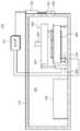
도 1은 일반적인 베이크 유닛을 보여주는 단면도이다.1 is a sectional view showing a general bake unit.
도 1을 참조하면, 베이크 유닛은 내부에 베이크 공정을 수행하는 공간을 제공하는 상부 챔버와 하부 챔버(2,3)과, 하부 챔버(3) 내부에 설치되어 공정시 기판(s)을 가열하는 히터(4), 그리고 배기라인(5)를 포함한다. 베이크 공정을 수행하는 과정에서 기판으로부터 발생되는 흄(fume)은 배기라인(5)을 통해 외부로 배출된다.Referring to Fig. 1, the bake unit includes an upper chamber and a
도 1에서와 같은 베이크 장치(1)에서의 기판 베이크 공정은 기판 예열 단계(step 1)(핀업(pin up)/챔버 다운(chamber down))과 기판 가열 단계(step 2)(핀 다운(pin-down)/챔버 다운)로 이루어진다.The substrate baking process in the
그러나 이러한 기판 베이크 공정에서는 기판 중앙 부분의 두께가 과도하게 상승되는 문제점이 있으며, 이러한 문제는 기판 상의 기류 영향이 주요 원인으로 주목되고 있다. 즉, 베이크 장치(1)는 상부 챔버의 중앙에 제공되는 배기라인을 통한 중앙 집중식 배기 방식으로 베이크 공정시 챔버 내부에 음압이 발생하게 되고 특히 기판 중앙에 형성되는 중앙 기류에 의해 기판 중앙 부분의 막이 상승기류에 의해 솟아오르는 현상으로 기판의 두께 불균일을 유발시킨다.However, in such a substrate baking process, there is a problem that the thickness of the central portion of the substrate is excessively increased, and such a problem is attracting attention as a main cause of airflow on the substrate. That is, the
본 발명의 일 과제는 기판 상의 막 가교 반응 시점에서 기판 상부의 기류 영향을 최소화할 수 있는 베이크 장치 및 이를 이용한 기판 처리 방법을 제공하는데 있다.It is an object of the present invention to provide a bake apparatus capable of minimizing the influence of an air flow above a substrate at the time of film cross-linking reaction on a substrate, and a substrate processing method using the same.
본 발명의 일 과제는 기판의 막 균일성을 개선할 수 있는 베이크 장치 및 이를 이용한 기판 처리 방법을 제공하는데 있다.An object of the present invention is to provide a baking apparatus capable of improving film uniformity of a substrate and a substrate processing method using the same.
본 발명의 일 과제는 기판으로부터 발생되는 흄의 리바운드 현상을 최소화할 수 있는 베이크 장치 및 이를 이용한 기판 처리 방법을 제공하는데 있다.An object of the present invention is to provide a bake apparatus capable of minimizing the rebound phenomenon of fumes generated from a substrate, and a substrate processing method using the same.
본 발명이 해결하고자 하는 과제는 여기에 제한되지 않으며, 언급되지 않은 또 다른 과제들은 아래의 기재로부터 당업자에게 명확하게 이해될 수 있을 것이다.The problems to be solved by the present invention are not limited thereto, and other matters not mentioned can be clearly understood by those skilled in the art from the following description.
본 발명의 일 측면에 따르면, 내부에 열처리 공간을 제공하는 그리고 일측에 기판 반입반출을 위한 슬롯과 상기 슬롯을 개폐하는 셔터 그리고 상기 셔터를 구동하는 셔터 구동부를 갖는 공정 챔버; 상기 공정 챔버의 열처리 공간에 위치되어 기판을 냉각처리하는 냉각 플레이트; 및 기판을 가열처리하는 가열 처리 유닛을 포함하되; 상기 공정 챔버는 상기 가열 처리 유닛에서의 기판 베이크 처리시 상기 슬롯의 오픈율을 변경하기 위해 상기 셔터 구동부를 제어하는 제어부를 포함하는 베이크 장치가 제공될 수 있다.According to an aspect of the present invention, there is provided a process chamber comprising: a processing chamber for providing a heat treatment space therein; a processing chamber having a slot for carrying and unloading a substrate, a shutter for opening and closing the slot, and a shutter driving unit for driving the shutter; A cooling plate positioned in a heat treatment space of the process chamber to cool the substrate; And a heat treatment unit for heat-treating the substrate; The processing chamber may be provided with a bake apparatus including a control unit for controlling the shutter driving unit to change the open rate of the slot in the substrate baking process in the heating processing unit.
또한, 상기 가열 처리 유닛은 기판에 대한 베이크 처리가 진행되는 처리공간을 제공하는 상부바디와 하부바디를 갖는 하우징; 상기 상부바디에 제공되어 상기 처리공간에서의 기류를 배기시키는 배기부재; 상기 하부 바디에 제공되며, 발열체를 갖는 가열 플레이트; 및 상기 상부바디를 상기 하부 바디로부터 이격 또는 상기 상부바디를 상기 하부 바디에 접촉시키기 위한 승강부재를 포함하고, 상기 제어부는 상기 가열 플레이트에 기판이 안착되면 상기 슬롯의 오픈율이 20% 이하를 유지하도록 상기 셔터 구동부를 제어할 수 있다.Further, the heating processing unit may include: a housing having an upper body and a lower body for providing a processing space in which the bake processing for the substrate proceeds; An exhaust member provided on the upper body to exhaust airflow in the processing space; A heating plate provided on the lower body, the heating plate having a heating element; And an elevating member for separating the upper body from the lower body or contacting the upper body with the lower body, wherein the controller controls the opening ratio of the slot to be 20% or less when the substrate is placed on the heating plate The shutter driving unit can be controlled.
또한, 상기 제어부는 기판이 상기 가열 플레이트에 안착되면 상기 상부 바디가 상기 하부 바디로부터 이격된 상태를 소정시간 유지한 후 다시 상기 하부 바디에 밀착되도록 상기 승강부재를 제어할 수 있다.The control unit may control the elevating member such that when the substrate is seated on the heating plate, the upper body is kept apart from the lower body for a predetermined time and then closely contacted to the lower body.
또한, 상기 제어부는 상기 승강부재에 의해 상기 상부 바디가 상기 하부 바디에 밀착되면, 상기 슬롯의 오픈율이 80% 이상을 유지하도록 상기 셔터 구동부를 제어할 수 있다.In addition, the control unit may control the shutter driving unit to maintain the open rate of the slot at 80% or more when the upper body is brought into close contact with the lower body by the elevating member.
본 발명의 일 측면에 따르면, 슬롯을 갖는 공정 챔버와, 기판에 대한 베이크 처리공간을 제공하는 상부바디와 하부바디를 갖는 가열 처리 유닛이 상기 챔버 내부에 제공되는 베이크 장치에서의 기판 처리 방법에 있어서: 상기 기판이 상기 가열 처리 유닛의 베이크 처리 공간에서 예열하는 단계; 상기 기판이 상기 가열 처리 유닛의 가열 플레이트에 안착되어 베이킹하는 단계를 포함하되; 상기 베이킹 단계는 상기 기판 상의 기류 영향을 최소화한 상태에서 기판을 베이킹하는 1차 베이킹 단계; 및 상기 기판 상의 기류 영향을 최대화한 상태에서 기판을 베이킹하는 2차 베이킹 단계를 포함하는 기판 처리 방법이 제공될 수 있다.According to an aspect of the present invention, there is provided a substrate processing method in a bake apparatus in which a process chamber having a slot, a heat processing unit having an upper body and a lower body for providing a bake processing space with respect to the substrate, : Preheating the substrate in the bake processing space of the heat treatment unit; Placing the substrate on a heating plate of the heat treatment unit and baking; Wherein the baking step comprises: a first baking step of baking the substrate with the air flow influence on the substrate minimized; And a secondary baking step of baking the substrate in a state in which the air flow influence on the substrate is maximized.
또한, 상기 1차 베이킹 단계는 상기 슬롯의 오픈율이 20% 이하로 낮아진 상태에서 진행될 수 있다.Also, the first baking may be performed in a state where the open rate of the slot is lowered to 20% or less.
또한, 상기 1차 베이킹 단계는 상기 상부 바디가 상기 하부 바디로부터 이격되는 상기 베이크 처리공간이 개방된 상태에서 진행될 수 있다.In addition, the first baking step may be performed while the bake processing space in which the upper body is spaced apart from the lower body is opened.
또한, 상기 2차 베이킹 단계는 상기 슬롯의 오픈율이 80% 이상 높아진 상태에서 진행될 수 있다.Also, the secondary baking may be performed in a state where the open rate of the slot is increased by 80% or more.
또한, 상기 2차 베이킹 단계는 상기 상부 바디가 상기 하부 바디로부터 밀착되는 상기 베이크 처리공간이 닫힌 상태에서 진행될 수 있다.Also, the secondary baking step may be performed while the bake processing space in which the upper body is in contact with the lower body is closed.
본 발명의 일 측면에 따르면, 베이크 처리공간을 제공하는 가열 처리 유닛과, 상기 가열 처리 유닛이 위치되는 열처리 공간을 제공하는 공정 챔버를 갖는 베이크 장치에서의 기판 처리 방법에 있어서: 상기 베이크 처리공간은 닫혀진 상태에서 기판은 가열 플레이트로부터 이격되도록 리프트 핀에 안착된 상태로 예열처리되는 1단계; 상기 베이크 처리공간은 오픈된 상태에서 상기 기판은 상기 가열 플레이트에 안착된 상태로 1차 베이킹되는 2단계; 상기 베이크 처리공간은 닫혀진 상태에서 상기 기판은 상기 가열 플레이트에 안착된 상태로 2차 베이킹되는 3단계를 포함하는 기판 처리 방법이 제공될 수 있다.According to an aspect of the present invention, there is provided a substrate processing method in a bake apparatus having a heat processing unit for providing a bake processing space and a process chamber for providing a heat processing space in which the heat processing unit is located, A step of preheating the substrate in a closed state while being seated on the lift pin so as to be spaced from the heating plate; A second stage in which the substrate is first baked while the substrate is seated on the heating plate in an open state; And the substrate is secondarily baked while the substrate is placed on the heating plate in a state where the bake processing space is closed.
또한, 상기 2단계와 상기 3단계는 상기 공정 챔버의 기판 출입을 위해 제공되는 슬롯의 오픈율이 서로 상이할 수 있다.Also, the openings of the slots provided for entering and exiting the process chamber may differ from each other in the second and third steps.
또한, 상기 2단계에서 상기 슬롯의 오픈율은 상기 3단계에서 상기 슬롯 오픈율보다 작을 수 있다.In addition, the open rate of the slot in the
본 발명의 실시예에 의하면, 기판 상의 막 가교 반응 시점에서 기판 상부의 배기 기류를 최소화함으로써 기판의 막 균일성을 개선할 수 있다.According to the embodiment of the present invention, the film uniformity of the substrate can be improved by minimizing the exhaust air flow above the substrate at the time of film cross-linking reaction on the substrate.
본 발명의 실시예에 의하면, 슬롯의 오픈율 조정을 통해 외부기류 유입량을 조절하여 기판으로부터 발생되는 흄의 리바운드 현상을 최소화할 수 있다.According to the embodiment of the present invention, the rebound phenomenon of the fume generated from the substrate can be minimized by adjusting the flow rate of the external air flow through the adjustment of the open rate of the slots.
도 1은 일반적인 베이크 유닛을 보여주는 단면도이다.
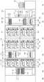
도 2는 기판 처리 설비를 상부에서 바라본 도면이다.
도 3은 도 2의 설비를 A-A 방향에서 바라본 도면이다.
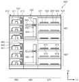
도 4는 도 2의 설비를 B-B 방향에서 바라본 도면이다.
도 5는 도 2의 설비를 C-C 방향에서 바라본 도면이다.
도 6은 본 발명의 실시예에 따른 베이크 유닛을 보여주는 평면도이다.
도 7은 도 6에 도시된 베이크 유닛을 보여주는 측면도이다.
도 8은 도 6의 가열 처리 공정을 수행하는 가열 처리 유닛을 보여주는 단면도이다.
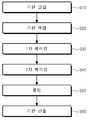
도 9는 베이크 유닛에서의 기판 처리 방법을 보여주는 플로우 챠트이다.
도 10은 도 9에 도시된 기판 처리 과정에서 상부바디,리프트핀 그리고 슬롯의 동작 상태를 보여주는 도면이다.
도 11 및 도 14는 도 9의 각 단계별 기판 처리 상태를 보여주는 도면들이다.1 is a sectional view showing a general bake unit.
Figure 2 is a top view of the substrate processing facility.
Fig. 3 is a view of the equipment of Fig. 2 viewed from the direction AA.
Fig. 4 is a view of the equipment of Fig. 2 viewed from the BB direction. Fig.
Fig. 5 is a view of the equipment of Fig. 2 viewed from the CC direction.
6 is a plan view showing a bake unit according to an embodiment of the present invention.
7 is a side view showing the bake unit shown in Fig.
8 is a cross-sectional view showing a heat treatment unit for performing the heat treatment process of FIG.
9 is a flow chart showing a substrate processing method in the bake unit.
FIG. 10 is a view showing operation states of the upper body, the lift pins, and the slots in the substrate processing process shown in FIG.
FIGS. 11 and 14 are views showing substrate processing states of the respective steps of FIG.
이하, 본 발명의 실시 예를 첨부된 도면을 참조하여 더욱 상세히 설명한다. 본 발명의 실시 예는 여러 가지 형태로 변형될 수 있으며, 본 발명의 범위가 아래의 실시 예들로 한정되는 것으로 해석되어서는 안 된다. 본 실시 예는 당업계에서 평균적인 지식을 가진 자에게 본 발명을 더욱 완전하게 설명하기 위해 제공되는 것이다. 따라서 도면에서의 요소의 형상은 보다 명확한 설명을 강조하기 위해 과장되었다.Hereinafter, embodiments of the present invention will be described in detail with reference to the accompanying drawings. The embodiments of the present invention may be modified in various forms, and the scope of the present invention should not be construed as being limited to the following embodiments. This embodiment is provided to more fully describe the present invention to those skilled in the art. Thus, the shape of the elements in the figures has been exaggerated to emphasize a clearer description.
본 실시예의 설비는 반도체 웨이퍼 또는 평판 표시 패널과 같은 기판에 대해 포토리소그래피 공정을 수행하는 데 사용될 수 있다. 특히 본 실시예의 설비는 노광장치에 연결되어 기판에 대해 도포 공정 및 현상 공정을 수행하는 데 사용될 수 있다. 아래에서는 기판으로 웨이퍼가 사용된 경우를 예로 들어 설명한다.The facilities of this embodiment can be used to perform a photolithography process on a substrate such as a semiconductor wafer or a flat panel display panel. In particular, the apparatus of this embodiment can be used to perform a coating process and a developing process on a substrate, which is connected to an exposure apparatus. Hereinafter, a case where a wafer is used as a substrate will be described as an example.
도 2 내지 도 5는 본 발명의 일 실시예에 따른 기판 처리 설비를 개략적으로 보여주는 도면들이다. 도 2는 기판 처리 설비를 상부에서 바라본 도면이고, 도 3은 도 2의 설비를 A-A 방향에서 바라본 도면이고, 도 4는 도 2의 설비를 B-B 방향에서 바라본 도면이고, 도 5는 도 2의 설비를 C-C 방향에서 바라본 도면이다.FIGS. 2 to 5 are views schematically showing a substrate processing apparatus according to an embodiment of the present invention. FIG. 2 is a view of the substrate processing apparatus viewed from above, FIG. 3 is a view of the apparatus of FIG. 2 viewed from the AA direction, FIG. 4 is a view of the apparatus of FIG. 2 viewed from the BB direction, In the CC direction.
도 2 내지 도 5를 참조하면, 기판 처리 설비(1)는 로드 포트(100), 인덱스 모듈(200), 제 1 버퍼 모듈(300), 도포 및 현상 모듈(400), 제 2 버퍼 모듈(500), 노광 전후 처리 모듈(600), 그리고 인터페이스 모듈(700)을 포함한다. 로드 포트(100), 인덱스 모듈(200), 제 1 버퍼 모듈(300), 도포 및 현상 모듈(400), 제 2 버퍼 모듈(500), 노광 전후 처리 모듈(600), 그리고 인터페이스 모듈(700)은 순차적으로 일 방향으로 일렬로 배치된다.2 to 5, the
이하, 로드 포트(100), 인덱스 모듈(200), 제 1 버퍼 모듈(300), 도포 및 현상 모듈(400), 제 2 버퍼 모듈(500), 노광 전후 처리 모듈(600), 그리고 인터페이스 모듈(700)이 배치된 방향을 제 1 방향(12)이라 칭하고, 상부에서 바라볼 때 제 1 방향(12)과 수직한 방향을 제 2 방향(14)이라 칭하고, 제 1 방향(12) 및 제 2 방향(14)과 각각 수직한 방향을 제 3 방향(16)이라 칭한다.Hereinafter, the
기판(W)은 카세트(20) 내에 수납된 상태로 이동된다. 이때 카세트(20)는 외부로부터 밀폐될 수 있는 구조를 가진다. 예컨대, 카세트(20)로는 전방에 도어를 가지는 전면 개방 일체식 포드(Front Open Unified Pod; FOUP)가 사용될 수 있다.The substrate W is moved in a state accommodated in the
이하에서는 로드 포트(100), 인덱스 모듈(200), 제 1 버퍼 모듈(300), 도포 및 현상 모듈(400), 제 2 버퍼 모듈(500), 노광 전후 처리 모듈(600), 그리고 인터페이스 모듈(700)에 대해 상세히 설명한다.Hereinafter, the
로드 포트(100)는 기판들(W)이 수납된 카세트(20)가 놓여지는 재치대(120)를 가진다. 재치대(120)는 복수개가 제공되며, 재치대들(200)은 제 2 방향(14)을 따라 일렬로 배치된다. 도 1에서는 4개의 재치대(120)가 제공되었다.The
인덱스 모듈(200)은 로드 포트(100)의 재치대(120)에 놓인 카세트(20)와 제 1 버퍼 모듈(300) 간에 기판(W)을 이송한다. 인덱스 모듈(200)은 프레임(210), 인덱스 로봇(220), 그리고 가이드 레일(230)을 가진다. 프레임(210)은 대체로 내부가 빈 직육면체의 형상으로 제공되며, 로드 포트(100)와 제 1 버퍼 모듈(300) 사이에 배치된다. 인덱스 모듈(200)의 프레임(210)은 후술하는 제 1 버퍼 모듈(300)의 프레임(310)보다 낮은 높이로 제공될 수 있다. 인덱스 로봇(220)과 가이드 레일(230)은 프레임(210) 내에 배치된다. 인덱스 로봇(220)은 기판(W)을 직접 핸들링하는 핸드(221)가 제 1 방향(12), 제 2 방향(14), 제 3 방향(16)으로 이동 가능하고 회전될 수 있도록 4축 구동이 가능한 구조를 가진다. 인덱스 로봇(220)은 핸드(221), 아암(222), 지지대(223), 그리고 받침대(224)를 가진다. 핸드(221)는 아암(222)에 고정 설치된다. 아암(222)은 신축 가능한 구조 및 회전 가능한 구조로 제공된다. 지지대(223)는 그 길이 방향이 제 3 방향(16)을 따라 배치된다. 아암(222)은 지지대(223)를 따라 이동 가능하도록 지지대(223)에 결합된다. 지지대(223)는 받침대(224)에 고정결합된다. 가이드 레일(230)은 그 길이 방향이 제 2 방향(14)을 따라 배치되도록 제공된다. 받침대(224)는 가이드 레일(230)을 따라 직선 이동 가능하도록 가이드 레일(230)에 결합된다. 또한, 도시되지는 않았지만, 프레임(210)에는 카세트(20)의 도어를 개폐하는 도어 오프너가 더 제공된다.The
제 1 버퍼 모듈(300)은 프레임(310), 제 1 버퍼(320), 제 2 버퍼(330), 냉각 챔버(350), 그리고 제 1 버퍼 로봇(360)을 가진다. 프레임(310)은 내부가 빈 직육면체의 형상으로 제공되며, 인덱스 모듈(200)과 도포 및 현상 모듈(400) 사이에 배치된다. 제 1 버퍼(320), 제 2 버퍼(330), 냉각 챔버(350), 그리고 제 1 버퍼 로봇(360)은 프레임(310) 내에 위치된다. 냉각 챔버(350), 제 2 버퍼(330), 그리고 제 1 버퍼(320)는 순차적으로 아래에서부터 제 3 방향(16)을 따라 배치된다. 제 1 버퍼(320)는 후술하는 도포 및 현상 모듈(400)의 도포 모듈(401)과 대응되는 높이에 위치되고, 제 2 버퍼(330)와 냉각 챔버(350)는 후술하는 도포 및 현상 모듈(400)의 현상 모듈(402)과 대응되는 높이에 위치된다. 제 1 버퍼 로봇(360)은 제 2 버퍼(330), 냉각 챔버(350), 그리고 제 1 버퍼(320)와 제 2 방향(14)으로 일정 거리 이격되게 위치된다.The
제 1 버퍼(320)와 제 2 버퍼(330)는 각각 복수의 기판들(W)을 일시적으로 보관한다. 제 2 버퍼(330)는 하우징(331)과 복수의 지지대들(332)을 가진다. 지지대들(332)은 하우징(331) 내에 배치되며, 서로 간에 제 3 방향(16)을 따라 이격되게 제공된다. 각각의 지지대(332)에는 하나의 기판(W)이 놓인다. 하우징(331)은 인덱스 로봇(220), 제 1 버퍼 로봇(360), 그리고 후술하는 현상 모듈(402)의 현상부 로봇(482)이 하우징(331) 내 지지대(332)에 기판(W)을 반입 또는 반출할 수 있도록 인덱스 로봇(220)이 제공된 방향, 제 1 버퍼 로봇(360)이 제공된 방향, 그리고 현상부 로봇(482)이 제공된 방향에 개구(도시되지 않음)를 가진다. 제 1 버퍼(320)는 제 2 버퍼(330)와 대체로 유사한 구조를 가진다. 다만, 제 1 버퍼(320)의 하우징(321)에는 제 1 버퍼 로봇(360)이 제공된 방향 및 후술하는 도포 모듈(401)에 위치된 도포부 로봇(432)이 제공된 방향에 개구를 가진다. 제 1 버퍼(320)에 제공된 지지대(322)의 수와 제 2 버퍼(330)에 제공된 지지대(332)의 수는 동일하거나 상이할 수 있다. 일 예에 의하면, 제 2 버퍼(330)에 제공된 지지대(332)의 수는 제 1 버퍼(320)에 제공된 지지대(322)의 수보다 많을 수 있다.The
제 1 버퍼 로봇(360)은 제 1 버퍼(320)와 제 2 버퍼(330) 간에 기판(W)을 이송시킨다. 제 1 버퍼 로봇(360)은 핸드(361), 아암(362), 그리고 지지대(363)를 가진다. 핸드(361)는 아암(362)에 고정 설치된다. 아암(362)은 신축 가능한 구조로 제공되어, 핸드(361)가 제 2 방향(14)을 따라 이동 가능하도록 한다. 아암(362)은 지지대(363)를 따라 제 3 방향(16)으로 직선 이동 가능하도록 지지대(363)에 결합된다. 지지대(363)는 제 2 버퍼(330)에 대응되는 위치부터 제 1 버퍼(320)에 대응되는 위치까지 연장된 길이를 가진다. 지지대(363)는 이보다 위 또는 아래 방향으로 더 길게 제공될 수 있다. 제 1 버퍼 로봇(360)은 단순히 핸드(361)가 제 2 방향(14) 및 제 3 방향(16)을 따른 2축 구동만 되도록 제공될 수 있다.The
냉각 챔버(350)는 각각 기판(W)을 냉각한다. 냉각 챔버(350)는 하우징(351)과 냉각 플레이트(352)를 가진다. 냉각 플레이트(352)는 기판(W)이 놓이는 상면 및 기판(W)을 냉각하는 냉각 수단(353)을 가진다. 냉각 수단(353)으로는 냉각수에 의한 냉각이나 열전 소자를 이용한 냉각 등 다양한 방식이 사용될 수 있다. 또한, 냉각 챔버(350)에는 기판(W)을 냉각 플레이트(352) 상에 위치시키는 리프트 핀 어셈블리(도시되지 않음)가 제공될 수 있다. 하우징(351)은 인덱스 로봇(220) 및 후술하는 현상 모듈(402)에 제공된 현상부 로봇(482)이 냉각 플레이트(352)에 기판(W)을 반입 또는 반출할 수 있도록 인덱스 로봇(220)이 제공된 방향 및 현상부 로봇(482)이 제공된 방향에 개구(도시되지 않음)를 가진다. 또한, 냉각 챔버(350)에는 상술한 개구를 개폐하는 도어들(도시되지 않음)이 제공될 수 있다.The cooling
도포 및 현상 모듈(400)은 노광 공정 전에 기판(W) 상에 포토 레지스트를 도포하는 공정 및 노광 공정 후에 기판(W)을 현상하는 공정을 수행한다. 도포 및 현상 모듈(400)은 대체로 직육면체의 형상을 가진다. 도포 및 현상 모듈(400)은 도포 모듈(401)과 현상 모듈(402)을 가진다. 도포 모듈(401)과 현상 모듈(402)은 서로 간에 층으로 구획되도록 배치된다. 일 예에 의하면, 도포 모듈(401)은 현상 모듈(402)의 상부에 위치된다.The application and
도포 모듈(401)은 기판(W)에 대해 포토레지스트와 같은 감광액을 도포하는 공정 및 레지스트 도포 공정 전후에 기판(W)에 대해 가열 및 냉각과 같은 열처리 공정을 포함한다. 도포 모듈(401)은 레지스트 도포 챔버(410), 베이크 유닛(420), 그리고 반송 챔버(430)를 가진다. 레지스트 도포 챔버(410), 베이크 유닛(420), 그리고 반송 챔버(430)는 제 2 방향(14)을 따라 순차적으로 배치된다. 따라서 레지스트 도포 챔버(410)와 베이크 유닛(420)은 반송 챔버(430)를 사이에 두고 제 2 방향(14)으로 서로 이격되게 위치된다. 레지스트 도포 챔버(410)는 복수 개가 제공되며, 제 1 방향(12) 및 제 3 방향(16)으로 각각 복수 개씩 제공된다. 도면에서는 6개의 레지스트 도포 챔버(410)가 제공된 예가 도시되었다. 베이크 유닛(420)은 제 1 방향(12) 및 제 3 방향(16)으로 각각 복수 개씩 제공된다. 도면에서는 6개의 베이크 유닛(420)이 제공된 예가 도시되었다. 그러나 이와 달리 베이크 유닛(420)은 더 많은 수로 제공될 수 있다.The
반송 챔버(430)는 제 1 버퍼 모듈(300)의 제 1 버퍼(320)와 제 1 방향(12)으로 나란하게 위치된다. 반송 챔버(430) 내에는 도포부 로봇(432)과 가이드 레일(433)이 위치된다. 반송 챔버(430)는 대체로 직사각의 형상을 가진다. 도포부 로봇(432)은 베이크 유닛들(420), 레지스트 도포 챔버들(400), 제 1 버퍼 모듈(300)의 제 1 버퍼(320), 그리고 후술하는 제 2 버퍼 모듈(500)의 제 1 냉각 챔버(520) 간에 기판(W)을 이송한다. 가이드 레일(433)은 그 길이 방향이 제 1 방향(12)과 나란하도록 배치된다. 가이드 레일(433)은 도포부 로봇(432)이 제 1 방향(12)으로 직선 이동되도록 안내한다. 도포부 로봇(432)은 핸드(434), 아암(435), 지지대(436), 그리고 받침대(437)를 가진다. 핸드(434)는 아암(435)에 고정 설치된다. 아암(435)은 신축 가능한 구조로 제공되어 핸드(434)가 수평 방향으로 이동 가능하도록 한다. 지지대(436)는 그 길이 방향이 제 3 방향(16)을 따라 배치되도록 제공된다. 아암(435)은 지지대(436)를 따라 제 3 방향(16)으로 직선 이동 가능하도록 지지대(436)에 결합된다. 지지대(436)는 받침대(437)에 고정 결합되고, 받침대(437)는 가이드 레일(433)을 따라 이동 가능하도록 가이드 레일(433)에 결합된다.The
레지스트 도포 챔버들(410)은 모두 동일한 구조를 가진다. 다만, 각각의 레지스트 도포 챔버(410)에서 사용되는 포토 레지스트의 종류는 서로 상이할 수 있다. 일 예로서 포토 레지스트로는 화학 증폭형 레지스트(chemical amplification resist)가 사용될 수 있다. 레지스트 도포 챔버(410)는 기판(W) 상에 포토 레지스트를 도포한다. 레지스트 도포 챔버(410)는 하우징(411), 지지 플레이트(412), 그리고 노즐(413)을 가진다. 하우징(411)은 상부가 개방된 컵 형상을 가진다. 지지 플레이트(412)는 하우징(411) 내에 위치되며, 기판(W)을 지지한다. 지지 플레이트(412)는 회전 가능하게 제공된다. 노즐(413)은 지지 플레이트(412)에 놓인 기판(W) 상으로 포토 레지스트를 공급한다. 노즐(413)은 원형의 관 형상을 가지고, 기판(W)의 중심으로 포토 레지스트를 공급할 수 있다. 선택적으로 노즐(413)은 기판(W)의 직경에 상응하는 길이를 가지고, 노즐(413)의 토출구는 슬릿으로 제공될 수 있다. 또한, 추가적으로 레지스트 도포 챔버(410)에는 포토 레지스트가 도포된 기판(W) 표면을 세정하기 위해 탈이온수와 같은 세정액을 공급하는 노즐(414)이 더 제공될 수 있다.The resist
베이크 유닛(420)은 기판(W)을 열처리한다. 예컨대, 베이크 유닛들(420)은 포토 레지스트를 도포하기 전에 기판(W)을 소정의 온도로 가열하여 기판(W) 표면의 유기물이나 수분을 제거하는 프리 베이크(prebake) 공정이나 포토레지스트를 기판(W) 상에 도포한 후에 행하는 소프트 베이크(soft bake) 공정 등을 수행하고, 각각의 가열 공정 이후에 기판(W)을 냉각하는 냉각 공정 등을 수행한다.The
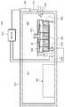
도 6은 본 발명의 실시예에 따른 베이크 유닛을 보여주는 평면도이고, 도 7은 도 6에 도시된 베이크 유닛을 보여주는 측면도이며, 도 8은 도 6의 가열 처리 공정을 수행하는 가열 처리 유닛을 보여주는 단면도이다.FIG. 6 is a plan view showing the bake unit according to the embodiment of the present invention, FIG. 7 is a side view showing the bake unit shown in FIG. 6, and FIG. 8 is a sectional view showing the heat treatment unit performing the heat treatment process of FIG. to be.
도 6 내지 도 8을 참조하면, 베이크 유닛(420)은 공정 챔버(423), 냉각 플레이트(422), 그리고 가열 처리 유닛(800)을 포함할 수 있다.6 to 8, the
공정 챔버(423)는 내부에 열처리 공간(421)을 제공한다. 공정 챔버(423)는 직육면체 형상을 가지도록 제공될 수 있다. 공정 챔버(423)의 일측에는 기판 반입 및 반출을 위한 슬롯(424)이 제공되며, 슬롯(424)은 셔터(425)에 의해 개폐되고, 셔터(425)는 셔터 구동부(426)에 의해 구동된다. 공정 진행시 슬롯(424)의 오픈율은 100%-> 0-20% -> 80% -> 100% 순으로 변경되며, 이를 위해 셔터 구동부(426)는 제어부(con)에 의해 제어된다.The
제어부(con)는 가열 플레이트(810)에 기판이 안착되면 슬롯(424)의 오픈율이 20% 이하를 유지하도록 셔터 구동부(426)를 제어하고, 승강부재(868)에 의해 상부 바디(864)가 다운 이동되면, 슬롯(424)의 오픈율이 80% 이상을 유지하도록 셔터 구동부(426)를 제어할 수 있다. 또한, 제어부(con)는 기판이 가열 플레이트로부터 안착되도록 핀구동부재(844)를 제어할 수 있다.The control unit con controls the
냉각 플레이트(422)는 가열 처리 유닛(800)에 의해 가열 처리된 기판을 냉각 처리할 수 있다. 냉각 플레이트(422)는 열 처리 공간(421)에 위치될 수 있다. 냉각 플레이트(422)는 원형의 판 형상으로 제공될 수 있다. 냉각 플레이트(422)의 내부에는 냉각수 또는 열전 소자와 같은 냉각 수단이 제공된다. 예컨대, 냉각 플레이트(422)는 가열된 기판을 상온으로 냉각시킬 수 있다.The
가열 처리 유닛(800)은 기판을 가열 처리한다. 가열 처리 유닛(800)은 하우징(860), 가열 플레이트(810), 가열부재(830), 그리고 배기부재(870)를 포함할 수 있다.The
하우징은(860)은 기판(W)의 가열 처리 공정이 진행되는 처리 공간(802)을 제공한다. 하우징(860)은 하부 바디(862), 상부 바디(864), 구동기(868)를 포함한다.The
하부 바디(862)는 상측이 개방된 통 형상으로 제공될 수 있다. 하부 바디(862)에는 가열 플레이트(810)와 가열부재(830)가 위치된다. 하부 바디(862)는 가열 플레이트(810)의 주변에 위치한 장치들이 열 변형되는 것을 방지하기 위해 단열 커버들을 포함할 수 있다.The
상부 바디(864)는 하부가 개방된 통 형상을 가진다. 상부 바디(864)는 하부 바디(862)와 조합되어 내부에 처리 공간(802)을 형성한다. 상부 바디(864)는 하부 바디(862)보다 큰 직경을 가진다. 상부 바디(864)는 하부 바디(862)의 상부에 위치된다.The
상부 바디(864)는 승강부재(868)에 의해 상하 방향으로 이동 가능하다. 상부 바디(864)는 상하 방향으로 이동되어 승강(UP) 위치 및 하강(Down) 위치로 이동 가능하다. 여기서 승강 위치되는 상부 바디(864)가 하부 바디(862)와 이격되는 위치이고, 하강 위치는 상부 바디(864)가 하부 바디(862)에 접촉되게 제공되는 위치이다. 승강부재(868)는 제어부(con)에 의해 제어된다.The
가열 플레이트(810)는 열 처리 공간(802)에 위치된다. 가열 플레이트(810)는 냉각 플레이트(422)의 일측에 위치된다. 가열 플레이트(810)는 원형의 판 형상으로 제공된다. 가열 플레이트(810)의 상면은 기판(W)이 놓이는 지지 영역으로 제공된다. 도 8를 참조하면, 가열 플레이트(810)의 상면에는 복수 개의 핀 홀들(812)이 형성된다. 예컨대, 핀 홀(812)들은 3개로 제공될 수 있다. 각각의 핀 홀(812)은 가열 플레이트(810)의 원주방향을 따라 이격되게 위치된다. 핀 홀(812)들은 서로 간에 동일 간격으로 이격되게 위치된다. 각각의 핀 홀(812)에는 리프트핀(842)이 제공된다. 리프트핀(842)은 핀구동부재(844)에 의해 상하방향으로 이동 가능한다.The
가열 부재(830)는 가열 플레이트(810)에 놓인 기판(W)을 기설정 온도로 가열한다. 가열 부재(830)는 복수 개의 발열체를 포함할 수 있. 가열 부재(830)는 가열 플레이트(810)의 내부에 위치될 수 있다. 각각의 발열체는 가열 플레이트(810)의 서로 상이한 영역을 가열할 수 있다. 가열 플레이트(810)의 서로 상이한 영역은 각 발열체에 의해 가열되는 히팅존으로 제공된다. 각 히텅존은 발열체들과 일대일 대응되도록 제공된다. 예컨대, 가열 부재(830)는 열전 소자 또는 열선 또는 면상 발열체일 수 있다.The
배기 부재(870)는 가이드 부재(872)와 배기관(874)을 포함할 수 있다.The
가이드 부재(872)는 가열 플레이트(810)와 대향되게 배치되며 상부 바디(864)의 상면 내벽 및 측면 내벽과 이격되게 위치된다. 따라서, 하우징(860)의 처리 공간(802)에는 가이드 부재(872) 위쪽의 상부공간(804)과 가이드 부재(872) 아래쪽의 하부 공간(806)이 형성될 수 있다. 하부 공간(806)은 기판 상부로 유입되는 기체 및 기판으로부터 발생되는 흄이 배기되는 배기영역일 수 있다.The
가이드 부재(872)는 중앙에 배기공(873)이 형성된 원형의 플레이트로 제공될 수 있으며, 배기관(874)은 상부바디(864)를 관통하여 배기공(873)과 연결된다. 또한, 가이드 부재(872)의 크기는 기판보다 크게 형성될 수 있다. 가이드 부재는 중앙에서 가장자리로 갈수록 하향경사지게 형성될 수 있다.The
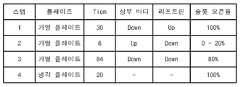
도 9는 베이크 유닛에서의 기판 처리 방법을 보여주는 플로우 챠트이고, 도 10은 도 9에 도시된 기판 처리 과정에서 상부바디,리프트핀 그리고 슬롯의 동작 상태를 보여주는 표이다. 그리고, 도 11 및 도 14는 도 9의 각 단계별 기판 처리 상태를 보여주는 도면들이다.FIG. 9 is a flowchart showing a substrate processing method in the bake unit, and FIG. 10 is a table showing the operation states of the upper body, the lift pins, and the slots in the substrate processing process shown in FIG. 11 and 14 are views showing substrate processing states of the respective steps of FIG.
도 9 내지 도 14를 참조하면, 베이크 유닛에서의 기판 처리 방법은 기판 반입 단계(S10), 기판 예열 단계(S20), 1차 베이킹 단계(S30), 2차 베이킹 단계(S40), 쿨링 단계(S50) 그리고 기판 반출 단계(S60)를 포함한다.9 to 14, a substrate processing method in a bake unit includes a substrate carrying-in step S10, a substrate preheating step S20, a first baking step S30, a second baking step S40, a cooling step S50) and a substrate removal step (S60).
(기판 반입 단계)(Substrate loading step)
도 9를 참조하면, 기판(W)은 반송 챔버(430)의 도포부 로봇(432)에 의해 베이크 유닛(420)의 공정 챔버(423) 내부로 반입된 후 업(UP) 포지션의 리프트핀(842)에 안착된다. 기판 반입은 가열 처리 유닛(800)의 하우징(860)이 오픈된 상태인 상부 바디(864)가 UP 포지션으로 상승 이동된 상태에서 이루어진다.9, the substrate W is carried into the
(기판 예열 단계)(Substrate preheating step)
도 9, 도 10 그리고 도 11을 참조하면, 기판 예열은 가열 처리 유닛(800)의 하우징(860)이 오프된 상태(상부 바디(864)가 Down 포지션으로 하강 이동된 상태), 리프트핀(842)은 업 포지션, 슬롯(424)은 100% 오픈된 상태에서 이루어진다. 기판은 업(UP) 포지션의 리프트핀(842)에 안착된 상태에서 가열 부재(830)로부터 발생되는 열에 의해 예열된다.9, 10, and 11, the preheating of the substrate is performed in a state where the
(1차 베이킹 단계)(Primary baking step)
도 9, 도 10 그리고 도 12를 참조하면, 1차 베이킹은 가열 처리 유닛(800)의 하우징(860)이 오픈된 상태(상부 바디(864)가 UP 포지션으로 상승 이동된 상태), 리프트핀(842)은 다운 포지션, 슬롯(424)은 0~20% 오픈된 상태에서 이루어진다. 기판은 가열 플레이트(810)에 안착된 상태에서 가열 부재(830)로부터 발생되는 열에 의해 1차 베이킹된다. 일 예로, 1차 베이킹은 대략 6초 가량 소요된다.9, 10 and 12, the primary baking is performed in a state in which the
1차 베이킹은 기판 상의 막 가교 반응 시점에서 기판 상부의 기류 영향을 최소화할 수 있어 기판 중심부분의 두께 균일성을 개선시킬 수 있다. 일 예로, 1차 베이킹 처리 시간은 막의 가교 반응 시간과 대응될 수 있다. 즉, 가교 반응이 완료된 후에는 2차 베이킹 단계로 넘어가게 된다.The first baking can minimize the influence of the airflow above the substrate at the time of film cross-linking reaction on the substrate, thereby improving the uniformity of the thickness of the central portion of the substrate. In one example, the first baking treatment time may correspond to the crosslinking reaction time of the film. That is, after the crosslinking reaction is completed, the second baking step is carried out.
1차 베이킹이 하우징(860)이 오픈된 상태 그리고 슬롯(424)은 0-20%만 오픈된 상태에서 진행됨으로써 하우징(860) 내부의 음압 발생을 감소시켜 기판 중앙 부분의 막이 솟아오르는 현상을 방지할 수 있다. 만약, 슬롯(424)의 오픈율을 20% 이상으로 상승시킬 경우 슬롯(424)을 통해 외부 기류 유입량이 증가되고 외부 기류가 가열 처리 유닛(80))의 하우징(86)) 내부로 유입되면서 기판으로부터 발생되는 흄이 리바운드되는 현상을 가중시킬 수 있게 된다. 따라서, 1차 베이킹은 하우징(860) 내부의 음압 발생을 방지하기 위해 하우징(860)이 오픈된 상태에서 진행되고, 외부기류 유입에 의한 흄 리바운드 현상 및 외부 파티클 유입에 의한 기판 오염을 최소화하기 위해 슬롯(424)의 오픈율을 20% 이하로 유지하는 것이 바람직하다.The first baking is performed in a state where the
(2차 베이킹 단계)(Secondary baking step)
도 9, 도 10 그리고 도 13을 참조하면, 2차 베이킹은 가열 처리 유닛(800)의 하우징(860)이 오프된 상태(상부 바디(864)가 Down 포지션으로 하강 이동된 상태), 리프트핀(842)은 다운 포지션, 슬롯(424)은 80% 오픈된 상태에서 이루어진다. 기판은 가열 플레이트(810)에 안착된 상태에서 가열 부재(830)로부터 발생되는 열에 의해 2차 베이킹된다. 일 예로, 2차 베이킹은 대략 84초 가량 소요된다.9, 10 and 13, the secondary baking is performed in a state where the
(쿨링 단계)(Cooling step)
도 9, 도 10 그리고 도 14를 참조하면, 2차 베이킹을 마친 기판은 가열 처리 유닛(800)로부터 냉각 플레이트(422)로 이송되어 냉각 플레이트에 안착된다. 쿨링 단계는 냉각 플레이트서 진행된다. 이때, 쿨링 단계는 슬롯(424)이 100% 오픈된 상태에서 이루어진다. 일 예로, 쿨링 단게는 대략 20초 가량 소요된다.9, 10, and 14, the substrate after the second baking is transferred from the
(기판 반출 단계)(Substrate take-out step)
도 9를 참조하면, 기판(W)은 반송 챔버(430)의 도포부 로봇(432)에 의해 베이크 유닛(420)의 공정 챔버(423)로부터 반출된다.9, the substrate W is taken out of the
상술한 바와 같이, 베이크 유닛에서의 기판 처리 방법은 기판의 막 두께 균일성 관점에서 하우징(860) 오픈(상부 바디(864)가 UP 포지션으로 상승 이동), 리프트핀(842) 다운 공정을 추가함으로써, 가교 시점에서 하우징 내부의 배기 기류를 최소화하여 기판 중앙부분의 막 균일성을 개선할 수 있다.As described above, the substrate processing method in the bake unit is advantageous in that the
또한, 베이크 유닛에서의 기판 처리 방법은 흄(fume) 관점에서 1차 베이킹시 슬롯의 오픈율을 20%이하로 변경하여 외부 기류 유입을 최소화함으로써 흄 리바운드 감소에 의한 결함을 최소화할 수 있다.In addition, from the viewpoint of the fume, the substrate processing method in the bake unit minimizes the defects due to the reduction of the fume rebound by minimizing the inflow of the external airflow by changing the open rate of the slots to less than 20% in the first baking.
다시 도 2 내지 도 5를 참조하면, 현상 모듈(402)은 기판(W) 상에 패턴을 얻기 위해 현상액을 공급하여 포토 레지스트의 일부를 제거하는 현상 공정, 및 현상 공정 전후에 기판(W)에 대해 수행되는 가열 및 냉각과 같은 열처리 공정을 포함한다. 현상모듈(402)은 현상 챔버(460), 베이크 유닛(470), 그리고 반송 챔버(480)를 가진다. 현상 챔버(460), 베이크 유닛(470), 그리고 반송 챔버(480)는 제 2 방향(14)을 따라 순차적으로 배치된다. 따라서 현상 챔버(460)와 베이크 유닛(470)은 반송 챔버(480)를 사이에 두고 제 2 방향(14)으로 서로 이격되게 위치된다. 현상 챔버(460)는 복수 개가 제공되며, 제 1 방향(12) 및 제 3 방향(16)으로 각각 복수 개씩 제공된다. 도면에서는 6개의 현상 챔버(460)가 제공된 예가 도시되었다. 베이크 유닛(470)은 제 1 방향(12) 및 제 3 방향(16)으로 각각 복수 개씩 제공된다. 도면에서는 6개의 베이크 유닛(470)이 제공된 예가 도시되었다. 그러나 이와 달리 베이크 유닛(470)은 더 많은 수로 제공될 수 있다.2 to 5, the developing
반송 챔버(480)는 제 1 버퍼 모듈(300)의 제 2 버퍼(330)와 제 1 방향(12)으로 나란하게 위치된다. 반송 챔버(480) 내에는 현상부 로봇(482)과 가이드 레일(483)이 위치된다. 반송 챔버(480)는 대체로 직사각의 형상을 가진다. 현상부 로봇(482)은 베이크 유닛들(470), 현상 챔버들(460), 제 1 버퍼 모듈(300)의 제 2 버퍼(330)와 냉각 챔버(350), 그리고 제 2 버퍼 모듈(500)의 제 2 냉각 챔버(540) 간에 기판(W)을 이송한다. 가이드 레일(483)은 그 길이 방향이 제 1 방향(12)과 나란하도록 배치된다. 가이드 레일(483)은 현상부 로봇(482)이 제 1 방향(12)으로 직선 이동되도록 안내한다. 현상부 로봇(482)은 핸드(484), 아암(485), 지지대(486), 그리고 받침대(487)를 가진다. 핸드(484)는 아암(485)에 고정 설치된다. 아암(485)은 신축 가능한 구조로 제공되어 핸드(484)가 수평 방향으로 이동 가능하도록 한다. 지지대(486)는 그 길이 방향이 제 3 방향(16)을 따라 배치되도록 제공된다. 아암(485)은 지지대(486)를 따라 제 3 방향(16)으로 직선 이동 가능하도록 지지대(486)에 결합된다. 지지대(486)는 받침대(487)에 고정 결합된다. 받침대(487)는 가이드 레일(483)을 따라 이동 가능하도록 가이드 레일(483)에 결합된다.The
현상 챔버들(460)은 모두 동일한 구조를 가진다. 다만, 각각의 현상 챔버(460)에서 사용되는 현상액의 종류는 서로 상이할 수 있다. 현상 챔버(460)는 기판(W) 상의 포토 레지스트 중 광이 조사된 영역을 제거한다. 이때, 보호막 중 광이 조사된 영역도 같이 제거된다. 선택적으로 사용되는 포토 레지스트의 종류에 따라 포토 레지스트 및 보호막의 영역들 중 광이 조사되지 않은 영역만이 제거될 수 있다.The
현상 챔버(460)는 하우징(461), 지지 플레이트(462), 그리고 노즐(463)을 가진다. 하우징(461)은 상부가 개방된 컵 형상을 가진다. 지지 플레이트(462)는 하우징(461) 내에 위치되며, 기판(W)을 지지한다. 지지 플레이트(462)는 회전 가능하게 제공된다. 노즐(463)은 지지 플레이트(462)에 놓인 기판(W) 상으로 현상액을 공급한다. 노즐(463)은 원형의 관 형상을 가지고, 기판(W)의 중심으로 현상액 공급할 수 있다. 선택적으로 노즐(463)은 기판(W)의 직경에 상응하는 길이를 가지고, 노즐(463)의 토출구는 슬릿으로 제공될 수 있다. 또한, 현상 챔버(460)에는 추가적으로 현상액이 공급된 기판(W) 표면을 세정하기 위해 탈이온수와 같은 세정액을 공급하는 노즐(464)이 더 제공될 수 있다.The
현상모듈(402)의 베이크 유닛(470)은 기판(W)을 열처리한다. 예컨대, 베이크 유닛들(470)은 현상 공정이 수행되기 전에 기판(W)을 가열하는 포스트 베이크 공정 및 현상 공정이 수행된 후에 기판(W)을 가열하는 하드 베이크 공정 및 각각의 베이크 공정 이후에 가열된 기판(W)을 냉각하는 냉각 공정 등을 수행한다. 베이크 유닛(470)은 냉각 플레이트(471) 또는 가열 플레이트(472)를 가진다. 냉각 플레이트(471)에는 냉각수 또는 열전 소자와 같은 냉각 수단(473)이 제공된다. 또는 가열 플레이트(472)에는 열선 또는 열전 소자와 같은 가열 수단(474)이 제공된다. 냉각 플레이트(471)와 가열 플레이트(472)는 하나의 베이크 유닛(470) 내에 각각 제공될 수 있다. 선택적으로 베이크 유닛(470)들 중 일부는 냉각 플레이트(471)만을 구비하고, 다른 일부는 가열 플레이트(472)만을 구비할 수 있다. 현상 모듈(402)의 베이크 유닛(470)은 도포 모듈(401)의 베이크 챔버와 동일한 구성을 가지므로, 이에 대한 상세한 설명은 생략한다.The
제 2 버퍼 모듈(500)은 도포 및 현상 모듈(400)과 노광 전후 처리 모듈(600) 사이에 기판(W)이 운반되는 통로로서 제공된다. 또한, 제 2 버퍼 모듈(500)은 기판(W)에 대해 냉각 공정이나 에지 노광 공정 등과 같은 소정의 공정을 수행한다. 제 2 버퍼 모듈(500)은 프레임(510), 버퍼(520), 제 1 냉각 챔버(530), 제 2 냉각 챔버(540), 에지 노광 챔버(550), 그리고 제 2 버퍼 로봇(560)을 가진다. 프레임(510)은 직육면체의 형상을 가진다. 버퍼(520), 제 1 냉각 챔버(530), 제 2 냉각 챔버(540), 에지 노광 챔버(550), 그리고 제 2 버퍼 로봇(560)은 프레임(510) 내에 위치된다. 버퍼(520), 제 1 냉각 챔버(530), 그리고 에지 노광 챔버(550)는 도포 모듈(401)에 대응하는 높이에 배치된다. 제 2 냉각 챔버(540)는 현상 모듈(402)에 대응하는 높이에 배치된다. 버퍼(520), 제 1 냉각 챔버(530), 그리고 제 2 냉각 챔버(540)는 순차적으로 제 3 방향(16)을 따라 일렬로 배치된다. 상부에서 바라볼 때 버퍼(520)은 도포 모듈(401)의 반송 챔버(430)와 제 1 방향(12)을 따라 배치된다. 에지 노광 챔버(550)는 버퍼(520) 또는 제 1 냉각 챔버(530)와 제 2 방향(14)으로 일정 거리 이격되게 배치된다.The
제 2 버퍼 로봇(560)은 버퍼(520), 제 1 냉각 챔버(530), 그리고 에지 노광 챔버(550) 간에 기판(W)을 운반한다. 제 2 버퍼 로봇(560)은 에지 노광 챔버(550)와 버퍼(520) 사이에 위치된다. 제 2 버퍼 로봇(560)은 제 1 버퍼 로봇(360)과 유사한 구조로 제공될 수 있다. 제 1 냉각 챔버(530)와 에지 노광 챔버(550)는 도포 모듈(401)에서 공정이 수행된 기판들(W)에 대해 후속 공정을 수행한다. 제 1 냉각 챔버(530)는 도포 모듈(401)에서 공정이 수행된 기판(W)을 냉각한다. 제 1 냉각 챔버(530)는 제 1 버퍼 모듈(300)의 냉각 챔버(350)과 유사한 구조를 가진다. 에지 노광 챔버(550)는 제 1 냉각 챔버(530)에서 냉각 공정이 수행된 기판들(W)에 대해 그 가장자리를 노광한다. 버퍼(520)는 에지 노광 챔버(550)에서 공정이 수행된 기판(W)들이 후술하는 전처리 모듈(601)로 운반되기 전에 기판(W)을 일시적으로 보관한다. 제 2 냉각 챔버(540)는 후술하는 후처리 모듈(602)에서 공정이 수행된 기판들(W)이 현상 모듈(402)로 운반되기 전에 기판들(W)을 냉각한다. 제 2 버퍼 모듈(500)은 현상 모듈(402)와 대응되는 높이에 추가된 버퍼를 더 가질 수 있다. 이 경우, 후처리 모듈(602)에서 공정이 수행된 기판들(W)은 추가된 버퍼에 일시적으로 보관된 후 현상 모듈(402)로 운반될 수 있다.The
노광 전후 처리 모듈(600)은, 노광 장치(900)가 액침 노광 공정을 수행하는 경우, 액침 노광시에 기판(W)에 도포된 포토레지스트 막을 보호하는 보호막을 도포하는 공정을 처리할 수 있다. 또한, 노광 전후 처리 모듈(600)은 노광 이후에 기판(W)을 세정하는 공정을 수행할 수 있다. 또한, 화학증폭형 레지스트를 사용하여 도포 공정이 수행된 경우, 노광 전후 처리 모듈(600)은 노광 후 베이크 공정을 처리할 수 있다.The pre- and
노광 전후 처리 모듈(600)은 전처리 모듈(601)과 후처리 모듈(602)을 가진다. 전처리 모듈(601)은 노광 공정 수행 전에 기판(W)을 처리하는 공정을 수행하고, 후처리 모듈(602)은 노광 공정 이후에 기판(W)을 처리하는 공정을 수행한다. 전처리 모듈(601)과 후처리 모듈(602)은 서로 간에 층으로 구획되도록 배치된다. 일 예에 의하면, 전처리 모듈(601)은 후처리 모듈(602)의 상부에 위치된다. 전처리 모듈(601)은 도포 모듈(401)과 동일한 높이로 제공된다. 후처리 모듈(602)은 현상 모듈(402)과 동일한 높이로 제공된다. 전처리 모듈(601)은 보호막 도포 챔버(610), 베이크 유닛(620), 그리고 반송 챔버(630)를 가진다. 보호막 도포 챔버(610), 반송 챔버(630), 그리고 베이크 유닛(620)는 제 2 방향(14)을 따라 순차적으로 배치된다. 따라서 보호막 도포 챔버(610)와 베이크 유닛(620)은 반송 챔버(630)를 사이에 두고 제 2 방향(14)으로 서로 이격되게 위치된다. 보호막 도포 챔버(610)는 복수 개가 제공되며, 서로 층을 이루도록 제 3 방향(16)을 따라 배치된다. 선택적으로 보호막 도포 챔버(610)는 제 1 방향(12) 및 제 3 방향(16)으로 각각 복수 개씩 제공될 수 있다. 베이크 유닛(620)은 복수 개가 제공되며, 서로 층을 이루도록 제 3 방향(16)을 따라 배치된다. 선택적으로 베이크 유닛(620)은 제 1 방향(12) 및 제 3 방향(16)으로 각각 복수 개씩 제공될 수 있다.The
반송 챔버(630)는 제 2 버퍼 모듈(500)의 제 1 냉각 챔버(530)와 제 1 방향(12)으로 나란하게 위치된다. 반송 챔버(630) 내에는 전처리 로봇(632)이 위치된다. 반송 챔버(630)는 대체로 정사각 또는 직사각의 형상을 가진다. 전처리 로봇(632)은 보호막 도포 챔버들(610), 베이크 유닛(620), 제 2 버퍼 모듈(500)의 버퍼(520), 그리고 후술하는 인터페이스 모듈(700)의 제 1 버퍼(720) 간에 기판(W)을 이송한다. 전처리 로봇(632)은 핸드(633), 아암(634), 그리고 지지대(635)를 가진다. 핸드(633)는 아암(634)에 고정 설치된다. 아암(634)은 신축 가능한 구조 및 회전 가능한 구조로 제공된다. 아암(634)은 지지대(635)를 따라 제 3 방향(16)으로 직선 이동 가능하도록 지지대(635)에 결합된다.The
보호막 도포 챔버(610)는 액침 노광 시에 레지스트 막을 보호하는 보호막을 기판(W) 상에 도포한다. 보호막 도포 챔버(610)는 하우징(611), 지지 플레이트(612), 그리고 노즐(613)을 가진다. 하우징(611)은 상부가 개방된 컵 형상을 가진다. 지지 플레이트(612)는 하우징(611) 내에 위치되며, 기판(W)을 지지한다. 지지 플레이트(612)는 회전 가능하게 제공된다. 노즐(613)은 지지 플레이트(612)에 놓인 기판(W) 상으로 보호막 형성을 위한 보호액을 공급한다. 노즐(613)은 원형의 관 형상을 가지고, 기판(W)의 중심으로 보호액을 공급할 수 있다. 선택적으로 노즐(613)은 기판(W)의 직경에 상응하는 길이를 가지고, 노즐(613)의 토출구는 슬릿으로 제공될 수 있다. 이 경우, 지지 플레이트(612)는 고정된 상태로 제공될 수 있다. 보호액은 발포성 재료를 포함한다. 보호액은 포토 레지스터 및 물과의 친화력이 낮은 재료가 사용될 수 있다. 예컨대, 보호액은 불소계의 용제를 포함할 수 있다. 보호막 도포 챔버(610)는 지지 플레이트(612)에 놓인 기판(W)을 회전시키면서 기판(W)의 중심 영역으로 보호액을 공급한다.The protective
베이크 유닛(620)은 보호막이 도포된 기판(W)을 열처리한다. 베이크 유닛(620)은 냉각 플레이트(621) 또는 가열 플레이트(622)를 가진다. 냉각 플레이트(621)에는 냉각수 또는 열전 소자와 같은 냉각 수단(623)이 제공된다. 또는 가열 플레이트(622)에는 열선 또는 열전 소자와 같은 가열 수단(624)이 제공된다. 가열 플레이트(622)와 냉각 플레이트(621)는 하나의 베이크 유닛(620) 내에 각각 제공될 수 있다. 선택적으로 베이크 유닛들(620) 중 일부는 가열 플레이트(622) 만을 구비하고, 다른 일부는 냉각 플레이트(621) 만을 구비할 수 있다.The
후처리 모듈(602)은 세정 챔버(660), 노광 후 베이크 유닛(670), 그리고 반송 챔버(680)를 가진다. 세정 챔버(660), 반송 챔버(680), 그리고 노광 후 베이크 유닛(670)은 제 2 방향(14)을 따라 순차적으로 배치된다. 따라서 세정 챔버(660)와 노광 후 베이크 유닛(670)은 반송 챔버(680)를 사이에 두고 제 2 방향(14)으로 서로 이격되게 위치된다. 세정 챔버(660)는 복수 개가 제공되며, 서로 층을 이루도록 제 3 방향(16)을 따라 배치될 수 있다. 선택적으로 세정 챔버(660)는 제 1 방향(12) 및 제 3 방향(16)으로 각각 복수 개씩 제공될 수 있다. 노광 후 베이크 유닛(670)은 복수 개가 제공되며, 서로 층을 이루도록 제 3 방향(16)을 따라 배치될 수 있다. 선택적으로 노광 후 베이크 유닛(670)은 제 1 방향(12) 및 제 3 방향(16)으로 각각 복수 개씩 제공될 수 있다.The
반송 챔버(680)는 상부에서 바라볼 때 제 2 버퍼 모듈(500)의 제 2 냉각 챔버(540)와 제 1 방향(12)으로 나란하게 위치된다. 반송 챔버(680)는 대체로 정사각 또는 직사각의 형상을 가진다. 반송 챔버(680) 내에는 후처리 로봇(682)이 위치된다. 후처리 로봇(682)은 세정 챔버들(660), 노광 후 베이크 유닛들(670), 제 2 버퍼 모듈(500)의 제 2 냉각 챔버(540), 그리고 후술하는 인터페이스 모듈(700)의 제 2 버퍼(730) 간에 기판(W)을 운반한다. 후처리 모듈(602)에 제공된 후처리 로봇(682)은 전처리 모듈(601)에 제공된 전처리 로봇(632)과 동일한 구조로 제공될 수 있다.The
세정 챔버(660)는 노광 공정 이후에 기판(W)을 세정한다. 세정 챔버(660)는 하우징(661), 지지 플레이트(662), 그리고 노즐(663)을 가진다. 하우징(661)는 상부가 개방된 컵 형상을 가진다. 지지 플레이트(662)는 하우징(661) 내에 위치되며, 기판(W)을 지지한다. 지지 플레이트(662)는 회전 가능하게 제공된다. 노즐(663)은 지지 플레이트(662)에 놓인 기판(W) 상으로 세정액을 공급한다. 세정액으로는 탈이온수와 같은 물이 사용될 수 있다. 세정 챔버(660)는 지지 플레이트(662)에 놓인 기판(W)을 회전시키면서 기판(W)의 중심 영역으로 세정액을 공급한다. 선택적으로 기판(W)이 회전되는 동안 노즐(663)은 기판(W)의 중심 영역에서 가장자리 영역까지 직선 이동 또는 회전 이동할 수 있다.The
노광 후 베이크 유닛(670)은 원자외선을 이용하여 노광 공정이 수행된 기판(W)을 가열한다. 노광 후 베이크 공정은 기판(W)을 가열하여 노광에 의해 포토 레지스트에 생성된 산(acid)을 증폭시켜 포토 레지스트의 성질 변화를 완성시킨다. 노광 후 베이크 유닛(670)은 가열 플레이트(672)를 가진다. 가열 플레이트(672)에는 열선 또는 열전 소자와 같은 가열 수단(674)이 제공된다. 노광 후 베이크 ㅇ유닛(670)은 그 내부에 냉각 플레이트(671)를 더 구비할 수 있다. 냉각 플레이트(671)에는 냉각수 또는 열전 소자와 같은 냉각 수단(673)이 제공된다. 또한, 선택적으로 냉각 플레이트(671)만을 가진 베이크 유닛이 더 제공될 수 있다.The
상술한 바와 같이 노광 전후 처리 모듈(600)에서 전처리 모듈(601)과 후처리 모듈(602)은 서로 간에 완전히 분리되도록 제공된다. 또한, 전처리 모듈(601)의 반송 챔버(630)와 후처리 모듈(602)의 반송 챔버(680)는 동일한 크기로 제공되어, 상부에서 바라볼 때 서로 간에 완전히 중첩되도록 제공될 수 있다. 또한, 보호막 도포 챔버(610)와 세정 챔버(660)는 서로 동일한 크기로 제공되어 상부에서 바라볼 때 서로 간에 완전히 중첩되도록 제공될 수 있다. 또한, 베이크 유닛(620)과 노광 후 베이크 유닛(670)은 동일한 크기로 제공되어, 상부에서 바라볼 때 서로 간에 완전히 중첩되도록 제공될 수 있다.As described above, the
인터페이스 모듈(700)은 노광 전후 처리 모듈(600), 및 노광 장치(900) 간에 기판(W)을 이송한다. 인터페이스 모듈(700)은 프레임(710), 제 1 버퍼(720), 제 2 버퍼(730), 그리고 인터페이스 로봇(740)를 가진다. 제 1 버퍼(720), 제 2 버퍼(730), 그리고 인터페이스 로봇(740)은 프레임(710) 내에 위치된다. 제 1 버퍼(720)와 제 2 버퍼(730)는 서로 간에 일정거리 이격되며, 서로 적층되도록 배치된다. 제 1 버퍼(720)는 제 2 버퍼(730)보다 높게 배치된다. 제 1 버퍼(720)는 전처리 모듈(601)과 대응되는 높이에 위치되고, 제 2 버퍼(730)는 후처리 모듈(602)에 대응되는 높이에 배치된다. 상부에서 바라볼 때 제 1 버퍼(720)는 전처리 모듈(601)의 반송 챔버(630)와 제 1 방향(12)을 따라 일렬로 배치되고, 제 2 버퍼(730)는 후처리 모듈(602)의 반송 챔버(630)와 제 1 방향(12)을 따라 일렬로 배치되게 위치된다.The
인터페이스 로봇(740)은 제 1 버퍼(720) 및 제 2 버퍼(730)와 제 2 방향(14)으로 이격되게 위치된다. 인터페이스 로봇(740)은 제 1 버퍼(720), 제 2 버퍼(730), 그리고 노광 장치(900) 간에 기판(W)을 운반한다. 인터페이스 로봇(740)은 제 2 버퍼 로봇(560)과 대체로 유사한 구조를 가진다.The
제 1 버퍼(720)는 전처리 모듈(601)에서 공정이 수행된 기판(W)들이 노광 장치(900)로 이동되기 전에 이들을 일시적으로 보관한다. 그리고 제 2 버퍼(730)는 노광 장치(900)에서 공정이 완료된 기판(W)들이 후처리 모듈(602)로 이동되기 전에 이들을 일시적으로 보관한다. 제 1 버퍼(720)는 하우징(721)과 복수의 지지대들(722)을 가진다. 지지대들(722)은 하우징(721) 내에 배치되며, 서로 간에 제 3 방향(16)을 따라 이격되게 제공된다. 각각의 지지대(722)에는 하나의 기판(W)이 놓인다. 하우징(721)은 인터페이스 로봇(740) 및 전처리 로봇(632)이 하우징(721) 내로 지지대(722)에 기판(W)을 반입 또는 반출할 수 있도록 인터페이스 로봇(740)이 제공된 방향 및 전처리 로봇(632)이 제공된 방향에 개구(도시되지 않음)를 가진다. 제 2 버퍼(730)는 제 1 버퍼(720)와 대체로 유사한 구조를 가진다. 다만, 제 2 버퍼(730)의 하우징(4531)에는 인터페이스 로봇(740)이 제공된 방향 및 후처리 로봇(682)이 제공된 방향에 개구(도시되지 않음)를 가진다. 인터페이스 모듈에는 기판에 대해 소정의 공정을 수행하는 챔버의 제공 없이 상술한 바와 같이 버퍼들 및 로봇만 제공될 수 있다.The
420 : 베이크 유닛423 : 공정 챔버
422 : 냉각 플레이트800 : 가열 처리 유닛420: bake unit 423: process chamber
422: cooling plate 800: heating processing unit
Claims (14)
Translated fromKorean상기 공정 챔버의 열처리 공간에 위치되어 기판을 냉각처리하는 냉각 플레이트; 및
기판을 가열처리하는 가열 처리 유닛을 포함하되;
상기 공정 챔버는
상기 가열 처리 유닛에서의 기판 베이크 처리시 상기 슬롯의 오픈율을 변경하기 위해 상기 셔터 구동부를 제어하는 제어부를 포함하는 베이크 장치.A processing chamber for providing a heat treatment space therein and having a slot for carrying in and carrying out a substrate, a shutter for opening and closing said slot, and a shutter driving portion for driving said shutter;
A cooling plate positioned in a heat treatment space of the process chamber to cool the substrate; And
A heating processing unit for heating the substrate;
The process chamber
And a control unit for controlling the shutter driving unit to change the open rate of the slot in the substrate baking process in the heating processing unit.
상기 가열 처리 유닛은
기판에 대한 베이크 처리가 진행되는 처리공간을 제공하는 상부바디와 하부바디를 갖는 하우징;
상기 상부바디에 제공되어 상기 처리공간에서의 기류를 배기시키는 배기부재;
상기 하부 바디에 제공되며, 발열체를 갖는 가열 플레이트; 및
상기 상부바디를 상기 하부 바디로부터 이격 또는 상기 상부바디를 상기 하부 바디에 접촉시키기 위한 승강부재를 포함하고,
상기 제어부는 상기 가열 플레이트에 기판이 안착되면 상기 슬롯의 오픈율이 20% 이하를 유지하도록 상기 셔터 구동부를 제어하는 베이크 장치.The method according to claim 1,
The heating processing unit
A housing having an upper body and a lower body for providing a processing space in which a bake process for the substrate proceeds;
An exhaust member provided on the upper body to exhaust airflow in the processing space;
A heating plate provided on the lower body, the heating plate having a heating element; And
And an elevating member for separating the upper body from the lower body or contacting the upper body with the lower body,
Wherein the controller controls the shutter driving unit to maintain the open rate of the slot to 20% or less when the substrate is mounted on the heating plate.
상기 제어부는
기판이 상기 가열 플레이트에 안착되면 상기 상부 바디가 상기 하부 바디로부터 이격된 상태를 소정시간 유지한 후 다시 상기 하부 바디에 밀착되도록 상기 승강부재를 제어하는 베이크 장치.3. The method of claim 2,
The control unit
Wherein when the substrate is mounted on the heating plate, the elevating member is kept in contact with the lower body after the upper body is separated from the lower body for a predetermined time.
상기 제어부는
상기 승강부재에 의해 상기 상부 바디가 상기 하부 바디에 밀착되면, 상기 슬롯의 오픈율이 80% 이상을 유지하도록 상기 셔터 구동부를 제어하는 베이크 장치.The method of claim 3,
The control unit
And controls the shutter driving unit to maintain the open rate of the slot at 80% or more when the upper body is brought into close contact with the lower body by the lifting member.
상기 기판이 상기 가열 처리 유닛의 베이크 처리 공간에서 예열하는 단계;
상기 기판이 상기 가열 처리 유닛의 가열 플레이트에 안착되어 베이킹하는 단계를 포함하되;
상기 베이킹 단계는
상기 기판 상의 기류 영향을 최소화한 상태에서 기판을 베이킹하는 1차 베이킹 단계; 및
상기 기판 상의 기류 영향을 최대화한 상태에서 기판을 베이킹하는 2차 베이킹 단계를 포함하는 기판 처리 방법.A substrate processing method in a bake apparatus in which a processing chamber having a slot and a heating processing unit having an upper body and a lower body for providing a bake processing space with respect to the substrate are provided in the chamber,
Preheating the substrate in a bake processing space of the heat processing unit;
Placing the substrate on a heating plate of the heat treatment unit and baking;
The baking step
A first baking step of baking the substrate with the influence of air flow on the substrate minimized; And
And a second baking step of baking the substrate in a state in which the air flow influence on the substrate is maximized.
상기 1차 베이킹 단계는
상기 슬롯의 오픈율이 20% 이하로 낮아진 상태에서 진행되는 기판 처리 방법.6. The method of claim 5,
The first baking step
Wherein an open rate of the slot is lowered to 20% or less.
상기 1차 베이킹 단계는
상기 상부 바디가 상기 하부 바디로부터 이격되는 상기 베이크 처리공간이 개방된 상태에서 진행되는 기판 처리 방법.The method according to claim 5 or 6,
The first baking step
And the bake processing space in which the upper body is spaced apart from the lower body proceeds in an open state.
상기 2차 베이킹 단계는
상기 슬롯의 오픈율이 80% 이상 높아진 상태에서 진행되는 기판 처리 방법.6. The method of claim 5,
The second baking step
Wherein the open rate of the slot is increased by 80% or more.
상기 2차 베이킹 단계는
상기 상부 바디가 상기 하부 바디로부터 밀착되는 상기 베이크 처리공간이 닫힌 상태에서 진행되는 기판 처리 방법.9. The method according to claim 5 or 8,
The second baking step
Wherein the bake processing space in which the upper body is in close contact with the lower body proceeds in a closed state.
상기 베이크 처리공간은 닫혀진 상태에서 기판은 가열 플레이트로부터 이격되도록 리프트 핀에 안착된 상태로 예열처리되는 1단계;
상기 베이크 처리공간은 오픈된 상태에서 상기 기판은 상기 가열 플레이트에 안착된 상태로 1차 베이킹되는 2단계;
상기 베이크 처리공간은 닫혀진 상태에서 상기 기판은 상기 가열 플레이트에 안착된 상태로 2차 베이킹되는 3단계를 포함하는 기판 처리 방법.A substrate processing method in a baking apparatus having a heat processing unit for providing a baking space and a process chamber for providing a heat treatment space in which the heat processing unit is located,
A step of preheating the substrate in a state in which the bake processing space is closed, the substrate being seated on the lift pin so as to be spaced apart from the heating plate;
A second stage in which the substrate is first baked while the substrate is seated on the heating plate in an open state;
And wherein the baking treatment space is closed and the substrate is secondarily baked while being seated on the heating plate.
상기 2단계와 상기 3단계는 상기 공정 챔버의 기판 출입을 위해 제공되는 슬롯의 오픈율이 서로 상이한 기판 처리 방법.11. The method of claim 10,
Wherein the second and third steps are different from each other in the open rates of the slots provided for entering and exiting the process chamber.
상기 2단계에서 상기 슬롯의 오픈율은 상기 3단계에서 상기 슬롯 오픈율보다 작은 기판 처리 방법.12. The method of claim 11,
Wherein the open rate of the slot in the step (2) is smaller than the slot open rate in the step (3).
서로 조합되어 기판을 처리하는 처리 공간을 제공하는 상부 바디 및 하부 바디를 가지는 하우징;
상기 처리 공간이 외부에 대해 밀폐 또는 개방 가능하도록 상부 바디 또는 상기 하부 바디를 이동시키는 승강부재;
상기 하우징 내에서 기판을 지지하는 플레이트;
상기 플레이트 상에 놓인 기판을 가열하는 가열 부재;
외부의 반송유닛으로부터 기판을 인계받고, 이를 상기 플레이트에 인계하는 리프트 핀과;
상기 리프트 핀을 상하로 이동시키는 핀구동부재;
상기 승강부재 및 상기 핀 구동부재를 제어하는 제어기를 포함하되,
상기 제어기는,
상기 반송유닛으로터 상기 리프트 핀으로 기판이 인계된 후 상기 처리공간을 외부로부터 밀폐하는 제1단계와;
상기 리프트 핀이 하강하는 동안 상기 처리공간이 외부에 대해 개방되도록 하는 제2단계와;
상기 기판이 상기 플레이트에 놓인 이후 상기 처리공간이 외부에 대해 밀폐되도록 하는 제3단계가 순차적으로 수행하도록 상기 승강부재 및 상기 핀 구동부재를 제어하는 기판 처리 장치.An apparatus for processing a substrate,
A housing having an upper body and a lower body for providing a processing space for processing the substrate in combination with each other;
A lifting member for moving the upper body or the lower body such that the processing space is hermetically or openable to the outside;
A plate for supporting the substrate within the housing;
A heating member for heating a substrate placed on the plate;
A lift pin for taking over the substrate from an external transfer unit and transferring the transferred substrate to the plate;
A pin driving member for moving the lift pin up and down;
And a controller for controlling the elevating member and the pin driving member,
The controller comprising:
A first step of sealing the processing space from the outside after the substrate is taken over by the lift pin to the transfer unit;
A second step of causing the processing space to be open to the outside while the lift pin is lowered;
And a third step of causing the processing space to be sealed with respect to the outside after the substrate is placed on the plate, in order to control the elevating member and the pin driving member.
상기 제1단계와 상기 제3단계는 상기 제2단계보다 긴 시간으로 제공되고,
상기 기판의 처리는 상기 기판을 베이크하는 공정인 기판 처리 장치.14. The method of claim 13,
Wherein the first step and the third step are provided for a longer time than the second step,
Wherein the processing of the substrate is a step of baking the substrate.
Priority Applications (1)
| Application Number | Priority Date | Filing Date | Title |
|---|---|---|---|
| KR1020160079989AKR102516725B1 (en) | 2016-06-27 | 2016-06-27 | bake apparatus a having the unit and method processing substrate by using thereof |
Applications Claiming Priority (1)
| Application Number | Priority Date | Filing Date | Title |
|---|---|---|---|
| KR1020160079989AKR102516725B1 (en) | 2016-06-27 | 2016-06-27 | bake apparatus a having the unit and method processing substrate by using thereof |
Publications (2)
| Publication Number | Publication Date |
|---|---|
| KR20180001690Atrue KR20180001690A (en) | 2018-01-05 |
| KR102516725B1 KR102516725B1 (en) | 2023-04-04 |
Family
ID=61001535
Family Applications (1)
| Application Number | Title | Priority Date | Filing Date |
|---|---|---|---|
| KR1020160079989AActiveKR102516725B1 (en) | 2016-06-27 | 2016-06-27 | bake apparatus a having the unit and method processing substrate by using thereof |
Country Status (1)
| Country | Link |
|---|---|
| KR (1) | KR102516725B1 (en) |
Cited By (4)
| Publication number | Priority date | Publication date | Assignee | Title |
|---|---|---|---|---|
| KR20190114859A (en)* | 2018-03-29 | 2019-10-10 | 에이에스엠 아이피 홀딩 비.브이. | A waper boat cooldown device |
| CN111048445A (en)* | 2018-10-15 | 2020-04-21 | 细美事有限公司 | Heating plate cooling method and substrate processing apparatus |
| KR102172513B1 (en)* | 2019-07-01 | 2020-11-02 | 세메스 주식회사 | Substrate baking apparatus |
| US12154796B2 (en) | 2018-12-18 | 2024-11-26 | Semes Co., Ltd. | Method for treating substrate |
Citations (4)
| Publication number | Priority date | Publication date | Assignee | Title |
|---|---|---|---|---|
| KR20080018455A (en)* | 2006-08-24 | 2008-02-28 | 세메스 주식회사 | Bake Process Equipment and Method |
| KR20080056461A (en)* | 2006-12-18 | 2008-06-23 | 세메스 주식회사 | Photoresist Pattern Baking Method and Apparatus |
| JP2010056223A (en)* | 2008-08-27 | 2010-03-11 | Sokudo Co Ltd | Substrate treating device |
| KR20110061252A (en)* | 2009-12-01 | 2011-06-09 | 세메스 주식회사 | Control System and Method of Semiconductor Manufacturing Equipment |
- 2016
- 2016-06-27KRKR1020160079989Apatent/KR102516725B1/enactiveActive
Patent Citations (4)
| Publication number | Priority date | Publication date | Assignee | Title |
|---|---|---|---|---|
| KR20080018455A (en)* | 2006-08-24 | 2008-02-28 | 세메스 주식회사 | Bake Process Equipment and Method |
| KR20080056461A (en)* | 2006-12-18 | 2008-06-23 | 세메스 주식회사 | Photoresist Pattern Baking Method and Apparatus |
| JP2010056223A (en)* | 2008-08-27 | 2010-03-11 | Sokudo Co Ltd | Substrate treating device |
| KR20110061252A (en)* | 2009-12-01 | 2011-06-09 | 세메스 주식회사 | Control System and Method of Semiconductor Manufacturing Equipment |
Cited By (5)
| Publication number | Priority date | Publication date | Assignee | Title |
|---|---|---|---|---|
| KR20190114859A (en)* | 2018-03-29 | 2019-10-10 | 에이에스엠 아이피 홀딩 비.브이. | A waper boat cooldown device |
| CN111048445A (en)* | 2018-10-15 | 2020-04-21 | 细美事有限公司 | Heating plate cooling method and substrate processing apparatus |
| CN111048445B (en)* | 2018-10-15 | 2023-08-08 | 细美事有限公司 | Heating plate cooling method and substrate processing apparatus |
| US12154796B2 (en) | 2018-12-18 | 2024-11-26 | Semes Co., Ltd. | Method for treating substrate |
| KR102172513B1 (en)* | 2019-07-01 | 2020-11-02 | 세메스 주식회사 | Substrate baking apparatus |
Also Published As
| Publication number | Publication date |
|---|---|
| KR102516725B1 (en) | 2023-04-04 |
Similar Documents
| Publication | Publication Date | Title |
|---|---|---|
| KR20160017699A (en) | Bake unit, substrate treating apparatus including the unit, and substrate treating method | |
| KR101605721B1 (en) | Bake apparatus and Apparatus for treating substrate | |
| KR20180000928A (en) | unit for treating substrate and bake apparatus a having the unit and method processing substrate by using thereof | |
| KR102516725B1 (en) | bake apparatus a having the unit and method processing substrate by using thereof | |
| KR20190012965A (en) | Apparatus and Method for treating substrate | |
| KR20190080326A (en) | Apparatus and Method for treating substrate | |
| KR102397846B1 (en) | Apparatus for treating a substrate | |
| KR102315662B1 (en) | Substrate treating apparatus and method | |
| KR101895404B1 (en) | Apparatus and Method for treating substrate | |
| KR20170024211A (en) | Unit for supporting substrate, Apparatus for treating substrate, and Method for treating substrate | |
| KR20160081010A (en) | Bake unit, substrate treating apparatus including the unit, and substrate treating method | |
| KR101909481B1 (en) | Bake unit, Apparatus and method for treating substrate with the unit | |
| KR102000023B1 (en) | Substrate treating apparatus | |
| KR20150078629A (en) | Apparatus for treating substrate | |
| KR102223764B1 (en) | Apparatus and Method for treating substrate | |
| KR101776018B1 (en) | Method for heating a substrate and Apparatus for treating a substrate | |
| KR101914482B1 (en) | Substrate treating apparatus and substrate treating method | |
| KR20180031849A (en) | Apparatus for treatinf substrate | |
| KR20170056990A (en) | Apparatus for treating substrate and Exhaust method | |
| KR101885567B1 (en) | Apparatus treating substrate | |
| KR20170056224A (en) | Bake apparatus and bake method | |
| KR101968488B1 (en) | Apparatus and Method for treating substrate | |
| KR20160134926A (en) | Method for applying a liquid and apparatus for treating a substrate | |
| KR20210000364A (en) | Heat processing apparatus | |
| KR101721148B1 (en) | Nozzle, Apparatus for treating substrate and method for applying chemicals |
Legal Events
| Date | Code | Title | Description |
|---|---|---|---|
| PA0109 | Patent application | Patent event code:PA01091R01D Comment text:Patent Application Patent event date:20160627 | |
| PG1501 | Laying open of application | ||
| PA0201 | Request for examination | Patent event code:PA02012R01D Patent event date:20210521 Comment text:Request for Examination of Application Patent event code:PA02011R01I Patent event date:20160627 Comment text:Patent Application | |
| E902 | Notification of reason for refusal | ||
| PE0902 | Notice of grounds for rejection | Comment text:Notification of reason for refusal Patent event date:20220727 Patent event code:PE09021S01D | |
| E701 | Decision to grant or registration of patent right | ||
| PE0701 | Decision of registration | Patent event code:PE07011S01D Comment text:Decision to Grant Registration Patent event date:20230323 | |
| GRNT | Written decision to grant | ||
| PR0701 | Registration of establishment | Comment text:Registration of Establishment Patent event date:20230328 Patent event code:PR07011E01D | |
| PR1002 | Payment of registration fee | Payment date:20230329 End annual number:3 Start annual number:1 | |
| PG1601 | Publication of registration |