KR20170139606A - Tensioners for operating elements, their associated remote actuating devices, systems and methods - Google Patents
Tensioners for operating elements, their associated remote actuating devices, systems and methodsDownload PDFInfo
- Publication number
- KR20170139606A KR20170139606AKR1020177033603AKR20177033603AKR20170139606AKR 20170139606 AKR20170139606 AKR 20170139606AKR 1020177033603 AKR1020177033603 AKR 1020177033603AKR 20177033603 AKR20177033603 AKR 20177033603AKR 20170139606 AKR20170139606 AKR 20170139606A
- Authority
- KR
- South Korea
- Prior art keywords
- actuating element
- actuating
- tension
- exemplary embodiment
- slack
- Prior art date
- Legal status (The legal status is an assumption and is not a legal conclusion. Google has not performed a legal analysis and makes no representation as to the accuracy of the status listed.)
- Granted
Links
Images


Classifications
- A—HUMAN NECESSITIES
- A61—MEDICAL OR VETERINARY SCIENCE; HYGIENE
- A61B—DIAGNOSIS; SURGERY; IDENTIFICATION
- A61B34/00—Computer-aided surgery; Manipulators or robots specially adapted for use in surgery
- A61B34/30—Surgical robots
- A61B34/35—Surgical robots for telesurgery
- A—HUMAN NECESSITIES
- A61—MEDICAL OR VETERINARY SCIENCE; HYGIENE
- A61B—DIAGNOSIS; SURGERY; IDENTIFICATION
- A61B34/00—Computer-aided surgery; Manipulators or robots specially adapted for use in surgery
- A61B34/30—Surgical robots
- A—HUMAN NECESSITIES
- A61—MEDICAL OR VETERINARY SCIENCE; HYGIENE
- A61B—DIAGNOSIS; SURGERY; IDENTIFICATION
- A61B34/00—Computer-aided surgery; Manipulators or robots specially adapted for use in surgery
- A61B34/70—Manipulators specially adapted for use in surgery
- A61B34/71—Manipulators operated by drive cable mechanisms
- B—PERFORMING OPERATIONS; TRANSPORTING
- B25—HAND TOOLS; PORTABLE POWER-DRIVEN TOOLS; MANIPULATORS
- B25J—MANIPULATORS; CHAMBERS PROVIDED WITH MANIPULATION DEVICES
- B25J9/00—Programme-controlled manipulators
- B25J9/10—Programme-controlled manipulators characterised by positioning means for manipulator elements
- B25J9/104—Programme-controlled manipulators characterised by positioning means for manipulator elements with cables, chains or ribbons
- B25J9/1045—Programme-controlled manipulators characterised by positioning means for manipulator elements with cables, chains or ribbons comprising tensioning means
- A—HUMAN NECESSITIES
- A61—MEDICAL OR VETERINARY SCIENCE; HYGIENE
- A61B—DIAGNOSIS; SURGERY; IDENTIFICATION
- A61B34/00—Computer-aided surgery; Manipulators or robots specially adapted for use in surgery
- A61B34/70—Manipulators specially adapted for use in surgery
- A61B34/71—Manipulators operated by drive cable mechanisms
- A61B2034/715—Cable tensioning mechanisms for removing slack
Landscapes
- Health & Medical Sciences (AREA)
- Engineering & Computer Science (AREA)
- Life Sciences & Earth Sciences (AREA)
- Surgery (AREA)
- Robotics (AREA)
- Medical Informatics (AREA)
- Biomedical Technology (AREA)
- Heart & Thoracic Surgery (AREA)
- Nuclear Medicine, Radiotherapy & Molecular Imaging (AREA)
- Molecular Biology (AREA)
- Animal Behavior & Ethology (AREA)
- General Health & Medical Sciences (AREA)
- Public Health (AREA)
- Veterinary Medicine (AREA)
- Mechanical Engineering (AREA)
- Manipulator (AREA)
- Surgical Instruments (AREA)
Abstract
Translated fromKorean
Description
Translated fromKorean관련 출원Related application
이 특허 출원은 그 전체 내용이 여기에 참조되는 2015년 4월 22일자로 출원된 "작동 요소용 인장 조정기, 그 관련 원격 작동 기기, 시스템 및 방법(TENSION REGULATOR FOR ACTUATION ELEMENTS, AND RELATED REMOTELY ACTUATED INSTRUMENTS, SYSTEMS, AND METHODS)"이라는 명칭의 미국 가특허 출원 62/151,138의 우선권을 주장한다.This patent application is a continuation-in-part of US patent application entitled "TENSION REGULATOR FOR OPERATING ELEMENTS, RELATED REMOTE OPERATING ELEMENTS, AND RELATED REMOTELY ACTUATED INSTRUMENTS, " filed on April 22, 2015, SYSTEMS, AND METHODS ", which claims priority to patent application 62 / 151,138.
발명의 분야Field of invention
본 발명의 양태는 예를 들어 작동 요소를 포함하는 힘 전달 기구에 사용되는 하나 이상의 장치를 통해 작동 요소의 인장을 조정하는 것에 관한 것이다. 특히, 본 발명의 양태는 하나 이상의 그러한 인장 조정 기구를 포함하는 힘 전달 기구를 통해 작동가능한 수술 기기에 관한 것이다.Aspects of the invention relate to adjusting the tension of the actuating element through one or more devices used for example in a force transmission mechanism comprising an actuating element. In particular, aspects of the present invention relate to a surgical instrument operable through a force transmission mechanism comprising at least one such tension adjustment mechanism.
최소 침습 수술의 이점들은 잘 알려져 있으며, 그러한 이점들은 전통적인 개방형 절개 수술과 비교하여 적은 환자의 외상, 출혈 감소 및 빠른 회복 시간을 포함한다. 또한, 미국 캘리포니아 서니베일의 Intuitive Surgical, Inc.에 의해 제조된 da Vinci® Surgical System과 같은 원격조작 수술 시스템(예를 들어, 원격 현장감을 제공하는 로봇 시스템)의 사용이 공지되어 있다. 이러한 원격조작 수술 시스템은 외과의가 직관적인 제어 및 정확성을 가지고 수술하는 것을 가능하게 해줄 수 있다.Advantages of minimally invasive surgery are well known, and these advantages include fewer patient trauma, less bleeding, and faster recovery time compared to traditional open incision surgery. It is also known to use a remote operated surgical system (e.g., a robotic system that provides a remote presence), such as the da Vinci® Surgical System manufactured by Intuitive Surgical, Inc. of Sunnyvale, California, USA. Such a remotely operated surgical system can enable the surgeon to operate with intuitive control and accuracy.
외과의에 의해 지시되는 동작을 수행하기 위해, 수술 기기는 구동 입력을 수취하고 작동 요소를 통해 수술 기기의 근위 단부로부터 그것의 샤프트를 따라 수술 기기의 원위 단부로 연관된 힘을 전달하는 힘 전달 기구를 사용할 수 있다. 일부의 경우에, 작동 요소는 케이블, 와이어 등과 같은 인장 부재를 포함한다. 그러한 작동 요소에서 발달할 수 있는 느슨함(slack)이 그러한 작동 요소를 따른 힘의 전달에 영향을 미칠 수 있다. 또한, 느슨함은 캡스턴(capstan)이나 풀리 등에서의 작동 요소의 오정렬 및/또는 탈선을 초래할 수 있다. 따라서, 작동 요소의 오정렬 또는 탈선을 최소화하거나 방지하고 그리고/또는 힘 전달 기구에서의 구동 입력으로부터 수술 기기의 원위 단부의 최종적인 작동까지의 힘 전달의 응답성을 제공하도록 느슨함을 관리하기 위한 방법을 제공하는 것이 바람직하다.To perform the operation indicated by the surgeon, the surgical instrument uses a force transmission mechanism that receives the drive input and transmits the associated force from the proximal end of the surgical instrument through its operating element to its distal end of the surgical instrument along its shaft . In some cases, the actuating element includes a tension member, such as a cable, wire, or the like. The slack that can develop in such actuating elements can affect the transmission of forces along those actuating elements. Also, looseness can result in misalignment and / or derailment of operating elements in the capstan, pulleys, and the like. Thus, a method for managing looseness to minimize or prevent misalignment or derailment of the actuating element and / or to provide responsiveness of force transmission from the actuating input in the force transmitting mechanism to the final actuation of the distal end of the surgical instrument . ≪ / RTI >
본 발명의 예시적인 실시예는 전술한 문제점들 중의 하나 이상을 해결할 수 있으며 그리고/또는 전술한 바람직한 특징들 중의 하나 이상을 예증할 수 있다. 다른 특징들 및/또는 장점들은 다음의 설명으로부터 명백해질 수 있다.Exemplary embodiments of the invention may address one or more of the problems set forth above and / or illustrate one or more of the above-described preferred features. Other features and / or advantages may become apparent from the following description.
적어도 하나의 예시적인 실시예에 따라, 수술 기기의 움직임을 작동시키기 위한 작동 요소의 인장을 조정하는 장치는 상기 작동 요소에 결합되도록 구성되는 탄성적으로 변형가능한 바디를 포함한다. 상기 변형가능한 바디는 상기 작동 요소에 느슨함이 발생한 상태에 응답하여 탄성 변형되도록 구성된다. 상기 작동 요소에 느슨함이 발생할 때, 상기 변형가능한 바디는 느슨함을 수용하기 위해 상기 작동 요소의 경로를 전환시키도록 구성되어, 상기 작동 요소의 전환된 경로는 상기 작동 요소가 느슨함을 발달시키기 전에 상기 작동 요소가 따르는 축과 다르다.According to at least one exemplary embodiment, an apparatus for adjusting the tension of an actuating element for actuating motion of a surgical instrument includes an elastically deformable body configured to be coupled to the actuating element. And the deformable body is configured to be elastically deformed in response to a state where the operating element is loosened. Wherein the deformable body is configured to switch the path of the actuating element to accommodate the slack when the actuating element is loosened so that the diverted path of the actuating element causes the actuating element to develop a slack Is different from the axis along which the actuating element follows.
적어도 하나의 예시적인 실시예에 따라, 원격조작 수술 기기용 힘 전달 기구는 섀시, 상기 섀시에 장착되는 작동 입력 기구, 작동 요소 및 인장 조정기를 포함한다. 상기 작동 입력 기구는 원격조작 수술 시스템의 작동 인터페이스 어셈블리로부터의 힘을 수취하도록 구성된다. 상기 작동 요소는 상기 수술 기기의 엔드 이펙터를 작동시키기에 충분한 힘을 전달하도록 구성된다. 상기 인장 조정기는 상기 작동 요소의 느슨함을 보상하기 위해 상기 작동 요소에 결합된다. 상기 작동 요소에 느슨함이 발생할 때, 상기 인장 조정기는 느슨함을 수용하기 위해 상기 작동 요소의 경로를 전환시키도록 구성되어, 상기 작동 요소의 전환된 경로는 상기 작동 요소가 느슨함을 발달시키기 전에 상기 작동 요소가 따르는 축과 다르다.According to at least one exemplary embodiment, the force transmission mechanism for a remote operated surgical instrument includes a chassis, an actuation input mechanism mounted to the chassis, an actuating element, and a tension adjuster. The operating input mechanism is configured to receive a force from an operating interface assembly of a remote operated surgical system. The actuating element is configured to transmit a force sufficient to actuate the end effector of the surgical instrument. The tension regulator is coupled to the actuating element to compensate for the slack of the actuating element. Wherein the tension adjuster is configured to switch the path of the actuating element to accommodate the slack when the actuating element is loosened so that the diverted path of the actuating element causes the actuating element Is different from the axis along which the actuating element follows.
적어도 하나의 예시적인 실시예에 따라, 수술 기기의 작동 요소의 느슨함을 보상하는 방법은 탄성적으로 변형가능한 바디를 포함하는 인장 조정기를 상기 작동 요소에 결합시키는 과정 및 상기 작동 요소의 경로를 전환시켜, 상기 작동 요소의 전환된 경로가 상기 작동 요소가 느슨함을 발달시키기 전에 상기 작동 요소가 따르는 축과 다르도록 함으로써, 상기 작동 요소에 발달하는 느슨함을 보상하는 과정을 포함한다.According to at least one exemplary embodiment, a method of compensating for the loosening of an operating element of a surgical instrument comprises the steps of engaging a tension adjuster including an elastically deformable body to the actuating element, And compensating for loosening of the actuating element by making the diverted path of the actuating element different from the axis along which the actuating element follows before the actuating element develops slack.
또 다른 목적, 특징 및 장점들은 이하의 설명에서 일부 설명될 것이고, 일부는 그 설명으로부터 자명할 것이며, 또는 본 명세서 및/또는 청구범위의 실시예 의해 습득될 수 있을 것이다. 이러한 목적 및 장점들 중의 적어도 몇몇은 첨부의 청구범위에서 구체적으로 지적된 요소들 및 그 조합들에 의해 실현 및 성취될 수 있을 것이다.Other objects, features and advantages will be set forth in part in the description which follows, and in part will be obvious from the description, or may be learned by practice of the specification and / or claims. At least some of these objects and advantages will be realized and attained by means of the elements and combinations particularly pointed out in the appended claims.
전술한 개략적인 설명과 이하의 상세한 설명은 모두 본 발명의 예시 및 설명만을 위한 것으로 청구되는 본 발명의 한정사항은 아니며, 청구범위가 그 균등론적 범위를 포함하여 본 발명의 전체 범위로 해석되어야 한다.It is to be understood that both the foregoing general description and the following detailed description are exemplary and explanatory only and are not restrictive of the invention, as claimed, and are intended to cover the full range of the invention, including the equivalents thereof .
본 발명은 단독으로 설명되거나 첨부도면과 함께 설명되는 이하의 상세한 설명으로부터 이해될 수 있을 것이다. 도면은 본 발명의 보다 명백한 이해를 위해 포함되었으며, 본 명세서에 편입되어 본 명세서의 일부를 구성하고 있다. 도면은 본 발명의 교시의 하나 이상의 예시의 실시형태를 도해하고 있으며, 이하의 상세한 설명과 함께 본 발명의 원리 및 작동을 설명하는 기능을 한다.
도 1은 하나의 예시적인 실시예에 따른 원격조작 수술 시스템의 환자측 카트를 도시한다.
도 2는 하나의 예시적인 실시예에 따른 수술 기기의 개략적 사시도이다.
도 3은 하나의 예시적인 실시예에 따른 힘 전달 기구의 내부 부분 및 섀시의 사시도이다.
도 4는 도 3의 작동 요소 및 인장 조정기의 부분 사시도이다.
도 5는 하나의 예시적인 실시예에 따른 인장 조정기를 각각 포함하는 작동 요소의 부분도이다.
도 6은 하나의 예시적인 실시예에 따른 인장 조정기의 평면도이다.
도 7은 도 6의 7-7 시선에서 본 측면도이다.
도 8은 본 발명의 하나의 실시예에 따른, 팽팽한 상태에서의 작동 요소에 결합된 도 6의 인장 조정기를 도시한다.
도 9는 느슨한 상태에서의 도 8의 인장 조정기 및 작동 요소를 도시한다.
도 10은 또 다른 느슨한 상태에서의 도 9의 인장 조정기 및 작동 요소를 도시한다.
도 11은 또 다른 예시적인 실시예에 따른, 느슨한 상태에서의 작동 요소에 결합된 인장 조정기를 도시한다.
도 12는 또 다른 예시적인 실시예에 따른 인장 조정기를 도시한다.
도 13은 또 다른 예시적인 실시예에 따른, 팽팽한 상태에서의 힘 전달 요소에 결합된 인장 조정기를 도시한다.
도 14는 느슨한 상태에서의 도 13의 인장 조정기 및 작동 요소를 도시한다.
도 15는 또 다른 예시적인 실시예에 따른, 느슨한 상태에서의 작동 요소에 결합된 인장 조정기를 도시한다.
도 16은 하나의 예시적인 실시예에 따른, 2개의 작동 요소에 결합된 인장 조정기를 도시한다.
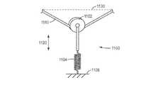
도 17은 하나의 예시적인 실시예에 따른, 힘 전달 기구에 장착되고 작동 요소에 결합된 인장 조정기를 도시한다.BRIEF DESCRIPTION OF THE DRAWINGS The invention may be understood by reference to the following detailed description, taken alone or in conjunction with the accompanying drawings. The drawings are included for a more clear understanding of the present invention and are incorporated herein and form part of the present disclosure. The drawings illustrate one or more illustrative embodiments of the teachings of the present invention and, together with the description that follows, serve to explain the principles and operation of the invention.
1 shows a patient side cart of a remote operated surgical system according to one exemplary embodiment.
2 is a schematic perspective view of a surgical instrument according to one exemplary embodiment.
3 is a perspective view of an interior portion of a force transmission mechanism and a chassis in accordance with one exemplary embodiment.
Figure 4 is a partial perspective view of the actuating element and tension adjuster of Figure 3;
Figure 5 is a partial view of a actuating element, each including a tension regulator according to one exemplary embodiment.
6 is a top view of a tension regulator according to one exemplary embodiment.
FIG. 7 is a side view seen from the line 7-7 of FIG. 6; FIG.
Figure 8 shows the tension regulator of Figure 6 coupled to an actuating element in a taut condition in accordance with one embodiment of the present invention.
Figure 9 shows the tension regulator and operating element of Figure 8 in a loose state.
Figure 10 shows the tension regulator and operating element of Figure 9 in yet another loose condition.
Figure 11 shows a tension regulator coupled to an actuating element in a loose state, according to yet another exemplary embodiment.
12 shows a tension regulator according to another exemplary embodiment.
Figure 13 illustrates a tension regulator coupled to a force transmission element in a taut state, according to another exemplary embodiment.
Figure 14 shows the tension regulator and operating element of Figure 13 in a loose state.
Figure 15 illustrates a tension regulator coupled to an actuating element in a loose state, in accordance with another exemplary embodiment.
Figure 16 shows a tension regulator coupled to two actuating elements, according to one exemplary embodiment.
Figure 17 illustrates a tension regulator mounted to and coupled to a force transmitting mechanism in accordance with one exemplary embodiment.
예시의 실시형태들을 설명하는 이 항목의 설명 및 첨부도면은 본 발명의 범위를 한정하는 것으로 받아들여져서는 안된다. 다양한 기계적, 조성적, 구조적, 전기적 및 작동적 변경이 이 항목의 설명 및 균등론적 범위를 포함한 청구범위의 발명의 범위를 벗어나는 일 없이 이루어질 수 있다. 경우에 따라서는, 잘 알려진 구조 및 기술들은 본 발명의 설명을 불명료하게 하지 않기 위해 도시하지 않거나 자세히 설명하지 않는다. 2개 이상의 도면에서 동일한 도면부호는 동일하거나 유사한 요소를 나타낸다. 또한, 하나의 실시형태와 관련하여 상세히 설명되는 요소 및 그 관련 세부 형상부는 실시가능하다면 언제든 특정적으로 도시되거나 설명되지 않은 다른 실시형태에 포함될 수도 있다. 예컨대, 하나의 요소가 하나의 실시형태와 관련하여 상세히 설명되어 있지만 제2 실시형태와 관련하여서는 설명되어 있지 않은 경우, 그 요소는 그럼에도 불구하고 제2 실시형태에 포함되어 있는 것으로 청구될 수도 있다.The description of this item and the accompanying drawings that illustrate exemplary embodiments should not be taken as limiting the scope of the invention. Various mechanical, structural, structural, electrical, and operational changes may be made without departing from the scope of the claimed invention, including the description and equivalents of these items. In some instances, well-known structures and techniques are not shown or described in detail so as not to obscure the description of the present invention. In the drawings, the same reference numerals denote the same or similar elements. In addition, elements described in greater detail in connection with one embodiment and associated details features may, wherever practicable, be included in other embodiments not specifically shown or described. For example, although an element has been described in detail with respect to one embodiment, but not described with respect to the second embodiment, the element may nevertheless be claimed to be included in the second embodiment.
본 명세서 및 첨부된 청구범위를 위해, 달리 지시되어 있지 않다면, 양, 퍼센티지 또는 비율을 표현하는 모든 숫자 및 본 명세서 및 청구범위에 사용되는 수치값은 이미 변경되어 있지 않은 한 모든 경우에 있어 "약"이라는 용어에 의해 변경되는 것으로서 이해되어야 한다. 따라서, 달리 지시되어 있지 않다면, 이하의 명세서 및 첨부된 청구범위에 기술되는 수치 파라미터는 본 발명에 의해 얻어질 것으로 기대되는 소정의 특성값에 따라 변경될 수 있는 근사값이다. 적어도 청구항의 범위에 대한 균등론의 적용을 제한하는 것을 꾀하지 않는 것으로서, 각각의 수치 파라미터는 적어도 보고된 유효 자릿수의 수치를 고려하여 반올림 기법을 적용하여 해석되어야 한다.For purposes of this specification and the appended claims, unless otherwise indicated, all numbers expressing quantities, percentages or ratios, and numerical values used in the specification and claims are to be understood as " "As used herein. Accordingly, unless otherwise indicated, the numerical parameters set forth in the following specification and attached claims are approximations that may be altered according to certain characteristic values that are expected to be obtained by the present invention. Each numerical parameter should be construed by applying a rounding technique, taking into account at least the numerical value of the reported significant digits, without intending to limit the application of the doctrine of equivalents to the scope of the claims.
본 명세서 및 첨부된 청구범위에 사용되는 것으로서, "하나의" 및 "그 하나의"와 같은 단수 형태의 표현 및 임의의 단일 사용을 나타내는 표현은 특별하고 명백히 하나의 대상으로 한정하고 있지 않은 한 복수의 대상을 포함하는 것으로 해석됨에 유의해야 한다. 여기에 사용되는 것으로서, "포함하다", "구비하다" 및 이에 준하는 표현의 용어는 제한하는 것을 의도하지 않는 것으로, 목록 내의 항목들의 열거는 열거된 항목들에 대체될 수 있거나 추가될 수 있는 다른 유사한 항목들의 배제를 의도하지 않는다.As used in this specification and the appended claims, the singular forms "a," "an," and "the singular" as used herein and the singular forms "a," "an," and "the" It should be noted that the term " object " As used herein, the terms "comprises," "comprising," and the like, are not intended to be limiting, It does not intend to exclude similar items.
또한, 이러한 설명의 용어는 본 발명을 한정하는 것을 의도하지 않는다. 예컨대, "밑", "아래", "하부", "위", "상부", "근위", "원위" 등과 같은 공간적으로 상대적인 용어들은 도면에 예시되는 바와 같이 하나의 요소의 또 다른 요소에 대한 관계나 하나의 피처(feature)의 또 다른 피처에 대한 관계를 설명하기 위해 사용될 수 있을 것이다. 이러한 공간적으로 상대적인 용어들은 도면에 도시된 포지션과 배향뿐만 아니라 사용 또는 작동에 있어서의 장치의 다른 포지션들(즉, 위치들) 및 배향들(즉, 회전 위치들)을 아우르는 것으로 의도된다. 예컨대, 도면의 장치가 뒤집어진다면, 다른 요소 또는 피처의 "아래" 또는 "밑"으로 설명된 요소는 이번에는 다른 요소 또는 피처의 "상부" 또는 "위"가될 것이다. 따라서, 예시의 용어 "아래"는 위와 아래의 양자 모두의 포지션 및 배향을 아우를 수 있다. 장치는 다르게 배향될 수 있으며(예컨대 90도 회전되거나 다른 배향으로), 여기에 사용되는 공간적으로 상대적인 용어들은 그에 따라 해석될 수 있다.Moreover, the terminology of such description is not intended to limit the invention. For example, spatially relative terms such as "under", "under", "under", "above", "upper", "proximal", "distal" And may be used to describe the relation to another feature of one feature or feature. These spatially relative terms are intended to encompass the positions and orientations shown in the drawings, as well as other positions (i.e., positions) and orientations (i.e., rotational positions) of the device in use or operation. For example, if the device in the figures is inverted, the elements described as "below" or "below" another element or feature will now be "upper" or "above" another element or feature. Thus, the example term "below" can cover both the top and bottom positions and orientations. The device may be oriented differently (e.g., rotated 90 degrees or in a different orientation), and the spatially relative terms used herein may be interpreted accordingly.
다양한 예시적인 실시예에 따라, 본 발명은 작동 요소의 느슨함을 보상하는 인장 조정기를 포함하는 힘 전달 기구를 의도한다. 다양한 예시적인 실시예에 있어서, 인장 조정기는 수동적 방식(passive manner)으로 느슨함을 수용할 수 있다. 하나의 예시적인 실시예에 따라, 인장 조정기는 느슨함을 수동적으로 보상하기 위해 포텐셜 에너지를 이용할 수 있다. 예를 들어, 인장 조정기는 느슨함이 발달할 때 그것의 형태 또는 형상을 변경시킴으로써(예를 들어, 탄성 변형을 통해) 느슨함을 수동적으로 보상할 수 있다. 본 명세서에 기술되는 다양한 예시적인 실시예의 인장 조정기는 자동화된 제어 또는 수동식 조절(manual adjustment) 없이 작동 요소의 인장이 유지되는 것을 가능하게 해주어, 작동 요소의 인장을 조정하는 효율적이고 견고한 수단을 제공할 수 있다. 따라서, 작동 요소가 시간이 경과함에 따라 변하여 느슨함을 발달시킬 때, 인장 조정기는 아래에 논고되는 바와 같이 느슨함을 보상하고 작동 요소의 원하는 인장을 실질적으로 유지할 수 있다.According to various exemplary embodiments, the present invention contemplates a force transmission mechanism comprising a tension regulator that compensates for the slack of the actuating element. In various exemplary embodiments, the tension adjuster may accommodate loosening in a passive manner. According to one exemplary embodiment, the tension regulator may utilize potential energy to passively compensate for the slack. For example, the tension adjuster can passively compensate for loosening (e.g., through elastic deformation) by changing its shape or shape when the looseness develops. The tension adjusters of the various exemplary embodiments described herein enable the tension of the actuating element to be maintained without automated control or manual adjustment to provide an efficient and robust means of adjusting the tension of the actuating element . Thus, when the actuating element develops over time to develop looseness, the tension adjuster can compensate for the slack as described below and substantially maintain the desired tension of the actuating element.
하나의 예시적인 실시예에 따라, 작동 요소는 전달 기구로부터 수술 기기의 샤프트 내로 연장될 때 실질적 직선 경로를 따를 수 있다. 수술 기기의 여러 가지 부분들의 움직임을 실행하기 위한 힘을 전달하기 위해, 작동 요소는 일반적으로 인장 상태에 있다. 하지만, 다양한 예시적인 실시예에 따라, 느슨함이 작동 요소에 발생할 때, 작동 요소에 결합된 인장 조정기가 작동 요소의 일부분을 팽팽한 상태일 때의 작동 요소의 초기 경로로부터 전환시킴으로써 느슨함을 수용할 수 있다. 예를 들어, 인장 조정기는 작동 요소의 길이방향 축이 인장 조정기가 배치되는 위치에서 직선이 아니도록 작동 요소에 하나 이상의 굽힘부를 형성할 수 있다. 따라서, 인장 조정기는 작동 요소의 느슨함이 발달하는 부분에 작용하여 그 부분에서의 인장을 유지시키기 위한 힘을 가함으로써 느슨함을 수용할 수 있다. 작동 요소가 팽팽함을 잃어 갈 때, 작동 요소에 결합된 인장 조정기는, 본 발명의 하나의 예시적인 실시예에 따라, 작동 요소의 일부분의 원래 경로(예를 들어, 직선 경로)에 대해 횡단적인(예를 들어 수직인) 방향을 따라 작동 요소를 당길 수 있다. 작동 요소가 느슨함을 발달시킬 때(즉, 인장을 잃어갈 때), 작동 요소의 길이의 일부분을 전환시키는 것은 작동 요소의 인장된 팽팽한 상태를 재정립하고 유지시키도록 기능할 수 있다. 하나의 예시적인 실시예에 따라, 인장 조정기는 작동 요소의 느슨함이 시간이 경과함에 따라 증가하는 경우와 같이 변동하는 크기의 느슨함(예컨대, 인장 조정기가 감당할 수 있는 최대 보상 크기까지의)을 보상하도록(예를 들어, 동적으로 보상하도록) 구성될 수 있다.According to one exemplary embodiment, the actuating element may follow a substantially straight path as it extends into the shaft of the surgical instrument from the delivery mechanism. In order to deliver the force to carry out the movement of the various parts of the surgical instrument, the actuating element is generally in a tensioned state. However, according to various exemplary embodiments, when the looseness occurs in the actuating element, a tension regulator coupled to the actuating element is adapted to receive the looseness by switching from the initial path of the actuating element when the portion of the actuating element is in its taut condition . For example, the tension adjuster may form one or more bends in the actuating element such that the longitudinal axis of the actuating element is not straight at the position where the tension adjuster is disposed. Thus, the tension regulator can accommodate looseness by applying a force to act on the developing portion of the loosening of the actuating element to maintain the tension in that portion. When the actuating element loses its torsion, the tension adjuster coupled to the actuating element is moved in a direction transverse to the original path (e. G., A straight path) of a portion of the actuating element, according to one exemplary embodiment of the present invention For example vertical) direction. Switching a portion of the length of the actuating element may serve to reestablish and maintain the tensioned tension condition of the actuating element when the actuating element develops looseness (i.e., when the tension is lost). According to one exemplary embodiment, the tension regulator is configured to adjust the amount of loosening of a varying magnitude (e.g., up to the maximum compensation size that the tension regulator can afford), such as when the loosening of the actuating element increases with time (E. G., To compensate dynamically). ≪ / RTI >
인장 조정기는 수술 기기의 힘 전달 기구 내에 배치되는 작동 요소의 일부분을 따라 작동 요소에 결합될 수 있다. 다양한 예시적인 실시예에 있어서, 인장 조정기는 작동 요소가 하나의 예시적인 실시예에 따라 작동될 때 인장 조정기가 작동 요소와 함께 이동하도록 작동 요소에 결합될 수 있다. 다양한 예시적인 실시예에 있어서, 인장 조정기는 힘 전달 기구에 대해 부동(floating)하도록(예를 들어, 힘 전달 기구에 대해 상대적으로 작동 부재와 함께 이동하도록) 구성될 수 있는 한편, 또 다른 예시적인 실시예에 있어서는, 인장 조정기는 힘 전달 기구에, 힘 전달 기구의 섀시 등에, 고정될 수 있다. 하나의 예시적인 실시예에 따라, 인장 조정기는 작동 입력 기구에 연결된 복수의 작동 요소 중의 하나 이상에 결합될 수 있다. 인장 조정기들이 단일의 작동 요소의 인장을 조정하도록 결합될 수 있겠지만, 하나의 인장 조정기가 하나의 예시적인 실시예에 따라 2개 이상의 작동 요소의 인장을 동시에 조정하도록 결합될 수 있다.The tension regulator may be coupled to the actuating element along a portion of the actuating element disposed within the force transmission mechanism of the surgical instrument. In various exemplary embodiments, the tension regulator may be coupled to the actuating element such that the tension adjuster moves with the actuating element when the actuating element is operated in accordance with one exemplary embodiment. In various exemplary embodiments, the tension regulator may be configured to be floating relative to the force transmission mechanism (e.g., to move with the actuating member relative to the force transmission mechanism), while another exemplary In the embodiment, the tension regulator can be fixed to the force transmitting mechanism, the chassis of the force transmitting mechanism, or the like. According to one exemplary embodiment, the tension regulator may be coupled to one or more of a plurality of actuating elements coupled to the actuating input mechanism. Although the tension regulators may be combined to adjust the tension of a single actuating element, one tension regulator may be combined to simultaneously adjust the tension of two or more actuating elements in accordance with one exemplary embodiment.
본 명세서에 기술되는 다양한 예시적인 실시예는 단일 피스(예컨대, 모놀리딕(monolithic)) 구조를 갖는 인장 조정기를 고려한다. 예를 들어, 인장 조정기는 단일 피스의 와이어, 단일 피스의 박판 금속, 단일 몰딩 피스(single molded piece), 단일 탄성 재료 밴드 또는 당업계의 통상의 지식을 가진 자에게 친숙한 다른 단일 피스 구조체일 수 있다. 인장 조정기를 통해 연장되는 작동 요소의 일부분은 하나의 예시적인 실시예에 따라 작동 요소의 연속 길이 부분일 수 있다. 다시 말해, 인장 조정기는 예를 들어 작동 요소의 단부에 작용하는 것과 대조적으로 작동 요소의 단부들 사이의 작동 요소의 일정 길이의 부분 상에 작용함으로써 느슨함을 처리할 수 있다.The various exemplary embodiments described herein contemplate a tension adjuster having a single piece (e.g., monolithic) structure. For example, the tension regulator may be a single piece of wire, a single piece of sheet metal, a single molded piece, a single elastic material band, or other single piece structure familiar to those of ordinary skill in the art . A portion of the actuating element extending through the tension adjuster may be a continuous length portion of the actuating element in accordance with one exemplary embodiment. In other words, the tension regulator can handle loosening by acting on a part of the length of the actuating element between the ends of the actuating element, for example, as opposed to acting on the end of the actuating element.
이제 도 1을 참조하면, 원격조작 수술 시스템의 환자측 카트(100)의 하나의 예시적인 실시예가 도시되어 있다. 원격조작 수술 시스템은 또한 환자측 카트(100)에 장착된 기기를 제어하기 위해 사용자로부터 입력을 수신하는 외과의 콘솔(미도시)을 포함할 수 있다. 원격조작 수술 시스템은 또한, 예를 들어 그 전체 내용이 여기에 참조되는 2013년 12월 5일자로 공개된 "다중 포트 수술용 로봇 시스템 구조(Multi-Port Surgical Robotic System Architecture)"라는 명칭의 미국 특허공개 US 2013/0325033 및 2013년 12월 5일자로 공개된 "하드웨어 구속된 원격 중심 로봇 매니퓰레이터를 위한 다중 축 및 자유도(Redundant Axis and Degree of Freedom for Hardware-Constrained Remote Center Robotic Manipulator)"라는 명칭의 미국 특허공개 US 2013/0325031에 개시된 바와 같은 보조 제어/비전 카트(auxiliary control/vision cart)(미도시)를 포함할 수 있다. 또한, 본 명세서에 기술되는 예시적인 실시예는 예를 들어 Intuitive Surgical, Inc.로부터 입수가능한 Da Vinci® Surgical System, Da Vinci® Si Surgical System, Single site Da Vinci® Surgical System 또는 Da Vinci® Xi Surgical System과 함께 사용될 수 있다.Referring now to FIG. 1, one exemplary embodiment of a
환자측 카트(100)는 베이스(102), 메인 컬럼(104) 및 메인 컬럼(104)에 연결된 메인 붐(106)을 포함할 수 있다. 환자측 카트(100)는 또한 각각이 메인 붐(106)에 연결될 수 있는 복수의 매니퓰레이터 암(110, 111, 112, 113)을 포함할 수 있다. 매니퓰레이터 암(110, 111, 112, 113)은 각각이 도 1에서 매니퓰레이터 암(110)에 부착된 것으로서 예시된 기기(130)가 장착될 수 있는 기기 장착부(120)를 포함할 수 있다. 매니퓰레이터 암(110, 111, 112, 113)의 부분들은 수술 절차 중에 외과의 콘솔에 위치한 사용자에 의해 제공되는 명령에 따라 조작될 수 있다. 하나의 예시적인 실시예에 있어서, 외과의 콘솔로부터 전송된 신호 즉 입력은 제어/비전 카트로 전송될 수 있으며, 제어/비전 카트는 입력을 해석하고, 예를 들어 드라이브 인터페이스 장치를 통해 환자측 카트(100)로 그리고 최종적으로 수술 기기 전달 기구로 전송될 명령 즉 출력을 생성하여, 기기(130)(도 1에서는 단지 하나의 기기만이 장착되어 있다) 및/또는 환자측 카트(100)에서 기기(130)가 연결되게 되는 매니퓰레이터 암(110)의 부분들의 조작을 일부분(예를 들어, 도 1에 도시된 바와 같은 하나의기구 만)을 조작을 발생시킨다.The
기기 장착부(120)는, 하나의 예시적인 실시예에 따라, 작동 인터페이스 어셈블리(122) 및 캐뉼라 마운트(124)를 포함하고, 기기(130)의 샤프트(132)가 캐뉼라 마운트(124)를 통해(그리고 수술 절차 중에 수술 부위까지) 연장되고, 기기(130)의 힘 전달 기구(134)가 작동 인터페이스 어셈블리(122)와 연결되어 있다. 캐뉼라 마운트(124)는 수술 절차 중에 기기(130)의 샤프트(132)가 수술 부위로 관통하여 연장될 수 있는 캐뉼라(도 1에 도시되지 않음)를 유지시키도록 구성될 수 있다. 작동 인터페이스 어셈블리(122)는 외과의 콘솔에서의 입력 명령에 응답하여 당업자에게 친숙한 바와 같이 기기(130)를 작동시키기 위해 힘 전달 기구(134)에 힘을 전달하도록 제어되는 다양한 드라이브(예를 들어, 입력 드라이브)를 포함할 수 있고, 따라서 넓게는 드라이브 인터페이스 장치로 분류될 수 있다. 예를 들어, 작동 인터페이스 어셈블리(122)의 입력 드라이브들은 후술되는 바와 같이 힘 전달 기구(134)의 인터페이스 구조(도시되지 않음)와 직접적으로 결합하여 힘을 힘 전달 기구(134)에 전달할 수 있다.The
도 1의 예시적인 실시예는 설명의 용이성을 위해 매니퓰레이터 암(110)에만 부착된 기기(130)를 도시하고 있지만, 기기는 매니퓰레이터 암(110, 111, 112, 113)의 어느 것에 또는 각각에 부착될 수 있다. 기기(130)는 엔드 이펙터를 갖는 수술 기기일 수 있으며, 또는 수술 절차 중에 원결 수술 부위의 정보(예를 들어, 시각화, 전기생리학 활동, 압력, 체액 흐름 및/또는 다른 감지 데이터)를 제공하기 위해 사용되는 내시경 촬영 기기 또는 다른 감지 기기일 수 있다. 도 1의 예시적인 실시예에 있어서는, 엔드 이펙터 또는 촬영 기기를 갖는 수술 기기가 임의의 매니퓰레이터 암(110, 111, 112, 113)에 부착되어 사용될 수 있다. 하지만, 본 명세서에 설명되는 실시예는 도 1의 환자측 카트의 예시적인 실시예에 한정되지 않으며, 환자측 카트 구성을 포함하는 다양한 다른 원격조작 수술 시스템 구성이 본 명세서에 설명되는 예시적인 실시예와 함께 사용될 수 있다.Although the illustrative embodiment of FIG. 1 illustrates a
도 2를 참조하면, 수술 기기(200)의 하나의 예시적인 실시예의 개략적 측면도가 도시되어 있다. 예를 들어, 수술 기기(200)는 기기(130)로서 도 1의 예시적인 실시예의 환자측 카트(100)와 함께 사용될 수 있다. 수술 기기(200)는 힘 전달 기구(210)(힘 전달 기구(210)의 내부의 구성요소들을 드러내기 위해 도면에서 하우징이 제거된 상태로 도 2의 예시적인 실시예에 도시된 섀시(211)), 그것의 근위 단부(223)에서 힘 전달 기구(210)에 연결된 샤프트(222), 샤프트(222)의 원위 단부(224)에 연결된 리스트(222) 및 리스트(230)에 연결된 엔드 이펙터(220)를 포함할 수 있다. 샤프트(222)는 가요성이거나 강성일 수 있다. 하나의 예시적인 실시예에 따라, 샤프트(222)는 약 3 mm 내지 약 15 mm 범위의 직경을 가질 수 있다. 또 다른 예시적인 실시예에 따라, 샤프트(222)의 직경은 예를 들어 약 5 mm 내지 약 8 mm의 범위일 수 있다. 엔드 이펙터(220)는 예를 들어 포셉, 봉합을 위한 니들 드라이버, 절단 장치, 절개용 장치, 클립 어플리이어 및 다양한 수술 절차를 수행하기 위한 다른 엔드 이펙터 구성을 포함할 수 있다.Referring to FIG. 2, a schematic side view of one exemplary embodiment of a
수술 기기(200)는 힘 전달 기구(210)와 엔드 이펙터(220) 사이 및/또는 힘 전달 기구(210)와 리스트(230) 사이에서 힘을 전달하기 위한 하나 이상의 부재를 포함할 수 있다. 예를 들어, 작동 요소(242, 244)가 엔드 이펙터(220)에 작동력을 제공하기 위해 샤프트(222)의 내부를 통해 연장되는 등에 의해 힘 전달 기구(210)를 엔드 이펙터(220)에 연결할 수 있다. 작동 요소(242, 244)를 이용함으로써, 힘 전달 기구(210)는 예컨대 엔드 이펙터(220)의 조(jaw)(또는 엔드 이펙터(220)의 다른 가동 부분)를 제어하도록 엔드 이펙터(220)를 작동시킬 수 있다. 또 다른 예에 있어서, 작동 요소(242, 244)는 리스트(230)를 하나 이상의 자유도(예를 들어, 피치(pitch) 및/또는 요(yaw))로 작동시키도록 사용될 수 있다. 작동 요소(242, 244)는 그 전체 내용이 여기에 참조되는 미국 특허 제8,545,515호에 개시된 바와 같이 힘 전달 기구(210)가 풀-풀 기구(pull-pull mechanism)일 때와 같은 인장 부재의 형태일 수 있다.The
힘 전달 기구(210)는 원격조작 수술 시스템의 환자측 카트(100)와 결합하여 환자측 카트에 의해 제공된 힘을 수술 기기(200)로 전달하는 하나 이상의 구성요소를 포함할 수 있다. 예를 들어, 힘 전달 기구(210)는 도 1의 예시적인 실시예의 환자측 카트(100)의 작동 인터페이스 어셈블리(122)와 연결될 수 있어, 작동 인터페이스 어셈블리(122)가 기기(200)를 작동시키도록 힘 전달 기구(210)에 힘을 전달할 수 있다. 하나의 예시적인 실시예에 따라, 힘 전달 기구(210)는 환자측 카트(100)의 작동 인터페이스 어셈블리(122)와 같은 환자측 카트의 매니퓰레이터와 결합되는(예를 들어, 힘 전달 기구(210)의 원위 단부를 통해) 하나 이상의 피구동형 작동 입력 기구(212, 214)를 포함할 수 있다.The
하나의 예시적인 실시예에 따라, 작동 입력 기구(212, 214)은 아래에 설명되는 바와 같이 무균 어댑터(미도시)를 통해 환자측 카트(100)의 작동 인터페이스 어셈블리(122)와 같은 환자측 카트의 매니퓰레이터와 상호작용할 수 있다. 힘 전달 기구(210)에 사용될 수 있는 하나의 예시적인 종류의 작동 입력 기구는 그 예시적인 실시예가 그 전체 내용이 여기에 참조되는 미국 특허 제8,545,515호에 기재되어 있는 풀-풀 기구이다. 하나의 예시적인 실시예에 따라, 힘 전달 기구(210)는 풀-풀 기구를 이용할 수 있고, 작동 요소(242, 244)는 인장 부재일 수 있고, 피구동형 작동 입력 기구(212, 214)는 기기를 작동시키기 위해 작동 요소(242, 244)를 인장시키도록 회전 구동되는 캡스턴(capstan)일 수 있다. 따라서, 피구동형 작동 입력 기구(212, 214)는 기기(200)를 작동시키기 위해 작동 인터페이스 어셈블리로부터의 작동력을 이용한다. 힘 전달 기구(210)는 당업자에게 친숙한 바와 같은 수술 기기의 다양한 다른 기능들을 작동시키기 위해 캡스턴에 추가적이거나 캡스턴 대신의 다른 구성요소를 포함할 수 있다. 이러한 구성요소는 기어, 클러치, 풀리, 링키지 및 입력 및/또는 모션을 원하는 출력 및/또는 모션으로 변환시키기 위한 다른 기구를 포함하며, 이들에 한정되지는 않는다. 또한, 힘 전달 기구(210)는 예를 들어, 1개, 3개, 4개, 5개, 6개, 7개, 8개 또는 그 이상의 작동 입력 기구와 같이 도 2의 예시적인 실시예에 도시된 것과 다른 개수의 작동 입력 기구(212, 214)를 포함할 수 있다. 예를 들어, 수술 기기의 특성에 따라 그리고 이러한 기기의 작동 자유도에 따라, 임의의 개수의 작동 입력 기구(212, 214)가 사용될 수 있다.In accordance with one exemplary embodiment, the
도 2의 힘 전달 기구는 회전 운동의 원격조작 수술 시스템의 수술 기기를 위한 작동 요소의 병진 운동으로의 정확한 변환을 제공한다. 하지만, 힘 전달 기구의 작동 요소는 형상의 변화를 경험할 수 있다. 예를 들어, 인장 부재일 수 있는 도 2의 예시적인 실시예의 작동 요소(242)는 전달되는 하중에 비례하여 신장되고 길이가 증가하는 등에 의해 변형될 수 있다. 그 결과, 작동 요소(242)는 느슨함을 발달시킬 수 있다. 작동 요소(244)와 작동 요소(242)의 양자 모두가 리스트(230) 또는 엔드 이펙터(220)의 움직임에 결합되어 있는 경우, 작동 요소(244)는 작동 요소(242)와 협력하여 움직일 수 있다. 이러한 협조 움직임(coordinated movement)으로 인해, 작동 요소(244) 또한 느슨함을 발달시킬 수 있다. 반면에, 작동 요소(242)는 인장되어 있고, 작동 요소(244)가 느슨함을 가질 수도 있을 것이다. 또한, 작동 요소(242, 244)가 느슨한 상태에 있을 때, 엔드 이펙터(220) 또는 리스트(230)와 같은 기기(200)를 작동시키는 힘 전달 기구(210)의 정밀도가 감소될 수 있다. 예를 들어, 작동 요소(242, 244)를 기기(200)를 작동시킬 수 있는 팽팽한 상태로 두기 위해, 피구동형 작동 입력 기구(212, 214)의 회전은 작동 요소(242, 244)로부터 느슨함을 제거하도록 회전될 필요가 있을 수 있다. 또한, 피구동형 작동 입력 기구(212, 214)는 힘 전달 기구(210)의 사용 중에 작동 요소(242, 244)가 정상적으로 내치(lying-in)되는 그루브(도시되지 않음)를 포함할 수 있다. 작동 요소(242, 244)의 느슨함은 작동 요소(242, 244)가 그루브로부터 이탈할 정도로 충분히 커질 수 있을 것이며, 이 또한 기기(200)의 작동에 영향을 줄 수 있다. 따라서, 수술 기기 내의 제한된 공간을 보다 효율적으로 활용하는 인장 조정 장치를 사용하는 등과 같이 수술 기기 구성요소가 작동 요소의 변화를 보상하는 것에 의해 추가적인 개선이 이루어질 수 있다.The force transmission mechanism of Figure 2 provides accurate translation into the translational motion of the actuating element for the surgical instrument of the rotationally operated, remote operated surgical system. However, the operating element of the force transmission mechanism can experience a change in shape. For example, the
도 3을 참조하면, 하나의 예시적인 실시예에 따라, 힘 전달 기구(310)의 내부가 도시되어 있다. 힘 전달 기구(310)는 섀시(320) 및 하우징(힘 전달 기구(310)의 내부의 구성요소들을 드러내기 위해 도시되지 않음)을 포함할 수 있다. 힘 전달 기구(310)는 도 1의 예시적인 실시예의 기기(130)의 힘 전달 기구(134)로서 사용될 수 있다. 하나의 예시적인 실시예에 따라, 힘 전달 기구(310)는 예를 들어 기기의 샤프트(도시되지 않음)의 근위 부분과 맞물려 도 2의 예시적인 실시예의 기기(200)의 샤프트(222)와 같은 샤프트를 롤링시키기 위한 롤 기어(도시 안됨), 기기의 엔드 이펙터로 플럭스(예를 들어, 전기 에너지, 유체, 석션, 빛 등)를 전달하기 위한 플럭스 도관(flux conduit) 및 당업자에게 친숙한 다른 구성요소와 같은 다른 구성요소들을 포함할 수 있다.Referring to Figure 3, in accordance with one exemplary embodiment, the interior of the
힘 전달 기구(310)는 도 3의 예시적인 실시예에 도시된 바와 같이 하나 이상의 작동 입력 기구(330, 332)를 포함할 수 있다. 하나의 예시의 비제한적 실시예에 있어서, 작동 입력 기구(330, 332)는, 다양한 다른 작동 입력 기구 구성이 본 발명의 범위를 벗어남이 없이 사용될 수도 있겠지만, 도 2의 예시적인 실시예의 작동 입력 기구(212, 214)에 관해 상술한 바와 같이 캡스턴일 수 있다. 작동 요소는 각각 피구동형 작동 입력 기구(330, 332)에 결합될 수 있다. 예를 들어, 도 3의 예시적인 실시예에 도시된 바와 같이, 작동 요소(340, 342)는 작동 입력 기구(330)에 결합될 수 있고, 작동 요소(344, 346)는 작동 입력 기구(332)에 결합될 수 있다. 하나의 예시적인 실시예에 따라, 작동 요소(340, 342, 344, 346)는 그 전체 내용이 여기에 참조되는 2013년 10월 1일에 발행된 미국 특허 제8,545,515호에 기술된 바와 같이 케이블과 같은 인장 부재일 수 있다. 하나의 예시적인 실시예에 따라, 풀-풀 기구가 하나의 인장 부재가 엔드 이펙터 또는 리스트를 한쪽 방향으로 작동시키도록 당겨지고, 다른 하나의 인장 부재가 엔드 이펙터 또는 리스트를 또 다른 방향으로 작동시키도록 당겨지게 되는 2개의 인장 부재를 포함할 수 있다. 또 다른 예시적인 실시예에 따라, 풀-풀 기구가 인장 요소의 한쪽 부분이 엔드 이펙터 또는 리스트를 한쪽 방향으로 작동시키도록 당겨지고, 인장 요소의 다른쪽 부분이 엔드 이펙터 또는 리스트를 다른 방향으로 작동시키도록 당겨지게 되는 단일 인장 요소(예컨대, 캡스턴 또는 다른 액추에이터 둘레로 권취되는 단일 인장 요소)를 포함할 수 있다. 힘 전달 기구(310)의 섀시(320)는 또한 하나의 예시적인 실시예에 따라, 작동 요소(340, 342, 344, 346)가 샤프트(예컨대, 도 2의 샤프트(222))를 통해 기기의 원위 단부로 경로설정될 수 있도록 작동 요소(340, 342, 344)가 연장되게 되는 출구 구멍(324)을 한정하는 섀시 부분(322)을 포함할 수 있다.The
피구동형 작동 입력 기구에 연결되는 작동 요소는 하나의 예시적인 실시예에 따라 단일 작동 요소로 형성될 수 있다. 따라서, 작동 입력 기구(330)에 연결되는 작동 요소(340, 342)는 당해 작동 요소(340, 342)가 힘 전달 기구(31)와 기기의 원위 단부 사이에 연장되는 단일 작동 요소의 두 부분으로 한정되는 단일 작동 요소로 형성될 수 있다. 예를 들어, 작동 요소(340, 342)는, 작동 입력 기구(330)가 구동될 때 기기를 작동시키도록, 힘 전달 기구의 한쪽 단부에서 작동 입력 기구(330) 둘레로 고리 모양으로 감기고, 힌 전달 기구(310)로부터 기기의 샤프트(예컨대, 도 2의 샤프트(222))를 통해 기기의 원위 단부(예를 들어, 도 2의 리스트(230) 또는 엔드 이펙터(220))까지 연장된다. 따라서, 도 3의 예시적인 실시예에서 화살표(331)로 지시된 방향을 따라 회전되는 등에 의해 작동 입력 기구(330)가 구동될 때, 단일 작동 요소의 두 부분 중의 한쪽 부분(예를 들어, 작동 요소(340, 342) 중의 하나)은 작동 입력 기구(330)로부터 풀어지는 한편, 단일 작동 요소의 다른쪽 부분(예를 들어, 작동 요소(340, 342) 중의 다른 하나)은 작동 입력 기구(330)에 감겨진다(예를 들어, 권취된다). 작동 입력 기구(332)에 연결되는 작동 요소(344, 346)는 유사하게 구성될 수 있다.The actuating element connected to the driven operative input mechanism can be formed as a single actuating element according to one exemplary embodiment. The
또 다른 예시적인 실시예에 따라, 작동 요소(340, 342)는 2개의 별개의 작동 요소일 수 있다. 예를 들어, 작동 요소(340, 342) 각각의 제1 단부가 작동 입력 기구(330)에 연결될 수 있고, 작동 요소(340, 342)의 각각의 제2 단부가 기기의 원위 단부(예컨대, 리스트(230) 또는 엔드 이펙터(220))에 연결될 수 있다. 작동 입력 기구(332)에 연결되는 작동 요소(344, 346)는 하나의 예시적인 실시예에 따라 2개의 별개의 작동 요소로 구성될 수 있다. 따라서, 작동 입력 기구(예를 들어, 도 3의 작동 입력 기구(330))에 연결되는 작동 요소(예를 들어, 도 3의 작동 요소들(340, 342))는 단일 작동 요소의 두 부분일 수 있거나, 2개의 작동 요소로 형성될 수 있다.According to another exemplary embodiment, the
하나의 예시적인 실시예에 따라, 본 명세서에 기술되는 다양한 예시적인 실시예의 인장 조정기는 힘 전달 기구가 조립되기 전 또는 후에 힘 전달 기구의 적어도 하나의 작동 요소에 결합될 수 있다. 예를 들어, 인장 조정기는 작동 요소가 기기의 리스트 또는 엔드 이펙터(예를 들어, 도 2의 230 또는 220)에 연결되고 작동 입력 기구(예를 들어, 도 3의 330 또는 332)에 연결된 후에 작동 요소에 결합될 수 있다. 또 다른 예시적인 실시예에 따라, 인장 조정기가 작동 요소에 결합되고, 그런 다음 작동 요소가 기기의 리스트 또는 엔드 이펙터(예컨대, 도 2의 230 또는 220)에 연결되고 작동 입력 기구(예를 들어, 도 3의 330 또는 332)에 연결될 수 있다.According to one exemplary embodiment, the tension adjusters of the various exemplary embodiments described herein may be coupled to at least one actuating element of the force transmission mechanism either before or after the force transmission mechanism is assembled. For example, the tension regulator may be actuated after the actuating element is connected to the list of instruments or the end effector (e.g., 230 or 220 of Figure 2) and connected to the actuating input mechanism (e.g., 330 or 332 of Figure 3) Lt; / RTI > element. According to another exemplary embodiment, a tension regulator is coupled to the actuating element, and then the actuating element is connected to a list of devices or an end effector (e.g., 230 or 220 in FIG. 2) 330 or 332 of Figure 3).
도 3의 예시적인 실시예에 도시된 바와 같이, 인장 조정기(350)는 힘 전달 기구(310)의 하나 이상의 작동 요소에 결합될 수 있고, 하나 이상의 작동 요소의 느슨함을 수동적으로 보상하도록 구성될 수 있다. 다양한 예시적인 실시예에 있어서, 인장 조정기(350)는 힘 전달 기구(310)의 섀시(320)와 분리될 수 있고, 따라서 작동 요소와 자유롭게 병진운동할 수 있다.As shown in the exemplary embodiment of FIG. 3, the
인장 조정기(350)가 작동 요소(예를 들어, 작동 요소(340, 342, 344, 346) 중의 하나)에 결합되는 방식 때문에, 작동 요소가 도 3의 예시적인 실시예에 화살표(370)로 지시된 방향을 따른 것과 같이 개개의 작동 입력 기구(예를 들어, 작동 입력 기구(330 또는 332))에 대해 감겨지거나 풀어짐에 따라, 인장 조정기(350)도 섀시(320)에 대해 화살표(370)로 지시된 방향을 따라 이동한다. 인장 조정기(350)가 작동 요소에 결합되는 그러한 구성에 대한 한가지 고려점은 작동 요소가 작동 입력 기구와 출구 구멍(324) 사이에서 전후로 이동함에 따라, 인장 조정기(350)가 작동 입력 기구에 충격하거나 출구 구멍(324)을 한정하는 섀시 부분(322)에 충격할 수도 있을 것이란 점이다. 힘 전달 기구(310)의 크기 및 작동 요소가 구멍(324)과 작동 입력 기구 사이를 이동하는 거리로 인해, 작동 요소에 결합되었을 때 인장 조정기(350)가 이동하는 데 작은 공간이 제공된다. 이를 고려하여, 작동 요소에 결합되도록 구성된 인장 조정기(350)는 작동 요소의 느슨함을 보상하면서도 인장 조정기(350)와 섀시 부분(322) 또는 작동 입력 기구와의 사이의 충격을 최소화하거나 제거하기에 충분히 작은 크기를 갖도록 설계될 수 있다.Because of the manner in which the
다양한 예시적인 실시예에 있어서, 인장 조정기는 작동 입력 기구에 연결되는 작동 요소들 중의 하나에만 결합되거나(예를 들어, 도 3의 작동 요소(340, 342)가 2개의 작동 요소로 한정될 때), 힘 전달 기구와 기기의 원위 단부 사이에 연장되는 단일 작동 요소의 한쪽 부분에만 결합될 수도 있다(예컨대, 도 3의 작동 요소(340, 342)가 단일 작동 요소의 부분들일 때). 하지만, 본 명세서에 기술되는 다양한 예시적인 실시예는 이러한 구성들에 제한되지 않으며, 그 대신 하나의 주어진 작동 입력 기구의 2개 이상의 작동 요소에 결합되는 인장 조정기를 가질 수 있다. 하나의 예시적인 실시예에 따라, 인장 조정기는 하나의 작동 입력 기구에 대한 각각의 작동 요소에 결합될 수 있다. 작동 요소에 대한 인장 조정기의 결합은 예를 들어, 하나의 예시적인 실시예에 따라, 작동 요소에 의해 작동되는 구성요소의 기능에 기초할 수 있다.In various exemplary embodiments, the tension regulator may be coupled to only one of the actuating elements coupled to the actuating input mechanism (e.g., when the
도 3의 예시적인 실시예의 작동 요소(340, 342, 344, 346)의 부분도인 도 4의 예시적인 실시예에 도시된 바와 같이, 인장 조정기(350)는 작동 요소(340)에 결합되지만 작동 요소(342)에는 결합되지 않을 수 있다. 유사하게, 인장 조정기(350)는 작동 요소(344)에 결합된다. 다시 말해, 작동 요소(342 및 346)는 도 3 및 도 4에 도시된 바와 같이 인장 조정기(350)가 없을 수 있다.As shown in the exemplary embodiment of FIG. 4, which is also a portion of the
양쪽 모두의 쌍으로 된 작동 요소(예를 들어, 작동 요소(340 및 342) 또는 작동 요소(344 및 346))에 느슨함이 존재하는 상황에서, 엔드 이펙터 요소의 정밀 제어는 한 쌍의 작동 요소 중의 하나의 작동 요소에만 전체 느슨함을 선택적으로 축적시키는 것에 의해 향상될 수 있다. 예를 들어, 모든 느슨함이 작동 요소(340 및 342) 중의 하나 또는 작동 요소(344 및 346) 중의 하나에 결합된 단일 인장 조정기(350)로 축적될 수 있다. 따라서, 쌍으로 된 작동 요소(340, 342) 내의 또는 쌍으로 된 작동 요소(344, 346) 내의 모든 느슨함은 각각의 쌍의 작동 요소들 중의 하나(예를 들어, 작동 요소(340, 342) 중의 하나)에 결합된 인장 조정기(350)에 축적되는 한편, 쌍으로 된 작동 요소들 중의 다른 하나(예를 들어, 작동 요소(340, 342) 중의 다른 하나)는 인장 조정기(350)를 통한 한 쌍의 작동 요소로부터의 느슨함의 제거로 인해 팽팽하게 당겨진다. 다른 하나의 작동 요소가 팽팽하고 실질적 직선이기 때문에, 다른 하나의 작동 요소의 길이는 실질적으로 알려지고, 이는 작동 요소에 의해 작동되는 요소의 정밀한 제어를 용이하게 해준다.In the situation where there is slack in both paired actuating elements (e.g., actuating
예를 들어, 인장 조정기(350)가 작동 요소(340)에 결합되고, 작동 요소(342)에 결합되지 않을 때, 인장 조정기(350)가 한쌍의 작동 요소(340 및 342)의 모든 느슨함을 축적한다. 이러한 방식으로, 작동 요소(342)가 도 4에 도시된 바와 같이 팽팽해지고, 작동 요소(342)의 길이가 실질적으로 알려진다. 작동 요소(342)에 의해 작동되는 엔드 이펙터 요소를 정밀하게 제어하기 위해, 작동 입력 기구(330)가 작동 요소(342)의 길이에 일치하는 양만큼 회전될 수 있다(예를 들어, 방향(330)을 따라). 반대로, 작동 요소(342)의 느슨함으로 인해 작동 요소(342)의 길이가 실질적으로 알려지지 않을 때에는, 작동 입력 기구(330)의 회천이 더 이상 작동 요소의 길이와 일치되지 않기 때문에, 작동 입력 기구(330)의 회천이 반드시 엔드 이펙터 요소의 정밀한 제어를 제공하지는 않는다. 다시 말해, 작동 요소(342)에 느슨함이 존재하기 때문에, 작동 입력 기구(330)의 회전의 양이 더 이상 작동 요소(342)의 풀어짐 또는 감김의 특정 양과 일치하지 않는다.For example, when the
다양한 예시적인 실시예에 따라, 인장 조정기(350)는 작동 요소의 기능에 따라 작동 요소에 선택적으로 결합될 수 있다. 인장 조정기(350)를 작동 요소(예컨대, 작동 요소(340))에 결합시키는 것은 한 쌍의 작동 요소(예를 들어, 작동 요소(340, 342)) 사이의 느슨함의 제거를 낳을 수 있고, 한 쌍의 작동 요소 중의 인장 조정기에 결합되지 않은 작동 요소(예를 들어, 작동 요소(342))가 도 4에 도시된 바와 같이 팽팽하고 직선이 되게 하는 한편, 인장 조정기(350)가 결합되는 다른 작동 요소(예를 들어, 작동 요소(340))는 느슨함을 축적하는 인장 조정기(350)의 기능의 관점에서 더 이상 직선이 아니다. 하나의 작동 요소(예를 들어, 작동 요소(342))는 팽팽하기 때문에, 그 길이가 실질적으로 알려지고, 이는 작동 요소의 정밀한 기능을 용이하게 해주어, 작동 요소를 그 길이에 일치하는 양만큼 이동시킴으로써 엔드 이펙터를 작동시킨다. 반면에, 다른 작동 요소(예를 들어, 작동 요소(340))는 직선이 아니므로, 그 길이가 정확하게 알려지지 않기 때문에 다른 작동 요소를 정밀하게 사용하는 것이 더 어려울 수 있다. 이러한 점을 고려하여, 작동 요소의 기능에 기초하여 한 쌍의 작동 요소 중의 어느 작동 요소에 인장 조정기를 결합시킬 것인지와 작동 요소의 기능을 사용할 때 어느 정도의 정밀도가 바람직한지를 선택할 수 있다.According to various exemplary embodiments, the
예를 들어, 도 3 및 도 4의 인장 조정기(350)는 엔드 이펙터(예를 들어, 도 2의 엔드 이펙터(220))를 개방 위치로 작동시키도록 당겨지는 작동 요소(340 및 344)에 결합되는 한편, 엔드 이펙터를 폐쇄 위치로 작동시키도록 당겨지는 작동 요소(342 및 346)에 결합되지 않을 수 있다. 예를 들어, 엔드 이펙터를 개방시키는 것보다 엔드 이펙터를 폐쇄시키는 데 더 큰 정밀도가 바람직할 수 있고, 이를 고려하여 인장 조정기(350)의 결합이 선택된다. 이러한 구성에서, 엔드 이펙터를 개방 위치로 작동시키는 것이 엔드 이펙터를 폐쇄 위치로 작동시키는 것보다 적은 정밀도 및 힘으로 달성될 수 있기 때문에, 인장 조정기(350)를 작동 요소(340 및 344)에 결합시킴으로써 느슨함이 최소화되거나 제거된다. 반면에, 작동 요소(342 및 346)는 인장 조정기(350)가 없을 수 있지만 작동 요소(340, 344)에 결합된 인장 조정기(350)를 통한 느슨함의 제거로 인해 팽팽하다. 따라서, 엔드 이펙터는 인장 작동 요소(342, 346)에 의해 원하는 양의 힘으로 정확한 방식으로 효과적으로 폐쇄될 수 있다.For example, the
또 다른 예시적인 실시예에 따라, 인장 조정기는 도 5의 예시적인 실시예에 도시된 바와 같이 하나의 작동 입력 기구에 대한 각각의 작동 요소에 결합될 수 있다. 도 5는 도 3의 예시적인 실시예의 작동 입력 기구(330 또는 332)와 같은 단일 작동 입력 기구(도시되지 않음)에 연결된 작동 요소(440 및 442)의 부분도이다. 인장 조정기(450)는 도 5에 도시된 바와 같이 각각의 작동 요소(440, 442)에 결합된다.According to another exemplary embodiment, the tension regulator may be coupled to each actuating element for one actuating input mechanism as shown in the exemplary embodiment of Fig. 5 is a partial view of actuating
도 3-5의 예시적인 실시예에 도시된 바와 같이, 단일 인장 조정기가 하나의작동 요소에 결합될 수 있다. 하지만, 본 명세서에 기술되는 다양한 예시적인 실시예는 하나의 특정 작동 요소에 결합되는 단일 작동 요소에 제한되지 않는다. 하나의 예시적인 실시예에 따라, 하나 이상의 인장 조정기가 하나의 특정 작동 요소에 결합될 수 있다. 예를 들어, 2개, 3개 또는 그 이상의 인장 조정기가 하나의 특정 작동 요소에 결합될 수 있다.As shown in the exemplary embodiment of Figures 3-5, a single tension regulator may be coupled to one actuating element. However, the various exemplary embodiments described herein are not limited to a single actuating element that is coupled to one particular actuating element. According to one exemplary embodiment, one or more tension regulators may be coupled to one particular actuating element. For example, two, three, or more tension regulators may be coupled to one particular actuation element.
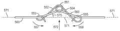
도 6을 참조하면, 인장 조정기(550)의 하나의 예시적인 실시예가 도시된다. 인장 조정기(550)는 예를 들어 도 3의 예시적인 실시예의 작동 요소(340, 342, 344, 346) 중의 어느 것과 같은 하나의 작동 요소에 결합될 수 있다. 인장 조정기(550)는 예를 들어 스테인리스 스틸 또는 당업자에게 친숙한 다른 수술 기기 재료로 제조될 수 있다. 인장 조정기(550)는 메인 루프(551)에 의해 연결된 제1 레그(552) 및 제2 레그(554)를 포함할 수 있다. 제1 레그(552)는 도 6의 예시적인 실시예에서 화살표(557)로 지시된 방향과 같이 메인 루프(551)에 대해(예를 들어 회전 방식으로) 운동하도록 구성될 수 있다. 또한, 제2 레그(554)는 도 6의 예시적인 실시예에서 화살표(559)로 지시된 방향과 같이 메인 루프(551)에 대해(예를 들어, 회전 방식으로) 운동하도록 구성될 수 있다. 하나의 예시적인 실시예에 따라, 레그(552, 554)의 운동은 예를 들어 인장 조정기(550)의 탄성 변형을 통해 달성될 수 있다.Referring to FIG. 6, one exemplary embodiment of a
인장 조정기(550)는 또한 도 6에 도시된 바와 같이 제1 및 제2 레그(552, 554)의 각각의 단부에 엔드 루프(553, 555)를 포함할 수 있다. 루프(551, 553, 555)는 인장 조정기(550)를 작동 요소에 결합시키는 기능을 할 수 있다. 예를 들어, 작동 요소(도시되지 않음)가 각각의 루프(551, 553, 555)를 통과하여 인장 조정기(550)가 작동 요소에 결합될 수 있다. 도 6-10에 도시된 루프 구성은 단지 예시적인 것으로 의도되며, 다양한 수정이 본 개시 및 청구 범위의 범위를 벗어남이 없이 이루어질 수 있다는 것을 이해해야 한다. 예를 들어, 방향(나선 방향), 피치 및/또는 직경이 예를 들어 작동 요소 내의 임의의 국부 응력 상승 인자를 최소화하도록 수정될 수 있다. 도 6-10의 인장 조정기의 루프 구조도 인장 조정기가 기기용 힘 전달 기구에 이미 설치된 작동 요소에 결합되는 것을 가능하게 해줄 수 있다.The
메인 루프(551) 주위에서의 레그(552 및 554)의 회전은 하나의 예시적인 실시예에 따라 인장 조정기가 대략 직선인 형태와 인장 조정기가 레그(552, 554) 사이의 감소된 각도(예를 들어, 인장 조정기 내에서의 하나 이상의 예각 또는 곡선)로 굽혀진 형태 사이에서 인장 조정기(550)를 천이시킨다. 하나의 예시적인 실시예에 따라, 메인 루프(551)에 대한 것과 같은 레그(552, 554)의 굽힘은 인장 조정기(550)의 탄성 변형을 통해 달성될 수 있다. 예를 들어, 인장 조정기(550)가 제조되는 재료는 대략 직선 형태와 굽힘 형태 사이에서의 탄성 변형을 가능하게 해주고, 굽힘 형태는 굽힘 형태는 인장 조정기가 바이어스된(biased) 상태(예를 들어, 인장 조정기의 낮은 에너지 상태)이다. 즉, 인장 조정기(550)를 직선화시키는 방식으로 작용하는 힘이 없으면, 인장 조정기(550)는 자연적으로 도 6에 도시된 굽힘 형상으로 있다. 하나의 예시적인 실시예에 따라, 인장 조정기(550)는 당해 인장 조정기(550)가 결합되는 작동 요소에 의해 인장 조정기(550)에 가해지는 힘의 크기에 따라, 대략 직선 형태와 도 6에 도시된 굽힘 형태의 중간 형태를 가질 수 있다.The rotation of the
하나의 예시적인 실시예에 따라, 인장 조정기(550)는, 당해 인장 조정기(550)가 작동 요소가 느슨함이 없을 때와 같은 대략 직선 형태로부터 작동 요소가 느슨함을 발달시킬 때와 같은 도 6의 굽힘 형태로 천이함에 따라, 작동 요소를 그것의 길이를 따른 실질적 직선 경로로부터 전환시키도록 구성될 수 있다. 인장 조정기(550)는 탄성 변형을 통해 대략 직선 형태로부터 굽힘 형상으로 천이할 수 있으며, 이는 인장 조정기(550)의 에너지 상태의 동적 변화를 발생시킨다(예를 들어, 대략 직선 형태에서의 고 에너지 상태로부터 굽힘 형태에서의 저 에너지 상태로). 따라서, 인장 조정기(550)는 작동 요소의 느슨함의 증가를 수동적으로 보상할 수 있다.According to one exemplary embodiment, the
인장 조정기(550)의 사용 및 작동이 이제 하나의 예시적인 실시예에 따라 도 8-10을 참조하여 설명된다. 도 8은 작동 요소(560)에 결합되는, 도 6 및 도 7과 관련하여 상술한 바와 같은, 인장 조정기(550)를 도시한다. 특히, 작동 요소(560)는 인장 조정기(550)의 루프(551, 553, 555)를 통해 경로설정되어, 인장 조정기(550)는 작동 요소(560)에 체결될 수 있다. 그 결과, 작동 요소(560)의 일부분은 인장 조정기(550)를 통해 연속적이고 비단절적인 방식으로 연장될 수 있다. 다시 말해, 인장 조정기(550)를 작동 요소(560)의 한쪽 단부에 부착하거나 인장 조정기(550)를 작동 요소의 개별의 양 단부에 부착할(예컨대, 인장 조정기가 작동 요소의 개별의 양 단부를 연결시킬) 필요가 없다. 또한, 작동 요소(560)가 도 8의 화살표(570)로 지시된 방향을 따라 당겨지면, 인장 조정기(550)는 도 3의 예시적인 실시예와 관련하여 전술한 바와 같이 작동 요소(560)와 함께 운동한다. 루프(553 또는 555)가 도 3의 섀시 부분(327) 또는 캡스턴(330)과 조우할 정도로 작동 요소(560)의 큰 양의 움직임이 발생할 때는, 예를 들어 인장 조정기(550)는 작동 요소(560)의 이동을 제한하기보다는 작동 요소(560) 상에서의 새로운 위치로 슬라이드하여 조정될 수 있다. 따라서, 일부 실시예에 있어서, 인장 조정기는, 이하에 일부 실시예에 대해 추가로 설명되는 바와 같이 인장 부재들을 작동 요소의 연속적인 길이를 따라 부착될 수 있게 구성함으로써, 힘 전달 하우징 구성요소들과 이미 조립된 상태의 작동 요소에 상대적으로 간단하게 결합될 수 있다.The use and operation of the
도 8의 하나의 예시적인 실시예에 있어서, 작동 요소(560)는 팽팽하고, 실질적을 직선이며, 기본적으로 느슨함이 없다(예를 들어, 느슨함을 발달시키기 전). 인장 조정기(550)와의 결합으로 인해, 작동 요소(560)는 루프(551, 553, 555)를 통해 작동 요소(560)를 연장시키는 것에 의해 인장 조정기(550)에 힘을 가한다. 이는 제1 레그(552) 및 제2 레그(554)가 메인 루프(551)에 대해 방향(557 및 559)으로 서로로부터 멀어지게 당겨지도록 만든다(예를 들어, 탄성 변형을 통해). 그 결과, 인장 조정기(550)는, 안장 조정기(550)가 작동 요소에 의해 굽혀지지 않았을 때에 대해 도 8에 도시된 실질적 직선화되어 신장된 형태로 인해, 증가된 양의 포텐셜 에너지를 가진다. 작동 요소(560)가 엔드 루프(553, 555) 및 메인 루프(551)를 통해 연장되고 또한 작동 요소(560)가 8의 예시적인 실시예에서 팽팽하고 느슨함이 없기 때문에, 작동 요소(560)는, 작동 요소(560)가 도 8에 도시된 상태에 있을 때, 작동 요소(560)의 직선 축(571)에 대해 방향(574)을 따라 레그(552, 554)를 당기고 또한 메인 루프(551)를 당긴다. 하나의 예시적인 실시예에 따라, 축(571)은 도 8에 도시된 바와 같이 작동 요소(560)가 팽팽하고, 실질적으로 직선이며, 기본적으로 느슨함이 없을 때(예를 들어. 느슨함을 발달시키기 전) 작동 요소(560)가 따르는 경로를 나타낼 수 있다.In one exemplary embodiment of FIG. 8, the
시간이 경과함에 따라, 작동 요소(560)는 예를 들어 작동 요소(560)의 변형 및 신장으로 인해 느슨함을 발달시킬 수 있다. 하지만, 느슨함이 작동 요소(560)에 발달할 때, 인장 조정기(550)가 느슨함을 보상할 수 있다. 도 9를 참조하면, 인장 조정기(550) 및 작동 요소(560)는 작동 요소(560)가 도 8에 도시된 초기 느슨함이 없는 상태에 비해 느슨함을 발달시킨 상태로 도시되어 있다. 느슨함이 발달함에 따라, 작동 요소(560)는 덜 팽팽해지고, 인장 조정기(550)에 더 적은 힘을 가한다. 이는 인장 조정기(550)가 도 8에 도시된 상태에 대해 다소 완화되고 덜 탄 성 변형되는 결과를 낳는다. 예를 들어, 제1 레그(552)는 도 9의 화살표(557)로 지시된 방향으로 메인 루프(551)에 대해 굽혀질 수 있고, 제2 레그(554)는 도 9의 화살표(559)로 지시된 방향으로 메인 루프(551)에 대해 굽혀질 수 있다. 제1 레그(552) 및 제2 레그(554)는 느슨함이 제거되고 작동 요소(560)가 다시 팽팽해질 때까지 도 9에 도시된 바와 같이 굽혀질 수 있다.As time elapses, the
하나의 예시적인 실시예에 따라, 인장 조정기(550)는 작동 요소(560)가 느슨함을 발달시킴에 따라 작동 요소(560)의 축(571)에 대해 실질적으로 수직인 도 9의 화살표(572)로 지시된 방향을 따라 작동 요소(560)를 당길 수 있다. 예를 들어, 메인 루프(551)는 도 9의 방향(572)을 따라 운동할 수 있고, 작동 요소가 도 8에 도시된 바와 같이 팽팽하고 실질적으로 직선일 때의 작동 요소(560)의 축(571)에 대해 작동 요소(560)를 국부적으로 당긴다. 그 결과, 인장 조정기(550)의 변형(예를 들어, 작동 요소(560)가 팽팽한 상태에 있고 인장 조정기(550)에 작용할 때의)으로 인한 포텐셜 에너지의 일부가 작동 요소(560)의 느슨함을 보상하여 제거하는 데 사용될 수 있어, 작동 요소(560)는 실질적으로 팽팽하게 유지되어 수술 기기를 작동시키는데 사용될 수 있다. 따라서, 인장 조정기(550)는 당해 인장 조정기(550)의 포텐셜 에너지의 동적 변화를 통해 작동 요소(560)의 느슨함을 보상할 수 있다.According to one exemplary embodiment, the
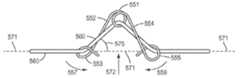
도 8의 예시적인 실시예에 도시된 바와 같이, 작동 요소(560)는 당해 작동 요소가 느슨함이 없을 때 실질적으로 직선일 수 있다. 예를 들어, 작동 요소(560)는 당해 작동 요소(560)가 팽팽하고 실질적으로 직선일 때 도 8에 도시된 축(571)을 따라 실질적 직선 경로를 따라 연장될 수 있다. 작동 요소(560)가 느슨함을 발달시킴에 따라, 인장 조정기(550)는 작동 요소(560)를 축(571)을 따른 직선 경로로부터 전환시킴으로써 느슨함을 보상할 수 있다. 도 9에 도시된 바와 같이, 인장 조정기(550)를 통해 연장되는 작동 요소(560)의 일부분은 길이방향 축(571)을 따라(예를 들어, 실질적으로 동축으로) 연장되는 경로로부터 벗어나는 경로를 따른다. 예를 들어, 작동 요소(560)가 느슨함을 발달시켰을 때, 인장 조정기(550)를 통해 연장되는 작동 요소(560)의 일부분은 도 9의 예시적인 실시예에 도시된 바와 같이 축(571)에 대해 0이 아닌 각도(575)를 갖는 인장 조정기(550)를 통한 경로를 따를 수 있다. 작동 요소(560)의 인장의 크기에 의존할 수 있는 각도(575)는 작동 요소(560)가 느슨함을 발달시킬 때 예를 들어 약 5도 내지 약 80도 사이에서 변할 수 있다. 또 다른 예시적인 실시예에 따라, 인장 조정기(550)는 작동 요소(560)가 느슨함을 발달시킬 때 예를 들어 약 5도 내지 약 30도의 각도(575)를 갖는 경로를 따라 작동 요소(560)를 전환시킬 수 있다.As shown in the exemplary embodiment of Figure 8, the
하나의 예시적인 실시예에 따라, 작동 요소(560)와 쌍을 이루는 또 다른 작동 요소의 신장으로 인해 또는 축(571)을 따른 작동 요소(560)의 신장을 통하는 등의 작동 요소(560)의 길이의 증가를 통해, 작동 요소(560)가 느슨함을 발달시키는 경우, 인장 조정기(550)는 작동 요소(560)가 도 8에 도시된 바와 같이 팽팽하고 실질적으로 직선일 때의 작동 요소(560)의 축(571)을 따른(예컨대, 실질적으로 동축인) 경로와 다른 방향의 작동 요소(560)의 경로 길이를 증가시킴으로써 작동 요소(560)의 느슨함을 수용할 수 있다. 예를 들어, 인장 조정기(550)는 작동 요소(560)의 길이방향 축(571)에 대해 실질적으로 횡단적인(예를 들어, 수직인) 방향(572)을 따라 작동 요소를 당김으로써 작동 요소(560)의 길이의 증가를 수용할 수 있다. 그 결과, 인장 조정기(550)를 통해 연장되는 작동 요소(560)의 일부분은 작동 요소(560)가 도 8에 도시된 바와 같이 팽팽하고 실질적으로 직선일 때의 작동 요소(560)의 축(571)에 대해 각도(575)를 갖는 경로를 따를 수 있다.Depending on the elongation of another actuating element that is paired with
인장 조정기(550)는 작동 요소(560)의 변동하는 양의 느슨함을 보상하도록 구성될 수 있다. 예를 들어, 작동 요소(560)의 느슨함은 도 9에 도시된 상태로부터 도 10에 되된 에시적인 실시예로 더 증가할 수 있다. 그 결과, 인장 조정기(550)는 도 9에 도시된 상태에 비해 더 완화되고 덜 탄성 변형될 수 있어, 변형으로 인한 인장 조정기(550)의 포텐셜 에너지의 변화가 작동 요소(560)의 느슨함을 동적으로 보상하고 제거하는데 사용될 수 있다. 예를 들어, 제1 레그(552) 및 제2 레그(554)는 메인 루프(551)가 축(571)에 대한 방향(572)을 따라 더 운동하는 것과 함께 메인 루프(551)에 대한 그들의 각각의 방향을 따라 더 굽혀질 수 있다. 따라서, 느슨함의 양이 증가함에 따라, 인장 조정기(550)는 작동 요소(560)를 방향(572)을 따라 더 당길 수 있고, 인장 조정기(550)를 통해 연장되는 작동 요소(560) 일부분의 경로의 각도(575)가 증가할 수 있다. 그 결과, 작동 요소(560)의 느슨함이 증가할 때에도, 인장 조정기(550)는 지속적으로 보상하고, 작동 요소(560)를 실질적으로 팽팽하게 유지시킬 수 있다.The
본 명세서에 기술되는 예시적인 실시예들의 인장 조정기는 최대 느슨함 보상량을 가질 수 있다. 하나의 예시적인 실시예에 따라, 최대 느슨함 보상량은 인장 조정기가 경험할 수 있는 탄성 변형량에 상응할 수 있다. 예를 들어, 인장 조정기(550)는 하나의 예시적인 실시예에 따라 도 6에 도시된 비변형 상태와 도 8에 도시된 변형된 형상 간의 차이에 상응하는 양만큼 탄성 변형될 수 있다. 인장 조정기가 경험할 수 있는 탄성 변형의 양은 하나의 예시적인 실시예에 따라 적어도 부분적으로 인장 조정기의 재료 및 인장 조정기의 기하학적 형태에 의해 결정될 수 있다. 또한, 본 명세서에 기술되는 예시적인 실시예들의 인장 조정기는 도 9 및 도 10의 예시적인 실시예에 도시된 상태에서와 같이 작동 요소에 인장을 가하여 느슨함을 제거하지만 작동 요소에 과응력(overstress)을 줄 수 있는 과도한 양의 인장을 가하지 않도록 설계될 수 있다.The tension adjusters of the exemplary embodiments described herein can have a maximum slack compensation amount. According to one exemplary embodiment, the maximum relaxation compensation amount may correspond to an amount of elastic deformation that the tension regulator can experience. For example, the
다른 구성들이 여기에 기술되는 예시적인 실시예들의 인장 조정기에 사용될 수 있다. 도 11을 참조하면, 작동 요소(620)에 결합된 인장 조정기(600)가 도시되어 있다. 인장 조정기(600)는 작동 요소(620)에 체결될 수 있어, 인장 조정기(600)는 도 3의 예시적인 실시예와 관련하여 전술한 바와 같이 작동 요소(620)와 함께 운동한다. 도 11은 비변형 상태의 인장 조정기(600)를 도시한다. 인장 조정기(600)는 예를 들어 스테인레스 스틸 또는 당업자에게 친숙한 다른 수술 기기 재료로 제조될 수 있다. 하나의 예시적인 실시예에 따라, 정점부(606)는 당해 정점부(606)로부터 벗어나려는 작동 요소(620)에 저항하도록 형성될 수 있다. 예를 들어, 정점부(606)는 도 11의 예시적인 실시예에 도시된 바와 같이 작동 요소(620)의 측편에 돌출부(608)를 포함할 수 있다.Other arrangements may be used in the tension regulator of the exemplary embodiments described herein. Referring to FIG. 11, a
인장 조정기(600)는 작동 요소(620)를 인장 조정기의 제1 레그(602) 내의 홀(610 및 612)을 통해, 정점부(606) 위로, 그리고 제2 레그(604)의 홀(614 및 616)을 통해 뀀(threading)으로써 작동 요소(620)에 결합될 수 있다. 따라서, 작동 요소(620)가 팽팽하고, 실질적으로 직선이며, 느슨함이 없을 때는, 제1 레그(602) 및 제2 레그(604)는 정점부(606)에 대해 각각의 방향(601 및 603)을 따라 굽혀질 수 있고(예컨대, 탄성 변형될 수 있고), 정점부(606)는 도 11의 예시적인 실시예에 도시된 바와 같은 작동 요소(620)의 길이방향 축(624)에 대한 방향(605)을 따라 당겨질 수 있다. 그 결과, 인장 조정기(600)의 포텐셜 에너지가 증가되어 작동 요소(620)에 발달하는 느슨함을 동적으로 보상하는데 사용될 수 있다. 작동 요소(620)가 팽팽하고 느슨함이 없을 때는, 작동 요소(620)는 실질적으로 직선이며, 도 8의 예시적인 실시예와 관련하여 전술한 바와 같이 축(624)을 따라(예를 들어, 실질적으로 동축으로) 연장될 수 있다. 작동 요소(620)가 느슨함을 발달시킴에 따라, 인장 조정기(600)는 작동 요소(620)를 축(624)을 따른 경로로부터 전환시킬 수 있다. 예를 들어, 인장 조정기(600)는 인장 조정기(600)를 통해 연장되는 작동 요소(620)의 일부분을 축(624)에 대해 0이 아닌 각도(630)를 형성하는 경로를 따라 전환시킬 수 있다. 따라서, 인장 조정기(600)는 작동 요소(620)의 경로 길이를 증가시킴으로써 작동 요소(620)의 느슨함을 수용할 수 있다. 또 다른 예에 있어서, 인장 조정기(600)는 길이방향 축(624)에 대해 실질적으로 횡단적인(예를 들어, 수직인) 방향을 따라 작동 요소(620)를 당길 수 있다.The
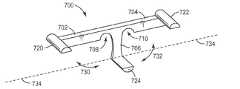
인장 조정기(700)의 또 다른 예시적인 실시예가 도 12에 도시되어 있다. 인장 조정기(700)는 각각의 단부에 접촉부(720, 722)를 갖는 제1 레그(702) 및 제2 레그(704)를 포함할 수 있다. 인장 조정기(700)는 또한 접촉부(724)를 포함한 메인 레그(706)를 포함할 수 있다. 작동 요소(미도시)는 예를 들어 레그(702, 704)의 양 단부에서의 접촉부(720, 722) 위로 그리고 접촉부(724) 아래로 꿰어질 수 있다. 하나의 예시적인 실시예에 따라, 제1 및 제2 레그(702, 704)는 메인 레그(706)에 대해 굽혀지도록(예를 들어, 탄성 변형되도록) 구성될 수 있다. 예를 들어, 제1 및 제2 레그(702, 704)는, 당해 제1 및 제2 레그(702, 704)가 도 12의 예시적인 실시예의 방향(730 및 732)을 따라 메인 레그(706)에 대해 굽혀지는 것을 용이하게 해주도록, 절결부(708 및 710)와 같은 재료 연약 영역을 포함할 수 있다. 따라서, 인장 조정기(700)는 인장 조정기(700)가 굽혀짐에 따라 포텐셜 에너지의 변화를 경험할 수 있으며, 이는 작동 요소의 느슨함을 동적으로 보상하는데 사용될 수 있다.Another exemplary embodiment of the
하나의 예시적인 실시예에 따라, 인장 조정기(700)가 결합되는 작동 요소가 느슨함이 없을 때는(예를 들어, 팽팽하고 도 12의 축(734)을 따라 연장되는 경로를 따라 실질적으로 직선일 때는), 작동 요소는 레그(702, 704)가 메인 레그(706)를 향한 방향(730, 732)을 따라 굽혀지게 할 수 있다. 작동 요소가 느슨함을 발달시킴에 따라, 인장 조정기(700)는 완화될 수 있고, 레그(702, 704)는 메인 레그(706)로부터 멀어지게 펴질 수 있다. 예를 들어, 인장 조정기(700)는 도 8-10의 예시적인 실시예와 유사하게 작동 요소의 경로를 축(734)을 따른 경로로부터 전환시킴으로써 작동 요소의 느슨함을 수용할 수 있다. 그 결과, 인장 조정기(700)는 길이방향 축(734)에 대해 작동 요소의 경로 길이를 증가시킬 수 있다.According to one exemplary embodiment, when the actuating element to which the
도 13을 참조하면, 인장 조정기(810)의 또 다른 예시적인 실시예가 도시되어 있다. 인장 조정기(810)는 당해 인장 조정기(810)의 제1 단부(812) 및 제2 단부(814)를 작동 요소(800)에 접합시킴으로써 작동 요소(800)에 결합된다. 인장 조정기(810)는 하나의 예시적인 실시예에 따라 탄성 재료의 밴드일 수 있다. 도 13은 작동 요소(800)가 팽팽하고 느슨함이 없는 상태를 도시한다. 그 결과, 인장 조정기(810)는 도 13의 예시적인 실시예에 도시된 바와 같이 작동 요소(800)를 따라 탄성 변형되고 신장된다. 도 14의 예시적인 실시예에 도시된 바와 같이, 작동 요소(800)가 느슨함을 발달시킴에 따라, 인장 조정기(810)는 도 14에서 화살표(820)로 지시된 방향을 따라 완화되어, 느슨함을 보상하여 작동 요소(800)를 팽팽하게 유지시킬 수 있다. 도 6-10의 예시적인 실시예와 유사하게, 인장 조정기(810)는 작동 요소(800)가 도 13에 도시된 바와 같이 팽팽하고 실질적으로 직선일 때 작동 요소(800)가 연장되어 따르게 되는 축(830)에 대한 작동 요소(800)의 경로를 전환시킴으로써 작동 요소(800)의 느슨함을 수용할 수 있다. 예를 들어, 인장 조정기(810)는 축(830)에 대해 작동 요소(800)의 경로의 길이를 증가시킬 수 있다.Referring to FIG. 13, another exemplary embodiment of the
도 3의 예시적인 실시예와 관련하여 전술한 바와 같이, 인장 조정기는 작동 요소에 체결될 수 있어, 인장 조정기는 작동 요소가 작동 입력 기구에 대해 풀어지거나 감겨질 때 작동 요소와 함께 운동한다. 하나의 예시적인 실시예에 따라, 인장 조정기의 접촉면은 인장 조정기가 작동 요소에 체결되지만, 작동 요소가 풀어지거나 감겨질 때 인장 조정기가 힘 전달 기구의 구성요소(예를 들어, 도 3의 섀시 부분(322) 또는 작동 입력 기구(330, 332))와 접촉하는 경우에, 인장 조정기 및 힘 전달 기구 구성요소들에 대한 손상을 최소화하거나 방지하기 위해 작동 요소가 인장 조정기에 대해 슬라이하는 것이 허용될 수 있도록 구성된다. 예를 들어, 도 6의 예시적인 실시예의 인장 조정기(550)의 루프(551, 553, 555)의 표면들은 인장 조정기(550)가 힘 전달 기구 구성요소에 충격할 때, 작동 요소가 인장 조정기(550)에 대해 상대적으로 슬라이드하는 것을 가능하게 해주도록 매끄러울 수 있다. 도 11-14의 예시적인 실시예들의 인장 조정기(600, 700, 810)도 작동 요소가 슬라이드하는 것을 가능하게 해줄 수 있다. 하나의 예시적인 실시예에 따라, 인장 조정기의 표면은 인장 조정기 표면을 큰 곡률 반경을 갖도록 형성하는 등에 의해, 인장 조정기에 대한 슬라이딩으로 인한 작동 요소의 마모를 최소화하도록 형성될 수 있다.As described above in connection with the exemplary embodiment of Fig. 3, the tension regulator can be fastened to the actuating element such that the tension regulator moves with the actuating element when the actuating element is unwound or rolled against the actuating input mechanism. According to one exemplary embodiment, the contact surface of the tension regulator is tensioned by the tensile regulator being fastened to the actuating element, but when the actuating element is loosened or rolled up, (The
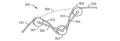
도 15를 참조하면, 인장 조정기(900)를 작동 요소(910)에 결합시키지만, 인장 조정기(900)가 힘 전달 기구의 구성요소에 충격할 때 등에, 인장 조정기(900)가 작동 요소(910)에 대해 슬라이드하는 것을 허용하는 표면을 포함하는 인장 조정기(900)의 하나의 예시적인 실시예가 도시된다. 인장 조정기(900)는 메인 풀리(903)에 연결되는 제1 레그(902) 및 제2 레그(904)를 포함할 수 있고, 풀리(901 및 905)가 제1 및 제2 레그(902, 904)의 단부에 배치된다. 제1 및 제2 레그(902, 904)는 도 6-11의 예시적인 실시예와 유사하게 메인 풀리(903)에 대해 굽혀질(예를 들어, 탄성 변형될) 수 있다. 인장 조정기(900)는, 인장 조정기(900)가 작동 요소(910)에 결합되지만, 인장 조정기(900)가 힘 전달 기구 구성요소(예를 들어, 도 3의 섀시 부분(322) 또는 작동 입력 기구(330, 332))에 충격할 때는 인장 조정기(900)가 작동 요소(910)에 대해 슬라이드하는 것이 허용되도록, 풀리(901, 903, 905)를 통해 꿰어질 수 있다. 하나의 예시적인 실시예에 따라, 작동 요소(910)가 느슨함을 발달시킴에 따라, 인장 조정기(900)는 도 6-10의 예시적인 실시예들과 유사하게 작동 요소(910)의 축(920)에 대한 작동 요소(910)의 경로(예를 들어, 작동 요소(910)가 팽팽하고 실질적으로 직선일 때 연장되게 되는 경로)를 전환시킬 수 있다. 그 결과, 인장 조정기(900)는 하나의 예시적인 실시예에 따라 축(920)에 대한 작동 요소(910)의 경로 길이를 증가시킬 수 있다.15, the
도 4-15의 예시적인 실시예들과 관련하여 전술한 바와 같이, 인장 조정기는 단일 작동 요소에 결합될 수 있다. 하지만, 본 명세서에 기술되는 다양한 예시적인 실시예의 인장 조정기는 단일 작동 요소에 결합되는 것으로 제한되지 않는다. 도 16을 참조하면, 인장 조정기(1000)가 제1 작동 요소(1010) 및 제2 작동 요소(1012)에 결합된 것으로 도시되어 있다. 작동 요소(1010, 1012)는 동일한 작동 입력 기구(예를 들어, 도 3의 예시적인 실시예의 작동 입력 기구(330 또는 332))에 결합될 수 있다. 인장 조정기(1000)는 작동 요소(1012)에 결합되는 제1 단부(1002) 및 작동 요소(1010)에 결합되는 제2 단부(1004)를 포함할 수 있고, 단부단부(1002, 1004)는 작동 요소(1010, 1012)가 도 16의 예시적인 실시예에 화살표(1020)로 지시된 방향을 따라 이동됨에 따라 작동 요소(1010, 1012)에 대해 슬라이드하도록 구성된다. 인장 조정기(1000)는 도 16에 화살표(1022)로 지시된 방향을 따른 인장 조정기(1000)의 변형(예를 들어, 탄성 변형)을 용이하게 해주는 변형가능 부분(1006)을 포함할 수 있으며, 이는 작동 요소(1010, 1012) 중의 하나 또는 모두의 느슨함의 보상을 용이하게 해준다. 변형 부분(1006)은 예를 들어 인장 조정기(1000)의 잔여부가 스프링으로 형성되거나 인장 조정기(1000)의 탄성 변형을 용이하게 해주는 다른 구성을 가질 수 있도록 보다 쉽게 변형가능한 인장 조정기(1000)의 컴플라이언트(compliant) 부분일 수 있다.As described above in connection with the exemplary embodiments of Figs. 4-15, the tension regulator can be coupled to a single actuating element. However, the tension regulators of the various exemplary embodiments described herein are not limited to being coupled to a single actuating element. Referring to FIG. 16, a
하나의 예시적인 실시예에 따라, 작동 요소(1010, 1012)가 팽팽하고 느슨함이 없을 때(예를 들어, 느슨함을 발달시키기 전), 작동 요소(1010, 1012)는 축(1030, 1032)을 따른 경로를 따라 연장될 수 있다. 이러한 상태에서, 변형 부분(1006)은 신장되고(예를 들어, 탄성 변형을 통해), 인장 조정기(1000)는 포텐셜 에너지의 증가를 경험한다. 작동 요소(1010, 1012)가 느슨함을 발달시킴에 따라, 변형 부분(1006)은 완화될 수 있고, 인장 조정기(1000)는 느슨함을 보상하기 위해, 도 8-10의 예시적인 실시예와 유사하게, 작동 요소(1010, 1012)를 각각의 축(1030, 1012)을 따른(예를 들어, 실질적으로 동축인) 경로로부터 전환시킬 수 있다. 예를 들어, 단부(1002, 1004)를 통해 연장되는 작동 요소(1010, 1012)의 부분들은 축(1030, 1032)과 0이 아닌 각도를 형성할 수 있다.According to one exemplary embodiment, when the
도 3-16의 예시적인 실시예와 관련하여 전술한 바와 같이, 인장 조정기는 당해 인장 조정기가 작동 요소와 함께 운동하도록 작동 요소에 결합될 수 있다. 따라서, 작동 요소가 작동 입력 기구에 대해 풀어지고 감겨질 때, 인장 조정기는 힘 전달 기구의 섀시에 대해 상대적으로 이동한다. 본 명세서에 기술되는 다양한 예시적인 실시예는 이러한 인장 조정기에 제한되지 않으며, 힘 전달 기구의 섀시에 고정된 인장 조정기를 포함할 수도 있다.As described above in connection with the exemplary embodiment of Figs. 3-16, the tension regulator may be coupled to the actuating element such that the tension regulator in question cooperates with the actuating element. Thus, when the actuating element is unwound and rolled relative to the actuating input mechanism, the tension regulator moves relative to the chassis of the force transmission mechanism. The various exemplary embodiments described herein are not limited to such a tension regulator and may include a tension regulator fixed to the chassis of the force transmission mechanism.
도 17을 참조하면, 힘 전달 기구의 부분(1106)(예를 들어, 도 3의 섀시(320))에 고정되는 인장 조정기(1100)의 하나의 예시적인 실시예가 도시되어 있다. 인장 조정기(1100)는 풀리(1102) 또는 인장 조정기(1100)를 작동 요소(1110)에 결합시키는 인장 조정기(1100)의 다른 부재를 통해 작동 요소(1110)를 연장시키는 등에 의해 작동 요소(1110)에 결합될 수 있다. 인장 조정기(1100)는 또한 도 17에 화살표(1120)로 지시된 방향을 따른 인장 조정기(1100)의 변형을 용이하게 해주는 변형가능 부분(1104)을 포함할 수 있으며, 이는 작동 요소(1110)의 느슨함의 보상을 용이하게 해준다. 변형 부분(1104)은 예를 들어 인장 조정기(1100)의 잔여부가 스프링으로 형성되거나 인장 조정기(1100)의 탄성 변형을 용이하게 해주는 다른 구성을 가질 수 있도록 보다 쉽게 변형가능한 인장 조정기(1100)의 컴플라이언트(compliant) 부분일 수 있다. 작동 요소(1110)가 느슨함이 없을 때는, 작동 요소(1110)는 도 8-10의 예시적인 실시예와 관련하여 전술한 바와 같이 작동 요소(1110)의 축(1130)을 따른(예를 들어, 실질적으로 동축인) 경로를 따를 수 있다. 작동 요소(1110)가 느슨함을 발달시킴에 따라, 인장 조정기(1100)는 횡단(예를 들어, 축(1130)에 대 수직인) 방향을 따라 작동 요소(1110)를 당길 수 있다. 따라서, 작동 요소(1110)의 경로는 도 8-10의 예시적인 실시예와 유사하게 작동 요소(1110)가 팽팽하고 느슨함을 발달시키지 않았을 때의 축(1130)을 따른 경로와 다르다. 그 결과, 인장 조정기(1100)는 작동 요소(1110)에 느슨함이 발달됨에 따라 작동 요소(1110)의 경로 길이를 증가시킬 수 있다.17, there is shown one exemplary embodiment of a
인장 조정기는 단일 피스(예컨대, 모놀리딕(monolithic)) 구조를 가질 수 있다. 단일 피스(예컨대, 모놀리딕) 구조를 갖는 인장 조정기는 제조하고 작동 요소에 결합시키는 데 효율적일 뿐만 아니라 느슨함 보상에 효과적일 수 있다. 도 6 및 도 7의 예시적인 실시예에 도시된 바와 같이, 인장 조정기(550)는 단일 부품(예컨대, 모놀리딕) 구조를 가질 수 있다. 예를 들어, 인장 조정기(550)는 예컨대 단일 피스의 와이어일 수 있다. 도 11의 예시적인 실시예의 인장 조정기(600)도 단일 피스(예컨대, 모놀리딕) 구조를 가질 수 있다. 예를 들어, 인장 조정기(600)는 도 11의 예시적인 실시예에 도시된 형상을 갖는 단일 피스의 박판 금속일 수 있다. 단일 피스(예컨대, 모놀리딕) 구조를 가질 수 있는 인장 조정기의 또 다른 예시적인 실시예는 도 12의 인장 조정기(700)이다. 인장 조정기(700)는 예컨대 단일 피스로 몰딩될 수 있다. 도 13 및 도 14의 예시적인 실시예의 인장 조정기(810)도 단일 피스(예컨대, 모놀리딕) 구조를 가질 수 있다. 하나의 예시적인 실시예에 따라, 도 16의 인장 조정기(1000)는 단부(1002, 1004) 및 변형 부분(1006)을 포함하는 단일 피스(예컨대, 모놀리딕) 구조를 가질 수 있다.The tensile regulator may have a single piece (e.g., monolithic) structure. Tension regulators having a single piece (e.g., monolithic) structure can be effective in making and binding loose components as well as being effective in bonding to a working element. As shown in the exemplary embodiment of Figures 6 and 7, the
본 명세서에서 고려되는 다양한 예시적인 실시예의 인장 조정기가 수술 기기의 힘 전달 기구 내의 작동 요소와 관련하여 설명되었지만, 본 명세서에 기술되는 다양한 예시적인 실시예의 인장 조정기는 기기의 힘 전달 기구와 함께 사용하는 것으로 제한되지 않는다. 예를 들어, 본 명세서에 기술되는 다양한 예시적인 실시예의 인장 조정기는 원격조작 수술 시스템의 환자측 카트의 작동 요소에 결합될 수 있다. 하나의 예시적인 실시예에 따라, 본 명세서에 기술되는 다양한 예시적인 실시예의 인장 조정기는 도 1의 예시적인 실시예의 환자측 카트(100)의 매니퓰레이터 암(110-113)을 작동시키는 데 사용되는 작동 요소(예컨대, 인장 요소)에 결합될 수 있다. 따라서, 본 명세서에 기술되는 다양한 예시적인 실시예의 인장 조정기는 도 1의 힘 전달 기구(134) 내에 위치되는 작동 요소뿐만 아니라 매니퓰레이터 암(110-113) 내의 작동 요소에 결합될 수 있다.Although the tension adjusters of the various exemplary embodiments contemplated herein are described in connection with the actuating elements in the force transmission mechanism of the surgical instrument, the tension adjusters of the various exemplary embodiments described herein may be used with a force transmission mechanism of the instrument . For example, the tension adjusters of the various exemplary embodiments described herein may be coupled to a working element of a patient side cart of a remote operated surgical system. In accordance with one exemplary embodiment, the tension adjusters of the various exemplary embodiments described herein may be used in combination with actuating elements (not shown) used to actuate the manipulator arms 110-113 of the
인장 조정기를 포함하는 힘 전달 기구를 제공함으로써, 작동 요소의 느슨함이 보상될 수 있다. 또한, 인장 조정기는 작동 요소의 느슨함을 보상할 수 있는 동시에, 제조하고 작동 요소에 결합시키는 데 효율적인 간단한 디자인을 가질 수 있다.By providing a force transmission mechanism including a tension regulator, the slack of the actuating element can be compensated. In addition, the tension regulator can have a simple design that is effective in compensating for the loosening of the actuating element, while also being manufactured and coupled to the actuating element.
또 다른 수정 및 변경된 실시형태들이 여기에 설명된 것에 비추어 자명한 것일 수 있을 것이다. 예컨대, 시스템 및 방법은 작동의 명료함을 위해 도면과 설명에서 생략된 추가적인 구성요소 또는 단계를 포함할 수 있을 것이다. 따라서, 여기서의 설명은 예시일 뿐으로 본 발명을 실시하는 일반적인 방식을 당업자에게 교시하는 것을 목적으로 하는 것으로 해석되어야 한다. 여기에 도시되고 설명된 다양한 실시형태는 예시로서 취급되어야 한다는 것을 이해해야 한다. 여기에 설명한 이점을 가지면서 당업자에 자명하다면, 여러 가지 요소와 재료 및 그러한 여러 가지 요소와 재료의 구성이 여기에 도시되고 설명된 것들과 대체될 수 있고, 부품들 및 공정들의 순서가 뒤집어질 수 있으며, 교시된 실시형태들의 임의의 세부 특징이 독립적으로 사용될 수도 있을 것이다. 본 명세서 및 청구범위의 사상 및 범위를 벗어나는 일없이, 여기에 설명된 요소들에 있어서의 변경이 이루어질 수 있을 것이다.Other modifications and variations may be apparent in light of the teachings herein. For example, the system and method may include additional components or steps omitted in the drawings and description for clarity of operation. Therefore, the description herein is merely illustrative and should be understood as directed to teach those skilled in the art the general manner of practicing the invention. It is to be understood that the various embodiments shown and described herein should be regarded as illustrative examples. It will be apparent to those skilled in the art, having the advantages herein described, that various elements and materials and configurations of such various elements and materials may be substituted for those shown and described herein, and that the order of parts and processes may be reversed And any of the detailed features of the disclosed embodiments may be used independently. Changes may be made in the elements set forth herein without departing from the spirit and scope of the disclosure and the claims.
여기에 기술된 특정 예시 및 실시형태는 제한을 위한 것이 아니며, 구조, 치수, 재료 및 방법에 대한 변경이 본 명세서의 범위를 벗어나는 일없이 이루어질 수 있다는 것을 이해해야 한다.It is to be understood that the specific examples and embodiments described herein are not intended to be limiting, and that modifications to the structure, dimensions, materials, and methods may be made without departing from the scope of the disclosure.
여기에 설명된 발명의 상세한 설명 및 실시예를 고려하면 본 발명에 따르는 다른 실시형태들도 당업자에 자명할 수 있을 것이다. 상세한 설명 및 실시예들은 예시로만 간주되고, 발명의 진정한 사상 및 범위는 후속의 청구범위에 의해 지정되는 것으로 한다.Other embodiments in accordance with the present invention will be apparent to those skilled in the art from consideration of the detailed description and the embodiments thereof set forth herein. It is intended that the specification and examples be considered as exemplary only, with the true spirit and scope of the invention being indicated by the following claims.
Claims (22)
Translated fromKorean상기 작동 요소에 결합되도록 구성되는 탄성적으로 변형가능한 바디를 포함하고,
상기 변형가능한 바디는 상기 작동 요소에 느슨함이 발생한 상태에 응답하여 탄성 변형되도록 구성되고,
상기 작동 요소에 느슨함이 발생할 때, 상기 변형가능한 바디는 느슨함을 수용하기 위해 상기 작동 요소의 경로를 전환시키도록 구성되어, 상기 작동 요소의 전환된 경로는 상기 작동 요소가 느슨함을 발달시키기 전에 상기 작동 요소가 따르는 축과 다른 것을 특징으로 하는 장치.An apparatus for adjusting the tension of an actuating element for actuating movement of a surgical instrument, the apparatus comprising:
A resiliently deformable body configured to be coupled to the actuating element,
Wherein the deformable body is configured to be resiliently deformed in response to a state where the operating element is loosened,
Wherein the deformable body is configured to switch the path of the actuating element to accommodate the slack when the actuating element is loosened so that the diverted path of the actuating element causes the actuating element to develop a slack Wherein the actuating element is different from the axis along which the actuating element follows.
섀시;
상기 섀시에 장착되고, 원격조작 수술 시스템의 작동 인터페이스 어셈블리로부터의 힘을 수취하도록 구성되는 작동 입력 기구;
상기 수술 기기의 엔드 이펙터를 작동시키기에 충분한 힘을 전달하도록 구성되는 작동 요소; 및
상기 작동 요소의 느슨함을 보상하기 위해 상기 작동 요소에 결합되는 인장 조정기를 포함하고,
상기 작동 요소에 느슨함이 발생할 때, 상기 인장 조정기는 느슨함을 수용하기 위해 상기 작동 요소의 경로를 전환시키도록 구성되어, 상기 작동 요소의 전환된 경로는 상기 작동 요소가 느슨함을 발달시키기 전에 상기 작동 요소가 따르는 축과 다른 것을 특징으로 하는 힘 전달 기구.12. A force transmission mechanism for a remote operated surgical instrument, the force transmission mechanism comprising:
Chassis;
An operating input mechanism mounted to the chassis and configured to receive a force from an operating interface assembly of a remote operated surgical system;
An actuating element configured to transmit a force sufficient to actuate an end effector of the surgical instrument; And
And a tension regulator coupled to the actuating element to compensate for the slack of the actuating element,
Wherein the tension adjuster is configured to switch the path of the actuating element to accommodate the slack when the actuating element is loosened so that the diverted path of the actuating element causes the actuating element Wherein the axis is different from the axis along which the actuating element follows.
탄성적으로 변형가능한 바디를 포함하는 인장 조정기를 상기 작동 요소에 결합시키는 과정; 및
상기 작동 요소의 경로를 전환시켜, 상기 작동 요소의 전환된 경로가 상기 작동 요소가 느슨함을 발달시키기 전에 상기 작동 요소가 따르는 축과 다르도록 함으로써, 상기 작동 요소에 발달하는 느슨함을 보상하는 과정을 포함하는 것을 특징으로 하는 방법.CLAIMS What is claimed is: 1. A method of compensating for loosening of a working element of a surgical instrument,
Coupling a tension regulator including an elastically deformable body to the actuating element; And
A step of changing the path of the actuating element to compensate for the slack developed in the actuating element by making the switched path of the actuating element different from the axis along which the actuating element follows before developing the slack of the actuating element ≪ / RTI >
Applications Claiming Priority (3)
| Application Number | Priority Date | Filing Date | Title |
|---|---|---|---|
| US201562151138P | 2015-04-22 | 2015-04-22 | |
| US62/151,138 | 2015-04-22 | ||
| PCT/US2016/028575WO2016172299A1 (en) | 2015-04-22 | 2016-04-21 | Tension regulator for actuation elements, and related remotely actuated instruments, systems, and methods |
Publications (2)
| Publication Number | Publication Date |
|---|---|
| KR20170139606Atrue KR20170139606A (en) | 2017-12-19 |
| KR102499214B1 KR102499214B1 (en) | 2023-02-14 |
Family
ID=57144304
Family Applications (1)
| Application Number | Title | Priority Date | Filing Date |
|---|---|---|---|
| KR1020177033603AActiveKR102499214B1 (en) | 2015-04-22 | 2016-04-21 | Tension adjuster for actuating element, related remotely actuated device, system and method |
Country Status (5)
| Country | Link |
|---|---|
| US (3) | US11185380B2 (en) |
| EP (2) | EP3285676B1 (en) |
| KR (1) | KR102499214B1 (en) |
| CN (2) | CN113229940B (en) |
| WO (1) | WO2016172299A1 (en) |
Cited By (3)
| Publication number | Priority date | Publication date | Assignee | Title |
|---|---|---|---|---|
| WO2022131556A1 (en)* | 2020-12-14 | 2022-06-23 | 주식회사 이지엔도서지컬 | Wire tension adjusting device for surgical tool |
| WO2022245088A1 (en)* | 2021-05-17 | 2022-11-24 | 주식회사 이지엔도서지컬 | Surgical tool device having wire hysteresis compensation function and method for controlling same |
| WO2025018763A1 (en)* | 2023-07-18 | 2025-01-23 | (주)더스탠다드 | Irreversible electroporation probe |
Families Citing this family (24)
| Publication number | Priority date | Publication date | Assignee | Title |
|---|---|---|---|---|
| US10076348B2 (en) | 2013-08-15 | 2018-09-18 | Intuitive Surgical Operations, Inc. | Rotary input for lever actuation |
| US10550918B2 (en) | 2013-08-15 | 2020-02-04 | Intuitive Surgical Operations, Inc. | Lever actuated gimbal plate |
| WO2016172299A1 (en) | 2015-04-22 | 2016-10-27 | Intuitive Surgical Operations, Inc. | Tension regulator for actuation elements, and related remotely actuated instruments, systems, and methods |
| CN109414300B (en) | 2016-07-14 | 2021-11-09 | 直观外科手术操作公司 | Instrument flushing system |
| EP3484397B1 (en) | 2016-07-14 | 2024-07-24 | Intuitive Surgical Operations, Inc. | Multi-cable medical instrument |
| WO2018013316A1 (en) | 2016-07-14 | 2018-01-18 | Intuitive Surgical Operations, Inc. | Geared roll drive for medical instrument |
| WO2018013298A1 (en) | 2016-07-14 | 2018-01-18 | Intuitive Surgical Operations, Inc. | Geared grip actuation for medical instruments |
| WO2018057690A1 (en)* | 2016-09-22 | 2018-03-29 | Intuitive Surgical Operations, Inc. | Tension regulation of remotely actuated instruments, and related devices, systems, and methods |
| WO2018094191A1 (en)* | 2016-11-21 | 2018-05-24 | Intuitive Surgical Operations, Inc. | Cable length conserving medical instrument |
| US10357321B2 (en) | 2017-02-24 | 2019-07-23 | Intuitive Surgical Operations, Inc. | Splayed cable guide for a medical instrument |
| US11076926B2 (en) | 2017-03-21 | 2021-08-03 | Intuitive Surgical Operations, Inc. | Manual release for medical device drive system |
| EP3746144A4 (en) | 2018-02-02 | 2021-11-24 | Calyxo, Inc. | DEVICES AND METHODS FOR MINIMALLY INVASIVE KIDNEY STONE REMOVAL BY COMBINED SUCTION AND FLUSHING |
| US11497567B2 (en) | 2018-02-08 | 2022-11-15 | Intuitive Surgical Operations, Inc. | Jointed control platform |
| US11118661B2 (en) | 2018-02-12 | 2021-09-14 | Intuitive Surgical Operations, Inc. | Instrument transmission converting roll to linear actuation |
| US12048504B2 (en) | 2018-11-15 | 2024-07-30 | Intuitive Surgical Operations, Inc. | Cable drive limited slip capstan and shaft |
| WO2020102776A1 (en) | 2018-11-15 | 2020-05-22 | Intuitive Surgical Operations, Inc. | Surgical instrument with sensor aligned cable guide |
| US11364084B2 (en) | 2018-11-21 | 2022-06-21 | Biosense Webster (Israel) Ltd. | Contact force compensation in a robot manipulator |
| WO2020171819A1 (en) | 2019-02-22 | 2020-08-27 | W. L. Gore & Associates, Inc. | Actuation line storage systems and methods |
| CN113811257B (en) | 2019-06-13 | 2025-09-30 | 直观外科手术操作公司 | Medical tool with length conservation mechanism for actuating a tension band |
| AU2020315615A1 (en) | 2019-07-15 | 2022-02-17 | Stryker Corporation | Robotic hand-held surgical instrument systems and methods |
| WO2023022913A1 (en)* | 2021-08-17 | 2023-02-23 | Intuitive Surgical Operations, Inc. | Surgical instrument cable control and routing structures |
| US12329396B2 (en) | 2022-03-02 | 2025-06-17 | Calyxo, Inc. | Kidney stone treatment system |
| US20240108412A1 (en) | 2022-09-29 | 2024-04-04 | Calyxo, Inc. | Tool guiding device for kidney stone treatment apparatus |
| NL2036065B1 (en) | 2023-10-17 | 2025-05-01 | R Solution Medical B V | Method and device for automated packing |
Citations (1)
| Publication number | Priority date | Publication date | Assignee | Title |
|---|---|---|---|---|
| US20140128849A1 (en)* | 2012-11-02 | 2014-05-08 | Intuitive Surgical Operations, Inc. | Self-antagonistic drive for medical instruments |
Family Cites Families (19)
| Publication number | Priority date | Publication date | Assignee | Title |
|---|---|---|---|---|
| US6394998B1 (en) | 1999-01-22 | 2002-05-28 | Intuitive Surgical, Inc. | Surgical tools for use in minimally invasive telesurgical applications |
| EP1224918A3 (en) | 1999-05-10 | 2002-12-18 | endoVia Medical Inc. | Surgical instrument |
| JP2002200092A (en)* | 2000-12-27 | 2002-07-16 | Mizuho Co Ltd | Loosening correction mechanism for drive wire in operative instrument operation |
| JP3910945B2 (en)* | 2002-09-09 | 2007-04-25 | 邦一 堂上 | Chain slack correction device |
| US8021326B2 (en)* | 2004-03-05 | 2011-09-20 | Hansen Medical, Inc. | Instrument driver for robotic catheter system |
| US7736254B2 (en) | 2006-10-12 | 2010-06-15 | Intuitive Surgical Operations, Inc. | Compact cable tension tender device |
| US9096033B2 (en)* | 2007-06-13 | 2015-08-04 | Intuitive Surgical Operations, Inc. | Surgical system instrument sterile adapter |
| ES2539521T3 (en)* | 2008-10-10 | 2015-07-01 | Fundacion Fatronik | Universal haptic drive system |
| JP2010194102A (en)* | 2009-02-25 | 2010-09-09 | Olympus Corp | Separable endoscope and operating part of separable endoscope |
| US8545515B2 (en) | 2009-09-23 | 2013-10-01 | Intuitive Surgical Operations, Inc. | Curved cannula surgical system |
| KR102386692B1 (en) | 2012-06-01 | 2022-04-14 | 인튜어티브 서지컬 오퍼레이션즈 인코포레이티드 | Redundant axis and degree of freedom for hardware-constrained remote center robotic manipulator |
| EP4070755A1 (en) | 2012-06-01 | 2022-10-12 | Intuitive Surgical Operations, Inc. | Multi-port surgical robotic system architecture |
| WO2013190475A2 (en) | 2012-06-19 | 2013-12-27 | Baylis Medical Company Inc. | Steerable medical device handle |
| US9839481B2 (en)* | 2013-03-07 | 2017-12-12 | Intuitive Surgical Operations, Inc. | Hybrid manual and robotic interventional instruments and methods of use |
| US9750578B2 (en) | 2014-03-17 | 2017-09-05 | Intuitive Surgical Operations, Inc. | Surgical instrument actuation input mechanisms, and related devices, systems, and methods |
| JP6265853B2 (en)* | 2014-07-10 | 2018-01-24 | オリンパス株式会社 | Medical equipment |
| WO2016172299A1 (en) | 2015-04-22 | 2016-10-27 | Intuitive Surgical Operations, Inc. | Tension regulator for actuation elements, and related remotely actuated instruments, systems, and methods |
| WO2018057690A1 (en) | 2016-09-22 | 2018-03-29 | Intuitive Surgical Operations, Inc. | Tension regulation of remotely actuated instruments, and related devices, systems, and methods |
| US10709512B2 (en)* | 2016-11-03 | 2020-07-14 | Verb Surgical Inc. | Tool driver with linear drives for use in robotic surgery |
- 2016
- 2016-04-21WOPCT/US2016/028575patent/WO2016172299A1/ennot_activeCeased
- 2016-04-21CNCN202110324355.6Apatent/CN113229940B/enactiveActive
- 2016-04-21CNCN201680036371.2Apatent/CN107809981B/enactiveActive
- 2016-04-21EPEP16783826.7Apatent/EP3285676B1/enactiveActive
- 2016-04-21KRKR1020177033603Apatent/KR102499214B1/enactiveActive
- 2016-04-21EPEP22157629.1Apatent/EP4018958A1/ennot_activeWithdrawn
- 2016-04-21USUS15/568,356patent/US11185380B2/enactiveActive
- 2021
- 2021-10-22USUS17/507,937patent/US12295691B2/enactiveActive
- 2025
- 2025-01-16USUS19/023,675patent/US20250152287A1/enactivePending
Patent Citations (1)
| Publication number | Priority date | Publication date | Assignee | Title |
|---|---|---|---|---|
| US20140128849A1 (en)* | 2012-11-02 | 2014-05-08 | Intuitive Surgical Operations, Inc. | Self-antagonistic drive for medical instruments |
Cited By (3)
| Publication number | Priority date | Publication date | Assignee | Title |
|---|---|---|---|---|
| WO2022131556A1 (en)* | 2020-12-14 | 2022-06-23 | 주식회사 이지엔도서지컬 | Wire tension adjusting device for surgical tool |
| WO2022245088A1 (en)* | 2021-05-17 | 2022-11-24 | 주식회사 이지엔도서지컬 | Surgical tool device having wire hysteresis compensation function and method for controlling same |
| WO2025018763A1 (en)* | 2023-07-18 | 2025-01-23 | (주)더스탠다드 | Irreversible electroporation probe |
Also Published As
| Publication number | Publication date |
|---|---|
| CN107809981B (en) | 2021-04-16 |
| US11185380B2 (en) | 2021-11-30 |
| EP4018958A1 (en) | 2022-06-29 |
| US12295691B2 (en) | 2025-05-13 |
| CN113229940B (en) | 2025-01-14 |
| US20180116743A1 (en) | 2018-05-03 |
| US20220039893A1 (en) | 2022-02-10 |
| CN107809981A (en) | 2018-03-16 |
| EP3285676B1 (en) | 2022-07-27 |
| EP3285676A1 (en) | 2018-02-28 |
| EP3285676A4 (en) | 2018-12-19 |
| WO2016172299A1 (en) | 2016-10-27 |
| CN113229940A (en) | 2021-08-10 |
| US20250152287A1 (en) | 2025-05-15 |
| KR102499214B1 (en) | 2023-02-14 |
Similar Documents
| Publication | Publication Date | Title |
|---|---|---|
| KR20170139606A (en) | Tensioners for operating elements, their associated remote actuating devices, systems and methods | |
| US11890073B2 (en) | Tension regulation of remotely actuated instruments, and related devices, systems, and methods | |
| US11547503B2 (en) | Passive preload and capstan drive for surgical instruments | |
| KR102504243B1 (en) | Robotic Microsurgical Assembly | |
| US11523732B2 (en) | Surgical device actuated using asymmetric spring system | |
| KR102780460B1 (en) | Systems to apply preload tension for surgical instruments and related methods | |
| JP5128904B2 (en) | manipulator | |
| EP2675385B1 (en) | Jointed link structures exhibiting preferential bending | |
| US20150080908A1 (en) | Energy balance mechanism for flexure joint | |
| JP7498611B2 (en) | Joint function area | |
| JP6177406B2 (en) | Medical instruments |
Legal Events
| Date | Code | Title | Description |
|---|---|---|---|
| PA0105 | International application | Patent event date:20171121 Patent event code:PA01051R01D Comment text:International Patent Application | |
| PG1501 | Laying open of application | ||
| A201 | Request for examination | ||
| PA0201 | Request for examination | Patent event code:PA02012R01D Patent event date:20210408 Comment text:Request for Examination of Application | |
| E902 | Notification of reason for refusal | ||
| PE0902 | Notice of grounds for rejection | Comment text:Notification of reason for refusal Patent event date:20220816 Patent event code:PE09021S01D | |
| E701 | Decision to grant or registration of patent right | ||
| PE0701 | Decision of registration | Patent event code:PE07011S01D Comment text:Decision to Grant Registration Patent event date:20221110 | |
| GRNT | Written decision to grant | ||
| PR0701 | Registration of establishment | Comment text:Registration of Establishment Patent event date:20230208 Patent event code:PR07011E01D | |
| PR1002 | Payment of registration fee | Payment date:20230209 End annual number:3 Start annual number:1 | |
| PG1601 | Publication of registration |