KR20170139518A - Fire hydrant shear valve and method - Google Patents
Fire hydrant shear valve and methodDownload PDFInfo
- Publication number
- KR20170139518A KR20170139518AKR1020177028440AKR20177028440AKR20170139518AKR 20170139518 AKR20170139518 AKR 20170139518AKR 1020177028440 AKR1020177028440 AKR 1020177028440AKR 20177028440 AKR20177028440 AKR 20177028440AKR 20170139518 AKR20170139518 AKR 20170139518A
- Authority
- KR
- South Korea
- Prior art keywords
- valve
- hydrant
- valve member
- valve body
- shear
- Prior art date
- Legal status (The legal status is an assumption and is not a legal conclusion. Google has not performed a legal analysis and makes no representation as to the accuracy of the status listed.)
- Withdrawn
Links
Images


Classifications
- F—MECHANICAL ENGINEERING; LIGHTING; HEATING; WEAPONS; BLASTING
- F16—ENGINEERING ELEMENTS AND UNITS; GENERAL MEASURES FOR PRODUCING AND MAINTAINING EFFECTIVE FUNCTIONING OF MACHINES OR INSTALLATIONS; THERMAL INSULATION IN GENERAL
- F16K—VALVES; TAPS; COCKS; ACTUATING-FLOATS; DEVICES FOR VENTING OR AERATING
- F16K17/00—Safety valves; Equalising valves, e.g. pressure relief valves
- F16K17/36—Safety valves; Equalising valves, e.g. pressure relief valves actuated in consequence of extraneous circumstances, e.g. shock, change of position
- F16K17/363—Safety valves; Equalising valves, e.g. pressure relief valves actuated in consequence of extraneous circumstances, e.g. shock, change of position the closure members being rotatable or pivoting
- E—FIXED CONSTRUCTIONS
- E03—WATER SUPPLY; SEWERAGE
- E03B—INSTALLATIONS OR METHODS FOR OBTAINING, COLLECTING, OR DISTRIBUTING WATER
- E03B9/00—Methods or installations for drawing-off water
- E03B9/02—Hydrants; Arrangements of valves therein; Keys for hydrants
- E03B9/04—Column hydrants
- F—MECHANICAL ENGINEERING; LIGHTING; HEATING; WEAPONS; BLASTING
- F16—ENGINEERING ELEMENTS AND UNITS; GENERAL MEASURES FOR PRODUCING AND MAINTAINING EFFECTIVE FUNCTIONING OF MACHINES OR INSTALLATIONS; THERMAL INSULATION IN GENERAL
- F16K—VALVES; TAPS; COCKS; ACTUATING-FLOATS; DEVICES FOR VENTING OR AERATING
- F16K17/00—Safety valves; Equalising valves, e.g. pressure relief valves
- F16K17/40—Safety valves; Equalising valves, e.g. pressure relief valves with a fracturing member, e.g. fracturing diaphragm, glass, fusible joint
- F—MECHANICAL ENGINEERING; LIGHTING; HEATING; WEAPONS; BLASTING
- F16—ENGINEERING ELEMENTS AND UNITS; GENERAL MEASURES FOR PRODUCING AND MAINTAINING EFFECTIVE FUNCTIONING OF MACHINES OR INSTALLATIONS; THERMAL INSULATION IN GENERAL
- F16K—VALVES; TAPS; COCKS; ACTUATING-FLOATS; DEVICES FOR VENTING OR AERATING
- F16K27/00—Construction of housing; Use of materials therefor
- F16K27/006—Construction of housing; Use of materials therefor of hydrants
Landscapes
- Engineering & Computer Science (AREA)
- General Engineering & Computer Science (AREA)
- Mechanical Engineering (AREA)
- Health & Medical Sciences (AREA)
- Life Sciences & Earth Sciences (AREA)
- Hydrology & Water Resources (AREA)
- Public Health (AREA)
- Water Supply & Treatment (AREA)
- Fire-Extinguishing By Fire Departments, And Fire-Extinguishing Equipment And Control Thereof (AREA)
- Safety Valves (AREA)
Abstract
Translated fromKoreanDescription
Translated fromKorean본 발명은 일반적으로 소화전 전단 밸브 및 소화전에 대한 액체의 흐름을 차단하는 방법에 관한 것이다.FIELD OF THE INVENTION [0002] The present invention relates generally to a fire hydrant shear valve and a method for shutting off the flow of liquid to a fire hydrant.
이 출원은 2015년 3월 10일자로 출원된 소화전 전단 밸브 및 방법(HYDRANT SHEAR VALVE AND METHOD)이라는 제목의 미국 가출원 출원번호 제 62/131,222호와 관련이 있고 이를 우선권 주장한, 2015년 6월 30일자로 출원된 소화전 전달 밸브 및 방법이라는 제목의 미국 특허출원 출원번호 제 14/788,448 호에 대한 우선권을 주장한다.This application is related to U.S. Provisional Application No. 62 / 131,222 entitled HYDRANT SHEAR VALVE AND METHOD, filed March 10, 2015, and is incorporated herein by reference in its entirety, No. 14 / 788,448 entitled " Fire Hydrant Delivery Valve < / RTI >
이 항목에서 개시된 배경 기술은 법적으로 선행 기술을 구성한다는 점을 인정하지 않는다.We do not recognize that the background technology described in this section constitutes a legitimate prior art.
예를 들어, 소화전이 우연히 이동하는 자동차에 의해 부딪혀 급수관에서 제거될 때, 물 낭비와 재산 피해가 우연히 발생한다. 소화전이 이동하는 차량에 의해 손상을 입었을 때, 약 60 피트 만큼의 높은 압력으로 분당 수천 갤런의 물이 공기 중에 분사될 수 있다. 이 물은 소방서에서 인라인 밸브를 수동으로 차단할 때까지, 30분에서 60분 정도의 많은 시간 동안 제어할 수 없이 계속 솟구친다.For example, when a fire hydrant is hit by an accidentally moving car and removed from the water line, water waste and property damage occur accidentally. When a hydrant is damaged by a moving vehicle, thousands of gallons of water per minute can be injected into the air at pressures as high as about 60 feet. This water rises uncontrollably for as long as 30 to 60 minutes, until the fire department manually blocks the inline valve.
주변의 기업, 주택 및 50 야드와 같은 넓은 반경 내의 다른 재산에 대한 재산 피해는, 물 넘침의 직접적인 결과로 보수적으로 수천 달러가 될 수 있다. 또한 납세자에게는 귀중한 물자가 되고 있는 수천 갤런의 물을 고려하지 않아도, 땅을 파내고 파손된 라인을 교체하는 추가 비용이 든다.Property damage to surrounding businesses, homes and other properties within a broad radius, such as 50 yards, can be conservatively thousands of dollars as a direct result of flooding. And even if taxpayers do not consider thousands of gallons of water, which is a valuable resource, it costs extra to dig the ground and replace broken lines.
이하에서, 본 발명의 실시예가 전부가 아닌, 일부가 도시되어 있는, 첨부된 도면을 참조하여 본 발명의 확실한 실시예에 대하여 상세히 설명한다. 실제로, 본 발명의 이러한 실시예는 많은 상이한 형태일 수 있으며, 따라서 본 발명은 본 명세서에 설명된 실시예에 한정되는 것으로 이해되어서는 안되며; 오히려, 이들 실시예는 이 개시가 적용 가능한 법적 요건을 충족시키도록 단지 실례가 되는 예시로서만 제공된다. 동일한 번호는 동일한 요소를 지칭한다.In the following, certain embodiments of the present invention will be described in detail with reference to the accompanying drawings, in which some, but not all embodiments of the invention are shown. Indeed, this embodiment of the present invention can be in many different forms, and therefore the present invention should not be construed as limited to the embodiments described herein; Rather, these embodiments are provided as illustrative examples only so that this disclosure will satisfy applicable legal requirements. Like numbers refer to like elements.
본 명세서에서 일반적으로 기술되고 도시된 실시예의 구성 요소는 다양한 다른 구성으로 배열되고 설계될 수 있음이 쉽게 이해될 것이다. 따라서, 도면들에 나타난 바와 같이, 본 발명의 시스템, 구성 요소 및 방법의 실시예들 중 특정 하나에 대한 다음의 더욱 상세한 설명은, 청구된 바와 같이, 본 발명의 범위를 제한하는 것이 아니라 단지 본 발명의 실시예의 대표적인 것이다.It will be readily appreciated that the components of the embodiments generally and described herein may be arranged and designed in a variety of different configurations. Thus, as shown in the drawings, the following more detailed description of a particular embodiment of the systems, components and methods of the present invention is not intended to limit the scope of the invention, as claimed, Which is representative of an embodiment of the invention.
적어도 하나의 실시예에 따르면, 소화전용 소화전 전단 밸브는 소화전과 급수관 사이에서 유체 연결 상태로 장착된 밸브 바디를 포함하는 소화전 급수관과 유체 연통 상태로 연결될 수 있다. 투-피스 밸브 부재는 개방 위치와 폐쇄 위치 사이에서 이동하도록 밸브 바디에 피봇식으로 장착된다. 상기 밸브 부재는 개방 위치에서 밸브 바디 내에 축방향으로 정렬되어 서로 중첩하여 배치되고, 폐쇄 위치에서 밸브 시트와 맞물려 동일 평면 구조로 배치되는 한 쌍의 밸브 부재 부분을 포함한다.According to at least one embodiment, the extinguishing extinguishing shear valve may be connected in fluid communication with a hydrant supply line including a valve body mounted in fluid connection between the hydrant and the water line. A two-piece valve member is pivotally mounted on the valve body for movement between an open position and a closed position. The valve member includes a pair of valve member portions axially aligned in the valve body at the open position and disposed in overlapping relation to each other and arranged in a coplanar structure in engagement with the valve seat at the closed position.
상기 소화전 전단 밸브는 개방 위치에서 밸브 부재 부분을 해제 가능하게 유지하고 밸브 부재 부분이 공급 파이프로부터 흐르는 유체의 힘에 의하여 폐쇄 위치로 이동시키도록 허가하기 위한 적어도 하나의 바이어스 부재를 포함할 수 있다. 또한, 밸브 부재 부분이 폐쇄 위치를 향하여 이동하도록 하기 위하여, 상기 소화전이 바이어스 부재를 자유롭게 하기 위한 충분한 충격으로 부딪혀질 때 적어도 하나의 취약성(frangible) 액추에이터가 이탈된다.The hydrant front end valve may include at least one biasing member for releasably holding the valve member portion in the open position and for allowing the valve member portion to move to a closed position by a force of fluid flowing from the supply pipe. In addition, at least one frangible actuator is released when the hydrant is struck with sufficient impact to free the biasing member, so that the valve member portion moves toward the closed position.
적어도 하나의 실시예에 따르면, 소화전에 대한 유체의 유동을 차단하기 위한 소화전 전단 밸브의 제조 방법은 충분한 충격을 수용하는 소화전에 반응하여 이탈되는 밸브 바디 상에 적어도 하나의 취약성 액추에이터를 장착하는 단계를 포함한다. 상기 방법은 또한 이탈에 대한 응답으로 소화전에 대한 유체의 유동을 차단하기 위하여 투-피스 밸브 부재를 밸브 바디 상에 장착하는 단계를 포함할 수 있다.According to at least one embodiment, a method of manufacturing a hydrant front end valve for shutting off fluid flow to a hydrant includes mounting at least one vulnerable actuator on a valve body that is released in response to a fire hydrant that receives sufficient impact . The method may also include mounting a two-piece valve member on the valve body to block fluid flow to the hydrant in response to the release.
이 소화전 전단 밸브의 적어도 하나의 목적은 수압 자체를 사용하여 상기 밸브를 폐쇄하는 것이다. 일 실시예에서, 파손된 전단 밸브의 교체는 단지 소화전으로부터 그것을 분리하고 교체하는 문제일 수 있다. 또 다른 실시예에 따르면, 상기 전단 밸브는 택트(tact) 상태로 유지되도록 설계되고, 오직 파손된 전단 볼트만이 교체를 필요로 한다.At least one purpose of this fire hydrant shear valve is to close the valve using the water pressure itself. In one embodiment, the replacement of the broken shear valve may be a matter of only removing and replacing it from the hydrant. According to another embodiment, the shear valve is designed to remain in a tact state, and only the broken shear bolt needs to be replaced.
본 발명을 더 잘 이해하고 실제로 어떻게 수행할 수 있는지를 알기 위해, 본 발명의 비-제한적인 바람직한 실시예가 첨부 도면을 참조하여 설명될 것이다.
도 1 은 일 실시예에 따라 구성되고, 급수관과 유체 연통하는 소화전에 장착되는 것으로 도시된 소화전 전단 밸브의 도식적인 입면도이다.
도 2 는 도 1 의 소화전 전단 밸브의 확대된 도식적인 입면도이다.
도 3 은 도 2 의 밸브의 회화도이다.
도 4 는 도 1 의 밸브의 평면도이다.
도 5 는 실질적으로 라인 5-5 에 따른 도 4 의 밸브의 단면도이다.
도 6 은 도 2 의 밸브 구성 요소의 확대된 분해도이다.
도 7 은 폐쇄 위치에 있는 구성 요소를 도시하는 도 6 의 구성 요소의 조립 평면도이다.
도 8 은 도 7 의 구성 요소의 입면도이다.
도 9 는 도 7 의 구성 요소의 개략도이고, 개방 위치를 도시한다.
도 10 은 도 7 의 구성 요소의 슬라이드 입면도이다.
도 11 은 또 다른 실시예에 따라 구성되고, 급수관과 유체 연통하는 소화전에 장착되는 것으로 도시된 소화전 전단 밸브의 입면도로서, 차량에 의해 치이는 소화전을 도시하고 있다.
도 12 는 개방 위치에 있는 도 11 의 밸브의 회화도이다.
도 13 은 폐쇄 위치에 있는 도 11 의 밸브의 회화도이다.
도 14 는 도 11 의 밸브의 분해도이다.
도 15, 16 및 17 은 도 11 의 밸브의 투-피스 밸브 부재 부분의 회화도이다.
도 18, 19 및 20 은 도 11 의 밸브의 다른 투-피스 밸브 부재 부분의 회화도이다.
도 21 은 도 11 의 밸브의 저면도 및 측면도로서, 개방 위치로부터 폐쇄 위치로 이동하는 과정의 밸브를 도시한다.
도 22 는 도 12 의 라인 22-22 을 실질적으로 따른 밸브의 단면도로서, 밸브가 열린 위치에 있는 것을 도시한다.
도 23 은 도 13 의 라인 23-23 을 실질적으로 따른 밸브의 단면도로서, 밸브가 폐쇄 위치에 있는 것을 도시한다.BRIEF DESCRIPTION OF THE DRAWINGS In order to better understand the invention and to see how it may be carried out in practice, a non-limiting preferred embodiment of the invention will be described with reference to the accompanying drawings.
1 is a schematic elevational view of a hydrant front end valve constructed in accordance with one embodiment and shown mounted to a hydrant in fluid communication with a water supply line.
2 is an enlarged schematic elevation view of the fire hydrant frontal valve of FIG.
Figure 3 is a pictorial representation of the valve of Figure 2;
Figure 4 is a top view of the valve of Figure 1;
Figure 5 is a cross-sectional view of the valve of Figure 4 substantially along line 5-5.
Figure 6 is an exploded exploded view of the valve component of Figure 2;
Figure 7 is an assembly plan view of the component of Figure 6 showing components in the closed position.
Figure 8 is an elevational view of the components of Figure 7;
Figure 9 is a schematic view of the components of Figure 7, showing the open position.
10 is a slide elevational view of the components of Fig.
Fig. 11 is an elevational view of a hydrant front-end valve constructed in accordance with yet another embodiment and shown mounted to a hydrant in fluid communication with a water supply line, showing a hydrant hit by a vehicle.
Figure 12 is a pictorial representation of the valve of Figure 11 in an open position;
Figure 13 is a pictorial representation of the valve of Figure 11 in the closed position.
14 is an exploded view of the valve of Fig.
Figures 15, 16 and 17 are pictorial representations of the two-piece valve member portion of the valve of Figure 11;
Figures 18, 19 and 20 are pictorial representations of another two-piece valve member portion of the valve of Figure 11;
FIG. 21 is a bottom view and a side view of the valve of FIG. 11, showing the valve in the process of moving from the open position to the closed position.
FIG. 22 is a cross-sectional view of the valve substantially along line 22-22 of FIG. 12, showing that the valve is in the open position.
23 is a cross-sectional view of the valve substantially along line 23-23 of FIG. 13, showing that the valve is in the closed position.
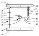
도 1 내지 10 을 참조하면, 일 실시예에 따라 구성되고, 소화전(12) 아래에서 유체 연통 상태로 장착되도록 되고 가압 소화전의 급수원으로서 쓰이는 급수관(22)의 상부 단부와 유체 연통 상태로 연결된 소화전 전단 밸브(10)가 도시되어 있다.Referring to Figs. 1 to 10, a
상기 밸브(10)는 상부 플랜지(14)와 하부 플랜지(16) 및, 상기 상부 플랜지(14)에 고정된 보호 커버 플레이트(19)(도 1) 뒤의 횡방향 로드 또는 샤프트(41)(도 6 및 8)에 피봇식으로 장착되는 투-피스 밸브 부재(18)를 가지는 밸브 바디(13)를 포함한다. 상기 상부 플랜지(14)는 패스너(fastener)(15)(도 1)와 같은 패스너들을 수용하기 위한 구멍(11)(도 4)과 같은 일련의 이격된 패스너 구멍들을 포함한다. 상기 하부 플랜지(16)는 도 1 의 패스너(15)와 같은 패스너들을 수용하기 위한 구멍(17)(도 2 및 3)과 같은 이격된 패스너 구멍들을 포함한다.The
스프링(23)(도 2)의 형태인 바이어스 부재 또는 기구(21)는 개방 위치에서 밸브 부재(18)를 해제 가능하게 유지시킨다. 상기 바디(13)의 취약성 액추에이터 또는 부분(25)은 차량(도시되지 않음)이 충돌할 때와 같이 의도치 않은 충분한 충격으로 소화전(12)이 부딪혀질 때 이탈하도록 되어 있다. 상기 취약성 액추에이터는 상기 소화전(12)의 바닥부에 장착된 밸브 바디(13)가 상부 플랜지(14)에 의해 측방향 힘 및/또는 각도 힘의 결과로서 이탈하거나 파열될 수 있게 하기 위하여 환상의 형상일 수 있고 정사각형 환상의 세레이션(serration)(27) 및 V 자형 환상의 세레이션(29)을 포함할 수 있다.A biasing member or
일반적으로 도면 부호 32로 표시된 트리거 기구 또는 부재는 상기 밸브 부재(18)에 연결된 횡방향으로 연장되는 아암(34), 및 소방관에 의해 정상적으로 사용될 때 소화전(12)을 통해 물과 같은 액체가 가압하에서 유동하는 것을 허용하도록 도 4 및 5 에 잘 도시된 바와 같이 상기 밸브 부재(18)를 정지부(71)에 맞물리는 개방 위치에 유지하기 위하여 상기 아암(34)의 외부 단부 사이에서 연결되고 상부 플랜지(14)에 고정되는 축방향으로 연장되는 전단 핀(36)을 포함한다. 가이드 브래킷(38)은 제자리에 고정시키는 것을 돕기 위하여 전단 핀(36)의 중간 부분을 수용한다. 상기 아암(34)은 그 말단부가 단단하거나 정지부(39)에 대해 가압되도록 일반적으로 스프링(32)에 의해 스프링 바이어스된다. 상기 소화전(12)에 충분한 충격이 가해질 때, 핀(36)을 자유롭게 하기 위하여 상부 바디 부분 및 전단 핀(36)을 이탈시키고 상기 스프링(23)이 상기 아암(34)을 상기 샤프트(41)에 의해 도 2 에서 반시계 방향으로 회전시키도록 허용하도록 취약성 액추에이터(25)가 파손되어, 상기 밸브 부재(18)는 도 4 에 도시된 바와 같이 그 폐쇄 위치를 향하여 튀어오른다. 그러면 상기 전단 밸브(10)가 소화전에서 제거되어 새로운 전단 밸브(도시되지 않음)로 교체될 수 있도록 물 메인 공급 밸브(도시 생략)를 끌 수 있을 때까지, 수압은 상기 투-피스 밸브 부재(18)의 C자형 밸브 부재 부분(45 및 47)을 그 동일 평면상의 폐쇄 위치(도 4, 7 및 10)로 계속 이동시키고 더 이상의 물의 배출을 차단하기 위하여 그 위치에서 유지된다.A trigger mechanism or member, generally designated 32, includes a laterally extending
도 4, 5, 6, 7, 8, 9 및 10 을 참조하여 상기 밸브 부재(18)를 보다 상세히 고려하면, 상기 밸브 부재(18)는 상기 밸브 부재(18)를 폐쇄 위치로 구동시키기 위하여 밸브 바디(13) 내에 횡방향으로 배치된 회전 가능하게 장착된 샤프트(41)를 포함한다. 상기 샤프트(41)는 키 홈(43)에서 샤프트(41)를 수용하는 슬리브(46)를 가지는 밸브 부재 부분(45)에 고정된 축방향으로 연장하는 키 홈 슬롯 (43)을 포함한다. 상기 밸브 부재 부분(47)은 상기 소화전 전단 밸브(10) 내의 유체 유동을 차단하기 위하여 동일 평면 형태로 배치될 때 밸브 부재 부분(45)과 협력한다. 상기 밸브 부재 부분(47)은 상기 밸브 부재 부분(45)의 상기 슬리브(46)의 대향 측에서 샤프트(41)를 수용하기 위한 한 쌍의 이격된 슬리브(48 및 49)를 포함한다. 상기 샤프트(41)에 고정된 상기 아암(34)이 소화전(12)에 대한 충격으로 도 2 에서 반시계 방향으로 회전할 때, 상기 밸브 부재 부분(45)은 샤프트(41)와 함께 회전하기 위하여 상기 슬리브(46)는 상기 키 홈(43) 내에 끼워 맞춰지는 내부 키(52)를 포함한다.Considering the
상기 밸브 부재 부분(45)을 회전 가능하게 이동시키기 위하여 상기 샤프트(41)가 회전할 때 상기 슬리브(48 및 49) 사이의 상기 밸브 부재 부분(47) 상의 단일의 스퍼 기어 치형부(54)(도 6, 7, 8 및 9)는 상기 밸브 부재 부분(45)의 상기 슬리브(46) 상의 1/4 회전 스퍼 기어 세그먼트(56)에 의하여 구동된다. 이러한 방식으로, 상기 샤프트(41)가 스프링(23)에 의해 회전함에 따라, 두 밸브 부재 부분(45 및 47) 모두 도 5 및 9 에 도시된 바와 같은 하향으로 중첩된 위치로부터 도 4 및 7 에 도시된 바와 같은 동일 평면상의 폐쇄 위치로 이동한다.A single spur gear teeth portion 54 (shown in FIG. 1) on the
상기 소화전 전단 밸브(10)는 상기 밸브 바디 상의 특정 지점으로 브레이크를 방향 전환시키고 수압 자체는 상기 전단 밸브(10)가 수리되거나 교체될 때까지 상기 밸브 부재(18)를 닫힌 동일 평면 위치로 폐쇄하고 유지시키도록 사용된다. 파손된 전단 밸브(10)의 수리 또는 교체는 소화전(12) 및 급수관으로부터 분리시킴으로써 이루어진다.The fire
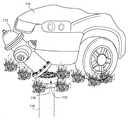
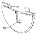
도 11 내지 23 을 참조하면, 실질적으로 모든 메커니즘이 내부에 있고 전체 구조가 보다 콤팩트하다는 점을 제외하고는, 상기 소화전 전단 밸브(10)와 유사한 소화전 전단 밸브(110)가 도시되어 있다. 상기 밸브(110)는 소화전(112)의 하측 및 소화전 급수관(116)의 상부 환형 플랜지(118)에 이탈 방식으로 고정될 수 있다. 이러한 방식으로, 상기 소화전(112)이 도 11 의 차량(114)과 같은 차량과의 우연한 충돌 또는 다른 이유로 인해 불가항력의 충격을 받으면, 상기 공급관(116)으로부터의 물의 유동을 차단하게 하도록 밸브(110)를 이동시키기 위하여 상기 소화전(112)이 상기 전단 밸브(110)로부터 분리된다.Referring to Figures 11-23, a hydrant
상기 전단 밸브(110)는 스틸과 같은 단단한 재료 또는 적합한 복합 재료로 구성된 환상의 원형 밸브 바디(121)를 포함할 수 있다. 일반적으로 도면 부호 123으로 표시된 관통 구멍을 수용하는 일련의 이격된 패스너는 더욱 자세히 후술하는 바와 같이 밸브 바디(121)가 상기 소화전(112)에 해제 가능하고 상기 급수관 플랜지(118)에 확고하게 고정되기 위하여 축방향으로 연장된다.The
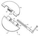
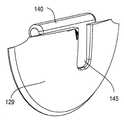
도 22 및 23 을 참조하면, 상기 밸브 바디(121)의 상부 부분에 있는 환형 밸브 시트(125)는 상기 관(116)으로부터 액체의 유동을 봉쇄하기 위해 투-피스 밸브 부재(126)를 수용하도록 되어 있다. 상기 밸브 부재(126)는 횡방향 피봇 핀(128) 상에 피봇식으로 장착된 반원형 밸브 부재 부분(127) 및 반원형 밸브 부재 부분(129)을 포함할 수 있다. 상기 밸브 부재 부분들은 일반적으로 도 12 에 도시된 바와 같이 밸브 개방 위치에서 중첩하는 배치로 위치된다. 상기 밸브(110)로부터 상기 소화전(112)이 제거되는 사건이 발생할 때, 상기 밸브 부재 부분들(127, 129)은 떨어져 이동하고 도 13 에 도시된 바와 같이 상기 밸브 시트(125)와의 밀봉 맞물림을 향해 상향으로 이동하기 위하여 상기 공급관(116)으로부터의 수압의 힘에 의해 피봇 핀(128)을 중심으로 피봇하도록 된다.22 and 23, the
도 14 에 도시된 바와 같이, 상기 피봇 핀(128)은 상기 핀의 대향 단부에서 상기 밸브 바디(121)에 고정되고, 상기 단부는 구멍(130)과 같은 직경 방향으로 대향된 한쌍의 측 구멍 내에 끼워 맞춰진다(도 14). 상기 밸브 부분(127)(도 16) 상에 일반적으로 도면 부호 131로 표시된 한 쌍의 이격된 슬리브는 그 사이에서 밸브 부분(129) 상의 슬리브(140)를 수용하여 상기 슬리브들(131, 140)은 피봇 핀(128)을 수용하고 거기에 대해서 피봇하도록 된다.14, the
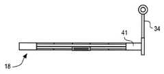
도 14 내지 20 에 가장 잘 도시된 바와 같이, L 자형 바이어스 부재(132)는 용접부(도시되지 않음)를 용접 및 연삭 가공하는 것과 같은 적절한 수단에 의하여 상기 밸브 부분(127)에 고정되고 상기 밸브 부분(127)의 상보적인 리세스(136) 내에 고정되는 풋 패드(134)를 가지는 매끄러운 윤곽의 풋(135)에 직각으로 연장되는 아암 또는 로드(133)를 포함한다. 도 12 및 22 에 가장 잘 도시된 바와 같이, 상기 밸브 바디(121)가 상기 소화전(112)의 하부에 고정될 때, 상기 소화전(112)은 도 12 및 22 에 도시된 바와 같이 상기 밸브 부분(127)이 상기 밸브 개방 위치로 유지되도록 이것의 리세스(137) 내에서 아암(133)을 유지하기 위하여 상기 아암(133)은 상기 밸브 바디(121)의 상부에서 리세스(137)에 끼워진다.As best seen in Figures 14-20, the L-shaped
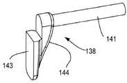
유사하게, L 자형 바이어스 부재(138)는 상기 바이어스 부재(132)와 유사하고, 아암(141)과 동일한 목적으로 상부 아암 수용 리세스(142)에 끼워지는 아암 또는 로드(141)를 포함한다. 풋 패드(143)를 가지는 매끄러운 윤곽의 풋(144)은 아암(141)으로부터 직각으로 연장되고 도 20 에 가장 잘 도시된 바와 같이 상기 밸브 부분(129)의 상보적인 형상의 리세스(145) 내에 고정된다. 그러므로, 상기 소화전(112)이 상기 밸브(110)로부터 우연하게 제거될 때, 양쪽 아암(133 및 141)은 각각의 리세스(137 및 142)로부터 자유롭게 피봇되고 도 13 및 23 에 가장 잘 도시된 바와 같이, 상기 관(116)을 통해 가해지는 수압 하에서 상기 밸브 시트(125)와의 밀봉 맞물림에 따른 상기 밸브 폐쇄 위치로 강제된다.Similarly, the L-shaped
도 22 에서 가장 잘 도시된 상기 밸브 폐쇄 위치에서, 소방 활동 또는 다른 목적을 위해 호스(도시되지 않음)를 통해 물을 전달하기 위한 정상 작동 중에 상기 소화전(112)이 사용될 때, 상기 소화전은 정상적으로 기능할 수 있도록 상기 밸브 부분(127 및 129)의 외부 표면은 상기 밸브(126) 주위의 유체의 유선형 층류 유동을 용이하게 하기 위하여 각각 매끄러운 윤곽을 이룬다.22, when the
도 22 및 23 에 도시된 바와 같이, 스프링(146)은 그 일 단부가 상기 밸브 부분(129)의 스프링 수용 리세스(147)에 고정되고 그 대향 단부는 상기 밸브 부분(127)의 스프링 수용 리세스(154)를 지지한다. 그렇게 하여, 상기 소화전(112)이 상기 밸브(110)로부터 제거되는 사건이 발생할 때, 파이프 (116) 내의 압력하에 흐르는 물이 상기 밸브 부분들을 상기 밸브 시트(125)에 붙이도록 하기 위하여 상기 스프링(146)은 밸브 부분(127, 129)이 떨어지도록 탄성적으로 압력을 가한다.22 and 23, the
상기 밸브 부재 부분(127 및 129)이 밸브 폐쇄 위치를 향해 이동하게 하기 위한 상기 바이어스 부재(132 및 138)를 자유롭게 하기 위하여 충분한 힘 또는 충격으로 상기 소화전이 부딪혀질 때 취약성 액추에이터(148)와 같은 적어도 하나의 취약성 액추에이터는 이탈된다. 예를 들어, 상기 취약성 액추에이터(148)는 환상의 소화전 플랜지(152)의 구멍(151)과 정렬되는 밸브 바디 구멍(150)을 통해 연장되고 너트(153)에 의해 제 위치에 고정되는 시어 볼트(149) 형태의 패스너를 포함할 수 있다(도 22 및 23). 상기 볼트(149)의 육각 헤드(155)는 상기 밸브 바디(121)의 하부 부분에서 상기 구멍(150)의 육각형의 납작한 확대부(157) 내에 견고하게 위치된다.Such as the
일 실시예에 따르면, 상기 밸브 부재(126)가 개방 위치에 유지되므로 소화전의 정상 작동이 발생할 수 있도록 취약성 액추에이터(148)와 같은 일련의 이격된 취약성 액추에이터가 제공되고 맞물림을 위하여 상기 밸브(110)로부터 상향으로 연장되고 상기 소화전 플랜지(152)에 해제 가능하게 고정된다(도 22). 소화전이 제거되는 사건이 발생할 때, 상기 볼트(149)와 같은 상기 전단 볼트는 상기 아암(133, 141)을 자유롭게 하기 위하여 도 23 에 도시된 바와 같이 이탈된다. 부가적으로, 도 11 에 도시된 바와 같이, 밸브 (110)의 낮은 프로파일 소형 구조로 인해, 상기 소화전(112)은 호스 연결을 용이하게 하기 위하여 지면 위의 관례적인 높이에서 수도관(116)에 장착될 수 있다.According to one embodiment, a series of spaced apart vulnerable actuators, such as the
상기 밸브(110)와 수도관 플랜지(118)의 연결을 보다 자세하게 고려하면, 상기 구멍(150)과 같은 시어 볼트 수용 구멍과 번갈아 있는 것은, 구멍(160)을 통과하여 상기 수도관 플랜지(118)의 구멍(161) 내부로 연장되고 너트(162)에 의하여 제자리에 고정되는 종래의 볼트(159)와 같은 종래의 볼트를 수용하는 구멍(160)과 같은 축방향으로 연장되는 구멍이다. 상기 너트(162)의 육각 헤드(163)는 상기 구멍(160)의 육각의 납작한 확대부(164) 내에 위치된다. 이러한 방식으로, 상기 소화전의 제거 사건 동안에 상기 볼트(159)와 같은 일련의 이격된 종래의 볼트는 상기 밸브(110)의 바닥으로부터 연장되고 상기 밸브(110)를 제 위치에 유지시키기 위하여 고정 방식으로 상기 수도관 플랜지(118)에 고정되도록 되어 있다. 그러므로, 도 23 에 도시된 바와 같이, 이러한 사건이 발생하면, 상기 시어 볼트(149)와 같은 전단 볼트가 상기 밸브(110)로부터 상기 소화전을 자유롭게 하기 위하여 파손되고 이탈한다. 따라서, 상기 밸브(10)는 일반적으로 손상되지 않고 단지 전단 볼트만이 소화전을 상기 밸브(110)에 고정하기 위하여 교체할 필요가 있다. 그러므로, 상기 밸브(110)의 사용은 일반적으로 새로운 전단 밸브가 통상적으로 사건 후 필요하지 않기 때문에 비용 효과적이다.Considering the connection of the
상부 오 링(166) 및 하부 오 링 (167)은 소화전(112)을 물 관(116)과 상기 환형의 밸브 바디(121)를 통해 유체 연통하도록 상기 밸브 바디(121)를 소화전 플랜지(152)의 하부 부분에 밀봉하기 위하여 상기 밸브 바디(121)의 상부 부분의 각각의 환형 리세스(168, 169) 내에 끼워진다. 도 14 에 도시된 바와 같이, 한 쌍의 캡 너트 및 와셔(182 및 184)는 피봇 핀(128)의 단부를 상기 밸브 바디(121)의 외부에 고정하는데 사용될 수 있다.The
본 발명은 상기 실시예를 참조하여 설명되었지만, 여기에 개시되고 청구된 것과 같이 본 발명의 실시예 및 청구항의 진정한 사상 및 범위 내에서 많은 수정 및 변형이 고려될 수 있음이 이해될 것이다. 여기에 제시된 본 발명의 많은 수정 및 다른 실시예는 본 발명이 속하는 기술분야에서 통상의 기술자가 상기 설명 및 관련된 도면에 제시된 교시의 이점을 가지는 것을 생각해 낼 것이다. 그러므로, 본 발명은 개시된 특정 실시예들에 한정되지 않으며 수정들 및 다른 실시예들은 첨부된 청구항들의 범위 내에 포함되도록 의도되고 고려되도록 이해될 것이다. 본 명세서에서 특정 용어가 사용되었지만, 이들은 제한적인 목적이 아닌 일반적이고 기술적인 의미로 사용된다.While the invention has been described with reference to the above embodiments, it will be understood that many modifications and variations are possible within the spirit and scope of the embodiments of the invention and claims, as disclosed and claimed herein. Many modifications and other embodiments of the invention as set forth herein will come to mind to one skilled in the art to which this invention pertain having the benefit of the teachings presented in the foregoing descriptions and the associated drawings. Therefore, it is to be understood that the invention is not to be limited to the specific embodiments disclosed, and that modifications and other embodiments are intended and should be considered to be included within the scope of the appended claims. Although specific terms are employed herein, they are used in a generic and descriptive sense only and not for purposes of limitation.
Claims (13)
Translated fromKorean상기 소화전과 상기 급수관 사이에서 유체 연통 가능하게 상기 밸브를 장착하기 위한 패스너 수용 개구와, 밸브 시트를 가지는 밸브 바디;
개방 위치와 폐쇄 위치 사이에서 이동하도록 상기 밸브 바디에 피봇식으로 장착되며, 상기 개방 위치에서 상기 밸브 바디 내에 축방향으로 정렬되어 서로 중첩하여 배치되고 폐쇄 위치에서 상기 밸브 시트와 맞물리는 동일-평면 상의 형태로 배치되는 한 쌍의 밸브 부재 부분을 가지는 투-피스 밸브 부재;
상기 개방 위치에서 상기 밸브 부재를 해제 가능하게 유지하고 상기 밸브 부재 부분이 공급 파이프로부터 유동하는 유체의 힘에 의하여 폐쇄 위치로 이동시키도록 허용하는 하나 이상의 바이어스 부재; 및
상기 소화전이 상기 바이어스 부재를 자유롭게 하기 위한 충분한 충격으로 부딪혀질 때 상기 밸브 부재 부분이 폐쇄 위치를 향해 이동하도록 하기 위하여 이탈하는 하나 이상의 취약성(frangible) 액추에이터를 포함하는 소화전 전단 밸브.An extinguishing extinguishing shear valve connected in fluid communication with a hydrant supply pipe having a pipe flange,
A fastener receiving opening for mounting the valve in fluid communication between the hydrant and the water supply pipe, and a valve body having a valve seat;
A valve body pivotally mounted on the valve body for movement between an open position and a closed position, axially aligned within the valve body at the open position, Piece valve member having a pair of valve member portions arranged in the shape of a pair;
At least one biasing member for releasably holding the valve member in the open position and allowing the valve member portion to move to a closed position by a force of fluid flowing from the supply pipe; And
And a frangible actuator for releasing said valve member to move toward said closed position when said hydrant is hit with sufficient impact to free said biasing member.
트리거 메커니즘은 유체가 새어 나가는 것을 방지하기 위하여 상기 취약성 액추에이터의 이탈에 반응하여 상기 바이어스 부재가 상기 밸브 부재 위치를 폐쇄 위치로 이동시키게 하는 것을 허용하여 상기 밸브 부재를 해제하는 소화전 전단 밸브.The method according to claim 1,
Wherein the trigger mechanism releases the valve member by allowing the biasing member to move the valve member position to the closed position in response to disengagement of the vulnerable actuator to prevent fluid from escaping.
상기 트리거는 전단 핀을 포함하고, 상기 바이어스 부재는 스프링을 포함하는 소화전 전단 밸브.3. The method of claim 2,
Wherein the trigger comprises a shear pin, and wherein the biasing member comprises a spring.
상기 바이어스 부재는 밸브 바디 리세스에 수용되는 하나 이상의 아암을 포함하는 소화전 전단 밸브.3. The method of claim 2,
Wherein said biasing member comprises at least one arm received in a valve body recess.
상기 소화전과 상기 급수관 사이에서 상기 밸브를 장착시키고 제 1 복수의 패스너가 상기 소화전의 바닥까지 연장되도록 하고 제 2 복수의 패스너가 상기 급수관까지 연장되도록 하기 위한 일련의 축방향으로 연장되는 패스너-수용 납작 구멍을 더 포함하는 소화전 전단 밸브.The method according to claim 1,
A series of axially extending fastener-receiving tabs for mounting the valve between the hydrator and the feed pipe and allowing a first plurality of fasteners to extend to the bottom of the hydrants and a second plurality of fasteners to the feed pipe, A fire hydrant shear valve further comprising a hole.
상기 하나 이상의 취약성 액추에이터는 하나 이상의 전단 패스너를 포함하는 소화전 전단 밸브.The method according to claim 1,
Wherein the at least one vulnerable actuator comprises at least one shear fastener.
각각의 밸브 부재 부분은 개방 위치에서 상기 밸브 부재를 지나간 유체 유동을 용이하게 하기 위하여 매끄러운 윤곽면을 포함하는 소화전 전단 밸브.The method according to claim 1,
Each valve member portion including a smooth contoured surface to facilitate fluid flow through the valve member in an open position.
상기 밸브 부재 부분이 폐쇄 위치를 향해 이동할 때 상기 밸브 부재를 서로 멀어지도록 탄성적으로 압력을 가하기 위한 스프링을 더 포함하는 소화전 전단 밸브.The method according to claim 1,
Further comprising: a spring for elastically biasing the valve member away from each other as the valve member portion moves toward the closed position.
상기 소화전으로의 유체 유동을 차단하기 위한 밸브 부재를 가지는 소형 밸브 바디;
상기 소화전이 충분한 충격으로 부딪혀질 때 상기 밸브 부재가 소화전으로의 유체 유동을 차단하게 하기 위하여 이탈하는 하나 이상의 취약성 부재; 및
상기 소화전과 상기 급수관 사이에서 상기 밸브를 장착시키고 제 1 복수의 패스너가 상기 소화전의 바닥까지 연장되도록 하고 제 2 복수의 패스너가 상기 급수관까지 연장되도록 하기 위한 일련의 축방향으로 연장되는 패스너-수용 납작 구멍을 포함하는 소화전 전단 밸브.A hydrant shear valve for a hydrant fluid in fluid communication with a hydrant supply line having a pipe flange,
A small valve body having a valve member for blocking fluid flow to the hydrant;
One or more fragile members for releasing the valve member to block fluid flow to the hydrants when the hydrants are hit with sufficient impact; And
A series of axially extending fastener-receiving tabs for mounting the valve between the hydrator and the feed pipe and for allowing a first plurality of fasteners to extend to the bottom of the hydrants and a second plurality of fasteners to the feed pipe Fire hydrant shear valves containing holes.
소화전이 충분한 충격을 받는 것에 반응하여 이탈하기 위하여 밸브 바디 상에 취약성 액추에이터를 장착하는 단계; 및
상기 이탈에 대응하여 상기 소화전에 대한 유체의 유동을 차단하기 위하여 상기 밸브 바디에 투-피스 밸브 부재를 장착하는 단계를 포함하는 소화전 전단 밸브를 제조하는 방법.A method of manufacturing a fire hydrant shear valve for shutting off fluid flow to a fire hydrant,
Mounting the vulnerable actuator on the valve body to escape in response to the hydrants having sufficient impact; And
And fitting a two-piece valve member to the valve body to block fluid flow to the hydrant corresponding to the departure.
상기 투-피스 밸브 부재를 개방 위치에서 유지하기 위하여 하나 이상의 바이어스 부재를 상기 밸브 바디에 장착하는 단계를 더 포함하는 소화전 전단 밸브를 제조하는 방법.11. The method of claim 10,
Further comprising mounting one or more biasing members to the valve body to hold the two-piece valve member in an open position.
상기 바이어스 부재는 상기 밸브 바디에 장착된 아암을 포함하는 소화전 전단 밸브를 제조하는 방법.11. The method of claim 10,
Wherein the biasing member comprises an arm mounted on the valve body.
상기 밸브 부재 위치를 떨어지게 하기 위하여 스프링 수단을 상기 밸브 부재에 제공하는 단계를 더 포함하는 소화전 전단 밸브를 제조하는 방법.11. The method of claim 10,
Further comprising the step of providing a spring means to said valve member to disengage said valve member position.
Applications Claiming Priority (5)
| Application Number | Priority Date | Filing Date | Title |
|---|---|---|---|
| US201562131222P | 2015-03-10 | 2015-03-10 | |
| US62/131,222 | 2015-03-10 | ||
| US14/788,448US9890866B2 (en) | 2015-03-10 | 2015-06-30 | Hydrant shear valve and method |
| US14/788,448 | 2015-06-30 | ||
| PCT/US2015/039124WO2016144378A1 (en) | 2015-03-10 | 2015-07-02 | Hydrant shear valve and method |
Publications (1)
| Publication Number | Publication Date |
|---|---|
| KR20170139518Atrue KR20170139518A (en) | 2017-12-19 |
Family
ID=56880325
Family Applications (1)
| Application Number | Title | Priority Date | Filing Date |
|---|---|---|---|
| KR1020177028440AWithdrawnKR20170139518A (en) | 2015-03-10 | 2015-07-02 | Fire hydrant shear valve and method |
Country Status (8)
| Country | Link |
|---|---|
| US (1) | US9890866B2 (en) |
| EP (1) | EP3268645B1 (en) |
| JP (1) | JP6669769B2 (en) |
| KR (1) | KR20170139518A (en) |
| CN (1) | CN107407433A (en) |
| BR (1) | BR112017019253A2 (en) |
| MX (1) | MX2017011575A (en) |
| WO (1) | WO2016144378A1 (en) |
Families Citing this family (13)
| Publication number | Priority date | Publication date | Assignee | Title |
|---|---|---|---|---|
| US10407882B2 (en) | 2015-03-10 | 2019-09-10 | Mueller International, Llc | Hydrant shear valve and method |
| US10550551B2 (en)* | 2017-03-28 | 2020-02-04 | Herbert W. Hoeptner, III | Valve assembly for use with multiple liquid lines |
| USD854125S1 (en) | 2018-07-13 | 2019-07-16 | Mueller International, Llc | Modular hydrant |
| US10767775B2 (en) | 2019-02-07 | 2020-09-08 | Mcwane, Inc. | Low profile break-off check valve for wet barrel hydrant |
| US11187332B2 (en) | 2019-04-11 | 2021-11-30 | Melvin Plummer | Break-away check valve |
| US11156303B2 (en) | 2019-05-31 | 2021-10-26 | Mueller International, Llc | Break check valve for hydrant |
| US11204102B2 (en) | 2020-03-19 | 2021-12-21 | Mueller International, Llc | Watertight check valve |
| US11725746B2 (en) | 2021-06-07 | 2023-08-15 | Mueller International, Llc | Low water hammer break check valve |
| US11377826B1 (en) | 2022-03-11 | 2022-07-05 | Alan D. Beneventi | Automatic shutoff valve for breakaway wet barrel fire hydrant |
| US12188212B2 (en) | 2022-03-11 | 2025-01-07 | Alan D. Beneventi | Automatic shutoff valve for breakaway wet barrel fire hydrant |
| CN114876013B (en)* | 2022-04-17 | 2024-07-26 | 百安消防科技有限公司 | Intelligent anti-collision fire hydrant with built-in collision alarm |
| CN114876012B (en)* | 2022-04-17 | 2024-07-26 | 百安消防科技有限公司 | Intelligent fire hydrant with multiple anti-collision structure |
| US12270478B2 (en)* | 2023-05-15 | 2025-04-08 | Hydrant Guard Llc | Valve system and method for reducing water hammer effect |
Family Cites Families (17)
| Publication number | Priority date | Publication date | Assignee | Title |
|---|---|---|---|---|
| US3542045A (en)* | 1968-04-26 | 1970-11-24 | Tokheim Corp | Emergency shut-off valve |
| US3709240A (en)* | 1971-01-06 | 1973-01-09 | Universal Valve Co Inc | Frost heave-protected shut-off valve with lockable nipple |
| US4127142A (en) | 1977-05-11 | 1978-11-28 | James Allen Snider | Slow close hydrant check valve |
| JPS5666354U (en)* | 1979-10-29 | 1981-06-03 | ||
| US4361165A (en) | 1980-08-07 | 1982-11-30 | Exxon Research And Engineering Co. | Breakaway pipe coupling with automatically closed valves |
| JPS62170460U (en)* | 1986-04-17 | 1987-10-29 | ||
| CN2063596U (en)* | 1990-01-06 | 1990-10-10 | 张国泰 | Clamped butterfly check valve |
| CN2067782U (en)* | 1990-02-17 | 1990-12-19 | 胡德英 | Butt-clamping rotation one-way valve |
| JPH078607Y2 (en)* | 1991-03-25 | 1995-03-01 | 孝芳 藤森 | Fire hydrant for cold regions |
| US5244006A (en)* | 1992-03-17 | 1993-09-14 | Universal Valve Company, Inc. | Double poppet valve with removable shear fitting |
| JPH0656175U (en)* | 1992-05-13 | 1994-08-05 | 清晴 藤田 | Fire hydrant antifreeze |
| JP2649769B2 (en)* | 1993-05-25 | 1997-09-03 | 苫小牧市 | Fire hydrant |
| US5609179A (en) | 1995-09-25 | 1997-03-11 | Dawn Hartman | Automatic shut-off valve |
| US6401745B1 (en) | 2001-04-09 | 2002-06-11 | Harold Eugene Corder | Fire hydrant automatic shut-off valve |
| JP2004019689A (en)* | 2002-06-12 | 2004-01-22 | Osaka Gas Co Ltd | Gas leakage preventing device |
| US20050224114A1 (en) | 2004-04-07 | 2005-10-13 | Christopher Michael Cook | Breakaway pipe coupling with automatic shutoff |
| US9353878B2 (en)* | 2014-02-27 | 2016-05-31 | Melvin Plummer | Dual plate backflow and breakaway check valve |
- 2015
- 2015-06-30USUS14/788,448patent/US9890866B2/enactiveActive
- 2015-07-02BRBR112017019253Apatent/BR112017019253A2/ennot_activeApplication Discontinuation
- 2015-07-02KRKR1020177028440Apatent/KR20170139518A/ennot_activeWithdrawn
- 2015-07-02CNCN201580077611.9Apatent/CN107407433A/enactivePending
- 2015-07-02JPJP2017548223Apatent/JP6669769B2/enactiveActive
- 2015-07-02EPEP15884895.2Apatent/EP3268645B1/enactiveActive
- 2015-07-02WOPCT/US2015/039124patent/WO2016144378A1/ennot_activeCeased
- 2015-07-02MXMX2017011575Apatent/MX2017011575A/enunknown
Also Published As
| Publication number | Publication date |
|---|---|
| BR112017019253A2 (en) | 2018-05-02 |
| WO2016144378A1 (en) | 2016-09-15 |
| EP3268645A4 (en) | 2019-01-09 |
| JP2018509541A (en) | 2018-04-05 |
| CN107407433A (en) | 2017-11-28 |
| EP3268645A1 (en) | 2018-01-17 |
| US9890866B2 (en) | 2018-02-13 |
| US20160265197A1 (en) | 2016-09-15 |
| JP6669769B2 (en) | 2020-03-18 |
| EP3268645B1 (en) | 2020-09-09 |
| MX2017011575A (en) | 2017-10-26 |
Similar Documents
| Publication | Publication Date | Title |
|---|---|---|
| KR20170139518A (en) | Fire hydrant shear valve and method | |
| US10407882B2 (en) | Hydrant shear valve and method | |
| CA2956665C (en) | Coupling | |
| JP5128901B2 (en) | Shut-off valve for use in fuel distributor | |
| US6401745B1 (en) | Fire hydrant automatic shut-off valve | |
| US7293721B2 (en) | Check valve assembly for sprinkler head | |
| US20190388720A1 (en) | Tool and Method for Draining a Fire Sprinkler System and a Fire Sprinkler | |
| JPS638354B2 (en) | ||
| CA2986101C (en) | Breakaway coupling | |
| US7850214B2 (en) | Closure safety interlock for a pressure vessel | |
| US20050224114A1 (en) | Breakaway pipe coupling with automatic shutoff | |
| NZ203837A (en) | Alarm check valve for sandwiching between flanges of pipes in automatic sprinkler system | |
| US10767775B2 (en) | Low profile break-off check valve for wet barrel hydrant | |
| US20160348846A1 (en) | Closure safety interlock with lockout plate for pressure vessel | |
| US5033592A (en) | Spring applied/pressure release emergency brake actuator | |
| JP2017506955A (en) | Fire extinguishing fluid nozzle system for stationary fire extinguishing systems with a throttling ring, and throttling rings for fire extinguishing fluid nozzles and fire extinguishing fluid nozzles | |
| JPH05504393A (en) | Fluid control valve device with pivoting latch | |
| US7325574B1 (en) | Rupture disc assembly for pneumatic plugs | |
| JPH0517999B2 (en) | ||
| US4519580A (en) | Safe high pressure instrument valve | |
| JP2021535341A (en) | Check valves and system separators, especially for the fire extinguishing department | |
| US10549408B2 (en) | Hydrant valve removal tool and improved keys therefore | |
| CN203797068U (en) | Fire fighting non-return valve | |
| CN113646055A (en) | Fire water monitor braking system and method | |
| RU2188683C1 (en) | Fire extinguisher |
Legal Events
| Date | Code | Title | Description |
|---|---|---|---|
| PA0105 | International application | Patent event date:20171010 Patent event code:PA01051R01D Comment text:International Patent Application | |
| PG1501 | Laying open of application | ||
| PC1203 | Withdrawal of no request for examination |