KR20170136816A - Power management device and method - Google Patents
Power management device and methodDownload PDFInfo
- Publication number
- KR20170136816A KR20170136816AKR1020160068824AKR20160068824AKR20170136816AKR 20170136816 AKR20170136816 AKR 20170136816AKR 1020160068824 AKR1020160068824 AKR 1020160068824AKR 20160068824 AKR20160068824 AKR 20160068824AKR 20170136816 AKR20170136816 AKR 20170136816A
- Authority
- KR
- South Korea
- Prior art keywords
- unit
- power
- breaker
- control
- standby power
- Prior art date
- Legal status (The legal status is an assumption and is not a legal conclusion. Google has not performed a legal analysis and makes no representation as to the accuracy of the status listed.)
- Ceased
Links
- 238000000034methodMethods0.000titleclaimsabstractdescription18
- 238000000926separation methodMethods0.000claimsabstractdescription16
- 238000007726management methodMethods0.000claimsdescription41
- 238000004891communicationMethods0.000claimsdescription23
- 238000001514detection methodMethods0.000claimsdescription20
- 230000000903blocking effectEffects0.000claimsdescription11
- 238000010248power generationMethods0.000claimsdescription2
- 239000000470constituentSubstances0.000description6
- 238000010586diagramMethods0.000description6
- 238000003745diagnosisMethods0.000description1
- 230000000694effectsEffects0.000description1
- 230000007274generation of a signal involved in cell-cell signalingEffects0.000description1
- 238000012986modificationMethods0.000description1
- 230000004048modificationEffects0.000description1
- 238000012544monitoring processMethods0.000description1
Images


Classifications
- H—ELECTRICITY
- H02—GENERATION; CONVERSION OR DISTRIBUTION OF ELECTRIC POWER
- H02J—CIRCUIT ARRANGEMENTS OR SYSTEMS FOR SUPPLYING OR DISTRIBUTING ELECTRIC POWER; SYSTEMS FOR STORING ELECTRIC ENERGY
- H02J9/00—Circuit arrangements for emergency or stand-by power supply, e.g. for emergency lighting
- H02J9/005—Circuit arrangements for emergency or stand-by power supply, e.g. for emergency lighting using a power saving mode
- H—ELECTRICITY
- H01—ELECTRIC ELEMENTS
- H01R—ELECTRICALLY-CONDUCTIVE CONNECTIONS; STRUCTURAL ASSOCIATIONS OF A PLURALITY OF MUTUALLY-INSULATED ELECTRICAL CONNECTING ELEMENTS; COUPLING DEVICES; CURRENT COLLECTORS
- H01R9/00—Structural associations of a plurality of mutually-insulated electrical connecting elements, e.g. terminal strips or terminal blocks; Terminals or binding posts mounted upon a base or in a case; Bases therefor
- H01R9/22—Bases, e.g. strip, block, panel
- H01R9/24—Terminal blocks
- H—ELECTRICITY
- H02—GENERATION; CONVERSION OR DISTRIBUTION OF ELECTRIC POWER
- H02H—EMERGENCY PROTECTIVE CIRCUIT ARRANGEMENTS
- H02H3/00—Emergency protective circuit arrangements for automatic disconnection directly responsive to an undesired change from normal electric working condition with or without subsequent reconnection ; integrated protection
- H02H3/08—Emergency protective circuit arrangements for automatic disconnection directly responsive to an undesired change from normal electric working condition with or without subsequent reconnection ; integrated protection responsive to excess current
- Y—GENERAL TAGGING OF NEW TECHNOLOGICAL DEVELOPMENTS; GENERAL TAGGING OF CROSS-SECTIONAL TECHNOLOGIES SPANNING OVER SEVERAL SECTIONS OF THE IPC; TECHNICAL SUBJECTS COVERED BY FORMER USPC CROSS-REFERENCE ART COLLECTIONS [XRACs] AND DIGESTS
- Y02—TECHNOLOGIES OR APPLICATIONS FOR MITIGATION OR ADAPTATION AGAINST CLIMATE CHANGE
- Y02B—CLIMATE CHANGE MITIGATION TECHNOLOGIES RELATED TO BUILDINGS, e.g. HOUSING, HOUSE APPLIANCES OR RELATED END-USER APPLICATIONS
- Y02B20/00—Energy efficient lighting technologies, e.g. halogen lamps or gas discharge lamps
- Y02B20/40—Control techniques providing energy savings, e.g. smart controller or presence detection
- Y—GENERAL TAGGING OF NEW TECHNOLOGICAL DEVELOPMENTS; GENERAL TAGGING OF CROSS-SECTIONAL TECHNOLOGIES SPANNING OVER SEVERAL SECTIONS OF THE IPC; TECHNICAL SUBJECTS COVERED BY FORMER USPC CROSS-REFERENCE ART COLLECTIONS [XRACs] AND DIGESTS
- Y02—TECHNOLOGIES OR APPLICATIONS FOR MITIGATION OR ADAPTATION AGAINST CLIMATE CHANGE
- Y02B—CLIMATE CHANGE MITIGATION TECHNOLOGIES RELATED TO BUILDINGS, e.g. HOUSING, HOUSE APPLIANCES OR RELATED END-USER APPLICATIONS
- Y02B30/00—Energy efficient heating, ventilation or air conditioning [HVAC]
- Y—GENERAL TAGGING OF NEW TECHNOLOGICAL DEVELOPMENTS; GENERAL TAGGING OF CROSS-SECTIONAL TECHNOLOGIES SPANNING OVER SEVERAL SECTIONS OF THE IPC; TECHNICAL SUBJECTS COVERED BY FORMER USPC CROSS-REFERENCE ART COLLECTIONS [XRACs] AND DIGESTS
- Y02—TECHNOLOGIES OR APPLICATIONS FOR MITIGATION OR ADAPTATION AGAINST CLIMATE CHANGE
- Y02B—CLIMATE CHANGE MITIGATION TECHNOLOGIES RELATED TO BUILDINGS, e.g. HOUSING, HOUSE APPLIANCES OR RELATED END-USER APPLICATIONS
- Y02B70/00—Technologies for an efficient end-user side electric power management and consumption
- Y02B70/30—Systems integrating technologies related to power network operation and communication or information technologies for improving the carbon footprint of the management of residential or tertiary loads, i.e. smart grids as climate change mitigation technology in the buildings sector, including also the last stages of power distribution and the control, monitoring or operating management systems at local level
- Y02B70/3225—Demand response systems, e.g. load shedding, peak shaving
- Y02B70/3275—
- Y02B70/3283—
Landscapes
- Business, Economics & Management (AREA)
- Emergency Management (AREA)
- Engineering & Computer Science (AREA)
- Power Engineering (AREA)
- Remote Monitoring And Control Of Power-Distribution Networks (AREA)
Abstract
Translated fromKoreanDescription
Translated fromKorean본 발명은 중앙 집중식 전원 관리 장치 및 방법에 관한 것으로, 아파트 및 건물내의 전기 배선 기기 등을 통합적으로 관리할 수 있는 중앙 집중식 전원 관리 장치 및 방법에 관한 것이다.The present invention relates to a centralized power management apparatus and method, and more particularly, to a centralized power management apparatus and method capable of integrally managing an apartment wiring and an electric wiring apparatus in a building.
일반적으로 건물 내 전기에너지를 절약하기 위해서는 미 사용 부하의 제어를 효율적으로 함으로써 달성할 수 있다.Generally, in order to save electric energy in the building, it can be achieved by efficiently controlling unused loads.
이를 위해 미 사용 조명, 콘센트 등을 제어하기 위해 별도의 제어 반을 별로도 설치하여야 하고 이를 위해 릴레이 및 제어 컨트롤러를 설치하여야 일괄적인 감시 및 제어가 가능하였다.For this purpose, separate control panels must be installed to control unused lighting, receptacles, etc. In order to do this, a relay and a control controller must be installed to enable comprehensive monitoring and control.
또한, 대기 전력을 막기 위해 사용하지 않는 전기 제품의 플러그를 콘센트로 부터 분리하기 위해 손수 플러그를 분리하거나 별도의 스위치를 동작시켜야 하는 등의 사용자의 노력이 필요한 단점이 있고, 이를 전기 에너지의 소비절감 효과에 미흡한 단점이 있었다.In addition, in order to prevent standby power, there is a disadvantage that the user needs to separate the hand-held plug or operate a separate switch to disconnect the plug of the unused electric appliance from the outlet. There was a drawback that the effect was insufficient.
또한, 이를 해결하기 위해 별도의 감지 센서를 기반으로 전력 제어를 수행하였지만, 이는 센서부등의 지속적인 동작으로 인해 불필요한 전기 에너지가 낭비되는 문제가 있었다.In order to solve this problem, power control is performed based on a separate sensing sensor. However, there is a problem that unnecessary electric energy is wasted due to continuous operation of the sensor unit.
본 발명은 상술한 문제점을 해결하기 위해 안출된 것으로, 운영자가 한 장소에서 각 장소의 전등 및 콘센트와 보일러 또는 가스 밸브를 개별 제어하여 과부하 및 누전으로 인한 화재를 방지하고, 불필요한 전력 낭비를 줄 일 수 있고, 배선의 분리 시공으로 인한 단락등의 고장 진단을 할 수 있고, 수동형, 자동형 및 대기전력 차단형의 모듈을 통해 다양한 제어가 가능한 중앙 집중식 전원 관리 장치 및 방법을 제공한다.The present invention has been devised to solve the above-mentioned problems, and it is an object of the present invention to provide an apparatus and a method for controlling an electric power source and an outlet of a boiler or a gas valve, The present invention provides a centralized power management apparatus and method capable of diagnosing a fault such as a short circuit due to separation of wiring and performing various control through a passive type, automatic type, and standby power type.
본 발명에 따른 다수의 분리 공간으로 분할된 건물 영역에 위치하는 부하에 외부로부터 전원을 제공받아 공급하기 위한 메인 차단기와, 상기 메인 차단기로부터 전원을 공급받아 각각의 분리 공간의 부하에 독립적으로 전원을 공급하기 위한 다수의 분배 차단기와, 상기 분배 차단기에 각기 접속된 다수의 차단기 단자대와, 각 분리 공간의 차단기 단자대와 부하 사이에 위치하는 다수의 시스템 차단부 및 기 다수의 시스템 차단부를 각기 제어하는 차단 제어부를 포함하는 것을 특징으로 하는 중앙 집중식 전원 관리 장치를 제공한다.A main breaker for supplying power to the load placed in a building area divided into a plurality of separation spaces according to the present invention and supplying the power to the load; A plurality of breaker terminal blocks respectively connected to the distribution breaker, a plurality of system breakers located between the breaker terminal blocks of each separation space and the loads, and a plurality of system breakers for controlling the plurality of system breakers And a controller for controlling power consumption of the power supply.
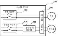
상기 시스템 차단부는 사용자 또는 차단 제어부의 신호에 따라 다수의 전등 부하 각각의 온/오프를 제어하는 다수의 전등 차단부와, 사용자 또는 차단 제어부의 신호에 따라 다수의 콘센트에 접속된 기타 부하의 온/오프를 제어하는 다수의 콘센트 차단부와, 다수의 콘센트에 접속된 기타 부하의 대기 전력을 제어하는 다수의 대기 전력 제어부와, 전등 차단부와 콘센트 차단부에 접속된 시스템 단자부를 포함하는 것을 특징으로 한다.The system shut-off unit includes a plurality of light cut-off units for controlling on / off of each of a plurality of light loads according to a signal of a user or a cut-off control unit, A plurality of standby power control units for controlling the standby power of other loads connected to the plurality of sockets, and a system terminal unit connected to the light blocking unit and the outlet shedding unit, do.
상기 전등 차단부 및 콘센트 차단부는 수동 제어와 자동 제어가 모두 가능한 형태의 두 라인 단락 가능한 스위치를 사용하는 것을 특징으로 한다.And the light blocking part and the outlet blocking part use a two-line short-circuitable switch of a type in which both manual control and automatic control are possible.
상기 차단 제어부는 과부하를 감지하는 과부하 감지부와, 과전류를 감지하는 전류 감지부와, 통신을 통해 외부로부터 관리 신호를 제공받는 통신부와, 제어 신호를 입력받는 사용자 입력부와, 과부하 감지부, 전류 감지부, 사용자 입력부 또는 통신부를 통해 제공받은 신호 및 별도의 대기 전력 정보를 분석하여 시스템 차단부, 메인 차단기 및 분배 차단기를 제어하는 통합 제어기를 포함하는 것을 특징으로 한다.The shutdown control unit includes an overload detection unit for detecting an overload, a current sensing unit for sensing an overcurrent, a communication unit for receiving a management signal from outside through communication, a user input unit for receiving a control signal, an overload detection unit, And an integrated controller for controlling the system breaker, the main breaker, and the distribution breaker by analyzing signals received from the user input unit or the communication unit and the separate standby power information.
상기 차단 제어부는 가스 공급을 제어하는 가스 스위치를 관리하는 가스 스위치 관리부와, 보일러 구동을 제어하는 보일러 관리부와, 전원을 공급받는 전원 공급부와, 수동 모드일 경우 차단 제어부의 감지 및 통신 동작을 최소화하는 전원 관리부와, 알람을 통해 경고음을 발생시키는 경보부 또한, 정보를 표시하는 표시부를 포함하는 것을 특징으로 한다.The shut-off control unit includes a gas switch management unit that manages a gas switch that controls gas supply, a boiler management unit that controls boiler operation, a power supply unit that receives power, and a shutdown control unit that minimizes the sensing and communication operations of the shut- A power management unit, and an alarm unit for generating a warning sound through an alarm, and a display unit for displaying information.
상기 통합 제어기는 사용자의 입력에 따라 수동 모드일 경우에는 과부하 감지부 및 전류 감지부의 동작을 오프 시켜 사용자가 직접 모든 차단기와 시스템 차단부를 수동으로 제어할 수 있도록 하고, 자동 모드일 경우에는 대기 전력 제어를 위한 부분을 제외한 동작을 활성화 시키고, 대기 전력 모드일 경우에는 대기 전력 제어를 위한 부분을 포함한 모든 부분의 동작을 활성화시키는 것을 특징으로 한다.In the case of the manual mode, the integrated controller turns off the operation of the overload detection unit and the current detection unit so that the user can directly control all the circuit breakers and the system shutoff unit. In case of the automatic mode, And in the case of the standby power mode, the operation of all parts including the part for standby power control is activated.
또한, 본 발명에 따른 청구항 1에 따른 중앙 집중식 전원 관리 장치를 이용한 전원 관리 방법에 있어서, 사용자가 수동 모드, 자동 모드 및 대기 전력 모드 중 하나의 모드를 선택하는 단계와, 사용자가 대기 전력 모드를 선택하는 경우, 과부하 감지 및 과전류 감지를 실시하고, 대기 전력 발생 유무를 판단하여, 과부하 및 과전류 및 대기 전력 발생시에는 차단기를 제어하거나, 시스템 차단부를 제어하기 위한 제어 신호를 제공하여 부하로 공급되는 전력을 자동으로 차단하고, 사용자가 자동 모드를 선택하는 경우, 과부하 및 과전류를 감지하고, 과부하 및 과전류 발생시 차단기 및 시스템 차단부를 제어하기 위한 제어 신호를 제공하여 부하로의 전력 공급을 자동으로 차단하며, 사용자가 수동 모드를 선택하는 경우, 차단기 및 시스템 차단부를 수동으로 제어하는 것을 특징으로 하는 중앙 집중식 전원 관리 방법을 제공한다.In accordance with another aspect of the present invention, there is provided a method of managing power using a centralized power management apparatus, the method comprising: selecting one of a manual mode, an automatic mode, and a standby power mode; When overload is detected and overcurrent is detected, it is determined whether or not standby power is generated, and a control signal for controlling the circuit breaker when the overload, overcurrent and standby power is generated, And automatically stops the power supply to the load by providing a control signal for controlling the circuit breaker and the system breaking unit when an overload and an overcurrent are generated in the case where the user selects the automatic mode, If the user selects manual mode, the breaker and system breaker must be manually It provides a centralized power management method characterized in that control.
상기 전력 공급의 차단은 부하에 접속되는 2개의 라인 모드를 차단하는 것을 특징으로 한다.And the interruption of the power supply cuts off two line modes connected to the load.
이와 같이 본 발명은 운영자가 한 장소에서 각 장소의 전등 및 콘센트와 보일러 또는 가스 밸브를 개별 제어하여 과부하 및 누전으로 인한 화재를 방지하고, 불필요한 전력 낭비를 줄 일 수 있다. 배선의 분리 시공으로 인한 단락등의 고장 진단을 할 수 있고, 수동형, 자동형 및 대기전력 차단형의 모듈을 통해 다양한 제어가 가능할 수 있다.As described above, the present invention allows the operator to separately control the lamps and the outlets of each place and the boiler or the gas valve in one place, thereby preventing an overload and a fire caused by a short circuit, and reducing unnecessary power consumption. Diagnosis of faults such as short circuit due to separation of wiring can be performed, and various controls can be performed through passive type, automatic type and standby power type.
도 1은 본 발명의 일 실시예에 따른 중앙 집중식 전원 관리 장치의 블록도.
도 2는 일 실시예에 따른 시스템 차단부의 블록도.
도 3은 일 실시예에 따른 차단 제어부의 블록도.
도 4는 본 발명의 일 실시예에 따른 중앙 집중식 전원 관리 방법을 설명하기 위한 흐름도.1 is a block diagram of a centralized power management apparatus in accordance with an embodiment of the present invention.
2 is a block diagram of a system blocking unit according to one embodiment.
3 is a block diagram of a block control unit according to an embodiment;
4 is a flowchart illustrating a centralized power management method according to an embodiment of the present invention.
이하, 첨부된 도면을 참조하여 본 발명의 실시예를 더욱 상세히 설명하기로 한다. 그러나 본 발명은 이하에서 개시되는 실시예에 한정되는 것이 아니라 서로 다른 다양한 형태로 구현될 것이며, 단지 본 실시예들은 본 발명의 개시가 완전하도록 하며, 통상의 지식을 가진 자에게 발명의 범주를 완전하게 알려주기 위해 제공되는 것이다. 도면상에서 동일 부호는 동일한 요소를 지칭한다.Hereinafter, embodiments of the present invention will be described in detail with reference to the accompanying drawings. It will be apparent to those skilled in the art that the present invention may be embodied in many different forms and should not be construed as limited to the embodiments set forth herein. Rather, these embodiments are provided so that this disclosure will be thorough and complete, It is provided to let you know. Wherein like reference numerals refer to like elements throughout.
본 명세서에서의 구성부들에 대한 구분은 각 구성부가 담당하는 주기능별로 구분한 것에 불과함을 명확히 하고자 한다. 즉, 이하에서 설명할 2개 이상의 구성부가 하나의 구성부로 합쳐지거나 또는 하나의 구성부가 보다 세분화된 기능별로 2개 이상으로 분화되어 구비될 수도 있다. 그리고 이하에서 설명할 구성부 각각은 자신이 담당하는 주기능 이외에도 다른 구성부가 담당하는 기능 중 일부 또는 전부의 기능을 추가적으로 수행할 수도 있으며, 구성부 각각이 담당하는 주기능 중 일부 기능이 다른 구성부에 의해 전담되어 수행될 수도 있음은 물론이다. 따라서, 본 명세서를 통해 설명되는 각 구성부들의 존재 여부는 기능적으로 해석 되어야 할 것이다. 이러한 이유로 본 발명의 중앙 집중식 전원 관리 장치 및 방법은 본 발명의 목적을 달성할 수 있는 한도 내에서 상이해질 수 있음을 명확히 밝혀둔다.It is to be clarified that the division of components in this specification is merely a division by main function which each component is responsible for. That is, two or more constituent parts to be described below may be combined into one constituent part, or one constituent part may be divided into two or more functions according to functions that are more subdivided. In addition, each of the constituent units described below may additionally perform some or all of the functions of other constituent units in addition to the main functions of the constituent units themselves, and that some of the main functions, And may be carried out in a dedicated manner. Accordingly, the presence or absence of each component described in this specification should be interpreted as a function. For this reason, it is clear that the centralized power management apparatus and method of the present invention can be varied within the scope of achieving the object of the present invention.
도 1은 본 발명의 일 실시예에 따른 중앙 집중식 전원 관리 장치의 블록도이다. 도 2는 일 실시예에 따른 시스템 차단부의 블록도이다. 도 3은 일 실시예에 따른 차단 제어부의 블록도이다.1 is a block diagram of a centralized power management apparatus in accordance with an embodiment of the present invention. 2 is a block diagram of a system blocking unit according to one embodiment. 3 is a block diagram of a block control unit according to an embodiment.
도 1 내지 도 3에 도시된 바와 같이 본 실시예에 따른 중앙 집중식 전원 관리 장치는 다수의 분리 공간으로 분할된 건물 영역에 위치하는 부하에 외부로부터 전원을 제공받아 공급하기 위한 메인 차단기(100)와, 메인 차단기(100)로부터 전원을 공급받아 각각의 분리 공간의 부하에 독립적으로 전원을 공급하기 위한 다수의 분배 차단기(200)와, 분배 차단기(200)에 각기 접속된 다수의 차단기 단자대(300)와, 각 분리 공간의 차단기 단자대(300)와 부하 사이에 위치하는 다수의 시스템 차단부(400)와, 다수의 시스템 차단부(400)를 각기 제어하는 차단 제어부(500)를 포함한다.1 to 3, the centralized power management apparatus according to the present embodiment includes a
메인 차단기(100)는 외부 변압기로부터 전원을 제공받아 이를 건물의 분리 공간에 제공한다. 이때, 건물은 아파트일 수도 있고, 사무실과 같은 공간일 수도 있다. 물론 이에 한정되지 않고, 창고, 공장과 같이 다수의 공간으로 분리가능한 다양한 건물체일 수 있다. 본 실시예에서는 다양한 형태의 메인 차단기(100)가 사용될 수 있기 때문에 본 설명에서는 특정한 한정을 하지 아니한다.The
다수의 분배 차단기(200)는 건물의 분리 공간에 대응하여 각 공간마다 하나씩 설치된다. 기존의 차단기는 그 목적에 따라 차단기를 설치하였지만, 본 실시예에서는 각 공간 단위로 차단기를 설치하는 것이 효과적이다. 즉, 기존에는 전등, 콘센트를 그룹핑하여 이 그룹에 해당하는 차단기를 각기 설치하였다. 하지만, 본 실시예에서는 해당 공간 아파트의 경우, 거실, 안방, 작은방들, 주방, 화장실 등으로 분리하여 차단기를 설치한다.A plurality of
차단기 단자대(300)는 분배 차단기(200)로부터 제공된 전원을 해당 분리 공간의 부하들에 제공한다. 본 실시예에서는 다양한 형태와 구성의 차단기 단자대(300)가 설비되는 것이 가능하다. 바람직하게는 분리 공간의 부하 개수에 따라 이와 같거나 이보다 많은 단자를 갖는 차단기 단자대(300)가 마련되는 것이 효과적이다.The
시스템 차단부(400)는 사용자 또는 차단 제어부(500)의 신호에 따라 다수의 전등 부하 각각의 온/오프를 제어하는 다수의 전등 차단부(410)와, 사용자 또는 차단 제어부의 신호에 따라 다수의 콘센트에 접속된 기타 부하의 온/오프를 제어하는 다수의 콘센트 차단부(420)와, 다수의 콘센트에 접속된 기타 부하의 대기 전력을 제어하는 다수의 대기 전력 제어부(430)와, 전등 차단부(410)와 콘센트 차단부(420)에 접속된 시스템 단자부(440)를 포함한다.The
본 실시예의 전등 차단부(410)로는 사용자가 수동으로 온/오프 조작을 하는 전등 스위치를 사용하는 것이 가능하다. 사용자의 조작은 물론 차단 제어부의 제어 신호에 따라 자동으로 온/오프가 가능한 터치식 전등 스위치를 사용하는 것이 효과적이다. 이때, 전등 차단부(410)는 전등으로 제공되는 두개의 전원 라인 모두에 대한 단락(개방) 하거나 연결하는 것이 바람직하다. 이를 통해 하나의 전원 라인 만을 단락할 때 보다 전력 소비량을 줄일 수 있다.It is possible to use a light switch for manually turning on and off the
전등 차단부(410)로 수동 제어와 자동 제어가 가능한 형태의 두 라인 단락 가능한 스위치를 사용할 수 있다. 이를 통해 전체 시스템이 수동 모드일 때는 자동 제어가 완전히 동작하지 않게 되어 자동 제어를 위한 전력 소비를 줄일 수 있다.A two-line short-circuitable switch of a type that can be manually controlled and automatically controlled can be used as the
콘센트 차단부(420) 또한 사용자가 수동으로 온/오프 조작할 수 있는 스위치를 사용하는 것이 가능하지만, 바람직하게 터치식 콘센트 스위치를 사용하는 것이 효과적이다. 또한, 콘센트 차단부(420)도 콘센트에 제공되는 두개의 전원 라인 모두를 단락하거나 연결하는 것이 바람직하다. 콘센트 차단부(420) 또한 앞서 언급한 전등 차단부(410)와 같이 수동 제어와 자동 제어가 모두 가능한 형태의 두 라인 단락 가능한 스위치를 사용하는 것이 바람직하다.Although it is possible to use a switch that can be manually turned on / off by a user, it is preferable to use a touch-type outlet switch. It is also preferable that the
대기 전력 제어부(430)는 콘센트 차단부(420)를 제어하여 콘센트에 접속된 기타 부하로 인한 대기 전력을 절감시킨다. 대기 전력 제어부(430)는 대기 전력을 감지하여 그 결과에 따라 콘센트 차단부(420)를 자동으로 동작시켜 기타 부하의 대기 전력을 절감한다.The standby
물론, 대기 전력 제어부(430)가 콘센트에 접속되는 두 배선 사이에 위치하고, 배선 접촉을 제어하여 대기 전력 발생을 제어할 수도 있다. 이를 위해 대기 전력 제어부(430)로는 대기 전력 스위치를 사용하는 것이 가능하다. 이때, 두 개의 배선을 동시에 단선시키기 때문에 하나의 스위치 내에 2개의 배선 단선이 가능한 구조를 갖는 것이 효과적이다.Of course, the standby
본 실시예에서는 건물 내의 전원을 중앙 집중 제어하기 위한 차단 제어부(500)를 구비한다. 차단 제어부(500)는 메인 차단기(100), 분배 차단기(200), 차단기 단자대(300), 다수의 시스템 차단부(400)를 각기 제어한다.In this embodiment, the
차단 제어부(500)는 과부하를 감지하는 과부하 감지부(510)와, 과전류를 감지하는 전류 감지부(520)와, 가스 공급을 제어하는 가스 스위치를 관리하는 가스 스위치 관리부(530)와, 보일러 구동을 제어하는 보일러 관리부(540)와, 통신을 통해 외부로부터 관리 신호를 제공받는 통신부(550)와, 제어 신호를 입력받는 사용자 입력부(560)와, 과부하 감지부(510), 전류 감지부(520), 사용자 입력부(560) 또는 통신부(550)를 통해 제공받은 신호 및 별도의 대기 전력 정보를 분석하여 시스템 차단부(400), 메인 차단기(100) 및 분배 차단기(200)를 제어하거나, 가스 스위치 관리부(530) 및 보일러 관리부(540)의 동작을 제어하는 통합 제어기(570)를 포함한다. 또한, 전원을 공급받는 전원 공급부(501)와, 수동 모드일 경우 차단 제어부(500)의 감지 및 통신 동작을 최소화하는 전원 관리부(502)와, 알람을 통해 경고음을 발생시키는 경보부(503) 또한, 정보를 표시하는 표시부(504)를 포함한다. 이때, 통합 제어기(570)는 사용자 입력부(560) 및 통신부(550)의 입력 신호에 따라 수동 모드, 자동 모드 및 대기전력 모드로 분리하여 전체 동작을 제어할 수 있다. 이에 관한 구체적인 설명은 후술한다. 터치 디스플레이 장치를 사용하여 입력부(560)와 표시부(504)를 하나의 장치로 구현할 수도 있다. 대기 전력 정보는 대기 전력 제어부(430)를 통해 제공받을 수 있다.The
과부하 감지부(510)는 과부하 발생 여부를 감지하고, 그 감지 결과를 통합 제어부(570)에 제공한다. 이때, 과부하가 발생한 구역의 시스템 차단부(400)의 위치를 통합 제어기(570)에 정확하게 알릴 수 있다. 이는 각 시스템 차단부(400)는 각기 고유한 번호를 부여 받기 때문에 가능하다. 통합 제어기(570)는 과부하 감지부(510)에 의해 과부하가 발생하는 경우, 1차로 전등 차단부(410) 또는 콘센트 차단부(420)를 제어하는 제어신호를 통해 더 이상의 부하가 연결되지 않도록 한다. 이후, 경보부(503)를 통해 과부하 발생을 사용자에게 알릴 수 있다. 또는 통신부(550)를 통해 원거리에 위치한 사용자에게 과부하 발생을 알려줄 수 있다.The
전류 감지부(520)는 과전류 발생 여부를 감지하고, 과전류가 발생하는 경우, 해당 분배 차단기(200)를 제어하여 전원 공급을 차단하거나, 해당 시스템 차단부(400)의 전등 차단부(410) 및 콘센트 차단부(420)를 제어하여 전원 공급을 차단하는 것이 가능하다. 또한, 과전류 사실을 사용자에게 알릴 수도 있다.The
가스 스위치 관리부(530) 및 보일러 관리부(540)는 이들의 동작을 관리하는 것으로, 언급된 사용자 입력부(560) 및 표시부(504) 이외에 별도 입출력이 가능한 구성으로 제작되는 것이 가능하다. 이를 통해 사용자가 별도의 장치를 통해 이들을 개별적으로 제어할 수 있다. 또한, 통신부(550)를 통해 외부에서 가스 스위치 및 보일러를 관리할 수도 있다.The gas
통신부(550)는 유/무선 통신을 통해 사용자로부터 관리 및 제어 신호를 제공 받거나, 사용자에게 이상 발생시 통지할 수 있다. 이때, 통신 방식은 와이파이, 근거리 통신 등과 같은 다양한 무선 통신 방식의 사용이 가능하고, 이더넷과 같은 다양한 유선 통신 방식의 사용 또한 가능하다.The
사용자 입력부(560)는 별도의 입력 장치를 통해 사용자로부터 관리 및 제어 신호를 제공 받는다. 이때, 사용자 입력부(560)로 터치 패널을 사용하는 것이 효과적이다.The
또는 사용자 입력부(560)는 각 시스템 차단부(400) 마다 하나의 사용자 입력부(560)가 구비될 수 있다. 이를 통해 시스템 차단부를 각기 제어하는 것이 가능하다.Alternatively, the
통합 제어기(570)는 과부하 및 과전류를 감지하고, 대기 전력을 감지하며, 그 감지 결과는 물론 사용자의 제어 신호에 따라 각 시스템 차단부(400)의 동작을 제어한다.The
통합 제어기(570)는 사용자의 입력에 따라 수동 모드일 경우에는 과부하 감지부(510) 및 전류 감지부(520)의 동작을 오프 시키고, 차단기들과 시스템 차단부(400)를 동작시키기 위한 별도의 제어나 명령 신호를 생성하지 않는다. 이를 통해 사용자가 직접 모든 차단기와 시스템 차단부를 수동으로 제어할 수 있도록 한다. 이는 최소 전력 사용을 위한 모드로 이를 사용하는 경우 각 감지부와 신호 발생으로 인한 전력 손실을 억제할 수 있다. 통합 제어기(570)는 자동 모드일 경우에는 전체 동작을 온 시키되, 대기 전력 제어를 위한 부분만을 오프 시킨다. 대기 전력 모드일 경우에는 대기 전력 제어를 위한 부분을 포함한 모든 부분의 동작을 정상화시킨다.The
전원 공급부(501)는 외부 전원을 제공받고, 전원 관리부(502)는 앞서 언급한 모드들에 따라 차단 제어부(500) 및 시스템 차단부(400) 그리고, 차단기(100, 200) 각각에 제공되는 전원을 제어하여 그 동작을 제어한다.The
하기에서는 상술한 구성을 갖는 중앙 집중식 전원 관리 방법에 관하여 설명한다. 이때, 차단 제어부의 동작을 중심으로 설명한다.In the following, a centralized power management method having the above-described configuration will be described. At this time, the operation of the cut-off control unit will be mainly described.
도 4는 본 발명의 일 실시예에 따른 중앙 집중식 전원 관리 방법을 설명하기 위한 흐름도이다.4 is a flowchart illustrating a centralized power management method according to an exemplary embodiment of the present invention.
도 4에 도시된 바와 같이, 사용자가 수동 모드, 자동 모드 및 대기 전력 모드 중 하나의 모드를 선택한다(S110).As shown in FIG. 4, the user selects one of a manual mode, an automatic mode, and a standby power mode (S110).
사용자가 대기 전력 모드를 선택하는 경우(S120), 과부하 감지 및 과전류 감지를 실시하고, 대기 전력 발생 유무를 판단한다. 이때, 과부하 및 과전류 및 대기 전력 발생시에는 차단기를 제어하거나, 시스템 차단부를 제어하기 위한 제어 신호를 제공하여 부하로 공급되는 전력을 자동으로 차단한다. 이때, 부하에 접속되는 2개의 라인 모드를 제어한다. 또한, 가스 스위치와 보일러를 관리하기 위한 관리신호를 제공하여 이들의 동작을 제어한다.When the user selects the standby power mode (S120), the overload detection and the overcurrent detection are performed, and it is determined whether standby power is generated or not. At this time, at the time of overload, overcurrent, and standby power generation, a breaker is controlled or a control signal for controlling the system breaker is provided to automatically shut off the power supplied to the load. At this time, two line modes connected to the load are controlled. It also provides control signals to control the gas switch and boiler to control their operation.
사용자가 자동 모드를 선택하는 경우(S130), 과부하 및 과전류를 감지한다. 그리고, 과부하 및 과전류 발생시 차단기 및 시스템 차단부를 제어하기 위한 제어 신호를 제공하여 부하로의 전력 공급을 자동으로 차단한다.When the user selects the automatic mode (S130), it detects overload and overcurrent. In addition, when an overload and an overcurrent are generated, a control signal for controlling the circuit breaker and the system breaker is provided to automatically shut off the power supply to the load.
사용자가 수동 모드를 선택하는 경우(S140), 가스 스위치와 보일러 관리를 위한 관리 신호 이외에 다른 신호를 생성하지 아니하고, 차단기 및 시스템 차단부를 수동으로 동작시킨다.If the user selects the manual mode (S140), the control unit does not generate a signal other than the management signal for managing the gas switch and the boiler, and manually operates the circuit breaker and the system breaking unit.
이때, 모드 선택은 입력부를 통한 직접 입력이 가능하고, 유/무선 통신을 통한 입력이 가능하다.At this time, mode selection can be directly input through the input unit, and input through wired / wireless communication is possible.
이상, 본 발명에 대하여 전술한 실시예들 및 첨부된 도면을 참조하여 설명하였으나, 본 발명은 이에 한정되지 않으며 후술되는 특허청구범위에 의해 한정된다. 따라서 본 기술분야의 통상의 지식을 가진 자라면 후술되는 특허청구범위의 기술적 사상을 벗어나지 않는 범위 내에서 본 발명이 다양하게 변형 및 수정될 수 있음을 알 수 있을 것이다.While the present invention has been particularly shown and described with reference to exemplary embodiments thereof, it is to be understood that the invention is not limited to the disclosed exemplary embodiments. It will be apparent to those skilled in the art that various modifications and variations can be made in the present invention without departing from the spirit or scope of the following claims.
100: 메인 차단기200: 다수의 분배 차단기
300: 차단기 단자대400: 시스템 차단부
410: 전등 차단부420: 콘센트 차단부
430: 대기 전력 제어부 440: 시스템 단자부
500: 차단 제어부510: 과부하 감지부
520: 전류 감지부530: 가스 스위치 관리부
540: 보일러 관리부550: 통신부
560: 사용자 입력부570: 통합 제어기100: Main breaker 200: Multiple distribution breakers
300: Circuit breaker terminal block 400:
410: light blocking part 420:
430: standby power control unit 440:
500: Blocking control unit 510: Overload detection unit
520: current sensing unit 530: gas switch management unit
540: boiler management unit 550: communication unit
560: User Inputs 570: Integrated Controller
Claims (8)
Translated fromKorean상기 메인 차단기로부터 전원을 공급받아 각각의 분리 공간의 부하에 독립적으로 전원을 공급하기 위한 다수의 분배 차단기;
상기 분배 차단기에 각기 접속된 다수의 차단기 단자대;
각 분리 공간의 차단기 단자대와 부하 사이에 위치하는 다수의 시스템 차단부; 및
상기 다수의 시스템 차단부를 각기 제어하는 차단 제어부를 포함하는 것을 특징으로 하는 중앙 집중식 전원 관리 장치.
A main breaker for supplying power to the load located in a building area divided into a plurality of separation spaces from outside and supplying the load;
A plurality of distribution breakers for receiving power from the main breaker and supplying power independently to loads in the respective separation spaces;
A plurality of breaker terminal blocks respectively connected to the distribution breaker;
A plurality of system shut-off portions located between the circuit breaker terminal block and the load of each separation space; And
And a shutdown control unit for controlling each of the plurality of system shutdown units.
상기 시스템 차단부는 사용자 또는 차단 제어부의 신호에 따라 다수의 전등 부하 각각의 온/오프를 제어하는 다수의 전등 차단부와, 사용자 또는 차단 제어부의 신호에 따라 다수의 콘센트에 접속된 기타 부하의 온/오프를 제어하는 다수의 콘센트 차단부와, 다수의 콘센트에 접속된 기타 부하의 대기 전력을 제어하는 다수의 대기 전력 제어부와, 전등 차단부와 콘센트 차단부에 접속된 시스템 단자부를 포함하는 것을 특징으로 하는 중앙 집중식 전원 관리 장치.The method according to claim 1,
The system shut-off unit includes a plurality of light cut-off units for controlling on / off of each of a plurality of light loads according to a signal of a user or a cut-off control unit, A plurality of standby power control units for controlling the standby power of other loads connected to the plurality of sockets, and a system terminal unit connected to the light blocking unit and the outlet shedding unit, A centralized power management device.
상기 전등 차단부 및 콘센트 차단부는 수동 제어와 자동 제어가 모두 가능한 형태의 두 라인 단락 가능한 스위치를 사용하는 것을 특징으로 하는 중앙 집중식 전원 관리 장치.
3. The method of claim 2,
Wherein the electric power cut-off unit and the outlet cut-off unit use a two-line short-circuitable switch of a type in which manual control and automatic control are both possible.
상기 차단 제어부는 과부하를 감지하는 과부하 감지부와, 과전류를 감지하는 전류 감지부와, 통신을 통해 외부로부터 관리 신호를 제공받는 통신부와, 제어 신호를 입력받는 사용자 입력부와, 과부하 감지부, 전류 감지부, 사용자 입력부 또는 통신부를 통해 제공받은 신호 및 별도의 대기 전력 정보를 분석하여 시스템 차단부, 메인 차단기 및 분배 차단기를 제어하는 통합 제어기를 포함하는 것을 특징으로 하는 중앙 집중식 전원 관리 장치.
The method according to claim 1,
The shutdown control unit includes an overload sensing unit for sensing an overload, a current sensing unit for sensing an overcurrent, a communication unit for receiving a management signal from outside through communication, a user input for receiving a control signal, an overload sensing unit, And a central controller for controlling the system breaker, the main breaker, and the distribution breaker by analyzing signals received from a user, a user input unit, or a communication unit, and additional standby power information.
상기 차단 제어부는 가스 공급을 제어하는 가스 스위치를 관리하는 가스 스위치 관리부와, 보일러 구동을 제어하는 보일러 관리부와, 전원을 공급받는 전원 공급부와, 수동 모드일 경우 차단 제어부의 감지 및 통신 동작을 최소화하는 전원 관리부와, 알람을 통해 경고음을 발생시키는 경보부 또한, 정보를 표시하는 표시부를 포함하는 것을 특징으로 하는 중앙 집중식 전원 관리 장치.
5. The method of claim 4,
The shut-off control unit includes a gas switch management unit that manages a gas switch that controls gas supply, a boiler management unit that controls boiler operation, a power supply unit that receives power, and a shutdown control unit that minimizes the sensing and communication operations of the shut- A power management unit, and an alarm unit for generating a warning sound through an alarm, and a display unit for displaying information.
상기 통합 제어기는 사용자의 입력에 따라 수동 모드일 경우에는 과부하 감지부 및 전류 감지부의 동작을 오프 시켜 사용자가 직접 모든 차단기와 시스템 차단부를 수동으로 제어할 수 있도록 하고,
자동 모드일 경우에는 대기 전력 제어를 위한 부분을 제외한 동작을 활성화 시키고, 대기 전력 모드일 경우에는 대기 전력 제어를 위한 부분을 포함한 모든 부분의 동작을 활성화시키는 것을 특징으로 하는 중앙 집중식 전원 관리 장치.
6. The method of claim 5,
The integrated controller turns off the operation of the overload detection unit and the current detection unit in the manual mode according to the user's input so that the user can manually control all the circuit breakers and the system breakers directly,
Wherein the control unit activates an operation except a portion for standby power control in an automatic mode, and activates all portions including a standby power control portion in a standby power mode.
사용자가 수동 모드, 자동 모드 및 대기 전력 모드 중 하나의 모드를 선택하는 단계;
사용자가 대기 전력 모드를 선택하는 경우, 과부하 감지 및 과전류 감지를 실시하고, 대기 전력 발생 유무를 판단하여, 과부하 및 과전류 및 대기 전력 발생시에는 차단기를 제어하거나, 시스템 차단부를 제어하기 위한 제어 신호를 제공하여 부하로 공급되는 전력을 자동으로 차단하고,
사용자가 자동 모드를 선택하는 경우, 과부하 및 과전류를 감지하고, 과부하 및 과전류 발생시 차단기 및 시스템 차단부를 제어하기 위한 제어 신호를 제공하여 부하로의 전력 공급을 자동으로 차단하며,
사용자가 수동 모드를 선택하는 경우, 차단기 및 시스템 차단부를 수동으로 제어하는 것을 특징으로 하는 중앙 집중식 전원 관리 방법.
A power management method using a centralized power management apparatus according to claim 1,
Selecting a mode of one of a manual mode, an automatic mode, and a standby power mode by a user;
When the user selects the standby power mode, the overload detection and the overcurrent detection are performed, and the presence or absence of the standby power generation is determined, and when the overload, the overcurrent, and the standby power are generated, the control signal for controlling the circuit breaker Thereby automatically shutting off power supplied to the load,
When the user selects the automatic mode, it detects an overload and an overcurrent, and provides a control signal for controlling the circuit breaker and the system breaker when an overload and an overcurrent occur, thereby automatically shutting off the power supply to the load,
Characterized in that when the user selects the manual mode, the breaker and the system breaker are manually controlled.
상기 전력 공급의 차단은 부하에 접속되는 2개의 라인 모드를 차단하는 것을 특징으로 하는 중앙 집중식 전원 관리 방법.8. The method of claim 7,
And the interruption of the power supply interrupts the two line modes connected to the load.
Priority Applications (1)
| Application Number | Priority Date | Filing Date | Title |
|---|---|---|---|
| KR1020160068824AKR20170136816A (en) | 2016-06-02 | 2016-06-02 | Power management device and method |
Applications Claiming Priority (1)
| Application Number | Priority Date | Filing Date | Title |
|---|---|---|---|
| KR1020160068824AKR20170136816A (en) | 2016-06-02 | 2016-06-02 | Power management device and method |
Publications (1)
| Publication Number | Publication Date |
|---|---|
| KR20170136816Atrue KR20170136816A (en) | 2017-12-12 |
Family
ID=60943968
Family Applications (1)
| Application Number | Title | Priority Date | Filing Date |
|---|---|---|---|
| KR1020160068824ACeasedKR20170136816A (en) | 2016-06-02 | 2016-06-02 | Power management device and method |
Country Status (1)
| Country | Link |
|---|---|
| KR (1) | KR20170136816A (en) |
Cited By (3)
| Publication number | Priority date | Publication date | Assignee | Title |
|---|---|---|---|---|
| KR20200059138A (en)* | 2019-09-02 | 2020-05-28 | 김은태 | Smart distribution device for multi-purpose and system including the same, and operating method thereof |
| WO2020105793A1 (en)* | 2018-11-20 | 2020-05-28 | 김은태 | Multipurpose smart switchboard device and system, and operation method thereof |
| KR20240001546U (en)* | 2023-03-10 | 2024-09-20 | 한국농업연구원 주식회사 | Remote control systems combined with electric power suppliers for smart farm irrigation |
- 2016
- 2016-06-02KRKR1020160068824Apatent/KR20170136816A/ennot_activeCeased
Cited By (4)
| Publication number | Priority date | Publication date | Assignee | Title |
|---|---|---|---|---|
| WO2020105793A1 (en)* | 2018-11-20 | 2020-05-28 | 김은태 | Multipurpose smart switchboard device and system, and operation method thereof |
| US11962148B2 (en) | 2018-11-20 | 2024-04-16 | EunTae KIM | Multipurpose smart switchboard device and system, and operation method thereof |
| KR20200059138A (en)* | 2019-09-02 | 2020-05-28 | 김은태 | Smart distribution device for multi-purpose and system including the same, and operating method thereof |
| KR20240001546U (en)* | 2023-03-10 | 2024-09-20 | 한국농업연구원 주식회사 | Remote control systems combined with electric power suppliers for smart farm irrigation |
Similar Documents
| Publication | Publication Date | Title |
|---|---|---|
| US20140067137A1 (en) | System and apparatus for providing and managing electricity. | |
| KR101216882B1 (en) | Smart Switching Apparatus and Method for Electric Power Saving | |
| JP2011055643A (en) | Power supply system | |
| US9935495B2 (en) | Automatic transfer switch | |
| KR20170136816A (en) | Power management device and method | |
| US20090027219A1 (en) | Dimming system powered by two current sources and having an operation indicator module | |
| KR101622677B1 (en) | Auxiliary power unit for emergency light upon fire state or power failaure | |
| KR20180054246A (en) | Arc dual standby power automatic shutdown receptacle including overload that enables real-time remote monitoring based on IoT | |
| KR100789915B1 (en) | Standby power cut-off device in multi-tap and its method | |
| KR101057982B1 (en) | Standby Power Cutoff Distribution Board | |
| CN105655095A (en) | Air-cooled control device | |
| KR100977039B1 (en) | Automatic power supply switching device with no delay during commercial power priority switching | |
| KR101163165B1 (en) | A simplified apparatus for monitoring a circuit-breaker status | |
| CN205725135U (en) | Three-phase intelligent seamless auto switching device for dual-electric source | |
| KR100762356B1 (en) | Breaker with address setting function and power control method using same | |
| CN103699034B (en) | A kind of centralized management touches battery-conserving switch control system | |
| KR20120137125A (en) | The system for cutting off of the standby power based on a integrated elb | |
| KR101061676B1 (en) | Standby power interruption and its unblocking system and method | |
| CN205692655U (en) | A kind of wind cooling controller | |
| KR20160028893A (en) | A multi outlet device for controlling standby power of electric appliances with master and slave relationship | |
| CN204406171U (en) | Power supply smart controller | |
| KR100600439B1 (en) | Automatic Power Off Device | |
| KR20200034208A (en) | Standby power distribution panel | |
| US9653918B2 (en) | Autonomous thermal event control and monitoring system for a network vault | |
| KR101200192B1 (en) | Multi-tap including sleep mode and operation method for the multi-tap |
Legal Events
| Date | Code | Title | Description |
|---|---|---|---|
| A201 | Request for examination | ||
| PA0109 | Patent application | Patent event code:PA01091R01D Comment text:Patent Application Patent event date:20160602 | |
| PA0201 | Request for examination | ||
| E902 | Notification of reason for refusal | ||
| PE0902 | Notice of grounds for rejection | Comment text:Notification of reason for refusal Patent event date:20170906 Patent event code:PE09021S01D | |
| PG1501 | Laying open of application | ||
| E601 | Decision to refuse application | ||
| PE0601 | Decision on rejection of patent | Patent event date:20180403 Comment text:Decision to Refuse Application Patent event code:PE06012S01D Patent event date:20170906 Comment text:Notification of reason for refusal Patent event code:PE06011S01I |