KR20170128492A - Flavor inhaler - Google Patents
Flavor inhalerDownload PDFInfo
- Publication number
- KR20170128492A KR20170128492AKR1020177029447AKR20177029447AKR20170128492AKR 20170128492 AKR20170128492 AKR 20170128492AKR 1020177029447 AKR1020177029447 AKR 1020177029447AKR 20177029447 AKR20177029447 AKR 20177029447AKR 20170128492 AKR20170128492 AKR 20170128492A
- Authority
- KR
- South Korea
- Prior art keywords
- housing
- flow path
- cartridge
- aerosol
- inlet
- Prior art date
- Legal status (The legal status is an assumption and is not a legal conclusion. Google has not performed a legal analysis and makes no representation as to the accuracy of the status listed.)
- Granted
Links
Images


Classifications
- A—HUMAN NECESSITIES
- A24—TOBACCO; CIGARS; CIGARETTES; SIMULATED SMOKING DEVICES; SMOKERS' REQUISITES
- A24F—SMOKERS' REQUISITES; MATCH BOXES; SIMULATED SMOKING DEVICES
- A24F40/00—Electrically operated smoking devices; Component parts thereof; Manufacture thereof; Maintenance or testing thereof; Charging means specially adapted therefor
- A24F40/50—Control or monitoring
- A—HUMAN NECESSITIES
- A24—TOBACCO; CIGARS; CIGARETTES; SIMULATED SMOKING DEVICES; SMOKERS' REQUISITES
- A24F—SMOKERS' REQUISITES; MATCH BOXES; SIMULATED SMOKING DEVICES
- A24F42/00—Simulated smoking devices other than electrically operated; Component parts thereof; Manufacture or testing thereof
- A24F42/20—Devices without heating means
- A—HUMAN NECESSITIES
- A24—TOBACCO; CIGARS; CIGARETTES; SIMULATED SMOKING DEVICES; SMOKERS' REQUISITES
- A24F—SMOKERS' REQUISITES; MATCH BOXES; SIMULATED SMOKING DEVICES
- A24F40/00—Electrically operated smoking devices; Component parts thereof; Manufacture thereof; Maintenance or testing thereof; Charging means specially adapted therefor
- A24F40/40—Constructional details, e.g. connection of cartridges and battery parts
- A24F40/48—Fluid transfer means, e.g. pumps
- A24F40/485—Valves; Apertures
- A24F47/008—
- A—HUMAN NECESSITIES
- A24—TOBACCO; CIGARS; CIGARETTES; SIMULATED SMOKING DEVICES; SMOKERS' REQUISITES
- A24F—SMOKERS' REQUISITES; MATCH BOXES; SIMULATED SMOKING DEVICES
- A24F40/00—Electrically operated smoking devices; Component parts thereof; Manufacture thereof; Maintenance or testing thereof; Charging means specially adapted therefor
- A24F40/40—Constructional details, e.g. connection of cartridges and battery parts
- A24F40/48—Fluid transfer means, e.g. pumps
- A—HUMAN NECESSITIES
- A24—TOBACCO; CIGARS; CIGARETTES; SIMULATED SMOKING DEVICES; SMOKERS' REQUISITES
- A24F—SMOKERS' REQUISITES; MATCH BOXES; SIMULATED SMOKING DEVICES
- A24F42/00—Simulated smoking devices other than electrically operated; Component parts thereof; Manufacture or testing thereof
- A24F42/10—Devices with chemical heating means
- A—HUMAN NECESSITIES
- A24—TOBACCO; CIGARS; CIGARETTES; SIMULATED SMOKING DEVICES; SMOKERS' REQUISITES
- A24F—SMOKERS' REQUISITES; MATCH BOXES; SIMULATED SMOKING DEVICES
- A24F42/00—Simulated smoking devices other than electrically operated; Component parts thereof; Manufacture or testing thereof
- A24F42/60—Constructional details
- A—HUMAN NECESSITIES
- A61—MEDICAL OR VETERINARY SCIENCE; HYGIENE
- A61M—DEVICES FOR INTRODUCING MEDIA INTO, OR ONTO, THE BODY; DEVICES FOR TRANSDUCING BODY MEDIA OR FOR TAKING MEDIA FROM THE BODY; DEVICES FOR PRODUCING OR ENDING SLEEP OR STUPOR
- A61M15/00—Inhalators
- A61M15/06—Inhaling appliances shaped like cigars, cigarettes or pipes
- A—HUMAN NECESSITIES
- A24—TOBACCO; CIGARS; CIGARETTES; SIMULATED SMOKING DEVICES; SMOKERS' REQUISITES
- A24F—SMOKERS' REQUISITES; MATCH BOXES; SIMULATED SMOKING DEVICES
- A24F40/00—Electrically operated smoking devices; Component parts thereof; Manufacture thereof; Maintenance or testing thereof; Charging means specially adapted therefor
- A24F40/10—Devices using liquid inhalable precursors
- A—HUMAN NECESSITIES
- A24—TOBACCO; CIGARS; CIGARETTES; SIMULATED SMOKING DEVICES; SMOKERS' REQUISITES
- A24F—SMOKERS' REQUISITES; MATCH BOXES; SIMULATED SMOKING DEVICES
- A24F40/00—Electrically operated smoking devices; Component parts thereof; Manufacture thereof; Maintenance or testing thereof; Charging means specially adapted therefor
- A24F40/30—Devices using two or more structurally separated inhalable precursors, e.g. using two liquid precursors in two cartridges
- A—HUMAN NECESSITIES
- A61—MEDICAL OR VETERINARY SCIENCE; HYGIENE
- A61M—DEVICES FOR INTRODUCING MEDIA INTO, OR ONTO, THE BODY; DEVICES FOR TRANSDUCING BODY MEDIA OR FOR TAKING MEDIA FROM THE BODY; DEVICES FOR PRODUCING OR ENDING SLEEP OR STUPOR
- A61M15/00—Inhalators
- A61M15/0001—Details of inhalators; Constructional features thereof
- A61M15/0021—Mouthpieces therefor
- A—HUMAN NECESSITIES
- A61—MEDICAL OR VETERINARY SCIENCE; HYGIENE
- A61M—DEVICES FOR INTRODUCING MEDIA INTO, OR ONTO, THE BODY; DEVICES FOR TRANSDUCING BODY MEDIA OR FOR TAKING MEDIA FROM THE BODY; DEVICES FOR PRODUCING OR ENDING SLEEP OR STUPOR
- A61M2205/00—General characteristics of the apparatus
- A61M2205/33—Controlling, regulating or measuring
- A61M2205/3331—Pressure; Flow
Landscapes
- Health & Medical Sciences (AREA)
- Engineering & Computer Science (AREA)
- Bioinformatics & Cheminformatics (AREA)
- Pulmonology (AREA)
- Anesthesiology (AREA)
- Biomedical Technology (AREA)
- Heart & Thoracic Surgery (AREA)
- Hematology (AREA)
- Life Sciences & Earth Sciences (AREA)
- Animal Behavior & Ethology (AREA)
- General Health & Medical Sciences (AREA)
- Public Health (AREA)
- Veterinary Medicine (AREA)
- Disinfection, Sterilisation Or Deodorisation Of Air (AREA)
- Medicinal Preparation (AREA)
- Nozzles (AREA)
- Containers And Packaging Bodies Having A Special Means To Remove Contents (AREA)
Abstract
Translated fromKorean
Description
Translated fromKorean본 발명은 에어로졸 원(源)을 무화(霧化)하는 무화부를 갖는 향미 흡인기에 관한 것이다.The present invention relates to a flavor aspirator having an atomization part for atomizing an aerosol source.
종래, 향미를 흡인하기 위한 향미 흡인기가 알려져 있다. 예를 들어, 향미 흡인기는, 인렛에서 아웃렛까지 연속하는 공기 유로(流路)와, 공기 유로 내에 배치되어 있으며, 에어로졸 원을 무화하는 무화부를 갖는다(예를 들어, 특허문헌 1, 2).Conventionally, a flavor aspirator for absorbing flavor is known. For example, the flavor aspirator has an air flow path continuous from the inlet to the outlet, and an atomization portion disposed in the air flow passage and atomizing the aerosol source (for example,
제1의 특징은, 향미 흡인기로서, 인렛에서 아웃렛까지 연속하는 공기 유로를 갖는 하우징과, 에어로졸 원의 연소를 수반하지 않고 상기 에어로졸 원을 무화하는 무화부를 구비하고, 상기 공기 유로의 적어도 일부는, 상기 무화부에서 발생하는 에어로졸의 유로인 에어로졸 유로이며, 상기 공기 유로의 전체의 통기(通氣) 저항은, 25mmAq 이하인 것을 요지로 한다.A first aspect of the present invention is a flavor aspirator comprising a housing having an air flow path continuous from an inlet to an outlet and an atomization section atomizing the aerosol source without burning the aerosol source, And an aerosol flow path which is a flow path of the aerosol generated in the atomization portion, wherein the air flow resistance of the entire air flow path is 25 mmAq or less.
제2의 특징은, 제1의 특징에 있어서, 유저(user)가 흡인 동작을 행하지 않을 때에 상기 무화부에 대해서 전원 출력을 공급하지 않고, 유저가 흡인 동작을 행할 때에 상기 무화부에 대해서 전원 출력을 공급하기 위한 스위치를 향미 흡인기가 구비하는 것을 요지로 한다.According to a second aspect of the present invention, in the first aspect, when the user performs the suction operation without supplying the power output to the atomization unit when the user does not perform the suction operation, The flavor aspirator being provided with a switch for supplying the flavor.
제3의 특징은, 제2의 특징에 있어서, 상기 유저의 흡인 동작에 따라 변화하는 응답값을 출력하는 센서를 향미 흡인기가 구비한다. 상기 스위치는, 상기 센서로부터 출력되는 응답값에 따라 동작하는 것을 요지로 한다.In a third aspect, in the second aspect, the flavor aspirator is provided with a sensor that outputs a response value that changes in accordance with the suction operation of the user. And the switch operates according to a response value output from the sensor.
제4의 특징은, 제3의 특징에 있어서, 상기 하우징은, 상기 무화부를 수용하는 제1 하우징과, 상기 제1 하우징에 착탈 가능하게 구성되어 있으며, 상기 무화부에 공급하는 전력을 축적하는 전원을 수용하는 제2 하우징을 포함하고, 상기 센서는, 상기 제2 하우징에 수용됨과 동시에, 상기 전원보다도 상기 제1 하우징 측에 설치되는 것을 요지로 한다.According to a fourth aspect, in the third aspect, the housing may include: a first housing that houses the atomization unit; Wherein the sensor is housed in the second housing and is disposed closer to the first housing than the power source.
제5의 특징은, 제4의 특징에 있어서, 상기 인렛은, 상기 센서와 상기 무화부 사이에 설치되는 것을 요지로 한다.A fifth aspect of the present invention according to the fourth aspect is that the inlet is provided between the sensor and the atomizing unit.
제6의 특징은, 제3의 특징 내지 제5의 특징 중 어느 하나에 있어서, 상기 하우징은, 상기 센서보다도 상기 인렛 및 상기 아웃렛과 동일한 측에 설치되는 제1 공동 및 상기 센서보다도 상기 인렛 및 상기 아웃렛의 반대측에 설치되는 제2 공동을 갖고 있으며, 상기 제1 공동 및 상기 제2 공동은, 상기 하우징 내에서 서로 연통하지 않도록 구획되어 있는 것을 요지로 한다.According to a sixth aspect, in any one of the third to fifth aspects, the housing may include a first cavity provided on the same side of the inlet and the outlet as the sensor, And a second cavity provided on the opposite side of the outlet, wherein the first cavity and the second cavity are partitioned so as not to communicate with each other in the housing.
제7의 특징은, 제3의 특징 내지 제6의 특징 중 어느 하나에 있어서, 상기 무화부에 대하여 전원 출력을 공급하지 않도록 상기 스위치를 동작시킬 것인지를 판정하기 위해 상기 응답값과 비교되는 종료 임계값은, 상기 무화부에 대하여 전원 출력을 공급하도록 상기 스위치를 동작시킬 것인지를 판정하기 위해 상기 응답값과 비교되는 시작 임계값보다도 큰 것을 요지로 한다.A seventh aspect is characterized in that, in any one of the third to sixth aspects, a finite threshold value is compared with the response value so as to determine whether to operate the switch so as not to supply the power output to the atomization section. Value is greater than a start threshold value that is compared with the response value to determine whether to operate the switch to supply a power output to the atomization unit.
제8의 특징은, 제2의 특징에 있어서, 유저에 의해 조작되는 조작 인터페이스를 향미 흡인기가 구비하고, 상기 스위치는, 상기 조작 인터페이스에 대한 조작에 따라 동작하는 것을 요지로 한다.An eighth aspect is that, in the second aspect, the flavor aspirator has an operation interface operated by a user, and the switch operates according to an operation on the operation interface.
제9의 특징은, 제1 특징 내지 제8의 특징 중 어느 하나에 있어서, 상기 공기 유로의 전체의 통기 저항은, 15mmAq 이하인 것을 요지로 한다.A ninth feature is that, in any one of the first to eighth aspects, the air flow resistance of the entire air flow path is 15 mmAq or less.
제10의 특징은, 제1 특징 내지 제9의 특징 중 어느 하나에 있어서, 상기 공기 유로의 전체의 통기 저항은, 2mmAq 이상 8mmAq 이하인 것을 요지로 한다.The tenth feature is that, in any one of the first to ninth aspects, the ventilation resistance of the entire air passage is not less than 2 mmAq and not more than 8 mmAq.
제11의 특징은, 제1 특징 내지 제10의 특징 중 어느 하나에 있어서, 상기 공기 유로는, 상기 무화부를 통하는 제1 공기 유로와, 상기 무화부를 통하지 않는 제2 공기 유로를 포함하고, 상기 인렛은, 상기 제1 공기 유로에 공기를 도입하는 제1 인렛과, 상기 제2 공기 유로에 공기를 도입하는 제2 인렛을 포함하고, 상기 아웃렛은, 상기 제1 공기 유로에서 공기를 도출하는 제1 아웃렛과, 상기 제2 공기 유로에서 공기를 도출하는 제2 아웃렛을 포함하고, 상기 제2 인렛은, 상기 제1 인렛과 상이하고, 상기 제2 인렛은, 상기 무화부보다도 상기 제1 아웃렛 측에 상기 에어로졸 유로에 연통가능하게 구성되는, 또는, 상기 에어로졸 유로에 연통하지 않고 상기 제2 아웃렛에 연통하는 것을 요지로 한다.According to an eleventh aspect, in any one of the first through tenth aspects, the air flow path includes a first air flow path through the atomization section and a second air flow path not through the atomization section, A first inlet for introducing air into the first air passage and a second inlet for introducing air into the second air passage; and the outlet includes a first inlet for introducing air into the first air passage, And a second outlet for drawing air out of the second air passage, wherein the second inlet is different from the first inlet, and the second inlet is connected to the first outlet side And the second outlet communicates with the aerosol flow passage, or communicates with the second outlet without communicating with the aerosol flow passage.
제12의 특징은, 제11의 특징에 있어서, 상기 제2 인렛에서 유입하는 공기의 양은, 상기 아웃렛으로부터 유출되는 공기의 양의 50% 이상인 것을 요지로 한다.A twelfth feature of the present invention resides in the eleventh feature that the amount of air flowing in from the second inlet is at least 50% of the amount of air flowing out of the outlet.
제13의 특징은, 제11의 특징 또는 제12의 특징에 있어서, 상기 하우징은, 상기 무화부를 적어도 수용하는 흡인기 하우징과, 상기 무화부보다도 상기 제1 아웃렛 측에 설치되는 향미원을 적어도 수용하는 카트리지 하우징을 포함하고, 상기 흡인기 하우징은, 상기 무화부보다도 상기 제1 아웃렛 측에 상기 에어로졸 유로에 연통 가능하게 구성되는 제2 인렛을 갖고 있으며, 상기 카트리지 하우징은, 상기 제2 공기 유로의 적어도 일부를 형성하는 것을 요지로 한다.According to a thirteenth aspect of the present invention, in the eleventh or twelfth aspect, the housing further includes: a suction device housing that houses at least the atomizing portion; Wherein the suction port has a second inlet communicating with the aerosol flow path on the first outlet side with respect to the atomization portion, and the cartridge housing includes at least a portion of the second air flow path As shown in Fig.
제14의 특징은, 제13의 특징에 있어서, 상기 카트리지 하우징은, 상기 흡인기 하우징에 소정 방향을 따라 삽입되도록 구성되어 있으며, 상기 카트리지 하우징은, 상기 흡인기 하우징과 인접하는 외측면에 형성되는 제1 요홈 부분을 갖고 있으며, 상기 제1 요홈 부분은, 상기 소정 방향에 있어서 상기 제2 인렛과 대응하는 위치에서, 상기 소정 방향에 직교하는 단면에 있어서 환상으로 연속하고 있으며, 상기 제2 공기 유로의 일부를 구성하는 것을 요지로 한다.According to a fourteenth aspect, in the thirteenth aspect, the cartridge housing is configured to be inserted into the suction device housing along a predetermined direction, and the cartridge housing includes: a first portion formed on an outer surface adjacent to the suction device housing; And the first concave portion is annularly continuous in a section orthogonal to the predetermined direction at a position corresponding to the second inlet in the predetermined direction, and a portion of the second air channel As shown in Fig.
제15의 특징은, 제11의 특징 또는 제12의 특징에 있어서, 상기 하우징은, 상기 무화부를 적어도 수용하는 흡인기 하우징과, 상기 무화부보다도 상기 제1 아웃렛 측에 설치되는 향미원을 적어도 수용하는 카트리지 하우징을 포함하고, 상기 흡인기 하우징은, 상기 에어로졸 유로에 연통하지 않고 상기 제2 아웃렛에 연통하는 제2 인렛을 갖는 것을 요지로 한다.According to a fifteenth aspect of the present invention, in the eleventh or twelfth aspect, the housing further includes: a suction device housing which houses at least the atomizing part; Wherein the suction port housing has a second inlet communicating with the second outlet without communicating with the aerosol flow path.
제16의 특징은, 제15의 특징에 있어서, 상기 카트리지 하우징은, 상기 흡인기 하우징에 소정 방향을 따라 삽입되도록 구성되어 있으며, 상기 카트리지 하우징은, 상기 흡인기 하우징과 인접한 외측면에 형성된 제2 요홈 부분을 갖고 있으며, 상기 제2 요홈 부분은, 상기 소정 방향에 있어서 상기 제2 인렛과 대응하는 위치에서, 상기 소정 방향에 직교하는 단면에 있어서 환상으로 연속하는 것을 요지로 한다.According to a sixteenth aspect, in the fifteenth aspect, the cartridge housing is configured to be inserted into the suction device housing along a predetermined direction, and the cartridge housing includes a second groove portion formed on an outer surface adjacent to the suction device housing, And the second concave portion is annularly continuous in a cross section orthogonal to the predetermined direction at a position corresponding to the second inlet in the predetermined direction.
제17의 특징은, 제11의 특징 또는 제12의 특징에 있어서, 상기 하우징은, 상기 무화부를 적어도 수용하는 흡인기 하우징과, 상기 무화부보다도 상기 제1 아웃렛 측에 설치되는 향미원을 적어도 수용하는 카트리지 하우징을 포함하고, 상기 제2 인렛은, 상기 카트리지 하우징이 상기 소정 방향에 있어서 상기 흡인기 하우징보다도 상기 제1 아웃렛 측에 연장되는 카트리지 돌출 부분을 포함하는 경우에, 상기 카트리지 돌출 부분에 설치되어 있으며, 혹은, 상기 흡인기 하우징이 상기 소정 방향에 있어서 상기 카트리지 하우징보다도 상기 제1 아웃렛 측에 연장되는 흡인기 돌출 부분을 갖는 경우에, 상기 흡인기 돌출 부분에 설치되는 것을 요지로 한다.According to a seventeenth aspect of the invention, in the eleventh or twelfth aspect, the housing further includes: a suction device housing which houses at least the atomizing part; and at least a flavor circle provided on the first outlet side of the atomizing part Wherein the second inlet is installed in the cartridge protruding portion when the cartridge housing includes a cartridge protruding portion extending in the predetermined direction to the first outlet side than the suction device housing Or when the suction device housing has a suction member protruding portion extending in the predetermined direction from the cartridge housing to the first outlet side, the suction member protruding portion is provided.
제18의 특징은, 제11의 특징 내지 제17의 특징 중 어느 하나에 있어서, 상기 무화부보다도 상기 제1 아웃렛 측에 설치되는 향미원을 향미 흡인기가 구비하고, 상기 제2 인렛은, 상기 향미원보다도 상기 제2 아웃렛 측에 설치되는 것을 요지로 한다.According to an eighteenth aspect of the present invention, in any one of the eleventh to seventeenth aspects, the flavor source provided on the first outlet side of the atomizing portion is provided with the flavor aspirator, And the second outlet is provided closer to the second outlet than the circle.
제19의 특징은, 제1 특징 내지 제18의 특징 중 어느 하나에 있어서, 상기 무화부보다도 상기 아웃렛 측에 설치되는 향미원을 향미 흡인기가 구비하고, 상기 에어로졸 유로는, 상기 향미원을 통해서 상기 아웃렛 측에 에어로졸을 유도하는 제1 에어로졸 유로와, 상기 제1 에어로졸 유로와는 상이한 제2 에어로졸 유로를 포함하고, 상기 제2 에어로졸 유로에 있어서의 에어로졸의 저감률은, 상기 제1 에어로졸 유로에 있어서의 에어로졸의 저감률보다도 작은 것을 요지로 한다.A nineteenth feature is that, in any one of the first to eighteenth aspects, the flavor source provided on the outlet side of the atomizing section is provided with a flavor suction device, and the aerosol flow path And a second aerosol flow path different from the first aerosol flow path, wherein the rate of reduction of the aerosol flow in the second aerosol flow path is smaller than that of the first aerosol flow path in the first aerosol flow path Is smaller than the reduction rate of the aerosol.
제20의 특징은, 제19의 특징에 있어서, 상기 제2 에어로졸 유로는, 상기 향미 원을 통하지 않고 상기 아웃렛 측에 에어로졸을 유도하는 유로인 것을 요지로 한다.A twentieth aspect is that, in the nineteenth aspect, the second aerosol flow path is a flow path for guiding the aerosol to the outlet side without passing through the flavor circle.
제21의 특징은, 제1 특징 내지 제20의 특징 중 어느 하나에 있어서, 상기 무화부보다도 상기 아웃렛 측에 설치되는 향미원을 갖는 향미원 유닛을 향미 흡인기가 구비하고, 상기 하우징은, 소정 방향을 따라 연장되는 형상을 갖고 있으며, 상기 향미원 유닛은, 상기 인렛 측의 제1 공간과 상기 아웃렛 측의 제2 공간에 상기 에어로졸 유로를 구획하도록 상기 하우징 내에 배치되어 있으며, 상기 제1 공간과 상기 제2 공간의 적어도 어느 한쪽에 노출하는 상기 향미원 유닛의 면적은, 상기 소정 방향에 직교하는 단면에 있어서 상기 하우징의 내주(內周)에 의해 규정되는 단면적보다도 큰 것을 요지로 한다.According to a twenty-first feature of the present invention, in any one of the first to twentieth aspects, the flavor / fragrance unit having a flavor circle provided on the outlet side of the atomizing unit is provided in the flavor / Wherein the flavor source unit is disposed in the housing so as to partition the aerosol flow path into a first space on the inlet side and a second space on the outlet side, And the area of the flavor source unit exposed to at least one of the first space and the second space is larger than the sectional area defined by the inner circumference of the housing at a cross section orthogonal to the predetermined direction.
제22의 특징은, 제 21의 특징에 있어서, 상기 향미원 유닛은, 상기 제1 공간 및 상기 제2 공간을 상기 소정 방향을 따라 구획하고 있으며, 상기 향미원 유닛은, 상기 제1 공간 및 상기 제2 공간에 노출되는 제1 벽체와, 상기 제1 벽체에 연속하는 제2 벽체를 갖고 있으며, 상기 제1 벽체는, 통기성을 갖는 부재에 의해 구성되어 있으며, 상기 제1 벽체의 외면의 면적은, 상기 제2 벽체의 외면의 면적보다 큰 것을 요지로 한다.In the twenty-second aspect, in the twenty-first aspect, the flavor source unit may divide the first space and the second space along the predetermined direction, and the flavor source unit may include: A first wall exposed to the second space and a second wall continuous with the first wall, wherein the first wall is constituted by a member having air permeability, the area of the outer surface of the first wall is Is larger than the area of the outer surface of the second wall body.
제23의 특징은, 제1 특징 내지 제22의 특징 중 어느 하나에 있어서, 상기 향미 흡인기가 상기 공기 유로의 전체의 통기 저항을 25mmAq 이하로 가변하도록 구성되어 있는 것을 요지로 한다.A twenty-third feature of the present invention resides in that, in any one of the first through twenty-second aspects, the flavor absorber is configured to vary the total air flow resistance of the air flow path to 25 mmAq or less.
상술한 특징에 있어서, 상기 인렛과 상기 센서 사이의 거리는, 20mm 이하이어도 된다. 상기 인렛과 상기 센서 사이의 거리는, 15mm 이하인 것이 바람직하고, 10mm 이하인 것이 더욱 바람직하다.In the above-described aspect, the distance between the inlet and the sensor may be 20 mm or less. The distance between the inlet and the sensor is preferably 15 mm or less, more preferably 10 mm or less.
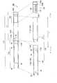
도 1은 제1 실시 형태에 관계되는 비 연소형 향미 흡인기(100)를 나타내는 도면이다.
도 2는 제1 실시 형태에 관계되는 무화 유닛(111)을 나타내는 도면이다.
도 3은 제1 실시 형태에 관계되는 비 연소형 향미 흡인기(100)의 블록 구성을 나타내는 도면이다.
도 4는 변경 예 1에 관계되는 무화 유닛(111) 및 카트리지(130)를 나타내는 도면이다.
도 5는 변경 예 2에 관계되는 무화 유닛(111) 및 카트리지(130)를 나타내는 도면이다.
도 6은 변경 예 2에 관계되는 무화 유닛(111) 및 카트리지(130)를 나타내는 도면이다.
도 7은 변경 예 3에 관계되는 무화 유닛(111) 및 카트리지(130)를 나타내는 도면이다.
도 8은 변경 예 3에 관계되는 무화 유닛(111) 및 카트리지(130)를 나타내는 도면이다.
도 9는 변경 예 3에 관계되는 무화 유닛(111) 및 카트리지(130)를 나타내는 도면이다.
도 10은 변경 예 4에 관계되는 무화 유닛(111) 및 카트리지(130)를 나타내는 도면이다.
도 11은 변경 예 6에 관계되는 무화 유닛(111) 및 카트리지(130)를 나타내는 도면이다.
도 12는 변경 예 7에 관계되는 무화 유닛(111) 및 카트리지(130)를 나타내는 도면이다.
도 13은 변경 예 8에 관계되는 센서(20)를 나타내는 도면이다.
도 14는 변경 예 9에 관계되는 카트리지(130)를 나타내는 도면이다.
도 15는 변경 예 9에 관계되는 카트리지(130)를 나타내는 도면이다.
도 16은 변경 예 9에 관계되는 무화 유닛(111) 및 카트리지(130)를 나타내는 도면이다.
도 17은 변경 예 10에 관계되는 무화 유닛(111) 및 카트리지(130)를 나타내는 도면이다.
도 18은 변경 예 10에 관계되는 무화 유닛(111) 및 카트리지(130)를 나타내는 도면이다.
도 19는 실험 결과를 설명하기 위한 도면이다.
도 20은 실험 결과를 설명하기 위한 도면이다.
도 21은 실험 결과를 설명하기 위한 도면이다.
도 22는 실험 결과를 설명하기 위한 도면이다.1 is a view showing a
2 is a view showing the
3 is a diagram showing a block configuration of a non-flammable flavor absorber 100 according to the first embodiment.
4 is a view showing the
5 is a view showing the
6 is a view showing the
7 is a view showing the
8 is a view showing the
9 is a view showing an
10 is a view showing the
11 is a view showing the
12 is a view showing the
13 is a view showing a
Fig. 14 is a view showing the
Fig. 15 is a view showing the
16 is a view showing the
17 is a view showing an
FIG. 18 is a view showing the
Fig. 19 is a diagram for explaining an experimental result.
20 is a diagram for explaining the experimental result.
21 is a diagram for explaining the experimental result.
22 is a diagram for explaining the experimental result.
이하에 있어서, 실시 형태에 관하여 설명한다. 또한, 이하의 도면의 기재에 있어서, 동일 또는 유사한 부분에는, 동일 또는 유사한 부호를 붙이고 있다. 단, 도면은 모식적인 것이고, 각 치수의 비율 등은 현실의 것과는 다른 경우가 있는 것에 유의해야 한다.Hereinafter, an embodiment will be described. In the following description of the drawings, the same or similar components are denoted by the same or similar reference numerals. However, it should be noted that the drawings are schematic, and the ratios of the respective dimensions and the like may be different from those of the real world.
따라서, 구체적인 치수 등은 이하의 설명을 참작하여 판단해야 할 것이다. 또한, 도면 상호 간에도 서로의 치수의 관계나 비율이 다른 부분이 포함되어 있는 것은 물론이다.Therefore, specific dimensions and the like should be judged based on the following description. It is needless to say that the drawings also include portions having different dimensional relationships or proportions.
[실시형태의 개요][Outline of Embodiment]
상술한 배경 기술하에서, 발명자들은, 예의 검토 결과, 유저가 구강 내에서 에어로졸을 체류시키는 퍼프 흡인에 있어서, 구강 내에 체류하는 에어로졸에서 구강 밖으로 새어 버리는, 에어로졸 원의 손실 및 에어로졸 원의 무화에 필요한 에너지의 손실(이하, 이러한 현상을 통합하여 에어로졸 손실이라 칭함)이 발생하는 것을 발견했다. 또한, 발명자들은, 예의 검토 결과, 유저가 퍼프 흡인을 하는 요인이 공기 유로의 통기 저항임을 발견했다.SUMMARY OF THE INVENTION Under the above-described background, the inventors of the present invention have found that, in a puff aspiration in which a user stays an aerosol in the oral cavity as a result of examination, the loss of the aerosol source and the energy required for atomizing the aerosol source, (Hereinafter, this phenomenon is collectively referred to as " aerosol loss "). Further, as a result of an intensive investigation, the inventors have found that the factor by which the user performs puff suction is the air flow resistance of the air flow path.
실시 형태에 따른 향미 흡인기는, 인렛에서 아웃렛까지 연속하는 공기 유로를 갖는 하우징과, 에어로졸 원의 연소를 수반하지 않고 상기 에어로졸 원을 무화하는 무화부를 구비하고, 상기 공기 유로의 적어도 일부는, 상기 무화부에서 발생하는 에어로졸의 유로인 에어로졸 유로이며, 상기 공기 유로의 전체의 통기 저항은, 25mmAq 이하이다.The flavor aspirator according to the embodiment includes a housing having an air flow path continuous from an inlet to an outlet and an atomization portion atomizing the aerosol source without involving combustion of the aerosol source, Wherein the air flow resistance of the air flow path as a whole is 25 mmAq or less.
실시 형태에서는, 공기 유로의 전체의 통기 저항이 25mmAq 이하이기 때문에, 유저가 구강 내에서 에어로졸을 체류시키는 퍼프 흡인이 행해지지 어렵고, 직접적인 흡인 동작(이하, 직접 흡인)이 행해지기 쉽다. 따라서, 에어로졸의 손실을 저감함으로써, 향끽미의 저하를 억제할 수 있다.In the embodiment, since the entire air flow resistance of the air flow path is 25 mmAq or less, it is difficult for the user to perform puff suction in which the aerosol stays in the oral cavity, and direct suction operation (hereinafter, direct suction) is likely to be performed. Therefore, by reducing the loss of aerosol, it is possible to suppress the decrease in the aroma of flavor.
[제1 실시 형태][First Embodiment]
(향미 흡인기)(Flavor aspirator)
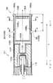
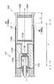
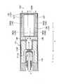
이하에 있어서, 제1 실시 형태에 따른 향미 흡인기에 관하여 설명한다. 도 1은, 제1 실시 형태에 관계되는 비 연소형 향미 흡인기(100)를 나타내는 도면이다. 비 연소형 향미 흡인기(100)는, 향끽미 성분을 흡인하기 위한 기구이며, 비 흡구단에서 흡구단으로 향하는 방향인 소정 방향(A)을 따라 연장되는 형상을 갖는다. 도 2는, 제1 실시 형태에 따른 무화 유닛(111)을 나타내는 도면이다. 또한, 이하에 있어서는, 비 연소형 향미 흡인기(100)를 단순히 향미 흡인기(100)라고 칭하는 것에 유의해야 한다.Hereinafter, the flavor / aspirator according to the first embodiment will be described. 1 is a view showing a
도 1에 도시한 바와 같이, 향미 흡인기(100)는, 흡인기 본체(110)와, 카트리지(130)를 갖는다.1, the flavor /
흡인기 본체(110)는, 향미 흡인기(100)의 본체를 구성하고 있으며, 카트리지(130)를 접속가능한 형상을 갖는다. 구체적으로는, 흡인기 본체(110)는, 흡인기 하우징(110X)을 가지고 있으며, 카트리지(130)는, 흡인기 하우징(110X)의 흡구측단에 접속된다. 흡인기 본체(110)는 에어로졸 원의 연소를 수반하지 않고 에어로졸 원을 무화하도록 구성된 무화 유닛(111)과, 전장(電裝) 유닛(112)을 갖는다. 무화 유닛(111) 및 전장 유닛(112)은, 흡인기 하우징(110X)에 수용된다.The aspirator
제1 실시 형태에서는, 무화 유닛(111)은, 흡인기 하우징(110X)의 일부를 구성하는 제1 통체(筒體)(111X)(즉, 제1 하우징)를 갖는다. 무화 유닛(111)은, 도 2에 나타낸 바와 같이, 리저브(111P)와, 위크(wick; 111Q)와, 무화부(111R)를 갖는다. 리저브(111P), 위크(111Q) 및 무화부(111R)는, 제1 통체(111X)에 수용된다. 제1 통체(111X)는, 소정 방향(A)을 따라 연장되는 통상 형상(예를 들면, 원통 형상)을 갖는다. 리저브(111P)는, 에어로졸 원을 유지한다. 예를 들어, 리저브(111P)는 수지 웹 등의 재료에 의해 구성되는 공질체(孔質體)이다. 위크(111Q)는, 리저브(111P)에 유지되는 에어로졸 원을 빨아올리는 에어로졸 흡인부의 일례이다. 예를 들어, 위크(111Q)는, 유리 섬유에 의해 구성된다. 무화부(111R)는, 위크(111Q) 의해 빨아 올려진 에어로졸 원을 무화한다. 무화부(111R)는, 예를 들어, 위크(111Q)에 소정 피치로 권회되는 발열 저항체(예를 들어, 전열선)에 의해 구성된다.In the first embodiment, the
에어로졸 원은, 글리세린 또는 프로필렌 글리콜 등의 액체이다. 에어로졸 원은, 예를 들어, 상술한 바와 같이, 수지 웹 등의 재료에 의해 구성되는 공질체에 의해 유지된다. 공질체는 비 담배 재료로 구성되어 있어도 되고, 담배 재료로 구성되어 있어도 된다. 또한, 에어로졸 원은, 니코틴 성분 등을 함유하는 향미원을 포함하고 있어도 된다. 혹은, 에어로졸 원은, 니코틴 성분 등을 함유하는 향미원을 포함하지 않아도 된다. 에어로졸 원은, 니코틴 성분 이외의 성분을 포함하는 향미원을 포함하고 있어도 된다. 혹은, 에어로졸 원은, 니코틴 성분 이외의 성분을 포함하는 향미원을 포함하지 않아도 된다.The aerosol source is a liquid such as glycerin or propylene glycol. The aerosol source is maintained by a hollow body composed of a material such as a resin web, for example, as described above. The coarse body may be composed of non-tobacco materials or may be composed of tobacco materials. In addition, the aerosol source may contain a flavor source containing a nicotine component or the like. Alternatively, the aerosol source may not contain a flavor source containing a nicotine component or the like. The aerosol source may contain a flavor source containing components other than the nicotine component. Alternatively, the aerosol source may not contain a flavor source including components other than the nicotine component.
제1 실시 형태에서는, 무화 유닛(111)으로서, 가열에 의해 에어로졸 원을 무화하는 가열 타입의 유닛을 예시하고 있다. 그러나, 무화 유닛(111)은, 에어로졸 원을 무화하는 기능을 갖고 있으면 되고, 초음파에 의해 에어로졸 원을 무화하는 초음파 타입의 유닛이어도 된다.In the first embodiment, as the
전장 유닛(112)은, 흡인기 하우징(110X)의 일부를 구성하는 제2 통체(112X)(즉, 제2 하우징)를 갖는다. 제1 실시 형태에 있어서, 전장 유닛(112)은, 인렛(112A)을 갖는다. 인렛(112A)에서 유입하는 공기는, 도 2에 나타낸 바와 같이, 무화 유닛(111)(무화부(111R))에 유도된다. 상세하게는, 전장 유닛(112)은, 전원(10)과, 센서(20)와, 누름 버튼(30)과, 제어 회로(50)를 갖는다. 전원(10), 센서(20), 누름 버튼(30) 및 제어 회로(50)는, 제2 통체(112X)에 수용된다. 제2 통체(112X)는, 소정 방향(A)을 따라 연장되는 통상 형상(예를 들면, 원통 형상)을 갖는다.The
전원(10)은, 예를 들면, 리튬 이온 전지이다. 전원(10)은, 향미 흡인기(100)의 동작에 필요한 전력을 축적한다. 예를 들면, 전원(10)은, 센서(20) 및 제어 회로(50)에 공급하는 전력을 축적한다. 또한, 전원(10)은, 무화 유닛(111)(무화부(111R))에 공급하는 전력을 축적한다.The
센서(20)는, 유저의 흡인 동작을 검지하기 위한 센서(흡인 센서, 유량 센서, 압력 센서 등)이다. 센서(20)는, 비 흡구단에서 흡구단으로 향해 흡인되는 공기(즉, 유저의 흡인 동작)에 의해 변화하는 응답값을 출력한다.The
누름 버튼(30)은, 향미 흡인기(100) 외측에서 내측으로 압입하도록 구성된다. 실시 형태에서는, 누름 버튼(30)은, 향미 흡인기(100)의 비 흡구단에 설치되어 있으며, 비 흡구단에서 흡구단으로 향하는 방향(즉, 소정 방향(A))에 압입하도록 구성된다. 예를 들어, 누름 버튼(30)이 소정 회수에 걸쳐 연속적으로 압입된 경우에, 향미 흡인기(100)의 전원이 투입된다. 또한, 향미 흡인기(100)의 전원은 흡인 동작이 행해지고 나서 소정 시간이 경과한 경우에 절단된다.The
제어 회로(50)는, 향미 흡인기(100)의 동작을 제어한다. 구체적으로는, 제어 회로(50)는, 무화 유닛(111)(무화부(111R))에 대한 전원 출력을 제어한다.The control circuit (50) controls the operation of the flavor absorber (100). More specifically, the
카트리지(130)는 향미 흡인기(100)를 구성하는 흡인기 본체(110)에 접속 가능하게 구성된다. 카트리지(130)는, 인렛(제1 실시 형태에서는, 상술한 인렛(112A))에서 아웃렛(제1 실시 형태에서는, 후술하는 아웃렛(130A))까지 연속하는 공기 유로 상에 있어서 무화 유닛(111)보다도 아웃렛(흡구) 측에 설치된다. 환언하면, 카트리지(130)는, 반드시 물리 공간적으로 무화 유닛(111)보다도 아웃렛(흡구) 측에 설치되어 있을 필요는 없고, 공기 유로 상에 있어서 무화 유닛(111)보다도 아웃렛(흡구) 측에 설치돼 있으면 된다. 즉, 제1 실시 형태에서, 「아웃렛(흡구) 측」은 흡인 동작에 있어서의 공기의 흐름의「하류」와 동의(同義)라고 생각해도 되고, 「비 흡구측」은, 흡인 동작에 있어서의 공기 흐름의 「상류」와 동의라고 생각해도 된다.The
구체적으로는, 카트리지(130)는, 카트리지 하우징(131)과, 향미원(132)과, 메쉬(mesh; 133A)와, 필터(133B)를 갖는다. 또한 카트리지(130)는, 흡구에 설치되는 아웃렛(130A)을 갖는다.Specifically, the
카트리지 하우징(131)은 소정 방향(A)을 따라 연장되는 통상 형상(예를 들면, 원통 형상)을 갖는다. 카트리지 하우징(131)은 향미원(132)을 수용한다. 여기서는, 카트리지 하우징(131)은, 흡인기 하우징(110X)에 소정 방향(A)에 따라 삽입되도록 구성된다.The
향미원(132)은, 인렛(112A)에서 아웃렛(130A)까지 연속하는 공기 유로에 있어서 무화 유닛(111)보다도 아웃렛(130)(흡구) 측에 설치된다. 향미원(132)은, 에어로졸 원에서 발생하는 에어로졸에 향끽미 성분을 부여한다. 환언하면, 향미원(132)에 의해 에어로졸에 부여되는 향끽미 성분은, 아웃렛(130A)(흡구)으로 옮겨진다.The
제1 실시 형태에서, 향미원(132)은, 무화 유닛(111)에서 발생하는 에어로졸에 향끽미 성분을 부여하는 원료 편(片)에 의해 구성된다. 원료 편의 크기는, 0.2mm 이상 1.2mm 이하인 것이 바람직하다. 또한, 원료 편의 크기는, 0.2mm 이상 0.7mm 이하인 것이 바람직하다. 향미원(132)을 구성하는 원료 편의 크기가 작을수록 비 표면적이 커지기 때문에, 향미원(132)을 구성하는 원료 편에서 향끽미 성분이 릴리즈되기 쉽다. 따라서, 원하는 양의 향끽미 성분을 에어로졸에 부여함에 있어서, 원료 편의 양을 억제할 수 있다. 향미원(132)을 구성하는 원료 편으로서는, 살담배, 담배 원료를 입상으로 성형한 성형체를 사용할 수 있다. 단, 향미원(132)은, 담배 원료를 시트 형상으로 성형한 성형체이어도 된다. 또한 향미원(132)을 구성하는 원료 편은, 담배 이외의 식물(예를 들어, 민트, 허브 등)에 의해 구성되어도 된다. 향미원(132)에는, 멘톨 등의 향료가 부여되어 있어도 된다.In the first embodiment, the
여기서, 향미원(132)을 구성하는 원료 편은, 예를 들어, JIS Z 8801에 준거한 스테인레스 체를 이용하여, JIS Z 8815에 준거하는 체(篩) 분류에 의해 얻어진다. 예를 들어, 0.71mm의 목개(目開)를 갖는 스테인리스 체를 이용하여, 건조식 또는 기계식 진탕 법에 의해 20분에 걸쳐 원료 편을 체로 분류하여, 0.71mm의 목개를 갖는 스테인리스 체를 통과하는 원료 편을 얻는다. 이어서 0.212mm의 목개를 갖는 스테인리스 체를 이용하여, 건조식 또는 기계식 진탕 법에 의해 20분에 걸쳐 원료 편을 체로 분류하여, 0.212mm의 목개를 갖는 스테인리스 체를 통과하는 원료 편을 취출 제거한다. 즉, 향미원(132)을 구성하는 원료 편은, 상한을 규정하는 스테인리스 체(목개 = 0.71mm)를 통과하고, 하한을 규정하는 스테인리스 체(목개 = 0.212mm)를 통과하지 않는 원료 편이다. 따라서, 실시 형태에서는, 향미원(132)을 구성하는 원료 편의 크기의 하한은, 하한을 규정하는 스테인리스 체의 목개에 의해 정의된다. 또한, 향미원(132)을 구성하는 원료 편의 크기 상한은, 상한을 규정하는 스테인리스 체의 목개에 의해 정의된다.Here, the raw material pieces constituting the
제1 실시 형태에 있어서, 향미원(132)은, 알칼리성의 pH를 갖는 담배 원(源)이다. 담배 원의 pH는, 7보다 큰 것이 바람직하고, 8 이상인 것이 보다 바람직하다. pH를 7보다 크게 함으로써, 담배 원에서 발생하는 향끽미 성분을 에어로졸에 의해 효율적으로 취출할 수 있다. 이것에 의해, 소망량의 향끽미 성분을 에어로졸에 부여함에 있어서, 담배 원의 양을 억제할 수 있다. 한편, 담배 원의 pH는, 14 이하인 것이 바람직하고, 10 이하인 것이 보다 바람직하다. pH를 14 이하로 함으로써, 향미 흡인기(100)(예를 들어, 카트리지(130) 또는 흡인기 본체(110))에 대한 손상(부식 등)을 보다 효과적으로 억제할 수 있다.In the first embodiment, the
또한 향미원(132)에서 발생하는 향끽미 성분은 에어로졸에 의해 반송되고 있으며, 향미원(132) 자체를 가열할 필요는 없다는 것에 유의해야 한다.It should also be noted that the fragrance ingredient generated in the
망목(網目; 133A)은, 향미원(132)에 대해서 비 흡구측에서 카트리지 하우징(131)의 개구를 막도록 설치되어 있으며, 필터(133B)는, 향미원(132)에 대해서 흡구측에 있어서 카트리지 하우징(131)의 개구를 막도록 설치되어 있다. 망목(133A)은, 향미원(132)을 구성하는 원료 편이 통과하지 않을 정도의 거칠기를 갖는다. 망목(133A)의 거칠기는, 예를 들어, 0.077mm 이상 0.198mm 이하의 목개를 갖는다. 필터(133B)는, 통기성을 갖는 물질로 구성된다. 필터(133B)는, 예를 들어, 아세테이트 필터인 것이 바람직하다. 필터(133B)는, 향미원(132)을 구성하는 원료 편이 통과하지 않을 정도의 거칠기를 갖는다.The
제1 실시 형태에서, 흡인기 본체(110)의 흡인기 하우징(110X) 및 카트리지 하우징(131)은, 인렛(112A)에서 아웃렛(130A)까지 연속하는 공기 유로를 갖는 하우징을 구성한다. 공기 유로의 적어도 일부(즉, 도 2에 도시한 무화부(111R)의 하류 측의 유로)는, 무화 유닛(111)에서 발생하는 에어로졸의 유로인 에어로졸 유로이다.In the first embodiment, the
이러한 경우에 있어서, 공기 유로의 전체의 통기 저항은, 25mmAq 이하이다. 바람직하게는, 공기 유로의 전체의 통기 저항은, 15mmAq 이하이다. 더욱 바람직하게는, 공기 유로의 전체의 통기 저항은, 2mmAq 이상 8mmAq 이하이다. 통기 저항이 작으면 작을수록, 유저가 구강 내에서 에어로졸을 체류시키는 퍼프 흡인이 행해지기 어렵고, 직접적인 흡인 동작(직접 흡인)이 행해지기 쉽다. 또한, 1mmAq는, 9.80665Pa에 해당하는 것에 유의해야 한다.In this case, the total air flow resistance of the air flow path is 25 mmAq or less. Preferably, the total air flow resistance of the air flow path is 15 mmAq or less. More preferably, the total air flow resistance of the air flow path is 2 mmAq or more and 8 mmAq or less. The smaller the ventilation resistance is, the more difficult it is for the user to hold the aerosol in the oral cavity and the direct suction operation (direct suction) is likely to be performed. It should also be noted that 1 mmAq corresponds to 9.80665 Pa.
여기서, 통기 저항은, ISO 6565-1997 Draw resistance of cigarettes and pressure drop of filter rods에 준거한 방법에 의해 측정된다. 구체적으로는, 통기 저항은, 공기 유로의 상류 측으로부터 향미 흡인기(100), 차압계, 매스 플로 컨트롤러, 진공 펌프의 순서로 각 장치를 접속함과 동시에, 진공 펌프로 1050ml/min로 흡인했을 때의 압력 손실로서 정의된다.Here, the ventilation resistance is measured by the method according to ISO 6565-1997 Draw resistance of cigarettes and pressure drop of filter rods. Concretely, the ventilation resistance was measured by connecting each device in the order of the
또한, 공기 유로의 전체의 통기 저항은 0.5mmAq 이상인 것이 바람직하다. 또한, 공기 유로의 전체의 통기 저항은, 상술한 센서(20)가 흡인 동작을 검지할 수 있는 정도의 값 이상인 것이 바람직하다.Further, it is preferable that the total air flow resistance of the air flow path is 0.5 mmAq or more. It is preferable that the entire air flow resistance of the air flow path is at least a value at which the above-described
(블록 구성)(Block configuration)
이하에 있어서, 제1 실시 형태에 따른 향미 흡인기의 블록 구성에 대해서 설명한다. 도 3은, 제1 실시 형태에 따른 향미 흡인기(100)의 블록 구성을 나타내는 도면이다.Hereinafter, the block configuration of the flavor / suction device according to the first embodiment will be described. Fig. 3 is a diagram showing the block configuration of the flavor /
도 3에 나타낸 바와 같이, 제어 회로(50)는, 흡인 스위치(51)와, 전원 스위치(52)와, 제어부(53)를 갖는다.3, the
흡인 스위치(51)는, 유저가 흡인 동작을 행하고 있는 경우에 온 상태로 전환하고, 유저가 흡인 동작을 행하고 있지 않은 경우에 오프 상태로 전환하는 스위치이다. 구체적으로는 흡인 스위치(51)는, 유저의 흡인 동작을 검지하기 위한 센서(20)에 접속되어 있으며, 센서(20)로부터 출력되는 응답값에 기초하여 동작한다. 즉, 흡인 스위치(51)는, 응답값이 흡인 동작을 행하고 있는 취지를 나타내는 경우에 온 상태로 전환된다. 한편, 흡인 스위치(51)는, 응답값이 흡인 동작을 행하고 있지 않은 취지를 나타내는 경우에 오프 상태로 전환된다.The
전원 스위치(52)는, 비 연소형 향미 흡인기(100)의 전원이 투입되는 경우에 온 상태로 전환되고, 비 연소형 향미 흡인기(100)의 전원이 단절되는 경우에 오프 상태로 전환된다. 구체적으로는, 전원 스위치(52)는, 누름 버튼(30)에 접속되어 있으며, 누름 버튼(30)이 소정 회수에 걸쳐 연속적으로 눌려진 경우에 온 상태로 전환된다. 한편, 전원 스위치(52)는, 타이머를 가지고 있으며, 흡인 동작이 행해지고부터 소정 시간이 경과 한 경우에 오프 상태로 전환된다.The
제어부(53)는, 비 연소형 향미 흡인기(100)의 전원이 투입된 상태에서, 비 연소형 향미 흡인기(100)를 제어한다. 구체적으로는, 제어부(53)는, 무화부(111R)에 대한 전원 출력을 제어한다. 제어부(53)는, 유저가 흡인 동작을 행하는 경우에, 즉, 흡인 스위치(51)가 온 상태인 경우에, 무화부(111R)에 전원 출력을 공급한다. 한편, 제어부(53)는, 유저가 흡인 동작을 하지 행하고 있지 않은 경우, 즉 흡인 스위치(51)가 오프 상태인 경우에, 무화부(111R)에 전원 출력을 공급하지 않는다. 즉, 흡인 스위치(51)는, 유저가 흡인 동작을 행하고 있지 않을 때에 무화부(111R)에 전원 출력을 공급하지 않고, 유저가 흡인 동작을 행하고 있는 때에 무화부(111R)에 대해서 전원 출력을 공급하기 위한 스위치이다.The
여기서, 전원 출력의 크기는, 무화부(111R)에 대해서 연속적으로 전압이 인가되는 경우에 있어서는, 무화부(111R)에 대해서 인가되는 전압의 값으로 정의된다. 한편, 전원 출력의 크기는, 무화부(111R)에 대해서 단속적으로 전압이 인가되는 경우(펄스 제어)에 있어서는, 무화부(111R)에 인가되는 전압 값, 펄스 폭 및 펄스 간격 중 적어도 어느 하나의 파라미터에 의해 정의된다.Here, the magnitude of the power output is defined as the value of the voltage applied to the
여기서 종료 임계값은 개시 임계값보다 크다. 종료 임계값은 무화부(111R)에 전원 출력을 공급하지 않도록 흡인 스위치(51)를 동작시킬 것인지를 판정하기 위해 센서(20)로부터 출력되는 응답값과 비교되는 임계값, 즉, 흡인 스위치(51)를 오프시킬지를 판정하기 위해 응답값과 비교되는 임계값이다. 한편, 개시 임계값은, 무화부(111R)에 전원 출력을 공급하도록 흡인 스위치(51)를 동작시킬 것인지를 판정하기 위해 센서(20)로부터 출력되는 응답값과 비교되는 임계값, 즉, 흡인 스위치(51)를 온으로 할지를 판정하기 위해 응답값과 비교되는 임계값이다. 이러한 특징에 따르면, 종료 임계값이 개시 임계값보다 크기 때문에, 무화부(111R)에 대한 전원 출력의 공급이 정지한 후에 있어서도, 실제의 실제 흡인 동작을 계속하기 위해, 에어로졸 유로에 있어서의 에어로졸의 체류나 응축이 억제되고, 에어로졸의 손실이 억제된다. 한편, 개시 임계값이 종료 임계값보다 작기 때문에, 실제의 흡인 동작이 시작된 후에 있어서, 무화부(111R)에 대한 전원 출력의 공급이 즉시 시작된다.Where the termination threshold is greater than the initiation threshold. The end threshold is a threshold value that is compared with the response value output from the
(작용 및 효과)(Action and effect)
제1 실시 형태에서, 공기 유로의 전체의 통기 저항이 25mmAq 이하이기 때문에, 유저가 구강 내에서 에어로졸을 체류시키는 퍼프 흡인이 행해지기 어렵고, 직접적인 흡인 동작(직접 흡인)이 행해지기 쉽다. 따라서, 에어로졸의 손실을 저감함으로써, 향끽미의 저하를 억제할 수 있다.In the first embodiment, since the entire air flow resistance of the air flow path is 25 mmAq or less, it is difficult for the user to perform puff suction in which the aerosol stays in the oral cavity, and direct suction operation (direct suction) is likely to be performed. Therefore, by reducing the loss of aerosol, it is possible to suppress the decrease in the aroma of flavor.
[변경 예 1][Modification example 1]
이하에 있어서, 제1 실시 형태의 변경 예 1에 대해서 설명한다. 다음에서는, 제1 실시 형태에 대한 차이점에 관하여 주로 설명한다.
변경 예 1에 있어서, 공기 유로는, 무화부(111R)를 통하는 제1 공기 유로와, 무화부(111R)를 통하지 않는 제2 공기 유로를 포함한다. 인렛은, 제1 공기 유로에 공기를 도입하는 인렛(112A)(제1 인렛)과, 제2 공기 유로에 공기를 도입하는 인렛(80)(제2 인렛)을 포함한다. 아웃렛은, 제1 공기 유로에서 공기를 도출하는 아웃렛(130A)(제1 아웃렛)과, 제2 공기 유로에서 공기를 도출하는 아웃렛(130A)(제2 아웃렛)을 포함한다. 인렛(80)(제2 인렛)은, 인렛(112A)(제1 인렛)과 다르다. 또한, 에어로졸 유로는, 제1 공기 유로의 일부이다.In the modified example 1, the air flow path includes a first air flow path passing through the
구체적으로는, 카트리지 하우징(131)은, 흡인기 하우징(110X)에 소정 방향(A)에 따라 삽입되도록 구성된다. 흡인기 하우징(110X)은, 도 4와 같이, 소정 방향(A)과 교차하는 방향에 있어서 흡인기 하우징(110X)을 관통하는 흡인기 관통공(110B)을 가지고 있으며, 카트리지 하우징(131)은, 소정 방향(A)과 교차하는 방향에서 카트리지 하우징(131)을 관통하는 카트리지 관통공(130B)을 갖는다. 흡인기 관통공(110B) 및 카트리지 관통공(130B)은, 인렛(80)(제2 인렛)을 구성하고 있으며, 카트리지 하우징(131)의 내측 공간에 연통한다.Specifically, the
여기서, 흡인기 관통공(110B)은, 무화부(111R)보다도 아웃렛(130A) 측에서 에어로졸 유로에 연통 가능하게 구성된다. 여기서,「연통 가능」이란, 카트리지 하우징(131)을 흡인기 하우징(110X)에 올바르게 삽입함으로써, 흡인기 관통공(110B)이 공기 유로에 연통하는 것을 의미한다. 따라서, 카트리지 하우징(131)을 흡인기 하우징(110X)에 삽입하는 태양에 따라서는, 흡인기 관통공(110B)이 공기 유로에 연통하지 않을 가능성이 있는 것에 유의해야 한다. 단, 「연통 가능」이란, 후술하는 변경 예 2, 3에서 설명하는 바와 같이, 흡인기 관통공(110B)이 공기 유로에 반드시 연통하는 태양을 포함 것에도 유의해야 한다.Here, the aspirator through
변경 예 1에 있어서, 인렛(80)은, 인렛(112A)과는 별도로 설치된다. 인렛(80)은, 공기 유로의 상류/하류와 관계없는 공간적 배치의 의미로, 무화부(111R)보다도 흡구측에 위치하는 것이 바람직하다. 아웃렛(130A)은, 제1 공기 유로에서 공기를 도출하는 제1 아웃렛 및 제2 공기 유로에서 공기를 도출하는 제2 아웃렛 모두를 구성한다.In the modified example 1, the
또한, 변경 예 1에 있어서, 제2 공기 유로는, 인렛(80)(흡인기 관통공(110B) 및 카트리지 관통공(130B)), 에어로졸 유로의 일부(카트리지 하우징(131)의 내부 공간) 및 아웃렛(130A)에 의해 구성된다.The second air flow path in Modification Example 1 includes the inlet 80 (the suction through
또한, 카트리지 관통공(130B)은, 향미원(132)을 구성하는 원료 편이 통과하지 않을 정도의 크기를 갖는 1 이상의 구멍에 의해 구성되는 것이 바람직하다. 혹은, 카트리지 관통공(130B)은, 향미원(132)을 구성하는 원료 편이 통과하지 않을 정도의 거칠기를 갖는 메쉬를 갖는 것이 바람직하다. 원료 편이 통과하지 않을 정도의 크기는, 예를 들어, 0.077mm 이상 0.198mm 이하이며, 원료 편이 통과하지 않을 정도의 거칠기는, 예를 들어, 0.077mm 이상 0.198mm 이하의 목개이다.It is preferable that the cartridge through
여기서, 인렛(80)(흡인기 관통공(110B) 및 카트리지 관통공(130B))에서 유입하는 공기의 양은, 아웃렛(130A)에서 유출되는 공기의 양의 50% 이상인 것이 바람직하다. 환언하면, 흡인기 관통공(110B)에서 유입하는 공기의 양은, 인렛(112A)에서 유입하는 공기의 양 이상인 것이 바람직하다. 더욱 바람직하게는, 인렛(80)으로부터 유입되는 공기의 양은, 아웃렛(130A)에서 유출되는 공기의 양의 60% 이상이다. 이에 의해, 인렛(112A)에서 유입하는 공기가 무화부(111R)를 통하는 경우에도, 공기 유로의 전체의 통기 저항을 25mmAq 이하로 억제하기 쉽다.Here, it is preferable that the amount of the air flowing in the inlet 80 (the suction through
이러한 경우에 있어서, 소정 방향(A)에 있어서 공기 유로를 갖는 하우징의 흡구단(여기서는, 카트리지 하우징(131)의 흡구단)과 인렛(80)(제2 인렛) 사이의 거리(L)는, 1.5mm 이상인 것이 바람직하다. 또한, 거리(L)는, 3.0mm 이상인 것이 바람직하고, 5.0mm 이상인 것이 더욱 바람직하다. 가장 바람직하게는, 거리(L)는, 8.0mm 이상이다. 이것에 의해서, 유저가 향미 흡인기(100)를 물었을 때에, 흡인기 관통공(110B)이 유저의 입술로 막히거나, 흡인기 관통공(110B)이 유저의 구강 내에 도달하거나 하는 현상이 억제된다.In this case, the distance L between the inlet end of the housing (here, the inlet end of the cartridge housing 131) having the air flow path in the predetermined direction A and the inlet 80 (second inlet) And is preferably 1.5 mm or more. Further, the distance L is preferably 3.0 mm or more, more preferably 5.0 mm or more. Most preferably, the distance L is 8.0 mm or more. Thereby, when the user touches the
한편, 거리(L)는, 소정 방향(A)에서 공기 유로를 갖는 하우징의 흡구단(여기서는, 카트리지 하우징(131)의 흡구단)과 인렛(112A)(제1 인렛)과의 거리보다도 작은 것이 바람직하다. 거리(L)는, 소정 방향에 있어서의 카트리지(130)의 전체 길이보다도 작아도 된다. 카트리지(130)의 전체 길이는, 5mm 이상 30mm 이하인 것이 바람직하고, 10mm 이상 25mm 이하인 것이 더욱 바람직하다. 카트리지(130)의 전체 길이보다 작은 것을 전제로 해서, 예를 들면, 거리(L)는, 25mm 미만인 것이 바람직하다. 또한, 거리(L)는, 20mm 미만인 것이 바람직하고, 15mm 미만인 것이 더욱 바람직하다. 가장 바람직하게는, 거리(L)는, 10mm 미만이다. 이것에 의해서, 공기 유로의 전체의 통기 저항을 25mmAq 이하로 억제하기 쉽다.On the other hand, the distance L is smaller than the distance between the inlet end of the housing (here, the inlet end of the cartridge housing 131) having the air passage in the predetermined direction A and the
또한, 하우징에 설치되는 흡인기 관통공(110B)은, 하나이어도 되고, 2 이상 이어도 된다. 즉, 흡인기 관통공(110B)의 수는 특별히 한정되는 것은 아니다.Further, the number of the aspirator through
(작용 및 효과)(Action and effect)
변경 예 1에서는, 비 연소형 향미 흡인기(100)는, 무화부(111R)를 통하는 제1 공기 유로에 더하여, 무화부(111R)를 통하지 않는 제2 공기 유로를 갖는다. 따라서, 인렛(112A)에서 유입되는 공기 무화부(111R)를 통하는 경우에도, 공기 유로의 전체의 통기 저항을 25mmAq 이하로 억제하기 쉽다.In the modified example 1, the
변경 예 1에서는, 인렛(80)에서 유입되는 공기의 양은, 아웃렛(130A)에서 유출되는 공기의 양의 50% 이상이다. 따라서, 인렛(112A)에서 유입되는 공기가 무화부(111R)를 통하는 경우에도, 공기 유로의 전체의 통기 저항을 25mmAq 이하로 억제하기 쉽다.In Modification Example 1, the amount of air flowing in the
[변경 예 2][Modification example 2]
이하에 있어서, 제1 실시 형태의 변경 예 2에 대해서 설명한다. 이하에 있어서는, 변경 예 1에 대한 차이점에 관하여 주로 설명한다.In the following,
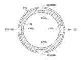
변경 예 1에서는, 인렛(80)은, 흡인기 관통공(110B) 및 카트리지 관통공(130B)에 의해 구성된다. 이에 대해서, 변경 예 2에서는, 제2 인렛(80)은, 도 5 및 도 6에 나타낸 바와 같이, 흡인기 관통공(110B), 카트리지 요홈 부분(130B1) 및 카트리지 관통공(130B2)에 의해 구성된다. 카트리지 요홈 부분(130B1)은, 소정 방향(A)에 대한 직교하는 단면에서 카트리지 하우징(131)의 전체 둘레를 둘러싸도록 설치되어 있다. 카트리지 관통공(130B2)은, 카트리지 요홈 부분(130B1)에 설치되어 있다. 또한, 도 6은, 도 5에 도시된 F-F 단면(즉, 소정 방향(A)에 대한 직교 단면)을 나타내고 있다.In the
구체적으로는, 카트리지 하우징(131)은, 흡인기 하우징(110X)에 소정 방향(A)에 따라 삽입되도록 구성된다. 카트리지 하우징(131)은, 도 5 및 도 6에 나타낸 바와 같이, 흡인기 하우징(110X)과 인접한 외측면에 형성된 카트리지 요홈 부분(130B1)(제1 요홈 부분)과, 소정 방향(A)과 교차하는 방향에 있어서 카트리지 요홈 부분(130B1)을 관통하는 카트리지 관통공(130B2)을 갖는다. 카트리지 요홈 부분(130B1)(제1 요홈 부분)은, 소정 방향(A)에 있어서 흡인기 관통공(110B)이 설치되는 위치에서, 소정 방향(A)에 직교하는 단면에서 환상으로 연속한다.Specifically, the
여기서,「환상(環狀)으로 연속하는」이란, 소정 방향(A)에 직교하는 단면에 있어서, 소정 방향(A)을 중심으로 하는 둘레 방향의 전체(360 °)에 걸쳐 연속되지 않아도 된다. 예를 들면, 카트리지 요홈 부분(130B1)은, 둘레 방향에서 불연속적인 부분에 의해 구획되어 있어도 된다. 단, 둘레 방향에 있어서, 불연속적인 부분에 의해 구획되는 카트리지 요홈 부분(130B1)의 각각의 폭은, 서로 인접하는 흡인기 관통공(110B)의 간격(가장 가까운 간격)보다도 크면 된다. 혹은, 둘레 방향에서 흡인기 관통공(110B)의 폭은, 불연속 부분의 폭보다도 크면 된다.Here, the term " annularly continuous " is not necessarily continuous across the entire circumferential direction (360 DEG) centering on the predetermined direction (A) on a cross section orthogonal to the predetermined direction (A). For example, the
또한, 변경 예 2에서, 제2 공기 유로는, 인렛(80)(흡인기 관통공(110B), 카트리지 요홈 부분(130B1), 카트리지 관통공(130B2)), 에어로졸 유로의 일부(카트리지 하우징(131)의 내부 공간) 및 아웃렛(130A)에 의해 구성된다.In the modified example 2, the second air flow path is formed by the inlet 80 (the suction through
변경 예 2에 있어서, 카트리지 요홈 부분(130B1)은, 카트리지 하우징(131)의 두께를 얇게 함으로써 구성되어 있다. 그러나, 변경 예 2는 이에 한정되는 것은 아니다. 카트리지 요홈 부분(130B1)은, 흡인기 하우징(110X)의 내측면과 카트리지 하우징(131)의 외측면 사이에 공극(空隙)이 가능하도록 구성되어 있으면 된다. 예를 들어, 카트리지 하우징(131)의 두께가 일정하며, 카트리지 하우징(131)이 소정 방향(A)과 직교하는 단면에 있어서 내측으로 오목한 요홈 부분을 갖고 있으며, 이러한 요홈 부분이 카트리지 요홈 부분(130B1)이어도 된다.In Modification Example 2, the
(작용 및 효과)(Action and effect)
변경 예 2는, 인렛(80)은, 소정 방향(A)에 직교하는 단면에 있어서 환상으로 연속하는 카트리지 요홈 부분(130B1)을 포함한다. 따라서, 변경 예 1과 동일한 효과에 더해서, 카트리지 하우징(131)의 회전 방향에 있어서 카트리지 하우징(131)과 흡인기 하우징(110X)과의 상대 위치에 관계없이 카트리지 하우징(131)을 흡인기 하우징(110X) 삽입한다고 해도, 흡인기 관통공(110B)이 카트리지 요홈 부분(130B1)과 연통하기 때문에, 제2 공기 유로를 항상 형성할 수 있다.In the second modification, the
[변경 예 3][Modification Example 3]
이하에 있어서, 제1 실시 형태의 변경 예 3에 대해서 설명한다. 이하에 있어서는, 변경 예 1에 대한 차이점에 관하여 주로 설명한다.In the following,
변경 예 1에서는, 제2 공기 유로는, 에어로졸 유로의 일부(카트리지 하우징(131)의 내부 공간)를 포함한다. 환언하면, 변경 예 1에서는, 흡인기 관통공(110B) 및 카트리지 관통공(130B)은, 인렛(80)(제2 인렛)을 구성하고 있으며, 카트리지 하우징(131)의 내부 공간에 연통한다. 이에 대해서, 변경 예 3에서는, 제2 공기 유로는, 에어로졸 유로의 일부(카트리지 하우징(131)의 내부 공간)를 포함하지 않는다. 환언하면, 변경 예 3에서는, 흡인기 관통공(110B)이 인렛(80)(제2 인렛)을 구성하고 있으며, 에어로졸 유로에 연통하지 않고 아웃렛(130A1)(제2 아웃렛)에 연통한다.In the modified example 1, the second air passage includes a part of the aerosol passage (the inner space of the cartridge housing 131). In other words, in the modified example 1, the aspirator through
변경 예 3에서, 인렛(80)은, 인렛(112A)과는 별도로 설치되어 있다. 인렛(80)은, 공기 유로의 상류/하류와 관계없는 공간적인 배치의 의미에서, 무화부(111R)보다도 흡구측에 위치하는 것이 바람직하다. 아웃렛(130A)은, 제1 공기 유로에서 공기를 도출하는 제1 아웃렛을 구성하고 있으며, 아웃렛(130A1)은, 아웃렛(130A)과는 별도로 설치되어 있으며, 제2 공기 유로에서 공기를 도출하는 제2 아웃렛을 구성한다. 아웃렛(130A1) 및 아웃렛(130A)은 흡구에 설치된다.In the modified example 3, the
구체적으로는, 카트리지 하우징(131)은, 흡인기 하우징(110X)에 소정 방향(A)에 따라 삽입되도록 구성된다. 카트리지 하우징(131)은, 도 7에 나타낸 바와 같이, 에어로졸 유로와 공통되는 유로를 갖고 있지 않은 제2 공기 유로의 적어도 일부를 형성한다. 구체적으로는, 카트리지 하우징(131)은, 흡인기 하우징(110X)과 인접하는 외측면에 형성된 카트리지 요홈 부분(130B3)(제2 요홈 부분)을 갖는다. 카트리지 요홈 부분(130B3)은, 소정 방향(A)에 따라 흡인기 관통공(110B)(제2 인렛)에서 아웃렛(130A1)(제2 아웃렛)까지 연속하는 것이 바람직하다. 카트리지 요홈 부분(130B3)은, 제2 공기 유로의 일부를 구성한다.Specifically, the
이러한 경우에 있어서, 카트리지 요홈 부분(130B3)은, 도 8에 나타낸 바와 같이, 흡인기 관통공(110B)과 대응하는 위치에 설치되어 있어도 된다. 예를 들어, 도 8에서는, 4개의 흡인기 관통공(110B)이 예시되어 있으며, 이들 흡인기 관통공(110B)과 대응하는 위치에 4개의 카트리지 요홈 부분(130B3)이 설치되어 있다. 소정 방향(A)에 직교하는 단면에서 소정 방향(A)을 중심으로 하는 둘레 방향에 있어서, 카트리지 요홈 부분(130B3)의 전체 길이는, 흡인기 관통공(110B)의 폭보다 긴 것이 바람직하다. 또한, 도 8은, 도 7에 나타낸 H-H 단면(소정 방향(A)에 대한 직교 단면)을 나타내고 있다.In this case, the cartridge recess part (130B3) will, or may, as shown in Figure 8, is provided at a position corresponding to a suction apparatus through hole (110B). For example, in Figure 8, four suction apparatus through hole (110B) is illustrated, and these suction apparatus has a through hole (110B) is positioned four cartridge groove portion (130B3) is installed in the corresponding. The entire length of the
혹은, 카트리지 요홈 부분(130B3)은, 도 9와 같이, 소정 방향(A)에 직교하는 단면에서 환상으로 연속하고 있어도 된다. 즉, 흡인기 관통공(110B)에서 아웃렛(130A1) 사이에서, 카트리지 하우징(131)의 외경이 다른 부분보다 작아도 된다. 또한, 도 9는, 도 7에 나타낸 H-H 단면(소정 방향(A)에 대한 직교 단면)을 나타내고 있다.Alternatively, the cartridge recess part (130B3) is, as shown in Figure 9, or may, and continuous in cross-section perpendicular to the predetermined direction (A) annularly. That is, the outer diameter of the
여기서,「환상으로 연속하는」이란, 소정 방향(A)에 직교하는 단면에서 소정 방향(A)을 중심으로 하는 둘레 방향의 전체(360 °)에 걸쳐 연속되지 않아도 된다. 예를 들어, 카트리지 요홈 부분(130B3)은, 둘레 방향에서 불연속적인 부분에 의해 구획되어 있어도 된다. 단, 둘레 방향에 있어서, 불연속적인 부분에 의해 구획되는 카트리지 요홈 부분(130B3)의 각각의 폭은, 서로 인접하는 흡인기 관통공(110B)의 간격(가장 가까운 거리)보다도 크면 된다. 혹은, 둘레 방향에서, 흡인기 관통공(110B)의 폭은, 불연속 부분의 폭보다 크면 된다.Here, " continuous in the annular shape " does not have to be continuous across the entire circumferential direction (360 DEG) centering on the predetermined direction A on the cross section orthogonal to the predetermined direction (A). For example, the cartridge recess part (130B3) is or may be defined by a discontinuous part in the circumferential direction. However, in the circumferential direction, the width of each of the
또한, 카트리지 요홈 부분(130B3)은, 소정 방향(A)에서 흡인기 관통공(110B)이 설치되는 위치(즉, H-H 단면)에서, 도 9와 같이, 환상으로 연속하는 형상을 갖는 부분을 포함하고 있으면 된다. 따라서, 카트리지 요홈 부분(130B3)은, 소정 방향(A)에 있어서 흡인기 관통공(110B)이 설치되는 위치보다도 하류의 위치(예를 들면, G-G 단면)에 있어서, 도 8에 나타낸 단면(단, 흡인기 관통공(110B)이 존재하지 않고, 흡인기 본체(110)가 환상으로 연속하고 있는 태양)을 갖고 있어도 된다. 이에 의해서, 카트리지 하우징(131)의 회전 방향에 있어서 카트리지 하우징(131)과 흡인기 하우징(110X)과의 상대 위치에 관계없이 제2 공기 유로를 항상 형성할 수 있다. 또한, 흡인기 하우징(110X)이 가요성을 갖는 부재로 구성되어 있는 경우에 있어서도, 소정 방향(A)에서 흡인기 관통공(110B)이 설치되는 위치보다 하류의 위치(예를 들면, G-G 단면)에 있어서 유저가 흡인기 하우징(110X)을 눌렀을 때에 흡인기 하우징(110X)이 찌부러지기 어렵다.Further, the cartridge recess part (130B3) is a predetermined direction (A) being an aspirator through hole (110B) is installed at a position (i.e., HH cross-section), the including a portion having a shape in which a continuous annular as shown in Figure 9 . Therefore, the
또한, 변경 예 3에 있어서, 제2 공기 유로는, 인렛(80)(흡인기 관통공(110B)) 카트리지 요홈 부분(130B3) 및 아웃렛(130A1)으로 구성된다. 즉, 제2 공기 유로는, 에어로졸 유로(카트리지 하우징(131)의 내부 공간)를 포함한다.In the modified example 3, the second air passage is constituted by an inlet 80 (suctioning through
변경 예 3에 있어서, 카트리지 요홈 부분(130B3)은, 카트리지 하우징(131)의 두께를 얇게 함으로써 구성되어 있다. 그러나 변경 예 3은 이에 한정되는 것은 아니다. 카트리지 요홈 부분(130B3)은, 흡인기 하우징(110X)의 내측면과 카트리지 하우징(131)의 외측면 사이에 공극이 가능하도록 구성되어 있으면 된다. 예를 들어, 카트리지 하우징(131)의 두께가 일정하며, 카트리지 하우징(131)이 소정 방향(A)과 직교하는 단면에 있어서 내측으로 오목한 요홈 부분을 갖고 있으며, 이러한 요홈 부분이 카트리지 요홈 부분(130B3)이어도 된다.In
변경 예 3에서는, 인렛(80)(흡인기 관통공(110B))에서 유입되는 공기의 양은, 아웃렛(아웃렛(130A) 및 아웃렛(130A1)으로부터 유출되는 공기의 양의 50% 이상이다. 따라서, 인렛(112A)에서 유입되는 공기가 무화부(111R)를 통하는 경우에도, 공기 유로의 전체의 통기 저항을 25mmAq 이하로 억제하기 쉽다.The amount of the air introduced from the inlet 80 (the suction through
(작용 및 효과)(Action and effect)
변경 예 3에서는, 제2 공기 유로는, 공기 유로의 일부(카트리지 하우징(131)의 내부 공간)를 포함하지 않는다. 환언하면, 제2 공기 유로 내에 향미원(132)이 존재하지 않는다. 따라서, 공기 유로의 전체의 통기 저항을 25mmAq 이하로 더욱 억제하기 쉽다.In the third modification, the second air passage does not include a part of the air passage (the inner space of the cartridge housing 131). In other words, the
변경 예 3에 있어서, 카트리지 요홈 부분(130B3)이 소정 방향(A)에 직교하는 단면에 있어서 환상으로 연속하여 있으면, 카트리지 하우징(131)의 회전 방향에 있어서 카트리지 하우징(131)과 흡인기 하우징(110X)과의 상대 위치에 관계없이 카트리지 하우징(131)을 흡인기 하우징(110X)에 삽입한다고 해도, 흡인기 관통 공(110B)이 카트리지 요홈 부분(130B3)과 연통하기 때문에, 제2 공기 유로를 항상 형성할 수 있다.In the modified example 3, the cartridge recess part (130B3) is, if successively annularly in the cross section perpendicular to the predetermined direction (A), the
[변경 예 4][Modification 4]
이하에 있어서, 제1 실시 형태의 변경 예 4에 대해서 설명한다. 이하에 있어서는, 변경 예 1에 대한 차이점에 관하여 주로 설명한다.In the following,
변경 예 1에서는, 인렛(80)(제2 인렛)은, 흡인기 하우징(110X) 및 카트리지 하우징(131)이 중첩하는 위치에 있어서, 흡인기 하우징(110X)에 설치된다. 이에 대해, 변경 예 4에서는, 인렛(80)(제2 인렛)은, 흡인기 하우징(110X) 및 카트리지 하우징(131)이 중첩하지 않는 위치에서, 카트리지 하우징(131)에 설치된다.In the modified example 1, the inlet 80 (second inlet) is installed in the
구체적으로는, 카트리지 하우징(131)은, 흡인기 하우징(110X)에 소정 방향(A)에 따라 삽입되도록 구성된다. 카트리지 하우징(131)은, 도 10에 나타낸 바와 같이, 카트리지 하우징(131)을 관통하는 카트리지 관통공(130B4)을 갖는다. 카트리지 관통공(130B4)은, 흡인기 하우징(110X)에서 노출하는 노출 부분에 설치된다. 카트리지 관통공(130B4)은, 인렛(80)(제2 인렛)을 구성한다. 환언하면, 카트리지 하우징(131)은, 소정 방향(A)에 있어서 흡인기 하우징(110X)보다도 아웃렛(130A) 측에 연장되고 있는 카트리지 돌출 부분(노출 부분)을 포함한다. 카트리지 관통공(130B4)(제2 인렛)은, 카트리지 하우징(131)의 카트리지 돌출 부분(노출 부분)에 설치된다.Specifically, the
또한, 변경 예 4에서는, 카트리지 하우징(131)은, 소정 방향(A)에 있어서 흡인기 하우징(110X)보다도 아웃렛(130A) 측으로 연장되어 있는 돌출 부분을 포함하지만, 변경 예 4는 이에 한정되는 것은 아니다. 예를 들어, 흡인기 하우징(110X)은, 소정 방향(A)에 있어서 카트리지 하우징(131)보다도 아웃렛(130A) 측으로 연장되어 있는 흡인기 돌출 부분을 포함하고 있어도 된다. 이러한 경우에 있어서, 상술한 인렛(80)은, 흡인기 하우징(110X)의 흡인기 돌출 부분에 설치되어도 된다.In
(작용 및 효과)(Action and effect)
변경 예 4에서는, 카트리지 하우징(131)은, 흡인기 하우징(110X)에서 노출되는 노출 부분에 인렛(80)(제2 인렛)을 갖는다. 따라서, 변경 예 1과 동일한 효과에 더해서, 카트리지 하우징(131)의 회전 방향에 있어서 카트리지 하우징(131)과 흡인기 하우징(110X)과의 상대 위치에 관계없이 카트리지 하우징(131)을 흡인기 하우징(110X)에 삽입했다고 해도, 제2 공기 유로를 항상 형성할 수 있다.In the modified example 4, the
[변경 예 5][Modification 5]
이하에 있어서, 제1 실시 형태의 변경 예 5에 대해서 설명한다. 이하에 있어서는, 제1 실시 형태에 대한 차이점에 관하여 주로 설명한다.In the following,
구체적으로는, 제1 실시 형태에서는, 흡인 스위치(51)는, 센서(20)에 접속되어 있으며, 센서(20)로부터 출력되는 응답값에 따라 동작한다. 변경 예 5에서는, 흡인 스위치(51)는, 흡인 버튼(예를 들어, 누름 버튼(30))에 접속되어 있으며, 흡인 버튼에 대한 조작에 따라 동작한다. 흡인 버튼은, 유저에 의해 조작되는 조작 인터페이스의 일례이다. 변경 예 5에서는, 상술한 센서(20)는 불필요하다.Specifically, in the first embodiment, the
변경 예 5에 있어서, 흡인 버튼은, 유저가 흡인 동작을 행할 때에 누르도록 구성된 조작 인터페이스이다. 즉, 흡인 스위치(51)는, 흡인 버튼이 눌려진 경우에 온 상태로 전환되고, 흡인 버튼이 눌려 있지 않은 경우에 오프 상태로 전환된다.In
또한, 흡인 버튼(예를 들면, 누름 버튼(30))의 위치는 특별히 한정되는 것이 아니고, 도 1에 나타낸 바와 같이, 흡인기 하우징(110X)의 비 흡구단에 설치되어 있어도 되고, 흡인기 하우징(110X)(예를 들면, 전장 유닛(112)의 제2 통체(112X))의 외주면에 설치되어 있어도 된다.The position of the suction button (for example, the push button 30) is not particularly limited. As shown in FIG. 1, the position of the suction button (for example, the push button 30) may be provided at the non-suction end of the
[변경 예 6][Modification 6]
이하에 있어서, 제1 실시 형태의 변경 예 6에 대해서 설명한다. 이하에 있어서는, 변경 예 4에 대한 차이점에 관하여 주로 설명한다.Modification 6 of the first embodiment will be described below. Hereinafter, the difference with respect to the fourth variation will be mainly described.
변경 예 4에 있어서, 카트리지 관통공(130B4)은, 인렛(80)(제2 인렛)을 구성하고 있으며, 필터(133B)보다도 망목(133A) 측에 설치된다. 이에 대해서, 변경 예 6에서는, 카트리지 관통공(130B4)은, 인렛(80)(제2 인렛)을 구성하고 있으며, 향미원(132)보다도 아웃렛(130A) 측에 설치된다.In the modified example 4, the cartridge through holes (130B4) is, which constitute the inlet 80 (second inlet) than the filter (133B) is provided on the mesh (133A) side. On the other hand, in the modification 6, the cartridge through
구체적으로는, 카트리지 하우징(131)은, 도 11에 나타낸 바와 같이, 카트리지 하우징(131)을 관통하는 카트리지 관통공(130B4)을 갖는다. 카트리지 관통공(130B4)은, 향미원(132)보다도 아웃렛(130A) 측에 설치된다. 카트리지 관통공(130B4)은, 필터(133B)보다도 아웃렛(130A) 측에 설치된다. 카트리지 관통공(130B4)은, 필터(133B) 중첩하는 위치에 설치되어 있다.Specifically, the
변경 예 6에서는, 향미원(132)보다도 아웃렛(130A) 측에 설치되는 인렛(80)(제2 인렛)으로서 카트리지 관통공(130B4)을 예시했다. 그러나, 실시 형태는 이에 한정되는 것은 아니다. 상술한 위치에 설치되는 인렛(80)(제2 인렛)은, 흡인기 본체(110)에 설치되는 흡인기 관통공(110B)이어도 된다. 혹은, 상술한 위치에 설치되는 인렛(80)(제2 인렛)은, 흡인기 관통공(110B) 및 카트리지 관통공(130B)이어도 된다.In the modification 6, as the inlet 80 (second inlet) provided in the original flavor than 132 outlets (130A) side was illustrative of the cartridge through holes (130B4). However, the embodiment is not limited to this. The inlet 80 (second inlet) installed at the above-described position may be the aspirator through
[변경 예 7][Modification Example 7]
이하에 있어서, 제1 실시 형태의 변경 예 7에 대해서 설명한다. 이하에 있어서는, 변경 예 1에 대한 차이점에 관하여 주로 설명한다.Modification 7 of the first embodiment will be described below. Hereinafter, the differences with respect to the first modification will be mainly described.
변경 예 1에 있어서, 향미 흡인기(100)는, 카트리지(130)를 갖는다. 이에 대해서, 변경 예 7에서는, 향미 흡인기(100)는, 카트리지(130)를 갖고 있지 않다.In the modified example 1, the
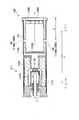
구체적으로는, 향미 흡인기(100)는, 도 12에 나타낸 바와 같이, 카트리지(130)를 갖고 있지 않다. 흡인기 하우징(110X)은, 변경 예 1과 동일하게, 인렛(80)(제2 인렛)을 구성하는 흡인기 관통공(110B)을 갖고 있어도 된다. 즉, 비 연소형 향미 흡인기(100)는, 무화부(111R)를 통하는 제1 공기 유로에 더하여, 무화부(111R)를 통하지 않는 제2 공기 유로를 갖고 있어도 된다.Specifically, the
단, 변경 예 7은 이에 한정되는 것은 아니다. 흡인기 하우징(110X)은, 인렛(80)(제2 인렛)을 구성하는 흡인기 관통공(110B)을 갖고 있지 않아도 된다. 즉, 비 연소형 향미 흡인기(100)는, 무화부(111R)를 통하지 않는 제2 공기 유로를 갖고 있지 않아도 된다.However, the modified example 7 is not limited to this. The
[변경 예 8][Modification 8]
이하에 있어서, 제1 실시 형태의 변경 예 8에 대해서 설명한다. 이하에 있어서는, 제1 실시 형태에 대한 차이점에 관하여 주로 설명한다. 변경 예 8에서는, 유저의 흡인 동작을 검지하기 위한 센서(20)의 일례에 대해서 설명한다.In the following,
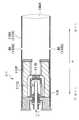
상술한 바와 같이, 흡인기 하우징(110X)은, 무화부(111R)를 수용하는 제1 통체(111X)(제1 하우징)와, 제1 통체(111X)에 착탈 가능하게 구성되어 있으며, 전원(10)을 수용하는 제2 통체(112X)(제2 하우징)를 갖는다. 센서(20)는, 제2 통체(112X)에 수용됨과 동시에, 전원(10)보다도 제1 통체(111X) 측에 설치된다. 즉, 센서(20)는, 제2 통체(112X)가 제1 통체(111X)에 접속되는 부위(변경 예 8에서는, 인렛(112A))의 근방에 설치된다.As described above, the
도 13에 나타낸 바와 같이, 흡인기 하우징(110X)(여기서는, 제2 통체 112X)은, 센서(20)보다도 인렛(112A) 및 아웃렛(130A)과 동일한 측에 설치되는 제1 공동(105) 및 센서보다도 인렛(112A) 및 아웃렛(130A)의 반대측에 설치되는 제2 공동(106)을 갖는다.13, the
이러한 전제하에 있어서, 센서(20)는, 예를 들면, 콘덴서를 갖는 센서이며, 제1 공동(105)의 내압과 제2 공동(106)의 내압과의 차압에 따른 콘덴서의 전기 용량을 나타내는 응답값(예를 들면, 전압 값)을 출력한다. 센서(20)는, 도 13에 나타낸 바와 같이, 커버(21)와, 기판(22)과, 전극 막(23)과, 고정 전극(24)과, 제어 회로(25)와, 개구(26)와, 개구(27)를 갖는다. 커버(21)와 흡인기 하우징(110X) 사이에는 간극이 존재하지 않고, 제1 공동(105) 및 제2 공동(106)은, 흡인기 하우징(110X) 내에서 서로 연통하지 않도록 센서(20)에 의해 구획되어 있다. 기판(22)에는, 고정 전극(24) 및 제어 회로(25)가 설치된다. 전극 막(23)은, 제1 공동(105)의 내압과 제2 공동(106)의 압력과의 차압의 변화에 따라 변형된다. 고정 전극(24)은, 전극 막(23) 콘덴서를 형성한다. 콘덴서의 전기 용량은, 전극 막(23)의 변형에 의해 변화한다. 제어 회로(25)는, 전극 막(23)의 변형에 의해 변화하는 전기 용량을 검출하고, 검출된 전기 용량의 변화에 따른 응답값을 출력한다. 개구(26)는, 제1 공동(105)에 연통한다. 따라서, 흡인 동작에 의해 제1 공동(105)의 내압이 변화함과 동시에 전극 막(23)이 변형된다.Under these assumptions, the
구체적으로는, 예를 들면, 흡인 동작을 행한 경우, 제1 공동(105)의 내압이 저하하는 반면, 제2 공동(106)의 내압은 실질적으로 변화하지 않고, 대기압과 대략 동일하기 때문에, 실질적으로는 센서(20)는 제1 공동(105)에 있어서의 압력 변화를 검출한다. 또한, 예를 들어, 취입 동작을 행한 경우, 제1 공동(105)의 내압이 상승하는 반면, 제2 공동(106)의 압력은 실질적으로 변화하지 않고, 대기압과 대략 동일하기 때문에, 실질적으로는 센서(20)는 제1 공동(105)의 압력 변화를 검출한다.Specifically, for example, when the suction operation is performed, the inner pressure of the
또한, 변경 예 8에 있어서, 인렛(112A)은, 센서(20)와 무화부(111R)와의 사이에 설치된다. 예를 들어, 인렛(112A) 및 센서(20) 사이의 거리는, 20mm 이하이어도 된다. 인렛(112A) 및 센서(20) 사이의 거리는, 15mm 이하인 것이 바람직하고, 10mm 이하인 것이 더욱 바람직하다. 제2 공동은, 대기에 개방되어 있다. 예를 들어, 제2 공동은, 전원(10)과 제2 통체(112X) 사이의 간극을 통해 제2 통체(112X)의 비 흡구단의 개구에 연통 있어도 되고, 제2 통체(112X)의 측면에 설치되는 구멍에 연통하고 있어도 된다.In the modified example 8, the
(작용 및 효과)(Action and effect)
변경 예 8에서는, 센서(20)는, 제2 통체(112X)에 수용됨과 동시에, 전원(10)보다도 제1 통체(111X) 측에 설치된다. 즉, 센서(20)는, 제2 통체(112X)가 제1 통체(111X)에 접속되는 부위(변경 예 8에서는, 인렛(112A))의 근방에 설치된다. 따라서, 공기 유로의 전체의 통기 저항이 25mmAq 이하로 낮아져도, 흡인 동작의 검출 정밀도가 향상된다.In the modified example 8, the
변경 예 8에서는, 제1 공동(105) 및 제2 공동(106)은, 흡인기 하우징(110X) 내에서 서로 연통하지 않도록 센서(20)에 의해 구획되어 있다. 이러한 구성에 의하면, 흡인 동작에 따라 제1 공동(105)의 내압이 높아지기 쉽고, 공기 유로의 전체의 통기 저항이 25mmAq 이하로 낮아져도, 흡인 동작의 검출 정밀도가 향상된다.In the modified example 8, the
[변경 예 9][Modification 9]
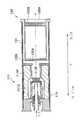
이하에 있어서, 제1 실시 형태의 변경 예 9에 대해서 설명한다. 이하에 있어서는, 제1 실시 형태에 대한 차이점에 관하여 주로 설명한다. 변경 예 9에서는, 상술한 무화 유닛(111) 및 카트리지(130)의 변경 예에 대해서 설명한다. 도 14는, 변경 예 9에 관련되는 카트리지(130)의 사시도이고, 도 15는, 변경 예 9에 관련되는 카트리지(130)를 흡구측에서 본 도면이다. 도 16은, 흡인기 하우징(110X)에 카트리지(130)가 수용된 상태에 있어서의 향미 흡인기(100)의 내부 구조를 나타낸 모식도이다.Modification Example 9 of the first embodiment will be described below. Hereinafter, the difference from the first embodiment will be mainly described. In Modification 9, a modification example of the above-described
구체적으로는, 변경 예 9에서는, 공기 유로의 일부를 구성하는 에어로졸 유로는, 향미원(132)을 통해서 아웃렛(130A) 측에 에어로졸을 유도하는 제1 에어로졸 유로(140A)와, 제1 유로와는 상이한 제2 에어로졸 유로(140B)를 포함한다. 제2 에어로졸 유로(140B)에 있어서의 에어로졸의 저감률은, 제1 에어로졸 유로(140A)에 있어서의 에어로졸의 저감률보다도 작다. 또한, 제2 에어로졸 유로(140B)를 통해서 흡구측에 유도되는 에어로졸 양은, 제1 에어로졸 유로(140A)를 통해서 흡구측에 유도되는 에어로졸 양 이상인 것이 바람직하다. 여기서, 「저감률」이란, 「유로로 유입하는 에어로졸 양(유입량)」에 대한 「유로에서 손실한 에어로졸 양(유입량 - 유출량)」의 비율(즉, (유입량 - 유출 양)/유입량)이다.Specifically, in modified example 9, the aerosol flow path constituting a part of the air flow path includes a first
여기서, 제1 에어로졸 유로(140A) 및 제2 에어로졸 유로(140B) 모두가 카트리지 하우징(131) 내에 형성된다. 환언하면, 카트리지 하우징(131)에 형성되는 제1 에어로졸 유로(140A) 및 카트리지 하우징(131)에 형성되는 제2 에어로졸 유로(140B)는 서로 교차하지 않도록 독립적으로 형성된다. 예를 들어, 제2 에어로졸 유로(140B)는, 향미원(132)을 통하지 않고 아웃렛(130A) 측에 에어로졸을 유도하는 유로이다.Here, both the
상세하게는, 도 14 및 도 15에 나타낸 바와 같이, 카트리지(130)는, 상술한 카트리지 하우징(131)으로서, 내체(內體; 134), 외체(外體; 135) 및 리브(136)를 갖는다. 또한, 도 14에서는, 상술한 향미원(132)이 생략되어 있는 것에 유의해야 한다.14 and 15, the
내체(134)는, 소정 방향(A)을 따라 연장되는 통상(筒狀) 형상을 갖는다. 내체(134)는, 향미원(132)을 수용한다. 내체(134)의 비 흡구측에 망목(133A)이 형성되어 있으며, 내체(134)의 흡구측에는 필터(133B)가 설치된다.The
외체(135)는, 소정 방향(A)을 따라 연장되는 통상 형상을 갖는다. 외체(135)는, 내체(134)를 수용한다. 외체(135)는, 소정 방향(A)을 따라 연장되는 리브(136)에 의해 내체(134)에 고정된다.The
변경 예 9에서는, 외체(135)는, 4개의 리브(136)에 의해 내체(134)에 고정되어 있으며, 서로 인접한 리브(136) 사이에는, 소정 방향(A)을 따라 연장되는 공극(137)이 형성된다.In the modified example 9, the
도 16에 나타내는 바와 같이, 변경 예 9에 관련되는 카트리지(130)를 이용한 경우에 있어서, 상술한 제1 에어로졸 유로(140A)는, 내체(134)의 내측을 통하는 유로이며, 상술한 제2 에어로졸 유로(140B)는, 공극(137)을 통하는 유로이다.As shown in Fig. 16, in the case of using the
변경 예 9에 있어서는, 내체(134), 외체(135) 및 리브(136)에 의해 카트리지 하우징(131)이 구성된 경우에 대해 예시했다. 그러나, 변경 예 9는 이에 한정되는 것은 아니다. 제1 에어로졸 유로(140A) 및 제2 에어로졸 유로(140B) 모두가 카트리지 하우징(131)에 형성되는 태양이라면, 다양한 변경을 가하는 것이 가능하다는 것에 유의해야한다.Modification Example 9 exemplifies the case where the
변경 예 9에 있어서는, 제1 에어로졸 유로(140A) 및 제2 에어로졸 유로(140B) 모두가 주로 카트리지 하우징(131) 내에 형성되어 있으며, 제1 에어로졸 유로(140A) 및 제2 에어로졸 유로(140B)의 분기 부분(145)은, 제1 실시 형태와 동일하게, 카트리지 하우징(131) 외부에 설치된다.In the modified example 9, both the
또한, 제1 에어로졸 유로(140A) 및 제2 에어로졸 유로(140B)는, 서로 공통하는 공통 유로를 갖고 있다. 상술한 분기 부분(145)은, 무화 유닛(111)과 카트리지(130)와의 사이에 형성되는 공통 유로에 설치된다. 또한, 공통 부분은, 2개소 이상 설치되어 있어도 된다. 환언하면, 제1 에어로졸 유로(140A) 및 제2 에어로졸 유로(140B)는, 2개소 이상에서 합류 또는 분기하고 있어도 된다.The first
변경 예 9에서는, 제1 에어로졸 유로(140A)의 적어도 일부는, 흡인기 하우징(110X) 및 카트리지 하우징(131)에 의해 형성된다. 제2 에어로졸 유로(140B)의 적어도 일부는, 흡인기 하우징(110X) 및 카트리지 하우징(131)에 의해 형성된다.In the modified example 9, at least a part of the
(작용 및 효과)(Action and effect)
변경 예 9에서는, 제1 에어로졸 유로(140A)와는 별도로 제2 에어로졸 유로(140B)를 설치함으로써, 공기 유로의 전체의 통기 저항을 25mmAq 이하로 억제하기 쉽다. 제2 에어로졸 유로(140B)에 있어서의 에어로졸의 저감률은, 제1 에어로졸 유로(140A)에 있어서의 에어로졸의 저감률보다도 작기 때문에, 에어로졸이 향미원(132)에 의해 여과되는 영향이 작고, 에어로졸의 손실을 억제할 수 있다. 더욱이, 제2 에어로졸 유로(140B)가 향미원(132)을 통하지 않고 아웃렛(130A) 측에 에어로졸을 유도하는 유로이므로, 에어로졸이 향미원(132)에 의해 여과되지 않고, 에어로졸의 손실을 억제할 수 있다.In the modified example 9, by providing the second
변경 예 9에서는, 제1 에어로졸 유로(140A) 및 제2 에어로졸 유로(140B)는, 카트리지 하우징(131) 내에 형성된다. 따라서, 흡인기 본체(110)의 설계를 변경하지 않고도, 제2 에어로졸 유로(140B)를 형성할 수 있다.In the modified example 9, the
[변경 예 10][Modification 10]
이하에 있어서, 제1 실시 형태의 변경 예 10에 대해서 설명한다. 이하에 있어서는, 제1 실시 형태에 대한 차이점에 관하여 주로 설명한다. 변경 예 10에서는, 상술한 무화 유닛(111) 및 카트리지(130)의 변경 예에 대해서 설명한다.In the following, a
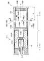
구체적으로는, 도 17 및 도 18에 나타낸 바와 같이, 향미 흡인기(100)는, 무화부(111R)보다도 아웃렛(130A) 측에 설치되는 향미원(132)을 갖는 카트리지(130)(향미원 유닛)를 갖는다. 흡인기 하우징(110X)은, 소정 방향(A)을 따라 연장되는 형상을 갖고 있으며, 카트리지(130)를 유지하는 벽체(201), 벽체 유지체(202), 규제부(208) 및 규제부(209)를 갖는다. 또한, 도 17(B)은, 도 17(A)에 나타내는 P측에서 향미 흡인기(100)를 본 측면도를 나타내고 있으며, 도 17(B)은, 도 17(A)의 Q-Q 단면을 나타내고 있다. 동일하게, 도 18(B)은, 도 18(A)에 나타내는 P측에서 향미 흡인기(100)를 본 측면도를 나타내고 있으며, 도 18(B)은, 도 18(A)의 Q-Q 단면을 나타내고 있다.Specifically, as shown in Figs. 17 and 18, the
도 17에 나타낸 바와 같이, 카트리지(130)는, 소정 방향(A)에 따라 흡인기 하우징(110X)에 설치되는 삽입구(206)에 삽입된다. 도 18에 나타낸 바와 같이, 카트리지(130)는, 흡인기 하우징(110X)에 의해 유지된다.17, the
여기서, 벽체(201)는, 카트리지(130)의 삽입 길이를 규제하는 기능을 갖고 있으며, 벽체(202)는, 제1 공간(204)을 구획하는 기능을 갖고 있다. 규제부(208)는, 소정 방향(A)에 따라 벽체(202)측으로부터 벽체(201)까지 연속하고 있으며, 카트리지(130)의 하면(벽체(211B))을 지지한다. 규제부(209)는, 소정 방향(A)에 따라 벽체(202)측으로부터 벽체(201)까지 연속하고, 카트리지(130)의 상면(벽체 211A)을 지지한다. 이와 같이, 도 18에 있어서의 상하 방향에 있어서, 카트리지(130)의 움직임이 규제부(208) 및 규제부(209)에 의해 제한된다.Here, the
여기서, 카트리지(130)는, 인렛(112A) 측의 제1 공간(204)과 아웃렛(130A) 측의 제2 공간(205)에 무화부(111R)에서 발생하는 에어로졸의 유로인 에어로졸 유로를 구획하도록 흡인기 하우징(110X) 내에 배치된다. 구체적으로는, 카트리지(130)는, 제1 공간(204) 및 제2공간(205)을 소정 방향(A)에 따라 구획한다.Here, the
변경 예 10에 있어서, 제1 공간(204) 및 제2 공간(205)의 적어도 어느 한쪽에 노출되는 카트리지(130)의 면적은, 소정 방향으로 직교하는 단면에 있어서 흡인기 하우징(110X)의 내주에 의해서 규정되는 단면적보다도 크다.In the modified example 10, the area of the
예를 들면, 카트리지(130)는, 제1 공간(204) 및 제2 공간(205)에 노출되는 제1 벽체(211A 및 211B)와, 제1 벽체(211A 및 211B)와 연속하는 제2 벽체(212A ~ 211D)를 갖는다. 제1 벽체(211A 및 211B)는, 곡선 부분을 포함해도 되고, 제2 벽체(212A ~ 211D)는, 곡선 부분을 포함해도 된다. 제2 벽체(212A ~ 211D)는, 제1 공간(204) 및 제2 공간(205)이 모두 노출하지 않아도 된다.For example, the
제1 벽체(211A 및 211B)는, 통기성을 갖는 부재에 의해 구성된다. 제1 벽체(211A 및 211B)는, 제1 실시 형태와 동일하게 망목 또는 필터에 의해 구성되어 있어도 되고, 부직포 등으로 구성되어 있어도 된다. 제1 벽체(211A 및 211B)의 외면의 면적은, 제2 벽체(212A ~ 211D)의 외면의 면적보다도 크다.The
무화부(111R)에서 발생하는 에어로졸은, 제1 공간(204)에서 제1 벽체(211A)를 통해서 카트리지(130) 내로 유도되고, 카트리지(130) 내로 유도된 에어로졸은, 제1 벽체(211B)를 통해서 제2 공간(205)으로 유도된다.The aerosol generated in the
(작용 및 효과)(Action and effect)
변경 예 10에서는, 한 쌍의 제1 벽체(211A 및 211B) 외면의 면적은, 한 쌍의 제2 벽체(212A 및 212B)의 외면의 면적보다 크다. 따라서, 향미원(132) 전체에 걸쳐 에어로졸을 통기시키기 쉽고, 또한, 공기 유로의 전체의 통기 저항을 25mmAq 이하로 억제하기 쉽다. 또한, 에어로졸이 향미원(132)을 통과하는 거리가 단축되기 때문에, 에어로졸이 향미원(132)에 의해 여과되는 영향이 작고, 에어로졸의 손실을 억제할 수 있다.In the modified example 10, the outer surface area of the pair of
[그 밖의 실시 형태][Other Embodiments]
본 발명은 상술한 실시 형태에 따라 설명했지만, 이 개시의 일부를 이루는 논술 및 도면은, 본 발명을 한정하는 것이라고 이해해서는 안 된다. 이 개시로부터 당업자에게는 다양한 대체 실시 형태, 실시예 및 운용 기술이 명확해질 것이다.While the present invention has been described in accordance with the foregoing embodiments, it is to be understood that the description and the drawings constituting part of this disclosure are not intended to limit the present invention. From this disclosure, various alternative embodiments, examples and operational techniques will be apparent to those skilled in the art.
실시 형태에서는, 특히 다루고 있지 않지만, 카트리지(130)를 흡인기 본체(110)에 접속할 때, 카트리지 하우징(131)의 회전 방향에 있어서 카트리지 하우징(131)과 흡인기 하우징(110X)과의 상대 위치를 신경 쓰지 않는다면, 인렛(80)을 형성할 수 없는 경우가 존재한다(예를 들어, 도 4나 도 8을 참조). 이러한 경우에 있어서는, 카트리지(130) 및 흡인기 본체(110)의 적어도 한쪽은, 인렛(80)을 형성하기 위한 위치 결정 기능을 갖는 것이 바람직하다. 이러한 위치 결정 기능의 예는, 이하에 나타내는 바와 같다.The relative positions of the
예를 들어, 흡인기 본체(110)를 구성하는 흡인기 하우징(110X)이 원통 형상을 갖고 있으며, 카트리지(130)가 원주(圓柱) 형상을 갖는 경우를 생각한다. 즉, 흡인기 하우징(110X) 내에 카트리지(130)를 삽입할 때에, 소정 방향(A)을 따라 연장되는 카트리지(130)의 중심축을 중심으로 해서 카트리지(130)가 회전 가능하다. 카트리지 하우징(131)의 회전 방향에 있어서 흡인기 본체(110)와 카트리지(130)의 상대 위치를 일의(一意)로 특정하기 위해, 흡인기 하우징(110X)의 내면에 가이드 리브가 설치되어 있으며, 카트리지 하우징(131)의 외부에 가이드 홈이 설치되어 있어도 된다. 반대로, 흡인기 하우징(110X)의 내면에 가이드 홈이 설치되어 있고, 카트리지 하우징(131)의 외면에 가이드 리브가 설치되어 있어도 된다. 가이드 홈 및 가이드 리브는, 소정 방향(A)을 따라 연장되는 형상을 갖는 것이 바람직하다.For example, suppose that the
혹은, 흡인기 본체(110)를 구성하는 흡인기 하우징(110X)이 다각 형상 또는 타원 형상의 공동(空洞)을 갖고 있으며, 카트리지(130)가 다각 기둥 형상 또는 타원 기둥 형상을 갖는 경우를 생각한다. 이러한 경우에 있어서, 흡인기 하우징(110X) 및 카트리지(130)는, 카트리지(130)와 흡인기 본체(110)와의 상대 위치가 일의로 특정되는 형상을 갖는 것이 바람직하다. 혹은, 흡인기 본체(110) 및 카트리지(130)는, 소정 방향(A)에 대한 직교 방향에 있어서 카트리지 하우징(131)의 외주에 따른 방향에 있어서 흡인기 본체(110)와 카트리지(130)와의 상대 위치를 일의로 특정하기 위한 가이드 리브나 가이드 홈을 가지고 있어도 된다.Alternatively, it is assumed that the
혹은, 흡인기 본체(110) 및 카트리지(130)는, 흡인기 본체(110)와 카트리지(130)의 상대 위치를 일의로 특정하기 위한 표식을 갖고 있어도 된다.Alternatively, the aspirator
실시 형태에서는, 카트리지 하우징(131)의 회전 방향에 있어서 카트리지 하우징(131)과 흡인기 하우징(110X)과의 상대 위치를 일의로 식별하는 점에 관하여 설명했다. 그러나, 실시 형태는 이에 한정되는 것은 아니다. 구체적으로는, 소정 방향(A)에 있어서 카트리지 하우징(131)과 흡인기 하우징(110X)과의 상대 위치는 일의로 특정되는 것이 바람직하다. 예를 들어, 흡인기 하우징(110X)은, 흡인기 하우징(110X)에 대한 카트리지 하우징(131)의 삽입 깊이를 규정하는 스페이서를 갖는 것이 바람직하다. 흡인기 하우징(110X)에 대한 카트리지 하우징(131)의 삽입 깊이가 스페이서에 의해 규정되기 때문에, 소정 방향(A)에 있어서 카트리지 하우징(131)과 흡인기 하우징(110X)과의 상대 위치를 일의로 특정할 수 있다.The embodiment has been described in terms of uniquely identifying the relative positions of the
실시 형태에서는 특히 다루고 있지 않지만, 제어부(53)는, 무화부(111R)에 대한 전원 출력의 출력을 개시하고 나서 소정 기간이 경과한 경우, 흡인 동작이 계속하고 있어도, 무화부(111R)에 대한 전원 출력의 출력을 정지해도 된다. 소정 기간은, 유저의 퍼프 기간의 통계로부터 도출되는 표준 퍼프 기간의 상한값보다 짧다. 환언하면, 흡인 동작의 종료 후에 있어서 에어로졸 유로 내에 에어로졸이 체류나 응축하는 사태를 억제하기 위해, 흡인 동작을 행하고 있는 사이에 무화부(111R)에 대한 전원 출력의 출력을 정지하는 것이 바람직하다. 이에 의해서, 에어로졸의 손실이 억제된다.Although not particularly described in the embodiment, when the predetermined period has elapsed since the start of the output of the power output to the
또한, 표준 퍼프 기간이란, 유저의 퍼프 기간의 통계에서 도출하는 것이 가능하며, 복수의 유저의 퍼프 기간 중의 하한값과 복수의 유저 퍼프 기간 중의 상한값 사이의 기간이다. 하한값 및 상한값은, 유저의 퍼프 기간 데이터의 분포에 기초해서 도출된다. 예를 들면, 평균값의 95% 신뢰 구간의 하한값 및 상한값이 하한값 및 상한값으로서 도출되어도 되고, m ± nσ(여기서 m은 평균값, σ는 표준 편차, n은 양의 실수)가 하한값 및 상한값으로 도출되어도 된다.The standard puff period can be derived from the statistics of the user's puff period, and is a period between a lower limit of a plurality of users' puff periods and an upper limit of a plurality of user puff periods. The lower limit value and the upper limit value are derived based on the distribution of the puff period data of the user. For example, the lower limit value and the upper limit value of the 95% confidence interval of the average value may be derived as the lower limit value and the upper limit value, and m ± nσ (where m is an average value, σ is a standard deviation and n is a positive real number) do.
예를 들면, 소정 기간은, 1초 이상 3초 이하이다. 소정 기간이 1초 이상인 것에 의하여, 무화부에 대한 통전 시간이 퍼프 기간에 비해 짧게 되는 것에 불과하여, 유저에게 주는 위화감이 경감된다. 한편, 소정 기간이 3초 이하인 것에 의하여, 무화부에 대한 통전 시간이 소정 기간으로 고정되는 퍼프 동작을 일정 수 이상으로 할 수 있다. 또한, 소정 기간은, 1.5초 이상 2.5초 이하이어도 된다. 이에 의해서, 유저에게 주는 위화감이 더욱 경감되고, 무화부에 대한 통전 시간이 소정 기간으로 고정되는 퍼프 동작을 늘릴 수 있다.For example, the predetermined period is from 1 second to 3 seconds. When the predetermined period is one second or more, the energization time to the atomizing section is shorter than that in the puff period, and the uncomfortable feeling given to the user is reduced. On the other hand, when the predetermined period is 3 seconds or less, the puff operation in which the energization time for the atomizing unit is fixed to the predetermined period can be made to be a certain number or more. The predetermined period may be 1.5 seconds to 2.5 seconds or less. Thereby, the feeling of discomfort given to the user is further reduced, and the puff operation in which the energization time to the atomizing portion is fixed to the predetermined period can be increased.
실시 형태에서는, 카트리지(130)는 무화 유닛(111)을 포함하지만, 실시 형태는 이에 한정되는 것은 아니다. 예를 들면, 카트리지(130)는, 무화 유닛(111)과 함께 하나의 유닛을 구성해도 된다.In the embodiment, the
실시 형태에서는, 특히 다루고 있지 않지만, 무화 유닛(111)은, 흡인기 본체(110)에 접속 가능하게 구성되어 있어도 된다.In the embodiment, the
실시 형태에서는, 전력을 이용하여 연소를 수반하지 않고 에어로졸 원을 무화하는 무화부를 갖는 비 연소형 향미 흡인기(100)를 향미 흡인기의 일례로서 설명했다. 그러나, 실시 형태는, 이에 한정되는 것이 아니고, 에어로졸 원의 연소를 수반하지 않고 에어로졸 원을 무화할 수 있으면 된다. 예를 들어, 무화부로서는, 탄소 열원의 연소열, 화학 반응에 의해 발생하는 열, 혹은, 진동 등 열 이외의 수단에 의해 에어로졸을 발생시키는 것을 들 수 있다.In the embodiment, the non-combustion
실시 형태에서는, 누름 버튼(30)이 설치되어 있지만, 누름 버튼(30)이 설치되어 있지 않아도 된다. 또한, 상술한 전원 스위치(52)가 설치되어 있지 않아도 된다. 즉, 전원(10)에서 센서(20) 및 제어 회로(50)에 전원이 항상 공급되어 있어도 된다.In the embodiment, the
실시 형태에서는, 카트리지(130)가 설치되어 있지만, 카트리지(130)가 설치되어 있지 않아도 된다. 이러한 경우에 있어서, 에어로졸 원은, 향미 성분을 포함하는 것이 바람직하다.In the embodiment, the
실시 형태에서는, 향미원 유닛은, 카트리지 하우징(131), 망목(133A) 및 필터(133B)에 의해 구성되는 공간 내에 향미원(132)을 갖는 카트리지(130)이다. 그러나, 실시 형태는 이에 한정되는 것은 아니다. 구체적으로는, 향미원 유닛은, 살담배 또는 입상의 담배 원료를 주머니 형상의 부재에 수용하는 형태의 유닛(파우치 등)이어도 된다. 또한, 향미원 유닛은, 입상의 담배 원료 및 바인더를 부직포에 의해 끼워 넣는 형태의 유닛(시트 형상 부재)이어도 된다. 부직포는 열 용착에 의해 시트 형상으로 형성된다.In the embodiment, the flavor source unit is the
실시 형태에서는 특히 다루고 있지 않지만, 향미 흡인기(100)는, 상기 공기 유로의 전체의 통기 저항을 25mmAq 이하로 가변하도록 구성되어 있어도 된다. 「공기 유로의 전체의 통기 저항이 가변이다」이란, 통기 저항이 25mmAq보다도 큰 상태에서 25mmAq 이하의 상태로의 변화가 가능하다는 것을 의미해도 되고, 그 반대의 변화도 가능하다는 것을 의미해도 된다. 「공기 유로의 전체의 통기 저항이 가변이다」이란, 통기 저항이 25mmAq 이하인 조건에서 통기 저항이 가변이다는 것을 의미하여도 된다. 예를 들면, 도 4의 경우에 있어서, 흡인기 본체(110) 내에 있어서 카트리지 하우징(131)을 회동하는 것에 따라 흡인기 관통공(110B)과 카트리지 관통공(130B)과의 중복 면적을 변경함으로써, 공기 유로의 전체의 통기 저항이 변경되어도 된다. 혹은, 카트리지 관통공(130B)의 크기가 상이한 카트리지(130)의 용도에 따라, 공기 유로의 전체의 통기 저항이 변경되어도 된다. 카트리지 관통공(130B)을 갖는 카트리지(130)와 카트리지 관통공(130B)을 갖지 않는 카트리지(130)의 용도에 따라, 공기 유로의 전체의 통기 저항이 변경되어도 된다. 혹은, 향미 흡인기(100)의 하우징이 흡구를 다른 부재로서 갖는 경우에는, 흡구의 용도에 따라, 공기 유로의 전체의 통기 저항이 변경되어도 된다.Though not specifically described in the embodiment, the
실시 형태에서는 특히 언급하고 있지 않지만, 전원(10)으로부터 무화부(111R)에 3초간에 걸쳐 전력을 공급하는 경우에, 무화부(111R)에서 발생하는 에어로졸의 양은 10mg 이하인 것이 바람직하다.Although not particularly mentioned in the embodiment, when power is supplied from the
실시 형태에서는 특히 언급하고 있지 않지만, 흡인기 하우징(110X)의 외경은, 18mm 이하인 것이 바람직하고, 15mm 이하인 것이 더욱 바람직하다.Although not particularly mentioned in the embodiments, the outer diameter of the
실시 형태에서는 특히 언급하고 있지 않지만, 전원(10)을 구성하는 전지의 용량은, 1000mAh 이하인 것이 바람직하고, 800mAh 이하인 것이 더욱 바람직하다.Although not particularly mentioned in the embodiment, the capacity of the battery constituting the
실시 형태에서는 특히 다루고 있지 않지만, 무화 유닛(111)에 설치되는 에어로졸 유로의 직경(즉, 리저브(111P)에 끼워지는 유로의 직경)는 3mm 이하인 것이 바람직하다.The diameter of the aerosol flow path provided in the atomization unit 111 (that is, the diameter of the flow path sandwiched between the
[실험 결과][Experiment result]
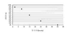
실험에서는, 폴리프로필렌(PP) 제의 튜브에 아세테이트 필터를 삽입한 흡구 샘플을 준비함과 동시에, 10명의 피험자(성인 남성 흡연자)가 샘플을 이용하여 흡인 동작을 실시했다. 구체적으로는, 샘플로서, 통기 저항이 2mmAq 샘플(실시예 1), 통기 저항이 8mmAq 샘플(실시예 2), 통기 저항이 15mmAq 샘플(실시예 3), 통기 저항이 25mmAq 샘플(실시예 4), 통기 저항이 40mmAq 샘플(비교 예 1) 샘플을 준비했다. 각 샘플의 통기 저항은 아세테이트 필터의 길이에 따라 조정했다.In the experiment, 10 samples (adult male smokers) were used to carry out the suction operation while preparing an inlet sample in which an acetate filter was inserted into a tube made of polypropylene (PP). Specifically, samples were prepared in the same manner as in Example 1 except that a sample having a ventilation resistance of 2 mmAq (Example 1), a ventilation resistance of 8 mmAq sample (Example 2), a ventilation resistance of 15 mmAq sample (Example 3) , And a sample having a 40 mmAq air permeation resistance (Comparative Example 1) were prepared. The aeration resistance of each sample was adjusted according to the length of the acetate filter.
첫째, 직접 흡인과 퍼프 흡인 중, 직접 흡인의 쪽이 자연스럽다고 회답한 피험자의 비율에 대해 조사했다. 실험 결과는, 도 19에 나타내는 바와 같다. 도 19에 나타낸 바와 같이, 비교예 1(40mmAq)에 관해서는, 직접 흡인의 쪽이 자연스럽다고 회답한 피험자의 비율은 0%였다. 이에 대해, 실시예 1(2mmAq), 실시예 2(8mmAq), 실시예 3(15mmAq), 실시예 4(25mmAq)에 관해서는, 직접 흡인의 쪽이 자연스럽다고 회답한 피험자가 존재하고 있으며, 통기 저항이 작을수록, 직접 흡인의 쪽이 자연스럽다고 회답한 피험자의 비율이 상승하는 것이 확인되었다.First, we investigated the ratio of subjects who answered that direct suction is natural in direct aspiration and puff aspiration. The results of the experiment are shown in Fig. As shown in Fig. 19, the ratio of subjects who responded to Comparative Example 1 (40 mmAq) that the direct suction was natural was 0%. On the other hand, there were subjects who answered that the direct suction was natural in the cases of Example 1 (2 mmAq), Example 2 (8 mmAq), Example 3 (15 mmAq), and Example 4 (25 mmAq) It was confirmed that the smaller the resistance, the higher the percentage of subjects who answered that the direct suction was natural.
둘째, 직접 흡인을 시도한 경우에, 직접 흡인을 할 수 없다고 회답한 피험자의 비율에 대해 조사했다. 실험 결과는, 도 20에 나타낸 바와 같다. 도 20에 나타낸 바와 같이, 비교예 1(40mmAq)에 관하여는, 직접 흡인을 할 수 없다고 회답한 피험자의 비율이 70%였다. 이에 대해, 실시예 1(2mmAq), 실시예 2(8mmAq), 실시예 3(15mmAq), 실시예 4(25mmAq)에 관하여는, 직접 흡인을 할 수 없다고 회답한 피험자의 비율이 0%였다.Second, we investigated the proportion of subjects who replied that they were unable to perform direct aspiration when attempting direct aspiration. The experimental results are shown in Fig. As shown in Fig. 20, regarding the comparative example 1 (40 mmAq), the percentage of subjects who answered that direct suction was not possible was 70%. On the other hand, the percentage of subjects who responded that direct suction was impossible with respect to Example 1 (2 mmAq), Example 2 (8 mmAq), Example 3 (15 mmAq), and Example 4 (25 mmAq) was 0%.
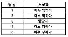
셋째, 직접 흡인을 시도한 경우에, 어느 정도 저항감을 느끼는지에 관하여 5단계의 평점으로 조사했다. 평점과 저항감과의 대응 관계는 도 21에 나타내는 바와 같으며, 실험 결과는, 도 22에 나타내는 바와 같다. 도 22에 나타낸 바와 같이, 비교예 1(40mmAq)에 관하여는, 모든 피험자가 저항감이 매우 강하다(평점 5)고 평가했다. 이에 대해서, 실시예 1(2mmAq), 실시예 2(8mmAq), 실시예 3(15mmAq), 실시예 4(25mmAq) 대해서는, 통기 저항이 작을수록, 저항감이 약해지는 것으로 확인되었다. 특히, 실시예 1(2mmAq)에 대해서는, 저항감이 알맞다(평점 3)고 회답한 피험자가 50%이고, 나머지 50%의 피험자는, 다소 약하다(평점 2) 또는 약하다(평점 1)고 회답했다. 한편, 실시예 2(8mmAq)에 대해서는, 저항감이 알맞다(평점 3)고 회답한 피험자가 50%이고, 나머지 50%의 피험자는, 다소 강하다(평점 4)고 회답하고 있으며, 다소 약하다(평점 2) 또는 약하다(평점 1)고 회답한 피험자는 존재하지 않았다.Third, we evaluated the degree of resistance in the case of attempting direct aspiration with the score of 5 levels. The correspondence between the rating and the resistance is shown in Fig. 21, and the results of the experiment are as shown in Fig. As shown in Fig. 22, regarding the comparative example 1 (40 mmAq), all the subjects evaluated that the resistance was very strong (rating 5). On the contrary, with respect to Example 1 (2 mmAq), Example 2 (8 mmAq), Example 3 (15 mmAq), and Example 4 (25 mmAq), it was confirmed that the lower the ventilation resistance, the weaker the resistance. Particularly, in the case of Example 1 (2 mmAq), 50% of subjects responded well (rating 3) and responded 50%, and subjects 50% answered that they were somewhat weak (rated 2) or weak (rated 1). On the other hand, for Example 2 (8 mmAq), 50% of the respondents answered with a good resistance (rating 3) and 50% of the respondents answered that they are somewhat strong (rating 4) ) Or weak (rating 1).
이들 실험 결과로부터, 첫째, 통기 저항이 40mmAq 이상인 경우에, 70%의 피험자가 직접 흡인을 할 수 없다고 회답한 반면, 통기 저항이 25mmAq 이하인 경우에, 직접 흡인을 할 수 없다고 회답한 피험자가 존재하지 않는 것으로 확인되었다(도 20을 참조). 둘째, 통기 저항이 15mmAq 이하인 경우에, 직접 흡인의 쪽이 자연스럽다고 회답한 피험자의 비율이 50% 이상인 것으로 확인되었다(도 19를 참조). 셋째, 통기 저항이 2mmAq 이상 8mmAq 이하인 경우에, 저항감이 알맞다(평점 3)고 회답한 피험자가 50%이고, 통기 저항이 2mmAq인 경우에, 다소 약하다(평점 2) 또는 약하다(평점 1)고 회답한 피험자가 존재하는 한편으로, 통기 저항이 8mmAq인 경우에, 다소 약하다(평점 2) 또는 약하다(평점 1)고 회답한 피험자는 존재하지 않는 것으로 확인되었다.From the results of these experiments, first, 70% of the subjects answered that they could not directly perform the suction when the ventilation resistance was 40 mmAq or more, whereas when the ventilation resistance was 25 mmAq or less, there was no subject who answered that direct suction could not be performed (See Fig. 20). Second, when the ventilation resistance was 15 mmAq or less, it was confirmed that the proportion of subjects who answered that the direct suction was natural was 50% or more (see FIG. 19). Third, when the ventilation resistance is 2mmAq or more and 8mmAq or less, the resistance is satisfactory (rating 3), the response is 50%, and the ventilation resistance is 2mmAq, it is somewhat weak (rating 2) or weak (rating 1) While there was one subject, it was found that there were no subjects with a high response (rating 2) or weak (rating 1) when the ventilation resistance was 8 mmAq.
즉, 공기 유로의 전체의 통기 저항은, 25mmAq 이하인 것이 바람직하다는 것이 확인되었다. 또한, 공기 유로의 전체의 통기 저항은, 15mmAq 이하인 것이 더욱 바람직하다는 것이 확인되었다. 또한, 공기 유로의 전체의 통기 저항은, 2mmAq 이상 8mmAq 이하인 것이 더욱 바람직하다는 것이 확인되었다.That is, it was confirmed that the total air flow resistance of the air flow path is preferably 25 mmAq or less. Further, it was confirmed that the total air flow resistance of the air flow path is more preferably 15 mmAq or less. Further, it was confirmed that the ventilation resistance of the whole air passage was more preferably 2 mmAq or more and 8 mmAq or less.
실시 형태에 따르면, 에어로졸의 손실을 줄임으로써, 향끽미의 저하를 억제하는 것을 가능하게 하는 향미 흡인기를 제공할 수 있다.According to the embodiment, it is possible to provide a flavor-and-aspirator capable of suppressing a decrease in the aroma of flavor by reducing the loss of aerosol.
Claims (23)
Translated fromKorean에어로졸 원의 연소를 수반하지 않고 상기 에어로졸 원을 무화하는 무화부를 구비하고,
상기 공기 유로의 적어도 일부는, 상기 무화부에서 발생하는 에어로졸의 유로인 에어로졸 유로이며,
상기 공기 유로의 전체의 통기 저항은, 25mmAq 이하인 것을 특징으로 하는 향미 흡인기.A housing having a continuous air flow path from the inlet to the outlet,
And an atomization section which atomizes the aerosol source without combustion of the aerosol source,
At least a part of the air flow path is an aerosol flow path which is a flow path of the aerosol generated in the atomization part,
Wherein the air flow resistance of the air flow path as a whole is 25 mmAq or less.
유저가 흡인 동작을 행하지 않을 때에 상기 무화부에 대해서 전원 출력을 공급하지 않고, 유저가 흡인 동작을 행할 때에 상기 무화부에 대해서 전원 출력을 공급하기 위한 스위치를 구비하는 것을 특징으로 하는 향미 흡인기.The method according to claim 1,
And a switch for supplying a power output to the atomizing unit when the user performs a suction operation without supplying a power output to the atomizing unit when the user does not perform the suction operation.
상기 유저의 흡인 동작에 따라 변화하는 응답값을 출력하는 센서를 구비하고,
상기 스위치는, 상기 센서로부터 출력되는 응답값에 따라 동작하는 것을 특징으로 하는 향미 흡인기.3. The method of claim 2,
And a sensor for outputting a response value varying in accordance with the suction operation of the user,
Wherein the switch operates according to a response value output from the sensor.
상기 하우징은, 상기 무화부를 수용하는 제1 하우징과, 상기 제1 하우징에 착탈 가능하게 구성되어 있으며, 상기 무화부에 공급하는 전력을 축적하는 전원을 수용하는 제2 하우징을 포함하고,
상기 센서는, 상기 제2 하우징에 수용됨과 동시에, 상기 전원보다도 상기 제1 하우징 측에 설치되는 것을 특징으로 하는 향미 흡인기.The method of claim 3,
The housing includes a first housing for housing the atomization portion, and a second housing detachably attached to the first housing, the second housing housing a power source for storing electric power to be supplied to the atomization portion,
Wherein the sensor is housed in the second housing and is disposed on the first housing side with respect to the power source.
상기 인렛은, 상기 센서와 상기 무화부 사이에 설치되는 것을 특징으로 하는 향미 흡인기.5. The method of claim 4,
Wherein the inlet is installed between the sensor and the atomization unit.
상기 하우징은, 상기 센서보다도 상기 인렛 및 상기 아웃렛과 동일한 측에 설치되는 제1 공동 및 상기 센서보다 상기 인렛 및 상기 아웃렛 반대측에 설치되는 제2 공동을 갖고 있으며,
상기 제1 공동 및 상기 제2 공동은, 상기 하우징 내에서 서로 연통하지 않도록 구획되어 있는 것을 특징으로 하는 향미 흡인기.6. The method according to any one of claims 3 to 5,
Wherein the housing has a first cavity that is disposed on the same side of the inlet and the outlet as the sensor and a second cavity that is located on the opposite side of the inlet and the outlet than the sensor,
Wherein the first cavity and the second cavity are partitioned so as not to communicate with each other in the housing.
상기 무화부에 대하여 전원 출력을 공급하지 않도록 상기 스위치를 동작시킬 것인지를 판정하기 위해 상기 응답값과 비교되는 종료 임계값은, 상기 무화부에 대하여 전원 출력을 공급하도록 상기 스위치를 동작시킬 것인지를 판정하기 위해 상기 응답값과 비교되는 시작 임계값보다도 큰 것을 특징으로 하는 향미 흡인기.7. The method according to any one of claims 3 to 6,
A finishing threshold value, which is compared with the response value to determine whether to operate the switch so as not to supply the power output to the atomization section, determines whether to operate the switch to supply a power output to the atomization section Is greater than a starting threshold value that is compared with the response value to determine a response value.
유저에 의해 조작되는 조작 인터페이스를 구비하고,
상기 스위치는, 상기 조작 인터페이스에 대한 조작에 따라 동작하는 것을 특징으로 하는 향미 흡인기.3. The method of claim 2,
And an operation interface which is operated by a user,
Wherein the switch operates according to an operation on the operation interface.
상기 공기 유로의 전체의 통기 저항은, 15mmAq 이하인 것을 특징으로 하는 향미 흡인기.9. The method according to any one of claims 1 to 8,
Wherein the air flow resistance of the air flow path as a whole is not more than 15 mmAq.
상기 공기 유로의 전체의 통기 저항은, 2mmAq 이상 8mmAq 이하인 것을 특징으로 하는 향미 흡인기.10. The method according to any one of claims 1 to 9,
Wherein a ventilation resistance of the entire air passage is not less than 2 mmAq and not more than 8 mmAq.
상기 공기 유로는, 상기 무화부를 통하는 제1 공기 유로와, 상기 무화부를 통하지 않는 제2 공기 유로를 포함하고,
상기 인렛은, 상기 제1 공기 유로에 공기를 도입하는 제1 인렛과, 상기 제2 공기 유로에 공기를 도입하는 제2 인렛을 포함하고,
상기 아웃렛은, 상기 제1 공기 유로에서 공기를 도출하는 제1 아웃렛과, 상기 제2 공기 유로에서 공기를 도출하는 제2 아웃렛을 포함하고,
상기 제2 인렛은, 상기 제1 인렛과 상이하고,
상기 제2 인렛은, 상기 무화부보다도 상기 제1 아웃렛 측에 상기 에어로졸 유로에 연통가능하게 구성되는, 또는, 상기 에어로졸 유로에 연통하지 않고 상기 제2 아웃렛에 연통하는 것을 특징으로 하는 향미 흡인기.11. The method according to any one of claims 1 to 10,
Wherein the air flow path includes a first air flow path through the atomization section and a second air flow path not through the atomization section,
The inlet includes a first inlet for introducing air into the first air passage and a second inlet for introducing air into the second air passage,
The outlet includes a first outlet for drawing air out of the first air flow path and a second outlet for drawing air out of the second air flow path,
Wherein the second inlet is different from the first inlet,
Wherein the second inlet communicates with the aerosol flow path on the first outlet side with respect to the atomization port or with the second outlet without communicating with the aerosol flow path.
상기 제2 인렛에서 유입되는 공기의 양은, 상기 아웃렛으로부터 유출되는 공기의 양의 50% 이상인 것을 특징으로 하는 향미 흡인기.12. The method of claim 11,
Wherein the amount of air flowing in the second inlet is at least 50% of the amount of air flowing out of the outlet.
상기 하우징은, 상기 무화부를 적어도 수용하는 흡인기 하우징과, 상기 무화부보다도 상기 제1 아웃렛 측에 설치되는 향미원을 적어도 수용하는 카트리지 하우징을 포함하고,
상기 흡인기 하우징은, 상기 무화부보다도 상기 제1 아웃렛 측에 상기 에어로졸 유로에 연통 가능하게 구성되는 제2 인렛을 갖고 있으며,
상기 카트리지 하우징은, 상기 제2 공기 유로의 적어도 일부를 형성하는 것을 특징으로 하는 향미 흡인기.13. The method according to claim 11 or 12,
The housing includes a suction housing housing at least containing the atomization portion and a cartridge housing housing at least a flavor circle provided on the first outlet side of the atomization portion,
The aspirator housing has a second inlet communicating with the aerosol flow path on the side of the first outlet than the atomization portion,
Wherein the cartridge housing forms at least a part of the second air passage.
상기 카트리지 하우징은, 상기 흡인기 하우징에 소정 방향을 따라 삽입되도록 구성되어 있으며,
상기 카트리지 하우징은, 상기 흡인기 하우징과 인접하는 외측면에 형성되는 제1 요홈 부분을 갖고 있으며,
상기 제1 요홈 부분은, 상기 소정 방향에 있어서 상기 제2 인렛과 대응하는 위치에서, 상기 소정 방향에 직교하는 단면에 있어서 환상으로 연속하고 있으며, 상기 제2 공기 유로의 일부를 구성하는 것을 특징으로 하는 향미 흡인기.14. The method of claim 13,
The cartridge housing is configured to be inserted into the suction device housing along a predetermined direction,
Wherein the cartridge housing has a first groove portion formed on an outer surface adjacent to the suction device housing,
The first groove portion is annularly continuous in a section orthogonal to the predetermined direction at a position corresponding to the second inlet in the predetermined direction and constitutes a part of the second air passage Flavor aspirator.
상기 하우징은, 상기 무화부를 적어도 수용하는 흡인기 하우징과, 상기 무화부보다도 상기 제1 아웃렛 측에 설치되는 향미원을 적어도 수용하는 카트리지 하우징을 포함하고,
상기 흡인기 하우징은, 상기 에어로졸 유로에 연통하지 않고 상기 제2 아웃렛에 연통하는 제2 인렛을 갖는 것을 특징으로 하는 향미 흡인기.13. The method according to claim 11 or 12,
The housing includes a suction housing housing at least containing the atomization portion and a cartridge housing housing at least a flavor circle provided on the first outlet side of the atomization portion,
Wherein the suction device housing has a second inlet communicating with the second outlet without communicating with the aerosol flow path.
상기 카트리지 하우징은, 상기 흡인기 하우징에 소정 방향을 따라 삽입되도록 구성되어 있으며,
상기 카트리지 하우징은, 상기 흡인기 하우징과 인접한 외측면에 형성된 제2 요홈 부분을 갖고 있으며,
상기 제2 요홈 부분은, 상기 소정 방향에 있어서 상기 제2 인렛과 대응하는 위치에서, 상기 소정 방향에 직교하는 단면에 있어서 환상으로 연속하는 것을 특징으로 하는 향미 흡인기.16. The method of claim 15,
The cartridge housing is configured to be inserted into the suction device housing along a predetermined direction,
Wherein the cartridge housing has a second groove portion formed on an outer surface adjacent to the suction device housing,
Wherein the second concave portion is annularly continuous in a section orthogonal to the predetermined direction at a position corresponding to the second inlet in the predetermined direction.
상기 하우징은, 상기 무화부를 적어도 수용하는 흡인기 하우징과, 상기 무화부보다도 상기 제1 아웃렛 측에 설치되는 향미원을 적어도 수용하는 카트리지 하우징을 포함하고,
상기 제2 인렛은, 상기 카트리지 하우징이 상기 소정 방향에 있어서 상기 흡인기 하우징보다도 상기 제1 아웃렛 측에 연장되는 카트리지 돌출 부분을 포함하는 경우에, 상기 카트리지 돌출 부분에 설치되어 있으며, 혹은, 상기 흡인기 하우징이 상기 소정 방향에 있어서 상기 카트리지 하우징보다도 상기 제1 아웃렛 측에 연장되는 흡인기 돌출 부분을 갖는 경우에, 상기 흡인기 돌출 부분에 설치되는 것을 특징으로 하는 향미 흡인기.13. The method according to claim 11 or 12,
The housing includes a suction housing housing at least containing the atomization portion and a cartridge housing housing at least a flavor circle provided on the first outlet side of the atomization portion,
The second inlet may be provided on the cartridge protruding portion when the cartridge housing includes a cartridge protruding portion extending in the predetermined direction from the first outlet side to the first outlet side, Wherein the suction port is provided in the suction protruding portion when the suction port has a suction protruding portion extending to the first outlet side than the cartridge housing in the predetermined direction.
상기 무화부보다도 상기 제1 아웃렛 측에 설치되는 향미원을 구비하고,
상기 제2 인렛은, 상기 향미원보다도 상기 제2 아웃렛 측에 설치되는 것을 특징으로 하는 향미 흡인기.18. The method according to any one of claims 11 to 17,
And a flavor circle provided on the first outlet side with respect to the atomization portion,
Wherein the second inlet is provided on the second outlet side with respect to the flavor source.
상기 무화부보다도 상기 아웃렛 측에 설치되는 향미원을 구비하고,
상기 에어로졸 유로는, 상기 향미원을 통해서 상기 아웃렛 측에 에어로졸을 유도하는 제1 에어로졸 유로와, 상기 제1 에어로졸 유로와는 상이한 제2 에어로졸 유로를 포함하고,
상기 제2 에어로졸 유로에 있어서의 에어로졸의 저감률은, 상기 제1 에어로졸 유로에 있어서의 에어로졸의 저감률보다도 작은 것을 특징으로 하는 향미 흡인기.19. The method according to any one of claims 1 to 18,
And a flavor circle provided on the outlet side of the atomizing section,
Wherein the aerosol flow path includes a first aerosol flow path for leading an aerosol to the outlet side through the flavor circle and a second aerosol flow path different from the first aerosol flow path,
Wherein a reduction ratio of the aerosol in the second aerosol flow path is smaller than a reduction rate of the aerosol in the first aerosol flow path.
상기 제2 에어로졸 유로는, 상기 향미원을 통하지 않고 상기 아웃렛 측에 에어로졸을 유도하는 유로인 것을 특징으로 하는 향미 흡인기.20. The method of claim 19,
Wherein the second aerosol flow path is a flow path for guiding the aerosol to the outlet side without passing through the flavor circle.
상기 무화부보다도 상기 아웃렛 측에 설치되는 향미원을 갖는 향미원 유닛을 구비하고,
상기 하우징은, 소정 방향을 따라 연장되는 형상을 갖고 있으며,
상기 향미원 유닛은, 상기 인렛 측의 제1 공간과 상기 아웃렛 측의 제2 공간에 상기 에어로졸 유로를 구획하도록 상기 하우징 내에 배치되어 있으며,
상기 제1 공간 및 상기 제2 공간의 적어도 어느 한쪽에 노출하는 상기 향미원 유닛의 면적은, 상기 소정 방향에 직교하는 단면에 있어서 상기 하우징의 내주에 의해 규정되는 단면적보다도 큰 것을 특징으로 하는 향미 흡인기.21. The method according to any one of claims 1 to 20,
And an flavor source unit having a flavor source provided on the outlet side of the atomization unit,
The housing has a shape extending along a predetermined direction,
The flavor source unit is disposed in the housing so as to partition the aerosol flow path into a first space on the inlet side and a second space on the outlet side,
Wherein an area of the flavor source unit exposed to at least one of the first space and the second space is larger than a cross-sectional area defined by an inner periphery of the housing at a cross section orthogonal to the predetermined direction, .
상기 향미원 유닛은, 상기 제1 공간 및 상기 제2 공간을 상기 소정 방향을 따라 구획하고 있으며,
상기 향미원 유닛은, 상기 제1 공간 및 상기 제2 공간에 노출되는 제1 벽체와, 상기 제1 벽체에 연속하는 제2 벽체를 갖고 있으며,
상기 제1 벽체는, 통기성을 갖는 부재에 의해 구성되어 있으며,
상기 제1 벽체의 외면의 면적은, 상기 제2 벽체의 외면의 면적보다 큰 것을 특징으로 하는 향미 흡인기.22. The method of claim 21,
Wherein the flavor source unit divides the first space and the second space along the predetermined direction,
The flavor source unit includes a first wall exposed to the first space and the second space and a second wall continuous to the first wall,
The first wall is constituted by a member having air permeability,
Wherein the area of the outer surface of the first wall is larger than the area of the outer surface of the second wall.
상기 향미 흡인기는, 상기 공기 유로의 전체의 통기 저항을 25mmAq 이하로 가변하도록 구성되어 있는 것을 특징으로 하는 향미 흡인기.23. The method according to any one of claims 1 to 22,
Wherein the flavor / aspirator is configured to vary the ventilation resistance of the entire air flow path to 25 mmAq or less.
Applications Claiming Priority (3)
| Application Number | Priority Date | Filing Date | Title |
|---|---|---|---|
| JPPCT/JP2015/060493 | 2015-04-02 | ||
| JP2015060493 | 2015-04-02 | ||
| PCT/JP2016/060251WO2016159013A1 (en) | 2015-04-02 | 2016-03-29 | Flavor inhaler |
Publications (2)
| Publication Number | Publication Date |
|---|---|
| KR20170128492Atrue KR20170128492A (en) | 2017-11-22 |
| KR102105747B1 KR102105747B1 (en) | 2020-04-28 |
Family
ID=57005844
Family Applications (1)
| Application Number | Title | Priority Date | Filing Date |
|---|---|---|---|
| KR1020177029447AExpired - Fee RelatedKR102105747B1 (en) | 2015-04-02 | 2016-03-29 | Flavor inhaler |
Country Status (10)
| Country | Link |
|---|---|
| US (1) | US10881137B2 (en) |
| EP (2) | EP3275321B1 (en) |
| JP (2) | JP6637486B2 (en) |
| KR (1) | KR102105747B1 (en) |
| CN (1) | CN107404951B (en) |
| AU (1) | AU2016240554B2 (en) |
| CA (1) | CA2980426C (en) |
| EA (1) | EA036430B1 (en) |
| MY (1) | MY184410A (en) |
| WO (1) | WO2016159013A1 (en) |
Cited By (4)
| Publication number | Priority date | Publication date | Assignee | Title |
|---|---|---|---|---|
| KR20200096977A (en)* | 2017-12-15 | 2020-08-14 | 레이 스트라티직 홀딩스, 인크. | Aerosol delivery device with multiple aerosol delivery routes |
| KR20210016586A (en)* | 2018-07-04 | 2021-02-16 | 브리티시 아메리칸 토바코 (인베스트먼츠) 리미티드 | Aerosol-generating consumables |
| KR20210058334A (en) | 2019-11-14 | 2021-05-24 | 강원대학교산학협력단 | Composition for treating asherman syndrome comprising perivascular stem cell medium or cyclophilin a |
| KR20220012081A (en)* | 2020-07-22 | 2022-02-03 | 주식회사 케이티앤지 | Aerosol generating device |
Families Citing this family (68)
| Publication number | Priority date | Publication date | Assignee | Title |
|---|---|---|---|---|
| EA034513B1 (en)* | 2015-02-27 | 2020-02-14 | Джапан Тобакко Инк. | Non-burning type flavor inhaler |
| JP6637486B2 (en) | 2015-04-02 | 2020-01-29 | 日本たばこ産業株式会社 | Flavor inhaler |
| US10500354B2 (en)* | 2015-09-25 | 2019-12-10 | Sanmina Corporation | System and method for atomizing and monitoring a drug cartridge during inhalation treatments |
| CA173518S (en) | 2016-02-08 | 2017-09-01 | Nicoventures Holdings Ltd | Cartridge for an electronic cigarette |
| GB201605100D0 (en) | 2016-03-24 | 2016-05-11 | Nicoventures Holdings Ltd | Vapour provision system |
| GB201605102D0 (en) | 2016-03-24 | 2016-05-11 | Nicoventures Holdings Ltd | Mechanical connector for electronic vapour provision system |
| GB201605105D0 (en) | 2016-03-24 | 2016-05-11 | Nicoventures Holdings Ltd | Vapour provision apparatus |
| GB201605101D0 (en) | 2016-03-24 | 2016-05-11 | Nicoventures Holdings Ltd | Electronic vapour provision system |
| RU2741664C2 (en) | 2016-07-22 | 2021-01-28 | Никовенчерс Трейдинг Лимитед | Case for device for providing vapour |
| RU2750465C2 (en) | 2016-12-16 | 2021-06-28 | Кей Ти Энд Джи Корпорейшн | Aerosol-generating apparatus |
| KR20180070451A (en)* | 2016-12-16 | 2018-06-26 | 주식회사 케이티앤지 | Heater and system for heating an aerosol generating substrate |
| US10820633B2 (en)* | 2016-12-19 | 2020-11-03 | Altria Client Services Llc | Aerosol-generating system comprising multiple aerosol-forming substrates and a transfer element |
| EP3554291B1 (en)* | 2016-12-19 | 2020-11-04 | Philip Morris Products S.a.s. | Aerosol-generating system comprising multiple aerosol-forming substrates and a liquid transfer element |
| US10716333B2 (en) | 2016-12-19 | 2020-07-21 | Altria Client Services Llc | Aerosol-generating system having a cartridge and a bypass air inlet |
| RU2754659C2 (en)* | 2016-12-19 | 2021-09-06 | Филип Моррис Продактс С.А. | Aerosol generating system with cartridge and bypass air inlet |
| EP3554289B1 (en) | 2016-12-19 | 2023-11-22 | Philip Morris Products S.A. | Aerosol-generating system having a cartridge with a side aperture |
| GB201700136D0 (en) | 2017-01-05 | 2017-02-22 | British American Tobacco Investments Ltd | Aerosol generating device and article |
| CA3054492C (en)* | 2017-03-06 | 2022-11-29 | Japan Tobacco Inc. | Battery unit, flavor inhaler, method of controlling battery unit, and program |
| RU2737855C1 (en) | 2017-03-30 | 2020-12-03 | Кей Ти Энд Джи Корпорейшн | Aerosol generation device and holder to accommodate device thereof |
| CN115024512B (en) | 2017-04-11 | 2025-09-19 | 韩国烟草人参公社 | Aerosol generating device |
| US11622582B2 (en) | 2017-04-11 | 2023-04-11 | Kt&G Corporation | Aerosol generating device and method for providing adaptive feedback through puff recognition |
| CN115708600A (en) | 2017-04-11 | 2023-02-24 | 韩国烟草人参公社 | Aerosol generating device |
| US11432593B2 (en) | 2017-04-11 | 2022-09-06 | Kt&G Corporation | Device for cleaning smoking member, and smoking member system |
| US12102131B2 (en) | 2017-04-11 | 2024-10-01 | Kt&G Corporation | Aerosol generating device and method for providing adaptive feedback through puff recognition |
| JP6930687B2 (en) | 2017-04-11 | 2021-09-01 | ケーティー・アンド・ジー・コーポレーション | Aerosol generator |
| JP7180947B2 (en) | 2017-04-11 | 2022-11-30 | ケーティー アンド ジー コーポレイション | AEROSOL GENERATING DEVICES AND METHODS OF PROVIDING SMOKING RESTRICTION FEATURES IN AEROSOL GENERATING DEVICES |
| GB201705888D0 (en)* | 2017-04-12 | 2017-05-24 | British American Tobacco Investments Ltd | Apparatus for volatilising smokable material and a smoking article |
| WO2018198154A1 (en)* | 2017-04-24 | 2018-11-01 | 日本たばこ産業株式会社 | Aerosol generation apparatus, method for controlling aerosol generation apparatus, and program |
| KR102216139B1 (en)* | 2017-04-28 | 2021-02-16 | 주식회사 케이티앤지 | Method and apparatus for generating aerosols |
| GB2562764A (en)* | 2017-05-24 | 2018-11-28 | Robert Hopps Jason | Tobacco-containing consumable for aerosol generating devices |
| KR102035313B1 (en) | 2017-05-26 | 2019-10-22 | 주식회사 케이티앤지 | Heater assembly and aerosol generating apparatus having the same |
| WO2018230002A1 (en)* | 2017-06-16 | 2018-12-20 | 株式会社 東亜産業 | Method for manufacturing filler for electronic cigarette cartridge in which non-tobacco plant is used, and filler for electronic cigarette cartridge in which non-tobacco plant is used |
| WO2019031871A1 (en) | 2017-08-09 | 2019-02-14 | 주식회사 케이티앤지 | Electronic cigarette control method and device |
| CN116172276A (en) | 2017-08-09 | 2023-05-30 | 韩国烟草人参公社 | Aerosol generating device and aerosol generating device control method |
| JP6959429B2 (en) | 2017-09-06 | 2021-11-02 | ケーティー・アンド・ジー・コーポレーション | Aerosol generator |
| US12317923B2 (en)* | 2017-10-30 | 2025-06-03 | Kt&G Corporation | Aerosol generating device |
| GB201720338D0 (en) | 2017-12-06 | 2018-01-17 | British American Tobacco Investments Ltd | Component for an aerosol-generating apparatus |
| US12102118B2 (en) | 2018-03-09 | 2024-10-01 | Rai Strategic Holdings, Inc. | Electronically heated heat-not-burn smoking article |
| CN108158044B (en)* | 2018-03-12 | 2023-10-10 | 惠州市新泓威科技有限公司 | Electronic cigarette with double-cavity double-air-passage atomizer |
| US11311048B2 (en) | 2018-09-07 | 2022-04-26 | Altria Client Services Llc | E-vaping device with an insert |
| US11432581B2 (en) | 2018-09-07 | 2022-09-06 | Altria Client Services Llc | Capsule containing a matrix, device with the matrix, and method of forming the matrix |
| US12171261B2 (en)* | 2018-10-12 | 2024-12-24 | Rai Strategic Holdings, Inc. | Vaporization system |
| MX2021006880A (en)* | 2018-12-17 | 2021-09-14 | Philip Morris Products Sa | Cartridge assembly for an aerosol-generating system having leakage prevention. |
| CN110680018A (en)* | 2019-03-31 | 2020-01-14 | 株式会社东亚产业 | Support member for incense core and incense core having the same |
| EP3965601B1 (en)* | 2019-05-07 | 2023-08-16 | Philip Morris Products S.A. | Leakage prevention structure in a vaporizer device |
| US11517688B2 (en)* | 2019-05-10 | 2022-12-06 | Rai Strategic Holdings, Inc. | Flavor article for an aerosol delivery device |
| EP3794970A1 (en)* | 2019-09-20 | 2021-03-24 | Nerudia Limited | Smoking substitute apparatus |
| US11744288B2 (en) | 2020-06-30 | 2023-09-05 | Altria Client Services Llc | Capsules including internal filters, heat-not-burn (HNB) aerosol-generating devices, and methods of generating an aerosol |
| JPWO2022123649A1 (en)* | 2020-12-08 | 2022-06-16 | ||
| US12193502B2 (en) | 2020-12-30 | 2025-01-14 | Altria Client Services Llc | Capsules including embedded corrugated heater, heat-not-burn (HNB) aerosol-generating devices, and methods of generating an aerosol |
| US12053022B2 (en) | 2021-01-04 | 2024-08-06 | Altria Client Services Llc | Capsules with integrated mouthpieces, heat-not-burn (HNB) aerosol-generating devices, and methods of generating an aerosol |
| US12201148B2 (en) | 2021-01-18 | 2025-01-21 | Altria Client Services Llc | Closed system capsule with airflow, heat-not-burn (HNB) aerosol-generating devices, and methods of generating an aerosol |
| US12274295B2 (en) | 2021-01-18 | 2025-04-15 | Altria Client Services Llc | Heat-not-burn (HNB) aerosol-generating devices and capsules |
| US12011034B2 (en) | 2021-01-18 | 2024-06-18 | Altria Client Services Llc | Capsules including embedded heaters and heat-not-burn (HNB) aerosol-generating devices |
| US11789476B2 (en) | 2021-01-18 | 2023-10-17 | Altria Client Services Llc | Heat-not-burn (HNB) aerosol-generating devices including intra-draw heater control, and methods of controlling a heater |
| US11910826B2 (en) | 2021-01-18 | 2024-02-27 | Altria Client Services Llc | Heat-not-burn (HNB) aerosol-generating devices and capsules |
| USD1095794S1 (en) | 2021-01-18 | 2025-09-30 | Altria Client Services Llc | Aerosol-generating capsule |
| CN115211587B (en)* | 2021-04-19 | 2024-06-28 | 中国烟草总公司郑州烟草研究院 | Aerosol generating product capable of modulating release of fragrant substances and method thereof |
| KR102621735B1 (en)* | 2021-04-29 | 2024-01-04 | 주식회사 케이티앤지 | Device for generating aerosol |
| US12127592B2 (en) | 2021-09-20 | 2024-10-29 | Altria Client Services Llc | Capsule validation for heat-not-burn (HNB) aerosol-generating devices |
| CN114128923B (en)* | 2021-11-02 | 2024-07-05 | 深圳麦时科技有限公司 | Electronic atomization device and electronic atomization system |
| KR102617072B1 (en)* | 2021-11-04 | 2023-12-27 | 주식회사 케이티앤지 | Aerosol-generating device and medium receiving rod |
| CN114027566B (en)* | 2021-11-19 | 2023-12-22 | 深圳湃科锐锋科技有限公司 | Operation equipment for calibrating electronic cigarette |
| CN113892692B (en)* | 2021-11-22 | 2024-08-23 | 云南拓宝科技有限公司 | Dry ice atomizing electronic cigarette without heat source |
| CN114128930B (en)* | 2021-11-26 | 2024-07-26 | 东莞市克莱鹏科技有限公司 | Liquid flavor enhancement filter structure and electronic cigarette |
| CN114128931B (en)* | 2021-11-26 | 2024-07-02 | 东莞市克莱鹏科技有限公司 | Liquid flavor-enhancing electronic cigarette |
| WO2023113644A1 (en)* | 2021-12-16 | 2023-06-22 | Плонк Дмсс | Single-use electronic cigarette |
| KR102860721B1 (en)* | 2022-04-05 | 2025-09-17 | 주식회사 케이티앤지 | Multi smoking material which can be used smoke or smokeless and manufacturing method thereof |
Citations (9)
| Publication number | Priority date | Publication date | Assignee | Title |
|---|---|---|---|---|
| KR100264617B1 (en)* | 1996-06-17 | 2000-09-01 | 미즈노 마사루 | Flavor producing article |
| KR20100134700A (en)* | 2008-03-27 | 2010-12-23 | 맨카인드 코포레이션 | A dry powder inhalation system |
| US20110226236A1 (en)* | 2008-10-23 | 2011-09-22 | Helmut Buchberger | Inhaler |
| WO2014060269A1 (en)* | 2012-10-19 | 2014-04-24 | Nicoventures Holdings Limited | Electronic inhalation device |
| WO2014085719A1 (en) | 2012-11-28 | 2014-06-05 | E-Nicotine Technology, Inc. | Methods and devices for compound delivery |
| WO2014130772A1 (en) | 2013-02-22 | 2014-08-28 | Altria Client Services Inc. | Electronic smoking article |
| KR20140110848A (en)* | 2011-12-08 | 2014-09-17 | 필립모리스 프로덕츠 에스.에이. | An aerosol generating device with adjustable airflow |
| KR20140123487A (en)* | 2012-01-03 | 2014-10-22 | 필립모리스 프로덕츠 에스.에이. | An aerosol generating device and system with improved airflow |
| KR20150005514A (en)* | 2012-01-31 | 2015-01-14 | 알트리아 클라이언트 서비시스 인코포레이티드 | Electronic cigarette |
Family Cites Families (12)
| Publication number | Priority date | Publication date | Assignee | Title |
|---|---|---|---|---|
| GB873410A (en)* | 1958-11-11 | 1961-07-26 | Frank T Bartolomeo | Smoking simulating device |
| US4936920A (en)* | 1988-03-09 | 1990-06-26 | Philip Morris Incorporated | High void volume/enhanced firmness tobacco rod and method of processing tobacco |
| US5095921A (en) | 1990-11-19 | 1992-03-17 | Philip Morris Incorporated | Flavor generating article |
| US5479948A (en) | 1993-08-10 | 1996-01-02 | Philip Morris Incorporated | Electrical smoking article having continuous tobacco flavor web and flavor cassette therefor |
| CA2420623C (en)* | 1993-08-10 | 2005-03-15 | Philip Morris Products Inc. | Electrical smoking article having continuous tobacco flavor web and flavor cassette therefor |
| JP2984657B2 (en)* | 1997-07-23 | 1999-11-29 | 日本たばこ産業株式会社 | Flavor generator |
| CN201067079Y (en)* | 2006-05-16 | 2008-06-04 | 韩力 | Simulated aerosol inhaler |
| US9078473B2 (en)* | 2011-08-09 | 2015-07-14 | R.J. Reynolds Tobacco Company | Smoking articles and use thereof for yielding inhalation materials |
| GB201216621D0 (en)* | 2012-09-18 | 2012-10-31 | British American Tobacco Co | Heading smokeable material |
| US20150351456A1 (en)* | 2013-01-08 | 2015-12-10 | L. Perrigo Company | Electronic cigarette |
| JP5990638B2 (en)* | 2013-03-28 | 2016-09-14 | 日本たばこ産業株式会社 | Non-heated flavor aspirator |
| JP6637486B2 (en) | 2015-04-02 | 2020-01-29 | 日本たばこ産業株式会社 | Flavor inhaler |
- 2016
- 2016-03-29JPJP2017510059Apatent/JP6637486B2/enactiveActive
- 2016-03-29AUAU2016240554Apatent/AU2016240554B2/ennot_activeCeased
- 2016-03-29CACA2980426Apatent/CA2980426C/enactiveActive
- 2016-03-29WOPCT/JP2016/060251patent/WO2016159013A1/ennot_activeCeased
- 2016-03-29KRKR1020177029447Apatent/KR102105747B1/ennot_activeExpired - Fee Related
- 2016-03-29EPEP16772894.8Apatent/EP3275321B1/enactiveActive
- 2016-03-29MYMYPI2017703627Apatent/MY184410A/enunknown
- 2016-03-29CNCN201680019012.6Apatent/CN107404951B/enactiveActive
- 2016-03-29EPEP23159897.0Apatent/EP4218465A3/enactivePending
- 2016-03-29EAEA201792196Apatent/EA036430B1/ennot_activeIP Right Cessation
- 2017
- 2017-09-22USUS15/712,705patent/US10881137B2/enactiveActive
- 2019
- 2019-12-19JPJP2019229031Apatent/JP6703638B2/ennot_activeExpired - Fee Related
Patent Citations (9)
| Publication number | Priority date | Publication date | Assignee | Title |
|---|---|---|---|---|
| KR100264617B1 (en)* | 1996-06-17 | 2000-09-01 | 미즈노 마사루 | Flavor producing article |
| KR20100134700A (en)* | 2008-03-27 | 2010-12-23 | 맨카인드 코포레이션 | A dry powder inhalation system |
| US20110226236A1 (en)* | 2008-10-23 | 2011-09-22 | Helmut Buchberger | Inhaler |
| KR20140110848A (en)* | 2011-12-08 | 2014-09-17 | 필립모리스 프로덕츠 에스.에이. | An aerosol generating device with adjustable airflow |
| KR20140123487A (en)* | 2012-01-03 | 2014-10-22 | 필립모리스 프로덕츠 에스.에이. | An aerosol generating device and system with improved airflow |
| KR20150005514A (en)* | 2012-01-31 | 2015-01-14 | 알트리아 클라이언트 서비시스 인코포레이티드 | Electronic cigarette |
| WO2014060269A1 (en)* | 2012-10-19 | 2014-04-24 | Nicoventures Holdings Limited | Electronic inhalation device |
| WO2014085719A1 (en) | 2012-11-28 | 2014-06-05 | E-Nicotine Technology, Inc. | Methods and devices for compound delivery |
| WO2014130772A1 (en) | 2013-02-22 | 2014-08-28 | Altria Client Services Inc. | Electronic smoking article |
Cited By (5)
| Publication number | Priority date | Publication date | Assignee | Title |
|---|---|---|---|---|
| KR20200096977A (en)* | 2017-12-15 | 2020-08-14 | 레이 스트라티직 홀딩스, 인크. | Aerosol delivery device with multiple aerosol delivery routes |
| KR20210016586A (en)* | 2018-07-04 | 2021-02-16 | 브리티시 아메리칸 토바코 (인베스트먼츠) 리미티드 | Aerosol-generating consumables |
| KR20210058334A (en) | 2019-11-14 | 2021-05-24 | 강원대학교산학협력단 | Composition for treating asherman syndrome comprising perivascular stem cell medium or cyclophilin a |
| KR20220029634A (en) | 2019-11-14 | 2022-03-08 | 강원대학교산학협력단 | Composition for treating asherman syndrome comprising perivascular stem cell medium or cyclophilin a |
| KR20220012081A (en)* | 2020-07-22 | 2022-02-03 | 주식회사 케이티앤지 | Aerosol generating device |
Also Published As
| Publication number | Publication date |
|---|---|
| AU2016240554B2 (en) | 2019-09-19 |
| EP4218465A2 (en) | 2023-08-02 |
| US10881137B2 (en) | 2021-01-05 |
| CN107404951B (en) | 2020-03-03 |
| CA2980426C (en) | 2020-09-15 |
| EP4218465A3 (en) | 2023-08-09 |
| EA036430B1 (en) | 2020-11-10 |
| HK1245596A1 (en) | 2018-08-31 |
| CN107404951A (en) | 2017-11-28 |
| EA201792196A1 (en) | 2018-02-28 |
| EP3275321A1 (en) | 2018-01-31 |
| JP6637486B2 (en) | 2020-01-29 |
| EP3275321B1 (en) | 2023-05-03 |
| JP2020048574A (en) | 2020-04-02 |
| JPWO2016159013A1 (en) | 2017-08-03 |
| CA2980426A1 (en) | 2016-10-06 |
| KR102105747B1 (en) | 2020-04-28 |
| MY184410A (en) | 2021-04-01 |
| AU2016240554A1 (en) | 2017-10-12 |
| US20180007960A1 (en) | 2018-01-11 |
| WO2016159013A1 (en) | 2016-10-06 |
| JP6703638B2 (en) | 2020-06-03 |
| EP3275321A4 (en) | 2018-12-12 |
Similar Documents
| Publication | Publication Date | Title |
|---|---|---|
| JP6703638B2 (en) | Flavor suction device | |
| CN107072311B (en) | Non-combustion type fragrance extractor | |
| CN107072310B (en) | Cartridges and non-combustible aroma extractors | |
| CN108433184B (en) | Non-combustion type fragrance extractor | |
| CN108135290B (en) | Electronic vaping section and electronic vaping device and method of manufacturing the same | |
| TWI604799B (en) | Non-burning type fragrance inhaler and method of supplying aerosols | |
| CN105592737B (en) | Non-combustion type fragrance extractor | |
| HK1246218A1 (en) | Non-combustion flavor suction apparatus | |
| JP2022539979A (en) | vapor delivery system | |
| JP2022539685A (en) | steam delivery system | |
| WO2020200652A1 (en) | Aerosol delivery device | |
| TWI581725B (en) | Fragrance suction device | |
| HK1245596B (en) | Flavor inhaler | |
| TWI627911B (en) | Heating-type fragrance inhaler | |
| JP2022540023A (en) | vapor delivery system | |
| RU2826214C2 (en) | Steam supply systems | |
| RU2818782C2 (en) | Device and means for generating an inhalable medium, a receptacle for flavouring material, a method for flavouring an inhalable medium and a method for manufacturing the receptacle | |
| TWI618493B (en) | Non-combustible flavor applicator, fragrant taste source unit and atomization unit | |
| HK1239473A1 (en) | Cartridge and non-combusting flavor inhaler | |
| HK1239472A1 (en) | Non-combusting flavor inhaler |
Legal Events
| Date | Code | Title | Description |
|---|---|---|---|
| A201 | Request for examination | ||
| P11-X000 | Amendment of application requested | St.27 status event code:A-2-2-P10-P11-nap-X000 | |
| P13-X000 | Application amended | St.27 status event code:A-2-2-P10-P13-nap-X000 | |
| PA0105 | International application | St.27 status event code:A-0-1-A10-A15-nap-PA0105 | |
| PA0201 | Request for examination | St.27 status event code:A-1-2-D10-D11-exm-PA0201 | |
| PG1501 | Laying open of application | St.27 status event code:A-1-1-Q10-Q12-nap-PG1501 | |
| E14-X000 | Pre-grant third party observation filed | St.27 status event code:A-2-3-E10-E14-opp-X000 | |
| E902 | Notification of reason for refusal | ||
| PE0902 | Notice of grounds for rejection | St.27 status event code:A-1-2-D10-D21-exm-PE0902 | |
| P11-X000 | Amendment of application requested | St.27 status event code:A-2-2-P10-P11-nap-X000 | |
| P13-X000 | Application amended | St.27 status event code:A-2-2-P10-P13-nap-X000 | |
| E14-X000 | Pre-grant third party observation filed | St.27 status event code:A-2-3-E10-E14-opp-X000 | |
| R18-X000 | Changes to party contact information recorded | St.27 status event code:A-3-3-R10-R18-oth-X000 | |
| E90F | Notification of reason for final refusal | ||
| PE0902 | Notice of grounds for rejection | St.27 status event code:A-1-2-D10-D21-exm-PE0902 | |
| E14-X000 | Pre-grant third party observation filed | St.27 status event code:A-2-3-E10-E14-opp-X000 | |
| T11-X000 | Administrative time limit extension requested | St.27 status event code:U-3-3-T10-T11-oth-X000 | |
| R18-X000 | Changes to party contact information recorded | St.27 status event code:A-3-3-R10-R18-oth-X000 | |
| T11-X000 | Administrative time limit extension requested | St.27 status event code:U-3-3-T10-T11-oth-X000 | |
| T11-X000 | Administrative time limit extension requested | St.27 status event code:U-3-3-T10-T11-oth-X000 | |
| P11-X000 | Amendment of application requested | St.27 status event code:A-2-2-P10-P11-nap-X000 | |
| P13-X000 | Application amended | St.27 status event code:A-2-2-P10-P13-nap-X000 | |
| E14-X000 | Pre-grant third party observation filed | St.27 status event code:A-2-3-E10-E14-opp-X000 | |
| E701 | Decision to grant or registration of patent right | ||
| PE0701 | Decision of registration | St.27 status event code:A-1-2-D10-D22-exm-PE0701 | |
| GRNT | Written decision to grant | ||
| PR0701 | Registration of establishment | St.27 status event code:A-2-4-F10-F11-exm-PR0701 | |
| PR1002 | Payment of registration fee | St.27 status event code:A-2-2-U10-U12-oth-PR1002 Fee payment year number:1 | |
| PG1601 | Publication of registration | St.27 status event code:A-4-4-Q10-Q13-nap-PG1601 | |
| R18-X000 | Changes to party contact information recorded | St.27 status event code:A-5-5-R10-R18-oth-X000 | |
| P22-X000 | Classification modified | St.27 status event code:A-4-4-P10-P22-nap-X000 | |
| P22-X000 | Classification modified | St.27 status event code:A-4-4-P10-P22-nap-X000 | |
| P22-X000 | Classification modified | St.27 status event code:A-4-4-P10-P22-nap-X000 | |
| PR1001 | Payment of annual fee | St.27 status event code:A-4-4-U10-U11-oth-PR1001 Fee payment year number:4 | |
| R18-X000 | Changes to party contact information recorded | St.27 status event code:A-5-5-R10-R18-oth-X000 | |
| PC1903 | Unpaid annual fee | St.27 status event code:A-4-4-U10-U13-oth-PC1903 Not in force date:20240423 Payment event data comment text:Termination Category : DEFAULT_OF_REGISTRATION_FEE | |
| PC1903 | Unpaid annual fee | St.27 status event code:N-4-6-H10-H13-oth-PC1903 Ip right cessation event data comment text:Termination Category : DEFAULT_OF_REGISTRATION_FEE Not in force date:20240423 |