KR20170123801A - Method and apparatus for keeping horizontal position accuracy for taking off and landing of unmanned air vehicle - Google Patents
Method and apparatus for keeping horizontal position accuracy for taking off and landing of unmanned air vehicleDownload PDFInfo
- Publication number
- KR20170123801A KR20170123801AKR1020160052812AKR20160052812AKR20170123801AKR 20170123801 AKR20170123801 AKR 20170123801AKR 1020160052812 AKR1020160052812 AKR 1020160052812AKR 20160052812 AKR20160052812 AKR 20160052812AKR 20170123801 AKR20170123801 AKR 20170123801A
- Authority
- KR
- South Korea
- Prior art keywords
- positioning data
- satellite
- unmanned aerial
- aerial vehicle
- viewing angle
- Prior art date
- Legal status (The legal status is an assumption and is not a legal conclusion. Google has not performed a legal analysis and makes no representation as to the accuracy of the status listed.)
- Ceased
Links
- 238000000034methodMethods0.000titleclaimsabstractdescription42
- 238000012937correctionMethods0.000claimsdescription58
- 238000004364calculation methodMethods0.000claimsdescription12
- 238000010586diagramMethods0.000description6
- 238000004458analytical methodMethods0.000description3
- 238000011161developmentMethods0.000description3
- 238000013459approachMethods0.000description2
- 238000004891communicationMethods0.000description2
- 238000005516engineering processMethods0.000description2
- 238000012544monitoring processMethods0.000description2
- 238000012545processingMethods0.000description2
- 238000010276constructionMethods0.000description1
- 238000003384imaging methodMethods0.000description1
- 230000006698inductionEffects0.000description1
- 238000005259measurementMethods0.000description1
- 238000012986modificationMethods0.000description1
- 230000004048modificationEffects0.000description1
- 239000000575pesticideSubstances0.000description1
- 238000005507sprayingMethods0.000description1
Images


Classifications
- B—PERFORMING OPERATIONS; TRANSPORTING
- B64—AIRCRAFT; AVIATION; COSMONAUTICS
- B64D—EQUIPMENT FOR FITTING IN OR TO AIRCRAFT; FLIGHT SUITS; PARACHUTES; ARRANGEMENT OR MOUNTING OF POWER PLANTS OR PROPULSION TRANSMISSIONS IN AIRCRAFT
- B64D45/00—Aircraft indicators or protectors not otherwise provided for
- B64D45/04—Landing aids; Safety measures to prevent collision with earth's surface
- B—PERFORMING OPERATIONS; TRANSPORTING
- B64—AIRCRAFT; AVIATION; COSMONAUTICS
- B64U—UNMANNED AERIAL VEHICLES [UAV]; EQUIPMENT THEREFOR
- B64U70/00—Launching, take-off or landing arrangements
- B64U70/80—Vertical take-off or landing, e.g. using rockets
- B—PERFORMING OPERATIONS; TRANSPORTING
- B64—AIRCRAFT; AVIATION; COSMONAUTICS
- B64C—AEROPLANES; HELICOPTERS
- B64C39/00—Aircraft not otherwise provided for
- B64C39/02—Aircraft not otherwise provided for characterised by special use
- B64C39/024—Aircraft not otherwise provided for characterised by special use of the remote controlled vehicle type, i.e. RPV
- B—PERFORMING OPERATIONS; TRANSPORTING
- B64—AIRCRAFT; AVIATION; COSMONAUTICS
- B64U—UNMANNED AERIAL VEHICLES [UAV]; EQUIPMENT THEREFOR
- B64U20/00—Constructional aspects of UAVs
- B64U20/80—Arrangement of on-board electronics, e.g. avionics systems or wiring
- B—PERFORMING OPERATIONS; TRANSPORTING
- B64—AIRCRAFT; AVIATION; COSMONAUTICS
- B64U—UNMANNED AERIAL VEHICLES [UAV]; EQUIPMENT THEREFOR
- B64U20/00—Constructional aspects of UAVs
- B64U20/80—Arrangement of on-board electronics, e.g. avionics systems or wiring
- B64U20/87—Mounting of imaging devices, e.g. mounting of gimbals
- G—PHYSICS
- G05—CONTROLLING; REGULATING
- G05D—SYSTEMS FOR CONTROLLING OR REGULATING NON-ELECTRIC VARIABLES
- G05D1/00—Control of position, course, altitude or attitude of land, water, air or space vehicles, e.g. using automatic pilots
- G05D1/60—Intended control result
- G05D1/654—Landing
- B64C2201/127—
- B64C2201/145—
- B64C2201/18—
- B64D2700/62184—
- B64D2700/62228—
- B—PERFORMING OPERATIONS; TRANSPORTING
- B64—AIRCRAFT; AVIATION; COSMONAUTICS
- B64U—UNMANNED AERIAL VEHICLES [UAV]; EQUIPMENT THEREFOR
- B64U2101/00—UAVs specially adapted for particular uses or applications
- B64U2101/30—UAVs specially adapted for particular uses or applications for imaging, photography or videography
- B—PERFORMING OPERATIONS; TRANSPORTING
- B64—AIRCRAFT; AVIATION; COSMONAUTICS
- B64U—UNMANNED AERIAL VEHICLES [UAV]; EQUIPMENT THEREFOR
- B64U2201/00—UAVs characterised by their flight controls
- B64U2201/10—UAVs characterised by their flight controls autonomous, i.e. by navigating independently from ground or air stations, e.g. by using inertial navigation systems [INS]
- B64U2201/104—UAVs characterised by their flight controls autonomous, i.e. by navigating independently from ground or air stations, e.g. by using inertial navigation systems [INS] using satellite radio beacon positioning systems, e.g. GPS
Landscapes
- Engineering & Computer Science (AREA)
- Aviation & Aerospace Engineering (AREA)
- Remote Sensing (AREA)
- Microelectronics & Electronic Packaging (AREA)
- Mechanical Engineering (AREA)
- Radar, Positioning & Navigation (AREA)
- Physics & Mathematics (AREA)
- General Physics & Mathematics (AREA)
- Automation & Control Theory (AREA)
- Navigation (AREA)
- Position Fixing By Use Of Radio Waves (AREA)
Abstract
Translated fromKoreanDescription
Translated fromKorean본 발명은 무인비행체의 이착륙용 수평위치 정확도 유지방법 및 그 장치에 관한 것으로, 더욱 상세하게는 카메라로부터 수집되는 고도별 영상을 이용하여, 위성수신 환경이 불량한 지역에서도 무인비행체의 측위데이터를 자체적으로 보정함으로써, 상기 무인비행체의 수평정확도를 지속적으로 유지하여 상기 무인비행체가 지상의 목표지점까지 정확하게 착륙하거나 목표지점으로부터 정확하게 이륙할 수 있도록 하는 방법 및 그 장치에 관한 것이다.The present invention relates to a method and apparatus for maintaining horizontal positional accuracy for takeoff and landing of an unmanned aerial vehicle, and more particularly, to a method and apparatus for maintaining horizontal positional accuracy for an unmanned aerial vehicle using an altitude- The present invention relates to a method and apparatus for continuously maintaining the horizontal accuracy of the unmanned aerial vehicle so that the unmanned aerial vehicle can accurately land on a ground target or take off accurately from a target point.
최근 산업기술의 발전과 정보통신 기술의 급속한 발전으로 드론(drone)과 같은 무인비행체의 기술적인 발전이 가속화되고 확대됨에 따라 그 활용분야가 광범위해 지고 있다.Recently, as the development of industrial technology and the rapid development of information and communication technology have accelerated and expanded the technological development of unmanned aerial vehicles such as drone, their application fields are becoming widespread.
예를 들어, 무인비행체에 물건을 탑재할 수 있는 장비를 장착하여 교통이 복구되지 않은 재난지역에 의료품이나 긴급구호물품을 제공하거나, 택배서비스와 같이 사용자가 주문한 물건을 신속하게 배송하는 운송서비스가 번창하고 있다. 또한 무인비행체에 카메라를 장착하여 스포츠 경기와 같은 중계방송, 해수욕장이나 건설현장에서의 안전사고에 대한 모니터링, 농경지에 대한 농약살포 또는 사람이 접근하기 어려운 장소에서 사람을 대신해 위험한 작업을 수행하는 것과 같이 다양한 분야에서 상기 무인비행체를 활용하고 있다.For example, it is possible to provide medical goods or emergency relief goods in disaster areas where transportation is not restored by attaching equipment to the unmanned aerial vehicle, or to provide transportation services such as courier service to promptly deliver goods ordered by the user It is thriving. In addition, by attaching a camera to a unmanned aerial vehicle, it can be used as a relay broadcast such as a sports game, monitoring safety accidents at beaches or construction sites, spraying pesticides on agricultural lands, or performing dangerous tasks on behalf of people The unmanned aerial vehicle is utilized in various fields.
운송서비스를 제공하는 무인비행체를 예를 들어 설명하면, 운송할 물품을 탑재한 무인비행체가 운송지로 이동하기 위해서는 출발지에서 이륙한 후, 복수의 항법위성인 GNSS(Global Navigation Satellite System)위성으로부터 수신되는 위성항법신호를 활용하여 자율비행을 통해 운송목적지까지 이동하여, 상기 운송목적지에 착륙하여 물품을 배송하게 된다. 이러한 무인비행체는 인구 밀접지역에서 주로 사용되기 때문에 고도가 높은 상공을 비행할 때보다 이착륙시에 더욱 정밀하게 제어될 필요가 있다.For example, an unmanned aerial vehicle that provides transportation services can be described as follows. In order to move an unmanned aerial vehicle carrying goods to be transported to a transportation place, it is necessary to take off from a departure point and then receive from a Global Navigation Satellite System (GNSS) It uses the satellite navigation signal to move to the destination of the transportation through the autonomous flight and land at the transportation destination to deliver the goods. Since these unmanned aerial vehicles are mainly used in close-to-population areas, they need to be controlled more precisely during takeoff and landing than when flying in high altitude airspace.
그러나 무인비행체가 상공에서 지상의 목표지점으로 착륙할 때 건물이나 기타 시설물로 인해 특정 GNSS위성으로부터 전송되는 위성항법신호가 차단되거나 약하게 수신될 수 있다. 이로 인해 상기 무인비행체의 위치에 대한 정확한 측위가 수행되지 못해, 상기 목표지점으로부터 상기 무인비행체가 이탈할 수 있으며, 상기 무인비행체가 건물 등에 부딪혀 파손되거나 사람들과 충돌하여 인명피해가 발생될 위험성이 있다.However, satellite navigation signals transmitted from specific GNSS satellites due to buildings or other facilities may be blocked or weakly received when the unmanned aerial vehicle lands from above to above the ground target. As a result, the unmanned aerial vehicle can be disengaged from the target point because the accurate positioning of the unmanned aerial vehicle can not be performed, and there is a risk that the unmanned aerial vehicle collides with buildings or the like, .
한편 위성항법신호를 이용하여 무인비행체의 측위를 수행하는 방법으로 GNSS(이하 GPS 포함)신호를 이용한 RTK(Real Time Kinematic)방식이 있다. 상기 RTK방식은 반송파 신호를 사용하는 방식으로 CDGPS(Carrier phase Differential GPS, CDGPS)라고 하며, 지상국에 고정된 GPS수신기를 통해 지상국 위치 좌표와 GPS위성에 의한 좌표 차이값(즉, 위치 보정 데이터)을 취득해 무인비행체에 탑재된 GPS수신기에 전달한다. 이때 상기 무인비행체는 GPS위성으로부터 수신한 GPS좌표에 상기 수신한 좌표 차이값을 합성해 현재 지점의 좌표를 실시간으로 결정한다. 또한 상기 RTK방식은 그 오차범위가 5cm 이하로 정밀하게 측위데이터를 생성하는 장점이 있다.On the other hand, RTK (Real Time Kinematic) method using GNSS (hereinafter referred to as GPS) signal is a method of performing positioning of an unmanned aerial vehicle using a satellite navigation signal. The RTK method is called CDGPS (Carrier Phase Differential GPS) using a carrier signal. The RTK method uses a GPS receiver fixed to a ground station to measure the position of the ground station and the coordinate difference value (i.e., position correction data) And transmits it to the GPS receiver mounted on the unmanned aerial vehicle. At this time, the unmanned aerial vehicle synthesizes the received coordinate difference value with the GPS coordinates received from the GPS satellites to determine the coordinates of the current point in real time. Also, the RTK scheme has an advantage of generating positioning data precisely with an error range of 5 cm or less.
그러나 상기 RTK방식은 상기 무인비행체가 위성신호 수신불량 지역으로 진입하는 경우에는 상기 무인비행체에서 정확하게 위치를 측위할 수 없는 문제점이 있다.However, the RTK method has a problem in that when the unmanned aerial vehicle enters the bad reception region of the satellite signal, it can not accurately locate the position in the unmanned aerial vehicle.
이에 따라 본 발명에서는 무인비행체를 지상의 목표지점에 착륙하거나 상기 목표지점으로부터 이륙함에 있어서, 카메라로부터 수집되는 영상과 지상의 목표지점까지에 대한 수직거리정보를 획득할 수 있는 복수의 센서들을 통해, 건물이나 기타 시설물 등에 의해 위성항법 신호에 대한 수신이 불량한 경우에도 상기 무인비행체에서 자체적으로 정밀한 위치보정을 수행할 수 있도록 함으로써, 안전하게 상기 무인비행체를 이착륙할 수 있도록 하는 방법 및 그 장치를 제시하고자 한다.Accordingly, in the present invention, when the unmanned aerial vehicle is landed at a target point on the ground or when taking off from the target point, through the plurality of sensors capable of acquiring the image collected from the camera and the vertical distance information to the target point on the ground, The present invention provides a method and an apparatus for safely performing the landing and landing of the unmanned aerial vehicle by allowing the unmanned aerial vehicle to carry out precise position correction on its own even when the satellite navigation signal is poorly received by a building or other facilities .
다음으로 본 발명의 기술 분야에 존재하는 선행기술에 대하여 간단하게 설명하고, 이어서 본 발명이 상기 선행기술에 비해서 차별적으로 이루고자 하는 기술적 사항에 대해서 기술하고자 한다.Next, a brief description will be given of the prior arts that exist in the technical field of the present invention, and technical matters which the present invention intends to differentiate from the prior arts will be described.
먼저 한국등록특허 제1527210호(2015.06.09.)는 드론 이착륙 시스템 및 그 운용 방법에 관한 것으로, 드론이 이착륙하기 위한 별도의 베이스들을 제공하고, 드론이 소정의 거리 내로 복수의 베이스중 하나에 접근하는 경우 상기 드론과 상기 베이스에 구비된 근거리 통신 모듈을 통해 착륙유도신호를 상호 송수신함으로써, 상기 드론을 상기 베이스에 착륙할 수 있도록 하는 드론 이착륙 시스템 및 그 운용 방법에 관한 것이다.Korean Registered Patent No. 1527210 (June 5, 2015) discloses a dron landing and landing system and a method of operating the same. The dron is provided with separate bases for taking-off and landing, and the drones approach one of the plurality of bases within a predetermined distance Landing / landing system and a method of operating the same, wherein the landing induction signal is transmitted / received through the near-field communication module provided on the drone and the base, thereby allowing the dron to land on the base.
또한 한국공개특허 제2015-0019771호(2015.02.25.)는 무인 항공기의 착륙 방법 및 시스템에 관한 것으로, 착륙점 주변에 설치된 복수 개의 비전센서를 통해 무인 항공기에 설치된 표적을 인식하여 상기 무인 항공기의 상대위치를 계산하여, 상기 계산한 상대 위치와 상기 착륙점의 절대위치를 이용하여 무인 항공기를 착륙점에 착륙시킬 수 있도록 하는 무인 항공기 착륙 방법 및 시스템에 관한 것이다.Korean Unexamined Patent Publication No. 2015-0019771 (Feb. 25, 2015) discloses a method and system for landing an unmanned airplane, which recognizes a target installed on the unmanned airplane through a plurality of vision sensors installed around the landing point, And the landing point of the unmanned airplane can be landed by using the calculated relative position and the absolute position of the landing point.
상기 선행기술들은 무인비행체를 지상에 착륙시키도록 하는 점에서 본 발명과 일부분 유사하나, 반면에 본 발명은 무인비행체에서 수집되는 고도별 영상을 분석하여, 지상의 목표지점에서 벗어난 거리만큼 측위데이터를 보정함으로써, 위성항법 신호의 수신이 불량한 지역에서도 상기 무인비행체의 수평정확도를 지속적으로 유지할 수 있도록 하여, 상기 무인비행체가 안전하게 이착륙할 수 있도록 하는 기술적 특징에 대해서는 기재하거나 시사하고 있지 않다.The above prior arts are somewhat similar to the present invention in that it allows the unmanned aerial vehicle to land on the ground, whereas the present invention analyzes the altitude images collected from the unmanned aerial vehicle, It is possible to maintain the horizontal accuracy of the unmanned aerial vehicle continuously even in an area where the reception of the satellite navigation signal is poor so that the technical characteristics that the unmanned aerial vehicle can safely be taken off and landed are not described or suggested.
본 발명은 상기와 같은 문제점을 해결하기 위해 창작 된 것으로서, 본 발명의 일 실시예는 위성신호 수신환경이 양호한 지역과 위성신호 수신환경이 불량한 지역에서의 무인비행체에 대한 측위방법을 달리하여 수행함으로써, 지상의 목표지점에 대한 수평정확도를 지속적으로 유지할 수 있도록 하고, 이를 통해 안전하게 지상의 목표지점에 착륙할 수 있도록 하는 방법 및 그 장치를 제공하는 것을 목적으로 한다.The present invention has been made in order to solve the above-mentioned problems. One embodiment of the present invention is to perform a positioning method for an unmanned aerial vehicle differently in an area where the satellite signal reception environment is good and a satellite signal reception environment is poor , And to provide a method and apparatus for continuously maintaining the horizontal accuracy of the target point on the ground, thereby enabling to safely land on the ground target point.
또한 본 발명의 일 실시예는 무인비행체에 구비되는 위성항법수신기에서 출력하는 측위데이터를 기반으로 특정구간이 위성신호 수신환경이 불량한 지역임을 판단하고, 이를 통해 상기 무인비행체에서 자체적으로 측위데이터를 정밀하게 보정할 수 있도록 하는 방법 및 그 장치를 제공하는 것을 목적으로 한다.According to an embodiment of the present invention, it is determined that a specific section is a region where the satellite signal receiving environment is poor based on the positioning data output from the satellite navigation receiver provided in the unmanned air vehicle, And to provide a method and a device for correcting the error.
또한 본 발명의 일 실시예는 무인비행체가 착륙시 위성신호 수신환경이 불량한 구간으로 진입한 경우, 카메라로부터 수집되는 고도별 영상을 분석하여, 분석한 결과를 토대로 상기 측위데이터를 보정하는 방법 및 그 장치를 제공하는 것을 목적으로 한다.According to another embodiment of the present invention, there is provided a method of calibrating the positioning data based on a result of analysis of an altitude image collected from a camera when an unmanned aerial vehicle enters a zone where reception conditions of a satellite signal are poor at landing, And an object of the present invention is to provide a device.
또한 본 발명의 일 실시예는 상기 무인비행체에서 위치를 보정함에 있어서, 상기 무인비행체와 지표면 사이의 수직거리를 적용하여 상기 기준영상과 현재영상의 배율차이를 계산하고, 상기 기준영상과 현재영상의 가로 및 세로 픽셀 차이를 분석하여 픽셀 차이값을 실제 거리로 계산하여, 상기 계산한 거리만큼 상기 무인비행체의 위치를 보정함으로써, 목표지점에 정확하게 수직으로 착륙할 수 있도록 하는 방법 및 그 장치를 제공하는 것을 목적으로 한다.According to an embodiment of the present invention, in correcting the position of the unmanned aerial vehicle, the vertical distance between the unmanned aerial vehicle and the ground surface is used to calculate a magnification difference between the reference image and the current image, There is provided a method and an apparatus for calculating a pixel difference value by analyzing a difference between a horizontal pixel and a vertical pixel to calculate an actual distance and correcting the position of the unmanned air vehicle by the calculated distance, .
본 발명의 일 실시예에 따른 무인비행체의 이착륙용 수평위치 정확도 유지 장치는 GNSS 위성으로부터 위성항법신호를 수신하여 측위데이터를 생성하는 위성항법수신기 및 상기 위성항법수신기에서 생성한 측위데이터를 보정하여 보정된 측위데이터를 생성하여 출력하는 측위데이터 보정모듈를 포함하며, 상기 보정된 측위데이터는 고도별 영상을 분석하여 상기 측위데이터를 보정하여 생성되는 것을 특징으로 한다.The apparatus for maintaining horizontal position accuracy for takeoff and landing of an unmanned aerial vehicle according to an embodiment of the present invention includes a satellite navigation receiver for receiving satellite navigation signals from GNSS satellites to generate positioning data and correcting the positioning data generated by the satellite navigation receiver And a positioning data correction module for generating and outputting the positioning data, wherein the corrected positioning data is generated by analyzing the altitude-specific image and correcting the positioning data.
또한 상기 측위데이터 보정모듈은, 상기 측위데이터로부터 상기 GNSS 위성으로부터 위성수신 시야각이 확보되었는지 여부를 판단하는 위성수신시야각판단부를 포함하며, 상기 판단은 측위데이터 중 GGA의 position fix indicator의 값을 이용하여 상기 시야각의 확보여부를 판단하는 것을 특징으로 한다.Further, the positioning data correction module may include a satellite reception viewing angle determination unit for determining whether a satellite reception viewing angle is secured from the GNSS satellite, from the positioning data, using the position fix indicator of the GGA in the positioning data It is determined whether or not the viewing angle is secured.
또한 상기 측위데이터 보정모듈은, 카메라로 촬영한 영상과 해당 영상이 촬영된 지점에서의 지상과의 수직거리로부터 무인비행체가 목표지점에서 벗어난 거리를 계산하는 보정정보 계산부를 더 포함하는 것을 특징으로 한다.The positioning data correction module may further include a correction information calculation unit for calculating a distance that the unmanned aerial vehicle deviates from the target point based on the vertical distance between the image photographed by the camera and the ground at the point where the corresponding image is photographed .
또한 상기 측위데이터 보정모듈은, 상기 목표지점에서 벗어난 거리만큼 상기 측위데이터를 보정하여 출력하는 측위데이터 보정부를 더 포함하는 것을 특징으로 한다.The positioning data correction module may further comprise a positioning data correction unit for correcting and outputting the positioning data by a distance deviated from the target point.
또한 상기 보정된 측위데이터에 따라 상기 무인비행체의 위치를 제어하는 운행제어부를 더 포함하는 것을 특징으로 한다.And an operation control unit for controlling the position of the unmanned air vehicle according to the corrected positioning data.
아울러 본 발명의 일 실시예에 따른 무인비행체의 이착륙용 수평정확도 유지 방법은 위성항법수신기를 이용하여 GNSS 위성으로부터 위성항법신호를 수신하여 측위데이터를 생성하는 단계 및 상기 위성항법수신기에서 생성한 측위데이터를 보정하여 보정된 측위데이터를 생성하여 출력하는 측위데이터 보정 단계를 포함하며, 상기 보정된 측위데이터는 고도별 영상을 분석하여 상기 측위데이터를 보정하여 생성되는 것을 특징으로 한다.According to another aspect of the present invention, there is provided a method for maintaining a horizontal accuracy for takeoff and landing of an unmanned aerial vehicle, comprising: generating positioning data by receiving a satellite navigation signal from a GNSS satellite using a satellite navigation receiver; And generating and outputting the corrected positioning data, wherein the corrected positioning data is generated by analyzing the altitude-specific image and correcting the positioning data.
또한 상기 측위데이터 보정 단계는, 상기 측위데이터로부터 상기 GNSS 위성으로부터 위성수신 시야각이 확보되었는지 여부를 판단하는 위성수신시야각판단 단계를 포함하며, 상기 판단은 측위데이터 중 GGA의 position fix indicator의 값을 이용하여 상기 시야각의 확보여부를 판단하는 것을 특징으로 한다.In addition, the positioning data correction step may include a satellite reception viewing angle determination step of determining whether a satellite reception viewing angle is secured from the GNSS satellite from the positioning data, and the determination is made using the position fix indicator of the GGA in the positioning data And determines whether or not the viewing angle is secured.
또한 상기 측위데이터 보정 단계는, 카메라로 촬영한 영상과 해당 영상이 촬영된 지점에서의 지상과의 수직거리로부터 무인비행체가 목표지점에서 벗어난 거리를 계산하는 보정정보 계산 단계를 더 포함하는 것을 특징으로 한다.The positioning data correction step may further include a correction information calculation step of calculating a distance that the unmanned aerial vehicle deviates from the target point based on the vertical distance between the image photographed by the camera and the ground at the point where the corresponding image is photographed do.
또한 상기 측위데이터 보정 단계는, 상기 목표지점에서 벗어난 거리만큼 상기 측위데이터를 보정하여 출력하는 측위데이터 보정 단계를 더 포함하는 것을 특징으로 한다.The positioning data correction step may further include a positioning data correction step of correcting and outputting the positioning data by a distance deviated from the target point.
또한 상기 보정된 측위데이터에 따라 상기 무인비행체의 위치를 제어하는 운행제어 단계를 더 포함하는 것을 특징으로 한다.And controlling the position of the unmanned air vehicle according to the corrected positioning data.
본 발명은 무인비행체의 이착륙용 수평위치 정확도 유지 방법 및 그 장치에 관한 것으로, GNSS위성으로부터 위성항법신호의 수신이 불량한 지역에서도 카메라로부터 수집되는 고도별 영상을 분석하여, 상기 무인비행체에 대한 측위데이터를 보정함으로써, 지상의 목표지점과의 수평위치를 정확하게 유지할 수 있도록 함과 동시에, 상기 무인비행체가 지상의 목표지점에 수직으로 착륙할 수 있도록 유도함으로써, 안전하고 정확하게 착륙할 수 있도록 하는 효과가 있다.The present invention relates to a method and apparatus for maintaining horizontal position accuracy for takeoff and landing of an unmanned aerial vehicle, and more particularly, to an apparatus and method for analyzing altitude images collected from a camera in a region where reception of a satellite navigation signal from a GNSS satellite is poor, So that the horizontal position with respect to the target point on the ground can be accurately maintained and at the same time the unmanned aerial vehicle can be landed vertically at a target point on the ground so as to enable safe and accurate landing .
도 1은 본 발명의 일 실시예에 따른 무인비행체의 이착륙용 수평위치 정확도 유지방법 및 그 장치를 개략적으로 설명하기 위한 개념도이다.
도 2는 본 발명의 일 실시예에 따른 무인비행체의 이착륙용 수평위치 정확도 유지 장치의 구성을 나타낸 블록도이다.
도 3은 본 발명의 일 실시예에 따른 위치정보 보정모듈의 구성을 나타낸 블록도이다.
도 4는 본 발명의 일 실시예에 따른 무인비행체의 수평위치 정확도를 유지하여, 목표지점에 안전하고 정확하게 착륙하기 위한 절차를 나타낸 흐름도이다.FIG. 1 is a conceptual diagram for schematically explaining a method for maintaining horizontal position accuracy for takeoff and landing of an unmanned aerial vehicle and an apparatus therefor according to an embodiment of the present invention.
FIG. 2 is a block diagram illustrating a configuration of an apparatus for maintaining horizontal position accuracy for takeoff and landing of an unmanned aerial vehicle according to an embodiment of the present invention. Referring to FIG.
3 is a block diagram illustrating a configuration of a position information correction module according to an embodiment of the present invention.
FIG. 4 is a flowchart illustrating a procedure for safely and accurately landing at a target point by maintaining horizontal positional accuracy of an unmanned aerial vehicle according to an embodiment of the present invention.
이하, 본 발명의 바람직한 실시 예를 첨부된 도면을 참조하여 상세히 설명한다. 각 도면에 제시된 동일한 참조부호는 동일한 부재를 나타낸다.Hereinafter, preferred embodiments of the present invention will be described in detail with reference to the accompanying drawings. Like reference symbols in the drawings denote like elements.
도 1은 본 발명의 일 실시예에 따른 무인비행체 수평위치 정확도 유지방법 및 그 장치를 개략적으로 설명하기 위한 개념도이다.FIG. 1 is a conceptual diagram for schematically explaining a method for maintaining horizontal positional accuracy of an unmanned aerial vehicle according to an embodiment of the present invention and an apparatus therefor.
이하에서는 고도와 수직거리를 혼용하여 쓰고 있으나 상기 고도와 수직거리는 무인비행체와 지표면 사이의 수직거리를 의미한다.Hereinafter, altitude and vertical distance are used in combination, but the altitude and vertical distance mean the vertical distance between the unmanned aerial vehicle and the ground surface.
도 1에 도시한 바와 같이, 상기 무인비행체(200)는 운송서비스를 위한 물건의 배송, 재난지역에 긴급구호물품의 전달 또는 특정 현장의 모니터링 등과 같이 특정임무를 위해 출발지에서 이륙하여 목적지까지 비행하게 된다.As shown in FIG. 1, the unmanned
또한 상기 무인비행체(200)는 사람과 밀접한 공간에서 주로 사용되기 때문에 비스듬히 이착륙을 수행하는 경우에는 주변의 건물이나 기타 시설에 부딪혀 파손되거나 사람과 충돌하여 인명피해가 발생할 수 있으므로, 상기 무인비행체(200)의 이착륙은 지면과 수직방향으로 수행된다.In addition, since the
또한 상기 무인비행체(200)는 근거리에서 지상의 사용자가 원격 조종기를 통해 직접 제어 할 수 있으나, 상기 원격 조종기의 전파가 도달하지 않는 원격지로 이동하는 경우에는 사용자가 원격 조종기를 통해 직접 제어하는 것이 불가능하게 되며, 이때 상기 무인비행체(200)는 자율비행을 통해 상기 원격지까지 운행을 수행하게 된다.Also, the UAV 200 can directly control a ground user through a remote controller at a short distance, but it is impossible for the user to directly control the
무인비행체(200)가 원격지로 이동하기 위해 출발지에서 이륙을 하게 되면 상기 무인비행체(200)는 복수의 GNSS위성으로부터 수신되는 위성항법 정보를 활용하여 해당 무인비행체(200)의 위치, 고도치 또는 속도 등을 계산한 측위데이터를 생성하고, 상기 생성한 측위데이터를 기반으로 기 설정된 좌표에 해당하는 목적지로 이동하게 된다.When the
또한 목적지에 도착하면, 상기 무인비행체(200)는 부여된 임무를 수행하기 위해(예: 물건의 배송), 또는 임무를 수행하는 도중 상기 무인비행체(200)에 전력을 공급하기 위한 배터리가 거의 다 소모된 경우에 지상의 목표지점과 수평정확도를 유지하면서, 상기 지상의 목표지점에 안전하고 정확하게 착륙하여야 한다.When arriving at a destination, the unmanned
이때 상기 목표지점에 인접한 고층건물, 빌딩 또는 기타 시설물로 인해 상기 복수의 GNSS위성에서 전송되는 위성항법신호의 수신이 불량한 경우가 발생될 수 있다. 이러한 경우, 상기 무인비행체(200)는 정확한 측위를 수행하지 못함에 따라 착륙시에 지상의 목표지점으로부터 이탈될 수 있으며, 상기 목표지점에 정확하게 착륙하지 못할 수 있다.At this time, due to a high-rise building, a building or other facility adjacent to the target point, it may happen that reception of the satellite navigation signal transmitted from the plurality of GNSS satellites is poor. In this case, since the unmanned
이를 방지하기 위해 상기 무인비행체(200)에 구비된 수평위치 정확도 유지 장치(100)는 상기 무인비행체(200)가 지상의 목표지점으로 착륙하는 경우에 복수의 GNSS위성으로부터 위성수신 시야각이 확보되는 구간(즉, 위성항법신호의 수신이 양호한 구간으로 도 1에 도시한 것과 같이 A구간을 의미함)과 위성수신 시야각이 확보되지 않는 구간(즉, 위성항법신호의 수신이 불량한 구간으로 도 1에 도시한 것과 같이 B구간을 의미함)에서 상기 무인비행체(200)의 위치에 대한 측위를 각각 다른 방법으로 수행한다. 이를 통해 상기 지상의 목표지점에 대한 상기 무인비행체(200)의 수평정확도를 지속적으로 유지할 수 있도록 함으로써, 정확하게 상기 지상의 목표지점으로 착륙할 수 있도록 한다.In order to prevent this, the horizontal position
이를 위해 상기 수평위치 정확도 유지 장치(100)는 상기 위성항법신호의 수신이 양호한 구간에서는 기존과 동일하게 위성항법신호를 이용하여 측위를 수행하며, 상기 위성항법신호의 수신이 불량한 구간에서는 상기 무인비행체(200)에 탑재된 카메라(300)로부터 수집되는 영상을 기반으로 측위를 수행한다.For this purpose, the horizontal positional
또한 수평위치 정확도 유지 장치(100)는 상기 위성수신 시야각의 확보 여부에 대한 판단을 위해 GGA(Global Positioning System Fix Data)의 PFI(Position Fix Indicator)값을 이용하며, 상기 PFI값이 특정값을 가지지 않는 경우, 상기 위성수신 시야각이 확보되지 않는 구간으로 판단한다.In addition, the horizontal position
한편 상기 GGA는 상기 복수의 GNSS위성으로부터 수신되는 위성항법신호를 기반으로 획득되는 측위데이터인 NMEA(National Marine Electronics Association)데이터 중의 하나로써, 시간, 위도, 경도, 고도, 측위에 사용된 위성수 및 PFI 등을 포함한다.Meanwhile, the GGA is one of NMEA (National Marine Electronics Association) data, which is positioning data acquired based on a satellite navigation signal received from the plurality of GNSS satellites. The GGA is used to calculate the time, latitude, longitude, altitude, PFI and the like.
일반적으로 상기 PFI값은 0에서 8의 값을 가지며, 상기 각각의 값은 복수의 GNSS위성으로부터 위성항법신호를 수신하여, 상기 무인비행체(200)의 측위를 수행하기 위한 방법을 나타낸다. 예를 들어, 0의 경우에는 invalid한 데이터를 의미하며, 이는 측위데이터로써 쓰지 못하는 데이터를 의미하며, 1의 경우에는 GNSS위성의 위성항법신호만으로 측위를 수행하여 상기 무인비행체(200)의 위치를 계산한 것을 의미한다. 또한 상기 PFI의 값이 2인 경우에는 DGPS(Differential Global Positioning System)로 상기 측위를 수행한 것을 의미한다.Generally, the PFI value has a value from 0 to 8, and each value represents a method for receiving the satellite navigation signal from a plurality of GNSS satellites to perform positioning of the
특히 PFI의 값이 4인 경우에는 RTK방법으로 측위를 수행한 것으로 의미하며, 본 발명에서는 상기 무인비행체(200)의 이착륙을 보다 정밀하게 제어하기 위해 RTK방법으로 측위를 수행한 것 의외에는 모두 위성수신환경이 불량한 것으로 판단한다.In particular, when the value of PFI is 4, it means that the positioning is performed by the RTK method. In the present invention, positioning is performed by the RTK method to control the takeoff and landing of the
한편 상기 PFI의 값이 나타내는 각각의 측위방법은 공지의 기술이므로 자세한 설명은 생략하도록 한다.Meanwhile, the respective positioning methods indicated by the values of the PFI are well known in the art, and a detailed description thereof will be omitted.
또한 상기 수평위치 정확도 유지 장치(100)는 기 설정한 좌표에 따라 목표지점의 상공에 도착하여 착륙을 수행하는 경우에는, 카메라(300)를 통해 지상의 목표지점에 대한 영상을 고도별(한편 고도는 무인비행체와 지면까지의 수직거리를 의미함)로 촬영하여 수집하며, 상기 무인비행체(200)는 복수의 GNSS위성으로부터 수신되는 위성항법신호를 이용하여 측위를 수행하면서 수직으로 하강한다.In the case where the horizontal position
또한 상기 수평위치 정확도 유지 장치(100)는 특정고도에 따른 영상의 배율, 상기 배율에 따른 픽셀간의 간격 및 상기 픽셀간의 간격에 대한 실제거리를 미리 계산하여 저장하고 있다. 이에 따라 고도에 따른 픽셀간의 간격과 이에 대한 실제 거리를 알 수 있다.In addition, the horizontal position
또한 상기 수평위치 정확도 유지 장치(100)는 지상의 목표지점으로 하강하는 경우, 상기 PFI의 값을 이용하여 위성수신 시야각 확보 여부를 판단한다. 이 때 위성수신 시야각이 확보되지 않는 구간이라고 판단되면 상기 위성수신 시야각이 확보되지 않는 구간으로 진입하기 직전에 촬영한 영상(즉, A구간에 촬영한 영상 중 가장 최근 영상)을 기준영상으로 설정한다.When the horizontal position
또한 상기 수평위치 정확도 유지 장치(100)는 상기 저장한 특정고도에 따른 영상정보의 배율과 픽셀간의 간격 및 상기 픽셀간의 간격에 대한 실제거리를 기반으로, 상기 기준영상과 현재고도에서 촬영한 현재영상의 배율 차이를 계산하고, 상기 기준영상과 현재영상의 가로 및 세로 픽셀 차이를 분석한다.In addition, the horizontal position
또한 상기 수평위치 정확도 유지 장치(100)는 상기 분석한 픽셀 차이값을 실제거리로 계산하여, 상기 복수의 GNSS로부터 수신되는 위성항법신호를 기반으로 출력되는 측위데이터에 상기 계산한 거리만큼 보정하여, 보정된 측위데이터를 출력한다.In addition, the horizontal position
한편 상기 분석한 픽셀 차이값에 대한 실제거리는 현재영상이 촬영된 지점에서 지상과의 수직거리로부터 무인비행체가 목표지점에서 벗어난 거리를 나타낸다.On the other hand, the actual distance to the analyzed pixel difference value indicates the distance that the unmanned aerial vehicle deviates from the target point from the vertical distance from the ground at the point where the current image is captured.
또한 상기 수평위치 정확도 유지 장치(100)는 상기 보정된 측위데이터를 기반으로 상기 지상의 목표지점에 대한 좌표에 따라 상기 무인비행체(200)를 제어하여 상기 무인비행체(200)의 위치를 보정함으로써, 상기 무인비행체(200)가 상기 지상의 목표지점과의 수평정확도를 유지할 수 있도록 하고, 이를 통해 정확하게 상기 목표지점으로 수직 하강할 수 있도록 한다.In addition, the horizontal position
또한 상기 수평위치 정확도 유지 장치(100)는 일정한 고도 이하로 하강한 경우에는 상기 무인비행체(200)의 이동속도를 감속하여, 상기 무인비행체(200)에 지면에 충돌하지 않고 안전하게 착륙할 수 있도록 한다.In addition, when the horizontal position
이하에서는 상기 수평위치 정확도 유지 장치(100)의 내부 구성을 상세히 설명하도록 한다.Hereinafter, the internal configuration of the horizontal position
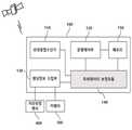
도 2는 본 발명의 일 실시예에 따른 무인비행체 수평위치 정확도 유지 장치의 구성을 나타낸 블록도이다.2 is a block diagram illustrating a configuration of an apparatus for maintaining horizontal position accuracy of an unmanned aerial vehicle according to an embodiment of the present invention.
도 2에 도시한 바와 같이, 상기 무인비행체 수평위치 정확도 유지 장치(100)는 복수의 GNSS위성으로부터 위성항법신호를 수신하는 위성항법수신기(110), 상기 무인비행체(200)의 운행을 제어하는 운행제어부(120), 카메라(300)와 거리측정센서(400)로부터 지상의 목표지점에 대한 영상정보와 상기 무인비행체(200)의 고도를 각각 수집하는 센싱정보 수집부(130), 상기 무인비행체(200)의 위치를 보정하는 위치정보 보정모듈(140) 및 메모리(150)를 포함하여 구성된다.2, the apparatus for maintaining horizontal positional accuracy of the unmanned aerial vehicle includes a
또한 상기 위성항법수신기(110)는 상기 수신한 위성항법신호를 활용하여 시간, 위치, 방위 또는 이들의 조합을 포함하는 측위데이터를 출력한다.The
또한 상기 운행제어부(120)는 상기 위성항법수신기(110)에서 출력한 측위데이터 기반으로 기 설정한 목표지점의 좌표로 이동할 수 있도록 상기 무인비행체(200)를 제어한다.Also, the
또한 상기 무인비행체(200)가 기 설정한 목표지점의 상공에 도착한 경우에는 상기 운행제어부(120)는 상기 무인비행체(200)를 제어하여 지상의 목표지점과의 수평정확도를 유지하고, 안전하게 수직 착륙할 수 있도록 제어한다.In addition, when the
또한 상기 무인비행체(200)가 상기 목표지점에 착륙하기 위해 수직으로 하강하는 경우, 상기 센싱정보 수집부(130)는 거리측정 센서(400)와 카메라(300)를 이용하여 상기 지상의 목표지점에 대한 고도별 영상을 수집한다.When the
상기 카메라(300)는 CMOS 카메라, CCD 카메라, 적외선 카메라, 뎁스 카메라 또는 이들의 조합을 포함하여 구성되어, 야간이나 낮에도 상기 영상을 수집할 수 있도록 한다.The
또한 상기 거리측정 센서(400)는 초음파센서 또는 레이저 센서와 같은 상기 무인비행체(200)와 지상까지의 수직거리에 대한 거리정보(즉, 무인비행체의 고도)를 획득하기 위한 적어도 하나 이상의 센서로 구성된다.Also, the
또한 상기 센싱정보 수집부(130)는 상기 뎁스 카메라를 이용하여 수직 거리를 획득하다가 상기 무인비행체(200)가 일정한 고도 이하로 내려가면 초음파 센서 또는 레이저 센서를 이용하여 더욱 정확하게 상기 거리정보를 획득할 수 있다.Also, the sensing
또한 상기 위치정보 보정모듈(140)은 상기 무인비행체(200)가 착륙하는 과정에 있어서, 정확하게 상기 무인비행체(200)의 수평정확도를 유지하기 위해 위성수신 시야각 확보 여부를 판단한다.In addition, the position
상기 판단은 상기 위성항법수신기(110)에서 출력되는 측위데이터 중 GGA의 PFI값이 4인 경우 상기 무인비행체(200)가 위성수신 시야각이 확보되는 구간에서 동작하고 있다고 판단한다. 또한 상기 PFI의 값이 4가 아닌 경우 위성수신 시야각이 확보되지 않는 구간에서 상기 무인비행체(200)가 동작하고 있다고 판단한다. 이 때 상기 위치정보 보정모듈(140)는 상기 PFI 값이 4인 구간에서 촬영한 영상정보 중 가장 최근의 고도별 영상을 기준 영상으로 설정하여, 이후에 촬영되는 고도별 영상정보와 상기 기준 영상정보간의 배율 차이와 픽셀 차이를 분석하여 보정된 측위데이터를 출력한다.If the PFI value of the GGA is 4 among the positioning data output from the
또한 상기 운행제어부(120)는 상기 위치정보 보정모듈(140)에서 출력한 보정된 측위데이터를 기반으로 상기 무인비행체(200)를 제어하여 상기 지상의 목표지점에 대한 수평정확도를 유지할 수 있도록 한다.Also, the
또한 상기 운행제어부(120)는 상기 무인비행체(200)와 지상의 목표지점간의 수직선상의 거리가 일정한 임계값 이하로 측정되면 상기 무인비행체(200)의 착륙속도를 감속하여 안전하게 착륙할 수 있도록 한다.When the distance on the vertical line between the
또한 상기 메모리(150)는 상기 무인비행체(200)의 목적지점에 대한 좌표, 특정고도에서 영상을 촬영할 때의 배율정보 및 상기 배율정보에 따른 픽셀간의 간격 등을 저장한다.In addition, the
도 3은 본 발명의 일 실시예에 따른 위치정보 보정모듈의 구성을 나타낸 블록도이다.3 is a block diagram illustrating a configuration of a position information correction module according to an embodiment of the present invention.
도 3에 도시한 바와 같이, 상기 위치정보 보정모듈(140)는 위성수신 시야각 확보 여부를 판단하는 위성수신시야각판단부(141), 상기 판단에 따라 고도별 영상을 분석하여 보정정보를 계산하는 보정정보 계산부(142), 상기 계산한 보정정보에 따라 측위데이터를 보정하는 측위데이터 보정부(143)를 포함하여 구성된다.As shown in FIG. 3, the position
또한 상기 위성수신시야각 판단부(141)는 상기 위성항법수신기(110)에서 출력되는 측위데이터 중에서 GGA의 PFI값을 이용하여 위성수신 시야각 확보여부를 판단하고, 이를 통해 복수의 GNSS위성으로부터 위성항법신호의 수신이 양호한지를 판단한다.The satellite reception viewing
한편 상기 PFI의 값이 특정값(여기서 특정값은 4를 의미함)을 나타내고 있지 않는 경우에는 위성항법신호의 수신이 불량하다고 간주한다. 이때 상기 위성항법수신기(110)로부터 입력되는 측위데이터는 상기 무인비행체(200)의 수평정확도를 유지하면서 착륙을 수행하기 위하여 상기 무인비행체(200)를 정밀하게 제어할 수 있는 데이터가 아닌 것으로 간주한다.On the other hand, when the value of the PFI does not indicate a specific value (the specific value is 4), it is considered that the reception of the satellite navigation signal is poor. At this time, the positioning data inputted from the
일반적으로 GNSS 활용분야에서는 PFI값은 자료처리에 사용된 보정정보의 종류를 구분하거나 자료처리에 사용된 방법을 구분하는 용도로 사용되며, GNSS 데이터를 활용하는 분야에 따라서 PFI값이 4가 아닌 경우(예를 들어, 2 또는 5인 경우)에도 의미 있는 데이터로 판단하고 사용된다.Generally, in the GNSS application field, the PFI value is used to classify the type of correction information used in data processing or to distinguish the method used for data processing. If the PFI value is not 4 according to the field using GNSS data (For example, 2 or 5), it is judged as meaningful data and used.
그러나 본 발명에서는 무인비행체의 수직 이착륙에 대한 정확도를 확보할 수 있는 정밀한 측위를 필요로 하기 때문에 상기 PFI 값이 4가 아닌 경우는 모두 위성수신시야각이 확보되지 않은 상태로 판단한다.However, since the present invention requires precise positioning to ensure the accuracy of the vertical take-off and landing of the unmanned aerial vehicle, it is determined that the satellite reception viewing angle is not secured when the PFI value is not 4.
또한 상기 보정정보 계산부(142)는 상기 판단결과 위성수신 시야각이 확보되지 않은 경우에는 상기 센싱정보 수집부(130)로부터 제공되는 고도별 영상을 분석하여, 상기 무인비행체(200)에 대한 측위데이터를 정확하게 보정할 수 있도록 한다.When the satellite reception viewing angle is not secured as a result of the determination, the correction
또한 상기 보정정보 계산부(142)는 상기 고도별 영상을 분석하기 위해 기준이 되는 영상을 설정하고, 상기 설정한 기준영상과 현재 고도에서 촬영한 현재영상을 비교하여 분석을 수행한다.In addition, the correction
상기 기준이 되는 영상은 위성항법신호의 수신이 양호한 구간에서 무인비행체(200)와 지상의 목표지점과의 수평정확도를 유지한 상태에서 상기 목표지점을 촬영한 영상 중에서 가장 최근의 영상을 의미한다.The reference image means the latest image of the image captured at the target point while maintaining the horizontal accuracy between the
또한 상기 보정정보 계산부(142)는 상기 설정한 기준영상과 상기 현재영상의 배율차이를 계산하여 상기 기준영상과 현재영상의 가로 및 세로에 대한 픽셀 차이를 계산하고, 상기 계산한 픽셀차이에 따른 실제거리를 계산한다. 즉, 상기 보정정보계산부(142)는 위성수신 시야각이 확보되지 않는 구간에서 촬영한 영상과 해당 영상이 촬영된 지점에서 지상과의 수직거리로부터 상기 무인비행체(200)가 목표지점에서 벗어난 거리를 나타내는 보정정보 계산한다.The correction
한편 상기 보정정보를 계산하는 것은 미리 설정하여 저장한 특정높이에서의 촬영배율, 상기 배율에 따른 픽셀간의 간격 및 상기 픽셀간의 간격에 대한 실제거리를 기반으로 수행됨은 상술한 바와 같다.On the other hand, the calculation of the correction information is performed based on the imaging magnification at a predetermined height stored in advance, the interval between pixels according to the magnification, and the actual distance between the pixels.
또한 상기 측위데이터 보정부(143)는 상기 계산한 보정정보를 상기 위성항법수신기(110)에서 출력한 측위데이터에 적용하여, 상기 측위데이터를 보정하고, 상기 운행제어부(120)로 제공한다.The positioning
한편 상기 측위데이터는 NMEA데이터로써, 상기 GGA에서 표시되는 고도는 특정 위경도 좌표에서 해수면 기준 고도와 표준타원체 기준높이(WGS84 기준 높이)를 각각 구분해서 표시되기 때문에 상기 거리측정센서(400)를 통해 측정한 높이(즉, 상기 현재영상을 촬영한 지점에서 지표면까지의 수직거리)를 상기 GGA의 고도로 사용할 수 없다.On the other hand, since the positioning data is NMEA data, the altitude displayed in the GGA is displayed separately from the sea level reference height and the standard ellipsoid reference height (WGS84 reference height) at a specific lumenal coordinate, The measured height (i.e., the vertical distance from the point at which the current image is photographed to the surface of the ground) can not be used as the altitude of the GGA.
따라서 상기 측위데이터 보정부(143)는 상기 위성항법수신기(110)에서 측정하여 출력한 가장 최근의 측위데이터(즉, 상기 기준영상을 촬영한 시점에서의 측위데이터를 말함)에서 GGA 중 WGS84 위도 및 경도 좌표값과 해수면 기준고도(MSL Altitude) 및 WGS84 기준높이(Geoid Separation)와 상기 기준영상을 촬영한 지점에서 거리측정센서(400)를 통해 측정한 수직거리인 기준높이를 메모리(150)에 저장한다.Therefore, the
이 때 상기 WGS84 기준높이는 위성수신시야각이 확보되지 않은 구간에서도 동일하다고 간주할 수 있다. 따라서 상기 보정된 측위데이터의 WGS84 기준높이는 메모리에 저장된 WGS84 기준높이로 할 수 있다.At this time, the WGS84 reference height can be regarded as the same in a section where the satellite reception viewing angle is not ensured. Therefore, the WGS84 reference height of the corrected positioning data may be the WGS84 reference height stored in the memory.
또한 현재영상이 촬영된 지점에서의 해수면 기준 고도는, [해수면 기준 고도 = 메모리(150)에 저장된 해수면 기준 고도 - (메모리(150)에 저장된 기준높이 - 현재높이)]에 따라 계산된다. 여기서 현재높이는 상기 현재영상이 촬영된 지점에서 무인비행체(200)와 지표면사이의 수직거리를 의미한다.In addition, the sea level reference altitude at the point where the current image is captured is calculated according to the sea level reference altitude (reference height stored in the memory 150 - current height stored in the memory 150). Here, the current height means a vertical distance between the
이에 따라 상기 측위데이터 보정부(143)는 현재영상이 촬영된 지점에서의 현재높이를 상기 해수면 기준고도로 계산하여 상기 측위데이터를 보정한다.Accordingly, the positioning
한편 상기 측위데이터 보정부(143)는 상기 위성수신시야각판단부(141)의 판단에 따라 위성수신시야각이 확보된 경우에는 상기 위성항법수신기(110)로부터 입력되는 측위데이터를 보정하지 않고, 상기 운행제어부(120)로 제공한다.On the other hand, when the satellite reception viewing angle is secured according to the determination of the satellite reception viewing
또한 상기 운행제어부(120)는 측위데이터 보정부(143)로부터 제공받은 측위데이터(여기서 상기 측위데이터는 보정되었거나 보정되지 않은 측위데이터임)를 기반으로 무인비행체(200)를 제어하여 상기 지상의 목표지점과의 수평정확도를 지속적으로 유지함과 동시에 상기 목표지점에 안전하게 착륙할 수 있도록 한다.Also, the
한편 도 3을 참조하여 상기 무인비행체(200)의 착륙에 대해서 상세히 설명하였으나 상기 무인비행체(200)의 이륙에 대해서도 동일한 방법으로 수행된다. 이때 상기 무인비행체(200)는 위성수신 시야각이 확보될 때 까지 고도별 영상정보를 분석하여 보정정보를 계산함으로써, 측위데이터를 보정한다. 또한 상기 분석 시 사용되는 기준영상은 이륙 즉시 촬영한 영상 또는 일정한 높이로 상승하였을 때 촬영된 영상으로 설정될 수 있다.Although the landing of the
도 4는 본 발명의 일 실시예에 따른 무인비행체의 수평위치 정확도를 유지하여, 목표지점에 안전하고 정확하게 착륙하기 위한 절차를 나타낸 흐름도이다.FIG. 4 is a flowchart illustrating a procedure for safely and accurately landing at a target point by maintaining horizontal positional accuracy of an unmanned aerial vehicle according to an embodiment of the present invention.
도 4에 도시한 바와 같이, 상기 무인비행체(200)의 수평위치 정확도를 유지하면서 지상의 목표지점에 착륙하기 위한 절차는 우선, 상기 측위데이터 보정모듈(140)은 위성항법수신기(110)으로부터 출력한 상기 무인비행체(200)에 대한 측위데이터를 입력받는다(S110).4, the procedure for landing at a target point on the ground while maintaining the horizontal positional accuracy of the
한편 상기 측위데이터는 상기 무인비행체(200)의 위치에 대한 정보를 포함하는 데이터이기 때문에 상기 특정시점에서 출력되는 것이 아니라 보다 정확한 착륙을 위해 실시간으로 출력되는 것이 바람직하며, 일정한 시간마다 출력될 수도 있다.Since the positioning data is data including information on the position of the unmanned
다음으로 센싱정보 수집부(130)를 통해 상기 무인비행체(200)가 하강하는 동안 지상의 목표지점에 대한 영상과 해당 영상이 촬영된 지점에서의 지면에 대한 수직거리를 수집한다(S120).Next, the sensing
한편 상기 영상은 하강에 따라 상기 지표면과 상기 무인비행체(200)간의 수직거리 별로 수집되며, 상기 영상과 상기 수직거리는 카메라(300)와 거리측정 센서(400)를 이용하여 각각 수집된다.Meanwhile, the image is collected according to the vertical distance between the ground surface and the
다음으로 위성수신시야각판단부(141)를 통해 GNSS위성으로부터 위성수신 시야각이 확보되었는지에 대한 여부를 판단한다(S130).Next, it is determined whether the satellite reception viewing angle is secured from the GNSS satellite through the satellite reception viewing angle determination unit 141 (S130).
상기 위성수신 시야각 확보 여부는 위성수신환경이 불량한지 양호한지에 대한 여부를 판단하는 것으로 상기 위성항법수신기(110)에서 출력되는 측위데이터에서 GGA의 PFI에 대한 값에 따라 판단된다.Whether or not the satellite reception viewing angle is secured is determined based on the value of the PGA of the GGA in the positioning data output from the
다음으로 상기 판단결과 위성항법신호의 수신이 불량한 경우(S140), 보정정보 계산부(142)를 통해 상기 위성항법신호의 수신이 불량한 지역에서 수신한 GNSS위성의 위성항법 신호에 대한 측위데이터를 보정하기 위한 보정정보를 계산한다(S150).If it is determined that the satellite navigation signal has not been successfully received (S140), the correction
상기 보정정보는 카메라(300)로 촬영한 현재영상과 해당 영상이 촬영된 지점에서의 지상과의 수직거리로부터 상기 무인비행체(200)가 목표지점에서 벗어난 거리를 의미하는 것으로, 상기 보정정보 계산부(142)에서 설정한 기준영상과 상기 현재영상의 픽셀차이를 분석하여, 상기 분석한 픽셀 차이값 실제거리로 계산한 수치이다.The correction information indicates a distance that the
다음으로 측위데이터 보정부(143)를 통해 상기 계산한 보정정보를 상기 위성항법수신기(110)에서 출력한 측위데이터에 적용하여, 상기 측위데이터를 보정한다(S160).Next, the calculated correction information is applied to the positioning data output from the
한편 상기 측위데이터의 보정은 위성수신 시야각이 확보되지 않은 지역에서 수신한 위성항법신호로부터 출력한 측위데이터는 실제로 상기 무인비행체(200)의 위치를 정확하게 보장하지 못하기 때문에 수행된다.On the other hand, the correction of the positioning data is performed because the positioning data output from the satellite navigation signal received in an area where the satellite reception viewing angle is not secured can not accurately guarantee the position of the
즉, 위성항법신호의 수신이 불량한 구역에서의 상기 측위데이터를 보정하여, 상기 보정된 측위데이터를 토대로 상기 무인비행체(200)를 제어함으로써, 지상의 목표지점간의 수평정확도를 지속적으로 유지할 수 있도록 한다.That is, the positioning data in the area where reception of the satellite navigation signal is poor is corrected, and the
다음으로 상기 측위데이터 보정부(143)를 통해 상기 위성항법수신기(110)로부터 입력받은 측위데이터를 상기 계산한 보정정보를 적용하여 보정된 측위데이터를 출력한다(S160).Next, the positioning data corrected by applying the calculated correction information to the positioning data received from the
이때 상기 운행제어부(120)는 상기 측위데이터 보정부(143)에서 출력한 보정된 측위데이터를 이용하여 상기 무인비행체(200)를 제어함으로써, 상기 지상의 목표지점과 수평정확도를 유지하면서 수직으로 상기 목표지점으로 착륙할 수 있도록 한다.At this time, the
또한 상기 운행제어부(120)는 상기 지상의 목표지점으로 근접하는 경우, 상기 무인비행체(200)의 하강속도를 제어하여 안전하게 착륙할 수 있도록 한다.In addition, when the
한편 위성수신시야각판단부(141)를 통해 판단한 결과, 위성수신 시야각이 확보되어 위성항법신호의 수신이 양호한 경우(S140)에는 상기 측위데이터 보정부(143)는 상기 위성항법수신기(110)로부터 입력받은 측위데이터를 보정하지 않고 출력한다(S141). 따라서 상기 운행제어부(120)는 상기 보정하지 않은 측위데이터를 이용하여 상기 무인비행체(200)를 제어하게 된다.If it is determined that the satellite reception viewing angle is secured and the reception of the satellite navigation signal is good at step S140, the positioning
이상에서 설명하였듯이, 본 발명인 무인비행체의 이착륙용 수평정확도 유지 방법 및 그 장치는, 상기 무인비행체의 이륙 또는 착륙을 수행할 때 고도별 영상정보를 이용하여 상기 무인비행체의 측위데이터를 보정할 수 있도록 함으로써, 위성항법신호의 수신환경이 불량한 지역에서도 안전하고 정확하게 상기 무인비행체의 수직 이착륙을 유도할 수 있도록 하는 효과가 있다.As described above, the present invention provides a horizontal accuracy maintaining method and apparatus for a takeoff and landing of an unmanned aerial vehicle, which is capable of correcting the positioning data of the unmanned aerial vehicle using the image information of the altitude when performing takeoff or landing of the unmanned aerial vehicle Thus, there is an effect that it is possible to safely and accurately induce vertical takeoff and landing of the unmanned aerial vehicle even in an area where reception environment of the satellite navigation signal is poor.
상기에서는 본 발명에 따른 바람직한 실시예를 위주로 상술하였으나, 본 발명의 기술적 사상은 이에 한정되는 것은 아니며 본 발명의 각 구성요소는 동일한 목적 및 효과의 달성을 위하여 본 발명의 기술적 범위 내에서 변경 또는 수정될 수 있을 것이다.While the present invention has been particularly shown and described with reference to exemplary embodiments thereof, it is to be understood that the invention is not limited to the disclosed exemplary embodiments. .
또한, 이상에서는 본 발명의 바람직한 실시 예에 대하여 도시하고 설명하였지만, 본 발명은 상술한 특정의 실시 예에 한정되지 아니하며, 청구범위에서 청구하는 본 발명의 요지를 벗어남이 없이 당해 발명이 속하는 기술분야에서 통상의 지식을 가진 자에 의해 다양한 변형 실시가 가능한 것은 물론이고, 이러한 변형 실시들은 본 발명의 기술적 사상이나 전망으로부터 개별적으로 이해되어서는 안 될 것이다.While the present invention has been particularly shown and described with reference to exemplary embodiments thereof, it is to be understood that the invention is not limited to the disclosed exemplary embodiments, but, on the contrary, It will be understood by those skilled in the art that various changes and modifications may be made without departing from the spirit and scope of the present invention.
100 : 수평위치 정확도 유지 장치 110 : 위성항법수신기
120 : 운행제어부 130 : 센싱정보 수집부
140 : 측위데이터 보정모듈 141 : 위성수신시야각판단부
142 : 보정정보 계산부 143 : 측위데이터 보정부
150 : 메모리 200 : 무인비행체
300 : 카메라 400 : 거리측정센서100: Horizontal position accuracy maintaining device 110: Satellite navigation receiver
120: Operation control unit 130: Sensing information collecting unit
140: positioning data correction module 141: satellite reception viewing angle determination unit
142: correction information calculation unit 143: positioning data correction unit
150: memory 200: unmanned aerial vehicle
300: camera 400: distance measuring sensor
Claims (10)
Translated fromKorean상기 위성항법수신기에서 생성한 측위데이터를 보정하여 보정된 측위데이터를 생성하여 출력하는 측위데이터 보정모듈;를 포함하며,
상기 보정된 측위데이터는 고도별 영상을 분석하여 상기 측위데이터를 보정하여 생성되는 것을 특징으로 하는 무인비행체의 이착륙용 수평정확도 유지 장치.A satellite navigation receiver that receives the satellite navigation signal from the GNSS satellite and generates positioning data; And
And a positioning data correction module for correcting the positioning data generated by the satellite navigation receiver to generate and output the corrected positioning data,
Wherein the corrected positioning data is generated by analyzing an altitude-specific image and correcting the positioning data.
상기 측위데이터 보정모듈은,
상기 측위데이터로부터 상기 GNSS 위성으로부터 위성수신 시야각이 확보되었는지 여부를 판단하는 위성수신시야각판단부;를 포함하며,
상기 판단은 측위데이터 중 GGA의 position fix indicator의 값을 이용하여 상기 시야각의 확보여부를 판단하는 것을 특징으로 하는 무인비행체의 이착륙용 수평정확도 유지 장치.The method according to claim 1,
Wherein the positioning data correction module comprises:
And a satellite reception viewing angle determiner for determining, from the positioning data, whether a satellite reception viewing angle is secured from the GNSS satellite,
Wherein the determination of whether or not the viewing angle is secured is made using the value of the position fix indicator of the GGA in the positioning data.
상기 측위데이터 보정모듈은,
카메라로 촬영한 영상과 해당 영상이 촬영된 지점에서의 지상과의 수직거리로부터 무인비행체가 목표지점에서 벗어난 거리를 계산하는 보정정보 계산부;를 더 포함하는 것을 특징으로 하는 무인비행체의 이착륙용 수평정확도 유지 장치.The method of claim 2,
Wherein the positioning data correction module comprises:
And a correction information calculation unit for calculating a distance that the unmanned aerial vehicle deviates from the target point based on the vertical distance between the image photographed by the camera and the ground at the point where the corresponding image is photographed. Accuracy maintaining device.
상기 측위데이터 보정모듈은,
상기 목표지점에서 벗어난 거리만큼 상기 측위데이터를 보정하여 출력하는 측위데이터 보정부;를 더 포함하는 것을 특징으로 하는 무인비행체의 이착륙용 수평정확도 유지 장치.The method of claim 3,
Wherein the positioning data correction module comprises:
And a positioning data correcting unit for correcting and outputting the positioning data by a distance deviated from the target point.
상기 보정된 측위데이터에 따라 상기 무인비행체의 위치를 제어하는 운행제어부;를 더 포함하는 것을 특징으로 하는 무인비행체의 이착륙용 수평정확도 유지 장치.The method according to claim 1,
And a travel controller for controlling the position of the unmanned air vehicle according to the corrected positioning data.
상기 위성항법수신기에서 생성한 측위데이터를 보정하여 보정된 측위데이터를 생성하여 출력하는 측위데이터 보정 단계;를 포함하며,
상기 보정된 측위데이터는 고도별 영상을 분석하여 상기 측위데이터를 보정하여 생성되는 것을 특징으로 하는 무인비행체의 이착륙용 수평정확도 유지 방법.Receiving satellite navigation signals from a GNSS satellite using a satellite navigation receiver to generate positioning data; And
And a positioning data correction step of correcting the positioning data generated by the satellite navigation receiver to generate and output the corrected positioning data,
Wherein the corrected positioning data is generated by analyzing an altitude-specific image and correcting the positioning data.
상기 측위데이터 보정 단계는,
상기 측위데이터로부터 상기 GNSS 위성으로부터 위성수신 시야각이 확보되었는지 여부를 판단하는 위성수신시야각판단 단계;를 포함하며,
상기 판단은 측위데이터 중 GGA의 position fix indicator의 값을 이용하여 상기 시야각의 확보여부를 판단하는 것을 특징으로 하는 무인비행체의 이착륙용 수평정확도 유지 방법.The method of claim 6,
The positioning data correction step includes:
And a satellite reception viewing angle determining step of determining, from the positioning data, whether a satellite reception viewing angle is secured from the GNSS satellite,
Wherein the determination of whether or not to obtain the viewing angle is made using the value of the position fix indicator of the GGA in the positioning data.
상기 측위데이터 보정 단계는,
카메라로 촬영한 영상과 해당 영상이 촬영된 지점에서의 지상과의 수직거리로부터 무인비행체가 목표지점에서 벗어난 거리를 계산하는 보정정보 계산 단계;를 더 포함하는 것을 특징으로 하는 무인비행체의 이착륙용 수평정확도 유지 방법.The method of claim 7,
The positioning data correction step includes:
And calculating a distance of the unmanned aerial vehicle from the target point based on the vertical distance between the image photographed by the camera and the ground at the point where the corresponding image is photographed. How to maintain accuracy.
상기 측위데이터 보정 단계는,
상기 목표지점에서 벗어난 거리만큼 상기 측위데이터를 보정하여 출력하는 측위데이터 보정 단계;를 더 포함하는 것을 특징으로 하는 무인비행체의 이착륙용 수평정확도 유지 방법.The method of claim 8,
The positioning data correction step includes:
And a positioning data correction step of correcting and outputting the positioning data by a distance deviated from the target point.
상기 보정된 측위데이터에 따라 상기 무인비행체의 위치를 제어하는 운행제어 단계;를 더 포함하는 것을 특징으로 하는 무인비행체의 이착륙용 수평정확도 유지 방법.The method of claim 6,
And controlling the position of the unmanned air vehicle according to the corrected positioning data.
Priority Applications (1)
| Application Number | Priority Date | Filing Date | Title |
|---|---|---|---|
| KR1020160052812AKR20170123801A (en) | 2016-04-29 | 2016-04-29 | Method and apparatus for keeping horizontal position accuracy for taking off and landing of unmanned air vehicle |
Applications Claiming Priority (1)
| Application Number | Priority Date | Filing Date | Title |
|---|---|---|---|
| KR1020160052812AKR20170123801A (en) | 2016-04-29 | 2016-04-29 | Method and apparatus for keeping horizontal position accuracy for taking off and landing of unmanned air vehicle |
Publications (1)
| Publication Number | Publication Date |
|---|---|
| KR20170123801Atrue KR20170123801A (en) | 2017-11-09 |
Family
ID=60385801
Family Applications (1)
| Application Number | Title | Priority Date | Filing Date |
|---|---|---|---|
| KR1020160052812ACeasedKR20170123801A (en) | 2016-04-29 | 2016-04-29 | Method and apparatus for keeping horizontal position accuracy for taking off and landing of unmanned air vehicle |
Country Status (1)
| Country | Link |
|---|---|
| KR (1) | KR20170123801A (en) |
Cited By (3)
| Publication number | Priority date | Publication date | Assignee | Title |
|---|---|---|---|---|
| CN110413004A (en)* | 2019-08-23 | 2019-11-05 | 酷黑科技(北京)有限公司 | A method and system for precise take-off and landing control of unmanned aerial vehicles |
| KR20210088142A (en)* | 2020-01-06 | 2021-07-14 | 세종대학교산학협력단 | System for detecting and tracking target of unmanned aerial vehicle |
| KR20210088145A (en)* | 2020-01-06 | 2021-07-14 | 세종대학교산학협력단 | System and method for automatic precision landing of unmmaned aerial vehicle |
- 2016
- 2016-04-29KRKR1020160052812Apatent/KR20170123801A/ennot_activeCeased
Cited By (3)
| Publication number | Priority date | Publication date | Assignee | Title |
|---|---|---|---|---|
| CN110413004A (en)* | 2019-08-23 | 2019-11-05 | 酷黑科技(北京)有限公司 | A method and system for precise take-off and landing control of unmanned aerial vehicles |
| KR20210088142A (en)* | 2020-01-06 | 2021-07-14 | 세종대학교산학협력단 | System for detecting and tracking target of unmanned aerial vehicle |
| KR20210088145A (en)* | 2020-01-06 | 2021-07-14 | 세종대학교산학협력단 | System and method for automatic precision landing of unmmaned aerial vehicle |
Similar Documents
| Publication | Publication Date | Title |
|---|---|---|
| EP2877904B1 (en) | Method for the acquisition and processing of geographical information of a path | |
| AU2018388887B2 (en) | Image based localization for unmanned aerial vehicles, and associated systems and methods | |
| JP5767731B1 (en) | Aerial video distribution system and aerial video distribution method | |
| US20190273909A1 (en) | Methods and systems for selective sensor fusion | |
| TW518422B (en) | Positioning and proximity warning method and system thereof for vehicle | |
| CN112335190B (en) | Radio link coverage map and impairment system and method | |
| US20200372814A1 (en) | On-board command unit for a drone system, drone and drone system including the on-board command unit | |
| KR20170111921A (en) | Method and system for controlling unmanned air vehicle | |
| KR101160454B1 (en) | Construction method of 3D Spatial Information using position controlling of UAV | |
| KR20150000053A (en) | Method and Apparatus for Guiding Unmanned Aerial Vehicle and Method and Apparatus for Controlling Unmanned Aerial Vehicle | |
| KR20190000439A (en) | Unmanned air vehicle for birds control and operating method by using the same | |
| KR20140123835A (en) | Apparatus for controlling unmanned aerial vehicle and method thereof | |
| KR20170101776A (en) | Method and system for providing route of unmanned air vehicle | |
| KR20170126637A (en) | Method and system for providing route of unmanned air vehicle | |
| CN111819610A (en) | Air situational information and traffic management systems for unmanned and manned aerial vehicles | |
| US20120158237A1 (en) | Unmanned apparatus and method of driving the same | |
| RU2584368C1 (en) | Method of determining control values of parameters of spatial-angular orientation of aircraft on routes and pre-aerodrome zones in flight tests of pilot-navigation equipment and system therefor | |
| JP2020149640A (en) | Flight system and landing control method | |
| Martínez-de Dios et al. | Experimental results of automatic fire detection and monitoring with UAVs | |
| JP2020135327A (en) | Flight body system, flight body, position measuring method and program | |
| KR20170123801A (en) | Method and apparatus for keeping horizontal position accuracy for taking off and landing of unmanned air vehicle | |
| Burdziakowski et al. | Accuracy of a low-cost autonomous hexacopter platforms navigation module for a photogrammetric and environmental measurements | |
| Hosseinpoor et al. | Pricise target geolocation based on integeration of thermal video imagery and rtk GPS in UAVS | |
| US12406586B2 (en) | 3D localization and mapping systems and methods | |
| EP3331758B1 (en) | An autonomous vehicle control system |
Legal Events
| Date | Code | Title | Description |
|---|---|---|---|
| PA0109 | Patent application | Patent event code:PA01091R01D Comment text:Patent Application Patent event date:20160429 | |
| PG1501 | Laying open of application | ||
| A201 | Request for examination | ||
| PA0201 | Request for examination | Patent event code:PA02012R01D Patent event date:20180111 Comment text:Request for Examination of Application Patent event code:PA02011R01I Patent event date:20160429 Comment text:Patent Application | |
| E902 | Notification of reason for refusal | ||
| PE0902 | Notice of grounds for rejection | Comment text:Notification of reason for refusal Patent event date:20190327 Patent event code:PE09021S01D | |
| E601 | Decision to refuse application | ||
| PE0601 | Decision on rejection of patent | Patent event date:20190730 Comment text:Decision to Refuse Application Patent event code:PE06012S01D Patent event date:20190327 Comment text:Notification of reason for refusal Patent event code:PE06011S01I |