KR20170118069A - Fluid displacement and pressure device, and assembly thereof - Google Patents
Fluid displacement and pressure device, and assembly thereofDownload PDFInfo
- Publication number
- KR20170118069A KR20170118069AKR1020177022397AKR20177022397AKR20170118069AKR 20170118069 AKR20170118069 AKR 20170118069AKR 1020177022397 AKR1020177022397 AKR 1020177022397AKR 20177022397 AKR20177022397 AKR 20177022397AKR 20170118069 AKR20170118069 AKR 20170118069A
- Authority
- KR
- South Korea
- Prior art keywords
- housing
- carrier
- plunger
- carrier member
- receptacle
- Prior art date
- Legal status (The legal status is an assumption and is not a legal conclusion. Google has not performed a legal analysis and makes no representation as to the accuracy of the status listed.)
- Granted
Links
- 239000012530fluidSubstances0.000titleclaimsabstractdescription40
- 238000006073displacement reactionMethods0.000titleclaimsabstractdescription31
- 238000000034methodMethods0.000claimsabstractdescription11
- 230000000717retained effectEffects0.000claimsabstractdescription4
- 238000007789sealingMethods0.000claimsdescription9
- 230000006835compressionEffects0.000claims5
- 238000007906compressionMethods0.000claims5
- 230000008569processEffects0.000abstractdescription6
- 230000000399orthopedic effectEffects0.000description6
- 229920000642polymerPolymers0.000description5
- 239000004568cementSubstances0.000description4
- 238000010276constructionMethods0.000description4
- 238000009434installationMethods0.000description4
- 230000007246mechanismEffects0.000description4
- 239000007787solidSubstances0.000description4
- 230000003993interactionEffects0.000description3
- 230000014759maintenance of locationEffects0.000description3
- 239000004033plasticSubstances0.000description3
- 238000006243chemical reactionMethods0.000description2
- 239000002184metalSubstances0.000description2
- 238000003825pressingMethods0.000description2
- 241001631457CannulaSpecies0.000description1
- 230000009471actionEffects0.000description1
- 230000006978adaptationEffects0.000description1
- 239000002639bone cementSubstances0.000description1
- 230000008878couplingEffects0.000description1
- 238000010168coupling processMethods0.000description1
- 238000005859coupling reactionMethods0.000description1
- 238000011900installation processMethods0.000description1
- 239000000314lubricantSubstances0.000description1
- 238000004519manufacturing processMethods0.000description1
- 239000003550markerSubstances0.000description1
- 230000013011matingEffects0.000description1
- 230000004048modificationEffects0.000description1
- 238000012986modificationMethods0.000description1
- 230000008520organizationEffects0.000description1
- 239000000088plastic resinSubstances0.000description1
- 239000004417polycarbonateSubstances0.000description1
- 229920000515polycarbonatePolymers0.000description1
- 239000002861polymer materialSubstances0.000description1
- 239000011347resinSubstances0.000description1
- 229920005989resinPolymers0.000description1
- 230000004044responseEffects0.000description1
- 230000008961swellingEffects0.000description1
Images


Classifications
- A—HUMAN NECESSITIES
- A61—MEDICAL OR VETERINARY SCIENCE; HYGIENE
- A61B—DIAGNOSIS; SURGERY; IDENTIFICATION
- A61B17/00—Surgical instruments, devices or methods
- A61B17/56—Surgical instruments or methods for treatment of bones or joints; Devices specially adapted therefor
- A61B17/58—Surgical instruments or methods for treatment of bones or joints; Devices specially adapted therefor for osteosynthesis, e.g. bone plates, screws or setting implements
- A61B17/88—Osteosynthesis instruments; Methods or means for implanting or extracting internal or external fixation devices
- A61B17/8802—Equipment for handling bone cement or other fluid fillers
- A61B17/8805—Equipment for handling bone cement or other fluid fillers for introducing fluid filler into bone or extracting it
- A61B17/8825—Equipment for handling bone cement or other fluid fillers for introducing fluid filler into bone or extracting it characterised by syringe details
- A—HUMAN NECESSITIES
- A61—MEDICAL OR VETERINARY SCIENCE; HYGIENE
- A61B—DIAGNOSIS; SURGERY; IDENTIFICATION
- A61B17/00—Surgical instruments, devices or methods
- A61B17/56—Surgical instruments or methods for treatment of bones or joints; Devices specially adapted therefor
- A61B17/58—Surgical instruments or methods for treatment of bones or joints; Devices specially adapted therefor for osteosynthesis, e.g. bone plates, screws or setting implements
- A61B17/88—Osteosynthesis instruments; Methods or means for implanting or extracting internal or external fixation devices
- A61B17/8802—Equipment for handling bone cement or other fluid fillers
- A61B17/8805—Equipment for handling bone cement or other fluid fillers for introducing fluid filler into bone or extracting it
- A61B17/8816—Equipment for handling bone cement or other fluid fillers for introducing fluid filler into bone or extracting it characterised by the conduit, e.g. tube, along which fluid flows into the body or by conduit connections
- A—HUMAN NECESSITIES
- A61—MEDICAL OR VETERINARY SCIENCE; HYGIENE
- A61B—DIAGNOSIS; SURGERY; IDENTIFICATION
- A61B17/00—Surgical instruments, devices or methods
- A61B17/56—Surgical instruments or methods for treatment of bones or joints; Devices specially adapted therefor
- A61B17/58—Surgical instruments or methods for treatment of bones or joints; Devices specially adapted therefor for osteosynthesis, e.g. bone plates, screws or setting implements
- A61B17/88—Osteosynthesis instruments; Methods or means for implanting or extracting internal or external fixation devices
- A61B17/8802—Equipment for handling bone cement or other fluid fillers
- A61B17/8805—Equipment for handling bone cement or other fluid fillers for introducing fluid filler into bone or extracting it
- A61B17/8822—Equipment for handling bone cement or other fluid fillers for introducing fluid filler into bone or extracting it characterised by means facilitating expulsion of fluid from the introducer, e.g. a screw pump plunger, hydraulic force transmissions, application of vibrations or a vacuum
- A—HUMAN NECESSITIES
- A61—MEDICAL OR VETERINARY SCIENCE; HYGIENE
- A61M—DEVICES FOR INTRODUCING MEDIA INTO, OR ONTO, THE BODY; DEVICES FOR TRANSDUCING BODY MEDIA OR FOR TAKING MEDIA FROM THE BODY; DEVICES FOR PRODUCING OR ENDING SLEEP OR STUPOR
- A61M25/00—Catheters; Hollow probes
- A61M25/10—Balloon catheters
- A61M25/1018—Balloon inflating or inflation-control devices
- A61M25/10181—Means for forcing inflation fluid into the balloon
- A61M25/10182—Injector syringes
- A—HUMAN NECESSITIES
- A61—MEDICAL OR VETERINARY SCIENCE; HYGIENE
- A61M—DEVICES FOR INTRODUCING MEDIA INTO, OR ONTO, THE BODY; DEVICES FOR TRANSDUCING BODY MEDIA OR FOR TAKING MEDIA FROM THE BODY; DEVICES FOR PRODUCING OR ENDING SLEEP OR STUPOR
- A61M25/00—Catheters; Hollow probes
- A61M25/10—Balloon catheters
- A61M25/1018—Balloon inflating or inflation-control devices
- A61M25/10184—Means for controlling or monitoring inflation or deflation
- A61M25/10187—Indicators for the level of inflation or deflation
- A—HUMAN NECESSITIES
- A61—MEDICAL OR VETERINARY SCIENCE; HYGIENE
- A61B—DIAGNOSIS; SURGERY; IDENTIFICATION
- A61B17/00—Surgical instruments, devices or methods
- A61B2017/00535—Surgical instruments, devices or methods pneumatically or hydraulically operated
- A—HUMAN NECESSITIES
- A61—MEDICAL OR VETERINARY SCIENCE; HYGIENE
- A61B—DIAGNOSIS; SURGERY; IDENTIFICATION
- A61B90/00—Instruments, implements or accessories specially adapted for surgery or diagnosis and not covered by any of the groups A61B1/00 - A61B50/00, e.g. for luxation treatment or for protecting wound edges
- A61B90/06—Measuring instruments not otherwise provided for
- A61B2090/063—Measuring instruments not otherwise provided for for measuring volume
- A—HUMAN NECESSITIES
- A61—MEDICAL OR VETERINARY SCIENCE; HYGIENE
- A61B—DIAGNOSIS; SURGERY; IDENTIFICATION
- A61B90/00—Instruments, implements or accessories specially adapted for surgery or diagnosis and not covered by any of the groups A61B1/00 - A61B50/00, e.g. for luxation treatment or for protecting wound edges
- A61B90/08—Accessories or related features not otherwise provided for
- A61B2090/0807—Indication means
- A—HUMAN NECESSITIES
- A61—MEDICAL OR VETERINARY SCIENCE; HYGIENE
- A61M—DEVICES FOR INTRODUCING MEDIA INTO, OR ONTO, THE BODY; DEVICES FOR TRANSDUCING BODY MEDIA OR FOR TAKING MEDIA FROM THE BODY; DEVICES FOR PRODUCING OR ENDING SLEEP OR STUPOR
- A61M2205/00—General characteristics of the apparatus
- A61M2205/33—Controlling, regulating or measuring
- A61M2205/3379—Masses, volumes, levels of fluids in reservoirs, flow rates
Landscapes
- Health & Medical Sciences (AREA)
- Life Sciences & Earth Sciences (AREA)
- Surgery (AREA)
- Orthopedic Medicine & Surgery (AREA)
- Heart & Thoracic Surgery (AREA)
- Public Health (AREA)
- General Health & Medical Sciences (AREA)
- Engineering & Computer Science (AREA)
- Biomedical Technology (AREA)
- Veterinary Medicine (AREA)
- Animal Behavior & Ethology (AREA)
- Molecular Biology (AREA)
- Nuclear Medicine, Radiotherapy & Molecular Imaging (AREA)
- Medical Informatics (AREA)
- Pulmonology (AREA)
- Hematology (AREA)
- Biophysics (AREA)
- Child & Adolescent Psychology (AREA)
- Anesthesiology (AREA)
- Physics & Mathematics (AREA)
- Fluid Mechanics (AREA)
- Infusion, Injection, And Reservoir Apparatuses (AREA)
- Surgical Instruments (AREA)
- Reciprocating Pumps (AREA)
Abstract
Translated fromKoreanDescription
Translated fromKorean관련 출원(우선권 주장)Related application (priority claim)
본 출원은 2015년 2월 16일자로 출원된 미국 가특허 출원 제62/116,803호에 기초하여 우선권을 주장하고, 이는 본원에서 전체적으로 참조로 통합되었다.This application claims priority based on US patent application Ser. No. 62 / 116,803, filed Feb. 16, 2015, which is hereby incorporated by reference in its entirety.
본 발명은 대체로 유체 변위 및 가압 장치, 및 그러한 장치를 조립하는 방법에 관한 것이다.The present invention generally relates to fluid displacement and pressurization devices, and methods of assembling such devices.
더 구체적으로, 본 발명은 실질적으로 미국 특허 제6,796,959호; 제6,938,319호; 제8,191,457호; 및 제8,499,681호에 개시되어 있는 장치 및 조립 방법에 대한 개선에 관한 것이고, 이들 모두는 본원에서 전체적으로 참조로 통합되었다.More specifically, the present invention is substantially directed to U.S. Patent Nos. 6,796,959; 6,938, 319; 8,191,457; And 8,499,681, all of which are incorporated herein by reference in their entirety.
그러한 특허에 개시되어 있는 장치들은 시린지 하우징의 보어의 종축을 따라 종방향으로 삽입되고, 그 다음 시린지 하우징 내에 맞물려서 추가의 이동에 대해 로킹되도록 회전되는 캐리어 부재(예를 들어, '959 및 '319 특허의 부품 번호 110 참조)를 이용한다. 그러한 특허에 개시되어 있는 장치들이 그들의 의도된 목적에 대해 신뢰할 수 있지만, 플런저 나사산 맞물림 및 해제 메커니즘(즉, '959 및 '319 특허의 너트 부재(80) 및 링크 부재(102, 104))이 설치될 수 있기 전에, 장치들이 캐리어 부재가 종방향으로 설치되고, 그 다음 시린지 하우징에 대해 제 위치에 캐리어 부재를 로킹시키도록 회전되어야 하도록 구성되기 때문에 (예를 들어, '959 및 '319 특허의 부품 번호 42 참조), 장치는 자동화된 조립 방법에 적합하지 않다. 캐리어 부재를 설치하기 위한 조립 단계들은 시린지 하우징의 종축을 따른 캐리어 부재의 종방향 도입, 및 이어서 캐리어 부재를 제 위치에 안착시키고 로킹시키기 위해 대략 90° 또는 ¼ 선회 회전을 요구한다. 이러한 설치 과정은, 예를 들어, '959 특허의 10칼럼, 3 - 9행에 설명되어 있다. 캐리어 부재가 시린지 하우징 내에 안착되어 로킹된 이후까지 캐리어 부재 내로의 플런저 나사산 맞물림 및 해제 메커니즘(즉, '959 및 '319 특허의 너트 부재(80) 및 링크 부재(102, 104))의 설치를 방지하는 이러한 조립 방법은 장치 조립 과정을 느리게 한다.The devices disclosed in such patents are inserted into the syringe housing longitudinally along the longitudinal axis of the bore of the syringe housing and then pushed into a carrier member (e.g., the '959 and' 319 patents 110 "). Although the devices disclosed in such patents may be relied upon for their intended purpose, the plunger thread engagement and disengagement mechanism (i.e., the
초고압에서 큰 체적의 유체를 전달하기 위한 플라스틱 수지 중합체로 만들어진 1회용 시린지에 대한 소정의 의료 분야에서의 증가하는 요구가 있다. 작은 캐뉼라를 통한 확장식 팽창 가능한 정형외과용 못 및 뼈 시멘트 전달과 같은 몇몇 새로운 정형외과 용도는 2,700 p.s.i까지의 압력을 요구할 수 있다. 이러한 극한 압력은 사용자가 대량의 플런저 입력 토크를 공급할 것을 요구한다. 몇몇 경우에, 요구되는 입력 토크는 이전의 더 낮은 압력 용도에서 경험했던 힘의 2배일 수 있고, 이는 그러므로 사용되는 장치가 사용자가 가압 중에 장치를 편안하게 유지하고 제어하도록 허용하기에 적절한 손잡이를 포함하는 것을 필요로 한다.There is an increasing need in the medical field for disposable syringes made of plastic resin polymers to deliver large volumes of fluid at ultra high pressure. Some new orthopedic applications, such as expandable inflatable orthopedic nails via small cannulas and bone cement delivery, may require pressures up to 2,700 p.s.i. This extreme pressure requires the user to supply a large amount of plunger input torque. In some cases, the required input torque may be twice the force experienced in previous lower pressure applications, and this therefore includes a handle suitable for allowing the device used to allow the user to comfortably maintain and control the device during pressure application .
저압 용도에 비교하여, 초고압 용도는 이전에 식별된 특허에 개시되어 있는 것과 같은 설계에 관한 한 추가의 난점을 제시한다. 예를 들어, 해제 시의 너트 부재의 회전 운동과 조합된 캐리어 부재(즉, '959 및 '319 특허의 부품 번호 110)에 대한 중하중 너트 부재(예를 들어, '959 및 '319 특허의 부품 번호 80 참조)의 극도로 높은 마찰 맞물림은 (즉, 시린지 하우징(즉, '959 및 '319 특허의 부품 번호 42)에 대해) 캐리어 부재를 안착시키고 로킹시키기 위해 사용되는 ¼ 선회 회전을 반전시킬 가능성을 갖는다. 이러한 풀림력은 캐리어의 보유 메커니즘(즉, '959 및 '319 특허의 부품 번호 172)을 통해 하우징 내로 직접 전달되고, 이에 의해 하우징이 뒤틀리게 한다. 풀림 중에 마찰 유도 회전에 의해 극복되는 것을 방지하기 위해, 이러한 보유 메커니즘은 또한 훨씬 더 크고 더 강성으로 만들어져야 한다. 이전에 식별된 특허에 개시되어 있는 것과 같은 종래 기술의 장치를 사용하여 초고압을 얻기 위해 요구되는 사용자 입력 토크는 또한 장치 하우징 구조물이 가압 중에 인가되는 비틀림 부하에 응답하여 뒤틀리게 할 수 있다. 그러므로, 이러한 종래 기술의 장치는 그의 압력 용량과 관련된 매우 높은 종방향 플런저 부하를 견디기 위한 추가의 구조물을 가져야 할 뿐만 아니라, 회전 플런저 전진 및 너트 부재의 해제로부터의 비틀림 반작용에 저항하기 위한 추가의 구조물을 또한 가져야 한다. 추가로, 너트 부재로부터 캐리어 부재로 직접 전달되는 이러한 높은 종방향 부하는, 본질적으로 (즉, 구성으로 인해) 각각 캐리어 부재의 외경의 ¼ 초과만큼 하우징과 맞물리도록 만들어질 수 없는 베요닛형 이어(bayonet style ear)(즉, '959 및 '319 특허의 부품 번호 172)의 대칭 쌍에 의해 캐리어 부재로부터 시린지 하우징으로 분배된다. 그러므로, 이러한 이어에 대한 맞물림 표면 영역은 제한되고, 극한 압력 부하 하에서의 작동은 하우징 및 캐리어 부재가 형성되는 중합체의 압축 강도를 초과하는 것으로 입증되었다.Compared to low pressure applications, ultra high pressure applications present additional difficulties with respect to designs such as those disclosed in previously identified patents. (E. G., Parts of the '959 and' 319 patent) for a carrier member in combination with rotational movement of the nut member upon release (I. E., For
본 발명의 실시예의 목적은 조립하기 쉬운 유체 변위 및 가압 장치를 제공하는 것이다.It is an object of embodiments of the present invention to provide a fluid displacement and pressurizing device that is easy to assemble.
본 발명의 실시예의 다른 목적은 자동화된 공정으로 조립되기에 적합한 구성을 갖는 유체 변위 및 가압 장치를 제공하는 것이다.Another object of an embodiment of the present invention is to provide a fluid displacement and pressurizing device having a configuration suitable for being assembled in an automated process.
본 발명의 실시예의 또 다른 목적은 적당하게 콤팩트한 구조 내에서의 상대적으로 저렴한 고부하, 초고압 장치의 구성을 허용하는 유체 변위 및 가압 장치를 제공하는 것이다.It is a further object of embodiments of the present invention to provide a fluid displacement and pressurizing device that allows the construction of a relatively inexpensive high load, ultra high pressure device within a reasonably compact structure.
간략하게, 본 발명의 일 실시예는 하우징, 및 하우징 내에 전체적으로 배치되며 그로부터 제거 가능한 캐리어 부재를 포함하는 유체 변위 및 가압 장치를 제공한다. 플런저가 캐리어 부재를 통해 연장하고, 플런저 맞물림 구조물이 캐리어 부재에 의해 보유된다. 플런저 맞물림 구조물은 플런저와 선택적으로 맞물리고 그로부터 분리될 수 있다. 하우징 및 캐리어 부재는 캐리어 부재가 하우징의 종축을 따라 설치 가능하기보다는, 하우징 내에 횡방향으로 설치 가능하도록 구성된다. 바람직하게는, 캐리어 부재 및 플런저 맞물림 구조물은 하위 조립체를 형성하고, 하위 조립체는 조립된 후에 하우징 내에 횡방향으로 설치 가능하다. 캐리어 부재가 플런저 맞물림 구조물을 포함하는 하위 조립체로서 횡방향으로 설치 가능함을 제공함으로써, 장치는 조립하기가 쉽고, 장치는 자동화된 조립 과정에 적합하다.Briefly, an embodiment of the present invention provides a fluid displacement and pressurizing device including a housing and a carrier member disposed entirely within and removable from the housing. The plunger extends through the carrier member and the plunger engagement structure is retained by the carrier member. The plunger engagement structure can selectively engage and separate from the plunger. The housing and the carrier member are configured such that the carrier member is laterally installable within the housing, rather than being installable along the longitudinal axis of the housing. Preferably, the carrier member and the plunger engagement structure form a subassembly and the subassembly is laterally mountable within the housing after being assembled. By providing that the carrier member is laterally mountable as a subassembly comprising a plunger engagement structure, the device is easy to assemble and the device is suitable for automated assembly processes.
본 발명의 구조 및 작동의 조직화 및 방식은, 본 발명의 추가의 목적 및 장점과 함께, 유사한 도면 부호가 유사한 요소를 식별하는 첨부된 도면과 관련하여 취해지는 다음의 설명을 참조하면 가장 잘 이해될 수 있다.The organization and manner of construction and operation of the present invention, together with further objects and advantages thereof, may best be understood by reference to the following description taken in conjunction with the accompanying drawings, in which like reference numerals identify like elements .
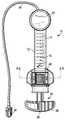
도 1은 본 발명의 제1 실시예에 따른, 유체 변위 및 가압 장치, 구체적으로 고체적, 초고압 팽창 장치의 평면도이다.
도 2는 도 1에 도시된 유체 변위 및 가압 장치의 분해 사시도이다.
도 3은 도 1 및 도 2에 도시된 유체 변위 및 가압 장치의 캐리어 하위 조립체의 분해 사시도이다.
도 4 및 도 5는 2개의 상이한 상태에서 장치를 도시하는, 도 1의 선 A-A를 따라 취한, 도 1 - 도 2에 도시된 유체 변위 및 가압 장치의 단면도이다.
도 5는 풀림 위치에서 장치를 도시하는, 도 4와 매우 유사한 도면이다.
도 6은 본 발명의 제2 실시예에 따른, 유체 변위 및 가압 장치, 구체적으로 초고압 정형외과용 시멘트 전달 장치의 일 부분의 측면도이다.
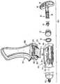
도 7은 도 6에 도시된 것의 분해 사시도이다.
도 8은 도 6 및 도 7에 도시된 유체 변위 및 가압 장치의 캐리어 하위 조립체의 분해 사시도이다.
도 9 및 도 10은 2개의 상이한 상태에서 장치를 도시하는, 도 6의 선 B-B를 따라 취한, 도 6 - 도 7에 도시된 유체 변위 및 가압 장치의 단면도이다.1 is a plan view of a fluid displacement and pressurization device, specifically a solid, ultra-high pressure expansion device, according to a first embodiment of the present invention.
2 is an exploded perspective view of the fluid displacement and pressure device shown in FIG.
3 is an exploded perspective view of the carrier subassembly of the fluid displacement and pressure device shown in Figs. 1 and 2. Fig.
Figs. 4 and 5 are cross-sectional views of the fluid displacement and pressurizing device shown in Figs. 1-2, taken along line AA of Fig. 1, showing the device in two different states.
Figure 5 is a view very similar to Figure 4, showing the device in the unlocked position.
Figure 6 is a side view of a portion of a fluid displacement and pressurization device, specifically a ultra high pressure orthopedic cement delivery device, according to a second embodiment of the present invention.
FIG. 7 is an exploded perspective view of the structure shown in FIG. 6; FIG.
8 is an exploded perspective view of the carrier subassembly of the fluid displacement and biasing device shown in Figs. 6 and 7. Fig.
Figs. 9 and 10 are cross-sectional views of the fluid displacement and pressurizing device shown in Figs. 6-7, taken along line BB of Fig. 6, showing the device in two different states.
본 발명이 상이한 형태의 실시예를 허용할 수 있지만, 본 개시내용이 본 발명의 원리의 예시로 간주되어야 하며, 본 발명을 도시된 것으로 제한하도록 의도되지 않음을 이해와 함께, 구체적인 실시예가 도면에 도시되고 본원에서 상세하게 설명될 것이다.It is to be understood that while the invention is susceptible to embodiment in different forms, it is to be understood that the disclosure is to be considered as illustrative of the principles of the invention and is not intended to limit the invention to the embodiments shown, And will be described in detail herein.
도 1 및 도 6은 각각 본 발명의 일 실시예에 따른 유체 변위 및 가압 장치를 도시한다. 구체적으로, 도 1은 고체적, 초고압 팽창 장치(즉, 팽창기)(10)를 도시하고, 도 6은 초고압 정형외과용 시멘트 전달 장치(100)를 도시한다. 또 다른 실시예들이 여전히 본 발명의 범주 내에 유지되면서 완전히 가능하고, 이러한 2개의 구체적인 실시예들은 예시의 목적으로 도시되었다.Figures 1 and 6 each illustrate a fluid displacement and pressurizing device in accordance with an embodiment of the present invention. Specifically, FIG. 1 illustrates a solid, ultra-high pressure expansion device (i.e., inflator) 10, and FIG. 6 illustrates an ultra high pressure orthopedic
이하에서 더 상세하게 설명될 바와 같이, 두 실시예들은 조립하기가 쉽고, 자동화된 조립 공정에 적합하고, 적당하게 콤팩트한 구조 내에서의 상대적으로 저렴한 고부하, 초고압 장치의 구성을 허용한다. 도 1에 도시된 장치(10)가 먼저 상세하게 설명될 것이고, 그 다음 도 6에 도시된 장치(100)는 기본적으로 차이점을 강조하면서 설명될 것이다.As will be described in more detail below, the two embodiments allow for easy assembly, adaptation to an automated assembly process, and the construction of a relatively inexpensive high load, ultra-high pressure device within a suitably compact structure. The
도 1에 도시된 장치(10)는 고체적, 초고압 팽창 장치(즉, 팽창기)이다. 장치(10)는 내부에 유체 변위 챔버(16)를 갖는 배럴(14)을 제공하는 대체로 원통형인 시린지 하우징 본체(12)를 포함한다. 바람직하게는, 하우징(12)은 투명하여, 유체 흡인 또는 분배 중에 유체 변위 챔버(16) 내의 유체의 관찰을 용이하게 한다. 하우징은 바람직하게는 플라스틱으로 형성되고, 폴리카르보네이트 또는 다른 유형의 수지로부터 성형될 수 있다. 하우징은 바람직하게는 그 위에 체적 표식(18)을 가져서, 사용자가 유체 변위 챔버(16) 내에 담긴 유체의 체적을 즉시 결정할 수 있다. 도 2에 도시된 바와 같이, 바람직하게는 손잡이 부분(20)이 하우징(12)의 측면들 상에 제공된다.The
피스톤(22)은 (즉, 하우징 내의) 유체 변위 챔버(16) 내에서 활주 가능하게 변위 가능하다. 도 2에 도시된 바와 같이, 쿼드 링과 같은 밀봉 부재(24)가 피스톤(22) 상에 배치된다. 윤활제가 피스톤(22) 상에 밀봉 부재(24)를 위치시키기 위해 사용될 수 있다. 밀봉 부재(24)는 압력 보유, 및 유체 변위 챔버(16) 내의 피스톤(22)을 지나는 유체의 누출의 방지를 위해 구성된다. 도 1 및 도 2에 도시된 바와 같이, 하우징(12)은 유체 전달 호스(26)에 연결되도록 구성되고, 호스(26) 및 그의 대향 단부는 용도에 의존하여, 풍선 카테터 구조물(도시되지 않음), 유체 공급 저장소(도시되지 않음), 또는 몇몇 다른 구조물에 연결 가능한 루어 커넥터와 같은 커넥터(28)에 연결될 수 있다. 바람직하게는, 하우징(12)은 유체 압력이 표시될 수 있도록 압력 게이지 조립체(30)와 맞물리도록 구성된다.The
도 2에 도시된 바와 같이, 바람직하게는 피스톤(22)은 플런저(34)의 비나사산 파일럿 노즈 단부(32) 상에 장착된다. 플런저(34)는 바람직하게는 비나사산 파일럿 노즈 단부(32)에 대향하는 그의 단부(38)에 손잡이(36)를 갖는다. 손잡이(36)와 파일럿 노즈 단부(32) 사이에 나사산(40)이 있어서, 플런저(34)는 나사산 스크루 플런저로서 간주될 수 있다. 파일럿 노즈 단부(32)는 피스톤(22)의 중심 저널 공동(42) 내에서 자유롭게 회전하거나 자유로운 회전을 방지하기 위해 로킹되도록 구성될 수 있다. 구체적으로, 피스톤(22)은 바람직하게는 나사산 스크루 플런저가 유체 변위 챔버(16) 내로 유체를 흡인하기 위해 (즉, 손잡이(36)를 사용하여) 후퇴될 때, 파일럿 노즈 단부(32)가 피스톤(22)의 중심 저널 공동(42)의 외부로 쉽게 취출되거나 후퇴되는 것을 방지하는 스냅 작용, 끼워 맞춤 결합으로 플런저(34)의 파일럿 노즈 단부(32) 상에 장착된다. 바람직하게는, 피스톤(22)과 플런저(34) 사이의 결합 메커니즘은 2개의 부품들이 각각이 구조물 내에서 그 자신의 정렬, 즉, 보어와 정렬된 피스톤(22), 및 보어 및 반부 너트(58)와 정렬된 플런저(34)를 확립할 수 있기에 충분히 헐거운 방식으로 로킹 결합되도록 허용하면서, 2개의 부품들의 서로로부터의 독립된 회전을 방지하는 키형(keyed) 맞물림을 제공하도록 구성된다. 대안적으로, 플런저(34)는 피스톤(22)에 대해, 모두가 함께 회전하도록 로킹될 수 있다. 이는 사용자가 장치(10)를 그의 플런저(34)에 의해 (즉, 손잡이(36)에 의해) 유지하도록 허용하고, 장치(10)가 플런저의 배향에 대한 제 위치에서 벗어나게 회전하도록 하지 않는다.2, the
하우징(12)은 바람직하게는 캐리어 하위 조립체(50)를 수납하기 위한 그의 상부 표면(48) 상에서와 같은 캐리어 리셉터클(46)을 포함하고, 캐리어 하위 조립체(50)는 하우징(12)의 종축(52)에 대해 횡방향인 방향으로 하우징(12)에 대해 설치 가능하다. 하우징(12)에 대한 캐리어 하위 조립체(50)의 이러한 설치 방향은 도 2에서 화살표(54)로 표시되어 있다.The
캐리어 하위 조립체(50)의 바람직한 구성요소들은 캐리어 하위 조립체(50)의 분해도를 제공하는 도 3에서 가장 잘 볼 수 있다. 도 3에 도시된 바와 같이, 캐리어 하위 조립체(50)는 바람직하게는 캐리어 부재(56), 너트 부재 또는 구체적으로 반부 너트(58)와 같은 플런저 맞물림 부재, 및 작동식 레버-링크 부재(60)를 포함한다. 작동식 레버-링크 부재(60)는 제1 피벗 핀(62)을 거쳐 반부 너트(58)에 결합되고, 제2 피벗 핀(64)을 거쳐 캐리어 부재(56)에 결합된다. 모든 구성요소들은 플라스틱으로 형성될 수 있지만, 제2 피벗 핀(64)은 대신에 금속으로 형성될 수 있다.Preferred components of the
바람직하게는, 작동식 레버-링크(60)는 장치(10)의 사용자에 의해 맞물리도록 구성된 제어 표면(66)을 갖는다. 작동식 레버-링크(60)는 또한 바람직하게는 제1 피벗 핀(62)을 수납하기 위한 리셉터클(68), 및 제2 피벗 핀(64)을 수납하기 위한 베어링(70)을 제공한다. 바람직하게는, 반부 너트(58)는 제1 피벗 핀(62)을 수납하기 위한 베어링(72), 플런저(34) 상의 나사산(40)과의 선택적인 맞물림을 위한 그의 내측 표면(76) 상의 나사산 세그먼트(74), 및 장치(10)가 완전히 조립되면 플런저(34)가 그를 통해 연장하는 개방부(77)를 제공한다. 작동식 레버-링크 부재(60)는 제1 피벗 핀(62)을 거쳐 반부 너트(58)에 결합된다. 구체적으로, 제1 피벗 핀(62)은 작동식 레버-링크(60) 내의 리셉터클(68)을 통해 연장하고, 그의 단부들 각각에 근접하여 반부 너트(58)의 베어링(72)에 의해 보유된다.Preferably, the actuating lever-
바람직하게는, 캐리어 부재(56)는 (즉, 반부 너트(58) 및 작동식 레버-링크 부재(60)가 제1 피벗 핀(62)을 사용하여 함께 결합된 후에) 반부 너트(58) 및 작동식 레버-링크 부재(60)를 수납하기 위한 포켓(80)을 형성하는 이격된 벽(78)들을 갖는다. 캐리어 부재(56)는 제2 피벗 핀(64)을 수납하기 위한 리셉터클(82), 플런저 통로를 형성하는 개방부(84), 및 손잡이 부분 또는 표면(86, 87)들을 또한 포함한다. 반부 너트(58) 및 작동식 레버-링크 부재(60)는 (제1 피벗 핀(62)을 사용하여 함께 결합된 후에) 제2 피벗 핀(64)을 거쳐 캐리어 부재(56)에 결합된다. 구체적으로, 제2 피벗 핀(64)은 작동식 레버-링크 부재(60) 내의 베어링(70)을 통해 연장하고, 그의 단부들 각각에서 캐리어 부재(56) 내의 리셉터클(82)에 의해 보유된다.Preferably, the
바람직하게는, 하우징(12) 및 캐리어 부재(56)는 캐리어 부재(56)가 캐리어 리셉터클(46) 내에서 제 위치에 스냅핑하도록 구성된다. 예를 들어, 도 4 및 도 5에 도시된 바와 같이, 캐리어 부재(56)는 캐리어 리셉터클(46)에 근접하여, 하우징(12) 내에 제공되는 대응하는 스트라이커 바 요소(90)와 맞물리는 편향 가능한 래치 요소(88)를 포함할 수 있고, 이에 의해 캐리어 부재(56)를 하우징(12) 내에 고정시킨다.Preferably, the
작동식 링크-레버의 제어 표면이 가압 또는 해제될 때 또는 플런저의 손잡이가 밀릴 때와 같은, 반부 너트 및 작동식 링크-레버의 구조 및 기능에 관련하여, 이것은 본원에서 매우 상세하게 설명될 필요가 없고, 이는 그러한 세부가 본원에서 이전에 식별된 특허에 완전히 설명되어 있기 때문이다.With regard to the structure and function of the half-nut and operable link-lever, such as when the control surface of the operative link-lever is pressed or released, or when the plunger's handle is pushed, this needs to be described in greater detail herein , Since such details are fully described in the patents previously identified herein.
도 1 및 도 2에 도시된 장치(10)의 조립에 관련하여, 먼저 캐리어 하위 조립체(50)가 조립되고, 그 다음 캐리어 하위 조립체(50)가 하우징(12) 내의 캐리어 리셉터클(46) 내에 설치된다. 캐리어 하위 조립체(50)를 조립하기 위해, 먼저 작동식 레버-링크 부재(60)가 반부 너트(58) 내로 삽입되고, 그 다음 제1 피벗 핀(62)이 반부 너트(58) 내의 베어링(72)들 중 하나 내로, 레버-링크 부재(60) 내의 리셉터클(68)을 통해, 그리고 반부 너트(58) 내의 다른 베어링(72) 내로 삽입된다. 이러한 조립체는 그 다음 캐리어 부재(56) 내의 포켓(80) 내로 삽입되어, 작동식 레버-링크(60)의 베어링(70)을 캐리어 부재(56)의 벽(78)들 내의 리셉터클(82)과 정렬시킨다. 제2 피벗 핀(64)은 그 다음 리셉터클(82)들 중 하나 내로, 작동식 레버-링크(60) 내의 베어링(70)을 통해, 그리고 다른 리셉터클(82) 내로 삽입되고, 이에 의해 캐리어 하위 조립체(50)의 모든 부품들을 작동식으로 정렬되게 고정시킨다.1 and 2, first the
캐리어 하위 조립체(50)를 조립하기 전 또는 후에, 피스톤(22)은 (그 위의 밀봉 부재(24)와 함께) 하우징의 배럴(14) 내로 (도 2에 도시된 바와 같이 챔버(16) 내로) 삽입되고, 이에 의해 밀봉 부재(24)가 하우징(12)의 배럴(14) 내의 내부 벽(44)과 함께 밀봉되게 한다.Before or after the
그러나, 피스톤(22)이 배럴(14) 내에 설치된 후에, 그리고 캐리어 하위 조립체(50)가 조립된 후에, 캐리어 하위 조립체(50)는 그 다음 하우징 내의 캐리어 리셉터클(46) 내로 설치된다. 이러한 설치는 하우징(12)의 종축(52)에 대해 횡방향인 방향으로 수행되어 (설치 방향은 도 2에서 화살표(54)를 사용하여 도시되어 있음), 캐리어 부재(56) 상의 편향 가능한 래치 요소(88)가 하우징(12) 내에 제공된 스트라이커 바 요소(90)를 지나 활주하여 그와 보유식으로 맞물리도록 스냅핑하게 하고 (도 4 및 도 5 참조), 이에 의해 캐리어 부재 하위 조립체(50)를 하우징(12) 내에 고정시킨다.However, after the
도 4 및 도 5에 도시된 바와 같이, 캐리어 하위 조립체(50)가 설치되면, 캐리어 상의 손잡이 부분(86)은 하우징(12) 상의 손잡이 부분(20)과 효과적으로 정합하고, 이에 의해 함께 장치(10)의 작동 중에 사용자에 의해 맞물리는 손잡이(92)를 형성한다. 아울러, 손잡이 표면(87)은 캐리어 리셉터클(46)의 바닥을 효과적으로 폐쇄하고, 사용자의 손 안에 장치(10)를 쥐고 지지하기 위한 손잡이 표면이 된다. 필요하다면, 캐리어 리셉터클(46)의 후방 벽에 의해 형성된 전체 표면 영역은 캐리어 부재(56)로부터 부하를 받도록 이용될 수 있다.4 and 5, when the
캐리어 부재(56)는 손잡이 부분(86)이 캐리어 부재(56) 자체로의 토크 반작용을 격리시키고 비틀림 부하가 장치 하우징(12)에 도달하는 것을 방지하도록 구성된다. 이러한 일체형 손잡이 부분(86)은 (표면(87)과 함께) 사용 중에 장치(10)를 유지하고 비틀림 입력에 저항하기 위한 주된 파지 특징부로서 역할한다. 추가로, 이전에 식별된 특허에 개시되어 있는 장치와 달리, 캐리어 부재(56)는 바람직하게는 그의 부하를 하우징(12)으로 전달하기 위해 제한된 표면 영역의 베요닛형 이어에 의존하지 않는다. 대신에, 캐리어 부재(56)는 훨씬 더 큰 접촉 영역에 걸쳐 하우징(12)으로 그의 부하를 분배하고, 이는 캐리어 부재(56) 및 하우징(12)을 포함하는 중합체의 강도를 초과하는 것을 방지한다.The
캐리어 하위 조립체(50)가 하우징(12)에 대해 설치된 후에, 플런저(34)의 단부(32)는 피스톤(22)과 고정 가능하게 맞물린다. 이를 행하기 위해, 작동식 링크-레버(60)의 제어 표면(66)이 가압되고, 이는 반부 너트(58)가 작동 중지되어 변위하게 하고, 이에 의해 플런저(34)의 단부(32)가 피스톤(22)에 접근하도록 통로를 효과적으로 확보한다. 플런저(34)의 단부(32)를 피스톤(22)과 맞물리기 위해, 제어 표면(66)이 가압되는 동안, 플런저(34)의 단부(32)는 하우징(12)의 단부(94) 내로 (도 2 참조), 캐리어 부재(56) 내의 하나의 리셉터클(84) 내로 (도 3 참조) 삽입되고, 반부 너트(58) 내의 개방부(77)를 따라서, 캐리어 부재(56) 내의 다른 리셉터클(84)을 통해 밀려서, 배럴(14) 내에 있는 피스톤(22)과 고정 정합식으로 맞물린다. 그 후에, 제어 표면(66)은 해제되어, 반부 너트(58)가 플런저(34)와 나사식으로 맞물리도록 피벗하게 할 수 있다. 이러한 시점에서 (호스(26) 및 게이지(30)가 제 위치에 있다고 가정하면), 장치(10)는 작동을 위해 준비된다.After the
장치(10)의 그가 조립된 후의 작동에 관련하여, 플런저(34)의 큰 이동 및 작동 이동 모두와 관련된, 제어 표면(66) 및 플런저(34)의 손잡이(36) 모두와의 사용자 상호 작용은 이전에 식별된 특허에 상세하게 개시되어 있고, 본원에서 매우 상세하게 반복될 필요가 없다. 일반적으로 말하자면, 작동식 레버-링크(60)는 작동식 레버-링크(60)가 반부 너트(58)를 플런저(34)의 나사산(40)과 나사식으로 맞물리게 편위시키도록 구성된다 (도 4 참조). 이러한 시점에서, 플런저(34)의 손잡이(36)는 반부 너트(58) 상의 나사산 세그먼트(74)와의 나사식 상호 작용을 거쳐, 플런저(34) (및 그 위의 피스톤(22))의 작은 이동을 일으키도록 회전 가능하다. 작동식 레버-링크(60)의 제어 표면(66)을 가압하는 것은 반부 너트(58)가 플런저(34) 상의 나사산(40)으로부터 분리되게 하고 (도 5 참조), 이에 의해 손잡이(36)를 밀거나 당김으로써 플런저(34) (및 그 위의 피스톤(22))의 큰 이동을 허용한다.User interaction with both the
도 1 및 도 2에 도시된 장치(10)는 고체적, 초고압 팽창 장치(즉, 팽창기)이고, 도 6 및 도 7에 도시된 장치(100)는 정형외과용 시멘트 전달 장치인 점에서, 도 1에 도시된 장치(10)가 도 6에 도시된 장치(100)와 상이하지만, 양 장치들은 하우징의 종축에 대해 횡방향인 방향으로, 하우징 내에 (조립된 후에) 설치되는 캐리어 하위 조립체를 포함한다.The
도 6에 도시된 장치(100)가 이제 설명될 것이다. 도 7은 그의 분해도를 제공한다. 도 7에 도시된 바와 같이, (이전에 설명된) 도 1 및 도 2에 도시된 장치와 매우 유사하게, 도 6 및 도 7에 도시된 장치(100)는 피스톤(22), 밀봉 부재(24), 및 플런저(34)를 포함한다. 플런저(34)는 그 위의 나사산(40), 일 단부(38)에서의 손잡이(36), 및 대향 단부에서의 피스톤(22)과 맞물리기 위한 파일럿 노즈 단부(32)를 갖는다.The
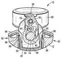
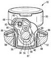
도 6 및 도 7에 도시된 장치(100)의 하우징(112)은 하우징(112)이 상부가 아니고 하우징(112)의 바닥(113)으로부터 캐리어 하위 조립체(150)를 수납하도록 구성되는 점에서 도 1 및 도 2에 도시된 장치의 하우징(12)과 다소 상이하다. 그러나, 캐리어 하위 조립체(150)는, 조립되고, 그 다음 하우징(112)의 종축(152)에 대해 횡방향인 (도 7에서 화살표(154)로 표시된) 방향으로, 하우징(112) 내의 캐리어 리셉터클(146) 내에서, 하우징(112)에 대해 제 위치에 스냅핑하도록 구성된다. 하우징(112)은 배럴(114), 및 그의 단부에 근접한 출구 포트(119)를 포함한다.The
바람직하게는, 하우징(112) 및 캐리어 부재(150)는 캐리어 부재(150)가 캐리어 리셉터클(146) 내에서 제 위치에 스냅핑하도록 구성된다. 이러한 목적으로, 도 7, 도 8, 및 도 9에 도시된 바와 같이, 하우징(112)은 캐리어 부재(156) 상의 래치 요소(188)와 맞물리도록 구성된 스트라이커 바 요소(190)를 포함할 수 있다. 캐리어 하위 조립체(150)가 이제 설명될 것이다.Preferably, the
도 6 및 도 7에 도시된 장치(100)의 캐리어 하위 조립체(150)의 바람직한 구성요소들은 캐리어 하위 조립체(150)의 분해도를 제공하는 도 8에서 가장 잘 볼 수 있다. 도 8에 도시된 바와 같이, 캐리어 하위 조립체(150)는 도 3에 도시된 캐리어 하위 조립체(50)와 매우 유사하게, 바람직하게는 캐리어 부재(156), 너트 부재 또는 구체적으로 반부 너트(158)와 같은 플런저 맞물림 부재, 및 작동식 레버-링크 부재(160)를 포함한다. 작동식 레버-링크 부재(160)는 제1 피벗 핀(162)을 거쳐 반부 너트(158)에 결합되고, 제2 피벗 핀(164)을 거쳐 캐리어 부재(156)에 결합된다. 모든 구성요소들은 플라스틱으로 형성될 수 있지만, 제2 피벗 핀은 대신에 금속으로 형성될 수 있다.Preferred components of the
바람직하게는, 작동식 레버-링크 부재(160)는 제어 표면(166), 제1 피벗 핀(162)이 그를 통해 연장하는 리셉터클(168), 및 제2 피벗 핀(164)이 그를 통해 연장하는 베어링(170)을 포함한다. 바람직하게는, 너트 부재(158)는 플런저(34)가 그를 통해 연장하는 개방부(176), 제1 피벗 핀(162)을 보유하기 위한 베어링(172), 및 나사산 세그먼트(174)를 포함한다. 캐리어 부재(156)는 손잡이 부분(187)을 제공하고, 아울러 바람직하게는 플런저(34)가 그를 통해 연장하는 (즉, 각각의 단부에서 하나씩인) 리셉터클(184), 및 제2 피벗 핀(164)을 보유하기 위한 리셉터클(182)을 포함한다. 바람직하게는, 도 9 및 도 10에 가장 잘 도시된 바와 같이, 캐리어 부재(156)는 하우징(112) 내부의 스트라이커 바 요소(190)와 맞물리고, 이에 의해 캐리어 하위 조립체(150)를 제 위치에 효과적으로 로킹시키는 래치 요소(188)를 또한 포함한다.Preferably, the operative lever-
작동식 링크-레버(160)의 제어 표면(166)이 가압 또는 해제될 때 또는 플런저(34)의 손잡이(36)가 밀리거나, 당겨지거나, 회전될 때와 같은, 반부 너트(158) 및 작동식 링크-레버(160)의 구조 및 기능에 관련하여, 이것은 본원에서 매우 상세하게 설명될 필요가 없고, 이는 그러한 세부가 본원에서 이전에 식별된 특허에 상세하게 설명되어 있기 때문이다.Such as when the
도 6 및 도 7에 도시된 장치(100)의 조립에 관련하여, 먼저 캐리어 하위 조립체(150)가 조립되고, 그 다음 캐리어 하위 조립체(150)가 하우징(112) 내의 캐리어 리셉터클(146) 내에 설치된다. 캐리어 하위 조립체(150)를 조립하기 위해, 먼저 작동식 레버-링크 부재(160)가 반부 너트(158) 내로 삽입되고, 그 다음 제1 피벗 핀(162)이 반부 너트(158) 내의 베어링(172)들 중 하나 내로, 레버-링크 부재(160) 내의 리셉터클(168)을 통해, 그리고 반부 너트(158) 내의 다른 베어링(172) 내로 삽입된다. 이러한 조립체는 그 다음 캐리어 부재(156)와 맞물려서, 작동식 레버-링크(160)의 베어링(170)을 캐리어 부재(156) 내의 리셉터클(182)과 정렬시킨다. 제2 피벗 핀(164)이 그 다음 리셉터클(182)들 중 하나 내로, 작동식 레버-링크(160) 내의 베어링(170)을 통해, 그리고 캐리어 부재(156) 내의 다른 리셉터클(182) 내로 삽입되고, 이에 의해 캐리어 하위 조립체(150)의 모든 부품들을 작동식으로 정렬되게 고정시킨다.6 and 7, the
캐리어 하위 조립체(150)를 조립하기 전 또는 후에, 피스톤(22)은 (그 위의 밀봉 부재(24)와 함께) 하우징(112)의 배럴(114) 내로 삽입되고, 이에 의해 밀봉 부재(24)가 하우징(112)의 배럴(114) 내의 내부 벽과 함께 밀봉되게 한다.The
그러나, 피스톤(22)이 배럴(114) 내에 설치된 후에, 그리고 캐리어 하위 조립체(150)가 조립된 후에, 캐리어 하위 조립체(150)는 그 다음 하우징(112) 내의 캐리어 리셉터클(146) 내로 설치된다. 이러한 설치는 하우징(112)의 종축(152)에 대해 횡방향인 방향(설치 방향은 도 7에서 화살표(154)를 사용하여 도시됨)으로 수행되어, 편향 가능한 래치 요소(188)가 하우징(112) 내에 제공된 스트라이커 바 요소(190)를 지나 활주하여 그와 보유식으로 맞물리도록 스냅핑하게 하고 (도 9 및 도 10 참조), 이에 의해 캐리어 하위 조립체(150)를 하우징(112) 내에 고정시킨다.After the
캐리어 하위 조립체(150)가 하우징(112)에 대해 설치된 후에, 플런저(34)의 단부(32)가 피스톤(22)과 맞물린다. 이를 행하기 위해, 작동식 링크-레버(160)의 제어 표면(166)은 가압되고, 이는 반부 너트(158)가 작동 중지되어 변위하게 하고, 이에 의해 플런저(34)의 단부(32)가 피스톤(22)에 접근하도록 통로를 효과적으로 확보한다. 플런저(34)의 단부(32)를 피스톤(22)과 맞물리기 위해, 제어 표면(166)이 가압되는 동안, 플런저(34)의 단부(32)는 하우징(112)의 단부(194) 내로, 캐리어 부재(156) 내의 리셉터클(184)들 중 하나 내로 삽입되고, 반부 너트(158)를 통해 (즉, 개방부(177) 내로), 캐리어 내의 다른 리셉터클(184)을 통해 밀려서, 배럴(114) 내에 있는 피스톤(22)과 고정 정합식으로 맞물린다. 그 후에, 제어 표면(166)은 해제되어, 반부 너트(158)가 플런저(34)와 나사식으로 맞물리도록 피벗하게 할 수 있다. 이러한 시점에서 (전달 라인이 출구 포트(119)와 맞물린다고 가정하면), 장치는 작동을 위해 준비된다.After the
장치(100)의 그가 조립된 후의 작동에 관련하여, 한 손으로 손잡이(187)에 의해 장치를 유지하면서, 사용자의 다른 손은 플런저(34)의 큰 이동 및 작은 이동모두와 관련하여, 제어 표면(166) 및 플런저(34)의 손잡이(36) 모두와 상호 작용할 수 있고, 이는 이전에 식별된 특허에 상세하게 개시되어 있고, 본원에서 매우 상세하게 반복될 필요가 없다. 그러나, 일반적으로 말하자면, 작동식 레버-링크(160)는 작동식 레버-링크(160)가 반부 너트(158)를 플런저(34)의 나사산(40)과 나사식으로 맞물리도록 편위시키도록 구성된다 (도 9 참조). 이 때, 플런저(34)의 손잡이(36)는 플런저(34) (및 그 위의 피스톤(22))의 작은 이동을 일으키도록 회전 가능하다. 작동식 레버-링크(160)의 제어 표면(166)을 가압하는 것은 반부 너트(158)가 플런저(34) 상의 나사산(40)으로부터 분리되게 하고 (도 10 참조), 이에 의해 손잡이(36)를 밀거나 당김으로써 플런저(34) (및 그 위의 피스톤(22))의 큰 이동을 허용한다.With respect to the operation of the
양쪽 장치(즉, 도 1 - 도 2에 도시된 팽창기 및 도 6 - 도 7에 도시된 정형외과용 시멘트 전달 장치)는 완전히 조립된 캐리어 하위 조립체가 하우징의 종축에 대해 횡방향인 방향으로 하우징 내에 설치되는 것을 제공한다. 이는 쉬운 수동 조립을 제공하고, 아울러 조립 과정을 자동화하는 것을 매우 용이하게 한다. 본원에서 개시되는 횡방향 스냅핑 캐리어 접근은 사용자에 의한 상호 작용을 위해 필요한 손잡이 표면을 제공하면서, 적당히 콤팩트한 구조 내에서의 상대적으로 저렴한 고부하, 초고압 장치의 구성을 허용한다.Both devices (i. E., The inflator shown in Figs. 1-2 and the orthopedic cement delivery device shown in Figs. 6 - 7) have a fully assembled carrier subassembly in the housing in a direction transverse to the longitudinal axis of the housing To be installed. This provides for easy manual assembly and makes it very easy to automate the assembly process. The transverse snapping carrier approach disclosed herein permits the construction of a relatively inexpensive high load, ultra-high pressure device within a reasonably compact structure, while providing the handle surface required for interaction by a user.
본원에서 개시되는 횡방향으로 스냅핑되는 캐리어 하위 조립체는 고용량, 초고압 중합체 팽창 및 전달 장치 설계에서 직면하는 여러 문제점을 해결한다. 각 캐리어 하위 조립체는 하우징의 종축에 대해 횡방향으로, 하우징 내로 바로 하위 조립체를 삽입함으로써 설치되고, 이는 자동화된 조립 및 감소된 비용을 위해 제조를 단순화한다. 일체형 손잡이 및 파지 특징부는 장치의 제어 및 작동을 사용자에 대해 더 쉽게 하고, 캐리어 부재가 비틀림 부하가 장치 본체에 도달하는 것을 방지하기 위해 자체 내에서 비틀림 작동 부하를 분해하도록 허용한다. 각각의 장치의 캐리어 부재를 제 위치에 유지하는 스냅핑 보유 특징부는 사용 중에 비틀림 부하에 저항하도록 설계될 필요는 없다. 캐리어 하위 조립체는 가압 중에 장치 본체의 수납 구조물에 직접, 종방향 플런저 분할 부하를 분배하고 전달하기 위한 더 큰 표면 영역을 제공한다. 하우징 상에서 캐리어 부하를 분배하기 위한 더 큰 표면 영역을 갖는 것은 더 낮은 강도의 특수 중합체, 및 몇몇 경우에, 초고성능, 고압 시린지 용도의 본체 내에서의 더 낮은 비용의 중합체 재료의 사용을 허용한다.The laterally snapped carrier subassembly disclosed herein solves several problems encountered in high capacity, ultra high pressure polymer swelling and delivery device designs. Each carrier subassembly is installed by inserting a subassembly directly into the housing in a transverse direction relative to the longitudinal axis of the housing, which simplifies manufacture for automated assembly and reduced cost. The integral handle and grip features make it easier for the user to control and operate the device and allow the carrier member to disassemble the torsional working load within itself to prevent the torsional load from reaching the device body. The snapping retaining feature that keeps the carrier member of each device in place need not be designed to resist torsional loads during use. The carrier subassembly provides a larger surface area for distributing and delivering the longitudinal plunger divided load directly to the housing structure of the device body during pressurization. Having a larger surface area for distributing the carrier load on the housing allows the use of lower strength specialty polymers and, in some cases, lower cost polymer materials in the body for ultra high performance, high pressure syringe applications.
본 발명의 구체적인 실시예들이 도시되고 설명되었지만, 본 기술 분야의 통상의 기술자는 본 발명의 사상 및 범주로부터 벗어남이 없이 다양한 변형을 고안할 수 있음이 고려된다.While specific embodiments of the present invention have been shown and described, it is contemplated that many modifications may be devised by those skilled in the art without departing from the spirit and scope of the present invention.
Claims (15)
Translated fromKorean종축을 갖는 하우징;
하우징 내에 전체적으로 배치되며, 하우징으로부터 제거 가능한 캐리어 부재;
캐리어 부재를 통해 연장하는 플런저;
캐리어 부재에 의해 보유되는 플런저 맞물림 구조물
을 포함하고,
플런저 맞물림 구조물은 플런저와 선택적으로 맞물리며 분리 가능하고, 하우징 및 캐리어 부재는 캐리어 부재가 하우징의 종축에 대해 하우징 내에 횡방향으로 설치 가능하도록 구성되는,
유체 변위 및 가압 장치.A fluid displacement and pressure device,
A housing having a longitudinal axis;
A carrier member disposed entirely within the housing, the carrier member being removable from the housing;
A plunger extending through the carrier member;
The plunger engagement structure held by the carrier member
/ RTI >
The plunger engaging structure being selectively engageable and releasable with the plunger and the housing and carrier member being configured such that the carrier member is laterally mountable within the housing relative to the longitudinal axis of the housing,
Fluid displacement and pressure device.
캐리어 하위 조립체를 조립하기 위해 캐리어 맞물림 구조물을 캐리어 부재와 맞물리는 단계;
캐리어 하위 조립체를 조립하기 전에 또는 후에, 하우징 내로 피스톤을 삽입하여, 그에 의해 피스톤 상의 밀봉 부재가 하우징의 내부 벽과 함께 밀봉되게 하는 단계;
하우징의 종축에 대해 횡방향인 방향으로, 하우징 내의 캐리어 리셉터클 내로 캐리어 하위 조립체를 설치하는 단계; 및
플런저를 피스톤과 맞물리도록 하우징 내로 삽입하는 단계
를 포함하는, 방법.A housing having a longitudinal axis, the housing including an interior wall, the housing including a housing, a carrier member, a piston having a sealing member thereon, a plunger, and a plunger engagement structure for providing a carrier receptacle, A method of assembling an apparatus,
Engaging a carrier engagement structure with a carrier member to assemble the carrier subassembly;
Inserting a piston into the housing before or after assembling the carrier subassembly so that the sealing member on the piston is sealed with the inner wall of the housing;
Installing a carrier subassembly into the carrier receptacle in the housing in a direction transverse to the longitudinal axis of the housing; And
Inserting the plunger into the housing to engage the piston
/ RTI >
Applications Claiming Priority (3)
| Application Number | Priority Date | Filing Date | Title |
|---|---|---|---|
| US201562116803P | 2015-02-16 | 2015-02-16 | |
| US62/116,803 | 2015-02-16 | ||
| PCT/US2016/016613WO2016133718A1 (en) | 2015-02-16 | 2016-02-04 | Fluid displacement and pressurizing devices, and assembly thereof |
Publications (2)
| Publication Number | Publication Date |
|---|---|
| KR20170118069Atrue KR20170118069A (en) | 2017-10-24 |
| KR102542391B1 KR102542391B1 (en) | 2023-06-09 |
Family
ID=56620527
Family Applications (1)
| Application Number | Title | Priority Date | Filing Date |
|---|---|---|---|
| KR1020177022397AActiveKR102542391B1 (en) | 2015-02-16 | 2016-02-04 | Fluid displacement and pressurization devices and assemblies thereof |
Country Status (9)
| Country | Link |
|---|---|
| US (1) | US10390868B2 (en) |
| EP (1) | EP3258996B1 (en) |
| JP (1) | JP6741677B2 (en) |
| KR (1) | KR102542391B1 (en) |
| CN (1) | CN107249671B (en) |
| DK (1) | DK3258996T3 (en) |
| ES (1) | ES2822132T3 (en) |
| PL (1) | PL3258996T3 (en) |
| WO (1) | WO2016133718A1 (en) |
Families Citing this family (4)
| Publication number | Priority date | Publication date | Assignee | Title |
|---|---|---|---|---|
| US10722347B2 (en)* | 2015-12-17 | 2020-07-28 | Atrion Medical Products, Inc. | Intraocular lens delivery device and method of use |
| US11547555B2 (en) | 2015-12-17 | 2023-01-10 | Atrion Medical Products, Inc. | Intraocular lens delivery device and method of use |
| US11844914B2 (en)* | 2018-06-05 | 2023-12-19 | Edwards Lifesciences Corporation | Removable volume indicator for syringe |
| EP4415791A4 (en) | 2021-10-15 | 2025-08-20 | Atrion Medical Products Inc | ADVANCED ACTUATION MECHANISM AND OPERATING METHOD FOR FLUID DISPLACEMENT AND PRESSURIZATION DEVICE |
Citations (5)
| Publication number | Priority date | Publication date | Assignee | Title |
|---|---|---|---|---|
| US5713242A (en)* | 1995-07-20 | 1998-02-03 | Atrion Medical Products, Inc. | Actuating mechanism for fluid displacement and pressurizing device |
| US20020010431A1 (en)* | 2000-06-08 | 2002-01-24 | Cook Incorporated | High pressure injection syringe |
| US20080077075A1 (en)* | 2006-09-26 | 2008-03-27 | Moreira Alexander Marra | Constructive disposition introduced in indeflator equipment applied in coronary angioplasty intervention |
| KR20130047657A (en)* | 2011-10-31 | 2013-05-08 | 아트리온 메디칼 프로덕츠 인크. | Actuating mechanism for fluid displacement and pressurizing device |
| JP2014519388A (en)* | 2011-06-10 | 2014-08-14 | グローバス メディカル インコーポレイティッド | Device for dispensing biomaterials |
Family Cites Families (9)
| Publication number | Priority date | Publication date | Assignee | Title |
|---|---|---|---|---|
| US2695023A (en) | 1952-01-04 | 1954-11-23 | Pfizer & Co C | Hypodermic syringe |
| US3353718A (en) | 1966-05-24 | 1967-11-21 | Fischer & Porter Co | Syringe, column or the like |
| US5137514A (en)* | 1990-11-01 | 1992-08-11 | Accumed Systems, Inc. | Inflation syringe assembly for percutaneous transluminal angioplasty |
| US6796959B2 (en) | 2001-03-19 | 2004-09-28 | Atrion Medical Products, Inc. | Actuating mechanism for fluid displacement and pressurizing device |
| KR100756672B1 (en)* | 2006-04-21 | 2007-09-10 | 세원셀론텍(주) | Piston Pressing Device of Syringe |
| EP2187996B1 (en)* | 2007-08-13 | 2011-10-12 | Mallinckrodt LLC | Drive ram for medical injectors |
| CH698343A2 (en) | 2008-01-11 | 2009-07-15 | Medmix Systems Ag | Discharge WITH TURNING DEVICE. |
| US8191457B2 (en)* | 2008-11-13 | 2012-06-05 | Atrion Medical Products, Inc. | Actuating mechanism for fluid displacement and pressurizing device |
| US8499681B2 (en) | 2008-11-13 | 2013-08-06 | Atrion Medical Products, Inc. | Actuating mechanism for fluid displacement and pressurizing device |
- 2016
- 2016-02-03USUS15/014,712patent/US10390868B2/enactiveActive
- 2016-02-04CNCN201680010262.3Apatent/CN107249671B/enactiveActive
- 2016-02-04PLPL16752793Tpatent/PL3258996T3/enunknown
- 2016-02-04WOPCT/US2016/016613patent/WO2016133718A1/ennot_activeCeased
- 2016-02-04JPJP2017542911Apatent/JP6741677B2/enactiveActive
- 2016-02-04KRKR1020177022397Apatent/KR102542391B1/enactiveActive
- 2016-02-04ESES16752793Tpatent/ES2822132T3/enactiveActive
- 2016-02-04DKDK16752793.6Tpatent/DK3258996T3/enactive
- 2016-02-04EPEP16752793.6Apatent/EP3258996B1/enactiveActive
Patent Citations (5)
| Publication number | Priority date | Publication date | Assignee | Title |
|---|---|---|---|---|
| US5713242A (en)* | 1995-07-20 | 1998-02-03 | Atrion Medical Products, Inc. | Actuating mechanism for fluid displacement and pressurizing device |
| US20020010431A1 (en)* | 2000-06-08 | 2002-01-24 | Cook Incorporated | High pressure injection syringe |
| US20080077075A1 (en)* | 2006-09-26 | 2008-03-27 | Moreira Alexander Marra | Constructive disposition introduced in indeflator equipment applied in coronary angioplasty intervention |
| JP2014519388A (en)* | 2011-06-10 | 2014-08-14 | グローバス メディカル インコーポレイティッド | Device for dispensing biomaterials |
| KR20130047657A (en)* | 2011-10-31 | 2013-05-08 | 아트리온 메디칼 프로덕츠 인크. | Actuating mechanism for fluid displacement and pressurizing device |
Also Published As
| Publication number | Publication date |
|---|---|
| EP3258996A1 (en) | 2017-12-27 |
| CN107249671B (en) | 2020-08-14 |
| EP3258996A4 (en) | 2018-12-05 |
| CN107249671A (en) | 2017-10-13 |
| PL3258996T3 (en) | 2021-04-06 |
| DK3258996T3 (en) | 2020-10-26 |
| EP3258996B1 (en) | 2020-08-05 |
| US10390868B2 (en) | 2019-08-27 |
| ES2822132T3 (en) | 2021-04-29 |
| KR102542391B1 (en) | 2023-06-09 |
| JP2018504998A (en) | 2018-02-22 |
| JP6741677B2 (en) | 2020-08-19 |
| US20160235458A1 (en) | 2016-08-18 |
| WO2016133718A1 (en) | 2016-08-25 |
Similar Documents
| Publication | Publication Date | Title |
|---|---|---|
| KR20170118069A (en) | Fluid displacement and pressure device, and assembly thereof | |
| US6231320B1 (en) | Drug infusion pumping cassette latching mechanism | |
| US6019747A (en) | Spring-actuated infusion syringe | |
| US5891096A (en) | Medicament infusion device | |
| US8490256B2 (en) | Release mechanism | |
| CA2307207A1 (en) | Preloadable syringe for automated dispensing device | |
| EP2154382B1 (en) | Clamp device | |
| CA3039462C (en) | System and method for a syringe micro pump with wave spring | |
| US10806852B2 (en) | System for syringe engagement to an injector | |
| CN102686258A (en) | Medicament delivery device | |
| US10082233B2 (en) | Hose quick coupling | |
| BR102012027931A2 (en) | actuator mechanism for pressurization and fluid displacement device | |
| CN108367122B (en) | System and method for removable syringe micropump with scroll spring | |
| KR20170072872A (en) | Handle to apply a torque and delivery unit provided with such handle | |
| US20180161845A1 (en) | Hydraulic tool | |
| US10967120B2 (en) | Portable liquid drug delivery device | |
| EP3181168B1 (en) | Manually operated instrument for filling syringes | |
| US9802032B2 (en) | Connecting module and syringe having such a connecting module | |
| WO2001054756A1 (en) | Improvements in single use syringes | |
| DE102015009751A1 (en) | cleaner | |
| US10071235B1 (en) | Slide-button catheter connector device | |
| JP2015066070A (en) | Drug injector | |
| US20140228757A1 (en) | Bent syringes and devices including same |
Legal Events
| Date | Code | Title | Description |
|---|---|---|---|
| PA0105 | International application | Patent event date:20170810 Patent event code:PA01051R01D Comment text:International Patent Application | |
| PG1501 | Laying open of application | ||
| A201 | Request for examination | ||
| PA0201 | Request for examination | Patent event code:PA02012R01D Patent event date:20210105 Comment text:Request for Examination of Application | |
| E902 | Notification of reason for refusal | ||
| PE0902 | Notice of grounds for rejection | Comment text:Notification of reason for refusal Patent event date:20221221 Patent event code:PE09021S01D | |
| E701 | Decision to grant or registration of patent right | ||
| PE0701 | Decision of registration | Patent event code:PE07011S01D Comment text:Decision to Grant Registration Patent event date:20230531 | |
| GRNT | Written decision to grant | ||
| PR0701 | Registration of establishment | Comment text:Registration of Establishment Patent event date:20230607 Patent event code:PR07011E01D | |
| PR1002 | Payment of registration fee | Payment date:20230607 End annual number:3 Start annual number:1 | |
| PG1601 | Publication of registration |