KR20170117750A - Relay for protecting electric system - Google Patents
Relay for protecting electric systemDownload PDFInfo
- Publication number
- KR20170117750A KR20170117750AKR1020160045542AKR20160045542AKR20170117750AKR 20170117750 AKR20170117750 AKR 20170117750AKR 1020160045542 AKR1020160045542 AKR 1020160045542AKR 20160045542 AKR20160045542 AKR 20160045542AKR 20170117750 AKR20170117750 AKR 20170117750A
- Authority
- KR
- South Korea
- Prior art keywords
- voltage
- relay
- rated voltage
- grid
- present
- Prior art date
- Legal status (The legal status is an assumption and is not a legal conclusion. Google has not performed a legal analysis and makes no representation as to the accuracy of the status listed.)
- Granted
Links
Images


Classifications
- G—PHYSICS
- G01—MEASURING; TESTING
- G01R—MEASURING ELECTRIC VARIABLES; MEASURING MAGNETIC VARIABLES
- G01R31/00—Arrangements for testing electric properties; Arrangements for locating electric faults; Arrangements for electrical testing characterised by what is being tested not provided for elsewhere
- G01R31/327—Testing of circuit interrupters, switches or circuit-breakers
- G—PHYSICS
- G01—MEASURING; TESTING
- G01R—MEASURING ELECTRIC VARIABLES; MEASURING MAGNETIC VARIABLES
- G01R19/00—Arrangements for measuring currents or voltages or for indicating presence or sign thereof
- G01R19/165—Indicating that current or voltage is either above or below a predetermined value or within or outside a predetermined range of values
- G01R19/16566—Circuits and arrangements for comparing voltage or current with one or several thresholds and for indicating the result not covered by subgroups G01R19/16504, G01R19/16528, G01R19/16533
- G01R19/16576—Circuits and arrangements for comparing voltage or current with one or several thresholds and for indicating the result not covered by subgroups G01R19/16504, G01R19/16528, G01R19/16533 comparing DC or AC voltage with one threshold
- G—PHYSICS
- G01—MEASURING; TESTING
- G01R—MEASURING ELECTRIC VARIABLES; MEASURING MAGNETIC VARIABLES
- G01R19/00—Arrangements for measuring currents or voltages or for indicating presence or sign thereof
- G01R19/165—Indicating that current or voltage is either above or below a predetermined value or within or outside a predetermined range of values
- G01R19/16566—Circuits and arrangements for comparing voltage or current with one or several thresholds and for indicating the result not covered by subgroups G01R19/16504, G01R19/16528, G01R19/16533
- G01R19/1659—Circuits and arrangements for comparing voltage or current with one or several thresholds and for indicating the result not covered by subgroups G01R19/16504, G01R19/16528, G01R19/16533 to indicate that the value is within or outside a predetermined range of values (window)
- G01R31/025—
- G—PHYSICS
- G01—MEASURING; TESTING
- G01R—MEASURING ELECTRIC VARIABLES; MEASURING MAGNETIC VARIABLES
- G01R31/00—Arrangements for testing electric properties; Arrangements for locating electric faults; Arrangements for electrical testing characterised by what is being tested not provided for elsewhere
- G01R31/08—Locating faults in cables, transmission lines, or networks
Landscapes
- Physics & Mathematics (AREA)
- General Physics & Mathematics (AREA)
- Engineering & Computer Science (AREA)
- Power Engineering (AREA)
- Emergency Protection Circuit Devices (AREA)
- Supply And Distribution Of Alternating Current (AREA)
Abstract
Translated fromKoreanDescription
Translated fromKorean본 발명은 계통 보호용 계전기에 관한 것으로, 보다 상세하게는 정격 전압 목록과 계통 전압을 비교함으로써 계전기의 오동작을 줄일 수 있는 계통 보호용 계전기에 관한 것이다.BACKGROUND OF THE INVENTION Field of the Invention [0002] The present invention relates to a system protection relay, and more particularly, to a system protection relay capable of reducing a malfunction of a relay by comparing a rated voltage list with a system voltage.
전력 계통에서 안정적이고 지속적인 양질의 전력 공급은 현대사회에서 아주 중요한 문제이며, 이로 인해 전력 계통 보호에 대한 중요성이 점차 증가하고 있다. 특히, 고장 발생 시 신속하고 정확하게 고장을 검출하는 것은 전력 계통 보호의 핵심이라 할 수 있다. 이에 따라 전력 계통을 구성하는 각종 전력기기, 설비들의 고장 및 사고 발생시 이를 검출하고 보호하기 위해 계전기가 사용되고 있다.Reliable and continuous supply of quality power in the power system is a very important issue in modern society, and the importance of power system protection is increasing. In particular, detecting faults quickly and accurately in the event of a fault can be said to be key to power system protection. Accordingly, relays are used to detect and protect the various power devices and facilities that constitute the power system in the event of a failure or an accident.
계전기는 수배전반의 각종 전기량을 감지하여 정상운전시의 값과 비교하고, 단락 또는 지락 사고 등이 발생하여 각종 전기량이 미리 설정된 기준치를 벗어난 경우에 이를 신속히 검출하는 장치이다. 또한, 계전기는 피보호 전력계통이나 기기 설비를 정상 계통으로부터 분리시키기 위해 각종 차단기, 개폐기를 동작시키기 위한 제어기능을 수행한다.The relay detects various electric quantities of the switchboard and compares them with the value of the normal operation, and when the various electric quantities deviate from preset reference values due to a short circuit or a ground fault, it is a device for detecting the electric quantities quickly. In addition, the relay performs a control function for operating various circuit breakers and switches in order to separate the protected power system and equipment from the normal system.
근래에는 피보호 설비의 구성과 특징이 복잡하고 다양해져서 그 보호 요구조건이 보다 엄격하게 높아지고 있을 뿐만 아니라, 디지털 기술의 발전으로 아날로그 형태보다 디지털 방식의 계전기가 실용화되고 있다. 또한, 최근 들어 전력 계통의 구성이 복잡해짐에 따라 디지털 계전기도 보다 다양한 기능이 요구되며 이에 따라 디지털 계전기는 그 내부에 복수의 계전 모듈이 구비되는 복합 장치로 구성되고 있다.In recent years, the configuration and characteristics of the protection facilities have become complicated and diverse, and the protection requirements have become stricter. In addition, the development of digital technology has made digital relays more practical than analog ones. In addition, as the configuration of a power system becomes complicated in recent years, digital relays also require a variety of functions. Accordingly, a digital relay is composed of a composite device having a plurality of relay modules therein.
한편, 계전기의 종류에는 변압기 보호용 계전기, 모터 보호용 계전기 및 계통 보호용 계전기가 있다. 변압기 보호용 계전기는 선로에 단선, 지락 등의 고장이 발생할 경우 선로와 변압기 사이를 개방함으로써 변압기를 보호하는 계전기이다. 모터 보호용 계전기는 선로에 고장이 발생할 경우 선로와 모터 사이를 개방함으로써 모터를 보호하는 계전기이다.On the other hand, the types of relays include transformer protection relays, motor protection relays, and system protection relays. The transformer protection relay is a relay that protects the transformer by opening between the line and the transformer in case of failure such as disconnection or ground fault in the line. The motor protection relay is a relay that protects the motor by opening between the line and the motor in the event of a line failure.
계통 보호용 계전기는 배전 선로에 고장이 발생할 경우 일부 구간만을 차단하여 정전 구간이 최소가 되도록 하는 계전기이다. 도 1은 종래의 계통 보호용 계전기(10)가 배전 선로(20)와 연결된 모습을 도시한 도면이다. 도 1을 참조하여 종래의 계통 보호용 계전기(10)를 설명하면, 먼저 사용자가 정격 전압을 설정한다. 그 다음, 계통 전압을 측정하고, 측정된 계통 전압과 정격 전압을 비교하여 계통의 정상여부를 판단한다. 판단 결과 계통이 이상이라고 판단되면 차단기(11)를 개방하고, 계통이 정상이라고 판단되면 차단기(11)가 단락된 상태를 유지한다.The system protection relay is a relay that cuts off only a section when a power line failure occurs, so that the power section is minimized. FIG. 1 is a view showing a state where a conventional
다만, 종래의 계통 보호용 계전기에 따르면 사용자가 계통 전압을 일일이 설정해야 하므로 계통 보호용 계전기를 사용하기가 번거롭다는 문제점이 있다. 또한, 사용자가 계통 전압을 잘못 설정할 경우 계전기가 오동작하여 전력 설비에 피해를 주는 문제점이 있다.However, according to the conventional system protection relay, it is troublesome to use the system protection relay because the user must set the system voltage one by one. In addition, when the user sets the system voltage incorrectly, there is a problem that the relay malfunctions and damages the power equipment.
본 발명은 정격 전압 목록과 계통 전압을 비교함으로써 계전기의 오동작을 줄일 수 있는 계통 보호용 계전기를 제공하는 것을 목적으로 한다.An object of the present invention is to provide a system protection relay which can reduce a malfunction of a relay by comparing a rated voltage list with a grid voltage.
또한, 본 발명은 정격 전압을 설정하는 과정을 생략함으로써 계전기 사용자의 편의성을 증가시킬 수 있는 계통 보호용 계전기를 제공하는 것을 목적으로 한다.It is another object of the present invention to provide a relay for protecting a system which can increase the convenience of a relay user by omitting a process of setting a rated voltage.
또한, 본 발명은 정격 전압 목록의 오차 범위와 계통 전압을 비교함으로써 정확하게 계통의 이상 여부를 판단할 수 있는 계통 보호용 계전기를 제공하는 것을 목적으로 한다.It is another object of the present invention to provide a system protection relay which can accurately determine whether a system is abnormal by comparing an error range of a rated voltage list with a system voltage.
또한, 본 발명은 판단 결과를 표시부를 통해 출력함으로써 사용자가 계통의 이상 여부를 실시간으로 확인할 수 있는 계통 보호용 계전기를 제공하는 것을 목적으로 한다.It is another object of the present invention to provide a system protection relay capable of checking whether a user is abnormal in real time by outputting a determination result through a display unit.
본 발명의 목적들은 이상에서 언급한 목적으로 제한되지 않으며, 언급되지 않은 본 발명의 다른 목적 및 장점들은 하기의 설명에 의해서 이해될 수 있고, 본 발명의 실시예에 의해 보다 분명하게 이해될 것이다. 또한, 본 발명의 목적 및 장점들은 특허 청구 범위에 나타낸 수단 및 그 조합에 의해 실현될 수 있음을 쉽게 알 수 있을 것이다.The objects of the present invention are not limited to the above-mentioned objects, and other objects and advantages of the present invention which are not mentioned can be understood by the following description and more clearly understood by the embodiments of the present invention. It will also be readily apparent that the objects and advantages of the invention may be realized and attained by means of the instrumentalities and combinations particularly pointed out in the appended claims.
이러한 목적을 달성하기 위한 본 발명의 일 실시예에 따른 계통 보호용 계전기는 계통 전압에 이상이 있을 경우 계통을 보호하는 계통 보호용 계전기에 있어서, 상기 계통 전압을 측정하는 측정부, 상기 계통 전압과 정격 전압 목록을 비교하여 상기 계통의 정상 여부를 판단하는 판단부 및 상기 계통 전압이 상기 정격 전압 목록에 포함되면 상기 계통 전압을 정격 전압으로 설정하는 제어부를 포함하는 것을 특징으로 한다.According to an aspect of the present invention, there is provided a grid protection relay for protecting a grid when an abnormal grid voltage exists, the grid protection relay comprising: a measurement unit for measuring the grid voltage; And a control unit for setting the grid voltage to a rated voltage when the grid voltage is included in the rated voltage list.
전술한 바와 같은 본 발명에 의하면 정격 전압 목록과 계통 전압을 비교함으로써 계전기의 오동작을 줄일 수 있는 효과가 있다.According to the present invention as described above, malfunction of the relay can be reduced by comparing the rated voltage list with the grid voltage.
또한, 본 발명에 의하면 정격 전압을 설정하는 과정을 생략함으로써 계전기 사용자의 편의성을 증가시킬 수 있는 효과가 있다.In addition, according to the present invention, the convenience of the relay user can be increased by omitting the process of setting the rated voltage.
또한, 본 발명에 의하면 정격 전압 목록의 오차 범위와 계통 전압을 비교함으로써 정확하게 계통의 이상 여부를 판단할 수 있는 효과가 있다.In addition, according to the present invention, it is possible to accurately determine whether the system is abnormal by comparing the error range of the rated voltage list with the system voltage.
또한, 본 발명에 의하면 판단 결과를 표시부를 통해 출력함으로써 사용자가 계통의 이상 여부를 실시간으로 확인할 수 있는 효과가 있다.In addition, according to the present invention, the determination result is outputted through the display unit, thereby enabling the user to check in real time whether the system is abnormal.
도 1은 종래의 계통 보호용 계전기가 배전 선로와 연결된 모습을 도시한 도면.
도 2는 본 발명의 일 실시예에 따른 계통 보호용 계전기를 도시한 도면.
도 3은 본 발명의 일 실시예에 따른 판단부가 계통의 정상 여부를 판단하는 과정을 도시한 도면.
도 4는 본 발명의 일 실시예에 따른 계통 보호 방법을 도시한 순서도.BRIEF DESCRIPTION OF THE DRAWINGS Fig. 1 is a view showing a conventional system protection relay connected to a distribution line. Fig.
2 is a view illustrating a relay for protecting a system according to an embodiment of the present invention;
3 is a diagram illustrating a process of determining whether the determination unit is normal according to an embodiment of the present invention.
4 is a flowchart illustrating a system protection method according to an embodiment of the present invention.
전술한 목적, 특징 및 장점은 첨부된 도면을 참조하여 상세하게 후술되며, 이에 따라 본 발명이 속하는 기술분야에서 통상의 지식을 가진 자가 본 발명의 기술적 사상을 용이하게 실시할 수 있을 것이다. 본 발명을 설명함에 있어서 본 발명과 관련된 공지 기술에 대한 구체적인 설명이 본 발명의 요지를 불필요하게 흐릴 수 있다고 판단되는 경우에는 상세한 설명을 생략한다. 이하, 첨부된 도면을 참조하여 본 발명에 따른 바람직한 실시예를 상세히 설명하기로 한다. 도면에서 동일한 참조부호는 동일 또는 유사한 구성요소를 가리키는 것으로 사용된다.The above and other objects, features, and advantages of the present invention will become more apparent by describing in detail exemplary embodiments thereof with reference to the attached drawings, which are not intended to limit the scope of the present invention. In the following description, well-known functions or constructions are not described in detail since they would obscure the invention in unnecessary detail. Hereinafter, preferred embodiments of the present invention will be described in detail with reference to the accompanying drawings. In the drawings, the same reference numerals are used to denote the same or similar elements.
도 2는 본 발명의 일 실시예에 따른 계통 보호용 계전기(100)를 도시한 도면이다. 도 2를 참조하면, 본 발명의 일 실시예에 따른 계통 보호용 계전기(100)는 측정부(110), 판단부(120), 제어부(130), 전압 변환부(140), 필터(150), 디지털 변환부(160) 및 표시부(170)를 포함하여 구성될 수 있다. 도 2에 도시된 계통 보호용 계전기(100)는 일 실시예에 따른 것이고, 그 구성요소들이 도 2에 도시된 실시 예에 한정되는 것은 아니며, 필요에 따라 일부 구성요소가 부가, 변경 또는 삭제될 수 있다.2 is a diagram illustrating a
도 3은 본 발명의 일 실시예에 따른 판단부(120)가 계통의 정상 여부를 판단하는 과정을 도시한 도면이다. 이하 도 2 및 도 3을 참조하여 본 발명의 일 실시예에 따른 계통 보호용 계전기(100)를 설명하도록 한다.FIG. 3 is a diagram illustrating a process in which the
측정부(110)는 계통 전압을 측정할 수 있다. 계통 전압은 발전소, 변전소, 배전소와 연결된 선로의 전압 일 수 있고, 예를 들어 110V, 220V, 380V, 440V일 수 있다. 측정부(110)는 계통의 전류를 측정할 수도 있고, 전압 측정기 또는 전류 측정기일 수 있다.The
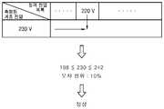
판단부(120)는 계통 전압과 정격 전압 목록을 비교하여 계통의 정상 여부를 판단할 수 있다. 정격 전압 목록은 계통에 인가될 수 있는 전압의 목록으로서 측정부(110)에서 측정된 계통 전압에 대응하여 자동으로 설정될 수 있다. 또한, 정격 전압 목록은 110V, 220V, 380V, 440V 중 하나 이상일 수 있다. 도 3을 참조하면, 측정된 계통 전압이 230V이면 정격 전압 목록 중 230V와 가장 가까운 값인 220V와 계통 전압을 비교할 수 있다.The
일 실시예로 판단부(120)는 계통 전압이 정격 전압 목록의 오차 범위 내이면 계통이 정상이라고 판단할 수 있다. 다시 도 3을 참조하면, 정격 전압이 220V이고 오차가 10%이면, 측정된 계통 전압 230V는 정격 전압의 오차 범위인 198V 에서 242V내에 포함된다. 따라서, 판단부(120)는 계통을 정상으로 판단할 수 있다.In one embodiment, the
한편, 판단부(120)는 계통 전압이 정격 전압의 오차 범위 외이면 계통이 이상이라고 판단할 수 있다. 예를 들어, 정격 전압이 220V이고 오차가 1%이면, 측정된 계통 전압이 230V이므로 측정된 계통 전압이 정격 전압의 오차 범위 외가 된다. 따라서, 판단부(120)는 계통을 이상으로 판단할 수 있다. 이 때, 오차는 사용자에 의해 설정될 수도 있고, 판단부(120)에서 자동으로 설정할 수도 있다.On the other hand, if the grid voltage is outside the error range of the rated voltage, the
일 실시예로 판단부(120)는 미리 설정된 시간에 계통의 정상 여부를 판단할 수도 있다. 미리 설정된 시간은 사용자에 의해 설정된 시간으로 특정 시각일 수도 있고, 일정 기간일 수도 있다. 예를 들어 사용자가 미리 설정된 시간으로 2016년 03월 07일 오후 01시를 설정하면, 판단부(120)는 상술한 시간에 계통의 정상 여부를 판단할 수 있다. 또한, 사용자가 미리 설정된 시간으로 1시간을 설정하면, 판단부(120)는 1시간 동안 계통의 정상 여부를 판단할 수 있다.In one embodiment, the
일 실시예로 계통 전압은 3상 전압이고, 판단부(120)는 3상 전압 중 어느 하나의 상을 선택하여 계통의 정상 여부를 판단할 수 있다. 예를 들어, 계통 전압은 R상, S상, T상을 갖는 3상 전압이고, 판단부(120)는 R상 전압을 선택하여 정상 여부를 판단할 수 있다. 또한, 판단부(120)는 R상, S상, T상 모두의 전압을 기초로 계통의 정상 여부를 판단할 수 있다.In one embodiment, the system voltage is a three-phase voltage, and the
제어부(130)는 상기 계통 전압이 상기 정격 전압 목록에 포함되면 상기 계통 전압을 정격 전압으로 설정할 수 있다. 정격 전압은 정격 전압 목록에 포함되는 전압으로서, 예를 들어 정격 전압 목록이 110V, 220V, 380V, 440V이면 정격 전압은 110V, 220V, 380V, 440V 중 어느 하나 일 수 있다. 한편, 계통 전압이 230V이고 오차가 10%이면, 계통 전압 230V는 정격 전압 220V의 오차 범위 내에 포함되므로 제어부는 230V를 정격 전압으로 설정할 수 있다.The
제어부(130)는 판단 결과 계통에 이상이 있을 경우 차단기를 개방할 수 있다. 계통 전압이 정격 전압보다 크면 과전류가 흐르고 폭발의 위험성이 있으므로 제어부(130)는 차단기를 개방함으로써 이를 예방할 수 있다. 또한, 계통 전압이 정격 전압보다 작으면 전자 설비가 제대로 동작하지 않으므로 제어부(130)는 차단기를 개방함으로써 이를 예방할 수 있다. 한편, 제어부(130)는 판단 결과 계통이 정상이면 차단기가 단락된 상태를 유지할 수도 있으며, 하나 이상의 차단기를 제어할 수도 있다.As a result of the determination, the
일 실시예로 제어부(130)는 판단 결과 상기 계통에 이상이 있을 경우 경고 메시지를 출력할 수 있다. 이 때, 경고 메시지는 알람음, 경고등 등을 통해 계통의 이상 여부를 알리는 메시지로서, 제어부(130)는 경고 메시지를 출력함으로써 사용자에게 계통의 이상 여부를 알릴 수 있다.In one embodiment, the
전압 변환부(140)는 계통 전압을 감압하여 계통 전압을 디지털 변환부(160)의 정격 전압으로 변환시킬 수 있다. 디지털 변환부(160)는 계통 전압을 디지털 값으로 변환하는 구성으로서 이에 대해서는 후술하도록 한다. 일 실시예로 전압 변환부(140)는 측정부(110)에 연결되어 측정부(110)에서 측정한 계통 전압을 감압하여 변환시킬 수 있다. 예를 들어, 계통 전압이 440V이고, 디지털 변환부(160)의 정격 전압이 400V이면 전압 변환부(140)는 440V를 감압하여 400V로 변환시킬 수 있다. 본 발명의 일 실시예에 따른 전압 변환부(140)는 계통 전압을 감압함으로써 디지털 변환부(160)에 정격 전압을 인가할 수 있는 효과가 있다.The
필터(150)는 계통 전압의 노이즈를 제거할 수 있다. 필터(150)는 전압 변환부(140) 및 후술하는 디지털 변환부(160)와 연결될 수 있고, 계통 전압의 노이즈를 제거함으로써 판단 결과의 정확도를 높일 수 있다.The
디지털 변환부(160)는 계통 전압을 디지털 값으로 변환할 수 있다. 계통 전압은 아날로그 값이므로 디지털 변환부(160)는 아날로그 값을 디지털 값으로 변환함으로써 판단부(120)가 인식할 수 있는 데이터의 형태로 변환할 수 있다. 한편, 계통 전압을 디지털 값으로 변환한 후 판단부(120)는 디지털 값과 정격 전압 목록을 비교하여 계통의 정상 여부를 판단할 수 있다.The
표시부(170)는 판단 결과 계통에 이상이 있을 경우 경고 메시지를 출력할 수 있다. 경고 메시지는 화면을 통해 문자 형태로 출력될 수도 있고, 스피커를 통해 경고음 형태로 출력될 수도 있으며, 경고 메시지의 종류는 상술한 실시예에 한정하지 않는다.The
도 4는 본 발명의 일 실시예에 따른 계통 보호 방법을 도시한 순서도이다. 이하 도 4를 참조하여 본 발명의 일 실시예에 따른 계통 보호 방법을 설명하도록 한다. 먼저, 계통 전압을 측정하고(S410) 측정된 계통 전압을 디지털 변환부의 정격 전압으로 변환한다(S420). 그 다음, 노이즈를 제거하고(S430) 디지털 값으로 변환한(S440) 후 디지털 값을 판단부로 전송한다.4 is a flowchart illustrating a system protection method according to an embodiment of the present invention. The system protection method according to an embodiment of the present invention will be described with reference to FIG. First, the grid voltage is measured (S410), and the measured grid voltage is converted into a rated voltage of the digital converter (S420). Next, the noise is removed (S430) and converted into a digital value (S440), and then the digital value is transmitted to the determination unit.
디지털 값이 판단부로 전송되면 판단부는 디지털 값과 미리 설정된 값을 비교하여(S450) 계통이 정상인지 여부를 판단한다(S460). 계통이 정상이면 다시 계통 전압을 측정하고, 계통이 이상이면 차단기를 개방하여 계통을 보호한다(S470).If the digital value is transmitted to the determination unit, the determination unit compares the digital value with a preset value (S450), and determines whether the system is normal (S460). If the system is normal, the system voltage is again measured. If the system is abnormal, the system is protected by opening the circuit breaker (S470).
전술한 바와 같은 본 발명에 의하면 정격 전압 목록과 계통 전압을 비교함으로써 계전기의 오동작을 줄일 수 있는 효과가 있다. 또한, 본 발명에 의하면 정격 전압을 설정하는 과정을 생략함으로써 계전기 사용자의 편의성을 증가시킬 수 있는 효과가 있다.According to the present invention as described above, malfunction of the relay can be reduced by comparing the rated voltage list with the grid voltage. In addition, according to the present invention, the convenience of the relay user can be increased by omitting the process of setting the rated voltage.
또한, 본 발명에 의하면 정격 전압 목록의 오차 범위와 계통 전압을 비교함으로써 정확하게 계통의 이상 여부를 판단할 수 있는 효과가 있다. 또한, 본 발명에 의하면 판단 결과를 표시부를 통해 출력함으로써 사용자가 계통의 이상 여부를 실시간으로 확인할 수 있는 효과가 있다.In addition, according to the present invention, it is possible to accurately determine whether the system is abnormal by comparing the error range of the rated voltage list with the system voltage. In addition, according to the present invention, the determination result is outputted through the display unit, thereby enabling the user to check in real time whether the system is abnormal.
전술한 본 발명은, 본 발명이 속하는 기술 분야에서 통상의 지식을 가진 자에게 있어 본 발명의 기술적 사상을 벗어나지 않는 범위 내에서 여러 가지 치환, 변형 및 변경이 가능하므로 전술한 실시예 및 첨부된 도면에 의해 한정되는 것이 아니다.While the present invention has been described in connection with what is presently considered to be practical exemplary embodiments, it is to be understood that the invention is not limited to the disclosed embodiments, but, on the contrary, But the present invention is not limited thereto.
Claims (4)
Translated fromKorean상기 계통 전압을 측정하는 측정부;
상기 계통 전압과 정격 전압 목록을 비교하여 상기 계통의 정상 여부를 판단하는 판단부; 및
상기 계통 전압이 상기 정격 전압 목록에 포함되면 상기 계통 전압을 정격 전압으로 설정하는제어부를
포함하는 계통 보호용 계전기.
A system protection relay for protecting a system in case of an abnormal system voltage,
A measurement unit for measuring the grid voltage;
A determination unit comparing the grid voltage with a rated voltage list to determine whether the grid is normal; And
And a controller for setting the grid voltage to a rated voltage when the grid voltage is included in the rated voltage list
Including a system protection relay.
상기 판단부는
상기 계통 전압이 상기 상기 정격 전압의 오차 범위 내이면 상기 계통이 정상이라고 판단하고, 상기 계통 전압이 상기 정격 전압의 오차 범위 외이면 상기 계통이 이상이라고 판단하는 계통 보호용 계전기.
The method according to claim 1,
The determination unit
And determines that the system is abnormal if the system voltage is within an error range of the rated voltage, and determines that the system is abnormal if the system voltage is outside an error range of the rated voltage.
상기 제어부는
상기 판단 결과 상기 계통에 이상이 있을 경우 차단기를 개방하는 계통 보호용 계전기.
The method according to claim 1,
The control unit
Wherein the circuit breaker is opened when an abnormality occurs in the system.
상기 제어부는
상기 판단 결과 상기 계통에 이상이 있을 경우 경고 메시지를 출력하는 계통 보호용 계전기.The method according to claim 1,
The control unit
And outputs a warning message if there is an abnormality in the system as a result of the determination.
Priority Applications (1)
| Application Number | Priority Date | Filing Date | Title |
|---|---|---|---|
| KR1020160045542AKR102633927B1 (en) | 2016-04-14 | 2016-04-14 | Relay for protecting electric system |
Applications Claiming Priority (1)
| Application Number | Priority Date | Filing Date | Title |
|---|---|---|---|
| KR1020160045542AKR102633927B1 (en) | 2016-04-14 | 2016-04-14 | Relay for protecting electric system |
Publications (2)
| Publication Number | Publication Date |
|---|---|
| KR20170117750Atrue KR20170117750A (en) | 2017-10-24 |
| KR102633927B1 KR102633927B1 (en) | 2024-02-05 |
Family
ID=60299532
Family Applications (1)
| Application Number | Title | Priority Date | Filing Date |
|---|---|---|---|
| KR1020160045542AActiveKR102633927B1 (en) | 2016-04-14 | 2016-04-14 | Relay for protecting electric system |
Country Status (1)
| Country | Link |
|---|---|
| KR (1) | KR102633927B1 (en) |
Cited By (1)
| Publication number | Priority date | Publication date | Assignee | Title |
|---|---|---|---|---|
| CN111756020A (en)* | 2020-06-15 | 2020-10-09 | 深圳供电局有限公司 | A device for automatic checking of fixed value of relay protection |
Citations (4)
| Publication number | Priority date | Publication date | Assignee | Title |
|---|---|---|---|---|
| JPH04299025A (en)* | 1991-03-27 | 1992-10-22 | Toshiba Corp | DC power supply |
| KR960002324A (en)* | 1994-06-22 | 1996-01-26 | 배순훈 | Superimposable CDG discs and their playback devices |
| JP2006129585A (en)* | 2004-10-27 | 2006-05-18 | Hitachi Ltd | DC power distribution system control device and converter control device |
| KR20110104730A (en)* | 2010-03-17 | 2011-09-23 | 엘에스산전 주식회사 | Ground fault relay with incorrect wiring compensation |
- 2016
- 2016-04-14KRKR1020160045542Apatent/KR102633927B1/enactiveActive
Patent Citations (4)
| Publication number | Priority date | Publication date | Assignee | Title |
|---|---|---|---|---|
| JPH04299025A (en)* | 1991-03-27 | 1992-10-22 | Toshiba Corp | DC power supply |
| KR960002324A (en)* | 1994-06-22 | 1996-01-26 | 배순훈 | Superimposable CDG discs and their playback devices |
| JP2006129585A (en)* | 2004-10-27 | 2006-05-18 | Hitachi Ltd | DC power distribution system control device and converter control device |
| KR20110104730A (en)* | 2010-03-17 | 2011-09-23 | 엘에스산전 주식회사 | Ground fault relay with incorrect wiring compensation |
Cited By (1)
| Publication number | Priority date | Publication date | Assignee | Title |
|---|---|---|---|---|
| CN111756020A (en)* | 2020-06-15 | 2020-10-09 | 深圳供电局有限公司 | A device for automatic checking of fixed value of relay protection |
Also Published As
| Publication number | Publication date |
|---|---|
| KR102633927B1 (en) | 2024-02-05 |
Similar Documents
| Publication | Publication Date | Title |
|---|---|---|
| CN106066450B (en) | Insulation monitoring device with voltage monitoring and method based on same | |
| US11258249B2 (en) | Primary and system protection for an electric power delivery system | |
| KR101421564B1 (en) | Electrical leakage detection apparatus with unexpected motion blocking function | |
| KR101003814B1 (en) | Switchgear with electrical circuit abnormality detection function and control method | |
| EP1696531B1 (en) | A method and an apparatus for supervising the operation of current transformers of a protection relay | |
| US7103486B2 (en) | Device for monitoring a neutral and earth break and electrical switchgear apparatus comprising such a device | |
| KR101451387B1 (en) | The Switchboard with the device of sensing open state of the secondary terminal and protecting of a current transformer | |
| CN102013661B (en) | breaker | |
| WO2014027571A1 (en) | Digital protection relay, digital protection relay test device, and method for testing digital protection relay | |
| CN109917230B (en) | Grounding fault monitoring and protection integrated method for neutral point resistance-containing grounding power distribution network | |
| KR101708005B1 (en) | Dc overload and combined arc interruption device | |
| CN104459367A (en) | Electrical control and protection device | |
| KR101449706B1 (en) | Distributing board for realtime segmented sensing fault, harmonic wave and grounding resistance of power line and having a brocking and recovering function | |
| KR101451389B1 (en) | The Switchboard with the device of sensing open state and protecting of a current transformer | |
| US6426856B1 (en) | Method for monitoring a protective gear | |
| CN110036547A (en) | Under-voltage circuit breaker equipment | |
| CN105765393A (en) | Electronic circuit breaker | |
| JP6509029B2 (en) | Distribution board | |
| US9568510B2 (en) | System and method for monitoring a three-phase network | |
| US20090257156A1 (en) | Method of setting a ground fault trip function for a trip unit and a trip unit having a defined trip function for ground fault protection | |
| JP4262155B2 (en) | Protective relay device for generator main circuit | |
| JP2011244593A (en) | Accident aspect decision device | |
| KR20170117750A (en) | Relay for protecting electric system | |
| KR20180110484A (en) | Protective relay system for substation protection | |
| KR101442178B1 (en) | A Distributing Board System having Malfunction Diagnosing Function |
Legal Events
| Date | Code | Title | Description |
|---|---|---|---|
| PA0109 | Patent application | St.27 status event code:A-0-1-A10-A12-nap-PA0109 | |
| PG1501 | Laying open of application | St.27 status event code:A-1-1-Q10-Q12-nap-PG1501 | |
| P22-X000 | Classification modified | St.27 status event code:A-2-2-P10-P22-nap-X000 | |
| P22-X000 | Classification modified | St.27 status event code:A-2-2-P10-P22-nap-X000 | |
| PN2301 | Change of applicant | St.27 status event code:A-3-3-R10-R13-asn-PN2301 St.27 status event code:A-3-3-R10-R11-asn-PN2301 | |
| A201 | Request for examination | ||
| PA0201 | Request for examination | St.27 status event code:A-1-2-D10-D11-exm-PA0201 | |
| D13-X000 | Search requested | St.27 status event code:A-1-2-D10-D13-srh-X000 | |
| D14-X000 | Search report completed | St.27 status event code:A-1-2-D10-D14-srh-X000 | |
| E902 | Notification of reason for refusal | ||
| PE0902 | Notice of grounds for rejection | St.27 status event code:A-1-2-D10-D21-exm-PE0902 | |
| AMND | Amendment | ||
| P11-X000 | Amendment of application requested | St.27 status event code:A-2-2-P10-P11-nap-X000 | |
| P13-X000 | Application amended | St.27 status event code:A-2-2-P10-P13-nap-X000 | |
| PN2301 | Change of applicant | St.27 status event code:A-3-3-R10-R13-asn-PN2301 St.27 status event code:A-3-3-R10-R11-asn-PN2301 | |
| R18-X000 | Changes to party contact information recorded | St.27 status event code:A-3-3-R10-R18-oth-X000 | |
| E601 | Decision to refuse application | ||
| PE0601 | Decision on rejection of patent | St.27 status event code:N-2-6-B10-B15-exm-PE0601 | |
| AMND | Amendment | ||
| P11-X000 | Amendment of application requested | St.27 status event code:A-2-2-P10-P11-nap-X000 | |
| P13-X000 | Application amended | St.27 status event code:A-2-2-P10-P13-nap-X000 | |
| PX0901 | Re-examination | St.27 status event code:A-2-3-E10-E12-rex-PX0901 | |
| PX0701 | Decision of registration after re-examination | St.27 status event code:A-3-4-F10-F13-rex-PX0701 | |
| X701 | Decision to grant (after re-examination) | ||
| GRNT | Written decision to grant | ||
| PR0701 | Registration of establishment | St.27 status event code:A-2-4-F10-F11-exm-PR0701 | |
| PR1002 | Payment of registration fee | St.27 status event code:A-2-2-U10-U11-oth-PR1002 Fee payment year number:1 | |
| PG1601 | Publication of registration | St.27 status event code:A-4-4-Q10-Q13-nap-PG1601 |