KR20170113580A - A diptube insertion member for easily inserting a diptube into a container without removing the container cap - Google Patents
A diptube insertion member for easily inserting a diptube into a container without removing the container capDownload PDFInfo
- Publication number
- KR20170113580A KR20170113580AKR1020177022919AKR20177022919AKR20170113580AKR 20170113580 AKR20170113580 AKR 20170113580AKR 1020177022919 AKR1020177022919 AKR 1020177022919AKR 20177022919 AKR20177022919 AKR 20177022919AKR 20170113580 AKR20170113580 AKR 20170113580A
- Authority
- KR
- South Korea
- Prior art keywords
- dip tube
- cap
- probe
- sealing cap
- sealing
- Prior art date
- Legal status (The legal status is an assumption and is not a legal conclusion. Google has not performed a legal analysis and makes no representation as to the accuracy of the status listed.)
- Granted
Links
Images


Classifications
- B—PERFORMING OPERATIONS; TRANSPORTING
- B67—OPENING, CLOSING OR CLEANING BOTTLES, JARS OR SIMILAR CONTAINERS; LIQUID HANDLING
- B67B—APPLYING CLOSURE MEMBERS TO BOTTLES JARS, OR SIMILAR CONTAINERS; OPENING CLOSED CONTAINERS
- B67B7/00—Hand- or power-operated devices for opening closed containers
- B67B7/24—Hole-piercing devices
- B67B7/26—Hole-piercing devices combined with spouts
- B—PERFORMING OPERATIONS; TRANSPORTING
- B65—CONVEYING; PACKING; STORING; HANDLING THIN OR FILAMENTARY MATERIAL
- B65D—CONTAINERS FOR STORAGE OR TRANSPORT OF ARTICLES OR MATERIALS, e.g. BAGS, BARRELS, BOTTLES, BOXES, CANS, CARTONS, CRATES, DRUMS, JARS, TANKS, HOPPERS, FORWARDING CONTAINERS; ACCESSORIES, CLOSURES, OR FITTINGS THEREFOR; PACKAGING ELEMENTS; PACKAGES
- B65D51/00—Closures not otherwise provided for
- B65D51/18—Arrangements of closures with protective outer cap-like covers or of two or more co-operating closures
- B65D51/20—Caps, lids, or covers co-operating with an inner closure arranged to be opened by piercing, cutting, or tearing
- B65D51/22—Caps, lids, or covers co-operating with an inner closure arranged to be opened by piercing, cutting, or tearing having means for piercing, cutting, or tearing the inner closure
- B65D51/221—Caps, lids, or covers co-operating with an inner closure arranged to be opened by piercing, cutting, or tearing having means for piercing, cutting, or tearing the inner closure a major part of the inner closure being left inside the container after the opening
- B65D51/222—Caps, lids, or covers co-operating with an inner closure arranged to be opened by piercing, cutting, or tearing having means for piercing, cutting, or tearing the inner closure a major part of the inner closure being left inside the container after the opening the piercing or cutting means being integral with, or fixedly attached to, the outer closure
- B05B15/005—
- B—PERFORMING OPERATIONS; TRANSPORTING
- B05—SPRAYING OR ATOMISING IN GENERAL; APPLYING FLUENT MATERIALS TO SURFACES, IN GENERAL
- B05B—SPRAYING APPARATUS; ATOMISING APPARATUS; NOZZLES
- B05B15/00—Details of spraying plant or spraying apparatus not otherwise provided for; Accessories
- B05B15/30—Dip tubes
- B—PERFORMING OPERATIONS; TRANSPORTING
- B65—CONVEYING; PACKING; STORING; HANDLING THIN OR FILAMENTARY MATERIAL
- B65D—CONTAINERS FOR STORAGE OR TRANSPORT OF ARTICLES OR MATERIALS, e.g. BAGS, BARRELS, BOTTLES, BOXES, CANS, CARTONS, CRATES, DRUMS, JARS, TANKS, HOPPERS, FORWARDING CONTAINERS; ACCESSORIES, CLOSURES, OR FITTINGS THEREFOR; PACKAGING ELEMENTS; PACKAGES
- B65D47/00—Closures with filling and discharging, or with discharging, devices
- B65D47/04—Closures with discharging devices other than pumps
- B65D47/06—Closures with discharging devices other than pumps with pouring spouts or tubes; with discharge nozzles or passages
- B—PERFORMING OPERATIONS; TRANSPORTING
- B67—OPENING, CLOSING OR CLEANING BOTTLES, JARS OR SIMILAR CONTAINERS; LIQUID HANDLING
- B67D—DISPENSING, DELIVERING OR TRANSFERRING LIQUIDS, NOT OTHERWISE PROVIDED FOR
- B67D1/00—Apparatus or devices for dispensing beverages on draught
- B67D1/0003—Apparatus or devices for dispensing beverages on draught the beverage being a single liquid
- B67D1/0004—Apparatus or devices for dispensing beverages on draught the beverage being a single liquid the beverage being stored in a container, e.g. bottle, cartridge, bag-in-box, bowl
- B—PERFORMING OPERATIONS; TRANSPORTING
- B67—OPENING, CLOSING OR CLEANING BOTTLES, JARS OR SIMILAR CONTAINERS; LIQUID HANDLING
- B67D—DISPENSING, DELIVERING OR TRANSFERRING LIQUIDS, NOT OTHERWISE PROVIDED FOR
- B67D1/00—Apparatus or devices for dispensing beverages on draught
- B67D1/08—Details
- B67D1/0801—Details of beverage containers, e.g. casks, kegs
- B67D1/0802—Dip tubes
- B—PERFORMING OPERATIONS; TRANSPORTING
- B67—OPENING, CLOSING OR CLEANING BOTTLES, JARS OR SIMILAR CONTAINERS; LIQUID HANDLING
- B67D—DISPENSING, DELIVERING OR TRANSFERRING LIQUIDS, NOT OTHERWISE PROVIDED FOR
- B67D1/00—Apparatus or devices for dispensing beverages on draught
- B67D1/08—Details
- B67D1/0829—Keg connection means
Landscapes
- Engineering & Computer Science (AREA)
- Mechanical Engineering (AREA)
- Closures For Containers (AREA)
- Sampling And Sample Adjustment (AREA)
Abstract
Translated fromKorean
Description
Translated fromKorean본 발명은 액체 저장 용기로부터 액체를 분배하기 위한 분배 장치와, 액체 저장 용기의 밀봉 캡을 제거하지 않고 액체 저장 용기 안으로 딥 튜브의 삽입을 용이하게 하기 위한 딥 튜브 삽입 부재에 관한 것이다. 분배 장치는 냉각된 음료수, 온수, 주위 온도의 음료수, 탄산음료 및/또는 이들의 임의의 조합을 포함하지만, 이에 한정되지 않는 임의의 적합한 액체를 분배할 수 있다. 액체 저장 용기는 분배 장치의 하부에 저장된 교체 가능한 5 갤런 물병을 포함할 수 있지만, 이에 한정되는 것은 아니다. 액체 저장 용기는 일체형 스케일링 캡 또는 멀티-피스 스케일링 캡(예: 2-피스 밀봉 캡)을 포함할 수 있다. 가장 바람직한 형태에서, 본 발명은 분배 유닛의 하부에 직립 배향으로 저장된 교체 가능한 5 갤런 물병으로부터 적어도 냉각된 음료수를 분배하는 액체 분배 유닛과 함께 사용하기 위한 장치에 관한 것이다.The present invention relates to a dispensing device for dispensing liquid from a liquid storage container and a dip tube insertion member for facilitating insertion of the dip tube into the liquid storage container without removing the sealing cap of the liquid storage container. The dispensing device may dispense any suitable liquid, including, but not limited to, cold beverage, hot water, ambient temperature beverage, carbonated beverage, and / or any combination thereof. The liquid reservoir can include, but is not limited to, a replaceable 5 gallon water bottle stored in the lower portion of the dispensing apparatus. The liquid reservoir can include an integral scaling cap or a multi-piece scaling cap (e.g., a two-piece sealing cap). In a most preferred form, the invention relates to an apparatus for use with a liquid dispensing unit dispensing at least a cooled beverage from a replaceable 5 gallon water bottle stored in an upright orientation in the lower portion of the dispensing unit.
상당한 수의 기존의 워터 디스펜서는 중력을 사용하여 워터 디스펜서로부터 물을 분사한다. 이러한 유형의 워터 디스펜서에서, 물병은 디스펜스 위치 위에 위치한다. 이들 디스펜서는 "탑 로딩(Top-Loading)" 워터 디스펜서라고 한다. 탑 로딩 워터 디스펜서는 전형적으로 워터 디스펜서의 최상부에 5 갤런의 물병을 수용하기 위한 수단을 포함한다. 5 갤런의 물병은 꽤 무겁기 때문에 어떤 사람들은 물병을 워터 쿨러의 최상부에 장착하는 것이 어렵다.A significant number of existing water dispensers use water to spray water from a water dispenser. In this type of water dispenser, the water bottle is positioned above the dispensing position. These dispensers are referred to as "Top-Loading" water dispensers. The top loading water dispenser typically includes means for receiving a 5 gallon water bottle at the top of the water dispenser. Because a 5-gallon water bottle is quite heavy, it is difficult for some to mount the water bottle on the top of the water cooler.
탑 로딩 워터 디스펜서의 문제점을 극복하기 위해, 워터 디스펜서의 하부에 물병이 저장되는 워터 디스펜서가 제안되었다. 이러한 시스템은 음료수의 분배를 중력에 의존할 수 없기 때문에, 일반적으로 물병 위에 위치된 분배 위치로 음료수를 펌핑하기 위한 펌프가 사용된다. 이러한 타입의 워터 디스펜서는 본 명세서에서 "하부 로딩(Bottom-Loading)" 워터 디스펜서라고 한다. 이러한 워터 디스펜서의 일례는 미국 특허 제 8,887,955 호에 개시되어 있으며, 그 전체 내용이 본원에서 참고로 인용되어 있다. 하부 로딩 워터 디스펜서는 탑 로딩 워터 디스펜서와 관련된 물병 설치의 문제를 해결한다. 그러나 하부 로딩 워터 디스펜서는 탑 로딩 워터 디스펜서보다 훨씬 더 많은 물 접촉 구성 요소를 사용하므로 효과적인 위생 처리가 어렵다. 미국 특허 제 8,887,955 호는 이미 공지된 액체 분배기의 위생 특성을 상당히 개선시킨 액체 디스펜서를 제공한다. 본 발명의 바람직한 형태는 이미 공지된 액체 디스펜서의 위생 특성을 더욱 개선하도록 설계된다.In order to overcome the problems of the top loading water dispenser, a water dispenser in which a water bottle is stored under the water dispenser has been proposed. Because such a system can not rely on gravity to dispense the beverage, a pump is generally used to pump the beverage to a dispensing position located above the water bottle. This type of water dispenser is referred to herein as a " bottom-loading "water dispenser. An example of such a water dispenser is disclosed in U.S. Patent No. 8,887,955, the entire contents of which are incorporated herein by reference. The lower loading water dispenser solves the problem of water bottle installation related to the top loading water dispenser. However, the lower loading water dispenser uses far more water contact components than the top loading water dispenser, making effective hygiene difficult. U.S. Patent No. 8,887,955 provides a liquid dispenser that significantly improves the hygiene characteristics of the already known liquid dispenser. The preferred form of the invention is designed to further improve the hygiene properties of the already known liquid dispenser.
본 발명의 목적은 액체 저장 용기로부터 액체를 분배하기 위한 신규하고 명확한 장치를 제공하는 것이다.It is an object of the present invention to provide a new and distinct apparatus for dispensing liquid from a liquid storage vessel.
본 발명의 다른 목적은 액체 저장 용기로부터 밀봉 캡을 제거하지 않고 밀봉 캡을 갖는 액체 저장 용기에 팁 튜브를 삽입하는 것을 용이하게 하는 신규하고 명확한 딥 튜브 삽입 부재를 제공하는 것이다.It is another object of the present invention to provide a new and clear dip tube insertion member that facilitates insertion of a tip tube into a liquid storage vessel having a sealing cap without removing the sealing cap from the liquid storage vessel.
본 발명의 바람직한 실시예의 또 다른 목적은 생산이 상대적으로 저렴하고 매우 짧은 시간 주기로 위생처리가 쉬운 하부 로딩 워터 디스펜서를 제공하는 것이다.Another object of the preferred embodiment of the present invention is to provide a lower loading water dispenser which is relatively inexpensive to produce and easy to sanitize in a very short time period.
본 발명의 바람직한 실시예의 또 다른 목적은 액체 저장 용기의 밀봉 캡과 그 주위에 쉽고 용이하게 장착될 수 있는 딥 튜브 삽입 캡을 제공하는 것이다.It is a further object of the preferred embodiments of the present invention to provide a sealing cap of a liquid storage container and a dip tube insertion cap which can be easily and easily mounted around the sealing cap.
본 발명의 바람직한 실시예의 또 다른 목적은 딥 튜브 삽입 캡이 액체 저장 용기의 밀봉 캡과 그 주위에 장착될 때, 액체 저장 용기의 밀봉 캡의 밀봉 부재를 쉽고 용이하게 개봉할 수 있는 딥 튜브 삽입 캡을 제공하는 것이다.Another object of a preferred embodiment of the present invention is to provide a dip tube insertion cap which can easily and easily open the sealing member of the sealing cap of the liquid storage container when the dip tube insertion cap is mounted on and around the sealing cap of the liquid storage container. .
본 발명의 바람직한 실시예의 또 다른 목적은 프로브를 둘러싸는 공기 챔버를 형성하는 딥 튜브 삽입 부재를 제공하는 것이며, 상기 프로브는 딥 튜브를 수용하고 액체 저장 용기의 밀봉 캡의 밀봉 부재를 개봉한다.Yet another object of a preferred embodiment of the present invention is to provide a dip tube insert which forms an air chamber surrounding the probe, the probe receiving the dip tube and opening the seal member of the seal cap of the liquid reservoir.
본 발명의 바람직한 실시예의 또 다른 목적은 딥 튜브를 수용하는 프로브를 갖는 딥 튜브 삽입 부재를 제공하는 것이며, 상기 프로브는 프로브의 외부 표면에 형성된 하나 이상의 수직 연장 홈을 포함하여, 공기가 액체 저장 용기에 용이하게 들어가게 한다.Yet another object of a preferred embodiment of the present invention is to provide a dip tube insert having a probe for receiving a dip tube, the probe comprising at least one vertical extension groove formed in the outer surface of the probe, .
본 발명의 바람직한 실시예의 또 다른 목적은 액체 저장 용기의 밀봉 캡의 외주면과 맞물리는 밀봉 부재를 갖는 딥 튜브 삽입 부재를 제공하는 것이다.It is still another object of the present invention to provide a dip tube insertion member having a sealing member engaged with an outer circumferential surface of a sealing cap of a liquid storage container.
본 발명의 어떠한 실시예도 본 발명의 전술한 모든 목적들을 포함할 필요는 없다는 것을 이해해야 한다. 오히려, 주어진 실시예는 전술한 목적들 중 하나 또는 모두를 포함할 수 있다. 따라서, 이들 목적들은 본 발명의 청구 범위를 한정하는 것으로 사용되어서는 안 된다.It is to be understood that any embodiment of the invention need not necessarily include all of the foregoing objects of the invention. Rather, a given embodiment may include one or both of the foregoing objects. Accordingly, these objects should not be used as limiting the scope of the present invention.
요약하면, 본 발명의 하나의 바람직한 실시예는, 액체 용기로부터 밀봉 캡을 제거하지 않고 밀봉 캡을 갖는 액체 용기 내로 딥 튜브의 삽입을 용이하게 하기 위한 딥 튜브 삽입 부재에 관한 것이다. 상기 딥 튜브 삽입 부재는 딥 튜브를 수용하기 위한 중공 공동을 갖는 프로브를 포함한다. 상기 프로브는 액체 용기 내로의 딥 튜브의 삽입을 용이하게 하기 위한 상부 개구 및 하부 개구를 더 포함한다. 상기 딥 튜브 삽입 부재는 프로브를 둘러싸는 공기 챔버를 형성하기 위한 밀봉 부재를 포함한다. 공기 챔버는 공기를 수용하고, 이 공기가 액체 용기의 내부와 연통하는 적어도 하나의 공기 통로를 향하도록 구성된다.In summary, one preferred embodiment of the present invention relates to a dip tube insertion member for facilitating insertion of a dip tube into a liquid container having a sealing cap without removing the sealing cap from the liquid container. The dip tube insertion member includes a probe having a hollow cavity for receiving the dip tube. The probe further includes an upper opening and a lower opening to facilitate insertion of the dip tube into the liquid container. The dip tube insertion member includes a sealing member for forming an air chamber surrounding the probe. The air chamber is configured to receive air and direct the air to at least one air passage communicating with the interior of the liquid container.
본 발명의 다른 바람직한 실시예는, 액체 용기로부터 밀봉 캡을 제거하지 않고 밀봉 캡을 갖는 액체 용기 내로 딥 튜브의 삽입을 용이하게 하기 위한 딥 튜브 삽입 부재에 관한 것이다. 상기 딥 튜브 삽입 부재는 적어도 하나의 상부 벽, 적어도 하나의 외부 벽 및 프로브를 갖는 딥 튜브 삽입 캡을 포함한다. 상기 프로브는 딥 튜브를 수용하기 위한 중공 공동을 포함한다. 상기 프로브는 액체 용기 내로의 딥 튜브의 삽입을 용이하게 하기 위한 상부 개구 및 하부 개구를 더 포함한다. 상기 프로브는 액체 용기의 밀봉 캡의 밀봉 부재를 개봉하도록 구성되어, 액체 용기 내로의 딥 튜브의 삽입을 허용한다. 상기 딥 튜브 삽입 캡의 적어도 하나의 외부 벽은, 액체 용기의 밀봉 캡의 적어도 일부를 수용하기 위한 내부 수용 영역을 형성하여, 딥 튜브 삽입 부재가 밀봉 캡을 갖는 액체 용기에 설치될 때, 액체 용기의 밀봉 캡의 일부는 상기 수용 영역 내로 연장되고, 딥 튜브 삽입 캡의 일부는 액체 용기의 밀봉 캡의 적어도 일부를 둘러싸 덮는다.Another preferred embodiment of the present invention relates to a dip tube insertion member for facilitating insertion of a dip tube into a liquid container having a sealing cap without removing the sealing cap from the liquid container. The dip tube insertion member includes a dip tube insertion cap having at least one top wall, at least one outer wall and a probe. The probe includes a hollow cavity for receiving the dip tube. The probe further includes an upper opening and a lower opening to facilitate insertion of the dip tube into the liquid container. The probe is configured to open the sealing member of the sealing cap of the liquid container to allow insertion of the dip tube into the liquid container. Wherein at least one outer wall of the dip tube insertion cap defines an inner receiving region for receiving at least a portion of the sealing cap of the liquid container such that when the dip tube insertion member is installed in a liquid container having a sealing cap, And a portion of the dip tube insertion cap surrounds and covers at least part of the sealing cap of the liquid container.
본 발명의 또 다른 바람직한 실시예는, 액체를 분배하기 위한 장치와 작동 가능하게 결합된 액체 저장 용기로부터 액체를 분배하기 위한 장치에 관한 것이다. 이 장치는 액체 저장 용기로부터의 액체가 분배되는 분배 위치와, 액체 저장 용기를 저장하기 위한 저장 위치를 갖는 주 하우징을 포함한다. 상기 분배 위치는 저장 위치의 적어도 일부 위에 배치된다. 상기 장치는 딥 튜브 및 적어도 하나의 도관을 더 포함한다. 상기 적어도 하나의 도관은 딥 튜브를 분배 위치에 연결한다. 상기 장치는 적어도 하나의 상부 벽, 적어도 하나의 외부 벽 및 프로브를 갖는 딥 튜브 삽입 캡을 더 포함한다. 상기 프로브는 딥 튜브를 수용하기 위한 중공 공동을 포함한다. 상기 프로브는 액체 저장 용기에 딥 튜브의 삽입을 용이하게 하기 위한 상부 개구 및 하부 개구를 더 포함한다. 상기 프로브는 액체 저장 용기의 밀봉 캡의 밀봉 부재를 개봉하도록 구성되어, 액체 저장 용기로부터 밀봉 캡을 제거하지 않고 액체 저장 용기 내에 딥 튜브를 삽입할 수 있게 한다. 딥 튜브 삽입 캡의 적어도 하나의 외부 벽은 액체 저장 용기의 밀봉 캡의 적어도 일부를 수용하기 위한 내부 수용 영역을 형성하여, 딥 튜브 삽입 캡이 밀봉 캡을 갖는 액체 저장 용기에 설치될 때, 액체 저장 용기의 밀봉 캡의 일부는 상기 수용 영역 내로 연장되고, 딥 튜브 삽입 캡의 일부는 액체 저장 용기의 밀봉 캡의 적어도 일부를 둘러싸 덮는다.Another preferred embodiment of the present invention is directed to an apparatus for dispensing liquid from a liquid storage vessel operatively associated with an apparatus for dispensing liquid. The apparatus includes a main housing having a dispensing position for dispensing liquid from the liquid storage container and a storage position for storing the liquid storage container. The dispensing position is disposed over at least a portion of the storage location. The apparatus further comprises a dip tube and at least one conduit. The at least one conduit connects the dip tube to a dispensing position. The apparatus further includes a dip tube insertion cap having at least one top wall, at least one outer wall and a probe. The probe includes a hollow cavity for receiving the dip tube. The probe further includes an upper opening and a lower opening for facilitating insertion of the dip tube into the liquid storage container. The probe is configured to open the sealing member of the sealing cap of the liquid storage container to allow insertion of the dip tube into the liquid storage container without removing the sealing cap from the liquid storage container. At least one outer wall of the dip tube insertion cap defines an inner receiving region for receiving at least a portion of the sealing cap of the liquid storage vessel such that when the dip tube insertion cap is installed in a liquid storage vessel having a sealing cap, A portion of the sealing cap of the container extends into the receiving area and a portion of the dip tube insertion cap surrounds at least a portion of the sealing cap of the liquid storage container.
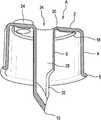
도 1은 본 발명의 바람직한 실시예에 따라 형성된 딥 튜브 삽입 부재의 사시도로서, 딥 튜브 삽입 부재는 액체 저장 용기의 밀봉 캡에 장착되고, 딥 튜브는 딥 튜브 삽입 부재를 통해 액체 저장 용기(일부만이 도시됨) 안으로 삽입된다. 도관 커넥터는 딥 튜브 주위의 딥 튜브 삽입 부재의 상부 개구를 밀봉하도록 딥 튜브의 상부에 장착된다.
도 2는 본 발명의 바람직한 실시예에 따라 형성된 딥 튜브 삽입 부재의 사시도이다.
도 3은 도 2에 도시된 딥 튜브 삽입 부재의 부분 사시도이다.
도 4는 도 2에 도시된 딥 튜브 삽입 부재의 또 다른 부분 사시도이다.
도 5는 액체 저장 용기의 일체형 밀봉 캡의 사시도이다.
도 6은 일체형 밀봉 캡의 밀봉 부재가 개봉된 도 5에 도시된 액체 저장 용기의 일체형 밀봉 캡의 저부의 사시도이다.
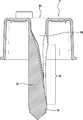
도 7은 액체 저장 용기에 장착된 밀봉 캡을 갖는 액체 저장 용기 위에 위치된 딥 튜브 삽입 부재의 부분 사시도이다.
도 8은 딥 튜브 삽입 부재의 프로브가 액체 저장 용기의 밀봉 캡의 밀봉 부재를 찢어내는, 딥 튜브 삽입 부재의 부분 사시도이다.
도 9는 액체 저장 용기의 밀봉 캡 및 그 주위의 최종 안착 위치 바로 위에 있는 딥 튜브 삽입 부재의 부분 사시도이다.
도 10은 액체 저장 용기의 밀봉 캡 및 그 주위의 최종 안착 위치에 있는 딥 튜브 삽입 부재, 및 딥 튜브 삽입 부재의 프로브의 중공 공동에 부분적으로 삽입된 딥 튜브의 사시도이다.
도 11은 딥 튜브가 액체 저장 위치 내로 더욱 전진된 도 10과 유사한 사시도이다.
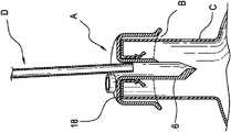
도 12는 딥 튜브와 도관 커넥터가 작동 위치에 있는 도 11과 유사한 부분 사시도이다.
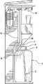
도 13은 본 발명의 다른 바람직한 실시예에 따라 형성된 딥 튜브 삽입 부재의 부분 사시도이다.
도 14는 도 13에 도시된 딥 튜브 삽입 부재의 부분 사시도이다.
도 15는 액체 분배 장치의 바람직한 형태이다.FIG. 1 is a perspective view of a dip tube insertion member formed in accordance with a preferred embodiment of the present invention, wherein the dip tube insertion member is mounted to a sealing cap of a liquid storage vessel and the dip tube is connected to a liquid reservoir Shown in Fig. The conduit connector is mounted on the top of the dip tube to seal the top opening of the dip tube insertion member around the dip tube.
2 is a perspective view of a dip tube insertion member formed in accordance with a preferred embodiment of the present invention.
3 is a partial perspective view of the dip tube insertion member shown in Fig.
4 is another partial perspective view of the dip tube insertion member shown in Fig.
5 is a perspective view of the integral sealing cap of the liquid storage container.
6 is a perspective view of the bottom of the integral sealing cap of the liquid storage container shown in Fig. 5 in which the sealing member of the integral sealing cap is opened.
7 is a partial perspective view of a dip tube insertion member positioned above a liquid storage vessel having a sealing cap mounted to the liquid storage vessel.
8 is a partial perspective view of a dip tube insertion member in which the probe of the dip tube insertion member tears the sealing member of the sealing cap of the liquid storage container.
9 is a partial perspective view of the dip tube insertion member immediately above the sealing cap of the liquid storage container and its final seating position.
10 is a perspective view of a dip tube partially inserted in a hollow cavity of a probe of a dip tube insertion member and a sealing cap of a liquid storage container and a dip tube insertion member in a final seating position therearound;
Figure 11 is a perspective view similar to Figure 10 where the dip tube is further advanced into the liquid storage position.
Figure 12 is a partial perspective view similar to Figure 11 with the dip tube and conduit connector in the operative position;
13 is a partial perspective view of a dip tube insertion member formed in accordance with another preferred embodiment of the present invention.
14 is a partial perspective view of the dip tube insertion member shown in Fig.
15 is a preferred form of the liquid dispensing apparatus.
이제 본 발명의 바람직한 형태가 도 1 내지 도 15를 참조하여 설명될 것이다. 첨부된 청구범위는 바람직한 형태에 제한되지 않으며, 본 명세서에서 사용된 용어 및/또는 문구는 명시적으로 다르게 언급되지 않는 한 통상적인 의미 이외의 의미를 부여하지는 않는다.Preferred embodiments of the present invention will now be described with reference to Figs. The appended claims are not to be construed as being limited to the preferred forms, and the terms and / or phrases used herein should not be construed as indicating any ordinary meaning unless expressly stated otherwise.
도 11내지 도To 12 12
도 1 내지 도 4, 및 도 7 내지 도 12를 참조하면, 딥 튜브 삽입 부재(A)의 바람직한 형태가 다수의 가능한 구성 중 하나로 도시되어 있다. 딥 튜브 삽입 부재(A)는 액체 저장 용기(C)를 밀봉하는 밀봉 캡(B)에 장착되고 그 주위를 둘러싸는 캡형 구조를 갖는 것이 가장 바람직하다. 딥 튜브 삽입 부재(A)는 캡형 구조에 한정되지 않고 어떤 적합한 형태를 취할 수 있다.Referring to Figs. 1 to 4 and Figs. 7 to 12, a preferred form of dip tube insertion member A is shown in one of a number of possible configurations. It is most preferable that the dip tube insertion member A has a cap-shaped structure mounted on and surrounding the sealing cap B for sealing the liquid storage container C. The dip tube insertion member A is not limited to the cap type structure and can take any suitable form.
도 1 내지 도 4, 및 도 7 내지 도 12를 참조하면, 딥 튜브 삽입 부재(A)는 상부 벽(2), 외부 환형 벽(4) 및 프로브(6)를 포함한다. 외부 환형 벽(4)의 바닥은, 개별적으로 딥 튜브 삽입 부재(A)를 밀봉 캡(B)에 견고히 고정할 수 있는 환형 고정 립(8)을 포함한다. 바람직하게는, 프로브(6)는 프로브의 최하단에 비교적 날카로운 팁(10)을 갖는다. 팁(10)의 단부는 프로브(6)가 종래의 일체형 밀봉 캡(B)을 쉽게 개봉하도록 한다. 도 5 및 도 6을 참조하면, 일체형 밀봉 캡(B)은 3개의 반경 방향으로 연장된 얇은 홈(14)을 갖는 중앙 밀봉 부재(12)를 갖는다. 팁(10)은 바람직하게는 3개의 반경 방향으로 연장된 얇은 홈(14)의 내부 접합부에 충돌하도록 구성된다.Referring to Figs. 1 to 4 and Figs. 7 to 12, the dip tube insertion member A includes a
도 7 내지 도 10을 참조하면, 프로브(6)가 액체 저장 용기(C) 내로 하방으로 이동할 때, 밀봉 부재(12)는 프로브(6)의 하향 힘에 의해 3개의 얇은 홈(14)에서 찢어지거나 파단되어, 뒤로 접혀지는 3개의 플랩(16)을 형성한다. 도 6은, 프로브(6)가 밀봉 캡(B)의 밀봉을 파손한 후의, 일체형 밀봉 캡(B)을 도시한다.7 to 10, when the
도 10 내지 도 12를 참조하면, 딥 튜브 삽입 부재(A)는 밀봉 캡(B)에 안착하여 이를 덮는다. 바람직하게는, 딥 튜브 삽입 부재(A)의 환형 외벽(4)은 밀봉 캡(B)의 환형 외벽을 완전히 둘러싼다.10 to 12, the dip tube insertion member A is seated on the sealing cap B and covers it. Preferably, the annular
도 3, 도 4 및 도 10 내지 도 12를 참조하면, 딥 튜브 삽입 부재(A)는 상부 벽(2)의 내부 표면으로부터 하향 연장되는 환형 밀봉 부재(18)를 포함한다. 환형 밀봉 부재(18)는 프로브(6)를 완전히 둘러싸서, 밀봉 캡(B)의 상부의 외부 주변 표면과 맞물린다. 밀봉 부재(18)는 상부 벽(2)의 내부 표면(20)과 밀봉 캡(B)의 상부 외부 표면(22) 사이에 공기 챔버를 형성한다. 공기 챔버는 밀봉 부재(18)로부터 내측으로 연장하여 프로브(6)를 완전히 둘러싼다.3, 4 and 10 to 12, the dip tube insertion member A includes an
딥 튜브 삽입 부재(A)는 상승된 포트(24)를 포함한다. 포트(24)는 주변 환경을 위하여 공기를 밀봉 부재(18)에 의해 형성된 공기 챔버 내로 향하게 한다. 프로브(6)는 프로브(6)의 외부 표면에 형성된 하나 이상의 수직 연장 홈 또는 리세스를 포함하며, 이는 공기 채널과 연통하고 공기를 액체 저장 용기(C)로 향하게 한다. 도 3과 도 4를 참조하면, 수직 연장 홈(26)은 프로브(6)의 벽 두께보다 작은 깊이를 가지므로, 수직 연장 홈(26)은 프로브(6)에 의해 형성된 중공 공동(28)과는 연통하지 않는다. 수직 연장 홈(26)은 공기 챔버로부터의 공기를 프로브(6)의 외부 표면을 따라 아래를 향해 액체 저장 용기(C) 내로 향하게 한다. 도 2를 참조하면, 수직 연장 홈(30)은 프로브(6)의 벽 두께보다 작은 깊이를 가지므로, 수직 연장 홈(30)은 프로브(6)에 의해 형성된 중공 공동(28)과는 연통하지 않는다. 수직 연장 홈(30)은 프로브(6)의 하부에 형성된 슬롯형 개구(32)에서 종결될 때 홈(26)보다 작은 길이를 갖는다. 그러나 수직 연장 홈(30)은 여전히 공기 챔버로부터의 공기를 프로브(6)의 외부 표면을 따라 아래를 향해 액체 저장 용기(C) 내로 향하게 한다. 도면에는 2개의 수직 연장 홈만이 도시되어 있지만, 프로브(6)는 3개 이상의 수직 연장 홈을 가질 수 있다. 예를 들어, 프로브(6)는 각각의 홈이 인접한 홈으로부터 원주 방향으로 90도 만큼 이격된 4개의 수직 연장 홈을 가질 수 있다.The dip tube insertion member A includes the raised
도 3 및 도 10 내지 도 12를 참조하면, 딥 튜브(D)는 상부 벽(2)의 개구(34)로 삽입되고 중공 공동(28) 및 슬롯형 개구(32)를 통해 아래쪽으로 삽입되어 있어, 딥 튜브(D)의 하단부가 액체 저장 용기(C)의 바닥, 또는 바닥에 인접하여 위치한다. 도 10 내지 도 12로부터 쉽게 알 수 있듯이, 딥 튜브(D)는 대각선 경로로 연장되는데, 즉, 딥 튜브(D)는 프로브(6)의 중심을 통과하는 수직 연장 축으로부터 예각으로 연장된다.3 and 10 to 12, a diptube D is inserted into the
도 1을 참조하면, 도관 커넥터(E)가 딥 튜브(D)의 상부에 안착 되어 있다. 도관 커넥터(E)의 베이스(36)는 딥 튜브(D)와 개구(34)를 형성하는 상부 벽(2)의 표면 사이의 환형 공간을 밀봉하도록 형성되는 것이 바람직하다. 주변 환경으로부터의 공기는 포트(24)를 통해 공기 챔버로, 그리고 프로브(6)의 외부 표면에 형성된 홈에서 수직 하향으로 통과함으로써 액체 저장 용기(C)로 진입할 수 있다. 포트(24)의 상단부는 공기의 통과를 허용하는 다수의 개구부를 갖는 그리드를 포함한다. 그리드는 2개 이상의 교차 부재 또는 리브에 의해 형성될 수 있다. 예를 들어, 4개의 개구는 십자형 방식으로 배향된, 즉 서로에 대해 수직인 2개의 리브에 의해 형성될 수 있다. 그리드는 공기 필터를 장착하기 위한 지지 표면을 제공한다. 따라서 액체 저장 용기에 들어가는 임의의 공기는 그리드에 장착된 공기 필터를 통과해야만 한다. 공기 필터는 임의의 적절한 방식으로 그리드에 고정될 수 있다. 대안적으로, 그리드는 공기 필터가 포트(24)의 중공 보어의 상부 내에 완전히 안착하도록, 공기 필터의 두께와 동일하거나 그보다 큰 거리로 포트(24)의 상부로부터 내부를 향해 리세스 될 수 있다.Referring to Fig. 1, a conduit connector E is seated on top of the diptube D. The
도 15를 참조하면, 도관 커넥터(E)의 단부(38)는 튜브(40)에 연결된다. 바람직하게는, 액체 저장 용기(C)로부터의 액체는 액체 저장 용기(C)로부터 펌프 되며, 미국 특허 제 8,887,955 호에 기재된 방식으로 분배 노즐(40)을 통해 분배된다. 그러나, 본 발명은 미국 특허 제 8,887,955 호에 기재된 분배 장치를 사용하는 것에 한정하지 않으며, 오히려 본 발명은 임의의 적합한 분배 장치에 사용될 수 있다.Referring to Fig. 15, the
도 13과 도 1413 and 14
도 13과 도 14를 참조하면, 대안적인 딥 튜브 삽입 부재(F)가 많은 가능한 구성 중 하나로 도시되어 있다. 딥 튜브 삽입 부재(F)는 딥 튜브 삽입 부재(A)와 유사하므로, 그 차이점만을 설명한다. 딥 튜브 삽입 부재(F)의 프로브(52)의 단부(50)는 미국 특허 제 5,542,555 호(그 전체 내용은 본원에서 참고로 인용됨)에 기재된 유형의 2 피스 밀봉 캡의 내부 캡을 제거 및 유지하도록 형성된다. 구체적으로, 딥 튜브 삽입 캡(F)이 미국 특허 제 5,542,555 호에 기재된 유형의 2 피스 밀봉 캡 위로 내려감에 따라, 프로브(52)는 내부 캡(미국 특허 제 5,542,555 호에서 참조 번호 16으로 언급됨)과 맞물려 내부 캡을 제거하고, 내부 캡의 비드(미국 특허 제 5,542,555 호에서 참조 번호 42로 언급됨)는, 내부 캡이 프로브(52)에 의해 유지되고 프로브(52)에 연결된 채로 있는 것을 보장하기 위해, 프로브(52)의 환형 홈(54) 내에 유지된다. 도 4를 참조하면, 프로브(52)의 한 측면에 형성된 슬롯형 개구(56), 중공 공동(58) 및 개구(60)는 딥 튜브가 액체 저장 용기 내로 삽입되는 것을 허용한다.Referring to Figures 13 and 14, an alternative dip tube insertion member F is shown in one of many possible configurations. Since the dip tube insertion member F is similar to the dip tube insertion member A, only the difference will be described. The
본 발명은 바람직한 디자인을 갖는 것으로 설명되었지만, 이러한 바람직한 디자인은 일반적으로 본 발명의 원리에 따라 추가로 수정되거나 변경될 수 있으며, 공지된 것의 범위 내에서 본 발명으로부터의 이탈을 포함하지만 이에 한정되지는 않으며, 본 발명이 속하는 기술 분야의 통상적인 관행을 포함한다. 청구 범위는 바람직한 실시예에 한정되지 않고 청구항 차별 원칙을 사용하여 그러한 좁은 구성을 배제하기 위해 작성되었다.While this invention has been described as having a preferred design, such preferred designs are generally additionally modified or modified in accordance with the principles of the present invention and include, but are not limited to, departures from the present invention within the scope of what is known And includes common practice in the art to which this invention pertains. The claims are not intended to be limited to the preferred embodiment and are intended to exclude such narrow constructions using the principle of claim discrimination.
Claims (20)
Translated fromKorean딥 튜브를 수용하기 위한 중공 공동을 갖는 프로브로서, 상기 프로브는 액체 용기 내로 딥 튜브의 삽입을 용이하게 하기 위한 상부 개구 및 하부 개구를 더 포함하는, 프로브와,
상기 프로브를 둘러싸는 공기 챔버를 형성하기 위한 밀봉 부재를 포함하며,
상기 공기 챔버는 공기를 수용하고, 이 공기가 액체 용기의 내부와 연통하는 적어도 하나의 공기 통로를 향하도록 구성되는, 딥 튜브 삽입 부재.A dip tube insertion member for facilitating insertion of a dip tube into a liquid container having a sealing cap without removing the sealing cap from the liquid container,
1. A probe having a hollow cavity for receiving a dip tube, the probe further comprising an upper opening and a lower opening for facilitating insertion of the dip tube into the liquid container,
And a sealing member for forming an air chamber surrounding the probe,
Wherein the air chamber is configured to receive air and direct the air to at least one air passage communicating with the interior of the liquid container.
상기 딥 튜브 삽입 부재의 캡을 더 포함하며, 상기 캡은, 딥 튜브 삽입 부재가 밀봉 캡을 갖는 액체 저장 용기에 설치될 때, 상기 딥 튜브 삽입 부재의 상기 캡의 일부는 액체 용기의 상기 밀봉 캡의 외벽의 실질적으로 수직으로 연장되는 부분을 둘러싸는, 딥 튜브 삽입 부재.The method according to claim 1,
Wherein when the dip tube insertion member is installed in a liquid storage container having a sealing cap, a part of the cap of the dip tube insertion member is in contact with the sealing cap of the liquid container, And a substantially vertically extending portion of the outer wall of the dip tube insertion member.
상기 밀봉 부재는 실질적으로 환형이고, 상기 딥 튜브 삽입 부재의 상기 캡의 제 1 벽으로부터 아래로 연장되며, 상기 제 1 벽은 실질적으로 수평으로 연장되는, 딥 튜브 삽입 부재.3. The method of claim 2,
Wherein the sealing member is substantially annular and extends downwardly from a first wall of the cap of the dip tube insertion member, the first wall extending substantially horizontally.
상기 프로브는 제 1 두께를 갖는 적어도 하나의 벽을 포함하고, 상기 적어도 하나의 공기 통로는 상기 프로브의 적어도 하나의 벽의 외부 표면에 형성된 제 1 깊이를 갖는 적어도 하나의 홈을 포함하며, 상기 제 1 깊이는 상기 제 1 깊이보다 작은, 딥 튜브 삽입 부재.The method of claim 3,
Wherein the probe comprises at least one wall having a first thickness and the at least one air passage includes at least one groove having a first depth formed on an outer surface of at least one wall of the probe, 1 depth is smaller than the first depth.
상기 적어도 하나의 공기 통로는 각각 제 1 깊이를 갖는 복수의 홈을 포함하고, 상기 복수의 홈 각각은 상기 프로브의 적어도 하나의 벽의 외부 표면에 형성되는, 딥 튜브 삽입 부재.5. The method of claim 4,
Wherein the at least one air passage includes a plurality of grooves each having a first depth and each of the plurality of grooves is formed on an outer surface of at least one wall of the probe.
상기 복수의 홈 중 적어도 하나는 실질적으로 수직으로 연장되는, 딥 튜브 삽입 부재.6. The method of claim 5,
Wherein at least one of the plurality of grooves extends substantially vertically.
상기 딥 튜브 삽입 부재의 상기 캡은 공기를 수용하기 위한 포트를 포함하고, 상기 포트의 일부는 상기 딥 튜브 삽입 부재의 상기 캡의 최상부를 형성하고, 상기 포트는 공기 챔버와 연통하여 공기를 공기 챔버 내로 안내하는, 딥 튜브 삽입 부재.3. The method of claim 2,
Wherein the cap of the dip tube insertion member includes a port for receiving air and a portion of the port defines a top portion of the cap of the dip tube insertion member and the port communicates with the air chamber, The dip tube insertion member.
상기 밀봉 부재는, 상기 딥 튜브 삽입 부재가 상기 밀봉 캡을 갖는 액체 용기에 설치될 때, 상기 액체 용기의 밀봉 캡의 외주면과 맞물리는, 딥 튜브 삽입 부재.3. The method of claim 2,
Wherein the sealing member is engaged with the outer circumferential surface of the sealing cap of the liquid container when the dip tube insertion member is installed in the liquid container having the sealing cap.
적어도 하나의 상부 벽, 적어도 하나의 외부 벽 및 프로브를 갖는 딥 튜브 삽입 캡으로서, 상기 프로브는 딥 튜브를 수용하기 위한 중공 공동을 포함하며, 상기 프로브는 액체 용기 내로의 딥 튜브의 삽입을 용이하게 하기 위한 상부 개구 및 하부 개구를 더 포함하며, 상기 프로브는 액체 용기의 밀봉 캡의 밀봉 부재를 개봉하도록 구성되어, 액체 용기 내로의 딥 튜브의 삽입을 허용하는, 딥 튜브 삽입 캡을 포함하며,
상기 딥 튜브 삽입 캡의 적어도 하나의 외부 벽은, 액체 용기의 밀봉 캡의 적어도 일부를 수용하기 위한 내부 수용 영역을 형성하여, 딥 튜브 삽입 부재가 밀봉 캡을 갖는 액체 용기에 설치될 때, 액체 용기의 밀봉 캡의 일부는 상기 수용 영역 내로 연장되고, 딥 튜브 삽입 캡의 일부는 액체 용기의 밀봉 캡의 적어도 일부를 둘러싸 덮는, 딥 튜브 삽입 부재.A dip tube insertion member for facilitating insertion of a dip tube into a liquid container having a sealing cap without removing the sealing cap from the liquid container,
A dip tube insert cap having at least one top wall, at least one outer wall and a probe, wherein the probe includes a hollow cavity for receiving a dip tube, the probe facilitating insertion of the dip tube into the liquid container The probe including a dip tube insertion cap configured to open a sealing member of a sealing cap of a liquid container to permit insertion of the dip tube into the liquid container,
Wherein at least one outer wall of the dip tube insertion cap defines an inner receiving region for receiving at least a portion of the sealing cap of the liquid container such that when the dip tube insertion member is installed in a liquid container having a sealing cap, Wherein a portion of the sealing cap of the dip tube extends into the receiving area and a portion of the dip tube insertion cap surrounds and covers at least part of the sealing cap of the liquid container.
상기 프로브의 외부 표면을 둘러싸는 공기 챔버를 형성하기 위한 밀봉 부재를 더 포함하며, 상기 공기 챔버는 공기를 수용하고, 이 공기가 액체 용기의 내부와 연통하는 적어도 하나의 공기 통로를 향하도록 구성되는, 딥 튜브 삽입 부재.10. The method of claim 9,
Further comprising a sealing member for forming an air chamber surrounding the outer surface of the probe, the air chamber being configured to receive air and direct the air towards at least one air passage communicating with the interior of the liquid container , A dip tube insertion member.
상기 공기 챔버는 상기 액체 용기의 상기 밀봉 캡의 최상 표면과 상기 딥 튜브 삽입 캡의 적어도 하나의 상부 벽 사이에 형성되는, 딥 튜브 삽입 부재.11. The method of claim 10,
Wherein the air chamber is formed between an uppermost surface of the sealing cap of the liquid container and at least one upper wall of the dip tube insertion cap.
상기 프로브는 제 1 두께를 갖는 적어도 하나의 벽을 포함하고, 상기 적어도 하나의 공기 통로는 상기 프로브의 적어도 하나의 벽의 외부 표면에 형성된 제 1 깊이를 갖는 적어도 하나의 홈을 포함하며, 상기 제 1 깊이는 상기 프로브의 적어도 하나의 벽의 상기 제 1 깊이보다 작은, 딥 튜브 삽입 부재.10. The method of claim 9,
Wherein the probe comprises at least one wall having a first thickness and the at least one air passage includes at least one groove having a first depth formed on an outer surface of at least one wall of the probe, 1 depth is less than the first depth of at least one wall of the probe.
상기 프로브는 상기 딥 튜브 삽입 캡의 중심축에 배치되는, 딥 튜브 삽입 부재.10. The method of claim 9,
Wherein the probe is disposed on a central axis of the dip tube insertion cap.
상기 프로브는 상기 액체 용기의 밀봉 캡의 상기 밀봉 부재를 개봉하기 위한 개봉부를 포함하는, 딥 튜브 삽입 부재.10. The method of claim 9,
Wherein the probe includes an opening portion for opening the sealing member of the sealing cap of the liquid container.
상기 프로브는 상기 액체 용기의 밀봉 캡의 밀봉 부재를 개봉하기 위해 상기 프로브의 최하단에 날카로운 팁을 포함하는, 딥 튜브 삽입 부재.10. The method of claim 9,
Wherein the probe includes a sharp tip at the lowermost end of the probe for opening the sealing member of the sealing cap of the liquid container.
상기 프로브는, 상기 액체 용기의 2 피스 밀봉 캡의 내부 캡을 제거하고 상기 프로브 상의 상기 2 피스 밀봉 캡의 제거된 내부 캡을 유지하기 위한 제거 및 유지 부재를 갖는 하부를 포함하는, 딥 튜브 삽입 부재.10. The method of claim 9,
The probe includes a lower portion having a removal and holding member for removing the inner cap of the two-piece sealing cap of the liquid container and holding the removed inner cap of the two-piece sealing cap on the probe, .
액체 저장 용기로부터의 액체가 분배되는 분배 위치와, 액체 저장 용기를 저장하기 위한 저장 위치를 갖는 주 하우징으로서, 상기 분배 위치는 상기 저장 위치의 적어도 일부 위에 배치되는, 주 하우징과,
딥 튜브 및 상기 딥 튜브를 분배 위치에 연결하는 적어도 하나의 도관과,
적어도 하나의 상부 벽, 적어도 하나의 외부 벽 및 프로브를 갖는 딥 튜브 삽입 캡을 포함하며,
상기 프로브는 상기 딥 튜브를 수용하기 위한 중공 공동을 포함하며, 상기 프로브는 액체 저장 용기에 딥 튜브의 삽입을 용이하게 하기 위한 상부 개구 및 하부 개구를 더 포함하며, 상기 프로브는 액체 저장 용기의 밀봉 캡의 밀봉 부재를 개봉하도록 구성되어, 액체 저장 용기로부터 밀봉 캡을 제거하지 않고 액체 저장 용기 내에 딥 튜브를 삽입할 수 있게 하며, 상기 딥 튜브 삽입 캡의 적어도 하나의 외부 벽은 액체 저장 용기의 밀봉 캡의 적어도 일부를 수용하기 위한 내부 수용 영역을 형성하여, 딥 튜브 삽입 캡이 밀봉 캡을 갖는 액체 저장 용기에 설치될 때, 액체 저장 용기의 밀봉 캡의 일부는 상기 수용 영역 내로 연장되고, 딥 튜브 삽입 캡의 일부는 액체 저장 용기의 밀봉 캡의 적어도 일부를 둘러싸 덮는, 액체 저장 용기로부터 액체를 분배하기 위한 장치.An apparatus for dispensing liquid from a liquid reservoir operably associated with an apparatus for dispensing liquid, the apparatus comprising:
A main housing having a dispensing position where liquid from a liquid storage container is dispensed and a storage position for storing a liquid storage container, the dispensing position being disposed over at least a portion of the storage location;
At least one conduit connecting the dip tube and the dip tube to a dispensing position,
A dip tube insertion cap having at least one top wall, at least one outer wall and a probe,
Wherein the probe further comprises a hollow cavity for receiving the dip tube, the probe further comprising an upper opening and a lower opening for facilitating insertion of the dip tube into the liquid storage vessel, Wherein the at least one outer wall of the dip tube insertion cap is adapted to seal the sealing member of the liquid storage vessel to seal the sealing member of the liquid storage vessel, Wherein a portion of the sealing cap of the liquid storage container extends into the receiving area when the dip tube insertion cap is installed in the liquid storage container having the sealing cap, A portion of the insertion cap surrounds at least a portion of the sealing cap of the liquid storage container, .
상기 딥 튜브 삽입 캡은 상기 프로브를 둘러싸는 공기 챔버를 형성하는 환형 밀봉 부재를 포함하는, 액체 저장 용기로부터 액체를 분배하기 위한 장치.18. The method of claim 17,
Wherein the dip tube insertion cap comprises an annular sealing member defining an air chamber surrounding the probe. ≪ RTI ID = 0.0 >< / RTI >
상기 프로브는 상기 프로브의 외부 표면에 형성된 적어도 하나의 수직 연장 홈을 포함하고, 상기 적어도 하나의 수직 연장 홈은 공기 챔버와 연통하는, 액체 저장 용기로부터 액체를 분배하기 위한 장치.19. The method of claim 18,
Wherein the probe comprises at least one vertical extending groove formed in the outer surface of the probe and the at least one vertical extending groove communicates with the air chamber.
상기 저장 위치에 배치된 밀봉 캡을 갖는 액체 저장 용기를 더 포함하며, 상기 딥 튜브 삽입 캡은 상기 액체 저장 용기의 밀봉 캡 상에 장착되어 상기 밀봉 캡을 감싸며, 상기 공기 챔버는 상기 딥 튜브 삽입 캡의 적어도 하나의 상부 벽과 상기 액체 저장 용기의 밀봉 캡의 최상부 표면 사이에 형성되는, 액체 저장 용기로부터 액체를 분배하기 위한 장치.20. The method of claim 19,
Further comprising a liquid storage container having a sealing cap disposed at the storage location, wherein the dip tube insertion cap is mounted on a sealing cap of the liquid storage container to enclose the sealing cap, Is formed between at least one top wall of the liquid storage vessel and the top surface of the sealing cap of the liquid storage vessel.
Applications Claiming Priority (3)
| Application Number | Priority Date | Filing Date | Title |
|---|---|---|---|
| US14/604,904 | 2015-01-26 | ||
| US14/604,904US9527639B2 (en) | 2015-01-26 | 2015-01-26 | Dip tube insertion member for facilitating insertion of a dip tube into a container without removing the container cap |
| PCT/IB2015/060077WO2016120702A1 (en) | 2015-01-26 | 2015-12-31 | A dip tube insertion member for facilitating insertion of a dip tube into a container without removing the container cap |
Publications (2)
| Publication Number | Publication Date |
|---|---|
| KR20170113580Atrue KR20170113580A (en) | 2017-10-12 |
| KR102493571B1 KR102493571B1 (en) | 2023-01-31 |
Family
ID=55173870
Family Applications (1)
| Application Number | Title | Priority Date | Filing Date |
|---|---|---|---|
| KR1020177022919AActiveKR102493571B1 (en) | 2015-01-26 | 2015-12-31 | Dip tube insertion member for easy insertion of the dip tube into the vessel without removing the vessel cap |
Country Status (7)
| Country | Link |
|---|---|
| US (1) | US9527639B2 (en) |
| EP (1) | EP3250500B1 (en) |
| KR (1) | KR102493571B1 (en) |
| CN (1) | CN107257774B (en) |
| MY (1) | MY186762A (en) |
| PL (1) | PL3250500T3 (en) |
| WO (1) | WO2016120702A1 (en) |
Cited By (1)
| Publication number | Priority date | Publication date | Assignee | Title |
|---|---|---|---|---|
| KR102606788B1 (en)* | 2022-07-15 | 2023-11-29 | 대상웰라이프 주식회사 | A connector that engages the pouch spout |
Families Citing this family (6)
| Publication number | Priority date | Publication date | Assignee | Title |
|---|---|---|---|---|
| US9714164B2 (en) | 2015-05-18 | 2017-07-25 | Cardomon International Limited | Apparatus for storing and dispensing liquid from a liquid retaining bag |
| US10843850B2 (en)* | 2016-10-11 | 2020-11-24 | Runway Blue, Llc | Containers and container closures |
| CN109368009B (en)* | 2018-11-02 | 2023-08-25 | 浙江高成绿能科技有限公司 | Prevent misplug quick feed arrangement and subassembly |
| CN111840069B (en)* | 2020-07-10 | 2022-11-15 | 万晶晶 | Sealing cover for physiological saline container and physiological saline container |
| US20240286882A1 (en)* | 2023-02-23 | 2024-08-29 | Crystal Mountain International Limited | Method for hands free auto-filling one or more water reservoirs of a liquid dispenser and a related apparatus |
| USD1068472S1 (en) | 2023-05-01 | 2025-04-01 | C-Loop Packaging Sweden Ab | Can end |
Citations (6)
| Publication number | Priority date | Publication date | Assignee | Title |
|---|---|---|---|---|
| US4058121A (en)* | 1976-06-29 | 1977-11-15 | American Hospital Supply Corporation | Vented needle for medical liquids |
| WO1987005208A1 (en)* | 1986-02-26 | 1987-09-11 | Broden Bengt Inge | A device for use in the handling of body fluids |
| US5542555A (en)* | 1992-10-01 | 1996-08-06 | Hidding; Walter E. | Valved bottle cap |
| US6139534A (en)* | 2000-01-24 | 2000-10-31 | Bracco Diagnostics, Inc. | Vial access adapter |
| US6269976B1 (en)* | 2000-08-17 | 2001-08-07 | Saint-Gobain Calmar Inc. | Vial access spike adapter for pump sprayer |
| US20130048681A1 (en)* | 2011-08-29 | 2013-02-28 | Philip A. Walton | Apparatus for dispensing a liquid from a liquid storage container |
Family Cites Families (25)
| Publication number | Priority date | Publication date | Assignee | Title |
|---|---|---|---|---|
| DE390369C (en) | 1921-10-23 | 1924-02-18 | Anton Franz Jung | Device for opening and pulling off the contents of metal containers |
| DE1293052B (en) | 1965-12-03 | 1969-04-17 | Flake Ice Machines Inc | Removal device for beverage container |
| GB2046226A (en) | 1979-03-09 | 1980-11-12 | Gabr S Z M | Dispensing of packaged liquids |
| US4265372A (en) | 1979-03-30 | 1981-05-05 | Lawrence Wainberg | Container and dispenser-cutter unit combination for containing and holding detachable flexible form-fill-seal plastic pouches |
| US4484697A (en) | 1980-08-27 | 1984-11-27 | Shasta Beverages, Inc. | Method and apparatus for dispensing liquid |
| GB8321590D0 (en) | 1983-08-11 | 1983-09-14 | Douwe Egberts Tabaksfab | Container holder |
| US4997429A (en)* | 1988-12-28 | 1991-03-05 | Sherwood Medical Company | Enteral bottle cap with vent valve |
| CN2058850U (en)* | 1989-12-29 | 1990-07-04 | 林玮 | Negative liquid suction device |
| GB9109168D0 (en) | 1991-04-29 | 1991-06-19 | Du Pont Canada | Reuseable pouch fitment |
| US5328055A (en) | 1992-11-27 | 1994-07-12 | Battle John R | Refillable liquid dispenser with diamond-shaped inner pliant bladder |
| US5392968A (en)* | 1993-06-14 | 1995-02-28 | Dark; Richard C. G. | Dispensing closure and method |
| US5975359A (en) | 1995-12-27 | 1999-11-02 | International Sanitary Ware Manufacturing Cy, S.A. | Needle engaging soap bag |
| US6161728A (en)* | 1999-08-18 | 2000-12-19 | Dark; Richard C. G. | Barrier piercing dispensing closure |
| US7799009B2 (en) | 2000-01-24 | 2010-09-21 | Bracco Diagnostics Inc. | Tabletop drug dispensing vial access adapter |
| US6832994B2 (en)* | 2000-01-24 | 2004-12-21 | Bracco Diagnostics Inc. | Table top drug dispensing vial access adapter |
| WO2005040034A2 (en) | 2003-10-23 | 2005-05-06 | Don Miller | Container adapted to hold and dispense bagged fluids |
| US7168599B1 (en) | 2004-03-16 | 2007-01-30 | Richard Criswell | Water-handling system |
| US20060032864A1 (en) | 2004-08-16 | 2006-02-16 | Jung Suk D | Water dispenser |
| NL1030883C1 (en) | 2006-01-10 | 2007-07-11 | 4Sight Innovation Bv | Device for tapping a beverage from a can. |
| JP5048968B2 (en) | 2006-05-08 | 2012-10-17 | サーパス工業株式会社 | Connector structure |
| DE102006035761B4 (en)* | 2006-08-01 | 2015-10-01 | Fresenius Kabi Deutschland Gmbh | Cap for a container filled with a medical fluid and container with a cap |
| US9101936B2 (en) | 2007-04-27 | 2015-08-11 | Radiometer Medical Aps | Sealed oxygen reference fluid containing bag |
| US20130053815A1 (en)* | 2011-08-23 | 2013-02-28 | Allergan, Inc. | High recovery vial adaptor |
| GB201218217D0 (en) | 2012-10-10 | 2012-11-21 | Blackburn Raymond W | Fluid dispenser with isolation membrane |
| CN104455411B (en)* | 2014-11-19 | 2016-10-05 | 朱苗君 | Pressure vessel |
- 2015
- 2015-01-26USUS14/604,904patent/US9527639B2/enactiveActive
- 2015-12-31PLPL15825867Tpatent/PL3250500T3/enunknown
- 2015-12-31CNCN201580074576.5Apatent/CN107257774B/enactiveActive
- 2015-12-31WOPCT/IB2015/060077patent/WO2016120702A1/ennot_activeCeased
- 2015-12-31KRKR1020177022919Apatent/KR102493571B1/enactiveActive
- 2015-12-31EPEP15825867.3Apatent/EP3250500B1/enactiveActive
- 2015-12-31MYMYPI2017702568Apatent/MY186762A/enunknown
Patent Citations (8)
| Publication number | Priority date | Publication date | Assignee | Title |
|---|---|---|---|---|
| US4058121A (en)* | 1976-06-29 | 1977-11-15 | American Hospital Supply Corporation | Vented needle for medical liquids |
| WO1987005208A1 (en)* | 1986-02-26 | 1987-09-11 | Broden Bengt Inge | A device for use in the handling of body fluids |
| US4982740A (en)* | 1986-02-26 | 1991-01-08 | Broden Bengt Inge | Method for use in the handling of body fluids |
| US5542555A (en)* | 1992-10-01 | 1996-08-06 | Hidding; Walter E. | Valved bottle cap |
| US6139534A (en)* | 2000-01-24 | 2000-10-31 | Bracco Diagnostics, Inc. | Vial access adapter |
| US6269976B1 (en)* | 2000-08-17 | 2001-08-07 | Saint-Gobain Calmar Inc. | Vial access spike adapter for pump sprayer |
| US20130048681A1 (en)* | 2011-08-29 | 2013-02-28 | Philip A. Walton | Apparatus for dispensing a liquid from a liquid storage container |
| US8887955B2 (en)* | 2011-08-29 | 2014-11-18 | Cardomon International Limited | Apparatus for dispensing a liquid from a liquid storage container |
Cited By (2)
| Publication number | Priority date | Publication date | Assignee | Title |
|---|---|---|---|---|
| KR102606788B1 (en)* | 2022-07-15 | 2023-11-29 | 대상웰라이프 주식회사 | A connector that engages the pouch spout |
| WO2024014774A1 (en)* | 2022-07-15 | 2024-01-18 | 대상웰라이프 주식회사 | Connector coupled to inlet part for liquid container |
Also Published As
| Publication number | Publication date |
|---|---|
| HK1245227A1 (en) | 2018-08-24 |
| CN107257774A (en) | 2017-10-17 |
| US9527639B2 (en) | 2016-12-27 |
| EP3250500B1 (en) | 2019-11-20 |
| MY186762A (en) | 2021-08-18 |
| EP3250500A1 (en) | 2017-12-06 |
| PL3250500T3 (en) | 2020-06-01 |
| CN107257774B (en) | 2020-09-01 |
| US20160214771A1 (en) | 2016-07-28 |
| WO2016120702A1 (en) | 2016-08-04 |
| KR102493571B1 (en) | 2023-01-31 |
Similar Documents
| Publication | Publication Date | Title |
|---|---|---|
| KR20170113580A (en) | A diptube insertion member for easily inserting a diptube into a container without removing the container cap | |
| US5289855A (en) | Liquid container support and probe-type hygienic liquid dispensing system | |
| US20050224515A1 (en) | Pump dispenser and cartridge | |
| US20080041493A1 (en) | Water cooler separator body and assembly | |
| AU678200B2 (en) | Improvements in and relating to packaged beverages and packaging therefor | |
| TR201807708T4 (en) | Capping for a non-refillable container intended for use in a liquid such as oil or vinegar. | |
| JP2010070203A (en) | Liquid dispensing container | |
| US11548773B1 (en) | Multipurpose vented funnel | |
| US8453881B2 (en) | Bottle mounting assembly for refrigerated dispensers | |
| CN114206170A (en) | Beverage dispenser system for a motor vehicle | |
| AU2016264985B2 (en) | An apparatus for storing and dispensing liquid from a liquid retaining bag | |
| HK1245227B (en) | A dip tube insertion member for facilitating insertion of a dip tube into a container without removing the container cap | |
| JPH0338149Y2 (en) | ||
| AU2013395748B2 (en) | Refill dispensing bottle | |
| JP5564374B2 (en) | Beverage server | |
| US11758917B2 (en) | Closures for liquid-dispensing containers and methods for making and using such closures | |
| JP5234810B2 (en) | Liquid ejection device | |
| US20070169844A1 (en) | Inverted bottle fluid dispensing system | |
| RU78783U1 (en) | FILLING UNIT OF LIQUID CAPACITY | |
| JP2018154377A (en) | Carbonated drink server | |
| JP2001278370A (en) | Mixed liquid ejecting container | |
| JPH1111510A (en) | Instrument for liquid ejection |
Legal Events
| Date | Code | Title | Description |
|---|---|---|---|
| PA0105 | International application | Patent event date:20170817 Patent event code:PA01051R01D Comment text:International Patent Application | |
| PG1501 | Laying open of application | ||
| A201 | Request for examination | ||
| PA0201 | Request for examination | Patent event code:PA02012R01D Patent event date:20201020 Comment text:Request for Examination of Application | |
| E902 | Notification of reason for refusal | ||
| PE0902 | Notice of grounds for rejection | Comment text:Notification of reason for refusal Patent event date:20220720 Patent event code:PE09021S01D | |
| E701 | Decision to grant or registration of patent right | ||
| PE0701 | Decision of registration | Patent event code:PE07011S01D Comment text:Decision to Grant Registration Patent event date:20221111 | |
| GRNT | Written decision to grant | ||
| PR0701 | Registration of establishment | Comment text:Registration of Establishment Patent event date:20230126 Patent event code:PR07011E01D | |
| PR1002 | Payment of registration fee | Payment date:20230127 End annual number:3 Start annual number:1 | |
| PG1601 | Publication of registration |