KR20170109232A - Battery cell and battery system - Google Patents
Battery cell and battery systemDownload PDFInfo
- Publication number
- KR20170109232A KR20170109232AKR1020177021105AKR20177021105AKR20170109232AKR 20170109232 AKR20170109232 AKR 20170109232AKR 1020177021105 AKR1020177021105 AKR 1020177021105AKR 20177021105 AKR20177021105 AKR 20177021105AKR 20170109232 AKR20170109232 AKR 20170109232A
- Authority
- KR
- South Korea
- Prior art keywords
- holder
- electrode coil
- collector
- cathode
- battery cell
- Prior art date
- Legal status (The legal status is an assumption and is not a legal conclusion. Google has not performed a legal analysis and makes no representation as to the accuracy of the status listed.)
- Withdrawn
Links
Images


Classifications
- H—ELECTRICITY
- H01—ELECTRIC ELEMENTS
- H01M—PROCESSES OR MEANS, e.g. BATTERIES, FOR THE DIRECT CONVERSION OF CHEMICAL ENERGY INTO ELECTRICAL ENERGY
- H01M10/00—Secondary cells; Manufacture thereof
- H01M10/04—Construction or manufacture in general
- H01M10/0486—Frames for plates or membranes
- H—ELECTRICITY
- H01—ELECTRIC ELEMENTS
- H01M—PROCESSES OR MEANS, e.g. BATTERIES, FOR THE DIRECT CONVERSION OF CHEMICAL ENERGY INTO ELECTRICAL ENERGY
- H01M10/00—Secondary cells; Manufacture thereof
- H01M10/04—Construction or manufacture in general
- H01M10/0431—Cells with wound or folded electrodes
- H01M2/0237—
- H01M2/06—
- H01M2/26—
- H—ELECTRICITY
- H01—ELECTRIC ELEMENTS
- H01M—PROCESSES OR MEANS, e.g. BATTERIES, FOR THE DIRECT CONVERSION OF CHEMICAL ENERGY INTO ELECTRICAL ENERGY
- H01M50/00—Constructional details or processes of manufacture of the non-active parts of electrochemical cells other than fuel cells, e.g. hybrid cells
- H01M50/10—Primary casings; Jackets or wrappings
- H01M50/102—Primary casings; Jackets or wrappings characterised by their shape or physical structure
- H01M50/103—Primary casings; Jackets or wrappings characterised by their shape or physical structure prismatic or rectangular
- H—ELECTRICITY
- H01—ELECTRIC ELEMENTS
- H01M—PROCESSES OR MEANS, e.g. BATTERIES, FOR THE DIRECT CONVERSION OF CHEMICAL ENERGY INTO ELECTRICAL ENERGY
- H01M50/00—Constructional details or processes of manufacture of the non-active parts of electrochemical cells other than fuel cells, e.g. hybrid cells
- H01M50/10—Primary casings; Jackets or wrappings
- H01M50/172—Arrangements of electric connectors penetrating the casing
- H01M50/174—Arrangements of electric connectors penetrating the casing adapted for the shape of the cells
- H01M50/176—Arrangements of electric connectors penetrating the casing adapted for the shape of the cells for prismatic or rectangular cells
- H—ELECTRICITY
- H01—ELECTRIC ELEMENTS
- H01M—PROCESSES OR MEANS, e.g. BATTERIES, FOR THE DIRECT CONVERSION OF CHEMICAL ENERGY INTO ELECTRICAL ENERGY
- H01M50/00—Constructional details or processes of manufacture of the non-active parts of electrochemical cells other than fuel cells, e.g. hybrid cells
- H01M50/40—Separators; Membranes; Diaphragms; Spacing elements inside cells
- H—ELECTRICITY
- H01—ELECTRIC ELEMENTS
- H01M—PROCESSES OR MEANS, e.g. BATTERIES, FOR THE DIRECT CONVERSION OF CHEMICAL ENERGY INTO ELECTRICAL ENERGY
- H01M50/00—Constructional details or processes of manufacture of the non-active parts of electrochemical cells other than fuel cells, e.g. hybrid cells
- H01M50/50—Current conducting connections for cells or batteries
- H01M50/531—Electrode connections inside a battery casing
- H01M50/533—Electrode connections inside a battery casing characterised by the shape of the leads or tabs
- H—ELECTRICITY
- H01—ELECTRIC ELEMENTS
- H01M—PROCESSES OR MEANS, e.g. BATTERIES, FOR THE DIRECT CONVERSION OF CHEMICAL ENERGY INTO ELECTRICAL ENERGY
- H01M2220/00—Batteries for particular applications
- H01M2220/20—Batteries in motive systems, e.g. vehicle, ship, plane
- Y—GENERAL TAGGING OF NEW TECHNOLOGICAL DEVELOPMENTS; GENERAL TAGGING OF CROSS-SECTIONAL TECHNOLOGIES SPANNING OVER SEVERAL SECTIONS OF THE IPC; TECHNICAL SUBJECTS COVERED BY FORMER USPC CROSS-REFERENCE ART COLLECTIONS [XRACs] AND DIGESTS
- Y02—TECHNOLOGIES OR APPLICATIONS FOR MITIGATION OR ADAPTATION AGAINST CLIMATE CHANGE
- Y02E—REDUCTION OF GREENHOUSE GAS [GHG] EMISSIONS, RELATED TO ENERGY GENERATION, TRANSMISSION OR DISTRIBUTION
- Y02E60/00—Enabling technologies; Technologies with a potential or indirect contribution to GHG emissions mitigation
- Y02E60/10—Energy storage using batteries
- Y—GENERAL TAGGING OF NEW TECHNOLOGICAL DEVELOPMENTS; GENERAL TAGGING OF CROSS-SECTIONAL TECHNOLOGIES SPANNING OVER SEVERAL SECTIONS OF THE IPC; TECHNICAL SUBJECTS COVERED BY FORMER USPC CROSS-REFERENCE ART COLLECTIONS [XRACs] AND DIGESTS
- Y02—TECHNOLOGIES OR APPLICATIONS FOR MITIGATION OR ADAPTATION AGAINST CLIMATE CHANGE
- Y02P—CLIMATE CHANGE MITIGATION TECHNOLOGIES IN THE PRODUCTION OR PROCESSING OF GOODS
- Y02P70/00—Climate change mitigation technologies in the production process for final industrial or consumer products
- Y02P70/50—Manufacturing or production processes characterised by the final manufactured product
Landscapes
- Chemical & Material Sciences (AREA)
- Chemical Kinetics & Catalysis (AREA)
- Electrochemistry (AREA)
- General Chemical & Material Sciences (AREA)
- Engineering & Computer Science (AREA)
- Manufacturing & Machinery (AREA)
- Connection Of Batteries Or Terminals (AREA)
- Secondary Cells (AREA)
- Sealing Battery Cases Or Jackets (AREA)
- Battery Mounting, Suspending (AREA)
Abstract
Translated fromKoreanDescription
Translated fromKorean본 발명은 청구항 제 1 항의 전제부에 따른 배터리 셀 및 청구항 제 12 항에 따른 배터리 시스템에 관한 것이다.The present invention relates to a battery cell according to the preamble of claim 1 and a battery system according to
미래에는, 풍력 발전소와 같은 고정 응용 분야, 하이브리드 자동차 또는 전기 자동차로서 설계된 자동차뿐만 아니라 랩탑이나 휴대 전화와 같은 전자 장치에도, 신뢰성, 안전성, 성능 및 내구성과 관련한 높은 요구 조건이 주어지는 새로운 배터리 시스템이 사용될 것이 명백하다.In the future, new battery systems will be introduced that will provide high requirements for reliability, safety, performance and durability in fixed applications such as wind power plants, automobiles designed as hybrid cars or electric vehicles, as well as electronic devices such as laptops and cell phones It is obvious.
특히, 소위 리튬 이온 배터리 셀이 사용된다. 상기 배터리 셀은 특히 높은 에너지 밀도, 열 안정성 및 극도로 낮은 자기 방전을 특징으로 한다. 리튬 이온 배터리 셀은 포지티브 전극 및 네거티브 전극을 포함하고, 충전 과정 및 방전 과정 중에 상기 전극들에서 리튬 이온들이 가역적으로 저장되고 다시 빠져나올 수 있다. 이러한 과정은 인터칼레이션 또는 디인터칼레이션이라고도 한다.Particularly, a so-called lithium ion battery cell is used. The battery cell is characterized by a particularly high energy density, thermal stability and extremely low self-discharge. The lithium ion battery cell includes a positive electrode and a negative electrode, and lithium ions can be reversibly stored and discharged again at the electrodes during charging and discharging processes. This process is also called intercalation or deintercalation.
배터리 셀은 일반적으로 와인딩의 형태로 설계된 하나 이상의 전극 유닛을 포함한다. 전극 유닛은 2개의 필름 형태 전극, 즉 애노드 및 캐소드를 포함한다. 전극들은 세퍼레이터가 사이에 배치된 상태로 감겨서, 젤리 롤(Jelly Roll)이라고도 하는 전극 코일을 형성한다. 전극 코일의 2개의 전극들은 컬렉터에 의해 단자라고도 하는 배터리 셀의 극에 전기적으로 연결된다.The battery cell generally includes one or more electrode units designed in the form of a winding. The electrode unit includes two film-type electrodes, an anode and a cathode. The electrodes are rolled with the separator interposed therebetween to form an electrode coil, also called a jelly roll. The two electrodes of the electrode coil are electrically connected to the pole of the battery cell, also called the terminal, by the collector.
배터리 셀은 또한 예를 들어 알루미늄으로 이루어진 셀 하우징을 포함한다. 셀 하우징은 일반적으로 각 기둥으로, 특히 직육면체 형태로 설계되고 내압성을 갖도록 형성된다. 전극을 단자에 연결한 후 전해질 용액이 셀 하우징 내로 채워진다.The battery cell also includes a cell housing made, for example, of aluminum. The cell housing is generally designed for each column, especially in the form of a rectangular parallelepiped, and is formed to have pressure resistance. After the electrode is connected to the terminal, the electrolyte solution is filled into the cell housing.
EP 2 675 000 A1은 전극 코일을 갖는 상기 유형의 배터리 셀을 개시한다. 애노드 및 캐소드는 반대편 측면에서 와인딩 축에 대해 평행하게 전극 코일로부터 돌출하고, 각각 하나의 컬렉터에 연결된다. 2개의 컬렉터는 전극 코일의 와인딩 축에 대해 실질적으로 수직으로 연장되고 애노드와 캐소드를 단자에 연결한다.
다른 상기 유형의 배터리 셀은 US 2010/0028770 A1에 개시되어 있다. 전극 코일의 전극들은 전극 코일로부터 돌출하여 컬렉터에 연결된 접촉 러그들을 포함한다. 컬렉터에 연결하기 전에 접촉 러그들은 상이한 길이를 갖는다.Other types of battery cells are disclosed in US 2010/0028770 A1. The electrodes of the electrode coil include contact lugs protruding from the electrode coil and connected to the collector. The contact lugs have different lengths before they are connected to the collector.
전극 및 셀 하우징의 전기 절연을 위해, 예를 들어 플라스틱으로 이루어진 절연체가 제공된다. 배터리 셀용 절연체를 갖는 전극 코일은 US 2013/0288092 A1에 개시되어있다.For electrical insulation of the electrode and the cell housing, for example, an insulator made of plastic is provided. An electrode coil having an insulator for a battery cell is disclosed in US 2013/0288092 Al.
리튬 이온 배터리 셀들은 환경 영향, 특히 공기와 습기에 대해 비교적 민감하다. 언급된 셀 하우징은 상기 환경 영향에 대한 보호를 제공한다. 다수의 이러한 배터리 셀들이 결합되어, 배터리 팩이라고도 하는 배터리 시스템을 형성한다.Lithium ion battery cells are relatively sensitive to environmental influences, particularly air and moisture. The mentioned cell housing provides protection against the environmental impact. A number of such battery cells are combined to form a battery system, also referred to as a battery pack.
본 발명의 과제는 조립이 간단한 배터리 셀 및 배터리 시스템을 제공하는 것이다.An object of the present invention is to provide a battery cell and a battery system which are simple to assemble.
네거티브 단자 및 포지티브 단자가 배치된 커버 면을 갖는 각기둥 모양으로 설계된 셀 하우징, 및 상기 셀 하우징 내부에 배치되며 캐소드 및 애노드를 갖는 적어도 하나의 전극 코일을 포함하는 배터리 셀이 제안된다.There is proposed a battery cell including a cell housing designed in a prismatic shape having a negative terminal and a cover surface on which a positive terminal is disposed and at least one electrode coil disposed inside the cell housing and having a cathode and an anode.
본 발명에 따르면, 적어도 하나의 전극 코일은 전기 절연 홀더에 의해 커버 면에 고정되고, 홀더는 적어도 하나의 전기 절연 스페이서에 연결된다.According to the present invention, at least one electrode coil is fixed to the cover surface by an electrically insulating holder, and the holder is connected to at least one electrically insulating spacer.
바람직하게는, 스페이서가 커버 면에 고정된다.Preferably, the spacer is fixed to the cover surface.
바람직하게 스페이서는 캐소드 또는 애노드를 단자에 전기적으로 연결하는 컬렉터에 의해 커버 면에 지지, 특히 클램핑된다.Preferably, the spacer is supported, especially clamped, on the cover surface by a collector that electrically connects the cathode or anode to the terminal.
본 발명의 바람직한 실시 예에 따르면, 홀더는 프레임 형태로 설계되고, 적어도 하나의 전극 코일은 홀더 내에 클램핑된다.According to a preferred embodiment of the present invention, the holder is designed in the form of a frame, and at least one electrode coil is clamped in the holder.
전극 코일이 감기는 와인딩 축은 바람직하게는 셀 하우징의 커버 면에 대해 평행하게 연장된다.The winding axis on which the electrode coils are wound preferably extends parallel to the cover surface of the cell housing.
본 발명의 다른 바람직한 실시 예에 따르면, 홀더는 스페이서에 연결된 커버 영역, 및 상기 커버 영역에 연결된 바닥 영역을 포함하며, 적어도 하나의 전극 코일은 커버 영역과 바닥 면적 사이에 지지된다.According to another preferred embodiment of the present invention, the holder comprises a cover region connected to the spacer and a bottom region connected to the cover region, wherein at least one electrode coil is supported between the cover region and the floor area.
적어도 하나의 전극 코일은 홀더에 의해 적어도 거의 완전히 둘러싸인다.The at least one electrode coil is at least nearly completely surrounded by the holder.
본 발명의 다른 바람직한 실시 예에 따르면, 홀더는 평평한 대상물로서 설계되고, 적어도 하나의 전극 코일은 홀더 둘레에 감긴다.According to another preferred embodiment of the present invention, the holder is designed as a flat object, and at least one electrode coil is wound around the holder.
바람직하게는, 적어도 하나의 전극 코일이 감기는 와인딩 축은 셀 하우징의 커버 면에 대해 수직으로 연장된다.Preferably, the winding axis on which at least one electrode coil is wound extends perpendicular to the cover surface of the cell housing.
본 발명의 다른 바람직한 실시 예에 따르면, 홀더는 이중 프레임의 형태로 설계된다. 홀더는 적어도 하나의 전극 코일을 사이에 수용하는 제 1 프레임 부 및 제 2 프레임 부를 포함한다.According to another preferred embodiment of the present invention, the holder is designed in the form of a double frame. The holder includes a first frame portion and a second frame portion for receiving at least one electrode coil therebetween.
홀더가 적어도 하나의 전기 절연 스페이서와 일체형으로 형성되면, 바람직하고 조립이 쉽다.If the holder is integrally formed with at least one electrically insulating spacer, it is desirable and easy to assemble.
적어도 하나의 본 발명에 따른 배터리 셀을 포함하는 배터리 시스템도 제안된다.A battery system including at least one battery cell according to the present invention is also proposed.
본 발명에 따른 배터리 셀은 전기 자동차(EV), 하이브리드 자동차(HEV) 또는 플러그-인 하이브리드 자동차(PHEV)에 바람직하게 사용된다.The battery cell according to the present invention is preferably used in an electric vehicle (EV), a hybrid vehicle (HEV) or a plug-in hybrid vehicle (PHEV).
적어도 하나의 전극 코일이 셀 하우징의 커버 면 상의 홀더에 고정되면, 배터리 셀의 조립이 간단해진다. 커버 면이 나머지 셀 하우징에 결합될 때, 적어도 하나의 전극 코일이 셀 하우징의 내부로 자동 삽입된다. 이미 존재하고 셀 하우징에 대해 컬렉터를 절연시키는 역할을 하는 스페이서들이 홀더를 고정하는 데 사용된다. 캐소드와 애노드를 배터리 셀의 단자에 연결하는 상기 컬렉터들은 스페이서들을 커버 면 상에 기계적으로 지지하고 스페이서를 커버 면 상에 고정시킨다.When at least one electrode coil is fixed to the holder on the cover surface of the cell housing, assembly of the battery cell is simplified. When the cover surface is coupled to the remaining cell housing, at least one electrode coil is automatically inserted into the interior of the cell housing. Spacers that already exist and serve to isolate the collector with respect to the cell housing are used to secure the holder. The collectors connecting the cathode and the anode to the terminals of the battery cell mechanically support the spacers on the cover surface and secure the spacers on the cover surface.
본 발명의 실시 예들이 도면 및 이하의 설명을 참조하여 더욱 상세히 설명된다.BRIEF DESCRIPTION OF THE DRAWINGS Embodiments of the present invention are described in further detail with reference to the drawings and the following description.
도 1은 컬렉터가 없는 배터리 셀의 개략적인, 반투명 사시도.
도 2는 전극 코일이 없는 제 1 실시 예에 따른 배터리 셀의 개략적인, 반투명 사시도.
도 3은 전극 코일이 없는 제 2 실시 예에 따른 배터리 셀의 개략적인, 반투명 사시도.
도 4는 셀 하우징 내에 설치하기 전 전극 코일의 단부면의 평면도.
도 5a는 컬렉터와 연결 전 절단선 V-V를 따른 도 4의 전극 코일의 부분 단면도.
도 5b는 컬렉터와 연결 후 도 5a의 전극 코일을 도시한 도면.
도 6a는 컬렉터와 연결 전 도 5a의 전극 코일의 변형 예.
도 6b는 컬렉터와 연결 후 도 6a의 전극 코일을 도시한 도면.
도 7은 전극 코일의 제조를 나타낸 개략도.
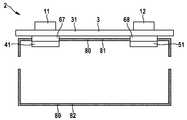
도 8은 전극 코일용 홀더의 제 1 실시 예를 갖는 배터리 셀의 개략적인 단면도.
도 9는 전극 코일용 홀더의 제 2 실시 예를 갖는 배터리 셀의 개략적인 단면도.
도 10은 전극 코일용 홀더의 제 3 실시 예를 갖는 배터리 셀의 개략적인 단면도.
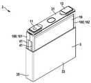
도 11은 전극 코일용 홀더의 제 4 실시 예를 갖는 배터리 셀의 개략적인 분해도.
도 12는 셀 하우징의 조립 시 도 11의 배터리 셀의 개략적인 사시도.1 is a schematic, semi-transparent perspective view of a battery cell without a collector;
2 is a schematic, semi-transparent perspective view of a battery cell according to a first embodiment without an electrode coil;
3 is a schematic, semi-transparent perspective view of a battery cell according to a second embodiment without electrode coils;
4 is a plan view of an end face of the electrode coil before being installed in the cell housing;
Fig. 5A is a partial cross-sectional view of the electrode coil of Fig. 4 taken along the cutting line VV before connection with the collector; Fig.
Figure 5b shows the electrode coil of Figure 5a after connection with the collector.
6A is a modification of the electrode coil of FIG. 5A before connection with the collector.
Figure 6b shows the electrode coil of Figure 6a after connection with the collector.
7 is a schematic view showing the manufacture of an electrode coil;
8 is a schematic cross-sectional view of a battery cell having a first embodiment of an electrode coil holder.
9 is a schematic cross-sectional view of a battery cell having a second embodiment of an electrode coil holder.
10 is a schematic cross-sectional view of a battery cell having a third embodiment of an electrode coil holder.
11 is a schematic exploded view of a battery cell having a fourth embodiment of an electrode coil holder.
12 is a schematic perspective view of the battery cell of Fig. 11 when assembling the cell housing;
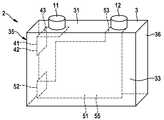
배터리 셀(2)은 각 기둥으로, 본 경우에 직육면체 형태로 형성된 셀 하우징(3)을 포함한다. 셀 하우징(3)은 본 경우에 도전성을 갖도록 설계되고, 예를 들어 알루미늄으로 제조된다. 셀 하우징(3)은 전기 절연 재료, 예를 들면 플라스틱으로 제조되거나 전기 절연 재료로 코팅될 수도 있다.The
배터리 셀(2)은 네거티브 단자(11) 및 포지티브 단자(12)를 포함한다. 배터리 셀(2)에 의해 제공된 전압은 단자들(11, 12)을 통해 태핑(tapping)될 수 있다. 또한, 배터리 셀(2)은 단자들(11, 12)을 통해 충전될 수도 있다.The battery cell (2) includes a negative terminal (11) and a positive terminal (12). The voltage provided by the
배터리 셀(2)의 직육면체 형태의 셀 하우징(3)은 3개의 상이한 크기의 표면적을 갖는 6개의 면을 포함하며, 동일한 크기의 표면적을 갖는 각각 2개의 면은 서로 대향한다. 가장 큰 표면적을 갖는 면들을 이하에서 제 1 전방 면(33) 및 제 2 전방 면(34)이라 한다. 가장 작은 표면적을 갖는 면들을 이하에서 제 1 단부면(35) 및 제 2 단부면(36)이라 한다. 중간 크기의 표면적을 갖는 나머지 면들을 커버 면(31) 및 바닥 면(32)이라 한다.The
단자들(11, 12)은 서로 이격되어 셀 하우징(3)의 커버 면(31)에 배치된다. 이 경우, 네거티브 단자(11)는 제 1 단부면(35)에 인접하고, 포지티브 단자(12)는 제 2 단부면(36)에 인접한다.The
배터리 셀(2)의 셀 하우징(3) 내에는 2개의 전극, 즉 캐소드(14)와 애노드(16)를 포함하는 전극 코일(10)이 배치되어 있다. 캐소드(14) 및 애노드(16)는 필름 형태로 구현되고, 제 1 세퍼레이터(18)와 제 2 세퍼레이터(19)가 사이에 배치된 상태로 와인딩 축(A)을 중심으로 와인딩되어 전극 코일(10)을 형성한다. 전극 코일(10)은 와인딩 축(A)이 단부면(35, 36)에 대해 수직으로 연장되도록 셀 하우징(3) 내에 배치된다.In the
배터리 셀(2)은 전기적으로 병렬로 또는 충분한 절연의 경우에 직렬로 연결된 다수의 전극 코일(10)을 포함할 수도 있다. 셀 하우징(3) 내에는 전해질이 존재한다.The
애노드(16)는 배터리 셀(2)의 네거티브 단자(11)에 전기적으로 연결된 다수의 애노드 접촉 러그(26)를 포함한다. 캐소드(14)는 배터리 셀(2)의 포지티브 단자(12)에 전기적으로 연결된 다수의 캐소드 접촉 러그(24)를 포함한다. 애노드 접촉 러그들(26) 및 캐소드 접촉 러그들(24)은 동일한 단부면에서 나란히 전극 코일(10)로부터 돌출하고, 전극 코일(10)로부터 셀 하우징(3)의 제 1 단부면(35)을 향해 연장된다.The
전극 코일(10)의 애노드 접촉 러그(26)와 캐소드 접촉 러그(24) 사이에는 여기에 도시되지 않은 절연 필름이 배치되며, 상기 절연 필름은 애노드(16)의 애노드 접촉 러그(16)를 캐소드(14)의 캐소드 접촉 러그(24)로부터 전기적으로 절연시킨다. 본 경우에 상기 절연 필름은 절연 코일(10)의 애노드(16)와 캐소드(14) 사이에 제공된 세퍼레이터들(18, 19) 중 하나의 세퍼레이터의 부분이다.An insulating film not shown here is disposed between the anode contact lug 26 of the
네거티브 단자(11)에 애노드(16)를 전기 접속하기 위해, 제 1 컬렉터(41)가 제공된다. 제 1 컬렉터(41)는, 제 1 단부면(35)에 대해 평행하게 그리고 제 1 단부면(35) 가까이에서 연장되며 애노드(16)의 애노드 접촉 러그(26)에 연결된 제 1 영역(42)을 포함한다. 제 1 컬렉터(41)의 제 1 영역(42)은 커버 면(31)을 향해 연장되며 제 2 영역(43)으로 이어지고, 상기 제 2 영역(43)은 상기 커버 면(31)에 대해 평행하게 연장된다. 제 1 컬렉터(41)의 제 2 영역(43)은 네거티브 단자(11)에 연결된다. 제 1 컬렉터(41)와 배터리 셀(2)의 셀 하우징(42) 사이에는 전기 절연체가 제공된다.In order to electrically connect the
포지티브 단자(12)에 캐소드(14)를 전기적으로 연결하기 위해, 제 2 컬렉터(51)가 제공된다. 제 2 컬렉터(51)는 제 1 단부면(35)에 대해 평행하게 제 1 단부면(35) 가까이에서 연장하며 캐소드(14)의 캐소드 접촉 러그(24)에 연결된 제 1 영역(52)을 포함한다. 제 2 컬렉터(51)는 포지티브 단자(12)에 연결된 제 2 영역(53)을 포함한다.In order to electrically connect the
도 2에 도시된 배터리 셀(2)의 제 1 실시 예에 따르면, 제 2 컬렉터(51)는 중앙 영역(55)을 포함하고, 상기 중앙 영역(55)은 제 1 영역(52)과 제 2 영역(53)에 연결된다. 이 경우, 제 2 컬렉터(51)의 중앙 영역(55)은 전방 면들(33, 34)에 대해 평행하게 연장된다. 본 경우에 제 2 컬렉터(51)의 중앙 영역(55)은 전극 코일(10)과 제 1 전방면(33) 사이에 배치된다. 제 2 컬렉터(51)와 배터리 셀(2)의 셀 하우징(3) 사이에는 전기 절연체가 제공된다.According to a first embodiment of the
제 2 컬렉터(51)의 중앙 영역(55)은 전극 코일(10)과 제 2 전방 면(34) 사이에 배치될 수 있다. 또한, 전극 코일(10)의 양측에 배치된 제 2 컬렉터(51)의 2 개의 평행한 중앙 영역(55)이 제공될 수 있다.The
도 3에 도시된 배터리 셀(2)의 제 2 실시 예에 따르면, 제 2 컬렉터(51)는 제 1 영역(52)에 연결된 하부 영역(56)을 포함한다. 또한, 제 2 컬렉터(51)는 제 2 영역(53)에 연결된 후방 영역(57)을 포함한다. 이 경우, 제 2 컬렉터(51)의 하부 영역(56)은 제 2 컬렉터(51)의 후방 영역(57)에 연결된다.According to a second embodiment of the
제 2 컬렉터(51)의 하부 영역(56)은 제 2 컬렉터(51)의 제 1 영역(52)으로부터 전극 코일(10)과 바닥면(32) 사이에서 상기 바닥 면(32)에 대해 평행하게 제 2 단부면(36)을 향해 연장된다. 제 2 컬렉터(51)의 후방 영역(57)은 제 2 컬렉터(51)의 제 2 영역(53)으로부터 전극 코일(10)과 제 2 단부면(36) 사이에서 제 2 단부면(36)에 대해 평행하게 바닥면(32)을 향해 연장된다. 또한, 제 2 컬렉터(51)의 후방 영역(57)은 제 2 컬렉터(51)의 하부 영역(56)에 연결된다. 또한, 제 2 컬렉터(51)와 배터리 셀(2)의 셀 하우징(3) 사이에는 전기 절연체가 제공된다.The
배터리 셀(2)의 여기에 도시되지 않은 다른 실시 예에 따르면, 도전성 셀 하우징(3)은 포지티브 단자(12)에 전기적으로 연결된다. 이 경우, 제 2 컬렉터(51)와 셀 하우징(3) 사이에 절연체가 필요 없다.According to another embodiment of the
대안으로서, 도전성 셀 하우징(3)은 네거티브 단자(11)에 전기적으로 연결된다. 이 경우, 제 1 컬렉터(41)와 셀 하우징(3) 사이에 절연체가 필요 없다.Alternatively, the
또한, 포지티브 단자(12)와 캐소드(14)의 캐소드 접촉 러그(24)가 셀 하우징(3)에 전기적으로 연결될 수 있다. 이 경우, 셀 하우징(3)은 제 2 컬렉터(51)의 기능, 즉 포지티브 단자(12)와 캐소드(14)의 전기적 연결을 수행할 것이다. 이 경우, 제 2 컬렉터(51)는 완전히 생략될 수 있다. 제 2 컬렉터(51)가 캐소드(14)의 캐소드 접촉 러그(24)를 셀 하우징(3)의 제 1 단부면(35)에 전기적으로 연결하는 것도 가능하다.In addition, the
대안으로서, 네거티브 단자(11)와 애노드(16)의 애노드 접촉 러그(26)를 셀 하우징(3)에 전기적으로 연결하는 것도 가능하다. 이 경우, 셀 하우징(3)은 제 1 컬렉터(41)의 기능, 즉 네거티브 단자(11)와 애노드(16)의 전기적 연결을 수행할 것이다. 이 경우, 제 1 컬렉터(41)는 완전히 생략될 수 있다. 제 1 컬렉터(41)가 애노드(16)의 애노드 접촉 러그(26)를 예를 들어 셀 하우징(3)의 제 1 단부면(35)에 전기적으로 연결하는 것도 가능하다.Alternatively, it is also possible to electrically connect the
도 4는 배터리 셀(2)의 셀 하우징(3) 내에 장착되기 전의 전극 코일(10)의 하나의 단부면을 평면도로 도시한다. 애노드(16)의 애노드 접촉 러그(26)는 와인딩 축(A)에 대해 대략 평행하게 전극 코일(10)로부터 돌출한다. 와인딩 축(A)에 대해 수직인 방향으로, 애노드(16)의 애노드 접촉 러그들(26)이 서로 일렬로 정렬되어 배치된다. 캐소드(14)의 캐소드 접촉 러그들(24)은 와인딩 축(A)에 대해 대략 평행하게 전극 코일(10)로부터 돌출한다. 와인딩 축(A)에 대해 수직인 방향으로, 캐소드(14)의 캐소드 접촉 러그들(24)이 서로 일렬로 정렬되어 배치된다.Fig. 4 is a plan view of one end face of the
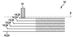
도 5a는 절단선 Ⅴ-Ⅴ을 따른 도 4의 전극 코일(10)의 부분 단면도이다. 이 경우, 제 2 컬렉터(51)와 연결 전에 캐소드(14)의 캐소드 접촉 러그(24)를 갖는 전극 코일(10)의 부분이 도시되어있다. 제 2 컬렉터(51)는 전극 코일(10)의 와인딩 축(A)에 대해 수직으로 연장된다.FIG. 5A is a partial cross-sectional view of the
캐소드(14)의 개별 캐소드 접촉 러그들(24)은 상이한 길이를 갖는다. 와인딩 축(A)을 향한 캐소드 접촉 러그(24)는 가장 짧은 길이를 갖는다. 캐소드 접촉 러그들(24)의 길이는 와인딩 축(A)과 캐소드 접촉 러그(24) 사이의 간격이 커짐에 따라 증가한다. 와인딩 축(A)으로부터 떨어져 있는 캐소드 접촉 러그(24)는 최대 길이를 갖는다.The individual cathode contact lugs (24) of the cathode (14) have different lengths. The
도 5b는 제 2 컬렉터(51)와 연결 후에 도 5a의 전극 코일(10)을 도시한다. 캐소드(14)의 개별 캐소드 접촉 러그들(24)은 각각 와인딩 축(A)에 대해 수직으로 연장되는 축을 중심으로 구부러지고 서로 중첩된다. 와인딩 축(A)으로부터 떨어져 있는 캐소드(14)의 캐소드 접촉 러그(24)는 제 2 컬렉터(51) 상에 놓인다. 캐소드(14)의 캐소드 접촉 러그들(24)은 서로 그리고 제 2 컬렉터(51)에 연결, 특히 용접된다.Fig. 5b shows the
캐소드(14)의 개별 캐소드 접촉 러그들(24)의 길이는, 전극 코일(10)로부터 떨어져 있는 캐소드 접촉 러그(24)의 단부가 캐소드 접촉 러그(24)와 제 2 컬렉터(51)의 연결 후에 서로 정렬되도록 서로 매칭된다.The length of the individual cathode contact lugs 24 of the
도 6a는 제 2 컬렉터(51)와 연결 전에 도 5a의 전극 코일(10)의 변형 예를 도시한다. 이 경우 제 2 컬렉터(51)는 전극 코일(10)의 와인딩 축(A)에 대해 평행하게 연장된다.Fig. 6A shows a modification of the
전극 코일(10)의 상기 변형 예의 경우, 캐소드(14)의 개별 캐소드 접촉 러그들(24)은 상이한 길이를 갖는다. 와인딩 축(A) 및 제 2 컬렉터(51)를 향하는 캐소드 접촉 러그(24)는 가장 짧은 길이를 갖는다. 캐소드 접촉 러그들(24)의 길이는 와인딩 축(A) 및 제 2 컬렉터(51)와 캐소드 접촉 러그(24) 사이의 간격이 커짐에 따라 길어진다. 와인딩 축(A) 및 제 2 컬렉터(51)로부터 떨어져 있는 캐소드 접촉 러그(24)는 최대 길이를 갖는다.In the case of this variant of the
도 6b는 제 2 컬렉터(51)와 연결 후 도 6a의 전극 코일(10)을 도시한다. 캐소드(14)의 개별 캐소드 접촉 러그들(24)은 서로 중첩된다. 와인딩 축(A)을 향한 캐소드(14)의 캐소드 접촉 러그(24)는 제 2 컬렉터(51) 상에 놓인다. 캐소드(14)의 캐소드 접촉 러그들(24)은 서로 그리고 제 2 컬렉터(51)에 연결, 특히 용접된다.6B shows the
전극 코일(10)의 상기 변형 예의 경우, 캐소드(14)의 개별 캐소드 접촉 러그들(24)의 길이는 전극 코일(10)로부터 떨어져 있는 캐소드 접촉 러그(24)의 단부가 캐소드 접촉 러그(24)와 제 2 컬렉터(51)의 연결 후에 서로 정렬되도록 서로 매칭된다.The length of the individual cathode contact lugs 24 of the
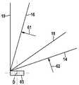
도 7은 전극 코일(10)의 제조를 개략적으로 도시한다. 와인딩 코어(65)는 회전축(D)을 중심으로 회전한다. 필름 형태의 캐소드(14), 필름 형태의 제 1 세퍼레이터(18), 필름 형태의 애노드(16) 및 필름 형태의 제 2 세퍼레이터(19)는 와인딩 코어(65)에 고정된다. 와인딩 코어(65)의 회전축(D)은 전극 코일(10)의 와인딩 축(A)에 대해 정렬된다.Fig. 7 schematically shows the manufacture of the
와인딩 코어(65)의 회전에 의해, 캐소드(14), 제 1 세퍼레이터(18), 애노드(16) 및 제 2 세퍼레이터(19)가 와인딩 코어(65) 상에 감긴다. 따라서 캐소드(14)와 애노드(16) 사이에는 각각 세퍼레이터들(18, 19) 중 하나가 배치된다.The
제 1 레이저 빔(61)은 필름 형태의 애노드(16)의 에지 영역을 절삭한다. 그러나 이 경우 애노드(16)의 애노드 접촉 러그들(26)은 남아있다. 와인딩 코어(65)의 완전한 일 회전 후에, 애노드(16)의 애노드 접촉 러그들(26) 중 하나가 남아있다. 이로 인해, 애노드(16)의 애노드 접촉 러그들(26)이 도 4에 도시된 바와 같이, 서로 일렬로 정렬되어 배치되는 것이 보장된다.The
애노드(16)의 남아있는 애노드 접촉 러그들(26)의 길이는 매 회전마다 증가한다. 이로 인해, 와인딩 축(A) 및 회전축(D)을 향하는 애노드(16)의 애노드 접촉 러그(26)는 가장 짧은 길이를 갖고, 와인딩 축(A) 및 회전축(D)으로부터 떨어져 있는 애노드(16)의 애노드 접촉 러그(26)는 최대 길이를 갖는다.The length of the remaining anode contact lugs 26 of the
제 2 레이저 빔(62)은 필름 형태의 캐소드(14)의 에지 영역을 절삭한다. 그러나 이 경우 캐소드(14)의 캐소드 접촉 러그(24)는 남아있다. 와인딩 코어(65)의 완전한 회전 후에, 캐소드(14)의 캐소드 접촉 러그들(24) 중 하나가 남아있다. 이로 인해, 캐소드(14)의 캐소드 접촉 러그들(24)이 도 4에 도시된 바와 같이, 서로 일렬로 정렬되어 배치되는 것이 보장된다.The
캐소드(14)의 남아있는 캐소드 접촉 러그들(24)의 길이는 매 회전마다 증가한다. 이로 인해, 와인딩 축(A) 및 회전축(D)을 향하는 캐소드(14)의 캐소드 접촉 러그(24)는 가장 짧은 길이를 갖고, 와인딩 축(A) 및 회전축(D)으로부터 떨어져 있는 캐소드(14)의 캐소드 접촉 러그(24)는 도 5a에 도시된 바와 같이, 최대 길이를 갖는다.The length of the remaining cathode contact lugs 24 of the
캐소드(14), 애노드(16) 및 세퍼레이터들(18, 19)이 완전히 감긴 후, 와인딩 코어(65)가 제거될 수 있다. 전극 코일(10)은 쉽게 함께 압축될 수 있어서, 빠진 와인딩 코어(65)에 의해 야기되는 공동이 폐쇄된다.After the
도 8은 전극 코일(10)을 위한 제 1 실시 예에 따른 홀더(70)를 갖는 배터리 셀(2)의 개략적인 단면도를 도시한다. 컬렉터들(41, 51)은 전체가 도시되지 않았다.Figure 8 shows a schematic cross-sectional view of a
제 1 실시 예에 따른 홀더(70)는 직사각형 프레임으로서 설계되고 비도전성 재료, 특히 플라스틱으로 제조된다. 제 1 실시 예에 따른 홀더(70)는 제 1 길이 방향 측면(71), 및 상기 제 1 길이 방향 측면(71)에 대해 평행하게 연장되는 제 2 길이 방향 측면(72)을 포함한다. 제 1 길이 방향 측면(71) 및 제 2 길이 방향 측면(72)의 단부들은 제 1 횡 방향 측면(73) 및 제 2 횡 방향 측면(74)에 의해 서로 연결된다. 제 1 횡 방향 측면(73) 및 제 2 횡 방향 측면(74)은 서로 평행하게 그리고 길이 방향 측면(71, 72)에 대해 수직으로 연장된다.The
제 1 실시 예에 따른 프레임 형태 홀더(70)의 제 1 길이 방향 측면(71)은 배터리 셀(2)의 셀 하우징(3)의 커버 면(31)에 고정된다. 제 1 실시 예에 따른 홀더(70)의 제 1 길이 방향 측면(71)의 단부로부터, 제 1 횡 방향 측면(73) 및 제 2 횡 방향 측면(74)이 수직으로 커버 면(31)으로부터 셀 하우징(3)의 도시되지 않은 바닥면(32)을 향해 연장된다. 제 1 횡 방향 측면(73)은 셀 하우징(3)의 도시되지 않은 제 1 단부면(35) 가까이에서 연장되고, 제 2 횡 방향 측면(74)은 셀 하우징(3)의 도시되지 않은 제 2 단부면(36) 가까이에서 연장된다. 제 2 길이 방향 측면(72)은 셀 하우징(3)의 도시되지 않은 바닥면(32) 가까이에서 연장된다.The first
전극 코일(10)은 제 1 실시 예에 따른 프레임 형태 홀더(70) 내에 클램핑된다. 전극 코일(10)의 와인딩 축(A)은 제 1 실시 예에 따른 홀더(70)의 길이 방향 측면(71, 72)에 대해 평행하게 그리고 셀 하우징(3)의 커버 면(31)에 대해 평행하게 연장된다. 애노드(16) 및 캐소드(14)는 제 1 실시 예에 따른 홀더(70)의 제 1 횡 방향 측면(73) 가까이에서 전극 코일(10)로부터 돌출한다.The
배터리 셀(2)의 제 1 컬렉터(41)는 네거티브 단자(11)에 전기적 및 기계적으로 연결된다. 제 1 스페이서(67)는 제 1 컬렉터(41)와 셀 하우징(3)의 커버 면(31) 사이에 배치된다. 제 1 스페이서(67)는 비도전성 재료, 특히 플라스틱으로 제조되고, 제 1 컬렉터(41)를 셀 하우징(3)의 커버 면(31)으로부터 전기적으로 절연시킨다. 따라서, 제 1 스페이서(67)는 셀 하우징(3) 내에서 커버 면(31)에 기계적으로 고정된다.The
배터리 셀(2)의 제 2 컬렉터(51)는 포지티브 단자(12)에 전기적 및 기계적으로 연결된다. 제 2 스페이서(68)는 제 2 컬렉터(51)와 셀 하우징(3)의 커버 면(31) 사이에 배치된다. 제 2 스페이서(68)는 비도전성 재료, 특히 플라스틱으로 제조되고, 제 2 컬렉터(51)를 셀 하우징(3)의 커버 면(31)으로부터 전기적으로 절연시킨다. 따라서, 제 2 스페이서(68)는 셀 하우징(3) 내에서 커버 면(31)에 기계적으로 고정된다.The
제 1 실시 예에 따른 홀더(70)의 제 1 길이 방향 측면(71)은 제 1 스페이서(67) 및 제 2 스페이서(68)에 기계적으로 연결된다. 제 1 실시 예에 따른 홀더(70)의 제 1 길이 방향 측면(71)은 클립 연결과 유사하게, 스페이서(67, 68)의 대응 오목부 내로 가압되어 거기에 형상 끼워맞춤 방식으로 고정된다. 제 1 실시 예에 따른 홀더(70)는 스페이서들(67, 68)과 일체형으로 형성될 수도 있다.The first
도 9는 도시되지 않은 전극 코일을 위한 제 2 실시 예에 따른 홀더(80)를 갖는 배터리 셀(2)의 개략적인 단면도를 도시한다. 컬렉터들(41, 51)은 전체가 도시되지 않았다.Figure 9 shows a schematic cross-sectional view of a
제 2 실시 예에 따른 홀더(80)는 적어도 거의 폐쇄된 캔의 형태로 설계되며, 비도전성 재료, 특히 플라스틱으로 제조된다. 제 2 실시 예에 따른 홀더(80)는 커버 영역(81) 및 바닥 영역(82)을 포함한다.The
제 2 실시 예에 따른 홀더(80)의 커버 영역(81)은 배터리 셀(2)의 셀 하우징(3)의 커버 면(31)에 고정된다. 도시된 도면에서는 바닥 영역(82)이 커버 영역(81)으로부터 떨어져 배치된다. 바닥 영역(82)은 도시되지 않은 전극 코일(10)의 접속 후에 커버 영역(81) 상에 가압되고 커버 영역(81) 상에 형상 끼워맞춤 방식으로 록킹된다. 도시되지 않은 전극 코일(10)은 그 후에 제 2 실시 예에 따른 캔의 형태로 형성된 홀더(80)에 의해 둘러싸인다.The
배터리 셀(2)의 제 1 컬렉터(41)는 네거티브 단자(11)에 전기적 및 기계적으로 연결된다. 제 1 스페이서(67)는 제 1 컬렉터(41)와 셀 하우징(3)의 커버 면(31) 사이에 배치된다. 제 1 스페이서(67)는 비도전성 재료, 특히 플라스틱으로 제조되고, 제 1 컬렉터(41)를 셀 하우징(3)의 커버 면(31)으로부터 전기적으로 절연시킨다. 따라서, 제 1 스페이서(67)는 셀 하우징(3) 내에서 커버 면(31)에 기계적으로 고정된다.The
배터리 셀(2)의 제 2 컬렉터(51)는 포지티브 단자(12)에 전기적 및 기계적으로 연결된다. 제 2 스페이서(68)는 제 2 컬렉터(51)와 셀 하우징(3)의 커버 면(31) 사이에 배치된다. 제 2 스페이서(68)는 비도전성 재료, 특히 플라스틱으로 제조되고, 제 2 컬렉터(51)를 셀 하우징(3)의 커버 면(31)으로부터 전기적으로 절연시킨다. 따라서, 제 2 스페이서(68)는 셀 하우징(3) 내에서 커버 면(31)에 기계적으로 고정된다.The
제 2 실시 예에 따른 홀더(80)의 커버 영역(81)은 제 1 스페이서(67) 및 제 2 스페이서(68)에 기계적으로 연결된다. 커버 영역(81)은 클립 연결과 유사하게 스페이서(67, 68)의 대응 오목부 내로 가압되어 거기에 형상 끼워 맞춤 방식으로 고정된다. 커버 영역(81)이 스페이서(67, 68)와 일체형으로 형성될 수도 있다.The
도 10은 도시되지 않은 전극 코일(10)을 위한 제 3 실시 예에 따른 홀더(90)를 갖는 배터리 셀(2)의 개략적인 단면도를 도시한다. 컬렉터들(41, 51)은 전체가 도시되지 않았다.10 shows a schematic cross-sectional view of a
제 3 실시 예에 따른 홀더(90)는 직사각형의 평평한 대상물로서 설계되고, 비도전성 재료, 특히 플라스틱으로 제조된다. 제 3 실시 예에 따른 홀더(90)는 헤드 측면(91), 상기 헤드 측면(91)에 대해 평행하게 연장되는 풋 측면(92), 제 1 외 측면(93) 및 제 2 외측면(94)에 의해 한정된다. 제 1 외측면(93) 및 제 2 외측면(94)은 서로 평행하게 그리고 헤드 측면(91) 및 풋 측면(92)에 대해 수직으로 연장된다.The
제 3 실시 예에 따른 홀더(90)의 헤드 측면(91)은 배터리 셀(2)의 셀 하우징(3)의 커버 면(31)에 고정된다. 제 1 외측면(93) 및 제 2 외측면(94)은 커버 면(31)으로부터 수직으로 셀 하우징(3)의 도시되지 않은 바닥면(32)을 향해 연장된다. 제 1 외측면(93)은 셀 하우징(3)의 도시되지 않은 제 1 단부면(35) 가까이에서 연장되고, 제 2 외측면(94)은 셀 하우징(3)의 도시되지 않은 제 2 단부면(36) 가까이에서 연장된다. 풋 측면(92)은 셀 하우징(3)의 도시되지 않은 바닥면(32) 가까이에서 연장된다.The
도시되지 않은 전극 코일(10)은 제 3 실시 예에 따른 홀더(90) 둘레에 감긴다. 전극 코일(10)의 와인딩 축(A)은 제 3 실시 예에 따른 홀더(90)의 헤드 측면(91)에 대해 수직으로 그리고 셀 하우징(3)의 커버 면(31)에 대해 수직으로 연장된다. 애노드(16), 캐소드(14) 및 세퍼레이터들(18, 19)은 제 3 실시 예에 따른 홀더(90)의 외측면(93, 94) 둘레에 놓인다.An
배터리 셀(2)의 제 1 컬렉터(41)는 네거티브 단자(11)에 전기적 및 기계적으로 연결된다. 제 1 스페이서(67)는 제 1 컬렉터(41)와 셀 하우징(3)의 커버 면(31) 사이에 배치된다. 제 1 스페이서(67)는 비도전성 재료, 특히 플라스틱으로 제조되고, 제 1 컬렉터(41)를 셀 하우징(3)의 커버 면(31)으로부터 전기적으로 절연시킨다. 따라서, 제 1 스페이서(67)는 셀 하우징(3) 내에서 커버 면(31)에 기계적으로 고정된다.The
배터리 셀(2)의 제 2 컬렉터(51)는 포지티브 단자(12)에 전기적 및 기계적으로 연결된다. 제 2 스페이서(68)는 제 2 컬렉터(51)와 셀 하우징(3)의 커버 면(31) 사이에 배치된다. 제 2 스페이서(68)는 비도전성 재료, 특히 플라스틱으로 제조되고, 제 2 컬렉터(51)를 셀 하우징(3)의 커버 면(31)으로부터 전기적으로 절연시킨다. 따라서, 제 2 스페이서(68)는 셀 하우징(3) 내에서 커버 면(31)에 기계적으로 고정된다.The
제 3 실시 예에 따른 홀더(90)의 헤드 측면(91)은 제 1 스페이서(67) 및 제 2 스페이서(68)에 기계적으로 연결된다. 제 3 실시 예에 따른 홀더(90)의 헤드 측면(91)은 클립 연결과 유사하게 스페이서(67, 68)의 대응 오목부 내로 가압되고 거기에 형상 끼워 맞춤 방식으로 고정된다. 제 3 실시 예에 따른 홀더(90)가 스페이서(67, 68)와 일체형으로 형성되는 것도 가능하다.The
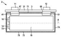
도 11은 제 4 실시 예에 따른 홀더(100)를 갖는 배터리 셀(2)의 개략적인 분해도를 도시한다. 제 4 실시 예에 따른 홀더(100)는 2개의 전극 코일(10)을 수용하는 역할을 한다.11 shows a schematic exploded view of a
제 4 실시 예에 따른 홀더(100)는 이중 프레임의 형태로 설계되고 비도전성 재료, 특히 플라스틱으로 제조된다. 제 4 실시 예에 따른 홀더(100)는 2개의 전극 코일(10)을 사이에 수용하는 제 1 프레임 부(101)와 제 2 프레임 부(102)를 포함한다. 따라서, 전극 코일(10)은 제 4 실시 예에 따른 홀더(100)의 프레임 부들(101, 102)에 의해 측면으로 둘러싸인다.The holder 100 according to the fourth embodiment is designed in the form of a double frame and is made of a non-conductive material, especially plastic. The holder 100 according to the fourth embodiment includes a first frame portion 101 and a second frame portion 102 that receive two
2개의 전극 코일(10)의 각각은 애노드(16) 및 캐소드(14)를 포함한다. 애노드(16)의 애노드 접촉 러그들(26)과 캐소드(14)의 캐소드 접촉 러그들(24)은 나란히 동일한 단부면에서 전극 코일(10)로부터 돌출한다.Each of the two
2개의 전극 코일(10)의 애노드 접촉 러그(26)와 캐소드 접촉 러그(24) 사이에 각각 도시되지 않은 절연 필름이 배치되고, 상기 절연 필름은 각각 애노드 접촉 러그(26)를 캐소드 접촉 러그(24)로부터 전기적으로 절연시킨다. 본 경우, 2개의 절연 필름은 각각 2개의 전극 코일(10)의 애노드(16)와 캐소드(14) 사이에 제공된 세퍼레이터(18, 19)의 부분이다.An insulating film, not shown, is disposed between the anode contact lug 26 and the
2개의 제 1 컬렉터(41)는 네거티브 단자(11)와 애노드(16)의 전기적 연결을 위해 제공된다. 이 경우, 2개의 전극 코일(10)의 애노드(16)의 애노드 접촉 러그들(26)은 각각 제 1 컬렉터들(41) 중 하나에 연결, 본 경우에 용접된다. 제 1 컬렉터들(41)은 본 경우에 구리로 제조된다.Two
제 1 컬렉터들(41)은 애노드(16)의 애노드 접촉 러그(26)로부터 먼저 제 1 단부면(35)에 대해 평행하게 그리고 제 1 단부면(35) 가까이에서 커버 면(31)을 향해 연장된다. 제 1 컬렉터들(41)은 네거티브 단자(11)에 전기적 및 기계적으로 연결된다.The
제 1 컬렉터들(41)은 본 경우에 별도의 부품으로서 설계된다. 제 1 컬렉터들(41)은 일체형으로도 설계될 수 있다. 이 경우, 2개의 전극 코일(10)의 애노드 접촉 러그들(26)은 동일한 단일 제 1 컬렉터(41)에 연결된다.The
2개의 제 2 컬렉터(51)는 포지티브 단자(12)와 캐소드(14)의 전기적 연결을 위해 제공된다. 이 경우, 2개의 전극 코일(10)의 캐소드들(14)의 캐소드 접촉 러그들(24)은 제 2 컬렉터들(51) 중 하나에 연결, 본 경우에 용접된다. 제 2 컬렉터들(51)은 본 경우에 알루미늄으로 제조된다. 제 2 컬렉터들(51)은 도 2에 도시된 바와 유사하게 연장되지만 도 11에 도시되지 있지 않다.Two
제 2 컬렉터들(51)은 각각 제 1 영역(52)을 포함하는데, 상기 제 1 영역(52)은 제 1 단부면(35)에 대해 평행하게 제 1 단부면(35) 가까이에서 연장되며 전극 코일들(10) 중 하나의 전극 코일의 캐소드 접촉 러그(24)에 연결된다. 또한, 각각의 제 2 컬렉터(51)는 포지티브 단자(12)에 전기적 및 기계적으로 연결된 제 2 영역(53)을 포함한다.The
제 2 컬렉터들(51)은 각각 제 1 영역(52)과 제 2 영역(53)에 연결된 중앙 영역(55)을 포함한다. 제 2 컬렉터들(51)의 중앙 영역들(55)은 전방 면들(33, 34)에 대해 평행하게 연장된다. 이 경우, 제 2 컬렉터들(51) 중 하나의 컬렉터의 중앙 영역(55)은 전극 코일들(10) 중 하나와 제 1 전방면(33) 사이에 배치되고, 다른 제 2 컬렉터(51)의 중앙 영역(55)은 다른 전극 코일(10)과 제 2 전방면(34) 사이에 배치된다. 따라서, 제 2 컬렉터(51)의 중앙 영역(55)은 2개의 전극 코일(10)의 양측에 배치된다.The
제 2 컬렉터들(51)은 본 경우에 별도의 부품으로서 설계된다. 제 2 컬렉터들(51)은 일체형으로도 설계될 수 있다. 이를 위해, 2개의 제 2 컬렉터(51)의 제 2 영역들(53)은 각각 서로 연결된다.The
제 1 스페이서(67)는 셀 하우징(3)의 커버 면(31)과 제 1 컬렉터(41) 사이에 배치된다. 제 1 스페이서(67)는 비도전성 재료, 특히 플라스틱으로 제조되고, 제 1 컬렉터(41)를 셀 하우징(3)의 커버 면(31)으로부터 전기적으로 절연시킨다. 따라서 제 1 스페이서(67)는 셀 하우징(3) 내에서 커버 면(31)에 기계적으로 고정된다.The
제 1 스페이서(67)는 본 경우에 제 4 실시 예에 따른 홀더(100)와 일체형으로 형성된다. 이 경우, 제 1 스페이서(67)는 부분적으로 제 1 프레임 부(101) 및 제 2 프레임 부(102) 상에 배치된다. 제 1 프레임 부(101)와 제 2 프레임 부(102)를 결합함으로써 완전한 제 1 스페이서(67)가 형성된다.The
제 2 스페이서(68)는 제 2 컬렉터(51)와 셀 하우징(3)의 커버 면(31) 사이에 배치된다. 제 2 스페이서(68)는 비도전성 재료, 특히 플라스틱으로 제조되고, 제 2 컬렉터(51)를 셀 하우징(3)의 커버 면(31)으로부터 전기적으로 절연시킨다. 따라서, 제 2 스페이서(68)는 셀 하우징(3) 내에서 커버 면(31)에 기계적으로 고정된다.The
제 2 스페이서(68)는 본 경우에 제 4 실시 예에 따른 홀더(100)와 일체형으로 형성된다. 제 2 스페이서(68)는 부분적으로 제 1 프레임 부(101) 및 제 2 프레임 부(102) 상에 배치된다. 제 1 프레임 부(101)와 제 2 프레임 부(102)를 결합함으로써 완전한 제 2 스페이서(68)가 형성된다.The
도시되지 않은 제 2 컬렉터(51)가 도전성 셀 하우징(3), 특히 셀 하우징(3)의 커버 면(31)에 직접 연결될 수도 있다. 포지티브 단자(12)는 커버 면(31)에 전기적으로 연결된다. 이 경우, 제 2 컬렉터(51)와 셀 하우징(3) 사이에 추가 절연체가 필요 없다.A
도 12는 셀 하우징(3)의 조립 중에 제 4 실시 예에 따른 홀더(100)를 갖는 배터리 셀(2)의 개략적인 사시도를 도시한다.12 shows a schematic perspective view of a
제 1 프레임 부(101)와 제 2 프레임 부(102)를 결합함으로써, 프레임 부들(101, 102) 사이에 전극 코일(10)을 수용하는 제 4 실시 예에 따른 홀더(100)가 형성된다. 제 4 실시 예에 따른 홀더(100), 전극 코일(10) 및 커버 면(31)을 포함하는 조립체는 후속해서 커버 면(31)과 함께 셀 하우징(3)을 형성하는 용기 내로 삽입된다.The holder 100 according to the fourth embodiment in which the
배터리 셀(2)의 셀 하우징(3)은 플라스틱과 같은 전기 절연 재료로 제조될 수 있다. 마찬가지로, 배터리 셀(2)의 셀 하우징(3)은 전기 절연 재료로 코팅될 수 있다. 이러한 경우, 제 1 컬렉터(41)와 셀 하우징(3) 사이에 그리고 제 2 컬렉터(51)와 셀 하우징(3) 사이에 절연체가 필요 없다.The
본 발명은 설명된 실시 예들 및 거기에 나타나는 양상들로 제한되지 않는다. 오히려, 청구 범위에 기재된 범위 내에서, 당업자의 행위의 범위 내에 있는 다양한 변형이 가능하다.The invention is not limited to the embodiments described and the aspects shown therein. Rather, within the scope of the claims, various modifications are possible that fall within the scope of the person skilled in the art.
2배터리 셀
3셀 하우징
10전극 코일
11네거티브 단자
12포지티브 단자
14캐소드
16애노드
31커버 면
41, 51컬렉터
67, 68스페이서
70, 80, 90, 100홀더
81커버 영역
82바닥 영역
101제 1 프레임 부
102제 2 프레임 부2 battery cell
3-cell housing
10 electrode coil
11 Negative terminal
12 positive terminal
14 cathode
16 anode
31 cover face
41, 51 collector
67, 68 Spacer
70, 80, 90, 100 Holder
81 Cover Area
82 floor area
101 first frame portion
102 second frame portion
Claims (13)
Translated fromKorean상기 적어도 하나의 전극 코일(10)은 전기 절연 홀더(70, 80, 90, 100)에 의해 상기 커버 면(31)에 고정되고,
상기 홀더(70, 80, 90, 100)는 적어도 하나의 전기 절연 스페이서(67, 68)에 연결되는 것을 특징으로 하는 배터리 셀.A cell housing 3 designed in a prismatic shape having a negative terminal 11 and a cover surface 31 on which a positive terminal 12 is disposed and a cathode housing 12 disposed in the cell housing 3 and having a cathode 14 and an anode 16. [ (2) comprising at least one electrode coil (10)
The at least one electrode coil 10 is fixed to the cover surface 31 by means of electrical insulation holders 70, 80, 90, 100,
Characterized in that said holder (70, 80, 90, 100) is connected to at least one electrically insulating spacer (67, 68).
Applications Claiming Priority (3)
| Application Number | Priority Date | Filing Date | Title |
|---|---|---|---|
| DE102015201658.7ADE102015201658A1 (en) | 2015-01-30 | 2015-01-30 | Battery cell and battery system |
| DE102015201658.7 | 2015-01-30 | ||
| PCT/EP2016/051746WO2016120358A1 (en) | 2015-01-30 | 2016-01-28 | Battery cell and battery system |
Publications (1)
| Publication Number | Publication Date |
|---|---|
| KR20170109232Atrue KR20170109232A (en) | 2017-09-28 |
Family
ID=55236379
Family Applications (1)
| Application Number | Title | Priority Date | Filing Date |
|---|---|---|---|
| KR1020177021105AWithdrawnKR20170109232A (en) | 2015-01-30 | 2016-01-28 | Battery cell and battery system |
Country Status (6)
| Country | Link |
|---|---|
| US (1) | US10818958B2 (en) |
| JP (1) | JP6454423B2 (en) |
| KR (1) | KR20170109232A (en) |
| CN (1) | CN107251263B (en) |
| DE (1) | DE102015201658A1 (en) |
| WO (1) | WO2016120358A1 (en) |
Families Citing this family (5)
| Publication number | Priority date | Publication date | Assignee | Title |
|---|---|---|---|---|
| DE102015201658A1 (en) | 2015-01-30 | 2016-08-04 | Robert Bosch Gmbh | Battery cell and battery system |
| DE102017208612A1 (en)* | 2017-05-22 | 2018-11-22 | Bayerische Motoren Werke Aktiengesellschaft | Memory cell for storing electrical energy, in particular for a motor vehicle, and motor vehicle with at least one such memory cell |
| DE102019211253A1 (en)* | 2019-07-29 | 2021-02-04 | Elringklinger Ag | Galvanic cells and battery modules |
| CN114204222B (en)* | 2020-08-31 | 2023-11-14 | 比亚迪股份有限公司 | Battery and battery pack |
| DE102022132732A1 (en) | 2022-12-08 | 2024-06-13 | Audi Aktiengesellschaft | Battery cell for a vehicle battery or other applications and method for producing such a battery cell |
Family Cites Families (16)
| Publication number | Priority date | Publication date | Assignee | Title |
|---|---|---|---|---|
| KR100627313B1 (en)* | 2004-11-30 | 2006-09-25 | 삼성에스디아이 주식회사 | Secondary battery |
| US9653748B2 (en)* | 2005-04-14 | 2017-05-16 | Enerdel, Inc. | Apparatus and method for securing battery cell packs |
| KR100848788B1 (en) | 2006-07-24 | 2008-07-30 | 주식회사 엘지화학 | Electrode Assembly Having Electrode Tabs of the Same Size in Joint Portion thereof and Electrochemical Cell Containing the Same |
| JP4586820B2 (en) | 2007-05-07 | 2010-11-24 | ソニー株式会社 | Winding type non-aqueous electrolyte secondary battery |
| KR101036089B1 (en)* | 2010-01-27 | 2011-05-19 | 에스비리모티브 주식회사 | Secondary Battery with Insulation Bag |
| US8518569B2 (en)* | 2010-03-01 | 2013-08-27 | Apple Inc. | Integrated frame battery cell |
| EP2549562B1 (en) | 2010-06-21 | 2016-12-14 | Kabushiki Kaisha Toshiba | Battery |
| US9472802B2 (en)* | 2011-07-25 | 2016-10-18 | Samsung Sdi Co., Ltd. | Secondary battery |
| JP5621751B2 (en)* | 2011-11-07 | 2014-11-12 | 株式会社豊田自動織機 | Secondary battery, secondary battery temperature control structure, and vehicle equipped with secondary battery |
| US20140377607A1 (en)* | 2012-01-23 | 2014-12-25 | Hitachi Automotive Systems, Ltd. | Secondary battery |
| US9356264B2 (en) | 2012-04-26 | 2016-05-31 | Medtronic, Inc. | Electrode assemblies including a mandrel and at least one insulative portion |
| US9287550B2 (en) | 2012-06-11 | 2016-03-15 | Samsung Sdi Co., Ltd. | Rechargeable battery |
| JP2014022102A (en)* | 2012-07-13 | 2014-02-03 | Toyota Industries Corp | Power storage device and secondary battery and manufacturing method for electrode |
| JP6056254B2 (en)* | 2012-08-13 | 2017-01-11 | 株式会社豊田自動織機 | Power storage device |
| DE102013200555A1 (en) | 2013-01-16 | 2014-07-17 | Robert Bosch Gmbh | Method for manufacturing battery cell for battery module or battery system of motor car, involves introducing liquid sealed in electrode coil into metal casing and closing metal casing by inserting cover assembly to casing |
| DE102015201658A1 (en) | 2015-01-30 | 2016-08-04 | Robert Bosch Gmbh | Battery cell and battery system |
- 2015
- 2015-01-30DEDE102015201658.7Apatent/DE102015201658A1/ennot_activeWithdrawn
- 2016
- 2016-01-28USUS15/546,691patent/US10818958B2/ennot_activeExpired - Fee Related
- 2016-01-28KRKR1020177021105Apatent/KR20170109232A/ennot_activeWithdrawn
- 2016-01-28JPJP2017540136Apatent/JP6454423B2/ennot_activeExpired - Fee Related
- 2016-01-28CNCN201680007826.8Apatent/CN107251263B/ennot_activeExpired - Fee Related
- 2016-01-28WOPCT/EP2016/051746patent/WO2016120358A1/ennot_activeCeased
Also Published As
| Publication number | Publication date |
|---|---|
| CN107251263A (en) | 2017-10-13 |
| CN107251263B (en) | 2020-08-25 |
| US20180013167A1 (en) | 2018-01-11 |
| DE102015201658A1 (en) | 2016-08-04 |
| JP6454423B2 (en) | 2019-01-16 |
| US10818958B2 (en) | 2020-10-27 |
| WO2016120358A1 (en) | 2016-08-04 |
| JP2018503959A (en) | 2018-02-08 |
Similar Documents
| Publication | Publication Date | Title |
|---|---|---|
| JP7484992B2 (en) | Energy storage element | |
| EP2919296B1 (en) | Battery module comprising bus bar assembly, and battery pack comprising same | |
| KR101041153B1 (en) | Secondary Battery and Its Module | |
| CN103227311B (en) | Sealed secondary battery | |
| US20180047948A1 (en) | Battery cell | |
| KR20170109232A (en) | Battery cell and battery system | |
| KR101443833B1 (en) | External Input and Output Cable Assembly with Novel Structure, and Battery Module Assembly Employed with the Same | |
| KR20200024249A (en) | Battery cell | |
| WO2020069642A1 (en) | Battery cell for electric vehicle battery pack | |
| JP6454424B2 (en) | Battery cell and battery system | |
| KR20060022358A (en) | Secondary Battery and Electrode Assembly Used in the Same | |
| CN108023034B (en) | Battery cell and method for manufacturing a battery cell | |
| CN110165099A (en) | The manufacturing method of battery pack and battery pack | |
| US10930979B2 (en) | Energy storage device and method of manufacturing energy storage device | |
| KR102108208B1 (en) | Cylindrical Secondary Battery Having Circular Electrode | |
| WO2019179526A1 (en) | Battery cell for electric vehicle battery pack | |
| KR100599733B1 (en) | Electrode Assembly and Secondary Battery thereof | |
| CN107278339B (en) | Battery cell and battery system | |
| CN110291658B (en) | Battery unit and battery module | |
| KR20140032713A (en) | Secondary battery having improved electrolyte wetting property | |
| KR20140146936A (en) | Battery cell with improved safety and method of manufacturing the same |
Legal Events
| Date | Code | Title | Description |
|---|---|---|---|
| PA0105 | International application | Patent event date:20170727 Patent event code:PA01051R01D Comment text:International Patent Application | |
| PG1501 | Laying open of application | ||
| PC1203 | Withdrawal of no request for examination |