KR20170102799A - Assesment device and assessment method - Google Patents
Assesment device and assessment methodDownload PDFInfo
- Publication number
- KR20170102799A KR20170102799AKR1020167026005AKR20167026005AKR20170102799AKR 20170102799 AKR20170102799 AKR 20170102799AKR 1020167026005 AKR1020167026005 AKR 1020167026005AKR 20167026005 AKR20167026005 AKR 20167026005AKR 20170102799 AKR20170102799 AKR 20170102799A
- Authority
- KR
- South Korea
- Prior art keywords
- data
- bucket
- evaluation
- movement
- detection
- Prior art date
- Legal status (The legal status is an assumption and is not a legal conclusion. Google has not performed a legal analysis and makes no representation as to the accuracy of the status listed.)
- Ceased
Links
Images


Classifications
- G—PHYSICS
- G06—COMPUTING OR CALCULATING; COUNTING
- G06Q—INFORMATION AND COMMUNICATION TECHNOLOGY [ICT] SPECIALLY ADAPTED FOR ADMINISTRATIVE, COMMERCIAL, FINANCIAL, MANAGERIAL OR SUPERVISORY PURPOSES; SYSTEMS OR METHODS SPECIALLY ADAPTED FOR ADMINISTRATIVE, COMMERCIAL, FINANCIAL, MANAGERIAL OR SUPERVISORY PURPOSES, NOT OTHERWISE PROVIDED FOR
- G06Q10/00—Administration; Management
- G06Q10/06—Resources, workflows, human or project management; Enterprise or organisation planning; Enterprise or organisation modelling
- G06Q10/063—Operations research, analysis or management
- G06Q10/0631—Resource planning, allocation, distributing or scheduling for enterprises or organisations
- G06Q10/06311—Scheduling, planning or task assignment for a person or group
- G06Q10/063114—Status monitoring or status determination for a person or group
- E—FIXED CONSTRUCTIONS
- E02—HYDRAULIC ENGINEERING; FOUNDATIONS; SOIL SHIFTING
- E02F—DREDGING; SOIL-SHIFTING
- E02F9/00—Component parts of dredgers or soil-shifting machines, not restricted to one of the kinds covered by groups E02F3/00 - E02F7/00
- E02F9/26—Indicating devices
- E—FIXED CONSTRUCTIONS
- E02—HYDRAULIC ENGINEERING; FOUNDATIONS; SOIL SHIFTING
- E02F—DREDGING; SOIL-SHIFTING
- E02F3/00—Dredgers; Soil-shifting machines
- E02F3/04—Dredgers; Soil-shifting machines mechanically-driven
- E02F3/28—Dredgers; Soil-shifting machines mechanically-driven with digging tools mounted on a dipper- or bucket-arm, i.e. there is either one arm or a pair of arms, e.g. dippers, buckets
- E02F3/36—Component parts
- E02F3/42—Drives for dippers, buckets, dipper-arms or bucket-arms
- E02F3/43—Control of dipper or bucket position; Control of sequence of drive operations
- E02F3/435—Control of dipper or bucket position; Control of sequence of drive operations for dipper-arms, backhoes or the like
- E—FIXED CONSTRUCTIONS
- E02—HYDRAULIC ENGINEERING; FOUNDATIONS; SOIL SHIFTING
- E02F—DREDGING; SOIL-SHIFTING
- E02F9/00—Component parts of dredgers or soil-shifting machines, not restricted to one of the kinds covered by groups E02F3/00 - E02F7/00
- E02F9/26—Indicating devices
- E02F9/264—Sensors and their calibration for indicating the position of the work tool
- G—PHYSICS
- G06—COMPUTING OR CALCULATING; COUNTING
- G06Q—INFORMATION AND COMMUNICATION TECHNOLOGY [ICT] SPECIALLY ADAPTED FOR ADMINISTRATIVE, COMMERCIAL, FINANCIAL, MANAGERIAL OR SUPERVISORY PURPOSES; SYSTEMS OR METHODS SPECIALLY ADAPTED FOR ADMINISTRATIVE, COMMERCIAL, FINANCIAL, MANAGERIAL OR SUPERVISORY PURPOSES, NOT OTHERWISE PROVIDED FOR
- G06Q10/00—Administration; Management
- G06Q10/06—Resources, workflows, human or project management; Enterprise or organisation planning; Enterprise or organisation modelling
- G06Q10/063—Operations research, analysis or management
- G06Q10/0633—Workflow analysis
- G—PHYSICS
- G06—COMPUTING OR CALCULATING; COUNTING
- G06Q—INFORMATION AND COMMUNICATION TECHNOLOGY [ICT] SPECIALLY ADAPTED FOR ADMINISTRATIVE, COMMERCIAL, FINANCIAL, MANAGERIAL OR SUPERVISORY PURPOSES; SYSTEMS OR METHODS SPECIALLY ADAPTED FOR ADMINISTRATIVE, COMMERCIAL, FINANCIAL, MANAGERIAL OR SUPERVISORY PURPOSES, NOT OTHERWISE PROVIDED FOR
- G06Q50/00—Information and communication technology [ICT] specially adapted for implementation of business processes of specific business sectors, e.g. utilities or tourism
- G06Q50/08—Construction
- G—PHYSICS
- G06—COMPUTING OR CALCULATING; COUNTING
- G06T—IMAGE DATA PROCESSING OR GENERATION, IN GENERAL
- G06T7/00—Image analysis
- G06T7/70—Determining position or orientation of objects or cameras
- G—PHYSICS
- G07—CHECKING-DEVICES
- G07C—TIME OR ATTENDANCE REGISTERS; REGISTERING OR INDICATING THE WORKING OF MACHINES; GENERATING RANDOM NUMBERS; VOTING OR LOTTERY APPARATUS; ARRANGEMENTS, SYSTEMS OR APPARATUS FOR CHECKING NOT PROVIDED FOR ELSEWHERE
- G07C5/00—Registering or indicating the working of vehicles
- G07C5/08—Registering or indicating performance data other than driving, working, idle, or waiting time, with or without registering driving, working, idle or waiting time
- G07C5/0808—Diagnosing performance data
- G—PHYSICS
- G07—CHECKING-DEVICES
- G07C—TIME OR ATTENDANCE REGISTERS; REGISTERING OR INDICATING THE WORKING OF MACHINES; GENERATING RANDOM NUMBERS; VOTING OR LOTTERY APPARATUS; ARRANGEMENTS, SYSTEMS OR APPARATUS FOR CHECKING NOT PROVIDED FOR ELSEWHERE
- G07C5/00—Registering or indicating the working of vehicles
- G07C5/08—Registering or indicating performance data other than driving, working, idle, or waiting time, with or without registering driving, working, idle or waiting time
- G07C5/0816—Indicating performance data, e.g. occurrence of a malfunction
- G—PHYSICS
- G07—CHECKING-DEVICES
- G07C—TIME OR ATTENDANCE REGISTERS; REGISTERING OR INDICATING THE WORKING OF MACHINES; GENERATING RANDOM NUMBERS; VOTING OR LOTTERY APPARATUS; ARRANGEMENTS, SYSTEMS OR APPARATUS FOR CHECKING NOT PROVIDED FOR ELSEWHERE
- G07C5/00—Registering or indicating the working of vehicles
- G07C5/08—Registering or indicating performance data other than driving, working, idle, or waiting time, with or without registering driving, working, idle or waiting time
- G07C5/0841—Registering performance data
- H—ELECTRICITY
- H04—ELECTRIC COMMUNICATION TECHNIQUE
- H04N—PICTORIAL COMMUNICATION, e.g. TELEVISION
- H04N7/00—Television systems
- H04N7/18—Closed-circuit television [CCTV] systems, i.e. systems in which the video signal is not broadcast
- H04N7/183—Closed-circuit television [CCTV] systems, i.e. systems in which the video signal is not broadcast for receiving images from a single remote source
- H04N7/185—Closed-circuit television [CCTV] systems, i.e. systems in which the video signal is not broadcast for receiving images from a single remote source from a mobile camera, e.g. for remote control
- E—FIXED CONSTRUCTIONS
- E02—HYDRAULIC ENGINEERING; FOUNDATIONS; SOIL SHIFTING
- E02F—DREDGING; SOIL-SHIFTING
- E02F3/00—Dredgers; Soil-shifting machines
- E02F3/04—Dredgers; Soil-shifting machines mechanically-driven
- E02F3/28—Dredgers; Soil-shifting machines mechanically-driven with digging tools mounted on a dipper- or bucket-arm, i.e. there is either one arm or a pair of arms, e.g. dippers, buckets
- E02F3/30—Dredgers; Soil-shifting machines mechanically-driven with digging tools mounted on a dipper- or bucket-arm, i.e. there is either one arm or a pair of arms, e.g. dippers, buckets with a dipper-arm pivoted on a cantilever beam, i.e. boom
- E02F3/32—Dredgers; Soil-shifting machines mechanically-driven with digging tools mounted on a dipper- or bucket-arm, i.e. there is either one arm or a pair of arms, e.g. dippers, buckets with a dipper-arm pivoted on a cantilever beam, i.e. boom working downwardly and towards the machine, e.g. with backhoes
Landscapes
- Engineering & Computer Science (AREA)
- Business, Economics & Management (AREA)
- Human Resources & Organizations (AREA)
- General Physics & Mathematics (AREA)
- Physics & Mathematics (AREA)
- Economics (AREA)
- Strategic Management (AREA)
- Entrepreneurship & Innovation (AREA)
- Structural Engineering (AREA)
- General Engineering & Computer Science (AREA)
- Civil Engineering (AREA)
- Mining & Mineral Resources (AREA)
- Theoretical Computer Science (AREA)
- General Business, Economics & Management (AREA)
- Tourism & Hospitality (AREA)
- Marketing (AREA)
- Mechanical Engineering (AREA)
- Game Theory and Decision Science (AREA)
- Educational Administration (AREA)
- Operations Research (AREA)
- Quality & Reliability (AREA)
- Development Economics (AREA)
- General Health & Medical Sciences (AREA)
- Health & Medical Sciences (AREA)
- Computer Vision & Pattern Recognition (AREA)
- Primary Health Care (AREA)
- Multimedia (AREA)
- Signal Processing (AREA)
- Component Parts Of Construction Machinery (AREA)
- Operation Control Of Excavators (AREA)
- Image Analysis (AREA)
- Image Processing (AREA)
Abstract
Translated fromKoreanDescription
Translated fromKorean본 발명은, 평가 장치 및 평가 방법에 관한 것이다.The present invention relates to an evaluation apparatus and an evaluation method.
조작자가 작업 차량(work vehicle)을 조작(操作)하여 시공하는 경우, 조작자의 기량에 의해 시공 효율이 변경된다. 특허 문헌 1에는 조작자의 기량(잘하고 못함)을 평가하는 기술이 개시되어 있다.When the operator operates the work vehicle to operate the work vehicle, the construction efficiency is changed depending on the skill of the operator.
조작자의 기량을 객관적으로 평가할 수 있으면, 조작의 개선점이 명확해져, 기량 향상을 위한 조작자의 의욕은 향상된다.If the skill of the operator can be objectively evaluated, the improvement of the operation is clarified, and the motivation of the operator for improving the skill is improved.
본 발명의 태양(態樣)은, 작업 차량의 조작자의 기량을 객관적으로 평가할 수 있는 평가 장치 및 평가 방법을 제공하는 것을 목적으로 한다.It is an object of the present invention to provide an evaluation apparatus and an evaluation method capable of objectively evaluating the skill of an operator of a work vehicle.
본 발명의 제1 태양에 따르면, 작업 차량의 작업기(working unit)의 동작을 검출하는 검출 장치에 의해 검출된, 상기 작업기의 이동 개시 위치로부터 이동 종료 위치까지의 동작 데이터에 기초하여 상기 작업기의 소정부의 검출 이동 궤적을 포함하는 검출 데이터를 취득하는 검출 데이터 취득부와, 상기 작업기의 소정부의 목표 이동 궤적을 포함하는 목표 데이터를 생성하는 목표 데이터 생성부와, 상기 검출 데이터와 상기 목표 데이터에 기초하여, 상기 작업기를 조작하는 조작자의 평가 데이터를 생성하는 평가 데이터 생성부를 구비하는 평가 장치가 제공된다.According to a first aspect of the present invention, there is provided a control method for a work machine, comprising the steps of: detecting, based on operation data from a movement start position to a movement end position of the work machine, A target data generating section for generating target data including a target movement locus of the small section of the work machine; and a target data generating section for generating target data including the detection data and the target data, And an evaluation data generation unit that generates evaluation data of an operator who operates the work machine on the basis of the evaluation data.
본 발명의 제2 태양에 따르면, 작업 차량의 작업기의 동작 데이터에 기초하여, 상기 작업기의 굴삭량을 나타내는 제1 검출 데이터 및 상기 작업기의 굴삭 시간을 나타내는 제2 검출 데이터를 취득하는 검출 데이터 취득부와, 상기 제1 검출 데이터 및 상기 제2 검출 데이터에 기초하여, 상기 작업기를 조작하는 조작자의 평가 데이터를 생성하는 평가 데이터 생성부를 구비하는 평가 장치가 제공된다.According to the second aspect of the present invention, there is provided a data processing apparatus including a detection data obtaining unit that obtains, based on operation data of a working machine of a work vehicle, first detection data indicating an excavation amount of the working machine and second detection data indicating excavation time of the working machine, And an evaluation data generation unit that generates evaluation data of an operator who operates the work machine based on the first detection data and the second detection data.
본 발명의 제3 태양에 따르면, 작업 차량의 작업기의 동작을 검출하는 검출 장치에 의해 검출된, 상기 작업기의 이동 개시 위치로부터 이동 종료 위치까지의 작업 차량의 작업기의 동작 데이터에 기초하여 상기 작업기의 소정부의 검출 이동 궤적을 포함하는 검출 데이터를 취득하는 것과, 상기 작업기의 소정부의 목표 이동 궤적을 포함하는 목표 데이터를 생성하는 것과, 상기 검출 데이터와 상기 목표 데이터에 기초하여, 상기 작업기를 조작하는 조작자의 평가 데이터를 생성하는 것을 포함하는 평가 방법이 제공된다.According to the third aspect of the present invention, there is provided a control method for a work vehicle, comprising: a step of detecting, based on operation data of a work machine of a work vehicle from a movement start position to a movement end position of the work machine, And a control unit for controlling the operation of the operation unit based on the detection data and the target data based on the detection data and the target data. And generating evaluation data of the operator who performs the evaluation.
본 발명의 제4 태양에 따르면, 작업 차량의 작업기의 동작 데이터에 기초하여, 상기 작업기의 굴삭량을 나타내는 제1 검출 데이터 및 상기 작업기의 굴삭 시간을 나타내는 제2 검출 데이터를 취득하는 것과, 상기 제1 검출 데이터 및 상기 제2 검출 데이터에 기초하여, 상기 작업기를 조작하는 조작자의 평가 데이터를 생성하는 것을 포함하는 평가 방법이 제공된다.According to a fourth aspect of the present invention, there is provided a control method for a vehicle, comprising: obtaining, based on operation data of a working machine of a working vehicle, first detection data indicating an excavation amount of the working machine and second detection data indicating a digging time of the working
본 발명의 태양에 의하면, 작업 차량의 조작자의 기량을 객관적으로 평가할 수 있는 평가 장치 및 평가 방법이 제공된다.According to an aspect of the present invention, there is provided an evaluation apparatus and an evaluation method capable of objectively evaluating skill of an operator of a work vehicle.
도 1은, 제1실시형태에 관한 평가 시스템의 일례를 모식적으로 나타낸 도면이다.
도 2는, 제1 실시형태에 관한 유압 셔블(hydraulic shovel)의 일례를 나타낸 측면도이다.
도 3은, 제1 실시형태에 관한 유압 셔블의 일례를 나타낸 평면도이다.
도 4는, 제1 실시형태에 관한 조작 장치의 일례를 모식적으로 나타낸 도면이다.
도 5는, 제1 실시형태에 관한 평가 시스템의 하드웨어 구성의 일례를 모식적으로 나타낸 도면이다.
도 6은, 제1 실시형태에 관한 휴대 기기(機器)의 일례를 나타낸 기능 블록도이다.
도 7은, 제1 실시형태에 관한 평가 방법의 일례를 나타낸 플로우차트이다.
도 8은, 제1 실시형태에 관한 촬영 준비 방법의 일례를 나타낸 플로우차트이다.
도 9는, 제1 실시형태에 관한 촬영 방법의 일례를 설명하기 위한 도면이다.
도 10은, 제1 실시형태에 관한 상부 선회체(旋回體)의 위치 특정 방법을 설명하기 위한 도면이다.
도 11은, 제1 실시형태에 관한 작업기의 위치 특정 방법을 설명하기 위한 도면이다.
도 12는, 제1 실시형태에 관한 평가 방법의 일례를 설명하기 위한 모식도이다.
도 13은, 제1 실시형태에 관한 촬영 및 평가 방법의 일례를 나타낸 플로우차트이다.
도 14는, 제1 실시형태에 관한 작업기의 이동 개시 위치의 특정 방법을 설명하기 위한 도면이다.
도 15는, 제1 실시형태에 관한 작업기의 검출 이동 궤적을 포함하는 촬영 데이터의 취득 방법을 설명하기 위한 도면이다.
도 16은, 제1 실시형태에 관한 작업기의 검출 이동 궤적을 포함하는 촬영 데이터의 취득 방법을 설명하기 위한 도면이다.
도 17은, 제1 실시형태에 관한 작업기의 이동 종료 위치의 특정 방법을 설명하기 위한 도면이다.
도 18은, 제1 실시형태에 관한 작업기의 목표 이동 궤적을 나타내는 목표 데이터의 생성 방법을 설명하기 위한 도면이다.
도 19는, 제1 실시형태에 관한 평가 데이터의 표시 방법을 설명하기 위한 도면이다.
도 20은, 제1 실시형태에 관한 상대(相對) 데이터의 표시 방법의 일례를 설명하기 위한 도면이다.
도 21은 , 제1 실시형태에 관한 조작자의 평가 방법의 일례를 설명하기 위한 도면이다.
도 22는, 제1 실시형태에 관한 조작자의 평가 방법의 일례를 설명하기 위한 도면이다.
도 23은, 제2 실시형태에 관한 휴대 기기의 일례를 나타낸 기능 블록도이다.
도 24는, 제2 실시형태에 관한 촬영 및 평가 방법의 일례를 나타낸 플로우차트이다.
도 25는, 제2 실시형태에 관한 굴삭량의 산출 방법의 일례를 설명하기 위한 도면이다.
도 26은, 버킷(bucket)의 동작을 검출하는 검출 장치를 가지는 유압 셔블의 일례를 모식적으로 나타낸 도면이다.
도 27은, 유압 셔블의 원격 조작 방법의 일례를 설명하기 위한 도면이다.
도 28은, 유압 셔블의 원격 조작 방법의 일례를 설명하기 위한 도면이다.1 is a diagram schematically showing an example of an evaluation system according to the first embodiment.
2 is a side view showing an example of a hydraulic shovel according to the first embodiment.
3 is a plan view showing an example of a hydraulic excavator according to the first embodiment.
4 is a diagram schematically showing an example of the operating device according to the first embodiment.
5 is a diagram schematically showing an example of the hardware configuration of the evaluation system according to the first embodiment.
6 is a functional block diagram showing an example of a portable device (device) according to the first embodiment.
7 is a flowchart showing an example of an evaluation method according to the first embodiment.
8 is a flowchart showing an example of a photographing preparation method according to the first embodiment.
Fig. 9 is a view for explaining an example of a photographing method according to the first embodiment.
10 is a view for explaining a method of specifying the position of the upper revolving body according to the first embodiment.
11 is a diagram for explaining a method of specifying a position of a working machine according to the first embodiment.
12 is a schematic diagram for explaining an example of the evaluation method according to the first embodiment.
13 is a flowchart showing an example of a photographing and evaluation method according to the first embodiment.
14 is a diagram for explaining a method for specifying a movement start position of a working machine according to the first embodiment.
Fig. 15 is a diagram for explaining a method of acquiring photographic data including a detection movement locus of the working machine according to the first embodiment. Fig.
16 is a diagram for explaining a method of acquiring photographic data including a detection moving locus of the working machine according to the first embodiment.
Fig. 17 is a diagram for explaining a method for specifying a movement end position of a working machine according to the first embodiment. Fig.
18 is a diagram for explaining a method of generating target data indicating a target movement trajectory of the working machine according to the first embodiment.
19 is a diagram for explaining a display method of evaluation data according to the first embodiment.
20 is a diagram for explaining an example of a display method of the relative data according to the first embodiment.
21 is a diagram for explaining an example of an evaluation method of an operator according to the first embodiment.
22 is a diagram for explaining an example of an evaluation method of an operator according to the first embodiment.
Fig. 23 is a functional block diagram showing an example of the portable device according to the second embodiment.
24 is a flowchart showing an example of a photographing and evaluation method according to the second embodiment.
25 is a view for explaining an example of a method of calculating the excavation amount according to the second embodiment.
26 is a diagram schematically showing an example of a hydraulic excavator having a detecting device for detecting the operation of a bucket.
27 is a diagram for explaining an example of a remote operation method of the hydraulic excavator.
28 is a view for explaining an example of a remote operation method of the hydraulic excavator.
이하, 본 발명에 관한 실시형태에 대하여 도면을 참조하면서 설명하지만, 본 발명은 이에 한정되지 않는다. 이하에서 설명하는 각각의 실시형태의 구성 요소는 적절히 조합시키는 것이 가능하다. 또한, 일부의 구성 요소를 이용하지 않을 경우도 있다.Hereinafter, embodiments of the present invention will be described with reference to the drawings, but the present invention is not limited thereto. The constituent elements of the respective embodiments described below can be appropriately combined. In addition, some components may not be used.
[제1 실시형태][First Embodiment]
<평가 시스템><Evaluation System>
도 1은, 본 실시형태에 관한 평가 시스템(1)의 일례를 모식적으로 나타낸 도면이다. 시공 현장(2)에 있어서 작업 차량(3)이 가동(稼動)한다. 작업 차량(3)은, 그 작업 차량(3)에 탑승한 조작자 Ma에 의해 조작된다. 평가 시스템(1)은, 작업 차량(3)의 동작의 평가, 및 작업 차량(3)을 조작하는 조작자 Ma의 기량의 평가의 한쪽 또는 양쪽을 실시한다. 조작자 Ma는, 작업 차량(3)을 조작하여 시공 현장(2)을 시공한다. 시공 현장(2)에 있어서는 조작자 Ma와는 다른 작업자 Mb가 작업을 실시한다. 작업자 Mb는, 예를 들면, 시공 현장(2)에서 보조 작업을 실시한다. 예를 들면, 작업자 Mb는, 휴대 기기(6)를 사용한다.1 is a diagram schematically showing an example of an
평가 시스템(1)은, 컴퓨터 시스템을 포함하는 관리 장치(4)와, 컴퓨터 시스템을 포함하는 휴대 기기(6)를 구비한다. 관리 장치(4)는, 서버로서 기능한다. 관리 장치(4)는, 클라이언트에 서비스를 제공한다. 클라이언트는, 조작자 Ma, 작업자 Mb, 작업 차량(3)의 보유자, 및 작업 차량(3)이 렌탈되는 계약자 중 하나 이상을 포함한다. 그리고, 작업 차량(3)의 보유자와 작업 차량(3)의 조작자 Ma와는 동일한 사람이라도 되고 다른 사람이라도 된다.The
휴대 기기(6)는, 조작자 Ma 및 작업자 Mb 중 적어도 한쪽에 소지된다. 휴대 기기(6)는, 스마트 폰 또는 태블릿형(tablet type) 퍼스널 컴퓨터와 같은 휴대형 컴퓨터를 포함한다.The
관리 장치(4)는, 복수의 휴대 기기(6)와 서로 데이터 통신 가능하다.The
<작업 차량><Work vehicle>
다음에, 본 실시형태에 관한 작업 차량(3)에 대하여 설명한다. 본 실시형태에 있어서는, 작업 차량(3)이 유압 셔블인 예에 대하여 설명한다. 도 2는, 본 실시형태에 관한 유압 셔블(3)의 일례를 나타낸 측면도이다. 도 3은, 본 실시형태에 관한 유압 셔블(3)의 일례를 나타낸 평면도이다. 도 3은, 도 2에 나타낸 작업기(10)의 자세에 있어서, 유압 셔블(3)을 위쪽으로부터 보았을 때의 평면도를 나타낸다.Next, the working
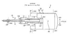
도 2 및 도 3에 나타낸 바와 같이, 유압 셔블(3)은, 유압(油壓)에 의해 작동하는 작업기(10)와, 작업기(10)를 지지하는 차량 본체(20)를 구비한다. 차량 본체(20)는, 상부 선회체(21)와, 상부 선회체(21)를 지지하는 하부 주행체(22)를 포함한다.2 and 3, the
상부 선회체(21)는, 캡(cab)(23)과, 기계실(24)과, 카운터웨이트(counterweight)(24C)를 가진다. 캡(23)은, 운전실을 포함한다. 운전실에는, 조작자 Ma가 착석하는 운전석(7)과, 조작자 Ma에 조작되는 조작 장치(8)가 배치된다. 조작 장치(8)는, 작업기(10) 및 상부 선회체(21)를 조작하기 위한 작업 레버, 및 하부 주행체(22)를 조작하기 위한 주행 레버를 포함한다. 작업기(10)는, 조작 장치(8)를 통하여 조작자 Ma에 조작된다. 상부 선회체(21) 및 하부 주행체(22)는, 조작 장치(8)를 통하여 조작자 Ma에 조작된다. 조작자 Ma는, 운전석(7)에 착석한 상태로 조작 장치(8)를 조작 가능하다.The upper revolving
하부 주행체(22)는, 스프로켓(sprocket)이라는 구동륜(25)과, 아이들러(idler)라는 유동륜(遊動輪)(26)과, 구동륜(25) 및 유동륜(26)에 지지되는 크롤러 벨트(crawler belt)(27)을 가진다. 구동륜(25)은, 예를 들면, 유압 모터와 같은 구동원이 발생하는 동력에 의해 작동한다. 구동륜(25)은, 조작 장치(8)의 주행 레버의 조작에 의해 회전한다. 구동륜(25)은, 회전축 DX1을 회전 중심으로 하여 회전한다. 유동륜(26)은, 회전축 DX2를 회전 중심으로 하여 회전한다. 회전축 DX1과 회전축 DX2는 평행이다. 구동륜(25)이 회전하여 크롤러 트랙(27)이 회전함으로써 유압 셔블(3)이 전후로 주행 또는 선회(旋回)한다.The
상부 선회체(21)는, 하부 주행체(22)에 지지된 상태로 선회축(旋回軸) RX를 중심으로 선회 가능하다.The upper revolving
작업기(10)는, 차량 본체(20)의 상부 선회체(21)에 지지된다. 작업기(10)는, 상부 선회체(21)에 연결되는 붐(boom)(11)과, 붐(11)에 연결되는 암(arm)(12)과, 암(12)에 연결되는 버킷(13)을 가진다. 버킷(13)은, 예를 들면, 볼록형상의 복수의 날을 가진다. 날의 선단부인 날끝(blade tip)(13B)은 복수 설치된다. 그리고, 버킷(13)의 날끝(13B)은, 버킷(13)에 설치된 스트레이트 형상의 날의 선단부라도 된다.The working
도 3에 나타낸 바와 같이, 상부 선회체(21)와 붐(11)은 붐 핀(boom pin)(11P)을 통하여 연결된다. 붐(11)은, 회전축 AX1을 지점(支点)으로 하여 동작 가능하게 상부 선회체(21)에 지지된다. 붐(11)과 암(12)은 암 핀(arm pin)(12P)을 통하여 연결된다. 암(12)은, 회전축 AX2를 지점으로 하여 동작 가능하게 붐(11)에 지지된다. 암(12)과 버킷(13)은 버킷 핀(bucket pin)(13P)을 통하여 연결된다. 버킷(13)은, 회전축 AX3을 지점으로 하여 동작 가능하게 암(12)에 지지된다. 회전축 AX1과 회전축 AX2와 회전축 AX3와는 전후 방향으로 평행이다. 전후 방향의 정의에 대해서는 후술한다.As shown in Fig. 3, the upper revolving
이하의 설명에 있어서는, 회전축 AX1, AX2, AX3의 축이 연장되는 방향을 적절히, 상부 선회체(21)의 차폭 방향이라고 하고, 선회축 RX의 축이 연장되는 방향을 적절히, 상부 선회체(21)의 상하 방향이라고 하고, 회전축 AX1, AX2, AX3 및 선회축 RX의 양쪽과 직교하는 방향을 적절히, 상부 선회체(21)의 전후 방향이라고 한다.The direction in which the axes of the rotating shafts AX1, AX2 and AX3 extend is appropriately referred to as the vehicle width direction of the
본 실시형태에 있어서는, 운전석(7)에 착석한 조작자 Ma를 기준으로 하여, 버킷(13)을 포함하는 작업기(10)가 존재하는 방향이 전방이며 전방의 역방향이 후방이다. 차폭 방향의 한쪽이 우측이며 우측의 역방향, 즉 캡(23)이 존재하는 방향이 좌측이다. 버킷(13)은, 상부 선회체(21)보다 전방에 배치된다. 버킷(13)의 복수의 날끝(13B)은, 차폭 방향으로 배치된다. 상부 선회체(21)는, 하부 주행체(22)의 위쪽에 배치된다.In the present embodiment, the direction in which the working
작업기(10)는, 유압 실린더에 의해 작동한다. 유압 셔블(3)은, 붐(11)을 동작시키기 위한 붐 실린더(14)와, 암(12)을 동작시키기 위한 암 실린더(15)와, 버킷(13)을 동작시키기 위한 버킷 실린더(16)를 가진다. 붐 실린더(14)가 신축(伸縮) 동작하면, 붐(11)이 회전축 AX1을 지점으로 동작하여, 붐(11)의 선단부가 상하 방향으로 이동한다. 암 실린더(15)가 신축 동작하면, 암(12)이 회전축 AX2를 지점으로 동작하여, 암(12)의 선단부가 상하 방향 또는 전후 방향으로 이동한다. 버킷 실린더(16)가 신축 동작하면, 버킷(13)이 회전축 AX3을 지점으로 동작하여, 버킷(13)의 날끝(13B)이 상하 방향 또는 전후 방향으로 이동한다. 붐 실린더(14), 암 실린더(15), 및 버킷 실린더(16)를 포함하는 작업기(10)의 유압 실린더는, 조작 장치(8)의 작업 레버에 의해 조작된다. 작업기(10)의 유압 실린더가 신축 동작함으로써, 작업기(10)의 자세가 변화한다.The working
<조작 장치>≪ Operation device >
다음에, 본 실시형태에 관한 조작 장치(8)에 대하여 설명한다. 도 4는, 본 실시형태에 관한 조작 장치(8)의 일례를 모식적으로 나타낸 도면이다. 조작 장치(8)의 작업 레버는, 차폭 방향에 있어서 운전석(7)의 중심보다 우측에 배치되는 우측 작업 레버(8WR)와, 차폭 방향에 있어서 운전석(7)의 중심보다 좌측 방향에 배치되는 좌측 작업 레버(8WL)를 포함한다. 조작 장치(8)의 주행 레버는, 차폭 방향에 있어서 운전석(7)의 중심보다 우측에 배치되는 우측 주행 레버(8MR)와, 차폭 방향에 있어서 운전석(7)의 중심보다 좌측 방향에 배치되는 좌측 주행 레버(8ML)를 포함한다.Next, the operating
중립 위치에 있는 우측 작업 레버(8WR)를 전방으로 동작하면 붐(11)이 하강 동작하고, 후방으로 동작하면 붐(11)이 상승 동작한다. 중립 위치에 있는 우측 작업 레버(8WR)를 우측으로 동작하면 버킷(13)이 덤프 동작하고, 좌측 방향으로 동작하면 버킷(13)이 건짐 동작(scooping operation)한다.When the right working lever 8WR in the neutral position is operated forward, the
중립 위치에 있는 좌측 작업 레버(8WL)를 우측으로 동작하면 상부 선회체(21)가 우측 선회하고, 좌측 방향으로 동작하면 상부 선회체(21)가 좌측 선회한다. 중립 위치에 있는 좌측 작업 레버(8WL)를 아래쪽으로 동작하면 암(12)이 건짐 동작하고 위쪽으로 동작하면 암(12)이 신장 동작한다.When the left working lever 8WL at the neutral position is operated to the right, the
중립 위치에 있는 우측 주행 레버(8MR)를 전방으로 동작하면 우측의 크롤러 (27)가 전진 동작하고, 후방으로 동작하면 우측의 크롤러(27)가 후진 동작한다. 중립 위치에 있는 좌측 주행 레버(8ML)를 전방으로 동작하면 좌측의 크롤러(27)가 전진 동작하고, 후방으로 동작하면 좌측의 크롤러(27)가 후진 동작한다.When the right travel lever 8MR in the neutral position is operated forward, the
그리고, 우측 작업 레버(8WR) 및 좌측 작업 레버(8WL)의 경도 방향(inclination direction)과, 작업기(10)의 동작 방향 및 상부 선회쌍(21)의 선회 방향의 동작 관계에 대한 조작 패턴은, 전술한 관계가 아니어도 된다.The operating pattern for the operating relationship between the inclination direction of the right working lever 8WR and the left working lever 8WL and the operating direction of the working
<하드웨어 구성><Hardware configuration>
다음에, 본 실시형태에 관한 평가 시스템(1)의 하드웨어 구성에 대하여 설명한다. 도 5는, 본 실시형태에 관한 평가 시스템(1)의 하드웨어 구성의 일례를 모식적으로 나타낸 도면이다.Next, the hardware configuration of the
휴대 기기(6)는, 컴퓨터 시스템을 포함한다. 휴대 기기(6)는, 연산 처리 장치(60)와, 기억 장치(61)와, 휴대 기기(6)의 위치를 검출하는 위치 검출 장치(62)와, 촬영 장치(63)와, 표시 장치(64)와, 입력 장치(65)와, 입출력 인터페이스 장치(66)와, 통신 장치(67)를 가진다.The
연산 처리 장치(60)는, CPU(Central Processing Unit)와 같은 마이크로 프로세서를 포함한다. 기억 장치(61)는, ROM(Read Only Memory) 또는 RAM(Random Access Memory)과 같은 메모리 및 스토리지를 포함한다. 연산 처리 장치(60)는, 기억 장치(61)에 기억되어 있는 컴퓨터 프로그램에 따라 연산 처리를 실시한다.The
위치 검출 장치(62)는, 전지구 측위 시스템(global navigation satellite system: GNSS)에 의해, 글로벌 좌표계에서의 휴대 기기(6)의 위치를 나타내는 절대 위치를 검출한다.The
촬영 장치(63)는, 피사체의 동영상 데이터를 취득 가능한 비디오 카메라 기능, 및 피사체의 정지화상 데이터를 취득 가능한 스틸 카메라 기능을 가진다. 촬영 장치(63)는, 광학계와, 광학계를 통하여 피사체의 촬영 데이터를 취득하는 촬상(撮像) 소자를 가진다. 촬상 소자는, CCD(charge coupled device) 이미지 센서 또는 CMOS(complementary metal oxide semiconductor) 이미지 센서를 포함한다.The photographing
촬영 장치(63)는, 유압 셔블(3)을 촬영 가능하다. 촬영 장치(63)는, 유압 셔블(3)의 작업기(10)의 동작을 검출하는 검출 장치로서 기능한다. 촬영 장치(63)는, 유압 셔블(3)의 외부로부터 유압 셔블(3)을 촬영하여, 작업기(10)의 동작을 검출한다. 촬영 장치(63)는, 작업기(10)의 촬영 데이터를 취득하여, 작업기(10)의 이동 궤적, 이동 속도, 및 이동 시간 중 하나 이상을 포함하는 작업기(10)의 이동 데이터를 취득 가능하다. 작업기(10)의 촬영 데이터는, 작업기(10)의 동영상 데이터 및 정지화상 데이터의 한쪽 또는 양쪽을 포함한다.The photographing
표시 장치(64)는, 액정 디스플레이(liquid crystal display: LCD) 또는 유기 EL 디스플레이(organic electroluminescence display: OLED)와 같은 평판 디스플레이를 포함한다. 입력 장치(65)는, 조작됨으로써 입력 데이터를 생성한다. 본 실시형태에 있어서, 입력 장치(65)는, 표시 장치(64)의 표시 화면에 설치된 터치 센서를 포함한다. 표시 장치(64)는, 터치 패널을 포함한다.The
입출력 인터페이스 장치(66)는, 연산 처리 장치(60)와 기억 장치(61)와 위치 검출 장치(62)와 촬영 장치(63)와 표시 장치(64)와 입력 장치(65)와 통신 장치(67)와의 사이에서 데이터 통신한다.The input / output interface device 66 includes an
통신 장치(67)는, 관리 장치(4)와 무선으로 데이터 통신한다. 통신 장치(67)는, 위성 통신망, 휴대 전화기 통신망 또는 인터넷 회선을 사용하여 관리 장치(4)와 데이터 통신한다. 그리고, 통신 장치(67)는, 관리 장치(4)와 유선으로 데이터 통신해도 된다.The
관리 장치(4)는, 컴퓨터 시스템을 포함한다. 관리 장치(4)는, 예를 들면, 서버를 사용한다. 관리 장치(4)는, 연산 처리 장치(40)와, 기억 장치(41)와, 출력 장치(42)와, 입력 장치(43)와, 입출력 인터페이스 장치(44)와, 통신 장치(45)를 가진다.The
연산 처리 장치(40)는, CPU와 같은 마이크로 프로세서를 포함한다. 기억 장치(41)는, ROM 또는 RAM과 같은 메모리 및 스토리지를 포함한다.The arithmetic processing unit 40 includes a microprocessor such as a CPU. The
출력 장치(42)는, 평판 디스플레이와 같은 표시 장치를 포함한다. 그리고, 출력 장치(42)는, 프린트 데이터를 출력하는 인쇄 장치를 포함해도 된다. 입력 장치(43)는, 조작됨으로써 입력 데이터를 생성한다. 입력 장치(43)는, 키보드 및 마우스 중 적어도 한쪽을 포함한다. 그리고, 입력 장치(43)가 표시 장치의 표시 화면에 설치된 터치 센서를 포함해도 된다.The
입출력 인터페이스 장치(44)는, 연산 처리 장치(40)와 기억 장치(41)와 출력 장치(42)와 입력 장치(43)와 통신 장치(45)와의 사이에서 데이터 통신한다.The input /
통신 장치(45)는, 휴대 기기(6)와 무선으로 데이터 통신한다. 통신 장치(45)는, 휴대 전화기 통신망 또는 인터넷 회선을 사용하여 휴대 기기(6)와 데이터 통신한다. 그리고, 통신 장치(45)는, 휴대 기기(6)와 유선으로 데이터 통신해도 된다.The
<휴대 기기><Mobile device>
다음에, 도 5에 나타낸 휴대 기기(6)에 대하여 상세하게 설명한다. 도 6은, 본 실시형태에 관한 휴대 기기(6)의 일례를 나타낸 기능 블록도이다. 휴대 기기(6)는, 유압 셔블(3)의 동작의 평가, 및 유압 셔블(3)을 조작하는 조작자 Ma의 기량의 평가의 한쪽 또는 양쪽을 실시하는 평가 장치(600)로서 기능한다. 평가 장치(600)의 기능은, 연산 처리 장치(60) 및 기억 장치(61)에 의해 발휘된다.Next, the
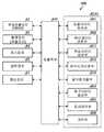
평가 장치(600)는, 촬영 장치(63)에 의해 검출된, 유압 셔블(3)의 작업기(10)의 촬영 데이터(이하, 적절히, 동작 데이터라고 함)에 기초하여, 작업기(10)의 이동 상태를 포함하는 검출 데이터를 취득하는 검출 데이터 취득부(601)와, 촬영 장치(63)에 의해 검출된 유압 셔블(3)의 작업기(10)의 동작 데이터에 기초하여, 작업기(10)의 위치 데이터를 산출하는 위치 데이터 산출부(602)와, 작업기(10)의 목표 이동 조건을 포함하는 목표 데이터를 생성하는 목표 데이터 생성부(603)와, 검출 데이터와 목표 데이터에 기초하여, 평가 데이터를 생성하는 평가 데이터 생성부(604)와, 표시 장치(64)를 제어하는 표시 제어부(605)와, 기억부(608)와, 입출력부(610)를 가진다. 평가 장치(600)는, 입출력부(610)를 통하여 데이터 통신한다.The
촬영 장치(63)는, 조작 장치(8)를 통하여 조작자 Ma에 의해 조작된, 작업기(10)의 이동 개시 위치로부터 이동 종료 위치까지의 작업기(10)의 동작 데이터를 검출한다. 본 실시형태에 있어서, 작업기(10)의 동작 데이터는, 촬영 장치(63)에 의해 촬영된 작업기(10)의 촬영 데이터를 포함한다.The photographing
검출 데이터 취득부(601)는, 촬영 장치(63)에 의해 검출된, 작업기(10)의 이동 개시 위치로부터 이동 종료 위치까지의 작업기(10)의 동작 데이터에 기초하여, 작업기(10)의 소정부의 검출 이동 궤적을 포함하는 검출 데이터를 취득한다. 또한, 검출 데이터 취득부(601)는, 촬영 데이터에 기초하여, 버킷(13)이 이동을 개시하고나서의 경과 시간을 취득한다.The detection
위치 데이터 취득부(602)는, 촬영 장치(63)에 의해 검출된 작업기(10)의 동작 데이터로부터 작업기(10)의 위치 데이터를 산출한다. 위치 데이터 취득부(602)는, 예를 들면, 패턴 매칭법을 이용하여, 작업기(10)의 촬영 데이터로부터 작업기(10)의 위치 데이터를 산출한다.The position
목표 데이터 생성부(603)는, 촬영 장치(63)에 의해 검출된 작업기(10)의 동작 데이터로부터 작업기(10)의 목표 이동 궤적을 포함하는 목표 데이터를 생성한다. 목표 데이터의 상세한 것에 대해서는 후술한다.The target
평가 데이터 생성부(604)는, 검출 데이터 취득부(601)에 의해 취득된 검출 데이터와 목표 데이터 생성부(603)와 생성된 목표 데이터에 기초하여 평가 데이터를 생성한다. 평가 데이터는, 작업기(10)의 동작의 평가를 나타내는 평가 데이터 및 조작 장치(8)를 통하여 작업기(10)를 조작한 조작자 Ma의 평가를 나타내는 평가 데이터의 한쪽 또는 양쪽을 포함한다. 평가 데이터의 상세한 것에 대해서는 후술한다.The evaluation
표시 제어부(605)는, 검출 데이터 및 목표 데이터로부터 표시 데이터를 생성하여 표시 장치(64)에 표시하게 한다. 또한, 표시 제어부(605)는, 평가 데이터로부터 표시 데이터를 생성하여 표시 장치(64)에 표시하게 한다. 표시 데이터의 상세한 것에 대해서는 후술한다.The
기억부(608)는, 각종 데이터를 기억한다. 또한, 기억부(608)는, 본 실시형태에 관한 평가 방법을 실시하기 위한 컴퓨터 프로그램을 기억한다.The
<평가 방법><Evaluation method>
다음에, 본 실시형태에 관한 조작자 Ma의 평가 방법에 대하여 설명한다. 도 7은, 본 실시형태에 관한 평가 방법의 일례를 나타낸 플로우차트이다.Next, an evaluation method of the operator Ma according to the present embodiment will be described. Fig. 7 is a flowchart showing an example of the evaluation method according to the present embodiment.
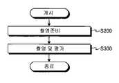
본 실시형태에 있어서, 평가 방법은, 촬영 장치(63)에 의한 유압 셔블(3)의 촬영 준비를 실시하는 스텝 S200과, 촬영 장치(63)를 사용하여 유압 셔블(3)을 촬영하여 조작자 Ma의 기량을 평가하는 스텝 S300을 포함한다.In the present embodiment, the evaluation method includes a step S200 of preparing the photographing of the
(촬영 준비)(Ready for shooting)
촬영 장치(63)에 의한 유압 셔블(3)의 촬영 준비가 실시된다(스텝 S200). 도 8은, 본 실시형태에 관한 촬영 준비 방법의 일례를 나타낸 플로우차트이다.The photographing preparation of the
본 실시형태에 있어서, 촬영 준비 방법은, 유압 셔블(3)에 대한 촬영 장치(63)의 촬영 위치를 결정하는 스텝 S210과, 상부 선회체(21)의 위치를 특정하는 스텝 S220과, 붐(11)의 위치를 특정하는 스텝 S230과, 암(12)의 위치를 특정하는 스텝 S240과, 버킷(13)의 위치를 특정하는 스텝 S250을 포함한다.In this embodiment, the photographing preparatory method includes a step S210 of determining a photographing position of the photographing
유압 셔블(3)의 촬영 조건을 일정하게 하기 위해, 유압 셔블(3)과 그 유압 셔블(3)을 촬영하는 촬영 장치(63)와의 상대 위치를 결정하는 처리가 실시된다(스텝 S210).Processing for determining the relative position between the
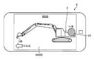
도 9는, 본 실시형태에 관한 촬영 방법의 일례를 설명하기 위한 도면이다. 조작자 Ma 또는 작업자 Mb에 의해 휴대 기기(6)의 입력 장치(65)가 조작됨으로써, 기억부(608)에 기억되어 있는 컴퓨터 프로그램이 기동한다. 컴퓨터 프로그램의 기동에 의해, 휴대 기기(6)는, 촬영 준비 모드로 천이한다. 촬영 준비 모드에 있어서는, 촬영 장치(63)의 광학계의 줌 기능이 제한된다. 유압 셔블(3)은, 고정된 규정 촬영 배율의 촬영 장치(63)에 의해 촬영된다.Fig. 9 is a diagram for explaining an example of a photographing method according to the present embodiment. The
예를 들면, 작업자 Mb가 휴대 기기(6)를 유지하고, 유압 셔블(3)의 외부에 있는 촬영 위치를 결정한 후, 입력 장치(65)를 통하여 처리 개시의 조작을 하면, 상부 선회체(21)의 위치를 특정하는 처리가 실시된다(스텝 S220). 위치 데이터 산출부(602)는, 패턴 매칭법을 이용하여, 상부 선회체(21)의 위치를 특정한다.For example, when the worker Mb holds the
도 10은, 본 실시형태에 관한 상부 선회체(21)의 위치 특정 방법을 설명하기 위한 도면이다. 도 10에 나타낸 바와 같이, 촬영 장치(63)는, 유압 셔블(3)을 포함하는 촬영 영역(73)의 촬영 데이터를 취득한다. 위치 데이터 산출부(602)는, 촬영 장치(63)에 의해 촬영된 촬영 영역(73)의 촬영 데이터에 기초하여, 작업기(10)의 위치 데이터를 산출한다. 위치 데이터 산출부(602)는, 표시 장치(64)의 표시 화면에 있어서, 촬영 영역(73)에 대하여, 상부 선회체(21)의 템플레이트(template)인 상부 선회체 템플레이트(21T)(제1 템플레이트)를 스캔 이동시켜, 차량 본체(20)의 위치 데이터를 산출한다. 상부 선회체 템플레이트(21T)는, 상부 선회체(21)를 좌측으로부터 본 외형을 나타내는 데이터로서, 캡(23)과 기계실(24) 및 카운터웨이트(24C)를 포함하는 외형을 나타내는 데이터이며, 미리 기억부(608)에 기억되어 있다. 위치 데이터 산출부(602)는, 차량 본체(20)의 촬영 데이터와 상부 선회체 템플레이트(21T)와의 상관값에 기초하여, 차량 본체(20)의 위치 데이터를 산출한다. 여기서, 상부 선회체 템플레이트(21T)가, 캡(23)만, 또는 기계실(24)만의 외형을 나타내는 데이터이면, 그 외형은 사각형에 가깝게 되어 자연계에 존재할 가능성이 있는 형태로 되고, 촬영 데이터에 따른 상부 선회쌍(21)의 위치의 특정이 곤란해질 우려가 있다. 상부 선회체 템플레이트(21T)가, 캡(23)과 적어도 기계실(24)을 포함하는 외형을 나타내는 데이터이면, 그 외형은 L자형의 다각형으로 되어 자연계에 존재할 가능성이 적은 형태로 되고, 촬영 데이터에 따른 상부 선회쌍(21)의 위치의 특정이 용이해진다.Fig. 10 is a view for explaining a position specifying method of the upper revolving
차량 본체(20)의 위치 데이터가 산출되는 것에 의해, 상부 선회체(21)의 위치가 특정된다. 상부 선회체(21)의 위치가 특정되는 것에 의해, 붐 핀(11P)의 위치가 특정된다.By calculating the position data of the
또한, 위치 데이터 산출부(602)는, 촬영 영역(73)의 촬영 데이터에 기초하여, 차량 본체(20)의 치수를 나타내는 치수 데이터를 산출한다. 본 실시형태에 있어서, 위치 데이터 산출부(602)는, 상부 선회체(21)를 좌측편으로부터 보았을 때의, 표시 장치(64)의 표시 화면에서의, 상부 선회체(21)의 치수(전후 방향의 치수 L)를 산출한다.The position
상부 선회체(21)의 위치 데이터가 산출된 후, 붐(11)의 위치를 특정하는 처리가 실시된다(스텝 S230). 위치 데이터 산출부(602)는, 표시 장치(64)의 표시 화면에 있어서, 촬영 영역(73)에 대하여, 붐(11)의 템플레이트인 붐 템플레이트(11T)(제2 템플레이트)를 이동시켜, 붐(11)의 위치 데이터를 산출한다. 붐 템플레이트(11T)는, 붐(11)의 외형을 나타내는 데이터로서, 미리 기억부(608)에 기억되어 있다. 위치 데이터 산출부(602)는, 붐(11)의 촬영 데이터와 붐 템플레이트(11T)와의 상관값에 기초하여, 붐(11)의 위치 데이터를 산출한다.After the position data of the upper revolving
도 11은, 본 실시형태에 관한 붐(11)의 위치 특정 방법을 설명하기 위한 도면이다. 붐(11)은 상부 선회체(21)에 대하여 회전축 AX1을 지점으로 동작 가능하다. 그러므로, 회전축 AX1을 지점으로 하여 붐(11)은 회전하고, 다양한 자세를 취득할 수 있으므로, 붐(11)의 회전 각도에 따라서는, 촬영 영역(73)에 대하여 붐 템플레이트(11T)를 스캔 이동시킨 것만으로는, 붐(11)의 촬영 데이터와 준비된 붐 템플레이트(11T)가 일치하지 않을 가능성이 있다.Fig. 11 is a view for explaining the position specifying method of the
전술한 바와 같이, 상부 선회체(21)의 위치가 특정되는 것에 의해, 붐 핀(11P)의 위치가 특정된다. 본 실시형태에 있어서는, 도 11에 나타낸 바와 같이, 위치 데이터 산출부(602)는, 표시 장치(64)의 표시 화면에 있어서, 스텝 S230에 의해 특정된 붐(11)의 붐 핀(11P)의 위치와 붐 템플레이트(11T)의 붐 핀의 위치를 일치시킨다. 붐(11)의 붐 핀(11P)의 위치와 붐 템플레이트(11T)의 붐 핀의 위치를 일치시킨 후, 위치 데이터 산출부(602)는, 표시 장치(64)의 표시 화면에 있어서, 촬영 데이터가 나타내는 붐(11)과 붐 템플레이트(11T)가 일치하도록, 붐 템플레이트(11T)를 회전 이동시켜, 붐(11)의 위치 데이터를 산출한다. 위치 데이터 산출부(602)는, 붐(11)의 촬영 데이터와 붐 템플레이트(11T)와의 상관값에 기초하여, 붐(11)의 위치 데이터를 산출한다. 여기서, 미리 다양한 자세의 붐 템플레이트(11T)를 기억부(608)에 기억시켜 두고, 촬영 데이터가 나타내는 붐(11)에 일치하는 붐 템플레이트(11T)를 탐색하여, 어느 하나의 붐 템플레이트(11T)를 선택함으로써 붐(11)의 위치 데이터를 산출하도록 해도 된다.As described above, by specifying the position of the upper revolving
붐(11)의 위치 데이터가 산출되는 것에 의해, 붐(11)의 위치가 특정된다. 붐(11)의 위치가 특정되는 것에 의해, 암 핀(12P)의 위치가 특정된다.By calculating the position data of the
붐(11)의 위치가 산출된 후, 암(12)의 위치를 특정하는 처리가 실시된다(스텝 S240). 위치 데이터 산출부(602)는, 표시 장치(64)의 표시 화면에 있어서, 촬영 영역(73)에 대하여, 암(12)의 템플레이트인 암 템플레이트(제2 템플레이트)를 이동시켜, 암(12)의 위치 데이터를 산출한다. 위치 데이터 산출부(602)는, 암(12)의 촬영 데이터와 암 템플레이트와의 상관값에 기초하여, 암(12)의 위치 데이터를 산출한다.After the position of the
암(12)은 붐(11)에 대하여 회전축 AX2를 지점으로 동작 가능하다. 그러므로, 회전축 AX2를 지점으로 하여 암(12)은 회전하여, 다양한 자세를 취득할 수 있으므로, 암(12)의 회전 각도에 따라서는, 촬영 영역(73)에 대하여 암 템플레이트를 스캔 이동시킨 것만으로는, 암(12)의 촬영 데이터와 준비된 암 템플레이트가 일치하지 않을 가능성이 있다.The arm (12) is operable with respect to the boom (11) about the axis of rotation (Ax2). Therefore, the
전술한 바와 같이, 붐(11)의 위치가 특정되는 것에 의해, 암 핀(12P)의 위치가 특정된다. 본 실시형태에 있어서는, 위치 데이터 산출부(602)는, 붐(11)의 위치를 특정한 수순과 동일한 수순으로, 암(12)의 위치를 특정한다. 위치 데이터 산출부(602)는, 표시 장치(64)의 표시 화면에 있어서, 스텝 S240에 의해 특정된 암(12)의 암 핀(12P)과 암 템플레이트의 암 핀의 위치를 일치시킨다. 암(12)의 암 핀(12P)의 위치와 암 템플레이트의 암 핀의 위치를 일치시킨 후, 위치 데이터 산출부(602)는, 표시 장치(64)의 표시 화면에 있어서, 촬영 데이터가 나타내는 암(12)과 암 템플레이트가 일치하도록, 암 템플레이트를 회전 이동시켜, 암(12)의 위치 데이터를 산출한다. 위치 데이터 산출부(602)는, 암(12)의 촬영 데이터와 암 템플레이트와의 상관값에 기초하여, 암(12)의 위치 데이터를 산출한다. 여기서, 미리 다양한 자세의 암 템플레이트를 기억부(608)에 기억시켜 두고, 촬영 데이터가 나타내는 암(12)에 일치하는 암 템플레이트를 탐색하여, 어느 하나의 암 템플레이트를 선택함으로써 암(12)의 위치 데이터를 산출하도록 해도 된다.As described above, by specifying the position of the
암(12)의 위치 데이터가 산출되는 것에 의해, 암(12)의 위치가 특정된다. 암(12)의 위치가 특정되는 것에 의해, 버킷 핀(13P)의 위치가 특정된다.By calculating the position data of the
암(12)의 위치가 산출된 후, 버킷(13)의 위치를 특정하는 처리가 실시된다(스텝 S250). 위치 데이터 산출부(602)는, 표시 장치(64)의 표시 화면에 있어서, 촬영 영역(73)에 대하여, 버킷(13)의 템플레이트인 버킷 템플레이트(제2 템플레이트)를 이동시켜, 버킷(13)의 위치 데이터를 산출한다. 위치 데이터 산출부(602)는, 버킷(13)의 촬영 데이터와 버킷 템플레이트와의 상관값에 기초하여, 버킷(13)의 위치 데이터를 산출한다.After the position of the
버킷(13)은 암(12)에 대하여 회전축 AX3을 지점으로 동작 가능하다. 그러므로, 회전축 AX3을 지점으로 하여 버킷(13)은 회전하고, 다양한 자세를 취득할 수 있으므로 버킷(13)의 각도에 따라서는, 촬영 영역(73)에 대하여 버킷 템플레이트를 스캔 이동시킨 것만으로는, 버킷(13)의 촬영 데이터와 준비된 버킷 템플레이트가 일치하지 않을 가능성이 있다.The
전술한 바와 같이, 암(12)의 위치가 특정되는 것에 의해, 버킷 핀(13P)의 위치가 특정된다. 본 실시형태에 있어서는, 위치 데이터 산출부(602)는, 붐(11)의 위치를 특정한 수순 및 암(12)의 위치를 특정한 수순과 동일한 수순으로, 버킷(13)의 위치를 특정한다. 위치 데이터 산출부(602)는, 표시 장치(64)의 표시 화면에 있어서, 스텝 S250에 의해 특정된 버킷(13)의 버킷 핀(13P)과 버킷 템플레이트의 버킷 핀의 위치를 일치시킨다. 버킷(13)의 버킷 핀(13P)의 위치와 버킷 템플레이트의 버킷 핀의 위치를 일치시킨 후, 위치 데이터 산출부(602)는, 표시 장치(64)의 표시 화면에 있어서, 촬영 데이터가 나타내는 버킷(13)과 버킷 템플레이트가 일치하도록, 버킷 템플레이트를 회전 이동시켜, 버킷(13)의 위치 데이터를 산출한다. 위치 데이터 산출부(602)는, 버킷(13)의 촬영 데이터와 버킷 템플레이트와의 상관값에 기초하여, 버킷(13)의 위치 데이터를 산출한다. 여기서, 미리 다양한 자세의 버킷 템플레이트를 기억부(608)에 기억시켜 두고, 촬영 데이터가 나타내는 버킷(13)에 일치하는 버킷 템플레이트를 탐색하여, 어느 하나의 버킷 템플레이트를 선택함으로써 버킷(13)의 위치 데이터를 산출하도록 해도 된다.As described above, by specifying the position of the
버킷(13)의 위치 데이터가 산출되는 것에 의해, 버킷(13)의 위치가 특정된다. 버킷(13)의 위치가 특정되는 것에 의해, 버킷(13)의 날끝(13B)의 위치가 특정된다.By calculating the position data of the
(촬영 및 평가)(Shooting and evaluation)
촬영 장치(63)에 의한 유압 셔블(3)의 촬영 준비를 실시하는 스텝 S200이 실행되고, 작업기(10)의 위치가 특정되고, 하기에 설명하는, 버킷(13)의 이동 개시 위치가 특정되면, 휴대 기기(6)는, 촬영 및 평가 모드로 천이한다. 촬영 및 평가 모드에 있어서도, 촬영 장치(63)의 광학계의 줌 기능이 제한된다. 유압 셔블(3)은, 고정된 규정 촬영 배율의 촬영 장치(63)에 의해 촬영된다. 촬영 준비 모드에서의 규정 촬영 배율과, 촬영 및 평가 모드에서의 규정 촬영 배율은 동일하다.A step S200 of preparing the photographing of the
조작 장치(8)를 통하여 조작자 Ma에 의해 조작되는 유압 셔블(3)의 작업기(10)의 이동 상황이 휴대 기기(6)의 촬영 장치(63)에 의해 촬영된다. 본 실시형태에 있어서는, 조작자 Ma의 기량의 평가에 있어서, 작업기(10)가 특정한 이동 조건 하에서 이동하도록, 조작자 Ma에 의한 작업기(10)의 조작 조건이 결정되어 있다.The moving state of the working
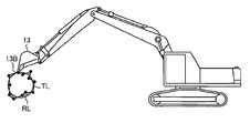
도 12는, 본 실시형태에 관한 평가 방법에 있어서 조작자 Ma에 부과되는 작업기(10)의 조작 조건을 모식적으로 나타낸 도면이다. 본 실시형태에 있어서는, 도 12에 나타낸 바와 같이, 작업기(10)를 조작하는 조작 조건으로서, 공중에 있어서 무부하 상태의 버킷(13)의 날끝(13B)이 수평면을 따라 직선의 이동 궤적을 그리도록 조작시키는 것을 유압 셔블(3)의 조작자 Ma에 부과한다. 조작자 Ma는, 버킷(13)의 날끝(13B)이 수평면을 따른 직선의 이동 궤적을 그리도록 조작 장치(8)를 조작한다.Fig. 12 is a diagram schematically showing the operating condition of the working
본 실시형태에 있어서, 버킷(13)의 이동 개시 위치 및 이동 종료 위치는, 조작자 Ma에 의해 임의로 결정된다. 본 실시형태에 있어서는, 버킷(13)의 날끝(13B)이 정지하고 있는 시간이 규정 시간 이상이며 그 정지 상태의 버킷(13)이 이동을 개시한 위치가 이동 개시 위치로 결정된다. 또한, 정지 상태의 버킷(13)이 이동을 개시한 시점(時点)이 이동 개시 시점으로 결정된다. 또한, 이동 상태의 버킷(13)의 날끝(13B)이 이동을 정지하고 그 정지하고 있는 시간이 규정 시간 이상인 것으로 판정된 버킷(13)의 위치가 이동 종료 위치로 결정된다. 또한, 이동을 종료한 시점이 이동 종료 시점으로 결정된다. 환언하면, 정지 상태의 버킷(13)이 동작을 개시한 위치가 이동 개시 위치이며, 동작을 개시한 시점이 이동 개시 시점이다. 이동 상태의 버킷(13)이 정지한 위치가 이동 종료 위치이며, 정지한 시점이 이동 종료 시점이다.In this embodiment, the movement start position and the movement end position of the
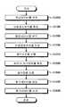
도 13은, 본 실시형태에 관한 촬영 및 평가 방법의 일례를 나타낸 플로우차트이다. 도 13은, 촬영 장치(63)를 사용하여 유압 셔블(3)을 촬영하여 조작자 Ma의 기량을 평가하는 스텝 S300을 나타낸다. 본 실시형태에 관한 촬영 및 평가 방법은, 작업기(10)의 이동 개시 위치를 특정하는 스텝 S310과, 이동하는 작업기(10)의 촬영 데이터를 취득하는 스텝 S320과, 작업기(10)의 이동 종료 위치를 특정하는 스텝 S330과, 작업기(10)의 목표 데이터를 생성하는 스텝 S340과, 촬영 데이터와 목표 데이터에 기초하여 조작자 Ma의 평가 데이터를 생성하는 스텝 S350과, 표시 장치(64)에 평가 데이터를 표시하는 스텝 S360을 포함한다.13 is a flowchart showing an example of a photographing and evaluation method according to the present embodiment. Fig. 13 shows a step S300 of evaluating the skill of the operator Ma by photographing the
여기서, 작업자 Mb는, 도 9에 나타낸 바와 같이, 표시 장치(64)에 입력 장치(65)의 하나로서 표시된 녹화 버튼을 가압한다. 작업자 Mb는, 유압 셔블(3)의 외부로부터 유압 셔블(3)을 촬영한다. 작업기(10)의 버킷(13)의 이동 개시 위치 및 이동 개시 시점을 특정하는 처리가 실시된다(스텝 S310). 도 14는, 본 실시형태에 관한 작업기(10)의 이동 개시 위치의 특정 방법을 설명하기 위한 도면이다. 검출 데이터 취득부(601)는, 촬영 장치(63)에 의해 촬영된 작업기(10)의 촬영 데이터에 기초하여, 정지 상태의 작업기(10)의 버킷(13)의 날끝(13B)의 위치를 특정한다. 검출 데이터 취득부(601)는, 버킷(13)의 날끝(13B)이 정지하고 있는 시간이 규정 시간 이상인 것으로 판정한 경우, 그 버킷(13)의 날끝(13B)의 위치를 버킷(13)의 이동 개시 위치로 결정한다.Here, the worker Mb presses the recording button displayed as one of the
정지 상태의 버킷(13)이 조작자 Ma의 조작에 의해 이동을 개시한 경우, 검출 데이터 취득부(601)는, 작업기(10)의 촬영 데이터에 기초하여, 버킷(13)의 이동이 개시된 것을 검출한다. 검출 데이터 취득부(601)는, 정지 상태의 버킷(13)의 날끝(13B)이 이동을 개시한 시점을 버킷(13)의 이동 개시 시점인 것으로 판정한다.The detection
버킷(13)의 이동이 개시되면, 검출 데이터 취득부(601)는, 작업기(10)의 동영상 데이터인 촬영 데이터를 촬영 장치(63)로부터 취득한다(스텝 S320). 도 15 및 도 16은, 본 실시형태에 관한 작업기(10)의 촬영 데이터의 취득 방법을 설명하기 위한 도면이다. 검출 데이터 취득부(601)는, 이동을 개시한 작업기(10)의 촬영 데이터의 취득을 개시한다.When the movement of the
본 실시형태에 있어서, 검출 데이터 취득부(601)는, 이동 개시 위치로부터 이동 종료 위치까지의 버킷(13)의 촬상 데이터에 기초하여, 작업기(10)의 이동 궤적을 포함하는 검출 데이터를 취득한다. 본 실시형태에 있어서, 검출 데이터는, 이동 개시 위치에 있어서 정지 상태의 작업기(10)가 이동을 개시하고나서 이동 종료 위치에 있어서 이동을 종료할 때까지의 공중에서의 무부하 상태의 작업기(10)의 이동 궤적을 포함한다. 검출 데이터 취득부(601)는, 촬영 데이터에 기초하여, 버킷(13)의 이동 궤적을 취득한다. 또한, 검출 데이터 취득부(601)는, 촬영 데이터에 기초하여, 버킷(13)이 이동을 개시하고나서의 경과 시간을 취득한다.In the present embodiment, the detection
도 15는, 버킷(13)의 이동이 개시된 직후의 표시 장치(64)를 나타낸다. 검출 데이터 취득부(601)에 의해 버킷(13)의 이동이 개시된 것으로 판정되면, 위치 데이터 산출부(602)는, 작업기(10)의 위치 데이터에 포함되는 버킷(13)의 날끝(13B)의 위치 데이터를 산출하고, 표시 제어부(605)는, 버킷(13)의 날끝(13B)을 나타내는 표시 데이터를 표시 장치(64)에 표시하게 한다. 도 15에 나타낸 바와 같이, 표시 데이터로서, 이동 개시 위치 SP를 예를 들면, 둥근 점으로서 표시 장치(64)에 표시한다. 표시 제어부(605)는, 이동 종료 위치 EP도 마찬가지로, 예를 들면, 둥근 점으로서 표시 장치(64)에 표시한다. 본 실시형태에 있어서는, 표시 제어부(605)는, 날끝(13B)을 나타내는 표시 데이터인 플롯(plot) PD(SP, EP)를 예를 들면, 둥근 점으로서 표시 장치(64)에 표시하게 한다.15 shows the
또한, 표시 제어부(605)는, 작업기(10)가 이동 개시 위치로부터 이동을 개시하고나서의 경과 시간을 나타내는 표시 데이터인 경과 시간 데이터 TD, 및 작업기(10)가 이동 개시 위치와 이동 종료 위치와의 사이에 있어서 이동 중인 것을 나타내는 표시 데이터인 문자 데이터 MD를 표시 장치(64)에 표시하게 한다. 본 실시형태에 있어서, 표시 제어부(605)는, 「Moving」의 문자 데이터 MD를 표시 장치(64)에 표시하게 한다. 이로써, 촬영자인 작업자 Mb는, 버킷(13)의 이동이 개시되고, 버킷(13)의 날끝(13B)의 이동 궤적의 취득이 개시된 것을 인식할 수 있다.The
도 16은, 버킷(13)이 이동하고 있을 때의 표시 장치(64)를 나타낸다. 검출 데이터 취득부(601)는, 촬영 데이터에 기초하여, 버킷(13)의 위치를 계속 검출하고, 위치 데이터 산출부(602)는, 버킷(13)의 날끝(13B)의 위치 데이터를 계속 산출하고, 버킷(13)의 날끝(13B)의 검출 이동 궤적을 취득한다. 또한, 검출 데이터 취득부(601)는, 이동 개시 시점에서의 버킷(13)의 이동 시간을 나타내는 경과 시간을 취득한다.16 shows the
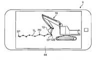
표시 제어부(605)는, 검출 데이터로부터 버킷(13)의 검출 이동 궤적을 나타내는 표시 데이터를 생성하여, 표시 장치(64)에 표시하게 한다. 표시 제어부(605)는, 검출 데이터에 기초하여, 버킷(13)의 날끝(13B)의 위치를 나타내는 플롯을 일정 시간 간격으로 생성한다. 표시 제어부(605)는, 일정 시간 간격으로 생성된 플롯을 표시 장치(64)에 표시하게 한다. 도 16에 있어서, 플롯의 간격이 짧은 것은, 버킷(13)의 이동 속도가 낮은 것을 나타내고, 플롯의 간격이 긴 것은, 버킷(13)의 이동 속도가 높은 것을 나타낸다.The
또한, 표시 제어부(605)는, 복수의 플롯에 기초하여, 버킷(13)의 검출 이동 궤적을 나타내는 검출 라인 TL을 표시 장치(64)에 표시하게 한다. 검출 라인 TL은, 복수의 플롯을 연결한 절곡선형의 표시 데이터이다. 검출 라인 TL은, 복수의 플롯을 스무스한 곡선으로 연결하여 표시시켜도 된다.The
이동 상태의 버킷(13)이 조작자 Ma의 조작에 의해 이동을 정지한 경우, 작업기(10)의 버킷(13)의 이동 종료 위치 및 이동 종료 시점을 특정하는 처리가 실시된다(스텝 S330). 도 17은, 본 실시형태에 관한 작업기(10)의 이동 종료 위치의 특정 방법을 설명하기 위한 도면이다.When the
이동 상태의 버킷(13)이 조작자 Ma의 조작에 의해 이동을 정지한 경우, 검출 데이터 취득부(601)는, 촬영 데이터에 기초하여, 버킷(13)의 이동이 정지된 것을 검출한다. 검출 데이터 취득부(601)는, 이동 상태의 버킷(13)의 날끝(13B)이 이동을 정지한 위치를 버킷(13)의 이동 종료 위치로 결정한다. 또한, 검출 데이터 취득부(601)는, 이동 상태의 버킷(13)의 날끝(13B)이 이동을 정지한 시점을 버킷(13)의 이동 종료 시점으로 결정한다. 검출 데이터 취득부(601)는, 이동 상태의 버킷(13)이 이동을 정지하고, 그 버킷(13)의 날끝(13B)이 정지하고 있는 시간이 규정 시간 이상인 것으로 판정한 경우, 그 버킷(13)의 날끝(13B)의 위치를 버킷(13)의 이동 종료 위치로 결정한다. 위치 데이터 산출부(602)는, 이동 종료 위치의 버킷(13)의 날끝(13B)의 위치 데이터를 산출한다.When the
도 17은, 버킷(13)의 이동이 정지된 직후의 표시 장치(64)를 나타낸다. 검출 데이터 취득부(601)에 의해 버킷(13)의 이동이 정지된 것으로 판정되면, 표시 제어부(605)는, 경과 시간 데이터 TD 및 문자 데이터 MD를 표시 장치(64)로부터 소거한다. 이로써, 촬영자인 작업자 Mb는, 버킷(13)의 이동이 정지된 것을 인식할 수 있다. 여기서, 문자 데이터 MD를 표시 장치(64)로부터 소거하지 않고, 버킷(13)의 이동이 정지된 것을 나타내는 문자 데이터 MD를 표시시켜도 된다.17 shows the
작업기(10)의 이동이 정지된 후, 작업기(10)의 목표 이동 궤적을 나타내는 목표 데이터를 생성하는 처리가 실시된다(스텝 S340). 도 18은, 본 실시형태에 관한 작업기(10)의 목표 이동 궤적을 나타내는 목표 데이터의 생성 방법을 설명하기 위한 도면이다. 목표 데이터 생성부(603)는, 버킷(13)의 목표 이동 궤적을 나타내는 목표 데이터를 생성한다.After the movement of the working
본 실시형태에 있어서, 목표 이동 궤적은, 이동 개시 위치 SP와 이동 종료 위치 EP를 연결하는 직선을 포함한다.In this embodiment, the target movement locus includes a straight line connecting the movement start position SP and the movement end position EP.
도 18에 나타낸 바와 같이, 표시 제어부(605)는, 목표 데이터로부터 표시 장치(64)에 표시하게 하는 표시 데이터를 생성하여, 표시 장치(64)에 표시하게 한다. 본 실시형태에 있어서는, 표시 제어부(605)는, 이동 개시 위치 SP와 이동 종료 위치 EP를 연결하는 목표 이동 궤적을 나타내는 목표 라인 RL을 표시 장치(64)에 표시하게 한다. 목표 라인 RL은, 이동 개시 위치 SP와 이동 종료 위치 EP를 연결한 직선형의 표시 데이터이다. 목표 라인 RL은, 목표 데이터에 기초하여 생성된다. 즉, 목표 라인 RL은, 목표 데이터를 나타낸다.As shown in Fig. 18, the
또한, 표시 제어부(605)는, 플롯(SP, EP) 및 검출 라인 TL을 목표 라인 RL과 함께 표시 장치(64)에 표시하게 한다. 이와 같이, 표시 제어부(605)는, 검출 데이터로부터 플롯 및 검출 라인 TL을 포함하는 표시 데이터를 생성하고, 목표 데이터인 목표 라인 RL을 포함하는 표시 데이터를 생성하여, 표시 장치(64)에 표시하게 한다.The
검출 라인 TL과 목표 라인 RL이 표시 장치(64)에 동시에 표시되므로, 작업자 Mb 또는 조작자 Ma는, 버킷(13)[날끝(13B)]의 실제의 이동 궤적이, 직선으로 나타내는 목표 이동 궤적으로부터 어느 정도 이격되어 있는지를 정성적(定性的)으로 인식할 수 있다.Since the detection line TL and the target line RL are simultaneously displayed on the
이동 궤적을 포함하는 검출 데이터가 취득되고, 목표 이동 궤적을 포함하는 목표 데이터가 생성된 후, 검출 데이터와 목표 데이터에 기초하여, 조작자 Ma의 정량적(定量的) 평가 데이터를 생성하는 처리가 실시된다(스텝 S350).After the detection data including the movement trajectory is acquired and the target data including the target movement trajectory is generated, a process of generating the quantitative evaluation data of the operator Ma based on the detection data and the target data is performed (Step S350).
본 실시형태에 있어서는, 촬영 장치(63)에 의해 취득된 작업기(10)의 촬영 데이터가 기억부(608)에 기억된다. 작업기(10)의 촬영 데이터가 기억부(608)에 복수 기억되어 있는 경우, 작업자 Mb는, 기억부(608)에 기억되어 있는 복수의 촬영 데이터 중에서 평가하는 촬영 데이터를 입력 장치(65)를 통하여 선택한다. 평가 데이터 생성부(604)는, 선택된 촬영 데이터로부터 평가 데이터를 생성한다.In the present embodiment, the photographing data of the working
평가 데이터 생성부(604)는, 이동 궤적과 목표 이동 궤적과의 차분에 기초하여, 조작자 Ma의 평가 데이터를 생성한다. 검출된 검출 이동 궤적과 목표 이동 궤적과의 차분이 작을수록, 목표 이동 궤적을 따라 버킷(13)을 이동할 수 있었던 것을 의미하고, 조작자 Ma의 기량은 높은 것으로 평가된다. 한편, 검출 이동 궤적과 목표 이동 궤적과의 차분이 클수록, 목표 이동 궤적을 따라 버킷(13)[날끝(13B)]을 이동할 수 없었던 것을 의미하고, 조작자 Ma의 기량은 낮은 것으로 평가된다. 즉, 날끝(13B)을 직선적으로 이동시키려고 하면, 조작 장치(8)의 우측 작업 레버(8WR)와 좌측 작업 레버(8WL)의 양자를 동시 또는 교호적(交互的)으로 조작하지 않으면 안되므로, 조작자 Ma의 기량이 낮을 경우, 단시간에 날끝(13B)을 직선적이고 장거리 이동을 시키는 것은 용이하지 않다.The evaluation
본 실시형태에 있어서, 평가 데이터 생성부(604)는, 검출 이동 궤적을 나타내는 검출 라인 TL과 목표 이동 궤적을 나타내는 목표 라인 RL로 규정되는 평면의 면적에 기초하여, 평가 데이터를 생성한다. 즉, 도 18의 사선 부분으로 나타낸 바와 같이, 오로지 곡선으로 나타내는 검출 라인 TL과, 직선으로 나타내는 목표 라인 RL로 규정되는 평면 DI의 면적이 평가 데이터 생성부(604)에 의해 산출되고, 그 면적에 기초하여 평가 데이터가 생성된다. 면적이 작을수록 조작자 Ma의 기량은 높은 것으로 평가되고, 면적이 클수록 조작자 Ma의 기량은 낮은 것으로 평가된다. 그 면적(평면 D1)의 대소(大小)도 평가 데이터에 포함된다.In this embodiment, the evaluation
또한, 본 실시형태에 있어서는, 촬영 데이터에 기초하여, 이동 개시 위치 SP와 이동 종료 위치 EP가 특정된다. 검출 데이터 취득부(601)는, 촬영 데이터에 기초하여, 이동 개시 위치 SP와 이동 종료 위치 EP와의 거리를 취득한다. 본 실시형태에 있어서, 검출 데이터 취득부(601)가 취득하는 검출 데이터는, 이동 개시 위치 SP와 이동 종료 위치 EP와의 사이의 버킷(13)의 이동 거리를 포함한다.In the present embodiment, the movement start position SP and the movement end position EP are specified based on the photographic data. The detection
평가 데이터 생성부(604)는, 이동 개시 위치 SP와 이동 종료 위치 EP와의 거리에 기초하여, 평가 데이터를 생성한다. 이동 개시 위치 SP와 이동 종료 위치 EP와의 거리가 길수록, 목표 이동 궤적을 따라 버킷(13)을 장거리 이동할 수 있었던 것을 의미하고, 조작자 Ma의 기량은 높은 것으로 평가된다. 이동 개시 위치 SP와 이동 종료 위치 EP와의 거리가 짧을수록, 목표 이동 궤적을 따라 버킷(13)을 단거리 밖에 이동할 수 없었던 것을 의미하고, 조작자 Ma의 기량은 낮은 것으로 평가된다.The evaluation
본 실시형태에 있어서는, 도 10을 참조하여 설명한 바와 같이, 촬영 준비 모드에 있어서, 표시 장치(64)의 표시 화면에서의 전후 방향의 차량 본체(20)의 치수 L이 산출된다. 또한, 차량 본체(20)의 전후 방향의 실제 치수를 나타내는 실제 치수 데이터가 기억부(608)에 기억되어 있다. 따라서, 표시 장치(64)의 표시 화면에서의 이동 개시 위치 SP와 이동 종료 위치 EP와의 거리가 산출되는 것에 의해, 검출 데이터 취득부(601)는, 치수 L과 기억부(608)에 기억되어 있는 차량 본체(20)의 실제 치수와의 비에 기초하여, 이동 개시 위치 SP로부터 이동 종료 위치 EP까지의 버킷(13)의 실제의 이동 거리를 산출할 수 있다. 이 이동 거리는, 위치 데이터 산출 장치(602)에 의해 산출해도 된다.In the present embodiment, as described with reference to Fig. 10, the dimension L of the
또한, 본 실시형태에 있어서는, 촬영 데이터에 기초하여, 버킷(13)이 이동을 개시하고나서의 경과 시간, 및 이동 개시 위치 SP로부터 이동 종료 위치 EP까지의 버킷(13)의 이동 시간이 취득된다. 검출 데이터 취득부(601)는, 내부 타이머를 가진다. 검출 데이터 취득부(601)는, 내부 타이머의 계측 결과와 촬영 장치(63)의 촬영 데이터에 기초하여, 버킷(13)의 이동 개시 시점과 이동 종료 시점과의 시간을 취득한다. 본 실시형태에 있어서, 검출 데이터 취득부(601)가 취득하는 검출 데이터는, 이동 개시 시점과 이동 종료 시점과의 사이의 버킷(13)의 이동 시간을 포함한다.In the present embodiment, the elapsed time from the start of movement of the
평가 데이터 생성부(604)는, 이동 개시 시점과 이동 종료 시점과의 사이의 버킷(13)[날끝(13B)]의 이동 시간에 기초하여, 평가 데이터를 생성한다. 이동 개시 시점과 이동 종료 시점과의 시간이 짧을수록, 목표 이동 궤적을 따라 버킷(13)을 단시간에 이동할 수 있었던 것을 의미하고, 조작자 Ma의 기량은 높은 것으로 평가된다. 이동 개시 시점과 이동 종료 시점과의 시간이 길수록, 목표 이동 궤적을 따라 버킷(13)을 이동시키는 데 장시간을 필요로 한 것을 의미하고, 조작자 Ma의 기량은 낮은 것으로 평가된다.The evaluation
또한, 전술한 바와 같이, 검출 데이터 취득부(601)는, 이동 개시 위치 SP로부터 이동 종료 위치 EP까지의 버킷(13)의 실제의 이동 거리를 산출한다. 따라서, 검출 데이터 취득부(601)는, 이동 개시 위치 SP로부터 이동 종료 위치 EP까지의 버킷(13)의 실제의 이동 거리와, 이동 개시 시점에서 이동 종료 시점까지의 버킷(13)의 이동 시간에 기초하여, 이동 개시 위치 SP와 이동 종료 위치 EP와의 사이의 버킷(13)의 이동 속도(평균 이동 속도)를 산출할 수 있다. 이 이동 속도는, 위치 데이터 산출 장치(602)에 의해 산출해도 된다. 본 실시형태에 있어서, 검출 데이터 취득부(601)가 취득하는 검출 데이터는, 이동 개시 위치 SP와 이동 종료 위치 EP와의 사이의 버킷(13)의 이동 속도를 포함한다.As described above, the detection
평가 데이터 생성부(604)는, 이동 개시 위치 SP와 이동 종료 위치 EP와의 사이의 버킷(13)[날끝(13B)]의 이동 속도에 기초하여, 평가 데이터를 생성한다. 이동 개시 위치 SP와 이동 종료 위치 EP와의 사이의 버킷(13)의 이동 속도가 높을수록, 목표 이동 궤적을 따라 버킷(13)[날끝(13B)]을 고속도로 이동할 수 있었던 것을 의미하고, 조작자 Ma의 기량은 높은 것으로 평가된다. 이동 개시 위치 SP와 이동 종료 위치 EP와의 사이의 버킷(13)의 이동 속도가 낮을수록, 목표 이동 궤적을 따라 버킷(13)[날끝(13B)]을 저속도로 밖에 이동할 수 없었던 것을 의미하고, 조작자 Ma의 기량은 낮은 것으로 평가된다.The evaluation
이상에서 설명한 같은 평가 데이터가 생성된 후, 그 평가 데이터를 표시 장치(64)에 표시하게 하는 처리가 실시된다(스텝 S360). 도 19는, 본 실시형태에 관한 평가 데이터의 표시 방법을 설명하기 위한 도면이다. 표시 제어부(605)는, 평가 데이터로부터 표시 데이터를 생성하여 표시 장치(64)에 표시하게 한다.After the evaluation data described above is generated, processing for displaying the evaluation data on the
도 19에 나타낸 바와 같이, 표시 제어부(605)는, 예를 들면, 개인 데이터인 조작자 Ma의 성명을 표시 장치(64)에 표시하게 한다. 개인 데이터는, 미리 기억부(606)에 보존되어 있다. 또한, 표시 제어부(605)는, 평가 데이터로서, 목표 이동 궤적과 검출 이동 궤적과의 차분을 나타내는 「직선성」, 이동 개시 위치 SP로부터 이동 종료 위치 EP까지의 버킷(13)의 이동 거리를 나타내는 「거리」, 이동 개시 위치 SP로부터 이동 종료 위치 EP까지의 버킷(13)의 이동 시간을 나타내는 「시간」, 및 이동 개시 위치 SP로부터 이동 종료 위치 EP까지의 버킷(13)의 평균 이동 속도를 나타내는 「속도」의 각각의 항목을 표시 장치(64)에 표시하게 한다. 또한, 표시 제어부(605)는, 정량적 평가 데이터로서, 「직선성」, 「거리」, 「시간」, 및 「속도」의 각각의 항목의 수치 데이터를 표시 장치(64)에 표시하게 한다. 「직선성」의 수치 데이터는, 예를 들면, 목표 이동 궤적과 검출 이동 궤적과의 차분(평면 DI)이 소정량보다 적은 경우를 100점 만점으로 하고, 그 차분이 소정량보다 많아짐에 따라, 100점으로부터 감점(減点)하여 가도록 하여 구할 수 있다. 그리고, 「거리」, 「시간」, 및 「속도」에 대해서도, 100점 만점으로 되는 기준의 수치와의 차에 기초하여, 점수로서 수치 데이터를 표시 장치(64)에 표시시켜도 된다.As shown in Fig. 19, the
그리고, 본 실시형태에 있어서는, 작업기(10)의 동작으로서, 작업기(10)의 소정부인, 버킷(13)의 날끝(13B)에 주목하고, 날끝(13B)의 이동 궤적을 취득함으로써, 날끝(13)에 대한 「직선성」, 「거리」, 「시간」, 「속도」라고 하는 평가 데이터를 취득하였다. 그러나, 예를 들면, 작업기(10)의 동작으로서, 다른 부분, 예를 들면, 암의 선단 또는 버킷(13)의 날끝(13B) 이외의 부분(소정부)에 주목하고, 상기 부분의 목표 이동 궤적과 상기 부분의 검출 이동 궤적과의 차분을 나타내는 「직선성」, 이동 개시 위치 SP로부터 이동 종료 위치 EP까지의 상기 부분의 이동 거리를 나타내는 「거리」, 이동 개시 위치 SP로부터 이동 종료 위치 EP까지의 상기 부분의 이동 시간을 나타내는 「시간」, 및 이동 개시 위치 SP로부터 이동 종료 위치 EP까지의 상기 부분의 평균 이동 속도를 나타내는 「속도」라고 하는 평가 데이터를 취득해도 된다. 즉, 촬영 장치(63)(검출 장치)가 작업기(10)의 동작을 검출하여 촬영 데이터를 취득하기 위해, 촬영 데이터에 포함되는 작업기(10)의 이동에 기초한 동작 데이터를 사용하여, 작업기(10)의 소정부의 이동 궤적을 취득하여 평가 데이터를 생성해도 된다.In this embodiment, as the operation of the working
또한, 표시 제어부(605)는, 정량적 평가 데이터로서, 조작자 Ma의 기량의 득점(得点)을 표시 장치(64)에 표시하게 한다. 기억부(608)에는, 기량에 대한 레퍼런스 데이터가 기억되어 있다. 레퍼런스 데이터는, 예를 들면, 표준적인 기량을 가지는 조작자에 대하여, 「직선성」, 「거리」, 「시간」, 및 「속도」의 각각의 항목의 수치 데이터를 총합적으로 평가한 평가 데이터이며, 통계적 또는 경험적으로 구해진다. 조작자 Ma의 기량의 득점은, 그 레퍼런스 데이터를 기준으로 산출된다.Further, the
또한, 표시 제어부(605)는, 과거에 조작자 Ma가 몇회의 평가 데이터를 생성했는지를 나타내는 횟수 데이터와, 과거의 평가 데이터(기량의 득점)의 평균점 또는 최고 득점을 표시 장치(64)에 표시시켜도 된다.The
본 실시형태에 있어서, 평가 데이터 생성부(604)는, 생성한 평가 데이터를, 통신 장치(67)를 통하여 외부 서버에 출력한다. 외부 서버는, 관리 장치(4)라도 되고, 관리 장치(4)와는 다른 서버라도 된다.In this embodiment, the evaluation
평가 데이터가 외부 서버에 송신된 후, 조작자 Ma의 다른 조작자 Ma와의 상대적인 평가를 나타내는 상대 데이터가 외부 서버로부터 휴대 기기(6)의 통신 장치(67)에 제공된다. 평가 데이터 생성부(604)는, 외부 서버로부터 공급된 상대 데이터를 취득한다. 표시 제어부(605)는, 그 상대 데이터에 관한 표시 데이터를 생성하여 표시 장치(64)에 표시하게 한다.After the evaluation data is transmitted to the external server, relative data indicating an evaluation of the operator Ma relative to the other operator Ma is provided from the external server to the
본 실시형태에 있어서, 조작자 Ma와 다른 조작자 Ma와의 상대적인 평가를 나타내는 상대 데이터는, 복수의 조작자 Ma의 기량을 순위를 부여한 랭킹(ranking) 데이터를 포함한다. 외부 서버에는 전국 각지에 존재하는 복수의 조작자 Ma의 평가 데이터가 수집된다. 외부 서버는, 복수의 조작자 Ma의 평가 데이터를 집계 및 해석하여, 복수의 조작자 Ma마다 기량의 랭킹 데이터를 생성한다. 외부 서버는, 생성한 랭킹 데이터를, 복수의 휴대 기기(6)의 각각에 전송한다. 랭킹 데이터는, 평가 데이터에 포함되는 것이며, 다른 조작자 Ma와의 상대적인 평가를 나타내는 상대 데이터이다.In this embodiment, the relative data indicating the relative evaluation of the operator Ma and the other operators Ma includes ranking data in which the competence of the plurality of operators Ma is ranked. Evaluation data of a plurality of operators Ma existing in various parts of the nation are collected in the external server. The external server aggregates and analyzes evaluation data of a plurality of operators Ma, and generates ranking data of skill for each of the plurality of operators Ma. The external server transmits the generated ranking data to each of the plurality of
도 20은, 본 실시형태에 관한 상대 데이터의 표시 방법의 일례를 설명하기 위한 도면이다. 도 20에 나타낸 바와 같이, 표시 제어부(605)는, 상대 데이터로부터 표시 데이터를 생성하여 표시 장치(64)에 표시하게 한다. 도 22에 나타낸 예와 같이, 표시 제어부(605)는, 표시 장치(64)에, 다음과 같은 표시 데이터에 관한 정보를 표시하게 한다. 예를 들면, 조작자 Ma의 성명과, 휴대 기기(6)와 개인 데이터를 등록하고, 그 휴대 기기(6)를 사용하여 평가 데이터를 생성한, 전국의 조작자 Ma의 인원수와, 전국의 조작자 Ma 중, 그 휴대 기기(6)[표시 데이터를 표시시키려고 하고 있는 휴대 기기(6)]와 평가 데이터를 생성한 조작자 Ma의 평가 데이터(득점)에 기초한 순위와, 평가 데이터를 나타내는 득점을 표시 장치(64)에 표시하게 한다. 여기서, 평가 데이터를 나타내는 득점이 상위의 조작자 Ma의 성명과 득점을 나타내는 정보를 외부 서버로부터 수신하고, 표시 제어부(605)는 표시 장치(64)에, 그 정보를 표시시켜도 된다. 평가 데이터에 따른 순위도, 평가 데이터에 포함하는 것이며, 다른 조작자 Ma와의 상대적인 평가를 나타내는 상대 데이터이다.20 is a diagram for explaining an example of a display method of relative data according to the present embodiment. As shown in Fig. 20, the
<작용 및 효과><Action and Effect>
이상 설명한 바와 같이, 본 실시형태에 의하면, 작업기(10)의 검출 이동 궤적을 포함하는 검출 데이터를 취득하는 검출 데이터 취득부(601)와, 작업기(10)의 목표 이동 궤적을 포함하는 목표 데이터를 생성하는 목표 데이터 생성부(603)와, 검출 데이터와 목표 데이터에 기초하여 조작자 Ma의 평가 데이터를 생성하는 평가 데이터 생성부(604)를 구비하는 평가 장치(600)에 의해, 유압 셔블(3)의 조작자 Ma의 기량을 객관적 및 정량적으로 평가할 수 있다. 평가 데이터나 평가 데이터에 따른 상대 데이터가 제공되는 것에 의해, 기량 향상을 위한 조작자 Ma의 의욕은 향상된다. 또한, 조작자 Ma는, 평가 데이터에 기초하여, 자체의 조작을 개선할 수 있다.As described above, according to the present embodiment, the target data including the target movement trajectory of the working
또한, 본 실시형태에 있어서는, 검출 데이터는, 이동 개시 위치 SP에 있어서 정지 상태의 작업기(10)가 이동을 개시하고나서 이동 종료 위치 EP에 있어서 이동을 종료할 때까지의 공중에서의 무부하 상태의 작업기(10)의 이동 궤적을 포함한다. 작업기(10)가 공중에서 이동하도록 조작 조건을 부과함으로써, 전국 각지에 존재하는 조작자 Ma의 평가 조건을 일정하게 할 수 있다. 예를 들면, 시공 현장(2)마다 토질이 상이한 경우, 전국 각지에 존재하는 조작자 Ma에, 예를 들면, 실제로 굴삭 동작을 실시시켜 평가하면, 조작자 Ma는, 상이한 평가 조건 하에서 기량이 평가되게 된다. 이 경우, 평가의 공평성이 부족할 가능성이 있다. 작업기(10)가 공중에서 이동하도록 조작시킴으로써, 동일한 평가 조건 하에서 공평하게 조작자 Ma의 기량을 평가할 수 있다.Further, in the present embodiment, the detection data indicates the state of no-load state in the air from the start of movement of the
또한, 본 실시형태에 있어서는, 목표 이동 궤적은, 이동 개시 위치 SP와 이동 종료 위치 EP를 연결하는 직선을 채용한다. 이로써, 번거로운 처리를 행하지 않고, 목표 이동 궤적을 간단하게 설정할 수 있다.In the present embodiment, the target movement locus adopts a straight line connecting the movement start position SP and the movement end position EP. Thereby, it is possible to easily set the target movement locus without performing cumbersome processing.
또한, 본 실시형태에 의하면, 평가 데이터 생성부(604)는, 검출 이동 궤적과 목표 이동 궤적과의 차분에 기초하여 평가 데이터를 생성한다. 이로써, 버킷(13)의 날끝(13B)을 똑바로 이동시키는 조작자 Ma의 기량을 적절하게 평가할 수 있다. 본 실시형태에 의하면, 평가 데이터 생성부(604)는, 검출 이동 궤적을 나타내는 검출 라인 TL과 목표 이동 궤적을 나타내는 목표 라인 RL로 규정되는 평면의 면적(차분)에 기초하여 평가 데이터를 생성한다. 이로써, 버킷(13)의 날끝(13B)을 똑바로 이동시키는 조작자 Ma의 기량을 더욱 적절하게 평가할 수 있다.Further, according to the present embodiment, the evaluation
또한, 본 실시형태에 의하면, 검출 데이터는, 이동 개시 위치 SP와 이동 종료 위치 EP와의 사이의 버킷(13)의 이동 거리를 포함하고, 평가 데이터 생성부(604)는, 그 버킷(13)의 이동 거리에 기초하여 평가 데이터를 생성한다. 이로써, 버킷(13)의 날끝(13B)을 장거리 이동 가능한 조작자 Ma를 높은 기량을 가진 자로서 적절하게 평가할 수 있다.According to the present embodiment, the detection data includes the moving distance of the
또한, 본 실시형태에 의하면, 검출 데이터는, 이동 개시 위치 SP로부터 이동 종료 위치 EP까지의 버킷(13)의 이동 시간을 포함하고, 평가 데이터 생성부(603)는, 그 버킷(13)의 이동 시간에 기초하여 평가 데이터를 생성한다. 이로써, 버킷(13)의 날끝(13B)을 단시간에 이동 가능한 조작자 Ma를 높은 기량을 가진 자로서 적절하게 평가할 수 있다.According to the present embodiment, the detected data includes the moving time of the
또한, 본 실시형태에 의하면, 작업기(10)의 동작 데이터를 검출하는 검출 장치(63)는, 작업기(10)의 동작 데이터를 검출하는 촬영 장치(63)이다. 이로써, 대규모의 장치를 사용하지 않고, 작업기(10)의 동작 데이터를 간단하게 취득할 수 있다.According to the present embodiment, the detecting
또한, 본 실시형태에 의하면, 위치 데이터 산출부(602)는, 촬영 영역(73)에 대하여 상부 선회체 템플레이트(21T)를 스캔 이동시켜 상부 선회체(21)의 촬영 데이터와 상부 선회체 템플레이트(21T)(제1 템플레이트)와의 상관값에 기초하여 상부 선회체(21)의 위치 데이터를 산출한 후, 촬영 영역(73)에 대하여 붐 템플레이트(11T)(제2 템플레이트)를 이동시켜 붐(11)의 촬영 데이터와 붐 템플레이트(11T)와의 상관값에 기초하여 붐(11)의 위치 데이터를 산출한다. 이로써, 차량 본체(20)에 대하여 이동하는 작업기(10)가 존재한다는 특징적인 구조나 동작을 가지는 유압 셔블(3)에 있어서도, 작업기(10)의 위치를 특정할 수 있다. 이 특정은, 본 실시형태에 있어서는, 패턴 매칭법으로 붐 핀(11P)을 포함하는 상부 선회체(21)의 위치가 특정된 후, 붐 핀(11P)을 기준으로 하여 붐(11)의 위치가 특정되는 것에 의해, 붐(11)의 위치가 정확하게 특정된다. 붐(11)의 위치가 특정된 후, 암 핀(12P)을 기준으로 하여 암(12)의 위치가 특정되어 암(12)의 위치가 특정된 후, 버킷 핀(13P)을 기준으로 하여 버킷(13)의 위치가 특정되는 것에 의해, 특징적인 구조나 동작을 가지는 유압 셔블(3)에 있어서도, 버킷(13)의 날끝(13B)의 위치를 정확하게 특정할 수 있다.According to the present embodiment, the position
또한, 본 실시형태에 의하면, 위치 데이터 산출부(602)는, 촬영 영역(73)의 촬영 데이터에 기초하여 표시 장치(64)의 표시 화면에서의 상부 선회체(21)의 치수 데이터를 산출한다. 이로써, 평가 데이터 생성부(604)는, 표시 장치(64)의 표시 화면에서의 상부 선회체(21)의 치수 데이터와 상부 선회체(21)의 실제 치수 데이터와의 비로부터, 이동 개시 위치 SP와 이동 종료 위치 EP와의 실제의 거리를 산출할 수 있다.According to the present embodiment, the position
또한, 본 실시형태에 의하면, 검출 데이터 및 목표 데이터로부터 표시 데이터를 생성하여 표시 장치(64)에 표시하게 하는 표시 제어부(605)가 설치된다. 이로써, 조작자 Ma는, 자체의 기량이 목표로부터 얼마나 이격되어 있는지를 시각을 통해 정성적으로 인식할 수 있다. 또한, 표시 데이터를, 직선성, 거리, 시간, 속도, 득점이라는 수치 데이터로 표시 장치(64)에 표시하게 할 수 있으므로, 자체의 기량을 정량적으로 인식할 수 있다.According to the present embodiment, there is provided a
또한, 본 실시형태에 의하면, 표시 데이터는, 작업기(10)가 이동 개시 위치 SP로부터 이동을 개시하고나서의 경과 시간을 나타내는 경과 시간 데이터 TD, 및 작업기(10)가 이동 개시 위치 SP와 이동 종료 위치 EP와의 사이에 있어서 이동 중인 것을 나타내는 문자 데이터 MD의 한쪽 또는 양쪽을 포함한다. 경과 시간 데이터 TD가 표시되므로, 촬영자인 작업자 Mb는, 작업기(10)의 이동이 개시되고나서부터의 경과 시간을 시각을 통해 인식할 수 있다. 문자 데이터 MD가 표시되므로, 촬영자인 작업자 Mb는, 작업기(10)가 이동 중인 것을, 시각을 통해 인식할 수 있다.Further, according to the present embodiment, the display data includes elapsed time data TD indicating the elapsed time since the
또한, 본 실시형태에 의하면, 표시 제어부(605)는, 평가 데이터로부터 표시 데이터를 생성하여 표시 장치(64)에 표시하게 한다. 이로써, 조작자 Ma는, 자체의 기량의 평가 데이터를, 시각을 통해 객관적으로 인식할 수 있다.In addition, according to the present embodiment, the
도 21 및 도 22는, 본 실시형태에 관한 조작자 Ma의 평가 방법의 일례를 설명하기 위한 도면이다. 전술한 실시형태(이하, 제1 평가 방법)에 있어서는, 도 12에 나타낸 바와 같이, 공중에 있어서 무부하 상태의 버킷(13)의 날끝(13B)이 수평면을 따라 직선의 이동 궤적을 그리도록 조작자 Ma에게 작업기(10)를 조작시켜, 조작자 Ma의 기량을 평가하는 것으로 했다. 이와 같은 제1 평가 방법과 같은 작업기(10)의 조작은, 지면을 평면에 성형하는 시공이나, 토사를 깔아 평균화하도록 한 시공이 상정(想定)된다. 도 21에 나타낸 바와 같이, 공중에 있어서 무부하 상태의 버킷(13)의 날끝(13B)이 수평면에 대하여 경사진 직선의 이동 궤적을 그리도록 조작자 Ma에 작업기(10)를 조작시켜, 조작자 Ma의 기량을 평가(이하, 제2 평가 방법)해도 된다. 이와 같은 제2 평가 방법과 같은 작업기(10)의 조작은, 법면(法面)을 성형하는 시공이 상정되어 높은 기량을 필요로 한다. 도 22에 나타낸 바와 같이, 공중에 있어서 무부하 상태의 버킷(13)의 날끝(13B)이 원형의 이동 궤적을 그리도록 조작자 Ma에 작업기(10)를 조작시켜, 조작자 Ma의 기량을 평가(이하, 제3 평가 방법)해도 된다. 조작자 Ma의 기량을 평가할 때, 이상과 같은 제1 내지 제3의 3개의 평가 방법을 모두 실시해도 되고, 어느 하나의 평가 방법을 실시해도 된다. 또는, 조작자 Ma의 기량을 평가할 때, 이상과 같은 제1 내지 제3의 3가지의 평가 방법을 단계적으로 실시해도 된다.21 and 22 are diagrams for explaining an example of an evaluation method of the operator Ma according to the present embodiment. In the above-described embodiment (hereinafter referred to as the first evaluation method), as shown in Fig. 12, the
그리고, 유압 셔블(3)의 작업기(10)를 사용하여 하물을 매달아 올리는 적하작업이 실시되는 경우가 있다. 적하 작업을 할 때의 작업기(10)의 동작 데이터를 촬영 장치(63)에 의해 촬영하고, 그 동작 데이터에 기초하여 조작자 Ma의 기량이 평가되어도 된다.There is also a case where the loading operation for suspending the load by using the working
[제2 실시형태][Second Embodiment]
제2 실시형태에 대하여 설명한다. 이하의 설명에 있어서, 전술한 실시형태와 동일하거나 또는 동등한 구성 요소에 대해서는 동일한 부호를 부여하고, 그 설명을 간략 또는 생략한다.The second embodiment will be described. In the following description, the same reference numerals are assigned to the same or equivalent elements as those in the above-described embodiment, and the description thereof will be simplified or omitted.
전술한 실시형태에 있어서는, 공중에서의 무부하 상태의 작업기(10)의 이동 상태에 기초하여 조작자 Ma를 평가하는 것으로 했다. 본 실시형태에 있어서는, 버킷(13)이 굴삭 동작하도록 조작자 Ma에 작업기(10)를 조작시켜, 조작자 Ma를 평가하는 예에 대하여 설명한다.In the above-described embodiment, the operator Ma is evaluated based on the moving state of the working
본 실시형태에 있어서도, 조작자 Ma의 평가에는, 촬영 장치(63)를 가지는 휴대 기기(6)가 사용된다. 조작 장치(8)를 통하여 조작자 Ma에 조작된 유압 셔블(3)의 작업기(10)의 굴삭 동작이, 예를 들면, 작업자 Mb가 유지하는 휴대 기기(6)의 촬영 장치(63)에 의해 촬영된다. 촬영 장치(63)는, 유압 셔블(3)의 외부로부터, 작업기(10)의 굴삭 동작을 촬영한다.Also in this embodiment, the
도 23은, 본 실시형태에 관한 휴대 기기의 일례를 나타낸 기능 블록도이다. 전술한 실시형태와 마찬가지로, 평가 장치(600)는, 검출 데이터 취득부(601)와, 위치 데이터 산출부(602)와, 평가 데이터 생성부(604)와, 표시 제어부(605)와, 기억부(608)와, 입출력부(610)를 가진다.23 is a functional block diagram showing an example of the portable device according to the present embodiment. The
본 실시형태에 있어서, 검출 데이터 취득부(601)는, 촬영 장치(63)에 의해 검출된 작업기(10)의 촬영 데이터를 포함하는 동작 데이터에 기초하여, 화상 처리하여 버킷(13)의 굴삭량을 나타내는 제1 검출 데이터 및 버킷(13)의 굴삭 시간을 나타내는 제2 검출 데이터를 취득한다. 평가 데이터 생성부(604)는, 제1 검출 데이터 및 제2 검출 데이터에 기초하여, 조작자 Ma의 평가 데이터를 생성한다.In the present embodiment, the detection
본 실시형태에 있어서는, 평가 장치(600)는, 촬영 장치(63)에 의해 촬영된 버킷(13)의 촬영 데이터를 화상 처리하여, 버킷(13)에 의한 1회의 굴삭 동작의 굴삭 시간을 산출하는 굴삭 시간 산출부(613)를 구비한다.In the present embodiment, the
또한, 평가 장치(600)는, 촬영 장치(63)에 의해 촬영된 버킷(13)의 촬영 데이터를 화상 처리하여, 버킷(13)을 측방(좌측 또는 우측)으로부터 보았을 때, 버킷(13)의 개구단부[도 25에 나타낸 개구단부(13K)]로부터 돌출되어 있는 굴삭물의 면적으로부터, 버킷(13)의 굴삭량을 산출하는 굴삭량 산출부(614)를 구비한다.When the
버킷(13)에 의한 1회의 굴삭 동작은, 버킷(13)이, 예를 들면, 토사로서의 굴삭물을 굴삭하기 위해 이동을 개시하여 지면에 돌입(突入; penetrate)하고, 버킷(13)이 토사를 건져올리면서 이동하여 버킷(13)으로 토사를 떠안아, 버킷(13)의 이동이 정지할 때까지의 동작이다. 그 동작에 관한 굴삭 시간의 평가에 있어서는, 굴삭 시간이 짧을수록 조작자 Ma의 기량이 높은 것으로 판정되고, 굴삭 시간이 길수록 조작자 Ma의 기량이 낮은 것으로 판정된다. 굴삭 시간과 점수를 대응시키고 있어, 짧은 굴삭 시간의 경우, 고득점으로 되는 평가 데이터를 생성해도 된다. 한편, 굴삭량의 평가에 있어서는, 1회의 굴삭 동작에서의 버킷(13)의 목표 굴삭량이 지정되고, 실제의 굴삭량과 목표 굴삭량과의 차분이 작을수록 조작자 Ma의 기량이 높은 것으로 판정된다. 차분과 점수를 대응시켜 두고, 작은 차분의 경우, 고득점으로 되는 평가 데이터를 생성해도 된다. 또는, 후술하는 만배율(滿杯率; overflow rate)을 이용하여, 목표로 하는 만배율에 대한, 실제의 굴삭량에 기초한 만배율을 평가 데이터로서 생성해도 된다. 본 실시형태에 있어서는, 평가 장치(600)는, 작업기(10)의 목표 굴삭량을 나타내는 목표 데이터를 취득하는 목표 데이터 취득부(611)를 구비한다. 평가 데이터 생성부(604)는, 작업기(10)의 굴삭량을 나타내는 제1 검출 데이터와, 목표 데이터 취득부(611)에 의해 취득된 목표 데이터와의 차분에 기초하여, 조작자 Ma의 평가 데이터를 생성한다.The excavation operation by the
다음에, 본 실시형태에 관한 촬영 및 평가 방법의 일례에 대하여 설명한다. 도 24는, 본 실시형태에 관한 촬영 및 평가 방법의 일례를 나타낸 플로우차트이다. 본 실시형태에 관한 촬영 및 평가 방법은, 작업기(10)의 목표 굴삭량을 나타내는 목표 데이터를 취득하는 스텝(S305B)과, 작업기(10)의 이동 개시 위치를 특정하는 스텝(S310B)과, 이동하는 작업기(10)의 촬영 데이터를 취득하는 스텝(S320B)과, 작업기(10)의 이동 종료 위치를 특정하는 스텝(S330B)과, 버킷(13)의 굴삭 시간을 산출하는 스텝(S332B)과, 버킷(13)의 개구단부를 특정하는 스텝(S335B)과, 버킷(13)의 굴삭량을 산출하는 스텝(S348B)과, 조작자 Ma의 평가 데이터를 생성하는 스텝( S350B)과, 표시 장치(64)에 평가 데이터를 표시하는 스텝(S360B)을 포함한다.Next, an example of the photographing and evaluation method according to the present embodiment will be described. Fig. 24 is a flowchart showing an example of a photographing and evaluation method according to the present embodiment. The photographing and evaluation method according to the present embodiment includes a step S305B of acquiring target data indicating the target excavation amount of the working
작업기(10)의 목표 굴삭량을 나타내는 목표 데이터를 취득하는 처리가 실시된다(스텝 S305B). 조작자 Ma는, 자신이 굴삭하고자 하는 목표 굴삭량을 선언하고, 입력 장치(65)를 통하여 목표 굴삭량을 평가 장치(600)에 입력한다. 목표 데이터 취득부(611)는, 버킷(13)의 목표 굴삭량을 나타내는 목표 데이터를 취득한다. 그리고, 미리 목표 굴삭량을 기억부(608)에 기억시켜 두고, 그 목표 굴삭량을 사용해도 된다.Processing for acquiring target data representing the target excavation amount of the working
목표 굴삭량은, 굴삭물의 용량으로 지정되어도 되고, 버킷(13)의 개구단부로부터 규정 용적의 굴삭물이 나온 상태를 기준으로 한 만배율로 지정되어도 된다. 본 실시형태에 있어서는, 목표 굴삭량이 만배율로 지정되는 것으로 한다. 만배율이란, 산적 용량(heaped capacity)의 일종이며, 본 실시형태에 있어서는, 버킷(13)의 개구단부(상부 에지)로부터 1: 1의 구배(勾配)로 굴삭물을 쌓아올렸을(heaped up) 때, 소정의 토량(예를 들면, 1.0[m3])의 굴삭물이 버킷(13)에 건져올려지고(scooped up) 있는 상태를 예를 들면, 만배율 1.0으로 한다.The target excavation amount may be specified by the capacity of the excavated material or may be specified at a rate of ten thousand times based on a state in which a predetermined volume of excavated material is discharged from the opening end of the
다음에, 작업기(10)의 버킷(13)의 이동 개시 위치 및 이동 개시 시점을 특정하는 처리가 실시된다(스텝 S310B). 위치 데이터 산출부(602)는, 촬영 장치(63)의 촬영 데이터에 기초하여, 버킷(13)이 정지하고 있는 시간이 규정 시간 이상인 것으로 판정한 경우, 그 버킷(13)의 위치를 버킷(13)의 이동 개시 위치로 결정한다.Next, processing for specifying the movement start position and the movement start point of the
정지 상태의 버킷(13)이 조작자 Ma의 조작에 의해 이동을 개시한 경우, 위치 데이터 산출부(602)는, 촬영 데이터에 기초하여, 버킷(13)의 이동이 개시된 것을 검출한다. 위치 데이터 산출부(602)는, 정지 상태의 버킷(13)이 이동을 개시한 시점을 버킷(13)의 이동 개시 시점으로 결정한다.When the
버킷(13)의 이동이 개시되면, 버킷(13)의 동작 데이터를 취득하는 처리가 실시된다(스텝 S320B). 버킷(13)의 동작 데이터는, 이동 개시 위치에 있어서 정지 상태의 작업기(10)가 이동을 개시하여 굴삭 동작을 행하고, 굴삭 동작이 종료되어 이동 종료 위치에 있어서 이동을 종료할 때까지의 버킷(13)의 촬영 데이터를 포함한다.When the movement of the
이동 상태의 버킷(13)이 조작자 Ma의 조작에 의해 이동을 정지한 경우, 작업기(10)의 버킷(13)의 이동 종료 위치 및 이동 종료 시점을 특정하는 처리가 실시된다(스텝 S330B).When the
이동 상태의 버킷(13)이 조작자 Ma의 조작에 의해 이동을 정지한 경우, 위치 데이터 산출부(602)는, 촬영 데이터에 기초하여, 버킷(13)의 이동이 정지된 것을 검출한다. 위치 데이터 산출부(602)는, 이동 상태의 버킷(13)이 이동을 정지한 위치를 버킷(13)의 이동 종료 위치로 결정한다. 또한, 위치 데이터 산출부(602)는, 이동 상태의 버킷(13)이 이동을 정지한 시점을 버킷(13)의 이동 종료 시점으로 결정한다. 위치 데이터 산출부(602)는, 이동 상태의 버킷(13)이 이동을 정지하고, 그 버킷(13)이 정지하고 있는 시간이 규정 시간 이상인 것으로 판정한 경우, 그 버킷(13)의 위치를 버킷(13)의 이동 종료 위치로 결정한다.When the
굴삭 시간 산출부(613)는, 촬영 데이터에 기초하여, 버킷(13)의 굴삭 시간을 산출한다(스텝 S332B). 굴삭 시간은, 이동 개시 시점에서 이동 종료 시점까지의 시간이다.The excavation
다음에, 굴삭량 산출부(614)는, 촬영 장치(63)에 의해 촬영된 버킷(13)의 촬영 데이터에 기초하여 버킷(13)의 개구단부(13K)를 특정한다.Next, the excavation
도 25는, 본 실시형태에 관한 굴삭량의 산출 방법의 일례를 설명하기 위한 도면이다. 도 25에 나타낸 바와 같이, 굴삭 동작이 종료됨으로써, 버킷(13)에 굴삭물이 담겨진다. 본 실시형태에 있어서는, 조작자 Ma의 평가에 있어서, 예를 들면, 굴삭물이 버킷(13)의 개구단부(13K)로부터 위쪽으로 나오도록 굴삭 동작이 행해진다. 굴삭량 산출부(614)는, 촬영 장치(63)에 의해 좌측으로부터 촬영된 버킷(13)의 촬영 데이터를 화상 처리하여, 버킷(13)과 굴삭물과의 경계인 버킷(13)의 개구단부(13K)를 특정한다. 버킷(13)과 굴삭물과의 휘도의 차, 명도의 차, 및 색도의 차 중 하나 이상을 포함하는 콘트라스트 데이터에 의해, 굴삭량 산출부(614)는, 버킷(13)의 개구단부(13K)를 특정할 수 있다.Fig. 25 is a view for explaining an example of a method of calculating the excavation amount according to the present embodiment. As shown in Fig. 25, when the excavation operation is completed, excavation material is contained in the
굴삭량 산출부(614)는, 버킷(13)의 개구단부(13K)의 위치를 특정하고, 촬영 장치(63)에 의해 촬영된 버킷(13) 및 굴삭물의 촬영 데이터를 화상 처리하여 버킷(13)의 개구단부(13K)로부터 나와 있는 굴삭물의 면적을 산출한다.The excavation
굴삭량 산출부(614)는, 개구단부(13K)로부터 나와 있는 굴삭물의 면적으로부터, 버킷(13)의 굴삭량을 산출한다. 개구단부(13K)로부터 나와 있는 굴삭물의 면적으로부터, 1회의 굴삭 동작으로 버킷(13)에 의해 굴삭된, 대략의 토량(굴삭량)이 추정된다. 즉, 사용하는 버킷(13)의 용량[m3]이나 버킷(13)의 폭 방향의 치수는 기지(旣知)이며, 예를 들면, 기억부(608)에 미리 기억되어 있고, 굴삭량 산출부(614)는, 버킷(13)의 용량이나 폭 방향의 치수와, 개구단부(13K)로부터 나와 있는 굴삭물의 면적에 기초하여 산출되는, 개구단부(13K)로부터 나와 있는 굴삭물의 면적에 상당하는 토량[m3]를 사용하여, 1회의 굴삭 동작으로 버킷(13)에 의해 굴삭된, 대략의 토량(굴삭량)을 산출할 수 있다. 산출된 굴삭량에 기초하여, 이하에 설명하는 평가 데이터를 생성할 수 있다. 그리고, 개구단부(13K)로부터 나와 있는 굴삭물의 면적에 상당하는 토량[m3]만을 사용하여, 이하에 설명하는 평가 데이터를 생성해도 된다.The excavation
평가 데이터 생성부(604)는, 스텝 S348B에서 산출된 버킷(13)의 굴삭량을 나타내는 제1 검출 데이터와, 스텝 S332B에서 산출된 버킷(13)의 굴삭 시간을 나타내는 제2 검출 데이터에 기초하여, 조작자 Ma의 평가 데이터를 생성한다. 평가 데이터는, 굴삭량에 대해서만의 평가 데이터라도 되고, 굴삭 시간에 대해서만의 평가 데이터라도 되지만, 굴삭 작업에 있어서, 높은 기량을 가지는 것은, 1회의 굴삭 동작에 있어서, 단시간에 적당량의 굴삭량을 버킷(13)으로 굴삭할 수 있는 것이므로, 그와 같은 기량을 조작자 Ma가 가지는지의 여부를 정량적으로 평가하기 위해서는, 평가 데이터는 굴삭량과 굴삭 시간과의 양자를 사용하여 생성되는 것이 바람직하다. 즉, 예를 들면, 평가 데이터 생성부(604)에 의해, 굴삭량에 관한 점수와 굴삭 시간에 관한 점수를 합산하고, 총합적으로 평가된 점수를 생성한다.The evaluation
평가 데이터 생성부(604)는, 버킷(13)의 굴삭량을 나타내는 제1 검출 데이터와, 스텝 S305B에서 취득된 버킷(13)의 목표 굴삭량을 나타내는 목표 데이터와의 차분에 기초하여, 조작자 Ma의 평가 데이터를 생성한다. 제1 검출 데이터와 목표 데이터와의 차분이 작을수록, 조작자 Ma의 기량은 우수한 것으로 평가된다. 한편, 제1검출 데이터와 목표 데이터와의 차분이 클수록, 조작자 Ma의 기량은 뒤떨어져 있는 것으로 평가된다. 또한, 굴삭 시간이 짧을수록 조작자 Ma의 기량이 높은 것으로 판정되고, 굴삭 시간이 길수록 조작자 Ma의 기량이 낮은 것으로 판정된다.Based on the difference between the first detection data representing the excavation amount of the
평가 데이터가 생성된 후, 그 평가 데이터를 표시 장치(64)에 표시하게 하는 처리가 실시된다(스텝 S360B). 예를 들면, 평가 데이터를 나타내는 점수를 표시 장치(64)에 표시하게 한다.After the evaluation data is generated, processing for displaying the evaluation data on the
이상 설명한 바와 같이, 본 실시형태에 의하면, 조작자 Ma의 평가에 있어서 조작자 Ma에게 실제로 굴삭 동작을 실시시켜, 굴삭량을 나타내는 제1 검출 데이터와 작업기(10)의 굴삭 시간을 나타내는 제2 검출 데이터를 취득하고, 그 제1 검출 데이터 및 제2 검출 데이터에 기초하여 조작자 Ma의 평가 데이터를 생성하도록 했으므로, 조작자 Ma의 실제의 굴삭 동작의 기량을 정량적으로 평가할 수 있다.As described above, according to the present embodiment, in the evaluation of the operator Ma, the operator Ma is actually subjected to the excavation operation, and the first detection data indicating the excavation amount and the second detection data indicating the excavation time of the working
또한, 본 실시형태에 의하면, 평가 장치(600)는, 목표 굴삭량을 나타내는 목표 데이터를 취득하는 목표 데이터 취득부(611)를 구비하고, 평가 데이터 생성부(604)는, 제1 검출 데이터와 목표 데이터와의 차분에 기초하여 평가 데이터를 생성한다. 예를 들면, 목표 데이터를 만배율 1.0로 하여, 만배율 1.0에 상당하는 굴삭량에 대한 제1 검출 데이터가 나타내는 굴삭량의 만배율을 평가 데이터로서 생성해도 되고, 목표 데이터에 대한 제1 검출 데이터의 비율을 점수로서 평가 데이터를 생성해도 된다. 이로써, 임의의 목표 굴삭량을 지정하여, 굴삭량에 대한 조작자 Ma의 기량을 평가할 수 있다. 예를 들면, 유압 셔블(3)을 사용하여 덤프 트럭의 짐받이에 굴삭물을 적재한다고 하는 적입(積入; loading) 작업을 행하는 경우, 조작자 Ma는, 적정한 적재량으로 되도록 버킷(13)에 의한 굴삭량을 미세 조정할 필요가 있다. 목표 굴삭량이 지정되어 그 목표 굴삭량에 기초하여 조작자 Ma의 기량이 평가되는 것에 의해, 조작자 Ma의 실제의 적입 작업의 기량을 평가할 수 있다.According to the present embodiment, the
또한, 본 실시형태에 의하면, 버킷(13)의 굴삭량은, 촬영 장치(63)에 의해 촬영된 버킷(13)의 촬영 데이터를 화상 처리하여 버킷(13)의 개구단부(13K)로부터 나와 있는 굴삭물의 면적으로부터 산출된다. 이로써, 번거로운 처리를 행하지 않고, 버킷(13)의 굴삭량을 간단하게 구할 수 있다. 본 실시형태에 의하면, 1회의 굴삭 동작으로 적당량의 토량을 버킷(13)으로 굴삭하는 것을 단시간에 할 수 있었는지의 여부를 평가할 수 있어, 조작자 Ma의 굴삭 작업 효율을 평가할 수 있다.The amount of excavation of the
<그 외의 실시형태><Other Embodiments>
그리고, 전술한 실시형태에 있어서는, 버킷(13)의 동작 데이터가 촬영 장치(63)에 의해 검출되는 것으로 하였다. 버킷(13)의 동작 데이터는, 버킷(13)에, 예를 들면, 레이더 등의 검출광을 조사(照射)하여 버킷(13)의 동작 데이터를 검출 가능한 스캐너 장치에 의해 검출되어도 되고, 버킷(13)에 전파를 조사하여 버킷(13)의 동작 데이터를 검출 가능한 레이더 장치에 의해 검출되어도 된다.In the above-described embodiment, it is assumed that the operation data of the
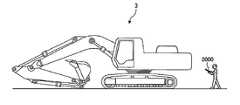
그리고, 버킷(13)의 동작 데이터는, 유압 셔블(3)에 설치된 센서에 의해 검출되어도 된다. 도 26은, 버킷(13)의 동작 데이터를 검출하는 검출 장치(63C)를 가지는 유압 셔블(3C)의 일례를 모식적으로 나타낸 도면이다.The operation data of the
검출 장치(63C)는, 상부 선회체(21)에 대한 버킷(13)의 날끝(13B)의 상대 위치를 검출한다. 검출 장치(63C)는, 붐 실린더 스트로크 센서(14S)와, 암 실린더 스트로크 센서(15S)와, 버킷 실린더 스트로크 센서(16S)를 가진다. 붐 실린더 스트로크 센서(14S)는, 붐 실린더(14)의 스트로크 길이를 나타내는 붐 실린더 길이 데이터를 검출한다. 암 실린더 스트로크 센서(15S)는, 암 실린더(15)의 스트로크 길이를 나타내는 암 실린더 길이 데이터를 검출한다. 버킷 실린더 스트로크 센서(16S)는, 버킷 실린더(16)의 스트로크 길이를 나타내는 버킷 실린더 길이 데이터를 검출한다. 이와 같은 스트로크 센서 대신에, 각도 센서를 검출 장치(63C)로서 사용해도 된다.The detecting
검출 장치(63C)는, 붐 실린더 길이 데이터에 기초하여, 상부 선회체(21)의 선회축 RX와 평행한 방향에 대한 붐(11)의 경사각(θ1)을 산출한다. 검출 장치(63C)는, 암 실린더 길이 데이터에 기초하여, 붐(11)에 대한 암(12)의 경사각(θ2)을 산출한다. 검출 장치(63C)는, 버킷 실린더 길이 데이터에 기초하여, 암(12)에 대한 버킷(13)의 날끝(13B)의 경사각(θ3)을 산출한다. 검출 장치(63C)는, 경사각(θ1), 경사각(θ2), 경사각(θ3), 기지인 작업기의 치수[붐(11)의 길이 L1], 암(12)의 길이(L2), 및 버킷(13)의 길이 L3에 기초하여, 상부 선회체(21)에 대한 버킷(13)의 날끝(13B)의 상대 위치를 산출한다. 검출 장치(63C)는, 상부 선회체(21)에 대한 버킷(13)의 상대 위치를 검출할 수 있으므로, 버킷(13)의 이동 상태를 검출할 수 있다.The detecting
검출 장치(63C)에 의하면, 버킷(13)의 동작 데이터 중, 적어도, 버킷(13)의 위치, 이동 궤적, 이동 속도, 및 이동 시간을 검출할 수 있다. 그리고, 버킷(13)의 굴삭량은, 버킷(13)에 중량 센서를 설치하고, 검출된 중량에 기초하여 굴삭량[m3]를 구해도 된다.The detecting
그리고, 전술한 실시형태에 있어서는, 조작자 Ma가 운전석(7)에 착석하여 작업기(10)를 조작하는 것으로 하였다. 작업기(10)는 원격 조작되어도 된다. 도 27 및 도 28은, 유압 셔블(3)의 원격 조작 방법의 일례를 설명하기 위한 도면이다.In the above-described embodiment, the operator Ma sits on the driver's
도 27은, 원격 조작실(1000)로부터 유압 셔블(3)이 원격 조작되는 방법을 나타낸 도면이다. 원격 조작실(1000)과 유압 셔블(3)은, 통신 장치를 통하여 무선 통신 가능하다. 도 27에 나타낸 바와 같이, 원격 조작실(1000)에는, 시공 정보 표시 장치(1100)와, 운전석(1200)과, 유압 셔블(3)을 원격 조작하는 조작 장치(1300)와, 모니터 장치(1400)가 설치된다.27 is a view showing a method of remotely operating the
시공 정보 표시 장치(1100)는, 시공 현장의 화상 데이터, 작업기(10)의 화상 데이터, 시공 프로세스 데이터, 및 시공 제어 데이터와 같은 각종 데이터를 표시한다.The construction
조작 장치(1300)는, 우측 작업 레버(1310R)와, 좌측 작업 레버(1310L)와, 우측 주행 레버(1320R)와, 좌측 주행 레버(1320L)를 포함한다. 조작 장치(1300)가 조작되면, 그 조작 방향 및 조작량에 기초하여, 조작 신호가 유압 셔블(3)에 무선 송신된다. 이로써, 유압 셔블(3)은 원격 조작된다.The
모니터 장치(1400)는, 운전석(1200)의 경사 전방에 설치되어 있다. 유압 셔블(3)의 도시하지 않은 센서 시스템의 검출 데이터는, 통신 장치를 통하여 원격 조작실(1000)에 무선 송신되고, 그 검출 데이터에 따른 표시 데이터가 모니터 장치(1400)에 표시된다.The
도 28은, 휴대 단말기 장치(2000)에 의해 유압 셔블(3)이 원격 조작되는 방법을 나타낸 도면이다. 휴대 단말기 장치(2000)는, 시공 정보 표시 장치와, 유압 셔블(3)을 원격 조작하는 조작 장치와, 모니터 장치를 가진다.28 is a diagram showing a method in which the
원격 조작되는 유압 셔블(3)의 동작 데이터가 취득되는 것에 의해, 원격 조작하는 조작자 Ma의 기량을 평가할 수 있다.By acquiring the operation data of the
그리고, 전술한 실시형태에 있어서, 평가 장치(600)의 기능의 일부 또는 전부를 관리 장치(4)가 구비해도 된다. 검출 장치(63)에 의해 검출된 유압 셔블(3)의 동작 데이터가 통신 장치(67)를 통하여 관리 장치(4)에 송신되는 것에 의해, 관리 장치(4)는, 유압 셔블(3)의 동작 데이터에 기초하여 조작자 Ma의 기량을 평가할 수 있다. 관리 장치(4)는, 연산 처리 장치(40) 및 본 실시형태에 관한 평가 방법을 실시하는 컴퓨터 프로그램을 기억 가능한 기억 장치(41)를 가지므로, 평가 장치(600)의 기능을 발휘할 수 있다.In the above-described embodiment, the
그리고, 전술한 실시형태에 있어서는, 작업기(10)의 동작 데이터에 기초하여, 조작자 Ma의 기량이 평가되는 것으로 하였다. 작업기(10)의 동작 데이터에 기초하여, 작업기(10)의 작동 상태가 평가되어도 된다. 예를 들면, 작업기(10)의 동작 데이터에 기초하여, 작업기(10)의 작동 상태가 정상인지의 여부를 판정하는 점검 처리가 실시되어도 된다.In the above-described embodiment, it is assumed that the skill of the operator Ma is evaluated based on the operation data of the working
그리고, 전술한 실시형태에 있어서는, 작업 차량(3)이 유압 셔블(3)이면 하였다. 작업 차량(3)은, 불도저(bulldozer), 휠 로더(wheel loader), 및 포크리프트(forklift) 등, 차량 본체에 대하여 상대 이동 가능한 작업기를 구비하는 작업 차량이면 된다.In the above-described embodiment, the
1: 평가 시스템, 2: 시공 현장, 3: 유압 셔블(작업 차량), 3C: 유압 셔블(작업 차량, 4: 관리 장치(제1 서버), 6: 휴대 기기, 7: 운전석, 8: 조작 장치, 8WR: 우측 작업 레버, 8WL: 좌측 작업 레버, 8MR: 우측 주행 레버, 8ML: 좌측 주행 레버, 10: 작업기, 11: 붐, 11P: 붐 핀, 12: 암, 12P: 암 핀, 13: 버킷, 13B: 날끝, 13K: 개구단부, 13P: 버킷 핀, 14: 붐 실린더, 14S: 붐 실린더 스트로크 센서, 15: 암 실린더, 15S: 암 실린더 스트로크 센서, 16: 버킷 실린더, 16S: 버킷 실린더 스트로크 센서, 20: 차량 본체, 21: 상부 선회체, 22: 하부 주행체, 23: 캡, 24: 카운터웨이트, 25: 구동륜, 26: 유동륜, 27: 크롤러, 40: 연산 처리 장치, 41: 기억 장치, 42: 출력 장치, 43: 입력 장치, 44: 입출력 인터페이스 장치, 45: 통신 장치, 60: 연산 처리 장치(평가 장치), 61: 기억 장치, 62: 위치 검출 장치, 63: 촬영 장치, 63C: 검출 장치, 64: 표시 장치, 65: 입력 장치, 66: 입출력 인터페이스 장치, 67: 통신 장치, 70: 가이드선, 73: 촬영 영역, 600: 평가 장치, 601: 검출 데이터 취득부, 602: 위치 데이터 산출부, 603: 목표 데이터 생성부, 604: 평가 데이터 생성부, 605: 표시 제어부, 608: 기억부, 610: 입출력부, 611: 목표 데이터 취득부, 613: 굴삭 시간 산출부, 614: 굴삭량 산출부, 1000: 원격 조작실, 1100: 시공 정보 표시 장치, 1200: 운전석, 1300: 조작 장치, 1310R: 우측 작업 레버, 1310L: 좌측 작업 레버, 1320R: 우측 주행 레버, 1320L: 좌측 주행 레버, 1400: 모니터 장치, 2000: 휴대 단말기 장치, AX1: 회전축, AX2: 회전축, AX3: 회전축, DX1: 회전축, DX2: 회전축, EP: 이동 종료 위치, Ma: 조작자, Mb: 작업자, MD: 문자 데이터, PD: 플롯, PM: 플롯, RL: 목표 라인, RX: 선회축, SP: 이동 개시 위치, TD: 경과 시간 데이터, TL: 검출 라인.1: evaluation system, 2: construction site, 3: hydraulic excavator (work vehicle), 3C: hydraulic excavator (work vehicle, 4: management device (first server), 6: portable device, 7: , 8WR: right work lever, 8WL: left work lever, 8MR: right travel lever, 8ML: left travel lever, 10: work machine, 11: boom, 11P: boom pin, 12: A
Claims (12)
Translated fromKorean상기 작업기의 소정부의 목표 이동 궤적을 포함하는 목표 데이터를 생성하는 목표 데이터 생성부; 및
상기 검출 데이터와 상기 목표 데이터에 기초하여, 상기 작업기를 조작하는 조작자의 평가 데이터를 생성하는 평가 데이터 생성부;
를 포함하는 평가 장치.A detection movement locus of a small portion of the work machine based on operation data from a movement start position to a movement end position of the work machine, which is detected by a detection device that detects an operation of a work unit of a work vehicle, A detection data acquiring unit that acquires detection data including the detection data;
A target data generating unit for generating target data including a target moving locus of the small portion of the working machine; And
An evaluation data generation unit that generates evaluation data of an operator who operates the working machine based on the detection data and the target data;
.
상기 검출 데이터는, 상기 이동 개시 위치에 있어서 정지 상태의 상기 작업기가 이동을 개시하고나서 상기 이동 종료 위치에 있어서 이동을 종료할 때까지의 공중에서의 무부하 상태의 상기 작업기의 검출 이동 궤적을 포함하는, 평가 장치.The method according to claim 1,
Wherein the detection data includes a detection trajectory of the work machine in a no-load state in the air from the start of movement of the work machine in the stop state at the movement start position to the end of movement at the movement end position , And an evaluation device.
상기 목표 이동 궤적은, 상기 이동 개시 위치와 상기 이동 종료 위치를 연결하는 직선을 포함하는, 평가 장치.3. The method according to claim 1 or 2,
Wherein the target movement locus includes a straight line connecting the movement start position and the movement end position.
상기 평가 데이터 생성부는, 상기 검출 이동 궤적과 상기 목표 이동 궤적과의 차분에 기초하여 상기 평가 데이터를 생성하는, 평가 장치.4. The method according to any one of claims 1 to 3,
Wherein the evaluation data generation unit generates the evaluation data based on a difference between the detection movement locus and the target movement locus.
상기 검출 데이터는, 상기 이동 개시 위치와 상기 이동 종료 위치와의 거리를 포함하고,
상기 평가 데이터 생성부는, 상기 거리에 기초하여 상기 평가 데이터를 생성하는, 평가 장치.5. The method according to any one of claims 1 to 4,
Wherein the detection data includes a distance between the movement start position and the movement end position,
And the evaluation data generation unit generates the evaluation data based on the distance.
상기 검출 데이터는, 상기 이동 개시 위치로부터 상기 이동 종료 위치까지의 상기 작업기의 이동 시간을 포함하고,
상기 평가 데이터 생성부는, 상기 이동 시간에 기초하여 상기 평가 데이터를 생성하는, 평가 장치.6. The method according to any one of claims 1 to 5,
Wherein the detection data includes a moving time of the work machine from the movement start position to the movement end position,
And the evaluation data generation unit generates the evaluation data based on the movement time.
상기 검출 장치는, 상기 작업 차량을 촬영 가능한 촬영 장치를 포함하고,
상기 동작 데이터는, 상기 작업기의 촬영 데이터를 포함하고,
상기 작업기는, 상기 작업 차량의 차량 본체에 지지되고,
상기 동작 데이터는, 상기 촬영 장치에 의해 촬영된 상기 작업 차량을 포함하는 촬영 영역의 촬영 데이터를 포함하고,
상기 촬영 영역의 촬영 데이터에 기초하여 상기 작업기의 위치 데이터를 산출하는 위치 데이터 산출부를 구비하고,
상기 위치 데이터 산출부는, 상기 촬영 영역에 대하여 제1 템플레이트(template)를 이동시켜 상기 차량 본체의 촬영 데이터와 상기 제1 템플레이트와의 상관값에 기초하여 상기 차량 본체의 위치 데이터를 산출한 후, 상기 촬영 영역에 대하여 제2 템플레이트를 이동시켜 상기 작업기의 촬영 데이터와 상기 제2 템플레이트와의 상관값에 기초하여 상기 작업기의 위치 데이터를 산출하는, 평가 장치.7. The method according to any one of claims 1 to 6,
Wherein the detection device includes a photographing device capable of photographing the working vehicle,
Wherein the operation data includes photographing data of the working machine,
The working machine is supported on a vehicle body of the working vehicle,
Wherein the operation data includes photographing data of a photographing area including the working vehicle photographed by the photographing apparatus,
And a position data calculation unit for calculating position data of the working machine based on the photographing data of the photographing area,
The position data calculator calculates position data of the vehicle body based on the correlation value between the photographing data of the vehicle body and the first template by moving a first template with respect to the photographing area, And the position data of the working machine is calculated based on the correlation value between the photographing data of the working machine and the second template by moving the second template with respect to the photographing area.
상기 제1 검출 데이터 및 상기 제2 검출 데이터에 기초하여, 상기 작업기를 조작하는 조작자의 평가 데이터를 생성하는 평가 데이터 생성부;
를 포함하는 평가 장치.A detection data acquiring unit that acquires first detection data indicating an excavation amount of the working machine and second detection data indicating a digging time of the working machine based on operation data of the working machine of the working vehicle; And
An evaluation data generation unit that generates evaluation data of an operator who operates the work machine based on the first detection data and the second detection data;
.
상기 작업기의 목표 굴삭량을 나타내는 목표 데이터를 취득하는 목표 데이터 취득부를 구비하고,
상기 평가 데이터 생성부는, 상기 제1 검출 데이터와 상기 목표 데이터와의 차분에 기초하여 상기 평가 데이터를 생성하는, 평가 장치.9. The method of claim 8,
And a target data acquiring section that acquires target data representing a target excavation amount of the working machine,
And the evaluation data generation section generates the evaluation data based on a difference between the first detection data and the target data.
상기 검출 장치는, 상기 작업 차량을 촬영 가능한 촬영 장치를 포함하고,
상기 동작 데이터는, 상기 작업기의 촬영 데이터를 포함하고,
상기 작업기는, 버킷(bucket)을 포함하고,
상기 촬영 장치에 의해 촬영된 상기 버킷의 촬영 데이터를 화상 처리하여 상기 버킷의 개구단부로부터 돌출되어 있는 굴삭물의 면적으로부터 상기 굴삭량을 산출하는 굴삭량 산출부를 구비하는, 평가 장치.10. The method according to claim 8 or 9,
Wherein the detection device includes a photographing device capable of photographing the working vehicle,
Wherein the operation data includes photographing data of the working machine,
The work machine includes a bucket,
And an excavation amount calculating unit for image-processing the photographed data of the bucket photographed by the photographing apparatus and calculating the excavation amount from the area of excavated material protruding from the opening end of the bucket.
상기 작업기의 소정부의 목표 이동 궤적을 포함하는 목표 데이터를 생성하는 목표 데이터 생성 단계; 및
상기 검출 데이터와 상기 목표 데이터에 기초하여, 상기 작업기를 조작하는 조작자의 평가 데이터를 생성하는 평가 데이터 생성 단계;
를 포함하는 평가 방법.And a detecting movement locus of the small portion of the work machine based on operation data of the work machine of the work vehicle from the movement start position to the movement end position of the work machine detected by the detection device for detecting the operation of the work machine of the work vehicle A detection data obtaining step of obtaining detection data;
A target data generating step of generating target data including a target moving trajectory of the small section of the working machine; And
An evaluation data generation step of generating evaluation data of an operator who operates the working machine based on the detection data and the target data;
Lt; / RTI >
상기 제1 검출 데이터 및 상기 제2 검출 데이터에 기초하여, 상기 작업기를 조작하는 조작자의 평가 데이터를 생성하는 평가 데이터 생성 단계;
를 포함하는 평가 방법.A detection data acquiring step of acquiring first detection data indicating a machining amount of the working machine and second detection data indicating a machining time of the working machine based on operation data of the working machine of the work vehicle; And
An evaluation data generation step of generating evaluation data of an operator who operates the machine based on the first detection data and the second detection data;
Lt; / RTI >
Applications Claiming Priority (1)
| Application Number | Priority Date | Filing Date | Title |
|---|---|---|---|
| PCT/JP2016/056290WO2016125915A1 (en) | 2016-03-01 | 2016-03-01 | Assesment device and assessment method |
Publications (1)
| Publication Number | Publication Date |
|---|---|
| KR20170102799Atrue KR20170102799A (en) | 2017-09-12 |
Family
ID=56564245
Family Applications (1)
| Application Number | Title | Priority Date | Filing Date |
|---|---|---|---|
| KR1020167026005ACeasedKR20170102799A (en) | 2016-03-01 | 2016-03-01 | Assesment device and assessment method |
Country Status (7)
| Country | Link |
|---|---|
| US (1) | US20170255895A1 (en) |
| JP (1) | JP6259515B2 (en) |
| KR (1) | KR20170102799A (en) |
| CN (1) | CN107343381A (en) |
| AU (1) | AU2016216347B2 (en) |
| DE (1) | DE112016000019T5 (en) |
| WO (1) | WO2016125915A1 (en) |
Cited By (1)
| Publication number | Priority date | Publication date | Assignee | Title |
|---|---|---|---|---|
| KR20200105380A (en)* | 2019-02-28 | 2020-09-07 | 베이징 바이두 넷컴 사이언스 앤 테크놀로지 코., 엘티디. | Method and apparatus for determining position and orientation of bucket of excavator |
Families Citing this family (37)
| Publication number | Priority date | Publication date | Assignee | Title |
|---|---|---|---|---|
| EP3399109B1 (en)* | 2015-12-28 | 2020-03-18 | Sumitomo (S.H.I.) Construction Machinery Co., Ltd. | Excavator |
| JP2017156972A (en)* | 2016-03-01 | 2017-09-07 | 株式会社小松製作所 | Evaluation device, management device, evaluation system, and evaluation method |
| KR101945655B1 (en)* | 2016-03-11 | 2019-02-07 | 히다찌 겐끼 가부시키가이샤 | Control equipment for construction machinery |
| AU2016224354B2 (en)* | 2016-03-28 | 2019-02-14 | Komatsu Ltd. | Evaluation apparatus and evaluation method |
| JP6697955B2 (en)* | 2016-05-26 | 2020-05-27 | 株式会社クボタ | Work vehicles and time-based management systems applied to work vehicles |
| WO2018043299A1 (en) | 2016-08-31 | 2018-03-08 | 株式会社小松製作所 | Work machine graphics display system, work machine remote control system, work machine, and work machine graphics display method |
| US11016501B2 (en)* | 2017-01-23 | 2021-05-25 | Built Robotics Inc. | Mapping a dig site diagram |
| US10408241B2 (en) | 2017-02-09 | 2019-09-10 | Deere & Company | Method of determining cycle time of an actuator and a system for determining a cycle time of a machine having an actuator |
| EP3604689B1 (en)* | 2017-03-22 | 2024-09-25 | Sumitomo Heavy Industries, Ltd. | Shovel, and management device and support device for shovels |
| JP6986853B2 (en)* | 2017-04-28 | 2021-12-22 | 株式会社小松製作所 | Work machine and control method of work machine |
| CN109034509A (en)* | 2017-06-08 | 2018-12-18 | 株式会社日立制作所 | Operating personnel's evaluation system, operating personnel's evaluating apparatus and evaluation method |
| DE112018001594T5 (en) | 2017-07-14 | 2019-12-19 | Komatsu Ltd. | OPERATING INFORMATION TRANSFER DEVICE, CONSTRUCTION DESIGN MANAGEMENT SYSTEM, OPERATING INFORMATION TRANSFER METHOD AND PROGRAM |
| JP6930337B2 (en)* | 2017-09-27 | 2021-09-01 | カシオ計算機株式会社 | Electronics, travel route recording methods, and programs |
| JP7344800B2 (en) | 2017-12-11 | 2023-09-14 | 住友建機株式会社 | Excavators and shovel management systems |
| JP7106851B2 (en)* | 2017-12-12 | 2022-07-27 | 富士フイルムビジネスイノベーション株式会社 | Information processing device and program |
| JP2019159818A (en)* | 2018-03-13 | 2019-09-19 | 矢崎総業株式会社 | Work evaluation device and work evaluation method |
| JP7143634B2 (en)* | 2018-05-29 | 2022-09-29 | コベルコ建機株式会社 | Skill evaluation system and skill evaluation method |
| JP7059845B2 (en)* | 2018-07-18 | 2022-04-26 | トヨタ自動車株式会社 | In-vehicle device |
| CN109296024B (en)* | 2018-11-30 | 2023-04-07 | 徐州市产品质量监督检验中心 | Unmanned excavator mining and loading pose precision detection method |
| JP7439053B2 (en)* | 2019-03-27 | 2024-02-27 | 住友重機械工業株式会社 | Excavators and shovel management devices |
| JP7163235B2 (en)* | 2019-03-29 | 2022-10-31 | コベルコ建機株式会社 | Work analysis method, work analysis device and program |
| JP7293822B2 (en)* | 2019-04-05 | 2023-06-20 | コベルコ建機株式会社 | Skill evaluation system and skill evaluation method |
| JP2020170474A (en)* | 2019-04-05 | 2020-10-15 | コベルコ建機株式会社 | Skill information presentation system and skill information presentation method |
| JP7302244B2 (en)* | 2019-04-05 | 2023-07-04 | コベルコ建機株式会社 | Skill information presentation system and skill information presentation method |
| JP7563759B2 (en)* | 2019-06-27 | 2024-10-08 | 住友重機械工業株式会社 | Work machine management system, work machine management device, worker terminal, contractor terminal |
| JP7383255B2 (en)* | 2019-08-22 | 2023-11-20 | ナブテスコ株式会社 | Information processing systems, information processing methods, construction machinery |
| WO2021085608A1 (en)* | 2019-10-31 | 2021-05-06 | 住友建機株式会社 | Shovel management system, portable terminal for shovel, and program used in portable terminal for shovel |
| JP7392422B2 (en)* | 2019-11-25 | 2023-12-06 | コベルコ建機株式会社 | Work support server and work support system |
| JP7490948B2 (en)* | 2019-11-25 | 2024-05-28 | コベルコ建機株式会社 | Work support server and work support system |
| JP7388954B2 (en) | 2020-03-11 | 2023-11-29 | 株式会社小松製作所 | Operation guide device |
| CN111557642B (en)* | 2020-03-31 | 2021-05-11 | 广东省国土资源测绘院 | Method and system for evaluating field operation effect based on track |
| JP7496278B2 (en)* | 2020-10-02 | 2024-06-06 | コベルコ建機株式会社 | Sorting destination specification device, sorting destination specification method, and program |
| KR20220064599A (en)* | 2020-11-12 | 2022-05-19 | 주식회사 가린시스템 | System and method of providing active service using remote vehicle starter based on big data analysis |
| JP7540358B2 (en)* | 2021-02-09 | 2024-08-27 | コベルコ建機株式会社 | Device to be operated |
| JP7540359B2 (en)* | 2021-02-09 | 2024-08-27 | コベルコ建機株式会社 | Device to be operated |
| KR20240144438A (en)* | 2022-03-31 | 2024-10-02 | 히다찌 겐끼 가부시키가이샤 | Work Support System |
| CN115327516A (en)* | 2022-08-31 | 2022-11-11 | 江苏徐工工程机械研究院有限公司 | A system and method for evaluating the control accuracy of an excavator |
Family Cites Families (13)
| Publication number | Priority date | Publication date | Assignee | Title |
|---|---|---|---|---|
| JP3805504B2 (en)* | 1997-11-14 | 2006-08-02 | 株式会社トプコン | Surveyor communication system |
| WO2003091856A2 (en)* | 2002-04-26 | 2003-11-06 | Emotion Mobility, Llc | System for vehicle assignment and pickup |
| JP4233932B2 (en)* | 2003-06-19 | 2009-03-04 | 日立建機株式会社 | Work support / management system for work machines |
| JP5108350B2 (en)* | 2007-03-26 | 2012-12-26 | 株式会社小松製作所 | Work amount measuring method and work amount measuring apparatus for hydraulic excavator |
| JP5133755B2 (en)* | 2008-03-28 | 2013-01-30 | 株式会社小松製作所 | Construction machine operation evaluation system and operation evaluation method |
| JP2010287069A (en)* | 2009-06-11 | 2010-12-24 | Caterpillar Sarl | Working machine management method in working machine management system |
| JP5337220B2 (en)* | 2011-09-29 | 2013-11-06 | 株式会社小松製作所 | Work machine display device and work machine equipped with the display device |
| JP5944805B2 (en)* | 2012-09-26 | 2016-07-05 | 株式会社クボタ | Combine and combine management system |
| JP5937499B2 (en)* | 2012-12-05 | 2016-06-22 | 鹿島建設株式会社 | Work content classification system and work content classification method |
| JP2015067990A (en)* | 2013-09-27 | 2015-04-13 | ダイキン工業株式会社 | Construction machinery |
| JP2015132090A (en)* | 2014-01-10 | 2015-07-23 | キャタピラー エス エー アール エル | Construction machinery |
| JP5781668B2 (en)* | 2014-05-30 | 2015-09-24 | 株式会社小松製作所 | Hydraulic excavator display system |
| CN105297817A (en)* | 2014-07-28 | 2016-02-03 | 西安众智惠泽光电科技有限公司 | Method for monitoring excavator |
- 2016
- 2016-03-01KRKR1020167026005Apatent/KR20170102799A/ennot_activeCeased
- 2016-03-01DEDE112016000019.7Tpatent/DE112016000019T5/enactivePending
- 2016-03-01WOPCT/JP2016/056290patent/WO2016125915A1/ennot_activeCeased
- 2016-03-01USUS15/128,210patent/US20170255895A1/ennot_activeAbandoned
- 2016-03-01JPJP2016523353Apatent/JP6259515B2/ennot_activeExpired - Fee Related
- 2016-03-01CNCN201680000912.6Apatent/CN107343381A/enactivePending
- 2016-03-01AUAU2016216347Apatent/AU2016216347B2/ennot_activeCeased
Cited By (1)
| Publication number | Priority date | Publication date | Assignee | Title |
|---|---|---|---|---|
| KR20200105380A (en)* | 2019-02-28 | 2020-09-07 | 베이징 바이두 넷컴 사이언스 앤 테크놀로지 코., 엘티디. | Method and apparatus for determining position and orientation of bucket of excavator |
Also Published As
| Publication number | Publication date |
|---|---|
| JPWO2016125915A1 (en) | 2017-04-27 |
| US20170255895A1 (en) | 2017-09-07 |
| DE112016000019T5 (en) | 2016-12-01 |
| AU2016216347B2 (en) | 2019-05-23 |
| WO2016125915A1 (en) | 2016-08-11 |
| JP6259515B2 (en) | 2018-01-10 |
| CN107343381A (en) | 2017-11-10 |
| AU2016216347A1 (en) | 2018-02-08 |
Similar Documents
| Publication | Publication Date | Title |
|---|---|---|
| KR20170102799A (en) | Assesment device and assessment method | |
| JP6002873B1 (en) | Evaluation apparatus and evaluation method | |
| CN108604326A (en) | Evaluation device, management device, evaluation system and evaluation method | |
| CN106460373B (en) | Evaluation device | |
| US11994397B2 (en) | Shovel and assist device for shovel | |
| US11072911B2 (en) | Image display apparatus for shovel | |
| KR102570490B1 (en) | Shovel and shovel display device | |
| CN114423906B (en) | Excavator and management device thereof | |
| CN117522378A (en) | Point inspection support system, management server, and point inspection report creation system for construction machine | |
| CN112218988A (en) | Excavator | |
| WO2017061512A1 (en) | Work-performing method, control system for work machine, and work machine | |
| CN113785091B (en) | Construction machine, information management system, information terminal, and program | |
| CN114731388B (en) | Work support server, work support method, and work support system | |
| JP7092714B2 (en) | Work machine control device and work machine control method | |
| JP2024001740A (en) | Operation support device, operation support system, and program | |
| WO2025018223A1 (en) | Autonomous driving information calculation system and autonomous driving information calculation method | |
| CN118742697A (en) | Remote operation processing device and remote operation processing system | |
| CN118900945A (en) | Measuring system for working machine, working machine, and measuring method for working machine |
Legal Events
| Date | Code | Title | Description |
|---|---|---|---|
| A201 | Request for examination | ||
| PA0105 | International application | Patent event date:20160921 Patent event code:PA01051R01D Comment text:International Patent Application | |
| PA0201 | Request for examination | ||
| PG1501 | Laying open of application | ||
| E902 | Notification of reason for refusal | ||
| PE0902 | Notice of grounds for rejection | Comment text:Notification of reason for refusal Patent event date:20171102 Patent event code:PE09021S01D | |
| E601 | Decision to refuse application | ||
| PE0601 | Decision on rejection of patent | Patent event date:20180323 Comment text:Decision to Refuse Application Patent event code:PE06012S01D Patent event date:20171102 Comment text:Notification of reason for refusal Patent event code:PE06011S01I |