KR20170102567A - Laser light source, wavelength conversion light source, light combining light source, and projection system - Google Patents
Laser light source, wavelength conversion light source, light combining light source, and projection systemDownload PDFInfo
- Publication number
- KR20170102567A KR20170102567AKR1020177024143AKR20177024143AKR20170102567AKR 20170102567 AKR20170102567 AKR 20170102567AKR 1020177024143 AKR1020177024143 AKR 1020177024143AKR 20177024143 AKR20177024143 AKR 20177024143AKR 20170102567 AKR20170102567 AKR 20170102567A
- Authority
- KR
- South Korea
- Prior art keywords
- laser light
- laser
- light
- array
- light source
- Prior art date
- Legal status (The legal status is an assumption and is not a legal conclusion. Google has not performed a legal analysis and makes no representation as to the accuracy of the status listed.)
- Granted
Links
- 238000006243chemical reactionMethods0.000titleclaimsabstractdescription20
- 230000003287optical effectEffects0.000claimsabstractdescription76
- 238000003491arrayMethods0.000claimsdescription14
- 238000000034methodMethods0.000claimsdescription12
- 238000000149argon plasma sinteringMethods0.000claimsdescription10
- 230000005284excitationEffects0.000claimsdescription9
- 238000004904shorteningMethods0.000claimsdescription7
- 230000010354integrationEffects0.000claimsdescription6
- 239000007787solidSubstances0.000claimsdescription5
- 230000002250progressing effectEffects0.000claimsdescription2
- 230000000694effectsEffects0.000description6
- 238000005516engineering processMethods0.000description5
- 238000005286illuminationMethods0.000description4
- 238000010586diagramMethods0.000description3
- 230000008569processEffects0.000description3
- 230000006835compressionEffects0.000description2
- 238000007906compressionMethods0.000description2
- 238000013461designMethods0.000description2
- 230000009471actionEffects0.000description1
- 238000004458analytical methodMethods0.000description1
- 230000009286beneficial effectEffects0.000description1
- 230000005540biological transmissionEffects0.000description1
- 230000008859changeEffects0.000description1
- 238000010276constructionMethods0.000description1
- 238000002474experimental methodMethods0.000description1
- 230000006872improvementEffects0.000description1
- 239000004973liquid crystal related substanceSubstances0.000description1
- 230000014759maintenance of locationEffects0.000description1
- 238000012986modificationMethods0.000description1
- 230000004048modificationEffects0.000description1
- 238000012545processingMethods0.000description1
- 230000000644propagated effectEffects0.000description1
- 238000011160researchMethods0.000description1
- 239000004065semiconductorSubstances0.000description1
- 238000007493shaping processMethods0.000description1
Images


Classifications
- G—PHYSICS
- G03—PHOTOGRAPHY; CINEMATOGRAPHY; ANALOGOUS TECHNIQUES USING WAVES OTHER THAN OPTICAL WAVES; ELECTROGRAPHY; HOLOGRAPHY
- G03B—APPARATUS OR ARRANGEMENTS FOR TAKING PHOTOGRAPHS OR FOR PROJECTING OR VIEWING THEM; APPARATUS OR ARRANGEMENTS EMPLOYING ANALOGOUS TECHNIQUES USING WAVES OTHER THAN OPTICAL WAVES; ACCESSORIES THEREFOR
- G03B21/00—Projectors or projection-type viewers; Accessories therefor
- G03B21/14—Details
- G03B21/20—Lamp housings
- G03B21/208—Homogenising, shaping of the illumination light
- G—PHYSICS
- G02—OPTICS
- G02B—OPTICAL ELEMENTS, SYSTEMS OR APPARATUS
- G02B27/00—Optical systems or apparatus not provided for by any of the groups G02B1/00 - G02B26/00, G02B30/00
- G02B27/09—Beam shaping, e.g. changing the cross-sectional area, not otherwise provided for
- G02B27/0938—Using specific optical elements
- G02B27/0994—Fibers, light pipes
- G—PHYSICS
- G03—PHOTOGRAPHY; CINEMATOGRAPHY; ANALOGOUS TECHNIQUES USING WAVES OTHER THAN OPTICAL WAVES; ELECTROGRAPHY; HOLOGRAPHY
- G03B—APPARATUS OR ARRANGEMENTS FOR TAKING PHOTOGRAPHS OR FOR PROJECTING OR VIEWING THEM; APPARATUS OR ARRANGEMENTS EMPLOYING ANALOGOUS TECHNIQUES USING WAVES OTHER THAN OPTICAL WAVES; ACCESSORIES THEREFOR
- G03B21/00—Projectors or projection-type viewers; Accessories therefor
- G03B21/14—Details
- G03B21/20—Lamp housings
- G03B21/2006—Lamp housings characterised by the light source
- G03B21/2013—Plural light sources
- G—PHYSICS
- G03—PHOTOGRAPHY; CINEMATOGRAPHY; ANALOGOUS TECHNIQUES USING WAVES OTHER THAN OPTICAL WAVES; ELECTROGRAPHY; HOLOGRAPHY
- G03B—APPARATUS OR ARRANGEMENTS FOR TAKING PHOTOGRAPHS OR FOR PROJECTING OR VIEWING THEM; APPARATUS OR ARRANGEMENTS EMPLOYING ANALOGOUS TECHNIQUES USING WAVES OTHER THAN OPTICAL WAVES; ACCESSORIES THEREFOR
- G03B21/00—Projectors or projection-type viewers; Accessories therefor
- G03B21/14—Details
- G03B21/20—Lamp housings
- G03B21/2006—Lamp housings characterised by the light source
- G03B21/2033—LED or laser light sources
- G03B21/204—LED or laser light sources using secondary light emission, e.g. luminescence or fluorescence
- H—ELECTRICITY
- H01—ELECTRIC ELEMENTS
- H01S—DEVICES USING THE PROCESS OF LIGHT AMPLIFICATION BY STIMULATED EMISSION OF RADIATION [LASER] TO AMPLIFY OR GENERATE LIGHT; DEVICES USING STIMULATED EMISSION OF ELECTROMAGNETIC RADIATION IN WAVE RANGES OTHER THAN OPTICAL
- H01S3/00—Lasers, i.e. devices using stimulated emission of electromagnetic radiation in the infrared, visible or ultraviolet wave range
- H01S3/005—Optical devices external to the laser cavity, specially adapted for lasers, e.g. for homogenisation of the beam or for manipulating laser pulses, e.g. pulse shaping
- H01S3/0092—Nonlinear frequency conversion, e.g. second harmonic generation [SHG] or sum- or difference-frequency generation outside the laser cavity
Landscapes
- Physics & Mathematics (AREA)
- General Physics & Mathematics (AREA)
- Optics & Photonics (AREA)
- Engineering & Computer Science (AREA)
- Multimedia (AREA)
- Electromagnetism (AREA)
- Plasma & Fusion (AREA)
- Projection Apparatus (AREA)
- Semiconductor Lasers (AREA)
- Optical Couplings Of Light Guides (AREA)
- Non-Portable Lighting Devices Or Systems Thereof (AREA)
- Lasers (AREA)
- Microscoopes, Condenser (AREA)
Abstract
Translated fromKoreanDescription
Translated fromKorean본 발명은 조명 및 표시 기술 분야에 관한 것이며, 특히 레이저 광원, 파장 변환 광원, 합광 광원 및 프로젝션 시스템에 관한 것이다.The present invention relates to the field of illumination and display technology, and more particularly to a laser light source, a wavelength conversion light source, a light source and a projection system.
반도체 기술의 발전에 따라, 고체 조명 광원의 우위는 점점 뚜렷해지고 있다. 레이저 광원은 고 휘도, 고 시준의 신형 광원으로서, 프로젝션, 조명 등 분야에 점점 적용되고 있다. 레이저 광원의 광학적 확장량이 작으므로 고 휘도의 광 출력을 얻을 수 있으며, 이와 동시에 그 균일화가 더 어려워진다.With advances in semiconductor technology, the dominance of solid state lighting sources is becoming increasingly apparent. The laser light source is a new type of light source with high luminance and high collimation, and it is increasingly applied to the field of projection, illumination and the like. The amount of optical expansion of the laser light source is small, so that a light output of high luminance can be obtained, and at the same time, the uniformization becomes more difficult.
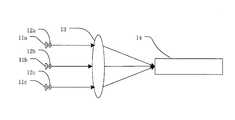
도 1은 종래 기술에서 사각 봉을 이용하여 광 균일화를 진행하는 레이저 광원에 관한 것이며, 여기서 11a-11c는 레이저 다이오드이고, 12a-12c는 시준 렌즈, 13은 집광 렌즈, 14는 직사각형 사각 봉이다. 여기서 시준 렌즈(12a-12c)는 구면 또는 비구면 렌즈 어레이이며, 각각의 렌즈는 하나의 레이저 다이오드에 대응된다. 레이저 다이오드(11a-11c)로부터 방출된 레이저 광은, 먼저 시준 렌즈(12a-12c)를 지나 평행 광 빔으로 시준된 후, 집광 렌즈(13)에 의해 하나의 소형 광반으로 집광되며, 이 광반의 사이즈는 직사각형 사각 봉(14)의 입광구 사이즈와 매칭된다. 직사각형 사각 봉(14)은 중공 또는 솔리드 광 가이드 봉으로서, 입력 광 빔을 균일화하기 위한 것이다. 다만, 실험에 따르면, 이러한 광 균일화 효과는 훌륭하지 않으며, 사각 봉(14) 출구의 출사광은 여전히 분리된 레이저 광점을 이루고 하나의 균일한 면 분포를 이루도록 혼합되지 않는다. 사각 봉(14)의 길이를 연장하여 사각 봉에서의 레이저 광의 반사 횟수를 증가해도 뚜렷하게 개선되지 않는다.FIG. 1 shows a conventional laser light source for performing light uniformization using a rectangular rod, wherein 11a-11c are laser diodes, 12a-12c is a collimating lens, 13 is a condensing lens, and 14 is a rectangular square bar. Here, the
본 발명이 주로 해결하고자 하는 기술적 과제는, 방출된 레이저 광 빔의 균일성을 향상하는 레이저 광원을 제공하는 것이다.SUMMARY OF THE INVENTION It is an object of the present invention to provide a laser light source that improves the uniformity of emitted laser light beams.
본 발명의 실시예는 레이저 광원을 제공하며, 상기 레이저 광원은,An embodiment of the present invention provides a laser light source,
레이저 소자 어레이를 포함하는 레이저 광원 어레이;A laser light source array including a laser element array;
상기 레이저 광원 어레이의 후단에 위치하여 차례로 배열된 집광용 광학 소자 및 시준용 광학 소자; 및A light converging optical element and a collimating optical element which are arranged at a rear end of the laser light source array and are arranged in order; And
시준용 광학 소자의 후단에 위치하는 적분 봉을 포함하며,And an integrating rod located at the rear end of the optical element for collimating,
상기 레이저 광원 어레이는, 시준된 1차 레이저 광 빔 어레이를 발생시키기 위한 것이고,The laser light source array is for generating a collimated primary laser light beam array,
상기 1차 레이저 광 빔 어레이는 집광용 광학 소자와 시준용 광학 소자를 차례로 지나, 시준된 2차 레이저 광 빔 어레이를 발생시키며, 2차 레이저 광 빔 어레이 중 2차 레이저 광 빔의 간격은 1차 레이저 광 빔 어레이 중 1차 레이저 광 빔의 간격보다 작으며,The primary laser light beam array sequentially passes through a light-converging optical element and a collimating optical element to generate a collimated secondary laser light beam array, and the interval of the secondary laser light beams in the secondary laser light beam array is a first The distance between the primary laser light beams in the laser light beam array is smaller than the interval between the primary laser light beams,
상기 적분 봉은 2차 레이저 광 빔 어레이를 수광하여 균일화하기 위한 것이며,The integrating rod is for receiving and equalizing the secondary laser light beam array,
상기 레이저 소자 어레이와 상기 적분 봉 사이의 광 경로에는 각도 분포 제어 소자가 더 마련되며, 상기 각도 분포 제어 소자는, 상기 레이저 광 빔 어레이에 있어서 광 분포의 단축 방향에서의 발산각을 증대시켜, 상기 적분 봉에 입사한 2차 레이저 광 빔 어레이 중 각각의 2차 레이저 광 빔의 광 분포의 단축 방향에서의 발산각과 장축 방향에서의 발산각의 비율 값이 0.7 이상이 되도록 한다.Wherein an angular distribution control element is further provided in an optical path between the laser element array and the integrating rod, and the angular distribution control element increases the divergence angle in the short axis direction of the light distribution in the laser light beam array, The ratio of the divergence angle in the short axis direction and the divergence angle in the long axis direction of the light distribution of each secondary laser light beam among the secondary laser light beam arrays incident on the integrating rod is 0.7 or more.
바람직하게는, 상기 각도 분포 제어 소자는 시준 렌즈 어레이이며, 그 중 각각의 시준 렌즈는 하나의 레이저 소자에 대응되어, 상기 레이저 소자가 방출한 레이저 광을 시준하기 위한 것이며,Preferably, the angular distribution control element is a collimating lens array, wherein each collimating lens corresponds to one laser element and collimates the laser beam emitted by the laser element,
상기 레이저 소자는 그에 대응되는 시준 렌즈의 광축 상에 위치하고 상기 시준 렌즈의 초점으로부터 이탈되어, 상기 시준 렌즈가 방출한 1차 레이저 광 빔의 광 분포의 단축 방향에서의 발산각과, 그 장축 방향에서의 발산각의 비율 값이 0.7 이상이 되도록 한다.Wherein the laser device is located on the optical axis of the collimating lens corresponding thereto and is deviated from the focal point of the collimating lens so that the divergence angle in the direction of the short axis of the light distribution of the primary laser light beam emitted by the collimating lens, The ratio of the divergence angle should be 0.7 or more.
바람직하게는, 상기 각도 분포 제어 소자는 적어도 하나의 기둥면 렌즈로서, 상기 시준용 광학 소자와 상기 적분 봉 사이에 위치하며, 그 중 각각의 기둥면 렌즈는 상기 시준용 광학 소자로부터 방출된 2차 레이저 광 빔 어레이 중 적어도 1열의 2차 레이저 광 빔에 대응되며, 상기 적어도 1열의 2차 레이저 광 빔 중 각 열의 진행 방향은 상기 기둥면 렌즈의 모선에 평행하고, 각 열의 2차 레이저 광 빔 중 각각의 2차 레이저 광 빔의 광 분포의 장축 방향은 상기 기둥면 렌즈의 모선에 평행하며,Preferably, the angular distribution control element is at least one columnar lens, positioned between the optical element for collimating and the integrating rod, and each of the columnar lenses has a secondary laser beam emitted from the optical element for collimating, And a second laser beam of at least one of the beam arrays, wherein a progressing direction of each of the at least one secondary laser beam is parallel to a busbar of the columnar lens, and each of the secondary laser beams The major axis direction of the light distribution of the secondary laser light beam is parallel to the bus bar of the columnar lens,
각각의 2차 레이저 광 빔은 그에 대응되는 기둥면 렌즈를 지난 후, 광 분포의 단축 방향에서의 발산각과 그 장축 방향에서의 발산각의 비율 값은 0.7 이상이다.The ratio of the divergence angle in the short axis direction and the divergence angle in the long axis direction of the light distribution is 0.7 or more after each of the secondary laser light beams passes through the corresponding columnar lens.
바람직하게는, 상기 각도 분포 제어 소자는 광 산란 시트로서, 상기 시준용 광학 소자와 상기 적분 봉 사이에 위치하며, 상기 광 산란 시트에 의해 산란된 2차 레이저 광 빔 어레이의 단축 방향에서의 발산각과 장축 방향에서의 발산각의 비율 값이 0.7 이상이 되도록 한다.Preferably, the angular distribution control element is a light scattering sheet, which is located between the optical element for collimating and the integrating rod, and has a divergence angle in the minor axis direction of the secondary laser light beam array scattered by the light scattering sheet, So that the ratio of the divergence angle in the major axis direction is 0.7 or more.
바람직하게는, 상기 각도 분포 제어 소자는 마이크로 렌즈 어레이로서, 상기 시준용 광학 소자와 상기 적분 봉 사이에 위치하고, 그 중 각각의 마이크로 렌즈는 장방형을 이루며,Preferably, the angular distribution control element is a microlens array, which is located between the optical element for collimating and the integrating rod, each of which has a rectangular shape,
상기 마이크로 렌즈 어레이에 입사한 2차 레이저 광 빔 어레이는 광 분포의 단축 방향에서 각각의 마이크로 렌즈의 장변 방향에 평행하고, 상기 마이크로 렌즈 어레이로부터 방출된 2차 레이저 광 빔 어레이는 광 분포의 단축 방향에서의 발산각과 장축 방향에서의 발산각의 비율 값이 0.7 이상이다.The secondary laser light beam arrays incident on the microlens array are parallel to the long side direction of the respective microlenses in the direction of the short axis of the light distribution and the secondary laser light beam arrays emitted from the microlens array are arranged in the short axis direction And the ratio of the divergent angle in the major axis direction is 0.7 or more.
바람직하게는, 상기 레이저 광원 어레이는 레이저 소자 어레이와 시준 렌즈 어레이를 포함하며, 그 중 각각의 시준 렌즈는 하나의 레이저 소자에 대응되어, 상기 레이저 소자가 방출한 레이저 광을 시준하며, 각각의 레이저 소자는 그에 대응되는 시준 렌즈의 광축에 위치하고, 상기 시준 렌즈의 초점으로부터 이탈되며,Preferably, the laser light source array includes a laser element array and a collimating lens array, wherein each of the collimating lenses corresponds to one laser element, collimates the laser light emitted by the laser element, The element is located on the optical axis of the collimating lens corresponding thereto, is deviated from the focus of the collimating lens,
상기 각도 분포 제어 소자는 상기 시준용 광학 소자와 상기 적분 봉 사이에 위치하여, 입사한 2차 레이저 광 빔의 광 분포의 단축 방향에서의 발산각을 증대시키거나, 또는 입사한 2차 레이저 광 빔의 광 분포의 장축 방향에서의 발산각을 감소시켜, 상기 적분 봉에 입사한 2차 레이저 광 빔 어레이 중 각각의 2차 레이저 광 빔의 광 분포의 단축 방향에서의 발산각과 장축 방향에서의 발산각의 비율 값이 0.7 이상이 되도록 한다.The angle distribution control element is positioned between the collimating optical element and the integrating rod to increase the divergence angle in the short axis direction of the light distribution of the incident secondary laser light beam, And the divergence angle in the minor axis direction and the divergence angle in the major axis direction of the light distribution of each secondary laser light beam among the secondary laser light beam arrays incident on the integrating rod, Is 0.7 or more.
바람직하게는, 상기 적분 봉은 솔리드 봉이며, 상기 각도 분포 제어 소자와 상기 적분 봉은 일체로 성형된다.Preferably, the integrating rod is a solid rod, and the angle distribution controlling element and the integrating rod are integrally formed.
본 발명의 실시예는 레이저 광원을 더 제공하며, 상기 레이저 광원은,An embodiment of the present invention further provides a laser light source,
시준된 1차 레이저 광 빔 어레이를 발생시키기 위한 레이저 광원 어레이;A laser light source array for generating a collimated primary laser light beam array;
상기 레이저 광원 어레이의 후단에 위치하여 차례로 배열된 집광용 광학 소자 및 시준용 광학 소자; 및A light converging optical element and a collimating optical element which are arranged at a rear end of the laser light source array and are arranged in order; And
시준용 광학 소자의 후단에 위치하는 적분 봉을 포함하고,And an integrating rod located at the rear end of the optical element for collimating,
상기 1차 레이저 광 빔 어레이는 집광용 광학 소자와 시준용 광학 소자를 차례로 지난 후 시준된 2차 레이저 광 빔 어레이를 형성하고, 2차 레이저 광 빔 어레이 중 2차 레이저 광 빔의 간격은 1차 레이저 광 빔 어레이 중 1차 레이저 광 빔의 간격보다 작으며,Wherein the primary laser light beam array forms a collimated secondary laser light beam array after sequentially passing through the optical element for focusing and the optical element for collimating and the interval of the secondary laser light beams in the secondary laser light beam array is a first The distance between the primary laser light beams in the laser light beam array is smaller than the interval between the primary laser light beams,
상기 적분 봉은 2차 레이저 광 빔 어레이를 수광하여 균일화하기 위한 것이며, 그 중 상기 적분 봉의 입광구의 면적은 그 출광구의 면적보다 크며,The integrating rod is for receiving and equalizing the secondary laser light beam array. The area of the entrance of the integrating rod is larger than the area of the exit,
상기 적분 봉의 입광구는 서로 수직하는 제1 변과 제2 변을 포함하고, 출광구는 서로 수직하는 제1 변과 제2 변을 포함하며, 그 중 입광구와 출광구의 제1 변은 평행하고, 입광구와 출광구의 제1 변 길이의 비율 값은 입광구와 출광구의 제2 변 길이의 비율 값보다 작으며,Wherein the input port of the integrating rod includes first and second sides that are perpendicular to each other, the output port includes first and second sides that are perpendicular to each other, wherein the first side of the input port and the output port are parallel And the ratio of the length of the first side of the inlet and the outlet is smaller than the ratio of the length of the second side of the inlet and the outlet,
상기 2차 레이저 광 빔 어레이는 상기 적분 봉에 입사할 때, 각각의 2차 레이저 광 빔의 광 분포의 장축 방향은 상기 적분 봉의 입광구의 제1 변에 평행한다.When the secondary laser light beam array is incident on the integrating rod, the major axis direction of the light distribution of each secondary laser light beam is parallel to the first side of the entrance of the integrating rod.
바람직하게는, 상기 적분 봉의 입광구의 제1 변은 출광구의 제1 변과 같다.Preferably, the first side of the entrance of the integrating rod is the same as the first side of the exit.
바람직하게는, 상기 적분 봉의 입광구는 정방형을 이룬다.Preferably, the entrance of the integrating rod has a square shape.
바람직하게는, 상기 레이저 소자 어레이와 상기 적분 봉 사이의 광 경로에는 각도 분포 제어 소자가 더 마련되고, 상기 각도 분포 제어 소자는, 상기 레이저 광 빔 어레이를 정형하여, 상기 적분 봉에 입사한 2차 레이저 광 빔 어레이 중 각각의 2차 레이저 광 빔의 광 분포의 단축 방향에서의 발산각과 장축 방향에서의 발산각의 비율 값을 증대시킨다.Preferably, an angle distribution control element is further provided in the optical path between the laser element array and the integrating rod, and the angular distribution control element forms the laser beam beam array, The ratio of the divergence angle in the short axis direction and the divergence angle in the long axis direction of the light distribution of each secondary laser light beam in the laser light beam array is increased.
본 발명의 실시예는 파장 변환 광원을 더 제공하며, 상기 파장 변환 광원은,An embodiment of the present invention further provides a wavelength conversion light source,
상기 레이저 광원; 및The laser light source; And
상기 레이저 광원이 방출한 광을 수광하여 자극광을 방출하기 위한 파장 변환 장치를 포함한다.And a wavelength conversion device for receiving the light emitted from the laser light source and emitting stimulated light.
본 발명의 실시예는 합광 광원을 더 제공하며, 상기 합광 광원은,An embodiment of the present invention further provides a summing light source,
상기 레이저 광원;The laser light source;
여기 광원 및 상기 여기 광원으로부터 방출된 여기광을 흡수하여 자극광을 방출하기 위한 파장 변환 장치를 포함하는 파장 변환 광원; 및A wavelength conversion light source including an excitation light source and a wavelength conversion device for absorbing excitation light emitted from the excitation light source and emitting stimulated light; And
합광 장치를 포함하며,A light-
상기 레이저 광원이 방출한 광과 상기 파장 변환 광원이 방출한 자극광이 서로 다른 방향으로부터 합광 장치로 입사하고 합광 장치에 의해 하나의 광 빔으로 혼합되어 방출된다.The light emitted by the laser light source and the stimulated light emitted by the wavelength conversion light source enter the light multiplexer from different directions and are mixed and emitted by one light beam by the light multiplexer.
본 발명의 실시예는 프로젝션 시스템을 더 제공하며, 상기 프로젝션 시스템은,An embodiment of the present invention further provides a projection system,
상기 합광 광원; 및The summing light source; And
상기 합광 광원으로부터의 광 빔을 수광하여 변조하기 위한 공간광 변조 장치를 포함한다.And a spatial light modulator for receiving and modulating the light beam from the summing light source.
종래 기술에 비해, 본 발명은 아래와 같은 유익한 효과를 포함한다.Compared to the prior art, the present invention includes the following beneficial effects.
본 발명에 따르면, 집광용 광학 소자와 시준용 광학 소자의 작용에 의해, 1차 레이저 광 빔 어레이의 단면은 압축되어 2차 레이저 광 빔 어레이를 형성하며, 2차 레이저 광 빔의 발산각은 1차 레이저 광 빔의 발산각보다 크다. 이로써, 2차 레이저 광 빔은 그 후단의 적분 봉을 지난 후 더 균일한 면 분포를 구현할 수 있다. 동시에, 레이저 광원 어레이와 적분 봉 사이의 광 경로에 각도 분포 제어 소자가 마련되며, 상기 각도 분포 제어 소자는 상기 레이저 광 빔 어레이의 광 분포의 단축 방향에서의 발산각을 증대시켜, 적분 봉에 입사한 2차 레이저 광 빔 어레이 중 각각의 2차 레이저 광 빔의 단축 방향에서의 발산각과 장축 방향에서의 발산각의 비율 값이 0.7 이상이 되도록 한다. 이로써, 2차 레이저 광 빔 어레이 중 단축 방향에서의 광 빔의 적분 봉 내부에서의 반사 횟수를 증가시켜, 단축 방향과 장축 방향에서의 광 빔의 적분 봉 내부에서의 반사 횟수가 서로 근접하도록 하여, 적분 봉을 지난 2차 레이저 광 빔의 균일성을 향상한다.According to the present invention, by the action of the light-converging optical element and the collimating optical element, the cross section of the primary laser light beam array is compressed to form a secondary laser light beam array, and the divergence angle of the secondary laser light beam is 1 Is larger than the divergence angle of the secondary laser light beam. As a result, the secondary laser light beam can realize a more uniform surface distribution after passing through the integration bar at the subsequent stage. At the same time, an angular distribution control element is provided in the optical path between the laser light source array and the integrating rod, and the angular distribution control element increases the divergence angle in the short axis direction of the light distribution of the laser light beam array, The ratio of the divergence angle in the minor axis direction and the divergence angle in the major axis direction of each secondary laser light beam in one secondary laser light beam array is 0.7 or more. This increases the number of times of reflection of the light beam within the integrating bar in the minor axis direction of the secondary laser light beam array so that the number of times of reflection of the light beam in the minor axis direction and the major axis direction within the integrating rod becomes close to each other, Thereby improving the uniformity of the secondary laser light beam passing through the integrating rod.
도 1은 종래 기술에서 사각 봉을 이용하여 광 균일화를 진행하는 레이저 광원을 나타낸 도면이다.
도 2는 종래 기술에 따른 직사각형 사각 봉의 작동 원리의 개략도이다.
도 3a는 본 발명에 따른 레이저 광원의 일 실시예의 구성 개략도이다.
도 3b는 레이저 소자의 발광 개략도이다.
도 3c는 레이저 소자가 방출한 광이 시준 렌즈를 지난 후의 발광 개략도이다.
도 3d는 본 발명에 따른 레이저 광원 중 마이크로 렌즈 어레이의 구성 개략도이다.
도 4는 시준 렌즈의 초점에 위치한 경우와 상기 초점으로부터 이탈된 경우의 레이저 소자의 구성 개략도이다.
도 5는 본 발명에 따른 레이저 광원의 또 다른 실시예의 구성 개략도이다.
도 6은 도 5에 나타낸 레이저 광원 중 적분 봉의 사시도이다.FIG. 1 is a view showing a laser light source for performing light uniformization using a rectangular rod in the prior art.
2 is a schematic view of the operating principle of a rectangular bar according to the prior art.
3A is a schematic view showing the configuration of an embodiment of a laser light source according to the present invention.
3B is an emission schematic diagram of the laser device.
3C is a schematic diagram of the emission after the light emitted by the laser device passes through the collimator lens.
3D is a schematic view of the configuration of a microlens array among the laser light sources according to the present invention.
4 is a schematic view of the configuration of the laser device when it is located at the focal point of the collimator lens and when it is deviated from the focal point.
Fig. 5 is a schematic view showing the construction of another embodiment of the laser light source according to the present invention.
6 is a perspective view of an integration rod among the laser light sources shown in Fig.
발명자는 도 1에 나타낸 레이저 광원이 균일한 면 분포를 형성할 수 없는 문제점에 대한 전문적인 연구를 거쳐 아래 사항을 발견했다. 즉, 통상의 광 빔이 사각 봉에서 균일화를 구현할 수 있는 핵심적 원인은, 상기 광 빔의 각도 분포가 연속적이므로, 사각 봉 내부에서 수회 반사된 후에야 그 면 분포가 연속적일 수 있으며, 반사 횟수가 많을수록 면 분포의 균일성이 더 좋아질 수 있다.The inventor of the present invention has made the following researches on the problem that the laser light source shown in Fig. 1 can not form a uniform surface distribution. That is, the main reason that a normal light beam can realize uniformization in a square bar is that the angle distribution of the light beam is continuous, so that the surface distribution may be continuous after several reflection in the square rod, The uniformity of the surface distribution can be improved.
다만, 집광 렌즈(13)에 의해 집광된 레이저 광 빔은 통상의 광 빔과 달리, 다수의 레이저 광 빔이 조합되어 형성된 것으로서, 각각의 레이저 광 빔은 하나의 레이저 다이오드 및 대응되는 시준 렌즈로부터 유래된다. 따라서 전체 광 빔의 각도 분포는 연속적이지 않고 분리된다. 이들 분리된 레이저 광 빔이 사각 봉(14)에서 전파되는 과정은 도 2와 같다. 레이저 광 빔(L1)이 입사각 α로 입사하여 출사각 α로 방출되며, 레이저 광 빔(L2)은 입사각 β로 입사하여 출사각 β로 방출된다. 양자는 각자의 각도가 모두 매우 작으므로, 사각 봉에서 수회 반사되어도 여전히 하나의 매우 가는 광선을 유지한다. 따라서 사각 봉의 출구 측에서 혼합 효과, 즉 균일한 광 분포를 형성할 수 없다.However, unlike ordinary light beams, the laser beam condensed by the
이하, 도면과 실시형태를 결합하여 본 발명의 실시예를 상세히 설명한다.Hereinafter, embodiments of the present invention will be described in detail by combining drawings and embodiments.
[실시예 1][Example 1]
도 3a는 본 발명에 따른 레이저 광원의 일 실시예의 구성 개략도이다. 상기 레이저 광원(300)은 레이저 광원 어레이를 포함하고, 상기 레이저 광원 어레이는 시준된 1차 레이저 광 빔 어레이(381)를 발생시키기 위한 것이다. 여기서 레이저 광원 어레이는 레이저 소자 어레이와 시준 렌즈 어레이를 포함하며, 레이저 소자 어레이는 레이저 소자(31a, 31b, 31c)를 포함하고, 시준 렌즈 어레이는 시준 렌즈(32a, 32b, 32c)를 포함하며, 각각의 시준 렌즈는 하나의 레이저 소자에 대응된다. 레이저 소자의 발광 위치는 대응되는 시준 렌즈의 초점에 위치하고, 레이저 소자로부터 방출된 광은 시준 렌즈를 지나 시준된다.3A is a schematic view showing the configuration of an embodiment of a laser light source according to the present invention. The
본 실시예에서, 레이저 소자는 레이저 다이오드이며, 사실상 레이저 소자는 레이저 광을 방출하는 다른 소자일 수도 있으며, 본 발명은 이를 한정하지 않는다. 물론, 레이저 소자 어레이와 시준 렌즈 어레이 중 소자의 개수는 예시적인 것일 뿐, 이를 한정하지 않는다.In this embodiment, the laser element is a laser diode, and in fact, the laser element may be another element emitting laser light, but the present invention is not limited thereto. Of course, the number of elements in the laser element array and the collimator lens array is only exemplary and not limited thereto.
도 3b를 참조하면, 도 3b는 레이저 소자의 발광 개략도이다. 레이저 소자(31)의 발광면은 장방형이며, 상기 장방형의 장변(311)을 지나는 단면에서의 광 발산각은 α이고, 상기 장방형의 단변(312)을 지나는 단면에서의 광 발산각은 β이며, α는 β보다 작다. 일반적으로, β는 α의 5배보다 크다. 즉, 레이저 소자(31)의 출사광의 광 분포의 장축(313)은 장방형의 단변(312)에 평행하며, 출사광의 광 분포의 단축(314)은 장방형의 장변(311)에 평행한다.Referring to FIG. 3B, FIG. 3B is an emission schematic diagram of a laser device. The light emitting surface of the
레이저 소자(31)의 방출 광이 시준 렌즈를 지난 후의 1차 레이저 광 빔은 엄격한 의미에서의 평행광이 아니다. 레이저 소자의 방출 광에 비해, 시준된 레이저 광 빔의 발산각은 감소되나, 시준된 레이저 광 빔은 여전히 광 분포의 장축 방향과 단축 방향이 존재한다. 도 3c를 참조하면, 도 3c는 레이저 소자(31)의 방출 광이 시준 렌즈(32)를 지난 후의 발광 개략도이다. 참고로, 1차 레이저 광 빔의 광 분포의 장축(315)은 레이저 소자(31)의 발광면의 장변(311)에 평행하고, 1차 레이저 광 빔의 광 분포의 단축(316)은 레이저 소자(31)의 발광면의 단변(312)에 평행하며, 장축(315) 방향에서의 발산각과 단축(316) 방향에서의 발산각의 비율 값이 크고 또한 일반적으로 5보다 크다. 명확한 설명을 위해, 하기에서의 "장축 방향"과 "단축 방향"은 모두 광 빔의 광 분포에서의 장축 방향과 단축 방향을 가리킨다.The primary laser light beam after the emitted light of the
이로써, 각각의 레이저 소자의 방출 광이 시준 렌즈에 의해 시준되어 얻어지는 1차 레이저 광 빔 어레이(381)에서, 각각의 1차 레이저 광 빔의 광축은 서로 평행하나, 각각의 레이저 광 빔은 일정한 발산각을 가지고, 광 분포의 장축 방향에서의 발산각과 단축 방향에서의 발산각의 비율 값이 여전히 크다.Thus, in the primary laser
레이저 광원(300)은 레이저 광원 어레이의 후단에 위치하여 차례로 배열된 집광용 광학 소자(33)와 시준용 광학 소자(34)를 더 포함하며, 1차 레이저 광 빔 어레이(381)는 집광용 광학 소자(33)와 시준용 광학 소자(34)를 차례로 지나 시준된 2차 레이저 광 빔 어레이(382)를 형성한다.The
본 실시예에서, 집광용 광학 소자는 볼록 렌즈(33)이고, 시준용 광학 소자는 오목 렌즈(34)이며, 볼록 렌즈(33)와 오목 렌즈(34)의 초점은 중첩된다. 여기서 오목 렌즈(34)의 초점은 허초점이고, 상기 허초점은 오목 렌즈(34)의 광 경로 후단에 위치한다. 이로써, 1차 레이저 광 빔 어레이(381)는 먼저 볼록 렌즈(33)에 의해 집광되어 그 초점을 향해 집속되며, 오목 렌즈(34)로 입사할 때, 그 광 빔의 단면적은 볼록 렌즈(33)로 입사할 때의 광 빔의 단면적보다 작아진다. 이때, 상기 레이저 광 빔도 오목 렌즈의 초점을 향해 집속되므로, 오목 렌즈(34)를 지난 후 다시 평행광을 이루면서 방출되어, 시준된 2차 레이저 광 빔 어레이(382)를 형성하나, 레이저 광 빔의 단면적이 압축된다. 즉, 2차 레이저 광 빔 어레이(382) 중 각각의 2차 레이저 광 빔의 간격은 1차 레이저 광 빔 어레이 중 각각의 1차 레이저 광 빔의 간격보다 작다.In this embodiment, the light-converging optical element is a
광학적 확장량 보존 원리에 따르면, 광 빔의 단면적이 압축되면 그 발산각은 자연히 증대한다. 즉,According to the optical expansion amount retention principle, when the cross-sectional area of a light beam is compressed, its divergence angle naturally increases. In other words,

여기서 S1, θ1은 각각 1차 레이저 광 빔 어레이의 횡단면적과 발산 반각이고, S2, θ2는 각각 2차 레이저 광 빔 어레이의 횡단면적과 발산 반각이며, 여기서 S2<S1이면, θ2는 θ1보다 반드시 크다. 참고로, 식(1)의 발산 반각은 각각의 레이저 광 빔 사이의 끼인각이 아니라, 각각의 레이저 광 빔 자체의 발산각의 절반이다.Where S1 and θ1 are respectively the transverse area and divergence angle of the primary laser light beam array and S2 and θ2 are the transverse area and the divergence angle of the secondary laser light beam array, respectively, where S2 <S1 ,?2 is necessarily larger than?1 . For reference, the divergence angle in equation (1) is not the angle of subtraction between the respective laser light beams, but half of the divergence angle of each laser light beam itself.
실제 적용에서, 볼록 렌즈(33)와 오목 렌즈(34)의 위치와 곡률을 제어함으로써, 1차 레이저 광 빔 어레이(381)의 단면적에 대한 2차 레이저 광 빔 어레이(382)의 압축 비율(유사하게 말하면, 볼록 렌즈(33)와 오목 렌즈(34)의 초점거리의 비율이 바로 광 빔의 압축비이다)을 제어할 수 있으며, 나아가, 2차 레이저 광 빔 어레이 중 각각의 레이저 광 빔의 발산 반각이 1차 레이저 광 빔 어레이 중 각각의 레이저 광 빔의 발산 반각에 비해 증대하는 정도를 제어할 수 있다. 쉽게 이해할 수 있듯이, 여기서 2차 레이저 광 빔 어레이 중 각각의 레이저 광 빔의 광 분포의 장축 방향에서의 발산각과 단축 방향에서의 발산각의 증대 정도는 거의 같으므로, 상기 두 방향에서의 발산각의 비율 값은 여전히 크다.By controlling the position and curvature of the
레이저 광원(300)은 시준용 광학 소자(34)의 후단에 위치하는 각도 분포 제어 소자(35)를 더 포함하며, 상기 각도 분포 제어 소자(35)는, 2차 레이저 광 빔 어레이(382)를 수광하여 정형하되, 정형된 2차 레이저 광 어레이(382) 중 각각의 2차 레이저 광 빔의 광 분포 단축 방향에서의 발산각과, 장축 방향에서의 발산각의 비율 값이 0.7 이상이 되도록 한다.The
구체적으로, 본 실시예에서 각도 분포 제어 소자(35)는 기둥면 렌즈이다. 기둥면 렌즈가 하나의 위도에서만 하나의 광 빔의 발산각을 변경할 수 있으므로, 기둥면 렌즈를 이용하여 레이저 광 빔의 단축 방향에서의 발산각을 변경하고, 장축 방향에서의 발산각을 변경하지 않을 수 있으며, 기둥면 렌즈의 기둥면에 대한 곡률 설계를 통해 각각의 레이저 광 빔의 단축 방향에서의 발산각과 장축 방향에서의 발산각의 비율 값이 0.7 이상이 되도록 할 수 있다. 상기 목적을 구현하기 위해, 기둥면 렌즈로 입사한 2차 레이저 광 빔 어레이 중 각각의 2차 레이저 광 빔의 광 분포의 장축 방향은 모두 상기 기둥면 렌즈의 모선에 평행한다.Specifically, in this embodiment, the angular
레이저 광원(300)은 각도 분포 제어 소자(35)의 후단에 위치한 적분 봉(36)을 더 포함하며, 상기 적분 봉(36)은 각도 분포 제어 소자(35)에 의해 정형된 2차 레이저 광 빔 어레이(382)를 수광하여 균일화하기 위한 것이다.The
종래의 적분 봉(배경 기술에 따른 사각 봉과 콘형 봉은 모두 적분 봉 중 하나임)에 대한 이해에 따르면, 입사광은 반드시 하나의 큰 각도 범위로 입사해야만 바람직한 광 균일화 효과가 발생할 수 있다. 그 이유는, 이와 같이 해야만 광선이 적분 봉 내부에서 수회 반사되어 균일화될 수 있기 때문이다. 다만, 본 발명에 대한 연구를 거쳐, 발명자는 적분 봉에 대해 더 깊은 이해를 했다. 즉, 레이저 광 분야에 적용할 경우, 각 빔의 레이저 광을 집속하여 비교적 큰 각도 범위를 형성하는 것만으로는 작업할 수 없으며, 반드시 각 빔의 레이저 광의 발산 반각을 증가시켜야 한다. 각 빔의 레이저 광의 발산 반각을 증가시켜야만, 각 빔의 레이저 광 사이가 평행에 근접해도 적분 봉을 지나면서 매우 훌륭한 균일화 효과가 발생할 수 있다.According to the understanding of the conventional integrating rod (one of the rod and the cone rod according to the background art is one of the integrating rods), the incident light must be incident in one large angular range, so that the desired light equalizing effect may occur. This is because the light beam can be reflected in the integrating rod several times and uniformized in this way. However, after studying the present invention, the inventor has gained a deeper understanding of the integral rod. That is, when it is applied to the field of laser light, it is impossible to work only by forming a relatively large angular range by focusing the laser light of each beam, and it is necessary to increase the half angle of divergence of the laser light of each beam. It is necessary to increase the half angle of divergence of the laser beam of each beam so that even when the laser beams of the respective beams are in parallel to each other,
그러나, 각 빔의 레이저 광의 발산 반각을 증가시키는 과정에서, 각 빔의 레이저 광의 광 분포의 장축 방향과 단축 방향에서의 발산각이 증가하는 정도가 거의 같다. 따라서, 적분 봉으로 입사할 때, 비록 각 빔의 레이저 광의 발산 반각이 증가하지만, 각 빔의 레이저 광은 단축 방향에서의 발산각이 장축 방향에서의 발산각보다 훨씬 작다. 따라서 이 두 방향에서의 광 빔이 적분 봉 내부에서 반사하는 횟수는 큰 차이가 있으며, 각각의 2차 레이저 광 빔이 적분 봉의 출광구가 위치하는 면에 형성하는 광반이 장축 방향에서 균일하게 혼합되나, 단축 방향에서의 광 균일화 효과가 떨어진다. 따라서, 본 실시예에서는 시준용 광학 소자와 적분 봉 사이에 각도 분포 제어 소자를 설치함으로써, 적분 봉으로 입사하는 각각의 2차 레이저 광 빔의 광 분포의 단축 방향과 장축 방향에서의 발산각의 비율 값이 0.7 이상이 되도록 하고, 나아가 각각의 2차 레이저 광 빔의 단축 방향에서의 광 균일화 효과를 향상한다.However, in the process of increasing the half angle of divergence of the laser beam of each beam, the degree of divergence of the light distribution of the laser beam of each beam in the major axis direction and the minor axis direction increases to almost the same degree. Therefore, when incident on the integrating rod, the divergence angle of the laser beam of each beam increases, but the divergence angle of the laser beam of each beam in the uniaxial direction is much smaller than the divergence angle in the major axis direction. Therefore, there is a large difference in the number of times the light beam in these two directions is reflected in the integrating rod, and the light beams formed by the respective secondary laser light beams on the surface on which the output port of the integrating rod is located are uniformly mixed in the long axis direction , The light uniformizing effect in the short axis direction is reduced. Therefore, in this embodiment, by providing the angle distribution control element between the optical element for collimating and the integrating rod, the ratio of the divergence angle in the short axis direction and the long axis direction of the light distribution of each secondary laser beam incident on the integrating rod Value of 0.7 or more, and further improves the light uniformizing effect in the minor axis direction of each secondary laser light beam.
본 실시예에서, 각도 분포 제어 소자는 기둥면 렌즈 어레이일 수도 있다. 기둥면 렌즈 어레이를 설치함으로써, 각각의 기둥면 렌즈가 적어도 1열의 2차 레이저 광 빔을 얼라이먼트하고, 각 열의 2차 레이저 광 빔의 진행 방향이 모두 상기 기둥면 렌즈의 모선에 평행하도록 한다. 여기서 상기 적어도 1열의 2차 레이저 광 빔 중 각각의 2차 레이저 광 빔의 광 분포의 장축 방향은 모두 서로 평행하며, 상기 기둥면 렌즈의 모선에 평행하다. 하나의 기둥면 렌즈만을 이용하는 경우에 비해, 기둥면 렌즈 어레이를 이용하면 각각의 2차 레이저 광 빔의 광 분포에서의 단축 방향에서의 발산각이 더욱 크게 증가하여, 장축 방향에서의 발산각에 더욱 근접하도록 할 수 있다. 그러나 하나의 기둥면 렌즈만을 이용하면 실제 가공에 더욱 편리하다.In this embodiment, the angular distribution control element may be a columnar lens array. By providing the columnar lens array, each of the columnar lenses aligns the at least one column of the secondary laser beam so that the traveling direction of the secondary laser beam in each column is parallel to the busbar of the columnar lens. Wherein a major axis direction of a light distribution of each of the secondary laser light beams in the at least one secondary laser light beam is parallel to each other and parallel to a bus line of the columnar lens. The divergence angle in the short axis direction in the light distribution of each secondary laser light beam is further increased by using the columnar lens array and the divergence angle in the major axis direction is made closer to that in the case of using only one columnar lens can do. However, it is more convenient to actual processing by using only one plane lens.
본 실시예에서, 레이저 소자 자체가 방출한 레이저 광 빔의 시준성이 좋은 경우에, 시준 렌즈는 생략할 수도 있다. 다만, 레이저 광원 어레이에서 시준 렌즈 어레이를 생략하면, 1차 레이저 광 빔 어레이 중 각각의 1차 레이저 광 빔의 장축 방향과 단축 방향이 90도로 회전함에 유의해야 한다. 따라서, 이에 대응되도록, 기둥면 렌즈의 배치 위치는 이상 실시예에서 설명된 위치보다 레이저 광 빔 어레이의 광축에 수직하는 평면에서 90도로 회전되도록 해야 한다.In this embodiment, when the laser beam emitted by the laser device itself has good collimation, the collimator lens may be omitted. However, when the collimator lens array is omitted in the laser light source array, it should be noted that the major axis direction and the minor axis direction of each primary laser light beam in the primary laser light beam array rotate by 90 degrees. Therefore, in order to cope with this, the arrangement position of the columnar lens must be rotated by 90 degrees in a plane perpendicular to the optical axis of the laser light beam array rather than the position described in the above embodiment.
물론, 본 실시예에서 각도 분포 제어 소자(35)는 기둥면 렌즈 어레이가 아니라 광 산란 시트일 수도 있으며, 상기 광 산란 시트의 2차 레이저 광 빔의 단축 방향에 대한 산란 정도가 상기 2차 레이저 광 빔의 장축 방향에 대한 산란 정도보다 클 수 있다. 또는 상기 2차 레이저 광 빔의 단축 방향에 대해서만 산란하고, 상기 레이저 광 빔의 광 분포의 단축 방향에서의 발산각과 장축 방향에서의 발산각의 비율 값이 0.7 이상이 되도록 할 수 있다.Of course, in the present embodiment, the angle
예를 들어, 상기 광 산란 시트 표면의 산란 구조체는 서로 긴밀히 배열된 다수의 광 투과성 마이크로 구조체이며, 그 중 각각의 마이크로 구조체는 기둥면 구조체이며, 각각의 마이크로 구조체의 모선은 모두 서로 평행하고, 입사한 2차 레이저 광 빔의 광 분포 장축 방향에 평행하다. 또는, 기둥형 또는 기둥 형상의 일부를 나타내는 광 투과 및 산란 구조체를 하나의 투명 베이스 내부에 혼입시킬 수도 있으며, 여기서 상기 산란 구조체와 상기 베이스 사이에는 굴절율 차이가 있고, 각각의 산란 구조체의 모선은 서로 평행하거나 또는 거의 평행하며, 입사한 2차 레이저 광 빔의 광 분포 장축 방향에 평행할 수 있다. 또는, 상기 광 산란 시트는 DOE(Diffraction Optical Element, 회절 광학 소자)일 수도 있으며, DOE 위의 각 점에 대한 위상 설계에 의해, 상기 DOE가, 입사한 2차 레이저 광 빔의 광 분포 단축 방향에서의 발산각만을 증가시키거나, 또는 입사한 2차 레이저 광 빔의 광 분포 단축 방향에서의 발산각에 대한 증가량이 장축 방향에서의 발산각의 증가량보다 더 커지도록 할 수 있다.For example, the scattering structure on the surface of the light scattering sheet is a plurality of light transmitting microstructures arranged closely to each other, wherein each of the microstructures is a columnar structure, the busbars of the microstructures are all parallel to each other, Parallel to the long axis direction of the light distribution of the secondary laser light beam. Alternatively, a light transmission and scattering structure representing a part of a columnar or columnar shape may be incorporated into one transparent base, wherein there is a difference in refractive index between the scattering structure and the base, Parallel, or substantially parallel, and may be parallel to the light distribution major axis direction of the incident secondary laser light beam. Alternatively, the light scattering sheet may be a DOE (Diffraction Optical Element). By the phase design for each point on the DOE, the DOE transmits the incident light in the direction of the short axis of light distribution of the incident second laser light beam Or the amount of increase in the divergence angle of the incident secondary laser light beam in the direction of the shortening of the light distribution can be made larger than the increase amount of the divergence angle in the major axis direction.
본 실시예에서, 각도 분포 제어 소자(35)는 다수의 장방형 렌즈를 조립하여 이루어진 마이크로 렌즈 어레이일 수도 있다. 도 3d를 참조하면, 도 3d는 본 발명에 따른 레이저 광원 중 마이크로 렌즈 어레이의 구성 개략도이다. 각각의 마이크로 렌즈(351)는 장방형이며, 두 변의 길이는 각각 D1과 D2이고, D1은 D2보다 작다. 하나의 평행 광 빔이 마이크로 렌즈 어레이로 입사한 후, 장방형의 두 변을 따르는, 발산각이 서로 다른 하나의 광 빔을 형성하며, 그 중 장변 방향에서의 발산각과 단변 방향에서의 발산각의 비율은 약 D2 : D1이다. 따라서, 마이크로 렌즈 어레이로 입사한 2차 레이저 광 빔 어레이 중 각각의 2차 레이저 광 빔의 광 분포 단축 방향이 각각의 마이크로 렌즈의 장변 방향에 평행하도록 할 수 있으며, 이로써 각각의 2차 레이저 광 빔의 광 분포 단축 방향에서의 발산각의 증가량이 장축 방향에서의 발산각의 증가량보다 크도록 할 수 있다. 또한, 각각의 마이크로 렌즈의 두 변의 길이 비율 및 마이크로 렌즈의 표면 곡률에 대한 설계를 통해, 상기 마이크로 렌즈 어레이로부터 방출된 2차 레이저 광 빔 어레이의 광 분포 단축 방향에서의 발산각과 장축 방향에서의 발산각의 비율 값이 0.7 이상이 되도록 할 수 있다.In this embodiment, the angle
본 실시예에서, 각도 분포 제어 소자와 적분 봉을 일체로 성형할 수도 있다. 예를 들어, 적분 봉은 솔리드형을 이용하고, 입광구 위치를 하나의 기둥면 구조체로 구성하거나, 또는 입광구 위치에 광 산란 시트와 동일한 산란 구조체를 형성한다.In this embodiment, the angle distribution control element and the integrating rod may be integrally formed. For example, the solid rod is used as the integrating rod, the position of the entrance port is constituted by a single columnar structure, or the scattering structure is formed at the entrance of the light scattering sheet.
이상 실시예에서, 각도 분포 제어 소자(35)는 모두 시준용 광학 소자와 적분 봉 사이에 설치된다. 실제 적용에서, 각도 분포 제어 소자(35)를 레이저 광원 어레이와 적분 봉 사이의 광 경로 상의 임의의 위치에 설치할 수도 있으며, 레이저 광원 어레이로부터 방출된 레이저 광 빔 어레이 중 각각의 레이저 광 빔의 단축 방향에서의 발산각과 장축 방향에서의 발산각의 비율 값이 0.7 이상이 되기만 하면 본 발명의 목적을 구현할 수 있다.In the above embodiment, all of the angular
본 실시예에서, 시준용 광학 소자는 오목 렌즈이다. 실제 적용에서, 시준용 광학 소자는 볼록 렌즈를 이용할 수도 있으며, 집광용 광학 소자(33)와 상기 볼록 렌즈의 초점이 중첩되기만 하면 그 효과는 오목 렌즈를 사용하는 것과 동일하다. 다만, 광 전파 방향의 길이가 증가하여, 전체 시스템이 커진다. 더 일반적으로, 집광용 광학 소자와 시준용 광학 소자는 본 실시예에서 이용한 볼록 렌즈 또는 오목 렌즈에 한정되지 않으며, 예를 들어 집광용 광학 소자는 하나 또는 다수의 반사경이 다수의 레이저 광 빔을 집광시키는 것일 수도 있으며, 시준용 광학 소자는 프레넬 렌즈일 수 있다. 전체적으로, 동일한 기능을 구현 가능하면 본 특허의 보호 범위에 속한다.In this embodiment, the optical element for collimating is a concave lens. In practical applications, a convex lens may be used as the optical element for collimating, and the effect is the same as using a concave lens as long as the focus of the convex lens and the light-converging
[실시예 2][Example 2]
실시예 1에서, 레이저 광원 어레이와 적분 봉 사이에 각도 분포 제어 소자를 설치하여 각각의 레이저 광 빔의 단축 방향에서의 발산각과 장축 방향에서의 발산각의 비율 값을 증가시켰다. 다만, 레이저 광원 어레이와 적분 봉 사이에 각도 분포 제어 소자를 설치하지 않고, 레이저 광원 어레이 중 시준 렌즈 어레이에 의해 상기 목적을 구현할 수도 있다. 본 실시예에서 상기 시준 렌즈 어레이는 각도 분포 제어 소자에 해당한다.In Example 1, an angle distribution control element was provided between the laser light source array and the integrating rod to increase the ratio of the divergence angle in the short axis direction and the divergence angle in the long axis direction of each laser light beam. However, the above object can be achieved by a collimating lens array among laser beam source arrays without providing an angle distribution control element between the laser beam source array and the integrating rod. In the present embodiment, the collimator lens array corresponds to an angular distribution control element.
명료한 설명을 위해, 후술하는 "길이-폭 비율"은 타원의 장축과 단축의 비율을 가리킨다. 도 4를 참조하면, 레이저 소자(41)가 마침 시준 렌즈(42)의 초점에 위치하는 경우, 시준 렌즈(42)는 그 광축의 위치 A에 위치하며, 시준 렌즈(42)로부터 방출된 레이저 광 빔이 집광 렌즈(미도시)에 의해 목표면에 집광된 광반은 가늘고 긴 바형의 타원 a이다. 레이저 소자(41)가 시준 렌즈(42)의 광축에서 그 초점으로부터 벗어난 위치에 놓여진 경우, 예를 들어 시준 렌즈(42)가 레이저 소자(41)에 비교적 가까운 위치 B에 놓여진 경우, 시준 렌즈(42)로부터 방출된 레이저 광이 집광 렌즈에 의해 목표면에 집광된 광반은 타원 b이며, b의 길이-폭 비율은 a의 길이-폭 비율보다 작다. 만약 시준 렌즈(42)가 레이저 소자(41)에 더욱 가까운 위치 A에 놓여진 경우, 시준 렌즈(42)로부터 방출된 레이저 광이 집광 렌즈에 의해 목표면에 집광된 광반은 타원 c이며, c의 길이-폭 비율은 b의 길이-폭 비율보다 작다.For clarity, the "length-width ratio" described below refers to the ratio of the major axis to the minor axis of the ellipse. 4, when the
실험 통계와 이론 분석을 거쳐, 발명자는 그 원인이 아래와 같음을 발견했다. 탈초점의 경우, 레이저 소자가 방출한 광 분포의 장축 방향 최외곽에서의 광선과 시준 렌즈의 광축의 거리는, 단축 방향 최외곽에서의 광선과 광축의 거리보다 더 빠르게 증가하며, 몇 배 더 빠르다. 도 3b로부터 알 수 있듯이, 레이저 소자가 방출한 광 분포의 장축 방향이 상기 레이저 소자의 발광면의 단변에 평행하고, 광 분포의 단축 방향이 상기 레이저 소자의 발광면의 장변에 평행한다. 따라서, 시준 렌즈로부터 방출된 광 빔에서, 상기 레이저 소자의 발광면의 단변에 평행하는 방향에서의 발산각의 증가 속도는, 상기 레이저 소자의 발광면의 장변에 평행하는 방향에서의 발산각의 증가 속도보다 훨씬 크다.Through experimental statistics and theoretical analysis, the inventor found that the cause is as follows. In the case of defocusing, the distance between the light ray at the outermost long axis direction of the light distribution emitted by the laser device and the optical axis of the collimator lens increases more rapidly than the distance between the light ray and the optical axis at the outermost short axis direction, and is several times faster. 3B, the major axis direction of the light distribution emitted by the laser device is parallel to the short side of the light emitting surface of the laser device, and the short axis direction of the light distribution is parallel to the long side of the light emitting surface of the laser device. Therefore, in the light beam emitted from the collimator lens, the increasing rate of the divergence angle in the direction parallel to the short side of the light emitting surface of the laser element is an increase in the divergence angle in the direction parallel to the long side of the light emitting surface of the laser element It is much bigger than speed.
그리고, 도 3c로부터 알 수 있듯이, 시준 렌즈로부터 방출된 광 빔에서, 상기 레이저 소자의 발광면의 단변에 평행하는 방향은 상기 광 빔의 광 분포의 단축 방향이고, 상기 레이저 소자의 발광면의 장변에 평행하는 방향은 상기 광 빔의 광 분포의 장축 방향이다. 따라서, 시준 렌즈로부터 방출된 광 빔 중 광 분포의 단축 방향에서의 발산각의 증가 속도는 장축 방향에서의 발산각의 증가 속도보다 더 크며, 몇 배 더 크다. 이로써, 목표면 상의 타원 광반의 단축이 장축보다 더 빨리 증가하므로, 타원 광반의 길이-폭 비율에 변화가 발생한다.3C, in the light beam emitted from the collimator lens, the direction parallel to the shorter side of the light emitting surface of the laser device is the minor axis direction of the light distribution of the light beam, and the longer side of the light emitting surface of the laser device Is the major axis direction of the light distribution of the light beam. Therefore, the rate of increase of the divergence angle in the short axis direction of the light distribution among the light beams emitted from the collimating lens is larger than the increasing rate of the divergence angle in the long axis direction, and is several times larger. As a result, the short axis of the elliptical light half on the target surface increases faster than the long axis, so that a change occurs in the length-width ratio of the elliptical light half.
따라서, 실시예 1과 다른 점은, 본 실시예에서 각각의 레이저 소자는 그에 대응되는 시준 렌즈의 광축에 위치하고 당해 시준 렌즈의 초점으로부터 벗어난다(이하 "탈초점"이라고 약칭). 여기서 탈초점 정도는 상기 시준 렌즈가 방출한 1차 레이저 광 빔의 단축 방향에서의 발산각과 그 장축 방향에서의 발산각의 비율 값이 0.7 이상이 되도록 한다.Therefore, the difference from the first embodiment is that in this embodiment, each laser element is located on the optical axis of the collimating lens corresponding thereto and deviates from the focus of the collimating lens (hereinafter abbreviated as "decoupling"). Wherein the defocus degree is such that the ratio of the divergence angle in the minor axis direction and the divergence angle in the major axis direction of the primary laser light beam emitted by the collimator lens is 0.7 or more.
실시예 1에서 이용한 광 산란 시트 또는 기둥면 렌즈는 모두 일정 정도로 광 손실을 초래하며, 특히 광 산란 시트가 그러하다. 그러나, 본 실시예는 탈초점을 이용하여 광 손실을 작게 하고 효율을 더 높일 수 있다.Both the light scattering sheet or the columnar lens used in Example 1 cause a certain degree of light loss, and in particular the light scattering sheet. However, this embodiment can reduce the light loss and increase the efficiency further by using defocusing.
바람직하게는, 시준 렌즈의 위치를 이상적인 시준 위치(즉, 레이저 소자가 시준 렌즈의 초점에 위치하도록 하는 위치)로부터 레이저 소자 방향으로 이동시켜, 레이저 소자와 그에 대응되는 시준 렌즈의 거리가 상기 시준 렌즈의 초점 거리보다 작아지도록 한다. 이때 시준 렌즈가 광을 수집하는 각도가 더 크며, 광 이용율이 높다. 시준 렌즈가 방출한 광 빔의 발산각이 너무 커지는 것을 방지하도록, 탈초점 거리는 너무 크게 설정하지 않는다. 바람직하게는, 탈초점 후 시준 렌즈의 위치와, 이상적인 시준 위치 사이의 거리는 0.05mm 이하이다.Preferably, the position of the collimating lens is shifted from the ideal collimating position (i.e., the position at which the laser device is positioned at the focal point of the collimating lens) toward the laser device so that the distance between the laser device and the collimating lens corresponding thereto, Is smaller than the focal length of the lens. At this time, the angle at which the collimator lens collects light is larger, and the light utilization rate is high. The defocus distance is not set too large to prevent the divergence angle of the light beam emitted by the collimator lens from becoming too large. Preferably, the distance between the position of the collimating lens after defocusing and the ideal collimating position is 0.05 mm or less.
실제 적용에서는, 실시예 1과 실시예 2에서 이용한 방법을 결합할 수 있다. 즉, 레이저 광원 어레이에서 각각의 레이저 소자와 그에 대응되는 시준 렌즈가 탈초점 하도록 하고, 이와 동시에 레이저 광원 어레이와 적분 봉 사이에 각도 분포 제어 소자를 설치함으로써, 각각의 레이저 광 빔이 적분 봉으로 입사할 때 단축 방향에서의 발산각과 장축 방향에서의 발산각의 비율 값이 0.7 이상이 되도록 한다.In practical application, the methods used in Example 1 and Example 2 can be combined. That is, in the laser light source array, each laser element and the corresponding collimating lens are defocused, and at the same time, an angle distribution control element is provided between the laser light source array and the integrating rod, so that each laser light beam enters the integrating rod The ratio of the divergence angle in the short axis direction to the divergence angle in the long axis direction is set to be 0.7 or more.
[실시예 3][Example 3]
이상 실시예에서는 모두 적분 봉 앞의 광 경로에서 각각의 레이저 광 빔을 정형함으로써 본 발명의 목적을 이루었다. 다만, 적분 봉을 설치함으로써, 단축 방향에서의 발산각과 장축 방향에서의 발산각의 비율 값이 작은 레이저 광 빔이 적분 봉을 지난 후에도 여전히 상기 두 방향에서 모두 고르게 균일화된 광을 얻을 수 있도록 할 수도 있다. 이하 구체적으로 설명한다.All of the above embodiments achieve the object of the present invention by shaping each laser light beam in the optical path in front of the integrating rod. However, by providing an integrating rod, it is possible to obtain evenly uniform light in both directions even after the laser beam having a small ratio of the divergence angle in the minor axis direction and the divergence angle in the major axis direction passes through the integrating rod have. This will be described in detail below.
도 5를 참조하면, 도 5는 본 발명에 따른 레이저 광원의 또 다른 실시예의 구성 개략도이다. 레이저 광원(500)은 레이저 광원 어레이, 집광용 광학 소자(53), 시준용 광학 소자(54)와 적분 봉(56)을 포함한다.Referring to FIG. 5, FIG. 5 is a schematic view of a laser light source according to another embodiment of the present invention. The
이상 실시예와의 다른 점은 아래와 같다.The differences from the above embodiment are as follows.
본 실시예에서, 레이저 광원 어레이는 일일이 대응되는 레이저 소자 어레이(51)와 시준 렌즈 어레이(52)를 포함하며, 상기 시준 렌즈 어레이(52)는 시준된 1차 레이저 광 빔 어레이를 형성하기 위한 것이다. 여기서, 각각의 레이저 소자와 그에 대응되는 시준 렌즈는 탈초점하지 않는다. 물론, 레이저 소자 자체가 방출한 레이저 광 빔의 시준성이 좋은 경우에는 시준 렌즈 어레이를 이용하지 않아도 된다.In this embodiment, the laser light source array includes a corresponding
1차 레이저 광 빔 어레이는 집광 광학 소자(53)에 의한 집광과, 시준용 광학 소자(54)에 의한 시준을 거쳐 2차 레이저 광 빔 어레이를 형성하며 바로 적분 봉(56)으로 입사한다.The primary laser light beam array forms a secondary laser light beam array through the convergence by the converging optical element 53 and the collimation by the collimating
도 6을 참조하면, 도 6은 도 5의 레이저 광원 중 적분 봉의 사시도이다. 적분 봉(56)의 입광구(561)의 면적은 출광구(562)의 면적보다 크다. 본 실시예에서 입광구(561)와 출광구(562)는 모두 직사각형을 이룬다. 바람직하게는, 출광구(562)의 장변과 단변의 비율 값이 16/9 또는 4/3이며, 이로써 후단 광 경로 상의 광 변조 장치 중 광 밸브의 형태와 매칭되도록 한다.Referring to FIG. 6, FIG. 6 is a perspective view of an integration rod among the laser light sources of FIG. The area of the
본 실시예에서, 입광구(561)의 장변(561a)은 제1 변이고, 단변(561b)은 제2 변이다. 출광구(562)의 장변(562a)은 제1 변이고, 단변(562b)은 제2 변이다. 입광구의 장변(561a)과 출광구의 장변(562a)은 평행하고, 입광구의 제1 변(561a)의 길이와 출광구의 제1 변(562a)의 길이의 비율 값은, 입광구의 제2 변(561b)의 길이와 출광구의 제2 변(562b)의 길이의 비율 값보다 작다.In this embodiment, the
2차 레이저 광 빔 어레이가 적분 봉(56)의 입광구(561)로 입사하는 경우, 각각의 2차 레이저 광 빔의 장축 방향은 모두 입광구(561)의 제1 변(561a)에 평행하면, 각각의 2차 레이저 광 빔의 단축 방향은 모두 입광구(561)의 제2 변(561b)에 평행하거나 또는 근접하게 평행한다. 적분 봉의 입광구의 제1 변(561a)의 길이와 출광구의 제1 변(562a)의 길이의 비율 값이, 입광구의 제2 변(561b)의 길이와 출광구의 제2 변(562b)의 길이의 비율 값보다 작으므로, 상기 레이저 광 빔의 단축 방향을 따르는 광 빔이 적분 봉 내부에서 반사되는 횟수는 장축 방향을 따르는 광 빔보다 많으며, 나아가 2차 레이저 광 빔 어레이가 광 균일화 봉을 지난 후 단축 방향에서의 균일성이 향상된다.When the secondary laser light beam array is incident on the
본 실시예에서, 적분 봉의 입광구의 제1 변(561a) 길이와 출광구의 제1 변(562a) 길이의 비율 값은 1인 것이 바람직하며, 이로써 2차 레이저 광 빔의 광 분포의 장축 방향에서의 발산각이 증가하는 것을 방지한다.In this embodiment, it is preferable that the ratio of the length of the
적분 봉의 입광구(561)는 사각형을 이루어, 더 많은 2차 레이저 광 빔을 커플링할 수 있도록 하는 것이 바람직하다.The
본 실시예에서는, 실시예 1에 따른 각도 분포 제어 소자 및/또는 실시예 2에 따른 탈초점을 결합함으로써, 적분 봉으로 입사한 2차 레이저 광 빔 어레이 중 각각의 2차 레이저 광 빔의 광 분포 단축 방향에서의 발산각과 장축 방향에서의 발산각의 비율 값을 증가시킴으로써, 적분 봉에 의해 균일화된 레이저 광 빔의 균일성을 한층 더 향상할 수도 있다. 쉽게 이해할 수 있듯이, 본 실시예에 따른 적분 봉을 이용함과 동시에 각도 분포 제어 소자 및/또는 레이저 소자와 시준 렌즈 탈초점 방법을 이용하여 레이저 광 빔의 광 분포 단축 방향에서의 발산각과 장축 방향에서의 발산각의 비율 값을 증가시킬 때, 상기 비율 값은 실시예 1 및 실시예 2에서와 같이 엄격하지 않아도 되며, 상기 비율 값은 0.7 미만일 수도 있다. 각도 분포 제어 소자를 설치하지 않고(또는) 탈초점을 이용하지 않은 경우에 비해, 적분 봉으로 입사한 2차 레이저 광 빔 어레이 중 각각의 2차 레이저 광 빔의 광 분포 단축 방향에서의 발산각과 장축 방향에서의 발산각의 비율 값보다 크기만 하면 된다.In this embodiment, by combining the angular distribution control element according to the first embodiment and / or the defocusing according to the second embodiment, the light distribution of each secondary laser light beam among the secondary laser light beam arrays incident on the integration rod By increasing the ratio of the divergence angle in the short axis direction and the divergence angle in the long axis direction, the uniformity of the laser beam uniformized by the integration rod can be further improved. As can be easily understood, by using the integrating rod according to the present embodiment, and by using the angular distribution control element and / or the laser element and the collimator lens defocusing method, the divergence angle in the direction of the light distribution shortening of the laser light beam, When the ratio value of the divergence angle is increased, the ratio value may not be strict as in the first and second embodiments, and the ratio value may be less than 0.7. The divergence angle in the direction of the light distribution shortening of each secondary laser light beam among the secondary laser light beam arrays incident on the integrating rod is smaller than that in the case where the angle distribution control element is not provided and / It is only required to be larger than the ratio value of the divergence angle in the direction.
본 명세서에 기재한 각 실시예는 점진적 방식으로 설명되었으며, 각 실시예에서 중점으로 설명한 것은 모두 그밖의 다른 실시예와 상이한 점이며, 각 실시예 사이의 동일 유사한 부분은 서로 참조하면 된다.Each embodiment described in this specification has been described in an incremental manner, and all of the emphasis in each embodiment is different from the other embodiments, and the same or similar portions between the embodiments are mutually referenced.
본 발명의 실시예는 레이저 광원을 포함하는 파장 변환 광원을 더 제공하며, 상기 레이저 광원은 상기 각각의 실시예에서의 구성과 기능을 가질 수 있다. 상기 파장 변환 광원은 또한, 레이저 광원이 방출한 광을 수광하여 자극광을 방출하기 위한 파장 변환 장치를 더 포함한다.The embodiment of the present invention further provides a wavelength conversion light source including a laser light source, and the laser light source may have the configuration and the function in each of the above embodiments. The wavelength conversion light source further includes a wavelength conversion device for receiving the light emitted by the laser light source and emitting stimulated light.
본 발명의 실시예는 레이저 광원을 포함하는 합광 광원을 더 제공하며, 상기 레이저 광원은 상기 각각의 실시예에서의 구성과 기능을 가질 수 있다. 상기 합광 광원은 또한 파장 변환 광원을 더 포함하며, 상기 파장 변환 광원은 여기 광원과 파장 변환 장치를 포함하며, 상기 파장 변환 장치는 상기 여기 광원이 방출한 여기광을 흡수하여 자극광을 방출한다. 상기 합광 광원은 또한 합광 장치를 더 포함하며, 상기 레이저 광원이 방출한 광과 상기 파장 변환 광원이 방출한 자극광은 서로 다른 방향으로부터 합광 장치로 입사하고 합광 장치에 의해 하나의 광 빔으로 혼합되어 방출된다.The embodiment of the present invention further provides a light source including a laser light source, and the laser light source may have the configuration and the function in each of the above embodiments. The light source further includes a wavelength conversion light source. The wavelength conversion light source includes an excitation light source and a wavelength conversion device. The wavelength conversion device absorbs excitation light emitted from the excitation light source and emits stimulated light. The light source further includes a light condensing device, wherein the light emitted from the laser light source and the stimulated light emitted from the wavelength-converted light source are incident on the light multiplexer from different directions and are mixed into one light beam by the light multiplexer .
본 발명의 실시예는 프로젝션 시스템을 더 제공하며, 상기 프로젝션 시스템은 상기 합광 장치를 포함하고, 상기 합광 광원의 광 빔을 수광하여 변조시키는 공간광 변조 장치를 더 포함한다. 상기 프로젝션 시스템은 다양한 프로젝션 기술, 예를 들어 액정디스플레이(LCD, Liquid Crystal Display) 프로젝션 기술, 디지털 광 경로 프로세서(DLP, Digital Light Processor) 프로젝션 기술을 이용할 수 있다. 또한 상기 합광 광원은 조명 시스템, 예를 들어 무대 램프 조명에 적용할 수도 있다.An embodiment of the present invention further provides a projection system, wherein the projection system further includes a spatial light modulator that includes the light multiplexer and receives and modulates the light beam of the light source. The projection system can use various projection technologies, for example, a liquid crystal display (LCD) projection technology, and a digital light processor (DLP) projection technology. The light source may also be applied to an illumination system, for example a stage lamp illumination.
이상은 단지 본 발명의 실시형태일 뿐이며, 본 발명의 특허청구범위를 한정하지 않는다. 본 발명의 명세서 및 도면의 내용을 이용하여 진행한 등가적 구성 또는 등가적 프로세스 변경, 또는 기타 관련 기술 분야에 직간접적으로 적용한 것은 동일한 이치로 모두 본 발명의 보호 범위에 포함된다.The foregoing is merely illustrative of the present invention and does not limit the scope of the claims of the present invention. Equivalent configurations or equivalent process modifications made using the teachings of the present invention and drawings, or any other directly or indirectly applied to the related art, are equally applicable to the scope of the present invention.
Claims (11)
Translated fromKorean레이저 소자 어레이를 포함하고, 시준된 레이저 광 빔 어레이를 발생시키는 레이저 광원 어레이;
상기 레이저 광원 어레이의 후단에 위치하여 상기 레이저 광 빔 어레이를 집속시키는 집광용 광학 소자; 및
상기 집광용 광학 소자의 후단에 위치하여, 집속된 레이저 광 빔 어레이를 수광하여 균일화하는 적분 봉을 포함하며,
상기 레이저 소자 어레이와 상기 적분 봉 사이의 광 경로에는 각도 분포 제어 소자가 더 마련되며, 상기 각도 분포 제어 소자는, 상기 적분 봉에 입사한 레이저 광 빔 어레이 중 각각의 레이저 광 빔의 광 분포의 단축 방향에서의 발산각과 장축 방향에서의 발산각의 비율 값을 증가시키는 것을 특징으로 하는 레이저 광원.
In the laser light source,
A laser light source array including a laser element array and generating a collimated laser light beam array;
A light-converging optical element positioned at a rear end of the laser light source array to focus the laser light beam array; And
And an integrating rod which is positioned at the rear end of the light-converging optical element and receives and uniformizes the converged laser light beam array,
Wherein an angular distribution control element is further provided in an optical path between the laser element array and the integrating rod, and the angular distribution control element includes a shortening of the light distribution of each laser light beam among the laser light beam arrays incident on the integrating rod And the ratio of the divergent angle in the longitudinal direction and the divergent angle in the longitudinal direction is increased.
상기 레이저 광원 어레이는 시준된 1차 레이저 광 빔 어레이를 발생시키며,
상기 레이저 광원은 상기 집광용 광학 소자의 후단에 위치한 시준용 광학 소자를 더 포함하고, 상기 1차 레이저 광 빔 어레이는 집광용 광학 소자와 시준용 광학 소자를 차례대로 거친 후 서로 평행하는 시준된 2차 레이저 광 빔 어레이를 발생시키며,
상기 각도 분포 제어 소자는 상기 적분 봉에 입사한 상기 2차 레이저 광 빔 어레이 중 각각의 레이저 광 빔의 광 분포의 단축 방향에서의 발산각과, 장축 방향에서의 발산각의 비율 값을 증가시키는 것을 특징으로 하는 레이저 광원.
The method according to claim 1,
The laser light source array generates a collimated primary laser light beam array,
Wherein the laser light source further comprises a collimating optical element located at a rear end of the light converging optical element, wherein the primary laser light beam array passes through the collimating optical element and the collimating optical element one after another, Generating a secondary laser light beam array,
The angle distribution control element increases the ratio of the divergence angle in the short axis direction and the divergence angle in the long axis direction of the light distribution of each laser light beam among the secondary laser light beam arrays incident on the integration rod .
상기 각도 분포 제어 소자는 시준 렌즈 어레이이며, 각각의 시준 렌즈는 하나의 레이저 소자에 대응되어 당해 레이저 소자에서 방출된 레이저 광을 시준시키며,
상기 레이저 소자는 그에 대응되는 시준 렌즈의 광축 상에 위치하고 당해 시준 렌즈의 초점으로부터 이탈되며, 초점으로부터 이탈된 상기 시준 렌즈의 위치와 이상적인 시준 위치 사이의 거리는 0.05mm 이하이고, 상기 이상적인 시준 위치는 상기 레이저 소자가 시준 렌즈 초점에 위치할 때의 위치인 것을 특징으로 하는 레이저 광원.
3. The method according to claim 1 or 2,
Wherein the angle distribution control element is a collimator lens array, each collimating lens collimates the laser beam emitted from the laser element corresponding to one laser element,
The distance between the position of the collimator lens deviated from the focal point and the ideal collimating position is 0.05 mm or less, and the ideal collimating position is the distance from the focal point of the collimating lens, And a position at which the laser device is positioned at the collimating lens focus.
상기 각도 분포 제어 소자는 상기 집광용 광학 소자와 상기 적분 봉 사이에 위치하는 적어도 하나의 기둥면 렌즈이고, 각각의 기둥면 렌즈는 상기 집광용 광학 소자를 거쳐 출사된 레이저 광 빔 어레이 중의 적어도 1렬의 레이저 광 빔에 대응되며, 당해 적어도 1렬의 레이저 광 빔 중의 각 열의 진행 방향은 당해 기둥면 렌즈의 모선에 평행하며, 각 열의 레이저 광 빔 중의 각 레이저 광 빔의 광 분포의 장축 방향은 당해 기둥면 렌즈의 모선에 평행하거나; 또는,
상기 각도 분포 제어 소자는 적어도 하나의 기둥면 렌즈로서, 상기 시준용 광학 소자와 상기 적분 봉 사이에 위치하며, 그 중 각각의 기둥면 렌즈는 상기 시준용 광학 소자를 거쳐 출사된 2차 레이저 광 빔 어레이 중 적어도 1렬의 2차 레이저 광 빔에 대응되며, 상기 적어도 1렬의 2차 레이저 광 빔 중 각 열의 진행 방향은 상기 기둥면 렌즈의 모선에 평행하고, 각 열의 2차 레이저 광 빔 중 각각의 2차 레이저 광 빔의 광 분포 장축 방향은 상기 기둥면 렌즈의 모선에 평행하는 것을 특징으로 하는 레이저 광원.
3. The method according to claim 1 or 2,
Wherein the angle distribution control element is at least one columnar lens positioned between the light-converging optical element and the integrating rod, and each of the columnar lenses has at least one column of laser light beams emitted from the laser light beam array emitted through the light- Wherein a progress direction of each column in the at least one column of laser light beams is parallel to a bus line of the column surface lens and a major axis direction of a light distribution of each laser light beam in each column of the laser light beams corresponds to a light beam, Parallel to the busbar; or,
Wherein the angle distribution control element is at least one columnar lens positioned between the collimating optical element and the integrating rod, and each of the columnar lenses is a collimated light beam array of a secondary laser beam beam emitted through the collimating optical element Wherein at least one of the at least one column of secondary laser light beams corresponds to at least one column of secondary laser light beams, the progressing direction of each column of the at least one column of secondary laser light beams is parallel to the busline of the column- Wherein a direction of a long axis of light distribution of the laser light beam is parallel to a bus line of the columnar lens.
상기 각도 분포 제어 소자는 광 산란 시트로서, 상기 집광용 광학 소자와 상기 적분 봉 사이에 위치하거나 또는 상기 시준용 광학 소자와 상기 적분 봉 사이에 위치하는 것을 특징으로 하는 레이저 광원.
3. The method according to claim 1 or 2,
Wherein the angular distribution control element is a light scattering sheet and is located between the optical element for focusing and the integrating rod or between the optical element for collimating and the integrating rod.
상기 각도 분포 제어 소자는 마이크로 렌즈 어레이로서, 상기 집광용 광학 소자와 상기 적분 봉 사이에 위치하고, 그 중 각각의 마이크로 렌즈는 장방형을 이루며, 당해 마이크로 렌즈 어레이에 입사한 상기 레이저 광 빔 어레이는 광 분포의 단축 방향에서 각각의 마이크로 렌즈의 장변 방향에 평행하거나; 또는,
상기 각도 분포 제어 소자는 마이크로 렌즈 어레이로서, 상기 시준용 광학 소자와 상기 적분 봉 사이에 위치하고, 그 중 각각의 마이크로 렌즈는 장방형을 이루며, 당해 마이크로 렌즈 어레이에 입사한 상기 2차 레이저 광 빔 어레이는 광 분포의 단축 방향에서 각각의 마이크로 렌즈의 장변 방향에 평행하는 것을 특징으로 하는 레이저 광원.
3. The method according to claim 1 or 2,
Wherein the angle distribution control element is a microlens array which is located between the light converging optical element and the integrating rod, each of the microlenses forming a rectangular shape, and the laser beam beam array incident on the microlens array has a light distribution Parallel to the longitudinal direction of each microlens in the minor axis direction of the microlenses; or,
The angle distribution control element is a microlens array, which is located between the optical element for collimating and the integrating rod, each of which has a rectangular shape, and the secondary laser light beam array incident on the microlens array Parallel to the longitudinal direction of each microlens in the direction of the short axis of the light distribution.
상기 각도 분포 제어 소자는 회절용 광학 소자로서, 상기 집광용 광학 소자와 상기 적분 봉 사이에 위치하거나, 또는 상기 시준용 광학 소자와 상기 적분 봉 사이에 위치하는 것을 특징으로 하는 레이저 광원.
3. The method according to claim 1 or 2,
Wherein the angular distribution control element is a diffractive optical element and is located between the optical element for focusing and the integrating rod or between the optical element for collimating and the integrating rod.
상기 적분 봉은 솔리드 봉이며, 상기 각도 분포 제어 소자와 상기 적분 봉은 일체로 성형된 것을 특징으로 하는 레이저 광원.
3. The method according to claim 1 or 2,
Wherein the integrating rod is a solid rod, and the angle distribution controlling element and the integrating rod are integrally formed.
제1 항 또는 제2 항에 따른 레이저 광원; 및
상기 레이저 광원이 방출한 광을 수광하여 자극광을 방출하기 위한 파장 변환 장치를 포함하는 것을 특징으로 하는 파장 변환 광원.
In the wavelength conversion light source,
A laser light source according to claim 1 or 2; And
And a wavelength conversion device for receiving the light emitted by the laser light source and emitting stimulated light.
제1 항 또는 제2 항에 따른 레이저 광원;
여기 광원 및 상기 여기 광원으로부터 방출된 여기광을 흡수하여 자극광을 방출하기 위한 파장 변환 장치를 포함하는 파장 변환 광원; 및
합광 장치를 포함하며,
상기 레이저 광원이 방출한 광과 상기 파장 변환 광원이 방출한 자극광이 서로 다른 방향으로부터 합광 장치로 입사하고 합광 장치에 의해 하나의 광 빔으로 혼합되어 방출되는 것을 특징으로 하는 합광 광원.
In the light source,
A laser light source according to claim 1 or 2;
A wavelength conversion light source including an excitation light source and a wavelength conversion device for absorbing excitation light emitted from the excitation light source and emitting stimulated light; And
A light-
Wherein the light emitted by the laser light source and the stimulated light emitted by the wavelength conversion light source are incident on the light multiplexer from different directions and are mixed and emitted as one light beam by the light multiplexer.
제10 항에 따른 합광 광원; 및
상기 합광 광원으로부터의 광 빔을 수광하여 변조하기 위한 공간광 변조 장치를 포함하는 것을 특징으로 하는 프로젝션 시스템.In a projection system,
A light source according to claim 10; And
And a spatial light modulator for receiving and modulating the light beam from the light source.
Applications Claiming Priority (3)
| Application Number | Priority Date | Filing Date | Title |
|---|---|---|---|
| CN201310174987.4ACN103279005B (en) | 2013-05-13 | 2013-05-13 | Laser light source, wavelength conversion light source, combined light source and projection system |
| CN201310174987.4 | 2013-05-13 | ||
| PCT/CN2014/076946WO2014183581A1 (en) | 2013-05-13 | 2014-05-07 | Laser light source, wavelength conversion light source, light combining light source, and projection system |
Related Parent Applications (1)
| Application Number | Title | Priority Date | Filing Date |
|---|---|---|---|
| KR1020157033729ADivisionKR101774409B1 (en) | 2013-05-13 | 2014-05-07 | Laser light source, wavelength conversion light source, light combining light source, and projection system |
Publications (2)
| Publication Number | Publication Date |
|---|---|
| KR20170102567Atrue KR20170102567A (en) | 2017-09-11 |
| KR101993300B1 KR101993300B1 (en) | 2019-06-26 |
Family
ID=49061573
Family Applications (2)
| Application Number | Title | Priority Date | Filing Date |
|---|---|---|---|
| KR1020157033729AActiveKR101774409B1 (en) | 2013-05-13 | 2014-05-07 | Laser light source, wavelength conversion light source, light combining light source, and projection system |
| KR1020177024143AActiveKR101993300B1 (en) | 2013-05-13 | 2014-05-07 | Laser light source, wavelength conversion light source, light combining light source, and projection system |
Family Applications Before (1)
| Application Number | Title | Priority Date | Filing Date |
|---|---|---|---|
| KR1020157033729AActiveKR101774409B1 (en) | 2013-05-13 | 2014-05-07 | Laser light source, wavelength conversion light source, light combining light source, and projection system |
Country Status (6)
| Country | Link |
|---|---|
| US (4) | US9778554B2 (en) |
| EP (1) | EP2998788B1 (en) |
| JP (1) | JP6096987B2 (en) |
| KR (2) | KR101774409B1 (en) |
| CN (2) | CN103279005B (en) |
| WO (1) | WO2014183581A1 (en) |
Families Citing this family (63)
| Publication number | Priority date | Publication date | Assignee | Title |
|---|---|---|---|---|
| CN106647124A (en)* | 2013-02-04 | 2017-05-10 | 深圳市光峰光电技术有限公司 | Laser light source, wavelength conversion light source, light composition light source and projection display equipment |
| CN107632487B (en) | 2013-04-20 | 2020-03-24 | 深圳光峰科技股份有限公司 | Light emitting device and related light source system |
| CN103279005B (en)* | 2013-05-13 | 2015-08-19 | 深圳市绎立锐光科技开发有限公司 | Laser light source, wavelength conversion light source, combined light source and projection system |
| CN104635342A (en) | 2013-11-14 | 2015-05-20 | 清华大学 | Optical illuminating system |
| JP5804102B2 (en)* | 2014-02-12 | 2015-11-04 | ウシオ電機株式会社 | Laser light source device and image projection device |
| JP5804101B2 (en)* | 2014-02-12 | 2015-11-04 | ウシオ電機株式会社 | Laser light source device and image projection device |
| CN111029906B (en)* | 2014-05-16 | 2021-03-30 | 深圳光峰科技股份有限公司 | Correcting system of laser, light source system and projection device |
| CN104154495B (en)* | 2014-05-20 | 2017-12-15 | 广州市浩洋电子股份有限公司 | Mixed type optics integrator component and its optical system |
| EP2952948B1 (en)* | 2014-06-06 | 2023-05-17 | Airbus Defence and Space GmbH | Thermal heating device using light for binder activation and its integration in preforming device |
| JP5963993B2 (en)* | 2014-07-02 | 2016-08-03 | 三菱電機株式会社 | Light homogenizer |
| CN104503103A (en)* | 2014-12-12 | 2015-04-08 | 常州市武进区半导体照明应用技术研究院 | Method for adjusting laser illumination and laser illuminating device |
| BR202014032034U2 (en)* | 2014-12-19 | 2016-06-21 | André Luiz Esteves Palmeira | solar and electromagnetic concentrator |
| CN105987323A (en)* | 2015-02-12 | 2016-10-05 | 中国科学院理化技术研究所 | A light source module and display device |
| US10326967B2 (en) | 2015-05-15 | 2019-06-18 | Dolby Laboratories Licensing Corporation | Control of light spreading with blurring element in projector systems |
| CN105186391A (en)* | 2015-08-13 | 2015-12-23 | 苏州大学 | Hybrid wavelength laser wire-stripping method and wire-stripping apparatus of wire sheaths |
| WO2017056479A1 (en)* | 2015-09-28 | 2017-04-06 | Ricoh Company, Ltd. | System |
| JP6206560B2 (en) | 2015-09-28 | 2017-10-04 | 株式会社リコー | system |
| CN105301781B (en)* | 2015-10-20 | 2018-12-14 | 浙江科技学院 | The optical system and its light field angle of divergence adjusting method of zero pole point can be eliminated |
| CN105467599A (en)* | 2015-12-25 | 2016-04-06 | 深圳乐行天下科技有限公司 | Laser plastic-surgery optical component |
| CN106291965B (en)* | 2016-08-26 | 2019-10-29 | 湖北久之洋红外系统股份有限公司 | A kind of no speckle tricolor laser light source and laser projection system |
| WO2018037548A1 (en)* | 2016-08-26 | 2018-03-01 | 株式会社島津製作所 | Light emitting device |
| JP6681605B2 (en)* | 2016-08-30 | 2020-04-15 | パナソニックIpマネジメント株式会社 | Method of manufacturing lighting equipment, and lighting equipment |
| CN106308731A (en)* | 2016-08-31 | 2017-01-11 | 北京数字精准医疗科技有限公司 | Endoscopic multi-spectrum excited imaging system |
| JP6926526B2 (en)* | 2017-02-28 | 2021-08-25 | セイコーエプソン株式会社 | projector |
| DE102017108936A1 (en)* | 2017-04-26 | 2018-10-31 | Trumpf Laser Gmbh | Homogenization of pump laser radiation |
| CN108802986B (en)* | 2017-05-02 | 2020-06-19 | 台达电子工业股份有限公司 | Laser projection light source |
| CN107397307B (en)* | 2017-08-15 | 2023-06-20 | 武汉洛芙科技股份有限公司 | Full-color laser optical fiber trophy |
| JP7009910B2 (en)* | 2017-10-26 | 2022-01-26 | セイコーエプソン株式会社 | Light source device and projector |
| GB2567874B (en) | 2017-10-27 | 2023-09-20 | Innerscene Ltd | A collimating system |
| CN108020926A (en)* | 2018-02-07 | 2018-05-11 | 北京镭创高科光电科技有限公司 | A kind of laser display system and its dodging device |
| JP7109934B2 (en)* | 2018-02-13 | 2022-08-01 | スタンレー電気株式会社 | Lighting device and vehicle lamp |
| CN110221509B (en)* | 2018-03-01 | 2024-08-20 | 青岛海信激光显示股份有限公司 | Lens sheet and laser projection device |
| CN108559835B (en)* | 2018-03-22 | 2020-02-21 | 江苏大学 | Device and method for laser processing outer raceway of ball bearing |
| CN110475164B (en)* | 2018-05-09 | 2021-11-16 | 北京吉视汇通科技有限责任公司 | Optical splitter and single-fiber bidirectional passive optical network transmission system |
| KR102592916B1 (en)* | 2018-07-31 | 2023-10-23 | 삼성전자주식회사 | Maskless exposure apparatus and method, and method for fabricating semiconductor device comprising the exposure method |
| CN112567294B (en)* | 2018-08-16 | 2023-02-17 | 索尼公司 | Light source device and projection type display device |
| EP3627637B1 (en)* | 2018-09-18 | 2021-04-21 | ZKW Group GmbH | Method for connecting a collimating optics unit with a multi-mode laser light source at an optimized position |
| CN111059488B (en)* | 2018-10-15 | 2022-03-15 | 深圳市绎立锐光科技开发有限公司 | Lighting device and lighting system |
| CN109557676A (en)* | 2018-12-24 | 2019-04-02 | 浙江大学昆山创新中心 | A kind of simple dodging device |
| CN111381235B (en)* | 2018-12-27 | 2022-05-27 | 深圳市速腾聚创科技有限公司 | Laser radar transmitting system |
| JP7174251B2 (en)* | 2019-03-22 | 2022-11-17 | 日亜化学工業株式会社 | Light source device and optical engine |
| US11503274B2 (en)* | 2019-05-02 | 2022-11-15 | Disney Enterprises, Inc. | High speed binary compressive light field projection system |
| CN112255871B (en)* | 2019-07-02 | 2023-08-04 | 深圳光峰科技股份有限公司 | Light source device, including projection equipment and 3D equipment of the light source device |
| CN112666196B (en)* | 2019-10-16 | 2025-05-09 | 北航(四川)西部国际创新港科技有限公司 | A radiation integration device |
| JP7400417B2 (en)* | 2019-11-29 | 2023-12-19 | 株式会社リコー | Light source optical system, light source device and image display device |
| CN113074328A (en)* | 2019-12-18 | 2021-07-06 | 深圳市中光工业技术研究院 | Light beam lamp light source system |
| CN113131339B (en)* | 2019-12-31 | 2025-05-09 | 上海蓝湖照明科技有限公司 | Laser device |
| CN111258163B (en)* | 2020-03-19 | 2021-04-13 | 无锡视美乐激光显示科技有限公司 | Light source device, light path structure design method and projection system |
| CN113495414B (en)* | 2020-03-20 | 2025-08-22 | 深圳光峰科技股份有限公司 | Projection device and projection control method thereof |
| CN113534586B (en)* | 2020-04-17 | 2025-09-12 | 深圳市绎立锐光科技开发有限公司 | A laser light source |
| CN113970871B (en)* | 2020-07-22 | 2025-05-09 | 深圳光峰科技股份有限公司 | A light source system and a projection system |
| CN111948892B (en)* | 2020-09-02 | 2021-09-21 | 中国人民解放军陆军装甲兵学院 | Integrated imaging display system |
| WO2022078098A1 (en)* | 2020-10-14 | 2022-04-21 | 青岛海信激光显示股份有限公司 | Light source assembly, optical engine, and projection device |
| CN112394606B (en)* | 2020-11-19 | 2022-06-03 | 无锡视美乐激光显示科技有限公司 | Light source device and projection system |
| CN120630574A (en)* | 2020-12-29 | 2025-09-12 | 青岛海信激光显示股份有限公司 | Laser light source device and projection apparatus |
| CN112821958B (en)* | 2020-12-30 | 2022-05-13 | 西安电子科技大学 | Underwater blue-green laser communication emission method and system based on random micro-lens array |
| CN114815476A (en)* | 2021-01-19 | 2022-07-29 | 深圳光峰科技股份有限公司 | Light source system and projection system |
| CN112882317A (en)* | 2021-03-23 | 2021-06-01 | 深圳博升光电科技有限公司 | Light emission module and TOF imaging device |
| CN113641063B (en)* | 2021-08-16 | 2023-12-08 | 深圳市火乐科技发展有限公司 | Dodging device, projector optical machine and projector |
| CN113867090B (en)* | 2021-09-30 | 2024-02-09 | 深圳市火乐科技发展有限公司 | Projection apparatus and light source device thereof |
| LU103034B1 (en)* | 2022-11-11 | 2024-05-13 | Barco Nv | Diffuser rod |
| CN119050804B (en)* | 2024-08-09 | 2025-09-05 | 华中科技大学 | A shaping device for wide-faceted semiconductor lasers |
| CN119937230A (en)* | 2025-03-05 | 2025-05-06 | 西安通立软件开发有限公司 | Projection optical structure, projection optical mirror adjustment method and projection lens |
Citations (14)
| Publication number | Priority date | Publication date | Assignee | Title |
|---|---|---|---|---|
| JPH07199117A (en)* | 1993-12-20 | 1995-08-04 | Agfa Gevaert Nv | Device that converges plurality of light rays to common optical point |
| JPH1032359A (en)* | 1996-07-16 | 1998-02-03 | Matsushita Electric Ind Co Ltd | Semiconductor laser light focusing device |
| KR19980066783A (en)* | 1997-01-28 | 1998-10-15 | 김광호 | An optical system for beam shaping and an optical pickup employing the optical system |
| KR20060111793A (en)* | 2005-04-25 | 2006-10-30 | 삼성전자주식회사 | Lighting unit and image projector using the same |
| JP2007058163A (en)* | 2005-07-27 | 2007-03-08 | Ricoh Co Ltd | LIGHT SOURCE DEVICE, LIGHT MODULATION DEVICE, DISPLAY DEVICE, CONCENTRATION LIGHTING DEVICE, AND PROJECTION COLOR DISPLAY DEVICE |
| KR20070086010A (en)* | 2004-11-12 | 2007-08-27 | 어플라이드 머티어리얼스, 인코포레이티드 | Single axis light pipe for synchronizing one axis of illumination system based on laser diode |
| KR20080039581A (en)* | 2006-11-01 | 2008-05-07 | 엘지전자 주식회사 | Projection optics using integrated tunnel structure |
| KR20080039582A (en)* | 2006-11-01 | 2008-05-07 | 엘지전자 주식회사 | Projection optics using integrated structure |
| JP2010027492A (en)* | 2008-07-23 | 2010-02-04 | Panasonic Corp | Planar light emitting device and image display device |
| JP4723637B2 (en)* | 2006-03-23 | 2011-07-13 | パナソニック株式会社 | Projection display device and light source device |
| WO2012053167A1 (en)* | 2010-10-19 | 2012-04-26 | パナソニック株式会社 | Optical multiplexer and projector |
| US20120133904A1 (en)* | 2010-11-29 | 2012-05-31 | Seiko Epson Corporation | Light source device and projector |
| CN102591120A (en)* | 2012-02-22 | 2012-07-18 | 海信集团有限公司 | Light source device, light source generation method and laser projection machine comprising light source device |
| JP2012195064A (en)* | 2011-03-15 | 2012-10-11 | Seiko Epson Corp | Light source device and projector |
Family Cites Families (46)
| Publication number | Priority date | Publication date | Assignee | Title |
|---|---|---|---|---|
| JPH0557475A (en)* | 1991-09-04 | 1993-03-09 | Matsushita Electric Ind Co Ltd | Laser optical device |
| CN2203785Y (en) | 1994-12-16 | 1995-07-19 | 中国科学院半导体研究所 | A laser light source that emits uniformly |
| US6497488B1 (en)* | 1999-08-06 | 2002-12-24 | Ricoh Company, Ltd. | Illumination system and projector |
| US6903859B2 (en)* | 2001-12-07 | 2005-06-07 | Micronic Laser Systems Ab | Homogenizer |
| US7522792B2 (en)* | 2003-12-10 | 2009-04-21 | Panasonic Corporation | Optical element, laser light source, and two-dimensional image forming apparatus |
| US7101050B2 (en)* | 2004-05-14 | 2006-09-05 | 3M Innovative Properties Company | Illumination system with non-radially symmetrical aperture |
| KR100832655B1 (en)* | 2004-10-15 | 2008-05-27 | 삼성전기주식회사 | Color display device using color filter with increased diffraction efficiency |
| CN101065694A (en)* | 2004-11-12 | 2007-10-31 | 应用材料股份有限公司 | Single axis light pipe for homogenizing one axis of illumination system based on laser diodes |
| KR100677551B1 (en)* | 2005-01-05 | 2007-02-02 | 삼성전자주식회사 | LED package, lighting system and projection system using the same |
| FR2884621B1 (en) | 2005-04-14 | 2008-01-11 | Saint Louis Inst | LASER ILLUMINATOR |
| CN2795628Y (en)* | 2005-05-25 | 2006-07-12 | 无锡市星迪仪器有限公司 | Device for combining multiple small power light emitting devices into large power light emitting device |
| KR20060125346A (en) | 2005-06-02 | 2006-12-06 | 삼성전자주식회사 | Lighting system with adjustable aspect ratio and projection system |
| US7135392B1 (en)* | 2005-07-20 | 2006-11-14 | Applied Materials, Inc. | Thermal flux laser annealing for ion implantation of semiconductor P-N junctions |
| CN101233443B (en)* | 2005-07-28 | 2010-06-23 | 松下电器产业株式会社 | laser image display |
| CN1953070B (en)* | 2005-10-21 | 2010-05-26 | 鸿富锦精密工业(深圳)有限公司 | Beam shaping device and optical recording/reproducing device using same |
| US7411735B2 (en)* | 2005-12-06 | 2008-08-12 | 3M Innovative Property Company | Illumination system incorporating collimated light source |
| JP5244612B2 (en) | 2005-12-20 | 2013-07-24 | コーニンクレッカ フィリップス エレクトロニクス エヌ ヴィ | Color mixing rod integrator in laser-based projectors |
| KR100811177B1 (en) | 2006-07-31 | 2008-03-07 | 삼성전자주식회사 | Backlight unit and display device having same |
| ITGE20060081A1 (en) | 2006-08-03 | 2008-02-04 | Grafoplast Spa | AUTOMATIC LOADING / UNLOADING OF PRINT MEDIA IN A PRINTING MACHINE. |
| US20080315748A1 (en)* | 2007-03-30 | 2008-12-25 | Takaaki Kitada | Display Device |
| JP2008281829A (en)* | 2007-05-11 | 2008-11-20 | Konica Minolta Opto Inc | Illumination optical system |
| US20080316748A1 (en) | 2007-06-21 | 2008-12-25 | Carl Zeiss Laser Optics Gmbh | Illumination system |
| TW200903138A (en)* | 2007-07-12 | 2009-01-16 | Young Optics Inc | Illumination system |
| JP5141243B2 (en)* | 2007-12-27 | 2013-02-13 | コニカミノルタアドバンストレイヤー株式会社 | Projection device |
| JP2010256572A (en)* | 2009-04-23 | 2010-11-11 | Olympus Corp | Projection display device |
| JP5313029B2 (en)* | 2009-04-23 | 2013-10-09 | オリンパス株式会社 | Projection display |
| US20110234985A1 (en)* | 2010-03-26 | 2011-09-29 | Alcatel-Lucent Usa Inc. | Despeckling laser-image-projection system |
| JP2012141411A (en)* | 2010-12-28 | 2012-07-26 | Jvc Kenwood Corp | Light source device |
| CN103502726A (en)* | 2011-02-23 | 2014-01-08 | 瓦维恩股份有限公司 | Light emitting diode array illumination system with recycling |
| CN102147532B (en) | 2011-03-26 | 2012-06-27 | 电子科技大学 | Optical engine for projector |
| JP5648556B2 (en) | 2011-03-28 | 2015-01-07 | ソニー株式会社 | Illumination device, projection display device, and direct view display device |
| ES2770329T3 (en)* | 2011-04-12 | 2020-07-01 | Barco Nv | Reduced speckle laser projector |
| JP5979365B2 (en)* | 2011-10-06 | 2016-08-24 | パナソニックIpマネジメント株式会社 | Light source device and image display device |
| JP5744232B2 (en)* | 2011-12-12 | 2015-07-08 | 三菱電機株式会社 | Laser light source device and video display device |
| JP5914808B2 (en)* | 2011-12-21 | 2016-05-11 | パナソニックIpマネジメント株式会社 | Light source device and projection display device |
| CN102722072B (en)* | 2011-12-25 | 2014-12-31 | 深圳市光峰光电技术有限公司 | Projection display equipment |
| JP5909369B2 (en)* | 2012-01-16 | 2016-04-26 | 浜松ホトニクス株式会社 | Method for designing optical component for laser beam shaping, and method for manufacturing optical component for laser beam shaping |
| CN102566236B (en) | 2012-03-05 | 2015-02-25 | 海信集团有限公司 | Light source device, light source generating method and laser projector comprising light source device |
| JP5867721B2 (en)* | 2012-04-02 | 2016-02-24 | ソニー株式会社 | Illumination device and display device |
| JP6075705B2 (en)* | 2012-05-11 | 2017-02-08 | ウシオ電機株式会社 | Light source device and projector |
| JP6089616B2 (en)* | 2012-11-20 | 2017-03-08 | セイコーエプソン株式会社 | Light source device and projector |
| US20150323861A1 (en)* | 2012-12-25 | 2015-11-12 | Nec Display Solutions, Ltd. | Light source apparatus, projector, and method for illuminating an image modulation element |
| CN103091842B (en)* | 2013-01-30 | 2015-04-22 | 中国科学院长春光学精密机械与物理研究所 | Reshaping mirror group design method capable of converting elliptical gaussian light beam into circular flat-topped light beam |
| CN103279005B (en) | 2013-05-13 | 2015-08-19 | 深圳市绎立锐光科技开发有限公司 | Laser light source, wavelength conversion light source, combined light source and projection system |
| US20150124225A1 (en)* | 2013-11-07 | 2015-05-07 | Seiko Epson Corporation | Light source device and projector |
| CN107436528A (en)* | 2016-05-26 | 2017-12-05 | 精工爱普生株式会社 | Light supply apparatus and projecting apparatus |
- 2013
- 2013-05-13CNCN201310174987.4Apatent/CN103279005B/enactiveActive
- 2013-05-13CNCN201510434455.9Apatent/CN105158913B/enactiveActive
- 2014
- 2014-05-07JPJP2016513215Apatent/JP6096987B2/enactiveActive
- 2014-05-07EPEP14798594.9Apatent/EP2998788B1/enactiveActive
- 2014-05-07WOPCT/CN2014/076946patent/WO2014183581A1/enactiveApplication Filing
- 2014-05-07USUS14/890,899patent/US9778554B2/enactiveActive
- 2014-05-07KRKR1020157033729Apatent/KR101774409B1/enactiveActive
- 2014-05-07KRKR1020177024143Apatent/KR101993300B1/enactiveActive
- 2017
- 2017-09-13USUS15/703,544patent/US20180004076A1/ennot_activeAbandoned
- 2017-09-13USUS15/703,530patent/US11106121B2/enactiveActive
- 2021
- 2021-08-30USUS17/461,268patent/US20210389653A1/ennot_activeAbandoned
Patent Citations (14)
| Publication number | Priority date | Publication date | Assignee | Title |
|---|---|---|---|---|
| JPH07199117A (en)* | 1993-12-20 | 1995-08-04 | Agfa Gevaert Nv | Device that converges plurality of light rays to common optical point |
| JPH1032359A (en)* | 1996-07-16 | 1998-02-03 | Matsushita Electric Ind Co Ltd | Semiconductor laser light focusing device |
| KR19980066783A (en)* | 1997-01-28 | 1998-10-15 | 김광호 | An optical system for beam shaping and an optical pickup employing the optical system |
| KR20070086010A (en)* | 2004-11-12 | 2007-08-27 | 어플라이드 머티어리얼스, 인코포레이티드 | Single axis light pipe for synchronizing one axis of illumination system based on laser diode |
| KR20060111793A (en)* | 2005-04-25 | 2006-10-30 | 삼성전자주식회사 | Lighting unit and image projector using the same |
| JP2007058163A (en)* | 2005-07-27 | 2007-03-08 | Ricoh Co Ltd | LIGHT SOURCE DEVICE, LIGHT MODULATION DEVICE, DISPLAY DEVICE, CONCENTRATION LIGHTING DEVICE, AND PROJECTION COLOR DISPLAY DEVICE |
| JP4723637B2 (en)* | 2006-03-23 | 2011-07-13 | パナソニック株式会社 | Projection display device and light source device |
| KR20080039582A (en)* | 2006-11-01 | 2008-05-07 | 엘지전자 주식회사 | Projection optics using integrated structure |
| KR20080039581A (en)* | 2006-11-01 | 2008-05-07 | 엘지전자 주식회사 | Projection optics using integrated tunnel structure |
| JP2010027492A (en)* | 2008-07-23 | 2010-02-04 | Panasonic Corp | Planar light emitting device and image display device |
| WO2012053167A1 (en)* | 2010-10-19 | 2012-04-26 | パナソニック株式会社 | Optical multiplexer and projector |
| US20120133904A1 (en)* | 2010-11-29 | 2012-05-31 | Seiko Epson Corporation | Light source device and projector |
| JP2012195064A (en)* | 2011-03-15 | 2012-10-11 | Seiko Epson Corp | Light source device and projector |
| CN102591120A (en)* | 2012-02-22 | 2012-07-18 | 海信集团有限公司 | Light source device, light source generation method and laser projection machine comprising light source device |
Also Published As
| Publication number | Publication date |
|---|---|
| WO2014183581A1 (en) | 2014-11-20 |
| US9778554B2 (en) | 2017-10-03 |
| US11106121B2 (en) | 2021-08-31 |
| CN103279005B (en) | 2015-08-19 |
| EP2998788A1 (en) | 2016-03-23 |
| JP6096987B2 (en) | 2017-03-15 |
| US20180011394A1 (en) | 2018-01-11 |
| US20210389653A1 (en) | 2021-12-16 |
| CN103279005A (en) | 2013-09-04 |
| JP2016526258A (en) | 2016-09-01 |
| KR20160016802A (en) | 2016-02-15 |
| CN105158913A (en) | 2015-12-16 |
| KR101774409B1 (en) | 2017-09-12 |
| US20180004076A1 (en) | 2018-01-04 |
| KR101993300B1 (en) | 2019-06-26 |
| CN105158913B (en) | 2019-06-21 |
| EP2998788B1 (en) | 2019-07-10 |
| US20160091784A1 (en) | 2016-03-31 |
| EP2998788A4 (en) | 2016-09-07 |
Similar Documents
| Publication | Publication Date | Title |
|---|---|---|
| KR101993300B1 (en) | Laser light source, wavelength conversion light source, light combining light source, and projection system | |
| US10338461B2 (en) | Light-emitting device and related light source system | |
| CN103969933B (en) | Laser light source, wavelength conversion light source, combined light source and projection display device | |
| US10197900B2 (en) | Light-emitting device employing a reflective light focusing system having a focusing region and a non-focusing region and projection system incorporating the same | |
| CN103913937B (en) | Light-emitting device and relevant projecting system thereof | |
| CN104049445A (en) | Light emitting device and a projection system | |
| CN204575981U (en) | Laser Multiplexing apparatus and projector equipment | |
| CN106406001A (en) | Light source and projection system using the same | |
| TWI486700B (en) | Light source and projection system using the same | |
| CN102375315B (en) | Light source and projection system for its application | |
| WO2013082794A1 (en) | Light source and projection system applying same | |
| JP2004061949A (en) | Light converging device and laser beam emitting device |
Legal Events
| Date | Code | Title | Description |
|---|---|---|---|
| A107 | Divisional application of patent | ||
| A201 | Request for examination | ||
| PA0104 | Divisional application for international application | Comment text:Divisional Application for International Patent Patent event code:PA01041R01D Patent event date:20170829 Application number text:1020157033729 Filing date:20151126 | |
| PA0201 | Request for examination | ||
| PG1501 | Laying open of application | ||
| E902 | Notification of reason for refusal | ||
| PE0902 | Notice of grounds for rejection | Comment text:Notification of reason for refusal Patent event date:20170927 Patent event code:PE09021S01D | |
| PN2301 | Change of applicant | Patent event date:20180503 Comment text:Notification of Change of Applicant Patent event code:PN23011R01D | |
| E902 | Notification of reason for refusal | ||
| PE0902 | Notice of grounds for rejection | Comment text:Notification of reason for refusal Patent event date:20180622 Patent event code:PE09021S01D | |
| E902 | Notification of reason for refusal | ||
| PE0902 | Notice of grounds for rejection | Comment text:Notification of reason for refusal Patent event date:20181211 Patent event code:PE09021S01D | |
| E701 | Decision to grant or registration of patent right | ||
| PE0701 | Decision of registration | Patent event code:PE07011S01D Comment text:Decision to Grant Registration Patent event date:20190425 | |
| GRNT | Written decision to grant | ||
| PR0701 | Registration of establishment | Comment text:Registration of Establishment Patent event date:20190620 Patent event code:PR07011E01D | |
| PR1002 | Payment of registration fee | Payment date:20190621 End annual number:3 Start annual number:1 | |
| PG1601 | Publication of registration | ||
| PR1001 | Payment of annual fee | Payment date:20220616 Start annual number:4 End annual number:4 | |
| PR1001 | Payment of annual fee | Payment date:20240613 Start annual number:6 End annual number:6 |