KR20170102397A - The Tunnel construction method to use retangular pipe - Google Patents
The Tunnel construction method to use retangular pipeDownload PDFInfo
- Publication number
- KR20170102397A KR20170102397AKR1020160023236AKR20160023236AKR20170102397AKR 20170102397 AKR20170102397 AKR 20170102397AKR 1020160023236 AKR1020160023236 AKR 1020160023236AKR 20160023236 AKR20160023236 AKR 20160023236AKR 20170102397 AKR20170102397 AKR 20170102397A
- Authority
- KR
- South Korea
- Prior art keywords
- pipe
- tunnel
- rectangular
- ground
- rectangular pipe
- Prior art date
- Legal status (The legal status is an assumption and is not a legal conclusion. Google has not performed a legal analysis and makes no representation as to the accuracy of the status listed.)
- Abandoned
Links
Images


Classifications
- E—FIXED CONSTRUCTIONS
- E21—EARTH OR ROCK DRILLING; MINING
- E21D—SHAFTS; TUNNELS; GALLERIES; LARGE UNDERGROUND CHAMBERS
- E21D9/00—Tunnels or galleries, with or without linings; Methods or apparatus for making thereof; Layout of tunnels or galleries
- E21D9/06—Making by using a driving shield, i.e. advanced by pushing means bearing against the already placed lining
- E—FIXED CONSTRUCTIONS
- E21—EARTH OR ROCK DRILLING; MINING
- E21D—SHAFTS; TUNNELS; GALLERIES; LARGE UNDERGROUND CHAMBERS
- E21D11/00—Lining tunnels, galleries or other underground cavities, e.g. large underground chambers; Linings therefor; Making such linings in situ, e.g. by assembling
- E21D11/04—Lining with building materials
- E21D11/08—Lining with building materials with preformed concrete slabs
- E—FIXED CONSTRUCTIONS
- E21—EARTH OR ROCK DRILLING; MINING
- E21D—SHAFTS; TUNNELS; GALLERIES; LARGE UNDERGROUND CHAMBERS
- E21D13/00—Large underground chambers; Methods or apparatus for making them
- E—FIXED CONSTRUCTIONS
- E21—EARTH OR ROCK DRILLING; MINING
- E21D—SHAFTS; TUNNELS; GALLERIES; LARGE UNDERGROUND CHAMBERS
- E21D15/00—Props; Chocks, e.g. made of flexible containers filled with backfilling material
- E21D15/50—Component parts or details of props
- E21D15/51—Component parts or details of props specially adapted to hydraulic, pneumatic, or hydraulic-pneumatic props, e.g. arrangements of relief valves
- E—FIXED CONSTRUCTIONS
- E21—EARTH OR ROCK DRILLING; MINING
- E21D—SHAFTS; TUNNELS; GALLERIES; LARGE UNDERGROUND CHAMBERS
- E21D9/00—Tunnels or galleries, with or without linings; Methods or apparatus for making thereof; Layout of tunnels or galleries
- E21D9/001—Improving soil or rock, e.g. by freezing; Injections
- E—FIXED CONSTRUCTIONS
- E21—EARTH OR ROCK DRILLING; MINING
- E21D—SHAFTS; TUNNELS; GALLERIES; LARGE UNDERGROUND CHAMBERS
- E21D9/00—Tunnels or galleries, with or without linings; Methods or apparatus for making thereof; Layout of tunnels or galleries
- E21D9/005—Tunnels or galleries, with or without linings; Methods or apparatus for making thereof; Layout of tunnels or galleries by forcing prefabricated elements through the ground, e.g. by pushing lining from an access pit
Landscapes
- Engineering & Computer Science (AREA)
- Mining & Mineral Resources (AREA)
- Life Sciences & Earth Sciences (AREA)
- Geochemistry & Mineralogy (AREA)
- General Life Sciences & Earth Sciences (AREA)
- Geology (AREA)
- Structural Engineering (AREA)
- Environmental & Geological Engineering (AREA)
- Architecture (AREA)
- Mechanical Engineering (AREA)
- Soil Sciences (AREA)
- Civil Engineering (AREA)
- Excavating Of Shafts Or Tunnels (AREA)
Abstract
Translated fromKoreanDescription
Translated fromKorean본 발명은 사각관을 이용한 비개착식 터널굴착공법에 관한 것으로, 더욱 상세하게는 사각관을 유압잭 등의 압입장치를 이용하여 지중에 압입한 후에, 사각관의 내부를 절단하고 지주를 설치한 후 내부 공간으로 콘크리트 터널 구조물을 삽입함으로써 터널을 완성하게 되는 사각관을 이용한 비개착식 터널굴착공법에 관한 것이다.The present invention relates to a non-detachable tunnel excavation method using a square pipe, and more particularly, to a method of excavating a square pipe by press-fitting a rectangular pipe into a ground using a press fitting device such as a hydraulic jack, The present invention relates to a non-detachable tunnel excavation method using a rectangular pipe to complete a tunnel by inserting a concrete tunnel structure into an inner space.
일반적으로 지하도, 터널 등의 터널 구조물을 시공하는 방법으로 오픈 트랜치 공법이 사용되어 오고 있다.Generally, an open trench construction method has been used as a method of constructing tunnel structures such as underpasses and tunnels.
이러한 오픈 트랜치 공법은 터널을 시공하고자 하는 곳의 땅을 완전히 개착하여 터널 구조물을 시공한 후 개착되어진 토사를 시공된 터널 구조물의 위로 덮어 시공을 완성하는 방법이다.This open trench method is a method to completely construct the tunnel to construct the tunnel structure and then to cover the tunnel with the installed gravel to cover the tunnel construction.
하지만 이러한 오픈 트랜치 공법은 터널 시공시에 지반을 개착한 상태에서 터널 시공이 진행되어 지상의 도로나 건물 등에 의해 시공장소의 제약이 가해지는 문제점이 있었다.However, this open trench construction method has a problem that construction of a tunnel is carried out in a state where the ground is opened when the tunnel is constructed, and the construction site is restricted by the road or the building on the ground.
이러한 문제점을 해결하기 위해 등록특허 제10-0562121호에 터널 구조물을 연속적으로 밀어넣으면서 터널을 시공하는 발명을 제공하고 있으나, 상기의 제안된 발명 역시 터널 구조물과는 별도로 루프 파이프만을 압입하여 시공함에 따라 공사시간이 증가하는 등의 문제점이 있었다.In order to solve such a problem, Japanese Patent Application No. 10-0562121 proposes an invention for constructing a tunnel by continuously pushing a tunnel structure. However, in the proposed invention, And the construction time is increased.
또한 등록특허 제10-1021867호는 비개착식으로 지중에 터널 구조물을 시공하기 위해 터널 구조물의 전방에 구비되어 터널 구조물의 지중 압입을 안내하는 비개착식 터널 구조물 시공용 선단헤드에 있어서, 상기 터널구조물의 외측으로 루프 구조물을 형성하기 위한 다수의 관통홀이 형성되는 메인 프레임; 상기 메인프레임의 후단에 고정설치되고, 상기 터널구조물로 토사의 유입을 방지하기 위해 상기 터널 구조물이 소정길이 삽입되는 토사유입방지판; 일측은 상기 메인 프레임의 소정위치에 고정결합되고, 타측은 상기 터널 구조물의 전면에 접하게 위치하며, 상기 메인 프레임을 상기 터널 구조물에 대해 전진 압입 시키는 다수의 전진압입잭; 상기 토사유입방지판과 상기 터널 구조물의 외측에 길이방향으로 구비되며, 전방 일측은 상기 메인 프레임의 관통홀에 소정길이로 끼워져 결합되며, 상기 관통홀에 끼워진 소정위치에 관통홀에서 빠지는 것을 방지하기 위한 걸림턱이 형성되는 다수의 파이프로 구성되는 루프구조물; 및 상기 메인 프레임의 전방의 외측면을 따라 구비되는 압입날;로 구성되는 것을 특징으로 하는 비개착식 터널 구조물 시공용 선단헤드에 관한 기술을 제공하고 있다.In addition, Japanese Patent Application No. 10-1021867 discloses an end head for installation of a non-detachable tunnel structure, which is provided at the front of a tunnel structure for guiding a tunnel structure to be grounded, A main frame having a plurality of through holes for forming a loop structure outside the structure; A soil inflow preventing plate fixed to a rear end of the main frame and having a predetermined length inserted into the tunnel structure to prevent the infiltration of the soil into the tunnel structure; A plurality of forward press-fitting jacks, one side of which is fixedly coupled to a predetermined position of the main frame, the other side of which is adjacent to a front surface of the tunnel structure, and which presses the main frame forward with respect to the tunnel structure; And the tunnel structure is provided on the outer side of the tunnel infiltration prevention plate and the tunnel structure, and the front side of the tunnel is connected to the through hole of the main frame by a predetermined length and is prevented from falling out of the through hole at a predetermined position sandwiched by the through- A loop structure including a plurality of pipes on which a latching jaw is formed; And a press-in blade provided along an outer surface of a front side of the main frame. The present invention relates to a tip head for constructing a non-tipped tunnel structure.
또한, 등록특허 제10-1276216호는 지반굴착장치의 비트 조립체에 관한 기술로서, 터널공사나 상하수도 및 가스관로 등과 같은 건축물 기초공사 시 지반을 뚫는 굴착장치의 전측부에 설치되어 굴착공사 진행 중 나타나는 암반과 토사를 파쇄하여 굴착시키는 비트조립체를 링비트의 단일 구조로 형성하고, 내부 구조를 개량함으로써 경질의 지반이나 전석층(轉石層) 및 암괴(巖塊)가 형성된 지반에서도 원활한 지반 굴착이 가능하고, 굴착면의 마찰저항을 최소화하여 부하를 적게 걸리게 함으로써 추진속도를 확보할 수 있으며, 추진 작업 시 정상 경로를 이탈하게 되는 경우 그 추진 방향을 정상궤도로 수정할 수 있는 지반 굴착장치의 비트조립체에 관한 기술을 제시하고 있다.In addition, Patent No. 10-1276216 relates to a bit assembly of a ground excavation apparatus, which is installed on the front side of a drilling apparatus that penetrates the ground during construction of a building such as tunnel construction, water supply and sewage, and gas pipeline, The bit assembly that excavates the rock and soil and excavates it is formed into a single structure of the ring bit and the internal structure is improved so that the ground excavation is smooth even in the ground where the hard ground, the rock layer and the rock mass are formed. A bit assembly of a ground excavation apparatus capable of securing a propulsion speed by minimizing a friction load on an excavation surface by minimizing a load and correcting the propulsion direction to a normal orbit when the propulsion operation is deviated from a normal path, And the like.
또한, 등록특허 제1072470호는 지지보 설치 후에 굴착을 수행하는 지하터널 시공방법에 관한 것으로서, 터널 윤곽선에 맞춰 다수 개 강관을 삽입한 후에, 터널 종방향(길이방향)으로 일정 구간(span)에 대해 수직지지보 및 천장지지보를 설치하여 지압 하중에 충분히 견디도록 강구조물을 설치한 이후에 해당 구간(강구조물이 설치된 구간)에 대해 굴착작업을 수행하고, 다시 일정 구간만큼 터널의 길이방향으로 더 전진하여 수직지지보 및 천장지지보를 설치한 후에 해당 구간 굴착작업을 반복적으로 수행하면서 지하터널을 점진적으로 시공하는 지하터널 시공방법에 관한 기술을 제시하고 있다.In addition, Japanese Patent No. 1072470 relates to a method of constructing an underground tunnel for performing excavation after installing a support beam, wherein a plurality of steel pipes are inserted in accordance with the contour of the tunnel, and then a predetermined span is formed in the longitudinal direction After installing the steel structure so that the vertical support beam and the ceiling support beam are installed to withstand the earth pressure load, the excavation work is performed on the corresponding section (section in which the steel structure is installed) and further forward in the longitudinal direction of the tunnel by a predetermined section This paper presents a technique for constructing underground tunnels in which underground tunnels are gradually installed while repeatedly performing excavation work for the relevant sections after installing vertical support beams and ceiling support beams.
상기의 제안된 기술들은, 터널 선단구조체의 진행이 어렵고, 시공중에 손상이 발생하는 경우 교체가 어렵다는 문제점과, 다수의 파이프를 이용하여 일부를 절단하고 지지보를 설치한 후 다시 굴착을 해야하기 때문에 많은 작업시간이 소요되는 등의 문제점이 있었다.The above-described techniques are problematic in that it is difficult to change the tunnel end structure in the event that the tunnel end structure progresses and damage occurs during construction, and a problem arises in that it is necessary to cut a part using a plurality of pipes, There is a problem that the operation time is required.
본 발명은 상술한 바와 같은 문제점을 해결하기 위하여 안출된 것으로, 터널의 외부를 구성하는 사각관을 삽입하여 토사를 굴착한 후 바로 콘크리트 터널 구조물을 삽입함으로써 시공비용 및 시공기간을 획기적으로 줄일 수 있는 사각관을 이용한 비개착식 터널 굴착공법을 제공함을 목적으로 한다.Disclosure of Invention Technical Problem [8] Accordingly, the present invention has been made in order to solve the above-mentioned problems, and it is an object of the present invention to provide a concrete tunnel structure, The present invention provides a non-detachable tunnel excavation method using a square pipe.
상기의 목적을 달성하기 위해 본 발명은, 다수의 사각관을 지중으로 압입하여 터널을 굴착하는 사각관을 이용한 비개착식 터널굴착공법에 있어서, 터널이 형성될 지점의 추진기지와 도달기지를 형성하는 단계; 상기 추진기지에 압입장치를 설치하는 단계; 상기 압입장치를 이용하여 일정길이를 가진 다수의 사각관을 지중으로 압입하는 단계; 상기 일정길이의 사각관을 지중으로 압입한 후, 상기 사각관의 내부에 있는 토사를 제거하는 단계; 상기 토사가 제거된 사각관에서 다른 사각관과 겹치는 관벽을 제거하여 내측에 공간을 형성하는 단계; 상기 겹치는 관벽이 제거된 사각관 내측 공간에 지주를 설치하는 단계; 상기 지주가 설치된 사각관의 내측 하부에 마찰력 저감을 위한 다수의 가이드레일을 설치하는 단계; 상기 다수의 가이드레일이 설치된 사각관 내측으로 다수의 콘크리트 터널 단위구조물을 삽입하는 단계; 및 상기 콘크리트 터널 단위구조물을 통해서 단위구조물의 외측으로 그라우팅재를 주입하는 단계;로 구성되는 것을 특징으로 하는 사각관을 이용한 비개착식 터널굴착공법을 제공한다.In order to achieve the above object, the present invention provides a non-detachable tunnel excavation method using a square pipe for excavating a tunnel by press-fitting a plurality of square pipes into the ground, wherein the propulsion base and the reaching base of the tunnel are formed ; Installing a press-fitting device on the propulsion base; Pressing a plurality of rectangular pipes having a predetermined length into the ground using the press-fitting device; Pressing the rectangular pipe of the predetermined length into the ground, and removing the gravel inside the rectangular pipe; Forming a space inside the rectangular pipe from which the gravel is removed by removing a pipe wall overlapping another square pipe; Installing a strut in the inner space of the rectangular pipe from which the overlapping pipe wall is removed; Providing a plurality of guide rails for reducing frictional force in an inner lower portion of the rectangular pipe provided with the column; Inserting a plurality of concrete tunnel unit structures into a rectangular pipe provided with the plurality of guide rails; And injecting a grouting material into the unit structure through the concrete tunnel unit structure. The present invention also provides a non-detachable tunnel excavation method using the rectangular pipe.
본 발명의 지주는, 가로지주와 세로지주로 구성되고, 상기 가로지주와 상기 세로지주는, 일정길이의 빔과 빔을 밀착 고정시키기 위한 유압잭으로 구성되어, 상기 관벽이 제거된 부분에 서로 번갈아 설치되는 것을 특징으로 한다. 또한, 가로지주와 세로지주는 서로 분리된 상부 파이프 및 하부 파이프와, 상기 상부 파이프와 하부 파이프를 상하로 이동하게 하는 이동부로 구성되어 상기 관벽이 제거된 부분에 서로 번갈아 설치되는 것을 특징으로 한다.The strut of the present invention is constituted by a transverse strut and a vertical strut, wherein the transverse strut and the vertical strut are constituted by a hydraulic jack for closely fixing a beam and a beam of a predetermined length, . The vertical strut and the vertical strut may include upper and lower pipes separated from each other, and a moving unit for moving the upper pipe and the lower pipe upward and downward, and are alternately installed at the portions where the pipe walls are removed.
본 발명에서 터널 단위구조물을 삽입하면서, 터널 단위구조물의 전방에 있는 가로지주 및 세로지주는 하나씩 제거되는 것을 특징으로 한다.The present invention is characterized in that the horizontal strut and the vertical strut at the front of the tunnel unit structure are removed one by one while inserting the tunnel unit structure.
본 발명에서 터널 단위구조물에는 그라우팅재 주입을 위한 하나 이상의 체크밸브가 설치되는 것을 특징으로 한다.In the present invention, at least one check valve for injecting grouting material is installed in the tunnel unit structure.
본 발명에서 그라우팅을 주입하는 단계는, 콘크리트 터널 단위 구조물에 형성된 홀에 고정체결부가 설치되고, 상기 고정체결부에 체크밸브가 삽입 설치된 체결 파이프가 체결되어, 상기 체크밸크를 통해 그라우팅이 주입되고, 상기 체결파이프는 지중의 토사면까지 삽입되어 상기 콘크리트 터널 단위 구조물의 위치를 고정하는 것을 특징으로 한다.In the step of injecting grouting, grouting is injected through the check valve. The grouting is injected into the concrete tunnel unit structure through a check pipe. The coupling pipe is inserted up to the ground slope in the ground to fix the position of the concrete tunnel unit structure.
본 발명은 터널굴착을 위해 사각관을 먼저 삽입하고 토사를 굴착한 후에 콘크리트 터널 구조물을 삽입하기 때문에 시공기간이 단축되고 그에 따라 시공비용을 획기적으로 줄일 수 있는 효과가 있다.In the present invention, since the rectangular pipe is first inserted for tunnel excavation and the concrete tunnel structure is inserted after the excavation of the gravel, the construction period is shortened and the construction cost can be drastically reduced.
또한, 본 발명은 터널굴착을 위해 사각관을 먼저 삽입하고 굴착을 진행하기 때문에 안전성이 확보된다는 장점이 있다.Further, the present invention has an advantage that safety is ensured because a rectangular pipe is first inserted for tunnel excavation and excavation proceeds.
또한, 본 발명은 다수의 사각관을 접촉시킨 상태에서 지중으로 압입하기 때문에 사각관을 압입 및 굴착한 후에는 별도의 토사굴착이 필요없다는 장점이 있다.In addition, the present invention has the advantage that since the square pipe is press-fitted into the ground in a state in which the square pipes are in contact with each other, there is no need for separate soil excavation after the square pipe is press-fitted and excavated.
또한, 본 발명은 사각관의 내부로 직접 콘크리트 터널 구조물을 삽입하기 때문에 손상의 가능성을 획기적으로 줄일 수 있는 장점이 있다.In addition, since the concrete tunnel structure is directly inserted into the inside of the square pipe, the present invention has the advantage of drastically reducing the possibility of damage.
도 1은 본 발명에 따른 사각관을 압입하는 것을 도시한 측면도.
도 2는 본 발명에 따른 사각관을 압입한 상태를 도시한 측면도.
도 3은 본 발명에 따른 사각관을 압입한 상태를 도시한 정면도.
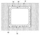
도 4는 본 발명에 따른 사각관의 겹치는 관벽을 제거하고, 사각관 내측 공간에 가로지주 및 세로지주를 설치한 상태를 도시한 정면도.
도 5는 도 4의 가로지주 및 세로지주가 사각관 내측 공간에 설치된 상태를 도시한 사시도.
도 6은 본 발명에 따른 지주의 다른 실시예를 도시한 정면도.
도 7은 본 발명에 따른 콘크리트 단위구조물을 도시한 사시도.
도 8은 도 7의 콘크리트 단위구조물에 설치된 체크밸브를 도시한 정면도 및 측면도.
도 9는 도 7의 콘크리트 단위구조물에 설치된 체크밸브의 다른 실시예.
도 10은 본 발명에 따른 콘크리트 구조물을 사각관의 내측 공간으로 삽입하는 것을 도시한 측면도.
도 11은 본 발명에 따른 사각관과 콘크리트 구조물 사이에 그라우팅재가 주입된 것을 도시한 정면도.
도 12는 본 발명에 따른 터널이 완성된 상태를 도시한 측면도.BRIEF DESCRIPTION OF THE DRAWINGS FIG. 1 is a side view showing the press-fitting of a rectangular tube according to the present invention; FIG.
2 is a side view showing a state in which a rectangular tube according to the present invention is press-fitted.
3 is a front view showing a state in which a rectangular tube according to the present invention is press-fitted.
FIG. 4 is a front view showing a state in which the overlapping pipe walls of the rectangular pipe according to the present invention are removed, and the vertical pipe and the vertical pipe are installed in the inner space of the rectangular pipe.
5 is a perspective view showing a state in which the transverse post and the vertical post of Fig. 4 are installed in the inner space of the square pipe.
6 is a front view showing another embodiment of a strut according to the present invention;
7 is a perspective view showing a concrete unit structure according to the present invention.
8 is a front view and a side view showing a check valve installed in the concrete unit structure of FIG. 7;
9 is another embodiment of a check valve installed in the concrete unit structure of FIG.
10 is a side view illustrating the insertion of a concrete structure according to the present invention into the interior space of a square tube.
11 is a front view showing grouting material injected between a square pipe and a concrete structure according to the present invention.
12 is a side view showing a state in which a tunnel according to the present invention is completed;
이하 첨부된 도면을 참조하여 본 발명의 바람직한 실시예에 따른 비개착식 터널굴착용 터널구조체에 대해 상세히 설명한다. 본 실시 예들을 설명함에 있어서 동일 구성에 대해서는 동일 명칭 및 부호가 사용되며, 이에 따른 부가적인 설명은 생략하기로 한다.DETAILED DESCRIPTION OF THE PREFERRED EMBODIMENTS The present invention will now be described more fully with reference to the accompanying drawings, in which exemplary embodiments of the invention are shown. In the description of the embodiments, the same names and symbols are used for the same components, and further description thereof will be omitted.
도 1은 본 발명에 따른 사각관을 압입하는 것을 도시한 측면도이고, 도 2는 본 발명에 따른 사각관을 압입한 상태를 도시한 측면도이고, 도 3은 본 발명에 따른 사각관을 압입한 상태를 도시한 정면도이고, 도 4는 본 발명에 따른 사각관의 겹치는 관벽을 제거하고, 사각관 내측 공간에 가로지주 및 세로지주를 설치한 상태를 도시한 정면도이고, 도 5는 도 4의 가로지주 및 세로지주가 사각관 내측 공간에 설치된 상태를 도시한 사시도이고, 도 6은 본 발명에 따른 지주의 다른 실시예를 도시한 정면도이고, 도 7은 본 발명에 따른 콘크리트 단위구조물을 도시한 사시도이고, 도 8은 도 7의 콘크리트 단위구조물에 설치된 체크밸브를 도시한 정면도 및 측면도이고, 도 9는 도 7의 콘크리트 단위구조물에 설치된 체크밸브의 다른 실시예이고, 도 10은 본 발명에 따른 콘크리트 구조물을 사각관의 내측 공간으로 삽입하는 것을 도시한 측면도이고, 도 11은 본 발명에 따른 사각관과 콘크리트 구조물 사이에 그라우팅재가 주입된 것을 도시한 정면도이고, 도 12는 본 발명에 따른 터널이 완성된 상태를 도시한 측면도이다.FIG. 1 is a side view showing the press-fitting of a rectangular pipe according to the present invention, FIG. 2 is a side view showing a state in which a rectangular pipe according to the present invention is press- 4 is a front view showing a state in which the overlapping pipe walls of the rectangular pipe according to the present invention are removed and the vertical pipe and the vertical pipe are installed in the inner space of the rectangular pipe, and FIG. 5 is a front view And FIG. 6 is a front view showing another embodiment of the strut according to the present invention, and FIG. 7 is a perspective view showing a concrete unit structure according to the present invention. FIG. FIG. 8 is a front view and a side view showing a check valve installed in the concrete unit structure of FIG. 7, FIG. 9 is another embodiment of a check valve installed in the concrete unit structure of FIG. 7, 11 is a front view showing grouting material injected between a square pipe and a concrete structure according to the present invention, FIG. 12 is a front view showing a tunnel according to the present invention, And is a side view showing the completed state.
도 1 내지 도 12를 참조하여 본 발명에 따른 사각관을 이용한 비개착식 터널굴착공법을 상세히 설명하기로 한다. 본 발명에 따른 사각관을 이용한 비개착식 터널굴착공법은 터널이 형성될 지점의 추진기지와 도달기지를 형성하는 단계와, 상기 추진기지에 압입장치를 설치하는 단계와, 상기 압입장치를 이용하여 일정길이를 가진 다수의 사각관을 지중으로 압입하는 단계와, 상기 일정길이의 사각관을 지중으로 압입한 후, 상기 사각관의 내부에 있는 토사를 제거하는 단계와, 상기 토사가 제거된 사각관에서 다른 사각관과 겹치는 관벽을 제거하여 내측에 공간을 형성하는 단계와, 상기 겹치는 관벽이 제거된 사각관 내측 공간에 지주를 설치하는 단계와, 상기 지주가 설치된 사각관의 내측 하부에 마찰력 저감을 위한 다수의 가이드레일을 설치하는 단계와, 상기 다수의 가이드레일이 설치된 사각관 내측으로 다수의 콘크리트 터널 단위구조물을 삽입하는 단계 및 상기 콘크리트 터널 단위구조물을 통해서 단위구조물의 외측으로 그라우팅재를 주입하는 단계로 구성된다.1 to 12, a non-detachable tunnel excavation method using a rectangular pipe according to the present invention will be described in detail. The non-detachable tunnel excavation method using a square pipe according to the present invention includes the steps of forming a propulsion base and a reaching base at a point where a tunnel is to be formed, installing a press fitting device on the propulsion base, A step of press-inserting a plurality of rectangular pipes having a predetermined length into the ground, a step of press-fitting the rectangular pipe having a predetermined length into the ground, and then removing the gravel inside the rectangular pipe; Forming a space on the inner side by removing a pipe wall overlapping another rectangular pipe on the inner side of the square pipe, removing the pipe wall overlapping with the other square pipe, forming a space on the inner side by removing the overlapping pipe wall, Inserting a plurality of concrete tunnel unit structures into a rectangular pipe provided with the plurality of guide rails; It consists of injecting a grouting material to the outside of the concrete structure through the tunnel unit group unit structures.
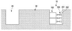
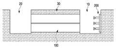
도 1은 터널이 형성되는 구간에 추진기지(10)와 도달기지(20)가 설치되고, 추진기지(10)에는 압입장치(200)가 설치된 것을 도시하고 있다. 도면에 도시된 바와 같이, 터널이 설치될 구간의 전방과 후방에는 도달기지(20)와 추진기지(10)가 형성되어, 추진기지(10)에 설치되는 압입장치(200)를 이용하여 사각관(100)을 지중(30)으로 압입하게 된다. 압입장치(200)는 반력벽(202)과 유압잭(201)으로 구성되고, 반력벽(202)의 반력에 의해 유압잭(201)을 이용하여 사각관(140)을 지중(30)으로 압입하게 된다. 지중(30)으로 압입되는 사각관(100)은 보통 일정길이로 형성되며, 따라서 다수의 사각관(100)을 서로 용접 등을 통하여 연결하면서 지중으로 압입하게 된다. 도 2는 사각관(100)이 터널설치구간의 지중(30)에 압입된 상태를 도시하고 있다.FIG. 1 shows a
도 3은 지중으로 압입된 사각관(100)의 내부에는 토사가 제거된 상태를 도시하고 있는데, 사각관(100)은 지중(30)으로 압입되면서 사각관(100) 내부의 토사는 계속적으로 굴착되어 외부로 반출되게 된다. 따라서, 사각관(100)이 추진기지(10)에서 도달기지(20)까지 관통하게 되면, 사각관(100)의 내부 토사는 완전히 제거된 상태가 된다. 사각관(100)의 토사를 굴착차하면서 그 내부에는, 사각관(100)의 변형을 방지하기 위한 변형방지 보강부재(미도시)가 더 장착될 수 있다. 보강부재는 일반적으로 도 6과 같은 길이 조절이 가능한 파이프가 설치되어 사각관의 변형을 방지할 수 있다.FIG. 3 shows a state in which the soil is removed from the inside of the
도 4는 사각관(100) 내부의 토사가 제거된 상태에서, 사각관(100)이 서로 겹쳐지는 관벽이 제거되고, 제거된 관벽의 지지를 위하여 세로지주(120) 및 가로지주(110)가 설치되는 것을 도시하고 있다. 관벽은 일정길이가 제거된 상태에서 가로지주(110) 및 세로지주(120)가 서로 번갈아 설치되는데, 안전을 위해서는 짧은 길이의 세로관벽 및 가로관벽이 제거된 상태에서 가로지주(110) 또는 세로지주(120)가 설치됨이 바람직하다. 가로지주(11)는 일정길이의 빔(111)과 빔을 밀착 고정시키기 위한 유압잭(112)이 서로 연결되어 설치된다. 따라서, 가로관벽이 제거된 부분의 일측에는 유압잭(112)이 고정되고, 타측에는 빔(111)이 고정되며, 유압잭(112)으로 빔(111)을 밀어줌으로써, 지주역할을 하여 가로관벽의 공백을 메꾸어줄 수 있도록 한다. 또한, 세로관벽이 제거된 부분의 하부에는 유압잭(122)이 설치되고, 상부에는 빔(121)이 설치되며, 하부의 유압잭(122)을 작동시켜 빔(121)이 상부측의 관벽이 제거된 부분과 밀착되면서 고정되도록 한다. 따라서 세로지주(120)는 세로관벽의 공백을 메꾸어줄 수 있게 된다.4 shows a state in which the tubular wall overlapping the
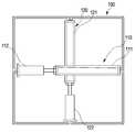
도 5는 가로지주(110)와 세로지주(120)가 서로 번갈아 가면서 내측 공간에 설치된 상태를 도시하고 있다. 내측 공간에 가로지주(110)와 세로지주(120)가 번갈아가면서 설치되기 때문에 지주의 설치로 인한 비용을 획기적으로 줄일 수 있게 된다. 또한, 사각관(100)의 내측 공간 하부에는 콘크리트 터널 단위구조물의 삽입이 용이하도록 마찰력 저감을 위한 가이드 레일(130)가 설치된다. 가이드 레일(130)이 설치됨으로써 가이드 레일(130)에 의해 사각관(100)의 내부로 쉽게 콘크리트 터널 단위구조물(140)이 삽입될 수 있게 된다. 가이드 레일(130)은 파이프, 사각형상 채널 또는 플레이트 박스 등으로 형성될 수 있다. 더 나아가 가이드 레일(130)이 파이프나 사각형상 채널인 경우 상부에 구멍을 형성하고, 상기 구멍으로 물이나 윤활제를 주입하는 경우, 더 쉽게 콘크리트 터널 단위구조물(140)을 삽입할 수 있다.5 shows a state in which the
도 6은 지주의 또 다른 실시예를 도시하고 있다. 도면에서 가로지주(110')에 대한 실시예를 도시하였으나, 세로지주(120')도 상기 가로지주(110')와 도면 부호를 달리할 뿐 그 구성은 동일하므로 생략하기로 한다. 상기 도면에 도시된 바와 같이, 가로지주(110')는 상부파이프(111a')와 하부파이프(111b') 및 상부파이프와 하부파이프를 상하로 이동시키기 위한 이동부(112')로 구성된다. 이동부(112')의 움직임에 따라 상하가 서로 반대로 움직일 수 있도록 볼트형 또는 공압형이나 유압형으로 형성하여 상하로 이동할 수 있도록 할 수 있다.Figure 6 shows another embodiment of a strut. Although the embodiment of the horizontal support 110 'is shown in the drawing, the vertical support 120' is also different from that of the horizontal support 110 ', but the configuration is the same. As shown in the figure, the horizontal support 110 'is composed of an
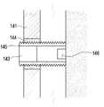
도 7은 콘크리트 터널 단위구조물(140)을 도시하고 있다. 콘크리트 터널 단위구조물(140)은 지상에서 제작된 후에 추진기지(10)로 투입된 후 압입장치(200)에 의해 사각관(100)의 내부로 삽입된다. 콘크리트 터널 단위구조물(140)은 사각관(100) 내부로 쉽게 삽입되도록 모서리 부분이 모따기가 되어 있으며, 단위구조물(140)의 외측으로 그라우팅재(150)를 주입할 수 있도록 체크밸브(143)가 설치된다. 체크밸브(143)를 설치하기 위해 단위구조물(140)에는 홀(142)이 형성되어야 한다. 도 8은 체크밸브(143)가 도시된 상태를 도시하고 있다. 체크밸브(143)의 역할은, 터널 단위구조물(140)의 외측으로 주입된 그라우팅재(150)가 역류하지 않도록 일방향으로만 유체가 주입되도록 한다. 터널 단위구조물(140)의 벽면(141)에는 체크밸브(143)가 설치될 수 있으며, 또한 많이 필요하지 않은 경우에는 하나의 체크밸브(143)만을 설치하여 외측으로 주입되도록 할 수도 있다. 도 9는 체크밸브를 설치한 다른 실시예를 도시하고 있다. 도 9에서는 콘크리트 터널 단위구조물에 형성된 홀(142)에 내측에 나사산이 형성된 고정체결부(144)가 설치되고, 고정체결부(144)에는 체크밸브(143)가 장착된 체결파이프(145)가 체결된다. 체결파이프(145)는 터널 단위구조물(140)를 위치고정하기 위해서 사용되는 것으로서, 체결파이프(145)는 고정체결부(144)를 통해 지중의 토사면까지 닿을 수 있도록 체결된다. 따라서, 체결파이프(145)는 그라우팅재(150)가 투입되는 경우 터널 단위 구조물(140)이 부력에 의해 상승하는 것을 방지하면서 위치를 고정해 주는 역할을 수행한다. 또한 체결파이프(145)가 토사면과 닿는 단부에는 그라우팅제(150)가 쉽게 빠져 나갈 수 있도록 홀(146)이 더 형성될 수 있다.Figure 7 shows a concrete
도 10은 사각관(100)의 내측 공간으로 터널 단위구조물(140)을 삽입하는 것을 도시하고 있다. 터널 단위구조물(140)도 압입장치(200)에 의해 사각관(100)의 내측 공간으로 삽입된다. 터널 단위구조물(140)도 일정길이를 가지기 때문에, 다수의 터널 단위구조물(140)이 사각관(100)의 내측 공간으로 삽입되게 된다. 다수의 터널 단위구조물(140)이 서로 연결될 수 있도록 콘크리트 형태의 조인트(미도시)나 러그(미도시)를 전후면에 부착하여 서로 고정시킬 수도 있다. 콘크리트 터널 단위구조물(140)이 직접 지중과 맞닿지 않기 때문에, 터널 단위구조물(140)의 손상을 방지할 수 있는 이점을 가진다.10 shows the insertion of the
도 11은 사각관(100)의 내측 공간에 터널 단위구조물(140)이 삽입된 후, 그라우팅재가 터널 단위구조물(140)의 외측에 완전히 주입된 상태를 도시하고 있다. 그라우팅재(150)가 주입됨으로써 단위구조물(140)과 사각관(100)은 완전히 한 몸체가 되고, 아주 큰 강도를 가질 수 있게 된다. 또한, 내부에 설치되었던 가로지주(110) 및 세로지주(120)는 터널 단위구조물(140)이 삽입되면서 제거되기 때문에 재사용이 가능하게 된다.FIG. 11 shows a state in which the
도 12는 사각관(100)에 터널 단위구조물(140)이 삽입되어 터널이 완성된 상태를 도시하고 있다. 터널이 완성된 상태에서, 터널 구조물(140)의 내부에 타일 작업이나 다른 필요한 내장 작업이 더 이루어질 수 있게 된다. 또한, 바닥면에는 아스팔트 등의 도로 작업도 진행될 수 있다.12 shows a state in which the
이상에서 본 발명의 바람직한 일실시예를 설명하였으나, 본 발명은 다양한 변화와 변경 및 균등물을 사용할 수 있고, 상기 실시예를 적절히 변형하여 동일하게 응용할 수 있음이 명확하다. 따라서 상기 기재내용은 하기 특허청구범위의 한계에 의해 정해지는 본 발명의 범위를 한정하는 것이 아니다.While the invention has been shown and described with reference to certain preferred embodiments thereof, it will be understood by those skilled in the art that various changes and modifications may be made therein without departing from the spirit and scope of the invention as defined by the appended claims. Therefore, the above description does not limit the scope of the present invention defined by the limitations of the following claims.
10 : 추진기지20 : 도달기지
30 : 지중
100 : 사각관
110 : 가로지주111 : 빔
112 : 유압잭111' : 파이프
112' : 이동부
120 : 세로지주121 : 빔
122 : 유압잭
130 : 마찰 저감 가이드 레일
140 : 콘크리트 터널 단위구조물141 : 벽면
142 : 홀143 : 체크밸브
144 : 고정체결부145 : 체결파이프
150 : 그라우팅재
200 : 압입장치201 : 유압잭
202 : 반력벽10: Promotion base 20: Reaching base
30: Underground
100: square tube
110: transverse support 111: beam
112: Hydraulic jack 111 ': Pipe
112 ': moving part
120: vertical support 121: beam
122: Hydraulic jack
130: Friction reduction guide rail
140: Concrete tunnel unit structure 141: Wall surface
142: hole 143: check valve
144: Fixed fastening part 145: Fastening pipe
150: Grouting material
200: press-in device 201: hydraulic jack
202: reaction wall
Claims (6)
Translated fromKorean터널이 형성될 지점의 추진기지와 도달기지를 형성하는 단계;
상기 추진기지에 압입장치를 설치하는 단계;
상기 압입장치를 이용하여 일정길이를 가진 다수의 사각관을 지중으로 압입하는 단계;
상기 일정길이의 사각관을 지중으로 압입한 후, 상기 사각관의 내부에 있는 토사를 제거하는 단계;
상기 토사가 제거된 사각관에서 다른 사각관과 겹치는 관벽을 제거하여 내측에 공간을 형성하는 단계;
상기 겹치는 관벽이 제거된 사각관 내측 공간에 지주를 설치하는 단계;
상기 지주가 설치된 사각관의 내측 하부에 마찰력 저감을 위한 다수의 가이드레일을 설치하는 단계;
상기 다수의 파이프가 설치된 사각관 내측으로 다수의 콘크리트 터널 단위구조물을 삽입하는 단계; 및
상기 콘크리트 터널 단위구조물을 통해서 단위구조물의 외측으로 그라우팅재를 주입하는 단계;
로 구성되는 것을 특징으로 하는 사각관을 이용한 비개착식 터널굴착공법.In a non-detachable tunnel excavation method using a square pipe in which a plurality of square pipes are press-fitted into a ground to excavate a tunnel,
Forming a propulsion station and a reaching base at a point where a tunnel is to be formed;
Installing a press-fitting device on the propulsion base;
Pressing a plurality of rectangular pipes having a predetermined length into the ground using the press-fitting device;
Pressing the rectangular pipe of the predetermined length into the ground, and removing the gravel inside the rectangular pipe;
Forming a space inside the rectangular pipe from which the gravel is removed by removing a pipe wall overlapping another square pipe;
Installing a strut in the inner space of the rectangular pipe from which the overlapping pipe wall is removed;
Providing a plurality of guide rails for reducing frictional force in an inner lower portion of the rectangular pipe provided with the column;
Inserting a plurality of concrete tunnel unit structures into a rectangular pipe provided with the plurality of pipes; And
Injecting a grouting material to the outside of the unit structure through the concrete tunnel unit structure;
Wherein the tunnel is formed of a rectangular pipe.
상기 지주는, 가로지주와 세로지주로 구성되고,
상기 가로지주와 상기 세로지주는, 일정길이의 빔과 빔을 밀착 고정시키기 위한 유압잭으로 구성되어, 상기 관벽이 제거된 부분에 서로 번갈아 설치되는 것을 특징으로 하는 사각관을 이용한 비개착식 터널굴착공법.
The method according to claim 1,
Wherein the strut is composed of a transverse strut and a vertical strut,
Wherein the horizontal support and the vertical support are constituted by a hydraulic jack for tightly fixing a beam and a beam of a predetermined length and are alternately installed at portions where the pipe walls are removed, .
상기 터널 단위구조물을 삽입하면서, 터널 단위구조물의 전방에 있는 가로지주 및 세로지주는 하나씩 제거되는 것을 특징으로 하는 사각관을 이용한 비개착식 터널굴착공법.
The method according to claim 1,
Wherein the horizontal strut and the vertical strut at the front of the tunnel unit structure are removed one by one while inserting the tunnel unit structure.
상기 터널 단위구조물에는 그라우팅재 주입을 위한 하나 이상의 체크밸브가 설치되는 것을 특징으로 하는 사각관을 이용한 비개착식 터널굴착공법.
The method according to claim 1,
Wherein at least one check valve for injecting grouting material is installed in the tunnel unit structure.
상기 지주는, 가로지주와 세로지주로 이루어지고,
상기 가로지주와 세로지주는, 서로 분리된 상부 파이프 및 하부 파이프와, 상기 상부 파이프와 하부 파이프를 상하로 이동하게 하는 이동부로 구성되어, 상기 관벽이 제거된 부분에 서로 번갈아 설치되는 것을 특징으로 하는 사각관을 이용한 비개착식 터널굴착공법.
The method according to claim 1,
Wherein the support comprises a transverse support and a vertical support,
Wherein the horizontal support and the vertical support are constituted by an upper pipe and a lower pipe separated from each other and a moving part for moving the upper pipe and the lower pipe up and down, Non - slip tunnel excavation method using square pipe.
상기 그라우팅을 주입하는 단계는, 상기 콘크리트 터널 단위 구조물에 형성된 홀에 고정체결부가 설치되고, 상기 고정체결부에 체크밸브가 삽입 설치된 체결 파이프가 체결되어, 상기 체크밸크를 통해 그라우팅이 주입되고,
상기 체결파이프는 지중의 토사면까지 삽입되어 상기 콘크리트 터널 단위 구조물의 위치를 고정하는 것을 특징으로 하는 사각관을 이용한 비개착식 터널굴착공법.The method according to claim 1,
Wherein the grouting is injected into the concrete tunnel unit structure through a hole formed in the concrete tunnel unit, a fastening pipe having a check valve inserted therein is fastened to the fastening unit, grouting is injected through the check valve,
Wherein the fastening pipe is inserted up to the ground slope in the ground to fix the position of the concrete tunnel unit structure.
Priority Applications (1)
| Application Number | Priority Date | Filing Date | Title |
|---|---|---|---|
| KR1020160023236AKR20170102397A (en) | 2016-02-26 | 2016-02-26 | The Tunnel construction method to use retangular pipe |
Applications Claiming Priority (1)
| Application Number | Priority Date | Filing Date | Title |
|---|---|---|---|
| KR1020160023236AKR20170102397A (en) | 2016-02-26 | 2016-02-26 | The Tunnel construction method to use retangular pipe |
Publications (1)
| Publication Number | Publication Date |
|---|---|
| KR20170102397Atrue KR20170102397A (en) | 2017-09-11 |
Family
ID=59926131
Family Applications (1)
| Application Number | Title | Priority Date | Filing Date |
|---|---|---|---|
| KR1020160023236AAbandonedKR20170102397A (en) | 2016-02-26 | 2016-02-26 | The Tunnel construction method to use retangular pipe |
Country Status (1)
| Country | Link |
|---|---|
| KR (1) | KR20170102397A (en) |
Cited By (7)
| Publication number | Priority date | Publication date | Assignee | Title |
|---|---|---|---|---|
| CN111173525A (en)* | 2020-03-05 | 2020-05-19 | 西南科技大学 | A support device for shield tunneling through buildings |
| KR102170800B1 (en) | 2019-12-13 | 2020-10-28 | 한국철도기술연구원 | Connection structure of round type of pressing square pipe structure using angle reinforcement |
| KR102170797B1 (en) | 2019-12-13 | 2020-10-28 | 한국철도기술연구원 | Leading pipe propulsion apparatus of pressing square pipe structure using angle reinforcement |
| KR102185920B1 (en) | 2019-12-20 | 2020-12-02 | 창문건설 주식회사 | Pressing square pipe structure using angle reinforcement, and construction method for the same |
| KR102191503B1 (en) | 2019-07-30 | 2020-12-15 | 한광우 | The Tunnel construction method to use retangular pipe |
| KR102364887B1 (en)* | 2021-06-14 | 2022-02-18 | 송관권 | Non-open cut construction method for a tunnel and temporary structure |
| KR102756500B1 (en)* | 2024-04-26 | 2025-01-21 | 주식회사 특수건설 | Method for constructing underground structure by steel tube propulsion |
- 2016
- 2016-02-26KRKR1020160023236Apatent/KR20170102397A/ennot_activeAbandoned
Cited By (7)
| Publication number | Priority date | Publication date | Assignee | Title |
|---|---|---|---|---|
| KR102191503B1 (en) | 2019-07-30 | 2020-12-15 | 한광우 | The Tunnel construction method to use retangular pipe |
| KR102170800B1 (en) | 2019-12-13 | 2020-10-28 | 한국철도기술연구원 | Connection structure of round type of pressing square pipe structure using angle reinforcement |
| KR102170797B1 (en) | 2019-12-13 | 2020-10-28 | 한국철도기술연구원 | Leading pipe propulsion apparatus of pressing square pipe structure using angle reinforcement |
| KR102185920B1 (en) | 2019-12-20 | 2020-12-02 | 창문건설 주식회사 | Pressing square pipe structure using angle reinforcement, and construction method for the same |
| CN111173525A (en)* | 2020-03-05 | 2020-05-19 | 西南科技大学 | A support device for shield tunneling through buildings |
| KR102364887B1 (en)* | 2021-06-14 | 2022-02-18 | 송관권 | Non-open cut construction method for a tunnel and temporary structure |
| KR102756500B1 (en)* | 2024-04-26 | 2025-01-21 | 주식회사 특수건설 | Method for constructing underground structure by steel tube propulsion |
Similar Documents
| Publication | Publication Date | Title |
|---|---|---|
| KR20170102397A (en) | The Tunnel construction method to use retangular pipe | |
| KR100984883B1 (en) | The construction method of shield tunneling | |
| KR101179778B1 (en) | Method for constructing underground structure | |
| KR100713787B1 (en) | Underground structure assembly and underground structure construction method using the same | |
| KR100936471B1 (en) | Circular support structure by segment with drainage structure and method of constructing shield tunnel using the same | |
| KR101479267B1 (en) | Method for constructing tunnel by using pipe | |
| KR102239089B1 (en) | Underaround continued wall structure using casing and pile continuous connection and method therefor | |
| JP5393947B2 (en) | Multiple tunnel construction method and connection structure, and tunnel and pipe roof connection structure constituting the multiple tunnel | |
| KR101021867B1 (en) | Tip head for construction of non-removable tunnel structure | |
| KR101468613B1 (en) | Underground structure construction method using the moveable temporary supporting frame | |
| KR101133734B1 (en) | Method for tunneling construction and tunnel structure | |
| KR100898969B1 (en) | Tunnel excavation method using sheet pile and tunnel structure | |
| KR20050020451A (en) | Shield tunneling construction method and tunnel structure | |
| KR101925828B1 (en) | Underground structure pressing system for reducing friction and construction method using the same | |
| KR101194102B1 (en) | The Excavation Method of Concrete Tunnel Construction | |
| KR20100129839A (en) | Construction method of non-adhesive tunnel structure | |
| KR102134603B1 (en) | Apparatus and method for constructing non-open cut structure | |
| JP5012149B2 (en) | Ground support structure and ground support method | |
| KR100846571B1 (en) | Earth and sand tunnel construction using grouting method | |
| KR101625101B1 (en) | Steel pipe wall temporary construction method | |
| KR101523948B1 (en) | Construction method of underground structure under the established building | |
| KR102191503B1 (en) | The Tunnel construction method to use retangular pipe | |
| KR101772276B1 (en) | The front structure for non-open cut type tunnel pressing | |
| JP4833089B2 (en) | Water stop device for underground penetrating body and construction method of underground penetrating body using the same | |
| KR101007089B1 (en) | Indentation device for construction of non-adhesive tunnel structure |
Legal Events
| Date | Code | Title | Description |
|---|---|---|---|
| A201 | Request for examination | ||
| PA0109 | Patent application | Patent event code:PA01091R01D Comment text:Patent Application Patent event date:20160226 | |
| PA0201 | Request for examination | ||
| E902 | Notification of reason for refusal | ||
| PE0902 | Notice of grounds for rejection | Comment text:Notification of reason for refusal Patent event date:20170109 Patent event code:PE09021S01D | |
| AMND | Amendment | ||
| E601 | Decision to refuse application | ||
| PE0601 | Decision on rejection of patent | Patent event date:20170728 Comment text:Decision to Refuse Application Patent event code:PE06012S01D Patent event date:20170109 Comment text:Notification of reason for refusal Patent event code:PE06011S01I | |
| AMND | Amendment | ||
| PX0901 | Re-examination | Patent event code:PX09011S01I Patent event date:20170728 Comment text:Decision to Refuse Application Patent event code:PX09012R01I Patent event date:20170309 Comment text:Amendment to Specification, etc. | |
| PG1501 | Laying open of application | ||
| PX0701 | Decision of registration after re-examination | Patent event date:20170928 Comment text:Decision to Grant Registration Patent event code:PX07013S01D Patent event date:20170830 Comment text:Amendment to Specification, etc. Patent event code:PX07012R01I Patent event date:20170728 Comment text:Decision to Refuse Application Patent event code:PX07011S01I Patent event date:20170309 Comment text:Amendment to Specification, etc. Patent event code:PX07012R01I | |
| X701 | Decision to grant (after re-examination) | ||
| PC1904 | Unpaid initial registration fee |