KR20170101283A - Dental instruments that provide exposed occlusal surfaces - Google Patents
Dental instruments that provide exposed occlusal surfacesDownload PDFInfo
- Publication number
- KR20170101283A KR20170101283AKR1020177020824AKR20177020824AKR20170101283AKR 20170101283 AKR20170101283 AKR 20170101283AKR 1020177020824 AKR1020177020824 AKR 1020177020824AKR 20177020824 AKR20177020824 AKR 20177020824AKR 20170101283 AKR20170101283 AKR 20170101283A
- Authority
- KR
- South Korea
- Prior art keywords
- removable dental
- patient
- dental appliance
- tooth
- teeth
- Prior art date
- Legal status (The legal status is an assumption and is not a legal conclusion. Google has not performed a legal analysis and makes no representation as to the accuracy of the status listed.)
- Withdrawn
Links
- 230000001815facial effectEffects0.000claimsabstractdescription40
- 238000000034methodMethods0.000claimsdescription64
- 239000000463materialSubstances0.000claimsdescription20
- 206010061274MalocclusionDiseases0.000claimsdescription4
- 210000000214mouthAnatomy0.000claims1
- 238000004519manufacturing processMethods0.000description62
- 238000011282treatmentMethods0.000description48
- 238000013461designMethods0.000description28
- 238000000547structure dataMethods0.000description19
- 229910052751metalInorganic materials0.000description18
- 239000002184metalSubstances0.000description18
- 230000006870functionEffects0.000description14
- 238000003860storageMethods0.000description12
- 210000002455dental archAnatomy0.000description11
- 238000005266castingMethods0.000description10
- 230000033001locomotionEffects0.000description7
- 230000008569processEffects0.000description7
- 2380000101463D printingMethods0.000description6
- 238000003745diagnosisMethods0.000description6
- 238000010586diagramMethods0.000description6
- 210000001847jawAnatomy0.000description6
- 230000036544postureEffects0.000description6
- 230000015572biosynthetic processEffects0.000description5
- 238000012937correctionMethods0.000description5
- 238000013500data storageMethods0.000description5
- 238000003384imaging methodMethods0.000description5
- 239000004033plasticSubstances0.000description5
- 238000012546transferMethods0.000description5
- 241000282465CanisSpecies0.000description4
- 230000008901benefitEffects0.000description4
- 238000007408cone-beam computed tomographyMethods0.000description4
- 238000003698laser cuttingMethods0.000description4
- 238000003801millingMethods0.000description4
- 238000004458analytical methodMethods0.000description3
- 238000002591computed tomographyMethods0.000description3
- 238000007726management methodMethods0.000description3
- 238000012544monitoring processMethods0.000description3
- 238000007639printingMethods0.000description3
- 238000009877renderingMethods0.000description3
- 239000007779soft materialSubstances0.000description3
- 238000003325tomographyMethods0.000description3
- 230000036346tooth eruptionEffects0.000description3
- 238000013519translationMethods0.000description3
- 230000014616translationEffects0.000description3
- 230000017105transpositionEffects0.000description3
- KDLHZDBZIXYQEI-UHFFFAOYSA-NPalladiumChemical compound[Pd]KDLHZDBZIXYQEI-UHFFFAOYSA-N0.000description2
- 239000000654additiveSubstances0.000description2
- 230000000996additive effectEffects0.000description2
- 238000004873anchoringMethods0.000description2
- 238000005452bendingMethods0.000description2
- 210000000988bone and boneAnatomy0.000description2
- 230000008859changeEffects0.000description2
- 239000003086colorantSubstances0.000description2
- 238000010276constructionMethods0.000description2
- 210000003464cuspidAnatomy0.000description2
- 210000004513dentitionAnatomy0.000description2
- 238000005516engineering processMethods0.000description2
- 210000004195gingivaAnatomy0.000description2
- 239000007943implantSubstances0.000description2
- 238000001746injection mouldingMethods0.000description2
- 210000004373mandibleAnatomy0.000description2
- 239000003550markerSubstances0.000description2
- 230000007246mechanismEffects0.000description2
- 230000003287optical effectEffects0.000description2
- 230000000737periodic effectEffects0.000description2
- BASFCYQUMIYNBI-UHFFFAOYSA-NplatinumChemical compound[Pt]BASFCYQUMIYNBI-UHFFFAOYSA-N0.000description2
- 239000002861polymer materialSubstances0.000description2
- 230000005855radiationEffects0.000description2
- 230000003362replicative effectEffects0.000description2
- 230000000717retained effectEffects0.000description2
- 210000003296salivaAnatomy0.000description2
- 239000000523sampleSubstances0.000description2
- 238000000110selective laser sinteringMethods0.000description2
- 239000004575stoneSubstances0.000description2
- 230000001360synchronised effectEffects0.000description2
- 238000003856thermoformingMethods0.000description2
- 210000001519tissueAnatomy0.000description2
- FHVDTGUDJYJELY-UHFFFAOYSA-N6-{[2-carboxy-4,5-dihydroxy-6-(phosphanyloxy)oxan-3-yl]oxy}-4,5-dihydroxy-3-phosphanyloxane-2-carboxylic acidChemical compoundO1C(C(O)=O)C(P)C(O)C(O)C1OC1C(C(O)=O)OC(OP)C(O)C1OFHVDTGUDJYJELY-UHFFFAOYSA-N0.000description1
- 208000006558Dental CalculusDiseases0.000description1
- BQCADISMDOOEFD-UHFFFAOYSA-NSilverChemical compound[Ag]BQCADISMDOOEFD-UHFFFAOYSA-N0.000description1
- 241001024096UleiotaSpecies0.000description1
- 239000006096absorbing agentSubstances0.000description1
- 230000009471actionEffects0.000description1
- 238000004026adhesive bondingMethods0.000description1
- 229940072056alginateDrugs0.000description1
- 229920000615alginic acidPolymers0.000description1
- 235000010443alginic acidNutrition0.000description1
- 210000004763bicuspidAnatomy0.000description1
- 229910010293ceramic materialInorganic materials0.000description1
- 230000001149cognitive effectEffects0.000description1
- 230000006835compressionEffects0.000description1
- 238000007906compressionMethods0.000description1
- 238000004590computer programMethods0.000description1
- 238000005094computer simulationMethods0.000description1
- 230000001054cortical effectEffects0.000description1
- 239000002537cosmeticSubstances0.000description1
- 238000002788crimpingMethods0.000description1
- 230000001419dependent effectEffects0.000description1
- 230000000694effectsEffects0.000description1
- 230000005489elastic deformationEffects0.000description1
- 239000003822epoxy resinSubstances0.000description1
- 238000011156evaluationMethods0.000description1
- 230000000977initiatory effectEffects0.000description1
- 238000005495investment castingMethods0.000description1
- 238000002595magnetic resonance imagingMethods0.000description1
- 238000012423maintenanceMethods0.000description1
- 230000018984masticationEffects0.000description1
- 238000010077masticationMethods0.000description1
- 238000002844meltingMethods0.000description1
- 230000008018meltingEffects0.000description1
- 238000012986modificationMethods0.000description1
- 230000004048modificationEffects0.000description1
- 229910000510noble metalInorganic materials0.000description1
- NJPPVKZQTLUDBO-UHFFFAOYSA-NnovaluronChemical compoundC1=C(Cl)C(OC(F)(F)C(OC(F)(F)F)F)=CC=C1NC(=O)NC(=O)C1=C(F)C=CC=C1FNJPPVKZQTLUDBO-UHFFFAOYSA-N0.000description1
- 239000005022packaging materialSubstances0.000description1
- 229910052763palladiumInorganic materials0.000description1
- 210000002379periodontal ligamentAnatomy0.000description1
- 238000013439planningMethods0.000description1
- 238000007747platingMethods0.000description1
- 229910052697platinumInorganic materials0.000description1
- 229920000647polyepoxidePolymers0.000description1
- 229920000642polymerPolymers0.000description1
- -1polyvinylsiloxanePolymers0.000description1
- 238000002360preparation methodMethods0.000description1
- 238000012545processingMethods0.000description1
- 230000001105regulatory effectEffects0.000description1
- 229920005989resinPolymers0.000description1
- 239000011347resinSubstances0.000description1
- 238000012552reviewMethods0.000description1
- 229910052703rhodiumInorganic materials0.000description1
- 239000010948rhodiumSubstances0.000description1
- MHOVAHRLVXNVSD-UHFFFAOYSA-Nrhodium atomChemical compound[Rh]MHOVAHRLVXNVSD-UHFFFAOYSA-N0.000description1
- 239000011435rockSubstances0.000description1
- 238000005070samplingMethods0.000description1
- 230000035939shockEffects0.000description1
- 229910052709silverInorganic materials0.000description1
- 239000004332silverSubstances0.000description1
- 239000007787solidSubstances0.000description1
- 238000000638solvent extractionMethods0.000description1
- 230000026676system processEffects0.000description1
- 239000003826tabletSubstances0.000description1
- 238000002560therapeutic procedureMethods0.000description1
- 210000000332tooth crownAnatomy0.000description1
- 230000036339tooth positioningEffects0.000description1
- 230000005945translocationEffects0.000description1
- 238000012384transportation and deliveryMethods0.000description1
- 238000002604ultrasonographyMethods0.000description1
- 238000011179visual inspectionMethods0.000description1
Images


Classifications
- A—HUMAN NECESSITIES
- A61—MEDICAL OR VETERINARY SCIENCE; HYGIENE
- A61C—DENTISTRY; APPARATUS OR METHODS FOR ORAL OR DENTAL HYGIENE
- A61C7/00—Orthodontics, i.e. obtaining or maintaining the desired position of teeth, e.g. by straightening, evening, regulating, separating, or by correcting malocclusions
- A61C7/002—Orthodontic computer assisted systems
- A—HUMAN NECESSITIES
- A61—MEDICAL OR VETERINARY SCIENCE; HYGIENE
- A61C—DENTISTRY; APPARATUS OR METHODS FOR ORAL OR DENTAL HYGIENE
- A61C7/00—Orthodontics, i.e. obtaining or maintaining the desired position of teeth, e.g. by straightening, evening, regulating, separating, or by correcting malocclusions
- A61C7/08—Mouthpiece-type retainers or positioners, e.g. for both the lower and upper arch
- A—HUMAN NECESSITIES
- A61—MEDICAL OR VETERINARY SCIENCE; HYGIENE
- A61C—DENTISTRY; APPARATUS OR METHODS FOR ORAL OR DENTAL HYGIENE
- A61C7/00—Orthodontics, i.e. obtaining or maintaining the desired position of teeth, e.g. by straightening, evening, regulating, separating, or by correcting malocclusions
- A61C7/12—Brackets; Arch wires; Combinations thereof; Accessories therefor
- A61C7/20—Arch wires
- A—HUMAN NECESSITIES
- A61—MEDICAL OR VETERINARY SCIENCE; HYGIENE
- A61C—DENTISTRY; APPARATUS OR METHODS FOR ORAL OR DENTAL HYGIENE
- A61C7/00—Orthodontics, i.e. obtaining or maintaining the desired position of teeth, e.g. by straightening, evening, regulating, separating, or by correcting malocclusions
- A61C7/36—Devices acting between upper and lower teeth
Landscapes
- Health & Medical Sciences (AREA)
- Oral & Maxillofacial Surgery (AREA)
- Dentistry (AREA)
- Epidemiology (AREA)
- Life Sciences & Earth Sciences (AREA)
- Animal Behavior & Ethology (AREA)
- General Health & Medical Sciences (AREA)
- Public Health (AREA)
- Veterinary Medicine (AREA)
- Engineering & Computer Science (AREA)
- General Engineering & Computer Science (AREA)
- Dental Tools And Instruments Or Auxiliary Dental Instruments (AREA)
- Dental Prosthetics (AREA)
Abstract
Translated fromKoreanDescription
Translated fromKorean본 개시는 치과교정술(orthodontics), 및 보다 구체적으로는 치과교정 진단 및 치료를 돕기 위한 컴퓨터-기반 방법에 관한 것이다.This disclosure relates to orthodontics, and more particularly, to a computer-based method for assisting dental correction and diagnosis.
치과교정술 분야는 개선된 기능과 미적 외양을 위해 환자의 치아를 재위치(repositioning)시키는 것에 관한 것이다. 예를 들어, 치과교정 치료는 흔히, 일반적으로 환자의 전치(anterior teeth), 견치(cuspid teeth), 및 소구치(bicuspid teeth)에 고정되는, 브래킷(bracket)으로 알려진, 작은 슬롯형성된 기구의 사용을 수반한다. 아치와이어(archwire)가 각각의 브래킷의 슬롯 내에 수용되고, 원하는 배향으로의 치아의 움직임을 안내하기 위한 트랙(track)으로서의 역할을 한다. 아치와이어의 단부는 보통 환자의 대구치(molar teeth)에 고정된 협면관(buccal tube)으로 알려진 기구 내에 수용된다. 아치와이어 및 기구는 보통 "브레이스(brace)"로 지칭된다. 치과교정 치료는 또한 투명한, 플라스틱 치아 위치설정 트레이(tray) 또는 다른 기능적 기구의 사용을 통해 구현될 수 있다.The field of orthodontics relates to repositioning a patient's teeth for improved functionality and aesthetic appearance. For example, dental orthodontic treatment often involves the use of small slotted devices, commonly known as brackets, which are anchored to the patient's anterior teeth, cuspid teeth, and bicuspid teeth It is accompanied. An archwire is received in the slot of each bracket and serves as a track to guide the movement of the tooth in the desired orientation. The ends of the arch wires are housed in a device commonly known as buccal tubes fixed to the patient's molar teeth. Arch wires and instruments are commonly referred to as "braces. &Quot; The orthodontic treatment may also be implemented through the use of a transparent, plastic tooth positioning tray or other functional device.
치과교정술의 실시는 전통적으로 특정 환자를 위한 적절한 기구의 선택, 구강 내에의 기구의 배치, 및 치료 전반에 걸친 기구의 조정과 같은 수동 단계에 의존하였다. 보다 최근에는, 기술의 발전이 이들 단계 중 일부가 컴퓨터의 사용을 통해 도움을 받도록 허용하였다. 예를 들어, 컴퓨터는 개인 환자의 치아 배열을 나타내는 데이터의 획득을 안내하는 데 사용될 수 있다. 그러한 데이터는 이어서 진단할 환자의 치열(dentition)을 시각화하는 데, 그리고 임의의 치료 단계에서 계획하는 치과교정 치료를 돕는 데 사용될 수 있다. 또한, 이들 데이터는 환자에게 맞춤화된, 브래킷과 같은, 기구를 제조하는 데 사용될 수 있다.The practice of orthodontics has traditionally relied on manual steps such as the selection of appropriate instruments for a particular patient, placement of instruments in the mouth, and adjustment of instruments throughout the treatment. More recently, advances in technology have allowed some of these steps to be helped through the use of computers. For example, the computer may be used to guide acquisition of data indicative of an individual patient's tooth alignment. Such data can then be used to visualize the dentition of the patient to be diagnosed and to assist in the orthodontic treatment planning in any treatment step. In addition, these data can be used to manufacture instruments, such as brackets, customized to the patient.
본 개시는 치아 재정렬 및/또는 유지를 위한 제거가능 치과용 기구(removable dental appliance), 및 제거가능 치과용 기구를 설계, 제조 및 사용하기 위한 장치, 시스템, 및 기술에 관한 것이다. 몇몇 예에서, 제거가능 치과용 기구는 환자에 의해 착용될 때 환자의 치아의 실질적으로 노출된 교합면(occlusal surface)을 제공한다. 실질적으로 노출된 교합면을 제공하는 제거가능 치과용 기구는 환자의 치아를 실질적으로 폐쇄하는 제거가능 치과용 기구에 비해 다수의 이점, 예를 들어 개선된 환자의 편안함, 치과용 기구의 감소된 가시성, 치아들 사이의 증가된 공기 및 타액 흐름으로 인한 감소된 타터(tarter) 성장, 및 치과용 기구를 제거할 필요 없이 환자가 어느 정도 먹거나 마시는 능력을 제공할 수 있다.The present disclosure relates to removable dental appliances for tooth replacement and / or maintenance, and to devices, systems, and techniques for designing, manufacturing and using removable dental appliances. In some instances, the removable dental appliance provides a substantially exposed occlusal surface of the patient ' s teeth when worn by the patient. A removable dental appliance that provides a substantially exposed occlusal surface provides a number of advantages over a removable dental appliance that substantially occludes a patient's teeth, such as improved patient comfort, reduced visibility of the dental appliance Reduced tarter growth due to increased air and saliva flow between the teeth, and the ability of the patient to eat or drink to some extent without having to remove the dental appliance.
일례에서, 본 개시는 컴퓨터 시스템을 이용하여, 환자의 3차원(3D) 치아 구조의 디지털 표현을 수신하는 단계 - 치아 구조는 환자의 하나 이상의 치아의 초기 위치를 제공함 -, 컴퓨터 시스템을 이용하여, 환자를 위한 제거가능 치과용 기구의 치수 및 형상을 결정하는 단계 - 제거가능 치과용 기구의 치수 및 형상은 제거가능 치과용 기구가 환자에 의해 착용될 때 환자의 하나 이상의 치아를 하나 이상의 치아의 초기 위치(initial position)로부터 조정된 위치(adjusted position)로 재위치시키도록 구성됨 -, 및 컴퓨터 시스템을 이용하여, 제거가능 치과용 기구의 표현을 컴퓨터-지원 제조 시스템으로 전송하는 단계를 포함하는, 방법에 관한 것이다. 제거가능 치과용 기구는 환자의 2개 이상의 치아를 둘러싸도록 구성된 기구 몸체를 포함한다. 기구 몸체는 둘러싸인 치아의 안면측(facial side)과 정합하도록 구성된 안면측 부분(facial portion), 및 둘러싸인 치아의 설측(lingual side)과 정합하도록 구성된 설측 부분(lingual portion)을 포함한다. 기구 몸체는 제거가능 치과용 기구가 환자에 의해 착용될 때 환자의 둘러싸인 치아의 교합면이 노출되도록 구성된다.In one example, the disclosure provides a method of using a computer system to receive a digital representation of a patient's three-dimensional (3D) tooth structure, the tooth structure providing an initial location of one or more teeth of a patient, Determining the dimensions and shape of the removable dental appliance for the patient, the dimensions and shape of the removable dental appliance being such that when the removable dental appliance is worn by the patient, one or more teeth of the patient are inserted into the initial And transferring the representation of the removable dental appliance to a computer-assisted manufacturing system, using a computer system. ≪ RTI ID = 0.0 > . The removable dental appliance includes a tool body configured to surround two or more teeth of a patient. The instrument body includes a facial portion configured to mate with a facial side of the enclosed tooth and a lingual portion configured to mate with the lingual side of the enclosed tooth. The instrument body is configured to expose the occlusal surface of the patient ' s surrounding teeth when the removable dental appliance is worn by the patient.
또한, 본 개시는 또한, 실행될 때, 프로세서로 하여금 그러한 방법을 수행하도록 구성하는 컴퓨터 시스템-실행가능 명령어를 저장하는 컴퓨터-판독가능 저장 매체에 관한 것이다.The disclosure is also directed to a computer-readable storage medium storing computer-executable instructions that, when executed, cause the processor to perform such a method.
추가의 예에서, 본 개시는 컴퓨터-실행가능 명령어를 저장하는 컴퓨터-판독가능 저장 매체로서, 컴퓨터-실행가능 명령어는, 실행될 때, 프로세서로 하여금 환자의 3차원(3D) 치아 구조의 디지털 표현을 수신하고 - 치아 구조는 환자의 하나 이상의 치아의 초기 위치를 제공함 -, 환자를 위한 제거가능 치과용 기구의 치수 및 형상을 결정하고 - 제거가능 치과용 기구의 치수 및 형상은 제거가능 치과용 기구가 환자에 의해 착용될 때 환자의 하나 이상의 치아를 하나 이상의 치아의 초기 위치로부터 조정된 위치로 재위치시키도록 구성됨 -, 제거가능 치과용 기구의 표현을 컴퓨터-지원 제조 시스템으로 전송하도록 구성하는, 컴퓨터-판독가능 저장 매체에 관한 것이다. 제거가능 치과용 기구는 환자의 2개 이상의 치아를 둘러싸도록 구성된 기구 몸체를 포함한다. 기구 몸체는 둘러싸인 치아의 안면측과 정합하도록 구성된 안면측 부분, 및 둘러싸인 치아의 설측과 정합하도록 구성된 설측 부분을 포함한다. 기구 몸체는 제거가능 치과용 기구가 환자에 의해 착용될 때 환자의 둘러싸인 치아의 교합면이 노출되도록 구성된다.In a further example, the disclosure is directed to a computer-readable storage medium storing computer-executable instructions, wherein the computer-executable instructions, when executed, cause the processor to perform a digital representation of a patient's three- And the tooth structure provides an initial position of at least one tooth of the patient to determine the dimensions and shape of the removable dental appliance for the patient and the dimensions and shape of the removable dental appliance to be removable. Configured to transfer a representation of a removable dental appliance to a computer-aided manufacturing system, the computer configured to transfer a representation of the removable dental appliance to a computer-aided manufacturing system, To a readable storage medium. The removable dental appliance includes a tool body configured to surround two or more teeth of a patient. The instrument body includes a facial portion configured to mate with a facial side of the enclosed tooth, and a lingual portion configured to mate with the lingual side of the enclosed tooth. The instrument body is configured to expose the occlusal surface of the patient ' s surrounding teeth when the removable dental appliance is worn by the patient.
다른 예에서, 본 개시는 환자의 3차원(3D) 치아 구조의 디지털 표현을 저장하는 하나 이상의 데이터베이스 - 치아 구조는 환자의 하나 이상의 치아의 초기 위치를 제공함 -, 및 하나 이상의 프로세서를 포함하는, 컴퓨터 시스템에 관한 것이다. 하나 이상의 프로세서는 3D 치아 구조의 디지털 표현에 접속하고, 환자를 위한 제거가능 치과용 기구의 치수 및 형상을 결정하고 - 제거가능 치과용 기구의 치수 및 형상은 제거가능 치과용 기구가 환자에 의해 착용될 때 환자의 하나 이상의 치아를 그것들의 초기 위치로부터 조정된 미래 위치로 재위치시키도록 구성됨 -, 제거가능 치과용 기구의 표현을 컴퓨터-지원 제조 시스템으로 전송하도록 구성된다. 제거가능 치과용 기구는 환자의 2개 이상의 치아를 둘러싸도록 구성된 기구 몸체를 포함한다. 기구 몸체는 둘러싸인 치아의 안면측과 정합하도록 구성된 안면측 부분, 및 둘러싸인 치아의 설측과 정합하도록 구성된 설측 부분을 포함한다. 기구 몸체는 제거가능 치과용 기구가 환자에 의해 착용될 때 환자의 둘러싸인 치아의 교합면이 노출되도록 구성된다.In another example, the disclosure provides a computer-readable medium having stored thereon a computer-readable program that, when executed, causes the computer to perform the steps of: ≪ / RTI > One or more processors connect to the digital representation of the 3D tooth structure and determine the dimensions and shape of the removable dental appliance for the patient and the dimensions and shape of the removable dental appliance are removable The dental appliance is worn by the patient When configured to reposition the at least one tooth of the patient from their initial position to their adjusted future position, to transfer the representation of the removable dental appliance to the computer-assisted manufacturing system. The removable dental appliance includes a tool body configured to surround two or more teeth of a patient. The instrument body includes a facial portion configured to mate with a facial side of the enclosed tooth, and a lingual portion configured to mate with the lingual side of the enclosed tooth. The instrument body is configured to expose the occlusal surface of the patient ' s surrounding teeth when the removable dental appliance is worn by the patient.
추가의 예에서, 본 개시는 환자의 하나 이상의 치아를 재위치시키도록 구성된 제거가능 치과용 기구에 관한 것이다. 제거가능 치과용 기구는 환자의 2개 이상의 치아를 둘러싸도록 구성된 활성 밴드(active band)를 형성하는 기구 몸체를 포함한다. 기구 몸체는 둘러싸인 치아의 안면측과 정합하도록 구성된 안면측 부분, 및 둘러싸인 치아의 설측과 정합하도록 구성된 설측 부분을 포함한다. 기구 몸체의 안면측 부분과 기구 몸체의 설측 부분은 리셉터클(receptacle)을 형성한다. 각각의 리셉터클은 둘러싸인 치아 중 적어도 하나를 수용하도록 구성된다. 리셉터클은 적어도 기구 몸체의 전방 부분을 따라 안면측 부분을 설측 부분으로부터 분리시킨다. 활성 밴드는 둘러싸인 치아가 기구 몸체의 활성 밴드 내에 위치된 상태로 제거가능 치과용 기구가 환자에 의해 착용될 때 환자의 둘러싸인 치아의 교합면이 노출되도록 구성된다.In a further example, the disclosure is directed to a removable dental appliance configured to reposition one or more teeth of a patient. The removable dental appliance includes a tool body defining an active band configured to surround two or more teeth of the patient. The instrument body includes a facial portion configured to mate with a facial side of the enclosed tooth, and a lingual portion configured to mate with the lingual side of the enclosed tooth. The face side portion of the instrument body and the lid portion of the instrument body form a receptacle. Each receptacle is configured to receive at least one of the enclosed teeth. The receptacle at least separates the face side portion from the lingual portion along the front portion of the instrument body. The active band is configured such that the occlusal surface of the surrounding tooth of the patient is exposed when the removable dental appliance is worn by the patient while the enclosed tooth is located within the active band of the appliance body.
다른 예에서, 본 개시는 환자의 하나 이상의 치아를 재위치시키도록 구성된 제거가능 치과용 기구의 순서화된 세트(ordered set)를 포함하는 시스템으로서, 제거가능 치과용 기구의 세트 내의 각각의 제거가능 치과용 기구는 환자의 2개 이상의 치아를 둘러싸도록 구성된 활성 밴드를 형성하는 기구 몸체를 포함하는, 시스템에 관한 것이다. 기구 몸체는 둘러싸인 치아의 안면측과 정합하도록 구성된 안면측 부분, 및 둘러싸인 치아의 설측과 정합하도록 구성된 설측 부분을 포함한다. 기구 몸체의 안면측 부분과 기구 몸체의 설측 부분은 리셉터클을 형성한다. 각각의 리셉터클은 둘러싸인 치아 중 적어도 하나를 수용하도록 구성된다. 활성 밴드는 적어도 기구 몸체의 전방 부분을 따라 안면측 부분을 설측 부분으로부터 분리시킨다. 활성 밴드는 둘러싸인 치아가 기구 몸체의 활성 밴드 내에 위치된 상태로 제거가능 치과용 기구가 환자에 의해 착용될 때 환자의 둘러싸인 치아의 교합면이 노출되도록 구성된다.In another example, the disclosure provides a system comprising an ordered set of removable dental appliances configured to reposition at least one tooth of a patient, wherein each removable dental instrument in the set of removable dental instruments comprises: The instrument comprising a tool body defining an active band configured to surround two or more teeth of a patient. The instrument body includes a facial portion configured to mate with a facial side of the enclosed tooth, and a lingual portion configured to mate with the lingual side of the enclosed tooth. The face side portion of the instrument body and the lug side portion of the instrument body form a receptacle. Each receptacle is configured to receive at least one of the enclosed teeth. The active band at least separates the face side portion from the lingual portion along the front portion of the instrument body. The active band is configured such that the occlusal surface of the surrounding tooth of the patient is exposed when the removable dental appliance is worn by the patient while the enclosed tooth is located within the active band of the appliance body.
본 개시의 하나 이상의 예에 대한 상세 내용이 첨부 도면 및 이하의 설명에 기술된다. 본 개시의 다른 특징, 목적 및 이점이 이 설명 및 도면으로부터, 그리고 청구범위로부터 명백할 것이다.The details of one or more examples of this disclosure are set forth in the accompanying drawings and the description below. Other features, objects, and advantages of the disclosure will be apparent from the description and drawings, and from the claims.
도 1은 진료소와 제조 시설이 치과용 기구 제조 공정 전반에 걸쳐 정보를 통신하는 예시적인 컴퓨터 환경을 예시하는 블록 다이어그램.
도 2는 본 개시의 일례에 따른 진료소에서 수행되는 프로세스를 예시하는 순서도.
도 3은 네트워크를 통해 제조 시설에 연결된 클라이언트 컴퓨팅 장치의 예를 예시하는 블록 다이어그램.
도 4a와 도 4b는 환자에 의해 착용될 때 노출된 교합면을 제공하는 예시적인 제거가능 치과용 기구를 예시하는 도면.
도 5a와 도 5b는 환자의 치아의 3D 디지털 모델과 조합된, 노출된 교합면을 제공하는 제거가능 치과용 기구의 3D 디지털 모델을 예시하는 도면.
도 6은 II급 부정교합(Class II malocclusion)의 교정을 용이하게 하는 상부 및 하부 제거가능 치과용 기구의 3D 디지털 모델을 예시하는 도면.
도 7은 환자의 치아의 3D 디지털 모델과 조합된, 인공치아(pontic)를 포함하는 제거가능 치과용 기구의 3D 디지털 모델의 전방 부분을 예시하는 도면.
도 8은 환자의 치아의 3D 디지털 모델과 조합된, 설측 핑거(lingual finger)를 포함하고 노출된 교합면을 제공하는 제거가능 치과용 기구의 3D 디지털 모델의 전방 부분을 예시하는 도면.
도 9는 제거가능 치과용 기구의 세트의 구성을 위해 제조 시설에서 수행되는 프로세스를 예시하는 순서도.
도 10은 제거가능 치과용 기구의 순서화된 세트를 사용한 치료의 연속 반복을 예시하는 순서도.
도 11a와 도 11b는 환자에 의해 착용될 때 노출된 교합면을 제공하는 예시적인 제거가능 치과용 기구를 예시하는 도면이며, 이때 이러한 예시적인 제거가능 치과용 기구는 치아를 둘러쌈으로써 고정을 위해 구강의 각각의 사분역(quadrant) 내의 2개의 인접한 구치(posterior teeth)에 의존함.
도 12는 환자에 의해 착용될 때 노출된 교합면을 제공하는 예시적인 제거가능 치과용 기구를 예시하는 도면이며, 이때 이러한 예시적인 제거가능 치과용 기구는 치아의 설측면 및 교합면의 부분에 대해 브레이싱(bracing)함으로써 고정을 위해 구강의 각각의 사분역 내의 3개의 구치에 의존함.
도 13a와 도 13b는 환자에 의해 착용될 때 노출된 교합면을 제공하는 예시적인 제거가능 치과용 기구를 예시하는 도면이며, 이때 이러한 예시적인 제거가능 치과용 기구는 치아를 부분적으로 둘러쌈으로써 고정을 위해 견치에 의존함.
도 14a와 도 14b는 환자에 의해 착용될 때 노출된 교합면을 제공하는 예시적인 제거가능 치과용 기구를 예시하는 도면이며, 이때 이러한 예시적인 제거가능 치과용 기구는 치아의 설측면 및 교합면의 부분에 대한 브레이싱으로서 금속 와이어를 사용함으로써 고정을 위해 구강의 각각의 사분역 내의 3개의 구치에 의존함.
도 15a와 도 15b는 환자에 의해 착용될 때 노출된 교합면을 제공하는 예시적인 제거가능 치과용 기구를 예시하는 도면이며, 이때 이러한 예시적인 제거가능 치과용 기구는 금속 와이어에 의해 형성되는 활성 밴드를 포함하고, 치아의 설측면 및 교합면의 부분에 대한 브레이싱으로서 금속 와이어를 사용함으로써 고정을 위해 구강의 각각의 사분역 내의 3개의 구치에 의존함.BRIEF DESCRIPTION OF THE DRAWINGS Figure 1 is a block diagram illustrating an exemplary computer environment in which a clinic and a manufacturing facility communicate information throughout a dental appliance manufacturing process.
2 is a flow diagram illustrating a process performed in a clinic in accordance with an example of the present disclosure;
3 is a block diagram illustrating an example of a client computing device connected to a manufacturing facility over a network.
Figures 4A and 4B illustrate an exemplary removable dental appliance that provides an exposed occlusal surface when worn by a patient.
Figures 5A and 5B illustrate a 3D digital model of a removable dental appliance that provides an exposed occlusal surface in combination with a 3D digital model of a patient's teeth.
Figure 6 illustrates a 3D digital model of upper and lower removable dental instruments that facilitates the correction of Class II malocclusion.
Figure 7 illustrates a frontal portion of a 3D digital model of a removable dental appliance comprising an artificial tooth (pontic) in combination with a 3D digital model of a patient's teeth.
Figure 8 illustrates a frontal portion of a 3D digital model of a removable dental appliance that includes a lingual finger and provides an exposed occlusal surface, in combination with a 3D digital model of a patient's teeth.
Figure 9 is a flow chart illustrating a process performed at a facility for the construction of a set of removable dental instruments.
10 is a flow chart illustrating a series of repetitions of treatment using an ordered set of removable dental instruments.
11A and 11B are illustrations of an exemplary removable dental appliance that provides an occlusal surface that is exposed when worn by a patient, wherein such an exemplary removable dental appliance can be used for securing Depends on two adjacent posterior teeth in each quadrant of the mouth.
Figure 12 is an illustration of an exemplary removable dental appliance that provides an exposed occlusal surface when worn by a patient, wherein the exemplary removable dental appliance includes a removable, Depends on three postures in each quadrant of the mouth for fixation by bracing.
Figures 13a and 13b illustrate an exemplary removable dental appliance that provides an occlusal surface that is exposed when worn by a patient, wherein the exemplary removable dental appliance is secured by partially surrounding the tooth Depending on the canine.
Figures 14a and 14b are illustrations of an exemplary removable dental appliance that provides an exposed occlusal surface when worn by a patient, wherein the exemplary removable dental instrument comprises a lingual and occlusal surfaces Dependent on the three postures in each quadrant of the mouth for fixation by using metal wires as bracing for the part.
Figures 15a and 15b illustrate an exemplary removable dental appliance that provides an exposed occlusal surface when worn by a patient, wherein the exemplary removable dental appliance comprises an active band < RTI ID = 0.0 > And relies on three postures in each quadrant of the mouth for fixation by using metal wires as the bracing for the lingual and occlusal surfaces of the teeth.
도 1은 진료소(44)와 제조 시설(48)이 환자(42)를 위한 제거가능 치과용 기구(52)의 세트의 제조 공정 전반에 걸쳐 정보를 통신하는 예시적인 컴퓨터 환경(40)을 예시하는 블록 다이어그램이다. 처음에, 진료소(44)의 치과교정 의사가 임의의 적합한 이미지 형성 기법을 사용하여 환자(42)의 치아 구조의 하나 이상의 이미지를 생성하고, 디지털 치아 구조 데이터(46)(예컨대, 환자(42)의 치아 구조의 디지털 표현)를 생성한다. 예를 들어, 의사는 디지털 방식으로 스캐닝될 수 있는 X-선 이미지를 생성할 수 있다. 대안적으로, 의사는 예를 들어 종래의 컴퓨터 단층촬영(computed tomography, CT), 레이저 스캐닝, 구강내 스캐닝, 치과 인상(dental impression)의 CT 스캔, 인상으로부터 푸어링되는(poured) 치과 모형(dental cast)의 스캔, 초음파 기구, 자기 공명 영상(magnetic resonance imaging, MRI), 또는 3D 데이터 획득의 임의의 다른 적합한 방법을 사용하여 환자 치아 구조의 디지털 이미지를 포착할 수 있다. 다른 실시예에서, 디지털 이미지는 브론테스 테크놀로지즈, 인크.(Brontes Technologies, Inc.)(미국 매사추세츠주 렉싱턴)에 의해 개발되고 본 명세서에 참고로 포함되는 PCT 공개 WO 2007/084727호(뵈르제스(Boerjes) 등)에 기재된 능동 파면 샘플링(active wavefront sampling)을 사용하는 구강내 스캐너와 같은 핸드-헬드(hand-held) 구강내 스캐너를 사용하여 제공될 수 있다. 대안적으로, 다른 구강내 스캐너 또는 구강내 접촉 프로브가 사용될 수 있다. 다른 옵션으로서, 디지털 구조 데이터(48)는 환자의 치아의 음각 인상(negative impression)을 스캐닝함으로써 제공될 수 있다. 또 다른 옵션으로서, 디지털 구조 데이터(48)는 환자의 치아의 양각 물리적 모델(positive physical model)을 이미지 형성함으로써 또는 환자의 치아의 모델에 접촉 프로브를 사용함으로써 제공될 수 있다. 스캐닝에 사용되는 모델은 예를 들어 알긴산염 또는 폴리비닐실록산(PVS)과 같은 적합한 인상 재료로부터 환자의 치열의 인상을 주조하고, 주조 재료(예컨대, 치과교정용 스톤(stone) 또는 에폭시 수지)를 인상 내로 푸어링하고, 주조 재료가 경화되게 함으로써 제조될 수 있다. 전술된 것을 비롯한 임의의 적합한 스캐닝 기법이 모델을 스캐닝하기 위해 사용될 수 있다. 다른 가능한 스캐닝 방법이 본 명세서에 참고로 포함되는 미국 특허 공개 제2007/0031791호(시나더(Cinader) 등)에 기재된다.Figure 1 illustrates an
치아의 노출된 표면을 스캐닝함으로써 디지털 이미지를 제공하는 것에 더하여, 환자의 치아의 치근(root) 및 환자의 악골(jaw bone)과 같은 치열의 숨겨진 특징부를 이미지 형성하는 것이 가능하다. 몇몇 실시예에서, 디지털 치아 구조 데이터는 이들 특징부의 수개의 3D 이미지를 제공하고 후속하여 그것들을 함께 "스티칭(stitching)"함으로써 형성된다. 이들 상이한 이미지는 동일한 이미지 형성 기법을 사용하여 제공될 필요가 없다. 예를 들어, CT 스캔으로 제공되는 치근의 디지털 이미지가 구강내 가시광 스캐너로 제공되는 치관(teeth crown)의 디지털 이미지와 통합될 수 있다. 2D 치아 이미지와 3D 치아 이미지의 스케일링(scaling) 및 정합(registering)이 본 명세서에 참고로 포함되는 미국 특허 제6,845,175호(코펠만(Kopelman) 등), 및 또한 본 명세서에 참고로 포함되는 미국 특허 공개 제2004/0029068호(바두라(Badura) 등)에 기재된다. 본 명세서에 참고로 포함되는 허여된 미국 특허 제7,027,642호(임그런드(Imgrund) 등), 및 또한 본 명세서에 참고로 포함되는 허여된 미국 특허 제7,234,937호(사치데바(Sachdeva) 등)는 다양한 3D 소스로부터 제공되는 디지털 이미지를 통합하는 기법의 사용을 기재한다. 따라서, 용어 "이미지 형성(imaging)"은 그것이 본 명세서에 사용될 때 시각적으로 분명한 구조의 통상적인 사진 이미지 형성으로 제한되는 것이 아니라, 가려져서 보이지 않는 치아 구조의 이미지 형성을 포함한다. 치아 구조는 치열궁(dental arch)의 하나 이상의 치아의 치관 및/또는 치근의 임의의 부분, 치은(gingiva), 치주 인대(periodontal ligament), 치조골(alveolar bone), 피질골(cortical bone), 임플란트(implant), 인공 치관(artificial crown), 브리지(bridge), 베니어(veneer), 의치(denture), 치과교정용 기구, 또는 치료 전에, 치료 중에, 또는 치료 후에 치열의 일부로 고려될 수 있는 임의의 구조를 포함할 수 있지만, 이로 제한되지 않는다.In addition to providing a digital image by scanning an exposed surface of a tooth, it is possible to image the dentition's hidden feature, such as the root of the patient's tooth and the patient's jaw bone. In some embodiments, digital tooth structure data is formed by providing several 3D images of these features and subsequently "stitching " them together. These different images need not be provided using the same image forming technique. For example, a digital image of a root provided by a CT scan can be integrated with a digital image of a teeth crown provided by an intraoral oral visible scanner. U.S. Patent No. 6,845,175 (Kopelman et al.), Which is incorporated herein by reference, scaling and registering a 2D tooth image and a 3D tooth image, as well as US Pat. For example, in Publication No. 2004/0029068 (Badura et al.). U.S. Patent No. 7,027,642 (Imgrund et al.), Which is incorporated herein by reference, and U.S. Patent No. 7,234,937 (Sachdeva et al.), Also incorporated herein by reference, Describes the use of techniques to integrate digital images provided from 3D sources. Thus, the term "imaging" is not limited to the formation of a typical photographic image of a visually distinct structure when it is used in this specification, but rather includes the formation of an image of a hidden and invisible tooth structure. The tooth structure may be any part of the crown and / or root of one or more teeth of the dental arch, gingiva, periodontal ligament, alveolar bone, cortical bone, implant, an artificial crown, a bridge, a veneer, a denture, a dental orthodontic appliance, or any structure that can be considered as part of a tooth before, during, But is not limited thereto.
디지털 치아 구조 데이터(46)를 생성하기 위해, 컴퓨터는 이미지 형성 시스템으로부터의 원시 데이터(raw data)를 사용가능 디지털 모델로 변환시켜야 한다. 예를 들어, 컴퓨터에 의해 수신되는 치아의 형상을 나타내는 원시 데이터의 경우, 원시 데이터는 흔히 3D 공간 내의 점군(point cloud)에 불과하다. 전형적으로, 이러한 점군은 하나 이상의 치아, 치은 조직, 및 다른 주위 구강 구조를 비롯한 환자의 치열의 3D 객체 모델을 생성하기 위해 표면화된다. 이러한 데이터가 치과교정 진단 및 치료에 유용하기 위해, 컴퓨터는 개별 치아를 나타내는 하나 이상의 별개의, 이동가능한 3D 치아 객체 모델을 생성하도록 치열 표면을 "분할(segment)"할 수 있다. 컴퓨터는 또한 이들 치아 모델을 치은으로부터 별개의 객체로 분리할 수 있다.In order to generate the digital tooth structure data 46, the computer must convert the raw data from the image forming system into a usable digital model. For example, in the case of raw data representing the shape of a tooth received by a computer, the raw data is often only a point cloud within 3D space. Typically, this point cloud is surfaced to create a 3D object model of the patient's teeth, including one or more teeth, gingival tissue, and other surrounding oral structures. In order for such data to be useful in dental correction and diagnosis, the computer may "segment " the dental surface to create one or more distinct, movable 3D tooth object models representative of individual teeth. The computer can also separate these tooth models from the gingiva into separate objects.
분할은 사용자가 치아 배열을 개별 객체의 세트로서 특성화하고 조작하도록 허용한다. 유리하게도, 컴퓨터는 이들 모델로부터 치열궁 길이(arch length), 교합 세팅(bite setting), 및 심지어 미국 치과교정전문의사협회(American Board of Orthodontics, ABO) 오브젝티브 그레이딩(objective grading)과 같은 진단 정보를 도출할 수 있다. 추가의 이득으로서, 디지털 치과교정 셋업은 제조 공정에 있어서의 융통성을 제공할 수 있다. 물리적 공정을 디지털 공정으로 대체함으로써, 데이터 획득 단계 및 데이터 조작 단계가 스톤 모델 또는 인상을 하나의 위치로부터 다른 위치로 이송할 필요 없이 별개의 위치에서 실행될 수 있다. 물리적 객체를 왔다갔다 발송하는 것에 대한 필요성을 감소시키거나 없애는 것은 고객 및 맞춤형 기구의 제조자 둘 모두에게 상당한 비용 절감을 가져올 수 있다.Partitioning allows the user to characterize and manipulate the tooth array as a set of individual objects. Advantageously, the computer is able to derive diagnostic information from these models, such as arch length, bite setting, and even the American Board of Orthodontics (ABO) objective grading . As a further benefit, the digital dental calibration setup can provide flexibility in the manufacturing process. By replacing the physical process with a digital process, the data acquisition and data manipulation steps can be performed in a separate location without having to transfer the stone model or impression from one location to another. Reducing or eliminating the need to send physical objects back and forth can result in significant cost savings for both the customer and the custom fabricator.
디지털 치아 구조 데이터(46)를 생성한 후에, 진료소(44)는 디지털 치아 구조 데이터(46)를 데이터베이스 내의 환자 기록 내에 저장할 수 있다. 진료소(44)는 예를 들어 복수의 환자 기록을 갖는 로컬 데이터베이스를 업데이트할 수 있다. 대안적으로, 진료소(44)는 네트워크(50)를 통해 (선택적으로 제조 시설(48) 내의) 중앙 데이터베이스를 원격으로 업데이트할 수 있다. 디지털 치아 구조 데이터(46)가 저장된 후에, 진료소(44)는 디지털 치아 구조 데이터(46)를 제조 시설(48)에 전자적으로 전달한다. 대안적으로, 제조 시설(48)이 중앙 데이터베이스에서 디지털 치아 구조 데이터(46)를 검색할 수 있다.After generating the digital tooth structure data 46, the
진료소(44)는 또한 환자(42)를 위한 의사의 진단 및 치료 계획에 관한 일반 정보를 전달하는 처방 데이터(47)를 제조 시설(48)로 전송할 수 있다. 몇몇 예에서, 처방 데이터(47)는 더 구체적일 수 있다. 예를 들어, 디지털 치아 구조 데이터(46)는 환자(42)의 치아 구조의 디지털 표현일 수 있고, 진료소(44)의 의사는 디지털 치아 구조 데이터(46)를 제조 시설(48)로 전송하기 전에 디지털 표현을 검토하고 제거가능 치과용 기구(52)의 세트를 이용한 치료 후의 환자(42)의 개별 치아의 원하는 움직임, 간격 또는 최종 위치를 지시할 수 있다. 제조 시설(48)은 떨어져 위치되거나, 진료소(44)와 함께 위치될 수 있다.The
예를 들어, 각각의 진료소(44)는 제조 시설(48)을 위한 그것 자체의 장비를 포함할 수 있어서, 치료 계획 및 디지털 설계가 전적으로 임상 의사, 또는 보조원에 의해, 임상 환경에서, 로컬 설치된 소프트웨어를 사용하여 수행될 수 있다. 제조가 또한 진료소 내에서 3D 프린터를 사용함으로써(또는 다른 가법 제조(additive manufacturing) 방법에 의해) 수행될 수 있다. 3D 프린터는 가법 인쇄(additive printing)를 통해 환자(42)의 치아 구조의 물리적 표현 또는 치과용 기구의 복잡한 특징부의 제조를 허용한다. 3D 프린터는 환자(42)의 원래 치아 구조뿐만 아니라 환자(42)의 원하는 치아 구조의 반복 디지털 설계를 사용하여, 환자(42)의 원하는 치아 구조를 생성하도록 맞춤화된 다수의 디지털 기구 및/또는 디지털 기구 패턴을 생성할 수 있다. 제조는 미경화 수지를 제거하고 지지 구조체를 제거하기 위한, 또는 다양한 구성요소를 조립하기 위한 후처리를 포함할 수 있는데, 이는 임상 환경에서 또한 필요할 수 있고 또한 수행될 수 있다.For example, each
제조 시설(48)은 환자(42)의 치아를 재위치시키기 위해 환자(42)의 디지털 치아 구조 데이터(46)를 이용하여 제거가능 치과용 기구(52)의 세트를 구성한다. 그 후 언젠가, 제조 시설(48)은 제거가능 치과용 기구(52)의 세트를 진료소(44)로, 또는 대안적으로 직접 환자(42)에게 발송한다. 예를 들어, 제거가능 치과용 기구(52)의 세트는 제거가능 치과용 기구의 순서화된 세트일 수 있다. 환자(42)는 이어서 환자(42)의 치아를 재위치시키기 위해 규정된 일정에 따라서 시간 경과에 따라 순차적으로 제거가능 치과용 기구(52)의 세트 내의 제거가능 치과용 기구를 착용한다. 예를 들어, 환자(42)는 제거가능 치과용 기구(52)의 세트 내의 각각의 제거가능 치과용 기구를 약 2주 내지 약 12주, 예를 들어 약 3주 내지 약 10주 또는 약 4주 내지 약 8주의 기간 동안 착용할 수 있다. 선택적으로, 환자(42)는 제거가능 치과용 기구(52)를 이용한 치료의 진행의 주기적인 모니터링을 위해 진료소(44)로 되돌아갈 수 있다.The
그러한 주기적인 모니터링 중에, 임상의는 시간 경과에 따라 순차적으로 제거가능 치과용 기구(52)의 세트 내의 제거가능 치과용 기구를 착용하기 위한 환자(42)의 규정된 일정을 조정할 수 있다. 모니터링은 일반적으로 환자(42)의 치아의 시각적 검사를 포함하고, 또한 디지털 치아 구조 데이터를 생성하기 위한 이미지 형성을 포함할 수 있다. 비교적 흔하지 않은 몇몇 상황에서, 임상의는 예를 들어 제거가능 치과용 기구의 새로운 세트를 제조하기 위해 새로이 생성된 디지털 치아 구조 데이터를 제조 시설(48)에 보냄으로써 제거가능 치과용 기구(52)의 세트를 이용한 환자(42)의 치료를 중단시키기로 결정할 수 있다. 동일한 또는 상이한 예에서, 임상의는 제거가능 치과용 기구(52)를 이용한 치료의 규정된 일정의 완료 후에 새로이 생성된 디지털 치아 구조 데이터를 제조 시설(48)에 보낼 수 있다. 또한, 제거가능 치과용 기구(52)를 이용한 치료의 규정된 일정의 완료 후에, 임상의는 환자(42)의 치료를 계속하기 위해 제조 시설(48)로부터의 제거가능 치과용 기구의 새로운 세트를 요청할 수 있다.During such periodic monitoring, the clinician may adjust the prescribed schedule of the patient 42 to wear the removable dental appliance in the set of removable dental instruments 52 sequentially over time. Monitoring generally includes visual inspection of the teeth of the patient 42, and may also include image formation to generate digital tooth structure data. In some relatively uncommon situations, the clinician may send the newly created digital tooth structure data to the
도 2는 본 개시의 일례에 따른 진료소(44)에서 수행되는 프로세스(60)를 예시하는 순서도이다. 처음에, 진료소(44)에 있는 의사가 환자(42)로부터 환자 신원 및 다른 정보를 수집하고 환자 기록(62)을 생성한다. 기술된 바와 같이, 환자 기록은 진료소(44) 내에 위치될 수 있고, 선택적으로 제조 시설(48) 내의 데이터베이스와 데이터를 공유하도록 구성될 수 있다. 대안적으로, 환자 기록은 네트워크(50)를 통해 진료소(44)에 원격으로 접속가능한 제조 시설(48)에 있는 데이터베이스 내에, 또는 제조 시설(48) 및 진료소(44) 둘 모두에 의해 원격으로 접속가능한 데이터베이스 내에 위치될 수 있다.2 is a flow diagram illustrating a
다음에, 환자(42)의 치아 구조의 디지털 데이터(46)가 임의의 적합한 기법을 사용하여 생성되어서(64), 가상 치아 구조를 생성할 수 있다. 디지털 데이터(46)는 치아 구조의 2차원(2D) 이미지 및/또는 3차원(3D) 표현으로 구성될 수 있다.The digital data 46 of the tooth structure of the patient 42 may then be generated (64) using any suitable technique to create a virtual tooth structure. The digital data 46 may comprise a two-dimensional (2D) image of the tooth structure and / or a three-dimensional (3D) representation.
일례에서, 치아 구조의 3D 표현은 미국 펜실베이니아주 햇필드 1910 N 펜 로드 소재의 이미징 사이언시즈 인터내셔널, 엘엘씨(Imaging Sciences International, LLC)로부터 입수가능한 i-CAT 3D 치과용 이미지 형성 장치와 같은 콘 빔 컴퓨터 단층촬영(cone beam computerized tomography, CBCT) 스캐너를 사용하여 생성된다. 진료소(44)는 CBCT 스캐너로부터 생성된 (방사선 이미지(radiological image)의 형태의) 3D 데이터(46)를 진료소(44) 내에, 또는 대안적으로 제조 시설(48) 내에 위치된 데이터베이스 내에 저장한다. 컴퓨팅 시스템은 복수의 슬라이스(slice)의 형태일 수 있는, CBCT 스캐너로부터의 디지털 데이터(46)를 처리하여, 3D 모델링 환경 내에서 조작될 수 있는 치아 구조의 디지털 표현을 계산한다.In one example, the 3D representation of the tooth structure is represented by a cone beam, such as an i-CAT 3D dental imaging device, available from Imaging Sciences International, LLC, Hatfield 1910 N Pen Rod Materials, Pennsylvania, And is generated using a computerized tomography (cone beam computerized tomography, CBCT) scanner. The
2D 방사선 이미지가 사용되면(65), 의사는 또한 3D 디지털 데이터를 생성할 수 있다(66). 3D 데이터(46)는 예를 들어 환자(42)의 치아 구조의 물리적 인상 또는 주물을 형성하고 후속하여 디지털 방식으로 스캐닝함으로써 생성될 수 있다. 예를 들어, 환자(42)의 치열궁의 물리적 인상 또는 주물이 미국 미네소타주 미니애폴리스 소재의 레이저 디자인, 인크.(Laser Design, Inc.)로부터 입수가능한 OM-3R 스캐너와 같은 가시광 스캐너를 사용하여 스캐닝될 수 있다. 대안적으로, 의사가 환자(42)의 치열궁의 구강내 스캔, 또는 기존 3D 치아 데이터의 사용에 의해 교합 서비스(occlusal service)의 3D 데이터(46)를 생성할 수 있다. 일례에서, 발명의 명칭이 "물리적 및 가상 치아 구조와 페데스탈의 정합(REGISTERING PHYSICAL AND VIRTUAL TOOTH STRUCTURES WITH PEDESTALS)"이고 2013년 7월 23일자로 허여된 미국 특허 제8,491,306호에 기재된 주물 또는 인상으로부터 디지털 스캔을 형성하는 방법이 사용될 수 있다. 미국 특허 제8,491,306호는 전체적으로 본 명세서에 참고로 포함된다. 동일한 또는 상이한 예에서, 발명의 명칭이 "치과교정용 디지털 셋업(ORTHODONTIC DIGITAL SETUPS)"이고 2014년 11월 25일자로 공개된 미국 특허 제8,897,902호에 기재된 바와 같은 가상 치아 표면 및 가상 치아 좌표계를 한정하기 위한 기법이 사용될 수 있다. 미국 특허 제8,897,902호는 전체적으로 본 명세서에 참고로 포함된다. 어느 경우든, 디지털 데이터는 치근뿐만 아니라 교합면을 포함할 수 있는 치아 구조의 복합 디지털 표현을 형성하도록 3D 모델링 환경 내에서 디지털 방식으로 정합된다.If a 2D radiation image is used (65), the physician may also generate 3D digital data (66). The 3D data 46 may be generated, for example, by physical impression of the tooth structure of the patient 42 or by casting and subsequently digitally scanning. For example, a physical impression of the dental arch of the patient 42 or a cast may be scanned using a visible light scanner, such as an OM-3R scanner, available from Laser Design, Inc., Minneapolis, Minn. . Alternatively, the physician may generate 3D data 46 of an occlusal service by intraoral scanning of the dental arch of the patient 42, or by use of existing 3D tooth data. In one example, the invention is referred to as " REGULATING PHYSICAL AND VIRTUAL TOOTH STRUCTURES WITH PEDESTALS ", from the cast or impression described in U.S. Patent No. 8,491,306, issued July 23, A method of forming a scan can be used. U.S. Patent No. 8,491,306 is incorporated herein by reference in its entirety. In the same or different example, a virtual tooth surface and virtual tooth coordinate system as described in U.S. Patent No. 8,897,902, entitled " ORTHODONTIC DIGITAL SETUPS ", issued November 25, 2014, May be used. U.S. Patent No. 8,897,902 is incorporated herein by reference in its entirety. In either case, the digital data is digitally matched within the 3D modeling environment to form a complex digital representation of the tooth structure that may include the root as well as the occlusal surface.
일례에서, 치열궁의 교합면에 대한 2D 방사선 이미지와 3D 디지털 데이터가, 방사선 이미지 및 3D 디지털 스캔 둘 모두를 생성하기 전에, 우선 정합 마커(registration marker)(예컨대, 기준 마커(fiducial marker) 또는 알려진 기하학적 구조를 갖는 페데스탈(pedestal))를 환자(42)의 치아 구조에 부착함으로써 정합된다. 그 후에, 2D 방사선 이미지와 3D 디지털 데이터 내의 정합 마커의 디지털 표현이 미국 특허 제8,491,306호에 기재된 정합 기법을 사용하여 3D 모델링 환경 내에서 정렬될 수 있다.In one example, the 2D radiographic image and the 3D digital data for the occlusal surface of the arch of the dental arch are first registered with a registration marker (e.g., a fiducial marker or a known geometric (E.g., a pedestal having a structure) to the tooth structure of the patient 42. The digital representation of the matching markers in the 2D radiation image and the 3D digital data can then be aligned in a 3D modeling environment using the matching technique described in U.S. Patent No. 8,491,306.
다른 예에서, 치아 구조의 3D 디지털 데이터는 치아 구조의 2개의 3D 디지털 표현을 조합함으로써 생성된다. 예를 들어, 제1 3D 디지털 표현은 CBCT 스캐너(예컨대, i-CAT 3D 치과용 이미지 형성 장치)로부터 획득된 치근의 비교적 저 해상도 이미지일 수 있고, 제2 3D 디지털 표현은 인상의 산업용 CT 스캔 또는 환자의 치열궁의 주물의 가시광(예컨대, 레이저) 스캔으로부터 획득된 치관의 비교적 고 해상도 이미지일 수 있다. 3D 디지털 표현은 3D 표현이 컴퓨터 환경 내에서 조작될 수 있게 하는 소프트웨어 프로그램(예컨대, 미국 사우스 캐롤라이나주 록 힐 333 쓰리 디 시스템즈 서클 소재의 쓰리디 시스템즈, 인크.(3D Systems, Inc.)로부터 입수가능한 지오매직 스튜디오(Geomagic Studio) 소프트웨어)을 사용하여 정합될 수 있거나, 대안적으로 미국 특허 제8,491,306호에 기재된 정합 기법이 사용될 수 있다.In another example, 3D digital data of a tooth structure is generated by combining two 3D digital representations of a tooth structure. For example, the first 3D digital representation may be a relatively low resolution image of a root obtained from a CBCT scanner (e.g., an i-CAT 3D dental imaging apparatus), the second 3D digital representation may be an impression of an industrial CT scan or Resolution image of the crown obtained from a visible light (e.g., laser) scan of the casting of the patient's dental arch. The 3D digital representation is a software program that enables the 3D representation to be manipulated within a computer environment (e.g., available from 3D Systems, Inc., Three Hills, SC 333 Rock Hill, SC, USA) Geomagic Studio software), or alternatively, the matching technique described in U.S. Patent No. 8,491,306 may be used.
다음에, 3D 모델링 소프트웨어를 실행하는 컴퓨터 시스템이 교합면뿐만 아니라 환자의 치열궁의 치근 구조를 비롯한 치아 구조의 결과적으로 생성된 디지털 표현을 렌더링(rendering)한다. 모델링 소프트웨어는 의사가 환자의 치열궁의 디지털 표현에 대해 3D 공간 내에서 치아의 디지털 표현을 조작하도록 허용하는 사용자 인터페이스를 제공한다. 컴퓨터 시스템과 상호작용함으로써, 의사는 예를 들어 환자(42)의 치아 또는 원하는 최종 위치의 표시를 선택함으로써 치료 정보를 생성한다(67).Next, a computer system running 3D modeling software renders the resulting digital representation of the tooth structure, including the occlusal surface as well as the root structure of the patient's dental arch. The modeling software provides a user interface that allows the physician to manipulate the digital representation of the tooth within the 3D space against the digital representation of the patient's dental arch. By interacting with the computer system, the physician generates treatment information (67), for example, by selecting an indication of the teeth of the patient 42 or an indication of the desired end position.
일단 의사가 3D 환경 내에서 진단 및 치료 계획에 관한 일반 정보의 전달을 완료하였으면, 컴퓨터 시스템은 의사에 의해 지정된 바와 같은 진단 및 치료 계획에 관한 일반 정보를 전달하는 처방 데이터(47)를 기록하도록 환자 기록과 관련된 데이터베이스를 업데이트한다(68). 그 후에, 처방 데이터(47)가 제조 시설(48)에 전달되어 제조 시설(48)이 하나 이상의 제거가능 치과용 기구, 예를 들어 제거가능 치과용 기구(52)를 구성한다(70).Once the physician has completed the delivery of general information about the diagnosis and treatment plan within the 3D environment, the computer system may be instructed to record
치과교정 진료소에 위치한 치과교정 의사에 관하여 기술되지만, 도 2에 관하여 논의된 단계 중 하나 이상이 원격 사용자, 예를 들어 제조 시설(48)에 위치한 사용자에 의해 수행될 수 있다. 예를 들어, 치과교정 의사는 단지 방사선 이미지 데이터와 환자의 인상 또는 주물을 제조 시설(48)에 보낼 수 있으며, 거기에서 사용자가 3D 모델링 환경 내에서 치료 계획을 수립하도록 컴퓨터 시스템과 상호작용한다. 선택적으로, 3D 모델링 환경 내에서의 치료 계획의 디지털 표현이 이어서 진료소(44)의 치과교정 의사에게 전송될 수 있으며, 치과교정 의사는 치료 계획을 검토하고 그의 또는 그녀의 승인을 회신하거나 원하는 변경을 지시할 수 있다.Although described with respect to a dental orthodontist located at a dental correctional clinic, one or more of the steps discussed with respect to FIG. 2 may be performed by a remote user, for example, a user located at the
도 3은 네트워크(50)를 통해 제조 시설(48)에 연결된 클라이언트 컴퓨팅 장치(80)의 예를 예시하는 블록 다이어그램이다. 예시된 예에서, 클라이언트 컴퓨팅 장치(80)는 모델링 소프트웨어(82)를 위한 동작 환경을 제공한다. 모델링 소프트웨어(82)는 환자(42)의 치아의 3D 표현을 모델링하고 묘사하기 위한 모델링 환경을 제시한다. 예시된 예에서, 모델링 소프트웨어(82)는 사용자 인터페이스(84), 정렬 모듈(86), 및 렌더링 엔진(88)을 포함한다.FIG. 3 is a block diagram illustrating an example of a
사용자 인터페이스(84)는 환자(42)의 치아의 3D 표현을 시각적으로 표시하는 그래픽 사용자 인터페이스(graphical user interface, GUI)를 제공한다. 또한, 사용자 인터페이스(84)는 모델링된 치열궁 내에서 환자(42)의 치아를 조작하기 위해, 예컨대 키보드와 포인팅 장치(pointing device)를 통해, 진료소(44)(도 1)의 의사(89)로부터의 입력을 받아들이기 위한 인터페이스를 제공한다.The user interface 84 provides a graphical user interface (GUI) for visually displaying the 3D representation of the teeth of the patient 42. The user interface 84 also allows the
모델링 소프트웨어(82)는 네트워크 인터페이스(81)를 통해 제조 시설(48)에 접속가능할 수 있다. 모델링 소프트웨어(82)는 데이터베이스(90)와 상호작용하여 다양한 데이터, 예를 들어 치료 데이터(92), 환자(42)의 치아 구조에 관한 3D 데이터(94), 및 환자 데이터(96)에 접속한다. 데이터베이스(90)는 데이터 저장 파일, 룩업 테이블(lookup table), 또는 하나 이상의 데이터베이스 서버 상에서 실행되는 데이터베이스 관리 시스템(database management system, DBMS)을 비롯한 다양한 형태로 표현될 수 있다. 데이터베이스 관리 시스템은 관계형(RDBMS), 계층형(HDBMS), 다차원형(MDBMS), 객체 지향형(ODBMS 또는 OODBMS), 또는 객체 관계형(ORDBMS) 데이터베이스 관리 시스템일 수 있다. 데이터는 예를 들어 마이크로소프트 코포레이션(Microsoft Corporation)으로부터의 SQL 서버(Server)와 같은 단일 관계형 데이터베이스 내에 저장될 수 있다. 클라이언트 컴퓨터 장치(80)에 로컬로 예시되지만, 데이터베이스(90)는 클라이언트 컴퓨팅 장치로부터 떨어져 위치되고 공중(public) 또는 사설(private) 네트워크, 예컨대 네트워크(50)를 통해 클라이언트 컴퓨팅 장치에 결합될 수 있다.The
치료 데이터(92)는, 의사(89)에 의해 선택되고 3D 모델링 환경 내에 위치되는 환자(42)의 치아의 진단 및/또는 재위치설정 정보를 기술한다.The
환자 데이터(96)는 의사(89)와 관련된 일단의 1명 이상의 환자, 예컨대 환자(42)를 기술한다. 예를 들어, 환자 데이터(96)는 각각의 환자에 대한 일반 정보, 예를 들어 성명, 생년월일, 및 치과 병력(dental history)을 명시한다.
렌더링 엔진(88)은 3D 데이터(94)에 접속하고 그것을 렌더링하여 사용자 인터페이스(84)에 의해 의사(89)에게 제시되는 3D 뷰(view)를 생성한다. 더 구체적으로, 3D 데이터(94)는 3D 환경 내에서 각각의 치아(선택적으로 치근을 포함함)와 악골을 표현하는 3D 객체를 한정하는 정보를 포함한다. 렌더링 엔진(88)은 3D 환경 내에서 의사(89)의 관찰 시점(viewing perspective)에 기초하여 3D 삼각 메시(triangular mesh)를 렌더링하도록 각각의 객체를 처리한다. 사용자 인터페이스(84)는 의사(89)에게 렌더링된 3D 삼각 메시를 표시하고, 의사(89)가 3D 환경 내에서 관찰 시점을 변경하고 객체를 조작하도록 허용한다.The
2012년 6월 5일자로 허여된, 발명의 명칭이 "3차원(3D) 환경 내에서 치과교정용 기구 배치를 시각적으로 돕기 위한 평탄한 가이드(PLANAR GUIDES TO VISUALLY AID ORTHODONTIC APPLIANCE PLACEMENT WITHIN A THREE-DIMENSIONAL (3D) ENVIRONMENT)"인 미국 특허 제8,194,067호, 및 2010년 6월 8일자로 허여된, 발명의 명칭이 "디지털 치과교정술을 위한 단면 제어 도구를 갖춘 사용자 인터페이스(USER INTERFACE HAVING CROSS SECTION CONTROL TOOL FOR DIGITAL ORTHODONTICS)"인 미국 특허 제7,731,495호는 본 명세서에 기술된 기법과 함께 사용될 수 있는 사용자 인터페이스를 갖춘 3D 모델링 소프트웨어 및 컴퓨터 시스템에 대한 다른 예를 기재하며, 이들 미국 특허 각각은 전체적으로 참고로 포함된다.The present invention, titled "PLANAR GUIDES TO VISUALLY AID ORTHODONTIC APPLIANCE PLACEMENT WITHIN A THREE-DIMENSIONAL ("), 3D) ENVIRONMENT ", and U.S. Patent No. 8,194,067, entitled "USER INTERFACE HAVING CROSS SECTION CONTROL TOOL FOR DIGITAL " US Pat. No. 7,731,495, entitled "ORTHODONTICS", describes another example of a 3D modeling software and computer system with a user interface that can be used with the techniques described herein, each of which is incorporated by reference in its entirety.
클라이언트 컴퓨팅 장치(80)는 모델링 소프트웨어(82)를 저장하고 실행하기 위해 프로세서(83)와 메모리(85)를 포함한다. 메모리(85)는 임의의 휘발성 또는 비-휘발성 저장 요소를 나타낼 수 있다. 예는 동기식 동적 랜덤 액세스 메모리(synchronous dynamic random access memory, SDRAM)와 같은 랜덤 액세스 메모리(random access memory, RAM), 판독-전용 메모리(read-only memory, ROM), 비-휘발성 랜덤 액세스 메모리(non-volatile random access memory, NVRAM), 전기적 소거가능 프로그램가능 판독-전용 메모리(electrically erasable programmable read-only memory, EEPROM), 및 플래시(FLASH) 메모리를 포함한다. 예는 또한 비-휘발성 저장 장치, 예를 들어 하드 디스크, 자기 테이프, 자기 또는 광학 데이터 저장 매체, 콤팩트 디스크(compact disk, CD), 디지털 다용도 디스크(digital versatile disk, DVD), 블루-레이(Blu-ray) 디스크, 및 홀로그래픽 데이터 저장 매체를 포함할 수 있다.The
프로세서(83)는 범용 마이크로프로세서, 특수 설계된 프로세서, 주문형 집적 회로(application specific integrated circuit, ASIC), 필드 프로그래머블 게이트 어레이(field programmable gate array, FPGA), 개별 로직의 집합, 또는 본 명세서에 기술된 기법을 실행할 수 있는 임의의 타입의 처리 장치와 같은 하나 이상의 프로세서를 나타낸다. 일례에서, 메모리(214)는 본 명세서에 기술된 기법을 수행하기 위해 프로세서(212)에 의해 실행되는 프로그램 명령어(예컨대, 소프트웨어 명령어)를 저장할 수 있다. 다른 예에서, 기법은 프로세서(83)의 특별히 프로그램된 회로에 의해 실행될 수 있다. 이들 또는 다른 방식으로, 프로세서(83)는 본 명세서에 기술된 기법을 실행하도록 구성될 수 있다.The
클라이언트 컴퓨팅 장치(80)는 환자의 3D 치아 구조의 디지털 표현, 및 선택적으로 치료 데이터(92) 및/또는 환자 데이터(96)를 네트워크(50)를 통해 제조 시설(48)의 컴퓨터(70)에 보내도록 구성된다. 컴퓨터(70)는 사용자 인터페이스(72)를 포함한다. 사용자 인터페이스(72)는 치아의 디지털 모델의 3D 표현을 시각적으로 표시하는 GUI를 제공한다. 또한, 사용자 인터페이스(72)는 환자의 3D 치아 구조의 디지털 표현 내에서 환자의 치아를 조작하기 위해, 예컨대 키보드와 포인팅 장치를 통해, 사용자로부터의 입력을 받아들이기 위한 인터페이스를 제공한다.The
컴퓨터(70)는 또한 환자를 위한 제거가능 치과용 기구의 세트의 치수와 형상을 결정하도록 구성될 수 있으며, 이때 제거가능 치과용 기구의 치수와 형상은 제거가능 치과용 기구가 환자에 의해 착용될 때 환자의 하나 이상의 치아를 그것들의 초기 위치로부터 조정된 위치로 재위치시키도록 구성된다. 컴퓨터(70)는 환자를 위한 제거가능 치과용 기구의 세트의 치수와 형상을 제거가능 치과용 기구의 세트의 생산을 위해 자동화된 제조 시스템(74)에 제공할 수 있다.The
클라이언트 컴퓨팅 장치(80)와 컴퓨터(70)는 단지 예시적인 컴퓨터 시스템의 개념적인 표현이다. 몇몇 예에서, 클라이언트 컴퓨팅 장치(80) 및/또는 컴퓨터(70)에 관하여 기술된 기능이 단일 컴퓨팅 장치로 조합되거나 컴퓨터 시스템 내의 다수의 컴퓨팅 장치 간에 분산될 수 있다. 예를 들어, 클라우드 컴퓨팅(cloud computing)이 본 명세서에 기술된 치과용 기구의 디지털 설계를 위해 사용될 수 있다. 일례에서, 치아 구조의 디지털 표현은 진료소에 있는 하나의 컴퓨터에서 수신되는 반면, 컴퓨터(70)와 같은 상이한 컴퓨터가 치과용 기구의 형상과 치수를 결정하는 데 사용된다. 또한, 컴퓨터(70)와 같은 그러한 상이한 컴퓨터가 그것이 형상과 치수를 결정하기 위해 동일한 데이터 모두를 수신할 필요는 없을 수 있다. 형상과 치수는, 해당 사례의 완전한 3D 표현을 수신함이 없이, 적어도 부분적으로, 역사적 사례 또는 예시적인 사례의 가상 모델의 분석을 통해 도출되는 지식에 기초하여 결정될 수 있다. 그러한 예에서, 클라이언트 컴퓨팅 장치(80)와 컴퓨터(70) 사이에서 전송되거나, 달리 맞춤형 치과용 기구를 설계하는 데 이용되는 데이터는 환자의 완전한 디지털 치아 모델을 표현하는 완전한 데이터 세트보다 상당히 적을 수 있다.The
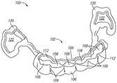
도 4a와 도 4b는 환자의 하나 이상의 치아를 재위치시키도록 구성된 예시적인 제거가능 치과용 기구(100)를 예시한다. 유사하게, 도 5a와 도 5b는 환자의 치아 구조의 3D 디지털 모델(130)과 조합된, 제거가능 치과용 기구(100)의 3D 디지털 모델을 예시한다.Figures 4A and 4B illustrate an exemplary removable
제거가능 치과용 기구(100)는 환자에 의해 착용될 때 환자의 치아의 교합면을 실질적으로 노출시키도록 구성된다. 노출된 교합면을 제공함으로써, 제거가능 치과용 기구(100)는 환자의 치아를 실질적으로 둘러싸는 제거가능 치과용 기구에 비해 다수의 이점, 예를 들어 개선된 환자의 편안함, 치과용 기구의 감소된 가시성, 치아들 사이의 증가된 공기 및 타액 흐름으로 인한 감소된 타터 성장, 및 치과용 기구의 제거 없이 환자가 어느 정도 먹거나 마시는 능력을 제공할 수 있다.The removable
제거가능 치과용 기구(100)는 기구 몸체(102)를 포함한다. 기구 몸체(102)는 환자의 2개 이상의 치아(도시된 예에서, 전치)를 둘러싸도록 구성된 활성 밴드(112)를 포함한다. 활성 밴드(112)는 안면측 부분(106)과 설측 부분(104)을 포함한다. 안면측 부분(106)은 활성 밴드(112) 내의 둘러싸인 치아의 안면측과 정합하도록 구성되는 반면, 설측 부분(104)은 둘러싸인 치아의 설측과 정합하도록 구성된다.The removable dental appliance (100) includes a tool body (102). The
안면측 부분(106)과 설측 부분(104)은 협력하여 리셉터클(108)을 형성한다. 각각의 리셉터클(108)은 안면측 부분(106)의 섹션과 설측 부분(104)의 대응하는 섹션을 나타내며, 이때 이들 섹션은 치과용 기구(100)가 환자에 의해 착용될 때 둘러싸인 치아 중 하나를 수용하도록 구성된다. 개별 리셉터클(108)은 기구 몸체(102)의 안면측 부분(106) 내의 안면측 리지(ridge)(109)와 설측 부분(104) 내의 설측 리지(107)에 의해 분리될 수 있다. 설측 리지(107)와 안면측 리지(109)는 둘러싸인 치아의 인접한 치아들 사이의 계면에 대응할 수 있지만, 임의의 2개의 인접한 치아의 치간 영역(interproximal area) 내로 연장될 필요는 없다.The
리셉터클(108)은 기구 몸체(102)에 의해 형성되는 활성 밴드(112)를 적어도 부분적으로 한정한다. 활성 밴드(112)는 개방 단부를 갖도록 구성되어, 제거가능 치과용 기구(100)가 환자에 의해 착용될 때 환자의 둘러싸인 치아의 교합면이 노출된다. 예를 들어, 환자에 의해 착용될 때, 둘러싸인 치아는 기구 몸체(102)의 개별 리셉터클(108) 내에 위치된다. 도시된 예에서, 개별 리셉터클(108)은 설측 리지 및 안면측 리지 중 적어도 하나에 의해 분리되고/되거나 개별적으로 한정된다. 다른 예에서, 리셉터클이 다수의 인접한 치아를 수용할 수 있다.The
환자의 치아의 위치설정을 용이하게 하기 위해, 개별 리셉터클(108) 중 적어도 하나가 환자의 대응하는 치아와 비교하여 오정렬될 수 있다. 이러한 방식으로, 기구 몸체(102)는 제거가능 치과용 기구(100)가 환자에 의해 착용될 때 환자의 대응하는 치아에 회전력 및/또는 병진력을 인가하도록 구성된다. 동일한 또는 상이한 예에서, 기구 몸체(102)는 개별 리셉터클(108) 내의 치아 중 하나 이상에 병진력을 인가하도록 구성된다. 활성 밴드(112)는 또한 에워싸인 치아의 순측면(labial surface) 및 설측면(lingual surface) 둘 모두에 서로 반대의 힘들을 인가하도록 구성될 수 있으며; 이러한 압박 "압착(squeezing)"은 치과용 기구(100)의 작동을, 개방-면 리셉터클(open-faced receptacle)을 포함한 다른 기구와 구별시킬 수 있다.In order to facilitate positioning of the patient's teeth, at least one of the
제거가능 치과용 기구(100)는 앵커(anchor)(120)를 추가로 포함한다. 앵커(120)는 기구 몸체(102)의 양측으로부터 연장된다. 앵커(120) 각각은 환자의 치아를 수용하도록 구성된 밴드(122)와, 밴드(122)를 기구 몸체/활성 밴드(112)에 결합시키는 스트럿(strut)(121)을 포함한다. 도시된 예에서, 앵커 밴드(anchor band)(122)는 환자의 하나 이상의 구치를 에워싼다. 몇몇 예에서, 구치는 환자의 소구치(premolar) 또는 대구치일 수 있다. 둘러싸인 치아가 기구 몸체(102)의 개별 리셉터클(108) 내에 위치된 상태로 제거가능 치과용 기구(100)가 환자에 의해 착용될 때, 구치는 앵커(120)의 밴드(122) 내에 위치된다. 앵커(120)는 제거가능 치과용 기구(100)가 환자에 의해 착용될 때 환자의 수용된 구치의 교합면이 노출되어 유지되도록 구성된다. 다른 예에서, 활성 밴드는, 앵커가 활성 밴드로부터 원위에(distally) 또는 중앙에(mesially) 위치되는 상태로, 하나 이상의 구치를 둘러싸도록 구성될 수 있다. 따라서, 앵커는 구치, 전치, 또는 이들 둘 모두의 조합을 둘러쌀 수 있다.The removable
제거가능 치과용 기구(100)는 기구 몸체(102)의 설측 부분(104)이 둘러싸인 치아 중 하나 이상에 대체로 전방 방향으로 힘을 인가하도록 구성될 수 있다는 점에서 스프링 정렬기(spring aligner)로서 기능할 수 있다. 한편, 앵커(120)는 제거가능 치과용 기구(100)가 환자에 의해 착용될 때 수용된 구치에 대체로 후방 방향으로 힘을 인가함으로써 기구 몸체(102)의 설측 부분(104)에 의한 대체로 전방 방향으로의 힘의 인가를 지원하도록 구성된다. 대안적인 구현예(도시되지 않음)에서, 기구 몸체에는 설측 부분 또는 안면측 부분이 없을 수 있어서, 하나 이상의 표적 치아가 단지 전방 또는 후방 지향 힘 중 하나만을 겪는다.The removable
몇몇 예에서, 제거가능 치과용 기구(100)는 환자의 구강 내의 치과교정용 고정 장치에 연결하도록 구성된 캐치(catch)를 포함할 수 있다. 그러한 캐치는 앵커(120)들 중 하나 또는 둘 모두 상에 위치될 수 있다.In some instances, the removable
동일한 또는 상이한 예에서, 기구 몸체(102)와 앵커(120)를 포함한 제거가능 치과용 기구(100)는 하나 이상의 중합체를 포함한다. 예를 들어, 기구 몸체(102)와 앵커(120)를 포함한 제거가능 치과용 기구(100)는 단일의 연속 3D 인쇄된 구성요소로 이루어질 수 있다. 몇몇 특정 예에서, 기구 몸체(102)와 앵커(120)를 포함한 제거가능 치과용 기구(100)의 구성요소의 두께는 약 0.25 밀리미터 내지 약 2.0 밀리미터의 두께, 예를 들어 약 0.5 내지 약 1.0 밀리미터의 두께, 또는 약 0.75 밀리미터의 두께일 수 있다. 몇몇 예에서, 제거가능 치과용 기구(100)의 특징부의 두께는 더 맞추어진(tailored) 힘을 달성하기 위해 달라질 수 있다. 동일한 또는 상이한 예에서, 제거가능 치과용 기구(100)는 활성 밴드(112)의 에지 및 다른 공간 상에 챔퍼(chamfer) 또는 필릿(fillet)을 포함할 수 있다. 그러한 챔퍼 또는 필릿은 환자의 편안함을 개선하고 제거가능 치과용 기구(100)의 가시성을 감소시킬 수 있다.In the same or different examples, the removable
다른 예에서, 제거가능 치과용 기구(100)는 제거가능 치과용 기구에 의해, 둘러싸인 치아 중 하나 이상에 인가되는 힘을 향상시키기 위해 중합체 구성요소에 강성(stiffness)을 제공하도록 구성된 금속성 구성요소를 포함할 수 있다. 예를 들어, 금속성 구성요소는 기구 몸체(102)의 설측 부분(104)을 통해 앵커(120)들 사이에서 연장되는 와이어를 포함할 수 있다. 몇몇 예에서, 고압 교합 접촉의 응력을 극복하기 위해 더 큰 내구성이 필요한 경우에, 환자에 의해 착용될 때 노출된 교합면을 제공하는 제거가능 치과용 기구는 금속 교합 점퍼(occlusal jumper)와 같은 하나 이상의 다른 금속 구성요소를 포함할 수 있다. 금속 교합 점퍼에 대한 필요성은 이갈이(bruxing) 또는 저작(mastication)과 같은 비-순응성 환자 활동에 기인할 수 있다. 동일한 또는 상이한 예에서, 환자에 의해 착용될 때 노출된 교합면을 제공하는 제거가능 치과용 기구는 환자 내에 이식된 고정 장치에 연결하기 위한 캐치를 포함할 수 있다. 이러한 방식으로, 노출된 교합면을 제공하는 그러한 제거가능 치과용 기구는 금속과 플라스틱의 하이브리드 구성을 제공할 수 있다.In another example, the removable
플라스틱 구성요소가 감소된 가시성을 위해 대체로 투명할 수 있지만, 금속 구성요소는 환자에 의해 착용될 때 제거가능 치과용 기구의 가시성을 감소시키기 위해 도금 또는 다른 착색제를 포함할 수 있다. 예를 들어, 이식될 때 환자의 치아 부근에 위치되는 금속 구성요소는 백색 착색제를 포함할 수 있는 반면, 다른 곳에 위치되는 금속 구성요소는 환자의 구강 내의 조직 색과 대체로 일치하도록 착색될 수 있다.While the plastic component may be generally transparent for reduced visibility, the metal component may include plating or other coloring agents to reduce the visibility of the removable dental appliance when worn by the patient. For example, metal components located near the patient ' s teeth when implanted may include a white colorant, while metal components located elsewhere may be colored to substantially match the tissue color within the patient ' s mouth.
제거가능 치과용 기구(100)는 디지털 방식으로 설계될 수 있다. 몇몇 예에서, 제거가능 치과용 기구의 순서화된 세트가 일련의 디지털 셋업에 기초하여 순차적으로 착용되도록 설계된다. 그러한 예에서, 세트 내의 각각의 제거가능 치과용 기구는 약 2주 내지 약 12주, 예를 들어 약 3주 내지 약 10주 또는 약 4주 내지 약 8주 동안 착용될 수 있다. 세트 내의 제거가능 치과용 기구를 규정된 기간 동안 착용한 후에, 세트 내의 제거가능 치과용 기구는 폐기되거나 세트 내의 다음 제거가능 치과용 기구로 대체될 수 있다. 이러한 제거가능 치과용 기구(100)의 설계는 세트 내의 제거가능 치과용 기구의 교체 사이의 더 긴 기간을 용이하게 할 수 있다. 예를 들어, 활성 밴드(112)가 환자의 2개 이상의 치아를 둘러싸기 때문에, 설측 부분(104)과 안면측 부분(106)은 각각의 치아가 별개의 공동(cavity) 내에 격리되는 유사한 치과용 기구 설계에서보다, 환자에 의해 처음 착용될 때 더 큰 정도로 편향될 수 있다. 이러한 이유로, 제거가능 치과용 기구(100)는 각각의 치아가 별개의 공동 내에 격리되는 유사한 치과용 기구 설계에서보다 더 많은 양의 치아 움직임을 제공하도록 설계될 수 있으며, 이에 의해 세트 내의 다음 치과용 기구에 의해 대체되기 전에 환자에 의해 더 긴 기간 동안 착용되도록 설계될 수 있다.The removable
제거가능 치과용 기구(100)가 기구 몸체(102) 내에 개별 리셉터클(108)을 포함하지만, 다른 예에서, 기구 몸체(102)는 기구 몸체(102)에 의해 둘러싸인 환자의 치아 각각에 대한 별개의 공동을 한정하는 리지를 포함하지 않을 수 있다. 또한, 제거가능 치과용 기구(100)가 단일 활성 밴드(112)를 포함하지만, 다른 예는 하나 초과의 활성 밴드를 포함할 수 있으며, 이때 각각의 활성 밴드는 하나 이상의 치아를 둘러싼다. 도시되지 않지만, 제거가능 치과용 기구(100)와 그러한 다른 예는 선택적으로 하나 이상의 활성 밴드를 서로, 치아에, 또는 치아에 직접 접합되거나 달리 부착된 별개의 기구에 연결하거나, 부착하거나, 고정시키는 하나 이상의 추가의 스트럿을 포함할 수 있다.The removable
이러한 예 및 다른 예에서, 활성 밴드의 형상과 치수는 각각의 둘러싸인 치아 표면의 일부가 예를 들어 기구 몸체(102)의 안면측 부분(106) 내의 안면측 리지(109)와 설측 부분(104) 내의 설측 리지(107)를 포함한, 제거가능 치과용 기구(100)의 내측 표면에 의해 복제되도록 한정된다. 그러한 복제는 기구 압착(appliance expression)의 종료시에 발생하는 이완된 상태에서 정합 기구(conforming appliance)를 제공함과 동시에, 치아가 제거가능 치과용 기구(100)에 대해 이상위치(malposed)될 때 기구 압착의 활성 기간 동안인 응력 상태에서 제거가능 치과용 기구(100)의 탄성 변형을 용이하게 할 수 있다.In this and other examples, the shape and dimensions of the active bands are such that a portion of each encircling tooth surface is exposed, for example, between the
치아의 순측면과 설측면의 어느 정도 상당한 부분을 복제함으로써(그러나 교합면은 그만큼 복제하지 않음), 치아가 제거가능 치과용 기구(100)에 대해 더 이상위치됨에 따라 더 큰 커플(couple)의 형성으로 인해 치아의 회전이 영향을 받을 수 있다. 제거가능 치과용 기구(100)의 내측 표면에서 치아의 특징부를 근사하게 복제함으로써, 제거가능 치과용 기구(100)는 제거가능 치과용 기구(100)가 약간이라도 변형될 때 커플의 존재로 인해 마무리 경우에 특히 효과적일 수 있다. 대조적으로, 스프링 정렬기 또는 인만 정렬기(Inman aligner)와 같은 많은 기존의 제거가능 기구는 그것들이 이동함에 따라 치아와의 간섭을 회피하기 위해 이들 표면에서의 세부구조(detail)의 복제를 회피하여서, 치아가 단일 기구를 사용하여 더 큰 거리 또는 각도에 걸쳐 이동될 수 있다. 이들 기구에서의 세부구조의 제거는 그것들이 이동함에 따라 치아가 그것 위에서 미끄러질 수 있는 매끄러운 표면을 제공하는 역할을 하지만, 단점은 의도된 회전을 유발하는 접촉점에 의해 형성되는 커플이 크기가 훨씬 더 작다는 것이며, 이는 더 작은 힘 및 덜한 기구 압착을 초래한다.By replicating somewhat substantial portions of the net and lingual sides of the tooth (but not duplicating the occlusal surface that much), the larger the number of teeth of a larger couple, as the teeth are no longer positioned relative to the removable
비유를 사용하면, 조(jaw)의 내측 표면이 대응하는 너트에 근사하게 정합하도록 설계될 때(즉, 곧고 평행함) 개방-단부형 렌치(wrench)가 더 효과적이다. 그러나, 조들 사이의 거리가 중간 지점에서 최소이고 양단부에서 개구를 향해 증가하도록 조의 내측 표면이 둥글면, 렌치에 토크를 인가하는 동안에 조와 너트 사이의 접촉점에 의해 형성되는 커플은, 조들이 평행하고 그것의 정점(vertex)에서 너트와 접촉하는 경우에 달리 가질 반경보다 작은 반경을 가질 것이다(조와 너트 사이의 어느 정도의 허용오차(tolerance)를 가정함). 유사하게, 제거가능 치과용 기구(100)의 활성 밴드(112)의 폭(즉, 교합 치은 두께)에 있어서의 증가가 커플의 반경에 있어서의 증가를 가져올 것이며, 이는 기구 변형 중에 인가되는 힘을 증가시킬 것이다. 몇몇 경우에, 동기는 미관 또는 환자의 편안함의 이유로 밴드의 폭을 최소화하는 것일 수 있지만(예컨대, 가는 와이어에 이르기까지), 다른 경우에, 제거가능 치과용 기구(100)의 내측 표면적을 증가시키고 치아의 특징부를 근사하게 복제함으로써 인지 미관을 더 큰 기능과 교환하는 것이 유리할 수 있다.With metaphor, an open-end wrench is more effective when the inner surface of the jaw is designed to closely match the corresponding nut (i.e., straight and parallel). However, a couple formed by the contact point between the jaw and the nut while the torque is applied to the wrench, if the inner surface of the jaw is rounded so that the distance between the jaws is minimum at the midpoint and increases towards the opening at both ends, (Assuming some tolerance between the nut and the nut) that would otherwise be different if it comes in contact with the nut at its vertex. Similarly, an increase in the width of the active band 112 (i.e., occlusal tooth thickness) of the removable
제거가능 치과용 기구(100)는 컴퓨터(70)(도 3)와 같은 컴퓨터 시스템에 의해 생성된 제거가능 치과용 기구(100)의 디지털 모델에 기초하여, 자동화된 제조 시스템(74)(도 3)과 같은 자동화된 제조 시스템을 사용하여 제조될 수 있다. 상이한 예에서, 제거가능 치과용 기구(100)는 3D 인쇄를 사용하여 형성되거나 열-성형되고 트리밍될 수 있는데, 예를 들어 5-축 밀링 또는 레이저 커팅에 의해 트리밍될 수 있다. 3D 인쇄의 경우에, 제거가능 치과용 기구(100)는 3D 인쇄 시스템에 의해 직접 3D 인쇄될 수 있지만, 다른 예에서, 제거가능 치과용 기구(100)는 3D 인쇄를 사용하여 형성된 치아의 주형(mold)을 통해 열성형될 수 있다. 몇몇 예에서, 3D 인쇄된 치아는 융기된 교합면을 구비할 수 있거나, 달리 환자의 치아와는 상이하여, 3D 인쇄를 사용하여 형성된 치아의 주형을 통해 제거가능 치과용 기구(100)를 열성형한 후에 교합면 영역으로부터 재료를 제거하는 것에 대한 필요성을 제한한다.The removable
동일한 또는 상이한 예에서, 제거가능 치과용 기구(100)의 자동화된 또는 반-자동화된 제조는 사출 성형, 로스트 왁스 주조(lost wax casting), 5-축 밀링, 레이저 커팅 및 다른 제조 기술을 포함할 수 있다. 제거가능 치과용 기구가 금속 교합 점퍼와 같은 하나 이상의 금속 구성요소를 포함하는 예에서, 자동화된 제조는 와이어와 같은 금속성 구성요소의 로봇 굽힘가공(robotic bending)과 같은, 금속성 구성요소의 로봇 조작을 포함할 수 있다. 금속과 플라스틱의 하이브리드 구성을 제공하는 제거가능 치과용 기구는 또한 오버몰딩(overmolding) 및/또는 스냅-핏(snap-fit) 기술을 사용하여 제조될 수 있다. 그러한 금속 구성요소는 또한 디지털 방식으로 설계되고 로봇에 의해 맞춤-굽힘가공된 금속 와이어로부터, 3D-인쇄된 왁스 모델의 금속 인베스트먼트 주조(investment casting)로부터, 선택적 레이저 용융(Selective Laser Melting, SLM) 또는 선택적 레이저 소결(Selective Laser Sintering, SLS)을 비롯한 "직접 금속(direct metal)" 3D 인쇄로부터, 또는 금속 블록의 3-축, 4-축, 또는 5-축 밀링으로부터 제조될 수 있다. 대안적으로, 제거가능 치과용 기구의 중합체 구성요소와 조합하여 사용하기 위한 더 강한 구성요소가 투명한 또는 치아 색의 세라믹 재료로부터 제조될 수 있다. 몇몇 예에서, 금속이 미관을 개선하기 위해 은, 백금, 팔라듐, 또는 로듐과 같은 "백색" 귀금속으로 도금될 수 있다. 일반적으로, 더 많은 구성요소를 추가하는 것은 조인트(joint)를 도입할 것이며, 자동화된 또는 반-자동화된 제조 공정 후에 어느 정도의 조립이 요구될 수 있다.In the same or different examples, automated or semi-automated manufacture of the removable
이러한 방식으로, 노출된 교합면을 제공하는 제거가능 치과용 기구에 관하여 본 명세서에 개시된 기술은 많은 다양한 구성을 용이하게 한다. 이러한 기술은 치료된 치아 및 고정 치아(anchoring teeth) 둘 모두의 선택뿐만 이니라, 힘 부재, 앵커, 및 다른 특징부의 맞춤화된 크기, 형상, 및 배치의 선택을 용이하게 한다. 또한, 재료 조합과 조인트 타입이 또한 환자를 위한 원하는 치료 결과를 제공하도록 선택될 수 있다.In this manner, the techniques disclosed herein for a removable dental appliance that provides an exposed occlusal surface facilitate many different configurations. This technique facilitates the selection of customized sizes, shapes, and arrangements of force members, anchors, and other features, as well as selection of both treated teeth and anchoring teeth. In addition, the material combination and joint type may also be selected to provide the desired treatment outcome for the patient.
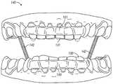
도 6은 II급 부정교합의 교정을 용이하게 하는 상부 제거가능 치과용 기구(101)와 하부 제거가능 치과용 기구(100)의 3D 디지털 모델(140)을 예시한다. 도 6은 또한 환자의 하치(lower teeth)의 3D 디지털 모델(130)과 환자의 상치(upper teeth)의 3D 디지털 모델(131)을 예시한다. 하부 제거가능 치과용 기구(100)는 도 4a 내지 도 5b에 예시된 바와 같은 제거가능 치과용 기구(100)와 유사하지만, 탄성 결찰사(elastic ligature)(142)에 연결하기 위한 노브(knob), 후크(hook), 루프(loop), 캐치, 또는 다른 특징부가 추가된다. 또한, 상부 제거가능 치과용 기구(101)는, 그것이 3D 디지털 모델(131)에 도시된 환자의 상치 위에 착용되도록 구성되는 것을 제외하고는, 제거가능 치과용 기구(100)와 유사하다. 상부 제거가능 치과용 기구(101)가 또한 탄성 결찰사(142)에 연결하기 위한 후크 또는 다른 특징부를 포함한다. 다른 예에서, 기구는 포서스(FORSUS) II급 교정기 또는 허브스트(Herbst) 교정기를 사용하여 상치열궁(upper arch)과 하치열궁(lower arch)을 활주 "완충기(shock absorber)"를 통해 연결할 수 있다. 포서스 커넥터의 경우에, 하악골이 닫힐 때 코일형 스프링이 압축된다. 하악골이 열릴 때, 스프링은 이완되고 일단 그것이 그것의 범위의 끝에 도달하면 자유롭게 활주한다. 포서스 또는 허브스트 II급 교정기는 치과용 기구를 끌어당기지 않고 단지 밀어내기만 하며, 상부 제거가능 치과용 기구(101)와 하부 제거가능 치과용 기구(100)를 환자의 치아로부터 끌어당기는 경향이 있을 수 있는 탄성 결찰사(142)보다, 제거가능 기구 내에 포함시키기에 더 적합할 수 있다.6 illustrates a 3D
제거가능 치과용 기구(100)와 마찬가지로, 제거가능 치과용 기구(101)는 환자에 의해 착용될 때 환자의 치아의 교합면을 노출시키도록 구성된다. 제거가능 치과용 기구(100)와 마찬가지로, 제거가능 치과용 기구(101)는 그것이 둘러싸인 치아 중 하나 이상에 대체로 전방 방향으로 힘을 인가하도록 구성될 수 있다는 점에서 스프링 정렬기로서 기능할 수 있다. 제거가능 치과용 기구(101)는 또한 제거가능 치과용 기구(101)가 환자에 의해 착용될 때 대체로 전방 방향으로의 힘의 인가를 지원하기 위해 앵커를 포함하지만, 앵커는 또한 다른 예에서 대체로 원위 방향으로의 힘의 인가를 지원할 수 있다. 대체로 전방 방향은 제거가능 치과용 기구(101)에 의해 인가되는 힘이 치아를 함께 압착하는 경향이 있기 때문에 환자의 치아마다 다를 수 있어서, 하나 이상의 치아가 겪는 힘은 대체로 전방 방향과는 다를 수 있다. 일반적으로, 제거가능 치과용 기구(101)에 의해 형성되는 루프는 이상위치된 치아에 의해 확장되고, 제거가능 치과용 기구(101)는 그것이 더 작은 주연부(perimeter)를 갖는 그것의 평형 상태로 이완되려고 시도함에 따라 치아를 다양한 병진 및 회전으로 가압한다. 상부 제거가능 치과용 기구(101)는 도 4a 내지 도 5b 및 제거가능 치과용 기구(100)에 관하여 기재된 바와 같은 기술을 사용하여 제조될 수 있다.Similar to the removable
상부 제거가능 치과용 기구(101)는 상부 제거가능 치과용 기구(101)와 하부 제거가능 치과용 기구(100)의 조합이 II급 부정교합의 교정을 용이하게 하도록 하부 제거가능 치과용 기구(100)와 상호작용하도록 구성된다. 특히, 상부 제거가능 치과용 기구(101)는 탄성 결찰사(142)에 연결하기 위한 후크 또는 다른 특징부를 포함한다. 하부 제거가능 치과용 기구(100)가 또한 탄성 결찰사(142)에 연결하기 위한 후크 또는 다른 특징부를 포함한다. 탄성 결찰사(142)는 상부 제거가능 치과용 기구(101) 및 하부 제거가능 치과용 기구(100)와 조합하여 환자에 의해 착용될 때 II급 부정교합의 교정을 제공한다. 탄성 결찰사(142)가 상부 제거가능 치과용 기구(101)와 하부 제거가능 치과용 기구(100)를 치아로부터 빼내는 것을 방지하기 위해, 상부 제거가능 치과용 기구(101) 및 하부 제거가능 치과용 기구(100) 중 하나 또는 둘 모두는 치아 상의 접합된 부착물과 맞물릴 수 있다. 예시적인 접합된 부착물을, 발명의 명칭이 "제거가능 섹션을 갖춘 설측 치과교정용 기구(LINGUAL ORTHODONTIC APPLIANCE WITH REMOVABLE SECTION)"이고 2014년 9월 9일자로 허여된, 시나더 등의 미국 특허 제8,827,697호에서 찾아볼 수 있다. 미국 특허 제8,827,697호는 전체적으로 본 명세서에 참고로 포함된다.The top removable
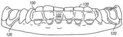
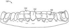
도 7은 환자의 치아의 3D 디지털 모델(133)과 조합된, 활성 밴드(103)를 구비하고 인공치아(152)를 포함하는 제거가능 치과용 기구(150)의 3D 디지털 모델의 전방 부분을 예시한다. 제거가능 치과용 기구(150)는 도 4a 내지 도 5b에 예시된 바와 같은 제거가능 치과용 기구(100)와 동일하거나 유사하지만, 인공치아(152)가 추가된다.7 illustrates an example of a frontal portion of a 3D digital model of a removable
제거가능 치과용 기구(100)와 마찬가지로, 제거가능 치과용 기구(150)는 환자에 의해 착용될 때 환자의 치아의 교합면을 노출시키도록 구성된다. 제거가능 치과용 기구(100)와 마찬가지로, 제거가능 치과용 기구(150)는 그것이 둘러싸인 치아 중 하나 이상에 대체로 전방 방향으로 힘을 인가하도록 구성될 수 있다는 점에서 스프링 정렬기로서 기능할 수 있다. 대체로 전방 방향은 제거가능 치과용 기구(100)에 의해 인가되는 힘이 치아를 함께 압착하는 경향이 있기 때문에 환자의 치아마다 다를 수 있어서, 하나 이상의 치아가 겪는 힘은 대체로 전방 방향과는 다를 수 있다. 일반적으로, 제거가능 치과용 기구(100)에 의해 형성되는 루프는 이상위치된 치아에 의해 확장되고, 제거가능 치과용 기구(100)는 그것이 더 작은 주연부를 갖는 그것의 평형 상태로 이완되려고 시도함에 따라 치아를 다양한 병진 및 회전으로 가압한다. 제거가능 치과용 기구(150)는 또한 제거가능 치과용 기구(150)가 환자에 의해 착용될 때 대체로 전방 방향으로의 힘의 인가를 지원하기 위해 앵커를 포함한다. 제거가능 치과용 기구(150)는 도 4a 내지 도 5b 및 제거가능 치과용 기구(100)에 관하여 기재된 바와 같은 기술을 사용하여 제조될 수 있다.Similar to the removable
인공치아(152)는 환자의 치아의 3D 디지털 모델(133)에 표현된 바와 같이, 환자의 결손 치아(missing tooth)로부터의 공간을 충전하도록 구성된다. 몇몇 예에서, 인공치아(152)는 환자의 치아와의 일관성을 위해 착색될 수 있다. 인공치아(152)의 기하학적 구조는 인공치아(152)에 인접한 치아의 재위치설정을 돕도록 선택될 수 있다. 예를 들어, 각각이 인공치아를 포함하는, 제거가능 치과용 기구의 순서화된 세트에서, 인공치아는 원하는 임플란트, 브리지 또는 다른 미용 치아에 충분한 공간을 생성하기 위해 제거가능 치과용 기구의 순서화된 세트의 시퀀스 전반에 걸쳐 점진적으로 커질 수 있다.The
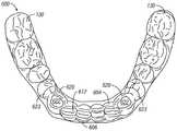
도 8은 환자의 치아의 3D 디지털 모델(130)과 조합된, 활성 밴드(105)를 구비하고 설측 핑거(162)를 포함하며 노출된 교합면을 제공하는 제거가능 치과용 기구(160)의 3D 디지털 모델의 전방 부분을 예시한다. 제거가능 치과용 기구(160)는 도 4a 내지 도 5b에 예시된 바와 같은 제거가능 치과용 기구(100)와 동일하거나 유사하지만, 설측 핑거(162)가 추가된다.Figure 8 illustrates a 3D view of a removable
제거가능 치과용 기구(100)와 마찬가지로, 제거가능 치과용 기구(160)는 환자에 의해 착용될 때 환자의 치아의 교합면을 노출시키도록 구성된다. 제거가능 치과용 기구(100)와 마찬가지로, 제거가능 치과용 기구(160)는 그것이 둘러싸인 치아 중 하나 이상에 대체로 전방 방향으로 힘을 인가하도록 구성될 수 있다는 점에서 스프링 정렬기로서 기능할 수 있다. 제거가능 치과용 기구(160)는 또한 제거가능 치과용 기구(160)가 환자에 의해 착용될 때 대체로 전방 방향으로의 힘의 인가를 지원하기 위해 앵커를 포함한다.Similar to the removable
설측 핑거(162)는 둘러싸인 치아 각각에 별개의 힘을 대체로 전방 방향으로 인가할 수 있다. 둘러싸인 치아 각각에 인가되는 방향과 크기는 설측 핑거(162)들 중 인접한 것의 설계에 따라 맞춤화될 수 있다. 상이한 예에서, 설측 핑거(162)는 약 0.25 밀리미터 내지 약 2.0 밀리미터의 두께, 예를 들어 약 0.5 내지 약 1.0 밀리미터의 두께, 또는 약 0.75 밀리미터의 두께일 수 있다. 제거가능 치과용 기구(160)는 도 4a 내지 도 5b 및 제거가능 치과용 기구(100)에 관하여 기재된 바와 같은 기술을 사용하여 제조될 수 있다.The
제거가능 치과용 기구(160)가 환자에 의해 착용될 때, 설측 핑거(162)는, 치과용 기구의 설측 부분 상에 위치되면, 치아를 순측 보우(labial bow)(치과용 기구의 전방 부분) 쪽으로 전방으로 밀어냄으로써 대체로 전방 방향으로 힘을 인가한다. 그러나, 제거가능 치과용 기구(160)의 순측 보우는 또한 치아를 설측 방향으로 후방으로 밀어낸다. 서로 반대측 및 서로 반대 방향으로부터 동시에 밀어내지는 치아의 이중 작용은 서로 반대편에 있는 접촉점에 커플이 형성되게 한다. 이들 커플이 모멘트의 중심에 대해 형성되는 곳이 회전축 및 달성되는 레버리지(leverage)의 크기를 결정한다. 접촉이 단지 일측으로부터 이루어지고, 커플이 형성되지 않으면, 치아는 병진된다. 그러나, 접촉점이 치아의 치관 상에 있고, 모멘트의 중심이 치근의 중간의 어딘가에 있기 때문에, 순수 병진이 달성되지 않으며, 대신에 접촉점으로부터 치근 내의 모멘트의 중심까지의 거리인 긴 아암(arm)을 중심으로 하는 회전으로서 나타난다. 이는 단지 회전에 가깝다. 순수 병진은 치아를 국소적으로 확고하게 둘러싸고 치과용 기구의 다른, 더 멀리 있는 부분이 병진력을 생성하는 변형을 겪게 함으로써 달성될 수 있다. 그렇기 때문에, 소정의 치아를 그룹으로서가 아니라 개별적으로 둘러싸고 이들 치아와 다른, 고정 치아 사이에 스트럿을 탄성 변형 힘 부재로서 사용하는 것이 유리할 수 있다. 이러한 방식으로, 제거가능 치과용 기구(160)는 앵커로서의 역할을 하는(그러나 또한 자체적으로 반대 방향으로 이동할 수 있음) 구치에 대항하여 전치 모두를 그룹으로서 전방으로 밀어냄으로써 전방 세그먼트와 후방 세그먼트 사이에 공간을 생성하는 데 사용될 수 있다.When the removable
도 9는 제거가능 치과용 기구(52)(도 1)의 구성을 위해 제조 시설(48)에서 수행되는 프로세스(100)를 예시하는 순서도이다. 몇몇 예에서, 제거가능 치과용 기구(52)는 제거가능 치과용 기구(100), 제거가능 치과용 기구(101), 제거가능 치과용 기구(150) 및/또는 제거가능 치과용 기구(160) 중 하나 이상을 포함할 수 있다. 제조 시설(48)에 있는 컴퓨터(70)는 진료소(44)로부터 디지털 치아 구조 데이터(46), 환자의 하나 이상의 치아의 환자 제공 초기 위치, 및 처방 데이터(47)를 수신한다(202). 대안적으로, 컴퓨터(70)는 컴퓨터(70) 내에 위치된 또는 달리 컴퓨터(70)에 의해 접속가능한 데이터베이스에서 정보를 검색한다. 컴퓨터(70)와 관련된 숙련된 사용자가 컴퓨터(70) 상에서 실행되는 컴퓨터화된 모델링 환경과 상호작용하여, 환자의 치아 구조의 디지털 표현에 관한 치료 계획을 수립하고 처방 데이터(47)를 생성할 수 있다(만약 진료소(44)가 이미 그렇게 하지 않았으면). 다른 예에서, 컴퓨터(70)는 오직 환자의 치아 구조 및 미리 정해진 설계 제약에 기초하여 치료 계획을 자동적으로 수립할 수 있다.Figure 9 is a flow chart illustrating a
일단 컴퓨터(70)가 환자의 치아 구조를 수신하면, 컴퓨터(70)가 환자를 위한 제거가능 치과용 기구의 치수와 형상을 결정한다(204). 제거가능 치과용 기구의 치수와 형상은 제거가능 치과용 기구가 환자에 의해 착용될 때 환자의 하나 이상의 치아를 그것들의 초기 위치로부터 조정된 위치로 재위치시키도록 구성된다. 동일한 또는 추가의 예에서, 컴퓨터(70)는 환자를 위한 제거가능 치과용 기구의 세트의 치수와 형상을 결정하며, 이때 환자를 위한 제거가능 치과용 기구의 세트는 순차적으로 착용되도록 구성된다.Once the
몇몇 예에서, 제거가능 치과용 기구의 치수와 형상을 결정하는 것은, 컴퓨터(70)로, 미리 정해진 설계 제약의 세트에 따라 제거가능 치과용 기구의 치수와 형상을 선택하는 것을 포함한다. 미리 정해진 설계 제약의 세트는 둘러싸인 치아 중 하나 이상에 인가되는 최대 국소적 힘, 둘러싸인 치아 중 하나 이상에 인가되는 최대 회전력, 둘러싸인 치아 중 하나 이상에 인가되는 최대 병진력, 둘러싸인 치아 중 하나 이상에 인가되는 최대 총 힘, 및 둘러싸인 치아가 그것들의 초기 위치에 있을 때 환자에 의해 착용될 때 제거가능 치과용 기구에 적용되는 최대 변형률(strain)을 포함하지만 이로 제한되지 않는 하나 이상의 인자를 포함할 수 있다.In some instances, determining the dimensions and shape of the removable dental appliance includes selecting, by the
컴퓨터(70)는 제거가능 치과용 기구의 치수와 형상의 결정 중에 환자의 치아뿐만 아니라 제거가능 치과용 기구 상의 힘을 분석하기 위해 유한 요소 분석(finite element analysis, FEA) 기법을 사용할 수 있다. 예를 들어, 컴퓨터(70)는 모델링된 치아가 그것들의 초기 위치로부터 그것들의 최종 위치로 이동하여 제거가능 치과용 기구의 순서화된 세트를 포함하는 치료를 나타낼 때 환자의 치아의 솔리드 모델(solid model)에 FEA를 적용할 수 있다. 컴퓨터(70)는 치아에 원하는 힘을 인가하기 위해 제거가능 치과용 기구에 적절한 FEA 선택을 사용할 수 있다. 또한, 컴퓨터(70)는 치료 중에 모델링된 치아의 움직임 전반에 걸쳐 치아 사이의 접촉점을 결정하기 위해 가상 교합기(virtual articulator)를 사용할 수 있다. 컴퓨터(70)는 제거가능 치과용 기구의 순서화된 세트 내의 제거가능 치과용 기구의 설계 중에 장치로부터의 힘과 조합하여 FEA 힘 분석에서, 상호감입력(interdigitation force)과 같은, 교합 접촉력을 추가로 포함할 수 있다.The
동일한 또는 상이한 예에서, 제거가능 치과용 기구의 치수와 형상을 결정하는 것은 제거가능 치과용 기구가 환자에 의해 착용될 때 환자의 하나 이상의 치아를 그것들의 초기 위치로부터 조정된 위치로 재위치시키기에 적합한 강성을 제공하기 위해, 컴퓨터(70)로, 치과용 기구 몸체의 안면측 부분과 설측 부분의 두께를 선택하는 것을 포함한다. 상이한 예에서, 그러한 선택된 두께는 약 0.25 밀리미터 내지 약 2.0 밀리미터의 두께, 예를 들어 약 0.5 내지 약 1.0 밀리미터의 두께의 범위일 수 있다. 몇몇 예에서, 컴퓨터(70)는 또한 미리 정해진 설계 제약에 따라 또는 두께를 필연적으로 증가시킴이 없이 원하는 강성 특성을 제공하도록 제거가능 치과용 기구의 적어도 일부분(예컨대, 안면측 및 설측 몸체 부분)의 재료를 선택할 수 있다.In the same or different example, the determination of the dimensions and shape of the removable dental appliance may include repositioning one or more teeth of the patient from their initial position to their adjusted position when the removable dental appliance is worn by the patient To provide the appropriate stiffness, the
환자를 위한 제거가능 치과용 기구의 치수와 형상은 컴퓨터(70)의 사용자 인터페이스(72)를 통해 사용자에게 제시될 수 있다(206). 제거가능 치과용 기구의 치수와 형상이 컴퓨터(70)의 사용자 인터페이스(72)를 통해 사용자에게 제시되는 예에서, 사용자는 설계 데이터가 자동화된 제조 시스템에 보내지기 전에 설계 제약을 조정하거나 제거가능 치과용 기구의 치수와 형상을 직접 조정할 기회를 가질 수 있다.The dimensions and shape of the removable dental appliance for the patient may be presented to the user via the
대안적으로 또는 추가적으로, 환자를 위한 제거가능 치과용 기구의 치수와 형상은 자동화된 제조 시스템(74)에 의해 제조된 제거가능 치과용 기구로서 직접 컴퓨터(70)에 의해 사용자에게 제시될 수 있다(206). 그러한 예에서, 컴퓨터(70)는 제거가능 치과용 기구의 디지털 모델을 자동화된 제조 시스템(74)에 보내고, 자동화된 제조 시스템(74)은 컴퓨터(70)로부터의 디지털 모델에 따라 제거가능 치과용 기구를 제조한다.Alternatively or additionally, the dimensions and shape of the removable dental appliance for the patient can be presented to the user directly by the
그러나, 환자를 위한 제거가능 치과용 기구의 치수와 형상이 컴퓨터(70)의 사용자 인터페이스(72)를 통해 사용자에게 제시될 수 있는 예에서도, 사용자 승인 후에, 컴퓨터(70)가 제거가능 치과용 기구의 디지털 모델을 자동화된 제조 시스템(74)에 보내고(208), 자동화된 제조 시스템(74)이 컴퓨터(70)로부터의 디지털 모델에 따라 제거가능 치과용 기구를 제조한다(210).However, even in the example in which the dimensions and shape of the removable dental appliance for the patient may be presented to the user via the
몇몇 예에서, 자동화된 제조 시스템(74)은 3D 프린터를 포함할 수 있다. 치과용 기구 몸체의 활성 밴드의 형상을 형성하는 것은 치과용 기구 몸체의 활성 밴드를 형성하는 치과용 기구 몸체의 표면을 3D 프린터로 인쇄하는 것을 포함할 수 있다. 그러한 활성 밴드는 제거가능 치과용 기구(100)에 관하여 앞서 기술되었다. 다른 예에서, 치과용 기구 몸체의 활성 밴드의 형상을 형성하는 것은 환자의 치아의 표현을 3D 프린터로 인쇄하고 환자의 치아의 표현 위에 치과용 기구 몸체를 열성형하는 것을 포함할 수 있다. 예를 들어, 환자의 치아의 표현은 열성형된 기구 몸체에서 안면측 부분을 설측 부분으로부터 분리시키는 공간의 형성을 용이하게 하기 위해 융기된 교합면을 포함할 수 있다.In some instances, the automated
도 9의 기술은 환자를 위한 순서화된 세트의 제거가능 치과용 기구들 각각의 설계와 제조에 적용될 수 있다. 예를 들어, 제거가능 치과용 기구의 순서화된 세트 내의 각각의 제거가능 치과용 기구는 환자의 치아를 증분식으로 재위치시키도록 구성될 수 있다. 이러한 방식으로, 제거가능 치과용 기구의 순서화된 세트는 환자의 치아를, 제거가능 치과용 기구의 세트 내의 제거가능 치과용 기구 중 임의의 것보다 큰 정도로 재위치시키도록 구성될 수 있다. 그러한 환자를 위한 제거가능 치과용 기구의 순서화된 세트는 환자를 위한 제거가능 치과용 기구의 순서화된 세트의 제거가능 치과용 기구가 환자에 의해 순차적으로 착용될 때 환자의 하나 이상의 치아를 그것들의 초기 위치로부터 최종 조정된 위치로 증분식으로 재위치시키도록 특별히 구성될 수 있다.The technique of FIG. 9 may be applied to the design and manufacture of each of an ordered set of removable dental instruments for a patient. For example, each removable dental appliance in an ordered set of removable dental appliances may be configured to incrementally reposition the patient's teeth. In this manner, an ordered set of removable dental instruments may be configured to reposition the patient's teeth to a greater degree than any of the removable dental instruments in the set of removable dental instruments. An ordered set of removable dental appliances for such a patient can be used to remove one or more teeth of the patient from their initials when the removable dental appliance of the orderly set of removable dental appliances for the patient is sequentially worn by the patient Position to the final adjusted position. ≪ RTI ID = 0.0 > [0031] < / RTI >
몇몇 예에서, 도 9에 관하여 기재된 기술은 클라이언트 컴퓨팅 장치(80)(도 3) 및/또는 컴퓨터(70)(도 3)의 컴퓨터-판독가능 저장 매체와 같은 컴퓨터-판독가능 저장 매체 내에서 구현될 수 있다. 컴퓨터-판독가능 저장 매체는, 실행될 때, 프로세서로 하여금 도 9에 관하여 기재된 기술을 수행하도록 구성하는 컴퓨터-실행가능 명령어를 저장한다.9 may be implemented in a computer-readable storage medium, such as a client-computing device 80 (Fig. 3) and / or a computer-readable storage medium in a computer 70 (Fig. 3) . The computer-readable storage medium, when executed, stores computer-executable instructions for configuring the processor to perform the techniques described with respect to FIG.
제거가능 치과용 기구(52)의 설계 후에, 제조 시설(48)은 디지털 치아 구조 데이터(46)와 처방 데이터(47)에 따라 제거가능 치과용 기구(52)를 제조한다(206). 제거가능 치과용 기구(52)의 구성은 3D 인쇄, 열성형, 사출 성형, 로스트 왁스 주조, 5-축 밀링, 레이저 커팅, 하이브리드 플라스틱 및 금속 제조 기술, 예를 들어 스냅-피팅 및 오버몰딩뿐만 아니라, 다른 제조 기술을 포함할 수 있다.After the design of the removable dental appliance 52, the
도 10은 제거가능 치과용 기구의 순서화된 세트를 사용한 치료의 연속 반복을 예시하는 순서도이다. 제거가능 치과용 기구의 순서화된 세트는 환자의 하나 이상의 치아를 재위치시키도록 구성된다. 다양한 예에서, 제거가능 치과용 기구의 순서화된 세트는 제거가능 치과용 기구(100), 제거가능 치과용 기구(101), 제거가능 치과용 기구(150), 제거가능 치과용 기구(160), 및/또는 추가로 후술되는 임의의 다른 제거가능 치과용 기구 중 하나 이상을 포함할 수 있다. 따라서, 치료는 본 명세서에 기술된 복수의 제거가능 치과용 기구를 특징으로 할 수 있으며, 하나의 특정 치과용 기구 실시예의 반복으로 제한될 필요가 없을 수 있다. 하나의 예시적인 구현예에서, 치료는 초기에 하나 이상의 제거가능 치과용 기구(800)(아래의 도 15a와 도 15b 참조)의 반복으로 시작할 수 있고, 일단 환자의 치아가 소정의 원하는 양만큼 이동하였으면, 치료는 제거가능 치과용 기구(100)의 반복을 계속할 수 있다.Figure 10 is a flow chart illustrating successive iterations of treatment using an ordered set of removable dental instruments. An ordered set of removable dental instruments is configured to reposition one or more teeth of a patient. In various embodiments, an ordered set of removable dental appliances includes a removable
치료는 치료의 제1 반복으로 시작한다(302). 치료의 제1 반복의 시작시에, 환자의 치아는 치열 상태 X에 의해 표현된 바와 같이 그것들의 초기 위치에 있다(310). 제거가능 치과용 기구의 순서화된 세트의 설계를 용이하게 하기 위해 환자의 치아의 스캔이 행해진다(304). 환자의 치아의 스캔으로부터, 컴퓨터가 순서화된 세트 내의 제거가능 치과용 기구에 대한 2가지 상이한 형상과 치수, 즉 설계(306a)와 설계(306b)를 결정한다. 환자의 치아의 디지털 모델을 생성하기 위한 예시적인 기법이 발명의 명칭이 "가상 치열 모델을 생성하고 이로부터 치과용 리테이너를 제조하는 방법(METHODS OF PREPARING A VIRTUAL DENTITION MODEL AND FABRICATING A DENTAL RETAINER THEREFROM)"이고 2014년 5월 27일자로 허여된, 시나더 등의 미국 특허 제8,738,165호에 기재된다. 미국 특허 제8,738,165호는 전체적으로 본 명세서에 참고로 포함된다. 컴퓨터는 우선 치료 후의 환자의 치아의 원하는 위치의 모델을 생성하도록 환자의 치아의 디지털 모델을 조정함으로써 순서화된 세트 내의 제거가능 치과용 기구에 대한 2가지 상이한 형상과 치수를 결정할 수 있다. 이어서, 컴퓨터는 환자의 치아를 초기 위치로부터 그것들의 원하는 위치로 이동시키는 데 필요한 힘과 시간에 기초하여 순서화된 세트 내의 제거가능 치과용 기구에 대한 형상과 치수를 생성할 수 있다. 예를 들어, 컴퓨터 모델은 환자의 치아를 초기 위치로부터 그것들의 원하는 위치로 이동시키는 데 필요한 힘을 생성하도록 순서화된 세트 내의 제거가능 치과용 기구의 스프링-유사 요소의 두께 및 다른 치수를 조정할 수 있다. 순서화된 세트 내의 제거가능 치과용 기구에 의해 인가되는 모델링된 힘은 또한 치료 중 환자의 치아의 증분 위치 이동에 기초할 수 있다. 이러한 방식으로, 컴퓨터는 치료 중에 순서화된 세트 내의 제거가능 치과용 기구가 환자에 의해 착용될 때에 예측된 위치에 대해 치아에 인가되는 예상된 힘에 따라 순서화된 세트 내의 제거가능 치과용 기구들 각각에 대한 형상과 치수를 설계할 수 있다.Treatment begins with the first iteration of treatment (302). At the beginning of the first iteration of treatment, the patient's teeth are in their initial position as represented by the dental state X (310). A scan of the patient's teeth is performed 304 to facilitate the design of an ordered set of removable dental instruments. From the scan of the patient's teeth, the computer determines two different shapes and dimensions for the removable dental appliance in the ordered set:
몇몇 예에서, 제거가능 치과용 기구의 세트 내의 1개 초과의, 예를 들어 3개의 상이한 제거가능 치과용 기구가 2가지 상이한 형상과 치수 각각을 사용하여 제조되어, 제거가능 치과용 기구의 세트 내의 6개의 제거가능 치과용 기구를 생성할 수 있다. 치과용 기구의 순서화된 세트 내의 제1 내지 제3 치과용 기구는 동일한 형상과 치수를 갖지만, 상이한 강성 특성을 갖는 재료를 포함한다. 제2 및 제3 치과용 기구는 제1 치과용 기구보다 높은 강성 특성을 갖고, 제3 치과용 기구는 또한 제2 치과용 기구보다 높은 강성 특성을 갖는다. 마찬가지로, 치과용 기구의 순서화된 세트 내의 제4 내지 제6 치과용 기구는 동일한 형상과 치수를 갖지만, 상이한 강성 특성을 갖는 재료를 포함한다. 제5 및 제6 치과용 기구는 제4 치과용 기구보다 높은 강성 특성을 갖고, 제6 치과용 기구는 또한 제5 치과용 기구보다 높은 강성 특성을 갖는다. 몇몇 예에서, 제1 치과용 기구는 제4 치과용 기구와 동일한 강성 특성을 가질 수 있다. 마찬가지로, 몇몇 예에서, 제2 치과용 기구는 제5 치과용 기구와 동일한 강성 특성을 가질 수 있다. 또한, 몇몇 예에서, 제3 치과용 기구는 제6 치과용 기구와 동일한 강성 특성을 가질 수 있다.In some instances, more than one, e.g., three, different removable dental appliances in a set of removable dental appliances are manufactured using each of two different shapes and dimensions so that a set of removable dental appliances Six removable dental appliances can be created. The first to third dental appliances in the ordered set of dental appliances have the same shape and dimensions but include materials having different stiffness characteristics. The second and third dental appliances have higher stiffness characteristics than the first dental appliance, and the third dental appliance also has higher stiffness characteristics than the second dental appliance. Likewise, the fourth to sixth dental appliances in the ordered set of dental appliances have the same shape and dimensions but include materials having different stiffness characteristics. The fifth and sixth dental appliances have higher stiffness characteristics than the fourth dental appliance, and the sixth dental appliance also has higher stiffness characteristics than the fifth dental appliance. In some instances, the first dental appliance may have the same stiffness characteristics as the fourth dental appliance. Likewise, in some instances, the second dental appliance may have the same stiffness characteristics as the fifth dental appliance. Further, in some examples, the third dental appliance may have the same stiffness characteristics as the sixth dental appliance.
하나의 예시적인 치료 방법론에서, 제거가능 치과용 기구의 순서화된 세트 내의 제1 제거가능 치과용 기구는 비교적 연질의 재료, 예를 들어 비교적 연질의 중합체 재료로부터 제조된다. 제거가능 치과용 기구의 순서화된 세트 내의 제1 제거가능 치과용 기구는 설계(306a)를 따르고, 비교적 연질의 재료, 예를 들어 비교적 연질의 중합체 재료로부터 제조된다. 제거가능 치과용 기구의 순서화된 세트 내의 제2 제거가능 치과용 기구는 설계(306a)를 따르고, 중간 강성의 재료, 예를 들어 제거가능 치과용 기구의 순서화된 세트 내의 제1 제거가능 치과용 기구에서보다 상대적으로 더 강성의 중합체 재료로부터 제조된다. 제거가능 치과용 기구의 순서화된 세트 내의 제3 제거가능 치과용 기구는 설계(306a)를 따르고, 높은 강성의 재료, 예를 들어 제거가능 치과용 기구의 순서화된 세트 내의 제2 제거가능 치과용 기구에서보다 상대적으로 더 강성의 중합체 재료로부터 제조된다. 제거가능 치과용 기구의 순서화된 세트 내의 제4 제거가능 치과용 기구는 설계(306b)를 따르고, 비교적 연질의 재료로부터 제조된다. 제거가능 치과용 기구의 순서화된 세트 내의 제5 제거가능 치과용 기구는 설계(306b)를 따르고, 중간 강성의 재료로부터 제조된다. 제거가능 치과용 기구의 순서화된 세트 내의 제6 제거가능 치과용 기구는 설계(306b)를 따르고, 높은 강성의 재료로부터 제조된다.In one exemplary treatment methodology, the first removable dental instruments in the ordered set of removable dental instruments are made from a relatively soft material, for example a relatively soft polymer material. Removably a first removable dental instruments in the ordered set of dental instruments is following design (306a), are made from relatively soft material, for example of relatively soft polymer material. A second removable dental instruments in the ordered set of removable dental instruments are designed (306a) to follow, the intermediate rigid material, for example, be removably first removed in the ordered set of dental instruments dental instruments Lt; RTI ID = 0.0 > polymeric material. ≪ / RTI > A first removing three possible dental instruments in the ordered set of removable dental instruments is the mechanism for a possible second removing dental in the following design (306a), an ordered set of high rigidity of the material, for example for a removable dental instruments Lt; RTI ID = 0.0 > polymeric material. ≪ / RTI > A fourth removable dental appliance in an ordered set of removable dental instruments follows
제거가능 치과용 기구의 순서화된 세트 내의 제1 내지 제6 제거가능 치과용 기구는 환자에 의해 시간 경과에 따라 순서대로 착용된다. 예를 들어, 제거가능 치과용 기구의 순서화된 세트 내의 제거가능 치과용 기구들 각각은 약 2주 내지 약 12주, 예를 들어 약 3주 내지 약 10주 또는 약 4주 내지 약 8주 동안 착용될 수 있다. 제1 내지 제6 제거가능 치과용 기구를 사용한 치료 계획 후에, 환자의 치아는 치열 상태 X+1에 의해 표현된 바와 같이 치료의 제1 반복에 대한 그것들의 최종 위치에 있다(311).The first to sixth removable dental instruments in an ordered set of removable dental appliances are worn sequentially by the patient over time. For example, each of the removable dental instruments in the ordered set of removable dental appliances may be worn for from about 2 weeks to about 12 weeks, such as from about 3 weeks to about 10 weeks, or from about 4 weeks to about 8 weeks . After the treatment plan using the first to sixth removable dental appliances, the patient's teeth are in their final position for the first iteration of treatment (311) as represented by the dental
이 시점에, 환자는 치료의 제1 반복의 결과를 평가할 수 있는 임상의에게 되돌아갈 수 있다(320). 치료의 제1 반복이 환자의 치아의 만족스러운 최종 배치의 결과를 가져온 경우, 치료가 종료될 수 있다(330). 그러나, 치료의 제1 반복이 환자의 치아의 원하는 움직임을 완료하지 못하였으면, 1회 이상의 치료의 추가의 반복이 수행될 수 있다. 다음의 치료의 반복을 시작하기 위해, 임상의는 제거가능 치과용 기구의 순서화된 세트의 설계를 용이하게 하기 위해 환자의 치아의 다른 스캔을 행할 수 있다(304). 몇몇 예에서, 치료의 제1 반복의 결과의 평가는 환자의 치아의 다른 스캔을 행하는 것을 포함할 수 있으며, 이러한 경우에 다음의 치료의 반복을 시작하는 것은 단순히 환자의 치아의 디지털 모델을 제조 시설로 전송하여, 환자의 치아의 새로운 위치에 기초하여 환자에 대해 제거가능 치과용 기구의 다른 순서화된 세트가 제조될 수 있게 하는 것을 수반할 수 있다. 또 다른 예에서, 새롭게 획득된 스캔은 임상의의 시설에서 제거가능 치과용 기구의 1회 이상의 반복을 생성하는 데 사용될 수 있다.At this point, the patient may return to the clinician who can evaluate the outcome of the first iteration of treatment (320). If the first iteration of treatment results in a satisfactory final placement of the patient's teeth, treatment may be terminated (330). However, if the first iteration of the treatment has not completed the desired movement of the patient's teeth, additional iterations of one or more treatments may be performed. To begin the next iteration of the treatment, the clinician may perform another scan of the patient's teeth (304) to facilitate the design of an ordered set of removable dental instruments. In some instances, an evaluation of the results of the first iteration of treatment may include performing another scan of the patient ' s teeth, and in this case initiating the next iteration of treatment may simply involve the digital model of the patient ' To allow another ordered set of removable dental instruments to be manufactured for the patient based on the new location of the patient's teeth. In yet another example, a newly acquired scan can be used to create one or more repetitions of a removable dental appliance in a clinician's facility.
도 10의 기술은 하나의 구체적인 예를 나타내며, 본 개시의 사상 내에서 다양한 변경이 도 10의 기술에 대해 이루어질 수 있다. 예를 들어, 제거가능 치과용 기구의 순서화된 세트는 6개 초과의 또는 6개 미만의 제거가능 치과용 기구를 포함할 수 있다. 다른 예로서, 제거가능 치과용 기구의 순서화된 세트 내의 각각의 제거가능 치과용 기구는 특유의 형상과 치수를 가질 수 있다. 다른 예로서, 컴퓨터는 환자의 치아의 초기 스캔 X로부터 순서화된 세트 내의 제거가능 치과용 기구(들)에 대한 단일 형상과 치수를 결정한다.The technique of FIG. 10 represents one specific example, and various modifications within the spirit of the present disclosure can be made to the technique of FIG. For example, an ordered set of removable dental instruments may include more than six or less than six removable dental appliances. As another example, each removable dental appliance in an ordered set of removable dental appliances may have a unique shape and dimensions. As another example, the computer determines a single shape and dimensions for the removable dental instrument (s) in the ordered set from the initial scan X of the patient's teeth.
도 11a와 도 11b는 환자에 의해 착용될 때 노출된 교합면을 제공하는 예시적인 제거가능 치과용 기구를 예시하며, 이때 예시적인 제거가능 치과용 기구는 환자의 2개의 구치를 수용하도록 구성된 앵커를 양측에 포함한다. 도 11a는 또한 환자의 치아의 3D 디지털 모델(130)과 조합된, 제거가능 치과용 기구(400)의 3D 디지털 모델을 예시한다. 제거가능 치과용 기구(400)는 앵커(420)의 구성을 제외하고는 제거가능 치과용 기구(100)(도 4a 내지 도 5b)와 실질적으로 유사할 수 있다. 간결함을 위해, 제거가능 치과용 기구(100)에 관하여 앞서 기술된 상세 사항과 동일하거나 유사한 제거가능 치과용 기구(400)의 상세 사항은 제거가능 치과용 기구(400)에 관하여 제한적으로 상세히 기술되거나 또는 상세히 기술되지 않는다.11A and 11B illustrate an exemplary removable dental appliance that provides an exposed occlusal surface when worn by a patient, wherein the exemplary removable dental appliance comprises an anchor configured to receive two postures of a patient It is included in both sides. 11A also illustrates a 3D digital model of a removable
제거가능 치과용 기구(400)는 환자에 의해 착용될 때 환자의 치아의 교합면을 노출시키도록 구성된다. 제거가능 치과용 기구(400)는 기구 몸체(402)를 포함한다. 기구 몸체(402)는 환자의 2개 이상의 치아를 둘러싸도록 구성된 활성 밴드(412)를 형성한다. 기구 몸체(402)는 안면측 부분(406)과 설측 부분(404)을 포함한다. 안면측 부분(406)은 둘러싸인 치아의 안면측과 정합하도록 구성되는 반면, 설측 부분(404)은 둘러싸인 치아의 설측과 정합하도록 구성된다.The removable
안면측 부분(406)과 설측 부분(404)은 리셉터클(408)을 형성한다. 각각의 리셉터클(408)은 치과용 기구(400)가 환자에 의해 착용될 때 둘러싸인 치아 중 하나를 수용하도록 구성된, 안면측 부분(406)의 섹션과 설측 부분(404)의 대응하는 섹션을 나타낸다. 리셉터클(408)은 기구 몸체(402)의 안면측 부분(406) 내의 안면측 리지(409)와 설측 부분(404) 내의 설측 리지(407)에 의해 분리될 수 있다. 설측 리지(407)와 안면측 리지(409)는 둘러싸인 치아의 인접한 치아들 사이의 계면에 대응할 수 있다.The
활성 밴드(412)는 제거가능 치과용 기구(400)가 환자에 의해 착용될 때 환자의 둘러싸인 치아의 교합면이 노출되도록 구성된다. 예를 들어, 환자에 의해 착용될 때, 둘러싸인 치아는 기구 몸체(402)의 리셉터클(408) 내에 위치된다.The
환자의 치아의 위치설정을 용이하게 하기 위해, 리셉터클(408) 중 적어도 하나가 환자의 대응하는 치아와 비교하여 오정렬될 수 있다. 이러한 방식으로, 기구 몸체(402)는 제거가능 치과용 기구(400)가 환자에 의해 착용될 때 환자의 대응하는 치아에 회전력 및/또는 병진력을 인가하도록 구성될 수 있다. 몇몇 특정 예에서, 기구 몸체(402)는 단지 압착력(compressive force) 또는 선형력만을 제공하도록 구성될 수 있다. 동일한 또는 상이한 예에서, 기구 몸체(402)는 리셉터클(408) 내의 치아 중 하나 이상에 병진력을 인가하도록 구성될 수 있다.In order to facilitate positioning of the patient's teeth, at least one of the
제거가능 치과용 기구(400)는 앵커(420)를 추가로 포함한다. 앵커(420)는 기구 몸체(402)의 양측으로부터 연장된다. 앵커(420) 각각은 환자의 구치를 수용하도록 구성된 2개의 리셉터클(422)을 포함한다. 리셉터클(422)은 치간 브레이스(interdental brace)(421)에 의해 활성 밴드(412)로부터 분리된다. 몇몇 예에서, 구치는 환자의 소구치 및/또는 대구치를 포함할 수 있다. 둘러싸인 치아가 기구 몸체(402)의 리셉터클(408) 내에 위치된 상태로 제거가능 치과용 기구(400)가 환자에 의해 착용될 때, 구치는 앵커(420)의 리셉터클(422) 내에 위치된다. 앵커(420)는 제거가능 치과용 기구(400)가 환자의 치열궁 상에 안착될 때 환자의 수용된 구치의 교합면이 노출되어 유지되도록 구성된다.The removable
제거가능 치과용 기구(400)는 기구 몸체(402)의 설측 부분(404)이 둘러싸인 치아 중 하나 이상에 대체로 전방 방향으로 힘을 인가하도록 구성될 수 있다는 점에서 스프링 정렬기로서 기능할 수 있다. 한편, 앵커(420)는 제거가능 치과용 기구(400)가 환자에 의해 착용될 때 수용된 구치에 대체로 후방 방향으로 힘을 인가함으로써 기구 몸체(402)의 설측 부분(404)에 의한 대체로 전방 방향으로의 힘의 인가를 지원하도록 구성된다.The removable
도 12는 환자에 의해 착용될 때 노출된 교합면을 제공하는 예시적인 제거가능 치과용 기구(500)를 예시하며, 이때 예시적인 제거가능 치과용 기구(500)는 환자의 구치의 설측과 정합하도록 구성된 앵커를 포함한다. 도 12는 또한 환자의 치아의 3D 디지털 모델(130)과 조합된, 제거가능 치과용 기구(500)의 3D 디지털 모델을 예시한다. 제거가능 치과용 기구(500)는 앵커(520)의 구성을 제외하고는 제거가능 치과용 기구(100)(도 4a 내지 도 5b)와 실질적으로 유사할 수 있다. 간결함을 위해, 제거가능 치과용 기구(100)에 관하여 앞서 기술된 상세 사항과 동일하거나 유사한 제거가능 치과용 기구(500)의 상세 사항은 제거가능 치과용 기구(500)에 관하여 제한적으로 상세히 기술되거나 또는 상세히 기술되지 않는다.Figure 12 illustrates an exemplary removable
제거가능 치과용 기구(500)는 환자에 의해 착용될 때 환자의 치아의 교합면을 노출시키도록 구성된다. 제거가능 치과용 기구(500)는 기구 몸체(502)를 포함한다. 기구 몸체(502)는 환자의 2개 이상의 치아를 둘러싸도록 구성된 활성 밴드(512)를 형성한다. 기구 몸체(502)는 안면측 부분(506)과 설측 부분(504)을 포함한다. 안면측 부분(506)은 둘러싸인 치아의 안면측과 정합하도록 구성되는 반면, 설측 부분(504)은 둘러싸인 치아의 설측과 정합하도록 구성된다. 제거가능 치과용 기구(100)에 관하여 논의된 바와 같이, 안면측 부분(506)과 설측 부분(504)은 치과용 기구(500)가 환자에 의해 착용될 때 둘러싸인 치아 중 하나를 수용하도록 구성된 리셉터클을 형성한다.The removable
기구 몸체(502)는 기구 몸체(502)의 전방 부분을 따라 안면측 부분(506)과 설측 부분(504)을 포함하는 활성 밴드(512)를 형성한다. 활성 밴드(512)는 제거가능 치과용 기구(500)가 환자에 의해 착용될 때 환자의 둘러싸인 치아의 교합면이 노출되도록 구성된다. 예를 들어, 환자에 의해 착용될 때, 둘러싸인 치아는 기구 몸체(502)의 리셉터클 내에 위치된다.The
환자의 치아의 위치설정을 용이하게 하기 위해, 리셉터클 중 적어도 하나가 환자의 대응하는 치아와 비교하여 오정렬될 수 있다. 이러한 방식으로, 기구 몸체(502)는 제거가능 치과용 기구(500)가 환자에 의해 착용될 때 환자의 대응하는 치아에 회전력 및/또는 병진력을 인가하도록 구성될 수 있다. 몇몇 특정 예에서, 기구 몸체(502)는 단지 압착력 또는 선형력만을 제공하도록 구성될 수 있다. 동일한 또는 상이한 예에서, 기구 몸체(502)는 리셉터클 내의 치아 중 하나 이상에 병진력을 인가하도록 구성될 수 있다.In order to facilitate positioning of the patient's teeth, at least one of the receptacles may be misaligned relative to the corresponding tooth of the patient. In this manner,
제거가능 치과용 기구(500)는 앵커(520)를 추가로 포함한다. 앵커(520)는 기구 몸체(502)의 양측으로부터 연장된다. 앵커(520) 각각은 환자의 구치와 맞물리도록 구성된 후크(522)를 포함한다. 몇몇 예에서, 구치는 환자의 소구치 또는 대구치를 포함할 수 있다. 둘러싸인 치아가 기구 몸체(502)의 리셉터클 내에 위치된 상태로 제거가능 치과용 기구(500)가 환자에 의해 착용될 때, 구치는 앵커(520)의 후크(522)에 의해 맞물린다. 앵커(520)는 제거가능 치과용 기구(500)가 환자의 치열궁 상에 안착될 때 환자의 수용된 구치의 교합면이 노출되어 유지되도록 구성된다.The removable
제거가능 치과용 기구(500)는 기구 몸체(502)의 설측 부분(504)이 둘러싸인 치아 중 하나 이상에 대체로 전방 방향으로 힘을 인가하도록 구성될 수 있다는 점에서 스프링 정렬기로서 기능할 수 있다. 한편, 앵커(520)는 제거가능 치과용 기구(500)가 환자에 의해 착용될 때 수용된 구치에 대체로 후방 방향으로 힘을 인가함으로써 기구 몸체(502)의 설측 부분(504)에 의한 대체로 전방 방향으로의 힘의 인가를 지원하도록 구성된다.The removable
도 13a와 도 13b는 환자에 의해 착용될 때 노출된 교합면을 제공하는 예시적인 제거가능 치과용 기구를 예시하며, 이때 예시적인 제거가능 치과용 기구는 환자의 견치(canine teeth)를 수용하도록 구성된 앵커를 포함한다. 도 13a와 도 13b는 또한 환자의 치아의 3D 디지털 모델(130)과 조합된, 제거가능 치과용 기구(500)의 3D 디지털 모델을 예시한다. 제거가능 치과용 기구(600)는 앵커(620)의 구성을 제외하고는 제거가능 치과용 기구(100)(도 4a 내지 도 5b)와 실질적으로 유사할 수 있다. 간결함을 위해, 제거가능 치과용 기구(100)에 관하여 앞서 기술된 상세 사항과 동일하거나 유사한 제거가능 치과용 기구(600)의 상세 사항은 제거가능 치과용 기구(600)에 관하여 제한적으로 상세히 기술되거나 또는 상세히 기술되지 않는다.13A and 13B illustrate an exemplary removable dental appliance that provides an exposed occlusal surface when worn by a patient, wherein an exemplary removable dental appliance is configured to receive a canine teeth of a patient Includes anchors. 13A and 13B also illustrate a 3D digital model of a removable
제거가능 치과용 기구(600)는 환자에 의해 착용될 때 환자의 치아의 교합면을 노출시키도록 구성된다. 제거가능 치과용 기구(600)는 기구 몸체(602)를 포함한다. 기구 몸체(602)는 환자의 2개 이상의 치아를 둘러싸도록 구성된 활성 밴드(612)를 형성한다. 기구 몸체(602)는 안면측 부분(606)과 설측 부분(604)을 포함한다. 안면측 부분(606)은 둘러싸인 치아의 안면측과 정합하도록 구성되는 반면, 설측 부분(604)은 둘러싸인 치아의 설측과 정합하도록 구성된다. 제거가능 치과용 기구(100)에 관하여 논의된 바와 같이, 안면측 부분(606)과 설측 부분(604)은 치과용 기구(600)가 환자에 의해 착용될 때 둘러싸인 치아 중 하나를 수용하도록 구성된 리셉터클을 형성한다.The removable
기구 몸체(602)는 기구 몸체(602)의 전방 부분을 따라 안면측 부분(606)과 설측 부분(604)을 포함하는 활성 밴드(612)를 형성한다. 활성 밴드(612)는 제거가능 치과용 기구(600)가 환자에 의해 착용될 때 환자의 둘러싸인 치아의 교합면이 노출되도록 구성된다. 예를 들어, 환자에 의해 착용될 때, 둘러싸인 치아는 기구 몸체(602)의 리셉터클 내에 위치된다.The
환자의 치아의 위치설정을 용이하게 하기 위해, 리셉터클 중 적어도 하나가 환자의 대응하는 치아와 비교하여 오정렬될 수 있다. 이러한 방식으로, 기구 몸체(602)는 제거가능 치과용 기구(600)가 환자에 의해 착용될 때 환자의 대응하는 치아에 회전력 및/또는 병진력을 인가하도록 구성될 수 있다. 몇몇 특정 예에서, 기구 몸체(602)는 단지 압착력 또는 선형력만을 제공하도록 구성될 수 있다. 동일한 또는 상이한 예에서, 기구 몸체(602)는 리셉터클 내의 치아 중 하나 이상에 병진력을 인가하도록 구성될 수 있다.In order to facilitate positioning of the patient's teeth, at least one of the receptacles may be misaligned relative to the corresponding tooth of the patient. In this manner,
제거가능 치과용 기구(600)는 앵커(620)를 추가로 포함한다. 앵커(620)는 기구 몸체(602)의 양측으로부터 바로 연장된다. 앵커(620) 각각은 환자의 견치를 수용하도록 구성된 리셉터클(622)을 포함한다. 둘러싸인 치아가 기구 몸체(602)의 리셉터클 내에 위치된 상태로 제거가능 치과용 기구(600)가 환자에 의해 착용될 때, 견치는 앵커(620)의 리셉터클(622) 내에 위치된다. 앵커(620)는 제거가능 치과용 기구(600)가 환자의 치열궁 상에 안착될 때 환자의 수용된 구치의 교합면이 노출되어 유지되도록 구성된다.The removable
제거가능 치과용 기구(600)는 기구 몸체(602)의 설측 부분(604)이 둘러싸인 치아 중 하나 이상에 대체로 전방 방향으로 힘을 인가하도록 구성될 수 있다는 점에서 스프링 정렬기로서 기능할 수 있다. 한편, 앵커(620)는 제거가능 치과용 기구(600)가 환자에 의해 착용될 때 수용된 견치에 대체로 후방 방향으로 힘을 인가함으로써 기구 몸체(602)의 설측 부분(604)에 의한 대체로 전방 방향으로의 힘의 인가를 지원하도록 구성된다. 앞서의 예와 마찬가지로, 제거가능 치과용 기구(600)는 구치, 또는 구치 및 전치 둘 모두를 에워싸도록 개조될 수 있다.The removable
도 14a와 도 14b는 환자에 의해 착용될 때 노출된 교합면을 제공하는 예시적인 제거가능 치과용 기구를 예시하며, 이때 예시적인 제거가능 치과용 기구는 와이어 앵커(wire anchor)를 포함한다. 도 14a는 또한 환자의 치아의 3D 디지털 모델(130)과 조합된, 제거가능 치과용 기구(700)의 3D 디지털 모델을 예시한다. 제거가능 치과용 기구(700)는 앵커(720)의 구성을 제외하고는 제거가능 치과용 기구(100)(도 4a 내지 도 7b)와 실질적으로 유사할 수 있다. 간결함을 위해, 제거가능 치과용 기구(100)에 관하여 앞서 기술된 상세 사항과 동일하거나 유사한 제거가능 치과용 기구(700)의 상세 사항은 제거가능 치과용 기구(700)에 관하여 제한적으로 상세히 기술되거나 또는 상세히 기술되지 않는다.14A and 14B illustrate an exemplary removable dental appliance that provides an exposed occlusal surface when worn by a patient, wherein the exemplary removable dental appliance includes a wire anchor. Figure 14A also illustrates a 3D digital model of a removable
제거가능 치과용 기구(700)는 환자에 의해 착용될 때 환자의 치아의 교합면을 노출시키도록 구성된다. 제거가능 치과용 기구(700)는 기구 몸체(702)를 포함한다. 기구 몸체(702)는 환자의 2개 이상의 치아를 둘러싸도록 구성된 활성 밴드(712)를 형성한다. 기구 몸체(702)는 안면측 부분(706)과 설측 부분(704)을 포함한다. 안면측 부분(706)은 둘러싸인 치아의 안면측과 정합하도록 구성되는 반면, 설측 부분(704)은 둘러싸인 치아의 설측과 정합하도록 구성된다. 제거가능 치과용 기구(100)에 관하여 논의된 바와 같이, 안면측 부분(706)과 설측 부분(704)은 치과용 기구(700)가 환자에 의해 착용될 때 둘러싸인 치아 중 하나를 수용하도록 구성된 리셉터클을 형성한다.The removable
기구 몸체(702)는 기구 몸체(702)의 전방 부분을 따라 안면측 부분(706)과 설측 부분(704)을 포함하는 활성 밴드(712)를 형성한다. 활성 밴드(712)는 제거가능 치과용 기구(700)가 환자에 의해 착용될 때 환자의 둘러싸인 치아의 교합면이 노출되도록 구성된다. 예를 들어, 환자에 의해 착용될 때, 둘러싸인 치아는 기구 몸체(702)의 리셉터클 내에 위치된다.The
환자의 치아의 위치설정을 용이하게 하기 위해, 리셉터클 중 적어도 하나가 환자의 대응하는 치아와 비교하여 오정렬될 수 있다. 이러한 방식으로, 기구 몸체(702)는 제거가능 치과용 기구(700)가 환자에 의해 착용될 때 환자의 대응하는 치아에 회전력 및/또는 병진력을 인가하도록 구성될 수 있다. 몇몇 특정 예에서, 기구 몸체(702)는 단지 압착력 또는 선형력만을 제공하도록 구성될 수 있다. 동일한 또는 상이한 예에서, 기구 몸체(702)는 리셉터클 내의 치아 중 하나 이상에 병진력을 인가하도록 구성될 수 있다.In order to facilitate positioning of the patient's teeth, at least one of the receptacles may be misaligned relative to the corresponding tooth of the patient. In this manner,
제거가능 치과용 기구(700)는 앵커(720)를 추가로 포함한다. 앵커(720)는 기구 몸체(702)의 양측으로부터 연장된다. 앵커(720) 각각은 환자의 구치의 일부분, 전형적으로 교두(cusp)와 맞물리도록 구성된 후크(722)를 포함한다. 몇몇 예에서, 구치는 환자의 소구치 또는 대구치를 포함할 수 있다. 둘러싸인 치아가 기구 몸체(702)의 리셉터클 내에 위치된 상태로 제거가능 치과용 기구(700)가 환자에 의해 착용될 때, 구치는 앵커(720)의 후크(722)에 의해 맞물린다. 앵커(720)는 제거가능 치과용 기구(700)가 환자에 의해 착용될 때 환자의 수용된 구치의 교합면이 노출되어 유지되도록 구성된다. 상이한 예에서, 후크(722)는 환자의 치아와 구강에 정합하도록 컴퓨터화된 제조 시스템을 사용하여 또는 임상의에 의해 수동으로 구부러질 수 있다.The removable
앞서 기술된 제거가능 치과용 기구와는 대조적으로, 앵커(720)는 금속 와이어로부터 형성될 수 있다. 특히, 앵커(720) 각각은 기구 몸체(702)에 연결하는 근위 부분(proximal portion)(724)을 포함한다. 상이한 예에서, 기구 몸체(702)가 앵커(720)의 근위 부분(726) 상에 오버몰딩될 수 있거나, 근위 부분(726)이 예를 들어 접착(gluing) 또는 다른 접합 기술에 의해 기구 몸체(702)에 직접 고정될 수 있다. 앵커(720)를 기구 몸체(702)에 고정시키기 위한 다른 적합한 기술이 또한 사용될 수 있다.In contrast to the removable dental instrument described above, the
앵커(720)는 본 명세서에 기술된 바와 같이 중합체 재료로부터 형성될 수 있는 기구 몸체(702)에 강성을 제공할 수 있다. 제거가능 치과용 기구(700)의 특정 예에서, 앵커(720)의 근위 부분(726)은 기구 몸체(702)의 설측 부분(704)과 안면측 부분(706)을 연결하고, 기구 몸체(702)의 설측 부분(704)과 안면측 부분(706)은 그 외에는 분리된다. 다른 예에서, 기구 몸체(702)의 설측 부분(704)과 안면측 부분(706)은 본 명세서에 기술된 다른 제거가능 치과용 기구에서와 같이 서로 연결될 수 있다.The
앵커(720)는 곧은 부분에 비해, 제거가능 치과용 기구(700)가 환자에 의해 착용될 때 제거가능 치과용 기구(700)를 제 위치에 더 확고하게 유지할 뿐만 아니라 환자의 구강 내로의 침입을 제한하기 위해, 환자의 치은선(gumline)을 따르도록 구부러질 수 있는 중심 부분(724)을 추가로 포함한다. 상이한 예에서, 중심 부분(724)은 환자의 치아와 구강에 정합하도록 컴퓨터화된 제조 시스템을 사용하여 또는 임상의에 의해 수동으로 구부러질 수 있다. 몇몇 예에서, 앵커(720)의 임의의 부분이 환자의 치아 구조의 디지털 모델(130)에 기초하여 CNC 와이어-벤딩기(wire-bending machine)를 사용하여 형성될 수 있다. 다른 예에서, 와이어 부분은 CNC 레이저 커팅기(laser cutting machine)를 사용하여 형성될 수 있다.The
제거가능 치과용 기구(700)는 기구 몸체(702)의 설측 부분(704)이 둘러싸인 치아 중 하나 이상에 대체로 전방 방향으로 힘을 인가하도록 구성될 수 있다는 점에서 스프링 정렬기로서 기능할 수 있다. 한편, 앵커(720)는 제거가능 치과용 기구(700)가 환자에 의해 착용될 때 수용된 구치에 대체로 후방 방향으로 힘을 인가함으로써 기구 몸체(702)의 설측 부분(704)에 의한 대체로 전방 방향으로의 힘의 인가를 지원하도록 구성된다.The removable
도 15a와 도 15b는 환자에 의해 착용될 때 노출된 교합면을 제공하는 예시적인 제거가능 치과용 기구를 예시하며, 이때 예시적인 제거가능 치과용 기구는 와이어 활성 밴드(812)와 와이어 앵커(820)를 포함한다. 도 15a는 또한 환자의 치아의 3D 디지털 모델(130)과 조합된, 제거가능 치과용 기구(800)의 3D 디지털 모델을 예시한다. 제거가능 치과용 기구(800)는 와이어 활성 밴드(812)의 구성을 제외하고는 제거가능 치과용 기구(700)(도 14a와 도 14b)와 실질적으로 유사할 수 있다. 간결함을 위해, 제거가능 치과용 기구(100)에 관하여 앞서 기술된 상세 사항과 동일하거나 유사한 제거가능 치과용 기구(800)의 상세 사항은 제거가능 치과용 기구(800)에 관하여 제한적으로 상세히 기술되거나 또는 상세히 기술되지 않는다.15A and 15B illustrate an exemplary removable dental appliance that provides an exposed occlusal surface when worn by a patient, wherein an exemplary removable dental appliance includes a wire
제거가능 치과용 기구(800)는 환자에 의해 착용될 때 환자의 치아의 교합면을 노출시키도록 구성된다. 제거가능 치과용 기구(800)는 기구 몸체(802)를 포함한다. 기구 몸체(802)는 환자의 2개 이상의 치아를 둘러싸도록 구성된 와이어 활성 밴드(812)를 형성한다. 기구 몸체(802)는 안면측 부분(806)과 설측 부분(804)을 포함한다. 안면측 부분(806)은 둘러싸인 치아의 안면측과 정합하도록 구성되는 반면, 설측 부분(804)은 둘러싸인 치아의 설측과 정합하도록 구성된다. 제거가능 치과용 기구(700)와 제거가능 치과용 기구(100)에 관하여 논의된 바와 같이, 안면측 부분(806)과 설측 부분(804)은 치과용 기구(800)가 환자에 의해 착용될 때 둘러싸인 치아 중 하나를 수용하도록 구성된 리셉터클을 형성한다.The removable
기구 몸체(802)는 기구 몸체(802)의 전방 부분을 따라 안면측 부분(806)과 설측 부분(804)을 포함하는 와이어 활성 밴드(812)를 형성한다. 와이어 활성 밴드(812)는 제거가능 치과용 기구(800)가 환자(800)에 의해 착용될 때 환자의 둘러싸인 치아의 교합면이 노출되도록 구성된다. 예를 들어, 환자에 의해 착용될 때, 둘러싸인 치아는 기구 몸체(802)의 리셉터클 내에 위치된다.The
환자의 치아의 위치설정을 용이하게 하기 위해, 리셉터클 중 적어도 하나가 환자의 대응하는 치아와 비교하여 오정렬될 수 있다. 이러한 방식으로, 기구 몸체(802)는 제거가능 치과용 기구(800)가 환자에 의해 착용될 때 환자의 대응하는 치아에 회전력 및/또는 병진력을 인가하도록 구성될 수 있다. 몇몇 특정 예에서, 기구 몸체(802)는 단지 압착력 또는 선형력만을 제공하도록 구성될 수 있다. 동일한 또는 상이한 예에서, 기구 몸체(802)는 리셉터클 내의 치아 중 하나 이상에 병진력을 인가하도록 구성될 수 있다.In order to facilitate positioning of the patient's teeth, at least one of the receptacles may be misaligned relative to the corresponding tooth of the patient. In this manner,
제거가능 치과용 기구(800)는 앵커(820)를 추가로 포함한다. 앵커(820)는 기구 몸체(802)의 양측으로부터 연장된다. 앵커(820) 각각은 환자의 구치와 맞물리도록 구성된 후크(822)를 포함한다. 몇몇 예에서, 구치는 환자의 소구치 또는 대구치를 포함할 수 있다. 둘러싸인 치아가 기구 몸체(802)의 리셉터클 내에 위치된 상태로 제거가능 치과용 기구(800)가 환자에 의해 착용될 때, 구치는 앵커(820)의 후크(822)에 의해 맞물린다. 앵커(820)는 제거가능 치과용 기구(800)가 환자에 의해 착용될 때 환자의 수용된 구치의 교합면이 노출되어 유지되도록 구성된다. 상이한 예에서, 후크(822)는 환자의 치아와 구강에 정합하도록 컴퓨터화된 제조 시스템을 사용하여 또는 임상의에 의해 수동으로 구부러질 수 있다.The removable
앞서 기술된 제거가능 치과용 기구와는 대조적으로, 안면측 부분(806) 및 설측 부분(804)뿐만 아니라 앵커(820) 각각을 포함한 활성 밴드(812)는 금속 와이어로부터 형성될 수 있다. 특히, 앵커(820) 각각은 기구 몸체(802)에 연결하는 근위 부분(826)을 포함한다. 몇몇 예에서, 안면측 부분(806) 및 설측 부분(804)뿐만 아니라 앵커(820) 각각을 포함한, 활성 밴드(812)와 같은, 치과용 기구(800)의 임의의 부분이 환자의 치아 구조의 디지털 모델(130)에 기초하여 CNC 와이어-벤딩기를 사용하여 형성될 수 있다.In contrast to the removable dental appliance described above, the
제거가능 치과용 기구(800)의 특정 예에서, 앵커(820)의 근위 부분(826)은 기구 몸체(802)의 설측 부분(804)과 안면측 부분(806)을 연결하고, 기구 몸체(802)의 설측 부분(804)과 안면측 부분(806)은 그 외에는 분리된다. 다른 예에서, 기구 몸체(802)의 설측 부분(804)과 안면측 부분(806)은 본 명세서에 기술된 다른 제거가능 치과용 기구에서와 같이 서로 연결될 수 있다.In a particular example of removable
앵커(820)는 곧은 부분에 비해, 제거가능 치과용 기구(800)가 환자에 의해 착용될 때 제거가능 치과용 기구(800)를 제 위치에 더 확고하게 유지할 뿐만 아니라 환자의 구강 내로의 침입을 제한하기 위해, 환자의 치은선을 따르도록 구부러질 수 있는 중심 부분(824)을 추가로 포함한다. 상이한 예에서, 중심 부분(824)은 환자의 치아와 구강에 정합하도록 컴퓨터화된 제조 시스템을 사용하여 또는 임상의에 의해 수동으로 구부러질 수 있다.The
제거가능 치과용 기구(800)는 기구 몸체(802)의 설측 부분(804)이 둘러싸인 치아 중 하나 이상에 대체로 전방 방향으로 힘을 인가하도록 구성될 수 있다는 점에서 스프링 정렬기로서 기능할 수 있다. 한편, 앵커(820)는 제거가능 치과용 기구(800)가 환자에 의해 착용될 때 수용된 구치에 대체로 후방 방향으로 힘을 인가함으로써 기구 몸체(802)의 설측 부분(804)에 의한 대체로 전방 방향으로의 힘의 인가를 지원하도록 구성된다.The removable
본 개시의 다양한 기술은 서버(클라우드(Cloud)를 포함함), 랩톱 컴퓨터, 데스크톱 컴퓨터, 노트북 컴퓨터, 태블릿 컴퓨터, 핸드-헬드 컴퓨터, 스마트 폰 등과 같은 매우 다양한 컴퓨터 장치로 구현될 수 있다. 임의의 구성요소, 모듈 또는 유닛은 기능적 태양을 강조하기 위해 기술되었고, 반드시 상이한 하드웨어 유닛에 의한 실현을 필요로 하지는 않는다. 본 명세서에서 설명된 기술은 또한 하드웨어, 소프트웨어, 펌웨어, 또는 이들의 임의의 조합으로 구현될 수 있다. 모듈, 유닛 또는 구성요소로서 기술된 임의의 특징부는 통합 로직 디바이스로 함께 구현될 수 있거나, 또는 별개이지만 상호운용 가능한 로직 디바이스로서 개별적으로 구현될 수 있다. 몇몇 경우에, 다양한 특징부가 집적 회로 칩 또는 칩셋과 같은 집적 회로 디바이스로서 구현될 수 있다. 추가로, 대부분이 고유의 기능을 수행하는 다수의 별개의 모듈이 본 설명 전반에 걸쳐 기술되었지만, 모든 모듈의 모든 기능은 단일 모듈로 조합될 수 있거나 또는 심지어 추가의 부가적인 모듈로 분할될 수 있다. 본 명세서에서 기술된 모듈은 단지 예시적이며, 더 나은 이해의 용이함을 위해 그와 같이 기술되었다.The various techniques of this disclosure may be implemented in a wide variety of computing devices such as servers (including Cloud), laptop computers, desktop computers, notebook computers, tablet computers, hand-held computers, smart phones and the like. Any component, module, or unit has been described for emphasizing the functional aspects and does not necessarily require implementation by a different hardware unit. The techniques described herein may also be implemented in hardware, software, firmware, or any combination thereof. Any feature described as a module, unit, or component may be implemented together as an integrated logic device, or separately as a separate but interoperable logic device. In some cases, various features may be implemented as an integrated circuit device, such as an integrated circuit chip or chipset. In addition, although a number of discrete modules, many of which perform their inherent functions, have been described throughout this description, all functions of all modules may be combined into a single module or may even be further divided into additional modules . The modules described herein are exemplary only and have been so described for the sake of better understanding.
소프트웨어로 구현되는 경우, 본 기술은, 프로세서에서 실행될 때, 전술된 방법들 중 하나 이상을 수행하는 명령어를 포함하는 컴퓨터-판독가능 매체에 의해 적어도 부분으로 실현될 수 있다. 컴퓨터-판독가능 매체는 유형의(tangible) 컴퓨터-판독가능 저장 매체를 포함할 수 있으며, 패키징 재료를 포함할 수 있는 컴퓨터 프로그램 제품의 일부를 형성할 수 있다. 컴퓨터-판독가능 저장 매체는 동기식 동적 랜덤 액세스 메모리(SDRAM)와 같은 랜덤 액세스 메모리(RAM), 판독 전용 메모리(ROM), 비휘발성 랜덤 액세스 메모리(NVRAM), 전기적 소거가능 프로그램가능 판독 전용 메모리(EEPROM), 플래시(FLASH) 메모리, 자기 또는 광학 데이터 저장 매체 등을 포함할 수 있다. 컴퓨터-판독가능 저장 매체는 또한 하드 디스크, 자기 테이프, 콤팩트 디스크(CD), 디지털 다용도 디스크(DVD), 블루-레이 디스크, 홀로그래픽 데이터 저장 매체, 또는 다른 비휘발성 저장 장치와 같은 비휘발성 저장 장치를 포함할 수 있다.When implemented in software, the techniques may be realized, at least in part, by a computer-readable medium including instructions that, when executed on a processor, perform one or more of the methods described above. The computer-readable medium may comprise a tangible computer-readable storage medium and may form part of a computer program product that may include packaging material. The computer-readable storage medium may include random access memory (RAM) such as synchronous dynamic random access memory (SDRAM), read only memory (ROM), nonvolatile random access memory (NVRAM), electrically erasable programmable read only memory ), Flash (FLASH) memory, magnetic or optical data storage media, and the like. The computer-readable storage medium may also be a non-volatile storage device such as a hard disk, a magnetic tape, a compact disk (CD), a digital versatile disk (DVD), a Blu-ray disk, a holographic data storage medium, . ≪ / RTI >
본 명세서에서 사용된 바와 같은 용어 "프로세서"는 본 명세서에 설명된 기술의 구현에 적합한 전술한 구조 또는 임의의 다른 구조 중 임의의 것을 지칭할 수 있다. 또한, 몇몇 태양에서, 본 명세서에서 설명된 기능은 본 개시의 기술을 수행하기 위해 구성된 전용 소프트웨어 모듈 또는 하드웨어 모듈 내에 제공될 수 있다. 소프트웨어로 구현되는 경우에도, 본 기술은 소프트웨어를 실행하기 위한 프로세서, 및 소프트웨어를 저장하기 위한 메모리와 같은 하드웨어를 사용할 수 있다. 임의의 그러한 경우에, 본 명세서에 설명된 컴퓨터는 본 명세서에 설명된 특정 기능을 실행할 수 있는 특정 기계를 정의할 수 있다. 또한, 본 기술은 프로세서로 또한 간주될 수 있는 하나 이상의 회로 또는 로직 요소로 완전히 구현될 수 있다.The term "processor" as used herein may refer to any of the structures described above or any other structure suitable for implementation of the techniques described herein. Further, in some aspects, the functionality described herein may be provided in a dedicated software module or hardware module configured to perform the techniques of this disclosure. Even when implemented in software, the present technique may use hardware such as a processor for executing software and a memory for storing software. In any such case, the computer described herein may define a particular machine capable of performing the specified function described herein. In addition, the techniques may be fully implemented with one or more circuits or logic elements that may also be considered processors.
다양한 예가 설명되었다. 이들 및 다른 예는 하기 청구범위의 범주 내에 속한다.Various examples have been described. These and other examples fall within the scope of the following claims.
실시예Example
1.환자의 하나 이상의 치아를 재위치시키도록 구성된 제거가능 치과용 기구로서, 제거가능 치과용 기구는 환자의 2개 이상의 치아를 둘러싸도록 구성된 활성 밴드를 형성하는 기구 몸체를 포함하며, 활성 밴드는 둘러싸인 치아의 안면측과 정합하도록 구성된 안면측 부분; 및 둘러싸인 치아의 설측과 정합하도록 구성된 설측 부분을 포함하고, 기구 몸체의 안면측 부분 및 기구 몸체의 설측 부분은 리셉터클을 형성하고, 각각의 리셉터클은 둘러싸인 치아 중 적어도 하나를 수용하도록 구성되며, 리셉터클은 적어도 기구 몸체의 전방 부분을 따라 안면측 부분을 설측 부분으로부터 분리시키고, 활성 밴드는 둘러싸인 치아가 기구 몸체의 활성 밴드 내에 위치된 상태로 제거가능 치과용 기구가 환자에 의해 착용될 때 환자의 둘러싸인 치아의 교합면이 노출되도록 구성되는, 제거가능 치과용 기구.One.A removable dental appliance configured to reposition at least one tooth of a patient, the removable dental appliance comprising a tool body defining an active band configured to surround two or more teeth of a patient, A face side portion configured to mate with a face side of the body; And a lingual portion configured to mate with a lingual side of the enclosed tooth, the lingual portion of the instrument body and the lingual portion of the instrument body forming a receptacle, each receptacle configured to receive at least one of the enclosed teeth, At least the front side portion along the front portion of the instrument body from the lingual portion and the active band removable with the enclosed tooth positioned within the active band of the instrument body When the dental appliance is worn by the patient, Wherein an occlusal surface of the removable dental appliance is exposed.
2.실시예 1에 있어서, 기구 몸체 내의 리셉터클 중 적어도 하나는 제거가능 치과용 기구가 환자에 의해 착용될 때 기구 몸체가 환자의 대응하는 치아에 회전력 또는 병진력을 인가하게 구성되도록 환자의 대응하는 치아와 비교하여 정렬되는, 제거가능 치과용 기구.2.In
3.실시예 1 또는 실시예 2에 있어서, 제거가능 치과용 기구는 기구 몸체의 양측으로부터 연장되는 앵커를 추가로 포함하며, 앵커 각각은 둘러싸인 치아로부터 원위의(distal) 또는 중앙의(mesial) 치아를 수용하도록 구성된 하나 이상의 앵커 밴드를 포함하는, 제거가능 치과용 기구.3.In
4.실시예 3에 있어서, 앵커는 둘러싸인 치아가 활성 밴드 내에 위치되고 수용된 앵커 치아가 앵커 밴드 내에 위치된 상태로 제거가능 치과용 기구가 환자에 의해 착용될 때 환자의 수용된 앵커 치아의 교합면이 노출되어 유지되도록 구성되는, 제거가능 치과용 기구.4.In Embodiment 3, the anchor is such that the occlusal surface of the patient's received anchor tooth is exposed when the removable dental appliance is worn by the patient with the enclosed tooth positioned in the active band and the received anchor tooth positioned within the anchor band Wherein the removable dental appliance is configured to retain the removable dental appliance.
5.실시예 3에 있어서, 기구 몸체 및 앵커를 포함한 제거가능 치과용 기구는 활성 밴드 및 앵커 밴드를 형성하는 중합체 구성요소를 포함하고, 제거가능 치과용 기구에 의해 둘러싸인 치아 중 하나 이상에 인가되는 힘을 향상시키기 위해 중합체 구성요소에 강성을 제공하도록 구성된 금속성 구성요소를 추가로 포함하는, 제거가능 치과용 기구.5.In Embodiment 3, the removable dental appliance including the instrument body and the anchor includes a polymeric component forming the active band and the anchor band, and the force applied to one or more of the teeth surrounded by the removable dental appliance Further comprising a metallic component configured to provide stiffness to the polymeric component to enhance the integrity of the polymeric component.
6.실시예 3 또는 실시예 4에 있어서, 기구 몸체 및 앵커를 포함한 제거가능 치과용 기구는 단일의 연속 3차원(3D) 인쇄된 구성요소로 본질적으로 이루어지는, 제거가능 치과용 기구.6.The removable dental appliance of embodiment 3 or 4, wherein the removable dental appliance, including the appliance body and the anchor, consists essentially of a single continuous three-dimensional (3D) printed component.
7.실시예 1 내지 실시예 6 중 어느 한 실시예에 있어서, 환자의 구강 내의 치과교정용 고정 장치에 연결하도록 구성된 캐치를 추가로 포함하는, 제거가능 치과용 기구.7.[0063] [0062] 7. The removable dental appliance as in any one of embodiments 1-6, further comprising a catch configured to connect to a fixture for orthodontic fixation in a patient's mouth.
8.실시예 1 내지 실시예 4, 실시예 6 및 실시예 7 중 어느 한 실시예에 있어서, 제거가능 치과용 기구는 하나 이상의 중합체 재료로 본질적으로 이루어지는, 제거가능 치과용 기구.8.[0071] In any of embodiments 1-4, 6, and 7, the removable dental appliance consists essentially of one or more polymeric materials.
9.실시예 1 내지 실시예 8 중 어느 한 실시예에 있어서, 환자의 결손 치아로부터의 공간을 충전하도록 구성된 인공치아를 추가로 포함하는, 제거가능 치과용 기구.9.[0065] [0063] In any of embodiments 1-8, the removable dental appliance further comprises an artificial tooth configured to fill a space from the missing tooth of the patient.
10.실시예 1 내지 실시예 9 중 어느 한 실시예에 있어서, 리셉터클은 리지에 의해 분리되는, 제거가능 치과용 기구.10.[0073] [0074] 9. The removable dental appliance as in any one of embodiments 1-9, wherein the receptacle is separated by a ridge.
11.실시예 1 내지 실시예 10 중 어느 한 실시예에 있어서, 활성 밴드는 제1 활성 밴드이고, 제거가능 치과용 기구는 안면측 부분 및 설측 부분에 의해 형성되고 환자의 하나 이상의 치아를 둘러싸도록 구성된 제2 활성 밴드를 추가로 포함하며, 제1 활성 밴드는 안면측 부분을 설측 부분에 연결하는 치간 브레이스에 의해 제2 활성 밴드로부터 분리되는, 제거가능 치과용 기구.11.The method of any one of embodiments 1-9, wherein the active band is a first active band and the removable dental appliance comprises a body configured by a facial portion and a lingual portion and configured to surround one or more teeth of a patient 2 active band, wherein the first active band is separated from the second active band by an interdental brace connecting the facial portion to the lingual portion.
12.실시예 1 내지 실시예 11 중 어느 한 실시예에 있어서, 둘러싸인 치아는 환자의 전치인, 제거가능 치과용 기구.12.[0063] [0063] In any of embodiments 1-11, the enclosed tooth is the anterior of the patient.
13.환자의 하나 이상의 치아를 재위치시키도록 구성된 제거가능 치과용 기구의 순서화된 세트를 포함하는 시스템으로서, 제거가능 치과용 기구의 세트 내의 각각의 제거가능 치과용 기구는 환자의 2개 이상의 치아를 둘러싸도록 구성된 활성 밴드를 형성하는 기구 몸체를 포함하며, 기구 몸체는 둘러싸인 치아의 안면측과 정합하도록 구성된 안면측 부분; 및 둘러싸인 치아의 설측과 정합하도록 구성된 설측 부분을 포함하고, 기구 몸체의 안면측 부분 및 기구 몸체의 설측 부분은 리셉터클을 형성하고, 각각의 리셉터클은 둘러싸인 치아 중 적어도 하나를 수용하도록 구성되며, 활성 밴드는 적어도 기구 몸체의 전방 부분을 따라 안면측 부분을 설측 부분으로부터 분리시키고, 활성 밴드는 둘러싸인 치아가 기구 몸체의 활성 밴드 내에 위치된 상태로 제거가능 치과용 기구가 환자에 의해 착용될 때 환자의 둘러싸인 치아의 교합면이 노출되도록 구성되는, 시스템.13.A system comprising an ordered set of removable dental appliances configured to reposition at least one tooth of a patient, each removable dental appliance in a set of removable dental appliances surrounding two or more teeth of a patient Wherein the instrument body comprises a face side portion configured to mate with a face side of the enclosed tooth; And a lingual portion configured to mate with a lingual side of the enclosed tooth, wherein a face side portion of the instrument body and a lug side portion of the instrument body form a receptacle, each receptacle configured to receive at least one of the enclosed teeth, Separates the face side portion from the lingual portion along at least the front portion of the instrument body and the active band is removable with the enclosed tooth positioned within the active band of the instrument body When the dental appliance is worn by the patient, Wherein an occlusal surface of the tooth is exposed.
14.실시예 13에 있어서, 제거가능 치과용 기구의 세트 내의 제거가능 치과용 기구의 기구 몸체 내의 활성 밴드는 제거가능 치과용 기구의 순서화된 세트 전체에 걸쳐 초기 위치와 최종 위치 사이의 증분식으로 서로 상이한 위치(incrementally different position)들에서 환자의 치아를 수용하도록 구성되는, 시스템.14.The active band in the instrument body of the removable dental appliance in the set of removable dental appliances is different from the active band in the incremental manner between the initial position and the final position over the ordered set of removable dental appliances Wherein the system is configured to receive the patient's teeth in incrementally different positions.
15.실시예 13 또는 실시예 14에 있어서, 치과용 기구의 순서화된 세트 내의 2개 이상의 치과용 기구는 동일한 형상 및 치수를 갖지만, 서로 상이한 강성 특성을 갖는 재료를 포함하며, 치과용 기구의 순서화된 세트 내의 동일한 형상 및 치수를 갖는 2개 이상의 치과용 기구 중 뒤의 것은, 치과용 기구의 순서화된 세트 내의 동일한 형상 및 치수를 갖는 2개 이상의 치과용 기구 중 앞의 것보다 높은 강성 특성을 갖는, 시스템.15.The toothbrush of embodiment 13 or 14 wherein the two or more dental appliances in the ordered set of dental appliances have the same shape and dimensions but comprise a material having different stiffness characteristics and wherein an ordered set of dental appliances Of the two or more dental appliances having the same shape and dimensions within the dental appliance has a higher rigidity characteristic than the previous one of the two or more dental appliances having the same shape and dimensions in an ordered set of dental appliances .
16.실시예 13 내지 실시예 15 중 어느 한 실시예에 있어서, 제거가능 치과용 기구의 순서화된 세트 내의 제거가능 치과용 기구는 환자의 상치 위에 착용되도록 구성된 상부 제거가능 치과용 기구의 순서화된 세트, 및 환자의 하치 위에 착용되도록 구성된 하부 제거가능 치과용 기구의 순서화된 세트를 포함하는, 시스템.16.[0065] [0062] 15. The method as in any of the embodiments 13-15, wherein the removable dental appliance in the ordered set of removable dental appliances comprises an ordered set of top removable dental appliances configured to be worn on the patient's upper surface, And an ordered set of lower removable dental instruments configured to be worn on the patient's lower surface.
17.실시예 16에 있어서, 상부 제거가능 치과용 기구의 순서화된 세트 내의 각각의 상부 제거가능 치과용 기구는 상부 제거가능 치과용 기구가 환자에 의해 착용될 때 환자의 둘러싸인 상치의 교합면이 노출되어 유지되도록 구성되고,17.16. The topically removable dental appliance of claim 16, wherein each top removable dental appliance in an ordered set of top removable dental appliances is configured such that when the top removable dental appliance is being worn by the patient, the occlusal surface of the patient ' Respectively,
하부 제거가능 치과용 기구의 순서화된 세트 내의 각각의 하부 제거가능 치과용 기구는 하부 제거가능 치과용 기구가 환자에 의해 착용될 때 환자의 둘러싸인 하치의 교합면이 노출되어 유지되도록 구성되어, 상부 제거가능 치과용 기구 및 하부 제거가능 치과용 기구가 동시에 착용될 때 둘러싸인 상치와 둘러싸인 하치 사이의 치아간 접촉(tooth to tooth contact)을 허용하는, 시스템.Each of the lower removable dental instruments in the ordered set of lower removable dental appliances is configured to expose and maintain the occlusal surface of the patient's surrounding lower teeth when the lower removable dental appliance is worn by the patient, Allowing tooth-to-tooth contact between the surrounding upper teeth and the encircling lower teeth when the possible dental appliance and the lower removable dental appliance are simultaneously worn.
18.실시예 16에 있어서, 순서화된 세트의 상부 제거가능 치과용 기구 중 적어도 하나는, 상부 제거가능 치과용 기구와 하부 제거가능 치과용 기구의 조합이 II급 부정교합의 교정을 용이하게 하도록, 순서화된 세트의 하부 제거가능 치과용 기구 중 적어도 하나와 상호작용하도록 구성되는, 시스템.18.Embodiment 16: The method of embodiment 16 wherein at least one of the ordered set of top removable dental instruments comprises at least one of the ordered removable dental instruments and the bottom removable dental instruments, The set of lower removable dental instruments being configured to interact with at least one of the set of lower removable dental instruments.
19.선행하는 실시예들 중 어느 한 실시예에 있어서, 제거가능 치과용 기구의 세트 내의 각각의 제거가능 치과용 기구에 대해, 기구 몸체 내의 리셉터클 중 적어도 하나는 제거가능 치과용 기구가 환자에 의해 착용될 때 기구 몸체가 환자의 대응하는 치아에 회전력을 인가하게 구성되도록 환자의 대응하는 치아와 비교하여 정렬되는, 시스템.19.In any one of the preceding embodiments, for each removable dental appliance in the set of removable dental appliances, at least one of the receptacles in the appliance body is configured such that the removable dental appliance is worn by the patient Wherein the tool body is aligned relative to a corresponding tooth of a patient such that the tool body is configured to apply a rotational force to a corresponding tooth of a patient.
20.선행하는 실시예들 중 어느 한 실시예에 있어서, 제거가능 치과용 기구의 세트 내의 각각의 제거가능 치과용 기구는 기구 몸체의 양측으로부터 연장되는 앵커를 추가로 포함하는, 시스템.20.Wherein in any one of the preceding embodiments, each removable dental appliance in the set of removable dental appliances further comprises an anchor extending from both sides of the appliance body.
21.실시예 20에 있어서, 앵커 각각은 둘러싸인 치아로부터 원위의 또는 중앙의 치아를 수용하도록 구성된 적어도 하나의 앵커 밴드를 포함하는, 시스템.21.The system of embodiment 20 wherein each anchor includes at least one anchor band configured to receive a distal or central tooth from the enclosed tooth.
22.실시예 21에 있어서, 앵커는 둘러싸인 치아가 기구 몸체의 활성 밴드 내에 위치되고 수용된 앵커 치아가 앵커의 활성 밴드 내에 위치된 상태로 제거가능 치과용 기구가 환자에 의해 착용될 때 환자의 수용된 앵커 치아의 교합면이 노출되어 유지되도록 구성되는, 시스템.22.The anchor according to embodiment 21, wherein the anchor is removable when the enclosed tooth is located within the active band of the instrument body and the anchored tooth is located within the active band of the anchor. When the dental appliance is worn by the patient, Wherein the occlusal surface is configured to be exposed and maintained.
23.선행하는 실시예들 중 어느 한 실시예에 있어서, 제거가능 치과용 기구의 세트 내의 제거가능 치과용 기구 중 적어도 일부에 대해, 활성 밴드는 와이어를 포함하는, 시스템.23.In at least one of the preceding embodiments, for at least a portion of the removable dental appliance in the set of removable dental appliances, the active band comprises a wire.
24.실시예 22에 있어서, 와이어는 CNC-형성된 와이어인, 시스템.24.The system of embodiment 22 wherein the wire is a CNC-formed wire.
25.선행하는 실시예들 중 어느 한 실시예에 있어서, 둘러싸인 치아는 환자의 전치인, 시스템.25.In any one of the preceding embodiments, the enclosed tooth is the anterior of the patient.
Claims (20)
Translated fromKorean둘러싸인 치아의 안면측(facial side)과 정합하도록 구성된 안면측 부분(facial portion); 및
상기 둘러싸인 치아의 설측(lingual side)과 정합하도록 구성된 설측 부분(lingual portion)
을 포함하고,
상기 기구 몸체의 상기 안면측 부분 및 상기 기구 몸체의 상기 설측 부분은 리셉터클(receptacle)을 형성하고, 각각의 리셉터클은 상기 둘러싸인 치아 중 적어도 하나를 수용하도록 구성되며,
상기 리셉터클은 적어도 상기 기구 몸체의 전방 부분을 따라 상기 안면측 부분을 상기 설측 부분으로부터 분리시키고, 상기 활성 밴드는 상기 둘러싸인 치아가 상기 기구 몸체의 상기 활성 밴드 내에 위치된 상태로 상기 제거가능 치과용 기구가 상기 환자에 의해 착용될 때 상기 환자의 상기 둘러싸인 치아의 교합면(occlusal surface)이 노출되도록 구성되는, 제거가능 치과용 기구.A removable dental appliance configured to reposition at least one tooth of a patient, the removable dental appliance forming an active band configured to surround two or more teeth of the patient The active band comprising:
A facial portion configured to mate with the facial side of the surrounding tooth; And
A lingual portion configured to mate with a lingual side of the surrounding tooth,
/ RTI >
Wherein the face side portion of the instrument body and the lid portion of the instrument body form a receptacle and each receptacle is configured to receive at least one of the enclosed teeth,
Wherein said receptacle separates said face side portion from said lingual portion along at least a front portion of said instrument body and said active band is located within said active band of said instrument body with said removable dental instrument Wherein an occlusal surface of the enclosed tooth of the patient is exposed when the patient is being worn by the patient.
둘러싸인 치아의 안면측과 정합하도록 구성된 안면측 부분; 및
상기 둘러싸인 치아의 설측과 정합하도록 구성된 설측 부분
을 포함하고,
상기 기구 몸체의 상기 안면측 부분 및 상기 기구 몸체의 상기 설측 부분은 리셉터클을 형성하고, 각각의 리셉터클은 상기 둘러싸인 치아 중 적어도 하나를 수용하도록 구성되며,
상기 활성 밴드는 적어도 상기 기구 몸체의 전방 부분을 따라 상기 안면측 부분을 상기 설측 부분으로부터 분리시키고, 상기 활성 밴드는 상기 둘러싸인 치아가 상기 기구 몸체의 상기 활성 밴드 내에 위치된 상태로 상기 제거가능 치과용 기구가 상기 환자에 의해 착용될 때 상기 환자의 상기 둘러싸인 치아의 교합면이 노출되도록 구성되는, 시스템.A system comprising an ordered set of removable dental appliances configured to reposition at least one tooth of a patient, each removable dental appliance in the set of removable dental appliances comprising: A tool body defining an active band configured to surround two or more teeth, the tool body comprising:
A face side portion configured to mate with the face side of the enclosed tooth; And
A lingual portion configured to mate with a lingual side of the enclosed tooth
/ RTI >
Wherein the face side portion of the instrument body and the lingual portion of the instrument body form a receptacle, each receptacle configured to receive at least one of the enclosed teeth,
Wherein the active band separates the face side portion from the lingual portion along at least the front portion of the instrument body and the active band is positioned within the active band of the instrument body, Wherein the occlusal surface of the enclosed tooth of the patient is exposed when the device is worn by the patient.
상기 상부 제거가능 치과용 기구의 순서화된 세트 내의 각각의 상부 제거가능 치과용 기구는 상기 상부 제거가능 치과용 기구가 상기 환자에 의해 착용될 때 상기 환자의 상기 둘러싸인 상치의 교합면이 노출되어 유지되도록 구성되고,
상기 하부 제거가능 치과용 기구의 순서화된 세트 내의 각각의 하부 제거가능 치과용 기구는 상기 하부 제거가능 치과용 기구가 상기 환자에 의해 착용될 때 상기 환자의 상기 둘러싸인 하치의 교합면이 노출되어 유지되도록 구성되어, 상기 상부 제거가능 치과용 기구 및 상기 하부 제거가능 치과용 기구가 동시에 착용될 때 상기 둘러싸인 상치와 상기 둘러싸인 하치 사이의 치아간 접촉(tooth to tooth contact)을 허용하는, 시스템.16. The method of claim 15,
Each of the top removable dental instruments in an ordered set of the top removable dental appliances is configured such that when the top removable dental appliance is worn by the patient, the occlusal surface of the enclosed upper surface of the patient is exposed and maintained Respectively,
Each of the lower removable dental instruments in an ordered set of the lower removable dental appliances is configured such that the occlusal surface of the enclosed lower teeth of the patient is exposed and held when the lower removable dental appliance is worn by the patient To allow tooth-to-tooth contact between the encased upper surface and the encircling lower teeth when the upper removable dental appliance and the lower removable dental appliance are simultaneously worn.
Applications Claiming Priority (5)
| Application Number | Priority Date | Filing Date | Title |
|---|---|---|---|
| US201462097733P | 2014-12-30 | 2014-12-30 | |
| US201462097735P | 2014-12-30 | 2014-12-30 | |
| US62/097,735 | 2014-12-30 | ||
| US62/097,733 | 2014-12-30 | ||
| PCT/US2015/068054WO2016109660A1 (en) | 2014-12-30 | 2015-12-30 | Dental appliance providing exposed occlusal surfaces |
Publications (1)
| Publication Number | Publication Date |
|---|---|
| KR20170101283Atrue KR20170101283A (en) | 2017-09-05 |
Family
ID=56285035
Family Applications (2)
| Application Number | Title | Priority Date | Filing Date |
|---|---|---|---|
| KR1020177020824AWithdrawnKR20170101283A (en) | 2014-12-30 | 2015-12-30 | Dental instruments that provide exposed occlusal surfaces |
| KR1020177020825AAbandonedKR20170101284A (en) | 2014-12-30 | 2015-12-30 | Computer Systems - Supporting Design of Dental Instruments |
Family Applications After (1)
| Application Number | Title | Priority Date | Filing Date |
|---|---|---|---|
| KR1020177020825AAbandonedKR20170101284A (en) | 2014-12-30 | 2015-12-30 | Computer Systems - Supporting Design of Dental Instruments |
Country Status (9)
| Country | Link |
|---|---|
| US (2) | US10426574B2 (en) |
| EP (2) | EP3240496B1 (en) |
| JP (2) | JP6698090B2 (en) |
| KR (2) | KR20170101283A (en) |
| CN (3) | CN115737158A (en) |
| BR (2) | BR112017014209A2 (en) |
| MX (2) | MX2017008598A (en) |
| RU (2) | RU2687867C2 (en) |
| WO (2) | WO2016109654A1 (en) |
Cited By (6)
| Publication number | Priority date | Publication date | Assignee | Title |
|---|---|---|---|---|
| WO2020111443A1 (en)* | 2018-11-28 | 2020-06-04 | 주식회사 메디센 | Front tooth correction mechanism and tooth correction device having same |
| KR20210033960A (en)* | 2018-11-28 | 2021-03-29 | 주식회사 메디센 | Anterior Orthodontic Appliance And Orthodontic Device Having The Same |
| KR20230089912A (en)* | 2021-12-14 | 2023-06-21 | 오스템임플란트 주식회사 | Clear Aligner |
| KR20230089911A (en)* | 2021-12-14 | 2023-06-21 | 오스템임플란트 주식회사 | Clear Aligner |
| WO2023113132A1 (en)* | 2021-12-14 | 2023-06-22 | 오스템임플란트 주식회사 | Transparent orthodontic device |
| WO2023149627A1 (en)* | 2022-02-04 | 2023-08-10 | 연세대학교 산학협력단 | Teeth retainer and manufacturing method thereof |
Families Citing this family (109)
| Publication number | Priority date | Publication date | Assignee | Title |
|---|---|---|---|---|
| US10555792B2 (en)* | 2014-01-31 | 2020-02-11 | Align Technology, Inc. | Direct fabrication of orthodontic appliances with elastics |
| US10758323B2 (en) | 2014-01-31 | 2020-09-01 | Align Technology, Inc. | Orthodontic appliances with elastics |
| CN106413623B (en) | 2014-03-21 | 2020-07-03 | 阿莱恩技术有限公司 | Segmented orthodontic appliance with elastomer |
| CH709687B1 (en)* | 2014-05-23 | 2018-03-29 | Digital Smile Gmbh | Orthodontic apparatus and method for producing an orthodontic appliance. |
| CN111631832B (en) | 2014-06-20 | 2022-02-25 | 阿莱恩技术有限公司 | Orthotic with elastic layer |
| CN116077212A (en) | 2014-06-20 | 2023-05-09 | 阿莱恩技术有限公司 | Elastic piece covered orthodontic appliance |
| US10111730B2 (en) | 2014-11-12 | 2018-10-30 | Align Technology, Inc. | Orthodontic aligner with isolated segments |
| US10426574B2 (en) | 2014-12-30 | 2019-10-01 | 3M Innovative Properties Company | Computer system-aided design of dental appliances |
| US11980523B2 (en) | 2015-01-05 | 2024-05-14 | Align Technology, Inc. | Method to modify aligner by modifying tooth position |
| CN107405178A (en) | 2015-03-13 | 2017-11-28 | 3M创新有限公司 | Orthodontic appliances including arcuate members |
| US20160287354A1 (en)* | 2015-04-06 | 2016-10-06 | Smarter Alloys Inc. | Systems and methods for orthodontic archwires for malocclusions |
| US10357336B2 (en)* | 2015-10-07 | 2019-07-23 | uLab Systems, Inc. | Systems and methods for fabricating dental appliances or shells |
| BR112018008915A2 (en) | 2015-11-02 | 2018-11-27 | 3M Innovative Properties Co | continuous format memory orthodontic appliance |
| FR3051352B1 (en)* | 2016-05-18 | 2021-08-27 | D & D | SHAPE MEMORY TAPE |
| AU2017268703B2 (en)* | 2016-05-23 | 2018-12-13 | Jessi Lew Pty Limited | Methods and apparatus for digital imaging of dental models |
| BR112018077517A2 (en) | 2016-06-30 | 2019-04-02 | 3M Innovative Properties Company | printable compositions including highly viscous components and methods for creating 3d articles from them |
| CH712924B1 (en)* | 2016-11-21 | 2018-03-15 | Juerg Hostettler | Three-dimensional orthodontic retainer and method for making a three-dimensional orthodontic retainer. |
| JP7223693B2 (en) | 2016-12-23 | 2023-02-16 | スリーエム イノベイティブ プロパティズ カンパニー | Printable compositions, articles comprising polymers and polymerizable components, and methods of making articles therefrom |
| KR101901646B1 (en)* | 2017-03-07 | 2018-10-01 | 주식회사 메가젠임플란트 | Orthognathic system using three-dimensional hybrid image constructing program |
| JP7223704B2 (en)* | 2017-03-15 | 2023-02-16 | スリーエム イノベイティブ プロパティズ カンパニー | Method of operating dental instruments and automatic manufacturing system for dental instruments |
| US11007035B2 (en) | 2017-03-16 | 2021-05-18 | Viax Dental Technologies Llc | System for preparing teeth for the placement of veneers |
| KR102673971B1 (en) | 2017-07-25 | 2024-06-12 | 솔벤텀 인텔렉추얼 프로퍼티즈 캄파니 | Photopolymerizable compositions, articles, and methods comprising a urethane component and a reactive diluent |
| US11341609B2 (en)* | 2017-09-28 | 2022-05-24 | 3Shape A/S | Method and system for generating a panoramic image |
| EP3687439B1 (en)* | 2017-09-29 | 2024-05-15 | Align Technology, Inc. | Cellular architecture for controlled focal stiffness across intraoral appliances |
| US11033359B2 (en) | 2017-10-05 | 2021-06-15 | Align Technology, Inc. | Virtual fillers |
| US10722328B2 (en)* | 2017-10-05 | 2020-07-28 | Align Technology, Inc. | Virtual fillers for virtual models of dental arches |
| US11517401B2 (en)* | 2017-10-06 | 2022-12-06 | 3M Innovative Properties Company | Removable dental appliance including spring bellows |
| WO2019104079A1 (en) | 2017-11-22 | 2019-05-31 | 3M Innovative Properties Company | Orthodontic articles comprising polymerized composition comprising at least two free-radical initiators |
| CN111372959B (en) | 2017-11-22 | 2022-09-02 | 3M创新有限公司 | Photopolymerizable compositions, articles, and methods comprising a urethane component and a monofunctional reactive diluent |
| EP3713535A1 (en) | 2017-11-22 | 2020-09-30 | 3M Innovative Properties Company | Orthodontic articles comprising cured free-radically polymerizable composition comprising polymer or macromolecule with photoinitiator group |
| US11904031B2 (en) | 2017-11-22 | 2024-02-20 | 3M Innovative Properties Company | Orthodontic articles comprising polymerized composition comprising at least two free-radical initiators |
| US10485635B2 (en)* | 2018-01-31 | 2019-11-26 | Won Moon | Orthodontic appliance |
| US20190231481A1 (en)* | 2018-01-31 | 2019-08-01 | Won Moon | Elastic orthodontic appliance |
| US10413386B2 (en)* | 2018-01-31 | 2019-09-17 | Won Moon | Hybrid orthodontic appliance |
| US20210038346A1 (en)* | 2018-02-05 | 2021-02-11 | Dean UltraThin Retainer, LLC | Metal orthodontic retainer or dental flipper |
| US10779917B2 (en)* | 2018-02-20 | 2020-09-22 | Ivoclar Vivadent Ag | Computer implemented method for modifying a digital three-dimensional model of a dentition |
| CN111868125A (en)* | 2018-03-15 | 2020-10-30 | 3M创新有限公司 | Photopolymerizable compositions, articles and methods comprising polypropylene oxide components |
| JP6945108B2 (en)* | 2018-03-20 | 2021-10-06 | SheepMedical株式会社 | Orthodontic appliance |
| US11883252B2 (en)* | 2018-03-28 | 2024-01-30 | Koninklijke Philips N.V. | Systems and methods for measuring an oral arch geometry and selecting a mouthpiece based on oral arch measurements |
| EP3790504A4 (en)* | 2018-05-09 | 2022-03-09 | Orthofx, LLC | Generating a 3d-printed medical appliance treatment plan and providing 3d-printed medical appliances in accordance therewith |
| CN112584792A (en)* | 2018-05-10 | 2021-03-30 | 网络牙科(美国)公司 | Device and method for tooth clamping |
| JP6424368B1 (en)* | 2018-06-04 | 2018-11-21 | 株式会社Takk | Dental brace |
| JP6421891B1 (en)* | 2018-06-04 | 2018-11-14 | 株式会社Takk | Dentition orthosis |
| US11091579B2 (en) | 2018-06-19 | 2021-08-17 | 3M Innovative Properties Company | Aqueous dispersions including polyester particles, photopolymerizable compositions, articles, and methods |
| EP3813763A1 (en) | 2018-06-29 | 2021-05-05 | 3M Innovative Properties Company | Orthodontic articles comprising cured free-radically polymerizable composition with improved strength in aqueous environment |
| JP7010455B2 (en) | 2018-06-29 | 2022-01-26 | スリーエム イノベイティブ プロパティズ カンパニー | Orthodontic articles prepared using polycarbonate diol and its manufacturing method |
| US11945900B2 (en) | 2018-06-29 | 2024-04-02 | 3M Innovative Properties Company | Orthodontic articles prepared using a polycarbonate diol, polymerizable compositions, and methods of making the articles |
| US11395717B2 (en)* | 2018-06-29 | 2022-07-26 | Align Technology, Inc. | Visualization of clinical orthodontic assets and occlusion contact shape |
| US11225535B2 (en) | 2018-06-29 | 2022-01-18 | 3M Innovative Properties Company | Photopolymerizable compositions including a polyurethane methacrylate polymer prepared using a polycarbonate diol, articles, and methods |
| WO2020003197A2 (en) | 2018-06-29 | 2020-01-02 | 3M Innovative Properties Company | Orthodontic articles prepared using a polycarbonate diol, polymerizable compositions, and methods of making the articles |
| CN108961326B (en) | 2018-07-03 | 2020-07-07 | 雅客智慧(北京)科技有限公司 | Registration method for visual navigation of dental implant surgery and electronic equipment |
| CN110680531A (en)* | 2018-07-06 | 2020-01-14 | 林昱璿 | Tooth protecting tooth socket with exposed occlusal surface |
| CN110916822A (en)* | 2018-09-19 | 2020-03-27 | 邓允文 | Orthodontic braces |
| CN110916824A (en)* | 2018-09-19 | 2020-03-27 | 邓允文 | Tooth socket |
| JP6624700B2 (en)* | 2018-10-01 | 2019-12-25 | 株式会社Takk | Dentition orthosis |
| US10315353B1 (en) | 2018-11-13 | 2019-06-11 | SmileDirectClub LLC | Systems and methods for thermoforming dental aligners |
| US11737856B2 (en)* | 2018-11-15 | 2023-08-29 | 3M Innovative Properties Company | Removable dental appliance with gingival ridges |
| US11737855B2 (en)* | 2018-11-15 | 2023-08-29 | 3M Innovative Properties Company | Removable dental appliance with interproximal reinforcement |
| CN113015511A (en) | 2018-11-19 | 2021-06-22 | 3M创新有限公司 | Orthodontic articles, methods, and polymerizable compositions comprising polyester urethane (meth) acrylate polymers and monofunctional (meth) acrylate monomers |
| CN109394365B (en)* | 2018-12-17 | 2021-03-26 | 东莞理工学院 | A kind of preparation method of ceramic under-dental exposure type photocuring |
| CN111358583B (en)* | 2018-12-26 | 2022-09-20 | 无锡时代天使医疗器械科技有限公司 | Shell-like dental instrument accessory mounting system and method |
| CN113795218B (en)* | 2019-01-03 | 2023-07-04 | 阿莱恩技术有限公司 | Automatic appliance design using robust parameter optimization method |
| CN113286560A (en) | 2019-01-29 | 2021-08-20 | 3M创新有限公司 | Orthodontic articles and methods of making and post-treating the same |
| US11007042B2 (en) | 2019-02-06 | 2021-05-18 | Sdc U.S. Smilepay Spv | Systems and methods for marking models for dental aligner fabrication |
| US10482192B1 (en) | 2019-02-12 | 2019-11-19 | SmileDirectClub LLC | Systems and methods for selecting and marking a location on a dental aligner |
| FI129361B (en)* | 2019-03-11 | 2021-12-31 | Lm Instr Oy | Determination of at least one suitable removable orthodontic appliance |
| CN109935334A (en)* | 2019-03-22 | 2019-06-25 | 杭州师范大学 | A virtual bracket interaction method using layered depth profiles to match point sets |
| CR20210560A (en)* | 2019-04-11 | 2022-04-07 | Candid Care Co | Dental aligners and procedures for aligning teeth |
| JP2022528184A (en)* | 2019-04-11 | 2022-06-08 | スリーエム イノベイティブ プロパティズ カンパニー | Detachable dental device including bendable flaps and arcuate members |
| US12351668B2 (en) | 2019-05-21 | 2025-07-08 | Solventum Intellectual Properties Company | Orthodontic articles comprising polymerized composition with pendent cyclic moieties, methods, and polymerizable compositions |
| JP2022535362A (en)* | 2019-05-31 | 2022-08-08 | スリーエム イノベイティブ プロパティズ カンパニー | Automatic creation of dental appliances for tooth restoration |
| AU2020297342A1 (en)* | 2019-06-17 | 2022-01-20 | Dentsply Sirona Inc. | Additively manufactured denture base with bracing body |
| US10624722B1 (en) | 2019-08-14 | 2020-04-21 | SmileDirectClub LLC | Systems and methods for laser trimming dental aligners |
| CN110584805B (en) | 2019-09-20 | 2022-06-14 | 正雅齿科科技(上海)有限公司 | A treatment system for concave jaw deformity and its design method |
| CN110638538B (en)* | 2019-09-26 | 2024-11-22 | 上海诚恒医疗器械有限公司 | Invisible correction device without occlusal surface and manufacturing method thereof |
| CN110693618B (en)* | 2019-10-15 | 2021-11-16 | 浙江隐齿丽医学技术有限公司 | Method and device for determining cutting direction of shell-shaped tooth appliance and electronic equipment |
| JP2022552538A (en)* | 2019-10-16 | 2022-12-16 | スリーエム イノベイティブ プロパティズ カンパニー | Systems and methods for determining force vectors for virtual dentition |
| WO2021100752A1 (en) | 2019-11-18 | 2021-05-27 | クラレノリタケデンタル株式会社 | Dental intraoral device and manufacturing method thereof |
| US12023214B2 (en) | 2020-01-30 | 2024-07-02 | James R. Glidewell Dental Ceramics, Inc. | Dental appliance and method for making the same |
| RU2733161C1 (en)* | 2020-02-28 | 2020-09-29 | Сергей Дарчоевич Арутюнов | Method of making a removable denture |
| DE102020105853A1 (en)* | 2020-03-04 | 2020-05-14 | Michael Konik | Tooth splint, aligner set with such a tooth splint and process for its production |
| JP6945113B1 (en)* | 2020-05-21 | 2021-10-06 | SheepMedical株式会社 | Orthodontic appliance manufacturing equipment and methods |
| JP7418815B2 (en)* | 2020-05-27 | 2024-01-22 | 株式会社フィルダクト | How to match patients and dentists |
| CN111571033A (en)* | 2020-05-29 | 2020-08-25 | 上海正雅齿科科技股份有限公司 | Laser cutting system for preparing shell-shaped tooth appliance and preparation method |
| MX2023000083A (en)* | 2020-06-25 | 2023-04-14 | Viax Dental Tech Llc | SYSTEM FOR THE PREPARATION OF TEETH FOR RESTORATION. |
| US20220061963A1 (en)* | 2020-09-01 | 2022-03-03 | Dean UltraThin Retainer, LLC | Patient specific dental appliances |
| US10993782B1 (en) | 2020-09-08 | 2021-05-04 | Oxilio Ltd | Systems and methods for determining a tooth trajectory |
| USD958170S1 (en) | 2020-09-08 | 2022-07-19 | Arkimos Ltd | Display screen or portion thereof with graphical user interface |
| US11590555B2 (en) | 2020-10-26 | 2023-02-28 | Joseph Oshman | Methods of creating bike rack hooks |
| US20230355352A1 (en) | 2020-11-20 | 2023-11-09 | 3M Innovative Properties Company | Articles, methods and compositions comprising polymerizable dicarbonyl polymers |
| US11278376B1 (en) | 2021-01-07 | 2022-03-22 | Ortho Future Technologies (Pty) Ltd | Orthodontic treatment staging |
| US11229504B1 (en) | 2021-01-07 | 2022-01-25 | Ortho Future Technologies (Pty) Ltd | System and method for determining a target orthodontic force |
| US11291524B1 (en) | 2021-01-07 | 2022-04-05 | Ortho Future Technologies (Pty) Ltd | Orthodontic appliance configuration |
| US11241301B1 (en) | 2021-01-07 | 2022-02-08 | Ortho Future Technologies (Pty) Ltd | Measurement device |
| US20230380939A1 (en) | 2021-01-08 | 2023-11-30 | 3M Innovative Properties Company | Prescription attachments for use in each phase of combination orthodontic treatment |
| CN112883997B (en)* | 2021-01-11 | 2023-05-12 | 武汉坤能轨道系统技术有限公司 | Rail transit fastener detection system and detection method |
| EP4284292B1 (en) | 2021-01-29 | 2025-05-28 | Solventum Intellectual Properties Company | Multilayer films having discrete structures covered by an ion permeable release layer, dental appliances made therefrom and a method of making said dental appliances |
| US20230000594A1 (en)* | 2021-07-02 | 2023-01-05 | Tae Weon Kim | Method and computer program for designing straightening aligners |
| JP7701587B2 (en)* | 2021-08-26 | 2025-07-02 | 株式会社oral design | Retainer and method for manufacturing the same |
| EP4483375A1 (en) | 2022-02-25 | 2025-01-01 | Solventum Intellectual Properties Company | Systems and methods for visualization of oral care treatment timeline |
| JP2023127580A (en)* | 2022-03-01 | 2023-09-13 | 利彰 牛込 | orthodontic appliance |
| WO2023220642A1 (en)* | 2022-05-10 | 2023-11-16 | Align Technology, Inc. | Occlusal features for mandibular arch expansion |
| US11897205B2 (en) | 2022-06-02 | 2024-02-13 | Sdc U.S. Smilepay Spv | Laser-based support structure removal |
| JP2022173606A (en)* | 2022-07-08 | 2022-11-21 | 笑顔世界株式会社 | Mouthpiece type orthodontic retention device |
| CN115317159B (en)* | 2022-08-12 | 2024-05-17 | 维视医疗信息科技(山东)有限公司 | Manufacturing method of tooth space maintaining device manufactured by integrated numbers |
| WO2024073753A1 (en)* | 2022-09-30 | 2024-04-04 | Align Technology, Inc. | Lower arch expansion |
| WO2024079567A1 (en) | 2022-10-14 | 2024-04-18 | Solventum Intellectual Properties Company | Dental appliance, system, and method |
| KR102847832B1 (en)* | 2023-02-27 | 2025-08-20 | 오스템임플란트 주식회사 | Clear retainer |
| WO2025057020A1 (en) | 2023-09-12 | 2025-03-20 | Solventum Intellectual Properties Company | Photopolymerizable compositions including urea/acrylamide functional component, articles and methods |
Family Cites Families (85)
| Publication number | Priority date | Publication date | Assignee | Title |
|---|---|---|---|---|
| US4253828A (en)* | 1979-04-09 | 1981-03-03 | Coles Donna C | Orthodontic appliance |
| US4299568A (en) | 1980-06-13 | 1981-11-10 | Crowley John A | Orthodontic appliance |
| US4413978A (en) | 1982-05-17 | 1983-11-08 | Kurz Craven H | Orthodontic retainer |
| US4976614A (en)* | 1987-02-06 | 1990-12-11 | Tepper Harry W | Removable orthodontic appliance |
| US5055039A (en) | 1988-10-06 | 1991-10-08 | Great Lakes Orthodontics, Ltd. | Orthodontic positioner and methods of making and using same |
| RU2017655C1 (en) | 1989-06-09 | 1994-08-15 | Авиационный научно-технический комплекс им.О.К.Антонова | Method of producing tread casings of anti-icing system |
| US5096416A (en)* | 1990-05-01 | 1992-03-17 | Tp Orthodontics, Inc. | Orthodontic retainer |
| US5145364A (en) | 1991-05-15 | 1992-09-08 | M-B Orthodontics, Inc. | Removable orthodontic appliance |
| US5242304A (en) | 1991-10-24 | 1993-09-07 | Tru-Tain, Inc. | Dental appliance including surface-mounted undercuts and method of manufacture |
| US5580243A (en) | 1995-06-01 | 1996-12-03 | Bloore; John A. | Removable orthodontic aligner with eyelet arm springs |
| US5536169A (en)* | 1995-08-07 | 1996-07-16 | Pro-Orthoappliance Corporation | Full arch spring orthodontic retainer |
| US5607300A (en)* | 1995-11-14 | 1997-03-04 | Tepper; Harry W. | Removable resilient orthodontic retainer |
| US5692894A (en) | 1996-04-08 | 1997-12-02 | Raintree Essix, Inc. | Thermoformed plastic dental retainer and method of construction |
| US6217334B1 (en)* | 1997-01-28 | 2001-04-17 | Iris Development Corporation | Dental scanning method and apparatus |
| US6450807B1 (en) | 1997-06-20 | 2002-09-17 | Align Technology, Inc. | System and method for positioning teeth |
| AU744385B2 (en) | 1997-06-20 | 2002-02-21 | Align Technology, Inc. | Method and system for incrementally moving teeth |
| US5975893A (en) | 1997-06-20 | 1999-11-02 | Align Technology, Inc. | Method and system for incrementally moving teeth |
| US8496474B2 (en)* | 1997-06-20 | 2013-07-30 | Align Technology, Inc. | Computer automated development of an orthodontic treatment plan and appliance |
| US6152731A (en)* | 1997-09-22 | 2000-11-28 | 3M Innovative Properties Company | Methods for use in dental articulation |
| IL126838A (en) | 1998-11-01 | 2003-04-10 | Cadent Ltd | Dental image processing method and system |
| US20020192617A1 (en) | 2000-04-25 | 2002-12-19 | Align Technology, Inc. | Embedded features and methods of a dental appliance |
| US6572372B1 (en) | 2000-04-25 | 2003-06-03 | Align Technology, Inc. | Embedded features and methods of a dental appliance |
| US6135767A (en) | 1999-07-19 | 2000-10-24 | Tp Orthodontics, Inc. | Spring loop retainer and method of making same |
| US7234937B2 (en) | 1999-11-30 | 2007-06-26 | Orametrix, Inc. | Unified workstation for virtual craniofacial diagnosis, treatment planning and therapeutics |
| US6350120B1 (en)* | 1999-11-30 | 2002-02-26 | Orametrix, Inc. | Method and apparatus for designing an orthodontic apparatus to provide tooth movement |
| US6454565B2 (en) | 2000-04-25 | 2002-09-24 | Align Technology, Inc. | Systems and methods for varying elastic modulus appliances |
| ES2604578T3 (en) | 2000-04-25 | 2017-03-07 | Align Technology, Inc. | Built-in features of a dental appliance |
| US6524101B1 (en)* | 2000-04-25 | 2003-02-25 | Align Technology, Inc. | System and methods for varying elastic modulus appliances |
| US7027642B2 (en) | 2000-04-28 | 2006-04-11 | Orametrix, Inc. | Methods for registration of three-dimensional frames to create three-dimensional virtual models of objects |
| US7717708B2 (en) | 2001-04-13 | 2010-05-18 | Orametrix, Inc. | Method and system for integrated orthodontic treatment planning using unified workstation |
| US6830450B2 (en)* | 2002-04-18 | 2004-12-14 | Align Technology, Inc. | Systems and methods for improved engagement between aligners and teeth |
| US20040009449A1 (en)* | 2002-07-09 | 2004-01-15 | James Mah | Removable expansion appliance |
| US7458810B2 (en)* | 2002-09-20 | 2008-12-02 | Bergersen Earl O | Dental appliance having an altered vertical thickness between an upper shell and a lower shell with an integrated hinging mechanism to attach an upper shell and a lower shell and a system and a method for treating malocclusions |
| US6766802B1 (en)* | 2003-06-05 | 2004-07-27 | Bryan Keropian | Sleep appliance |
| JP4403489B2 (en)* | 2003-06-20 | 2010-01-27 | 株式会社 アソインターナショナル | Dental retention device |
| US8062031B2 (en) | 2003-08-11 | 2011-11-22 | Inman Donal P | Orthodontic appliance and method |
| EP1675524B1 (en)* | 2003-10-03 | 2015-01-14 | Joseph Da Cruz | Dental appliance for orthodontic correction |
| US8194067B2 (en) | 2004-02-04 | 2012-06-05 | 3M Innovative Properties Company | Planar guides to visually aid orthodontic appliance placement within a three-dimensional (3D) environment |
| JP2005304904A (en)* | 2004-04-23 | 2005-11-04 | Olympus Corp | Method and apparatus for manufacturing for dental braces |
| WO2005115266A2 (en) | 2004-05-24 | 2005-12-08 | Great Lakes Orthodontics, Ltd. | Digital manufacturing of removable oral appliances |
| US20060078840A1 (en)* | 2004-10-08 | 2006-04-13 | Robson Farrand C | Dental orthotic for management of impaired oral functions |
| US20060110698A1 (en)* | 2004-10-08 | 2006-05-25 | Robson Farrand C | Dental orthotic devices and methods for management of impaired oral functions and resultant indications |
| US20060099545A1 (en)* | 2004-11-08 | 2006-05-11 | 3M Innovative Properties Company | Methods of orthodontic treatment |
| US20070087300A1 (en) | 2005-07-20 | 2007-04-19 | Willison Brian D | Invisible spring aligner |
| US20070031791A1 (en) | 2005-08-03 | 2007-02-08 | 3M Innovative Properties Company | Scanning models for digital orthodontics |
| US8491306B2 (en) | 2005-08-03 | 2013-07-23 | 3M Innovative Properties Company | Registering physical and virtual tooth structures with pedestals |
| US7731495B2 (en) | 2005-12-20 | 2010-06-08 | 3M Innovative Properties Company | User interface having cross section control tool for digital orthodontics |
| US7813591B2 (en) | 2006-01-20 | 2010-10-12 | 3M Innovative Properties Company | Visual feedback of 3D scan parameters |
| BRPI0709249A2 (en) | 2006-03-28 | 2011-07-12 | Matsushita Electric Works Ltd | orthodontic appliance |
| ES2258939B1 (en) | 2006-05-05 | 2007-03-16 | Juan Carlos Diaz Rendon | ORTHODONTIC DEVICE AND DEVICE. |
| US7653455B2 (en) | 2006-07-28 | 2010-01-26 | 3M Innovative Properties Company | Computer-aided implanting of orthodontic anchorage devices using surgical guides |
| US8359114B2 (en) | 2006-11-28 | 2013-01-22 | Dentsable, Inc. | Haptically enabled dental modeling system |
| US8939762B2 (en)* | 2007-03-14 | 2015-01-27 | Orthoaccel Technologies, Inc. | Vibrating orthodontic remodeling device and method thereof |
| US8882499B2 (en) | 2007-05-30 | 2014-11-11 | Velton C. White | Orthodontic appliance |
| JP5209725B2 (en)* | 2007-09-27 | 2013-06-12 | スリーエム イノベイティブ プロパティズ カンパニー | Method of digitally forming a dental model for manufacturing orthodontic craft instruments |
| US7914283B2 (en)* | 2007-12-06 | 2011-03-29 | Align Technology, Inc. | Activatable dental appliance |
| EP2242441B1 (en) | 2007-12-21 | 2019-01-23 | 3M Innovative Properties Company | Methods of preparing a virtual dentition model and fabricating a dental retainer therefrom |
| JP5186915B2 (en)* | 2007-12-25 | 2013-04-24 | 日本デンタルサポート株式会社 | Orthodontic appliance and biasing force applicator used therefor |
| DE112009000857T5 (en)* | 2008-04-09 | 2011-05-05 | 3M Innovative Properties Co., Saint Paul | Lingual orthodontic appliance with removable section |
| US8172569B2 (en) | 2008-06-12 | 2012-05-08 | Align Technology, Inc. | Dental appliance |
| CN102123678B (en) | 2008-06-19 | 2014-08-06 | 百特技术有限公司 | compound mouthpiece |
| US8152518B2 (en) | 2008-10-08 | 2012-04-10 | Align Technology, Inc. | Dental positioning appliance having metallic portion |
| GB0821366D0 (en)* | 2008-11-21 | 2008-12-31 | Ortho Pro Teknica Ltd | Orthodontic teeth positioning appliances |
| US20130266906A1 (en) | 2010-06-07 | 2013-10-10 | The Regents Of The University Of California | Orthodontic systems |
| US20120214121A1 (en)* | 2011-01-26 | 2012-08-23 | Greenberg Surgical Technologies, Llc | Orthodontic Treatment Integrating Optical Scanning and CT Scan Data |
| EP3569167B1 (en) | 2011-02-18 | 2021-06-16 | 3M Innovative Properties Co. | Orthodontic digital setups |
| KR101109424B1 (en)* | 2011-06-16 | 2012-01-30 | 김태원 | Manufacturing method of transparent braces |
| US10383704B2 (en) | 2011-10-12 | 2019-08-20 | Ormco Corporation | Direct manufacture of orthodontic aligner appliance |
| CN103142317A (en) | 2011-10-12 | 2013-06-12 | 奥姆科公司 | Direct manufacture of orthodontic aligner |
| US20130230819A1 (en)* | 2011-12-15 | 2013-09-05 | Airton Arruda | Apparatus for orthodontic aligner tray retention |
| US20130323665A1 (en)* | 2012-06-05 | 2013-12-05 | Paul D. Dinh | Orthodontic aligners, methods of using such aligners, and additive manufacturing methods and apparatus for making and using such aligners |
| RU2533051C2 (en)* | 2012-11-26 | 2014-11-20 | Ортоснэп Корп | Method for correction of dentofacial anomalies by elastic exposure of corrective trays on apical portions of dental roots, and system of corrective elastic trays |
| NZ738712A (en) | 2013-01-02 | 2019-02-22 | Geniova Tech S L | Removable lingual-vestibular dental alignment device and method for the production thereof |
| EP2754407A1 (en)* | 2013-01-10 | 2014-07-16 | Ormco Corporation | Direct manufacture of orthodontic aligner appliance |
| ITFI20130028A1 (en) | 2013-02-09 | 2014-08-10 | Leone Spa | ORTHODONTIC EXPANDER. |
| JP5366162B1 (en)* | 2013-03-29 | 2013-12-11 | 忠輝 平久 | Orthodontic retainer |
| CN104224330B (en)* | 2013-06-07 | 2019-01-22 | 无锡时代天使医疗器械科技有限公司 | Dental appliance, accessory device, and method of making an dental appliance |
| CN103340690A (en) | 2013-07-17 | 2013-10-09 | 上海正雅齿科科技有限公司 | Methods for manufacturing and using invisible orthodontic devices |
| CN203815613U (en) | 2014-03-20 | 2014-09-10 | 上海市徐汇区牙病防治所 | Tooth maintainer |
| CN203935287U (en) | 2014-04-14 | 2014-11-12 | 中国人民解放军总医院 | The attached tongue side of Improvement type rustless steel hyperbolic arch wire removable retainer |
| CH709687B1 (en) | 2014-05-23 | 2018-03-29 | Digital Smile Gmbh | Orthodontic apparatus and method for producing an orthodontic appliance. |
| CN104083223B (en) | 2014-07-26 | 2017-04-19 | 何炳蔚 | Device for inducing reasonable arrangement of teeth of children and manufacturing method of device |
| US20160081767A1 (en)* | 2014-09-22 | 2016-03-24 | ClearRetain, LLC | Dental Retainer |
| US10426574B2 (en) | 2014-12-30 | 2019-10-01 | 3M Innovative Properties Company | Computer system-aided design of dental appliances |
| CA2924932C (en)* | 2015-03-26 | 2018-05-01 | Cheng-Hsiang Hung | Orthognathic correction device and orthognathic correction method |
- 2015
- 2015-12-30USUS15/539,198patent/US10426574B2/enactiveActive
- 2015-12-30CNCN202211341681.9Apatent/CN115737158A/enactivePending
- 2015-12-30BRBR112017014209-0Apatent/BR112017014209A2/ennot_activeApplication Discontinuation
- 2015-12-30WOPCT/US2015/068041patent/WO2016109654A1/ennot_activeCeased
- 2015-12-30USUS15/538,670patent/US11103328B2/enactiveActive
- 2015-12-30JPJP2017534964Apatent/JP6698090B2/enactiveActive
- 2015-12-30JPJP2017535005Apatent/JP6886918B2/enactiveActive
- 2015-12-30RURU2017122798Apatent/RU2687867C2/enactive
- 2015-12-30BRBR112017014088-8Apatent/BR112017014088A2/ennot_activeApplication Discontinuation
- 2015-12-30RURU2017122625Apatent/RU2678411C1/ennot_activeIP Right Cessation
- 2015-12-30EPEP15876254.2Apatent/EP3240496B1/enactiveActive
- 2015-12-30MXMX2017008598Apatent/MX2017008598A/enunknown
- 2015-12-30MXMX2017008545Apatent/MX2017008545A/enunknown
- 2015-12-30KRKR1020177020824Apatent/KR20170101283A/ennot_activeWithdrawn
- 2015-12-30KRKR1020177020825Apatent/KR20170101284A/ennot_activeAbandoned
- 2015-12-30WOPCT/US2015/068054patent/WO2016109660A1/ennot_activeCeased
- 2015-12-30CNCN201580071361.8Apatent/CN107106261A/enactivePending
- 2015-12-30EPEP15876248.4Apatent/EP3240500B1/enactiveActive
- 2015-12-30CNCN201580071310.5Apatent/CN107106260A/enactivePending
Cited By (6)
| Publication number | Priority date | Publication date | Assignee | Title |
|---|---|---|---|---|
| WO2020111443A1 (en)* | 2018-11-28 | 2020-06-04 | 주식회사 메디센 | Front tooth correction mechanism and tooth correction device having same |
| KR20210033960A (en)* | 2018-11-28 | 2021-03-29 | 주식회사 메디센 | Anterior Orthodontic Appliance And Orthodontic Device Having The Same |
| KR20230089912A (en)* | 2021-12-14 | 2023-06-21 | 오스템임플란트 주식회사 | Clear Aligner |
| KR20230089911A (en)* | 2021-12-14 | 2023-06-21 | 오스템임플란트 주식회사 | Clear Aligner |
| WO2023113132A1 (en)* | 2021-12-14 | 2023-06-22 | 오스템임플란트 주식회사 | Transparent orthodontic device |
| WO2023149627A1 (en)* | 2022-02-04 | 2023-08-10 | 연세대학교 산학협력단 | Teeth retainer and manufacturing method thereof |
Also Published As
| Publication number | Publication date |
|---|---|
| BR112017014209A2 (en) | 2018-03-06 |
| US20170367791A1 (en) | 2017-12-28 |
| RU2017122798A (en) | 2019-01-31 |
| US11103328B2 (en) | 2021-08-31 |
| US20170367792A1 (en) | 2017-12-28 |
| EP3240496A4 (en) | 2018-07-18 |
| WO2016109660A1 (en) | 2016-07-07 |
| RU2017122798A3 (en) | 2019-01-31 |
| BR112017014088A2 (en) | 2018-01-09 |
| EP3240500B1 (en) | 2020-03-25 |
| JP6698090B2 (en) | 2020-05-27 |
| US10426574B2 (en) | 2019-10-01 |
| EP3240500A1 (en) | 2017-11-08 |
| WO2016109654A1 (en) | 2016-07-07 |
| EP3240496A1 (en) | 2017-11-08 |
| EP3240496B1 (en) | 2020-09-16 |
| KR20170101284A (en) | 2017-09-05 |
| RU2678411C1 (en) | 2019-01-28 |
| CN115737158A (en) | 2023-03-07 |
| MX2017008545A (en) | 2017-10-20 |
| JP2018506329A (en) | 2018-03-08 |
| MX2017008598A (en) | 2017-11-15 |
| CN107106260A (en) | 2017-08-29 |
| JP2018504191A (en) | 2018-02-15 |
| JP6886918B2 (en) | 2021-06-16 |
| EP3240500A4 (en) | 2018-07-25 |
| CN107106261A (en) | 2017-08-29 |
| RU2687867C2 (en) | 2019-05-16 |
Similar Documents
| Publication | Publication Date | Title |
|---|---|---|
| US11103328B2 (en) | Dental appliance providing exposed occlusal surfaces | |
| US11058516B2 (en) | Orthodontic palatal expander including split beams | |
| US11446117B2 (en) | Removable dental appliance including positioning member | |
| US11517401B2 (en) | Removable dental appliance including spring bellows | |
| US20200397537A1 (en) | Removable dental appliance including bendable flaps | |
| US12023219B2 (en) | Removable dental appliance including spring member | |
| JP2022507499A (en) | Detachable dental device with adjacent interdental reinforcement | |
| US11395718B2 (en) | Removable dental appliance including jumpers | |
| US20220211470A1 (en) | Removable dental appliances including bendable flaps and arcuate members |
Legal Events
| Date | Code | Title | Description |
|---|---|---|---|
| PA0105 | International application | Patent event date:20170725 Patent event code:PA01051R01D Comment text:International Patent Application | |
| PG1501 | Laying open of application | ||
| PC1203 | Withdrawal of no request for examination |