KR20170099739A - Contact-type staining-assist patch, manufacturing method thereof and staining method using the patch - Google Patents
Contact-type staining-assist patch, manufacturing method thereof and staining method using the patchDownload PDFInfo
- Publication number
- KR20170099739A KR20170099739AKR1020160069938AKR20160069938AKR20170099739AKR 20170099739 AKR20170099739 AKR 20170099739AKR 1020160069938 AKR1020160069938 AKR 1020160069938AKR 20160069938 AKR20160069938 AKR 20160069938AKR 20170099739 AKR20170099739 AKR 20170099739A
- Authority
- KR
- South Korea
- Prior art keywords
- patch
- specimen
- sample
- dyeing
- contact
- Prior art date
- Legal status (The legal status is an assumption and is not a legal conclusion. Google has not performed a legal analysis and makes no representation as to the accuracy of the status listed.)
- Pending
Links
Images


Classifications
- G—PHYSICS
- G01—MEASURING; TESTING
- G01N—INVESTIGATING OR ANALYSING MATERIALS BY DETERMINING THEIR CHEMICAL OR PHYSICAL PROPERTIES
- G01N33/00—Investigating or analysing materials by specific methods not covered by groups G01N1/00 - G01N31/00
- G01N33/48—Biological material, e.g. blood, urine; Haemocytometers
- G01N33/483—Physical analysis of biological material
- G01N33/4833—Physical analysis of biological material of solid biological material, e.g. tissue samples, cell cultures
- G—PHYSICS
- G01—MEASURING; TESTING
- G01N—INVESTIGATING OR ANALYSING MATERIALS BY DETERMINING THEIR CHEMICAL OR PHYSICAL PROPERTIES
- G01N1/00—Sampling; Preparing specimens for investigation
- G01N1/28—Preparing specimens for investigation including physical details of (bio-)chemical methods covered elsewhere, e.g. G01N33/50, C12Q
- G01N1/30—Staining; Impregnating ; Fixation; Dehydration; Multistep processes for preparing samples of tissue, cell or nucleic acid material and the like for analysis
- G01N1/31—Apparatus therefor
- G01N1/312—Apparatus therefor for samples mounted on planar substrates
- C—CHEMISTRY; METALLURGY
- C12—BIOCHEMISTRY; BEER; SPIRITS; WINE; VINEGAR; MICROBIOLOGY; ENZYMOLOGY; MUTATION OR GENETIC ENGINEERING
- C12Q—MEASURING OR TESTING PROCESSES INVOLVING ENZYMES, NUCLEIC ACIDS OR MICROORGANISMS; COMPOSITIONS OR TEST PAPERS THEREFOR; PROCESSES OF PREPARING SUCH COMPOSITIONS; CONDITION-RESPONSIVE CONTROL IN MICROBIOLOGICAL OR ENZYMOLOGICAL PROCESSES
- C12Q1/00—Measuring or testing processes involving enzymes, nucleic acids or microorganisms; Compositions therefor; Processes of preparing such compositions
- C12Q1/02—Measuring or testing processes involving enzymes, nucleic acids or microorganisms; Compositions therefor; Processes of preparing such compositions involving viable microorganisms
- C12Q1/025—Measuring or testing processes involving enzymes, nucleic acids or microorganisms; Compositions therefor; Processes of preparing such compositions involving viable microorganisms for testing or evaluating the effect of chemical or biological compounds, e.g. drugs, cosmetics
- B—PERFORMING OPERATIONS; TRANSPORTING
- B01—PHYSICAL OR CHEMICAL PROCESSES OR APPARATUS IN GENERAL
- B01F—MIXING, e.g. DISSOLVING, EMULSIFYING OR DISPERSING
- B01F33/00—Other mixers; Mixing plants; Combinations of mixers
- B01F33/30—Micromixers
- B01F33/3039—Micromixers with mixing achieved by diffusion between layers
- B—PERFORMING OPERATIONS; TRANSPORTING
- B01—PHYSICAL OR CHEMICAL PROCESSES OR APPARATUS IN GENERAL
- B01L—CHEMICAL OR PHYSICAL LABORATORY APPARATUS FOR GENERAL USE
- B01L3/00—Containers or dishes for laboratory use, e.g. laboratory glassware; Droppers
- C—CHEMISTRY; METALLURGY
- C07—ORGANIC CHEMISTRY
- C07K—PEPTIDES
- C07K16/00—Immunoglobulins [IGs], e.g. monoclonal or polyclonal antibodies
- C07K16/18—Immunoglobulins [IGs], e.g. monoclonal or polyclonal antibodies against material from animals or humans
- C07K16/28—Immunoglobulins [IGs], e.g. monoclonal or polyclonal antibodies against material from animals or humans against receptors, cell surface antigens or cell surface determinants
- C07K16/30—Immunoglobulins [IGs], e.g. monoclonal or polyclonal antibodies against material from animals or humans against receptors, cell surface antigens or cell surface determinants from tumour cells
- C07K16/3061—Blood cells
- C—CHEMISTRY; METALLURGY
- C12—BIOCHEMISTRY; BEER; SPIRITS; WINE; VINEGAR; MICROBIOLOGY; ENZYMOLOGY; MUTATION OR GENETIC ENGINEERING
- C12Q—MEASURING OR TESTING PROCESSES INVOLVING ENZYMES, NUCLEIC ACIDS OR MICROORGANISMS; COMPOSITIONS OR TEST PAPERS THEREFOR; PROCESSES OF PREPARING SUCH COMPOSITIONS; CONDITION-RESPONSIVE CONTROL IN MICROBIOLOGICAL OR ENZYMOLOGICAL PROCESSES
- C12Q1/00—Measuring or testing processes involving enzymes, nucleic acids or microorganisms; Compositions therefor; Processes of preparing such compositions
- C12Q1/68—Measuring or testing processes involving enzymes, nucleic acids or microorganisms; Compositions therefor; Processes of preparing such compositions involving nucleic acids
- C12Q1/6844—Nucleic acid amplification reactions
- C12Q1/6848—Nucleic acid amplification reactions characterised by the means for preventing contamination or increasing the specificity or sensitivity of an amplification reaction
- C—CHEMISTRY; METALLURGY
- C12—BIOCHEMISTRY; BEER; SPIRITS; WINE; VINEGAR; MICROBIOLOGY; ENZYMOLOGY; MUTATION OR GENETIC ENGINEERING
- C12Q—MEASURING OR TESTING PROCESSES INVOLVING ENZYMES, NUCLEIC ACIDS OR MICROORGANISMS; COMPOSITIONS OR TEST PAPERS THEREFOR; PROCESSES OF PREPARING SUCH COMPOSITIONS; CONDITION-RESPONSIVE CONTROL IN MICROBIOLOGICAL OR ENZYMOLOGICAL PROCESSES
- C12Q1/00—Measuring or testing processes involving enzymes, nucleic acids or microorganisms; Compositions therefor; Processes of preparing such compositions
- C12Q1/68—Measuring or testing processes involving enzymes, nucleic acids or microorganisms; Compositions therefor; Processes of preparing such compositions involving nucleic acids
- C12Q1/6844—Nucleic acid amplification reactions
- C12Q1/686—Polymerase chain reaction [PCR]
- C—CHEMISTRY; METALLURGY
- C12—BIOCHEMISTRY; BEER; SPIRITS; WINE; VINEGAR; MICROBIOLOGY; ENZYMOLOGY; MUTATION OR GENETIC ENGINEERING
- C12Q—MEASURING OR TESTING PROCESSES INVOLVING ENZYMES, NUCLEIC ACIDS OR MICROORGANISMS; COMPOSITIONS OR TEST PAPERS THEREFOR; PROCESSES OF PREPARING SUCH COMPOSITIONS; CONDITION-RESPONSIVE CONTROL IN MICROBIOLOGICAL OR ENZYMOLOGICAL PROCESSES
- C12Q1/00—Measuring or testing processes involving enzymes, nucleic acids or microorganisms; Compositions therefor; Processes of preparing such compositions
- C12Q1/70—Measuring or testing processes involving enzymes, nucleic acids or microorganisms; Compositions therefor; Processes of preparing such compositions involving virus or bacteriophage
- C12Q1/701—Specific hybridization probes
- G—PHYSICS
- G01—MEASURING; TESTING
- G01N—INVESTIGATING OR ANALYSING MATERIALS BY DETERMINING THEIR CHEMICAL OR PHYSICAL PROPERTIES
- G01N1/00—Sampling; Preparing specimens for investigation
- G01N1/28—Preparing specimens for investigation including physical details of (bio-)chemical methods covered elsewhere, e.g. G01N33/50, C12Q
- G01N1/2813—Producing thin layers of samples on a substrate, e.g. smearing, spinning-on
- G—PHYSICS
- G01—MEASURING; TESTING
- G01N—INVESTIGATING OR ANALYSING MATERIALS BY DETERMINING THEIR CHEMICAL OR PHYSICAL PROPERTIES
- G01N1/00—Sampling; Preparing specimens for investigation
- G01N1/28—Preparing specimens for investigation including physical details of (bio-)chemical methods covered elsewhere, e.g. G01N33/50, C12Q
- G01N1/30—Staining; Impregnating ; Fixation; Dehydration; Multistep processes for preparing samples of tissue, cell or nucleic acid material and the like for analysis
- G01N1/31—Apparatus therefor
- G—PHYSICS
- G01—MEASURING; TESTING
- G01N—INVESTIGATING OR ANALYSING MATERIALS BY DETERMINING THEIR CHEMICAL OR PHYSICAL PROPERTIES
- G01N15/00—Investigating characteristics of particles; Investigating permeability, pore-volume or surface-area of porous materials
- G01N15/06—Investigating concentration of particle suspensions
- G—PHYSICS
- G01—MEASURING; TESTING
- G01N—INVESTIGATING OR ANALYSING MATERIALS BY DETERMINING THEIR CHEMICAL OR PHYSICAL PROPERTIES
- G01N15/00—Investigating characteristics of particles; Investigating permeability, pore-volume or surface-area of porous materials
- G01N15/10—Investigating individual particles
- G01N15/14—Optical investigation techniques, e.g. flow cytometry
- G01N15/1429—Signal processing
- G01N15/1433—Signal processing using image recognition
- G—PHYSICS
- G01—MEASURING; TESTING
- G01N—INVESTIGATING OR ANALYSING MATERIALS BY DETERMINING THEIR CHEMICAL OR PHYSICAL PROPERTIES
- G01N21/00—Investigating or analysing materials by the use of optical means, i.e. using sub-millimetre waves, infrared, visible or ultraviolet light
- G01N21/75—Systems in which material is subjected to a chemical reaction, the progress or the result of the reaction being investigated
- G01N21/77—Systems in which material is subjected to a chemical reaction, the progress or the result of the reaction being investigated by observing the effect on a chemical indicator
- G01N21/78—Systems in which material is subjected to a chemical reaction, the progress or the result of the reaction being investigated by observing the effect on a chemical indicator producing a change of colour
- G—PHYSICS
- G01—MEASURING; TESTING
- G01N—INVESTIGATING OR ANALYSING MATERIALS BY DETERMINING THEIR CHEMICAL OR PHYSICAL PROPERTIES
- G01N21/00—Investigating or analysing materials by the use of optical means, i.e. using sub-millimetre waves, infrared, visible or ultraviolet light
- G01N21/84—Systems specially adapted for particular applications
- G—PHYSICS
- G01—MEASURING; TESTING
- G01N—INVESTIGATING OR ANALYSING MATERIALS BY DETERMINING THEIR CHEMICAL OR PHYSICAL PROPERTIES
- G01N33/00—Investigating or analysing materials by specific methods not covered by groups G01N1/00 - G01N31/00
- G01N33/48—Biological material, e.g. blood, urine; Haemocytometers
- G01N33/483—Physical analysis of biological material
- G01N33/487—Physical analysis of biological material of liquid biological material
- G01N33/4875—Details of handling test elements, e.g. dispensing or storage, not specific to a particular test method
- G01N33/48778—Containers specially adapted therefor, e.g. for dry storage
- G—PHYSICS
- G01—MEASURING; TESTING
- G01N—INVESTIGATING OR ANALYSING MATERIALS BY DETERMINING THEIR CHEMICAL OR PHYSICAL PROPERTIES
- G01N33/00—Investigating or analysing materials by specific methods not covered by groups G01N1/00 - G01N31/00
- G01N33/48—Biological material, e.g. blood, urine; Haemocytometers
- G01N33/483—Physical analysis of biological material
- G01N33/487—Physical analysis of biological material of liquid biological material
- G01N33/48785—Electrical and electronic details of measuring devices for physical analysis of liquid biological material not specific to a particular test method, e.g. user interface or power supply
- G01N33/48792—Data management, e.g. communication with processing unit
- G—PHYSICS
- G01—MEASURING; TESTING
- G01N—INVESTIGATING OR ANALYSING MATERIALS BY DETERMINING THEIR CHEMICAL OR PHYSICAL PROPERTIES
- G01N33/00—Investigating or analysing materials by specific methods not covered by groups G01N1/00 - G01N31/00
- G01N33/48—Biological material, e.g. blood, urine; Haemocytometers
- G01N33/483—Physical analysis of biological material
- G01N33/487—Physical analysis of biological material of liquid biological material
- G01N33/49—Blood
- G—PHYSICS
- G01—MEASURING; TESTING
- G01N—INVESTIGATING OR ANALYSING MATERIALS BY DETERMINING THEIR CHEMICAL OR PHYSICAL PROPERTIES
- G01N33/00—Investigating or analysing materials by specific methods not covered by groups G01N1/00 - G01N31/00
- G01N33/48—Biological material, e.g. blood, urine; Haemocytometers
- G01N33/50—Chemical analysis of biological material, e.g. blood, urine; Testing involving biospecific ligand binding methods; Immunological testing
- G01N33/5005—Chemical analysis of biological material, e.g. blood, urine; Testing involving biospecific ligand binding methods; Immunological testing involving human or animal cells
- G01N33/5008—Chemical analysis of biological material, e.g. blood, urine; Testing involving biospecific ligand binding methods; Immunological testing involving human or animal cells for testing or evaluating the effect of chemical or biological compounds, e.g. drugs, cosmetics
- G01N33/5082—Supracellular entities, e.g. tissue, organisms
- G—PHYSICS
- G01—MEASURING; TESTING
- G01N—INVESTIGATING OR ANALYSING MATERIALS BY DETERMINING THEIR CHEMICAL OR PHYSICAL PROPERTIES
- G01N33/00—Investigating or analysing materials by specific methods not covered by groups G01N1/00 - G01N31/00
- G01N33/48—Biological material, e.g. blood, urine; Haemocytometers
- G01N33/50—Chemical analysis of biological material, e.g. blood, urine; Testing involving biospecific ligand binding methods; Immunological testing
- G01N33/52—Use of compounds or compositions for colorimetric, spectrophotometric or fluorometric investigation, e.g. use of reagent paper and including single- and multilayer analytical elements
- G—PHYSICS
- G01—MEASURING; TESTING
- G01N—INVESTIGATING OR ANALYSING MATERIALS BY DETERMINING THEIR CHEMICAL OR PHYSICAL PROPERTIES
- G01N33/00—Investigating or analysing materials by specific methods not covered by groups G01N1/00 - G01N31/00
- G01N33/48—Biological material, e.g. blood, urine; Haemocytometers
- G01N33/50—Chemical analysis of biological material, e.g. blood, urine; Testing involving biospecific ligand binding methods; Immunological testing
- G01N33/53—Immunoassay; Biospecific binding assay; Materials therefor
- G01N33/5302—Apparatus specially adapted for immunological test procedures
- G01N33/5304—Reaction vessels, e.g. agglutination plates
- G—PHYSICS
- G01—MEASURING; TESTING
- G01N—INVESTIGATING OR ANALYSING MATERIALS BY DETERMINING THEIR CHEMICAL OR PHYSICAL PROPERTIES
- G01N33/00—Investigating or analysing materials by specific methods not covered by groups G01N1/00 - G01N31/00
- G01N33/48—Biological material, e.g. blood, urine; Haemocytometers
- G01N33/50—Chemical analysis of biological material, e.g. blood, urine; Testing involving biospecific ligand binding methods; Immunological testing
- G01N33/53—Immunoassay; Biospecific binding assay; Materials therefor
- G01N33/531—Production of immunochemical test materials
- G01N33/532—Production of labelled immunochemicals
- G01N33/533—Production of labelled immunochemicals with fluorescent label
- G—PHYSICS
- G01—MEASURING; TESTING
- G01N—INVESTIGATING OR ANALYSING MATERIALS BY DETERMINING THEIR CHEMICAL OR PHYSICAL PROPERTIES
- G01N33/00—Investigating or analysing materials by specific methods not covered by groups G01N1/00 - G01N31/00
- G01N33/48—Biological material, e.g. blood, urine; Haemocytometers
- G01N33/50—Chemical analysis of biological material, e.g. blood, urine; Testing involving biospecific ligand binding methods; Immunological testing
- G01N33/53—Immunoassay; Biospecific binding assay; Materials therefor
- G01N33/574—Immunoassay; Biospecific binding assay; Materials therefor for cancer
- G—PHYSICS
- G01—MEASURING; TESTING
- G01N—INVESTIGATING OR ANALYSING MATERIALS BY DETERMINING THEIR CHEMICAL OR PHYSICAL PROPERTIES
- G01N33/00—Investigating or analysing materials by specific methods not covered by groups G01N1/00 - G01N31/00
- G01N33/48—Biological material, e.g. blood, urine; Haemocytometers
- G01N33/50—Chemical analysis of biological material, e.g. blood, urine; Testing involving biospecific ligand binding methods; Immunological testing
- G01N33/58—Chemical analysis of biological material, e.g. blood, urine; Testing involving biospecific ligand binding methods; Immunological testing involving labelled substances
- G01N33/60—Chemical analysis of biological material, e.g. blood, urine; Testing involving biospecific ligand binding methods; Immunological testing involving labelled substances involving radioactive labelled substances
- G—PHYSICS
- G01—MEASURING; TESTING
- G01N—INVESTIGATING OR ANALYSING MATERIALS BY DETERMINING THEIR CHEMICAL OR PHYSICAL PROPERTIES
- G01N35/00—Automatic analysis not limited to methods or materials provided for in any single one of groups G01N1/00 - G01N33/00; Handling materials therefor
- G01N35/00029—Automatic analysis not limited to methods or materials provided for in any single one of groups G01N1/00 - G01N33/00; Handling materials therefor provided with flat sample substrates, e.g. slides
- G—PHYSICS
- G06—COMPUTING OR CALCULATING; COUNTING
- G06T—IMAGE DATA PROCESSING OR GENERATION, IN GENERAL
- G06T7/00—Image analysis
- G06T7/0002—Inspection of images, e.g. flaw detection
- G06T7/0012—Biomedical image inspection
- G—PHYSICS
- G06—COMPUTING OR CALCULATING; COUNTING
- G06T—IMAGE DATA PROCESSING OR GENERATION, IN GENERAL
- G06T7/00—Image analysis
- G06T7/0002—Inspection of images, e.g. flaw detection
- G06T7/0012—Biomedical image inspection
- G06T7/0014—Biomedical image inspection using an image reference approach
- B—PERFORMING OPERATIONS; TRANSPORTING
- B01—PHYSICAL OR CHEMICAL PROCESSES OR APPARATUS IN GENERAL
- B01L—CHEMICAL OR PHYSICAL LABORATORY APPARATUS FOR GENERAL USE
- B01L3/00—Containers or dishes for laboratory use, e.g. laboratory glassware; Droppers
- B01L3/50—Containers for the purpose of retaining a material to be analysed, e.g. test tubes
- B01L3/505—Containers for the purpose of retaining a material to be analysed, e.g. test tubes flexible containers not provided for above
- B—PERFORMING OPERATIONS; TRANSPORTING
- B01—PHYSICAL OR CHEMICAL PROCESSES OR APPARATUS IN GENERAL
- B01L—CHEMICAL OR PHYSICAL LABORATORY APPARATUS FOR GENERAL USE
- B01L7/00—Heating or cooling apparatus; Heat insulating devices
- B01L7/52—Heating or cooling apparatus; Heat insulating devices with provision for submitting samples to a predetermined sequence of different temperatures, e.g. for treating nucleic acid samples
- C—CHEMISTRY; METALLURGY
- C12—BIOCHEMISTRY; BEER; SPIRITS; WINE; VINEGAR; MICROBIOLOGY; ENZYMOLOGY; MUTATION OR GENETIC ENGINEERING
- C12N—MICROORGANISMS OR ENZYMES; COMPOSITIONS THEREOF; PROPAGATING, PRESERVING, OR MAINTAINING MICROORGANISMS; MUTATION OR GENETIC ENGINEERING; CULTURE MEDIA
- C12N2503/00—Use of cells in diagnostics
- C12N2503/02—Drug screening
- G—PHYSICS
- G01—MEASURING; TESTING
- G01N—INVESTIGATING OR ANALYSING MATERIALS BY DETERMINING THEIR CHEMICAL OR PHYSICAL PROPERTIES
- G01N15/00—Investigating characteristics of particles; Investigating permeability, pore-volume or surface-area of porous materials
- G01N15/01—Investigating characteristics of particles; Investigating permeability, pore-volume or surface-area of porous materials specially adapted for biological cells, e.g. blood cells
- G—PHYSICS
- G01—MEASURING; TESTING
- G01N—INVESTIGATING OR ANALYSING MATERIALS BY DETERMINING THEIR CHEMICAL OR PHYSICAL PROPERTIES
- G01N15/00—Investigating characteristics of particles; Investigating permeability, pore-volume or surface-area of porous materials
- G01N15/06—Investigating concentration of particle suspensions
- G01N15/075—Investigating concentration of particle suspensions by optical means
- G—PHYSICS
- G01—MEASURING; TESTING
- G01N—INVESTIGATING OR ANALYSING MATERIALS BY DETERMINING THEIR CHEMICAL OR PHYSICAL PROPERTIES
- G01N1/00—Sampling; Preparing specimens for investigation
- G01N1/28—Preparing specimens for investigation including physical details of (bio-)chemical methods covered elsewhere, e.g. G01N33/50, C12Q
- G01N1/30—Staining; Impregnating ; Fixation; Dehydration; Multistep processes for preparing samples of tissue, cell or nucleic acid material and the like for analysis
- G01N2001/302—Stain compositions
- G—PHYSICS
- G01—MEASURING; TESTING
- G01N—INVESTIGATING OR ANALYSING MATERIALS BY DETERMINING THEIR CHEMICAL OR PHYSICAL PROPERTIES
- G01N21/00—Investigating or analysing materials by the use of optical means, i.e. using sub-millimetre waves, infrared, visible or ultraviolet light
- G01N21/75—Systems in which material is subjected to a chemical reaction, the progress or the result of the reaction being investigated
- G01N21/77—Systems in which material is subjected to a chemical reaction, the progress or the result of the reaction being investigated by observing the effect on a chemical indicator
- G01N21/7703—Systems in which material is subjected to a chemical reaction, the progress or the result of the reaction being investigated by observing the effect on a chemical indicator using reagent-clad optical fibres or optical waveguides
- G01N2021/7706—Reagent provision
- G01N2021/7723—Swelling part, also for adsorption sensor, i.e. without chemical reaction
- G—PHYSICS
- G01—MEASURING; TESTING
- G01N—INVESTIGATING OR ANALYSING MATERIALS BY DETERMINING THEIR CHEMICAL OR PHYSICAL PROPERTIES
- G01N21/00—Investigating or analysing materials by the use of optical means, i.e. using sub-millimetre waves, infrared, visible or ultraviolet light
- G01N21/75—Systems in which material is subjected to a chemical reaction, the progress or the result of the reaction being investigated
- G01N21/77—Systems in which material is subjected to a chemical reaction, the progress or the result of the reaction being investigated by observing the effect on a chemical indicator
- G01N2021/7769—Measurement method of reaction-produced change in sensor
- G01N2021/7786—Fluorescence
- G—PHYSICS
- G01—MEASURING; TESTING
- G01N—INVESTIGATING OR ANALYSING MATERIALS BY DETERMINING THEIR CHEMICAL OR PHYSICAL PROPERTIES
- G01N35/00—Automatic analysis not limited to methods or materials provided for in any single one of groups G01N1/00 - G01N33/00; Handling materials therefor
- G01N35/00029—Automatic analysis not limited to methods or materials provided for in any single one of groups G01N1/00 - G01N33/00; Handling materials therefor provided with flat sample substrates, e.g. slides
- G01N2035/00039—Transport arrangements specific to flat sample substrates, e.g. pusher blade
- G—PHYSICS
- G01—MEASURING; TESTING
- G01N—INVESTIGATING OR ANALYSING MATERIALS BY DETERMINING THEIR CHEMICAL OR PHYSICAL PROPERTIES
- G01N2500/00—Screening for compounds of potential therapeutic value
- G01N2500/10—Screening for compounds of potential therapeutic value involving cells
- Y—GENERAL TAGGING OF NEW TECHNOLOGICAL DEVELOPMENTS; GENERAL TAGGING OF CROSS-SECTIONAL TECHNOLOGIES SPANNING OVER SEVERAL SECTIONS OF THE IPC; TECHNICAL SUBJECTS COVERED BY FORMER USPC CROSS-REFERENCE ART COLLECTIONS [XRACs] AND DIGESTS
- Y02—TECHNOLOGIES OR APPLICATIONS FOR MITIGATION OR ADAPTATION AGAINST CLIMATE CHANGE
- Y02A—TECHNOLOGIES FOR ADAPTATION TO CLIMATE CHANGE
- Y02A50/00—TECHNOLOGIES FOR ADAPTATION TO CLIMATE CHANGE in human health protection, e.g. against extreme weather
- Y02A50/30—Against vector-borne diseases, e.g. mosquito-borne, fly-borne, tick-borne or waterborne diseases whose impact is exacerbated by climate change
- Y—GENERAL TAGGING OF NEW TECHNOLOGICAL DEVELOPMENTS; GENERAL TAGGING OF CROSS-SECTIONAL TECHNOLOGIES SPANNING OVER SEVERAL SECTIONS OF THE IPC; TECHNICAL SUBJECTS COVERED BY FORMER USPC CROSS-REFERENCE ART COLLECTIONS [XRACs] AND DIGESTS
- Y02—TECHNOLOGIES OR APPLICATIONS FOR MITIGATION OR ADAPTATION AGAINST CLIMATE CHANGE
- Y02P—CLIMATE CHANGE MITIGATION TECHNOLOGIES IN THE PRODUCTION OR PROCESSING OF GOODS
- Y02P20/00—Technologies relating to chemical industry
- Y02P20/50—Improvements relating to the production of bulk chemicals
- Y02P20/582—Recycling of unreacted starting or intermediate materials
Landscapes
- Health & Medical Sciences (AREA)
- Life Sciences & Earth Sciences (AREA)
- Engineering & Computer Science (AREA)
- Chemical & Material Sciences (AREA)
- Immunology (AREA)
- Physics & Mathematics (AREA)
- Biomedical Technology (AREA)
- General Health & Medical Sciences (AREA)
- Biochemistry (AREA)
- Analytical Chemistry (AREA)
- Molecular Biology (AREA)
- General Physics & Mathematics (AREA)
- Pathology (AREA)
- Hematology (AREA)
- Urology & Nephrology (AREA)
- Organic Chemistry (AREA)
- Medicinal Chemistry (AREA)
- Food Science & Technology (AREA)
- Biophysics (AREA)
- Microbiology (AREA)
- Biotechnology (AREA)
- Proteomics, Peptides & Aminoacids (AREA)
- Wood Science & Technology (AREA)
- Zoology (AREA)
- Chemical Kinetics & Catalysis (AREA)
- Cell Biology (AREA)
- Bioinformatics & Cheminformatics (AREA)
- Genetics & Genomics (AREA)
- General Engineering & Computer Science (AREA)
- Medical Informatics (AREA)
- Dispersion Chemistry (AREA)
- Optics & Photonics (AREA)
- Computer Vision & Pattern Recognition (AREA)
- Nuclear Medicine, Radiotherapy & Molecular Imaging (AREA)
- Theoretical Computer Science (AREA)
- Quality & Reliability (AREA)
- Radiology & Medical Imaging (AREA)
- Toxicology (AREA)
- Ecology (AREA)
- Plasma & Fusion (AREA)
Abstract
Description
Translated fromKorean본 발명은 접촉식 염색 보조 패치 및 이를 이용하는 염색 방법에 관한 것으로, 보다 상세하게는 혈액 등의 검체와 접촉하여 검체를 고정시키거나 염색 시료로 염색한 검체에 지적 pH를형성하는 등과 같이 염색 프로세스 상에서 염색을 보조하는 기능을 수행하는 겔(gel) 상의 패치 및 이를 이용하는 염색 방법에 관한 것이다.The present invention relates to a contact type dyeing auxiliary patch and a dyeing method using the same. More particularly, the present invention relates to a contact type dyeing auxiliary patch and a dyeing method using the dye, To a patch on a gel to perform a function of assisting dyeing, and a dyeing method using the same.
혈액 도말 검사는 혈액을 도말하여 염색한 후 현미경으로 혈구 세포들의 형태를 관찰하는 검사 방법이다. 혈액 도말 검사는 주로 말라리아 등의 기생충 질환의 감염, 백혈병을 포함한 혈액 종양이나 선천성 혈구형태 이상 등의 검사에 이용되고 있다.Blood smear test is a test method in which blood is stained and stained and then the morphology of blood cells is observed with a microscope. Blood smear tests are mainly used for infections of parasitic diseases such as malaria, and blood cell tumors including leukemia and congenital hematopoietic abnormalities.
말라리아 등의 기생충 질환의 검사에는 대개 신속 진단법(RDT: Rapid Diagnostic Test)과 혈액 도말 검사법이 이용된다. RDT의 경우는 비교적 저비용의 진단 키트를 이용하여 간편하고 신속한 검사가 이루어지는 장점이 있으나 그 검사 결과가 다소 부정확한 문제점이 있다. 따라서, 최근에는 보다 정확한 검사를 하기 위하여 혈액 도말 검사법이 권장되고 있다.Rapid Diagnostic Test (RDT) and blood smear test are usually used for the detection of parasitic diseases such as malaria. In the case of RDT, there is an advantage that a simple and rapid inspection can be performed using a relatively low-cost diagnostic kit, but the test result is somewhat inaccurate. Therefore, in recent years, blood smears have been recommended for more accurate testing.
혈액 도말 검사는 환자의 혈액을 슬라이드에 주입하여 이를 도말하여 염색한 뒤, 염색된 혈액을 현미경으로 관찰하여 질환을 검사하는 방법이다. 종래의 혈액 도말 검사에서는 혈액의 도말이나 염색, 현미경 관찰의 프로세스가 검사자의 수작업에 의존하고 있어, 숙련된 검사자가 아닌 경우 혈액의 도말 상태가 불균일하게 되거나 염색 과정에서 반응 조건의 오차로 인해 오염색되는 등에 따라 원활히 검사를 하기 어려운 문제점이 있으며, 이에 따라 아프리카 등과 같이 의료 인력이 부족한 저개발 국가에서는 실질적으로 질환의 검사에 혈액 도말 검사를 운용하기 어려운 실정이다.The blood smear test is a method of injecting the patient's blood into a slide, staining it, staining it, and observing the stained blood with a microscope. In the conventional blood smear test, the process of blood smearing, dyeing, and microscopic observation depends on the manual operation of the inspector, and when the operator is not skilled, the smear state of the blood becomes uneven or the contamination color Therefore, it is difficult to operate the blood smear test for the disease test in an underdeveloped country which lacks medical personnel such as Africa.
본 발명의 일 과제는 염색 과정 중 염색을 보조하는 각종 작용을 수행하는 접촉식 염색 보조 패치를 제공하는 것이다.It is an object of the present invention to provide a contact type dyeing auxiliary patch which performs various functions assisting dyeing during dyeing process.
본 발명의 다른 과제는 염색 프로세스 상 염색 시료를 전달받은 검체에 완충액을 제공하는 접촉식 염색 보조 패치를 제공하는 것이다.Another object of the present invention is to provide a contact type dyeing auxiliary patch for providing a buffer solution to a sample which has received a dyeing sample in a dyeing process.
본 발명의 또 다른 과제는 염색 프로세스 상의 검체 고정 기능/매염 기능/탈색 기능 등을 수행하는 접촉식 염색 보조 패치를 제공하는 것이다.Another object of the present invention is to provide a contact type dyeing auxiliary patch which performs a sample fixing function / mushing function / discoloration function in a dyeing process.
본 발명이 해결하고자 하는 과제가 상술한 과제로 제한되는 것은 아니며, 언급되지 아니한 과제들은 본 명세서 및 첨부된 도면으로부터 본 발명이 속하는 기술분야에서 통상의 지식을 가진 자에게 명확하게 이해될 수 있을 것이다.It is to be understood that the present invention is not limited to the above-described embodiments and that various changes and modifications may be made without departing from the spirit and scope of the present invention as defined by the following claims .
본 발명의 일 양상에 따르면, 기 염색된 검체와 접촉하여 상기 검체를 염색시킨 염색 시료의 지적 pH를 형성시키는 접촉식 버퍼 패치로, 상기 염색 시료의 지적 pH를 가지는 버퍼액; 및 상기 버퍼액을 수용하는 겔 수용체;를 포함하는 접촉식 버퍼 패치가 제공될 수 있다.According to one aspect of the present invention, there is provided a contact type buffer patch for forming an intellectual pH of a stained sample stained with a base dye in contact with a stained sample, comprising: a buffer solution having an intellectual pH value of the stained sample; And a gel receptor for receiving the buffer solution.
본 발명의 다른 양상에 따르면, 슬라이드에 놓인 검체와 접촉하여 상기 검체를 상기 슬라이드에 고정시키는 접촉식 고정 패치로, 상기 검체를 상기 슬라이드에 고정시키는 검체 고정제; 및 상기 고정제를 수용하는 겔 수용체;를 포함하는 접촉식 고정 패치가 제공될 수 있다.According to another aspect of the present invention, there is provided a contact fixation patch for fixing a specimen placed on a slide to the slide to fix the specimen to the slide, the specimen fixation device fixing the specimen to the slide; And a gel receiver for accommodating the fixing agent can be provided.
본 발명의 또 다른 양상에 따르면, 기 염색된 검체와 접촉하여 상기 검체를 탈색시키는 접촉식 탈색 패치로, 상기 검체를 염색시킨 염색 시료를 상기 검체로부터 제거하여 상기 검체를 탈색시키는 탈색제; 및 상기 탈색제를 수용하는 겔 수용체;를 포함하는 접촉식 탈색 패치가 제공될 수 있다.According to still another aspect of the present invention, there is provided a contact type bleaching patch for contacting a base stained sample to decolorize the sample to remove the stained sample stained with the sample from the sample to decolorize the sample; And a gel receptacle containing the decoloring agent may be provided.
본 발명의 다시 또 다른 양상에 따르면, 기 염색된 검체와 접촉하여 상기 검체를 매염시키는 접촉식 매염 패치로, 상기 검체를 염색시킨 염색 시료와 반응하여 상기 염색 시료를 발색시키는 매염제; 및 상기 매염제를 수용하는 겔 수용체;를 포함하는 접촉식 매염 패치가 제공될 수 있다.According to still another aspect of the present invention, there is provided a contact mush patch for mushing the specimen in contact with a stained specimen, comprising: a mordant for reacting with the specimen stained with the specimen to develop the stained specimen; And a gel receptacle containing the mordanting agent, may be provided.
본 발명의 다시 또 다른 양상에 따르면, 기 염색된 검체와 접촉하여 상기 검체를 염색시킨 염색 시료의 지적 pH를 형성시키는 접촉식 버퍼 패치의 제조 방법으로, 상기 염색 시료의 지적 pH를 가지는 버퍼액과 겔화 가능한 분말을 혼합하는 단계; 상기 혼합하는 단계에서 혼합된 혼합물을 가열하는 단계; 상기 혼합물이 겔 상이 되도록 냉각시키는 단계;를 포함하는 접촉식 버퍼 패치의 제조 방법이 제공될 수 있다.According to still another aspect of the present invention, there is provided a method of producing a contact type buffer patch which forms an intellectual pH of a dyed sample in contact with a stained sample and stained the sample, comprising the steps of: Mixing the gellable powder; Heating the mixed mixture in the mixing step; And cooling the mixture so as to be in a gel phase.
본 발명의 다시 또 다른 양상에 따르면, 염색 시료를 수용하는 겔 상의 염색 패치를 검체와 접촉시켜 상기 검체를 염색 시료로 염색하는 단계; 및 상기 염색 시료의 지적 pH를 가지는 버퍼액을 수용하는 겔 상의 버퍼 패치를 상기 검체와 접촉시켜 상기 검체에 상기 염색 시료의 지적 pH를 형성시키는 단계;를 포함하는 염색 방법이 제공될 수 있다.According to yet another aspect of the present invention, there is provided a method of staining a stained sample, comprising: staining a gel staining patch containing a stained sample with a stained sample to stain the stained sample; And contacting the specimen with a gel buffer patch containing a buffer solution having an intellectual pH value of the dye sample to form an intellectual pH of the dye sample on the specimen.
본 발명의 다시 또 다른 양상에 따르면, 제1 염색 시료와 제2 염색 시료를 포함하는 염색약을 이용하는 염색 방법으로, 상기 제1 염색 시료를 수용하는 겔 상의 제1 염색 패치를 상기 검체와 접촉시켜 상기 검체를 제1 염색 시료로 염색하는 단계; 상기 제2 염색 시료를 수용하는 겔 상의 제2 염색 패치를 상기 검체와 접촉시켜 상기 검체를 제2 염색 시료로 염색하는 단계; 및 상기 염색약의 지적 pH를 가지는 버퍼액을 수용하는 겔 상의 버퍼 패치를 상기 검체와 접촉시켜 상기 검체에 상기 염색약의 지적 pH를 조성하는 단계;를 포함하는 염색 방법이 제공될 수 있다.According to still another aspect of the present invention, there is provided a dyeing method using a dyeing agent comprising a first stain sample and a second stain sample, wherein a gel stain patch containing the first stain sample is contacted with the sample, Staining a specimen with a first staining sample; Contacting a gel-colored second staining patch containing the second stained sample with the specimen to stain the specimen with a second stained specimen; And a step of contacting the specimen with a gel-like buffer patch containing a buffer solution having an intellectual pH of the dye, so as to form an intellectual pH of the dye on the specimen.
본 발명의 과제의 해결 수단이 상술한 해결 수단들로 제한되는 것은 아니며, 언급되지 아니한 해결 수단들은 본 명세서 및 첨부된 도면으로부터 본 발명이 속하는 기술분야에서 통상의 지식을 가진 자에게 명확하게 이해될 수 있을 것이다.It is to be understood that the solution of the problem of the present invention is not limited to the above-mentioned solutions, and the solutions which are not mentioned can be clearly understood by those skilled in the art to which the present invention belongs It will be possible.
본 발명에 의하면, 검체를 염색 시 염색액을 분사하는 대신 접촉식 염색 패치를 검체에 접촉시키는 것만으로 검체를 염색하여 염색 과정이 편리해질 수 있다.According to the present invention, it is possible to dye the specimen by simply contacting the specimen with the contact type dyeing patch instead of spraying the specimen with the dyeing solution, thereby making the dyeing process convenient.
또 본 발명에 의하면, 접촉식 염본 발명에 의하면, 검체를 염색 시 염색에 부수적으로 수반되는 각종 과정을 단순히 접촉식 염색 보조 패치를 검체에 접촉시키는 것만으로 수행할 수 있어, 전체 염색 프로세스가 극도로 간단해질 수 있다.According to the present invention, according to the present invention, various kinds of processes accompanied by dyeing during dyeing of a specimen can be carried out simply by bringing a contact type dyeing auxiliary patch into contact with a specimen, It can be simplified.
또 본 발명의 의하면, 검체에 염색 시료를 전달한 뒤 버퍼 패치를 접촉시키면, 염색 시료의 지적 pH가 만족되어 염색 성능이 향상될 수 있다. 또한 버퍼 패치를 이용하면, 검체에 과도한 양의 완충액이 전달되지 않음에 따라 검체에 잔류물이 거의 없어 추후 세척이나 건조 과정을 생략할 수 있다.According to the present invention, when a dye sample is transferred to a specimen and then a buffer patch is brought into contact with the specimen, the intellectual pH of the dye sample is satisfied and the dyeing performance can be improved. In addition, when a buffer patch is used, an excessive amount of buffer solution is not transferred to the specimen, so that there is no residue in the specimen, and subsequent washing and drying steps can be omitted.
또 본 발명에 의하면, 고정용 패치, 매염용 패치, 탈색용 패치 등을 이용하여 염색 과정에 수반되는 고정/매염/탈색을 간편하게 수행할 수 있다.In addition, according to the present invention, fixing / mordanting / decoloring accompanied by a dyeing process can be easily performed by using a fixation patch, a mushing patch, a decoloring patch or the like.
본 발명의 효과가 상술한 효과들로 제한되는 것은 아니며, 언급되지 아니한 효과들은 본 명세서 및 첨부된 도면으로부터 본 발명이 속하는 기술분야에서 통상의 지식을 가진 자에게 명확히 이해될 수 있을 것이다.The effects of the present invention are not limited to the above-mentioned effects, and the effects not mentioned can be clearly understood by those skilled in the art from the present specification and the accompanying drawings.
도 1은 본 발명의 실시예에 따른 접촉식 염색 패치의 단면도이다.
도 2는 종래의 혈액 도말 검사 과정을 도시한 도면이다.
도 3은 종래의 혈액 도말 검사 과정 중 염색 용액을 준비하는 과정 및 염색 과정에 관한 도면이다.
도 4는 본 발명의 실시예에 따른 접촉식 염색 패치의 사시도이다.
도 5는 본 발명의 실시예에 따른 접촉식 염색 패치와 검체 슬라이드의 접촉 상태를 도시한 도면이다.
도 6은 본 발명의 실시예에 따른 접촉식 염색 패치를 이용한 염색 과정에 관한 도면이다.
도 7은 표준 김자 염색 프로세스, 즉 기존의 유체 분사 방식에 따른 김자 염색법을 이용한 염색 결과물의 사진이다.
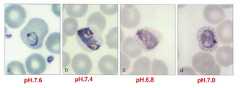
도 8은 표준 김자 염색 프로세스에 따른 김자 염색법을 이용한 염색 결과물의 pH 농도 별 사진이다.
도 9는 본 발명의 실시예에 따른 접촉식 염색 패치를 적용한 김자 염색법을 이용한 염색 결과물의 사진이다.
도 10은 본 발명의 실시예에 따른 접촉식 염색 패치를 적용한 김자 염색법을 이용한 다른 염색 결과물의 사진이다.
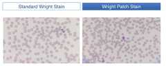
도 11은 라이트 염색법에 대하여 각각 표준 염색법과 접촉식 염색 패치를 접목한 염색법에 따른 결과물을 도시한 도면이다.
도 12은 DAPI 염색법에 대하여 접촉식 염색 패치를 접목한 염색법에 따른 결과물을 도시한 도면이다.
도 13은 메틸렌 블루 패치와 에오신 패치를 접촉시킨 뒤, 버퍼 패치를 접촉시키기 이전에 관찰한 염색 결과를 도시한 도면이다.
도 14는 메틸렌 블루 패치와 에오신 패치를 접촉시킨 뒤, 버퍼 패치를 접촉시킨 이후에 관찰한 염색 결과를 도시한 도면이다.
도 15는 본 발명의 실시예에 따른 테스트 키트의 일 예의 분해사시도이다.
도 16은 본 발명의 실시예에 따른 테스트 키트의 일 예의 결합 사시도이다.
도 17은 본 발명의 실시예에 따른 패치 플레이트의 일 예의 사시도이다.
도 18은 본 발명의 실시예에 따른 홈 형태의 수납부의 일 예의 단면도이다.
도 19 및 도 20은 본 발명의 실시예에 따른 다양한 접촉 유도 수단을 가지는 홈 형태의 수납부의 단면도이다.
도 21은 본 발명의 실시예에 따른 검체 플레이트의 일 예의 사시도이다.
도 22는 본 발명의 실시예에 따른 검체 영역과 비검체 영역 간에 단차가 있는 검체 플레이트의 예의 사시도이다.
도 23은 종래의 혈액 도말 검사 과정에 따른 혈액 도말 방식을 도시한 것이다.
도 24는 본 발명의 실시예에 따른 테스트 키트의 도말부의 단면도이다.
도 25는 본 발명의 실시예에 따른 테스트 키트의 도말부를 이용한 혈액 도말 과정을 도시한 도면이다.
도 26은 본 발명의 실시예에 따른 테스트 키트의 로딩부에 관한 도면이다.
도 27은 본 발명의 실시예에 따른 로딩부를 이용한 검체 로딩에 관한 도면이다.
도 28은 본 발명의 실시예에 따른 승강 가이드를 가진 패치 플레이트의 사시도이다.
도 29는 본 발명의 실시예에 따른 승강 가이드를 가진 검체 플레이트의 사시도이다.1 is a cross-sectional view of a contact type dyeing patch according to an embodiment of the present invention.
2 is a view showing a conventional blood smear inspection process.
FIG. 3 is a diagram illustrating a process of preparing a staining solution and a staining process in a conventional blood smear test process.
4 is a perspective view of a contact type dyeing patch according to an embodiment of the present invention.
5 is a view showing a contact state between a contact type dyeing patch and a sample slide according to an embodiment of the present invention.
FIG. 6 is a diagram illustrating a dyeing process using a contact type dyeing patch according to an embodiment of the present invention.
FIG. 7 is a photograph of the result of dyeing using a standard kimchi dyeing process, that is, a Kimchi dyeing method according to a conventional fluid jetting method.
FIG. 8 is a photograph of the result of dyeing using the Kimchi staining method according to the standard Kimchi dyeing process.
FIG. 9 is a photograph of the result of dyeing using a Kimchi staining method using a contact type dyeing patch according to an embodiment of the present invention.
10 is a photograph of another result of dyeing using a Kimchi staining method using a contact type dyeing patch according to an embodiment of the present invention.
FIG. 11 is a view showing a result obtained by staining using a standard staining method and a contact type staining patch for a light staining method, respectively.
FIG. 12 is a view showing the result of staining according to a DAPI staining method in which a contact type dyeing patch is grafted.
FIG. 13 is a diagram showing the results of staining observed after contacting the methylene blue patch with the eosin patch and before contacting the buffer patch.
14 is a diagram showing the results of staining observed after contacting a methylene blue patch and an eosin patch and then contacting a buffer patch.
15 is an exploded perspective view of an example of a test kit according to an embodiment of the present invention.
16 is an assembled perspective view of an example of a test kit according to an embodiment of the present invention.
17 is a perspective view of an example of a patch plate according to an embodiment of the present invention.
18 is a cross-sectional view of an example of a groove-like receiving portion according to an embodiment of the present invention.
19 and 20 are cross-sectional views of a groove-shaped storage portion having various contact guiding means according to an embodiment of the present invention.
21 is a perspective view of an example of a specimen plate according to an embodiment of the present invention.
22 is a perspective view of an example of a sample plate having a step between a specimen area and a non-specimen area according to an embodiment of the present invention.
FIG. 23 shows a blood smearing method according to a conventional blood smear examination process.
24 is a cross-sectional view of an end portion of a test kit according to an embodiment of the present invention.
25 is a view showing a blood smearing process using the smear unit of the test kit according to the embodiment of the present invention.
26 is a diagram of a loading unit of a test kit according to an embodiment of the present invention.
27 is a diagram illustrating sample loading using a loading unit according to an embodiment of the present invention.
28 is a perspective view of a patch plate having an elevation guide according to an embodiment of the present invention.
29 is a perspective view of a specimen plate having an elevation guide according to an embodiment of the present invention.
본 명세서에 기재된 실시예는 본 발명이 속하는 기술 분야에서 통상의 지식을 가진 자에게 본 발명의 사상을 명확히 설명하기 위한 것이므로, 본 발명이 본 명세서에 기재된 실시예에 의해 한정되는 것은 아니며, 본 발명의 범위는 본 발명의 사상을 벗어나지 아니하는 수정예 또는 변형예를 포함하는 것으로 해석되어야 한다.It is to be understood that both the foregoing general description and the following detailed description are exemplary and explanatory and are intended to be illustrative of the present invention and not to limit the scope of the invention. Should be interpreted to include modifications or variations that do not depart from the spirit of the invention.
본 명세서에서 사용되는 용어는 본 발명에서의 기능을 고려하여 가능한 현재 널리 사용되고 있는 일반적인 용어를 선택하였으나 이는 본 발명이 속하는 기술 분야에서 통상의 지식을 가진 자의 의도, 관례 또는 새로운 기술의 출현 등에 따라 달라질 수 있다. 다만, 이와 달리 특정한 용어를 임의의 의미로 정의하여 사용하는 경우에는 그 용어의 의미에 관하여 별도로 기재할 것이다. 따라서 본 명세서에서 사용되는 용어는 단순한 용어의 명칭이 아닌 그 용어가 가진 실질적인 의미와 본 명세서의 전반에 걸친 내용을 토대로 해석되어야 한다.Although the terms used in the present invention have been selected in consideration of the functions of the present invention, they are generally used in general terms. However, the present invention is not limited to the intention of the person skilled in the art to which the present invention belongs . However, if a specific term is defined as an arbitrary meaning, the meaning of the term will be described separately. Accordingly, the terms used herein should be interpreted based on the actual meaning of the term rather than on the name of the term, and on the content throughout the description.
본 명세서에 첨부된 도면은 본 발명을 용이하게 설명하기 위한 것으로 도면에 도시된 형상은 본 발명의 이해를 돕기 위하여 필요에 따라 과장되어 표시된 것일 수 있으므로 본 발명이 도면에 의해 한정되는 것은 아니다.The drawings attached hereto are intended to illustrate the present invention easily, and the shapes shown in the drawings may be exaggerated and displayed as necessary in order to facilitate understanding of the present invention, and thus the present invention is not limited to the drawings.
본 명세서에서 본 발명에 관련된 공지의 구성 또는 기능에 대한 구체적인 설명이 본 발명의 요지를 흐릴 수 있다고 판단되는 경우에 이에 관한 자세한 설명은 필요에 따라 생략하기로 한다.DETAILED DESCRIPTION OF THE PREFERRED EMBODIMENTS Hereinafter, a detailed description of known configurations or functions related to the present invention will be omitted when it is determined that the gist of the present invention may be obscured.
본 발명의 일 양상에 따르면, 기 염색된 검체와 접촉하여 지적 pH를 형성시키는 접촉식 버퍼 패치로, 상기 염색 시료의 지적 pH와 관련된 미리 정해진 pH값을 가지는 버퍼액; 및 상기 버퍼액을 수용하는 겔 수용체;를 포함하는 접촉식 버퍼 패치가 제공될 수 있다.According to one aspect of the present invention there is provided a contact type buffer patch for contacting with a stained specimen to form an intellectual pH, the buffer solution having a predetermined pH value related to the intellectual pH of the stained specimen; And a gel receptor for receiving the buffer solution.
또 상기 겔 수용체는, 상기 검체와 접촉하는 접촉면을 가지고, 상기 접촉면이 상기 검체와 접촉하면 상기 검체에 상기 염색에 관한 지적 pH를 조성하여 상기 검체와 상기 염색 시료를 반응시킬 수 있다.The gel receptors may have a contact surface in contact with the specimen, and when the contact surface makes contact with the specimen, the specimen may be reacted with the specimen by creating an intellectual pH relating to the specimen.
또 상기 미리 정해진 pH는, 상기 반응에 대한 지적 pH값과 동일한 것을 특징으로 할 수 있다.The predetermined pH may be the same as the intellectual pH value for the reaction.
또 상기 미리 정해진 pH는, 상기 지적 pH가 산성인 경우에는 상기 지적 pH보다 작고, 상기 상기 지적 pH가 염기성인 경우에는 상기 지적 pH보다 큰 것을 특징으로 할 수 있다.The predetermined pH may be characterized by being smaller than the intellectual pH when the intellectual pH is acidic and larger than the intellectual pH when the intellectual pH is basic.
또 상기 미리 정해진 pH와 상기 지적 pH의 차이값은, 상기 겔 수용체의 단단함, 상기 겔 수용체의 공극률, 상기 겔 수용체의 겔 농도 및 상기 겔 수용체의 그물 구조의 조밀도 중 적어도 하나에 따라 결정될 수 있다.The difference between the predetermined pH and the intellectual pH may be determined according to at least one of the rigidity of the gel receptor, the porosity of the gel receptor, the gel concentration of the gel receptor, and the density of the net structure of the gel receptor .
또 상기 겔 수용체는, 하이드로 겔인 것을 특징으로 할 수 있다.Further, the gel receptor may be characterized by being a hydrogel.
또 상기 하이드로 겔은, 아가로스 겔인 것을 특징으로 할 수 있다.The hydrogel may be an agarose gel.
또 상기 겔 수용체는, 아가로스 농도가 1~3%인 것을 특징으로 할 수 있다.The gel receptors may be characterized in that the agarose concentration is 1 to 3%.
또 상기 겔 수용체는, 그 내부에 상기 버퍼액을 수용하는 포어를 형성하는 그물 구조를 가지고, 상기 그물 구조에 의해 상기 버퍼액의 외부 유출 또는 변질을 방지할 수 있다.Further, the gel receptor has a net structure for forming pores for containing the buffer solution therein, and the netting structure can prevent the buffer solution from flowing out or altering the outside.
또 상기 겔 수용체는, 그 내부에 상기 버퍼액을 수용하는 포어를 형성하는 그물 구조를 가지고, 상기 검체에 접촉 시 상기 그물 구조에 의해 상기 버퍼액이 상기 검체로 전달되는 것을 제어하여 상기 검체에 잔류물이 잔류하는 것을 억제할 수 있다.The gel receptor has a net structure for forming a pore for containing the buffer solution therein, and when the sample is contacted with the sample, the gel receptacle controls the delivery of the buffer solution to the sample by the net structure, Water can be restrained from remaining.
또 상기 염색 시료는, 로마노스키 염색액이고, 상기 버퍼액은, pH 6.6~7.6를 가지는 것을 특징으로 할 수 있다.The dyed sample is a Romanosky staining solution, and the buffer solution has a pH of 6.6 to 7.6.
본 발명의 다른 양상에 따르면, 슬라이드에 놓인 검체와 접촉하여 상기 검체를 상기 슬라이드에 고정시키는 접촉식 고정 패치로, 상기 검체를 상기 슬라이드에 고정시키는 검체 고정제; 및 상기 고정제를 수용하는 겔 수용체;를 포함하는 접촉식 고정 패치가 제공될 수 있다.According to another aspect of the present invention, there is provided a contact fixation patch for fixing a specimen placed on a slide to the slide to fix the specimen to the slide, the specimen fixation device fixing the specimen to the slide; And a gel receiver for accommodating the fixing agent can be provided.
또 상기 고정제는, 알코올인 것을 특징으로 할 수 있다.The fixing agent may be an alcohol.
또 상기 겔 수용체는, 비수용성겔(non-hydrogel)인 것을 특징으로 할 수 있다.The gel receptor may be a non-water-soluble gel.
본 발명의 또 다른 양상에 따르면, 기 염색된 검체와 접촉하여 상기 검체를 탈색시키는 접촉식 탈색 패치로, 상기 검체를 염색시킨 염색 시료를 상기 검체로부터 제거하여 상기 검체를 탈색시키는 탈색제; 및 상기 탈색제를 수용하는 겔 수용체;를 포함하는 접촉식 탈색 패치가 제공될 수 있다.According to still another aspect of the present invention, there is provided a contact type bleaching patch for contacting a base stained sample to decolorize the sample to remove the stained sample stained with the sample from the sample to decolorize the sample; And a gel receptacle containing the decoloring agent may be provided.
본 발명의 다시 또 다른 양상에 따르면, 기 염색된 검체와 접촉하여 상기 검체를 매염시키는 접촉식 매염 패치로, 상기 검체를 염색시킨 염색 시료와 반응하여 상기 염색 시료를 발색시키는 매염제; 및 상기 매염제를 수용하는 겔 수용체;를 포함하는 접촉식 매염 패치가 제공될 수 있다.According to still another aspect of the present invention, there is provided a contact mush patch for mushing the specimen in contact with a stained specimen, comprising: a mordant for reacting with the specimen stained with the specimen to develop the stained specimen; And a gel receptacle containing the mordanting agent, may be provided.
본 발명의 다시 또 다른 양상에 따르면, 기 염색된 검체와 접촉하여 상기 검체를 염색시킨 염색 시료의 지적 pH를 형성시키는 접촉식 버퍼 패치의 제조 방법으로, 상기 염색 시료의 지적 pH와 관련된 미리 정해진 pH값을 가지는 버퍼액과 겔화 가능한 분말을 혼합하는 단계; 상기 혼합하는 단계에서 혼합된 혼합물을 가열하는 단계; 상기 혼합물이 겔 상이 되도록 냉각시키는 단계;를 포함하는 접촉식 버퍼 패치의 제조 방법이 제공될 수 있다.According to still another aspect of the present invention, there is provided a method of producing a contact type buffer patch which forms an intellectual pH of a stained sample stained with a stained sample by contacting with the stained sample, comprising the steps of: Mixing a buffer liquid having a value of < RTI ID = 0.0 > 1, < / RTI > Heating the mixed mixture in the mixing step; And cooling the mixture so as to be in a gel phase.
본 발명의 다시 또 다른 양상에 따르면, 염색 시료를 수용하는 겔 상의 염색 패치를 검체와 접촉시켜 상기 검체를 염색 시료로 염색하는 단계; 및 상기 염색 시료의 지적 Ph와 관련된 미리 정해진 pH값을 가지는 버퍼액을 수용하는 겔 상의 버퍼 패치를 상기 검체와 접촉시켜 상기 검체에 상기 염색 시료의 지적 pH를 형성시키는 단계;를 포함하는 염색 방법이 제공될 수 있다.According to yet another aspect of the present invention, there is provided a method of staining a stained sample, comprising: staining a gel staining patch containing a stained sample with a stained sample to stain the stained sample; And a step of contacting the specimen with a gel buffer patch containing a buffer solution having a predetermined pH value related to the cognitive Ph of the dyed specimen to form an intellectual pH of the specimen in the specimen Can be provided.
본 발명의 다시 또 다른 양상에 따르면, 제1 염색 시료와 제2 염색 시료를 포함하는 염색약을 이용하는 염색 방법으로, 상기 제1 염색 시료를 수용하는 겔 상의 제1 염색 패치를 상기 검체와 접촉시켜 상기 검체를 제1 염색 시료로 염색하는 단계; 상기 제2 염색 시료를 수용하는 겔 상의 제2 염색 패치를 상기 검체와 접촉시켜 상기 검체를 제2 염색 시료로 염색하는 단계; 및 상기 염색약의 지적 pH와 관련된 미리 정해진 pH값을 가지는 버퍼액을 수용하는 겔 상의 버퍼 패치를 상기 검체와 접촉시켜 상기 검체에 상기 염색약의 지적 pH를 조성하는 단계;를 포함하는 염색 방법이 제공될 수 있다.According to still another aspect of the present invention, there is provided a dyeing method using a dyeing agent comprising a first stain sample and a second stain sample, wherein a gel stain patch containing the first stain sample is contacted with the sample, Staining a specimen with a first staining sample; Contacting a gel-colored second staining patch containing the second stained sample with the specimen to stain the specimen with a second stained specimen; And contacting the specimen with a gel buffer patch containing a buffer solution having a predetermined pH value related to the intellectual pH of the dye, so as to form an intellectual pH of the dye on the specimen .
또 상기 조성하는 단계는, 상기 제1 염색 시료로 염색하는 단계와 상기 제2 염색 시료로 염색하는 단계 사이의 제1 시점 및 상기 제2 염색 시료로 염색하는 단계 이후의 제2 시점 중 적어도 하나의 시점에 수행될 수 있다.The forming step may further include a step of forming at least one of a first point of time between the step of staining with the first staining sample and the step of staining with the second staining sample and the second point of time after staining with the second staining sample Lt; / RTI >
또 상기 조성하는 단계에서, 상기 버퍼 패치는, 상기 검체에 먼저 반응한 제1 시료를 일부 흡수하여 상기 제2 시료와 상기 검체의 반응을 유도할 수 있다.Further, in the forming step, the buffer patch may partially absorb the first sample reacted first to the specimen to induce the reaction between the second specimen and the specimen.
1. 접촉식 염색 패치1. Contact dyeing patch
1.1. 겔 상의 접촉식 염색 패치1.1. Gel touch dyed patch
이하에서는 본 발명의 실시예에 따른 접촉식 염색 패치(100)에 관하여 설명한다.Hereinafter, a contact
본 발명의 실시예에 따른 접촉식 염색 패치(100)는 검체(T)와 접촉하여 이를 염색할 수 있다.The contact
예를 들어, 접촉식 염색 패치(100)는 1) 염색하고자 하는 대상을 염색 시료(140)를 직접 반응시켜 염색하는 1-1) 말라리아 검진에 이용되는 말초 혈액 도말 검사를 비롯한 혈액 도말 검사에 수반되는 김자 염색법(Giemsa stain)이나 라이트 염색법(Wright stain), 1-2) 세균 검사에 수반되는 단순 염색법(simple stain)이나 그람 염색법(Gram stain), AFB [Ziehl-Neelsen] 염색법은 물론, 2) 자궁경부암을 조사하는데 주로 이용되는 파파니콜라우(Papanicolaou) 도말 검사, 3) DAPI와 같은 형광 염색법, 4) 항원-항체 반응을 이용하여 동위 원소나 형광 물질 또는 효소 등과 결합된 항체를 이용하여 검출하고자 하는 대상이 방사선 검출, 형광 발색, 효소에 의한 간접 발색시키는 4-1) 암 검사 등에 이용되는 특수한 염색법인 면역 화학 염색법(immunohistochemistry)이나 4-2) 인간 면역 결핍 바이러스(HIV: human immunodeficiency syndrome) 검사에 이용되는 효소결합 면역흡착 분석법(ELISA: Enzyme Linked Immunosorbent Assay), 5) DNA 상의 특정 염기 서열을 확인하기 위하여 대상 염기 서열에 상보적인 DNA 프로브에 형광 물질을 결합시켜 이를 검출하는 형광 동소 보합법(FISH: Fluorescence In Situ Hybridization) 및 6) 항원-항체 반응을 이용한 침전법이나 응집법 등에까지 다양하게 이용될 수 있다.For example, the contact
본 발명에서 접촉식 염색 패치(100)의 "염색"이란, 검체(T)에서 검출하고자 하는 대상을 직접적으로 염색시키는 것에 국한되어 해석되는 것은 아니며, 상술한 바와 같이 검출 대상을 형광 발색시키거나 방사선 검출이 가능케 하거나 효소에 의해 특정 기질에 투입된 경우 반응 발색케 하거나, 응집이나 침전을 유도하여 검출이 가능토록 하는 등 검체(T)로부터 특정 대상 물질을 검출, 확인 가능케 하는 모든 방법을 포괄적으로 아우르는 단어로 해석되어야 한다.In the present invention, "dyeing" of the contact
다시 말해, 본 발명에서 접촉식 염색 패치(100)는 검사하고자 하는 물질을 검체(T)로부터 검출 가능한 상태로 만드는 기능을 하는 것으로, 그 실질적인 기술적 사상에 따르면 접촉식 "검출 유도" 패치가 보다 명확한 표현이겠으나, 본 발명에 대한 설명과 이해의 편의를 돕기 위하여 필요에 따라 접촉식 "염색" 패치라는 용어를 포괄적인 의미로 이용하기로 한다.In other words, in the present invention, the contact
따라서, 이와 유사하게 본 발명의 명세서 전반에 걸쳐 "염색"이라는 용어 역시 검출 대상에 대한 직접적인 염색이라는 협의의 의미가 아닌 형광 발색, 발색 유도, 방사선 검출 유도, 침전, 응집이나 그 이외의 검출이 가능한 상태로 유도하는 모든 "검출 유도"를 포괄하는 넓은 의미로 해석됨이 마땅할 것이다.Similarly, the term "dyeing" throughout the specification of the present invention is also applicable to detection of fluorescent dye, induction of color development, induction of radiation, precipitation, aggregation or other detection It should be interpreted broadly to encompass all "detection induction"
한편, 이와 함께 검체(T)란 검사 대상이 되는 물질로, 혈액이나 세포, 조직, 염색체, DNA, 또는 기생충이나 세균 등 의료 검사의 대상이 되는 모든 바이오 샘플을 아우르는 것으로 해석됨이 타당하다.Together with this, the sample (T) is a substance to be examined and is understood to include all the bio-samples to be subjected to medical tests such as blood, cells, tissues, chromosomes, DNA, or parasites or bacteria.
접촉식 염색 패치(100)를 이용한 검체(T)의 염색은 다음과 같이 이루어질 수 있다.The staining of the specimen (T) using the contact type dyeing patch (100) can be carried out as follows.
먼저 접촉식 염색 패치(100)는 겔(gel) 상으로 제공되며, 그 내부의 포어(122)에 염색 시료(140)를 보관한다. 이 상태에서 접촉식 염색 패치(100)를 검체(T)와 접촉시키면, 내부 포어(122)의 염색 시료(140)가 겔 매트릭스의 그물 구조를 거쳐 검체(T)으로 이동하여 염색 대상 물질을 염색시킨다.First, the contact
1.1.1. 접촉식 염색 패치의 기본 조성1.1.1. Basic composition of contact dyeing patch
도 1은 본 발명의 실시예에 따른 접촉식 염색 패치(100)의 단면도이다.1 is a cross-sectional view of a contact
도 1을 참조하면, 접촉식 염색 패치(100)는 겔 수용체(120) 및 염색 시료(140)를 포함할 수 있다.Referring to FIG. 1, the contact
겔 수용체(120)는 그 내부에 포어(122)를 형성하는 다공성의 그물 구조를 가지는 겔 상의 물질로 제공된다. 겔 수용체(120)의 포어(122)는 염색 시료(140)를 수용할 수 있다.The
겔 수용체(120)는 겔 메트릭스를 형성하는 다양한 겔로 제공될 수 있다. 예를 들어, 겔 수용체(120)는 아가로스(agarose)로 만들어진 겔일 수 있다. 여기서, 아가로스 대신 아가(agar)를 사용하는 것도 가능하다. 아가와 아가로스를 비교하면, 아가로부터 폴리락토스(polygalactose) 성분을 정제한 아가로스로 만들어진 겔 수용체(120)가 투명도나 굳기 제어면에서 뛰어난 장점이 있으나, 아가를 사용하는 경우에는 정제 과정 등을 생략할 수 있어 대량 생산 시 코스트 측면에서 장점이 있을 수 있다.The
이외에도 실리콘 겔, 실리카 겔(silica gel), 실리콘 고무, 수지의 주성분으로서 알려진 PDMS(PolyDiMethylSiloxane) 겔, PMMA(polymethylmethacrylate) 겔 및 그 외의 다양한 소재를 이용한 겔이 겔 수용체(120)로 이용될 수 있다.In addition, gels using silicone gel, silica gel, silicone rubber, PDMS (polyDiMethylSiloxane) gel known as a main component of resin, PMMA (polymethylmethacrylate) gel and various other materials can be used as
겔 수용체(120)는 주로 수용액 형태인 염색 시료(140)를 잘 머금을 수 있는 하이드로겔(hydrogel)을 이용하는 것이 가능하나, 필요에 따라서는 이와 달리 비수용성(non-hydrogel)을 이용할 수도 있다.The
염색 시료(140)는 검체(T)와 반응하여 이를 염색하는 물질이다. 여기서, 염색 시료(140)는 직접 검체(T)를 염색하는 염색 시약 뿐만 아니라 염색 물질이나 형광 물질 등이 결합된 항체나 DNA 프로브 등 상술한 접촉식 염색 패치(100)가 이용될 수 있는 염색 방법의 예시들에서 염색 대상 물질과 반응하여 염색 대상을 검출 가능케하는 물질을 모두 아우르는 포괄적인 의미로 해석되어야 한다.The
예를 들어, 염색 시료(140)는 아세트산카민, 멜틸렌블루, 에오신, 산성 훅신, 사프라닌, 야누스그린 B, 헤모톡실린, 김자액, 라이트액, 라이트-김자액 등과 같은 로마노스키 염색법(Romanowsky stain)에 이용되는 염색액, 리슈먼 염색액, 그램 염색액, 카르볼푹신, Ziehl액 등의 다양한 염색액을 포함할 수 있다.For example, the stained
다른 예를 들어, 염색 시료(140)는 DAPI(4,6-diamidino-2-phenylindole) 형광 색소, 형광 물질과 결합한 DNA 프로브, 효소나 형광 물질, 동위 원소 등과 결합한 항체를 포함할 수도 있다. 물론, 염색 시료(140)가 상술한 예로 한정되는 것은 아니며, 이미 언급한 바와 같이 염색 대상 물질과 반응하여 검출 가능케 유도하는 어떠한 물질이어도 무방하다.For example, the stained
포어(122)에는 단일의 염색 시료(140) 또는 둘 이상의 염색 시료(140)가 혼합되어 저장될 수 있다.A
예를 들어, 접촉식 염색 패치(100)를 이용하여 단순 염색(simple stain, 세균 등을 슬라이드(S)에 고정한 후 한가지 염색 시료(140)로 염색하는 방법)을 수행하고자 하는 경우에는, 포어(122)에는 하나의 염색 시료(140)가 저장될 수 있다. 이때, 염색 시료(140)로는 메틸렌블루(Methylene blue), 크리스탈 바이올렛(Crystal violet), 사프라닌(Safranin) 등이 사용될 수 있다. 이와 유사하게 특정 염기 서열만을 검출하기 위해 접촉식 염색 패치(100)를 이용하고자 하는 경우에는 특정 염기 서열에 대응하는 단종의 DNA 프로브에 형광 물질과 같은 검출 유도 물질을 결합시킨 단일의 염색 시료(140)를 이용할 수 있다.For example, when a simple stain (a method of fixing a bacterium or the like on a slide S and then staining with a single stained sample 140) is performed using a contact
위의 예와 달리, 접촉식 염색 패치(100)를 이용하여 김자 염색을 수행하고자 하는 경우에는, 세포질을 적염시키는 에오신과 핵을 자염시키는 메틸렌 블루의 이종 염색 물질로 구성되는 복합 시료가 염색 시료(140)로 이용될 수 있다. 즉, 포어(122)에는 에오신인 제1 염색 시료(140-1)과 메틸렌 블루인 제2 염색 시료(140-2)가 혼합되어 저장될 수 있다.Unlike the above example, when the
물론, 복합 시료를 염색 시료(140)로 이용하는 염색법에서는 상술한 바와 같이 포어(122)에 복수의 염색 시료(140)를 혼합하여 담는 대신 단일의 염색 시료(140)을 담는 접촉식 염색 패치(100)를 여러 개 이용하는 것도 가능하다. 예를 들어, 김자 염색을 수행하고 하려는 경우에는 에오신 패치(에오신을 제1 염색 시료(140-1)로 저장하는 제1 접촉식 염색 패치(100-1))와 메틸렌 블루 패치(메틸렌 블루를 제2 염색 시료(140-2)로 저장하는 제2 접촉식 염색 패치(100-2))와 같은 식으로, 염색 시료(140)를 각각 별개의 접촉식 염색 패치(100)에 분할 저장하는 것도 가능하다.Of course, in the staining method using the complex sample as the
1.1.2. 접촉식 염색 패치의 버퍼액1.1.2. Buffer solution of contact dyeing patch
염색 시료(140)는 필요에 따라 용매에 용해된 형태로 겔 수용체(120)의 포어(122)에 수용될 수 있다. 여기서, 용매로는 염색 시료(140)와 염색 대상 물질 간의 반응 시 반응 조건을 조성하는 버퍼액(B)을 이용할 수 있다.The
버퍼액(B)은 염색 반응 시에 염색 대상과 염색 시료(140) 간의 반응이 잘 일어나도록 반응 환경을 조성하는 역할을 한다. 예를 들어, 김자 염색 등과 같은 염색 반응에서는 염기성의 메틸렌 블루가 음전하를 띄는 세포 핵과 결합하여 이를 염색하고 산성의 에오신은 세포질을 염색하므로 pH 농도가 염색 결과와 밀접하게 관련되며, 이로 인해 염색이 올바르게 되기 위해서는 적절한 pH 농도를 조성하는 것이 매우 중요할 수 있다. 따라서, 이러한 경우 버퍼액(B)은 접촉식 염색 패치(100)의 염색 시료(140)를 이용한 반응에 대한 지적 pH를 유지하는 pH 완충액일 수 있다.The buffer solution (B) serves to create a reaction environment so that the reaction between the dyeing object and the
버퍼 패치에 관한 설명에서도 후술하겠지만, 이러한 버퍼액(B)으로는 그 pH 농도가 염색 반응의 지적 pH와 동일한 것을 이용할 수 있다.As will be described later in the description of the buffer patch, it is also possible to use the same buffer solution (B) whose pH is the same as the intellectual pH of the dyeing reaction.
또는 버퍼액(B)으로는 그 pH 농도가 염색 반응의 지적 pH와 다소 상이한 것을 이용할 수 있다. 기존의 염색 프로세스에서 버퍼 단계에서 버퍼액(B)을 다량으로 염색된 검체(T)에 분사하여 지적 pH를 맞추는 것과는 달리 접촉식 염색 패치(100)에서의 버퍼액(B)은 겔 수용체(120) 내에 함유되며, 접촉식 염색 패치(100)와 검체(T)의 접촉 과정에서 염색 반응의 지적 pH를 맞춰준다. 여기서,겔 수용체(120)에 버퍼액(B)이 함유되는 경우에는 염색 시료(140) 등과 반응하여 그 pH가 다소 조정될 수 있다. 구체적인 예를 들면, 김자 염색약을 염색 시료(140)로 사용하는 접촉식 염색 패치(100)의 경우에는 버퍼액(B)의 pH가 접촉식 염색 패치(100)의 제조되기 전보다 접촉식 염색 패치(100)로 제조된 뒤에 다소 간 상승하게 된다. 이는 버퍼액(B)과 염색 시료(140), 그리고 겔 수용체(100) 간에 상호 작용에 의한 요소와 기존의 액상 분사형 대신 겔 접촉형으로 버퍼 작용을 시킬 때 실질적으로 작용하는 pH가 다소 상이해짐이 그 원인이다. 다시 김자 염색을 위한 접촉식 염색 패치(100)에 대해서는 원료 버퍼액(B)의 pH보다 접촉식 염색 패치(100)에 함유되는 버퍼액(B)의 pH가 약 0.1~0.4 가량 상승할 수 있다. 만약 원하는 반응의 지적 pH 6.8인 경우라면, 버퍼액(B)은 그 pH가 약 6.4~6.7의 pH농도를 가지는 것을 이용할 수 있다. 버퍼액(B)의 pH를 이용하여 접촉식 염색 패치(100)의 지적 pH를 맞추는 것에 대한 설명은 후술되는 버퍼 패치 부분에서 보다 명확히 설명될 것이다.Or the pH value of the buffer solution (B) is slightly different from the intellectual pH of the dyeing reaction. The buffer solution B in the contact
구체적으로 약 6.5pH를 가진 버퍼액(B)을 이용하여 제조한 김자 염색용 접촉식 염색 패치(100)를 기 염색된 검체(T)에 접촉시킨 뒤 염색된 검체(T)를 관측하면, 실제로는 약 6.6~6.9pH의 버퍼액(B)을 기 염색된 검체(T)에 분사한 것과 유사한 염색 결과가 관측되었다.Specifically, when a stained specimen (T) is observed after contacting a stained specimen (T) with a contact dyeing patch (100) for kimchi staining prepared using a buffer solution (B) having a pH of about 6.5 pH, (B) of about 6.6 to 6.9 pH was injected into the stained specimen (T).
다시 말해, 특정 pH값을 가지는 버퍼액(B)을 이용하여 제조한 접촉식 염색 패치(100)의 실효 pH는 버퍼액(B) 자체의 pH값과 다소 상이하게 변성될 수 있다. 여기서, 실효 pH란 검체(T)와 패치 간의 반응 시에 느껴지는 pH로서, 이를 테면, 액상의 버퍼액(B)을 검체에 분사하는 경우에 검체(T)에 조성되는 pH일 수 있다.In other words, the effective pH of the contact
따라서, 접촉식 염색 패치(100) 제조 시에는 그 실효 pH값이 염색법의 지적 pH값과 실질적으로 동일해지도록 버퍼액(B)의 pH를 조정할 필요가 있다.Therefore, when manufacturing the contact
즉, 버퍼 패치에 이용될 버퍼액(B) 자체의 pH값은 종래의 염색법에서 정의될 수 있는 염색이 잘되도록 하는 지적 pH값에 대하여 겔 매트릭스 내에서 겔과 염색 시료, 그리고 버퍼액(B) 간의 상호 작용에 의해 편향되는 pH를 고려한 보정 pH값만큼을 보정한 값으로 세팅될 수 있다.That is, the pH value of the buffer solution (B) itself to be used in the buffer patch can be determined by comparing the gel and dye samples and the buffer solution (B) in the gel matrix with the intellectual pH value, The correction value can be set to a value obtained by correcting the corrected pH value in consideration of the pH deflected by the interaction between the two.
이때, 보정 pH값은 겔의 특성, 염색 시료의 종류, 버퍼액(B)에 대한 염색 시료나 겔 물질의 양 등에 따라 결정될 수 있다.At this time, the corrected pH value can be determined according to the characteristics of the gel, the kind of the dye sample, the amount of the dye sample or the gel material with respect to the buffer solution (B), and the like.
여기서, 겔의 특성에 관해서는, 보정 pH값의 크기(즉, 절대값)은 겔 수용체(120)의 겔의 농도, 하드니스, 공극률, 그물 구조의 조밀도 등에 따라 증감될 수 있다. 예를 들어, 겔 수용체(120)의 겔 농도가 커질수록 보정 pH의 크기가 커지고 겔 농도가 낮아질수록 보정 pH의 크기는 작아질 수 있다. 또 예를 들어, 겔 수용체(120)로 아가로스 겔을 이용하는 경우 아가로스의 농도가 높아지면, 보정 pH값의 크기가 커지고 아가로스의 농도가 낮아지면 보정 pH값은 작아질 수 있다. 또 겔 수용체(120)가 단단해질수록 보정 pH의 크기가 커지고 물렁해질수록 보정 pH의 크기가 작아질 수 있다. 또 겔 수용체(120)의 공극률이 커질수록 보정 pH의 크기는 작아지고 공극률이 작아질수록 보정 pH의 크기는 커질 수 있다. 또 겔 수용체(120)의 그물 구조의 조밀도가 커질수록 보정 pH의 크기는 커지고 조밀도가 낮아질수록 보정 pH의 크기는 작아질 수 있다.Here, regarding the characteristics of the gel, the magnitude (i.e., absolute value) of the corrected pH value can be increased or decreased depending on the concentration of the gel of the
또, 염색 물질에 대한 상호 작용에 관해서는 버퍼액(B)에 대한 염색 물질의 양이 클수록 ph 쉬프트가 크게 일어날 수 있으며, 산성 방향으로 쉬프티될지 염기성 방향으로 쉬프트될지는 염색 물질의 종류에 따라 정해질 수 있다. 김자 염색 물질의 경우에는 PBS 버퍼액에 대하여 염기성 방향으로 약 pH0.1~0.4 가량의 pH 쉬프트를 초래할 수 있다. 이는 버퍼액 대비 염색 물질의 양이 커질수록 더 크게 쉬프트될 수 있으며, 염색 물질의 종류가 변하면 염기성 방향으로 쉬프트될 수도 있다.With respect to the interaction with the dyeing material, the larger the amount of the dyeing material to the buffer solution (B), the greater the pH shift. In the case of the dyeing material which is shifted in the acid direction or shifted in the basic direction, . In the case of a Kimja dye, the pH shift may be about 0.1 to 0.4 in the basic direction with respect to the PBS buffer solution. The larger the amount of the dyeing material to the buffer solution, the greater the shift can be, and if the type of the dyeing material is changed, it may be shifted in the basic direction.
이상에서 설명한 본 발명의 실시예에 따른 접촉식 염색 패치(100)에서 겔 수용체(120)는 염색 시료(140)의 보관 기능을 수행한다. 여기서, 보관이란 1) 겔 수용체(120)가 그 내부에 저장되는 염색 시료(140)가 외부에 유출되지 않도록 하고 2) 염색 시료(140)과 외부로부터 오염되지 않도록 하는 것을 의미한다. 이러한 보관 기능은 1) 겔 수용체(120)의 겔 매트릭스의 구조적 성질과 2) 겔 수용체(120) 및 염색 시료(140)의 전기화학적 성질에 의한 것이다.In the contact
겔 수용체(120)의 구조적 특징에 의한 보관 기능은 겔 수용체(120)의 그물 구조에 의해 포어(122)에 수용된 염색 시료(140)가 겔 수용체(120)의 표면까지 이동하는 것이 억제됨에 따라 이루어질 수 있다. 이에 대하여 구체적으로 설명하면 다음과 같다.The storage function by the structural characteristic of the
겔 수용체(120)는 그물 구조로써 포어(122)를 형성하여 염색 시료(140)가 겔 수용체(120)의 내부에 수용되도록 할 수 있다. 이때, 포어(122) 내의 염색 시료(140)가 외부로 빠져나가기 위해서는 포어(122)로부터 겔 수용체(120)의 표면까지 이동해야 하는데, 이 과정에서 그물 구조를 거쳐야 하므로 내부 포어(122)에 수용된 염색 시료(140)가 외부로 유출되는 것을 방지할 수 있다. 다시 말해, 겔 수용체(120)의 그물 구조가 포어(122)에 수용된 염색 시료(140)가 겔 수용체(120)의 표면을 통해 증발되거나 유출되기 것을 억제하는 것이다. 또 이와 반대로, 염색 시료(140)가 오염되기 위해서는 외부로부터 오염 물질이 겔 수용체(120)의 표면을 거쳐 겔 수용체(120)의 내부 포어(122)까지 이동해야 하는데, 겔 수용체(120)의 그물 구조는 이 과정에서 이물질이 겔 수용체(120)의 내부로 유입되는 것을 억제하여 겔 수용체(120) 내부의 염색 시료(140)가 오염되는 것을 방지할 수 있다.The
또 겔 수용체(120)의 전기화학적 성질에 의한 보관 기능은 겔 수용체(120)와 염색 시료(140) 사이의 전기화학적 반응성에 의해 이루어질 수 있다. 예를 들어, 겔 수용체(120)의 포어(122)에 저장된 염색 시료(140)가 수용액 형태라면, 겔 수용체(120)를 친수성 겔로 준비함으로써 염색 시료(140)가 겔 수용체(120)로부터 외부로 빠져나가는 것을 억제할 수 있다. 또 이러한 겔 수용체(120)의 성질에 따라 반대 성질의 물질은 외부로부터 겔 수용체(120) 내부로 침입하지 못하게 되므로(예를 들어, 소수성 오염 물질은 친수성 겔 수용체(120) 내부로 침입이 억제된다) 내부에 저장된 염색 시료(140)가 오염으로부터 차단될 수 있다.Also, the electrochemical property of the
또한, 겔 수용체(120)의 보관 기능은 단순히 염색 시료(140)의 유출이나 오염만을 방지하는 것에 그치는 것은 아니다. 혈액 도말 검사에서 혈액을 원활히 염색하기 위해서는 염색 시의 반응 조건이 매우 중요하다. 예를 들어, 적절한 pH 농도가 갖추어지지 않은 경우에는 염색 시료(140)와 혈액 간의 반응이 제대로 이루어지지 않게 되어 오염색된 혈액을 현미경으로 관찰하게 되고 결과적으로 검사에 오류가 발생할 수 있다.In addition, the function of storing the
이에 대해 본 발명에서는 염색 시료(140)가 적절한 반응 조건을 갖춘 상태로 겔 수용체(120)의 포어(122)에 수용될 수 있으며, 겔 수용체(120)는 반응 조건을 유지하면서 염색 시료(140)를 보관할 수 있다. 예를 들어, 김자(Giemsa) 염색의 경우에는 pH7.2의 조건에서 이루어지는데, 이를 위해 겔 수용체(120)의 포어(122)에는 김자 염색을 위한 염색 시료(140)가 pH7.2인 수용액 상태로 저장될 수 있으며, 겔 수용체(120)의 그물 구조에 의해 염색 시료(140)나 수용액의 외부로 유출과 외부의 물질에 의한 오염 등의 방지되므로, 김자 염색을 위한 염색 시료(140)는 겔 수용체(120) 내부에 pH7.2 상태를 유지하는 수용액 상태로 보관될 수 있다.In contrast, in the present invention, the
이와 같은 접촉식 염색 패치(100)는 염색 시료(140)를 원하는 반응 조건이 유지된 상태로 장기간 보호할 수 있는 장점이 있다. 이는 기존의 염색법을 이용하는 경우 염색 시료(140)의 반응 조건을 염색 시행 시마다 맞춰주어야 하는 것과 비교하여 큰 장점이다.The contact
1.1.2. 접촉식 염색 패치의 첨가 조성1.1.2. Added composition of contact dyeing patch
한편, 접촉식 염색 패치(100)에는 다양한 첨가 조성이 추가로 포함될 수 있다. 이들의 추가적인 첨가 조성은 염색 시료(140)와 유사하게 겔 수용체(120)의 포어(122)에 수용되어 접촉식 염색 패치(100)에 함유될 수 있다.On the other hand, the contact
일 예로, 접촉식 염색 패치(100)에는 증발 방지제가 포함될 수 있다. 증발 방지제는 겔 수용체(120) 내부의 염색 시료(140)가 증발에 의해 외부로 유출되는 것을 방지하는 역할을 할 수 있다. 상술한 바와 같이 수용액 상태 등으로 겔 수용체(120)의 포어(122)에 보관되는 염색 시료(140)는 겔 메트릭스 구조나 겔 수용체(120)의 수용성 성질에 의해 외부 유출이 어느 정도 억제되지만, 겔 수용체(120)에 증발 방지제를 함유시킴으로써 접촉식 염색 패치(100)의 성능을 유지하면서 장기간 보관하는 것이 가능해진다. 이러한 증발 방지제는 5% 이하의 중량비를 가질 수 있으며, 바람직하게는 1% 중량비 이하를 가질 수 있다.As an example, the contact
다른 예로는, 접촉식 염색 패치(100)에는 변질 방지제가 포함될 수 있다. 변질 방지제는 접촉식 염색 패치(100)에서 박테리아가 증식하는 것을 방지하는 방부제나 항생제 등과 같이 접촉식 염색 패치(100) 내부의 염색 시료(140)가 다양한 원인에 의해 변질되는 것을 방지하는 기능을 수행한다. 겔 수용체(120)가 노출되면, 그 내부에서 박테리아나 세균 등이 증식하게 되어 결과적으로 염색 시료(140) 등이 오염되어 성능이 저하될 수 있는데, 접촉식 염색 패치(100)에 변질 방지제를 첨가하면 접촉식 염색 패치(100)의 유통 기간을 늘릴 수 있다.As another example, the contact
1.2. 접촉식 염색 패치를 이용한 염색 프로세스1.2. Dyeing process using contact dyeing patch
도 2는 종래의 혈액 도말 검사 과정을 도시한 도면이고, 도 3은 종래의 혈액 도말 검사 과정 중 염색 과정에 관한 도면이다.FIG. 2 is a view showing a conventional blood smear inspection process, and FIG. 3 is a diagram showing a staining process during a conventional blood smear inspection process.
도 2를 참조하면, 종래의 혈액 도말 검사는 다음과 같이 수행되어 왔다. 먼저 염색 용액 등의 반응 물질을 준비한다. 다음으로는 슬라이드(S) 상에 혈액을 투입하고, 이를 도말한다. 슬라이드(S)에 혈액이 도말되면 이를 고정한 뒤 건조시킨다. 도말 혈액의 고정은 주로 화학적 고정 방식을 이용할 수 있다. 슬라이드(S)에 도말된 혈액이 고정되면 염색 용액을 부어 혈액을 염색한다. 이때, 혈액에 염색 용액을 붓게 되므로 다량의 염색 용액이 혈액에 섞여 있으므로 이를 세척한 뒤 다시 건조시킨다. 이러한 과정을 거치면 슬라이드(S) 상의 염색된 혈액을 현미경 등을 통해 관측하여 혈액 도말 검사를 할 수 있다.Referring to FIG. 2, the conventional blood smear test has been performed as follows. First, a reaction material such as a dyeing solution is prepared. Next, the blood is put on the slide S, and the blood is smudged. If the blood is smudged on the slide (S), fix it and dry it. Immobilization of smear blood can be mainly performed by chemical immobilization. When the blood smears on the slide (S) are fixed, the staining solution is poured to stain the blood. At this time, since the dye solution is poured into the blood, a large amount of dye solution is mixed with the blood, so it is washed and dried again. Through this process, the blood stained on the slide (S) can be observed through a microscope or the like to perform blood smear test.
도 3을 참조하면, 종래의 혈액 도말 검사에서는 혈액이 도말된 슬라이드(S)에 염색 용액을 분사하는 형태로 염색을 수행하는데, 이를 위해 분말 형태의 염색 시료(140)를 이용하여 즉석에서 염색 용액을 제조해야 했다. 따라서, 염색 시료(140)와 용매의 비율을 맞추기 위해서는 숙련자의 수작업이 필요하거나 또는 적정 비율의 혼합을 위한 별도의 장비가 필요했다. 뿐만 아니라 염색 용액을 사전 제조한 경우에는 1) 미리 제조한 염색 용액이 공기와 접촉해 반응하거나 또는 2) 염색 용액 내부에서 용매와 염색 시료(140) 간의 반응이 일어나거나 또는 3) 복수의 염색 시료(140)를 혼합해 염색 용액을 제조하여 사용하는 경우에 이종의 염색 시료(140) 간에 반응이 일어날 수 있으며, 이에 따라 염색 용액이 오염되거나 또는 적절한 반응 조건을 유지하지 못하기 때문에 염색 용액을 제조 후 단시간 내에만 사용할 수 있었다.Referring to FIG. 3, in the conventional blood smear test, a dyeing solution is sprayed on a slide (S) on which blood is smudged. For this purpose, a dyeing sample (140) . Therefore, in order to match the ratio of the
이에 대해 본 발명의 실시예에 따른 접촉식 염색 패치(100)는 그 겔 수용체(120)에 그물 구조가 형성하는 내부 포어(122)에 염색 시료(140)를 원하는 반응 조건을 유지한 상태로 보관하므로, 검사 현장에서 염색 시료(140)와 용매를 혼합하여 염색 용액을 제조하는 대신 사전에 접촉식 염색 패치(100)를 제작하는 것이 가능하며 또 이를 장기간에 걸쳐 검사에 이용할 수 있게 되는 것이다.On the contrary, in the contact
도 4는 본 발명의 실시예에 따른 접촉식 염색 패치(100)의 사시도이고, 도 5는 본 발명의 실시예에 따른 접촉식 염색 패치(100)와 검체 슬라이드(S)의 접촉 상태를 도시한 도면이다.FIG. 4 is a perspective view of a contact
도 4를 참조하면, 접촉식 염색 패치(100)의 형상은 겔 수용체(120)의 형상에 의해 정의될 수 있는데, 적어도 일면에 검체(T)와 접촉하기 위한 접촉면(102)을 가질 수 있다. 여기서, 접촉면(102)은 검체(T)와 직접 접촉하는 면으로, 슬라이드(S) 상에 도말된 검체(T)와의 접촉이 용이하도록 평면인 것이 바람직할 수 있다. 일 예로, 접촉식 염색 패치(100)는 도 4에 도시된 바와 같이 기둥 형태로 제공될 수 있으며, 이러한 원 기둥 형태에서는 기둥의 상면 및 하면 중 일면이 접촉면(102)이 될 수 있다.Referring to FIG. 4, the shape of the
도 5를 살펴보면, 도 4에 도시된 접촉식 염색 패치(100)의 상면에 검체(T)가 도말된 슬라이드(S)를 안착시키거나 반대로 검체(T)가 도말된 슬라이드(S) 상에 염색 패치를 안착시키는 식으로 접촉식 염색 패치(100)와 검체(T)를 접촉시키는 것을 볼 수 있다.5, the slide S on which the specimen T is coated is placed on the upper surface of the contact
한편, 접촉식 염색 패치(100)의 형상이 도 4에 도시된 형태로 한정되는 것은 아니며, 접촉면(100)이 복수인 것도 가능하다. 예를 들어, 접촉식 염색 패치(100)는 육면체 형상으로 제작되고, 각 면들 중 하나 또는 복수의 면이 접촉면(100)을 이용될 수 있다. 다른 예를 들어, 접촉식 염색 패치(100)는 그 바닥면이 접촉면(100)이 되는 반구 형상으로 제조되는 것도 가능하다.On the other hand, the shape of the contact
도 6은 본 발명의 실시예에 따른 접촉식 염색 패치(100)를 이용한 염색 과정에 관한 도면이다.FIG. 6 is a diagram illustrating a dyeing process using the contact
도 6을 참조하면, 접촉식 염색 패치(100)는 슬라이드(S)에 도말된 검체(T)와 접촉될 수 있다. 다시 말해, 겔 수용체(120)의 접촉면(102)이 검체(T)와 직접적으로 접촉될 수 있다. 접촉이 이루어지면, 검체(T) 또는 염색 시료(140)와 반응하는 검체(T) 내의 특정 성분과 겔 수용체(120) 내부에 저장된, 즉 내부 포어(122)에 수용된 염색 시료(140) 간의 전기화학적 작용에 의해 염색 시료(140)가 그물 구조를 통과하여 접촉면을 통해 검체(T)로 이동하게 된다. 검체(T)로 이동한 염색 시료(140)는 검체(T) 또는 검체(T) 내의 특정 성분과 반응하여 이를 염색시킬 수 있다.Referring to FIG. 6, the contact
이때, 염색 시료(140)는 겔 수용체(120) 내부에 반응 조건을 유지한 상태로 저장되어 있으므로 별도로 반응 조건을 조정하지 않아도 염색이 원활하게 수행될 수 있다.At this time, since the
한편, 염색 시료(140)와 검체(T) 또는 검체(T) 내의 특정 성분 간에 작용하는 힘에 의해 염색 시료(140)가 겔 수용체(120)의 그물 구조를 통과하여 검체(T)로 이동하기는 하지만, 그물 구조에 의해 다소간 이동에 제약을 받는 상태에서 이동이 이루어지므로 염색 시료(140)나 염색 용액이 과도하게 다량으로 검체(T)에 이동하는 것이 방지될 수 있다.On the other hand, the
여기서, 염색 시료(140)나 염색 용액이 검체(T)로 이동하는 양은 그물 구조의 조밀도나 겔의 유동성, 다공성의 정도 등을 조정하는 것에 의해 제어될 수 있다. 즉, 겔의 단단함(hardness)를 적절히 조절함으로써 접촉식 염색 패치(100)로부터 검체(T)로 적절한 양의 염색 시료(140)만이 전달되도록 할 수 있다.Here, the amount of the
예를 들어, 말초 혈액 도말 검사용으로 아가로스 겔을 이용하여 김자 염색을 위한 접촉식 염색 패치(100)를 제조하는 경우에, 아가로스의 농도는 바람직하게는 1~5%일 수 있다. 아가로스의 농도가 이 범위보다 높은 경우에는 염색 시료(140)의 이동이 지연되어 혈액으로 충분한 약의 염색 시료(140)가 이동하지 못해 염색이 되지 않는 문제가 있을 수 있다. 반대로 아가로스의 농도가 이 범위보다 낮은 경우에는 염색 시료(140)의 이동이 과도하게 일어나 혈액으로 필요 이상의 염색 시료(140)가 전달될 수 있다. 필요 이상의 염색 시료(140)가 전달되는 경우에는 염색은 원활히 이루어질 수 있으나, 염색 시료(140)의 낭비가 발생하며 혈액 상에 잔류물이 남아 이후 잔류물을 제거하기 위한 세척 및 건조 과정이 필요하게 되는 단점이 있을 수 있다. 이를 위해 아가로스의 농도는 보다 바람직하게 1.5~2.5%일 수 있다.For example, when preparing a contact
한편, 다시 도 5를 참조하면, 접촉식 염색 패치(100)를 검체(T)에 접촉시킬 때에는 외부 압력 없이 접촉식 염색 패치(100)와 검체(T)를 단순 접촉(상하방으로 단순 접촉 시에는 중력만 작용하나 이는 실질적으로 압력이 거의 없는 것으로 볼 수 있음)시키거나 또는 둘 사이에 소정의 압력을 인가할 수 있는데, 이는 접촉식 염색 패치(100)의 단단함에 따라 적절히 선택될 수 있다. 예를 들어, 접촉식 염색 패치(100)를 다소 소프트하게 제조한 경우에는 단순 접촉만으로도 충분한 양의 염색 시료(140)가 검체(T)로 전달될 수 있으며, 반대로 접촉식 염색 패치(100)를 다소 하드하게 제조한 경우에는 일정한 압력을 인가하여야 적절한 양의 염색 시료(140)가 검체(T)으로 전달될 것이다.Referring again to FIG. 5, when the contact
이와 같은 검체(T)와 직접 접촉하여 검체(T)를 염색하는 접촉식 염색 패치(100)를 이용하면 1) 간단히 검체(T)에 접촉식 염색 패치(100)를 접촉시키는 것만으로도 별도로 반응 조건 조정하지 않고도 올바른 반응 조건 하에서 염색을 할 수 있고, 2) 염색 시료(140)의 낭비를 최소화하며, 3) 염색 전의 검체(T)의 고정(fixation)과 같은 전처리 공정이나 염색 후의 세척 및 건조와 같은 후처리 고정을 생략하여 염색 과정이 간편해 지는 장점이 있다.The use of the contact
다시 도 2 및 도 3을 참조하면, 종래의 혈액 도말 검사에서는 염색을 위해 염색 용액을 즉석에서 제작하여야 하는데, 작업자의 실수에 의해 적절한 반응 조건을 맞추지 못해 염색에 오류가 발생할 가능성이 다분한 문제점이 있었다. 또는 이를 보완하기 위해 염색 시료(140)와 용매를 적절히 혼합해주는 별도의 장비를 사용한다 하더라도, 이에는 혼합 장비를 구매하기 위한 추가 비용이 발생할 뿐 아니라 매 염색 작업 시마다 혼합 작업을 수행해야 하는 불편함이 수반되어 시간과 비용에 손해가 있어왔다.Referring to FIGS. 2 and 3 again, in the conventional blood smear test, the dyeing solution should be prepared on the spot for dyeing. However, there is a possibility that errors in dyeing are likely to occur due to the operator's error . Even if a separate equipment for mixing the dyeing sample (140) and the solvent is used in order to compensate for this, there is an additional cost for purchasing the mixing equipment, and inconvenience is required to perform the mixing operation for each dyeing operation This has led to a loss of time and money.
이에 반해 본 발명의 실시예에 따른 접촉식 염색 패치(100)는 그 내부에 적절한 반응 조건을 유지한 상태의 염색 시료(140)가 보관되어 있으며, 이를 단순히 검체(T)에 접촉시키는 것만으로도 염색이 올바르게 수행되므로 훨씬 편리한 점이 있어 숙련된 의료진 이외에도 일반인도 염색을 수행할 수 있게 된다.On the contrary, in the contact
또, 도 2 및 도 3을 참조하면, 종래의 혈액 도말 검사에서는 혈액이 도말된 슬라이드(S)에 염색 용액을 분사하는 형태로 염색을 해왔는데, 이때에 다량의 염색 시료(140)가 낭비되는 문제가 있어왔다. 한번 분사된 염색 시료(140)는 재활용이 어려워 비용 상의 손해가 클 뿐 아니라 그대로 방치 시에는 환경에 악영향을 줄 수 있기 때문에 그 관리 부담까지 가중되는 실정이었다.2 and 3, in the conventional blood smear test, a dyeing solution is sprayed onto a blood-smear slide S, and a large amount of the
이에 반해 본 발명의 실시예에 따른 접촉식 염색 패치(100)는 그 내부에 염색 시료(140) 또는 염색 용액을 보관한 상태에서 검체(T)와의 접촉에 의해 염색이 필요한 양만큼만을 혈액에 전달하므로 염색에 실질적으로 필요한 최소한의 양만으로 염색을 수행할 수 있어 염색 시료(140)를 절감할 수 있으며, 유체 형태로 염색 시료(140)를 분사하는 대신 겔 상을 접촉시키는 방식이어서 사용 후 회수가 훨씬 간편한 장점이 있다.On the other hand, the contact
나아가, 접촉식 염색 패치(100)는 장기간 보관이 가능하므로 1회 사용 후 버려지는 것이 아니라 복수 회의 사용도 가능한데, 복수 회 사용 시에는 비용 절감과 환경 보호에 보다 강점이 뚜렷해진다.Furthermore, since the contact
또, 도 2 및 도 3을 참조하면, 종래의 혈액 도말 검사에서는 혈액에 염색 용액을 분사하는 형태로 염색이 이루어지므로 혈액이 염색 용액에 쓸려나가는 것을 방지하기 위해 슬라이드(S) 상에 고정시키는 전처리 과정이 요청되었다.2 and 3, in the conventional blood smear test, since dyeing is performed in the form of injecting a staining solution into blood, in order to prevent the blood from being washed away into the staining solution, a pretreatment The process was requested.
이에 반해 본 발명의 실시예에 따른 접촉식 염색 패치(100)는 단순 접촉을 통해 혈액으로 염색 시료(140)를 전달하므로 이 과정에서 검체(T)가 슬라이드(S)로부터 소실되지 않거나 혹은 슬라이드(S)로부터 접촉식 염색 패치(100) 측으로 혈액의 일부가 묻어가더라도 소량에 불과하므로 필요에 따라서는 슬라이드(S) 상에 검체(T) 고정을 하지 않아도 무방할 수 있다. 물론, 보다 최적의 검사 결과를 위해서는 검체(T) 고정이 필요한 경우가 있을 수 있으나, 이는 검사 프로세스의 간략화로 인해 발생하는 이득과 적절히 고려하여 작업자가 선택할 수 있는 정도이다.On the other hand, the contact
또, 도 2 및 도 3을 참조하면, 종래의 혈액 도말 검사에서는 혈액을 염색시킨 뒤에 분사된 염색 용액이 슬라이드(S) 상에 잔류하는 것을 제거해야 했으며 이에 따라 세척과 건조의 후처리가 요청되었다.Referring to FIGS. 2 and 3, in the conventional blood smear test, it is required to remove the dyeing solution remaining on the slide S after dyeing the blood, and accordingly, a post-treatment of washing and drying is required .
이에 반해 본 발명의 실시예에 따른 접촉식 염색 패치(100)는 염색 시료(140) 또는 염색 용액이 슬라이드(S)에 과도하게 전달되지 않아 슬라이드(S) 상에 잔류물이 잔류하는 것이 방지되므로 이후 이를 세척하는 과정을 생략하여도 좋으며, 세척 과정을 생략함에 따라 건조 과정 역시 생략될 수 있다.On the contrary, in the contact
특히, 종래의 혈액 도말 검사에서는 세척을 오래하는 경우 탈색이 발생하는 등과 같이 세척 과정으로 인한 오염색 결과가 초래되는 문제점이 있어왔는데, 본 발명의 실시예에 따른 접촉식 염색 패치(100)를 이용하면 세척 과정 자체가 불필요해지므로 세척 과정으로 인한 오염색 자체가 방지될 수 있다.Particularly, in the conventional blood smear test, there is a problem that, when the cleaning is performed for a long period of time, discoloration occurs, and the contamination color result is caused by the washing process. However, the contact
1.3. 접촉식 염색 패치의 제조 방법1.3. Manufacturing method of contact type dyeing patch
이하에서는 상술한 본 발명의 실시예에 따른 접촉식 염색 패치(100)의 제조 방법에 관하여 설명한다.Hereinafter, a method of manufacturing the contact
접촉식 염색 패치(100)의 제조 방법의 일 예는, 겔 수용체(120)를 형성하는 단계 및 겔 수용체(120)에 염색 시료(140)를 흡수시키는 단계를 포함할 수 있다.One example of a method of manufacturing the
먼저, 아가로스 분말 등과 같은 겔 형성 물질, 겔화 가능한 물질 등으로 역할하는 겔 원료를 이용하여 겔 수용체(120)를 만든다. 예를 들어, 아가로스 분말과 물을 적절한 비율로 혼합한 뒤 이를 가열한 뒤 냉각시키면 겔 수용체(120)가 제조될 수 있다. 여기서, 가열은 혼합물을 끓이는 방식 내지는 전자 레인지 등으로 베이킹하는 방식 등이 이용될 수 있다. 또 여기서, 냉각은 자연 냉각이나 강제 냉각 등이 있을 수 있으며, 냉각 시에는 필요에 따라 스터링 과정이 포함될 수 있다.First, a gel-receiving
다음으로는 제조된 겔 수용체(120)에 염색 시료(140)를 흡수시킬 수 있다. 염색 시료를 흡수시키기 위해서는 겔 수용체(120)를 염색 시료(140)가 수용된 챔버나 용기 등에 일정 시간 담근 뒤 겔 수용체(120)가 염색 시료(140)를 충분히 흡수한 뒤 건져내는 방법이 이용될 수 있다.Next, the stained
접촉식 염색 패치(100)의 제조 방법의 다른 예는, 겔 원료, 수용액 및 염색 시료를 혼합하여 겔 수용체를 형성하는 방법이 있을 수 있다. 예를 들어, 아가로스와 수용액(또는 완충액) 그리고 염색 시료(140, 버퍼액과 혼합된 형태일 수 있음)를 적절한 비율로 혼합한 뒤, 이를 가열/냉각시킴으로써 접촉식 염색 패치(100)가 제조될 수 있다. 여기서, 가열/냉각의 방식은 상술한 예와 유사할 수 있다.Another example of the manufacturing method of the contact
접촉식 염색 패치(100)의 제조 방법의 또 다른 예로는, 겔 원료와 용액을 혼합하여 가열한 뒤, 이를 냉각시키는 과정 중에 염색 시료(140)를 투입하는 방식이 있을 수 있다. 예를 들어, 아가로스와 수용액을 적절한 비율로 혼합한 뒤 가열한 다음, 이를 냉각 시키는 과정 중에 염색 시료(140)를 투입하는 것이다.Another example of the manufacturing method of the contact
1.4. 접촉식 염색 패치의 실험예1.4. Experimental Example of Contact Dyeing Patch
이하에서는 상술한 본 발명의 실시예에 따른 접촉식 염색 패치(100)의 실험예에 관하여 설명한다.Hereinafter, an experimental example of the contact
본 실험예는 말라리아 검사용으로 전통적인 김자 염색법에 본 발명의 실시예에 따른 접촉식 염색 패치(100)를 접목한 것이다.In this experiment, a contact
한편, 본 실험예를 비롯하여 본 명세서에서 후술될 다양한 실험예에 있어서, 김자 염색법은 로마노스키 염색법의 대표로 설명되는 것에 불과하므로, 김자 염색법으로 한정되는 것은 아니며 그 외의 다양한 로마노스키 염색법에도 적용될 수 있다. 첨언하자면, 본 명세서에서 설명되는 접촉식 패치(100)를 활용하여 수행되는 검체 염색법은 기존의 로마노스키 염색법 및 그 외의 다양한 염색법의 효과를 유지하면서도 그 절차가 간편하여 이들을 대체할 것으로 기대되며, 본 발명과 관련하여 출원인들이 작성하고자 하는 논문에서는 “노을 염색법(Noul stain)”으로 이를 지칭할 예정이다.Meanwhile, in various experimental examples to be described later in this specification, since the Kimja staining method is only described as a representative of the Romanoski staining method, it is not limited to the Kimja staining method and can be applied to various other Romanoski staining methods . In other words, the sample staining method using the
이를 위한 접촉식 염색 패치(100)는 다음과 같은 프로토콜에 따라 제조하였다.The contact
1) 아가로스와 김자 분말, 그리고 버퍼액(B)를 혼합한 후, 그 혼합물을 끊인 뒤 이를 상온에서 냉각시켰다. 아가로스는 2% 농도를 이용하였으며, pH7.2의 버퍼액(B)을 이용하였다. 또 혼합물은 100℃ 이상으로 끓였다. 여기서, 아가로스의 농도는 1~3% 범위 내에서 조절이 가능하다. 또한, 버퍼액(B)의 pH 농도는 pH6.4~7.6 범위에서 조절할 수 있다.1) Agarose, Kimja powder, and buffer solution (B) were mixed, and the mixture was terminated and then cooled at room temperature. Agarose was used at a concentration of 2%, and a buffer solution (B) of pH 7.2 was used. The mixture boiled above 100 ° C. Here, the concentration of the agarose can be adjusted within the range of 1 to 3%. Further, the pH concentration of the buffer solution (B) can be adjusted in the range of pH 6.4 to 7.6.
이와 같이 제조된 접촉식 염색 패치(100)를 슬라이드(S)에 모노 레이어로 도말된 혈액 상에 약 5분 얹어놓은 뒤, 그 염색 결과를 100X 현미경으로 관측하였다. 혈액으로는 플라스모디움(말라리아 원충, Plasmodium)에 감염된 마우스의 눈에서 채취된 것을 이용하였다.The thus prepared contact
도 7은 표준 김자 염색 프로세스, 즉 기존의 유체 분사 방식에 따른 김자 염색법을 이용한 염색 결과물의 사진이고, 도 8은 표준 김자 염색 프로세스에 따른 김자 염색법을 이용한 염색 결과물의 pH 농도 별 사진이고, 9는 본 발명의 실시예에 따른 접촉식 염색 패치(100)를 적용한 김자 염색법을 이용한 염색 결과물의 사진이다.FIG. 7 is a photograph of the result of dyeing using the standard Kimchi dyeing process, that is, the Kimchi dyeing method according to the conventional fluid jetting method, FIG. 8 is a photograph of the dyeing result using the Kimchi dyeing method according to the standard Kimchi dyeing process, 2 is a photograph of the result of dyeing using the Kimchi staining method using the contact
도 7은 김자 염색의 적정 pH 농도를 준수한 염색 결과인 반면 도 8은 염색 과정에서 pH 농도가 적정치에서 벗어난 경우의 염색 결과이다. 도 9를 참조하면, 위의 접촉식 염색 패치(100)를 김자 염색법에 적용한 결과물은 적정 pH 농도를 준수한 올바른 염색 결과와 유사한 결과를 보이고 있어, 접촉식 염색 패치(100)를 이용한 염색이 제대로 이루어졌음을 시사하고 있다.FIG. 7 shows the result of dyeing in accordance with the appropriate pH of the Kimchi dyeing, whereas FIG. 8 shows the result of dyeing in the case where the pH concentration deviates from the appropriate value in the dyeing process. Referring to FIG. 9, the result of applying the contact
특히, 표준 김자 염색 프로세스에서는 도말된 혈액 슬라이드(S)에 염색액을 분사하여 염색하는데 20~30분 이상이 소요되는데 반해 접촉식 염색 패치(100)를 이용한 경우에는 5분 이하로 동일한 결과물을 얻을 수 있었다. 더욱이 기존 표준 프로세스에서는 염색 용액의 준비나 염색 후 세척, 건조 등에 적어도 수십 분의 시간이 소요되는데, 접촉식 염색 패치(100)를 이용한 경우에는 염색 후 수십 초 가량의 자연 건조 이후 곧바로 현미경 관찰이 가능해지므로 시간 단축 효과는 더욱 커진다.In particular, in the standard kimchi dyeing process, it takes 20 to 30 minutes or more to dye and spray the stained blood slide (S), whereas when using the contact dyeing patch (100), the same result is obtained in 5 minutes or less I could. In addition, in the conventional standard process, it takes at least several tens of minutes to prepare, dye, clean and dry the dye solution. In the case of using the
한편, 위와 동일한 검사를 위한 접촉식 염색 패치(100)는 다음과 같은 프로토콜에 따라 제조될 수도 있다.On the other hand, the contact
2) 아가로스 0.4g에 ph 7.2 버퍼액(B)의 혼합 용액 20ml를 혼합한 후, 그 혼합물을 전자레인지에서 30초 가열한 뒤, 스터링하면서 냉각시키고, 여기에 김자 모디파이드(Giemsa modified) 1ml를 섞은 뒤, 마저 냉각시켜 겔 상으로 굳힌다.2) After mixing 20 ml of a mixed solution of pH 7.2 buffer solution (B) in 0.4 g of agarose, the mixture was heated in a microwave oven for 30 seconds and then cooled while being sterilized. 1 ml of Giemsa modified , And then it is cooled and solidified into a gel.
이와 같이 제조된 접촉식 염색 패치(100)를 슬라이드(S)에 모노 레이어로 도말된 혈액 상에 약 5분 얹어놓은 뒤, 그 염색 결과를 100X 현미경으로 관측하였다. 혈액으로는 플라스모디움(말라리아 원충, Plasmodium)에 감염된 마우스의 눈에서 채취된 것을 이용하였다.The thus prepared contact
도 10은 본 발명의 실시예에 따른 접촉식 염색 패치(100)를 적용한 김자 염색법을 이용한 다른 염색 결과물의 사진이다. 도 10을 참조하면, 상술한 전자 레인지 베이킹을 이용하여 제조한 접촉식 염색 패치(100)를 김자 염색법에 적용한 결과물 역시 적정 pH 농도를 준수한 올바른 염색 결과와 유사한 결과를 보이고 있어, 이 경우에도 접촉식 염색 패치(100)를 이용한 염색이 제대로 이루어졌음을 시사하고 있다.10 is a photograph of another result of dyeing using the Kimi staining method using the contact
이러한 염색 결과물을 고려하면, 본 발명의 실시예에 따른 접촉식 염색 패치(100)는 기존의 표준 프로세스에 따라 수행되던 염색 방법보다 안정적인 염색 성능을 기대할 수 있다.Considering the result of the dyeing, the contact
이상의 실험예에서는 김자 염색법에 접촉식 염색 패치(100)를 접목한 것을 설명하였으나, 이외의 다른 염색법에도 접촉식 염색 패치(100)가 적용될 수 있는 것은 자명하다.In the above experimental example, the contact
도 11은 라이트 염색법에 대하여 각각 표준 염색법과 접촉식 염색 패치(100)를 접목한 염색법에 따른 결과물을 도시한 도면이다.FIG. 11 is a diagram showing the result of staining according to a standard staining method and a contact
라이트 염색을 위한 접촉식 염색 패치(100)로는 pH6.8 버퍼액(B)에 라이트 염색 시료(140)를 혼합한 염색 용액과 아가로스를 이용하여 겔 상 접촉식 염색 패치(100)를 제조하여 검체(T)에 약 5분 가량 얹어놓은 뒤 400X 현미경으로 관측한 결과이다. 도 11에 도시된 바와 같이 라이트 염색법의 경우에도 역시 표준 프로세스에 따른 결과물과 거의 유사한 결과물이 획득됨을 확인하였다.As the contact
도 12는 DAPI 염색법에 대하여 접촉식 염색 패치(100)를 접목한 염색법에 따른 결과물을 도시한 도면이다.FIG. 12 is a view showing a result obtained by staining a contact
DAPI 염색을 위한 접촉식 염색 패치(100)로는 아가로스 0.4g, PBS(Phosphate Buffer Saline, 인산 완충 식염수) 20ml, DAPI 20㎕를 이용하여 겔 상 접촉식 염색 패치(100)를 제조하여 검체(T)에 약 5분 가량 얹어놓은 뒤 각각 Bright 20x와 Fluorescence 20x로 관측한 결과이다. 10에 도시된 바와 같이 DAPI 염색법의 경우에도 안정적으로 형광 발색이 된거을 결과물에서 확인할 수 있었다.The contact
이러한 염색 결과물을 고려하면, 본 발명의 실시예에 따른 접촉식 염색 패치(100)가 기존에 수행되던 염색법의 대부분의 표준 프로세스를 간소화하면서도 안정적인 염색 성능을 보장하여 대체할 수 있을 것으로 예상된다.Considering the result of the dyeing, it is expected that the contact
1.5. 접촉식 염색 패치의 활용1.5. Use of contact dyeing patch
이를 고려하여 대표적인 접촉식 염색 패치(100)의 활용예를 나열하면 다음과 같다.Considering this, an application example of a typical contact
1.5.1. 스테이닝 패치(Staining patch)1.5.1. Staining patch
혈액학(Hematology)에서 사용되는 전통적인 염색법은 액상의 염색액을 혈액 세포나 조직 위에 분사하였다. 그러나, 이러한 방법은 검체(T) 상에 잔류물이 남아 이를 제거하기 위해 필수적으로 수반되는 세척(washing)과 건조(drying) 과정을 일정하게 제어하기 곤란하며, 사용되는 염색 시약들의 제조방법, 제조시기, 버퍼의 pH 농도 변화 등에 따라 결과물이 민감하게 변형되므로, 안정적인 염색 결과를 얻기 어려웠다. 뿐만 아니라 기존의 표준 프로세스들은 다양한 장비를 필요로 하며, 이를 이용한 프로토콜이 매우 복잡해 숙련되지 않은 작업자가 진행하기에도 매우 어려웠다.Conventional staining methods used in hematology have injected a liquid dye solution onto blood cells or tissues. However, it is difficult to control the washing and drying processes, which are essential for removing residues on the specimen (T), to be uniformly controlled. It was difficult to obtain a stable dyeing result because the result was sensitive to changes depending on the pH, the timing, and the change in the pH of the buffer. In addition, existing standard processes require a variety of equipment, and protocols using them are very complex, making it difficult for untrained workers to proceed.
스테이닝 패치는 이러한 기존의 전통적인 염색법을 혁신적으로 개선한 것으로, 기본적으로 하이드로겔(Hydrogel) 상태로 염색 시료(140)를 머금은 겔 상 수용체를 의미한다. 이러한 스테이닝 패치는 염색 파우더, 하이드로겔, 버퍼액(B), 안정제, 물 등을 필요에 따라 적절히 조합하여 제조될 수 있으며, 제조된 염색 패치를 혈액 세포나 조직 위에 비교적 짧은 시간 동안 접촉시켰다 떼어냄으로써 염색이 완료되는 간단한 프로토콜을 가지게 해준다.The staining patch is an innovative improvement to this conventional traditional staining method, which basically refers to a gel-like receptor having a stained sample (140) in a hydrogel state. Such a staining patch may be prepared by appropriately combining a dyeing powder, a hydrogel, a buffer solution (B), a stabilizer, water and the like as necessary, and the prepared staining patch is contacted with blood cells or tissues for a relatively short period of time This allows you to have a simple protocol to complete dyeing.
이러한 방법은 전체 염색 과정 중 세척과 건조 과정을 생략할 수 있으며, 염색 자체의 시간도 짧고, 검체(T) 상에 얼룩 등의 잔류물이 남지 않으며, 시료 사용을 최소화할 수 있을 뿐 아니라, 기존 방법 대비 결과물이 일정한 안정성을 갖는 장점이 있다.This method can omit washing and drying during the entire dyeing process, shortening the time of dyeing itself, leaving no residue such as stains on the specimen (T), minimizing the use of the sample, There is an advantage that the result is stable compared to the method.
결과적으로, 스테이닝 패치는 물을 머금고 있으면서, 염색 과정에서의 반응 조건(또는 환경 조건)을 조성함으로써 염색 시료(140)와 반응 대상물 간의 화학반응을 유도하면서도, 동시에 물과 기타 버퍼 물질은 하이드로겔 속에 그대로 남도록 하여, 세척 및 건조 과정이 필요없게 된다.As a result, while the staining patch is faded with water to induce a chemical reaction between the
스테이닝 패치의 대표적인 예로는, 김자 패치나 라이트 패치과 같은 로마노스키 염색 패치 내지는 파파니콜라우 염색 패치를 들 수 있다.Representative examples of staining patches include Romanosky staining patches such as Kimja patches and light patches, or Papanicolaou staining patches.
1.5.2. 항체 패치(Antibody patch)1.5.2. Antibody patch
면역 화학 염색법(immunohistochemistry), 혹은 효소결합 면역흡착 분석법(ELISA: Enzyme Linked Immunosorbent Assay)을 수행하는데 있어서, 항체 혹은 형광 물질 같은 리포터들이 결합된 항체를 딜리버리 하기 위하여, 기존의 액체 상태에서가 아닌 하이드로겔 상태에서의 딜리버리를 할 수 있는 패치이다.In performing immunohistochemistry or enzyme linked immunosorbent assay (ELISA), in order to deliver antibodies bound with reporters such as antibodies or fluorescent substances, a hydrogel, not a conventional liquid state, It is a patch that can be delivered in a state.
이러한 항체 패치는 스테이닝 패치와 유사하게, 혈액이나 조직 위에 소정의 시간 동안 접촉시키는 것을 통해 겔 내부에 저장된 항체들이 항원-항체 반응에 따라 항체 패치로부터 빠져나감에 따라 반응이 종료된다.This antibody patch, like the staining patch, terminates the reaction as the antibodies stored in the gel through contact with blood or tissue for a predetermined period of time escape from the antibody patch in accordance with the antigen-antibody reaction.
항체 패치를 이용하면 기존의 방식보다 신속하게 결과물을 얻을 수 있으며, 세척/건조 과정을 생략할 수 있으며, 백그라운드 노이즈를 최소화할 수 있게 된다.The use of antibody patches can result in faster results than conventional methods, eliminating the washing / drying process and minimizing background noise.
1.5.3. DNA 패치(DNA patch)1.5.3. DNA patch (DNA patch)
FISH 검사 등을 수행함에 있어서, 형광 물질 리포터가 결합된 DNA 프로브를 딜리버리 하기 위한 패치로, 기존의 액체 상태에서가 아닌 하이드로겔 상태에서의 딜리버리를 수행하는 패치이다.A patch for delivering a DNA probe coupled with a fluorescent substance reporter in performing a FISH test or the like and performing delivery in a hydrogel state rather than a conventional liquid state.
DNA 패치는 스테이닝 패치와 유사하게, 혈액이나 조직 등의 검체(T)와 소정 시간 접촉 후 분리하면, 혼성(hybridization) 결합을 위해 DNA 프로브들이 패치를 빠져나가 반응이 종료된다.Similar to the staining patch, the DNA patch is separated from the sample (T) such as blood or tissue for a predetermined period of time, and the DNA probes exit the patch to terminate the reaction for hybridization.
DNA 검사에 있어서도 DNA 패치를 이용하면 기존의 방법보다 신속하고, 정확한 결과를 얻을 수 있으며, 세척 및 건조 과정을 생략할 수 있게 된다.In DNA testing, DNA patches can provide faster and more accurate results than conventional methods, and eliminate the need for washing and drying.
이상에서는 접촉식 염색 패치(100)의 다양한 활용예에 대하여 살펴보았는데, 접촉식 염색 패치(100)의 활용처가 상술한 예시로 한정되는 것은 아니며, 이외의 다양한 염색(본 명세서에서 정의된 ‘광의의 염색’으로써 검체 검사 시 검출을 유도하는 것)이 접촉식 염색 패치(100)가 활용될 수 있다. 이때에는 그 활용처에 따라 염색 시료(140)를 적절히 선택할 수 있을 것이다. 예를 들어, 스테이닝 패치의 경우에는 염색 시료(140)로 염색 물질을, 항체 패치의 경우에는 염색 시료(140)로 항체를, DNA 패치의 경우에는 DNA 프로브를 사용할 수 있는 식일 것이다.The application examples of the contact
2. 접촉식 염색 보조 패치2. Contact Dyeing Aux Patch
이상에서는 검체(T)의 반응 대상 물질과 반응하는 염색 시료(140)를 함유하는 접촉식 염색 패치(100)에 관하여 설명하였는데, 이하에서는 염색 프로세스에 걸쳐 이루어지는 다른 과정들, 예를 들어, 검체(T)의 고정이나 완충, 탈색, 매염, 세척 등을 수행하는 본 발명의 실시예에 따른 접촉식 염색 보조 패치(100’)에 관하여 설명한다.The above description has been made with respect to the contact
2.1. 접촉식 염색 보조 패치의 예2.1. Examples of contact dyeing auxiliary patches
접촉식 염색 보조 패치(100’)의 구성은 기본적으로 접촉식 염색 패치(100)와 대동 소이하다. 구체적으로 접촉식 염색 보조 패치(100’)는 접촉식 염색 패치(100)와 마찬가지로 겔 수용체(120)를 포함하고, 염색 시료(140) 대신 염색 보조제(160)를 포함할 수 있다.The construction of the contact type dyeing auxiliary patch 100 'basically corresponds to that of the contact
염색 보조제(160)는 접촉식 염색 보조 패치(100’)의 사용처에 따라 선택될 수 있다.The dyeing aid 160 may be selected according to the use of the contact dyeing auxiliary patch 100 '.
2.1.1. 고정 패치2.1.1. Fixed patch
예를 들어, 검체(T)의 고정(fixation)에 이용되는 경우에는 염색 보조제(160)는 슬라이드(S) 등의 상에 검체(T)를 고정시키는 알코올(에탄올(Ethanol)이나 메탄올(Methanol) 등)과 같은 검체 고정제일 수 있다.For example, when used for fixation of a specimen T, the dyeing aid 160 may be an alcohol (ethanol or methanol) which fixes the specimen T on a slide S, Or the like).
2.1.2. 탈색 패치 및 매염 패치2.1.2. Decolorization Patch & Melt Patch
다른 예를 들어, 탈색이나 매염에 이용되는 경우에는 탈색제나 매염제가 염색 보조제(160)로 이용될 수 있다. 그람 염색법에서는 본염색제로 크리스탈 바이올렛(Crystal Violet)을 이용하여 그람 양성(Gram positive) 세균과 그람 음성(Gram negative) 세균을 모두 염색한 뒤, 아이오딘(Iodine)을 매염제로 이용하여 그람 양성 세균에 본염색제를 고정시키고, 이후 알코올(에탄올이나 메탄올 등등) 등의 탈색제를 이용하여 그람 음성 세균으로부터 그람 음성 세균에 고정되지 못한 본염색제를 벗겨내고, 사프라닌(Safranin)을 대조염색제로 사용하여 탈색된 그람 음성 세균을 염색하여, 결과적으로는 그람 양성 세균은 본염색제에 의해 염색되고 그람 음성 세균은 대조염색제에 의해 염색되어 서로 상이한 컬러를 띄도록 한다. 이러한 과정에서 실제 염색은 본염색제와 대조염색제로만 이루어지면, 매염제와 탈색제를 염색 자체를 수행하지는 않으나, 염색을 보조하는 역할을 한다. 이러한 그람 염색법에 대해서는, 본 발명의 실시예에 따른 접촉식 염색 패치(100)로서 크리스탈 바이올렛(본염색제)를 염색 시료(140)로 하는 본염색 패치와 사프라닌 O(대조염색제, safranain O)를 염색 시료(140)로 하는 대조염색 패치를 준비하고, 본 발명의 실시예에 따른 접촉식 염색 보조 패치(100’)로서 아이오딘(매염제)를 염색 보조제(160)로 함유하는 매염 패치와 알코올(탈색제)를 염색 보조제(160)로 함유하는 탈색 패치를 준비하여, 본염색 패치, 매염 패치, 탈색 패치, 대조염색 패치 순으로 검체(T)에 접촉시킴으로써 그람 염색법을 수행할 수 있다.As another example, when used for decolorization or mordanting, a decolorizing agent or a mordanting agent may be used as the dyeing auxiliary agent 160. In Gram staining method, crystal violet was used as a staining agent to stain both Gram positive bacteria and Gram negative bacteria, and then Iodine was used as a mordant for Gram positive bacteria This dyestuff was immobilized and then the dyestuff which was not fixed to Gram negative bacteria was peeled off from the gram negative bacteria using a decolorizing agent such as alcohol (ethanol, methanol, etc.), and decolorization was performed using Safranin as a contrast dye The resulting gram-negative bacteria are stained, and as a result, gram-positive bacteria are stained with this stain and gram-negative bacteria are stained with a control stain to make them different colors. In this process, if the actual dyeing is performed only with the present dyeing agent and the contrasting dyeing agent, it does not dye the mordanting agent and decolorizing agent, but plays a role of supporting the dyeing. As for the Gram staining method, the present staining patches and crystal stain patches (crystal staining patches) using crystal violet (the present staining agent) as the contact
상술한 고정제나 탈색제를 이용하여 고정 패치(fixation patch)나 탈색 패치(decolorization patch)와 같은 염색 보조 패치(100’)를 제조할 때에는, 겔 수용체(120)의 소재로 비수용성겔(non-hydrogel)이 주로 이용될 수 있다(물론, 때에 따라서는 하이드로겔을 이용할 수도 있다). 슬라이드(S) 상에 검체(T)를 고정시키기 위해서는 고정제로 높은 농도의 알코올(예를 들어, 99% 이상)를 이용할 필요가 있을 수 있는데, 이때 수용성겔(hydrogel)을 이용하면 겔 수용체(140)와 알코올 간의 상호 작용에 의해 알코올 농도가 낮아질 수 있으며 이에 따라 고정 작용이 저하될 수 있다. 이에 반해 겔 수용체(120)가 비친수성겔(non-hydrogel)인 경우에는 위와 같은 경우 알코올의 농도를 비교적 잘 유지할 수 있기 때문에 고정 성능이나 탈색 성능을 향상될 수 있다. 비친수성겔로는 PDMS 겔이나 PMMA 겔, 실리콘 겔 등이 이용될 수 있다.When preparing the dyeing auxiliary patch 100 'such as a fixation patch or a decolorization patch by using the fixing agent or the decoloring agent described above, it is preferable to use a non-water-soluble gel as the material of the gel receptacle 120 ) May be mainly used (although, of course, a hydrogel may be used at times). In order to immobilize the specimen T on the slide S, it may be necessary to use a high concentration of alcohol (for example, 99% or more) as a fixing agent, wherein a water- ) And alcohol may lower the alcohol concentration and thus the fixing action may be lowered. On the other hand, when the
또 고정 패치나 탈색 패치에 대해서는 겔 수용체(120)를 고체화시킨 고정제나 탈색제로 대체하는 것도 가능하다. 예를 들어, 고정 패치 또는 탈색 패치로 고체화된 메탄올(solidified-methanol) 자체를 이용할 수도 있다.It is also possible to replace the fixation patches or the discoloration patches with fixing agents or decoloring agents which solidify the
2.1.3. 버퍼 패치2.1.3. Buffer Patch
또 다른 예로는, 버퍼액(B)을 염색 보조제(160)로 하는 버퍼 패치가 있을 수 있다. 버퍼 패치는 검체(T) 염색의 전이나 후 또는 전후에 검체(T)와 접촉하여 검체(T)에 염색을 위한 반응 조건(환경 조건)을 조성해주는 패치일 수 있다. 김자 염색의 경우에 버퍼 패치는 겔 수용체(120)에 김자 염색에 적절한 pH의 버퍼액(B)을 염색 보조제(160)로서 수용하는 형태로 마련될 수 있을 것이다.As another example, there may be a buffer patch in which the buffer solution (B) is used as the dyeing auxiliary agent (160). The buffer patch may be a patch that forms a reaction condition (environmental condition) for staining the specimen (T) by contacting the specimen (T) before or after the specimen (T) staining or before or after staining. In the case of Kimchi dyeing, the buffer patch may be provided in a form that the buffer solution (B) having a pH appropriate for dyeing the gel is accommodated in the
버퍼 패치에 함유될 버퍼액(B)의 pH는 반응 조건에 따른 pH, 즉 지적 pH와 실질적으로 동일할 수 있다.The pH of the buffer solution (B) to be contained in the buffer patch may be substantially equal to the pH according to the reaction conditions, that is, the intellectual pH.
또는 이와 달리 버퍼액(B)의 pH는 반응을 위한 최적의 지적 pH와 다소 상이할 수 있다.Alternatively, the pH of the buffer solution (B) may be slightly different from the optimum intellectual pH for the reaction.
염색 시에는 염색이 적절하게 이루어지도록 염색 환경, 특히 pH를 적절히 조성해주는 것이 중요한 요소가 될 수 있다. 일반적으로 기존의 염색 절차 중 완충 단계에서는 기 염색된, 또는 염색 중이거나 염색할 검체에 지적 pH를 가지는 버퍼액(B)을 분사하거나 흘리는 식으로 제공하여 pH 조건을 맞춰왔다. 반면, 접촉식 염색 보조 패치(100’)를 이용하는 완충 단계에서는 검체(T)에 버퍼 패치를 접촉시키는 방식으로 검체에 pH 조건을 조성한다. 따라서, 접촉식 염색 보조 패치(100)’는 기존의 액상으로 검체와 접촉하는 방식과는 상이한 기전에 따라 검체(T)에 완충 작용을 일으킨다.In dyeing, it is important to appropriately prepare the dyeing environment, especially the pH, so that the dyeing is appropriately performed. In general, in the buffering step of the conventional dyeing procedure, a buffer solution (B) having an intellectual pH is injected or flowed in a stained or stained or stained specimen so as to adjust pH conditions. On the other hand, in the buffering step using the contact type dyeing auxiliary patch 100 ', a pH condition is created in the sample by contacting the buffer patch with the sample T. Therefore, the contact type dyeing auxiliary patch 100 'causes a buffering effect on the specimen T in accordance with a mechanism different from the conventional method of contacting the specimen with the liquid phase.
구체적으로 약 6.5pH를 가진 버퍼액(B)을 이용하여 제조한 버퍼 패치를 기 염색된 검체(T)에 접촉시킨 뒤 염색된 검체(T)를 관측하면, 실제로는 약 6.6~6.9pH의 버퍼액(B)을 기 염색된 검체(T)에 분사한 것과 유사한 염색 결과가 관측되었다.Specifically, when a buffer patch prepared by using a buffer solution (B) having a pH of about 6.5 pH is contacted with a stained specimen (T) and a stained specimen (T) is observed, a buffer of about 6.6 to 6.9 pH Dyeing results similar to those obtained by spraying liquid (B) on stained specimen (T) were observed.
반대로 약 7.6pH를 가진 버퍼액(B)을 이용하여 제조한 버퍼 패치를 기 염색된 검체(T)에 접촉시킨 뒤 염색된 검체(T)를 관측하면, 실제로는 약 7.2~7.4pH의 버퍼액(B)을 기 염색된 검체(T)에 분사한 것과 유사한 염색 결과가 관측되었다.On the contrary, when the buffer patch prepared by using the buffer solution (B) having a pH of about 7.6 is contacted with the stained specimen (T) and the stained specimen (T) is observed, (B) was sprayed onto the stained specimen (T).
이러한 점을 고려할 때, 겔 수용체(S)에 담긴 상태로 버퍼액(B)을 검체(T)에 제공하는 경우에 검체(T)에 조성되는 pH가 검체(T)에 액상으로 직접 버퍼액(B)을 분사하는 경우에 조성되는 pH보다 다소 중성으로 바이어스됨(baised)을 알 수 있다. 이는 직접 버퍼 패치로 제공되는 경우 버퍼액(B)과 검체(T) 간에 이루어지는 산-염기 작용이 겔 메트릭스의 그물 구조를 거쳐 이루어짐에 따라 액상으로 분사되는 버퍼액(B)과 검체 간의 작용보다 다소 지연되기 때문이다.Considering this point, when the buffer solution (B) is supplied to the sample (T) while being contained in the gel receptor (S), the pH of the sample (T) B is biased more or less neutrally than the pH to be formed. This is because, when provided as a direct buffer patch, the acid-base action between the buffer solution (B) and the sample (T) is performed through the net structure of the gel matrix, It is delayed.
다시 말해, 특정 pH값을 가지는 버퍼액(B)을 이용하여 제조한 버퍼 패치의 실효 pH는 버퍼액(B) 자체의 pH값보다 다소 중성으로 편향된다. 여기서, 실효 pH란 검체(T) 측에서 느껴지는 pH로서, 이를 테면, 액상의 버퍼액(B)을 검체에 분사하는 경우에 검체(T)에 조성되는 pH일 수 있다.In other words, the effective pH of the buffer patch prepared using the buffer solution (B) having a specific pH value is slightly more neutral than the pH value of the buffer solution (B) itself. Here, the effective pH is a pH felt on the side of the specimen (T), for example, pH that is formed in the specimen (T) when the liquid buffer solution (B) is injected onto the specimen.
따라서, 버퍼 패치 제조 시에는 버퍼 패치의 실효 pH값이 버퍼 패치를 이용하여 완충시킬 염색법의 지적 pH값과 실질적으로 동일해지도록 버퍼액(B)의 pH를 조정할 필요가 있다.Therefore, it is necessary to adjust the pH of the buffer solution (B) so that the effective pH value of the buffer patch is substantially equal to the intellectual pH value of the staining method to be buffered using the buffer patch.
즉, 버퍼 패치에 이용될 버퍼액(B) 자체의 pH값은 종래의 염색법에서 정의될 수 있는 염색이 잘되도록 하는 지적 pH값에 대하여 겔 매트릭스에 의해 산-염기 작용이 저해되는 정도를 고려한 보정 pH값으로 보정한 값으로 세팅될 수 있다.That is, the pH value of the buffer solution (B) itself to be used in the buffer patch can be adjusted by taking into consideration the degree of inhibition of the acid-base action by the gel matrix with respect to the intellectual pH value, It can be set to the value corrected by the pH value.
여기서, 보정 pH값은 지적 pH가 산성인 경우에는 음의 값일 수 있다. 예를 들어, 지적 pH가 6.8인 경우에는 보정 pH값은 -0.3일 수 있으며, 이에 따라 실효 pH6.8을 위하여 버퍼 패치 제조 시에 이용되는 버퍼액(B)의 pH값은 pH6.5일 수 있다.Here, the corrected pH value may be a negative value when the intellectual pH is acidic. For example, if the intellectual pH is 6.8, the corrected pH value may be -0.3. Accordingly, the pH value of the buffer solution (B) used for preparing the buffer patch for an effective pH of 6.8 may be pH 6.5 have.
또 여기서, 보정 pH값은 지적 pH가 염기성인 경우에는 양의 값일 수 있다. 예를 들어, 지적 pH가 7.4인 경우에는 보정 pH값은 +0.2일 수 있으며, 이에 따라 실효 pH7.4를 위하여 버퍼 패치 제조 시에 이용되는 버퍼액(B)의 pH값은 pH7.6일 수 있다.Here, the corrected pH value may be a positive value when the intellectual pH is basic. For example, if the intellectual pH is 7.4, the corrected pH value may be +0.2, and accordingly, the pH value of the buffer solution (B) used for preparing the buffer patch for the effective pH of 7.4 may be pH 7.6 have.
이러한 보정 pH값의 크기(즉, 절대값)은 겔 수용체(120)의 겔의 농도, 하드니스, 공극률, 그물 구조의 조밀도 등에 따라 증감될 수 있다.The magnitude (i.e., absolute value) of the corrected pH value can be increased or decreased depending on the concentration of the gel of the
겔 수용체(120)의 겔 농도가 커질수록 보정 pH의 크기가 커지고 겔 농도가 낮아질수록 보정 pH의 크기는 작아질 수 있다. 예를 들어, 겔 수용체(120)로 아가로스 겔을 이용하는 경우 아가로스의 농도가 높아지면, 보정 pH값의 크기가 커지고 아가로스의 농도가 낮아지면 보정 pH값은 작아질 수 있다.As the gel concentration of the
또 겔 수용체(120)가 단단해질수록 보정 pH의 크기가 커지고 물렁해질수록 보정 pH의 크기가 작아질 수 있다.Further, as the
또 겔 수용체(120)의 공극률이 커질수록 보정 pH의 크기는 작아지고 공극률이 작아질수록 보정 pH의 크기는 커질 수 있다.Also, as the porosity of the
또 겔 수용체(120)의 그물 구조의 조밀도가 커질수록 보정 pH의 크기는 커지고 조밀도가 낮아질수록 보정 pH의 크기는 작아질 수 있다.Also, as the density of the net structure of the
이러한 버퍼 패치의 pH 쉬프트 현상은 접촉식 염색 패치(100)에서 염색 시료(140)를 버퍼액(B)과 혼합하는 경우 버퍼액(B)의 pH가 쉬프트되는 것과는 다소 상이한 원인에 기인하는 것이다. 즉, 버퍼 패치에 대해서는 바로 위에 설명한 원인에 의해서 pH 쉬프팅이 일어나지만, 접촉식 염색 패치(100)에 대해서는 바로 위에 설명한 원인과 접촉식 염색 패치(100)의 버퍼액(B)에 관하여 설명한 부분에 따른 원인이 복합 작용할 수 있다.The pH shift phenomenon of this buffer patch is due to a cause that is slightly different from the pH shift of the buffer solution (B) when the dye sample (140) is mixed with the buffer solution (B) in the contact type dyeing patch (100). That is, in the case of the buffer patch, pH shifting occurs due to the above-described cause. However, in the case of the contact
한편, 상술한 완충액(B)의 pH 보정에 대한 설명은 버퍼 패치에 포함되는 완충액(B)에만 적용되는 것은 아니며, 버퍼액(B)을 가지는 접촉식 염색 패치(100)나 접촉식 염색 보조 패치(100’)에 전반적으로 적용될 수 있다. 예를 들어, 접촉식 염색 패치(100)에 포함되는 염색 시료(140)이 염색 분말과 버퍼액(B)을 혼합한 용액 형태인 경우에도 그 버퍼액(B)의 pH값을 지적 pH로 맞추는 대신 지적 pH에 보정 pH를 가감한 pH값으로 설정할 수 있을 것이다.The description of the pH correction of the buffer solution B is not limited to the buffer solution B included in the buffer patch but may be applied to the contact
2.1.4. 세척 패치2.1.4. Cleaning Patch
다시 또 다른 예로는, 세척 패치가 있을 수 있다. 세척 패치는 염색 프로세스 중 워싱(washing)을 수행하는 패치로서, 세척 패치는 상술한 접촉식 염색 보조 패치(100’)와는 다소 상이하게 별도의 염색 보조제(160)를 포함하지 않거나 또는 염색 보조제(160)로 소량의 물이나 알코올 등을 이용할 수 있다.As yet another example, there may be a cleaning patch. The cleaning patches are those that perform washing during the dyeing process and the cleaning patches do not include separate dyeing auxiliaries 160 that are somewhat different from the contact dyeing auxiliary patches 100 ' A small amount of water or alcohol can be used.
세척 패치는 검체(T)와 접촉하여 검체(T) 상의 잔류 이물질 등을 제거하는 역할을 수행한다. 예를 들어, 염색 과정 중 검체(T)에 염색약이나 매염제, 탈색제, 고정제 등이 가해지면, 그 일부가 검체(T)에 잔류하게 되어 이를 세척할 필요가 있는데, 이러한 검체(T)에 세척 패치를 접촉시키면, 세척 패치의 겔 메트릭스의 공극에 이물질이 흡수되면서 검체(T)가 세척될 수 있다. 이는 세척 패치가 그 내부에 용액 등을 함유하지 않거나 소량만 함유하고 있으므로 접촉된 이물질을 흡수하는 성질을 가지기 때문이다.The cleaning patch is in contact with the specimen (T) to remove residual foreign matter on the specimen (T). For example, when a dye, a mordant, a decoloring agent, a fixing agent, or the like is added to the specimen (T) during the staining process, a part thereof remains in the specimen (T) When the patch is brought into contact, the specimen T can be cleaned while foreign matter is absorbed into the pores of the gel matrix of the cleaning patch. This is because the cleaning patch has a property of absorbing foreign substances that are contacted because it does not contain a solution or the like in its inside or contains only a small amount.
세척 패치는 또한 검체(T) 상의 액체를 흡수하는 기능을 하기 때문에 염색 과정에서 세척을 수행함과 동시에 검체(T)를 건조시키는 기능도 함께 하므로 건조 패치로 지칭되어도 무방하다.Since the cleaning patch also functions to absorb the liquid on the specimen (T), it may also be referred to as a dry patch, since it also functions to perform the washing in the dyeing process and to dry the specimen (T).
한편, 세척 패치의 세척 및 건조 기능은 세척 패치 이외의 버퍼 패치에 의해 수행될 수도 있다. 버퍼 패치의 경우에는 세척 패치에 비하여 비교적 다량의 용액을 그 겔 수용체(120) 내부에 포함하고 있기 때문에 검체(T)와 접촉 시 검체(T) 상의 이물질을 흡수하는 성능이 다소 낮을 수는 있지만, 버퍼 패치의 겔 수용체(120) 역시 어느 정도의 공극을 가지고 있기 때문에 검체(T) 상의 잔류물을 흡수하는 기능을 다소 간 수행할 수 있기 때문이다. 결과적으로 버퍼 패치는 검체(T)에 대하여 지적 pH를 설정하는 완충 역할 이외에도 세척과 건조 역할까지도 일부 수행하는 것이 가능한 것이며, 이로 인해 염색 프로세스 상 단순히 버퍼 패치를 검체(T)에 접촉시키는 것만으로 완충/세척/건조가 수행됨에 따라 염색 프로세스가 간단해 질 수 있다. 물론, 과량의 잔류물이 존재하는 경우에는 세척 패치를 이용한 별도의 세척/건조 과정을 수행하는 것이 허용됨은 당연할 것이다.On the other hand, the cleaning and drying function of the cleaning patch may be performed by a buffer patch other than the cleaning patch. In the case of the buffer patch, since a relatively large amount of solution is contained in the
한편, 세척 패치의 흡수력을 강화하기 위하여 세척 패치의 겔 수용체(140)에 염색 보조제(160)로서 흡수제를 함유시키는 것도 가능하다. 상술한 바와 같이 겔 수용체(140)에 별도의 용액을 넣지 않거나 또는 소량의 용액만을 넣는 방식으로 겔 수용체(140)의 공극률을 높여서 접촉된 검체(T)로부터 이물질이 잘 흡수되도록 하는 것도 가능하지만, 이보다 더욱 흡수력을 향상시키기 위하여 겔 수용체(140)에 염색 보조제(160)로 흡수제를 넣어주면, 흡수제가 접촉된 검체(T) 상의 이물질을 빨아들여 흡수율이 향상될 수 있다.Meanwhile, it is also possible to add an absorbent as the dyeing auxiliary agent 160 to the
2.1.5. 복합 패치2.1.5. Compound patch
한편, 이상에서는 접촉식 염색 보조 패치(100’)에 관하여 기능 별로 설명하였으나, 염색 보조 패치는 경우에 따라 둘 이상의 기능을 동시에 지닐 수도 있다.In the above description, the contact type dyeing auxiliary patch 100 'has been described by function, but the dyeing auxiliary patch may have two or more functions at the same time in some cases.
예를 들어, 버퍼 패치는 염색된 검체(T)에 pH 농도 등의 반응 조건을 완충하는 역할을 함과 검체(T) 상에 잔류하는 잔류물을 세척하는 역할을 함께 수행할 수 있다. 본 발명의 실시예에 따른 접촉식 염색 패치(100)를 이용하여 검체(T)를 염색하는 경우에는 실질적으로는 검체(T)에 잔류물이 거의 남지 않지만, 검체(T)로부터 접촉식 염색 패치(100)를 이탈시킨 뒤에 검체(T)에 버퍼 패치를 접촉시키면 검체(T)에 극미량이라도 존재할 수 있는 잔류물을 깨끗하게 제거할 수 있다.For example, the buffer patch can play a role of buffering the reaction conditions such as the pH concentration in the stained specimen (T) and cleaning the residue remaining on the specimen (T). When the specimen T is dyed using the contact
또 한편, 이상에서는 접촉식 염색 보조 패치(100’)는 각 역할 별로 단일의 패치로 구현되는 것으로 설명하였으나, 이와 달리 하나의 접촉식 염색 보조 패치(100’)가 복합 염색 보조제(160)를 함유하도록 하여 둘 이상의 역할을 수행하도록 할 수도 있다.In the above description, the contact type dyeing auxiliary patch 100 'is described as a single patch for each role. Alternatively, a single contact type dyeing auxiliary patch 100' may include a complex dyeing auxiliary agent 160 So as to perform two or more roles.
예를 들어, 매염 패치와 탈색 패치를 하나의 매염/탈색 패치로 구현하는 것도 가능하다. 겔 수용체(120)에 염색 보조제(160)로서, 매염제와 탈색제를 동시에 저장하게 한 매염/탈색 패치는, 검체(T)와 접촉하면 검체(T)에 대한 매염 및 탈색을 함께 수행할 수 있다.For example, it is possible to implement a mushing patch and a discoloration patch in one mushing / discoloration patch. The mordanting / bleaching patch which simultaneously stores the mordanting agent and the decoloring agent as the dyeing auxiliary agent 160 in the
더 나아가, 접촉식 염색 패치(100)와 접촉식 염색 보조 패치(100’)를 병합 구현하는 것도 가능하다. 예를 들어, 겔 수용체(120)에 그람 염색법을 위한 본염색제, 매염제, 탈색제, 대조염색제를 수용토록하면 하나의 패치(이하 복합 패치)로 접촉식 염색 패치(100)와 접촉식 염색 보조 패치(100’)를 구현할 수 있다.Furthermore, it is also possible to combine the contact
이러한 복합 패치는 염색 프로세스를 극단적으로 간소화시켜 사용하기에 편리한 장점이 있으나, 겔 수용체(120) 내부에서 염색 시료(140) 간, 염색 보조제(160) 간 및 염색 시료(140)와 염색 보조제(160) 간의 반응이 일어나는 경우에는 염색에 실패하거나 오염색되는 결과를 얻을 수 있으므로, 장단점을 적절히 고려하여 이용해야 한다.Such complex patches are advantageous in that the dyeing process is extremely simplified and convenient to use. However, in the
2.2. 접촉식 염색 보조 패치의 제조 방법2.2. Manufacturing method of contact type dyeing auxiliary patch
이하에서는 상술한 본 발명의 실시예에 따른 접촉식 염색 보조 패치(100’)의 제조 방법에 관하여 설명한다.Hereinafter, a method of manufacturing the contact type dyeing auxiliary patch 100 'according to the embodiment of the present invention will be described.
접촉식 염색 보조 패치(100’)의 제조 방법의 일 예는, 겔 수용체(120)를 형성하는 단계 및 겔 수용체(120)에 염색 보조제(160)를 흡수시키는 단계를 포함할 수 있다.One example of a method of making the contact dyeing auxiliary patch 100 'may include forming the
먼저, 아가로스 분말 등과 같은 겔 형성 물질, 겔화 가능한 물질 등으로 역할하는 겔 원료를 이용하여 겔 수용체(120)를 만든다. 예를 들어, 아가로스 분말과 물을 적절한 비율로 혼합한 뒤 이를 가열한 뒤 냉각시키면 겔 수용체(120)가 제조될 수 있다. 여기서, 가열은 혼합물을 끓이는 방식 내지는 전자 레인지 등으로 베이킹하는 방식 등이 이용될 수 있다. 또 여기서, 냉각은 자연 냉각이나 강제 냉각 등이 있을 수 있으며, 냉각 시에는 필요에 따라 스터링 과정이 포함될 수 있다.First, a gel-receiving
다음으로는 제조된 겔 수용체(120)에 염색보조제(160)를 흡수시킬 수 있다. 염색 보조제(160)를 흡수시키기 위해서는 겔 수용체(120)를 염색 보조제(160)가 수용된 챔버나 용기 등에 일정 시간 담근 뒤 겔 수용체(120)가 염색 보조제(160)를 충분히 흡수한 뒤 건져내는 방법이 이용될 수 있다.Next, the manufactured
접촉식 염색 보조 패치(100’)의 제조 방법의 다른 예는, 겔 원료, 수용액 및 염색 시료를 혼합하여 겔 수용체를 형성하는 방법이 있을 수 있다. 예를 들어, 아가로스와 수용액(또는 완충액) 그리고 염색 보조제(160)를 적절한 비율로 혼합한 뒤, 이를 가열/냉각시킴으로써 접촉식 염색 보조 패치(100’)가 제조될 수 있다. 여기서, 가열/냉각의 방식은 상술한 예와 유사할 수 있다.Another example of the method for producing the contact type dyeing auxiliary patch 100 'may be a method of mixing a gel raw material, an aqueous solution and a dye sample to form a gel receptacle. For example, a contact dyeing auxiliary patch 100 'may be prepared by mixing agarose with an aqueous solution (or buffer) and a dyeing aid 160 in an appropriate ratio and heating / cooling the mixture. Here, the heating / cooling method may be similar to the above-described example.
접촉식 염색 보조 패치(100’)의 제조 방법의 또 다른 예로는, 겔 원료와 용액을 혼합하여 가열한 뒤, 이를 냉각시키는 과정 중에 염색 보조제(160)를 투입하는 방식이 있을 수 있다. 예를 들어, 아가로스와 수용액을 적절한 비율로 혼합한 뒤 가열한 다음, 이를 냉각 시키는 과정 중에 염색 보조제(160)를 투입하는 것이다.Another example of the manufacturing method of the contact type dyeing auxiliary patch 100 'is a method of mixing the gel material and the solution, heating the mixture, and then adding the dyeing auxiliary 160 during the cooling process. For example, agarose and an aqueous solution are mixed in an appropriate ratio, heated, and then the dyeing aid 160 is added during the cooling process.
2.3. 접촉식 염색 보조 패치의 실험예2.3. Experimental Example of Contact Dyeing Auxiliary Patch
이하에서는 상술한 본 발명의 실시예에 따른 접촉식 염색 보조 패치(100’)의 실험예에 관하여 설명한다.Hereinafter, an experimental example of the contact type dyeing auxiliary patch 100 'according to the embodiment of the present invention will be described.
본 실험예는 말라리아 검사용으로 전통적인 김자 염색법에 본 발명의 실시예에 따른 접촉식 염색 패치(100)와 접촉식 염색 보조 패치(100’)를 접목한 것이다.In this experiment, a contact
이를 위한 접촉식 염색 패치(100)는 김자 염색 시료(140)인 메틸렌블루와 에오신에 대하여 이들 각각을 단일 시료로 하도록 두 개로 제작하였다.For this purpose, the contact
이처럼 각각 단일 시료에 대하여 복수의 패치를 제작하는 것은, 하나의 패치에 두 염색 시료(140)를 혼합하여 패치를 제작하는 경우보다 접촉식 염색 패치(100)의 보관 기간이 장기간으로 유지되는 장점이 있을 수 있다. 구체적인 예를 들어, 단일한 접촉시 염색 패치에 메틸렌블루와 에오신을 혼합 수용하게 되면, 시간이 흐름에 따라 염기성인 메틸렌블루와 산성인 에오신이 서로 반응하여 검체(T)에 대한 반응성이 저하될 수 있는 반면, 각각의 접촉식 염색 패치(100)를 따로 제작하면 이러한 문제가 완화될 수 있기 때문이다.The production of a plurality of patches for each single sample as described above is advantageous in that the storage period of the contact
구체적인 제조 프로토콜을 다음과 같다.A specific manufacturing protocol is as follows.
1) 아가로스와 메틸렌블루, 그리고 버퍼액(B)를 혼합한 후, 그 혼합물을 끊이거나 전자렌지에 베이킹한 뒤 이를 상온에서 냉각시켜 메틸렌블루 염색 패치를 제작하였다.1) After agarose, methylene blue and buffer solution (B) were mixed, the mixture was broken or baked in a microwave oven, and then cooled at room temperature to prepare a methylene blue staining patch.
2) 아가로스와 에오신, 그리고 버퍼액(B)를 혼합한 후, 그 혼합물을 끊이거나 전자렌지에 베이킹한 뒤 이를 상온에서 냉각시켜 에오신 염색 패치를 제작하였다.2) Agarose, eosin, and buffer solution (B) were mixed, and the mixture was cut or baked in a microwave oven and cooled at room temperature to prepare an eosin staining patch.
1), 2)의 과정에서 아가로스는 농도 1~5%를 사용하였으며, 버퍼액(B) pH 농도는 각각 염색 시료(140)의 지적 pH로 하였다.Agarose was used at a concentration of 1 ~ 5% in the course of 1) and 2), and the pH concentration of the buffer solution (B) was adjusted to the intellectual pH of the dye sample (140).
다음으로는 접촉식 염색 보조 패치(100’)를 다음 프로토콜에 따라 제작하였다.Next, a contact type dyeing auxiliary patch 100 'was prepared according to the following protocol.
3) 아가로스와 염색 시료(140) 없이 버퍼액(B)만을 혼합한 후, 그 혼합물을 끓이거나 전자렌지에 베이킹한 뒤 이를 상온에서 냉각시켜 버퍼 패치를 제작하였다. 이때 버퍼액(B)으로는 pH7.2의 PBS 용액을 이용하였다.3) Agarose and Dyeing A buffer solution (B) alone was mixed without sample (140), and the mixture was boiled or baked in a microwave oven and then cooled at room temperature to prepare a buffer patch. At this time, a PBS solution of pH 7.2 was used as the buffer solution (B).
이처럼 제작한 메틸렌블루 패치와 에오신 패치, 그리고 버퍼 패치를 슬라이드(S)에 도말한 혈액에 순서도로 접촉/이탈시켰다. 이때, 메틸렌블루 패치는 약 30초, 에오신 패치는 약 1분을 접촉시켰다. 이후 버퍼 패치를 약 3분에 걸쳐 혈액에 접촉시켰다.The methylene blue patch, the eosin patch, and the buffer patch thus prepared were brought into contact with the blood stained on the slide (S) in a flow chart. At this time, the methylene blue patch was contacted for about 30 seconds and the eosin patch was contacted for about 1 minute. The buffer patch was then contacted with blood for approximately three minutes.
도 13은 메틸렌 블루 패치와 에오신 패치를 접촉시킨 뒤, 버퍼 패치를 접촉시키기 이전에 관찰한 염색 결과를 도시한 도면이고, 도 14는 메틸렌 블루 패치와 에오신 패치를 접촉시킨 뒤, 버퍼 패치를 접촉시킨 이후에 관찰한 염색 결과를 도시한 도면이다.Fig. 13 is a view showing the result of staining observed before contacting the buffer of the methylene blue patch and the eosin patch, and Fig. 14 is a graph showing the result of contacting the buffer of the methylene blue patch and the eosin patch, And the results of staining observed thereafter.
도 13과 도 14를 비교해 보면, 도 13이 김자 염색의 표준 염색 프로세스에 따라 정상적으로 염색된 결과와 더 유사한 것을 알 수 있다. 구체적으로 도 13이 도 14에 비하여 청색(메틸렌블루)가 강하게 염색되어 있으며, 상대적으로 에오신에 의한 적염이 잘 관찰되지 않는다. 이는 먼저 혈액에 접촉한 메틸렌블루에 의해 나중에 혈액으로 투입된 에오신의 반응을 방해한 때문이다. 이러한 상태에서 버퍼 패치를 혈액에 접촉시키면, 혈액 상의 반응 조건(pH 농도 등)이 반응에 적절한 지적 pH로 조정되면서 메틸렌블루의 과다 반응이 감소하고, 에오신의 과소 반응이 증가되면서 정상적인 염색이 이루어지는 것이다.Comparing FIG. 13 and FIG. 14, it can be seen that FIG. 13 is more similar to the result of staining normally according to the standard dyeing process of Kimja staining. Specifically, blue (methylene blue) is strongly stained in FIG. 13 as compared to FIG. 14, and redness due to eosin is not observed relatively. This is because the methylene blue in contact with the blood interfered with the reaction of eosin, which was later injected into the blood. In this state, when the buffer patch is brought into contact with the blood, the reaction condition (pH concentration, etc.) on the blood is adjusted to the intellectual pH appropriate for the reaction, and the methylene blue excess reaction is decreased and the underreaction of eosin is increased, .
또한, 도 13과 도 14를 세밀하게 살펴보면, 버퍼 패치 접촉 이전에 관찰되던 얼룩 등(도 11의 좌상 측)이 버퍼 패치 접촉 이후에 제거된 것을 알 수 있다.13 and 14, it can be seen that the unevenness (left upper side in FIG. 11) observed before the buffer patch contact was removed after the buffer patch contact.
이러한 점들을 고려하면, 염색 시료(140)를 복합적으로 사용하는 경우, 버퍼 패치는 각각의 염색 시료(140)가 잘 반응하도록 반응 조건을 적절히 조성함과 동시에 이물질 제거의 워싱 기능까지 수행하는 것을 알 수 있다.Considering these points, when the
추가적으로, 버퍼 패치에 저장된 버퍼액(B)은 혈액, 즉 검체(T) 측으로 과량 이동되지 않으므로 이후 추가적인 드라이 절차가 생략될 수 있거나 최소로 필요하게 된다.In addition, since the buffer solution B stored in the buffer patch is not excessively moved toward the blood, that is, the specimen T, the additional drying procedure may be omitted or minimized thereafter.
3. 테스트 키트3. Test Kit
이하에서는 본 발명의 실시예에 따른 테스트 키트(1000)에 관하여 설명한다.Hereinafter, a
본 발명의 실시예에 따른 테스트 키트(1000)는 그 내부에 접촉식 염색 패치(100)를 수납하여 검체(T)가 투입되면 이를 염색할 수 있다.The
3.1. 테스트 키트의 구성3.1. Configuration of test kit
테스트 키트(1000)는 두 개의 플레이트를 포함할 수 있다. 여기서, 이 중 하나는 접촉식 염색 패치(100)를 수납하는 플레이트(220, 이하 ‘패치 플레이트’라고 함)이고 다른 하나는 검체(T)를 투입받는 플레이트(240, 이하 ‘검체 플레이트’라고 함)일 수 있다.The
테스트 키트(1000)에서 두 플레이트, 즉 패치 플레이트(1200)와 검체 플레이트(1400)는 상대적인 이동이 가능하게 결합될 수 있다. 여기서, 이동이란 슬라이드 이동이나 로테이션 이동을 포괄하는 개념이다.In the
테스트 키트(1000)는 검체 플레이트(1400)에 검체(T)가 투입되면, 패치 플레이트(1200)에 수납된 접촉식 염색 패치(100)가 검체(T) 투입 지점 상에 위치하도록 패치 플레이트(1200)가 검체 플레이트(1400)에 대하여 상대적으로 이동하여 검체(T)와 염색 패치를 접촉시킴으로써 검체(T)를 염색시킬 수 있다.The
도 15는 본 발명의 실시예에 따른 테스트 키트(1000)의 일 예의 분해사시도이고, 도 16은 본 발명의 실시예에 따른 테스트 키트(1000)의 일 예의 결합 사시도이다.FIG. 15 is an exploded perspective view of an example of a
도 15 및 도 16을 참조하면, 테스트 키트(1000)에서 검체 플레이트(1400)는 원판 형상의 몸체(1402)를 가질 수 있다. 또 패치 플레이트(1200)는 원판에서 일부가 절개된 판(예를 들어, 부채꼴판) 형상의 몸체(1202)를 가질 수 있다. 패치 플레이트(1200)와 검체 플레이트(1400)는 서로 마주보도록 제공되며, 원판 또는 부채꼴판의 중심부에서 상대 회전 가능하게 결합될 수 있다.Referring to FIGS. 15 and 16, the
패치 플레이트(1200)와 검체 플레이트(1400)의 몸체(1202, 1402)는 각각 내측면, 외측면 및 측면을 가질 수 있다. 여기서, 내측면은 패치 플레이트(1200)와 검체 플레이트(1400)가 서로 마주보는 면이고, 외측면은 내측면은 반대면이다. 즉, 패치 플레이트(1200)의 내측면(1204)은 검체 플레이트(1400)에 가까운 면이고 패치 플레이트(1200)의 외측면은 검체 플레이트(1400)에 먼 면이며, 검체 플레이트(1400)의 내측면(1404)은 패치 플레이트(1200)에 가까운 면이고 검체 플레이트(1400)의 외측면은 패치 플레이트(1200)에 먼 면이다.The
패치 플레이트(1200)와 검체 플레이트(1400)는 그 중심부에서 결합될 수 있다. 예를 들어, 도 15 및 도 16에 도시된 바와 같이 패치 플레이트(1200) 또는 검체 플레이트(1400) 중 어느 한 쪽의 중앙부에는 내측면으로 돌출되는 결합 돌기(1208)가 형성되고 다른 한쪽의 중앙부에는 결합 홀(1408) 내지는 결합 홈이 형성되어, 결합 홀(1408) 내지 결합 홈에 결합 돌기(1208)가 삽입됨에 따라 패치 플레이트(1200)와 검체 플레이트(1400)가 결합될 수 있다. 이때 두 플레이트 간의 결합이 안정적이 되도록 결합 홀을 관통한 결합 돌기의 단부에 너트를 연결하거나 결합 돌기의 단부에서 직경 방향으로 연장되는 날개를 형성하거나 또는 별도의 핀을 이용하여 두 플레이트 간을 결합시키는 것 등도 가능하다.The
한편, 패치 플레이트(1200) 및/또는 검체 플레이트(1400)는 투명 또는 반(半)투명 재질로 제공될 수 있다. 패치 플레이트(1200) 및/또는 검체 플레이트(1400)가 투명 또는 반투명하면 테스트 키트(1000)를 이용한 염색 과정을 작업자가 육안으로 확인 가능한 장점이 있을 수 있다.On the other hand, the
3.2. 패치 플레이트의 구조3.2. Structure of patch plate
도 17은 본 발명의 실시예에 따른 패치 플레이트(1200)의 일 예의 사시도이다.17 is a perspective view of an example of a
도 17을 참조하면, 패치 플레이트(1200)는 일 부위가 절개된 원판(예를 들어, 부채꼴판) 형상의 몸체를 가질 수 있다.Referring to FIG. 17, the
몸체에는 접촉식 염색 패치(100)나 접촉식 염색 보조 패치(100’) 를 수납하는 수납부(1220)가 형성될 수 있다. 이하에서는 접촉식 염색 패치(100)와 접촉식 염색 보조 패치(100’)를 포괄하여 ‘접촉식 패치’로 지칭하기로 한다.The body may be provided with a receiving
수납부(1220)는 패치 플레이트(1200)의 부채꼴 영역 상에 형성될 수 있으며, 보다 구체적으로는 패치 플레이트(1200)의 중심으로부터 반경 방향으로 미리 정해진 거리만큼 이격된 위치에 형성될 수 있다.The
수납부(1220)는 패치 플레이트(1200)에 하나 또는 복수개가 형성될 수 있다. 예를 들어, 김자 염색법에 따라 혈액을 염색하고자 하는 경우에는 패치 플레이트(1200)의 수납부(1220)의 개수는 다음과 같을 수 있다. 패치 플레이트(1200)에는 1) 메틸렌블루-에오신 패치(메틸렌블루와 에오신 두 개의 염색 시료(140)를 동시에 함유하는 접촉식 염색 패치(100)임)만을 수납하기 위한 단일의 수납부(1220)만 형성되거나, 2) 메틸렌블루 패치와 에오신 패치를 각각 수납하기 위한 두 개의 수납부(1220)만 형성되거나 또는 3) 메틸렌블루 패치와 에오신 패치 그리고 버퍼 패치를 수납하기 위한 세 개의 수납부(1220)가 형성될 수 있다. 참고로 도 17는 두 개의 수납부(1220)가 형성된 패치 플레이트(1220)를 도시한 것이다.One or a plurality of the
수납부(1220)가 복수인 경우에는 패치 플레이트(1200)의 내측면 방향에서 볼 때 패치 플레이트(1200)의 중심에 대하여 각각의 수납부(1220)가 이루는 각도는 균일할 수 있다. 예를 들어, 패치 플레이트(1200)의 중심으로부터 제1 수납부(1220-1)와 제2 수납부(1220-2) 간의 각도, 제2 수납부(1220-2)와 제3 수납부(1220-3) 간의 각도는 45°일 수 있다. 수납부(1220) 간의 각도 간격을 동일하게 설정하면, 동일 각도만큼을 회전시켜 가며 접촉식 패치를 차례로 검체(T)에 접촉시키는 것이 가능하여 후술할 진단 디바이스의 제어가 용이한 장점이 있다.The angle formed by the
수납부(1220)는 수납하는 접촉식 염색 패치(100)나 접촉식 염색 보조 패치(100’)가 패치 플레이트(1200)의 내측면 방향에서 노출되도록 수납할 수 있다.The
예를 들어, 수납부(1220)는 도 17에 도시된 바와 같이 홈 형태로 형성될 수 있다. 홈은 패치 플레이트(1200)의 내측면 방향이 개방된 형태, 즉 패치 플레이트(1200)의 내측면 방향으로부터 함몰된 형태일 수 있다. 이에 따라 수납부(1220)에 수납된 접촉식 패치가 검체 플레이트(1400) 상에 투입될 검체(T)와 접촉이 가능해질 수 있다.For example, the
여기서, 홈은 수납하고자 하는 접촉식 패치에 대응되는 형태를 가질 수 있다.Here, the groove may have a shape corresponding to the contact type patch to be stored.
한편, 접촉식 패치는 다양한 형태로 제작될 수 있으나, 설명의 편의를 위하여 접촉식 패치는 원 또는 다각형의 상면과 하면인 주면 및 상면과 하면을 연결하는 측면을 가지는 원통 또는 다각통 형상으로 제작된 것을 기준으로 설명한다. 물론, 접촉식 패치는 이외에도 반구 형상, 상면과 하면의 사이즈가 다른 원 기둥 또는 다각 기둥 형상, 측면이 배불뚝이 형태를 가지는 원 기둥 또는 다각 기둥 형상을 비롯한 다양한 형태로 제작되는 것도 가능하다.Meanwhile, the contact type patch can be manufactured in various forms, but for convenience of explanation, the contact type patch is formed in a cylindrical or polygonal shape having a top surface of a circle or polygon, a main surface as a bottom surface, and a side surface connecting the top surface and the bottom surface . Of course, the contact patch may be formed in various shapes including hemispherical shape, circular column or polygonal column shape having different sizes of upper and lower surfaces, and circular column or polygonal column shape having side biaxial shape.
도 18은 본 발명의 실시예에 따른 홈 형태의 수납부(1220)의 일 예의 단면도이다.18 is a cross-sectional view of an example of a groove-
도 17 및 도 18을 참조하면, 홈(1220’)은 개구면(1222), 바닥면(1224) 및 측면(1226)을 가질 수 있다.17 and 18, the groove 1220 'may have an
홈(1220’)을 내측면(1204) 방향에서 볼 때 홈(1220’)의 개구면(1222)과 바닥면(1224)은 접촉식 패치의 주면과 동일한 형태를 가질 수 있다. 이때, 홈(1220’)을 내측면(1204) 방향에서 볼 때 홈(1220)의 개구면(1222) 및 바닥면(1224) 중 적어도 하나는 접촉식 패치의 주면과 동일하거나 접촉식 패치의 주면보다 작은 사이즈를 가질 수 있다. 홈(1220’)의 개구면(1222)이나 바닥면(1224)의 사이즈가 접촉식 패치의 주면보다 작은 경우에는 접촉식 패치가 다소 압축된 상태로 홈에 수납됨으로써 수납부(1220)는 접촉식 패치를 안정적으로 수납할 수 있다.The
홈(1220’)의 측면(1226)의 깊이는 접촉식 패치의 두께와 동일하거나 접촉식 패치의 두께보다 작은 깊이를 가질 수 있다. 홈(1220’)의 측면(1226)의 깊이가 접촉식 패치의 두께보다 작은 경우에는 홈에 수납된 접촉식 패치의 일부가 패치 플레이트(1200)의 내측면으로부터 일부 돌출되며, 이에 따라 접촉식 패치와 검체 플레이트(1400) 상의 검체(T)의 접촉이 보다 용이할 수 있다.The depth of
홈(1220’)에는 홈(1220’)에 수납된 접촉식 패치가 이탈되는 것을 방지하는 이탈 방지 수단이 마련될 수 있다.The groove 1220 'may be provided with a release preventing means for preventing the contact patch stored in the groove 1220' from being released.
예를 들어, 이탈 방지 수단은 홈(1220’)의 개구면(1222)과 만나는 측면(1226)으로부터 개구면(1222)의 중앙 부위 쪽으로 연장되는 이탈 방지 턱과 같이 구현될 수 있다. 수납부(1220)에 수납된 접촉식 패치는 이탈 방지 턱에 의해 홈의 개구면(1222)에서 걸림에 따라 외부로 이탈되지 않게 된다.For example, the departure-avoidance means may be implemented as an escape-preventing jaw extending from the
다른 예를 들어, 이탈 방지 수단은 홈(1220’)의 측면(1226)으로부터 홈(1220’)의 중앙 부위 쪽으로 연장되는 이탈 방지 돌기와 같이 구현될 수 있다. 접촉식 패치는 이탈 방지 돌기에 의해 수납부(1220)에 압축 수납됨에 따라 수납부(1220)에 안정적으로 고정되어 외부로 이탈되지 않게 된다.As another example, the departure prevention means may be implemented as an escape prevention projection extending from the
또다른 예를 들어, 홈(1220’)의 측벽(1226)을바닥면으로부터 개구면으로 가면서 점차 홈(1220’)의 중앙 방면으로 경사지는 형태로 형성하면, 측벽(1226)이 홈(1220’)에 수납되는 접촉식 패치가 외부로 유출되는 것을 방지하는 이탈 방지 수단의 기능을 대신 수행할 수도 있다.For example, if the
또 홈의 바닥면에는 홈에 수납된 접촉식 패치와 검체 플레이트(1400) 상의 검체(T)가 용이하게 접촉되도록 하는 접촉 유도 수단(1228)이 마련될 수 있다.The bottom surface of the groove may be provided with a contact guiding means 1228 for easily contacting the specimen T on the
도 19 및 도 20은 본 발명의 실시예에 따른 다양한 접촉 유도 수단(1228)을 가지는 홈 형태의 수납부(1220)의 단면도이다.Figs. 19 and 20 are sectional views of a groove-shaped
예를 들어, 접촉 유도 수단(1228)은 도 19에 도시된 홈(1220’)의 바닥면(1224)으로부터 볼록하게 돌출되는 접촉 유도 돌기(1228’)와 같이 구현될 수 있다. 수납부(1220)에 수납되는 접촉식 패치는 홈의 바닥면의 접촉 유도 돌기에 의해 그 일부가 패치 플레이트(1200)의 내측면으로부터 돌출되며, 이에 따라 검체 플레이트(1400) 상의 검체(T)와의 접촉이 용이해질 수 있다. 접촉 유도 돌기(1228’)가 반드시 도 19에 도시된 형태를 취해야 하는 것은 아니며, 이외에도 도 20에 도시된 바와 홈(1220’)의 바닥면(1224) 자체가 볼록면(1228’’)으로 형성되어 접촉 유도 수단(1228)으로 기능하는 것도 가능하다.For example, the contact-inducing
이상에서는 수납부(1220)가 홈 형태로 구현되는 것으로 설명하였으나, 이와 달리 수납부(1220)는 홀 형태를 취하는 것도 가능하다.Although it has been described above that the receiving
홀은 패치 플레이트(1200)의 내측면에 형성되는 제1 개구면, 외측면에 형성되는 제2 개구면 및 측면을 가질 수 있다. 이때, 제2 개구면에는 제2 개구면 방향으로 수납된 접촉식 패치가 빠지는 것을 방지하기 위한 이탈 방지 수단이 마련될 수 있다. 예를 들어, 이탈 방지 수단은 이탈 방지 그물과 같이 구현될 수 있다.The hole may have a first opening surface formed on the inner surface of the
한편, 홈 형태의 수납부(1220)에 대한 설명에서 언급된 기술적 특징들(예를 들어, 개구면의 사이즈, 홈의 깊이, 이탈 방지 턱, 이탈 방지 돌기 등)은 홀 형태의 수납부(1220)에도 적합한 방식으로 적용되는 것이 가능하다. 예를 들어, 홀의 직경은 접촉식 패치의 직경 이하일 수 있거나, 홀의 길이는 접촉식 패치의 두께 이하일 수 있거나, 또는 홀의 측면에는 이탈 방지 돌기가 형성될 수 있다.On the other hand, the technical features (for example, the size of the opening surface, the depth of the groove, the separation preventing jaw, the separation preventing protrusion, etc.) mentioned in the description of the groove
3.3. 검체 플레이트의 구조3.3. Structure of specimen plate
도 21은 본 발명의 실시예에 따른 검체 플레이트(1400)의 일 예의 사시도이다. 도 21을 참조하면, 검체 플레이트(1400)는 상술한 바와 같이 내측면(1404), 외측면 및 측면을 가지는 원판 형상의 몸체(1402)를 가질 수 있다. 내측면(1404)은 패치 플레이트(1200)와 마주하는 면으로, 본 실시예에서는 원 형상으로 제공될 수 있다.21 is a perspective view of an example of a
원 형상의 검체 플레이트(1400)의 내측면에는 검체 영역(1420)이 마련될 수 있다. 여기서, 검체 영역(1420)이란 테스트 키트(1000)에 투입된 검체(T)가 놓이는 영역으로, 단순히 검체(T)가 투입되는 영역일 수도 있지만 혈액 도말 검사와 같이 검체(T)를 도말하는 경우에는 검체(T)가 도말되는 영역까지도 포함하는 영역으로 보아야 할 것이다. 예를 들어, 혈액 도말 검사를 수행하고자 하는 경우에는, 혈액은 검체 영역(1420)에 물방울 형태로 투입된 뒤 도말될 수 있을 것이다.A
검체 영역(1420)은 검체 플레이트(1400)의 몸체 내측면의 특정 영역에 마련될 수 있다. 예를 들어, 검체 영역(1420)은 원판의 중심을 기준으로 미리 정해진 각도 범위만큼 내측면일 수 있다.The
후술하겠지만, 검체 영역(1420)에 놓인 검체(T)는 패치 플레이트(1200)가 수납하는 접촉식 패치와 접촉되고 또 관측홀을 통해 관측되어야 하는데, 이를 위해 검체 영역(1420)은 패치 플레이트(1200)가 검체 플레이트(1400)에 대한 상대 회전에 따라 패치 플레이트(1200)의 각 부위(수납부(1220)나 관측홀 등)와 정합될 필요가 있다.As will be described later, the specimen T placed in the
또한, 테스트 키트(1000)를 이용하여 혈액 도말 검사를 하고자 하는 경우를 고려하면, 검체 영역(1420)은 투입된 혈액이 도말되기 충분한 영역을 제공할 필요가 있다.In addition, considering the case where blood test is performed using the
이러한 점들을 고려할 때, 검체 영역(1420)은 바람직하게는 도 21에 도시된 바와 같이 약 45~90°의 각도 영역으로 내측면에 마련될 수 있다. 이러한 각도 영역은 패치 플레이트(1200)에 수납되는 접촉식 패치의 개수, 혈액 도말의 수행 여부 등을 고려하여 조정될 수 있다.In view of these points, the
한편, 검체 영역(1420)으로의 검체 투입 시에는 검체(T)를 검체 영역(1420) 상에 직접 드롭(drop)하는 방식을 취할 수 있는데, 이때 검체 영역(1420)이 외부로 노출되도록 검체 영역(1420) 상에 패치 플레이트(1200)의 절개 부위가 정합될 수 있다. 이를 위해서 검체 영역(1420)의 각도 범위와 패치 플레이트(1200)의 절개 부위의 각도 범위는 서로 동일하게 조정될 수 있다.On the other hand, when the sample is introduced into the
또 검체 영역(1420)은 그 표면이 특수하게 처리될 수 있다. 예를 들어, 검체 영역(1420)의 표면은 친수성 또는 소수성일 수 있다. 구체적으로는 검체 영역(1420)은 표면은 친수성 또는 소수성으로 코팅되거나 검체 플레이트(1400)의 검체 영역(1420) 부위가 소수성 또는 친수성의 재질로 준비될 수 있다.In addition, the
이와 같이 검체 영역(1420)이 친수성 또는 소수성을 띄도록 하는 것은 1) 검체 영역(1420)이 투입된 검체(T)를 잘 머금고 및/또는 2) 접촉식 패치로부터 염색 시료(140)나 버퍼액(B) 등을 잘 전달받을 수 있도록 하기 위함이다. 예를 들어, 김자 염색법을 통해 혈액 도말 검사를 하고자 하는 경우에는 검체 영역(1420)은 투입되는 혈액을 잘 머금고 접촉식 염색 패치(100)로부터 김자 염색 시료(140)를 잘 전달받을 수 있도록 친수성으로 마련될 수 있다.In order to make the
검체 플레이트(1400)의 내측면에서 검체 영역(1420)을 제외한 나머지 영역은 비검체 영역(1440)이 될 수 있다. 비검체 영역(1440)은 검체(T)가 투입되거나 도말되지 않을 것으로 예상되는 영역일 수 있다.The remaining region on the inner surface of the
비검체 영역(1440)은 그 표면이 검체 영역(1420)의 표면과 반대되는 특성을 띄도록 처리될 수 있다. 예를 들어, 검체 영역(1420)이 친수성이라면 비검체 영역(1440)은 소수성일 수 있으며, 반대로 검체 영역(1420)이 소수성이라면 비검체 영역(1440)은 친수성일 수 있다.The
이와 같이 비검체 영역(1440)이 친수성 또는 소수성을 띄도록 하는 것은 1) 검체 영역(1420)이 투입된 검체(T)가 비검체 영역(1440)으로 전달되는 것을 억제하고 및/또는 2) 접촉식 패치로부터 염색 시료(140)나 버퍼액(B) 등이 전달되지 않도록 하기 위함이다. 특히, 검체(T)에 접촉식 패치를 접촉시키기 위하여 검체 플레이트(1400)에 대하여 패치 플레이트(1200)를 상대 회전시키는 과정에서 (비록 검체 영역(1420)과 비검체 영역(1440) 간의 단차가 있더라도) 접촉식 패치가 검체 플레이트(1400)의 비검체 영역(1440)을 쓸고 지나갈 수 있는데, 이러한 과정에서 접촉식 패치로부터 비검체 영역(1440)으로 염색 시료(140)나 버퍼액(B)이 전달되어 불필요하게 낭비되거나 또는 비검체 영역(1440) 상의 이물질로 인해 접촉식 패치가 오염될 수 있는데, 비검체 영역(1440)을 친수성 또는 소수성으로 처리하는 것은 이를 방지하기 위함이다. 예를 들어, 김자 염색법을 통해 혈액 도말 검사를 하고자 하는 경우에는 비검체 영역(1440)은 검체 영역(1420)에 투입되는 혈액이 전달되지 않고 및/또는 접촉식 염색 패치(100)로부터 김자 염색 시료(140)가 전달되지 않도록 소수성으로 마련될 수 있다.In order to make the
도 22는 본 발명의 실시예에 따른 검체 영역(1420)과 비검체 영역(1440) 간에 단차가 있는 검체 플레이트(1400)의 예의 사시도이다.22 is a perspective view of an example of a
또 도 22를 참조하면, 비검체 영역(1440)은 검체 영역(1420)보다 낮은 높이를 가질 수 있다. 예를 들어, 검체 영역(1420)과 비검체 영역(1440)의 경계에는 단차가 형성되어, 패치 플레이트(1200)의 내측면에 대한 비검체 영역(1440)에 해당하는 검체 플레이트(1400)의 내측면의 거리가 검체 영역(1420)에 해당하는 검체 플레이트(1400)의 내측면의 거리보다 클 수 있다.22, the
검체(T)와 접촉식 패치를 접촉시키는 과정 동안 검체 영역(1420) 상에 접촉식 패치를 정합시키기 위하여 검체 플레이트(1400)에 대하여 패치 플레이트(1200)를 상대 회전시키게 된다. 검체 영역(1420)과 비검체 영역(1440) 사이에 단차를 두면, 접촉식 패치와 검체 영역(1420) 상의 검체(T) 간의 접촉은 용이하게 유지하면서 회전 중 접촉식 패치가 검체 플레이트(1400)의 비검체 영역(1440)을 쓸고 지나가는 것이 방지될 수 있으며, 이에 따라 접촉식 패치의 염색 시료(140)나 버퍼액(B)이 비검체 영역(1440)에 전달되어 낭비되는 것이 방지되고 비검체 영역(1440)과의 접촉으로 인해 접촉식 패치가 오염되는 것을 억제할 수 있다.The
3.4. 도말부3.4. Smear
한편, 테스트 키트(1000)는 검체 영역(1420)에 투입된 검체(T)를 도말하는 도말부(1420)를 추가로 더 가질 수 있다. 이하에서는 검체 도말을 수행하는 도말부(1240)에 관하여 설명한다.The
종래의 염색법에서 검체(T)의 도말은 작업자의 수작업에 의해 이루어져왔다.In the conventional staining method, smearing of the specimen (T) has been performed manually by the operator.
도 23은 종래의 혈액 도말 검사 과정에 따른 혈액 도말 방식을 도시한 것이다.FIG. 23 shows a blood smearing method according to a conventional blood smear examination process.
도 23을 참조하면, 종래의 혈액 도말 검사 과정에서는 먼저 슬라이드(S)에 검체(T)가 놓인 상태에서 다른 슬라이드를 검체(T)가 놓인 슬라이드(S)와 예각을 이루도록 접촉시킨다. 이후 작업자가 다른 슬라이드의 끝단을 검체(T)에 접촉시킨 상태에서 검체(T)가 놓인 슬라이드 (S) 상을 슬라이딩시키면, 검체(T)가 슬라이드(S) 상에 펴지면서 도말될 수 있다. 검체(T)를 원하는 형태(예를 들어, 모노레이어)로 도말하기 위해서는 슬라이드 간의 각도와슬라이딩 시키는 속도를 적절히 조절할 필요가 있는데 종래에는 이러한 요소들은 전적으로 작업자에 의존하여 안정성이 낮은 문제가 있었다.Referring to FIG. 23, in the conventional blood smear examination process, another slide is first brought into contact with the slide S on which the specimen T is placed at an acute angle while the specimen T is placed on the slide S. Then, when the operator slides the slide S on which the sample T is placed while the end of the other slide is in contact with the sample T, the sample T can be spread on the slide S and smudged. In order to smear the specimen T with a desired shape (for example, a mono layer), it is necessary to appropriately adjust the angle between slides and the speed at which the slides are slid. In the past, these factors were entirely dependent on the operator,
도 24는 본 발명의 실시예에 따른 테스트 키트(1000)의 도말부(1240)의 단면도이다.24 is a sectional view of the
도 15 내지 도 17와 더불어 도 24를 참조하면, 패치 플레이트(1200)의 절개된 부위 중 어느 한 쪽에는 도말부(1240)가 마련될 수 있다. 도말부(1240)는 검체 영역(1420)에 놓인 검체(T)를 도말하는 기능을 수행할 수 있다.Referring to FIG. 24 in addition to FIGS. 15 to 17, a
도말부(1240)는 측면에서 볼 때 마주하는 검체 플레이트(1400)의 내측면에 대하여 예각을 이루는 경사면(1242)과 경사면(1242)에 부착된 도말 필름(1244)을 포함할 수 있다.The
이하에서는 도말부(1240)를 이용한 검체 도말 과정에 대하여 간략히 설명하기로 한다. 다만, 이에 대해서는 설명의 편의를 위하여 혈액 도말을 기준으로 설명하기로 한다.Hereinafter, a sample smearing process using the
도 25는 본 발명의 실시예에 따른 테스트 키트(1000)의 도말부(1240)를 이용한 혈액 도말 과정을 도시한 도면이다.25 is a view showing a blood smearing process using the
먼저 도 25의 (a)와 같이 검체 플레이트(1400)의 검체 영역(1420)에 혈액을 투입한다. 이때 검체 영역(1420)이 외부로 노출되도록 패치 플레이트(1200)의 절개 부위와 검체 플레이트(1400)의 검체 영역(1420)이 서로 정합되어 있는 상태이다.First, blood is injected into the
혈액이 투입되면, 도 25의 (b)와 같이 도말부(1240)가 혈액 투입 지점을 향하여 이동하도록 검체 플레이트(1400)에 대하여 패치 플레이트(1200)를 회전시킨다(본 회전 방향을 ‘역방향’으로 정의함). 결과적으로 도말 필름(1244)과 검체 영역(1420) 상에 놓인 혈액 방울이 서로 접촉하게 된다.When the blood is supplied, the
도말 필름(1244)과 혈액이 접촉하면 모세관 현상에 의해 도말 필름(1244)을 타고 혈액이 도말 필름(1244)과 검체 영역(1420)의 표면 사이로 패치 플레이트(1200)의 절개 방향을 따라 퍼지게 된다. 패치 플레이트(1200)가 원판을 반경 방향으로 절개한 부채꼴판 형상인 경우라면 혈액은 반경 방향으로 퍼질 것이다.When blood contacts the
혈액이 퍼진 상태에서 검체 플레이트(1400)에 대하여 패치 플레이트(1200)를 정방향(역방향의 반대 방향)으로 회전시키면, 도 25의 (c)와 같이 혈액이 도말 필름(1244)을 따라 이동하며 도말될 수 있다.When the
여기서, 도말부(1240)의 경사면은 검체 플레이트(1400)의 내측면에 대하여 10~60°가량의 경사각을 가지는 것이 바람직할 수 있다. 경사각의 각도는 검체(T)의 특성에 따라 적절히 조절될 수 있다.Here, it is preferable that the inclined surface of the
경사각이 너무 크면(예를 들어, 직각), 도말 필름(1244)과 검체(T)가 접촉하는 단계(도 25의 (b)에 도시된 단계)에서 모세관 현상이 발생하기 어려워져 검체(T)가 절개 방향으로 충분히 퍼지지 않게 될 수 있다. 또한 정방향 회전에 의해 검체(T)를 도말시키고자 할 때에도 혈액이 도말 필름(1244)을 추종하지 않게되어 도말이 제대로 수행되지 않을 수 있다.The capillary phenomenon is less likely to occur in the step of contacting the
반면, 경사각이 너무 작으면, 도말 필름(1244)과 검체(T)가 접촉할 때 도말 필름(1244)의 하단부가 아닌 부위에서 접촉하여 모세관 현상이 제대로 발생하지 않고 혈액의 추종 역시 제대로 이루어지지 않아 도말이 안될 수 있다.On the other hand, if the inclination angle is too small, the contact between the
도말 필름(1244)은 검체(T)가 잘 추종할 수 있는 재질의 것을 이용할 수 있다. 예를 들어, 검체(T)가 혈액인 경우에는 도말 필름(1244)으로 친수성 재질을 이용하여야 정방향 회전 시 혈액이 도말 필름(1244)을 추종하여 도말이 이루어질 수 있다. 만약 혈액 검체(T)에 대하여 소수성 도말 필름(1244)을 이용하면 도말이 이루어지지 않을 수 있다.The
상부에서 볼 때는 도말 필름(1244)은 절개 방향을 따라 부착, 설치될 수 있다. 상부에서 볼 때 도말 필름(1244)은 모세관 현상에 따라 검체(T)가 절개 방향으로 충분히 퍼질 수 있을 정도의 길이는 가져야 한다. 예를 들어, 도말 필름(1244)은 반경 방향으로 절개면의 30~100% 정도의 길이를 가질 수 있다.When viewed from above, the
측면에서 볼 때는 경사면에 그 경사각을 따라 부착, 설치될 수 있다. 이때, 도말 필름(1244)은 검체 플레이트(1400)의 내측면에 닿을 수 있도록 설치된다. 이에 따라 도말 필름(1244)은 검체(T)에 모세관 현상을 일으킬 수 있다.And when viewed from the side, it can be attached to the inclined surface along its inclination angle. At this time, the
이론적으로는 도말 필름(1244)의 하단이 검체 플레이트(1400)의 내측면에 정확히 접촉하도록 제작하는 것이 바람직하겠지만, 제조 공차 등을 고려했을 때 이는 사실상 불가능하거나 높은 비용이 필요하다.Although it is theoretically preferable to make the lower end of the
따라서, 도말 필름(1244)은 검체 영역(1420)에 접촉하도록 하기 위하여 그 하부가 패치 플레이트(1200)의 내측면으로부터 검체 플레이트(1400)의 내측면 방향으로 돌출되도록 설치될 수 있다. 이에 따르면, 도말 필름(1244)은 어느 정도 유연성을 가지므로 그 하부가 꼬부라지는 형태로 말리면서 검체 영역(1420)과 접촉할 수 있다. 이와 함께, 도말 필름(1244)의 꼬부라지는 부위가 수용되는 공간을 위해 경사면의 하부에는 홈을 형성할 수 있다.Therefore, the
한편, 이상에서는 검체(T) 투입 시 작업자가 직접 검체 영역(1420)에 검체(T)를 드롭하는 식으로 설명하였으나, 이와 달리 검체(T)가 투입되는 로딩부(1250)를 마련하는 것도 가능하다.In the above description, the operator drops the specimen T directly to the
도 26은 본 발명의 실시예에 따른 테스트 키트(1000)의 로딩부(1250)에 관한 도면이고, 도 27은 본 발명의 실시예에 따른 로딩부(1250)를 이용한 검체(T) 로딩에 관한 도면이다.FIG. 26 is a view of a
도 26을 참조하면, 로딩부(1250)는 누름판(1252), 채취핀(1254) 및 로딩홀(1256) 을 가질 수 있다.Referring to FIG. 26, the
누름판(1252)은 검체(T)를 채취할 피검자의 신체 부위로 눌러지는 부위이다. 예를 들어, 사람의 손가락 끝에서 혈액을 채취하고자 하는 경우라면 누름판(1252)은 사람의 손가락 끝으로 누르기 적당한 크기의 판상 형태로 제공될 수 있다. 누름판(1252)은 채취되는 검체(T)를 검체 플레이트(1400)의 검체 영역(1420)으로 전달할 수 있는 위치에 설치될 수 있다. 예를 들어, 누름판(1252)은 패치 플레이트(1200)의 절개면의 외곽부나 검체 영역(1420)의 외곽부에 배치될 수 있다.The
채취핀(1254)은 누름판(1252)에 돌출되는 형태로 설치되는 핀으로서, 피검자의 신체 부위가 누름판(1252)은 누르는 과정에서 그 신체 부위의 피부를 찔러 피검자로부터 검체(T)가 채취될 수 있도록 한다. 채취핀(1254)은 바람직하게는 누름판(1252)의 중앙부에 위치하여 테스트 키트(1000)의 바깥 방향을 향해 설치될 수 있다.The
로딩홀(1256)은 누름판(1252)을 관통하는 홀 형태로 형성되며, 누름판(1252)의 외측면(피검자의 신체 부위와 접촉하는 면)으로부터 그 반대면까지 관통 형성될 수 있다. 이에 따라 로딩홀(1256)은 누름판(1252)의 외측으로부터 테스트 키트(1000)의 내측, 구체적으로는 검체 플레이트(1400)의 검체 영역(1420) 또는 도말부(1240) 측으로, 검체(T)를 로딩시킬 수 있다. 로딩홀(1256)은 채취핀(1254)의 근방에 형성되어 채취핀(1254)에 의해 피검자의 피부로부터 채취되는 검체(T)를 유입받고, 모세관 현상에 따라 이를 검체 영역(1420)이나 도말부(1240) 측으로 전달 투입할 수 있다.The
검체(T)의 로딩은 다음과 같이 이루어질 수 있다.Loading of the specimen (T) can be accomplished as follows.
먼저 피검자가 도 27의 (b)와 같이 손가락으로 누름판(1252)을 누르면, 채취핀(1254)에 의해 손가락 피부에서 혈액이 나오게 된다. 혈액은 도 27의 (c)와 같이 로딩홀(1256)을 통해 도말 필름(1244)과 접하는 검체 영역(1420)의 외측으로 전달된다. 전달된 혈액은 도말 필름(1244)과 검체 영역(1420) 간의 모세관 현상에 의해 검체 영역(1420)의 내측으로 전달되어 간다. 이후에는 검체 플레이트(1400)에 대하여 패치 플레이트(1200)를 정방향 회전시켜 혈액이 도말되도록 할 수 있다.First, when the examinee presses the
이와 같이 로딩부(1250)를 이용하면 상술한 바와 같이 검체 영역(1420)에 작업자가 직접 검체(T)를 투입하는 대신 단순히 로딩부를 피검자의 신체 부위로 누르는 것만으로 테스트 키트(1000)에 검체(T)가 투입될 수 있게 된다.The use of the
한편, 상술한 검체(T)의 로딩 과정에서 누름판(1252)에 채취핀(1254)이 생략될 수 있는데, 이 경우에는 도 27의 (a)와 같이 피검자의 신체 부위로 누름판(1252)을 누르기 전에 별도의 핀으로 해당 부위에서 검체(T)가 채취될 수 있는 상태를 만들어주면 된다.Meanwhile, the
3.5. 테스트 키트의 회전/승강 동작3.5. Rotation / lift operation of test kit
이상에서 검체 플레이트(1400)에 대하여 패치 플레이트(1200)가 상대 회전하면서 검체 플레이트(1400)에 투입된 검체(T)에 접촉식 패치를 접촉시킴으로써 검체(T)에 대한 염색 프로세스를 진행할 수 있음은 언급한 바 있다.It is noted that the dyeing process for the specimen T can be carried out by bringing the contact patch into contact with the specimen T put into the
구체적으로 접촉식 패치와 검체(T)를 접촉시키는 과정은 1) 검체 플레이트(1400)에 대하여 패치 플레이트(1200)를 상대 회전시켜 검체(T) 또는 도말된 검체(T) 상에 접촉식 패치를 위치시키고 2) 검체 플레이트(1400)에 대하여 패치 플레이트(1200)를 상대적으로 하강시켜 패치 플레이트(1200)에 수납된 접촉식 패치가 검체(T)와 접촉하도록 함으로써 진행될 수 있다.Specifically, the process of bringing the contact type patch into contact with the specimen T is performed by: 1) rotating the
기본적으로 패치 플레이트(1200)와 검체 플레이트(1400)는 그 내측면이 서로 소정의 간격을 가지고 이격되도록 결합되어 있는데, 이는 회전 과정 중에 패치 플레이트(1200)에 수납되어 있는 접촉식 패치가 검체 플레이트(1400)에 쓸리는 것으로 막기 위함이다. 따라서, 접촉식 패치를 검체(T) 상에 위치시킨 이후에는 패치 플레이트(1200)와 검체 플레이트(1400)를 서로 밀착시켜 검체(T)에 접촉식 패치가 접촉되도록 할 필요가 있다.Basically, the
이를 위해 패치 플레이트(1200) 및/또는 검체 플레이트(1400)에는 승강 가이드(1260, 1460)가 형성될 수 있다. 승강 가이드(1260, 1460)는 패치 플레이트(1200)와 검체 플레이트(1400)의 상대 회전에 따라 패치 플레이트(1200)와 검체 플레이트(1400)의 승강이 이루어지도록 할 수 있다.To this end, elevation guides 1260 and 1460 may be formed on the
도 28는 본 발명의 실시예에 따른 승강 가이드(1260, 1460)를 가진 패치 플레이트(1200)의 사시도이고, 도 29는 본 발명의 실시예에 따른 승강 가이드(1260, 1460)를 가진 검체 플레이트(1200)의 사시도이다.FIG. 28 is a perspective view of a
도 28 및 도 29를 참조하면, 승강 가이드(1260, 1460)는 패치 플레이트(1200) 및 검체 플레이트(1400)의 몸체 외측에 형성될 수 있다. 두 플레이트에 형성되는 승강 가이드(1260, 1460) 각각은 몸체의 원주를 둘러쌓도록 형성되는 베이스판(1262, 1462)과 베이스판(1262, 1462)에 소정의 패턴으로 형성되는 승강 패턴(1264, 1464)을 포함할 수 있다.Referring to FIGS. 28 and 29, elevation guides 1260 and 1460 can be formed outside the body of the
베이스판(1262, 1462)은 패치 플레이트(1200) 및 검체 플레이트(1400)의 몸체보다 작은 두께를 가지고 패치 플레이트(1200) 및 검체 플레이트(1400)의 몸체 외주면을 둘러쌓도록 형성된다. 다시 말해, 베이스판(1262, 1462)은 패치 플레이트(1200) 및 검체 플레이트(1400) 각각의 내측면 원주에서 외측면 방향으로 단차를 가지고 절곡되어 패치 플레이트(1200) 및 검체 플레이트(1400)의 테두리를 형성한다.The
한편, 도 28에서 패치 플레이트(1200)는 절개된 부채꼴판 몸체 대신 원판 몸체를 이용할 수 있다. 이 경우, 검체(T)의 투입은 절개된 부위를 거쳐 드랍되는 대신 검체 투입홀(1230)을 통해 검체 플레이트(1400)로 전달될 수 있다. 또 패치 플레이트(1200)에는 결합 돌기가 있는 것으로 설명했으나, 도 28에는 결합 돌기 대신 결합 홀이 형성되어 있으며, 이 결합 홀은 검체 플레이트(1400)의 결합 홀과 연통되며, 이 연통된 경로로 결합 핀이 끼워져 두 플레이트가 결합될 수 있다. 다만, 부채꼴판 형태나 도 28에 따른 원판 형태의 몸체 모두 본 발명의 사상에서 벗어나지 않은 변형예임을 밝혀둔다.In FIG. 28, the
승강 패턴(1264, 1464)은 베이스판에 돌출되거나 함몰되어 형성될 수 있다. 이러한 승강 패턴(1264, 1464)은 두 플레이트가 결합된 상태에서 두 플레이트 간의 상대 각도에 따라 두 플레이트의 내측면 간의 간격을 조정하는 역할을 할 수 있다.The lifting
승강 패턴(1264, 1464)은 고점부(H), 저점부(L), 슬로프부(I) 및 단차부(R)를 포함할 수 있다. 여기서, 고점부(H)는 승강 패턴(1264, 1464) 중 가장 높은 부분이고, 저점부(L)는 승강 패턴 중 가장 낮은 부분이다. 예를 들어, 고점부(H)는 베이스판으로부터 가장 높이 돌출된 부분일 수 있으며, 저점부(L)는 베이스판으로부터 돌출이 없는 부분일 수 있다. 슬로프부(I)는 저점부로부터 고점부를 향해 경사를 가지고 높아지는 부분일 수 있다. 단차부(R)는 고점부(H)에서 수직으로 저점부(L)로 절곡되는 부분일 수 있다.The lifting
패치 플레이트(1200)가 검체 플레이트(1400)에 대하여 회전 운동하면 패치 플레이트(1200)의 승강 패턴이 검체 플레이트(1400)의 승강 패턴 상을 이동하게 되면서 검체 플레이트(1400)에 대한 패치 플레이트(1200)의 승강이 이루어질 수 있다. 여기서, 승강은 두 플레이트 간의 간격이 좁아지거나 멀어지는 것을 의미하며, 검체 플레이트(1400)에 대하여 패치 플레이트(1200)가 멀어지는 것을 상승으로 정의하고 검체 플레이트(1400)에 대하여 패치 플레이트(1200)가 가까워지는 것을 하강으로 정의한다.When the
검체 플레이트(1400)의 고점부가 다른 하나의 플레이트의 저점부와 정합된 상태에서는 패치 플레이트(1200)가 검체 플레이트(1400)에 대하여 최대한 하강한 상태, 즉 두 플레이트 간의 간격이 최소 간격인 상태이다.In the state where the high point portion of the
검체 플레이트(1400)의 고점부가 패치 플레이트(1200)의 고점부와 정합된 상태에서는 패치 플레이트(1200)가 검체 플레이트(1400)에 대하여 최대한 상승한 상태, 즉 두 플레이트 간의 간격이 최대 간격인 상태이다.In a state in which the high point portion of the
또 검체 플레이트(1400)의 고점부가 패치 플레이트(1200)의 슬로프부를 따라 패치 플레이트(1200)의 저점부로부터 패치 플레이트(1200)의 고점부 방향으로 이동하는 동안에는 패치 플레이트(1200)가 검체 플레이트(1400)에 대하여 서서히 상승하게 된다. 반대로 검체 플레이트(1400)의 고점부가 패치 플레이트(1200)의 슬로프부를 따라 패치 플레이트(1200)의 고점부로부터 패치 플레이트(1200)의 저점부 방향으로 이동하는 동안에는 패치 플레이트(1200)가 검체 플레이트(1400)에 대하여 서서히 하강하게 된다.The
또 검체 플레이트(1400)의 고점부가 패치 플레이트(1200)의 고점부로부터 패치 플레이트(1200)의 저점부를 향하는 방향으로 패치 플레이트(1200)의 단차부를 통과하면 검체 플레이트(1400)에 대하여 패치 플레이트(1200)가 수직 하강하게 된다.When the high point portion of the
반대로 검체 플레이트(1400)의 고점부가 패치 플레이트(1200)의 저점부로부터 패치 플레이트(1200)의 고점부를 향하는 방향으로 이동하려 할 때 패치 플레이트(1200)에 단차부가 형성되어 있다면 단차에 의해 검체 플레이트(1400)에 대한 패치 플레이트(1200)의 상대 회전이 억제될 수 있다.Conversely, if a stepped portion is formed on the
테스트 키트(1000)는 검체 플레이트(1400)에 대하여 패치 플레이트(1200)가 최대 하강한 위치에서 패치 플레이트(1200)에 수납된 접촉식 패치가 검체 플레이트(1400)의 내측면의 적어도 일부에 접촉하도록 설계될 수 있으며, 이하에서는 이를 접촉 상태로 정의한다. 예를 들어, 접촉 상태에서는 수납부(1220)에 수납된 접촉식 패치가 검체 영역(1420)에 놓인 검체(T)와 접촉할 수 있다.The
또 테스트 키트(1000)는 검체 플레이트(1400)에 대하여 패치 플레이트(1200)가 최대한 하강한 위치 이외에서는 패치 플레이트(1200)에 수납된 접촉식 패치가 검체 플레이트(1400)의 내측면에 접촉하지 않도록 설계될 수 있으며, 이하에서는 이를 이격 상태로 정의한다. 예를 들어, 이격 상태에서는 수납부(1220)에 수납된 접촉식 패치가 비검체 영역(1440)과 접촉하지 않을 수 있다.The
이러한 원리를 고려하면 승강 패턴은 다음과 같이 설계될 수 있다.Considering this principle, the lift pattern can be designed as follows.
승강 패턴은 패치 플레이트(1200)의 수납부(1220)가 검체 플레이트(1400)의 검체 영역(1420)에 정합된 앵글에서는 접촉 상태가 되도록 설계할 수 있다. 이에 따라 수납부(1220)에 수납된 접촉식 패치가 검체(T)와 접촉할 수 있다.The lifting and lowering pattern can be designed so that the receiving
또 승강 패턴은 패치 플레이트(1200)의 수납부(1220)가 검체 플레이트(1400)의 비검체 영역(1440) 상에 있는 앵글에서는 접촉 상태가 되지 않도록 설계할 수 있다. 이에 따라 수납부(1220)에 수납된 접촉식 패치가 비검체 영역(1440)에 접촉하지 않을 수 있다.The elevation pattern can be designed so that the receiving
다시 도 29를 참조하면, 검체 플레이트(1400)의 승강 패턴은 다음과 같이 형성될 수 있다.Referring again to Fig. 29, the ascending / descending pattern of the
검체 영역(1420)의 테두리 측의 적어도 일부분에 고점부가 위치한다. 여기서, 일 부분은 검체 영역(1420)에서 검체(T)가 놓인 위치의 테두리 측일 수 있으며, 만약 검체(T)가 도말된 경우에는 검체(T)가 도말된 영역의 가운데 지점의 테두리 측일 수 있다. 비검체 영역(1440)의 테두리 측에는 저점부가 위치하도록 승강 패턴이 형성될 수 있다. 고점부와 저점부 사이에는 슬로프부가 배치되거나 또는 단차부가 배치될 수 있다.The high point portion is located at least at a portion on the rim side of the
다시 도 28을 참조하면, 패치 플레이트(1200)의 승강 패턴은 다음과 같이 형성될 수 있다. 도 28은 패치 플레이트(1200)를 외측면 방향에서 도시한 것이다.Referring again to Fig. 28, the lift pattern of the
수납부(1220)의 테두리 측의 일 부분에는 저점부가 위치한다. 여기서,일 부분은 패치 플레이트(1200)의 중심으로부터 수납부(1220)의 중심을 향하는 방경 방향 측의 테두리일 수 있다. 패치 플레이트(1200)의 나머지 부분의 테두리에는 고점부가 배치된다. 고점부와 저점부 사이에는 슬로프부나 단차부가 배치될 수 있다.A low point is located at a portion on the rim side of the
이러한 승강 패턴에 의하면, 테스트 키트(1000)는 다음과 같이 동작할 수 있다.According to this lift-up pattern, the
먼저 패치 플레이트(1200)의 절개 부위가 검체 플레이트(1400)의 검체 영역(1420) 상에 배치되어 검체 영역(1420)이 외부로 노출될 수 있다. 노출된 검체 영역(1420)으로 작업자는 검체(T)를 직접 드롭할 수 있다. 검체(T)가 드롭되면 검체 플레이트(1400)에 대하여 패치 플레이트(1200)를 역방향으로 회전시켜 도말부(1240)가 검체(T)에 접촉하도록 하여 검체(T)가 도말부(1240)를 따라 퍼지도록 한다. 검체(T)가 퍼지면 다음으로는 패치 플레이트(1200)를 정방향으로 회전시켜 검체(T)를 도말할 수 있다. 이러한 과정 동안에는 검체 플레이트(1400)의 고점부가 패치 플레이트(1200)의 고점부와 접하고 있으며 이에 따라 수납부(1220)는 검체 플레이트(1400)의 내측면(비검체 영역(1440))과 접촉하지 않는 상태이다.The incision site of the
도말이 완료 후 패치 플레이트(1200)를 정방향으로 더 회전시키면, 검체 플레이트(1400)의 고점부는 수납부(1220)의 테두리 측에 위치하는 패치 플레이트(1200)의 저점부에 접하게 되고 이에 따라 두 플레이트는 접촉 상태가 되어 수납부(1220)에 수납된 접촉식 패치가 검체 영역(1420)의 검체(T)에 접촉하게 된다.When the
이때, 도말부(1240)에 테두리 측의 고점부로부터 수납부(1220)의 저점부 사이에는 단차부가 마련될 수 있으며, 이에 따라 이 단차부를 통과하는 과정에서 패치 플레이트(1200)는 검체 플레이트(1400)에 대하여 수직으로 하강하게 되며, 이로써 접촉식 패치는 검체(T)에 스탬핑 되는 방식으로 접촉할 수 있게 된다. 또 이러한 단차부에 의해 접촉식 패치의 스탬핑 이후에는 역방향 회전이 억제될 수 있다.At this time, the
스탬핑 이후 패치 플레이트(1200)를 정방향으로 더 회전시키면, 검체 플레이트(1400)의 고점부는 패치 플레이트(1200)의 슬로프부를 지나게 되고 이에 따라 검체 플레이트(1400)에 대하여 패치 플레이트(1200)가 상승하면서 접촉식 패치가 검체(T)로부터 이격된다.When the
검체 플레이트(1400)의 고점부는 패치 플레이트(1200)의 슬로프부를 지나면 다시 패치 플레이트(1200)의 고점부에 접하게 되어 이격이 완료된다. 이에 따라 패치 플레이트(1200)에 수납된 접촉식 패치가 비검체 영역(1440) 상을 지나갈 때 검체 플레이트(1400)의 내측면과 접하지 않을 수 있다.The high point portion of the
만약 수납부(1220)가 하나 이상이라면 패치 플레이트(1200)를 정방향으로 더 회전시킬 수 있으며, 이때에는 검체 플레이트(1400)의 고점부가 다음 수납부(1220)에 따른 패치 플레이트(1200)의 저점부와 접하게 되어 다음 접촉식 패치가 검체(T)에 접하게 된다. 이러한 과정에서는 상술한 스탬핑 과정과 슬로프부에 의한 검체(T)로부터의 접촉식 패치를 이격시키는 과정이 유사하게 뒤따를 수 있다.The
검체(T)를 테스트 키트(1000)에 마련된 모든 접촉식 패치에 접촉시킨 뒤추가적으로 정방향 회전을 시키면, 검체 플레이트(1400)의 고점부는 패치 플레이트(1200)의 관측부의 테두리 측에 형성된 저점부와 접하게 된다.When the specimen T is brought into contact with all the contact patches provided in the
여기서, 관측부는 패치 플레이트(1200)의 일 지점에 형성된 관측홀로 형성될 수 있으며, 작업자는 관측홀(1280)을 통해 염색 등이 완료된 검체(T)를 현미경 등을 이용하여 관측, 검사할 수 있다.Here, the observation part may be formed as an observation hole formed at one point of the
이상의 설명은 본 발명의 기술 사상을 예시적으로 설명한 것에 불과한 것으로서, 본 발명이 속하는 기술 분야에서 통상의 지식을 가진 자라면 본 발명의 본질적인 특성에서 벗어나지 않는 범위에서 다양한 수정 및 변형이 가능할 것이다. 따라서, 이상에서 설명한 본 발명의 실시예들은 서로 별개로 또는 조합되어 구현되는 것도 가능하다.The foregoing description is merely illustrative of the technical idea of the present invention, and various changes and modifications may be made by those skilled in the art without departing from the essential characteristics of the present invention. Therefore, the embodiments of the present invention described above can be implemented separately or in combination.
따라서, 본 발명에 개시된 실시 예들은 본 발명의 기술 사상을 한정하기 위한 것이 아니라 설명하기 위한 것이고, 이러한 실시 예에 의하여 본 발명의 기술 사상의 범위가 한정되는 것은 아니다. 본 발명의 보호 범위는 아래의 청구범위에 의하여 해석되어야 하며, 그와 동등한 범위 내에 있는 모든 기술 사상은 본 발명의 권리범위에 포함되는 것으로 해석되어야 할 것이다.Therefore, the embodiments disclosed in the present invention are intended to illustrate rather than limit the scope of the present invention, and the scope of the technical idea of the present invention is not limited by these embodiments. The scope of protection of the present invention should be construed according to the following claims, and all technical ideas within the scope of equivalents should be construed as falling within the scope of the present invention.
100: 접촉식 염색 패치
120: 겔 수용체
122: 포어
140: 염색 시료
1000: 테스트 키트
1200: 패치 플레이트
1220: 수납부
1400: 검체 플레이트
1420: 검체 영역100: Contact dyeing patch
120: Gel receptor
122: Pore
140: Dye sample
1000: Test Kit
1200: patch plate
1220:
1400: Specimen plate
1420: specimen area
Claims (21)
Translated fromKorean상기 염색 시료의 지적 pH와 관련된 미리 정해진 pH값을 가지는 버퍼액; 및
상기 버퍼액을 수용하는 겔 수용체;를 포함하는
접촉식 버퍼 패치.
A contact-type buffer patch which contacts with a stained sample to form an intellectual pH on the sample,
A buffer solution having a predetermined pH value related to the intellectual pH of the dye sample; And
And a gel receiver for containing the buffer solution
Contacted buffer patch.
상기 겔 수용체는, 상기 검체와 접촉하는 접촉면을 가지고, 상기 접촉면이 상기 검체와 접촉하면 상기 검체에 상기 염색에 관한 지적 pH를 조성하여 상기 검체와 상기 염색 시료를 반응시키는
접촉식 버퍼 패치.
The method according to claim 1,
Wherein the gel receptor has a contact surface in contact with the specimen, and when the contact surface makes contact with the specimen, the specimen is caused to have an intellectual pH relating to the staining to cause the specimen to react with the specimen
Contacted buffer patch.
상기 미리 정해진 pH는, 상기 반응에 대한 지적 pH값과 동일한 것을 특징으로 하는
접촉식 버퍼 패치.
The method according to claim 1,
Characterized in that the predetermined pH is equal to the intellectual pH value for the reaction
Contacted buffer patch.
상기 미리 정해진 pH는, 상기 지적 pH가 산성인 경우에는 상기 지적 pH보다 작고, 상기 상기 지적 pH가 염기성인 경우에는 상기 지적 pH보다 큰 것을 특징으로 하는
접촉식 버퍼 패치.
The method according to claim 1,
Wherein the predetermined pH is smaller than the intellectual pH when the intellectual pH is acidic and is greater than the intellectual pH when the intellectual pH is basic.
Contacted buffer patch.
상기 미리 정해진 pH와 상기 지적 pH의 차이값은, 상기 겔 수용체의 단단함, 상기 겔 수용체의 공극률, 상기 겔 수용체의 겔 농도 및 상기 겔 수용체의 그물 구조의 조밀도 중 적어도 하나에 따라 결정되는
접촉식 버퍼 패치.
5. The method of claim 4,
The difference between the predetermined pH and the intellectual pH is determined according to at least one of the rigidity of the gel receptor, the porosity of the gel receptor, the gel concentration of the gel receptor, and the density of the net structure of the gel receptor
Contacted buffer patch.
상기 겔 수용체는, 하이드로 겔인 것을 특징으로 하는
접촉식 버퍼 패치.
The method according to claim 1,
Characterized in that the gel receptor is a hydrogel
Contacted buffer patch.
상기 하이드로 겔은, 아가로스 겔인 것을 특징으로 하는
접촉식 버퍼 패치.
The method according to claim 6,
Characterized in that the hydrogel is an agarose gel
Contacted buffer patch.
상기 겔 수용체는, 아가로스 농도가 1~3%인 것을 특징으로 하는
접촉식 버퍼 패치.
8. The method of claim 7,
The gel receptor is characterized by having an agarose concentration of 1 to 3%
Contacted buffer patch.
상기 겔 수용체는, 그 내부에 상기 버퍼액을 수용하는 포어를 형성하는 그물 구조를 가지고, 상기 그물 구조에 의해 상기 버퍼액의 외부 유출 또는 변질을 방지하는
접촉식 버퍼 패치.
The method according to claim 1,
Wherein the gel receptacle has a net structure for forming a pore for containing the buffer solution therein, and the net structure prevents the buffer solution from flowing out or deteriorating
Contacted buffer patch.
상기 겔 수용체는, 그 내부에 상기 버퍼액을 수용하는 포어를 형성하는 그물 구조를 가지고, 상기 검체에 접촉 시 상기 그물 구조에 의해 상기 버퍼액이 상기 검체로 전달되는 것을 제어하여 상기 검체에 잔류물이 잔류하는 것을 억제하는
접촉식 버퍼 패치.
The method according to claim 1,
Wherein the gel receptacle has a net structure for forming a pore for receiving the buffer solution therein and controlling the delivery of the buffer solution to the specimen by the net structure upon contact with the specimen, Inhibiting
Contacted buffer patch.
상기 염색 시료는, 로마노스키 염색액이고,
상기 버퍼액은, pH 6.6~7.6를 가지는 것을 특징으로 하는
접촉식 버퍼 패치.
The method according to claim 1,
The staining sample is a Romanosky staining solution,
Characterized in that the buffer solution has a pH of 6.6 to 7.6
Contacted buffer patch.
상기 검체를 상기 슬라이드에 고정시키는 검체 고정제; 및
상기 고정제를 수용하는 겔 수용체;를 포함하는
접촉식 고정 패치.
A contact-type fixed patch which is brought into contact with a specimen placed on a slide to fix the specimen to the slide,
A sample fixing agent for fixing the specimen to the slide; And
And a gel receptor for accommodating the fixing agent
Contact Fixed Patch.
상기 고정제는, 알코올인 것을 특징으로 하는
접촉식 고정 패치.
13. The method of claim 12,
Characterized in that the fixing agent is an alcohol
Contact Fixed Patch.
상기 겔 수용체는, 비수용성겔(non-hydrogel)인 것을 특징으로 하는
접촉식 고정 패치.
13. The method of claim 12,
Characterized in that the gel receptor is a non-water-soluble gel (non-hydrogel)
Contact Fixed Patch.
상기 검체를 염색시킨 염색 시료를 상기 검체로부터 제거하여 상기 검체를 탈색시키는 탈색제; 및
상기 탈색제를 수용하는 겔 수용체;를 포함하는
접촉식 탈색 패치.
A contact type discoloration patch for contacting a stained specimen to discolor the specimen,
A decolorant which decolorizes the specimen by removing the specimen stained with the specimen from the specimen; And
And a gel receptor for containing the bleaching agent
Contact type bleaching patch.
상기 검체를 염색시킨 염색 시료와 반응하여 상기 염색 시료를 발색시키는 매염제; 및
상기 매염제를 수용하는 겔 수용체;를 포함하는
접촉식 매염 패치.
A contact mush patch for mushing the specimen in contact with the stained specimen,
A mordant which reacts with a stained sample stained with the specimen to develop the stained specimen; And
A gel receptor for containing the mordant;
Contact type matt patch.
상기 염색 시료의 지적 pH와 관련된 미리 정해진 pH값을 가지는 버퍼액과 겔화 가능한 분말을 혼합하는 단계;
상기 혼합하는 단계에서 혼합된 혼합물을 가열하는 단계;
상기 혼합물이 겔 상이 되도록 냉각시키는 단계;를 포함하는
접촉식 버퍼 패치의 제조 방법.
A method for producing a contact-type buffer patch which forms an intellectual pH of a dyed sample in contact with a dyed sample and dyes the sample,
Mixing a buffer solution having a predetermined pH value associated with the intellectual pH of the dye sample and the gelable powder;
Heating the mixed mixture in the mixing step;
And cooling the mixture to be in a gel phase
A method for manufacturing a contact type buffer patch.
상기 염색 시료의 지적 pH와 관련된 미리 정해진 pH값을 가지는 버퍼액을 수용하는 겔 상의 버퍼 패치를 상기 검체와 접촉시켜 상기 검체에 상기 염색 시료의 지적 pH를 형성시키는 단계;를 포함하는
염색 방법.
Contacting a gel staining patch containing a stained sample with a specimen to stain the specimen with a staining specimen; And
Contacting a gel buffer patch containing a buffer solution having a predetermined pH value related to the intellectual pH of the stained sample with the specimen to form an intellectual pH of the stained specimen on the specimen;
Dyeing method.
상기 제1 염색 시료를 수용하는 겔 상의 제1 염색 패치를 상기 검체와 접촉시켜 상기 검체를 제1 염색 시료로 염색하는 단계;
상기 제2 염색 시료를 수용하는 겔 상의 제2 염색 패치를 상기 검체와 접촉시켜 상기 검체를 제2 염색 시료로 염색하는 단계; 및
상기 염색약의 지적 pH와 관련된 미리 정해진 pH값을 가지는 버퍼액을 수용하는 겔 상의 버퍼 패치를 상기 검체와 접촉시켜 상기 검체에 상기 염색약의 지적 pH를 조성하는 단계;를 포함하는
염색 방법.
By a dyeing method using a dye including a first dye sample and a second dye sample,
Contacting the gel with a first staining patch containing the first staining sample with the specimen to stain the specimen with the first staining specimen;
Contacting a gel-colored second staining patch containing the second stained sample with the specimen to stain the specimen with a second stained specimen; And
And contacting the specimen with a gel buffer patch containing a buffer solution having a predetermined pH value related to the intellectual pH of the dye, thereby creating an intellectual pH of the dye on the specimen
Dyeing method.
상기 조성하는 단계는, 상기 제1 염색 시료로 염색하는 단계와 상기 제2 염색 시료로 염색하는 단계 사이의 제1 시점 및 상기 제2 염색 시료로 염색하는 단계 이후의 제2 시점 중 적어도 하나의 시점에 수행되는
염색 방법.
20. The method of claim 19,
Wherein the step of forming comprises forming at least one of a first point of time between the step of staining with the first staining sample and the step of staining with the second staining sample and the second point of time after staining with the second staining sample Performed in
Dyeing method.
상기 조성하는 단계에서, 상기 버퍼 패치는, 상기 검체에 먼저 반응한 제1 시료를 일부 흡수하여 상기 제2 시료와 상기 검체의 반응을 유도하는
염색 방법.
20. The method of claim 19,
In the forming step, the buffer patch absorbs a part of the first sample reacted first to the specimen to induce the reaction between the second specimen and the specimen
Dyeing method.
Priority Applications (78)
| Application Number | Priority Date | Filing Date | Title |
|---|---|---|---|
| US15/206,247US10371610B2 (en) | 2016-02-23 | 2016-07-09 | Contact-type patch, staining method using the same, and manufacturing method thereof |
| PCT/KR2017/002027WO2017146503A1 (en) | 2016-02-23 | 2017-02-23 | Method and apparatus for ctc diagnosis using patch |
| KR1020170024387AKR102045068B1 (en) | 2016-02-23 | 2017-02-23 | Polymerase chain reaction patch, diagnostic method using the patch and device using the same |
| US16/079,406US20190025281A1 (en) | 2016-02-23 | 2017-02-23 | Method and device for ctc diagnosis using patch |
| US16/079,299US11041842B2 (en) | 2016-02-23 | 2017-02-23 | Culturing patch, culturing method, culture test method, culture test device, drug test method, and drug test device |
| EP17756843.3AEP3428643B1 (en) | 2016-02-23 | 2017-02-23 | Substance-marking patch, and method and apparatus for tissue diagnosis using same |
| EP23172629.0AEP4235144A3 (en) | 2016-02-23 | 2017-02-23 | Antibody-providing kit, antibody-storing patch, and immunity diagnosis method and device using same |
| US16/079,271US20190056296A1 (en) | 2016-02-23 | 2017-02-23 | Blood staining patch, method and device for blood test using the same |
| US16/079,360US11808677B2 (en) | 2016-02-23 | 2017-02-23 | Polymerase chain reaction patch, method and device for diagnosis using the same |
| CN201780025321.9ACN109073630B (en) | 2016-02-23 | 2017-02-23 | Diagnostic method and apparatus for performing the diagnostic method |
| EP17756842.5AEP3428642B1 (en) | 2016-02-23 | 2017-02-23 | Antibody-providing kit, antibody-storing patch, and immunity diagnosis method and device using same |
| EP17756845.8AEP3421992B1 (en) | 2016-02-23 | 2017-02-23 | Culture patch, culture method, method and apparatus for testing culture, and method and apparatus for testing medicine |
| AU2017224479AAU2017224479B2 (en) | 2016-02-23 | 2017-02-23 | Blood staining patch, method and device for blood test using the same |
| KR1020170024388AKR102045069B1 (en) | 2016-02-23 | 2017-02-23 | Circulating tumor cell diagnosis method using the patch and device using the same |
| EP21207600.4AEP3982120B1 (en) | 2016-02-23 | 2017-02-23 | Diagnostic method, and device for executing same |
| CA3015598ACA3015598C (en) | 2016-02-23 | 2017-02-23 | Blood staining patch, method and device for blood test using the same |
| KR1020170024390AKR20170099787A (en) | 2016-02-23 | 2017-02-23 | Labeling substance storing patch, tissue diagnostic method using the patch and device using the same |
| JP2018562492AJP6773304B2 (en) | 2016-02-23 | 2017-02-23 | Diagnostic method and its execution device |
| PCT/KR2017/002031WO2017146507A1 (en) | 2016-02-23 | 2017-02-23 | Culture patch, culture method, method and apparatus for testing culture, and method and apparatus for testing medicine |
| US16/079,236US20190064140A1 (en) | 2016-02-23 | 2017-02-23 | Substance labeling patch, method and apparatus for tissue diagnosis using the same |
| JP2018562491AJP6699879B2 (en) | 2016-02-23 | 2017-02-23 | Culture patch, culture method, culture test method, culture test device, drug test method and drug test device |
| CN201780025367.0ACN109073632B (en) | 2016-02-23 | 2017-02-23 | Kit for providing antibody, patch for storing antibody, and immunodiagnostic method and device using the same |
| ES17756846TES2907868T3 (en) | 2016-02-23 | 2017-02-23 | Diagnostic method and device to run the same |
| EP17756841.7AEP3428641A4 (en) | 2016-02-23 | 2017-02-23 | METHOD AND APPARATUS FOR CIRCULATING TUMOR CELL (CTC) DIAGNOSIS USING A STAMP |
| CA3015599ACA3015599C (en) | 2016-02-23 | 2017-02-23 | Antibody-providing kit, antibody-containing patch, method and device for immunoassay using the same |
| KR1020170024389AKR102045070B1 (en) | 2016-02-23 | 2017-02-23 | Antibody providing kit, antibody storing patch, immunological diagnostic method using the patch and device using the same |
| CN202110067930.9ACN112795618A (en) | 2016-02-23 | 2017-02-23 | Culture patches, culture methods, methods and devices for testing cultures, and methods and devices for testing drugs |
| US16/079,451US11385144B2 (en) | 2016-02-23 | 2017-02-23 | Antibody-providing kit, antibody-containing patch, method and device for immunoassay using the same |
| PCT/KR2017/002026WO2017146502A1 (en) | 2016-02-23 | 2017-02-23 | Polymerase chain reaction patch, and diagnostic method and apparatus using same |
| EP24180166.1AEP4424844A3 (en) | 2016-02-23 | 2017-02-23 | Diagnostic device |
| PCT/KR2017/002032WO2017146508A1 (en) | 2016-02-23 | 2017-02-23 | Diagnostic method, and device for executing same |
| CN201780025355.8ACN109073631B (en) | 2016-02-23 | 2017-02-23 | Substance labeling patch and method and device for diagnosing tissue using the same |
| CN201780025078.0ACN109073628B (en) | 2016-02-23 | 2017-02-23 | Culture patches, culture methods, methods and devices for testing cultures, and methods and devices for testing drugs |
| DK17756846.6TDK3421993T3 (en) | 2016-02-23 | 2017-02-23 | DIAGNOSTIC METHOD AND UNIT TO PERFORM THE SAME |
| CN201780025111.XACN109073629B (en) | 2016-02-23 | 2017-02-23 | Blood stain patch and method and device for testing blood using the same |
| EP23172630.8AEP4239332A3 (en) | 2016-02-23 | 2017-02-23 | Substance-marking patch, and method and apparatus for tissue diagnosis using same |
| CA3015603ACA3015603C (en) | 2016-02-23 | 2017-02-23 | Diagnostic method and device performing the same |
| JP2018562490AJP6773370B2 (en) | 2016-02-23 | 2017-02-23 | Blood staining patches, methods and devices for blood tests using them |
| US16/079,485US11208685B2 (en) | 2016-02-23 | 2017-02-23 | Diagnostic method and device performing the same |
| EP17756840.9AEP3421991A4 (en) | 2016-02-23 | 2017-02-23 | POLYMERASE CHAIN REACTION STAMP, AND DIAGNOSTIC METHOD AND APPARATUS USING THE SAME |
| EP17756846.6AEP3421993B1 (en) | 2016-02-23 | 2017-02-23 | Diagnostic method, and device for executing same |
| KR1020170024392AKR102175128B1 (en) | 2016-02-23 | 2017-02-23 | Culturing patch, culturing method, culture test method, culture test device, drug test method, and drug test device |
| EP23206371.9AEP4300070A3 (en) | 2016-02-23 | 2017-02-23 | Culture patch, culture method, method and apparatus for testing culture, and method and apparatus for testing medicine |
| PCT/KR2017/002029WO2017146505A1 (en) | 2016-02-23 | 2017-02-23 | Substance-marking patch, and method and apparatus for tissue diagnosis using same |
| EP17756844.1AEP3428644B1 (en) | 2016-02-23 | 2017-02-23 | Blood staining patch, and method and apparatus for testing blood using same |
| JP2018562489AJP6828986B2 (en) | 2016-02-23 | 2017-02-23 | Antibody donation kits, antibody-containing patches, methods and devices for immunological measurements using them |
| PL17756846TPL3421993T3 (en) | 2016-02-23 | 2017-02-23 | Diagnostic method, and device for executing same |
| CN201780025297.9ACN109477825B (en) | 2016-02-23 | 2017-02-23 | Method and device for CTC diagnosis using a patch |
| KR1020170024391AKR102045071B1 (en) | 2016-02-23 | 2017-02-23 | Blood stainig patch, hematologic diagnostic method using the patch and device using the same |
| CA3015602ACA3015602C (en) | 2016-02-23 | 2017-02-23 | Culturing patch, culturing method, culture test method, culture test device, drug test method, and drug test device |
| PCT/KR2017/002028WO2017146504A1 (en) | 2016-02-23 | 2017-02-23 | Antibody-providing kit, antibody-storing patch, and immunity diagnosis method and device using same |
| BR112018017168-9ABR112018017168B1 (en) | 2016-06-04 | 2017-02-23 | BLOOD STAINING PATCH, METHOD AND DEVICE FOR BLOOD TESTING USING THE SAME |
| PCT/KR2017/002030WO2017146506A1 (en) | 2016-02-23 | 2017-02-23 | Blood staining patch, and method and apparatus for testing blood using same |
| EP23206369.3AEP4293338A3 (en) | 2016-02-23 | 2017-02-23 | Blood staining patch, and method and apparatus for testing blood using same |
| CN201780025053.0ACN109073627B (en) | 2016-02-23 | 2017-02-23 | Polymerase chain reaction patch and methods and devices for diagnosis using the same |
| US15/498,343US10345204B2 (en) | 2016-02-23 | 2017-04-26 | Contact-type patch, staining method using the same, and manufacturing method thereof |
| US16/417,419US11740162B2 (en) | 2016-02-23 | 2019-05-20 | Contact-type patch, staining method using the same, and manufacturing method thereof |
| US16/455,484US20190316995A1 (en) | 2016-02-23 | 2019-06-27 | Contact-type patch, staining method using the same, and manufacturing method thereof |
| US16/585,600US11366043B2 (en) | 2016-02-23 | 2019-09-27 | Contact-type patch, staining method using the same, and manufacturing method thereof |
| US16/585,665US11360005B2 (en) | 2016-02-23 | 2019-09-27 | Contact-type patch, staining method using the same, and manufacturing method thereof |
| KR1020190142554AKR102406596B1 (en) | 2016-02-23 | 2019-11-08 | Circulating tumor cell diagnosis method using the patch and device using the same |
| KR1020190142553AKR102406592B1 (en) | 2016-02-23 | 2019-11-08 | Blood stainig patch, hematologic diagnostic method using the patch and device using the same |
| KR1020190143008AKR102478637B1 (en) | 2016-02-23 | 2019-11-08 | Antibody providing kit, antibody storing patch, immunological diagnostic method using the patch and device using the same |
| KR1020190143007AKR102478636B1 (en) | 2016-02-23 | 2019-11-08 | Polymerase chain reaction patch, diagnostic method using the patch and device using the same |
| JP2020076739AJP7036453B2 (en) | 2016-02-23 | 2020-04-23 | Culture patch, culture method, culture test method, culture test device, drug test method and drug test device |
| JP2020161952AJP7120515B2 (en) | 2016-02-23 | 2020-09-28 | Blood staining patch, method and device for blood testing using same |
| JP2021006421AJP7173464B2 (en) | 2016-02-23 | 2021-01-19 | Antibody-providing kit, antibody-containing patch, method and device for immunoassay using the same |
| KR1020210011788AKR102478639B1 (en) | 2016-02-23 | 2021-01-27 | Labeling substance storing patch, tissue diagnostic method using the patch and device using the same |
| US17/322,803US20210340607A1 (en) | 2016-02-23 | 2021-05-17 | Culturing patch, culturing method, culture test method, culture test device, drug test method, and drug test device |
| US17/512,571US11898947B2 (en) | 2016-02-23 | 2021-10-27 | Diagnostic method and device performing the same |
| US17/842,651US20230009655A1 (en) | 2016-02-23 | 2022-06-16 | Antibody-providing kit, antibody-containing patch, method and device for immunoassay using the same |
| KR1020220173046AKR102603738B1 (en) | 2016-02-23 | 2022-12-12 | Labeling substance storing patch, tissue diagnostic method using the patch and device using the same |
| US18/160,985US20230194398A1 (en) | 2016-02-23 | 2023-01-27 | Blood staining patch, method and device for blood test using the same |
| US18/351,796US12216033B2 (en) | 2016-02-23 | 2023-07-13 | Contact-type patch, staining method using the same, and manufacturing method thereof |
| US18/364,392US12181390B2 (en) | 2016-02-23 | 2023-08-02 | Substance labeling patch, method and apparatus for tissue diagnosis using the same |
| US18/403,459US20240210289A1 (en) | 2016-02-23 | 2024-01-03 | Diagnostic method and device performing the same |
| US18/945,241US20250067642A1 (en) | 2016-02-23 | 2024-11-12 | Substance labeling patch, method and apparatus for tissue diagnosis using the same |
| US19/000,072US20250130144A1 (en) | 2016-02-23 | 2024-12-23 | Contact-type patch, staining method using the same, and manufacturing method thereof |
Applications Claiming Priority (2)
| Application Number | Priority Date | Filing Date | Title |
|---|---|---|---|
| US201662298959P | 2016-02-23 | 2016-02-23 | |
| US62/298,959 | 2016-02-23 |
Related Child Applications (1)
| Application Number | Title | Priority Date | Filing Date |
|---|---|---|---|
| KR1020170087858ADivisionKR20170099810A (en) | 2016-02-23 | 2017-07-11 | Contact-type staining-assist patch, manufacturing method thereof and staining method using the patch |
Publications (1)
| Publication Number | Publication Date |
|---|---|
| KR20170099739Atrue KR20170099739A (en) | 2017-09-01 |
Family
ID=59923756
Family Applications (23)
| Application Number | Title | Priority Date | Filing Date |
|---|---|---|---|
| KR1020160069938APendingKR20170099739A (en) | 2016-02-23 | 2016-06-04 | Contact-type staining-assist patch, manufacturing method thereof and staining method using the patch |
| KR1020160069937APendingKR20170099738A (en) | 2016-02-23 | 2016-06-04 | Contact-type staining patch and manufacturing method thereof |
| KR1020160069936APendingKR20170099737A (en) | 2016-02-23 | 2016-06-04 | Contact-type staining patch and staining method using the same |
| KR1020160095739APendingKR20170099741A (en) | 2016-02-23 | 2016-07-27 | Test kit |
| KR1020160118462APendingKR20170099742A (en) | 2016-02-23 | 2016-09-13 | Test kit and staining method using the same |
| KR1020160144551APendingKR20170099745A (en) | 2016-02-23 | 2016-11-01 | Method for diagnosis and device perfoming the same |
| KR1020170024392AActiveKR102175128B1 (en) | 2016-02-23 | 2017-02-23 | Culturing patch, culturing method, culture test method, culture test device, drug test method, and drug test device |
| KR1020170024389AActiveKR102045070B1 (en) | 2016-02-23 | 2017-02-23 | Antibody providing kit, antibody storing patch, immunological diagnostic method using the patch and device using the same |
| KR1020170024391AActiveKR102045071B1 (en) | 2016-02-23 | 2017-02-23 | Blood stainig patch, hematologic diagnostic method using the patch and device using the same |
| KR1020170087857ACeasedKR20170099809A (en) | 2016-02-23 | 2017-07-11 | Contact-type staining patch and manufacturing method thereof |
| KR1020170087856AActiveKR102213840B1 (en) | 2016-02-23 | 2017-07-11 | Contact-type staining patch and staining method using the same |
| KR1020170087860AActiveKR102175127B1 (en) | 2016-02-23 | 2017-07-11 | Test kit and staining method using the same |
| KR1020170087859AActiveKR102075702B1 (en) | 2016-02-23 | 2017-07-11 | Test kit |
| KR1020170087858ACeasedKR20170099810A (en) | 2016-02-23 | 2017-07-11 | Contact-type staining-assist patch, manufacturing method thereof and staining method using the patch |
| KR1020170087861AActiveKR102045072B1 (en) | 2016-02-23 | 2017-07-11 | Method for diagnosis and device perfoming the same |
| KR1020190143009AActiveKR102478638B1 (en) | 2016-02-23 | 2019-11-08 | Method for diagnosis and device perfoming the same |
| KR1020190142553AActiveKR102406592B1 (en) | 2016-02-23 | 2019-11-08 | Blood stainig patch, hematologic diagnostic method using the patch and device using the same |
| KR1020190143008AActiveKR102478637B1 (en) | 2016-02-23 | 2019-11-08 | Antibody providing kit, antibody storing patch, immunological diagnostic method using the patch and device using the same |
| KR1020200036988AActiveKR102258707B1 (en) | 2016-02-23 | 2020-03-26 | Contact-type staining-assist patch, manufacturing method thereof and staining method using the patch |
| KR1020200037756AActiveKR102374704B1 (en) | 2016-02-23 | 2020-03-27 | Contact-type staining patch and manufacturing method thereof |
| KR1020210065715AActiveKR102373559B1 (en) | 2016-02-23 | 2021-05-21 | Contact-type staining-assist patch, manufacturing method thereof and staining method using the patch |
| KR1020220029461AActiveKR102478640B1 (en) | 2016-02-23 | 2022-03-08 | Contact-type staining patch and manufacturing method thereof |
| KR1020220173046AActiveKR102603738B1 (en) | 2016-02-23 | 2022-12-12 | Labeling substance storing patch, tissue diagnostic method using the patch and device using the same |
Family Applications After (22)
| Application Number | Title | Priority Date | Filing Date |
|---|---|---|---|
| KR1020160069937APendingKR20170099738A (en) | 2016-02-23 | 2016-06-04 | Contact-type staining patch and manufacturing method thereof |
| KR1020160069936APendingKR20170099737A (en) | 2016-02-23 | 2016-06-04 | Contact-type staining patch and staining method using the same |
| KR1020160095739APendingKR20170099741A (en) | 2016-02-23 | 2016-07-27 | Test kit |
| KR1020160118462APendingKR20170099742A (en) | 2016-02-23 | 2016-09-13 | Test kit and staining method using the same |
| KR1020160144551APendingKR20170099745A (en) | 2016-02-23 | 2016-11-01 | Method for diagnosis and device perfoming the same |
| KR1020170024392AActiveKR102175128B1 (en) | 2016-02-23 | 2017-02-23 | Culturing patch, culturing method, culture test method, culture test device, drug test method, and drug test device |
| KR1020170024389AActiveKR102045070B1 (en) | 2016-02-23 | 2017-02-23 | Antibody providing kit, antibody storing patch, immunological diagnostic method using the patch and device using the same |
| KR1020170024391AActiveKR102045071B1 (en) | 2016-02-23 | 2017-02-23 | Blood stainig patch, hematologic diagnostic method using the patch and device using the same |
| KR1020170087857ACeasedKR20170099809A (en) | 2016-02-23 | 2017-07-11 | Contact-type staining patch and manufacturing method thereof |
| KR1020170087856AActiveKR102213840B1 (en) | 2016-02-23 | 2017-07-11 | Contact-type staining patch and staining method using the same |
| KR1020170087860AActiveKR102175127B1 (en) | 2016-02-23 | 2017-07-11 | Test kit and staining method using the same |
| KR1020170087859AActiveKR102075702B1 (en) | 2016-02-23 | 2017-07-11 | Test kit |
| KR1020170087858ACeasedKR20170099810A (en) | 2016-02-23 | 2017-07-11 | Contact-type staining-assist patch, manufacturing method thereof and staining method using the patch |
| KR1020170087861AActiveKR102045072B1 (en) | 2016-02-23 | 2017-07-11 | Method for diagnosis and device perfoming the same |
| KR1020190143009AActiveKR102478638B1 (en) | 2016-02-23 | 2019-11-08 | Method for diagnosis and device perfoming the same |
| KR1020190142553AActiveKR102406592B1 (en) | 2016-02-23 | 2019-11-08 | Blood stainig patch, hematologic diagnostic method using the patch and device using the same |
| KR1020190143008AActiveKR102478637B1 (en) | 2016-02-23 | 2019-11-08 | Antibody providing kit, antibody storing patch, immunological diagnostic method using the patch and device using the same |
| KR1020200036988AActiveKR102258707B1 (en) | 2016-02-23 | 2020-03-26 | Contact-type staining-assist patch, manufacturing method thereof and staining method using the patch |
| KR1020200037756AActiveKR102374704B1 (en) | 2016-02-23 | 2020-03-27 | Contact-type staining patch and manufacturing method thereof |
| KR1020210065715AActiveKR102373559B1 (en) | 2016-02-23 | 2021-05-21 | Contact-type staining-assist patch, manufacturing method thereof and staining method using the patch |
| KR1020220029461AActiveKR102478640B1 (en) | 2016-02-23 | 2022-03-08 | Contact-type staining patch and manufacturing method thereof |
| KR1020220173046AActiveKR102603738B1 (en) | 2016-02-23 | 2022-12-12 | Labeling substance storing patch, tissue diagnostic method using the patch and device using the same |
Country Status (10)
| Country | Link |
|---|---|
| US (14) | US11208685B2 (en) |
| EP (13) | EP3421991A4 (en) |
| JP (7) | JP6773370B2 (en) |
| KR (23) | KR20170099739A (en) |
| CN (8) | CN109073631B (en) |
| AU (1) | AU2017224479B2 (en) |
| CA (4) | CA3015603C (en) |
| DK (1) | DK3421993T3 (en) |
| ES (1) | ES2907868T3 (en) |
| PL (1) | PL3421993T3 (en) |
Families Citing this family (19)
| Publication number | Priority date | Publication date | Assignee | Title |
|---|---|---|---|---|
| KR20170099739A (en) | 2016-02-23 | 2017-09-01 | 노을 주식회사 | Contact-type staining-assist patch, manufacturing method thereof and staining method using the patch |
| US10371610B2 (en) | 2016-02-23 | 2019-08-06 | Noul Co., Ltd. | Contact-type patch, staining method using the same, and manufacturing method thereof |
| KR102478639B1 (en) | 2016-02-23 | 2022-12-19 | 노을 주식회사 | Labeling substance storing patch, tissue diagnostic method using the patch and device using the same |
| JP7018955B2 (en)* | 2017-10-03 | 2022-02-14 | オリンパス株式会社 | Culture information processing equipment |
| US11326989B2 (en)* | 2017-10-26 | 2022-05-10 | Essenlix Corporation | Devices and methods for tissue and cell staining |
| KR102140802B1 (en)* | 2018-05-03 | 2020-08-04 | 노을 주식회사 | Method and apparatus for controlling posture of patch |
| KR102074378B1 (en)* | 2018-05-03 | 2020-02-07 | 노을 주식회사 | Medium receiving member, kit including the same and method using the same |
| WO2019212235A1 (en)* | 2018-05-03 | 2019-11-07 | 노을 주식회사 | Specimen inspecting method |
| US20220156561A1 (en)* | 2019-03-13 | 2022-05-19 | Tomocube, Inc. | Identifying microorganisms using three-dimensional quantitative phase imaging |
| JP2020151270A (en)* | 2019-03-20 | 2020-09-24 | 学校法人慶應義塾 | Joint state value acquisition device, joint state learning device, joint position identification device, joint position learning device, joint state value acquisition method, joint state learning method, joint position identification method, joint position learning method and program |
| CN110320079B (en)* | 2019-07-15 | 2021-10-26 | 黄山学院 | Rhizopus slide specimen and manufacturing method thereof |
| CN115698710A (en)* | 2020-05-20 | 2023-02-03 | 罗氏血液诊断股份有限公司 | Preparation of biomarkers and Romanowski-type stained samples printed on glass slides using an automated platform |
| CN112017790B (en)* | 2020-09-09 | 2023-06-20 | 平安科技(深圳)有限公司 | Electronic medical record screening method, device, equipment and medium based on countermeasure network |
| KR102227520B1 (en)* | 2020-11-25 | 2021-03-12 | 주식회사 티맥 | Cdr antibody reaction apparatus |
| CN113390791A (en)* | 2021-07-08 | 2021-09-14 | 湖南晟瞳科技有限公司 | Counting plate and film thereof |
| KR102646529B1 (en) | 2021-10-08 | 2024-03-13 | 서울대학교병원 | Kit for staining tissue for on-site evaluation |
| US20250251319A1 (en) | 2023-01-16 | 2025-08-07 | Noul Co., Ltd. | Fixative composition for preparing smear specimens of biological samples |
| KR102700713B1 (en)* | 2023-01-16 | 2024-08-30 | 노을 주식회사 | Fixative Composition for Preparation of Biological Sample Smear |
| KR20250113266A (en) | 2024-01-18 | 2025-07-25 | 부산가톨릭대학교 산학협력단 | Gram stain rod |
Family Cites Families (158)
| Publication number | Priority date | Publication date | Assignee | Title |
|---|---|---|---|---|
| US555270A (en) | 1896-02-25 | taylor | ||
| US3870146A (en) | 1973-12-10 | 1975-03-11 | Sci Med Lab Inc | Wright{3 s stain packet |
| IT1062483B (en) | 1975-08-08 | 1984-10-10 | Gen Electric | PRE-COLORED MICROSCOPE SLIDE COVER |
| US4250257A (en) | 1978-08-24 | 1981-02-10 | Technicon Instruments Corporation | Whole blood analyses in porous media |
| DE3638654A1 (en) | 1986-11-12 | 1988-05-26 | Boehringer Mannheim Gmbh | TEST CARRIER FOR ANALYTICAL DETERMINATION OF A COMPONENT OF A BODY LIQUID |
| US4938593A (en) | 1987-01-30 | 1990-07-03 | The Regents Of The University Of Michigan | Photothermal densitometer for reading electrophoresis gels |
| JPS63281050A (en) | 1987-05-13 | 1988-11-17 | Bio Meito:Kk | Blood smearing device |
| CN1034617A (en)* | 1987-10-09 | 1989-08-09 | 奈吉尼股份有限公司 | Identify the method and the device of biochemical species |
| GB8813628D0 (en) | 1988-06-09 | 1988-07-13 | Shandon Southern Prod | Immunostaining |
| US5726064A (en)* | 1990-11-22 | 1998-03-10 | Applied Research Systems Ars Holding Nv | Method of assay having calibration within the assay |
| RU1794088C (en) | 1991-03-18 | 1993-02-07 | Институт Молекулярной Биологии Ан@ Ссср | Method of dna nucleotide sequence determination and a device for its realization |
| US5552279A (en) | 1991-03-22 | 1996-09-03 | Amoco Corporation | Nucleic acid probes for the detection of mycoplasma pneumoniae and mycoplasma genitalium |
| US5468648A (en)* | 1991-05-29 | 1995-11-21 | Smithkline Diagnostics, Inc. | Interrupted-flow assay device |
| JPH0587709A (en)* | 1991-09-26 | 1993-04-06 | Omron Corp | Automatic manufacturing device of specimen sample for inspection |
| JPH0593678A (en)* | 1991-10-02 | 1993-04-16 | Omron Corp | Automatic apparatus for preparing blood sample |
| CA2151144A1 (en) | 1992-12-07 | 1994-06-23 | Masaru Saita | Diagnostic patch and method for diagnosis using the same |
| US5599660A (en)* | 1993-01-19 | 1997-02-04 | Pharmacia Biotech Inc. | Method and preparation for sequential delivery of wax-embedded, inactivated biological and chemical reagents |
| US5364790A (en) | 1993-02-16 | 1994-11-15 | The Perkin-Elmer Corporation | In situ PCR amplification system |
| US5385846A (en)* | 1993-06-03 | 1995-01-31 | Boehringer Mannheim Corporation | Biosensor and method for hematocrit determination |
| US5840338A (en) | 1994-07-18 | 1998-11-24 | Roos; Eric J. | Loading of biologically active solutes into polymer gels |
| JP3976356B2 (en) | 1995-03-31 | 2007-09-19 | シスメックス株式会社 | Automatic specimen preparation device |
| US5676910A (en)* | 1995-06-07 | 1997-10-14 | Alpha Scientific Corporation | Automatic blood film preparation device |
| US5928879A (en) | 1995-08-25 | 1999-07-27 | The Regents Of The University Of Minnesota | Method of diagnosing human granulocytic Ehrlichiosis |
| US20030086927A1 (en) | 1995-11-01 | 2003-05-08 | University Of Southern California | Expression of cyclin G1 in tumors |
| US5776684A (en) | 1995-12-28 | 1998-07-07 | Edvotek | Method for staining biomolecules using a gelled matrix |
| US6541213B1 (en) | 1996-03-29 | 2003-04-01 | University Of Washington | Microscale diffusion immunoassay |
| US20030211507A1 (en) | 1996-03-29 | 2003-11-13 | Anson Hatch | Microscale diffusion immunoassay in hydrogels |
| CN1207171A (en)* | 1996-09-18 | 1999-02-03 | 株式会社千代田制作所 | Liquid processing device for biological samples |
| US5948621A (en)* | 1997-09-30 | 1999-09-07 | The United States Of America As Represented By The Secretary Of The Navy | Direct molecular patterning using a micro-stamp gel |
| WO2000000813A1 (en)* | 1998-06-30 | 2000-01-06 | Lamina, Inc. | Cytological and histological fixative composition and methods of use |
| US6174683B1 (en) | 1999-04-26 | 2001-01-16 | Biocept, Inc. | Method of making biochips and the biochips resulting therefrom |
| US6409774B1 (en) | 1999-06-11 | 2002-06-25 | Resolution Sciences Corporation | Electrophoresis-assisted staining of materials |
| WO2001037192A1 (en) | 1999-11-18 | 2001-05-25 | Ikonisys, Inc. | Method and apparatus for computer controlled cell based diagnosis |
| AUPQ571400A0 (en)* | 2000-02-18 | 2000-03-16 | Life Therapeutics Limited | Improved electrophoresis gels |
| DE10009503A1 (en)* | 2000-02-29 | 2001-08-30 | Roche Diagnostics Gmbh | Procedure for immobilizing conjugates in diagnostic tests |
| CN100409010C (en) | 2001-02-23 | 2008-08-06 | 清华大学 | Two-dimensional Optical Encoder Made by Micromachining and Its Application |
| DE10111457B4 (en) | 2001-03-09 | 2006-12-14 | Siemens Ag | diagnostic device |
| US6761900B2 (en) | 2001-03-12 | 2004-07-13 | Teikoku Pharma Usa, Inc. | Topical patch preparation containing a delayed-type hypersensitivity inducer and methods for using the same |
| WO2002094846A2 (en) | 2001-05-22 | 2002-11-28 | Parallel Synthesis Technologies, Inc. | Method for in situ, on-chip chemical synthesis |
| EP2070939B1 (en) | 2001-05-25 | 2014-04-02 | Duke University | Modulators of pharmacological agents |
| WO2002103007A1 (en) | 2001-06-19 | 2002-12-27 | Eisai C0. Ltd. | Method of uniformizing dna fragment contents and subtraction method |
| ATE348192T1 (en) | 2001-08-23 | 2007-01-15 | Merck & Co Inc | MULTIPLEX HPV PCR FLUORESCENCE ASSAY USING MULTIPLE FLUOROPHORES |
| US6893431B2 (en)* | 2001-10-15 | 2005-05-17 | Scimed Life Systems, Inc. | Medical device for delivering patches |
| JP4144020B2 (en) | 2001-10-23 | 2008-09-03 | 旭硝子株式会社 | Fluororesin powder coating powder and coating composition using the same |
| JP4235014B2 (en) | 2002-03-19 | 2009-03-04 | ライフケア技研株式会社 | Skin reaction test patch and its test method |
| ATE378591T1 (en) | 2002-03-24 | 2007-11-15 | Univ Mcmaster | METHOD AND APPARATUS FOR PREDICTING CARDIOVASCULAR EVENTS |
| US7102005B2 (en) | 2002-05-03 | 2006-09-05 | Molecular Probes, Inc. | Compositions and methods for detection and isolation of phosphorylated molecules |
| JP2004077387A (en)* | 2002-08-21 | 2004-03-11 | Mitsubishi Heavy Ind Ltd | Protein detecting method and device |
| US7261800B1 (en) | 2002-08-26 | 2007-08-28 | Helena Laboratories | Automatic in situ electrophoresis method and apparatus |
| AU2003260979A1 (en) | 2002-09-13 | 2004-04-30 | Lg Chem, Ltd. | Bio-chip prepared by gelation on a chip substrate |
| US7695752B2 (en) | 2003-01-24 | 2010-04-13 | The Government Of The United States Of America As Represented By The Secretary Of The Department Of Health And Human Services | Target activated microtransfer |
| US7887842B2 (en) | 2003-02-07 | 2011-02-15 | Teikoku Pharma Usa, Inc. | Methods of administering a dermatological agent to a subject |
| US7052652B2 (en) | 2003-03-24 | 2006-05-30 | Rosedale Medical, Inc. | Analyte concentration detection devices and methods |
| JP2004298158A (en) | 2003-04-01 | 2004-10-28 | Asahi Kasei Corp | Biological particle detection method |
| JP2004298157A (en) | 2003-04-01 | 2004-10-28 | Asahi Kasei Corp | Cell capture method |
| SE0301592D0 (en) | 2003-05-28 | 2003-05-28 | Amersham Biosciences Ab | Electrophoretic support |
| JP3895307B2 (en) | 2003-06-12 | 2007-03-22 | ローム株式会社 | Quantitative method and quantitative chip for target substance |
| US7073667B2 (en) | 2003-10-24 | 2006-07-11 | Entegris, Inc. | Photochromic substrate container |
| WO2005083394A2 (en) | 2004-02-20 | 2005-09-09 | Molecular Probes, Inc. | Methods for detecting anionic and non-anionic proteins using carbocyanine dyes |
| CA2557841A1 (en)* | 2004-02-27 | 2005-09-09 | President And Fellows Of Harvard College | Polony fluorescent in situ sequencing beads |
| DE102004021822B3 (en) | 2004-04-30 | 2005-11-17 | Siemens Ag | Method and arrangement for DNA amplification by means of PCR using dry reagents |
| GB0414825D0 (en) | 2004-07-02 | 2004-08-04 | Biostatus Ltd | Gel formulations and uses thereof |
| US7358335B2 (en) | 2004-09-15 | 2008-04-15 | The Trustees Of Columbia University In The City Of New York | ARF-BP1 as mediator of p53-dependent and independent tumor suppression and uses thereof |
| US8039258B2 (en)* | 2004-09-28 | 2011-10-18 | Ethicon, Inc. | Tissue-engineering scaffolds containing self-assembled-peptide hydrogels |
| AU2005302584B2 (en) | 2004-10-28 | 2011-08-11 | Echo Therapeutics, Inc. | System and method for analyte sampling and analysis with hydrogel |
| JP5502279B2 (en) | 2004-10-28 | 2014-05-28 | エコー セラピューティクス, インコーポレイテッド | System and method for analyte sampling and analysis using hydrogels |
| EP1812594B1 (en) | 2004-11-18 | 2013-01-09 | Eppendorf Array Technologies | Real-time quantification of multiple targets on a micro-array |
| US20060111331A1 (en) | 2004-11-23 | 2006-05-25 | Aventis Pharmaceuticals Inc. | Gave10 agonists for treating inflammation |
| JP2008538282A (en) | 2005-04-05 | 2008-10-23 | セルポイント ダイアグノスティクス, インコーポレイテッド | Device and method for enrichment and modification of circulating tumor cells and other particles |
| US7767414B1 (en) | 2005-04-20 | 2010-08-03 | The Board Of Trustees Of The Leland Stanford Junior University | Optical imaging of molecular characteristics of biological specimen |
| US8486621B2 (en) | 2005-08-11 | 2013-07-16 | Cornell Research Foundation, Inc. | Nucleic acid-based matrixes |
| WO2013183976A1 (en) | 2012-06-08 | 2013-12-12 | 이화여자대학교 산학협력단 | Patch for tissue regeneration, comprising fibrous porous three-dimensional scaffold |
| JP2007097448A (en) | 2005-09-30 | 2007-04-19 | Sysmex Corp | Reagent kit for determining property of tissue |
| US20070128073A1 (en) | 2005-12-07 | 2007-06-07 | Beckman Coulter, Inc. | Device for automatic preparation of blood smears on plates |
| US20070224701A1 (en)* | 2006-02-16 | 2007-09-27 | Becton, Dickinson And Company | Combination vertical and lateral flow immunoassay device |
| EP1996320A2 (en) | 2006-03-10 | 2008-12-03 | The President and Fellows of Harvard College | Methods and apparatus for near field irradiation |
| WO2007138568A2 (en)* | 2006-05-25 | 2007-12-06 | Yeda Research And Development Co. Ltd. | A device for microscopy flow-through experiments on non-adherent live cells |
| US20080026366A1 (en)* | 2006-06-07 | 2008-01-31 | Newcomer Supply, Inc. | Biological fixative and method of using the biological fixative |
| KR100819122B1 (en) | 2006-09-30 | 2008-04-04 | 남명진 | Pancreatic Cancer Diagnostic Kit |
| JP4861788B2 (en) | 2006-10-11 | 2012-01-25 | キヤノン株式会社 | Biological specimen processing method and analysis method |
| US8305579B2 (en) | 2006-11-16 | 2012-11-06 | Thomas Pirrie Treynor | Sequential analysis of biological samples |
| US20080138842A1 (en) | 2006-12-11 | 2008-06-12 | Hans Boehringer | Indirect lateral flow sandwich assay |
| GB0625595D0 (en) | 2006-12-21 | 2007-01-31 | Oxford Gene Tech Ip Ltd | Sample analyser |
| JP2008164520A (en) | 2006-12-28 | 2008-07-17 | Aisin Seiki Co Ltd | Detection device using antigen-antibody reaction |
| EP2126587B1 (en)* | 2007-01-09 | 2010-09-29 | Cholestech Corporation | Device and method for measuring ldl-associated cholesterol |
| CN100451612C (en) | 2007-01-24 | 2009-01-14 | 北京望升伟业科技发展有限公司 | Kit for rapid diagnosis of sperm concentration, preparation, and method of application |
| EP2167537A2 (en)* | 2007-07-03 | 2010-03-31 | Dako Denmark A/S | Compiled methods for analysing and sorting samples |
| GB0716264D0 (en) | 2007-08-21 | 2007-09-26 | Isis Innovation | Bilayers |
| US7892567B2 (en) | 2007-10-01 | 2011-02-22 | Board Of Regents, The University Of Texas System | Methods and compositions for immunization against chlamydial infection and disease |
| US8911938B2 (en)* | 2007-12-10 | 2014-12-16 | The Trustees Of The University Of Pennsylvania | Reaction chamber having pre-stored reagents |
| JP4975599B2 (en) | 2007-12-17 | 2012-07-11 | シスメックス株式会社 | Specimen preparation apparatus and specimen preparation method |
| CN101225430A (en) | 2008-02-14 | 2008-07-23 | 江苏科技大学 | Isolation and screening method of antibacterial and anti-tuberculosis plant endophytes |
| WO2012030313A1 (en) | 2008-04-25 | 2012-03-08 | James Winkelman | Method of determining a complete blood count and a white blood cell differential count |
| US9602777B2 (en) | 2008-04-25 | 2017-03-21 | Roche Diagnostics Hematology, Inc. | Systems and methods for analyzing body fluids |
| JP5777510B2 (en)* | 2008-05-09 | 2015-09-09 | エボニック コーポレイションEvonik Corporation | Biocompatible and biodegradable elastomeric polymers |
| CN102171234A (en) | 2008-08-05 | 2011-08-31 | 康奈尔大学 | Photo-crosslinked nucleic acid hydrogels |
| US8586310B2 (en) | 2008-09-05 | 2013-11-19 | Washington University | Method for multiplexed nucleic acid patch polymerase chain reaction |
| JP2012503988A (en) | 2008-09-30 | 2012-02-16 | スリーエム イノベイティブ プロパティズ カンパニー | Biological detection article |
| GB0818609D0 (en) | 2008-10-10 | 2008-11-19 | Univ Hull | apparatus and method |
| AU2009305116B2 (en) | 2008-10-17 | 2014-11-06 | Sofradim Production | Surgical patch |
| IT1391619B1 (en) | 2008-11-04 | 2012-01-11 | Silicon Biosystems Spa | METHOD FOR THE IDENTIFICATION, SELECTION AND ANALYSIS OF TUMOR CELLS |
| US10928398B2 (en)* | 2008-12-17 | 2021-02-23 | Cornell University | Method for double staining colocalized nuclear-markers in histological lymphoid or bone marrow tissue sample |
| EP2206462A1 (en) | 2009-01-13 | 2010-07-14 | Nederlandse Organisatie voor toegepast-natuurwetenschappelijk Onderzoek TNO | A non-invasive chemical sensor, a skin patch, a packaging material and a monitoring system using the same |
| CN101474455B (en)* | 2009-01-19 | 2012-07-25 | 北京天地和协科技有限公司 | Nano-scale microporous structure medicine elution apparatus for storing and releasing various medicines and preparation method thereof |
| CN104722342B (en)* | 2009-03-24 | 2017-01-11 | 芝加哥大学 | Slip chip device and method |
| CA2795906C (en) | 2009-04-13 | 2019-02-26 | Inserm, Institut National De La Sante Et De La Recherche Medicale | Hpv particles and uses thereof |
| US20130058992A1 (en) | 2009-04-21 | 2013-03-07 | Andrew K. Godwin | Gene expression signatures associated with response to imatinib mesylate in gastrointestinal stromal tumors and use thereof for predicting patient response to therapy and identification of agents which have efficacy for the treatment of cancer |
| CN101598731B (en) | 2009-05-07 | 2013-04-24 | 陈志南 | Immune tissue chemical diagnostic kit used for pathological diagnosis of tumour |
| ITPI20090066A1 (en) | 2009-05-26 | 2010-11-27 | Consiglio Nazionale Ricerche | METHOD TO PRODUCE A DEVICE APPLICABLE TO BIOLOGICAL FABRICS, IN PARTICULAR A PATCH TO TREAT DAMAGED FABRICS, AND DEVICE OBTAINED WITH THIS METHOD |
| JP5572016B2 (en) | 2009-08-04 | 2014-08-13 | シスメックス株式会社 | Tissue fluid extraction device, manufacturing method thereof, and tissue fluid analysis method using the device |
| JP5278252B2 (en)* | 2009-08-31 | 2013-09-04 | ソニー株式会社 | Tissue section image acquisition display device, tissue section image acquisition display method, and tissue section image acquisition display program |
| JP5198399B2 (en) | 2009-09-10 | 2013-05-15 | シャープ株式会社 | Surface treatment apparatus for biological sample holding sheet, surface treatment method for biological sample holding sheet, biological sample processing apparatus, and biological sample processing method |
| US8809027B1 (en) | 2009-09-27 | 2014-08-19 | Opx Biotechnologies, Inc. | Genetically modified organisms for increased microbial production of 3-hydroxypropionic acid involving an oxaloacetate alpha-decarboxylase |
| CN103038639B (en) | 2009-11-24 | 2017-03-29 | 赛维登特公司 | Devices for detecting analytes |
| EP2335825A1 (en) | 2009-12-21 | 2011-06-22 | F. Hoffmann-La Roche AG | Unit and device for the preparation of cells and/or particles in a liquid and method for microscopic analysis |
| CA2782669A1 (en) | 2009-12-28 | 2011-07-07 | Achira Labs Pvt. Ltd. | Diagnostic element, and a diagnostic device comprising a diagnostic element |
| KR101546826B1 (en) | 2010-01-18 | 2015-08-24 | 엘지전자 주식회사 | Blood sample assay cartridge and cartridge reader |
| WO2011106693A2 (en) | 2010-02-26 | 2011-09-01 | The Regents Of The University Of Michigan | Microscale western blot |
| US8867803B2 (en) | 2010-04-20 | 2014-10-21 | Eric J. Seibel | Optical projection tomography microscopy (OPTM) for large specimen sizes |
| EP2585578A4 (en)* | 2010-05-08 | 2014-01-08 | Univ Twente | SIMPLE AND AFFORDABLE IMMUNOPHENOTYPING METHOD USING SAMPLE PREPARATION ON MICROFLUIDIC CHIP WITH IMAGE CYTOMETRY |
| CA2804861C (en) | 2010-07-09 | 2018-01-02 | The Governors Of The University Of Alberta | Solid gel amplification method and apparatus for genotyping and pathogen detection |
| US20120064041A1 (en) | 2010-09-03 | 2012-03-15 | Arshak Alexanian | Efficient Generation of Neurally-Induced Mesenchymal Stem Cells and Applications Thereof |
| CA2851101C (en) | 2010-10-06 | 2017-02-14 | Biocare Medical, Llc | Methods and systems for efficient processing of biological samples |
| CN103313732B (en) | 2010-11-12 | 2017-07-25 | 日产化学工业株式会社 | Gel sheet containing lipid peptide type gelling agent and polymer compound |
| GB201020236D0 (en) | 2010-11-30 | 2011-01-12 | Convatec Technologies Inc | A composition for detecting biofilms on viable tissues |
| WO2012086802A1 (en) | 2010-12-24 | 2012-06-28 | アークレイ株式会社 | Method for detecting cancer cell |
| WO2012092542A2 (en) | 2010-12-30 | 2012-07-05 | University Of Massachusetts Lowell | Responsive cell culture hydrogel |
| SG194064A1 (en) | 2011-04-08 | 2013-11-29 | Panasonic Corp | Diagnosis kit and method of using the same |
| US8445284B2 (en)* | 2011-06-17 | 2013-05-21 | Constitution Medical, Inc. | Fixative and staining solutions |
| EP2738250B1 (en) | 2011-07-26 | 2017-11-15 | National Institute of Advanced Industrial Science And Technology | Anti-beta1,6-N-acetylglucosaminyltransferase 5B antibody for detecting epithelial ovarian cancer and method for diagnosing epithelial ovarian cancer |
| EP2769197A1 (en)* | 2011-10-17 | 2014-08-27 | Victorious Medical Systems ApS | Method, apparatus and system for staining of biological samples |
| US9205150B2 (en) | 2011-12-05 | 2015-12-08 | Incept, Llc | Medical organogel processes and compositions |
| US8568991B2 (en) | 2011-12-23 | 2013-10-29 | General Electric Company | Photoactivated chemical bleaching of dyes |
| US8293487B1 (en) | 2012-01-06 | 2012-10-23 | Jiandi Zhang | Zestern, a simple, fast, specific and quantifiable improvement of immunodetection process |
| CN104094116B (en) | 2012-01-24 | 2017-05-31 | 辉瑞公司 | The method of 5T4 positive circulating tumor cells and the method for diagnosis 5T4 positive cancers are detected in mammalian subject |
| US20130338016A1 (en)* | 2012-04-17 | 2013-12-19 | Vala Sciences, Inc. | Method For Integrated Pathology Diagnosis And Digital Biomarker Pattern Analysis |
| WO2013169924A1 (en) | 2012-05-08 | 2013-11-14 | Health Line International Corp. | Hydrogel based delivery and sensor |
| US9786850B2 (en)* | 2012-09-07 | 2017-10-10 | President And Fellows Of Harvard College | Methods and systems for scaffolds comprising nanoelectronic components |
| WO2014041093A1 (en) | 2012-09-13 | 2014-03-20 | Ge Healthcare Uk Limited | Solid matrix for one step nucleic acid amplification |
| US11326197B2 (en)* | 2012-10-29 | 2022-05-10 | Freshair Sensor, Llc | Molecularly imprinted polymer-based passive sensor |
| KR101552138B1 (en)* | 2012-12-26 | 2015-09-10 | 국립암센터 | Novel composition for labelling cancer lesion |
| DK2909331T3 (en) | 2013-03-07 | 2019-08-19 | Rapid Pathogen Screening Inc | METHOD AND DEVICE FOR COMBINED DETECTION OF VIRUS AND BACTERIA INFECTIONS |
| US8809551B1 (en) | 2013-03-08 | 2014-08-19 | Illumina Cambridge Limited | Polymethine compounds and their use as fluorescent labels |
| US9857361B2 (en) | 2013-03-15 | 2018-01-02 | Iris International, Inc. | Flowcell, sheath fluid, and autofocus systems and methods for particle analysis in urine samples |
| SG10201913351XA (en)* | 2013-09-05 | 2020-03-30 | Jackson Lab | Compositions for rna-chromatin interaction analysis and uses thereof |
| CN103808551A (en) | 2013-10-15 | 2014-05-21 | 深圳市华中生物药械有限公司 | Diagnosis reagent for detecting pathological cells of epithelial tissue and preparation technology thereof as well as cotton swab |
| KR101670232B1 (en) | 2013-10-28 | 2016-10-31 | 한국과학기술연구원 | Porous matrix and method for producing thereof |
| KR102123092B1 (en) | 2013-11-21 | 2020-06-15 | 삼성전자주식회사 | Method for identifying fingerprint and electronic device thereof |
| KR101453796B1 (en) | 2014-03-14 | 2014-10-27 | 동아대학교 산학협력단 | Nano-micro hybridfiber-based cell culture construct and assay chip comprising the same |
| JP6404587B2 (en) | 2014-04-02 | 2018-10-10 | カオス.アプライド株式会社 | Immunoassay method and apparatus, and immunoassay kit |
| CN104651473B (en) | 2015-01-29 | 2017-08-11 | 淮南市妇幼保健院 | The method for determining the sub-lethal dose staphylococcus aureus resistance to the action of a drug and drug resistance simultaneously |
| US10473557B2 (en)* | 2015-06-30 | 2019-11-12 | Clarapath, Inc. | Method, system, and device for automating transfer of tape to microtome sections |
| CN105136795B (en) | 2015-07-20 | 2018-12-11 | 爱威科技股份有限公司 | Blood sample detection device, method and system |
| KR20190057445A (en) | 2015-09-14 | 2019-05-28 | 에센릭스 코프. | Device and system for analyzing a sample, particularly blood, as well as methods of using the same |
| CN105259095A (en) | 2015-10-14 | 2016-01-20 | 南昌西尔戴尔医疗科技有限公司 | Negative-exclusion-method intelligent screening system for cervical cancer cellpathology |
| US10371610B2 (en) | 2016-02-23 | 2019-08-06 | Noul Co., Ltd. | Contact-type patch, staining method using the same, and manufacturing method thereof |
| KR20170099739A (en) | 2016-02-23 | 2017-09-01 | 노을 주식회사 | Contact-type staining-assist patch, manufacturing method thereof and staining method using the patch |
| US10724647B2 (en) | 2018-04-12 | 2020-07-28 | Carefusion 303, Inc. | Check valves |
- 2016
- 2016-06-04KRKR1020160069938Apatent/KR20170099739A/enactivePending
- 2016-06-04KRKR1020160069937Apatent/KR20170099738A/enactivePending
- 2016-06-04KRKR1020160069936Apatent/KR20170099737A/enactivePending
- 2016-07-27KRKR1020160095739Apatent/KR20170099741A/enactivePending
- 2016-09-13KRKR1020160118462Apatent/KR20170099742A/enactivePending
- 2016-11-01KRKR1020160144551Apatent/KR20170099745A/enactivePending
- 2017
- 2017-02-23EPEP17756840.9Apatent/EP3421991A4/ennot_activeWithdrawn
- 2017-02-23KRKR1020170024392Apatent/KR102175128B1/enactiveActive
- 2017-02-23USUS16/079,485patent/US11208685B2/enactiveActive
- 2017-02-23KRKR1020170024389Apatent/KR102045070B1/enactiveActive
- 2017-02-23ESES17756846Tpatent/ES2907868T3/enactiveActive
- 2017-02-23CNCN201780025355.8Apatent/CN109073631B/enactiveActive
- 2017-02-23CNCN202110067930.9Apatent/CN112795618A/ennot_activeWithdrawn
- 2017-02-23CACA3015603Apatent/CA3015603C/enactiveActive
- 2017-02-23EPEP17756846.6Apatent/EP3421993B1/enactiveActive
- 2017-02-23USUS16/079,360patent/US11808677B2/enactiveActive
- 2017-02-23CNCN201780025111.XApatent/CN109073629B/enactiveActive
- 2017-02-23USUS16/079,406patent/US20190025281A1/ennot_activeAbandoned
- 2017-02-23EPEP23206369.3Apatent/EP4293338A3/enactivePending
- 2017-02-23CNCN201780025297.9Apatent/CN109477825B/enactiveActive
- 2017-02-23USUS16/079,299patent/US11041842B2/enactiveActive
- 2017-02-23AUAU2017224479Apatent/AU2017224479B2/enactiveActive
- 2017-02-23CNCN201780025367.0Apatent/CN109073632B/enactiveActive
- 2017-02-23CNCN201780025321.9Apatent/CN109073630B/enactiveActive
- 2017-02-23EPEP21207600.4Apatent/EP3982120B1/enactiveActive
- 2017-02-23EPEP23206371.9Apatent/EP4300070A3/enactivePending
- 2017-02-23USUS16/079,451patent/US11385144B2/enactiveActive
- 2017-02-23JPJP2018562490Apatent/JP6773370B2/enactiveActive
- 2017-02-23CACA3015598Apatent/CA3015598C/enactiveActive
- 2017-02-23USUS16/079,271patent/US20190056296A1/ennot_activeAbandoned
- 2017-02-23CACA3015602Apatent/CA3015602C/enactiveActive
- 2017-02-23EPEP23172630.8Apatent/EP4239332A3/enactivePending
- 2017-02-23CNCN201780025053.0Apatent/CN109073627B/enactiveActive
- 2017-02-23JPJP2018562492Apatent/JP6773304B2/enactiveActive
- 2017-02-23DKDK17756846.6Tpatent/DK3421993T3/enactive
- 2017-02-23EPEP23172629.0Apatent/EP4235144A3/enactivePending
- 2017-02-23EPEP17756845.8Apatent/EP3421992B1/enactiveActive
- 2017-02-23EPEP17756844.1Apatent/EP3428644B1/enactiveActive
- 2017-02-23CACA3015599Apatent/CA3015599C/enactiveActive
- 2017-02-23USUS16/079,236patent/US20190064140A1/ennot_activeAbandoned
- 2017-02-23EPEP17756843.3Apatent/EP3428643B1/enactiveActive
- 2017-02-23KRKR1020170024391Apatent/KR102045071B1/enactiveActive
- 2017-02-23EPEP17756842.5Apatent/EP3428642B1/enactiveActive
- 2017-02-23EPEP24180166.1Apatent/EP4424844A3/enactivePending
- 2017-02-23PLPL17756846Tpatent/PL3421993T3/enunknown
- 2017-02-23JPJP2018562491Apatent/JP6699879B2/enactiveActive
- 2017-02-23EPEP17756841.7Apatent/EP3428641A4/ennot_activeWithdrawn
- 2017-02-23JPJP2018562489Apatent/JP6828986B2/enactiveActive
- 2017-02-23CNCN201780025078.0Apatent/CN109073628B/enactiveActive
- 2017-07-11KRKR1020170087857Apatent/KR20170099809A/ennot_activeCeased
- 2017-07-11KRKR1020170087856Apatent/KR102213840B1/enactiveActive
- 2017-07-11KRKR1020170087860Apatent/KR102175127B1/enactiveActive
- 2017-07-11KRKR1020170087859Apatent/KR102075702B1/enactiveActive
- 2017-07-11KRKR1020170087858Apatent/KR20170099810A/ennot_activeCeased
- 2017-07-11KRKR1020170087861Apatent/KR102045072B1/enactiveActive
- 2019
- 2019-11-08KRKR1020190143009Apatent/KR102478638B1/enactiveActive
- 2019-11-08KRKR1020190142553Apatent/KR102406592B1/enactiveActive
- 2019-11-08KRKR1020190143008Apatent/KR102478637B1/enactiveActive
- 2020
- 2020-03-26KRKR1020200036988Apatent/KR102258707B1/enactiveActive
- 2020-03-27KRKR1020200037756Apatent/KR102374704B1/enactiveActive
- 2020-04-23JPJP2020076739Apatent/JP7036453B2/enactiveActive
- 2020-09-28JPJP2020161952Apatent/JP7120515B2/enactiveActive
- 2021
- 2021-01-19JPJP2021006421Apatent/JP7173464B2/enactiveActive
- 2021-05-17USUS17/322,803patent/US20210340607A1/enactivePending
- 2021-05-21KRKR1020210065715Apatent/KR102373559B1/enactiveActive
- 2021-10-27USUS17/512,571patent/US11898947B2/enactiveActive
- 2022
- 2022-03-08KRKR1020220029461Apatent/KR102478640B1/enactiveActive
- 2022-06-16USUS17/842,651patent/US20230009655A1/enactivePending
- 2022-12-12KRKR1020220173046Apatent/KR102603738B1/enactiveActive
- 2023
- 2023-01-27USUS18/160,985patent/US20230194398A1/enactivePending
- 2023-07-13USUS18/351,796patent/US12216033B2/enactiveActive
- 2024
- 2024-01-03USUS18/403,459patent/US20240210289A1/enactivePending
- 2024-12-23USUS19/000,072patent/US20250130144A1/enactivePending
Also Published As
Similar Documents
| Publication | Publication Date | Title |
|---|---|---|
| KR102373559B1 (en) | Contact-type staining-assist patch, manufacturing method thereof and staining method using the patch | |
| US11360005B2 (en) | Contact-type patch, staining method using the same, and manufacturing method thereof |
Legal Events
| Date | Code | Title | Description |
|---|---|---|---|
| PA0109 | Patent application | Patent event code:PA01091R01D Comment text:Patent Application Patent event date:20160604 | |
| A107 | Divisional application of patent | ||
| PA0107 | Divisional application | Comment text:Divisional Application of Patent Patent event date:20170711 Patent event code:PA01071R01D | |
| PG1501 | Laying open of application | ||
| PC1204 | Withdrawal of earlier application forming a basis of a priority claim | Patent event date:20160604 Comment text:Patent Application Patent event code:PC12041R01I |